STRUCTURAL ANALYSIS REPORT Prepared for ABC Tower and Tower Maintenance, Inc. 300’ Self-Supporting Antenna Tower N 37° 51.92’ W 87° 32.15’ Henderson, Henderson County, Kentucky Report Date: 12 July, 2004 Prepared By: Hodge Design Associates, P.C. 22 Chestnut Street Evansville, Indiana 47713-1022 812.422.2558 812.422.3337 (FAX) www.hodgedesign.com Project No. 04S-9999

Welcome message from author
This document is posted to help you gain knowledge. Please leave a comment to let me know what you think about it! Share it to your friends and learn new things together.
Transcript
8/18/2019 Analysis Self Supporting-1
http://slidepdf.com/reader/full/analysis-self-supporting-1 1/98
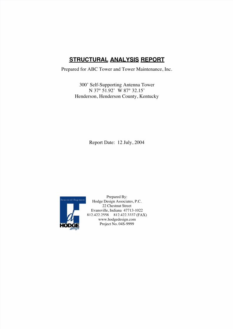
STRUCTURAL ANALYSIS REPORT
Prepared for ABC Tower and Tower Maintenance, Inc.
300’ Self-Supporting Antenna Tower
N 37° 51.92’ W 87° 32.15’
Henderson, Henderson County, Kentucky
Report Date: 12 July, 2004
Prepared By:
Hodge Design Associates, P.C.22 Chestnut Street
Evansville, Indiana 47713-1022
812.422.2558 812.422.3337 (FAX)
www.hodgedesign.comProject No. 04S-9999

8/18/2019 Analysis Self Supporting-1
http://slidepdf.com/reader/full/analysis-self-supporting-1 2/98
12 July, 2004
Mr. John Smith
ABC TOWER AND TOWER MAINTENANCE, INC.
123 Main StreetSt, Louis, Missouri 99999
Re: Structural Analysis Report
300’ Self-Supporting Antenna TowerHenderson, Henderson County, Kentucky
HDA Project No. 04S-9999
Dear Mr. Smith,
Per your request, we have performed a structural analysis for the referenced antennatower. The purpose of the analysis was to investigate the structural adequacy of the tower for the
existing configuration (antennas, transmission lines and other appurtenances) under ice and windloading conditions with the addition of two, 8’diameter high performance dish antennas with
transmission lines at 200’ AGL.
Our structural analysis of the antenna tower is based on data provided by ABC Towerand Tower Maintenance, Inc. and manufacturers' product data (please see Appendix A). We
assume that the data is correct. Structural analysis computations were performed utilizingspecialized computer software and the TIA-EIA-222-F Structural Standards for Steel Antenna
Towers and Antenna Supporting Structures. Please see Appendices B, C and D for structuralcalculations.
Our structural analysis of the antenna tower indicates that the antenna tower is not in
conformance with the referenced design standard. Recommendations for tower modifications are
outlined below. The antenna tower structural analysis may be summarized as follows:
H O D G E D E S I G N A S S O C I A T E S , P . C.
22 Chestnut Street• Evansville, Indiana 47713-1022• tel: 812.422.2558 • fax: 812.422.3337 • www.hodgedesign.com

8/18/2019 Analysis Self Supporting-1
http://slidepdf.com/reader/full/analysis-self-supporting-1 3/98
12 July, 2004
Mr. John SmithABC TOWER AND TOWER MAINTENANCE, INC.
123 Main Street
St, Louis, Missouri 99999
Re: Structural Analysis Report300’ Self-Supporting Antenna Tower
Henderson, Henderson County, Kentucky
HDA Project No. 04S-9999
Page 3
Tower Owner: Tower Leasing Corporation of America, LLC
Tower Location: Henderson, Henderson County, KentuckyTower Height: 300’
Face Width: VariesPanel Height: Varies
Tower Manufacturer: ABC TowerType: Self-Supporting
Number of Legs: 3
Design Standard: TIA/EIA-222-FLoading: 70 mph wind, no ice
61 mph wind, !" ice
Antenna Loading: See Appendices A and BMaterials: Legs: 50 ksi
Diagonals: 36 ksiHorizontals: 36 ksi
Guys: EHSBolts: ASTM A325
APPURTENANCE LIST
Elevation(AGL) Appurtenances Transmission Lines
EXISTING
300’ FAA Beacon 2’ Rigid Conduit
300’ 6’ Lightning Rod
295’ (12) DB858 w/12’ T Frames (3 Sections) (12) 1 5/8
280’ (12) DB858 w/12’ T Frames (3 Sections) (12) 1 5/8
260’ (12) DB858 w/12’ T Frames (3 Sections) (12) 1 5/8
200’ Dual Obstruction Lights
100’ Dual Obstruction Lights
PROPOSED
200’ (2) UHX8-59 (2) EW 63
Please review the above appurtenance loading and contact us immediately if any discrepancies arenoted. This listing represents our understanding of the appurtenance loading required.

8/18/2019 Analysis Self Supporting-1
http://slidepdf.com/reader/full/analysis-self-supporting-1 4/98
12 July, 2004
Mr. John SmithABC TOWER AND TOWER MAINTENANCE, INC.
123 Main Street
St, Louis, Missouri 99999
Re: Structural Analysis Report300’ Self-Supporting Antenna Tower
Henderson, Henderson County, Kentucky
HDA Project No. 04S-9999
Page 4
STRUCTURAL ANALYSIS RESULTS SUMMARYEXISTING TOWER CONFIGURATION
Elevation Member Status Notes and/or Recommendations
0’ – 300’ Leg OK
0’ – 300’ Diagonal OK
260’ – 300’ Girt/Horizontal OK
Notes:See Appendix B of Detailed Structural Analysis Report.
Assumptions:Where insufficient information regarding member sizes, material strength, etc. has been provided, certain assumptions have
been made as noted elsewhere in this report. It is the responsibility of the client to verify the validity of those assumptions.
STRUCTURAL ANALYSIS RESULTS SUMMARYEXISTING TOWER CONFIGURATION WITH PROPOSED ANTENNAS
Elevation Member Status Notes and/or Recommendations
100’ – 300’ Leg OK
140’ – 160’ Leg OK Add 2L 2x2x3/16 Secondary Horizontal Per Detail 1, Appendix E
100’ – 140’ Leg OK
80’ – 100’ Guy NG Add 2L 2x2x3/16 Secondary Horizontal Per Detail 1, Appendix E60’ - 80’ Leg OK40’ – 60’ Leg OK Add 2L 2x2x3/16 Secondary Horizontal Per Detail 1, Appendix E
0’ - 40’ Leg OK200’ – 300’ Diagonal OK
180’ – 200’ Diagonal NG 2L 2x2x3/16 Diagonals per Detail 2, Appendix E160’ – 180’ Diagonal NG 2L 2x2x1/4 Diagonals per Detail 2, Appendix E
140’ – 160’ Diagonal OK
120’ – 140’ Diagonal NG 2L 2 1/2 x2 1/4x3/16 Diagonals per Detail 2, Appendix E
100’ – 120’ Diagonal NG 2L 2 1/2 x2 1/4x1/4 Diagonals per Detail 2, Appendix E
80’ – 100’ Diagonal NG 2L 3x3x3/16 Diagonals per Detail 2, Appendix E60’ – 80’ Diagonal NG 2L 3x3x1/4 Diagonals per Detail 2, Appendix E
40’ – 60’ Diagonal NG 2L 3 1/2x3 1/2x3/16 Diagonals per Detail 2, Appendix E
20’ – 40’ Diagonal OK 2L 3 1/2x3 1/2x1/4 Diagonals per Detail 2, Appendix E
0’ – 20’ Diagonal OKTower Deflections:at 70 mph: at 50 mph:
Maximum Horizontal Deflection = 45.6” Maximum Horizontal Deflection = 23.3” Horizontal Deflection at 200’ AGL = 9.2”Maximum Tilt = 1.65° Maximum Tilt = 0.84° Tilt at 200’ AGL = 0.44°Maximum Twist = 0.10° Maximum Twist = 0.05° Twist at 200’ AGL = 0.15°
Note: It is the responsibility of the Owner to determine whether tower deflections are within the operational parameters of anyappurtenances.
Notes:See Appendix C of Detailed Structural Analysis Report.
Assumptions:Where insufficient information regarding member sizes, material strength, etc. has been provided, certain assumptions havebeen made as noted elsewhere in this report. It is the responsibility of the client to verify the validity of those assumptions.
8/18/2019 Analysis Self Supporting-1
http://slidepdf.com/reader/full/analysis-self-supporting-1 5/98
12 July, 2004
Mr. John SmithABC TOWER AND TOWER MAINTENANCE, INC.
123 Main Street
St, Louis, Missouri 99999
Re: Structural Analysis Report300’ Self-Supporting Antenna Tower
Henderson, Henderson County, Kentucky
HDA Project No. 04S-9999
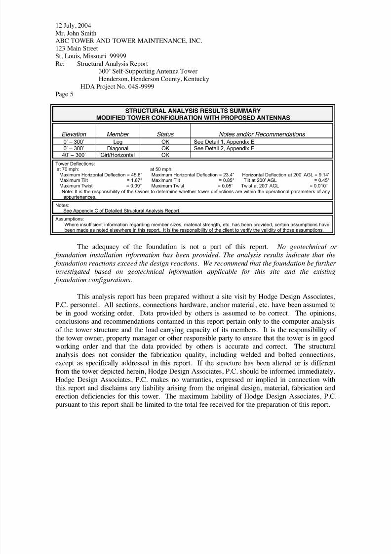
Page 5
STRUCTURAL ANALYSIS RESULTS SUMMARYMODIFIED TOWER CONFIGURATION WITH PROPOSED ANTENNAS
Elevation Member Status Notes and/or Recommendations
0’ – 300’ Leg OK See Detail 1, Appendix E
0’ – 300’ Diagonal OK See Detail 2, Appendix E
40’ – 300’ Girt/Horizontal OK
Tower Deflections:at 70 mph: at 50 mph:
Maximum Horizontal Deflection = 45.8” Maximum Horizontal Deflection = 23.4” Horizontal Deflection at 200’ AGL = 9.14”Maximum Tilt = 1.67° Maximum Tilt = 0.85° Tilt at 200’ AGL = 0.45°Maximum Twist = 0.09° Maximum Twist = 0.05° Twist at 200’ AGL = 0.010°
Note: It is the responsibility of the Owner to determine whether tower deflections are within the operational parameters of anyappurtenances.
Notes:See Appendix C of Detailed Structural Analysis Report.
Assumptions:
Where insufficient information regarding member sizes, material strength, etc. has been provided, certain assumptions havebeen made as noted elsewhere in this report. It is the responsibility of the client to verify the validity of those assumptions.
The adequacy of the foundation is not a part of this report. No geotechnical or
foundation installation information has been provided. The analysis results indicate that the
foundation reactions exceed the design reactions. We recommend that the foundation be further
investigated based on geotechnical information applicable for this site and the existing
foundation configurations.
This analysis report has been prepared without a site visit by Hodge Design Associates,P.C. personnel. All sections, connections hardware, anchor material, etc. have been assumed to
be in good working order. Data provided by others is assumed to be correct. The opinions,conclusions and recommendations contained in this report pertain only to the computer analysis
of the tower structure and the load carrying capacity of its members. It is the responsibility ofthe tower owner, property manager or other responsible party to ensure that the tower is in good
working order and that the data provided by others is accurate and correct. The structuralanalysis does not consider the fabrication quality, including welded and bolted connections,
except as specifically addressed in this report. If the structure has been altered or is differentfrom the tower depicted herein, Hodge Design Associates, P.C. should be informed immediately.
Hodge Design Associates, P.C. makes no warranties, expressed or implied in connection withthis report and disclaims any liability arising from the original design, material, fabrication and
erection deficiencies for this tower. The maximum liability of Hodge Design Associates, P.C.pursuant to this report shall be limited to the total fee received for the preparation of this report.

8/18/2019 Analysis Self Supporting-1
http://slidepdf.com/reader/full/analysis-self-supporting-1 6/98
12 July, 2004
Mr. John SmithABC TOWER AND TOWER MAINTENANCE, INC.
123 Main Street
St, Louis, Missouri 99999
Re: Structural Analysis Report300’ Self-Supporting Antenna Tower
Henderson, Henderson County, Kentucky
HDA Project No. 04S-9999
Page 6
If you have any questions regarding this matter, please do not hesitate to contact me.
Sincerely,
W. Gray Hodge, P.E., S.E.
HODGE DESIGN ASSOCIATES, P.C.Consulting Engineers
8/18/2019 Analysis Self Supporting-1
http://slidepdf.com/reader/full/analysis-self-supporting-1 7/98
APPENDIX A
D a t a S u p p li e d By O t h e r s
M a n u f a c t u r e r s ' D a t a

8/18/2019 Analysis Self Supporting-1
http://slidepdf.com/reader/full/analysis-self-supporting-1 8/98

8/18/2019 Analysis Self Supporting-1
http://slidepdf.com/reader/full/analysis-self-supporting-1 9/98
APPENDIX B
E x i s t in g A n t e n n a T o w e r
G r a p h i c a l Co m p u t e r O u t p u t
S t r u c t u r a l An a l y s i s R e p o r t a n d C a l c u l a t i o n s
8/18/2019 Analysis Self Supporting-1
http://slidepdf.com/reader/full/analysis-self-supporting-1 10/98
www.hodgedesign.com
Hodge Design Associates, P.C.22 Chestnut Street
Evansville, Indiana 47713-1022Phone: 812.422.2558
FAX: 812.422.3337
Job:Structural Analysis Report -- 300' Self-Supporting Tower (HDA Project No. 04S-9
Project: Henderson, Henderson County, KY --- Existing Tower Condition Analysis Client: ABC Towers and Tower Maintenance Drawn by: Gray Hodge App'd:
Code: TIA/EIA-222-F Date: 07/23/04 Scale: NTSPath:
C:\DocumentsandSettings\ghodge.HODGEDESIGN.000\MyDocuments\ERITowerProjectData Files\SampleReports\Sample-SS-R1.eri
Dwg No. E-1
300.0 ft
280.0 ft
260.0 ft
240.0 ft
220.0 ft
200.0 ft
180.0 ft
160.0 ft
140.0 ft
120.0 ft
100.0 ft
80.0 ft
60.0 ft
40.0 ft
20.0 ft
0.0 ft
REACTIONS - 70 mph WIND TORQUE 2 kip-ft
42 K SHEAR
7244 kip-ft MOMENT
66 K AXIAL
61 mph WIND - 0.5000 in ICE TORQUE 3 kip-ft
40 K SHEAR
6901 kip-ft MOMENT
96 K AXIAL
SHEAR: 26 K UPLIFT: -287 K DOWN: 344 K
MAX PIER FORCES:
T 1
T 2
T 3
T 4
T 5
T 6
T 7
T 8
T 9
T 1 0
T 1 1
T 1 2
T 1 3
T 1 4
T 1 5
S R 1 1 / 2
S R 2
S R 3
S R 3 1 / 4
S R 3 1 / 2
S R 3 3 / 4
S R 4
S
R 4 1 / 4
A 5 7 2 - 5 0
S R 3 / 4
S R 7 / 8
L 2 x 2 x 3 / 1 6
L 2 x 2 x 1 / 4
L 2 1 / 2 x 2 1 / 2 x 3 / 1 6
A
L 3 x 3 x 3 / 1 6
L 3 x 3 x 1 / 4
B
C
L 4 x 4 x 1 / 4
A 3 6
S R 3 / 4
S R 7 / 8
N . A .
S R 3 / 4
S R 7 / 8
N . A .
0 . 7
1 . 1
2 . 0
2 . 3
2 . 4
2 . 7
3 . 0
3 . 0
3 . 4
3 . 8
3 . 8
4 . 7
4 . 6
5 . 7
6 . 3
4
5 . 6 9 2 7 1
7 . 3 8 5 4 2
9 . 0 7 8 1 3
1 0 . 7 6 8 2
1 2 . 4 6 0 9
1 4 . 1 5 3 6
1 5 . 8 4 6 4
1 7 . 5 3 9 1
1 9 . 2 3 1 8
2 0 . 9 2 1 9
2 2 . 6 1 4 6
2 4 . 3 0 7 3
1 2 @ 3 . 2 0 8 3 3
3 9 @ 6 . 1 6 6 6 7
S e c t i o n
L e g s
L e g G r a d e
D i a g o n a l s
D i a g o n a l G r a d e
T o p G i r t s
B o t t o m G i r t s
F a c e W i d t h ( f t )
2 6
# P a n e l s @ (
f t )
W e i g h t ( K )
4 9 . 6
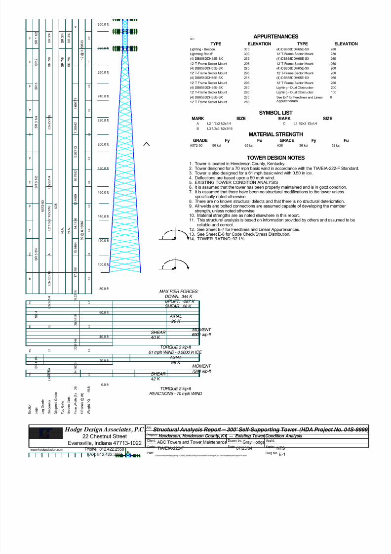
Lighting - Beacon 300Lightning Rod 6' 300(4) DB858DDH65E-SX 29512' T-Frame Sector Mount 295(4) DB858DDH65E-SX 29512' T-Frame Sector Mount 295(4) DB858DDH65E-SX 29512' T-Frame Sector Mount 295(4) DB858DDH65E-SX 28012' T-Frame Sector Mount 280(4) DB858DDH65E-SX 28012' T-Frame Sector Mount 280(4) DB858DDH65E-SX 28012' T-Frame Sector Mount 280(4) DB858DDH65E-SX 26012' T-Frame Sector Mount 260(4) DB858DDH65E-SX 26012' T-Frame Sector Mount 260(4) DB858DDH65E-SX 26012' T-Frame Sector Mount 260Lighting - Dual Obstruction 200Lighting - Dual Obstruction 100See E-7 for Feedlines and Linear Appurtenances
0 APPURTENANCES
TYPE TYPEELEVATION ELEVATIONLighting - Beacon 300
Lightning Rod 6' 300
(4) DB858DDH65E-SX 295
12' T-Frame Sector Mount 295
(4) DB858DDH65E-SX 295
12' T-Frame Sector Mount 295
(4) DB858DDH65E-SX 295
12' T-Frame Sector Mount 295
(4) DB858DDH65E-SX 280
12' T-Frame Sector Mount 280
(4) DB858DDH65E-SX 280
12' T-Frame Sector Mount 280
(4) DB858DDH65E-SX 280
12' T-Frame Sector Mount 280
(4) DB858DDH65E-SX 260
12' T-Frame Sector Mount 260
(4) DB858DDH65E-SX 260
12' T-Frame Sector Mount 260
(4) DB858DDH65E-SX 260
12' T-Frame Sector Mount 260
Lighting - Dual Obstruction 200
Lighting - Dual Obstruction 100
See E-7 for Feedlines and Linear Appurtenances
0
SYMBOL LISTMARK MARKSIZE SIZE
A L2 1/2x2 1/2x1/4
B L3 1/2x3 1/2x3/16
C L3 1/2x3 1/2x1/4
MATERIAL STRENGTHGRADE GRADEFy FyFu Fu
A572-50 50 ksi 65 ksi A36 36 ksi 58 ksi
TOWER DESIGN NOTES1. Tower is located in Henderson County, Kentucky.2. Tower designed for a 70 mph basic wind in accordance with the TIA/EIA-222-F Standa3. Tower is also designed for a 61 mph basic wind with 0.50 in ice.4. Deflections are based upon a 50 mph wind.
5. EXISTING TOWER CONDITION ANALYSIS6. It is assumed that the tower has been properly maintained and is in good condition.7. It is assumed that there have been no structural modifications to the tower unless
specifically noted otherwise.8. There are no known structural defects and that there is no structural deterioration.9. All welds and bolted connections are assumed capable of developing the member
strength, unless noted otherwise.10. Material strengths are as noted elsewhere in this report.11. This structural analysis is based on information provided by others and assumed to be
reliable and correct.12. See Sheet E-7 for Feedlines and Linear Appurtenances.13. See Sheet E-8 for Code Check/Stress Distribution.14. TOWER RATING: 97.1%

8/18/2019 Analysis Self Supporting-1
http://slidepdf.com/reader/full/analysis-self-supporting-1 11/98
www.hodgedesign.com
Hodge Design Associates, P.C.22 Chestnut Street
Evansville, Indiana 47713-1022Phone: 812.422.2558
FAX: 812.422.3337
Job:Structural Analysis Report -- 300' Self-Supporting Tower (HDA Project No. 04S-9
Project: Henderson, Henderson County, KY --- Existing Tower Condition Analysis Client: ABC Towers and Tower Maintenance Drawn by: Gray Hodge App'd:
Code: TIA/EIA-222-F Date: 07/23/04 Scale: NTSPath:
C:\DocumentsandSettings\ghodge.HODGEDESIGN.000\MyDocuments\ERITowerProjectData Files\SampleReports\Sample-SS-R1.eri
Dwg No. E-3
<- Minimum 0 Maximum ->
<- Minimum 0 Maximum ->
-500
-500
-1000
-1000
500
500
1000
1000
TIA/EIA-222-F - 70 mph/61 mph 0.5000 in Ice
Leg Capacity Leg Compression (K)
300' 300'
280' 280'
260' 260'
240' 240'
220' 220'
200' 200'
180' 180'
160' 160'
140' 140'
120' 120'
100' 100'
80' 80'
60' 60'
40' 40'
20' 20'
0' 0'
E l e v a t i o n
( f t )

8/18/2019 Analysis Self Supporting-1
http://slidepdf.com/reader/full/analysis-self-supporting-1 12/98
www.hodgedesign.com
Hodge Design Associates, P.C.22 Chestnut Street
Evansville, Indiana 47713-1022Phone: 812.422.2558
FAX: 812.422.3337
Job:Structural Analysis Report -- 300' Self-Supporting Tower (HDA Project No. 04S-9
Project: Henderson, Henderson County, KY --- Existing Tower Condition Analysis Client: ABC Towers and Tower Maintenance Drawn by: Gray Hodge App'd:
Code: TIA/EIA-222-F Date: 07/23/04 Scale: NTSPath:
C:\DocumentsandSettings\ghodge.HODGEDESIGN.000\MyDocuments\ERITowerProjectData Files\SampleReports\Sample-SS-R1.eri
Dwg No. E-4
0
0
50
50
Global Mast Shear (K)
300'
280'
260'
240'
220'
200'
180'
160'
140'
120'
100'
80'
60'
40'
20'
0'
E l e v a t i o n
( f t )
0
0
5000
5000
10000
10000
Global Mast Moment (kip-ft)
300'
280'
260'
240'
220'
200'
180'
160'
140'
120'
100'
80'
60'
40'
20'
0'
TIA/EIA-222-F - 70 mph/61 mph 0.5000 in Ice Maximum Values
Vx Vz Mx Mz

8/18/2019 Analysis Self Supporting-1
http://slidepdf.com/reader/full/analysis-self-supporting-1 13/98
www.hodgedesign.com
Hodge Design Associates, P.C.22 Chestnut Street
Evansville, Indiana 47713-1022Phone: 812.422.2558
FAX: 812.422.3337
Job:Structural Analysis Report -- 300' Self-Supporting Tower (HDA Project No. 04S-9
Project: Henderson, Henderson County, KY --- Existing Tower Condition Analysis Client: ABC Towers and Tower Maintenance Drawn by: Gray Hodge App'd:
Code: TIA/EIA-222-F Date: 07/23/04 Scale: NTSPath:
C:\DocumentsandSettings\ghodge.HODGEDESIGN.000\MyDocuments\ERITowerProjectData Files\SampleReports\Sample-SS-R1.eri
Dwg No. E-5
TIA/EIA-222-F - Service - 50 mph Maximum Values
0
0
5
5
10
10
15
15
20
20
25
25
Deflection (in)
300'
280'
260'
240'
220'
200'
180'
160'
140'
120'
100'
80'
60'
40'
20'
0'
E l e v a t i o n
( f t )
0
0
0.5
0.5
1
1
Tilt (deg)0
0
0.05
0.05
0.1
0.1
Twist (deg)
300
280
260
240
220
200
180
160
140
120
100
80'
60'
40'
20'
0'
8/18/2019 Analysis Self Supporting-1
http://slidepdf.com/reader/full/analysis-self-supporting-1 14/98
www.hodgedesign.com
Hodge Design Associates, P.C.22 Chestnut Street
Evansville, Indiana 47713-1022Phone: 812.422.2558
FAX: 812.422.3337
Job:Structural Analysis Report -- 300' Self-Supporting Tower (HDA Project No. 04S-9
Project: Henderson, Henderson County, KY --- Existing Tower Condition Analysis Client: ABC Towers and Tower Maintenance Drawn by: Gray Hodge App'd:
Code: TIA/EIA-222-F Date: 07/23/04 Scale: NTSPath:
C:\DocumentsandSettings\ghodge.HODGEDESIGN.000\MyDocuments\ERITowerProjectData Files\SampleReports\Sample-SS-R1.eri
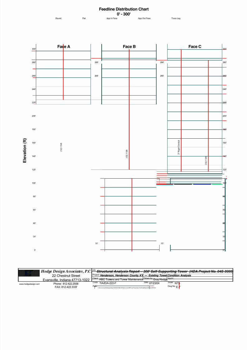
Dwg No. E-7
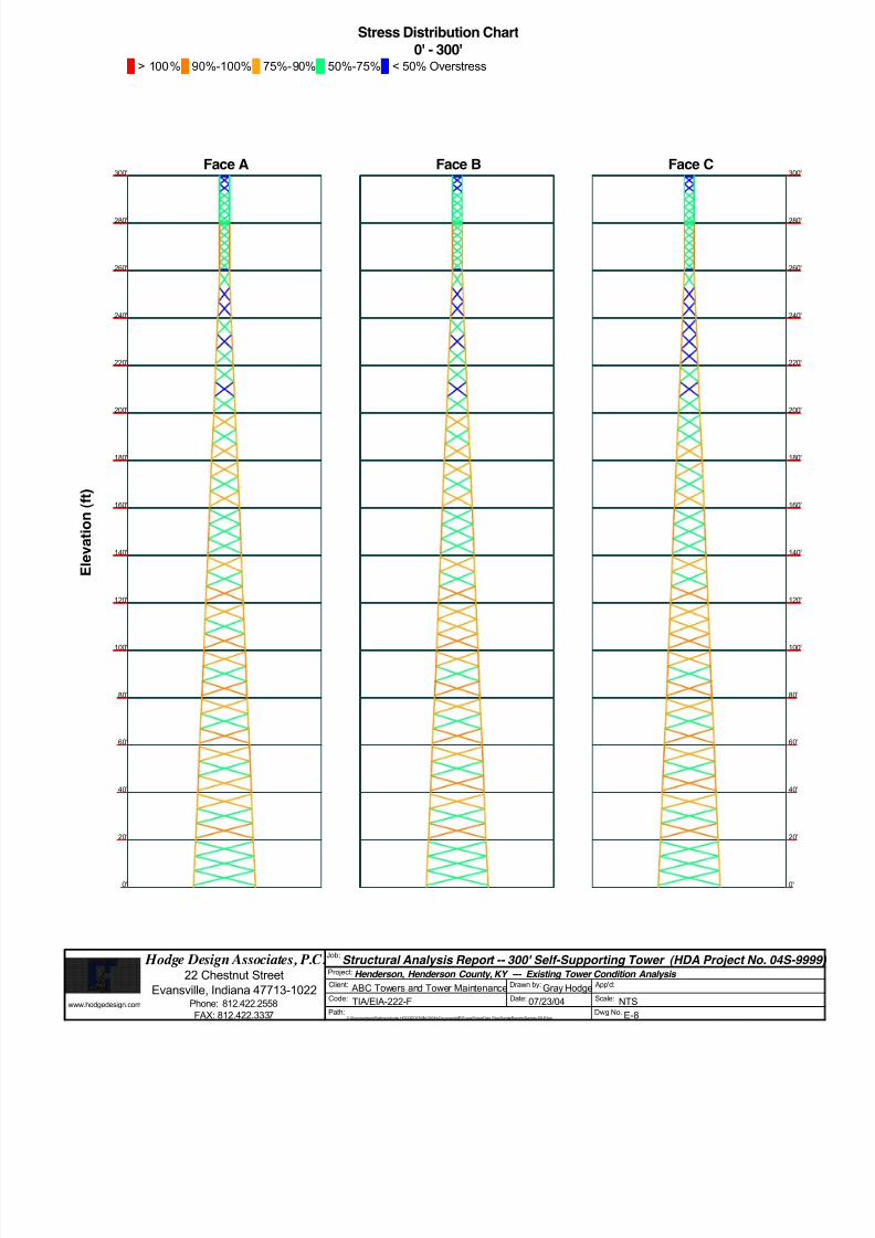
Feedline Distribution Chart
0' - 300'Round Flat App In Face App Out Face Truss Leg
Face A
280'
260'
240'
220'
200'
180'
160'
140'
120'
100'
80'
60'
40'
20'
0'
300'
E l e v a t i o n
( f t )
( 1 2 ) 1 5 / 8
Face B
10'10'10'
280'
10'
260'
( 1 2 ) 1 5 / 8
Face C
280
260
240
220
200
180
160
140
120
100
80'
60'
40'
20'
0'
300
10'10'10'
280'
10'
260'
2 " R i g i d C o n d u i t
( 1 2 ) 1 5 / 8
8/18/2019 Analysis Self Supporting-1
http://slidepdf.com/reader/full/analysis-self-supporting-1 15/98
www.hodgedesign.com
Hodge Design Associates, P.C.22 Chestnut Street
Evansville, Indiana 47713-1022Phone: 812.422.2558
FAX: 812.422.3337
Job:Structural Analysis Report -- 300' Self-Supporting Tower (HDA Project No. 04S-9
Project: Henderson, Henderson County, KY --- Existing Tower Condition Analysis Client: ABC Towers and Tower Maintenance Drawn by: Gray Hodge App'd:
Code: TIA/EIA-222-F Date: 07/23/04 Scale: NTSPath:
C:\DocumentsandSettings\ghodge.HODGEDESIGN.000\MyDocuments\ERITowerProjectData Files\SampleReports\Sample-SS-R1.eri
Dwg No. E-7
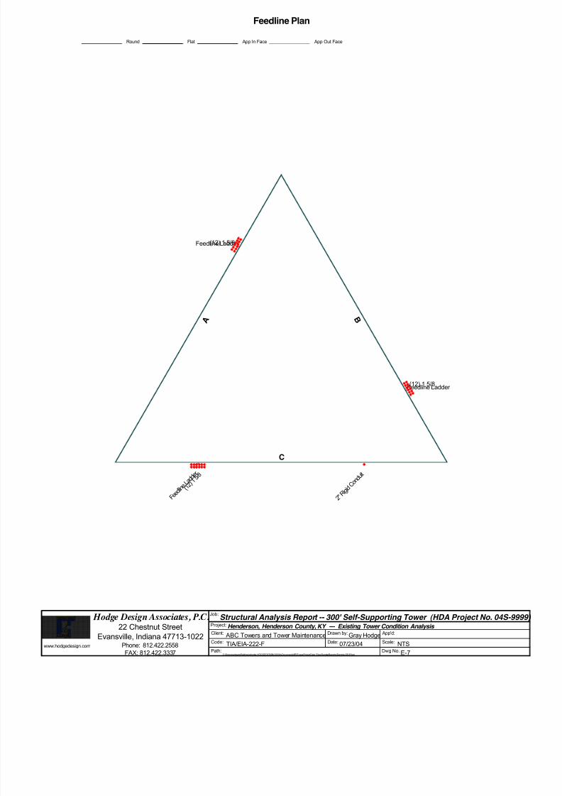
Feedline Plan
Round Flat App In Face App Out Face
A B
C
Feedline Ladder
Feedline Ladder
F e e d l i n
e L a d d e r
2 " R i g i d
C o n d u i t
(12) 1 5/8
(12) 1 5/8
( 1 2 ) 1
5 / 8
8/18/2019 Analysis Self Supporting-1
http://slidepdf.com/reader/full/analysis-self-supporting-1 16/98

8/18/2019 Analysis Self Supporting-1
http://slidepdf.com/reader/full/analysis-self-supporting-1 17/98
E E R R I I T T oowweer r Job
Structural Analysis Report -- 300' Self-Supporting Tower (HDAProject No. 04S-9999)
Page
1 of 20
Hodge Design Associates, P.C. 22 Chestnut Street
Project
Henderson, Henderson County, KY --- Existing TowerCondition Analysis
Date
12:49:20 07/23/04
Evansville, Indiana 47713-1022
Phone: 812.422.2558
FAX: 812.422.3337
Client
ABC Towers and Tower MaintenanceDesigned by
Gray Hodge
Tower Input Data
The main tower is a 3x free standing tower with an overall height of 300' above the ground line.
The base of the tower is set at an elevation of 0' above the ground line.The face width of the tower is 4' at the top and 26' at the base.
This tower is designed using the TIA/EIA-222-F standard.
The following design criteria apply:
Tower is located in Henderson County, Kentucky.
Basic wind speed of 70 mph.
Nominal ice thickness of 0.5000 in.
Ice density of 56 pcf.A wind speed of 61 mph is used in combination with ice.
Temperature drop of 75 °F.
Deflections calculated using a wind speed of 50 mph.
EXISTING TOWER CONDITION ANALYSIS.
It is assumed that the tower has been properly maintained and is in good condition..It is assumed that there have been no structural modifications to the tower unless specifically noted otherwise..
There are no known structural defects and that there is no structural deterioration..
All welds and bolted connections are assumed capable of developing the member strength, unless noted otherwise..
Material strengths are as noted elsewhere in this report..
This structural analysis is based on information provided by others and assumed to be reliable and correct..
See Sheet E-7 for Feedlines and Linear Appurtenances..See Sheet E-8 for Code Check/Stress Distribution..
A non-linear (P-delta) analysis was used.Pressures are calculated at each section.
Stress ratio used in tower member design is 1.333.
Local bending stresses due to climbing loads, feedline supports, and appurtenance mounts are not considered.
Options
Consider Moments - Legs Distribute Leg Loads As Uniform v Treat Feedline Bundles As Cylinder
Consider Moments - Horizontals Assume Legs Pinned Use ASCE 10 X-Brace Ly Rules
Consider Moments - Diagonals v Assume Rigid Index Plate v Calculate Redundant Bracing Forces
Use Moment Magnification v Use Clear Spans For Wind Area v Ignore Redundant Members in FEA
v Use Code Stress Ratios v Use Clear Spans For KL/r v SR Leg Bolts Resist Compression
v Use Code Safety Factors - Guys v Retension Guys To Initial Tension v All Leg Panels Have Same Allowable
Escalate Ice Bypass Mast Stability Checks Offset Girt At Foundation
Always Use Max Kz v Use Azimuth Dish Coefficients v Consider Feedline Torque
Use Special Wind Profile v Project Wind Area of Appurt. v Include Angle Block Shear CheckInclude Bolts In Member Capacity Autocalc Torque Arm Areas Poles
v Leg Bolts Are At Top Of Section v SR Members Have Cut Ends v Include Shear-Torsion Interaction
v Secondary Horizontal Braces Leg v Sort Capacity Reports By Component Always Use Sub-Critical Flow
Use Diamond Inner Bracing (4 Sided) v Triangulate Diamond Inner Bracing Use Top Mounted Sockets
Add IBC .6D+W Combination

8/18/2019 Analysis Self Supporting-1
http://slidepdf.com/reader/full/analysis-self-supporting-1 18/98
E E R R I I T T oowweer r Job
Structural Analysis Report -- 300' Self-Supporting Tower (HDAProject No. 04S-9999)
Page
2 of 20
Hodge Design Associates, P.C. 22 Chestnut Street
Project
Henderson, Henderson County, KY --- Existing TowerCondition Analysis
Date
12:49:20 07/23/04
Evansville, Indiana 47713-1022
Phone: 812.422.2558
FAX: 812.422.3337
Client
ABC Towers and Tower MaintenanceDesigned by
Gray Hodge
Leg BLeg C
Leg A
F a c e
A F
a c e B
Face C
Triangular Tower
Wind Normal
Wind 90
Wind 180
Z
X
Tower Section Geometry
Tower
Section
Tower
Elevation
ft
Assembly
Database
Description Section
Width
ft
Number
of
Sections
Section
Length
ft
T1 300'-280' 4' 1 20'
T2 280'-260' 4' 1 20'
T3 260'-240' 4' 1 20'
T4 240'-220' 5'8-9/32'' 1 20'
T5 220'-200' 7'4-11/16'' 1 20'
T6 200'-180' 9'31/32'' 1 20'
T7 180'-160' 10'9-1/4'' 1 20'
T8 160'-140' 12'5-17/32'' 1 20'
T9 140'-120' 14'1-13/16'' 1 20'
T10 120'-100' 15'10-3/16'' 1 20'
T11 100'-80' 17'6-15/32'' 1 20'
T12 80'-60' 19'2-3/4'' 1 20'
T13 60'-40' 20'11-1/32'' 1 20'T14 40'-20' 22'7-5/16'' 1 20'
T15 20'-0' 24'3-23/32'' 1 20'
Tower Section Geometry (cont’d)
Tower
Section
Tower
Elevation
ft
Diagonal
Spacing
ft
Bracing
Type
Has
K Brace
End
Panels
Has
Horizontals
Top Girt
Offset
in
Bottom Girt
Offset
in

8/18/2019 Analysis Self Supporting-1
http://slidepdf.com/reader/full/analysis-self-supporting-1 19/98
E E R R I I T T oowweer r Job
Structural Analysis Report -- 300' Self-Supporting Tower (HDAProject No. 04S-9999)
Page
3 of 20
Hodge Design Associates, P.C. 22 Chestnut Street
Project
Henderson, Henderson County, KY --- Existing TowerCondition Analysis
Date
12:49:20 07/23/04
Evansville, Indiana 47713-1022
Phone: 812.422.2558
FAX: 812.422.3337
Client
ABC Towers and Tower MaintenanceDesigned by
Gray Hodge
TowerSection
Tower Elevation
ft
DiagonalSpacing
ft
BracingType
HasK Brace
End
Panels
Has Horizontals
Top GirtOffset
in
Bottom GirtOffset
in
T1 300'-280' 3'2-17/32'' X Brace No No 4.5000 4.5000
T2 280'-260' 3'2-17/32'' X Brace No No 4.5000 4.5000
T3 260'-240' 6'2-1/32'' X Brace No No 9.0000 9.0000
T4 240'-220' 6'2-1/32'' X Brace No No 9.0000 9.0000
T5 220'-200' 6'2-1/32'' X Brace No No 9.0000 9.0000
T6 200'-180' 6'2-1/32'' X Brace No No 9.0000 9.0000
T7 180'-160' 6'2-1/32'' X Brace No No 9.0000 9.0000
T8 160'-140' 6'2-1/32'' X Brace No No 9.0000 9.0000
T9 140'-120' 6'2-1/32'' X Brace No No 9.0000 9.0000
T10 120'-100' 6'2-1/32'' X Brace No No 9.0000 9.0000
T11 100'-80' 6'2-1/32'' X Brace No No 9.0000 9.0000
T12 80'-60' 6'2-1/32'' X Brace No No 9.0000 9.0000
T13 60'-40' 6'2-1/32'' X Brace No No 9.0000 9.0000
T14 40'-20' 6'2-1/32'' X Brace No No 9.0000 9.0000
T15 20'-0' 6'2-1/32'' X Brace No No 9.0000 9.0000
Tower Section Geometry (cont’d)
Tower
Elevation
ft
Leg
Type
Leg
Size
Leg
Grade
Diagonal
Type
Diagonal
Size
Diagonal
Grade
T1 300'-280' Solid Round 1 1/2 A572-50
(50 ksi)
Solid Round 3/4 A36
(36 ksi)
T2 280'-260' Solid Round 2 A572-50
(50 ksi)
Solid Round 7/8 A36
(36 ksi)
T3 260'-240' Solid Round 3 A572-50
(50 ksi)
Equal Angle L2x2x3/16 A36
(36 ksi)T4 240'-220' Solid Round 3 1/4 A572-50
(50 ksi)
Equal Angle L2x2x3/16 A36
(36 ksi)
T5 220'-200' Solid Round 3 1/4 A572-50
(50 ksi)
Equal Angle L2x2x3/16 A36
(36 ksi)
T6 200'-180' Solid Round 3 1/2 A572-50
(50 ksi)
Equal Angle L2x2x3/16 A36
(36 ksi)
T7 180'-160' Solid Round 3 1/2 A572-50
(50 ksi)
Equal Angle L2x2x1/4 A36
(36 ksi)
T8 160'-140' Solid Round 3 1/2 A572-50
(50 ksi)
Equal Angle L2 1/2x2 1/2x3/16 A36
(36 ksi)
T9 140'-120' Solid Round 3 3/4 A572-50
(50 ksi)
Equal Angle L2 1/2x2 1/2x3/16 A36
(36 ksi)
T10 120'-100' Solid Round 3 3/4 A572-50
(50 ksi)
Equal Angle L2 1/2x2 1/2x1/4 A36
(36 ksi)
T11 100'-80' Solid Round 3 3/4 A572-50
(50 ksi)
Equal Angle L3x3x3/16 A36
(36 ksi)
T12 80'-60' Solid Round 4 A572-50(50 ksi)
Equal Angle L3x3x1/4 A36(36 ksi)
T13 60'-40' Solid Round 4 A572-50
(50 ksi)
Equal Angle L3 1/2x3 1/2x3/16 A36
(36 ksi)
T14 40'-20' Solid Round 4 1/4 A572-50
(50 ksi)
Equal Angle L3 1/2x3 1/2x1/4 A36
(36 ksi)
T15 20'-0' Solid Round 4 1/4 A572-50
(50 ksi)
Equal Angle L4x4x1/4 A36
(36 ksi)

8/18/2019 Analysis Self Supporting-1
http://slidepdf.com/reader/full/analysis-self-supporting-1 20/98
E E R R I I T T oowweer r Job
Structural Analysis Report -- 300' Self-Supporting Tower (HDAProject No. 04S-9999)
Page
4 of 20
Hodge Design Associates, P.C. 22 Chestnut Street
Project
Henderson, Henderson County, KY --- Existing TowerCondition Analysis
Date
12:49:20 07/23/04
Evansville, Indiana 47713-1022
Phone: 812.422.2558
FAX: 812.422.3337
Client
ABC Towers and Tower MaintenanceDesigned by
Gray Hodge
Tower Section Geometry (cont’d)
Tower
Elevation
ft
Top Girt
Type
Top Girt
Size
Top Girt
Grade
Bottom Girt
Type
Bottom Girt
Size
Bottom Girt
Grade
T1 300'-280' Solid Round 3/4 A36
(36 ksi)
Solid Round 3/4 A36
(36 ksi)
T2 280'-260' Solid Round 7/8 A36
(36 ksi)
Solid Round 7/8 A36
(36 ksi)
Tower Section Geometry (cont’d)
Tower
Elevation
ft
Gusset
Area
(per face)
ft 2
Gusset
Thickness
in
Gusset Grade Adjust. Factor
A f
Adjust.
Factor
Ar
Weight Mult. Double Angle
Stitch Bolt
Spacing
Diagonals
in
Double Angle
Stitch Bolt
Spacing
Horizontals
in
T1 300'-280' 0.00 0.0000 A36
(36 ksi)
1.01 1.01 1.01 36.0000 36.0000
T2 280'-260' 0.00 0.0000 A36
(36 ksi)
1.01 1.01 1.01 36.0000 36.0000
T3 260'-240' 2.50 0.7500 A36
(36 ksi)
1.01 1.01 1.01 36.0000 36.0000
T4 240'-220' 2.50 0.7500 A36
(36 ksi)
1.01 1.01 1.01 36.0000 36.0000
T5 220'-200' 2.50 0.7500 A36
(36 ksi)
1.01 1.01 1.01 36.0000 36.0000
T6 200'-180' 2.50 0.7500 A36
(36 ksi)
1.01 1.01 1.01 36.0000 36.0000
T7 180'-160' 2.50 0.7500 A36
(36 ksi)
1.01 1.01 1.01 36.0000 36.0000
T8 160'-140' 2.50 0.7500 A36
(36 ksi)
1.01 1.01 1.01 36.0000 36.0000
T9 140'-120' 2.50 0.7500 A36
(36 ksi)
1.01 1.01 1.01 36.0000 36.0000
T10 120'-100' 2.50 0.7500 A36
(36 ksi)
1.01 1.01 1.01 36.0000 36.0000
T11 100'-80' 2.50 0.7500 A36
(36 ksi)
1.01 1.01 1.01 36.0000 36.0000
T12 80'-60' 2.50 0.7500 A36
(36 ksi)
1.01 1.01 1.01 36.0000 36.0000
T13 60'-40' 2.50 0.7500 A36
(36 ksi)
1.01 1.01 1.01 36.0000 36.0000
T14 40'-20' 2.50 0.7500 A36
(36 ksi)
1.01 1.01 1.01 36.0000 36.0000
T15 20'-0' 2.50 0.7500 A36
(36 ksi)
1.01 1.01 1.01 36.0000 36.0000
Tower Section Geometry (cont’d)
K Factors1

8/18/2019 Analysis Self Supporting-1
http://slidepdf.com/reader/full/analysis-self-supporting-1 21/98
E E R R I I T T oowweer r Job
Structural Analysis Report -- 300' Self-Supporting Tower (HDAProject No. 04S-9999)
Page
5 of 20
Hodge Design Associates, P.C. 22 Chestnut Street
Project
Henderson, Henderson County, KY --- Existing TowerCondition Analysis
Date
12:49:20 07/23/04
Evansville, Indiana 47713-1022
Phone: 812.422.2558
FAX: 812.422.3337
Client
ABC Towers and Tower MaintenanceDesigned by
Gray Hodge
Tower Elevation
ft
CalcK
Single
Angles
CalcK
Solid
Rounds
Legs X Brace
Diags
X
Y
K Brace
Diags
X
Y
Single Diags
X
Y
Girts
X
Y
Horiz.
X
Y
Sec. Horiz.
X
Y
Inner Brace
X
Y
T1 300'-280' No No 1 1
1
1
1
1
1
1
1
1
1
1
1
1
1
T2 280'-260' No No 1 1
1
1
1
1
1
1
1
1
1
1
1
1
1
T3 260'-240' No No 1 1
1
1
1
1
1
1
1
1
1
1
1
1
1
T4 240'-220' No No 1 1
1
1
1
1
1
1
1
1
1
1
1
1
1
T5 220'-200' No No 1 1
1
1
1
1
1
1
1
1
1
1
1
1
1
T6 200'-180' No No 1 1
1
1
1
1
1
1
1
1
1
1
1
1
1
T7 180'-160' No No 1 11
11
11
11
11
11
11
T8 160'-140' No No 1 1
1
1
1
1
1
1
1
1
1
1
1
1
1
T9 140'-120' No No 1 1
1
1
1
1
1
1
1
1
1
1
1
1
1
T10 120'-100' No No 1 1
1
1
1
1
1
1
1
1
1
1
1
1
1
T11 100'-80' No No 1 1
1
1
1
1
1
1
1
1
1
1
1
1
1
T12 80'-60' No No 1 1
1
1
1
1
1
1
1
1
1
1
1
1
1
T13 60'-40' No No 1 1
1
1
1
1
1
1
1
1
1
1
1
1
1
T14 40'-20' No No 1 1
1
1
1
1
1
1
1
1
1
1
1
1
1
T15 20'-0' No No 1 11 11 11 11 11 11 111 Note: K factors are applied to member segment lengths. K-braces without inner supporting members will have the K factor in the out-of-plane direction applied to
the overall length.
Tower Section Geometry (cont’d)
Tower
Elevation
ft
Leg Diagonal Top Girt Bottom Girt Mid Girt Long Horizontal Short Horizontal
Net Width
Deductin
U Net Width
Deductin
U Net Width
Deductin
U Net
Width
Deduct
in
U Net
Width
Deduct
in
U Net
Width
Deduct
in
U Net
Width
Deduct
in
U
T1 300'-280' 0.0000 0.75 0.0000 0.75 0.0000 0.75 0.0000 0.75 0.0000 0.75 0.0000 0.75 0.0000 0.75
T2 280'-260' 0.0000 0.75 0.0000 0.75 0.0000 0.75 0.0000 0.75 0.0000 0.75 0.0000 0.75 0.0000 0.75
T3 260'-240' 0.0000 0.75 0.0000 0.75 0.0000 0.75 0.0000 0.75 0.0000 0.75 0.0000 0.75 0.0000 0.75
T4 240'-220' 0.0000 0.75 0.0000 0.75 0.0000 0.75 0.0000 0.75 0.0000 0.75 0.0000 0.75 0.0000 0.75
T5 220'-200' 0.0000 0.75 0.0000 0.75 0.0000 0.75 0.0000 0.75 0.0000 0.75 0.0000 0.75 0.0000 0.75
T6 200'-180' 0.0000 0.75 0.0000 0.75 0.0000 0.75 0.0000 0.75 0.0000 0.75 0.0000 0.75 0.0000 0.75
T7 180'-160' 0.0000 0.75 0.0000 0.75 0.0000 0.75 0.0000 0.75 0.0000 0.75 0.0000 0.75 0.0000 0.75
T8 160'-140' 0.0000 0.75 0.0000 0.75 0.0000 0.75 0.0000 0.75 0.0000 0.75 0.0000 0.75 0.0000 0.75
T9 140'-120' 0.0000 0.75 0.0000 0.75 0.0000 0.75 0.0000 0.75 0.0000 0.75 0.0000 0.75 0.0000 0.75
T10 120'-100' 0.0000 0.75 0.0000 0.75 0.0000 0.75 0.0000 0.75 0.0000 0.75 0.0000 0.75 0.0000 0.75
T11 100'-80' 0.0000 0.75 0.0000 0.75 0.0000 0.75 0.0000 0.75 0.0000 0.75 0.0000 0.75 0.0000 0.75
T12 80'-60' 0.0000 0.75 0.0000 0.75 0.0000 0.75 0.0000 0.75 0.0000 0.75 0.0000 0.75 0.0000 0.75
T13 60'-40' 0.0000 0.75 0.0000 0.75 0.0000 0.75 0.0000 0.75 0.0000 0.75 0.0000 0.75 0.0000 0.75

8/18/2019 Analysis Self Supporting-1
http://slidepdf.com/reader/full/analysis-self-supporting-1 22/98
E E R R I I T T oowweer r Job
Structural Analysis Report -- 300' Self-Supporting Tower (HDAProject No. 04S-9999)
Page
6 of 20
Hodge Design Associates, P.C. 22 Chestnut Street
Project
Henderson, Henderson County, KY --- Existing TowerCondition Analysis
Date
12:49:20 07/23/04
Evansville, Indiana 47713-1022
Phone: 812.422.2558
FAX: 812.422.3337
Client
ABC Towers and Tower MaintenanceDesigned by
Gray Hodge
Tower Elevation
ft
Leg Diagonal Top Girt Bottom Girt Mid Girt Long Horizontal Short Horizontal
Net Width
Deduct
in
U Net Width
Deduct
in
U Net Width
Deduct
in
U Net
Width
Deductin
U Net
Width
Deductin
U Net
Width
Deductin
U Net
Width
Deductin
U
T14 40'-20' 0.0000 0.75 0.0000 0.75 0.0000 0.75 0.0000 0.75 0.0000 0.75 0.0000 0.75 0.0000 0.75
T15 20'-0' 0.0000 0.75 0.0000 0.75 0.0000 0.75 0.0000 0.75 0.0000 0.75 0.0000 0.75 0.0000 0.75
Feed Line/Linear Appurtenances - Entered As Round Or Flat
Description Face
or
Leg
Allow
Shield
Component
Type
Placement
ft
Face
Offset
in
Lateral
Offset
(Frac FW)
# #
Per
Row
Clear
Spacing
in
Width or
Diameter
in
Perimeter
in
Weight
klf
Feedline
Ladder
A Yes Ar (CfAe) 10' - 10' 1.0000 0.25 1 1 1.5000 0.0000 0.01
Feedline
Ladder
B Yes Ar (CfAe) 10' - 10' 1.0000 0.25 1 1 1.5000 0.0000 0.01
Feedline
Ladder
C Yes Ar (CfAe) 10' - 10' 1.0000 0.25 1 1 1.5000 0.0000 0.01
2'' Rigid
Conduit
C Yes Ar (CfAe) 300' - 10' 1.0000 -0.25 1 1 2.0000 2.0000 0.00
1 5/8 A Yes Ar (CfAe) 300' - 10' 1.0000 0.25 12 6 0.3750 1.9800 0.00
1 5/8 B Yes Ar (CfAe) 280' - 10' 1.0000 0.25 12 6 0.3750 1.9800 0.00
1 5/8 C Yes Ar (CfAe) 260' - 10' 1.0000 0.25 12 6 0.3750 1.9800 0.00
Feed Line/Linear Appurtenances Section Areas
Tower
Section
Tower
Elevation
ft
Face A R
ft 2
AF
ft 2
C A A A
In Face
ft 2
C A A A
Out Face
ft 2
Weight
K
T1 300'-280' A
B
C
23.314
0.000
3.333
0.000
0.000
0.000
0.000
0.000
0.000
0.000
0.000
0.000
0.25
0.00
0.06
T2 280'-260' A
B
C
23.314
23.314
3.333
0.000
0.000
0.000
0.000
0.000
0.000
0.000
0.000
0.000
0.25
0.25
0.06
T3 260'-240' A
B
C
23.314
23.314
26.647
0.000
0.000
0.000
0.000
0.000
0.000
0.000
0.000
0.000
0.25
0.25
0.31
T4 240'-220' A
B
C
23.314
23.314
26.647
0.000
0.000
0.000
0.000
0.000
0.000
0.000
0.000
0.000
0.25
0.25
0.31
T5 220'-200' A
B
C
23.314
23.314
26.647
0.000
0.000
0.000
0.000
0.000
0.000
0.000
0.000
0.000
0.25
0.25
0.31
T6 200'-180' A
B
C
23.314
23.314
26.647
0.000
0.000
0.000
0.000
0.000
0.000
0.000
0.000
0.000
0.25
0.25
0.31
T7 180'-160' A
B
C
23.314
23.314
26.647
0.000
0.000
0.000
0.000
0.000
0.000
0.000
0.000
0.000
0.25
0.25
0.31
T8 160'-140' A
B
23.314
23.314
0.000
0.000
0.000
0.000
0.000
0.000
0.25
0.25

8/18/2019 Analysis Self Supporting-1
http://slidepdf.com/reader/full/analysis-self-supporting-1 23/98
E E R R I I T T oowweer r Job
Structural Analysis Report -- 300' Self-Supporting Tower (HDAProject No. 04S-9999)
Page
7 of 20
Hodge Design Associates, P.C. 22 Chestnut Street
Project
Henderson, Henderson County, KY --- Existing TowerCondition Analysis
Date
12:49:20 07/23/04
Evansville, Indiana 47713-1022
Phone: 812.422.2558
FAX: 812.422.3337
Client
ABC Towers and Tower MaintenanceDesigned by
Gray Hodge
TowerSection
Tower Elevation
ft
Face A R
ft 2
AF
ft 2
C A A A
In Face
ft 2
C A A A
Out Face
ft 2
Weight
K
C 26.647 0.000 0.000 0.000 0.31
T9 140'-120' A
B
C
23.314
23.314
26.647
0.000
0.000
0.000
0.000
0.000
0.000
0.000
0.000
0.000
0.25
0.25
0.31
T10 120'-100' A
B
C
23.314
23.314
26.647
0.000
0.000
0.000
0.000
0.000
0.000
0.000
0.000
0.000
0.25
0.25
0.31
T11 100'-80' A
B
C
23.314
23.314
26.647
0.000
0.000
0.000
0.000
0.000
0.000
0.000
0.000
0.000
0.25
0.25
0.31
T12 80'-60' A
B
C
23.314
23.314
26.647
0.000
0.000
0.000
0.000
0.000
0.000
0.000
0.000
0.000
0.25
0.25
0.31
T13 60'-40' A
B
C
23.314
23.314
26.647
0.000
0.000
0.000
0.000
0.000
0.000
0.000
0.000
0.000
0.25
0.25
0.31
T14 40'-20' A
B
C
23.314
23.314
26.647
0.000
0.000
0.000
0.000
0.000
0.000
0.000
0.000
0.000
0.25
0.25
0.31
T15 20'-0' A
B
C
11.657
11.657
13.323
0.000
0.000
0.000
0.000
0.000
0.000
0.000
0.000
0.000
0.12
0.12
0.15
Feed Line/Linear Appurtenances Section Areas - With Ice
Tower
Section
Tower
Elevation
ft
Face
or
Leg
Ice
Thickness
in
A R
ft 2
AF
ft 2
C A A A
In Face
ft 2
C A A A
Out Face
ft 2
Weight
K
T1 300'-280' A
B
C
0.500 4.967
0.000
5.000
20.014
0.000
0.000
0.000
0.000
0.000
0.000
0.000
0.000
0.56
0.00
0.09
T2 280'-260' A
B
C
0.500 4.967
4.967
5.000
20.014
20.014
0.000
0.000
0.000
0.000
0.000
0.000
0.000
0.56
0.56
0.09
T3 260'-240' A
B
C
0.500 4.967
4.967
9.967
20.014
20.014
20.014
0.000
0.000
0.000
0.000
0.000
0.000
0.56
0.56
0.65
T4 240'-220' A
B
C
0.500 4.967
4.967
9.967
20.014
20.014
20.014
0.000
0.000
0.000
0.000
0.000
0.000
0.56
0.56
0.65
T5 220'-200' A
B
C
0.500 4.967
4.967
9.967
20.014
20.014
20.014
0.000
0.000
0.000
0.000
0.000
0.000
0.56
0.56
0.65
T6 200'-180' A
BC
0.500 4.967
4.9679.967
20.014
20.01420.014
0.000
0.0000.000
0.000
0.0000.000
0.56
0.560.65
T7 180'-160' A
B
C
0.500 4.967
4.967
9.967
20.014
20.014
20.014
0.000
0.000
0.000
0.000
0.000
0.000
0.56
0.56
0.65
T8 160'-140' A
B
C
0.500 4.967
4.967
9.967
20.014
20.014
20.014
0.000
0.000
0.000
0.000
0.000
0.000
0.56
0.56
0.65
T9 140'-120' A
B
C
0.500 4.967
4.967
9.967
20.014
20.014
20.014
0.000
0.000
0.000
0.000
0.000
0.000
0.56
0.56
0.65
T10 120'-100' A
B
C
0.500 4.967
4.967
9.967
20.014
20.014
20.014
0.000
0.000
0.000
0.000
0.000
0.000
0.56
0.56
0.65
8/18/2019 Analysis Self Supporting-1
http://slidepdf.com/reader/full/analysis-self-supporting-1 24/98
E E R R I I T T oowweer r Job
Structural Analysis Report -- 300' Self-Supporting Tower (HDAProject No. 04S-9999)
Page
8 of 20
Hodge Design Associates, P.C. 22 Chestnut Street
Project
Henderson, Henderson County, KY --- Existing TowerCondition Analysis
Date
12:49:20 07/23/04
Evansville, Indiana 47713-1022
Phone: 812.422.2558
FAX: 812.422.3337
Client
ABC Towers and Tower MaintenanceDesigned by
Gray Hodge
TowerSection
Tower Elevation
ft
Faceor
Leg
IceThickness
in
A R
ft 2
AF
ft 2
C A A A
In Face
ft 2
C A A A
Out Face
ft 2
Weight
K
T11 100'-80' A
B
C
0.500 4.967
4.967
9.967
20.014
20.014
20.014
0.000
0.000
0.000
0.000
0.000
0.000
0.56
0.56
0.65
T12 80'-60' A
B
C
0.500 4.967
4.967
9.967
20.014
20.014
20.014
0.000
0.000
0.000
0.000
0.000
0.000
0.56
0.56
0.65
T13 60'-40' A
B
C
0.500 4.967
4.967
9.967
20.014
20.014
20.014
0.000
0.000
0.000
0.000
0.000
0.000
0.56
0.56
0.65
T14 40'-20' A
B
C
0.500 4.967
4.967
9.967
20.014
20.014
20.014
0.000
0.000
0.000
0.000
0.000
0.000
0.56
0.56
0.65
T15 20'-0' A
B
C
0.500 2.483
2.483
4.983
10.007
10.007
10.007
0.000
0.000
0.000
0.000
0.000
0.000
0.28
0.28
0.32
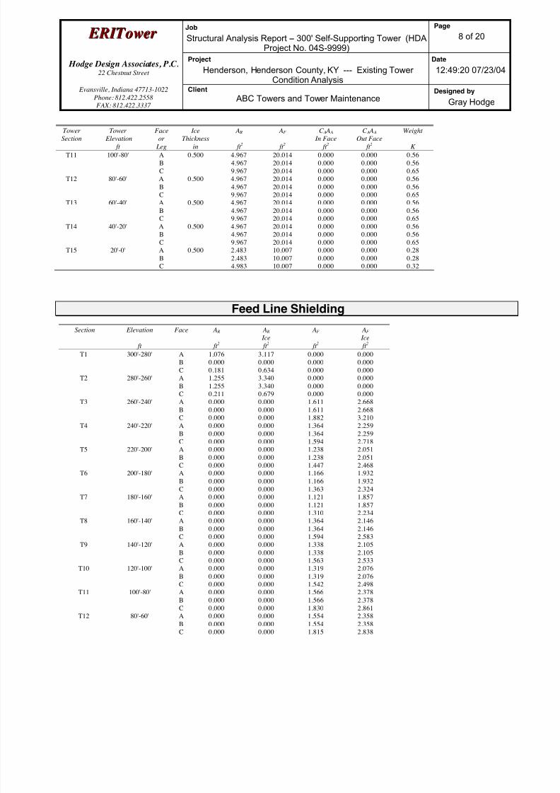
Feed Line Shielding
Section Elevation
ft
Face A R
ft 2
A R
Ice
ft 2
AF
ft 2
AF
Ice
ft 2
T1 300'-280' A
B
C
1.076
0.000
0.181
3.117
0.000
0.634
0.000
0.000
0.000
0.000
0.000
0.000
T2 280'-260' A
B
C
1.255
1.255
0.211
3.340
3.340
0.679
0.000
0.000
0.000
0.000
0.000
0.000T3 260'-240' A
B
C
0.000
0.000
0.000
0.000
0.000
0.000
1.611
1.611
1.882
2.668
2.668
3.210
T4 240'-220' A
B
C
0.000
0.000
0.000
0.000
0.000
0.000
1.364
1.364
1.594
2.259
2.259
2.718
T5 220'-200' A
B
C
0.000
0.000
0.000
0.000
0.000
0.000
1.238
1.238
1.447
2.051
2.051
2.468
T6 200'-180' A
B
C
0.000
0.000
0.000
0.000
0.000
0.000
1.166
1.166
1.363
1.932
1.932
2.324
T7 180'-160' A
B
C
0.000
0.000
0.000
0.000
0.000
0.000
1.121
1.121
1.310
1.857
1.857
2.234
T8 160'-140' A
BC
0.000
0.0000.000
0.000
0.0000.000
1.364
1.3641.594
2.146
2.1462.583
T9 140'-120' A
B
C
0.000
0.000
0.000
0.000
0.000
0.000
1.338
1.338
1.563
2.105
2.105
2.533
T10 120'-100' A
B
C
0.000
0.000
0.000
0.000
0.000
0.000
1.319
1.319
1.542
2.076
2.076
2.498
T11 100'-80' A
B
C
0.000
0.000
0.000
0.000
0.000
0.000
1.566
1.566
1.830
2.378
2.378
2.861
T12 80'-60' A
B
C
0.000
0.000
0.000
0.000
0.000
0.000
1.554
1.554
1.815
2.358
2.358
2.838
8/18/2019 Analysis Self Supporting-1
http://slidepdf.com/reader/full/analysis-self-supporting-1 25/98
E E R R I I T T oowweer r Job
Structural Analysis Report -- 300' Self-Supporting Tower (HDAProject No. 04S-9999)
Page
9 of 20
Hodge Design Associates, P.C. 22 Chestnut Street
Project
Henderson, Henderson County, KY --- Existing TowerCondition Analysis
Date
12:49:20 07/23/04
Evansville, Indiana 47713-1022
Phone: 812.422.2558
FAX: 812.422.3337
Client
ABC Towers and Tower MaintenanceDesigned by
Gray Hodge
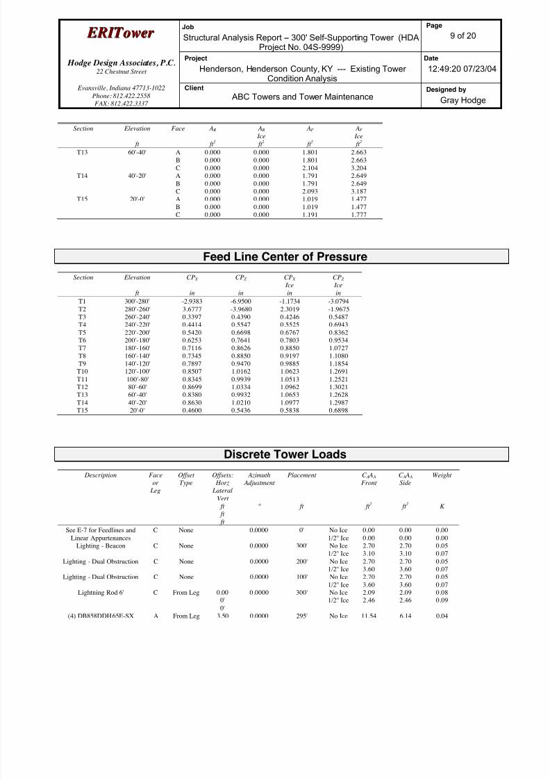
Section Elevation
ft
Face A R
ft 2
A R
Ice
ft 2
AF
ft 2
AF
Ice
ft 2
T13 60'-40' A
B
C
0.000
0.000
0.000
0.000
0.000
0.000
1.801
1.801
2.104
2.663
2.663
3.204
T14 40'-20' A
B
C
0.000
0.000
0.000
0.000
0.000
0.000
1.791
1.791
2.093
2.649
2.649
3.187
T15 20'-0' A
B
C
0.000
0.000
0.000
0.000
0.000
0.000
1.019
1.019
1.191
1.477
1.477
1.777
Feed Line Center of PressureSection Elevation
ft
CP X
in
CP Z
in
CP X
Ice
in
CP Z
Ice
in
T1 300'-280' -2.9383 -6.9500 -1.1734 -3.0794
T2 280'-260' 3.6777 -3.9680 2.3019 -1.9675
T3 260'-240' 0.3397 0.4390 0.4246 0.5487
T4 240'-220' 0.4414 0.5547 0.5525 0.6943
T5 220'-200' 0.5420 0.6698 0.6767 0.8362
T6 200'-180' 0.6253 0.7641 0.7803 0.9534
T7 180'-160' 0.7116 0.8626 0.8850 1.0727
T8 160'-140' 0.7345 0.8850 0.9197 1.1080
T9 140'-120' 0.7897 0.9470 0.9885 1.1854
T10 120'-100' 0.8507 1.0162 1.0623 1.2691
T11 100'-80' 0.8345 0.9939 1.0513 1.2521
T12 80'-60' 0.8699 1.0334 1.0962 1.3021T13 60'-40' 0.8380 0.9932 1.0653 1.2628
T14 40'-20' 0.8630 1.0210 1.0977 1.2987
T15 20'-0' 0.4600 0.5436 0.5838 0.6898
Discrete Tower Loads
Description Face
or
Leg
Offset
Type
Offsets:
Horz
Lateral
Vert
ft
ft ft
Azimuth
Adjustment
°
Placement
ft
C A A A
Front
ft 2
C A A A
Side
ft 2
Weight
K
See E-7 for Feedlines and
Linear Appurtenances
C None 0.0000 0' No Ice
1/2'' Ice
0.00
0.00
0.00
0.00
0.00
0.00
Lighting - Beacon C None 0.0000 300' No Ice
1/2'' Ice
2.70
3.10
2.70
3.10
0.05
0.07
Lighting - Dual Obstruction C None 0.0000 200' No Ice
1/2'' Ice
2.70
3.60
2.70
3.60
0.05
0.07
Lighting - Dual Obstruction C None 0.0000 100' No Ice
1/2'' Ice
2.70
3.60
2.70
3.60
0.05
0.07
Lightning Rod 6' C From Leg 0.00
0'
0'
0.0000 300' No Ice
1/2'' Ice
2.09
2.46
2.09
2.46
0.08
0.09
(4) DB858DDH65E-SX A From Leg 3.50 0.0000 295' No Ice 11.54 6.14 0.04

8/18/2019 Analysis Self Supporting-1
http://slidepdf.com/reader/full/analysis-self-supporting-1 26/98
E E R R I I T T oowweer r Job
Structural Analysis Report -- 300' Self-Supporting Tower (HDAProject No. 04S-9999)
Page
10 of 20
Hodge Design Associates, P.C. 22 Chestnut Street
Project
Henderson, Henderson County, KY --- Existing TowerCondition Analysis
Date
12:49:20 07/23/04
Evansville, Indiana 47713-1022
Phone: 812.422.2558
FAX: 812.422.3337
Client
ABC Towers and Tower MaintenanceDesigned by
Gray Hodge
Description Faceor
Leg
OffsetType
Offsets: Horz
Lateral
Vert
ft
ft
ft
Azimuth Adjustment
°
Placement
ft
C A A A Front
ft 2
C A A A Side
ft 2
Weight
K
0'
0'
1/2'' Ice 12.16 6.73 0.10
12' T-Frame Sector Mount A From Leg 3.50
0'
0'
0.0000 295' No Ice
1/2'' Ice
13.60
18.40
13.60
18.40
0.47
0.60
(4) DB858DDH65E-SX B From Leg 3.50
0'
0'
0.0000 295' No Ice
1/2'' Ice
11.54
12.16
6.14
6.73
0.04
0.10
12' T-Frame Sector Mount B From Leg 3.50
0'
0'
0.0000 295' No Ice
1/2'' Ice
13.60
18.40
13.60
18.40
0.47
0.60
(4) DB858DDH65E-SX C From Leg 3.50
0'
0'
0.0000 295' No Ice
1/2'' Ice
11.54
12.16
6.14
6.73
0.04
0.10
12' T-Frame Sector Mount C From Leg 3.50
0'
0'
0.0000 295' No Ice
1/2'' Ice
13.60
18.40
13.60
18.40
0.47
0.60
(4) DB858DDH65E-SX A From Leg 3.50
0'
0'
0.0000 280' No Ice
1/2'' Ice
11.54
12.16
6.14
6.73
0.04
0.10
12' T-Frame Sector Mount A From Leg 3.50
0'
0'
0.0000 280' No Ice
1/2'' Ice
13.60
18.40
13.60
18.40
0.47
0.60
(4) DB858DDH65E-SX B From Leg 3.50
0'
0'
0.0000 280' No Ice
1/2'' Ice
11.54
12.16
6.14
6.73
0.04
0.10
12' T-Frame Sector Mount B From Leg 3.500'
0'
0.0000 280' No Ice1/2'' Ice
13.6018.40
13.6018.40
0.470.60
(4) DB858DDH65E-SX C From Leg 3.50
0'
0'
0.0000 280' No Ice
1/2'' Ice
11.54
12.16
6.14
6.73
0.04
0.10
12' T-Frame Sector Mount C From Leg 3.50
0'
0'
0.0000 280' No Ice
1/2'' Ice
13.60
18.40
13.60
18.40
0.47
0.60
(4) DB858DDH65E-SX A From Leg 3.50
0'
0'
0.0000 260' No Ice
1/2'' Ice
11.54
12.16
6.14
6.73
0.04
0.10
12' T-Frame Sector Mount A From Leg 3.50
0'
0'
0.0000 260' No Ice
1/2'' Ice
13.60
18.40
13.60
18.40
0.47
0.60
(4) DB858DDH65E-SX B From Leg 3.50
0'
0'
0.0000 260' No Ice
1/2'' Ice
11.54
12.16
6.14
6.73
0.04
0.10
12' T-Frame Sector Mount B From Leg 3.50
0'
0'
0.0000 260' No Ice
1/2'' Ice
13.60
18.40
13.60
18.40
0.47
0.60
(4) DB858DDH65E-SX C From Leg 3.50
0'
0'
0.0000 260' No Ice
1/2'' Ice
11.54
12.16
6.14
6.73
0.04
0.10
12' T-Frame Sector Mount C From Leg 3.50
0'
0'
0.0000 260' No Ice
1/2'' Ice
13.60
18.40
13.60
18.40
0.47
0.60
8/18/2019 Analysis Self Supporting-1
http://slidepdf.com/reader/full/analysis-self-supporting-1 27/98
E E R R I I T T oowweer r Job
Structural Analysis Report -- 300' Self-Supporting Tower (HDAProject No. 04S-9999)
Page
11 of 20
Hodge Design Associates, P.C. 22 Chestnut Street
Project
Henderson, Henderson County, KY --- Existing TowerCondition Analysis
Date
12:49:20 07/23/04
Evansville, Indiana 47713-1022
Phone: 812.422.2558
FAX: 812.422.3337
Client
ABC Towers and Tower MaintenanceDesigned by
Gray Hodge
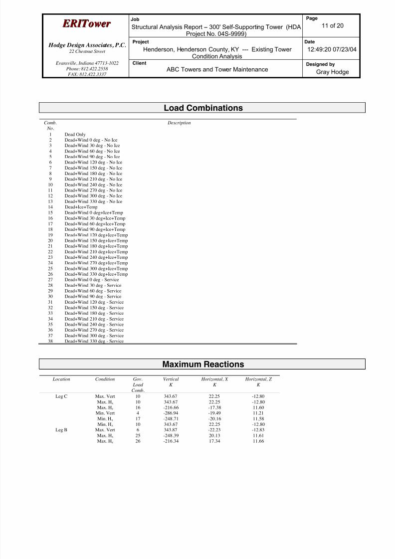
Load Combinations
Comb.
No.
Description
1 Dead Only
2 Dead+Wind 0 deg - No Ice
3 Dead+Wind 30 deg - No Ice
4 Dead+Wind 60 deg - No Ice
5 Dead+Wind 90 deg - No Ice
6 Dead+Wind 120 deg - No Ice
7 Dead+Wind 150 deg - No Ice
8 Dead+Wind 180 deg - No Ice
9 Dead+Wind 210 deg - No Ice
10 Dead+Wind 240 deg - No Ice11 Dead+Wind 270 deg - No Ice
12 Dead+Wind 300 deg - No Ice
13 Dead+Wind 330 deg - No Ice
14 Dead+Ice+Temp
15 Dead+Wind 0 deg+Ice+Temp
16 Dead+Wind 30 deg+Ice+Temp
17 Dead+Wind 60 deg+Ice+Temp
18 Dead+Wind 90 deg+Ice+Temp
19 Dead+Wind 120 deg+Ice+Temp
20 Dead+Wind 150 deg+Ice+Temp
21 Dead+Wind 180 deg+Ice+Temp
22 Dead+Wind 210 deg+Ice+Temp
23 Dead+Wind 240 deg+Ice+Temp
24 Dead+Wind 270 deg+Ice+Temp
25 Dead+Wind 300 deg+Ice+Temp
26 Dead+Wind 330 deg+Ice+Temp
27 Dead+Wind 0 deg - Service28 Dead+Wind 30 deg - Service
29 Dead+Wind 60 deg - Service
30 Dead+Wind 90 deg - Service
31 Dead+Wind 120 deg - Service
32 Dead+Wind 150 deg - Service
33 Dead+Wind 180 deg - Service
34 Dead+Wind 210 deg - Service
35 Dead+Wind 240 deg - Service
36 Dead+Wind 270 deg - Service
37 Dead+Wind 300 deg - Service
38 Dead+Wind 330 deg - Service
Maximum Reactions
Location Condition Gov.
Load
Comb.
Vertical
K
Horizontal, X
K
Horizontal, Z
K
Leg C Max. Vert 10 343.67 22.25 -12.80
Max. Hx 10 343.67 22.25 -12.80
Max. Hz 16 -216.66 -17.38 11.60
Min. Vert 4 -286.94 -19.49 11.21
Min. Hx 17 -248.71 -20.16 11.58
Min. Hz 10 343.67 22.25 -12.80
Leg B Max. Vert 6 343.87 -22.23 -12.83
Max. Hx 25 -248.39 20.13 11.61
Max. Hz 26 -216.34 17.34 11.66

8/18/2019 Analysis Self Supporting-1
http://slidepdf.com/reader/full/analysis-self-supporting-1 28/98
E E R R I I T T oowweer r Job
Structural Analysis Report -- 300' Self-Supporting Tower (HDAProject No. 04S-9999)
Page
12 of 20
Hodge Design Associates, P.C. 22 Chestnut Street
Project
Henderson, Henderson County, KY --- Existing TowerCondition Analysis
Date
12:49:20 07/23/04
Evansville, Indiana 47713-1022
Phone: 812.422.2558
FAX: 812.422.3337
Client
ABC Towers and Tower MaintenanceDesigned by
Gray Hodge
Location Condition Gov. Load
Comb.
VerticalK
Horizontal, XK
Horizontal, ZK
Min. Vert 12 -286.74 19.47 11.24
Min. Hx 6 343.87 -22.23 -12.83
Min. Hz 6 343.87 -22.23 -12.83
Leg A Max. Vert 2 343.59 0.04 25.67
Max. Hx 10 -138.78 3.03 -11.25
Max. Hz 2 343.59 0.04 25.67
Min. Vert 8 -287.01 -0.03 -22.49
Min. Hx 6 -138.78 -3.06 -11.25
Min. Hz 21 -248.77 -0.04 -23.24
Tower Mast Reaction Summary Load
Combination Vertical
K
Shear x
K
Shear z
K
Overturning
Moment, M x kip-ft
Overturning
Moment, M z kip-ft
Torque
kip-ft
Dead Only 66.38 0.00 -0.00 2.56 -2.57 0.00
Dead+Wind 0 deg - No Ice 66.38 -0.00 -42.23 -7238.41 -2.59 1.68
Dead+Wind 30 deg - No Ice 66.38 20.04 -34.71 -6084.58 -3516.99 1.76
Dead+Wind 60 deg - No Ice 66.38 34.09 -19.68 -3476.49 -6028.48 1.52
Dead+Wind 90 deg - No Ice 66.38 40.08 -0.00 2.57 -7031.42 0.99
Dead+Wind 120 deg - No Ice 66.38 36.57 21.11 3623.05 -6273.46 0.11
Dead+Wind 150 deg - No Ice 66.38 20.04 34.71 6089.70 -3517.02 -0.91
Dead+Wind 180 deg - No Ice 66.38 -0.00 39.37 6960.67 -2.59 -1.50
Dead+Wind 210 deg - No Ice 66.38 -20.04 34.71 6089.71 3511.84 -1.76
Dead+Wind 240 deg - No Ice 66.38 -36.57 21.11 3623.05 6268.28 -1.79
Dead+Wind 270 deg - No Ice 66.38 -40.08 -0.00 2.57 7026.24 -0.99
Dead+Wind 300 deg - No Ice 66.38 -34.09 -19.68 -3476.49 6023.31 -0.02Dead+Wind 330 deg - No Ice 66.38 -20.04 -34.71 -6084.59 3511.82 0.91
Dead+Ice+Temp 96.00 0.00 0.00 3.39 -4.08 -0.00
Dead+Wind 0 deg+Ice+Temp 96.00 -0.00 -40.22 -6891.92 -4.13 2.11
Dead+Wind 30 deg+Ice+Temp 96.00 18.43 -31.91 -5593.74 -3235.59 2.47
Dead+Wind 60 deg+Ice+Temp 96.00 30.94 -17.86 -3155.96 -5476.31 2.36
Dead+Wind 90 deg+Ice+Temp 96.00 36.85 -0.00 3.44 -6467.12 1.80
Dead+Wind 120 deg+Ice+Temp 96.00 34.83 20.11 3451.05 -5975.64 0.68
Dead+Wind 150 deg+Ice+Temp 96.00 18.43 31.91 5600.49 -3235.66 -0.77
Dead+Wind 180 deg+Ice+Temp 96.00 -0.00 35.73 6322.13 -4.14 -1.79
Dead+Wind 210 deg+Ice+Temp 96.00 -18.43 31.91 5600.49 3227.41 -2.47
Dead+Wind 240 deg+Ice+Temp 96.00 -34.83 20.11 3451.05 5967.39 -2.79
Dead+Wind 270 deg+Ice+Temp 96.00 -36.85 -0.00 3.44 6458.87 -1.80
Dead+Wind 300 deg+Ice+Temp 96.00 -30.94 -17.86 -3155.97 5468.06 -0.57
Dead+Wind 330 deg+Ice+Temp 96.00 -18.43 -31.91 -5593.74 3227.33 0.77
Dead+Wind 0 deg - Service 66.38 -0.00 -21.54 -3691.96 -2.59 0.85
Dead+Wind 30 deg - Service 66.38 10.23 -17.71 -3103.25 -1795.73 0.91
Dead+Wind 60 deg - Service 66.38 17.39 -10.04 -1772.54 -3077.15 0.78Dead+Wind 90 deg - Service 66.38 20.45 -0.00 2.57 -3588.87 0.49
Dead+Wind 120 deg - Service 66.38 18.66 10.77 1849.83 -3202.14 0.06
Dead+Wind 150 deg - Service 66.38 10.23 17.71 3108.38 -1795.73 -0.45
Dead+Wind 180 deg - Service 66.38 -0.00 20.09 3552.77 -2.59 -0.77
Dead+Wind 210 deg - Service 66.38 -10.23 17.71 3108.38 1790.55 -0.91
Dead+Wind 240 deg - Service 66.38 -18.66 10.77 1849.83 3196.97 -0.91
Dead+Wind 270 deg - Service 66.38 -20.45 -0.00 2.57 3583.70 -0.49
Dead+Wind 300 deg - Service 66.38 -17.39 -10.04 -1772.54 3071.98 -0.01
Dead+Wind 330 deg - Service 66.38 -10.23 -17.71 -3103.25 1790.55 0.45
8/18/2019 Analysis Self Supporting-1
http://slidepdf.com/reader/full/analysis-self-supporting-1 29/98
E E R R I I T T oowweer r Job
Structural Analysis Report -- 300' Self-Supporting Tower (HDAProject No. 04S-9999)
Page
13 of 20
Hodge Design Associates, P.C. 22 Chestnut Street
Project
Henderson, Henderson County, KY --- Existing TowerCondition Analysis
Date
12:49:20 07/23/04
Evansville, Indiana 47713-1022
Phone: 812.422.2558
FAX: 812.422.3337
Client
ABC Towers and Tower MaintenanceDesigned by
Gray Hodge
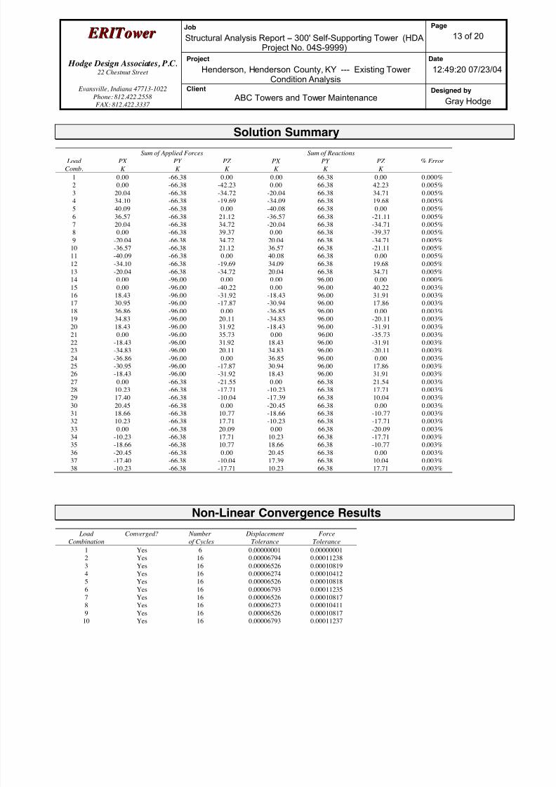
Solution Summary
Sum of Applied Forces Sum of Reactions
Load
Comb.
PX
K
PY
K
PZ
K
PX
K
PY
K
PZ
K
% Error
1 0.00 -66.38 0.00 0.00 66.38 0.00 0.000%
2 0.00 -66.38 -42.23 0.00 66.38 42.23 0.005%
3 20.04 -66.38 -34.72 -20.04 66.38 34.71 0.005%
4 34.10 -66.38 -19.69 -34.09 66.38 19.68 0.005%
5 40.09 -66.38 0.00 -40.08 66.38 0.00 0.005%
6 36.57 -66.38 21.12 -36.57 66.38 -21.11 0.005%
7 20.04 -66.38 34.72 -20.04 66.38 -34.71 0.005%
8 0.00 -66.38 39.37 0.00 66.38 -39.37 0.005%
9 -20.04 -66.38 34.72 20.04 66.38 -34.71 0.005%
10 -36.57 -66.38 21.12 36.57 66.38 -21.11 0.005%
11 -40.09 -66.38 0.00 40.08 66.38 0.00 0.005%
12 -34.10 -66.38 -19.69 34.09 66.38 19.68 0.005%
13 -20.04 -66.38 -34.72 20.04 66.38 34.71 0.005%
14 0.00 -96.00 0.00 0.00 96.00 0.00 0.000%
15 0.00 -96.00 -40.22 0.00 96.00 40.22 0.003%
16 18.43 -96.00 -31.92 -18.43 96.00 31.91 0.003%
17 30.95 -96.00 -17.87 -30.94 96.00 17.86 0.003%
18 36.86 -96.00 0.00 -36.85 96.00 0.00 0.003%
19 34.83 -96.00 20.11 -34.83 96.00 -20.11 0.003%
20 18.43 -96.00 31.92 -18.43 96.00 -31.91 0.003%
21 0.00 -96.00 35.73 0.00 96.00 -35.73 0.003%
22 -18.43 -96.00 31.92 18.43 96.00 -31.91 0.003%
23 -34.83 -96.00 20.11 34.83 96.00 -20.11 0.003%
24 -36.86 -96.00 0.00 36.85 96.00 0.00 0.003%
25 -30.95 -96.00 -17.87 30.94 96.00 17.86 0.003%
26 -18.43 -96.00 -31.92 18.43 96.00 31.91 0.003%
27 0.00 -66.38 -21.55 0.00 66.38 21.54 0.003%
28 10.23 -66.38 -17.71 -10.23 66.38 17.71 0.003%29 17.40 -66.38 -10.04 -17.39 66.38 10.04 0.003%
30 20.45 -66.38 0.00 -20.45 66.38 0.00 0.003%
31 18.66 -66.38 10.77 -18.66 66.38 -10.77 0.003%
32 10.23 -66.38 17.71 -10.23 66.38 -17.71 0.003%
33 0.00 -66.38 20.09 0.00 66.38 -20.09 0.003%
34 -10.23 -66.38 17.71 10.23 66.38 -17.71 0.003%
35 -18.66 -66.38 10.77 18.66 66.38 -10.77 0.003%
36 -20.45 -66.38 0.00 20.45 66.38 0.00 0.003%
37 -17.40 -66.38 -10.04 17.39 66.38 10.04 0.003%
38 -10.23 -66.38 -17.71 10.23 66.38 17.71 0.003%
Non-Linear Convergence Results
Load
Combination
Converged? Number
of Cycles
Displacement
Tolerance
Force
Tolerance
1 Yes 6 0.00000001 0.00000001
2 Yes 16 0.00006794 0.00011238
3 Yes 16 0.00006526 0.00010819
4 Yes 16 0.00006274 0.00010412
5 Yes 16 0.00006526 0.00010818
6 Yes 16 0.00006793 0.00011235
7 Yes 16 0.00006526 0.00010817
8 Yes 16 0.00006273 0.00010411
9 Yes 16 0.00006526 0.00010817
10 Yes 16 0.00006793 0.00011237

8/18/2019 Analysis Self Supporting-1
http://slidepdf.com/reader/full/analysis-self-supporting-1 30/98
E E R R I I T T oowweer r Job
Structural Analysis Report -- 300' Self-Supporting Tower (HDAProject No. 04S-9999)
Page
14 of 20
Hodge Design Associates, P.C. 22 Chestnut Street
Project
Henderson, Henderson County, KY --- Existing TowerCondition Analysis
Date
12:49:20 07/23/04
Evansville, Indiana 47713-1022
Phone: 812.422.2558
FAX: 812.422.3337
Client
ABC Towers and Tower MaintenanceDesigned by
Gray Hodge
11 Yes 16 0.00006527 0.0001081912 Yes 16 0.00006273 0.00010413
13 Yes 16 0.00006526 0.00010819
14 Yes 6 0.00000001 0.00000001
15 Yes 17 0.00006125 0.00010186
16 Yes 17 0.00005966 0.00009947
17 Yes 17 0.00005825 0.00009724
18 Yes 17 0.00005966 0.00009945
19 Yes 17 0.00006124 0.00010181
20 Yes 17 0.00005965 0.00009942
21 Yes 17 0.00005824 0.00009719
22 Yes 17 0.00005965 0.00009943
23 Yes 17 0.00006125 0.00010183
24 Yes 17 0.00005966 0.00009946
25 Yes 17 0.00005825 0.00009724
26 Yes 17 0.00005966 0.00009948
27 Yes 16 0.00006572 0.00010793
28 Yes 16 0.00006449 0.0001060629 Yes 16 0.00006329 0.00010415
30 Yes 16 0.00006449 0.00010604
31 Yes 16 0.00006571 0.00010789
32 Yes 16 0.00006448 0.00010602
33 Yes 16 0.00006328 0.00010412
34 Yes 16 0.00006448 0.00010603
35 Yes 16 0.00006572 0.00010791
36 Yes 16 0.00006449 0.00010606
37 Yes 16 0.00006329 0.00010416
38 Yes 16 0.00006449 0.00010607
Maximum Tower Deflections - Service Wind
Section
No.
Elevation
ft
Horz.
Deflection
in
Gov.
Load
Comb.
Tilt
°
Twist
°
T1 300 - 280 21.975 31 0.8178 0.0384
T2 280 - 260 18.536 31 0.7804 0.0335
T3 260 - 240 15.395 31 0.6499 0.0219
T4 240 - 220 12.734 31 0.5634 0.0105
T5 220 - 200 10.452 31 0.4888 0.0061
T6 200 - 180 8.480 31 0.4177 0.0045
T7 180 - 160 6.777 31 0.3602 0.0039
T8 160 - 140 5.313 31 0.3054 0.0034
T9 140 - 120 4.064 31 0.2534 0.0029
T10 120 - 100 3.007 31 0.2102 0.0024
T11 100 - 80 2.131 31 0.1682 0.0020
T12 80 - 60 1.413 31 0.1277 0.0015
T13 60 - 40 0.860 31 0.0928 0.0012T14 40 - 20 0.437 31 0.0589 0.0007
T15 20 - 0 0.157 27 0.0292 0.0003
Critical Deflections and Radius of Curvature - Service Wind
Elevation
ft
Appurtenance Gov.
Load
Comb.
Deflection
in
Tilt
°
Twist
°
Radius of
Curvature
ft
300' Lighting - Beacon 31 21.975 0.8178 0.0384 60360

8/18/2019 Analysis Self Supporting-1
http://slidepdf.com/reader/full/analysis-self-supporting-1 31/98
E E R R I I T T oowweer r Job
Structural Analysis Report -- 300' Self-Supporting Tower (HDAProject No. 04S-9999)
Page
15 of 20
Hodge Design Associates, P.C. 22 Chestnut Street
Project
Henderson, Henderson County, KY --- Existing TowerCondition Analysis
Date
12:49:20 07/23/04
Evansville, Indiana 47713-1022
Phone: 812.422.2558
FAX: 812.422.3337
Client
ABC Towers and Tower MaintenanceDesigned by
Gray Hodge
Elevation
ft
Appurtenance Gov. Load
Comb.
Deflection
in
Tilt
°
Twist
°
Radius ofCurvature
ft
295' (4) DB858DDH65E-SX 31 21.103 0.8149 0.0376 60360
280' (4) DB858DDH65E-SX 31 18.536 0.7804 0.0335 15248
260' (4) DB858DDH65E-SX 31 15.395 0.6499 0.0219 8903
200' Lighting - Dual Obstruction 31 8.480 0.4177 0.0045 18042
100' Lighting - Dual Obstruction 31 2.131 0.1682 0.0020 32630
0' See E-7 for Feedlines and Linear
Appurtenances
0 0.000 0.0000 0.0000 129954
Maximum Tower Deflections - Design Wind
Section
No.
Elevation
ft
Horz.
Deflection
in
Gov.
Load
Comb.
Tilt
°
Twist
°
T1 300 - 280 43.065 6 1.6009 0.0758
T2 280 - 260 36.326 6 1.5278 0.0661
T3 260 - 240 30.175 6 1.2726 0.0431
T4 240 - 220 24.962 6 1.1032 0.0207
T5 220 - 200 20.490 6 0.9572 0.0130
T6 200 - 180 16.627 6 0.8178 0.0116
T7 180 - 160 13.291 6 0.7053 0.0109
T8 160 - 140 10.422 6 0.5981 0.0101
T9 140 - 120 7.973 6 0.4962 0.0090
T10 120 - 100 5.900 6 0.4116 0.0077
T11 100 - 80 4.183 6 0.3294 0.0064
T12 80 - 60 2.775 6 0.2500 0.0049
T13 60 - 40 1.690 6 0.1818 0.0036
T14 40 - 20 0.859 6 0.1153 0.0022T15 20 - 0 0.308 2 0.0573 0.0010
Critical Deflections and Radius of Curvature - Design Wind
Elevation
ft
Appurtenance Gov.
Load
Comb.
Deflection
in
Tilt
°
Twist
°
Radius of
Curvature
ft
300' Lighting - Beacon 6 43.065 1.6009 0.0758 31014
295' (4) DB858DDH65E-SX 6 41.357 1.5954 0.0741 31014
280' (4) DB858DDH65E-SX 6 36.326 1.5278 0.0661 7830
260' (4) DB858DDH65E-SX 6 30.175 1.2726 0.0431 4549
200' Lighting - Dual Obstruction 6 16.627 0.8178 0.0116 9211
100' Lighting - Dual Obstruction 6 4.183 0.3294 0.0064 16679
0' See E-7 for Feedlines and Linear
Appurtenances
0 0.000 0.0000 0.0000 66454
Compression Checks
Leg Design Data (Compression)

8/18/2019 Analysis Self Supporting-1
http://slidepdf.com/reader/full/analysis-self-supporting-1 32/98
E E R R I I T T oowweer r Job
Structural Analysis Report -- 300' Self-Supporting Tower (HDAProject No. 04S-9999)
Page
16 of 20
Hodge Design Associates, P.C. 22 Chestnut Street
Project
Henderson, Henderson County, KY --- Existing TowerCondition Analysis
Date
12:49:20 07/23/04
Evansville, Indiana 47713-1022
Phone: 812.422.2558
FAX: 812.422.3337
Client
ABC Towers and Tower MaintenanceDesigned by
Gray Hodge
Section
No.
Elevation
ft
Size L
ft
Lu
ft
Kl/r F a
ksi
A
in2
Actual
P
K
Allow.
Pa
K
Ratio
P
Pa
T1 300 - 280 1 1/2 20' 3'2-
17/32''
102.7
K=1.00
14.083 1.7672 -21.22 24.89 0.853
T2 280 - 260 2 20' 3'2-
17/32''
77.0
K=1.00
19.605 3.1416 -76.31 61.59 1.239
T3 260 - 240 3 20'1/4'' 6'2-1/32'' 98.8
K=1.00
14.986 7.0686 -114.29 105.93 1.079
T4 240 - 220 3 1/4 20'1/4'' 6'2-1/32'' 91.2
K=1.00
16.682 8.2958 -140.44 138.39 1.015
T5 220 - 200 3 1/4 20'1/4'' 6'2-1/32'' 91.2
K=1.00
16.682 8.2958 -161.64 138.39 1.168
T6 200 - 180 3 1/2 20'1/4'' 6'2-1/32'' 84.7
K=1.00
18.062 9.6211 -181.12 173.78 1.042
T7 180 - 160 3 1/2 20'1/4'' 6'2-1/32'' 84.7
K=1.00
18.062 9.6211 -199.34 173.78 1.147
T8 160 - 140 3 1/2 20'1/4'' 6'2-1/32'' 84.7
K=1.00
18.062 9.6211 -216.96 173.78 1.248
T9 140 - 120 3 3/4 20'1/4'' 6'2-1/32'' 79.0
K=1.00
19.206 11.0447 -234.68 212.13 1.106
T10 120 - 100 3 3/4 20'1/4'' 6'2-1/32'' 79.0
K=1.00
19.206 11.0447 -252.41 212.13 1.190
T11 100 - 80 3 3/4 20'1/4'' 6'2-1/32'' 79.0
K=1.00
19.206 11.0447 -270.21 212.13 1.274
T12 80 - 60 4 20'1/4'' 6'2-1/32'' 74.1
K=1.00
20.168 12.5664 -288.61 253.44 1.139
T13 60 - 40 4 20'1/4'' 6'2-1/32'' 74.1
K=1.00
20.168 12.5664 -306.90 253.44 1.211
T14 40 - 20 4 1/4 20'1/4'' 6'2-1/32'' 69.7
K=1.00
20.988 14.1863 -325.76 297.74 1.094
T15 20 - 0 4 1/4 20'1/4'' 6'2-1/32'' 69.7
K=1.00
20.988 14.1863 -344.66 297.74 1.158
Diagonal Design Data (Compression)
Section
No.
Elevation
ft
Size L
ft
Lu
ft
Kl/r F a
ksi
A
in2
Actual
P
K
Allow.
Pa
K
Ratio
P
Pa
T1 300 - 280 3/4 5'1-9/16'' 2'5-3/4'' 159.0
K=1.00
5.910 0.4418 -2.46 2.61 0.942
T2 280 - 260 7/8 5'1-9/16'' 2'5-
17/32''
134.8
K=1.00
8.220 0.6013 -4.84 4.94 0.980
T3 260 - 240 L2x2x3/16 7'6-3/8'' 3'9-
19/32''
115.8
K=1.00
10.870 0.7150 -5.86 7.77 0.754
T4 240 - 220 L2x2x3/16 8'7-7/16'' 4'3-
27/32''
131.4
K=1.00
8.643 0.7150 -4.24 6.18 0.686
T5 220 - 200 L2x2x3/16 10'8-
17/32''
5'4-3/16'' 162.9
K=1.00
5.628 0.7150 -3.32 4.02 0.826
T6 200 - 180 L2x2x3/16 12'1-
9/16''
6'19/32'' 184.2
K=1.00
4.403 0.7150 -3.47 3.15 1.103
T7 180 - 160 L2x2x1/4 13 '7- 6'9- 208.4 3.439 0.9380 -3.64 3.23 1.127
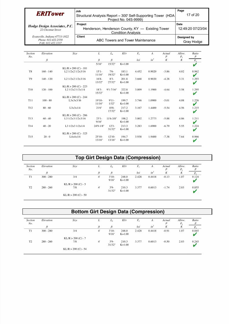
8/18/2019 Analysis Self Supporting-1
http://slidepdf.com/reader/full/analysis-self-supporting-1 33/98
E E R R I I T T oowweer r Job
Structural Analysis Report -- 300' Self-Supporting Tower (HDAProject No. 04S-9999)
Page
17 of 20
Hodge Design Associates, P.C. 22 Chestnut Street
Project
Henderson, Henderson County, KY --- Existing TowerCondition Analysis
Date
12:49:20 07/23/04
Evansville, Indiana 47713-1022
Phone: 812.422.2558
FAX: 812.422.3337
Client
ABC Towers and Tower MaintenanceDesigned by
Gray Hodge
Section No.
Elevation
ft
Size L
ft
Lu
ft
Kl/r F a
ksi
A
in2
ActualP
K
Allow.Pa
K
RatioP
Pa
5/16'' 15/32'' K=1.00
KL/R > 200 (C) - 181
T8 160 - 140 L2 1/2x2 1/2x3/16 15'1-
11/16''
7'6-
19/32''
183.1
K=1.00
4.452 0.9020 -3.86 4.02 0.962
T9 140 - 120 L2 1/2x2 1/2x3/16 16'8-
13/32''
8'3-
27/32''
201.8
K=1.00
3.668 0.9020 -4.28 3.31 1.293
KL/R > 200 (C) - 223
T10 120 - 100 L2 1/2x2 1/2x1/4 18'3-
15/32''
9'1-7/16'' 222.8
K=1.00
3.009 1.1900 -4.64 3.58 1.295
KL/R > 200 (C) - 244
T11 100 - 80 L3x3x3/16 19'10-
11/16''
9'11-
1/32''
199.7
K=1.00
3.746 1.0900 -5.01 4.08 1.226
T12 80 - 60 L3x3x1/4 21'6'' 10'8-17/32''
217.2K=1.00
3.167 1.4400 -5.54 4.56 1.215
KL/R > 200 (C) - 286
T13 60 - 40 L3 1/2x3 1/2x3/16 23'1-
9/16''
11'6-3/8'' 198.2
K=1.00
3.802 1.2773 -5.88 4.86 1.211
T14 40 - 20 L3 1/2x3 1/2x1/4 24'9-1/8'' 12'3-
31/32''
213.3
K=1.00
3.283 1.6900 -6.79 5.55 1.224
KL/R > 200 (C) - 325
T15 20 - 0 L4x4x1/4 25'10-
13/16''
12'10-
13/16''
194.7
K=1.00
3.938 1.9400 -7.38 7.64 0.966
Top Girt Design Data (Compression)
Section
No.
Elevation
ft
Size L
ft
Lu
ft
Kl/r F a
ksi
A
in2
Actual
P
K
Allow.
Pa
K
Ratio
P
Pa
T1 300 - 280 3/4 4' 3'10-
9/16''
248.0
K=1.00
2.428 0.4418 -0.13 1.07 0.124
KL/R > 200 (C) - 5
T2 280 - 260 7/8 4' 3'9-
31/32''
210.3
K=1.00
3.377 0.6013 -1.74 2.03 0.855
KL/R > 200 (C) - 50
Bottom Girt Design Data (Compression)
Section
No.
Elevation
ft
Size L
ft
Lu
ft
Kl/r F a
ksi
A
in2
Actual
P
K
Allow.
Pa
K
Ratio
P
Pa
T1 300 - 280 3/4 4' 3'10-
9/16''
248.0
K=1.00
2.428 0.4418 -0.91 1.07 0.845
KL/R > 200 (C) - 7
T2 280 - 260 7/8 4' 3'9-
31/32''
210.3
K=1.00
3.377 0.6013 -0.50 2.03 0.245
KL/R > 200 (C) - 54

8/18/2019 Analysis Self Supporting-1
http://slidepdf.com/reader/full/analysis-self-supporting-1 34/98
E E R R I I T T oowweer r Job
Structural Analysis Report -- 300' Self-Supporting Tower (HDAProject No. 04S-9999)
Page
18 of 20
Hodge Design Associates, P.C. 22 Chestnut Street
Project
Henderson, Henderson County, KY --- Existing TowerCondition Analysis
Date
12:49:20 07/23/04
Evansville, Indiana 47713-1022
Phone: 812.422.2558
FAX: 812.422.3337
Client
ABC Towers and Tower MaintenanceDesigned by
Gray Hodge
Tension Checks
Leg Design Data (Tension)
Section
No.
Elevation
ft
Size L
ft
Lu
ft
Kl/r F a
ksi
A
in2
Actual
P
K
Allow.
Pa
K
Ratio
P
Pa
T1 300 - 280 1 1/2 20' 3'2-
17/32''
102.7 30.000 1.7672 19.39 53.01 0.366
T2 280 - 260 2 20' 3'2-
17/32''
77.0 30.000 3.1416 72.11 94.25 0.765
T3 260 - 240 3 20'1/4'' 6'2-1/32'' 98.8 30.000 7.0686 106.98 212.06 0.505
T4 240 - 220 3 1/4 20'1/4'' 6'2-1/32'' 91.2 30.000 8.2958 130.62 248.87 0.525
T5 220 - 200 3 1/4 20'1/4'' 6'2-1/32'' 91.2 30.000 8.2958 149.18 248.87 0.599
T6 200 - 180 3 1/2 20'1/4'' 6'2-1/32'' 84.7 30.000 9.6211 165.58 288.63 0.574
T7 180 - 160 3 1/2 20'1/4'' 6'2-1/32'' 84.7 30.000 9.6211 180.51 288.63 0.625
T8 160 - 140 3 1/2 20'1/4'' 6'2-1/32'' 84.7 30.000 9.6211 194.69 288.63 0.675
T9 140 - 120 3 3/4 20'1/4'' 6'2-1/32'' 79.0 30.000 11.0447 208.58 331.34 0.630
T10 120 - 100 3 3/4 20'1/4'' 6'2-1/32'' 79.0 30.000 11.0447 222.13 331.34 0.670
T11 100 - 80 3 3/4 20'1/4'' 6'2-1/32'' 79.0 30.000 11.0447 235.58 331.34 0.711
T12 80 - 60 4 20'1/4'' 6'2-1/32'' 74.1 30.000 12.5664 248.94 376.99 0.660
T13 60 - 40 4 20'1/4'' 6'2-1/32'' 74.1 30.000 12.5664 262.15 376.99 0.695
T14 40 - 20 4 1/4 20'1/4'' 6'2-1/32'' 69.7 30.000 14.1863 275.08 425.59 0.646
T15 20 - 0 4 1/4 20'1/4'' 6'2-1/32'' 69.7 30.000 14.1863 287.83 425.59 0.676
Diagonal Design Data (Tension)
Section
No.
Elevation
ft
Size L
ft
Lu
ft
Kl/r F a
ksi
A
in2
Actual
P
K
Allow.
Pa
K
Ratio
P
Pa
T1 300 - 280 3/4 5'1-9/16'' 2'5-3/4'' 159.0 21.600 0.4418 2.46 9.54 0.257
T2 280 - 260 7/8 5'1-9/16'' 2'5-
17/32''
134.8 21.600 0.6013 4.81 12.99 0.370
T3 260 - 240 L2x2x3/16 7'6-3/8'' 3'9-
19/32''
74.0 21.600 0.7150 5.36 15.44 0.347

8/18/2019 Analysis Self Supporting-1
http://slidepdf.com/reader/full/analysis-self-supporting-1 35/98
E E R R I I T T oowweer r Job
Structural Analysis Report -- 300' Self-Supporting Tower (HDAProject No. 04S-9999)
Page
19 of 20
Hodge Design Associates, P.C. 22 Chestnut Street
Project
Henderson, Henderson County, KY --- Existing TowerCondition Analysis
Date
12:49:20 07/23/04
Evansville, Indiana 47713-1022
Phone: 812.422.2558
FAX: 812.422.3337
Client
ABC Towers and Tower MaintenanceDesigned by
Gray Hodge
Section No.
Elevation
ft
Size L
ft
Lu
ft
Kl/r F a
ksi
A
in2
ActualP
K
Allow.Pa
K
RatioP
Pa
T4 240 - 220 L2x2x3/16 8'7-7/16'' 4'3-
27/32''
83.9 21.600 0.7150 3.81 15.44 0.246
T5 220 - 200 L2x2x3/16 10'8-
17/32''
5'4-3/16'' 104.0 21.600 0.7150 3.45 15.44 0.223
T6 200 - 180 L2x2x3/16 12'1-
9/16''
6'19/32'' 117.6 21.600 0.7150 3.61 15.44 0.234
T7 180 - 160 L2x2x1/4 13'7-
5/16''
6'9-
15/32''
133.8 21.600 0.9380 3.83 20.26 0.189
T8 160 - 140 L2 1/2x2 1/2x3/16 15'1-
11/16''
7'6-
19/32''
116.5 21.600 0.9020 4.07 19.48 0.209
T9 140 - 120 L2 1/2x2 1/2x3/16 16'8-
13/32''
8'3-
27/32''
128.4 21.600 0.9020 4.48 19.48 0.230
T10 120 - 100 L2 1/2x2 1/2x1/4 18'3-
15/32''
9'1-7/16'' 142.3 21.600 1.1900 4.93 25.70 0.192
T11 100 - 80 L3x3x3/16 19'10-
11/16''
9'11-
1/32''
126.7 21.600 1.0900 5.27 23.54 0.224
T12 80 - 60 L3x3x1/4 21'6'' 10'8-
17/32''
138.2 21.600 1.4400 5.88 31.10 0.189
T13 60 - 40 L3 1/2x3 1/2x3/16 23'1-
9/16''
11'6-3/8'' 125.7 21.600 1.2773 6.17 27.59 0.224
T14 40 - 20 L3 1/2x3 1/2x1/4 24'9-1/8'' 12'3-
31/32''
135.8 21.600 1.6900 6.72 36.50 0.184
T15 20 - 0 L4x4x1/4 26'4-
29/32''
13'1-
29/32''
126.3 21.600 1.9400 8.63 41.90 0.206
Top Girt Design Data (Tension)
Section
No.
Elevation
ft
Size L
ft
Lu
ft
Kl/r F a
ksi
A
in2
Actual
P
K
Allow.
Pa
K
Ratio
P
Pa
T1 300 - 280 3/4 4' 3'10-
9/16''
248.0 21.600 0.4418 0.12 9.54 0.012
T2 280 - 260 7/8 4' 3'9-
31/32''
210.3 21.600 0.6013 1.75 12.99 0.134
Bottom Girt Design Data (Tension)Section
No.
Elevation
ft
Size L
ft
Lu
ft
Kl/r F a
ksi
A
in2
Actual
P
K
Allow.
Pa
K
Ratio
P
Pa
T1 300 - 280 3/4 4' 3'10-
9/16''
248.0 21.600 0.4418 0.85 9.54 0.089
T2 280 - 260 7/8 4' 3'9-
31/32''
210.3 21.600 0.6013 0.23 12.99 0.017

8/18/2019 Analysis Self Supporting-1
http://slidepdf.com/reader/full/analysis-self-supporting-1 36/98
E E R R I I T T oowweer r Job
Structural Analysis Report -- 300' Self-Supporting Tower (HDAProject No. 04S-9999)
Page
20 of 20
Hodge Design Associates, P.C. 22 Chestnut Street
Project
Henderson, Henderson County, KY --- Existing TowerCondition Analysis
Date
12:49:20 07/23/04
Evansville, Indiana 47713-1022
Phone: 812.422.2558
FAX: 812.422.3337
Client
ABC Towers and Tower MaintenanceDesigned by
Gray Hodge
Section Capacity Table
Section
No.
Elevation
ft
Component
Type
Size Critical
Element
P
K
SF*Pallow
K
%
Capacity
Pass
Fail
T1 300 - 280 Leg 1 1/2 3 -21.22 33.17 64.0 Pass
T2 280 - 260 Leg 2 48 -76.31 82.10 92.9 Pass
T3 260 - 240 Leg 3 93 -114.29 141.21 80.9 Pass
T4 240 - 220 Leg 3 1/4 114 -140.44 184.47 76.1 Pass
T5 220 - 200 Leg 3 1/4 134 -161.64 184.47 87.6 Pass
T6 200 - 180 Leg 3 1/2 155 -181.12 231.65 78.2 Pass
T7 180 - 160 Leg 3 1/2 176 -199.34 231.64 86.1 Pass
T8 160 - 140 Leg 3 1/2 197 -216.96 231.64 93.7 Pass
T9 140 - 120 Leg 3 3/4 218 -234.68 282.76 83.0 Pass
T10 120 - 100 Leg 3 3/4 239 -252.41 282.76 89.3 Pass
T11 100 - 80 Leg 3 3/4 260 -270.21 282.76 95.6 Pass
T12 80 - 60 Leg 4 281 -288.61 337.84 85.4 PassT13 60 - 40 Leg 4 302 -306.90 337.84 90.8 Pass
T14 40 - 20 Leg 4 1/4 323 -325.76 396.88 82.1 Pass
T15 20 - 0 Leg 4 1/4 344 -344.66 396.88 86.8 Pass
T1 300 - 280 Diagonal 3/4 15 -2.46 3.48 70.7 Pass
T2 280 - 260 Diagonal 7/8 60 -4.84 6.59 73.5 Pass
T3 260 - 240 Diagonal L2x2x3/16 111 -5.86 10.36 56.5 Pass
T4 240 - 220 Diagonal L2x2x3/16 129 -4.24 8.24 51.5 Pass
T5 220 - 200 Diagonal L2x2x3/16 138 -3.32 5.36 61.9 Pass
T6 200 - 180 Diagonal L2x2x3/16 160 -3.47 4.20 82.8 Pass
T7 180 - 160 Diagonal L2x2x1/4 181 -3.64 4.30 84.6 Pass
T8 160 - 140 Diagonal L2 1/2x2 1/2x3/16 202 -3.86 5.35 72.1 Pass
T9 140 - 120 Diagonal L2 1/2x2 1/2x3/16 223 -4.28 4.41 97.0 Pass
T10 120 - 100 Diagonal L2 1/2x2 1/2x1/4 244 -4.64 4.77 97.1 Pass
T11 100 - 80 Diagonal L3x3x3/16 265 -5.01 5.44 92.0 Pass
T12 80 - 60 Diagonal L3x3x1/4 286 -5.54 6.08 91.1 Pass
T13 60 - 40 Diagonal L3 1/2x3 1/2x3/16 307 -5.88 6.47 90.9 Pass
T14 40 - 20 Diagonal L3 1/2x3 1/2x1/4 325 -6.79 7.40 91.8 PassT15 20 - 0 Diagonal L4x4x1/4 352 -7.38 10.18 72.4 Pass
T1 300 - 280 Top Girt 3/4 5 -0.13 1.43 9.3 Pass
T2 280 - 260 Top Girt 7/8 50 -1.74 2.71 64.2 Pass
T1 300 - 280 Bottom Girt 3/4 7 -0.91 1.43 63.4 Pass
T2 280 - 260 Bottom Girt 7/8 54 -0.50 2.71 18.3 Pass
Summary
Leg (T11) 95.6 Pass
Diagonal
(T10)
97.1 Pass
Top Girt
(T2)
64.2 Pass
Bottom Girt
(T1)
63.4 Pass
RATING = 97.1 Pass
Program Version 3.0.0.16 - 7/10/2004 File:C:/Documents and Settings/ghodge.HODGEDESIGN.000/My Documents/ERITower Project Data Files/Sample
Reports/Sample-SS-R1.eri
8/18/2019 Analysis Self Supporting-1
http://slidepdf.com/reader/full/analysis-self-supporting-1 37/98
APPENDIX C
An t e n n a To w e r W i t h P r o p o s e d Ad d i ti o n a l An t e n n a s
G r a p h i c a l Co m p u t e r O u t p u t
S t r u c t u r a l An a l y s i s R e p o r t a n d C a l c u l a t i o n s

8/18/2019 Analysis Self Supporting-1
http://slidepdf.com/reader/full/analysis-self-supporting-1 38/98
www.hodgedesign.com
Hodge Design Associates, P.C.22 Chestnut Street
Evansville, Indiana 47713-1022Phone: 812.422.2558
FAX: 812.422.3337
Job:Structural Analysis Report -- 300' Self-Supporting Tower (HDA Project No. 04S-9
Project: Henderson, Henderson County, KY --- Existing Tower With Proposed Additional Antennas Client: ABC Towers and Tower Maintenance Drawn by: Gray Hodge App'd:
Code: TIA/EIA-222-F Date: 07/23/04 Scale: NTSPath:
C:\DocumentsandSettings\ghodge.HODGEDESIGN.000\MyDocuments\ERITowerProjectData Files\SampleReports\Sample-SS-R2.eri
Dwg No. E-1
300.0 ft
280.0 ft
260.0 ft
240.0 ft
220.0 ft
200.0 ft
180.0 ft
160.0 ft
140.0 ft
120.0 ft
100.0 ft
80.0 ft
60.0 ft
40.0 ft
20.0 ft
0.0 ft
REACTIONS - 70 mph WIND TORQUE 2 kip-ft
46 K SHEAR
7919 kip-ft MOMENT
67 K AXIAL
61 mph WIND - 0.5000 in ICE TORQUE 3 kip-ft
44 K SHEAR
7441 kip-ft MOMENT
98 K AXIAL
SHEAR: 28 K UPLIFT: -315 K DOWN: 374 K
MAX PIER FORCES:
T 1
T 2
T 3
T 4
T 5
T 6
T 7
T 8
T 9
T 1 0
T 1 1
T 1 2
T 1 3
T 1 4
T 1 5
S R 1 1 / 2
S R 2
S R 3
S R 3 1 / 4
S R 3 1 / 2
S R 3 3 / 4
S R 4
S
R 4 1 / 4
A 5 7 2 - 5 0
S R 3 / 4
S R 7 / 8
L 2 x 2 x 3 / 1 6
L 2 x 2 x 1 / 4
L 2 1 / 2 x 2 1 / 2 x 3 / 1 6
A
L 3 x 3 x 3 / 1 6
L 3 x 3 x 1 / 4
B
C
L 4 x 4 x 1 / 4
A 3 6
S R 3 / 4
S R 7 / 8
N . A .
S R 3 / 4
S R 7 / 8
N . A .
0 . 7
1 . 1
2 . 0
2 . 3
2 . 4
2 . 7
3 . 0
3 . 0
3 . 4
3 . 8
3 . 8
4 . 7
4 . 6
5 . 7
6 . 3
4
5 . 6 9 2 7 1
7 . 3 8 5 4 2
9 . 0 7 8 1 3
1 0 . 7 6 8 2
1 2 . 4 6 0 9
1 4 . 1 5 3 6
1 5 . 8 4 6 4
1 7 . 5 3 9 1
1 9 . 2 3 1 8
2 0 . 9 2 1 9
2 2 . 6 1 4 6
2 4 . 3 0 7 3
1 2 @ 3 . 2 0 8 3 3
3 9 @ 6 . 1 6 6 6 7
S e c t i o n
L e g s
L e g G r a d e
D i a g o n a l s
D i a g o n a l G r a d e
T o p G i r t s
B o t t o m G i r t s
F a c e W i d t h ( f t )
2 6
# P a n e l s @ (
f t )
W e i g h t ( K )
4 9 . 6
Lighting - Beacon 300Lightning Rod 6' 300(4) DB858DDH65E-SX 29512' T-Frame Sector Mount 295(4) DB858DDH65E-SX 29512' T-Frame Sector Mount 295(4) DB858DDH65E-SX 29512' T-Frame Sector Mount 295(4) DB858DDH65E-SX 28012' T-Frame Sector Mount 280(4) DB858DDH65E-SX 28012' T-Frame Sector Mount 280(4) DB858DDH65E-SX 28012' T-Frame Sector Mount 280(4) DB858DDH65E-SX 26012' T-Frame Sector Mount 260(4) DB858DDH65E-SX 26012' T-Frame Sector Mount 260(4) DB858DDH65E-SX 26012' T-Frame Sector Mount 260Lighting - Dual Obstruction 200UHX8-59 (Proposed) 200UHX8-59 (Proposed) 200Lighting - Dual Obstruction 100See E-7 for Feedlines and Linear Appurtenances
0 APPURTENANCES
TYPE TYPEELEVATION ELEVATIONLighting - Beacon 300
Lightning Rod 6' 300
(4) DB858DDH65E-SX 295
12' T-Frame Sector Mount 295
(4) DB858DDH65E-SX 295
12' T-Frame Sector Mount 295
(4) DB858DDH65E-SX 295
12' T-Frame Sector Mount 295
(4) DB858DDH65E-SX 280
12' T-Frame Sector Mount 280
(4) DB858DDH65E-SX 280
12' T-Frame Sector Mount 280
(4) DB858DDH65E-SX 280
12' T-Frame Sector Mount 280
(4) DB858DDH65E-SX 260
12' T-Frame Sector Mount 260
(4) DB858DDH65E-SX 260
12' T-Frame Sector Mount 260
(4) DB858DDH65E-SX 260
12' T-Frame Sector Mount 260
Lighting - Dual Obstruction 200
UHX8-59 (Proposed) 200
UHX8-59 (Proposed) 200
Lighting - Dual Obstruction 100
See E-7 for Feedlines and Linear Appurtenances
0
SYMBOL LISTMARK MARKSIZE SIZE
A L2 1/2x2 1/2x1/4
B L3 1/2x3 1/2x3/16
C L3 1/2x3 1/2x1/4
MATERIAL STRENGTHGRADE GRADEFy FyFu Fu
A572-50 50 ksi 65 ksi A36 36 ksi 58 ksi
TOWER DESIGN NOTES1. Tower is located in Henderson County, Kentucky.2. Tower designed for a 70 mph basic wind in accordance with the TIA/EIA-222-F Standa3. Tower is also designed for a 61 mph basic wind with 0.50 in ice.
4. Deflections are based upon a 50 mph wind.5. EXISTING TOWER WITH PROPOSED ADDITIONAL ANTENNAS6. It is assumed that the tower has been properly maintained and is in good condition.7. It is assumed that there have been no structural modifications to the tower unless
specifically noted otherwise.8. There are no known structural defects and that there is no structural deterioration.9. All welds and bolted connections are assumed capable of developing the member
strength, unless noted otherwise.10. Material strengths are as noted elsewhere in this report.11. This structural analysis is based on information provided by others and assumed to be
reliable and correct.12. See Sheet E-7 for Feedlines and Linear Appurtenances.13. See Sheet E-8 for Code Check/Stress Distribution.14. TOWER RATING: 113.8%

8/18/2019 Analysis Self Supporting-1
http://slidepdf.com/reader/full/analysis-self-supporting-1 39/98
www.hodgedesign.com
Hodge Design Associates, P.C.22 Chestnut Street
Evansville, Indiana 47713-1022Phone: 812.422.2558
FAX: 812.422.3337
Job:Structural Analysis Report -- 300' Self-Supporting Tower (HDA Project No. 04S-9
Project: Henderson, Henderson County, KY --- Existing Tower With Proposed Additional Antennas Client: ABC Towers and Tower Maintenance Drawn by: Gray Hodge App'd:
Code: TIA/EIA-222-F Date: 07/23/04 Scale: NTSPath:
C:\DocumentsandSettings\ghodge.HODGEDESIGN.000\MyDocuments\ERITowerProjectData Files\SampleReports\Sample-SS-R2.eri
Dwg No. E-3
<- Minimum 0 Maximum ->
<- Minimum 0 Maximum ->
-500
-500
-1000
-1000
500
500
1000
1000
TIA/EIA-222-F - 70 mph/61 mph 0.5000 in Ice
Leg Capacity Leg Compression (K)
300' 300'
280' 280'
260' 260'
240' 240'
220' 220'
200' 200'
180' 180'
160' 160'
140' 140'
120' 120'
100' 100'
80' 80'
60' 60'
40' 40'
20' 20'
0' 0'
E l e v a t i o n
( f t )

8/18/2019 Analysis Self Supporting-1
http://slidepdf.com/reader/full/analysis-self-supporting-1 40/98
www.hodgedesign.com
Hodge Design Associates, P.C.22 Chestnut Street
Evansville, Indiana 47713-1022Phone: 812.422.2558
FAX: 812.422.3337
Job:Structural Analysis Report -- 300' Self-Supporting Tower (HDA Project No. 04S-9
Project: Henderson, Henderson County, KY --- Existing Tower With Proposed Additional Antennas Client: ABC Towers and Tower Maintenance Drawn by: Gray Hodge App'd:
Code: TIA/EIA-222-F Date: 07/23/04 Scale: NTSPath:
C:\DocumentsandSettings\ghodge.HODGEDESIGN.000\MyDocuments\ERITowerProjectData Files\SampleReports\Sample-SS-R2.eri
Dwg No. E-4
0
0
50
50
Global Mast Shear (K)
300'
280'
260'
240'
220'
200'
180'
160'
140'
120'
100'
80'
60'
40'
20'
0'
E l e v a t i o n
( f t )
0
0
5000
5000
10000
10000
Global Mast Moment (kip-ft)
300'
280'
260'
240'
220'
200'
180'
160'
140'
120'
100'
80'
60'
40'
20'
0'
TIA/EIA-222-F - 70 mph/61 mph 0.5000 in Ice Maximum Values
Vx Vz Mx Mz

8/18/2019 Analysis Self Supporting-1
http://slidepdf.com/reader/full/analysis-self-supporting-1 41/98
www.hodgedesign.com
Hodge Design Associates, P.C.22 Chestnut Street
Evansville, Indiana 47713-1022Phone: 812.422.2558
FAX: 812.422.3337
Job:Structural Analysis Report -- 300' Self-Supporting Tower (HDA Project No. 04S-9
Project: Henderson, Henderson County, KY --- Existing Tower With Proposed Additional Antennas Client: ABC Towers and Tower Maintenance Drawn by: Gray Hodge App'd:
Code: TIA/EIA-222-F Date: 07/23/04 Scale: NTSPath:
C:\DocumentsandSettings\ghodge.HODGEDESIGN.000\MyDocuments\ERITowerProjectData Files\SampleReports\Sample-SS-R2.eri
Dwg No. E-5
TIA/EIA-222-F - Service - 50 mph Maximum Values
0
0
5
5
10
10
15
15
20
20
25
25
Deflection (in)
300'
280'
260'
240'
220'
200'
180'
160'
140'
120'
100'
80'
60'
40'
20'
0'
E l e v a t i o n
( f t )
0
0
0.5
0.5
1
1
Tilt (deg)0
0
0.05
0.05
0.1
0.1
Twist (deg)
300
280
260
240
220
200
180
160
140
120
100
80'
60'
40'
20'
0'

8/18/2019 Analysis Self Supporting-1
http://slidepdf.com/reader/full/analysis-self-supporting-1 42/98
www.hodgedesign.com
Hodge Design Associates, P.C.22 Chestnut Street
Evansville, Indiana 47713-1022Phone: 812.422.2558
FAX: 812.422.3337
Job:Structural Analysis Report -- 300' Self-Supporting Tower (HDA Project No. 04S-9
Project: Henderson, Henderson County, KY --- Existing Tower With Proposed Additional Antennas Client: ABC Towers and Tower Maintenance Drawn by: Gray Hodge App'd:
Code: TIA/EIA-222-F Date: 07/23/04 Scale: NTSPath:
C:\DocumentsandSettings\ghodge.HODGEDESIGN.000\MyDocuments\ERITowerProjectData Files\SampleReports\Sample-SS-R2.eri
Dwg No. E-7
Feedline Distribution Chart
0' - 300'Round Flat App In Face App Out Face Truss Leg
Face A
280'
260'
240'
220'
200'
180'
160'
140'
120'
100'
80'
60'
40'
20'
0'
300'
E l e v a t i o n
( f t )
( 1 2 ) 1 5 / 8
( 2 ) E W 6 3 ( t o P r o p o s e d A
n t e n n a s )
Face B
10'10'10'
280'
10'
260'
10'
200'
( 1 2 ) 1 5 / 8
Face C
280
260
240
220
200
180
160
140
120
100
80'
60'
40'
20'
0'
300
10'10'10'
280'
10'
260'
10'
200'
2 " R i g i d C o n d u i t
( 1 2 ) 1 5 / 8

8/18/2019 Analysis Self Supporting-1
http://slidepdf.com/reader/full/analysis-self-supporting-1 43/98
www.hodgedesign.com
Hodge Design Associates, P.C.22 Chestnut Street
Evansville, Indiana 47713-1022Phone: 812.422.2558
FAX: 812.422.3337
Job:Structural Analysis Report -- 300' Self-Supporting Tower (HDA Project No. 04S-9
Project: Henderson, Henderson County, KY --- Existing Tower With Proposed Additional Antennas Client: ABC Towers and Tower Maintenance Drawn by: Gray Hodge App'd:
Code: TIA/EIA-222-F Date: 07/23/04 Scale: NTSPath:
C:\DocumentsandSettings\ghodge.HODGEDESIGN.000\MyDocuments\ERITowerProjectData Files\SampleReports\Sample-SS-R2.eri
Dwg No. E-7
Feedline Plan
Round Flat App In Face App Out Face
A B
C
Feedline Ladder
Feedline Ladder
F e e d l i n
e L a d d e r
2 " R i g i d
C o n d u i t
(12) 1 5/8
(12) 1 5/8
( 1 2 ) 1
5 / 8
(2) EW63 (to Proposed Antennas)
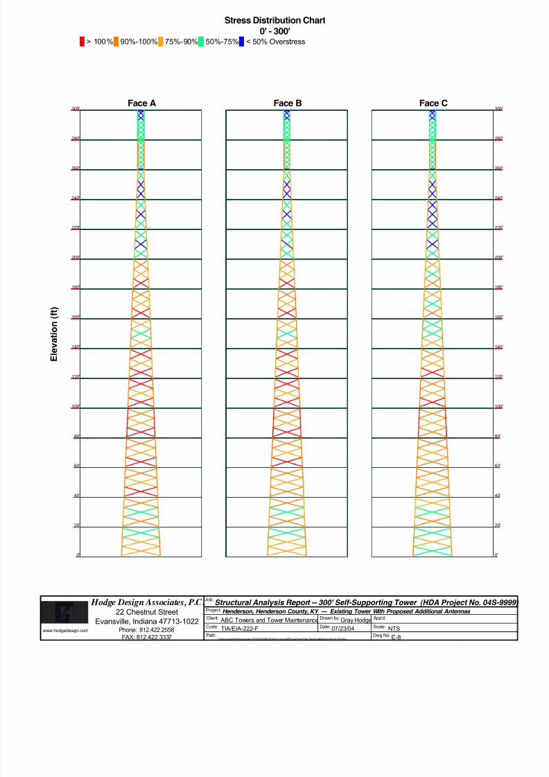
8/18/2019 Analysis Self Supporting-1
http://slidepdf.com/reader/full/analysis-self-supporting-1 44/98
www.hodgedesign.com
Hodge Design Associates, P.C.22 Chestnut Street
Evansville, Indiana 47713-1022Phone: 812.422.2558
FAX: 812.422.3337
Job:Structural Analysis Report -- 300' Self-Supporting Tower (HDA Project No. 04S-9
Project: Henderson, Henderson County, KY --- Existing Tower With Proposed Additional Antennas Client: ABC Towers and Tower Maintenance Drawn by: Gray Hodge App'd:
Code: TIA/EIA-222-F Date: 07/23/04 Scale: NTSPath:
C:\DocumentsandSettings\ghodge.HODGEDESIGN.000\MyDocuments\ERITowerProjectData Files\SampleReports\Sample-SS-R2.eri
Dwg No. E-8
Stress Distribution Chart
0' - 300'> 100% 90%-100% 75%-90% 50%-75% < 50% Overstress
Face A Face B Face C
280'
260'
240'
220'
200'
180'
160'
140'
120'
100'
80'
60'
40'
20'
0'
300'
E l e v a t i o n
( f t )
280
260
240
220
200
180
160
140
120
100
80'
60'
40'
20'
0'
300

8/18/2019 Analysis Self Supporting-1
http://slidepdf.com/reader/full/analysis-self-supporting-1 45/98
E E R R I I T T oowweer r Job
Structural Analysis Report -- 300' Self-Supporting Tower (HDAProject No. 04S-9999)
Page
1 of 21
Hodge Design Associates, P.C. 22 Chestnut Street
Project
Henderson, Henderson County, KY --- Existing Tower WithProposed Additional Antennas
Date
12:55:40 07/23/04
Evansville, Indiana 47713-1022
Phone: 812.422.2558
FAX: 812.422.3337
Client
ABC Towers and Tower MaintenanceDesigned by
Gray Hodge
Tower Input Data
The main tower is a 3x free standing tower with an overall height of 300' above the ground line.
The base of the tower is set at an elevation of 0' above the ground line.The face width of the tower is 4' at the top and 26' at the base.
This tower is designed using the TIA/EIA-222-F standard.
The following design criteria apply:
Tower is located in Henderson County, Kentucky.
Basic wind speed of 70 mph.
Nominal ice thickness of 0.5000 in.
Ice density of 56 pcf.A wind speed of 61 mph is used in combination with ice.
Temperature drop of 75 °F.
Deflections calculated using a wind speed of 50 mph.
EXISTING TOWER WITH PROPOSED ADDITIONAL ANTENNAS.
It is assumed that the tower has been properly maintained and is in good condition..It is assumed that there have been no structural modifications to the tower unless specifically noted otherwise..
There are no known structural defects and that there is no structural deterioration..
All welds and bolted connections are assumed capable of developing the member strength, unless noted otherwise..
Material strengths are as noted elsewhere in this report..
This structural analysis is based on information provided by others and assumed to be reliable and correct..
See Sheet E-7 for Feedlines and Linear Appurtenances..See Sheet E-8 for Code Check/Stress Distribution..
A non-linear (P-delta) analysis was used.Pressures are calculated at each section.
Stress ratio used in tower member design is 1.333.
Local bending stresses due to climbing loads, feedline supports, and appurtenance mounts are not considered.
Options
Consider Moments - Legs Distribute Leg Loads As Uniform v Treat Feedline Bundles As Cylinder
Consider Moments - Horizontals Assume Legs Pinned Use ASCE 10 X-Brace Ly Rules
Consider Moments - Diagonals v Assume Rigid Index Plate v Calculate Redundant Bracing Forces
Use Moment Magnification v Use Clear Spans For Wind Area v Ignore Redundant Members in FEA
v Use Code Stress Ratios v Use Clear Spans For KL/r v SR Leg Bolts Resist Compression
v Use Code Safety Factors - Guys v Retension Guys To Initial Tension v All Leg Panels Have Same Allowable
Escalate Ice Bypass Mast Stability Checks Offset Girt At Foundation
Always Use Max Kz v Use Azimuth Dish Coefficients v Consider Feedline Torque
Use Special Wind Profile v Project Wind Area of Appurt. v Include Angle Block Shear CheckInclude Bolts In Member Capacity Autocalc Torque Arm Areas Poles
v Leg Bolts Are At Top Of Section v SR Members Have Cut Ends v Include Shear-Torsion Interaction
v Secondary Horizontal Braces Leg v Sort Capacity Reports By Component Always Use Sub-Critical Flow
Use Diamond Inner Bracing (4 Sided) v Triangulate Diamond Inner Bracing Use Top Mounted Sockets
Add IBC .6D+W Combination

8/18/2019 Analysis Self Supporting-1
http://slidepdf.com/reader/full/analysis-self-supporting-1 46/98
E E R R I I T T oowweer r Job
Structural Analysis Report -- 300' Self-Supporting Tower (HDAProject No. 04S-9999)
Page
2 of 21
Hodge Design Associates, P.C. 22 Chestnut Street
Project
Henderson, Henderson County, KY --- Existing Tower WithProposed Additional Antennas
Date
12:55:40 07/23/04
Evansville, Indiana 47713-1022
Phone: 812.422.2558
FAX: 812.422.3337
Client
ABC Towers and Tower MaintenanceDesigned by
Gray Hodge
Leg BLeg C
Leg A
F a c e
A F
a c e B
Face C
Triangular Tower
Wind Normal
Wind 90
Wind 180
Z
X
Tower Section Geometry
Tower
Section
Tower
Elevation
ft
Assembly
Database
Description Section
Width
ft
Number
of
Sections
Section
Length
ft
T1 300'-280' 4' 1 20'
T2 280'-260' 4' 1 20'
T3 260'-240' 4' 1 20'
T4 240'-220' 5'8-9/32'' 1 20'
T5 220'-200' 7'4-11/16'' 1 20'
T6 200'-180' 9'31/32'' 1 20'
T7 180'-160' 10'9-1/4'' 1 20'
T8 160'-140' 12'5-17/32'' 1 20'
T9 140'-120' 14'1-13/16'' 1 20'
T10 120'-100' 15'10-3/16'' 1 20'
T11 100'-80' 17'6-15/32'' 1 20'
T12 80'-60' 19'2-3/4'' 1 20'
T13 60'-40' 20'11-1/32'' 1 20'T14 40'-20' 22'7-5/16'' 1 20'
T15 20'-0' 24'3-23/32'' 1 20'
Tower Section Geometry (cont’d)
Tower
Section
Tower
Elevation
ft
Diagonal
Spacing
ft
Bracing
Type
Has
K Brace
End
Panels
Has
Horizontals
Top Girt
Offset
in
Bottom Girt
Offset
in

8/18/2019 Analysis Self Supporting-1
http://slidepdf.com/reader/full/analysis-self-supporting-1 47/98
E E R R I I T T oowweer r Job
Structural Analysis Report -- 300' Self-Supporting Tower (HDAProject No. 04S-9999)
Page
3 of 21
Hodge Design Associates, P.C. 22 Chestnut Street
Project
Henderson, Henderson County, KY --- Existing Tower WithProposed Additional Antennas
Date
12:55:40 07/23/04
Evansville, Indiana 47713-1022
Phone: 812.422.2558
FAX: 812.422.3337
Client
ABC Towers and Tower MaintenanceDesigned by
Gray Hodge
TowerSection
Tower Elevation
ft
DiagonalSpacing
ft
BracingType
HasK Brace
End
Panels
Has Horizontals
Top GirtOffset
in
Bottom GirtOffset
in
T1 300'-280' 3'2-17/32'' X Brace No No 4.5000 4.5000
T2 280'-260' 3'2-17/32'' X Brace No No 4.5000 4.5000
T3 260'-240' 6'2-1/32'' X Brace No No 9.0000 9.0000
T4 240'-220' 6'2-1/32'' X Brace No No 9.0000 9.0000
T5 220'-200' 6'2-1/32'' X Brace No No 9.0000 9.0000
T6 200'-180' 6'2-1/32'' X Brace No No 9.0000 9.0000
T7 180'-160' 6'2-1/32'' X Brace No No 9.0000 9.0000
T8 160'-140' 6'2-1/32'' X Brace No No 9.0000 9.0000
T9 140'-120' 6'2-1/32'' X Brace No No 9.0000 9.0000
T10 120'-100' 6'2-1/32'' X Brace No No 9.0000 9.0000
T11 100'-80' 6'2-1/32'' X Brace No No 9.0000 9.0000
T12 80'-60' 6'2-1/32'' X Brace No No 9.0000 9.0000
T13 60'-40' 6'2-1/32'' X Brace No No 9.0000 9.0000
T14 40'-20' 6'2-1/32'' X Brace No No 9.0000 9.0000
T15 20'-0' 6'2-1/32'' X Brace No No 9.0000 9.0000
Tower Section Geometry (cont’d)
Tower
Elevation
ft
Leg
Type
Leg
Size
Leg
Grade
Diagonal
Type
Diagonal
Size
Diagonal
Grade
T1 300'-280' Solid Round 1 1/2 A572-50
(50 ksi)
Solid Round 3/4 A36
(36 ksi)
T2 280'-260' Solid Round 2 A572-50
(50 ksi)
Solid Round 7/8 A36
(36 ksi)
T3 260'-240' Solid Round 3 A572-50
(50 ksi)
Equal Angle L2x2x3/16 A36
(36 ksi)T4 240'-220' Solid Round 3 1/4 A572-50
(50 ksi)
Equal Angle L2x2x3/16 A36
(36 ksi)
T5 220'-200' Solid Round 3 1/4 A572-50
(50 ksi)
Equal Angle L2x2x3/16 A36
(36 ksi)
T6 200'-180' Solid Round 3 1/2 A572-50
(50 ksi)
Equal Angle L2x2x3/16 A36
(36 ksi)
T7 180'-160' Solid Round 3 1/2 A572-50
(50 ksi)
Equal Angle L2x2x1/4 A36
(36 ksi)
T8 160'-140' Solid Round 3 1/2 A572-50
(50 ksi)
Equal Angle L2 1/2x2 1/2x3/16 A36
(36 ksi)
T9 140'-120' Solid Round 3 3/4 A572-50
(50 ksi)
Equal Angle L2 1/2x2 1/2x3/16 A36
(36 ksi)
T10 120'-100' Solid Round 3 3/4 A572-50
(50 ksi)
Equal Angle L2 1/2x2 1/2x1/4 A36
(36 ksi)
T11 100'-80' Solid Round 3 3/4 A572-50
(50 ksi)
Equal Angle L3x3x3/16 A36
(36 ksi)
T12 80'-60' Solid Round 4 A572-50(50 ksi)
Equal Angle L3x3x1/4 A36(36 ksi)
T13 60'-40' Solid Round 4 A572-50
(50 ksi)
Equal Angle L3 1/2x3 1/2x3/16 A36
(36 ksi)
T14 40'-20' Solid Round 4 1/4 A572-50
(50 ksi)
Equal Angle L3 1/2x3 1/2x1/4 A36
(36 ksi)
T15 20'-0' Solid Round 4 1/4 A572-50
(50 ksi)
Equal Angle L4x4x1/4 A36
(36 ksi)

8/18/2019 Analysis Self Supporting-1
http://slidepdf.com/reader/full/analysis-self-supporting-1 48/98
E E R R I I T T oowweer r Job
Structural Analysis Report -- 300' Self-Supporting Tower (HDAProject No. 04S-9999)
Page
4 of 21
Hodge Design Associates, P.C. 22 Chestnut Street
Project
Henderson, Henderson County, KY --- Existing Tower WithProposed Additional Antennas
Date
12:55:40 07/23/04
Evansville, Indiana 47713-1022
Phone: 812.422.2558
FAX: 812.422.3337
Client
ABC Towers and Tower MaintenanceDesigned by
Gray Hodge
Tower Section Geometry (cont’d)
Tower
Elevation
ft
Top Girt
Type
Top Girt
Size
Top Girt
Grade
Bottom Girt
Type
Bottom Girt
Size
Bottom Girt
Grade
T1 300'-280' Solid Round 3/4 A36
(36 ksi)
Solid Round 3/4 A36
(36 ksi)
T2 280'-260' Solid Round 7/8 A36
(36 ksi)
Solid Round 7/8 A36
(36 ksi)
Tower Section Geometry (cont’d)
Tower
Elevation
ft
Gusset
Area
(per face)
ft 2
Gusset
Thickness
in
Gusset Grade Adjust. Factor
A f
Adjust.
Factor
Ar
Weight Mult. Double Angle
Stitch Bolt
Spacing
Diagonals
in
Double Angle
Stitch Bolt
Spacing
Horizontals
in
T1 300'-280' 0.00 0.0000 A36
(36 ksi)
1.01 1.01 1.01 36.0000 36.0000
T2 280'-260' 0.00 0.0000 A36
(36 ksi)
1.01 1.01 1.01 36.0000 36.0000
T3 260'-240' 2.50 0.7500 A36
(36 ksi)
1.01 1.01 1.01 36.0000 36.0000
T4 240'-220' 2.50 0.7500 A36
(36 ksi)
1.01 1.01 1.01 36.0000 36.0000
T5 220'-200' 2.50 0.7500 A36
(36 ksi)
1.01 1.01 1.01 36.0000 36.0000
T6 200'-180' 2.50 0.7500 A36
(36 ksi)
1.01 1.01 1.01 36.0000 36.0000
T7 180'-160' 2.50 0.7500 A36
(36 ksi)
1.01 1.01 1.01 36.0000 36.0000
T8 160'-140' 2.50 0.7500 A36
(36 ksi)
1.01 1.01 1.01 36.0000 36.0000
T9 140'-120' 2.50 0.7500 A36
(36 ksi)
1.01 1.01 1.01 36.0000 36.0000
T10 120'-100' 2.50 0.7500 A36
(36 ksi)
1.01 1.01 1.01 36.0000 36.0000
T11 100'-80' 2.50 0.7500 A36
(36 ksi)
1.01 1.01 1.01 36.0000 36.0000
T12 80'-60' 2.50 0.7500 A36
(36 ksi)
1.01 1.01 1.01 36.0000 36.0000
T13 60'-40' 2.50 0.7500 A36
(36 ksi)
1.01 1.01 1.01 36.0000 36.0000
T14 40'-20' 2.50 0.7500 A36
(36 ksi)
1.01 1.01 1.01 36.0000 36.0000
T15 20'-0' 2.50 0.7500 A36
(36 ksi)
1.01 1.01 1.01 36.0000 36.0000
Tower Section Geometry (cont’d)
K Factors1

8/18/2019 Analysis Self Supporting-1
http://slidepdf.com/reader/full/analysis-self-supporting-1 49/98
E E R R I I T T oowweer r Job
Structural Analysis Report -- 300' Self-Supporting Tower (HDAProject No. 04S-9999)
Page
5 of 21
Hodge Design Associates, P.C. 22 Chestnut Street
Project
Henderson, Henderson County, KY --- Existing Tower WithProposed Additional Antennas
Date
12:55:40 07/23/04
Evansville, Indiana 47713-1022
Phone: 812.422.2558
FAX: 812.422.3337
Client
ABC Towers and Tower MaintenanceDesigned by
Gray Hodge
Tower Elevation
ft
CalcK
Single
Angles
CalcK
Solid
Rounds
Legs X Brace
Diags
X
Y
K Brace
Diags
X
Y
Single Diags
X
Y
Girts
X
Y
Horiz.
X
Y
Sec. Horiz.
X
Y
Inner Brace
X
Y
T1 300'-280' No No 1 1
1
1
1
1
1
1
1
1
1
1
1
1
1
T2 280'-260' No No 1 1
1
1
1
1
1
1
1
1
1
1
1
1
1
T3 260'-240' No No 1 1
1
1
1
1
1
1
1
1
1
1
1
1
1
T4 240'-220' No No 1 1
1
1
1
1
1
1
1
1
1
1
1
1
1
T5 220'-200' No No 1 1
1
1
1
1
1
1
1
1
1
1
1
1
1
T6 200'-180' No No 1 1
1
1
1
1
1
1
1
1
1
1
1
1
1
T7 180'-160' No No 1 11
11
11
11
11
11
11
T8 160'-140' No No 1 1
1
1
1
1
1
1
1
1
1
1
1
1
1
T9 140'-120' No No 1 1
1
1
1
1
1
1
1
1
1
1
1
1
1
T10 120'-100' No No 1 1
1
1
1
1
1
1
1
1
1
1
1
1
1
T11 100'-80' No No 1 1
1
1
1
1
1
1
1
1
1
1
1
1
1
T12 80'-60' No No 1 1
1
1
1
1
1
1
1
1
1
1
1
1
1
T13 60'-40' No No 1 1
1
1
1
1
1
1
1
1
1
1
1
1
1
T14 40'-20' No No 1 1
1
1
1
1
1
1
1
1
1
1
1
1
1
T15 20'-0' No No 1 11 11 11 11 11 11 111 Note: K factors are applied to member segment lengths. K-braces without inner supporting members will have the K factor in the out-of-plane direction applied to
the overall length.
Tower Section Geometry (cont’d)
Tower
Elevation
ft
Leg Diagonal Top Girt Bottom Girt Mid Girt Long Horizontal Short Horizontal
Net Width
Deductin
U Net Width
Deductin
U Net Width
Deductin
U Net
Width
Deduct
in
U Net
Width
Deduct
in
U Net
Width
Deduct
in
U Net
Width
Deduct
in
U
T1 300'-280' 0.0000 0.75 0.0000 0.75 0.0000 0.75 0.0000 0.75 0.0000 0.75 0.0000 0.75 0.0000 0.75
T2 280'-260' 0.0000 0.75 0.0000 0.75 0.0000 0.75 0.0000 0.75 0.0000 0.75 0.0000 0.75 0.0000 0.75
T3 260'-240' 0.0000 0.75 0.0000 0.75 0.0000 0.75 0.0000 0.75 0.0000 0.75 0.0000 0.75 0.0000 0.75
T4 240'-220' 0.0000 0.75 0.0000 0.75 0.0000 0.75 0.0000 0.75 0.0000 0.75 0.0000 0.75 0.0000 0.75
T5 220'-200' 0.0000 0.75 0.0000 0.75 0.0000 0.75 0.0000 0.75 0.0000 0.75 0.0000 0.75 0.0000 0.75
T6 200'-180' 0.0000 0.75 0.0000 0.75 0.0000 0.75 0.0000 0.75 0.0000 0.75 0.0000 0.75 0.0000 0.75
T7 180'-160' 0.0000 0.75 0.0000 0.75 0.0000 0.75 0.0000 0.75 0.0000 0.75 0.0000 0.75 0.0000 0.75
T8 160'-140' 0.0000 0.75 0.0000 0.75 0.0000 0.75 0.0000 0.75 0.0000 0.75 0.0000 0.75 0.0000 0.75
T9 140'-120' 0.0000 0.75 0.0000 0.75 0.0000 0.75 0.0000 0.75 0.0000 0.75 0.0000 0.75 0.0000 0.75
T10 120'-100' 0.0000 0.75 0.0000 0.75 0.0000 0.75 0.0000 0.75 0.0000 0.75 0.0000 0.75 0.0000 0.75
T11 100'-80' 0.0000 0.75 0.0000 0.75 0.0000 0.75 0.0000 0.75 0.0000 0.75 0.0000 0.75 0.0000 0.75
T12 80'-60' 0.0000 0.75 0.0000 0.75 0.0000 0.75 0.0000 0.75 0.0000 0.75 0.0000 0.75 0.0000 0.75
T13 60'-40' 0.0000 0.75 0.0000 0.75 0.0000 0.75 0.0000 0.75 0.0000 0.75 0.0000 0.75 0.0000 0.75

8/18/2019 Analysis Self Supporting-1
http://slidepdf.com/reader/full/analysis-self-supporting-1 50/98
E E R R I I T T oowweer r Job
Structural Analysis Report -- 300' Self-Supporting Tower (HDAProject No. 04S-9999)
Page
6 of 21
Hodge Design Associates, P.C. 22 Chestnut Street
Project
Henderson, Henderson County, KY --- Existing Tower WithProposed Additional Antennas
Date
12:55:40 07/23/04
Evansville, Indiana 47713-1022
Phone: 812.422.2558
FAX: 812.422.3337
Client
ABC Towers and Tower MaintenanceDesigned by
Gray Hodge
Tower Elevation
ft
Leg Diagonal Top Girt Bottom Girt Mid Girt Long Horizontal Short Horizontal
Net Width
Deduct
in
U Net Width
Deduct
in
U Net Width
Deduct
in
U Net
Width
Deductin
U Net
Width
Deductin
U Net
Width
Deductin
U Net
Width
Deductin
U
T14 40'-20' 0.0000 0.75 0.0000 0.75 0.0000 0.75 0.0000 0.75 0.0000 0.75 0.0000 0.75 0.0000 0.75
T15 20'-0' 0.0000 0.75 0.0000 0.75 0.0000 0.75 0.0000 0.75 0.0000 0.75 0.0000 0.75 0.0000 0.75
Feed Line/Linear Appurtenances - Entered As Round Or Flat
Description Face
or
Leg
Allow
Shield
Component
Type
Placement
ft
Face
Offset
in
Lateral
Offset
(Frac FW)
# #
Per
Row
Clear
Spacing
in
Width or
Diameter
in
Perimeter
in
Weight
klf
Feedline
Ladder
A Yes Ar (CfAe) 10' - 10' 1.0000 0.25 1 1 1.5000 0.0000 0.01
Feedline
Ladder
B Yes Ar (CfAe) 10' - 10' 1.0000 0.25 1 1 1.5000 0.0000 0.01
Feedline
Ladder
C Yes Ar (CfAe) 10' - 10' 1.0000 0.25 1 1 1.5000 0.0000 0.01
2'' Rigid
Conduit
C Yes Ar (CfAe) 300' - 10' 1.0000 -0.25 1 1 2.0000 2.0000 0.00
1 5/8 A Yes Ar (CfAe) 300' - 10' 1.0000 0.25 12 6 0.3750 1.9800 0.00
1 5/8 B Yes Ar (CfAe) 280' - 10' 1.0000 0.25 12 6 0.3750 1.9800 0.00
1 5/8 C Yes Ar (CfAe) 260' - 10' 1.0000 0.25 12 6 0.3750 1.9800 0.00
EW63
(to Proposed
Antennas)
A Yes Af (CfAe) 200' - 10' 1.0000 -0.25 2 1 1.5742 1.5742 5.0668 0.00
Feed Line/Linear Appurtenances Section Areas
Tower
Section
Tower
Elevation
ft
Face A R
ft 2
AF
ft 2
C A A A
In Face
ft 2
C A A A
Out Face
ft 2
Weight
K
T1 300'-280' A
B
C
23.314
0.000
3.333
0.000
0.000
0.000
0.000
0.000
0.000
0.000
0.000
0.000
0.25
0.00
0.06
T2 280'-260' A
B
C
23.314
23.314
3.333
0.000
0.000
0.000
0.000
0.000
0.000
0.000
0.000
0.000
0.25
0.25
0.06
T3 260'-240' A
B
C
23.314
23.314
26.647
0.000
0.000
0.000
0.000
0.000
0.000
0.000
0.000
0.000
0.25
0.25
0.31
T4 240'-220' A
B
C
23.314
23.314
26.647
0.000
0.000
0.000
0.000
0.000
0.000
0.000
0.000
0.000
0.25
0.25
0.31
T5 220'-200' A
B
C
23.314
23.314
26.647
0.000
0.000
0.000
0.000
0.000
0.000
0.000
0.000
0.000
0.25
0.25
0.31
T6 200'-180' A
B
C
23.314
23.314
26.647
5.247
0.000
0.000
0.000
0.000
0.000
0.000
0.000
0.000
0.27
0.25
0.31
T7 180'-160' A
B
23.314
23.314
5.247
0.000
0.000
0.000
0.000
0.000
0.27
0.25

8/18/2019 Analysis Self Supporting-1
http://slidepdf.com/reader/full/analysis-self-supporting-1 51/98
E E R R I I T T oowweer r Job
Structural Analysis Report -- 300' Self-Supporting Tower (HDAProject No. 04S-9999)
Page
7 of 21
Hodge Design Associates, P.C. 22 Chestnut Street
Project
Henderson, Henderson County, KY --- Existing Tower WithProposed Additional Antennas
Date
12:55:40 07/23/04
Evansville, Indiana 47713-1022
Phone: 812.422.2558
FAX: 812.422.3337
Client
ABC Towers and Tower MaintenanceDesigned by
Gray Hodge
TowerSection
Tower Elevation
ft
Face A R
ft 2
AF
ft 2
C A A A
In Face
ft 2
C A A A
Out Face
ft 2
Weight
K
C 26.647 0.000 0.000 0.000 0.31
T8 160'-140' A
B
C
23.314
23.314
26.647
5.247
0.000
0.000
0.000
0.000
0.000
0.000
0.000
0.000
0.27
0.25
0.31
T9 140'-120' A
B
C
23.314
23.314
26.647
5.247
0.000
0.000
0.000
0.000
0.000
0.000
0.000
0.000
0.27
0.25
0.31
T10 120'-100' A
B
C
23.314
23.314
26.647
5.247
0.000
0.000
0.000
0.000
0.000
0.000
0.000
0.000
0.27
0.25
0.31
T11 100'-80' A
B
C
23.314
23.314
26.647
5.247
0.000
0.000
0.000
0.000
0.000
0.000
0.000
0.000
0.27
0.25
0.31
T12 80'-60' A
B
C
23.314
23.314
26.647
5.247
0.000
0.000
0.000
0.000
0.000
0.000
0.000
0.000
0.27
0.25
0.31
T13 60'-40' A
B
C
23.314
23.314
26.647
5.247
0.000
0.000
0.000
0.000
0.000
0.000
0.000
0.000
0.27
0.25
0.31
T14 40'-20' A
B
C
23.314
23.314
26.647
5.247
0.000
0.000
0.000
0.000
0.000
0.000
0.000
0.000
0.27
0.25
0.31
T15 20'-0' A
B
C
11.657
11.657
13.323
2.624
0.000
0.000
0.000
0.000
0.000
0.000
0.000
0.000
0.14
0.12
0.15
Feed Line/Linear Appurtenances Section Areas - With Ice
Tower
Section
Tower
Elevation
ft
Face
or
Leg
Ice
Thickness
in
A R
ft 2
AF
ft 2
C A A A
In Face
ft 2
C A A A
Out Face
ft 2
Weight
K
T1 300'-280' A
B
C
0.500 4.967
0.000
5.000
20.014
0.000
0.000
0.000
0.000
0.000
0.000
0.000
0.000
0.56
0.00
0.09
T2 280'-260' A
B
C
0.500 4.967
4.967
5.000
20.014
20.014
0.000
0.000
0.000
0.000
0.000
0.000
0.000
0.56
0.56
0.09
T3 260'-240' A
B
C
0.500 4.967
4.967
9.967
20.014
20.014
20.014
0.000
0.000
0.000
0.000
0.000
0.000
0.56
0.56
0.65
T4 240'-220' A
B
C
0.500 4.967
4.967
9.967
20.014
20.014
20.014
0.000
0.000
0.000
0.000
0.000
0.000
0.56
0.56
0.65
T5 220'-200' A
BC
0.500 4.967
4.9679.967
20.014
20.01420.014
0.000
0.0000.000
0.000
0.0000.000
0.56
0.560.65
T6 200'-180' A
B
C
0.500 4.967
4.967
9.967
27.483
20.014
20.014
0.000
0.000
0.000
0.000
0.000
0.000
0.63
0.56
0.65
T7 180'-160' A
B
C
0.500 4.967
4.967
9.967
27.483
20.014
20.014
0.000
0.000
0.000
0.000
0.000
0.000
0.63
0.56
0.65
T8 160'-140' A
B
C
0.500 4.967
4.967
9.967
27.483
20.014
20.014
0.000
0.000
0.000
0.000
0.000
0.000
0.63
0.56
0.65
T9 140'-120' A
B
C
0.500 4.967
4.967
9.967
27.483
20.014
20.014
0.000
0.000
0.000
0.000
0.000
0.000
0.63
0.56
0.65

8/18/2019 Analysis Self Supporting-1
http://slidepdf.com/reader/full/analysis-self-supporting-1 52/98
E E R R I I T T oowweer r Job
Structural Analysis Report -- 300' Self-Supporting Tower (HDAProject No. 04S-9999)
Page
8 of 21
Hodge Design Associates, P.C. 22 Chestnut Street
Project
Henderson, Henderson County, KY --- Existing Tower WithProposed Additional Antennas
Date
12:55:40 07/23/04
Evansville, Indiana 47713-1022
Phone: 812.422.2558
FAX: 812.422.3337
Client
ABC Towers and Tower MaintenanceDesigned by
Gray Hodge
TowerSection
Tower Elevation
ft
Faceor
Leg
IceThickness
in
A R
ft 2
AF
ft 2
C A A A
In Face
ft 2
C A A A
Out Face
ft 2
Weight
K
T10 120'-100' A
B
C
0.500 4.967
4.967
9.967
27.483
20.014
20.014
0.000
0.000
0.000
0.000
0.000
0.000
0.63
0.56
0.65
T11 100'-80' A
B
C
0.500 4.967
4.967
9.967
27.483
20.014
20.014
0.000
0.000
0.000
0.000
0.000
0.000
0.63
0.56
0.65
T12 80'-60' A
B
C
0.500 4.967
4.967
9.967
27.483
20.014
20.014
0.000
0.000
0.000
0.000
0.000
0.000
0.63
0.56
0.65
T13 60'-40' A
B
C
0.500 4.967
4.967
9.967
27.483
20.014
20.014
0.000
0.000
0.000
0.000
0.000
0.000
0.63
0.56
0.65
T14 40'-20' A
B
C
0.500 4.967
4.967
9.967
27.483
20.014
20.014
0.000
0.000
0.000
0.000
0.000
0.000
0.63
0.56
0.65
T15 20'-0' A
B
C
0.500 2.483
2.483
4.983
13.742
10.007
10.007
0.000
0.000
0.000
0.000
0.000
0.000
0.32
0.28
0.32
Feed Line Shielding
Section Elevation
ft
Face A R
ft 2
A R
Ice
ft 2
AF
ft 2
AF
Ice
ft 2
T1 300'-280' A
B
C
1.076
0.000
0.181
3.117
0.000
0.634
0.000
0.000
0.000
0.000
0.000
0.000T2 280'-260' A
B
C
1.255
1.255
0.211
3.340
3.340
0.679
0.000
0.000
0.000
0.000
0.000
0.000
T3 260'-240' A
B
C
0.000
0.000
0.000
0.000
0.000
0.000
1.611
1.611
1.882
2.668
2.668
3.210
T4 240'-220' A
B
C
0.000
0.000
0.000
0.000
0.000
0.000
1.364
1.364
1.594
2.259
2.259
2.718
T5 220'-200' A
B
C
0.000
0.000
0.000
0.000
0.000
0.000
1.238
1.238
1.447
2.051
2.051
2.468
T6 200'-180' A
B
C
0.000
0.000
0.000
0.000
0.000
0.000
1.321
1.166
1.363
2.268
1.932
2.324
T7 180'-160' A
BC
0.000
0.0000.000
0.000
0.0000.000
1.270
1.1211.310
2.181
1.8572.234
T8 160'-140' A
B
C
0.000
0.000
0.000
0.000
0.000
0.000
1.545
1.364
1.594
2.521
2.146
2.583
T9 140'-120' A
B
C
0.000
0.000
0.000
0.000
0.000
0.000
1.516
1.338
1.563
2.473
2.105
2.533
T10 120'-100' A
B
C
0.000
0.000
0.000
0.000
0.000
0.000
1.494
1.319
1.542
2.438
2.076
2.498
T11 100'-80' A
B
C
0.000
0.000
0.000
0.000
0.000
0.000
1.774
1.566
1.830
2.793
2.378
2.861
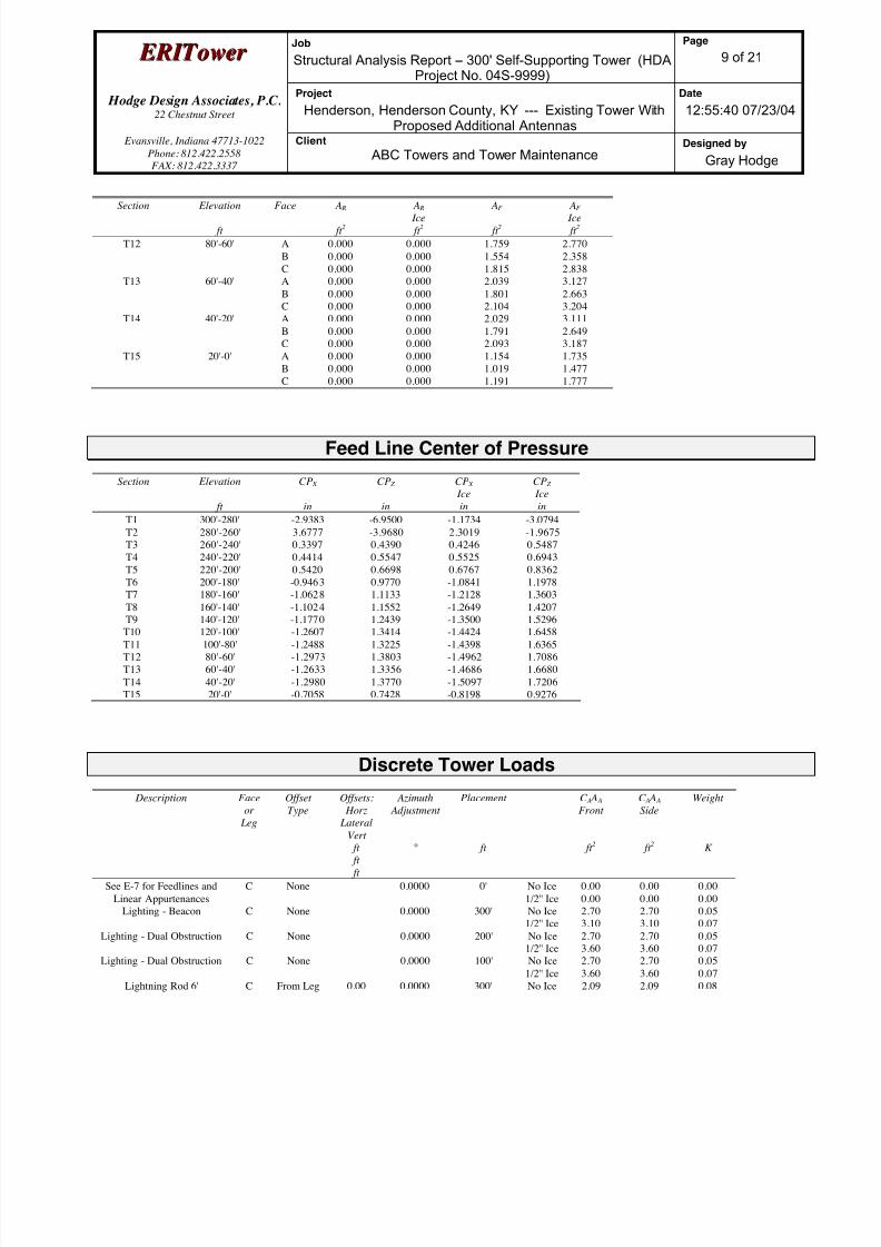
8/18/2019 Analysis Self Supporting-1
http://slidepdf.com/reader/full/analysis-self-supporting-1 53/98
E E R R I I T T oowweer r Job
Structural Analysis Report -- 300' Self-Supporting Tower (HDAProject No. 04S-9999)
Page
9 of 21
Hodge Design Associates, P.C. 22 Chestnut Street
Project
Henderson, Henderson County, KY --- Existing Tower WithProposed Additional Antennas
Date
12:55:40 07/23/04
Evansville, Indiana 47713-1022
Phone: 812.422.2558
FAX: 812.422.3337
Client
ABC Towers and Tower MaintenanceDesigned by
Gray Hodge
Section Elevation
ft
Face A R
ft 2
A R
Ice
ft 2
AF
ft 2
AF
Ice
ft 2
T12 80'-60' A
B
C
0.000
0.000
0.000
0.000
0.000
0.000
1.759
1.554
1.815
2.770
2.358
2.838
T13 60'-40' A
B
C
0.000
0.000
0.000
0.000
0.000
0.000
2.039
1.801
2.104
3.127
2.663
3.204
T14 40'-20' A
B
C
0.000
0.000
0.000
0.000
0.000
0.000
2.029
1.791
2.093
3.111
2.649
3.187
T15 20'-0' A
B
C
0.000
0.000
0.000
0.000
0.000
0.000
1.154
1.019
1.191
1.735
1.477
1.777
Feed Line Center of Pressure
Section Elevation
ft
CP X
in
CP Z
in
CP X
Ice
in
CP Z
Ice
in
T1 300'-280' -2.9383 -6.9500 -1.1734 -3.0794
T2 280'-260' 3.6777 -3.9680 2.3019 -1.9675
T3 260'-240' 0.3397 0.4390 0.4246 0.5487
T4 240'-220' 0.4414 0.5547 0.5525 0.6943
T5 220'-200' 0.5420 0.6698 0.6767 0.8362
T6 200'-180' -0.9463 0.9770 -1.0841 1.1978
T7 180'-160' -1.0628 1.1133 -1.2128 1.3603
T8 160'-140' -1.1024 1.1552 -1.2649 1.4207
T9 140'-120' -1.1770 1.2439 -1.3500 1.5296T10 120'-100' -1.2607 1.3414 -1.4424 1.6458
T11 100'-80' -1.2488 1.3225 -1.4398 1.6365
T12 80'-60' -1.2973 1.3803 -1.4962 1.7086
T13 60'-40' -1.2633 1.3356 -1.4686 1.6680
T14 40'-20' -1.2980 1.3770 -1.5097 1.7206
T15 20'-0' -0.7058 0.7428 -0.8198 0.9276
Discrete Tower Loads
Description Face
or
Leg
Offset
Type
Offsets:
Horz
LateralVert
ft
ft
ft
Azimuth
Adjustment
°
Placement
ft
C A A A
Front
ft 2
C A A A
Side
ft 2
Weight
K
See E-7 for Feedlines and
Linear Appurtenances
C None 0.0000 0' No Ice
1/2'' Ice
0.00
0.00
0.00
0.00
0.00
0.00
Lighting - Beacon C None 0.0000 300' No Ice
1/2'' Ice
2.70
3.10
2.70
3.10
0.05
0.07
Lighting - Dual Obstruction C None 0.0000 200' No Ice
1/2'' Ice
2.70
3.60
2.70
3.60
0.05
0.07
Lighting - Dual Obstruction C None 0.0000 100' No Ice
1/2'' Ice
2.70
3.60
2.70
3.60
0.05
0.07
Lightning Rod 6' C From Leg 0.00 0.0000 300' No Ice 2.09 2.09 0.08
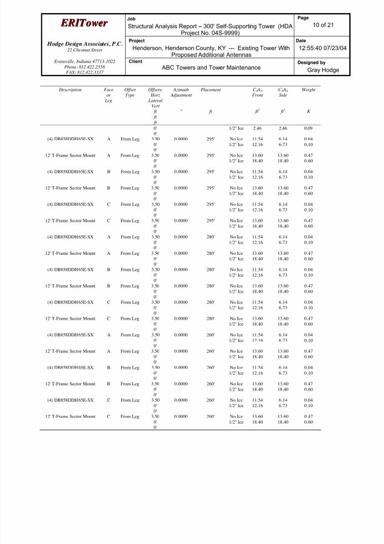
8/18/2019 Analysis Self Supporting-1
http://slidepdf.com/reader/full/analysis-self-supporting-1 54/98
E E R R I I T T oowweer r Job
Structural Analysis Report -- 300' Self-Supporting Tower (HDAProject No. 04S-9999)
Page
10 of 21
Hodge Design Associates, P.C. 22 Chestnut Street
Project
Henderson, Henderson County, KY --- Existing Tower WithProposed Additional Antennas
Date
12:55:40 07/23/04
Evansville, Indiana 47713-1022
Phone: 812.422.2558
FAX: 812.422.3337
Client
ABC Towers and Tower MaintenanceDesigned by
Gray Hodge
Description Faceor
Leg
OffsetType
Offsets: Horz
Lateral
Vert
ft
ft
ft
Azimuth Adjustment
°
Placement
ft
C A A A Front
ft 2
C A A A Side
ft 2
Weight
K
0'
0'
1/2'' Ice 2.46 2.46 0.09
(4) DB858DDH65E-SX A From Leg 3.50
0'
0'
0.0000 295' No Ice
1/2'' Ice
11.54
12.16
6.14
6.73
0.04
0.10
12' T-Frame Sector Mount A From Leg 3.50
0'
0'
0.0000 295' No Ice
1/2'' Ice
13.60
18.40
13.60
18.40
0.47
0.60
(4) DB858DDH65E-SX B From Leg 3.50
0'
0'
0.0000 295' No Ice
1/2'' Ice
11.54
12.16
6.14
6.73
0.04
0.10
12' T-Frame Sector Mount B From Leg 3.50
0'
0'
0.0000 295' No Ice
1/2'' Ice
13.60
18.40
13.60
18.40
0.47
0.60
(4) DB858DDH65E-SX C From Leg 3.50
0'
0'
0.0000 295' No Ice
1/2'' Ice
11.54
12.16
6.14
6.73
0.04
0.10
12' T-Frame Sector Mount C From Leg 3.50
0'
0'
0.0000 295' No Ice
1/2'' Ice
13.60
18.40
13.60
18.40
0.47
0.60
(4) DB858DDH65E-SX A From Leg 3.50
0'
0'
0.0000 280' No Ice
1/2'' Ice
11.54
12.16
6.14
6.73
0.04
0.10
12' T-Frame Sector Mount A From Leg 3.50
0'
0'
0.0000 280' No Ice
1/2'' Ice
13.60
18.40
13.60
18.40
0.47
0.60
(4) DB858DDH65E-SX B From Leg 3.500'
0'
0.0000 280' No Ice1/2'' Ice
11.5412.16
6.146.73
0.040.10
12' T-Frame Sector Mount B From Leg 3.50
0'
0'
0.0000 280' No Ice
1/2'' Ice
13.60
18.40
13.60
18.40
0.47
0.60
(4) DB858DDH65E-SX C From Leg 3.50
0'
0'
0.0000 280' No Ice
1/2'' Ice
11.54
12.16
6.14
6.73
0.04
0.10
12' T-Frame Sector Mount C From Leg 3.50
0'
0'
0.0000 280' No Ice
1/2'' Ice
13.60
18.40
13.60
18.40
0.47
0.60
(4) DB858DDH65E-SX A From Leg 3.50
0'
0'
0.0000 260' No Ice
1/2'' Ice
11.54
12.16
6.14
6.73
0.04
0.10
12' T-Frame Sector Mount A From Leg 3.50
0'
0'
0.0000 260' No Ice
1/2'' Ice
13.60
18.40
13.60
18.40
0.47
0.60
(4) DB858DDH65E-SX B From Leg 3.50
0'
0'
0.0000 260' No Ice
1/2'' Ice
11.54
12.16
6.14
6.73
0.04
0.10
12' T-Frame Sector Mount B From Leg 3.50
0'
0'
0.0000 260' No Ice
1/2'' Ice
13.60
18.40
13.60
18.40
0.47
0.60
(4) DB858DDH65E-SX C From Leg 3.50
0'
0'
0.0000 260' No Ice
1/2'' Ice
11.54
12.16
6.14
6.73
0.04
0.10
12' T-Frame Sector Mount C From Leg 3.50
0'
0'
0.0000 260' No Ice
1/2'' Ice
13.60
18.40
13.60
18.40
0.47
0.60
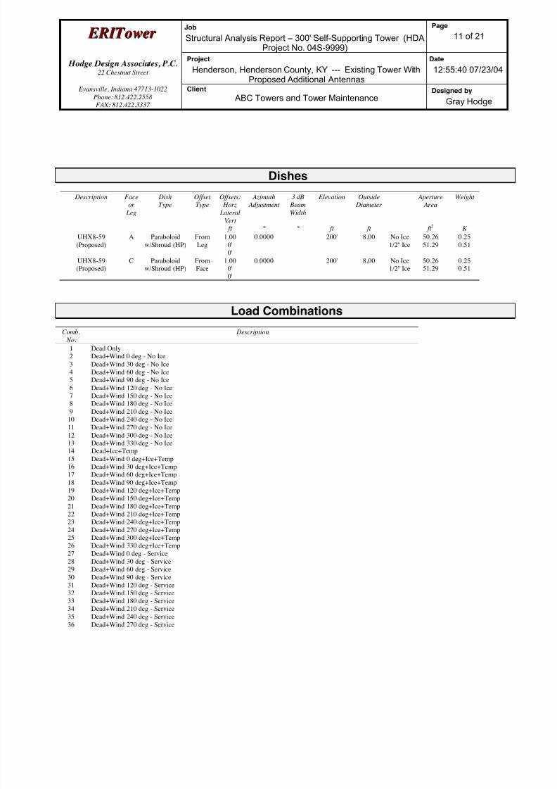
8/18/2019 Analysis Self Supporting-1
http://slidepdf.com/reader/full/analysis-self-supporting-1 55/98
E E R R I I T T oowweer r Job
Structural Analysis Report -- 300' Self-Supporting Tower (HDAProject No. 04S-9999)
Page
11 of 21
Hodge Design Associates, P.C. 22 Chestnut Street
Project
Henderson, Henderson County, KY --- Existing Tower WithProposed Additional Antennas
Date
12:55:40 07/23/04
Evansville, Indiana 47713-1022
Phone: 812.422.2558
FAX: 812.422.3337
Client
ABC Towers and Tower MaintenanceDesigned by
Gray Hodge
Dishes
Description Face
or
Leg
Dish
Type
Offset
Type
Offsets:
Horz
Lateral
Vert
ft
Azimuth
Adjustment
°
3 dB
Beam
Width
°
Elevation
ft
Outside
Diameter
ft
Aperture
Area
ft 2
Weight
K
UHX8-59
(Proposed)
A Paraboloid
w/Shroud (HP)
From
Leg
1.00
0'
0'
0.0000 200' 8.00 No Ice
1/2'' Ice
50.26
51.29
0.25
0.51
UHX8-59(Proposed)
C Paraboloidw/Shroud (HP)
FromFace
1.000'
0'
0.0000 200' 8.00 No Ice1/2'' Ice
50.2651.29
0.250.51
Load Combinations
Comb.
No.
Description
1 Dead Only
2 Dead+Wind 0 deg - No Ice
3 Dead+Wind 30 deg - No Ice
4 Dead+Wind 60 deg - No Ice
5 Dead+Wind 90 deg - No Ice
6 Dead+Wind 120 deg - No Ice
7 Dead+Wind 150 deg - No Ice
8 Dead+Wind 180 deg - No Ice
9 Dead+Wind 210 deg - No Ice
10 Dead+Wind 240 deg - No Ice
11 Dead+Wind 270 deg - No Ice
12 Dead+Wind 300 deg - No Ice
13 Dead+Wind 330 deg - No Ice
14 Dead+Ice+Temp
15 Dead+Wind 0 deg+Ice+Temp
16 Dead+Wind 30 deg+Ice+Temp
17 Dead+Wind 60 deg+Ice+Temp
18 Dead+Wind 90 deg+Ice+Temp
19 Dead+Wind 120 deg+Ice+Temp
20 Dead+Wind 150 deg+Ice+Temp
21 Dead+Wind 180 deg+Ice+Temp
22 Dead+Wind 210 deg+Ice+Temp
23 Dead+Wind 240 deg+Ice+Temp24 Dead+Wind 270 deg+Ice+Temp
25 Dead+Wind 300 deg+Ice+Temp
26 Dead+Wind 330 deg+Ice+Temp
27 Dead+Wind 0 deg - Service
28 Dead+Wind 30 deg - Service
29 Dead+Wind 60 deg - Service
30 Dead+Wind 90 deg - Service
31 Dead+Wind 120 deg - Service
32 Dead+Wind 150 deg - Service
33 Dead+Wind 180 deg - Service
34 Dead+Wind 210 deg - Service
35 Dead+Wind 240 deg - Service
36 Dead+Wind 270 deg - Service

8/18/2019 Analysis Self Supporting-1
http://slidepdf.com/reader/full/analysis-self-supporting-1 56/98
E E R R I I T T oowweer r Job
Structural Analysis Report -- 300' Self-Supporting Tower (HDAProject No. 04S-9999)
Page
12 of 21
Hodge Design Associates, P.C. 22 Chestnut Street
Project
Henderson, Henderson County, KY --- Existing Tower WithProposed Additional Antennas
Date
12:55:40 07/23/04
Evansville, Indiana 47713-1022
Phone: 812.422.2558
FAX: 812.422.3337
Client
ABC Towers and Tower MaintenanceDesigned by
Gray Hodge
Comb. No.
Description
37 Dead+Wind 300 deg - Service
38 Dead+Wind 330 deg - Service
Maximum Reactions
Location Condition Gov.
Load
Comb.
Vertical
K
Horizontal, X
K
Horizontal, Z
K
Leg C Max. Vert 10 366.41 23.71 -13.75
Max. Hx 10 366.41 23.71 -13.75
Max. Hz 16 -231.34 -18.35 12.42
Min. Vert 4 -306.82 -20.82 12.16
Min. Hx 17 -264.12 -21.23 12.33Min. Hz 10 366.41 23.71 -13.75
Leg B Max. Vert 6 366.51 -23.73 -13.71
Max. Hx 25 -264.17 21.26 12.29
Max. Hz 26 -231.38 18.39 12.35
Min. Vert 12 -306.72 20.84 12.12
Min. Hx 6 366.51 -23.73 -13.71
Min. Hz 6 366.51 -23.73 -13.71
Leg A Max. Vert 2 374.04 -0.04 27.90
Max. Hx 10 -158.94 3.31 -12.81
Max. Hz 2 374.04 -0.04 27.90
Min. Vert 8 -314.64 0.05 -24.66
Min. Hx 6 -158.94 -3.25 -12.81
Min. Hz 21 -270.27 0.05 -24.98
Tower Mast Reaction Summary
Load
Combination Vertical
K
Shear x
K
Shear z
K
Overturning
Moment, M x kip-ft
Overturning
Moment, M z kip-ft
Torque
kip-ft
Dead Only 67.07 0.00 0.00 2.12 -1.29 0.00
Dead+Wind 0 deg - No Ice 67.07 0.00 -46.20 -7918.83 -1.29 -2.20
Dead+Wind 30 deg - No Ice 67.07 21.02 -38.08 -6685.23 -3667.64 -1.37
Dead+Wind 60 deg - No Ice 67.07 35.80 -22.03 -3910.49 -6300.87 -1.37
Dead+Wind 90 deg - No Ice 67.07 42.53 -0.00 2.12 -7433.40 -0.25
Dead+Wind 120 deg - No Ice 67.07 38.67 23.70 4082.28 -6591.10 1.93
Dead+Wind 150 deg - No Ice 67.07 21.02 38.08 6689.46 -3667.67 1.59
Dead+Wind 180 deg - No Ice 67.07 0.00 42.88 7587.95 -1.29 1.92
Dead+Wind 210 deg - No Ice 67.07 -21.02 38.08 6689.45 3665.09 1.86
Dead+Wind 240 deg - No Ice 67.07 -38.67 23.70 4082.27 6588.50 0.27Dead+Wind 270 deg - No Ice 67.07 -42.53 -0.00 2.12 7430.80 0.25
Dead+Wind 300 deg - No Ice 67.07 -35.80 -22.03 -3910.49 6298.28 -0.55
Dead+Wind 330 deg - No Ice 67.07 -21.02 -38.08 -6685.23 3665.06 -2.08
Dead+Ice+Temp 97.73 -0.00 0.00 2.85 0.60 0.00
Dead+Wind 0 deg+Ice+Temp 97.73 0.00 -43.50 -7441.49 0.60 -2.37
Dead+Wind 30 deg+Ice+Temp 97.73 19.26 -34.63 -6071.04 -3356.65 -0.90
Dead+Wind 60 deg+Ice+Temp 97.73 32.36 -19.73 -3497.25 -5695.10 -0.27
Dead+Wind 90 deg+Ice+Temp 97.73 38.89 -0.00 2.88 -6790.31 1.06
Dead+Wind 120 deg+Ice+Temp 97.73 36.65 22.21 3816.91 -6239.05 3.06
Dead+Wind 150 deg+Ice+Temp 97.73 19.26 34.63 6076.65 -3356.74 2.32
Dead+Wind 180 deg+Ice+Temp 97.73 0.00 38.56 6819.11 0.61 1.98
Dead+Wind 210 deg+Ice+Temp 97.73 -19.26 34.63 6076.64 3357.95 1.28
Dead+Wind 240 deg+Ice+Temp 97.73 -36.65 22.21 3816.91 6240.25 -0.68

8/18/2019 Analysis Self Supporting-1
http://slidepdf.com/reader/full/analysis-self-supporting-1 57/98
E E R R I I T T oowweer r Job
Structural Analysis Report -- 300' Self-Supporting Tower (HDAProject No. 04S-9999)
Page
13 of 21
Hodge Design Associates, P.C. 22 Chestnut Street
Project
Henderson, Henderson County, KY --- Existing Tower WithProposed Additional Antennas
Date
12:55:40 07/23/04
Evansville, Indiana 47713-1022
Phone: 812.422.2558
FAX: 812.422.3337
Client
ABC Towers and Tower MaintenanceDesigned by
Gray Hodge
LoadCombination
Vertical
K
Shear x
K
Shear z
K
Overturning Moment, M x
kip-ft
Overturning Moment, M z
kip-ft
Torque
kip-ft
Dead+Wind 270 deg+Ice+Temp 97.73 -38.89 -0.00 2.88 6791.51 -1.06
Dead+Wind 300 deg+Ice+Temp 97.73 -32.36 -19.73 -3497.23 5696.31 -1.71
Dead+Wind 330 deg+Ice+Temp 97.73 -19.26 -34.63 -6071.04 3357.85 -2.70
Dead+Wind 0 deg - Service 67.07 0.00 -23.57 -4039.36 -1.30 -1.12
Dead+Wind 30 deg - Service 67.07 10.72 -19.43 -3409.94 -1871.98 -0.68
Dead+Wind 60 deg - Service 67.07 18.26 -11.24 -1994.19 -3215.51 -0.70
Dead+Wind 90 deg - Service 67.07 21.70 -0.00 2.12 -3793.35 -0.15
Dead+Wind 120 deg - Service 67.07 19.73 12.09 2083.92 -3363.59 0.99
Dead+Wind 150 deg - Service 67.07 10.72 19.43 3414.18 -1871.98 0.83
Dead+Wind 180 deg - Service 67.07 0.00 21.88 3872.62 -1.30 0.98
Dead+Wind 210 deg - Service 67.07 -10.72 19.43 3414.18 1869.39 0.93
Dead+Wind 240 deg - Service 67.07 -19.73 12.09 2083.92 3360.99 0.13
Dead+Wind 270 deg - Service 67.07 -21.70 -0.00 2.12 3790.75 0.15
Dead+Wind 300 deg - Service 67.07 -18.26 -11.24 -1994.19 3212.91 -0.28
Dead+Wind 330 deg - Service 67.07 -10.72 -19.43 -3409.94 1869.38 -1.08
Solution Summary
Sum of Applied Forces Sum of Reactions
Load
Comb.
PX
K
PY
K
PZ
K
PX
K
PY
K
PZ
K
% Error
1 0.00 -67.07 0.00 -0.00 67.07 0.00 0.000%
2 0.00 -67.07 -46.21 -0.00 67.07 46.20 0.005%
3 21.02 -67.07 -38.08 -21.02 67.07 38.08 0.005%
4 35.80 -67.07 -22.04 -35.80 67.07 22.03 0.005%
5 42.54 -67.07 0.00 -42.53 67.07 0.00 0.005%
6 38.68 -67.07 23.70 -38.67 67.07 -23.70 0.005%
7 21.02 -67.07 38.08 -21.02 67.07 -38.08 0.005%8 0.00 -67.07 42.88 0.00 67.07 -42.88 0.005%
9 -21.02 -67.07 38.08 21.02 67.07 -38.08 0.005%
10 -38.68 -67.07 23.70 38.67 67.07 -23.70 0.005%
11 -42.54 -67.07 0.00 42.53 67.07 0.00 0.005%
12 -35.80 -67.07 -22.04 35.80 67.07 22.03 0.005%
13 -21.02 -67.07 -38.08 21.02 67.07 38.08 0.005%
14 0.00 -97.73 0.00 0.00 97.73 0.00 0.000%
15 0.00 -97.73 -43.51 -0.00 97.73 43.50 0.003%
16 19.26 -97.73 -34.64 -19.26 97.73 34.63 0.003%
17 32.37 -97.73 -19.73 -32.36 97.73 19.73 0.003%
18 38.89 -97.73 0.00 -38.89 97.73 0.00 0.003%
19 36.65 -97.73 22.21 -36.65 97.73 -22.21 0.003%
20 19.26 -97.73 34.64 -19.26 97.73 -34.63 0.003%
21 0.00 -97.73 38.56 0.00 97.73 -38.56 0.003%
22 -19.26 -97.73 34.64 19.26 97.73 -34.63 0.003%
23 -36.65 -97.73 22.21 36.65 97.73 -22.21 0.003%
24 -38.89 -97.73 0.00 38.89 97.73 0.00 0.003%25 -32.37 -97.73 -19.73 32.36 97.73 19.73 0.003%
26 -19.26 -97.73 -34.64 19.26 97.73 34.63 0.003%
27 0.00 -67.07 -23.58 0.00 67.07 23.57 0.003%
28 10.73 -67.07 -19.43 -10.72 67.07 19.43 0.003%
29 18.26 -67.07 -11.24 -18.26 67.07 11.24 0.003%
30 21.70 -67.07 0.00 -21.70 67.07 0.00 0.003%
31 19.73 -67.07 12.09 -19.73 67.07 -12.09 0.003%
32 10.73 -67.07 19.43 -10.72 67.07 -19.43 0.003%
33 0.00 -67.07 21.88 0.00 67.07 -21.88 0.003%
34 -10.73 -67.07 19.43 10.72 67.07 -19.43 0.003%
35 -19.73 -67.07 12.09 19.73 67.07 -12.09 0.003%
36 -21.70 -67.07 0.00 21.70 67.07 0.00 0.003%
37 -18.26 -67.07 -11.24 18.26 67.07 11.24 0.003%

8/18/2019 Analysis Self Supporting-1
http://slidepdf.com/reader/full/analysis-self-supporting-1 58/98
E E R R I I T T oowweer r Job
Structural Analysis Report -- 300' Self-Supporting Tower (HDAProject No. 04S-9999)
Page
14 of 21
Hodge Design Associates, P.C. 22 Chestnut Street
Project
Henderson, Henderson County, KY --- Existing Tower WithProposed Additional Antennas
Date
12:55:40 07/23/04
Evansville, Indiana 47713-1022
Phone: 812.422.2558
FAX: 812.422.3337
Client
ABC Towers and Tower MaintenanceDesigned by
Gray Hodge
Sum of Applied Forces Sum of Reactions Load
Comb.
PX
K
PY
K
PZ
K
PX
K
PY
K
PZ
K
% Error
38 -10.73 -67.07 -19.43 10.72 67.07 19.43 0.003%
Non-Linear Convergence Results
Load
Combination
Converged? Number
of Cycles
Displacement
Tolerance
Force
Tolerance
1 Yes 6 0.00000001 0.00000001
2 Yes 16 0.00006924 0.00011391
3 Yes 16 0.00006620 0.00010920
4 Yes 16 0.00006300 0.000104185 Yes 16 0.00006592 0.00010891
6 Yes 16 0.00006904 0.00011371
7 Yes 16 0.00006571 0.00010840
8 Yes 16 0.00006287 0.00010382
9 Yes 16 0.00006571 0.00010840
10 Yes 16 0.00006905 0.00011372
11 Yes 16 0.00006592 0.00010891
12 Yes 16 0.00006300 0.00010418
13 Yes 16 0.00006619 0.00010920
14 Yes 6 0.00000001 0.00000001
15 Yes 17 0.00006237 0.00010322
16 Yes 17 0.00006057 0.00010057
17 Yes 17 0.00005886 0.00009792
18 Yes 17 0.00006047 0.00010049
19 Yes 17 0.00006229 0.00010316
20 Yes 17 0.00006033 0.00010013
21 Yes 17 0.00005875 0.0000976322 Yes 17 0.00006033 0.00010013
23 Yes 17 0.00006229 0.00010315
24 Yes 17 0.00006046 0.00010048
25 Yes 17 0.00005885 0.00009792
26 Yes 17 0.00006057 0.00010056
27 Yes 16 0.00006646 0.00010867
28 Yes 16 0.00006508 0.00010662
29 Yes 16 0.00006360 0.00010436
30 Yes 16 0.00006500 0.00010659
31 Yes 16 0.00006641 0.00010866
32 Yes 16 0.00006484 0.00010619
33 Yes 16 0.00006348 0.00010404
34 Yes 16 0.00006484 0.00010620
35 Yes 16 0.00006641 0.00010867
36 Yes 16 0.00006500 0.00010660
37 Yes 16 0.00006360 0.00010436
38 Yes 16 0.00006508 0.00010662
Maximum Tower Deflections - Service Wind
Section
No.
Elevation
ft
Horz.
Deflection
in
Gov.
Load
Comb.
Tilt
°
Twist
°
T1 300 - 280 23.280 27 0.8440 0.0514
T2 280 - 260 19.724 27 0.8066 0.0465
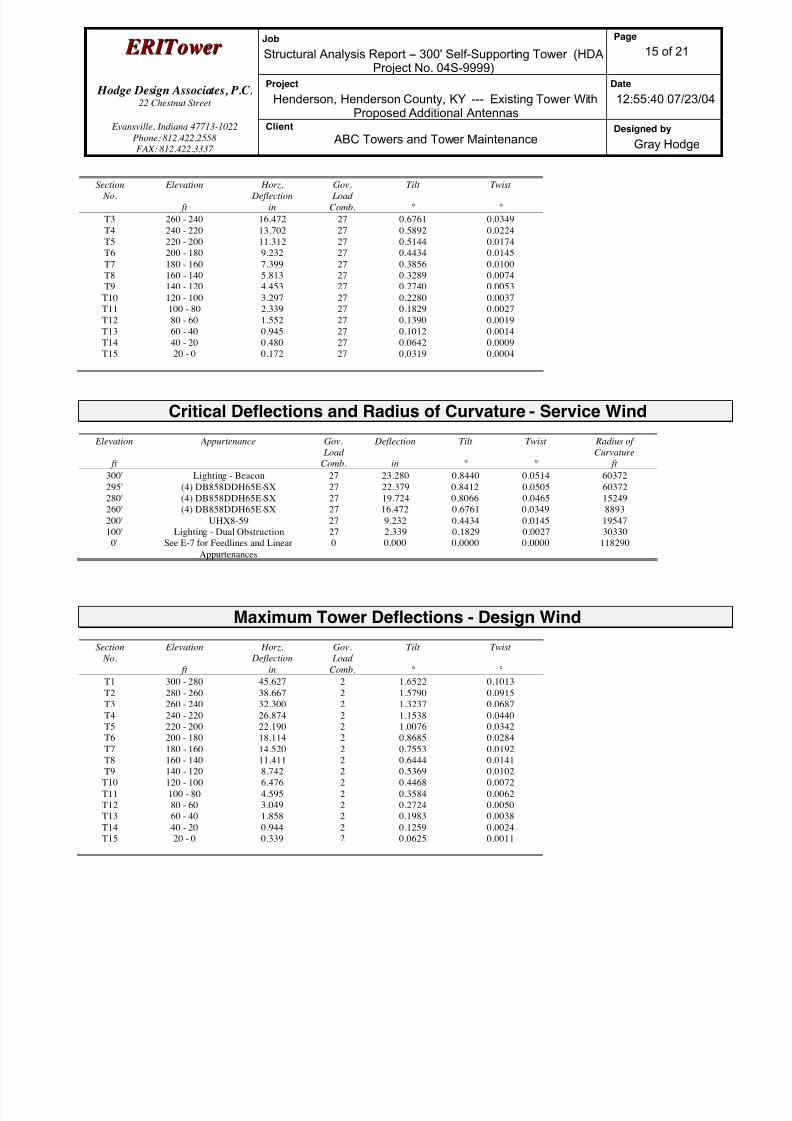
8/18/2019 Analysis Self Supporting-1
http://slidepdf.com/reader/full/analysis-self-supporting-1 59/98
E E R R I I T T oowweer r Job
Structural Analysis Report -- 300' Self-Supporting Tower (HDAProject No. 04S-9999)
Page
15 of 21
Hodge Design Associates, P.C. 22 Chestnut Street
Project
Henderson, Henderson County, KY --- Existing Tower WithProposed Additional Antennas
Date
12:55:40 07/23/04
Evansville, Indiana 47713-1022
Phone: 812.422.2558
FAX: 812.422.3337
Client
ABC Towers and Tower MaintenanceDesigned by
Gray Hodge
Section No.
Elevation
ft
Horz. Deflection
in
Gov. Load
Comb.
Tilt
°
Twist
°
T3 260 - 240 16.472 27 0.6761 0.0349
T4 240 - 220 13.702 27 0.5892 0.0224
T5 220 - 200 11.312 27 0.5144 0.0174
T6 200 - 180 9.232 27 0.4434 0.0145
T7 180 - 160 7.399 27 0.3856 0.0100
T8 160 - 140 5.813 27 0.3289 0.0074
T9 140 - 120 4.453 27 0.2740 0.0053
T10 120 - 100 3.297 27 0.2280 0.0037
T11 100 - 80 2.339 27 0.1829 0.0027
T12 80 - 60 1.552 27 0.1390 0.0019
T13 60 - 40 0.945 27 0.1012 0.0014
T14 40 - 20 0.480 27 0.0642 0.0009
T15 20 - 0 0.172 27 0.0319 0.0004
Critical Deflections and Radius of Curvature - Service Wind
Elevation
ft
Appurtenance Gov.
Load
Comb.
Deflection
in
Tilt
°
Twist
°
Radius of
Curvature
ft
300' Lighting - Beacon 27 23.280 0.8440 0.0514 60372
295' (4) DB858DDH65E-SX 27 22.379 0.8412 0.0505 60372
280' (4) DB858DDH65E-SX 27 19.724 0.8066 0.0465 15249
260' (4) DB858DDH65E-SX 27 16.472 0.6761 0.0349 8893
200' UHX8-59 27 9.232 0.4434 0.0145 19547
100' Lighting - Dual Obstruction 27 2.339 0.1829 0.0027 30330
0' See E-7 for Feedlines and Linear
Appurtenances
0 0.000 0.0000 0.0000 118290
Maximum Tower Deflections - Design Wind
Section
No.
Elevation
ft
Horz.
Deflection
in
Gov.
Load
Comb.
Tilt
°
Twist
°
T1 300 - 280 45.627 2 1.6522 0.1013
T2 280 - 260 38.667 2 1.5790 0.0915
T3 260 - 240 32.300 2 1.3237 0.0687
T4 240 - 220 26.874 2 1.1538 0.0440
T5 220 - 200 22.190 2 1.0076 0.0342
T6 200 - 180 18.114 2 0.8685 0.0284
T7 180 - 160 14.520 2 0.7553 0.0192
T8 160 - 140 11.411 2 0.6444 0.0141
T9 140 - 120 8.742 2 0.5369 0.0102
T10 120 - 100 6.476 2 0.4468 0.0072
T11 100 - 80 4.595 2 0.3584 0.0062
T12 80 - 60 3.049 2 0.2724 0.0050
T13 60 - 40 1.858 2 0.1983 0.0038
T14 40 - 20 0.944 2 0.1259 0.0024
T15 20 - 0 0.339 2 0.0625 0.0011
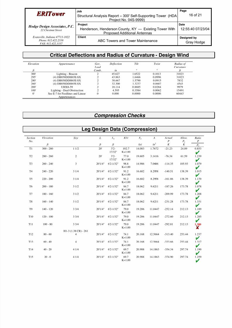
8/18/2019 Analysis Self Supporting-1
http://slidepdf.com/reader/full/analysis-self-supporting-1 60/98
E E R R I I T T oowweer r Job
Structural Analysis Report -- 300' Self-Supporting Tower (HDAProject No. 04S-9999)
Page
16 of 21
Hodge Design Associates, P.C. 22 Chestnut Street
Project
Henderson, Henderson County, KY --- Existing Tower WithProposed Additional Antennas
Date
12:55:40 07/23/04
Evansville, Indiana 47713-1022
Phone: 812.422.2558
FAX: 812.422.3337
Client
ABC Towers and Tower MaintenanceDesigned by
Gray Hodge
Critical Deflections and Radius of Curvature - Design Wind
Elevation
ft
Appurtenance Gov.
Load
Comb.
Deflection
in
Tilt
°
Twist
°
Radius of
Curvature
ft
300' Lighting - Beacon 2 45.627 1.6522 0.1013 31023
295' (4) DB858DDH65E-SX 2 43.863 1.6466 0.0996 31023
280' (4) DB858DDH65E-SX 2 38.667 1.5790 0.0915 7832
260' (4) DB858DDH65E-SX 2 32.300 1.3237 0.0687 4543
200' UHX8-59 2 18.114 0.8685 0.0284 9979
100' Lighting - Dual Obstruction 2 4.595 0.3584 0.0062 15491
0' See E-7 for Feedlines and Linear
Appurtenances
0 0.000 0.0000 0.0000 60443
Compression Checks
Leg Design Data (Compression)
Section
No.
Elevation
ft
Size L
ft
Lu
ft
Kl/r F a
ksi
A
in2
Actual
P
K
Allow.
Pa
K
Ratio
P
Pa
T1 300 - 280 1 1/2 20' 3'2-
17/32''
102.7
K=1.00
14.083 1.7672 -21.23 24.89 0.853
T2 280 - 260 2 20' 3'2-
17/32''
77.0
K=1.00
19.605 3.1416 -76.34 61.59 1.239
T3 260 - 240 3 20'1/4'' 6'2-1/32'' 98.8K=1.00
14.986 7.0686 -114.35 105.93 1.079
T4 240 - 220 3 1/4 20'1/4'' 6'2-1/32'' 91.2
K=1.00
16.682 8.2958 -140.51 138.39 1.015
T5 220 - 200 3 1/4 20'1/4'' 6'2-1/32'' 91.2
K=1.00
16.682 8.2958 -161.86 138.39 1.170
T6 200 - 180 3 1/2 20'1/4'' 6'2-1/32'' 84.7
K=1.00
18.062 9.6211 -187.26 173.78 1.078
T7 180 - 160 3 1/2 20'1/4'' 6'2-1/32'' 84.7
K=1.00
18.062 9.6211 -209.99 173.78 1.208
T8 160 - 140 3 1/2 20'1/4'' 6'2-1/32'' 84.7
K=1.00
18.062 9.6211 -231.28 173.78 1.331
T9 140 - 120 3 3/4 20'1/4'' 6'2-1/32'' 79.0
K=1.00
19.206 11.0447 -252.14 212.13 1.189
T10 120 - 100 3 3/4 20'1/4'' 6'2-1/32'' 79.0K=1.00 19.206 11.0447 -272.60 212.13 1.285
T11 100 - 80 3 3/4 20'1/4'' 6'2-1/32'' 79.0
K=1.00
19.206 11.0447 -292.81 212.13 1.380
H1-3 (1.38 CR) - 261
T12 80 - 60 4 20'1/4'' 6'2-1/32'' 74.1
K=1.00
20.168 12.5664 -313.40 253.44 1.237
T13 60 - 40 4 20'1/4'' 6'2-1/32'' 74.1
K=1.00
20.168 12.5664 -333.66 253.44 1.317
T14 40 - 20 4 1/4 20'1/4'' 6'2-1/32'' 69.7
K=1.00
20.988 14.1863 -354.34 297.74 1.190
T15 20 - 0 4 1/4 20'1/4'' 6'2-1/32'' 69.7
K=1.00
20.988 14.1863 -374.90 297.74 1.259

8/18/2019 Analysis Self Supporting-1
http://slidepdf.com/reader/full/analysis-self-supporting-1 61/98
E E R R I I T T oowweer r Job
Structural Analysis Report -- 300' Self-Supporting Tower (HDAProject No. 04S-9999)
Page
17 of 21
Hodge Design Associates, P.C. 22 Chestnut Street
Project
Henderson, Henderson County, KY --- Existing Tower WithProposed Additional Antennas
Date
12:55:40 07/23/04
Evansville, Indiana 47713-1022
Phone: 812.422.2558
FAX: 812.422.3337
Client
ABC Towers and Tower MaintenanceDesigned by
Gray Hodge
Section No.
Elevation
ft
Size L
ft
Lu
ft
Kl/r F a
ksi
A
in2
ActualP
K
Allow.Pa
K
RatioP
Pa
Diagonal Design Data (Compression)
Section
No.
Elevation
ft
Size L
ft
Lu
ft
Kl/r F a
ksi
A
in2
Actual
P
K
Allow.
Pa
K
Ratio
P
Pa
T1 300 - 280 3/4 5'1-9/16'' 2'5-3/4'' 159.0
K=1.00
5.910 0.4418 -2.46 2.61 0.943
T2 280 - 260 7/8 5'1-9/16'' 2'5-
17/32''
134.8
K=1.00
8.220 0.6013 -4.85 4.94 0.981
T3 260 - 240 L2x2x3/16 7'6-3/8'' 3'9-
19/32''
115.8
K=1.00
10.870 0.7150 -5.86 7.77 0.754
T4 240 - 220 L2x2x3/16 8'7-7/16'' 4'3-
27/32''
131.4
K=1.00
8.643 0.7150 -4.25 6.18 0.688
T5 220 - 200 L2x2x3/16 10'8-
17/32''
5'4-3/16'' 162.9
K=1.00
5.628 0.7150 -3.43 4.02 0.853
T6 200 - 180 L2x2x3/16 12'1-
9/16''
6'19/32'' 184.2
K=1.00
4.403 0.7150 -4.43 3.15 1.409
H1-3 (1.41 CR) - 159
T7 180 - 160 L2x2x1/4 13'7-
5/16''
6'9-
15/32''
208.4
K=1.00
3.439 0.9380 -4.52 3.23 1.400
KL/R > 200 (C) - 183
T8 160 - 140 L2 1/2x2 1/2x3/16 15'1-
11/16''
7'6-
19/32''
183.1
K=1.00
4.452 0.9020 -4.64 4.02 1.155
T9 140 - 120 L2 1/2x2 1/2x3/16 16'8-13/32''
8'3-27/32''
201.8K=1.00
3.668 0.9020 -5.02 3.31 1.517
KL/R > 200 (C) - 225
T10 120 - 100 L2 1/2x2 1/2x1/4 18'3-
15/32''
9'1-7/16'' 222.8
K=1.00
3.009 1.1900 -5.33 3.58 1.489
KL/R > 200 (C) - 246
T11 100 - 80 L3x3x3/16 19'10-
11/16''
9'11-
1/32''
199.7
K=1.00
3.746 1.0900 -5.66 4.08 1.387
H1-3 (1.39 CR) - 267
T12 80 - 60 L3x3x1/4 21'6'' 10'8-
17/32''
217.2
K=1.00
3.167 1.4400 -6.18 4.56 1.356
KL/R > 200 (C) - 288
T13 60 - 40 L3 1/2x3 1/2x3/16 23'1-
9/16''
11'6-3/8'' 198.2
K=1.00
3.802 1.2773 -6.50 4.86 1.338
H1-3 (1.34 CR) - 309
T14 40 - 20 L3 1/2x3 1/2x1/4 24'9-1/8'' 12'3-
31/32''
213.3
K=1.00
3.283 1.6900 -7.27 5.55 1.309
KL/R > 200 (C) - 330
T15 20 - 0 L4x4x1/4 25'10-
13/16''
12'10-
13/16''
194.7
K=1.00
3.938 1.9400 -7.78 7.64 1.018
Top Girt Design Data (Compression)

8/18/2019 Analysis Self Supporting-1
http://slidepdf.com/reader/full/analysis-self-supporting-1 62/98
E E R R I I T T oowweer r Job
Structural Analysis Report -- 300' Self-Supporting Tower (HDAProject No. 04S-9999)
Page
18 of 21
Hodge Design Associates, P.C. 22 Chestnut Street
Project
Henderson, Henderson County, KY --- Existing Tower WithProposed Additional Antennas
Date
12:55:40 07/23/04
Evansville, Indiana 47713-1022
Phone: 812.422.2558
FAX: 812.422.3337
Client
ABC Towers and Tower MaintenanceDesigned by
Gray Hodge
Section No.
Elevation
ft
Size L
ft
Lu
ft
Kl/r F a
ksi
A
in2
ActualP
K
Allow.Pa
K
RatioP
Pa
T1 300 - 280 3/4 4' 3'10-
9/16''
248.0
K=1.00
2.428 0.4418 -0.13 1.07 0.124
KL/R > 200 (C) - 5
T2 280 - 260 7/8 4' 3'9-
31/32''
210.3
K=1.00
3.377 0.6013 -1.74 2.03 0.856
KL/R > 200 (C) - 49
Bottom Girt Design Data (Compression)
Section No.
Elevation
ft
Size L
ft
Lu
ft
Kl/r F a
ksi
A
in2
ActualP
K
Allow.Pa
K
RatioP
Pa
T1 300 - 280 3/4 4' 3'10-
9/16''
248.0
K=1.00
2.428 0.4418 -0.91 1.07 0.845
KL/R > 200 (C) - 7
T2 280 - 260 7/8 4' 3'9-
31/32''
210.3
K=1.00
3.377 0.6013 -0.49 2.03 0.244
KL/R > 200 (C) - 54
Tension Checks
Leg Design Data (Tension)
Section
No.
Elevation
ft
Size L
ft
Lu
ft
Kl/r F a
ksi
A
in2
Actual
P
K
Allow.
Pa
K
Ratio
P
Pa
T1 300 - 280 1 1/2 20' 3'2-
17/32''
102.7 30.000 1.7672 19.40 53.01 0.366
T2 280 - 260 2 20' 3'2-
17/32''
77.0 30.000 3.1416 72.14 94.25 0.765
T3 260 - 240 3 20'1/4'' 6'2-1/32'' 98.8 30.000 7.0686 107.03 212.06 0.505
T4 240 - 220 3 1/4 20'1/4'' 6'2-1/32'' 91.2 30.000 8.2958 130.68 248.87 0.525
T5 220 - 200 3 1/4 20'1/4'' 6'2-1/32'' 91.2 30.000 8.2958 149.33 248.87 0.600
T6 200 - 180 3 1/2 20'1/4'' 6'2-1/32'' 84.7 30.000 9.6211 171.24 288.63 0.593
T7 180 - 160 3 1/2 20'1/4'' 6'2-1/32'' 84.7 30.000 9.6211 190.59 288.63 0.660
T8 160 - 140 3 1/2 20'1/4'' 6'2-1/32'' 84.7 30.000 9.6211 208.29 288.63 0.722
T9 140 - 120 3 3/4 20'1/4'' 6'2-1/32'' 79.0 30.000 11.0447 225.11 331.34 0.679
T10 120 - 100 3 3/4 20'1/4'' 6'2-1/32'' 79.0 30.000 11.0447 241.14 331.34 0.728
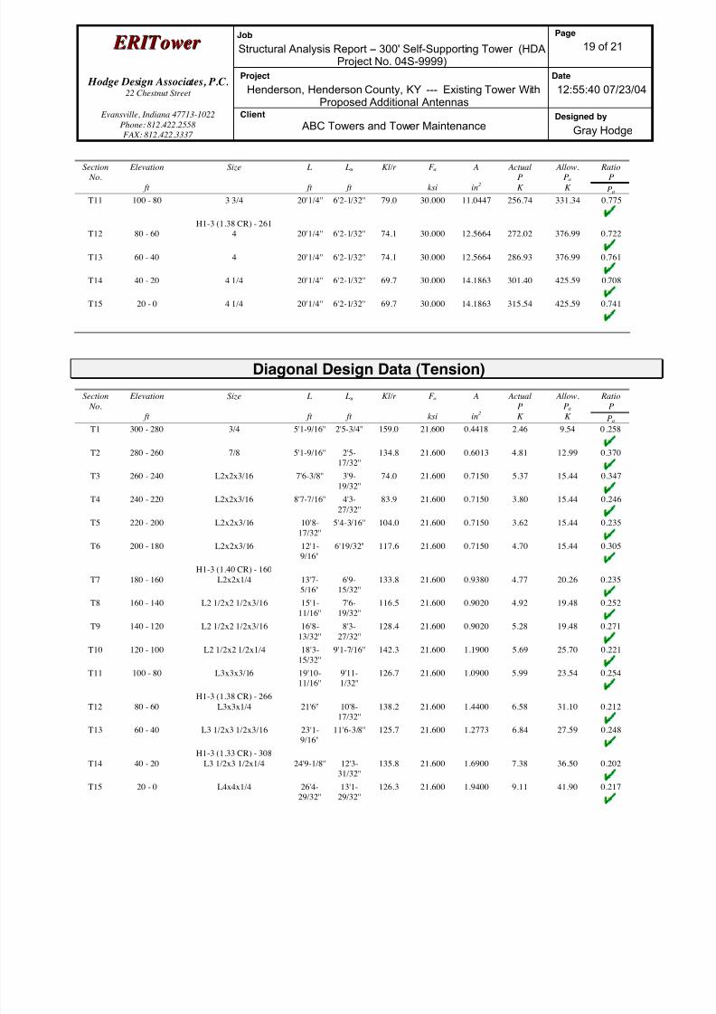
8/18/2019 Analysis Self Supporting-1
http://slidepdf.com/reader/full/analysis-self-supporting-1 63/98
E E R R I I T T oowweer r Job
Structural Analysis Report -- 300' Self-Supporting Tower (HDAProject No. 04S-9999)
Page
19 of 21
Hodge Design Associates, P.C. 22 Chestnut Street
Project
Henderson, Henderson County, KY --- Existing Tower WithProposed Additional Antennas
Date
12:55:40 07/23/04
Evansville, Indiana 47713-1022
Phone: 812.422.2558
FAX: 812.422.3337
Client
ABC Towers and Tower MaintenanceDesigned by
Gray Hodge
Section No.
Elevation
ft
Size L
ft
Lu
ft
Kl/r F a
ksi
A
in2
ActualP
K
Allow.Pa
K
RatioP
Pa
T11 100 - 80 3 3/4 20'1/4'' 6'2-1/32'' 79.0 30.000 11.0447 256.74 331.34 0.775
H1-3 (1.38 CR) - 261
T12 80 - 60 4 20'1/4'' 6'2-1/32'' 74.1 30.000 12.5664 272.02 376.99 0.722
T13 60 - 40 4 20'1/4'' 6'2-1/32'' 74.1 30.000 12.5664 286.93 376.99 0.761
T14 40 - 20 4 1/4 20'1/4'' 6'2-1/32'' 69.7 30.000 14.1863 301.40 425.59 0.708
T15 20 - 0 4 1/4 20'1/4'' 6'2-1/32'' 69.7 30.000 14.1863 315.54 425.59 0.741
Diagonal Design Data (Tension)
Section
No.
Elevation
ft
Size L
ft
Lu
ft
Kl/r F a
ksi
A
in2
Actual
P
K
Allow.
Pa
K
Ratio
P
Pa
T1 300 - 280 3/4 5'1-9/16'' 2'5-3/4'' 159.0 21.600 0.4418 2.46 9.54 0.258
T2 280 - 260 7/8 5'1-9/16'' 2'5-
17/32''
134.8 21.600 0.6013 4.81 12.99 0.370
T3 260 - 240 L2x2x3/16 7'6-3/8'' 3'9-
19/32''
74.0 21.600 0.7150 5.37 15.44 0.347
T4 240 - 220 L2x2x3/16 8'7-7/16'' 4'3-
27/32''
83.9 21.600 0.7150 3.80 15.44 0.246
T5 220 - 200 L2x2x3/16 10'8-
17/32''
5'4-3/16'' 104.0 21.600 0.7150 3.62 15.44 0.235
T6 200 - 180 L2x2x3/16 12'1-
9/16''
6'19/32'' 117.6 21.600 0.7150 4.70 15.44 0.305
H1-3 (1.40 CR) - 160
T7 180 - 160 L2x2x1/4 13'7-
5/16''
6'9-
15/32''
133.8 21.600 0.9380 4.77 20.26 0.235
T8 160 - 140 L2 1/2x2 1/2x3/16 15'1-
11/16''
7'6-
19/32''
116.5 21.600 0.9020 4.92 19.48 0.252
T9 140 - 120 L2 1/2x2 1/2x3/16 16'8-
13/32''
8'3-
27/32''
128.4 21.600 0.9020 5.28 19.48 0.271
T10 120 - 100 L2 1/2x2 1/2x1/4 18'3-
15/32''
9'1-7/16'' 142.3 21.600 1.1900 5.69 25.70 0.221
T11 100 - 80 L3x3x3/16 19'10-11/16''
9'11-1/32''
126.7 21.600 1.0900 5.99 23.54 0.254
H1-3 (1.38 CR) - 266
T12 80 - 60 L3x3x1/4 21'6'' 10'8-
17/32''
138.2 21.600 1.4400 6.58 31.10 0.212
T13 60 - 40 L3 1/2x3 1/2x3/16 23'1-
9/16''
11'6-3/8'' 125.7 21.600 1.2773 6.84 27.59 0.248
H1-3 (1.33 CR) - 308
T14 40 - 20 L3 1/2x3 1/2x1/4 24'9-1/8'' 12'3-
31/32''
135.8 21.600 1.6900 7.38 36.50 0.202
T15 20 - 0 L4x4x1/4 26'4-
29/32''
13'1-
29/32''
126.3 21.600 1.9400 9.11 41.90 0.217

8/18/2019 Analysis Self Supporting-1
http://slidepdf.com/reader/full/analysis-self-supporting-1 64/98
E E R R I I T T oowweer r Job
Structural Analysis Report -- 300' Self-Supporting Tower (HDAProject No. 04S-9999)
Page
20 of 21
Hodge Design Associates, P.C. 22 Chestnut Street
Project
Henderson, Henderson County, KY --- Existing Tower WithProposed Additional Antennas
Date
12:55:40 07/23/04
Evansville, Indiana 47713-1022
Phone: 812.422.2558
FAX: 812.422.3337
Client
ABC Towers and Tower MaintenanceDesigned by
Gray Hodge
Section No.
Elevation
ft
Size L
ft
Lu
ft
Kl/r F a
ksi
A
in2
ActualP
K
Allow.Pa
K
RatioP
Pa
Top Girt Design Data (Tension)
Section
No.
Elevation
ft
Size L
ft
Lu
ft
Kl/r F a
ksi
A
in2
Actual
P
K
Allow.
Pa
K
Ratio
P
Pa
T1 300 - 280 3/4 4' 3'10-
9/16''
248.0 21.600 0.4418 0.12 9.54 0.012
T2 280 - 260 7/8 4' 3'9-
31/32''
210.3 21.600 0.6013 1.75 12.99 0.134
Bottom Girt Design Data (Tension)
Section
No.
Elevation
ft
Size L
ft
Lu
ft
Kl/r F a
ksi
A
in2
Actual
P
K
Allow.
Pa
K
Ratio
P
Pa
T1 300 - 280 3/4 4' 3'10-
9/16''
248.0 21.600 0.4418 0.85 9.54 0.089
T2 280 - 260 7/8 4' 3'9-
31/32''
210.3 21.600 0.6013 0.23 12.99 0.017
Section Capacity Table
Section
No.
Elevation
ft
Component
Type
Size Critical
Element
P
K
SF*Pallow
K
%
Capacity
Pass
Fail
T1 300 - 280 Leg 1 1/2 3 -21.23 33.17 64.0 Pass
T2 280 - 260 Leg 2 48 -76.34 82.10 93.0 Pass
T3 260 - 240 Leg 3 93 -114.35 141.21 81.0 Pass
T4 240 - 220 Leg 3 1/4 114 -140.51 184.47 76.2 Pass
T5 220 - 200 Leg 3 1/4 135 -161.86 184.47 87.7 Pass
T6 200 - 180 Leg 3 1/2 156 -187.26 231.65 80.8 Pass
T7 180 - 160 Leg 3 1/2 177 -209.99 231.64 90.7 Pass
T8 160 - 140 Leg 3 1/2 198 -231.28 231.64 99.8 Pass
T9 140 - 120 Leg 3 3/4 219 -252.14 282.76 89.2 PassT10 120 - 100 Leg 3 3/4 240 -272.60 282.76 96.4 Pass
T11 100 - 80 Leg 3 3/4 261 -292.81 282.76 103.6 Fail
T12 80 - 60 Leg 4 282 -313.40 337.84 92.8 Pass
T13 60 - 40 Leg 4 303 -333.66 337.84 98.8 Pass
T14 40 - 20 Leg 4 1/4 324 -354.34 396.88 89.3 Pass
T15 20 - 0 Leg 4 1/4 345 -374.90 396.88 94.5 Pass
T1 300 - 280 Diagonal 3/4 15 -2.46 3.48 70.7 Pass
T2 280 - 260 Diagonal 7/8 60 -4.85 6.59 73.6 Pass
T3 260 - 240 Diagonal L2x2x3/16 111 -5.86 10.36 56.5 Pass
T4 240 - 220 Diagonal L2x2x3/16 129 -4.25 8.24 51.6 Pass
T5 220 - 200 Diagonal L2x2x3/16 139 -3.43 5.36 64.0 Pass
T6 200 - 180 Diagonal L2x2x3/16 159 -4.43 4.20 105.7 Fail
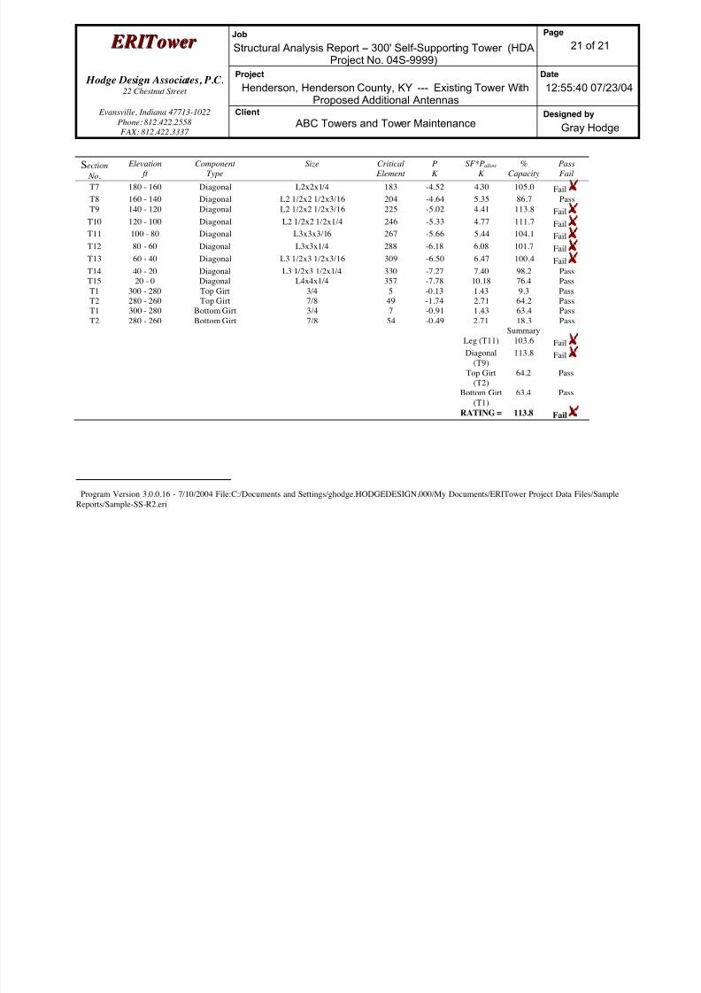
8/18/2019 Analysis Self Supporting-1
http://slidepdf.com/reader/full/analysis-self-supporting-1 65/98
E E R R I I T T oowweer r Job
Structural Analysis Report -- 300' Self-Supporting Tower (HDAProject No. 04S-9999)
Page
21 of 21
Hodge Design Associates, P.C. 22 Chestnut Street
Project
Henderson, Henderson County, KY --- Existing Tower WithProposed Additional Antennas
Date
12:55:40 07/23/04
Evansville, Indiana 47713-1022
Phone: 812.422.2558
FAX: 812.422.3337
Client
ABC Towers and Tower MaintenanceDesigned by
Gray Hodge
Section No.
Elevation ft
ComponentType
Size Critical Element
PK
SF*Pallow
K%
CapacityPassFail
T7 180 - 160 Diagonal L2x2x1/4 183 -4.52 4.30 105.0 Fail
T8 160 - 140 Diagonal L2 1/2x2 1/2x3/16 204 -4.64 5.35 86.7 Pass
T9 140 - 120 Diagonal L2 1/2x2 1/2x3/16 225 -5.02 4.41 113.8 Fail
T10 120 - 100 Diagonal L2 1/2x2 1/2x1/4 246 -5.33 4.77 111.7 Fail
T11 100 - 80 Diagonal L3x3x3/16 267 -5.66 5.44 104.1 Fail
T12 80 - 60 Diagonal L3x3x1/4 288 -6.18 6.08 101.7 Fail
T13 60 - 40 Diagonal L3 1/2x3 1/2x3/16 309 -6.50 6.47 100.4 Fail
T14 40 - 20 Diagonal L3 1/2x3 1/2x1/4 330 -7.27 7.40 98.2 Pass
T15 20 - 0 Diagonal L4x4x1/4 357 -7.78 10.18 76.4 Pass
T1 300 - 280 Top Girt 3/4 5 -0.13 1.43 9.3 Pass
T2 280 - 260 Top Girt 7/8 49 -1.74 2.71 64.2 Pass
T1 300 - 280 Bottom Girt 3/4 7 -0.91 1.43 63.4 Pass
T2 280 - 260 Bottom Girt 7/8 54 -0.49 2.71 18.3 Pass
SummaryLeg (T11) 103.6 Fail
Diagonal
(T9)
113.8 Fail
Top Girt
(T2)
64.2 Pass
Bottom Girt
(T1)
63.4 Pass
RATING = 113.8 Fail
Program Version 3.0.0.16 - 7/10/2004 File:C:/Documents and Settings/ghodge.HODGEDESIGN.000/My Documents/ERITower Project Data Files/SampleReports/Sample-SS-R2.eri

8/18/2019 Analysis Self Supporting-1
http://slidepdf.com/reader/full/analysis-self-supporting-1 66/98
APPENDIX D
An t e n n a To w e r Wi t h P r o p o s e d Ad d i t io n a l An t e n n a s a n d M o d if i c a t i o n s
G r a p h i c a l Co m p u t e r O u t p u t
S t r u c t u r a l An a l y s i s R e p o r t a n d C a l c u l a t i o n s

8/18/2019 Analysis Self Supporting-1
http://slidepdf.com/reader/full/analysis-self-supporting-1 67/98
www.hodgedesign.com
Hodge Design Associates, P.C.22 Chestnut Street
Evansville, Indiana 47713-1022Phone: 812.422.2558
FAX: 812.422.3337
Job:Structural Analysis Report -- 300' Self-Supporting Tower (HDA Project No. 04S-9
Project: Henderson, Henderson County, KY --- Existing Tower With Proposed Modifications Client: ABC Towers and Tower Maintenance Drawn by: Gray Hodge App'd:
Code: TIA/EIA-222-F Date: 07/23/04 Scale: NTSPath:
C:\DocumentsandSettings\ghodge.HODGEDESIGN.000\MyDocuments\ERITowerProjectData Files\SampleReports\Sample-SS-R3.eri
Dwg No. E-1
300.0 ft
280.0 ft
260.0 ft
240.0 ft
220.0 ft
200.0 ft
180.0 ft
160.0 ft
140.0 ft
120.0 ft
100.0 ft
80.0 ft
60.0 ft
40.0 ft
20.0 ft
0.0 ft
REACTIONS - 70 mph WIND TORQUE 2 kip-ft
47 K SHEAR
8007 kip-ft MOMENT
82 K AXIAL
61 mph WIND - 0.5000 in ICE TORQUE 3 kip-ft
44 K SHEAR
7519 kip-ft MOMENT
119 K AXIAL
SHEAR: 29 K UPLIFT: -313 K DOWN: 383 K
MAX PIER FORCES:
T 1
T 2
T 3
T 4
T 5
T 6
T 7
T 8
T 9
T 1 0
T 1 1
T 1 2
T 1 3
T 1 4
T 1 5
S R 1 1 / 2
S R 2
S R 3
S R 3 1 / 4
S R 3 1 / 2
S R 3 3 / 4
S R 4
S
R 4 1 / 4
A 5 7 2 - 5 0
S R 3 / 4
S R 7 / 8
L 2 x 2 x 3 / 1 6
2 L 2 x 2 x 3 / 1 6 x 3 / 4
2 L 2 x 2 x 1 / 4 x 3 / 4
A
B
C
2 L 3 x 3 x 3 / 1
6 x 3 / 4
2 L 3 x 3 x 1 / 4 x 3 / 8
2 L 3 1 / 2 x 3 1 / 2 x 1 / 4 x 3 / 4
L 4 x 4 x 1 / 4
A 3 6
S R 3 / 4
S R 7 / 8
N . A .
S R 3 / 4
S R 7 / 8
N . A .
N . A .
2 L 2 x 2 x 3 / 1 6 x 3 / 4
N . A .
2 L 2 x 2 x 3 / 1
6 x 3 / 4
N . A .
2 L 2 x 2 x 3 / 1 6 x 3 / 4
N . A .
0 . 7
1 . 1
2 . 0
2 . 3
2 . 4
3 . 2
3 . 7
3 . 6
4 . 3
5 . 1
5 . 9
6 . 6
8 . 5
8 . 2
6 . 3
4
5 . 6 9 2 7 1
7 . 3 8 5 4 2
9 . 0 7 8 1 3
1 0 . 7 6 8 2
1 2 . 4 6 0 9
1 4 . 1 5 3 6
1 5 . 8 4 6 4
1 7 . 5 3 9 1
1 9 . 2 3 1 8
2 0 . 9 2 1 9
2 2 . 6 1 4 6
2 4 . 3 0 7 3
1 2 @ 3 . 2 0 8 3 3
3 9 @ 6 . 1 6 6 6 7
S e c t i o n
L e g s
L e g G r a d e
D i a g o n a l s
D i a g o n a l G r a d e
T o p G i r t s
B o t t o m G i r t s
S e c . H o r i z o n t a l s
F a c e W i d t h ( f t )
2 6
# P a n e l s @ (
f t )
W e i g h t ( K )
6 4 . 1
Lighting - Beacon 300Lightning Rod 6' 300(4) DB858DDH65E-SX 29512' T-Frame Sector Mount 295(4) DB858DDH65E-SX 29512' T-Frame Sector Mount 295(4) DB858DDH65E-SX 29512' T-Frame Sector Mount 295(4) DB858DDH65E-SX 28012' T-Frame Sector Mount 280(4) DB858DDH65E-SX 28012' T-Frame Sector Mount 280(4) DB858DDH65E-SX 28012' T-Frame Sector Mount 280(4) DB858DDH65E-SX 26012' T-Frame Sector Mount 260(4) DB858DDH65E-SX 26012' T-Frame Sector Mount 260(4) DB858DDH65E-SX 26012' T-Frame Sector Mount 260Lighting - Dual Obstruction 200UHX8-59 (Proposed) 200UHX8-59 (Proposed) 200Lighting - Dual Obstruction 100See E-7 for Feedlines and Linear Appurtenances
0 APPURTENANCES
TYPE TYPEELEVATION ELEVATIONLighting - Beacon 300
Lightning Rod 6' 300
(4) DB858DDH65E-SX 295
12' T-Frame Sector Mount 295
(4) DB858DDH65E-SX 295
12' T-Frame Sector Mount 295
(4) DB858DDH65E-SX 295
12' T-Frame Sector Mount 295
(4) DB858DDH65E-SX 280
12' T-Frame Sector Mount 280
(4) DB858DDH65E-SX 280
12' T-Frame Sector Mount 280
(4) DB858DDH65E-SX 280
12' T-Frame Sector Mount 280
(4) DB858DDH65E-SX 260
12' T-Frame Sector Mount 260
(4) DB858DDH65E-SX 260
12' T-Frame Sector Mount 260
(4) DB858DDH65E-SX 260
12' T-Frame Sector Mount 260
Lighting - Dual Obstruction 200
UHX8-59 (Proposed) 200
UHX8-59 (Proposed) 200
Lighting - Dual Obstruction 100
See E-7 for Feedlines and Linear Appurtenances
0
SYMBOL LISTMARK MARKSIZE SIZE
A L2 1/2x2 1/2x3/16
B 2L2 1/2x2 1/2x3/16x3/4
C 2L2 1/2x2 1/2x1/4x3/4
MATERIAL STRENGTHGRADE GRADEFy FyFu Fu
A572-50 50 ksi 65 ksi A36 36 ksi 58 ksi
TOWER DESIGN NOTES1. Tower is located in Henderson County, Kentucky.2. Tower designed for a 70 mph basic wind in accordance with the TIA/EIA-222-F Standa3. Tower is also designed for a 61 mph basic wind with 0.50 in ice.
4. Deflections are based upon a 50 mph wind.5. EXISTING TOWER WITH PROPOSED MODIFICATIONS6. It is assumed that the tower has been properly maintained and is in good condition.7. It is assumed that there have been no structural modifications to the tower unless
specifically noted otherwise.8. There are no known structural defects and that there is no structural deterioration.9. All welds and bolted connections are assumed capable of developing the member
strength, unless noted otherwise.10. Material strengths are as noted elsewhere in this report.11. This structural analysis is based on information provided by others and assumed to be
reliable and correct.12. See Sheet E-7 for Feedlines and Linear Appurtenances.13. See Sheet E-8 for Code Check/Stress Distribution.14. TOWER RATING: 97.2%
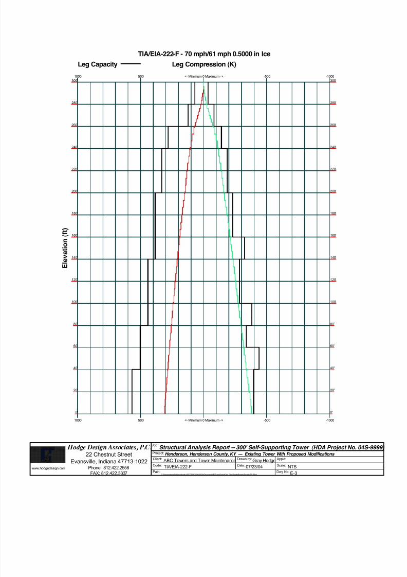
8/18/2019 Analysis Self Supporting-1
http://slidepdf.com/reader/full/analysis-self-supporting-1 68/98
www.hodgedesign.com
Hodge Design Associates, P.C.22 Chestnut Street
Evansville, Indiana 47713-1022Phone: 812.422.2558
FAX: 812.422.3337
Job:Structural Analysis Report -- 300' Self-Supporting Tower (HDA Project No. 04S-9
Project: Henderson, Henderson County, KY --- Existing Tower With Proposed Modifications Client: ABC Towers and Tower Maintenance Drawn by: Gray Hodge App'd:
Code: TIA/EIA-222-F Date: 07/23/04 Scale: NTSPath:
C:\DocumentsandSettings\ghodge.HODGEDESIGN.000\MyDocuments\ERITowerProjectData Files\SampleReports\Sample-SS-R3.eri
Dwg No. E-3
<- Minimum 0 Maximum ->
<- Minimum 0 Maximum ->
-500
-500
-1000
-1000
500
500
1000
1000
TIA/EIA-222-F - 70 mph/61 mph 0.5000 in Ice
Leg Capacity Leg Compression (K)
300' 300'
280' 280'
260' 260'
240' 240'
220' 220'
200' 200'
180' 180'
160' 160'
140' 140'
120' 120'
100' 100'
80' 80'
60' 60'
40' 40'
20' 20'
0' 0'
E l e v a t i o n
( f t )

8/18/2019 Analysis Self Supporting-1
http://slidepdf.com/reader/full/analysis-self-supporting-1 69/98
www.hodgedesign.com
Hodge Design Associates, P.C.22 Chestnut Street
Evansville, Indiana 47713-1022Phone: 812.422.2558
FAX: 812.422.3337
Job:Structural Analysis Report -- 300' Self-Supporting Tower (HDA Project No. 04S-9
Project: Henderson, Henderson County, KY --- Existing Tower With Proposed Modifications Client: ABC Towers and Tower Maintenance Drawn by: Gray Hodge App'd:
Code: TIA/EIA-222-F Date: 07/23/04 Scale: NTSPath:
C:\DocumentsandSettings\ghodge.HODGEDESIGN.000\MyDocuments\ERITowerProjectData Files\SampleReports\Sample-SS-R3.eri
Dwg No. E-4
0
0
50
50
Global Mast Shear (K)
300'
280'
260'
240'
220'
200'
180'
160'
140'
120'
100'
80'
60'
40'
20'
0'
E l e v a t i o n
( f t )
0
0
5000
5000
10000
10000
Global Mast Moment (kip-ft)
300'
280'
260'
240'
220'
200'
180'
160'
140'
120'
100'
80'
60'
40'
20'
0'
TIA/EIA-222-F - 70 mph/61 mph 0.5000 in Ice Maximum Values
Vx Vz Mx Mz
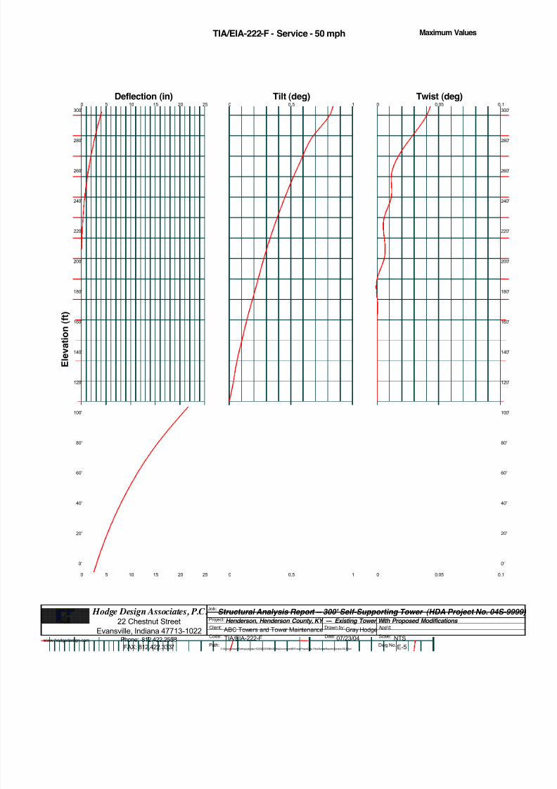
8/18/2019 Analysis Self Supporting-1
http://slidepdf.com/reader/full/analysis-self-supporting-1 70/98
www.hodgedesign.com
Hodge Design Associates, P.C.22 Chestnut Street
Evansville, Indiana 47713-1022Phone: 812.422.2558
FAX: 812.422.3337
Job:Structural Analysis Report -- 300' Self-Supporting Tower (HDA Project No. 04S-9
Project: Henderson, Henderson County, KY --- Existing Tower With Proposed Modifications Client: ABC Towers and Tower Maintenance Drawn by: Gray Hodge App'd:
Code: TIA/EIA-222-F Date: 07/23/04 Scale: NTSPath:
C:\DocumentsandSettings\ghodge.HODGEDESIGN.000\MyDocuments\ERITowerProjectData Files\SampleReports\Sample-SS-R3.eri
Dwg No. E-5
TIA/EIA-222-F - Service - 50 mph Maximum Values
0
0
5
5
10
10
15
15
20
20
25
25
Deflection (in)
300'
280'
260'
240'
220'
200'
180'
160'
140'
120'
100'
80'
60'
40'
20'
0'
E l e v a t i o n
( f t )
0
0
0.5
0.5
1
1
Tilt (deg)0
0
0.05
0.05
0.1
0.1
Twist (deg)
300
280
260
240
220
200
180
160
140
120
100
80'
60'
40'
20'
0'
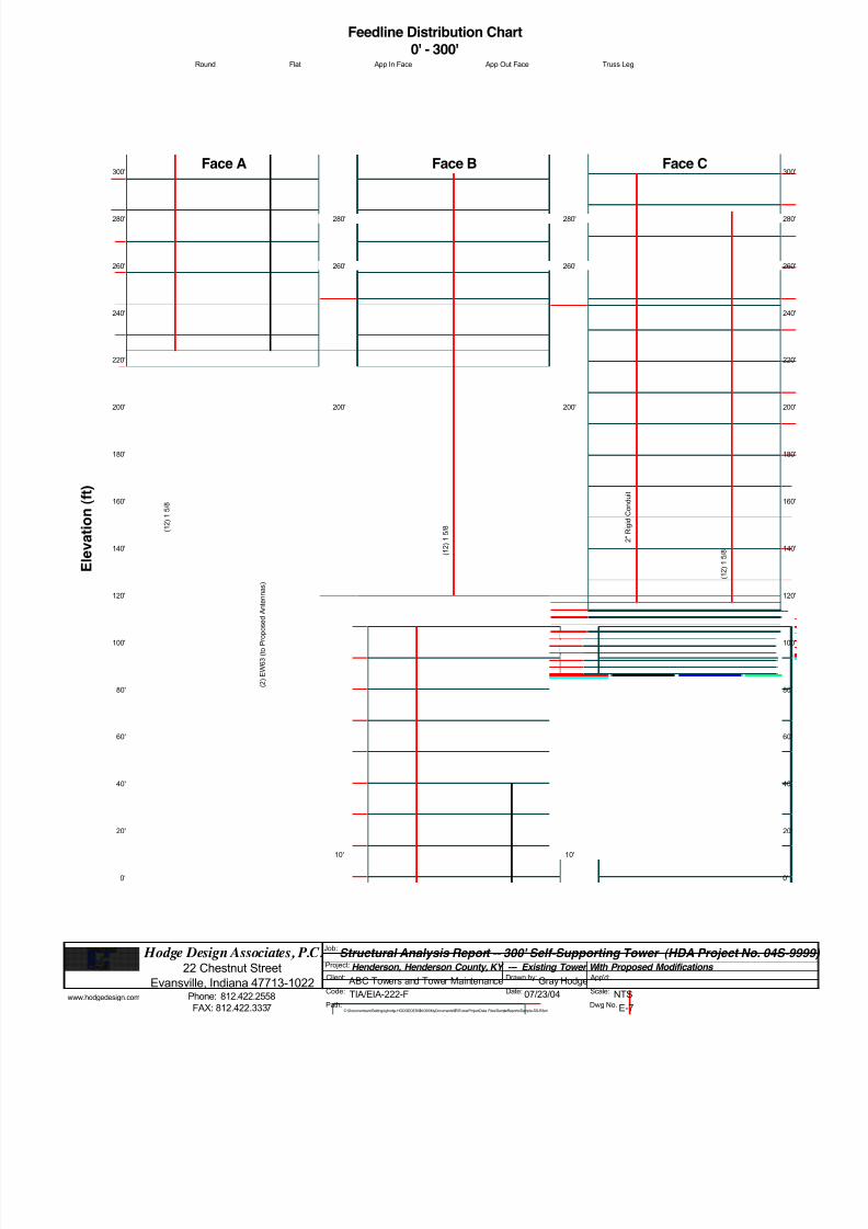
8/18/2019 Analysis Self Supporting-1
http://slidepdf.com/reader/full/analysis-self-supporting-1 71/98
www.hodgedesign.com
Hodge Design Associates, P.C.22 Chestnut Street
Evansville, Indiana 47713-1022Phone: 812.422.2558
FAX: 812.422.3337
Job:Structural Analysis Report -- 300' Self-Supporting Tower (HDA Project No. 04S-9
Project: Henderson, Henderson County, KY --- Existing Tower With Proposed Modifications Client: ABC Towers and Tower Maintenance Drawn by: Gray Hodge App'd:
Code: TIA/EIA-222-F Date: 07/23/04 Scale: NTSPath:
C:\DocumentsandSettings\ghodge.HODGEDESIGN.000\MyDocuments\ERITowerProjectData Files\SampleReports\Sample-SS-R3.eri
Dwg No. E-7
Feedline Distribution Chart
0' - 300'Round Flat App In Face App Out Face Truss Leg
Face A
280'
260'
240'
220'
200'
180'
160'
140'
120'
100'
80'
60'
40'
20'
0'
300'
E l e v a t i o n
( f t )
( 1 2 ) 1 5 / 8
( 2 ) E W 6 3 ( t o P r o p o s e d A
n t e n n a s )
Face B
10'10'10'
280'
10'
260'
10'
200'
( 1 2 ) 1 5 / 8
Face C
280
260
240
220
200
180
160
140
120
100
80'
60'
40'
20'
0'
300
10'10'10'
280'
10'
260'
10'
200'
2 " R i g i d C o n d u i t
( 1 2 ) 1 5 / 8
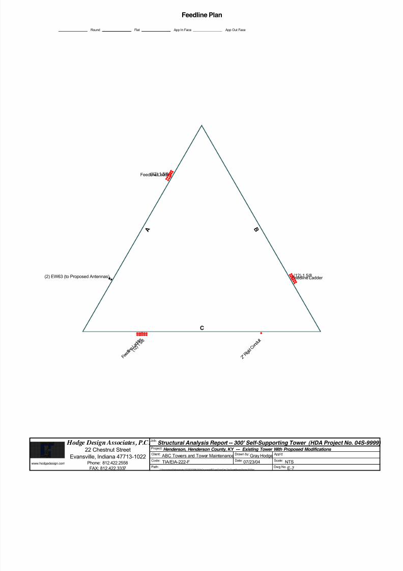
8/18/2019 Analysis Self Supporting-1
http://slidepdf.com/reader/full/analysis-self-supporting-1 72/98
www.hodgedesign.com
Hodge Design Associates, P.C.22 Chestnut Street
Evansville, Indiana 47713-1022Phone: 812.422.2558
FAX: 812.422.3337
Job:Structural Analysis Report -- 300' Self-Supporting Tower (HDA Project No. 04S-9
Project: Henderson, Henderson County, KY --- Existing Tower With Proposed Modifications Client: ABC Towers and Tower Maintenance Drawn by: Gray Hodge App'd:
Code: TIA/EIA-222-F Date: 07/23/04 Scale: NTSPath:
C:\DocumentsandSettings\ghodge.HODGEDESIGN.000\MyDocuments\ERITowerProjectData Files\SampleReports\Sample-SS-R3.eri
Dwg No. E-7
Feedline Plan
Round Flat App In Face App Out Face
A B
C
Feedline Ladder
Feedline Ladder
F e e d l i n
e L a d d e r
2 " R i g i d
C o n d u i t
(12) 1 5/8
(12) 1 5/8
( 1 2 ) 1
5 / 8
(2) EW63 (to Proposed Antennas)

8/18/2019 Analysis Self Supporting-1
http://slidepdf.com/reader/full/analysis-self-supporting-1 73/98
www.hodgedesign.com
Hodge Design Associates, P.C.22 Chestnut Street
Evansville, Indiana 47713-1022Phone: 812.422.2558
FAX: 812.422.3337
Job:Structural Analysis Report -- 300' Self-Supporting Tower (HDA Project No. 04S-9
Project: Henderson, Henderson County, KY --- Existing Tower With Proposed Modifications Client: ABC Towers and Tower Maintenance Drawn by: Gray Hodge App'd:
Code: TIA/EIA-222-F Date: 07/23/04 Scale: NTSPath:
C:\DocumentsandSettings\ghodge.HODGEDESIGN.000\MyDocuments\ERITowerProjectData Files\SampleReports\Sample-SS-R3.eri
Dwg No. E-8
Stress Distribution Chart
0' - 300'> 100% 90%-100% 75%-90% 50%-75% < 50% Overstress
Face A Face B Face C
280'
260'
240'
220'
200'
180'
160'
140'
120'
100'
80'
60'
40'
20'
0'
300'
E l e v a t i o n
( f t )
280
260
240
220
200
180
160
140
120
100
80'
60'
40'
20'
0'
300

8/18/2019 Analysis Self Supporting-1
http://slidepdf.com/reader/full/analysis-self-supporting-1 74/98
E E R R I I T T oowweer r Job
Structural Analysis Report -- 300' Self-Supporting Tower (HDAProject No. 04S-9999)
Page
1 of 22
Hodge Design Associates, P.C. 22 Chestnut Street
Project
Henderson, Henderson County, KY --- Existing Tower WithProposed Modifications
Date
13:04:30 07/23/04
Evansville, Indiana 47713-1022
Phone: 812.422.2558
FAX: 812.422.3337
Client
ABC Towers and Tower MaintenanceDesigned by
Gray Hodge
Tower Input Data
The main tower is a 3x free standing tower with an overall height of 300' above the ground line.
The base of the tower is set at an elevation of 0' above the ground line.The face width of the tower is 4' at the top and 26' at the base.
This tower is designed using the TIA/EIA-222-F standard.
The following design criteria apply:
Tower is located in Henderson County, Kentucky.
Basic wind speed of 70 mph.
Nominal ice thickness of 0.5000 in.
Ice density of 56 pcf.A wind speed of 61 mph is used in combination with ice.
Temperature drop of 75 °F.
Deflections calculated using a wind speed of 50 mph.
EXISTING TOWER WITH PROPOSED MODIFICATIONS.
It is assumed that the tower has been properly maintained and is in good condition..It is assumed that there have been no structural modifications to the tower unless specifically noted otherwise..
There are no known structural defects and that there is no structural deterioration..
All welds and bolted connections are assumed capable of developing the member strength, unless noted otherwise..
Material strengths are as noted elsewhere in this report..
This structural analysis is based on information provided by others and assumed to be reliable and correct..
See Sheet E-7 for Feedlines and Linear Appurtenances..See Sheet E-8 for Code Check/Stress Distribution..
A non-linear (P-delta) analysis was used.Pressures are calculated at each section.
Stress ratio used in tower member design is 1.333.
Local bending stresses due to climbing loads, feedline supports, and appurtenance mounts are not considered.
Options
Consider Moments - Legs Distribute Leg Loads As Uniform v Treat Feedline Bundles As Cylinder
Consider Moments - Horizontals Assume Legs Pinned Use ASCE 10 X-Brace Ly Rules
Consider Moments - Diagonals v Assume Rigid Index Plate v Calculate Redundant Bracing Forces
Use Moment Magnification v Use Clear Spans For Wind Area v Ignore Redundant Members in FEA
v Use Code Stress Ratios v Use Clear Spans For KL/r v SR Leg Bolts Resist Compression
v Use Code Safety Factors - Guys v Retension Guys To Initial Tension v All Leg Panels Have Same Allowable
Escalate Ice Bypass Mast Stability Checks Offset Girt At Foundation
Always Use Max Kz v Use Azimuth Dish Coefficients v Consider Feedline Torque
Use Special Wind Profile v Project Wind Area of Appurt. v Include Angle Block Shear CheckInclude Bolts In Member Capacity Autocalc Torque Arm Areas Poles
v Leg Bolts Are At Top Of Section v SR Members Have Cut Ends v Include Shear-Torsion Interaction
v Secondary Horizontal Braces Leg v Sort Capacity Reports By Component Always Use Sub-Critical Flow
Use Diamond Inner Bracing (4 Sided) v Triangulate Diamond Inner Bracing Use Top Mounted Sockets
Add IBC .6D+W Combination

8/18/2019 Analysis Self Supporting-1
http://slidepdf.com/reader/full/analysis-self-supporting-1 75/98
E E R R I I T T oowweer r Job
Structural Analysis Report -- 300' Self-Supporting Tower (HDAProject No. 04S-9999)
Page
2 of 22
Hodge Design Associates, P.C. 22 Chestnut Street
Project
Henderson, Henderson County, KY --- Existing Tower WithProposed Modifications
Date
13:04:30 07/23/04
Evansville, Indiana 47713-1022
Phone: 812.422.2558
FAX: 812.422.3337
Client
ABC Towers and Tower MaintenanceDesigned by
Gray Hodge
Leg BLeg C
Leg A
F a c e
A F
a c e B
Face C
Triangular Tower
Wind Normal
Wind 90
Wind 180
Z
X
Tower Section Geometry
Tower
Section
Tower
Elevation
ft
Assembly
Database
Description Section
Width
ft
Number
of
Sections
Section
Length
ft
T1 300'-280' 4' 1 20'
T2 280'-260' 4' 1 20'
T3 260'-240' 4' 1 20'
T4 240'-220' 5'8-9/32'' 1 20'
T5 220'-200' 7'4-11/16'' 1 20'
T6 200'-180' 9'31/32'' 1 20'
T7 180'-160' 10'9-1/4'' 1 20'
T8 160'-140' 12'5-17/32'' 1 20'
T9 140'-120' 14'1-13/16'' 1 20'
T10 120'-100' 15'10-3/16'' 1 20'
T11 100'-80' 17'6-15/32'' 1 20'
T12 80'-60' 19'2-3/4'' 1 20'
T13 60'-40' 20'11-1/32'' 1 20'T14 40'-20' 22'7-5/16'' 1 20'
T15 20'-0' 24'3-23/32'' 1 20'
Tower Section Geometry (cont’d)
Tower
Section
Tower
Elevation
ft
Diagonal
Spacing
ft
Bracing
Type
Has
K Brace
End
Panels
Has
Horizontals
Top Girt
Offset
in
Bottom Girt
Offset
in

8/18/2019 Analysis Self Supporting-1
http://slidepdf.com/reader/full/analysis-self-supporting-1 76/98
E E R R I I T T oowweer r Job
Structural Analysis Report -- 300' Self-Supporting Tower (HDAProject No. 04S-9999)
Page
3 of 22
Hodge Design Associates, P.C. 22 Chestnut Street
Project
Henderson, Henderson County, KY --- Existing Tower WithProposed Modifications
Date
13:04:30 07/23/04
Evansville, Indiana 47713-1022
Phone: 812.422.2558
FAX: 812.422.3337
Client
ABC Towers and Tower MaintenanceDesigned by
Gray Hodge
TowerSection
Tower Elevation
ft
DiagonalSpacing
ft
BracingType
HasK Brace
End
Panels
Has Horizontals
Top GirtOffset
in
Bottom GirtOffset
in
T1 300'-280' 3'2-17/32'' X Brace No No 4.5000 4.5000
T2 280'-260' 3'2-17/32'' X Brace No No 4.5000 4.5000
T3 260'-240' 6'2-1/32'' X Brace No No 9.0000 9.0000
T4 240'-220' 6'2-1/32'' X Brace No No 9.0000 9.0000
T5 220'-200' 6'2-1/32'' X Brace No No 9.0000 9.0000
T6 200'-180' 6'2-1/32'' X Brace No No 9.0000 9.0000
T7 180'-160' 6'2-1/32'' X Brace No No 9.0000 9.0000
T8 160'-140' 6'2-1/32'' X Brace No Yes 9.0000 9.0000
T9 140'-120' 6'2-1/32'' X Brace No No 9.0000 9.0000
T10 120'-100' 6'2-1/32'' X Brace No No 9.0000 9.0000
T11 100'-80' 6'2-1/32'' X Brace No Yes 9.0000 9.0000
T12 80'-60' 6'2-1/32'' X Brace No No 9.0000 9.0000
T13 60'-40' 6'2-1/32'' X Brace No Yes 9.0000 9.0000
T14 40'-20' 6'2-1/32'' X Brace No No 9.0000 9.0000
T15 20'-0' 6'2-1/32'' X Brace No No 9.0000 9.0000
Tower Section Geometry (cont’d)
Tower
Elevation
ft
Leg
Type
Leg
Size
Leg
Grade
Diagonal
Type
Diagonal
Size
Diagonal
Grade
T1 300'-280' Solid Round 1 1/2 A572-50
(50 ksi)
Solid Round 3/4 A36
(36 ksi)
T2 280'-260' Solid Round 2 A572-50
(50 ksi)
Solid Round 7/8 A36
(36 ksi)
T3 260'-240' Solid Round 3 A572-50
(50 ksi)
Equal Angle L2x2x3/16 A36
(36 ksi)T4 240'-220' Solid Round 3 1/4 A572-50
(50 ksi)
Equal Angle L2x2x3/16 A36
(36 ksi)
T5 220'-200' Solid Round 3 1/4 A572-50
(50 ksi)
Equal Angle L2x2x3/16 A36
(36 ksi)
T6 200'-180' Solid Round 3 1/2 A572-50
(50 ksi)
Double Equal
Angle
2L2x2x3/16x3/4 A36
(36 ksi)
T7 180'-160' Solid Round 3 1/2 A572-50
(50 ksi)
Double Equal
Angle
2L2x2x1/4x3/4 A36
(36 ksi)
T8 160'-140' Solid Round 3 1/2 A572-50
(50 ksi)
Equal Angle L2 1/2x2 1/2x3/16 A36
(36 ksi)
T9 140'-120' Solid Round 3 3/4 A572-50
(50 ksi)
Double Equal
Angle
2L2 1/2x2 1/2x3/16x3/4 A36
(36 ksi)
T10 120'-100' Solid Round 3 3/4 A572-50
(50 ksi)
Double Equal
Angle
2L2 1/2x2 1/2x1/4x3/4 A36
(36 ksi)
T11 100'-80' Solid Round 3 3/4 A572-50
(50 ksi)
Double Equal
Angle
2L3x3x3/16x3/4 A36
(36 ksi)
T12 80'-60' Solid Round 4 A572-50(50 ksi)
Double EqualAngle
2L3x3x1/4x3/8 A36(36 ksi)
T13 60'-40' Solid Round 4 A572-50
(50 ksi)
Double Equal
Angle
2L3 1/2x3 1/2x1/4x3/4 A36
(36 ksi)
T14 40'-20' Solid Round 4 1/4 A572-50
(50 ksi)
Double Equal
Angle
2L3 1/2x3 1/2x1/4x3/4 A36
(36 ksi)
T15 20'-0' Solid Round 4 1/4 A572-50
(50 ksi)
Equal Angle L4x4x1/4 A36
(36 ksi)

8/18/2019 Analysis Self Supporting-1
http://slidepdf.com/reader/full/analysis-self-supporting-1 77/98
E E R R I I T T oowweer r Job
Structural Analysis Report -- 300' Self-Supporting Tower (HDAProject No. 04S-9999)
Page
4 of 22
Hodge Design Associates, P.C. 22 Chestnut Street
Project
Henderson, Henderson County, KY --- Existing Tower WithProposed Modifications
Date
13:04:30 07/23/04
Evansville, Indiana 47713-1022
Phone: 812.422.2558
FAX: 812.422.3337
Client
ABC Towers and Tower MaintenanceDesigned by
Gray Hodge
Tower Section Geometry (cont’d)
Tower
Elevation
ft
Top Girt
Type
Top Girt
Size
Top Girt
Grade
Bottom Girt
Type
Bottom Girt
Size
Bottom Girt
Grade
T1 300'-280' Solid Round 3/4 A36
(36 ksi)
Solid Round 3/4 A36
(36 ksi)
T2 280'-260' Solid Round 7/8 A36
(36 ksi)
Solid Round 7/8 A36
(36 ksi)
Tower Section Geometry (cont’d)
Tower
Elevation
ft
Secondary
Horizontal Type
Secondary Horizontal
Size
Secondary
Horizontal
Grade
Inner Bracing
Type
Inner Bracing Size Inner Bracing
Grade
T8 160'-140' Double Angle 2L2x2x3/16x3/4 A36
(36 ksi)
Solid Round A36
(36 ksi)
T11 100'-80' Double Angle 2L2x2x3/16x3/4 A36
(36 ksi)
Solid Round A36
(36 ksi)
T13 60'-40' Double Equal
Angle
2L2x2x3/16x3/4 A36
(36 ksi)
Solid Round A36
(36 ksi)
Tower Section Geometry (cont’d)
Tower
Elevation
ft
Gusset
Area
(per face)
ft 2
Gusset
Thickness
in
Gusset Grade Adjust. Factor
A f
Adjust.
Factor
Ar
Weight Mult. Double Angle
Stitch Bolt
Spacing
Diagonals
in
Double Angle
Stitch Bolt
Spacing
Horizontals
in
T1 300'-280' 0.00 0.0000 A36
(36 ksi)
1.01 1.01 1.01 36.0000 36.0000
T2 280'-260' 0.00 0.0000 A36
(36 ksi)
1.01 1.01 1.01 36.0000 36.0000
T3 260'-240' 2.50 0.7500 A36
(36 ksi)
1.01 1.01 1.01 36.0000 36.0000
T4 240'-220' 2.50 0.7500 A36
(36 ksi)
1.01 1.01 1.01 36.0000 36.0000
T5 220'-200' 2.50 0.7500 A36
(36 ksi)
1.01 1.01 1.01 36.0000 36.0000
T6 200'-180' 2.50 0.7500 A36(36 ksi)
1.01 1.01 1.01 36.0000 36.0000
T7 180'-160' 2.50 0.7500 A36
(36 ksi)
1.01 1.01 1.01 36.0000 36.0000
T8 160'-140' 2.50 0.7500 A36
(36 ksi)
1.01 1.01 1.01 36.0000 36.0000
T9 140'-120' 2.50 0.7500 A36
(36 ksi)
1.01 1.01 1.01 36.0000 36.0000
T10 120'-100' 2.50 0.7500 A36
(36 ksi)
1.01 1.01 1.01 36.0000 36.0000
T11 100'-80' 2.50 0.7500 A36
(36 ksi)
1.01 1.01 1.01 36.0000 36.0000
T12 80'-60' 2.50 0.7500 A36
(36 ksi)
1.01 1.01 1.01 36.0000 36.0000
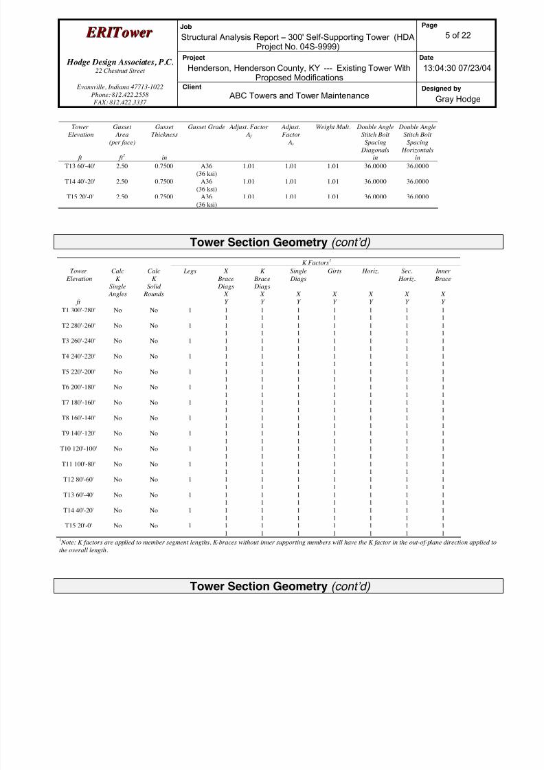
8/18/2019 Analysis Self Supporting-1
http://slidepdf.com/reader/full/analysis-self-supporting-1 78/98
E E R R I I T T oowweer r Job
Structural Analysis Report -- 300' Self-Supporting Tower (HDAProject No. 04S-9999)
Page
5 of 22
Hodge Design Associates, P.C. 22 Chestnut Street
Project
Henderson, Henderson County, KY --- Existing Tower WithProposed Modifications
Date
13:04:30 07/23/04
Evansville, Indiana 47713-1022
Phone: 812.422.2558
FAX: 812.422.3337
Client
ABC Towers and Tower MaintenanceDesigned by
Gray Hodge
Tower Elevation
ft
Gusset Area
(per face)
ft 2
GussetThickness
in
Gusset Grade Adjust. Factor A f
Adjust.Factor
Ar
Weight Mult. Double AngleStitch Bolt
Spacing
Diagonals
in
Double AngleStitch Bolt
Spacing
Horizontals
in
T13 60'-40' 2.50 0.7500 A36
(36 ksi)
1.01 1.01 1.01 36.0000 36.0000
T14 40'-20' 2.50 0.7500 A36
(36 ksi)
1.01 1.01 1.01 36.0000 36.0000
T15 20'-0' 2.50 0.7500 A36
(36 ksi)
1.01 1.01 1.01 36.0000 36.0000
Tower Section Geometry (cont’d)
K Factors1
Tower
Elevation
ft
Calc
K
Single
Angles
Calc
K
Solid
Rounds
Legs X
Brace
Diags
X
Y
K
Brace
Diags
X
Y
Single
Diags
X
Y
Girts
X
Y
Horiz.
X
Y
Sec.
Horiz.
X
Y
Inner
Brace
X
Y
T1 300'-280' No No 1 1
1
1
1
1
1
1
1
1
1
1
1
1
1
T2 280'-260' No No 1 1
1
1
1
1
1
1
1
1
1
1
1
1
1
T3 260'-240' No No 1 1
1
1
1
1
1
1
1
1
1
1
1
1
1
T4 240'-220' No No 1 1
1
1
1
1
1
1
1
1
1
1
1
1
1
T5 220'-200' No No 1 1
1
1
1
1
1
1
1
1
1
1
1
1
1
T6 200'-180' No No 1 1
1
1
1
1
1
1
1
1
1
1
1
1
1
T7 180'-160' No No 1 1
1
1
1
1
1
1
1
1
1
1
1
1
1
T8 160'-140' No No 1 1
1
1
1
1
1
1
1
1
1
1
1
1
1
T9 140'-120' No No 1 1
1
1
1
1
1
1
1
1
1
1
1
1
1
T10 120'-100' No No 1 1
1
1
1
1
1
1
1
1
1
1
1
1
1
T11 100'-80' No No 1 1
1
1
1
1
1
1
1
1
1
1
1
1
1
T12 80'-60' No No 1 1
1
1
1
1
1
1
1
1
1
1
1
1
1
T13 60'-40' No No 1 1
1
1
1
1
1
1
1
1
1
1
1
1
1
T14 40'-20' No No 1 11
11
11
11
11
11
11
T15 20'-0' No No 1 1
1
1
1
1
1
1
1
1
1
1
1
1
11 Note: K factors are applied to member segment lengths. K-braces without inner supporting members will have the K factor in the out-of-plane direction applied to
the overall length.
Tower Section Geometry (cont’d)

8/18/2019 Analysis Self Supporting-1
http://slidepdf.com/reader/full/analysis-self-supporting-1 79/98
E E R R I I T T oowweer r Job
Structural Analysis Report -- 300' Self-Supporting Tower (HDAProject No. 04S-9999)
Page
6 of 22
Hodge Design Associates, P.C. 22 Chestnut Street
Project
Henderson, Henderson County, KY --- Existing Tower WithProposed Modifications
Date
13:04:30 07/23/04
Evansville, Indiana 47713-1022
Phone: 812.422.2558
FAX: 812.422.3337
Client
ABC Towers and Tower MaintenanceDesigned by
Gray Hodge
Tower Elevation
ft
Leg Diagonal Top Girt Bottom Girt Mid Girt Long Horizontal Short Horizontal
Net Width
Deduct
in
U Net Width
Deduct
in
U Net Width
Deduct
in
U Net
Width
Deductin
U Net
Width
Deductin
U Net
Width
Deductin
U Net
Width
Deductin
U
T1 300'-280' 0.0000 0.75 0.0000 0.75 0.0000 0.75 0.0000 0.75 0.0000 0.75 0.0000 0.75 0.0000 0.75
T2 280'-260' 0.0000 0.75 0.0000 0.75 0.0000 0.75 0.0000 0.75 0.0000 0.75 0.0000 0.75 0.0000 0.75
T3 260'-240' 0.0000 0.75 0.0000 0.75 0.0000 0.75 0.0000 0.75 0.0000 0.75 0.0000 0.75 0.0000 0.75
T4 240'-220' 0.0000 0.75 0.0000 0.75 0.0000 0.75 0.0000 0.75 0.0000 0.75 0.0000 0.75 0.0000 0.75
T5 220'-200' 0.0000 0.75 0.0000 0.75 0.0000 0.75 0.0000 0.75 0.0000 0.75 0.0000 0.75 0.0000 0.75
T6 200'-180' 0.0000 0.75 0.0000 0.75 0.0000 0.75 0.0000 0.75 0.0000 0.75 0.0000 0.75 0.0000 0.75
T7 180'-160' 0.0000 0.75 0.0000 0.75 0.0000 0.75 0.0000 0.75 0.0000 0.75 0.0000 0.75 0.0000 0.75
T8 160'-140' 0.0000 0.75 0.0000 0.75 0.0000 0.75 0.0000 0.75 0.0000 0.75 0.0000 0.75 0.0000 0.75
T9 140'-120' 0.0000 0.75 0.0000 0.75 0.0000 0.75 0.0000 0.75 0.0000 0.75 0.0000 0.75 0.0000 0.75
T10 120'-100' 0.0000 0.75 0.0000 0.75 0.0000 0.75 0.0000 0.75 0.0000 0.75 0.0000 0.75 0.0000 0.75
T11 100'-80' 0.0000 0.75 0.0000 0.75 0.0000 0.75 0.0000 0.75 0.0000 0.75 0.0000 0.75 0.0000 0.75
T12 80'-60' 0.0000 0.75 0.0000 0.75 0.0000 0.75 0.0000 0.75 0.0000 0.75 0.0000 0.75 0.0000 0.75
T13 60'-40' 0.0000 0.75 0.0000 0.75 0.0000 0.75 0.0000 0.75 0.0000 0.75 0.0000 0.75 0.0000 0.75
T14 40'-20' 0.0000 0.75 0.0000 0.75 0.0000 0.75 0.0000 0.75 0.0000 0.75 0.0000 0.75 0.0000 0.75
T15 20'-0' 0.0000 0.75 0.0000 0.75 0.0000 0.75 0.0000 0.75 0.0000 0.75 0.0000 0.75 0.0000 0.75
Feed Line/Linear Appurtenances - Entered As Round Or Flat
Description Face
or
Leg
Allow
Shield
Component
Type
Placement
ft
Face
Offset
in
Lateral
Offset
(Frac FW)
# #
Per
Row
Clear
Spacing
in
Width or
Diameter
in
Perimeter
in
Weight
klf
Feedline
Ladder
A Yes Ar (CfAe) 10' - 10' 1.0000 0.25 1 1 1.5000 0.0000 0.01
Feedline
Ladder
B Yes Ar (CfAe) 10' - 10' 1.0000 0.25 1 1 1.5000 0.0000 0.01
Feedline
Ladder
C Yes Ar (CfAe) 10' - 10' 1.0000 0.25 1 1 1.5000 0.0000 0.01
2'' Rigid
Conduit
C Yes Ar (CfAe) 300' - 10' 1.0000 -0.25 1 1 2.0000 2.0000 0.00
1 5/8 A Yes Ar (CfAe) 300' - 10' 1.0000 0.25 12 6 0.3750 1.9800 0.00
1 5/8 B Yes Ar (CfAe) 280' - 10' 1.0000 0.25 12 6 0.3750 1.9800 0.00
1 5/8 C Yes Ar (CfAe) 260' - 10' 1.0000 0.25 12 6 0.3750 1.9800 0.00
EW63
(to Proposed
Antennas)
A Yes Af (CfAe) 200' - 10' 1.0000 -0.25 2 1 1.5742 1.5742 5.0668 0.00
Feed Line/Linear Appurtenances Section Areas
Tower
Section
Tower
Elevation
ft
Face A R
ft 2
AF
ft 2
C A A A
In Face
ft 2
C A A A
Out Face
ft 2
Weight
K
T1 300'-280' A
B
C
23.314
0.000
3.333
0.000
0.000
0.000
0.000
0.000
0.000
0.000
0.000
0.000
0.25
0.00
0.06
T2 280'-260' A
B
C
23.314
23.314
3.333
0.000
0.000
0.000
0.000
0.000
0.000
0.000
0.000
0.000
0.25
0.25
0.06
T3 260'-240' A 23.314 0.000 0.000 0.000 0.25
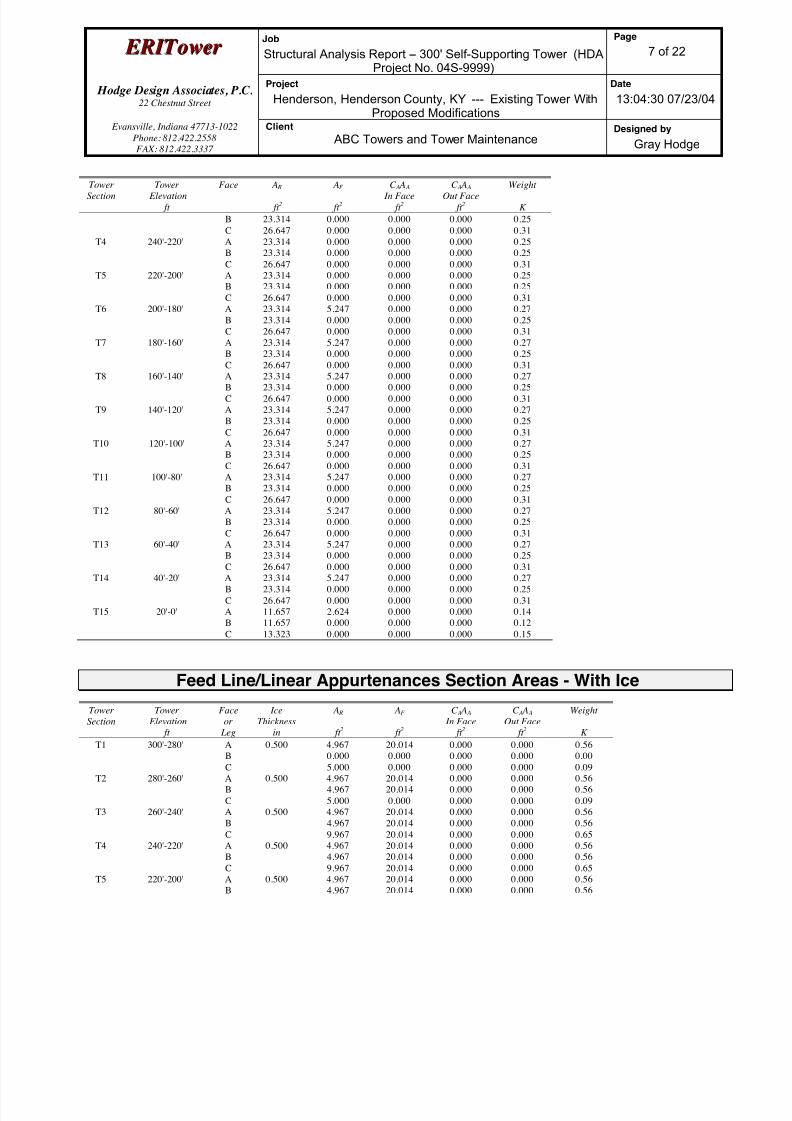
8/18/2019 Analysis Self Supporting-1
http://slidepdf.com/reader/full/analysis-self-supporting-1 80/98
E E R R I I T T oowweer r Job
Structural Analysis Report -- 300' Self-Supporting Tower (HDAProject No. 04S-9999)
Page
7 of 22
Hodge Design Associates, P.C. 22 Chestnut Street
Project
Henderson, Henderson County, KY --- Existing Tower WithProposed Modifications
Date
13:04:30 07/23/04
Evansville, Indiana 47713-1022
Phone: 812.422.2558
FAX: 812.422.3337
Client
ABC Towers and Tower MaintenanceDesigned by
Gray Hodge
TowerSection
Tower Elevation
ft
Face A R
ft 2
AF
ft 2
C A A A
In Face
ft 2
C A A A
Out Face
ft 2
Weight
K
B
C
23.314
26.647
0.000
0.000
0.000
0.000
0.000
0.000
0.25
0.31
T4 240'-220' A
B
C
23.314
23.314
26.647
0.000
0.000
0.000
0.000
0.000
0.000
0.000
0.000
0.000
0.25
0.25
0.31
T5 220'-200' A
B
C
23.314
23.314
26.647
0.000
0.000
0.000
0.000
0.000
0.000
0.000
0.000
0.000
0.25
0.25
0.31
T6 200'-180' A
B
C
23.314
23.314
26.647
5.247
0.000
0.000
0.000
0.000
0.000
0.000
0.000
0.000
0.27
0.25
0.31
T7 180'-160' A
B
C
23.314
23.314
26.647
5.247
0.000
0.000
0.000
0.000
0.000
0.000
0.000
0.000
0.27
0.25
0.31
T8 160'-140' A
B
C
23.314
23.314
26.647
5.247
0.000
0.000
0.000
0.000
0.000
0.000
0.000
0.000
0.27
0.25
0.31
T9 140'-120' A
B
C
23.314
23.314
26.647
5.247
0.000
0.000
0.000
0.000
0.000
0.000
0.000
0.000
0.27
0.25
0.31
T10 120'-100' A
B
C
23.314
23.314
26.647
5.247
0.000
0.000
0.000
0.000
0.000
0.000
0.000
0.000
0.27
0.25
0.31
T11 100'-80' A
B
C
23.314
23.314
26.647
5.247
0.000
0.000
0.000
0.000
0.000
0.000
0.000
0.000
0.27
0.25
0.31
T12 80'-60' A
B
C
23.314
23.314
26.647
5.247
0.000
0.000
0.000
0.000
0.000
0.000
0.000
0.000
0.27
0.25
0.31
T13 60'-40' A
BC
23.314
23.31426.647
5.247
0.0000.000
0.000
0.0000.000
0.000
0.0000.000
0.27
0.250.31
T14 40'-20' A
B
C
23.314
23.314
26.647
5.247
0.000
0.000
0.000
0.000
0.000
0.000
0.000
0.000
0.27
0.25
0.31
T15 20'-0' A
B
C
11.657
11.657
13.323
2.624
0.000
0.000
0.000
0.000
0.000
0.000
0.000
0.000
0.14
0.12
0.15
Feed Line/Linear Appurtenances Section Areas - With Ice
Tower
Section
Tower
Elevation
ft
Face
or
Leg
Ice
Thickness
in
A R
ft 2
AF
ft 2
C A A A
In Face
ft 2
C A A A
Out Face
ft 2
Weight
K
T1 300'-280' AB
C
0.500 4.9670.000
5.000
20.0140.000
0.000
0.0000.000
0.000
0.0000.000
0.000
0.560.00
0.09
T2 280'-260' A
B
C
0.500 4.967
4.967
5.000
20.014
20.014
0.000
0.000
0.000
0.000
0.000
0.000
0.000
0.56
0.56
0.09
T3 260'-240' A
B
C
0.500 4.967
4.967
9.967
20.014
20.014
20.014
0.000
0.000
0.000
0.000
0.000
0.000
0.56
0.56
0.65
T4 240'-220' A
B
C
0.500 4.967
4.967
9.967
20.014
20.014
20.014
0.000
0.000
0.000
0.000
0.000
0.000
0.56
0.56
0.65
T5 220'-200' A
B
0.500 4.967
4.967
20.014
20.014
0.000
0.000
0.000
0.000
0.56
0.56
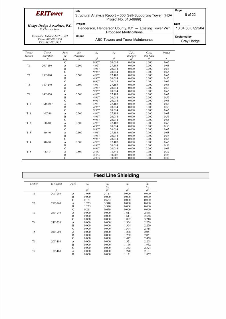
8/18/2019 Analysis Self Supporting-1
http://slidepdf.com/reader/full/analysis-self-supporting-1 81/98
E E R R I I T T oowweer r Job
Structural Analysis Report -- 300' Self-Supporting Tower (HDAProject No. 04S-9999)
Page
8 of 22
Hodge Design Associates, P.C. 22 Chestnut Street
Project
Henderson, Henderson County, KY --- Existing Tower WithProposed Modifications
Date
13:04:30 07/23/04
Evansville, Indiana 47713-1022
Phone: 812.422.2558
FAX: 812.422.3337
Client
ABC Towers and Tower MaintenanceDesigned by
Gray Hodge
TowerSection
Tower Elevation
ft
Faceor
Leg
IceThickness
in
A R
ft 2
AF
ft 2
C A A A
In Face
ft 2
C A A A
Out Face
ft 2
Weight
K
C 9.967 20.014 0.000 0.000 0.65
T6 200'-180' A
B
C
0.500 4.967
4.967
9.967
27.483
20.014
20.014
0.000
0.000
0.000
0.000
0.000
0.000
0.63
0.56
0.65
T7 180'-160' A
B
C
0.500 4.967
4.967
9.967
27.483
20.014
20.014
0.000
0.000
0.000
0.000
0.000
0.000
0.63
0.56
0.65
T8 160'-140' A
B
C
0.500 4.967
4.967
9.967
27.483
20.014
20.014
0.000
0.000
0.000
0.000
0.000
0.000
0.63
0.56
0.65
T9 140'-120' A
B
C
0.500 4.967
4.967
9.967
27.483
20.014
20.014
0.000
0.000
0.000
0.000
0.000
0.000
0.63
0.56
0.65
T10 120'-100' A
B
C
0.500 4.967
4.967
9.967
27.483
20.014
20.014
0.000
0.000
0.000
0.000
0.000
0.000
0.63
0.56
0.65
T11 100'-80' A
B
C
0.500 4.967
4.967
9.967
27.483
20.014
20.014
0.000
0.000
0.000
0.000
0.000
0.000
0.63
0.56
0.65
T12 80'-60' A
B
C
0.500 4.967
4.967
9.967
27.483
20.014
20.014
0.000
0.000
0.000
0.000
0.000
0.000
0.63
0.56
0.65
T13 60'-40' A
B
C
0.500 4.967
4.967
9.967
27.483
20.014
20.014
0.000
0.000
0.000
0.000
0.000
0.000
0.63
0.56
0.65
T14 40'-20' A
B
C
0.500 4.967
4.967
9.967
27.483
20.014
20.014
0.000
0.000
0.000
0.000
0.000
0.000
0.63
0.56
0.65
T15 20'-0' A
B
C
0.500 2.483
2.483
4.983
13.742
10.007
10.007
0.000
0.000
0.000
0.000
0.000
0.000
0.32
0.28
0.32
Feed Line Shielding
Section Elevation
ft
Face A R
ft 2
A R
Ice
ft 2
AF
ft 2
AF
Ice
ft 2
T1 300'-280' A
B
C
1.076
0.000
0.181
3.117
0.000
0.634
0.000
0.000
0.000
0.000
0.000
0.000
T2 280'-260' A
B
C
1.255
1.255
0.211
3.340
3.340
0.679
0.000
0.000
0.000
0.000
0.000
0.000
T3 260'-240' AB
C
0.0000.000
0.000
0.0000.000
0.000
1.6111.611
1.882
2.6682.668
3.210
T4 240'-220' A
B
C
0.000
0.000
0.000
0.000
0.000
0.000
1.364
1.364
1.594
2.259
2.259
2.718
T5 220'-200' A
B
C
0.000
0.000
0.000
0.000
0.000
0.000
1.238
1.238
1.447
2.051
2.051
2.468
T6 200'-180' A
B
C
0.000
0.000
0.000
0.000
0.000
0.000
1.321
1.166
1.363
2.268
1.932
2.324
T7 180'-160' A
B
0.000
0.000
0.000
0.000
1.270
1.121
2.181
1.857
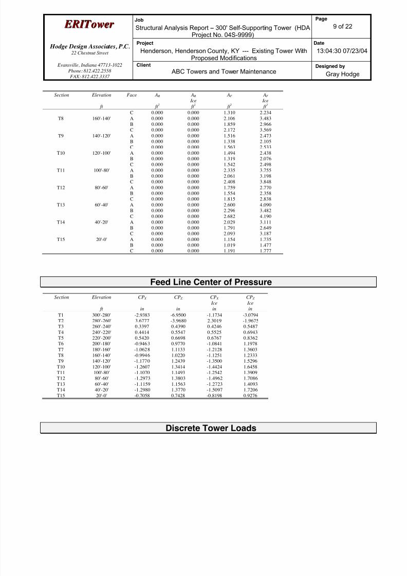
8/18/2019 Analysis Self Supporting-1
http://slidepdf.com/reader/full/analysis-self-supporting-1 82/98
E E R R I I T T oowweer r Job
Structural Analysis Report -- 300' Self-Supporting Tower (HDAProject No. 04S-9999)
Page
9 of 22
Hodge Design Associates, P.C. 22 Chestnut Street
Project
Henderson, Henderson County, KY --- Existing Tower WithProposed Modifications
Date
13:04:30 07/23/04
Evansville, Indiana 47713-1022
Phone: 812.422.2558
FAX: 812.422.3337
Client
ABC Towers and Tower MaintenanceDesigned by
Gray Hodge
Section Elevation
ft
Face A R
ft 2
A R
Ice
ft 2
AF
ft 2
AF
Ice
ft 2
C 0.000 0.000 1.310 2.234
T8 160'-140' A
B
C
0.000
0.000
0.000
0.000
0.000
0.000
2.106
1.859
2.172
3.483
2.966
3.569
T9 140'-120' A
B
C
0.000
0.000
0.000
0.000
0.000
0.000
1.516
1.338
1.563
2.473
2.105
2.533
T10 120'-100' A
B
C
0.000
0.000
0.000
0.000
0.000
0.000
1.494
1.319
1.542
2.438
2.076
2.498
T11 100'-80' A
B
C
0.000
0.000
0.000
0.000
0.000
0.000
2.335
2.061
2.408
3.755
3.198
3.848
T12 80'-60' A
B
C
0.000
0.000
0.000
0.000
0.000
0.000
1.759
1.554
1.815
2.770
2.358
2.838
T13 60'-40' A
B
C
0.000
0.000
0.000
0.000
0.000
0.000
2.600
2.296
2.682
4.090
3.482
4.190
T14 40'-20' A
B
C
0.000
0.000
0.000
0.000
0.000
0.000
2.029
1.791
2.093
3.111
2.649
3.187
T15 20'-0' A
B
C
0.000
0.000
0.000
0.000
0.000
0.000
1.154
1.019
1.191
1.735
1.477
1.777
Feed Line Center of Pressure
Section Elevation
ft
CP X
in
CP Z
in
CP X
Ice
in
CP Z
Ice
in
T1 300'-280' -2.9383 -6.9500 -1.1734 -3.0794
T2 280'-260' 3.6777 -3.9680 2.3019 -1.9675
T3 260'-240' 0.3397 0.4390 0.4246 0.5487
T4 240'-220' 0.4414 0.5547 0.5525 0.6943
T5 220'-200' 0.5420 0.6698 0.6767 0.8362
T6 200'-180' -0.9463 0.9770 -1.0841 1.1978
T7 180'-160' -1.0628 1.1133 -1.2128 1.3603
T8 160'-140' -0.9946 1.0220 -1.1251 1.2333
T9 140'-120' -1.1770 1.2439 -1.3500 1.5296
T10 120'-100' -1.2607 1.3414 -1.4424 1.6458
T11 100'-80' -1.1070 1.1493 -1.2542 1.3909
T12 80'-60' -1.2973 1.3803 -1.4962 1.7086
T13 60'-40' -1.1159 1.1563 -1.2723 1.4093T14 40'-20' -1.2980 1.3770 -1.5097 1.7206
T15 20'-0' -0.7058 0.7428 -0.8198 0.9276
Discrete Tower Loads
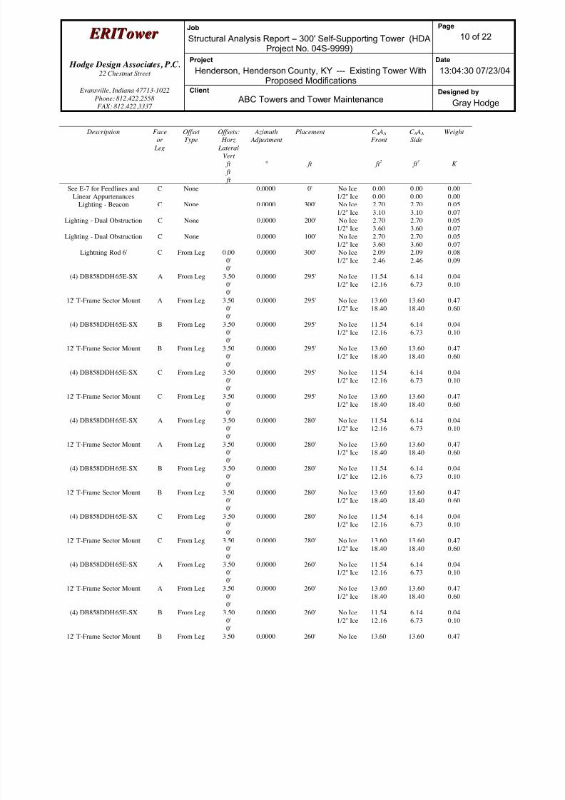
8/18/2019 Analysis Self Supporting-1
http://slidepdf.com/reader/full/analysis-self-supporting-1 83/98
E E R R I I T T oowweer r Job
Structural Analysis Report -- 300' Self-Supporting Tower (HDAProject No. 04S-9999)
Page
10 of 22
Hodge Design Associates, P.C. 22 Chestnut Street
Project
Henderson, Henderson County, KY --- Existing Tower WithProposed Modifications
Date
13:04:30 07/23/04
Evansville, Indiana 47713-1022
Phone: 812.422.2558
FAX: 812.422.3337
Client
ABC Towers and Tower MaintenanceDesigned by
Gray Hodge
Description Faceor
Leg
OffsetType
Offsets: Horz
Lateral
Vert
ft
ft
ft
Azimuth Adjustment
°
Placement
ft
C A A A Front
ft 2
C A A A Side
ft 2
Weight
K
See E-7 for Feedlines and
Linear Appurtenances
C None 0.0000 0' No Ice
1/2'' Ice
0.00
0.00
0.00
0.00
0.00
0.00
Lighting - Beacon C None 0.0000 300' No Ice
1/2'' Ice
2.70
3.10
2.70
3.10
0.05
0.07
Lighting - Dual Obstruction C None 0.0000 200' No Ice
1/2'' Ice
2.70
3.60
2.70
3.60
0.05
0.07
Lighting - Dual Obstruction C None 0.0000 100' No Ice
1/2'' Ice
2.70
3.60
2.70
3.60
0.05
0.07
Lightning Rod 6' C From Leg 0.00
0'
0'
0.0000 300' No Ice
1/2'' Ice
2.09
2.46
2.09
2.46
0.08
0.09
(4) DB858DDH65E-SX A From Leg 3.50
0'
0'
0.0000 295' No Ice
1/2'' Ice
11.54
12.16
6.14
6.73
0.04
0.10
12' T-Frame Sector Mount A From Leg 3.50
0'
0'
0.0000 295' No Ice
1/2'' Ice
13.60
18.40
13.60
18.40
0.47
0.60
(4) DB858DDH65E-SX B From Leg 3.50
0'
0'
0.0000 295' No Ice
1/2'' Ice
11.54
12.16
6.14
6.73
0.04
0.10
12' T-Frame Sector Mount B From Leg 3.50
0'
0'
0.0000 295' No Ice
1/2'' Ice
13.60
18.40
13.60
18.40
0.47
0.60
(4) DB858DDH65E-SX C From Leg 3.50
0'
0'
0.0000 295' No Ice
1/2'' Ice
11.54
12.16
6.14
6.73
0.04
0.10
12' T-Frame Sector Mount C From Leg 3.500'
0'
0.0000 295' No Ice1/2'' Ice
13.6018.40
13.6018.40
0.470.60
(4) DB858DDH65E-SX A From Leg 3.50
0'
0'
0.0000 280' No Ice
1/2'' Ice
11.54
12.16
6.14
6.73
0.04
0.10
12' T-Frame Sector Mount A From Leg 3.50
0'
0'
0.0000 280' No Ice
1/2'' Ice
13.60
18.40
13.60
18.40
0.47
0.60
(4) DB858DDH65E-SX B From Leg 3.50
0'
0'
0.0000 280' No Ice
1/2'' Ice
11.54
12.16
6.14
6.73
0.04
0.10
12' T-Frame Sector Mount B From Leg 3.50
0'
0'
0.0000 280' No Ice
1/2'' Ice
13.60
18.40
13.60
18.40
0.47
0.60
(4) DB858DDH65E-SX C From Leg 3.50
0'
0'
0.0000 280' No Ice
1/2'' Ice
11.54
12.16
6.14
6.73
0.04
0.10
12' T-Frame Sector Mount C From Leg 3.50
0'
0'
0.0000 280' No Ice
1/2'' Ice
13.60
18.40
13.60
18.40
0.47
0.60
(4) DB858DDH65E-SX A From Leg 3.50
0'
0'
0.0000 260' No Ice
1/2'' Ice
11.54
12.16
6.14
6.73
0.04
0.10
12' T-Frame Sector Mount A From Leg 3.50
0'
0'
0.0000 260' No Ice
1/2'' Ice
13.60
18.40
13.60
18.40
0.47
0.60
(4) DB858DDH65E-SX B From Leg 3.50
0'
0'
0.0000 260' No Ice
1/2'' Ice
11.54
12.16
6.14
6.73
0.04
0.10
12' T-Frame Sector Mount B From Leg 3.50 0.0000 260' No Ice 13.60 13.60 0.47

8/18/2019 Analysis Self Supporting-1
http://slidepdf.com/reader/full/analysis-self-supporting-1 84/98
E E R R I I T T oowweer r Job
Structural Analysis Report -- 300' Self-Supporting Tower (HDAProject No. 04S-9999)
Page
11 of 22
Hodge Design Associates, P.C. 22 Chestnut Street
Project
Henderson, Henderson County, KY --- Existing Tower WithProposed Modifications
Date
13:04:30 07/23/04
Evansville, Indiana 47713-1022
Phone: 812.422.2558
FAX: 812.422.3337
Client
ABC Towers and Tower MaintenanceDesigned by
Gray Hodge
Description Faceor
Leg
OffsetType
Offsets: Horz
Lateral
Vert
ft
ft
ft
Azimuth Adjustment
°
Placement
ft
C A A A Front
ft 2
C A A A Side
ft 2
Weight
K
0'
0'
1/2'' Ice 18.40 18.40 0.60
(4) DB858DDH65E-SX C From Leg 3.50
0'
0'
0.0000 260' No Ice
1/2'' Ice
11.54
12.16
6.14
6.73
0.04
0.10
12' T-Frame Sector Mount C From Leg 3.50
0'
0'
0.0000 260' No Ice
1/2'' Ice
13.60
18.40
13.60
18.40
0.47
0.60
Dishes
Description Face
or
Leg
Dish
Type
Offset
Type
Offsets:
Horz
Lateral
Vert
ft
Azimuth
Adjustment
°
3 dB
Beam
Width
°
Elevation
ft
Outside
Diameter
ft
Aperture
Area
ft 2
Weight
K
UHX8-59
(Proposed)
A Paraboloid
w/Shroud (HP)
From
Leg
1.00
0'
0'
0.0000 200' 8.00 No Ice
1/2'' Ice
50.26
51.29
0.25
0.51
UHX8-59
(Proposed)
C Paraboloid
w/Shroud (HP)
From
Face
1.00
0'0'
0.0000 200' 8.00 No Ice
1/2'' Ice
50.26
51.29
0.25
0.51
Load Combinations
Comb.
No.
Description
1 Dead Only
2 Dead+Wind 0 deg - No Ice
3 Dead+Wind 30 deg - No Ice
4 Dead+Wind 60 deg - No Ice
5 Dead+Wind 90 deg - No Ice
6 Dead+Wind 120 deg - No Ice
7 Dead+Wind 150 deg - No Ice
8 Dead+Wind 180 deg - No Ice9 Dead+Wind 210 deg - No Ice
10 Dead+Wind 240 deg - No Ice
11 Dead+Wind 270 deg - No Ice
12 Dead+Wind 300 deg - No Ice
13 Dead+Wind 330 deg - No Ice
14 Dead+Ice+Temp
15 Dead+Wind 0 deg+Ice+Temp
16 Dead+Wind 30 deg+Ice+Temp
17 Dead+Wind 60 deg+Ice+Temp
18 Dead+Wind 90 deg+Ice+Temp
19 Dead+Wind 120 deg+Ice+Temp
20 Dead+Wind 150 deg+Ice+Temp
21 Dead+Wind 180 deg+Ice+Temp
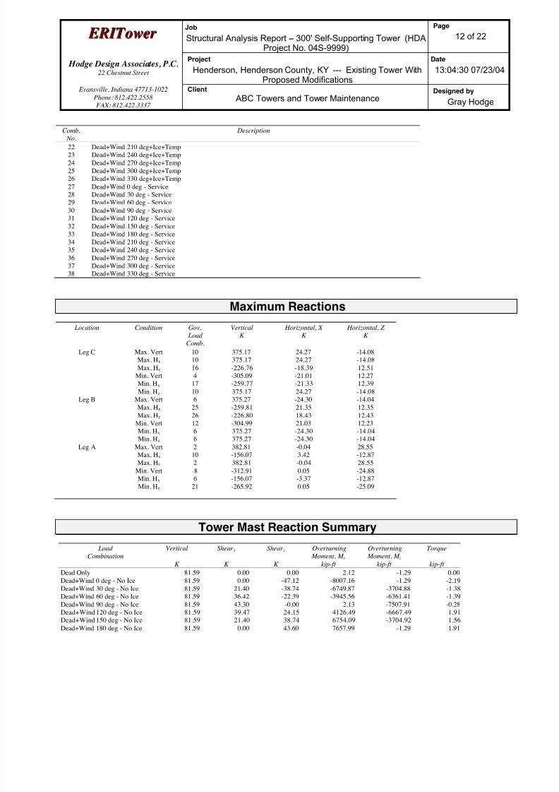
8/18/2019 Analysis Self Supporting-1
http://slidepdf.com/reader/full/analysis-self-supporting-1 85/98
E E R R I I T T oowweer r Job
Structural Analysis Report -- 300' Self-Supporting Tower (HDAProject No. 04S-9999)
Page
12 of 22
Hodge Design Associates, P.C. 22 Chestnut Street
Project
Henderson, Henderson County, KY --- Existing Tower WithProposed Modifications
Date
13:04:30 07/23/04
Evansville, Indiana 47713-1022
Phone: 812.422.2558
FAX: 812.422.3337
Client
ABC Towers and Tower MaintenanceDesigned by
Gray Hodge
Comb. No.
Description
22 Dead+Wind 210 deg+Ice+Temp
23 Dead+Wind 240 deg+Ice+Temp
24 Dead+Wind 270 deg+Ice+Temp
25 Dead+Wind 300 deg+Ice+Temp
26 Dead+Wind 330 deg+Ice+Temp
27 Dead+Wind 0 deg - Service
28 Dead+Wind 30 deg - Service
29 Dead+Wind 60 deg - Service
30 Dead+Wind 90 deg - Service
31 Dead+Wind 120 deg - Service
32 Dead+Wind 150 deg - Service
33 Dead+Wind 180 deg - Service
34 Dead+Wind 210 deg - Service
35 Dead+Wind 240 deg - Service
36 Dead+Wind 270 deg - Service
37 Dead+Wind 300 deg - Service
38 Dead+Wind 330 deg - Service
Maximum Reactions
Location Condition Gov.
Load
Comb.
Vertical
K
Horizontal, X
K
Horizontal, Z
K
Leg C Max. Vert 10 375.17 24.27 -14.08
Max. Hx 10 375.17 24.27 -14.08
Max. Hz 16 -226.76 -18.39 12.51
Min. Vert 4 -305.09 -21.01 12.27
Min. Hx 17 -259.77 -21.33 12.39
Min. Hz 10 375.17 24.27 -14.08Leg B Max. Vert 6 375.27 -24.30 -14.04
Max. Hx 25 -259.81 21.35 12.35
Max. Hz 26 -226.80 18.43 12.43
Min. Vert 12 -304.99 21.03 12.23
Min. Hx 6 375.27 -24.30 -14.04
Min. Hz 6 375.27 -24.30 -14.04
Leg A Max. Vert 2 382.81 -0.04 28.55
Max. Hx 10 -156.07 3.42 -12.87
Max. Hz 2 382.81 -0.04 28.55
Min. Vert 8 -312.91 0.05 -24.88
Min. Hx 6 -156.07 -3.37 -12.87
Min. Hz 21 -265.92 0.05 -25.09
Tower Mast Reaction Summary
Load
Combination Vertical
K
Shear x
K
Shear z
K
Overturning
Moment, M x kip-ft
Overturning
Moment, M z kip-ft
Torque
kip-ft
Dead Only 81.59 0.00 0.00 2.12 -1.29 0.00
Dead+Wind 0 deg - No Ice 81.59 0.00 -47.12 -8007.16 -1.29 -2.19
Dead+Wind 30 deg - No Ice 81.59 21.40 -38.74 -6749.87 -3704.88 -1.38
Dead+Wind 60 deg - No Ice 81.59 36.42 -22.39 -3945.56 -6361.41 -1.39
Dead+Wind 90 deg - No Ice 81.59 43.30 -0.00 2.13 -7507.91 -0.28
Dead+Wind 120 deg - No Ice 81.59 39.47 24.15 4126.49 -6667.49 1.91
Dead+Wind 150 deg - No Ice 81.59 21.40 38.74 6754.09 -3704.92 1.56
Dead+Wind 180 deg - No Ice 81.59 0.00 43.60 7657.99 -1.29 1.91
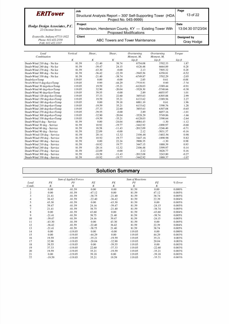
8/18/2019 Analysis Self Supporting-1
http://slidepdf.com/reader/full/analysis-self-supporting-1 86/98
E E R R I I T T oowweer r Job
Structural Analysis Report -- 300' Self-Supporting Tower (HDAProject No. 04S-9999)
Page
13 of 22
Hodge Design Associates, P.C. 22 Chestnut Street
Project
Henderson, Henderson County, KY --- Existing Tower WithProposed Modifications
Date
13:04:30 07/23/04
Evansville, Indiana 47713-1022
Phone: 812.422.2558
FAX: 812.422.3337
Client
ABC Towers and Tower MaintenanceDesigned by
Gray Hodge
LoadCombination
Vertical
K
Shear x
K
Shear z
K
Overturning Moment, M x
kip-ft
Overturning Moment, M z
kip-ft
Torque
kip-ft
Dead+Wind 210 deg - No Ice 81.59 -21.40 38.74 6754.08 3702.33 1.87
Dead+Wind 240 deg - No Ice 81.59 -39.47 24.15 4126.48 6664.89 0.28
Dead+Wind 270 deg - No Ice 81.59 -43.30 -0.00 2.13 7505.32 0.28
Dead+Wind 300 deg - No Ice 81.59 -36.42 -22.39 -3945.56 6358.81 -0.52
Dead+Wind 330 deg - No Ice 81.59 -21.40 -38.74 -6749.87 3702.29 -2.05
Dead+Ice+Temp 119.05 0.00 -0.00 2.85 0.61 -0.00
Dead+Wind 0 deg+Ice+Temp 119.05 0.00 -44.29 -7518.81 0.60 -2.34
Dead+Wind 30 deg+Ice+Temp 119.05 19.59 -35.21 -6128.03 -3389.44 -0.91
Dead+Wind 60 deg+Ice+Temp 119.05 32.90 -20.04 -3528.30 -5748.66 -0.30
Dead+Wind 90 deg+Ice+Temp 119.05 39.55 -0.00 2.89 -6855.97 1.01
Dead+Wind 120 deg+Ice+Temp 119.05 37.33 22.60 3855.63 -6305.88 2.99
Dead+Wind 150 deg+Ice+Temp 119.05 19.59 35.21 6133.62 -3389.56 2.27
Dead+Wind 180 deg+Ice+Temp 119.05 0.00 39.18 6881.10 0.61 1.96
Dead+Wind 210 deg+Ice+Temp 119.05 -19.59 35.21 6133.62 3390.76 1.28
Dead+Wind 240 deg+Ice+Temp 119.05 -37.33 22.60 3855.63 6307.08 -0.65
Dead+Wind 270 deg+Ice+Temp 119.05 -39.55 -0.00 2.89 6857.16 -1.01
Dead+Wind 300 deg+Ice+Temp 119.05 -32.90 -20.04 -3528.29 5749.86 -1.66
Dead+Wind 330 deg+Ice+Temp 119.05 -19.59 -35.21 -6128.03 3390.64 -2.64
Dead+Wind 0 deg - Service 81.59 0.00 -24.04 -4084.43 -1.30 -1.12
Dead+Wind 30 deg - Service 81.59 10.92 -19.77 -3442.92 -1890.97 -0.68
Dead+Wind 60 deg - Service 81.59 18.58 -11.43 -2012.09 -3246.40 -0.71
Dead+Wind 90 deg - Service 81.59 22.09 -0.00 2.12 -3831.37 -0.16
Dead+Wind 120 deg - Service 81.59 20.14 12.32 2106.48 -3402.56 0.98
Dead+Wind 150 deg - Service 81.59 10.92 19.77 3447.16 -1890.98 0.82
Dead+Wind 180 deg - Service 81.59 0.00 22.24 3908.35 -1.30 0.98
Dead+Wind 210 deg - Service 81.59 -10.92 19.77 3447.15 1888.39 0.93
Dead+Wind 240 deg - Service 81.59 -20.14 12.32 2106.48 3399.97 0.14
Dead+Wind 270 deg - Service 81.59 -22.09 -0.00 2.12 3828.77 0.16
Dead+Wind 300 deg - Service 81.59 -18.58 -11.43 -2012.08 3243.80 -0.27
Dead+Wind 330 deg - Service 81.59 -10.92 -19.77 -3442.92 1888.37 -1.07
Solution Summary
Sum of Applied Forces Sum of Reactions
Load
Comb.
PX
K
PY
K
PZ
K
PX
K
PY
K
PZ
K
% Error
1 0.00 -81.59 0.00 0.00 81.59 0.00 0.000%
2 0.00 -81.59 -47.12 0.00 81.59 47.12 0.005%
3 21.41 -81.59 -38.75 -21.40 81.59 38.74 0.005%
4 36.42 -81.59 -22.40 -36.42 81.59 22.39 0.004%
5 43.30 -81.59 0.00 -43.30 81.59 0.00 0.005%
6 39.47 -81.59 24.16 -39.47 81.59 -24.15 0.005%
7 21.41 -81.59 38.75 -21.40 81.59 -38.74 0.005%
8 0.00 -81.59 43.60 0.00 81.59 -43.60 0.004%
9 -21.41 -81.59 38.75 21.40 81.59 -38.74 0.005%10 -39.47 -81.59 24.16 39.47 81.59 -24.15 0.005%
11 -43.30 -81.59 0.00 43.30 81.59 0.00 0.005%
12 -36.42 -81.59 -22.40 36.42 81.59 22.39 0.004%
13 -21.41 -81.59 -38.75 21.40 81.59 38.74 0.005%
14 0.00 -119.05 0.00 -0.00 119.05 0.00 0.000%
15 0.00 -119.05 -44.29 0.00 119.05 44.29 0.003%
16 19.59 -119.05 -35.21 -19.59 119.05 35.21 0.003%
17 32.90 -119.05 -20.04 -32.90 119.05 20.04 0.003%
18 39.55 -119.05 0.00 -39.55 119.05 0.00 0.003%
19 37.33 -119.05 22.60 -37.33 119.05 -22.60 0.003%
20 19.59 -119.05 35.21 -19.59 119.05 -35.21 0.003%
21 0.00 -119.05 39.18 0.00 119.05 -39.18 0.003%
22 -19.59 -119.05 35.21 19.59 119.05 -35.21 0.003%

8/18/2019 Analysis Self Supporting-1
http://slidepdf.com/reader/full/analysis-self-supporting-1 87/98
E E R R I I T T oowweer r Job
Structural Analysis Report -- 300' Self-Supporting Tower (HDAProject No. 04S-9999)
Page
14 of 22
Hodge Design Associates, P.C. 22 Chestnut Street
Project
Henderson, Henderson County, KY --- Existing Tower WithProposed Modifications
Date
13:04:30 07/23/04
Evansville, Indiana 47713-1022
Phone: 812.422.2558
FAX: 812.422.3337
Client
ABC Towers and Tower MaintenanceDesigned by
Gray Hodge
Sum of Applied Forces Sum of Reactions Load
Comb.
PX
K
PY
K
PZ
K
PX
K
PY
K
PZ
K
% Error
23 -37.33 -119.05 22.60 37.33 119.05 -22.60 0.003%
24 -39.55 -119.05 0.00 39.55 119.05 0.00 0.003%
25 -32.90 -119.05 -20.04 32.90 119.05 20.04 0.003%
26 -19.59 -119.05 -35.21 19.59 119.05 35.21 0.003%
27 0.00 -81.59 -24.04 0.00 81.59 24.04 0.003%
28 10.92 -81.59 -19.77 -10.92 81.59 19.77 0.003%
29 18.58 -81.59 -11.43 -18.58 81.59 11.43 0.002%
30 22.09 -81.59 0.00 -22.09 81.59 0.00 0.003%
31 20.14 -81.59 12.32 -20.14 81.59 -12.32 0.003%
32 10.92 -81.59 19.77 -10.92 81.59 -19.77 0.003%
33 0.00 -81.59 22.25 0.00 81.59 -22.24 0.002%
34 -10.92 -81.59 19.77 10.92 81.59 -19.77 0.003%
35 -20.14 -81.59 12.32 20.14 81.59 -12.32 0.003%
36 -22.09 -81.59 0.00 22.09 81.59 0.00 0.003%
37 -18.58 -81.59 -11.43 18.58 81.59 11.43 0.002%
38 -10.92 -81.59 -19.77 10.92 81.59 19.77 0.003%
Non-Linear Convergence Results
Load
Combination
Converged? Number
of Cycles
Displacement
Tolerance
Force
Tolerance
1 Yes 6 0.00000001 0.00000001
2 Yes 16 0.00007202 0.00011799
3 Yes 16 0.00006877 0.00011301
4 Yes 16 0.00006538 0.00010774
5 Yes 16 0.00006848 0.00011274
6 Yes 16 0.00007181 0.000117817 Yes 16 0.00006826 0.00011217
8 Yes 16 0.00006525 0.00010734
9 Yes 16 0.00006827 0.00011218
10 Yes 16 0.00007182 0.00011782
11 Yes 16 0.00006848 0.00011274
12 Yes 16 0.00006538 0.00010774
13 Yes 16 0.00006877 0.00011301
14 Yes 6 0.00000001 0.00000001
15 Yes 17 0.00006501 0.00010698
16 Yes 17 0.00006307 0.00010412
17 Yes 17 0.00006122 0.00010132
18 Yes 17 0.00006295 0.00010405
19 Yes 17 0.00006493 0.00010693
20 Yes 17 0.00006281 0.00010367
21 Yes 17 0.00006113 0.00010100
22 Yes 17 0.00006282 0.00010367
23 Yes 17 0.00006493 0.00010692
24 Yes 17 0.00006294 0.00010405
25 Yes 17 0.00006122 0.00010131
26 Yes 17 0.00006307 0.00010412
27 Yes 16 0.00006917 0.00011234
28 Yes 16 0.00006767 0.00011013
29 Yes 16 0.00006608 0.00010774
30 Yes 16 0.00006757 0.00011011
31 Yes 16 0.00006911 0.00011233
32 Yes 16 0.00006741 0.00010969
33 Yes 16 0.00006597 0.00010741
34 Yes 16 0.00006741 0.00010970
35 Yes 16 0.00006911 0.00011234

8/18/2019 Analysis Self Supporting-1
http://slidepdf.com/reader/full/analysis-self-supporting-1 88/98
E E R R I I T T oowweer r Job
Structural Analysis Report -- 300' Self-Supporting Tower (HDAProject No. 04S-9999)
Page
15 of 22
Hodge Design Associates, P.C. 22 Chestnut Street
Project
Henderson, Henderson County, KY --- Existing Tower WithProposed Modifications
Date
13:04:30 07/23/04
Evansville, Indiana 47713-1022
Phone: 812.422.2558
FAX: 812.422.3337
Client
ABC Towers and Tower MaintenanceDesigned by
Gray Hodge
36 Yes 16 0.00006757 0.0001101237 Yes 16 0.00006608 0.00010774
38 Yes 16 0.00006766 0.00011013
Maximum Tower Deflections - Service Wind
Section
No.
Elevation
ft
Horz.
Deflection
in
Gov.
Load
Comb.
Tilt
°
Twist
°
T1 300 - 280 23.356 27 0.8522 0.0465
T2 280 - 260 19.766 27 0.8148 0.0416
T3 260 - 240 16.479 27 0.6842 0.0300
T4 240 - 220 13.676 27 0.5972 0.0175
T5 220 - 200 11.252 27 0.5225 0.0126
T6 200 - 180 9.139 27 0.4514 0.0097
T7 180 - 160 7.303 27 0.3924 0.0069
T8 160 - 140 5.714 27 0.3349 0.0052
T9 140 - 120 4.330 27 0.2800 0.0032
T10 120 - 100 3.182 27 0.2331 0.0023
T11 100 - 80 2.233 27 0.1871 0.0016
T12 80 - 60 1.465 27 0.1422 0.0012
T13 60 - 40 0.878 27 0.1036 0.0009
T14 40 - 20 0.453 27 0.0654 0.0007
T15 20 - 0 0.175 27 0.0322 0.0004
Critical Deflections and Radius of Curvature - Service Wind
Elevation
ft
Appurtenance Gov.
Load
Comb.
Deflection
in
Tilt
°
Twist
°
Radius of
Curvature
ft
300' Lighting - Beacon 27 23.356 0.8522 0.0465 60327
295' (4) DB858DDH65E-SX 27 22.446 0.8494 0.0457 60327
280' (4) DB858DDH65E-SX 27 19.766 0.8148 0.0416 15240
260' (4) DB858DDH65E-SX 27 16.479 0.6842 0.0300 8902
200' UHX8-59 27 9.139 0.4514 0.0097 16876
100' Lighting - Dual Obstruction 27 2.233 0.1871 0.0016 26627
0' See E-7 for Feedlines and Linear
Appurtenances
0 0.000 0.0000 0.0000 164362
Maximum Tower Deflections - Design Wind
Section
No.
Elevation
ft
Horz.
Deflection
in
Gov.
Load
Comb.
Tilt
°
Twist
°
T1 300 - 280 45.776 2 1.6681 0.0919
T2 280 - 260 38.749 2 1.5950 0.0822
T3 260 - 240 32.315 2 1.3396 0.0593
T4 240 - 220 26.822 2 1.1697 0.0346
T5 220 - 200 22.072 2 1.0234 0.0248
T6 200 - 180 17.930 2 0.8843 0.0192
T7 180 - 160 14.331 2 0.7688 0.0132
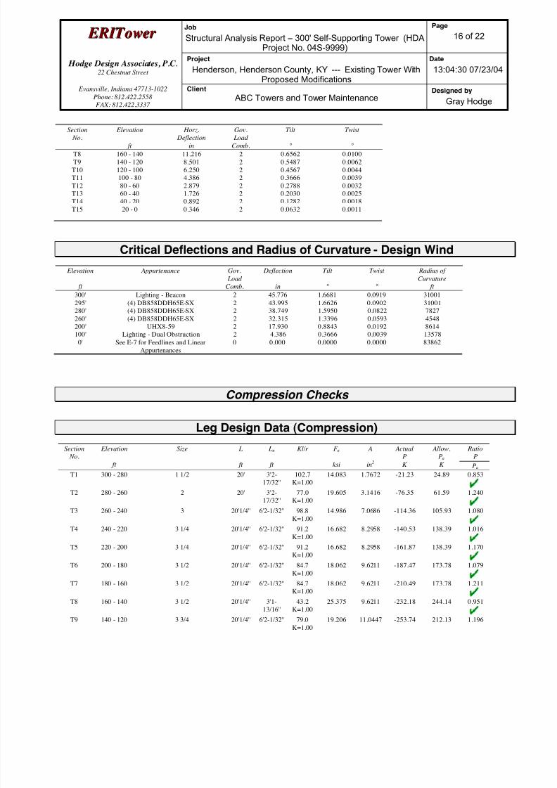
8/18/2019 Analysis Self Supporting-1
http://slidepdf.com/reader/full/analysis-self-supporting-1 89/98
E E R R I I T T oowweer r Job
Structural Analysis Report -- 300' Self-Supporting Tower (HDAProject No. 04S-9999)
Page
16 of 22
Hodge Design Associates, P.C. 22 Chestnut Street
Project
Henderson, Henderson County, KY --- Existing Tower WithProposed Modifications
Date
13:04:30 07/23/04
Evansville, Indiana 47713-1022
Phone: 812.422.2558
FAX: 812.422.3337
Client
ABC Towers and Tower MaintenanceDesigned by
Gray Hodge
Section No.
Elevation
ft
Horz. Deflection
in
Gov. Load
Comb.
Tilt
°
Twist
°
T8 160 - 140 11.216 2 0.6562 0.0100
T9 140 - 120 8.501 2 0.5487 0.0062
T10 120 - 100 6.250 2 0.4567 0.0044
T11 100 - 80 4.386 2 0.3666 0.0039
T12 80 - 60 2.879 2 0.2788 0.0032
T13 60 - 40 1.726 2 0.2030 0.0025
T14 40 - 20 0.892 2 0.1282 0.0018
T15 20 - 0 0.346 2 0.0632 0.0011
Critical Deflections and Radius of Curvature - Design Wind
Elevation
ft
Appurtenance Gov.
Load
Comb.
Deflection
in
Tilt
°
Twist
°
Radius of
Curvature
ft
300' Lighting - Beacon 2 45.776 1.6681 0.0919 31001
295' (4) DB858DDH65E-SX 2 43.995 1.6626 0.0902 31001
280' (4) DB858DDH65E-SX 2 38.749 1.5950 0.0822 7827
260' (4) DB858DDH65E-SX 2 32.315 1.3396 0.0593 4548
200' UHX8-59 2 17.930 0.8843 0.0192 8614
100' Lighting - Dual Obstruction 2 4.386 0.3666 0.0039 13578
0' See E-7 for Feedlines and Linear
Appurtenances
0 0.000 0.0000 0.0000 83862
Compression Checks
Leg Design Data (Compression)
Section
No.
Elevation
ft
Size L
ft
Lu
ft
Kl/r F a
ksi
A
in2
Actual
P
K
Allow.
Pa
K
Ratio
P
Pa
T1 300 - 280 1 1/2 20' 3'2-
17/32''
102.7
K=1.00
14.083 1.7672 -21.23 24.89 0.853
T2 280 - 260 2 20' 3'2-
17/32''
77.0
K=1.00
19.605 3.1416 -76.35 61.59 1.240
T3 260 - 240 3 20'1/4'' 6'2-1/32'' 98.8
K=1.00
14.986 7.0686 -114.36 105.93 1.080
T4 240 - 220 3 1/4 20'1/4'' 6'2-1/32'' 91.2
K=1.00
16.682 8.2958 -140.53 138.39 1.016
T5 220 - 200 3 1/4 20'1/4'' 6'2-1/32'' 91.2
K=1.00
16.682 8.2958 -161.87 138.39 1.170
T6 200 - 180 3 1/2 20'1/4'' 6'2-1/32'' 84.7
K=1.00
18.062 9.6211 -187.47 173.78 1.079
T7 180 - 160 3 1/2 20'1/4'' 6'2-1/32'' 84.7
K=1.00
18.062 9.6211 -210.49 173.78 1.211
T8 160 - 140 3 1/2 20'1/4'' 3'1-
13/16''
43.2
K=1.00
25.375 9.6211 -232.18 244.14 0.951
T9 140 - 120 3 3/4 20'1/4'' 6'2-1/32'' 79.0
K=1.00
19.206 11.0447 -253.74 212.13 1.196

8/18/2019 Analysis Self Supporting-1
http://slidepdf.com/reader/full/analysis-self-supporting-1 90/98
E E R R I I T T oowweer r Job
Structural Analysis Report -- 300' Self-Supporting Tower (HDAProject No. 04S-9999)
Page
17 of 22
Hodge Design Associates, P.C. 22 Chestnut Street
Project
Henderson, Henderson County, KY --- Existing Tower WithProposed Modifications
Date
13:04:30 07/23/04
Evansville, Indiana 47713-1022
Phone: 812.422.2558
FAX: 812.422.3337
Client
ABC Towers and Tower MaintenanceDesigned by
Gray Hodge
Section No.
Elevation
ft
Size L
ft
Lu
ft
Kl/r F a
ksi
A
in2
ActualP
K
Allow.Pa
K
RatioP
Pa
T10 120 - 100 3 3/4 20'1/4'' 6'2-1/32'' 79.0
K=1.00
19.206 11.0447 -274.94 212.13 1.296
T11 100 - 80 3 3/4 20'1/4'' 3'1-9/16'' 40.1
K=1.00
25.819 11.0447 -296.31 285.17 1.039
T12 80 - 60 4 20'1/4'' 6'2-1/32'' 74.1
K=1.00
20.168 12.5664 -318.08 253.44 1.255
T13 60 - 40 4 20'1/4'' 3'1-7/16'' 37.5
K=1.00
26.178 12.5664 -340.32 328.96 1.035
T14 40 - 20 4 1/4 20'1/4'' 6'2-1/32'' 69.7
K=1.00
20.988 14.1863 -362.54 297.74 1.218
T15 20 - 0 4 1/4 20'1/4'' 6'2-1/32'' 69.7
K=1.00
20.988 14.1863 -383.68 297.74 1.289
Diagonal Design Data (Compression)
Section
No.
Elevation
ft
Size L
ft
Lu
ft
Kl/r F a
ksi
A
in2
Actual
P
K
Allow.
Pa
K
Ratio
P
Pa
T1 300 - 280 3/4 5'1-9/16'' 2'5-3/4'' 159.0
K=1.00
5.910 0.4418 -2.46 2.61 0.943
T2 280 - 260 7/8 5'1-9/16'' 2'5-
17/32''
134.8
K=1.00
8.220 0.6013 -4.85 4.94 0.981
T3 260 - 240 L2x2x3/16 7'6-3/8'' 3'9-19/32''
115.8K=1.00
10.870 0.7150 -5.86 7.77 0.754
T4 240 - 220 L2x2x3/16 8'7-7/16'' 4'3-
27/32''
131.4
K=1.00
8.643 0.7150 -4.25 6.18 0.688
T5 220 - 200 L2x2x3/16 10'8-
17/32''
5'4-3/16'' 162.9
K=1.00
5.628 0.7150 -3.42 4.02 0.851
T6 200 - 180 2L2x2x3/16x3/4 12'1-
9/16''
6'19/32'' 117.6
K=1.00
10.623 1.4300 -4.47 15.19 0.294
2L 'a' > 34.7524 in - 159
T7 180 - 160 2L2x2x1/4x3/4 13'7-
5/16''
6'9-
15/32''
133.8
K=1.00
8.343 1.8800 -4.54 15.68 0.289
T8 160 - 140 L2 1/2x2 1/2x3/16 15'1-
11/16''
7'6-
19/32''
183.1
K=1.00
4.452 0.9020 -4.93 4.02 1.228
T9 140 - 120 2L2 1/2x2 1/2x3/16x3/4 16'8-
13/32''
8'3-
27/32''
128.4
K=1.00
9.060 1.8000 -5.17 16.31 0.317
T10 120 - 100 2L2 1/2x2 1/2x1/4x3/4 18'3-15/32''
9'1-7/16'' 142.3K=1.00
7.380 2.3800 -5.46 17.56 0.311
T11 100 - 80 2L3x3x3/16x3/4 19'10-
11/16''
9'11-
1/32''
126.7
K=1.00
9.292 2.1800 -6.17 20.26 0.305
T12 80 - 60 2L3x3x1/4x3/8 21'6'' 10'8-
17/32''
138.2
K=1.00
7.815 2.8800 -6.46 22.51 0.287
T13 60 - 40 2L3 1/2x3 1/2x1/4x3/4 23'1-
9/16''
11'6-3/8'' 126.9
K=1.00
9.274 3.3800 -7.22 31.35 0.230
T14 40 - 20 2L3 1/2x3 1/2x1/4x3/4 24'9-1/8'' 12'3-
31/32''
135.8
K=1.00
8.100 3.3800 -7.69 27.38 0.281
T15 20 - 0 L4x4x1/4 25'10-
13/16''
12'10-
13/16''
194.7
K=1.00
3.938 1.9400 -8.07 7.64 1.056

8/18/2019 Analysis Self Supporting-1
http://slidepdf.com/reader/full/analysis-self-supporting-1 91/98
E E R R I I T T oowweer r Job
Structural Analysis Report -- 300' Self-Supporting Tower (HDAProject No. 04S-9999)
Page
18 of 22
Hodge Design Associates, P.C. 22 Chestnut Street
Project
Henderson, Henderson County, KY --- Existing Tower WithProposed Modifications
Date
13:04:30 07/23/04
Evansville, Indiana 47713-1022
Phone: 812.422.2558
FAX: 812.422.3337
Client
ABC Towers and Tower MaintenanceDesigned by
Gray Hodge
Section No.
Elevation
ft
Size L
ft
Lu
ft
Kl/r F a
ksi
A
in2
ActualP
K
Allow.Pa
K
RatioP
Pa
Secondary Horizontal Design Data (Compression)
Section
No.
Elevation
ft
Size L
ft
Lu
ft
Kl/r F a
ksi
A
in2
Actual
P
K
Allow.
Pa
K
Ratio
P
Pa
T8 160 - 140 2L2x2x3/16x3/4 13'9-
27/32''
13'6-3/8'' 263.2
K=1.00
2.156 1.4300 -1.05 3.08 0.339
KL/R > 250 (C) - 205
T11 100 - 80 2L2x2x3/16x3/4 18'10-13/16''
18'7-3/32''
361.6K=1.00
1.142 1.4300 -1.19 1.63 0.726
KL/R > 250 (C) - 277
T13 60 - 40 2L2x2x3/16x3/4 22'3-
15/32''
21'11-
13/32''
427.0
K=1.00
0.819 1.4300 -1.18 1.17 1.011
KL/R > 250 (C) - 328
Top Girt Design Data (Compression)
Section
No.
Elevation
ft
Size L
ft
Lu
ft
Kl/r F a
ksi
A
in2
Actual
P
K
Allow.
Pa
K
Ratio
P
Pa
T1 300 - 280 3/4 4' 3'10-9/16''
248.0K=1.00
2.428 0.4418 -0.13 1.07 0.124
KL/R > 200 (C) - 5
T2 280 - 260 7/8 4' 3'9-
31/32''
210.3
K=1.00
3.377 0.6013 -1.74 2.03 0.856
KL/R > 200 (C) - 49
Bottom Girt Design Data (Compression)
Section
No.
Elevation
ft
Size L
ft
Lu
ft
Kl/r F a
ksi
A
in2
Actual
P
K
Allow.
Pa
K
Ratio
P
Pa
T1 300 - 280 3/4 4' 3'10-9/16''
248.0K=1.00
2.428 0.4418 -0.91 1.07 0.845
KL/R > 200 (C) - 7
T2 280 - 260 7/8 4' 3'9-
31/32''
210.3
K=1.00
3.377 0.6013 -0.49 2.03 0.244
KL/R > 200 (C) - 54
Tension Checks

8/18/2019 Analysis Self Supporting-1
http://slidepdf.com/reader/full/analysis-self-supporting-1 92/98
E E R R I I T T oowweer r Job
Structural Analysis Report -- 300' Self-Supporting Tower (HDAProject No. 04S-9999)
Page
19 of 22
Hodge Design Associates, P.C. 22 Chestnut Street
Project
Henderson, Henderson County, KY --- Existing Tower WithProposed Modifications
Date
13:04:30 07/23/04
Evansville, Indiana 47713-1022
Phone: 812.422.2558
FAX: 812.422.3337
Client
ABC Towers and Tower MaintenanceDesigned by
Gray Hodge
Leg Design Data (Tension)
Section
No.
Elevation
ft
Size L
ft
Lu
ft
Kl/r F a
ksi
A
in2
Actual
P
K
Allow.
Pa
K
Ratio
P
Pa
T1 300 - 280 1 1/2 20' 3'2-
17/32''
102.7 30.000 1.7672 19.40 53.01 0.366
T2 280 - 260 2 20' 3'2-
17/32''
77.0 30.000 3.1416 72.15 94.25 0.766
T3 260 - 240 3 20'1/4'' 6'2-1/32'' 98.8 30.000 7.0686 107.04 212.06 0.505
T4 240 - 220 3 1/4 20'1/4'' 6'2-1/32'' 91.2 30.000 8.2958 130.70 248.87 0.525
T5 220 - 200 3 1/4 20'1/4'' 6'2-1/32'' 91.2 30.000 8.2958 149.34 248.87 0.600
T6 200 - 180 3 1/2 20'1/4'' 6'2-1/32'' 84.7 30.000 9.6211 171.10 288.63 0.593
T7 180 - 160 3 1/2 20'1/4'' 6'2-1/32'' 84.7 30.000 9.6211 190.23 288.63 0.659
T8 160 - 140 3 1/2 20'1/4'' 3'1-
13/16''
43.2 30.000 9.6211 207.89 288.63 0.720
T9 140 - 120 3 3/4 20'1/4'' 6'2-1/32'' 79.0 30.000 11.0447 224.72 331.34 0.678
T10 120 - 100 3 3/4 20'1/4'' 6'2-1/32'' 79.0 30.000 11.0447 240.55 331.34 0.726
T11 100 - 80 3 3/4 20'1/4'' 3'1-9/16'' 40.1 30.000 11.0447 255.81 331.34 0.772
T12 80 - 60 4 20'1/4'' 6'2-1/32'' 74.1 30.000 12.5664 270.89 376.99 0.719
T13 60 - 40 4 20'1/4'' 3'1-7/16'' 37.5 30.000 12.5664 285.02 376.99 0.756
T14 40 - 20 4 1/4 20'1/4'' 6'2-1/32'' 69.7 30.000 14.1863 299.21 425.59 0.703
T15 20 - 0 4 1/4 20'1/4'' 6'2-1/32'' 69.7 30.000 14.1863 313.82 425.59 0.737
Diagonal Design Data (Tension)
Section
No.
Elevation
ft
Size L
ft
Lu
ft
Kl/r F a
ksi
A
in2
Actual
PK
Allow.
Pa K
Ratio
PPa
T1 300 - 280 3/4 5'1-9/16'' 2'5-3/4'' 159.0 21.600 0.4418 2.46 9.54 0.258
T2 280 - 260 7/8 5'1-9/16'' 2'5-
17/32''
134.8 21.600 0.6013 4.81 12.99 0.370
T3 260 - 240 L2x2x3/16 7'6-3/8'' 3'9-
19/32''
74.0 21.600 0.7150 5.37 15.44 0.347
T4 240 - 220 L2x2x3/16 8'7-7/16'' 4'3-
27/32''
83.9 21.600 0.7150 3.80 15.44 0.246
T5 220 - 200 L2x2x3/16 10'8-
17/32''
5'4-3/16'' 104.0 21.600 0.7150 3.58 15.44 0.232

8/18/2019 Analysis Self Supporting-1
http://slidepdf.com/reader/full/analysis-self-supporting-1 93/98
E E R R I I T T oowweer r Job
Structural Analysis Report -- 300' Self-Supporting Tower (HDAProject No. 04S-9999)
Page
20 of 22
Hodge Design Associates, P.C. 22 Chestnut Street
Project
Henderson, Henderson County, KY --- Existing Tower WithProposed Modifications
Date
13:04:30 07/23/04
Evansville, Indiana 47713-1022
Phone: 812.422.2558
FAX: 812.422.3337
Client
ABC Towers and Tower MaintenanceDesigned by
Gray Hodge
Section No.
Elevation
ft
Size L
ft
Lu
ft
Kl/r F a
ksi
A
in2
ActualP
K
Allow.Pa
K
RatioP
Pa
T6 200 - 180 2L2x2x3/16x3/4 12'1-
9/16''
6'19/32'' 117.6 21.600 1.4300 4.73 30.89 0.153
2L 'a' > 34.7524 in - 160
T7 180 - 160 2L2x2x1/4x3/4 13'7-
5/16''
6'9-
15/32''
133.8 21.600 1.8800 4.85 40.61 0.119
T8 160 - 140 L2 1/2x2 1/2x3/16 15'1-
11/16''
7'6-
19/32''
116.5 21.600 0.9020 4.74 19.48 0.243
T9 140 - 120 2L2 1/2x2 1/2x3/16x3/4 16'8-
13/32''
8'3-
27/32''
128.4 21.600 1.8000 5.40 38.88 0.139
T10 120 - 100 2L2 1/2x2 1/2x1/4x3/4 18'3-
15/32''
9'1-7/16'' 142.3 21.600 2.3800 5.85 51.41 0.114
T11 100 - 80 2L3x3x3/16x3/4 19'10-
11/16''
9'11-
1/32''
126.7 21.600 2.1800 5.95 47.09 0.126
T12 80 - 60 2L3x3x1/4x3/8 21'6'' 10'8-
17/32''
138.2 21.600 2.8800 6.86 62.21 0.110
T13 60 - 40 2L3 1/2x3 1/2x1/4x3/4 23'1-
9/16''
11'6-3/8'' 126.9 21.600 3.3800 7.02 73.01 0.096
T14 40 - 20 2L3 1/2x3 1/2x1/4x3/4 24'9-1/8'' 12'3-
31/32''
135.8 21.600 3.3800 7.98 73.01 0.109
T15 20 - 0 L4x4x1/4 26'4-
29/32''
13'1-
29/32''
126.3 21.600 1.9400 9.39 41.90 0.224
Secondary Horizontal Design Data (Tension)
Section
No.
Elevation
ft
Size L
ft
Lu
ft
Kl/r F a
ksi
A
in2
Actual
P
K
Allow.
Pa
K
Ratio
P
Pa
T8 160 - 140 2L2x2x3/16x3/4 13'9-
27/32''
13'6-3/8'' 263.2 21.600 1.4300 0.86 30.89 0.028
T11 100 - 80 2L2x2x3/16x3/4 18'10-
13/16''
18'7-
3/32''
361.6 21.600 1.4300 1.03 30.89 0.033
T13 60 - 40 2L2x2x3/16x3/4 22'3-
15/32''
21'11-
13/32''
427.0 21.600 1.4300 1.10 30.89 0.036
Top Girt Design Data (Tension)
Section
No.
Elevation
ft
Size L
ft
Lu
ft
Kl/r F a
ksi
A
in2
Actual
P
K
Allow.
Pa
K
Ratio
P
Pa
T1 300 - 280 3/4 4' 3'10-
9/16''
248.0 21.600 0.4418 0.12 9.54 0.012
T2 280 - 260 7/8 4' 3'9-
31/32''
210.3 21.600 0.6013 1.75 12.99 0.134
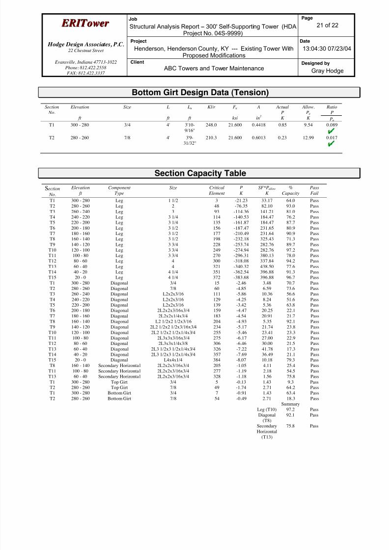
8/18/2019 Analysis Self Supporting-1
http://slidepdf.com/reader/full/analysis-self-supporting-1 94/98
E E R R I I T T oowweer r Job
Structural Analysis Report -- 300' Self-Supporting Tower (HDAProject No. 04S-9999)
Page
21 of 22
Hodge Design Associates, P.C. 22 Chestnut Street
Project
Henderson, Henderson County, KY --- Existing Tower WithProposed Modifications
Date
13:04:30 07/23/04
Evansville, Indiana 47713-1022
Phone: 812.422.2558
FAX: 812.422.3337
Client
ABC Towers and Tower MaintenanceDesigned by
Gray Hodge
Bottom Girt Design Data (Tension)
Section
No.
Elevation
ft
Size L
ft
Lu
ft
Kl/r F a
ksi
A
in2
Actual
P
K
Allow.
Pa
K
Ratio
P
Pa
T1 300 - 280 3/4 4' 3'10-
9/16''
248.0 21.600 0.4418 0.85 9.54 0.089
T2 280 - 260 7/8 4' 3'9-
31/32''
210.3 21.600 0.6013 0.23 12.99 0.017
Section Capacity Table
Section
No.
Elevation
ft
Component
Type
Size Critical
Element
P
K
SF*Pallow
K
%
Capacity
Pass
Fail
T1 300 - 280 Leg 1 1/2 3 -21.23 33.17 64.0 Pass
T2 280 - 260 Leg 2 48 -76.35 82.10 93.0 Pass
T3 260 - 240 Leg 3 93 -114.36 141.21 81.0 Pass
T4 240 - 220 Leg 3 1/4 114 -140.53 184.47 76.2 Pass
T5 220 - 200 Leg 3 1/4 135 -161.87 184.47 87.7 Pass
T6 200 - 180 Leg 3 1/2 156 -187.47 231.65 80.9 Pass
T7 180 - 160 Leg 3 1/2 177 -210.49 231.64 90.9 Pass
T8 160 - 140 Leg 3 1/2 198 -232.18 325.43 71.3 Pass
T9 140 - 120 Leg 3 3/4 228 -253.74 282.76 89.7 Pass
T10 120 - 100 Leg 3 3/4 249 -274.94 282.76 97.2 Pass
T11 100 - 80 Leg 3 3/4 270 -296.31 380.13 78.0 Pass
T12 80 - 60 Leg 4 300 -318.08 337.84 94.2 Pass
T13 60 - 40 Leg 4 321 -340.32 438.50 77.6 Pass
T14 40 - 20 Leg 4 1/4 351 -362.54 396.88 91.3 PassT15 20 - 0 Leg 4 1/4 372 -383.68 396.88 96.7 Pass
T1 300 - 280 Diagonal 3/4 15 -2.46 3.48 70.7 Pass
T2 280 - 260 Diagonal 7/8 60 -4.85 6.59 73.6 Pass
T3 260 - 240 Diagonal L2x2x3/16 111 -5.86 10.36 56.6 Pass
T4 240 - 220 Diagonal L2x2x3/16 129 -4.25 8.24 51.6 Pass
T5 220 - 200 Diagonal L2x2x3/16 139 -3.42 5.36 63.8 Pass
T6 200 - 180 Diagonal 2L2x2x3/16x3/4 159 -4.47 20.25 22.1 Pass
T7 180 - 160 Diagonal 2L2x2x1/4x3/4 183 -4.54 20.91 21.7 Pass
T8 160 - 140 Diagonal L2 1/2x2 1/2x3/16 204 -4.93 5.35 92.1 Pass
T9 140 - 120 Diagonal 2L2 1/2x2 1/2x3/16x3/4 234 -5.17 21.74 23.8 Pass
T10 120 - 100 Diagonal 2L2 1/2x2 1/2x1/4x3/4 255 -5.46 23.41 23.3 Pass
T11 100 - 80 Diagonal 2L3x3x3/16x3/4 275 -6.17 27.00 22.9 Pass
T12 80 - 60 Diagonal 2L3x3x1/4x3/8 306 -6.46 30.00 21.5 Pass
T13 60 - 40 Diagonal 2L3 1/2x3 1/2x1/4x3/4 326 -7.22 41.78 17.3 Pass
T14 40 - 20 Diagonal 2L3 1/2x3 1/2x1/4x3/4 357 -7.69 36.49 21.1 Pass
T15 20 - 0 Diagonal L4x4x1/4 384 -8.07 10.18 79.3 Pass
T8 160 - 140 Secondary Horizonta l 2L2x2x3/16x3/4 205 -1.05 4.11 25.4 PassT11 100 - 80 Secondary Horizonta l 2L2x2x3/16x3/4 277 -1.19 2.18 54.5 Pass
T13 60 - 40 Secondary Horizonta l 2L2x2x3/16x3/4 328 -1.18 1.56 75.8 Pass
T1 300 - 280 Top Girt 3/4 5 -0.13 1.43 9.3 Pass
T2 280 - 260 Top Girt 7/8 49 -1.74 2.71 64.2 Pass
T1 300 - 280 Bottom Girt 3/4 7 -0.91 1.43 63.4 Pass
T2 280 - 260 Bottom Girt 7/8 54 -0.49 2.71 18.3 Pass
Summary
Leg (T10) 97.2 Pass
Diagonal
(T8)
92.1 Pass
Secondary
Horizontal
(T13)
75.8 Pass
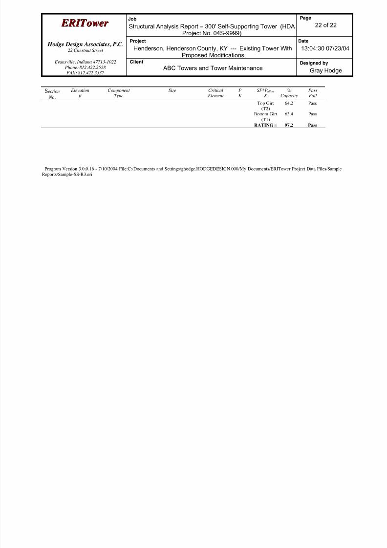
8/18/2019 Analysis Self Supporting-1
http://slidepdf.com/reader/full/analysis-self-supporting-1 95/98
E E R R I I T T oowweer r Job
Structural Analysis Report -- 300' Self-Supporting Tower (HDAProject No. 04S-9999)
Page
22 of 22
Hodge Design Associates, P.C. 22 Chestnut Street
Project
Henderson, Henderson County, KY --- Existing Tower WithProposed Modifications
Date
13:04:30 07/23/04
Evansville, Indiana 47713-1022
Phone: 812.422.2558
FAX: 812.422.3337
Client
ABC Towers and Tower MaintenanceDesigned by
Gray Hodge
Section No.
Elevation ft
ComponentType
Size Critical Element
PK
SF*Pallow
K%
CapacityPassFail
Top Girt
(T2)
64.2 Pass
Bottom Girt
(T1)
63.4 Pass
RATING = 97.2 Pass
Program Version 3.0.0.16 - 7/10/2004 File:C:/Documents and Settings/ghodge.HODGEDESIGN.000/My Documents/ERITower Project Data Files/Sample
Reports/Sample-SS-R3.eri
8/18/2019 Analysis Self Supporting-1
http://slidepdf.com/reader/full/analysis-self-supporting-1 96/98
APPENDIX E
S u g g e s t e d R e c o m m e n d a t i o n s f or T o w e r R e in f or c e m e n t
G r a p h i c a l Co m p u t e r O u t p u t
S t r u c t u r a l An a l y s i s R e p o r t a n d C a l c u l a t i o n s

8/18/2019 Analysis Self Supporting-1
http://slidepdf.com/reader/full/analysis-self-supporting-1 97/98

8/18/2019 Analysis Self Supporting-1
http://slidepdf.com/reader/full/analysis-self-supporting-1 98/98
=
Related Documents