dinak.com ‡ DINAK technological innovation SELF-SUPPORTING CHIMNEYS, VENTILATION TOWERS and STRUCTURES ECA E U R O P E A N C H IM N E Y S A S S O C I A T I O N

Welcome message from author
This document is posted to help you gain knowledge. Please leave a comment to let me know what you think about it! Share it to your friends and learn new things together.
Transcript
dinak.com
‡ DINAKtechnological innovation
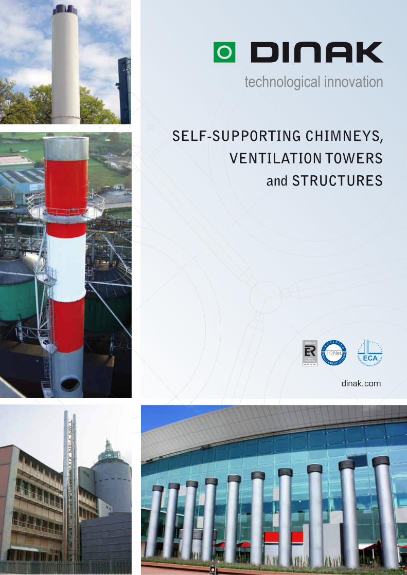
SELF-SUPPORTING CHIMNEYS,
VENTILATION TOWERS
and STRUCTURES
ECAEU
ROPEAN CHIMNEYS ASSOCIATI
ON
DINAK, technological innovation
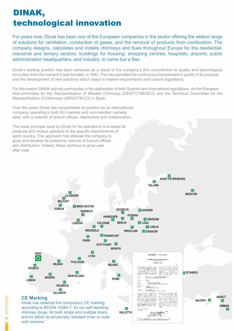
CE MarkingDinak has obtained the compulsory CE marking, according to BS-EN 13084-7, for our self standing chimney range, for both single and multiple liners, and for either its structurally resistant inner or outer wall versions.”
MADRID
BILBAO
PARIS
VIGO
BARCELONA
MILANO
LYON
MOSCOW
SAINT PETERSBURG
TALLINN
BELFAST
DUBLIN
LONDON
OPORTO
LISBON
ISTANBUL
ATHENS
SOFIA
VALLETTA
BUCAREST
NICOSIABEIRUT
AMMAN
GLASGOW
BRUSSELS
VALENCIA
ROME
ALICANTE
MANCHESTER
TOULOUSE
STUTTGART
FRANKFURT
LÓDZWARSAW
POZNAN
BERLIN
HANNOVER
MUNICH
GDANSKSZCZECIN
KRAKOWLUBLIN
WROCLAW
COLOGNE
NORWICH
For years now, Dinak has been one of the European companies in the sector offering the widest range of solutions for ventilation, conduction of gases, and the removal of products from combustion. The company designs, calculates and installs chimneys and flues throughout Europe for the residential, industrial and tertiary sectors: buildings for housing; shopping centres; hospitals; airports; public administration headquarters; and industry, to name but a few.
Dinak’s leading position has been achieved as a result of the company’s firm commitment to quality and technological innovation from the moment it was founded, in 1983. This has permitted the continuous improvement in quality of its products and the development of new solutions which adapt to market requirements and current regulations.
For this reason DINAK actively participates in the elaboration of both Spanish and international regulations, via the European Sub-committee for the Standardisation of Metallic Chimneys (CEN/TC166/SC2) and the Technical Committee for the Standardisation of Chimneys (AEN/CTN123) in Spain.
Over the years Dinak has consolidated its position as an international company operating in both EU markets and non-member markets alike, with a network of branch offices, distributors and collaborators.
The basic principle used by Dinak for its operations is to adapt its products and modus operandi to the specific requirements of each country. This approach has allowed the company to grow and develop its extensive network of branch offices and distributors. Indeed, these continue to grow year after year.
01
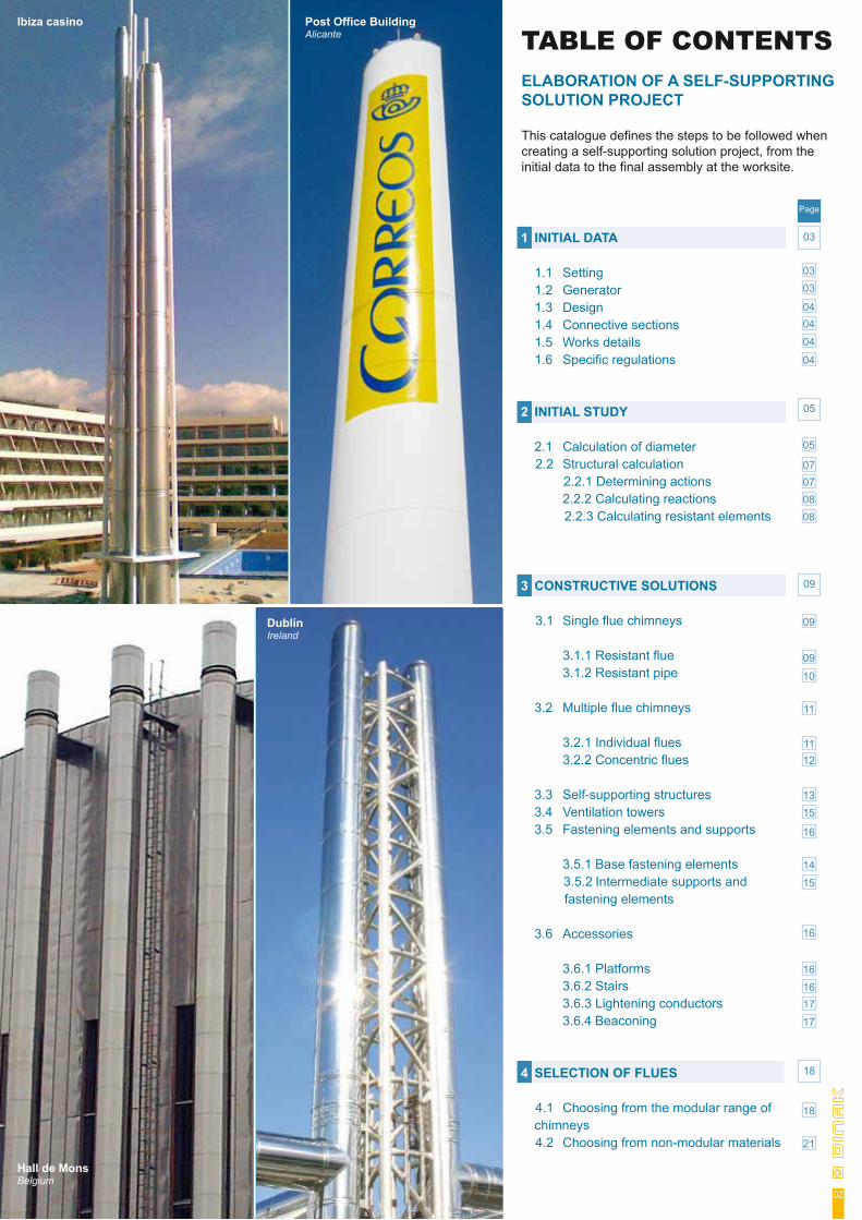
TABLE OF CONTENTSELABORATION OF A SELF-SUPPORTING SOLUTION PROJECT
This catalogue defines the steps to be followed when creating a self-supporting solution project, from the initial data to the final assembly at the worksite.
1 INITIAL DATA
1.1 Setting 1.2 Generator 1.3 Design 1.4 Connective sections 1.5 Works details 1.6 Specific regulations
2 INITIAL STUDY
2.1 Calculation of diameter 2.2 Structural calculation
2.2.1 Determining actions 2.2.2 Calculating reactions 2.2.3 Calculating resistant elements
3 CONSTRUCTIVE SOLUTIONS 3.1 Single flue chimneys
3.1.1 Resistant flue 3.1.2 Resistant pipe
3.2 Multiple flue chimneys
3.2.1 Individual flues 3.2.2 Concentric flues
3.3 Self-supporting structures 3.4 Ventilation towers 3.5 Fastening elements and supports
3.5.1 Base fastening elements 3.5.2 Intermediate supports and fastening elements 3.6 Accessories
3.6.1 Platforms 3.6.2 Stairs 3.6.3 Lightening conductors 3.6.4 Beaconing
4 SELECTION OF FLUES 4.1 Choosing from the modular range of chimneys 4.2 Choosing from non-modular materials
Page
03
0303
040404
04
05
05
07070808
11
09
09
09
10
1112
15
16
1415
16
13
1717
18
21
1616
18
Post Office BuildingAlicante
Ibiza casino
Dublín Ireland
Hall de Mons Belgium
02
1 INITIAL DATA
The initial data is the minimum, essential data required to begin the elaboration of the project
03
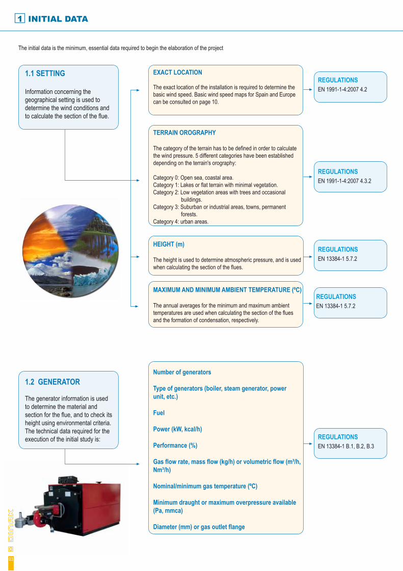
1.1 SETTING
Information concerning the geographical setting is used to determine the wind conditions and to calculate the section of the flue.
EXACT LOCATION The exact location of the installation is required to determine the basic wind speed. Basic wind speed maps for Spain and Europe can be consulted on page 10.
TERRAIN OROGRAPHY
The category of the terrain has to be defined in order to calculate the wind pressure. 5 different categories have been established depending on the terrain's orography:
Category 0: Open sea, coastal area.Category 1: Lakes or flat terrain with minimal vegetation.Category 2: Low vegetation areas with trees and occasional buildings.Category 3: Suburban or industrial areas, towns, permanent forests. Category 4: urban areas.
HEIGHT (m)
The height is used to determine atmospheric pressure, and is used when calculating the section of the flues.
MAXIMUM AND MINIMUM AMBIENT TEMPERATURE (ºC)
The annual averages for the minimum and maximum ambient temperatures are used when calculating the section of the flues and the formation of condensation, respectively.
Number of generators
Type of generators (boiler, steam generator, power unit, etc.)
Fuel
Power (kW, kcal/h)
Performance (%)
Gas flow rate, mass flow (kg/h) or volumetric flow (m³/h, Nm³/h)
Nominal/minimum gas temperature (ºC)
Minimum draught or maximum overpressure available (Pa, mmca)
Diameter (mm) or gas outlet flange
REGULATIONSEN 1991-1-4:2007 4.2
1.2 GENERATOR
The generator information is used to determine the material and section for the flue, and to check its height using environmental criteria. The technical data required for the execution of the initial study is:
REGULATIONSEN 1991-1-4:2007 4.3.2
REGULATIONSEN 13384-1 5.7.2
REGULATIONSEN 13384-1 5.7.2
REGULATIONSEN 13384-1 B.1, B.2, B.3
ELABORATING A PROJECT
Note 1: for those points not currently covered by applicable current European regulations, or which have not been defined in depth, some reference standards published in other countries are shown in italics.
04
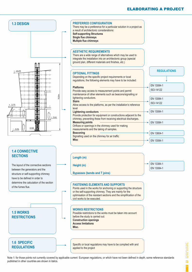
1.3 DESIGN PREFERRED CONFIGURATIONThere may be a preference for a particular solution in a project as a result of architectonic considerations:Self-supporting StructuresSingle flue chimneysMultiple flue chimneys
AESTHETIC REQUIREMENTSThere are a wide range of alternatives which may be used to integrate the installation into an architectonic group (special ground plan, different materials and finishes, etc.)
OPTIONAL FITTINGSDepending on the specific project requirements or local regulations, the following elements may have to be included:
PlatformsProvide easy access to measurement points and permit maintenance of other elements such as beacons/signalling or lightening conductors.StairsAllow access to the platforms, as per the installation’s reference level Lightening conductorsProvide protection for equipment or constructions adjacent to the chimney, preventing these from receiving electrical discharges.Measuring points Orifices or openings in the chimney used for making measurements and the taking of samples.BeaconingSignalling used on the chimney for air trafficMisc
Length (m)
Height (m)
Bypasses (bends and T joins)
FASTENING ELEMENTS AND SUPPORTSPoints used in the works for anchoring or supporting the structure or the self-supporting chimney. They are mainly for the optimisation of the resistant sections and the simplification of the civil works to be executed.
WORKS RESTRICTIONSPossible restrictions to the works must be taken into account before the study is carried out:Construction openingsAccess limitationsMisc.
Specific or local regulations may have to be complied with and applied to the project
1.4 CONNECTIVE SECTIONS
The layout of the connective sections between the generators and the structure or self-supporting chimney have to be defined in order to determine the calculation of the section of the fumes flue.
EN 13084-1 ISO-14122
1.5 WORKS RESTRICTIONS
1.6 SPECIFIC REGULATIONS
REGULATIONS
EN 13084-1 ISO-14122
EN 13084-1
EN 13084-1
EN 13804-1
EN 13084-1
EN 13384-1 EN 13084-1
2 INITIAL STUDY
Once all of the initial data for the project has been recompiled, the next step is to perform the initial study, which consists of the following sections:
2.1. CALCULATION OF DIAMETER
The calculation of the diameter of self-supporting chimneys is made by following the considerations outlined by the EN 13084-1 standard. This standard establishes that for heights less than 20m, the calculation method included in the EN 13384-1 standard may be used.
For heights equal to or greater than 20m, the calculation of the diameter has to be performed in accordance with the terms established under Annex A of the EN 13084-1 standard. This annex introduces an additional check for the requirements included in the EN 13384-1 standard, which are described below:
- The velocity of the fumes at the chimney outlet has to be greater than a minimum value which is a function of its diameter. This check is designed to ensure the suitability of the formulas used in the calculation, thus avoiding the possible effects of coatings on the chimney’s outlet. The minim velocities per diameter are shown in the following table:
Where, Di is the inner diameter of the flue in mm, and Wmin is the velocity of the fumes at the chimney outlet, in m/s.
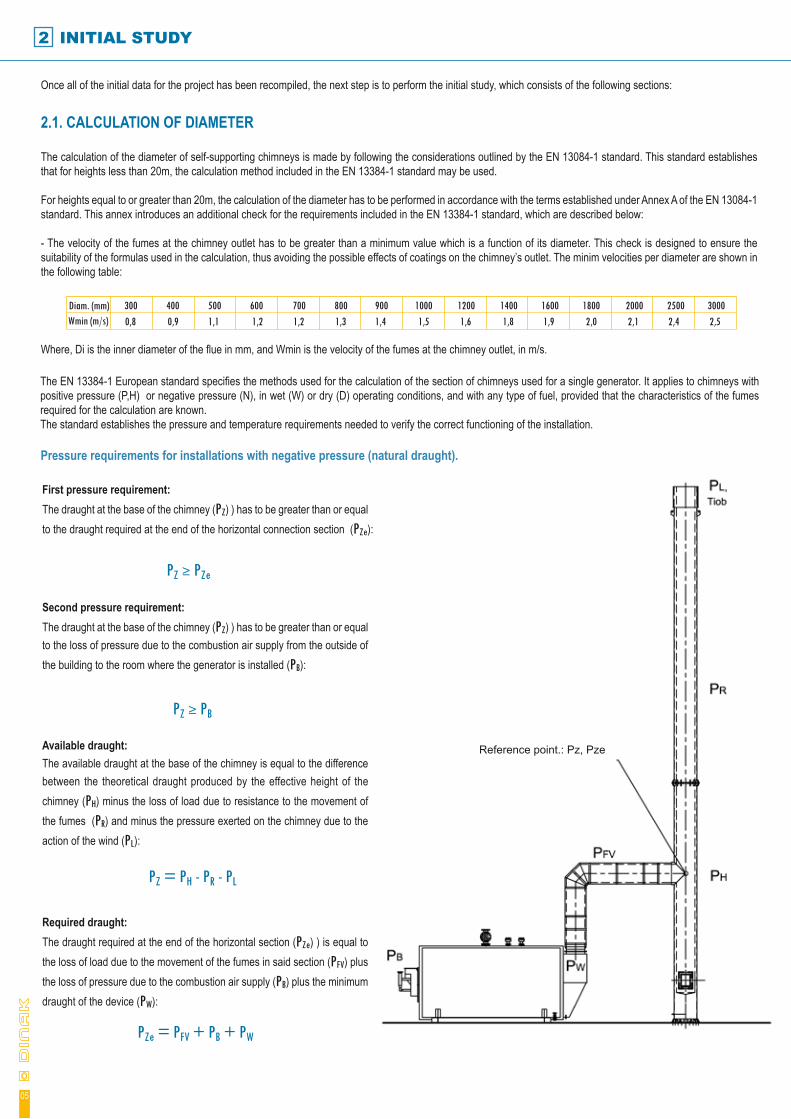
The EN 13384-1 European standard specifies the methods used for the calculation of the section of chimneys used for a single generator. It applies to chimneys with positive pressure (P,H) or negative pressure (N), in wet (W) or dry (D) operating conditions, and with any type of fuel, provided that the characteristics of the fumes required for the calculation are known.The standard establishes the pressure and temperature requirements needed to verify the correct functioning of the installation.
Pressure requirements for installations with negative pressure (natural draught).
Reference point.: Pz, Pze
05
Diam. (mm)Wmin (m/s)
300 400 500 600 700 800 900 1000 1200 1400 1600 1800 2000 2500 30002,52,42,12,01,91,81,61,51,41,31,21,21,10,90,8
First pressure requirement:The draught at the base of the chimney (PZ) ) has to be greater than or equal to the draught required at the end of the horizontal connection section (PZe):
PZ ≥ PZe
Second pressure requirement:The draught at the base of the chimney (PZ) ) has to be greater than or equal to the loss of pressure due to the combustion air supply from the outside of the building to the room where the generator is installed (PB):
PZ ≥ PB
Required draught:The draught required at the end of the horizontal section (PZe) ) is equal to the loss of load due to the movement of the fumes in said section (PFV) plus the loss of pressure due to the combustion air supply (PB) plus the minimum draught of the device (PW):
Available draught:The available draught at the base of the chimney is equal to the difference between the theoretical draught produced by the effective height of the chimney (PH) minus the loss of load due to resistance to the movement of the fumes (PR) and minus the pressure exerted on the chimney due to the action of the wind (PL):
PZ = PH - PR - PL
PZe = PFV + PB + PW

Dinak offers its customers a programme for the calculation of chimney diameters as per the requirements of the EN-13384-1 standard. This programme is called DINAKALC CE III, and allows you to determine the optimum operational diameter for all kinds of uses.
DINAKALC CE III is certified by ECA (European Chimneys Association) and by ESCHFOE (European Federation of Chimney-sweeps) and passed all of the required calculation tests in the Munich TUV.
The temperature of the inner wall of the chimney outlet (Tiob) has to be greater than or equal to the maximum temperature (Tg):
Pressure requirements for installations with positive pressure (overpressure)
The maximum temperature for chimneys operating in dry conditions (D) is equal to the condensation temperature for the fumes.The maximum temperature for chimneys operating in wet conditions (W) is equal to 0ºC to avoid the formation of ice at the chimney outlet.
Tiob ≥ Tg
ELABORATING A PROJECT
‡ DINAK
DINAKALC CE IVV.3.0.0
www.dinak.com
CHIMNEY SIZING PROGRAM ACCORDING TO THE EUROPEAN STANDARDS:EN 13384-1 (individual chimneys: boilers and power generators)
EN 13384-2 (collective chimneys: multi-inlet and cascade arrangements)
DINAK, S
.A. Cam
iño do Laranxo, 19. 36216 VIGO -SPAIN. +34 986 452 526 +34 986 454 192 [email protected]
ECAEU
ROPEAN CHIMNEYS ASSOCIATI
ON
NEWOFFER FOR COLLECTIVE DINAGAS FLUE SYSTEMSThis software produces a complete offer including a 2D diagram, list of items and economic valuation.
Reference Point: Pz, Pze
06
Second pressure requirement:The overpressure at the base of the chimney (PZO) ) has to be less than or equal to the maximum permitted overpressure for the chimney (PZexcess):
First pressure requirement:The overpressure at the base of the chimney (PZO) has to be less than or equal to the maximum available overpressure at the end of the horizontal connection section (PZOe):
PZO ≤PZOe
Available overpressure: The maximum overpressure available at the end of the horizontal connection section (PZOe) ) is equal to the difference between the maximum permitted overpressure at the generator outlet (PWO), minus the sum of the loss of effective load in said section and the loss of pressure due to the combustion air supply (PFV + PB):
Existing overpressure: The overpressure at the base of the chimney (PZO) is equal to the difference between the sum of the loss of pressure due to resistance to the movement of the fumes and the wind pressure (PR + PL), minus the theoretical draught (PH):
Third pressure requirement:The overpressure at the outlet from the generator (PZO + PFV) ) has to less than or equal to the maximum permitted overpressure for the horizontal connection section (PZVexcess)
The values of PZexcess and PZVexcess may be obtained from tables 1 and 2 for self-supporting and modular chimneys, respectively
PZO ≤ PZexcess
PZO + PFV ≤ PZVexcess
PZO = (PR + PL) - PH
PZOe = PWO - (PFV + PB)
Temperature requirements
Calculation programme
Table 1Self-Supporting chimneysPressure class, as per the Test pressure PZexcessUNE-EN 13084-6 standard H0 5.000 Pa 5.000 Pa H1 5.000 Pa 1.000 Pa P1 200 Pa 40 Pa
Table 2Modular chimneysPressure class, as per the Test pressure PZexcess,UNE-EN 1856-1 standard PZVexcess H1 5.000 Pa 5.000 Pa P1 200 Pa 200 Pa
2 INITIAL STUDY
2.2. STRUCTURAL CALCULATION
07
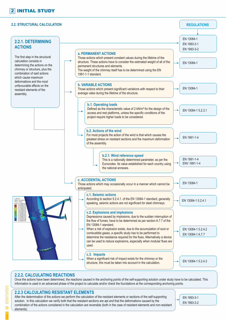
2.2.1. DETERMINING ACTIONS
The first step in the structural calculation consists in determining the actions on the chimney or structure, plus the combination of said actions which cause maximum deformations and the most unfavourable effects on the resistant elements of the assembly.
a. PERMANENT ACTIONSThose actions which present constant values during the lifetime of the structure. These actions have to consider the estimated weight of all of the permanent structures and elements.The weight of the chimney itself has to be determined using the EN 1991-1-1 standard.
EN 13084-1 5.2.3.1
REGULATIONS
EN 13084-1 EN 1993-3-1EN 1993-3-2
EN 13084-1
EN 13084-1
b.1. Operating loadsDefined as the characteristic value of 2 kN/m² for the design of the access and rest platforms, unless the specific conditions of the project require higher loads to be considered.
b.2. Actions of the windFor most projects the action of the wind is that which causes the greatest stress on resistant sections and the maximum deformation of the assembly.
EN 1991-1-4
b.2.1. Wind reference speed This is a nationally determined parameter, as per the Eurocodes. Its value established for each country using the national annexes.
EN 1991-1-4 ENV 1991-1-4
c. ACCIDENTAL ACTIONSThose actions which may occasionally occur in a manner which cannot be anticipated.
EN 13084-1
c.1. Seismic actionsAccording to section 5.2.4.1. of the EN 13084-1 standard, generally speaking, seismic actions are not significant for steel chimneys.
EN 13084-1 5.2.4.1
c.2. Explosions and implosionsDepressions caused by implosions, due to the sudden interruption of the flow of fumes, have to be determined as per section A.7.7 of the EN 13084-1 standard.When a risk of explosion exists, due to the accumulation of soot or combustible gases, a specific study has to be performed to determine the resistance required for the flues. Alternatively a device can be used to reduce explosions, especially when modular flues are used.
EN 13084-1 5.2.4.2EN 13084-1 A.7.7
EN 1993-3-1EN 1993-3-2
c.3. ImpactsWhen a significant risk of impact exists for the chimney or the structure, this must be taken into account in the calculation. EN 13084-1 5.2.4.3
b. VARIABLE ACTIONSThose actions which present significant variations with respect to their average vales during the lifetime of the structure.
2.2.2. CALCULATING REACTIONS Once the actions have been determined, the reactions caused in the anchoring points of the self-supporting solution under study have to be calculated. This information is used in an advanced phase of the project to calculate and/or check the foundations at the corresponding anchoring points.
2.2.3 CALCULATING RESISTANT ELEMENTSAfter the determination of the actions we perform the calculation of the resistant elements or sections of the self-supporting solution. In this calculation we verify both that the resistant sections are apt and that the deformations caused by the combination of the actions considered in the calculation are reversible (both in the case of resistant elements and non-resistant elements).
ELABORATING A PROJECT
08
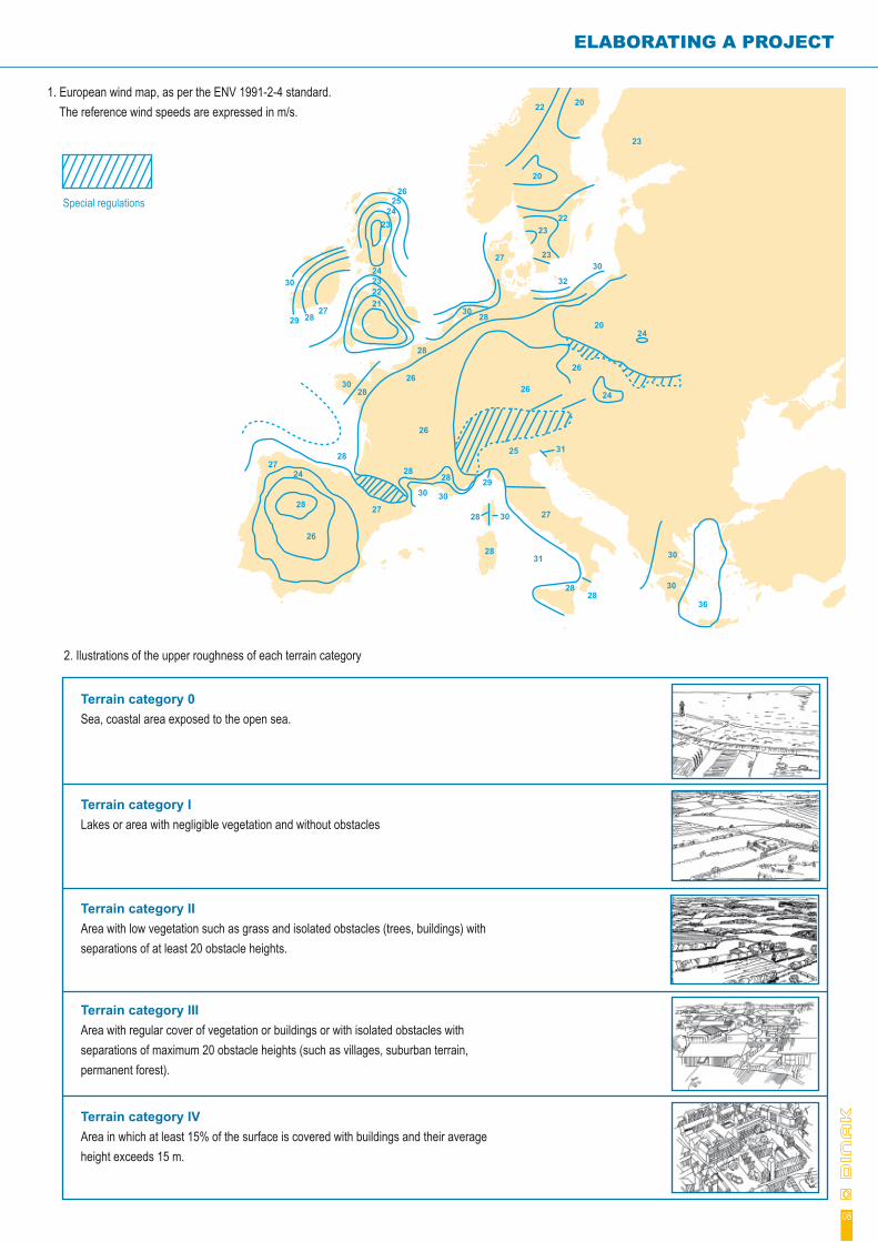
1. European wind map, as per the ENV 1991-2-4 standard. The reference wind speeds are expressed in m/s.
2. Ilustrations of the upper roughness of each terrain category
Terrain category 0Sea, coastal area exposed to the open sea.
Terrain category ILakes or area with negligible vegetation and without obstacles
Terrain category IIArea with low vegetation such as grass and isolated obstacles (trees, buildings) with separations of at least 20 obstacle heights.
Terrain category IIIArea with regular cover of vegetation or buildings or with isolated obstacles with separations of maximum 20 obstacle heights (such as villages, suburban terrain, permanent forest).
Terrain category IVArea in which at least 15% of the surface is covered with buildings and their average height exceeds 15 m.
2724
28
26
28
27
2828
26
2628
30 30
28 30
28
29
30
282927
30
21222324
2324
2526
28
2830
27 23
2322
23
20
22 20
30
32
2024
24
26
26
25
27
31
2828
30
36
30
31
Special regulations
3 CONSTRUCTIVE SOLUTIONS
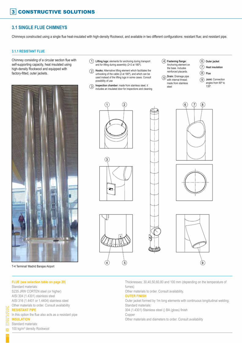
3.1 SINGLE FLUE CHIMNEYS
Chimneys constructed using a single flue heat-insulated with high-density Rockwool, and available in two different configurations: resistant flue; and resistant pipe.
3.1.1 RESISTANT FLUE
Chimney consisting of a circular section flue with self-supporting capacity, heat insulated using high-density Rockwool and equipped with factory-fitted, outer jackets.
FLUE (see selection table on page 20)Standard materials:S235 JRW CORTEN steel (or higher) AISI 304 (1.4301) stainless steelAISI 316 (1.4401 or 1.4404) stainless steelOther materials to order. Consult availabilityRESISTANT PIPEIn this option the flue also acts as a resistant pipeINSULATIONStandard materials:100 kg/m³ density Rockwool
Thicknesses; 30,40,50,60,80 and 100 mm (depending on the temperature of fumes)Other materials to order. Consult availability.OUTER FINISHOuter jacket formed by 1m long elements with continuous longitudinal welding.Standard materials:304 (1.4301) Stainless steel () BA (gloss) finishCopperOther materials and diameters to order. Consult availability
T-4 Terminal/ Madrid Barajas Airport
Lifting lugs: elements for anchoring during transport and for lifting during assembly (2+2 at 180º).
Hooks: Alternative lifting element which facilitates the unhooking of the cable (2 at 180º), and which can be used instead of the lifting lugs in some cases. Consult possibility of useInspection chamber: made from stainless steel, it includes an insulated door for inspections and cleaning
Fastening flange: Anchoring element on the base. Includes reinforced placards.Drain: Drainage pipe with internal thread; made from stainless steel
Outer jacket
Heat insulation
Flue
Joint: Connection angles from 90º to 135º.
1
2
3
4
5
6
7
8
9
09

ELABORATING A PROJECT
3.1.2 RESISTANT PIPE Self-supporting chimney consisting of an outer resistant metallic pipe with a circular section. In its interior it contains the flue, heat-insulated using high-density Rockwool, factory fitted, and supported and guided by low thermal bridge elements.
FLUE (see selection tables on pages 19 and 20)Standard materials:S235 JRW CORTEN steel (or higheAISI 304 (1.4301) stainless steelAISI 316 (1.4401 or 1.4404) stainless steelOptionally, any product from our range of modular chimneys may be used for the flue (page 19).Other materials to order. Consult availability.RESISTANT PIPEStandard materials:JR S235 Steel (or higher)
S235 JRW CORTEN steel (or higher) INSULATIONStandard materials:100 kg/m³ density RockwoolThicknesses; 30,40,50,60,80 and 100 mm (depending on the temperature of fumes)Other materials to order. Consult availability.STANDARD OUTER FINISHDusting to grade 2.5 s/sis-055900 of all of the outer surface using neutral sand; two coats of epoxy primer and final finish coat as per RAL colour chart. Final thickness of 100 to 150 microns.
AEMEDSA – Cartagena
Terminal: manufactured from stainless steel. This protects the outer finish of the chimney from contact with fumes.Lifting lugs: elements for anchoring during transport and for lifting during assembly (2+2 at 180º).
Inspection chamber: made from stainless steel, it includes two doors for inspections and cleaning of the flue and the ventilation chamber, respectively. The inner door is insulated.
Fastening flange: Anchoring element on the base. Includes reinforced placards.
Drain: Drainage pipe with internal thread and made from stainless steel
Outer resistant pipe
Flue
Joint: Connection angles from 90º to 135º.
Ventilation chamber: prevents the forming of condensation on the inner face of the resistant pipe.
1
2
4
5
6
7
9
10
11Hooks: Alternative lifting element which facilitates the unhooking of the cable (2 at 180º), and which can be used instead of the lifting lugs in some cases. Consult possibility of use.
3
Heat insulation8
10
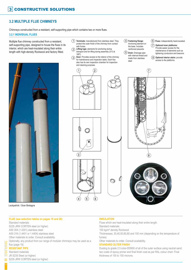
3.2 MULTIPLE FLUE CHIMNEYS
Chimneys constructed from a resistant, self-supporting pipe which contains two or more flues.3.2.1 INDIVIDUAL FLUES
Multiple flue chimney constructed from a resistant, self-supporting pipe, designed to house the flues in its interior, which are heat-insulated along their entire length with high-density Rockwool and factory fitted.
FLUE (see selection tables on pages 19 and 20)Standard materials:S235 JRW CORTEN steel (or higher) AISI 304 (1.4301) stainless steelAISI 316 (1.4401 or 1.4404) stainless steelOther materials to order. Consult availability.Optionally, any product from our range of modular chimneys may be used as a flue (page 19).RESISTANT PIPEStandard materialsJR S235 Steel (or higher)S235 JRW CORTEN steel (or higher)
IINSULATIONFlues which are heat-insulated along their entire length.Standard materials:100 kg/m³ density RockwoolThicknesses; 30,40,50,60,80 and 100 mm (depending on the temperature of fumes)Other materials to order. Consult availability.STANDARD OUTER FINISHDusting to grade 2.5 s/sis-055900 of all of the outer surface using neutral sand; two coats of epoxy primer and final finish coat as per RAL colour chart. Final thickness of 100 to 150 microns.
Leckpatrick / Gran Bretagna
3 CONSTRUCTIVE SOLUTIONS
Terminals: manufactured from stainless steel. They protect the outer finish of the chimney from contact with fumes. Lifting lugs: elements for anchoring during transport and for lifting during assembly (2+2 at 180º).Door: Provides access to the interior of the chimney for maintenance and inspection tasks. Each flue also has its own inspection chamber for inspection and cleaning purposes.
Fastening flange: Anchoring element on the base. Includes reinforced placardsDrain: Drainage pipe with internal thread and made from stainless steel
Flues: independently heat-insulated
Optional inner platforms: Provide easier access for the maintenance of elements such as lightening conductors and beacons
Optional interior stairs: provide access to the platforms.
1
2
3
4
5
6
7
8
11
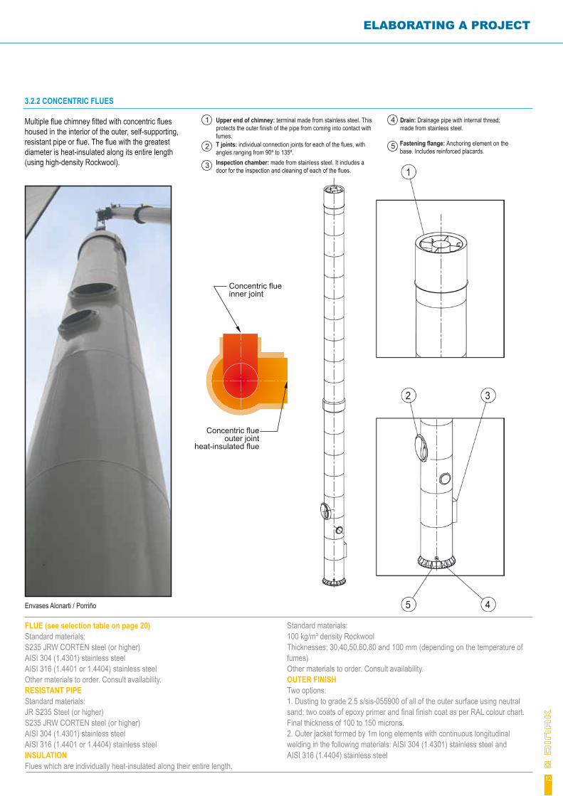
3.2.2 CONCENTRIC FLUES Multiple flue chimney fitted with concentric flues housed in the interior of the outer, self-supporting, resistant pipe or flue. The flue with the greatest diameter is heat-insulated along its entire length (using high-density Rockwool).
FLUE (see selection table on page 20)Standard materials:S235 JRW CORTEN steel (or higher) AISI 304 (1.4301) stainless steelAISI 316 (1.4401 or 1.4404) stainless steelOther materials to order. Consult availability.RESISTANT PIPEStandard materials:JR S235 Steel (or higher)S235 JRW CORTEN steel (or higher) AISI 304 (1.4301) stainless steelAISI 316 (1.4401 or 1.4404) stainless steelINSULATIONFlues which are individually heat-insulated along their entire length.
Standard materials:100 kg/m³ density RockwoolThicknesses; 30,40,50,60,80 and 100 mm (depending on the temperature of fumes)Other materials to order. Consult availability.OUTER FINISHTwo options:1. Dusting to grade 2.5 s/sis-055900 of all of the outer surface using neutral sand; two coats of epoxy primer and final finish coat as per RAL colour chart. Final thickness of 100 to 150 microns.2. Outer jacket formed by 1m long elements with continuous longitudinal welding in the following materials: AISI 304 (1.4301) stainless steel andAISI 316 (1.4404) stainless steel
ELABORATING A PROJECT
Envases Alonarti / Porriño
Upper end of chimney: terminal made from stainless steel. This protects the outer finish of the pipe from coming into contact with fumes.T joints: individual connection joints for each of the flues, with angles ranging from 90º to 135º. Inspection chamber: made from stainless steel. It includes a door for the inspection and cleaning of each of the flues.
Drain: Drainage pipe with internal thread; made from stainless steel.
Fastening flange: Anchoring element on the base. Includes reinforced placards.
1
2
3
4
5
Concentric flue inner joint
Concentric flue outer joint
heat-insulated flue
12

3.3 SELF-SUPPORTING STRUCTURES
Self-supporting structures made from interlinked latticework made from circular section metallic elements. The structures include factory fitted modular flues anchored to the structure using suitable stainless steel elements and screws
FLUE (see selection tables on page 19)Modular flues which are factory fitted, from the DINAK range chosen for use. Different product ranges and diameters may combined in the same structure. Consult possible combinations.SELF-SUPPORTING STRUCTURETwo typesSections in carbon steeStandard material:Steel S235 JOH / 235 JR (or higher)Standard finish:Dusting to grade 2.5 s/sis-055900 of all of the outer surface using neutral sand; two coats of epoxy primer and final finish coat as per RAL colour chart. Final
thickness of 100 to 150 microns.Stainless steel sectionsStandard material:AISI 304 (1.4301) stainless steelAISI 316 (1.4401 or 1.4404) stainless steelINSULATIONFlues which are individually heat-insulated along their entire length.Standard materials:100 kg/m³ density RockwoolThicknesses; from 25 to 150 mm (depending on ranges and diameters).Other materials to order. Consult availability.
3 CONSTRUCTIVE SOLUTIONS
Lifting lugs
Modular flues
Optional rain protection trays
Anchoring flange
1
2
3
4
Standard finish:Mate finish (2B)Gloss finish (BA)
Vigo General Hospital
13
ELABORATING A PROJECT
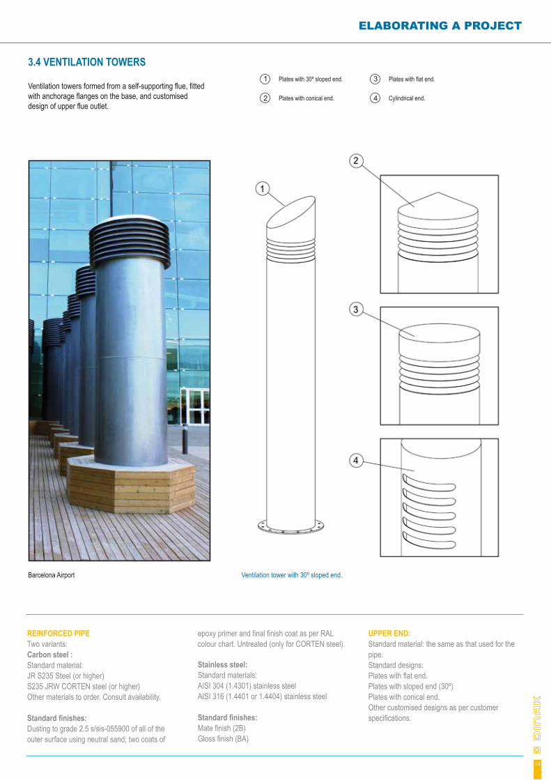
3.4 VENTILATION TOWERS
Ventilation towers formed from a self-supporting flue, fitted with anchorage flanges on the base, and customised design of upper flue outlet.
REINFORCED PIPE Two variants:Carbon steel :Standard material:JR S235 Steel (or higher)S235 JRW CORTEN steel (or higher) Other materials to order. Consult availability.
Standard finishes:Dusting to grade 2.5 s/sis-055900 of all of the outer surface using neutral sand; two coats of
epoxy primer and final finish coat as per RAL colour chart. Untreated (only for CORTEN steel).
Stainless steel:Standard materials:AISI 304 (1.4301) stainless steelAISI 316 (1.4401 or 1.4404) stainless steel
Standard finishes:Mate finish (2B)Gloss finish (BA)
UPPER END:Standard material: the same as that used for the pipe.Standard designs:Plates with flat end.Plates with sloped end (30º)Plates with conical end.Other customised designs as per customer specifications.
Barcelona Airport
Plates with 30º sloped end.
Plates with conical end.
1
2
Ventilation tower with 30º sloped end.
Plates with flat end.
Cylindrical end.
3
4
14
3 CONSTRUCTIVE SOLUTIONS
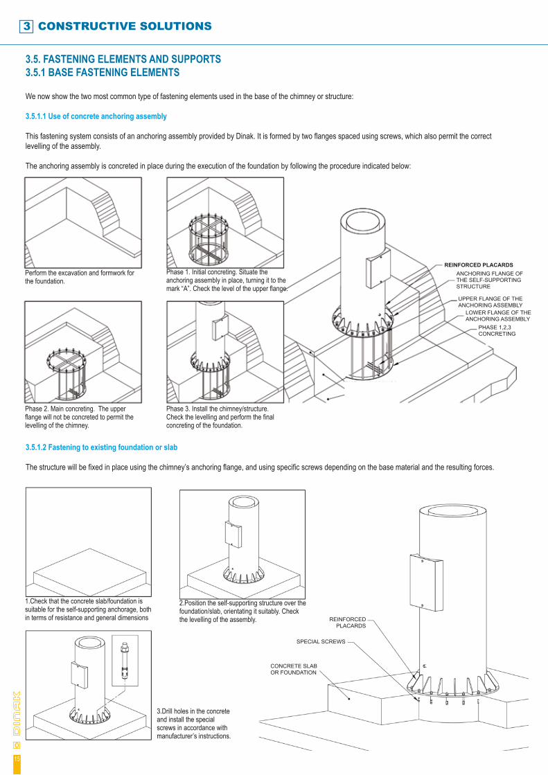
3.5. FASTENING ELEMENTS AND SUPPORTS3.5.1 BASE FASTENING ELEMENTS
We now show the two most common type of fastening elements used in the base of the chimney or structure:
3.5.1.1 Use of concrete anchoring assembly
This fastening system consists of an anchoring assembly provided by Dinak. It is formed by two flanges spaced using screws, which also permit the correct levelling of the assembly.
The anchoring assembly is concreted in place during the execution of the foundation by following the procedure indicated below:
3.5.1.2 Fastening to existing foundation or slab
The structure will be fixed in place using the chimney’s anchoring flange, and using specific screws depending on the base material and the resulting forces.
15
Perform the excavation and formwork for the foundation.
1.Check that the concrete slab/foundation is suitable for the self-supporting anchorage, both in terms of resistance and general dimensions
3.Drill holes in the concrete and install the special screws in accordance with manufacturer’s instructions.
2.Position the self-supporting structure over the foundation/slab, orientating it suitably. Check the levelling of the assembly.
Phase 2. Main concreting. The upper flange will not be concreted to permit the levelling of the chimney.
Phase 3. Install the chimney/structure. Check the levelling and perform the final concreting of the foundation.
Phase 1. Initial concreting. Situate the anchoring assembly in place, turning it to the mark “A”. Check the level of the upper flange.
REINFORCED PLACARDSANCHORING FLANGE OF THE SELF-SUPPORTING STRUCTURE
UPPER FLANGE OF THE ANCHORING ASSEMBLY
REINFORCED PLACARDS
SPECIAL SCREWS
CONCRETE SLAB OR FOUNDATION
LOWER FLANGE OF THE ANCHORING ASSEMBLY
PHASE 1,2,3 CONCRETING

3.5.2 INTERMEDIATE SUPPORTS AND FASTENING ELEMENTS
In general, the use of intermediate supports in the works allows the resistant sections of the chimney or structure to be optimised, and permits the simplification of the civil works. Thus, they should be used whenever possible.
The different types of supports are classified as follows. The supports may be used individually or in combination:
3.5.2.1 Roof supports
The chimney or structure is stabilised thanks to the use of a support anchored to a resistant slab.
ELABORATING A PROJECT
3.5.2.2 Wall supports
In this case, one or several intermediate levels of the structure or chimney are anchored in place using side anchorage to a resistant wall.
3.5.2.3 Winds
In this case stability is achieved by the use of one or several wind levels fixed to resistant elements.
16
Roof or resistant slab
Reinforced stainless steel hoop
Supporting arm
Special fixing screws
Stainless steel resistant hoop with sliders
Stainless steel fasteners
Resistant point in wall
Intermediate support system, allowing for the unrestricted dilation of the chimney.
Supporting anchoring plate. Fixed to resistant wall or slab
Fastener
Stainless steel closing screws
Special fastening screws
Height-adjustable supporting arm
3 CONSTRUCTIVE SOLUTIONS
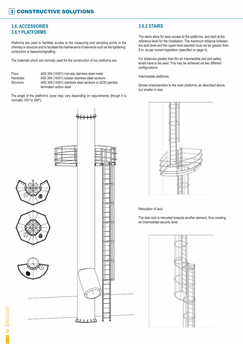
3.6. ACCESSORIES3.6.1 PLATFORMS
Platforms are used to facilitate access to the measuring and sampling points in the chimney or structure and to facilitate the maintenance of elements such as the lightening conductors or beacons/signalling.
The materials which are normally used for the construction of our platforms are:
Floor: AISI 304 (14301) non-slip stainless steel metalHandrails: AISI 304 (14301) tubular stainless steel sectionsStructure: AISI 304 (14301) stainless steel sections or S235 painted, laminated carbon steel
The angle of the platform’s cover may vary depending on requirements (though it is normally 150º to 360º).
3.6.2 STAIRS
The stairs allow for easy access to the platforms, and start at the reference level for the installation. The maximum distance between the start level and the upper level reached must not be greater than 9 m, as per current legislation (specified on page 4).
For distances greater than 9m an intermediate rest and safety levels have to be used. This may be achieved via two different configurations:
Intermediate platforms:
Similar characteristics to the main platforms, as described above, but smaller in size.
Relocation of axis: The stair axis is relocated towards another element, thus creating an intermediate security level.
17

3.6.3 LIGHTENING CONDUCTORS
As per the terms established under the UNE_EN 13084-1 European Standard, our self-supporting chimneys may be considered to be metallic structures with continuous electrical conductivity. For this reason they do not require specific protection against lightening or electrical discharges.
Nevertheless, the chimney may include a lightening conductor in order to protect buildings or equipment adjacent to the chimney from receiving electrical discharges.
The system normally used consists of a Franklin point installed on a stainless steel mast (the theoretical protection against lightening is shown in the following diagram).
Any other protection design may also be used, as per customer indications.
ELABORATING A PROJECT
18
Franklin Point Protection Diagram
Columbian Carbon Spain / Santander
Monza / Italy
3.6.4 BEACONING
The characteristics of the beaconing must be defined in the project report, and based on the geographical coordinates of the installation. Generally speaking, the configuration used for beaconing consists of the following elements:
Night beacons:Red lights, 16 cd each, long lasting ( > 100,000 h), low consumption thanks to the use of LEDs.
Day signalling:Alternating red and white coloured strips in the upper section of the chimney (normally between 1/3 and ½ of the total height).
ø1000 OUTER
4 SELECTION OF FLUES
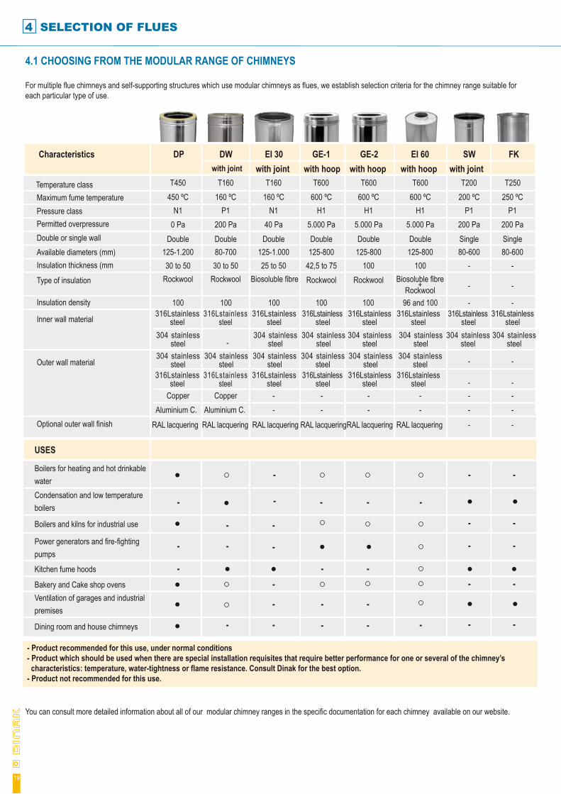
4.1 CHOOSING FROM THE MODULAR RANGE OF CHIMNEYS
For multiple flue chimneys and self-supporting structures which use modular chimneys as flues, we establish selection criteria for the chimney range suitable for each particular type of use.
You can consult more detailed information about all of our modular chimney ranges in the specific documentation for each chimney available on our website.
- Product recommended for this use, under normal conditions- Product which should be used when there are special installation requisites that require better performance for one or several of the chimney’s characteristics: temperature, water-tightness or flame resistance. Consult Dinak for the best option.- Product not recommended for this use.
-
19
USES
Boilers for heating and hot drinkable water
- - -----
- --
Characteristics DP DWwith joint
EI 30with joint
GE-1 GE-2 EI 60with hoop
SWwith joint
FKwith hoopwith hoop
- - ---
---
- - --
- - --
--
-
-
T450Temperature class T160 T160 T600 T600 T600 T200 T250
Optional outer wall finish
Outer wall material
Inner wall material
Insulation density
Type of insulation
Insulation thickness (mmAvailable diameters (mm)Double or single wallPermitted overpressurePressure classMaximum fume temperature
RAL lacquering RAL lacquering RAL lacquering RAL lacquering RAL lacquering RAL lacquering
Aluminium C.Copper
304 stainless steel
304 stainless steel
304 stainless steel
304 stainless steel
304 stainless steel
304 stainless steel
304 stainless steel
304 stainless steel
304 stainless steel
304 stainless steel
304 stainless steel
304 stainless steel
304 stainless steel
316Lstainless steel
316Lstainless steel
316Lstainless steel
316Lstainless steel
316Lstainless steel
316Lstainless steel
316Lstainless steel
316Lstainless steel
316Lstainless steel
316Lstainless steel
316Lstainless steel
316Lstainless steel
316Lstainless steel
316Lstainless steel
Rockwool30 to 50
125-1.200Double
0 PaN1
450 ºC
Aluminium C.Copper
-
Rockwool30 to 5080-700Double200 Pa
P1160 ºC
--
Biosoluble fibre25 to 50
125-1.000Double40 Pa
N1160 ºC
--
Rockwool42,5 to 75125-800Double
5.000 PaH1
600 ºC
Rockwool100
125-800Double
5.000 PaH1
600 ºC
--
100 100 100 100 100
--
96 and 100
100125-800Double
5.000 PaH1
600 ºC
-
---
-
-
-
-80-600Single200 Pa
P1200 ºC
-
---
-
-
-
-80-600Single200 Pa
P1250 ºC
Biosoluble fibre+Rockwool
- --
Dining room and house chimneys
Ventilation of garages and industrial premises
Bakery and Cake shop ovens
Kitchen fume hoods
Power generators and fire-fighting pumps
Boilers and kilns for industrial use
Condensation and low temperature boilers
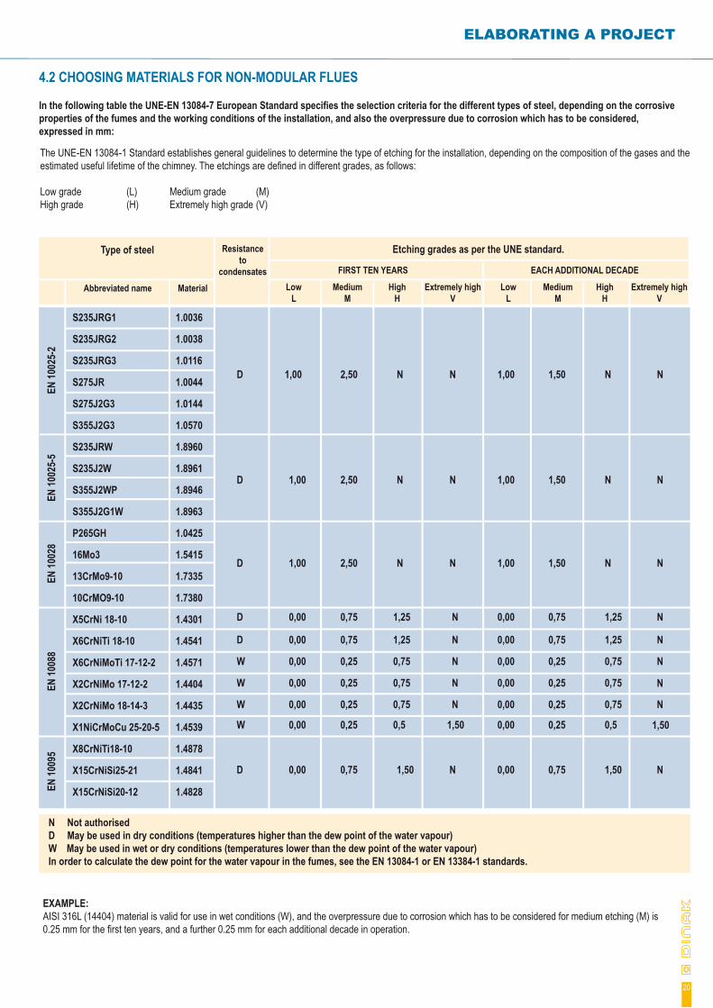
4.2 CHOOSING MATERIALS FOR NON-MODULAR FLUES
In the following table the UNE-EN 13084-7 European Standard specifies the selection criteria for the different types of steel, depending on the corrosive properties of the fumes and the working conditions of the installation, and also the overpressure due to corrosion which has to be considered, expressed in mm:
ELABORATING A PROJECT
EXAMPLE: AISI 316L (14404) material is valid for use in wet conditions (W), and the overpressure due to corrosion which has to be considered for medium etching (M) is 0.25 mm for the first ten years, and a further 0.25 mm for each additional decade in operation.
20
The UNE-EN 13084-1 Standard establishes general guidelines to determine the type of etching for the installation, depending on the composition of the gases and the estimated useful lifetime of the chimney. The etchings are defined in different grades, as follows:
Low grade (L) Medium grade (M)High grade (H) Extremely high grade (V)
Type of steel Resistance to
condensatesLow
LAbbreviated name Material Medium
MHigh
HExtremely high
VLow
LMedium
MHigh
HExtremely high
V
Etching grades as per the UNE standard.
S235JRG1
S235JRG2
S235JRG3
S275JR
S275J2G3
S355J2G3
S235JRW
S235J2W
S355J2WP
S355J2G1W
P265GH
16Mo3
13CrMo9-10
10CrMO9-10
X5CrNi 18-10
X6CrNiTi 18-10
X6CrNiMoTi 17-12-2
X2CrNiMo 17-12-2
X2CrNiMo 18-14-3
X1NiCrMoCu 25-20-5
X8CrNiTi18-10
X15CrNiSi25-21
X15CrNiSi20-12
EN 10
025-
2EN
1002
5-5
EN 10
028
EN 10
088
EN 10
095
1.0036
1.0038
1.0116
1.0044
1.0144
1.0570
1.8960
1.8961
1.8946
1.8963
1.0425
1.5415
1.7335
1.7380
1.4301
1.4541
1.4571
1.4404
1.4435
1.4539
1.4878
1.4841
1.4828
D 1,00 2,50 N N 1,00 1,50 N N
D 1,00 2,50 N N 1,00 1,50 N N
D 1,00 2,50 N N 1,00 1,50 N N
D 0,00 0,75 1,25 N 0,00 0,75 1,25 N
D 0,00 0,75 1,25 N 0,00 0,75 1,25 N
W 0,00 0,25 0,75 N 0,00 0,25 0,75 N
W 0,00 0,25 0,75 N 0,00 0,25 0,75
1,50
W 0,00 0,25 0,75 N 0,00 0,25 0,75 N
W 0,00 0,25 0,5 1,50 0,00 0,25 0,5
N
D 0,00 0,75 1,50 N 0,00 0,75 1,50 N
N Not authorisedD May be used in dry conditions (temperatures higher than the dew point of the water vapour)W May be used in wet or dry conditions (temperatures lower than the dew point of the water vapour)In order to calculate the dew point for the water vapour in the fumes, see the EN 13084-1 or EN 13384-1 standards.
FIRST TEN YEARS EACH ADDITIONAL DECADE
REFERENCES
21
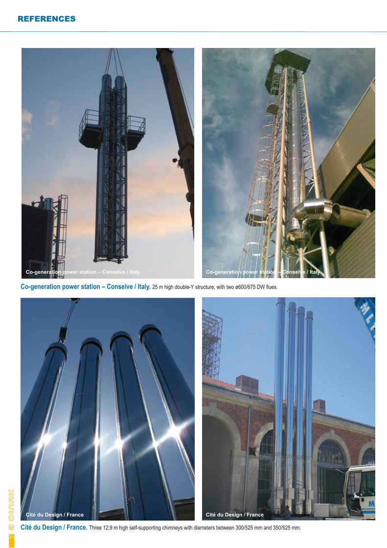
Co-generation power station – Conselve / Italy. 25 m high double-Y structure, with two ø600/675 DW flues.
Cité du Design / France. Three 12,9 m high self-supporting chimneys with diameters between 300/525 mm and 350/525 mm.
Co-generation power station – Conselve / ItalyCo-generation power station – Conselve / Italy
Cité du Design / FranceCité du Design / France
REFERENZE
22
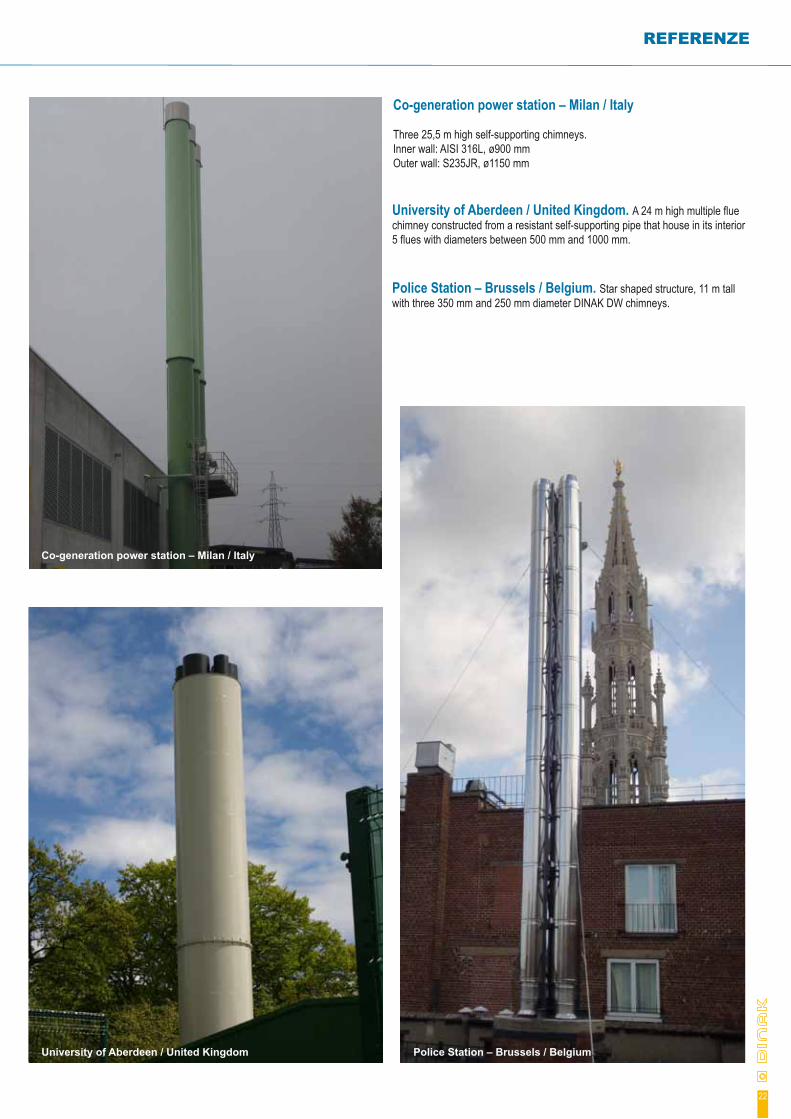
University of Aberdeen / United Kingdom. A 24 m high multiple flue chimney constructed from a resistant self-supporting pipe that house in its interior 5 flues with diameters between 500 mm and 1000 mm.
Police Station – Brussels / Belgium. Star shaped structure, 11 m tall with three 350 mm and 250 mm diameter DINAK DW chimneys.
Co-generation power station – Milan / Italy
University of Aberdeen / United Kingdom Police Station – Brussels / Belgium
Co-generation power station – Milan / Italy
Three 25,5 m high self-supporting chimneys.Inner wall: AISI 316L, ø900 mmOuter wall: S235JR, ø1150 mm
DINAK S.A. Camiño do Laranxo, 19 36216 VIGO 986 45 25 26 986 45 25 01 [email protected]
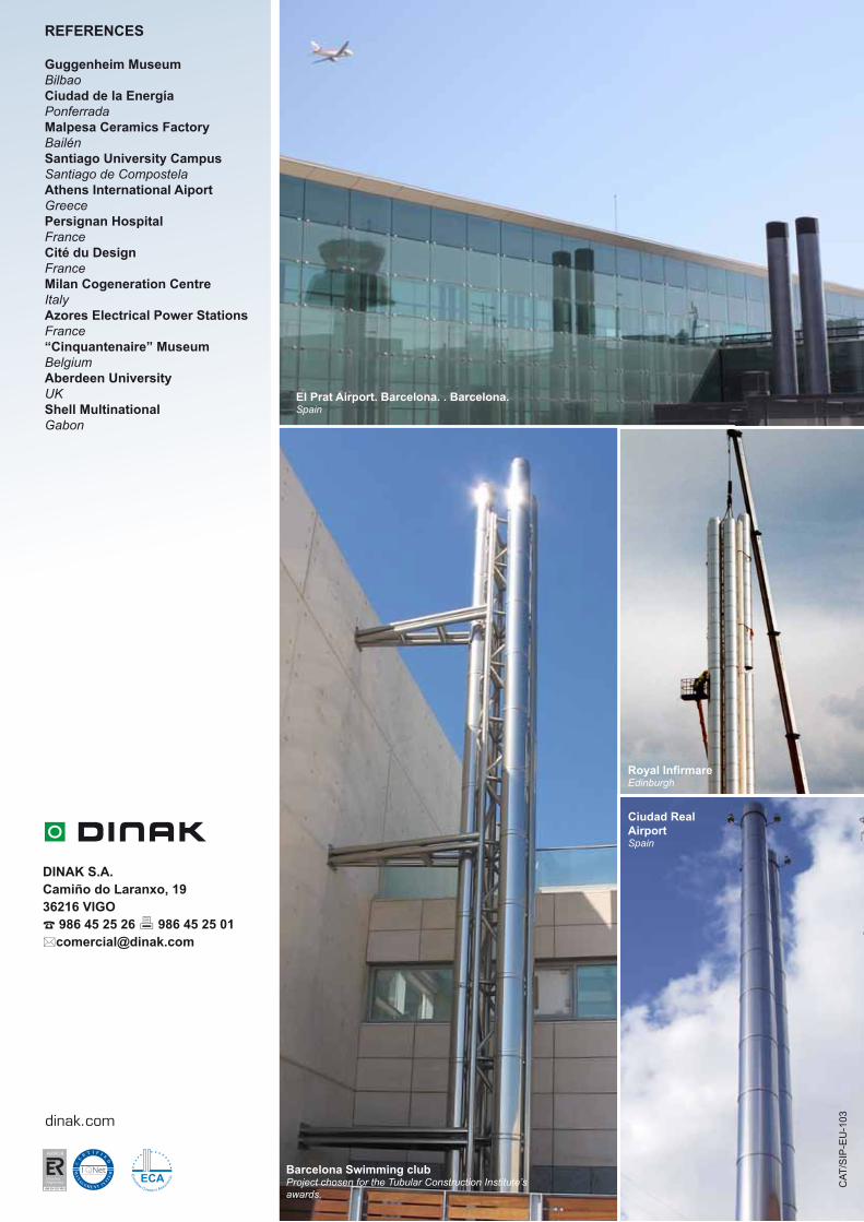
El Prat Airport. Barcelona. . Barcelona.Spain
Barcelona Swimming clubProject chosen for the Tubular Construction Institute’s awards.
Royal InfirmareEdinburgh
Ciudad Real AirportSpain
dinak.com
REFERENCES
Guggenheim MuseumBilbaoCiudad de la EnergíaPonferradaMalpesa Ceramics FactoryBailénSantiago University CampusSantiago de CompostelaAthens International AiportGreecePersignan HospitalFranceCité du DesignFranceMilan Cogeneration CentreItalyAzores Electrical Power StationsFrance“Cinquantenaire” MuseumBelgiumAberdeen UniversityUKShell MultinationalGabon
CAT
/SIP
-EU
-103
ECAEU
ROPEAN CHIMNEYS ASSOCIATI
ON
Related Documents


![[BS en 13084-2-2007] -- Free-standing Chimneys. Concrete Chimneys](https://static.cupdf.com/doc/110x72/577c7e1f1a28abe054a09ebb/bs-en-13084-2-2007-free-standing-chimneys-concrete-chimneys.jpg)
