1 Analysis of shear wall subjected to lateral load November 2013 Author: MD. ABDUL BATEN WUB 10/08/23/623 MD. ABUL KASHEM WUB 10/08/23/635 MD. ZAHIRUL HOQUE WUB 10/08/23/636 RANZU AHMED & WUB 10/08/23/637 MD. MASUD RANA WUB 10/08/23/639 Supervisor: AHMED SHIBLEE NOMAN Asst. Professor Dept. of Civil Engineering World University of Bangladesh S M TANVIR FAYSAL ALAM CHOWDHOURY Lecturer Dept. of Civil Engineering World University of Bangladesh Welcome to our presentation……… W O R L D U N I V E R S I T Y o f B a n g l a d e s h

Analysis of shear wall subjected to lateral load
Oct 24, 2015
Final Presentation 13.12.13
Welcome message from author
This document is posted to help you gain knowledge. Please leave a comment to let me know what you think about it! Share it to your friends and learn new things together.
Transcript

1 Analysis of shear wall subjected to lateral load
November 2013
Author: MD. ABDUL BATEN WUB 10/08/23/623MD. ABUL KASHEM WUB 10/08/23/635MD. ZAHIRUL HOQUE WUB 10/08/23/636RANZU AHMED & WUB 10/08/23/637MD. MASUD RANA WUB 10/08/23/639
Supervisor:
AHMED SHIBLEE NOMANAsst. ProfessorDept. of Civil EngineeringWorld University of Bangladesh
S M TANVIR FAYSAL ALAM CHOWDHOURYLecturer
Dept. of Civil EngineeringWorld University of Bangladesh
Welcome to our presentation………
W O R L D U N I V E R S I T Y o f B a n g l a d e s h

2
ABSTRACT
The purpose of this study is to model and analyze the non planar shear wall assemblies of shear wall-frame structures. Three dimensional models, for open and closed section shear wall assemblies, have been developed.
These models are based on conventional wide column analogy, in which a planar shear
wall is replaced by an idealized frame structure consisting of a column and rigid beams located at floor levels. The rigid diaphragm floor assumption, which is widely used in the analysis of multi storey building structures, is also taken into consideration. The connections of the rigid beams are released against torsion in the model proposed for open section shear walls.
Several shear wall systems having different shapes of wall-frame and flat plate shear wall assemblies have been analyzed by static lateral load, response spectrum where the proposed methods have been used. The results of these analyses are compared with the results obtained using common shear wall modeling techniques.

3
OBJECTIVES
The objectives of the project are:-
To carry out a frame analysis on shear wall models using ETABS non linear version 8.5 software.
To check the reliability of frame analysis method compare to wall frame shear wall and flat plate shear wall.
The study is focused on the determination of the ultimate lateral load due to wind and earthquake.
To find out and compare the different calculated value of those wall frame and flat plate shear wall structures.
To draw few recommendations based on the study.

4
METHODOLOGY
Analysis on shear wall structures can be
analyzed by three types methods mentionbelow:
Finite Element Analysis (FEA)Continuous connection method
(CCM)Equivalent Frame Analysis (EFA)
For this study we applied “Equivalent Frame
Analysis (EFA) methods” effectively.
CGh
E11
12
Evaluate the when rigidities (GA) of the rigid
frame bents and any wall frame bents:
GA =
Values obtained in items a and b to evaluate:
Horizontal Displacements:
Maximum story drift Index:
t
t
EI
GAHH
HZHKEI
wHZY
t
/8 11
4
CGh
E11
12
max6
max 2
3
kEI
WH
dz
dy
t
Evaluate the when rigidities (GA) of the rigid
frame bents and any wall frame bents:
GA =
Values obtained in items a and b to evaluate:
Horizontal Displacements:
Maximum story drift Index:
t
t
EI
GAHH
HZHKEI
wHZY
t
/8 11
4
CGh
E11
12
max6
max 2
3
kEI
WH
dz
dy
t

5
SHEAR WALLS SYSTEMS
Shear walls have been the most common lateral
force resisting elements for tall building besides
frame system.
The main intention of the research work presented
in this thesis is to study the majority of the high rise
building structures in Bangladesh have shear wall
frame systems.
Structural forms of shear wall are commonly using
buildings of 10 to 30 stories. Monolithic shear wall
can be classified as short, squat or cantilever as in
Figure 5.1 according to there height/depth ratio. Figure 5.1: Shapes of Shear Wall

6
EQUIVALENT LATERAL FORCE METHOD
A building structure subjected to lateralforces obtained by the equivalent lateral
force method is shown in Figure 6.1. A triangular distribution of equivalent lateral loads with zero loading at the base of the
structure is considered in theanalysis.
Figure 6.1 : Building structure subjected to equivalent wind loads

7
SHEAR WALLS
A shear wall is a wall that resists lateral
wind loads which acts parallel to the
plane of the wall.
Figure 7.1 : Shear wall frame structure
Wind results in a pressure on the surface of the
building pressure increases with height
Positive Pressure, acts towards the surface of the building
Negative Pressure, acts away from the surface of the building (suction)
.
Figure 7.2: Directions of wind pressure

FLOOR PLANFLOOR PLAN 3D VIEW OF BUILDING STRUCTURE3D VIEW OF BUILDING STRUCTURE
Type of Property to find
B1=10″ X 18″ B2=10″ X 21″ B3=10″ X 24″ C1=18″ X 21″ C2=18″ X 24″ C3=21″ X 24″
WORK PROCEDURE
8
Figure 8.1: Typical floor plan of a shear wall-frame building structure (14 storied)
Figure 8.2 : Building 3D view

CATEGORIESCATEGORIES METHOD & FACTORSMETHOD & FACTORS
The basic assumptions used in the
modeling studies are presented.
These assumptions are divided into
three categories:
Material behavior
Element behavior
Structural behavior
Used USD method
Given Load, code & factors: Dead load = 1.2 Live Load = 1.6 Earthquake Load = 1.0 Wind Load = 1.0 Code UBC 94 Design Code ACI 318-99 Site Co-Efficient, (s) = 1.2 Importance factor, (I) = 1.0 f’c = 4 ksi fy = 60
ksi
9
ASSUMPTION
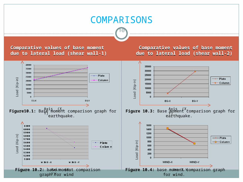
Comparative values of base moment due to lateral load (shear wall-2)
Comparative values of base moment due to lateral load (shear wall-2)
10
COMPARISONS
5100
5200
5300
5400
5500
5600
5700
5800
5900
6000
6100
WIND-X WIND-Y
Plate
Column
Axis (X, Y)
Axis (X, Y)
Comparative values of base moment due to lateral load (shear wall-1)Comparative values of base moment due to lateral load (shear wall-1)
Axis (X, Y)
Figure10.1: Base moment comparison graph for earthquake. Figure 10.3: Base moment comparison graph for earthquake.
Figure 10.2: base moment comparison graph for wind Figure 10.4: base moment comparison graph for wind.
11
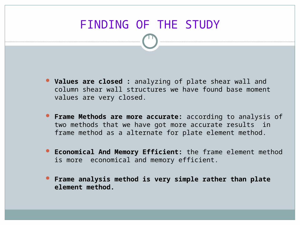
Values are closed : analyzing of plate shear wall and column shear wall structures we have found base moment values are very closed.
Frame Methods are more accurate: according to analysis of two methods that we have got more accurate results in frame method as a alternate for plate element method.
Economical And Memory Efficient: the frame element method is more economical and memory efficient.
Frame analysis method is very simple rather than plate element method.
FINDING OF THE STUDY

CONCLUSION & RECOMMENDATION
Conclusion:
Analyzed of Plate shear wall and column shear wall structures find base moment values are very closed.
According to analysis of two methods that we get more accurate results in frame method as a alternate for plate element method.
The frame element method is more economical and memory efficient.
Frame analysis method is very simple rather than plate element method.
12
Recommendation:
The study is used for building structure, similar study may be done for bridge structure.
We have done this method by static analysis, but dynamic analysis should also be performed.

13
THANKS TO ALL
Related Documents