Engineering Frac&re Mechanics Vol. 40, No. 6, pp. 105~1065,199l 0013-7944p1 s3.00 + 0.00 Printed in Great Britain. PergamonPrcs pk. ANALYSIS OF CRACKED PLATES WITH A BONDED PATCH JIANN-QUO TARN and KAM-LUN SHEK Department of Civil Engineering, National Cheng Kung University, Tainan, Taiwan 70101, R.O.C. AMraet-The problem of a hacked plate repaired by an adhesively bonded patch is studied. A shear spring model is adopted to reduce the problem to the analysis of a cracked plate and a patch subjected to external loads and interacting adhesive shear. While the patch is treated by the i?nite element method, the cracked plate is analyzed by the boundary element method, in which a special fundamental solution satisfying the boundary condition on the crack surface is introduced. The present formulation provides comparable results on the stress intensity factor of the patched crack with less computational effort. INTRODUCTION THE USE OF adhesive bonding for repair of damaged structures has been studied extensively[l-51. In particular, repair of cracked plates by bonding reinforcing patches to the plates over the crack is regarded as a fundamental problem in assessing the e&iency and the viability of the repair. Evaluation of the stress intensity factor of the patched crack and the stress transferred by the adhesive is essential in identifying the critical parameters for the crack patching design. Jones and colleagues[2-41 studied the theoretical and design aspects of crack patching. The finite element method was used in the analysis, in which a displacement field based on an assumed shear stress through-thickness profile was adopted in the development of a patch element. Due to the presence of stress singularity, special attention must be paid to the modeling of the problem domain by finite elements, especially in the vicinity of the crack tip. Chu and Ko[5] followed a similar approach to the problem by using a collapsed isoparametric element to preserve the singular stress character at the crack tip. In general, large numbers of nodal degrees of freedom result from the We element formulation of the problem. In this paper, we employ the boundary element approach combined with the finite element method to study the problem. A shear spring model is adopted to represent the effect of the adhesive layer, and the surface shear transmitted through the adhesive is assumed to act as a body force. Thus, the problem may be reduced to the analysis of the cracked plate and the patch subjected to external loads and body force. The basic assumptions were used by Erdogan and Arin[6], ,and subsequently by Ko[7] and Hong and Jeng[8] in the analysis of sandwich plates with a part-through crack. In the present analysis, while the patch is treated using finite elements, the cracked plate is analyzed by the boundary element method. A special fundamental solution satisfying the boundary condition on the crack surface is employed in the formulation, which results in complete elimination of integration over the free boundary of the crack. Hence, discretization of the crack boundary is not required and an accurate stress distribution around the crack can be expected. In this regard, the boundary integral equation analysis of cracked anisotropic plates has been reported by Synder and Cruse[9]. As an example of crack patching, the problem of a center-cracked plate with a bonded patch subjected to remote in-plane forces is considered. The present formulation provides comparable results on the stress intensity factor and stress distribution with less computational effort. PROBLEM FORMULATION Consider a thin elastic plate with a center-crack over which an elastic plate is adhesively bonded, either on a single side (single patch) or on both sides (double patch), as shown in Fig. 1. The cracked plate and the patch are made of isotropic metallic materials or anisotropic composites, 1055

Welcome message from author
This document is posted to help you gain knowledge. Please leave a comment to let me know what you think about it! Share it to your friends and learn new things together.
Transcript
Engineering Frac&re Mechanics Vol. 40, No. 6, pp. 105~1065,199l 0013-7944p1 s3.00 + 0.00 Printed in Great Britain. Pergamon Prcs pk.
ANALYSIS OF CRACKED PLATES WITH A BONDED PATCH
JIANN-QUO TARN and KAM-LUN SHEK
Department of Civil Engineering, National Cheng Kung University, Tainan, Taiwan 70101, R.O.C.
AMraet-The problem of a hacked plate repaired by an adhesively bonded patch is studied. A shear spring model is adopted to reduce the problem to the analysis of a cracked plate and a patch subjected to external loads and interacting adhesive shear. While the patch is treated by the i?nite element method, the cracked plate is analyzed by the boundary element method, in which a special fundamental solution satisfying the boundary condition on the crack surface is introduced. The present formulation provides comparable results on the stress intensity factor of the patched crack with less computational effort.
INTRODUCTION
THE USE OF adhesive bonding for repair of damaged structures has been studied extensively[l-51. In particular, repair of cracked plates by bonding reinforcing patches to the plates over the crack is regarded as a fundamental problem in assessing the e&iency and the viability of the repair. Evaluation of the stress intensity factor of the patched crack and the stress transferred by the adhesive is essential in identifying the critical parameters for the crack patching design.
Jones and colleagues[2-41 studied the theoretical and design aspects of crack patching. The finite element method was used in the analysis, in which a displacement field based on an assumed shear stress through-thickness profile was adopted in the development of a patch element. Due to the presence of stress singularity, special attention must be paid to the modeling of the problem domain by finite elements, especially in the vicinity of the crack tip. Chu and Ko[5] followed a similar approach to the problem by using a collapsed isoparametric element to preserve the singular stress character at the crack tip. In general, large numbers of nodal degrees of freedom result from the We element formulation of the problem.
In this paper, we employ the boundary element approach combined with the finite element method to study the problem. A shear spring model is adopted to represent the effect of the adhesive layer, and the surface shear transmitted through the adhesive is assumed to act as a body force. Thus, the problem may be reduced to the analysis of the cracked plate and the patch subjected to external loads and body force. The basic assumptions were used by Erdogan and Arin[6], ,and subsequently by Ko[7] and Hong and Jeng[8] in the analysis of sandwich plates with a part-through crack. In the present analysis, while the patch is treated using finite elements, the cracked plate is analyzed by the boundary element method. A special fundamental solution satisfying the boundary condition on the crack surface is employed in the formulation, which results in complete elimination of integration over the free boundary of the crack. Hence, discretization of the crack boundary is not required and an accurate stress distribution around the crack can be expected. In this regard, the boundary integral equation analysis of cracked anisotropic plates has been reported by Synder and Cruse[9]. As an example of crack patching, the problem of a center-cracked plate with a bonded patch subjected to remote in-plane forces is considered. The present formulation provides comparable results on the stress intensity factor and stress distribution with less computational effort.
PROBLEM FORMULATION
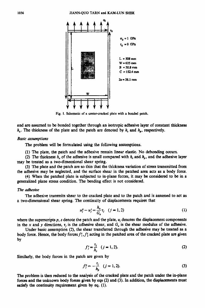
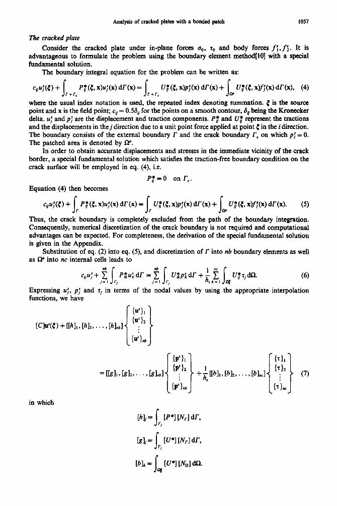
Consider a thin elastic plate with a center-crack over which an elastic plate is adhesively bonded, either on a single side (single patch) or on both sides (double patch), as shown in Fig. 1. The cracked plate and the patch are made of isotropic metallic materials or anisotropic composites,
1055
1056 JIA~~U~ TARN and KAM-LUN SHEIC
L =!mmm W-635mm B =50.8mm C -152.4UUiS
Fig. 1. Schematic of a center-cracked plate with a bonded patch.
and are assumed to be bonded together through an isotropic adhesive Iayer of constant thi&ness h,. The thickness of the plate and the patch are denoted by A, and 4, respectively.
The problem will be formulated using the following assumptions.
(I) The plate, the patch and the adhesive remain linear elastic. No denuding occurs. (2) The thickness !z, of the adhesive is small compared with h, and hp, and the adhesive layer
may be treated as a two-dim~nsjonal shear spring. (3) The plate and the patch are so thin that the thickness variation of stress transmitted from
the adhesive may be neglected, and the surface shear in the patched area acts as a body force. (4) When the patched plate is subjected to m-plane forces, it may be considered to be in a
generalized plane stress condition. The bending effect is not cdnsidered,
The adhesive The adhesive transmits shear to the cracked plate and to the patch and is &sumed to act as
a two-dimensional shear spring. The continuity of displacements requires that
where tbe superscripts p, s denote the patch and the plate, Uj denotes the displacement components in the x and y directions, ri is the adhesive shear, and G, is the shear moduhrs of the adhesive.
Under basic ~umptiou (2), the shear transferred through the adhesive may be treated as a body force. Hence, the body forcesfl ,fs;: acting in the patched area of the cracked plate are given by
J-+7;; rj (j = 1,2).
Similarly, the body forces in the patch are given by
(21
The problem is then reduced to the analysis of the cracked piate and the patch under the in-plane forces and the unknown body forces given by eqs (2) and (3). In addition, the displacements must satisfy the w~~~~ requirement given by eq. (1).
The cracked plate Consider the cracked
advantageous to formulate fundamental solution.
The boundary integral r
Analysis of cracked plates with a bonded patch 1057
plate under in-plane forces go, z. and body forces f;, f$. It is the problem using the boundary element method[lO] with a special
equation for the problem can be written as:
r r qu;(c) + J P; (c, x)$(x) dT(x) =
J u$ (C, @P;(X) dr(x) +
J U,f(C, W;(x) dr(x), (4)
r+r, r+r, Ip where the usual index notation is used, the repeated index denoting summation. C is the source point and x is the field point; cV = 0.56, for the points on a smooth contour, 6, being the Kronecker delta. UJ and pj are the displacement and traction components. Py* and U$ represent the tractions and the displacements in thej direction due to a unit point force applied at point < in the i direction. The boundary consists of the external boundary r and the crack boundary re on which p; = 0. The patched area is denoted by P.
In order to obtain accurate displacements and stresses in the immediate vicinity of the crack border, a special fundamental solution which satisfies the traction-free boundary condition on the crack surface will be employed in eq. (4), i.e.
Pa=0 onr,.
Equation (4) then becomes
c&(0 + s
Pif(C, x)$(x) dr(x) = s
u; (C, X)P; (~0 dr (x) + U,)l (b @f;(x) dr(x). (9 I- r s CP
Thus, the crack boundary is completely excluded from the path of the boundary integration. Consequently, numerical discretization of the crack boundary is not required and computational advantages can be expected. For completeness, the derivation of the special fundamental solution is given in the Appendix.
Substitution of eq. (2) into eq. (5), and discretization of r into nb boundary elements as well as W into nc internal cells leads to
(6)
Expressing UT, pf and rj in terms of the nodal values by using the appropriate interpolation functions, we have
in which
[hlj = s [P *1 mr 1 dr, ‘,
klj = I w*1 Wrl dr, r,
Wlk= q s W’l Wnl dQ.
10~38 JIANN-QUO TARN and KAM-LUN SHEK
{u’),, {p’}, denote the displacement and traction vectors at node j, {T}~ consists of the adhesive shear ri , z2 at internal node k, [Nr] and [NJ consist of one-dimensional and .two-dimensional interpolation functions, respectively.
Applying eq. (7) to all n boundary nodes under consideration yields the following system of equations in matrix form:
in which u,, pr denote the displacements and tractions at boundary r, and r is the shear stress at the node of the internal cells.
Writing eq. (7) for m nodes of the internal cell with cy = a,, we have
bb> 2mx1= -man., ~~r~~.~+[G*l,~,~~~~~.,+fIB*l,,,(~},., *
in which s, denotes the displacement at the node of the internal cells.
The patch
The finite element method will be used to establish the equation for the displacements of the patch. To account for the conditions of displacement continuity, the finite element mesh is chosen to be the same as the grid of the internal cell used in eq. (6). It should be noted that any node on the patch right above the crack line is associated with two nodes of the corresponding internal cells imposed along the opposite edges of the crack. This will allow for the crack opening displacements due to the action of the adhesive shear spring on the cracked plate.
The potential energy of the patch due to the body forcesf{,f$ is expressed by
n=‘f s 2k-I q
U1,&&L f fppm. s
w k-l l-if
Interpolating the displacements in terms of the nodal values and minimizing n, we obtain
KlGr”> = Or1 (11)
where
PI = &t, s, I~nlTVp~ a,
[II] is the derivative of the two-dimensional shape function [No] as in the conventional definition,
[D] is the material matrix. Substituting eq. (3) into eq. (1 l), the finite element equation for the patch is given by
hJ~lW) = -P.,lb) (12) and
P.1 = &f, s, P4J’W*l a.
Introducing the condition of displacement continuity, eq. (l), into eq. (12), we obtain
(13)
According to the formulation, at each boundary node there are two unknown nodal values. At each internal node, there are four nodal values u,, y, tl and r2 to be determined. The total number of unknowns are 2n + 4m. Equations (8) and (9) consist of 2n + 3m equations and eq. (13)
Analysis of cracked plates with a bonded patch 105Q
consists of 2m equations. Together, the unknown nodal values can be determined by solving the simultaneous equations.
As in the usual boundary element procedun$lO], the stress at the internal point of the cracked plate can be determined by placing the source in the fundamental solution at that point and obtained by combining the derivatives of eq. (6) with respect to 4 to produce the strain tensor, using Hooke’s Law. The stresses and the displacements close to the crack tip can be determined without difficulty since the boundary conditions along the crack are satisfied exactly.
THE STRESS INTENSTl’Y FACTORS
The stress intensity factors can be evaluated from the asymptotic expressions[l l] of the stress field near the crack tip,
(14)
where the origin of the coordinates (r, 0) is at the crack tip. The stress intensity factor KU of the cracked plate without patch can be computed easily by
letting the body forcesfj = 0 in the present formulation. To determine the location suf%ciently close to the crack tip at which the stresses are used to calculate the stress intensity factor, we computed K, for a center-crack in a rectangular plate of orthotropic material under uniaxial tension. The problem has been considered in ref. [123. The same material parameters were used for compu- tations. It was found that the computation of K, based on the stresses at points r/u < 10e5 from the crack tip is very accurate. Table 1 gives the numerical comparisons. When the crack length is small relative to the plate dimensions, only 10 constant elements at the remote boundary were used in the computation. In the following example, the stresses at r/a = 10v6 are used to calculate the stress intensity factor lu, for the patched crack.
NUMERICAL. RESULTS
The problem of a center-cracked plate with bonded patch under uniaxial tension is now considered (Fig. 1). The cracked plate is made of aluminum, and the patch is boron/epoxy composite. The finite element solutions were given in refs 13, SJ. The material parameters used are:
Aluminum:
E, = 71.02 GPa, v, = 0.32, h, = 2.29 mm;
E, =20&l GPa, E,/E,=8.18, v12=0.1677, G,2=G,3=7.24GPa;
Adhesive:
G, = 0.965 GPa, h, = 0.1016 mm.
Table 1. Comparison of stress intensity factors for cracked orthotropic rectangular plates in simple tension, L/W = 2.0,
E,/E,=O.l
2alW KS WI Present solution
0.1 1.01 1.0125
::: I.05 1.11 1.0491 1.1078
::: 1.19 1.29 1.1866 1.2855
z; oh
1.41 1.58 1.4105 1.5805 1.85 1.8761
1060 JLWN-QUO TARN and KAM-LUN SHEK
10 Boandaq &nears
Patch
Endofpatch @‘oint A)
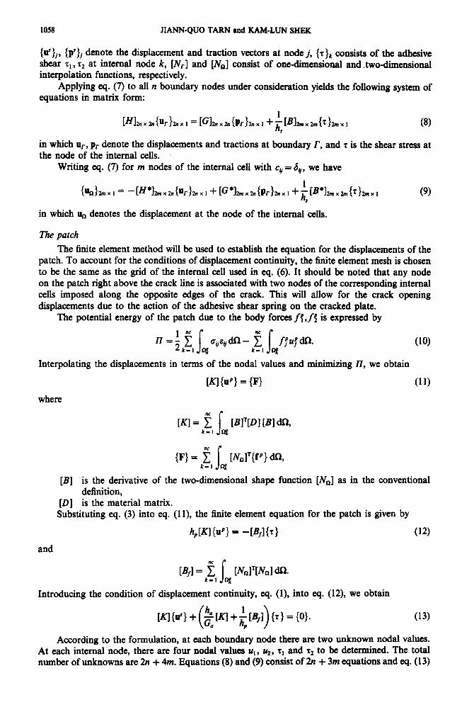
Fig. 2. Boundary elements and internal cells used in the computation.
In the present solution, we used 10 constant elements on the plate boundary where uniaxial tension is prescribed. One hundred and twelve linear triangular elements were used in the patch. A quarter of the finite elementmesh is shown in Fig. 2. In the case of the double patch, only the upper half of the patched plate from the middle plane is considered due to symmetry.
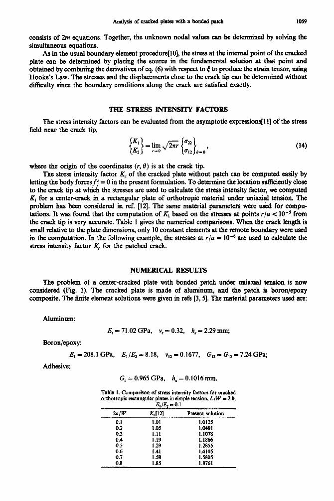
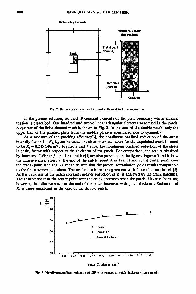
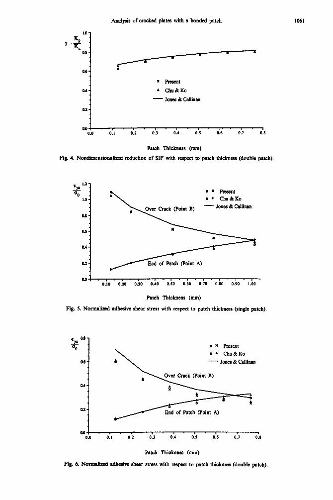
As a measure of the patching efficiency[3], the nondimensionalized reduction of the stress intensity factor 1 - K./K, can be used. The stress intensity factor for the unpatched crack is found to be KU = 0.245 GPa m”Z. Figures 3 and 4 show the nondimensionalized reduction of the stress intensity factor with respect to the thickness of the patch. For comparison, the results obtained by Jones and Callinan[3] and Chu and Ko[5] are also presented in the figures. Figures 5 and 6 show the adhesive shear stress at the end of the patch (point A in Fig. 2) and at the center point over the crack (point B in Fig. 2). It can be seen that the present formulation yields results comparable to the finite element solutions. The results are in better agreement with those obtained in ref. [5]. As the thickness of the patch increases greater reduction of K, is ach.ieved by the crack patching. The adhsive shear at the center point over the crack decreases when the patch thickness increases; however, the adhesive shear at the end of the patch increases with patch thickness. Reduction of K, is more significant in the case of the double patch.
01) . I - I . I . I - ” . 1 . 1 * 1 . - . ’ ’ 0.10 0.36 0.30 0.40 0.50 0.60 0.70 0.80 0.90 1.00
Patch Thickness (mm)
Fig. 3. Nondimensional&d reduction of SJF with respect to patch thickness (single patch).
Analysis of cracked plates with a bonded patch 1061
C: l -=o.s:
0.6- I
= Reseat
0.4 - b chll&Ko
- Jones&cauinsn
oa-
0.0 I . I . I . S’ . g - 8
0.0 0.1 0.7, 0.3 0.4 0.5 0.6 0.7 0.8
Patch Thickness (mm)
Fig. 4. Nondimensional&l reduction of SIF with respect to patch thickness (double patch).
La-
% a Qo 0 Y Pmsent .
1.0 - 4 + Chu&Ko
- Jones 6t Callinan
as -
0.6.
0.4.
0.2.
a.0 .,.,.,.1-1.1.1.1.1.1’ 0.10 0.20 0.30 0.40 0.50 0.60 0.70 0.60 0.90 1.00
Patch Thickness (mm)
Fig. 5. Normalized adhesive shear stress with respect to patch thickness (single patch).
0.6 - 7yr . =o .
0.6-
OA-
oa-
0 m Pnxent
\
. + Chu&Ko
I - Jones & Callinan
Over Crack (Point B)
fl End of Patch (Point A)
lw* 0.0 0.1 0.2 0.3 0.4 0.5 0.6 0.7 0.6
Patch Thickness (mm)
Fig. 6. Normalized adheaive shear stress with resptct to patch thickness (double patch).
JSLAblN-QUO TARN and KAM-LUN SHE?,K
0.4
0.2
0.10 0.20 0.30 0.40 0.50 0.60 0.70 0.80 0.90
Analysis of cracked plates with a bonded patch 1063
lb- ry. . =o 1.4-
1.2.
Ml-
01.
0.6 -
OA-
0.2 -
Adhesive Thickness
- 0.0508mm
- 0.1016 mm
044 . I . 1 - I - I ’ I ’ 1 - I . n . 1 . I-( 0.10 0.20 0.30 0.40 OS0 0.60 0.70 0.80 0.90 1.00
Patch Thickness (mm)
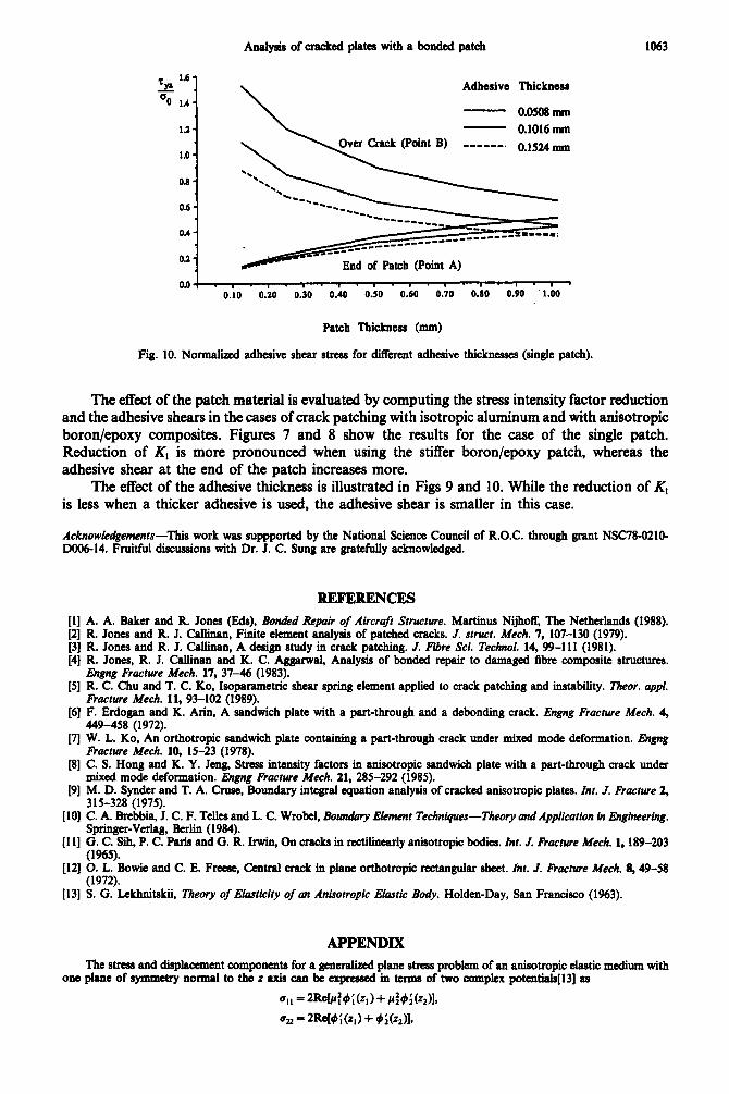
Fig. 10. Nonnalii adhesive shear stress for dilTerent adhesive thicknesses (single patch).
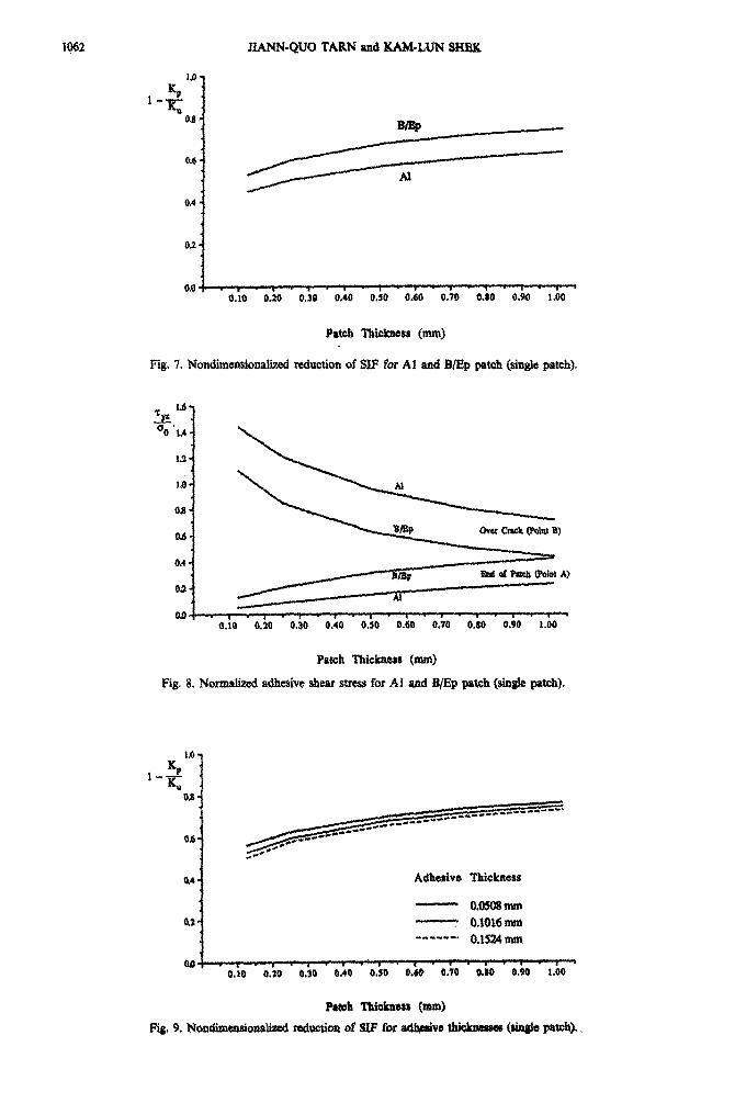
The effect of the patch material is evaluated by computing the stress intensity factor reduction and the adhesive shears in the cases of crack patching with isotropic aluminum and with anisotropic boron/epoxy composites. Figures 7 and 8 show the results for the case of the single patch. Reduction of K, is more pronounced when using the stiffer boron/epoxy patch, whereas the adhesive shear at the end of the patch increases more.
The effect of the adhesive thickness is illustrated in Figs 9 and 10. While the reduction of K, is less when a thicker adhesive is used, the adhesive shear is smaller in this case.
Acknowledgements-This work was suppported by the National Science Council of R.O.C. through grant NSC78-0210- DOO6-14. Fruitful discussions with Dr. J. C. Sung are gratefully acknowledged.
ii;
j
PI
[‘31
[71
PI
191
WI
1111
WI
P31
REFERENCES
A. A. Baker and R. Jones (Ed@, Bon&d Repair of Aircraft Structure. Martinus Nijhoff, The Netherlands (1988). R. Jones and R. J. Calhnan. Finite element analysis of uatched cracks. J. SPW. Me&. 7. 107-130 (1979). R. Jones and R. J. Calhnan; A design study in crack patching. .I. Fibre Sci. Tech&. 14,99-111 (1981). ’ R. Jones, R. J. Callinan and K. C. Aggarwal, Analysis of bonded repair to damaged fibre composite structurea. IJngng Fracture Afech. 17, 37-46 (1983). R. C. Chu and T. C. Ko, Isopammetric shear spring element applied to crack Patching and instability. Theor. uppl. Fracture Me&. 11, 93-102 (1989). F. Erdogan and K. Arin, A sandwich plate with a part-through and a debonding crack. Engng Fructure Mech. 4, 449-458 (1972). W. L. Ko, An orthotropic sandwich plate containing a part-through crack under mixed mode deformation. Engng Fracture Mech. 10, 15-23 (1978). C. S. Hong and K. Y. Jcng, Stress intensity factors in anisotropic sandwich plate with a part-through crack under mixed mode &formation. IJngng Fracfure Mech. 21, 285-292 (1985). M. D. Synder and T. A. Crust, Boundary integral equation analysis of cracked anisotropic plates. Inr. .I. Fracture 2, 315-328 (1975). C. A. Brcbbia, J. C. F. Telles and L. C. Wrobel. Boundary Element Techniques-Theory and Application in Engineering. Springer-Verlag, Berlin (1984). G. C. Sih, P. C. Paris and G. R. Irwin, Gn cracks in rectilinearly anisotropic bodies. InI. I. I+ucrure Mech. 1,189-203 (1%5). 0. L. Bowie and C. E. Freest, Central crack in plane orthotropic rectangular sheet. Inr. I. Frucrure Me& lJ, 49-58 (1972). S. G. Lekhnitskii, Theory of Elasticiry of an Anisotropic Elastic Body. Holden-Day, San Francisco (1963).
APPENDIX
The stress and displacement components for a generalized plane stress problem of an anisotropic elastic medium with one plane of symmetry normal to the 2 axis can be expmssed in terms of two complex potcntials[l3] as
011 =ZRe[lr:~;(z,)+r:b~(z~ll,
52 = 2w4;w + &@211,
1064 JIANN-QUO TARN and KAM-LUN SHEK
612 = -2W/414;(z,) +PMzA
uI = 2Reh 9, k) +P~~(z~)L
~2=2Re~q191(zl)+q2~2(z211 (AU
where
dk(zk), (k = 1,2) are complex potentials, z, = x + pky,
h=c,,P:+a,z--,6k,
au qk=a12~k++-a2@
Pk
al are the compliances of the material, and
A are found from the following characteristic equation:
a,,p’-2a,,pc’+(2a,,+a&‘-2a,,p +%=O. w
Consider an unbounded region containing a traction-free notch. The contour of the notch is denoted by r,. The boundary condition on f, can be expressed by
2Wd,(z,) + 42(z211= 0,
2Re~,~,(z,)+~292(z211=01 (A3)
Suppose that the exterior of Tc in the z, plane can be mapped conformally onto the exterior of the unit circle I(12 1 by the mapping functions
zk=Wk(tk) t&=1,2). (A4)
Then, the boundary conditions in the lk plane become
2W@,K,) + @,K2Il =O,
2Re~,~,(C,)+~2~2(C211=0,
where
c,=12=c =@,
@k(lk) = dklwk(ck)) (k = 1,219
The mapping functions that transform an elliptical notch with semi-axes a, b to the exterior of the unit circle are given by
The inverse functions are
ck= J
zk+ z:-a2-b2j4:
a-ibpk ’
The general forms of the complex potentials satisfying eqs (AS) are given by
(A7)
W)
where cs are coefhcients to be determined by the prescribed boundary conditions on I( I= 1. fi (I, ) andf (c2) are two complex functions holomorphic in I( I 2 1 except at the point where the_concentrated force is acting. f,andJ,denotethe corresponding complex conjugates, It is obvious that x (l/C,) and f2(l/C,) are holomorphic in I{ I ZB 1.
Substituting eqs (AS) into eqs (AS), we obtain the coet%cients cu as follows:
P2-P, c,, =-
lJ,-P2*
c,2 - I42 - lJ2 --
h-h’
PI -PI F2--PI c2,=- c22=-.
PC,-P2’
W h-P2
The fundamental solution for a concentrated unit force applied at point (x*,J+) in an unbounded region can be obtained from the complex potentials dt(zk),
du”(zk) =&log(zk-z:) (k - 1,2), (Alo)
Analysis of cracked plates with a bonded patch 1065
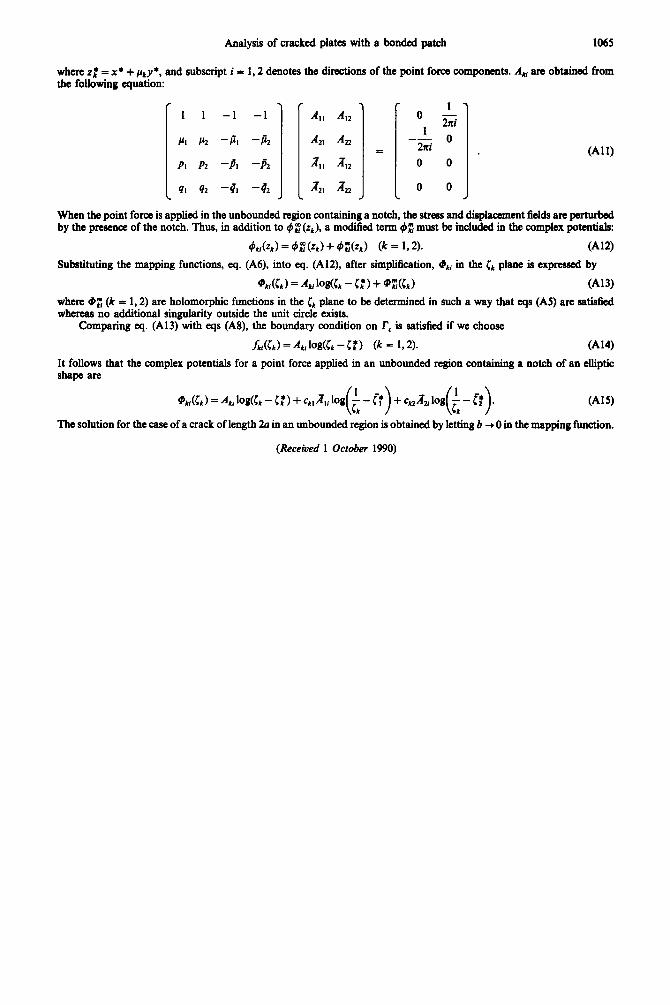
where z: = x* + ~~y*, and subscript i = 1,2 denotes the ditions of the point force components. A, are obtained from the following equation:
c
1
PI
PI
41 c
1 -1
Ir, -P,
P2 -A
42 -4,
> -1
-a
-h
-q2 ,
, r 1 - 0
1 zni
-- s 2ni O
* 0 0
0 0 , c
(All)
When the point force is applied in the unbounded region containing a notch, the stress and displacement fields are perturbed by the presence of the notch. Thus, in addition to 4; (q), a modified term I#BE must be included in the complex potentials:
&i(G) = 4E(G) + &X%) (k = 192). (A12)
Substituting the mapping functions, eq. (A6), into eq. (A12), after simplification, 4$, in the & plane is expressed by
‘&i(L) = A,logG - C:) + @%G) (A13)
where 9; (k = 1,2) are holomorphic functions in the iI plane to be determined in such a way that eqs (AS) are satisfied whereas no additional singularity outside the unit circle exists.
Comparing eq. (A13) with eqs (A8), the boundary condition on r, is satisfied if we choose
ML) = A,,log(L -I:) (k = 192). (A14)
It follows that the complex potentials for a point force applied in an unbounded region containing a notch of an elliptic shape are
@&) = A,, log& - I:) + ck,,&, log A - p L 1) N 21 L 2).
+ c 1 log A - [* (Al9
The solution for the case of a crack of length 20 in an unbounded region is obtained by letting b + 0 in the mapping function.
(Receiued 1 October 1990)
Related Documents