ANALYSIS OF A THREE-DIMENSIONAL RAILWAY VEHICLE-TRACK SYSTEM AND DEVELOPMENT OF A SMART WHEELSET Md. Rajib Ul Alam Uzzal A thesis In the Department of Mechanical and Industrial Engineering Presented in Partial Fulfillment of the Requirements for the Degree of Doctor of Philosophy at Concordia University Montreal, Quebec, Canada March 2012 © Md. Rajib Ul Alam Uzzal, 2012

Welcome message from author
This document is posted to help you gain knowledge. Please leave a comment to let me know what you think about it! Share it to your friends and learn new things together.
Transcript

ANALYSIS OF A THREE-DIMENSIONAL RAILWAY VEHICLE-TRACK SYSTEM AND DEVELOPMENT OF A SMART WHEELSET
Md. Rajib Ul Alam Uzzal
A thesis
In the Department of
Mechanical and Industrial Engineering
Presented in Partial Fulfillment of the Requirements
for the Degree of Doctor of Philosophy at
Concordia University
Montreal, Quebec, Canada
March 2012
© Md. Rajib Ul Alam Uzzal, 2012
iii
ABSTRACT
ANALYSIS OF A THREE-DIMENSIONAL RAILWAY VEHICLE-TRACK SYSTEM AND DEVELOPMENT OF A SMART WHEELSET
Md. Rajib Ul Alam Uzzal Concordia University, 2012
Wheel flats are the sources of high magnitude impact forces at the wheel-rail interface, which
can induce high levels of local stresses leading to fatigue damage, and failure of various vehicle
and track components. With demands for increased load and speed, the issue of wheel flats and a
strategy for effective maintenance and in-time replacement of defective wheels has become an
important concern for heavy haul operators. A comprehensive coupled vehicle-track model is
thus required in order to predict the impact forces and the resulting component stresses in the
presence of wheel flats.
This study presents the dynamic response of an Euler- Bernoulli beam supported on two-
parameter Pasternak foundation subjected to moving load as well as moving mass. Dynamic
responses of the beam in terms of normalized deflection and bending moment have been
investigated for different velocity ratios under moving load and moving mass conditions. The
effect of moving load velocity on dynamic deflection and bending moment responses of the
beam have been investigated. The effect of foundation parameters such as, stiffness and shear
modulus on dynamic deflection and bending moment responses have also been investigated for
both moving load and moving mass at constant speeds.
This dissertation research concerns about modeling of a three-dimensional railway vehicle-
track model that can accurately predict the wheel-rail interactions in the presence of wheel
defects. This study presents a three-dimensional track system model using two Timoshenko

iv
beams supported on discrete elastic supports, where the sleepers are considered as rigid masses,
and the rail pad and ballast as spring-damper elements. The vehicle system is modeled as a three-
dimensional 17- DOF lumped mass model comprising a full car body, two bogies and four
wheelsets. The railway track is modeled as a pair of three-dimensional flexible beams that
considers two parallel Timoshenko beams periodically supported by lumped masses representing
the sleepers.
The wheel-rail contact is modeled using nonlinear Hertzian contact theory. The developed
model is validated with the existing measured data and analytical solutions available in literature.
The nonlinear model is then employed to investigate the wheel-rail impact forces that arise in the
wheel-rail interface due to the presence of single as well as multiple wheel flats.
The effects of single and multiple wheel flats on the responses of vehicle and track
components in terms of displacements and acceleration responses are investigated for both
defective wheel and the flat-free wheel. The characteristics of the bounce, pitch and roll motions
of the bogie due to a single wheel flat are also investigated. The study shows that nonlinear
railpad and ballast model gives better prediction of the wheel-rail impact force than that of the
linear model when compared with the experimental data. The results clearly show that presence
of wheel flat within the same wheelset has significant effect on the impact force, displacement
and acceleration responses of that wheelset.
This study further presents the modeling of a MEMS based accelerometer in order to detect
the presence of a wheel flat in the railway vehicle. The proposed accelerometer can survive in a
dynamic shock environment with acceleration up to ±150g. Simulations of the accelerometer are
performed under various operating conditions in order to determine the optimum configuration.

v
This thesis is dedicated with all my heart to
my beloved parents, Md. Moksed Ali, and Most. Rawshan Ara Begum, whose
continuous support and encouragement throughout my educational career.

vi
ACKNOWLEDGEMENTS
I would like to thank my co-supervisors Dr. R. B. Bhat and Dr. A. K. W. Ahmed for their
continued intellectual guidance, encouragement throughout the course of this research. I would
also like to take this opportunity to express my gratitude to Dr. S. Rakheja for the advice I
received from him towards the scope and direction of this dissertation.
I would also like to thank my examination committee members for their assistance and time
during the course of this work, in particular, Dr. I. Stiharu. Special thanks are due to Canadian
National (CN) Railway, Quebec Govt. Transportation Dept. and Concordia University for their
financial support throughout the course of this dissertation.
My eternal thanks and gratitude to my parents-in-law, sister and sister-in-law for their moral
support made this achievement possible. I would also like to express my deepest gratitude to my
wife, Syeda Rubyat Shahid, for her understanding, encouragement and limitless patience during
this study. Thanks to my wonderful baby boy, Razeen Alam, who has been one of the sources of
inspiration in completing this thesis. I am also thankful to all my friends in Concordia, specially,
Santosh, Suresh, Saeedi and Azadeh for their help and support.
Above all, I thank to Almighty Allah for giving me the strength to complete this research.
vii
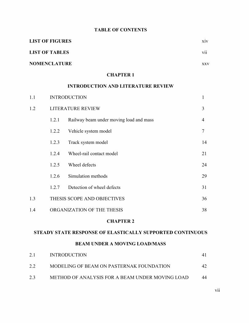
TABLE OF CONTENTS
LIST OF FIGURES
xiv
LIST OF TABLES
vii
NOMENCLATURE
xxv
CHAPTER 1
INTRODUCTION AND LITERATURE REVIEW
1.1 INTRODUCTION
1
1.2 LITERATURE REVIEW
3
1.2.1 Railway beam under moving load and mass
4
1.2.2 Vehicle system model
7
1.2.3 Track system model
14
1.2.4 Wheel-rail contact model
21
1.2.5 Wheel defects
24
1.2.6 Simulation methods
29
1.2.7 Detection of wheel defects
31
1.3 THESIS SCOPE AND OBJECTIVES
36
1.4 ORGANIZATION OF THE THESIS
38
CHAPTER 2
STEADY STATE RESPONSE OF ELASTICALLY SUPPORTED CONTINUOUS
BEAM UNDER A MOVING LOAD/MASS
2.1 INTRODUCTION
41
2.2 MODELING OF BEAM ON PASTERNAK FOUNDATION
42
2.3 METHOD OF ANALYSIS FOR A BEAM UNDER MOVING LOAD
44

viii
2.3.1 For undamped case (velocity less than the critical)
45
2.3.2
For undamped case (velocity greater than the critical) 49
2.3.3 For underdamped case (with two-parameter model)
51
2.4 ANALYSIS METHOD FOR A BEAM UNDER MOVING MASS
56
2.5 MODEL VALIDATION 57
2.6 RESULTS AND DISCUSSIONS 60
2.6.1 Exact analysis
60
2.6.2 Modal analysis
73
2.7 SUMMARY
85
CHAPTER 3
VEHICLE-TRACK SYSTEM MODEL AND ITS NATURAL FREQUENCIES
3.1 INTRODUCTION
87
3.2 VEHICLE SYSTEM MODEL
88
3.3 TRACK SYSTEM MODEL
95
3.4 WHEEL-RAIL CONTACT MODEL
100
3.5
METHOD OF ANALYSIS 103
3.6 NATURAL VIBRATION ANALYSIS OF THE VEHICLE-TRACK
SYSTEM
106
3.6.1 Natural vibration of the vehicle components 107
3.6.2 Natural vibration of the track structure 114
3.7 SUMMARY
129
CHAPTER 4

ix
MODEL VALIDATION AND DYNAMIC RESPONSE OF VEHICLE-TRACK
SYSTEM DUE TO WHEEL FLAT 4.1 INTRODUCTION
131
4.2 VALIDATION OF THE DEVELOPED MODEL 132
4.3 IMPACT RESPONSE DUE TO A SINGLE WHEEL FLAT 142
4.4 SUMMARY
160
CHAPTER 5
IMPACT RESPONSE DUE TO MULTIPLE WHEEL FLATS
5.1 INTRODUCTION
162
5.2 MULTIPLE WHEEL FLATS MODEL 163
5.3 DYNAMIC RESPONSE DUE TO TWO FLATS ON SINGLE WHEEL 166
5.4 DYNAMIC RESPONSE DUE TO SINGLE FLAT ON TWO WHEELS
OF SAME WHEELSET OUT-OF-PHASE
175
5.5 DYNAMIC RESPONSE DUE TO A SINGLE FLAT ON ALL WHEELS
OF FRONT BOGIE AND ENTIRE VEHICLE
182
5.6 DYNAMIC RESPONSE DUE TO TWO FLATS ON OPPOSITE
WHEELS OF SAME WHEELSET IN PHASE
185
5.7 DYNAMIC RESPONSE DUE TO TWO FLATS ON LEFT WHEELS OF
TWO WHEELSETS AT SAME POSITION
188
5.8 SUMMARY
190
CHAPTER 6
DEVELOPMENT OF A SMART WHEELSET
6.1 INTRODUCTION 192

x
6.2 FORMULATION OF INDICATOR AS A FUNCTION OF SPEED
194
6.3 FORMULATION OF INDICATOR AS A FUNCTION OF LOAD
203
6.4 FINAL PROPOSED MODEL FOR SMART WHEELSET 211
6.5 SUMMARY
212
CHAPTER 7
MODELING OF A MEMS BASED ACCELEROMETER FOR AUTOMATIC
DETECTION OF WHEEL FLAT
7.1 INTRODUCTION
214
7.2 MODELING OF THE VEHICLE, TRACK, AND WHEEL FLAT 216
7.3 DYNAMIC ANALYSIS OF WHEEL IN THE PRESENCE OF A
FLAT
217
7.4 DESIGN OF THE ACCELEROMETER 221
7.4.1 Spring 222
7.4.2 Proof mass and electrodes 224
7.5 SIMULATIONS AND RESULTS 228
7.5.1 50 g Force 229
7.5.2 150 g Force 230
7.6 FUNCTIONAL ANALYSIS 231
7.6.1 Output voltage and displacement 231
7.6.2 Stability and sensitivity analysis 240
7.7 SUMMARY 241
CHAPTER 8

xi
CONCLUSIONS AND RECOMMENDATIONS 8.1 GENERAL
243
8.2 HIGHLIGHTS OF THE PRESENT WORK
244
8.3 CONCLUSIONS
245
8.4 RECOMMENDATIONS FOR FUTURE WORK
248
REFERENCES
250

xii
LIST OF FIGURES
Fig. 1.1: A three-piece freight car truck 2
Fig. 1.2: Various layers of the track structure 3
Fig. 1.3: Beam structure resting on Winkler foundation 5
Fig. 1.4: Infinite beam model on Pasternak foundation subjected to moving load [50] 6
Fig. 1. 5: A three-parameter foundation model developed by Kerr [52] 7
Fig. 1. 6: A single DOF one dimensional vehicle model 8
Fig. 1. 7: A three-DOF one-dimensional vehicle model [4] 9
Fig. 1. 8: Four-DOF two-dimensional pitch-plane vehicle model [77] 10
Fig. 1. 9: A typical roll-plane vehicle model with several DOF 10
Fig. 1. 10: A three-dimensional 10-DOF vehicle model [16] 12
Fig. 1. 11: A three-dimensional vehicle model developed by Sun et al. [97], (a) car
body; (b) bogie
13
Fig. 1.12: Finite beam on single-layer continuous elastic foundation [99] 14
Fig. 1. 13: A two-layer continuous track model [101] 15
Fig. 1. 14: Two-layer discrete track model [19] 16
Fig. 1. 15: A comprehensive five-layer discrete track model developed by Ishida and
Ban [7]
17
Fig. 1. 16: A Timoshenko rail beam four-layer track model [113] 18
Fig. 1. 17: Different types of rail pad model: (a) one-parameter; (b) two-parameter; and
(c) and (d) three-parameter
19
Fig. 1. 18: Ballast model considering the stiffness and damping in shear [13, 15] 20
xiii
Fig. 1. 19: (a) Static stiffness of non-linear pads, — measured, ···· approximated. The
upper curves are for the stiff pad and the lower curves are for the medium
pad; (b) dynamic stiffness of non-linear pads, — stiff pad, --- medium pad,
···· soft pad [105]
21
Fig. 1. 20: A single point wheel-rail contact model applied by Tassilly and Vincent
[125]
22
Fig. 1. 21: Multipoint wheel-rail contact model 24
Fig. 1. 22: Wheel shelling defect 25
Fig. 1. 23: Chord type wheel flat model 27
Fig. 1. 24: A railway wheel (a) with two flats; (b) model with two haversine type flats 28
Fig. 1. 25: Testing train scheme with damaged wheels represented by deep marked and
instrumented rail where the arrows near the accelerometers indicate their
measuring axes [156]
33
Fig. 1. 26: Detector and pinhole assembly used to measure temporal changes in speckle
pattern [159]
34
Fig. 1. 27: Positioning of scanner assemblies to view inner bearing, outer bearing, and
wheels [161]
35
Fig. 2.1: Beam on Pasternak foundation subjected to a (a) moving load; and (b)
moving mass
44
Fig. 2. 2: Position of the poles for velocity less than the critical velocity 47
Fig. 2.3: Position of the poles for velocity greater than the critical velocity 50
Fig. 2.4: Position of the four poles for damping less than the critical damping 52

xiv
Fig. 2.5: Position of the poles for damping greater than the critical damping 55
Fig. 2. 6: Comparison of beam (a) deflection and (b) bending moment responses of
the present model with that reported by Mallik et al. [51]
59
Fig. 2. 7: Normalized deflection vs. Normalized distance with velocity ratios (a) less
than the critical velocity ( / crv v =0, 0.5, 0.75 and 0.9); (b) greater than the
critical velocity ( / crv v =1.25, 1.50, 1.75 and 2.0) with damping ratio ( / crc c =
0.0005) for two parameter model
62
Fig. 2. 8: Normalized deflection vs. Normalized distance with different velocity ratios
( / crv v =0.25, 0.50, 0.75 and 1.0) with damping ratio ( / crc c = 0.03) for two
parameter model
64
Fig. 2. 9: Normalised Bending Moment vs. Normalised Distance without damping for
velocity ratio =0.99 for one and two parameter models
64
Fig. 2. 10: Normalised Deflection vs. Normalised Distance with damping ratio=0.30
and velocity ratio =1, for one and two parameter models
65
Fig. 2. 11: Normalized deflection vs. Normalized distance with different velocity ratios
greater than the critical velocity ( / crv v =1.25, 1.50, 1.75 and 2.0) with
damping ratio ( / crc c = 0.3) for two parameter model
66
Fig. 2. 12: Normalized Bending Moment vs. Normalized distance with different
velocity ratios (a) ( / crv v =0, 0.50, 0.75 and 1.0); and (b) greater than the
critical velocity ( / crv v =1.50, 2.00, 2.50 and 3.00) with damping ratio
( / crc c = 0.3) for two parameter model
68

xv
Fig. 2. 13: Normalized Shear Force vs. Normalized distance with different velocity
ratios ( / crv v =0,0.75, 0.90 and 1.00) with damping ratio ( / crc c =0.1) for two
parameter model
69
Fig. 2. 14: Normalized Shear Force vs. Normalized distance with different velocity
ratios greater than the critical velocity ( / crv v =1.25, 1.50, 1.75 and 2.00) with
damping ratio ( / crc c = 0.1)
69
Fig. 2. 15: Normalized Shear Force vs. Normalized distance with different combination
of velocity ratios and damping ratios for two parameter model
70
Fig. 2. 16: Dynamic magnification factors for deflection vs. the velocity ratio with
different damping ratios under the load for two parameter model
71
Fig. 2. 17: Dynamic magnification factors for bending moment vs. the velocity ratio
with different damping ratios under the load for two parameter model
72
Fig. 2. 18: Dynamic magnification factors for deflection vs. the velocity ratio with
different damping ratios behind the load (settlement) for two parameter
model
72
Fig. 2. 19: Dynamic magnification factors for deflection vs. the velocity ratio with
different damping ratios ahead of the load (uplift) for two parameter model
73
Fig. 2. 20: Normalized deflection response with different velocity ratios; (a) velocity
ratio=0.025; (b) velocity ratio=0.05; (c) velocity ratio=0.075; (d) velocity
ratio=0.1
76
Fig. 2. 21: Normalized bending moment responses with different velocity ratios; (a)
velocity ratio=0.025; (b) velocity ratio=0.05; (c) velocity ratio=0.075; (d)
79

xvi
velocity ratio=0.1
Fig. 2. 22: Effect of foundation stiffness on dynamic deflection responses at a constant
speed of 88.25 km/h; (a) moving load (b) moving mass
80
Fig. 2. 23: Effect of foundation stiffness on dynamic bending moment responses at a
constant speed of 88.25 km/h; (a) moving load (b) moving mass
81
Fig. 2. 24: Effect of shear modulus on dynamic deflection responses at a constant speed
of 88.25 km/h; (a) moving load (b) moving mass
83
Fig. 2. 25: Effect of shear modulus on dynamic bending moment responses at a constant
speed of 88.25 km/h; (a) moving load (b) moving mass
84
Fig. 3. 1: Three-dimensional railway vehicle model with one full car and two bogies 90
Fig. 3. 2: Three-dimensional two-layer railway track model 97
Fig. 3. 3: A railway wheel with (a) single and (b) double haversine type flats 103
Fig. 3. 4: Flexural vibration of Timoshenko beam 115
Fig. 3. 5: Formulation of the track element for eigenvalue analysis (a) generalized
track element (b) simplified track element
125
Fig. 3. 6: First 10 natural frequencies of the railway track 128
Fig. 4. 1: Comparison of the wheel-rail impact force factor predicted by the current
model with experimental data [4] and analytical study [17]; (a) both railpad
and ballast are linear; (b) linear railpad and nonlinear ballast; (c) nonlinear
railpad and linear ballast; and (d) both railpad and ballast are nonlinear
137
Fig. 4. 2: Effect of speed on peak wheel-rail impact force with linear and nonlinear
railpad and ballast; (a) small flat (Df=.05 mm, Lf=20 mm); (b) medium flat
140

xvii
(Df=.9 mm, Lf=100 mm); (c) large flat (Df=1.5 mm, Lf=150 mm); and (d)
very large flat (Df=2.15 mm, Lf=150 mm)
Fig. 4. 3: Variations in radius of a wheel with single flat ( fL = 50 mm and fD = 0.35
mm) as a function of angular position of the contact
141
Fig. 4. 4: Time histories of vertical displacement responses of the wheels in first
wheelset (v = 100 km/h; fL = 50 mm; fD = 0.35 mm): (a) left wheel with
flat; (b) right wheel without flat
146
Fig. 4. 5: Time histories of vertical velocity responses of the wheels in first wheelset (v
= 100 km/h; fL = 50 mm; fD = 0.35 mm): (a) left wheel with flat; (b) right
wheel without flat
147
Fig. 4. 6: Time histories of vertical acceleration responses of the wheels in first
wheelset (v = 100 km/h; fL = 50 mm; fD = 0.35 mm): (a) left wheel with
flat; (b) right wheel without flat
149
Fig. 4. 7: Time histories of first wheelset with one wheel flat roll displacement
response (v = 100 km/h; fL = 50 mm; fD = 0.35 mm)
150
Fig. 4. 8: Time histories of first wheelset with one wheel flat roll velocity response (v
= 100 km/h; fL = 50 mm; fD = 0.35 mm)
150
Fig. 4. 9: Time histories of first wheelset with one wheel flat roll acceleration response
(v = 100 km/h; fL = 50 mm; fD = 0.35 mm)
151
Fig. 4. 10: Time histories of all four wheelsets vertical displacement response with left 152

xviii
wheel flat in first wheelset (v = 100 km/h; fL = 50 mm; fD = 0.35 mm)
Fig. 4. 11: Time histories of all four wheelsets roll motions with left wheel flat in first
wheelset (v = 100 km/h; fL = 50 mm; fD = 0.35 mm)
153
Fig. 4. 12: Time histories of bogie vertical displacement response with left wheel flat in
first wheelset (v = 100 km/h; fL = 50 mm; fD = 0.35 mm)
154
Fig. 4. 13: Time histories of bogie pitch motion with left wheel flat in first wheelset (v
= 100 km/h; fL = 50 mm; fD = 0.35 mm)
154
Fig. 4. 14: Time histories of bogie roll motion with left wheel flat in first wheelset (v =
100 km/h; fL = 50 mm; fD = 0.35 mm)
155
Fig. 4. 15: Time histories of rail vertical deflection with left wheel flat in first wheelset
(v = 100 km/h; fL = 50 mm; fD = 0.35 mm)
156
Fig. 4. 16: Time histories of rail vertical acceleration with left wheel flat in first
wheelset (v = 100 km/h; fL = 50 mm; fD = 0.35 mm)
156
Fig. 4. 17: Effect of vehicle speed on peak wheel acceleration: (a) with flat; (b) without
flat
158
Fig. 4.18: Effect of vehicle speed and flat size on frequency of excitation due to a flat 159
Fig. 5. 1: Location of same or different size flats (a) two flats within same wheel out-
of-phase; (b) two flats in different wheels within same wheelset in-phase; (c)
two flats in different wheels within same wheelset out-of- phase
164
Fig. 5. 2: Variations in radius of a wheel with two same size flats ( fL = 60 mm 165

xix
and fD = 0.45 mm), which are 450 apart
Fig. 5. 3: Wheel impact acceleration responses due to two flats on left wheel at 50 out-
of-phase (v=100 km/h and fL = 60 mm): (a) left wheel; (b) right wheel
167
Fig. 5. 4: Wheel impact acceleration responses due to two flats on left wheel at 150
out-of-phase (v=100 km/h and fL = 60 mm): (a) left wheel; (b) right wheel
168
Fig. 5. 5: Wheel impact acceleration responses due two flats on left wheel at 300 out-
of-phase (v=100 km/h and fL = 60 mm): (a) left wheel; (b) right wheel
169
Fig. 5. 6: Wheel impact acceleration responses due to two flats on left wheel at 450
out-of-phase (v=100 km/h and fL = 60 mm): (a) left wheel; (b) right wheel
170
Fig. 5. 7: Effect of speed on peak wheel acceleration response for different sizes of
flats with two flats on left wheel at 150 of phase angle
172
Fig. 5. 8: Effect of speed on peak wheel acceleration response for different sizes of
flats with two flats on left wheel at 300 of phase angle
173
Fig. 5. 9: Effect of speed on peak wheel acceleration response for different sizes of
flats with two flats on left wheel at 450 of phase angle
174
Fig. 5. 10: Left and right wheel impact acceleration responses due to a single flat on
both wheels of a wheelset at 150 out-of-phase (left wheel flat ahead by 150)
176
Fig. 5. 11: Left and right wheel impact acceleration responses due to a single flat on
both wheels of a wheelset at 300 out-of-phase (left wheel flat ahead by 300)
177
Fig. 5. 12: Left and right wheel impact acceleration responses due to a single flat on
both wheels of a wheelset at 450 out-of-phase (left wheel flat ahead by 450)
178

xx
Fig. 5. 13: Effect of speed on peak wheel impact acceleration due to a single flat on
both wheels of a wheelset at 150 out-of-phase
179
Fig. 5. 14: Effect of speed on peak wheel impact acceleration due to a single flat on
both wheels
180
Fig. 5. 15: Effect of speed on peak wheel impact acceleration due to a single flat on
both wheels of a wheelset at 450 out-of-phase
181
Fig. 5. 16: Time history of left or right wheel impact acceleration responses due to a
single flat on (a) all four wheels of the front bogie; (b) all eight wheels of the
entire vehicle, in phase
184
Fig. 5. 17: Time history of left and right wheel impact acceleration responses due to a
single flat on both wheels in phase (bogie pitch effect)
186
Fig. 5. 18: Effect of speed on peak wheel impact acceleration due to a single flat on left
wheel and two flats on both wheels of a wheelset in phase
186
Fig. 5. 19: Time history of left wheel impact acceleration responses due to a single flat
on left wheels of first and second wheelset of the front bogie in phase (bogie
roll effect)
188
Fig. 5. 20: Effect of speed on peak wheel impact acceleration due to a single flat on left
wheel and two flats on left wheels of first and second wheelset in phase
189
Fig. 6. 1: Actual relationship between the speed of the vehicle and peak wheel
acceleration and their corresponding third degree polynomials for different
flat lengths (For fully loaded car condition, 103 kN of static load/wheel)
196
Fig. 6. 2: The relationships between the coefficients of the polynomials obtained from 198

xxi
actual data and the flat lengths, (a) coefficient of v3; (b) coefficient of v2; (c)
coefficient of v (For fully loaded car condition, 103 kN of static load/wheel)
Fig. 6. 3: The relationship between the speed of the vehicle and peak wheel
acceleration obtained from best fit line and polynomial of actual data for
different flat lengths (For fully loaded car condition, 103 kN of static
load/wheel)
199
Fig. 6. 4: The second degree polynomial relationships between the coefficients of the
polynomials obtained from actual data (Fig. 6.1) and the flat lengths, (a)
coefficient of v3; (b) coefficient of v2; (c) coefficient of v (For fully loaded
car condition, 103 kN of static load/wheel)
201
Fig. 6. 5: The relationship between the vehicle speed and peak wheel acceleration
obtained from best fit line and polynomial of actual data (Eqn. 6.3) for
different flat lengths (For fully loaded car condition, 103 kN of static
load/wheel)
202
Fig. 6. 6: Actual relationship between the speed of the vehicle and peak wheel
acceleration and their corresponding fourth degree polynomials for different
flat lengths (For empty car condition, 5 kN of static load/wheel)
204
Fig. 6. 7: The relationships between the coefficients of the polynomials obtained from
actual data and the flat lengths, (a) coefficient of v4; (b) coefficient of v3; (c)
coefficient of v2; (d) coefficient of v (For empty car condition, 5 kN of static
load/wheel)
207
Fig. 6. 8: The relationship between the speed of the vehicle and peak wheel 209

xxii
acceleration obtained from best fit line and polynomial of actual data for
different flat lengths (For empty car condition, 5 kN of static load/wheel)
Fig. 6. 9: Relationship between the vehicle speed and peak wheel acceleration and
their corresponding sixth degree polynomials for different flat lengths (For
empty car condition, 5 kN of static load/wheel)
210
Fig. 7. 1: Acceleration time history of left wheel in the presence of a single wheel flat
( fL = 50 mm; fD = 0.35 mm) at a speed of (a) 50 km/h; (b) 90 km/h and (c)
130 km/h
220
Fig. 7. 2: Schematic diagram of a folded spring made of polysilicon 222
Fig. 7. 3: Schematic diagram of proof mass with sensing and self-test electrodes 224
Fig. 7. 4: Schematic view of the proposed accelerometer in COMSOL 228
Fig. 7. 5: 3-D highlighted view of the folded spring of the accelerometer 229
Fig. 7. 6: 3-D highlighted view of the moveable electrodes attached to the center plate 230
Fig. 7. 7: 3-D highlighted view of the fixed electrodes of the accelerometer 231
Fig. 7. 8: Displacement of proof mass along with moving electrodes under 50 g force 232
Fig. 7. 9: Expanded view of the spring deflection under 50 g force 233
Fig. 7. 10: Displacement of proof mass along with moving electrodes under 150 g force 234
Fig. 7. 11: Expanded view of the spring deflection under 150 g force 235
Fig. 7. 12: Stress in y-direction under 150 g force 236
Fig. 7. 13: Equivalent electrical circuit of the accelerometer 237
Fig. 7. 14: Displacement of moveable electrode due to acceleration 238
Fig. 7. 15: Comparison of calculated and simulated output voltages 239

xxiii
LIST OF TABLES
Table 2. 1: Simulation parameters [51] 58
Table 3. 1: Vehicle model parameters [8] 112
Table 3. 2: Natural frequencies, damped natural frequencies and corresponding
deflection modes
113
Table 3. 3: Track model parameters [8, 17] 127
Table 4. 1: Parameters used for model validation [4, 17] 133
Table 4. 2: Vehicle parameters for analysis of system response [4, 17] 143
Table 4. 3: Track parameters for analysis of system response [4, 17, 105] 144
Table 7. 1: Vehicle model parameters [8] 218
Table 7. 2: Track model parameters [4, 17, 105] 219
Table 7. 3: Parameters of electrodes attached to the center plate 226

xxiv
NOMENCLATURE
SYMBOL DESCRIPTION
c Damping coefficient per unit length of the beam (N.s/m2)
Vd Displacement vector of the vehicle subsystem (m)
Vd Velocity vector of the vehicle subsystem (m/s)
Vd Acceleration vector of the vehicle subsystem (m/s2)
Td Displacement vector of the track subsystem (m)
Td Velocity vector of the track subsystem (m/s)
Td Acceleration vector of the track subsystem (m/s2)
g Gravitational acceleration (kg. m/s2)
apg Distance between two adjacent electrodes (m)
j Number of wheels considered in the vehicle model (j=1-8)
k Number of rail mode corresponding to the sleeper position ( k =1, … K )
1k Shear coefficient of beam (N)
fk Foundation stiffness per unit length (N/m2)
rk Timoshenko shear coefficient of rail beam
bl Half of the wheelset distance in longitudinal direction (m)
cl Half of the car bogie distance in longitudinal direction (m)
pl half of the primary suspension distance in lateral direction (m)
sl Half of the secondary suspension distance in lateral direction (m)
xxv
m Total mass of the accelerometer (kg)
m Unit mass of the beam element (kg/m)
rm Rail mass per unit length (kg/m)
centralm Mass of the central plate of the accelerometer (kg)
fingersm Mass of the fingers of the accelerometer (kg)
( )kq t k th mode displacement of beam
( )kq t k th mode velocity of beam
( )kq t k th mode acceleration of beam
( )r t Wheel flat profile function
r Radius of gyration of the beam cross-section (m)
v Vehicle speed (m/s)
x Longitudinal coordinate along the length of the beam (m)
ix
Position of the sleeper ( i = 1, 2, 3,…… N )
Gjx Position of the wheel (j=1-8)
A Rail cross sectional area,
0A Overlap area between the fingers in the sensing region (m2)
biC
Ballast damping at the location of ith sleeper (N-s/m), ( i = 1, 2, 3,…… N )
HC Non-linear Hertzian spring constant (N/m3/2)

xxvi
pC Primary suspension damping (Ns/m)
priC
Railpad damping at the location of ith sleeper (N-s/m), ( i = 1, 2, 3,…… N )
sC Secondary suspension damping (Ns/m)
vC Damping matrix of the vehicle (N-s/m),
fD Flat depth (mm)
E Elastic modulus of rail (N/ m2)
EI Rail bending stiffness (N-m2)
EP Young’s modulus of polysilicon (N/m2)
F Electrostatic force (N)
RSiF
Rail/sleeper contact force ( i = 1, 2, 3,…… N )
VTF Interface force vector between the vehicle and track (N)
G Shear modulus of the rail (N/m2)
H Height of the polysilicon beam (m)
I Rail second moment of area (m4)
bxJ
Roll moment of inertia of the bogie (kg-m2)
byJ Pitch moment of inertia of the bogie (kg-m2)
cxJ Roll moment of inertia of the car body (kg-m2)
cyJ Pitch moment of inertia of the car body (kg-m2)

xxvii
wxJ
Roll moment of inertia of the wheelset (kg-m2)
K Total number of modes of the rail
biK
Ballast stiffness at the location of ith sleeper (N/m), ( i = 1, 2, 3,…… N )
KC Spring constant of the accelerometer (N/m)
pK Primary suspension stiffness (N/m)
priK Railpad stiffness at the location of ith sleeper (N/m), ( i = 1, 2, 3,…… N )
sK Secondary suspension stiffness (N/m)
Kv Stiffness matrix of the vehicle (N/m)
L
Total length of the rail (m)
fL Flat length (mm)
sL Half of the lateral distance between left and right end railpads (m)
M Sectional bending moment acting on beam element (N-m)
1bM Front bogie mass (kg)
2bM Rear bogie mass (kg)
cM Car body mass (kg)
siM Sleeper mass of the ith sleeper (kg), ( i = 1, 2, 3,…… N )
vM Mass matrix of the vehicle (kg)
wM Mass of the wheelset (kg)

xxviii
N Number of the sleepers/ballasts
( , )N k xψ k th mode shape functions of the rotation of the rail
( , )zN k x
k th mode shape functions of the vertical deflection of the rail
aP Constant axial force acting on beam element (N)
WRjP
Contact forces developed at the wheel-rail interface (N), (j=1-8)
WRljP
Contact forces developed at the left wheel-rail interface (N), (j=1-4)
WRrjP
Contact forces developed at the right wheel-rail interface (N), (j=1-4)
( )P x vtδ − Moving load per unit length (N/m)
R Wheel radius (m)
R Rotary inertial moment of the beam element (kg-m2)
U Sectional shear force acting on beam element (N)
V Potential difference between two electrodes (volt)
V0 Output voltage to the electrical circuit of the accelerometer (Volt)
CV Volume of the central plate of the accelerometer (m3)
piV Pull in voltage (Volt)
Vs Input voltage to the electrical circuit of the accelerometer (Volt)
W Width of the polysilicon beam (m)
WC Energy stored into the capacitor (Joules)
xxix
( )Y x Mode shape function
kY k th rail mode shape
0( )Z t
Wheel/rail irregularities function
1bZ Vertical displacement of the front bogie (m)
1bZ Vertical velocity of the front bogie (m/s)
1bZ Vertical acceleration of the front bogie (m/s2)
2bZ Vertical displacement of the rear bogie (m)
2bZ Vertical velocity of the rear bogie (m/s)
2bZ Vertical acceleration of the rear bogie (m/s2)
cZ Vertical displacement of the car body (m)
cZ Vertical velocity of the car body (m/s)
cZ Car body acceleration (m/s2)
( )kZ t
k th mode vertical displacement of the rail
( , )rlZ x t
Vertical displacement of the left rail beam (m)
( , )rrZ x t
Vertical displacement of the right rail beam (m)
( )sliZ t
Vertical displacement of the ith sleeper at the left end pad location (m), ( i = 1, 2,
3,…… N )
( )sliZ t
Vertical velocity of the ith sleeper at the left end pad location (m/s), ( i = 1, 2,

xxx
3,…… N )
( )sriZ t Vertical displacement of the ith sleeper at the right end pad location (m), ( i = 1, 2,
3,…… N )
( )sriZ t
Vertical velocity of the ith sleeper at the right end pad location (m/s), ( i = 1, 2,
3,…… N )
( )siZ t Vertical displacement of the ith sleeper (m), ( i = 1, 2, 3,…… N )
( )siZ t
Vertical velocity of the ith sleeper (m/s), ( i = 1, 2, 3,…… N )
siZ Vertical acceleration of the ith sleeper (m/s), ( i = 1, 2, 3,…… N )
1wZ Vertical displacement of the 1st wheelset (m)
1wZ Vertical velocity of the 1st wheelset (m/s)
1wZ Vertical acceleration of the 1st wheelset (m/s2)
2wZ Vertical displacement of the 2nd wheelset (m)
2wZ Vertical velocity of the 2nd wheelset (m/s)
2wZ Vertical acceleration of the 1st wheelset (m/s2)
3wZ Vertical displacement of the 3rd wheelset (m)
3wZ Vertical velocity of the 3rd wheelset (m/s)
3wZ Vertical acceleration of the 3rd wheelset (m/s2)
4wZ Vertical displacement of the 4th wheelset (m)

xxxi
4wZ Vertical velocity of the 4th wheelset (m/s)
4wZ Vertical acceleration of the 4th wheelset (m/s2)
wljZ
Vertical displacement of the left wheel for a particular Wheelset, (j=1-4)
wrjZ
Vertical displacement of the right wheel for a particular Wheelset, (j=1-4)
δ Dirac delta function
0ε Permittivity of the free space (F/m)
η Shear distortion of the beam element (m)
1bθ Pitch angular displacement of the front bogie (rad)
1bθ Pitch angular velocity of the front bogie (rad/s)
1bθ Pitch angular acceleration of the front bogie (rad/s2)
2bθ Pitch angular displacement of the rear bogie (rad)
2bθ Pitch angular velocity of the rear bogie (rad/s)
2bθ Pitch angular acceleration of the rear bogie (rad/s2)
cθ Pitch angular displacement of the car body (rad)
cθ Pitch angular velocity of the car body (rad/s)
cθ Pitch angular acceleration of the car body (rad/s2)
ρ Rail density (kg/m3)
Cρ Density of the central plate of the accelerometer (kg/m3)

xxxii
rρ Unit mass of the beam on Pasternak foundation (kg/m)
1bφ Roll angular displacement of the front bogie (rad)
1bφ Roll angular velocity of the front bogie (rad/s)
1bφ Roll angular acceleration of the front bogie (rad/s2)
2bφ Roll angular displacement of the rear bogie (rad)
2bφ Roll angular velocity of the rear bogie (rad/s)
2bφ Roll angular acceleration of the rear bogie (rad/s2)
cφ Roll angular displacement of the car body (rad)
cφ Roll angular velocity of the car body (rad/s)
cφ Roll angular acceleration of the car body (rad/s2)
( )si tφ Roll angular displacement of the ith sleeper (rad), ( i = 1, 2, 3,…… N )
( )si tφ Roll angular velocity of the ith sleeper (rad/s), ( i = 1, 2, 3,…… N )
siφ Roll angular acceleration of the ith sleeper (rad/s), ( i = 1, 2, 3,…… N )
1wφ Roll angular displacement of the 1st wheelset (rad)
2wφ Roll angular displacement of the 2nd wheelset (rad)
3wφ Roll angular displacement of the 3rd wheelset (rad)
4wφ Roll angular displacement of the 4th wheelset (rad)
xxxiii
1wφ Roll angular velocity of the 1st wheelset (rad/s)
2wφ Roll angular velocity of the 2nd wheelset (rad/s)
3wφ Roll angular velocity of the 3rd wheelset (rad/s)
4wφ Roll angular velocity of the 4th wheelset (rad/s)
1wφ Roll angular acceleration of the 1st wheelset (rad/s2)
2wφ Roll angular acceleration of the 2nd wheelset (rad/s2)
3wφ Roll angular acceleration of the 3rd wheelset (rad/s2)
4wφ Roll angular acceleration of the 4th wheelset (rad/s2)
ψ Rotational angle of the beam element (rad)
ω Natural frequency of the rail beam (rad/s)
0ω Resonant frequency of the accelerometer (rad/s)
cω Cut-off frequency (rad/s)
diω Damped natural frequency of the i'th component of the vehicle (rad/s), ( i = 1,
2,…17)
niω
Natural frequency of the i'th component of the vehicle (rad/s), ( i = 1, 2,…17)
z∆ Wheel-rail overlap in vertical direction
( )k tΨ
k th mode rotation of the rail

1
CHAPTER 1
INTRODUCTION AND LITERATURE REVIEW
1.1 INTRODUCTION
Railway transportation is an efficient means of conveyance of passengers and goods. It is
safe, economical and environment friendly too. Canada has one of the largest rail networks in the
world with over 48,000 km of track, used primarily for freight handling [1]. Association of
American Railroads (AAR) and Transport Canada regulations, standards and programs work to
make railway system safer, secure, accessible, competitive and more environmentally
responsible. In Canada, there are two major transcontinental freight railway systems,
the Canadian National (CN) and Canadian Pacific (CP) Railway. With highest revenue and large
physical size of its rail network, Canadian National (CN) is the largest railway in Canada
spanning from Atlantic coast in Nova Scotia to Pacific coast in British Columbia. In a very
recent announcement, the Association of American Railroads (AAR) has stated that U.S. freight
railroads are planning to spend a record $12 billion on capital improvements in year 2011
whereas it was $10.7 billion in 2010 [2]. According to Rail Association of Canada (RAC),
Canada spends approximately $9 billion per year in railway sector [3]. Study shows that Rail
system moves over 70 million people and 75 per cent of all surface goods every year in Canada.
Furthermore, it is growing throughout Canada every year for its economical and environment
friendly operation and its more than 35,000 employees help provide safe and secure access to
national and international markets for its customers, enabling Canada to successfully grow and
compete in the 21st century [3].

2
In typical North American freight cars, the car body is supported on a pair of trucks or
bogies. In a typical freight truck, as shown in Fig. 1.1, the wheelset to side frame connection
consists of only a bearing and bearing adapter with associated friction. The lateral and yaw
motions of the wheelsets relative to the side frames are thus generally very small. The
elastomeric pads between the bearing adapter and the sideframe, however, form the primary
suspension, whose stiffness is usually considered in the modeling process. The bolster is
connected to the sideframes by a combination of vertical springs, as shown, in parallel with the
friction plates, which constitute the secondary suspension. The lateral motion is restricted by the
bolster gibs. The dry friction at the centerplate together with the stiffness of continuous contact
with the side bearings resists the truck rotation relative to the centerplate.
Fig. 1.1: A three-piece freight car truck
The conventional railway track structure consists of various discrete subsystem layers
representing the rails, sleepers, railpads, fasteners, ballast, sub-ballast, and the sub-grade. Rails
are connected to the sleepers through rail-pads and fasteners, which are supported by the ballast.
The ballast bed rests on a sub-ballast layer, which forms the transition layer to the subgrade. The

3
different layers of the track structure are shown in Fig. 1.2. The modern rail is made of steel and
its cross section is derived from an I-profile that serves as a carrier of the vertical load of the
train that is distributed over the sleepers. Railpads are usually synthetic materials to provide
some cushioning effect between the rail and the sleeper. The properties of the pads affect the
overall track stiffness, while soft railpads attenuate the high frequency vibration and permit
larger deflection due to load. The modeling of the track structure thus necessitates identification
of appropriate parameters of the railpad, apart from other structural layers.
Fig. 1.2: Various layers of the track structure
1.2 LITERATURE REVIEW
The dynamic wheel-rail interactions in the presence of wheel/rail defects require accurate
characterization of the complex wheel-rail contact model particularly in the presence of interface
defects. With the significant increase of train speed and axle load, the vibrations of the coupled
vehicle and track system due to a single or multiple wheel flats are further intensified adversely
affecting the safe operation of trains. Furthermore, the presence of nonlinearity in between the
wheel-rail contact points and the track components makes the analysis more complex. In order to

4
analyze the railway coupled vehicle-track interaction in the presence of wheel/rail defects,
numerous studies have been carried out to date. These studies include both analytical and
experimental analyses of vehicle-track interactions in the presence of wheel/rail defects. A vast
majority of these studies are analytical which incorporate one or two-dimensional vehicle and
track models in order to predict wheel-rail impact force due the presence of wheel and rail
defects [4-18]. A very few studies have been carried out field measurement of impact loads and
accelerations caused by the wheel and rail defects [4, 19, 20, 21]. A comprehensive review on
different types of dynamic vehicle and track models and the sources of the wheel-rail impact
forces has been presented by Knothe and Grassie [22]. Another comprehensive review on the
effects of wheel defects on vehicle and track components has been presented by Barke and Chiu
[23]. In order to have accurate prediction through the analysis, detailed study of the modeling of
vehicle, track and wheel/rail defects is required. The relevant reported studies, grouped under
relevant topics, are thus reviewed and discussed in the following subsections in order to build
essential background and to formulate the scope of this dissertation research.
1.2.1 Railway beam under moving load and mass:
The dynamic behavior of beams on elastic foundations subjected to moving loads or masses
has been investigated by many researchers, especially in Railway Engineering. The modern trend
towards higher speeds in the railways has further intensified the research in order to accurately
predict the vibration behavior of the railway track. These studies mostly considered the Winkler
elastic foundation model that consists of infinite closely-spaced linear springs subjected to a
moving load [24-28]. These models are also termed as one-parameter models [29]. These one-
parameter models, as shown in Fig. 1.3, have been extensively employed in early studies to
investigate the vibration of beams subjected to moving loads. In case of moving mass, studies are

5
limited to single [30-42] or multiple span [43, 44] beams with different boundary conditions and
without any elastic supports. A very few studies considered one parameter foundation model for
prediction of beam responses subjected to a moving mass [45-47]. However, these one parameter
models do not accurately represent the continuous characteristics of practical foundations since it
assumes no interaction among the lateral springs. Moreover, it also results in overlooking the
influence of the soil on either side of the beam [48].
Fig. 1.3: Beam structure resting on Winkler foundation.
In order to overcome the limitations of the one parameter model, several two-parameter
models, also known as Pasternak models, have been proposed for the analysis of the dynamic
behavior of beams under moving loads [49-51]. A two-parameter Pasternak foundation model
excited by a moving force is shown in Fig. 1.4. All of these models are mathematically
equivalent and differ only in foundation parameters. However, dynamic response of the beam
supported on a two parameter foundation model under a moving mass is not investigated so far.
Moreover, the effects of shear modulus and foundation stiffness on deflection and bending
moment responses of the beam supported by Pasternak foundation have also never been
investigated in the presence of a moving mass.
( )k x

6
−∞ +∞
1k
__
+
Fig. 1.4: Infinite beam model on Pasternak foundation subjected to a moving load [50].
In order to capture the distributed stresses accurately, a three-parameter model has been
developed for cohesive and non-cohesive soil foundations [52-54]. This model, as shown in Fig.
1. 5, offers the continuity in the vertical displacements at the boundaries between the loaded and
the unloaded surfaces of the soil [55]. In the analysis of vibration of beams under the moving
loads and masses, the beam has been modeled as either a Timoshenko beam [30, 47, 48, 56-61],
or an Euler-Bernoulli beam [24-29, 32-38, 43, 50, 51, 62- 64]. The analytical solution of the
vibration of infinite beams under the moving load has received considerable attention by
researchers [24, 28, 51, 65, 66]. In the case of two-parameter model, studies are scarce due to the
model complexity and difficulties in estimating parameter values [51, 65-67]. In recent years, a
growing interest on the vibration of the beam under moving load arises in railway industry
because of the use of beam type structure as simplified physical model for railway track and
pavements [26, 28, 68].

7
Fig. 1. 5: A three-parameter foundation model developed by Kerr [52]
Apart from the one-, two- or three- parameter foundation models, poroelastic half space
model of the foundation is also common in the dynamic analysis of a beam due to a moving
oscillating load [69, 71], or moving point load [70, 72-76]. These half-space models can be
single layer [71, 72, 74-76], or multiple layers [70, 73]. Responses of the beams in terms of
displacements [69-76], bending moments [70], accelerations [71] and shear force [70] have been
analyzed in these studies. Studies with multilayer half space show that the response calculated
for the multi-layered case exhibits higher frequencies and larger amplitudes than the response
obtained for a uniform half-space [70, 73].
1.2.2 Vehicle system model:
In analyzing the interaction between the train and the track, the vehicle system can be
modeled as one-dimensional, two-dimensional, or three-dimensional model. The simplest vehicle
model is a single DOF one dimensional model, which considers a single wheel with static force
representing the static load due to the car and bogie where the contact between the wheel and rail

8
is maintained by either linear or non-linear spring. This model is shown in Fig. 1. 6. This model
has been applied in a number of published studies concerned with dynamic wheel-rail
interactions [5, 18, 19], and is considered sufficient for high frequency vibration analysis
considering the interaction between the wheel and rail with surface irregularities. However, this
model is insufficient in a number of scenarios, namely: (i) to evaluate the effects of vehicle
suspensions on the impact loads caused by a wheel flat; (ii) to analyze the contributions due to
pitch and roll motions of the vehicle on wheel-rail impact load; and (iii) to investigate the effect
of multiple defects in different wheelsets.
Fig. 1. 6: A single DOF one dimensional vehicle model
Several two- or three- DOF vehicle models have been evolved those employ car, bogie, a
single wheelset, and primary and secondary suspensions [4, 6, 7]. A three-DOF one-dimensional
model is shown in Fig. 1.7. This model permits the analysis of influence of car body and
suspension on the wheel-rail impact loads, while the pitch and roll dynamic responses could not
be evaluated.
W
HC
Wheel
Rail
Vehicle Load
Hertzian contact spring

9
Fig. 1. 7: A three-DOF one-dimensional vehicle model [4]
Alternatively, two-dimensional or in-plane models those include half of the car body and two
bogies and four wheelsets have been most widely formulated and applied for studies on wheel-
rail interactions. A two-dimensional model can be either a pitch-plane or a roll-plane model. A
vast majority of the studies dealing with the two-dimensional vehicle model employ the pitch-
plane vehicle model in order to incorporate the pitch effect of the vehicle on wheel-rail impact
force [8, 9, 10, 77], while some studies employ roll-plane vehicle models in order to incorporate
the influence of the roll dynamics [11, 12]. A four-DOF two-dimensional pitch plane vehicle
model, as shown in Fig. 1.8, has been developed by Nielsen and Igeland [77] in order to study
the influence of wheel and rail imperfections on vehicle-track interaction. This model has been
further employed by Dong [8] and Cai [9] in order to simulate the vehicle-track interaction under
wheel defects.
Bogie
Car body
Secondary suspension
Primary Suspension
Wheel

10
Fig. 1. 8: Four-DOF two-dimensional pitch-plane vehicle model [77].
Unlike the pitch-plane vehicle model, little effort has been made to develop a roll- plane
two-dimensional vehicle model in order to study the contribution due to roll dynamics. A two-
dimensional vehicle model in the roll plane consists of a wheelset, side frame and car body
connected together through the primary and secondary suspension, as shown in Fig. 1.9 [11, 78].
These models permit the study of effects of wheel defects within the opposite wheels.
Fig. 1. 9: A typical roll-plane vehicle model with several DOF [11]
Wheel
Bogie
Car body
Rail

11
Several two-dimensional vehicle models have also been formulated with 10-12 DOF that
consist of half bogie and a quarter of the car body weight and include the pitch motion of both
the car body and bogie [13, 15]. Such a model would be sufficient to analyze the dynamic
interaction between the leading and trailing bogie and wheels and effect of the cross wheel
defects. However, contributions due to either pitch or roll motion of the car body and bogies
have to be neglected in such models.
A number of comprehensive three-dimensional vehicle models have been developed in
recent years [16, 79, 80] incorporating a full or half of the car body, two bogies, and two
wheelsets, as shown in Fig. 1. 10. Such models permit dynamic coupling between the leading
and trailing bogies. These vehicle models are employed to investigate the wheel-rail impact force
and track component force due to rail joints [81], sleeper voids [82], curved tracks [83, 84, 85,
86], random track irregularities [87, 88, 89], wheel flats [90], rail corrugation [91] and out-of-
roundness (OOR) of wheel [92, 93]. Several three-dimensional railway vehicle-track models
have also been developed in order to study vehicle-track-bridge interactions in the absence of
wheel/rail defects [94, 95, 96]. However, the effects of multiple wheel flats on the wheel-rail
impact forces and their consequences have never been investigated with these full three-
dimensional vehicle models.

12
Fig. 1. 10: A three-dimensional 10-DOF vehicle model [16]
Sun et al. [97] developed a comprehensive three dimensional vehicle model, as shown in Fig.
1. 11, in order to study lateral and vertical dynamics of the wagon-track system. Such a model
provides all the advantages of roll, pitch plane models, and quite adequate for the investigation
of the influences of coupled vertical, pitch, and lateral dynamics of the vehicle. Furthermore,
under certain conditions, the pitch and roll motions of the car body and bogie that could enhance
the wheel-rail impact force caused by the wheel and rail irregularities can be adequately
investigated. Moreover, the investigation of the cross wheel effects of the four wheels of a bogie
and the leading and trailing wheelsets can be effectively carried out.

13
Fig. 1. 11: A three-dimensional vehicle model developed by Sun et al. [97], (a) car body; (b)
bogie.
14
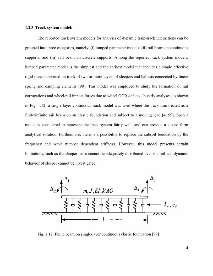
1.2.3 Track system model:
The reported track system models for analysis of dynamic train-track interactions can be
grouped into three categories, namely: (i) lumped parameter models; (ii) rail beam on continuous
supports; and (iii) rail beam on discrete supports. Among the reported track system models,
lumped parameter model is the simplest and the earliest model that includes a single effective
rigid mass supported on track of two or more layers of sleepers and ballasts connected by linear
spring and damping elements [98]. This model was employed to study the formation of rail
corrugations and wheel/rail impact forces due to wheel OOR defects. In early analyses, as shown
in Fig. 1.12, a single-layer continuous track model was used where the track was treated as a
finite/infinite rail beam on an elastic foundation and subject to a moving load [4, 99]. Such a
model is considered to represent the track system fairly well, and can provide a closed form
analytical solution. Furthermore, there is a possibility to replace the subsoil foundation by the
frequency and wave number dependent stiffness. However, this model presents certain
limitations, such as the sleeper mass cannot be adequately distributed over the rail and dynamic
behavior of sleeper cannot be investigated.
Fig. 1.12: Finite beam on single-layer continuous elastic foundation [99]
15
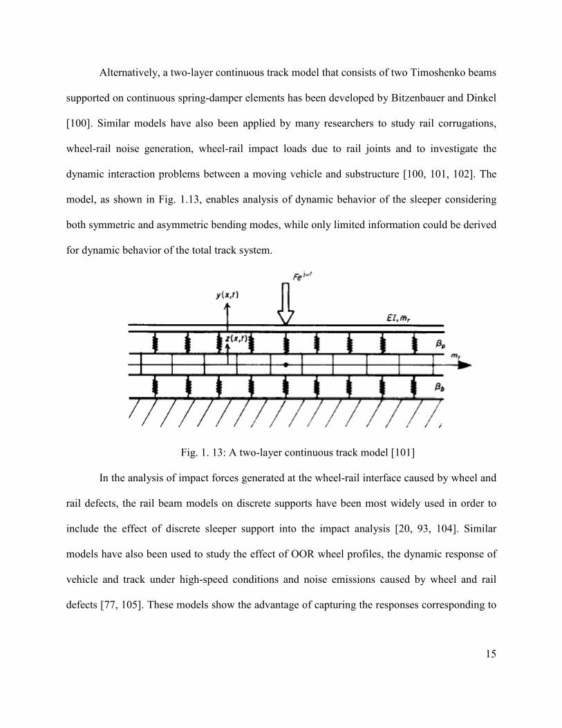
Alternatively, a two-layer continuous track model that consists of two Timoshenko beams
supported on continuous spring-damper elements has been developed by Bitzenbauer and Dinkel
[100]. Similar models have also been applied by many researchers to study rail corrugations,
wheel-rail noise generation, wheel-rail impact loads due to rail joints and to investigate the
dynamic interaction problems between a moving vehicle and substructure [100, 101, 102]. The
model, as shown in Fig. 1.13, enables analysis of dynamic behavior of the sleeper considering
both symmetric and asymmetric bending modes, while only limited information could be derived
for dynamic behavior of the total track system.
Fig. 1. 13: A two-layer continuous track model [101]
In the analysis of impact forces generated at the wheel-rail interface caused by wheel and
rail defects, the rail beam models on discrete supports have been most widely used in order to
include the effect of discrete sleeper support into the impact analysis [20, 93, 104]. Similar
models have also been used to study the effect of OOR wheel profiles, the dynamic response of
vehicle and track under high-speed conditions and noise emissions caused by wheel and rail
defects [77, 105]. These models show the advantage of capturing the responses corresponding to

16
three resonance frequencies of the track structure, the rail and the sleeper [106]. A two-layer
discrete track model is shown in Fig. 1.14.
Fig. 1. 14: Two-layer discrete track model [19]
Three-layer track models have also been formulated where the ballast is modeled as a
massive mass in addition to the sleeper mass. These models have been employed by Zhai and
Cai [13, 15] to study the wheel-rail impact loads due to wheel flats and rail joints, and Jin et al.
[6, 14] to study the effect of rail corrugations on vertical dynamics of the vehicle and track.
Oscarsson [107] also used this model to simulate the train-track interactions with stochastic track
properties. Ishida and Ban [7] developed a five layers track model, as shown in Fig. 1.15, in
order to analyze the effect of different types of wheel flats in terms of impact loads and rail
acceleration where the ballast is divided into three different layers coupled through damping and
spring elements. This model permits analysis of the response of ballast at different positions to
the excitation at wheel-rail interface. The model results, however, did not show substantial
advantage in enhancing the dynamic wheel-rail impact load prediction ability when compared to
the simpler models.

17
Fig. 1. 15: A comprehensive five-layer discrete track model developed by Ishida and Ban [7].
Apart from the track system modeling, modeling of the track components, such as rail,
sleeper, railpad, ballast, also varies depending upon the purpose of studies. The rail is mostly
modeled as a continuous beam, either as an Euler-Bernoulli beam or a Timoshenko beam. The
Euler beam model of the rail has been used in many studies on dynamic analysis of the vehicle-
track system to study the effects of wheel flats [88, 108], rail corrugation [6, 14, 91], rail dipped
joints [109], rail welds [81, 108], bridge-train interactions [110] and OOR defects [93]. However,
the Euler beam model neglects shear deformation and rotational inertia of the rail which may
yield overestimation of the dynamic force in the high frequency range. Thus, lateral dynamic
studies that involve lateral flexibility of the rail web may not be suitable with this model.
Furthermore, it has been reported that Euler beam representation of the rail is adequate for the
rail response to vertical excitation for frequencies less than about 500 Hz, while for Timoshenko
beam model it is up to 2.5 kHz [22]. Timoshenko beam model of rail has, thus, been widely
employed in order to study the dynamic interaction between the wheel and rail in the presence of
wheel and/or rail imperfections, effect of nonlinearity and railpad stiffness on wheel-rail impact
and noise generation [18, 103, 105, 111, 112]. In recent years, several number of studies have
employed Timoshenko beam to model the rail in order to analyze the vehicle-track interactions

18
due to the wheel flats [78, 113, 114] and track irregularities [81, 87, 115]. A Timoshenko rail
beam four-layer track model is shown in Fig. 1. 16.
Fig. 1. 16: A Timoshenko rail beam four-layer track model [113]
Railpads are used to support the rail, and to protect sleepers from wear and damage. Railpad
is generally modeled using spring elements [104, 116] or combined spring and damping elements
[6, 14, 93, 108] to form either continuous or discrete rail support. A state-dependent three-
parameter viscoelastic railpad model has been developed by Anderson and Oscarsson [5] in
order to study the dynamic behavior of pad under low and high frequency excitations. Different
types of pad models utilized in railway vehicle-track interaction analysis in the presence of wheel
and rail defects are shown in Fig. 1. 17. In a continuous rail support, the railpad is continuously
placed under the rail beam [99, 100], whereas the discrete models consider the visco-elastic pad
model at a point on the rail foot at the center of the sleeper support to investigate the wheel-rail
interactions [10, 18, 23, 104, 108].
(a) (b) (c) (d)
Stiffness
Damping

19
Fig. 1. 17: Different types of rail pad model: (a) one-parameter; (b) two-parameter; and (c) and
(d) three-parameter.
In the analysis of vehicle-track interactions in the presence of wheel and rail defects, a
sleeper can be considered either as a transverse beam with either uniform or variable cross
section [118] or as discrete mass [6, 10, 14, 105, 107] on an elastic foundation representing the
ballast. These studies have invariably concluded that sleeper modeled as a rigid mass is adequate
for prediction of dynamic vehicle-track interaction force, while the bending stiffness is neglected
that may yield an overestimation of impact force at higher speeds. The ballast is generally
modeled as parallel spring-damper elements [4, 8, 10, 93, 103, 104, 105] or as rigid masses those
are interconnected by the shear springs and dashpots [6, 13, 14, 15]. The latter model permits
analysis of distributed ballast deflections under excitations at the wheel-rail interface. However,
the ballasts do not greatly affect the wheel-rail contact forces due to their distant placement from
the wheel-rail contact [119]. A comprehensive ballast model developed by Zhai et al. [13, 15]
that considers shear interaction between the ballast masses is shown in Fig. 1. 18.
Fig. 1. 18: Ballast model considering the stiffness and damping in shear [13, 15]
Sleeper
Ballast
Damper
Spring

20
The elastic properties of the track system can be modeled with either linear or nonlinear
stiffnesses and damping. Although the properties of railpad and ballast in practice are nonlinear,
a vast majority of the studies involving vehicle-track interaction in the presence of wheel and rail
defects considered the linear properties of the railpad stiffness and damping [4, 8, 9, 13, 14, 16,
83, 88]. The analytical studies of wheel-rail impact loads due to wheel and rail defects showed
reasonably good agreements with measured peak contact force in the presence of wheel defects
[13, 21]. The difference between the predicted peak wheel-rail impact loads and the measured
data is, however, very high in case of high vehicle speed [4, 8]. The predicted wheel-rail impact
loads were compared using linear and nonlinear rail track properties by Johansson and Nielsen
[19]. The study concluded that a linear track model yields lower magnitudes of the impact loads
than the nonlinear track model in low and medium speed range. However, at higher speeds, more
than 70 km/h, both models predicted higher impact forces than the measured data. The nonlinear
properties of the railpad are included in a very few studies in order to investigate the wheel-rail
interaction in the presence of wheel/rail defects [105, 117]. These studies showed considerable
differences in the results due to linear and nonlinear track models. Dahlberg [117] claimed the
necessity of a nonlinear track model when the load to the railpad and ballasts varies significantly
because of the dramatic change in the railpad and ballasts stiffness with change in loads.
However, these studies simplify the vehicle model to a single wheel model only, which do not
consider the pitch and roll motion of the car body and bogie. Change in the static and dynamic
stiffness of nonlinear railpad due to change in the load is shown in Fig. 1. 19.

21
Fig. 1. 19: (a) static stiffness of non-linear pads, — measured , ···· approximated. The upper
curves are for the stiff pad and the lower curves are for the medium pad; (b) dynamic stiffness of
non-linear pads, — stiff pad, --- medium pad, ···· soft pad [105].
1.2.4 Wheel-rail contact model:
Wheel-rail contact points couple the vehicle model with the track model. The accurate and
reliable prediction of wheel-rail impact force largely depends upon the accuracy of the wheel-rail
contact model. A number of theories have been evolved to accurately describe the dynamic
wheel-rail contact point. The vast majority of the analytical studies considered linear [114, 120,
121, 122, 123, 124, 125] or non-linear [5, 13, 14, 15, 97, 103, 107, 126, 127] Hertzian contact
model in order to study the wheel-rail interactions due to wheel/rail defects. Hertzian contact
model, as shown in Fig. 1. 20, is perhaps the simplest and most widely used to characterize the
rolling contact in railway vehicle. A major disadvantage of non-linear Hertzian contact model is
that it underestimates the impact force at low speeds and overestimates the impact force at higher
speeds [112]. It has been suggested that a linearized contact spring could adequately represent

22
the wheel-rail contact when variations in the overlap are very small [121]. The linearized contact
spring has been widely used to study the rail corrugations, vibration due to high frequency
irregularities on wheel-rail tread, and noise generations [102, 121, 127, 128]. The linearization,
however, yields overestimation of the contact stiffness in the vicinity of discontinuity and
thereby the impact loads [8].
Fig. 1. 20: A single point wheel-rail contact model applied by Tassilly and Vincent [125]
Kalker [129] proposed a Non-Hertzian contact model based on predicted contact area and
shape, which requires extensive computation as the contact area must be established as a
function of wheel angular position relative to the rail. A study of vehicle-track interaction by
Baeza et al. [130] has used the non-Hertzian contact model for a wheel with flat. The study
stated that it is not viable to solve this contact model simultaneously with the integration of
differential equation of motion. Alternate methods to calculate the wheel-rail contact forces
using non–Hertzian contact patch have been reported by Pascal and Sauvage [131]. The solutions
of contact problems for an elliptical contact zone are presented by Kalker [132] and Shen et al.

23
[133], and later mostly used by others for analysis of wheel-rail squealing noise [134],
corrugation studies [135], and interaction due to rail irregularities [136] etc.
For analysis of vehicle system dynamics, instead of using single-point contact, multiple point
wheel-rail contact models were used in [137, 138, 139, 140]. Several multipoint contact models
based on elliptic and non-elliptic profile are cited in [139]. A multiple point contact model, as
shown in Fig. 1. 21, has been developed by Dong [8] based on Hertzian static contact theory in
order to study the wheel-rail impact load due to wheel flat. This model has also been employed
later by Hou et al [90] and Sun et al [97] for the same purpose. Both of these studies reported
that multiple contact model shows good correlation between the predicted and experimental data,
except for some overestimations of wheel-rail impact load at a speed of 70 km/h [97]. These
studies, nevertheless, assume that contact region is symmetric about the vertical axis, and the
results obtained are very similar to those predicted by Hertzian point contact model. A recent
study by Zhu [78] developed a multipoint adaptive contact model to account for the asymmetric
contact as the flat enters the rail. Further study is, however, required to establish the spring
stiffness for the model.

24
Fig. 1. 21: Multipoint wheel-rail contact model.
1.2.5 Wheel defects:
Railway wheel defects are generally attributed to the imperfections caused by the
misalignment and fixation, manufacturing flaws, and those caused by the operation of the
vehicle. These defects are termed as wheel flat, shelling, spalling, shattering, corrugation,
eccentricity, etc. Several comprehensive reviews on various types of wheel defects, their effect
on wheel-rail impact loads, and vehicle and track components have been described in [20, 23].
Wheel shelling is a type of wheel defect that is caused by loss of materials from the wheel
tread and is assumed as the result of rolling contact fatigue. Moyar and Stone [139] carried out a
study on formation of railway wheel shelling due to thermal effect and concluded that periodic
rail chill has a strong effect on shelling in the case of hot-braked treads. Wheel spalling is
another type of wheel defect that has been associated with rolling contact fatigue. Railway wheel
spalling is assumed to occur as the result of fine thermal cracks joining to produce the loss of a
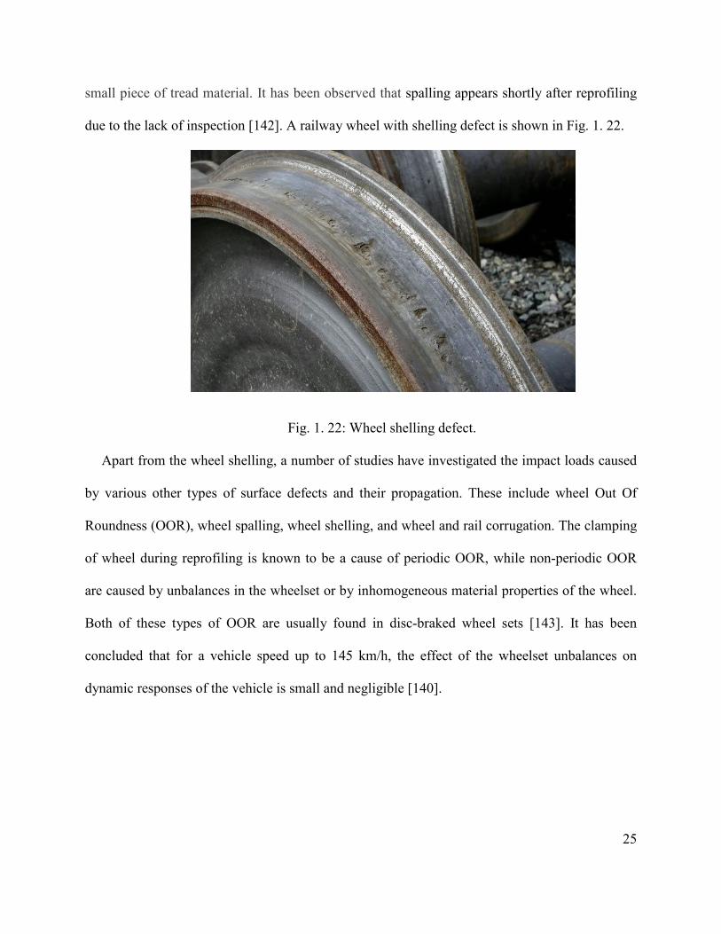
25
small piece of tread material. It has been observed that spalling appears shortly after reprofiling
due to the lack of inspection [142]. A railway wheel with shelling defect is shown in Fig. 1. 22.
Fig. 1. 22: Wheel shelling defect.
Apart from the wheel shelling, a number of studies have investigated the impact loads caused
by various other types of surface defects and their propagation. These include wheel Out Of
Roundness (OOR), wheel spalling, wheel shelling, and wheel and rail corrugation. The clamping
of wheel during reprofiling is known to be a cause of periodic OOR, while non-periodic OOR
are caused by unbalances in the wheelset or by inhomogeneous material properties of the wheel.
Both of these types of OOR are usually found in disc-braked wheel sets [143]. It has been
concluded that for a vehicle speed up to 145 km/h, the effect of the wheelset unbalances on
dynamic responses of the vehicle is small and negligible [140].

26
. The formation of the wheel OOR, their experimental detection, mathematical model to predict
impact load due to wheel OOR and criteria for removal of OOR wheels have been thoroughly
discussed in a comprehensive review presented by Barke and Chiu [23], and Nielsen and
Johansson [20].
Among all the types of wheel defects, wheel flat is the most common type encountered
by railway industry [8]. The impact load due to wheel flats induces high-frequency vibrations of
the track that causes damage to track components, which may also be high enough to shear the
rail [7, 13, 15]. Wheel flats thus affect track maintenance and the reliability of the vehicle’s
rolling elements [130]. In addition to safety and economic considerations, these defects reduce
passenger comfort and significantly increase the intensity of noise [120]. Due to the modern
trend in increasing the speed and wheel load of the vehicle, replacement of defective wheels and
in-time maintenance of the track has become an important concern for heavy haul operators. In
order to predict the wheel-rail impact load accurately, it is necessary to develop the effective
impact load prediction tools. A wide range of mathematical models have thus evolved to
characterize the geometry of wheel flats in order to investigate the impact loads [7, 8, 15, 90,
103].
In order to control the adverse effect of wheel flats and ensure the safe operation of the
railroads, various railroad organizations have set the criteria for removal of wheels with flats
primarily based on flat size and the impact load produced by the flat. The American Association
of Railroad (AAR) has set the criteria to replace the wheel from the service for 50.8 mm long
single flat or 38.1mm long two adjoining flats [144]. The AAR also states that a wheel should be
replaced if the peak impact forces due to single flat approaches the 222.41 to 266.89 kN range

27
[145]. According to Transport Canada safety regulations, a railway car may not continue in
service if one of its wheels has a flat of more than 63.50 mm in length or two adjoining flats each
of which is more than 50.80 mm [1]. Swedish Railway sets the condemning limit for a wheel flat
based on a flat length of 40 mm and flat depth of 0.35 mm [17]. According to UK Rail safety and
standard board [146], freight vehicle with axle load equal to or over 17.5 tonnes a wheel with flat
length exceeding 70 mm must be taken out of service. These removal criteria for defective
wheels are based on the damage potential of the wheel flat and mostly the magnitude of the
wheel-rail impact force due to the wheel flat. The presence of multiple flats either within a single
wheel or within a multiple wheels of a freight car that could lead to considerably different
magnitudes of impact loads is not properly addressed by the current guidelines. The Transport
Canada guidelines also stipulate the threshold lengths of two adjoining flats in a single wheel,
while the basis for the threshold values is not known. Furthermore, the contributions due to roll
and pitch dynamics of the car and relative positions of different wheel flats with wide variations
in relative positions between the flats on the wheel-rail impact forces were not investigated.
In order to predict the wheel-rail impact load accurately, it is necessary to develop the
effective impact load prediction tools. A wide range of mathematical descriptions have thus
evolved to characterize the geometry of wheel flats in order to investigate the impact loads [7, 8,
13, 16, 103]. Wheel flats have been classified as chord type flat, cosine type flat and combined
flat based on the flat geometries. As shown in Fig. 1. 23, a newly formed fresh flat with
relatively sharp edges is known as chord type flat. This type of flat model has been widely used
in various studies on wheel-rail impact load, rail acceleration, and noise [7, 16, 103]. However, it
has been shown that the chord type flat model overestimates the wheel-rail impact load [7].
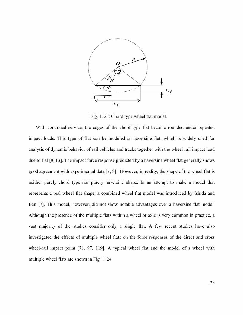
28
Fig. 1. 23: Chord type wheel flat model.
With continued service, the edges of the chord type flat become rounded under repeated
impact loads. This type of flat can be modeled as haversine flat, which is widely used for
analysis of dynamic behavior of rail vehicles and tracks together with the wheel-rail impact load
due to flat [8, 13]. The impact force response predicted by a haversine wheel flat generally shows
good agreement with experimental data [7, 8]. However, in reality, the shape of the wheel flat is
neither purely chord type nor purely haversine shape. In an attempt to make a model that
represents a real wheel flat shape, a combined wheel flat model was introduced by Ishida and
Ban [7]. This model, however, did not show notable advantages over a haversine flat model.
Although the presence of the multiple flats within a wheel or axle is very common in practice, a
vast majority of the studies consider only a single flat. A few recent studies have also
investigated the effects of multiple wheel flats on the force responses of the direct and cross
wheel-rail impact point [78, 97, 119]. A typical wheel flat and the model of a wheel with
multiple wheel flats are shown in Fig. 1. 24.
θ
ϕ
fD
o
fL
R
x
( )tr
A

29
Lf2
Df2
xf2
r2(t)
ϕ
Lf1
Df1
R
xf1 r1(t)
(a) (b)
Fig. 1. 24: A railway wheel (a) with two flats; (b) model with two haversine type flats.
Experimental and theoretical studies on impact loads due to wheel flats have been described
by Johansson and Nielsen [20], Newton and Clark [4] and Fermer and Nielsen [21]. These
studies revealed that impact loads produced by wheel defects are not always easily detectable by
visual inspection of the wheel and a nonlinear track model yields more accurate prediction of the
wheel-rail impact force due to wheel defects than the linear track model. Early experimental
studies carried out by Jenkins et al [147] and Frederick [148] showed the effect of vehicle and
track parameters on vertical dynamic forces in the presence of wheel flats and rail joints. A
recent experimental study on vertical wheel-rail contact force in the presence of track
irregularities has been carried out by Gullers et al. [149]. The experimental study to observe the
flat growth has been carried out by Jergeus et al. [142]. The study concluded that the rate of
growth of wheel flat is very high at the beginning and it is thus essential to take the wheelset out
of service as soon as possible when a wheel flat is observed.
1.2.6 Simulation methods:
There are two different techniques widely used in the analysis of moving load and moving
mass problems. These are Fourier transformation method and generalized mode or assumed

30
mode method. Fryba [24] presented a detailed solution of the moving load problem where the
beam was modeled as infinitely long Euler-Bernoulli beam resting on Winkler foundation. A
vast majority of the studies dealing with the moving load problems utilized the Fourier
transformation method to solve the governing differential equations arising from either Euler-
Bernoulli or Timoshenko theory [24, 28, 51, 65, 66]. The responses of the infinite beam under
moving load supported on either Winkler or Pasternak foundation were studied by means of
Fourier transforms and using Green’s function in [25, 66, 150]. Mead and Mallik [151], and Cai
et al. [152] presented an approximate “assumed mode” method to study the space-averaged
response of infinitely long periodic beams subjected to convected loading and moving force,
respectively. These methods are applicable to the forced vibration analysis of an infinite
continuous beam subjected to arbitrary excitations. In order to consider the effect of non linearity
in beam analysis, Finite Element Analysis (FEA) of an infinite beam has been carried out in
[153-155]. In these studies, FEA has been adopted to perform the analysis of nonlinear dynamic
structure under moving loads where the load varies with both time and space.
In moving force problem, the magnitude of the moving force has been assumed to be constant
by neglecting the inertia forces of a moving mass. However, in case of moving mass, the
interaction force consists of inertia of the mass, centrifugal force, etc. Hence, the velocity of the
moving mass, structural flexibility, and the mass ratio of the moving mass to structure play
important roles on the overall interaction process. A closed-form solution to a moving mass
problem is obtained by Michaltos et al. [32] by approximating the solution without the effect of
the mass. By using the method of Green functions, the effects of the system parameters on the
dynamic response of the beam subjected to a moving mass have been studied by Ting et al. [36],
Foda and Abduljabbar [37], and Sadiku and Leipholz [39]. The method of the eigenfunction

31
expansion in series or modal analysis has been employed by Akin and Mofid [41], Bowe and
Mullarkey [42], Ichikawa et al. [43], Stanisic and Lafayette [46], and Lee [47]. Lou et al. [60],
Yavari et al. [61], Vu-Quoc and Olsson [62], Bajer and Dyniewicz [63], and Cifuentes [64]
investigated the dynamic response of single and multi span beams subjected to a moving mass by
using finite element method.
To analyze the wheel-rail interactions in presence of wheel/rail defects, two different
techniques, namely, Frequency domain and Time domain techniques are widely used. Frequency
domain technique has been used to study the impact load due to wheel defects, track
irregularities and the formation of corrugations [93, 122, 135]. This technique takes less time to
analyze and is effective for the prediction of the frequency response related to excitation.
However, it is limited to investigation of the linear models only. When nonlinearity is present
either in vehicle-track system model or in contact model, it is necessary to adopt the solution
process in time domain. Time domain analysis can be further classified into modal analysis
method and finite element method. Modal analysis method has been used to study the wheel-rail
impact load due to wheel flats and rail joints, noise generation and rail corrugations [6, 13, 14,
15, 119, 134]. This method has the advantage of fast computing when the local variations of the
track are small. However, many modes are required to exactly model the track in order to have
accurate prediction of the track behavior. Alternatively, use of finite element method for solution
of train-track interaction has become more attractive due to the recent progress in computer
capacity. Finite element method has been applied to study the impact load due to wheel and rail
defects and formation of OOR in wheel profiles [18, 89, 112, 113, 147]. The extreme
adaptability and flexibility of finite element method have made it a powerful tool to solve PDE
over complex domain. However, the accuracy of the obtained solution is usually a function of

32
the mesh resolution and the solution often requires substantial amount of computer and user
time, particularly when extensive parametric study is required.
1.2.7 Detection of wheel defects:
Imperfections on the wheel tread and rail surface can have detrimental influence on both
vehicle and track components such as vehicle bogies, wheelsets, bearings, rails and railpads. The
high impact forces from a defective wheel cause stress in the rail, and in extreme cases can break
the track or cause the wheel to jump off the track, resulting in derailment. The continuous
repetitions of impacts on rail, together with the high forces involved, cause rapid deterioration of
both rolling and fixed railway equipment. If ignored or underestimated, the fault will wear out
materials up to the breakdown. Thus, various methods have been proposed for detecting flat
wheels. One method is to employ inspectors to listen to the trains as they move through a
particular location. In some cases, flat wheels are identified through routine inspections when the
cars are being serviced. These methods employ a range of technologies from optical systems that
gauge the wheels in real time to sensors that look for vibrations and stress levels.
Continuous wavelet transform has been applied to vibration signal analysis of railway wheels
in order to detect the wheel tread defects by Belotti et al. [156] and Yue et al. [157]. Belotti et al.
[156] has shown a wheel-flat diagnostic tool by using wavelet transform method, as shown in
Fig. 1. 25. In this study, an experimental layout was designed to develop and to validate a
reliable, effective, and low-cost wheel-flat diagnostic tool. The method implies the detection of
the wheel flats through the measurement of peak acceleration by the use of several
accelerometers placed in fixed positions on the rail. The results obtained from experimental
study validate the theoretical model and demonstrates the advantages of wavelet-based detection
of signatures. However, the wired connections between the accelerometer and the analysis house

33
make the overall system bulky. Furthermore, the entire train has to pass through the specific test
section that can be far from the train operating area.
Fig. 1. 25: Testing train scheme with damaged wheels represented by deep marked and
instrumented rail where the arrows near the accelerometers indicate their measuring axes [156].
The detection of wheel flats with fiber optic sensors has been reported by Anderson [158]. In
this method, the screen is fixed between the end of the fiber and the active area of the detector,
and the pinhole is sized to have the same diameter as the RMS value of the bright/dark spots in
the speckle pattern, as shown in Fig. 1.26. When the fiber is disturbed the speckle pattern
changes. As the speckle pattern changes, bright and dark fringes pass over the pinhole, resulting
in a time varying signal that is indicative of the vibration of the fiber. For small perturbations, the
frequency of this signal is equal to the frequency of the physical disturbance. The advantages of
the pinhole/detector system are low cost and simplicity. For visible and near-infrared light, large-
area detectors are readily available for modest cost, and can be readily assembled with a built-in
pinhole and fiber-optic connector, making field assembly simple and straight forward. However,
the design has poor optical efficiency, wasting up to 90% or more of the incident light, which is
attributed to the limiting aperture of the pinhole. Furthermore, the placement of the fiber on the

34
underside of the metal grating alongside the track makes the system rather complicated. Several
different types of optical sensors have been applied in order to detect wheel and rail defects with
fair accuracy and high resolutions [159, 160].
Fig. 1. 26: Detector and pinhole assembly used to measure temporal changes in speckle pattern [159].
Another method of detecting wheel flats employs scanning with laser beam [161], as shown
in Fig. 1. 27. The entire module consists of a detector to send and receive radiation signals after
the scanning of the wheel. The module also has a smart electronics box (SEB) that contains
digital signal processors and connection to the wayside personal computer (PC) for further
analysis. Wheel flats can be clearly detected from the unique signature and the gradients between
scans at different heights on the wheel. Similar technique has also been applied by Kenderian et
al. [162] in order to detect dynamic railroad defects.
Ultrasound technique has often been used as a non-destructive technique in order to inspect
the defects of rail wheel [163-167]. The methods consist of sending an ultrasound pulse over the
rolling surface to detect echoes produced by the defects. The inspections can be carried out
manually or by expensive and complex installations. In both cases, however, long inspection

35
time is required. Moreover, ultrasound techniques use high frequencies that cannot penetrate
certain type of defects because of excessive attenuation [166].
Fig. 1. 27: Positioning of scanner assemblies to view inner bearing, outer bearing, and wheels
[161]
Acoustic method for detection of wheel flats is also available in literatures [168, 169]. In this
method, sound from a passing train is recorded and the particular sound caused by the impact
between a wheel flat and the supporting rail is distinguished by detecting frequencies in that
particular sound. Another method for detection of the presence of the wheel flats rely on the
sensing of changes in voltage resulting from a break in the established circuit caused by the
wheel flat.
The most common approach to detect wheel defects is based on the analysis of impact loads
or accelerations of wheels or rails developed due to the presence of wheel and rail defects in
time-domain schemes [170-173]. These methods employ several accelerometers placed on rails
in order to detect the wheel/rail defects by inspecting the acceleration levels. Detection of the
wheel/rail defects depends on the analysis of the frequency spectrum of the measured rail
accelerations. Bracccialli et al. [172] presented a description of this type of method based on the
cepstrum analysis of rail accelerations. These accelerometers can be MEMS based

36
accelerometers or conventional piezoelectric accelerometers. The vast majority of accelerometers
are based on piezoelectric crystals, but they are too big and too clumsy, whereas, MEMS based
accelerometers are tiny and are made using a highly enabling technology with a huge
commercial potential. They provide lower power and robust sensing. The most common
application for MEMS based accelerometers in railway engineering is health monitoring of the
track [174-176]. A MEMS based sensor network for rail signal system has been proposed by
Fukuta [177]. Lee et al. [178] developed a MEMS based hybrid uniaxial strain transducer in
order to monitor the fatigue damage of the rail. However, all these MEMS based sensors are
developed to monitor the track only.
1.3 THESIS SCOPES AND OBJECTIVES
From the review of the relevant literature, it is evident that although different types of
railway vehicle and track models have been developed in order to study the interaction effect in
the presence of wheel and rail defects, very few studies have considered three-dimensional
representation of the railway vehicle and track model. Furthermore, although railpad and ballast
stiffness and damping properties are nonlinear in practice, a vast majority of the studies has
considered the linear properties of railpad and ballast model in dynamic analysis of vehicle-track
interaction due to wheel and rail defects.
It is also evident from the review of the relevant literature that a great deal of research efforts
has been made in order to predict the wheel-rail impact force in the presence of wheel and rail
defects such as, single wheel flat, rail corrugation, etc. These studies have provided guidelines
for acceptable limits of wheel flats for the railway transportation industry in order to ensure safe
and efficient operation. Although the presence of multiple flats within a wheel or different
wheels in the same or different axles have been widely noticed in practice, the vast majority of

37
the efforts focus on the impact interactions due to a single flat only. The influences of multiple
flats, and their consequences have not been adequately quantified. Furthermore, the pitch and roll
motions of the car body and bogie could adversely affect the wheel-rail impact force caused by
the wheel and rail irregularities. A comprehensive three-dimensional vehicle model coupled with
a three-dimensional track model is thus required in order to predict the wheel-rail impact loads
due to wheel and rail defects.
From the review of the relevant literature, it is also evident that considerable efforts have
been made to detect the presence of defects in the wheels and rails. However, all these detection
techniques utilize the railway track to mount the sensors, which requires the train to pass through
that particular test section of the rail in order to investigate the wheel defects. A train in operation
that needs prompt investigation may not be possible by these present techniques i.e. continuous
monitoring of all the wheels for detection of the flat is not possible. Furthermore, the present
techniques require huge connections of wires to transfer the data from the test section to analysis
center. One of the challenges for sensors is the need to operate remotely in harsh environments
with exposure to wide temperature ranges as well as rain, snow, slush, dirt and grime.
Development of an on-board measuring system is thus required that can be placed on the wheel
bearing in order to enable the detection of the wheel defects continuously.
The present dissertation research thus aims to develop a comprehensive three-dimensional
dynamic railway vehicle-track model coupled with non-linear railpad and ballast stiffness and
damping properties. The developed model must be capable of predicting dynamic responses in
terms of force or acceleration in the presence of single as well as multiple flats. Finally, based on
the analytical results predicted by the developed model, a smart railway wheelset will be

38
developed with MEMS based accelerometers. The specific objectives of the proposed research
are listed below, which are also the expected major contributions:
a) Develop a two-parameter Pasternak foundation model subjected to moving load or moving mass in order to analyze the vibration of Euler-Bernoulli beam of finite and infinite length.
b) Develop a comprehensive three-dimensional railway vehicle-track model using two Timoshenko beams supported by discrete non-linear elastic supports to study the interactions of two sideframe wheels and the wheels within a wheelset taking into account the contribution of vehicle pitch and roll motions.
c) Formulate models for single as well as multiple wheel flats in order to evaluate the impact responses in terms of force or acceleration arising from single as well as multiple wheel flats and investigate the influences of one wheel flat on the force or acceleration imparted at the interface of the adjacent wheel.
d) Investigate the influences of variations in various design and operating parameters on the magnitudes of the impact force or acceleration such as, speed, flat size and relative positions of the flats within the same wheel or wheelsets
e) Develop a smart wheelset that can detect its defect automatically.
f) Design and analyze MEMS based accelerometer for automatic detection of wheel flats.
1.4 ORGANIZATION OF THE THESIS
The first chapter summarizes the highlights of the relevant reported studies on different types
of modeling of vehicle and track systems employed in studies related to dynamic responses and
railway vehicle track interactions in the presence of wheel defects. The reported studies on
different types of wheel defects, analytical and experimental methods for detection of wheel
defects are also summarized in this chapter. The scope of the dissertation research is
subsequently formulated on the basis of the reviewed literature.
In chapter 2, dynamic response of an infinite Euler-Bernoulli beam under a constant moving
load is investigated. The same beam with finite length is further employed to obtain the dynamic
response with moving load as well as moving mass. The foundation representing the soil is
modeled as both one-parameter Winkler and two-parameter Pasternak model. Fourier transform

39
technique is employed to find the analytical solution of the governing partial differential
equation in the case of moving load problem. However, numerical method is employed in the
case of moving mass problem. The dynamic responses of the beam in terms of beam deflections,
and bending moments have been obtained with different velocity ratios. The effects of shear
modulus and foundation stiffness on deflection, bending moment and shear force responses have
also been investigated for both damped and undamped cases where the speed varies from below
critical to above critical velocity. In case of damped analysis, responses are obtained for both
underdamped and overdamped conditions.
In chapter 3, a three-dimensional vehicle model is developed together with a three-
dimensional two-layer track model. The two models are coupled by the non-linear Hertzian
wheel-rail contact model. The equations of motion of the vehicle and track system are presented
along with the parameter values. Modal analysis method is used to analyze the coupled
continuous rail track and lumped-parameter vehicle system models. Natural frequencies of the
vehicle and track systems are calculated and presented in this chapter. This chapter further
presents the validation of the developed vehicle-track system model under wheel flat conditions
using both theoretical and experimental results from the literature. The responses obtained from
the validated vehicle and track system model in terms of wheel-rail impact force are also
presented as functions of operating speed and flat geometry.
In chapter 4, the three-dimensional vehicle-track model developed in chapter 3 is validated in
terms of wheel-rail impact force with both experimental and analytical data available in
literature. The validation is carried out with both linear and nonlinear properties of railpad and
ballast. The validated model is then employed to obtain displacement and acceleration responses
of individual vehicle and track components in the presence of single wheel flat. The results are

40
shown for both defective and flat-free wheel. The characteristics of the bogie bounce, pitch and
roll motions due to a single wheel flat are also investigated. The analyses are performed with
different position of the wheel flats such as in front or rear wheelsets within a front or rear bogie.
The response characteristics are also obtained with different flat sizes and vehicle speeds.
In chapter 5, the developed and validated three-dimensional railway vehicle-track model is
employed to study the effect of multiple wheel flats on wheel acceleration response. The
response characteristics of wheel acceleration are obtained for both left and right wheels within
same and different wheelsets for different types of wheel flats and their relative positions. The
effects of both direct and cross wheel flats on different wheels within same bogie are also
investigated. The effect of bogie pitch and roll motions on overall peak acceleration of the wheel
is also investigated in the presence of multiple flats. In order to develop a smart wheelset that can
detect its wheel flat size by measurement of the peak wheel acceleration, the relation between the
peak wheel acceleration, vehicle speed and the wheel flat size are also presented.
In chapter 6, a MEMS based accelerometer model is developed for automatic detection of
wheel flat. The three-dimensional railway vehicle-track model developed in chapter 3 is
employed in order to investigate the wheel acceleration level in presence of a single wheel flat.
COMSOL Multiphysics software is employed to validate the developed accelerometer model.
The simulated responses are compared with the results obtained from the calculations. A self-test
region is designed within the accelerometer to facilitate the self-tests/diagnostics of each
individual accelerometer. Finally, the stability and maximum stress level of the accelerometer is
estimated in order to ensure the safe operation of the sensor.
In chapter 7, major conclusions drawn from this dissertation research are summarized and
a few recommendations and suggestions for further studies in this area are presented.

41
CHAPTER 2
STEADY STATE RESPONSE OF ELASTICALLY SUPPORTED CONTINUOUS BEAM
UNDER A MOVING LOAD/MASS
2.1 INTRODUCTION
The dynamic analysis of beam type structures subjected to moving loads or moving masses is
important and widespread in railway engineering as a beam resting on soil can be conveniently
used to represent the track of railway. As the loads/wheels of the railway move over the beam
with a very high speed, the structures over which they move are exposed to very high dynamic
forces. It is, thus, necessary to understand and analyze the behaviour of these structures in order
to facilitate their use in case of higher speeds and heavier loads. A wide range of analytical
studies have thus been evolved in order to accurately predict the vibration of the railway track
under moving loads/masses [24-38, 47, 48, 56- 64]. Most of these studies employed one-
parameter Winkler foundation model consisting of infinite closely-spaced linear springs
subjected to a moving load [24-28]. Although this model is very simple, it does not accurately
represent the characteristics of many practical applications. Two-parameter elastic foundations,
thus, have been suggested in some studies for the vibration analysis of beams under moving
loads [49-51]. These models are also known as Pasternak models, which allow shear interaction
between the continuous springs.
The beam, that represents the railway track, can be modeled as either an Euler-Bernoulli
beam [30, 47, 48, 56-61] or a Timoshenko beam [32-38, 43, 50, 51, 62- 64] depending upon the
physical system. A Timoshenko beam model considers the shear deformation and rotational
inertia of the beam. Chen and Huang [57] have graphically shown that an Euler-Bernoulli beam
can accurately predict the response of the beam for foundation stiffness up to 108 N/m2.
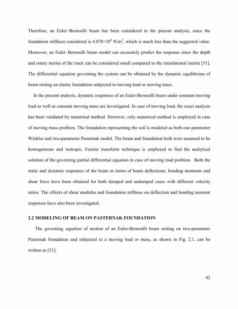
42
Therefore, an Euler–Bernoulli beam has been considered in the present analysis, since the
foundation stiffness considered is 4.078×10⁶ N/m2, which is much less than the suggested value.
Moreover, an Euler–Bernoulli beam model can accurately predict the response since the depth
and rotary inertia of the track can be considered small compared to the translational inertia [51].
The differential equation governing the system can be obtained by the dynamic equilibrium of
beam resting on elastic foundation subjected to moving load or moving mass.
In the present analysis, dynamic responses of an Euler-Bernoulli beam under constant moving
load as well as constant moving mass are investigated. In case of moving load, the exact analysis
has been validated by numerical method. However, only numerical method is employed in case
of moving mass problem. The foundation representing the soil is modeled as both one-parameter
Winkler and two-parameter Pasternak model. The beam and foundation both were assumed to be
homogeneous and isotropic. Fourier transform technique is employed to find the analytical
solution of the governing partial differential equation in case of moving load problem. Both the
static and dynamic responses of the beam in terms of beam deflections, bending moments and
shear force have been obtained for both damped and undamped cases with different velocity
ratios. The effects of shear modulus and foundation stiffness on deflection and bending moment
responses have also been investigated.
2.2 MODELING OF BEAM ON PASTERNAK FOUNDATION
The governing equation of motion of an Euler-Bernoulli beam resting on two-parameter
Pasternak foundation and subjected to a moving load or mass, as shown in Fig. 2.1, can be
written as [51]:

43
4 2 2
14 2 2 ( , )r fw w w wEI c k k w F x t
x t t xρ∂ ∂ ∂ ∂
+ + − + =∂ ∂ ∂ ∂
(2.1)
where, ( ), ( )F x t P x vtδ= − in case of moving load, and
( )2
2
( , ), ( )w vt tF x t Mg M x vtt
δ ∂
= − − ∂ in case of moving mass, ) ( ,w w x t= is the transverse
deflection of the beam, E is the Young’s modulus of elasticity of the beam material, I is the
second moment of area of the beam cross section about its neutral axis, rρ is the mass per unit
length of the beam, c is the coefficient of viscous damping per unit length of the beam, 1k is the
shear parameter of the beam, fk is the spring constant of the foundation per unit length,
( )P x vtδ − is the applied moving load per unit length, x is the space coordinate measured along
the length of the beam, t is the time in second, M is the moving mass, g is the acceleration due to
gravity, and δ is the Dirac delta function.
P( x,t )
+ ∞ - ∞ x
- y
+
1 k1
kf
c
(a)

44
x vt=
v
1k
fk c
+x
-y
(b)
Fig. 2.1: Beam on Pasternak foundation subjected to a (a) moving load; and (b) moving mass.
Defining the followings, 2
raEIρ
= , 2 fkb
EI= , 1
1 2kcEI
= , cdEI
= , Eqn. (2.1) can be written as:
4 2 22
14 2 22 2 ( , )w w w w Fa d c b w x tx t t x EI
∂ ∂ ∂ ∂+ + − + =
∂ ∂ ∂ ∂
(2.2)
2.3 METHOD OF ANALYSIS FOR A BEAM UNDER MOVING LOAD
The dynamic response of an Euler-Bernoulli beam under constant moving load has been
investigated by both Fourier transform technique and modal analysis method. The exact analysis
has been validated by the numerical method. This section describes the formulation of the
analytical solution of the governing partial differential equation by means of Fourier transform
technique. Solutions have been obtained for both damped and undamped conditions, where the
speed varies from below to above the critical velocities.

45
2.3.1 For undamped case (velocity less than the critical):
In case of undamped system, 0c = and for one parameter model, 1 0k = , then Eqn. (2.2) can
be written as:
4 22
4 22 ( )w w Pa b w x vtx t EI
δ∂ ∂+ + = −
∂ ∂
(2.3)
Let, *( , ) ( , ) i xw t w x t e dxγγ∞ −
−∞= ∫ (2.4.a)
and, 1( , ) *( , )2
i xw x t w t e dγγ γπ
∞ +
−∞= ∫
(2.4.b)
constitute a Fourier transform pair, where, γ is a variable in complex plane. Both sides of Eqn.
(2.3) are multiplied by i xe γ− and integrated by parts over x from −∞ to+∞ . Assuming that w and
its space derivatives vanish at x = ±∞ , namely, for x →+∞ , x →−∞ ;
( ) ( ) ( ) ( ) 0w x w x w x w x′ ′′ ′′′= = = = , we get
24 2
2
** * 2 i vtd w Pw b w a edt EI
γγ −+ + = (2.5)
The solution of the homogeneous part of Eqn. (2.5) in the presence of light damping dies down
and is neglected here. Thus, the steady state solution is given by only the particular integral of
Eqn. (2.5).
Substituting * * i vtw W e γ−= in Eqn. (2.5), we obtain
4 2 2 2( 2 ) * Pb a v WEI
γ γ+ − = (2.6)
or, 4 2 2 2
1*2
PWEI a v bγ γ
= − +
(2.7)

46
or, 4 2 2 2
1*2
i vtPw eEI a v b
γ
γ γ−
= − +
(2.8)
Thus, from Eqn. (2.4.b) one obtains
( )
4 2 2 2
1( , )2 2
i x vtP ew x t dEI a v b
γ
γπ γ γ
∞ −
−∞
=− +∫
(2.9)
The integral in Eqn. (2.9) is evaluated by contour integration as discussed below [25]
1( , ) (2 ) residues2
Pw x t iEI
ππ
= ∑ at four simple poles. (2.10)
Calculation of the residues:
Let 4 2 2 21 2 3 4( ) 2 ( )( )( )( )s a v bγ γ γ γ γ γ γ γ γ γ γ= − + = − − − − (2.11)
Let, as shown in Fig. 2.2, the four roots of γ of Eqn. (2.11) be,
1 iγ β α= + , and 3 ( )iγ β α= − + . (2.12)
2 iγ β α= − + , and 4 iγ β α= − . (2.13)
Substituting the values of ,iγ s in terms of α and β from Eqns. (2.12) and (2.13) into Eqn.
(2.11), and equating the coefficients of similar terms, we get:
2 2 bα β+ = , (2.14)
2 2 2avβ α− = . (2.15)
From Eqns. (2.14) and (2.15), we get
2
2b avβ +
= , 2
2b avα −
= . (2.16)
Poles at γ :
4 2 2 2( ) 0 2 0s a v bγ γ γ= ⇒ − + = .

47
Assume 2 bva
< , where the critical velocity is given by 2cr
bva
=
For crv v< ,
2 2 2 2 21,3 ( )av i b avγ = + − (2.17)
and, 2 2 2 2 22,4 ( )av i b avγ = − − (2.18)
The four poles are shown in Fig. 2. 2, two each on either side of the real axis.
4γ • 3γ •
2γ •
Re( )γ
C1
C2
1γ •
mI ( )γ
Fig. 2. 2: Position of the poles for velocity less than the critical velocity.
For ( ) 0x vtξ = − > , considering the contour 1C (going from −∞ to +∞ on the real axis in order
to travel in the counter clock wise direction along the contour), we get,
( , ) iPw x tEI
= [Residue at 1γ + Residue at 2γ ].
or, 1 2
1 2 1 3 1 4 2 1 2 3 2 4
( , )( )( )( ) ( )( )( )
i iiP e ew x tEI
γ ξ γ ξ
γ γ γ γ γ γ γ γ γ γ γ γ
= + − − − − − − .
(2.19)
Substituting ,iγ s in terms of α and β , we finally get
( , ) [ cos sin ]4
Pew x tEI b
αξ
β βξ α βξαβ
−
= + . (2.20)

48
Similarly, for 0ξ < , considering the contour 2C (going from +∞ to −∞ on the real axis in order
to travel in the counter-clock wise direction along the contour), we get
( , ) iPw x tEI
= [Residues at 3γ + Residues at 4γ ]. (2.21)
3 4
3 1 3 2 3 4 4 1 4 2 4 3
( , )( )( )( ) ( )( )( )
i iiP e ew x tEI
γ ξ γ ξ
γ γ γ γ γ γ γ γ γ γ γ γ
= + − − − − − − .
(2.22)
Substituting ,iγ s in terms of α and β , we finally get
( , ) [ cos sin ]4
Pew x tEI b
αξ
β βξ α βξαβ
= − . (2.23)
Bending moment:
We know, Bending moment, 2
2( , )) ( ,Mx
I wE xx tt =∂∂
(2.24)
For 0ξ > , substituting the value of ( , )w x t from Eqn. (2.20) into Eqn. (2.24) and differentiating
it twice with respect to x gives:
[ cos sin ]4
( , ) P eb
M x tαξβ β βξ α βξ
α
−−+= .
(2.25)
Similarly, for 0ξ < , substituting the value of ( , )w x t from Eqn. (2.23) into Eqn. (2.24) and
differentiating it twice with respect to x gives:
[ cos s( , in) ]4P e
bM x t
αξβ β βξ α βξα
−−= .
(2.26)
Shear force:
We know, Shear force 3
3( , )) ( ,Tx
I wE xx tt =∂∂
(2.27)

49
For 0ξ > , substituting the value of ( , )w x t from Eqn. (2.20) into Eqn. (2.27) and differentiating
it three times with respect to x gives:
2
[ sin co) s, ]4
( P eb
T x tαξβ β βξ α βξ
α
−
−= . (2.28)
Similarly, for 0ξ < , substituting the value of ( , )w x t from Eqn. (2.23) into Eqn. (2.27) and
differentiating it three times with respect to x gives:
2
[ sin co4
) s, ]( P eb
T x tαξβ β βξ α βξ
α+= .
(2.29)
2.3.2 For undamped case (velocity greater than the critical):
For crv v> , Eqns. (2.12) and (2.13) can be written for two parameter model as:
2 2 2 2 21,2,3,4 1 1( ) ( )av c av c bγ = − − ± − − (2.30)
Let, the four roots of γ of Eqn. (2.30) be
1
2
3
4
,,
,.
rr
γγγγ
== −== −
(2.31)
where, q and r are given by
2 21 1( ) ( )
2 2av c b av c bq − + − −
= + (2.32)
and,
2 21 1( ) ( )
2 2av c b av c br − + − −
= − (2.33)
Thus, the four poles are as shown in Fig. 2.3. For, ( ) 0x vtξ = − > ,

50
Fig. 2.3: Position of the poles for velocity greater than the critical velocity.
( , ) iPw x tEI
= [Residues at 1γ + Residues at 2γ ].
or,1 2
1 2 1 3 1 4 2 1 2 3 2 4
( , )( )( )( ) ( )( )( )
i iiP e ew x tEI
γ ξ γ ξ
γ γ γ γ γ γ γ γ γ γ γ γ
= + − − − − − − .
(2.34)
Substituting ,iγ s in terms of q and r , we get
2 2 2 2( , )2 ( ) 2 ( )
iq iqiP e ew x tEI q q r q q r
ξ ξ− = − − −
2 2
(cos sin ) (cos sin )2 ( )
iP q i q q i qEI q q r
ξ ξ ξ ξ + − −= −
(2.35)
Finally, the deflection of the beam is obtained as
2 2( , ) sin( )
Pw x t qqEI q r
ξ= −−
(2.36)
Similarly, for 0ξ < , we get
( , ) iPw x tEI
= [Residues at 3γ + Residues at 4γ ]. (2.37)
3 4
3 1 3 2 3 4 4 1 4 2 4 3
( , )( )( )( ) ( )( )( )
i iiP e ew x tEI
γ ξ γ ξ
γ γ γ γ γ γ γ γ γ γ γ γ
= + − − − − − − .
(2.38)
Substituting ,iγ s in terms of q and r , and following the same procedures as outlined in Eqn.
(2.35), the equation of beam deflection can be written as
R ( )e γ
mI ( )γ
1γ
3γ
2γ
4γ

51
2 2( , ) sin( )
Pw x t rrEI q r
ξ= −−
(2.39)
The expression for bending moment, ( , )M x t , and shear force, ( , )T x t , can also be obtained by
substituting the value of ( , )w x t from Eqns. (2.36) and (2.39) into Eqns. (2.24) and (2.27).
2.3.3 For underdamped case (with two-parameter model):
In the presence of damping, Eqn. (2.9) can be written as
( )
4 2 2 2 21
1( , )2 2 2
i x vtP ew x t dEI a v c idv b
γ
γπ γ γ γ γ
∞ −
−∞
=− + − +∫
(2.40)
The integral in Eqn. (2.40) can be expressed as the limit:
( )+R4 2 2 2 2RR 1
( ) lim2 2
i x vteF d da v b c idv
γγ γ γ
γ γ γ γ
−∞
−∞ −→∞=
− + + −∫ ∫
(2.41)
where R is the radius of semicircle C.
According to Cauchy’s residue theorem, the integral in the counter-clock wise direction around
the closed curve Cc consisting of segments –R, +R and semicircle C at limit R = ∞ is
( ) ( )+R
4 2 2 2 2 4 2 2 2 2RR1 1lim2 2 2 2
c
i x vt i x vt
C
e ed da v b c idv a v b c idv
γ γ
γ γγ γ γ γ γ γ γ γ
− −
−→∞=
− + + − − + + −∫∮
( )
4 2 2 2 211
2 ( ) |2 2 j
C
ni x vt
Cj
e d i residueFa v b c idv
γγ γγ π γ
γ γ γ γ
−
==
+ =− + + −
∑∫
(2.42)
where n=4, is the number of poles in the circle.
The integral in Eqn. (2.40) is evaluated by contour integration as discussed above [179], and we
obtain
1( , ) (2 ) residues2
Pw x t iEI
ππ
= ∑ at four simple poles. (2.43)
Considering ( 1 0k = and 0d = ) Let 4 2 2 2( ) 2s a v bγ γ γ= − +

52
Poles at γ : 4 2 2 2( ) 0 2 0s a v bγ γ γ= ⇒ − + = . (2.44)
Therefore, 2 2 2 2 21,2,3,4 ( )av av bγ = ± − (2.45)
Assume 2 bva
< where the critical velocity is given by 2cr
bva
=
For, crv v< , 2 2 2 2 21,3 ( )av i b avγ = + − . (2.46)
and, 2 2 2 2 22,4 ( )av i b avγ = − − . (2.47)
From Eqn. (2.46), let the two roots of γ be
1 ,p irγ = + and 3 q irγ = − . (2.48)
Similarly, from Eqn. (2.47) the other two roots of γ are
2 p irγ = − + , and 4 q irγ = − − . (2.49)
Let, the poles of the function of the complex variable in the integrand of Eqn. (2.40) be in the
form as shown in Fig. 2.4.
3γ •4γ •
2γ •
Re( )γ
C1
C2
1γ •
mI ( )γ
Fig. 2.4: Position of the four poles for damping less than the critical damping.

53
1
2
3
4
,,
,.
p irp ir
q irq ir
γγγγ
= += − += −= − −
(2.50)
The poles can be determined by the roots of the denominator ( )Q γ in Eqn. (2.40). The values of
,p ,q and r are computed from the condition:
4 2 2 2 21 1 2 3 4( ) 2 2 ( )( )( )( )Q a v c idv bγ γ γ γ γ γ γ γ γ γ γ γ γ= − + − + = − − − − (2.51)
Substituting the values of ,iγ s in terms of p , q and r from Eqn. (2.50) into Eqn. (2.51), and
equating the coefficients of similar terms, we get:
2 2 2 212 2 2 ,r p q av c− − = − + (2.52.a)
2 22 ( ) ,ri q p idv− = − (2.52.b)
2 2 2 2 2( )( ) .p r q r b+ + = (2.52.c)
From Eqns. (2.52.a) and (2.52.b), we get
2 2 21
14
p av c r dvr
= − + + , (2.53)
2 2 21
1 ,4
q av c r dvr
= − + −
(2.54)
By substituting the p and q values in Eqn. (2.52.c), we get
6 2 4 2 2 2 2 2 2 2 21 1
1 1 1 1 1( ) ( ) 04 2 4 4 16
r av c r a v av b c r d v+ − + − − + − = (2.55)
Calculating the residues:
For ( ) 0x vtξ = − > , as shown in Fig. 2.4, integrating in the upper half plane:
( , ) iPw x tEI
= [Residues at 1γ + Residues at 2γ ].

54
or, 1 2
1 2 1 3 1 4 2 1 2 3 2 4
( , )( )( )( ) ( )( )( )
i iiP e ew x tEI
γ ξ γ ξ
γ γ γ γ γ γ γ γ γ γ γ γ
= + − − − − − − .
(2.56)
Substituting ,iγ s in terms of p , q and r (as chosen in Eqn. 2.50), we finally get
1 21 2 1 22 2
1 2
( , ) ( ) ( )( )
i iPw x t A A i e A A i eEIp A A
γ ξ γ ξ = − + + +
= 1 22 21 2
2 ( cos sin )( )
rP e A p A pEIp A A
ξ ξ ξ− ++
.
(2.57)
Similarly, for 0ξ < ,
3 43 4 3 42 2
3 4
( , ) ( ) ( )( )
i iPw x t A A i e A A i eEIq A A
γ ξ γ ξ = + + − +
= 3 42 23 4
2 ( cos sin )( )
rP e A q A qEIq A A
ξ ξ ξ−+
.
(2.58)
where, 1 ,A pr= 3 ,A qr=
2 2 22
1 ( ),4
A r p q= − − 2 2 24
1 ( )4
A r p q= + − .
(2.59)
When damping is higher than the critical damping, Eqn. (2.54) becomes negative. Therefore, the
poles can be designated in this case as shown in Fig. 2.5.
1 ,p irγ = + 2 ,p irγ = − + 3 ( ) ,r q iγ = − − 4 ( )r q iγ = − + . (2.60)
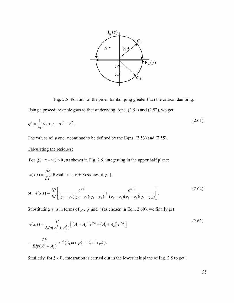
55
Fig. 2.5: Position of the poles for damping greater than the critical damping.
Using a procedure analogous to that of deriving Eqns. (2.51) and (2.52), we get
2 2 21
1 .4
q dv c av rr
= + − − (2.61)
The values of p and r continue to be defined by the Eqns. (2.53) and (2.55).
Calculating the residues:
For ( ) 0x vtξ = − > , as shown in Fig. 2.5, integrating in the upper half plane:
( , ) iPw x tEI
= [Residues at 1γ + Residues at 2γ ].
or, 1 2
1 2 1 3 1 4 2 1 2 3 2 4
( , )( )( )( ) ( )( )( )
i iiP e ew x tEI
γ ξ γ ξ
γ γ γ γ γ γ γ γ γ γ γ γ
= + − − − − − − .
(2.62)
Substituting ,iγ s in terms of p , q and r (as chosen in Eqn. 2.60), we finally get
1 21 2 1 22 2
1 2
( , ) ( ) ( )( )
i iPw x t A A i e A A i eEIp A A
γ ξ γ ξ = − + + +
= 1 22 21 2
2 ( cos sin )( )
rP e A p A pEIp A A
ξ ξ ξ− ++
.
(2.63)
Similarly, for 0ξ < , integration is carried out in the lower half plane of Fig. 2.5 to get:
C1
C2
1γ •
3γ
4γ
2γ •
eR ( )γ
mI ( )γ

56
( ) ( )3 4 4 32 2
4 3
( , ) ( ) ( )( )
r q r qPw x t A A e A A eEIq A A
ξ ξ− + = + − − −
(2.64)
where, 1 ,A pr= 3 ,A qr=
2 2 22
1 ( ),4
A r p q= − + 2 2 24
1 ( )4
A r p q= + + .
(2.65)
2.4 ANALYSIS METHOD FOR A BEAM UNDER MOVING MASS
The deflection modes of continuous beam with simply supported boundary conditions can be
obtained from the Euler-Bernoulli equation of the beam. The natural deflection modes and the
natural frequencies of a simply supported Euler beam can be expressed as:
( ) sinkk xY x
lπ =
; and
2
kr
k EIlπω
ρ =
, k =1, 2, 3……… K (2.66)
where ( )kY x is the normal mode, kω is the corresponding natural frequency and l is the beam
length.
The above equations were obtained for the following boundary conditions:
(0) ( ) 0Y Y l= = ; and (0) ( ) 0Y Y l′′ ′′= = (2.67)
Assume a solution of Eqn. (2.1) in the form of a series:
( )1
, ( ) ( )K
r k kk
w x t Y x q t=
=∑ 1, 2,3.....k K= (2.68)
where ( )kY x are the normal modes of the beam, ( )kq t are the functions of time which have to be
found and k is the number of contributing modes. Recalling Eqn. (2.1) for moving mass
problem as:
4 2 2 2
14 2 2 2
( , ) ( )r fw w w w w vt tEI c k k w Mg M x vt
x t t x tρ δ
∂ ∂ ∂ ∂ ∂+ + − + = − − ∂ ∂ ∂ ∂ ∂
(2.69)

57
The substitution of Eqn. (2.66) together with Eqn. (2.68) into the Eqn. (2.69) and using a
simplified subscript for differentiation yields:
1
4
2
1 1
11
1 1
( ) ( ) ( ) ( ) ( ) ( )
( ) ( ) ( ) ( ) ( ) ( )
K K K
k k k k k kk k k
K K K
k k k k k kk k k
r
f
kEI cl
kk k Mg Ml
Y x q t Y x q t Y x q t
Y x q t Y x q t Y vt q t
π ρ
π
= = =
= = =
+ +
− + = −
∑ ∑ ∑
∑ ∑ ∑
(2.70)
Multiplying both sides of Eqn. (2.70) by ( )pY x and integrating along the beam length, applying
the orthogonality of functions ( )qY x , and after some rearrangement it becomes
4 21
1
( ) ( ) ( ) ( ) ( )
( ) ( ) ( ) 2
f
r rk k k k k
K
k k
r
k
r
pr
q t q t q t q t q t
Y vt q
kkEI k c kl l
Mg vM Yl
t t
π πρ ρ ρ ρ
ρ =
+ + − +
= −
∑
for 1, 2,3.....k K=
(2.71)
In case of moving load problem, Eqn. (2.71) can be written as:
4 2
1
1( ) ( ) ( ) ( ) ( ) ( ) ( )2 K
k k k k k k pf
r r r r kr
q t q t q t q tkkEI k c k q t Y vt Y vtP
l l lπ π
ρ ρ ρ ρ ρ =
+ + − + =
∑ (2.72)
for 1,2,3.....k K=
Equations (2.71) and (2.72) are sets of coupled ordinary differential equations and a numerical
procedure is employed to solve them. A MATLAB predefined function “ode 45” is applied to
solve the differential equations in time domain. The equations are solved simultaneously to
obtain the deflection and bending moment responses for both moving mass and moving load
conditions.
2.5 MODEL VALIDATION
The validity of the present model is examined by comparing the responses in terms of
deflection and bending moment of the beam under moving load condition with the analytical

58
results presented in [51]. In this reported study, an infinite Euler–Bernoulli beam of constant
cross-section resting on an elastic foundation with both one and two parameters was considered.
The beam was subjected to a constant point load moving with a constant speed along the beam.
Dynamic responses such as beam deflection, bending moment have been obtained for different
velocity ratios. All the parameters considered in the validation are taken from Mallik et al. [51]
and presented in Table 2.1. The variations in beam deflection and bending moment responses
obtained from the present study is evaluated and compared with those reported in [51], as shown
in Fig. 2.6. It can be seen that the deflection and bending moment response predicted by the
current model agrees reasonably well with those reported in [51]. The amplitude of deflection
and bending moment and the period of vibrations predicted by both models are also in very good
agreement, although some differences in the bending moment responses become evident.
Table 2.1: Simulation parameters [51]
Parameters Assumed values
rρ (kg/m) 25 EI (N-m2) 1.75×10⁶
fk (N/m2) 40.78×10⁵
1k (N) 66.6875×10⁴ P ( N/m) 99.36×10³

59
Normalized Distance
Current model
Current model
Norm
alize
d Def
lect
ion
Mallik et al. [28]
Mallik et al. [28]
(a)
Nor
mal
ized
Ben
ding
Mom
ent
Current model
Current model
Mallik et al. [28]Mallik et al. [28]
Normalized Distance
(b)
Fig. 2. 6: Comparison of beam (a) deflection and (b) bending moment responses of the present
model with that reported by Mallik et al. [51].

60
2.6 RESULTS AND DISCUSSIONS
Numerical computations have been carried out based on the analytical solutions obtained in
sections 2.3 and 2.4 for both moving load and moving mass conditions. The normalized dynamic
responses in terms of deflection, bending moment and shear force are obtained with respect to
the normalized position of the beam. The deflection is normalized by dividing the response
obtained by its maximum value under static condition. The normalized distance is obtained by
multiplying the distance along the beam (ahead and behind the load) by the coefficient of
characteristic wavelength, which can be expressed as [51]: / 2bλ = . The velocity at which the
deflection response shoots up to infinity is known as critical velocity, which can be expressed
as: 1( ) /crv b c a= + . The normalized bending moment is obtained by dividing the bending
moment response by its maximum value for the static case. Similarly, the normalized shear force
is obtained by dividing the bending moment response by its maximum value for the static
condition. The parameters used in the present study are given in Table 2.1. The normalized
dynamic responses in terms of deflections, bending moment and shear force of the beam are
obtained with respect to the normalized position of the beam.
2.6.1 Exact analysis:
The dynamic normalized deflections of a beam resting on two-parameter Pasternak
foundation subjected to a moving load with various velocity ratios ( / crv v ) are shown in Fig. 2.7.
In Fig. 2.7 (a), the results show that the deflections are symmetric about the contact point with
moving load for all the selected velocity ratios and the maximum deflections occur beneath the
load and die down at a distance far away from the load. In this study, a zero velocity ratio
represents static load condition. The negative value of the deflection signifies the downward

61
deflection with the moving load acting downward. A small amount of uplift (positive deflection)
occurs at distances away from the load. The figure further shows that the maximum dynamic
deflection for both upward and downward deflection increases with increase in the velocity
ratios of the moving load.
The normalized deflection responses of the beam for velocities greater than the critical
velocity are shown in Fig. 2.7 (b). It can be seen that the deflection at the loading point
approaches zero as velocity increases to greater than the critical velocity. Figure 2.7 (b) further
shows that increase in velocities decreases the peak deflection of the beam for both front (right
hand side of the curve from origin zero) and rear wave (left hand side of the curve from origin
zero). The wavelengths of the front waves also decrease with increase in speed. However, the
peak deflection values in the rear waves are greater than the front waves for a constant velocity
ratio. The figure further shows that point of maximum settlement (downward deflection) occurs
behind the load and the distance of this point from the load increases with increasing speed. The
figure also illustrates that maximum amount of uplift never dies out although it is far away from
the load, which can be attributed to the very low damping ratio ( / crc c = 0.0005).

62
-6 -4 -2 0 2 4 6-2.5
-2
-1.5
-1
-0.5
0
0.5
1
Normalised Distance
Norm
alise
d De
flecti
on
Velocity Ratio=0Velocity Ratio=0.5Velocity Ratio=0.75Velocity Ratio=0.9
(a)
-6 -4 -2 0 2 4 6
-2
-1.5
-1
-0.5
0
0.5
1
1.5
2
Normalised Distance
Norm
alise
d De
flecti
on
Velocity ratio =1.25Velocity ratio =1.50Velocity ratio =1.75Velocity ratio =2.00
(b)
Fig. 2. 7: Normalized deflection vs. normalized distance with velocity ratios (a) less than the
critical velocity ( / crv v =0, 0.5, 0.75 and 0.9); (b) greater than the critical velocity ( / crv v =1.25,
1.50, 1.75 and 2.0) with damping ratio ( / crc c = 0.0005) for two parameter model.
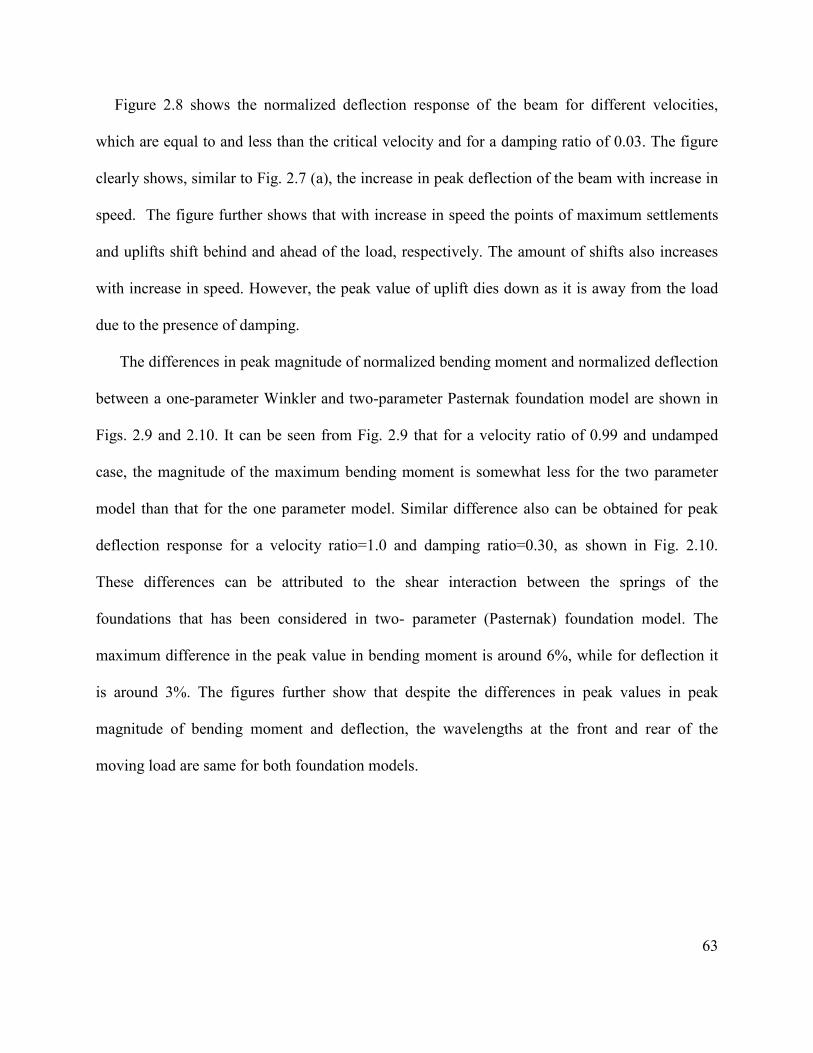
63
Figure 2.8 shows the normalized deflection response of the beam for different velocities,
which are equal to and less than the critical velocity and for a damping ratio of 0.03. The figure
clearly shows, similar to Fig. 2.7 (a), the increase in peak deflection of the beam with increase in
speed. The figure further shows that with increase in speed the points of maximum settlements
and uplifts shift behind and ahead of the load, respectively. The amount of shifts also increases
with increase in speed. However, the peak value of uplift dies down as it is away from the load
due to the presence of damping.
The differences in peak magnitude of normalized bending moment and normalized deflection
between a one-parameter Winkler and two-parameter Pasternak foundation model are shown in
Figs. 2.9 and 2.10. It can be seen from Fig. 2.9 that for a velocity ratio of 0.99 and undamped
case, the magnitude of the maximum bending moment is somewhat less for the two parameter
model than that for the one parameter model. Similar difference also can be obtained for peak
deflection response for a velocity ratio=1.0 and damping ratio=0.30, as shown in Fig. 2.10.
These differences can be attributed to the shear interaction between the springs of the
foundations that has been considered in two- parameter (Pasternak) foundation model. The
maximum difference in the peak value in bending moment is around 6%, while for deflection it
is around 3%. The figures further show that despite the differences in peak values in peak
magnitude of bending moment and deflection, the wavelengths at the front and rear of the
moving load are same for both foundation models.
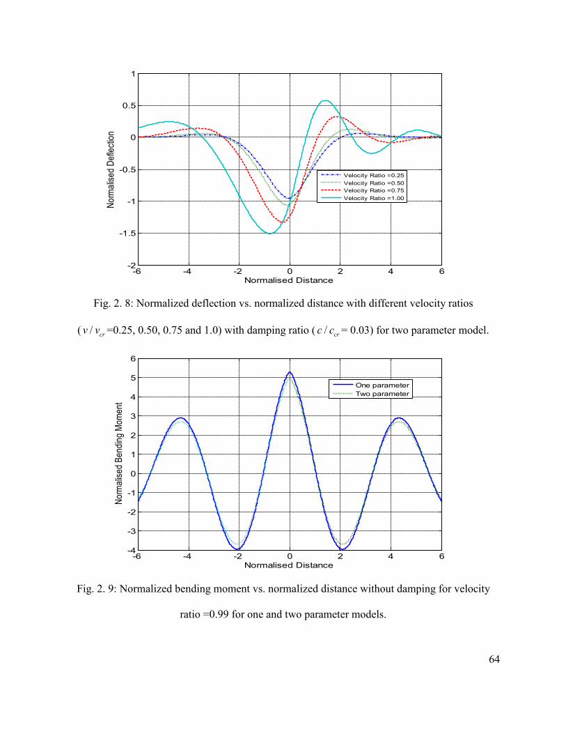
64
-6 -4 -2 0 2 4 6-2
-1.5
-1
-0.5
0
0.5
1
Normalised Distance
Norm
alise
d De
flecti
on
Velocity Ratio =0.25Velocity Ratio =0.50Velocity Ratio =0.75Velocity Ratio =1.00
Fig. 2. 8: Normalized deflection vs. normalized distance with different velocity ratios
( / crv v =0.25, 0.50, 0.75 and 1.0) with damping ratio ( / crc c = 0.03) for two parameter model.
-6 -4 -2 0 2 4 6-4
-3
-2
-1
0
1
2
3
4
5
6
Normalised Distance
Norm
alise
d Be
nding
Mom
ent
One parameterTwo parameter
Fig. 2. 9: Normalized bending moment vs. normalized distance without damping for velocity
ratio =0.99 for one and two parameter models.
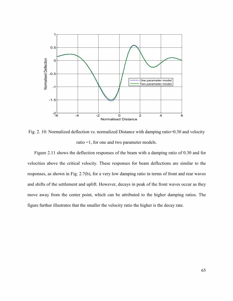
65
-6 -4 -2 0 2 4 6-2
-1.5
-1
-0.5
0
0.5
1
Normalised Distance
Norm
alise
d De
flecti
on
One parameter modelTwo parameter model
Fig. 2. 10: Normalized deflection vs. normalized Distance with damping ratio=0.30 and velocity
ratio =1, for one and two parameter models.
Figure 2.11 shows the deflection responses of the beam with a damping ratio of 0.30 and for
velocities above the critical velocity. These responses for beam deflections are similar to the
responses, as shown in Fig. 2.7(b), for a very low damping ratio in terms of front and rear waves
and shifts of the settlement and uplift. However, decays in peak of the front waves occur as they
move away from the center point, which can be attributed to the higher damping ratios. The
figure further illustrates that the smaller the velocity ratio the higher is the decay rate.

66
-6 -4 -2 0 2 4 6-1.2
-1
-0.8
-0.6
-0.4
-0.2
0
0.2
0.4
0.6
Normalised Distance
Norm
alise
d De
flecti
on
Velocity Ratio=1.25Velocity Ratio=1.50Velocity Ratio=1.75Velocity Ratio=2.00
Fig. 2. 11: Normalized deflection vs. normalized distance with different velocity ratios above the
critical velocity ( / crv v =1.25, 1.50, 1.75 and 2.0) with damping ratio ( / crc c = 0.3) for two
parameter model.
The variations in normalized bending moment (dividing the dynamic bending moment
responses by the maximum value of it in static case) for velocities less than and equal to the
critical velocity along the beam are shown in Fig. 2.12 (a). The figure shows the absolute value
of the bending moment distribution is symmetrical about the load for zero velocity ratio. The
figure also shows small variations in the maximum negative bending moment at front and rear
of the load for velocities below the critical velocity. The figure further shows that maximum
negative bending moment occurs at a point ahead of the load and the magnitude of this peak
negative bending moment increases with increase in speed. However, the maximum positive
bending moment occurs at the point of the load. With decrease in speed, the maximum negative
bending moments at both front and rear of the load shift away from the load.

67
Figure 2.12 (b) shows the variations in bending moment distribution along the beam for
velocities above the critical velocities. Similar to Fig. 2.12 (a), the maximum negative bending
moment occurs at a point ahead of the load and shifts away from the load with decrease in speed.
The magnitude of this peak negative bending moment, however, decreases with increase in
speed. As the speed decreases, the maximum positive bending moment shifts behind the load.
The maximum negative bending moment decreases in oscillatory fashion as it moves away from
the load, which can be attributed to the viscous damping coefficient of the beam. Similar to the
deflection characteristic of the beam, the higher the velocity ratio the smaller is the decay rate.
-6 -4 -2 0 2 4 6-1
-0.8
-0.6
-0.4
-0.2
0
0.2
0.4
0.6
0.8
1
Normalised Distance
Norm
alise
d Be
nding
Mom
ent
Velocity Ratio=0Velocity Ratio=0.5Velocity Ratio=0.75Velocity Ratio=1.0
(a)

68
-6 -4 -2 0 2 4 6-1
-0.8
-0.6
-0.4
-0.2
0
0.2
0.4
0.6
0.8
Normalised Distance
Norm
alise
d Be
nding
Mom
ent
Velocity Ratio=1.5Velocity Ratio=2.0Velocity Ratio=2.5Velocity Ratio=3.0
(b)
Fig. 2. 12: Normalized bending moment vs. normalized distance with different velocity ratios (a)
( / crv v =0, 0.50, 0.75 and 1.0); and (b) greater than the critical velocity ( / crv v =1.50, 2.00, 2.50
and 3.00) with damping ratio ( / crc c = 0.3) for two parameter model.
The variations in shear force distribution along the length of the beam for subcritical, critical
and supercritical velocities are shown in Figs. 2.13 and 2.14. The damping ratio is considered as
0.1. For all velocities, the maximum negative shear force occurs at a point ahead of the load and
shifts away from the load with decrease in speed. For subcritical velocities, as shown in Fig.
2.13, the maximum shear force becomes negative at the point just behind the load whereas it is
positive for critical and supercritical velocities, as shown in Fig. 2.14. For supercritical
velocities, the peak shear force decreases in oscillatory fashion as it moves away from the load
due to the presence of damping. Figure 2.14 further shows that the peak and wavelength of the
front waves decrease with increase in speed.

69
-6 -4 -2 0 2 4 6-1
-0.5
0
0.5
1
1.5
Normalised Distance
Norm
alise
d Sh
ear F
orce
Velocity Ratio=0Velocity Ratio=0.75Velocity Ratio=0.9Velocity Ratio=1.0
Fig. 2. 13: Normalized shear force vs. normalized distance with different velocity ratios
( / crv v =0,0.75, 0.90 and 1.00) with damping ratio ( / crc c =0.1) for two parameter model.
-6 -4 -2 0 2 4 6-1
-0.5
0
0.5
1
1.5
Normalised Distance
Norm
alise
d Sh
ear F
orce
Velocity Ratio=1.25Velocity Ratio=1.50Velocity Ratio=1.75Velocity Ratio=2.00
Fig. 2. 14: Normalized shear force vs. normalized distance with different velocity ratios greater
than the critical velocity ( / crv v =1.25, 1.50, 1.75 and 2.00) with damping ratio ( / crc c = 0.1).

70
The variations in shear force distribution along the beam for a combination of different
velocity and damping ratios where the damping is higher than the critical damping are shown in
Fig. 2.15. It can be seen that at the point of load, maximum positive shear force occurs for the
front wave and maximum negative shear force occurs for the rear wave. The responses are
similar to those obtained in Fig. 2.13. However, only a few waves can propagate along the beam
due to the high damping ratios.
A measure in terms of magnification factor is further defined as the ratio of the maximum
dynamic responses to maximum static values. The variations in dynamic magnification factors
for deflections and bending moments under, behind and ahead of the load with different
velocities and damping ratios are shown in Figs. 2.16-2.19.
-6 -4 -2 0 2 4 6-0.5
0
0.5
1
Normalised Distance
Norm
alise
d Sh
ear F
orce
Velocity Ratio=0.5,Damping Ratio=1.5
Velocity Ratio=1.5,Damping Ratio=2.0
Velocity Ratio=2.0, Damping Ratio=2.0
Fig. 2. 15: Normalized shear force vs. normalized distance with different combination of velocity
ratios and damping ratios for two parameter model.

71
Velocities are varied from static-subcritical-critical-supercritical velocities whereas the
damping ratios are varied from undamped-underdamped-critically damped-overdamped. The
figures clearly show the resemblance in nature to those of frequency response curves of a single
degree-of-freedom system. The figures further show that the maximum deflections and bending
moments are higher at lighter damping. From Figs. 2.18 and 2.19, it can be seen that the
deflection amplitude of the rear wave is much larger than that of the front wave for velocities
greater or equal to the critical velocities. For very low velocities ( / 0.5crv v ≤ ), these figures
further illustrate that the deflection waves become more symmetrical about the loading point as
the speed decreases.
0
0.5
1
1.5
2
2.5
3
3.5
4
0 0.5 1 1.5 2 2.5 3 3.5 4 4.5
Mag
nific
atio
n Fac
tor f
or D
eflec
tion
Velocity Ratio
Damping Ratio=0
Damping Ratio=0.1
Damping Ratio=0.5
Damping Ratio=1.0
Damping Ratio=2.0
Fig. 2. 16: Dynamic magnification factors for deflection vs. the velocity ratio with different
damping ratios under the load for two parameter model.

72
0
0.5
1
1.5
2
2.5
0 0.5 1 1.5 2 2.5 3 3.5 4 4.5
Mag
nifica
tion F
acto
r for
Bend
ing M
omen
t
Velocity Ratio
Damping Ratio=0
Damping Ratio=0.1
Damping Ratio=0.5
Damping Ratio=1.0
Damping Ratio=2.0
Fig. 2. 17: Dynamic magnification factors for bending moment vs. the velocity ratio with
different damping ratios under the load for two parameter model.
0
0.5
1
1.5
2
2.5
3
3.5
4
4.5
0 0.5 1 1.5 2 2.5 3 3.5
Mag
nific
atio
n Fa
ctor
for D
efle
ctio
n
Velocity ratio
Damping Ratio=0.05Damping Ratio=0.30Damping Ratio=1.1Damping Ratio=2.0
Fig. 2. 18: Dynamic magnification factors for deflection vs. the velocity ratio with different
damping ratios behind the load (settlement) for two parameter model.

73
0
0.5
1
1.5
2
2.5
3
0 0.5 1 1.5 2 2.5 3
Mag
nific
atio
n Fa
ctor
for D
efle
ctio
n
Velocity ratio
Damping Ratio=0.05
Damping Ratio=0.30
Damping Ratio=1.10
Damping Ratio=2.0
Fig. 2. 19: Dynamic magnification factors for deflection vs. the velocity ratio with different
damping ratios ahead of the load (uplift) for two parameter model.
2.6.2 Modal analysis:
Dynamic response of an Euler-Bernoulli beam resting on Pasternak foundation is further
investigated using the modal analysis approach under both moving load and moving mass
conditions. In case of “moving mass” condition, the mass of the wheel is considered to exert
force on the beam equivalent to the moving load. The parameters listed in Table 2.1 are
employed in this study and a total of 60 modes have been considered. The normalized dynamic
response in terms of deflection, bending moment for both “moving load” and “moving mass”
conditions is obtained with respect to the normalized position of the beam.
(i) Comparison between moving load and moving mass responses
Figure 2.20 shows normalized deflection responses for both moving load and moving mass
systems with different velocity ratios. The damping ratio of the beam is kept at 0.0005. The
figure shows that the maximum deflections occur, for all the given conditions, at the midpoint of

74
the beam. However, the maximum deflection is always higher in case of moving mass, which is
attributed to the inertia of the mass. The maximum normalized deflections for moving mass
problem are 1.248, 1.582, 1.656, and 1.725 for velocities of 44.12, 88.25, 132.38, and 176.50
km/h, respectively. The maximum normalized deflections for moving load problem are 1.002,
1.003, 1.005, and 1.007 for velocities of 44.12, 88.25, 132.38, and 176.50 km/h, respectively.
These results show that the variations in peak normalized deflections for moving mass problem
are significant with variations in speed for the given speed range. This variation is not significant
for moving load problem. These variations, however, can be significant for higher velocity ratios
as shown in Fig. 2.7 (a).
0.4 0.43 0.46 0.49 0.52 0.55 0.58 0.6
-1
-0.5
0
Normalized distance
Nor
mal
ized
def
lect
ion
Moving loadMoving mass
(a)

75
0.4 0.42 0.44 0.46 0.48 0.5 0.52 0.54 0.56 0.58 0.6-1.65
-1.15
-0.65
-0.15
0.2
Normalized distance
Nor
mal
ized
def
lect
ion
Moving loadMoving mass
(b)
0.4 0.42 0.44 0.46 0.48 0.5 0.52 0.54 0.56 0.58 0.6-1.8
-1.3
-0.8
-0.3
0.2
Normalized distance
Nor
mal
ized
def
lect
ion
Moving loadMoving mass
(c)

76
0.4 0.42 0.44 0.46 0.48 0.5 0.52 0.54 0.56 0.58 0.6
-1.8
-1.3
-0.8
-0.3
0.2
Normalized distance
Nor
mal
ized
def
lect
ion
Moving massMoving load
(d)
Fig. 2. 20: Normalized deflection response with different velocity ratios; (a) velocity
ratio=0.025; (b) velocity ratio=0.05; (c) velocity ratio=0.075; (d) velocity ratio=0.1.
The variations in normalized bending moment response for both moving load and moving
mass systems with different velocity ratios are shown in Fig. 2.21. Similar to the deflection
response, the maximum bending moments occur beneath the load for all the given conditions.
Figure 2.21 shows that the maximum bending moment is always higher for moving mass system
irrespective of the speed. The maximum normalized bending moments for moving mass problem
are 0.8767, 1.104, 1.211, and 1.326 for velocities of 44.12, 88.25, 132.38, and176.50 km/h,
respectively. In case of moving load problem, the maximum normalized bending moments are
0.7063, 0.7096, 0.7127, and 0.7157 for velocities of 44.12, 88.25, 132.38, and 176.50 km/h,
respectively. The figures further show that the peak bending moments increase significantly with
increase in speeds in case of moving mass problem for the considered speed range. Thus,
simplification of the moving vehicle into a moving load in analysis of dynamic vehicle-track

77
interactions can result in lower prediction of the deflections and bending moments of the track.
In case of moving load, the increment is not so pronounced which can be attributed to the
considered speed ratios. For higher speed ratios, as shown in Fig. 2.12 (a), this increment is
significant. It can be concluded that considering the moving load instead of moving mass
essentially neglects the inertia of the mass, centrifugal force, velocity of the moving mass which
in turn gives us the inaccurate prediction of the deflections, bending moments and contact forces
that arise in between the contact points.
0.4 0.42 0.44 0.46 0.48 0.5 0.52 0.54 0.56 0.58 0.6
0
0.5
1
Normalized distance
Nor
mal
ised
Ben
ding
Mom
ent
Moving loadMoving mass
(a)

78
0.4 0.42 0.44 0.46 0.48 0.5 0.52 0.54 0.56 0.58 0.6
-0.5
0
0.5
1
Normalized distance
Nor
mal
ised
Ben
ding
Mom
ent
Moving loadMoving mass
(b)
0.4 0.42 0.44 0.46 0.48 0.5 0.52 0.54 0.56 0.58 0.6-1.0176
-0.5176
-0.0176
0.4824
0.9824
1.4824
Normalized distance
Nor
mal
ized
Ben
ding
Mom
ent
Moving massMoving load
(c)

79
0.4 0.42 0.44 0.46 0.48 0.5 0.52 0.54 0.56 0.58 0.6-1
-0.5
0
0.5
1
1.5
Normalised distance
Nor
mal
ised
Ben
ding
Mom
ent
Moving massMoving load
(d)
Fig. 2. 21: Normalized bending moment responses with different velocity ratios; (a) velocity
ratio=0.025; (b) velocity ratio=0.05; (c) velocity ratio=0.075; (d) velocity ratio=0.1.
(ii) Effect of foundation stiffness
Foundation stiffness has significant influence on dynamic deflection response under both
moving load and moving mass conditions, as shown in Fig. 2.22. For both cases, decreasing the
foundation stiffness increases significantly the dimensionless peak deflections, while the speed is
kept constant at 88.25 km/h. However, the rate of increment is slightly higher for moving load
problem. When the value of the foundation stiffness decreases from 2.0 kf to 0.5 kf, the
normalized maximum deflection increases from 0.607 to 1.667 for moving load, while it is
0.9298 to 2.493 for moving mass.

80
0.4 0.42 0.44 0.46 0.48 0.5 0.52 0.54 0.56 0.58 0.6-2
-1.5
-1
-0.5
0
0.5
Normalized distance
Nor
mal
ized
def
lect
ion
0.5kf
1.0kf
1.5kf
2.0kf
(a)
0.4 0.42 0.44 0.46 0.48 0.5 0.52 0.54 0.56 0.58 0.6
-2.5
-2
-1.5
-1
-0.5
0
0.5
Normalized distance
Nor
mal
ized
def
lect
ion
0.5kf
1.0kf
1.5kf
2.0kf
(b)
Fig. 2. 22: Effect of foundation stiffness on dynamic deflection responses at a constant speed of
88.25 km/h; (a) moving load (b) moving mass.
The effect of foundation stiffness on normalized dynamic bending moment response for both
moving load and moving mass conditions is shown in Fig. 2.23. Similar to the deflection
response, for a constant speed, decreasing the foundation stiffness increases the peak of the
dimensionless bending moment. The rate of increment is slightly higher for moving load

81
problem. In case of moving load, the maximum normalized bending moment increases from
0.5541 to 0.8907, while for moving mass it is 0.8545 to 1.362, when the value of the foundation
stiffness decreases from 2.0 kf to 0.5kf.
0.4 0.42 0.44 0.46 0.48 0.5 0.52 0.54 0.56 0.58 0.6-0.4
-0.2
0
0.2
0.4
0.6
0.8
1
Normalized distance
Nor
mal
ized
ben
ding
mom
ent
0.5kf
1.0kf
1.5kf
2.0kf
(a)
0.4 0.42 0.44 0.46 0.48 0.5 0.52 0.54 0.56 0.58 0.6
-0.4
-0.2
0
0.2
0.4
0.6
0.8
1
1.2
1.4
Normalized distance
Nor
mal
ized
ben
ding
mom
ent
0.5kf
1.0kf
1.5kf
2.0kf
(b)
Fig. 2. 23: effect of foundation stiffness on dynamic bending moment responses at a constant
speed of 88.25 km/h; (a) moving load (b) moving mass.

82
(iii)Effect of shear modulus
The effect of shear modulus on dynamic normalized deflection responses for both moving
load and moving mass conditions is shown in Fig. 2.24. The figure shows that, for a constant
speed, increasing the shear modulus decreases the peak of the dimensionless deflection. The rate
of decrease is slightly higher for moving load problem. When the value of the shear modulus
decreases from 3.0 1k to 0.1 1k , the maximum normalized deflection increases about 17.71% and
15.22% for moving load and for moving mass, respectively.
0.4 0.42 0.44 0.46 0.48 0.5 0.52 0.54 0.56 0.58 0.6
-1
-0.5
0
Normalized distance
Nor
mal
ized
def
lect
ion
0.1k11.0k1
2.0k13.0k1
(a)

83
0.4 0.42 0.44 0.46 0.48 0.5 0.52 0.54 0.56 0.58 0.6
-1
-0.5
0
Normalized distance
Nor
mal
ized
def
lect
ion
0.1k11.0k1
2.0k13.0k1
(b)
Fig. 2. 24: Effect of shear modulus on dynamic deflection responses at a constant speed of 88.25
km/h; (a) moving load (b) moving mass.
Figure 2.25 shows the effect of shear modulus on normalized bending moment responses for
both moving load and moving mass conditions at a constant speed of 88.25 km/h. The figure
clearly shows that decrease in shear modulus increases the normalized bending moment for
given conditions. When the value of the shear modulus decreases from 3.0 1k to 0.1 1k , the
maximum normalized bending moment increases about 26.44% and 25.40% for moving load and
for moving mass, respectively.

84
0.4 0.42 0.44 0.46 0.48 0.5 0.52 0.54 0.56 0.58 0.6-0.4
0.1
0.6
0.9
Normalized distance
Nor
mal
ized
ben
ding
mom
ent
0.1k11.0k12.0k13.0k1
(a)
0.4 0.42 0.44 0.46 0.48 0.5 0.52 0.54 0.56 0.58 0.6-0.6
-0.1
0.4
0.9
1.3
Normalized distance
Nor
mal
ized
ben
ding
mom
ent
0.1k11.0k12.0k13.0k1
(b)
Fig. 2. 25: Effect of shear modulus on dynamic bending moment responses at a constant speed of
88.25 km/h; (a) moving load (b) moving mass.

85
2.7 SUMMARY
The dynamic response of an Euler-Bernoulli beam with both finite and infinite length
supported on both one-parameter Winkler and two-parameter Pasternak foundation and subjected
to a moving load as well as moving mass is investigated. Fourier transform technique is
employed to find the exact analytical solution of the governing partial differential equation of an
infinite beam subjected to a moving load. Modal analysis method is employed to convert the
partial differential equation into a series of ordinary differential equations for both moving load
and moving mass condition. Numerical calculations have been performed to analyze the
displacement and bending moment responses of the beam on the Pasternak foundation subjected
to both moving load and moving mass with different velocity ratios.
This study shows that for subcritical velocities of the moving load, the dynamic deflection
and bending moment responses of the beam are symmetrical about the location of the moving
load. In case of very low velocities ( / 0.5crv v ≤ ), the maximum deflection, bending moment and
shear force responses of the beam increases slightly with increase in speed and the responses
approach those for the static one as the velocity decreases.
The study further shows that for supercritical velocities of the load, significant deflection
occurs behind the load whereas bending moment and shear force are higher ahead of the load.
The maximum values of the front and rear waves decrease with increase in damping ratio. The
wavelengths of the rear waves are always higher than the front waves for deflection, bending
moment and shear force response of the beam. For all speeds above the critical speed, the
wavelengths of the front waves of deflection, bending moment and shear force decrease with
increase in speed. These indicate that only a small amount of disturbance could propagate in
front of a moving load when the load is moving at a very high speed. Furthermore, for

86
supercritical velocities, the point of maximum deflection, bending moment and shear force
behind the load shift farther behind with increase in speeds whereas the maximum positive peak
of the front wave shift towards the location of the load. The variations in dynamic magnification
factors with different velocities and damping ratios are analogous to the frequency response of
the single degree-of-freedom system. All the curves show a peak value near the critical speeds.
These peak values, however, increase with decrease in the damping ratios.
The study reveals that the results obtained from the modal analysis method are comparable to
those obtained from exact analytical method. This study further reveals that moving mass has
significantly higher effect on dynamic responses of the beam than that of the case of the moving
load. Furthermore, increase in speed increases both displacements and bending moments of the
beam. In case of moving load conditions, the deflections are symmetric about the contact point
and maximum deflections occur beneath the load for all the selected velocity ratios. The
deflection and bending moment responses are always higher for moving mass condition than
those for the moving load. Detailed analyses are also performed to investigate the effect of
various parameters such as foundation stiffness and shear modulus on dynamic deflection and
bending moment responses under a moving load as well as moving mass. The study shows that
the maximum deflection and bending moment of the beam increases significantly with the
reduced shear modulus and stiffness of the foundation for a constant velocity. For a given
velocity, this increment is always higher for moving load than the moving mass. For the given
range of shear modulus, the normalized maximum deflection increases about 26.44% and
25.40% for moving load and moving mass, respectively.

87
CHAPTER 3
VEHICLE-TRACK SYSTEM MODEL AND ITS NATURAL FREQUENCIES
3.1 INTRODUCTION
The analysis of wheel-rail impact force or acceleration responses in the presence of wheel
and/or rail defects requires development of a representative vehicle and track system models,
wheel-rail contact model together with wheel and rail defects. The magnitudes of the impact
forces and accelerations caused by the wheel and rail defects largely depend on interactions
between these elements. This study is primarily concerned with vertical wheel-rail impact
responses considering the contribution due to the pitch and roll motion of the car body and
bogies in the presence of multiple wheel defects. This research further aims to analyze the
dynamic interaction between the leading and trailing bogie, and two wheels within a wheelset in
the presence of cross wheel defects. A comprehensive three-dimensional vehicle model
incorporating a full car body, two bogies, and four wheelsets is thus required in order to
investigate the wheel-rail impact responses in terms of both force and acceleration due to wheel
defects. Since the impact magnitudes due to the presence of wheel flats are significantly
influenced by the track properties, more effort has thus been made in order to develop an
effective model of the track system [8]. Among these different types of railway track models, the
most common approach is to model a rail beam based on Timoshenko or Euler-Bernoulli theory
supported on discrete supports [2, 6, 13, 15].
This study describes the modeling of a three dimensional full car vehicle considering the
roll and pitch motion of the car body and bogie. A three-dimensional track model is also
developed using the discrete beam support. The rail beams are modeled as two parallel

88
Timoshenko beams periodically supporting lumped masses. The generalized coordinates method
is used to convert the partial differential equations (PDE) describing the deflections of the
continuous track to ordinary differential equations (ODE). In order to have practical
representation of the track model, the nonlinear properties of the railpad and ballast are
considered into the model. A shear parameter beneath the rail beams has also been considered
into the model in order to facilitate interactions between the discrete railpads. The vehicle and
track models are coupled through the nonlinear Hertzian contact spring. A MATLAB predefined
function “ode 45” is employed in order to solve the coupled partial and ordinary differential
equations of the vehicle-track system in presence of single wheel flat. The developed model is
then employed to identify the natural frequencies of the vehicle and track system. Since the
lateral and longitudinal relative motions between the wheel and rail are small, and creep forces at
the wheel-rail contact interface have little effect on the dynamic vertical forces, the track is
assumed as perfect and straight track. The forward speed of the vehicle is also assumed to be
constant, while the contribution due to the track roughness is considered small in relation to
forces that may be caused by wheel defects.
3.2 VEHICLE SYSTEM MODEL
The vehicle system model adopted in this study consists of a full car body, two bogie frames
and four wheelsets. The car body is supported on two double-axle bogies at each end. The bogie
frames are connected to the wheelsets through the primary suspensions and linked to the car
body through the secondary suspensions. The primary and secondary suspensions are modeled as
parallel combination of linear springs and viscous damping elements. The vehicle is assumed to
move on the track with a constant travelling speed, v . The mass of the car body cM , bogie
mass bM , and wheel mass wM are coupled through the suspension elements, as shown in Fig.

89
3.1. The vehicle is modeled as a rigid body having a mass cM and having second moments of
area cxJ and cyJ about transverse and longitudinal horizontal centroidal axes, respectively. Each
of the bogie frames is also modeled as a rigid body with a mass bM (for two bogie
frames 1bM and 2bM ) with second moments of area bxJ and byJ about transverse and longitudinal
horizontal centroidal axes, respectively. Each axle together with the wheels has a mass of
wM (for four axles 1wM , 2wM , 3wM and 4wM ). The total vehicle system model is represented by a
17-DOF dynamic system that includes the car body vertical, pitch and roll motions, cZ , cθ ,
and cφ , respectively, two bogies vertical, pitch and roll motions, 1bZ and 2bZ , 1bθ and 2bθ , and
1bφ and 2bφ , respectively, and four axles vertical and roll motions, 1wZ , 2wZ , 3wZ and 4wZ ,
and 1wφ , 2wφ , 3wφ and 4wφ , respectively. The primary suspension stiffness and damping elements
are represented by pK and pC , respectively, while sK and sC represent the stiffness and viscous
damping coefficient due to secondary suspension. Half of the bogie frame and wheelset distances
in longitudinal direction, respectively, are cl and bl . Similarly, pl and sl are half of the primary
and secondary suspension distance in lateral direction, respectively.
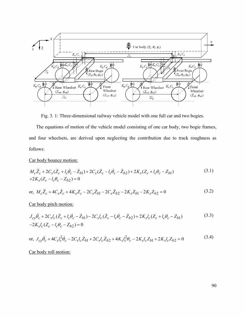
90
Fig. 3. 1: Three-dimensional railway vehicle model with one full car and two bogies.
The equations of motion of the vehicle model consisting of one car body, two bogie frames,
and four wheelsets, are derived upon neglecting the contribution due to track roughness as
follows:
Car body bounce motion:
1 2 1
2
2 ( ) 2 ( ) 2 ( )2 ( ) 0c c s c c c b s c c c b s c c c b
s c c c b
M Z C Z l Z C Z l Z K Z l ZK Z l Z
θ θ θθ
+ + − + − − + + −
+ − − =
(3.1)
or, 1 2 1 24 4 2 2 2 2 0c c s c s c s b s b s b s bM Z C Z K Z C Z C Z K Z K Z+ + − − − − = (3.2)
Car body pitch motion:
1 2 1
2
2 ( ) 2 ( ) 2 ( )
2 ( ) 0cy c s c c c c b s c c c c b s c c c c b
s c c c c b
J C l Z l Z C l Z l Z K l Z l Z
K l Z l Z
θ θ θ θ
θ
+ + − − − − + + −
− − − =
(3.3)
or, 2 21 2 1 24 2 2 4 2 2 0cy c s c c s c b s c b s c c s c b s c bJ C l C l Z C l Z K l K l Z K l Zθ θ θ+ − + + − + =
(3.4)
Car body roll motion:

91
1 1 1 1
2 2 2 2
1 1 1 1
2
{ ( )} { ( )}
{ ( )} { ( )}
{ ( )} { ( )}
{ (
cx c s s c s c b p b s s c s c b p b
s s c s c b p b s s c s c b p b
s s c s c b p b s s c s c b p b
s s c s c b p
J C l Z l Z l C l Z l Z l
C l Z l Z l C l Z l Z l
K l Z l Z l K l Z l Z l
K l Z l Z l
φ φ φ φ φ
φ φ φ φ
φ φ φ φ
φ
+ + − + − − − −
+ + − + − − − −
+ + − + − − − −
+ + − +
2 2 2)} { ( )} 0b s s c s c b p bK l Z l Z lφ φ φ− − − − =
(3.5)
or, 2 2 2 2 2 21 2 1 24 2 2 4 2 2 0cx c s s c s s b s s b s s c s s b s s bJ C l C l C l K l K l K lφ φ φ φ φ φ φ+ − − + − − = (3.6)
Bogie bounce motion:
Front bogie bounce:
1 1 1 1 1 1
1 1 1 1 1 2 1 1
1 1 1 1 1 1 1 2
{ ( )} { ( )} 2
( ) 2 ( ) { ( )}
{ ( )} 2 ( ) 2 ( ) 0
b b s b b b c c c s b b b c c c p
b b b w p b b b w s b b b c c c
s b b b c c c p b b b w p b b b w
M Z K Z l Z l K Z l Z l K
Z l Z K Z l Z C Z l Z l
C Z l Z l C Z l Z C Z l Z
θ θ θ θ
θ θ θ θ
θ θ θ θ
+ + + −
+ − + + +
− + −
− + − − +
− + − − +
− − + − + − =
or,
(3.7)
1 1 1 1 1 2 1
1 1 2
2 2 4 2 2 2
2 4 2 2 0b b s b s c p b p w p w s b
s c p b p w p w
M Z K Z K Z K Z K Z K Z C Z
C Z C Z C Z C Z
+ − − +
− −
+ −
+ − =
(3.8)
Rear bogie bounce:
2 2 2 2 2 2
2 2 3 2 2 4 2 2
2 2 2 2 3 2 2 4
{ ( )} { ( )} 2
( ) 2 ( ) { ( )}
{ ( )} 2 ( ) 2 ( ) 0
b b s b b b c c c s b b b c c c p
b b b w p b b b w s b b b c c c
s b b b c c c p b b b w p b b b w
M Z K Z l Z l K Z l Z l K
Z l Z K Z l Z C Z l Z l
C Z l Z l C Z l Z C Z l Z
θ θ θ θ
θ θ θ θ
θ θ θ θ
+ + + −
+ − + + +
− + −
− + − − +
− + − − +
− − + − + − =
or,
(3.9)
2 2 2 2 3 4 2
2 3 4
2 2 4 2 2 2 2
4 2 2 0b b s b s c p b p w p w s b s c
p b p w p w
M Z K Z K Z K Z K Z K Z C Z C Z
C Z C Z C Z
+ − − + −
−
+ −
+ − =
(3.10)
Bogie pitch motion:
Front bogie pitch:

92
1 1 1 1 1 1 2
1 1 1 1 1 2
2 ( ) 2 ( )
2 ( ) 2 ( ) 0by b p b b b b w p b b b b w
p b b b b w p b b b b w
J K l Z l Z K l Z l Z
C l Z l Z C l Z l Z
θ θ θ
θ θ
+ + − − − −
+ + − − − − =
(3.11)
or,
2 21 1 1 2 1 1 24 2 2 4 2 2 0by b p b b p b w p b w p b b p b w p b wJ C l C l Z C l Z K l K l Z K l Zθ θ θ+ − + + − + = (3.12)
Rear bogie pitch:
2 2 2 3 2 2 4
2 2 3 2 2 4
2 ( ) 2 ( )
2 ( ) 2 ( ) 0by b p b b b b w p b b b b w
p b b b b w p b b b b w
J K l Z l Z K l Z l Z
C l Z l Z C l Z l Z
θ θ θ
θ θ
+ + − − − −
+ + − − − − =
(3.13)
or,
2 22 2 3 4 2 3 44 2 2 4 2 2 0by b p b b p b w p b w p b b p b w p b wJ C l C l Z C l Z K l K l Z K l Zθ θ θ+ − + + − + =
(3.14)
Bogie roll motion:
Front bogie roll:
1 1 1 1 1 1 1 1 1 1
1 2 2 1 1 2 2 1 1
1 1 1 1 1
{ ( )} { ( )} {
( )} { ( )} { (
{ ( )} { (
bx b p p b p b w p w p p b p b w p w p p b
p b w p w p p b p b w p w s s b s b c s c
s s b s b c s c p p b p b w p
J K l Z l Z l K l Z l Z l K l Z
l Z l K l Z l Z l K l Z l Z l
K l Z l Z l C l Z l Z l
φ φ φ φ φ
φ φ φ φ φ φ
φ φ φ φ
+ + − + − − − − +
+ − + − − − − + + − +
− − − − + + − +
1 1 1
1 1 1 1 2 2 1 1 2 2
1 1 1 1
)} {
( )} { ( )} { ( )}
{ ( )} { ( )} 0
w p p b p b
w p w p p b p b w p w p p b p b w p w
s s b s b c s c s s b s b c s c
C l Z l
Z l C l Z l Z l C l Z l Z l
C l Z l Z l C l Z l Z l
φ
φ φ φ φ φ
φ φ φ φ
− − −
− + + − + − − − − +
+ − + − − − − =
(3.15)
or,
2 2 2 2 21 1 1 1 2
2 2 2 2 21 1 1 2
4 2 2 2 2
4 2 2 2 2 0
bx b p p b s s b p p w p p w s s c
p p b s s b p p w p p w s s c
J K l K l K l K l K l
C l C l C l C l C l
φ φ φ φ φ φ
φ φ φ φ φ
+ + − − −
+ + − − − =
(3.16)
Rear bogie roll:

93
2 2 2 3 3 2 2 3 3
2 2 4 4 2 2 4 4
2 2 2 2 2 2
3
{ ( )} { ( )}
{ ( )} { ( )}
{ ( )} { ( )} {
(
bx b p p b p b w p w p p b p b w p w
p p b p b w p w p p b p b w p w s s
b s b c s c s s b s b c s c p p b p b
w p
J K l Z l Z l K l Z l Z l
K l Z l Z l K l Z l Z l K l
Z l Z l K l Z l Z l C l Z l
Z l
φ φ φ φ φ
φ φ φ φ
φ φ φ φ φ
φ
+ + − + − − − −
+ + − + − − − − +
+ − + − − − − + + −
+
3 2 2 3 3 2 2 4
4 2 2 4 4 2 2
2 2
)} { ( )} { (
)} { ( )} { ( )}
{ ( )} 0
w p p b p b w p w p p b p b w
p w p p b p b w p w s s b s b c s c
s s b s b c s c
C l Z l Z l C l Z l Z
l C l Z l Z l C l Z l Z l
C l Z l Z l
φ φ φ
φ φ φ φ φ
φ φ
− − − − + + − +
− − − − + + − + −
− − − =
or,
(3.17)
2 2 2 2 2 22 2 2 3 4 22 2 2 2
2 3 4
4 2 2 2 2 4
2 2 2 2 0
bx b p p b s s b p p w p p w s s c p p b
s s b p p w p p w s s c
J K l K l K l K l K l C l
C l C l C l C l
φ φ φ φ φ φ φ
φ φ φ φ
+ + − − − +
+ − − − =
(3.18)
Wheelset bounce motion:
1st Wheelset:
1 1 1 1 1 1 1 12 { ( )} 2 { ( )} 0w w p w b b b p w b b b WRM Z K Z Z l C Z Z l Pθ θ+ − + −+ + + = (3.19)
or,
1 1 1 1 1 1 1 12 2 2 2 2 2 0w w p w p b p b b p w p b p b b WRM Z K Z K Z K l C Z C Z C l Pθ θ+ − + −+ + + = (3.20)
2nd Wheelset:
2 2 1 1 2 1 1 22 { ( )} 2 { ( )} 0w w p w b b b p w b b b WRM Z K Z Z l C Z Z l Pθ θ+ − + −+ + + = (3.21)
or,
2 2 1 1 2 1 1 22 2 2 2 2 2 0w w p w p b p b b p w p b p b b WRM Z K Z K Z K l C Z C Z C l Pθ θ+ − + −+ + + = (3.22)
3rd Wheelset:
3 3 2 2 3 2 2 32 { ( )} 2 { ( )} 0w w p w b b b p w b b b WRM Z K Z Z l C Z Z l Pθ θ+ − + −+ + + = (3.23)
or,

94
3 3 2 2 3 2 2 32 2 2 2 2 2 0w w p w p b p b b p w p b p b b WRM Z K Z K Z K l C Z C Z C l Pθ θ+ − + −+ + + = (3.24)
4th Wheelset:
4 4 2 2 4 2 2 42 { ( )} 2 { ( )} 0w w p w b b b p w b b b WRM Z K Z Z l C Z Z l Pθ θ+ − + −+ + + = (3.25)
or,
4 4 2 2 4 2 2 42 2 2 2 2 2 0w w p w p b p b b p w p b p b b WRM Z K Z K Z K l C Z C Z C l Pθ θ+ − + −+ + + =
(3.26)
Wheelset roll motion:
1st Wheelset:
1 1 1 1 1 1 1 1 1
1 1 1 1 1 1 1 1 5
{ ( )} { ( )}
{ ( )} { ( )} 0wx w p p w p w b p b p p w p w b p b
p p w p w b p b p p w p w b p b WR
J K l Z l Z l K l Z l Z l
C l Z l Z l C l Z l Z l P
φ φ φ φ φ
φ φ φ φ
+ − − −
+ − − −
+ + − − +
+ − − + =
(3.27)
or, 2 2 2 21 1 1 1 1 52 2 2 2 0wx w p p w p p b p p w p p b WRJ K l K l C l C l Pφ φ φ φ φ+ − + − + = (3.28)
2nd Wheelset:
2 2 2 1 1 2 2 1 1
2 2 1 1 2 2 1 1 6
{ ( )} { ( )}
{ ( )} { ( )} 0wx w p p w p w b p b p p w p w b p b
p p w p w b p b p p w p w b p b WR
J K l Z l Z l K l Z l Z l
C l Z l Z l C l Z l Z l P
φ φ φ φ φ
φ φ φ φ
+ − − −
+ − − −
+ + − − +
+ − − + =
(3.29)
or, 2 2 2 22 2 1 2 1 62 2 2 2 0wx w p p w p p b p p w p p b WRJ K l K l C l C l Pφ φ φ φ φ+ − + − + = (3.30)
3rd Wheelset:
3 3 3 2 2 3 3 2 2
3 3 2 2 3 3 2 2 7
{ ( )} { ( )}
{ ( )} { ( )} 0wx w p p w p w b p b p p w p w b p b
p p w p w b p b p p w p w b p b WR
J K l Z l Z l K l Z l Z l
C l Z l Z l C l Z l Z l P
φ φ φ φ φ
φ φ φ φ
+ − − −
+ − − −
+ + − − +
+ − − + =
(3.31)
or, 2 2 2 23 3 2 3 2 72 2 2 2 0wx w p p w p p b p p w p p b WRJ K l K l C l C l Pφ φ φ φ φ+ − + − + = (3.32)
4th Wheelset:

95
4 4 4 2 2 4 4 2 2
4 4 2 2 4 4 2 2 8
{ ( )} { ( )}
{ ( )} { ( )} 0wx w p p w p w b p b p p w p w b p b
p p w p w b p b p p w p w b p b WR
J K l Z l Z l K l Z l Z l
C l Z l Z l C l Z l Z l P
φ φ φ φ φ
φ φ φ φ
+ − − −
+ − − −
+ + − − +
+ − − + =
(3.33)
or, 2 2 2 24 4 2 4 2 82 2 2 2 0wx w p p w p p b p p w p p b WRJ K l K l C l C l Pφ φ φ φ φ+ − + − + = (3.34)
where, 1WRP , 2WRP , 3WRP , 4WRP , 5WRP , 6WRP , 7WRP , and 8WRP are the contact forces
developed at the wheel-rail interfaces corresponding to the 8 degrees of freedom of the wheelsets
obtained by algebraic summation of reactions from the left and right rails.
3.3 TRACK SYSTEM MODEL
The dynamic forces developed at the wheel-rail interface are derived upon development and
analysis of the railway track. In this study, a three-dimensional model of the track system model
consisting of rails, pads, sleepers and ballasts is developed upon consideration of two subsequent
layers. Two rails modeled as Timoshenko beams are discretely supported on the sleepers through
the railpads and fasteners that are modeled as combination of spring and damper elements, as
shown in Fig. 3.2. The sleepers are modeled as lumped masses which are discretely supported on
the ballasts. The ballasts are modeled as combination of spring and damper elements inserted
between each discrete sleeper and subgrade with consideration of the elastic properties of the
ballasts. The contribution due to the ballast mass to the wheel-rail contact forces is assumed to be
negligible. Two rail beams are modeled as Timoshenko beams, where both rotary inertia of the
beam cross section and beam deformations due to the shear force are taken into account. The
track is assumed to be symmetric with respect to its centerline. Furthermore, the track system
model is simplified to describe its dynamic motions in vertical plane only considering negligible
contributions of the longitudinal and lateral deformations of the track system. Since the
longitudinal and lateral motions have little effect on the vertical wheel-rail interactions, the

96
longitudinal and lateral displacements of all the masses are neglected. A finite length of the track
structure is considered by including a total of 100 sleepers/ballasts.
It has been suggested that a total of 50 to 60 sleepers/ballast elements would be sufficient for
analysis of dynamic wheel-rail impact load due to a wheel/rail defects [80, 109]. However, 100
sleepers/ballasts are considered in this study in order to investigate the contribution due to pitch
and roll dynamics of the car body and bogie, and various vehicle design parameters. The total
length of the rail with 100 sleepers is about 59.4 m with 0.6 m of sleeper distance. This length is
4.6 times higher than the total length of a full length railway car with two bogies, which is about
12.86 m. This sufficiently long rail length will allow steady state simulated results when the
system is stable. However, it will increase the simulation runtime of the total system. The
vertical and rotational motions of the two rail beams (left and right beams) coupled with the
sleepers are expressed as ( , )rlZ x t , ( , )rrZ x t and ( , )rl x tψ , ( , )rr x tψ , respectively, while
( )siZ t and ( )si tφ describe the vertical and roll motions of the i’th sleeper, respectively.
priK , priC , biK and biC are the nonlinear railpad and ballast stiffness and damping coefficients,
respectively. Further, 1k is the shear viscosity coefficient of the foundation under the rail beam
and sL is the half of the lateral distance between left and right end railpads. The length of the
track considered in simulation is sufficiently large to minimize the end effects. The infinite long
track is modeled as a track of finite length, whose two ends are simply supported.

97
Fig. 3. 2: Three-dimensional two-layer railway track model.
The equations of motion of the entire track system are derived upon integrating the equation
of motion for the two rails as Timoshenko beams with the differential equations of motion for the
discrete sleepers. The deflection of the continuous rail can be derived from the partial differential
equation for the Timoshenko beam as [17]:
For left rail:
2 2
2 2
4( ) ( )
21
1 1
2( , ) ( , ) ( , ) ( , ){ }
i pj
rl rl rl rlr
NRSli x x WRlj x x
i j
Z x t Z x t x t Z x tA GAkxt
F P
kxx
δ δ
ψρ
− −= =
∂∂ ∂ ∂− −
∂∂ ∂
= − +
−∂
∑ ∑
(3.35)
2 2
2 2( , ) ( , ) ( , ){ ( , )} 0rl rl rl
r rlx t Z x t x tA GAk x t EI
xt xψ ψ
ρ ψ∂ ∂ ∂
− − − =∂∂ ∂
(3.36)
For right rail:
Shear layer Left rail
Right
Sleeper
Ballast
Railpad Kpri,
Zsi, ϕsi
Zrl(x,t),ψrl(x,t)
Zrr(x,t),ψrr(x,t
Kbi, Cbi
2Ls 1k

98
2 2
2 2
4( ) ( )
21
1 1
2( , ) ( , ) ( , ) ( , ){ }
i pj
rr rr rr rrr
NRSri x x WRrj x x
i j
Z x t Z x t x t Z x tA GAkxt
F P
kxx
δ δ
ψρ
− −= =
∂∂ ∂ ∂− −
∂∂ ∂
= − +
−∂
∑ ∑
(3.37)
2 2
2 2( , ) ( , ) ( , ){ ( , )} 0rr rr rr
r rrx t Z x t x tA GAk x t EI
xt xψ ψρ ψ∂ ∂ ∂
− − − =∂∂ ∂
(3.38)
where, ρ is rail density, A is the rail cross sectional area, G is the shear modulus of rail, rk is
the Timoshenko shear coefficient, N is total number of the sleepers considered in the model,
k is the number of deflection modes considered for the rail beam and j is the number of
wheelsets incorporated in the vehicle model (j=1, 2,.., 4), which represent the number of moving
point loads acting on the beam. E is the elastic modulus of rail beam materials and I is the
second moment of area. The coordinate x represents the longitudinal position of the beam with
respect to the left end support of the rail beam. ix defines the position of the i th sleeper and
( )xδ is the Dirac delta function. RSriF and RSliF are the forces developed at the i th right and
left rail/sleeper interface, respectively (i=1,2,3,…N). WRrjP is the contact force develop at the
interface of the right side wheels of the vehicle and right rail, whereas WRljP is the contact force
developed at the interface of the left side wheels of the vehicle and left rail.
The equation of motion for the sleeper can be written as:
Sleepers bounce motion:
[ ][ ]
2 2 ( ) ( , ) ( ) ( , )
( ) ( , ) ( ) ( , ) 0
si si bi si bi si pri sli rl i pri sli rl i
pri sri rr i pri sri rr i
M Z K Z C Z K Z t Z x t C Z t Z x t
K Z t Z x t C Z t Z x t
+ + + − + − + − + − =
(3.39)

99
where, ( )sriZ t and ( )sliZ t are the vertical displacement of i'th sleeper at the right and left end pad
location, respectively. priK , and priC are nonlinear dynamic stiffness and equivalent viscous
damping of the railpad, which can be expressed for medium stiff pad as [105]:
0PiPbZK k e= MN/m (3.40)
1 1Pi PC m Kη= kN-s/m (3.41)
where, PZ is the compression of the pad (in meter), 1η is the loss factor of the hysteretic damping
of the pad ( 1η =0.25 [105]) and 1m is the equivalent mass. Further, 0k is the pad stiffness without
load, and for a medium stiff pad 0k =115.2 MN/m and b=7.49/mm. Since at high frequency, the
rail and sleepers vibrate separately on the pad and ballast stiffnesses, respectively. Thus, the
equivalent mass ( 1m ) can be calculated as parallel combination of rail and sleeper masses, such
as [105]:
1s r
s r
M MmM M
=+
(3.42)
where, rM is the rail mass in a sleeper bay. Similarly, the nonlinear stiffness and equivalent
viscous damping properties of the ballasts, biK and biC , can be expressed as [105]:
8 222.75 2.6 10bi bK Z= + × MN/m (3.43)
2 2bi bC m Kη= kN-s/m (3.44)
where, bZ is the compression of the pad (in meter), 2η is the loss factor of the hysteretic
damping of the ballast ( 2η =1 [105]) and 2m is the equivalent mass. In case of low frequency, the
entire track (rail mass and sleeper mass) vibrates together on the ballast stiffness. Hence, the

100
equivalent mass ( 2m ) can be calculated as series combination of rail and sleeper masses, such as
[105]:
2 s rm M M= + (3.45)
Sleepers roll motion:
The equation for sleeper roll motion is given by:
[ ][ ]
( ) ( ) ( )
( ) ( ) ( , ) ( ) ( , )
( ) ( , ) ( ) ( , ) 0
si si bi s si s si bi s si s si bi s si s si bi s
si s si pri s sli rl i pri s sli rl i
pri s sri rr i pri s sri rr i
J K L Z L K L Z L C L Z L C L
Z L K L Z t Z x t C L Z t Z x t
K L Z t Z x t C L Z t Z x t
φ φ φ φ
φ
+ ++ − − + −
− − − − − + − + − =
(3.46)
3.4 WHEEL-RAIL CONTACT MODEL
Wheel-rail interface distinguishes railways from other forms of land transports. In this study,
the wheel-rail contact is established by the nonlinear Hertzian contact theory commonly used in
the wheel-rail interaction problems [6, 4, 13, 14, 15, 87, 97, 105, 109, 113, 115, 119].
According to the Hertzian contact theory, the wheel-rail contact force is related to the rail
deflection in a nonlinear manner, such as:
3/ 2( ) ( )HP t C z t= ∆ (3.47)
where, ( )z t∆ is the wheel-rail overlap in the vertical direction, HC is the Hertzian contact
stiffness coefficient. In the absence of a wheel defect, the overlap is defined by the relative
motion of the wheel with respect to the rail:
( ) ( ) ( , )w rz t Z t Z x t∆ = − (3.48)
In the above equation, ( )wZ t and ( , )rZ x t are the wheel and rail deflections in vertical direction,
respectively.

101
In the presence of a wheel defect, the instantaneous overlap ( )z t∆ between the wheel and the rail
can be expressed as:
( ) ( ) ( , ) ( )w rz t Z t Z x t r t∆ = − − (3.49)
where, ( )r t is the wheel flat function. In case of haversine flat, as shown in Fig. 3.3 (a), the
function of the wheel flat geometry can be expressed as:
1( ) [1 cos(2 / )]2 f f fr t D x Lπ= −
(3.50)
where fD is the flat depth that has been related to wheel radius R , in the following manner [8]:
2 /(16 )f fD L R= (3.51)
where, fL is the flat length, and fx is the longitudinal coordinate of the instantaneous contact
point within the flat. The origin of fx lies at the vertical projection of the origin of the flat, as
shown in Fig. 3.3 (a). The change in radius ( )r t diminishes when the wheel-rail contact lies
outside the flat length.
In case of two flats within the same wheel, as shown in Fig. 3.3 (b), the variations in radius can
be expressed in similar fashion:
1( ) [1 cos(2 / )],2 fi fi fiir t D x Lπ= −
(3.52)
where ( )ir t define the change in radius of the wheel within the flat regions of lengths fiL , and
depths fiD , respectively, and ( )ifix v t t= − , and it refer to the instants when leading and
trailing flats come in contact with the rail, respectively. The relative position between the two
i=1, 2

102
flats, whether in a single wheel or in two wheels, is defined in terms of a phase angle ϕ (Fig. 3.3
(b)), which is expressed by the time lapse as a function of the forward velocity, such that:
12 /t t R vϕ=− (3.53)
(a)
R
xf r(t) Lf
Df

103
(b)
Fig. 3. 3: A railway wheel with (a) single and (b) double haversine type flats.
3.5 METHOD OF ANALYSIS
The linear equations of motion of the vehicle coupled with the nonlinear equations of motion
of the track are solved in time domain considering the nonlinear contact between the wheel and
rail. The presence of wheel defects as modeled in section 3.4 is also included in the resultant
vehicle-track model. In this study, the nonlinear track system model formulation comprises both
Ordinary Differential Equations (ODEs) and Partial Differential Equations (PDEs) describing the
deflection of sleeper and the continuous rail, respectively, under moving contact forces. By
applying Ritz’s method, all the PDE’s representing the continuous rail beam are converted in
ODEs by assuming mode shape functions. The fourth order PDEs describing the motion of the
continuous rail are expressed by a series of second order ordinary differential equations similar
to the vehicle equations of motion in terms of the time coordinates. The resulting ODEs of the
Lf2
Df2
xf2
r2(t)
ϕ
Lf1
Df1
R
xf1 r1(t)
104
track and vehicle systems are then solved in time domain to obtain responses of individual
components of the vehicle-track system model. As the vehicle moves along the track, the contact
force and deflections of the rail and those of the lumped masses of vehicle and the track are
calculated through numerical integration of the differential equations. It has been suggested that
good convergence of solution can be obtained if the number of modes is equal to or more than
60. A total of 100 modes of a single rail beam are considered in this study for analysis of the
coupled vehicle-track system model.
The vertical deflection , ( , )rl rZ x t and rotation , ( , )rl r x tψ of the left and right rail are obtained
using modal superposition method as:
,1
( , ) ( , ) ( )K
rl r z kk
Z x t N k x Z t=
= ∑ (3.54)
and,
,1
( , ) ( , ) ( )K
rl r kk
x t N k x tψψ=
= Ψ∑ (3.55)
where, ( , )zN k x and ( , )N k xψ are the k th mode shape functions of the vertical deflection and
rotation of the rail, respectively. ( )kZ t and ( )k tΨ are the k th mode time coefficients of the
vertical deflection and rotation of the rail, respectively. Further, ,l r denote either left or right side
of the rail beam. K is the total number of modes considered into the simulation and x represents
the linear coordinate along the length of the rail beam. ( , )zN k x and ( , )N k xψ can be assumed
as:
( , ) ( , ) sinzk xN k x N k x
Lψπ = =
(3.56)
where, L is the length of the beam considered into the simulation.

105
By substituting Eqns. (3.54) and (3.55) together with Eqn (3.56) into Eqns. (3.35) and (3.36) for
left side rail beam, we get:
2 22
21
4
1 1
( , ) ( ) ( ) ( )
( , ) ( , )
rl r rk k k
NRSli z i WRlj z j
i j
d Z x t Gk Gkk k kZ t t Z tL L A Ldt
F N k x P N k
k
x
π π πρ ρ ρ
= =
+ − Ψ + =
− +∑ ∑
(3.57)
22
2( ) ( ) ( ) 0k r r
k kd t GAk GAkE k kt Z t
I L I Ldtπ π
ρ ρ ρ
Ψ + + Ψ − =
(3.58)
The reaction force between the left rail and the i -th sleeper RSliF is expressed as:
[ ]( ) ( , ) ( ) ( , ) ( )RSli pri rl i sli pri rl i sliF t K Z x t Z t C Z x t Z t = − − − (3.59)
where, ( )sliZ t and ( )sliZ t are the vertical displacement and velocity of the i th sleeper at left end
pad location as given by:
( ) ( ) ( )sli si s siZ t Z t L tφ= − and ( ) ( ) ( )sli si s siZ t Z t L tφ= − (3.60)
where, sL is the lateral distance between two sleeper supports.
In Eqn. (3.57), the contact force WRljP between the j th wheel of the left side of the vehicle and
rail is determined by non linear Hertz contact theory as given by:
3/2{ ( ) ( , ) ( )}( )
0H wlj rl j
WRljC Z t Z x t r t
P t − − =
( ) ( , ) ( ) 0
( ) ( , ) ( ) 0wlj rl j
wlj rl j
Z t Z x t r t
Z t Z x t r t
− − >
− − ≤
(3.61)
where, ( )wljZ t is the vertical displacement of the left wheel for a particular wheelset ( 1,.., 4j = )
and expressed as:
( ) ( ) ( )wlj wj p wjZ t Z t l tφ= − (3.62)
Similarly, for right side rail beam:

106
2 22
21
4
1 1
( , ) ( ) ( ) ( )
( , ) ( , )
rr r rk k k
NRSri z i WRrj z j
i j
d Z x t Gk Gkk k kZ t t Z tL L A Ldt
F N k x P N k
k
x
π π πρ ρ ρ
= =
+ − Ψ + =
− +∑ ∑
(3.63)
22
2( ) ( ) ( ) 0k r r
k kd t GAk GAkE k kt Z t
I L I Ldtπ π
ρ ρ ρ
Ψ + + Ψ − =
(3.64)
The reaction force between the right rail and the i th sleeper RSriF is expressed as:
[ ]( ) ( , ) ( ) ( , ) ( )RSri pri rr i sri pri rr i sriF t K Z x t Z t C Z x t Z t = − − − (3.65)
where, ( )sriZ t and ( )sriZ t are the vertical displacement and velocity of the i ’th sleeper at the
right end pad location, and can be expressed as:
( ) ( ) ( )sri si s siZ t Z t L tφ= + and ( ) ( ) ( )sri si s siZ t Z t L tφ= + (3.66)
The contact force WRrjP between the j th wheel and rail is determined by non-linear Hertz
contact theory as given by:
3/20{ ( ) ( , ) ( )}
( )0
H wrj rr jWRrj
C Z t Z x t Z tP t
− − =
( ) ( , ) ( ) 0
( ) ( , ) ( ) 0wrj rr j
wrj rr j
Z t Z x t r t
Z t Z x t r t
− − >
− − ≤
(3.67)
where, ( )wrjZ t is the vertical displacement of the right wheel for a particular wheelset
( 1,.., 4j = ) and expressed as:
( ) ( ) ( )wrj wj p wjZ t Z t l tφ= + (3.68)
The equations of motion of the vehicle system described by Eqns. (3.1) to (3.34), and of the
track system derived by Eqns. (3.35) to (3.46) together with the Hertzian nonlinear contact
model in Eqn. (3.49) describe the vertical dynamics of the coupled vehicle-track system. These

107
equations are solved simultaneously to obtain the wheel-rail interaction force or acceleration and
the responses of the vehicle-track system components.
3.6 NATURAL VIBRATION ANALYSIS OF THE VEHICLE-TRACK SYSTEM
The natural vibration characteristics of the individual vehicle and track systems govern the
overall wheel-rail interaction responses. Natural frequencies provide useful information to
understand the basic behaviors of the vehicle-track system. In this section, the natural
frequencies of the individual vehicle components, such as car body, bogies and wheelsets are
investigated. The natural frequencies of the entire track system is also identified in order to
compare these frequencies with those obtained from the individual vehicle components and the
excitation frequencies obtained from the wheel-rail impact response analysis due to wheel flats.
3.6.1 Natural vibration of the vehicle components:
The dynamic behavior of the vehicle system components and structures largely depend
upon the natural frequencies and deflection modes of the individual components. In this study,
the vehicle system model consists of a car body, two bogies and four wheelsets. The car body
and two bogies have vertical, pitch and roll motions, whereas the four wheelsets have vertical
and roll motions only. The total vehicle system model is represented by 17-DOF system. This
system, thus, has a number of different natural frequencies and these frequencies can be
separated. An eigenvalue problem is formulated to derive the natural frequencies and deflection
modes of the vehicle, which is discussed below:
The equation of free vibration of linear vehicle can be written in matrix form as:
[ ] [ ] [ ] [ ]0v v vz C z K zM + + = (3.69)
where, vM , vC and vK are (17×17) mass, damping and stiffness matrices, respectively. These
matrices are shown below:
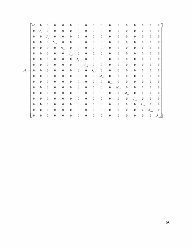
108
1
2
1
2
1
2
1
0 0 0 0 0 0 0 0 0 0 0 0 0 0 0 0
0 0 0 0 0 0 0 0 0 0 0 0 0 0 0 0
0 0 0 0 0 0 0 0 0 0 0 0 0 0 0 0
0 0 0 0 0 0 0 0 0 0 0 0 0 0 0 0
0 0 0 0 0 0 0 0 0 0 0 0 0 0 0 0
0 0 0 0 0 0 0 0 0 0 0 0 0 0 0 0
0 0 0 0 0 0 0 0 0 0 0 0 0 0 0 0
0 0 0 0 0 0 0 0 0 0 0 0 0 0 0 0
0 0 0 0 0 0 0 0 0 0 0 0 0 0 0 0
0 0 0 0 0 0 0 0 0 0 0 0 0 0 0 0
0 0 0 0
c
cy
cx
b
b
by
by
bx
v bx
w
M
J
J
M
M
J
J
J
M J
M
=
2
3
4
1
2
3
4
0 0 0 0 0 0 0 0 0 0 0 0
0 0 0 0 0 0 0 0 0 0 0 0 0 0 0 0
0 0 0 0 0 0 0 0 0 0 0 0 0 0 0 0
0 0 0 0 0 0 0 0 0 0 0 0 0 0 0 0
0 0 0 0 0 0 0 0 0 0 0 0 0 0 0 0
0 0 0 0 0 0 0 0 0 0 0 0 0 0 0 0
0 0 0 0 0 0 0 0 0 0 0 0 0 0 0 0
w
w
w
wx
wx
wx
wx
M
M
M
J
J
J
J

109
2
2 2
2
2
2 2 2
2
4 0 0 2 2 0 0 0
0 4 0 2 2 0 0 0
0 0 4 0 0 0 0 2
2 0 0 2 4 0 0 0 0
2 0 0 0 2 4 0 0 0
0 0 0 0 0 4 0 0
0 0 0 0 0 0 4 0
0 0 2 0 0 0 0 4 2
0 0 2 0 0 0 0 0
0 0 0 2 0 2 0 0
0 0 0 2 0 2 0 0
0 0 0 0 2 0
s s s
s c s c s c
s s s s
s s p
s s p
p b
p b
s s p p s s
v s s
p p b
p p b
p
K K K
K l K l K l
K l K l
K K K
K K K
K l
K l
K l K l K l
K K l
K K l
K K l
K
−
− −
−
− −
− −
−
−
− −
=
−
−
−
2
2
2 0
0 0 0 0 2 0 2 0
0 0 0 0 0 0 0 2
0 0 0 0 0 0 0 2
0 0 0 0 0 0 0 0
0 0 0 0 0 0 0 0
p b
p p b
p p
p p
K l
K K l
K l
K l
−
…..
2
2 2
2 2 2 2
0 0 0 0 0 0 0 0 0
0 0 0 0 0 0 0 0 0
2 0 0 0 0 0 0 0 0
0 2 2 0 0 0 0 0 0
0 0 0 2 2 0 0 0 0
0 2 2 0 0 0 0 0 0
0 0 0 2 2 0 0 0 0
0 0 0 0 0 2 2 0 0
4 2 0 0 0 0 0 0 2 2
0 2( ) 0 0 0 0 0 0 0
0 0 2( ) 0 0 0 0 0 0
0 0 0 2( ) 0 0 0 0 0
0 0 0 0
s s
p p
p p
p b p b
p b p b
p p p p
p p s s p p p p
p H
p H
p H
K l
K K
K K
K l K l
K l K l
K l K l
K l K l K l K l
K K
K K
K K
−
−
− −
− +
− +
− +
2
2
2 2
2 2
2( ) 0 0 0 0
0 0 0 0 0 2 ( ) 0 0 0
0 0 0 0 0 0 2 ( ) 0 0
2 0 0 0 0 0 0 2 ( ) 0
2 0 0 0 0 0 0 0 2 ( )
p H
p p H
p p H
p p p p H
p p p p H
K K
l K K
l K K
K l l K K
K l l K K
− +
− +
− +
− +
− +

110
2
2 2
2
2
2 2 2
2
4 0 0 2 2 0 0 00 4 0 2 2 0 0 00 0 4 0 0 0 0 2
2 0 0 2 4 0 0 0 02 0 0 0 2 4 0 0 0
0 0 0 0 0 4 0 00 0 0 0 0 0 4 00 0 2 0 0 0 0 4 20 0 2 0 0 0 0 00 0 0 2 0 2 0 00 0 0 2 0 2 0 00 0 0 0 2 0
s s s
s c s c s c
s s s s
s s p
s s p
p b
p b
s s p p s s
v s s
p p b
p p b
p
C C CC l C l C l
C l C lC C CC C C
C lC l
C l C l C lC l
C C lC C l
C
C
−
− −
−
− −
− −
−
−
− −
=
−
−
−
2
2
2 00 0 0 0 2 0 2 00 0 0 0 0 0 0 20 0 0 0 0 0 0 20 0 0 0 0 0 0 00 0 0 0 0 0 0 0
p b
p p b
p p
p p
C lC C l
C lC l
−
…
2
2 2
2 2 2 2
0 0 0 0 0 0 0 0 00 0 0 0 0 0 0 0 0
2 0 0 0 0 0 0 0 00 2 2 0 0 0 0 0 00 0 0 2 2 0 0 0 00 2 2 0 0 0 0 0 00 0 0 2 2 0 0 0 00 0 0 0 0 2 2 0 0
4 2 0 0 0 0 0 0 2 20 2 0 0 0 0 0 0 00 0 2 0 0 0 0 0 00 0 0 2 0 0 0 0 00 0 0 0 2 0 0 0 00 0 0 0 0 2
s s
p p
p p
p b p b
p b p b
p p p p
p p s s p p p p
p
p
p
p
C lC C
C CC l C l
C l C lC l C l
C l C l C l C lC
CC
C
−
−
− −
−
−
−
−
− 2
2
2 2
2 2
0 0 00 0 0 0 0 0 2 0 0
2 0 0 0 0 0 0 2 02 0 0 0 0 0 0 0 2
p p
p p
p p p p
p p p p
l Cl C
C l l CC l l C
−
−
−

111
, , , ,1 2 1 2 1 2 1 2 3 4 1 2 3 4[ ] [ , , , , , , , , , , , , ]Tc c c b b b b b b w w w w w w w wz Z Z Z Z Z Z Zθ φ θ θ φ φ φ φ φ φ=
1 1
0v v v vz zM C M K
z zI
− − − − =
(3.70)
where, I is an identity matrix, HK is linearized Hertzian contact stiffness that can be obtained
from Eqn. (3.47). If we consider the overlap between the wheel and rail ( z∆ ) in Eqn. (3.47) is
constant and can be evaluated by the static wheel load 0P . The linear contact stiffness can be
expressed as:
HP
zK ∂
∂∆=
(3.71)
or, 0
131.5 ( / )H H HK C P C=
(3.72)
where, HC is the nonlinear Hertzian contact coefficient.
The eigenvalue solution of the dynamic matrix of Eqn. (3.70) will generally yield 17 pairs of
complex conjugate eigenvalues of form:
i i iD jα β= + (3.73)
Natural frequency of ith mode is given by:
2 2ni i iω α β= + (3.74)
The damped natural frequency of ith mode is:
(3.75)
In order to identify the mode associated with the i'th natural frequency, the eigenvector for the
i'th eigenvalue may be examined. The maximum absolute value in a column of the eigenvector
will identify the corresponding eigenvalue and the corresponding 17 motions associated with the
di iω β=

112
natural modes. The eigenvalues and eigenvectors are obtained by using MATLAB. The
eigenvalue problem is solved using the model parameters summarized in Table 3.1.
Table 3.1: Vehicle model parameters [8].
Notation Parameter Value
cM Car body mass 76150 kg
tM Bogie mass 1700 kg
wM Wheelset mass 1120 kg
cxJ Mass moment of inertia of the car body about X axis 95576 kg-m2
cyJ Mass moment of inertia of the car body about Y axis 726462 kg-m2
bxJ Mass moment of inertia of the bogie about X axis 1600 kg-m2
byJ Mass moment of inertia of the bogie about Y axis 760 kg-m2
wxJ Mass moment of inertia of the wheelset about X axis 420.1 kg-m2
PK Primary suspension stiffness 7.88×10⁵ kN/m
PC Primary suspension damping 3.5 kN-s/m
SK Secondary suspension stiffness 5.32×10³ kN/m
SC Secondary suspension damping 70 kN-s/m
cl Semi-longitudinal distance between bogies 5.18 m
bl Semi-longitudinal distance between wheelsets in bogie 1.25 m
sl Semi-lateral distance between secondary suspensions 0.80 m
pl Semi-lateral distance between primary suspensions 0.80 m
R Wheel radius 0.475 m

113
The natural frequencies, damped natural frequencies and their corresponding deflection
modes for fully loaded conditions (103 kN of static wheel load) are shown in Table 3.2. It can be
seen from Table 3.2 that the natural frequencies of the car body are very small compared to the
wheelset natural frequencies. This is because of the very high primary stiffness considered in
modeling to ensure the isolation of the vibration from the exciting source. Furthermore, this also
indicates that the properties of the wheel-track system have little effect on fundamental
frequency of the vehicle system.
Table 3. 2: Natural frequencies, damped natural frequencies and corresponding deflection modes
Natural frequency (Hz) Damped natural frequency (Hz) Dominant modes
2.0308 2.0301 Car body roll
2.7544 2.7528 Car body bounce
4.7818 4.7818 Car body pitch
137.4785 137.3983 Front bogie roll
137.5231 137.3984 Rear bogie roll
156.1791 155.7443 Front bogie bounce
156.0906 155.7442 Rear bogie bounce
312.0656 312.0656 Axle bounce (j = 1, 2)
346.8085 345.8302 Axle bounce (j = 3, 4)
405.1506 405.1506 Front bogie pitch
405.1506 405.1506 Rear bogie pitch
407.6833 407.6833 Axle roll (j = 1, 2)
423.5512 423.1655 Axle roll (j = 3, 4)

114
3.6.2 Natural vibration of the track structure
The natural frequencies and different associated modes of the vibrating systems have
significant importance in railway engineering. The natural frequency of the railroad track has
been investigated in different studies for many years [9, 180, 181, 182]. Most of these reported
studies considered the railway track model as continuous Euler-Bernoulli or Timoshenko beam
resting on elastic layers to find out the natural frequencies of the track. These layers are modeled
as either one-parameter Winkler or two-parameter Pasternak foundation model. Cai [9] reported
a three-dimensional railway track model with discrete elastic supports representing the railpads
and ballasts. The entire track model was simplified to a generalized track element in order to
investigate the natural frequencies of the track. In this section, the natural frequencies of the
railway track model developed in section 3.3 will be identified. In order to facilitate the analysis,
the complex three-dimensional track model is simplified into a two-dimensional generalized
track model with linear railpad and ballast stiffness.
Equations of motion of Timoshenko beam under general condition:
Let us consider a free-body diagram of a differential element dx of an arbitrary beam. As
shown in Fig. 3.4, the beam is acted upon by general distributed force ( , )p x t , and a constant
axial force aP . U and UU dxx
∂+∂
are the sectional shear forces, M and MM dxx
∂+∂
are the
sectional bending moments, F is the inertial force and R is the rotary inertial moment. Since the
beam is considered as Timoshenko beam, the effects of the shear distortion and rotary inertia of
the beam mass has been taken into account. The rotational angle and shear distortion are denoted
by ψ and η , respectively.

115
Fig. 3. 4: Flexural vibration of Timoshenko beam
The vibrational equilibrium of the differential element can be established by summing up the
forces and moments equal to zero, as:
Summing all the forces in vertical direction:
( , ) ( ) 0UU p x t dx U dx Fx
∂− + + + − =
∂
(3.76)
which can be shown upon reduction as:
η
η
Zx
∂∂
ψ
Z (x,t)
X
dx
U
UU dxx
∂+∂
R
F
aP
M
MM dxx
∂+∂
( , )p x t
aP O

116
( , )U F p x tx
∂− + =∂
(3.77)
Summing all the moments about point O gives:
( ) ( , ) 02 a
M dxM Udx M dx p x t dx R P dxx
ψ∂+ − + − + + =
∂
(3.78)
Neglecting the higher order terms in dx yields:
( ) 0aMM Udx M dx R P dxx
ψ∂+ − + + + =
∂
(3.79)
where the rotary inertia R is given by:
22
2R mr dxtψ∂
=∂
(3.80)
where, m is the unit mass of the beam, and r is the radius of gyration of the beam cross-section.
Rearranging Equation 3.78 leads to:
22
2aMU P mrxt
ψψ ∂ ∂= − + +
∂∂
(3.81)
The relationships between the shear force and shear distortion, and between the moment and the
curvature can be expressed as:
( , )rU k AG x tη= − (3.82)
( , )x tM EIx
ψ∂= −
∂ (3.83)
where, rk and A are the shear coefficient and area of the beam cross section, respectively, and
G is the shear modulus of the beam material.
Substituting Equations (3.82) and (3.83) into Equations (3.77) and (3.81), the following relations
can be obtained:

117
2
2( ) ( , )rzk AG m p x t
x tη∂ ∂
+ =∂ ∂
(3.84)
22
2r ak AG P mr EIx xt
ψ ψη ψ ∂ ∂ ∂ − = − + − ∂ ∂ ∂
(3.85)
the shear distortion η can be replaced as:
zx
ψ η ∂= +
∂
(3.86)
The final form of Timoshenko beam can be written in terms of vertical deflection and rotation
angle as:
2
2( ) ( , )rz zk AG m p x t
x x tψ∂ ∂ ∂ − + = ∂ ∂ ∂
(3.87)
22
2( ) 0r azEI k AG mr P
x x x tψ ψψ ψ∂ ∂ ∂ ∂ − − − + = ∂ ∂ ∂ ∂
(3.88)
For free vibration case, setting ( , )p x t =0 and with added foundation stiffness term ( , )sk z x t ,
Equation (3.87) and (3.88) can be written as:
2
2( ) ( , ) 0r sz zk AG k z x t m
x x tψ∂ ∂ ∂ − + + = ∂ ∂ ∂
(3.89)
22
2( ) 0r azEI k AG mr P
x x x tψ ψψ ψ∂ ∂ ∂ ∂ − − − + = ∂ ∂ ∂ ∂
(3.90)
Dynamic stiffness matrix of a Timoshenko beam:
For a steady-state harmonic motion, displacement z and rotation ψ may be expressed by:

118
( , ) ( )
( , ) ( )
i t
i t
z x t Z x e
x t x e
ω
ωψ
=
= Ψ
(3.91)
where, ω represents the frequency, and Z and Ψ represent the amplitude functions.
Therefore, Equations (3.89) and (3.90) can be rewritten as:
" '1 0Z q Z+ −Ψ = (3.92)
'' 2 2 '( ) 0r a rEI mr k AG P k AGZωΨ + − + Ψ + = (3.93)
where, 21
1 ( )sr
q m kk AG
ω= −
Eliminating Z and Ψ from Equations (3.92) and (3.93) yields the following results:
"'' '' 0Z Zα β+ + = (3.94)
'''' '' 0α βΨ + Ψ + = (3.95)
where, 2 21
1 ( );aq mr PEI
α ω= + +
2 21 ( )r aq mr k AG PEI
β ω= − + (3.96)
Equations (3.94) and (3.95) represent the same form of 4th order ordinary differential equations
for the complex variables ( )Z x and ( )xΨ .
The solutions of the amplitude functions ( )Z x and ( )xΨ can be assumed in the form:
4
1( ) j x
jj
Z x C eλ
== ∑
(3.97)
4
1( ) j x
jj
x D eλ
=Ψ = ∑
(3.98)
where, jC and jD represent integration coefficients, and jλ represents solution of the
characteristic equations.

119
Substituting Equations (3.97) and (3.98) into Equations (3.94) and (3.95) gives the solution of
jλ as:
( )1/ 221 4
2jλ α α β= ± − ± − (3.99)
Substituting Equations (3.97) and (3.98) into Equations (3.92) and (3.93) yields the relationship
between the complex coefficients jC and jD as:
j j jD s C= (3.100)
where, 121jj
qjs λ
λ
+
= 1, 2, 3, 4j =
(3.101)
The four unknown complex coefficients jC ’s or jD ’s can be determined by four boundary
conditions at the beam ends.
The nodal displacement amplitudes at the beam ends can be expressed by the four complex
coefficients ( 1, 2, 3, 4)jjC = such that:
3 31 1
3 31 1
1 1 3 3
1 1 3 3
1 1 1 1(0)(0)( )( )
l ll l
l ll l
Zs s s s
e e e eZ ll s e s e s e s e
λ λλ λ
λ λλ λ
−
−
− −Ψ = − − Ψ − −
(3.102)
or, { } [ ]{ }P C∆ = (3.103)
Similarly, the nodal forces at the beam ends can be expressed by the corresponding
displacements by Equations (3.82) and (3.83) such that:

120
'
'
'
'
[ (0) (0)](0)(0) (0)
{ }( ) [ ( ) ( )]
( )( )
r
r
k AG ZUM EI
FU l k AG l Z l
M lEI l
Ψ − − − Ψ = = − − Ψ − Ψ
(3.104)
Substituting Equations (3.97) and (3.98) into Equation (3.104) gives:
{ } [ ]{ }F L C= (3.105)
where, the matrix [ ]L is given as:
3 31 1
3 31 1
1 1 1 1 3 3 3 3
1 1 1 1 3 3 3 3
1 1 1 1 3 3 3 3
1 1 1 1 3 3 3 3
( ) ( ) ( ) ( )
[ ]( ) ( ) ( ) ( )
k k k k
l ll lk k k k
l ll l
s s s s s s s sfs fs fs fs
Ls e s s e s s e s s e s
fe s fe s fe s fe s
λ λλ λ
λ λλ λ
λ λ λ λλ λ λ λ
λ λ λ λ
λ λ λ λ−−
− − − − − − − − − − = − − − − − −
(3.106)
where, f EI= and k rs k AG= .
From Equations (3.105) and (3.106), the dynamic stiffness matrix of a beam can be written as:
{ } [ ]{ }F K= ∆ (3.107)
where, 1[ ] [ ][ ]K L P −= (3.108)
since above discussions involve manipulation of complex numbers depending upon the relative
values of α and 2 4α β− of Equation (3.99), which in turn depend upon the magnitude of
frequencyω .
Considering the values of α and 2 4α β− , following two different cases with respect to the
value of cω (known as cut-off frequency) are dealt individually. Cut-off frequency can be defined
as:

121
1/ 2
2r a
ck AG P
mrω − =
(3.109)
Case 1: if the frequency satisfies the condition cω ω≤ ,
The values of jλ ’s are two imaginaries and two reals, and assumed as:
1,2 1iλ ρ= ± and 3,4 2λ ρ= ± (3.110)
where, 1ρ and 2ρ are given as follows:
( )1/ 22
11 42
ρ α α β= + − (3.111)
( )1/ 22
21 42
ρ α α β= − + − (3.112)
The corresponding js values those relate the coefficients jC and jD are given by:
1,2 1s iu= ± and 3,4 2s u= ± (3.113)
where, 11 1 2
1
1 qu ρρ
= −
and 1
2 2 22
1 qu ρρ
= −
(3.114)
The corresponding amplitude functions ( )Z x and ( )xΨ given by the Equations (3.97) and (3.98)
can be reduced to the following form as:
' ' ' '1 1 2 1 3 2 4 2( ) cos sin cosh sinhZ x C x C x C x C xρ ρ ρ ρ= + + + (3.115)
' ' ' '1 1 2 1 3 2 4 2( ) sin cos sinh coshx D x D x D x D xρ ρ ρ ρΨ = + + + (3.116)
where, '1C ’s and '
1D ’s are all real, and their relationships can be expressed as:
' '1 1 1D u C= − , ' '
2 1 2D u C= , ' '3 2 3D u C= − , ' '
4 2 4D u C= (3.117)
Finally, the general dynamic stiffness matrix for a Timoshenko beam for cω ω≤ is then given as
follows:

122
11 12 13 14
21 22 23 24
31 32 33 34
41 42 43 44
[ ]
K K K KK K K K
KK K K KK K K K
=
(3.118)
where,
( )
11 33 1 2 1 1 2 2 1 2
12 21 34 43
1 2 2 1 2 1 2 1 2 1
22 44 1 2 1 1 2 2 1 2
13 31 1 2 1 1 2 2 1 2
23 32 14 41
( )( )
( ) 1 ( )
( )( )
( )( )
k k k k k
k k k k k
k k k k k
k k k
k
K K B u u u u u s C u S c
K K K K
B u u u u c C u u s S
K K B u u u u u S c u s C
K K B u u u u u s u S
K K K K B u
ρ ρ
ρ ρ ρ ρ
ρ ρ
ρ ρ
= = + +
= = − = − =
− − + −
= = − + −
= = − + +
= = − = − = 1 2 1 1 2 2
24 42 1 1 2 2 1 2
( )( )
( )( )
k k
k k k
u u u c C
K K B u u u S u s
ρ ρ
ρ ρ
+ −
= = + −
(3.119)
where, 1sin( )ks lρ= , 1cos( )kc lρ= , 2sinh( )kS lρ= , 2cosh( )kC lρ= , and
( )2 22 1 1 22 ( 1)k
k k k k
EIBu u s S u u c C
=− + −
Case 2: if the frequency satisfies the condition cω ω> ,
The values of jλ ’s and js ’s are all imaginaries, and assumed as:
1,2 1iλ ρ= ± and 3,4 2iλ ρ= ± (3.120)
1,2 1s iu= ± and 3,4 2s iu= ± (3.121)
where, 1ρ and 2ρ are given as follows:

123
( )1/ 22
11 42
ρ α α β= + − (3.122)
( )1/22
21 42
ρ α α β= − − (3.123)
and, 11 1 2
1
1 qu ρρ
= −
and 1
2 2 22
1 qu ρρ
= −
(3.124)
The corresponding amplitude functions ( )Z x and ( )xΨ given by the Equations (3.97) and (3.98)
can be reduced to the following form as:
' ' ' '1 1 2 1 3 2 4 2( ) cos sin cos sinZ x C x C x C x C xρ ρ ρ ρ= + + + (3.125)
' ' ' '1 1 2 1 3 2 4 2( ) sin cos sin cosx D x D x D x D xρ ρ ρ ρΨ = + + + (3.126)
where, ' '1 1 1D u C= − , ' '
2 1 2D u C= , ' '3 2 3D u C= − , ' '
4 2 4D u C= (3.127)
The general dynamic stiffness matrix for a Timoshenko beam for cω ω> is then exactly same as
Equation (3.118) with different values of elements, such as:
( )
11 33 1 2 1 1 2 2 1 2
12 21 34 43
1 2 2 1 2 1 2 1 2 1
22 44 1 2 1 1 2 2 1 2
13 31 1 2 1 1 2 2 1 2
23 32 14 41
( )( )
( ) 1 ( )
( )( )
( )( )
k k k k k
k k k k k
k k k k k
k k k
k
K K B u u u u u s C u S c
K K K K
B u u u u c C u u s S
K K B u u u u u S c u s C
K K B u u u u u s u S
K K K K B
ρ ρ
ρ ρ ρ ρ
ρ ρ
ρ ρ
= = − − +
= = − = − =
− + − − +
= = − −
= = − −
= = − = − = − 1 2 1 1 2 2
24 42 1 1 2 2 1 2
( )( )
( )( )
k k
k k k
u u u u c C
K K B u u u S u s
ρ ρ
ρ ρ
− −
= = − − +
(3.128)

124
where, 1sin( )ks lρ= , 1cos( )kc lρ= , 2sin( )kS lρ= , 2cos( )kC lρ= ,and
( )2 22 1 1 22 ( 1)k
k k k k
EIBu u s S u u c C
=+ + −
Natural frequencies of the railway track:
The railway track model developed in section 3.3, as shown in Fig 3.2, has periodic, chain
type structure composed of two parallel rails and equally spaced sleepers. In order to obtain the
fundamental vibration characteristics of the railway track model, a generalized track element
model is developed, as described in [9]. The simplified model is shown in Fig. 3.5. The entire
three-dimensional track model is simplified to an assembly which consists of one rail span, two
adjacent sleepers and the contact stiffness between the rail and sleepers, as shown in Fig. 3.5 (a).
The rail beam is continuous and modeled by Timoshenko theory, whereas the sleepers are
considered as rigid masses. The stiffness and damping properties of the individual railpad and
ballast, rail sleeper mass are further represented by equivalent linear spring stiffness at each end
of the rail span, as shown in Fig. 3.5 (b). This equivalent spring stiffness depends upon the
inertial and elastic properties of the rail components as well as the vibration frequency of the
track, which can be expressed as [9]:
21 pe p
p s t
KK K
K K M ω
= − + −
(3.129)
where, eK represents the equivalent frequency-dependent spring stiffness, pK represents the
linear stiffness of the rail pad, tM is the total tie mass with respect to one rail, ω is the
vibrational frequency of the entire track system and sK is the total foundation stiffness that can
be expressed as:

125
p bs
p b
K KK
K K=
+
(3.130)
where, bK is the linear stiffness of the rail ballast.
(a)
(b)
Fig. 3. 5: Formulation of the track element for eigenvalue analysis (a) generalized track element
(b) simplified track element.
This equivalent spring stiffness significantly simplifies the analysis while preserving the
characteristics of the underlying rail supports. However, the damping properties of the railpad
and ballast are ignored in natural frequency analysis. The dynamic stiffness matrix of the rail
i i+1
Rail Zri Zri+1 ψrri ψrri+1
Ke Ke
i+1 Rail
Sleeper
Ballast
Railpad
Zri Zri+1
i
ψrri ψrri+1
Zsi+1 Zsi
Z
X

126
span as described in Eqn. (3.118) can be combined with the equivalent spring stiffness as
described in Eqn. (3.129) in order to formulate the generalized dynamic stiffness matrix of the
track element as:
11 12 13 14
21 22 23 24
31 32 33 34
41 42 43 44
[ ]
e
re
K K K K KK K K K
KK K K K KK K K K
+ = +
(3.131)
where, ijK ’s are the elements of the dynamic stiffness matrix as described by Eqns. (3.119) and
(3.128). The relationship between the modal forces and corresponding displacements, as shown
in Fig. 3.5, can be expressed as:
{ } { }[ ( )]r r rF K ω δ= (3.132)
where,
{ } 1 1[ , , , ]Tr i i i iF F M F M+ += (3.133)
and, { } 1 1[ , , , ]Tr ri rri ri rriZ Zδ ψ ψ+ += (3.134)
where, i refers to the thi rail/sleeper connection point, ,F M denote the modal force and moment,
respectively; ,r rrZ ψ denote the modal deflection and rotation angle of the rail, respectively.
The natural frequencies of the entire track are determined by formulating the overall dynamic
stiffness matrix of the track. The resulting set of simultaneous equations can be written as:
{ }[ ( )] 0R RK ω ∆ = (3.135)
where, [ ( )]RK ω represents the global dynamic stiffness matrix, and
{ } [ ]1 1 2 2, , , ,........, , TR r rr r rr rN rrNZ Z Zψ ψ ψ∆ = represents the displacements of the rail. Here, N is the
total number of sleepers included into the track model. The determinant of the overall dynamic

127
stiffness matrix needs to be set to zero in order to obtain non-trivial solutions of { }R∆ in Eqn.
(3.135), such as:
( ) 0RK ω = (3.136)
which forms the characteristic frequency function of the track system.
The undamped natural frequencies of the track system are obtained from Eqn. 3.136, while
the parameters used to solve the equation are summarized in Table 3.3.
Table 3. 3: Track model parameters [8, 17].
Notation Parameter Value
rm Rail mass per unit length 60.64 kg/m
E Elastic modulus of the rail 207×109 N/m2
I Rail second moment of area 2.94×10⁻⁵ m4
A Rail cross sectional area 7.77×10⁻³ m2
G Shear modulus of the rail 8.1×10⁹ N/m2
rk Timoshenko shear coefficient of the rail 0.34
sM Sleeper mass 250 kg
pK Railpad stiffness (linear) 140 MN/m
pC Railpad damping (linear) 45 kN-s/m
bK Ballast stiffness (linear) 40 MN/m
bC Ballast damping (linear) 50 kN-s/m
L Length of the rail beam 60 m

128
Figure 3.6 shows the first 10 natural frequencies of the railway track numerically, 161.54 Hz,
165.68 Hz, 175.86 Hz, 179.84 Hz, 187.80 Hz, 193.53 Hz, 201.49 Hz, 206.10 Hz, 213.26 Hz and
218.52 Hz. Cai [9] published natural frequencies of railway track model for 1st and 10th modes as
158.3 Hz and 176.0 Hz, respectively. The track model developed by Cai for natural frequency
study was similar to the model presented in this study. The track model was a two-layer three
dimensional Timoshenko beam model with linear railpad and ballast properties. However, the
parameters used for track model were different from the present model.
150 160 170 180 190 200 210 220-2.5
-2.0
-1.5
-1.0
-0.5
0
0.5
1.0
1.5
2.0
Frequency (Hz)
Det
erm
inan
t
Fig. 3. 6: First 10 natural frequencies of the railway track

129
3.7 SUMMARY
This chapter presents modeling of a comprehensive three-dimensional railway vehicle-track
in presence of wheel flat. The vehicle system model consists of a full car body, two bogies and
four wheelsets, whereas the railway track model consists of two parallel Timoshenko beams
periodically supported by lumped masses representing the sleepers. The equations of motion for
the lumped mass vehicle model and Timoshenko beam theory based continuous track model
have been formulated. Both the linear and nonlinear properties of the railpads and ballasts are
considered in the model in terms of nonlinear stiffness and damping elements.
In order to ensure the interactions between the railpads, a shear parameter beneath the rail
beams has also been considered into the model. A nonlinear Hertzian contact model is
considered for deriving the dynamic wheel-rail contact force. Wheel flats have been modeled for
both single and multiple flats. The solution method for the three dimensional vehicle and track
system has been presented. The PDEs representing the motion of the continuous rail beam is
converted to a set of ODEs by using generalized coordinate method.
The natural frequencies of the individual components of the railway vehicle and entire track
system have been obtained through eigenvalue analysis. In order to identify the natural
frequencies of the track, the three-dimensional railway track model has been simplified to a
generalized track element with equivalent stiffness representing the railpad and ballast stiffness
and sleeper mass. The nonlinear Hertzian contact stiffness has been converted in linear contact
stiffness in order to facilitate the eigenvalue analysis of the vehicle. Linear parameters of the
railpad and ballast stiffness have also been considered for eigenvalue analysis of the track model.
Damping properties of the railpads and ballasts are ignored in eigenvalue analysis of the track
model. The study shows that natural frequencies of the car body are far less than the natural

130
frequencies of the wheelsets, which in turn shows that the influence of primary suspension is
negligible due to relatively large wheelset stiffness. The fundamental natural frequency of the
track is found as 161.54 Hz, which is slightly higher than the reported study with different
parameters.

131
CHAPTER 4
MODEL VALIDATION AND DYNAMIC RESPONSE OF VEHICLE-TRACK
SYSTEM DUE TO WHEEL FLAT
4.1 INTRODUCTION
The primary objective in developing the three-dimensional railway vehicle-track model is to
examine the wheel-rail impact force and acceleration response of the wheel in the presence of
single and multiple wheel defects such as wheel flats. In order to examine the effect of relative
position of the wheel flats within the wheelsets or bogie on pitch and roll motion of the vehicle
necessitates a three-dimensional coupled railway vehicle-track model. Furthermore, in order to
find out the effect of presence of nonlinearity in the track model requires a nonlinear railpad and
ballast model. However, such a complex railway vehicle-track model together with the nonlinear
wheel-rail contact model must be first examined using the test data and analytical results that
deal with impact response due to wheel flats available in literature. Due to the lack of available
data for wide range of operating conditions and vehicle-track system design parameters in
addition to wheel defects, only a limited validation is possible for a study of this scope. Thus, the
present model parameters are assembled from different sources in order to represent the vehicle-
track system presented for the purpose of examining the model validity.
This chapter is devoted to the validation of the developed vehicle-track model where
simulations are carried out in order to examine quantitative and qualitative responses of the
wheel-rail impact responses. The wheel-rail contact model together with the coupled vehicle-
track model developed in chapter 3 is applied to obtain the vehicle-track interaction responses in
terms of impact forces and accelerations. Since the wheel-rail contact, the railpad and ballast
properties are nonlinear the proposed model is validated in time domain. The validated model is

132
utilized to investigate the responses in terms of impact forces or accelerations in the presence of
either single or multiple wheel flats. The purpose of this chapter is to carry out a thorough
investigation of wheel-rail impact load and acceleration responses in the presence of a single
wheel flat. The analyses are performed with different position of the wheel flats such as in front
or rear wheelsets within a front or rear bogie. The response characteristics are also obtained with
different flat sizes and vehicle speeds.
4.2 VALIDATION OF THE DEVELOPED MODEL
In an attempt to validate the present model in the presence of a wheel flat, the equations of
motion of vehicle and track system described in Eqns. (3.1) to (3.46) are combined with wheel-
rail interface and wheel defect models presented in Eqns. (3.49) and (3.50), respectively. The
developed model has been validated using the experimental data reported by Newton and Clark
[4], and the analytical data presented by Sun and Dhanasekar [17]. The study reported by Sun
and Dhanasekar [17] has presented and compared both the analytical and experimental data. In
this reported study, a 10-DOF pitch-plane model of the full car was considered with a four-layer
track model. The rail was modeled as a Timoshenko beam. The parameters employed in the
simulation are obtained from reported studies [4, 17] and listed in Table 4.1. The nonlinear
parameters of the railway track model such as railpad and ballast stiffness and damping are
obtained from Eqns. (3.40), (3.41) and Eqns. (3.43) , (3.44), respectively. The listed parameters
resulted in the total track length of 59.4 m and a total of 617 coupled ordinary differential
equations for the vehicle and track system model. A MATLAB predefined function “ode 45” has
been applied to solve the coupled partial and ordinary differential equations.

133
Table 4. 1: Parameters used for model validation [4, 17]
134
The dynamic response of the entire vehicle-track system is evaluated under a constant speed
of 117 km/h and static wheel load of 82 kN in the presence of a 150 mm long and 2.15 mm deep
flat on the left side wheel of the leading wheelset of the front bogie, as reported by Sun and
Dhanasekar [17]. The comparisons between the responses obtained by the developed model with
that of the reported study are shown in Fig. 4.1. In order to have in-depth investigation of the
developed model, validation has been carried out in four steps, namely (a) with linear railpad and
ballast; (b) with linear railpad and nonlinear ballast; (c) with nonlinear railpad and linear ballast;
and (d) with nonlinear railpad and ballast. However, the wheel-rail contact is always nonlinear
for all the simulations carried out in this study. The variation in the dynamic contact force
obtained at the interface of the defective wheel and rail is evaluated when the effect of the end
conditions diminishes. The simulations under selected excitations are performed with a time step
of 4.615e-5 s, which is significantly smaller than the time required for the selected flat size to
overcome the contact with rail in order to obtain accurate prediction of the contact force.
Figure 4.1 shows that the contact force response predicted by the current model with
nonlinear railpad and ballast properties agrees reasonably well with the experimental data
reported by Newton and Clark [4]. The ratio of the dynamic wheel-rail contact force to the static
wheel load can be defined as peak impact force factor. The value of peak impact force factor
and period of vibration due to excitation predicted by the current model and experimental data
are in very good agreement. The dominant period of oscillation of the contact force is
approximately 4.1 ms for both experimental data and current model. The peak contact force
factor predicted by the current model with nonlinear railpad and ballast is about 3.9, whereas for
linear railpad and ballast it is about 4.5. In the case of nonlinear railpad and linear ballast the
peak contact force factor is about 4.12, whereas for linear railpad and nonlinear ballast it is about

135
4.18. It can be seen from Fig. 4.1 that as the model moves from nonlinear to linear railpad and
ballast properties (Figs. 4.1 (a) to 4.1 (d)), the peak impact force factor increases slowly. It can be
seen from Fig. 4.1 that the impact force reaches a peak value of about 4.8 after followed by a loss
of contact between the wheel and rail. This loss of contact occurs in the time histories of the
impact force for about 2.7 ms as the wheel comes in contact with the rail. This loss of contact
time period predicted by the current model is almost same as the analytical study reported in
[17]. The figure further suggests that for a static load of 82 kN and a vehicle speed of 117 km/h,
the peak impact force could increase by 56.86% due to the consideration of the linear properties
of the railpad and ballast into the track model for the selected wheel flat parameter. This could be
attributed to the lower deflection of the relatively stiffer rail beam in the case of linear railpad.
(a)

136
(b)
(c)

137
(d)
Fig. 4. 1: Comparison of the wheel-rail impact force factor predicted by the current model with
experimental data [4] and analytical study [17]; (a) both railpad and ballast are linear; (b) linear
railpad and nonlinear ballast; (c) nonlinear railpad and linear ballast; and (d) both railpad and
ballast are nonlinear.
The effect of speed on peak wheel-rail impact force for both linear and nonlinear railpad and
ballast stiffness and damping properties are shown in Figs. 4.2 (a) to 4.2 (d). The results are
shown for three different sizes of flats ranging from small to relatively large flat. For all these
simulations, a single flat is assigned to the left wheel of the front wheelset of the front bogie with
same size as considered for validation. It can be seen from Figs. 4.2 (a) to 4.2 (d) that speed has
significant influence on peak wheel-rail impact force in the presence of wheel flat for both linear
and nonlinear railpad and ballast.

138
Figures 4.2 (a) to 4.2 (c) further show that the results of peak wheel-rail impact forces have a
small peak in low speed range (30-50 km/h) and rise gradually with increase in speed. However,
the rate of increase in peak impact load is lower in low speed range (up to 60 km/h) and higher at
high speed range. When the speed reaches over 80 km/h, the rate of increase of impact force is
very significant, which is due to the separation of the wheel, rail, and tie during the impact
process. The figure further shows that linear railpad and ballast model predicts higher wheel-rail
impact force than the nonlinear railpad and ballast model for the selected speed range and flat
sizes. These differences in peak impact forces are, however, more at high speeds and large size
flat and less at low speeds and small size flat. The comparison between the experimental data
reported by Johansson and Nielson [2] and the current model with linear and nonlinear railpad
and ballast properties is shown in Fig. 4.2 (b). It can be seen that the current model with linear
and nonlinear railpad and ballast underestimate the peak wheel-rail impact force at low speed
range (up to 60 km/h) and overestimate at high speed range. These discrepancies in the peak
impact forces can be attributed to the inclusion of nonlinear single point Hertzian contact spring
into the wheel-rail contact model.

139
100
120
140
160
180
200
220
240
0 20 40 60 80 100 120
Peak
W/R
Impa
ct fo
rce (k
N)
Vehicle speed (km/h)
Linear railpad and ballast model
Nonlinear railpad and ballast model
For a 20 mm long and .05 mm deep flat
(a)
0
50
100
150
200
250
300
350
0 20 40 60 80 100 120
Peak
W/R
Impa
ct fo
rce (
kN)
Vehicle speed (km/h)
Linear railpad and ballats model
Nonlinear railpad and ballast model
Experimental data from Johansson & Nielsen [20]
For a 100 mm long and .9 mm deep flat
(b)

140
0
50
100
150
200
250
300
350
400
0 20 40 60 80 100 120
Peak
W/R
Impa
ct fo
rce (
kN)
Vehicle speed (km/h)
Linear railpad and ballast model
Nonlinear railpad and ballast model
For a 150 mm long and 1.5 mm deep flat
(c)
0
100
200
300
400
500
600
0 20 40 60 80 100 120 140 160 180
Peak
W/R
Impa
ct fo
rce (
kN)
Vehicle speed (km/h)
Nonlinear railpad and ballast
Linear railpad and ballast
For a 150 mm long and 2.15 mm deep flat
(d)
Fig. 4. 2: Effect of speed on peak wheel-rail impact force with linear and nonlinear railpad and
ballast; (a) small flat (Df=.05 mm, Lf=20 mm); (b) medium flat (Df=.9 mm, Lf=100 mm); (c)
large flat (Df=1.5 mm, Lf=150 mm); and (d) very large flat (Df=2.15 mm, Lf=150 mm)
141
4.3 IMPACT RESPONSE DUE TO A SINGLE WHEEL FLAT
Wheel flat is the most common type of wheel defects encountered by the railway industry.
This defect causes significant wheel-rail impact loads, which can be as high as 2-3 times the
static wheel load. The peak dynamic impact loads produced by the wheel flats can be further
intensified by the flat sizes and speeds of the vehicle. The high magnitude impact loads create
high magnitude impact acceleration at both the defective and flat free wheels, which may cause
final fracture in vehicle and track components level such as bearings, axles and rails. Although
the impact accelerations produced at the flat free surface due to the adjacent wheel flat is small in
magnitude, they may contribute to the fatigue damage of the track and increase the maintenance
cost.
In this section, studies on impact acceleration response are carried out due to a single wheel
flat of 50 mm long and 0.35 mm deep. This size of the wheel flat is within the limit of the wheel
removal criteria set by AAR, Transport Canada and UK Rail safety and standard board [1, 139,
145]. The flat is only introduced to the left wheel of the first wheelset of the front bogie, while
all other wheels within the front and rear bogies of the car body are assumed to have perfect
profiles. The variations in radius of a wheel with a 50 mm long and 0.35 mm deep flat is shown
in Fig. 4.3 as a function of wheel angular position. The analytical method presented in chapter 3
is utilized here to generate time domain solutions. The vehicle and track parameters used for
simulations are presented in Tables 4.2 and 4.3, respectively. The simulations have been carried
out for a constant vehicle speed of 100 km/h and static wheel load of 103 kN.

142
0 50 100 150 200 250 300 3500.4745
0.4746
0.4746
0.4747
0.4747
0.4748
0.4748
0.4749
0.4749
0.475
0.475
Angular position (Degree)
Radi
us o
f the
whee
l (m
)
Fig. 4. 3: Variations in radius of a wheel with single flat ( fL = 50 mm and fD = 0.35 mm) as a
function of angular position of the contact.
Figure 4.4 shows the variations in the vertical displacement responses of the left wheel with
haversine flat and flat-free right wheel within first wheelset, while the vehicle is moving with a
constant velocity of 100 km/h. Figure 4.4 illustrates the displacement responses over two
consecutive cycles, while the static load per wheel is 103 kN. It can be seen from Fig. 4.4 (a) that
the left wheel with flat moves downwards due to its flat geometry as the flat approaches the
contact region. This is followed by a relaxation of the wheel prior to further compressions. The
maximum downward displacement of the left wheel with flat is 1.24 mm, while the steady
deflection of the wheel is 1.15 mm.

143
Table 4. 2: Vehicle parameters for analysis of system response [4, 17]
Notation Parameter Value
cM Car body mass 76150 kg
tM Bogie mass 1700 kg
wM Wheelset mass 1120 kg
cxJ Mass moment of inertia of the car body about X axis 95576 kg-m2
cyJ Mass moment of inertia of the car body about Y axis 726462 kg-m2
bxJ Mass moment of inertia of the bogie about X axis 1600 kg-m2
byJ Mass moment of inertia of the bogie about Y axis 760 kg-m2
wxJ Mass moment of inertia of the wheelset about X axis 420.1 kg-m2
PK Primary suspension stiffness 7.88×10⁵ kN/m
PC Primary suspension damping 3.5 kN-s/m
SK Secondary suspension stiffness 5.32×10³ kN/m
SC Secondary suspension damping 70 kN-s/m
cl Semi-longitudinal distance between bogies 5.18 m
bl Semi-longitudinal distance between wheelsets in bogie 1.25 m
sl Semi-lateral distance between secondary suspensions 0.80 m
pl Semi-lateral distance between primary suspensions 0.80 m
R Wheel radius 0.475 m
HC Nonlinear Hertzian spring constant 87×109 N/m3/2
fL Flat length 50 mm
fD Flat depth 0.35 mm

144
Table 4. 3: Track parameters for analysis of system response [4, 17, 105]
Notation Parameter Value
rm Rail mass per unit length 60.64 kg/m
E Elastic modulus of the rail 207×109 N/m2
I Rail second moment of area 2.94×10⁻⁵ m4
A Rail cross sectional area 7.77×10⁻³ m2
G Shear modulus of the rail 8.1×10⁹ N/m2
rk Timoshenko shear coefficient of the rail 0.34
1k Shear viscosity coefficient of the foundation 666870 N
sM Sleeper mass 250 kg
pK Railpad stiffness (nonlinear) * 0PbZk e MN/m
pC Railpad damping (nonlinear) * 1 1 Pm Kη kN-s/m
bK Ballast stiffness (nonlinear) * 8 222.75 2.6 10 bZ+ × MN/m
bC Ballast damping (nonlinear) * 2 2 bm Kη kN-s/m
L Length of the rail beam 60 m
lS
N
Sleeper spacing
No. of sleepers
0.6 m
100

145
* PZ and bZ are the compression of the pad and ballast, respectively (in meter), 1η =.25 and 2η =1,
1s r
s r
M MmM M
=+
and 2 s rm M M= + , 0k =115.2 MN/m and b=7.49/mm. [105]
The impact caused by the left wheel flat also yields deflections of flat free right wheel, as
shown in Fig. 4.4 (b), although the peak displacement is relatively small. This is attributed to the
cross wheel impact force generated at the left wheel-rail contact point. Figure 4.4 (b) further
shows that as the left wheel flat comes into the contact point, the right wheel moves upward at
the same time. Both Figs. 4.4 (a) and 4.4 (b) show that the variations in wheel displacement tend
to recover its static value in 15.5 ms, while the displacement responses exhibit oscillations near
45.6 Hz, which has been referred to as coupled vehicle-track system resonance [8, 17, 97].
The variations in the vertical velocity responses of the left wheel with flat and rear wheel
without flat within the first wheelset are shown in Fig. 4.5 for a constant vehicle speed of 100
km/h. Figure 4.5 (a) shows the velocity response for defective left wheel whereas Fig. 4.5 (b)
shows the velocity response for the flat-free right wheel. It can be seen from Fig. 4.5 that as the
wheel flat comes in contact with the rail, the velocity response of the left wheel goes downward
first before it reaches its maximum peak value, while the velocity of the flat free right wheel goes
upward at the same instant. For the given flat size and vehicle speed, the maximum peak vertical
velocity for the left wheel with flat is 0.128 m/s, whereas for flat-free right wheel it is 0.046 m/s.
Figures 4.5 (a) and 4.5 (b) further illustrate that the oscillations of the vertical velocity response
due to the excitation by the wheel flat comes into steady value (almost zero) after approximately
28.3 ms for both the defective left wheel and flat-free right wheels.

146
0.54 0.56 0.58 0.6 0.62 0.64 0.66-1.26
-1.24
-1.22
-1.2
-1.18
-1.16
-1.14
-1.12
x 10-3
Time (s)
Left
whe
el v
ertic
al d
ispl
acem
ent (
m)
(a)
0.54 0.56 0.58 0.6 0.62 0.64 0.66
-1.18
-1.17
-1.16
-1.15
-1.14
-1.13
-1.12
-1.11
-1.1x 10⁻³
Time (s)
Rig
ht w
heel
ver
tical
dis
plac
emen
t (m
)
(b)
Fig. 4. 4: Time histories of vertical displacement responses of the wheels in first wheelset (v =
100 km/h; fL = 50 mm; fD = 0.35 mm): (a) left wheel with flat; (b) right wheel without flat

147
0.54 0.56 0.58 0.6 0.62 0.64 0.66-0.15
-0.1
-0.05
0
0.05
0.1
Time (s)
Left
whe
el v
ertic
al v
eloc
ity (m
/s)
(a)
0.54 0.56 0.58 0.6 0.62 0.64 0.66
-0.04
-0.02
0
0.02
0.04
0.06
Rig
ht w
heel
ver
tical
vel
ocity
(m/s
)
Time (s)
(b)
Fig. 4. 5: Time histories of vertical velocity responses of the wheels in first wheelset (v = 100
km/h; fL = 50 mm; fD = 0.35 mm): (a) left wheel with flat; (b) right wheel without flat
148
The time histories of the vertical acceleration response for the both left wheel with flat and
flat- free right wheel within the first wheelset are shown in Fig. 4.6 for a constant vehicle speed
of 100 km/h. Figure 4.6 illustrates the acceleration responses over two consecutive cycles, while
the static load per wheel is 103 kN. It can be seen from Fig. 4.6 that the nature of oscillations is
similar to those obtained for displacement and velocity responses for both the defective left
wheel and flat-free right wheel. Figure 4.6 shows that as the vertical acceleration response at the
left wheel due to the flat goes down, the right wheel vertical acceleration response goes up at the
same instant. For the given parameters as listed in Tables 4.2 and 4.3, the maximum vertical
acceleration of the left wheel with flat is 33.32 g, whereas for the flat-free right wheel it is 10.24
g. It can also be seen from Fig. 4.6 that the excitation frequency due to the wheel flat of the given
size is approximately 588.2 Hz. Figure 4.6 further illustrates that the oscillations of the vertical
acceleration response due to the excitation by the wheel flat comes into steady value after
approximately16.9 ms for both the defective left wheel and flat-free right wheels.
The time histories of the roll displacement, velocity and acceleration responses of the first
wheelset with left wheel flat are shown in Figs. 4.7, 4.8 and 4.9, respectively. These figures
show that presence of flat, either in right or left wheel, has significant effect on roll
displacement, velocity and acceleration response of a wheelset. Figure 4.9 shows that for the
given parameters and flat size, the maximum roll acceleration of the wheelset with a medium
size flat can be as high as 250 rad/s2.
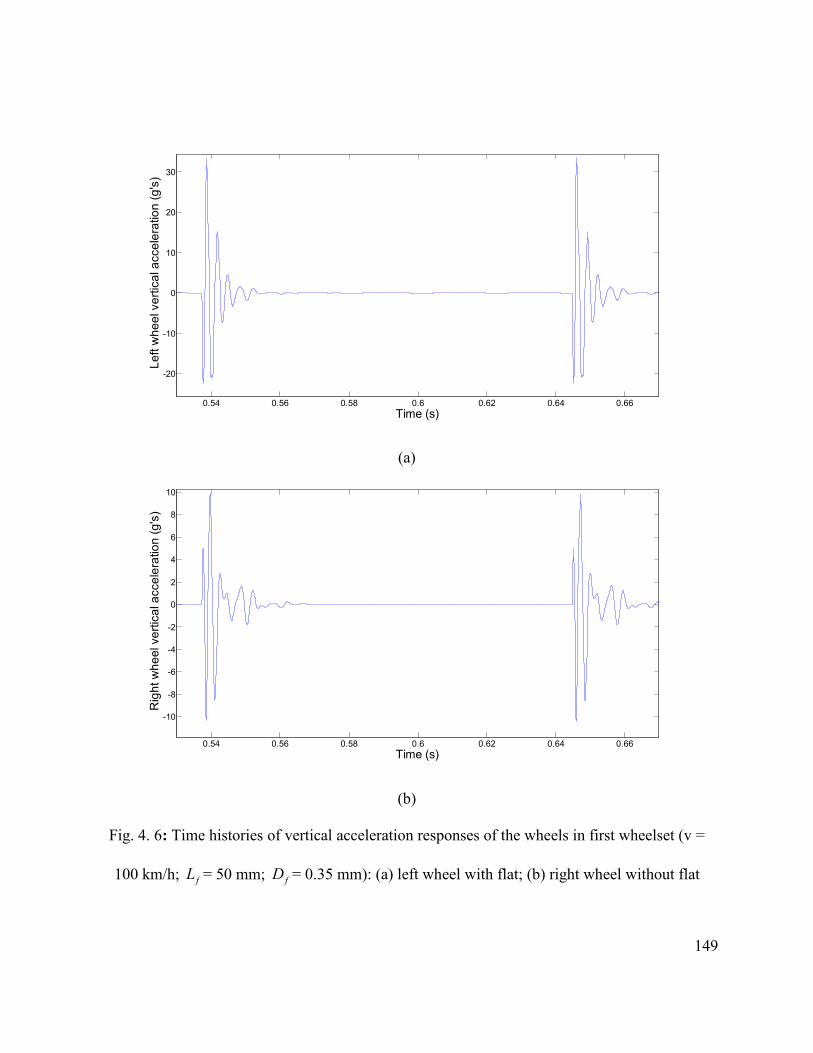
149
0.54 0.56 0.58 0.6 0.62 0.64 0.66
-20
-10
0
10
20
30
Left
whe
el v
ertic
al a
ccel
erat
ion
(g's
)
Time (s)
(a)
0.54 0.56 0.58 0.6 0.62 0.64 0.66
-10
-8
-6
-4
-2
0
2
4
6
8
10
Time (s)
Rig
ht w
heel
ver
tical
acc
eler
atio
n (g
's)
(b)
Fig. 4. 6: Time histories of vertical acceleration responses of the wheels in first wheelset (v =
100 km/h; fL = 50 mm; fD = 0.35 mm): (a) left wheel with flat; (b) right wheel without flat

150
0.54 0.56 0.58 0.6 0.62 0.64 0.66
-2
-1
0
1
2
3
4
5
6
x 10-5
Time (s)
Firs
t whe
else
t rol
l dis
plac
emen
t (ra
d)
Fig. 4. 7: Time histories of first wheelset with one wheel flat roll displacement response (v = 100
km/h; fL = 50 mm; fD = 0.35 mm).
0.54 0.56 0.58 0.6 0.62 0.64 0.66
-0.08
-0.06
-0.04
-0.02
0
0.02
0.04
0.06
0.08
Time (s)
Firs
t whe
else
t rol
l vel
ocity
(rad
/s)

151
Fig. 4. 8: Time histories of first wheelset with one wheel flat roll velocity response (v = 100
km/h; fL = 50 mm; fD = 0.35 mm).
0.54 0.56 0.58 0.6 0.62 0.64 0.66
-200
-150
-100
-50
0
50
100
150
Time (s)
Firs
t whe
else
t rol
l acc
eler
atio
n (ra
d/s2 )
Fig. 4. 9: Time histories of first wheelset with one wheel flat roll acceleration response (v = 100
km/h; fL = 50 mm; fD = 0.35 mm).
Figure 4.10 illustrates the variations in displacement responses of all the four wheelsets of
the vehicle, while the left wheel of the first wheelset has flat only. The displacement responses
are evaluated under constant static load of 103 kN, while the speed of the vehicle is 100 km/h.
Figure 4.10 clearly shows the difference in peak displacement responses due to the presence of
wheel flat. The maximum displacement of the first wheelset with a left wheel flat is 1.18 mm,
whereas the peak displacement of the second wheelset without any flat is in the order of 1.17
mm. The static displacements of all the wheelsets are in the order of 1.14 mm. The results clearly
show a considerable phase difference between the peak displacement responses developed at the
leading wheelset with a flat and the flat-free trailing wheelset, which is mainly due to the
transmission delay of the impact associated with the deflection of the continuous rail. It can be

152
further seen that the presence of flat within the first wheelset does not have any effect on
displacement responses of the third and fourth wheelsets of the rear bogie, which is mainly due
to the location of the flat being far away.
0.32 0.33 0.34 0.35 0.36 0.37 0.38 0.39 0.4 0.41 0.42
-1.19
-1.18
-1.17
-1.16
-1.15
-1.14
-1.13
-1.12
-1.11x 10⁻³
Time (s)
Whe
else
ts v
ertic
al d
ispl
acem
ents
(m)
First wheelsetSecond wheelsetThird wheelsetFourth wheelset
Fig. 4. 10: Time histories of all four wheelsets vertical displacement response with left wheel flat
in first wheelset (v = 100 km/h; fL = 50 mm; fD = 0.35 mm).
The variations in all four wheelsets roll motions due to a single wheel flat within first
wheelset are shown in Fig. 4.11. It can be seen that the peak value of roll motion is higher for
first wheelset, which is due to the presence of the flat within first wheelset. It can be also seen
that presence of wheel flat within first wheelset has also effect on roll motion of the second
wheelset although it does not have any effect on third and fourth wheelsets roll motions. Figure
4.11 further shows that the magnitudes of oscillations due to the impact come to zero after 45.8
ms. The magnitude of the first wheelset peak roll motion is in the order of 6.32×10⁻⁵ rad, while
for second wheelset it is in the order of 3.95×10⁻⁵ rad. When the wheelset with flat reaches the

153
wheel-rail contact point, the wheel axle starts to oscillate. This explains why the impact load at
left wheel-rail contact point is transmitted to the right rail as it will be shown in Fig. 4.15.
0.32 0.33 0.34 0.35 0.36 0.37 0.38 0.39 0.4 0.41 0.42
-1
0
1
2
3
4
5
6
x 10-5
Time (s)
Whe
else
ts ro
ll m
otio
ns (r
ad)
First wheelsetSecond wheelsetThird wheelsetFourth wheelset
Fig. 4. 11: Time histories of all four wheelsets roll motions with left wheel flat in first wheelset
(v = 100 km/h; fL = 50 mm; fD = 0.35 mm).
The time histories of the front and rear bogie bounce, pitch and roll motions are shown in
Figs. 4.12, 4.13 and 4.14, respectively. It can be seen from all these three figures that the
presence of a single wheel flat within first wheelset largely affect the front bogie bounce, pitch
and roll motions, which is primarily due to the location of the flat within the front bogie. Since
the location of the flat is not within the rear bogie the presence of flat within front wheelset has
little or no effect on bounce, pitch and roll motions of the rear bogie, as it can be seen from Figs.
4.12, 4.13 and 4.14. This can be attributed to the low secondary suspension spring stiffness.
Figure 4.12 shows that the maximum vertical displacement of the front bogie can reach up to
1.305 mm from a static value of 1.275 mm, for the given flat size and vehicle speed. This figure
further shows that the bounce motion of the front bogie is almost stabilized after 25.5 ms, as the

154
wheel with flat leaves the wheel-rail contact point by this time period as shown in Fig. 4.4. For
the given parameters, as shown by Figs. 4.13 and 4.14, the maximum pitch and roll motions of
the front bogie are 2.61×10⁻⁵ rad and 3.56×10⁻⁵ rad, respectively.
0.54 0.56 0.58 0.6 0.62 0.64 0.66
-1.3
-1.29
-1.28
-1.27
-1.26
-1.25
x 10-3
Bog
ie v
ertic
al d
ispl
acem
ent (
m)
Time (s)
Front bogieRear bogie
Fig. 4. 12: Time histories of bogie vertical displacement response with left wheel flat in first
wheelset (v = 100 km/h; fL = 50 mm; fD = 0.35 mm).
0.54 0.56 0.58 0.6 0.62 0.64 0.66-3
-2
-1
0
1
2
3x 10⁻⁵
Time (s)
Bog
ie p
itch
mot
ion
(rad)
Front bogieRear bogie

155
Fig. 4. 13: Time histories of bogie pitch motion with left wheel flat in first wheelset (v = 100
km/h; fL = 50 mm; fD = 0.35 mm).
0.54 0.56 0.58 0.6 0.62 0.64 0.66-2
-1
0
1
2
3
4x 10⁻⁵
Time (s)
Bog
ie ro
ll m
otio
n (ra
d)
Front bogieRear bogie
Fig. 4. 14: Time histories of bogie roll motion with left wheel flat in first wheelset (v = 100
km/h; fL = 50 mm; fD = 0.35 mm).
The deflection and acceleration responses of the left and right rail due to a single wheel flat
are also evaluated, as shown in Fig. 4.15 for the rail deflection and Fig 4.16 for rail acceleration
response. The left and right rail deflection response, as shown in Fig. 4.15, reveals that presence
of wheel flat in left wheel-rail contact point affects not only the left rail but also the right rail
deflection. However, the magnitude of the maximum amount of deflection is less for right rail.
Figure 4.15 further shows that as the flat approaches the contact region, the rail moves up prior
to the impact at the contact point followed by the downward deformation of the rail due to the
impact force developed at the wheel-rail interface, as seen in Fig. 4.4 (a). Subsequently, the rail
profile tends to recover its steady value after approximately 25 ms of the impact. The
acceleration response of the left rail with a single wheel flat shows that the impact acceleration

156
can be as high as 219 g, as it can be seen in Fig. 4.16, for the given parameters as listed in Tables
4.2 and 4.3. The figure further shows that the acceleration response comes to steady value after
9.5 ms of the impact for both left and right rails.
0.215 0.22 0.225 0.23 0.235 0.24-12
-11.5
-11
-10.5
-10
-9.5
-9
-8.5
-8
x 10-4
Time (s)
Rai
l ver
tical
def
lect
ion
(m)
Left railRight rail
Fig. 4. 15: Time histories of rail vertical deflection with left wheel flat in first wheelset (v = 100
km/h; fL = 50 mm; fD = 0.35 mm).
0.214 0.216 0.218 0.22 0.222 0.224 0.226 0.228 0.23-300
-200
-100
0
100
200
Time (s)
Rai
l ver
tical
acc
eler
atio
n (g
's)
Left railRight rail

157
Fig. 4. 16: Time histories of rail vertical acceleration with left wheel flat in first wheelset (v =
100 km/h; fL = 50 mm; fD = 0.35 mm).
The effects of wheel flat on peak wheel acceleration due to different vehicle speeds in the
range of 20-140 km/h are further investigated and the results obtained are shown in Fig. 4.17.
The results are presented for both left wheel with flat and flat-free right wheel accelerations
under the influence of five different sizes of wheel flats, while the static wheel load of 103 kN is
considered. Here, the depth of the flat is varied during the simulation and the length of the flat is
automatically changed following the relation between the length and the depth of the flat as
stated by Eqn. 3.51 in chapter 3. The figure illustrates that peak wheel acceleration increases
with increasing the speed of the vehicle for both defective and flat-free wheels. The rate of
increment, however, is considerably larger in the defective left wheel acceleration responses.
The left wheel acceleration response shows that the impact response exhibits higher
magnitude in the medium speed range (70-90 km/h) for low flat sizes (Df =0.2-.04 mm), and
tends to increase rapidly at speeds above 100 km/h. However, this higher magnitudes in the peak
acceleration response of the left wheel is not profound for higher flat sizes, which can be
attributed to the matching in excitation frequency due to the wheel flat (approximately 330 Hz)
with the natural bounce frequency of the first wheelset (312 Hz). The right wheel peak
acceleration responses due to the presence of left wheel flat within same wheelset also shows the
increase in peak acceleration with speeds and flat sizes as well. However, the magnitudes of the
right wheel peak impact accelerations are less than that of the left wheel. Furthermore, the cross-
wheel impact acceleration developed at the right wheel increases slightly with vehicle speed for
low flat sizes, while the effect of left wheel flat becomes evident at speeds above 90 km/h.

158
0
10
20
30
40
50
60
70
80
90
0 20 40 60 80 100 120 140 160
Lef
t w
heel
with
flat
pea
k ve
rtic
al a
ccel
erat
ion
(g's
)
Speed of the vehicle (km/h)
Df=0.2 mm
Df=0.3 mm
Df=0.4 mm
Df=0.5 mm
Df=0.6 mm
(a)
0
5
10
15
20
25
0 20 40 60 80 100 120 140 160
Rig
ht w
heel
with
out f
lat p
eak
vert
ical
acc
eler
atio
n (g
's)
Speed of the vehicle (km/h)
Df=0.2 mm
Df=0.3 mm
Df=0.4 mm
Df=0.5 mm
Df=0.6 mm
(b)
Fig. 4. 17: Effect of vehicle speed on peak wheel acceleration: (a) with flat; (b) without flat.
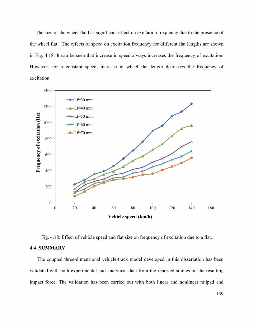
159
The size of the wheel flat has significant effect on excitation frequency due to the presence of
the wheel flat. The effects of speed on excitation frequency for different flat lengths are shown
in Fig. 4.18. It can be seen that increase in speed always increases the frequency of excitation.
However, for a constant speed, increase in wheel flat length decreases the frequency of
excitation.
0
200
400
600
800
1000
1200
1400
0 20 40 60 80 100 120 140 160
Lf=30 mm
Lf=40 mm
Lf=50 mm
Lf=60 mm
Lf=70 mm
Freq
uenc
y of
exc
itatio
n (H
z)
Vehicle speed (km/h)
Fig. 4.18: Effect of vehicle speed and flat size on frequency of excitation due to a flat.
4.4 SUMMARY
The coupled three-dimensional vehicle-track model developed in this dissertation has been
validated with both experimental and analytical data from the reported studies on the resulting
impact force. The validation has been carried out with both linear and nonlinear railpad and

160
ballast properties. The study shows that nonlinear railpad and ballast model gives better
prediction of the wheel-rail impact force than that of the linear model when compared with the
experimental data. The study shows that speed has significant effect on peak wheel-rail impact
force for both linear and nonlinear railpad and ballast models. However, linear railpad and ballast
predict higher peak wheel-rail impact forces in the selected speed range. This study shows that
for the selected parameter the consideration of the linear properties of the railpad and ballast into
the track model could increase the peak impact force up to 56.86%.
The validated model is then applied to obtain the response of individual vehicle and track
components. The effects of a single wheel flat on the responses of vehicle and track components
in terms of displacements and accelerations responses are investigated for both defective wheel
and the flat-free wheel. The characteristics of the bounce, pitch and roll motions of the bogie due
to a single wheel flat are also investigated. The results clearly show that presence of wheel flat
within the same wheelset has significant effect on the impact force, displacement and
acceleration responses of that wheelset. The results further show that although the effect of cross
wheel impact on responses of the neighborhood wheelset or bogie displacements and
accelerations responses are not so significant, this low magnitude impact may cause rapid fatigue
damage of the vehicle and track components. However, this study shows that the effect of the
transmitted force on the rear bogie due to the presence of the wheel flat within the front bogie is
little and negligible which can be attributed to the low suspension spring stiffness. The study
further shows that increase in vehicle speed and flat sizes always increases the wheel peak
accelerations for both defective and flat-free wheels.

161
CHAPTER 5
IMPACT RESPONSE DUE TO MULTIPLE WHEEL FLATS
5.1 INTRODUCTION
The presence of wheel flats can cause high magnitude impact excitations on both wheel and
rail eliciting large responses. This high frequency vibration in the vehicle track system affects the
track maintenance and reliability of the vehicle’s rolling elements. The presence of multiple
wheel flats within a wheel or axle of a car is not very uncommon in practice. Multiple flats can
be developed at the same locations of both wheels within a wheelset due to the locking of the
brake system. The presence of multiple flats on same wheel or wheelsets causes multiple impacts
in every revolutions of the wheel or wheelset. Furthermore, the number of flats, their sizes and
their location with respect to each other may play an important role on the peak wheel-rail
impact responses.
Various railroad organizations have been trying to set a threshold of flat size as an indication
for replacement of the wheel with flat. The American Association of Railroad (AAR) has set the
criteria to replace the wheel from the service for 50.8 mm long single flat or 38.1mm long two
adjoining flats [139]. According to Transport Canada safety regulations, a railway car may not
continue in service if one of its wheels has a flat of more than 63.50 mm in length or two
adjoining flats each of which is more than 50.80 mm [1]. Swedish Railway sets the condemning
limit for a wheel flat based on a flat length of 40 mm and flat depth of 0.35 mm [17]. According
to UK Rail safety and standard board [146], a wheel with flat length exceeding 70 mm must be
taken out of service. Most of these wheel removal criteria are based on single or multiple

162
adjoining flats within a wheel. The possible existence of flats on both wheels within same
wheelsets or bogies is not dealt by any of the requirements.
Although the presence of multiple wheel flats within a wheel or wheelset is common in
practice, the vast majority of the studies dealing with wheel flat utilizes simple vehicle-track
model and considers single wheel flat only. Presence of multiple defects within the contact point
would further enhance the complexity of the analytical model. The nonlinear contact of the
wheel and rail makes it more complex for analysis. Furthermore, the contributions due to roll and
pitch dynamics of the car and relative positions of different wheel flats with wide variations in
relative positions between the flats on the wheel-rail impact forces were not investigated. A
detailed study on dynamic wheel-rail interactions with 3-dimensional car and track model is thus
required in order to characterize the contact impact responses due to the presence of multiple
wheel flats.
In this chapter, the three-dimensional railway vehicle-track model developed in chapter 3 and
validated in chapter 4 is employed to study the effect of multiple wheel flats on wheel
acceleration response. Studies are carried out for different types of wheel flats and their relative
positions. The effect of multiple wheel flats on both direct and cross wheels within same or
different wheelsets are also investigated. The effects of vehicle speed on peak wheel acceleration
in presence of multiple wheel flats are further investigated for both left and right wheel within
same wheelset. Finally, the effect of bogie pitch and roll motion on overall peak acceleration of
the wheel is also investigated in presence of two in-phase flats.
5.2 MULTIPLE WHEEL FLATS MODEL
A single flat in one wheel may be followed by another flat of same or different size in the
adjacent wheel. Their relative positions can also be different. As discussed in chapter 1, although

163
the presence of multiple wheel flats in a single wheel or within same wheelsets are widely
observed the resulting impact response in terms of accelerations have not been reported. In this
section, the developed three-dimensional vehicle-track model is applied to study the influences
of multiple flats. In this study, similar to the single wheel flat model as described before,
commonly used haversine wheel flat model is utilized to study the effect of multiple flats. The
studies s are performed for two different cases: (i) two identical size flats on the same wheel
located at different angular positions (phase angle) (ii) two same size flats on the different
wheels either in phase or out-of-phase. Descriptions of two flats in same wheel with different
angular positions are already given in chapter 3. The positions of two similar or different flats in
same wheel or two different wheels within same wheelset are shown in Fig. 5.1. The flats are
defined such that the leading flat comes into contact with the rail first followed by trailing flat,
which enters the contact with a defined phase angle. The variations in radius of a wheel with two
flats each with 60 mm length and 0.45 mm depth that are 450 apart are illustrated in Fig. 5.2, as a
function of the wheel position.
(a)
Left wheel Right wheel
Leading flat
Trailing flat

164
(b)
(c)
Fig. 5. 1: Location of same or different size flats (a) two flats within same wheel out-of-phase;
(b) two flats in different wheels within same wheelset in-phase; (c) two flats in different wheels
within same wheelset out-of- phase.
Left wheel Right wheel
Leading flat
Trailing flat
Left wheel Right wheel
Leading flat
Trailing flat

165
0 50 100 150 200 250 300 350
0.4745
0.4746
0.4746
0.4747
0.4747
0.4748
0.4748
0.4749
0.4749
0.475
0.475
Angular position (degree)
Whe
el ra
dius
(m)
Trailing flatLeading flat
Fig. 5. 2: Variations in radius of a wheel with two same size flats ( fL = 60 mm and fD = 0.45
mm), which are 450 apart.
5.3 DYNAMIC RESPONSE DUE TO TWO FLATS ON SINGLE WHEEL
In order to analyze the effect of multiple wheel flats in same wheel on wheel acceleration
response, two same size flats with different specified phase angles are considered. The
simulations are carried out for multiple flats within the left wheel of first wheelset at a forward
speed of 100 km/h. Both flats are 60 mm long and the depths of the flats are determined by the
relationship between them as shown by Eqn. (3.51). Studies are carried out by considering the
fact that all wheels except the left wheel of front wheelset are perfect. The variations in the wheel
impact acceleration due to the presence of multiple flats are evaluated by considering different
phase angles between the two flats, namely, 50, 150, 300 and 450.
Figures 5.3 to 5.6 illustrate the variations in wheel acceleration response at the left and right
wheels for different phase angles between the flats, while the flats are within left wheel only and
the right wheel is assumed as perfect. The results clearly show two distinct peaks in the impact
acceleration response of both left and right wheel due to the presence of two flats in two different
locations. However, as expected, the peak impact accelerations for right wheel without flats are

166
much less than that for the left wheel with flats. The figures further show that although two flats
are identical in size, the magnitudes of the peak impact accelerations induced by the two flats
differ. The peak impact acceleration induced by the leading flat is in the order of ±45.6 g at the
left wheel and approximately ±13.5 g at the right wheel irrespective of the position of the trailing
flat. In case of left wheel acceleration, the magnitude of the peak impact acceleration induced by
the trailing flat tends to increase with increase in phase angles between the flats. The figures
further show that the difference between the peak acceleration induced by the leading and
trailing flats are insignificant when the flats are 300 and 450 apart, while the time lapse between
the two peak accelerations directly related to the vehicle speed and the phase difference between
the two flats.
0.215 0.22 0.225 0.23 0.235 0.24-30
-20
-10
0
10
20
30
40
Time (s)
Left
whe
el a
ccel
erat
ion
(g's
)
Impact due to leading flat
Impact due to trailing flat
(a)

167
0.215 0.22 0.225 0.23 0.235 0.24 0.245 0.25 0.255
-15
-10
-5
0
5
10
Time (s)
Rig
ht w
heel
acc
eler
atio
n (g
's)
Impacts due to left wheel flats
(b)
Fig. 5. 3: Wheel impact acceleration responses due to two flats on left wheel at 50 out-of-phase
(v=100 km/h and fL = 60 mm): (a) left wheel; (b) right wheel.
0.215 0.22 0.225 0.23 0.235 0.24
-30
-20
-10
0
10
20
30
40
Time (s)
Left
whe
el a
ccel
erat
ion
(g's
)
Impact due to trailing flatImpact due to leading flat
(a)

168
0.215 0.22 0.225 0.23 0.235 0.24 0.245 0.25 0.255
-15
-10
-5
0
5
10
15
Time (s)
Rig
ht w
heel
acc
eler
atio
n (g
's)
Impacts due to left wheel flats
(b)
Fig. 5. 4: Wheel impact acceleration responses due to two flats on left wheel at 150 out-of-phase
(v=100 km/h and fL = 60 mm): (a) left wheel; (b) right wheel.
0.215 0.22 0.225 0.23 0.235 0.24 0.245
-30
-20
-10
0
10
20
30
40
50
Time (s)
Left
whe
el a
ccle
ratio
n (g
's)
Impact due to trailing flatImpact due to leading flat
(a)

169
0.215 0.22 0.225 0.23 0.235 0.24 0.245 0.25 0.255-15
-10
-5
0
5
10
15
Time (s)
Rig
ht w
heel
acc
eler
atio
n (g
's)
Impacts due to left wheel flats
(b)
Fig. 5. 5: Wheel impact acceleration responses due two flats on left wheel at 300 out-of-phase
(v=100 km/h and fL = 60 mm): (a) left wheel; (b) right wheel.
0.215 0.22 0.225 0.23 0.235 0.24 0.245 0.25
-30
-20
-10
0
10
20
30
40
50
Time (s)
Left
whe
el a
ccel
erat
ion
(g's
)
Impact due to trailing flatImpact due to leading flat
(a)

170
0.215 0.22 0.225 0.23 0.235 0.24 0.245 0.25 0.255
-10
-5
0
5
10
Time (s)
Rig
ht w
heel
acc
eler
atio
n (g
's)
Impacts due to left wheel flats
(b)
Fig. 5. 6: Wheel impact acceleration responses due to two flats on left wheel at 450 out-of-phase
(v=100 km/h and fL = 60 mm): (a) left wheel; (b) right wheel.
In case of right wheel acceleration, the figures show that the peak impact acceleration
induced by the trailing flat can be slightly higher than the peak impact acceleration induced by
the leading flat for some phase angles, as it is evident in Figs. 5.4 and 5.5, for 300 and 450 phase
angles. The results further suggest that the magnitudes of impact accelerations induced by two
flats are similar to that caused by a single flat, if they are apart from each other by 300 phase
angle or more. The frequency of the impact, however, increases with increase in number of flats,
which could yield rapid fatigue damage of the vehicle and track components.
The second flat in a wheel of multiple flats may generate different impact acceleration from
those of a single flat case under certain condition, as it is shown in Figs. 5.3 to 5.6. Speed of the
vehicle also strongly affects the variations in impact accelerations responses induced by the
multiple flats. Increase in vehicle speed will particularly decrease the time lapse between the two
peak impacts caused by two flats. The effect of speed on the peak wheel accelerations due to

171
multiple wheel flats within left wheel under certain phase angles is therefore examined in the
speed range of 20-140 km/h. Figures 5.7 to 5.9 show the effect of speed on peak left wheel
acceleration responses caused by the presence of two flats within left wheel only and with phase
angles of 150, 300 and 450, respectively. The results show that, similar to single wheel flat,
increase in speed and flat size always increases the left wheel impact acceleration caused by the
leading flat irrespective of the phase angles between the two flats.
In case of left wheel acceleration caused by the trailing flat, the results show complex
relationship between the vehicle speed, flat size and the peak acceleration responses. It can be
seen from Figs. 5.7 to 5.9 that the peak impact acceleration due to the trailing flat on the
multiple-flat left wheel is significantly affected by the phase angles, when the phase angle is
small and the flat size is large. The results further show that the difference in impact
accelerations due to the leading and trailing flats on left wheel is not significant, when the phase
angle between the flats is more than 450 and the flat length is equal to or less than 60 mm,
irrespective of the vehicle speed. Beyond this value of phase angle and within this flat size, the
impact acceleration caused by the trailing flat is same as that predicted by the simulation of
single flat of same size.

172
0
20
40
60
80
100
120
140
0 20 40 60 80 100 120 140 160
Peak
left
whe
el a
ccel
erat
ion
(g's
)
Vehicle speed (km/h)
Leading flat, Lf=80 mm
Trailing flat, Lf=80 mm
Leading flat, Lf=70 mm
Trailing flat, Lf=70 mm
Leading flat, Lf=60 mm
Trailing flat, Lf=60 mm
Leading flat, Lf=45 mm
Trailing flat, Lf=45 mm
Leading flat, Lf=30 mm
Trailing flat, Lf=30 mm
Fig. 5. 7: Effect of speed on peak wheel acceleration response for different sizes of flats with two
flats on left wheel at 150 of phase angle.
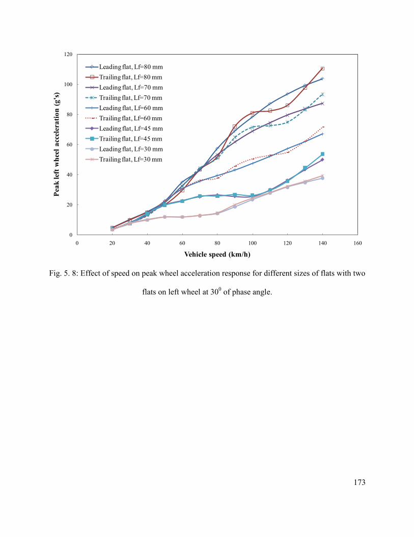
173
0
20
40
60
80
100
120
0 20 40 60 80 100 120 140 160
Peak
left
whe
el a
ccel
erat
ion
(g's
)
Vehicle speed (km/h)
Leading flat, Lf=80 mmTrailing flat, Lf=80 mmLeading flat, Lf=70 mmTrailing flat, Lf=70 mmLeading flat, Lf=60 mmTrailing flat, Lf=60 mmLeading flat, Lf=45 mmTrailing flat, Lf=45 mmLeading flat, Lf=30 mmTrailing flat, Lf=30 mm
Fig. 5. 8: Effect of speed on peak wheel acceleration response for different sizes of flats with two
flats on left wheel at 300 of phase angle.

174
0
20
40
60
80
100
120
0 20 40 60 80 100 120 140 160
Peak
left
whe
el a
ccel
erat
ion
(g's
)
Vehicle speed (km/h)
Leading flat, Lf=80 mmTrailing flat, Lf=80 mmLeading flat, Lf=70 mmTrailing flat, Lf=70 mmLeading flat, Lf=60 mmTrailing flat, Lf=60 mmLeading flat, Lf=45 mmTrailing flat, Lf=45 mmLeading flat, Lf=30 mmTrailing flat, Lf=30 mm
Fig. 5. 9: Effect of speed on peak wheel acceleration response for different sizes of flats with two
flats on left wheel at 450 of phase angle.
5.4 DYNAMIC RESPONSE DUE TO SINGLE FLAT ON TWO WHEELS OF SAME
WHEELSET OUT-OF-PHASE
The effect of multiple wheel flats on wheel acceleration response is further investigated with
two same size flats on both left and right wheels of the first wheelset with different specified
phase angles, while all other wheels of the vehicle are assumed as perfect. The simulations are
carried out for multiple flats of 60 mm length and a forward vehicle speed of 100 km/h. The
depths of the flats are determined by the relationship between the wheel flat length and depth as
shown by Eqn. (3.51). The left wheel flat is assigned ahead of the right wheel flat with a specific
phase angle. The variations in the both left and right wheel impact acceleration due to the
presence of multiple flats within a same wheelset are evaluated by considering different phase
angles between the two flats, namely, 150, 300 and 450.

175
The time histories of left and right wheel impact acceleration due to a single flat on both the
left and right wheels at 150, 300, and 450 out-of-phase are shown in Figs. 5.10 to 5.12,
respectively. The results clearly show two distinct peaks in both left and right wheel acceleration
responses corresponding to their respective flats, when the phase angle is more than 150. The
difference in magnitudes of the peak acceleration due to the direct and cross wheel flat is also
pronounced for all three phase angles considered. The magnitudes of the peak acceleration due to
the direct wheel flat are same as those obtained for a single wheel flat earlier.
Figures 5.10 to 5.12 illustrate that the impact acceleration due to the flat on left wheel which
enters into the contact first is unaffected by the flat on the right wheel, which enters the contact
region after the defined phase angle. This is consistent with the right wheel impact acceleration
responses too. The results further illustrate that the cross wheel flat effect is more pronounced
primarily for low phase angles. However, the extent of the effect is dependent on speed, flat size
and phase angles between the flats. For the given speed and flat size, the magnitude of the left or
right wheel acceleration due to direct wheel flat is in the order of 47.5 g irrespective of the phase
angle. However, the magnitudes of the left wheel acceleration due to the right wheel flat (cross
wheel flat effect) are 12.9, 14.6 and 16.4 g for phase angles of 150, 300 and 450, respectively. On
the other hand, the magnitude of the right wheel acceleration due to cross wheel flat is in the
order of 12.85 g irrespective of the phase angle.

176
0.43 0.435 0.44 0.445 0.45 0.455
-30
-20
-10
0
10
20
30
40
Time (s)
Left
whe
el a
ccel
erat
ion
(g's
)
Impact due to right wheel flat
(a)
0.43 0.435 0.44 0.445 0.45 0.455
-30
-20
-10
0
10
20
30
40
50
Time (s)
Rig
ht w
heel
acc
eler
atio
n (g
's) Impact due to left wheel flat
(b)
Fig. 5. 10: Left and right wheel impact acceleration responses due to a single flat on both wheels
of a wheelset at 150 out-of-phase (left wheel flat ahead by 150)

177
0.322 0.324 0.326 0.328 0.33 0.332 0.334 0.336 0.338 0.34 0.342
-30
-20
-10
0
10
20
30
40
Time (s)
Left
whe
el a
ccel
erat
ion
(g's
)
Impact due to right wheel flat
(a)
0.32 0.325 0.33 0.335 0.34 0.345 0.35
-30
-20
-10
0
10
20
30
40
50
Time (s)
Rig
ht w
heel
acc
eler
atio
n (g
's)
Impact due to left wheel flat
(b)
Fig. 5. 11: Left and right wheel impact acceleration responses due to a single flat on both wheels
of a wheelset at 300 out-of-phase (left wheel flat ahead by 300)

178
0.42 0.425 0.43 0.435 0.44 0.445 0.45 0.455 0.46
-30
-20
-10
0
10
20
30
40
Time (s)
Left
whe
el a
ccel
erat
ion
(g's
)
Impact due to right wheel flat
(a)
0.425 0.43 0.435 0.44 0.445 0.45 0.455 0.46 0.465
-30
-20
-10
0
10
20
30
40
Time (s)
Rig
ht w
heel
acc
eler
atio
n (g
's)
Impact due to left wheel flat
(b)
Fig. 5. 12: Left and right wheel impact acceleration responses due to a single flat on both wheels
of a wheelset at 450 out-of-phase (left wheel flat ahead by 450)

179
The effect of speed on peak left and right wheel acceleration due to a single flat on both
wheels at particular phase angles is further investigated in speed range of 20-140 km/h. Two
identical flats are assumed to be present on both left and right wheels of first wheelset of the
front bogie at 150, 300 and 450 phase difference. The peak magnitudes of the left and right wheel
acceleration due to the direct wheel flat with 30, 45, 60, 70 and 80 mm of lengths as a function of
speed were investigated. The depths of the flats are calculated by the relation as stated in Eqn.
(3.51). The simulations are carried out with static load per wheel of 103 kN, and the results
obtained are shown in Figs. 5.13 to 5.15 with different flat sizes and phase angles.
0
20
40
60
80
100
120
0 20 40 60 80 100 120 140 160
Peak
whe
el a
ccel
erat
ion
(g's
)
Vehicle speed (km/h)
Left wheel acceleration, Lf=80 mm
Right wheel acceleration, Lf=80 m
Left wheel acceleration, Lf=70 mm
Right wheel acceleration, Lf=70 m
Left wheel acceleration, Lf=60 mm
Right wheel acceleration, Lf=60 mm
Left wheel acceleration, Lf=45 mm
Right wheel acceleration, Lf=45 mm
Left wheel acceleration, Lf=30 mm
Right wheel acceleration, Lf=30 mm
Fig. 5. 13: Effect of speed on peak wheel impact acceleration due to a single flat on both wheels
of a wheelset at 150 out-of-phase.

180
0
20
40
60
80
100
120
0 20 40 60 80 100 120 140 160
Peak
whe
el a
ccel
erat
ion
(g's
)
Vehicle speed (km/h)
Left wheel acceleration, Lf=80 mm
Right wheel acceleration, Lf=80 mm
Left wheel acceleration, Lf=70 mm
Right wheel acceleration, Lf=70 mm
Left wheel acceleration, Lf=60 mm
Right wheel acceleration, Lf=60 mm
Left wheel acceleration, Lf=45 mm
Right wheel acceleration, Lf=45 mm
Left wheel acceleration, Lf=30 mm
Right wheel acceleration, Lf=30 mm
Fig. 5. 14: Effect of speed on peak wheel impact acceleration due to a single flat on both wheels
of a wheelset at 300 out-of-phase.
Similar to the peak impact acceleration response due to single wheel flat, figures 5.13 to 5.15
clearly show that increase in vehicle speed and flat length always increases the peak acceleration
responses for both the left and right wheel peak acceleration responses irrespective of phase
angles between the two flats. The right wheel peak impact acceleration increases in sinusoidal
motion which is mainly due to the sinusoidal motion of the left wheel acceleration response after
the impact. The results clearly demonstrate that the right wheel peak acceleration experienced
larger magnitudes of impact acceleration than that of the left wheel, when the speed is higher and
flat size is larger. This indicates the possibility of significantly larger impact acceleration due to a
direct wheel flat if the other wheel has experienced a flat prior to it. This study shows that for a

181
speed of 110 km/h, the left wheel with single flat of 60 mm length that comes into wheel-rail
contact first will generate a peak acceleration of 51.81g for a 150 phase angle between the flats.
However, the right wheel that experiences an impact due to a similar flat on left wheel 150 prior
to the direct wheel flat will generate a peak acceleration of 55.69 g.
0
20
40
60
80
100
120
0 20 40 60 80 100 120 140 160
Peak
whe
el a
ccel
erat
ion
(g's
)
Vehicle speed (km/h)
Left wheel acceleration, Lf=80 mm
Right wheel acceleration, Lf=80 mm
Left wheel acceleration, Lf=70 mm
Right wheel acceleration, Lf=70 mm
Left wheel acceleration, Lf=60 mm
Right wheel acceleration, Lf=60 mm
Left wheel acceleration, Lf=45 mm
Right wheel acceleration, Lf=45 mm
Left wheel acceleration, Lf=30 mm
Right wheel acceleration, Lf=30 mm
Fig. 5. 15: Effect of speed on peak wheel impact acceleration due to a single flat on both wheels
of a wheelset at 450 out-of-phase.
5.5 DYNAMIC RESPONSE DUE TO A SINGLE FLAT ON ALL WHEELS OF FRONT
BOGIE AND ENTIRE VEHICLE

182
In an attempt to investigate the effect of car body pitch and roll motion on peak wheel
acceleration response, the developed three-dimensional vehicle-track model is applied to study
the influence of multiple flats. Studies are carried out for two different cases: (i) four identical
wheel flats on four wheels within the front bogie only at same angular position; (ii) eight same
size flats on eight wheels of both front and rear bogies of the entire vehicle at same angular
position. Simulations are carried out with 60 mm flat length and for a vehicle speed of 100 km/h.
The entire parameters are same as for single wheel flat used before. The results obtain from
simulations are shown in Fig. 5.16 for both cases.
Figure 5.16 shows the time histories of left or right wheel acceleration response for the first
wheelset in presence of single flats on four wheels or eight wheels of the vehicle. However, it is
expected that all other wheels of the same bogie or entire car would show similar responses.
Hence, they are not shown here. It can be seen that time histories of impact acceleration for
multiple flats in phase within the front bogie and entire vehicle are same as the time history of
impact acceleration due to single wheel flat. However, there is a difference in peak magnitude
and frequency of oscillations after impact between the impact acceleration response due to single
and multiple wheel flats. This difference in peak magnitude of the impact acceleration is in the
order of 21 g.
Peak impact acceleration due to single flat on four wheels is 21 g less than the peak impact
acceleration due to single wheel flat of same size. This difference can be attributed to the
symmetry of the bogie about the central lateral axis due to the presence of flats on all four wheels
at same location. In the presence of flats on four wheels, both front and rear wheelsets of the
front bogie move together while the pitch and roll motions of the bogie are not excited. On the
other hand, in case of single wheel flat, owing to the pitch and roll motion of the front bogie

183
together with the roll motion of the wheelset, the deflections of wheel is more which ultimately
increases the wheel acceleration.
Fig. 5.16 further shows that there is no difference in peak magnitude and frequency of
oscillation of the impact acceleration due to four wheel flats within front bogie and eight wheel
flats within the entire vehicle. For both of these cases, the peak magnitude of the impact
acceleration is 26.7 g. This shows that car body pitch and roll motion have no effect on peak
acceleration response due to wheel flats. This can be attributed to the high suspension stiffness of
the primary and secondary suspension that isolates the car body from impact that occurs in
wheel-rail contact region.
0.21 0.215 0.22 0.225 0.23 0.235 0.24 0.245 0.25
-15
-10
-5
0
5
10
15
20
25
Time (s)
Left/
right
whe
el a
ccel
erat
ion
(g's
)
(a)

184
0.21 0.215 0.22 0.225 0.23 0.235 0.24 0.245 0.25
-20
-15
-10
-5
0
5
10
15
20
25
Left/
Rig
ht w
heel
acc
eler
atio
n (g
's)
Time (s)
(b)
Fig. 5. 16: Time history of left or right wheel impact acceleration responses due to a single flat
on (a) all four wheels of the front bogie; (b) all eight wheels of the entire vehicle, in phase.
5.6 DYNAMIC RESPONSE DUE TO TWO FLATS ON OPPOSITE WHEELS OF SAME
WHEELSET IN PHASE
The presence of two flats in two wheels of same wheelset is very common in practice due to
the sliding of the locked wheelset. These flats may be same or different in size and their effects
on impact acceleration response can be different too. In this subsection, the wheel impact
acceleration responses and effect of speed on peak impact accelerations are investigated. Two
flats of same size are assigned to left and right wheels of the first wheelset at same position, i.e.
00 phase angle.
Figure 5.17 illustrates the time history of left or right wheel impact acceleration due to a 60
mm long flat on both left and right wheels in same location within the first wheelset of the front
bogie. As the result shows, with two similar flats on both wheels in phase, the left or right wheel
impact acceleration develops response identical to the single wheel flat acceleration response.

185
However, the magnitude of the peak acceleration for two flats in opposite wheels in phase is less
than the impact acceleration due to single wheel flat. It can be seen that the magnitude of the
peak left or right wheel acceleration is in the order of 37.64 g. This peak is approximately 11 g
more than the peak magnitude of impact acceleration in the presence of single flat of same size
on all four wheels of the front bogie as shown in Fig. 5.16 (a). This difference can be attributed
to the excitation of the bogie pitch motion, in case of single flat on two wheels of first wheelset
of the front bogie. In case of flats on both wheels of the first wheelset, the displacement of the
first wheelset of the front bogie is more while the second wheelset without any flats remains
same. This motion of the first wheelset increases the peak wheel acceleration in case of single
flat on both wheels in phase.
The effect of speed on peak wheel acceleration due to a single flat on left wheel and two in-
phase flats on both wheels of a wheelset is shown in Fig. 5.18. The results are shown for speed
range of 20-140 km/h, where the flat length is varied from 30-80 mm. The figure clearly shows
that the peak impact acceleration due to a single wheel flat is higher than the peak wheel
acceleration due to the two in-phase flats on both wheels of same wheelset. This result is
consistent for the selected speed range and the flat sizes. For a vehicle speed of 140 km/h and flat
length of 80 mm, the difference can be as high as 27.3 g.
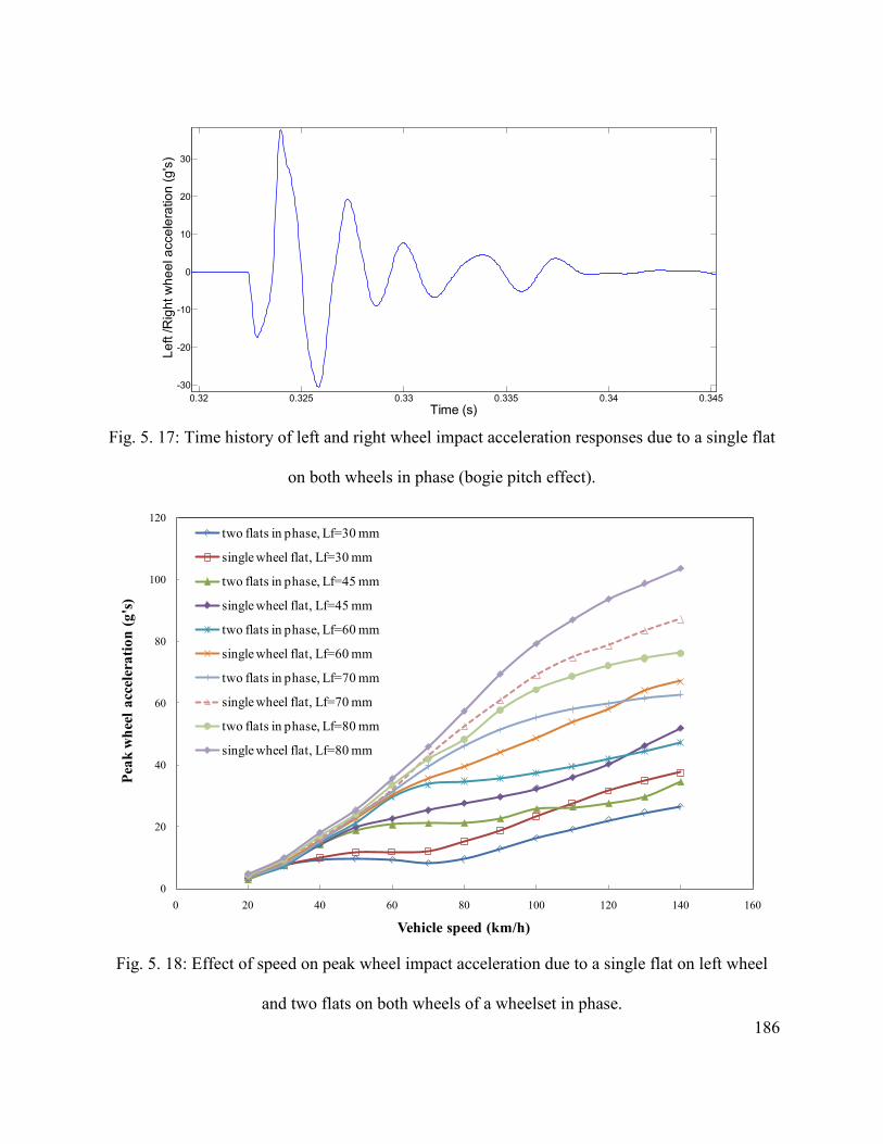
186
0.32 0.325 0.33 0.335 0.34 0.345-30
-20
-10
0
10
20
30
Time (s)
Left
/Rig
ht w
heel
acc
eler
atio
n (g
's)
Fig. 5. 17: Time history of left and right wheel impact acceleration responses due to a single flat
on both wheels in phase (bogie pitch effect).
0
20
40
60
80
100
120
0 20 40 60 80 100 120 140 160
Peak
whe
el a
ccel
erat
ion
(g's
)
Vehicle speed (km/h)
two flats in phase, Lf=30 mm
single wheel flat, Lf=30 mm
two flats in phase, Lf=45 mm
single wheel flat, Lf=45 mm
two flats in phase, Lf=60 mm
single wheel flat, Lf=60 mm
two flats in phase, Lf=70 mm
single wheel flat, Lf=70 mm
two flats in phase, Lf=80 mm
single wheel flat, Lf=80 mm
Fig. 5. 18: Effect of speed on peak wheel impact acceleration due to a single flat on left wheel
and two flats on both wheels of a wheelset in phase.

187
5.7 DYNAMIC RESPONSE DUE TO TWO FLATS ON LEFT WHEELS OF TWO
WHEELSETS AT SAME POSITION
The effect of presence of multiple wheel flats on two different wheelsets within the same
bogie is further investigated for a vehicle speed of 100 km/h. Two flats of identical size are
assigned to left wheels of the first and second wheelsets at same location. Figure 5.19 illustrates
the time history of left wheel impact acceleration due to a 60 mm long flat on left wheels of first
and second wheelsets within the front bogie in same location. As the result shows, the left wheel
impact acceleration response follows similar trend as the single wheel flat acceleration response.
However, similar to the multiple flats on both wheels within the same wheelset in phase
condition, the magnitude of the peak acceleration for two flats in left wheel of opposite wheelsets
in phase is less than the impact acceleration due to a single wheel flat.
The magnitude of the peak left wheel acceleration is in the order of 38.80 g, which is
approximately 12.2 g more than the peak magnitude of impact acceleration in the presence of
single flat of same size on all four wheels of the front bogie as shown in Fig. 5.16 (a). This
difference can be attributed to the excitation of the bogie roll motion. In case of flats on left
wheels of the first and second wheelset, the displacement of the left wheels of both first and
second wheelsets are more while the flat-free right wheels of first and second wheelsets remains
same. These motions of the left wheels increase the peak wheel acceleration in case of single flat
on left wheels of first and second wheelsets in phase. Furthermore, due to the presence of the
flats on left wheels only the roll motion of the wheel is also excited, which contributes in
increasing the magnitude of the peak wheel acceleration.
Figure 5.20 shows the effect of speed on peak wheel acceleration due to a single flat on left
wheel and two in-phase flats on left wheels of first and second wheelsets. The results are shown

188
for speed range of 20-140 km/h, where the flat length is varied from 30-80 mm. The figure
clearly shows that the peak impact acceleration due to a single wheel flat is higher than the peak
wheel acceleration due to the two in-phase flats on left wheels of first and second wheelset. This
result is consistent for the selected speed range and the flat sizes. For a vehicle speed of 100
km/h and flat length of 70 mm, the difference in magnitude of peak acceleration can be as high
as 13.25 g.
0.214 0.216 0.218 0.22 0.222 0.224 0.226 0.228
-20
-10
0
10
20
30
Time (s)
Left
whe
el a
ccel
erat
ion
(g's
)
Fig. 5. 19: Time history of left wheel impact acceleration responses due to a single flat on left
wheels of first and second wheelset of the front bogie in phase (bogie roll effect).
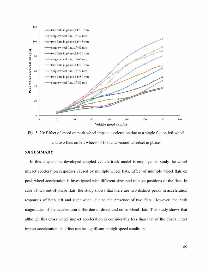
189
0
20
40
60
80
100
120
0 20 40 60 80 100 120 140 160
Peak
whe
el a
ccel
erat
ion
(g's
)
Vehicle speed (km/h)
two flats in phase, Lf=30 mm
single wheel flat, Lf=30 mm
two flats in phase, Lf=45 mm
single wheel flat, Lf=45 mm
two flats in phase, Lf=60 mm
single wheel flat, Lf=60 mm
two flats in phase, Lf=70 mm
single wheel flat, Lf=70 mm
two flats in phase, Lf=80 mm
single wheel flat, Lf=80 mm
Fig. 5. 20: Effect of speed on peak wheel impact acceleration due to a single flat on left wheel
and two flats on left wheels of first and second wheelset in phase.
5.8 SUMMARY
In this chapter, the developed coupled vehicle-track model is employed to study the wheel
impact acceleration responses caused by multiple wheel flats. Effect of multiple wheel flats on
peak wheel acceleration is investigated with different sizes and relative positions of the flats. In
case of two out-of-phase flats, the study shows that there are two distinct peaks in acceleration
responses of both left and right wheel due to the presence of two flats. However, the peak
magnitudes of the acceleration differ due to direct and cross wheel flats. This study shows that
although this cross wheel impact acceleration is considerably less than that of the direct wheel
impact acceleration, its effect can be significant in high-speed condition.

190
In investigations of impact acceleration due to multiple flats with the three-dimensional
vehicle-track model, it is observed that the presence of two flats on same location of different
wheels within same or different wheelsets has considerable effect on peak wheel-rail impact
load. This study shows that the presence of a single flat in all four wheels of front bogie in phase
induces impact acceleration less than the impact acceleration induces by a single wheel flat of
same size, which can be attributed to the symmetry of the bogie about the central lateral axis due
to the presence of flats on all four wheels at same location.
This study further shows that the magnitudes of the peak wheel impact accelerations produced
by two in-phase flats within same wheelset are lower than the impact acceleration produced by a
single flat of same size on one wheel for all vehicle speeds. This can be attributed to the bogie
pitch motion effect, which is excited due to the presence of two in-phase flats. It is also obvious
from this study that due to the excitation of bogie roll motion, the impact acceleration produced
by two in-phase flats on different wheels of opposite wheelset is lower than the impact
acceleration produced by a single flat of same size on one wheel for all vehicle speeds. The study
further illustrates that the magnitudes of the direct wheel impact acceleration generated due to
multiple flats either in the same or different wheels are same to that generated by single wheel
flat when the flats are far away from each other.

191
CHAPTER 6
DEVELOPMENT OF A SMART WHEELSET
6.1. INTRODUCTION
Formation of wheel flats on railway wheel profile is a major concern for railway industry
because of its effect on safe, secure and efficient operation of the railway. Due to the increases in
speed and axle load of the modern railway vehicle, presence of these defects either in wheel or in
rail can lead to excessive impact force leading to an accelerated deterioration of the vehicle or
track structure components, such as wheelsets, bearings, rails, and sleepers. It is estimated that
the railway industry in North America is currently spending nearly $90 millions annually to
replace 125,000 wheels due to wheel defects [8]. When a wheel flat exceeds a certain length and
depth, their impact forces become unacceptably high to keep operating in that condition.
Presence of undetected wheel flats can thus cause untimely on service failure of the railway
vehicle, requiring suspension of the operation and on-site replacement of wheelsets which is very
costly. Many defects worsen gradually and can be repaired or replaced before they reach
unacceptable level. In order to facilitate in-time maintenance of the vehicle, it is thus necessary
to detect and monitor the development of wheel defects so that its replacement or repair can be
properly scheduled. An automatic wheel defect detection system will allow for train maintenance
schedule to be done as indicated by the condition of the wheels, rather than just based on past
experience or regulations.
Industries have been looking for improved means to identify defective wheels for several
decades. The most primitive way to detect the wheel defects is by physical inspection of the train
by inspectors. Over the years, numerous techniques and tools have been developed to automate

192
the detection of wheel defects. Some of these include, acoustic, optical and laser-based detection
technology [161, 162, 168, 169]. In these detection systems, the variations of the signals in the
form of sound, light, or laser beam are detected through the detectors. In case of acoustical
detection system, the sound signal can be influenced by surrounding noise and therefore is not
considered as accurate as necessary in railway operation. Wheel flat detections can also be
carried out by measuring the dynamic force or acceleration of the track under the wheel. Belotti
et al. [156] and Yue et al. [157] have presented a wheel-flat diagnostic tool by using wavelet
transform method. In these studies, the detection of the wheel flats is carried out through the
measurement of peak acceleration by the use of several accelerometers placed in the fixed
position of the rail. These along with other measurement techniques are referred to as way-side
measurements, where the measurements are taken at a fixed instrumented location of the track as
the train passes over the section. Some of the drawbacks of such system include the fact that the
instrumented section can be far away from the maintenance facility. The detection system may
not accurately identify the wheel with the defect. The measurement may miss the wheel defect as
the impact due to defect may occur at different location with respect to the instrument. In general
way-side detection systems are known to exhibit poor repeatability and unreliable as they often
generate false warning or miss the defect. Most of these limitations of way-side detection system
based on instrumented track can be overcome by developing an instrumented smart wheelset that
will have an on-board measurement system, capable of monitoring its health in real time.
A smart wheelset is an instrumented wheelset that continuously monitors its dynamic
response and uses it to identify if and when a defect is developed on the wheel profile. It also has
the capability to establish the length and depth of the defect or a flat under all operation
conditions. The methodology for the smart wheelset is developed based on the extensive study
193
carried out in this investigation examining the responses of railway vehicle system due to
existence of wheel flats. Response acceleration of wheelsets being the most convenient variable
is selected for measurements. In this technique, two bearings of the wheelset will be fitted with
low cost accelerometers that does not require the wheel to be machined, thus the structural
integrity will not be altered. The major challenge in developing the smart wheelset is in
formulating the methodology in using the acceleration signals in real time to establish the
existence of a defect, the type of defect and the extent of the defect at all operating conditions.
The operating condition of a railway vehicle can vary widely as they carry wide range of loads at
a wide range of speeds. Since many factors strongly influence the response of railway wheelset
depending on the flat size, the system must predict the flat size using acceleration signal under
all conditions. It is, thus, required to establish, examine and incorporate the relationships
between all the operating parameters that are related to the change in acceleration of the
defective wheel.
In this chapter, development of a smart wheelset for continuous in-time automatic detection of
wheel defects is developed and described that can be realized through the use of an on-board
measurement technique. The effects of wheel flat size on peak wheel acceleration at different
vehicle speeds are identified. Simulations are carried out for different axle loads including empty
and fully loaded car conditions. Finally, the relation between the peak wheel acceleration,
vehicle speed and the wheel flat size is formulated for selected axle loads that can be readily
applied towards the development of a smart wheelset. The objective in this formulation for smart
wheelset is to measure the peak acceleration signal that should be an indicator for flat size
regardless of vehicle speed and axle weight.

194
6.2. FORMULATION OF INDICATOR AS A FUNCTION OF SPEED
Throughout the present investigation it has been shown that speed has a very significant effect
on the peak impact force and acceleration generated due to a flat within a wheel profile. The
effect of speed must therefore be an integral part in the formulation of a smart wheelset. The
maximum allowable speed of a freight car in Canada is 108 km/h [9]. Thus, for this
investigation, the influences of selected parameters on the nature of impact accelerations are
evaluated in 0-140 km/h speed range in order to ensure that the study is valid for future trends.
The range of flat is chosen in accordance with the threshold values for wheel removal by
different railway organizations. The American Association of Railroad (AAR) [144] criteria for
removal of wheel from service requires that a railway car wheel with a 50.8 mm long single flat
or two 38.1mm long adjoining flats cannot continue to be in service. According to Swedish
Railway, the condemning limit for single wheel flat is 40 mm long and 0.35 mm deep [17].
Transport Canada safety regulations [145] require that a railway company do not keep a car in
service if a wheel has a slid flat spot that is more than 63.50 mm in length or two adjoining flat
spots each of which is more than 50.80 mm.
In order to incorporate the stipulated guidelines, this study considers the flat length size in the
range of 30-80 mm, while the flat depths are changed automatically by following the relation
between the flat length and depth given by Eqn. 3.51. Simulations are carried out for a single
wheel flat assigned at the left side of the first wheelset. The parameters used for the simulations
are same as those presented in Tables 4.2 and 4.3. In Parametric studies, only one parameter and
its effects are varied while the other parameters are kept same as their nominal value. All the
results presented in this section correspond to the peak value of the acceleration level at the
bearing location of the wheel with defect predicted by a simulation.

195
Figure 6.1 shows the trend for peak wheel acceleration with vehicle speed due to a single
wheel flat on left wheel of first wheelset for different flat lengths and full load. A fully loaded
vehicle corresponds to a wheel load of 103 kN. As the results show, the relationships between
the vehicle speed and peak wheel acceleration for a given flat are similar to those obtained as
peak impact force presented in chapter 4. From these results it is observed that there is a clear
trend for increase in the peak acceleration as the speed is increased while the sensitivity to flat
size increases with increase in speed. It is further observed that the relationship between the peak
wheel acceleration and vehicle speed can be effectively expressed by a third order polynomial
function with real coefficients. For example, the third order polynomial function for a flat length
of 60 mm, can be expressed as:
Y = -1.98e-5*v3 + 0.0039*v2 + 0.324*v (6.1)
where, Y is the peak wheel acceleration in g’s and v is the vehicle speed in km/h. These
polynomial functions for each of the flat sizes are also presented in Figure 6.1 for comparison.
A close examination of all the polynomials obtained for different flat size in Figure 6.1
further reveals that there exist a trend for the coefficients of v3, v2 and v as a function of flat size.
These coefficients of v3, v2 and v as a function of flat lengths are shown in Fig. 6.2. Figures 6.2
(a) to (c) show each of these coefficients along with a third order polynomials that can represent
the trend for the change in each of the coefficients as a function of flat size (Lf). In order to
incorporate the effect of flat size within the expression for acceleration as a function of speed,
the fist, second and third coefficients in Equation 6.1 are replaced by the polynomials of Lf
obtained from Figures 6.2 (a), (b) and (c), respectively. In doing so, the final expression for the
peak acceleration as a function of velocity, v for different flat size can be predicted using:

196
Apeak=(2.60e-9*Lf3-4.62e-7*Lf
2+2.42e-5*Lf–3.7e-4)*v3+(-5.25e-7*Lf3+9.60e-
5*Lf2 - 0.005*Lf + 0.081)*v2 + (2.34e-5*Lf
3 -0.0044*Lf2 + 0.25*Lf - 3.98)*v
(6.2)
where, Apeak is the peak acceleration due to a wheel flat in g’s, Lf is the wheel flat length in mm,
and v is the vehicle speed in km/h.
0
20
40
60
80
100
120
0 20 40 60 80 100 120 140 160
Lf=30 mmLf=45 mmLf=60 mmLf=70 mmLf=80 mmPoly. (Lf=30 mm)Poly. (Lf=45 mm)Poly. (Lf=60 mm)Poly. (Lf=70 mm)Poly. (Lf=80 mm)
Vehicle speed (km/h)
Peak
whe
el a
ccel
erat
ion
(g's
)
Fig. 6. 1: Relationship between the speed of the vehicle, peak wheel acceleration and their
corresponding third order polynomials for different flat lengths for fully loaded condition.
In order to examine the effectiveness of Equation (6.2) obtained using compound
polynomials, it is utilized to obtain the peak acceleration as a function of speed for different flat
sizes and compared with the best fit lines derived from simulations in Figure 6.1. These results
presented in Figure 6.3 show that although there is slight difference for some flat sizes, the
percentage difference is negligibly small. In order to improve the results, further attempts were

197
made using higher order polynomials. The results, however, showed that improvement is
negligible for the complexity added by introducing higher order polynomials.
The Equation (6.2) thus established above can be readily used to estimate the flat length Lf,
knowing the vehicle forward speed, v, for a fully loaded freight train. When the flat length is
known, the flat depth can be easily identified by their relationship as given by Eqn. (3.51).
-0.00008
-0.00006
-0.00004
-0.00002
0
0.00002
0.00004
0 20 40 60 80 100
Actual data
Polynomial of actual data
Coe
ffic
ient
of
v3
Flat length (mm)
(a)

198
-0.01
-0.005
0
0.005
0.01
0.015
0.02
0 20 40 60 80 100
Actual data
Polynomial of actual data
Coeff
icien
t of v
2
Flat length (mm) (b)
-0.2
-0.1
0
0.1
0.2
0.3
0.4
0.5
0.6
0 20 40 60 80 100
Actual data
Polynomial of actual dataCoeff
icien
t of v
Flat length (mm) (c)
Fig. 6. 2: The relationships between the coefficients of the polynomials obtained from best fit
lines in Figure 6.1 as a function of flat length along with their representation by a third order
polynomial, (a) coefficient of v3; (b) coefficient of v2; (c) coefficient of v.

199
0
20
40
60
80
100
120
0 20 40 60 80 100 120 140 160
Best fit line, Lf=30 mm
Best fit line, Lf=45 mm
Best fit line, Lf=60 mm
Best fit line, Lf=70 mm
Best fit line, Lf=80 mm
Polynomial of actual data, Lf=30 mm
Polynomial of actual data, Lf=45 mm
Polynomial of actual data, Lf=60 mm
Polynomial of actual data, Lf=70 mm
Polynomial of actual data, Lf=80 mm
Vehicle speed (km/h)
Peak
whe
el a
ccel
erat
ion
(g's
)
Fig. 6. 3: Comparison of best fit peak acceleration generated by simulation (Figure 6.1) with
those predicted using Equation (6.2) as a function of speed for different flat lengths.
A modern railway freight train typically may consist of over 100 cars, each with four
wheelsets. Such a train will require 800 sensors or accelerometers simultaneously being
monitored. It is therefore desirable to minimize the costs of sensors and processors. One further
attempt is thus made to simplify the Equation (6.2) by reducing the number of coefficients for
the flat size. For this the results in Figure 6.2 are repeated using a second order polynomial rather
than the third order used earlier. These results showing comparison of the coefficients as
function of flat length with approximation by a second order polynomial are presented in Figure
6.4. Similar to Equation (6.2), replacing the three coefficients in Equation (6.1) by flat size
polynomial of Figure 6.4 (a) to (c), a simplified equation for acceleration can be established as:

200
Apeak =(-3.37e-8*Lf2 + 1.857e-6*Lf - 1.184e-6)*v3 + (9.055e-6*Lf
2 - 6.112e-4*Lf
+ 8.437e-3)*v2 +( -5.198e-4*Lf2 + 0.0486*Lf - 0.732)*v
(6.3)
where, Apeak is the peak acceleration due to a wheel flat in g’s, Lf is the wheel flat length in mm,
and v is the vehicle speed in km/h.
The simulated relationships between the vehicle speed and the peak wheel acceleration
expressed by the best fit line as shown in Figure 6.1 and those predicted using Equations (6.3)
are shown in Figure 6.5 for a wheel load of 103 kN. These results when compared to those
presented in Figure 6.3 reveal noticeable superiority of Equation (6.2) over that of (6.3) and thus
use of Equation (6.2) is recommended for the development of smart wheelset concept.
-0.0001
-0.00008
-0.00006
-0.00004
-0.00002
0
0.00002
0 10 20 30 40 50 60 70 80 90 100
Actual data Poly. (Actual data)
Coe
ffic
ient
of
v3
Flat length (mm)
(a)

201
-0.005
0
0.005
0.01
0.015
0.02
0 10 20 30 40 50 60 70 80 90
Actual data Poly. (Actual data)
Coeff
icien
t of v
2
Flat length (mm) (b)
-0.3
-0.2
-0.1
0
0.1
0.2
0.3
0.4
0.5
0.6
0 10 20 30 40 50 60 70 80 90
Actual data
Poly. (Actual data)
Coe
ffici
ent o
f v
Flat length (mm)
(c)
Fig. 6. 4: The relationships between the coefficients of the polynomials obtained from best fit
lines in Figure 6.1 as a function of flat length along with their representation by a second order
polynomial, (a) coefficient of v3; (b) coefficient of v2; (c) coefficient of v.

202
0
20
40
60
80
100
120
0 20 40 60 80 100 120 140 160
Best fit line, Lf=30 mm
Best fit line, Lf=45 mm
Best fit line, Lf=60 mm
Best fit line, Lf=70 mm
Best fit line, Lf=80 mm
Polynomial of actual data, Lf=30 mm
Polynomial of actual data, Lf=45 mm
Polynomial of actual data, Lf=60 mm
Polynomial of actual data, Lf=70 mm
Polynomial of actual data, Lf=80 mm
Speed (km/h)
Peak
acc
eler
atio
n (in
g's
)
Fig. 6. 5: Comparison of best fit peak acceleration generated by simulation (Figure 6.1) with
those predicted using Equation (6.3) as a function of speed for different flat lengths.
The results presented thus far in this section towards the development of smart wheelset for
freight trains consider response acceleration as vehicle speed is changed while the vehicle weight
represent a fully load car. It is, however, known that the axle load also plays a very significant
role on the magnitude of impact loads generated due to wheel flats. It is thus expected that the
load will also strongly influence the acceleration responses. For a smart wheelset to be useful, it
must also be effective at all wheel loads. This will introduce additional challenge in the

203
development of smart wheelset not only because of the effect of load but also due to difficulty in
determining the static axle load at each wheel. The following section examines the issues of
wheel loads.
6.3. FORMULATION OF INDICATOR AS A FUNCTION OF LOAD
During the operation of a freight car, its load can fluctuate from empty car to the fully loaded
condition. For a given freight car, the axle or wheel loads corresponding to empty as well as
when fully loaded condition are well defined or can be assumed to be a known parameter. Since
the axle load must be taken into account in the formulation of model for smart wheelset, it is
suggested that the model only consider either empty or fully loaded scenario. This will simplify
the design of the processor significantly while limiting the capability of smart wheelset to detect
defects only when operating under those conditions. Such approach is reasonable since
determination of wheel load at other loading conditions will be difficult. It is also reasonable to
assume that a freight train will operate more frequently when either empty or fully loaded.
Similar to the smart wheelset developed in section 6.2 for fully loaded condition, the
procedure is repeated here in order to develop a new relationship for an empty car. Literature
review shows that the variation in wheel load is in the range of 34.325-117.68 kN in Sweden
[17], and 3.11-146.8 kN in Canada [8]. In this study, a fully loaded car is assigned a static wheel
load of 103 kN and was the parameter used in section 6.2. For an empty car, a static load of 5 kN
will be assigned for each wheel. These are in line with load parameters commonly used in the
literature [8, 9, 17].
Similar to section 6.2, simulations are further carried out, for an empty car load in order to
establish the relationship between the peak wheel acceleration, vehicle speed and wheel flat
length. Figure 6.6 shows the simulated relationship between the vehicle speed and peak

204
acceleration at the wheel bearing location of the wheel with a flat for different flat sizes. These
results show that for very low static wheel loads, the dynamic response is significantly more
complex than those predicted for very high loads. In these cases, there is more than one peak that
can be attributed to natural frequencies of the vehicle and vehicle–track systems when the loads
are low. These cases further show that the peak acceleration has a decreasing tendency at very
high speeds, which is lower and more significant for smaller flat lengths.
0
1
2
3
4
5
6
7
8
9
10
0 20 40 60 80 100 120 140 160
Lf=30 mmLf=45 mmLf=60 mmLf=70 mmLf=80 mmPoly. (Lf=30 mm)Poly. (Lf=45 mm)Poly. (Lf=60 mm)Poly. (Lf=70 mm)Poly. (Lf=80 mm)
Vehicle speed (km/h)
Peak
whe
el a
ccel
erat
ion
(g's
)
Fig. 6.6: Relationship between the speed of the vehicle, peak wheel acceleration and their
corresponding fourth order polynomials for different flat lengths for empty car.
In order to account for such variations, the best fit of these trends are obtained using a fourth
order polynomials instead of third order used for fully loaded cars in Section 6.2. These best fit
205
lines are also presented in Figure 6.6 for direct comparison with the simulated results. As an
example, the polynomial generated for flat length of 60 mm, the fourth order polynomial
function for empty car wheel can be expressed as:
Y = -5.68e-8*v4 + 2.03e-5*v3 - 0.003*v2 + 0.25*v (6.4)
where, Y is the peak wheel acceleration in g’s and v is the vehicle speed in km/h.
The coefficients of v4, v3, v2 and v in the best fit line for each of the curves representing a flat
size in Figure 6.6 are next examined in order to establish a trend. For this the coefficients are
plotted as a function of flat size in Figure 6.7. The best fit lines for each of these coefficients are
next expressed using four different third order polynomials. These results are shown in Figures
6.7 (a) to (d). The third order polynomials are finally used to replace the coefficients in Equation
(6.4) which yields a relationship between the peak wheel acceleration, vehicle speed and wheel
flat length for empty car and is expressed as:
Apeak=(1.02e-11*Lf3 - 1.72e-9*Lf
2 + 8.91e-8*Lf - 1.38e-6)*v4 +(-2.84e-9*Lf3 +
4.87e-7*Lf2 - 2.56e-5*Lf + 4.13e-3)*v3 +(2.38e-7*Lf
3 -4.2e-5*Lf2 + 2.22e-3*Lf -
0.038)*v2 + (-5.64e-6*Lf3 + 9.93e-4*Lf
2 - 0.053*Lf + 1.05)*v
(6.5)
where, Apeak is the peak acceleration due to a wheel flat in g’s, Lf is the wheel flat length in mm,
and v is the vehicle speed in km/h.

206
-1.2E-07
-7E-08
-2E-08
3E-08
8E-08
0 10 20 30 40 50 60 70 80 90
Actual data
Poly. (Actual data)
Coe
ffic
ient
of v
4
Flat length (mm)
(a)
-0.00002
-0.00001
0
0.00001
0.00002
0.00003
0.00004
0 20 40 60 80 100
Actual data
Poly. (Actual data)
Coe
ffic
ient
of v
3
Flat length (mm)
(b)

207
-0.005
-0.0045
-0.004
-0.0035
-0.003
-0.0025
-0.002
-0.0015
-0.001
-0.0005
00 20 40 60 80 100
Actual data
Poly. (Actual data)
Coef
ficien
t of v
2
Flat length (mm) (c)
0
0.05
0.1
0.15
0.2
0.25
0.3
0.35
0 20 40 60 80 100
Actual data
Poly. (Actual data)
Coef
ficien
t of v
Flat length (mm) (d)
Fig. 6. 7: The relationships between the coefficients of the polynomials obtained from best fit
lines in Figure 6.6 as a function of flat length along with their representation by a fourth order
polynomial: (a) coefficient of v4; (b) coefficient of v3; (c) coefficient of v2; (d) coefficient of v.

208
Similar to the fully loaded condition of the vehicle, if the peak wheel acceleration and vehicle
speed are known, we can easily find the wheel flat length from Eqn. (6.5) for operation of an
unloaded car. Figure 6.8 shows the relationships between the vehicle speed and the peak wheel
acceleration obtained by the best fit line of simulations as shown in Figure 6.6, and the
compound polynomial derived in Equation (6.5). The results show the effectiveness of the
compound equation in predicting the peak acceleration for variation of speeds and flat sizes for
empty operation. It is, however, easy to foresee that the effectiveness of Equation (6.2) to predict
flat size of a fully loaded car will be superior to that of Equation (6.5) for prediction of flat size
on an unloaded wheel. This is due to the fact that multiple peaks are generated for empty cars
which will require higher order polynomial for generating better best fit lines. The results
generated using Equation (6.5) presented in Figure 6.8 clearly cannot predict these peaks and
may not be accurate in predicting flat size from the peak acceleration levels.
In order to overcome this limitation, polynomials with sixth order are considered in order to
represent the relationship between the peak wheel acceleration and vehicle speed. The results
obtained with sixth order polynomials are shown in Fig. 6.9. It can be seen that sixth order
polynomials can more accurately represent the actual peak wheel acceleration as a function of
velocity for only low flat sizes. On the other hand, it fails to predict the peaks accurately for
larger flats when multiple peaks are generated. It is, thus, logical to consider fourth degree
polynomials to represent actual relationship between the peak wheel acceleration and vehicle
speed, as it is shown in Fig. 6.8.

209
0
1
2
3
4
5
6
7
8
9
10
0 20 40 60 80 100 120 140 160
Best fit line, Lf=30 mmBest fit line, Lf=45 mmBest fit line, Lf=60 mmBest fit line, Lf=70 mmBest fit line, Lf=80 mmPolynomial of actual data, Lf=30 mmPolynomial of actual data, Lf=45 mmPolynomial of actual data, Lf=60 mmPolynomial of actual data, Lf=70 mmPolynomial of actual data, Lf=80 mm
Vehicle speed (km/h)
Peak
whe
el a
ccel
erat
ion
(g's)
Fig. 6. 8: Comparison of best fit peak acceleration generated by simulation (Figure 6.6) with
those predicted using Equation (6.5) as a function of speed for different flat lengths.

210
0
1
2
3
4
5
6
7
8
9
10
0 20 40 60 80 100 120 140 160
Lf=30 mmLf=45 mmLf=60 mmLf=70 mmLf=80 mmPoly. (Lf=30 mm)Poly. (Lf=45 mm)Poly. (Lf=60 mm)Poly. (Lf=70 mm)Poly. (Lf=80 mm)
Peak
whe
el a
ccel
erat
ion
(g's
)
Speed (km/h)
Fig. 6. 9: Relationship between the speed of the vehicle, peak wheel acceleration and their
corresponding sixth order polynomials for different flat lengths for empty car.
6.4. FINAL PROPOSED MODEL FOR SMART WHEELSET
As presented in the previous sections, acceleration responses are the simplest among the
different response variable that can be used for detecting wheel defects. It is also reasonable to
assume that a freight train will operate either empty or fully loaded conditions at most of the
times. Therefore the smart wheelset formulations presented in the previous sections can be
practically implemented for detection of wheel flats. The procedure will involve selecting the
appropriate equation based on the loading condition being either empty or fully loaded. Based on
the present investigation and parameters used for the vehicle, the proposed prediction models
are:

211
For empty condition:
Apeak=(1.02e-11*Lf3 - 1.72e-9*Lf
2 + 8.91e-8*Lf - 1.38e-6)*v4 +(-2.84e-9*Lf3 +
4.87e-7*Lf2 - 2.56e-5*Lf + 4.13e-3)*v3 +(2.38e-7*Lf
3 -4.2e-5*Lf2 + 2.22e-3*Lf -
0.038)*v2 + (-5.64e-6*Lf3 + 9.93e-4*Lf
2 - 0.053*Lf + 1.05)*v
and,
For fully loaded condition:
Apeak= (2.60e-9*Lf3- 4.62e-7*Lf
2 + 2.42e-5*Lf – 3.7e-4)*v3 + (-5.25e-
7*Lf3+9.60e-5*Lf
2 - 0.005*Lf + 0.081)*v2 + (2.34e-5*Lf3 -0.0044*Lf
2 + 0.25*Lf -
3.98)*v
(6.6)
(6.7)
where, Apeak is the peak acceleration due to a wheel flat in g’s, Lf is the wheel flat length in mm,
and v is the vehicle speed in km/h.
In the above equation, if we know the peak wheel acceleration due to a flat that can be
measured by an accelerometer we can easily obtain the wheel flat length knowing the velocity of
the vehicle. For example, if an empty train is moving at a speed of 80 km/h and the repeated
peak acceleration measured by an accelerometer on a wheel bearing is 7.9 g, the length of the flat
can be obtained from Eqn. (6.6) as 60 mm.
Similarly, if a fully loaded train is moving at a speed of 80 km/h and the repeated peak
acceleration measured by an accelerometer on a wheel bearing is 40.3 g, the length of the flat can
be obtained from Eqn. (6.7) as 60 mm. It should be noted that for each peak acceleration value,
Eqns. (6.6) and (6.7) will give three flat lengths out of which one will be positive and two other
will be negative. As wheel flat length cannot be negative, the positive value will be used as the
predicted flat size. Once the flat size is determined, the processor can be designed to further
determine if and when the wheel should be maintained or replaced based on existing guidelines.

212
6.5. SUMMARY
This chapter is devoted for development of a smart wheelset for detection of wheel flats from
the relationship between the peak wheel acceleration, vehicle speed and flat sizes. Two different
load conditions are considered assuming that the vehicle will operate on either empty or fully
loaded conditions. The influences of vehicle speeds on the nature of peak impact accelerations
are evaluated in 0-140 km/h speed range, which covers the maximum allowable speed of a
freight car in Canada. The range of flat is chosen in accordance with the threshold values for
wheel removal by different railway organizations, such as American Association of Railroad
(AAR), Transport Canada, and Swedish Railway.
In this chapter, the effects of speed on peak wheel acceleration due to different flat sizes have
been investigated for two common vehicle loading conditions. The models for smart wheelset are
based on curve fitting of simulated results as a function of vehicle speed. A further curve fitting
for the coefficients lead to a single compound equation that relates peak acceleration, velocity
and flat length for either empty or a fully loaded condition of the vehicle. By using these
relations, it is easy to identify the flat size developed at the wheel surface by knowing the peak
wheel acceleration developed at the wheel with defects. Two numerical examples are given in
order to show how to find the flat size from a knowledge of the peak wheel acceleration for a
given vehicle speed. The effects of using different order polynomials for generating the final
equation are also presented and discuss in this chapter. The development of a MEMS based
accelerometer in order to detect the wheel flat automatically is further presented in next chapter.

213
CHAPTER 7
MODELING OF A MEMS BASED ACCELEROMETER FOR AUTOMATIC
DETECTION OF WHEEL FLAT
7.1 INTRODUCTION
As described in chapter 1, wheel flat is the most common type of wheel defect encountered
by railway industry. During sliding of the wheel on the rail, the part of the wheel tread could be
removed causing a flat surface to form on the wheel profile. This surface irregularity causes
impact loads on the rail and track structure as the wheel rolls. A damaged bearing that seizes can
also cause skidding. Extreme flat wheels produce an audible "clank-clank" noise, due to the flat
surface impacting the rail with each turn. This impact load induces high frequency vibration of
the track and the vehicle components [183]. It has been suggested that excessive magnitude of
the impact load may even shear the rail [7].
With continuing increases in the in the axle loads and operating speed, the wheel flats are
becoming increasingly common. The high magnitude of impacts due to wheel flats, whether
single or multiple, not only induce high magnitude impact force and stress on vehicle
components but also to the rails and the sleepers [13, 15]. Wheel flats thus affect track
maintenance and the reliability of the vehicle’s rolling elements [130]. In addition to safety and
economic considerations, these defects reduce passenger comfort and significantly increase the
intensity of noise [120]. The high impact forces from a flat wheel cause stress in the rail, and in
extreme cases can break the track or cause the wheel to jump off the track, resulting in a
derailment. The contact forces are quite high; therefore, damage and wear are consistently

214
relevant, mainly due to the great weights involved in the rail traffic and to the hardness of rail
and wheel materials.
It is also clear that the continuous repetitions of impacts on rail, together with the high forces
involved, cause rapid deterioration of both rolling and fixed railway equipments. If ignored or
underestimated, the defects will wear out materials up to the breakdown. Various methods have
been proposed for detecting flat wheels. One method is to employ inspectors to listen to the
trains as they move through a particular location. Some flat wheels are found through routine
inspections when the cars are being serviced. A wide range of sensors has been proposed for
detecting flat wheels. These employ a range of technologies from optical systems that gauge the
wheels in real time to sensors that look for vibrations and stress.
From the review of the relevant literature as discussed in chapter 1, it is evident that
considerable efforts have been made to detect the presence of flats in the wheel. However, all
these detection techniques utilize the railway track to mount the sensors, which requires the train
to pass through that particular section of the rail in order to investigate the wheel flat. A train in
operation that needs prompt investigation may not be possible by the present techniques i.e.
continuous monitoring of all the wheels for detection of the flat is not possible. Furthermore, the
present techniques require huge connections of wires to transfer the data from the test section to
analysis center. One of the challenges for sensors is the need to operate remotely in harsh
environments with exposure to wide temperature ranges as well as rain, snow, slush, dirt and
grime.
The aim of this study is to design a MEMS based sensor that can be placed on a wheel
bearing that will enable to detect the wheel defect continuously. This MEMS based
accelerometer can sense and transmit the peak acceleration due to wheel flat automatically in
215
terms of electrical signal for further analytical study. The three-dimensional coupled railway
vehicle-track developed in chapter 3 is employed in this section in order to investigate the
acceleration level at the wheel in presence of a single wheel flat. An idealized haversine wheel
flat with the rounded corner is included in the wheel-rail contact model. A commercially
available software COMSOL Multiphysics is employed in order to validate the developed
accelerometer model. The simulated responses are compared with the results obtained from the
calculation. Finally, the stability and maximum stress level of the accelerometer is estimated in
order to ensure the safe operation of the sensor.
7.2 MODELING OF THE VEHICLE, TRACK, AND WHEEL FLAT
In order to design a MEMS based sensor to detect the acceleration caused by the presence of
wheel flat, it is required to know first the acceleration level that the sensor should able to detect.
The three-dimensional coupled vehicle-track model developed earlier in chapter 3 together with
wheel flat model and nonlinear Hertzian contact model are employed here. The dynamic model
used in this study to investigate the vehicle-track response in vertical direction consists of a 17-
DOF vehicle model coupled with a 2-layer three-dimensional track system.
The detailed descriptions of the mathematical model combined with the equations of motion
for vehicle and track system are given in chapter 3. The final forms of the equations for vehicle
and track subsystem are as follows:
Vehicle subsystem: V V V V V V VTM d C d K d F+ + = (7.1)
Track subsystem: T T T T T T VTM d C d K d F+ + = (7.2)
Wheel-rail interface subsystem: VTF = 3/2( )HC Z∆ (7.3)

216
where, VM , VC and VK are mass, damping and stiffness matrices of the vehicle subsystem,
respectively. Vd , Vd , Vd are displacement, velocity and acceleration vectors of the vehicle
subsystem, respectively. VTF is the interface force vector between the vehicle and track
subsystem. TM , TC and TK are mass, damping and stiffness matrices of the track subsystem
respectively. Td , Td and Td are displacement, velocity and acceleration vectors of the track
subsystem respectively. Z∆ is the wheel-rail overlap in the vertical direction and HC is the
Hertzian constant.
The equations of motion of the vehicle system described by Eqn. (7.1) and of the track system
shown by Eqn. (7.2) together with the Hertzian nonlinear contact model in Eqn. (7.3) describe
the vertical dynamics of the coupled vehicle-track system. All these equations of motion are
simultaneously solved together in order to obtained the acceleration level of the wheel in the
presence of a flat.
7.3 DYNAMIC ANALYSIS OF WHEEL IN THE PRESENCE OF A FLAT
In order to design of an accelerometer, the peak acceleration of the wheel in the presence of a
flat is required to be known for selection of the operating range of the accelerometer. Thus, the
coupled vehicle-track system developed at the previous is simulated for a set of given
parameters. In the simulation of the wheel-rail interaction, the contact is modeled with the
consideration of the wheel lift-off from the rail. The nominal vehicle, track and flat parameters
used for the simulations are presented in Tables 7.1 and 7.2.

217
Table 7. 1: Vehicle model parameters [8].
Notation Parameter Value
cM Car body mass 76150 kg
tM Bogie mass 1700 kg
wM Wheelset mass 1120 kg
cxJ Mass moment of inertia of the car body about X axis 95576 kg-m2
cyJ Mass moment of inertia of the car body about Y axis 726462 kg-m2
bxJ Mass moment of inertia of the bogie about X axis 1600 kg-m2
byJ Mass moment of inertia of the bogie about Y axis 760 kg-m2
wxJ Mass moment of inertia of the wheelset about X axis 420.1 kg-m2
PK Primary suspension stiffness 7.88×10⁵ kN/m
PC Primary suspension damping 3.5 kN-s/m
SK Secondary suspension stiffness 5.32×10³ kN/m
SC Secondary suspension damping 70 kN-s/m
cl Semi-longitudinal distance between bogies 5.18 m
bl Semi-longitudinal distance between wheelsets in bogie 1.25 m
sl Semi-lateral distance between secondary suspensions 0.80 m
pl Semi-lateral distance between primary suspensions 0.80 m
R Wheel radius 0.475 m
HC Nonlinear Hertzian spring constant 87×109 N/m3/2

218
Table 7. 2: Track model parameters [4, 17, 105]
* PZ and bZ are the compression of the pad and ballast, respectively (in meter), 1η =.25 and 2η =1,
1s r
s r
M MmM M
=+
and 2 s rm M M= + , 0k =115.2 MN/m and b=7.49/mm. [105],
Notation Parameter Value
rm Rail mass per unit length 60.64 kg/m
E Elastic modulus of the rail 207×109 N/m2
I Rail second moment of area 2.94×10⁻⁵ m4
A Rail cross sectional area 7.77×10⁻³ m2
G Shear modulus of the rail 8.1×10⁹ N/m2
rk Timoshenko shear coefficient of the rail 0.34
1k Shear viscosity coefficient of the foundation 666870 N
sM Sleeper mass 250 kg
pK Railpad stiffness (nonlinear) * 0PbZk e MN/m
pC Railpad damping (nonlinear) * 1 1 Pm Kη kN-s/m
bK Ballast stiffness (nonlinear) * 8 222.75 2.6 10 bZ+ × MN/m
bC Ballast damping (nonlinear) * 2 2 bm Kη kN-s/m
L Length of the rail beam 60 m
lS
N
Sleeper spacing
No. of sleepers
0.6 m
100

219
The time histories of the acceleration of the front wheel of the vehicle obtained from the
simulation are shown in Fig. 7.1 for three different vehicle forward speeds ( v = 50, 90 and 130
km/h), which covers the speed range of a freight car in Canada [9]. A wheel flat of 50 mm length
and 0.35 mm depth is considered that meets the wheel replacement criteria set by Association of
American Railway (AAR) [139] and Transport Canada [1]. The static load acting on the wheel is
103 kN, which is the nominal load for a freight car system in North America [120]. The figure
shows that the peak acceleration of the wheel can be reached as high as 46.86 g in the presence
of a single haversine wheel flat, when the speed of the vehicle is 130 km/h. After the first peak,
the time history of acceleration shows several peaks which die out after about 17.1 ms at a
vehicle speed of 130 km/h. Thus, an accelerometer capable of receiving this peak acceleration
within the fraction of a second should be designed.
0.2 0.25 0.3 0.35 0.4 0.45-25
-20
-15
-10
-5
0
5
10
15
20
25
Time (s)
Left
whe
el a
ccel
erat
ion
(g's
)
(a)

220
0.35 0.4 0.45 0.5
-20
-10
0
10
20
30
Time (s)
Left
whe
el a
ccel
erat
ion
(g's
)
(b)
0.24 0.26 0.28 0.3 0.32 0.34
-20
-10
0
10
20
30
40
Time (s)
Left
whe
el a
ccel
erat
ion
(g's
)
(c)
Fig. 7. 1: Acceleration time history of left wheel in the presence of a single wheel flat ( fL = 50
mm; fD = 0.35 mm) at a speed of (a) 50 km/h; (b) 90 km/h and (c) 130 km/h.
7.4 DESIGN OF THE ACCELEROMETER
It is apparent from the above section that the proposed accelerometer needs to sense the
acceleration in the range of ±50 g in vertical direction while able to maintain a 10 kHz frequency

221
response. The accelerometer should also able to survive a maximum shock of ±150 g in case of
extreme condition. The design’s layout should fit within an area of 1 cm2. In order to achieve the
desired output, accurate design of the each elements of the accelerometer is required. In this, the
analyses of the design of the various components are presented in order to satisfy the design
requirements. The design presented in this project geared towards the use of a multi-user
microfabrication facility/process known as PolyMUMPS. The decision to design the
accelerometer with this predefined process in mind was tied down to the low costs involved
when using such multi-user facilities and also due to the very high reliability of this
microfabrication process, which has turned out over 69 different fabrication runs with
outstanding success [184].
The PolyMUMPs process, started in 1992, is a surface micromachining process containing a
series of coating and etching procedures [184]. It contains three-layers of doped polysilicon,
which work as both structural and conducting layers. The anchor polysilicon layers are separated
by silicon dioxide layers that acted as sacrificial layers. In addition, there is a silicon nitride layer
at the bottom for isolation and metal on the top for making electrical contacts. This is the most
popular process that can be used for fabricating variety of MEMS designs. Other more complex
processes involving up-to 5 structural layers are also available (such as the SUMMiT IV process
from SANDIA National labs). However, the extra layers are not necessary for this accelerometer
design.
7.4.1 Spring
In an accelerometer, the displacement of the proof mass is restricted by the spring force. The
displacement of the proof mass will compress one spring and stretch the other until the spring
forces cancel the force due to acceleration. Thus, the combined spring constant of the springs

222
will determine the amount of proof mass displacement and hence the signal generated by the
sensing capacitors. Therefore, a suitable spring parameter is required to choose for accurate
prediction of the accelerometer output. In MEMS, the most convenient way to make a spring is
to use a folded structure as shown in Fig. 7.2 [185].
Fig. 7. 2: Schematic diagram of a folded spring made of polysilicon.
The spring is composed of four beams made of polysilicon layers. The “b” marked area in
Fig. 7.2 is the anchor, which fixes the spring on to the substrate. The central plate (proof mass) is
connected from the “a” marked area to the other symmetrical spring. The spring constant (KC)
determined the extent of displacement of the proof mass and can be calculated by the formula in
Equation (7.4) as given in [185].
34
3 31 2
( )[ ]6 (2 ) (2 )
PC
E WHKL L
π=
+
(7.4)
where, EP is the Young’s modulus of polysilicon, W is the beam width, H is the beam thickness
and L1, L2 are the beam lengths as shown in Fig. 7.2. From the above formula, it can be seen that
the spring constant is strongly dependent on the lengths (L1 and L2), if H and W are fixed. Other
important parameter in the design of an accelerometer is the proof mass (m) since the spring
constant and proof mass determine the resonant frequency (ω0) as given in Equation (7.5):

223
0 2 CKfm
ω π= = or, 20
CKmω
= (7.5)
The resonant frequency determines how fast the accelerometer can responds to a changing
acceleration or the bandwidth of operation. This study required the bandwidth to be
approximately 700 Hz and it is necessary to set the resonant frequency to be higher than the
bandwidth to avoid unstable operation [186]. In the present design, the resonant frequency was
set to be about 15 times the bandwidth or 10 kHz. For simplicity, lengths L1 and L2 are assumed
to be the same and the dimensions of W and H are also taken to be the same as the polysilicon
layer thickness (2 μm). In order to estimate the proof mass that gives the resonant frequency of
about 10 kHz, the total spring constant due to the two springs (2KC) using Eqn. (7.4) is first
calculated. Thereafter, using the resonant frequency and the calculated spring constants, the mass
of the proof mass are determined for different sets of L1 and L2. Several iterations are carried out
in order to find out the mass of the proof mass. The analysis showed that in order to achieve 10
kHz resonant frequency, it is necessary to have L1 = L2 = 150 μm and proof mass of 2.924×10⁻¹⁰
kg. The total stiffness of the accelerometer (2KC) is obtained as 1.1545 N/m.
7.4.2 Proof mass and electrodes
The proof mass included the masses of the central plate and all the moving electrodes as
illustrated in Fig. 7.3. In order to perform the self-test function, the whole structure is separated
into two parts, the sensing region, and the self-test region.

224
Fig. 7. 3: Schematic diagram of proof mass with sensing and self-test electrodes.
(i)Design of the electrodes
Sensing region is responsible for detecting motion when the acceleration is applied.
According to the previous calculation, the proof mass including the central plate and all of the
connected electrodes should be limited to about 2.924×10⁻¹⁰ kg. The attached finger-like
polysilicon structure in the central plate is the sensing element. The moving and fixed fingers
formed a parallel plate capacitor and the capacitance (C) can be estimated using Eqn. (7.6).
0 0
ap
ACgε
= (7.6)
where, 0ε is the permittivity, 0A is the total overlap area between all the fingers in the sensing
region, and apg is the separation between adjacent fingers. Since the changing capacitance is
proportional to the area ( 0A ), in order to achieve higher signal it is necessary to increase the area
or number of fingers. By setting the value of the capacitance to be about 100 fF, the number of
Sensing electrodes Self-test electrodes

225
fingers required is found to be about 80. The parameters used in this estimation are summarized
in Table 7.3. These electrodes can be placed on either side of the proof mass as illustrated in Fig.
7.3.
Table 7. 3: Parameters of electrodes attached to the center plate
Parameters Electrodes design data
Total length 176 μm
Overlap length 141 μm
Width 2 μm
Depth 2 μm
Gap between fingers 2 μm
Permittivity 8.854 × 10⁻¹² F/m
Density of the polysilicon 2330 kg/m3
In the self-test region, the design considerations are the same as that in the sensing region
except for the applied voltages and number of electrodes. Approximately, 30% of the sensing
electrodes (24) are selected for generating an internal electrostatic force for self-testing. These
are located on both sides of the central plate and separated into 4 regions. Each region is made of
6 electrodes and the dimensions are all the same as those found in Table 7.3.
(ii)Design of the proof mass
In order to achieve the required total mass (m), the dimensions of the central plate is
determined by subtracting the mass of all the fingers (including the ones used for testing) and
found to be 624 μm for length and 42.11 μm for width. The calculations of mass of the central
plate and 104 electrodes are shown below.
226
3 -10624 42.11 2 2330 / 1.2167 10central C Cm V m m m kg m kgρ µ µ µ= = × × × = ×
3 -10104 2 176 2 2330 / 1.7077 10fingersm m m m kg m kgµ µ µ= × × × × = ×
-102.9243 10central fingersm m m kg= + = ×
where, Cρ and CV are the density and volume of the central plate, respectively.
Force on the proof mass is achieved by applying a DC voltage to the self-test capacitor. The
amount of force as a function of DC voltage can be estimated using the stored energy (WC) on
the capacitor as followed:
212CW CV= (7.7)
where, V is the potential difference in Voltage .Using Eqn. (7.7), the electrostatic force F can be
found as:
20 0
22C
ap ap
W A VFg g
ε∂= =∂
(7.8)
If one plate is free and the other one is fixed in the parallel capacitor, it would mean that the
free plate could be driven by electrostatic force. The force controlled by voltage is inversely
proportional to apg and directly proportional to 2V . The force between each pair of movable and
fixed electrodes is given by:
20 0
22 ap
A VFg
ε=
(7.9)
Combining Hook’s law and Newton’s second law as well as the effective spring constant, one
could compute the displacement of the proof mass under the conditions of self-test, and under 50
g and 150 g of acceleration.
227
CF K x ma= = (7.10)
Using the total mass of the proof mass of 2.924×10⁻¹⁰ kg, the deflections under 50 g and 150 g
are found to be 1.242 × 10⁻⁷ m and 3.73 × 10⁻⁷ m, respectively. The corresponding voltages
required for achieving above displacements using the self-test capacitor can be estimated using
Eqn. (7.8) and found to be about 4.37 V and 7.58 V, respectively.
At this point, the preliminary design and operating parameters are set. These design
parameters of the accelerometer are used to layout the design using COMSOL Multiphysics
software as shown in Fig. 7.4. In addition to layout, COMSOL software is also used for finite
element modeling of the designed software. COMSOL is then used to run simulations that took
into account all the nonlinearities of the design and the results are used to perform analysis of the
designed accelerometer. The 3-D views of the various components of the accelerometer are
shown below in Figs. 7.5 to 7.7.
7.5 SIMULATIONS AND RESULTS
In order to perform a realistic simulation of the performance of the accelerometer, the
boundary conditions of the 3-D model with the points of acting load are set up in COMSOL,
where the COMSOL would perform the simulation depending on the various forces applied by
the user. Since the proof mass activates the movement due to acceleration, the supplied force was
also put on the central plate body and denoted as a force point in COMSOL. The simulated
results would show displacements and stresses in vertical axis. According to the requirements
described in section 7.4, the device should survive 150 g of acceleration. Although it is desired
that measurements at this high acceleration level are not required, but it should survive such
shocks. The easiest way to make sure that it works is to check whether the structure exceeds its
stress limits under 150 g of acceleration.

228
Fig. 7. 4: Schematic view of the proposed accelerometer in COMSOL
7.5.1 50 g Force
The designed accelerometer is first analyzed under the force of 50 g acceleration applied on
the proof mass. The simulations were carried out in COMSOL software. The simulated results
are shown in Figs. 7.8-7.9. In Figs. 7.8-7.9, the amount of deflection is color coded with maroon
being the highest deflection. The maximum deflection is found to be about 1.26×10⁻⁷ m. The
highlighted view of the local area of the springs shows that the deflection is minimum near the
anchors and increased gradually towards the center of the spring where the proof mass is

229
connected. This response is similar to the preliminary calculated result as presented in the
previous. The difference between the preliminary calculations and the COMSOL simulations is
about 1.5%.
Fig. 7. 5: 3-D highlighted view of the folded spring of the accelerometer
7.5.2 150 g Force
Similar to the 50 g simulation, one could put the force of 150 g on the central plate. In this
simulation, it is necessary to pay attention to stresses in the beams of the springs in addition to
displacements. Because the connecting region of springs to proof mass displayed the maximum
displacement, the COMSOL simulations were carried out highlighting these sections as shown in
Figs. 7.10-7.11. The simulated results yielded displacement of about 3.76×10⁻⁷ m along the
direction of the force (y direction). This is about 3 times larger than the displacement under 50 g

230
force. The calculated value is lower than the simulation by almost 1%. The maximum stress in
the anchor is found as 9.87 MPa as shown in Fig. 7.12. This stress level is, however, far smaller
than the material elastic limit of 130 GPa.
Fig. 7. 6: 3-D highlighted view of the moveable electrodes attached to the center plate
7.6 FUNCTIONAL ANALYSIS
7.6.1 Output voltage and displacement:
The basic working principle of the accelerometer is based on the fact that under an external
acceleration a proof mass is displaced a small distance, which changed the gap between the
electrodes that behave as varying capacitors. The moveable electrodes are located between two
fixed electrodes, which are biased using two voltage supplies with equal magnitudes and

231
opposite in direction. The device can be described by the following equivalent electrical circuit
[185], as shown in Fig. 7.13, where the C1 and C2 are variable capacitors.
Fig. 7. 7: 3-D highlighted view of the fixed electrodes of the accelerometer

232
Fig. 7. 8: Displacement of proof mass along with moving electrodes under 50 g force

233
Fig. 7. 9: Expanded view of the spring deflection under 50 g force

234
Fig. 7. 10: Displacement of proof mass along with moving electrodes under 150 g force

235
Fig. 7. 11: Expanded view of the spring deflection under 150 g force

236
Fig. 7. 12: Stress in y-direction under 150 g force

237
Fig. 7. 13: Equivalent electrical circuit of the accelerometer
The output voltage (Vo) of the circuit in Fig. 7.13 can be written as [185]:
1 1 2
1 2 1 2
(2 )o s s sC C CV V V V
C C C C−
= − + =+ +
(7.11)
The capacitances C1 and C2 are not fixed due to the motion of the electrodes attached to the
proof mass. When the moveable electrodes are at rest position, the two capacitances are equal
and the output voltage is zero. However, under acceleration, the movable electrodes will displace
and the gaps between fixed and movable electrodes will change by amount of δx as shown in
Fig. 7.14.

238
Fig. 7. 14: Displacement of moveable electrode due to acceleration.
Thus, the output voltage as a function of displacement (δx), original gap (gap) and input voltage
magnitude (Vs) can be written as:
1 apg g xδ= − and 2 apg g xδ= + (7.12)
2 1
1 2 1 2 1 2
2 11 2
1 2 1 2
o s s s
g gA AC C g g g gV V V VA A g gC C
g g g g
ε ε
ε ε
−−
−= = =
++ − s
ap
x Vgδ
=
(7.13)
The relationship between displacement and acceleration can be written as:
20CC
ma a ax KKm
δω
= = = (7.14)
Hence, the relationship between the output voltage and the applied acceleration can be obtained
as:
Direction of displacement

239
20
o s sap ap
x aV V Vg gδ
ω= =
(7.15)
The oV is then calculated using the design parameters for a given acceleration (10 to 50 g) and the
results are shown in Fig. 7.15. In addition, the output voltage is also estimated using the
simulated displacement values obtained from COMSOL software. From the Fig. 7.15, it can be
seen that the calculated and simulated output voltages are analogous. The linear relationship, as
shown in Fig. 7.15, is resulted from the linear dependence of output voltage with displacement.
Fig. 7. 15: Comparison of calculated and simulated output voltages.
7.6.2 Stability and sensitivity analysis:
The purpose of the stability analysis is to check whether the movable electrodes will remain
within the stable equilibrium range when the various accelerations are applied. If the net force
approaches an unstable point, the electrodes would have the possibility to hit the fixed structures
and/or brake away. At pull-in voltage, the displacement is equal to gap/ 3 and the magnitude of
the pull-in voltage can be obtained as [185]:

240
3
0
827
C appi
K gV
Aε=
(7.16)
Using Eqn. 7.16, it is found that the pull-in voltage of the proposed accelerometer is obtained as
33.1V. Thus, the input DC voltage of 7.58 V to achieve 150 g during the self-test will not push
the accelerometer into the unstable region.
The sensitivity of the accelerometer for a given acceleration can be estimated as [185]:
20
o sap
aV Vg ω
= (7.17)
Using the design parameters, the sensitivity of the accelerometer is found to be about 7.2 mV/g.
This corresponded to an output voltage of 0.36 V at 50 g acceleration. It can be seen from Eqn.
(7.17) that the sensitivity is strongly dependent on the resonant frequency, which is further
depended on the required bandwidth of operation.
7.7 SUMMARY
The characteristic of the impact acceleration due to a haversine wheel flat is investigated by a
three-dimensional vehicle model supported on the three-dimensional 2-layer track. In the design
of the accelerometer, two main functions are performed. Initially, the sensing region is designed
to measure the acceleration, which produces a change in displacement of the proof mass. This, in
turns, changes the distance between electrodes and produces a change in capacitance that can be
easily measured. Finally, a self-test region is designed within the accelerometer to facilitate the
self-tests/diagnostics of each individual accelerometer.
Finite element simulations are performed and their results are in very good agreement with
the calculated results. The results from simple calculations vary 1% to 2% from the highly
complex and time consuming simulations.

241
The current design resulted in a very high spring force, which is strong enough to prevent the
movable electrodes from hitting the fixed electrodes under the largest foreseeable accelerations
(150 g). This is favorable for stability, as the current design will never reach the unstable region
of operations.

242
CHAPTER 8
CONCLUSIONS AND RECOMMENDATIONS
8.1 INTRODUCTION
As set out in chapter 1, the overall objective of the present dissertation to study the railway
wheel-rail impact forces and accelerations caused by single and multiple wheel flats through
developing a comprehensive three-dimensional railway vehicle-track model that considers the
pitch and roll motion of the car body and bogie on overall wheel-rail impact responses. The
specific objectives include: analysis of the two-parameter Pasternak foundation under moving
load and moving mass; develop a comprehensive three-dimensional 17-DOF railway vehicle and
three-dimensional nonlinear two-layer track model based on Timoshenko beam theory; natural
frequency analysis of railway vehicle and track systems; coupling of the vehicle and track
interaction model through nonlinear Hertzian contact spring; carry out simulations to determine
wheel-rail impact forces and accelerations for various operating and wheel flat parameters;
develop a smart wheelset that can detect its flat automatically; and modeling and analysis of a
MEMS based accelerometer for automatic detection of the wheel flats.
Modal analysis method incorporating the MATLAB predefined function was applied to solve
coupled ordinary and partial differential equations representing the vehicle and track components
motions, respectively. A thorough investigation of wheel-rail impact force due to a single wheel
flat was conducted considering both linear and nonlinear track parameters. The results obtained
from the developed mathematical model were compared with the reported analytical and
measured data in the presence of a single wheel flat. Impact accelerations develop at both the
defective wheel and flat-free wheel were investigated. The results obtained from the simulations

243
are employed to develop a smart wheelset. Based on the outcomes, some general and specific
conclusions are drawn and a direction for future investigations is established.
8.2 HIGHLIGHTS OF THE PRESENT WORK
From the review of relevant literature, it was concluded that the accurate prediction of wheel-
rail impact forces and acceleration responses are mainly dependent on the accurate formulation
of the vehicle-track model. The most common vehicle-track model used in such studies is a
simple wheel that represents the vehicle moving on two-dimensional single- or double-layer
track. The rail beam is usually modeled as a continuous Euler-Bernoulli beam, which does not
consider the effect of rotary inertia of the beam cross section and beam deformation due to shear
force. Although the presence of multiple flats within a wheel or different wheels in same or
different axles have been widely noticed in practice, the vast majority of the efforts focus on the
impact interactions due to a single flat only. The influences of multiple flats and their
consequences have not been adequately quantified. Furthermore, under certain conditions, the
pitch and roll motions of the car body and bogie could enhance the wheel-rail impact force
caused by the wheel and rail irregularities, which has not been adequately investigated.
In this study, the effect of moving load and moving mass on a continuous one-or two-
parameter finite or infinite beam is investigated. After that, a three-dimensional vehicle-track
model is developed in order to incorporate pitch and roll motion of the bogie in overall wheel-
rail impact responses. The developed model can simulate the wheel-rail impact responses for
both single and multiple flats within a wheel or wheelsets or within a bogie. The foremost
contributions of the dissertation research are summarized below:

244
• Formulation of both one-parameter Winkler and two-parameter Pasternak
foundation model in order to analyze the vibration of beam under moving load or
moving mass with both finite and infinite length.
• Formulation of a three-dimensional railway vehicle-track model in order to study
the wheel-rail interactions in the presence of single and multiple wheel flats, while
the contribution due to the vehicle pitch and roll motions are considered.
• Formulation of a three-dimensional track system using two Timoshenko beams
supported by discrete non-linear elastic supports, while the contribution due to the
shear parameter of the rail beam is also considered. The natural frequencies of the
developed three-dimensional vehicle-track model have also been investigated.
• Validation of the developed model with the existing theoretical and measured data
available in literature considering both linear and nonlinear properties of the railpad
and ballast stiffness and damping. The validated model is employed to investigate
the vertical dynamic wheel accelerations and wheel-rail impact forces induced by
single and multiple wheel flats.
• Evaluation of the impact accelerations arising from single as well as multiple wheel
flats and investigation of the influences of one wheel flat on accelerations imparted
at the interface of the adjacent wheel.
• Development of a smart wheelset that can detect its defect automatically, and
design and analysis of a MEMS based accelerometer.
8.3 CONCLUSIONS
The major conclusions drawn from the present research work are summarized below:

245
a) The study showed that both the moving load and moving mass have significant
effect on the vibration of the beam. The study further revealed that moving mass
has significantly higher effect on dynamic responses of the beam over the moving
load for both displacement and bending moment responses. The simulation results
for a single moving mass over two-parameter finite Pasternak foundation showed
that the results obtained from the modal analysis method are comparable to those
obtained from exact analytical method.
b) This study with three-dimensional railway vehicle-track model showed that
railway bogie pitch and roll motions have strong influence on peak wheel
acceleration for all considered speed range, in case of multiple flats in phase.
However, the car body pitch and roll motions do not have any effect on peak wheel
acceleration with multiple flats in-phase condition.
c) The study showed that nonlinear railpad and ballast model gives better
prediction of the wheel-rail impact force than that of the linear model when
compared with the experimental data. The study further showed that speed has
significant effect on peak wheel-rail impact force for both linear and nonlinear
railpad and ballast models. However, linear railpad and ballast predict higher peak
wheel-rail impact forces for the selected speed range.
d) The study clearly showed that presence of wheel flat within the same wheelset
has significant effect on the impact force, displacement and acceleration responses
of that wheelset. This study further revealed that the effect of the transmitted force
on the rear bogie due to the presence of the wheel flat within the front bogie is little
of negligible which can be attributed to the low suspension spring stiffness.

246
e) This study showed that wheel flat on one side has influence on the wheel-rail
interaction of other side. The magnitude of the peak impact accelerations largely
depends on both length and depth of the wheel flats.
f) When multiple flats are present within one wheel, wheel-rail impact load that
arises at the position of second flat is mostly affected by the location of the first flat
within the same wheel. The effects are significant when the locations of the flats are
close to each other.
g) This study further showed the development of a smart wheelset for automatic
detection of wheel defects through the design and analysis of a MEMS based
accelerometer.
8.4 RECOMMENDATIONS FOR FUTURE WORK
The present work provided significant insights on the issues associated with wheel-rail impact
loads and impact accelerations in the presence of single and multiple wheel flats. Although this
study clearly demonstrates reasonably accurate results compare to the experimental data, the
potential usefulness and accuracy can be further enhanced upon some other more considerations.
In view of the potential benefits of the present research, further detailed modeling and through
investigations are required in order to improve accuracy of the prediction tools to ensure safe
operation and low cost maintenance. A list of further studies that can be carried out with the
developed model along with recommendations for model improvement is presented in the
followings:
• Although two-parameter Pasternak foundation can accurately represent the practical
railway track model for investigating the dynamics of moving load and moving mass,

247
further studies with three-parameter Kerr model is required in case of non-cohesive
soil foundation in order to study the dynamics of moving mass.
• The developed three-dimensional vehicle-track model utilized nonlinear Hertzian
single point contact model. This model is widely used in the study of vertical vehicle-
track interaction. However, this model assumes that contact occurs at wheel centre
point that may not always accurate especially in case of defective wheel. Thus, a
multipoint contact model that can accommodate the partial contact in the presence of
wheel defect would be a better alternative to predict the wheel-rail interaction forces,
especially in very high speed condition.
• In this study, the developed model is validated with analytical and experimental data
available in literature. However, dedicated experiment to validate the present work
will enhance the study, especially for multiple wheel flats.
• In development of a smart wheelset, this study developed relationships between the
wheel peak acceleration due to presence of flats, vehicle speed and flat sizes for two
different wheel load conditions. Further studies with more wheel load conditions are
required in order to cover wide variations of wheel load, especially for passenger rail.
• In design of a MEMS based accelerometer, since PolyMUMPS provides three layers to
construct the device and since only two layers (poly0 and poly1) are used in the current
design, there is one more layer available to extend the accelerometer design. Future work
is required to extend this accelerometer into a 3-axis design. Building the third axis on the
same planar design space will require some innovation.
248
REFERENCES:
1. Transport Canada “Railway Freight Car Inspection and Safety Rules” Report no. TC O-06-1, October 25th, 1994
2. Chang, A., “U.S Rail Freight to Invest Record $12B on network in 2011, says AAR” Industry Leaders Magazine April 10, 2011, p 15.
3. Railway Association of Canada yearly report “Rail Trends 2010”, December, 2010
4. Newton, S.G., and Clark, R.A., “An investigation into the dynamic effects on the track of wheel flats on railway vehicles” Journal of Mechanical Engineering Science, 21(4), 1979, pp 287–297.
5. Andersson, C., and Oscarsson, J., “Dynamic train/track interaction including state- dependent track properties and flexible vehicle components”, Vehicle System Dynamics Supplement, 33, 1999, pp 47–58.
6. Jin, X., Wang, K., Wen, Z., and Zhang, W., “Effect of rail corrugation on vertical dynamics of railway vehicle coupled with a track” Acta Mech Sinica, 21, 2005, pp 95–102.
7. Ishida, M., and Ban, T., “Modelling of the wheel flats for track dynamics” 30th Convegno Nazionale AIAS, 12-15 September, Cagliari, Italy, 2001.
8. Dong, R.G., “Vertical dynamics of railway vehicle-track system,” Ph.D. Thesis, Dept. of Mechanical and Industrial Engineering, Concordia University, Montreal, Canada, 1994.
9. Cai, Z., “Modeling of Rail track dynamics and wheel rail interaction” Ph D thesis, Dept. of Civil Engineering, Queen’s University, Kingston, Ontario, Canada, 1992.
10. Dahlberg, T., “Vertical dynamics Train /Track interaction – verifying a theoretical model by full scale experiments” Vehicle system dynamics, supplement, 24, 1995, pp 45-57.
11. Jaschinski, A., “Multibody simulation of flexible vehicles in interaction with flexible guidways” Journal of Vehicle system dynamics, supplement, 24, 1995, pp 31-44.
12. Chudzikiewicz, A., “Simulation of rail vehicle dynamics in MATLAB environment” Vehicle System Dynamics, 33, 2000, pp 107–119.
13. Zhai, W. M., Cai, C. B., Wang, Q. C., Lu, Z.W., and Wu., X. S., “Dynamic effects of Vehicles on Tracks in the case of raising train speed” Proceedings of the Institution of Mechanical Engineers, Part F, 215, 2001, pp 125-135.
14. Jin, X., Wen, Z., Wang, K., and Xiao, X., “Effect of passenger car curving on rail corrugation at a curved track” Wear, 260, 2006, pp 619-633.

249
15. Zhai, W., and Cai, Z., “Dynamic interaction between a lumped mass vehicle and a discretely supported continuous rail track”, Computers and Structures, 63(5), 1997, pp 987-997.
16. Hou, K., Kalousek, J., Dong, R., “A dynamic model for an asymmetrical vehicle/track system” Journal of Sound and Vibration, 267, 2003, pp 591–604.
17. Sun, Y.Q., and Dhanasekar, M., “A dynamic model for the vertical interaction of the rail track and wagon system” International Journal of Solids and Structures, 39, 2002, pp 1337-1359.
18. Wu, T.X., and D.J. Thompson, “On the impact noise generation due to a wheel passing over rail joints” Journal of Sound and Vibration, 267, 2003, pp 485–496.
19. Johansson, A., and Nielsen, J. C. O., “Out of round railway wheels, wheel rail contact forces and track response derived from the field tests and numerical simulation” Journal of Rail and Rapid Transit, 217, 1995, pp 135-146.
20. Nielsen, J.C.O, and Johansson, A., “Out of round railway wheels a literature survey” Journal of Rail and Rapid Transit, 214,2000, pp 79-91
21. Fermer, M., and Neilson, J. C. O., “Vertical interaction between train and track with soft and stiff rail pads” Proceedings of the Institution of Mechanical Engineers, 209, 1995, pp 39-47.
22. Knothe, K., and Grassie, S.L., “Modeling of railway track and vehicle/track interaction at high frequencies”, Vehicle System Dynamics, 22, 1993, pp. 209-262.
23. Barke, D.W., and Chiu, W. K., “A review of the effects of out-of-round wheels on track and vehicle components” Proceedings of the Institution of Mechanical Engineers, part F, 2005, 219, pp 151-175.
24. Fryba, L., “Vibration of solids and structures under moving loads, third edition”, Thomas Telford Ltd, Prague, Czech Republic, 1999.
25. Sun, L., “Dynamic displacement response of beam-type structures to moving line loads”, International Journal of Solids and Structures, 38, 2001, pp 8869-8878.
26. Patil, S., “Response of infinite railroad track to vibrating mass”, Journal of Engineering Mechanics, ASCE, 114(4), 1998, pp 688-703.
27. Clastornik, J., Eisenberger, M., Yankelevsky, D. Z., and Adin, M. A., "Beams on variable Winkler elastic foundation." Journal of Applied Mechanics, ASME, 53(4), 1986, pp 925-928.
28. Sun, L., and Deng, X., “Dynamic analysis to infinite beam under a moving line load with uniform velocity” Applied Mathematics and Mechanics, 19 (4), 1998, pp 367-373.
250
29. Eisenberger, M., and Clastornik, J., “Beams on variable two parameter elastic foundation”, Journal of Engineering Mechanics, 113(10), 1987, pp 1454-1466.
30. Mackertich, S., “Response of a beam to a moving mass”, Journal of Acoustical Society of America, 92(3), 1992, pp 1766-1769.
31. Esmailzadeh, E., and Ghorashi, M., “Vibration analysis of a Timoshenko beam subjected to a travelling mass”, Journal of Sound and Vibration, 199(4), 1997, pp 615-628.
32. Michaltsos, G., Sophianopoulos, D., and Kounadis, A. N., “The effect of a moving mass and other parameters on the dynamic response of a simply supported beam” Journal of Sound and Vibration 191(3), 1996, pp 357-362.
33. Lee, H. P., “Dynamic response of a beam with a moving mass”, Journal of Sound and Vibration, 191(2), 1996, pp 289-294.
34. Lee, H. P., “On the dynamic behavior of a beam with an accelerating mass”, Archive of Applied Mechanics, 65, 1995, pp 564-571.
35. Dehestani, M., Mofid, M., and Vafai, A., “Investigation of critical influential speed for moving mass problems on beams”, Applied Mathematical Modeling, 33, 2009, pp 3885–3895.
36. Ting, E. C., Genin, J., and Ginsberg, J. H., “A general algorithm for moving mass problems”, Journal of Sound and Vibration, 1974, 33(1), pp 49-58.
37. Foda, M. A., and Abduljabbar, Z., “A dynamic green function formulation for the response of a beam structure to a moving mass”, Journal of Sound and Vibration, 210(3), 1998, pp 295-306.
38. Wang, Y. M., “The dynamical analysis of a finite inextensible beam with an attached accelerating mass”, International Journal of Solids and Structures, 35(9), 1998, pp 831-854.
39. Sadiku, S., and Leipholz, H. H. E., “On the dynamics of elastic systems with moving concentrated masses” Ingenieur-Arehive, 57, 1987, pp 223-242.
40. Murphy, D. P., “The dynamic response of engineering structures subject to excitation by moving mass systems”, Ph.D thesis, University of Wyoming, Laramie, Wyoming, USA, 1984.
41. Akin, J. E., and Mofid, M., “Numerical solution for response of beams with moving mass” Journal of Structural Engineering, 115 (1), 1989, pp 120-131.
42. Bowe, C.J., and Mullarkey, T.P., “Unsprung wheel-beam interactions using modal and finite element models” Advances in Engineering Software, 39, 2008, pp 911–922.

251
43. Ichikawa, M., Miyakawa, Y., and Matsuda, A., “Vibration analysis of the continuous beam subjected to a moving mass” Journal of Sound and Vibration, 230(3), 2000, pp 493-506.
44. Banerjee, B.B., Das, R.N., and Sahoodynamic, M.C., “Response of a multi-span beam to transverse impact”, Nuclear Engineering and Design, 34, 1975, pp 335-348.
45. Duffy, D. G., “The Response of an Infinite Railroad Track to a Moving, Vibrating Mass”, Journal of Applied Mechanics, 57, 1990, pp 66-73.
46. Stanisic, M. M., and Lafayette, W., “On a new theory of the dynamic behavior of the structures carrying moving masses”, Ingenieur-Archiv, 55, 1985, pp 176-185.
47. Lee, H. P., “Dynamic response of a Timoshenko beam on a Winkler foundation subjected to a moving mass”, Applied Acoustics, 55(3), 1998, pp 203-215.
48. Avramidis, I. E. and Morfidis, K., “Bending of beams on three-parameter elastic foundation” International Journal of Solids and Structures, 43, 2006, pp 357-375.
49. Kerr, A. D., “Elastic and viscoelastic foundation Models”, Journal of Applied Mechanics, 31(3), 1964, pp 491-498.
50. Zhaohua, F., and Cook, R. D., "Beam element on two-parameter elastic foundations", Journal of Engineering Mechanics Division, ASCE, 109(6), 1983, pp 1390-1402.
51. Mallik, A. K., Chandra, S., and Singh, A. B., “Steady-state response of an elastically supported infinite beam to a moving load” Journal of Sound and Vibration, 291, 2006, pp 1148-1169.
52. Kerr, A. D., “A study of a new foundation model”, Acta Mechanica, 1(2), 1965, pp 135-147.
53. Reissner, E., “Note on the formulation of the problem of the plate on an elastic foundation”, Acta Mechanica, 4, 1967, pp 88-91.
54. Horvath, J. S., “New subgrade model applied to Mat foundations”. Journal of Geotechnical Engineering, 109 (12), 1983, pp 1567-1587.
55. Hetenyi, M., “A general solution for the bending of beams on an elastic foundation of arbitrary continuity”, Journal of Applied Physics, 21, 1950, pp 55-58.
56. Criner, H. E., and McCann, G. D., “Rails on elastic foundation under the influence of high-speed travelling loads”, Journal of Applied Mechanics, ASME, 75, 1953, pp 13-22.
57. Chen, Y. H., and Huang, Y. H., “Dynamic stiffness of infinite Timoshenko beam on viscoelastic foundation in moving co-ordinate” International Journal of Numerical Method and Engineering, 48, 2000, pp 1-18.
252
58. Achenbach, J. D., and Sun, C. T., “Moving load on a flexible supported Timoshenko beam”, International Journal of Solids and Structures, 1, 1965, pp 353-370.
59. De Rosa, M. A., “Free vibrations of Timoshenko beams on Two-parameter elastic foundation”, Computer and Structure, 57(1), 1995, pp 151-156.
60. Lou, P., Dai, G. L., and Zeng, Q.Y., “Finite-element analysis for a Timoshenko beam subjected to a moving mass”, Journal of Mechanical Engineering Science, 220, 2006, pp 669-678.
61. Yavari, A., Nouri, M., and Mofid, M., “Discrete element analysis of dynamic response of Timoshenko beams under moving mass”, Advances in Engineering Software, 33, 2002, pp 143-153.
62. Vu-Quoc, L., and Olsson, M., “A computational procedure for interaction of high-speed vehicles on flexible structures without assuming known vehicle nominal motion”, Computer Methods in Applied Mechanics and Engineering, 76, 1989, pp 207-244.
63. Bajer, C. I., and Dyniewicz, B., “Numerical modeling of structure vibrations under inertial moving loads”, Archive of Applied Mechanics, 79, 2009, pp 499-508.
64. Cifuentes, A. O., “Dynamic response of a beam excited by a moving mass”, Finite Elements in Analysis and Design, 5, 1989, pp 237-246.
65. Yong, C. C., and Yang, Z., “Dynamic responses of a beam on a Pasternak foundation and under a moving load” Journal of Chongqing University, 7(4), 2008, pp 311-316.
66. Kargarnovin, M. H., and Younesian, D., “Dynamics of Timoshenko Beams on Pasternak Foundation under Moving Load”, Mechanics Research communication, 31(6), 2004, pp 713-723.
67. Zehsaz, M., Sadeghi, M. H., and Asl, A. Z., “Dynamic response of Railway under a moving Load”, Journal of Applied sciences, 9(8), 2009, pp 1474-1481.
68. Hardy, M. S. A., and Cebon, D., “Importance of speed and frequency in flexible pavement response”, Journal of Engineering Mechanics, ASCE, 120(3), 1994, pp 463-482.
69. Jin, B., “Dynamic displacements of an infinite beam on a poroelastic half space due to a moving oscillating load” Archive of Applied Mechanics, 74, 2004, pp 277-287.
70. Xu, B., Lu, J. F., and Wang, J. H., “Dynamic response of an infinite beam overlying a layered poroelastic half-space to moving loads” Journal of Sound and Vibration, 306, 2007, pp 91-110.

253
71. Cao, Z. G., Cai, Y. Q., Sun, H. L., and Xu, C. J., “Dynamic responses of a poroelastic half-space from moving trains caused by vertical track irregularities” International Journal for Numerical and Analytical Methods in Geomechanics, 35, 2011, pp 761-786.
72. Kononov, A. V., and Wolfert, R. A. M., “Load motion along a beam on a viscoelastic half-space” European Journal of Mechanics - A/Solids,19, 2000, pp 361-371.
73. Barros, F.C.P., and Luco, J.E., “Response of a layered viscoelastic half-space to a moving point load” Wave Motion, 19, 1994, pp 189-210.
74. Yunmin, C., and Changjing, W., “Steady-state response of a Timoshenko beam on an elastic half-space under a moving load” Acta Mechanica Solida Sinica, 19(1), 2006, pp 26-39.
75. Steenbergen, M. J.M.M., and Metrikine, A. V., “The effect of the interface conditions on the dynamic response of a beam on a half-space to a moving load” European Journal of Mechanics A/Solids, 26, 2007, pp 33-54.
76. Sun, H., Cai, Y., and Xu, C., “Three-dimensional simulation of track on poroelastic half-space vibrations due to a moving point load” Soil Dynamics and Earthquake Engineering, 30, 2010, pp 958-967.
77. Nielsen, J.C.O., and Igeland, A., “Vertical dynamic interaction between train and track-influence of wheel and track imperfections” Journal of Sound and Vibration, 187(5), 1995, pp 825-839.
78. Zhu, J.J., Ahmed, W., Rakheja, S., and Hu, Y.S., “Impact load due to railway wheels with multiple flats predicted using an adaptive contact model Proceedings of the IMechE, Part F, Journal of Rail and Rapid Transit, 223 (4), 2009, pp 391-403.
79. Andersson, C., and Abrahamsson, T., “Simulation of interaction between a train in general motion and a track” Vehicle System Dynamics, 38(6), 2002, pp 433–455.
80. Johansson, A., and Andersson, C., “Out-of-round railway wheels–a study of wheel polygonalization through simulation of three-dimensional wheel–rail interaction and wear”, Vehicle System Dynamics, 43(8), 2005, pp 539–559.
81. Wen, Z., Xiao, G., Xiao, X., Jin, X., and Zhu, M., “Dynamic vehicle–track interaction and plastic deformation of rail at rail welds” Engineering Failure Analysis, 16, 2009, pp 1221–1237.
82. Bezin, Y., Iwnicki, S. D., Cavalletti, M., Vries, E., Shahzad, F., and Evans, G., “An investigation of sleeper voids using a flexible track model integrated with railway multi-body dynamics” Journal of Rail and Rapid transit, part F, 223, 2009, pp 597-607.

254
83. Jin, X., Xiao, X., Wen, Z., Guo, J., and Zhu, M., “An investigation into the effect of train curving on wear and contact stresses of wheel and rail” Tribology International, 42, 2009, pp 475–490.
84. Nejlaoui, M., Zouhaier, A., Ajmi, H., and Lotfi, R., “Analytical modeling of rail vehicle safety and comfort in short radius curved tracks” Comptes Rendus Mecanique, 337, 2009, pp 303–311.
85. Lee, S.Y., Cheng, Y.C., “A New Dynamic Model of High-Speed Railway Vehicle Moving on Curved Tracks” Journal of Vibration and Acoustics, 130 (1), 2008, pp 1-10.
86. Cheng, Y.C., Lee, S.Y., Chen, H.H., “Modeling and nonlinear hunting stability analysis of high-speed railway vehicle moving on curved tracks” Journal of Sound and Vibration, 324, 2009, pp 139–160
87. Sun, Y.Q., and Cole, C., “Comprehensive wagon–track modelling for simulation of three-piece bogie suspension dynamics” Journal of Rail and Rapid transit, part F, 221, 2007, pp 905-917.
88. Zhai, W., Wang, K., and Cai, C., “Fundamentals of vehicle–track coupled dynamics” Vehicle System Dynamics, 47(11), 2009, pp 1349–1376.
89. Dinh, V. N., Kim, K. D., Pennung, W., “Simulation procedure for vehicle–substructure dynamic interactions and wheel movements using linearized wheel–rail interfaces” Finite Elements in Analysis and Design, 45, 2009, pp 341 -356.
90. Hou, K., Kalousek, J., Dong, R., “A dynamic model for an asymmetrical vehicle/track system” Journal of Sound and Vibration, 267, 2003, pp 591–604.
91. Jin, X.S., Wen, Z.F., Wang, K.Y., Zhou, Z.R., Liu, Q.Y., and Li, C.H., “Three-dimensional train–track model for study of rail corrugation”, Journal of Sound and Vibration, 293, 2006, pp 830–855.
92. Popp, K., Kaiser, I., Kruse, H., “System dynamics of railway vehicles and track” Archive of Applied Mechanics, 72, 2003, pp 949–961
93. Morys, B., “Enlargement of out-of-round wheel Profiles on high speed trains” Journal of Sound and Vibration, 1999, 227(5), pp 965-978.
94. Dinh, V. N., Kim, K. D., Pennung, W., “Dynamic analysis of three-dimensional bridge-high-speed train interactions using a wheel-rail contact model” Engineering Structures, 31, 2009, pp 3090-3106.
95. Song, M.K., Noh, H.C., and Choi, C.K., “A new three-dimensional finite element analysis model of high-speed train–bridge interactions” Engineering Structures, 25, 2003, pp 1611–1626.

255
96. Wu, Y.S., Yang, Y.B., and Yau, J.D., “Three-Dimensional Analysis of Train-Rail-Bridge Interaction Problems” Vehicle System Dynamics, 36(1), 2001, pp 1-35.
97. Sun, Y. Q., Dhanasekar, M., and Roach, D., “A three-dimensional model for the lateral and Vertical Dynamics of wagon-track system.” Proceedings of the institution of Mechanical Engineers, Part F, 217 (1), 2003, pp 31-45.
98. Ahlbeck, D.R., and Daniels, L.E., “Investigation of rail corrugations on the Baltimore Metro” Wear, 144, 1991, pp 197-210.
99. Chen, Y-H., and Huang, Y-H., “Dynamic characteristics of infinite and finite railways to moving loads” Journal of Engineering Mechanics, 129 (9), 2003, pp 987-995.
100. Bitzenbauer, J., and Dinkel, J., “Dynamic interaction between a moving vehicle and an infinite structure excited by irregularities – Fourier transforms solution” Archive of Applied Mechanics, 72, 2002, pp 199-211.
101. Tassilly, E., and Vincent, N., “A linear model for the corrugation of rail”, Journal of Sound and Vibration, 150, 1991, pp 25-45.
102. Thompson, D., “Theoretical modeling of wheel rail noise generation” Journal of Rail and Rapid Transit, 205, 1991, pp 137-149.
103. Wu, T.X., and Thompson, D.J., “A hybrid model for the noise generation due to railway wheel flats.” Journal of Sound and Vibration, 251(1), 2002, pp 591-604.
104. Wu, T.X., and Thompson, D.J., “Behavior of the normal contact force under multiple Wheel/Rail interaction.” Vehicle System Dynamics, 37 (3), 2002, pp 157–174.
105. Thompson, D., and Wu, T.X., “The effect of non-linearity on wheel/rail impact” Journal of Rail and Rapid transit, 218, 2003, pp 1-15.
106. Dahlberg, T., “Some railroad settlement models—a critical review” Proceedings of the Institution of Mechanical Engineers, Part F, 215 (4), 2001, pp 289-300.
107. Oscarsson, J., “Simulation of Train-Track Interaction with Stochastic Track Properties” Vehicle System Dynamics, 37(6), 2002, pp 449-469.
108. Zhai, W. M., Cai, C. B., Wang, Q. C., Lu, Z.W., and Wu., X. S., “Dynamic effects of Vehicles on Tracks in the case of raising train speed” Proceedings of the Institution of Mechanical Engineers, Part F, 215, 2001, pp 125-135.
109. Zhai, W., and Cai, Z., “Dynamic interaction between a lumped mass vehicle and a discretely supported continuous rail track” Computers and Structures, 63(5), 1997, pp 987-997.

256
110. Michal, M., and Michael, H., “Effects of speed, load and damping on the dynamic response of railway bridges and vehicles” Computers and Structures, 86, 2008, pp 556–572.
111. Lei, X., “Dynamic analysis of the track structure of a high speed railway using finite elements” Proceedings of Institution of Mechanical Engineers, Part F, 215, 2001, pp 301-309.
112. Nielsen, J.C.O., and Oscarsson, J., “Simulation of dynamic train–track interaction with state-dependent track properties” Journal of Sound and Vibration, 275, 2004, pp 515-532.
113. Yang, S.C., “Enhancement of the finite-element method for the analysis of vertical train–track interactions” Proceedings of the IMechE, Part F, Journal of Rail and Rapid Transit, 223 (6), 2009, pp 609-620.
114. Mazilu, T., “Green’s functions for analysis of dynamic response of wheel/rail to vertical excitation” Journal of Sound and Vibration, 306, 2007, pp 31–58.
115. Zakeri, J.A., Xia, H., and Fan, J.J., “Dynamic responses of train-track system to single rail irregularity” Latin American Journal of Solids and Structures, 6, 2009, pp 89-104.
116. Arnold, D. K., and Joel, E.C., “Analysis and tests of bonded insulated rail joints subjected to vertical wheel loads” International Journal of Mechanical Sciences, 41,1999, pp 1253 -1272.
117. Dahlberg, T., “Dynamic interaction between train and non-linear railway track model” International conference (EURODYN), 2-5 September, Munich, Germany, 2002.
118. Chen, Y. H., and Huang, Y.H., “Dynamic stiffness of infinite Timoshenko beam on viscoelastic foundation in moving co-ordinate” International Journal of Numerical Method and Engineering, 48, 2000, pp 1-18.
119. Uzzal, R. U. A., Ahmed, W., and Rakheja, S.,, “Analysis of pitch plane railway vehicle-track interactions due to single and multiple wheel flats” Proceedings of the IMechE, Part F, Journal of Rail and Rapid Transit, 223 (4), 2009, pp 375-390.
120. Dukkipati, R.V., and Dong, R., “Impact loads due to wheel flats and shells” Journal of Vehicle System Dynamics, 31,1999, pp 1–22.
121. Thompson, D., Wu, T.X., and Armstrong, T., “Wheel/rail rolling noise - the effects of nonlinearities in the contact zone” Tenth international congress on sound and vibration, 7-10 July, Stockholm, Sweden, 2003.
122. Wu, T.X., and D.J. Thompson, “On the impact noise generation due to a wheel passing over rail joints” Journal of Sound and Vibration, 267, 2003, pp 485–496.

257
123. Steenbergen, M. J.M.M., “Quantification of dynamic wheel–rail contact forces at short rail irregularities and application to measured rail welds” Journal of Sound and Vibration, 312, 2008, pp 606–629.
124. Cai, Y., Cao, Z., Sun, H., and Xu, C., “Effects of the dynamic wheel–rail interaction on the ground vibration generated by a moving train” International Journal of Solids and Structures, 47, 2010, pp 2246–2259.
125. Tassilly, E., and Vincent, N., “A linear model for the corrugation of rail”, Journal of Sound and Vibration, 150, 1991, pp 25-45.
126. Wu, T.X., and Thompson, D.J., “Theoretical investigation of wheel/rail non-linear interaction due to roughness excitation” Vehicle System Dynamics, 34, 2000, pp 261–282.
127. Matsumoto, A., Sato, Y., Tanimoto, M., and Kang, Q., “Study on the formation mechanism of rail corrugation on curved track”, Vehicle System Dynamics, supplement, 25, 1996, pp 450-465.
128. Grassie, S. L., “A contribution to dynamics design of railway track” Proceedings of 12th IAVSD symposium, Lyon, France, 1991, pp 195-209.
129. Kalker, J.J., “A simplified theory for non-Hertzian contact” Proceedings of 8th IAVSD symposium, Cambridge, Massachusetts, USA, 1983 pp 295-302.
130. Baeza, L., Roda, A., and Nielsen, J.C.O., “Railway vehicle/track interaction analysis using a modal sub-structuring approach” Journal of Sound and Vibration, 293, 2006, pp 112–124.
131. Pascal, J.P., and Sauvage, G., “The available methods to calculate the wheel/rail forces in non Hertzian contact patches and rail damaging” Vehicle System Dynamics, 22, 1993, pp 263-275.
132. Kalker, J. J., “Survey of wheel rail rolling contact theory” vehicle system dynamics, 8, 1979, pp 317-358.
133. Shen, Z.Y., Hedrick, J.K. and Elkins, J.A.,“A Comparison of Alternative Creep Force Models for Rail Vehicle Dynamic Analysis” Proceedings of the 8th IAVSD-Symposium on the Dynamics of Vehicles on Roads and on Tracks. MIT, Cambridge, MA, 1983, pp 591-605.
134. Fingberg, U., “A Model of Wheel-Rail Squealing Noise”, Journal of Sound Vibration, 143, 1990, pp 365– 377.
135. Valdivia, A., “A linear dynamic wear model to explain the initiating mechanism of corrugation” In: Proceedings of the 10th IAVSD-Symposium on the Dynamics of Vehicles on Roads and on Tracks. Amsterdam, 1988, pp 493–496.

258
136. Jury, A., Enrico, M., Stefano, F., and Monica, M., “Dynamic simulation of railway vehicles: wheel/rail contact analysis” Vehicle System Dynamics, 47(7), 2009, pp 867–899.
137. Piotrowski, J., “Contact loading of a high rail in curves: Physical simulation method to investigate shelling”. Vehicle System Dynamics, 17, 1998, pp 57-79.
138. Kalker, J.J., and Piotrowski, J., “The elastic cross-influence between two quasi-Hertzian contact zones”. Vehicle System Dynamics, 17, 1988, pp 337-355.
139. Piotrowski, J., “A Theory of Wheelset forces for two point contact between wheel and rail”. Vehicle System Dynamics, 11(2), 1982, pp 63–87.
140. Szolc, T., “Medium frequency dynamic investigation of the railway wheelset-track system using a discrete-continuous model”, Archive of Applied Mechanics, 68, 1998, pp 30-45.
141. Moyar, G. J., and Stone, D. H., “An analysis of the thermal contributions to railway wheel Shelling” Wear, 144, 1991, pp 117-138.
142. Jergeus, J., Odenmarck, C., Lunden, R., Sotkovszki, P., Karlsson, B., and Gullers, P., “Full-scale railway wheel flat experiments” Proceedings of Institution of Mechanical Engineers Part F, 213, 1998, pp 1-13.
143. Hempelmann, K., Hiss, F., Knothe, K., and Ripke, B., “The Formation of Wear Patterns on Rail Tread”. Wear, 144, 1991, pp 179–195.
144. Lonsdale, C., Dedmon, S., and Pilch, J., “Effects of increased gross rail load on 36-inch diameter freight car wheels” Railway Wheel Manufacture's Engineering Committee 2001, Technical Conference Proceedings, Chicago, IL, Sep. 25, 2001, pp 12-18.
145. Tajaddini, A., and Kalay, S.F., “Time to revise wheel-removal rules? Association of American Railroads regulations,” Railway Age, 196 (9), 1995, pp 93-98.
146. Reilly, K., “Railway Wheelsets”, Rail Safety and Standards Board, London, UK, 2003.
147. Jenkins, H.H., Stephenson, J.E., Clayton, G.A., and Morland, G.W., “The Effect of Track and Vehicle Parameters on Wheel/Rail Vertical Dynamic Forces” Railway Engineering Journal, 3(1), 1974, pp 2-16.
148. Frederick, C. O., “The effect of wheel and rail irregularities on the track”, Proceedings of Heavy haul railways conference, 18-22, September, Perth, Australia, 1978.
149. Gullers, P., Andersson, L., and Lunden, R., “High-frequency vertical wheel-rail contact forces-field measurements and influence of track irregularities” Wear, 265, 2008, pp 1472-1478.

259
150. Nordborg, A., “Vertical Rail Vibrations: Parametric Excitation” Acta Acustica, 4, 1998, pp 289-300.
151. Mead, D. J. and Mallik, A.K., “An approximate method of predicting the response of periodically supported beams subjected to random convected loading” Journal of Sound and Vibration, 47 (4), 1976, pp 457-471.
152. Cai, C. W., Cheung, Y. K., and Chan, H. C., “Dynamic response of infinite continuous beams subjected to a moving force-an exact method” Journal of Sound and Vibration, 123 (3), 1988, pp 461-472.
153. Rieker, J., Lin, Y. H., and Trethewey, M., “Discretisation consideration in moving load finite element beam models” Finite Element Analysis and Design, 21, 1996, pp 129-144.
154. Andersen, L., Nielsen, S., and Kirkegaard, P., “Finite element modeling of infinite Euler beams on Kelvin foundations exposed to moving loads in convected coordinates”, Journal of Sound and Vibration, 241(4), 2001, pp 587-604.
155. Nguyen, V. H. and Duhamel, D., “Finite element procedures for nonlinear structures in moving coordinates Part II: Infinite beam under moving harmonic loads” Computers and Structures, 86, 2008, pp 2056–2063.
156. Belotti, V., Crenna, F., Michelini, R. C., and Rossi, G. B., “Wheel-flat diagnostic tool via wavelet transform” Mechanical Systems and Signal Processing, 20, 2006, pp 1953–1966.
157. Yue, J., Qiu, Z., and Chen, B., “Application of Wavelet Transform to Defect Detection of Wheelflats of Railway wheels” Proceedings of 6th International Conference on Signal Processing, 26-30 August, Beijing, China, 2002.
158. Anderson, D. R., “Detecting flat wheels with a Fiber-optic sensor” Proceedings of Joint Rail Conference, April 4-6, Atlanta, GA, USA, 2006.
159. Ho, T. K., Liu, S. Y., Ho, Y. T., Ho, K. H., Wong, K. K., Lee, K. Y., Tam, H. Y., and Ho, S. L., “Signature Analysis on Wheel-Rail Interaction for Rail Defect Detection” 4th IET International Conference on Railway Condition Monitoring, Derby, UK, 2008
160. Li, P., Fengping, Y., Zhi, W., Zhi, T., and Shuisheng, J., “Application of an Optical Fiber Grating Pressure Sensor on a High-Speed-Train Real-Time Tracing System” Microwave
and Optical Technology Letters, 37(2), 2003, pp 148-151.
161. Peter, H., Joe, N., and Tom, S., “Precision Train Inspection Methods – North American Adoption of Global Technology” General Electric Company, 2005.
162. Kenderian, S., Djordjevic, B. B., Cerniglia, D., and Garcia, G., “Dynamic railroad inspection using the laser-air hybrid ultrasonic technique” Insight, 48(6), 2006, pp 336-341.
260
163. Tittmann, B., Alers, R., and Lerch, R., “Ultrasonics for Locomotive Wheel Integrity” IEEE Ultrasonics Symposium, 22-25 October, San Juan, Puerto Rico, 2000.
164. Pau, M., Leban, B., and Baldi, A., “Simultaneous subsurface defect detection and contact parameter assessment in a wheel–rail system” Wear, 265, 2008, pp 1837–1847.
165. Brizuela, J., Ibanez, A., and Fritsch, C., “NDE system for railway wheel inspection in a standard FPGA” Journal of Systems Architecture, 56, 2010, pp 616–622.
166. Coccia, S., Bartoli, I., Salamone, S., Phillips, R., Scalea, F. L., Fateh, M., and Carr, G., “Noncontact Ultrasonic Guided Wave Detection of Rail Defects” Journal of the Transportation Research Board, 2117, 2009, pp 77-84.
167. Brizuela, J., Ibanez, A., Nevado, P., and Fritsch, C., “Railway Wheels Flat Detector Using Doppler Effect” Physics Procedia, 3, 2010, pp 811-817.
168. Anastasopoulos, A., Bollas, K., Papasalouros, D., and Kourousis, D., “Acoustic Emission on-line Inspection of Rail Wheels” Ewgae, 8-10 September, Vienna, Austira, 2010.
169. Svet, F. A., “Technique for the detection of flat wheels on railroad cars by acoustical measuring means” available at http://www.freepatentsonline.com/4129276.html
170. Madejski, J., “Automatic detection of flats on the rolling stock wheels” Journal of Achievements in Materials and Manufacturing Engineering, 16 (2), 2006, pp 160-163.
171. Skarlatos, D., Karakasis, K., and Trochidis, A., “Railway wheel fault diagnosis using a fuzzy-logic method”, Applied Acoustics, 65, 2004, pp 951-966.
172. Bracciali, A., and Cascini, G., “Detection of corrugation and Wheel flats of railway wheels using energy and cepstrum analysis of rail acceleration, Proc. Inst. Mech. Engrs, Part F, Journal of Rail and Rapid Transit, 21, 1997, pp 109-116.
173. Ahlbeck, D. R., and Hadden, J. A., “Measurement and Prediction of Impact Loads from Worn Railroad Wheel and Rail Surface Profiles” Journal of Engineering for Industry, 107(22), 1985, pp 197-205.
174. Kruger, M., Grosse, C.U., and Marron, P.J., “Wireless Structural Health Monitoring Using MEMS” Key Engineering materials, 2005, 293, pp 625-634.
175. Obadat, M., Lee, H.D., Bhatti, M., and Maclean, M., “Full-scale field evaluation of Micro-electromechanical system-based biaxial strain transducer and its application in fatigue analysis” Journal of Aerospace Engineering, 16(3), 2003, pp 100-107.
176. Lynch, J. P., Partridge, A., Law, K. H., Kenny, T. W., Kiremidjian, A. S., and Carryer, E., “Design of Piezoresistive MEMS-based accelerometer for integration with wireless sensing unit for structural monitoring” Journal of Aerospace Engineering, 16(3), 2003, pp 108-114.

261
177. Fukuta, Y., “Possibility of sensor network applying for railway signal system” 5th International Conference on Networked Sensing Systems, 17-19 June, 2008, pp 170 - 172.
178. Lee, H., Yun, H. B., and Maclean, B., “Development and field testing of a prototype hybrid uniaxial strain transducer” NDT&E International, 35, 2002, pp 125-134.
179. Brown, J. W., and Churchill, R.V., “Complex Variables and Applications”, 7th ed., McGraw-Hill Higher Education, Boston, 2004.
180. Rensburg, N. F. J., and Merwe, A. J., “Natural frequencies and modes of a Timoshenko beam” Wave Motion, 44, 2006, pp 58–69.
181. Lin, H. P. and Chang, S. C., “Free vibration analysis of multi-span beams with intermediate flexible constraints” Journal of Sound and Vibration, 281, 2005, pp 55–169
182. Patil, S. P., “Natural Frequencies of a Railroad Track” Journal of Applied Mechanics, 1987, 54 (2), pp 299-305
183. Snyder, T., Stone, D.H., and Kristan, J., “Wheel Flat and Out-of round formation and growth” Proceedings of the 2003 IEEE/ASME Joint Rail Conference April 22-24, 2003 Chicago, Illinois.
184. http://www.memsrus.com/mumps.pdf; accessed on Nov. 2, 2004
185. Stephen D. Senturia, “Microsystem Design”, Kluwer Academic Publishers, 2001
186. http://www.ee.ucla.edu/~wu/ee250b/Case%20study-apacitive%20Accelerometer.pdf
Related Documents