1 AUTOMATIC RAILWAY TRACK CONTROL A PROJECT REPORT Submitted by M.GOSPELSON (71005114011) V.POONGUNDRAN (71005114031) A.SIVASHANKAR (71005114051) P.NIKHIL (71005114307) in partial fulfillment for the award of the degree of BACHELOR OF ENGINEERING IN MECHANICAL ENGINEERING KARPAGAM COLLEGE OF ENGINEERING ANNA UNIVERSITY: CHENNAI 600 025 MAY 2008

Automatic Railway Track Control
Oct 30, 2014
Welcome message from author
This document is posted to help you gain knowledge. Please leave a comment to let me know what you think about it! Share it to your friends and learn new things together.
Transcript

1
AUTOMATIC RAILWAY TRACK CONTROL
A PROJECT REPORT
Submitted by
M.GOSPELSON (71005114011)
V.POONGUNDRAN (71005114031)
A.SIVASHANKAR (71005114051)
P.NIKHIL (71005114307)
in partial fulfillment for the award of the degree
of
BACHELOR OF ENGINEERING
IN
MECHANICAL ENGINEERING
KARPAGAM COLLEGE OF ENGINEERING
ANNA UNIVERSITY: CHENNAI 600 025
MAY 2008

2
ANNA UNIVERSITY: CHENNAI 600 025
BONAFIDE CERTIFICATE
Certified that this project report “AUTOMATIC RAILWAY
TRACK CONTROL” is the bonafide work of “M.GOSPELSON,
V.POONGUNDRAN, A.SIVASHANKAR, P.NIKHIL”who
carried out the project work under my supervision.
SIGNATURE SIGNATURE
Dr.S.CHARLES Mr.E.BABURAJ
PROJECT GUIDE
HEAD OF THE DEPARTMENT PROFESSOR
MECHANICAL ENGINEERING MECHANICAL ENGINEERING
KARPAGAM COLLEGE OF KARPAGAM COLLEGE OF
ENGINEERING ENGINEERING
OTHAKKALMANADAPAM POST, OTHAKKALMANADAPAM POST,
COIMBATORE – 641 032. COIMBATORE – 641 032.
Submitted by the university examination VIVA-VOCE held on _________
Internal Examiner External Examiner
ACKNOWLEDGEMENT
3
We express our sincere thanks to our respected principal
Dr.K.M.MohanaSundaram for the support he intended in carrying out the
project. We record gratitude to our Head of the Department Dr.S.Charles
for the help and support he extended during the complete phase of the
project. We are happy to owe our sincere thanks coupled with deep sense of
gratitude to our project guide Mr. E.BABURAJ for his enlighten persuasion
at every stage which helped us to bring out this project a successful one. We
also thank our project coordinator Mr.C.KRISHNARAJ for his constant
support.
4
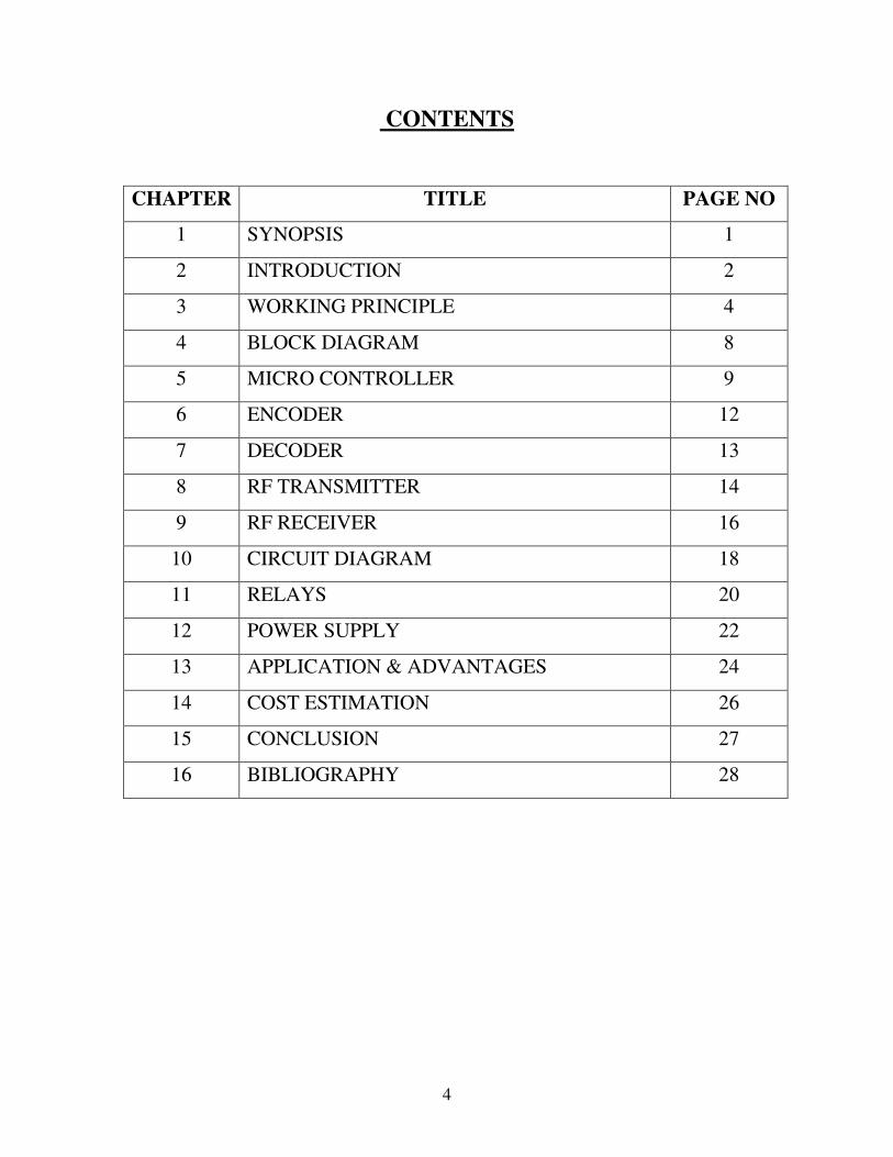
CONTENTS
CHAPTER TITLE PAGE NO
1 SYNOPSIS 1
2 INTRODUCTION 2
3 WORKING PRINCIPLE 4
4 BLOCK DIAGRAM 8
5 MICRO CONTROLLER 9
6 ENCODER 12
7 DECODER 13
8 RF TRANSMITTER 14
9 RF RECEIVER 16
10 CIRCUIT DIAGRAM 18
11 RELAYS 20
12 POWER SUPPLY 22
13 APPLICATION & ADVANTAGES 24
14 COST ESTIMATION 26
15 CONCLUSION 27
16 BIBLIOGRAPHY 28
5
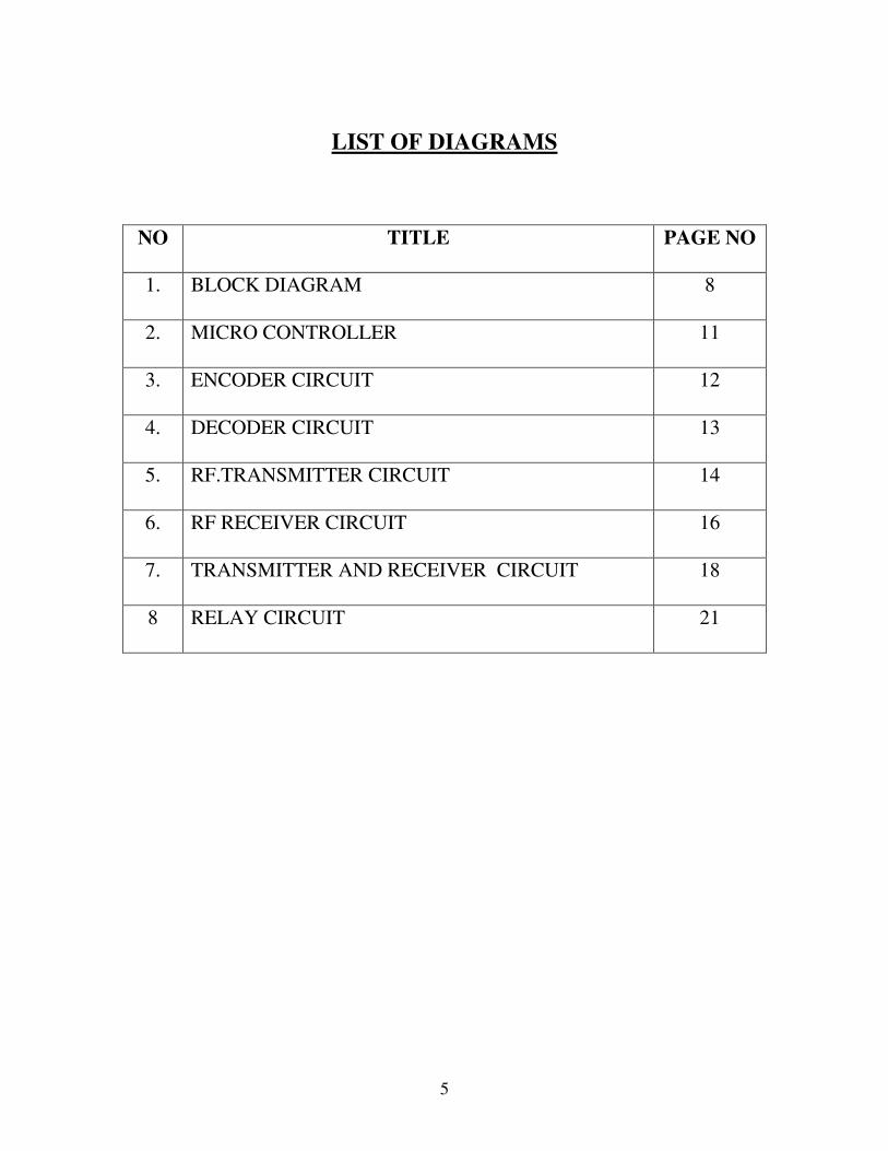
LIST OF DIAGRAMS
NO TITLE PAGE NO
1. BLOCK DIAGRAM 8
2. MICRO CONTROLLER 11
3. ENCODER CIRCUIT 12
4. DECODER CIRCUIT 13
5. RF.TRANSMITTER CIRCUIT 14
6. RF RECEIVER CIRCUIT 16
7. TRANSMITTER AND RECEIVER CIRCUIT 18
8 RELAY CIRCUIT 21
6
SYNOPSIS
The project titled “AUTOMATIC RAILWAY TRACK CONTROL”
is based on Micro controller 89c51 for track changing in railways.
Presently track changing is done manually or with the help of
motors.Due to this, manual errors may take place. To overcome this
problem, automation in track changing is done.In this project the command
given by the system (magnet) is encoded by a micro controller and transmits
via Radio Freqency transmitter.The system placed near the track receives the
data and decodes it using another micro controller and decoder. This micro
controller will activate the corresponding relay according to the program and
the motor works.Limit switches are used to stop the motor.
7
INTRODUCTION
The project “AUTOMATIC RAILWAY TRACK CONTROL’ is
aimed at providing full automation of railways. Also to provide secured
railway transportation.
The main components are
1. Micro controller
2. Encoder
3. Decoder
4. Radio Frequency transmitter
5. Radio Frequency receiver
6. Limit switches
7. DC motor
8. Magnetic sensor
MICRO CONTROLLER
The micro controller used is of 89c51 series. The main feature
of 89c51 micro controller is that it has a 8 Bit CPU optimized for control
application. Also it has a bi-directional and individually addressable I/O
lines.
ENCODER
Encoder is a combinational logic circuit that performs reverse
encoder function. It accepts an active level on one of its input and produce
an output code.

8
DECODER
Decoder is a logic circuit that accepts sets of inputs that
represents a binary number and activates only the output that corresponds to
that input number.
RF TRANSMITTER
The RF transmitter transmits the received signal to the receiver
circuit placed near the track changer. The range of this transmitter lies
between 100 to500 meters.
RF RECEIVER
It receives the signal from the transmitter.
LIMIT SWITCHES
Limits switches are used to stop the running motor.
The need of this project is to avoid manual errors in track
changing. The magnetic sensor placed on the track activates the RF
transmitter. The transmitter in turn sends the signal from the train to the
system placed near the track changer. The system decodes and transmits the
signal to the micro controller and the micro controller activates the relay
switches there by the motor works and the track changes. This concept can
be directly applied to the real track system.
9
WORKING PRINCIPLE
The project Automatic Wireless Railway track control is mainly
based on micro controller 89c51. As the name suggests it is concerned with
automatic changing of railway track.
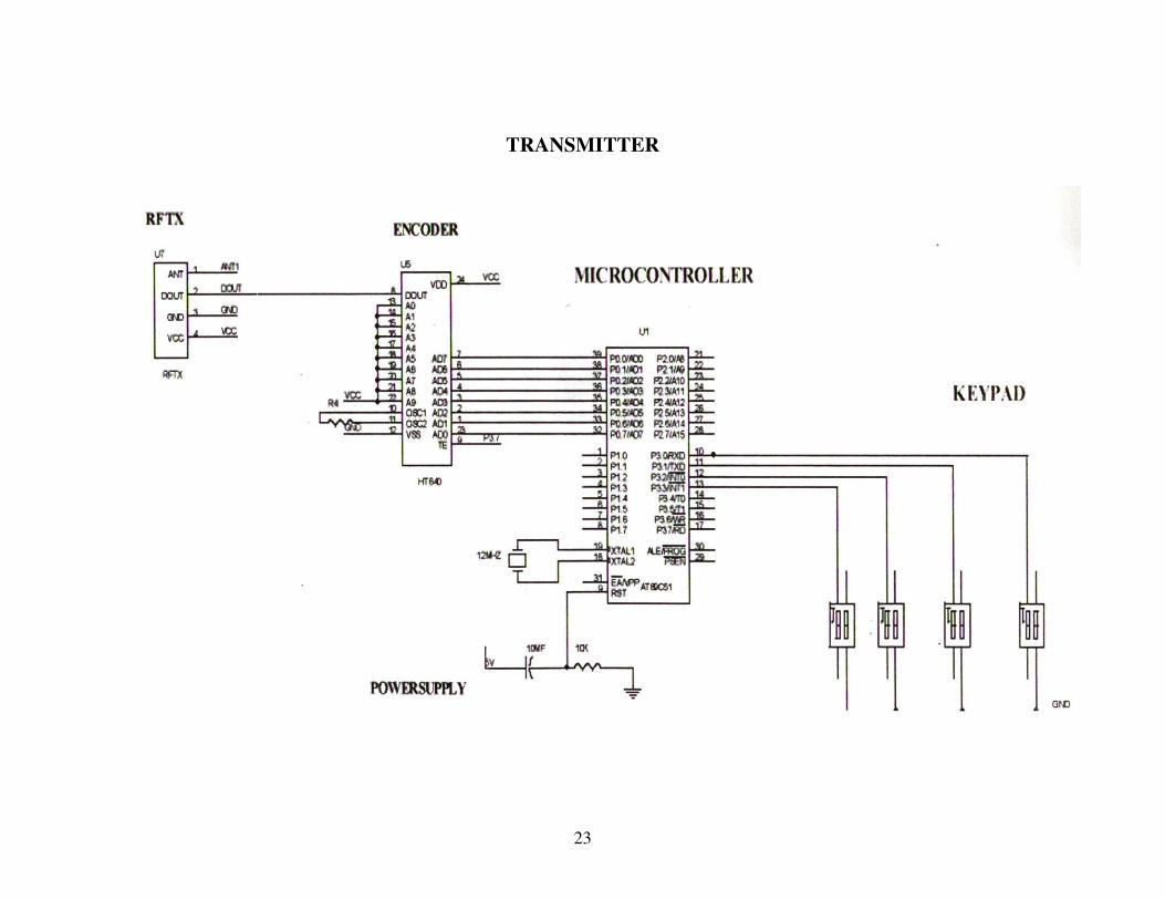
Here there are two circuits; one of them is located on the train
and the other one near the place of track change. The circuit on train consists
of a micro controller, encoder, and an ‘RF’ transmitter. The consists various
codes for different trains. These codes are transmitted to the micro
controller. The micro controller sends these codes to the encoder, which
converts it into digital form. These digital signals are transmitted to another
circuit placed near the track by and ‘RF’ transmitter.
The circuit placed near the track consists of ‘RF’ receiver,
decoder, limit switches, micro controller, relay drivers and a motor. The
‘RF’ receivers receive the digital datas sent by the train and transmit it to
the decoder, which decodes the codes into analog form. These codes are
then fed to the micro controller. The micro controller controls the relay
drivers to drive the motors. The limits switches are provided to control the
DC motor.

10
PROGRAM
// controlling a stepper motor
#include <stdio.h> //
#include <reg420.h> //
#include <ctype.h> //
#include "serial.h"
void main()
char o;
int i;
InitSerialHardware();
do
o = getchar();
if(isspace(o)) continue;
o = toupper(o);
if(o == 'S')
puts(" Stop");
P1 = 0;
11
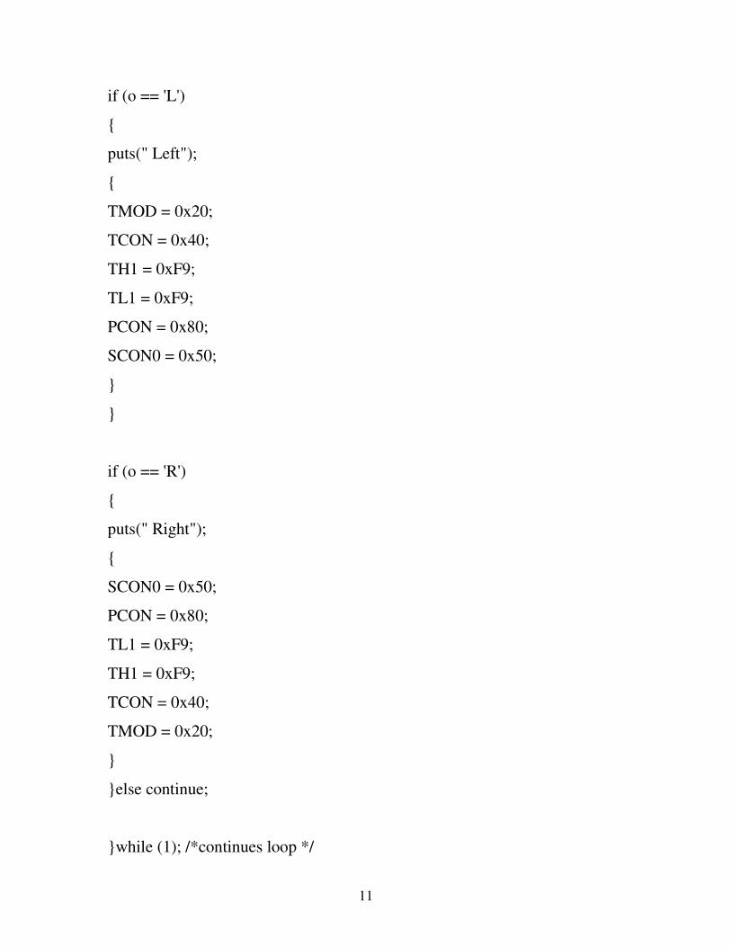
if (o == 'L')
puts(" Left");
TMOD = 0x20;
TCON = 0x40;
TH1 = 0xF9;
TL1 = 0xF9;
PCON = 0x80;
SCON0 = 0x50;
if (o == 'R')
puts(" Right");
SCON0 = 0x50;
PCON = 0x80;
TL1 = 0xF9;
TH1 = 0xF9;
TCON = 0x40;
TMOD = 0x20;
else continue;
while (1); /*continues loop */

12
printf("a"); // transmit a along with CR & LF.
For stopping the motor
if(o == 'S')
puts(" Stop");
P1 = 0;
goto exit; //put this label at the end of program with a while(1) loop.
//before the last braces of main function
exit:
while(1);
//this will stop
13
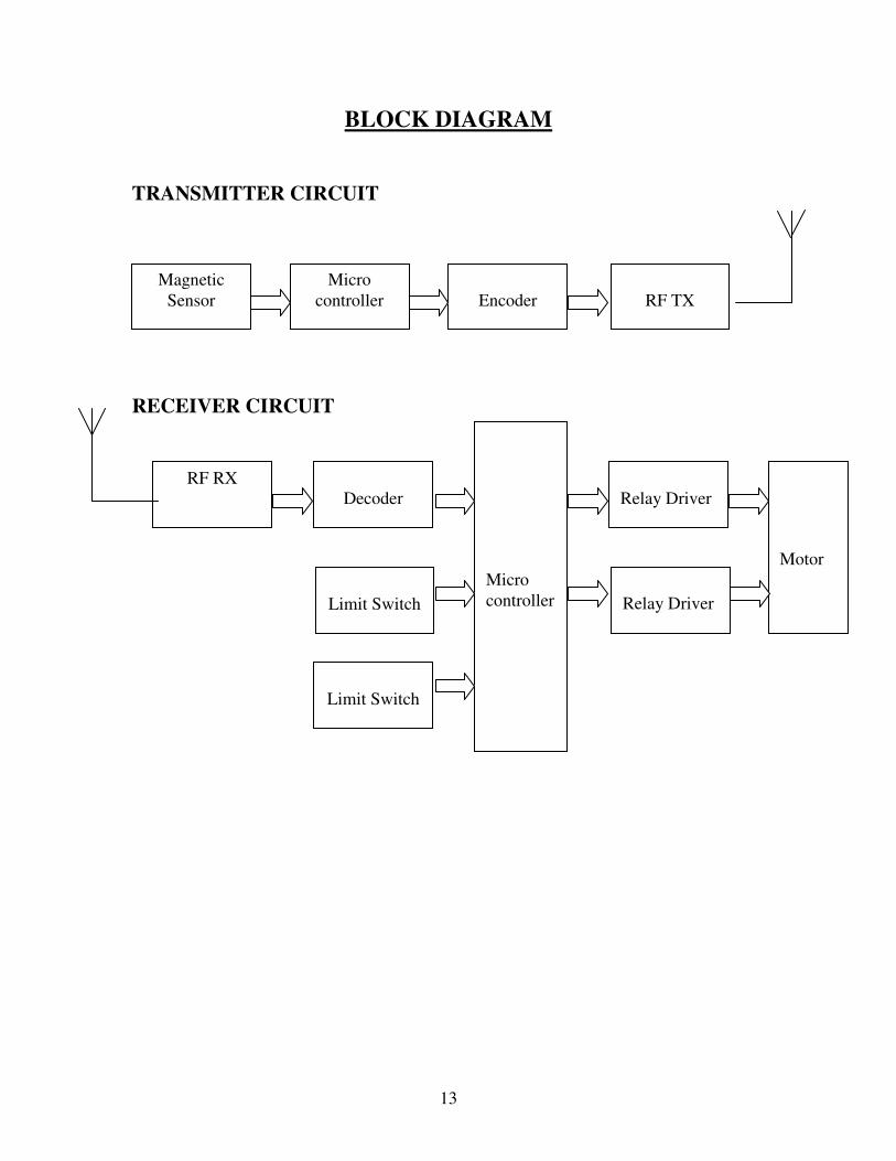
BLOCK DIAGRAM
TRANSMITTER CIRCUIT
RECEIVER CIRCUIT
Magnetic
Sensor
Micro
controller
Encoder
RF TX
RF RX
Decoder
Limit Switch
Limit Switch
Relay Driver
Relay Driver
Micro
controller
Motor
14
MICRO CONTROLLER
INTRODUCTION
A Micro Controller consists of a powerful CPU tightly coupled with
memory RAM, ROM, or EPROM, various I/O features such as Serial
ports, Parallel Ports, Timer/ Counters, Interrupt Controller, Data
Acquisitions interfaces- Analog to Digital Converter (ADC), Digital to
Analog Converter (ADC), everything integrated onto a single Silicon Chip.
It does not mean that any micro controller should have al the above
said features on chip, Depending on the need and area of application for
which it is designed. The on chip features present in it may or may not
include all the individual section said above.
Any microcomputer system requires memory to store a sequence of
instructions making up a program, parallel port or serial port for
communicating with an external system, timer/ counter for control purpose
like generating time delays, Baud rate for the serial port, apart from the
controlling unit called the Central Processing Unit.
15
ADVANTAGES OF MICROCONTROLLERS
1. If a system is developed with a microprocessor, the designer has to
go for external memory such as RAM, ROM or EPROM and
peripherals and hence the size of the PCB will be large enough
to hold all the required peripherals . But, the micro controller has got all
these peripheral facilities on a single chip so development of a similar
system with a micro controller reduces PCB size and cost of the design.
One of the major differences between a micro controller and a
microprocessor is that a controller often deals with bits, not bytes as in the
real world application, for example switch contacts can only be open or
close, indicators should be lit or dark and motors can be either turned on or
off and so forth.
INTRODUCTION TO ATMEL MICROCONTROLLER
SERIES : 89C51 Family, TECHNOLOGY: CMOS
The major Features of 8- bit Micro controller ATMEL 89C51:
• 8 Bit CPU optimized for control applications
• Extensive Boolean processing (Single – bit Logic ) capabilities
• On- Chip Flash Program Memory
• On- Chip Data RAM
• Bi- directional and Individually Addressable I/O Lines
• Multiple 16- Bit timer / Counters
• Full Duplex UART

16
• Multiple Source/ Vector/ Priority Interrupt Structure
• On- Chip Oscillator and clock circuitry.
• On- Chip EEPROM
• SPI Serial Bus Interface
• Watch Dog Timer
MICROCONTROLLER CIRCUIT

17
ENCODER
An encoder is a combinational logic circuit that performs reverse
decoder function and encoder accepts an active level on one of its input and
produce an output code.
An encoder has a number of input lines only one of which is activated
at a given time and produces an N bit output code depending on which input
is activated.

18
DECODER
A decoder is a logic circuit that accepts sets of inputs that represents a
binary number and activates only the output that corresponds to that input
number. In other words decoder looks at its input and determines which
binary number is present there and activities the one output that corresponds
to that number all other output remains deactivate.
19
RF TRANSMITTER
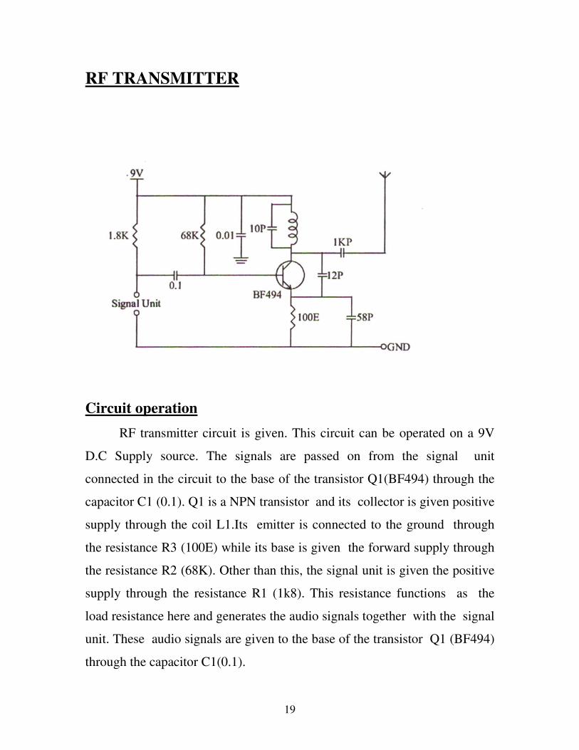
Circuit operation
RF transmitter circuit is given. This circuit can be operated on a 9V
D.C Supply source. The signals are passed on from the signal unit
connected in the circuit to the base of the transistor Q1(BF494) through the
capacitor C1 (0.1). Q1 is a NPN transistor and its collector is given positive
supply through the coil L1.Its emitter is connected to the ground through
the resistance R3 (100E) while its base is given the forward supply through
the resistance R2 (68K). Other than this, the signal unit is given the positive
supply through the resistance R1 (1k8). This resistance functions as the
load resistance here and generates the audio signals together with the signal
unit. These audio signals are given to the base of the transistor Q1 (BF494)
through the capacitor C1(0.1).

20
The coil L1 connected at its collector can be made by giving 5 turns
of 24 SWG wire on a base of 0.5 cm diameter. A capacitor C3 (12pf) has
also been connected between the collector and the emitter of the transistor
Q1. This capacitor triggers the oscillations. As soon as the audio signal is
received at the base then the transistor starts to oscillate and it generates
Radio frequency, which is given to the antenna through the capacitor C4
(1kpf ) and transmitted. The range of this transmitter lies between
100meters to 500 meters.

21
RF RECIEVER
Circuit Operation
IC CxA1019S is 30-pin DIL IC manufactured by Sony, Facility to
connect a tuning indicator has also been provided in this IC apart from the
various sections built within the IC. A 10.7MHz ceramic filter has been used
in this circuit in place of the IFTs. This is a single chip AM/FM Radio IC.
An audio output section is also built within the IC apart from all the
necessary sections for the AM/FM radio. The signal at the IC pin no.24 is
given to the pin-1 of the volume control and the pin 2 of the volume control
is connected to the audio output section. This section is not shown in the
given circuit.
The IC pin no.27 is the positive supply pin, which is given +6V
supply through a resistance R4 (56E). This supply is filtered by the
capacitor C1 (1000MF/16V). IC pin no.7 &8 are connected to the oscillator
section and a coil L1 is connected at the pin no.8. A capacitor C3 (39PF) and
22
a button trimmer B1 (15pf) are connected parallel to this coil L1. This
trimmer selects the desired frequency. RF coil L2 is connected at the IC pin
no.10 and a capacitor C7 (33pf) and a button trimmer B2(15pf) are
connected in parallel to this coil.
IC pin no.9 is the RF ground pin. RF coils, the oscillator and the
related components are all connected at this pin. Antenna coil L3 is
connected at the IC pin.no.13 through a capacitor C9 (lkpf) and a capacitor
C10 (27pf) is connected in parallel to this coil. A telescopic antenna is
connected from the center point of the capacitor C9 and coil L3. Tuning
indicator LED is connected to it for filtration. Positive supply is given to the
anode of the LED through a resistance R3 (920E). The IC pin no.
1,2,3,4,5,12,14,19,21 and 30 are the dc ground pins. IC pin no.9 is the RF
ground pin.
23
TRANSMITTER

24
RECEIVER
R.F. RECEIVER
25
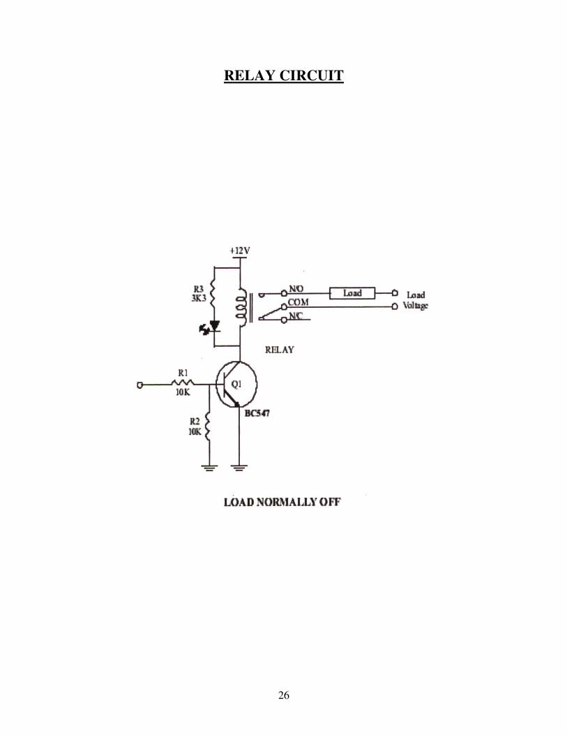
RELAYS
A relay is a switch worked by an electromagnet. It is useful if we want
a small current in one circuit to control another circuit containing a device
such as a lamp or electric motor which requires a large current, or if we
wish several different switch contacts to be operated simultaneously.
When the controlling current flows through the coil, the soft iron core
is magnetized and attracts the Lo shaped soft iron armature .This rocks on
its pivot and opens, closes or changes over, the electrical contacts in the
circuit being controlled it closes the contacts.
The current needed to operate a relay is called the pull- in current and
the dropout current in the coil when the relay just stops working. If the coil
resistance R of a relay is 185Ω and its operating voltage V is 12V, the pull-
in current I is given by:
I = V = 12 =0.065A= 65mA
R 185
26
RELAY CIRCUIT

27
POWER SUPPLIES
The ac voltage, typically 220V rms, is connected to a transformer,
which steps that ac voltage down to the level of the desired dc output. A
diode rectifier then provides a full- wave rectified voltage that is initially
filtered by a simple capacitor filter to produce a dc voltage. This resulting dc
voltage usually has some ripple or ac voltage variation.
A regulator circuit removes the ripples and also remains the same dc
value even if the input dc voltage varies, or the load connected to the output
dc voltage changes. This voltage regulation is usually obtained using one of
the popular voltage regulator IC units.

28
+5V POWER SUPPLY

29
APPLICATION
1. It can be used at major railway crossings
2. It can be applied were there is an heavy rail traffic
3. Can be made as an integral part of metro railways.
4. Can be made as a part of complete automation & modernization of
railway system.
ADVANTAGES
1. Reduction of railway accidents.
2. Avoid manual error in track changing
3. Reduction of reasonable delay in train timings
4. Less cost of manufacturing & more accurate in function .
30
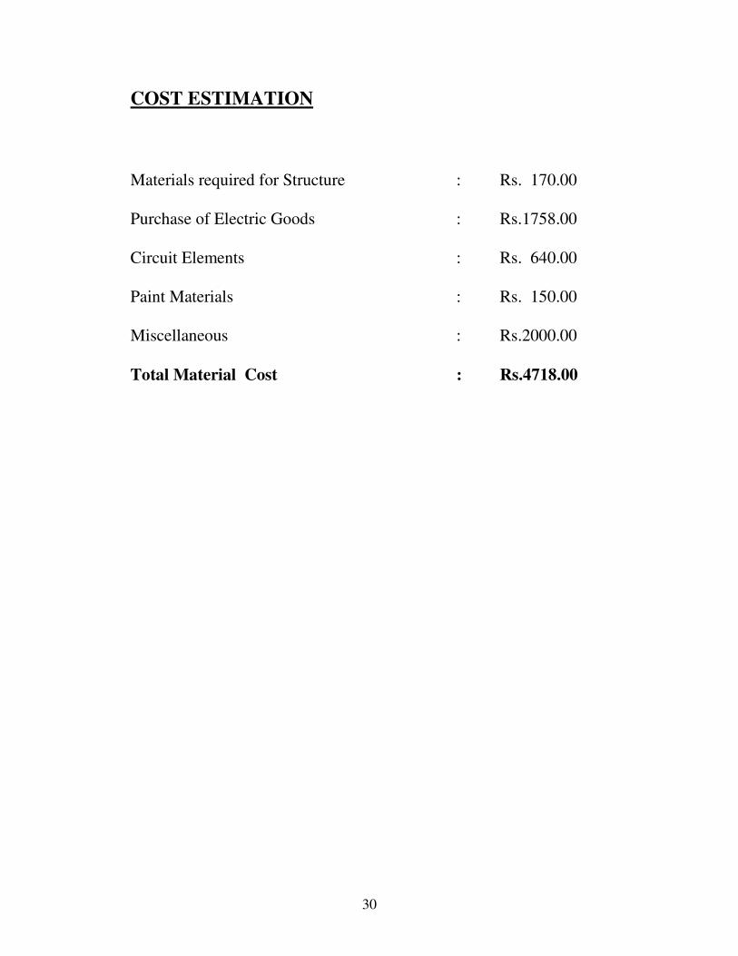
COST ESTIMATION
Materials required for Structure : Rs. 170.00
Purchase of Electric Goods : Rs.1758.00
Circuit Elements : Rs. 640.00
Paint Materials : Rs. 150.00
Miscellaneous : Rs.2000.00
Total Material Cost : Rs.4718.00

31
ESTIMATION OF LABOUR COST
Soldering : Rs.20.00
Cutting : Rs.20.00
Drilling : Rs.50.00
Welding : Rs.50.00
Painting : Rs.60.00
Assembling : Rs.200.00
Table Labour Cost : Rs.400.00
Total Cost : Cost Estimation + Labour Cost
: 4718 +400
: Rs.5118.00
32
CONCLUSION
Thus this project has tremendous potential in the field of rail
transportation. By this project we can ensure safe journey for the
passengers. This project can be modified easily and has great
potential for up
gradation.
FUTURE ENHANCEMENTS
The system can be used operate multiple tracks. We can increase
the range of signal transmission .This system can be also be used to
record the information of train passed. Alarm signals can be in
planted.

33
BIBLIOGRAPHY
REFERENCE BOOKS
1. Electronic Circuits: fundamentals applications by Mike Tony
2. Power electronics by S.K.Raja
3. Encoders and Decoders by Carl James
4. PSG design data book
WEBSITES
1. Wikipedia.org
2. Microcontroller.com
3. Atmel.com
Related Documents