IEEE TRANSACTIONS ON INDUSTRIAL ELECTRONICS, VOL. 57, NO. 12, DECEMBER 2010 4065 Analysis and Compensation of Inverter Nonlinearity Effect on a Sensorless PMSM Drive at Very Low and Zero Speed Operation Reiko Raute, Member, IEEE, Cedric Caruana, Member, IEEE, Cyril Spiteri Staines, Member, IEEE, Joseph Cilia, Mark Sumner, Senior Member, IEEE, and Greg M. Asher, Fellow, IEEE Abstract—It has been well established in the literature that in- verter nonlinearity effects afflict saliency-based sensorless drives. The inverter nonlinearity leads to the generation of signals that corrupt the useful position information. The resulting effect dif- fers depending on the injection approach utilized in the drive. Various compensation techniques to overcome this effect have been published in the literature. This paper is concerned with the zero-vector current-derivative technique. The effect of the varying ON-state resistance of the inverter power devices on the position signal is investigated in detail. Knowledge of the source of the corrupting signals facilitates compensation and determines its applicability. Two approaches for inverter nonlinearity compen- sation are compared. The first approach utilizes a lookup table from offline-processed data, while the second one is a simpler ap- proach based on the current-dependent resistance characteristic of the inverter switching devices. Experimental performance under sensorless condition is shown for both approaches. Index Terms—Inverter nonlinearity, permanent-magnet ma- chines, saliency, sensorless control. I. I NTRODUCTION I N THE PAST decades, many sensorless control methods have been reported [1], [2]. The techniques are based on either fundamental machine models [3]–[6], continuous high- frequency injection [7]–[15] or transient voltage injections [16]–[21]. In many cases, disturbances attributed to inverter nonlinear- ity were observed. Mostly, the switching dead-time effect and current clamping were tackled as major problems in sensorless schemes [9], [10]. However, also the voltage drop over the inverter switching devices can cause considerable effects as confirmed in [3] for a model-based technique. This effect can be taken into account by approximating the inverter’s semiconduc- tor voltage–current curve [3], [4]. Reference [22] reports that Manuscript received November 1, 2008; revised February 16, 2009, August 15, 2009, and November 6, 2009; accepted February 2, 2010. Date of publication March 1, 2010; date of current version November 10, 2010. This work was supported by the European Commission under a Marie Curie Research Training Network for realizing this work under the MEST-CT-2004- 504243 Research Project. R. Raute, C. Caruana, C. Spiteri Staines, and J. Cilia are with the Faculty of Engineering, University of Malta, MSD 2080 Msida, Malta (e-mail: cccaru@ eng.um.edu.mt). M. Sumner and G. M. Asher are with the Faculty of Engineer- ing, The University of Nottingham, NG7 2RD Nottingham, U.K. (e-mail: [email protected]). Color versions of one or more of the figures in this paper are available online at http://ieeexplore.ieee.org. Digital Object Identifier 10.1109/TIE.2010.2044116 this voltage drop can also be included into a sensorless control scheme using artificial neural networks. The zero-vector current-derivative (ZVCD) technique for permanent-magnet synchronous machines (PMSMs) has been proposed in [23]. The technique utilizes the derivative of the stator currents during the zero-voltage vectors without addi- tional test signal injection. The current derivative portrays infor- mation from both back electromotive force (EMF) and saliency effects, leading to the extraction of the rotor flux position information. This sensorless technique avoids several disad- vantages compared to injection-based methods, i.e., additional losses, torque ripple, electromagnetic compatibility problems, and excessive audible noise. It was observed in [23] that, apart from the rotor flux position information, a disturbing signal repeating with every commu- tation sector is present in the ZVCD signals. The inverter nonlinearity, particularly the current-dependent voltage drop across the power devices, is suspected to be the main cause of the modulation [24]. This paper investigates the effect of the varying ON-state resistance of the switching devices on the resulting position tracking. The effect is simulated using a simplified inverter model. Comparison of the predicted effect with experimental measurements corroborates the source of the corrupting signal. Two approaches for the compensation of the inverter nonlinearity effect are compared. The first ap- proach utilizes offline-processed experimental data stored in a lookup table (LUT), while the second approach approximates the compensation signal from the inverter switching devices’ ON-state resistance characteristic. Experimental results for both approaches are presented, and their efficacy is compared. II. ZVCD TECHNIQUE The machine stator voltage equations are given by v d = Ri d + L d di d dt − L q ωi q v q = Ri q + L q di q dt + L d ωi d + k e ω. (1) R is the stator resistance, L d and L q are the leakage in- ductances in the respective frames, ω is the rotor frequency, and k e represents the back-EMF constant. The inductance parameters are different due to the machine saliency, caused by the mechanical rotor construction and/or magnetic saturation. Under the application of the zero-voltage vector during the 0278-0046/$26.00 © 2010 IEEE

Welcome message from author
This document is posted to help you gain knowledge. Please leave a comment to let me know what you think about it! Share it to your friends and learn new things together.
Transcript
IEEE TRANSACTIONS ON INDUSTRIAL ELECTRONICS, VOL. 57, NO. 12, DECEMBER 2010 4065
Analysis and Compensation of Inverter NonlinearityEffect on a Sensorless PMSM Drive at Very
Low and Zero Speed OperationReiko Raute, Member, IEEE, Cedric Caruana, Member, IEEE, Cyril Spiteri Staines, Member, IEEE,
Joseph Cilia, Mark Sumner, Senior Member, IEEE, and Greg M. Asher, Fellow, IEEE
Abstract—It has been well established in the literature that in-verter nonlinearity effects afflict saliency-based sensorless drives.The inverter nonlinearity leads to the generation of signals thatcorrupt the useful position information. The resulting effect dif-fers depending on the injection approach utilized in the drive.Various compensation techniques to overcome this effect havebeen published in the literature. This paper is concerned withthe zero-vector current-derivative technique. The effect of thevarying ON-state resistance of the inverter power devices on theposition signal is investigated in detail. Knowledge of the source ofthe corrupting signals facilitates compensation and determines itsapplicability. Two approaches for inverter nonlinearity compen-sation are compared. The first approach utilizes a lookup tablefrom offline-processed data, while the second one is a simpler ap-proach based on the current-dependent resistance characteristic ofthe inverter switching devices. Experimental performance undersensorless condition is shown for both approaches.
Index Terms—Inverter nonlinearity, permanent-magnet ma-chines, saliency, sensorless control.
I. INTRODUCTION
IN THE PAST decades, many sensorless control methodshave been reported [1], [2]. The techniques are based on
either fundamental machine models [3]–[6], continuous high-frequency injection [7]–[15] or transient voltage injections[16]–[21].
In many cases, disturbances attributed to inverter nonlinear-ity were observed. Mostly, the switching dead-time effect andcurrent clamping were tackled as major problems in sensorlessschemes [9], [10]. However, also the voltage drop over theinverter switching devices can cause considerable effects asconfirmed in [3] for a model-based technique. This effect can betaken into account by approximating the inverter’s semiconduc-tor voltage–current curve [3], [4]. Reference [22] reports that
Manuscript received November 1, 2008; revised February 16, 2009,August 15, 2009, and November 6, 2009; accepted February 2, 2010. Dateof publication March 1, 2010; date of current version November 10, 2010.This work was supported by the European Commission under a Marie CurieResearch Training Network for realizing this work under the MEST-CT-2004-504243 Research Project.
R. Raute, C. Caruana, C. Spiteri Staines, and J. Cilia are with the Faculty ofEngineering, University of Malta, MSD 2080 Msida, Malta (e-mail: [email protected]).
M. Sumner and G. M. Asher are with the Faculty of Engineer-ing, The University of Nottingham, NG7 2RD Nottingham, U.K. (e-mail:[email protected]).
Color versions of one or more of the figures in this paper are available onlineat http://ieeexplore.ieee.org.
Digital Object Identifier 10.1109/TIE.2010.2044116
this voltage drop can also be included into a sensorless controlscheme using artificial neural networks.
The zero-vector current-derivative (ZVCD) technique forpermanent-magnet synchronous machines (PMSMs) has beenproposed in [23]. The technique utilizes the derivative of thestator currents during the zero-voltage vectors without addi-tional test signal injection. The current derivative portrays infor-mation from both back electromotive force (EMF) and saliencyeffects, leading to the extraction of the rotor flux positioninformation. This sensorless technique avoids several disad-vantages compared to injection-based methods, i.e., additionallosses, torque ripple, electromagnetic compatibility problems,and excessive audible noise.
It was observed in [23] that, apart from the rotor flux positioninformation, a disturbing signal repeating with every commu-tation sector is present in the ZVCD signals. The inverternonlinearity, particularly the current-dependent voltage dropacross the power devices, is suspected to be the main causeof the modulation [24]. This paper investigates the effect ofthe varying ON-state resistance of the switching devices onthe resulting position tracking. The effect is simulated using asimplified inverter model. Comparison of the predicted effectwith experimental measurements corroborates the source ofthe corrupting signal. Two approaches for the compensationof the inverter nonlinearity effect are compared. The first ap-proach utilizes offline-processed experimental data stored in alookup table (LUT), while the second approach approximatesthe compensation signal from the inverter switching devices’ON-state resistance characteristic. Experimental results for bothapproaches are presented, and their efficacy is compared.
II. ZVCD TECHNIQUE
The machine stator voltage equations are given by
vd =Rid + Lddiddt
− Lqωiq
vq =Riq + Lqdiqdt
+ Ldωid + keω. (1)
R is the stator resistance, Ld and Lq are the leakage in-ductances in the respective frames, ω is the rotor frequency,and ke represents the back-EMF constant. The inductanceparameters are different due to the machine saliency, caused bythe mechanical rotor construction and/or magnetic saturation.Under the application of the zero-voltage vector during the
0278-0046/$26.00 © 2010 IEEE
4066 IEEE TRANSACTIONS ON INDUSTRIAL ELECTRONICS, VOL. 57, NO. 12, DECEMBER 2010
Fig. 1. Definition of the estimated dqe frame for the ZVCD technique.
standard space vector pulsewidth modulation (PWM) cycle, thevoltages vd and vq are set to zero. Imposing the zero-voltage-vector condition on (1) and rearranging terms to consider thecurrent derivatives lead to
did0
dt= − R
Ldid0 +
Lq
Ldωiq0
diq0dt
= − R
Lqiq0 −
Ld
Lqωid0 −
keω
Lq. (2)
Equation (2) reveals two different time constants for the re-spective frame currents dependent on the difference betweenLd and Lq. The id0 and iq0 currents can be expressed as therespective id and iq plus respective ripples. The ripples areexpected to be small; hence, id0 and iq0 are approximated by idand iq in subsequent equations. Equation (2) only applies in thereal dq frame, which is not known under sensorless operation.Under sensorless operation, an estimated rotor flux frame dqe isassumed, misaligned from the real dq frame by the angle λerr.The drive current is imposed into the qe-direction, and thus, thevector controller is set to force ied to zero, as shown in Fig. 1.The respective ZVCD in the de-axis, assuming that ied is forcedto zero, is given by (3).
It can be seen that died0/dt depends on a saliency term, across-coupling term, a back EMF, and a dynamic component.As the saliency term and the back-EMF term are proportionalto sin(2λerr) and sin(λerr), respectively, they both provideinformation on the position error between the estimated dqe andactual dq frames. Assuming small λerr and that the estimatedrotor speed ωe is approximately the real rotor speed ω, thedied0/dt term can be simplified, as shown in (4), for no steady-state error
died0
dt=−R
2
(1Lq
− 1Ld
)sin(2λerr)ieq︸ ︷︷ ︸
Saliency
+(
Lq
Ld+
(Ld
Lq−Lq
Ld
)sin2(λerr)
)ω ieq︸ ︷︷ ︸
Cross coupling
− keω
Lqsin(λerr)︸ ︷︷ ︸
BackEMF
+ ieqdλerr
dt︸ ︷︷ ︸Dynamic
(3)
died0
dt−Lq
Ldωe ieq ≈−
(R
2
(1Lq
− 1Ld
)ieq+
keω
Lq
)λerr. (4)
Equation (4) shows that, under correct orientation (λerr = 0),the ZVCD in the de-axis is given by (Lq/Ld)ωeieq. This isin agreement with the zero-vector d-axis current derivative in(2) assuming zero id. A phase-locked loop (PLL) structure is
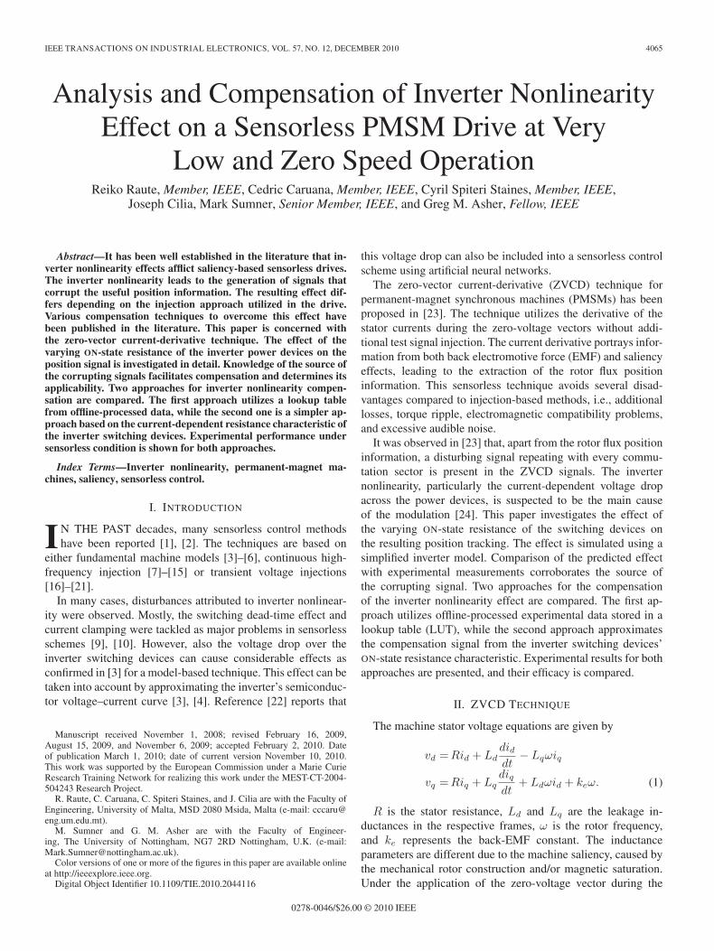
Fig. 2. Rotor position estimator showing the PLL structure used for the ZVCDtechnique.
used to force the error between the measured and the predicteddid0/dt to zero, thereby locking the dqe frame to the realdq frame. The rotor position estimator is shown in Fig. 2.Depending on the machine parameters, the (Lq/Ld)ωeieq termcan be small and hence negligible. It is neglected in thisimplementation.
The position error signal (died0/dt) is obtained either throughthe difference between successive samples or through a ded-icated current-derivative sensor, as explained in more detailin Section III. The polarity of the position error signal hasto be adjusted according to the quadrant of operation as itsterms depend on ieq and ω, respectively, as shown in (4). Thisis indicated by the error signal polarity block in Fig. 2. Theoutput of the tracking proportional–integral (PI) controller isintegrated to obtain the estimated rotor position λe that canbe used to transform the variables for vector control undersensorless operation. The PI controller output is the estimatedrotor speed ωe, which is also low-pass filtered to obtain a(filtered) speed estimate ωe
F . As a consequence of the changein polarity with the operating quadrant, the saliency and theback-EMF terms in the position error factor can be additiveor opposing, depending on the quadrant of operation and themachine Ld and Lq parameters. For the cases where the termsare opposing, at very low speed, the saliency signal is dominat-ing and can give enough information for the position tracking,and at above a certain speed, the back-EMF effect is muchstronger than the saliency. There will be only a small operationregion in the two quadrants of operation (both motoring or bothgenerating, depending on the machine inductance parameters)which the proposed scheme does not cover. In all other regions,the dominating effect needs to be known and the error inputsign accordingly selected [25].
III. IMPLEMENTATION
The machine under test, whose parameters are given in theAppendix, is a 4.4-kW Yaskawa PMSM with a segmentedstator design. It is coupled to a dc machine as a mechanicalload. The ac drive is a commercial inverter interfaced withexternally generated PWM switching signals. No dead-timecompensation strategy is implemented. There are basically twooptions for calculating the current derivative required for theposition error signal. The current derivative can be calculatedfrom two consecutive current samples taken during the samezero-voltage vector by the fundamental current transducers. In
RAUTE et al.: ANALYSIS AND COMPENSATION OF INVERTER NONLINEARITY EFFECT 4067
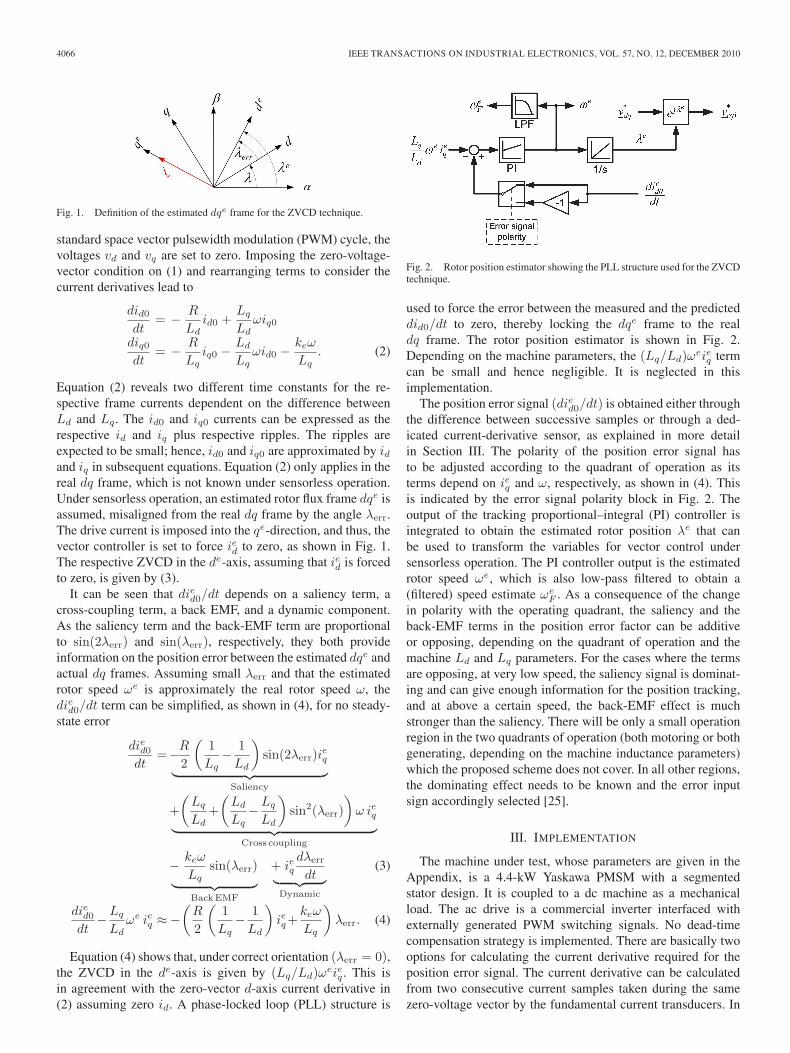
Fig. 3. Discrete current sampling instances as synchronized to the fundamen-tal PWM voltage waveforms.
this way, given sufficient zero-voltage-vector duration, a usableΔi/Δt ≈ di/dt signal can be obtained at no extra cost. Thecurrent derivatives can also be directly measured by dedicateddi/dt sensors, as used in [18]–[21], allowing operation witha shorter duration zero-voltage vector. In each case, sufficienttime has to be allowed before sampling such that any high-frequency oscillations following switching settle [18]–[21]. Forthis case, the former option is utilized, using three standardHall effect transducers. The PWM switching frequency is keptsufficiently low, and the fundamental output voltage is limitedto ≈30% of rated as the technique is intended for low- andzero-speed operation. These measures ensure a sufficient zero-voltage-vector duration, even under transients. The current sam-pling instances with reference to the inverter PWM waveformsare shown in Fig. 3.
A relatively low PWM switching frequency of 3.75 kHz,which is also suitable for higher power drives, is used toprovide longer zero vectors. The experimental rig is equippedwith 16-b A/D converters for a precise current measurement toreduce noise in the differentiation process to a minimum. Thecurrents are sampled four times per PWM period, as indicatedin Fig. 3 by the vertical dashed lines numbered 1–4. Therefore,the duration of the successive current sampling is 67 μs. Thecurrent measurement occurs at least 20 μs delayed from the endof the last active voltage vector. This allows current oscillationsfollowing switching to settle and gives the current transducerstime to follow the current trend precisely. The current derivativeis computed for each zero-voltage vector. Thus, there are twoΔi0/Δt ≈ di0/dt measurements made in each PWM period.Samples 2 and 3 are used for calculating the current variationduring v111 (all motor phases connected to the positive dc-linkrail), and samples 1 and 4 of the previous PWM period areused for calculating the current variation during v000 (all phasesconnected to the negative dc rail). The two measurements perPWM period are then averaged to give the position error signal.
IV. INVERTER NONLINEARITY
A. Observed Signal
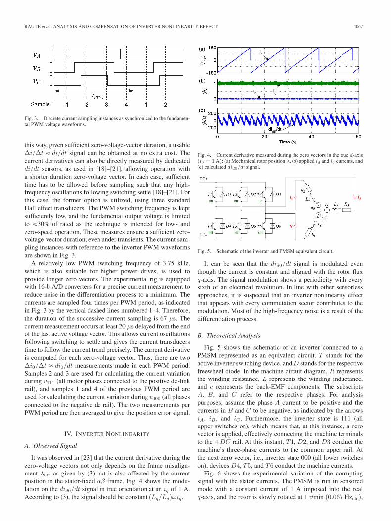
It was observed in [23] that the current derivative during thezero-voltage vectors not only depends on the frame misalign-ment λerr as given by (3) but is also affected by the currentposition in the stator-fixed αβ frame. Fig. 4 shows the modu-lation on the did0/dt signal in true orientation at an iq of 1 A.According to (3), the signal should be constant (Lq/Ld)ωiq .
Fig. 4. Current derivative measured during the zero vectors in the true d-axis(iq = 1 A): (a) Mechanical rotor position λ, (b) applied id and iq currents, and(c) calculated did0/dt signal.
Fig. 5. Schematic of the inverter and PMSM equivalent circuit.
It can be seen that the did0/dt signal is modulated eventhough the current is constant and aligned with the rotor fluxq-axis. The signal modulation shows a periodicity with everysixth of an electrical revolution. In line with other sensorlessapproaches, it is suspected that an inverter nonlinearity effectthat appears with every commutation sector contributes to themodulation. Most of the high-frequency noise is a result of thedifferentiation process.
B. Theoretical Analysis
Fig. 5 shows the schematic of an inverter connected to aPMSM represented as an equivalent circuit. T stands for theactive inverter switching device, and D stands for the respectivefreewheel diode. In the machine circuit diagram, R representsthe winding resistance, L represents the winding inductance,and e represents the back-EMF components. The subscriptsA, B, and C refer to the respective phases. For analysispurposes, assume the phase-A current to be positive and thecurrents in B and C to be negative, as indicated by the arrowsiA, iB , and iC . Furthermore, the inverter state is 111 (allupper switches on), which means that, at this instance, a zerovector is applied, effectively connecting the machine terminalsto the +DC rail. At this instant, T1, D2, and D3 conduct themachine’s three-phase currents to the common upper rail. Atthe next zero vector, i.e., inverter state 000 (all lower switcheson), devices D4, T5, and T6 conduct the machine currents.
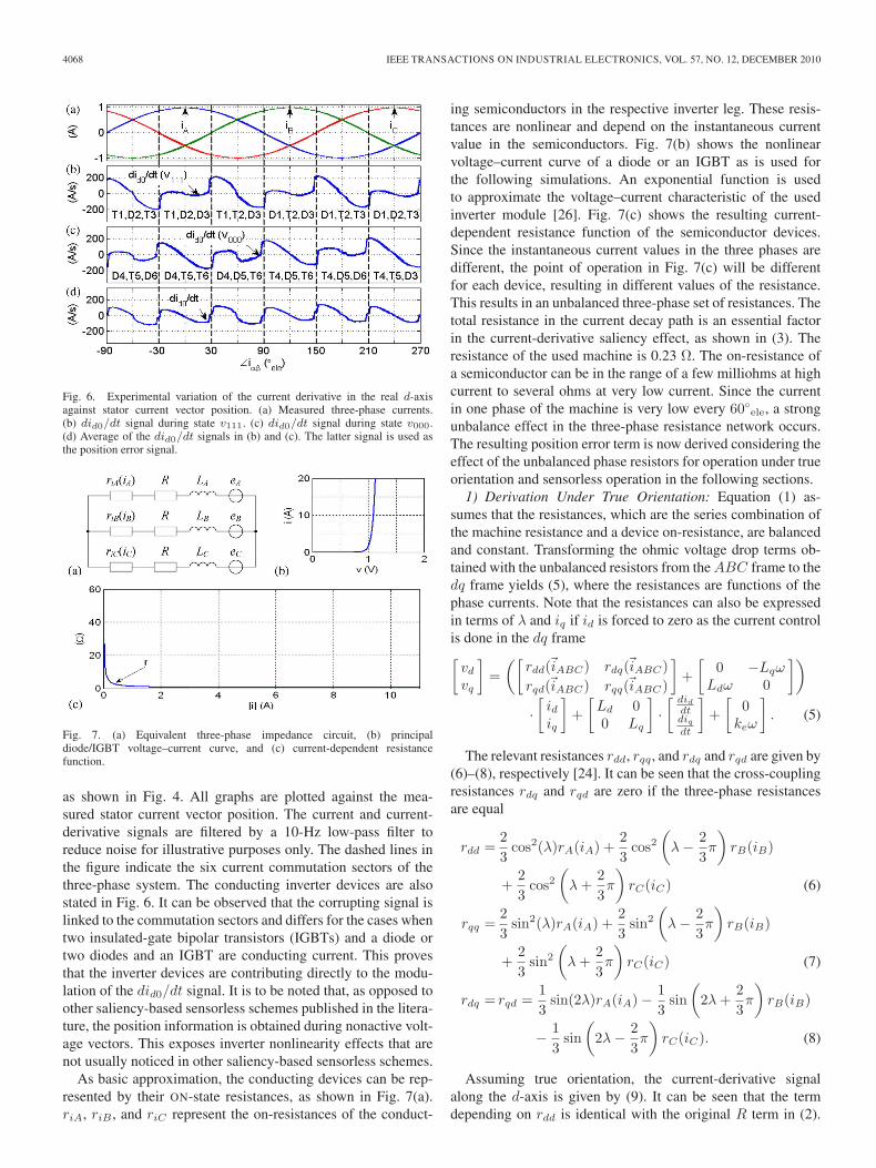
Fig. 6 shows the experimental variation of the corruptingsignal with the stator currents. The PMSM is run in sensoredmode with a constant current of 1 A imposed into the realq-axis, and the rotor is slowly rotated at 1 r/min (0.067 Hzele),
4068 IEEE TRANSACTIONS ON INDUSTRIAL ELECTRONICS, VOL. 57, NO. 12, DECEMBER 2010
Fig. 6. Experimental variation of the current derivative in the real d-axisagainst stator current vector position. (a) Measured three-phase currents.(b) did0/dt signal during state v111. (c) did0/dt signal during state v000.(d) Average of the did0/dt signals in (b) and (c). The latter signal is used asthe position error signal.
Fig. 7. (a) Equivalent three-phase impedance circuit, (b) principaldiode/IGBT voltage–current curve, and (c) current-dependent resistancefunction.
as shown in Fig. 4. All graphs are plotted against the mea-sured stator current vector position. The current and current-derivative signals are filtered by a 10-Hz low-pass filter toreduce noise for illustrative purposes only. The dashed lines inthe figure indicate the six current commutation sectors of thethree-phase system. The conducting inverter devices are alsostated in Fig. 6. It can be observed that the corrupting signal islinked to the commutation sectors and differs for the cases whentwo insulated-gate bipolar transistors (IGBTs) and a diode ortwo diodes and an IGBT are conducting current. This provesthat the inverter devices are contributing directly to the modu-lation of the did0/dt signal. It is to be noted that, as opposed toother saliency-based sensorless schemes published in the litera-ture, the position information is obtained during nonactive volt-age vectors. This exposes inverter nonlinearity effects that arenot usually noticed in other saliency-based sensorless schemes.
As basic approximation, the conducting devices can be rep-resented by their ON-state resistances, as shown in Fig. 7(a).riA, riB , and riC represent the on-resistances of the conduct-
ing semiconductors in the respective inverter leg. These resis-tances are nonlinear and depend on the instantaneous currentvalue in the semiconductors. Fig. 7(b) shows the nonlinearvoltage–current curve of a diode or an IGBT as is used forthe following simulations. An exponential function is usedto approximate the voltage–current characteristic of the usedinverter module [26]. Fig. 7(c) shows the resulting current-dependent resistance function of the semiconductor devices.Since the instantaneous current values in the three phases aredifferent, the point of operation in Fig. 7(c) will be differentfor each device, resulting in different values of the resistance.This results in an unbalanced three-phase set of resistances. Thetotal resistance in the current decay path is an essential factorin the current-derivative saliency effect, as shown in (3). Theresistance of the used machine is 0.23 Ω. The on-resistance ofa semiconductor can be in the range of a few milliohms at highcurrent to several ohms at very low current. Since the currentin one phase of the machine is very low every 60◦ele, a strongunbalance effect in the three-phase resistance network occurs.The resulting position error term is now derived considering theeffect of the unbalanced phase resistors for operation under trueorientation and sensorless operation in the following sections.
1) Derivation Under True Orientation: Equation (1) as-sumes that the resistances, which are the series combination ofthe machine resistance and a device on-resistance, are balancedand constant. Transforming the ohmic voltage drop terms ob-tained with the unbalanced resistors from the ABC frame to thedq frame yields (5), where the resistances are functions of thephase currents. Note that the resistances can also be expressedin terms of λ and iq if id is forced to zero as the current controlis done in the dq frame[
vd
vq
]=
([rdd(�iABC) rdq(�iABC)rqd(�iABC) rqq(�iABC)
]+
[0 −Lqω
Ldω 0
])
·[
idiq
]+
[Ld 00 Lq
]·[ did
dtdiq
dt
]+
[0
keω
]. (5)
The relevant resistances rdd, rqq, and rdq and rqd are given by(6)–(8), respectively [24]. It can be seen that the cross-couplingresistances rdq and rqd are zero if the three-phase resistancesare equal
rdd =23
cos2(λ)rA(iA) +23
cos2(
λ − 23π
)rB(iB)
+23
cos2(
λ +23π
)rC(iC) (6)
rqq =23
sin2(λ)rA(iA) +23
sin2
(λ − 2
3π
)rB(iB)
+23
sin2
(λ +
23π
)rC(iC) (7)
rdq = rqd =13
sin(2λ)rA(iA) − 13
sin(
2λ +23π
)rB(iB)
− 13
sin(
2λ − 23π
)rC(iC). (8)
Assuming true orientation, the current-derivative signalalong the d-axis is given by (9). It can be seen that the termdepending on rdd is identical with the original R term in (2).
RAUTE et al.: ANALYSIS AND COMPENSATION OF INVERTER NONLINEARITY EFFECT 4069
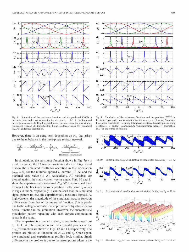
Fig. 8. Simulation of the resistance functions and the predicted ZVCD inthe d-direction under true orientation for the case iq = 0.1 A. (a) Simulatedthree-phase currents. (b) Resulting total phase resistance (inverter plus windingresistance). [(c) and (d)] Calculated dq-frame resistance values. (f) Theoreticaldid0/dt under true orientation.
However, there is an extra term depending on rdq that arisesdue to the unbalance in the three-phase resistor network
did0
dt= −rdd(iq, λ)
Ldid +
Lq
Ldω iq −rdq(iq, λ)
Ldiq︸ ︷︷ ︸
Resistanceunbalance
. (9)
In simulations, the resistance function shown in Fig. 7(c) isused to emulate the 12 inverter switching devices. Figs. 8 and9 show the simulated results for operation in true orientation(λerr = 0) for the minimal applied iq current (0.1 A) and themaximal used value (11 A), respectively. All variables areplotted against the stator current vector angle. Figs. 10 and 11show the experimentally measured did0/dt functions and theiraverage (solid line) over the rotor position for the same iq valuesin Figs. 8 and 9, respectively. It can be seen that the simulatedsignal pattern follows the experimentally measured signals. Athigh currents, the magnitude of the simulated did0/dt functiondiffers more from that of the measured function. This is partlydue to the voltage–current curve approximated by a basic expo-nential function in the simulation. However, the characteristicmodulation pattern repeating with each current commutationsector is the same.
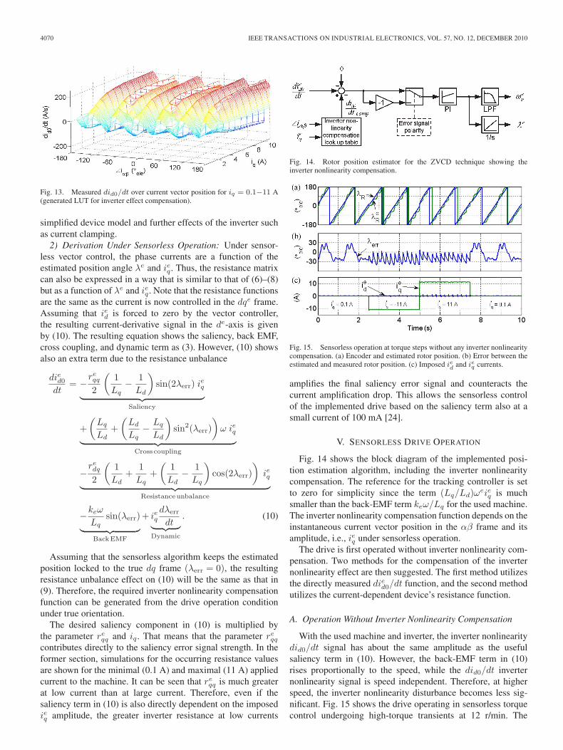
The comparison is extended to the iq values in the range from0.1 to 11 A. The simulation and experimental profiles of thedid0/dt function are shown in Figs. 12 and 13, respectively. Theprofiles are plotted as functions of ∠iαβ and iq. Once again,the simulated and experimental profiles look similar. Smalldifference in the profiles is due to the assumptions taken in the
Fig. 9. Simulation of the resistance functions and the predicted ZVCD inthe d-direction under true orientation for the case iq = 11 A. (a) Simulatedthree-phase currents. (b) Resulting total phase resistance (inverter plus windingresistance). [(c) and (d)] Calculated dq-frame resistance values. (f) Theoreticaldid0/dt under true orientation.
Fig. 10. Experimental did0/dt under true orientation for the case iq = 0.1 A.
Fig. 11. Experimental did0/dt under true orientation for the case iq = 11 A.
Fig. 12. Simulated did0/dt over current vector position for iq = 0.1−11 A.
4070 IEEE TRANSACTIONS ON INDUSTRIAL ELECTRONICS, VOL. 57, NO. 12, DECEMBER 2010
Fig. 13. Measured did0/dt over current vector position for iq = 0.1−11 A(generated LUT for inverter effect compensation).
simplified device model and further effects of the inverter suchas current clamping.
2) Derivation Under Sensorless Operation: Under sensor-less vector control, the phase currents are a function of theestimated position angle λe and ieq. Thus, the resistance matrixcan also be expressed in a way that is similar to that of (6)–(8)but as a function of λe and ieq. Note that the resistance functionsare the same as the current is now controlled in the dqe frame.Assuming that ied is forced to zero by the vector controller,the resulting current-derivative signal in the de-axis is givenby (10). The resulting equation shows the saliency, back EMF,cross coupling, and dynamic term as (3). However, (10) showsalso an extra term due to the resistance unbalance
died0
dt= −
reqq
2
(1Lq
− 1Ld
)sin(2λerr) ieq︸ ︷︷ ︸
Saliency
+(
Lq
Ld+
(Ld
Lq− Lq
Ld
)sin2(λerr)
)ω ieq︸ ︷︷ ︸
Cross coupling
−redq
2
(1Ld
+1Lq
+(
1Ld
− 1Lq
)cos(2λerr)
)ieq︸ ︷︷ ︸
Resistanceunbalance
−keω
Lqsin(λerr)︸ ︷︷ ︸
BackEMF
+ ieqdλerr
dt︸ ︷︷ ︸Dynamic
. (10)
Assuming that the sensorless algorithm keeps the estimatedposition locked to the true dq frame (λerr = 0), the resultingresistance unbalance effect on (10) will be the same as that in(9). Therefore, the required inverter nonlinearity compensationfunction can be generated from the drive operation conditionunder true orientation.
The desired saliency component in (10) is multiplied bythe parameter re
qq and iq. That means that the parameter reqq
contributes directly to the saliency error signal strength. In theformer section, simulations for the occurring resistance valuesare shown for the minimal (0.1 A) and maximal (11 A) appliedcurrent to the machine. It can be seen that re
qq is much greaterat low current than at large current. Therefore, even if thesaliency term in (10) is also directly dependent on the imposedieq amplitude, the greater inverter resistance at low currents
Fig. 14. Rotor position estimator for the ZVCD technique showing theinverter nonlinearity compensation.
Fig. 15. Sensorless operation at torque steps without any inverter nonlinearitycompensation. (a) Encoder and estimated rotor position. (b) Error between theestimated and measured rotor position. (c) Imposed ied and ieq currents.
amplifies the final saliency error signal and counteracts thecurrent amplification drop. This allows the sensorless controlof the implemented drive based on the saliency term also at asmall current of 100 mA [24].
V. SENSORLESS DRIVE OPERATION
Fig. 14 shows the block diagram of the implemented posi-tion estimation algorithm, including the inverter nonlinearitycompensation. The reference for the tracking controller is setto zero for simplicity since the term (Lq/Ld)ωeieq is muchsmaller than the back-EMF term keω/Lq for the used machine.The inverter nonlinearity compensation function depends on theinstantaneous current vector position in the αβ frame and itsamplitude, i.e., ieq under sensorless operation.
The drive is first operated without inverter nonlinearity com-pensation. Two methods for the compensation of the inverternonlinearity effect are then suggested. The first method utilizesthe directly measured died0/dt function, and the second methodutilizes the current-dependent device’s resistance function.
A. Operation Without Inverter Nonlinearity Compensation
With the used machine and inverter, the inverter nonlinearitydid0/dt signal has about the same amplitude as the usefulsaliency term in (10). However, the back-EMF term in (10)rises proportionally to the speed, while the did0/dt inverternonlinearity signal is speed independent. Therefore, at higherspeed, the inverter nonlinearity disturbance becomes less sig-nificant. Fig. 15 shows the drive operating in sensorless torquecontrol undergoing high-torque transients at 12 r/min. The
RAUTE et al.: ANALYSIS AND COMPENSATION OF INVERTER NONLINEARITY EFFECT 4071
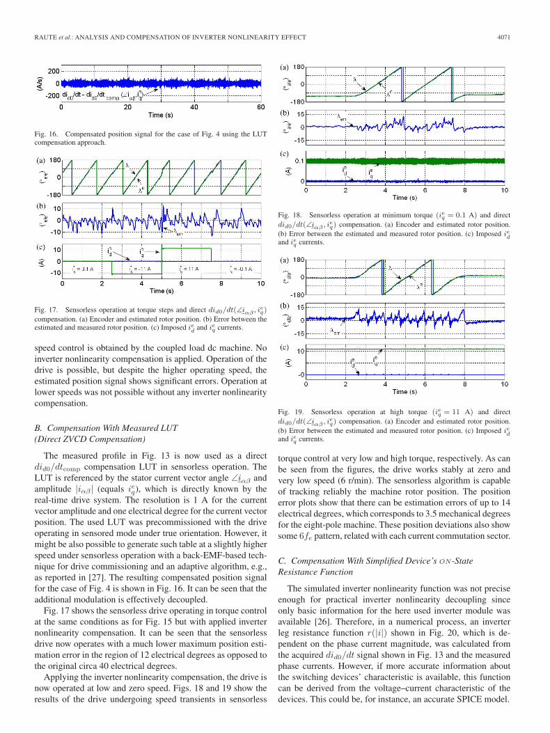
Fig. 16. Compensated position signal for the case of Fig. 4 using the LUTcompensation approach.
Fig. 17. Sensorless operation at torque steps and direct did0/dt(∠iαβ , ieq)
compensation. (a) Encoder and estimated rotor position. (b) Error between theestimated and measured rotor position. (c) Imposed ied and ieq currents.
speed control is obtained by the coupled load dc machine. Noinverter nonlinearity compensation is applied. Operation of thedrive is possible, but despite the higher operating speed, theestimated position signal shows significant errors. Operation atlower speeds was not possible without any inverter nonlinearitycompensation.
B. Compensation With Measured LUT(Direct ZVCD Compensation)
The measured profile in Fig. 13 is now used as a directdid0/dtcomp compensation LUT in sensorless operation. TheLUT is referenced by the stator current vector angle ∠iαβ andamplitude |iαβ | (equals ieq), which is directly known by thereal-time drive system. The resolution is 1 A for the currentvector amplitude and one electrical degree for the current vectorposition. The used LUT was precommissioned with the driveoperating in sensored mode under true orientation. However, itmight be also possible to generate such table at a slightly higherspeed under sensorless operation with a back-EMF-based tech-nique for drive commissioning and an adaptive algorithm, e.g.,as reported in [27]. The resulting compensated position signalfor the case of Fig. 4 is shown in Fig. 16. It can be seen that theadditional modulation is effectively decoupled.
Fig. 17 shows the sensorless drive operating in torque controlat the same conditions as for Fig. 15 but with applied inverternonlinearity compensation. It can be seen that the sensorlessdrive now operates with a much lower maximum position esti-mation error in the region of 12 electrical degrees as opposed tothe original circa 40 electrical degrees.
Applying the inverter nonlinearity compensation, the drive isnow operated at low and zero speed. Figs. 18 and 19 show theresults of the drive undergoing speed transients in sensorless
Fig. 18. Sensorless operation at minimum torque (ieq = 0.1 A) and directdid0/dt(∠iαβ , ieq) compensation. (a) Encoder and estimated rotor position.(b) Error between the estimated and measured rotor position. (c) Imposed iedand ieq currents.
Fig. 19. Sensorless operation at high torque (ieq = 11 A) and directdid0/dt(∠iαβ , ieq) compensation. (a) Encoder and estimated rotor position.(b) Error between the estimated and measured rotor position. (c) Imposed iedand ieq currents.
torque control at very low and high torque, respectively. As canbe seen from the figures, the drive works stably at zero andvery low speed (6 r/min). The sensorless algorithm is capableof tracking reliably the machine rotor position. The positionerror plots show that there can be estimation errors of up to 14electrical degrees, which corresponds to 3.5 mechanical degreesfor the eight-pole machine. These position deviations also showsome 6fe pattern, related with each current commutation sector.
C. Compensation With Simplified Device’s ON-StateResistance Function
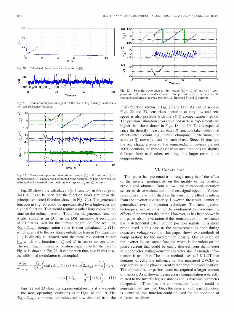
The simulated inverter nonlinearity function was not preciseenough for practical inverter nonlinearity decoupling sinceonly basic information for the here used inverter module wasavailable [26]. Therefore, in a numerical process, an inverterleg resistance function r(|i|) shown in Fig. 20, which is de-pendent on the phase current magnitude, was calculated fromthe acquired did0/dt signal shown in Fig. 13 and the measuredphase currents. However, if more accurate information aboutthe switching devices’ characteristic is available, this functioncan be derived from the voltage–current characteristic of thedevices. This could be, for instance, an accurate SPICE model.
4072 IEEE TRANSACTIONS ON INDUSTRIAL ELECTRONICS, VOL. 57, NO. 12, DECEMBER 2010
Fig. 20. Calculated phase resistance function r(|i|).
Fig. 21. Compensated position signal for the case in Fig. 4 using the device’sON-state resistance function.
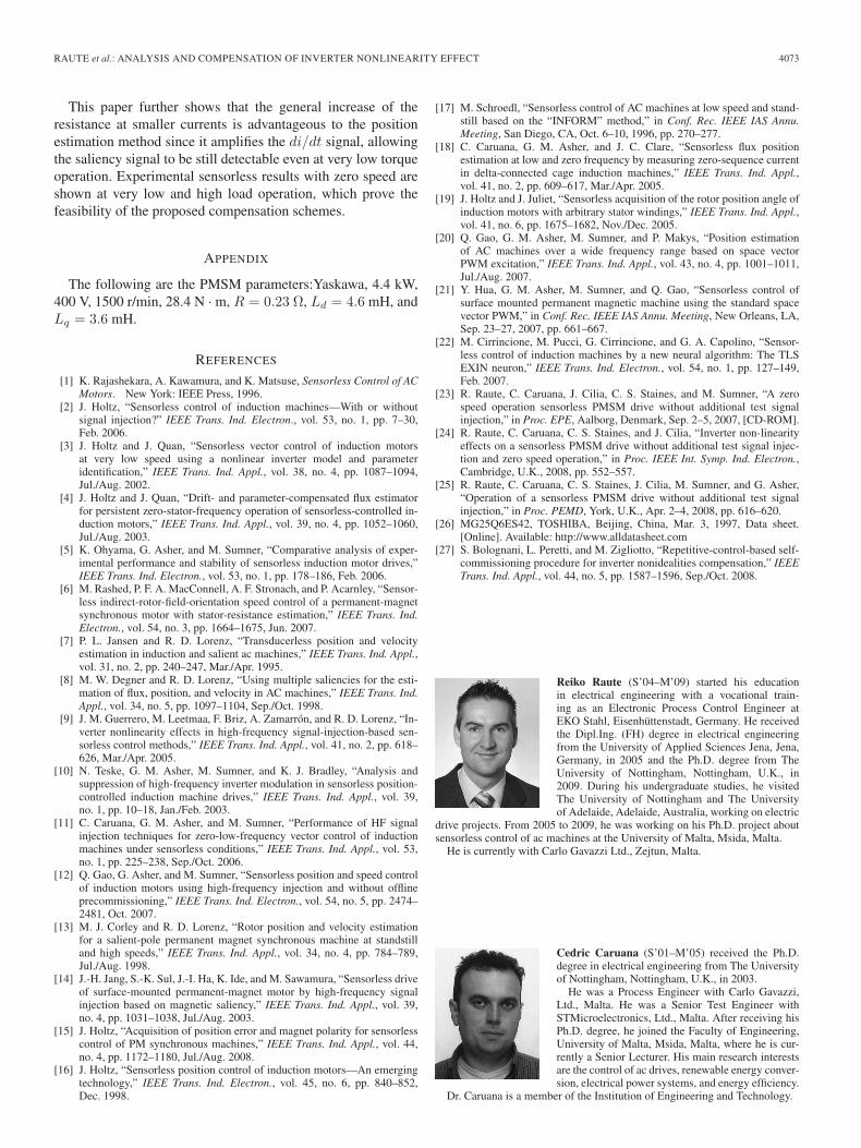
Fig. 22. Sensorless operation at minimum torque (ieq = 0.1 A) and r(|i|)compensation. (a) Encoder and estimated rotor position. (b) Error between theestimated and measured rotor position. (c) Imposed ied and ieq currents.
Fig. 20 shows the calculated r(|i|) function in the range of0–11 A. It can be seen that the function looks similar as theprincipal expected function shown in Fig. 7(c). The generatedfunction in Fig. 20 could be approximated by a high-order an-alytical function. This would require a rather long computationtime for the online operation. Therefore, the generated functionis also stored as an LUT in the DSP memory. A resolutionof 20 mA is used for the current magnitude. The resultingdid0/dtcomp compensation value is then calculated by (11),which is equal to the resistance unbalance term in (9). Equation(11) is directly calculated from the measured current vectoriαβ which is a function of ieq and λe in sensorless operation.The resulting compensated position signal, also for the case inFig. 4, is shown in Fig. 21. It can be seen that, also in this case,the additional modulation is decoupled
did0
dtcomp=
ieq3Ld
(sin(2∠iαβ)r(iA) + sin
(2∠iαβ +
23π
)r(iB)
+ sin(
2∠iαβ − 23π
)r(iC)
). (11)
Figs. 22 and 23 show the experimental results at low speedsat the same operating conditions as in Figs. 18 and 19. Thedid0/dtcomp compensation values are now obtained from the
Fig. 23. Sensorless operation at high torque (ieq = 11 A) and r(|i|) com-pensation. (a) Encoder and estimated rotor position. (b) Error between theestimated and measured rotor position. (c) Imposed ied and ieq currents.
r(|i|) function shown in Fig. 20 and (11). As can be seen inFigs. 22 and 23, sensorless operation at very low and zerospeed is also possible with the r(|i|) compensation method.The position estimation errors obtained in these experiments arehigher than those shown in Figs. 18 and 19. This is expectedsince the directly measured did0/dt function takes additionaleffects into account, e.g., current clamping. Furthermore, thesame r(|i|) curve is used for each phase. Since, in practice,the real characteristics of the semiconductor devices are not100% identical, the three-phase resistance functions are slightlydifferent from each other, resulting in a larger error in thecompensation.
VI. CONCLUSION
This paper has presented a thorough analysis of the effectof the inverter nonlinearity on the quality of the positionerror signal obtained from a low- and zero-speed-operationsensorless drive without additional test signal injection. Variousresearchers have published on the corrupting effect resultingfrom the inverter nonlinearity. However, the results cannot begeneralized over all injection techniques. Transient injectiontechniques, in particular, can be configured to overcome theeffects of the inverter dead time. However, as has been shown inthis paper, also the variation of the semiconductor on-resistancehas a detrimental effect on the position signals. It is morepronounced in this case as the measurement is done duringnonactive voltage vectors. This paper shows two methods ofcompensation for the inverter nonlinearity. One is based onthe inverter leg resistance function which is dependent on thephase current that could be easily derived from the invertersemiconductor voltage–current characteristic if enough infor-mation is available. The other method uses a 2-D LUT thatcontains directly the influence on the measured ZVCDs independence on the phase current vector amplitude and position.This allows a better performance but required a larger amountof memory. As is shown, the necessary compensation is directlyrelated to the inverter leg resistances and is machine parameterindependent. Therefore, the compensation function could begenerated with any load. Once the inverter nonlinearity functionis identified, this function could be used for the operation ofdifferent machines.
RAUTE et al.: ANALYSIS AND COMPENSATION OF INVERTER NONLINEARITY EFFECT 4073
This paper further shows that the general increase of theresistance at smaller currents is advantageous to the positionestimation method since it amplifies the di/dt signal, allowingthe saliency signal to be still detectable even at very low torqueoperation. Experimental sensorless results with zero speed areshown at very low and high load operation, which prove thefeasibility of the proposed compensation schemes.
APPENDIX
The following are the PMSM parameters:Yaskawa, 4.4 kW,400 V, 1500 r/min, 28.4 N · m, R = 0.23 Ω, Ld = 4.6 mH, andLq = 3.6 mH.
REFERENCES
[1] K. Rajashekara, A. Kawamura, and K. Matsuse, Sensorless Control of ACMotors. New York: IEEE Press, 1996.
[2] J. Holtz, “Sensorless control of induction machines—With or withoutsignal injection?” IEEE Trans. Ind. Electron., vol. 53, no. 1, pp. 7–30,Feb. 2006.
[3] J. Holtz and J. Quan, “Sensorless vector control of induction motorsat very low speed using a nonlinear inverter model and parameteridentification,” IEEE Trans. Ind. Appl., vol. 38, no. 4, pp. 1087–1094,Jul./Aug. 2002.
[4] J. Holtz and J. Quan, “Drift- and parameter-compensated flux estimatorfor persistent zero-stator-frequency operation of sensorless-controlled in-duction motors,” IEEE Trans. Ind. Appl., vol. 39, no. 4, pp. 1052–1060,Jul./Aug. 2003.
[5] K. Ohyama, G. Asher, and M. Sumner, “Comparative analysis of exper-imental performance and stability of sensorless induction motor drives,”IEEE Trans. Ind. Electron., vol. 53, no. 1, pp. 178–186, Feb. 2006.
[6] M. Rashed, P. F. A. MacConnell, A. F. Stronach, and P. Acarnley, “Sensor-less indirect-rotor-field-orientation speed control of a permanent-magnetsynchronous motor with stator-resistance estimation,” IEEE Trans. Ind.Electron., vol. 54, no. 3, pp. 1664–1675, Jun. 2007.
[7] P. L. Jansen and R. D. Lorenz, “Transducerless position and velocityestimation in induction and salient ac machines,” IEEE Trans. Ind. Appl.,vol. 31, no. 2, pp. 240–247, Mar./Apr. 1995.
[8] M. W. Degner and R. D. Lorenz, “Using multiple saliencies for the esti-mation of flux, position, and velocity in AC machines,” IEEE Trans. Ind.Appl., vol. 34, no. 5, pp. 1097–1104, Sep./Oct. 1998.
[9] J. M. Guerrero, M. Leetmaa, F. Briz, A. Zamarrón, and R. D. Lorenz, “In-verter nonlinearity effects in high-frequency signal-injection-based sen-sorless control methods,” IEEE Trans. Ind. Appl., vol. 41, no. 2, pp. 618–626, Mar./Apr. 2005.
[10] N. Teske, G. M. Asher, M. Sumner, and K. J. Bradley, “Analysis andsuppression of high-frequency inverter modulation in sensorless position-controlled induction machine drives,” IEEE Trans. Ind. Appl., vol. 39,no. 1, pp. 10–18, Jan./Feb. 2003.
[11] C. Caruana, G. M. Asher, and M. Sumner, “Performance of HF signalinjection techniques for zero-low-frequency vector control of inductionmachines under sensorless conditions,” IEEE Trans. Ind. Appl., vol. 53,no. 1, pp. 225–238, Sep./Oct. 2006.
[12] Q. Gao, G. Asher, and M. Sumner, “Sensorless position and speed controlof induction motors using high-frequency injection and without offlineprecommissioning,” IEEE Trans. Ind. Electron., vol. 54, no. 5, pp. 2474–2481, Oct. 2007.
[13] M. J. Corley and R. D. Lorenz, “Rotor position and velocity estimationfor a salient-pole permanent magnet synchronous machine at standstilland high speeds,” IEEE Trans. Ind. Appl., vol. 34, no. 4, pp. 784–789,Jul./Aug. 1998.
[14] J.-H. Jang, S.-K. Sul, J.-I. Ha, K. Ide, and M. Sawamura, “Sensorless driveof surface-mounted permanent-magnet motor by high-frequency signalinjection based on magnetic saliency,” IEEE Trans. Ind. Appl., vol. 39,no. 4, pp. 1031–1038, Jul./Aug. 2003.
[15] J. Holtz, “Acquisition of position error and magnet polarity for sensorlesscontrol of PM synchronous machines,” IEEE Trans. Ind. Appl., vol. 44,no. 4, pp. 1172–1180, Jul./Aug. 2008.
[16] J. Holtz, “Sensorless position control of induction motors—An emergingtechnology,” IEEE Trans. Ind. Electron., vol. 45, no. 6, pp. 840–852,Dec. 1998.
[17] M. Schroedl, “Sensorless control of AC machines at low speed and stand-still based on the “INFORM” method,” in Conf. Rec. IEEE IAS Annu.Meeting, San Diego, CA, Oct. 6–10, 1996, pp. 270–277.
[18] C. Caruana, G. M. Asher, and J. C. Clare, “Sensorless flux positionestimation at low and zero frequency by measuring zero-sequence currentin delta-connected cage induction machines,” IEEE Trans. Ind. Appl.,vol. 41, no. 2, pp. 609–617, Mar./Apr. 2005.
[19] J. Holtz and J. Juliet, “Sensorless acquisition of the rotor position angle ofinduction motors with arbitrary stator windings,” IEEE Trans. Ind. Appl.,vol. 41, no. 6, pp. 1675–1682, Nov./Dec. 2005.
[20] Q. Gao, G. M. Asher, M. Sumner, and P. Makys, “Position estimationof AC machines over a wide frequency range based on space vectorPWM excitation,” IEEE Trans. Ind. Appl., vol. 43, no. 4, pp. 1001–1011,Jul./Aug. 2007.
[21] Y. Hua, G. M. Asher, M. Sumner, and Q. Gao, “Sensorless control ofsurface mounted permanent magnetic machine using the standard spacevector PWM,” in Conf. Rec. IEEE IAS Annu. Meeting, New Orleans, LA,Sep. 23–27, 2007, pp. 661–667.
[22] M. Cirrincione, M. Pucci, G. Cirrincione, and G. A. Capolino, “Sensor-less control of induction machines by a new neural algorithm: The TLSEXIN neuron,” IEEE Trans. Ind. Electron., vol. 54, no. 1, pp. 127–149,Feb. 2007.
[23] R. Raute, C. Caruana, J. Cilia, C. S. Staines, and M. Sumner, “A zerospeed operation sensorless PMSM drive without additional test signalinjection,” in Proc. EPE, Aalborg, Denmark, Sep. 2–5, 2007, [CD-ROM].
[24] R. Raute, C. Caruana, C. S. Staines, and J. Cilia, “Inverter non-linearityeffects on a sensorless PMSM drive without additional test signal injec-tion and zero speed operation,” in Proc. IEEE Int. Symp. Ind. Electron.,Cambridge, U.K., 2008, pp. 552–557.
[25] R. Raute, C. Caruana, C. S. Staines, J. Cilia, M. Sumner, and G. Asher,“Operation of a sensorless PMSM drive without additional test signalinjection,” in Proc. PEMD, York, U.K., Apr. 2–4, 2008, pp. 616–620.
[26] MG25Q6ES42, TOSHIBA, Beijing, China, Mar. 3, 1997, Data sheet.[Online]. Available: http://www.alldatasheet.com
[27] S. Bolognani, L. Peretti, and M. Zigliotto, “Repetitive-control-based self-commissioning procedure for inverter nonidealities compensation,” IEEETrans. Ind. Appl., vol. 44, no. 5, pp. 1587–1596, Sep./Oct. 2008.
Reiko Raute (S’04–M’09) started his educationin electrical engineering with a vocational train-ing as an Electronic Process Control Engineer atEKO Stahl, Eisenhüttenstadt, Germany. He receivedthe Dipl.Ing. (FH) degree in electrical engineeringfrom the University of Applied Sciences Jena, Jena,Germany, in 2005 and the Ph.D. degree from TheUniversity of Nottingham, Nottingham, U.K., in2009. During his undergraduate studies, he visitedThe University of Nottingham and The Universityof Adelaide, Adelaide, Australia, working on electric
drive projects. From 2005 to 2009, he was working on his Ph.D. project aboutsensorless control of ac machines at the University of Malta, Msida, Malta.
He is currently with Carlo Gavazzi Ltd., Zejtun, Malta.
Cedric Caruana (S’01–M’05) received the Ph.D.degree in electrical engineering from The Universityof Nottingham, Nottingham, U.K., in 2003.
He was a Process Engineer with Carlo Gavazzi,Ltd., Malta. He was a Senior Test Engineer withSTMicroelectronics, Ltd., Malta. After receiving hisPh.D. degree, he joined the Faculty of Engineering,University of Malta, Msida, Malta, where he is cur-rently a Senior Lecturer. His main research interestsare the control of ac drives, renewable energy conver-sion, electrical power systems, and energy efficiency.
Dr. Caruana is a member of the Institution of Engineering and Technology.

4074 IEEE TRANSACTIONS ON INDUSTRIAL ELECTRONICS, VOL. 57, NO. 12, DECEMBER 2010
Cyril Spiteri Staines (S’94–M’98) received theB.Eng. (Hons.) degree from the University of Malta,Msida, Malta, in 1994 and the Ph.D. degree fromThe University of Nottingham, Nottingham, U.K., in1999, where he carried out his Ph.D. thesis on sen-sorless control of ac drives in the School of Electricaland Electronic Engineering from 1995 to 1998.
In 1995, he joined the University of Malta as anAssistant Lecturer, where he became a Lecturer in1999 and is currently the Head of the Departmentof Industrial Electrical Power Conversion, Faculty
of Engineering. From 2003 to 2004, he carried out postdoctoral research asa Visiting Lecturer with The University of Nottingham. He became a SeniorLecturer in 2004 and an Associate Professor in 2007. His research interestsinclude sensorless ac motor drives and grid connection of renewable energysources, in particular, for wind energy systems.
Dr. Staines is a member of the Institution of Engineering and Technology.
Joseph Cilia received the Ph.D. degree in sensor-less control of ac motors from The University ofNottingham, Nottingham, U.K., in 1997.
Since receiving his Ph.D. degree, he has been aLecturer in power electronics and drives with theUniversity of Malta, Msida, Malta. His research in-terests cover ac motor control and encoderless tech-niques, power converters for motor drive systems,battery management in motive power applications,grid-connected renewable energy sources, and en-ergy efficiency.
Mark Sumner (SM’05) received the B.Eng. degreein electrical and electronic engineering from the Uni-versity of Leeds, Leeds, U.K., in 1986 and the Ph.D.degree in induction motor drives from The Univer-sity of Nottingham, Nottingham, U.K., in 1990.
He was with Rolls-Royce, Ltd., Ansty, U.K. Hewas a Research Assistant with The University ofNottingham, where he was appointed Lecturer inOctober 1992 and is currently an Associate Professorand a Reader in power electronic systems. His re-search interests cover the control of power electronic
systems, including sensorless motor drives, diagnostics and prognostics fordrive systems, power electronics for enhanced power quality, and novel powersystem fault location strategies.
Greg M. Asher (SM’02–F’07) received the B.S. andPh.D. degrees in bond graph structures and generaldynamic systems from the University of Bath, Bath,U.K., in 1976 and 1979, respectively.
He was appointed Lecturer in control with the De-partment of Electrical and Electronic Engineering,The University of Nottingham, Nottingham, U.K., in1984, where he developed an interest in motor drivesystems, and was appointed Professor of electricaldrives in 2000. He is currently the Associate Deanof the Faculty of Engineering, The University of
Nottingham. He has published over 200 research papers and has received over£5 million in research contracts.
Dr. Asher has been a member of the Executive Committee of the EuropeanPower Electronics Society and the Chair of the Power Electronics TechnicalCommittee for the IEEE Industrial Electronics Society. He is an AssociateEditor of the IEEE Industrial Electronics Society.
Related Documents