Hardware and Engineering LE 4-206-AA1 Analog LE for Voltage Signals 06/99 AWB 27-1262 GB 1st published 1996, edition 07/96 2nd published 1999, edition 06/99 © Moeller GmbH, Bonn Author: Peter Roersch Editor: Thomas Kracht Translators: DK, Terence Osborn For Immediate Delivery call KMParts.com at (866) 595-9616

Welcome message from author
This document is posted to help you gain knowledge. Please leave a comment to let me know what you think about it! Share it to your friends and learn new things together.
Transcript

Hardware and Engineering
LE 4-206-AA1Analog LE for Voltage Signals
06/99 AWB 27-1262 GB1st published 1996, edition 07/962nd published 1999, edition 06/99
© Moeller GmbH, Bonn
Author: Peter Roersch
Editor: Thomas Kracht
Translators: DK, Terence Osborn
For Immediate Delivery call KMParts.com at (866) 595-9616

Caution!
Dangerous electrical voltage!
Before commencing the installation
● Disconnect the power supply of the device.
● Ensure that the device cannot be accidentally restarted.
● Verify isolation from the supply.
● Earth and short circuit.
● Cover or enclose neighbouring units that are live.
● Follow the engineering instructions (AWA) of the device concerned.
● Only suitably qualified personnel may work on this device/system.
● Before installation and before touching the device ensure that you are free of electrostatic charge.
● Connecting cables and signal lines should be installed so that inductive or capacitive interference do not impair the automation functions.
● Install automation devices and related operating elements in such a way that they are well protected against unintentional operation.
● Suitable safety hardware and software measures should be implemented for the I/O interface so that a line or wire breakage on the signal side does not result in undefined states in the automation devices.
● Ensure a reliable electrical isolation of the low voltage for the 24 volt supply. Only use power supply units complying with IEC 60 364-4-41 or HD 384.4.41 S2.
● Deviations of the mains voltage from the rated value must not exceed the tolerance limits given in the specifications, otherwise this may cause malfunction and dangerous operation.
● Emergency stop devices complying with IEC/EN 60 204-1 must be effective in all operating modes of the automation devices. Unlatching the emergency-stop devices must not cause uncontrolled operation or restart.
● Devices that are designed for mounting in housings or control cabinets must only be operated and controlled after they have been installed with the housing closed. Desktop or portable units must only be operated and controlled in enclosed housings.
● Measures should be taken to ensure the proper restart of programs interrupted after a voltage dip or failure. This should not cause dangerous operating states even for a short time. If necessary, emergency-stop devices should be implemented.
IBM is a registered trademark of International Business Machines Corporation.
All other brand and product names are trademarks or registered trademarks of the owner concerned.
All rights reserved, including those of the translation.
No part of this manual may be reproduced in any form (printed, photocopy, microfilm or any otherprocess) or processed, duplicated or distributed by means of electronic systems without written permission of Moeller GmbH, Bonn.
Subject to alterations without notice.
For Immediate Delivery call KMParts.com at (866) 595-9616

06/9
9 A
WB
27-
1262
GB
Contents
About This Manual 3
1 About the LE 4-206-AA1 5Application range 5Setup 6
2 Mounting 7Mounting on top-hat rail 7Mounting on mounting plate using mounting feet 8Installing in the control cabinet 8Fitting/removing the terminal strip 9
3 Engineering 11Connection overview 11Connecting analog cables 12Electromagnetic compatibility (EMC) 13Analog cables 13Connecting to the PS 4-200/300, EM 4-204-DX1 16
4 Configuration and Setting Parameters 17Setting the input and output parameters 17Parameter settings for the PROFIBUS-DP network 18
5 Addressing/Operation/Diagnostics 19Addressing 19Operation 20Diagnostics 20Diagnostics for the PROFIBUS-DP network 22
6 Analog Value Representation 23Analog-to-digital conversion 23
Appendix 27Technical Data 27
Stichwortverzeichnis 31
1For Immediate Delivery call KMParts.com at (866) 595-9616

AW
B 2
7-12
62 G
B
2 06/9
9
For Immediate Delivery call KMParts.com at (866) 595-9616

06/9
9 A
WB
27-
1262
GB
About This Manual
This manual is written for engineers and technicians with PLC experience.
It provides the specific information required for connecting the module correctly, as well as for configuring and programming it with Sucosoft S 40 programming software.
To use this manual, a knowledge of the following is required:
the master used;
the programming software.
You will find the required information in:
the “Hardware and Engineering” manual of your master
“Sucosoft S 40, User Interface” (AWB 2700-1305 GB)
“Sucosoft S 40, Language Elements for PS 4-... and PS 416” (AWB 2700-1306 GB)
The symbols used in this manual have the following meaning:
� Indicates actions to be taken.
�Draws your attention to useful tips and additional information.
NoteWarns of the possibility of damage to products, adjacent equipment or data.
3For Immediate Delivery call KMParts.com at (866) 595-9616

About This Manual
AW
B 2
7-12
62 G
B
Caution!Warns of the possibility of serious damage to products, adjacent equipment or data and risk of serious or fatal personal injury.
4 06/9
9
For Immediate Delivery call KMParts.com at (866) 595-9616
06/9
9 A
WB
27-
1262
GB
1 About the LE 4-206-AA1
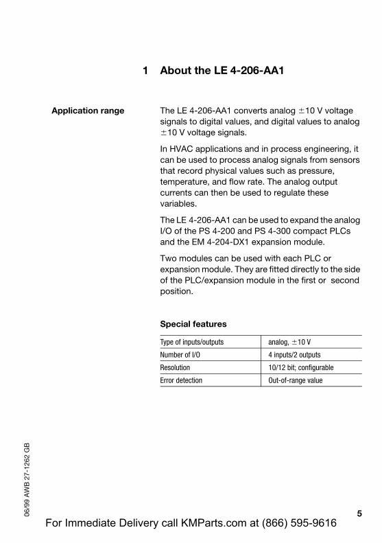
Application range The LE 4-206-AA1 converts analog �10 V voltage signals to digital values, and digital values to analog �10 V voltage signals.
In HVAC applications and in process engineering, it can be used to process analog signals from sensors that record physical values such as pressure, temperature, and flow rate. The analog output currents can then be used to regulate these variables.
The LE 4-206-AA1 can be used to expand the analog I/O of the PS 4-200 and PS 4-300 compact PLCs and the EM 4-204-DX1 expansion module.
Two modules can be used with each PLC or expansion module. They are fitted directly to the side of the PLC/expansion module in the first or second position.
Special features
Type of inputs/outputs analog, �10 V
Number of I/O 4 inputs/2 outputs
Resolution 10/12 bit; configurable
Error detection Out-of-range value
5For Immediate Delivery call KMParts.com at (866) 595-9616
About the LE 4-206-AA1
AW
B 2
7-12
62 G
B
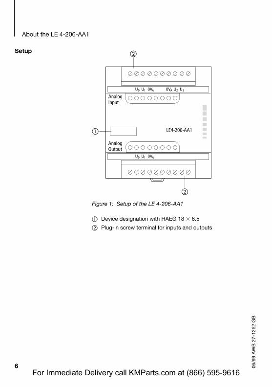
Figure 1: Setup of the LE 4-206-AA1
� Device designation with HAEG 18 � 6.5
� Plug-in screw terminal for inputs and outputs
LE4-206-AA1
AnalogOutput
AnalogInput
U0 U2 U3U1 0VA
U0 U1 0VA
0VA
�
�
�Setup
6 06/9
9
For Immediate Delivery call KMParts.com at (866) 595-9616

06/9
9 A
WB
27-
1262
GB
2 Mounting
The LE 4-206-AA1 can be mounted on a top-hat rail or on a mounting plate using mounting feet. The relevant dimensions are given in the Appendix.
Mounting on top-hat rail
� Mount the device on the top-hat rail so that the upper edge of the rail engages in the slot.
� Insert a screwdriver � into the slot of the spring-loaded clip and pull the clip downwards �.
� Push the device fully onto the top-hat rail �.
� Remove the screwdriver. The spring-loaded clip should snap back into position and hold the device securely.
� Check that the device is securely attached.
Figure 2: Mounting on top-hat rail
1
23
7For Immediate Delivery call KMParts.com at (866) 595-9616
Mounting
AW
B 2
7-12
62 G
B
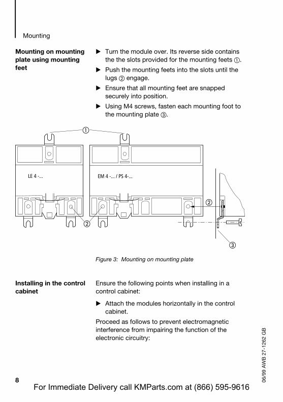
Mounting on mounting plate using mounting feet
� Turn the module over. Its reverse side contains the the slots provided for the mounting feets �.
� Push the mounting feets into the slots until the lugs � engage.
� Ensure that all mounting feet are snapped securely into position.
� Using M4 screws, fasten each mounting foot to the mounting plate �.
Figure 3: Mounting on mounting plate
Installing in the control cabinet
Ensure the following points when installing in a control cabinet:
� Attach the modules horizontally in the control cabinet.
Proceed as follows to prevent electromagnetic interference from impairing the function of the electronic circuitry:
�
�
LE 4 -... EM 4 -... / PS 4-...
�
�
8 06/9
9
For Immediate Delivery call KMParts.com at (866) 595-9616
Fitting/removing the terminal strip
06/9
9 A
WB
27-
1262
GB
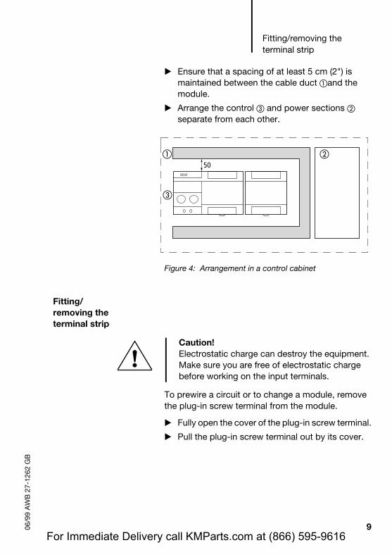
� Ensure that a spacing of at least 5 cm (2") is maintained between the cable duct �and the module.
� Arrange the control � and power sections � separate from each other.
Figure 4: Arrangement in a control cabinet
Fitting/removing the terminal strip
To prewire a circuit or to change a module, remove the plug-in screw terminal from the module.
� Fully open the cover of the plug-in screw terminal.
� Pull the plug-in screw terminal out by its cover.
�
�
50�
Caution!Electrostatic charge can destroy the equipment.Make sure you are free of electrostatic charge before working on the input terminals.
9For Immediate Delivery call KMParts.com at (866) 595-9616

Mounting
AW
B 2
7-12
62 G
B
� Use the same procedure for the other plug-in screw terminal.
Figure 5: Fitting/removing the plug-in screw terminal
To fit the plug-in screw terminal into the module:
� Fully open the cover of the plug-in screw terminal.
� Place the plug-in screw terminal into the slot and press it into position.
10 06/9
9
For Immediate Delivery call KMParts.com at (866) 595-9616
06/9
9 A
WB
27-
1262
GB
3 Engineering
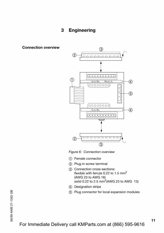
Connection overview
Figure 6: Connection overview
� Female connector
� Plug-in screw terminal
� Connection cross-sections:flexible with ferrule 0.22 to 1.5 mm2
(AWG 23 to AWG 16)solid 0.22 to 2.5 mm2(AWG 23 to AWG 13)
� Designation strips
� Plug connector for local expansion modules
�
�
�
�
�
�
�
�
U0 U1 0VA
U0 U1 0VA
0VA U2 U3
11For Immediate Delivery call KMParts.com at (866) 595-9616
Engineering
AW
B 2
7-12
62 G
B
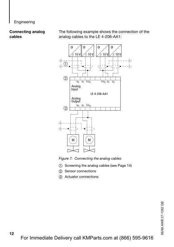
Connecting analog cables
The following example shows the connection of the analog cables to the LE 4-206-AA1:
Figure 7: Connecting the analog cables
� Screening the analog cables (see Page 14)
� Sensor connections
� Actuator connections
� 10 V
U0 U1 0 VA
U0 U1 0 VA
0 VA U2 U3
Analog
Output
M
Analog
Input
� 10 V � 10 V � 10 V
LE 4-206-AA1
M
�
�
�
12 06/9
9
For Immediate Delivery call KMParts.com at (866) 595-9616

Electromagnetic compatibility (EMC)
06/9
9 A
WB
27-
1262
GB
Electromagnetic compatibility (EMC)
The following engineering measures must be observed in order to meet the requirements of the EMC regulations and comply with the following European EMC standards:
EN 50 081-2 (Emission)EN 50 082-2 (Immunity)
Analog cables Only shielded cables must be used for analog lines (see Page 15).
�Other engineering instructions are given in the manual “EMC Guidelines for Automation Systems”, AWB 27-1287-GB and the EMC manual “Electromagnetic Compatibility of Machines”, TB 02-022 GB.
NoteElectromagnetic interferenceInterference and line-conducted interference according to ENV 50 140 and ENV 50 141 can corrupt your readings by up to 20 %. An improper connection of the module may produce interference in other components.
13For Immediate Delivery call KMParts.com at (866) 595-9616
Engineering
AW
B 2
7-12
62 G
B
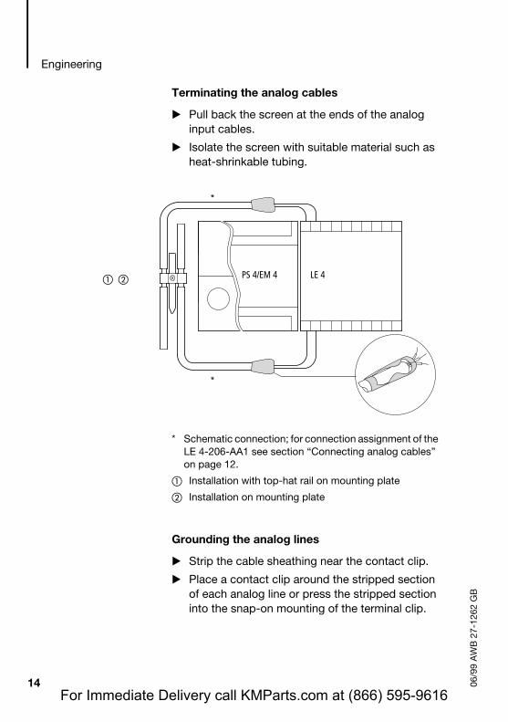
Terminating the analog cables
� Pull back the screen at the ends of the analog input cables.
� Isolate the screen with suitable material such as heat-shrinkable tubing.
* Schematic connection; for connection assignment of the LE 4-206-AA1 see section “Connecting analog cables” on page 12.
� Installation with top-hat rail on mounting plate
� Installation on mounting plate
Grounding the analog lines
� Strip the cable sheathing near the contact clip.
� Place a contact clip around the stripped section of each analog line or press the stripped section into the snap-on mounting of the terminal clip.
� � PS 4/EM 4 LE 4
*
*
14 06/9
9
For Immediate Delivery call KMParts.com at (866) 595-9616
Analog cables
06/9
9 A
WB
27-
1262
GB
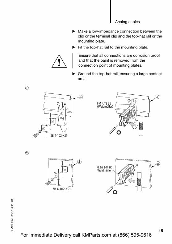
� Make a low-impedance connection between the clip or the terminal clip and the top-hat rail or the mounting plate.
� Fit the top-hat rail to the mounting plate.
� Ground the top-hat rail, ensuring a large contact area.
Ensure that all connections are corrosion proof and that the paint is removed from the connection point of mounting plates.
�
�
M4
ZB 4-102-KS1
FM 4/TS 35(Weidmüller)
ZB 4-102-KS1
KLBü 3-8 SC(Weidmüller)
15For Immediate Delivery call KMParts.com at (866) 595-9616
Engineering
AW
B 2
7-12
62 G
B
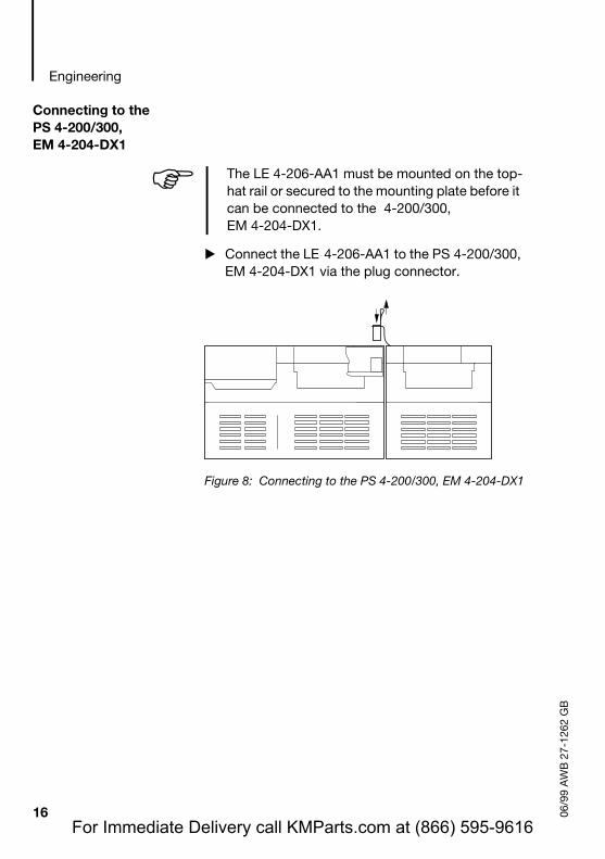
Connecting to the PS 4-200/300, EM 4-204-DX1
� Connect the LE 4-206-AA1 to the PS 4-200/300, EM 4-204-DX1 via the plug connector.
Figure 8: Connecting to the PS 4-200/300, EM 4-204-DX1
�The LE 4-206-AA1 must be mounted on the top-hat rail or secured to the mounting plate before it can be connected to the 4-200/300, EM 4-204-DX1.
16 06/9
9
For Immediate Delivery call KMParts.com at (866) 595-9616
06/9
9 A
WB
27-
1262
GB
4 Configuration and Setting Parameters
The LE 4-206-AA1 is configured with the Sucosoft S 40 Topology Configurator:
� In the Topology Configurator choose ‹Edit � ‹Local Expansion›.
� Select LE 4-206-AA1 from the device list. When selected, the LE 4 will be highlighted.
� Choose ‹Edit � Parameters› and set the input and output parameters of the device.
Setting the input and output parameters
To cover applications that require only a few or no analog inputs, a variety of configurations are available for selection in the parameter editor. Input and output scan times are defined for each configuration. These are listed in the table below. The resolution applies both to inputs and to outputs.
Scan times
In the specified period, the input signals are read and converted to a digital value, and signals are applied to the outputs.
�If each change of the digital value is to be output, the PLC cycle time must be greater than the scan time.
17For Immediate Delivery call KMParts.com at (866) 595-9616
Configuration and Setting Parameters
AW
B 2
7-12
62 G
B
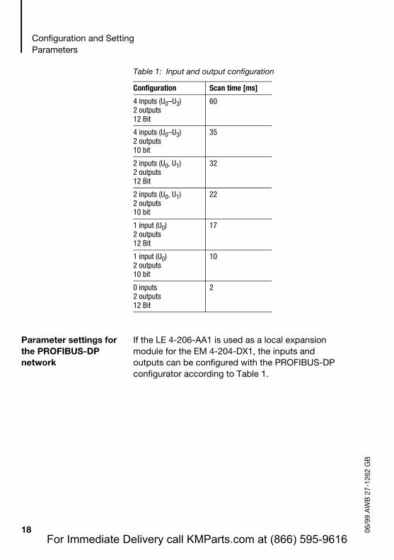
Table 1: Input and output configuration
Parameter settings for the PROFIBUS-DP network
If the LE 4-206-AA1 is used as a local expansion module for the EM 4-204-DX1, the inputs and outputs can be configured with the PROFIBUS-DP configurator according to Table 1.
Configuration Scan time [ms]
4 inputs (U0–U3)2 outputs12 Bit
60
4 inputs (U0–U3)2 outputs10 bit
35
2 inputs (U0, U1)2 outputs12 Bit
32
2 inputs (U0, U1)2 outputs10 bit
22
1 input (U0)2 outputs12 Bit
17
1 input (U0)2 outputs10 bit
10
0 inputs2 outputs12 Bit
2
18 06/9
9
For Immediate Delivery call KMParts.com at (866) 595-9616

06/9
9 A
WB
27-
1262
GB
5 Addressing/Operation/Diagnostics
Addressing Addressing the inputs and outputs of the LE 4-206-AA1 is described in the manual “Hardware and Engineering“ for the selected master. The data type of the analog values is always “Integer”. The operands are addressed as follows:
VARAnlgIn AT%IAW0.0.x.y:INT; (*Scan an input*)AnlgOut AT%QAW0.0.x.y:INT; (*Addressing an output*)END_VAR
LD AnlgInST AnlgOut
x = 1, 2: Module numbery = 0, 2, 4, 6: I/O number
Table 2: Overview of operands
Input designation Input number Operand
U0 0 IAW0.0.x.0
U1 2 IAW0.0.x.2
U2 4 IAW0.0.x.4
U3 6 IAW0.0.x.6
Output designation Output number Operand
U0 0 QAW0.0.x.0
U1 2 QAW0.0.x.2
19For Immediate Delivery call KMParts.com at (866) 595-9616

Addressing/Operation/Diagnostics
AW
B 2
7-12
62 G
B
Operation Startup behaviour
Once the power supply has been switched on, the PLC sends the user-defined parameters to the LE 4-206-AA1 and starts the exchange of process data. No process data is exchanged if the PLC is in HALT after being switched on. All outputs of the LE 4-206-AA1 remain at 0 V.
Diagnostics The diagnostics data of the LE 4 is stored in one diagnostics byte. If the input voltage exceeds the specified range and rises above +10.5 V or falls below –10.5 V, the digital value is set to 7530 hex, irrespective of the resolution.
In this case, the “DLS” bit in the diagnostics byte of the PS 4 is set, as is the corresponding error bit in the diagnostics byte of the LE 4.
The diagnostics byte of the LE 4 can be viewed in the “Test and commissioning - Topology Configurator” menu. If a limit value is exceeded, improved noise immunity measures must be implemented.
�In general, the device status of the LE 4-206-AA1 in the “Test and Commissioning” menu shows four inputs, regardless of the number of configured inputs.
20 06/9
9
For Immediate Delivery call KMParts.com at (866) 595-9616

Diagnostics
06/9
9 A
WB
27-
1262
GB
LE 4 diagnostics byte
The diagnostics data of the LE 4-206-AA1 is stored in the diagnostics byte. The diagnostics byte has the following structure:
Bit 0 = 0: device OK= 1: no/incorrect module
Bit 1 to 3: not used
Bit 4 = 0: OK= 1: out-of-range value U0
Bit 5 = 0: OK= 1: out-of-range value U1
Bit 6 = 0: OK= 1: out-of-range value U2
Bit 7 = 0: OK= 1: out-of-range value U3
ScanningThe diagnostics byte is scanned by bit or by byte with the following syntax:
Bit 7 6 5 4 3 2 1 0
�The variable declarations are not shown here. A general declaration is described in the manual “Language Elements for PS 4/PS 416” (AWB 2700-1306 GB).
Bit format Byte format
LD %ISB0.0.x.0.y LD %ISB0.0.x.0
x = 1 or 2 (module number)y = 0 to 7 (bit number)
21For Immediate Delivery call KMParts.com at (866) 595-9616

Addressing/Operation/Diagnostics
AW
B 2
7-12
62 G
B
Diagnostics for the PROFIBUS-DP network
The LE 4-206-AA1 can be used as local expansion module for the EM 4-204-DX1 in a PROFIBUS-DP line.
For a detailed description for the diagnosis on a PROFIBUS-DP line, refer to the “Hardware and Engineering” manual for EM 4-204-DX1 (AWB 27-1315 GB) and the manuals for the master used.
Scanning and evaluation of the diagnostics bytes for master module PS 416-NET-400 is described in manual “Hardware and Engineering” (AWB 2700-1330 GB).
The scanning of the diagnostic byte with, for example, LD%ISB1.2.1.0, as used for Sucosoft K stations, is not possible with PROFIBUS-DP. If the instruction is used, it results in an error message.
�In the diagnostics byte of the LE 4-206-AA1, an error message is generated for “Overrange”.
22 06/9
9
For Immediate Delivery call KMParts.com at (866) 595-9616
06/9
9 A
WB
27-
1262
GB
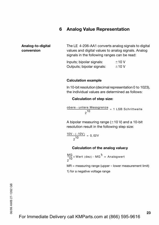
6 Analog Value Representation
Analog-to-digital conversion
The LE 4-206-AA1 converts analog signals to digital values and digital values to analog signals. Analog signals in the following ranges can be read:
Inputs; bipolar signals: �10 VOutputs; bipolar signals: �10 V
Calculation example
In 10-bit resolution (decimal representation 0 to 1023), the individual values are determined as follows:
Calculation of step size:
A bipolar measuring range (�10 V) and a 10-bit resolution result in the following step size:
Calculation of the analog value:y
MR = measuring range (upper – lower measurement limit)
1) for a negative voltage range
obere untere Messgrenze–
210
---------------------------------------------------------------------- 1 LSB Schrittweite=
10V 10V )–(–
210
------------------------------- 0 02V,=
MG
210
-------- Wert× dez( ) MG1)
– Ana wertlog=
23For Immediate Delivery call KMParts.com at (866) 595-9616

Analog Value Representation
AW
B 2
7-12
62 G
B
Positive voltage range: A bipolar measuring range (�10 V), a 10-bit resolution and a decimal value of 1 result in the following analog value:
Negative voltage range: A bipolar measuring range (±10 V), a 10-bit resolution and a decimal value of 516 result in the following analog value:
To calculate the value for a given analog value, the equation is reversed:
1) for a negative voltage range
Example:The analog value is –8 V
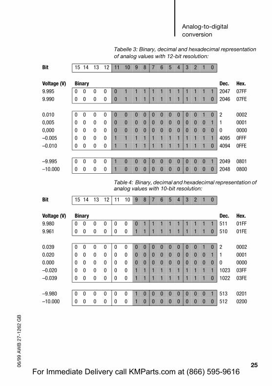
The table below lists the analog value representation of the bipolar analog signals of the analog LE for 12- and 10- bit resolution:
20 V
210
-------------- 1× 0 02 V,=
20 V
210
------------ 516× 20 V– 9 92 V,–=
Analogwert MG1)
+( ) 210
MG--------× Wert dez( )=
8– 20+( ) 210
20--------× 614 4,=
24 06/9
9
For Immediate Delivery call KMParts.com at (866) 595-9616
Analog-to-digital conversion
06/9
9 A
WB
27-
1262
GB
Tabelle 3: Binary, decimal and hexadecimal representation of analog values with 12-bit resolution:
Table 4: Binary, decimal and hexadecimal representation of analog values with 10-bit resolution:
Bit 15 14 13 12 11 10 9 8 7 6 5 4 3 2 1 0
Voltage (V) Binary Dec. Hex.9.995 0 0 0 0 0 1 1 1 1 1 1 1 1 1 1 1 2047 07FF9.990 0 0 0 0 0 1 1 1 1 1 1 1 1 1 1 0 2046 07FE
0.010 0 0 0 0 0 0 0 0 0 0 0 0 0 0 1 0 2 00020,005 0 0 0 0 0 0 0 0 0 0 0 0 0 0 0 1 1 00010,000 0 0 0 0 0 0 0 0 0 0 0 0 0 0 0 0 0 0000–0.005 0 0 0 0 1 1 1 1 1 1 1 1 1 1 1 1 4095 0FFF–0.010 0 0 0 0 1 1 1 1 1 1 1 1 1 1 1 0 4094 0FFE
–9.995 0 0 0 0 1 0 0 0 0 0 0 0 0 0 0 1 2049 0801–10.000 0 0 0 0 1 0 0 0 0 0 0 0 0 0 0 0 2048 0800
Bit 15 14 13 12 11 10 9 8 7 6 5 4 3 2 1 0
Voltage (V) Binary Dec. Hex.9.980 0 0 0 0 0 0 0 1 1 1 1 1 1 1 1 1 511 01FF9.961 0 0 0 0 0 0 1 1 1 1 1 1 1 1 1 0 510 01FE
0.039 0 0 0 0 0 0 0 0 0 0 0 0 0 0 1 0 2 00020.020 0 0 0 0 0 0 0 0 0 0 0 0 0 0 0 1 1 00010.000 0 0 0 0 0 0 0 0 0 0 0 0 0 0 0 0 0 0000–0.020 0 0 0 0 0 0 1 1 1 1 1 1 1 1 1 1 1023 03FF–0.039 0 0 0 0 0 0 1 1 1 1 1 1 1 1 1 0 1022 03FE
–9.980 0 0 0 0 0 0 1 0 0 0 0 0 0 0 0 1 513 0201–10.000 0 0 0 0 0 0 1 0 0 0 0 0 0 0 0 0 512 0200
25For Immediate Delivery call KMParts.com at (866) 595-9616

Analog Value Representation
AW
B 2
7-12
62 G
B
If the digital output value is increased beyond the highest possible 10-bit or 12-bit value, the higher-order bits are ignored by the digital-to-analog converter.
Example of a 10-bit resolution:
A value of 1026 is given by the user program.
1026 dec = 100 0000 0010 binary
Eleven bits are needed to represent this number. The eleventh bit is ignored by the converter, so that the number is converted to 00 0000 0010 (2 dec.).
A voltage of +0.039 V is applied to the voltage output!
26 06/9
9
For Immediate Delivery call KMParts.com at (866) 595-9616

06/9
9 A
WB
27-
1262
GB
Appendix
Technical Data General
Standards, regulations IEC/EN 61 131-2/EN 50 178
Ambient temperature 0 to 55 °C
Storage temperature –25 °C to +70 °C
Weight approx. 440 g
Shock resistance 15 g, 11 ms
Vibration resistance const. 1 g, f = 0 to 150 Hz
Device mounting Snap-fit on top-hat rail or mounting plate
Rated insulation voltage 600 V AC
Degree of protection IP 20
Terminals Plug-in screw terminal
Terminal cross-section
Flexible with ferrule 0.22 to 1.5 mm2
(AWG 23 to 16)
solid 0.22 to 2.5 mm2
(AWG 23 to 13)
Configuration PS 4-200, PS 4-300, EM 4-204-DX1
max. number per PS 4-200/300, EM 4-204-DX1
2
Insulation
LE bus to analog inputs/outputs Yes
Inputs/outputs to each other No
Analog inputs
Input ranges �10 V
Number of inputs 4
Transducer connection type Two-wire connection to transducer
Resolution 12 bit (4096 units)/10 bit (1024 units) configurable
Inputs against central grounding point see isolation voltage
27For Immediate Delivery call KMParts.com at (866) 595-9616

Appendix
AW
B 2
7-12
62 G
B
Permissible input voltage max. �15 V
Error message on
Out-of-range value Yes
Wire breakage detection No
Cumulative error typ. 0.8 % of upper range value
Cable length, screened max. 50 m at cable cross-section �014 mm²
Input resistance 40 k� per input
Analog outputs
Output ranges �10 V
Number of outputs 2
Load resistance per output 2 k�
Connection type Two-wire connection
Resolution configurable; 12 bit (4096 units)/10 bit (1024 units)
Short-circuit-proof Yes
Short-circuit current �32 mA
Permissible potential difference, to ground and between outputs
see isolation voltage
Cumulative error normally 0.8 % of upper range value
Cable length, screened max. 50 m at cable cross-section �0.14 mm²
28 06/9
9
For Immediate Delivery call KMParts.com at (866) 595-9616

Technical Data
06/9
9 A
WB
27-
1262
GB
General EMC specifications for automation equipment
Emission EN 55 011/22 Class A
Interference immunity
ESD EN 61 000-4-2 Contact dischargeAir discharge
4 kV8 kV
RFI EN 61 000-4-3 AM/PM 10 V/m
Burst EN 61 000-4-4 Mains/digital I/OAnalog I/O, fieldbus
2 kV1 kV
Surge EN 61 000-4-5 Digital I/O, asymmetricalMains DC, asymmetricalMains DC, symmetricalMains AC, asymmetricalMains AC, symmetrical
0.5 kV1 kV0.5 kV2 kV1 kV
Immunity to line-conducted
interference
EN 61 000-4-6 AM 10 V
29For Immediate Delivery call KMParts.com at (866) 595-9616

AW
B 2
7-12
62 G
B
30 06/9
9
For Immediate Delivery call KMParts.com at (866) 595-9616

06/9
9 A
WB
27-
1262
GB
Index
AAddressing ..................................................................... 19Analog cables ................................................................ 12Analog value representation .......................................... 24Analog value, calculation ............................................... 23Analog values, bipolar measuring range ........................ 23Analog-to-digital conversion .......................................... 23
CConfiguration ................................................................. 17Connecting ..................................................................... 12
Analog cables ............................................................. 12PS 4 ............................................................................ 12
Connection ..................................................................... 11Overview ..................................................................... 11
DDiagnostics byte ............................................................ 21
EEMC regulations ............................................................ 13Emission ......................................................................... 13
FFeatures ........................................................................... 5
GGrounding ...................................................................... 14
IImmunity ........................................................................ 13Installing in a control cabinet ........................................... 8
MMeasuring range ............................................................ 23Mounting .......................................................................... 7
Control cabinet ............................................................. 8Mounting feet ............................................................... 8On top-hat rail .............................................................. 7
31For Immediate Delivery call KMParts.com at (866) 595-9616

Index
AW
B 2
7-12
62 G
B
NNumber, I/O ...................................................................... 5
PParameter settings for inputs and outputs ..................... 17Plug-in screw terminal ................................................ 9, 10PROFIBUS-DP
Diagnostics ................................................................. 22Parameterization ......................................................... 18
PS 4 ................................................................................ 12
RResolution .................................................................. 5, 17
SScan times ...................................................................... 17Screen grounding, analog cables ................................... 15Setup ................................................................................ 6Shielding ......................................................................... 13Software configuration ................................................... 19Startup behaviour ........................................................... 20Step size, calculation ..................................................... 23
32 06/9
9
For Immediate Delivery call KMParts.com at (866) 595-9616
Related Documents