An Update of ILI Tools & Other Industry Technologies ® Registered trademarks of T.D. Williamson, Inc. in the United States and in foreign countries. © Copyright 2009 Lloyd Pirtle August 27 th , 2013 For the Oklahoma Gas Association

Welcome message from author
This document is posted to help you gain knowledge. Please leave a comment to let me know what you think about it! Share it to your friends and learn new things together.
Transcript
An Update of ILI Tools& Other Industry Technologies
® Registered trademarks of T.D. Williamson, Inc. in the United States and in foreign countries. © Copyright 2009
Lloyd PirtleAugust 27th, 2013
For the
Oklahoma Gas Association
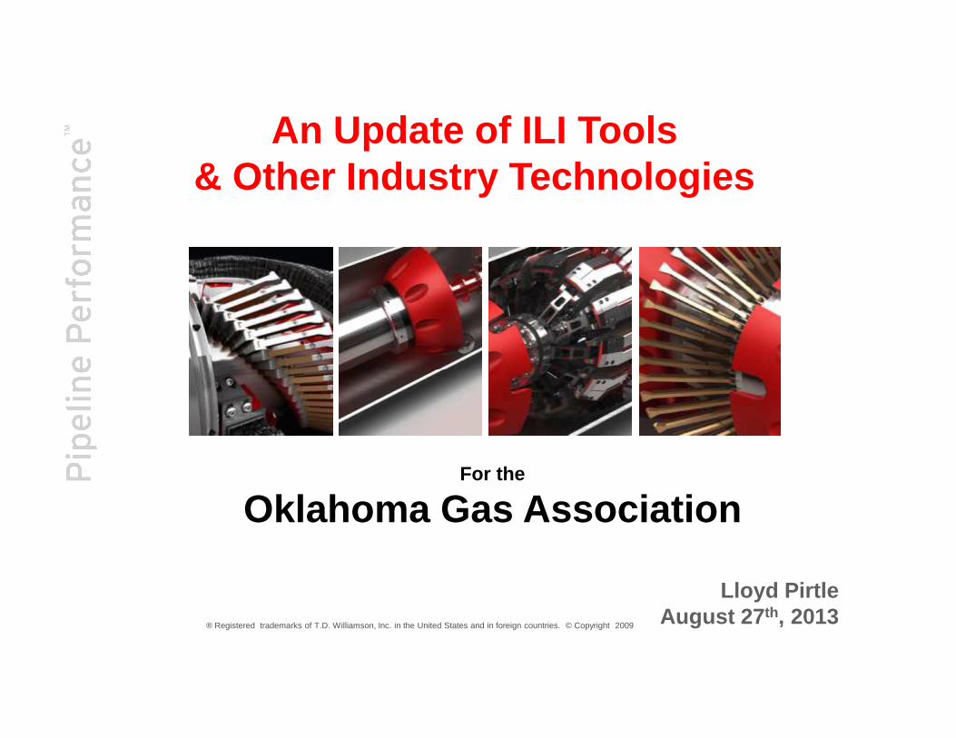
Outline
• Pipeline Preparation• Regulatory Notes• Technology Offerings• Value of Running Multiple Technologies• Mechanical Damage
2
• Mechanical Damage• Expanding the Multi-Data Set Value• Characterization of Materials• Positive Material Identification • Questions
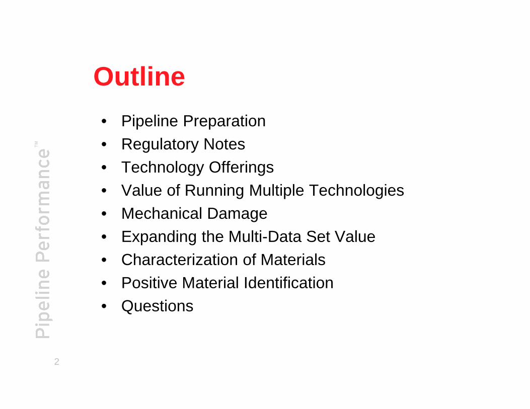
Design ReviewPipeline Dimensions – Length, wt, pipe ID
Pipeline Materials – Coatings, 70’s ERW, Seamless
Bends – Miters, Long Radius, Factory / Field
Reducers – Concentric/Eccentric
Pipeline Piggability
3
Tees – Position, Diameters, Flows, Barred/Unbarred
Stopple Fittings/Tees – Piggable Plugs installed
Valves – Appropriate design
Launchers/Receivers – design specs
Drips

Pigging Categories�Cleaning
�Corrosion Control - removal of undesirable corrosive mater ials
�Improve operating efficiency - savings in pump or compresso r fuel
�Batching�Product separation – Fuels, crudes, etc
�Slugging Operations – Cleaning, Biocides, Inhibitors, etc
4
�Displacement�Commissioning/Decommissioning
�Conversions
�Inspection Tools�Geometry
�Metal Loss
�Cracks
�Mapping

Pipeline Cleaning Choices
� Dry Mechanical Pigging* Debris can ignite on contact w/ O2 – Black Powder�Difficult to remove some debris (especially fine particles)�Various pigs, Tubs, Drums, Filters
� Detergent Enhanced Pigging�More effective at removing solids�Water or Diesel as Base solution
5
�Water or Diesel as Base solution�Wet film left behind
� On-Line�Convenience of being On-stream�In Gas, requires separation�Cash Register Running�Pig Velocity Control ??
�Off-Line�Virtually complete control of pig velocity�Can make more pig runs�Cash Register off
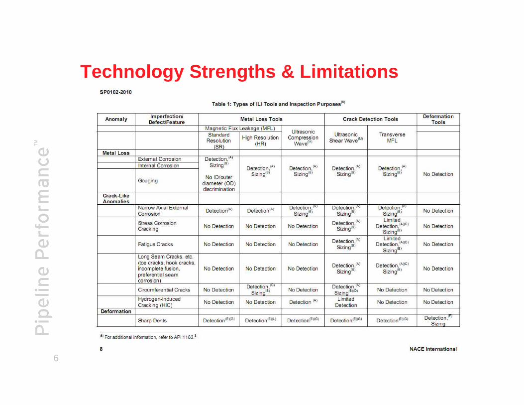
Technology Strengths & Limitations
6
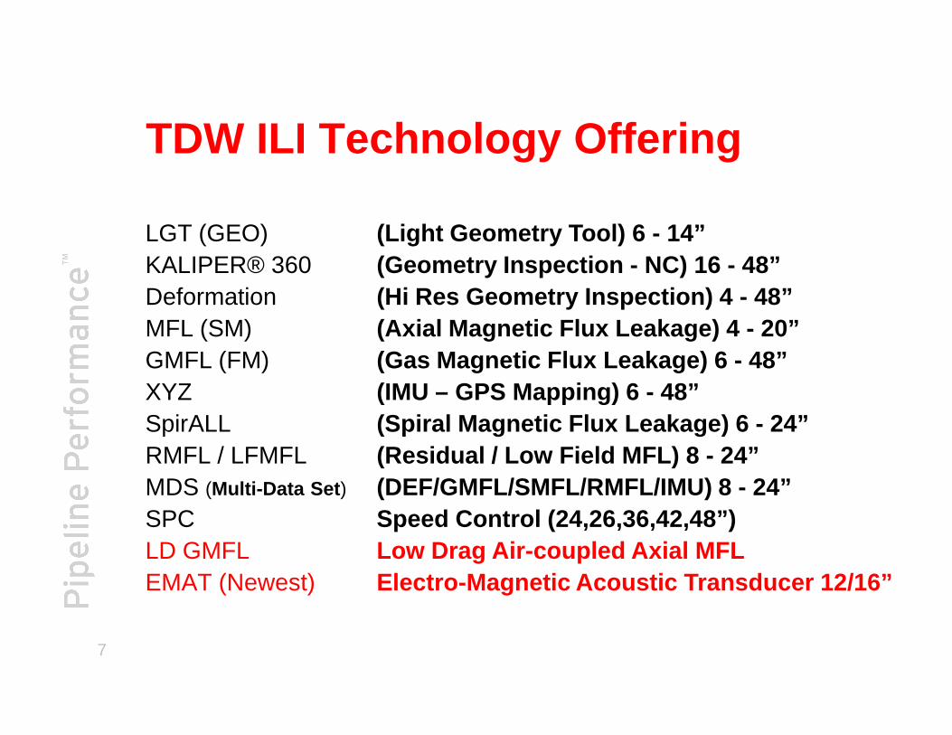
TDW ILI Technology Offering
LGT (GEO)KALIPER® 360DeformationMFL (SM) GMFL (FM)
(Light Geometry Tool) 6 - 14”(Geometry Inspection - NC) 16 - 48”(Hi Res Geometry Inspection) 4 - 48”(Axial Magnetic Flux Leakage) 4 - 20”(Gas Magnetic Flux Leakage) 6 - 48”
7
GMFL (FM)XYZSpirALLRMFL / LFMFL MDS (Multi-Data Set )
SPCLD GMFLEMAT (Newest)
(Gas Magnetic Flux Leakage) 6 - 48”(IMU – GPS Mapping) 6 - 48”(Spiral Magnetic Flux Leakage) 6 - 24”(Residual / Low Field MFL) 8 - 24”(DEF/GMFL/SMFL/RMFL/IMU) 8 - 24”Speed Control (24,26,36,42,48”)Low Drag Air-coupled Axial MFLElectro-Magnetic Acoustic Transducer 12/16”
Geometry InspectionGeometry InspectionGeometry InspectionGeometry Inspection
® Registered trademarks of T.D. Williamson, Inc. in the United States and in foreign countries. © Copyright 2009

KALIPER® 360 ILI Tool
Performance Specs• Provides Clock orientation &
distance for locating• 2% depth sizing accuracy
• 12” & below is 1/4” dent minimum
• Low drag can be run in low pressure, low flow applications.Pipeline Features Detected:
9
• Great tool for new build geometry inspection baselines.
Pipeline Features Detected:• Bends and elbows• Girth welds• ID changes
Pipe Anomalies Identified:• Misalignment• Ovality• Buckles• Dents• Wrinkles

K360 – Inside Dent View
10
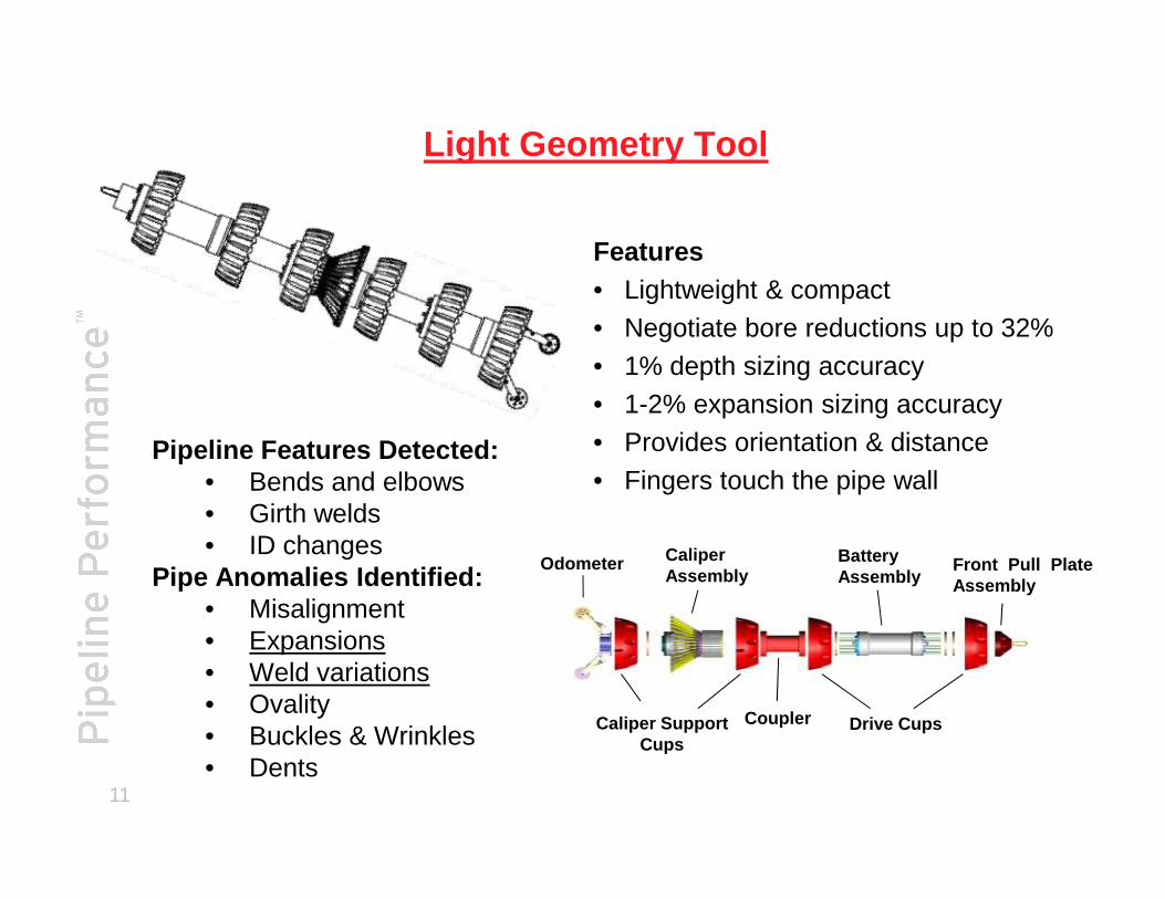
Light Geometry Tool
Features• Lightweight & compact• Negotiate bore reductions up to 32%• 1% depth sizing accuracy• 1-2% expansion sizing accuracy• Provides orientation & distancePipeline Features Detected:
11
• Provides orientation & distance• Fingers touch the pipe wall
Odometer
Drive Cups
BatteryAssembly
Coupler
CaliperAssembly
Caliper Support Cups
Front Pull PlateAssembly
Pipeline Features Detected:• Bends and elbows• Girth welds• ID changes
Pipe Anomalies Identified:• Misalignment• Expansions • Weld variations• Ovality• Buckles & Wrinkles• Dents
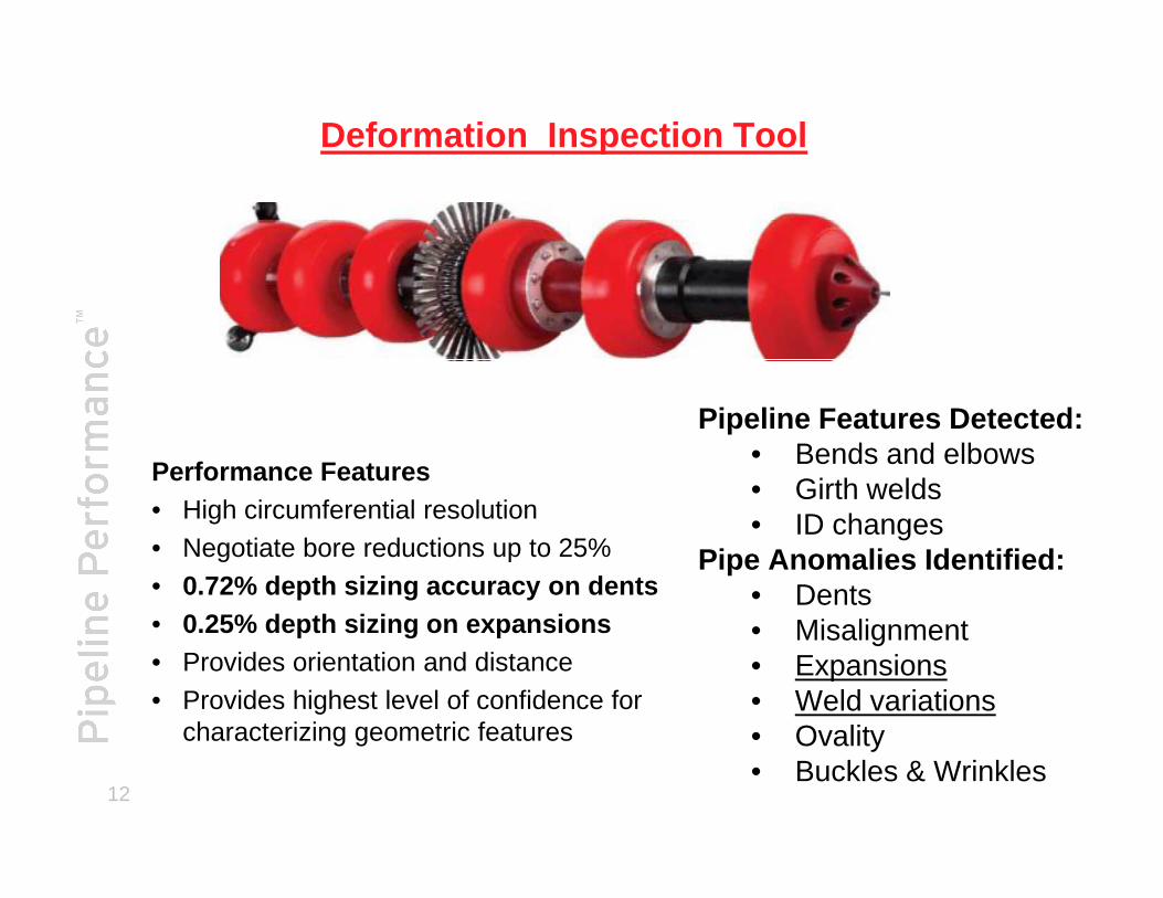
Deformation Inspection Tool
Pipeline Features Detected:• Bends and elbows
12
Performance Features• High circumferential resolution • Negotiate bore reductions up to 25%• 0.72% depth sizing accuracy on dents• 0.25% depth sizing on expansions• Provides orientation and distance• Provides highest level of confidence for
characterizing geometric features
• Bends and elbows• Girth welds• ID changes
Pipe Anomalies Identified:• Dents• Misalignment• Expansions • Weld variations• Ovality• Buckles & Wrinkles
Cross Section at Increased ID
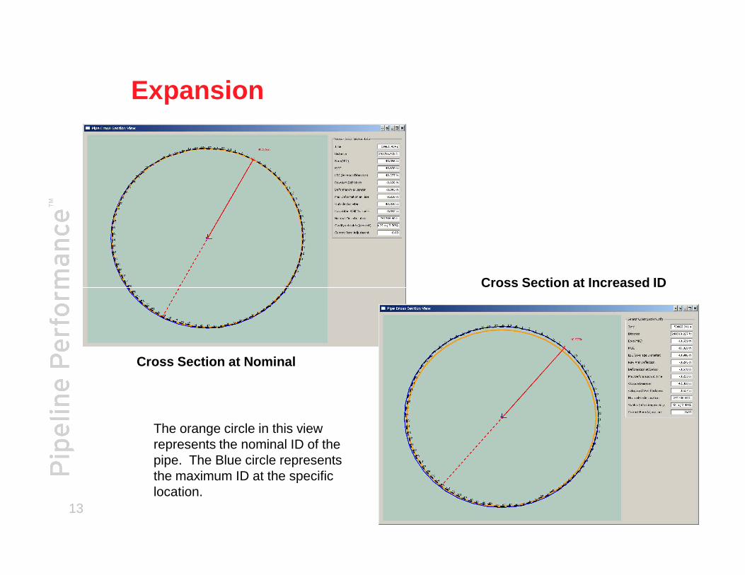
Expansion
13
Cross Section at Nominal
Cross Section at Increased ID
The orange circle in this view represents the nominal ID of the pipe. The Blue circle represents the maximum ID at the specific location.
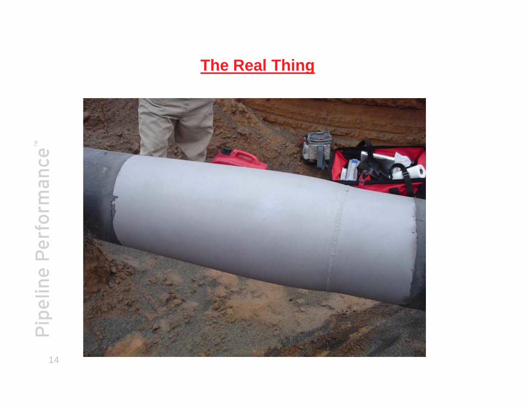
The Real Thing
14

Deformation – How sensitive is it ?
15 SLIGHT INDICATIONS IN DEFORMATION DATA
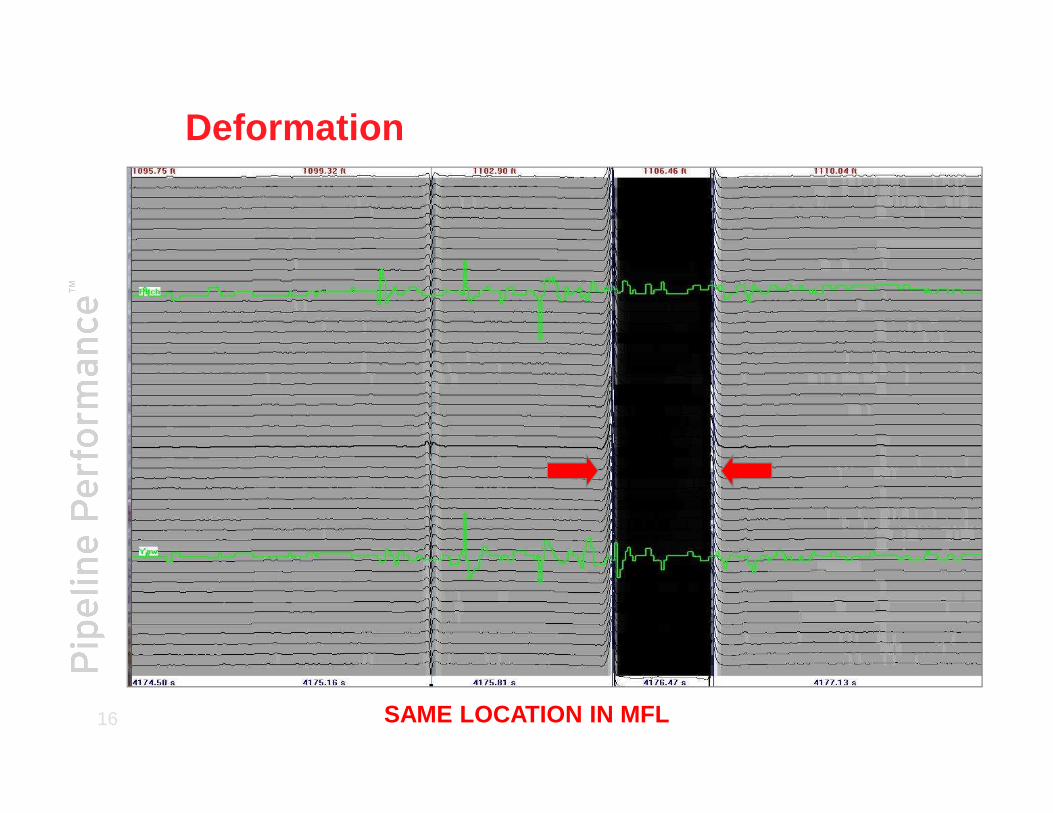
Deformation
16 SAME LOCATION IN MFL

Axial MFL Inspection Tools
® Registered trademarks of T.D. Williamson, Inc. in the United States and in foreign countries. © Copyright 2009

Axial MFL - Principle
Brushes
Magnet
Pipe Wall Section
SNSensor
18
SNSensor
Brushes
Magnet
Pipe Wall Section
Magnet Flux Leakage
Metal Loss Defect

Typical SM Axial MFL – Brush Tool
Magnetism running through pipe from pole North to South Pole
19
Sensors taking measurements of Magnetic Flux Leakage &
collecting data
Axial MFL Technology
Pipeline Features Detected:• Valves, flanges, fittings• Bends and elbows• Girth welds• Long Seam welds (HD)• Spiral welds
20
• Spiral welds• Wall Thickness change
Pipe Anomalies Identified:• General metal loss due to corrosion• Gouges• Internal/External metal loss

Value of Axial Datasets
MFL w/IDOD• Volumetric
Anomalies
21
Anomalies• Mill Anomalies• Extra Metal• Internal/External
Classification• Dents
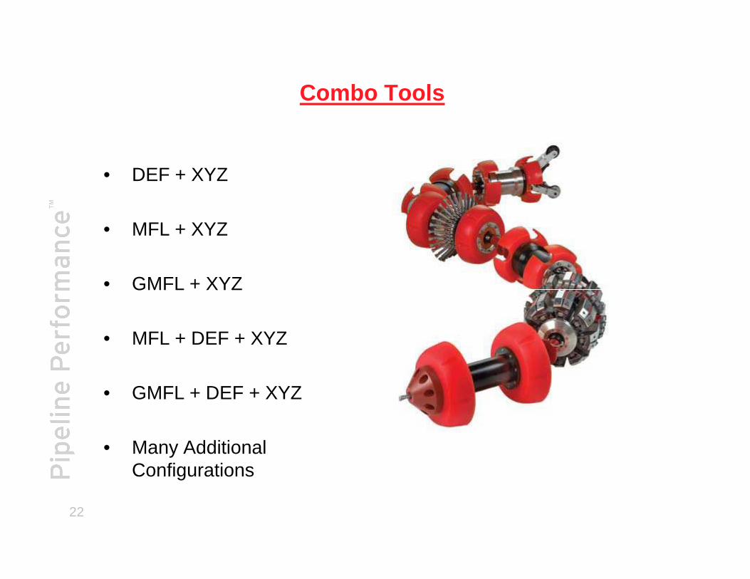
Combo Tools
• DEF + XYZ
• MFL + XYZ
• GMFL + XYZ
22
• GMFL + XYZ
• MFL + DEF + XYZ
• GMFL + DEF + XYZ
• Many Additional Configurations
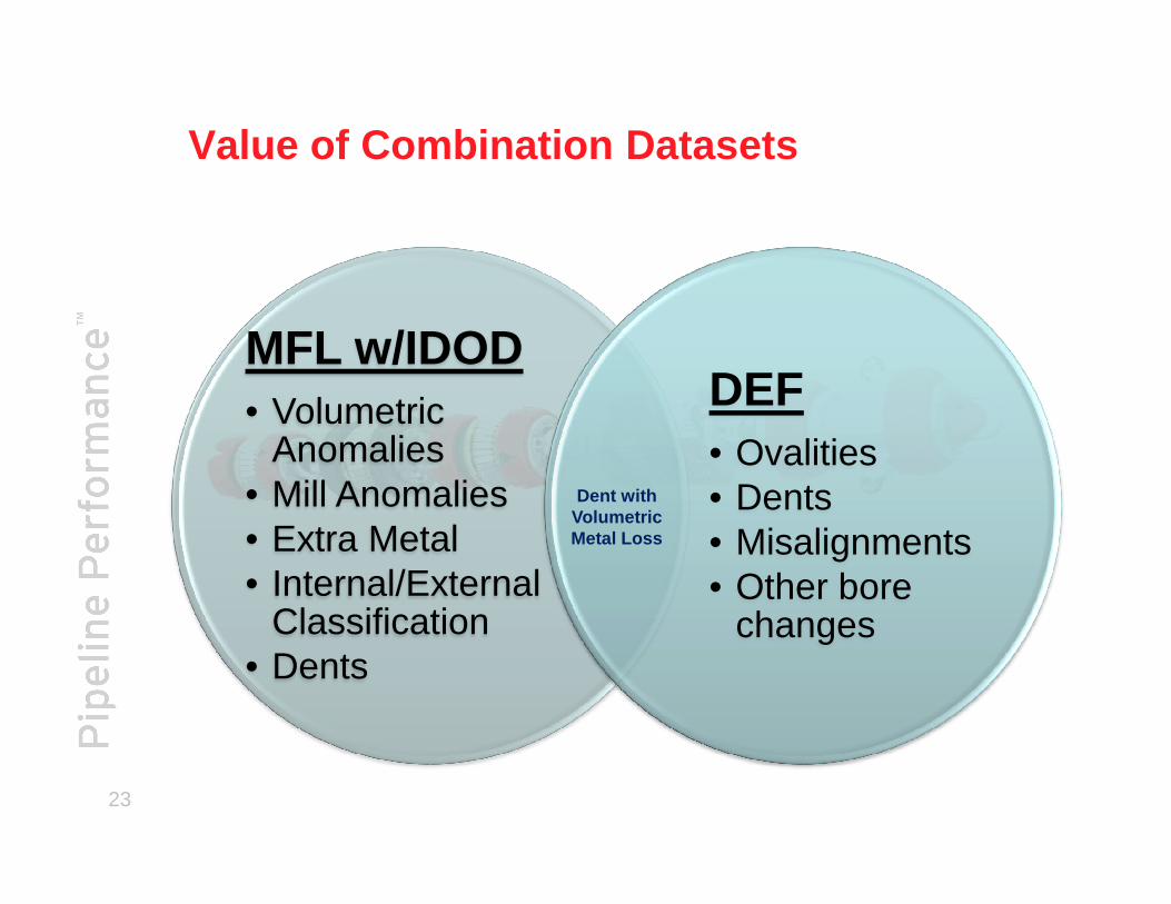
Value of Combination Datasets
MFL w/IDOD• Volumetric
Anomalies
DEF• Ovalities
23
Anomalies• Mill Anomalies• Extra Metal• Internal/External
Classification• Dents
• Ovalities• Dents• Misalignments• Other bore
changes
Dent with Volumetric Metal Loss
• Centerline
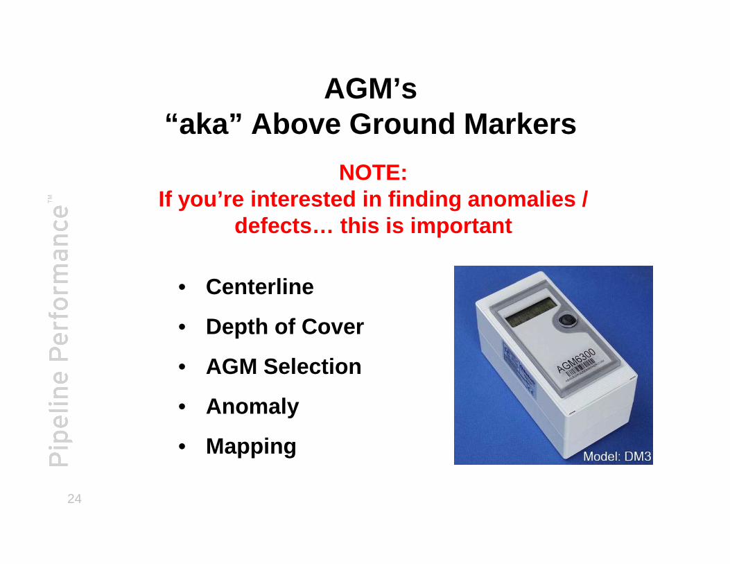
AGM’s“aka” Above Ground Markers
NOTE:If you’re interested in finding anomalies /
defects… this is important
24
• Centerline
• Depth of Cover
• AGM Selection
• Anomaly
• Mapping
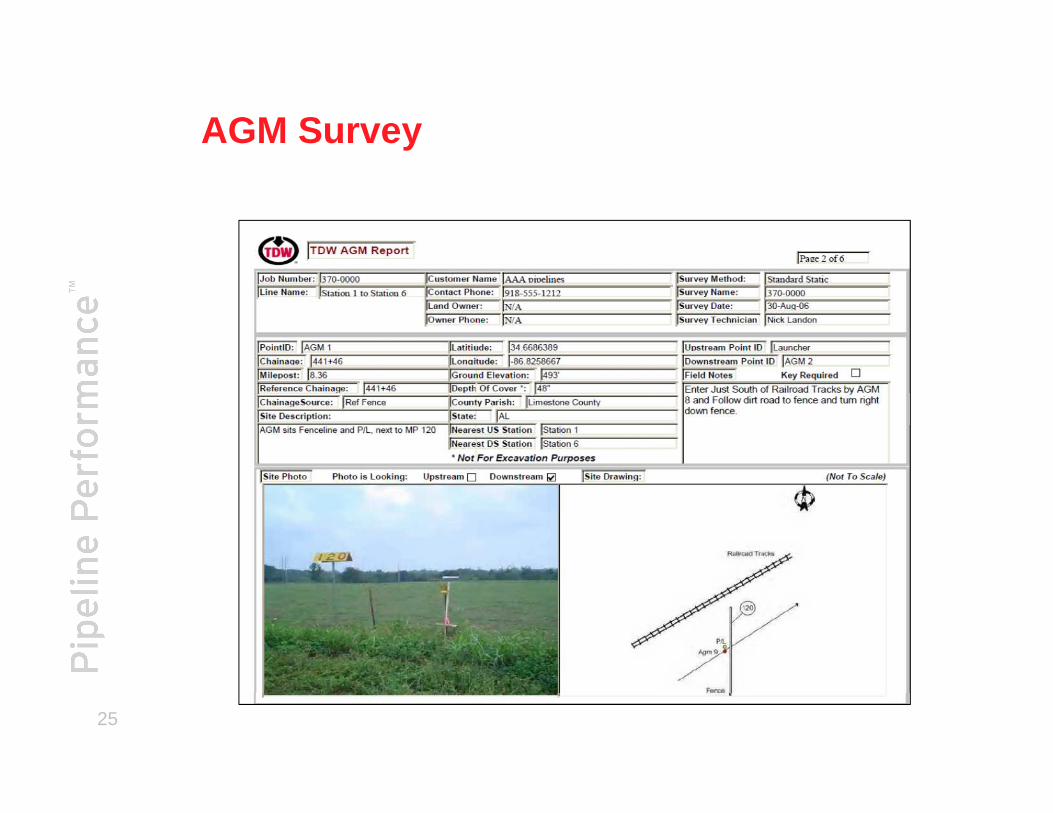
AGM Survey
25
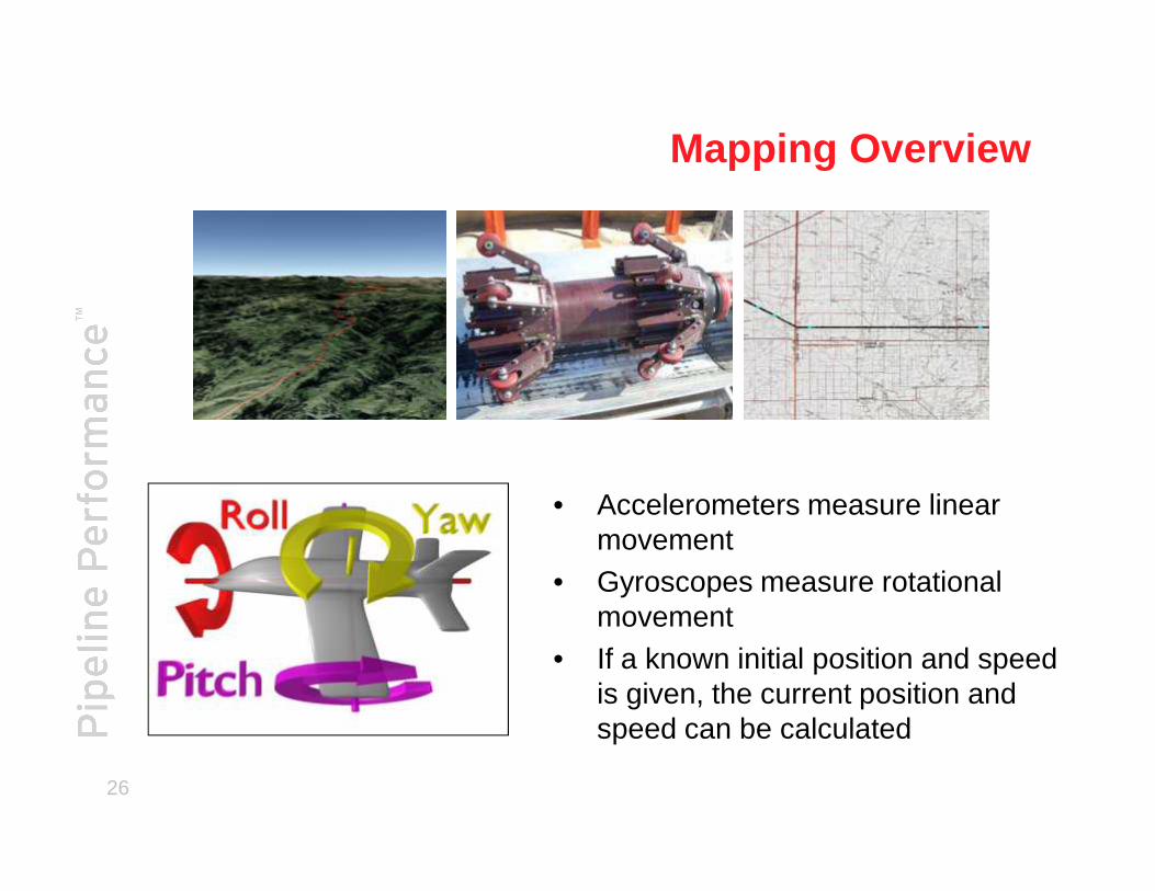
Mapping Overview
26
• Accelerometers measure linear movement
• Gyroscopes measure rotational movement
• If a known initial position and speed is given, the current position and speed can be calculated
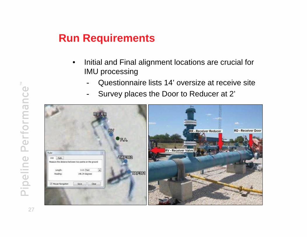
Run Requirements
• Initial and Final alignment locations are crucial for IMU processing- Questionnaire lists 14’ oversize at receive site- Survey places the Door to Reducer at 2’
27
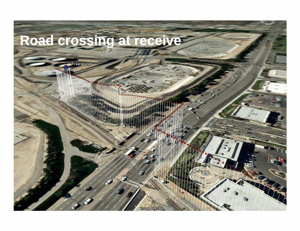
RoadRoad crossingcrossing atat receivereceive
28
LocationLocation AccuracyAccuracy
29

Run Requirements
Pipeline Operation• Mapping and/or chaining will be required to locate defects• Pipeline cleanliness is a key factor, minimal vibration is a key
element to successful mapping runs• Optimal tool speed of 1 - 3 m/s (3.3 ft/s - 9.8 ft/s)• Above ground reference points every 2km (1.24 miles) or 25
30
• Above ground reference points every 2km (1.24 miles) or 25 minutes- Stop points longer than the 5 minutes need to be
surveyed• A 15 minute alignment time at the launcher and receiver
locations- The tool must remain motionless during this time
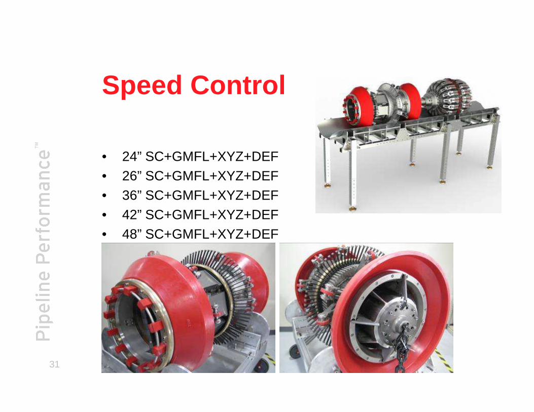
Speed Control
• 24” SC+GMFL+XYZ+DEF• 26” SC+GMFL+XYZ+DEF • 36” SC+GMFL+XYZ+DEF
31
• 42” SC+GMFL+XYZ+DEF• 48” SC+GMFL+XYZ+DEF
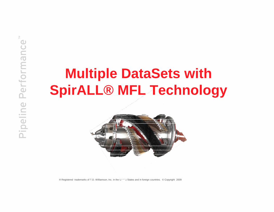
Multiple DataSets with SpirALL® MFL Technology
® Registered trademarks of T.D. Williamson, Inc. in the United States and in foreign countries. © Copyright 2009
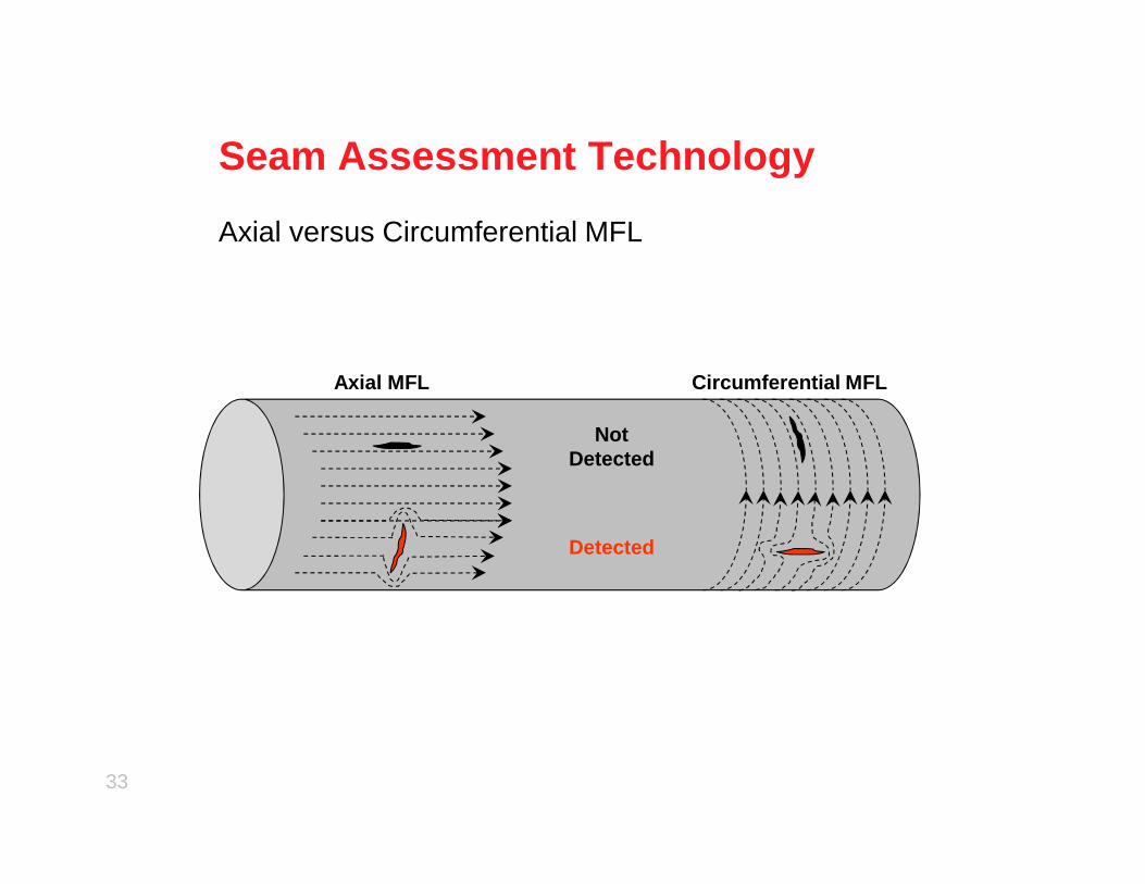
Seam Assessment Technology
Axial versus Circumferential MFL
Not
Circumferential MFLAxial MFL
33
Not Detected
Detected

Oblique Concept
Traditional MFL Oblique MFL
34
Oblique field illustration
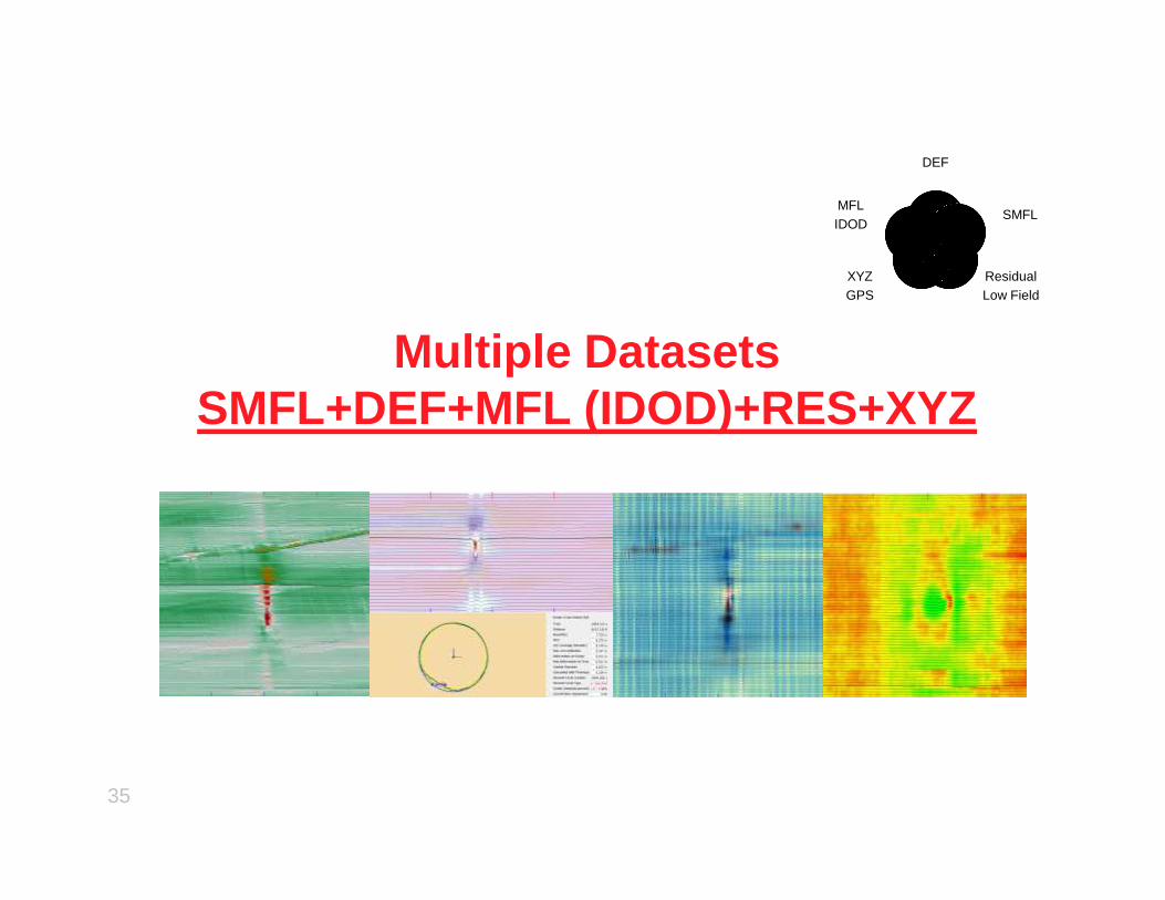
Multiple DatasetsSMFL+DEF+MFL (IDOD)+RES+XYZ
DEF
SMFL
ResidualLow Field
XYZGPS
MFLIDOD
35

Multiple Data Set Identification
36
SMFL DEF&IDOD with CPU MFL Residual with BatteryODO & Drive
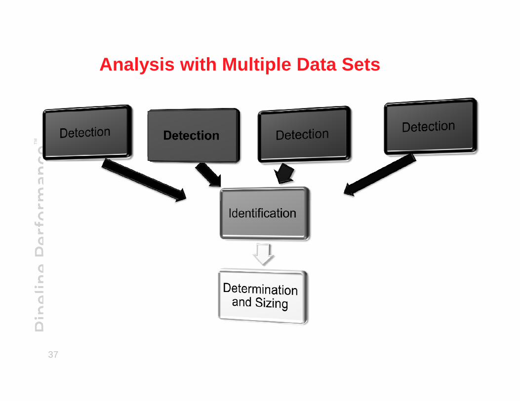
Analysis with Multiple Data Sets
37
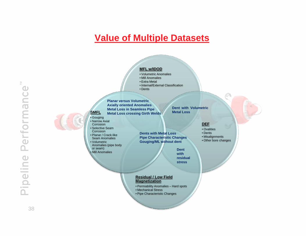
Value of Multiple Datasets
MFL w/IDOD• Volumetric Anomalies• Mill Anomalies• Extra Metal• Internal/External Classification• Dents
SMFL• Gouging
Dent with VolumetricMetal Loss
Planar versus VolumetricAxially oriented AnomaliesMetal Loss in Seamless PipeMetal Loss crossing Girth Welds
38
DEF• Ovalities• Dents• Misalignments• Other bore changes
Residual / Low Field Magnetization• Permiability Anomalies – Hard spots• Mechanical Stress• Pipe Characteristic Changes
• Gouging• Narrow Axial
Corrosion• Selective Seam
Corrosion• Planar / Crack-like
Seam Anomalies• Volumetric
Anomalies (pipe body or seam)
• Mill AnomaliesDentwithresidualstress
Dents with Metal LossPipe Characteristic ChangesGouging/ML without dent
5
6
7
8
Nor
mal
ized
Def
ect
Wid
th,
W/A
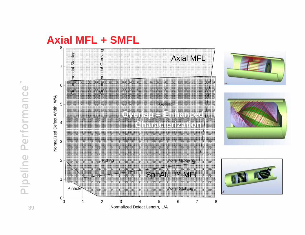
General
Circ
umfe
rent
ial S
lott
ing
Circ
umfe
rent
ial G
roov
ing
Axial MFL
Overlap = Enhanced
Axial MFL + SMFL
390 1 2 3 4 5 6 7 8
0
1
2
3
4
Normalized Defect Length, L/A
Nor
mal
ized
Def
ect
Wid
th,
W/A
Axial Slotting
Axial GroovingPitting
Pinhole
SpirALL™ MFL
Overlap = Enhanced Characterization
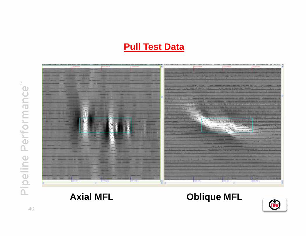
Pull Test Data
40
Axial MFL Oblique MFL
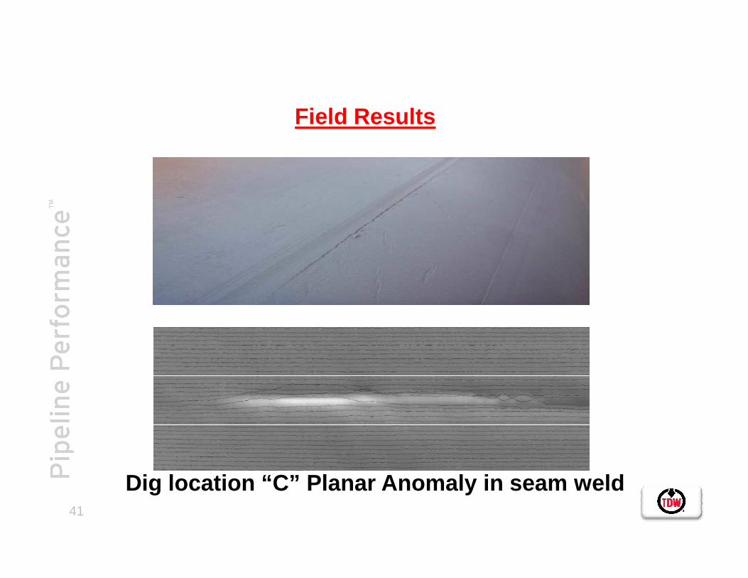
Field Results
41
Dig location “C” Planar Anomaly in seam weld

Characterization
Volumetric versus Planar anomalies Planar anomaly not visible in MFL
42
MFL data SMFL data
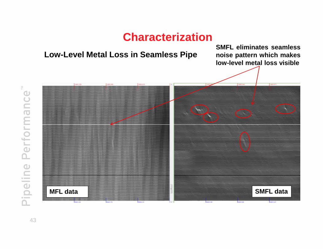
CharacterizationLow-Level Metal Loss in Seamless Pipe
SMFL eliminates seamlessnoise pattern which makeslow-level metal loss visible
43
MFL data SMFL data
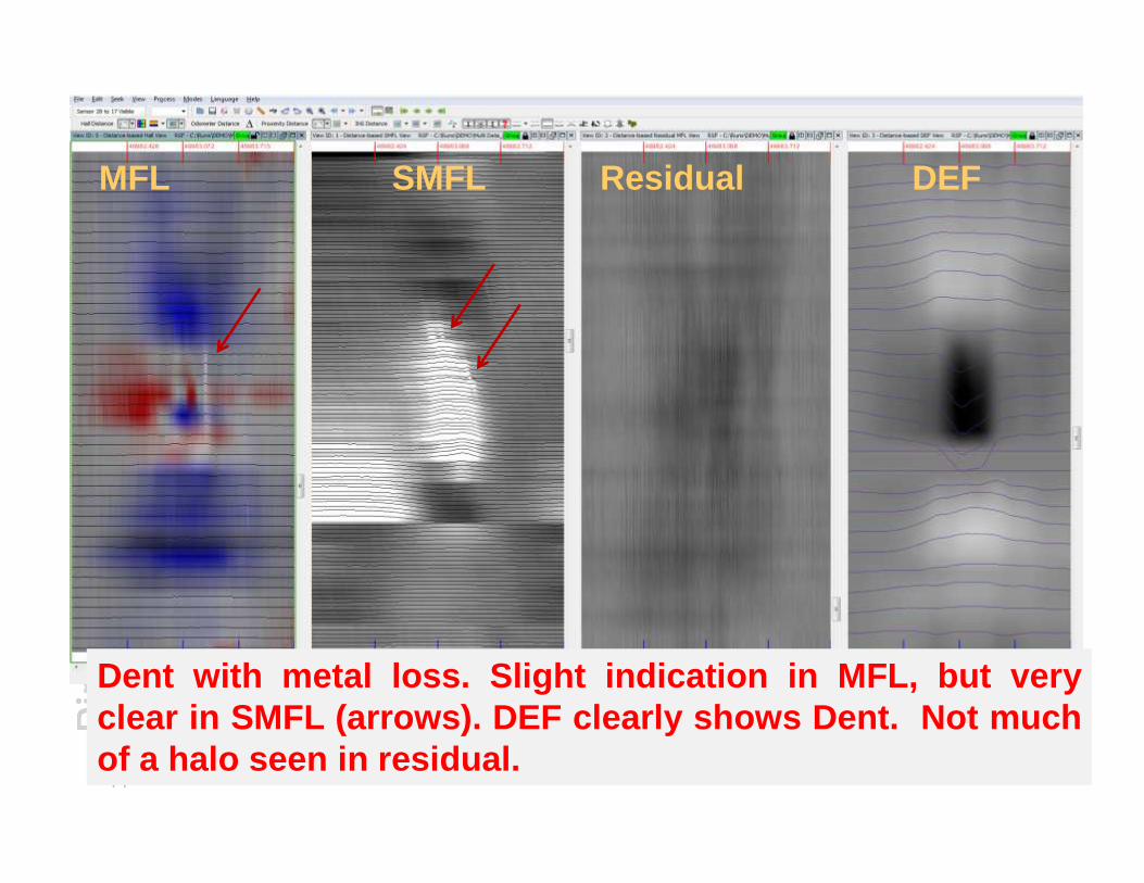
MFL SMFL Residual DEF
44
Dent with metal loss. Slight indication in MFL, but veryclear in SMFL (arrows). DEF clearly shows Dent. Not muchof a halo seen in residual.

API 1163 Qualification ofIn-Line Inspection SystemsFOREWORD
Pipeline Operators, Service Providers, and the Regulatory Community continuously striveto improve the safety and integrity of gas and liquid pipelines.
In-line inspection of pipelines is a key technology utilized by the industry to help maintainsystems safety and integrity.
This Standard serves as an umbrella document to be used with and complementcompanion standards. NACE RP 0102-2002, “Standard Recommended Practice, In-Line
45
companion standards. NACE RP 0102-2002, “Standard Recommended Practice, In-LineInspections of Pipelines”; and ASNT ILI PQ 2003, “In-Line Inspection PersonnelQualification & Certification” all have been developed to enable Service Providers andPipeline Operators to provide rigorous processes, that will consistently qualify theequipment, people, processes and software utilized in the in-line inspection industry. Theteams that have worked so diligently in the development of these three standards expectimprovement in the results from in-line inspections with accompanying improvements inthe safety and integrity of gas and liquid pipelines.
Appreciation is extended to the Pipeline Operators Forum for the use of their guide for in-line inspections, “Specifications and Requirements for Intelligent Pigging of Pipelines,”Version 2.1, Nov. ‘98. Portions of this guide were incorporated directly into this Standard.
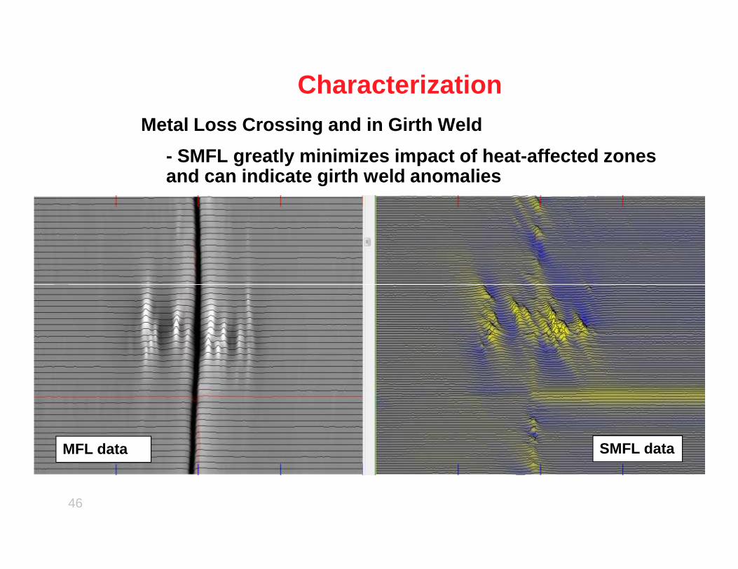
CharacterizationMetal Loss Crossing and in Girth Weld
- SMFL greatly minimizes impact of heat-affected zon es and can indicate girth weld anomalies
46
MFL data SMFL data

MFL SMFL
Anomaly 1
longitudinal seamweld
MFL SMFL
longitudinal seamweld
Anomaly 2
CharacterizationPlanar/Crack-like anomalies in the Long Seam
47
MFL SMFL
longitudinal seamweld
Anomaly 3
# Descr. ILI % Field % ILI Length (in.)
Field Length (in.)
ILI Width (in.)
Field Width (in.)
1 Planar 37 39 2.22 2.18 0.04 0.01
2 Planar 35 36 1.92 1.22 0.03 0.01
3 Planar 28 35 1.88 2.00 0.06 0.01
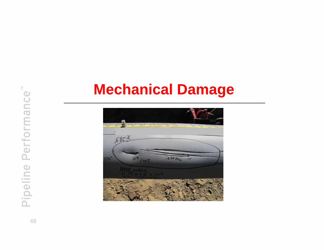
Mechanical Damage
48
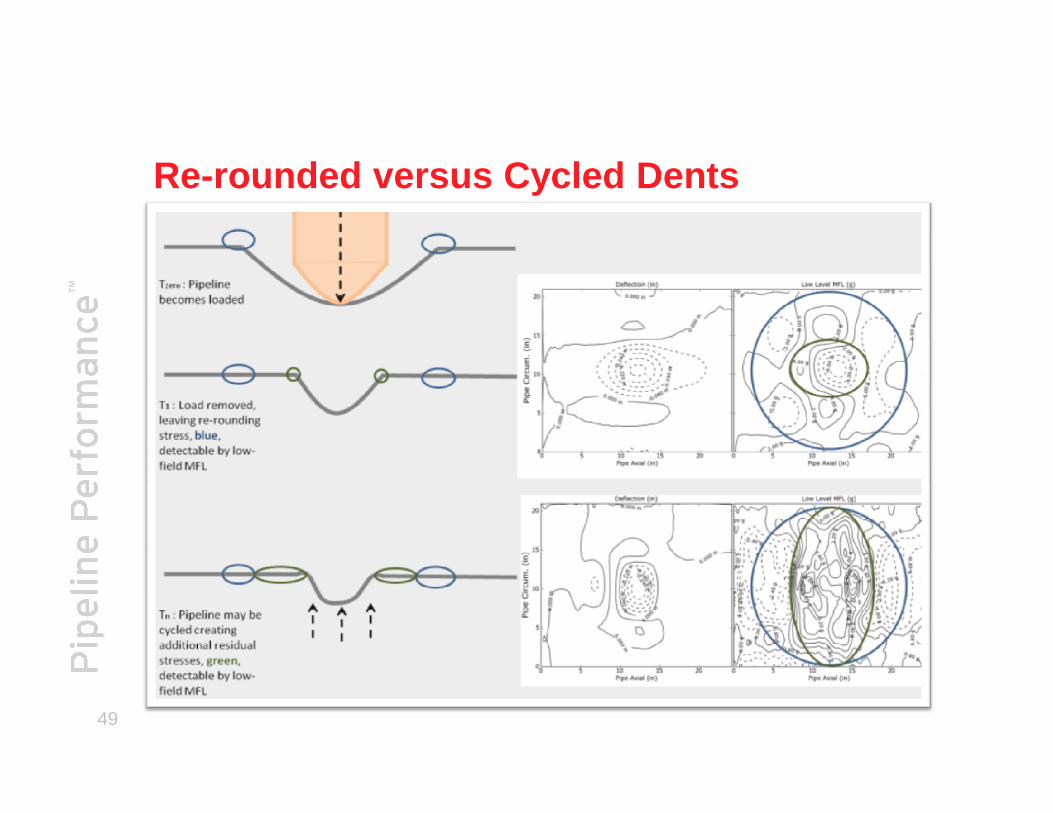
Re-rounded versus Cycled Dents
49
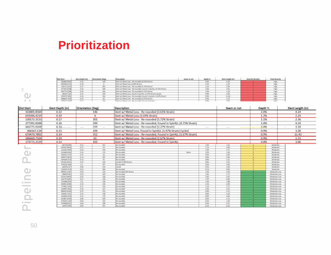
Prioritization
50
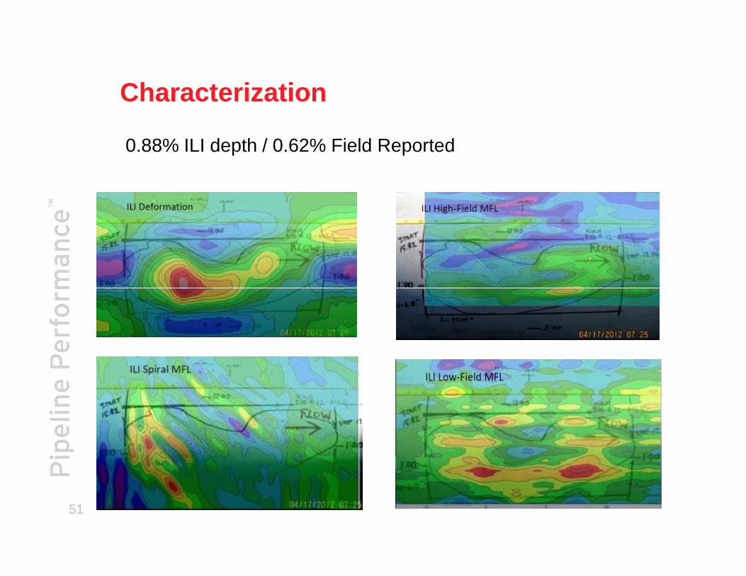
Characterization
0.88% ILI depth / 0.62% Field Reported
51

Ongoing Project and Future work
MDS_EMAT Development
52

The Next Addition - EMAT
53
54

Low Field MFL - Steel MicrostructureWeld Low Carbon
55
High Carbon Hard Spot
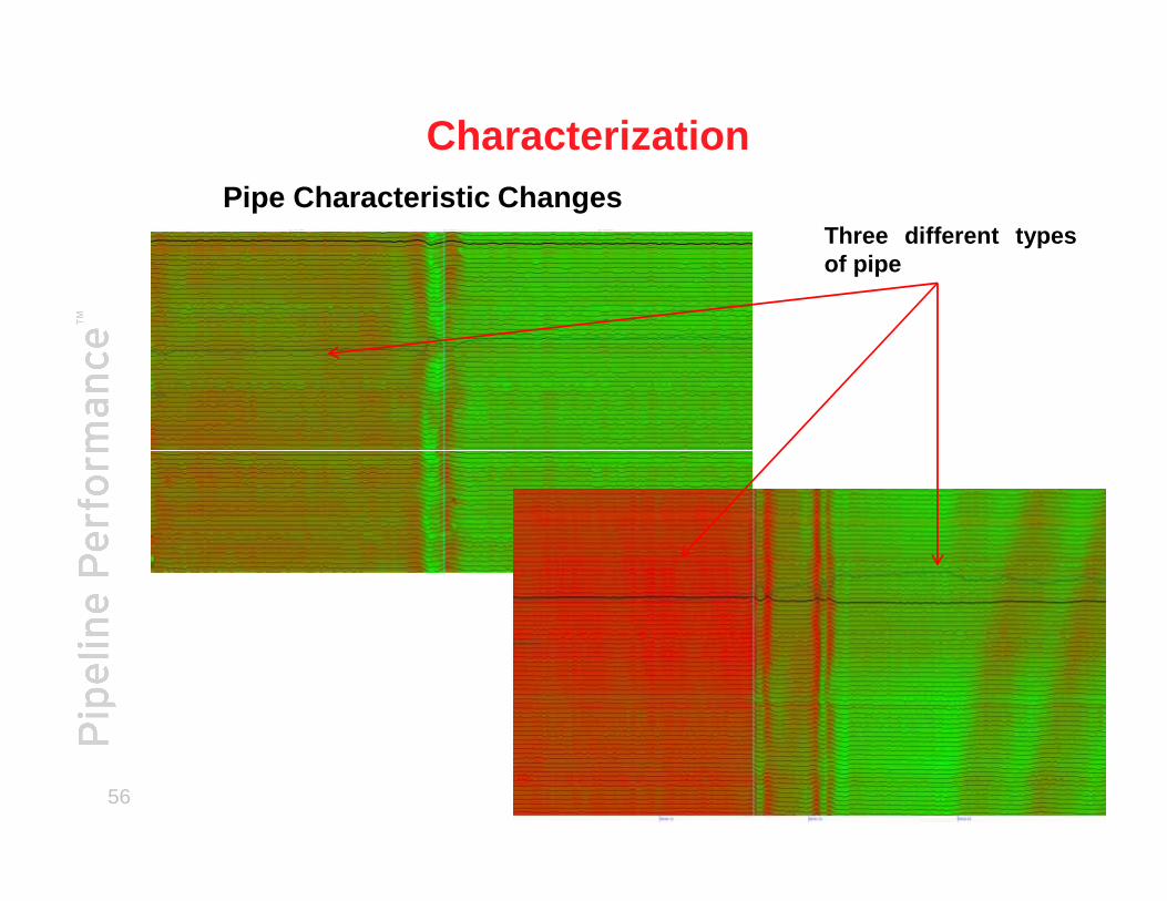
Pipe Characteristic Changes
Characterization
Three different typesof pipe
56
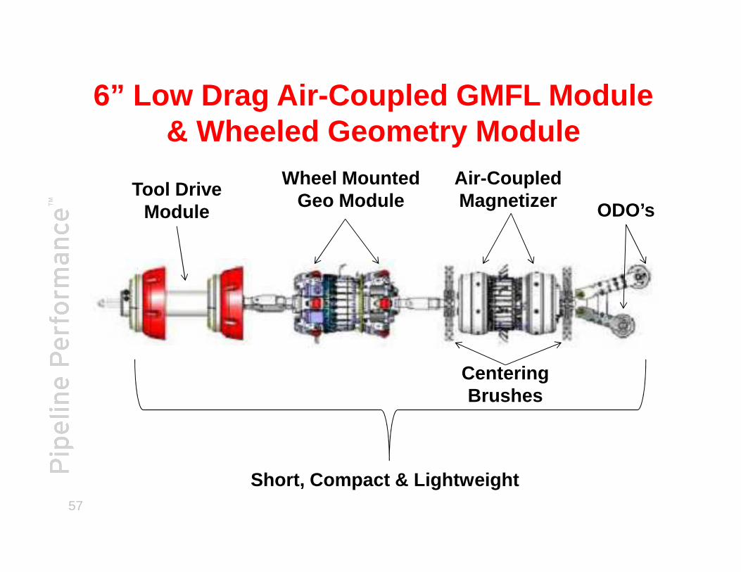
6” Low Drag Air-Coupled GMFL Module & Wheeled Geometry Module
Wheel Mounted Geo Module
Air-CoupledMagnetizer
Tool Drive Module ODO’s
57
Short, Compact & Lightweight
Centering Brushes
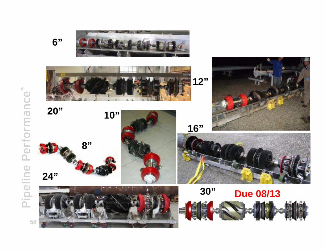
6”
20”
12”
16”10”
58
24”
16”
8”
30” Due 08/13
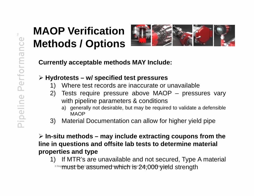
Currently acceptable methods MAY Include:
� Hydrotests – w/ specified test pressures1) Where test records are inaccurate or unavailable2) Tests require pressure above MAOP – pressures vary
with pipeline parameters & conditions
MAOP VerificationMethods / Options
® Registered trademarks of T.D. Williamson, Inc. in the United States and in foreign countries. © Copyright 2009
with pipeline parameters & conditionsa) generally not desirable, but may be required to validate a defensible
MAOP3) Material Documentation can allow for higher yield pipe
� In-situ methods – may include extracting coupons from the line in questions and offsite lab tests to determin e materialproperties and type
1) If MTR’s are unavailable and not secured, Type A materialmust be assumed which is 24,000 yield strength
PMI is…what ?
What is a proven used PMI Method ?
The analysis of a metallic alloy to establish composition by reading the quantitiesby percentage of its constituent elements as well as mechanical properties.
Cutting strips or coupons to have them material analyzed in a laboratory environment
Where are we headed with PMI ?OES + ABI = PMI
60
OES is a method for establishing elemental chemistry is the use of Optical EmissionSpectrometry. ABI is a method mechanical properties there are methods forestablishing Ultimate tensile strength, ultimate yield strength and fracture toughness.
OES + ABI = PMI
What other technology can helpenhance this Methodology ?
ILI tools are capable of establishing material types which can then be positively identified through PMI
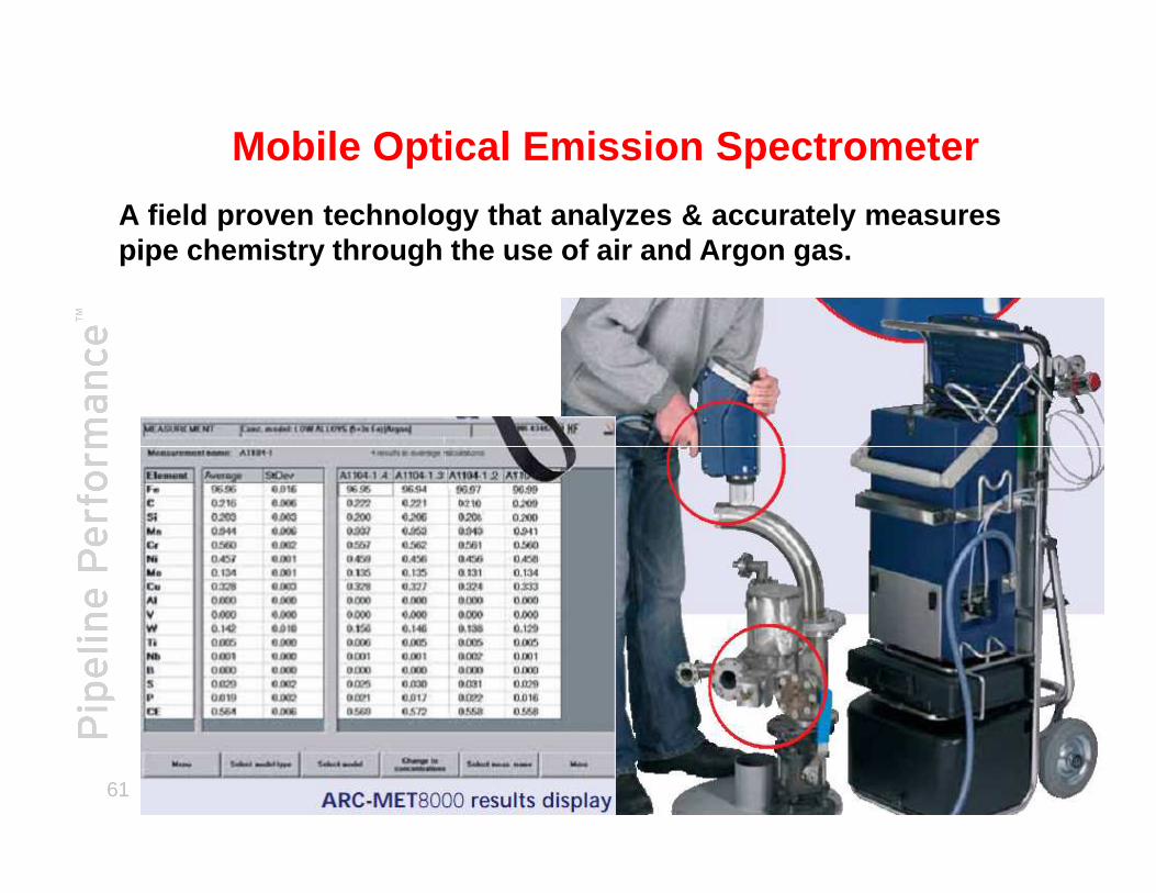
A field proven technology that analyzes & accurately measur espipe chemistry through the use of air and Argon gas.
Mobile Optical Emission Spectrometer
61
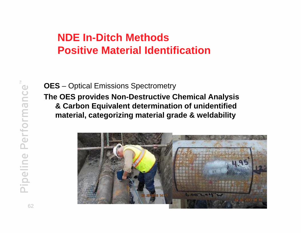
NDE In-Ditch MethodsPositive Material Identification
OES – Optical Emissions SpectrometryThe OES provides Non-Destructive Chemical Analysis
& Carbon Equivalent determination of unidentified material, categorizing material grade & weldability
62
material, categorizing material grade & weldability

NDE In-Ditch Methodsi.e. Positive Material Identification
The technique measures load-depth curve during indentatio n,creates a stress-strain and analyzes the mechanical proper tiesrelated to deformation such as yield strength, tensile stre ngth,and work -hardening index .
Automated Ball Indentation
63
and work -hardening index .

Automated BallIndentation Systems
• This technique is advantageous for in-field applications:�The system is very compact & portable
�Does not require a large excavation
® Registered trademarks of T.D. Williamson, Inc. in the United States and in foreign countries. © Copyright 2009
�This equipment can be secured via chains or magnets�Results can be provided in a very short time frame in field
�One to two hours
X
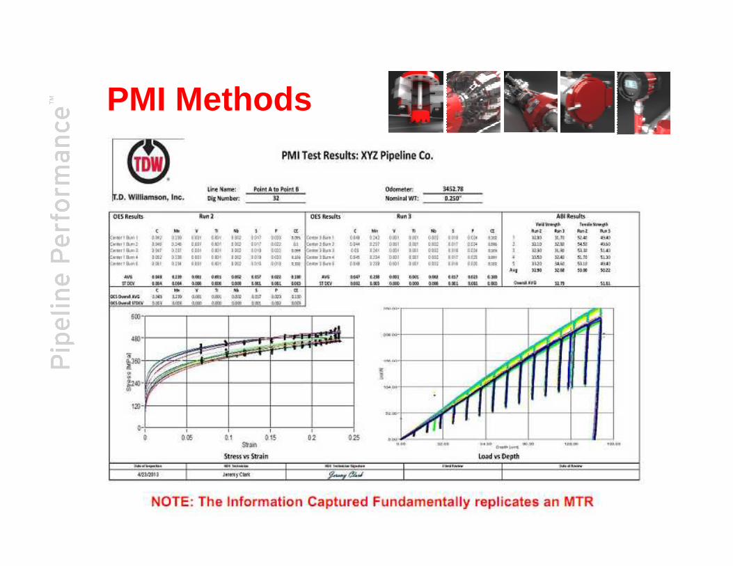
PMI Methods
® Registered trademarks of T.D. Williamson, Inc. in the United States and in foreign countries. © Copyright 2009
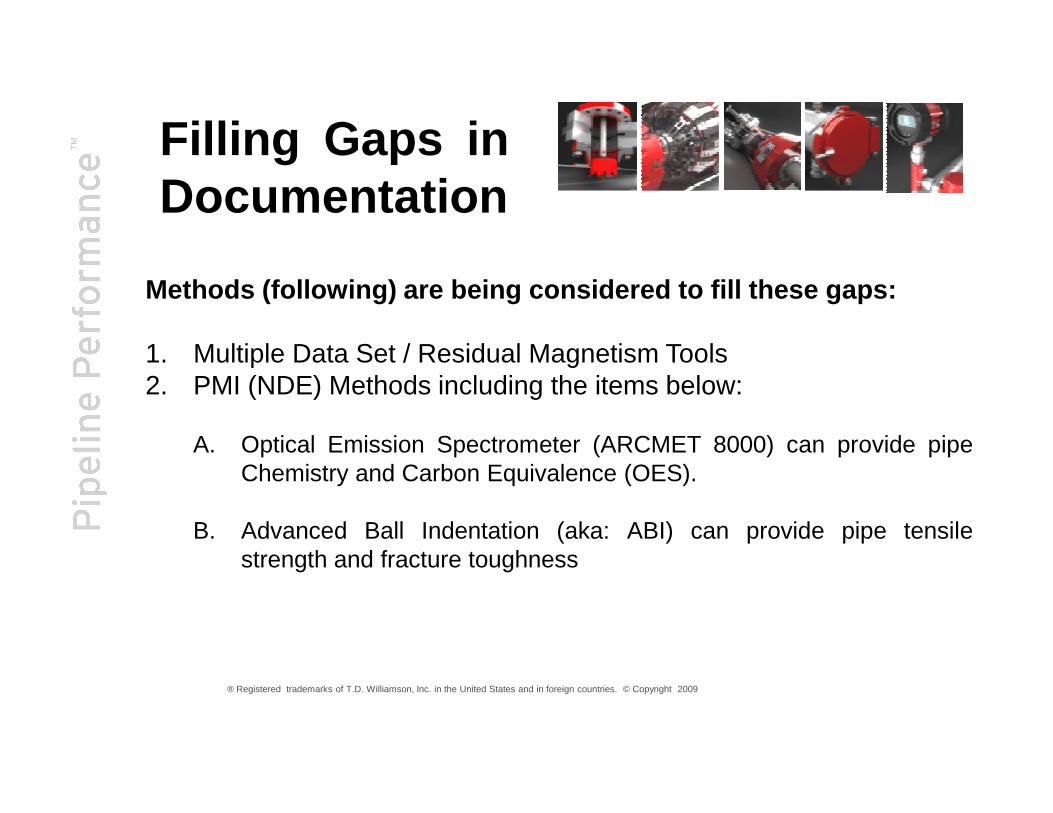
Methods (following) are being considered to fill these gaps :
1. Multiple Data Set / Residual Magnetism Tools2. PMI (NDE) Methods including the items below:
Filling Gaps inDocumentation
® Registered trademarks of T.D. Williamson, Inc. in the United States and in foreign countries. © Copyright 2009
A. Optical Emission Spectrometer (ARCMET 8000) can provide pipeChemistry and Carbon Equivalence (OES).
B. Advanced Ball Indentation (aka: ABI) can provide pipe tensilestrength and fracture toughness

Having the RIGHT tool for the RIGHT job is CRITICAL!
67
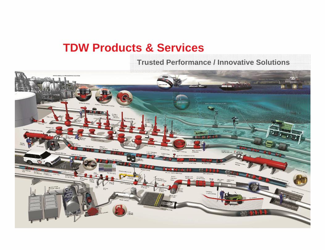
TDW Products & ServicesTrusted Performance / Innovative Solutions
68

Questions ?
69
Questions ?
Related Documents