IEEE SENSORS JOURNAL, VOL. 14, NO. 9, SEPTEMBER 2014 3283 An Optical Tactile Array Probe Head for Tissue Palpation During Minimally Invasive Surgery Hui Xie, Hongbin Liu, Lakmal D. Seneviratne, and Kaspar Althoefer Abstract—This paper presents a novel tactile probe head designed for tissue palpation during minimally invasive surgery (MIS). The probe head uses fiber optics and consists of 14 tactile sensing elements at 2.5-mm spacing with a diameter of 14 mm. Each tactile element contains a microstructure converting the tissue reaction force applied on sensing nodes into a circular image pattern through transmitting and receiving fibers. The image patterns of all the sensing elements are captured by a camera attached at the proximal end of the receiving fibers and are converted to tactile force feedback through image processing. Validation tests showed that each sensing element of the tactile probe head can measure forces from 0 to 0.5 N with a resolution of 0.05 N. The proposed sensing probe is low cost, lightweight, sterilizable, easy to be miniaturized, and magnetic resonance environment compatible. Experiments were performed for testing the probe’s capability of detecting the tissue abnormality through spatial distribution of tactile force feedback. The proposed tactile probe head with its capacity to accurately detect nodules embedded inside soft tissue can be an effective tool in surgical palpation during MIS. Index Terms—Tissue palpation, probe head, tactile sensor, optical fiber array, MR compatible. I. I NTRODUCTION D URING open surgery, palpation—the process where clin- icians press their fingers on the patient’s soft tissue organs to assess tool-tissue interaction forces- is a powerful tool in locating subsurface anatomical structures and assessing tissue properties [1]. As certain solid tumors are harder than the surrounding tissue, their presence, sizes, and locations can be obtained through tactile feedback. Manual palpation is effective in the detection of breast [2] and prostate [3] tumors, for example, and an essential means of ensuring a successful resection whilst reducing error margins. However, direct manual palpation cannot be performed through the small incisions used in minimally invasive surgery (MIS). Compared to the traditional open surgery, MIS offers many advantages [4] including lower infection risks, reduced tissue trauma, and accelerated postoperative recovery. However, a major drawback of MIS is the absence of direct tissue interaction Manuscript received April 4, 2014; accepted May 22, 2014. Date of publication June 3, 2014; date of current version July 29, 2014. This work was supported by the STIFF-FLOP Project through the European Communities Seventh Framework Programme under Grant 287728. The associate editor coordinating the review of this paper and approving it for publication was Prof. Boris Stoeber. (Corresponding author: Hongbin Liu.) The authors are with the Centre for Robotics Research, Department of Informatics, King’s College London, London WC2R 2LS, U.K. (e-mail: [email protected]; [email protected]; [email protected]; [email protected]). Color versions of one or more of the figures in this paper are available online at http://ieeexplore.ieee.org. Digital Object Identifier 10.1109/JSEN.2014.2328182 and the loss of tactile feedback [5], [6]. Surgical instruments with force sensing capability to indent, or grasp soft tissue [7] have been developed to provide surgeons performing MIS with an alternative to manual palpation. Tissue properties (e.g., size, shape, stiffness and depth) which provide the surgeon with a better understanding of internal organs during an operation [8] can be identified through mechanical soft tissue modelling and measurements of force and tissue local deformation. Numer- ous force and tactile sensing technologies for instrumenting the surgical devices of MIS have been developed [9], [10]. Tholey et al. [11] investigated current-based sensing methods in the framework of a specially designed laparoscopic grasper, which proposed a simple way to measure force in MIS. Tadano et al. developed a 4 degree-of-freedom pneumatic- driven forceps providing force sensing capabilities based on the measurement of air pressure. In [12], a force-sensitive probe has been created to localize lung tumors by analyzing tissue stiffness. In [13], a robotic palpation system equipped with the force/torque sensor, has been developed for examining the prostate gland. Furthermore, a rolling palpation probe, which measures the stiffness of soft tissue by rolling over it, was proposed for tissue abnormality localization in our previous work [14] and [15]. The aforementioned instruments are able to measure local tissue properties but investigation of large tissue areas can be time consuming [16]. To this purpose various palpation tools using tactile array sensors have been developed to mechanically image large tissue areas. Based on resistive sensing, Schostek et al. [17] developed a prototype of a MIS grasper which provides both the spatial distribution and magnitudes of the applied forces. Among certain sensing principles, capacitive-based sensing is comparably efficient for measuring the applied forces and it has been widely applied in palpation. Howe et al. [18] have developed a capacitive tactile array remote palpation system which can measure forces with a high resolution over a range of 0 to 2 N. Rajamani’s group [19] has developed a MEMS tactile sensor by using two capacitive force gauges, which are integrated under a pair of bumps with different stiffness. This sensor can quickly detect elasticity change and is capable of mea- suring tissue elasticity in-vivo. Commercial capacitive-based tactile array sensors have also been implemented in surgical palpation to localize prostate tumors [20] and to locate lung tumors [21], [22]. The main drawbacks [23] of the resistive- based and the capacitive-based tactile array sensor relate to issues of sterilization and MRI compatibility. Based on [24], the electronic components of these sensors could be dam- aged during the sterilization procedure, while their metallic 1530-437X © 2014 IEEE. Personal use is permitted, but republication/redistribution requires IEEE permission. See http://www.ieee.org/publications_standards/publications/rights/index.html for more information.

Welcome message from author
This document is posted to help you gain knowledge. Please leave a comment to let me know what you think about it! Share it to your friends and learn new things together.
Transcript

IEEE SENSORS JOURNAL, VOL. 14, NO. 9, SEPTEMBER 2014 3283
An Optical Tactile Array Probe Head for TissuePalpation During Minimally Invasive Surgery
Hui Xie, Hongbin Liu, Lakmal D. Seneviratne, and Kaspar Althoefer
Abstract— This paper presents a novel tactile probe headdesigned for tissue palpation during minimally invasive surgery(MIS). The probe head uses fiber optics and consists of 14 tactilesensing elements at 2.5-mm spacing with a diameter of 14 mm.Each tactile element contains a microstructure converting thetissue reaction force applied on sensing nodes into a circularimage pattern through transmitting and receiving fibers. Theimage patterns of all the sensing elements are captured by acamera attached at the proximal end of the receiving fibersand are converted to tactile force feedback through imageprocessing. Validation tests showed that each sensing elementof the tactile probe head can measure forces from 0 to 0.5 Nwith a resolution of 0.05 N. The proposed sensing probe islow cost, lightweight, sterilizable, easy to be miniaturized, andmagnetic resonance environment compatible. Experiments wereperformed for testing the probe’s capability of detecting the tissueabnormality through spatial distribution of tactile force feedback.The proposed tactile probe head with its capacity to accuratelydetect nodules embedded inside soft tissue can be an effectivetool in surgical palpation during MIS.
Index Terms— Tissue palpation, probe head, tactile sensor,optical fiber array, MR compatible.
I. INTRODUCTION
DURING open surgery, palpation—the process where clin-icians press their fingers on the patient’s soft tissue
organs to assess tool-tissue interaction forces- is a powerfultool in locating subsurface anatomical structures and assessingtissue properties [1]. As certain solid tumors are harder thanthe surrounding tissue, their presence, sizes, and locationscan be obtained through tactile feedback. Manual palpationis effective in the detection of breast [2] and prostate [3]tumors, for example, and an essential means of ensuring asuccessful resection whilst reducing error margins. However,direct manual palpation cannot be performed through the smallincisions used in minimally invasive surgery (MIS). Comparedto the traditional open surgery, MIS offers many advantages[4] including lower infection risks, reduced tissue trauma,and accelerated postoperative recovery. However, a majordrawback of MIS is the absence of direct tissue interaction
Manuscript received April 4, 2014; accepted May 22, 2014. Date ofpublication June 3, 2014; date of current version July 29, 2014. This work wassupported by the STIFF-FLOP Project through the European CommunitiesSeventh Framework Programme under Grant 287728. The associate editorcoordinating the review of this paper and approving it for publication wasProf. Boris Stoeber. (Corresponding author: Hongbin Liu.)
The authors are with the Centre for Robotics Research, Department ofInformatics, King’s College London, London WC2R 2LS, U.K. (e-mail:[email protected]; [email protected]; [email protected];[email protected]).
Color versions of one or more of the figures in this paper are availableonline at http://ieeexplore.ieee.org.
Digital Object Identifier 10.1109/JSEN.2014.2328182
and the loss of tactile feedback [5], [6]. Surgical instrumentswith force sensing capability to indent, or grasp soft tissue [7]have been developed to provide surgeons performing MIS withan alternative to manual palpation. Tissue properties (e.g., size,shape, stiffness and depth) which provide the surgeon with abetter understanding of internal organs during an operation [8]can be identified through mechanical soft tissue modelling andmeasurements of force and tissue local deformation. Numer-ous force and tactile sensing technologies for instrumentingthe surgical devices of MIS have been developed [9], [10].Tholey et al. [11] investigated current-based sensing methodsin the framework of a specially designed laparoscopic grasper,which proposed a simple way to measure force in MIS.Tadano et al. developed a 4 degree-of-freedom pneumatic-driven forceps providing force sensing capabilities based onthe measurement of air pressure. In [12], a force-sensitiveprobe has been created to localize lung tumors by analyzingtissue stiffness. In [13], a robotic palpation system equippedwith the force/torque sensor, has been developed for examiningthe prostate gland. Furthermore, a rolling palpation probe,which measures the stiffness of soft tissue by rolling overit, was proposed for tissue abnormality localization in ourprevious work [14] and [15].
The aforementioned instruments are able to measure localtissue properties but investigation of large tissue areas canbe time consuming [16]. To this purpose various palpationtools using tactile array sensors have been developed tomechanically image large tissue areas. Based on resistivesensing, Schostek et al. [17] developed a prototype of aMIS grasper which provides both the spatial distribution andmagnitudes of the applied forces. Among certain sensingprinciples, capacitive-based sensing is comparably efficient formeasuring the applied forces and it has been widely appliedin palpation. Howe et al. [18] have developed a capacitivetactile array remote palpation system which can measureforces with a high resolution over a range of 0 to 2 N.Rajamani’s group [19] has developed a MEMS tactile sensorby using two capacitive force gauges, which are integratedunder a pair of bumps with different stiffness. This sensorcan quickly detect elasticity change and is capable of mea-suring tissue elasticity in-vivo. Commercial capacitive-basedtactile array sensors have also been implemented in surgicalpalpation to localize prostate tumors [20] and to locate lungtumors [21], [22]. The main drawbacks [23] of the resistive-based and the capacitive-based tactile array sensor relate toissues of sterilization and MRI compatibility. Based on [24],the electronic components of these sensors could be dam-aged during the sterilization procedure, while their metallic
1530-437X © 2014 IEEE. Personal use is permitted, but republication/redistribution requires IEEE permission.See http://www.ieee.org/publications_standards/publications/rights/index.html for more information.
3284 IEEE SENSORS JOURNAL, VOL. 14, NO. 9, SEPTEMBER 2014
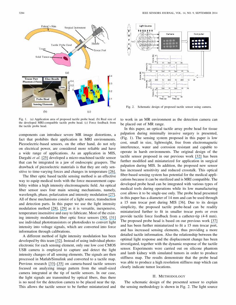
Fig. 1. (a) Application area of proposed tactile probe head. (b) Real size ofthe developed MRI-compatible tactile probe head. (c) Force feedback fromthe tactile probe head.
components can introduce severe MR image distortions, afact that prohibits their application in MRI environments.Piezoelectric-based sensors, on the other hand, do not relyon electrical power, are considered more reliable and havea wide range of applications. As an application in MIS,Dargahi et al. [25] developed a micro-machined tactile sensorthat can be integrated in a jaw of endoscopic graspers. Thedrawback of piezoelectric materials is that they are only sen-sitive to time-varying forces and changes in temperature [26].
The fiber optic based tactile sensing method is an effectiveway to equip medical tools with the force measurement capa-bility within a high intensity electromagnetic field. An opticalfiber sensor uses four main sensing mechanisms, namely,wavelength, phase, polarization and intensity modulation [27].All of these mechanisms consist of a light source, transductionand detection parts. In this paper we use the light intensitymodulation method [28], [29] as it is versatile, inexpensive,temperature insensitive and easy to fabricate. Most of the exist-ing intensity modulation fiber optic force sensors [30], [31]use individual phototransistors or photodiodes to convert lightintensity into voltage signals, which are converted into forceinformation through calibrations.
A different method of light intensity modulation has beendeveloped by this team [32]. Instead of using individual photo-electronic for each sensing element, only one low cost CMOSUSB camera is employed to capture and detect the lightintensity changes of all sensing elements. The signals are thenprocessed in Matlab/Simulink and converted to a tactile map.Previous research [33]–[35] on camera-based tactile sensorsfocused on analyzing image pattern from the small-sizedcamera integrated at the tip of tactile sensors. In our case,the light signals are transmitted by optical fibers, thus thereis no need for the detection camera to be placed near the tip.This allows the tactile sensor to be further miniaturized and
Fig. 2. Schematic design of proposed tactile sensor using camera.
to work in an MR environment as the detection camera canbe placed out of MR range.
In this paper, an optical tactile array probe head for tissuepalpation during minimally invasive surgery is presented,(Fig. 1). The sensing system proposed in this paper is lowcost, small in size, lightweight, free from electromagneticinterference, water and corrosion resistant and capable tooperate in harsh environments. The original design of thetactile sensor proposed in our previous work [32] has beenfurther modified and miniaturized for application in surgicalpalpation during MIS. In addition, the proposed new sensorhas increased sensitivity and reduced crosstalk. This opticalfiber-based sensing system has potential for the medical appli-cations because it can be sterilized and is MRI compatible. Thedeveloped probe head can be integrated with various types ofmedical tools during operations while its low manufacturingcost allows it to be single-use only. The probe head presentedin this paper has a diameter of 14 mm and can be used througha 15 mm trocar port during MIS [36]. Due to its designsimplicity, the proposed tactile probe-head can be readilyminiaturized further to fit in smaller trocar ports or evenprovide tactile force feedback from a catheter-tip (4-8 mm).The proposed probe head is based on our previous work [37]and has been further miniaturized to fit a 15 mm trocar port,and has increased sensing elements, thus providing a moredetailed tactile information. Also the relationship between theoptimal light response and the displacement change has beeninvestigated, together with the dynamic response of the tactilesensor. Experiments were carried out on silicone phantomand lamb kidney with simulated tumors in order to producestiffness map. The results demonstrate that the probe headwas able to produce a high resolution stiffness map which canclearly indicate tumor locations.
II. METHODOLOGY
The schematic design of the presented sensor to explainthe sensing methodology is shown in Fig. 2. The light source

XIE et al.: OPTICAL TACTILE ARRAY PROBE HEAD FOR TISSUE PALPATION 3285
Fig. 3. Sequence of Image Processing before and after thresholding:(a) gray scale images captured by camera, (b) binary image after thresholding,(c) gray value of individual pixel, (d) binary value of individual pixel,(e) intensity map of gray scale picture, and (f) intensity map after thresholding.
transmits the light to the sensing area, which is 14 mm indiameter with 14 sensing elements. When force is applied toa sensing element, the displacement change of the flexiblematerial varies the light intensity observed by the receivingfiber. The image of the light intensity distribution is capturedby the camera attached at the end of the receiving fiber, and isconverted to spatial contact forces through image processing.
A. Processing of Light Intensity Image
In order to extract useful information while at the sametime removing the background noise of the light intensityimage, we converted the gray scale image into binary image,Fig. 3. A variety of thresholding methods, such as the point-dependent and the region-dependent method [38] have beenproposed in the past where the threshold value is determinedeither by the gray level of each individual pixel or the localgray level neighbouring each pixel. A global thresholdingmethod [39] is giving one threshold value to the entire picture,while a local one [40] provides different values to subimages.To deal with the high contrast of background and object in
Fig. 4. Schematic drawing of the probe head design and assemblies.
the light intensity image, we have used here a thresholdingmethod in which the valley of the histogram is defined asthe threshold value [41]. Compare to previously describedthresholding methods, this is a more straightforward methodand has with less computational complexity. We define f (x, y)as the gray value of the pixel coordinated at (x, y) in the imagewith a size of xmax by ymax .
f (x, y)∈ {0, 1, 2 . . . , 255}, (1)
where 1 ≤ x ≤xmax, 1 ≤ y ≤ymax, 0 stands for the darkestpixel and 255 for the brightest pixel. Each pixel value isconverted from gray scale (0-255) to either 0 or 1 utilizingthe following equation:
fT (x, y) ={
0, i f f (x, y) < Ithreshold
1, i f f (x, y) > Ithreshold, (2)
where Ithreshold is the threshold value to eliminate ineffectivepixels from the background, fT (x, y) is the value of pixel at(x, y) after thresholding. The real-time image is divided into14 sections, each representing one single sensing element. Theactivate pixel number N of each section is given by:
N =∑
fT (x, y), (3)
where N is the total value of the pixels in each sensingarea, the size of the section is xmax by ymax . The relationbetween force f and pixel value N is further investigated anddemonstrated in sections below.
B. Probe Head Design
The proposed probe head design consists of two plasticoptical fiber bundles (SH1016, Mitsubishi Rayon Co., Ltd.,Tokyo). Each bundle contains 16 individual optical fibers witha core diameter of 0.231 mm to 0.279 mm. The core refractiveindex of each fiber is 1.49 and the numerical aperture is0.50. One fiber bundle is used for transmitting light from the

3286 IEEE SENSORS JOURNAL, VOL. 14, NO. 9, SEPTEMBER 2014
Fig. 5. (a) SolidWorks drawing. (b) Photograph of the tactile probe head.
Fig. 6. Different patterns of reflection shape for testing the relationshipbetween displacement and light intensity change: (a) reflector with small majorradius (r = 0.5 mm), (b) reflector with medium radius (r = 1 mm), (c)reflector with big radius (r = 2 mm), and (d) flat reflective surface (r = ∞).r is the major radius of the ellipse.
light source while the other for receiving light to the camera.The individual fibers are fixed on the supporting base (Fig. 4).The developed sensor prototype, shown in Fig. 5, was designedin Solidworks (Solidworks Corp., MA) and printed by a rapidprototype machine (Projet HD 3000 Plus, 3D-Systems, SC).In this paper, the sensor is fabricated using ABS (acrylonitrilebutadiene styrene) material which is light-weight, free frommost of the chemically corrosion and MRI compatible.
Latex rubber is used as the flexible structure between thesupporting material and sensing tip. The higher the value ofapplied force is, the bigger the deformation of the rubber.The supporting structure is designed with 14 separate grids toisolate the deforming area of each individual sensing elementfrom the adjacent elements, preventing crosstalk. There are14 cylindrical sensing units with a ball shape tip. Below eachunit, a concave aluminium surface is attached to reflect lightfrom the transmitting fiber to the receiving fiber, enablingmore effective light transmission between fibers. As the sensordetects z-axis force information only, a top layer is designedto constrain the x and y-axis movements of the sensing units.
Four different patterns of the reflective surface have beeninvestigated as shown in Fig. 6. One reflective surface is flatwhile the other three have ellipsoidal concave shape withsame minor radius of 1 mm but different major radius r (0.5mm, 1 mm and 2 mm). A pair of transmitting and receivingfibers (core diameter 0.25 mm, refractive index 1.49 andnumerical aperture 0.50) is placed in parallel with a distanceof 1 mm between them. A fiber optic illuminator (Fiber-Lite3100, Dolan-Jenner Industries, MA) is used for providing astable light source at a wavelength of 560 nm; a low-costCMOS HD camera (Microsoft LifeCam Studio, Microsoft,WA) is used as the receiver and controlled by MatLab
Fig. 7. Relationship between light intensity (activated pixel numbers) anddisplacement change.
Fig. 8. Equipment set-up.
(Mathworks Inc., MA). All parameters of the camera (e.g.autofocus, zoom, white balance and aperture) were kept con-stant during the test. The aluminium tape (Maplin ElectronicsLtd, UK) is used as reflective surface attached to ABS supportwith different inner structure.
To evaluate a different reflective surface, the light intensityimages are recorded while the distance between the reflectorand fiber is changing with increments of 0.1 mm from 0to 2.5 mm. For each reflective surface, tests are repeated10 times. The results are shown in Fig. 7. It was found thatthe flat reflector introduced a high level of error and thatno light signal could be detected after 1.5 mm. This mayhave been caused by the scattering of the light. On the otherhand with a concave shaped reflector, error was relativelylow and the light signal started to decrease significantly at1.5 mm and up to 2–2.5 mm. The proposed sensor requiresa relatively linear response within a displacement range ofat least 0.5 mm, allowing the flexible structure to deform sothat it can detect forces. From the test results, the concavereflector with medium radius (r = 1 mm) is chosen, utilizingits response range of 2-2.5 mm.
III. EXPERIMENTAL RESULTS
The experiment set-up for tactile probe head testing isshown in Fig. 8. The same light source (Fiber-Lite 3100Dolan-Jenner Industries, MA) is used during the test. A USB

XIE et al.: OPTICAL TACTILE ARRAY PROBE HEAD FOR TISSUE PALPATION 3287
Fig. 9. Sensor calibration set-up.
Fig. 10. Measured output responses of sensing element 1 to the normal forceapplied.
camera with high-definition is used to transfer the image oflight intensity to the computer for further analysis. An ATINano 17 Force/Torque sensor together with a data acquisitioncard (NI USB-6341, National Instruments, TX) is used forcalibrating the proposed tactile probe head.
A. Calibration
Before using the tactile probe for palpation, calibrationis essential. To conduct calibration, the tactile sensor wasmounted on a rigid static support, as shown in Fig. 9, and the14 sensing elements were loaded individually using the ATINano 17 Force/Torque sensor, at increments of 0.05 N from0 N to 0.4 N. The real-time image data is recorded by the cam-era and converted to distributed force information through theimage processing procedure elaborated in Section II.A. Fig. 10shows the relations between activated pixels and applied forcesof sensing element 1 for both linear and quadratic fitting. Thequadratic and linear relationship between the sensor output,which is the pixel number, and applied force are represented by
N = α f 2 + β f + γ, (4)
N = δ f + ε, (5)
where N is the output of the sensor, f is the force onindividual sensing element and α, β, γ , δ, ε are the calibrationcoefficients, which are listed in Table I and II together withrespective R-squared values.
TABLE I
COEFFICIENT OF LINEAR FITTING CURVE
TABLE II
COEFFICIENT OF QUADRATIC FITTING CURVE
Fig. 11. Comparison of R-square value between Tables I and II.
By comparing the R-squared values between Table I and IIin Fig. 11, it can be concluded that quadratic fitting for eachsensing element have higher R-squared values than linearfitting. In Table II it can be seen that the sensor has areasonable linearity between sensor output and applied forcewith most of the R-squared values close to 1. Each sensingelement has been tested 10 times and the standard deviationsare seen by the error bars corresponding to every increment.
B. Dynamic Response and Shape Detection
After calibration, the dynamic response of the proposed sen-sor was investigated. Same as the static calibration procedure,the sensor was placed onto the linear actuator controlled man-ually and was in contact with the Force/Torque Nano17 sensor.The responses of one single sensing element and the Nano17sensor are illustrated in Fig. 12. The test results demonstratedthat the proposed sensor is capable of providing accurate

3288 IEEE SENSORS JOURNAL, VOL. 14, NO. 9, SEPTEMBER 2014
Fig. 12. Proposed sensor responses under inputs with variable amplitudesfrom commercial force sensor.
Fig. 13. The accuracy of each sensing elements on the proposed tactile arrayprobe head.
measurements with a frequency up to 10 Hz. Also it can beseen that the crosstalk between sensing elements is relativelysmall due to the particular mechanical design of the sensor.The root mean square error (RMSE) is 0.0184 N (less than 5%of total amplitude range). The accuracy of all sensing elementsis presented in Fig. 13, with the minimum value of 90%. Theerror is mostly due to the hysteresis effect of the rubber andthe light signal loss by fiber bending and connection [42],which will be considered in the future research related to bothhardware design and software optimization.
After evaluating an individual sensing element of the probehead, shape detection tests are conducted using a cylindershape plastic object with a flat round tip fixed on the platform.Then the probe head was placed lowered on to the object untila firm contact with the object occurs, as shown in Fig. 14.The test was repeated three times. To intuitively view the testresults, the responses of all sensing elements were displayedaccording to their placement shape on the probe head, asshown in Fig. 15. From the results, it can be seen that thefour sensing elements which were in contact with the objecthad a force feedback higher than 0.05 N, while the other10 sensing elements’ responses were within the noise rangeof ± 0.03 N. The uneven force distribution on four contactingsensing elements may be caused by a different contact anglebetween sensor and object, the stiffness variation through therubber and the hysteresis effect. However, the detecting forcesare all within 0.05-0.15 N which demonstrates the usefulnessof shape detection.
Fig. 14. Shape detection test; a cylindrical object with flat round tip is incontact with four central sensing elements on the probe head.
Fig. 15. Displacements of the output of each sensing element on the probehead.
C. Experimental Results of Tissue Palpation
The tissue palpation experiment was conducted by mountingthe tactile probe head on a robot arm (Mitsubishi RV-6SL).During tests, the probe head palpated on a planar surfacesilicone phantom tissue made of RTV6166 (General ElectricCorp., CT) (ratio: 30/70, density: 1100 kg/m3, sound speed:1050 m/s, attenuation: 3.45Np/m/MHz, Young’s modulus:15.3 kPa [43], [44]), shown in Fig. 16. The silicone phantomhad two spherical nodules (Staedtler Mars plastic 526–50,Staedtler Mars GmbH, Nurnberg, Germany) with the hardnessof 47–50 Shore A, which were embedded at a depth of6 mm, as shown in Fig. 17 (a). The tactile probe head wasmaneuvered to conduct a series of indentations on the phantomtissue surface to cover the area A where the 2 nodules werelocated, Fig.16. The indentation depth was 2 mm; the lateraldistance between two adjacent indentations was 14 mm whichis the size of the probe head. Considering the light lossdue to fiber bending, the tactile sensing units of the probehead was recalibrated after being mounted on the robot arm.The palpation tests were repeated ten times, during whichthe bend radius was approximately constant. By fusing thepalpating locations of the probe head and the locally measuredforce distributions by the probe, a force map was generatedafter palpating area A, as shown in Fig. 17 (b), togetherwith the standard deviation of each sensing element shownin Fig. 17 (c). Through the force map, locations of the

XIE et al.: OPTICAL TACTILE ARRAY PROBE HEAD FOR TISSUE PALPATION 3289
Fig. 16. Integration of fiber optics tactile probe head with robot arm(A: Robot manipulator, B: Tactile probe head, C: Silicone phantom).
Fig. 17. (a) Palpation test in area A on silicone phantom tissue with twonodules embedded (diameter: left: 10 mm, right: 8 mm). (b) Test results ofarea A. (c) Standard deviation of each sensing element.
hard nodules can be easily visualized. The tests demonstratedthat the interaction forces measured by the sensing elementsexceeded the value 0.4 N when the probe was in contact witha nodule. Force feedback from the left nodule was higher thanforce feedback from the right one, due mainly to the size ofthe nodule [15]. On the contrary, in nodule-free area, outputsof each sensing element varied mostly in the range of 0.15–0.25 N, within which the noise level was within an acceptablerange compared to the interaction force level.
After evaluating the performance on silicone phantom tis-sue, a lamb kidney with an embedded nodule was tested.The nodule was made of rubber with an elastic modulus of79.5 kPa tested by Instron 5565 (Instron, Canton, MA) [45].The diameter of the nodule was 8 mm and it was muchstiffer than the lamb kidney, with a Young’s modulus of5.9 ± 0.7 kPa [46]. It was buried close to the kidney surface,shown in Fig. 18 (a). As an uneven tissue surface would have
Fig. 18. (a) Lamb kidney sample with invisible nodule buried in area B.(b) Test results of the tactile sensor. (c) Standard deviation of each sensingelement.
affected the effectiveness of the stiffness map [47] generatedby the developed tactile probe head, the hard nodule wasembedded beneath a relatively flat area B for palpation testing.During tests, the probe palpated the kidney following thesame procedure used when palpating the silicone phantomto cover area B. The test results for kidney palpation areshown in Fig. 18 (b) (c). By combining sensor outputs andthe palpating positions of the probe head, the force map ofarea B was created. It can clearly be seen from the forcemap that the forces concentrated in the central area of Bwhich coincided with the location of the hidden nodule. Theuneven force distribution from the rest of this stiffness mapand standard deviation of each sensing element during therepeated test may have been caused by the non-flat property ofthe tissue, together with the noise from shear force and fiberbending. Nevertheless, these values were kept in the range of0–0.1 N which did not affect the effectiveness of our tactileprobe head in tumor localization accuracy. Compared to thesilicone phantom tissue, lamb kidney is softer and can be easilydamaged requiring a flexible and sensitive palpation device,and the proposed one has shown its capability of conductingaccurate and effective tissue palpation for tissue abnormalitydetection.
IV. DISCUSSION AND CONCLUSION
This paper presents a laboratory prototype tactile probehead for detecting abnormal tissue during palpation in open aswell as minimally invasive surgery. The probe’s tactile sensingaccuracy in detecting nodules has been shown in the relevanttests. The probe head can measure the normal force and itsspatial distribution over the sensor’s surface based on light

3290 IEEE SENSORS JOURNAL, VOL. 14, NO. 9, SEPTEMBER 2014
intensity modulation. The force is detected and calculated bya single camera system using a pixel-based method makingthe proposed device low cost and ideal for high density tactilearray sensing. The sensor is suitable to a medical environmentas it uses fiber optics which is lightweight, not susceptible toelectromagnetic noise and easily sterilized. The absence ofmetallic materials and electrical signals from the sensing areamake this sensor MRI compatible too.
Future research will focus on 3-axis sensing as the currentdesigned sensor provides only uniaxial force feedback whichcan be affected by high shear forces. This will enable us tofurther investigate the relationship between applied force bythe surgical instrument and tissue reaction force applied onthe sensing nodes. In addition, further miniaturization will becarried out, aiming at allowing the probe head to fit througha trocar port of 8 mm diameter during MIS. Future workwill also focus on instantaneous measurement of indentationdepth in order to palpate non-flat surfaces and on extendingthe sensor spatial resolution by taking advantage of the largenumber of pixels available on camera images.
REFERENCES
[1] T. R. Coles, D. Meglan, and N. John, “The role of haptics in medicaltraining simulators: A survey of the state of the art,” IEEE Trans.Haptics, vol. 4, no. 1, pp. 51–66, Jan./Feb. 2011.
[2] M. Ayyildiz, B. Guclu, M. Z. Yildiz, and C. Basdogan, “Anoptoelectromechanical tactile sensor for detection of breast lumps,” IEEETrans. Haptics, vol. 6, no. 2, pp. 145–155, Apr./Jun. 2013.
[3] Q. Peng, S. Omata, D. M. Peehl, and C. E. Constantinou, “Stiffnessmapping prostate biopsy samples using a tactile sensor,” in Proc. IEEEConf. Eng. Med. Biol. Soc., Jan. 2011, pp. 8515–8518.
[4] Y. Park and J. W. Ha, “Comparison of one-level posterior lumbarinterbody fusion performed with a minimally invasive approach ora traditional open approach,” Spine, vol. 32, no. 5, pp. 537–543,Mar. 2007.
[5] J. Rosen, B. Hannaford, M. P. MacFarlane, and M. N. Sinanan, “Forcecontrolled and teleoperated endoscopic grasper for minimally invasivesurgery-experimental performance evaluation,” IEEE Trans. Biomed.Eng., vol. 46, no. 10, pp. 1212–1221, Oct. 1999.
[6] H. Liu, D. P. Noonan, B. J. Challacombe, P. Dasgupta, L. D. Seneviratne,and K. Althoefer, “Rolling mechanical imaging for tissue abnormalitylocalization during minimally invasive surgery,” IEEE Trans. Biomed.Eng., vol. 57, no. 2, pp. 404–14, Feb. 2010.
[7] G.-P. Haber et al., “Novel robotic da Vinci instruments forlaparoendoscopic single-site surgery,” Urology, vol. 76, no. 6,pp. 1279–82, Dec. 2010.
[8] M. V. Ottermo, O. Stavdahl, and T. A. Johansen, “Palpation instrumentfor augmented minimally invasive surgery,” in Proc. IEEE/RSJ Int. Conf.Intell. Robot. Syst., Sep./Oct. 2004, vol. 4, pp. 3960–3964.
[9] P. Puangmali, K. Althoefer, L. D. Seneviratne, D. Murphy, andP. Dasgupta, “State-of-the-art in force and tactile sensing for minimallyinvasive surgery,” IEEE Sensors J., vol. 8, no. 4, pp. 371–381, Apr. 2008.
[10] P. Peng, A. S. Sezen, R. Rajamani, and A. G. Erdman, “Novel MEMSstiffness sensor for force and elasticity measurements,” Sens. ActuatorsA, Phys., vol. 158, no. 1, pp. 10–17, Mar. 2010.
[11] K. Tadano and K. Kawashima, “Development of 4-DOFs forceps withforce sensing using pneumatic servo system,” in Proc. IEEE Int. Conf.Robot. Autom., May 2006, pp. 2250–2255.
[12] G. L. McCreery, A. L. Trejos, M. D. Naish, R. V. Patel, andR. A. Malthaner, “Feasibility of locating tumours in lung via kinaestheticfeedback,” Int. J. Med. Robot. Comput. Assist. Surgery, vol. 4, no. 1,pp. 58–68, Mar. 2008.
[13] B. Ahn, Y. Kim, C. K. Oh, and J. Kim, “Robotic palpation andmechanical property characterization for abnormal tissue localization,”Med. Biol. Eng. Comput., vol. 50, no. 9, pp. 961–971, Sep. 2012.
[14] H. Liu et al., “An indentation depth—Force sensing wheeled probe forabnormality identification during minimally invasive surgery,” Proc. Inst.Mech. Eng. Part H, J. Eng. Med., vol. 224, no. 6, pp. 751–763, Jun. 2010.
[15] H. Liu, J. Li, X. Song, L. D. Seneviratne, and K. Althoefer, “Rollingindentation probe for tissue abnormality identification during minimallyinvasive surgery,” IEEE Trans. Robot., vol. 27, no. 3, pp. 450–460,Jun. 2011.
[16] M. Li et al., “Real-time visual stiffness feedback for soft tissue palpationin a telemanipulation environment,” in Proc. Hamlyn Symp., 2013,pp. 77–78.
[17] R. D. Howe, W. J. Peine, D. A. Kantarinis, and J. S. Son, “Remotepalpation technology,” IEEE Eng. Med. Biol. Mag., vol. 14, no. 3,pp. 318–323, May/Jun. 1995.
[18] E. Petter, M. Biehl, and J.-U. Meyer, “Vibrotactite palpation instrumentfor use in minimal invasive surgery,” in Proc. 18th IEEE Annu. Int. Conf.Eng. Med. Biol. Soc., Bridging Discipl. Biomed., Oct./Nov. 1996, vol. 1,pp. 179–180.
[19] P. Peng and R. Rajamani, “Handheld microtactile sensor forelasticity measurement,” IEEE Sensors J., vol. 11, no. 9, pp. 1935–1942,Sep. 2011.
[20] V. Egorov, S. Ayrapetyan, and A. P. Sarvazyan, “Prostate mechanicalimaging: 3-D image composition and feature calculations,” IEEE Trans.Med. Imag., vol. 25, no. 10, pp. 1329–40, Oct. 2006.
[21] A. P. Miller, W. J. Peine, J. S. Son, and Z. T. Hammoud, “Tactileimaging system for localizing lung nodules during video assistedthoracoscopic surgery,” in Proc. IEEE Int. Conf. Robot. Autom.,Apr. 2007, pp. 2996–3001.
[22] A. L. Trejos, J. Jayender, M. P. Perri, M. D. Naish, R. V. Patel, andR. A. Malthaner, “Robot-assisted tactile sensing for minimally invasivetumor localization,” Int. J. Robot. Res., vol. 28, no. 9, pp. 1118–1133,May 2009.
[23] A. Talasaz and R. V. Patel, “Telerobotic palpation for tumor localizationwith depth estimation,” in Proc. IEEE/RSJ Int. Conf. Intell. Robot. Syst.,Nov. 2013, pp. 463–468.
[24] B. Kuebler, U. Seibold, and G. Hirzinger, “Development of actuatedand sensor integrated forceps for minimally invasive robotic surgery,”Int. J. Med. Robot. Comput. Assist. Surgery, vol. 1, no. 3, pp. 96–107,2005.
[25] S. J. Mihailov, “Fiber Bragg grating sensors for harsh environments,”Sensors, vol. 12, no. 2, pp. 1898–918, Jan. 2012.
[26] R. S. Dahiya, G. Metta, M. Valle, and G. Sandini, “Tactilesensing—From humans to humanoids,” IEEE Trans. Robot., vol. 26,no. 1, pp. 1–20, Feb. 2010.
[27] K. Grattan and T. Sun, “Fiber optic sensors: An introduction andoverview,” in Optical Fiber Sensor Technology. New York, NY, USA:Springer, 2000, pp. 1–44.
[28] P. D. Goodyer, J. C. Fothergill, N. B. Jones, and C. D. Hanning., “Thedesign of an optical fiber pressure transducer for use in the upperairways,” IEEE Trans. Biomed. Eng., vol. 43, no. 6, pp. 600–606,Jun. 1996.
[29] H. Xie, A. Jiang, L. Seneviratne, and K. Althoefer, “Pixel-based opticalfiber tactile force sensor for robot manipulation,” in Proc. IEEE SensorsConf., Oct. 2012, pp. 1–4.
[30] H. Liu, P. Puangmali, K. A. Althoefer, and L. D. Seneviratne,“Experimental study of soft tissue recovery using optical fiber probe,”in Proc. IEEE/RSJ Int. Conf. Intell. Robot. Syst., Oct./Nov. 2007,pp. 516–521.
[31] P. Polygerinos, T. Schaeffter, L. Seneviratne, and K. Althoefer,“A fibre-optic catheter-tip force sensor with MRI compatibility: Afeasibility study,” in Proc. IEEE Annu. Int. Conf. Eng. Med. Biol. Soc.,Sep. 2009, pp. 1501–1504.
[32] H. Xie, A. Jiang, H. A. Wurdemann, H. Liu, L. D. Seneviratne, andK. Althoefer, “Magnetic resonance-compatible tactile force sensor usingfiber optics and vision sensor,” IEEE Sensors J., vol. 14, no. 3,pp. 829–838, Mar. 2014.
[33] N. J. Ferrier and R. W. Brockett, “Reconstructing the shape of adeformable membrane from image data,” Int. J. Robot. Res., vol. 19,no. 9, pp. 795–816, Sep. 2000.
[34] H. Yussof, S. C. Abdullah, and M. Ohka, “Development of opticalthree-axis tactile sensor and its application to robotic hand for dexterousmanipulation tasks,” in Proc. 4th Asia Int. Conf. Math. AMS, May 2010,pp. 624–629.
[35] Y. Ito, Y. Kim, and G. Obinata, “Robust slippage degreeestimation based on reference update of vision-based tactilesensor,” IEEE Sensors J., vol. 11, no. 9, pp. 2037–2047,Sep. 2011.
[36] Q. Wan, E. Roche, and C. Walsh, “Multifunctional laparo-scopic trocar with built-in fascial closure and stabilizationdevice design,” J. Med. Device, vol. 7, no. 3, p. 030912,Jul. 2013.

XIE et al.: OPTICAL TACTILE ARRAY PROBE HEAD FOR TISSUE PALPATION 3291
[37] H. Xie, H. Liu, S. Luo, L. D. Seneviratne, and K. Althoefer, “Fiberoptics tactile array probe for tissue palpation during minimally invasivesurgery,” in Proc. IEEE/RSJ Int. Conf. Intell. Robot. Syst., Nov. 2013,pp. 2539–2544.
[38] P. K. Sahoo, S. Soltani, and A. K. C. Wong, “A survey of thresholdingtechniques,” Comput. Vis., Graph. Image Process., vol. 41, no. 2,pp. 233–260, Feb. 1988.
[39] S. S. Al-Amri and N. V. Kalyankar, “Image segmentation by usingthreshold techniques,” arXiv preprint arXiv:1005.4020, 2010.
[40] X. Jiang and D. Mojon, “Adaptive local thresholding by verification-based multithreshold probing with application to vessel detection inretinal images,” IEEE Trans. Pattern Anal. Mach. Intell., vol. 25, no. 1,pp. 131–137, Jan. 2003.
[41] J.-L. Fan and B. Lei, “A modified valley-emphasis method for automaticthresholding,” Pattern Recognit. Lett., vol. 33, no. 6, pp. 703–708,Apr. 2012.
[42] P. Puangmali, L. D. Seneviratne, P. Dasgupta, and K. Althoefer,“Miniature 3-axis distal force sensor for minimally invasive surgicalpalpation,” IEEE/ASME Trans. Mechatron., vol. 17, no. 4, pp. 646–656,Aug. 2012.
[43] M. P. Ottensmeyer, “Minimally invasive instrument for in vivomeasurement of solid organ mechanical impedance,” Ph.D. dissertation,Dept. Mech. Eng., Massachusetts Inst. Technol., Cambridge, MA, USA,2001.
[44] N. McDannold and S. E. Maier, “Magnetic resonance acoustic radiationforce imaging,” Med. Phys., vol. 35, no. 8, pp. 3748–3758, 2008.
[45] K. Sangpradit, H. Liu, P. Dasgupta, K. Althoefer, and L. D. Seneviratne,“Finite-element modeling of soft tissue rolling indentation,” IEEE Trans.Biomed. Eng., vol. 58, no. 12, pp. 3319–3327, Dec. 2011.
[46] V. Egorov, S. Tsyuryupa, S. Kanilo, M. Kogit, and A. Sarvazyan, “Softtissue elastometer,” Med. Eng. Phys., vol. 30, no. 2, pp. 206–212, 2008.
[47] A. Talasaz and R. V. Patel, “Integration of force reflection with tactilesensing for minimally invasive robotics-assisted tumor localization,”IEEE Trans. Haptics, vol. 6, no. 2, pp. 217–228, Apr./Jun. 2013.
Hui Xie (SM’12) received the B.Eng. degree inautomatic control from Northwestern PolytechnicalUniversity, Xi’an, China, in 2010. He is funded bythe King’s China Scholarship Council, and currentlypursuing the Ph.D. degree in tactile force sensorsat the Centre for Robotics Research, Department ofInformatics, King’s College London, London, U.K.His research interests include fiber optics, tactilesensing system, and image processing.
Hongbin Liu (M’11) received the B.Sc. degreefrom Northwestern Polytechnique University, Xi’an,China, in 2005, the M.Sc. and Ph.D. degrees fromKing’s College London in 2006 and 2010, respec-tively. He is currently a Lecturer (Assistant Pro-fessor) with the Department of Informatics, King’sCollege London, London, U.K. His research inter-ests include tactile/force perception-based roboticcognition, modeling of dynamic interaction, medicalrobotics, and haptics.
Lakmal D. Seneviratne (M’03) received the B.Sc.(Eng.) and Ph.D. degrees in mechanical engineer-ing from King’s College London, London, U.K.,in 1980 and 1985, respectively. He is currently aProfessor of Robotics with Khalifa University, AbuDhabi, UAE. He has authored over 250 refereedresearch papers related to robotics and mechatronics.His research interests include robotics and intelli-gent autonomous systems. He is a Fellow of theInstitution of Engineering and Technology and theInstitution of Mechanical Engineers.
Kaspar Althoefer (M’03) received the Dipl.Ing.degree in electronic engineering from the Universityof Aachen, Aachen, Germany, and the Ph.D. degreein electronic engineering from King’s College Lon-don, London, U.K., where he is currently a Professorof Robotics and Intelligent Systems and Head ofthe Centre for Robotics Research, Department ofInformatics. He has been involved in research onmechatronics since 1992, and gained considerableexpertise in the areas of sensing, sensor signal analy-sis, embedded intelligence, and sensor data interpre-
tation using neural networks, fuzzy logic, and robot-based applications. Hehas authored and co-authored more than 200 refereed research papers relatedto mechatronics and robotics.
Related Documents