400 Commonwealth Drive, Warrendale, PA 15096-0001 U.S.A. Tel: (724) 776-4841 Fax: (724) 776-0790 Web: www.sae.org SAE TECHNICAL PAPER SERIES 2008-01-1031 An Automated Model Based Design Flow for the Design of Robust FlexRay™ Networks Thorsten Gerke Synopsys GmbH David Bollati C&S Group/University of Applied Science Wolfenbüttel 2008 World Congress Detroit, Michigan April 14-17, 2008

Welcome message from author
This document is posted to help you gain knowledge. Please leave a comment to let me know what you think about it! Share it to your friends and learn new things together.
Transcript

400 Commonwealth Drive, Warrendale, PA 15096-0001 U.S.A. Tel: (724) 776-4841 Fax: (724) 776-0790 Web: www.sae.org
SAE TECHNICALPAPER SERIES 2008-01-1031
An Automated Model Based Design Flow for theDesign of Robust FlexRay™ Networks
Thorsten GerkeSynopsys GmbH
David BollatiC&S Group/University of Applied Science Wolfenbüttel
2008 World CongressDetroit, MichiganApril 14-17, 2008

By mandate of the Engineering Meetings Board, this paper has been approved for SAE publication uponcompletion of a peer review process by a minimum of three (3) industry experts under the supervision ofthe session organizer.
All rights reserved. No part of this publication may be reproduced, stored in a retrieval system, ortransmitted, in any form or by any means, electronic, mechanical, photocopying, recording, or otherwise,without the prior written permission of SAE.
For permission and licensing requests contact:
SAE Permissions400 Commonwealth DriveWarrendale, PA 15096-0001-USAEmail: [email protected]: 724-772-4028Fax: 724-776-3036
For multiple print copies contact:
SAE Customer ServiceTel: 877-606-7323 (inside USA and Canada)Tel: 724-776-4970 (outside USA)Fax: 724-776-0790Email: [email protected]
ISSN 0148-7191Copyright © 2008 SAE InternationalPositions and opinions advanced in this paper are those of the author(s) and not necessarily those of SAE.The author is solely responsible for the content of the paper. A process is available by which discussionswill be printed with the paper if it is published in SAE Transactions.
Persons wishing to submit papers to be considered for presentation or publication by SAE should send themanuscript or a 300 word abstract of a proposed manuscript to: Secretary, Engineering Meetings Board, SAE.
Printed in USA

Copyright © 2008 SAE International
ABSTRACT
The enormous increase of vehicle functions realized through electronic components significantly impacts the communication within the vehicle network. More functions are requesting higher bandwidth; safety applications require a deterministic communication scheme to ensure reliable system performance even under harsh real world conditions. The new FlexRay vehicle communication standard addresses these requirements, with production networks already on the road. The high transmission rate introduces new challenges for network developers dealing with the implementation of the electrical physical layer as the dynamic behavior of the system cannot be predicted using manual calculations. The FlexRay physical layer working group has therefore established a simulation task force dealing with issues related to FlexRay's physical layer implementation. This task force has developed a virtual prototype based methodology to give network developers early verification of FlexRay physical layer implementations. Topology variants that depend on equipment in the vehicle can be investigated quickly with regard to their robustness under nominal and even worst case conditions. This paper introduces an automated, simulation-based methodology based on the guidelines and criteria defined in the FlexRay physical layer specification. In addition, this paper shows how close OEMs, IC vendors, conformance testers and software tool vendors must work together to define and realize a robust design methodology that is based on a virtual prototype implementation of the FlexRay network.
BASICS OF FLEXRAY COMMUNICATION SYSTEMS
When developers are dealing with In-Vehicle network implementations they have to ensure that both the software part as well as the electrical physical implementations is robust. The design and verification of both parts is usually very time-consuming. Sufficient testing is not possible using vehicle hardware prototypes
since these are usually not available in the very early design stage when network concepts need to be evaluated in terms of their robustness. This paper shows how to design and verify the physical layer implementation of FlexRay systems through an automated and robust simulation based engineering method. The focus of this paper is on the verification methodology. Details about the FlexRay protocol and how to model them are comprehensively described in [4]. The FlexRay protocol and its electrical physical layer are specified in the FlexRay protocol and the Electrical Physical Layer (EPL) specification. These activities are standardized through the FlexRay consortium which is a society of all major automotive OEMs and their suppliers. Unlike the most popular CAN communication protocol, FlexRay is a time triggered communication protocol with a maximum transmission rate of 10 MBit/s. This is 10x higher than the theoretical transmission rate of CAN
which is 1 MBit/s (in practical applications the transmission rate of CAN is usually below 1 MBit/s to ensure enough robustness). FlexRay allows arbitrary topology types like linear, star, or even hybrid as shown in figure 1. Figure 2 shows a possible future vehicle
Figure 1: FlexRay topology (source FlexRay EPL)
2008-01-1031
An Automated Model Based Design Flow for the Design of Robust FlexRay™ Networks
Thorsten Gerke Synopsys GmbH
David Bollati C&S Group/University of Applied Science Wolfenbüttel

network implementation which uses FlexRay as a backbone communication channel to interconnect several networks together. One of the challenges while developing the implementation of FlexRay topologies is the signal integrity. The network developer dealing with the physical layer implementation of the vehicle network topology has to ensure a reliable implementation in terms of the signal integrity over the complete lifecycle of the vehicle. Furthermore, the reliability of the network implementation against component variations due to manufacturing tolerances or environmental impact must also be ensured. This is an enormous challenge for the network developer, considering that this verification needs to done for all vehicle platforms. This cannot be done through vehicle prototype testing since not all vehicle platforms are available before Start of Production (SOP). Even if they were available the developer could not perform tests across all variants since it would be too time consuming due to the time-to-market pressure. The FlexRay EPL specification gives guidelines for the implementation of the vehicle topology but does not prescribe any specific components. In addition, the specification does not ensure that the implementation will function even if the guidelines have been followed. The major problem related to the verification of these systems is the dynamics. The high dynamic behavior makes any manual calculation of the signal integrity impossible. Thus simulation is the only choice to evaluate the reliability and robustness of the FlexRay physical layer implementation before a vehicle prototype is built. This helps developers discover and fix problems very early in the design process before the hardware is assembled.
EVALUATION CRITERIA FOR THE SIGNAL INTEGRITY OF FLEXRAY NETWORKS
The FlexRay EPL specification defines valid ranges for system aspects related to signal integrity. This ensures interoperability of the system from an electrical perspective. The major items are:
• Asymmetric Delay
• Propagation Delay
• Truncation of the Transmission Start Sequence
• Bit deformation due to ringing and reflections
• Message frame stretching due to ringing after transition from active to idle
These items must be evaluated to prove the robustness of the electrical physical layer implementation. This paper focuses on evaluation of the asymmetric and propagation delays as well as on the bit deformation. In addition, a methodology will be presented showing how to automate the evaluation process. All items listed above are heavily dependent on the specific implementation of the topology which includes:
• Topology architecture (Linear, Star…,)
• Wire lengths
Figure 2: Possible future In-Vehicle Network topology using FlexRay

• EMC and HF circuitries
• Transceiver type
These aspects are explained in detail in [4] and will be explained in a compressed form in this paper.
Although FlexRay is a digital communication protocol the behavior of the signal along the path between different Electronic Control Units (ECU) is highly analog. Figure 3 shows this fact in detail. ECU 1 sends out a digital bit stream across the network to the other ECUs. Unlike the ideal edges of the transmitted frame, the bits appear in a corrupted form on the bus. This is caused
by circuit ringing, reflections, and other parasitic effects. FlexRay provides very robust mechanisms, such as majority voting, to ensure glitches caused by bit deformation or RF injection issues are covered. But it is also the responsibility of the network developer to ensure that bit deformation due to the topology does not inhibit communication among the ECUs.
Since behavior of the transceiver and other network components is never ideal, the falling and rising edges of the bits are associated with different slew rates. In addition, the transmission delay through the transceiver for the two logical levels (0 and 1) is different. Furthermore, the threshold levels of the transceiver may vary within a valid tolerance band which is defined in the FlexRay EPL specification. All these items have an impact on the length of the bit that actually arrives at the receiving node. This means a transmitted bit can be longer or shorter than the original signal. The amount of
change with respect to the original bit length or duration is called asymmetric delay. This delay has a significant impact on the correct sampling of the bit values.
Therefore the FlexRay EPL specification defines limits for the allowed asymmetric delay to ensure that the topology implementation satisfies the timing requirements.
In addition, the propagation delay needs to be evaluated since it has an impact on the precision of the overall clock synchronization. The propagation delay describes the time lapse between the point in time when the bit was sent out by the transmitting ECU and when it arrives at
the receiving ECU. Figure 5 explains the propagation delay for a FlexRay network example. The propagation delay must be evaluated for all possible signal paths of the topology.
Other ECUs
time
Asymmetric Delay
Transmitter
Receiver
1
0
1
0
Figure 4: Asymmetric Delay
Other ECUs
time
Propagation Delay
Transmitter
Receiver
1
0
1
0
Figure 5: Propagation Delay
ECU 3
ECU 2
ECU 1
ECU 6
ECU 5
ECU 4
Figure 3: Bit deformation during transmission
Transmitted Bits Bit Deformation
SIMULATION MODEL AND ENVIRONMENT TO EVALUATE A VIRTUAL FLEXRAY PROTOTYPE TOPOLOGY
In order to build up a virtual prototype for the FlexRay topology implementation, a simulator and a simulation model of the topology is needed. The simulator of choice is the Saber® simulator from Synopsys® Inc. which has the ability to simulate analog/mixed-signal systems and supports a robust design methodology. In addition, Saber supports the popular MAST (open industry standard) and VHDL-AMS (IEEE standard) modeling languages as well as models created in PSpice, HSpice and Berkley Spice. Flexible language support is required as OEMs typically receive models from multiple suppliers who use various language formats.
Derived from the evaluation criteria above, a simulation model is needed that allows analyzing the network implementation before the real vehicle prototype is
available. The components that need to be considered for the simulation are:
• FlexRay Bus driver (transceiver)
• Transmission line
• Split termination for the ECU
• ESD protection (in terms of signal integrity aspects)
• EMC or HF circuitries that significantly contribute to the overall signal integrity
For the FlexRay bus driver a model for the TJA1080 from NXP semiconductor [8] has been chosen. This is a behavioral model of the IC component and was specially created to address the needs of system simulation. It is a compromise of simulation speed and accuracy. In addition, the model lets developers analyze the worst case behavior of the transceiver component. This will be described in more detail later in this document.
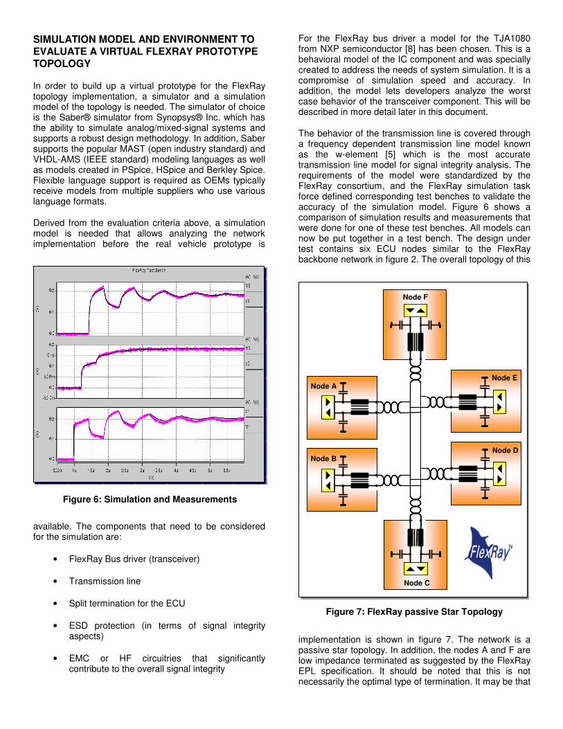
The behavior of the transmission line is covered through a frequency dependent transmission line model known as the w-element [5] which is the most accurate transmission line model for signal integrity analysis. The requirements of the model were standardized by the FlexRay consortium, and the FlexRay simulation task force defined corresponding test benches to validate the accuracy of the simulation model. Figure 6 shows a comparison of simulation results and measurements that were done for one of these test benches. All models can now be put together in a test bench. The design under test contains six ECU nodes similar to the FlexRay backbone network in figure 2. The overall topology of this
implementation is shown in figure 7. The network is a passive star topology. In addition, the nodes A and F are low impedance terminated as suggested by the FlexRay EPL specification. It should be noted that this is not necessarily the optimal type of termination. It may be that
Figure 7: FlexRay passive Star Topology
Node A
Node F
Node B
Node C
Node D
Node E
Figure 6: Simulation and Measurements

another termination method could be more efficient. This is up to the experience of the network developer and depends on the specific network implementation. Simulation can also help to investigate this issue very early in the development and concept phase.
SIMULATING THE NOMINAL CASE
A nominal design analysis is the first simulation to be performed. This means topology parameters are set to their nominal values without any variation. For a complete analysis of the overall topology in figure 7, a Round Robin communication is performed. Each ECU acts once as transmitter and sends a test pattern to the network; signal shapes are then evaluated for all ECUs. For the representation of simulation results, the test
plane definition as specified in the FlexRay EPL specification and as depicted in figure 8 is applied. Simulation results for a nominal topology configuration are shown in figure 9 where ECU C is acting as
transmitter and sends a single bit to all other ECUs. Figure 9 shows the differential mode signal for ECU E at test plane 4. This test enables the analysis of several important items. Figure 10 shows the transmit signal at
ECU C (upper signal) and the digital receive signal of ECU E. In FlexRay, each communication element starts with a so called Transmission Start Sequence (TSS) represented on the bus by Data_0 for a time span of several bits. This sequence may be shortened by the receiver and star couplers due to the filter time for activity detection. Figure 10 clearly shows this effect. Furthermore, the propagation delay is now easily determined from the lapse between the falling edges of the transmitter’s Txd signal and the receiver’s Rxd signal. In order to evaluate the asymmetric delay, the bit length of the transmitted bit is compared to the length of the received bit at the receiver’s Rxd pin. The difference between values is the asymmetric delay. All these evaluation criteria must be analyzed for a complete Round Robin communication cycle. Because the number of ECUs might be pretty high, it is a bit of an effort to manually perform this evaluation for all signals. Using simulation, developers can quickly set up an automated evaluation process. Saber provides a very advanced simulation and post processing environment allowing the user to define complete experiments including an automated post processing set-up. Figure 11 shows how to define a possible automated topology evaluation process. The network developer needs to define the topology. The test bench scenarios and the post processing are configured and archived in an experiment file as shown in figure 12. Within this experiment the test configuration can be defined through Saber Command Scripts (*.scs files) that define the parameter configuration as well as the simulation scenario e.g. who is acting as transmitter and which bit series are sent out by the transmitting ECU.
The second part of the experiment is the definition of measurements e.g. to measure the length of a received bit at the receiver’s Rxd pin in order to determine the
Figure 10: Evaluation of Signal Integrity for ECU C
Propagation Delay
TSS
Truncated TSS
Figure 9: Differential mode signal at test plane 4 of ECU E
Transition Idle to Active
Single Bit
Transition Active to Idle
Figure 8: Definition of Test Planes (Source: FlexRay EPL)

asymmetric delay. The last step contains the definition of customized results documentation. Microsoft Excel is a common platform typically used for documentation purposes to exchange information between OEMs and suppliers. Saber’s environment is based on the
interpreted TCL/TK language and allows through the Windows COM interface a communication with Microsoft applications like Excel. This connection is used to create an automated report showing the simulated values of the asymmetric delays. This approach allows any extension for any arbitrary customized verification procedure. The automation might be extended to contain e.g. the
information about the simulated propagation delay, the truncation of the TSS or any other required evaluation criteria. Figure 13 shows a possible output format for the
evaluation of the asymmetric delays for a Round Robin communication. This matrix representation contains transmitters and receivers and covers all possible communication scenarios in that configuration. This information can now be further applied to determine e.g. the maximum absolute value of the asymmetric
delay and validate it against the maximum allowed value of the FlexRay EPL specification. This automation can be furthered extended so that the network developer is alerted if there is a violation of the FlexRay EPL specification or any OEM specific requirements. In this case the simulated values of the topology are within the limits of the EPL spec (±30.75 ns).
TOPOLOGY IMPLEMENTATION AND COMPONENT TOLERANCES
In the previous scenario the nominal case for the implementation of the FlexRay topology was analyzed in terms of the asymmetric delays. The implementation of topologies is never ideal since components are usually associated with tolerances due to manufacturing or temperature issues. For example, the wire lengths of the wiring harness design can vary by several centimeters when the actual harness is delivered by the manufacturer. These small tolerances can have a significant impact on the overall signal integrity of the topology implementation. In addition, the values for termination as well as additional HF or ESD protection elements are also associated with tolerances and contribute to the signal integrity. These tolerances need to be taken into consideration to finally decide whether the topology implementation ensures well defined signal integrity. This is an important step of the Robust Design workflow methodology.
A significant part of the signal integrity analysis is related to the tolerances or worst case behavior of the FlexRay transceiver. NXP provides a very powerful and comprehensive model of the TJA1080 that takes into consideration the worst case behavior of this component. The model covers the following operational states
• Nominal (all component parameters are set to their nominal values)
Simulation Test Bench Configuration
Measurement Definition
Result Presentation
Result Documentation
Simulated Waveforms
Topology Specification
Experiment Definition Automated
Evaluation
Figure 11: Automated Evaluation Process for FlexRay Topologies
Definition of Measurement
Test Bench Set up
Figure 12: GUI to set up the Experiment
Figure 13: Automated Report in Excel
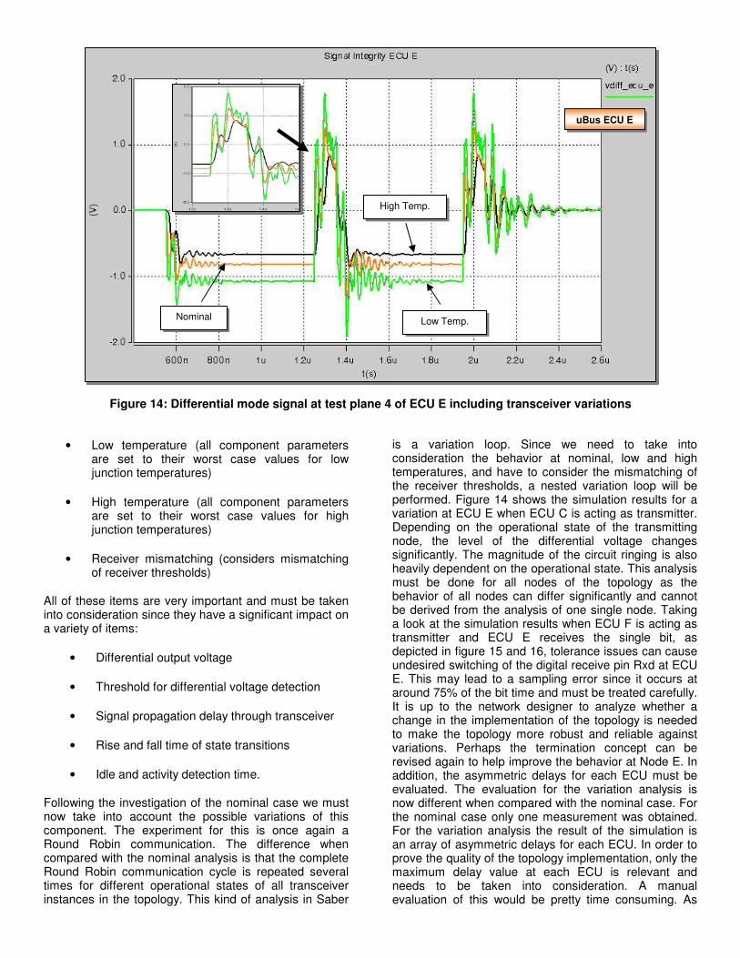
• Low temperature (all component parameters are set to their worst case values for low junction temperatures)
• High temperature (all component parameters are set to their worst case values for high junction temperatures)
• Receiver mismatching (considers mismatching of receiver thresholds)
All of these items are very important and must be taken into consideration since they have a significant impact on a variety of items:
• Differential output voltage
• Threshold for differential voltage detection
• Signal propagation delay through transceiver
• Rise and fall time of state transitions
• Idle and activity detection time.
Following the investigation of the nominal case we must now take into account the possible variations of this component. The experiment for this is once again a Round Robin communication. The difference when compared with the nominal analysis is that the complete Round Robin communication cycle is repeated several times for different operational states of all transceiver instances in the topology. This kind of analysis in Saber
is a variation loop. Since we need to take into consideration the behavior at nominal, low and high temperatures, and have to consider the mismatching of the receiver thresholds, a nested variation loop will be performed. Figure 14 shows the simulation results for a variation at ECU E when ECU C is acting as transmitter. Depending on the operational state of the transmitting node, the level of the differential voltage changes significantly. The magnitude of the circuit ringing is also heavily dependent on the operational state. This analysis must be done for all nodes of the topology as the behavior of all nodes can differ significantly and cannot be derived from the analysis of one single node. Taking a look at the simulation results when ECU F is acting as transmitter and ECU E receives the single bit, as depicted in figure 15 and 16, tolerance issues can cause undesired switching of the digital receive pin Rxd at ECU E. This may lead to a sampling error since it occurs at around 75% of the bit time and must be treated carefully. It is up to the network designer to analyze whether a change in the implementation of the topology is needed to make the topology more robust and reliable against variations. Perhaps the termination concept can be revised again to help improve the behavior at Node E. In addition, the asymmetric delays for each ECU must be evaluated. The evaluation for the variation analysis is now different when compared with the nominal case. For the nominal case only one measurement was obtained. For the variation analysis the result of the simulation is an array of asymmetric delays for each ECU. In order to prove the quality of the topology implementation, only the maximum delay value at each ECU is relevant and needs to be taken into consideration. A manual evaluation of this would be pretty time consuming. As
Nominal Low Temp.
High Temp.
Figure 14: Differential mode signal at test plane 4 of ECU E including transceiver variations
uBus ECU E

with the nominal case analysis, the post processing has been automated and a matrix is generated containing the maximum values of asymmetric delays based on variations for all simulation scenarios of the Round Robin communication. Figure 17 shows the Excel report that is automatically generated after the simulation. The field for
ECU F acting as transmitter and ECU E acting as receiver is marked in red. Due to the undesired switching at ECU E’s Rxd pin, no measurement is available. From the simulated matrix above it is now very obvious that it
is a fundamental requirement to take variations of the transceiver into consideration. The maximum value for the asymmetric delay is now 22.5 ns. The maximum asymmetric delay for the nominal case is -7.6 ns (see figure 12) which is only a third of the worst case. Taking into account an additional reserve against
RF injection issues, and additional parasitic effects that have not been modeled, the system is very close to its limits but still within the range specified by the FlexRay EPL specification (±30.75 ns).
The benefit of this automated evaluation approach is now even more obvious than before since the network
Figure 17: Maximum asymmetric delays
Undesired switching
RxD ECU E
Figure 16: Undesired switching of Rxd (ECU E)
Nominal
High Temp.
Low Temp.
Figure 15: Differential mode signal at test plane 4 of ECU E (Transmitter ECU F)
uBus ECU E
developer must only compare the values of the automatically generated Excel report with the limits specified in the FlexRay EPL specification or additional OEM specific requirements. This is one of the additional benefits of automating the evaluation process using system simulation.
OUTLOOK
The previous example has shown that an in depth understanding and comprehensive analysis of FlexRay topologies is needed in order to ensure a reliable implementation. The development and evaluation process for FlexRay topologies can almost be completely automated through system simulation. It requires the automatic evaluation of all important aspects of the FlexRay EPL specification as defined through limit values like the asymmetric delay example described
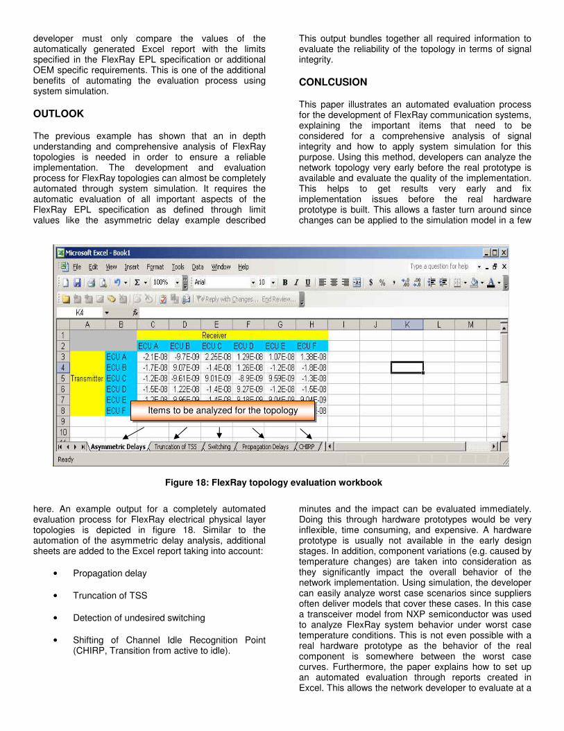
here. An example output for a completely automated evaluation process for FlexRay electrical physical layer topologies is depicted in figure 18. Similar to the automation of the asymmetric delay analysis, additional sheets are added to the Excel report taking into account:
• Propagation delay
• Truncation of TSS
• Detection of undesired switching
• Shifting of Channel Idle Recognition Point (CHIRP, Transition from active to idle).
This output bundles together all required information to evaluate the reliability of the topology in terms of signal integrity.
CONLCUSION
This paper illustrates an automated evaluation process for the development of FlexRay communication systems, explaining the important items that need to be considered for a comprehensive analysis of signal integrity and how to apply system simulation for this purpose. Using this method, developers can analyze the network topology very early before the real prototype is available and evaluate the quality of the implementation. This helps to get results very early and fix implementation issues before the real hardware prototype is built. This allows a faster turn around since changes can be applied to the simulation model in a few
minutes and the impact can be evaluated immediately. Doing this through hardware prototypes would be very inflexible, time consuming, and expensive. A hardware prototype is usually not available in the early design stages. In addition, component variations (e.g. caused by temperature changes) are taken into consideration as they significantly impact the overall behavior of the network implementation. Using simulation, the developer can easily analyze worst case scenarios since suppliers often deliver models that cover these cases. In this case a transceiver model from NXP semiconductor was used to analyze FlexRay system behavior under worst case temperature conditions. This is not even possible with a real hardware prototype as the behavior of the real component is somewhere between the worst case curves. Furthermore, the paper explains how to set up an automated evaluation through reports created in Excel. This allows the network developer to evaluate at a
Figure 18: FlexRay topology evaluation workbook
Items to be analyzed for the topology

glance the reliability of the implementation against component variations. The paper shows an example method depicting how the network developer can evaluate all items of the FlexRay EPL specification and OEM specific requirements through simulation and view the results at a glance in a single topology workbook.
REFERENCES
[1] FlexRay Consortium, www.flexray.com
[2] FlexRay Specification 2.1
[3] FlexRay Physical Layer Specification 2.1
[4] Development of the Physical Layer and Signal Integrity Analysis of FlexRay Design Systems, T. Gerke, D.Bollati, SAE 2007
[5] Optimal Transient Simulation of Transmission Lines, Dimitri Borisovich Kuznetsov, Jose E. Schutt-Aine, IEEE Transactions on Circuits and Systems, 1996
[6] HSpice Signal Integrity Guide, Synopsys, 2007
[7] Physical Layer - Basis of an Automotive Bus Using the Example of FlexRay, Prof. Jürgen Minuth, EESystems2006
[8] TJA1080 Transceiver Model Documentation,
NXP Semiconductor
[10] Monte Carlo Simulation for the Validation of the First FlexRay Series Networks, T. Suermann, FlexRay Product Day 2006
[11] Development and Verification of In-Vehicle Networks in a Virtual Environment, T. Gerke, C. Schanze, SAE 2005
CONTACTS
Thorsten Gerke Technical Marketing Europe – Saber Product Line Member of FlexRay Simulation Task Force Synopsys GmbH Karl-Hammer-Schmidtstr. 34 85609 Aschheim/Dornach (Germany) E-Mail: [email protected] Phone: +49 89 99320 227 David Bollati Network Engineer & Project Manager Chairman of FlexRay Simulation Task Force C&S Group/University of Applied Science Wolfenbüttel Salzdahlumerstr. 46/48 38302 Wolfenbüttel (Germany) E-Mail: [email protected] Phone: +49 5331 939 6623
Related Documents