Amphibious Aircraft ... a short overview Made by ckepper • English • 4 articles • 115 pages

Welcome message from author
This document is posted to help you gain knowledge. Please leave a comment to let me know what you think about it! Share it to your friends and learn new things together.
Transcript

Amphibious Aircraft... a short overview
Made by ckepper • English • 4 articles • 115 pages

Contents
Overview1. Amphibious aircraft . . . . . . . . . . . . . . . . . . . . . . . . . . . . . . . . . . . . . . . . . . . . . . . . . . . . . . . . . . . 3
Related types of aircraft2. Floatplane . . . . . . . . . . . . . . . . . . . . . . . . . . . . . . . . . . . . . . . . . . . . . . . . . . . . . . . . . . . . . . . . 73. Flying boat . . . . . . . . . . . . . . . . . . . . . . . . . . . . . . . . . . . . . . . . . . . . . . . . . . . . . . . . . . . . . . . 10
Technical Aspects4. Propeller . . . . . . . . . . . . . . . . . . . . . . . . . . . . . . . . . . . . . . . . . . . . . . . . . . . . . . . . . . . . . . . . 225. Turboprop . . . . . . . . . . . . . . . . . . . . . . . . . . . . . . . . . . . . . . . . . . . . . . . . . . . . . . . . . . . . . . . . 366. Wing configuration . . . . . . . . . . . . . . . . . . . . . . . . . . . . . . . . . . . . . . . . . . . . . . . . . . . . . . . . . . . 477. Lift-to-drag ratio . . . . . . . . . . . . . . . . . . . . . . . . . . . . . . . . . . . . . . . . . . . . . . . . . . . . . . . . . . . . 668. Thrust . . . . . . . . . . . . . . . . . . . . . . . . . . . . . . . . . . . . . . . . . . . . . . . . . . . . . . . . . . . . . . . . . . 72
Selected Amphibious Aircrafts9. Grumman J2F Duck . . . . . . . . . . . . . . . . . . . . . . . . . . . . . . . . . . . . . . . . . . . . . . . . . . . . . . . . . . 7610. Shin Meiwa US-1A . . . . . . . . . . . . . . . . . . . . . . . . . . . . . . . . . . . . . . . . . . . . . . . . . . . . . . . . . . 8311. Lake Aircraft . . . . . . . . . . . . . . . . . . . . . . . . . . . . . . . . . . . . . . . . . . . . . . . . . . . . . . . . . . . . . . 8712. Consolidated PBY Catalina . . . . . . . . . . . . . . . . . . . . . . . . . . . . . . . . . . . . . . . . . . . . . . . . . . . . . . 9013. Kawanishi H6K . . . . . . . . . . . . . . . . . . . . . . . . . . . . . . . . . . . . . . . . . . . . . . . . . . . . . . . . . . . 105
Appendix14. Article Sources and Contributors . . . . . . . . . . . . . . . . . . . . . . . . . . . . . . . . . . . . . . . . . . . . . . . . . 10915. Image Sources, Licenses and Contributors . . . . . . . . . . . . . . . . . . . . . . . . . . . . . . . . . . . . . . . . . . . . 111
A Canadair CL-215T amphibian with retractable wheels
Overview
Amphibious aircraft
An amphibious aircraft or amphibian is an aircraft that can take off and land onboth land and water. Fixed-wing amphibious aircraft are seaplanes (flying boats andfloatplanes) that are equipped with retractable wheels, at the expense of extraweight and complexity, plus diminished range and fuel economy compared toplanes designed for land or water only. Some amphibians are fitted with reinforcedkeels which act as skis, allowing them to land on snow or ice with their wheels up.
DesignFloatplanes often have floats that are interchangeable with wheeled landing gear
(thereby producing a conventional land-based aircraft) however in cases where this is
not practical amphibious floatplanes, such as the amphibious version of the DHC Otter,
incorporate retractable wheels within their floats.
Many amphibian aircraft are of the flying boat type. These aircraft, and those designed
as floatplanes with a single main float under the fuselage centerline (such as the Loen-
ing OL and Grumman J2F), require outrigger floats to provide lateral stability so as to
avoid dipping a wingtip, which can destroy an aircraft if it happens at speed, or can
cause the wingtip to fill with water and sink if stationary. While these impose weight
and drag, amphibious aircraft also face the possibility of these getting hit when operat-
ing from a runway. A common solution is to make them retractable as those found on
the Consolidated Catalina however these are even heavier than fixed floats. Some air-
craft may have the tip floats removed for extended use from land. Other amphibians,
such as the Dornier Seastar use stub wings called sponsons, mounted with their own
Amphibious aircraft | Article 1 of 4 3
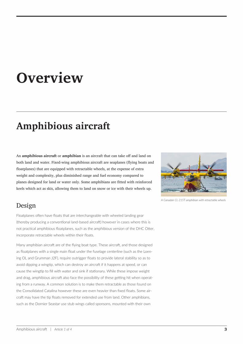
Vickers Viking - an early amphibian.
lower surfaces nearly even with the ventral "boat-hull" shaped fuselage surface to pro-
vide the needed stability, while floatplane amphibians usually avoid the problem by di-
viding their buoyancy requirements between two floats, much like a catamaran.
Some non-amphibious seaplanes may be mistaken for amphibians (such as the Shin
Meiwa PS-1) which carry their own beaching gear - usually this is a wheeled dolly or
temporary set of wheels used to move a flying boat or floatplane from the water and
allow it to be moved around on land but can also appear as a conventional undercar-
riage. These are not built to take the impact of the aircraft landing on them. An amphib-
ian can leave the water without anyone getting in the water to attach beaching wheels
(or even having to have any handy), yet a fully functional undercarriage is heavy and
impacts the aircraft's performance, and isn't required in all cases, so an aircraft may be
designed to carry its own.
HazardsAn occasional problem with amphibians is with ensuring the wheels are in the correct
position for landing. In normal operation, the pilot uses a checklist, verifying each item.
Since amphibians can land with them up or down though, the pilot must take extra care
to ensure they are correct for the chosen landing place. Landing wheels up on land
may damage the keel (unless done on wet grass, a technique occasionally used by pi-
lots of pure flying boats), while landing wheels down on water will almost always flip
the aircraft upside down, causing substantial damage.
UsageAmphibious aircraft are heavier and slower, more complex and more expensive to pur-
chase and operate than comparable landplanes but are also more versatile. Even if they
cannot hover or land vertically, for some jobs they compete favorably with helicopters
and do so at a significantly lower cost. Amphibious aircraft can be much faster and
have longer range than comparable helicopters, and can achieve nearly the range of
land based aircraft,[1] as an airplane's wing is more efficient than a helicopter's lifting ro-
tor. This makes an amphibious aircraft, such as the Grumman Albatross and the Shin
Meiwa US-2, useful for long-range air-sea rescue tasks. In addition, amphibious aircraft
are particularly useful as "Bushplanes" engaging in light transport in remote areas,
where they are required to operate not only from airstrips, but also from lakes and
rivers.
HistoryIn the United Kingdom, traditionally a maritime nation, a large number of amphibians
were built between the wars, starting from 1918 with the Vickers Viking and the early
1920s Supermarine Seagull and were used for exploration and military duties including
search and rescue, artillery spotting and anti-submarine patrol. The most notable being
the Short Sunderland which carried out many anti-submarine patrols over the North
Amphibious aircraft | Article 1 of 4 4
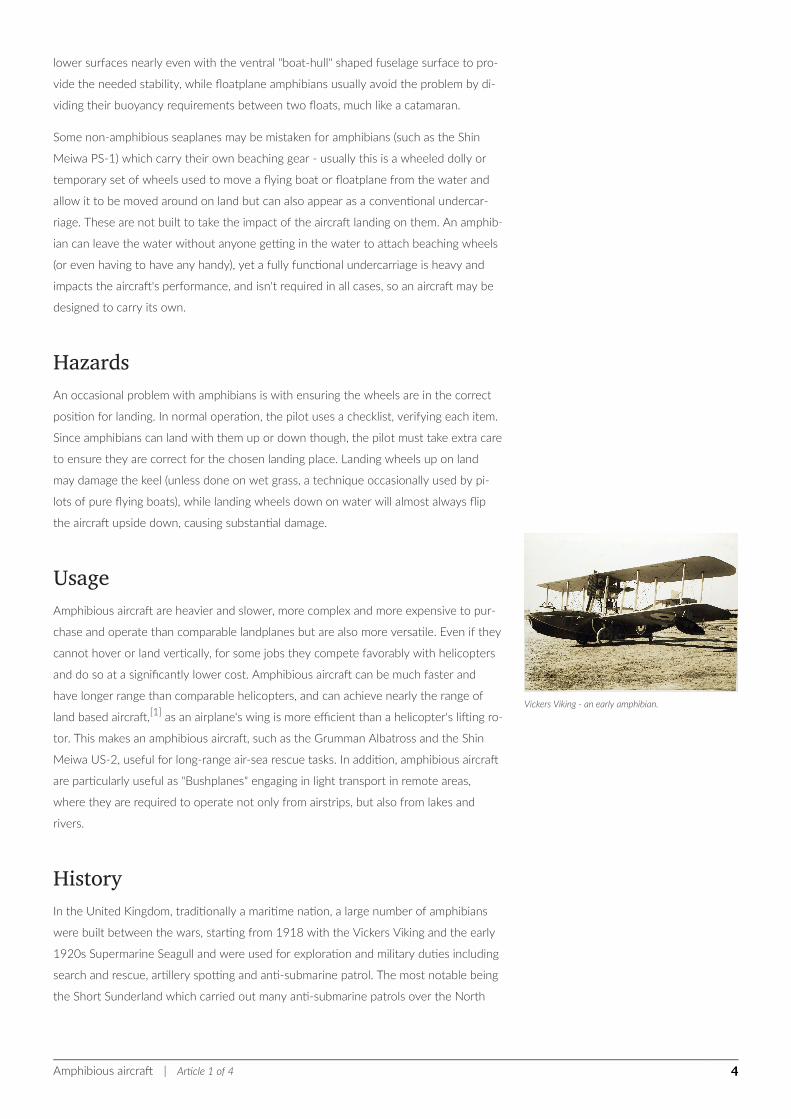
replica of Osa's Ark - a Sikorsky S-38 used to exploreAfrica in the 1930s.
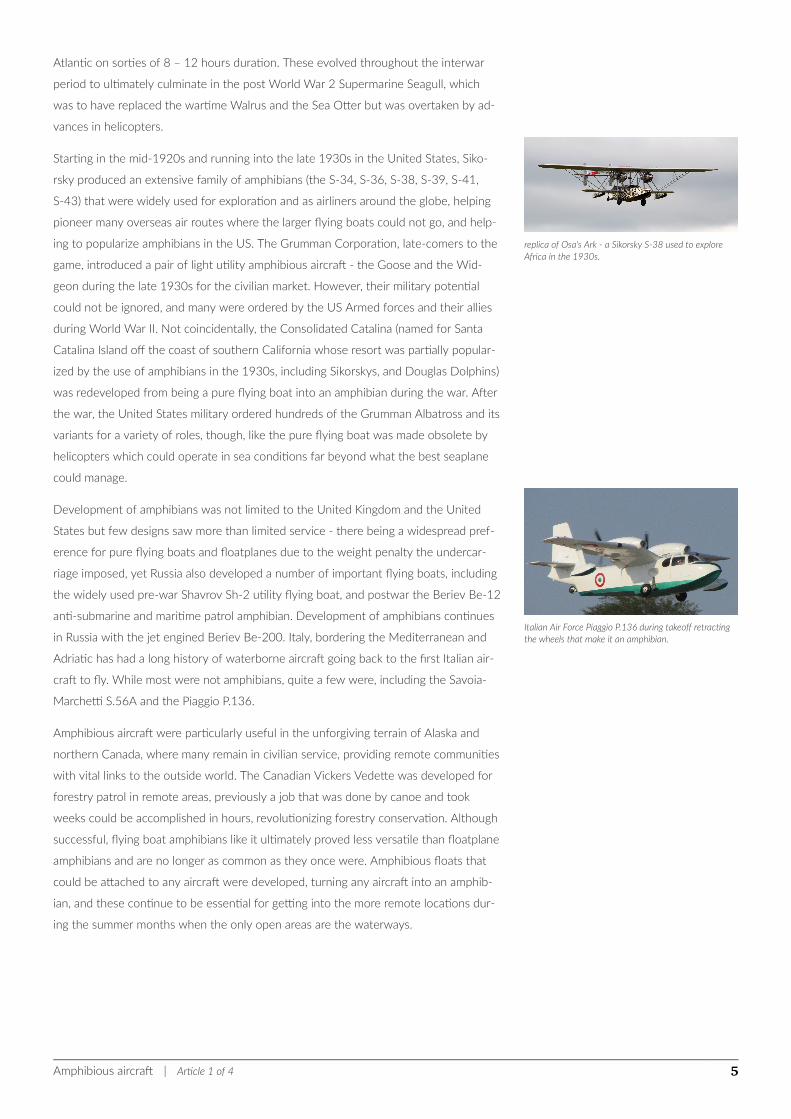
Italian Air Force Piaggio P.136 during takeoff retractingthe wheels that make it an amphibian.
Atlantic on sorties of 8 – 12 hours duration. These evolved throughout the interwar
period to ultimately culminate in the post World War 2 Supermarine Seagull, which
was to have replaced the wartime Walrus and the Sea Otter but was overtaken by ad-
vances in helicopters.
Starting in the mid-1920s and running into the late 1930s in the United States, Siko-
rsky produced an extensive family of amphibians (the S-34, S-36, S-38, S-39, S-41,
S-43) that were widely used for exploration and as airliners around the globe, helping
pioneer many overseas air routes where the larger flying boats could not go, and help-
ing to popularize amphibians in the US. The Grumman Corporation, late-comers to the
game, introduced a pair of light utility amphibious aircraft - the Goose and the Wid-
geon during the late 1930s for the civilian market. However, their military potential
could not be ignored, and many were ordered by the US Armed forces and their allies
during World War II. Not coincidentally, the Consolidated Catalina (named for Santa
Catalina Island off the coast of southern California whose resort was partially popular-
ized by the use of amphibians in the 1930s, including Sikorskys, and Douglas Dolphins)
was redeveloped from being a pure flying boat into an amphibian during the war. After
the war, the United States military ordered hundreds of the Grumman Albatross and its
variants for a variety of roles, though, like the pure flying boat was made obsolete by
helicopters which could operate in sea conditions far beyond what the best seaplane
could manage.
Development of amphibians was not limited to the United Kingdom and the United
States but few designs saw more than limited service - there being a widespread pref-
erence for pure flying boats and floatplanes due to the weight penalty the undercar-
riage imposed, yet Russia also developed a number of important flying boats, including
the widely used pre-war Shavrov Sh-2 utility flying boat, and postwar the Beriev Be-12
anti-submarine and maritime patrol amphibian. Development of amphibians continues
in Russia with the jet engined Beriev Be-200. Italy, bordering the Mediterranean and
Adriatic has had a long history of waterborne aircraft going back to the first Italian air-
craft to fly. While most were not amphibians, quite a few were, including the Savoia-
Marchetti S.56A and the Piaggio P.136.
Amphibious aircraft were particularly useful in the unforgiving terrain of Alaska and
northern Canada, where many remain in civilian service, providing remote communities
with vital links to the outside world. The Canadian Vickers Vedette was developed for
forestry patrol in remote areas, previously a job that was done by canoe and took
weeks could be accomplished in hours, revolutionizing forestry conservation. Although
successful, flying boat amphibians like it ultimately proved less versatile than floatplane
amphibians and are no longer as common as they once were. Amphibious floats that
could be attached to any aircraft were developed, turning any aircraft into an amphib-
ian, and these continue to be essential for getting into the more remote locations dur-
ing the summer months when the only open areas are the waterways.
Amphibious aircraft | Article 1 of 4 5
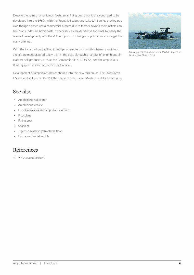
ShinMaywa US-2, developed in the 2000s in Japan fromthe older Shin Meiwa US-1A
Despite the gains of amphibious floats, small flying boat amphibians continued to be
developed into the 1960s, with the Republic Seabee and Lake LA-4 series proving pop-
ular, though neither was a commercial success due to factors beyond their makers con-
trol. Many today are homebuilts, by necessity as the demand is too small to justify the
costs of development, with the Volmer Sportsman being a popular choice amongst the
many offerings.
With the increased availability of airstrips in remote communities, fewer amphibious
aircraft are manufactured today than in the past, although a handful of amphibious air-
craft are still produced, such as the Bombardier 415, ICON A5, and the amphibious-
float equipped version of the Cessna Caravan.
Development of amphibians has continued into the new millennium. The ShinMaywa
US-2 was developed in the 2000s in Japan for the Japan Maritime Self-Defense Force.
See also• Amphibious helicopter
• Amphibious vehicle
• List of seaplanes and amphibious aircraft
• Floatplane
• Flying boat
• Seaplane
• Tigerfish Aviation (retractable float)
• Unmanned aerial vehicle
References1. ^ "Grumman Mallard".
Amphibious aircraft | Article 1 of 4 6
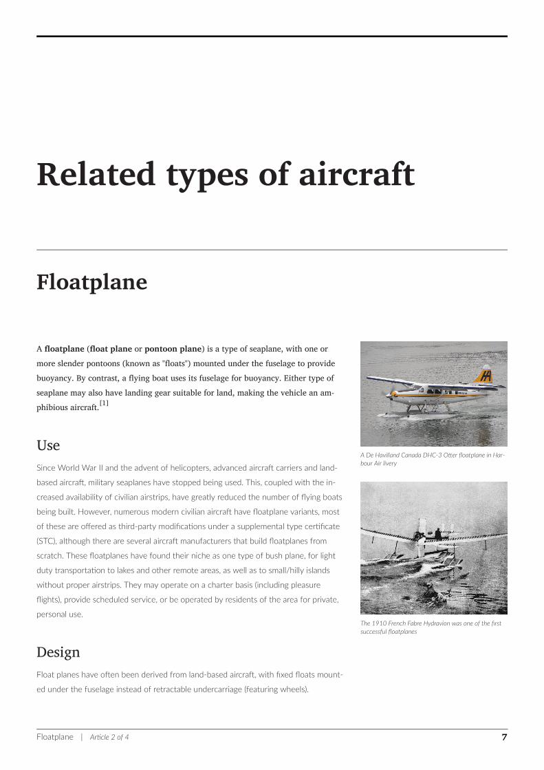
A De Havilland Canada DHC-3 Otter floatplane in Har-bour Air livery
The 1910 French Fabre Hydravion was one of the firstsuccessful floatplanes
Related types of aircraft
Floatplane
A floatplane (float plane or pontoon plane) is a type of seaplane, with one ormore slender pontoons (known as "floats") mounted under the fuselage to providebuoyancy. By contrast, a flying boat uses its fuselage for buoyancy. Either type ofseaplane may also have landing gear suitable for land, making the vehicle an am-phibious aircraft.[1]
UseSince World War II and the advent of helicopters, advanced aircraft carriers and land-
based aircraft, military seaplanes have stopped being used. This, coupled with the in-
creased availability of civilian airstrips, have greatly reduced the number of flying boats
being built. However, numerous modern civilian aircraft have floatplane variants, most
of these are offered as third-party modifications under a supplemental type certificate
(STC), although there are several aircraft manufacturers that build floatplanes from
scratch. These floatplanes have found their niche as one type of bush plane, for light
duty transportation to lakes and other remote areas, as well as to small/hilly islands
without proper airstrips. They may operate on a charter basis (including pleasure
flights), provide scheduled service, or be operated by residents of the area for private,
personal use.
DesignFloat planes have often been derived from land-based aircraft, with fixed floats mount-
ed under the fuselage instead of retractable undercarriage (featuring wheels).
Floatplane | Article 2 of 4 7
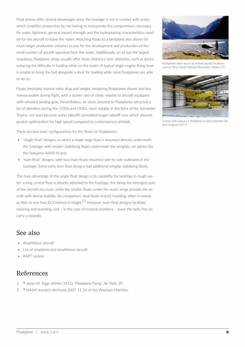
Floatplanes allow access to remote aquatic locations,such as Misty Fjords National Monument, Alaska, U.S.
Cessna 208 Caravan 1 floatplane at Gloucestershire Air-port, England (2017)
Float planes offer several advantages since the fuselage is not in contact with water,
which simplifies production by not having to incorporate the compromises necessary
for water tightness, general impact strength and the hydroplaning characteristics need-
ed for the aircraft to leave the water. Attaching floats to a landplane also allows for
much larger production volumes to pay for the development and production of the
small number of aircraft operated from the water. Additionally, on all but the largest
seaplanes, floatplane wings usually offer more clearance over obstacles, such as docks,
reducing the difficulty in loading while on the water. A typical single engine flying boat
is unable to bring the hull alongside a dock for loading while most floatplanes are able
to do so.
Floats inevitably impose extra drag and weight, rendering floatplanes slower and less
manoeuvrable during flight, with a slower rate of climb, relative to aircraft equipped
with wheeled landing gear. Nevertheless, air races devoted to floatplanes attracted a
lot of attention during the 1920s and 1930s, most notably in the form of the Schneider
Trophy, not least because water takeoffs permitted longer takeoff runs which allowed
greater optimization for high speed compared to contemporary airfields.
There are two basic configurations for the floats on floatplanes:
• "single float" designs, in which a single large float is mounted directly underneath
the fuselage, with smaller stabilizing floats underneath the wingtips, on planes like
the Nakajima A6M2-N and;
• "twin float" designs, with two main floats mounted side by side outboard of the
fuselage. Some early twin float designs had additional wingtip stabilizing floats.
The main advantage of the single float design is its capability for landings in rough wa-
ter: a long central float is directly attached to the fuselage, this being the strongest part
of the aircraft structure, while the smaller floats under the outer wings provide the air-
craft with lateral stability. By comparison, dual floats restrict handling, often to waves
as little as one foot (0.3 metres) in height.[2] However, twin float designs facilitate
mooring and boarding, and – in the case of torpedo bombers – leave the belly free to
carry a torpedo.
See also• Amphibious aircraft
• List of seaplanes and amphibious aircraft
• RAPT system
References1. ^ James M. Triggs (Winter 1971). "Floatplane Flying". Air Trails: 39.
2. ^ NASM research Archived 2007-11-24 at the Wayback Machine.
Floatplane | Article 2 of 4 8

External links
Wikimedia Commons has media related to Floatplanes.
• "Why Seaplanes Fly With Bullet Speed", December 1931, Popular Science excellent
article on the different design features of the floats on floatplanes
• "Will a Lake Be Your Postwar Landing Field?" Popular Science, February 1945,
pp. 134–135.
Floatplane | Article 2 of 4 9
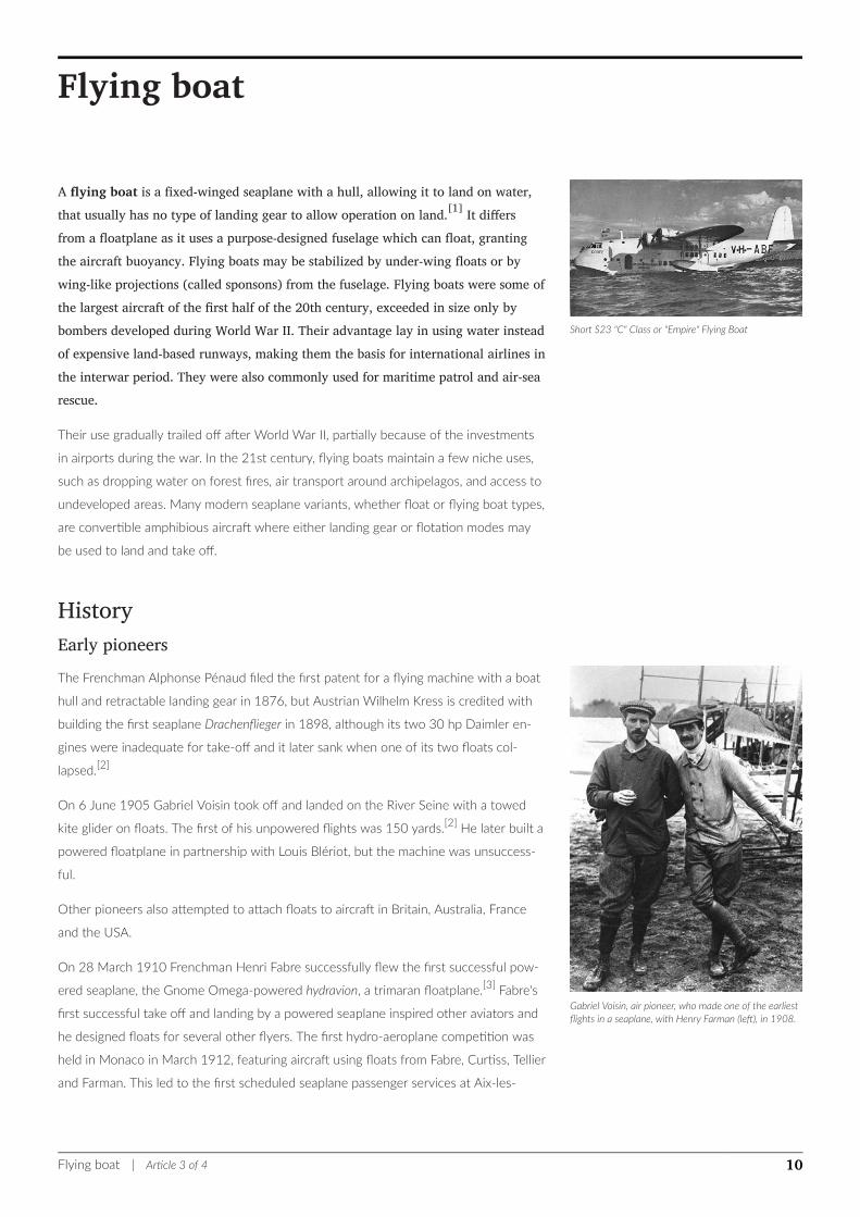
Short S23 "C" Class or "Empire" Flying Boat
Gabriel Voisin, air pioneer, who made one of the earliestflights in a seaplane, with Henry Farman (left), in 1908.
Flying boat
A flying boat is a fixed-winged seaplane with a hull, allowing it to land on water,that usually has no type of landing gear to allow operation on land.[1] It differsfrom a floatplane as it uses a purpose-designed fuselage which can float, grantingthe aircraft buoyancy. Flying boats may be stabilized by under-wing floats or bywing-like projections (called sponsons) from the fuselage. Flying boats were some ofthe largest aircraft of the first half of the 20th century, exceeded in size only bybombers developed during World War II. Their advantage lay in using water insteadof expensive land-based runways, making them the basis for international airlines inthe interwar period. They were also commonly used for maritime patrol and air-searescue.
Their use gradually trailed off after World War II, partially because of the investments
in airports during the war. In the 21st century, flying boats maintain a few niche uses,
such as dropping water on forest fires, air transport around archipelagos, and access to
undeveloped areas. Many modern seaplane variants, whether float or flying boat types,
are convertible amphibious aircraft where either landing gear or flotation modes may
be used to land and take off.
HistoryEarly pioneersThe Frenchman Alphonse Pénaud filed the first patent for a flying machine with a boat
hull and retractable landing gear in 1876, but Austrian Wilhelm Kress is credited with
building the first seaplane Drachenflieger in 1898, although its two 30 hp Daimler en-
gines were inadequate for take-off and it later sank when one of its two floats col-
lapsed.[2]
On 6 June 1905 Gabriel Voisin took off and landed on the River Seine with a towed
kite glider on floats. The first of his unpowered flights was 150 yards.[2] He later built a
powered floatplane in partnership with Louis Blériot, but the machine was unsuccess-
ful.
Other pioneers also attempted to attach floats to aircraft in Britain, Australia, France
and the USA.
On 28 March 1910 Frenchman Henri Fabre successfully flew the first successful pow-
ered seaplane, the Gnome Omega-powered hydravion, a trimaran floatplane.[3] Fabre's
first successful take off and landing by a powered seaplane inspired other aviators and
he designed floats for several other flyers. The first hydro-aeroplane competition was
held in Monaco in March 1912, featuring aircraft using floats from Fabre, Curtiss, Tellier
and Farman. This led to the first scheduled seaplane passenger services at Aix-les-
Flying boat | Article 3 of 4 10
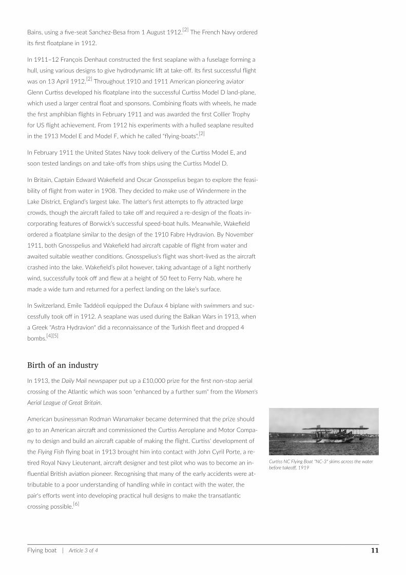
Curtiss NC Flying Boat "NC-3" skims across the waterbefore takeoff, 1919
Bains, using a five-seat Sanchez-Besa from 1 August 1912.[2] The French Navy ordered
its first floatplane in 1912.
In 1911–12 François Denhaut constructed the first seaplane with a fuselage forming a
hull, using various designs to give hydrodynamic lift at take-off. Its first successful flight
was on 13 April 1912.[2] Throughout 1910 and 1911 American pioneering aviator
Glenn Curtiss developed his floatplane into the successful Curtiss Model D land-plane,
which used a larger central float and sponsons. Combining floats with wheels, he made
the first amphibian flights in February 1911 and was awarded the first Collier Trophy
for US flight achievement. From 1912 his experiments with a hulled seaplane resulted
in the 1913 Model E and Model F, which he called "flying-boats".[2]
In February 1911 the United States Navy took delivery of the Curtiss Model E, and
soon tested landings on and take-offs from ships using the Curtiss Model D.
In Britain, Captain Edward Wakefield and Oscar Gnosspelius began to explore the feasi-
bility of flight from water in 1908. They decided to make use of Windermere in the
Lake District, England’s largest lake. The latter's first attempts to fly attracted large
crowds, though the aircraft failed to take off and required a re-design of the floats in-
corporating features of Borwick’s successful speed-boat hulls. Meanwhile, Wakefield
ordered a floatplane similar to the design of the 1910 Fabre Hydravion. By November
1911, both Gnosspelius and Wakefield had aircraft capable of flight from water and
awaited suitable weather conditions. Gnosspelius's flight was short-lived as the aircraft
crashed into the lake. Wakefield’s pilot however, taking advantage of a light northerly
wind, successfully took off and flew at a height of 50 feet to Ferry Nab, where he
made a wide turn and returned for a perfect landing on the lake’s surface.
In Switzerland, Emile Taddéoli equipped the Dufaux 4 biplane with swimmers and suc-
cessfully took off in 1912. A seaplane was used during the Balkan Wars in 1913, when
a Greek "Astra Hydravion" did a reconnaissance of the Turkish fleet and dropped 4
bombs.[4][5]
Birth of an industryIn 1913, the Daily Mail newspaper put up a £10,000 prize for the first non-stop aerial
crossing of the Atlantic which was soon "enhanced by a further sum" from the Women's
Aerial League of Great Britain.
American businessman Rodman Wanamaker became determined that the prize should
go to an American aircraft and commissioned the Curtiss Aeroplane and Motor Compa-
ny to design and build an aircraft capable of making the flight. Curtiss' development of
the Flying Fish flying boat in 1913 brought him into contact with John Cyril Porte, a re-
tired Royal Navy Lieutenant, aircraft designer and test pilot who was to become an in-
fluential British aviation pioneer. Recognising that many of the early accidents were at-
tributable to a poor understanding of handling while in contact with the water, the
pair's efforts went into developing practical hull designs to make the transatlantic
crossing possible.[6]
Flying boat | Article 3 of 4 11
At the same time the British boat building firm J. Samuel White of Cowes on the Isle of
Wight set up a new aircraft division and produced a flying boat in the United Kingdom.
This was displayed at the London Air Show at Olympia in 1913.[7] In that same year, a
collaboration between the S. E. Saunders boatyard of East Cowes and the Sopwith Avi-
ation Company produced the "Bat Boat", an aircraft with a consuta laminated hull that
could operate from land or on water, which today we call an amphibious aircraft.[7] The
"Bat Boat" completed several landings on sea and on land and was duly awarded the
Mortimer Singer Prize.[7] It was the first all-British aeroplane capable of making six re-
turn flights over five miles within five hours.
In the U.S. Wanamaker's commission built on Glen Curtiss' previous development and
experience with the Model F[8] for the U.S. Navy which rapidly resulted in the America,
designed under Porte's supervision following his study and rearrangement of the flight
plan; the aircraft was a conventional biplane design with two-bay, unstaggered wings of
unequal span with two pusher inline engines mounted side-by-side above the fuselage
in the interplane gap. Wingtip pontoons were attached directly below the lower wings
near their tips. The design (later developed into the Model H), resembled Curtiss' earli-
er flying boats, but was built considerably larger so it could carry enough fuel to cover
1,100 mi (1,800 km). The three crew members were accommodated in a fully enclosed
cabin.
Trials of the America began 23 June 1914 with Porte also as Chief Test Pilot; testing
soon revealed serious shortcomings in the design; it was under-powered, so the en-
gines were replaced with more powerful engines mounted in a tractor configuration.
There was also a tendency for the nose of the aircraft to try to submerge as engine
power increased while taxiing on water. This phenomenon had not been encountered
before, since Curtiss' earlier designs had not used such powerful engines nor large fu-
el/cargo loads and so were relatively more buoyant. In order to counteract this effect,
Curtiss fitted fins to the sides of the bow to add hydrodynamic lift, but soon replaced
these with sponsons, a type of underwater pontoon mounted in pairs on either side of
a hull. These sponsons (or their engineering equivalents) and the flared, notched hull
would remain a prominent feature of flying boat hull design in the decades to follow.
With the problem resolved, preparations for the crossing resumed. While the craft was
found to handle "heavily" on takeoff, and required rather longer take-off distances than
expected, the full moon on 5 August 1914 was selected for the trans-Atlantic flight;
Porte was to pilot the America with George Hallett as co-pilot and mechanic.
World War ICurtiss and Porte's plans were interrupted by the outbreak of World War I. Porte sailed
for England on 4 August 1914 and rejoined the Navy, as a member of the Royal Naval
Air Service. Appointed Squadron Commander of Royal Navy Air Station Hendon, he
soon convinced the Admiralty of the potential of flying boats and was put in charge of
the naval air station at Felixstowe in 1915. Porte persuaded the Admiralty to comman-
deer (and later, purchase) the America and a sister craft from Curtiss. This was followed
by an order for 12 more similar aircraft, one Model H-2 and the remaining as Model
Flying boat | Article 3 of 4 12
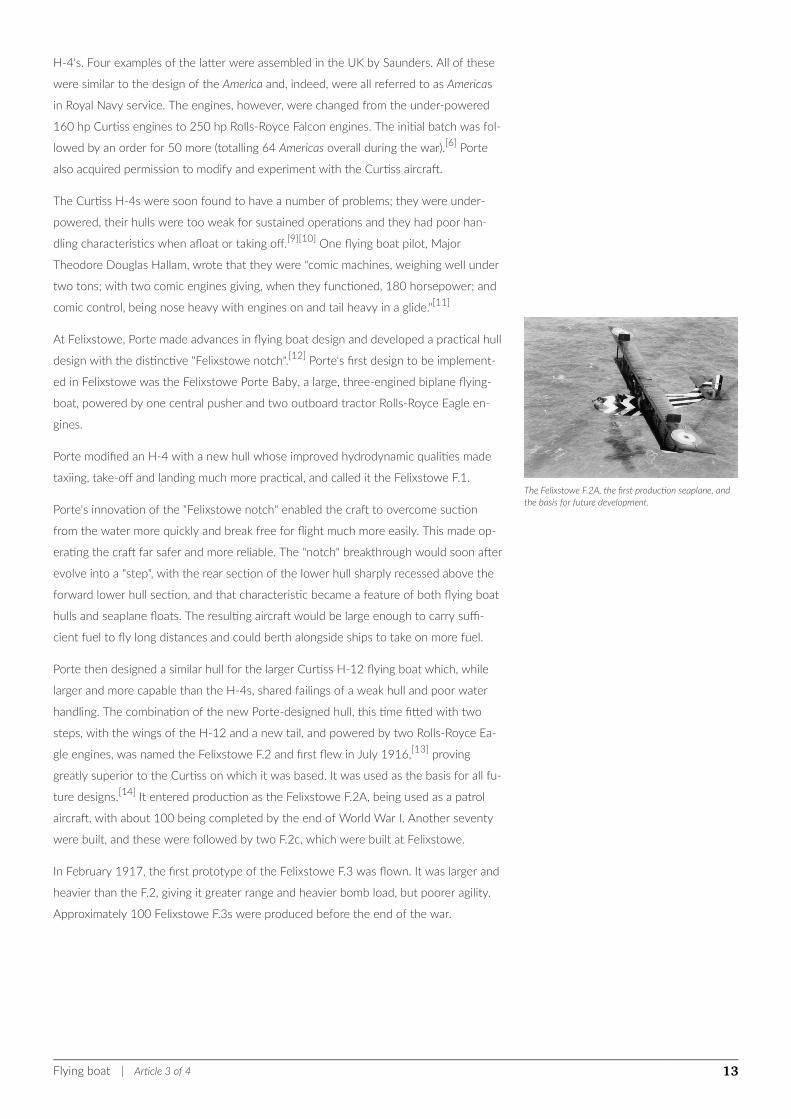
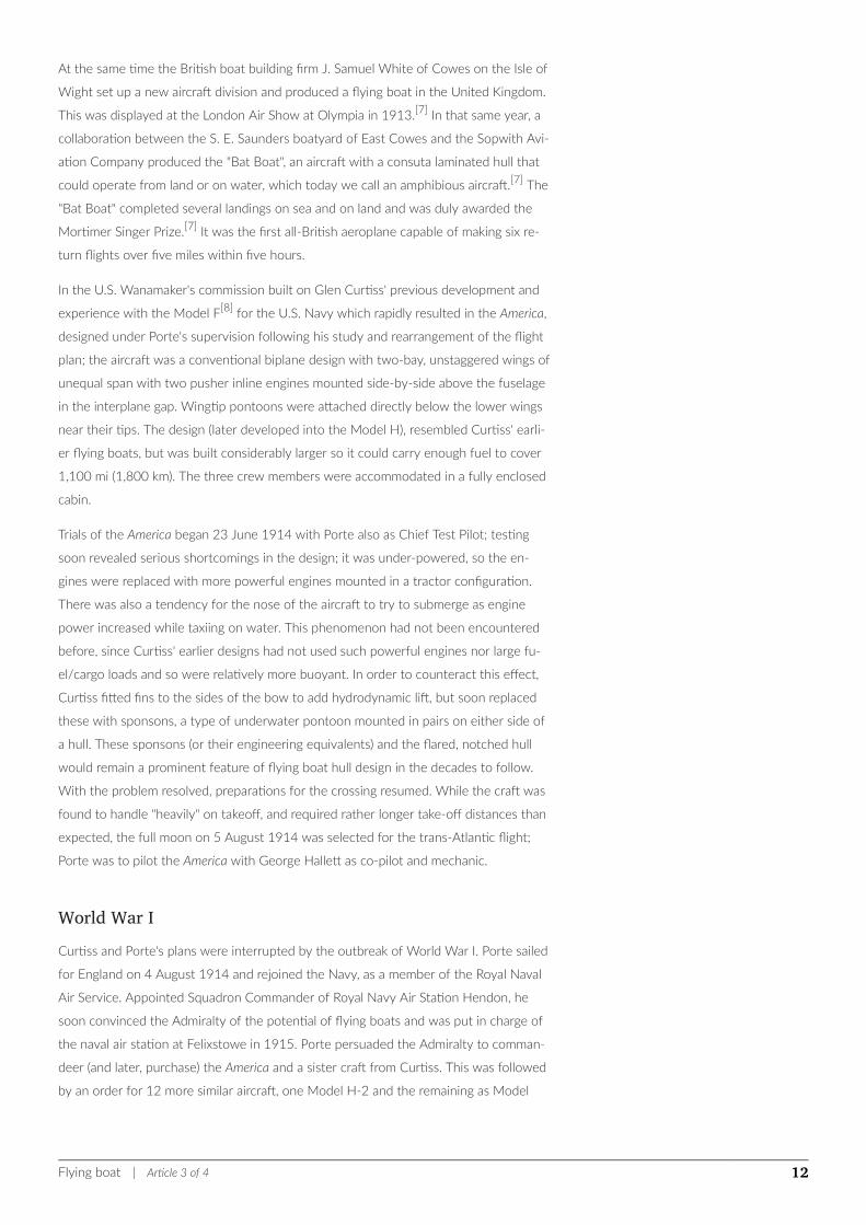
The Felixstowe F.2A, the first production seaplane, andthe basis for future development.
H-4's. Four examples of the latter were assembled in the UK by Saunders. All of these
were similar to the design of the America and, indeed, were all referred to as Americas
in Royal Navy service. The engines, however, were changed from the under-powered
160 hp Curtiss engines to 250 hp Rolls-Royce Falcon engines. The initial batch was fol-
lowed by an order for 50 more (totalling 64 Americas overall during the war).[6] Porte
also acquired permission to modify and experiment with the Curtiss aircraft.
The Curtiss H-4s were soon found to have a number of problems; they were under-
powered, their hulls were too weak for sustained operations and they had poor han-
dling characteristics when afloat or taking off.[9][10] One flying boat pilot, Major
Theodore Douglas Hallam, wrote that they were "comic machines, weighing well under
two tons; with two comic engines giving, when they functioned, 180 horsepower; and
comic control, being nose heavy with engines on and tail heavy in a glide."[11]
At Felixstowe, Porte made advances in flying boat design and developed a practical hull
design with the distinctive "Felixstowe notch".[12] Porte's first design to be implement-
ed in Felixstowe was the Felixstowe Porte Baby, a large, three-engined biplane flying-
boat, powered by one central pusher and two outboard tractor Rolls-Royce Eagle en-
gines.
Porte modified an H-4 with a new hull whose improved hydrodynamic qualities made
taxiing, take-off and landing much more practical, and called it the Felixstowe F.1.
Porte's innovation of the "Felixstowe notch" enabled the craft to overcome suction
from the water more quickly and break free for flight much more easily. This made op-
erating the craft far safer and more reliable. The "notch" breakthrough would soon after
evolve into a "step", with the rear section of the lower hull sharply recessed above the
forward lower hull section, and that characteristic became a feature of both flying boat
hulls and seaplane floats. The resulting aircraft would be large enough to carry suffi-
cient fuel to fly long distances and could berth alongside ships to take on more fuel.
Porte then designed a similar hull for the larger Curtiss H-12 flying boat which, while
larger and more capable than the H-4s, shared failings of a weak hull and poor water
handling. The combination of the new Porte-designed hull, this time fitted with two
steps, with the wings of the H-12 and a new tail, and powered by two Rolls-Royce Ea-
gle engines, was named the Felixstowe F.2 and first flew in July 1916,[13] proving
greatly superior to the Curtiss on which it was based. It was used as the basis for all fu-
ture designs.[14] It entered production as the Felixstowe F.2A, being used as a patrol
aircraft, with about 100 being completed by the end of World War I. Another seventy
were built, and these were followed by two F.2c, which were built at Felixstowe.
In February 1917, the first prototype of the Felixstowe F.3 was flown. It was larger and
heavier than the F.2, giving it greater range and heavier bomb load, but poorer agility.
Approximately 100 Felixstowe F.3s were produced before the end of the war.
Flying boat | Article 3 of 4 13
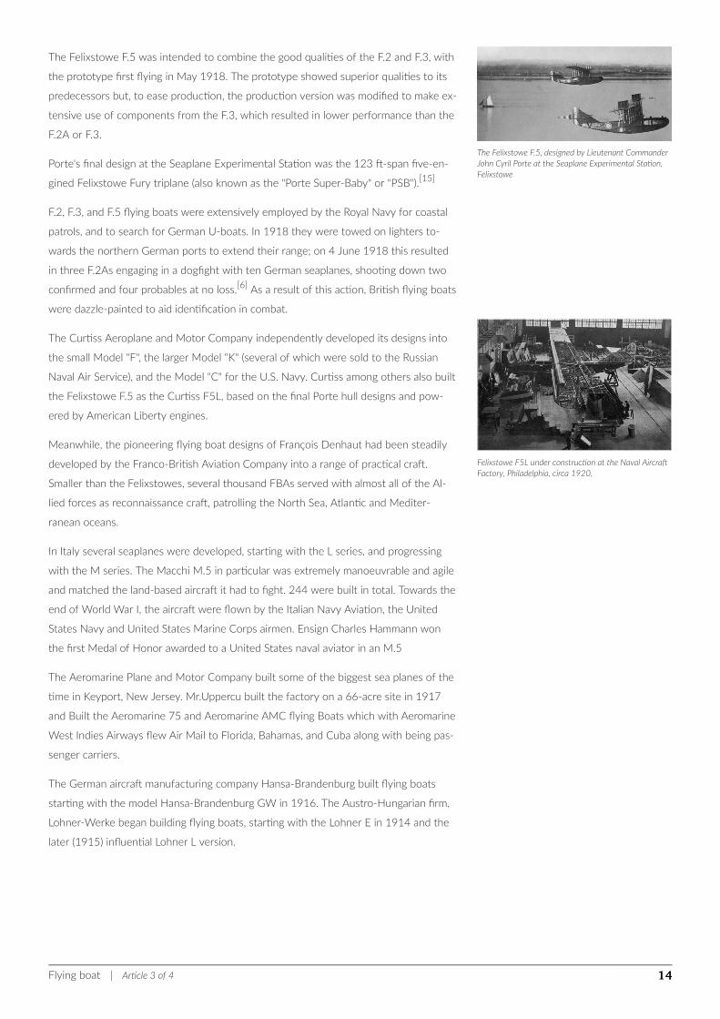
The Felixstowe F.5, designed by Lieutenant CommanderJohn Cyril Porte at the Seaplane Experimental Station,Felixstowe
Felixstowe F5L under construction at the Naval AircraftFactory, Philadelphia, circa 1920.
The Felixstowe F.5 was intended to combine the good qualities of the F.2 and F.3, with
the prototype first flying in May 1918. The prototype showed superior qualities to its
predecessors but, to ease production, the production version was modified to make ex-
tensive use of components from the F.3, which resulted in lower performance than the
F.2A or F.3.
Porte's final design at the Seaplane Experimental Station was the 123 ft-span five-en-
gined Felixstowe Fury triplane (also known as the "Porte Super-Baby" or "PSB").[15]
F.2, F.3, and F.5 flying boats were extensively employed by the Royal Navy for coastal
patrols, and to search for German U-boats. In 1918 they were towed on lighters to-
wards the northern German ports to extend their range; on 4 June 1918 this resulted
in three F.2As engaging in a dogfight with ten German seaplanes, shooting down two
confirmed and four probables at no loss.[6] As a result of this action, British flying boats
were dazzle-painted to aid identification in combat.
The Curtiss Aeroplane and Motor Company independently developed its designs into
the small Model "F", the larger Model "K" (several of which were sold to the Russian
Naval Air Service), and the Model "C" for the U.S. Navy. Curtiss among others also built
the Felixstowe F.5 as the Curtiss F5L, based on the final Porte hull designs and pow-
ered by American Liberty engines.
Meanwhile, the pioneering flying boat designs of François Denhaut had been steadily
developed by the Franco-British Aviation Company into a range of practical craft.
Smaller than the Felixstowes, several thousand FBAs served with almost all of the Al-
lied forces as reconnaissance craft, patrolling the North Sea, Atlantic and Mediter-
ranean oceans.
In Italy several seaplanes were developed, starting with the L series, and progressing
with the M series. The Macchi M.5 in particular was extremely manoeuvrable and agile
and matched the land-based aircraft it had to fight. 244 were built in total. Towards the
end of World War I, the aircraft were flown by the Italian Navy Aviation, the United
States Navy and United States Marine Corps airmen. Ensign Charles Hammann won
the first Medal of Honor awarded to a United States naval aviator in an M.5
The Aeromarine Plane and Motor Company built some of the biggest sea planes of the
time in Keyport, New Jersey. Mr.Uppercu built the factory on a 66-acre site in 1917
and Built the Aeromarine 75 and Aeromarine AMC flying Boats which with Aeromarine
West Indies Airways flew Air Mail to Florida, Bahamas, and Cuba along with being pas-
senger carriers.
The German aircraft manufacturing company Hansa-Brandenburg built flying boats
starting with the model Hansa-Brandenburg GW in 1916. The Austro-Hungarian firm,
Lohner-Werke began building flying boats, starting with the Lohner E in 1914 and the
later (1915) influential Lohner L version.
Flying boat | Article 3 of 4 14
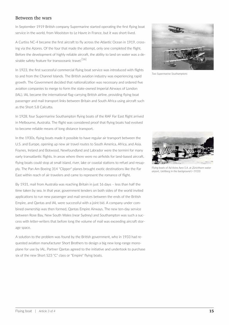
Two Supermarine Southamptons
Flying boats of Ad Astra Aero S.A. at Zürichhorn waterairport, Uetliberg in the background (~1920)
Between the warsIn September 1919 British company Supermarine started operating the first flying boat
service in the world, from Woolston to Le Havre in France, but it was short-lived.
A Curtiss NC-4 became the first aircraft to fly across the Atlantic Ocean in 1919, cross-
ing via the Azores. Of the four that made the attempt, only one completed the flight.
Before the development of highly reliable aircraft, the ability to land on water was a de-
sirable safety feature for transoceanic travel.[16]
In 1923, the first successful commercial flying boat service was introduced with flights
to and from the Channel Islands. The British aviation industry was experiencing rapid
growth. The Government decided that nationalization was necessary and ordered five
aviation companies to merge to form the state-owned Imperial Airways of London
(IAL). IAL became the international flag-carrying British airline, providing flying boat
passenger and mail transport links between Britain and South Africa using aircraft such
as the Short S.8 Calcutta.
In 1928, four Supermarine Southampton flying boats of the RAF Far East flight arrived
in Melbourne, Australia. The flight was considered proof that flying boats had evolved
to become reliable means of long distance transport.
In the 1930s, flying boats made it possible to have regular air transport between the
U.S. and Europe, opening up new air travel routes to South America, Africa, and Asia.
Foynes, Ireland and Botwood, Newfoundland and Labrador were the termini for many
early transatlantic flights. In areas where there were no airfields for land-based aircraft,
flying boats could stop at small island, river, lake or coastal stations to refuel and resup-
ply. The Pan Am Boeing 314 "Clipper" planes brought exotic destinations like the Far
East within reach of air travelers and came to represent the romance of flight.
By 1931, mail from Australia was reaching Britain in just 16 days – less than half the
time taken by sea. In that year, government tenders on both sides of the world invited
applications to run new passenger and mail services between the ends of the British
Empire, and Qantas and IAL were successful with a joint bid. A company under com-
bined ownership was then formed, Qantas Empire Airways. The new ten-day service
between Rose Bay, New South Wales (near Sydney) and Southampton was such a suc-
cess with letter-writers that before long the volume of mail was exceeding aircraft stor-
age space.
A solution to the problem was found by the British government, who in 1933 had re-
quested aviation manufacturer Short Brothers to design a big new long-range mono-
plane for use by IAL. Partner Qantas agreed to the initiative and undertook to purchase
six of the new Short S23 "C" class or "Empire" flying boats.
Flying boat | Article 3 of 4 15
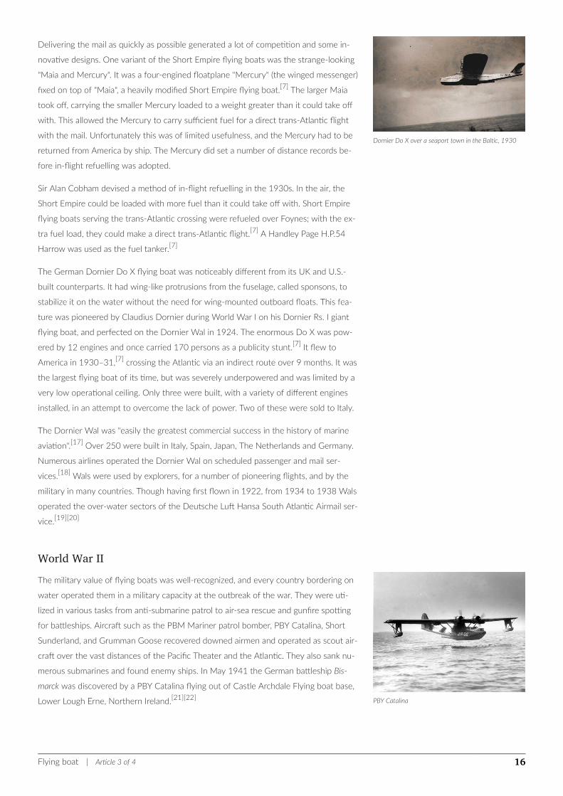
Dornier Do X over a seaport town in the Baltic, 1930
PBY Catalina
Delivering the mail as quickly as possible generated a lot of competition and some in-
novative designs. One variant of the Short Empire flying boats was the strange-looking
"Maia and Mercury". It was a four-engined floatplane "Mercury" (the winged messenger)
fixed on top of "Maia", a heavily modified Short Empire flying boat.[7] The larger Maia
took off, carrying the smaller Mercury loaded to a weight greater than it could take off
with. This allowed the Mercury to carry sufficient fuel for a direct trans-Atlantic flight
with the mail. Unfortunately this was of limited usefulness, and the Mercury had to be
returned from America by ship. The Mercury did set a number of distance records be-
fore in-flight refuelling was adopted.
Sir Alan Cobham devised a method of in-flight refuelling in the 1930s. In the air, the
Short Empire could be loaded with more fuel than it could take off with. Short Empire
flying boats serving the trans-Atlantic crossing were refueled over Foynes; with the ex-
tra fuel load, they could make a direct trans-Atlantic flight.[7] A Handley Page H.P.54
Harrow was used as the fuel tanker.[7]
The German Dornier Do X flying boat was noticeably different from its UK and U.S.-
built counterparts. It had wing-like protrusions from the fuselage, called sponsons, to
stabilize it on the water without the need for wing-mounted outboard floats. This fea-
ture was pioneered by Claudius Dornier during World War I on his Dornier Rs. I giant
flying boat, and perfected on the Dornier Wal in 1924. The enormous Do X was pow-
ered by 12 engines and once carried 170 persons as a publicity stunt.[7] It flew to
America in 1930–31,[7] crossing the Atlantic via an indirect route over 9 months. It was
the largest flying boat of its time, but was severely underpowered and was limited by a
very low operational ceiling. Only three were built, with a variety of different engines
installed, in an attempt to overcome the lack of power. Two of these were sold to Italy.
The Dornier Wal was "easily the greatest commercial success in the history of marine
aviation".[17] Over 250 were built in Italy, Spain, Japan, The Netherlands and Germany.
Numerous airlines operated the Dornier Wal on scheduled passenger and mail ser-
vices.[18] Wals were used by explorers, for a number of pioneering flights, and by the
military in many countries. Though having first flown in 1922, from 1934 to 1938 Wals
operated the over-water sectors of the Deutsche Luft Hansa South Atlantic Airmail ser-
vice.[19][20]
World War IIThe military value of flying boats was well-recognized, and every country bordering on
water operated them in a military capacity at the outbreak of the war. They were uti-
lized in various tasks from anti-submarine patrol to air-sea rescue and gunfire spotting
for battleships. Aircraft such as the PBM Mariner patrol bomber, PBY Catalina, Short
Sunderland, and Grumman Goose recovered downed airmen and operated as scout air-
craft over the vast distances of the Pacific Theater and the Atlantic. They also sank nu-
merous submarines and found enemy ships. In May 1941 the German battleship Bis-
marck was discovered by a PBY Catalina flying out of Castle Archdale Flying boat base,
Lower Lough Erne, Northern Ireland.[21][22]
Flying boat | Article 3 of 4 16

Kawanishi H8K, 1941–1945
Hughes H-4 Hercules
The largest flying boat of the war was the Blohm & Voss BV 238, which was also the
heaviest plane to fly during World War II and the largest aircraft built and flown by any
of the Axis Powers.
In November 1939, IAL was restructured into three separate companies: British Euro-
pean Airways, British Overseas Airways Corporation (BOAC), and British South Ameri-
can Airways (which merged with BOAC in 1949), with the change being made official
on 1 April 1940. BOAC continued to operate flying boat services from the (slightly)
safer confines of Poole Harbour during wartime, returning to Southampton in 1947.[7]
When Italy entered the war in June 1940, the Mediterranean was closed to allied
planes and BOAC and Qantas operated the Horseshoe Route between Durban and
Sydney using Short Empire flying boats.
The Martin Company produced the prototype XPB2M Mars based on their PBM
Mariner patrol bomber, with flight tests between 1941 and 1943. The Mars was con-
verted by the Navy into a transport aircraft designated the XPB2M-1R. Satisfied with
the performance, 20 of the modified JRM-1 Mars were ordered. The first, named
Hawaii Mars, was delivered in June 1945, but the Navy scaled back their order at the
end of World War II, buying only the five aircraft which were then on the production
line. The five Mars were completed, and the last delivered in 1947.[23]
Post-WarAfter World War II the use of flying boats rapidly declined for several reasons. The abil-
ity to land on water became less of an advantage owing to the considerable increase in
the number and length of land based runways during World War II. Further, as the reli-
ability, speed, and range of land-based aircraft increased, the commercial competitive-
ness of flying boats diminished; their design compromised aerodynamic efficiency and
speed to accomplish the feat of waterborne takeoff and landing. Competing with new
civilian jet aircraft like the de Havilland Comet and Boeing 707 proved impossible.
The Hughes H-4 Hercules, in development in the U.S. during the war, was even larger
than the BV 238 but it did not fly until 1947. The Spruce Goose, as the 180-ton H-4
was nicknamed, was the largest flying boat ever to fly. Carried out during Senate hear-
ings into Hughes use of government funds on its construction, the short hop of about
a mile at 70 ft above the water by the "Flying Lumberyard" was claimed by Hughes as
vindication of his efforts. Cutbacks in expenditure after the war and the disappearance
of its intended mission as a transatlantic transport left it no purpose.[24]
In 1944, the Royal Air Force began development of a small jet-powered flying boat that
it intended to use as an air defence aircraft optimised for the Pacific, where the rela-
tively calm sea conditions made the use of seaplanes easier. By making the aircraft jet
powered, it was possible to design it with a hull rather than making it a floatplane. The
Saunders-Roe SR.A/1 prototype first flew in 1947 and was relatively successful in
terms of its performance and handling. However, by the end of the war, carrier based
aircraft were becoming more sophisticated, and the need for the SR.A/1 evaporated.
Flying boat | Article 3 of 4 17
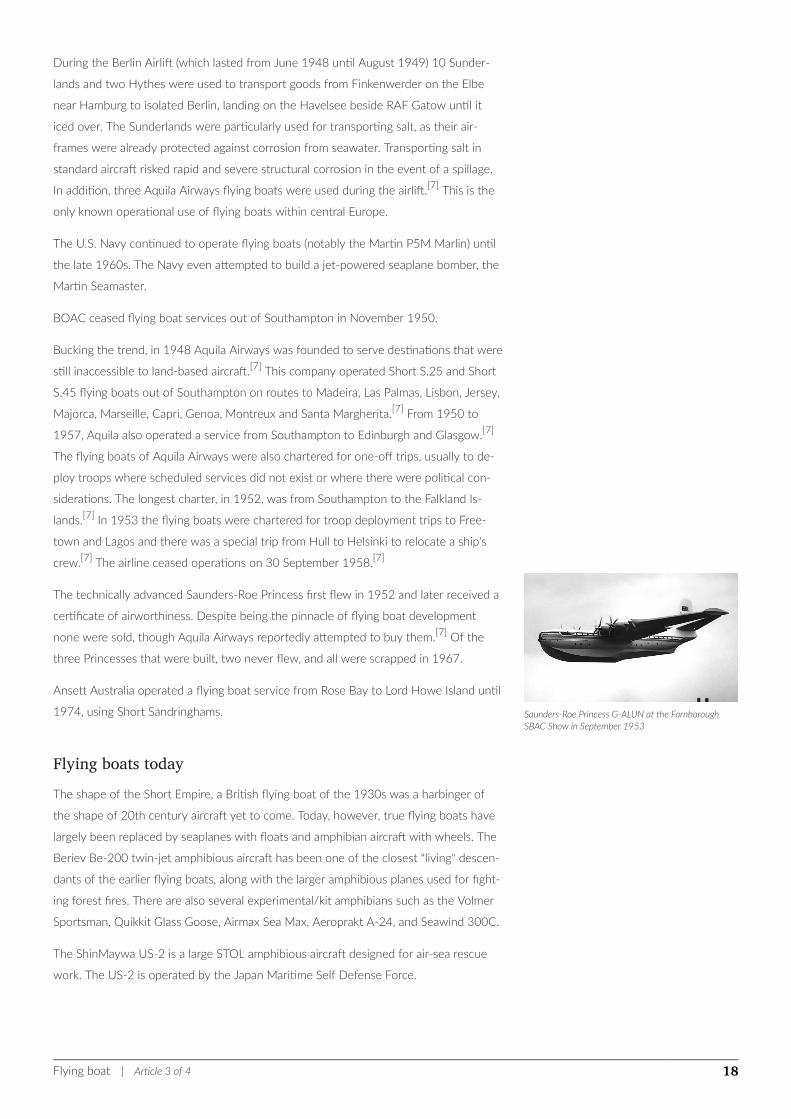
Saunders-Roe Princess G-ALUN at the FarnboroughSBAC Show in September 1953
During the Berlin Airlift (which lasted from June 1948 until August 1949) 10 Sunder-
lands and two Hythes were used to transport goods from Finkenwerder on the Elbe
near Hamburg to isolated Berlin, landing on the Havelsee beside RAF Gatow until it
iced over. The Sunderlands were particularly used for transporting salt, as their air-
frames were already protected against corrosion from seawater. Transporting salt in
standard aircraft risked rapid and severe structural corrosion in the event of a spillage.
In addition, three Aquila Airways flying boats were used during the airlift.[7] This is the
only known operational use of flying boats within central Europe.
The U.S. Navy continued to operate flying boats (notably the Martin P5M Marlin) until
the late 1960s. The Navy even attempted to build a jet-powered seaplane bomber, the
Martin Seamaster.
BOAC ceased flying boat services out of Southampton in November 1950.
Bucking the trend, in 1948 Aquila Airways was founded to serve destinations that were
still inaccessible to land-based aircraft.[7] This company operated Short S.25 and Short
S.45 flying boats out of Southampton on routes to Madeira, Las Palmas, Lisbon, Jersey,
Majorca, Marseille, Capri, Genoa, Montreux and Santa Margherita.[7] From 1950 to
1957, Aquila also operated a service from Southampton to Edinburgh and Glasgow.[7]
The flying boats of Aquila Airways were also chartered for one-off trips, usually to de-
ploy troops where scheduled services did not exist or where there were political con-
siderations. The longest charter, in 1952, was from Southampton to the Falkland Is-
lands.[7] In 1953 the flying boats were chartered for troop deployment trips to Free-
town and Lagos and there was a special trip from Hull to Helsinki to relocate a ship's
crew.[7] The airline ceased operations on 30 September 1958.[7]
The technically advanced Saunders-Roe Princess first flew in 1952 and later received a
certificate of airworthiness. Despite being the pinnacle of flying boat development
none were sold, though Aquila Airways reportedly attempted to buy them.[7] Of the
three Princesses that were built, two never flew, and all were scrapped in 1967.
Ansett Australia operated a flying boat service from Rose Bay to Lord Howe Island until
1974, using Short Sandringhams.
Flying boats todayThe shape of the Short Empire, a British flying boat of the 1930s was a harbinger of
the shape of 20th century aircraft yet to come. Today, however, true flying boats have
largely been replaced by seaplanes with floats and amphibian aircraft with wheels. The
Beriev Be-200 twin-jet amphibious aircraft has been one of the closest "living" descen-
dants of the earlier flying boats, along with the larger amphibious planes used for fight-
ing forest fires. There are also several experimental/kit amphibians such as the Volmer
Sportsman, Quikkit Glass Goose, Airmax Sea Max, Aeroprakt A-24, and Seawind 300C.
The ShinMaywa US-2 is a large STOL amphibious aircraft designed for air-sea rescue
work. The US-2 is operated by the Japan Maritime Self Defense Force.
Flying boat | Article 3 of 4 18

The Canadair CL-215 and successor Bombardier 415 are examples of modern flying
boats and are used for forest fire suppression.
Dornier announced plans in May 2010 to build CD2 SeaStar composite flying boats in
Quebec, Canada.
The Chinese state owned Aviation Industry Corporation of China is set to launch a
massive new AVIC TA-600 amphibious airplane in 2016.[25]
The ICON A5 is an amphibious aircraft in the light-sport class.
Gallery
Chinese Harbin/Shuihong 5 U.S. PBY Catalina serving as anaerial firefighting plane
Japanese ShinMaywa US-2
Canadair CL-215 Canadair CL-415 Russian Beriev Be-200
ICON A5
See also• Ground effect vehicle
• List of seaplanes and amphibious aircraft
• Maritime patrol aircraft
Flying boat | Article 3 of 4 19
ReferencesNotes
1. ^ E. R. Johnson, American Flying Boats and Amphibious Aircraft: An Illustrated History, McFarland and Company, Inc., IS-
BN 978-0-7864-3974-4
2. ^ a b c d e Flying Boats & Seaplanes: A History from 1905, Stéphane Nicolaou
3. ^ Naughton, Russell. Henri Fabre (1882–1984)." Monash University Centre for Telecommunications and Information Engineering, 15
May 2002. Retrieved: 9 May 2008
4. ^ Anonymous (2009) The establishment of the Navy Airforce, Fox2 Magazine (in Greek language) Archived 3 December 2013 at
the Wayback Machine.
5. ^ Nicolaou, Stephane (1998) [1996], Flying Boats & Seaplanes: A history from 1905, translated by Robin Sawers, Devon: Bay Books
View Ltd, p. 9, ISBN 1901432203
6. ^ a b c The Felixstowe Flying Boats, Flight 2 December 1955
7. ^ a b c d e f g h i j k l m n o p q Hull, Norman. Flying Boats of the Solent: A Portrait of a Golden Age of Air Travel (Aviation Heritage).
Great Addington, Kettering, Northants, UK: Silver Link Publishing, 2002. ISBN 1-85794-161-6.
8. ^ Carpenter, Jr, G. J. (Jack) (2005). "Photographs 1914". GLENN H. CURTISS Founder of The American Aviation Industry. Internet
Archive - Way Back Machine. Archived from the original on 20 October 2006. Retrieved 15 December 2015.
9. ^ Bruce Flight 2 December 1955, p.844.
10. ^ London 2003, pp. 16–17.
11. ^ Hallam 1919, pp. 21–22.
12. ^ "Felixstowe." Archived 1 September 2006 at the Wayback Machine. NASM. Retrieved: 20 May 2012.
13. ^ London 2003, pp. 24–25.
14. ^ Bruce Flight 2 December 1955, p. 846.
15. ^ "Felixstowe Flying-Boats." Will Higgs Co, United Kingdom. Retrieved: 24 December 2009.
16. ^ "Engines of Our Ingenuity No. 1988: THE SARO PRINCESS".
17. ^ Stéphane Nicolaou FLYING BOATS & SEAPLANES A History from 1905, Bay View Books Ltd Bideford Devon 1998 (English
translation, originally published in French - copyright ETAI, Paris 1996)
18. ^ Gandt, Robert L. CHINA CLIPPER - The Age of the Great Flying Boats, Naval Institute Press, Annapolis Maryland 1991 IS-
BN 0-87021-209-5
19. ^ "First Transatlantic air line", Popular Science, February 1933
20. ^ James W. Graue & John Duggan "Deutsche Lufthansa South Atlantic Airmail Service 1934 - 1939", Zeppelin Study Group, Ick-
enham, UK 2000 ISBN 0-9514114-5-4
21. ^ "Flying-boats in Fermanagh". Inland Waterways News. Inland Waterways Association of Ireland. Spring 2002. Archived from the origi-
nal on 20 July 2012. Retrieved 20 May 2012.
22. ^ "Castle Archdale Country Park". Northern Ireland Environment Agency. Archived from the original on 1 May 2009. Retrieved 19 June
2009.
23. ^ Goebel, Greg. "The Martin Mariner, Mars, & Marlin Flying Boats." Vectorsite. Retrieved: 20 May 2012.
24. ^ Its claim to true flying status is disputed as it made but one short flight in its life
25. ^ Slepian, Katya. "Test pilot school a success for Martin Mars – Alberni Valley News". Alberni Valley News. Archived from the original on
4 March 2016. Retrieved 27 February 2016.
Bibliography
• Davies, R.E.G. Pan Am: An Airline and its Aircraft. New York: Orion Books, 1987. ISBN 0-517-56639-7.
• Yenne, Bill. Seaplanes & Flying Boats: A Timeless Collection from Aviation's Golden Age. New York: BCL Press, 2003. IS-
BN 1-932302-03-4.
Flying boat | Article 3 of 4 20

External links
Wikimedia Commons has media related to Flying boats.
• When Boats Had Wings, June 1963 detail article Popular Science
Flying boat | Article 3 of 4 21
Technical Aspects
Propeller
A propeller is a type of fan that transmits power by converting rotational motioninto thrust. A pressure difference is produced between the forward and rear surfacesof the airfoil-shaped blade, and a fluid (such as air or water) is accelerated behindthe blade. Propeller dynamics, like those of aircraft wings, can be modelled byBernoulli's principle and Newton's third law. Most marine propellers are screw pro-pellers with fixed helical blades rotating around a horizontal (or nearly horizontal)axis or propeller shaft.
HistoryEarly developmentsThe principle employed in using a screw propeller is used in sculling. It is part of the
skill of propelling a Venetian gondola but was used in a less refined way in other parts
of Europe and probably elsewhere. For example, propelling a canoe with a single pad-
dle using a "pitch stroke" or side slipping a canoe with a "scull" involves a similar tech-
nique. In China, sculling, called "lu", was also used by the 3rd century AD.
In sculling, a single blade is moved through an arc, from side to side taking care to keep
presenting the blade to the water at the effective angle. The innovation introduced
with the screw propeller was the extension of that arc through more than 360° by at-
taching the blade to a rotating shaft. Propellers can have a single blade, but in practice
there are nearly always more than one so as to balance the forces involved.
Propeller | Article 4 of 4 22
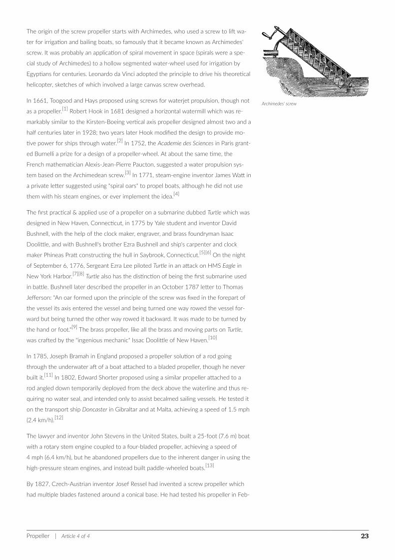
Archimedes' screw
The origin of the screw propeller starts with Archimedes, who used a screw to lift wa-
ter for irrigation and bailing boats, so famously that it became known as Archimedes'
screw. It was probably an application of spiral movement in space (spirals were a spe-
cial study of Archimedes) to a hollow segmented water-wheel used for irrigation by
Egyptians for centuries. Leonardo da Vinci adopted the principle to drive his theoretical
helicopter, sketches of which involved a large canvas screw overhead.
In 1661, Toogood and Hays proposed using screws for waterjet propulsion, though not
as a propeller.[1] Robert Hook in 1681 designed a horizontal watermill which was re-
markably similar to the Kirsten-Boeing vertical axis propeller designed almost two and a
half centuries later in 1928; two years later Hook modified the design to provide mo-
tive power for ships through water.[2] In 1752, the Academie des Sciences in Paris grant-
ed Burnelli a prize for a design of a propeller-wheel. At about the same time, the
French mathematician Alexis-Jean-Pierre Paucton, suggested a water propulsion sys-
tem based on the Archimedean screw.[3] In 1771, steam-engine inventor James Watt in
a private letter suggested using "spiral oars" to propel boats, although he did not use
them with his steam engines, or ever implement the idea.[4]
The first practical & applied use of a propeller on a submarine dubbed Turtle which was
designed in New Haven, Connecticut, in 1775 by Yale student and inventor David
Bushnell, with the help of the clock maker, engraver, and brass foundryman Isaac
Doolittle, and with Bushnell's brother Ezra Bushnell and ship's carpenter and clock
maker Phineas Pratt constructing the hull in Saybrook, Connecticut.[5][6] On the night
of September 6, 1776, Sergeant Ezra Lee piloted Turtle in an attack on HMS Eagle in
New York Harbor.[7][8] Turtle also has the distinction of being the first submarine used
in battle. Bushnell later described the propeller in an October 1787 letter to Thomas
Jefferson: "An oar formed upon the principle of the screw was fixed in the forepart of
the vessel its axis entered the vessel and being turned one way rowed the vessel for-
ward but being turned the other way rowed it backward. It was made to be turned by
the hand or foot."[9] The brass propeller, like all the brass and moving parts on Turtle,
was crafted by the "ingenious mechanic" Issac Doolittle of New Haven.[10]
In 1785, Joseph Bramah in England proposed a propeller solution of a rod going
through the underwater aft of a boat attached to a bladed propeller, though he never
built it.[11] In 1802, Edward Shorter proposed using a similar propeller attached to a
rod angled down temporarily deployed from the deck above the waterline and thus re-
quiring no water seal, and intended only to assist becalmed sailing vessels. He tested it
on the transport ship Doncaster in Gibraltar and at Malta, achieving a speed of 1.5 mph
(2.4 km/h).[12]
The lawyer and inventor John Stevens in the United States, built a 25-foot (7.6 m) boat
with a rotary stem engine coupled to a four-bladed propeller, achieving a speed of
4 mph (6.4 km/h), but he abandoned propellers due to the inherent danger in using the
high-pressure steam engines, and instead built paddle-wheeled boats.[13]
By 1827, Czech-Austrian inventor Josef Ressel had invented a screw propeller which
had multiple blades fastened around a conical base. He had tested his propeller in Feb-
Propeller | Article 4 of 4 23
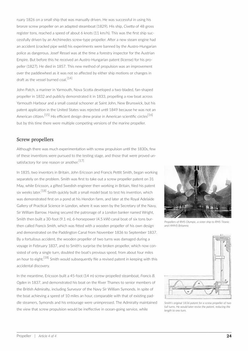
Propellers of RMS Olympic, a sister ship to RMS Titanicand HMHS Britannic
Smith's original 1836 patent for a screw propeller of twofull turns. He would later revise the patent, reducing thelength to one turn.
ruary 1826 on a small ship that was manually driven. He was successful in using his
bronze screw propeller on an adapted steamboat (1829). His ship, Civetta of 48 gross
register tons, reached a speed of about 6 knots (11 km/h). This was the first ship suc-
cessfully driven by an Archimedes screw-type propeller. After a new steam engine had
an accident (cracked pipe weld) his experiments were banned by the Austro-Hungarian
police as dangerous. Josef Ressel was at the time a forestry inspector for the Austrian
Empire. But before this he received an Austro-Hungarian patent (license) for his pro-
peller (1827). He died in 1857. This new method of propulsion was an improvement
over the paddlewheel as it was not so affected by either ship motions or changes in
draft as the vessel burned coal.[14]
John Patch, a mariner in Yarmouth, Nova Scotia developed a two-bladed, fan-shaped
propeller in 1832 and publicly demonstrated it in 1833, propelling a row boat across
Yarmouth Harbour and a small coastal schooner at Saint John, New Brunswick, but his
patent application in the United States was rejected until 1849 because he was not an
American citizen.[15] His efficient design drew praise in American scientific circles[16]
but by this time there were multiple competing versions of the marine propeller.
Screw propellersAlthough there was much experimentation with screw propulsion until the 1830s, few
of these inventions were pursued to the testing stage, and those that were proved un-
satisfactory for one reason or another.[17]
In 1835, two inventors in Britain, John Ericsson and Francis Pettit Smith, began working
separately on the problem. Smith was first to take out a screw propeller patent on 31
May, while Ericsson, a gifted Swedish engineer then working in Britain, filed his patent
six weeks later.[18] Smith quickly built a small model boat to test his invention, which
was demonstrated first on a pond at his Hendon farm, and later at the Royal Adelaide
Gallery of Practical Science in London, where it was seen by the Secretary of the Navy,
Sir William Barrow. Having secured the patronage of a London banker named Wright,
Smith then built a 30-foot (9.1 m), 6-horsepower (4.5 kW) canal boat of six tons bur-
then called Francis Smith, which was fitted with a wooden propeller of his own design
and demonstrated on the Paddington Canal from November 1836 to September 1837.
By a fortuitous accident, the wooden propeller of two turns was damaged during a
voyage in February 1837, and to Smith's surprise the broken propeller, which now con-
sisted of only a single turn, doubled the boat's previous speed, from about four miles
an hour to eight.[18] Smith would subsequently file a revised patent in keeping with this
accidental discovery.
In the meantime, Ericsson built a 45-foot (14 m) screw-propelled steamboat, Francis B.
Ogden in 1837, and demonstrated his boat on the River Thames to senior members of
the British Admiralty, including Surveyor of the Navy Sir William Symonds. In spite of
the boat achieving a speed of 10 miles an hour, comparable with that of existing pad-
dle steamers, Symonds and his entourage were unimpressed. The Admiralty maintained
the view that screw propulsion would be ineffective in ocean-going service, while
Propeller | Article 4 of 4 24
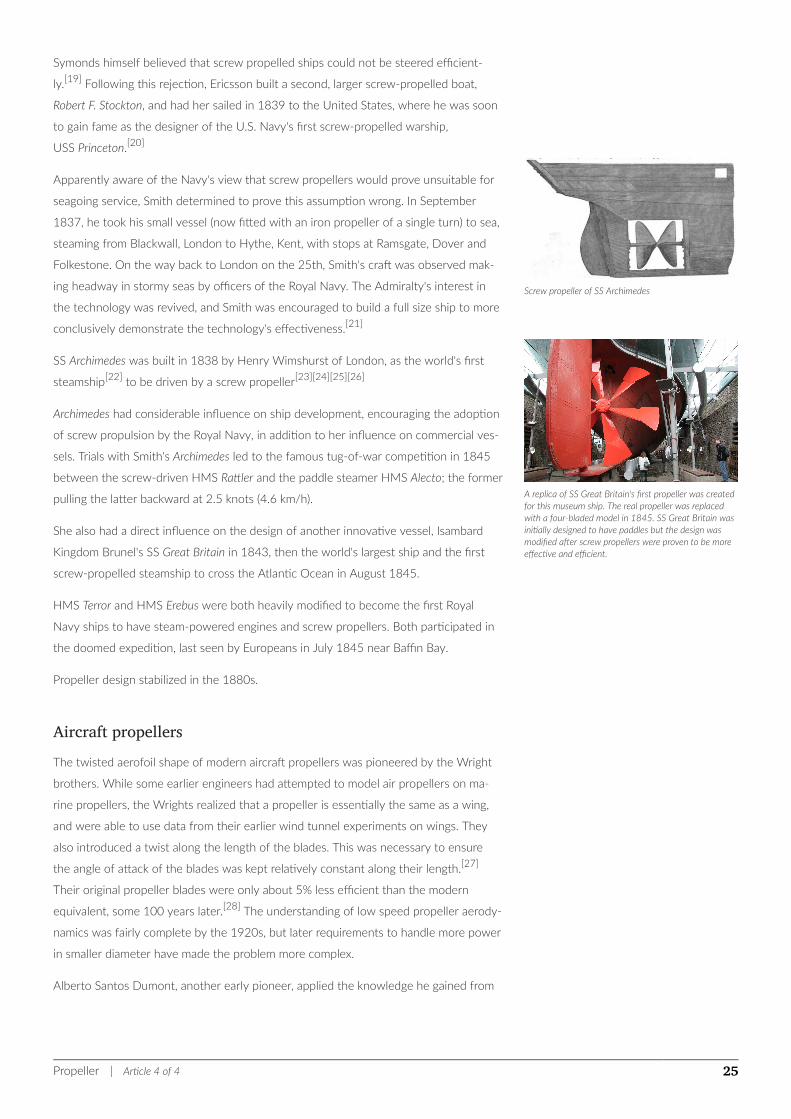
Screw propeller of SS Archimedes
A replica of SS Great Britain's first propeller was createdfor this museum ship. The real propeller was replacedwith a four-bladed model in 1845. SS Great Britain wasinitially designed to have paddles but the design wasmodified after screw propellers were proven to be moreeffective and efficient.
Symonds himself believed that screw propelled ships could not be steered efficient-
ly.[19] Following this rejection, Ericsson built a second, larger screw-propelled boat,
Robert F. Stockton, and had her sailed in 1839 to the United States, where he was soon
to gain fame as the designer of the U.S. Navy's first screw-propelled warship,
USS Princeton.[20]
Apparently aware of the Navy's view that screw propellers would prove unsuitable for
seagoing service, Smith determined to prove this assumption wrong. In September
1837, he took his small vessel (now fitted with an iron propeller of a single turn) to sea,
steaming from Blackwall, London to Hythe, Kent, with stops at Ramsgate, Dover and
Folkestone. On the way back to London on the 25th, Smith's craft was observed mak-
ing headway in stormy seas by officers of the Royal Navy. The Admiralty's interest in
the technology was revived, and Smith was encouraged to build a full size ship to more
conclusively demonstrate the technology's effectiveness.[21]
SS Archimedes was built in 1838 by Henry Wimshurst of London, as the world's first
steamship[22] to be driven by a screw propeller[23][24][25][26]
Archimedes had considerable influence on ship development, encouraging the adoption
of screw propulsion by the Royal Navy, in addition to her influence on commercial ves-
sels. Trials with Smith's Archimedes led to the famous tug-of-war competition in 1845
between the screw-driven HMS Rattler and the paddle steamer HMS Alecto; the former
pulling the latter backward at 2.5 knots (4.6 km/h).
She also had a direct influence on the design of another innovative vessel, Isambard
Kingdom Brunel's SS Great Britain in 1843, then the world's largest ship and the first
screw-propelled steamship to cross the Atlantic Ocean in August 1845.
HMS Terror and HMS Erebus were both heavily modified to become the first Royal
Navy ships to have steam-powered engines and screw propellers. Both participated in
the doomed expedition, last seen by Europeans in July 1845 near Baffin Bay.
Propeller design stabilized in the 1880s.
Aircraft propellersThe twisted aerofoil shape of modern aircraft propellers was pioneered by the Wright
brothers. While some earlier engineers had attempted to model air propellers on ma-
rine propellers, the Wrights realized that a propeller is essentially the same as a wing,
and were able to use data from their earlier wind tunnel experiments on wings. They
also introduced a twist along the length of the blades. This was necessary to ensure
the angle of attack of the blades was kept relatively constant along their length.[27]
Their original propeller blades were only about 5% less efficient than the modern
equivalent, some 100 years later.[28] The understanding of low speed propeller aerody-
namics was fairly complete by the 1920s, but later requirements to handle more power
in smaller diameter have made the problem more complex.
Alberto Santos Dumont, another early pioneer, applied the knowledge he gained from
Propeller | Article 4 of 4 25
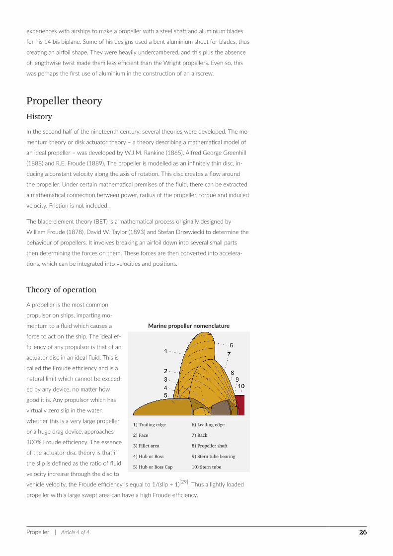
Marine propeller nomenclature
1) Trailing edge
2) Face
3) Fillet area
4) Hub or Boss
5) Hub or Boss Cap
6) Leading edge
7) Back
8) Propeller shaft
9) Stern tube bearing
10) Stern tube
experiences with airships to make a propeller with a steel shaft and aluminium blades
for his 14 bis biplane. Some of his designs used a bent aluminium sheet for blades, thus
creating an airfoil shape. They were heavily undercambered, and this plus the absence
of lengthwise twist made them less efficient than the Wright propellers. Even so, this
was perhaps the first use of aluminium in the construction of an airscrew.
Propeller theoryHistoryIn the second half of the nineteenth century, several theories were developed. The mo-
mentum theory or disk actuator theory – a theory describing a mathematical model of
an ideal propeller – was developed by W.J.M. Rankine (1865), Alfred George Greenhill
(1888) and R.E. Froude (1889). The propeller is modelled as an infinitely thin disc, in-
ducing a constant velocity along the axis of rotation. This disc creates a flow around
the propeller. Under certain mathematical premises of the fluid, there can be extracted
a mathematical connection between power, radius of the propeller, torque and induced
velocity. Friction is not included.
The blade element theory (BET) is a mathematical process originally designed by
William Froude (1878), David W. Taylor (1893) and Stefan Drzewiecki to determine the
behaviour of propellers. It involves breaking an airfoil down into several small parts
then determining the forces on them. These forces are then converted into accelera-
tions, which can be integrated into velocities and positions.
Theory of operationA propeller is the most common
propulsor on ships, imparting mo-
mentum to a fluid which causes a
force to act on the ship. The ideal ef-
ficiency of any propulsor is that of an
actuator disc in an ideal fluid. This is
called the Froude efficiency and is a
natural limit which cannot be exceed-
ed by any device, no matter how
good it is. Any propulsor which has
virtually zero slip in the water,
whether this is a very large propeller
or a huge drag device, approaches
100% Froude efficiency. The essence
of the actuator-disc theory is that if
the slip is defined as the ratio of fluid
velocity increase through the disc to
vehicle velocity, the Froude efficiency is equal to 1/(slip + 1)[29]. Thus a lightly loaded
propeller with a large swept area can have a high Froude efficiency.
Propeller | Article 4 of 4 26
An actual propeller has blades made up of sections of helicoidal surfaces which can be
thought to 'screw' through the fluid (hence the common reference to propellers as
"screws"). Actually the blades are twisted airfoils or hydrofoils and each section con-
tributes to the total thrust. Two to five blades are most common, although designs
which are intended to operate at reduced noise will have more blades and one-bladed
ones with a counterweight have also been used. Lightly loaded propellers for light air-
craft and human-powered boats mostly have two blades, motor boats mostly have
three blades. The blades are attached to a boss (hub), which should be as small as the
needs of strength allow – with fixed-pitch propellers the blades and boss are usually a
single casting.
An alternative design is the controllable-pitch propeller (CPP, or CRP for controllable-
reversible pitch), where the blades are rotated normally to the drive shaft by additional
machinery – usually hydraulics – at the hub and control linkages running down the
shaft. This allows the drive machinery to operate at a constant speed while the pro-
peller loading is changed to match operating conditions. It also eliminates the need for
a reversing gear and allows for more rapid change to thrust, as the revolutions are con-
stant. This type of propeller is most common on ships such as tugs where there can be
enormous differences in propeller loading when towing compared to running free. The
downsides of a CPP/CRP include: the large hub which decreases the torque required to
cause cavitation, the mechanical complexity which limits transmission power and the
extra blade shaping requirements forced upon the propeller designer.
For smaller motors there are self-pitching propellers. The blades freely move through
an entire circle on an axis at right angles to the shaft. This allows hydrodynamic and
centrifugal forces to 'set' the angle the blades reach and so the pitch of the propeller.
A propeller that turns clockwise to produce forward thrust, when viewed from aft, is
called right-handed. One that turns anticlockwise is said to be left-handed. Larger ves-
sels often have twin screws to reduce heeling torque, counter-rotating propellers, the
starboard screw is usually right-handed and the port left-handed, this is called outward
turning. The opposite case is called inward turning. Another possibility is contra-rotat-
ing propellers, where two propellers rotate in opposing directions on a single shaft, or
on separate shafts on nearly the same axis. Contra-rotating propellers offer increased
efficiency by capturing the energy lost in the tangential velocities imparted to the fluid
by the forward propeller (known as "propeller swirl"). The flow field behind the aft pro-
peller of a contra-rotating set has very little "swirl", and this reduction in energy loss is
seen as an increased efficiency of the aft propeller.
An azimuthing propeller is a propeller that turns around the vertical axis. The individual
airfoil-shaped blades turn as the propeller moves so that they are always generating lift
in the vessel's direction of movement. This type of propeller can reverse or change its
direction of thrust very quickly.
Fixed-wing aircraft are also subject to the P-factor effect, in which a rotating propeller
will yaw an aircraft slightly to one side because the relative wind it produces is asym-
metrical. It is particularly noticeable when climbing, but is usually simple to compensate
Propeller | Article 4 of 4 27
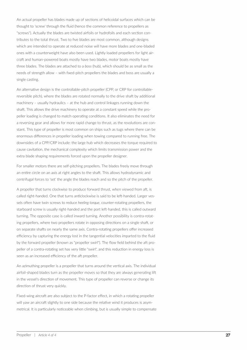
Cavitating propeller in water tunnel experiment
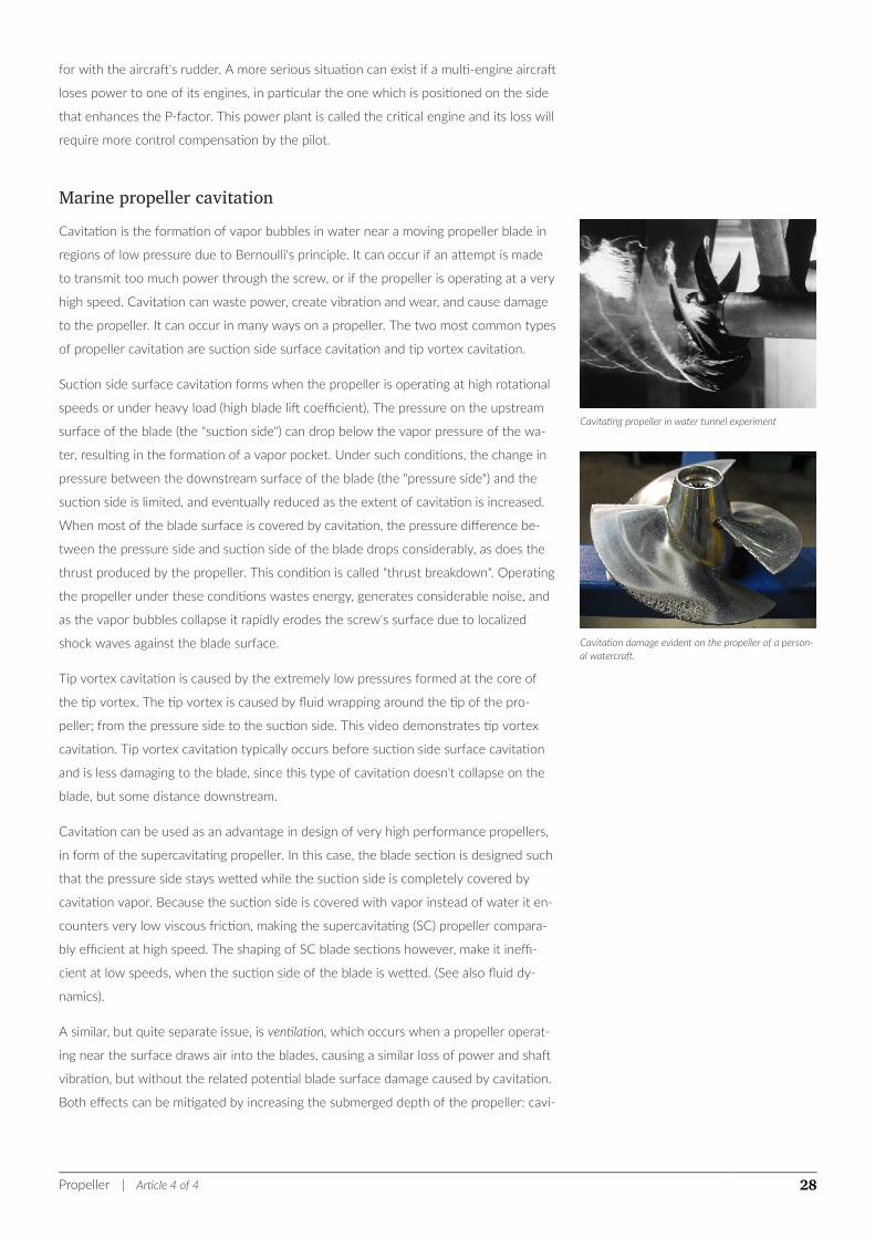
Cavitation damage evident on the propeller of a person-al watercraft.
for with the aircraft's rudder. A more serious situation can exist if a multi-engine aircraft
loses power to one of its engines, in particular the one which is positioned on the side
that enhances the P-factor. This power plant is called the critical engine and its loss will
require more control compensation by the pilot.
Marine propeller cavitationCavitation is the formation of vapor bubbles in water near a moving propeller blade in
regions of low pressure due to Bernoulli's principle. It can occur if an attempt is made
to transmit too much power through the screw, or if the propeller is operating at a very
high speed. Cavitation can waste power, create vibration and wear, and cause damage
to the propeller. It can occur in many ways on a propeller. The two most common types
of propeller cavitation are suction side surface cavitation and tip vortex cavitation.
Suction side surface cavitation forms when the propeller is operating at high rotational
speeds or under heavy load (high blade lift coefficient). The pressure on the upstream
surface of the blade (the "suction side") can drop below the vapor pressure of the wa-
ter, resulting in the formation of a vapor pocket. Under such conditions, the change in
pressure between the downstream surface of the blade (the "pressure side") and the
suction side is limited, and eventually reduced as the extent of cavitation is increased.
When most of the blade surface is covered by cavitation, the pressure difference be-
tween the pressure side and suction side of the blade drops considerably, as does the
thrust produced by the propeller. This condition is called "thrust breakdown". Operating
the propeller under these conditions wastes energy, generates considerable noise, and
as the vapor bubbles collapse it rapidly erodes the screw's surface due to localized
shock waves against the blade surface.
Tip vortex cavitation is caused by the extremely low pressures formed at the core of
the tip vortex. The tip vortex is caused by fluid wrapping around the tip of the pro-
peller; from the pressure side to the suction side. This video demonstrates tip vortex
cavitation. Tip vortex cavitation typically occurs before suction side surface cavitation
and is less damaging to the blade, since this type of cavitation doesn't collapse on the
blade, but some distance downstream.
Cavitation can be used as an advantage in design of very high performance propellers,
in form of the supercavitating propeller. In this case, the blade section is designed such
that the pressure side stays wetted while the suction side is completely covered by
cavitation vapor. Because the suction side is covered with vapor instead of water it en-
counters very low viscous friction, making the supercavitating (SC) propeller compara-
bly efficient at high speed. The shaping of SC blade sections however, make it ineffi-
cient at low speeds, when the suction side of the blade is wetted. (See also fluid dy-
namics).
A similar, but quite separate issue, is ventilation, which occurs when a propeller operat-
ing near the surface draws air into the blades, causing a similar loss of power and shaft
vibration, but without the related potential blade surface damage caused by cavitation.
Both effects can be mitigated by increasing the submerged depth of the propeller: cavi-
Propeller | Article 4 of 4 28
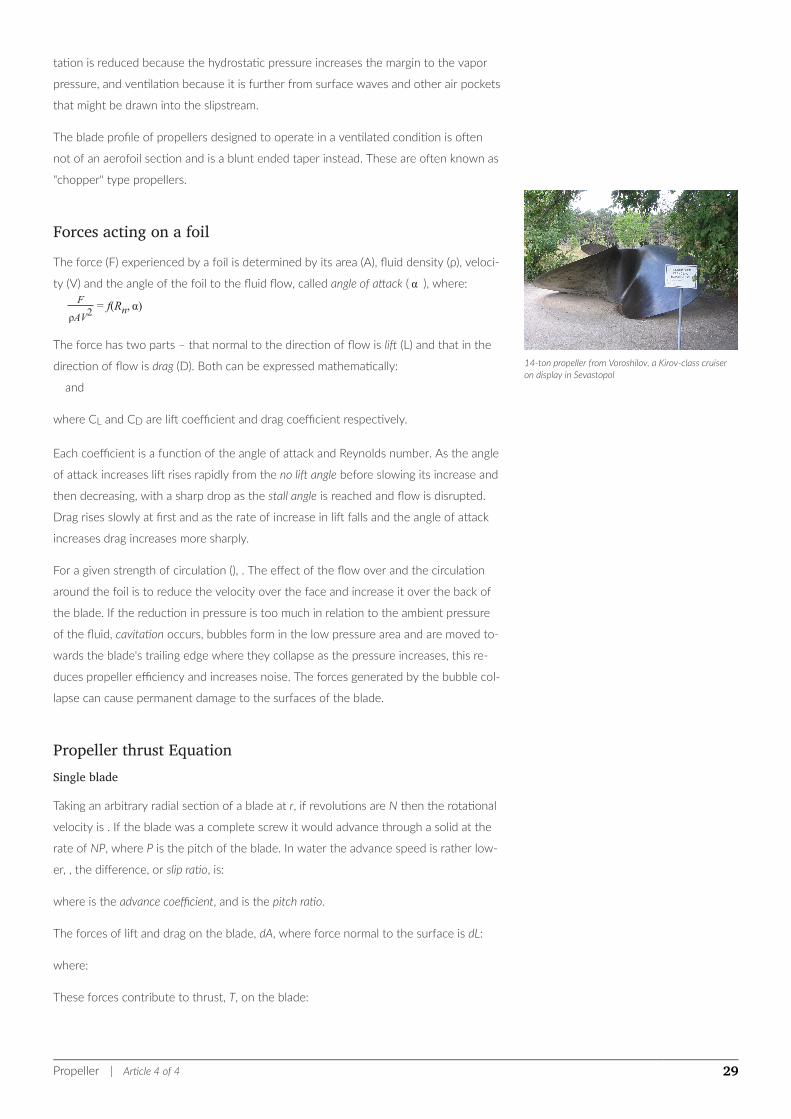
14-ton propeller from Voroshilov, a Kirov-class cruiseron display in Sevastopol
tation is reduced because the hydrostatic pressure increases the margin to the vapor
pressure, and ventilation because it is further from surface waves and other air pockets
that might be drawn into the slipstream.
The blade profile of propellers designed to operate in a ventilated condition is often
not of an aerofoil section and is a blunt ended taper instead. These are often known as
"chopper" type propellers.
Forces acting on a foilThe force (F) experienced by a foil is determined by its area (A), fluid density (ρ), veloci-
ty (V) and the angle of the foil to the fluid flow, called angle of attack ( α ), where:F
ρAV2= f(Rn, α)
The force has two parts – that normal to the direction of flow is lift (L) and that in the
direction of flow is drag (D). Both can be expressed mathematically:
and
where CL and CD are lift coefficient and drag coefficient respectively.
Each coefficient is a function of the angle of attack and Reynolds number. As the angle
of attack increases lift rises rapidly from the no lift angle before slowing its increase and
then decreasing, with a sharp drop as the stall angle is reached and flow is disrupted.
Drag rises slowly at first and as the rate of increase in lift falls and the angle of attack
increases drag increases more sharply.
For a given strength of circulation (), . The effect of the flow over and the circulation
around the foil is to reduce the velocity over the face and increase it over the back of
the blade. If the reduction in pressure is too much in relation to the ambient pressure
of the fluid, cavitation occurs, bubbles form in the low pressure area and are moved to-
wards the blade's trailing edge where they collapse as the pressure increases, this re-
duces propeller efficiency and increases noise. The forces generated by the bubble col-
lapse can cause permanent damage to the surfaces of the blade.
Propeller thrust EquationSingle blade
Taking an arbitrary radial section of a blade at r, if revolutions are N then the rotational
velocity is . If the blade was a complete screw it would advance through a solid at the
rate of NP, where P is the pitch of the blade. In water the advance speed is rather low-
er, , the difference, or slip ratio, is:
where is the advance coefficient, and is the pitch ratio.
The forces of lift and drag on the blade, dA, where force normal to the surface is dL:
where:
These forces contribute to thrust, T, on the blade:
Propeller | Article 4 of 4 29
where:
As ,
From this total thrust can be obtained by integrating this expression along the blade.
The transverse force is found in a similar manner:
Substituting for and multiplying by r, gives torque as:
which can be integrated as before.
The total thrust power of the propeller is proportional to and the shaft power to . So
efficiency is . The blade efficiency is in the ratio between thrust and torque:
showing that the blade efficiency is determined by its momentum and its qualities in
the form of angles and , where is the ratio of the drag and lift coefficients.
This analysis is simplified and ignores a number of significant factors including interfer-
ence between the blades and the influence of tip vortices.
Thrust and torque
The thrust, T, and torque, Q, depend on the propeller's diameter, D, revolutions, N, and
rate of advance, , together with the character of the fluid in which the propeller is op-
erating and gravity. These factors create the following non-dimensional relationship:
where is a function of the advance coefficient, is a function of the Reynolds' number,
and is a function of the Froude number. Both and are likely to be small in comparison
to under normal operating conditions, so the expression can be reduced to:
For two identical propellers the expression for both will be the same. So with the pro-
pellers , and using the same subscripts to indicate each propeller:
For both Froude number and advance coefficient:
where is the ratio of the linear dimensions.
Thrust and velocity, at the same Froude number, give thrust power:
For torque:
Actual performanceWhen a propeller is added to a ship its performance is altered; there is the mechanical
losses in the transmission of power; a general increase in total resistance; and the hull
also impedes and renders non-uniform the flow through the propeller. The ratio be-
tween a propeller's efficiency attached to a ship () and in open water () is termed rela-
tive rotative efficiency.
The overall propulsive efficiency (an extension of effective power ()) is developed from the
propulsive coefficient (), which is derived from the installed shaft power () modified by
the effective power for the hull with appendages (), the propeller's thrust power (), and
Propeller | Article 4 of 4 30
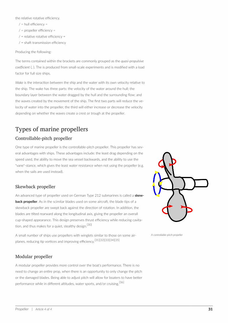
A controllable-pitch propeller
the relative rotative efficiency.
/ = hull efficiency =
/ = propeller efficiency =
/ = relative rotative efficiency =
/ = shaft transmission efficiency
Producing the following:
The terms contained within the brackets are commonly grouped as the quasi-propulsive
coefficient (, ). The is produced from small-scale experiments and is modified with a load
factor for full size ships.
Wake is the interaction between the ship and the water with its own velocity relative to
the ship. The wake has three parts: the velocity of the water around the hull; the
boundary layer between the water dragged by the hull and the surrounding flow; and
the waves created by the movement of the ship. The first two parts will reduce the ve-
locity of water into the propeller, the third will either increase or decrease the velocity
depending on whether the waves create a crest or trough at the propeller.
Types of marine propellersControllable-pitch propellerOne type of marine propeller is the controllable-pitch propeller. This propeller has sev-
eral advantages with ships. These advantages include: the least drag depending on the
speed used, the ability to move the sea vessel backwards, and the ability to use the
"vane"-stance, which gives the least water resistance when not using the propeller (e.g.
when the sails are used instead).
Skewback propellerAn advanced type of propeller used on German Type 212 submarines is called a skew-
back propeller. As in the scimitar blades used on some aircraft, the blade tips of a
skewback propeller are swept back against the direction of rotation. In addition, the
blades are tilted rearward along the longitudinal axis, giving the propeller an overall
cup-shaped appearance. This design preserves thrust efficiency while reducing cavita-
tion, and thus makes for a quiet, stealthy design.[30]
A small number of ships use propellers with winglets similar to those on some air-
planes, reducing tip vortices and improving efficiency.[31][32][33][34][35]
Modular propellerA modular propeller provides more control over the boat's performance. There is no
need to change an entire prop, when there is an opportunity to only change the pitch
or the damaged blades. Being able to adjust pitch will allow for boaters to have better
performance while in different altitudes, water sports, and/or cruising.[36]
Propeller | Article 4 of 4 31
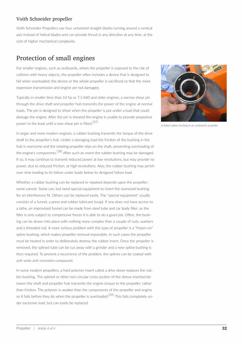
A failed rubber bushing in an outboard's propeller
Voith Schneider propellerVoith Schneider Propellers use four untwisted straight blades turning around a vertical
axis instead of helical blades and can provide thrust in any direction at any time, at the
cost of higher mechanical complexity.
Protection of small enginesFor smaller engines, such as outboards, where the propeller is exposed to the risk of
collision with heavy objects, the propeller often includes a device that is designed to
fail when overloaded; the device or the whole propeller is sacrificed so that the more
expensive transmission and engine are not damaged.
Typically in smaller (less than 10 hp or 7.5 kW) and older engines, a narrow shear pin
through the drive shaft and propeller hub transmits the power of the engine at normal
loads. The pin is designed to shear when the propeller is put under a load that could
damage the engine. After the pin is sheared the engine is unable to provide propulsive
power to the boat until a new shear pin is fitted.[37]
In larger and more modern engines, a rubber bushing transmits the torque of the drive
shaft to the propeller's hub. Under a damaging load the friction of the bushing in the
hub is overcome and the rotating propeller slips on the shaft, preventing overloading of
the engine's components.[38] After such an event the rubber bushing may be damaged.
If so, it may continue to transmit reduced power at low revolutions, but may provide no
power, due to reduced friction, at high revolutions. Also, the rubber bushing may perish
over time leading to its failure under loads below its designed failure load.
Whether a rubber bushing can be replaced or repaired depends upon the propeller;
some cannot. Some can, but need special equipment to insert the oversized bushing
for an interference fit. Others can be replaced easily. The "special equipment" usually
consists of a funnel, a press and rubber lubricant (soap). If one does not have access to
a lathe, an improvised funnel can be made from steel tube and car body filler; as the
filler is only subject to compressive forces it is able to do a good job. Often, the bush-
ing can be drawn into place with nothing more complex than a couple of nuts, washers
and a threaded rod. A more serious problem with this type of propeller is a "frozen-on"
spline bushing, which makes propeller removal impossible. In such cases the propeller
must be heated in order to deliberately destroy the rubber insert. Once the propeller is
removed, the splined tube can be cut away with a grinder and a new spline bushing is
then required. To prevent a recurrence of the problem, the splines can be coated with
anti-seize anti-corrosion compound.
In some modern propellers, a hard polymer insert called a drive sleeve replaces the rub-
ber bushing. The splined or other non-circular cross section of the sleeve inserted be-
tween the shaft and propeller hub transmits the engine torque to the propeller, rather
than friction. The polymer is weaker than the components of the propeller and engine
so it fails before they do when the propeller is overloaded.[39] This fails completely un-
der excessive load, but can easily be replaced.
Propeller | Article 4 of 4 32
See also• Screw-propelled vehicle
Propeller characteristics• Advance ratio
• Axial fan design
Propeller phenomena• Propeller walk
• Cavitation
Propeller variationsCleaver
A cleaver is a type of propeller design especially used for boat racing. Its leading edge
is formed round, while the trailing edge is cut straight. It provides little bow lift, so that
it can be used on boats that do not need much bow lift, for instance hydroplanes, that
naturally have enough hydrodynamic bow lift. To compensate for the lack of bow lift, a
hydrofoil may be installed on the lower unit. Hydrofoils reduce bow lift and help to get
a boat out of the hole and onto plane.
Other
• Azimuth thruster
◦ Azipod
• Helix
• Impeller
• Kitchen rudder
• Ducted propeller
◦ Kort nozzle
◦ Pump-jet
• Paddle steamer
• Pleuger rudder
• Propulsor
• Voith-Schneider
• Cleaver
• Bow/stern thruster
• Folding propeller
• Modular propeller
• Supercavitating propeller
Propeller | Article 4 of 4 33
Materials and manufactureConstruction of Wooden Propellers 1 2 3, NASA Langley
• Balancing machine
• Composite materials
Notes1. ^ Carlton, John, Marine Propellers and Propulsion Butterworth-Heinemann, 2012, p. 363
2. ^ Carlton, p. 1
3. ^ <Carlton, p. 1
4. ^ Murihead, James Patrick, The Life of James Watt, with Selections from His Correspondence ... With Portraits and Woodcuts, London:
John Murray,1858, p. 208
5. ^ Stein, Stephen K. The Sea in World History: Exploration, Travel, and Trade [2 volumes], Editor Stephen K. Stein, ABC-CLIO, 2017,
Volume 1, p. 600
6. ^ Manstan, Roy R.; Frese, Frederic J., Turtle: David Bushnell's Revolutionary Vessel, Yardley, Pa: Westholme Publishing. IS-
BN 978-1-59416-105-6. OCLC 369779489, 2010, pp. xiii, 52, 53
7. ^ Tucker, Spencer, Almanac of American Military History, ABC-CLIO, 2013, Volume 1, p. 305
8. ^ Mansten pp. xiii, xiv
9. ^ Nicholson, William, A Journal of Natural Philosophy, Chemistry and the Arts, Volume 4, G. G. and J. Robinson, 1801, p. 221
10. ^ Manstan, p.150
11. ^ Carlton, pp. 1–2
12. ^ Carlton, p.2
13. ^ Carlton, p.2
14. ^ Paul Augustin Normand, La Genèse de l'Hélice Propulsive (The Genesis of the Screw Propulsor). Paris: Académie de Marine, 1962,
pp. 31–50.
15. ^ Mario Theriault, Great Maritime Inventions Goose Lane Publishing (2001) pp. 58–59
16. ^ "Patch's Propeller", Scientific America, Vol. 4, No. 5 (October 10, 1848) p. 33, featured in The Archimedes Screw website retrieved
31 January 2010 Archived 8 July 2011 at the Wayback Machine.
17. ^ Smith, Edgar C. (1905). A Short history of Naval and Marine Engineering. University Press, Cambridge. pp. 66–67.
18. ^ a b Bourne, p. 84.
19. ^ In the case of Francis B. Ogden, Symonds was correct. Ericsson had made the mistake of placing the rudder forward of the pro-
pellers, which made the rudder ineffective. Symonds believed that Ericsson tried to disguise the problem by towing a barge dur-
ing the test.
20. ^ Bourne, pp. 87–89.
21. ^ Bourne, p. 85.
22. ^ The emphasis here is on ship. There were a number of successful propeller-driven vessels prior to Archimedes, including Smith's
own Francis Smith and Ericsson's Francis B. Ogden and Robert F. Stockton. However, these vessels were boats – designed for ser-
vice on inland waterways – as opposed to ships, built for seagoing service.
23. ^ "The type of screw propeller that now propels the vast majority of boats and ships was patented in 1836, first by the British
engineer Francis Pettit Smith, then by the Swedish engineer John Ericsson. Smith used the design in the first successful screw-
driven steamship, Archimedes, which was launched in 1839.". Marshall Cavendish, p. 1335.
24. ^ "The propeller was invented in 1836 by Francis Pettit Smith in Britain and John Ericsson in the United States. It first powered a
seagoing ship, appropriately called Archimedes, in 1839." Macauley and Ardley, p. 378.
25. ^ "In 1839, the Messrs. Rennie constructed the engines, machinery and propeller, for the celebrated Archimedes, from which may
Propeller | Article 4 of 4 34

be said to date the introduction of the screw system of propulsion ...". Mechanics Magazine, p. 220.
26. ^ "It was not until 1839 that the principle of propelling steamships by a screw blade was fairly brought before the world, and for
this we are indebted, as almost every adult will remember, to Mr. F. P. Smith of London. He was the man who first made the
screw propeller practically useful. Aided by spirited capitalists, he built a large steamer named the "Archimedes", and the results
obtained from her at once arrested public attention.". MacFarlane, p. 109.
27. ^ Pilot’s Handbook of Aeronautical Knowledge. Oklahoma City: U.S. Federal Aviation Administration. 2008. pp. 2–7. FAA-8083-25A.
28. ^ Ash, Robert L., Colin P. Britcher and Kenneth W. Hyde. "Wrights: How two brothers from Dayton added a new twist to airplane
propulsion." Mechanical Engineering: 100 years of Flight, 3 July 2007.
29. ^ Schmidt, Theo. "Propeller simulation with PropSim" (PDF). Human Power Number 48.
30. ^ "SILENT propellers". www.francehelices.fr. JMCWebCreation and Co. 2009. Retrieved July 21, 2017.
31. ^ Godske, Bjørn. "Energy saving propeller" (in Danish) Ingeniøren, 23 April 2012. Accessed: 15 March 2014. English translation
32. ^ Godske, Bjørn. "Kappel-propellers pave the way for success at MAN" (in Danish) Ingeniøren, 15 March 2014. Accessed: 15
March 2014. English translation
33. ^ "Kappel agreement secures access to major market" 30 August 2013.
34. ^ "KAPRICCIO Project" European Union. Accessed: 15 March 2014.
35. ^ "Industry Pays Tribute to Innovation Awards Winners" Marine link, 3 October 2002. Accessed: 15 March 2014. Quote: "Win-
ner: the energy-saving Kappel propeller concept from the European Commission-funded Kapriccio propulsion research project.
Blades curved towards the tips on the suction side reduce energy losses, fuel consumption, noise and vibration"
36. ^ Smrcka, Karel (March 18, 2005). "A new start for marine propellers". Engineering News. Retrieved July 21, 2017.
37. ^ Getchell, David (1994), The Outboard Boater's Handbook, ISBN 9780070230538
38. ^ Ministry Of Defence (Navy), Great Britain (1995), Admiralty Manual of Seamanship, ISBN 9780117726963
39. ^ US, "Torsionally twisting propeller drive sleeve and adapter", published March 8, 1994, issued January 16, 1996
External links
Wikimedia Commons has media related to Propellers.
• Titanic's Propellers
• Theory calculation propellers and wings: detailed article with blade element theory
software application
• "What You Should Know About Propellers For Our Fighting Planes", November
1943, Popular Science extremely detailed article with numerous drawings and cut-
away illustrations
• Archimedes Screw History: The story of marine propulsion
• propellers history: The story of propellers
• [1]: Wartsila Marine Propellers
Propeller | Article 4 of 4 35
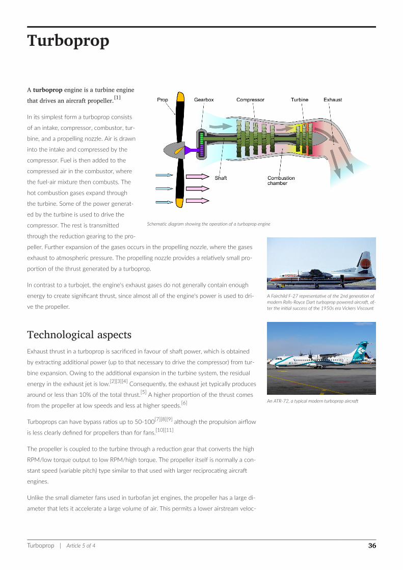
Schematic diagram showing the operation of a turboprop engine
A Fairchild F-27 representative of the 2nd generation ofmodern Rolls-Royce Dart turboprop powered aircraft, af-ter the initial success of the 1950s era Vickers Viscount
An ATR-72, a typical modern turboprop aircraft
Turboprop
A turboprop engine is a turbine enginethat drives an aircraft propeller.[1]
In its simplest form a turboprop consists
of an intake, compressor, combustor, tur-
bine, and a propelling nozzle. Air is drawn
into the intake and compressed by the
compressor. Fuel is then added to the
compressed air in the combustor, where
the fuel-air mixture then combusts. The
hot combustion gases expand through
the turbine. Some of the power generat-
ed by the turbine is used to drive the
compressor. The rest is transmitted
through the reduction gearing to the pro-
peller. Further expansion of the gases occurs in the propelling nozzle, where the gases
exhaust to atmospheric pressure. The propelling nozzle provides a relatively small pro-
portion of the thrust generated by a turboprop.
In contrast to a turbojet, the engine's exhaust gases do not generally contain enough
energy to create significant thrust, since almost all of the engine's power is used to dri-
ve the propeller.
Technological aspectsExhaust thrust in a turboprop is sacrificed in favour of shaft power, which is obtained
by extracting additional power (up to that necessary to drive the compressor) from tur-
bine expansion. Owing to the additional expansion in the turbine system, the residual
energy in the exhaust jet is low.[2][3][4] Consequently, the exhaust jet typically produces
around or less than 10% of the total thrust.[5] A higher proportion of the thrust comes
from the propeller at low speeds and less at higher speeds.[6]
Turboprops can have bypass ratios up to 50-100[7][8][9] although the propulsion airflow
is less clearly defined for propellers than for fans.[10][11]
The propeller is coupled to the turbine through a reduction gear that converts the high
RPM/low torque output to low RPM/high torque. The propeller itself is normally a con-
stant speed (variable pitch) type similar to that used with larger reciprocating aircraft
engines.
Unlike the small diameter fans used in turbofan jet engines, the propeller has a large di-
ameter that lets it accelerate a large volume of air. This permits a lower airstream veloc-
Turboprop | Article 5 of 4 36
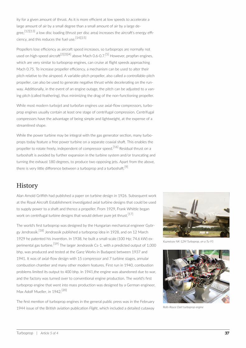
Kuznetsov NK-12M Turboprop, on a Tu-95
Rolls-Royce Dart turboprop engine
ity for a given amount of thrust. As it is more efficient at low speeds to accelerate a
large amount of air by a small degree than a small amount of air by a large de-
gree,[12][13] a low disc loading (thrust per disc area) increases the aircraft's energy effi-
ciency, and this reduces the fuel use.[14][15]
Propellers lose efficiency as aircraft speed increases, so turboprops are normally not
used on high-speed aircraft[2][3][4] above Mach 0.6-0.7.[5] However, propfan engines,
which are very similar to turboprop engines, can cruise at flight speeds approaching
Mach 0.75. To increase propeller efficiency, a mechanism can be used to alter their
pitch relative to the airspeed. A variable-pitch propeller, also called a controllable-pitch
propeller, can also be used to generate negative thrust while decelerating on the run-
way. Additionally, in the event of an engine outage, the pitch can be adjusted to a van-
ing pitch (called feathering), thus minimizing the drag of the non-functioning propeller.
While most modern turbojet and turbofan engines use axial-flow compressors, turbo-
prop engines usually contain at least one stage of centrifugal compression. Centrifugal
compressors have the advantage of being simple and lightweight, at the expense of a
streamlined shape.
While the power turbine may be integral with the gas generator section, many turbo-
props today feature a free power turbine on a separate coaxial shaft. This enables the
propeller to rotate freely, independent of compressor speed.[16] Residual thrust on a
turboshaft is avoided by further expansion in the turbine system and/or truncating and
turning the exhaust 180 degrees, to produce two opposing jets. Apart from the above,
there is very little difference between a turboprop and a turboshaft.[9]
HistoryAlan Arnold Griffith had published a paper on turbine design in 1926. Subsequent work
at the Royal Aircraft Establishment investigated axial turbine designs that could be used
to supply power to a shaft and thence a propeller. From 1929, Frank Whittle began
work on centrifugal turbine designs that would deliver pure jet thrust.[17]
The world's first turboprop was designed by the Hungarian mechanical engineer Györ-
gy Jendrassik.[18] Jendrassik published a turboprop idea in 1928, and on 12 March
1929 he patented his invention. In 1938, he built a small-scale (100 Hp; 74.6 kW) ex-
perimental gas turbine.[19] The larger Jendrassik Cs-1, with a predicted output of 1,000
bhp, was produced and tested at the Ganz Works in Budapest between 1937 and
1941. It was of axial-flow design with 15 compressor and 7 turbine stages, annular
combustion chamber and many other modern features. First run in 1940, combustion
problems limited its output to 400 bhp. In 1941,the engine was abandoned due to war,
and the factory was turned over to conventional engine production. The world's first
turboprop engine that went into mass production was designed by a German engineer,
Max Adolf Mueller, in 1942.[20]
The first mention of turboprop engines in the general public press was in the February
1944 issue of the British aviation publication Flight, which included a detailed cutaway
Turboprop | Article 5 of 4 37
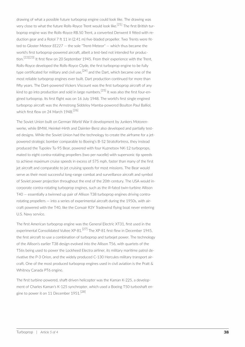
drawing of what a possible future turboprop engine could look like. The drawing was
very close to what the future Rolls-Royce Trent would look like.[21] The first British tur-
boprop engine was the Rolls-Royce RB.50 Trent, a converted Derwent II fitted with re-
duction gear and a Rotol 7 ft 11 in (2.41 m) five-bladed propeller. Two Trents were fit-
ted to Gloster Meteor EE227 — the sole "Trent-Meteor" — which thus became the
world's first turboprop-powered aircraft, albeit a test-bed not intended for produc-
tion.[22][23] It first flew on 20 September 1945. From their experience with the Trent,
Rolls-Royce developed the Rolls-Royce Clyde, the first turboprop engine to be fully
type certificated for military and civil use,[24] and the Dart, which became one of the
most reliable turboprop engines ever built. Dart production continued for more than
fifty years. The Dart-powered Vickers Viscount was the first turboprop aircraft of any
kind to go into production and sold in large numbers.[25] It was also the first four-en-
gined turboprop. Its first flight was on 16 July 1948. The world's first single engined
turboprop aircraft was the Armstrong Siddeley Mamba-powered Boulton Paul Balliol,
which first flew on 24 March 1948.[26]
The Soviet Union built on German World War II development by Junkers Motoren-
werke, while BMW, Heinkel-Hirth and Daimler-Benz also developed and partially test-
ed designs. While the Soviet Union had the technology to create the airframe for a jet-
powered strategic bomber comparable to Boeing's B-52 Stratofortress, they instead
produced the Tupolev Tu-95 Bear, powered with four Kuznetsov NK-12 turboprops,
mated to eight contra-rotating propellers (two per nacelle) with supersonic tip speeds
to achieve maximum cruise speeds in excess of 575 mph, faster than many of the first
jet aircraft and comparable to jet cruising speeds for most missions. The Bear would
serve as their most successful long-range combat and surveillance aircraft and symbol
of Soviet power projection throughout the end of the 20th century. The USA would in-
corporate contra-rotating turboprop engines, such as the ill-fated twin-turbine Allison
T40 — essentially a twinned up pair of Allison T38 turboprop engines driving contra-
rotating propellers — into a series of experimental aircraft during the 1950s, with air-
craft powered with the T40, like the Convair R3Y Tradewind flying boat never entering
U.S. Navy service.
The first American turboprop engine was the General Electric XT31, first used in the
experimental Consolidated Vultee XP-81.[27] The XP-81 first flew in December 1945,
the first aircraft to use a combination of turboprop and turbojet power. The technology
of the Allison's earlier T38 design evolved into the Allison T56, with quartets of the
T56s being used to power the Lockheed Electra airliner, its military maritime patrol de-
rivative the P-3 Orion, and the widely produced C-130 Hercules military transport air-
craft. One of the most produced turboprop engines used in civil aviation is the Pratt &
Whitney Canada PT6 engine.
The first turbine-powered, shaft-driven helicopter was the Kaman K-225, a develop-
ment of Charles Kaman's K-125 synchropter, which used a Boeing T50 turboshaft en-
gine to power it on 11 December 1951.[28]
Turboprop | Article 5 of 4 38
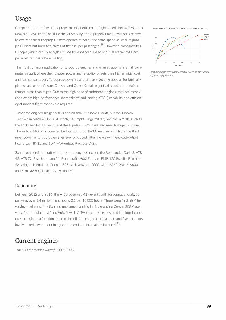
Propulsive efficiency comparison for various gas turbineengine configurations
UsageCompared to turbofans, turboprops are most efficient at flight speeds below 725 km/h
(450 mph; 390 knots) because the jet velocity of the propeller (and exhaust) is relative-
ly low. Modern turboprop airliners operate at nearly the same speed as small regional
jet airliners but burn two-thirds of the fuel per passenger.[29] However, compared to a
turbojet (which can fly at high altitude for enhanced speed and fuel efficiency) a pro-
peller aircraft has a lower ceiling.
The most common application of turboprop engines in civilian aviation is in small com-
muter aircraft, where their greater power and reliability offsets their higher initial cost
and fuel consumption. Turboprop-powered aircraft have become popular for bush air-
planes such as the Cessna Caravan and Quest Kodiak as jet fuel is easier to obtain in
remote areas than avgas. Due to the high price of turboprop engines, they are mostly
used where high-performance short-takeoff and landing (STOL) capability and efficien-
cy at modest flight speeds are required.
Turboprop engines are generally used on small subsonic aircraft, but the Tupolev
Tu-114 can reach 470 kt (870 km/h, 541 mph). Large military and civil aircraft, such as
the Lockheed L-188 Electra and the Tupolev Tu-95, have also used turboprop power.
The Airbus A400M is powered by four Europrop TP400 engines, which are the third
most powerful turboprop engines ever produced, after the eleven megawatt-output
Kuznetsov NK-12 and 10.4 MW-output Progress D-27.
Some commercial aircraft with turboprop engines include the Bombardier Dash 8, ATR
42, ATR 72, BAe Jetstream 31, Beechcraft 1900, Embraer EMB 120 Brasilia, Fairchild
Swearingen Metroliner, Dornier 328, Saab 340 and 2000, Xian MA60, Xian MA600,
and Xian MA700, Fokker 27, 50 and 60.
ReliabilityBetween 2012 and 2016, the ATSB observed 417 events with turboprop aircraft, 83
per year, over 1.4 million flight hours: 2.2 per 10,000 hours. Three were “high risk” in-
volving engine malfunction and unplanned landing in single‑engine Cessna 208 Cara-
vans, four “medium risk” and 96% “low risk”. Two occurrences resulted in minor injuries
due to engine malfunction and terrain collision in agricultural aircraft and five accidents
involved aerial work: four in agriculture and one in an air ambulance.[30]
Current enginesJane's All the World's Aircraft. 2005–2006.
Turboprop | Article 5 of 4 39

Manufacturer Country Designation
Dry
weight
(kg)
Takeoff
rating
(kW)
Application
DEMCPeople's
Republic
of China
WJ5E 720 2130 Harbin SH-5, Xi'an Y-7
Europrop In-
ternational
Eu-
ropean
Union
TP400-D6 1800 8203 Airbus A400M
General Elec-
tricUnited
States
CT7-5A 365 1294
General Elec-
tricUnited
States
CT7-9 365 1447
CASA/IPTN CN-235, Let
L-610, Saab 340, Sukhoi
Su-80
General Elec-
tric
United
States
Czech
Republic
H80 Series[31] 200550 -
625
Thrush Model 510, Let
410NG, Let L-410 Turbo-
let UVP-E, CAIGA Primus
150, Nextant G90XT
General Elec-
tricUnited
States
T64-P4D 538 2535
Aeritalia G.222, de Havil-
land Canada DHC-5 Buf-
falo, Kawasaki P-2J
Turboprop | Article 5 of 4 40

Honeywell United
States
TPE331 Series150 -
275
478 -
1650
Aero/Rockwell Turbo
Commander 680/690/
840/960/1000, Antonov
An-38, Ayres Thrush, BAe
Jetstream 31/32, BAe
Jetstream 41, CASA
C-212 Aviocar, Cessna
441 Conquest II, Dornier
Do 228, Fairchild
Swearingen Metroliner,
General Atomics MQ-9
Reaper, GrumGeman,
Mitsubishi MU-2, North
American Rockwell
OV-10 Bronco, Piper
PA-42 Cheyenne, RUAG
Do 228NG, Short SC.7
Skyvan, Short Tucano,
Swearingen Merlin,
Fairchild Swearingen
Metroliner
Honeywell United
States
LTP 101-700 147 522Air Tractor AT-302, Piag-
gio P.166
KKBMRussia
NK-12MV 1900 11033Antonov An-22, Tupolev
Tu-95, Tupolev Tu-114
ProgressUkraine
TV3-117VMA-
SB2560 1864 Antonov An-140
KlimovRussia
TV7-117S 530 2100Ilyushin Il-112, Ilyushin
Il-114
ProgressUkraine
AI20M 1040 2940Antonov An-12, Antonov
An-32, Ilyushin Il-18
ProgressUkraine
AI24T 600 1880Antonov An-24, Antonov
An-26, Antonov An-30
Turboprop | Article 5 of 4 41

LHTEC United
States
LHTEC T800 517 2013
AgustaWestland Super
Lynx 300 (CTS800-4N),
AgustaWestland AW159
Lynx Wildcat
(CTS800-4N), Ayres
LM200 Loadmaster
(LHTEC CTP800-4T) (air-
craft not built), Sikorsky
X2 (T800-LHT-801), TAI/
AgustaWestland T-129
(CTS800-4A)
OMKBRussia
TVD-20 240 1081Antonov An-3, Antonov
An-38
Pratt & Whit-
ney Canada CanadaPT-6 Series
149 -
260
430 -
1500
Air Tractor AT-502, Air
Tractor AT-602, Air Trac-
tor AT-802, Beechcraft
Model 99, Beechcraft
King Air, Beechcraft Super
King Air, Beechcraft
1900, Beechcraft T-6 Tex-
an II, Cessna 208 Cara-
van, Cessna 425 Corsair/
Conquest I, de Havilland
Canada DHC-6 Twin Ot-
ter, Harbin Y-12, Embraer
EMB 110 Bandeirante,
Let L-410 Turbolet, Piag-
gio P.180 Avanti, Pilatus
PC-6 Porter, Pilatus
PC-12, Piper PA-42
Cheyenne, Piper
PA-46-500TP Meridian,
Shorts 360, Daher TBM
700, Daher TBM 850,
Daher TBM 900, Embraer
EMB 314 Super Tucano
Pratt & Whit-
ney Canada CanadaPW120 418 1491 ATR 42-300/320
Pratt & Whit-
ney Canada CanadaPW121 425 1603
ATR 42-300/320, Bom-
bardier Dash 8 Q100
Pratt & Whit-
ney Canada CanadaPW123 C/D 450 1603 Bombardier Dash 8 Q300
Pratt & Whit-
ney Canada CanadaPW126 C/D 450 1950 BAe ATP
Turboprop | Article 5 of 4 42

Pratt & Whit-
ney Canada CanadaPW127 481 2051 ATR 72
Pratt & Whit-
ney Canada CanadaPW150A 717 3781 Bombardier Dash 8 Q400
PZLPoland
TWD-10B 230 754 PZL M28
RKBMRussia
TVD-1500S 240 1044 Sukhoi Su-80
Rolls-Royce United
Kingdom
Dart Mk 536 569 1700Avro 748, Fokker F27,
Vickers Viscount
Rolls-Royce United
Kingdom
Tyne 21 569 4500Aeritalia G.222, Breguet
Atlantic, Transall C-160
Rolls-Royce United
Kingdom
250-B17 88.4 313
Fuji T-7, Britten-Norman
Turbine Islander, O&N
Cessna 210, Soloy Cessna
206, Propjet Bonanza
Rolls-Royce United
Kingdom
Allison T56828 -
880
3424 -
3910
P-3 Orion, E-2 Hawkeye,
C-2 Greyhound, C-130
Hercules
Rolls-Royce United
Kingdom
AE2100A 715.8 3095 Saab 2000
Rolls-Royce United
Kingdom
AE2100J 710 3424 ShinMaywa US-2
Rolls-Royce United
Kingdom
AE2100D2,
D3702 3424
Alenia C-27J Spartan,
Lockheed Martin C-130J
Super Hercules
RybinskRussia
TVD-1500V 220 1156
SaturnRussia
TAL-34-1 178 809
TurbomecaFrance
Arrius 1D 111 313 Socata TB 31 Omega
Turboprop | Article 5 of 4 43
TurbomecaFrance
Arrius 2F 103 376
Walter Czech
Republic
M601 Se-
ries[32]200 560
Let L-410 Turbolet, Aero-
comp Comp Air 10 XL,
Aerocomp Comp Air 7,
Ayres Thrush, Dornier Do
28, Lancair Propjet, Let
Z-37T, Let L-420, Mya-
sishchev M-101T, PAC
FU-24 Fletcher, Progress
Rysachok, PZL-106 Kruk,
PZL-130 Orlik, SM-92T
Turbo Finist
Walter Czech
Republic
M602A 570 1360
Let L-610
Walter Czech
Republic
M602B 480 1500
See also• Jet engine
• Jet aircraft
• Jetboat
• Propfan
• Ramjet
• Scimitar propeller
• Supercharger
• Tiltrotor
• Turbocharger
• Turbofan
• Turbojet
• Turboshaft
ReferencesNotes1. ^ "Turboprop", Pilot's Handbook of Aeronautical Knowledge, Federal Aviation Administration, 2009.
2. ^ a b "Turboprop Engine" Glenn Research Center (NASA)
3. ^ a b "Turboprop Thrust" Glenn Research Center (NASA)
4. ^ a b "Variations of Jet Engines". smu.edu. Retrieved 31 August 2016.
Turboprop | Article 5 of 4 44
5. ^ a b ""The turbofan engine", page 7. SRM University, Department of aerospace engineering.
6. ^ J. Russell (2 Aug 1996). Performance and Stability of Aircraft. Butterworth-Heinemann. p. 16. ISBN 0080538649.
7. ^ Ilan Kroo and Juan Alonso. "Aircraft Design: Synthesis and Analysis, Propulsion Systems: Basic Concepts Archived 18 April
2015 at the Wayback Machine." Stanford University School of Engineering, Department of Aeronautics and Astronautics Main
page Archived 23 February 2001 at the Wayback Machine.
8. ^ Prof. Z. S. Spakovszky. "11.5 Trends in thermal and propulsive efficiency" MIT turbines, 2002. Thermodynamics and Propulsion
9. ^ a b Nag, P.K. "Basic And Applied Thermodynamics Archived 19 April 2015 at the Wayback Machine." p550. Published by Tata
McGraw-Hill Education. Quote: "If the cowl is removed from the fan the result is a turboprop engine. Turbofan and turboprop
engines differ mainly in their bypass ratio: 5 or 6 for turbofans and as high as 100 for turboprop."
10. ^ "Propeller thrust" Glenn Research Center (NASA)
11. ^ Philip Walsh, Paul Fletcher. "Gas Turbine Performance", page 36. John Wiley & Sons, 15 April 2008. Quote: "It has better fuel
consumption than a turbojet or turbofan, due to a high propulsive efficiency.., achieving thrust by a high mass flow of air from
the propeller at low jet velocity. Above 0.6 Mach number the turboprop in turn becomes uncompetitive, due mainly to higher
weight and frontal area."
12. ^ Paul Bevilaqua. The shaft driven Lift Fan propulsion system for the Joint Strike Fighter page 3. Presented 1 May 1997.
DTIC.MIL Word document, 5.5 MB. Accessed: 25 February 2012.
13. ^ Bensen, Igor. "How they fly - Bensen explains all" Gyrocopters UK. Accessed: 10 April 2014.
14. ^ Johnson, Wayne. Helicopter theory pp3+32, Courier Dover Publications, 1980. Accessed: 25 February 2012. IS-
BN 0-486-68230-7
15. ^ Wieslaw Zenon Stepniewski, C. N. Keys. Rotary-wing aerodynamics p3, Courier Dover Publications, 1979. Accessed: 25 Febru-
ary 2012. ISBN 0-486-64647-5
16. ^ "An Engine Ahead of Its Time". PT6 Nation. Pratt & Whitney Canada.
17. ^ Gunston Jet, p. 120
18. ^ Gunston World, p.111
19. ^ "Magyar feltalálók és találmányok - JENDRASSIK GYÖRGY (1898 - 1954)". SZTNH. Retrieved 2012-05-31.
20. ^ Green, W. and Swanborough, G.; "Plane Facts", 'Max'Air Enthusiast Vol. 1 No. 1 (1971), Page 53.
21. ^ "Our Contribution - How Flight Introduced and Made Familiar With Gas Turbines and Jet Propulsion" Flight, 11 May 1951, p.
569.
22. ^ James p. 251-2
23. ^ Green p.18-9
24. ^ "rolls-royce trent - armstrong siddeley - 1950 - 2035 - Flight Archive". flightglobal.com. Retrieved 31 August 2016.
25. ^ Green p.82
26. ^ Green p.81
27. ^ Green p.57
28. ^ "Smithsonian National Air and Space Museum - Collections - Kaman K-225 (Long Description)". National Air and Space Museum. Re-
trieved 4 April 2013.
29. ^ "More turboprops coming to the market - maybe - CAPA - Centre for Aviation". centreforaviation.com. Retrieved 31 August 2016.
30. ^ Gordon Gilbert (June 25, 2018). "ATSB Study Finds Turboprop Engines Safe, Reliable".
31. ^ "The H-Series Engine | Engines | B&GA | GE Aviation". www.geaviation.com. Retrieved 2016-06-01.
32. ^ [1], PragueBest s.r.o. "History | GE Aviation". www.geaviation.cz. Retrieved 2016-06-01.
Bibliography• Green, W. and Cross, R.The Jet Aircraft of the World (1955). London: MacDonald
• Gunston, Bill (2006). The Development of Jet and Turbine Aero Engines, 4th Edition.
Turboprop | Article 5 of 4 45

Sparkford, Somerset, England, UK: Patrick Stephens, Haynes Publishing. IS-
BN 0-7509-4477-3.
• Gunston, Bill (2006). World Encyclopedia of Aero Engines, 5th Edition. Phoenix Mill,
Gloucestershire, England, UK: Sutton Publishing Limited. ISBN 0-7509-4479-X.
• James, D.N. Gloster Aircraft since 1917 (1971). London: Putnam & Co. IS-
BN 0-370-00084-6
Further reading• Van Sickle, Neil D.; et al. (1999). "Turboprop Engines". Van Sickle's modern airmanship.
McGraw-Hill Professional. p. 205. ISBN 978-0-07-069633-4.
External links• Jet Turbine Planes by LtCol Silsbee USAAF, Popular Science, December 1945, first
article on turboprops printed
• Wikibooks: Jet propulsion
• "Development of the Turboprop" a 1950 Flight article on UK and US turboprop en-
gines
Turboprop | Article 5 of 4 46
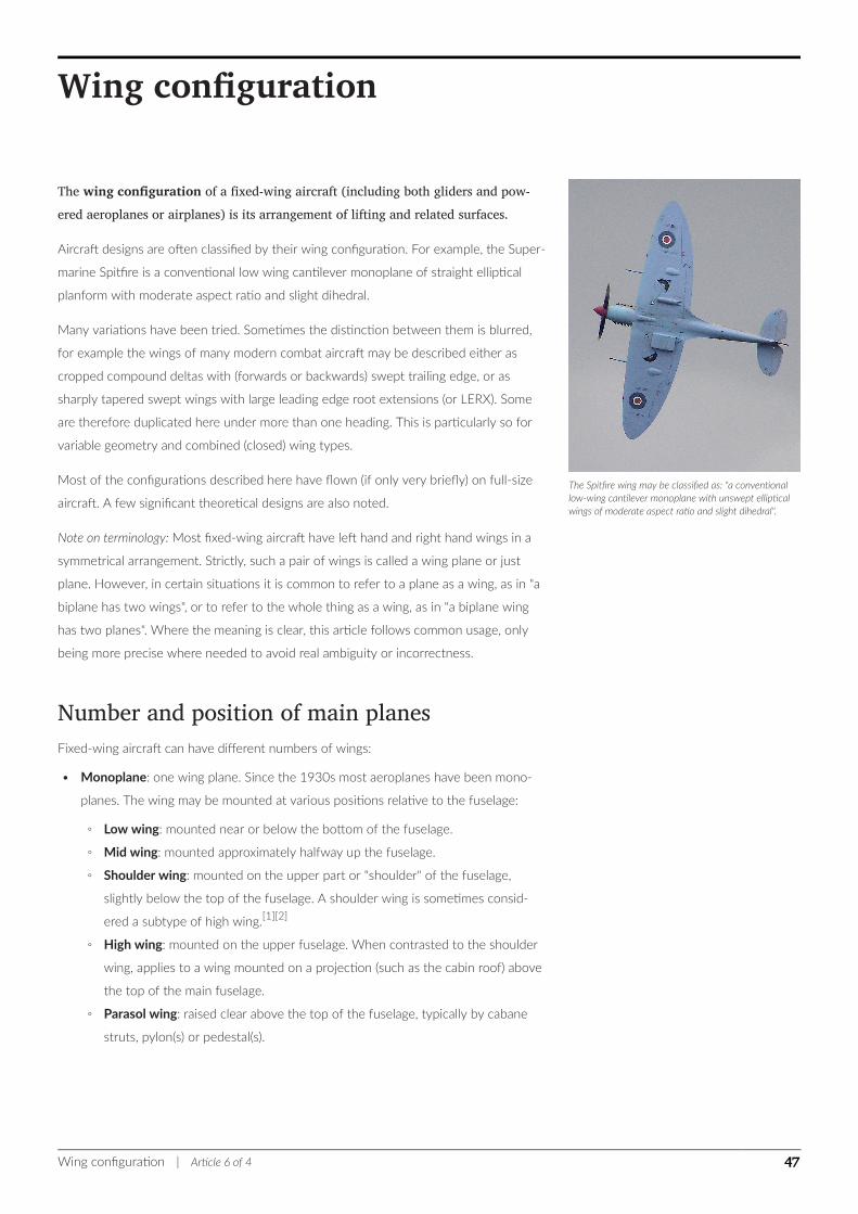
The Spitfire wing may be classified as: "a conventionallow-wing cantilever monoplane with unswept ellipticalwings of moderate aspect ratio and slight dihedral".
Wing configuration
The wing configuration of a fixed-wing aircraft (including both gliders and pow-ered aeroplanes or airplanes) is its arrangement of lifting and related surfaces.
Aircraft designs are often classified by their wing configuration. For example, the Super-
marine Spitfire is a conventional low wing cantilever monoplane of straight elliptical
planform with moderate aspect ratio and slight dihedral.
Many variations have been tried. Sometimes the distinction between them is blurred,
for example the wings of many modern combat aircraft may be described either as
cropped compound deltas with (forwards or backwards) swept trailing edge, or as
sharply tapered swept wings with large leading edge root extensions (or LERX). Some
are therefore duplicated here under more than one heading. This is particularly so for
variable geometry and combined (closed) wing types.
Most of the configurations described here have flown (if only very briefly) on full-size
aircraft. A few significant theoretical designs are also noted.
Note on terminology: Most fixed-wing aircraft have left hand and right hand wings in a
symmetrical arrangement. Strictly, such a pair of wings is called a wing plane or just
plane. However, in certain situations it is common to refer to a plane as a wing, as in "a
biplane has two wings", or to refer to the whole thing as a wing, as in "a biplane wing
has two planes". Where the meaning is clear, this article follows common usage, only
being more precise where needed to avoid real ambiguity or incorrectness.
Number and position of main planesFixed-wing aircraft can have different numbers of wings:
• Monoplane: one wing plane. Since the 1930s most aeroplanes have been mono-
planes. The wing may be mounted at various positions relative to the fuselage:
◦ Low wing: mounted near or below the bottom of the fuselage.
◦ Mid wing: mounted approximately halfway up the fuselage.
◦ Shoulder wing: mounted on the upper part or "shoulder" of the fuselage,
slightly below the top of the fuselage. A shoulder wing is sometimes consid-
ered a subtype of high wing.[1][2]
◦ High wing: mounted on the upper fuselage. When contrasted to the shoulder
wing, applies to a wing mounted on a projection (such as the cabin roof) above
the top of the main fuselage.
◦ Parasol wing: raised clear above the top of the fuselage, typically by cabane
struts, pylon(s) or pedestal(s).
Wing configuration | Article 6 of 4 47
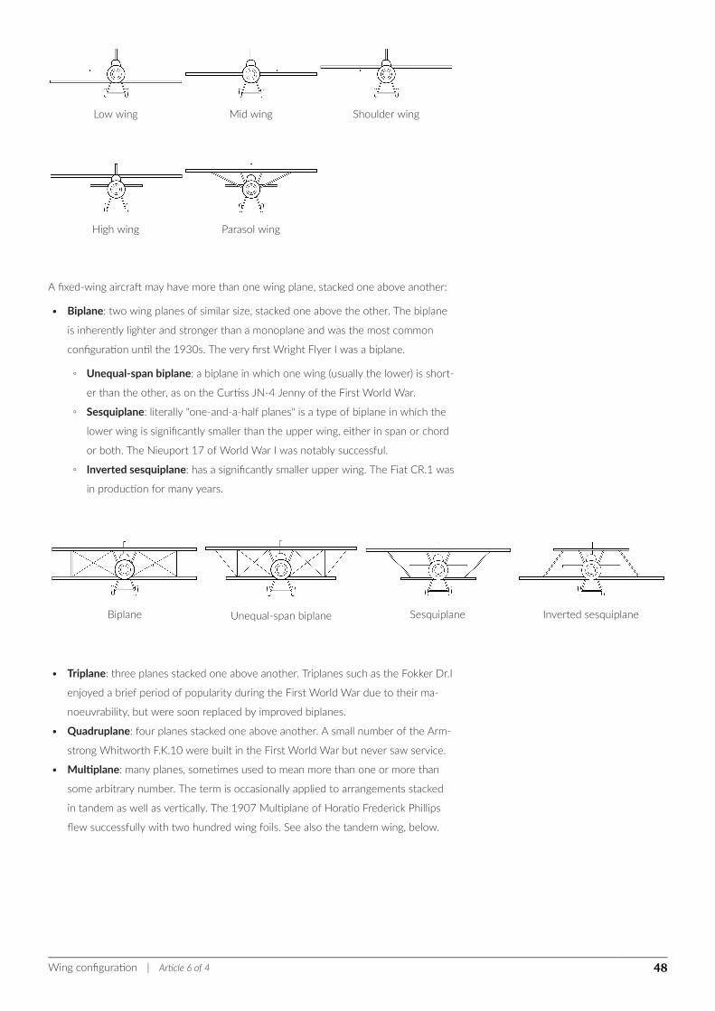
Low wing Mid wing Shoulder wing
High wing Parasol wing
A fixed-wing aircraft may have more than one wing plane, stacked one above another:
• Biplane: two wing planes of similar size, stacked one above the other. The biplane
is inherently lighter and stronger than a monoplane and was the most common
configuration until the 1930s. The very first Wright Flyer I was a biplane.
◦ Unequal-span biplane: a biplane in which one wing (usually the lower) is short-
er than the other, as on the Curtiss JN-4 Jenny of the First World War.
◦ Sesquiplane: literally "one-and-a-half planes" is a type of biplane in which the
lower wing is significantly smaller than the upper wing, either in span or chord
or both. The Nieuport 17 of World War I was notably successful.
◦ Inverted sesquiplane: has a significantly smaller upper wing. The Fiat CR.1 was
in production for many years.
Biplane Unequal-span biplane Sesquiplane Inverted sesquiplane
• Triplane: three planes stacked one above another. Triplanes such as the Fokker Dr.I
enjoyed a brief period of popularity during the First World War due to their ma-
noeuvrability, but were soon replaced by improved biplanes.
• Quadruplane: four planes stacked one above another. A small number of the Arm-
strong Whitworth F.K.10 were built in the First World War but never saw service.
• Multiplane: many planes, sometimes used to mean more than one or more than
some arbitrary number. The term is occasionally applied to arrangements stacked
in tandem as well as vertically. The 1907 Multiplane of Horatio Frederick Phillips
flew successfully with two hundred wing foils. See also the tandem wing, below.
Wing configuration | Article 6 of 4 48
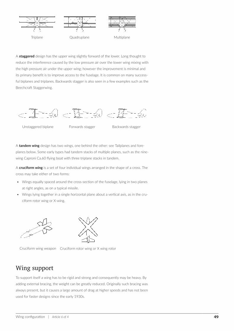
Triplane Quadruplane Multiplane
A staggered design has the upper wing slightly forward of the lower. Long thought to
reduce the interference caused by the low pressure air over the lower wing mixing with
the high pressure air under the upper wing; however the improvement is minimal and
its primary benefit is to improve access to the fuselage. It is common on many success-
ful biplanes and triplanes. Backwards stagger is also seen in a few examples such as the
Beechcraft Staggerwing.
Unstaggered biplane Forwards stagger Backwards stagger
A tandem wing design has two wings, one behind the other: see Tailplanes and fore-
planes below. Some early types had tandem stacks of multiple planes, such as the nine-
wing Caproni Ca.60 flying boat with three triplane stacks in tandem.
A cruciform wing is a set of four individual wings arranged in the shape of a cross. The
cross may take either of two forms:
• Wings equally spaced around the cross-section of the fuselage, lying in two planes
at right angles, as on a typical missile.
• Wings lying together in a single horizontal plane about a vertical axis, as in the cru-
ciform rotor wing or X-wing.
Cruciform wing weapon Cruciform rotor wing or X wing rotor
Wing supportTo support itself a wing has to be rigid and strong and consequently may be heavy. By
adding external bracing, the weight can be greatly reduced. Originally such bracing was
always present, but it causes a large amount of drag at higher speeds and has not been
used for faster designs since the early 1930s.
Wing configuration | Article 6 of 4 49
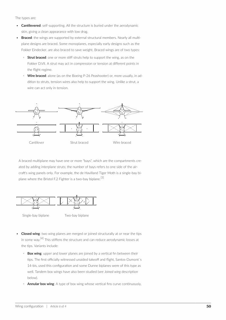
The types are:
• Cantilevered: self-supporting. All the structure is buried under the aerodynamic
skin, giving a clean appearance with low drag.
• Braced: the wings are supported by external structural members. Nearly all multi-
plane designs are braced. Some monoplanes, especially early designs such as the
Fokker Eindecker, are also braced to save weight. Braced wings are of two types:
◦ Strut braced: one or more stiff struts help to support the wing, as on the
Fokker D.VII. A strut may act in compression or tension at different points in
the flight regime.
◦ Wire braced: alone (as on the Boeing P-26 Peashooter) or, more usually, in ad-
dition to struts, tension wires also help to support the wing. Unlike a strut, a
wire can act only in tension.
Cantilever Strut braced Wire braced
A braced multiplane may have one or more "bays", which are the compartments cre-
ated by adding interplane struts; the number of bays refers to one side of the air-
craft's wing panels only. For example, the de Havilland Tiger Moth is a single-bay bi-
plane where the Bristol F.2 Fighter is a two-bay biplane.[3]
Single-bay biplane Two-bay biplane
• Closed wing: two wing planes are merged or joined structurally at or near the tips
in some way.[4] This stiffens the structure and can reduce aerodynamic losses at
the tips. Variants include:
◦ Box wing: upper and lower planes are joined by a vertical fin between their
tips. The first officially witnessed unaided takeoff and flight, Santos-Dumont´s
14-bis, used this configuration and some Dunne biplanes were of this type as
well. Tandem box wings have also been studied (see Joined wing description
below).
◦ Annular box wing: A type of box wing whose vertical fins curve continuously,
Wing configuration | Article 6 of 4 50
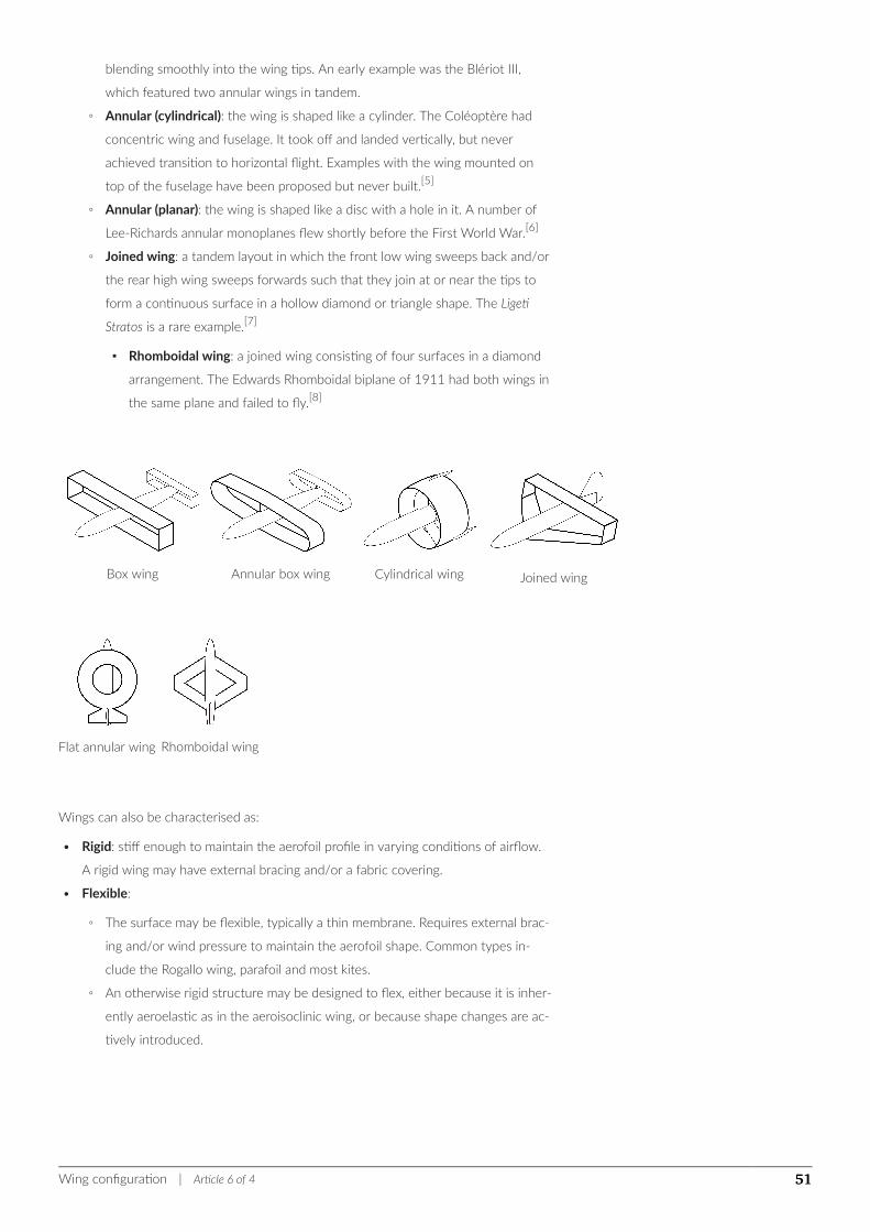
blending smoothly into the wing tips. An early example was the Blériot III,
which featured two annular wings in tandem.
◦ Annular (cylindrical): the wing is shaped like a cylinder. The Coléoptère had
concentric wing and fuselage. It took off and landed vertically, but never
achieved transition to horizontal flight. Examples with the wing mounted on
top of the fuselage have been proposed but never built.[5]
◦ Annular (planar): the wing is shaped like a disc with a hole in it. A number of
Lee-Richards annular monoplanes flew shortly before the First World War.[6]
◦ Joined wing: a tandem layout in which the front low wing sweeps back and/or
the rear high wing sweeps forwards such that they join at or near the tips to
form a continuous surface in a hollow diamond or triangle shape. The Ligeti
Stratos is a rare example.[7]
▪ Rhomboidal wing: a joined wing consisting of four surfaces in a diamond
arrangement. The Edwards Rhomboidal biplane of 1911 had both wings in
the same plane and failed to fly.[8]
Box wing Annular box wing Cylindrical wing Joined wing
Flat annular wing Rhomboidal wing
Wings can also be characterised as:
• Rigid: stiff enough to maintain the aerofoil profile in varying conditions of airflow.
A rigid wing may have external bracing and/or a fabric covering.
• Flexible:
◦ The surface may be flexible, typically a thin membrane. Requires external brac-
ing and/or wind pressure to maintain the aerofoil shape. Common types in-
clude the Rogallo wing, parafoil and most kites.
◦ An otherwise rigid structure may be designed to flex, either because it is inher-
ently aeroelastic as in the aeroisoclinic wing, or because shape changes are ac-
tively introduced.
Wing configuration | Article 6 of 4 51
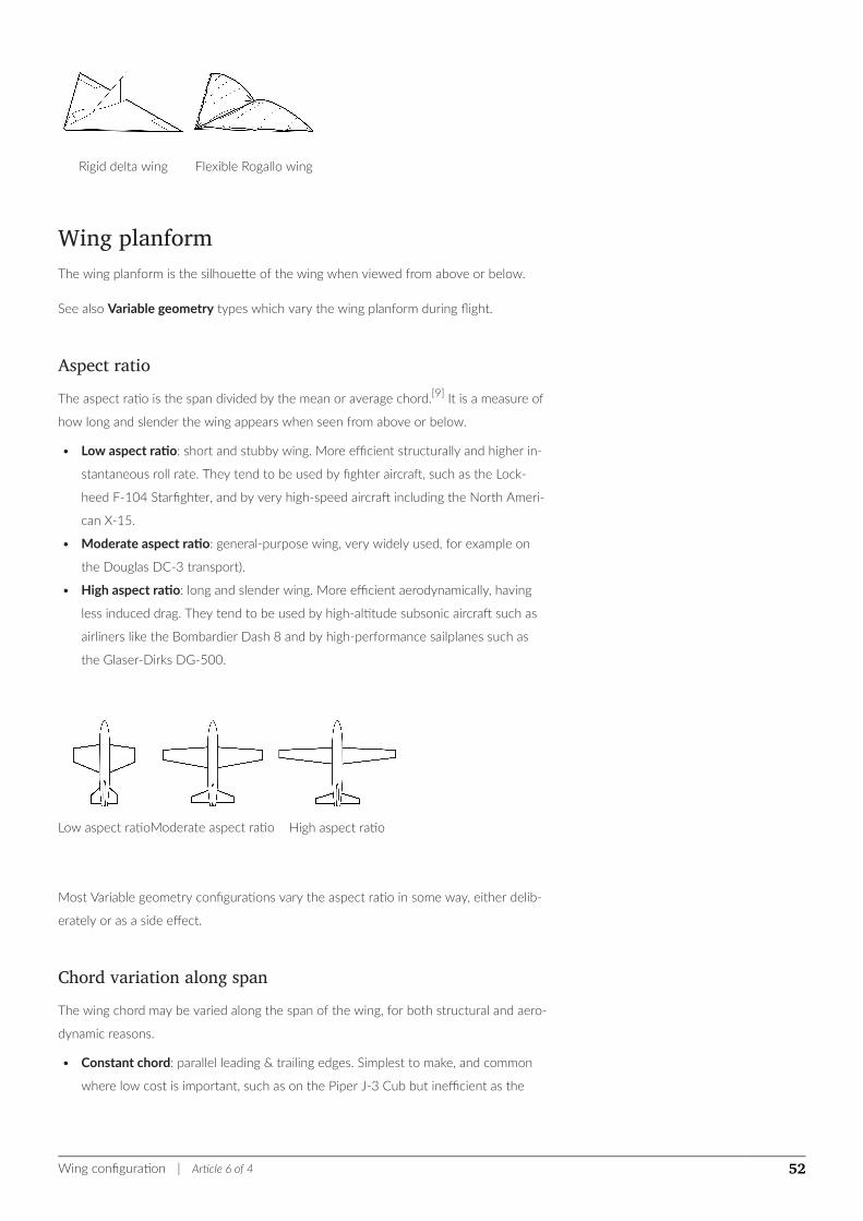
Rigid delta wing Flexible Rogallo wing
Wing planformThe wing planform is the silhouette of the wing when viewed from above or below.
See also Variable geometry types which vary the wing planform during flight.
Aspect ratioThe aspect ratio is the span divided by the mean or average chord.[9] It is a measure of
how long and slender the wing appears when seen from above or below.
• Low aspect ratio: short and stubby wing. More efficient structurally and higher in-
stantaneous roll rate. They tend to be used by fighter aircraft, such as the Lock-
heed F-104 Starfighter, and by very high-speed aircraft including the North Ameri-
can X-15.
• Moderate aspect ratio: general-purpose wing, very widely used, for example on
the Douglas DC-3 transport).
• High aspect ratio: long and slender wing. More efficient aerodynamically, having
less induced drag. They tend to be used by high-altitude subsonic aircraft such as
airliners like the Bombardier Dash 8 and by high-performance sailplanes such as
the Glaser-Dirks DG-500.
Low aspect ratioModerate aspect ratio High aspect ratio
Most Variable geometry configurations vary the aspect ratio in some way, either delib-
erately or as a side effect.
Chord variation along spanThe wing chord may be varied along the span of the wing, for both structural and aero-
dynamic reasons.
• Constant chord: parallel leading & trailing edges. Simplest to make, and common
where low cost is important, such as on the Piper J-3 Cub but inefficient as the
Wing configuration | Article 6 of 4 52
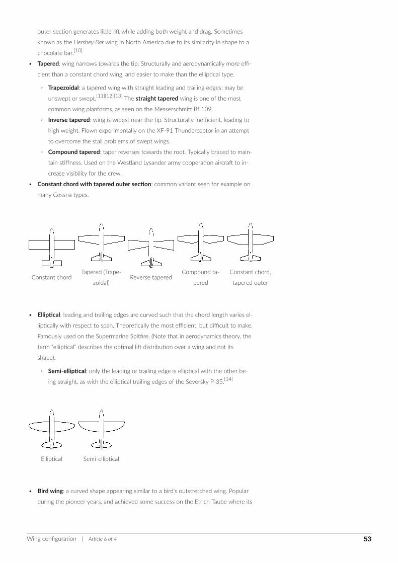
outer section generates little lift while adding both weight and drag. Sometimes
known as the Hershey Bar wing in North America due to its similarity in shape to a
chocolate bar.[10]
• Tapered: wing narrows towards the tip. Structurally and aerodynamically more effi-
cient than a constant chord wing, and easier to make than the elliptical type.
◦ Trapezoidal: a tapered wing with straight leading and trailing edges: may be
unswept or swept.[11][12][13] The straight tapered wing is one of the most
common wing planforms, as seen on the Messerschmitt Bf 109.
◦ Inverse tapered: wing is widest near the tip. Structurally inefficient, leading to
high weight. Flown experimentally on the XF-91 Thunderceptor in an attempt
to overcome the stall problems of swept wings.
◦ Compound tapered: taper reverses towards the root. Typically braced to main-
tain stiffness. Used on the Westland Lysander army cooperation aircraft to in-
crease visibility for the crew.
• Constant chord with tapered outer section: common variant seen for example on
many Cessna types.
Constant chordTapered (Trape-
zoidal)Reverse tapered
Compound ta-
pered
Constant chord,
tapered outer
• Elliptical: leading and trailing edges are curved such that the chord length varies el-
liptically with respect to span. Theoretically the most efficient, but difficult to make.
Famously used on the Supermarine Spitfire. (Note that in aerodynamics theory, the
term "elliptical" describes the optimal lift distribution over a wing and not its
shape).
◦ Semi-elliptical: only the leading or trailing edge is elliptical with the other be-
ing straight, as with the elliptical trailing edges of the Seversky P-35.[14]
Elliptical Semi-elliptical
• Bird wing: a curved shape appearing similar to a bird's outstretched wing. Popular
during the pioneer years, and achieved some success on the Etrich Taube where its
Wing configuration | Article 6 of 4 53
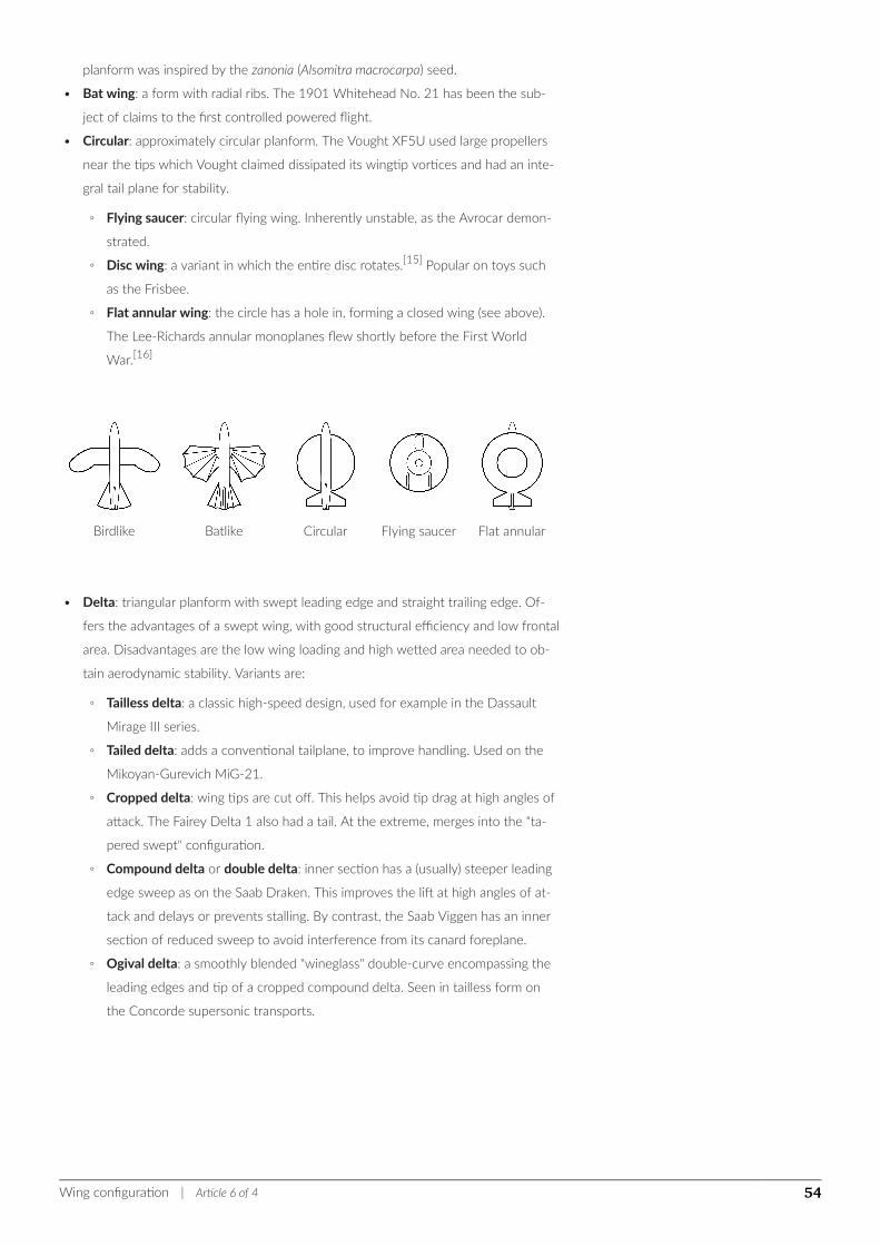
planform was inspired by the zanonia (Alsomitra macrocarpa) seed.
• Bat wing: a form with radial ribs. The 1901 Whitehead No. 21 has been the sub-
ject of claims to the first controlled powered flight.
• Circular: approximately circular planform. The Vought XF5U used large propellers
near the tips which Vought claimed dissipated its wingtip vortices and had an inte-
gral tail plane for stability.
◦ Flying saucer: circular flying wing. Inherently unstable, as the Avrocar demon-
strated.
◦ Disc wing: a variant in which the entire disc rotates.[15] Popular on toys such
as the Frisbee.
◦ Flat annular wing: the circle has a hole in, forming a closed wing (see above).
The Lee-Richards annular monoplanes flew shortly before the First World
War.[16]
Birdlike Batlike Circular Flying saucer Flat annular
• Delta: triangular planform with swept leading edge and straight trailing edge. Of-
fers the advantages of a swept wing, with good structural efficiency and low frontal
area. Disadvantages are the low wing loading and high wetted area needed to ob-
tain aerodynamic stability. Variants are:
◦ Tailless delta: a classic high-speed design, used for example in the Dassault
Mirage III series.
◦ Tailed delta: adds a conventional tailplane, to improve handling. Used on the
Mikoyan-Gurevich MiG-21.
◦ Cropped delta: wing tips are cut off. This helps avoid tip drag at high angles of
attack. The Fairey Delta 1 also had a tail. At the extreme, merges into the "ta-
pered swept" configuration.
◦ Compound delta or double delta: inner section has a (usually) steeper leading
edge sweep as on the Saab Draken. This improves the lift at high angles of at-
tack and delays or prevents stalling. By contrast, the Saab Viggen has an inner
section of reduced sweep to avoid interference from its canard foreplane.
◦ Ogival delta: a smoothly blended "wineglass" double-curve encompassing the
leading edges and tip of a cropped compound delta. Seen in tailless form on
the Concorde supersonic transports.
Wing configuration | Article 6 of 4 54
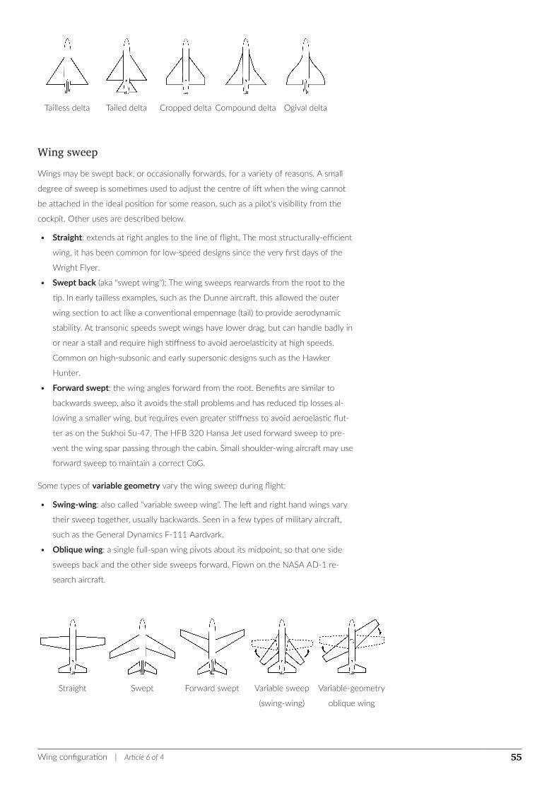
Tailless delta Tailed delta Cropped delta Compound delta Ogival delta
Wing sweepWings may be swept back, or occasionally forwards, for a variety of reasons. A small
degree of sweep is sometimes used to adjust the centre of lift when the wing cannot
be attached in the ideal position for some reason, such as a pilot's visibility from the
cockpit. Other uses are described below.
• Straight: extends at right angles to the line of flight. The most structurally-efficient
wing, it has been common for low-speed designs since the very first days of the
Wright Flyer.
• Swept back (aka "swept wing"): The wing sweeps rearwards from the root to the
tip. In early tailless examples, such as the Dunne aircraft, this allowed the outer
wing section to act like a conventional empennage (tail) to provide aerodynamic
stability. At transonic speeds swept wings have lower drag, but can handle badly in
or near a stall and require high stiffness to avoid aeroelasticity at high speeds.
Common on high-subsonic and early supersonic designs such as the Hawker
Hunter.
• Forward swept: the wing angles forward from the root. Benefits are similar to
backwards sweep, also it avoids the stall problems and has reduced tip losses al-
lowing a smaller wing, but requires even greater stiffness to avoid aeroelastic flut-
ter as on the Sukhoi Su-47. The HFB 320 Hansa Jet used forward sweep to pre-
vent the wing spar passing through the cabin. Small shoulder-wing aircraft may use
forward sweep to maintain a correct CoG.
Some types of variable geometry vary the wing sweep during flight:
• Swing-wing: also called "variable sweep wing". The left and right hand wings vary
their sweep together, usually backwards. Seen in a few types of military aircraft,
such as the General Dynamics F-111 Aardvark.
• Oblique wing: a single full-span wing pivots about its midpoint, so that one side
sweeps back and the other side sweeps forward. Flown on the NASA AD-1 re-
search aircraft.
Straight Swept Forward swept Variable sweep
(swing-wing)
Variable-geometry
oblique wing
Wing configuration | Article 6 of 4 55
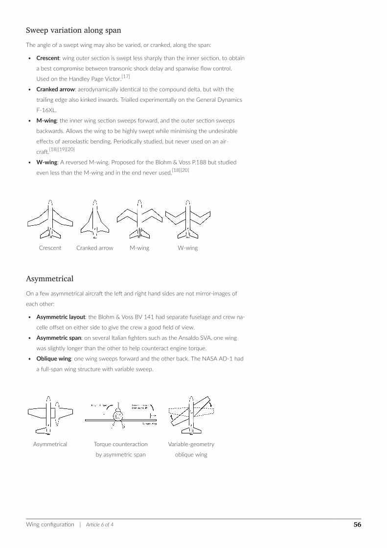
Sweep variation along spanThe angle of a swept wing may also be varied, or cranked, along the span:
• Crescent: wing outer section is swept less sharply than the inner section, to obtain
a best compromise between transonic shock delay and spanwise flow control.
Used on the Handley Page Victor.[17]
• Cranked arrow: aerodynamically identical to the compound delta, but with the
trailing edge also kinked inwards. Trialled experimentally on the General Dynamics
F-16XL.
• M-wing: the inner wing section sweeps forward, and the outer section sweeps
backwards. Allows the wing to be highly swept while minimising the undesirable
effects of aeroelastic bending. Periodically studied, but never used on an air-
craft.[18][19][20]
• W-wing: A reversed M-wing. Proposed for the Blohm & Voss P.188 but studied
even less than the M-wing and in the end never used.[18][20]
Crescent Cranked arrow M-wing W-wing
AsymmetricalOn a few asymmetrical aircraft the left and right hand sides are not mirror-images of
each other:
• Asymmetric layout: the Blohm & Voss BV 141 had separate fuselage and crew na-
celle offset on either side to give the crew a good field of view.
• Asymmetric span: on several Italian fighters such as the Ansaldo SVA, one wing
was slightly longer than the other to help counteract engine torque.
• Oblique wing: one wing sweeps forward and the other back. The NASA AD-1 had
a full-span wing structure with variable sweep.
Asymmetrical Torque counteraction
by asymmetric span
Variable-geometry
oblique wing
Wing configuration | Article 6 of 4 56
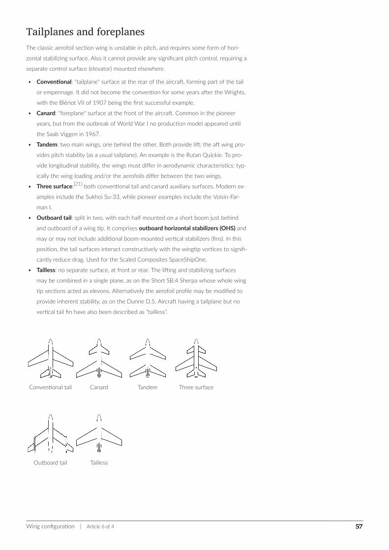
Tailplanes and foreplanesThe classic aerofoil section wing is unstable in pitch, and requires some form of hori-
zontal stabilizing surface. Also it cannot provide any significant pitch control, requiring a
separate control surface (elevator) mounted elsewhere.
• Conventional: "tailplane" surface at the rear of the aircraft, forming part of the tail
or empennage. It did not become the convention for some years after the Wrights,
with the Blériot VII of 1907 being the first successful example.
• Canard: "foreplane" surface at the front of the aircraft. Common in the pioneer
years, but from the outbreak of World War I no production model appeared until
the Saab Viggen in 1967.
• Tandem: two main wings, one behind the other. Both provide lift; the aft wing pro-
vides pitch stability (as a usual tailplane). An example is the Rutan Quickie. To pro-
vide longitudinal stability, the wings must differ in aerodynamic characteristics: typ-
ically the wing loading and/or the aerofoils differ between the two wings.
• Three surface:[21] both conventional tail and canard auxiliary surfaces. Modern ex-
amples include the Sukhoi Su-33, while pioneer examples include the Voisin-Far-
man I.
• Outboard tail: split in two, with each half mounted on a short boom just behind
and outboard of a wing tip. It comprises outboard horizontal stabilizers (OHS) and
may or may not include additional boom-mounted vertical stabilizers (fins). In this
position, the tail surfaces interact constructively with the wingtip vortices to signifi-
cantly reduce drag. Used for the Scaled Composites SpaceShipOne.
• Tailless: no separate surface, at front or rear. The lifting and stabilizing surfaces
may be combined in a single plane, as on the Short SB.4 Sherpa whose whole wing
tip sections acted as elevons. Alternatively the aerofoil profile may be modified to
provide inherent stability, as on the Dunne D.5. Aircraft having a tailplane but no
vertical tail fin have also been described as "tailless".
Conventional tail Canard Tandem Three surface
Outboard tail Tailless
Wing configuration | Article 6 of 4 57
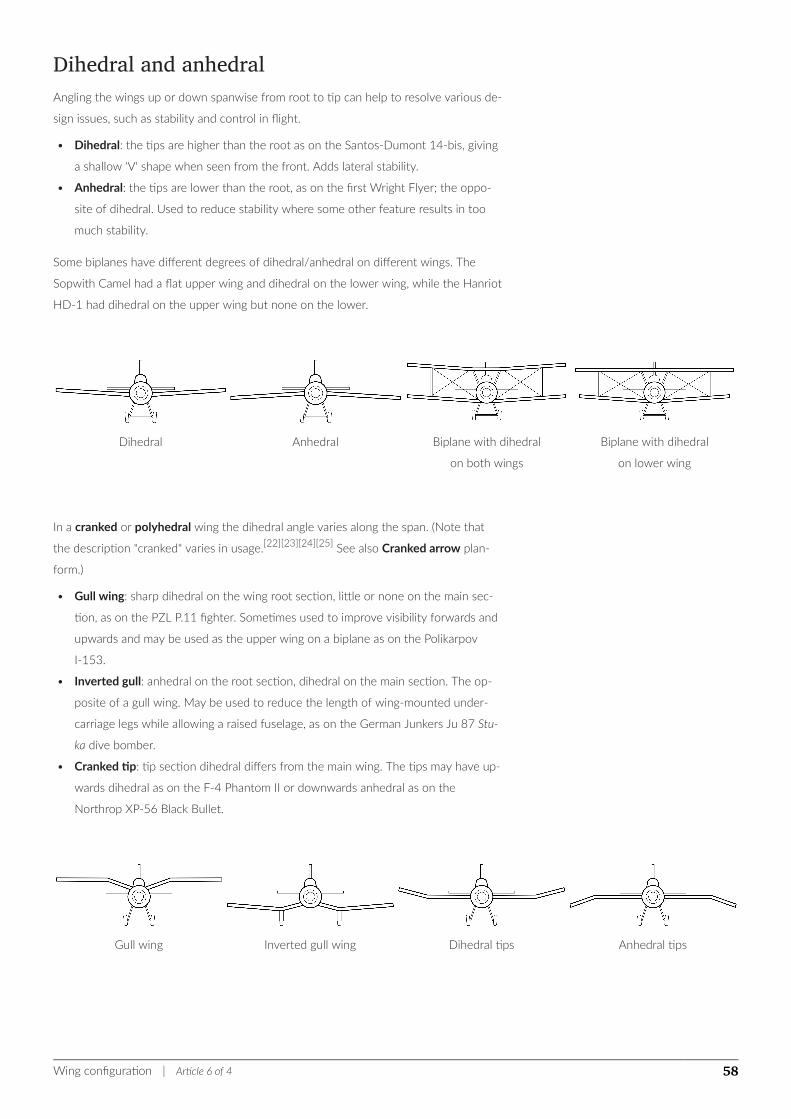
Dihedral and anhedralAngling the wings up or down spanwise from root to tip can help to resolve various de-
sign issues, such as stability and control in flight.
• Dihedral: the tips are higher than the root as on the Santos-Dumont 14-bis, giving
a shallow 'V' shape when seen from the front. Adds lateral stability.
• Anhedral: the tips are lower than the root, as on the first Wright Flyer; the oppo-
site of dihedral. Used to reduce stability where some other feature results in too
much stability.
Some biplanes have different degrees of dihedral/anhedral on different wings. The
Sopwith Camel had a flat upper wing and dihedral on the lower wing, while the Hanriot
HD-1 had dihedral on the upper wing but none on the lower.
Dihedral Anhedral Biplane with dihedral
on both wings
Biplane with dihedral
on lower wing
In a cranked or polyhedral wing the dihedral angle varies along the span. (Note that
the description "cranked" varies in usage.[22][23][24][25] See also Cranked arrow plan-
form.)
• Gull wing: sharp dihedral on the wing root section, little or none on the main sec-
tion, as on the PZL P.11 fighter. Sometimes used to improve visibility forwards and
upwards and may be used as the upper wing on a biplane as on the Polikarpov
I-153.
• Inverted gull: anhedral on the root section, dihedral on the main section. The op-
posite of a gull wing. May be used to reduce the length of wing-mounted under-
carriage legs while allowing a raised fuselage, as on the German Junkers Ju 87 Stu-
ka dive bomber.
• Cranked tip: tip section dihedral differs from the main wing. The tips may have up-
wards dihedral as on the F-4 Phantom II or downwards anhedral as on the
Northrop XP-56 Black Bullet.
Gull wing Inverted gull wing Dihedral tips Anhedral tips
Wing configuration | Article 6 of 4 58
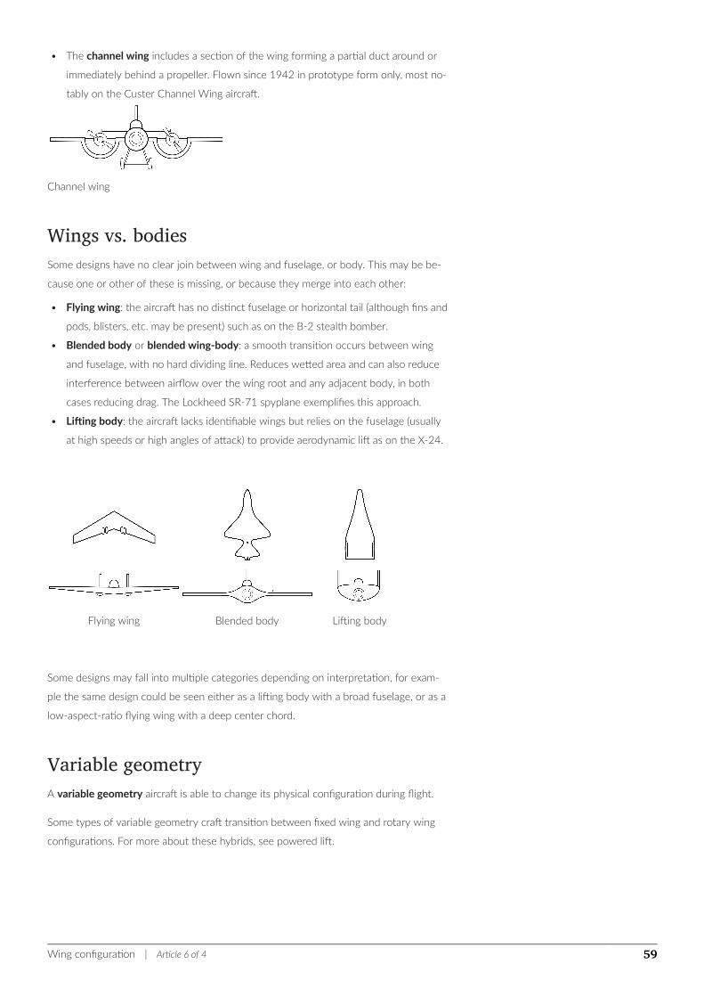
• The channel wing includes a section of the wing forming a partial duct around or
immediately behind a propeller. Flown since 1942 in prototype form only, most no-
tably on the Custer Channel Wing aircraft.
Channel wing
Wings vs. bodiesSome designs have no clear join between wing and fuselage, or body. This may be be-
cause one or other of these is missing, or because they merge into each other:
• Flying wing: the aircraft has no distinct fuselage or horizontal tail (although fins and
pods, blisters, etc. may be present) such as on the B-2 stealth bomber.
• Blended body or blended wing-body: a smooth transition occurs between wing
and fuselage, with no hard dividing line. Reduces wetted area and can also reduce
interference between airflow over the wing root and any adjacent body, in both
cases reducing drag. The Lockheed SR-71 spyplane exemplifies this approach.
• Lifting body: the aircraft lacks identifiable wings but relies on the fuselage (usually
at high speeds or high angles of attack) to provide aerodynamic lift as on the X-24.
Flying wing Blended body Lifting body
Some designs may fall into multiple categories depending on interpretation, for exam-
ple the same design could be seen either as a lifting body with a broad fuselage, or as a
low-aspect-ratio flying wing with a deep center chord.
Variable geometryA variable geometry aircraft is able to change its physical configuration during flight.
Some types of variable geometry craft transition between fixed wing and rotary wing
configurations. For more about these hybrids, see powered lift.
Wing configuration | Article 6 of 4 59

Variable planform• Variable-sweep wing or Swing-wing. The left and right hand wings vary their
sweep together, usually backwards. The first successful wing sweep in flight was
carried out by the Bell X-5 in the early 1950s. In the Beech Starship, only the ca-
nard foreplanes have variable sweep.
• Oblique wing: a single full-span wing pivots about its midpoint, as used on the
NASA AD-1, so that one side sweeps back and the other side sweeps forward.
• Telescoping wing: the outer section of wing telescopes over or within the inner
section of wing, varying span, aspect ratio and wing area, as used on the FS-29 TF
glider.[26]
• Detachable wing. The WS110A study proposed a long wing for efficient subsonic
cruise, which then ejects the outer panels to leave a short-span wing for a short
supersonic "dash" to its targets. See Slip wing.
• Extending wing or expanding wing: part of the wing retracts into the main aircraft
structure to reduce drag and low-altitude buffet for high-speed flight, and is ex-
tended only for takeoff, low-speed cruise and landing. The Gérin Varivol biplane,
which flew in 1936, extended the leading and trailing edges to increase wing
area.[27]
Variable sweep
(swing-wing)
Variable-geometry
oblique wing Telescoping wing Extending wing
• Folding wing: part of the wing extends for takeoff and landing, and folds away for
high-speed flight. The outer sections of the XB-70 Valkyrie wing folded down dur-
ing supersonic cruise. (Many aircraft have wings that may be folded for storage on
the ground or on board ship. These are not folding wings in the sense used here).
Folding wing
Variable chord• Variable incidence: the wing plane can tilt upwards or downwards relative to the
fuselage. The wing on the Vought F-8 Crusader was rotated, lifting the leading
edge on takeoff to improve performance. If powered prop-rotors are fitted to the
wing to allow vertical takeoff or STOVL performance, merges into the powered lift
Wing configuration | Article 6 of 4 60
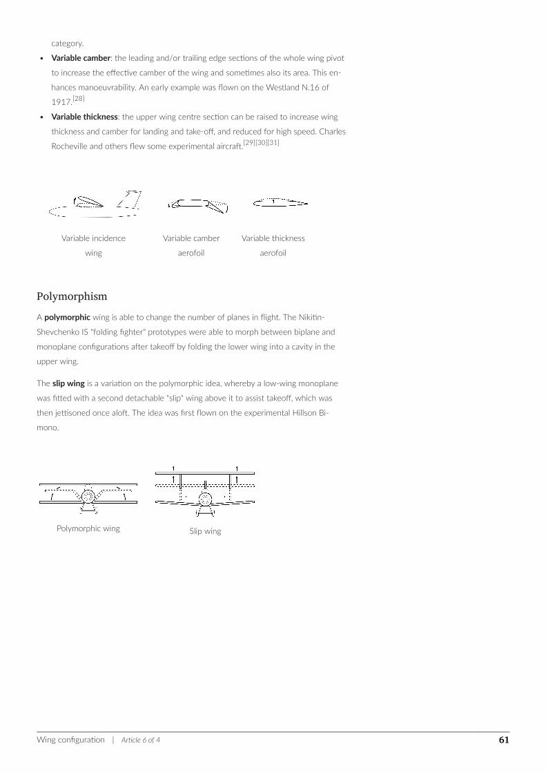
category.
• Variable camber: the leading and/or trailing edge sections of the whole wing pivot
to increase the effective camber of the wing and sometimes also its area. This en-
hances manoeuvrability. An early example was flown on the Westland N.16 of
1917.[28]
• Variable thickness: the upper wing centre section can be raised to increase wing
thickness and camber for landing and take-off, and reduced for high speed. Charles
Rocheville and others flew some experimental aircraft.[29][30][31]
Variable incidence
wing
Variable camber
aerofoil
Variable thickness
aerofoil
PolymorphismA polymorphic wing is able to change the number of planes in flight. The Nikitin-
Shevchenko IS "folding fighter" prototypes were able to morph between biplane and
monoplane configurations after takeoff by folding the lower wing into a cavity in the
upper wing.
The slip wing is a variation on the polymorphic idea, whereby a low-wing monoplane
was fitted with a second detachable "slip" wing above it to assist takeoff, which was
then jettisoned once aloft. The idea was first flown on the experimental Hillson Bi-
mono.
Polymorphic wing Slip wing
Wing configuration | Article 6 of 4 61
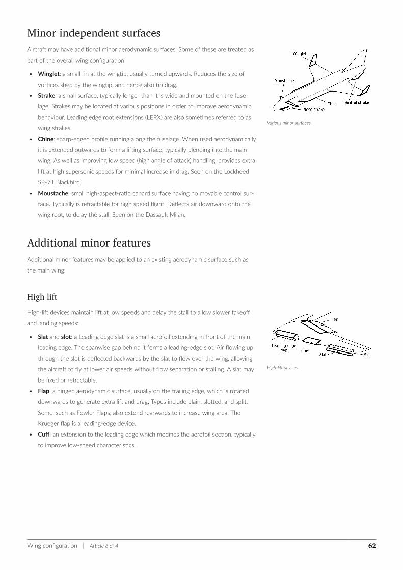
Various minor surfaces
High-lift devices
Minor independent surfacesAircraft may have additional minor aerodynamic surfaces. Some of these are treated as
part of the overall wing configuration:
• Winglet: a small fin at the wingtip, usually turned upwards. Reduces the size of
vortices shed by the wingtip, and hence also tip drag.
• Strake: a small surface, typically longer than it is wide and mounted on the fuse-
lage. Strakes may be located at various positions in order to improve aerodynamic
behaviour. Leading edge root extensions (LERX) are also sometimes referred to as
wing strakes.
• Chine: sharp-edged profile running along the fuselage. When used aerodynamically
it is extended outwards to form a lifting surface, typically blending into the main
wing. As well as improving low speed (high angle of attack) handling, provides extra
lift at high supersonic speeds for minimal increase in drag. Seen on the Lockheed
SR-71 Blackbird.
• Moustache: small high-aspect-ratio canard surface having no movable control sur-
face. Typically is retractable for high speed flight. Deflects air downward onto the
wing root, to delay the stall. Seen on the Dassault Milan.
Additional minor featuresAdditional minor features may be applied to an existing aerodynamic surface such as
the main wing:
High liftHigh-lift devices maintain lift at low speeds and delay the stall to allow slower takeoff
and landing speeds:
• Slat and slot: a Leading edge slat is a small aerofoil extending in front of the main
leading edge. The spanwise gap behind it forms a leading-edge slot. Air flowing up
through the slot is deflected backwards by the slat to flow over the wing, allowing
the aircraft to fly at lower air speeds without flow separation or stalling. A slat may
be fixed or retractable.
• Flap: a hinged aerodynamic surface, usually on the trailing edge, which is rotated
downwards to generate extra lift and drag. Types include plain, slotted, and split.
Some, such as Fowler Flaps, also extend rearwards to increase wing area. The
Krueger flap is a leading-edge device.
• Cuff: an extension to the leading edge which modifies the aerofoil section, typically
to improve low-speed characteristics.
Wing configuration | Article 6 of 4 62
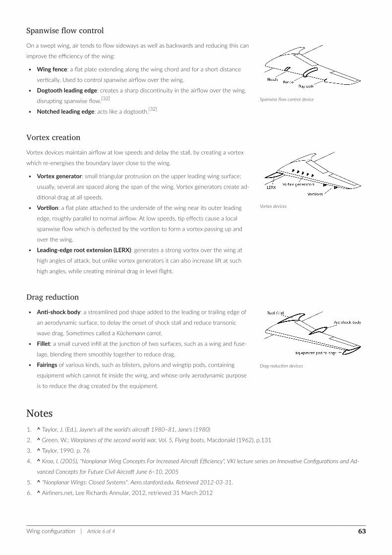
Spanwise flow control device
Vortex devices
Drag-reduction devices
Spanwise flow controlOn a swept wing, air tends to flow sideways as well as backwards and reducing this can
improve the efficiency of the wing:
• Wing fence: a flat plate extending along the wing chord and for a short distance
vertically. Used to control spanwise airflow over the wing.
• Dogtooth leading edge: creates a sharp discontinuity in the airflow over the wing,
disrupting spanwise flow.[32]
• Notched leading edge: acts like a dogtooth.[32]
Vortex creationVortex devices maintain airflow at low speeds and delay the stall, by creating a vortex
which re-energises the boundary layer close to the wing.
• Vortex generator: small triangular protrusion on the upper leading wing surface;
usually, several are spaced along the span of the wing. Vortex generators create ad-
ditional drag at all speeds.
• Vortilon: a flat plate attached to the underside of the wing near its outer leading
edge, roughly parallel to normal airflow. At low speeds, tip effects cause a local
spanwise flow which is deflected by the vortilon to form a vortex passing up and
over the wing.
• Leading-edge root extension (LERX): generates a strong vortex over the wing at
high angles of attack, but unlike vortex generators it can also increase lift at such
high angles, while creating minimal drag in level flight.
Drag reduction• Anti-shock body: a streamlined pod shape added to the leading or trailing edge of
an aerodynamic surface, to delay the onset of shock stall and reduce transonic
wave drag. Sometimes called a Küchemann carrot.
• Fillet: a small curved infill at the junction of two surfaces, such as a wing and fuse-
lage, blending them smoothly together to reduce drag.
• Fairings of various kinds, such as blisters, pylons and wingtip pods, containing
equipment which cannot fit inside the wing, and whose only aerodynamic purpose
is to reduce the drag created by the equipment.
Notes1. ^ Taylor, J. (Ed.), Jayne's all the world's aircraft 1980–81, Jane's (1980)
2. ^ Green, W.; Warplanes of the second world war, Vol. 5, Flying boats, Macdonald (1962), p.131
3. ^ Taylor, 1990. p. 76
4. ^ Kroo, I. (2005), "Nonplanar Wing Concepts For Increased Aircraft Efficiency", VKI lecture series on Innovative Configurations and Ad-
vanced Concepts for Future Civil Aircraft June 6–10, 2005
5. ^ "Nonplanar Wings: Closed Systems". Aero.stanford.edu. Retrieved 2012-03-31.
6. ^ Airliners.net, Lee Richards Annular, 2012, retrieved 31 March 2012
Wing configuration | Article 6 of 4 63
7. ^ Ligeti Stratos joined wing aircraft
8. ^ Angelucco, E. and Matrciardi, P.; World Aircraft Origins-World War 1, Sampson Low, 1977
9. ^ Kermode (1972), Chapter 3, p. 103.
10. ^ Garrison, Peter (2003-01-01). "Rectangular Wings | Flying Magazine". Flyingmag.com. Retrieved 2012-03-31.
11. ^ Tom Benson; Wing Area, NASA
12. ^ Ilan Kroo. AA241 Aircraft Design: Synthesis and Analysis Wing Geometry Definitions, Stanford University.
13. ^ G. Dimitriadis; Aircraft Design Lecture 2: Aerodynamics, Université de Liège.
14. ^ "Alexander de Seversky". centennialofflight.net. Retrieved 2012-03-31.
15. ^ Potts, J.R.; Disc-wing aerodynamics, University of Manchester, 2005.
16. ^ letter from Hall-Warren, N.; Flight International, 1962, p. 716.
17. ^ "swept wing | avro vulcan | 1953 | 0030 | Flight Archive". Flightglobal.com. 1952-12-05. Retrieved 2012-05-29.
18. ^ a b Diederich and Foss; Static Aeroelastic Phenomena of M-, W- and Λ- wings, NACA 1953.
19. ^ "Aerodynamics at Teddington", Flight: 764, 5 June 1959
20. ^ a b Katz, Marley, Pepper, NACA RM L50G31 (PDF), NACA
21. ^ P180 Avanti-Specification and Description. See page 55, Appendix A: "Notes about the 3-Lifting-Surface design".
22. ^ Ernst-Heinrich Hirschel; Horst Prem; Gero Madelung (2004). Aeronautical research in Germany: from Lilienthal until today. Springer
Science & Business Media. p. 167. ISBN 978-3-540-40645-7.
23. ^ Benoliel, Alexander M., Aerodynamic Pitch-up of Cranked Arrow Wings: Estimation, Trim, and Configuration Design, Virginia
Polytechnic Institute & State University, May 1994, retrieved 31 March 2012
24. ^ "Boeing Sonic Cruiser ousts 747X". Flightglobal.com. 2001-04-03. Retrieved 2012-03-31.
25. ^ "WHAT IS IT? Aircraft Characteristics That Aid the Spotter Classified : A Simple Guide for Basic Features in Design the Beginner", Flight:
562, 4 June 1942
26. ^ "fs 29 - "TF" ". Uni-stuttgart.de. 2012-02-05. Retrieved 2012-03-31.
27. ^ "Plane With Expanding Wing, Flies In Tests". Popular Science. November 1932. p. 31.
28. ^ Lukins, A.H.; The book of Westland aircraft, Aircraft (Technical) Publications Ltd, (1943 or 1944).
29. ^ Hearst Magazines (January 1931). "Adjustable Airplane's Wings Are Changed In Flight". Popular Mechanics. Hearst Magazines. p. 55.
30. ^ Flight, August 15, 1929
31. ^ Boyne, W.J.; The best of Wings magazine, Brassey's (2001)
32. ^ a b Wing vortex devices
References• Kermode, A. C.; Mechanics of Flight, Eighth (metric) edition, Pitman, London, 1972.
ISBN 0-273-31623-0
• Taylor, John W. R. The Lore of Flight, Universal Books, London, 1990. IS-
BN 0-9509620-1-5.
• "What is it? Aircraft Characteristics That Aid the Spotter". Flight. June 4, 1942.
See also
There is a Wikipedia Book on Aircraft wing configurations
Wing configuration | Article 6 of 4 64

• Aircraft design process
External links• High wing, low wing—Flight article on the merits of wing position
Wing configuration | Article 6 of 4 65
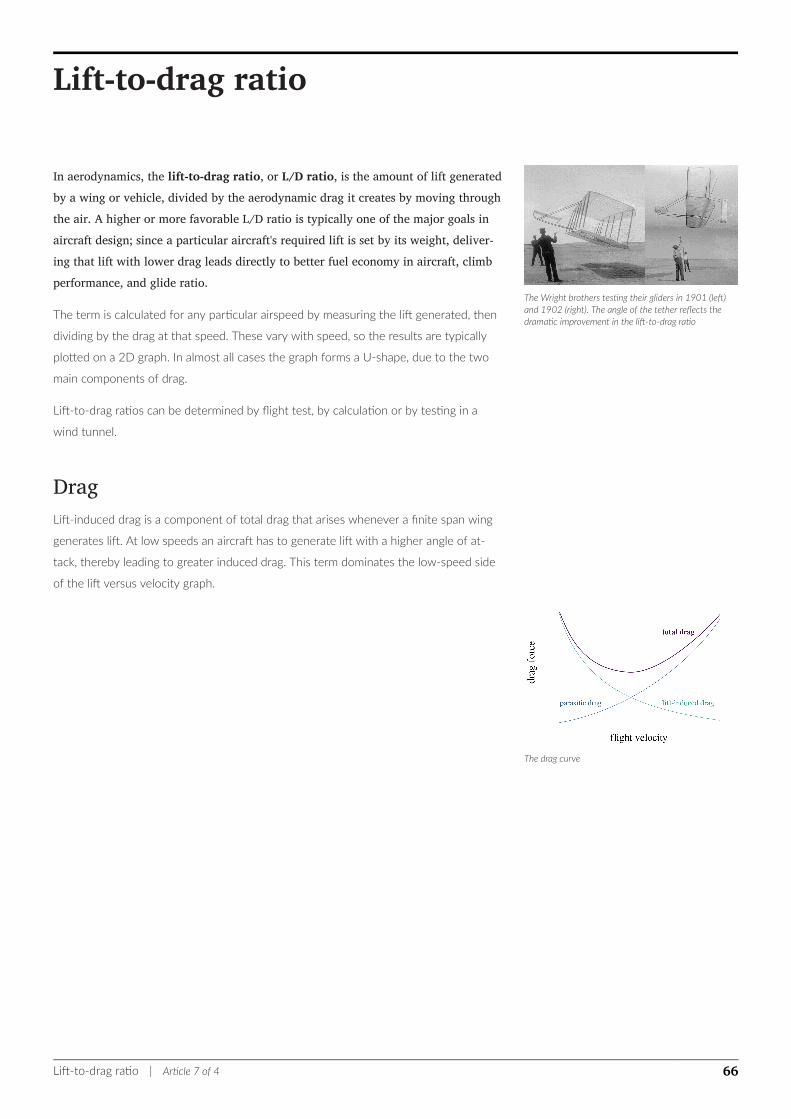
The Wright brothers testing their gliders in 1901 (left)and 1902 (right). The angle of the tether reflects thedramatic improvement in the lift-to-drag ratio
The drag curve
Lift-to-drag ratio
In aerodynamics, the lift-to-drag ratio, or L/D ratio, is the amount of lift generatedby a wing or vehicle, divided by the aerodynamic drag it creates by moving throughthe air. A higher or more favorable L/D ratio is typically one of the major goals inaircraft design; since a particular aircraft's required lift is set by its weight, deliver-ing that lift with lower drag leads directly to better fuel economy in aircraft, climbperformance, and glide ratio.
The term is calculated for any particular airspeed by measuring the lift generated, then
dividing by the drag at that speed. These vary with speed, so the results are typically
plotted on a 2D graph. In almost all cases the graph forms a U-shape, due to the two
main components of drag.
Lift-to-drag ratios can be determined by flight test, by calculation or by testing in a
wind tunnel.
DragLift-induced drag is a component of total drag that arises whenever a finite span wing
generates lift. At low speeds an aircraft has to generate lift with a higher angle of at-
tack, thereby leading to greater induced drag. This term dominates the low-speed side
of the lift versus velocity graph.
Lift-to-drag ratio | Article 7 of 4 66
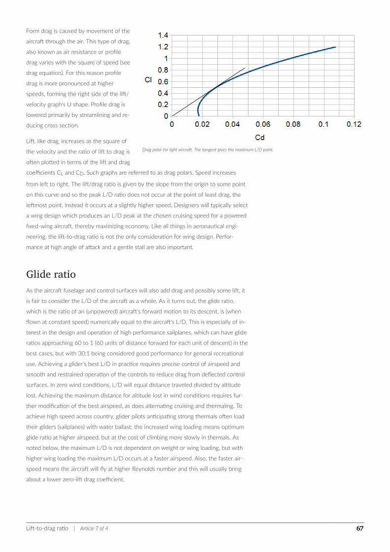
Drag polar for light aircraft. The tangent gives the maximum L/D point.
Form drag is caused by movement of the
aircraft through the air. This type of drag,
also known as air resistance or profile
drag varies with the square of speed (see
drag equation). For this reason profile
drag is more pronounced at higher
speeds, forming the right side of the lift/
velocity graph's U shape. Profile drag is
lowered primarily by streamlining and re-
ducing cross section.
Lift, like drag, increases as the square of
the velocity and the ratio of lift to drag is
often plotted in terms of the lift and drag
coefficients CL and CD. Such graphs are referred to as drag polars. Speed increases
from left to right. The lift/drag ratio is given by the slope from the origin to some point
on this curve and so the peak L/D ratio does not occur at the point of least drag, the
leftmost point. Instead it occurs at a slightly higher speed. Designers will typically select
a wing design which produces an L/D peak at the chosen cruising speed for a powered
fixed-wing aircraft, thereby maximizing economy. Like all things in aeronautical engi-
neering, the lift-to-drag ratio is not the only consideration for wing design. Perfor-
mance at high angle of attack and a gentle stall are also important.
Glide ratioAs the aircraft fuselage and control surfaces will also add drag and possibly some lift, it
is fair to consider the L/D of the aircraft as a whole. As it turns out, the glide ratio,
which is the ratio of an (unpowered) aircraft's forward motion to its descent, is (when
flown at constant speed) numerically equal to the aircraft's L/D. This is especially of in-
terest in the design and operation of high performance sailplanes, which can have glide
ratios approaching 60 to 1 (60 units of distance forward for each unit of descent) in the
best cases, but with 30:1 being considered good performance for general recreational
use. Achieving a glider's best L/D in practice requires precise control of airspeed and
smooth and restrained operation of the controls to reduce drag from deflected control
surfaces. In zero wind conditions, L/D will equal distance traveled divided by altitude
lost. Achieving the maximum distance for altitude lost in wind conditions requires fur-
ther modification of the best airspeed, as does alternating cruising and thermaling. To
achieve high speed across country, glider pilots anticipating strong thermals often load
their gliders (sailplanes) with water ballast: the increased wing loading means optimum
glide ratio at higher airspeed, but at the cost of climbing more slowly in thermals. As
noted below, the maximum L/D is not dependent on weight or wing loading, but with
higher wing loading the maximum L/D occurs at a faster airspeed. Also, the faster air-
speed means the aircraft will fly at higher Reynolds number and this will usually bring
about a lower zero-lift drag coefficient.
Lift-to-drag ratio | Article 7 of 4 67
TheoryMathematically, the maximum lift-to-drag ratio can be estimated as:
(L/D)max =12√πϵARCD,0
,[1]
where AR is the aspect ratio, ϵ the span efficiency factor, a number less than but close
to unity for long, straight edged wings, and CD,0 the zero-lift drag coefficient.
Most importantly, the maximum lift-to-drag ratio is independent of the weight of the
aircraft, the area of the wing, or the wing loading.
It can be shown that two main drivers of maximum lift-to-drag ratio for a fixed wing air-
craft are wingspan and total wetted area. One method for estimating the zero-lift drag
coefficient of an aircraft is the equivalent skin-friction method. For a well designed air-
craft, zero-lift drag (or parasite drag) is mostly made up of skin friction drag plus a small
percentage of pressure drag caused by flow separation. The method uses the equation:
CD,0 = CfeSwetSref
,[2]
where Cfe is the equivalent skin friction coefficient, Swet is the wetted area and Sref is
the wing reference area. The equivalent skin friction coefficient accounts for both sepa-
ration drag and skin friction drag and is a fairly consistent value for aircraft types of the
same class. Substituting this into the equation for maximum lift-to-drag ratio, along
with the equation for aspect ratio ( b2/Sref ), yields the equation:
(L/D)max =12√ πϵCfe b
2
Swet
where b is wingspan. The term b2/Swet is known as the wetted aspect ratio. The equa-
tion demonstrates the importance of wetted aspect ratio in achieving an aerodynami-
cally efficient design.
Supersonic/hypersonic lift to drag ratiosAt very high speeds, lift to drag ratios tend to be lower. Concorde had a lift/drag ratio
of around 7 at Mach 2, whereas a 747 is around 17 at about mach 0.85.
Dietrich Küchemann developed an empirical relationship for predicting L/D ratio for
high Mach:[3]
L/Dmax =4(M+3)M
where M is the Mach number. Windtunnel tests have shown this to be roughly accu-
rate.
ExamplesA House sparrow has a 4:1 L/D ratio, a Herring gull a 10:1 one, a Common tern 12:1
and an Albatross 20:1, to be compared to 8.3:1 for the Wright Flyer to 17.7:1 for a
Boeing 747 in cruise.[4] A cruising Airbus A380 reaches 20:1.[5] The Concorde at take-
off and landing had a 4:1 L/D ratio, increasing to 12:1 at Mach 0.95 and 7.5:1 at Mach
Lift-to-drag ratio | Article 7 of 4 68
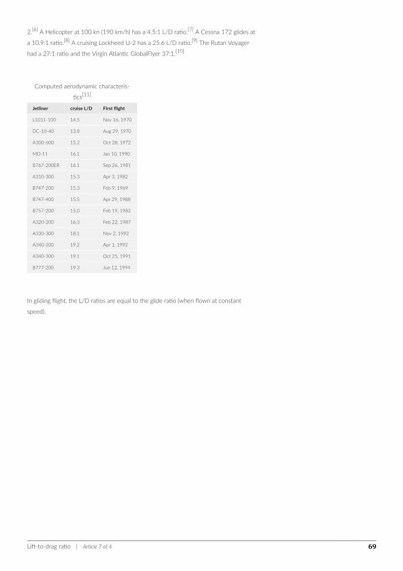
2.[6] A Helicopter at 100 kn (190 km/h) has a 4.5:1 L/D ratio.[7] A Cessna 172 glides at
a 10.9:1 ratio.[8] A cruising Lockheed U-2 has a 25.6 L/D ratio.[9] The Rutan Voyager
had a 27:1 ratio and the Virgin Atlantic GlobalFlyer 37:1.[10]
Computed aerodynamic characteris-
tics[11]
Jetliner cruise L/D First flight
L1011-100 14.5 Nov 16, 1970
DC-10-40 13.8 Aug 29, 1970
A300-600 15.2 Oct 28, 1972
MD-11 16.1 Jan 10, 1990
B767-200ER 16.1 Sep 26, 1981
A310-300 15.3 Apr 3, 1982
B747-200 15.3 Feb 9, 1969
B747-400 15.5 Apr 29, 1988
B757-200 15.0 Feb 19, 1982
A320-200 16.3 Feb 22, 1987
A330-300 18.1 Nov 2, 1992
A340-200 19.2 Apr 1, 1992
A340-300 19.1 Oct 25, 1991
B777-200 19.3 Jun 12, 1994
In gliding flight, the L/D ratios are equal to the glide ratio (when flown at constant
speed).
Lift-to-drag ratio | Article 7 of 4 69
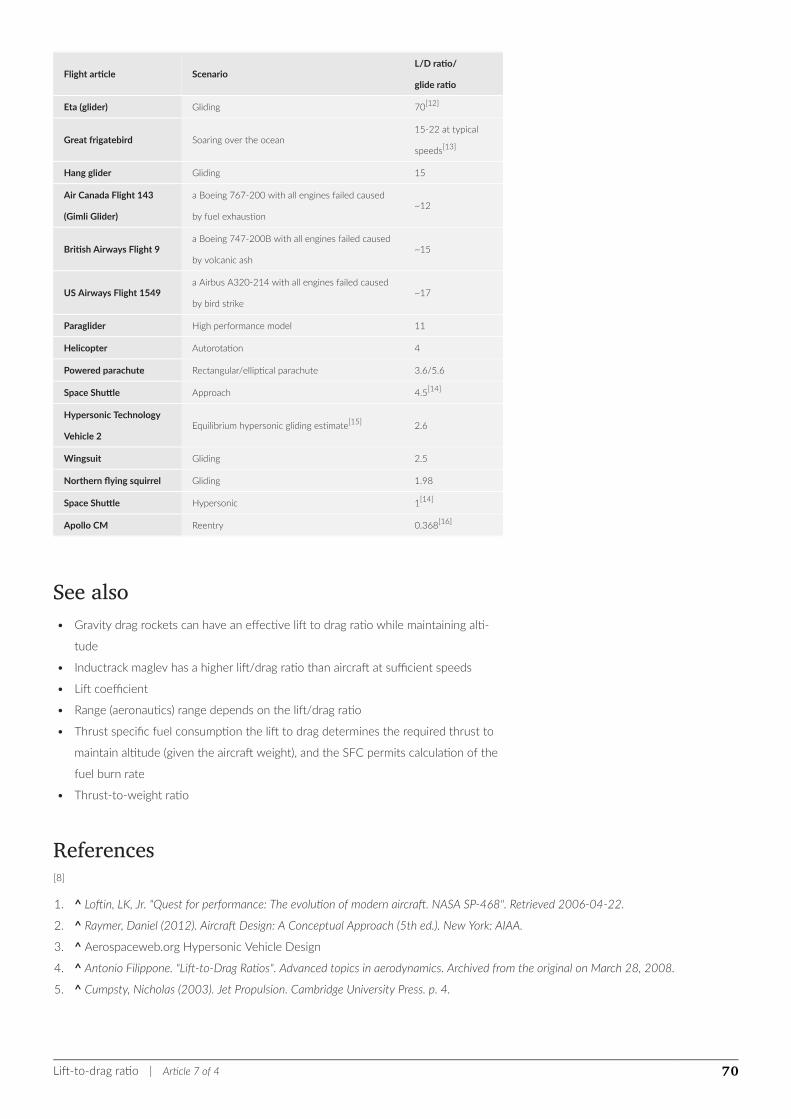
Flight article ScenarioL/D ratio/
glide ratio
Eta (glider) Gliding 70[12]
Great frigatebird Soaring over the ocean15-22 at typical
speeds[13]
Hang glider Gliding 15
Air Canada Flight 143
(Gimli Glider)
a Boeing 767-200 with all engines failed caused
by fuel exhaustion~12
British Airways Flight 9a Boeing 747-200B with all engines failed caused
by volcanic ash~15
US Airways Flight 1549a Airbus A320-214 with all engines failed caused
by bird strike~17
Paraglider High performance model 11
Helicopter Autorotation 4
Powered parachute Rectangular/elliptical parachute 3.6/5.6
Space Shuttle Approach 4.5[14]
Hypersonic Technology
Vehicle 2Equilibrium hypersonic gliding estimate[15] 2.6
Wingsuit Gliding 2.5
Northern flying squirrel Gliding 1.98
Space Shuttle Hypersonic 1[14]
Apollo CM Reentry 0.368[16]
See also• Gravity drag rockets can have an effective lift to drag ratio while maintaining alti-
tude
• Inductrack maglev has a higher lift/drag ratio than aircraft at sufficient speeds
• Lift coefficient
• Range (aeronautics) range depends on the lift/drag ratio
• Thrust specific fuel consumption the lift to drag determines the required thrust to
maintain altitude (given the aircraft weight), and the SFC permits calculation of the
fuel burn rate
• Thrust-to-weight ratio
References[8]
1. ^ Loftin, LK, Jr. "Quest for performance: The evolution of modern aircraft. NASA SP-468". Retrieved 2006-04-22.
2. ^ Raymer, Daniel (2012). Aircraft Design: A Conceptual Approach (5th ed.). New York: AIAA.
3. ^ Aerospaceweb.org Hypersonic Vehicle Design
4. ^ Antonio Filippone. "Lift-to-Drag Ratios". Advanced topics in aerodynamics. Archived from the original on March 28, 2008.
5. ^ Cumpsty, Nicholas (2003). Jet Propulsion. Cambridge University Press. p. 4.
Lift-to-drag ratio | Article 7 of 4 70

6. ^ Christopher Orlebar (1997). The Concorde Story. Osprey Publishing. p. 116. ISBN 9781855326675.
7. ^ Leishman, J. Gordon (24 April 2006). Principles of helicopter aerodynamics. Cambridge University Press. p. 230. ISBN 0521858607.
“The maximum lift-to-drag ratio of the complete helicopter is about 4.5”
8. ^ a b Cessna Skyhawk II Performance Assessment http://temporal.com.au/c172.pdf
9. ^ "U2 Developments transcript". Central Intelligence Agency. 1960. Lay summary – transcript.
10. ^ David Noland (February 2005). "The Ultimate Solo". Popular Mechanics.
11. ^ Rodrigo Martínez-Val; et al. (January 2005). "Historical evolution of air transport productivity and efficiency". 43rd AIAA Aerospace
Sciences Meeting and Exhibit. doi:10.2514/6.2005-121.
12. ^ Eta aircraft Eta aircraft performances plots - accessed 2004-04-11
13. ^ Flight performance of the largest volant bird
14. ^ a b Space Shuttle Technical Conference pg 258
15. ^ http://scienceandglobalsecurity.org/archive/2015/09/hypersonic_boost-glide_weapons.html
16. ^ Hillje, Ernest R., "Entry Aerodynamics at Lunar Return Conditions Obtained from the Flight of Apollo 4 (AS-501)," NASA TN
D-5399, (1969).
Lift-to-drag ratio | Article 7 of 4 71
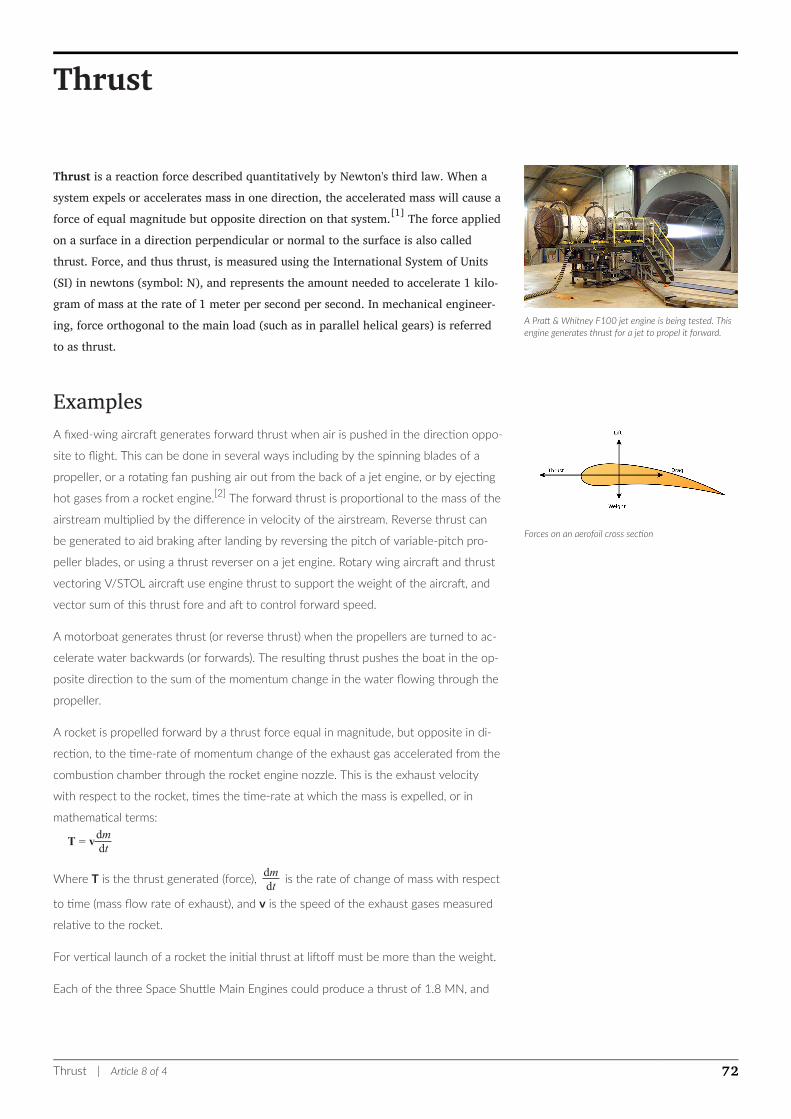
A Pratt & Whitney F100 jet engine is being tested. Thisengine generates thrust for a jet to propel it forward.
Forces on an aerofoil cross section
Thrust
Thrust is a reaction force described quantitatively by Newton's third law. When asystem expels or accelerates mass in one direction, the accelerated mass will cause aforce of equal magnitude but opposite direction on that system.[1] The force appliedon a surface in a direction perpendicular or normal to the surface is also calledthrust. Force, and thus thrust, is measured using the International System of Units(SI) in newtons (symbol: N), and represents the amount needed to accelerate 1 kilo-gram of mass at the rate of 1 meter per second per second. In mechanical engineer-ing, force orthogonal to the main load (such as in parallel helical gears) is referredto as thrust.
ExamplesA fixed-wing aircraft generates forward thrust when air is pushed in the direction oppo-
site to flight. This can be done in several ways including by the spinning blades of a
propeller, or a rotating fan pushing air out from the back of a jet engine, or by ejecting
hot gases from a rocket engine.[2] The forward thrust is proportional to the mass of the
airstream multiplied by the difference in velocity of the airstream. Reverse thrust can
be generated to aid braking after landing by reversing the pitch of variable-pitch pro-
peller blades, or using a thrust reverser on a jet engine. Rotary wing aircraft and thrust
vectoring V/STOL aircraft use engine thrust to support the weight of the aircraft, and
vector sum of this thrust fore and aft to control forward speed.
A motorboat generates thrust (or reverse thrust) when the propellers are turned to ac-
celerate water backwards (or forwards). The resulting thrust pushes the boat in the op-
posite direction to the sum of the momentum change in the water flowing through the
propeller.
A rocket is propelled forward by a thrust force equal in magnitude, but opposite in di-
rection, to the time-rate of momentum change of the exhaust gas accelerated from the
combustion chamber through the rocket engine nozzle. This is the exhaust velocity
with respect to the rocket, times the time-rate at which the mass is expelled, or in
mathematical terms:
T = vdmdt
Where T is the thrust generated (force), dmdt
is the rate of change of mass with respect
to time (mass flow rate of exhaust), and v is the speed of the exhaust gases measured
relative to the rocket.
For vertical launch of a rocket the initial thrust at liftoff must be more than the weight.
Each of the three Space Shuttle Main Engines could produce a thrust of 1.8 MN, and
Thrust | Article 8 of 4 72
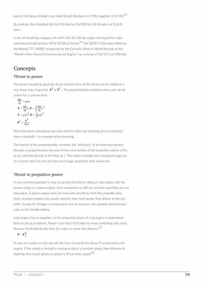
each of the Space Shuttle's two Solid Rocket Boosters 14.7 MN, together 29.4 MN.[3]
By contrast, the simplified Aid For EVA Rescue (SAFER) has 24 thrusters of 3.56 N
each.
In the air-breathing category, the AMT-USA AT-180 jet engine developed for radio-
controlled aircraft produce 90 N (20 lbf) of thrust.[4] The GE90-115B engine fitted on
the Boeing 777-300ER, recognized by the Guinness Book of World Records as the
"World's Most Powerful Commercial Jet Engine," has a thrust of 569 kN (127,900 lbf).
ConceptsThrust to powerThe power needed to generate thrust and the force of the thrust can be related in a
non-linear way. In general, P2 ∝ T3 . The proportionality constant varies, and can be
solved for a uniform flow:dmdt= ρAv
T =dmdtv,P =
12dmdtv2
T = ρAv2,P =12ρAv
3
P2 =T3
4ρA
Note that these calculations are only valid for when the incoming air is accelerated
from a standstill - for example when hovering.
The inverse of the proportionality constant, the "efficiency" of an otherwise-perfect
thruster, is proportional to the area of the cross section of the propelled volume of flu-
id ( A ) and the density of the fluid ( ρ ). This helps to explain why moving through wa-
ter is easier and why aircraft have much larger propellers than watercraft.
Thrust to propulsive powerA very common question is how to contrast the thrust rating of a jet engine with the
power rating of a piston engine. Such comparison is difficult, as these quantities are not
equivalent. A piston engine does not move the aircraft by itself (the propeller does
that), so piston engines are usually rated by how much power they deliver to the pro-
peller. Except for changes in temperature and air pressure, this quantity depends basi-
cally on the throttle setting.
A jet engine has no propeller, so the propulsive power of a jet engine is determined
from its thrust as follows. Power is the force (F) it takes to move something over some
distance (d) divided by the time (t) it takes to move that distance:[5]
P = Fdt
In case of a rocket or a jet aircraft, the force is exactly the thrust (T) produced by the
engine. If the rocket or aircraft is moving at about a constant speed, then distance di-
vided by time is just speed, so power is thrust times speed:[6]
Thrust | Article 8 of 4 73
P = Tv
This formula looks very surprising, but it is correct: the propulsive power (or power avail-
able [7]) of a jet engine increases with its speed. If the speed is zero, then the propulsive
power is zero. If a jet aircraft is at full throttle but attached to a static test stand, then
the jet engine produces no propulsive power, however thrust is still produced. Com-
pare that to a piston engine. The combination piston engine–propeller also has a
propulsive power with exactly the same formula, and it will also be zero at zero speed
–- but that is for the engine–propeller set. The engine alone will continue to produce
its rated power at a constant rate, whether the aircraft is moving or not.
Now, imagine the strong chain is broken, and the jet and the piston aircraft start to
move. At low speeds:
The piston engine will have constant 100% power, and the propeller's thrust will vary with speedThe jet engine will have constant 100% thrust, and the engine's power will vary with speed
Excess thrustIf a powered aircraft is generating thrust T and experiencing drag D, the difference be-
tween the two, T — D, is termed the excess thrust. The instantaneous performance of
the aircraft is mostly dependent on the excess thrust.
Excess thrust is a vector and is determined as the vector difference between the thrust
vector and the drag vector.
Centre of thrustThe centre of thrust for an object is an average point at which the total thrust may be
considered to apply. It may differ from the centre of gravity.
See also• Aerodynamic force
• Astern propulsion
• Gimballed thrust, the most common thrust system in modern rockets
• Stream thrust averaging
• Thrust-to-weight ratio
• Thrust vectoring
• Tractive effort
References1. ^ "What is Thrust?". www.grc.nasa.gov. Retrieved 16 February 2018.
2. ^ "Newton's Third Law of Motion". www.grc.nasa.gov. Retrieved 16 February 2018.
3. ^ "Space Launchers - Space Shuttle". www.braeunig.us. Retrieved 16 February 2018.
4. ^ "AMT-USA jet engine product information". Archived from the original on 2006-11-10. Retrieved 2006-12-13.
Thrust | Article 8 of 4 74

5. ^ "Convert Thrust to Horsepower By Joe Yoon". Retrieved 2009-05-01.
6. ^ "Introduction to Aircraft Flight Mechanics", Yechout & Morris
7. ^ "Understanding Flight", Anderson & Eberbaht
Thrust | Article 8 of 4 75
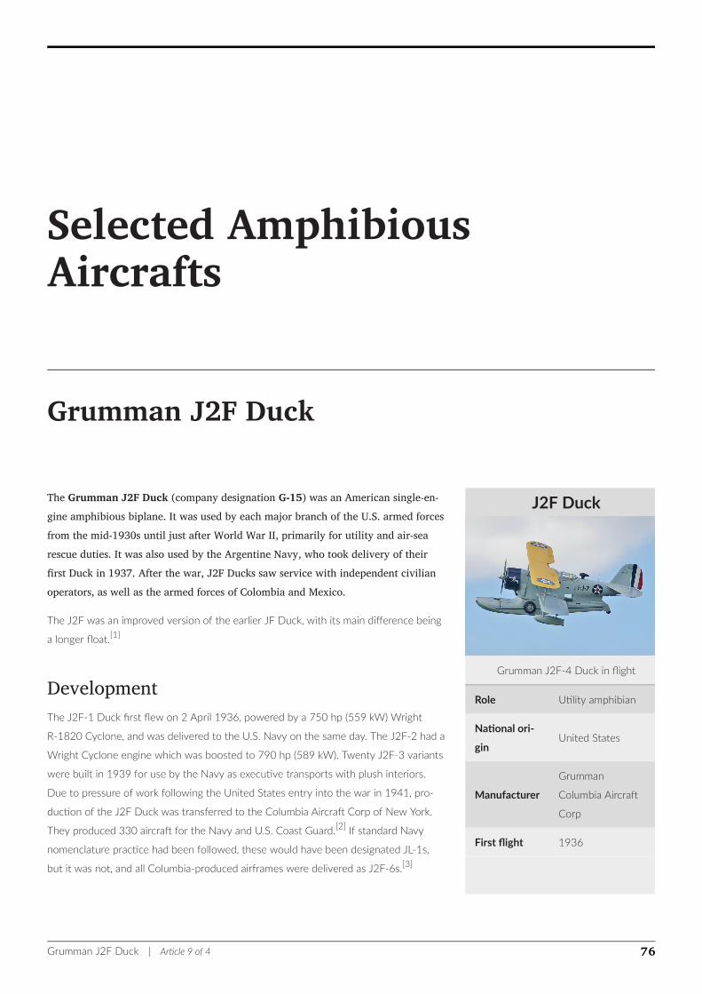
J2F Duck
Grumman J2F-4 Duck in flight
Role Utility amphibian
National ori-
ginUnited States
Manufacturer
Grumman
Columbia Aircraft
Corp
First flight 1936
Selected AmphibiousAircrafts
Grumman J2F Duck
The Grumman J2F Duck (company designation G-15) was an American single-en-gine amphibious biplane. It was used by each major branch of the U.S. armed forcesfrom the mid-1930s until just after World War II, primarily for utility and air-searescue duties. It was also used by the Argentine Navy, who took delivery of theirfirst Duck in 1937. After the war, J2F Ducks saw service with independent civilianoperators, as well as the armed forces of Colombia and Mexico.
The J2F was an improved version of the earlier JF Duck, with its main difference being
a longer float.[1]
DevelopmentThe J2F-1 Duck first flew on 2 April 1936, powered by a 750 hp (559 kW) Wright
R-1820 Cyclone, and was delivered to the U.S. Navy on the same day. The J2F-2 had a
Wright Cyclone engine which was boosted to 790 hp (589 kW). Twenty J2F-3 variants
were built in 1939 for use by the Navy as executive transports with plush interiors.
Due to pressure of work following the United States entry into the war in 1941, pro-
duction of the J2F Duck was transferred to the Columbia Aircraft Corp of New York.
They produced 330 aircraft for the Navy and U.S. Coast Guard.[2] If standard Navy
nomenclature practice had been followed, these would have been designated JL-1s,
but it was not, and all Columbia-produced airframes were delivered as J2F-6s.[3]
Grumman J2F Duck | Article 9 of 4 76
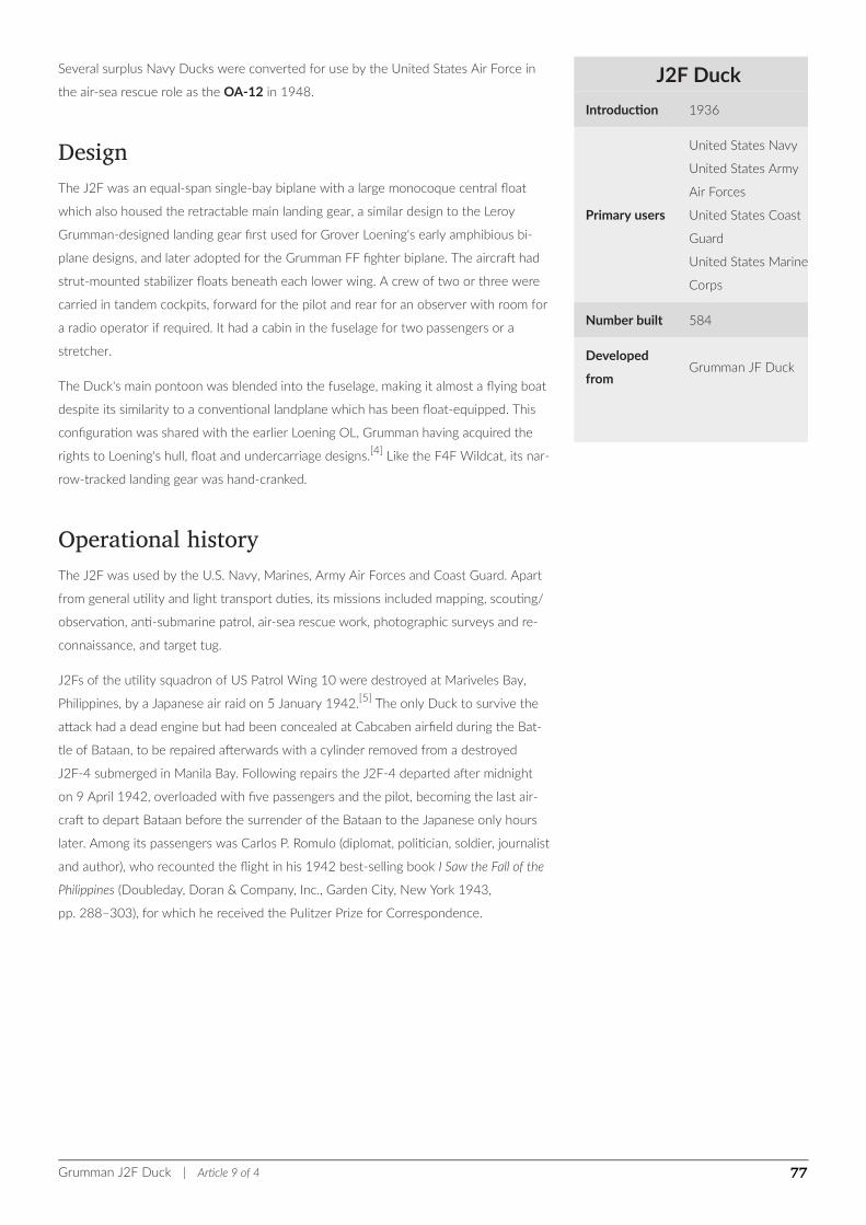
J2F Duck
Introduction 1936
Primary users
United States Navy
United States Army
Air Forces
United States Coast
Guard
United States Marine
Corps
Number built 584
Developed
fromGrumman JF Duck
Several surplus Navy Ducks were converted for use by the United States Air Force in
the air-sea rescue role as the OA-12 in 1948.
DesignThe J2F was an equal-span single-bay biplane with a large monocoque central float
which also housed the retractable main landing gear, a similar design to the Leroy
Grumman-designed landing gear first used for Grover Loening's early amphibious bi-
plane designs, and later adopted for the Grumman FF fighter biplane. The aircraft had
strut-mounted stabilizer floats beneath each lower wing. A crew of two or three were
carried in tandem cockpits, forward for the pilot and rear for an observer with room for
a radio operator if required. It had a cabin in the fuselage for two passengers or a
stretcher.
The Duck's main pontoon was blended into the fuselage, making it almost a flying boat
despite its similarity to a conventional landplane which has been float-equipped. This
configuration was shared with the earlier Loening OL, Grumman having acquired the
rights to Loening's hull, float and undercarriage designs.[4] Like the F4F Wildcat, its nar-
row-tracked landing gear was hand-cranked.
Operational historyThe J2F was used by the U.S. Navy, Marines, Army Air Forces and Coast Guard. Apart
from general utility and light transport duties, its missions included mapping, scouting/
observation, anti-submarine patrol, air-sea rescue work, photographic surveys and re-
connaissance, and target tug.
J2Fs of the utility squadron of US Patrol Wing 10 were destroyed at Mariveles Bay,
Philippines, by a Japanese air raid on 5 January 1942.[5] The only Duck to survive the
attack had a dead engine but had been concealed at Cabcaben airfield during the Bat-
tle of Bataan, to be repaired afterwards with a cylinder removed from a destroyed
J2F-4 submerged in Manila Bay. Following repairs the J2F-4 departed after midnight
on 9 April 1942, overloaded with five passengers and the pilot, becoming the last air-
craft to depart Bataan before the surrender of the Bataan to the Japanese only hours
later. Among its passengers was Carlos P. Romulo (diplomat, politician, soldier, journalist
and author), who recounted the flight in his 1942 best-selling book I Saw the Fall of the
Philippines (Doubleday, Doran & Company, Inc., Garden City, New York 1943,
pp. 288–303), for which he received the Pulitzer Prize for Correspondence.
Grumman J2F Duck | Article 9 of 4 77
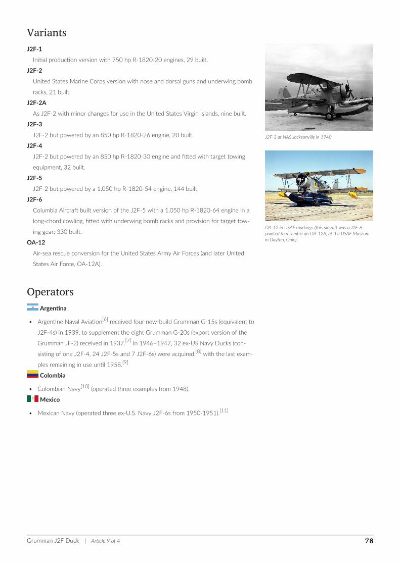
J2F-3 at NAS Jacksonville in 1940
OA-12 in USAF markings (this aircraft was a J2F-6painted to resemble an OA-12A, at the USAF Museumin Dayton, Ohio).
VariantsJ2F-1
Initial production version with 750 hp R-1820-20 engines, 29 built.
J2F-2
United States Marine Corps version with nose and dorsal guns and underwing bomb
racks, 21 built.
J2F-2A
As J2F-2 with minor changes for use in the United States Virgin Islands, nine built.
J2F-3
J2F-2 but powered by an 850 hp R-1820-26 engine, 20 built.
J2F-4
J2F-2 but powered by an 850 hp R-1820-30 engine and fitted with target towing
equipment, 32 built.
J2F-5
J2F-2 but powered by a 1,050 hp R-1820-54 engine, 144 built.
J2F-6
Columbia Aircraft built version of the J2F-5 with a 1,050 hp R-1820-64 engine in a
long-chord cowling, fitted with underwing bomb racks and provision for target tow-
ing gear; 330 built.
OA-12
Air-sea rescue conversion for the United States Army Air Forces (and later United
States Air Force, OA-12A).
OperatorsArgentina
• Argentine Naval Aviation[6] received four new-build Grumman G-15s (equivalent to
J2F-4s) in 1939, to supplement the eight Grumman G-20s (export version of the
Grumman JF-2) received in 1937.[7] In 1946–1947, 32 ex-US Navy Ducks (con-
sisting of one J2F-4, 24 J2F-5s and 7 J2F-6s) were acquired,[8] with the last exam-
ples remaining in use until 1958.[9]
Colombia
• Colombian Navy[10] (operated three examples from 1948).
Mexico
• Mexican Navy (operated three ex-U.S. Navy J2F-6s from 1950-1951).[11]
Grumman J2F Duck | Article 9 of 4 78
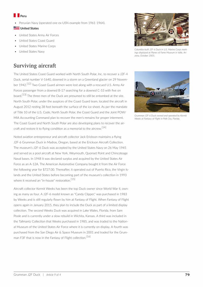
Columbia-built J2F-6 Duck in U.S. Marine Corps mark-ings displayed at Planes of Fame Museum in Valle, Ari-zona, October 2005.
Grumman J2F-6 Duck owned and operated by KermitWeeks at Fantasy of Flight in Polk City, Florida.
Peru
• Peruvian Navy (operated one ex-USN example from 1961-1964).
United States
• United States Army Air Forces
• United States Coast Guard
• United States Marine Corps
• United States Navy
Surviving aircraftThe United States Coast Guard worked with North South Polar, Inc. to recover a J2F-4
Duck, serial number V-1640, downed in a storm on a Greenland glacier on 29 Novem-
ber 1942.[12] Two Coast Guard airmen were lost along with a rescued U.S. Army Air
Forces passenger from a downed B-17 searching for a downed C-53 with five on
board.[13] The three men of the Duck are presumed to still be entombed at the site.
North South Polar, under the auspices of the Coast Guard team, located the aircraft in
August 2012 resting 38 feet beneath the surface of the ice sheet. As per the mandate
of Title 10 of the U.S. Code, North South Polar, the Coast Guard and the Joint POW/
MIA Accounting Command plan to recover the men's remains for proper interment.
The Coast Guard and North South Polar are also developing plans to recover the air-
craft and restore it to flying condition as a memorial to the aircrew.[14]
Noted aviation entrepreneur and aircraft collector Jack Erickson maintains a flying
J2F-6 Grumman Duck in Madras, Oregon, based at the Erickson Aircraft Collection.
The museum’s J2F-6 Duck was accepted by the United States Navy on 26 May 1945
and served as a pool aircraft at New York, Weymouth, Quonset Point and Chincoteage
Naval bases. In 1948 it was declared surplus and acquired by the United States Air
Force as an A-12A. The American Automotive Company bought it from the Air Force
the following year for $727.00. Thereafter, it operated out of Puerto Rico, the Virgin Is-
lands and the United States before becoming part of the museum’s collection in 1993
where it received an "in-house" restoration.[15]
Aircraft collector Kermit Weeks has been the top Duck owner since World War II, own-
ing as many as four. A J2F-6 model known as "Candy Clipper," was purchased in 1983
by Weeks and is still regularly flown by him at Fantasy of Flight. When Fantasy of Flight
opens again in January 2015, they plan to include the Duck as part of a limited display
collection. The second Weeks Duck was acquired in Lake Wales, Florida, from Sam
Poole and is currently under a slow rebuild in Wichita, Kansas. A third was included in
the Tallmantz Collection that Weeks purchased in 1985, and was traded to the Nation-
al Museum of the United States Air Force where it is currently on display. A fourth was
purchased from the San Diego Air & Space Museum in 2001 and traded for the Grum-
man F3F that is now in the Fantasy of Flight collection.[16]
Grumman J2F Duck | Article 9 of 4 79

Specifications (J2F-6)Data from Jane’s Fighting Aircraft of World War II[17]
General characteristics
• Crew: two (pilot and observer)
• Capacity: two rescued airmen
• Length: 34 ft 0 in (10.37 m)
• Wingspan: 39 ft 0 in (11.9 m)
• Height: 13 ft 11 in (4.25 m)
• Wing area: 409 ft² (38 m²)
• Empty weight: 5,480 lb (2,485 kg)
• Loaded weight: 7,700 lb (3,496 kg)
• Powerplant: 1 × Wright R-1820-54 nine-cylinder radial engine, 900 hp (670 kW)
Performance
• Maximum speed: 190 mph (304 km/h)
• Cruise speed: 155 mph (248 km/h)
• Stall speed: 70 mph (112 km/h)
• Range: 780 mi (1,255 km)
• Service ceiling: 20,000 ft (6,100 m)
• Rate of climb: ft/min (m/s)
Armament
• 1 × Browning .30 cal machine gun (7.62 mm) on flexible mount in rear cockpit
• 650 lb (295 kg) of bombs or depth charges
Popular culture• A J2F Duck was used in the 1971 film Murphy's War, which includes a spectacular
three-minute rough water takeoff scene along with numerous flying and aerobatic
sequences. The actual airplane used in this film is on display at the National Muse-
um of the United States Air Force near Dayton, Ohio; although it has been restored
and painted to represent a rescue OA-12.
• A Grumman Duck was also seen in several episodes of the 1970s TV series Baa
Baa Black Sheep, (aka Black Sheep Squadron) based on the legendary exploits of
Marine fighter squadron VMF-214.
See alsoRelated development
• Grumman JF Duck
Aircraft of comparable role, configuration and era
• Loening OL
Grumman J2F Duck | Article 9 of 4 80
Related lists
• List of aircraft of World War II
ReferencesNotes1. ^ Allen 1983, p. 49.
2. ^ Jordan, Corey C. "Grumman's Ascendency: Chapter Two." Archived 2012-03-25 at the Wayback Machine. Planes and Pilots Of
World War Two, 2000. Retrieved: 22 July 2011.
3. ^ Swanborough, Gordon, and Bowers, Peter M., "United States Navy Aircraft since 1911", Naval Institute Press, Annapolis, Mary-
land, 1976, Library of Congress card number 90-60097, ISBN 0-87021-792-5, page 221.
4. ^ Allen 1983, p. 47.
5. ^ Alsleben, Allan. "US Patrol Wing 10 in the Dutch East Indies, 1942." Forgotten Campaign: The Dutch East Indies Campaign
1941-1942, 2000. Retrieved: 22 July 2011.
6. ^ Nuñez Padin, 2002
7. ^ Lezon and Stitt 2003, pp. 41–42, 44–45
8. ^ Lezon and Stitt 2004, pp. 48–49.
9. ^ Lezon and Stitt 2004, p. 59.
10. ^ Allen 1983, p.77
11. ^ Allen 1983, p. 52.
12. ^ Zuckoff, pp 40-47
13. ^ Coast Guard announces WWII Coast Guard Grumman Duck crash site located after 70 years Archived 2013-07-06 at the
Wayback Machine.
14. ^ Mungier, Monique. "Race to Find Aviators Entombed in Greenland Glacier." The New York Times, 20 September 2010. Re-
trieved: 24 September 2010.
15. ^ http://www.ericksoncollection.com/aircraft/#/grumman-j2f-6-duck/
16. ^ "Fantasy of Flight's Facebook Page" Retrieved: 8 December 2014.
17. ^ Bridgeman 1946, pp. 235–236.
Bibliography• Allen, Francis J. "A Duck Without Feathers". Air Enthusiast. Issue 23, December 1983—March 1984, pp. 46–55, 77–78. Bromley,
Kent UK: Pilot Press, 1983.
• Bridgeman, Leonard. “ The Grumman Duck .” Jane's Fighting Aircraft of World War II. London: Studio, 1946. ISBN 1-85170-493-0.
• Hosek, Timothy. Grumman JF Duck - Mini in Action 7. Carrollton, Texas: Squadron/Signal Publications Inc., 1996. IS-
BN 0-89747-366-3.
• Jarski, Adam. Grumman JF/J2F Duck (Monografie Lotnicze 98) (in Polish with English captions). Gdańsk, Poland: AJ-Press, 2007. IS-
BN 978-83-7237-169-0.
• Lezon, Ricardo Martin and Robert M. Stitt. "Eyes of the Fleet:Seaplanes in Argentine Navy Service: Part one". Air Enthusiast. Issue
108, November/December 2003. pp. 34–45.
• Lezon, Ricardo Martin and Robert M. Stitt. "Eyes of the Fleet:Seaplanes in Argentine Navy Service: Part two". Air Enthusiast. Issue
10, January/February 2004. pp. 46–59.
• Nuñez Padin, Jorge Félix. Grumman G.15, G.20 & J2F Duck (Serie Aeronaval Nro. 15) (in Spanish). Buenos Aires, Argentina: Museo
de Aviación Naval, Instituto Naval, 2002.
Grumman J2F Duck | Article 9 of 4 81

• Zuckoff, Mitchell (2013). Frozen in Time. New York, New York: HarperCollins. ISBN 978-0-06-213343-4.
Further reading• Ginter, Steve (2009). Grumman JF/J2F Duck. Naval Fighters. Nº84 (First ed.). Califor-
nia, United States: Ginter Books. ISBN 0-942612-84-1. Retrieved 31 January 2015.
External links
Wikimedia Commons has media related to Grumman J2F Duck.
• (1945) NAVAER 01-220QA-1 Pilot's Handbook of Flight Operating Instructions
Navy Model J2F-6 Airplane
• Histarmar website, Grumman J2F5/6 page (retrieved 2015-01-31)
• Histarmar website, Grumman G-15/20 page (retrieved 2015-01-31)
Grumman J2F Duck | Article 9 of 4 82
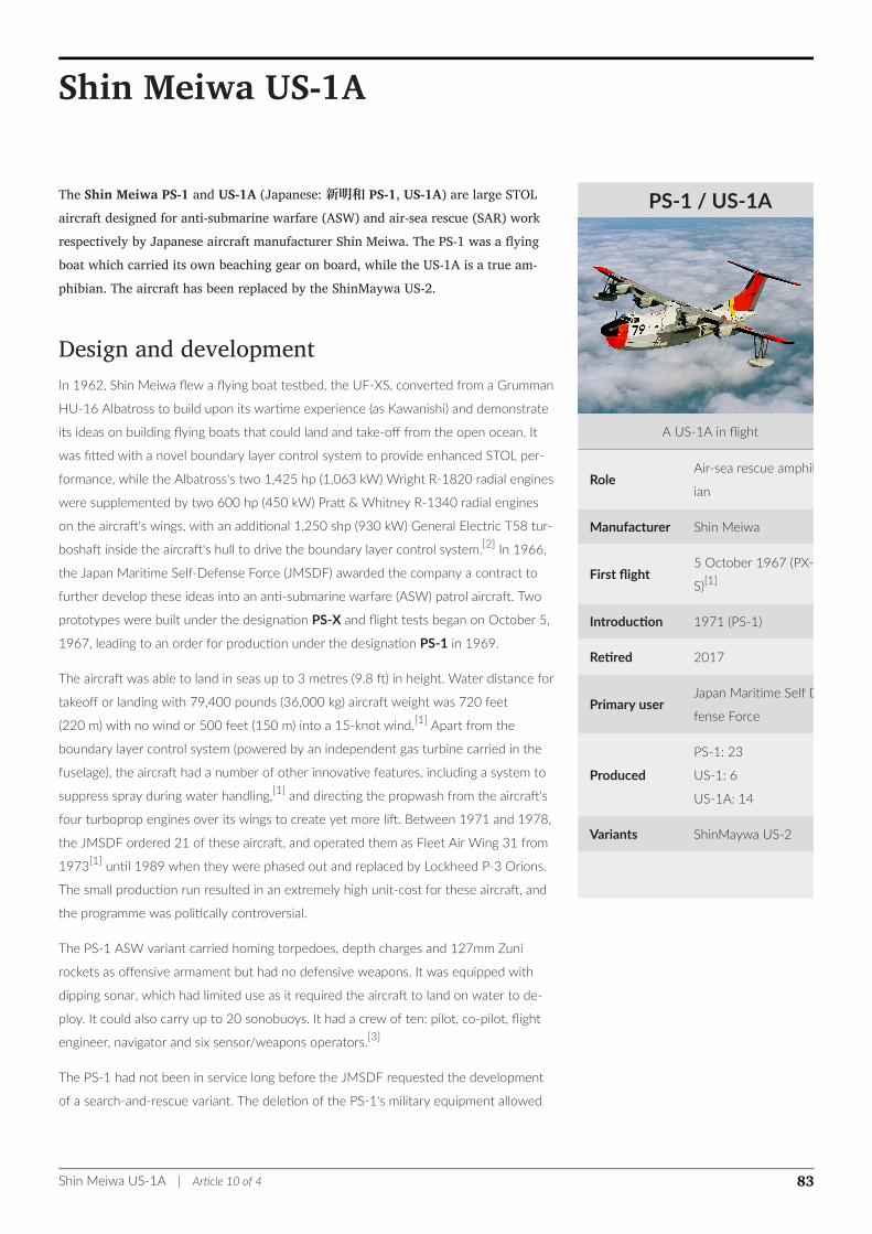
PS-1 / US-1A
A US-1A in flight
RoleAir-sea rescue amphib-
ian
Manufacturer Shin Meiwa
First flight5 October 1967 (PX-
S)[1]
Introduction 1971 (PS-1)
Retired 2017
Primary userJapan Maritime Self De-
fense Force
Produced
PS-1: 23
US-1: 6
US-1A: 14
Variants ShinMaywa US-2
Shin Meiwa US-1A
The Shin Meiwa PS-1 and US-1A (Japanese: 新明和 PS-1, US-1A) are large STOLaircraft designed for anti-submarine warfare (ASW) and air-sea rescue (SAR) workrespectively by Japanese aircraft manufacturer Shin Meiwa. The PS-1 was a flyingboat which carried its own beaching gear on board, while the US-1A is a true am-phibian. The aircraft has been replaced by the ShinMaywa US-2.
Design and developmentIn 1962, Shin Meiwa flew a flying boat testbed, the UF-XS, converted from a Grumman
HU-16 Albatross to build upon its wartime experience (as Kawanishi) and demonstrate
its ideas on building flying boats that could land and take-off from the open ocean. It
was fitted with a novel boundary layer control system to provide enhanced STOL per-
formance, while the Albatross's two 1,425 hp (1,063 kW) Wright R-1820 radial engines
were supplemented by two 600 hp (450 kW) Pratt & Whitney R-1340 radial engines
on the aircraft's wings, with an additional 1,250 shp (930 kW) General Electric T58 tur-
boshaft inside the aircraft's hull to drive the boundary layer control system.[2] In 1966,
the Japan Maritime Self-Defense Force (JMSDF) awarded the company a contract to
further develop these ideas into an anti-submarine warfare (ASW) patrol aircraft. Two
prototypes were built under the designation PS-X and flight tests began on October 5,
1967, leading to an order for production under the designation PS-1 in 1969.
The aircraft was able to land in seas up to 3 metres (9.8 ft) in height. Water distance for
takeoff or landing with 79,400 pounds (36,000 kg) aircraft weight was 720 feet
(220 m) with no wind or 500 feet (150 m) into a 15-knot wind.[1] Apart from the
boundary layer control system (powered by an independent gas turbine carried in the
fuselage), the aircraft had a number of other innovative features, including a system to
suppress spray during water handling,[1] and directing the propwash from the aircraft's
four turboprop engines over its wings to create yet more lift. Between 1971 and 1978,
the JMSDF ordered 21 of these aircraft, and operated them as Fleet Air Wing 31 from
1973[1] until 1989 when they were phased out and replaced by Lockheed P-3 Orions.
The small production run resulted in an extremely high unit-cost for these aircraft, and
the programme was politically controversial.
The PS-1 ASW variant carried homing torpedoes, depth charges and 127mm Zuni
rockets as offensive armament but had no defensive weapons. It was equipped with
dipping sonar, which had limited use as it required the aircraft to land on water to de-
ploy. It could also carry up to 20 sonobuoys. It had a crew of ten: pilot, co-pilot, flight
engineer, navigator and six sensor/weapons operators.[3]
The PS-1 had not been in service long before the JMSDF requested the development
of a search-and-rescue variant. The deletion of the PS-1's military equipment allowed
Shin Meiwa US-1A | Article 10 of 4 83
for greater fuel capacity, workable landing gear, and rescue equipment. The new vari-
ant, the US-1A, could also quickly be converted for troop-carrying duties. First flown
on October 15, 1974, it was accepted into service the following year, and eventually
19 aircraft were purchased. From the seventh aircraft on, an uprated version of the
original engine was used, but all aircraft were eventually modified to this US-1A stan-
dard. The US-1A's first rescue was from a Greek vessel in 1976. Between that time and
1999, US-1As had been used in over 500 rescues, saving 550 lives.[4]
In 1976, one PS-1 was experimentally modified for aerial firefighting, with an internal
capacity of 7,350 litres (1,940 US gal) of water.[5]
With the US-1A fleet beginning to show its age, the JMSDF attempted to obtain fund-
ing for a replacement in the 1990s, but could not obtain enough to develop an entirely
new aircraft. Therefore, in 1995, ShinMaywa (as Shin Meiwa was by then renamed) be-
gan plans for an upgraded version of the US-1A, the US-1A kai (US-1A 改 - "improved
US-1A"). This aircraft features numerous aerodynamic refinements, a pressurised hull,
and more powerful Rolls-Royce AE 2100 engines. Flight tests began on December 18,
2003. The JMSDF purchased up to 14 of these aircraft, which entered service as the
ShinMaywa US-2.
The US-1A was retired on December 13, 2017 when the last example in JMSDF ser-
vice made its final flight. A total of 827 people have been recued by US-1s since the
type entered service in 1976.[6]
Concept aircraft not builtIn 1977 Shin Meiwa had several ideas for its STOL flying boat concept on the drawing
board but none were ever built. They were the Shin Meiwa LA (Light Amphibian), a
40-passenger light amphibian for inter-island feeder service; the 400-passenger Shin
Meiwa MA (Medium Amphibian); the Shin Meiwa MS (Medium Seaplane) a 300-pas-
senger long-range flying boat with its own beaching gear; and the gargantuan Shin
Meiwa GS (Giant Seaplane) with a capacity of an astonishing 1200 passengers seated
on three decks. Unlike the Shin Meiwa LA and MA which were like the US-1 in design,
the Shin Meiwa MS and GS had their engines located in front of and above the wing to
take advantage of the Coandă effect. In the end, none of the four designs got beyond
the drawing boards.[7]
OperatorsJapan
• Japan Maritime Self Defense Force
Specifications (US-1A)Data from Jane's All The World's Aircraft 1988-89[8]
Shin Meiwa US-1A | Article 10 of 4 84

General characteristics
• Crew: nine (pilot, co-pilot, flight engineer, navigator, radio operator, radar operator,
two observers)
• Capacity: 20 survivors or 12 stretchers (US-1 only)[1]
• Length: 33.46 m (109 ft 9¼ in)
• Wingspan: 33.15 m (108 ft 9 in)
• Height: 9.95 m (32 ft 7¾ in)
• Wing area: 135.8 m² (1,462 ft²)
• Empty weight: 23,300 kg (51,367 lb)
• Max. takeoff weight: 45,000 kg[9] (99,200 lb)
• plus 1× General Electric T58 gas turbine, 1,104 kW (1,360 shp) driving boundary
layer control system
• Powerplant: 4 × Ishikawajima-Harima/General Electric T64-IHI-10J turboprops,
2,605 kW (3,493 ehp) each
Performance
• Maximum speed: 511 km/h (276 knots, 318 mph)
• Cruise speed: 426 km/h (230 knots, 265 mph)
• Range: 3,817 km (2,060 nmi, 2,372 mi)
• Service ceiling: 7,195 m (23,600 ft)
• Rate of climb: 8.1 m/s (1,600 ft/min)
Armament
• 4 x 150 kilograms (330 lb) depth charges, 2 x Mark 44 torpedo, 6 x 127mm Zuni
rockets (PS-1 only)[1]
Avionics[1]
• APS-80J Ocean search radar
• AQS-10A Magnetic anomaly detector
• HQS-101 dipping sonar
• 20 x Sonobuoys
• AQA-5N Sonobuoy signal processors
• ASA-16 ASW display system
See alsoRelated development
• ShinMaywa US-2
Aircraft of comparable role, configuration and era
• Harbin SH-5
• Beriev Be-12
• Martin P5M Marlin
• Canadair CL-215
Shin Meiwa US-1A | Article 10 of 4 85

Related lists
• List of military aircraft of Japan
• List of flying boats
ReferencesNotes
1. ^ a b c d e f g Dean, Ralph J. (1984). "Japan's Stalwart Seaplanes". Proceedings. United States Naval Institute. 110 (3): 182&183.
2. ^ Lake Air International November 2005, p. 27.
3. ^ Bernard Fitzsimons (1978). The Illustrated encyclopedia of 20th century weapons and warfare. 20. Columbia House. p. 2149.
4. ^ "Rescue Operations". ShinMaywa Industries, Ltd. Retrieved 22 October 2014.
5. ^ Jane's All the World's Aircraft 2003-2004. Jane's Information Group. 2003. p. 313. ISBN 0-7106-2537-5.
6. ^ Fischer, Bob (February 2018). "US-1A amphibian retired". Air International. Vol. 94 no. 2. p. 17. ISSN 0306-5634.
7. ^ Paul Wahl "1200 Passengers on three decks...a come back for flying boats" Popular Mechanics November 1977, pp. 84-85
8. ^ Taylor 1988, pp.172-173.
9. ^ Operating from land - Maximum takeoff weight from water 43,000 kg (94,800 lb)
Bibliography• Lake, Jon (November 2005). "ShinMaywa's Innovative Amphibian". Air International.
Vol. 69 no. 5. pp. 26–30. ISSN 0306-5634.
• Taylor, John W. R., ed. (1988). Jane's All The World's Aircraft 1988-89. Coulsdon, UK:
Jane's Defence Data. ISBN 0-7106-0867-5.
External links
Wikimedia Commons has media related to ShinMaywa US-1.
• ShinMaywa aircraft page
• Giant Amphibian - Japan has one godzilla of a seaplane - Air & Space/Smithsonian
magazine
• The Shin Meiwa PS-1 / US-1 & Harbin SH-5 Flying Boats www.airvectors.net
Shin Meiwa US-1A | Article 10 of 4 86
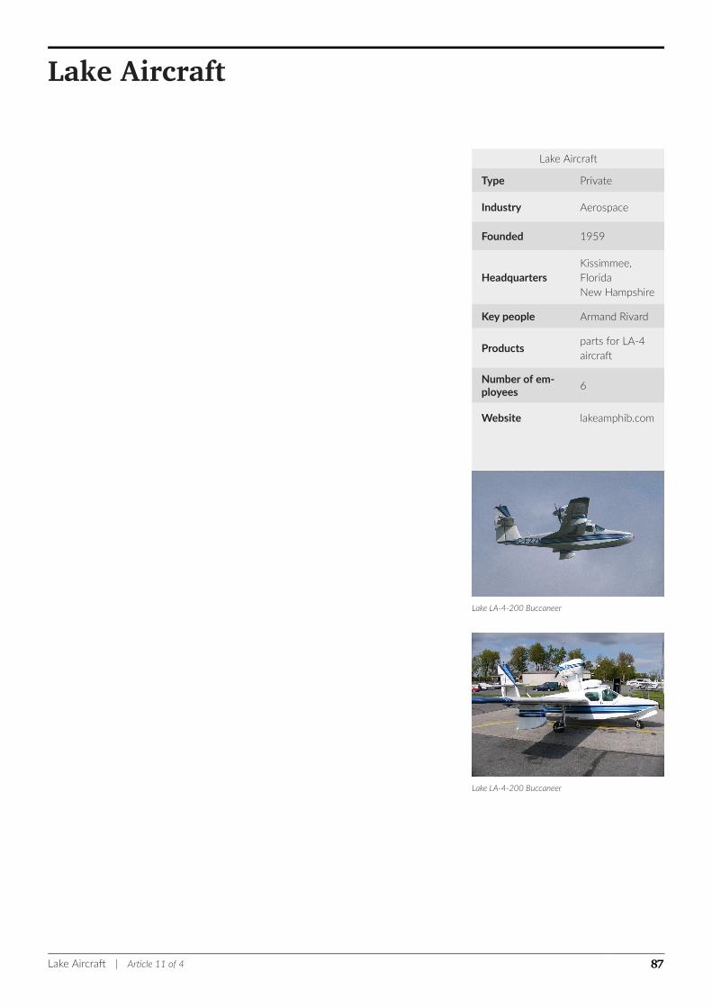
Lake Aircraft
Type Private
Industry Aerospace
Founded 1959
HeadquartersKissimmee,FloridaNew Hampshire
Key people Armand Rivard
Productsparts for LA-4aircraft
Number of em-ployees
6
Website lakeamphib.com
Lake LA-4-200 Buccaneer
Lake LA-4-200 Buccaneer
Lake Aircraft
Lake Aircraft | Article 11 of 4 87

Lake Model 250 Seawolf
Lake Aircraft was a manufacturer of amphibious aircraft. Its factory was in Sanford,Maine, USA, and its sales offices were located at Laconia / Gilford, New Hampshireand Kissimmee, Florida.
The assets of the company were sold in 2004 to an investor which incorporated as
"Sun Lake Aircraft" in Vero Beach, Florida.
The assets are now owned by Revo Inc, owned by Armand Rivard.
HistoryThe first design in the series produced was the Colonial Skimmer. It was derived from
an original design produced by David Thurston in 1946 when he was with Grumman
Aircraft. Grumman never produced the design, but Thurston formed Colonial Aircraft
Corporation as a side business to continue development.
Colonial's first amphibious aircraft, designated the "Colonial Aircraft C-1 Skimmer" and
based on the original Grumman G-65 Tadpole design, first flew in 1948. Colonial grew
to produce almost 50 of the C-1 and larger C-2 design before being sold in 1959.
The new owner, M.L. (Al) Alson, renamed the company Lake Aircraft and enlarged the
basic design again into the LA-4, a 180-horsepower, 4-seat aircraft, which was the ba-
sis for the entire line of aircraft that continues today.
Lake aircraft produced in the 1960 - 1980 range are listed by the Federal Aviation Ad-
ministration as having been built by "Consolidated Aeronautics."
For many years the Lake LA-4-200 was advertised as "The world's only single-engine
production amphibian."
In January 2009 company owner Armand Rivard indicated that he intended to sell the
company and retire. The company had previously been offered for sale in 2001, 2002,
via auction in 2005 and in 2007. Lake Aircraft produced one aircraft in 2007 and none
in 2008, but continues to make parts for existing aircraft. In 2009 the company em-
ployed six people, down from the 200 employees that it had in the 1980s.[1]
Lake Aircraft | Article 11 of 4 88

Evolution of Lake Amphibious Aircraft
Years Pro-
ducedModel seats Horsepower
Max
Cruise
Speed
Payload with
Main Full Fuel
1948–1959 C1 and C2 2 150-180 90 mph 340 lb payload
1960–1969 Lake LA-4 4 180 110 mph 440 lb
1970–1982 Lake LA4-200 4 200 105 knots 500 lb
1982–1985 Lake LA4-200 EP 4 200 110 knots 550 lb
1984–1995 Lake Model 250 6 250 132 knots 800 lb
1987–2005Lake Model 250
Turbocharged6 270 155 knots 720 lb
2006 Seafury 250 & 270
References1. ^ Pew, Glenn (January 2009). "Lake Aircraft Again Puts Assets Up For Sale". Retrieved 2009-01-12.
External links
Wikimedia Commons has media related to Lake Aircraft.
Official website
Lake Aircraft | Article 11 of 4 89
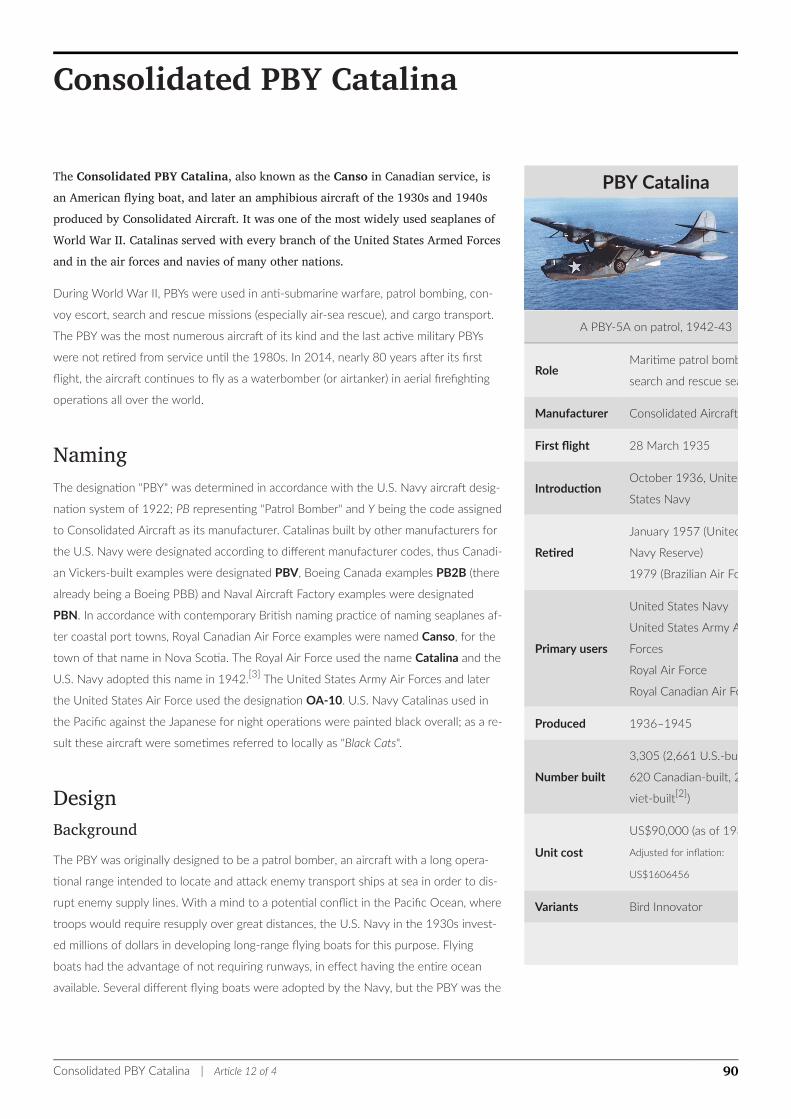
PBY Catalina
A PBY-5A on patrol, 1942-43
RoleMaritime patrol bomber
search and rescue seaplane
Manufacturer Consolidated Aircraft
First flight 28 March 1935
IntroductionOctober 1936, United
States Navy
Retired
January 1957 (United S
Navy Reserve)
1979 (Brazilian Air For
Primary users
United States Navy
United States Army Air
Forces
Royal Air Force
Royal Canadian Air For
Produced 1936–1945
Number built
3,305 (2,661 U.S.-built,
620 Canadian-built, 24 S
viet-built[2])
Unit cost
US$90,000 (as of 1935)
Adjusted for inflation:
US$1606456
Variants Bird Innovator
Consolidated PBY Catalina
The Consolidated PBY Catalina, also known as the Canso in Canadian service, isan American flying boat, and later an amphibious aircraft of the 1930s and 1940sproduced by Consolidated Aircraft. It was one of the most widely used seaplanes ofWorld War II. Catalinas served with every branch of the United States Armed Forcesand in the air forces and navies of many other nations.
During World War II, PBYs were used in anti-submarine warfare, patrol bombing, con-
voy escort, search and rescue missions (especially air-sea rescue), and cargo transport.
The PBY was the most numerous aircraft of its kind and the last active military PBYs
were not retired from service until the 1980s. In 2014, nearly 80 years after its first
flight, the aircraft continues to fly as a waterbomber (or airtanker) in aerial firefighting
operations all over the world.
NamingThe designation "PBY" was determined in accordance with the U.S. Navy aircraft desig-
nation system of 1922; PB representing "Patrol Bomber" and Y being the code assigned
to Consolidated Aircraft as its manufacturer. Catalinas built by other manufacturers for
the U.S. Navy were designated according to different manufacturer codes, thus Canadi-
an Vickers-built examples were designated PBV, Boeing Canada examples PB2B (there
already being a Boeing PBB) and Naval Aircraft Factory examples were designated
PBN. In accordance with contemporary British naming practice of naming seaplanes af-
ter coastal port towns, Royal Canadian Air Force examples were named Canso, for the
town of that name in Nova Scotia. The Royal Air Force used the name Catalina and the
U.S. Navy adopted this name in 1942.[3] The United States Army Air Forces and later
the United States Air Force used the designation OA-10. U.S. Navy Catalinas used in
the Pacific against the Japanese for night operations were painted black overall; as a re-
sult these aircraft were sometimes referred to locally as "Black Cats".
DesignBackgroundThe PBY was originally designed to be a patrol bomber, an aircraft with a long opera-
tional range intended to locate and attack enemy transport ships at sea in order to dis-
rupt enemy supply lines. With a mind to a potential conflict in the Pacific Ocean, where
troops would require resupply over great distances, the U.S. Navy in the 1930s invest-
ed millions of dollars in developing long-range flying boats for this purpose. Flying
boats had the advantage of not requiring runways, in effect having the entire ocean
available. Several different flying boats were adopted by the Navy, but the PBY was the
Consolidated PBY Catalina | Article 12 of 4 90
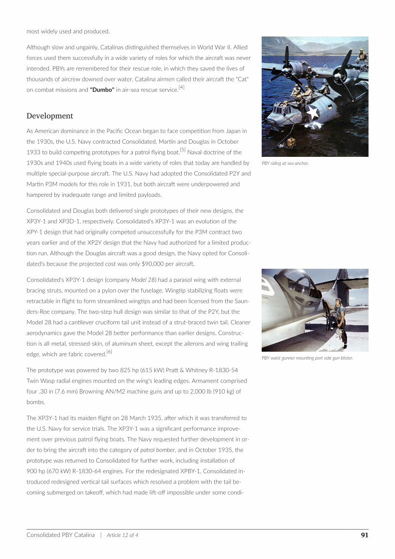
PBY riding at sea anchor.
PBY waist gunner mounting port side gun blister.
most widely used and produced.
Although slow and ungainly, Catalinas distinguished themselves in World War II. Allied
forces used them successfully in a wide variety of roles for which the aircraft was never
intended. PBYs are remembered for their rescue role, in which they saved the lives of
thousands of aircrew downed over water. Catalina airmen called their aircraft the "Cat"
on combat missions and "Dumbo" in air-sea rescue service.[4]
DevelopmentAs American dominance in the Pacific Ocean began to face competition from Japan in
the 1930s, the U.S. Navy contracted Consolidated, Martin and Douglas in October
1933 to build competing prototypes for a patrol flying boat.[5] Naval doctrine of the
1930s and 1940s used flying boats in a wide variety of roles that today are handled by
multiple special-purpose aircraft. The U.S. Navy had adopted the Consolidated P2Y and
Martin P3M models for this role in 1931, but both aircraft were underpowered and
hampered by inadequate range and limited payloads.
Consolidated and Douglas both delivered single prototypes of their new designs, the
XP3Y-1 and XP3D-1, respectively. Consolidated's XP3Y-1 was an evolution of the
XPY-1 design that had originally competed unsuccessfully for the P3M contract two
years earlier and of the XP2Y design that the Navy had authorized for a limited produc-
tion run. Although the Douglas aircraft was a good design, the Navy opted for Consoli-
dated's because the projected cost was only $90,000 per aircraft.
Consolidated's XP3Y-1 design (company Model 28) had a parasol wing with external
bracing struts, mounted on a pylon over the fuselage. Wingtip stabilizing floats were
retractable in flight to form streamlined wingtips and had been licensed from the Saun-
ders-Roe company. The two-step hull design was similar to that of the P2Y, but the
Model 28 had a cantilever cruciform tail unit instead of a strut-braced twin tail. Cleaner
aerodynamics gave the Model 28 better performance than earlier designs. Construc-
tion is all-metal, stressed-skin, of aluminum sheet, except the ailerons and wing trailing
edge, which are fabric covered.[6]
The prototype was powered by two 825 hp (615 kW) Pratt & Whitney R-1830-54
Twin Wasp radial engines mounted on the wing’s leading edges. Armament comprised
four .30 in (7.6 mm) Browning AN/M2 machine guns and up to 2,000 lb (910 kg) of
bombs.
The XP3Y-1 had its maiden flight on 28 March 1935, after which it was transferred to
the U.S. Navy for service trials. The XP3Y-1 was a significant performance improve-
ment over previous patrol flying boats. The Navy requested further development in or-
der to bring the aircraft into the category of patrol bomber, and in October 1935, the
prototype was returned to Consolidated for further work, including installation of
900 hp (670 kW) R-1830-64 engines. For the redesignated XPBY-1, Consolidated in-
troduced redesigned vertical tail surfaces which resolved a problem with the tail be-
coming submerged on takeoff, which had made lift-off impossible under some condi-
Consolidated PBY Catalina | Article 12 of 4 91

tions. The XPBY-1 had its maiden flight on 19 May 1936, during which a record non-
stop distance flight of 3,443 mi (2,992 nmi; 5,541 km) was achieved.
The XPBY-1 was delivered to VP-11F in October 1936. The second squadron to be
equipped was VP-12, which received the first of its aircraft in early 1937. The second
production order was placed on 25 July 1936. Over the next three years, the design
was gradually developed further and successive models introduced.
The aircraft eventually bore the name Catalina after Catalina Island; the name was
coined in November 1941, as Great Britain ordered their first 30 aircraft.[7]
Mass-produced U.S. Navy variants
Model Production period and distinguishing features Quantity
PBY-1September 1936 – June 1937
Original production model.60
PBY-2May 1937 – February 1938
Minor alterations to tail structure, hull reinforcements.50
PBY-3November 1936 – August 1938
Higher power engines.66
PBY-4
May 1938 – June 1939
Higher power engines, propeller spinners, acrylic glass blisters over waist guns
(some later units).
32
PBY-5
September 1940 – July 1943
Higher power engines (using higher octane fuel), discontinued use of propeller
spinners, standardized waist gun blisters. Self-sealing fuel tanks introduced dur-
ing production run.
684
PBY-5A
October 1941 – January 1945
Hydraulically actuated, retractable tricycle landing gear, with main gear design
based on one from the 1920s designed by Leroy Grumman, for amphibious op-
eration. Introduced tail gun position, replaced bow single gun position with
bow "eyeball" turret equipped with twin .30 machine guns (some later units),
improved armor, self-sealing fuel tanks.[8]
802
PBY-6A
January 1945 – May 1945
Incorporated changes from PBN-1,[8] including a taller vertical tail, increased
wing strength for greater carrying capacity, new electrical system, standardized
"eyeball" turret, and a radome over cockpit for radar.
175
An estimated 4,051 Catalinas, Cansos, and GSTs of all versions were produced be-
tween June 1937 and May 1945 for the U.S. Navy, the United States Army Air Forces,
the United States Coast Guard, Allied nations, and civilian customers.
Consolidated PBY Catalina | Article 12 of 4 92
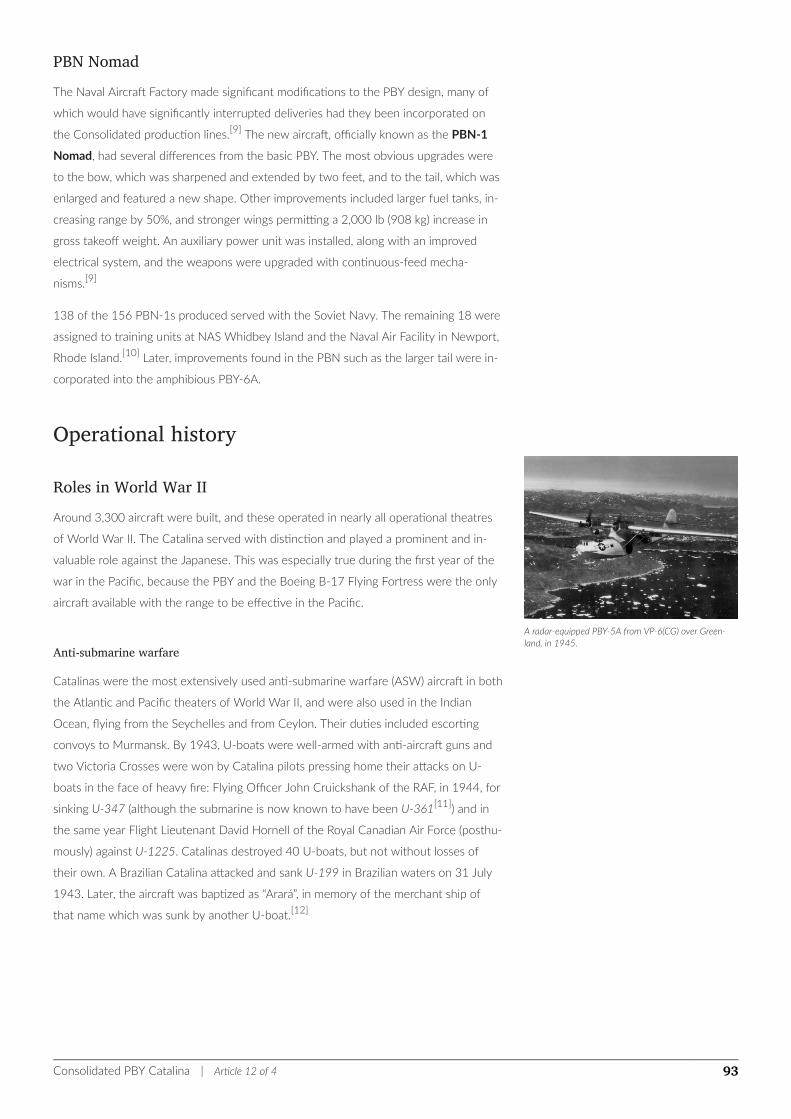
A radar-equipped PBY-5A from VP-6(CG) over Green-land, in 1945.
PBN NomadThe Naval Aircraft Factory made significant modifications to the PBY design, many of
which would have significantly interrupted deliveries had they been incorporated on
the Consolidated production lines.[9] The new aircraft, officially known as the PBN-1
Nomad, had several differences from the basic PBY. The most obvious upgrades were
to the bow, which was sharpened and extended by two feet, and to the tail, which was
enlarged and featured a new shape. Other improvements included larger fuel tanks, in-
creasing range by 50%, and stronger wings permitting a 2,000 lb (908 kg) increase in
gross takeoff weight. An auxiliary power unit was installed, along with an improved
electrical system, and the weapons were upgraded with continuous-feed mecha-
nisms.[9]
138 of the 156 PBN-1s produced served with the Soviet Navy. The remaining 18 were
assigned to training units at NAS Whidbey Island and the Naval Air Facility in Newport,
Rhode Island.[10] Later, improvements found in the PBN such as the larger tail were in-
corporated into the amphibious PBY-6A.
Operational history
Roles in World War IIAround 3,300 aircraft were built, and these operated in nearly all operational theatres
of World War II. The Catalina served with distinction and played a prominent and in-
valuable role against the Japanese. This was especially true during the first year of the
war in the Pacific, because the PBY and the Boeing B-17 Flying Fortress were the only
aircraft available with the range to be effective in the Pacific.
Anti-submarine warfare
Catalinas were the most extensively used anti-submarine warfare (ASW) aircraft in both
the Atlantic and Pacific theaters of World War II, and were also used in the Indian
Ocean, flying from the Seychelles and from Ceylon. Their duties included escorting
convoys to Murmansk. By 1943, U-boats were well-armed with anti-aircraft guns and
two Victoria Crosses were won by Catalina pilots pressing home their attacks on U-
boats in the face of heavy fire: Flying Officer John Cruickshank of the RAF, in 1944, for
sinking U-347 (although the submarine is now known to have been U-361[11]) and in
the same year Flight Lieutenant David Hornell of the Royal Canadian Air Force (posthu-
mously) against U-1225. Catalinas destroyed 40 U-boats, but not without losses of
their own. A Brazilian Catalina attacked and sank U-199 in Brazilian waters on 31 July
1943. Later, the aircraft was baptized as “Arará”, in memory of the merchant ship of
that name which was sunk by another U-boat.[12]
Consolidated PBY Catalina | Article 12 of 4 93
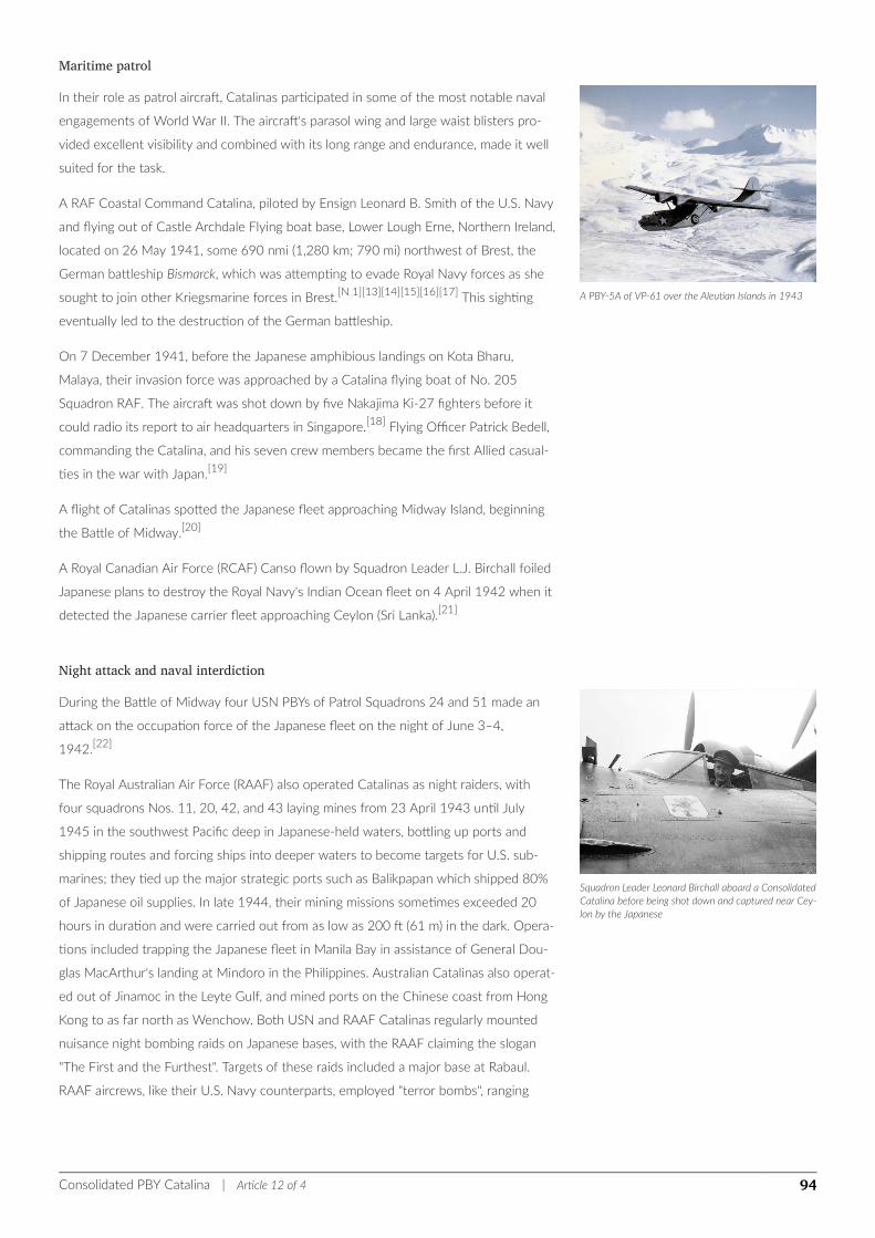
A PBY-5A of VP-61 over the Aleutian Islands in 1943
Squadron Leader Leonard Birchall aboard a ConsolidatedCatalina before being shot down and captured near Cey-lon by the Japanese
Maritime patrol
In their role as patrol aircraft, Catalinas participated in some of the most notable naval
engagements of World War II. The aircraft's parasol wing and large waist blisters pro-
vided excellent visibility and combined with its long range and endurance, made it well
suited for the task.
A RAF Coastal Command Catalina, piloted by Ensign Leonard B. Smith of the U.S. Navy
and flying out of Castle Archdale Flying boat base, Lower Lough Erne, Northern Ireland,
located on 26 May 1941, some 690 nmi (1,280 km; 790 mi) northwest of Brest, the
German battleship Bismarck, which was attempting to evade Royal Navy forces as she
sought to join other Kriegsmarine forces in Brest.[N 1][13][14][15][16][17] This sighting
eventually led to the destruction of the German battleship.
On 7 December 1941, before the Japanese amphibious landings on Kota Bharu,
Malaya, their invasion force was approached by a Catalina flying boat of No. 205
Squadron RAF. The aircraft was shot down by five Nakajima Ki-27 fighters before it
could radio its report to air headquarters in Singapore.[18] Flying Officer Patrick Bedell,
commanding the Catalina, and his seven crew members became the first Allied casual-
ties in the war with Japan.[19]
A flight of Catalinas spotted the Japanese fleet approaching Midway Island, beginning
the Battle of Midway.[20]
A Royal Canadian Air Force (RCAF) Canso flown by Squadron Leader L.J. Birchall foiled
Japanese plans to destroy the Royal Navy's Indian Ocean fleet on 4 April 1942 when it
detected the Japanese carrier fleet approaching Ceylon (Sri Lanka).[21]
Night attack and naval interdiction
During the Battle of Midway four USN PBYs of Patrol Squadrons 24 and 51 made an
attack on the occupation force of the Japanese fleet on the night of June 3–4,
1942.[22]
The Royal Australian Air Force (RAAF) also operated Catalinas as night raiders, with
four squadrons Nos. 11, 20, 42, and 43 laying mines from 23 April 1943 until July
1945 in the southwest Pacific deep in Japanese-held waters, bottling up ports and
shipping routes and forcing ships into deeper waters to become targets for U.S. sub-
marines; they tied up the major strategic ports such as Balikpapan which shipped 80%
of Japanese oil supplies. In late 1944, their mining missions sometimes exceeded 20
hours in duration and were carried out from as low as 200 ft (61 m) in the dark. Opera-
tions included trapping the Japanese fleet in Manila Bay in assistance of General Dou-
glas MacArthur's landing at Mindoro in the Philippines. Australian Catalinas also operat-
ed out of Jinamoc in the Leyte Gulf, and mined ports on the Chinese coast from Hong
Kong to as far north as Wenchow. Both USN and RAAF Catalinas regularly mounted
nuisance night bombing raids on Japanese bases, with the RAAF claiming the slogan
"The First and the Furthest". Targets of these raids included a major base at Rabaul.
RAAF aircrews, like their U.S. Navy counterparts, employed "terror bombs", ranging
Consolidated PBY Catalina | Article 12 of 4 94
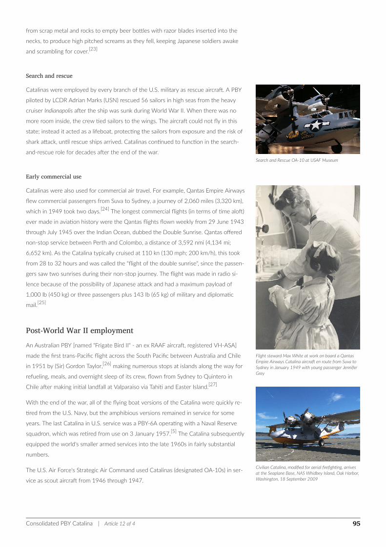
Search and Rescue OA-10 at USAF Museum
Flight steward Max White at work on board a QantasEmpire Airways Catalina aircraft en route from Suva toSydney in January 1949 with young passenger JenniferGrey
Civilian Catalina, modified for aerial firefighting, arrivesat the Seaplane Base, NAS Whidbey Island, Oak Harbor,Washington, 18 September 2009
from scrap metal and rocks to empty beer bottles with razor blades inserted into the
necks, to produce high pitched screams as they fell, keeping Japanese soldiers awake
and scrambling for cover.[23]
Search and rescue
Catalinas were employed by every branch of the U.S. military as rescue aircraft. A PBY
piloted by LCDR Adrian Marks (USN) rescued 56 sailors in high seas from the heavy
cruiser Indianapolis after the ship was sunk during World War II. When there was no
more room inside, the crew tied sailors to the wings. The aircraft could not fly in this
state; instead it acted as a lifeboat, protecting the sailors from exposure and the risk of
shark attack, until rescue ships arrived. Catalinas continued to function in the search-
and-rescue role for decades after the end of the war.
Early commercial use
Catalinas were also used for commercial air travel. For example, Qantas Empire Airways
flew commercial passengers from Suva to Sydney, a journey of 2,060 miles (3,320 km),
which in 1949 took two days.[24] The longest commercial flights (in terms of time aloft)
ever made in aviation history were the Qantas flights flown weekly from 29 June 1943
through July 1945 over the Indian Ocean, dubbed the Double Sunrise. Qantas offered
non-stop service between Perth and Colombo, a distance of 3,592 nmi (4,134 mi;
6,652 km). As the Catalina typically cruised at 110 kn (130 mph; 200 km/h), this took
from 28 to 32 hours and was called the "flight of the double sunrise", since the passen-
gers saw two sunrises during their non-stop journey. The flight was made in radio si-
lence because of the possibility of Japanese attack and had a maximum payload of
1,000 lb (450 kg) or three passengers plus 143 lb (65 kg) of military and diplomatic
mail.[25]
Post-World War II employmentAn Australian PBY [named "Frigate Bird II" - an ex RAAF aircraft, registered VH-ASA]
made the first trans-Pacific flight across the South Pacific between Australia and Chile
in 1951 by (Sir) Gordon Taylor,[26] making numerous stops at islands along the way for
refueling, meals, and overnight sleep of its crew, flown from Sydney to Quintero in
Chile after making initial landfall at Valparaiso via Tahiti and Easter Island.[27]
With the end of the war, all of the flying boat versions of the Catalina were quickly re-
tired from the U.S. Navy, but the amphibious versions remained in service for some
years. The last Catalina in U.S. service was a PBY-6A operating with a Naval Reserve
squadron, which was retired from use on 3 January 1957.[5] The Catalina subsequently
equipped the world's smaller armed services into the late 1960s in fairly substantial
numbers.
The U.S. Air Force's Strategic Air Command used Catalinas (designated OA-10s) in ser-
vice as scout aircraft from 1946 through 1947.
Consolidated PBY Catalina | Article 12 of 4 95
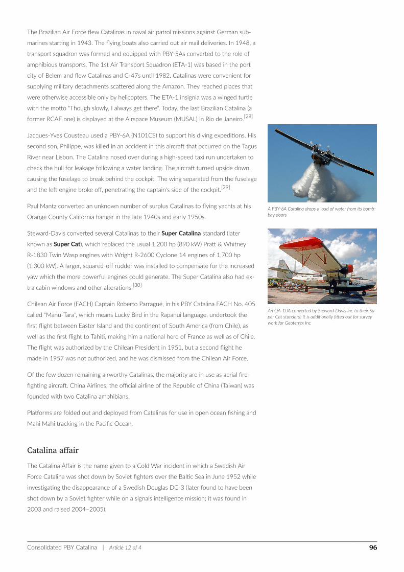
A PBY-6A Catalina drops a load of water from its bomb-bay doors
An OA-10A converted by Steward-Davis Inc to their Su-per Cat standard. It is additionally fitted out for surveywork for Geoterrex Inc
The Brazilian Air Force flew Catalinas in naval air patrol missions against German sub-
marines starting in 1943. The flying boats also carried out air mail deliveries. In 1948, a
transport squadron was formed and equipped with PBY-5As converted to the role of
amphibious transports. The 1st Air Transport Squadron (ETA-1) was based in the port
city of Belem and flew Catalinas and C-47s until 1982. Catalinas were convenient for
supplying military detachments scattered along the Amazon. They reached places that
were otherwise accessible only by helicopters. The ETA-1 insignia was a winged turtle
with the motto "Though slowly, I always get there". Today, the last Brazilian Catalina (a
former RCAF one) is displayed at the Airspace Museum (MUSAL) in Rio de Janeiro.[28]
Jacques-Yves Cousteau used a PBY-6A (N101CS) to support his diving expeditions. His
second son, Philippe, was killed in an accident in this aircraft that occurred on the Tagus
River near Lisbon. The Catalina nosed over during a high-speed taxi run undertaken to
check the hull for leakage following a water landing. The aircraft turned upside down,
causing the fuselage to break behind the cockpit. The wing separated from the fuselage
and the left engine broke off, penetrating the captain's side of the cockpit.[29]
Paul Mantz converted an unknown number of surplus Catalinas to flying yachts at his
Orange County California hangar in the late 1940s and early 1950s.
Steward-Davis converted several Catalinas to their Super Catalina standard (later
known as Super Cat), which replaced the usual 1,200 hp (890 kW) Pratt & Whitney
R-1830 Twin Wasp engines with Wright R-2600 Cyclone 14 engines of 1,700 hp
(1,300 kW). A larger, squared-off rudder was installed to compensate for the increased
yaw which the more powerful engines could generate. The Super Catalina also had ex-
tra cabin windows and other alterations.[30]
Chilean Air Force (FACH) Captain Roberto Parragué, in his PBY Catalina FACH No. 405
called "Manu-Tara", which means Lucky Bird in the Rapanui language, undertook the
first flight between Easter Island and the continent of South America (from Chile), as
well as the first flight to Tahiti, making him a national hero of France as well as of Chile.
The flight was authorized by the Chilean President in 1951, but a second flight he
made in 1957 was not authorized, and he was dismissed from the Chilean Air Force.
Of the few dozen remaining airworthy Catalinas, the majority are in use as aerial fire-
fighting aircraft. China Airlines, the official airline of the Republic of China (Taiwan) was
founded with two Catalina amphibians.
Platforms are folded out and deployed from Catalinas for use in open ocean fishing and
Mahi Mahi tracking in the Pacific Ocean.
Catalina affairThe Catalina Affair is the name given to a Cold War incident in which a Swedish Air
Force Catalina was shot down by Soviet fighters over the Baltic Sea in June 1952 while
investigating the disappearance of a Swedish Douglas DC-3 (later found to have been
shot down by a Soviet fighter while on a signals intelligence mission; it was found in
2003 and raised 2004–2005).
Consolidated PBY Catalina | Article 12 of 4 96
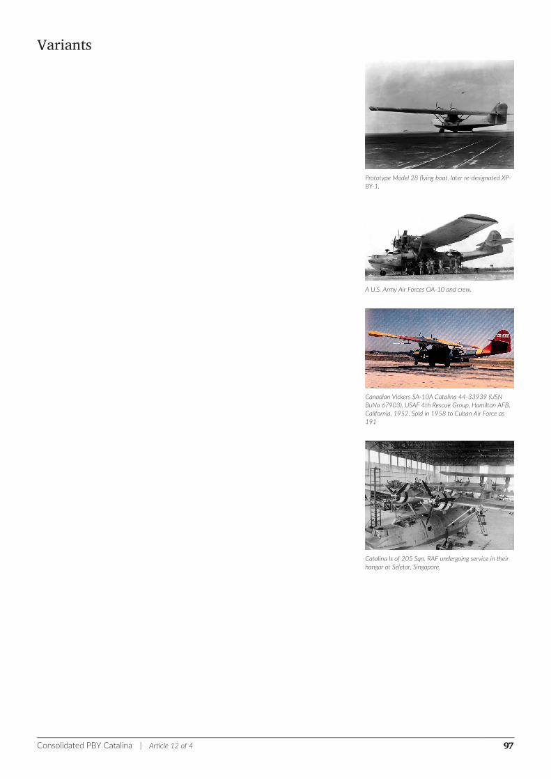
Prototype Model 28 flying boat, later re-designated XP-BY-1.
A U.S. Army Air Forces OA-10 and crew.
Canadian Vickers SA-10A Catalina 44-33939 (USNBuNo 67903), USAF 4th Rescue Group, Hamilton AFB,California, 1952. Sold in 1958 to Cuban Air Force as191
Catalina Is of 205 Sqn. RAF undergoing service in theirhangar at Seletar, Singapore.
Variants
Consolidated PBY Catalina | Article 12 of 4 97
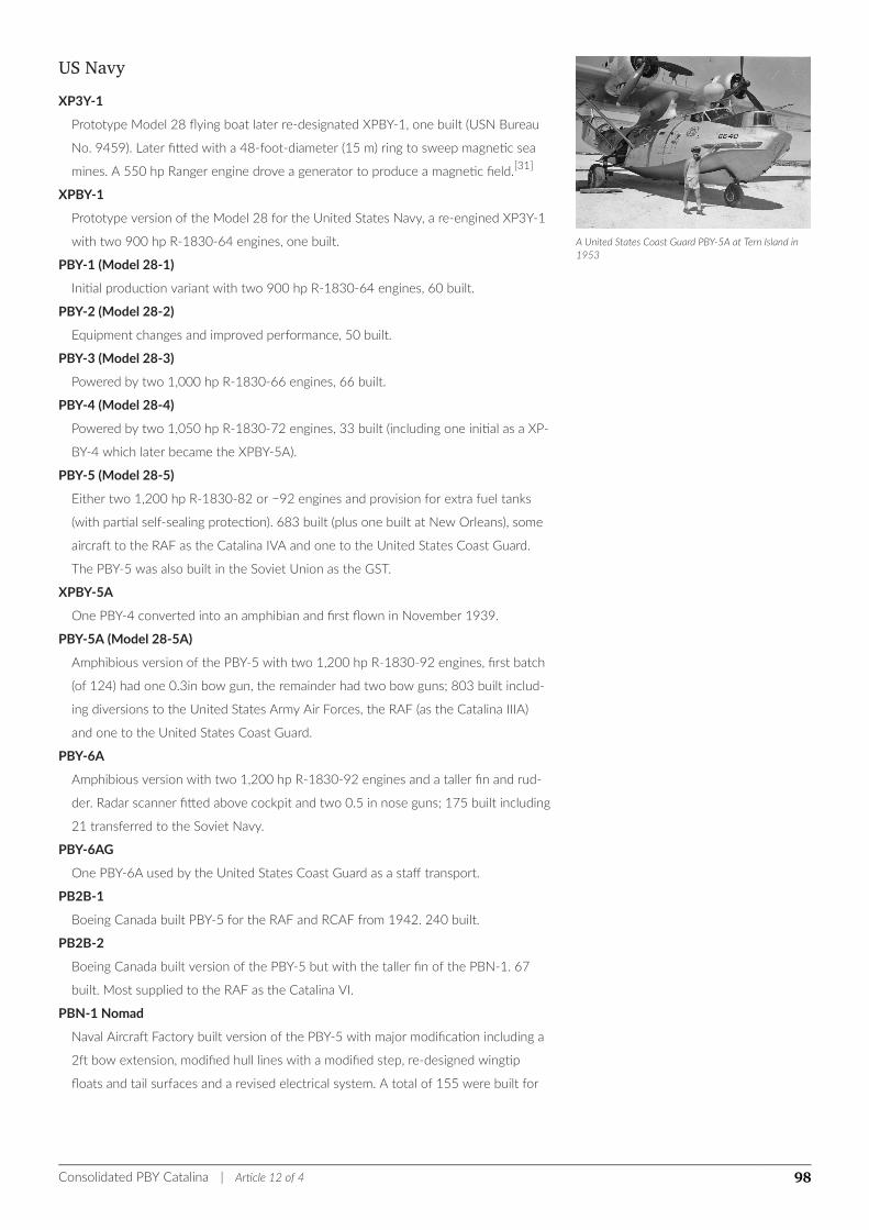
A United States Coast Guard PBY-5A at Tern Island in1953
US NavyXP3Y-1
Prototype Model 28 flying boat later re-designated XPBY-1, one built (USN Bureau
No. 9459). Later fitted with a 48-foot-diameter (15 m) ring to sweep magnetic sea
mines. A 550 hp Ranger engine drove a generator to produce a magnetic field.[31]
XPBY-1
Prototype version of the Model 28 for the United States Navy, a re-engined XP3Y-1
with two 900 hp R-1830-64 engines, one built.
PBY-1 (Model 28-1)
Initial production variant with two 900 hp R-1830-64 engines, 60 built.
PBY-2 (Model 28-2)
Equipment changes and improved performance, 50 built.
PBY-3 (Model 28-3)
Powered by two 1,000 hp R-1830-66 engines, 66 built.
PBY-4 (Model 28-4)
Powered by two 1,050 hp R-1830-72 engines, 33 built (including one initial as a XP-
BY-4 which later became the XPBY-5A).
PBY-5 (Model 28-5)
Either two 1,200 hp R-1830-82 or −92 engines and provision for extra fuel tanks
(with partial self-sealing protection). 683 built (plus one built at New Orleans), some
aircraft to the RAF as the Catalina IVA and one to the United States Coast Guard.
The PBY-5 was also built in the Soviet Union as the GST.
XPBY-5A
One PBY-4 converted into an amphibian and first flown in November 1939.
PBY-5A (Model 28-5A)
Amphibious version of the PBY-5 with two 1,200 hp R-1830-92 engines, first batch
(of 124) had one 0.3in bow gun, the remainder had two bow guns; 803 built includ-
ing diversions to the United States Army Air Forces, the RAF (as the Catalina IIIA)
and one to the United States Coast Guard.
PBY-6A
Amphibious version with two 1,200 hp R-1830-92 engines and a taller fin and rud-
der. Radar scanner fitted above cockpit and two 0.5 in nose guns; 175 built including
21 transferred to the Soviet Navy.
PBY-6AG
One PBY-6A used by the United States Coast Guard as a staff transport.
PB2B-1
Boeing Canada built PBY-5 for the RAF and RCAF from 1942. 240 built.
PB2B-2
Boeing Canada built version of the PBY-5 but with the taller fin of the PBN-1. 67
built. Most supplied to the RAF as the Catalina VI.
PBN-1 Nomad
Naval Aircraft Factory built version of the PBY-5 with major modification including a
2ft bow extension, modified hull lines with a modified step, re-designed wingtip
floats and tail surfaces and a revised electrical system. A total of 155 were built for
Consolidated PBY Catalina | Article 12 of 4 98
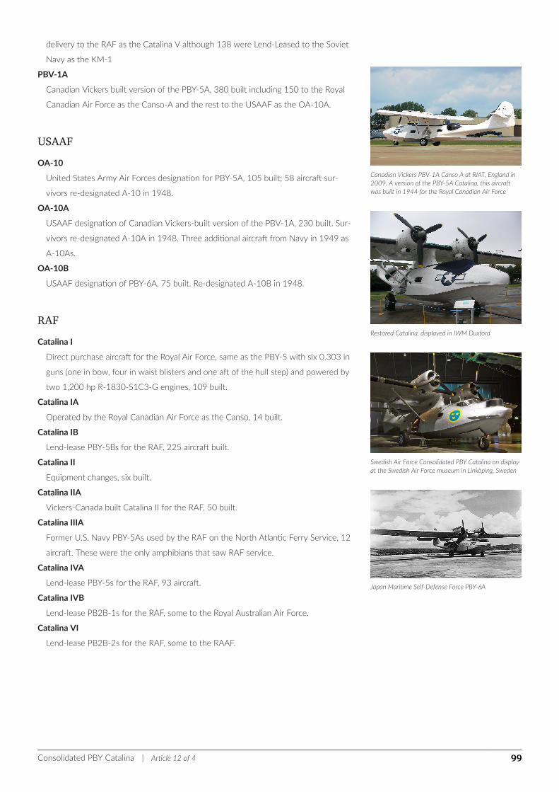
Canadian Vickers PBV-1A Canso A at RIAT, England in2009. A version of the PBY-5A Catalina, this aircraftwas built in 1944 for the Royal Canadian Air Force
Restored Catalina, displayed in IWM Duxford
Swedish Air Force Consolidated PBY Catalina on displayat the Swedish Air Force museum in Linköping, Sweden
Japan Maritime Self-Defense Force PBY-6A
delivery to the RAF as the Catalina V although 138 were Lend-Leased to the Soviet
Navy as the KM-1
PBV-1A
Canadian Vickers built version of the PBY-5A, 380 built including 150 to the Royal
Canadian Air Force as the Canso-A and the rest to the USAAF as the OA-10A.
USAAFOA-10
United States Army Air Forces designation for PBY-5A, 105 built; 58 aircraft sur-
vivors re-designated A-10 in 1948.
OA-10A
USAAF designation of Canadian Vickers-built version of the PBV-1A, 230 built. Sur-
vivors re-designated A-10A in 1948. Three additional aircraft from Navy in 1949 as
A-10As.
OA-10B
USAAF designation of PBY-6A, 75 built. Re-designated A-10B in 1948.
RAFCatalina I
Direct purchase aircraft for the Royal Air Force, same as the PBY-5 with six 0.303 in
guns (one in bow, four in waist blisters and one aft of the hull step) and powered by
two 1,200 hp R-1830-S1C3-G engines, 109 built.
Catalina IA
Operated by the Royal Canadian Air Force as the Canso, 14 built.
Catalina IB
Lend-lease PBY-5Bs for the RAF, 225 aircraft built.
Catalina II
Equipment changes, six built.
Catalina IIA
Vickers-Canada built Catalina II for the RAF, 50 built.
Catalina IIIA
Former U.S. Navy PBY-5As used by the RAF on the North Atlantic Ferry Service, 12
aircraft. These were the only amphibians that saw RAF service.
Catalina IVA
Lend-lease PBY-5s for the RAF, 93 aircraft.
Catalina IVB
Lend-lease PB2B-1s for the RAF, some to the Royal Australian Air Force.
Catalina VI
Lend-lease PB2B-2s for the RAF, some to the RAAF.
Consolidated PBY Catalina | Article 12 of 4 99

RCAFCanso-A
RCAF designation for PBV-1A
Other UsersGST
Soviet built version of the PBY-5 ("Gydro Samoliot Transportnyi").
Steward-Davis Super Catalina ("Super Cat")
Catalina converted to use 1,700 hp Wright R-2600 Cyclone 14 engines, with en-
larged rudder and other changes.
Avalon Turbo Canso
Proposed turboprop conversion of Canso water bombers, powered by two Rolls-
Royce Dart engines.
Consolidated PBY Catalina | Article 12 of 4 100
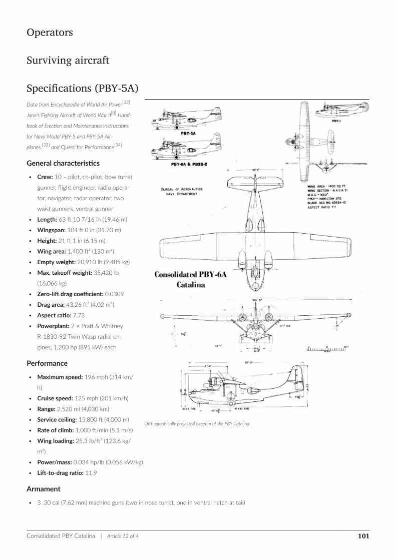
Orthographically projected diagram of the PBY Catalina.
Operators
Surviving aircraft
Specifications (PBY-5A)Data from Encyclopedia of World Air Power[32]
Jane's Fighting Aircraft of World War II[8] Hand-
book of Erection and Maintenance Instructions
for Navy Model PBY-5 and PBY-5A Air-
planes.[33] and Quest for Performance[34]
General characteristics
• Crew: 10 – pilot, co-pilot, bow turret
gunner, flight engineer, radio opera-
tor, navigator, radar operator, two
waist gunners, ventral gunner
• Length: 63 ft 10 7/16 in (19.46 m)
• Wingspan: 104 ft 0 in (31.70 m)
• Height: 21 ft 1 in (6.15 m)
• Wing area: 1,400 ft² (130 m²)
• Empty weight: 20,910 lb (9,485 kg)
• Max. takeoff weight: 35,420 lb
(16,066 kg)
• Zero-lift drag coefficient: 0.0309
• Drag area: 43.26 ft² (4.02 m²)
• Aspect ratio: 7.73
• Powerplant: 2 × Pratt & Whitney
R-1830-92 Twin Wasp radial en-
gines, 1,200 hp (895 kW) each
Performance
• Maximum speed: 196 mph (314 km/
h)
• Cruise speed: 125 mph (201 km/h)
• Range: 2,520 mi (4,030 km)
• Service ceiling: 15,800 ft (4,000 m)
• Rate of climb: 1,000 ft/min (5.1 m/s)
• Wing loading: 25.3 lb/ft² (123.6 kg/
m²)
• Power/mass: 0.034 hp/lb (0.056 kW/kg)
• Lift-to-drag ratio: 11.9
Armament
• 3 .30 cal (7.62 mm) machine guns (two in nose turret, one in ventral hatch at tail)
Consolidated PBY Catalina | Article 12 of 4 101
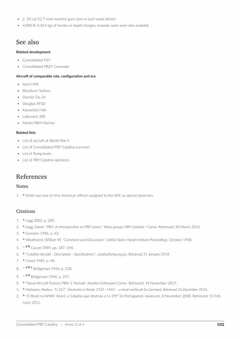
• 2 .50 cal (12.7 mm) machine guns (one in each waist blister)
• 4,000 lb (1,814 kg) of bombs or depth charges; torpedo racks were also available
See alsoRelated development
• Consolidated P2Y
• Consolidated PB2Y Coronado
Aircraft of comparable role, configuration and era
• Aichi H9A
• Blackburn Sydney
• Dornier Do 24
• Douglas XP3D
• Kawanishi H6K
• Latécoère 300
• Martin PBM Mariner
Related lists
• List of aircraft of World War II
• List of Consolidated PBY Catalina survivors
• List of flying boats
• List of PBY Catalina operators
ReferencesNotes1. ^ Smith was one of nine American officers assigned to the RAF as special observers.
Citations1. ^ Legg 2002, p. 285.
2. ^ Legg, David. "PBY: A retrospective on PBY bows." Yahoo groups: PBY Catalina / Canso. Retrieved: 30 March 2013.
3. ^ Gunston 1986, p. 63.
4. ^ Weathered, William W. "Comment and Discussion". United States Naval Institute Proceedings, October 1968.
5. ^ a b Cacutt 1989, pp. 187–194.
6. ^ "Catalina Aircraft - Description - Specifications". catalinaflying.org.au. Retrieved 31 January 2018.
7. ^ Creed 1985, p. 48.
8. ^ a b c Bridgeman 1946, p. 218.
9. ^ a b Bridgeman 1946, p. 247.
10. ^ "Naval Aircraft Factory PBN-1 Nomad." Aviation Enthusiast Corner. Retrieved: 14 November 2017.
11. ^ Hofmann, Markus. "U 347". Deutsche U-Boote 1935–1945 – u-boot-archiv.de (in German). Retrieved 26 December 2014.
12. ^ "O Brasil na WWII: ‘Arará’, o Catalina que destruiu o U-199" (in Portuguese). naval.com, 8 November 2008. Retrieved: 15 Feb-
ruary 2011.
Consolidated PBY Catalina | Article 12 of 4 102
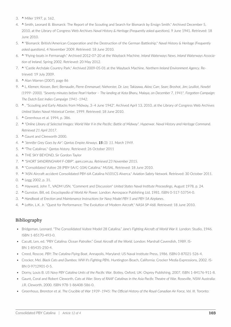
13. ^ Miller 1997, p. 162.
14. ^ Smith, Leonard B. Bismarck: The Report of the Scouting and Search for Bismarck by Ensign Smith." Archived December 5,
2010, at the Library of Congress Web Archives Naval History & Heritage (Frequently asked questions), 9 June 1941. Retrieved: 18
June 2010.
15. ^ "Bismarck: British/American Cooperation and the Destruction of the German Battleship." Naval History & Heritage (Frequently
asked questions), 4 November 2009. Retrieved: 18 June 2010.
16. ^ "Flying-boats in Fermanagh." Archived 2012-07-20 at the Wayback Machine. Inland Waterways News, Inland Waterways Associa-
tion of Ireland, Spring 2002. Retrieved: 20 May 2012.
17. ^ "Castle Archdale Country Park." Archived 2009-05-01 at the Wayback Machine. Northern Ireland Environment Agency. Re-
trieved: 19 July 2009.
18. ^ Alan Warren (2007), page 86
19. ^ L, Klemen; Kossen, Bert; Bernaudin, Pierre-Emmanuel; Niehorster, Dr. Leo; Takizawa, Akira; Carr, Sean; Broshot, Jim; Leulliot, Nowfel
(1999–2000). "Seventy minutes before Pearl Harbor – The landing at Kota Bharu, Malaya, on December 7, 1941". Forgotten Campaign:
The Dutch East Indies Campaign 1941–1942.
20. ^ . "Scouting and Early Attacks from Midway, 3–4 June 1942". Archived April 13, 2010, at the Library of Congress Web Archives
United States Naval Historical Center, 1999. Retrieved: 18 June 2010.
21. ^ Greenhous et al. 1994, p. 386.
22. ^ "Online Library of Selected Images: World War II in the Pacific: Battle of Midway". Hyperwar. Naval History and Heritage Command.
Retrieved 21 April 2017.
23. ^ Gaunt and Cleeworth 2000.
24. ^ "Jennifer Grey Goes by Air". Qantas Empire Airways. 15 (3): 11. March 1949.
25. ^ "The Catalinas." Qantas history. Retrieved: 26 October 2011
26. ^ THE SKY BEYOND, Sir Gordon Taylor
27. ^ "SHORT SANDRINGHAM F-OBIP". qam.com.au. Retrieved 23 November 2015.
28. ^ "Consolidated Vultee 28 (PBY-5A/C-10A) Catalina." MUSAL. Retrieved: 18 June 2010.
29. ^ "ASN Aircraft accident Consolidated PBY-6A Catalina N101CS Alverca." Aviation Safety Network. Retrieved: 30 October 2011.
30. ^ Legg 2002, p. 31.
31. ^ Hayward, John T., VADM USN. "Comment and Discussion" United States Naval Institute Proceedings, August 1978, p. 24.
32. ^ Gunston, Bill, ed. Encyclopedia of World Air Power. London: Aerospace Publishing Ltd, 1981. ISBN 0-517-53754-0.
33. ^ Handbook of Erection and Maintenance Instructions for Navy Model PBY-5 and PBY-5A Airplanes.
34. ^ Loftin, L.K. Jr. "Quest for Performance: The Evolution of Modern Aircraft." NASA SP-468. Retrieved: 18 June 2010.
Bibliography• Bridgeman, Leonard. “The Consolidated Vultee Model 28 Catalina.” Jane's Fighting Aircraft of World War II. London: Studio, 1946.
ISBN 1-85170-493-0.
• Cacutt, Len, ed. “PBY Catalina: Ocean Patroller.” Great Aircraft of the World. London: Marshall Cavendish, 1989. IS-
BN 1-85435-250-4.
• Creed, Roscoe. PBY: The Catalina Flying Boat. Annapolis, Maryland: US Naval Institute Press, 1986. ISBN 0-87021-526-4.
• Crocker, Mel. Black Cats and Dumbos: WW II's Fighting PBYs. Huntington Beach, California: Crocker Media Expressions, 2002. IS-
BN 0-9712901-0-5.
• Dorny, Louis B. US Navy PBY Catalina Units of the Pacific War. Botley, Oxford, UK: Osprey Publishing, 2007. ISBN 1-84176-911-8.
• Gaunt, Coral and Robert Cleworth. Cats at War: Story of RAAF Catalinas in the Asia Pacific Theatre of War. Roseville, NSW Australia:
J.R. Cleworth, 2000. ISBN 978-1-86408-586-0.
• Greenhous, Brereton et al. The Crucible of War 1939–1945: The Official History of the Royal Canadian Air Force, Vol. III. Toronto:
Consolidated PBY Catalina | Article 12 of 4 103

University of Toronto Press, 1994. ISBN 978-0-8020-0574-8.
• Gunston, Bill (1986). American Warplanes. New York: Crown Publishers Inc. ISBN 0-517-61351-4.
• Hendrie, Andrew. Flying Cats: The Catalina Aircraft in World War II. Annapolis, Maryland: US Naval Institute Press, 1988. IS-
BN 0-87021-213-3.
• Kinzey, Bert. PBY Catalina in Detail & Scale. Carrollton, Texas: Squadron/Signal Publications, Inc., 2000. ISBN 1-888974-19-2.
• Knott, Richard C. Black Cat Raiders of World War II. Annapolis, Maryland: US Naval Institute Press, 2000. ISBN 1-55750-471-7.
• Legg, David. Consolidated PBY Catalina: The Peacetime Record. Annapolis, Maryland: US Naval Institute Press, 2002. IS-
BN 1-55750-245-5.
• Miller, Nathan (1997). War at Sea: A Naval History of World War II. New York: Oxford University Press. ISBN 978-0-19-511038-8.
• Petrescu, FLorian Ion and Reilly Victoria Petrescu. The Aviation History. Stoughton, Wisconsin: Books on Demand, 2012. IS-
BN 978-3-84823-077-8.
• Ragnarsson, Ragnar. US Navy PBY Catalina Units of the Atlantic War. Botley, Oxford, UK: Osprey Publishing, 2006. IS-
BN 1-84176-910-X.
• Scarborough, William E. PBY Catalina in Action (Aircraft number 62). Carrollton, Texas: Squadron/Signal Publications, Inc., 1983. IS-
BN 0-89747-149-0.
• Scarborough, William E. PBY Catalina: Walk Around. Carrollton, Texas: Squadron/Signal Publications, Inc., 1996. IS-
BN 0-89747-357-4.
• Wagner, Ray. The Story of the PBY Catalina (Aero Biographies Volume 1). San Diego, California: Flight Classics, 1972. IS-
BN 978-0-911721-30-0.
Further reading• Núñez Padin, Jorge Felix (2009). Núñez Padin, Jorge Felix, ed. JRF Goose, PBY Catalina,
PBM Mariner & HU-16 Albatros. Serie Aeronaval (in Spanish). 25. Bahía Blanca, Argenti-
na: Fuerzas Aeronavales. ISBN 9789872055745. Archived from the original on
2016-03-03. Retrieved 2015-01-26.
External links
Wikimedia Commons has media related to Consolidated PBY Catalina.
• PBY Catalina Foundation
• (1945) AN 01-5M-3 Handbook of Structural Repair for Navy Models PBY-5,
PBY-5A , PBY-6A Army Model OA-10 Airplanes
• Catalina Aircraft Trust
• Popular Mechanics, February 1943, "Here Comes The Cats" very large and detailed
article
Consolidated PBY Catalina | Article 12 of 4 104
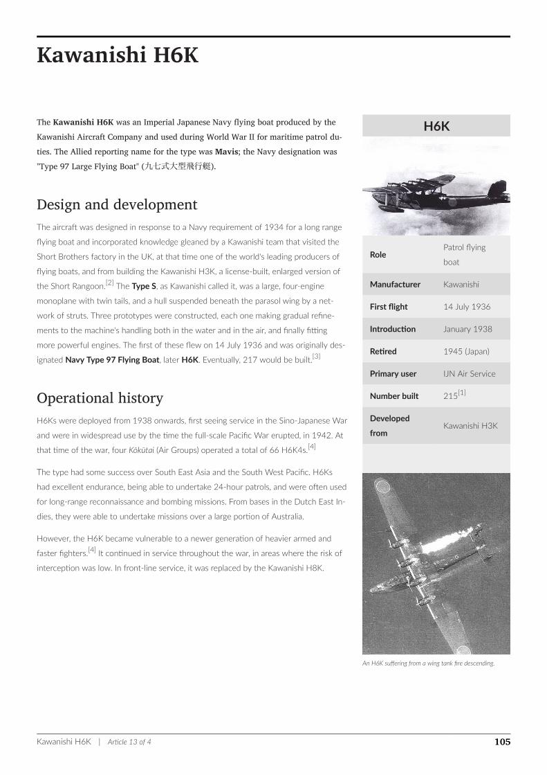
H6K
RolePatrol flying
boat
Manufacturer Kawanishi
First flight 14 July 1936
Introduction January 1938
Retired 1945 (Japan)
Primary user IJN Air Service
Number built 215[1]
Developed
fromKawanishi H3K
An H6K suffering from a wing tank fire descending.
Kawanishi H6K
The Kawanishi H6K was an Imperial Japanese Navy flying boat produced by theKawanishi Aircraft Company and used during World War II for maritime patrol du-ties. The Allied reporting name for the type was Mavis; the Navy designation was"Type 97 Large Flying Boat" (九七式大型飛行艇).
Design and developmentThe aircraft was designed in response to a Navy requirement of 1934 for a long range
flying boat and incorporated knowledge gleaned by a Kawanishi team that visited the
Short Brothers factory in the UK, at that time one of the world's leading producers of
flying boats, and from building the Kawanishi H3K, a license-built, enlarged version of
the Short Rangoon.[2] The Type S, as Kawanishi called it, was a large, four-engine
monoplane with twin tails, and a hull suspended beneath the parasol wing by a net-
work of struts. Three prototypes were constructed, each one making gradual refine-
ments to the machine's handling both in the water and in the air, and finally fitting
more powerful engines. The first of these flew on 14 July 1936 and was originally des-
ignated Navy Type 97 Flying Boat, later H6K. Eventually, 217 would be built.[3]
Operational historyH6Ks were deployed from 1938 onwards, first seeing service in the Sino-Japanese War
and were in widespread use by the time the full-scale Pacific War erupted, in 1942. At
that time of the war, four Kōkūtai (Air Groups) operated a total of 66 H6K4s.[4]
The type had some success over South East Asia and the South West Pacific. H6Ks
had excellent endurance, being able to undertake 24-hour patrols, and were often used
for long-range reconnaissance and bombing missions. From bases in the Dutch East In-
dies, they were able to undertake missions over a large portion of Australia.
However, the H6K became vulnerable to a newer generation of heavier armed and
faster fighters.[4] It continued in service throughout the war, in areas where the risk of
interception was low. In front-line service, it was replaced by the Kawanishi H8K.
Kawanishi H6K | Article 13 of 4 105
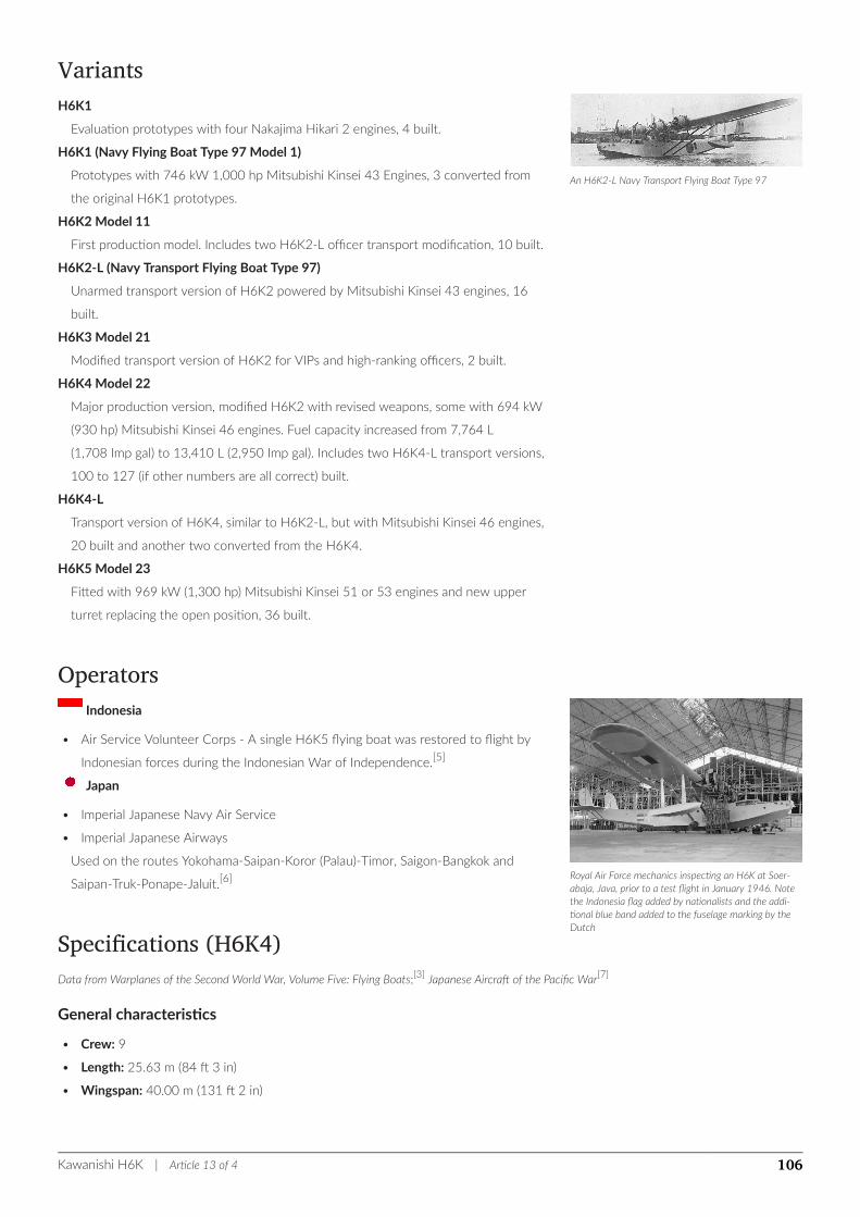
An H6K2-L Navy Transport Flying Boat Type 97
Royal Air Force mechanics inspecting an H6K at Soer-abaja, Java, prior to a test flight in January 1946. Notethe Indonesia flag added by nationalists and the addi-tional blue band added to the fuselage marking by theDutch
VariantsH6K1
Evaluation prototypes with four Nakajima Hikari 2 engines, 4 built.
H6K1 (Navy Flying Boat Type 97 Model 1)
Prototypes with 746 kW 1,000 hp Mitsubishi Kinsei 43 Engines, 3 converted from
the original H6K1 prototypes.
H6K2 Model 11
First production model. Includes two H6K2-L officer transport modification, 10 built.
H6K2-L (Navy Transport Flying Boat Type 97)
Unarmed transport version of H6K2 powered by Mitsubishi Kinsei 43 engines, 16
built.
H6K3 Model 21
Modified transport version of H6K2 for VIPs and high-ranking officers, 2 built.
H6K4 Model 22
Major production version, modified H6K2 with revised weapons, some with 694 kW
(930 hp) Mitsubishi Kinsei 46 engines. Fuel capacity increased from 7,764 L
(1,708 Imp gal) to 13,410 L (2,950 Imp gal). Includes two H6K4-L transport versions,
100 to 127 (if other numbers are all correct) built.
H6K4-L
Transport version of H6K4, similar to H6K2-L, but with Mitsubishi Kinsei 46 engines,
20 built and another two converted from the H6K4.
H6K5 Model 23
Fitted with 969 kW (1,300 hp) Mitsubishi Kinsei 51 or 53 engines and new upper
turret replacing the open position, 36 built.
OperatorsIndonesia
• Air Service Volunteer Corps - A single H6K5 flying boat was restored to flight by
Indonesian forces during the Indonesian War of Independence.[5]
Japan
• Imperial Japanese Navy Air Service
• Imperial Japanese Airways
Used on the routes Yokohama-Saipan-Koror (Palau)-Timor, Saigon-Bangkok and
Saipan-Truk-Ponape-Jaluit.[6]
Specifications (H6K4)Data from Warplanes of the Second World War, Volume Five: Flying Boats;[3] Japanese Aircraft of the Pacific War[7]
General characteristics
• Crew: 9
• Length: 25.63 m (84 ft 3 in)
• Wingspan: 40.00 m (131 ft 2 in)
Kawanishi H6K | Article 13 of 4 106
• Height: 6.27 m (20 ft 6 in)
• Wing area: 170 m2 (1,830 ft2)
• Empty weight: 11,707 kg (25,755 lb)
• Loaded weight: 17,000 kg (37,400 lb)
• Max. takeoff weight: 21,500 kg (47,300 lb)
• Powerplant: 4 × Mitsubishi Kinsei 43 or 46 14-cylinder, air-cooled, radial engines,
746 kW (1,000 hp) each
Performance
• Maximum speed: 331 km/h (211 mph)
• Cruise speed: 216 km/h (138 mph)
• Range: 6,580 km (4,112 mi)
• Service ceiling: 9,610 m (31,520 ft)
• Rate of climb: 370 m/min (1,213 ft/min)
• Wing loading: 100 kg/m2 (20 lb/ft2)
• Power/mass: 0.17 kW/kg (0.11 hp/lb)
Armament
• 1× 7.7 mm (0.30 in) Type 92 machine gun in nose
• 1× Type 92 machine gun in spine
• 2× Type 92 machine guns in waist blisters
• 1× 20 mm Type 99 cannon in tail turret
• 2× 800 kg (1,764 lb) torpedoes or 1,000 kg (2,205 lb) of bombs
See alsoRelated development
• Short Rangoon
• Kawanishi H3K
Aircraft of comparable role, configuration and era
• Aichi H9A
• Blackburn Sydney
• Consolidated PBY Catalina
• Dornier Do 24
• Latécoère 300
• Martin M-130
• Potez-CAMS 141
Related lists
• List of aircraft of World War II
• List of military aircraft of Japan
• List of seaplanes and flying boats
Kawanishi H6K | Article 13 of 4 107
ReferencesNotes
1. ^ Francillon 1979, p. 307.
2. ^ Air International & December 1985, p. 294.
3. ^ a b Green 1972, p. 129.
4. ^ a b Green 1972, p. 128.
5. ^ Air Enthusiast Quarterley 1976, p. 156.
6. ^ Francillon 1979, p. 306.
7. ^ Francillon 1979, pp. 306–307.
Bibliography
• Doubilet, David. "The Flying Boat". Sport Diver Magazine. Volume 15, Number 8, September 2007.
• Francillon, Ph.D., René J. Japanese Aircraft of the Pacific War. Annapolis, Maryland, MD: Naval Institute Press, 1995.
• Green, William. Warplanes of the Second World War, Volume Five: Flying Boats. London: Macdonald & Co.(Publishers) Ltd., 1962. IS-
BN 0-356-01449-5.
• "Kawanishi's Parasol Patroller". Air International, December 1985, Volume 29, No. 6. Bromley, UK: Fine Scroll. pp. 293–298,
304-305.
• "Pentagon Over The Islands...The Thirty Year History of Indonesian Military Aviation". Air Enthusiast Quarterly. No. 2, 1976.
pp. 154–162.
• Richards, M.C. "Kawanishi 4-Motor Flying-Boats (H6K 'Mavis' and H8K 'Emily')". Aircraft in Profile Volume 11. Windsor, Berkshire,
UK: Profile Publications Ltd., 1972.
• Van der Klaauw, Bart. Water- en Transportvliegtuigen Wereldoorlog II (in Dutch). Alkmaar, the Netherlands: Uitgeverij de Alk. IS-
BN 90-6013-677-2.
External links
Wikimedia Commons has media related to Kawanishi H6K.
• Kawanishi H6K (Mavis) on www.militaryfactory.com
• Duel between an HK6 and 2 B-17s
Kawanishi H6K | Article 13 of 4 108

Article Sources and Contributors
Amphibious aircraft Source: https://en.wikipedia.org/w/index.php?oldid=838278089 Contributors: Ahunt, Alishahss75ali, Ap0408, Arado, Ariadacapo, B0lt, BD2412, Badseed, BilCat, Binksternet, Bum-
bleMuffin, Chilloscope, Chris the speller, Ckp9w, Cyp, DGRJI, DJ Clayworth, Dcoetzee, Degen Earthfast, Delirium, DerGolgo, DexDor, Doc James, Edcolins, Edoe, Eric Shalov, Ericg, Fabartus, Gara-
mond Lethe, Greyengine5, Groyolo, Hattak, He!ko, Hmainsbot1, Holycharly, Infrogmation, Izkala, J 1982, J.delanoy, Jan olieslagers, Jcmurphy, Jmjanssen, John, John of Reading, Johnnywes05, Jose-
phus37, Keber, Kent Wang, Lagoset, Linmhall, M.mishnova, Megaman en m, Milesli, MrMac, Mrld, Mzajac, Nelsonlailaj, NiD.29, Nimbus227, Oshwah, Pabobfin, Phantom1209, Psb777, Rajatgarg79,
Raymondwinn, Reedy, Rjwilmsi, RuthAS, Seaplane, Selbaer, SimonP, Steelpillow, StuRat, SwisterTwister, Template namespace initialisation script, TerraFrost, The Bushranger, The PIPE, TopTopView,
Tpyvvikky, Triona, Vegaswikian, Vikreykja, Vincecate, Voxpuppet, Walworth, Welsh, Wjejskenewr, Wmahan, Yintan, 76 anonymous edits
Floatplane Source: https://en.wikipedia.org/w/index.php?oldid=825536311 Contributors: Alexseattle, Anthony Appleyard, Arpingstone, AvicAWB, BilCat, BjörnBergman, Bzuk, Chris the speller,
Dawnseeker2000, Dtom, Extemporalist, Faradayplank, FlugKerl, Fox, Gob Lofa, Grant65, Ground Zero, Headbomb, J 1982, Jackehammond, Jesperxson, Jhawkinson, Johnnywes05, Karanne, Keith D,
Khazar2, Kobalt64, Ledhed2222, LittleWink, Mdnavman, Milesli, Mr squelch, NancyHeise, NiD.29, Noodleki, Parsecboy, Peter R Hastings, Polylerus, Psb777, RCraig09, Rlandmann, Rps, Sario528, Spit-
firepilot19, The Bushranger, TheLongTone, TimothyDexter, Totensiebush, Trekphiler, WPGA2345, 28 anonymous edits
Flying boat Source: https://en.wikipedia.org/w/index.php?oldid=843612683 Contributors: ABBASALIBAZ, AgentPeppermint, Alarics, Alethe, Andrewa, Andy Dingley, AnonMoos, Anthony Appleyard,
Ap0408, Apanuugpak, Areskaratepe, Arpingstone, Arsenikk, Azurfrog, B5plane, BD2412, Bearcat, Before My Ken, Beland, BilCat, Binksternet, BjKa, Blok Glo, BolinhasFofas, Bollar, Brecchie, Bzero,
Bzuk, Catsmeat, Chris the speller, Christian Taylor, Ckp9w, Clipper471, ClueBot NG, Coelhodg, CommonsDelinker, Cricobr, CubeSat4U, Darci, DavidBlackwell, Dawnseeker2000, Denniss, Dl2000,
DocWatson42, DoorsAjar, Dtom, Emoscopes, Ephebi, Fabartus, Fahrenheit666, Fallaner, Foofbun, GERCHI, GMRE, Gaius Cornelius, Garand70, Gilgamesh he, Gillwhite, Goldydick, Gould363, Graeme
Bartlett, GraemeLeggett, Graham87, Grassynoel, Harmelodix, Headbomb, Hethurs, HighSpeed-X, Hmains, Hu12, Hutcher, Hydrargyrum, IPAddressConflict, Ian Dunster, Ingolfson, Intgr, Iridescent, Its-
fullofstars, Izkala, J 1982, JJMC89, Jackehammond, Jakuzem, Jellyfish dave, Jlintonm, Jmjanssen, Joe Decker, Joefromrandb, John J. Bulten, John of Reading, Johnnywes05, KTo288, Keith D, Keith Ed-
kins, Krellis, Lightmouse, LindsayH, Linmhall, LorenzoB, Magioladitis, Mandarax, Mattythewhite, Mean as custard, MfortyoneA, Michael Hardy, Michael Patrick Wilson, MikeLynch, MilborneOne, Milesli,
Miniapolis, Morn, Motthoangwehuong, Mrld, Mrleechamberlain, Msrasnw, Myasuda, Noelekim, Noodleki, Norsemanmick, Northamerica1000, Ohconfucius, Oreo Priest, Piledhigheranddeeper, Psb777,
R9tgokunks, RReis, Rajatgarg79, Rama, RandomAct, Randy Kryn, Rc119, Reaper Eternal, Red58bill, Rjwilmsi, Roland zh, Rrostrom, Rsduhamel, RuthAS, Sardanaphalus, Sca, Schgooda, Scythia, Seaplane,
Serols, Snigbrook, Snowmanradio, Sorruno, Starling13, StarryGrandma, SteinbDJ, TPIRFanSteve, Tdaddato, Terrortank, The Bushranger, The PIPE, The Proffesor, The Thing That Should Not Be,
Thumperward, TraceyR, Vahid alpha, VanBuren, Wavelength, Wetman, Whistler, Wilhelm Wiesel, Yol,owasdf, Δ, 隼鷹, 123 anonymous edits
Propeller Source: https://en.wikipedia.org/w/index.php?oldid=850098624 Contributors: 1ForTheMoney, 7severn7, 93, A Certain Lack of Grandeur, A. Parrot, A2soup, AdjustShift, Ahunt, Arado, Atul-
parab, Aymatth2, BD2412, BRW, BarretB, Ben Ben, Bender235, BilCat, Binksternet, Bongwarrior, Brad101, Brutaldeluxe, Burninthruthesky, CCHIPSS, Chetvorno, Chris the speller, ClueBot NG, Com-
monsDelinker, Connormah, DASHBotAV, DPdH, Daonguyen95, DavidLeighEllis, Dawnseeker2000, Dc6008, Dcirovic, DexDor, Dolphin51, Dough34, Epipelagic, Eurodyne, Excirial, Ferreiro, Fmadd,
Gatoclass, GliderMaven, GraemeLeggett, Graham87, HaeB, HammerHead470, Harrycroswell, Hidaspal, Highspeedchase, Honestman2010, Hooperbloob, Hunnjazal, Hydrargyrum, J 1982, JForget,
Jackehammond, Jackmcbarn HG, Jamessmith0599, Jim.henderson, Jim1138, Jimp, Jogordon, JohnPiepers, Jonesy 2010, Jorunn, Josh Parris, Julesd, Jusdafax, Katieh5584, Ken Gallager, Kidclubalot,
LP-mn, Leszek Jańczuk, Letterofmarque, Lifebaka, Liftarn, LilHelpa, Llammakey, LlywelynII, MKFI, Ma3naido, Magioladitis, Majidaskary1390, Malosse, Mandarax, Mandruss, Mark.murphy, Mean as cus-
tard, Michael Hardy, Mike1975, Miksmit, Mjs1991, Mr Grim Reaper, Natanta, Nedrutland, Neelix, NellieBly, Nick Number, NickPenguin, Nicola.Manini, Nimbus227, Noodleki, NorViking, Numbermaniac,
Old Bess, Ommnomnomgulp, Op47, Orhanghazi, PhoneixS, Pieter1963, Piledhigheranddeeper, Pinethicket, Prj1991, R'n'B, RDBury, Rehtjunior, Reinraum, Richard Weil, Roonil., Rrauenza, Sawback,
Serols, Shem1805, Shreditor, Sinuhe20, Snow Blizzard, Srich32977, Stephan Leeds, SteveStrummer, Suwa, Svenboatbuilder, Swpb, Syjeong31, TGCP, Tabletop, TastyPoutine, Tburke261, Tegetthoffs-
trasseNr43, TesLiszt, The PIPE, The Thing That Should Not Be, Theosch, ThoughtIdRetired, Tim PF, Tombo75, TracyMcClark, Trappist the monk, TwoTwoHello, Vancouver Outlaw, Verne Equinox,
Vgy7ujm, Volker.haas, Ward20, Webdzr, Wikipelli, YSSYguy, Yeokaiwei, Yintan, Zanudaaa~enwiki, 188,ماني anonymous edits
Turboprop Source: https://en.wikipedia.org/w/index.php?oldid=850131747 Contributors: ABMax24, AMCKen, Africaspotter, Akradecki, Altadena1, Amikake3, Andkore, Ariadacapo, Arrivisto, BD2412,
Belg4mit, Ben Ben, Bethpage89, Bigdumbdinosaur, BilCat, Blitterbug, Bobscola, Borgx, Burbank~enwiki, Caula, Celebration1981, Chris the speller, Chriswaterguy, ClueBot NG, CommonsDelinker, Con-
normah, Corella, DHN-bot~enwiki, DesmondW, Dewritech, DigbyDalton, Discospinster, Dl2000, Dolphin51, Europrobe, Froglich, Gerbrant, GliderMaven, GraemeLeggett, Graham87, Greg Salter, Grey-
Trafalgar, HUB, Hcobb, Hellbus, Hometack, Hooperbloob, Hustvedt, Ian Dunster, Ingolfson, Ixfd64, Jackehammond, Jelloman, Jester92, John from Idegon, John of Reading, Jongleur100, Jpgordon,
Jqsjqs, Julesd, Keallu, Kku, Kollioman12321, Kvuo, Lnemekhbayar, M0tty, Mailer diablo, Marc Lacoste, Matt Whyndham, Mbini, Mdnavman, Mesoderm, Meteoralv, Mikepurves, Modifiman, Moshe Con-
stantine Hassan Al-Silverburg, Mugaliens, Muhends, N328KF, Nakakapagpabagabag, Nikolas Ojala, Nimbus227, O.Koslowski, Oden, OnBeyondZebrax, Orange Suede Sofa, Paul White, Pauli133, Philip
Trueman, Pietrow, Plasticup, Polaron, Power22, Pwjb, Qutezuce, Ramisses, Redalert2fan, Redfish907, RenamedUser jaskldjslak9032, Reuted, Richard Keatinge, Rlandmann, Robert Merkel, Rocinante9x,
Rokadave, RottweilerCS, Rrostrom, Rt44, Ruuud, Rzuwig, Sadagar, Sandstein, Sardanaphalus, SchreiberBike, Shreditor, Sitkur1990, Smyth, Snowmanradio, Soccerrox18, SoftwareSimian, Solicitr, Special-
T, Srajan01, Steelpillow, Stephan Leeds, Sîmbotin, TDogg310, TGCP, TSRL, Tgies, The PIPE, The Wicked Twisted Road, Thunderbird2, Tntdj, Tommy2010, Tony Tan, Toymao, Trackteur, Trappist the
monk, Unixxx, Uterus.o, Vermont, Vietlong, WOSlinker, Weslam123, Whiterussian1974, Whoop whoop pull up, Widefox, Widr, Wolfkeeper, Xnuiem, Zubairno1, ZuluKane, Zwitterion117, 190 anony-
mous edits
Wing configuration Source: https://en.wikipedia.org/w/index.php?oldid=851005158 Contributors: Ahunt, Arado, Arrivisto, BD2412, BilCat, Burninthruthesky, Chadyoung, Chris the speller, Chris-
Gualtieri, ClueBot NG, Dawnseeker2000, Dcirovic, Deeday-UK, DexDor, DocWatson42, Dolphin51, Dw122339, Eio, Epipelagic, FireCrack, Flight Risk, Fnlayson, GraemeLeggett, Hairy Dude, Hmains,
Iridescent, Izkala, Jim1138, John of Reading, KaiKemmann, Mandarax, Marigold100, Markhurd, Maury Markowitz, Maxtremus, Mgiganteus1, Mimarx, Mogism, NiD.29, Oshwah, Pleiotrop3, Plxdesi2, Ri-
fleman 82, Sphilbrick, Srich32977, Steelpillow, Stodieck, StratosLiner, Sun Creator, Tavernsenses, The PIPE, TheLongTone, Weslam123, YSSYguy, 78 anonymous edits
Lift-to-drag ratio Source: https://en.wikipedia.org/w/index.php?oldid=848741957 Contributors: 2wikipedian, Adam Balme, Akradecki, Arado, Ariadacapo, BRW, Bhadani, Ciphergoth, ClueBot NG,
Czr88, Dawnseeker2000, DexDor, Dhaluza, Dmwpowers, Dolphin51, Egmonster, Emt147, EncMstr, Eric Kvaalen, Euphoria42, Excirial, GRAHAMUK, Gale, Geoffrey.landis, GliderMaven, GregorB,
Headbomb, Henristosch, Hooperbloob, Hulk1986, Infovarius, Intersofia, Jaganath, Jmcc150, Jnestorius, Josh Parris, Leonard G., Ligulem, Marc Lacoste, Maury Markowitz, Michael Hardy, Mild Bill Hic-
cup, Mion, Monolithica, Nabla, Nubifer, Petri Krohn, Rememberway, Robertinventor, Rodw, Sigma 7, Sigrana, TSRL, TheGrappler, Tom.Reding, UserDœ, Vianello, Wen D House, Wikiklaas, Wolfkeeper,
Білецький В.С., Верховий, 68 anonymous edits
Thrust Source: https://en.wikipedia.org/w/index.php?oldid=850827417 Contributors: 5D2262B74, 78.26, AMCKen, Abce2, AgnosticPreachersKid, Ahunt, Alansohn, Alpha Kand, Andonic, Anujjjj, Ar-
Appendix 109

avind374, Archon 2488, Army1987, Avicennasis, Bakkster Man, Battamer, Beauty School Dropout, Bender235, Bento00, Blanchardb, Bobdog54, Bobthebuilder22, Bongwarrior, CZmarlin, ChamithN,
Choij, Chris the speller, ClueBot NG, Cody Lawson111, Cristianrodenas, Cureden, Cwmhiraeth, David.moreno72, Dcirovic, Discospinster, Dolphin51, Eagleash, Enuja, Favonian, Fbastos7, Felyza, Fero-
ciouscatsnake, Fgnievinski, Floatjon, Flyer22 Reborn, Fmadd, ForrestVoight, Frosty, Gavin.perch, GlassCobra, Gmcrivello, Gulumeemee, Guy1890, Guyus24, Hakuzetsu, Happy5214, Harrstein, Heros-
tratus, Hippo Cloud, I dream of horses, J.delanoy, JaGa, Jfmantis, Jhertel, Jio1222, Joegreenwood, JohnCD, Julesd, Juliancolton, Kku, Kuyabribri, L293D, Lankiveil, Lechatjaune, Leoashduda, Little
Mountain 5, Lockley, Lotje, Maheshkhanwalkar, MarcusMaximus, Marek69, Mcmatter, Mean as custard, Mentifisto, Mild Bill Hiccup, Mr swordfish, Muhends, Muka80, MusikAnimal, My name is taimur
haha, N2e, Naddy, Nagualdesign, Neeraj1997, Niyaz.mala, NovaDog, ObeyTucker, Oktanyum, OliverTwisted, Oshwah, Ost316, Ox93g, PVLiska, Pachein, Patrick, Philip Trueman, Philroc, Piano non trop-
po, Queenpeace, RA0808, Rowscrime, Rsrikanth05, SQL, SalopianJames, Senthilvel32, Sentriclecub, Sfan00 IMG, Silqworm, Skelefunk, Skyzieloveswriting, Spitfire, Steevven1, Stephenb, Swedenwish,
The Bushranger, The Thing That Should Not Be, TheG3NERAL John 3:16, Theinstantmatrix, Thingg, Three-quarter-ten, ThrustBusterFromAES, Tide rolls, Ulric1313, Unbuttered Parsnip, VQuakr, Van-
ished user uih38riiw4hjlsd, Velella, Vishnava, WadeSimMiser, WereSpielChequers, Widr, WikiMasterGhibif, Willking1979, Wknight94, Wywin, Xanzzibar, Yoshi24517, Zachlipton, Zzaakkaa, ???, 236
anonymous edits
Grumman J2F Duck Source: https://en.wikipedia.org/w/index.php?oldid=833186723 Contributors: -js-, 777sms, Aathomson, Abu ari, Alai, Ariadacapo, BD2412, Balmung0731, Bergfalke2, BilCat,
Binksternet, Bob1960evens, Bobblewik, Bovineone, Brutaldeluxe, Bzuk, Carlsbad science, Chesipiero, Chris the speller, Cobatfor, Cuprum17, DPdH, Davidbspalding, Deeday-UK, Dirk P Broer, Djmck-
ee1, Ericg, FOX 52, Graeme374, Headbomb, Hydrargyrum, Iceberg3k, JHunterJ, John of Reading, Justfred, Karl Dickman, Khazar2, Kmccook, Kumioko (renamed), Lousapienza, MBK004, Magus732,
Marigold100, Mark Sublette, Mauser98, McNeight, Mekt-hakkikt, MilborneOne, Milesli, Netweave, NiD.29, Nigel Ish, Nosirrahg, Paul Richter, Pelzig, Pietro13, Reedmalloy, Rlandmann, RuthAS, Scotty-
Boy900Q, Sector001, Skipweasel, Skyraider1, Teratornis, The Bushranger, The PIPE, Uli Elch, WPGA2345, Water Bottle, Werddemer, Who Are Those People, 34 anonymous edits
Shin Meiwa US-1A Source: https://en.wikipedia.org/w/index.php?oldid=840652344 Contributors: .45Colt, 777sms, Aldis90, Alexmcfire, Askari Mark, BD2412, BOT-Superzerocool, BilCat, Binksternet,
Bobblewik, Chesipiero, DPdH, Dawkeye, Dckhggrks, Flightsoffancy, Fnlayson, Greyengine5, Hmains, Isaidnoway, Jackehammond, Josephus37, Kbdank71, Lightmouse, LilHelpa, LostCause231,
Megapixie, MilborneOne, Milesli, NiD.29, Nigel Ish, Nohomers48, Nowlookatthat, PalawanOz, Paul Richter, PetesGuide, Pieter1963, Redalert2fan, Rjwilmsi, Rlandmann, ShipFan, Tabletop, Template
namespace initialisation script, The Bushranger, Thewellman, Trevor MacInnis, Uli Elch, Volker.haas, WolfgangBSC, YSSYguy, 神守清華, 隼鷹, 28 anonymous edits
Lake Aircraft Source: https://en.wikipedia.org/w/index.php?oldid=843135094 Contributors: Ahunt, BD2412, BilCat, Bobblewik, Bovineone, Canto3433, Captcha-Nick, Change1211, Cherkash, Flyingid-
iot, Hirudo, Iediteverything, KPWM Spotter, Ken Gallager, Lommer, Magioladitis, Marip123, Nguyen QuocTrung, Pearle, Robofish, SaxTeacher, Sortior, SteveF48, THEN WHO WAS PHONE?, Who,
YSSYguy, 16 anonymous edits
Consolidated PBY Catalina Source: https://en.wikipedia.org/w/index.php?oldid=839368767 Contributors: 72stormer, 777sms, A75, AManlyMan4781, Adavidb, Afernand74, Ahunt, Allthenamesareal-
readytaken, Androstachys, Anotherclown, Apanuugpak, Ashley Pomeroy, Attilios, BD2412, Bender235, Bensin, BilCat, BillF11, Binksternet, BrandonJackTar, Brorsson, Brutaldeluxe, Bullzeye, Bwmoll3,
Bzuk, Camal697, CambridgeBayWeather, Chaelrs555, CharlesC, Chesipiero, Chiswick Chap, Chris the speller, Cjrother, ClueBot NG, Cobatfor, Codemajic, Colin Douglas Howell, CombatWombat42,
Crowish, DPdH, Darrend1967, Dawnseeker2000, Denniss, DerbyCountyinNZ, Desmoh, DexDor, Djkeddie, Doktorschley, Dpenn89, Drhoehl, Eteethan, F.bendik, FOX 52, Fireaxe888, Flightsoffancy,
Fmujica, Frietjes, Gnangarra, GraemeLeggett, Hohum, Hydrargyrum, Incitatus~enwiki, Ironman322, JLSperling1, Jackehammond, JoshDonaldson20, Keith-264, Kubanczyk, KylieTastic, Lhb1239, Magio-
laditis, Magus732, MattyBoyR, MerlinVtwelve, MilborneOne, Muhammad abidin, Mydesignvr, Mztourist, NiD.29, Nigel Ish, Nimbus227, Noha307, Nolabob, Notreallydavid, OhanaUnited, Ospalh,
Ozistry, P R Hastings, Palamabron, Pelzig, Petebutt, Pietro13, Plsuh, Reedmalloy, Robert32315, Rogerd, RuthAS, SamHolt6, ScottDavis, Shashenka, Shem1805, SkagitRiverQueen, Skintowner,
Skyraider1, Smolik, SrAtoz, SwampFox556, TSRL, The Bushranger, The PIPE, TheGrappler, Trident13, UConnHusky7, Uli Elch, Victoriaedwards, Wee Curry Monster, Whiteghost.ink, WikiReptile, Wik-
iuser100, Wolcott, Wolt-r, Wordreader, Ww2censor, Xyl 54, YSSYguy, Zqxwce123, ÄDA - DÄP, 隼鷹, 132 anonymous edits
Kawanishi H6K Source: https://en.wikipedia.org/w/index.php?oldid=836144764 Contributors: -js-, .45Colt, 777sms, Aphaia, Asams10, BD2412, BilCat, Binksternet, Bobblewik, BrayLockBoy, Chris the
speller, Cla68, Closedmouth, Curpsbot-unicodify, Dawkeye, Dieu2005, Dirk P Broer, Duch, Ericg, Friday83260, GERCHI, Grant65, Greyengine5, Gsl, Idsnowdog, Jimp, Josl22, Karl Dickman, Kintaro,
Kusunose, Magus732, Mdnavman, Megapixie, NameIsRon, NiD.29, Nigel Ish, Nimbus227, Paul Richter, Petebutt, Piotr Mikołajski, R'n'B, Rlandmann, Russ3Z, SCoal, Shell Kinney, Sushiya, Syd Midnight,
Template namespace initialisation script, The Bushranger, The ww2 album, Thunderbird2, Tnolley, Uli Elch, WPGA2345, Wikidemon, Wolcott, 隼鷹, 34 anonymous edits
Appendix 110

Image Sources, Licenses and Contributors
File:CL-215T_43-21_(29733827710).jpg Source: https://en.wikipedia.org/w/index.php?title=File:CL-215T_43-21_(29733827710).jpg License: Creative Commons Attribution-Sharealike 2.0 Contribu-
tors: Javier Rodríguez from Palma de Mallorca, España, see page 3
File:Vickers_Viking_amphi.jpg Source: https://en.wikipedia.org/w/index.php?title=File:Vickers_Viking_amphi.jpg License: unknown Contributors: Elisfkc, FlickreviewR 2, Numéro 1963, see page 4
File:Sikorsky_S-38B_2.jpg Source: https://en.wikipedia.org/w/index.php?title=File:Sikorsky_S-38B_2.jpg License: Creative Commons Attribution 2.0 Contributors: Tony Hisgett, see page 5
File:PiaggioP136L1Takeoff.jpg Source: https://en.wikipedia.org/w/index.php?title=File:PiaggioP136L1Takeoff.jpg License: Creative Commons Attribution-Sharealike 3.0 Contributors: User:FlugKerl2, see
page 5
File:US-2_9903-2.JPG Source: https://en.wikipedia.org/w/index.php?title=File:US-2_9903-2.JPG License: Public Domain Contributors: まも(Mamo), see page 6
File:Question_book-new.svg Source: https://en.wikipedia.org/w/index.php?title=File:Question_book-new.svg License: GNU Free Documentation License Contributors: Tkgd2007, see page 0
File:DeHavilland_Single_Otter_Harbour_Air.jpg Source: https://en.wikipedia.org/w/index.php?title=File:DeHavilland_Single_Otter_Harbour_Air.jpg License: GNU Free Documentation License Contribu-
tors: CambridgeBayWeather, Ekko, MGA73bot2, PeterWD, Smat, Timak, 2 anonymous edits, see page 7
File:Henri_Fabre_on_Hydroplane_28_March_1910.jpg Source: https://en.wikipedia.org/w/index.php?title=File:Henri_Fabre_on_Hydroplane_28_March_1910.jpg License: Public Domain Contributors:
Anonymous, French Navy, see page 7
File:19980605_Misty_Fjords_floatplane.jpg Source: https://en.wikipedia.org/w/index.php?title=File:19980605_Misty_Fjords_floatplane.jpg License: unknown Contributors: User:RCraig09, see page 8
File:Cessna_208_Caravan_1_floatplane_(G-MDJE)_at_Gloucestershire_Airport_(England)_24May2017_arp.jpg Source: https://en.wikipedia.org/w/index.php?title=File:Cessna_208_Caravan_1_float-
plane_(G-MDJE)_at_Gloucestershire_Airport_(England)_24May2017_arp.jpg License: Public domain Contributors: Myself (Adrian Pingstone)., see page 8
File:Short_S-23.jpg Source: https://en.wikipedia.org/w/index.php?title=File:Short_S-23.jpg License: Public Domain Contributors: Andy Dingley, Ardfern, BotMultichill, Chesipiero, Felix Stember, File Up-
load Bot (Magnus Manske), OgreBot 2, Timak, Wesha, 2 anonymous edits, see page 10
File:Gabriel_Voisin_and_Henry_Farman.jpg Source: https://en.wikipedia.org/w/index.php?title=File:Gabriel_Voisin_and_Henry_Farman.jpg License: Public Domain Contributors: M0tty, Mu, Tokorokoko,
World Imaging, 4 anonymous edits, see page 10
File:NC3TrepasseyBay.jpg Source: https://en.wikipedia.org/w/index.php?title=File:NC3TrepasseyBay.jpg License: Public Domain Contributors: Uncredited photographer, Leslie's Magazine, see page 11
File:F.2A_in_dazzle_scheme.jpg Source: https://en.wikipedia.org/w/index.php?title=File:F.2A_in_dazzle_scheme.jpg License: Public Domain Contributors: Official Photographer, see page 13
File:Felixstowe_F5s_in_flight.jpg Source: https://en.wikipedia.org/w/index.php?title=File:Felixstowe_F5s_in_flight.jpg License: unknown Contributors: Unknown (Life time: Unknown), see page 14
File:Felixstowe_F5L_under_construction_at_the_Naval_Aircraft_Factory,_Philadelphia,_circa_1920.jpg Source: https://en.wikipedia.org/w/index.php?title=File:Felixstowe_F5L_under_construc-
tion_at_the_Naval_Aircraft_Factory,_Philadelphia,_circa_1920.jpg License: Public Domain Contributors: Ariadacapo, Petebutt, PeterWD, Tagishsimon, see page 14
File:Supermarine_Southampton.jpg Source: https://en.wikipedia.org/w/index.php?title=File:Supermarine_Southampton.jpg License: Public Domain Contributors: Catsmeat, Chile1853~commonswiki,
FSII, Kges1901, Rcbutcher, Streamline8988, Tickle me, Wesha, 1 anonymous edits, see page 15
File:Ad_Astra_Aero_-_Zürichhorn_-_Albis-Fallätsche-Uetliberg_-_um_1920.jpg Source: https://en.wikipedia.org/w/index.php?title=File:Ad_Astra_Aero_-_Zürichhorn_-_Albis-Fallätsche-Uetliberg_-
_um_1920.jpg License: Public Domain Contributors: PeterWD, Roland zh, XR728, 1 anonymous edits, see page 15
File:Dox.JPG Source: https://en.wikipedia.org/w/index.php?title=File:Dox.JPG License: Creative Commons Attribution-ShareAlike 3.0 Unported Contributors: Picture taken by my grandfather Herman
Brüske. Uploaded and Copyleft by Ennobee, see page 16
File:PBY_Catalina_landing.jpg Source: https://en.wikipedia.org/w/index.php?title=File:PBY_Catalina_landing.jpg License: Public Domain Contributors: Chiswick Chap, Church of emacs, Cobatfor,
Hashekemist, Jacklee, Multichill, NiD.29, PMG, see page 16
File:Kawanishi_H8K_Emily_take_off.png Source: https://en.wikipedia.org/w/index.php?title=File:Kawanishi_H8K_Emily_take_off.png License: Public Domain Contributors: BotMultichill, Catsmeat, Flori-
val fr, Joshbaumgartner, Makthorpe, Petebutt, see page 17
File:H-4_Hercules_2.jpg Source: https://en.wikipedia.org/w/index.php?title=File:H-4_Hercules_2.jpg License: Public Domain Contributors: Ariadacapo, Denniss, Duk, Elisfkc, Hohum, Hydrargyrum, Mak-
thorpe, Mattes, Mozgulek, PeterWD, Threecharlie, Umedard, 2 anonymous edits, see page 17
File:Saro_Princess_G-ALUN_Farnborough_1953.jpg Source: https://en.wikipedia.org/w/index.php?title=File:Saro_Princess_G-ALUN_Farnborough_1953.jpg License: Creative Commons Attribution 3.0
Contributors: RuthAS, see page 18
File:Chinese_Shuihong_5_amphibious_aircraft.jpg Source: https://en.wikipedia.org/w/index.php?title=File:Chinese_Shuihong_5_amphibious_aircraft.jpg License: Creative Commons Attribution 2.0 Con-
tributors: tienvijftien, see page 0
File:PBY_Catalina.jpg Source: https://en.wikipedia.org/w/index.php?title=File:PBY_Catalina.jpg License: Public Domain Contributors: Ariadacapo, Articseahorse, Cobatfor, Denniss, Kameraad Pjotr, Mak-
thorpe, PMG, PeterWD, Rocket000, Stahlkocher, see page 0
File:US-1A-KAI-Flying_boat01.jpg Source: https://en.wikipedia.org/w/index.php?title=File:US-1A-KAI-Flying_boat01.jpg License: GNU Free Documentation License Contributors: Taisyo, see page 0
File:CL215-263.JPG Source: https://en.wikipedia.org/w/index.php?title=File:CL215-263.JPG License: Public domain Contributors: User:Alaniaris, see page 0
File:Canadair_CL-415_C-GOGX_Ontario_2.jpg Source: https://en.wikipedia.org/w/index.php?title=File:Canadair_CL-415_C-GOGX_Ontario_2.jpg License: Public domain Contributors: Ardfern, File Up-
load Bot (Magnus Manske), Gomera-b, Gump Stump, Gödeke, Mattes, Mindmatrix, OgreBot 2, see page 0
File:Beriew_Be-200_at_MAKS-2009.jpg Source: https://en.wikipedia.org/w/index.php?title=File:Beriew_Be-200_at_MAKS-2009.jpg License: Creative Commons Attribution-Sharealike 3.0 Contributors:
Vlsergey, see page 0
File:Icon_A5_in_the_water.jpg Source: https://en.wikipedia.org/w/index.php?title=File:Icon_A5_in_the_water.jpg License: Creative Commons Attribution-Sharealike 2.0 Contributors: H. Michael Miley,
see page 0
File:Ship-propeller.jpg Source: https://en.wikipedia.org/w/index.php?title=File:Ship-propeller.jpg License: Public Domain Contributors: US gov, see page 0
File:Archimedes_screw.JPG Source: https://en.wikipedia.org/w/index.php?title=File:Archimedes_screw.JPG License: Public Domain Contributors: Abdullah Köroğlu~commonswiki, FSII, Finnrind, Jian-
hui67, Juiced lemon, OgreBot 2, WikipediaMaster, 1 anonymous edits, see page 23
Appendix 111

File:Titanic's_propellers.jpg Source: https://en.wikipedia.org/w/index.php?title=File:Titanic's_propellers.jpg License: Public Domain Contributors: Antonynizh, see page 24
File:F._P._Smith's_original_1836_screw_propeller_patent.jpg Source: https://en.wikipedia.org/w/index.php?title=File:F._P._Smith's_original_1836_screw_propeller_patent.jpg License: unknown Contribu-
tors: F. P. Smith, see page 24
File:Illustrirte_Zeitung_(1843)_21_335_1_Archimedische_Schraube_des_Dampfschiffes_Archimedes.PNG Source: https://en.wikipedia.org/w/index.php?title=File:Illus-
trirte_Zeitung_(1843)_21_335_1_Archimedische_Schraube_des_Dampfschiffes_Archimedes.PNG License: unknown Contributors: Sinuhe20, Themightyquill, see page 25
File:Great_Britain_propeller_and_rudder_wideshot.jpg Source: https://en.wikipedia.org/w/index.php?title=File:Great_Britain_propeller_and_rudder_wideshot.jpg License: Creative Commons Attribution
2.0 Contributors: " Derbyshire Dale", see page 25
File:Precision_air_ATR72_5423a.gif Source: https://en.wikipedia.org/w/index.php?title=File:Precision_air_ATR72_5423a.gif License: unknown Contributors: Nevit Dilmen (talk), see page 0
File:Sketch_propeller.svg Source: https://en.wikipedia.org/w/index.php?title=File:Sketch_propeller.svg License: Creative Commons Attribution-Sharealike 3.0 Contributors: BoH, see page 26
File:Cavitating-prop.jpg Source: https://en.wikipedia.org/w/index.php?title=File:Cavitating-prop.jpg License: Public Domain Contributors: U.S. Navy, see page 28
File:Cavitation_Propeller_Damage.JPG Source: https://en.wikipedia.org/w/index.php?title=File:Cavitation_Propeller_Damage.JPG License: Creative Commons Attribution-Sharealike 2.5 Contributors:
Erik Axdahl () (), see page 28
File:Voroshilov_cruiser_propeller_at_the_Museum_on_Sapun_Mountain.jpg Source: https://en.wikipedia.org/w/index.php?title=File:Voroshilov_cruiser_propeller_at_the_Museum_on_Sapun_Moun-
tain.jpg License: Creative Commons Attribution 3.0 Contributors: Cmapm, see page 29
File:Controllable_pitch_propeller_schematic.svg Source: https://en.wikipedia.org/w/index.php?title=File:Controllable_pitch_propeller_schematic.svg License: Public Domain Contributors: Control-
lable_pitch_propeller_schematic.JPG: KVDP derivative work: PhoneixS (talk), see page 31
File:Propeller_rubber_bush_failed.jpg Source: https://en.wikipedia.org/w/index.php?title=File:Propeller_rubber_bush_failed.jpg License: Creative Commons Attribution-Sharealike 3.0 Contributors:
Mark.murphy, see page 32
File:Turboprop_operation-en.svg Source: https://en.wikipedia.org/w/index.php?title=File:Turboprop_operation-en.svg License: Creative Commons Attribution-ShareAlike 3.0 Unported Contributors: El
Grafo, M0tty, Sarang, see page 36
File:Horizon_f27.jpg Source: https://en.wikipedia.org/w/index.php?title=File:Horizon_f27.jpg License: unknown Contributors: Eduard Marmet, see page 36
File:AirDolomiti_ATR72_I-ADCC_MUC_2010-02-21.jpg Source: https://en.wikipedia.org/w/index.php?title=File:AirDolomiti_ATR72_I-ADCC_MUC_2010-02-21.jpg License: Creative Commons Attri-
bution-Sharealike 3.0 Contributors: ABF, Africaspotter, Ardfern, GT1976, Gomera-b, Joshbaumgartner, 1 anonymous edits, see page 36
File:Flowtp.gif Source: https://en.wikipedia.org/w/index.php?title=File:Flowtp.gif License: Public Domain Contributors: US GOV, see page 0
File:Kuznetsov_NK-12M_turboprop_on_Tu-95.jpg Source: https://en.wikipedia.org/w/index.php?title=File:Kuznetsov_NK-12M_turboprop_on_Tu-95.jpg License: Public Domain Contributors: Petebutt,
see page 37
File:Rolls_royce_dart_turboprop.jpg Source: https://en.wikipedia.org/w/index.php?title=File:Rolls_royce_dart_turboprop.jpg License: Creative Commons Attribution-Sharealike 3.0 Contributors:
User:Sanjay ach, see page 37
File:Gas_turbine_efficiency.png Source: https://en.wikipedia.org/w/index.php?title=File:Gas_turbine_efficiency.png License: unknown Contributors: User:Marc Lacoste, see page 39
File:Spitfire.planform.arp.jpg Source: https://en.wikipedia.org/w/index.php?title=File:Spitfire.planform.arp.jpg License: Public Domain Contributors: User:Arpingstone, User:Pibwl, see page 47
File:Monoplane_low.svg Source: https://en.wikipedia.org/w/index.php?title=File:Monoplane_low.svg License: Creative Commons Attribution-Sharealike 3.0 Contributors: Steelpillow, see page 48
File:Monoplane_mid.svg Source: https://en.wikipedia.org/w/index.php?title=File:Monoplane_mid.svg License: Creative Commons Attribution-Sharealike 3.0 Contributors: Steelpillow, see page 50
File:Monoplane_shoulder.svg Source: https://en.wikipedia.org/w/index.php?title=File:Monoplane_shoulder.svg License: Creative Commons Attribution-Sharealike 3.0 Contributors: Steelpillow, see page
48
File:Monoplane_high.svg Source: https://en.wikipedia.org/w/index.php?title=File:Monoplane_high.svg License: Creative Commons Attribution-Sharealike 3.0 Contributors: Steelpillow, see page 48
File:Monoplane_parasol.svg Source: https://en.wikipedia.org/w/index.php?title=File:Monoplane_parasol.svg License: Creative Commons Attribution-Sharealike 3.0 Contributors: Steelpillow, see page 48
File:Biplane_wire.svg Source: https://en.wikipedia.org/w/index.php?title=File:Biplane_wire.svg License: Creative Commons Attribution-Sharealike 3.0 Contributors: Steelpillow, see page 48
File:Biplane_unequal_span.svg Source: https://en.wikipedia.org/w/index.php?title=File:Biplane_unequal_span.svg License: Creative Commons Attribution-Sharealike 3.0 Contributors: User:Steelpillow,
see page 48
File:Sesquiplane.svg Source: https://en.wikipedia.org/w/index.php?title=File:Sesquiplane.svg License: Creative Commons Attribution-Sharealike 3.0 Contributors: Steelpillow, see page 48
File:Sesquiplane_inverted.svg Source: https://en.wikipedia.org/w/index.php?title=File:Sesquiplane_inverted.svg License: Creative Commons Attribution-Sharealike 3.0 Contributors: User:Steelpillow, see
page 48
File:Triplane.svg Source: https://en.wikipedia.org/w/index.php?title=File:Triplane.svg License: Creative Commons Attribution-Sharealike 3.0 Contributors: Steelpillow, see page 49
File:Quadruplane.svg Source: https://en.wikipedia.org/w/index.php?title=File:Quadruplane.svg License: Creative Commons Attribution-Sharealike 3.0 Contributors: Steelpillow, see page 49
File:Multiplane.svg Source: https://en.wikipedia.org/w/index.php?title=File:Multiplane.svg License: Creative Commons Attribution-Sharealike 3.0 Contributors: Steelpillow, see page 49
File:Biplane_unstaggered.svg Source: https://en.wikipedia.org/w/index.php?title=File:Biplane_unstaggered.svg License: Creative Commons Attribution-Sharealike 3.0 Contributors: Steelpillow, see page
49
File:Biplane_staggered.svg Source: https://en.wikipedia.org/w/index.php?title=File:Biplane_staggered.svg License: Creative Commons Attribution-Sharealike 3.0 Contributors: Steelpillow, see page 49
File:Biplane_backwards_staggered.svg Source: https://en.wikipedia.org/w/index.php?title=File:Biplane_backwards_staggered.svg License: Creative Commons Attribution-Sharealike 3.0 Contributors:
Steelpillow, see page 49
File:Cruciform_wing_weapon.svg Source: https://en.wikipedia.org/w/index.php?title=File:Cruciform_wing_weapon.svg License: unknown Contributors: User:Steelpillow, see page 49
File:Wing_X_rotor.svg Source: https://en.wikipedia.org/w/index.php?title=File:Wing_X_rotor.svg License: unknown Contributors: User:Steelpillow, see page 49
File:Biplane_cantilever.svg Source: https://en.wikipedia.org/w/index.php?title=File:Biplane_cantilever.svg License: Creative Commons Attribution-Sharealike 3.0 Contributors: Steelpillow, see page 50
File:Monoplane_strut.svg Source: https://en.wikipedia.org/w/index.php?title=File:Monoplane_strut.svg License: Creative Commons Attribution-Sharealike 3.0 Contributors: Steelpillow, see page 50
File:Biplane_strut.svg Source: https://en.wikipedia.org/w/index.php?title=File:Biplane_strut.svg License: Creative Commons Attribution-Sharealike 3.0 Contributors: Steelpillow, see page 50
File:Monoplane_wire.svg Source: https://en.wikipedia.org/w/index.php?title=File:Monoplane_wire.svg License: Creative Commons Attribution-Sharealike 3.0 Contributors: Steelpillow, see page 50
File:Biplane_struts-plus-wire.svg Source: https://en.wikipedia.org/w/index.php?title=File:Biplane_struts-plus-wire.svg License: unknown Contributors: User:Steelpillow, see page 50
File:Biplane_two_bay.svg Source: https://en.wikipedia.org/w/index.php?title=File:Biplane_two_bay.svg License: Creative Commons Attribution-Sharealike 3.0 Contributors: Steelpillow, see page 50
File:Box_wing.svg Source: https://en.wikipedia.org/w/index.php?title=File:Box_wing.svg License: Creative Commons Attribution-Sharealike 3.0 Contributors: Steelpillow, see page 51
File:Annular_box_wing.svg Source: https://en.wikipedia.org/w/index.php?title=File:Annular_box_wing.svg License: Creative Commons Attribution-Sharealike 3.0 Contributors: Steelpillow, see page 51
Appendix 112

File:Annular_cylindrical_wing.svg Source: https://en.wikipedia.org/w/index.php?title=File:Annular_cylindrical_wing.svg License: Creative Commons Attribution-Sharealike 3.0 Contributors: Steelpillow,
see page 51
File:Joined_wing.svg Source: https://en.wikipedia.org/w/index.php?title=File:Joined_wing.svg License: Creative Commons Attribution-Sharealike 3.0 Contributors: Steelpillow, see page 51
File:Wing_annular_flat.svg Source: https://en.wikipedia.org/w/index.php?title=File:Wing_annular_flat.svg License: Creative Commons Attribution-Sharealike 3.0 Contributors: Steelpillow, see page 54
File:Wing_rhomboidal.svg Source: https://en.wikipedia.org/w/index.php?title=File:Wing_rhomboidal.svg License: Creative Commons Attribution-Sharealike 3.0 Contributors: Steelpillow, see page 51
File:Rigid_delta_wing.svg Source: https://en.wikipedia.org/w/index.php?title=File:Rigid_delta_wing.svg License: Creative Commons Attribution-Sharealike 3.0 Contributors: Steelpillow, see page 52
File:Rogallo_wing.svg Source: https://en.wikipedia.org/w/index.php?title=File:Rogallo_wing.svg License: Creative Commons Attribution-Sharealike 3.0 Contributors: Steelpillow, see page 52
File:Wing_low_aspect.svg Source: https://en.wikipedia.org/w/index.php?title=File:Wing_low_aspect.svg License: Creative Commons Attribution-Sharealike 3.0 Contributors: Steelpillow, see page 52
File:Wing_tapered.svg Source: https://en.wikipedia.org/w/index.php?title=File:Wing_tapered.svg License: Creative Commons Attribution-Sharealike 3.0 Contributors: Steelpillow, see page 55
File:Wing_high_aspect.svg Source: https://en.wikipedia.org/w/index.php?title=File:Wing_high_aspect.svg License: Creative Commons Attribution-Sharealike 3.0 Contributors: Steelpillow, see page 52
File:Wing_constant.svg Source: https://en.wikipedia.org/w/index.php?title=File:Wing_constant.svg License: Creative Commons Attribution-Sharealike 3.0 Contributors: Steelpillow, see page 53
File:Wing_reverse_tapered.svg Source: https://en.wikipedia.org/w/index.php?title=File:Wing_reverse_tapered.svg License: Creative Commons Attribution-Sharealike 3.0 Contributors: Steelpillow, see
page 53
File:Wing_compound_tapered.svg Source: https://en.wikipedia.org/w/index.php?title=File:Wing_compound_tapered.svg License: Creative Commons Attribution-Sharealike 3.0 Contributors: Steelpillow,
see page 53
File:Wing_constant_tapered_outer.svg Source: https://en.wikipedia.org/w/index.php?title=File:Wing_constant_tapered_outer.svg License: Creative Commons Attribution-Sharealike 3.0 Contributors:
User:Steelpillow, see page 53
File:Wing_elliptical.svg Source: https://en.wikipedia.org/w/index.php?title=File:Wing_elliptical.svg License: Creative Commons Attribution-Sharealike 3.0 Contributors: Steelpillow, see page 53
File:Wing_semi-elliptical.svg Source: https://en.wikipedia.org/w/index.php?title=File:Wing_semi-elliptical.svg License: Creative Commons Attribution-Sharealike 3.0 Contributors: User:Steelpillow, see
page 53
File:Wing_birdlike.svg Source: https://en.wikipedia.org/w/index.php?title=File:Wing_birdlike.svg License: Creative Commons Attribution-Sharealike 3.0 Contributors: Steelpillow, see page 54
File:Wing_batlike.svg Source: https://en.wikipedia.org/w/index.php?title=File:Wing_batlike.svg License: Creative Commons Attribution-Sharealike 3.0 Contributors: Steelpillow, see page 54
File:Wing_circular.svg Source: https://en.wikipedia.org/w/index.php?title=File:Wing_circular.svg License: Creative Commons Attribution-Sharealike 3.0 Contributors: Steelpillow, see page 54
File:Flying_saucer.svg Source: https://en.wikipedia.org/w/index.php?title=File:Flying_saucer.svg License: Creative Commons Attribution-Sharealike 3.0 Contributors: Steelpillow, see page 54
File:Wing_tailless_delta.svg Source: https://en.wikipedia.org/w/index.php?title=File:Wing_tailless_delta.svg License: Creative Commons Attribution-Sharealike 3.0 Contributors: Steelpillow, see page 55
File:Wing_delta.svg Source: https://en.wikipedia.org/w/index.php?title=File:Wing_delta.svg License: Creative Commons Attribution-Sharealike 3.0,2.5,2.0,1.0 Contributors: Ala_delta.svg: Sorruno deriva-
tive work: Steelpillow (talk), see page 55
File:Wing_cropped_delta.svg Source: https://en.wikipedia.org/w/index.php?title=File:Wing_cropped_delta.svg License: Creative Commons Attribution-Sharealike 3.0 Contributors: Steelpillow, see page
55
File:Wing_compound_delta.svg Source: https://en.wikipedia.org/w/index.php?title=File:Wing_compound_delta.svg License: Creative Commons Attribution-Sharealike 3.0 Contributors: Steelpillow, see
page 55
File:Wing_ogival_delta.svg Source: https://en.wikipedia.org/w/index.php?title=File:Wing_ogival_delta.svg License: Creative Commons Attribution-Sharealike 3.0 Contributors: Steelpillow, see page 55
File:Wing_swept.svg Source: https://en.wikipedia.org/w/index.php?title=File:Wing_swept.svg License: Creative Commons Attribution-Sharealike 3.0 Contributors: Steelpillow, see page 57
File:Wing_forward_swept.svg Source: https://en.wikipedia.org/w/index.php?title=File:Wing_forward_swept.svg License: Creative Commons Attribution-Sharealike 3.0 Contributors: Steelpillow, see page
55
File:Wing_variable_sweep.svg Source: https://en.wikipedia.org/w/index.php?title=File:Wing_variable_sweep.svg License: Creative Commons Attribution-Sharealike 3.0 Contributors: Steelpillow, see page
60
File:Wing_oblique.svg Source: https://en.wikipedia.org/w/index.php?title=File:Wing_oblique.svg License: Creative Commons Attribution-Sharealike 3.0 Contributors: Steelpillow, see page 60
File:Wing_crescent.svg Source: https://en.wikipedia.org/w/index.php?title=File:Wing_crescent.svg License: Creative Commons Attribution-Sharealike 3.0 Contributors: Steelpillow, see page 56
File:Wing_cranked_arrow.svg Source: https://en.wikipedia.org/w/index.php?title=File:Wing_cranked_arrow.svg License: Creative Commons Attribution-Sharealike 3.0 Contributors: Steelpillow, see page
56
File:Wing_M.svg Source: https://en.wikipedia.org/w/index.php?title=File:Wing_M.svg License: Creative Commons Attribution-Sharealike 3.0 Contributors: Steelpillow, see page 56
File:Wing_W.svg Source: https://en.wikipedia.org/w/index.php?title=File:Wing_W.svg License: Creative Commons Attribution-Sharealike 3.0 Contributors: Steelpillow, see page 56
File:Wing_asymmetric.svg Source: https://en.wikipedia.org/w/index.php?title=File:Wing_asymmetric.svg License: Creative Commons Attribution-Sharealike 3.0 Contributors: User:Steelpillow, see page
56
File:Asymmetric_torque.svg Source: https://en.wikipedia.org/w/index.php?title=File:Asymmetric_torque.svg License: Creative Commons Attribution-Sharealike 3.0 Contributors: User:Steelpillow, see
page 56
File:Wing_canard.svg Source: https://en.wikipedia.org/w/index.php?title=File:Wing_canard.svg License: Creative Commons Attribution-Sharealike 3.0 Contributors: Steelpillow, see page 57
File:Wing_tandem.svg Source: https://en.wikipedia.org/w/index.php?title=File:Wing_tandem.svg License: Creative Commons Attribution-Sharealike 3.0 Contributors: Steelpillow, see page 57
File:Wing_tandem_triple.svg Source: https://en.wikipedia.org/w/index.php?title=File:Wing_tandem_triple.svg License: Creative Commons Attribution-Sharealike 3.0 Contributors: Steelpillow, see page
57
File:Outboard_tail.svg Source: https://en.wikipedia.org/w/index.php?title=File:Outboard_tail.svg License: unknown Contributors: User:Steelpillow, see page 57
File:Wing_tailless.svg Source: https://en.wikipedia.org/w/index.php?title=File:Wing_tailless.svg License: Creative Commons Attribution-Sharealike 3.0 Contributors: Steelpillow, see page 57
File:Monoplane_dihedral.svg Source: https://en.wikipedia.org/w/index.php?title=File:Monoplane_dihedral.svg License: Creative Commons Attribution-Sharealike 3.0 Contributors: Steelpillow, see page
58
File:Monoplane_anhedral.svg Source: https://en.wikipedia.org/w/index.php?title=File:Monoplane_anhedral.svg License: Creative Commons Attribution-Sharealike 3.0 Contributors: Steelpillow, see page
58
File:Biplane_dihedral.svg Source: https://en.wikipedia.org/w/index.php?title=File:Biplane_dihedral.svg License: Creative Commons Attribution-Sharealike 3.0 Contributors: User:Steelpillow, see page 58
File:Biplane_lower_dihedral.svg Source: https://en.wikipedia.org/w/index.php?title=File:Biplane_lower_dihedral.svg License: Creative Commons Attribution-Sharealike 3.0 Contributors: User:Steelpillow,
see page 58
Appendix 113
File:Monoplane_gull.svg Source: https://en.wikipedia.org/w/index.php?title=File:Monoplane_gull.svg License: Creative Commons Attribution-Sharealike 3.0 Contributors: Steelpillow, see page 58
File:Monoplane_inverted_gull.svg Source: https://en.wikipedia.org/w/index.php?title=File:Monoplane_inverted_gull.svg License: Creative Commons Attribution-Sharealike 3.0 Contributors: Steelpillow,
see page 58
File:Monoplane_cranked.svg Source: https://en.wikipedia.org/w/index.php?title=File:Monoplane_cranked.svg License: Creative Commons Attribution-Sharealike 3.0 Contributors: Steelpillow, see page
58
File:Monoplane_cranked_down.svg Source: https://en.wikipedia.org/w/index.php?title=File:Monoplane_cranked_down.svg License: Creative Commons Attribution-Sharealike 3.0 Contributors:
User:Steelpillow, see page 58
File:Channel_wing.svg Source: https://en.wikipedia.org/w/index.php?title=File:Channel_wing.svg License: Creative Commons Attribution-Sharealike 3.0 Contributors: Steelpillow, see page 59
File:Wing_flying.svg Source: https://en.wikipedia.org/w/index.php?title=File:Wing_flying.svg License: Creative Commons Attribution-Sharealike 3.0 Contributors: Steelpillow, see page 59
File:Flying_wing.svg Source: https://en.wikipedia.org/w/index.php?title=File:Flying_wing.svg License: Creative Commons Attribution-Sharealike 3.0 Contributors: Steelpillow, see page 59
File:Wing_blended.svg Source: https://en.wikipedia.org/w/index.php?title=File:Wing_blended.svg License: Creative Commons Attribution-Sharealike 3.0 Contributors: Steelpillow, see page 59
File:Body_blended.svg Source: https://en.wikipedia.org/w/index.php?title=File:Body_blended.svg License: Creative Commons Attribution-Sharealike 3.0 Contributors: Steelpillow, see page 59
File:Wing_lifting_body.svg Source: https://en.wikipedia.org/w/index.php?title=File:Wing_lifting_body.svg License: Creative Commons Attribution-Sharealike 3.0 Contributors: Steelpillow, see page 59
File:Body_lifting.svg Source: https://en.wikipedia.org/w/index.php?title=File:Body_lifting.svg License: Creative Commons Attribution-Sharealike 3.0 Contributors: Steelpillow, see page 59
File:Wing_telescopic.svg Source: https://en.wikipedia.org/w/index.php?title=File:Wing_telescopic.svg License: Creative Commons Attribution-Sharealike 3.0 Contributors: Steelpillow, see page 60
File:Wing_extending.svg Source: https://en.wikipedia.org/w/index.php?title=File:Wing_extending.svg License: Creative Commons Attribution-Sharealike 3.0 Contributors: Steelpillow, see page 60
File:Folding_wing.svg Source: https://en.wikipedia.org/w/index.php?title=File:Folding_wing.svg License: Creative Commons Attribution-Sharealike 3.0 Contributors: Steelpillow, see page 60
File:Variable_incidence.svg Source: https://en.wikipedia.org/w/index.php?title=File:Variable_incidence.svg License: Creative Commons Attribution-Sharealike 3.0 Contributors: Steelpillow, see page 61
File:Variable_camber.svg Source: https://en.wikipedia.org/w/index.php?title=File:Variable_camber.svg License: Creative Commons Attribution-Sharealike 3.0 Contributors: Steelpillow, see page 61
File:Variable_thickness.svg Source: https://en.wikipedia.org/w/index.php?title=File:Variable_thickness.svg License: Creative Commons Attribution-Sharealike 3.0 Contributors: Steelpillow, see page 61
File:Polymorphic_wing.svg Source: https://en.wikipedia.org/w/index.php?title=File:Polymorphic_wing.svg License: Creative Commons Attribution-Sharealike 3.0 Contributors: Steelpillow, see page 61
File:Slip_wing.svg Source: https://en.wikipedia.org/w/index.php?title=File:Slip_wing.svg License: Creative Commons Attribution-Sharealike 3.0 Contributors: User:Steelpillow, see page 61
File:Minorsurfaces_annotated.svg Source: https://en.wikipedia.org/w/index.php?title=File:Minorsurfaces_annotated.svg License: Creative Commons Attribution-Sharealike 3.0 Contributors:
User:Steelpillow, see page 62
File:High-lift-devices_annotated.svg Source: https://en.wikipedia.org/w/index.php?title=File:High-lift-devices_annotated.svg License: unknown Contributors: User:Steelpillow, see page 62
File:Spanwise-control_annotated.svg Source: https://en.wikipedia.org/w/index.php?title=File:Spanwise-control_annotated.svg License: unknown Contributors: User:Steelpillow, see page 63
File:Vortex-devices_annotated.svg Source: https://en.wikipedia.org/w/index.php?title=File:Vortex-devices_annotated.svg License: unknown Contributors: User:Steelpillow, see page 63
File:Drag-reduction_annotated.svg Source: https://en.wikipedia.org/w/index.php?title=File:Drag-reduction_annotated.svg License: unknown Contributors: User:Steelpillow, see page 63
File:Open_book_icon.png Source: https://en.wikipedia.org/w/index.php?title=File:Open_book_icon.png License: Creative Commons Attribution-Sharealike 3.0 Contributors: User:He!ko, user:Aryama-
narora, see page 0
File:WrightGlidersSideBySide.jpg Source: https://en.wikipedia.org/w/index.php?title=File:WrightGlidersSideBySide.jpg License: Public Domain Contributors: Wright Brothers, see page 66
File:Drag_curves_for_aircraft_in_flight.svg Source: https://en.wikipedia.org/w/index.php?title=File:Drag_curves_for_aircraft_in_flight.svg License: Creative Commons Zero Contributors: User:Ariadacapo,
see page 66
File:DargPolarAL.png Source: https://en.wikipedia.org/w/index.php?title=File:DargPolarAL.png License: Creative Commons Attribution-Sharealike 3.0 Contributors: User:TSRL, see page 67
File:Engine.f15.arp.750pix.jpg Source: https://en.wikipedia.org/w/index.php?title=File:Engine.f15.arp.750pix.jpg License: Public Domain Contributors: U.S. Air Force photo by Sue Sapp, see page 72
File:Aeroforces.svg Source: https://en.wikipedia.org/w/index.php?title=File:Aeroforces.svg License: Public Domain Contributors: Amada44, see page 72
File:Grumman_J2F-6_Duck_Candy_Clipper_BuNo_33549_N1214N_1st_Pass_10_15thAnny_FOF_28Nov2010_(cropped).jpg Source: https://en.wikipedia.org/w/index.php?title=File:Grum-
man_J2F-6_Duck_Candy_Clipper_BuNo_33549_N1214N_1st_Pass_10_15thAnny_FOF_28Nov2010_(cropped).jpg License: unknown Contributors: FOX 52, see page 76
File:J2F-3_NAS_Jax_1940-2.jpg Source: https://en.wikipedia.org/w/index.php?title=File:J2F-3_NAS_Jax_1940-2.jpg License: Public Domain Contributors: USN, see page 78
File:Grumman_OA-12_Duck_USAF.jpg Source: https://en.wikipedia.org/w/index.php?title=File:Grumman_OA-12_Duck_USAF.jpg License: Public Domain Contributors: Cobatfor, Denniss, PMG, Peter-
WD, Stahlkocher, see page 78
File:Columbia-built_J2F-6_Duck_USMC_Valle_AZ_22.10.05R.jpg Source: https://en.wikipedia.org/w/index.php?title=File:Columbia-built_J2F-6_Duck_USMC_Valle_AZ_22.10.05R.jpg License: Creative
Commons Attribution 3.0 Contributors: RuthAS, see page 79
File:Kermit_Weeks'_Grumman_Duck.JPG Source: https://en.wikipedia.org/w/index.php?title=File:Kermit_Weeks'_Grumman_Duck.JPG License: unknown Contributors: User:Netweave, see page 79
File:Us-1a_01l.jpg Source: https://en.wikipedia.org/w/index.php?title=File:Us-1a_01l.jpg License: unknown Contributors: Daphne Lantier, Homulka, Morio, see page 83
File:LakeLA-4-200BucaneerC-FZZN01.jpg Source: https://en.wikipedia.org/w/index.php?title=File:LakeLA-4-200BucaneerC-FZZN01.jpg License: Public domain Contributors: User:Nehrams2020, see
page 87
File:LakeLA-4-200BucaneerC-FZZN02.jpg Source: https://en.wikipedia.org/w/index.php?title=File:LakeLA-4-200BucaneerC-FZZN02.jpg License: Public domain Contributors: Aschroet, Common Good,
File Upload Bot (Magnus Manske), JotaCartas, Mindmatrix, OgreBot 2, PeterWD, see page 87
File:Lake_LA-4-250_Seawolf_N59CA_03.JPG Source: https://en.wikipedia.org/w/index.php?title=File:Lake_LA-4-250_Seawolf_N59CA_03.JPG License: Public Domain Contributors: Ahunt, see page 88
File:Aero-mfg-stub_img.png Source: https://en.wikipedia.org/w/index.php?title=File:Aero-mfg-stub_img.png License: GNU Free Documentation License Contributors: Ericg (talk) (Uploads), see page 0
File:Consolidated_PBY-5A_Catalina_in_flight_(cropped).jpg Source: https://en.wikipedia.org/w/index.php?title=File:Consolidated_PBY-5A_Catalina_in_flight_(cropped).jpg License: Public Domain Con-
tributors: FOX 52, see page 90
File:PBY_5A_Catalina.jpg Source: https://en.wikipedia.org/w/index.php?title=File:PBY_5A_Catalina.jpg License: Public Domain Contributors: US Navy, see page 91
File:PBY_Gun_Blister.jpg Source: https://en.wikipedia.org/w/index.php?title=File:PBY_Gun_Blister.jpg License: Public Domain Contributors: for the United States Office of War Information, see page 91
File:PBY-5A_VPB-6(CG)_over_Narssarsuak_Greenland_1945.jpeg Source: https://en.wikipedia.org/w/index.php?title=File:PBY-5A_VPB-6(CG)_over_Narssarsuak_Greenland_1945.jpeg License: Public
Domain Contributors: CDR John C. Redfield, USCGR, see page 93
File:PBY-5A_VP-61_Aleutians_Mar_1943.jpg Source: https://en.wikipedia.org/w/index.php?title=File:PBY-5A_VP-61_Aleutians_Mar_1943.jpg License: Public Domain Contributors: USN, see page 94
File:Leonard_birchall.jpg Source: https://en.wikipedia.org/w/index.php?title=File:Leonard_birchall.jpg License: Public Domain Contributors: Canadian Department of National Defence, see page 94
File:CatalinaUSAF-Museum.JPG Source: https://en.wikipedia.org/w/index.php?title=File:CatalinaUSAF-Museum.JPG License: Creative Commons Attribution 3.0 Contributors: Greg Hume / Greg5030 at
Appendix 114
en.wikipedia, see page 95
File:1949.01._Washing_up_on_Catalina_(Suva-Sydney)_copy.jpg Source: https://en.wikipedia.org/w/index.php?title=File:1949.01._Washing_up_on_Catalina_(Suva-Sydney)_copy.jpg License: Public Do-
main Contributors: Cobatfor, Jeff G., Jim.henderson, OgreBot 2, Whiteghost.ink, see page 95
File:PBY_Catalina_NAS_Whidbey_Seaplane_Base.jpg Source: https://en.wikipedia.org/w/index.php?title=File:PBY_Catalina_NAS_Whidbey_Seaplane_Base.jpg License: Creative Commons Attribution-
Sharealike 3.0 Contributors: SkagitRiverQueen (talk) 19:28, 9 October 2009 (UTC), see page 95
File:US_Navy_090925-N-9860Y-006_A_PBY-6A_Catalina_drops_a_load_of_water_from_its_bomb-bay_doors_over_Crescent_Harbor.jpg Source: https://en.wikipedia.org/w/index.php?ti-
tle=File:US_Navy_090925-N-9860Y-006_A_PBY-6A_Catalina_drops_a_load_of_water_from_its_bomb-bay_doors_over_Crescent_Harbor.jpg License: Public Domain Contributors: Ariadacapo, Benchill,
BotMultichill, BotMultichillT, Cobatfor, Petebutt, PeterWD, see page 96
File:Consolidated_28-ACF_N4760C_FLL_14.10.75_edited-2.jpg Source: https://en.wikipedia.org/w/index.php?title=File:Consolidated_28-ACF_N4760C_FLL_14.10.75_edited-2.jpg License: Creative
Commons Attribution 3.0 Contributors: RuthAS, see page 96
File:PBY-XP3Y-1_prototype_NAN7-61.jpg Source: https://en.wikipedia.org/w/index.php?title=File:PBY-XP3Y-1_prototype_NAN7-61.jpg License: Public Domain Contributors: USN, see page 97
File:USAFCatalina.jpg Source: https://en.wikipedia.org/w/index.php?title=File:USAFCatalina.jpg License: Public Domain Contributors: Bradipus, Makthorpe, NiD.29, PMG, Slomox, see page 97
File:Canadian_Vickers_SA-10A_Catalina_44-33939.jpg Source: https://en.wikipedia.org/w/index.php?title=File:Canadian_Vickers_SA-10A_Catalina_44-33939.jpg License: Public Domain Contributors:
United States Air Force, see page 97
File:PBYs_205_Sqn_RAF_in_hangar_Singapore_1941.jpg Source: https://en.wikipedia.org/w/index.php?title=File:PBYs_205_Sqn_RAF_in_hangar_Singapore_1941.jpg License: Public Domain Contribu-
tors: RAF; ; . Later version(s) were uploaded by Beao at en.wikipedia, (first version); (last version)., see page 97
File:PBY-5A_USCG_at_French_Frigate_Shoals_1953.jpeg Source: https://en.wikipedia.org/w/index.php?title=File:PBY-5A_USCG_at_French_Frigate_Shoals_1953.jpeg License: Public Domain Contribu-
tors: CDR John Redfield, USCGR, see page 98
File:Pbv-1a_canso_flying_boat_g-pbya_arp.jpg Source: https://en.wikipedia.org/w/index.php?title=File:Pbv-1a_canso_flying_boat_g-pbya_arp.jpg License: Public Domain Contributors: Arpingstone, Co-
batfor, GT1976, High Contrast, JotaCartas, LittleWink, PeterWD, 1 anonymous edits, see page 99
File:Catalina_IWM_Duxford.JPG Source: https://en.wikipedia.org/w/index.php?title=File:Catalina_IWM_Duxford.JPG License: Creative Commons Attribution-Sharealike 3.0 Contributors: Desmoh (talk),
see page 99
File:Consolidated_TP47_Catalina.jpg Source: https://en.wikipedia.org/w/index.php?title=File:Consolidated_TP47_Catalina.jpg License: Creative Commons Attribution-Sharealike 3.0 Contributors:
User:Brorsson, see page 99
File:PBY-6A(JMSDF).jpg Source: https://en.wikipedia.org/w/index.php?title=File:PBY-6A(JMSDF).jpg License: Attribution Contributors: Hunini, Yokohama1998, see page 99
File:PBY-6A_BuAer_3_side_view.jpg Source: https://en.wikipedia.org/w/index.php?title=File:PBY-6A_BuAer_3_side_view.jpg License: Public Domain Contributors: Bureau of Aeronautics, U.S. Navy, see
page 101
File:KawanishiH6K.jpg Source: https://en.wikipedia.org/w/index.php?title=File:KawanishiH6K.jpg License: Public Domain Contributors: BotMultichill, BotMultichillT, Denniss, Elkan76, Johnny Rotten,
Makthorpe, PMG, Raymond, Sceadugenga, Soica2001, Stahlkocher, 1 anonymous edits, see page 105
File:Kawanishi_H6K_Type_97_Transport_Flying_Boat_Mavis_H6K-16s.jpg Source: https://en.wikipedia.org/w/index.php?title=File:Kawanishi_H6K_Type_97_Transport_Fly-
ing_Boat_Mavis_H6K-16s.jpg License: Public Domain Contributors: BotMultichill, Elkan76, Florival fr, Makthorpe, PMG, Zolo, see page 105
File:Kawanishi_H6K_Type_97_Transport_Flying_Boat_Mavis_H6K-8s.jpg Source: https://en.wikipedia.org/w/index.php?title=File:Kawanishi_H6K_Type_97_Transport_Flying_Boat_Mavis_H6K-8s.jpg
License: Public Domain Contributors: Catsmeat, Elkan76, Makthorpe, Mattes, PMG, Zolo, see page 106
File:H6K_in_Soerabaja.jpg Source: https://en.wikipedia.org/w/index.php?title=File:H6K_in_Soerabaja.jpg License: Public Domain Contributors: Royal Air Force official photographer, see page 106
Appendix 115
Related Documents