AKM Deutsch Betriebsanleitung English Instructions Manual Italiano Manuale di Istruzioni Español Manual de Instrucciones Français Manuel d'Installation Русский Руководство по эксплуатации Edition September 2015 European Version (CE region) Deutsch English Italiano Español Français Русский Original Language is German. All other content is translated from the original language. Bewahren Sie alle Anleitungen während der gesamten Nutzungs- dauer des Produkts als Produktkomponente auf. Händigen Sie alle Anleitungen künftigen Anwendern/Besitzern des Produkts aus. Keep all manuals as a product component during the life span of the product. Pass all manuals to future users and owners of the product. Conservare il manuale per l’intera durata del prodotto. In caso di cam- bio di proprietà il manuale deve essere fornito al nuovo utilizzatore quale parte integrante del prodotto. Conserve el manual durante toda la vida útil del producto. Entregue el manual a posteriores usuarios o propietarios del producto. Le manuel faisant partie intégrante du produit, conservez-le pendant toute la durée de vie du produit. Remettez le manuel au futur utilisateur ou propriétaire du produit. Сохраняйте все руководства как составную часть продукта в течение всего срока его эксплуатации. Передавайте руководство следующему пользователю или владельцу продукта.

Welcome message from author
This document is posted to help you gain knowledge. Please leave a comment to let me know what you think about it! Share it to your friends and learn new things together.
Transcript
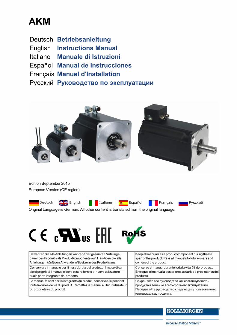
AKM
Deutsch BetriebsanleitungEnglish Instructions ManualItaliano Manuale di IstruzioniEspañol Manual de InstruccionesFrançais Manuel d'InstallationРусский Руководство по эксплуатации
Edition September 2015European Version (CE region)
Deutsch English Italiano Español Français Русский
Original Language is German. All other content is translated from the original language.
Bewahren Sie alle Anleitungen während der gesamten Nutzungs-dauer desProdukts alsProduktkomponente auf. Händigen Sie alleAnleitungen künftigen Anwendern/Besitzern desProdukts aus.
Keep allmanuals asa product component during the lifespan of the product. Passallmanuals to future users andowners of the product.
Conservare ilmanuale per l’intera durata del prodotto. In caso di cam-bio di proprietà ilmanuale deve essere fornito al nuovo utilizzatorequale parte integrante del prodotto.
Conserve elmanual durante toda la vida útil del producto.Entregue elmanual a posterioresusuarios o propietarios delproducto.
Lemanuel faisant partie intégrante du produit, conservez-le pendanttoute la durée de vie du produit. Remettez le manuel au futur utilisateurou propriétaire du produit.
Сохраняйте все руководства как составную частьпродукта в течение всего срока его эксплуатации.Передавайте руководство следующемупользователюили владельцупродукта.
Record of Document Revisions
Revision Remarks... Table with lifecycle information of this document ( # 198)12 / 2014 Technical data holding brakes updated, Connector-Feedback relationship table new04 / 2015 EAC certification, connector/feedback tables optimized, Molex connectors removed, shaft seal
run-in added,FR/FA diagram for AKM8with enforced bearing added, AKM 2/3 SpeedTec con-nectors, RoHS and REACH statements added
09 / 2015 Back cover page updated, DriveCLiQ feedback added, Washdown information updated (flanges),AKM64Q data (R, L) corrected, Safety feedback devices added, Connector-Feedback tableupdated, y-tec Comcoder pinout new
Table of Contents
Betriebsanleitung Deutsch ( # 3) Technical Data ( # 161)
Instructions Manual English ( # 29) Dimension Drawings ( # 175)
Manuale di Istruzioni Italiano ( # 55) Connector Pinout ( # 189)
Manual de Instrucciones Español ( # 81) Approvals ( # 196)
Manuel d'Installation Français ( # 107)
Руководство по эксплуатации Русский ( # 133)
Trademarks
EnDat is a registered trademark of Dr. Johannes Heidenhain GmbHHIPERFACE is a registered trademark of Max StegmannGmbHDRIVE-CLiQ and SIMATIC are registered trademarks of SIEMENS Aktiengesellschaft
Technische Änderungen, die der Verbesserung der Geräte dienen, vorbehalten!Gedruckt in der BRD. Alle Rechte vorbehalten. Kein Teil des Werkes darf in irgendeiner Form (Fotokopie, Mikrofilmoder in einem anderen Verfahren) ohne schriftliche Genehmigung der Firma Kollmorgen Europe GmbH reproduziertoder unter Verwendung elektronischer Systeme verarbeitet, vervielfältigt oder verbreitet werden.Technical changes to improve the performance of the equipment may be made without prior notice!Printed in the Federal Republic of Germany. All rights reserved. No part of this work may be reproduced in any form(by photocopying, microfilm or any other method) or stored, processed, copied or distributed by electronic meanswithout the written permission of Kollmorgen Europe GmbH.Il produttore si riserva la facoltà di apportare modifiche tecniche volte al miglioramento degli apparecchiStampato nella Repubblica federale tedesca. Tutti i diritti riservati. Nessuna parte di questo documento può essererielaborata, riprodotta in qualsiasi forma (fotocopia, microfilm o altro processo) o diffusa mediante l'uso di sistemielettronici senza l'approvazione scritta della ditta Kollmorgen Europe GmbH o rielaborata, riprodotta o diffusa medi-ante l’uso di sistemi elettronici.Reservado el derecho de introducir modificaciones técnicas para la mejora de los equiposImpreso en la RFA. Reservados todos los derechos. Prohibida la reproducción total o parcial de la presente obrapor cualquier medio (fotocopia, microfilm u otros), así como su procesamiento, reproducción y divulgación por mediode sistemas electrónicos, sin expresa autorización escrita de la empresa Kollmorgen Europe GmbH.Toutes modifications techniques concourant pour l'amélioration des appareils réservées !Imprimé en Allemagne. Tous droits réservés. Aucune partie de l'ouvrage ne peut être reproduite sous quelque formeque ce soit (imprimée, photocopiée, microfilmée ou par un autre procédé) ou encore traitée, reproduite ou diffuséeau moyen de systèmes électroniques sans autorisation écrite préalable de Kollmorgen Europe GmbH.Сохраняется право вносить технические изменения, служащие для совершенствования устройств!Напечатано в ФРГ. Все права защищены. Без письменного согласия фирмы Kollmorgen Europe GmbHзапрещается воспроизводить какие бы то ни было части данного руководства в любой форме (в печатной, ввиде фотокопии, микрофильма или другим способом), а также обрабатывать, размножать или распространятьих с использованием электронных систем.
2 Kollmorgen | September 2015
1 Deutsch
1.1 Allgemeines 41.1.1 Über dieses Handbuch 41.1.2 Verwendete Symbole 41.1.3 Verwendete Abkürzungen 4
1.2 Sicherheit 51.2.1 Das sollten Sie beachten 51.2.2 Bestimmungsgemäße Verwendung 71.2.3 Nicht bestimmungsgemäße Verwendung 71.2.4 Handhabung 8
1.3 Produktidentifizierung 101.3.1 Lieferumfang 101.3.2 Typenschild 101.3.3 Typenschlüssel 11
1.4 Technische Beschreibung 151.4.1 Allgemeine technische Daten 151.4.2 Bauform 151.4.3 Flansch 151.4.4 Schutzart 151.4.5 Isolierstoffklasse 161.4.6 Oberfläche 161.4.7Wellenende A-Seite 161.4.8 Schutzeinrichtung 161.4.9 Schwinggüte 161.4.10Wellendichtung 171.4.11 Anschlusstechnik 171.4.12 Haltebremse 181.4.13 Lüfter für AKM7 181.4.14Washdown undWashdown Food 19
1.5 Mechanische Installation 221.5.1Wichtige Hinweise 22
1.6 Elektrische Installation 231.6.1Wichtige Hinweise 231.6.2 Leitfaden für die elektrische Installation 241.6.3 Anschluss der Motorenmit vorkonfektionierten Kabeln 24
1.7 Inbetriebnahme 251.7.1Wichtige Hinweise 251.7.2 Leitfaden für die Inbetriebnahme 261.7.3 Beseitigen von Störungen 27
1.8 Begriffsdefinitionen der technischen Daten 28
AKM Installation | 1 Deutsch
Kollmorgen | September 2015 3
AKM Installation | 1 Deutsch
1.1 Allgemeines
1.1.1 Über dieses HandbuchDieses Handbuch beschreibt die Synchron-Servomotoren der Serie AKM (Stan-dardausführung). DieMotoren werden im Antriebssystem zusammenmit den KollmorgenServoverstärkern betrieben. Beachten Sie daher die gesamte Dokumentation des Systems,bestehend aus:
Betriebsanleitung des ServoverstärkersHandbuch Bus-Kommunikation (z.B CANopen oder EtherCAT)Online Hilfe der Inbetriebnahmesoftware des ServoverstärkersRegionales ZubehörhandbuchBetriebsanleitungMotorserie AKM (dieses Handbuch)
Weitere Hintergrundinformationen finden Sie im "Produkt-WIKI"(www.wiki-kollmorgen.eu).
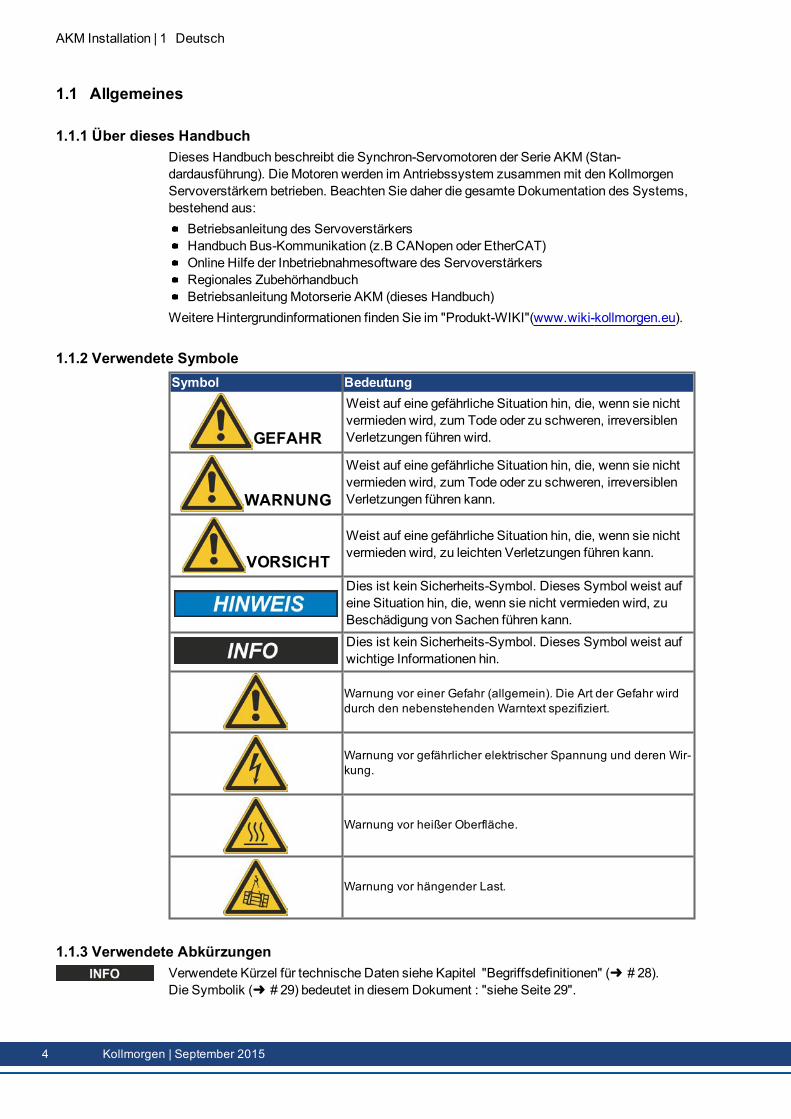
1.1.2 Verwendete SymboleSymbol Bedeutung
GEFAHR
Weist auf eine gefährliche Situation hin, die, wenn sie nichtvermieden wird, zum Tode oder zu schweren, irreversiblenVerletzungen führen wird.
WARNUNG
Weist auf eine gefährliche Situation hin, die, wenn sie nichtvermieden wird, zum Tode oder zu schweren, irreversiblenVerletzungen führen kann.
VORSICHTWeist auf eine gefährliche Situation hin, die, wenn sie nichtvermieden wird, zu leichten Verletzungen führen kann.
Dies ist kein Sicherheits-Symbol. Dieses Symbol weist aufeine Situation hin, die, wenn sie nicht vermieden wird, zuBeschädigung von Sachen führen kann.Dies ist kein Sicherheits-Symbol. Dieses Symbol weist aufwichtige Informationen hin.
Warnung vor einer Gefahr (allgemein). Die Art der Gefahr wirddurch den nebenstehenden Warntext spezifiziert.
Warnung vor gefährlicher elektrischer Spannung und deren Wir-kung.
Warnung vor heißer Oberfläche.
Warnung vor hängender Last.
1.1.3 Verwendete AbkürzungenVerwendete Kürzel für technische Daten siehe Kapitel "Begriffsdefinitionen" ( # 28).Die Symbolik ( # 29) bedeutet in diesem Dokument : "siehe Seite 29".
4 Kollmorgen | September 2015
1.2 SicherheitDieses Kapitel hilft Ihnen, Gefahren zu erkennen und zu vermeiden.
1.2.1 Das sollten Sie beachten
Fachpersonal erforderlich!Nur qualifiziertes Fachpersonal darf Arbeiten wie Transport, Montage, Inbetriebnahme undInstandhaltung ausführen. Qualifiziertes Fachpersonal sind Personen, die mit Transport, Auf-stellung, Montage, Inbetriebnahme und Betrieb vonMotoren vertraut sind und über die ihrerTätigkeit entsprechendenMindestqualifikationen verfügen:
Transport: nur durch Personal mit Kenntnissen in der Behandlung elektrostatisch gefähr-deter BauelementeMech. Installation: nur durch Fachleutemit maschinenbautechnischer Ausbildung.Elektr. Installation: nur durch Fachleutemit elektrotechnischer Ausbildung.Inbetriebnahme: nur durch Fachleutemit weitreichenden Kenntnissen in den BereichenElektrotechnik / Antriebstechnik
Das Fachpersonal muss ebenfalls IEC 60364 / IEC 60664 und nationale Unfall-verhütungsvorschriften kennen und beachten.
Dokumentation lesen!Lesen Sie vor der Montage und Inbetriebnahme die vorliegende Dokumentation. FalschesHandhaben des Motors kann zu Personen- oder Sachschäden führen. Der Betreiber mussdaher sicherstellen, dass alle mit Arbeiten amMotor betrauten Personen das Handbuch gele-sen und verstanden haben und dass die Sicherheitshinweise in diesem Handbuch beachtetwerden.
Technische Daten beachten!Halten Sie die technischen Daten und die Angaben zu den Anschlussbedingungen (Typen-schild und Dokumentation) ein. Wenn zulässige Spannungswerte oder Stromwerte über-schritten werden, können dieMotoren z.B. durch Überhitzung geschädigt werden.
Risikobeurteilung erstellen!DerMaschinenhersteller muss eine Risikobeurteilung für die Maschine erstellen und geeig-neteMaßnahmen treffen, dass unvorhergesehene Bewegungen nicht zu Schäden an Per-sonen oder Sachen führen können. Aus der Risikobeurteilung leiten sich eventuell auchzusätzliche Anforderungen an das Fachpersonal ab.
Sicher transportieren!Heben und bewegen SieMotorenmit mehr als 20kgGewicht (AKM7 und AKM8) nur mit Hilfevon Hebevorrichtungen. Heben ohne Hilfsmittel kann zu Rückenverletzungen führen. Beach-ten Sie die Hinweise auf ( # 8)
Passfeder sichern!Entfernen oder sichern Sie eine eventuell vorhandeneWellen-Passfeder, falls der Motorohne angekoppelte Last laufen soll, um einWegschleudern der Passfeder und die damit ver-bundene Verletzungsgefahr zu vermeiden. Im Auslieferzustand ist die Passfeder mit einerKunststoffkappe gesichert.
AKM Installation | 1 Deutsch
Kollmorgen | September 2015 5
AKM Installation | 1 Deutsch
Heiße Oberfläche!Während des Betriebes könnenMotoren ihrer Schutzart entsprechend heißeOberflächenbesitzen. Leichte Verbrennungsgefahr! Die Oberflächentemperatur kann 100°C über-schreiten. Messen Sie die Temperatur und warten Sie, bis der Motor auf 40°C abgekühlt ist,bevor Sie ihn berühren.
Erdung! Hohe Spannungen!Stellen Sie die ordnungsgemäße Erdung des Motors mit der PE-Schiene im Schaltschrankals Bezugspotential sicher. Ohne niederohmige Erdung ist keine personelle Sicherheitgewährleistet und es besteht Lebensgefahr durch elektrischen Schlag.Das Fehlen von optische Anzeigen gewährleisten nicht die Spannungsfreiheit. Leis-tungsanschlüsse können Spannung führen, auch wenn sich der Motor nicht dreht.Ziehen Sie keine Stecker während des Betriebs. Es besteht die Gefahr von Tod oder schwe-ren gesundheitlichen Schäden beim Berühren freiliegender Kontakte. In ungünstigen Fällenkönnen Lichtbögen entstehen und Personen und Kontakte schädigen.Warten Sie nach dem Trennen der Servoverstärker von den Versorgungsspannungenmeh-rereMinuten, bevor Sie spannungsführende Teile (z.B. Kontakte, Gewindebolzen) berührenoder Anschlüsse lösen.Kondensatoren im Servoverstärker führenmehrereMinuten nach Abschalten der Ver-sorgungsspannungen gefährliche Spannungen. Messen Sie zur Sicherheit die Spannung imZwischenkreis und warten Sie, bis die Spannung unter 60V abgesunken ist.
Hängende Lasten sichern!Eingebaute Haltebremsen sind nicht funktional sicher. Insbesondere bei hängender Last(Vertikalachsen) kann die funktionale Sicherheit nur mit einer zusätzlichen, externenmechanischen Bremse erreicht werden.
6 Kollmorgen | September 2015
1.2.2 Bestimmungsgemäße VerwendungSynchron-Servomotoren der Serie AKM sind insbesondere als Antrieb für Hand-habungsgeräte, Textilmaschinen, Werkzeugmaschinen, Verpackungsmaschinen undähnlichemit hohen Ansprüchen an die Dynamik konzipiert.Sie dürfen dieMotoren nur unter Berücksichtigung der in dieser Dokumentation defi-nierten Umgebungsbedingungen betreiben.Der Betrieb vonWashdownMotoren ist in Umgebungenmit ätzenden Säuren und Lau-gen unter Berücksichtigung der auf Seite ( # 19) definierten Bedingungen erlaubt.Der Betrieb vonWashdown FoodMotoren ist in Applikationenmit indirektem Kontakt zuLebensmitteln erlaubt.DieMotoren der Serie AKM sind ausschließlich dazu bestimmt, von digitalen Ser-voverstärkern drehzahl- und/oder drehmomentgeregelt angesteuert zu werden.DieMotoren werden als Bauteile in elektrische Anlagen oder Maschinen eingebaut unddürfen nur als integrierte Bauteile der Anlage in Betrieb genommenwerden.Der in die Motorwicklungen eingebaute Thermoschutzsensor muss ausgewertet und über-wacht werden.Eingebaute Haltebremsen sind als Stillstandsbremsen ausgelegt und für dauernde,betriebsmäßige Abbremsvorgänge ungeeignet.Die Konformität des Servosystems zu den in der EG-Konformitätserklärung ( # 196)genannten Normen garantieren wir nur, wenn von uns gelieferte Komponenten (Ser-voverstärker, Motor, Leitungen usw.) verwendet werden.
1.2.3 Nicht bestimmungsgemäße VerwendungDer Betrieb vonStandardMotoren ist verboten
direkt am Netz,in explosionsgefährdeten Bereichen,im Kontakt mit Lebensmitteln,in Umgebungenmit ätzenden und/oder elektrisch leitenden Säuren, Laugen, Ölen,Dämpfen, Stäuben.
Der Betrieb vonWashdownMotoren ist verbotendirekt am Netz,in explosionsgefährdeten Bereichen,im Kontakt mit Lebensmitteln,in Umgebungenmit Säuren oder Laugenmit PH Wert kleiner 2 oder größer 12,in Umgebungenmit Säuren oder Laugen die nicht von Kollmorgen getestet wurden.
Der Betrieb vonWashdown FoodMotoren ist verbotendirekt am Netz,in explosionsgefährdeten Bereichen,im direkten Kontakt mit Lebensmitteln.
Der bestimmungsgemäße Betrieb des Motors ist untersagt, wenn dieMaschine, in die ereingebaut wurde,
nicht den Bestimmungen der EGMaschinenrichtlinie entspricht,nicht die Bestimmung der EMV-Richtlinie erfüllt,nicht die Bestimmung der Niederspannungs-Richtlinie erfüllt.
Eingebaute Haltebremsen alleine dürfen nicht für die Sicherstellung der funktionalenSicherheit benutzt werden.
AKM Installation | 1 Deutsch
Kollmorgen | September 2015 7
AKM Installation | 1 Deutsch
1.2.4 Handhabung
1.2.4.1 TransportKlimaklasse 2K3 nach EN61800-2, IEC 60721-3-2Temperatur: -25..+70°C, max. 20K/Stunde schwankendLuftfeuchtigkeit: relative Feuchte 5% ... 95% nicht kondensierendNur von qualifiziertem Personal in der Original-Verpackung des HerstellersVermeiden Sie harte Stöße, insbesondere auf das WellenendeÜberprüfen Sie bei beschädigter Verpackung denMotor auf sichtbare Schäden. Infor-mieren Sie den Transporteur und gegebenenfalls den Hersteller.
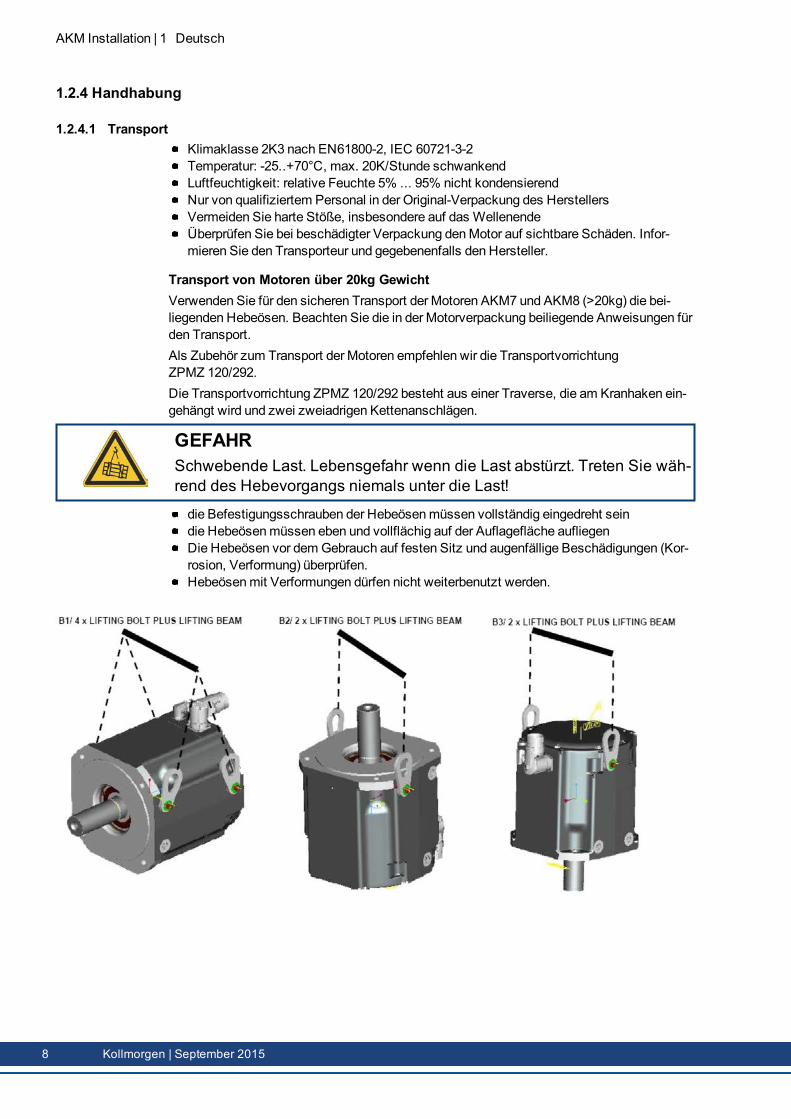
Transport von Motoren über 20kg GewichtVerwenden Sie für den sicheren Transport der Motoren AKM7 und AKM8 (>20kg) die bei-liegenden Hebeösen. Beachten Sie die in der Motorverpackung beiliegende Anweisungen fürden Transport.Als Zubehör zum Transport der Motoren empfehlen wir die TransportvorrichtungZPMZ 120/292.Die Transportvorrichtung ZPMZ 120/292 besteht aus einer Traverse, die am Kranhaken ein-gehängt wird und zwei zweiadrigen Kettenanschlägen.
GEFAHRSchwebende Last. Lebensgefahr wenn die Last abstürzt. Treten Sie wäh-rend des Hebevorgangs niemals unter die Last!
die Befestigungsschrauben der Hebeösenmüssen vollständig eingedreht seindie Hebeösenmüssen eben und vollflächig auf der Auflagefläche aufliegenDie Hebeösen vor demGebrauch auf festen Sitz und augenfällige Beschädigungen (Kor-rosion, Verformung) überprüfen.Hebeösenmit Verformungen dürfen nicht weiterbenutzt werden.
8 Kollmorgen | September 2015
1.2.4.2 VerpackungKartonverpackungmit Instapak®-Ausschäumung.Den Kunststoffanteil können Sie an den Lieferanten zurückgeben
Motortyp Verpackung Max. Sta-pelhöhe
Motortyp Verpackung Max. Sta-pelhöhe
AKM1 Karton 10 AKM5 Karton 5AKM2 Karton 10 AKM6 Karton 1AKM3 Karton 6 AKM7 Karton 1AKM4 Karton 6 AKM8 Mini-Palette 1
1.2.4.3 LagerungKlimaklasse 1K4 nach EN61800-2, IEC 60721-3-2Lagertemperatur-25...+55°C, max. 20K/Stunde schwankendLuftfeuchtigkeitrelative Feuchte 5% ... 95% nicht kondensierendNur in der Originalverpackung des Herstellers lagernMax. Stapelhöhe:siehe Tabelle in Kapitel "Verpackung"Lagerdauer:ohne Einschränkung
1.2.4.4 Wartung / ReinigungWartung und Reinigung nur von qualifiziertem Personal.Nach 20.000 Betriebsstunden unter Nennbedingungen sollten die Kugellager erneuert wer-den (vom Hersteller).Prüfen Sie denMotor alle 2500 Betriebsstunden bzw. einmal jährlich auf Kugel-lagergeräusche. Wenn Sie Geräusche feststellen, darf der Motor nicht weiterbetriebenwerden - die Lager müssen vom Hersteller erneuert werden.Öffnen der Motoren bedeutet den Verlust der Gewährleistung.Gehäusereinigungmit Isopropanol o.ä., nicht tauchen oder absprühen.
1.2.4.5 Reparatur / EntsorgungReparaturen des Motors darf nur der Hersteller durchführen, Öffnen der Geräte bedeutet Ver-lust der Gewährleistung. Gemäß derWEEE-2002/96/EG-Richtlinien nehmenwir Altgeräteund Zubehör zur fachgerechten Entsorgung zurück, sofern die Transportkosten vom Absen-der übernommenwerden. Schicken Sie denMotor an:KOLLMORGEN EuropeGmbHPempelfurtstr. 1D-40880 Ratingen
AKM Installation | 1 Deutsch
Kollmorgen | September 2015 9
AKM Installation | 1 Deutsch
1.3 Produktidentifizierung
1.3.1 LieferumfangMotor der Serie AKMProdukthandbuch gedruckt, mehrsprachig, einmal pro Lieferung
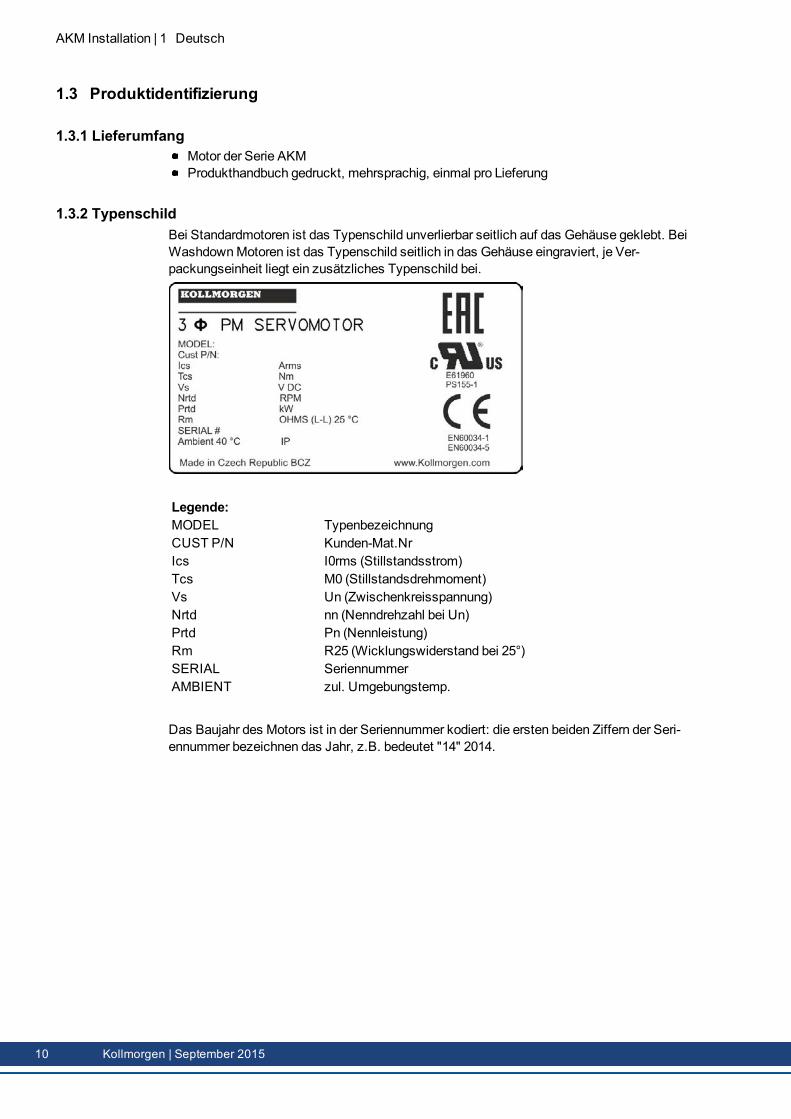
1.3.2 TypenschildBei Standardmotoren ist das Typenschild unverlierbar seitlich auf das Gehäuse geklebt. BeiWashdownMotoren ist das Typenschild seitlich in das Gehäuse eingraviert, je Ver-packungseinheit liegt ein zusätzliches Typenschild bei.
Legende:MODEL TypenbezeichnungCUST P/N Kunden-Mat.NrIcs I0rms (Stillstandsstrom)Tcs M0 (Stillstandsdrehmoment)Vs Un (Zwischenkreisspannung)Nrtd nn (Nenndrehzahl bei Un)Prtd Pn (Nennleistung)Rm R25 (Wicklungswiderstand bei 25°)SERIAL SeriennummerAMBIENT zul. Umgebungstemp.
Das Baujahr des Motors ist in der Seriennummer kodiert: die ersten beiden Ziffern der Seri-ennummer bezeichnen das Jahr, z.B. bedeutet "14" 2014.
10 Kollmorgen | September 2015
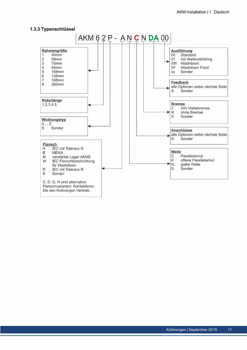
1.3.3 Typenschlüssel
AKM Installation | 1 Deutsch
Kollmorgen | September 2015 11
AKM Installation | 1 Deutsch
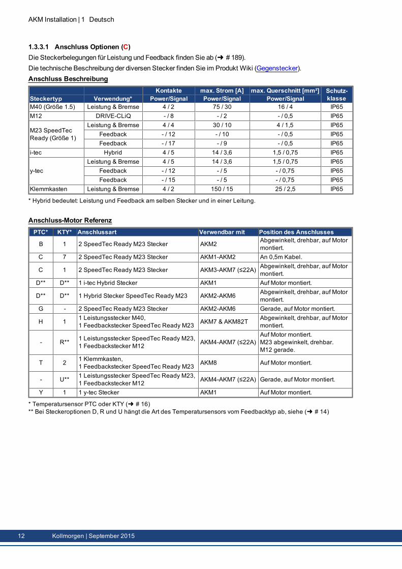
1.3.3.1 Anschluss Optionen (C)Die Steckerbelegungen für Leistung und Feedback finden Sie ab ( # 189).Die technische Beschreibung der diversen Stecker finden Sie im Produkt Wiki (Gegenstecker).Anschluss Beschreibung
Kontakte max. Strom [A] max. Querschnitt [mm²] Schutz-klasseSteckertyp Verwendung* Power/Signal Power/Signal Power/Signal
M40 (Größe 1.5) Leistung & Bremse 4 / 2 75 / 30 16 / 4 IP65M12 DRIVE-CLiQ - / 8 - / 2 - / 0,5 IP65
M23 SpeedTecReady (Größe 1)
Leistung & Bremse 4 / 4 30 / 10 4 / 1,5 IP65Feedback - / 12 - / 10 - / 0,5 IP65Feedback - / 17 - / 9 - / 0,5 IP65
i-tec Hybrid 4 / 5 14 / 3,6 1,5 / 0,75 IP65
y-tecLeistung & Bremse 4 / 5 14 / 3,6 1,5 / 0,75 IP65
Feedback - / 12 - / 5 - / 0,75 IP65Feedback - / 15 - / 5 - / 0,75 IP65
Klemmkasten Leistung & Bremse 4 / 2 150 / 15 25 / 2,5 IP65
* Hybrid bedeutet: Leistung und Feedback am selben Stecker und in einer Leitung.
Anschluss-Motor ReferenzPTC* KTY* Anschlussart Verwendbar mit Position des Anschlusses
B 1 2 SpeedTec Ready M23 Stecker AKM2 Abgewinkelt, drehbar, auf Motormontiert.
C 7 2 SpeedTec Ready M23 Stecker AKM1-AKM2 An 0,5m Kabel.
C 1 2 SpeedTec Ready M23 Stecker AKM3-AKM7 (≤22A) Abgewinkelt, drehbar, auf Motormontiert.
D** D** 1 i-tec Hybrid Stecker AKM1 Auf Motor montiert.
D** D** 1 Hybrid Stecker SpeedTec Ready M23 AKM2-AKM6 Abgewinkelt, drehbar, auf Motormontiert.
G - 2 SpeedTec Ready M23 Stecker AKM2-AKM6 Gerade, auf Motor montiert.
H 1 1 Leistungsstecker M40,1 Feedbackstecker SpeedTec Ready M23 AKM7 & AKM82T Abgewinkelt, drehbar, auf Motor
montiert.
- R** 1 Leistungsstecker SpeedTec Ready M23,1 Feedbackstecker M12 AKM4-AKM7 (≤22A)
Auf Motor montiert.M23 abgewinkelt, drehbar.M12 gerade.
T 2 1 Klemmkasten,1 Feedbackstecker SpeedTec Ready M23 AKM8 Auf Motor montiert.
- U** 1 Leistungsstecker SpeedTec Ready M23,1 Feedbackstecker M12 AKM4-AKM7 (≤22A) Gerade, auf Motor montiert.
Y 1 1 y-tec Stecker AKM1 Auf Motor montiert.
* Temperatursensor PTC oder KTY ( # 16)** Bei Steckeroptionen D, R und U hängt die Art des Temperatursensors vom Feedbacktyp ab, siehe ( # 14)
12 Kollmorgen | September 2015
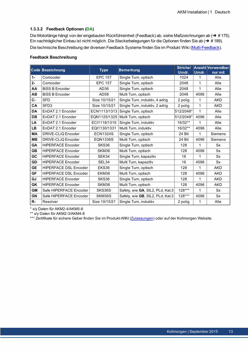
1.3.3.2 Feedback Optionen (DA)DieMotorlänge hängt von der eingebauten Rückführeinheit (Feedback) ab, sieheMaßzeichnungen ab ( # 175).Ein nachträglicher Einbau ist nicht möglich. Die Steckerbelegungen für die Optionen finden Sie ab ( # 189).Die technische Beschreibung der diversen Feedback Systeme finden Sie im Produkt Wiki (Multi-Feedback).
Feedback Beschreibung
Code Bezeichnung Type Bemerkung Striche/Umdr.
AnzahlUmdr.
Verwendbarnur mit
1- Comcoder EPC 15T Single Turn, optisch 1024 1 Alle2- Comcoder EPC 15T Single Turn, optisch 2048 1 AlleAA BiSS B Encoder AD36 Single Turn, optisch 2048 1 AlleAB BiSS B Encoder AD58 Multi Turn, optisch 2048 4096 AlleC- SFD Size 10/15/21 Single Turn, induktiv, 4 adrig 2 polig 1 AKDCA SFD3 Size 10/15/21 Single Turn, induktiv, 2 adrig 2 polig 1 AKDDA EnDAT 2.1 Encoder ECN1113/1313 Single Turn, optisch 512/2048* 1 AlleDB EnDAT 2.1 Encoder EQN1125/1325 Multi Turn, optisch 512/2048* 4096 AlleLA EnDAT 2.1 Encoder ECI1118/1319 Single Turn, induktiv 16/32** 1 AlleLB EnDAT 2.1 Encoder EQI1130/1331 Multi Turn, induktiv 16/32** 4096 AlleMA DRIVE-CLiQ Encoder ECN1324S Single Turn, optisch 24 Bit 1 SiemensMB DRIVE-CLiQ Encoder EQN1336S Multi Turn, optisch 24 Bit 4096 SiemensGA HIPERFACE Encoder SKS36 Single Turn, optisch 128 1 SxGB HIPERFACE Encoder SKM36 Multi Turn, optisch 128 4096 SxGC HIPERFACE Encoder SEK34 Single Turn, kapazitiv 16 1 SxGD HIPERFACE Encoder SEL34 Multi Turn, kapazitiv 16 4096 SxGE HIPERFACE DSL Encoder EKS36 Single Turn, optisch 128 1 AKDGF HIPERFACE DSL Encoder EKM36 Multi Turn, optisch 128 4096 AKDGJ HIPERFACE Encoder SKS36 Single Turn, optisch 128 1 AKDGK HIPERFACE Encoder SKM36 Multi Turn, optisch 128 4096 AKDGM Safe HIPERFACE Encoder SKS36S Safety, wie GA, SIL2, PLd, Kat.3 128*** 1 SxGN Safe HIPERFACE Encoder SKM36S Safety, wie GB, SIL2, PLd, Kat.3 128*** 4096 SxR- Resolver Size 10/15/21 Single Turn, induktiv 2 polig 1 Alle
* x/y Daten für AKM2-4/AKM5-8** x/y Daten für AKM2-3/AKM4-8*** Zertifikate für sichere Geber finden Sie im Produkt-WIKI (Zulassungen) oder auf der Kollmorgen Website.
AKM Installation | 1 Deutsch
Kollmorgen | September 2015 13
AKM Installation | 1 Deutsch
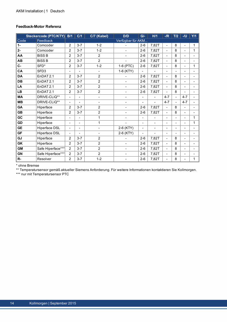
Feedback-Motor Referenz
Steckercode (PTC/KTY) B/1 C/1 C/7 (Kabel) D/D G/- H/1 -/R T/2 -/U Y/1Code Feedback Verfügbar für AKM...1- Comcoder 2 3-7 1-2 - 2-6 7,82T - 8 - 12- Comcoder 2 3-7 1-2 - 2-6 7,82T - 8 - 1AA BiSS B 2 3-7 2 - 2-6 7,82T - 8 - -AB BiSS B 2 3-7 2 - 2-6 7,82T - 8 - -C- SFD* 2 3-7 1-2 1-6 (PTC) 2-6 7,82T - 8 - 1CA SFD3 - - - 1-6 (KTY) - - - - - -DA EnDAT 2.1 2 3-7 2 - 2-6 7,82T - 8 - -DB EnDAT 2.1 2 3-7 2 - 2-6 7,82T - 8 - -LA EnDAT 2.1 2 3-7 2 - 2-6 7,82T - 8 - -LB EnDAT 2.1 2 3-7 2 - 2-6 7,82T - 8 - -MA DRIVE-CLiQ** - - - - - - 4-7 - 4-7 -MB DRIVE-CLiQ** - - - - - - 4-7 - 4-7 -GA Hiperface 2 3-7 2 - 2-6 7,82T - 8 - -GB Hiperface 2 3-7 2 - 2-6 7,82T - 8 - -GC Hiperface - - 1 - - - - - - 1GD Hiperface - - 1 - - - - - - 1GE Hiperface DSL - - - 2-6 (KTY) - - - - - -GF Hiperface DSL - - - 2-6 (KTY) - - - - - -GJ Hiperface 2 3-7 2 - 2-6 7,82T - 8 - -GK Hiperface 2 3-7 2 - 2-6 7,82T - 8 - -GM Safe Hiperface*** 2 3-7 2 - 2-6 7,82T - 8 - -GN Safe Hiperface*** 2 3-7 2 - 2-6 7,82T - 8 - -R- Resolver 2 3-7 1-2 - 2-6 7,82T - 8 - 1
* ohne Bremse** Temperatursensor gemäß aktueller Siemens Anforderung. Für weitere Informationen kontaktieren Sie Kollmorgen.*** nur mit Temperatursensor PTC
14 Kollmorgen | September 2015
1.4 Technische Beschreibung
1.4.1 Allgemeine technische DatenUmgebungstemperatur(bei Nenndaten)
5...+40°C bei Aufstellhöhe bis 1000m über NNSprechen Sie bei Umgebungstemperaturen über 40°C und beigekapseltem Einbau der Motoren unbedingt mit unserer Appli-kationsabteilung.
Zulässige Luftfeuchte(bei Nenndaten)
95% relative Feuchte, nicht betauend
Leistungsreduzierung(Ströme und Momente)
1%/K im Bereich 40°C...50°C bis 1000m über NNBei Aufstellhöhen über 1000m über NN und 40°C6% bei 2000m über NN17% bei 3000m über NN30% bei 4000m über NN55% bei 5000m über NNKeine Leistungsreduzierung bei Aufstellhöhen über 1000m überNN und Temperaturreduzierung um 10K / 1000m
Kugellager-Lebensdauer ≥ 20.000 BetriebsstundenTechnische Daten der Motortypen finden Sie im Kapitel "Technical Data" ab ( # 161).
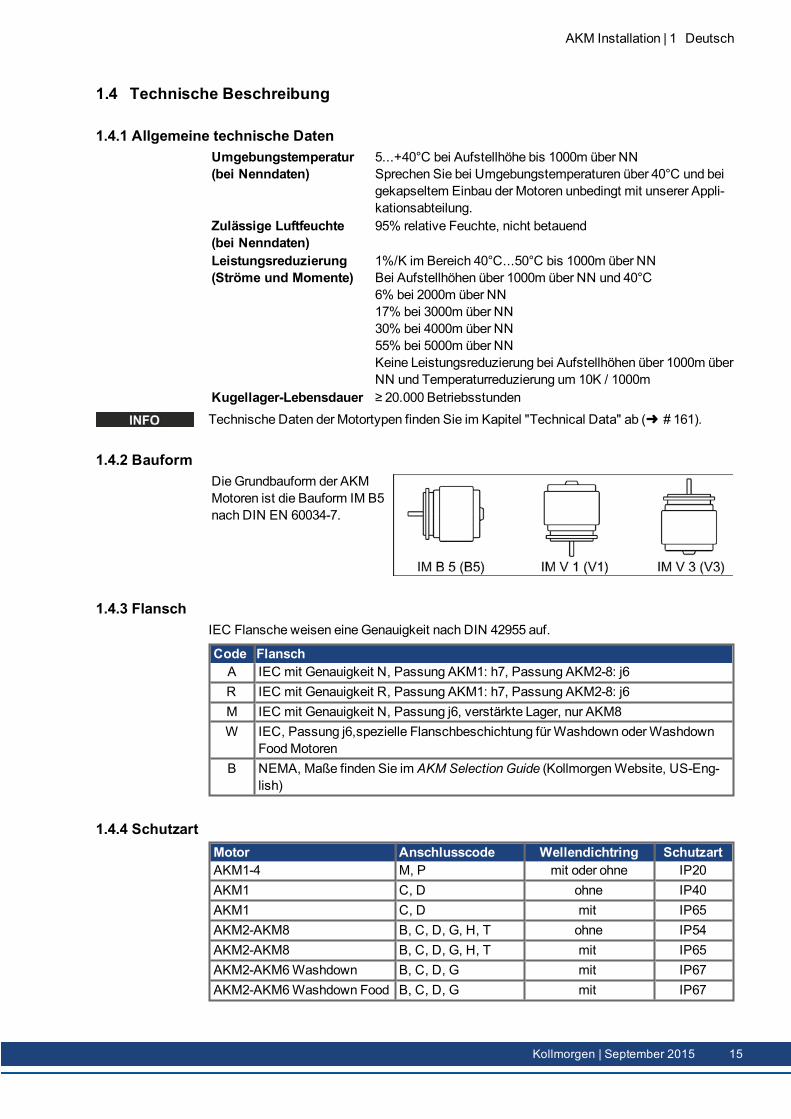
1.4.2 BauformDie Grundbauform der AKMMotoren ist die Bauform IM B5nach DIN EN 60034-7.
1.4.3 FlanschIEC Flansche weisen eine Genauigkeit nach DIN 42955 auf.
Code FlanschA IEC mit Genauigkeit N, Passung AKM1: h7, Passung AKM2-8: j6R IEC mit Genauigkeit R, Passung AKM1: h7, Passung AKM2-8: j6M IEC mit Genauigkeit N, Passung j6, verstärkte Lager, nur AKM8W IEC, Passung j6,spezielle Flanschbeschichtung fürWashdown oderWashdown
FoodMotorenB NEMA, Maße finden Sie im AKM Selection Guide (KollmorgenWebsite, US-Eng-
lish)
1.4.4 SchutzartMotor Anschlusscode Wellendichtring SchutzartAKM1-4 M, P mit oder ohne IP20AKM1 C, D ohne IP40AKM1 C, D mit IP65AKM2-AKM8 B, C, D, G, H, T ohne IP54AKM2-AKM8 B, C, D, G, H, T mit IP65AKM2-AKM6Washdown B, C, D, G mit IP67AKM2-AKM6Washdown Food B, C, D, G mit IP67
AKM Installation | 1 Deutsch
Kollmorgen | September 2015 15
AKM Installation | 1 Deutsch
1.4.5 IsolierstoffklasseDieMotoren entsprechen der Isolierstoffklasse F nach IEC 60085 (UL 1446 class F).
1.4.6 OberflächeDieMotoren sindmattschwarz mit Polyester pulverbeschichtet, eine Beständigkeit gegenLösungsmittel (Tri, Verdünnung o.ä.) besteht nicht.
1.4.7 Wellenende A-SeiteDie Kraftübertragung erfolgt über das zylindrischeWellenende A, Passung k6 (AKM1: h7)nach EN50347mit Anzuggewinde aber ohne Passfedernut. Für die Lebensdauer der Lagersind 20.000 Betriebsstunden zugrunde gelegt.
Bestellcode Wellenende verfügbar fürN Glatte Welle Alle Typen, StandardC Passfedernut, geschlossen AKM 2...8K Passfedernut, offen AKM 1...8
RadialkraftTreiben dieMotoren über Ritzel oder Zahnriemen an, so treten hohe Radialkräfte auf.ZugelasseneWerte amWellenende abhängig von der Drehzahl: Diagramme ab ( # 175).ZugelassenenMaximalwerte: Kapitel "Technical Data" ab ( # 161).Bei Kraftangriff an der Mitte des freienWellenendes darf FR 10% größer sein.
AxialkraftBei der Montage von Ritzel oder Riemenscheiben auf dieWelle und bei Betrieb von z.B. Win-kelgetrieben treten Axialkräfte auf. Die zugelassenenMaximalwerte finden Sie in den tech-nischen Daten.
KupplungAls ideale spielfreie Kupplungselemente haben sich doppelt konische Spannzangen even-tuell in Verbindungmit Metallbalg-Kupplungen bewährt.
1.4.8 SchutzeinrichtungIn der Standardausführung ist jeder Motor mit einem potentialfreien PTC Temperatursensorausgestattet. Der Schaltpunkt liegt bei 155°C ± 5%. Schutz gegen kurzzeitige, sehr hoheÜberlastung bietet der PTC nicht.Optional kann der Motor mit einem KTY 84-130 Sensor ausgerüstet werden (siehe Anschlus-soption 1, 2, 7 und D ( # 189)).Bei den digitalen Feedbacks SFD, SFD3, DSL (C-, CA, GE, GF) wird der Status des Tem-peratursensors digital übertragen und im Servoverstärker ausgewertet.Der Sensor ist bei Verwendung unserer konfektionierten Feedbackleitungen in das Über-wachungssystem der digitalen Servoverstärker integriert.
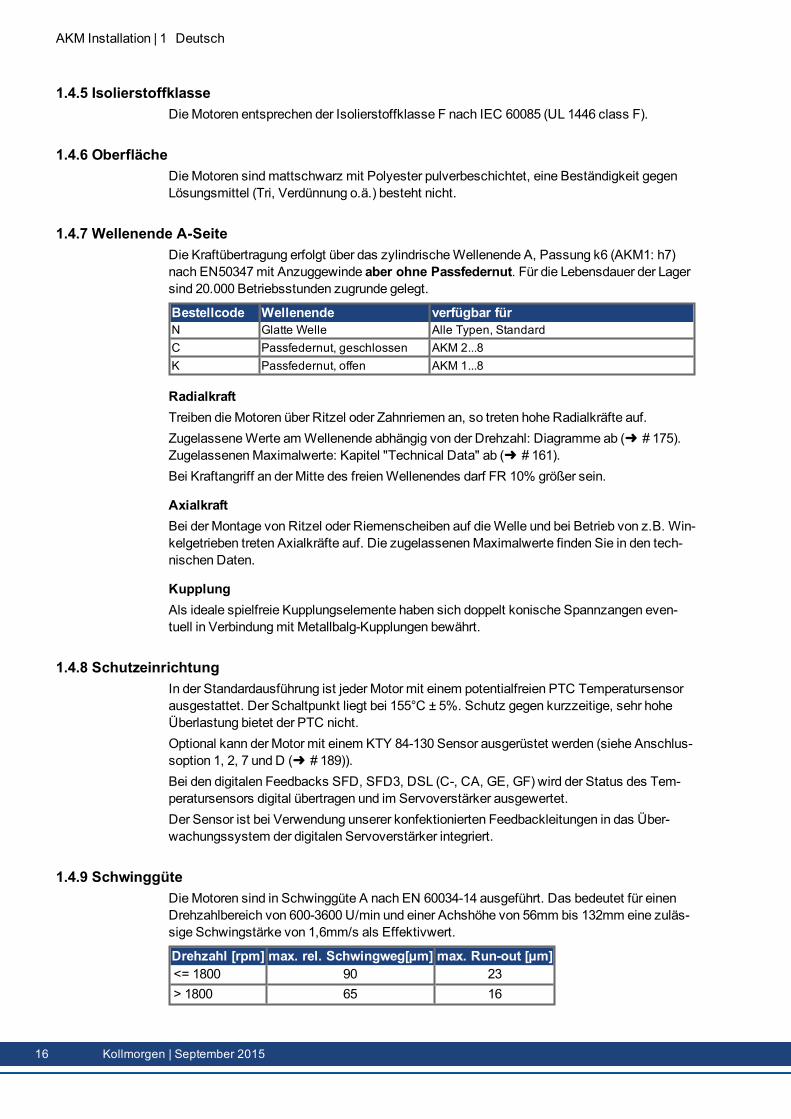
1.4.9 SchwinggüteDieMotoren sind in Schwinggüte A nach EN 60034-14 ausgeführt. Das bedeutet für einenDrehzahlbereich von 600-3600 U/min und einer Achshöhe von 56mm bis 132mm eine zuläs-sige Schwingstärke von 1,6mm/s als Effektivwert.
Drehzahl [rpm] max. rel. Schwingweg[µm] max. Run-out [µm]<= 1800 90 23> 1800 65 16
16 Kollmorgen | September 2015
1.4.10 WellendichtungWenn der AKM an einenMaschinenflanschmit ungeschütztemWellenbereich gekoppelt wer-den soll, stellt derWellendichtring (Option 01) die Abdichtung sicher. Zum Erreichen derNenndaten des AKMMotors muss dieWellendichtung einem Run-In Prozess unterzogenwerden.Führen Sie die folgenden Schritte durch:
30Minuten ohne Last bei maximaler Geschwindigkeit im Rechtslauf drehen lassen.30Minuten Abkühlphase.30Minuten ohne Last bei maximaler Geschwindigkeit im Linkslauf drehen lassen.30Minuten Abkühlphase.
Wiederholen Sie diesen Zyklus dreimal.
1.4.11 Anschlusstechnik
1.4.11.1 SteckerEine Beschreibung der verfügbaren Stecker finden Sie auf ( # 12).Steckerbelegungen finden Sie im Anhang ab ( # 189).
1.4.11.2 Kabelquerschnitte
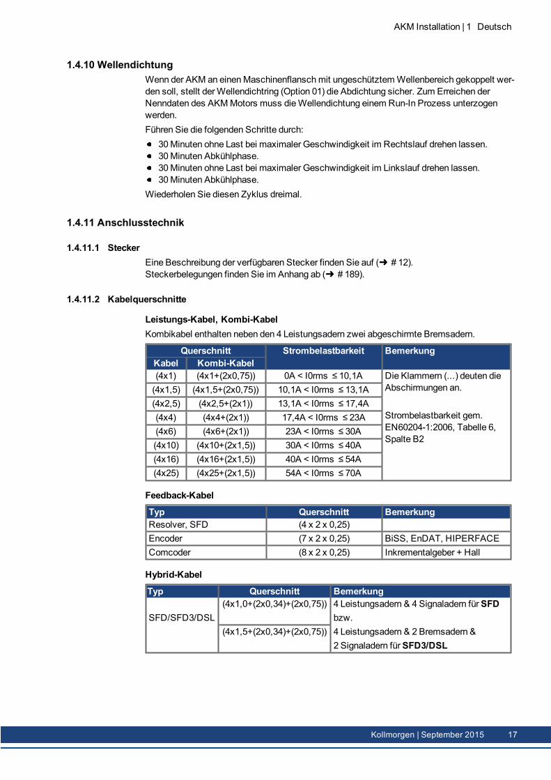
Leistungs-Kabel, Kombi-KabelKombikabel enthalten neben den 4 Leistungsadern zwei abgeschirmte Bremsadern.
Querschnitt Strombelastbarkeit BemerkungKabel Kombi-Kabel(4x1) (4x1+(2x0,75)) 0A < I0rms ≤ 10,1A Die Klammern (...) deuten die
Abschirmungen an.
Strombelastbarkeit gem.EN60204-1:2006, Tabelle 6,Spalte B2
(4x1,5) (4x1,5+(2x0,75)) 10,1A < I0rms ≤ 13,1A(4x2,5) (4x2,5+(2x1)) 13,1A < I0rms ≤ 17,4A(4x4) (4x4+(2x1)) 17,4A < I0rms ≤ 23A(4x6) (4x6+(2x1)) 23A < I0rms ≤ 30A(4x10) (4x10+(2x1,5)) 30A < I0rms ≤ 40A(4x16) (4x16+(2x1,5)) 40A < I0rms ≤ 54A(4x25) (4x25+(2x1,5)) 54A < I0rms ≤ 70A
Feedback-Kabel
Typ Querschnitt BemerkungResolver, SFD (4 x 2 x 0,25)Encoder (7 x 2 x 0,25) BiSS, EnDAT, HIPERFACEComcoder (8 x 2 x 0,25) Inkrementalgeber + Hall
Hybrid-Kabel
Typ Querschnitt Bemerkung
SFD/SFD3/DSL(4x1,0+(2x0,34)+(2x0,75)) 4 Leistungsadern & 4 Signaladern fürSFD
bzw.4 Leistungsadern & 2 Bremsadern &2 Signaladern fürSFD3/DSL
(4x1,5+(2x0,34)+(2x0,75))
AKM Installation | 1 Deutsch
Kollmorgen | September 2015 17
AKM Installation | 1 Deutsch
1.4.12 HaltebremseDieMotoren sind wahlweisemit eingebauter Haltebremse erhältlich. Die Federdruckbremse(24V DC) blockiert im spannungslosen Zustand den Rotor.
WARNUNGWenn bei hängender Last (Vertikalachsen) die Motorhaltebremse gelöstist und gleichzeitig der Servoantrieb keine Leistung erbringt, kann dieLast herunterfallen! Verletzungsgefahr für das Bedienpersonal derMaschine. Die funktionale Sicherheit kann bei vertikalen Achsen nur miteiner zusätzlichen, externen mechanischen Bremse erreicht werden.
Die Haltebremsen sind als Stillstandsbremsen ausgelegt und für dauernde, betriebsmäßigeAbbremsvorgänge ungeeignet. Bei häufiger betriebsmäßiger Abbremsung ist ein vorzeitigerVerschleiß und Ausfall der Haltebremse wahrscheinlich.Motorlänge vergrößert sich bei eingebauter Haltebremse.Die Haltebremsen können direkt vom Servoverstärker angesteuert werden (nicht personellsicher!), dann erfolgt das Löschen der Bremswicklung im Servoverstärker— eine zusätz-liche Beschaltung ist nicht erforderlich. Beachten Sie hierzu die Betriebsanleitung des Ser-voverstärkers. Wird die Haltebremse nicht vom Servoverstärker direkt angesteuert, musseine zusätzliche Beschaltung (z.B. Varistor) vorgenommenwerden. Sprechen Sie hierzumitunserem Kundendienst.
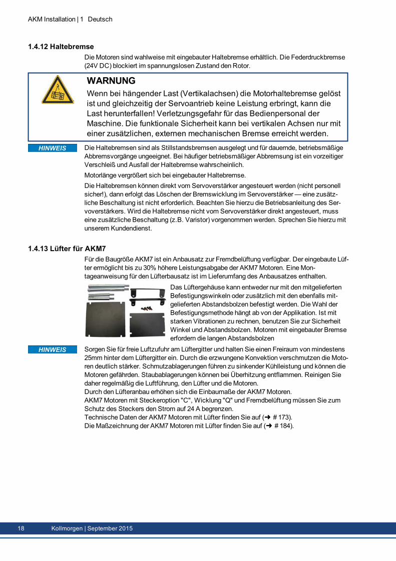
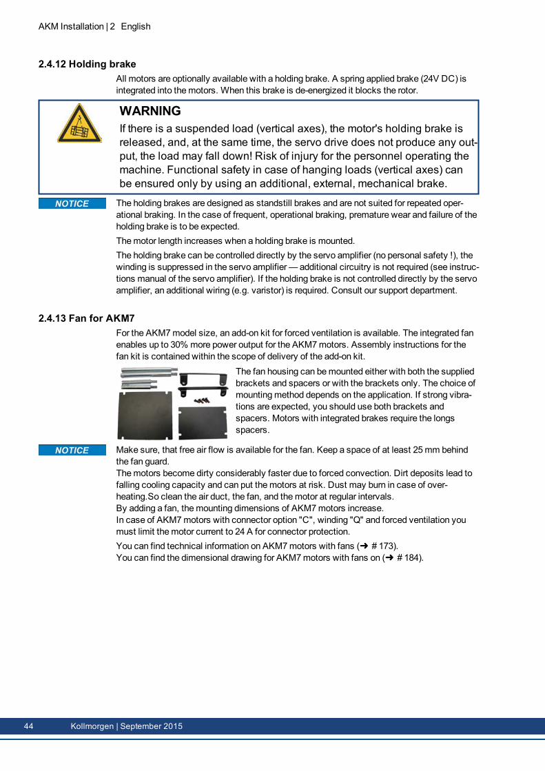
1.4.13 Lüfter für AKM7Für die Baugröße AKM7 ist ein Anbausatz zur Fremdbelüftung verfügbar. Der eingebaute Lüf-ter ermöglicht bis zu 30% höhere Leistungsabgabe der AKM7Motoren. EineMon-tageanweisung für den Lüfterbausatz ist im Lieferumfang des Anbausatzes enthalten.
Das Lüftergehäuse kann entweder nur mit denmitgeliefertenBefestigungswinkeln oder zusätzlichmit den ebenfalls mit-gelieferten Abstandsbolzen befestigt werden. DieWahl derBefestigungsmethode hängt ab von der Applikation. Ist mitstarken Vibrationen zu rechnen, benutzen Sie zur SicherheitWinkel und Abstandsbolzen. Motorenmit eingebauter Bremseerfordern die langen Abstandsbolzen
Sorgen Sie für freie Luftzufuhr am Lüftergitter und halten Sie einen Freiraum vonmindestens25mm hinter dem Lüftergitter ein. Durch die erzwungene Konvektion verschmutzen dieMoto-ren deutlich stärker. Schmutzablagerungen führen zu sinkender Kühlleistung und können dieMotoren gefährden. Staubablagerungen können bei Überhitzung entflammen. Reinigen Siedaher regelmäßig die Luftführung, den Lüfter und dieMotoren.Durch den Lüfteranbau erhöhen sich die Einbaumaße der AKM7Motoren.AKM7Motorenmit Steckeroption "C", Wicklung "Q" und Fremdbelüftungmüssen Sie zumSchutz des Steckers den Strom auf 24 A begrenzen.Technische Daten der AKM7Motorenmit Lüfter finden Sie auf ( # 173).DieMaßzeichnung der AKM7Motorenmit Lüfter finden Sie auf ( # 184).
18 Kollmorgen | September 2015
1.4.14 Washdown und Washdown FoodDieseMotorvarianten werden in Applikationen eingesetzt, die strengen hygienischen Vor-schriften unterliegen, in denen es Keimbildung und Korrosion zu vermeiden gilt und in denenMaschinen zyklisch gereinigt werdenmüssen.DieMotoren basieren auf den Standardtypen AKM2 - AKM6mit speziellen Veränderungenfür den Einsatz in der Lebensmittel verarbeitenden Industrie oder auch in der Ver-packungsindustrie. Zusätzlich gibt es jeweils die Möglichkeit, auch den Flansch zu beschich-ten - dann kann die Toleranzklasse N für den Flansch allerdings nicht gewährleistet werden.Im Typenschlüssel ist die Lackierung des Motorgehäuses (Typen "W" fürWashdown, "F" fürWashdown Food) in der Ausführung (letzten zwei Stellen) und die Flanschbeschichtunggetrennt definiert.
Washdown/Washdown Food Motor Anschluss Optionen Flansch OptionenAKM2 B*, D*, G A, B, W, RAKM3, 4, 6 C*, D*, G A, B, W, RAKM5 C*, D*, G B
* Die Anschlussstecker auf demMotor nicht weiter als +/- 180° drehen, ein größerer Dreh-winkel beschädigt die inneren Anschlüsse.
1.4.14.1 WashdownAKM^^^-^^^^^-^WAKM^^^-W^^^^^-^W
Washdown Lackierung ohne FlanschbeschichtungWashdownmit Flanschbeschichtung des IEC A-Flansch
DieWashdownMotoren dürfen keinen Kontakt zu unverpackten Lebensmitteln haben.
Einsatzgebiet: Raue Umgebungen, AußenbereicheBeispiel: Transport im Bereich Lebensmittel und Verpackung ohne Kontakt zu
Lebensmitteln, Radarstationen, Windturbinen, Offshore AnlagenStandards: UL, CE, RohSOberfläche: Silberne BeschichtungBeständigkeit: Gegen geprüfte Reinigungsmittel ( # 20), korrosionsfestSchutzart: IP67Welle: EdelstahlWellendichtring: PTFESchmiermittel: Industrielles Lagerschmierfett, nicht lebensmitteltauglichStecker: Edelstahl, glatte OberflächeSchrauben: EdelstahlTypenschild: Eingraviert, je Verpackungseinheit ein zusätzliches TypenschildBaugröße: AKM2 - AKM6
AKM Installation | 1 Deutsch
Kollmorgen | September 2015 19
AKM Installation | 1 Deutsch
1.4.14.2 Washdown FoodAKM^^^-^^^^^-^FAKM^^^-W^^^^^-^F
Washdown Food Lackierung ohne FlanschbeschichtungWashdown Foodmit Flanschbeschichtung des IEC A-Flansch
Die Oberfläche des Washdown FoodMotoren hat alle Tests gemäß FDA GlobalMigration fürindirekten Kontakt zu Lebensmitteln bestanden. Ein direkter Kontakt zu unverpacktenLebensmitteln ist nicht zulässig.Einsatzgebiet: Lebensmittel- undGetränkeindustrie, kein direkter Kontakt mit unver-
packten LebensmittelnBeispiel: Schneiden, Verpacken und Füllen ohne direkten Kontakt zum Lebens-
mittel, Motor seitlich oder unter dem Lebensmittel.Standards: UL, CE, RohS, FDAOberfläche: Weiße BeschichtungBeständigkeit: Gegen geprüfte Reinigungsmittel ( # 20), korrosionsfestGlobal Migration: US FDA Regulations 21 CFR 175.300, Condition of Use ESchutzart: IP67Welle: EdelstahlWellendichtring: PTFE, gemäß FDASchmiermittel: Lebensmitteltauglich, gemäß FDAStecker: Edelstahl, glatte OberflächeSchrauben: EdelstahlTypenschild: Eingraviert, je Verpackungseinheit ein zusätzliches TypenschildBaugröße: AKM2 - AKM6
1.4.14.3 Geprüfte und bestätigte Eigenschaften gegenüber ReingungsmittelIm Prüflabor der ECOLAB DeutschlandGmbH wurde die Resistenz derWashdown undWas-hdown FoodOberflächen gegen folgende industrielle Reinigungsmittel geprüft:
P3-topactive DESP3-topactive LAP3-topax 56P3-topax 66P3-topax 91
Dabei wurden die Oberflächen 28 Tage lang bei Raumtemperatur in das jeweilige Rei-nigungsmittel getaucht.Dies entspricht ca. 2500 Reingungszyklenmit jeweils 15minütigem Kontakt zum Rei-nigungsmittel bzw. 1500 Reinigungszyklenmit Reinigung und nachfolgender Desinfektion.Die Zertifikate finden Sie in unserem Produkt-WIKI auf der Seite Zulassungen .Kollmorgen kann eine Gewährleistung der Motorlebensdauer nur bei Einsatz der getestetenReinigungsmittel geben. Andere als die oben genannten Reinigungsmittel kann Kollmorgenauf Anfrage testen und gegebenfalls freigeben.
20 Kollmorgen | September 2015
1.4.14.4 Montage- und EinsatzbedingungenDieMotoren dürfen nur bei Umgebungstemperaturen bis maximal 50°C eingesetzt wer-den.Bei beschichtetem Vorderflansch ist die Toleranzklasse N nicht gewährleistet.
Bei Motorenmit Flanschen ohneWashdown Beschichtungmuss die Flanschfläche durchgeeigneteMontage vor dem Einfluss von Reinigungsmitteln geschützt werden.
1.4.14.5 ReinigungsplanEmpfohlener Reinigungsplan (Kurzform)mit den getesteten Reinigungsmitteln:
Spülen mit Wasser (40 °... 50 °C)Spülenmit niedrigem Druck. Von oben nach unten in Richtung zum Abfluss. Den Abfluss rei-nigen.
SchaumreinigungSchäumen von oben nach unten.Alkalisch: P3-topactive LA oder P3-topax 66 (2-5%, täglich 15min)Sauer: P3-topax 56 (2%, wenn erforderlich 15min)Temperatur: kalt bis zu 40 °C
DesinfektionAbsprühenmit Wasser (40°... 50°C)mit niedrigem Druck. Von oben nach unten.Sprühdesinfektion: P3-topax 91 (1-2%, wenn erforderlich 30-60min)Schaumdesinfektion: P3-topactiv DES (1-3%, wenn erforderlich 10-30min)
AKM Installation | 1 Deutsch
Kollmorgen | September 2015 21
AKM Installation | 1 Deutsch
1.5 Mechanische InstallationMaßzeichnungen finden Sie im Kapitel "Dimension Drawings" ab ( # 175).
1.5.1 Wichtige HinweiseNur Fachleutemit Maschinenbau-Kenntnissen dürfen denMotor montieren.
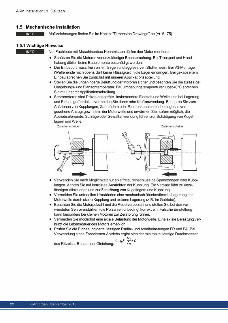
Schützen Sie dieMotoren vor unzulässiger Beanspruchung. Bei Transport und Hand-habung dürfen keine Bauelemente beschädigt werden.Der Einbauort muss frei von leitfähigen und aggressiven Stoffen sein. Bei V3-Montage(Wellenende nach oben), darf keine Flüssigkeit in die Lager eindringen. Bei gekapseltemEinbau sprechen Sie zunächst mit unserer Applikationsabteilung.Stellen Sie die ungehinderte Belüftung der Motoren sicher und beachten Sie die zulässigeUmgebungs- und Flanschtemperatur. Bei Umgebungstemperaturen über 40°C sprechenSiemit unserer Applikationsabteilung.Servomotoren sind Präzisionsgeräte. Insbesondere Flansch undWelle sind bei Lagerungund Einbau gefährdet — vermeiden Sie daher rohe Kraftanwendung. Benutzen Sie zumAufziehen von Kupplungen, Zahnrädern oder Riemenscheiben unbedingt das vor-gesehene Anzugsgewinde in der Motorwelle und erwärmen Sie, sofernmöglich, dieAbtriebselemente. Schläge oder Gewaltanwendung führen zur Schädigung von Kugel-lagern undWelle.
Verwenden Sie nachMöglichkeit nur spielfreie, reibschlüssige Spannzangen oder Kupp-lungen. Achten Sie auf korrektes Ausrichten der Kupplung. Ein Versatz führt zu unzu-lässigen Vibrationen und zur Zerstörung von Kugellagern und Kupplung.Vermeiden Sie unter allen Umständen einemechanisch überbestimmte Lagerung derMotorwelle durch starre Kupplung und externe Lagerung (z.B. im Getriebe).Beachten Sie dieMotorpolzahl und die Resolverpolzahl und stellen Sie bei den ver-wendeten Servoverstärkern die Polzahlen unbedingt korrekt ein. Falsche Einstellungkann besonders bei kleinenMotoren zur Zerstörung führen.Vermeiden Siemöglichst eine axiale Belastung der Motorwelle. Eine axiale Belastung ver-kürzt die Lebensdauer des Motors erheblich.Prüfen Sie die Einhaltung der zulässigen Radial- und Axialbelastungen FR und FA. BeiVerwendung eines Zahnriemen-Antriebs ergibt sich der minimal zulässige Durchmesser
des Ritzels z.B. nach der Gleichung:
22 Kollmorgen | September 2015
1.6 Elektrische InstallationSteckerbelegungen finden Sie im Kapitel "Connector Pinout" ab ( # 175). Die Pinbelegungauf der Verstärkerseite finden Sie in der Betriebsanleitung des Servoverstärkers.
1.6.1 Wichtige HinweiseNur Fachleutemit elektrotechnischer Ausbildung dürfen denMotor verdrahten.
GEFAHRVerdrahten Sie die Motoren immer im spannungsfreien Zustand, d.h.keine der Betriebsspannungen eines anzuschließenden Gerätes darf ein-geschaltet sein. Es besteht die Gefahr von Tod oder schweren gesund-heitlichen Schäden beim Berühren freiliegender Kontakte. Sorgen Sie füreine sichere Freischaltung des Schaltschrankes (Sperre, Warnschilderetc.). Erst bei der Inbetriebnahme werden die einzelnen Spannungen ein-geschaltet.Lösen Sie die elektrischen Anschlüsse der Motoren nie unter Spannung.Gefahr durch elektrischen Schlag! In ungünstigen Fällen können Licht-bögen entstehen und Personen und Kontakte schädigen.Restladungen in den Kondensatoren des Servoverstärkers können biszu 10 Minuten nach Abschalten der Netzspannung gefährliche Werte auf-weisen. Leistungsanschlüsse können Spannung führen, auch wenn sichder Motor nicht dreht.Messen Sie die Spannung im Zwischenkreis und warten Sie, bis dieSpannung unter 60V abgesunken ist.
Das Masse-Zeichen , das Sie in allen Anschlussplänen finden, deutet an, dass Sie füreinemöglichst großflächige, elektrisch leitende Verbindung zwischen dem gekenn-zeichneten Gerät und der Montageplatte in Ihrem Schaltschrank sorgenmüssen. Diese Ver-bindung soll die Ableitung von HF-Störungen ermöglichen und ist nicht zu verwechselnmitdem PE-Zeichen (Schutzmaßnahme nach EN 60204).Beachten Sie auch die Hinweise in den Anschlussplänen in der Betriebsanleitung des ver-wendeten Servoverstärkers.
AKM Installation | 1 Deutsch
Kollmorgen | September 2015 23

AKM Installation | 1 Deutsch
1.6.2 Leitfaden für die elektrische InstallationPrüfen Sie die Zuordnung von Servoverstärker undMotor. Vergleichen Sie Nenn-spannung und Nennstrom der Geräte. Führen Sie die Verdrahtung nach dem Anschluss-bild in der Betriebsanleitung des Servoverstärkers aus. Die Anschlüsse des Motors sindim Kapitel "Connector Pinout" ab ( # 175) dargestellt.Verlegen Sie sämtliche starkstromführenden Leitungen in ausreichendemQuerschnittnach EN 60204. Die empfohlenenQuerschnitte finden Sie in den technischen Daten.
Abhängig vom Typ des verwendeten Servoverstärkers muss bei langenMotorleitung (> 25m)eineMotordrossel (3YL oder 3YLN) in die Motorleitung geschaltet werden (siehe Betriebs-anleitung des Servoverstärkers und Zubehörhandbuch).
Achten Sie auf einwandfreie Erdung von Servoverstärker undMotor. EMV-gerechteAbschirmung und Erdung siehe Betriebsanleitung des verwendeten Servoverstärkers.Erden SieMontageplatte undMotorgehäuse.Bei Verwendung eines Motorleistungskabels mit integrierten Bremssteueradernmüssendie Bremssteueradern abgeschirmt sein. Der Schirm muss beidseitig aufgelegt werden(siehe auch Betriebsanleitung des Servoverstärkers).Verdrahtung:
Leistungs- und Steuerkabel möglichst getrennt verlegenRückführsystem (Feedback) anschließenMotorleitungen anschließen (Motordrossel nahe am Servoverstärker) , Abschirmungenbeidseitig auf Schirmklemmen bzw. EMV-SteckerMotor-Haltebremse anschließen, Abschirmung beidseitig auflegen.
Legen Sie Abschirmungen großflächig (niederohmig) über metallisierte Steckergehäusebzw. EMV-gerechte Kabelverschraubungen auf.Anforderungen an das Leitungsmaterial:KapazitätMotorleitung:kleiner als 150 pF/mFeedback-Leitung: kleiner als 120 pF/m
1.6.3 Anschluss der Motoren mit vorkonfektionierten KabelnFühren Sie die Verdrahtung gemäß den geltenden Vorschriften und Normen aus.Verwenden Sie für Leistungs- und Feedbackanschluss ausschließlich vorkonfektionierte,abgeschirmte Leitungen von AKM.Nicht korrekt aufgelegte Abschirmungen führen unweigerlich zu EMV-Störungen undFunktionsbeeintrachtigungen des Systems.Diemaximale Leitungslänge ist in der Betriebsanleitung des verwendeten Ser-voverstärkers definiert.
Technische Daten unserer konfektionierten Leitungen finden Sie im Zubehörhandbuch.
24 Kollmorgen | September 2015
1.7 Inbetriebnahme
1.7.1 Wichtige Hinweise
Nur Fachleutemit weitreichenden Kenntnissen in den Bereichen Elektrotechnik und Antriebs-technik dürfen die Antriebseinheit Servoverstärker/Motor in Betrieb nehmen.
GEFAHREs treten Spannungen bis zu 900V auf. Lebensgefahr durch elektrischenSchlag! Prüfen Sie, ob alle spannungsführenden Anschlussteile gegenBerührung sicher geschützt sind.Lösen Sie die elektrischen Anschlüsse der Motoren nie unter Spannung.Restladungen in den Kondensatoren des Servoverstärkers können bis zu10 Minuten nach Abschalten der Netzspannung gefährliche Werte auf-weisen. Steuer- und Leistungsanschlüsse können Spannung führen,auch wenn sich der Motor nicht dreht.Messen Sie die Spannung im Zwischenkreis und warten Sie, bis dieSpannung unter 60V abgesunken ist.
VORSICHTDie Oberflächentemperatur des Motors kann im Betrieb 100°C über-schreiten. Gefahr leichter Verbrennungen! Prüfen (messen) Sie die Tem-peratur des Motors.Warten Sie, bis der Motor auf 40°C abgekühlt ist, bevor Sie ihn berühren.
VORSICHTWährend der Inbetriebnahme ist nicht auszuschließen, dass der Antriebungeplant eine Bewegung durchführt.Stellen Sie sicher, dass auch bei ungewollter Bewegung des Antriebskeine Gefährdung von Personen oder Sachen eintreten kann.Die Maßnahmen, die Sie dazu in Ihrer Anwendung treffen müssen, erge-ben sich aus der Risikobeurteilung der Anwendung.
AKM Installation | 1 Deutsch
Kollmorgen | September 2015 25
AKM Installation | 1 Deutsch
1.7.2 Leitfaden für die InbetriebnahmeDas Vorgehen bei der Inbetriebnahmewird exemplarisch beschrieben. Je nach Einsatz derGeräte kann auch ein anderes Vorgehen sinnvoll und erforderlich sein.1. Prüfen SieMontage und Ausrichtung des Motors.2. Prüfen Sie die Abtriebselemente (Kupplung, Getriebe, Riemenscheibe) auf festen Sitz
und korrekte Einstellung (zulässige Radial- und Axialkräfte beachten).3. Prüfen Sie die Verdrahtung und Anschlüsse am Servoverstärker. Achten Sie auf ord-
nungsgemäße Erdung.4. Prüfen Sie die Funktion der Haltebremse, sofern vorhanden. (24V anlegen, Bremsemuss
lüften).5. Prüfen Sie, ob der Rotor des Motors sich frei drehen lässt (eventuell vorhandene Bremse
vorher lüften). Achten Sie auf Schleifgeräusche.6. Prüfen Sie, ob alle erforderlichen Berührungsschutz-Maßnahmen für bewegte und
spannungsführende Teile getroffen wurden.7. Führen Sie weitere für Ihre Anlage spezifischen und notwendigen Prüfungen durch.8. Nehmen Sie nun entsprechend der Inbetriebnahmeanweisung des Servoverstärkers den
Antrieb in Betrieb.9. Nehmen Sie bei Mehrachs-Systemen jede Antriebseinheit Servoverstärker/Motor einzeln
in Betrieb.
26 Kollmorgen | September 2015
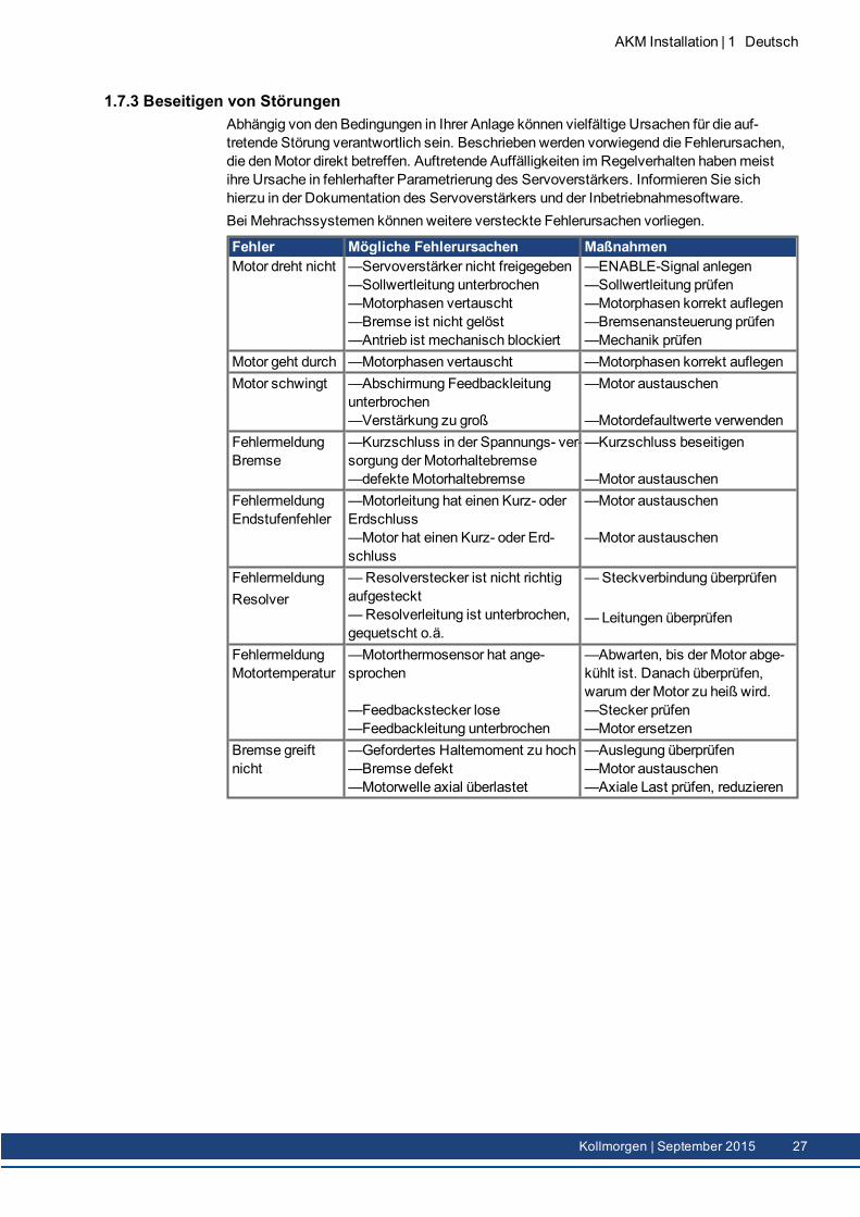
1.7.3 Beseitigen von StörungenAbhängig von den Bedingungen in Ihrer Anlage können vielfältige Ursachen für die auf-tretende Störung verantwortlich sein. Beschrieben werden vorwiegend die Fehlerursachen,die denMotor direkt betreffen. Auftretende Auffälligkeiten im Regelverhalten habenmeistihre Ursache in fehlerhafter Parametrierung des Servoverstärkers. Informieren Sie sichhierzu in der Dokumentation des Servoverstärkers und der Inbetriebnahmesoftware.Bei Mehrachssystemen können weitere versteckte Fehlerursachen vorliegen.
Fehler Mögliche Fehlerursachen MaßnahmenMotor dreht nicht —Servoverstärker nicht freigegeben
—Sollwertleitung unterbrochen—Motorphasen vertauscht—Bremse ist nicht gelöst—Antrieb ist mechanisch blockiert
—ENABLE-Signal anlegen—Sollwertleitung prüfen—Motorphasen korrekt auflegen—Bremsenansteuerung prüfen—Mechanik prüfen
Motor geht durch —Motorphasen vertauscht —Motorphasen korrekt auflegenMotor schwingt —Abschirmung Feedbackleitung
unterbrochen—Verstärkung zu groß
—Motor austauschen
—Motordefaultwerte verwendenFehlermeldungBremse
—Kurzschluss in der Spannungs- ver-sorgung der Motorhaltebremse—defekteMotorhaltebremse
—Kurzschluss beseitigen
—Motor austauschenFehlermeldungEndstufenfehler
—Motorleitung hat einen Kurz- oderErdschluss—Motor hat einen Kurz- oder Erd-schluss
—Motor austauschen
—Motor austauschen
FehlermeldungResolver
—Resolverstecker ist nicht richtigaufgesteckt—Resolverleitung ist unterbrochen,gequetscht o.ä.
—Steckverbindung überprüfen
— Leitungen überprüfen
FehlermeldungMotortemperatur
—Motorthermosensor hat ange-sprochen
—Feedbackstecker lose—Feedbackleitung unterbrochen
—Abwarten, bis der Motor abge-kühlt ist. Danach überprüfen,warum derMotor zu heiß wird.—Stecker prüfen—Motor ersetzen
Bremse greiftnicht
—Gefordertes Haltemoment zu hoch—Bremse defekt—Motorwelle axial überlastet
—Auslegung überprüfen—Motor austauschen—Axiale Last prüfen, reduzieren
AKM Installation | 1 Deutsch
Kollmorgen | September 2015 27
AKM Installation | 1 Deutsch
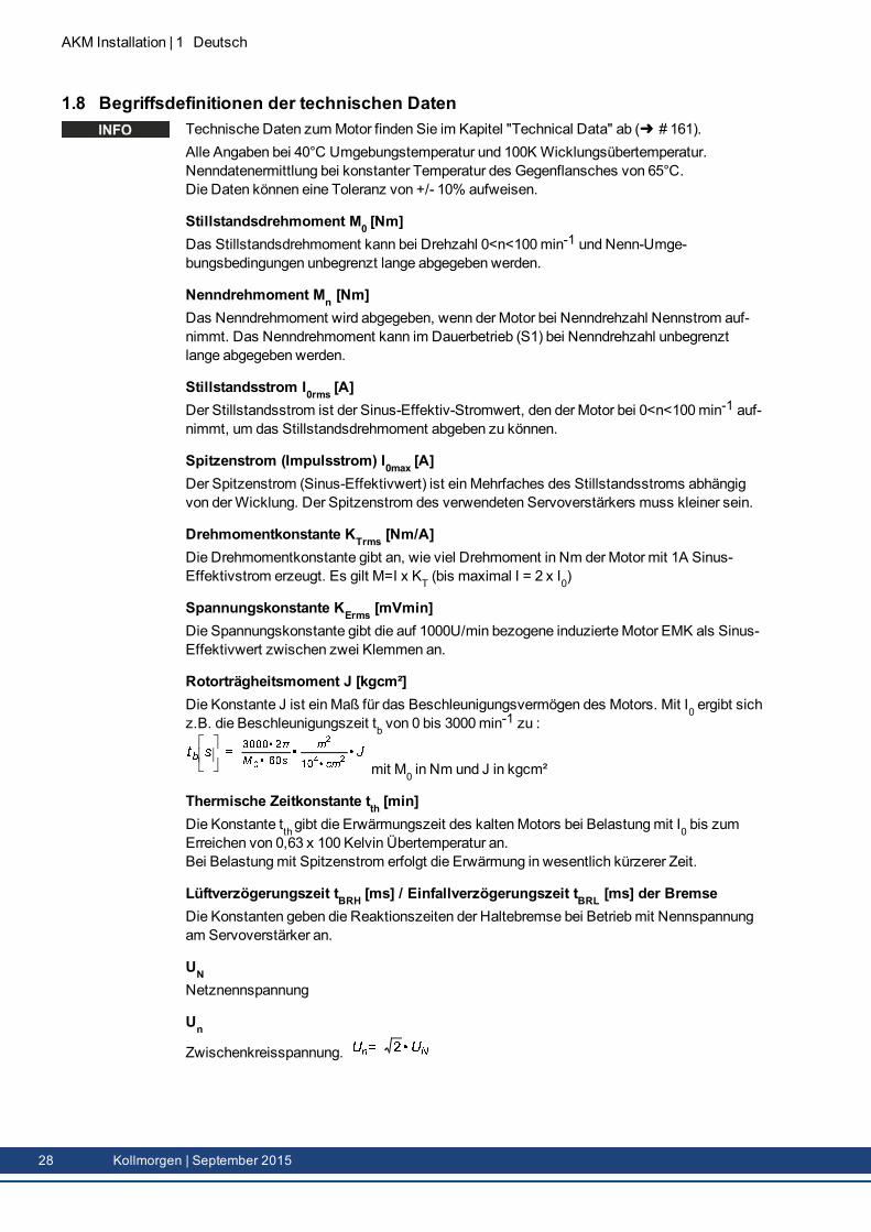
1.8 Begriffsdefinitionen der technischen DatenTechnische Daten zumMotor finden Sie im Kapitel "Technical Data" ab ( # 161).Alle Angaben bei 40°C Umgebungstemperatur und 100K Wicklungsübertemperatur.Nenndatenermittlung bei konstanter Temperatur des Gegenflansches von 65°C.Die Daten können eine Toleranz von +/- 10% aufweisen.
Stillstandsdrehmoment M0 [Nm]Das Stillstandsdrehmoment kann bei Drehzahl 0<n<100min-1 und Nenn-Umge-bungsbedingungen unbegrenzt lange abgegeben werden.
Nenndrehmoment Mn [Nm]Das Nenndrehmoment wird abgegeben, wenn der Motor bei Nenndrehzahl Nennstrom auf-nimmt. Das Nenndrehmoment kann im Dauerbetrieb (S1) bei Nenndrehzahl unbegrenztlange abgegeben werden.
Stillstandsstrom I0rms [A]Der Stillstandsstrom ist der Sinus-Effektiv-Stromwert, den der Motor bei 0<n<100min-1 auf-nimmt, um das Stillstandsdrehmoment abgeben zu können.
Spitzenstrom (Impulsstrom) I0max [A]Der Spitzenstrom (Sinus-Effektivwert) ist ein Mehrfaches des Stillstandsstroms abhängigvon derWicklung. Der Spitzenstrom des verwendeten Servoverstärkers muss kleiner sein.
Drehmomentkonstante KTrms [Nm/A]Die Drehmomentkonstante gibt an, wie viel Drehmoment in Nm derMotor mit 1A Sinus-Effektivstrom erzeugt. Es gilt M=I x KT (bis maximal I = 2 x I0)
Spannungskonstante KErms [mVmin]Die Spannungskonstante gibt die auf 1000U/min bezogene induzierte Motor EMK als Sinus-Effektivwert zwischen zwei Klemmen an.
Rotorträgheitsmoment J [kgcm²]Die Konstante J ist ein Maß für das Beschleunigungsvermögen des Motors. Mit I0 ergibt sichz.B. die Beschleunigungszeit tb von 0 bis 3000min
-1 zu :
mit M0 in Nm und J in kgcm²
Thermische Zeitkonstante tth [min]Die Konstante tthgibt die Erwärmungszeit des kaltenMotors bei Belastungmit I0 bis zumErreichen von 0,63 x 100 Kelvin Übertemperatur an.Bei Belastungmit Spitzenstrom erfolgt die Erwärmung in wesentlich kürzerer Zeit.
Lüftverzögerungszeit tBRH [ms] / Einfallverzögerungszeit tBRL [ms] der BremseDie Konstanten geben die Reaktionszeiten der Haltebremse bei Betriebmit Nennspannungam Servoverstärker an.
UNNetznennspannung
Un
Zwischenkreisspannung.
28 Kollmorgen | September 2015
2 English
2.1 General 302.1.1 About this manual 302.1.2 Symbols Used 302.1.3 Abbreviations used 30
2.2 Safety 312.2.1 You should pay attention to this 312.2.2 Use as directed 332.2.3 Prohibited use 332.2.4 Handling 34
2.3 Package 362.3.1 Delivery package 362.3.2 Nameplate 362.3.3Model number description 37
2.4 Technical Description 412.4.1 General technical data 412.4.2 Style 412.4.3 Flange 412.4.4 Protection class 412.4.5 Insulationmaterial class 422.4.6 Surface 422.4.7 Shaft end, A-side 422.4.8 Protective device 422.4.9 Vibration class 422.4.10 Shaft seal 432.4.11Wiring technology 432.4.12 Holding brake 442.4.13 Fan for AKM7 442.4.14Washdown andWashdown Food 45
2.5 Mechanical Installation 482.5.1 Important Notes 48
2.6 Electrical Installation 492.6.1 Important notes 492.6.2 Guide for electrical installation 502.6.3 Connection of themotors with preassembled cables 50
2.7 Setup 512.7.1 Important notes 512.7.2 Guide for setup 522.7.3 Trouble Shooting 53
2.8 Definition of Terms for Technical Data 54
AKM Installation | 2 English
Kollmorgen | September 2015 29
AKM Installation | 2 English
2.1 General
2.1.1 About this manualThis manual describes the AKM series of synchronous servomotors (standard version). Themotors are operated in drive systems together with Kollmorgen servo amplifiers. Pleaseobserve the entire system documentation, consisting of:
Instructions manual for the servo amplifierManual Bus Communication (e.g. CANopen or EtherCAT)Online help of the amplifier's setup softwareRegional accessories manualTechnical description of the AKM series of motors
More background information can be found in our "Product WIKI", available at www.wiki-koll-morgen.eu.
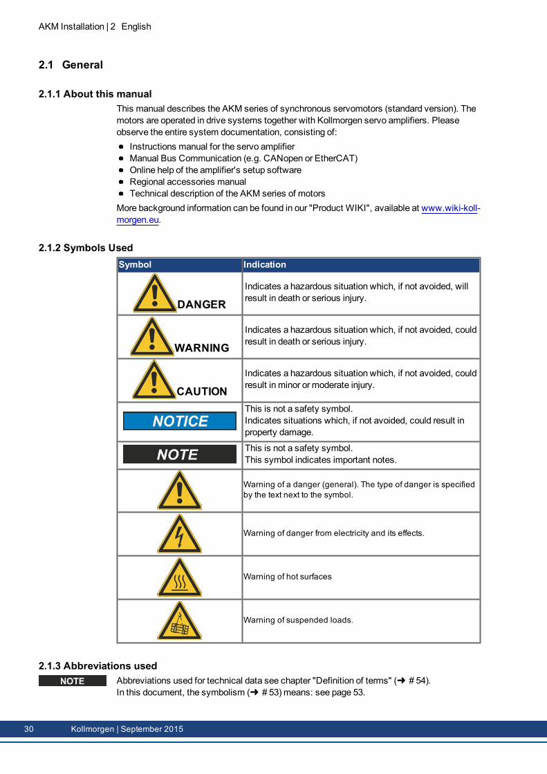
2.1.2 Symbols UsedSymbol Indication
DANGERIndicates a hazardous situation which, if not avoided, willresult in death or serious injury.
WARNINGIndicates a hazardous situation which, if not avoided, couldresult in death or serious injury.
CAUTIONIndicates a hazardous situation which, if not avoided, couldresult in minor or moderate injury.
This is not a safety symbol.Indicates situations which, if not avoided, could result inproperty damage.
This is not a safety symbol.This symbol indicates important notes.
Warning of a danger (general). The type of danger is specifiedby the text next to the symbol.
Warning of danger from electricity and its effects.
Warning of hot surfaces
Warning of suspended loads.
2.1.3 Abbreviations usedAbbreviations used for technical data see chapter "Definition of terms" ( # 54).In this document, the symbolism ( # 53) means: see page 53.
30 Kollmorgen | September 2015
2.2 SafetyThis section helps you to recognize and avoid dangers to people and objects.
2.2.1 You should pay attention to this
Specialist staff required!Only properly qualified personnel are permitted to perform such tasks as transport,assembly, setup andmaintenance. Qualified specialist staff are persons who are familiarwith the transport, installation, assembly, commissioning and operation of motors and whobring their relevant minimum qualifications to bear on their duties:
Transport :only by personnel with knowledge of handling electrostatically sensitive com-ponents.Mechanical Installation : only by mechanically qualified personnel.Electrical Installation :only by electrically qualified personnel.Setup :only by qualified personnel with extensive knowledge of electrical engineering anddrive technology
The qualified personnel must know and observe IEC 60364 / IEC 60664 and national acci-dent prevention regulations.
Read the documentation!Read the available documentation before installation and commissioning. Improper handlingof themotor can cause harm to people or damage to property. The operator must thereforeensure that all persons entrusted to work on themotor have read and understood themanualand that the safety notices in this manual are observed.
Pay attention to the technical data!Adhere to the technical data and the specifications on connection conditions (rating plate anddocumentation). If permissible voltage values or current values are exceeded, themotorscan be damaged, for example by overheating.
Perform a risk assessment!Themanufacturer of themachinemust generate a risk assessment for themachine, andtake appropriate measures to ensure that unforeseenmovements cannot cause injury or dam-age to any person or property. Additional requirements on specialist staff may also resultfrom the risk assessment.
Transport safely!Lift andmovemotors with more than 20 kg weight (AKM7 and AKM8) only with lifting tools.Lifting unassisted could result in back injury. Always observe the hints on ( # 34)
Secure the key!Remove any fitted key (if present) from the shaft before letting themotor run without coupledload, to avoid the dangerous results of the key being thrown out by centrifugal forces. Whendelivered, the key is protected with a plastic cap.
Hot surface!The surfaces of themotors can be very hot in operation, according to their protection cat-egory. Risk of minor burns! The surface temperature can exceed 100°C. Measure the tem-perature, and wait until themotor has cooled down below 40°C before touching it.
AKM Installation | 2 English
Kollmorgen | September 2015 31
AKM Installation | 2 English
Earthing! High voltages!It is vital that you ensure that themotor housing is safely earthed to the PE (protective earth)busbar in the switch cabinet. Risk of electric shock. Without low-resistance eart hing no per-sonal protection can be guaranteed and there is a risk of death from electric shock.Not having optical displays does not guarantee an absence of voltage. Power connectionsmay carry voltage even if themotor shaft is not rotating.Do not unplug any connectors during operation. There is a risk of death or severe injury fromtouching exposed contacts. Power connections may be live even when themotor shaft isnot rotating. This can cause flashovers with resulting injuries to persons and damage to thecontacts.After disconnecting the servo amplifier from the supply voltage, wait several minutes beforetouching any components which are normally live (e.g. contacts, screw connections) oropening any connections.The capacitors in the servo amplifier can still carry a dangerous voltage several minutesafter switching off the supply voltages. To be quite safe, measure the DC-link voltage andwait until the voltage has fallen below 60 V.
Secure hanging loads!Built-in holding brakes do not ensure functional safety!Hanging loads (vertical axes) require an additional, external mechanical brake to ensure per-sonnel safety.
32 Kollmorgen | September 2015
2.2.2 Use as directedThe AKM series of synchronous servomotors is designed especially for drives for indus-trial robots, machine tools, textile and packingmachinery and similar with high require-ments for dynamics.The user is only permitted to operate themotors under the ambient conditions which aredefined in this documentation.The use ofWashdownmotors is allowed in environments with caustic acids and baseswith respect to the defined conditions on page ( # 45).The use ofWashdown Foodmotors is allowed in applications with indirect contact tofood and beverage.The AKM series of motors is exclusively intended to be driven by servo amplifiers underspeed and / or torque control.Themotors are installed as components in electrical apparatus or machines and can onlybe commissioned and put into operation as integral components of such apparatus ormachines.The thermal sensor which is integrated in themotor windings must be observed and eval-uated.The holding brakes are designed as standstill brakes and are not suited for repeated oper-ational braking.The conformity of the servo system to the standards mentioned in the CE Declaration ofConformity ( # 196) is only guaranteed when the components (servo amplifier, motor,cables etc.) that are used have been supplied by Kollmorgen.
2.2.3 Prohibited useThe use of theStandardMotors is prohibited
directly onmains supply networks,in areas where there is a risk of explosions,in contact with food and beverage,in environments with caustic and/or electrically conducting acids, bases, oils, vapors,dusts.
The use of theWashdownMotors is prohibiteddirectly onmains supply networks,in areas where there is a risk of explosions,in contact with food and beverage,in environments with acids or bases with pH value below 2 or above 12,in environments with acids or bases that have not been tested by Kollmorgen.
The use of theWashdown FoodMotors is prohibiteddirectly onmains supply networks,in areas where there is a risk of explosions,in direct contact with food and beverage.
Commissioning themotor is prohibited if themachine in which it was installeddoes not meet the requirements of the EC Machinery Directive,does not comply with the EMC Directive,does not comply with the Low Voltage Directive.
Built-in holding brakes without further equipment must not be used to ensure functionalsafety.
AKM Installation | 2 English
Kollmorgen | September 2015 33
AKM Installation | 2 English
2.2.4 Handling
2.2.4.1 Transport
Climate category 2K3 according to EN61800-2, IEC 60721-3-2Temperature: -25...+70°C, max. 20K/hr changeHumidity: rel. humidity 5% - 95% , no condensationOnly by qualified personnel in themanufacturer’s original recyclable packagingAvoid shocks, especially to the shaft endIf the packaging is damaged, check themotor for visible damage. Inform the car rier and,if appropriate, themanufacturer.
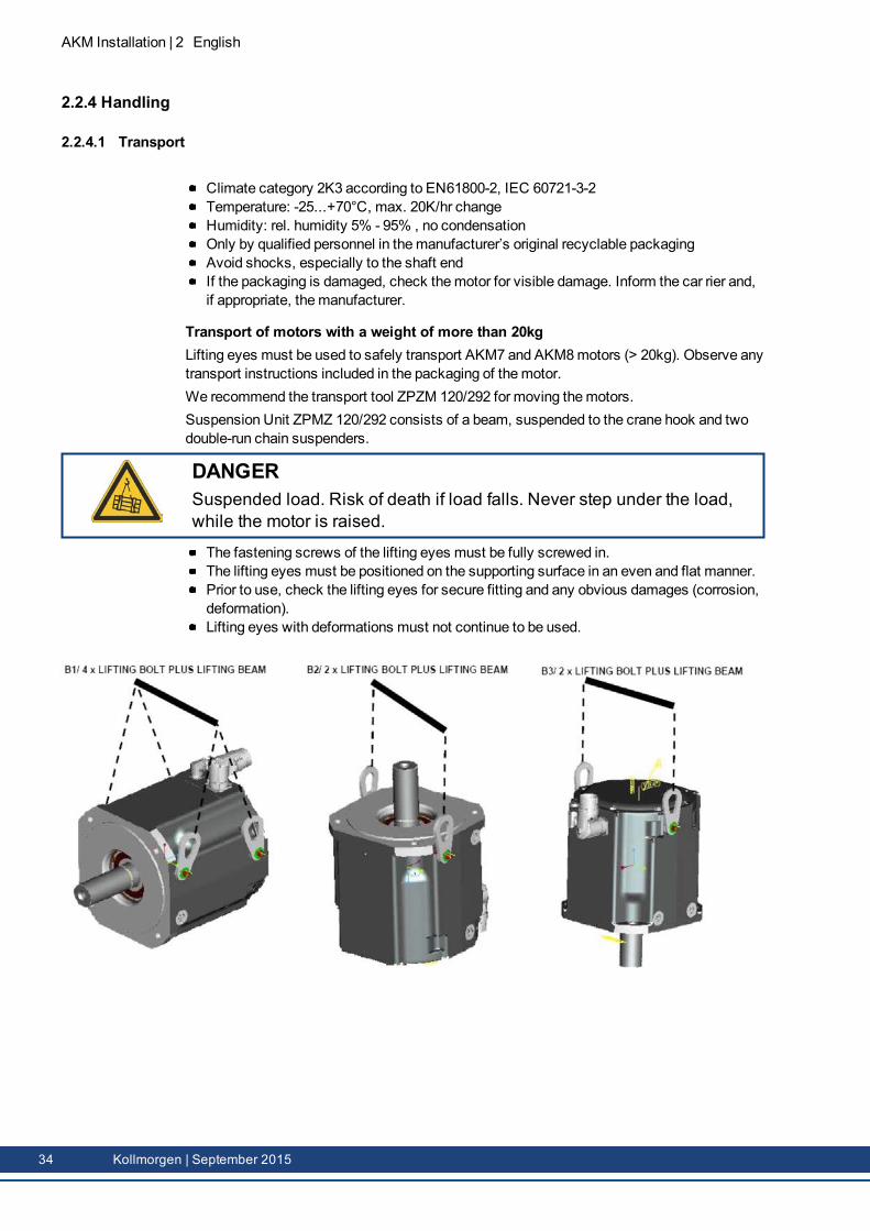
Transport of motors with a weight of more than 20kgLifting eyes must be used to safely transport AKM7 and AKM8motors (> 20kg). Observe anytransport instructions included in the packaging of themotor.We recommend the transport tool ZPZM 120/292 for moving themotors.Suspension Unit ZPMZ 120/292 consists of a beam, suspended to the crane hook and twodouble-run chain suspenders.
DANGERSuspended load. Risk of death if load falls. Never step under the load,while the motor is raised.
The fastening screws of the lifting eyes must be fully screwed in.The lifting eyes must be positioned on the supporting surface in an even and flat manner.Prior to use, check the lifting eyes for secure fitting and any obvious damages (corrosion,deformation).Lifting eyes with deformations must not continue to be used.
34 Kollmorgen | September 2015

2.2.4.2 PackagingCardboard packing with Instapak® foam cushion.You can return the plastic portion to the supplier (see "Disposal").
Motortype
Packing Max. stackingheight
Motortype
Packing Max. stackingheight
AKM1 Cardboard 10 AKM5 Cardboard 5AKM2 Cardboard 10 AKM6 Cardboard 1AKM3 Cardboard 6 AKM7 Cardboard 1AKM4 Cardboard 6 AKM8 Pallet 1
2.2.4.3 StorageClimate category 1K4 according to EN61800-2, IEC 60721-3-2Storage temperature: - 25...+55°C, max. variation 20K/hr.Humidity: rel. humidity 5% - 95%, no condensationStore only in themanufacturer’s original recyclable packagingMax. stacking height: see table in chapter "Packaging"Storage time: unlimited
2.2.4.4 Maintenance / CleaningMaintenance and cleaning only by qualified personnelThe ball bearings should be replaced after 20,000 hours of operation under rated con-ditions (by themanufacturer).Check themotor for bearing noise every 2500 operating hours, respectively each year. Ifany noises are heard, stop the operation of themotor, the bearings must be replaced (bythemanufacturer).Opening themotor invalidates the warranty.If the housing is dirty, clean housing with Isopropanol or similar, do not immerse or spray
2.2.4.5 Repair / DisposalRepair of themotor must be done by themanufacturer. Opening themotor invalidates thewarranty. In accordance to theWEEE-2002/96/EG-Guidelines we take old devices andaccessories back for professional disposal, if the transport costs are taken over by thesender. Send themotor to:KOLLMORGEN EuropeGmbHPempelfurtstr. 1D-40880 Ratingen
AKM Installation | 2 English
Kollmorgen | September 2015 35
AKM Installation | 2 English
2.3 Package
2.3.1 Delivery packageMotor from the AKM seriesProduct manual (multi language) printed, one per delivery
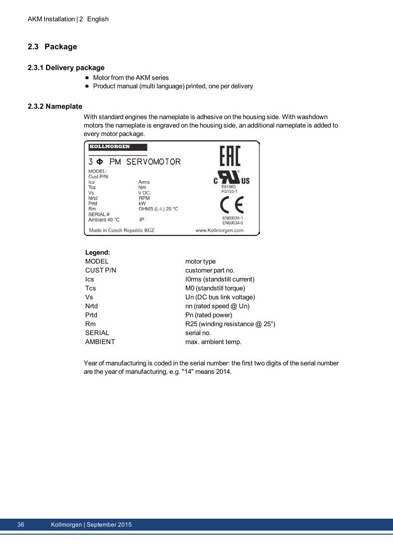
2.3.2 NameplateWith standard engines the nameplate is adhesive on the housing side. With washdownmotors the nameplate is engraved on the housing side, an additional nameplate is added toevery motor package.
Legend:MODEL motor typeCUST P/N customer part no.Ics I0rms (standstill current)Tcs M0 (standstill torque)Vs Un (DC bus link voltage)Nrtd nn (rated speed@ Un)Prtd Pn (rated power)Rm R25 (winding resistance@ 25°)SERIAL serial no.AMBIENT max. ambient temp.
Year of manufacturing is coded in the serial number: the first two digits of the serial numberare the year of manufacturing, e.g. "14" means 2014.
36 Kollmorgen | September 2015
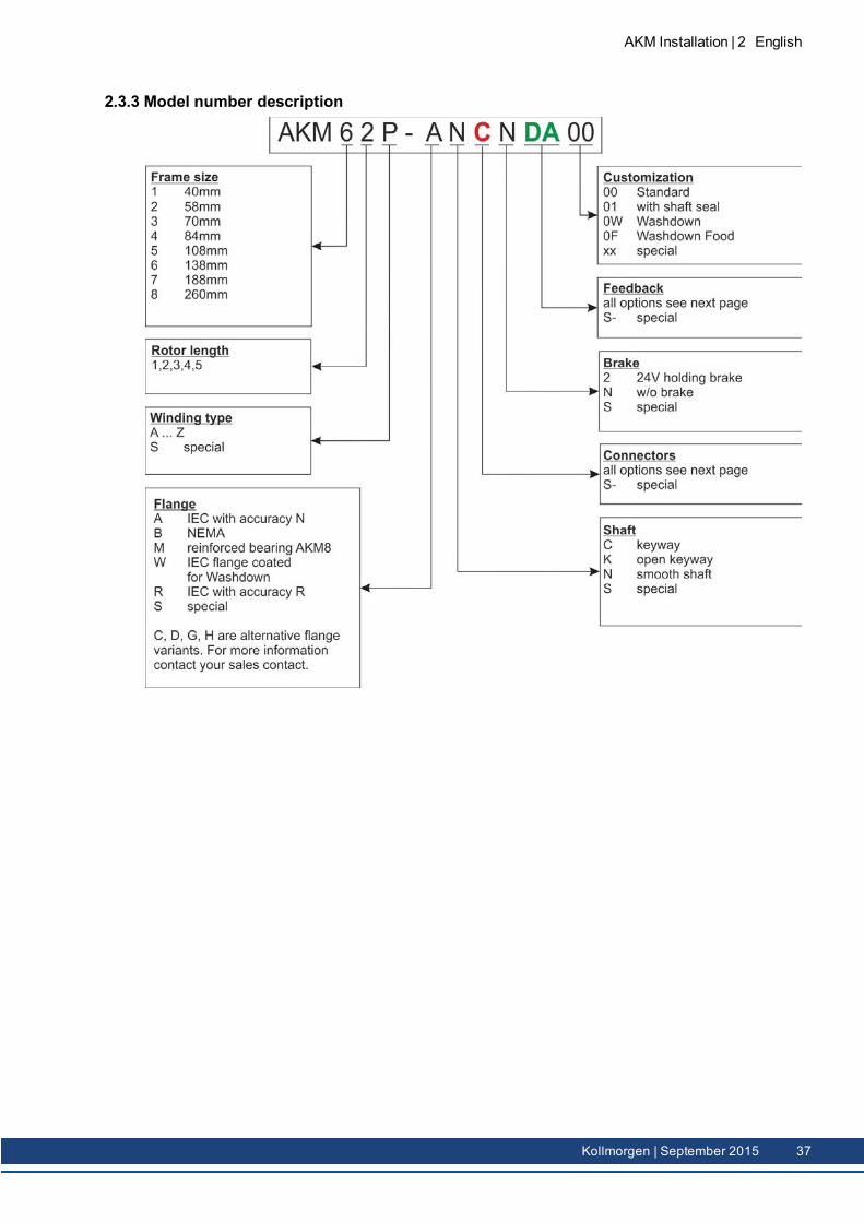
2.3.3 Model number description
AKM Installation | 2 English
Kollmorgen | September 2015 37
AKM Installation | 2 English
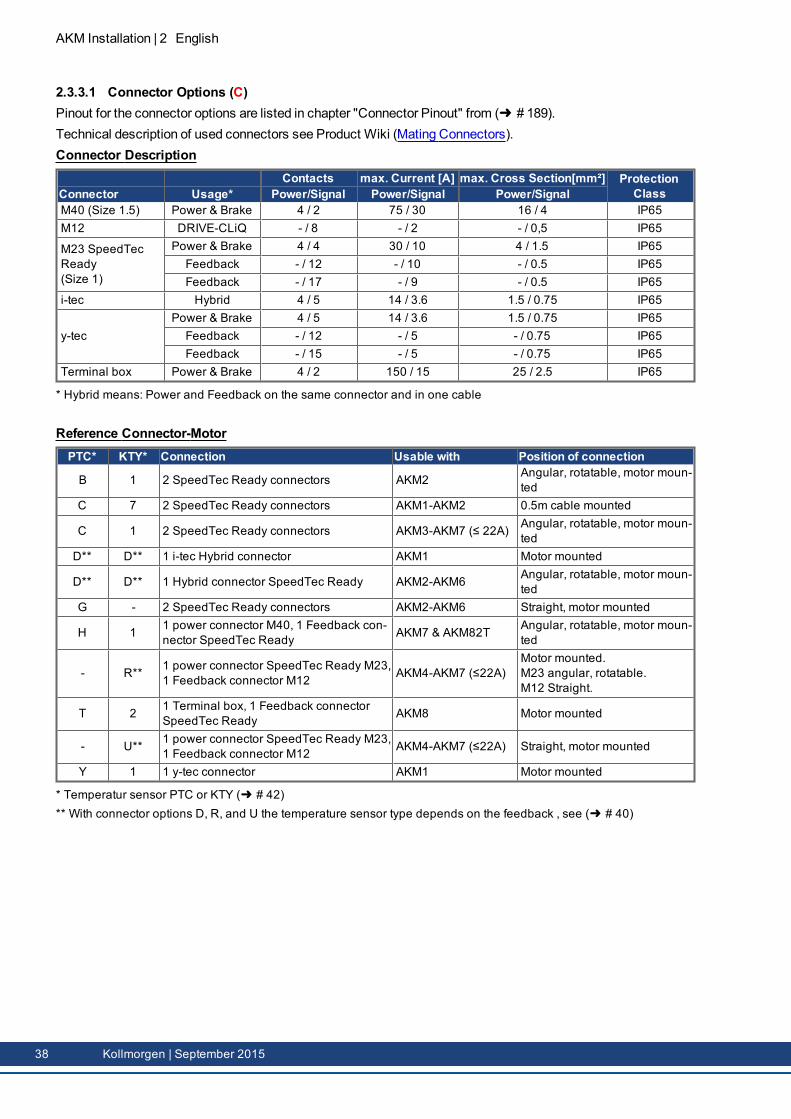
2.3.3.1 Connector Options (C)Pinout for the connector options are listed in chapter "Connector Pinout" from ( # 189).Technical description of used connectors see Product Wiki (Mating Connectors).Connector Description
Contacts max. Current [A] max. Cross Section[mm²] ProtectionClassConnector Usage* Power/Signal Power/Signal Power/Signal
M40 (Size 1.5) Power & Brake 4 / 2 75 / 30 16 / 4 IP65M12 DRIVE-CLiQ - / 8 - / 2 - / 0,5 IP65
M23 SpeedTecReady(Size 1)
Power & Brake 4 / 4 30 / 10 4 / 1.5 IP65Feedback - / 12 - / 10 - / 0.5 IP65Feedback - / 17 - / 9 - / 0.5 IP65
i-tec Hybrid 4 / 5 14 / 3.6 1.5 / 0.75 IP65
y-tecPower & Brake 4 / 5 14 / 3.6 1.5 / 0.75 IP65Feedback - / 12 - / 5 - / 0.75 IP65Feedback - / 15 - / 5 - / 0.75 IP65
Terminal box Power & Brake 4 / 2 150 / 15 25 / 2.5 IP65
* Hybrid means: Power and Feedback on the same connector and in one cable
Reference Connector-MotorPTC* KTY* Connection Usable with Position of connection
B 1 2 SpeedTec Ready connectors AKM2 Angular, rotatable, motor moun-ted
C 7 2 SpeedTec Ready connectors AKM1-AKM2 0.5m cable mounted
C 1 2 SpeedTec Ready connectors AKM3-AKM7 (≤ 22A) Angular, rotatable, motor moun-ted
D** D** 1 i-tec Hybrid connector AKM1 Motor mounted
D** D** 1 Hybrid connector SpeedTec Ready AKM2-AKM6 Angular, rotatable, motor moun-ted
G - 2 SpeedTec Ready connectors AKM2-AKM6 Straight, motor mounted
H 1 1 power connector M40, 1 Feedback con-nector SpeedTec Ready AKM7 & AKM82T Angular, rotatable, motor moun-
ted
- R** 1 power connector SpeedTec Ready M23,1 Feedback connector M12 AKM4-AKM7 (≤22A)
Motor mounted.M23 angular, rotatable.M12 Straight.
T 2 1 Terminal box, 1 Feedback connectorSpeedTec Ready AKM8 Motor mounted
- U** 1 power connector SpeedTec Ready M23,1 Feedback connector M12 AKM4-AKM7 (≤22A) Straight, motor mounted
Y 1 1 y-tec connector AKM1 Motor mounted
* Temperatur sensor PTC or KTY ( # 42)** With connector options D, R, and U the temperature sensor type depends on the feedback , see ( # 40)
38 Kollmorgen | September 2015
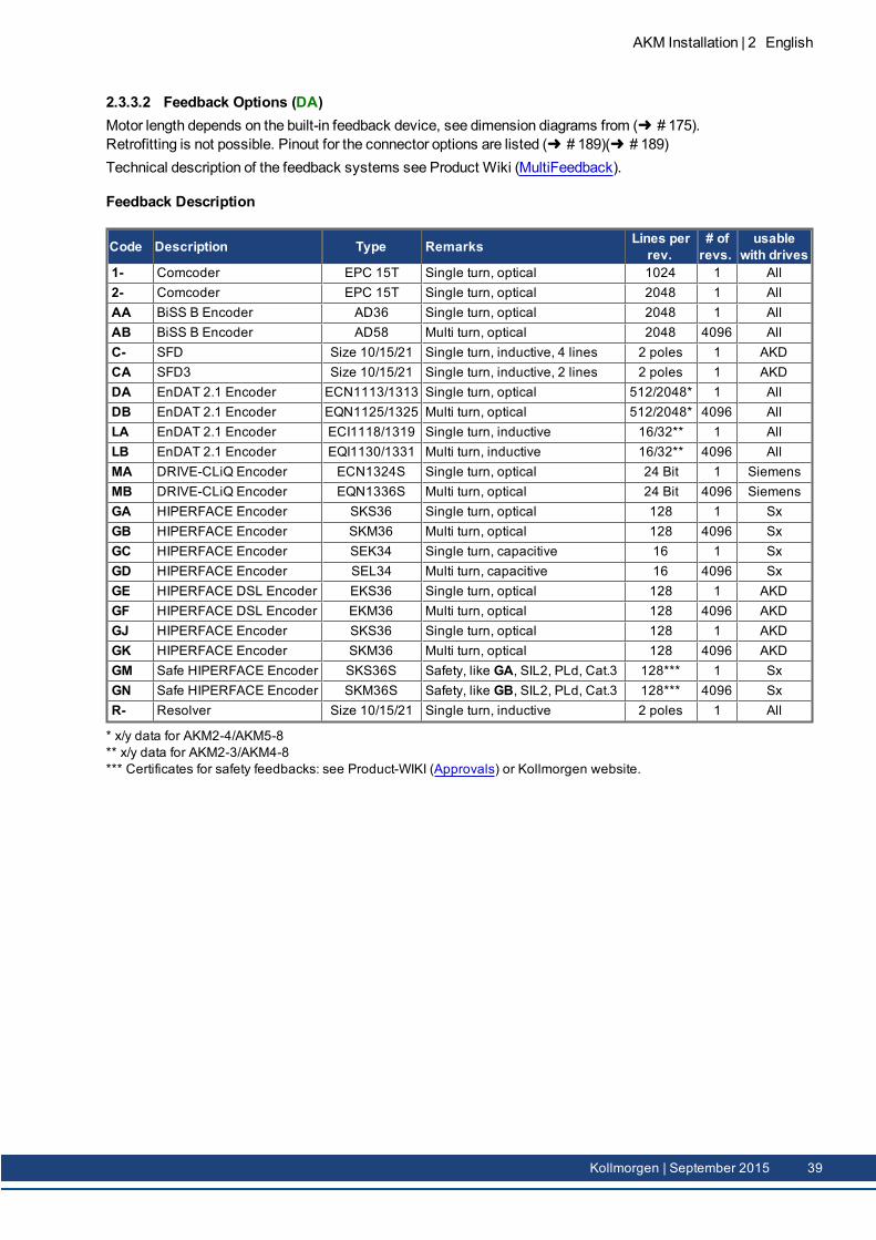
2.3.3.2 Feedback Options (DA)Motor length depends on the built-in feedback device, see dimension diagrams from ( # 175).Retrofitting is not possible. Pinout for the connector options are listed ( # 189)( # 189)Technical description of the feedback systems see Product Wiki (MultiFeedback).
Feedback Description
Code Description Type Remarks Lines perrev.
# ofrevs.
usablewith drives
1- Comcoder EPC 15T Single turn, optical 1024 1 All2- Comcoder EPC 15T Single turn, optical 2048 1 AllAA BiSS B Encoder AD36 Single turn, optical 2048 1 AllAB BiSS B Encoder AD58 Multi turn, optical 2048 4096 AllC- SFD Size 10/15/21 Single turn, inductive, 4 lines 2 poles 1 AKDCA SFD3 Size 10/15/21 Single turn, inductive, 2 lines 2 poles 1 AKDDA EnDAT 2.1 Encoder ECN1113/1313 Single turn, optical 512/2048* 1 AllDB EnDAT 2.1 Encoder EQN1125/1325 Multi turn, optical 512/2048* 4096 AllLA EnDAT 2.1 Encoder ECI1118/1319 Single turn, inductive 16/32** 1 AllLB EnDAT 2.1 Encoder EQI1130/1331 Multi turn, inductive 16/32** 4096 AllMA DRIVE-CLiQ Encoder ECN1324S Single turn, optical 24 Bit 1 SiemensMB DRIVE-CLiQ Encoder EQN1336S Multi turn, optical 24 Bit 4096 SiemensGA HIPERFACE Encoder SKS36 Single turn, optical 128 1 SxGB HIPERFACE Encoder SKM36 Multi turn, optical 128 4096 SxGC HIPERFACE Encoder SEK34 Single turn, capacitive 16 1 SxGD HIPERFACE Encoder SEL34 Multi turn, capacitive 16 4096 SxGE HIPERFACE DSL Encoder EKS36 Single turn, optical 128 1 AKDGF HIPERFACE DSL Encoder EKM36 Multi turn, optical 128 4096 AKDGJ HIPERFACE Encoder SKS36 Single turn, optical 128 1 AKDGK HIPERFACE Encoder SKM36 Multi turn, optical 128 4096 AKDGM Safe HIPERFACE Encoder SKS36S Safety, like GA, SIL2, PLd, Cat.3 128*** 1 SxGN Safe HIPERFACE Encoder SKM36S Safety, like GB, SIL2, PLd, Cat.3 128*** 4096 SxR- Resolver Size 10/15/21 Single turn, inductive 2 poles 1 All
* x/y data for AKM2-4/AKM5-8** x/y data for AKM2-3/AKM4-8*** Certificates for safety feedbacks: see Product-WIKI (Approvals) or Kollmorgen website.
AKM Installation | 2 English
Kollmorgen | September 2015 39
AKM Installation | 2 English
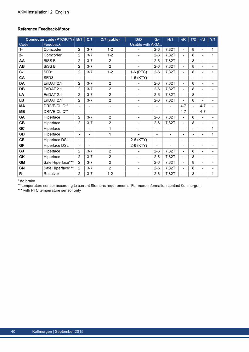
Reference Feedback-Motor
Connector code (PTC/KTY) B/1 C/1 C/7 (cable) D/D G/- H/1 -/R T/2 -/U Y/1Code Feedback Usable with AKM...1- Comcoder 2 3-7 1-2 - 2-6 7,82T - 8 - 12- Comcoder 2 3-7 1-2 - 2-6 7,82T - 8 - 1AA BiSS B 2 3-7 2 - 2-6 7,82T - 8 - -AB BiSS B 2 3-7 2 - 2-6 7,82T - 8 - -C- SFD* 2 3-7 1-2 1-6 (PTC) 2-6 7,82T - 8 - 1CA SFD3 - - - 1-6 (KTY) - - - - - -DA EnDAT 2.1 2 3-7 2 - 2-6 7,82T - 8 - -DB EnDAT 2.1 2 3-7 2 - 2-6 7,82T - 8 - -LA EnDAT 2.1 2 3-7 2 - 2-6 7,82T - 8 - -LB EnDAT 2.1 2 3-7 2 - 2-6 7,82T - 8 - -MA DRIVE-CLiQ** - - - - - - 4-7 - 4-7 -MB DRIVE-CLiQ** - - - - - - 4-7 - 4-7 -GA Hiperface 2 3-7 2 - 2-6 7,82T - 8 - -GB Hiperface 2 3-7 2 - 2-6 7,82T - 8 - -GC Hiperface - - 1 - - - - - - 1GD Hiperface - - 1 - - - - - - 1GE Hiperface DSL - - - 2-6 (KTY) - - - - - -GF Hiperface DSL - - - 2-6 (KTY) - - - - - -GJ Hiperface 2 3-7 2 - 2-6 7,82T - 8 - -GK Hiperface 2 3-7 2 - 2-6 7,82T - 8 - -GM Safe Hiperface*** 2 3-7 2 - 2-6 7,82T - 8 - -GN Safe Hiperface*** 2 3-7 2 - 2-6 7,82T - 8 - -R- Resolver 2 3-7 1-2 - 2-6 7,82T - 8 - 1
* no brake** temperature sensor according to current Siemens requirements. For more information contact Kollmorgen.*** with PTC temperature sensor only
40 Kollmorgen | September 2015
2.4 Technical Description
2.4.1 General technical dataAmbient temperature(at rated values)
5...+40°C for site altitude up to 1000m amslIt is vital to consult our applications department for ambient tem-peratures above 40°C and encapsulatedmounting of themotors.
Permissible humidity(at rated values)
95% rel. humidity, no condensation
Power derating(currents and torques)
1%/K in range 40°C...50°C up to 1000m amslfor site altitude above 1000m amsl and 40°C6% up to 2000m amsl17% up to 3000m amsl30% up to 4000m amsl55% up to 5000m amslNo derating for site altitudes above 1000m amsl with tem-perature reduction of 10K / 1000m
Ball-bearing life ≥ 20.000 operating hoursTechnical data for every motor type can be found in chapter "Technical Data" from ( #161).
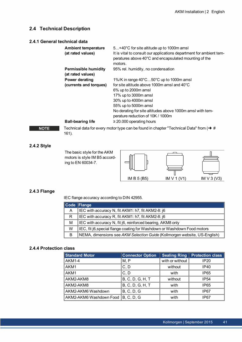
2.4.2 StyleThe basic style for the AKMmotors is style IM B5 accord-ing to EN 60034-7.
2.4.3 FlangeIEC flange accuracy according to DIN 42955.
Code FlangeA IEC with accuracy N, fit AKM1: h7, fit AKM2-8: j6R IEC with accuracy R, fit AKM1: h7, fit AKM2-8: j6M IEC with accuracy N, fit j6, reinforced bearing, AKM8 onlyW IEC, fit j6,special flange coating forWashdown orWashdown FoodmotorsB NEMA, dimensions seeAKM Selection Guide (Kollmorgen website, US-English)
2.4.4 Protection classStandard Motor Connector Option Sealing Ring Protection classAKM1-4 M, P with or without IP20AKM1 C, D without IP40AKM1 C, D with IP65AKM2-AKM8 B, C, D, G, H, T without IP54AKM2-AKM8 B, C, D, G, H, T with IP65AKM2-AKM6Washdown B, C, D, G with IP67AKM2-AKM6Washdown Food B, C, D, G with IP67
AKM Installation | 2 English
Kollmorgen | September 2015 41
AKM Installation | 2 English
2.4.5 Insulation material classThemotors come up to insulationmaterial class F according to IEC 60085 (UL1446 class F).
2.4.6 SurfaceThemotors are coated with polyester powder coating in matt black. This finish is not res-istant against solvents (e.g. trichlorethylene, nitro-thinners, or similar).
2.4.7 Shaft end, A-sidePower transmission is made through the cylindrical shaft end A, fit k6 (AKM1: h7) toEN 50347, with a locking thread but without a fitted keyway.Bearing life is calculated with 20.000 operating hours.
Order code Shaft end available forN Smooth shaft all types, standardC Keyway, closed AKM 2...8K Keyway, open AKM 1...8
Radial forceIf themotors drive via pinions or toothed belts, then high radial forces will occur. The per-missible values at the end of the shaft may be read from the diagrams in chapter "Drawings"from ( # 175). Themaximum values at rated speed you will find at the technical data from( # 161). Power take-off from themiddle of the free end of the shaft allows a 10% increasein FR.
Axial forceWhen assembling pinions or wheels to the axis and use of e.g. angular gearheads axialforces arise. Themaximum values at rated speed you will find at the technical data.
CouplingDouble-coned collets have proved to be ideal zero-backlash coupling devices, combined, ifrequired, with metal bellows couplings.
2.4.8 Protective deviceThe standard version of eachmotor is fitted with an electrically isolated PTC (ratedtemperature 155°C ± 5%). The PTC does not provide any protection against short, heavyoverloading.Themotor can be delivered with a KTY 84-130 sensor optionally (see Connector Options 1,2, 7 and D on ( # 189).With digital feedback system SFD, SFD3, DSL (C-, CA, GE, GF) the temperature sensorstatus is transmitted digitally and evaluated in the drive.Provided that our configured feedback cables are used, the sensor is integrated into themon-itoring system of the digital servo amplifiers.
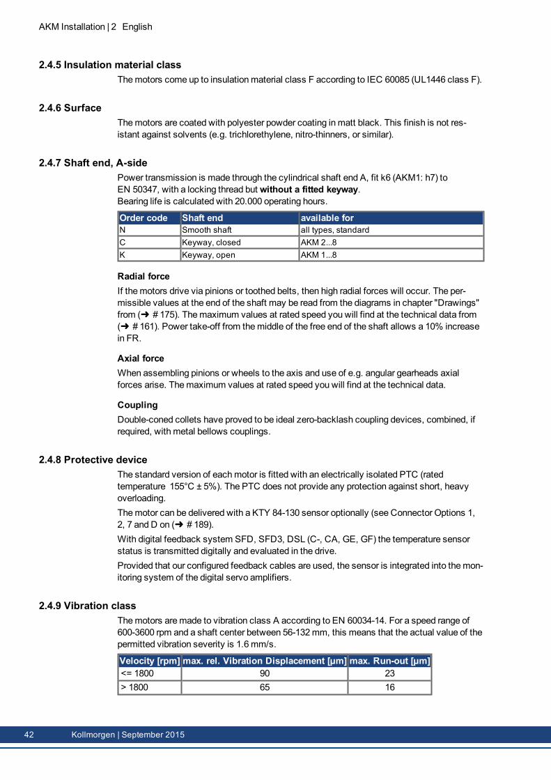
2.4.9 Vibration classThemotors aremade to vibration class A according to EN 60034-14. For a speed range of600-3600 rpm and a shaft center between 56-132 mm, this means that the actual value of thepermitted vibration severity is 1.6 mm/s.
Velocity [rpm] max. rel. Vibration Displacement [µm] max. Run-out [µm]<= 1800 90 23> 1800 65 16
42 Kollmorgen | September 2015
2.4.10 Shaft sealIf AKM is connected to amachine flange with unsealed shaft region, then the shaft seal(option "01") ensures the shaft sealing. Run-in procedure of shaft seal needs to be performedto ensure rated performance of AKMmotors.Execute the following run-in procedure:
30minutes no load run at maximum speed in CW direction,30minutes self-cooling of motor,30minutes no load run at maximum speed in CCW direction,30minutes self-cooling of motor.
This cycle should be repeated 3 times.
2.4.11 Wiring technology
2.4.11.1 ConnectorsDescriptions of the available connectors: ( # 38). Connector pinout: from ( # 189).
2.4.11.2 Wire cross sections
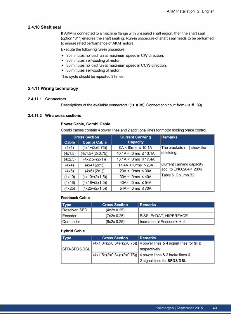
Power Cable, Combi CableCombi cables contain 4 power lines and 2 additional lines for motor holding brake control.
Cross Section Current CarryingCapacity
RemarksCable Combi Cable(4x1) (4x1+(2x0.75)) 0A < I0rms ≤ 10.1A The brackets (...) show the
shielding.
Current carrying capacityacc. to EN60204-1:2006Table 6, Column B2
(4x1.5) (4x1.5+(2x0.75)) 10.1A < I0rms ≤ 13.1A(4x2.5) (4x2.5+(2x1)) 13.1A < I0rms ≤ 17.4A(4x4) (4x4+(2x1)) 17.4A < I0rms ≤ 23A(4x6) (4x6+(2x1)) 23A < I0rms ≤ 30A(4x10) (4x10+(2x1.5)) 30A < I0rms ≤ 40A(4x16) (4x16+(2x1.5)) 40A < I0rms ≤ 54A(4x25) (4x25+(2x1.5)) 54A < I0rms ≤ 70A
Feedback Cable
Type Cross Section RemarksResolver, SFD (4x2x 0.25)Encoder (7x2x 0.25) BiSS, EnDAT, HIPERFACEComcoder (8x2x 0.25) Incremental Encoder + Hall
Hybrid Cable
Type Cross Section Remarks
SFD/SFD3/DSL(4x1.0+(2x0.34)+(2x0.75)) 4 power lines & 4 signal lines forSFD
respectively4 power lines & 2 brake lines &2 signal lines forSFD3/DSL
(4x1.5+(2x0.34)+(2x0.75))
AKM Installation | 2 English
Kollmorgen | September 2015 43
AKM Installation | 2 English
2.4.12 Holding brakeAll motors are optionally available with a holding brake. A spring applied brake (24V DC) isintegrated into themotors. When this brake is de-energized it blocks the rotor.
WARNINGIf there is a suspended load (vertical axes), the motor's holding brake isreleased, and, at the same time, the servo drive does not produce any out-put, the load may fall down! Risk of injury for the personnel operating themachine. Functional safety in case of hanging loads (vertical axes) canbe ensured only by using an additional, external, mechanical brake.
The holding brakes are designed as standstill brakes and are not suited for repeated oper-ational braking. In the case of frequent, operational braking, premature wear and failure of theholding brake is to be expected.Themotor length increases when a holding brake is mounted.The holding brake can be controlled directly by the servo amplifier (no personal safety !), thewinding is suppressed in the servo amplifier— additional circuitry is not required (see instruc-tions manual of the servo amplifier). If the holding brake is not controlled directly by the servoamplifier, an additional wiring (e.g. varistor) is required. Consult our support department.
2.4.13 Fan for AKM7For the AKM7model size, an add-on kit for forced ventilation is available. The integrated fanenables up to 30% more power output for the AKM7motors. Assembly instructions for thefan kit is contained within the scope of delivery of the add-on kit.
The fan housing can bemounted either with both the suppliedbrackets and spacers or with the brackets only. The choice ofmountingmethod depends on the application. If strong vibra-tions are expected, you should use both brackets andspacers. Motors with integrated brakes require the longsspacers.
Make sure, that free air flow is available for the fan. Keep a space of at least 25mm behindthe fan guard.Themotors become dirty considerably faster due to forced convection. Dirt deposits lead tofalling cooling capacity and can put themotors at risk. Dust may burn in case of over-heating.So clean the air duct, the fan, and themotor at regular intervals.By adding a fan, themounting dimensions of AKM7motors increase.In case of AKM7motors with connector option "C", winding "Q" and forced ventilation youmust limit themotor current to 24 A for connector protection.You can find technical information on AKM7motors with fans ( # 173).You can find the dimensional drawing for AKM7motors with fans on ( # 184).
44 Kollmorgen | September 2015
2.4.14 Washdown and Washdown FoodThesemotor variants are used in applications that are subject to strict hygiene regulations inwhich it is essential that the formation of nuclei and corrosion are avoided and in whichmachines must be cleaned cyclically.Themotors are based on the standard types AKM2 - AKM6with special modifications foruse in the food-processing industry or even in the packaging industry. In addition, it is alsopossible to coat the flange in each case – but then it is not possible to assure tolerance classN for the flange.In the type code, the coating of themotor housing (type “W” forWashdown, "F" forWash-down Food) is defined separately in the version (last two digits) and the flange coating.
Washdown/Washdown Food Motor Connector Options Flange OptionsAKM2 B*, D*, G A, B, W, RAKM3, 4, 6 C*, D*, G A, B, W, RAKM5 C*, D*, G B
* Do not turn the connector on themotor more than +/- 180 °, greater rotation angle will dam-age the internal connections.
2.4.14.1 WashdownAKM^^^-^^^^^-^WAKM^^^-W^^^^^-^W
Washdownwithout flange coatingWashdownwith flange coating of IEC A flange
TheWashdownmotors must not come into contact with any unpacked foodstuffs.
Application Area: Harsh environments, outdoorsExample: Transport in the foodstuff and packing area without contact with
foodstuff, radar stations, wind turbines, offshore installationsStandards: UL, CE, RohSSurface: Silver coatingImmunity: Against tested industrial cleaning agent ( # 46), corrosion-proofDegree of protection: IP67Shaft: Stainless steelRotary shaft seal: PTFELubricant: Industrial bearing grease, non-food-gradeConnector: Stainless steel, smooth surfaceScrews: Stainless SteelName plate: Engraved, additional nameplate in the packageSize: AKM2 - AKM6
AKM Installation | 2 English
Kollmorgen | September 2015 45
AKM Installation | 2 English
2.4.14.2 Washdown FoodAKM^^^-^^^^^-^FAKM^^^-W^^^^^-^F
Washdown Food without flange coatingWashdown Food with flange coating of IEC A flange
The surface of theWashdown foodmotor has passed all tests as per FDA GlobalMigrationfor indirect contact with foodstuffs. Any direct contact with unpacked foodstuffs is not per-mitted.
Application Area: Foodstuffs and drinks industry, no direct contact with unpackedfoodstuff
Example: Cutting, packing and filling without direct contact with foodstuffs.Motor laterally or below the food.
Standards: UL, CE, RoHs, FDASurface: White coatingImmunity: Against tested industrial cleaning agent ( # 46), corrosion-proofGlobal Migration: US FDA Regulations 21 CFR 175.300, Condition of Use EDegree of protection: IP67Shaft: Stainless steelRotary shaft seal: PTFE as per FDALubricant: food-grade as per FDAConnector: Stainless steel, smooth surfaceScrews: Stainless SteelName plate: Engraved, additional nameplate in the packageSize: AKM2 - AKM6
2.4.14.3 Tested and confirmed properties with respect to cleaning agentsThe testing lab of ECOLAB DeutschlandGmbH tested the resistance of theWashdown andWashdown Food surfaces to the following industrial cleaning agents:
P3-topactive DESP3-topactive LAP3-topax 56P3-topax 66P3-topax 91
In the process, the surfaces were immersed in the respective cleaning agent at room tem-perature for 28 days. This corresponds to approx. 2,500 cleaning cycles with 15-minute con-tact each with the cleaning agent or 1,500 cleaning cycles with cleaning and subsequentdisinfection.The certificates are located in our Product WIKI on the Approvals page.
Kollmorgen can only give a guarantee for themotor's lifecycle if the tested cleansing agentsare used. Any cleansing agent other than thosementioned above can be tested by Koll-morgen upon request and, if appropriate, be approved.
46 Kollmorgen | September 2015
2.4.14.4 Installation and operating conditionsThemotors may be used only in ambient temepratures up to 50 °C.If the front flange is coated, the tolerance class N is not guaranteed.
Motors with flanges without wash-outdown coating: The flange surfacemust be protected bysuitable assembly against the influence by cleaning agents.
2.4.14.5 Cleaning planRecommended cleaning plan (short form) with tested cleaning agents:
Flushing with water (40 °... 50 °C)Flushing with low pressure. From top to bottom in the direction of the drain. Clean the drain.
Foam cleaningFoaming from top to bottom.Alkaline: P3-topactive LA or P3-topax 66 (2-5%, 15min daily)Acid: P3-topax 56 (2%, if necessary 15min)Temperature: cold up to 40 °C
DisinfectionSpraying with wayer (40 °... 50 °C) with low pressure. From top to bottom.Spray disinfection: P3-topax 91 (1-2%, if necessary 30-60min)Foam disinfection: P3-topactiv DES (1-3%, if necessary 10-30min)
AKM Installation | 2 English
Kollmorgen | September 2015 47
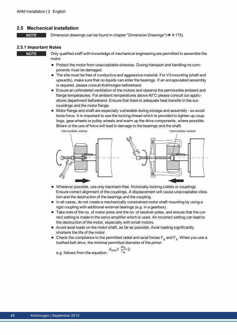
AKM Installation | 2 English
2.5 Mechanical InstallationDimension drawings can be found in chapter "Dimension Drawings"( # 175).
2.5.1 Important NotesOnly qualified staff with knowledge of mechanical engineering are permitted to assemble themotor.
Protect themotor from unacceptable stresses. During transport and handling no com-ponents must be damaged.The site must be free of conductive and aggressivematerial. For V3-mounting (shaft endupwards), make sure that no liquids can enter the bearings. If an encapsulated assemblyis required, please consult Kollmorgen beforehand.Ensure an unhindered ventilation of themotors and observe the permissible ambient andflange temperatures. For ambient temperatures above 40°C please consult our applic-ations department beforehand. Ensure that there is adequate heat transfer in the sur-roundings and themotor flange.Motor flange and shaft are especially vulnerable during storage and assembly - so avoidbrute force. It is important to use the locking thread which is provided to tighten up coup-lings, gear wheels or pulley wheels and warm up the drive components, where possible.Blows or the use of force will lead to damage to the bearings and the shaft.
Wherever possible, use only backlash-free, frictionally-locking collets or couplings.Ensure correct alignment of the couplings. A displacement will cause unacceptable vibra-tion and the destruction of the bearings and the coupling.In all cases, do not create amechanically constrainedmotor shaft mounting by using arigid coupling with additional external bearings (e.g. in a gearbox).Take note of the no. of motor poles and the no. of resolver poles, and ensure that the cor-rect setting is made in the servo amplifier which is used. An incorrect setting can lead tothe destruction of themotor, especially with small motors.Avoid axial loads on themotor shaft, as far as possible. Axial loading significantlyshortens the life of themotor.Check the compliance to the permitted radial and axial forces FR and FA. When you use atoothed belt drive, theminimal permitted diameter of the pinion
e.g. follows from the equation:
48 Kollmorgen | September 2015
2.6 Electrical InstallationPinout for the connector can be found in chapter "Connector Pinout" from ( # 175). Pinoutof the servo amplifier's end can be found in the instructions manual of the servo amplifier.
2.6.1 Important notesOnly staff qualified and trained in electrical engineering are allowed to wire up themotor.
DANGERAlways make sure that the motors are de-energized during assembly andwiring, i.e. no voltage may be switched on for any piece of equipmentwhich is to be connected.There is a risk of death or severe injury from touching exposed contacts.Ensure that the switch cabinet remains turned off (barrier, warning signsetc.). The individual voltages will only be turned on again during setup.Never undo the electrical connections to the motor while it is energized.Risk of electric shock! In unfavorable circumstances, electric arcs canarise causing harm to people and damaging contacts.A dangerous voltage, resulting from residual charge, can be still presenton the capacitors up to 10 minutes after switch-off of the mains supply.Even when the motor is not rotating, control and power leads may be live.Measure the DC-link voltage and wait until it has fallen below 60V.
The ground symbol , which you will find in the wiring diagrams, indicates that youmust provide an electrical connection, with as large a surface area as possible, between theunit indicated and themounting plate in the switch cabinet. This connection is to suppressHF interference andmust not be confused with the PE (protective earth) symbol (pro-tectivemeasure to EN 60204).
To wire up themotor, use the wiring diagrams in the Installation and Setup Instructions of theservo amplifier which is used.
AKM Installation | 2 English
Kollmorgen | September 2015 49
AKM Installation | 2 English
2.6.2 Guide for electrical installationCheck that the servo amplifier andmotor match each other. Compare the rated voltageand rated current of the unit. Carry out the wiring according to the wiring diagram in theinstructions manual of the servo amplifier. The connections to themotor are shown inchapter "Connector Pinout" from ( # 175).Install all cables carrying a heavy current with an adequate cross-section, as perEN 60204. The recommended cross-section can be found in the Technical data.
In case of longmotor cables (>25m) and dependent on the type of the used servo amplifier amotor choke (3YL or 3YLN)must be switched into themotor cable (see instructions manualof the servo amplifier and accessory manual).
Ensure that there is proper earthing of the servo amplifier and themotor. Use correct earth-ing and EMC-shielding according to the instructions manual of the servo amplifier whichis used. Earth themounting plate andmotor casing.If a motor power cable is used which includes integral brake control leads, then thesebrake control leads must be shielded. The shieldingmust be connected at both ends (seeinstructions manual of the servo amplifier).Cabling:
Route power cables as separately as possible from control cablesConnect up the resolver or encoder.Connect themotor cables, install motor chokes close to the amplifierConnect shields to shielding terminals or EMC connectors at both endsConnect the holding brake, if usedConnect shielding at both ends.
Connect up all shielding via a wide surface-area contact (low impedance) andmetallizedconnector housings or EMC-cable glands.Requirements to cablematerial:CapacityMotor cable: less than 150 pF/mResolver cable: less than 120 pF/m
2.6.3 Connection of the motors with preassembled cablesCarry out the wiring in accordance with the valid standards and regulations.Only use Kollmorgen preassembled shielded cables for the resolver and power con-nections.Incorrectly installed shielding leads to EMC interference and has an adverse effect on sys-tem function.Themaximum cable length is defined in the instructions manual of the used servo amp-lifier.
For a detailed description of configured cables, please refer to the regional accessoriesmanual.
50 Kollmorgen | September 2015

2.7 Setup
2.7.1 Important notes
Only specialist personnel with extensive knowledge in the areas of electrical engineering /drive technology are allowed to commission the drive unit of servo amplifier andmotor.
DANGERDeadly voltages can occur, up to 900 V. Risk of electric shock! Checkthat all live connection points are safe against accidental contact.Never undo the electrical connections to the motor when it is live. Risk ofelectric shock! The residual charge in the capacitors of the drive can pro-duce dangerous voltages up to 10 minutes after the mains supply hasbeen switched off.Even when the motor is not rotating, control and power leads may be live.Measure the DC-link voltage and wait until it has fallen below 60 V.
CAUTIONThe surface temperature of the motor can exceed 100°C in operation. Danger of light burns! Check (measure) the temperature of the motor. Wait until the motor has cooled down below 40°C before touching it.
CAUTIONThe drive performing unplanned movements during commissioning can-not be ruled out.Make sure that, even if the drive starts to move unintentionally, no dangercan result for personnel or machinery.The measures you must take in this regard for your task are based on therisk assessment of the application.
AKM Installation | 2 English
Kollmorgen | September 2015 51

AKM Installation | 2 English
2.7.2 Guide for setupThe procedure for setup is described as an example. A different methodmay be appropriateor necessary, depending on the application of the equipment.1. Check the assembly and orientation of themotor.2. Check the drive components (clutch, gear unit, belt pulley) for the correct seating and set-
ting (observe the permissible radial and axial forces).3. Check the wiring and connections to themotor and the servo amplifier. Check that the
earthing is correct.4. Test the function of the holding brake, if used. (apply 24 V, brakemust be released).5. Check whether the rotor of themotor revolves freely (release the brake, if necessary).
Listen out for grinding noises.6. Check that all the requiredmeasures against accidental contact with live andmoving
parts have been carried out.7. Carry out any further tests which are specifically required for your system.8. Now commission the drive according to the setup instructions for the servo amplifier.9. In multi-axis systems, individually commission each drive unit (amplifier andmotor).
52 Kollmorgen | September 2015
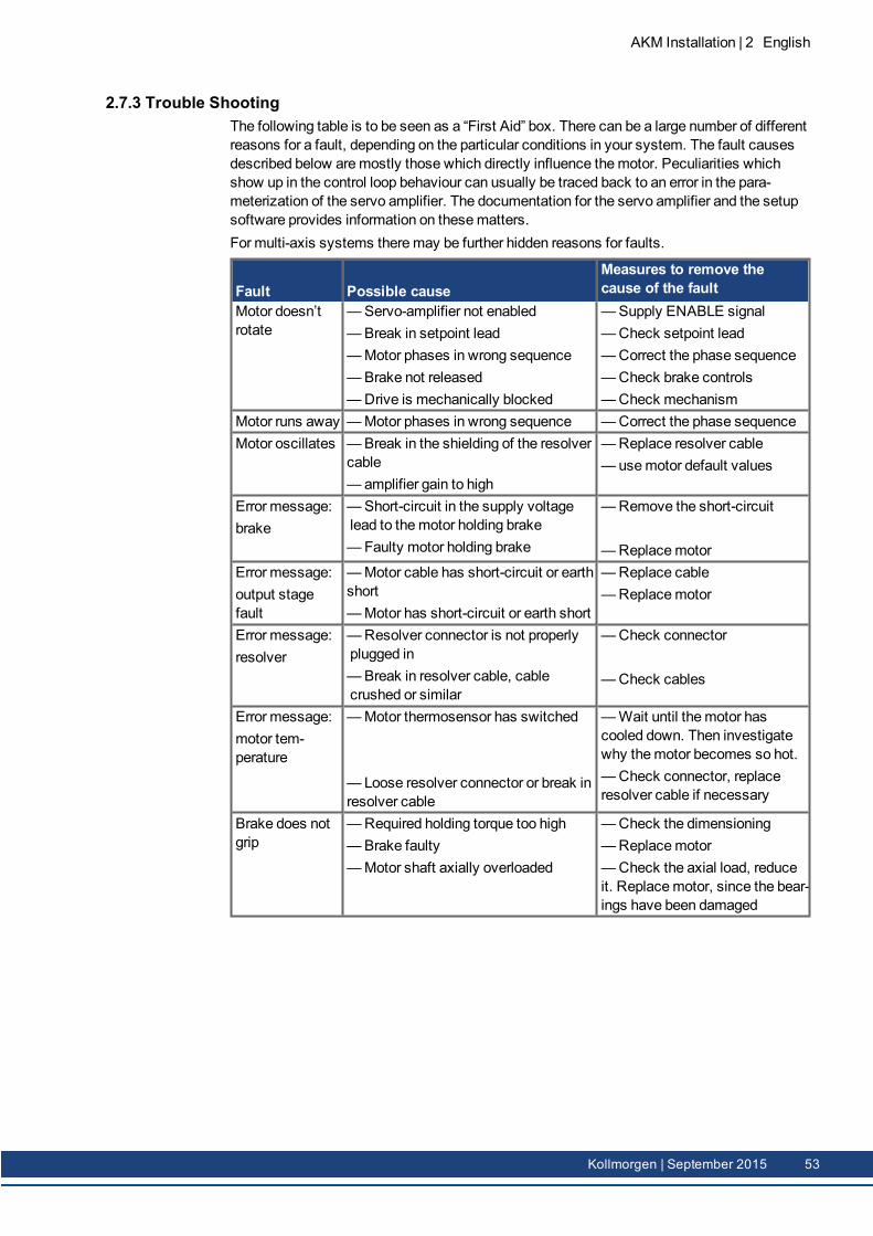
2.7.3 Trouble ShootingThe following table is to be seen as a “First Aid” box. There can be a large number of differentreasons for a fault, depending on the particular conditions in your system. The fault causesdescribed below aremostly those which directly influence themotor. Peculiarities whichshow up in the control loop behaviour can usually be traced back to an error in the para-meterization of the servo amplifier. The documentation for the servo amplifier and the setupsoftware provides information on thesematters.For multi-axis systems theremay be further hidden reasons for faults.
Fault Possible causeMeasures to remove thecause of the fault
Motor doesn’trotate
—Servo-amplifier not enabled—Break in setpoint lead—Motor phases in wrong sequence—Brake not released—Drive is mechanically blocked
—Supply ENABLE signal—Check setpoint lead—Correct the phase sequence—Check brake controls—Check mechanism
Motor runs away —Motor phases in wrong sequence —Correct the phase sequenceMotor oscillates —Break in the shielding of the resolver
cable— amplifier gain to high
—Replace resolver cable— usemotor default values
Error message:brake
—Short-circuit in the supply voltagelead to themotor holding brake—Faulty motor holding brake
—Remove the short-circuit
—ReplacemotorError message:output stagefault
—Motor cable has short-circuit or earthshort—Motor has short-circuit or earth short
—Replace cable—Replacemotor
Error message:resolver
—Resolver connector is not properlyplugged in—Break in resolver cable, cablecrushed or similar
—Check connector
—Check cables
Error message:motor tem-perature
—Motor thermosensor has switched
— Loose resolver connector or break inresolver cable
—Wait until themotor hascooled down. Then investigatewhy themotor becomes so hot.—Check connector, replaceresolver cable if necessary
Brake does notgrip
—Required holding torque too high—Brake faulty—Motor shaft axially overloaded
—Check the dimensioning—Replacemotor—Check the axial load, reduceit. Replacemotor, since the bear-ings have been damaged
AKM Installation | 2 English
Kollmorgen | September 2015 53
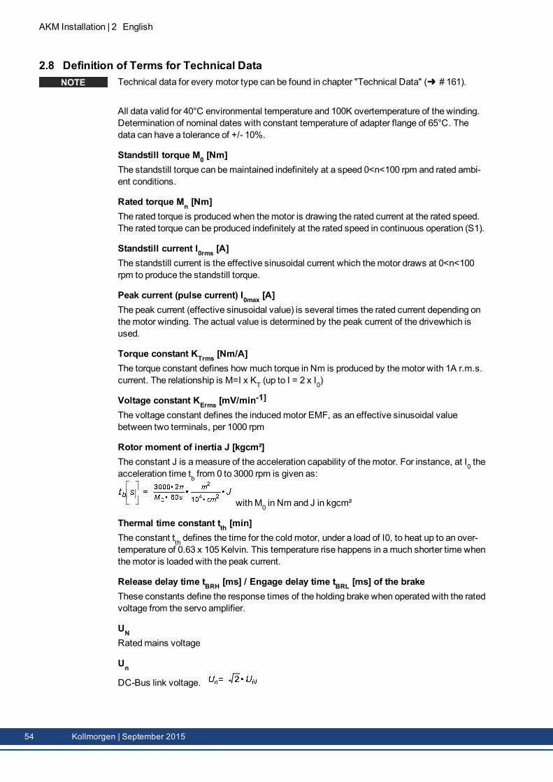
AKM Installation | 2 English
2.8 Definition of Terms for Technical DataTechnical data for every motor type can be found in chapter "Technical Data" ( # 161).
All data valid for 40°C environmental temperature and 100K overtemperature of the winding.Determination of nominal dates with constant temperature of adapter flange of 65°C. Thedata can have a tolerance of +/- 10%.
Standstill torque M0 [Nm]The standstill torque can bemaintained indefinitely at a speed 0<n<100 rpm and rated ambi-ent conditions.
Rated torque Mn [Nm]The rated torque is produced when themotor is drawing the rated current at the rated speed.The rated torque can be produced indefinitely at the rated speed in continuous operation (S1).
Standstill current I0rms [A]The standstill current is the effective sinusoidal current which themotor draws at 0<n<100rpm to produce the standstill torque.
Peak current (pulse current) I0max [A]The peak current (effective sinusoidal value) is several times the rated current depending onthemotor winding. The actual value is determined by the peak current of the drivewhich isused.
Torque constant KTrms [Nm/A]The torque constant defines how much torque in Nm is produced by themotor with 1A r.m.s.current. The relationship is M=I x KT (up to I = 2 x I0)
Voltage constant KErms [mV/min-1]
The voltage constant defines the inducedmotor EMF, as an effective sinusoidal valuebetween two terminals, per 1000 rpm
Rotor moment of inertia J [kgcm²]The constant J is ameasure of the acceleration capability of themotor. For instance, at I0 theacceleration time tb from 0 to 3000 rpm is given as:
with M0 in Nm and J in kgcm²
Thermal time constant tth [min]The constant tth defines the time for the cold motor, under a load of I0, to heat up to an over-temperature of 0.63 x 10⁵ Kelvin. This temperature rise happens in amuch shorter time whenthemotor is loaded with the peak current.
Release delay time tBRH [ms] / Engage delay time tBRL [ms] of the brakeThese constants define the response times of the holding brake when operated with the ratedvoltage from the servo amplifier.
UNRatedmains voltage
Un
DC-Bus link voltage.
54 Kollmorgen | September 2015
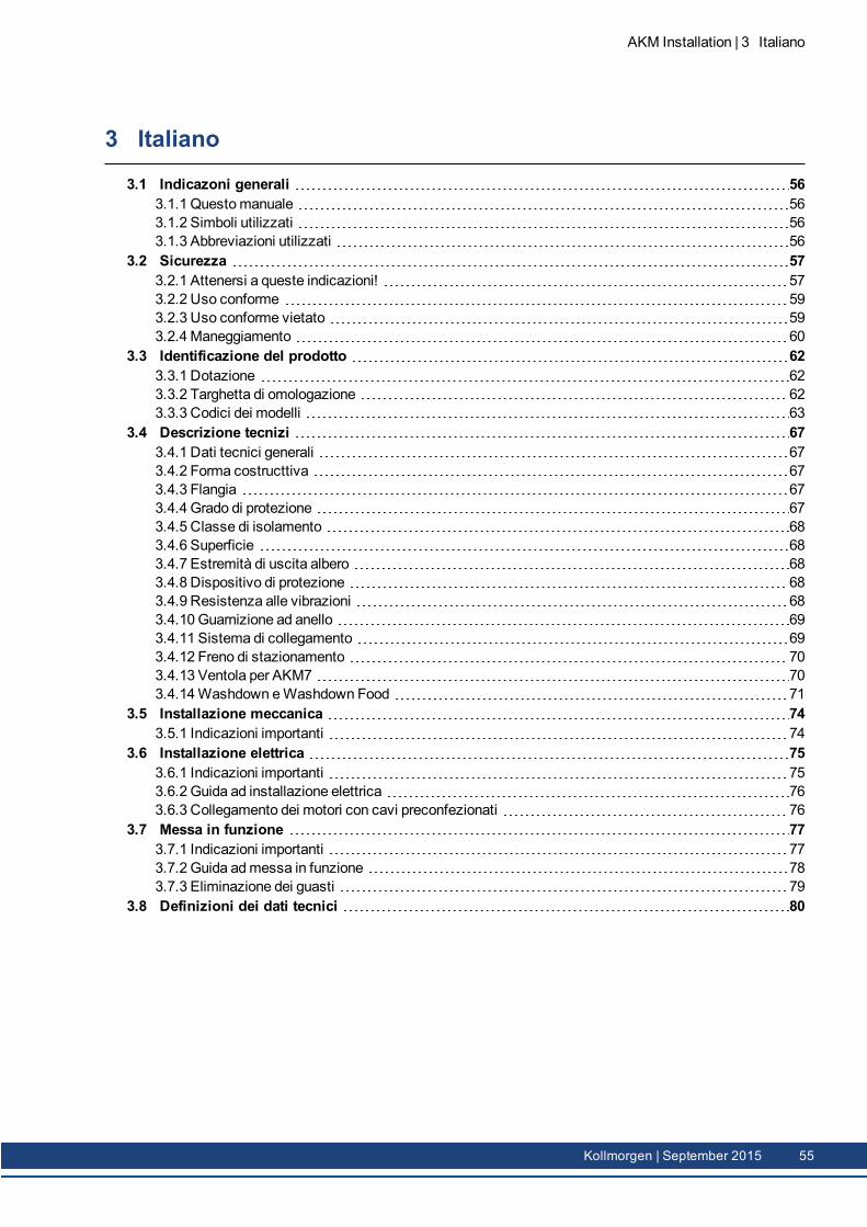
3 Italiano
3.1 Indicazoni generali 563.1.1 Questomanuale 563.1.2 Simboli utilizzati 563.1.3 Abbreviazioni utilizzati 56
3.2 Sicurezza 573.2.1 Attenersi a queste indicazioni! 573.2.2 Uso conforme 593.2.3 Uso conforme vietato 593.2.4Maneggiamento 60
3.3 Identificazione del prodotto 623.3.1 Dotazione 623.3.2 Targhetta di omologazione 623.3.3 Codici dei modelli 63
3.4 Descrizione tecnizi 673.4.1 Dati tecnici generali 673.4.2 Forma costructtiva 673.4.3 Flangia 673.4.4 Grado di protezione 673.4.5 Classe di isolamento 683.4.6 Superficie 683.4.7 Estremità di uscita albero 683.4.8 Dispositivo di protezione 683.4.9 Resistenza alle vibrazioni 683.4.10 Guarnizione ad anello 693.4.11 Sistema di collegamento 693.4.12 Freno di stazionamento 703.4.13 Ventola per AKM7 703.4.14Washdown eWashdown Food 71
3.5 Installazione meccanica 743.5.1 Indicazioni importanti 74
3.6 Installazione elettrica 753.6.1 Indicazioni importanti 753.6.2 Guida ad installazione elettrica 763.6.3 Collegamento dei motori con cavi preconfezionati 76
3.7 Messa in funzione 773.7.1 Indicazioni importanti 773.7.2 Guida admessa in funzione 783.7.3 Eliminazione dei guasti 79
3.8 Definizioni dei dati tecnici 80
AKM Installation | 3 Italiano
Kollmorgen | September 2015 55
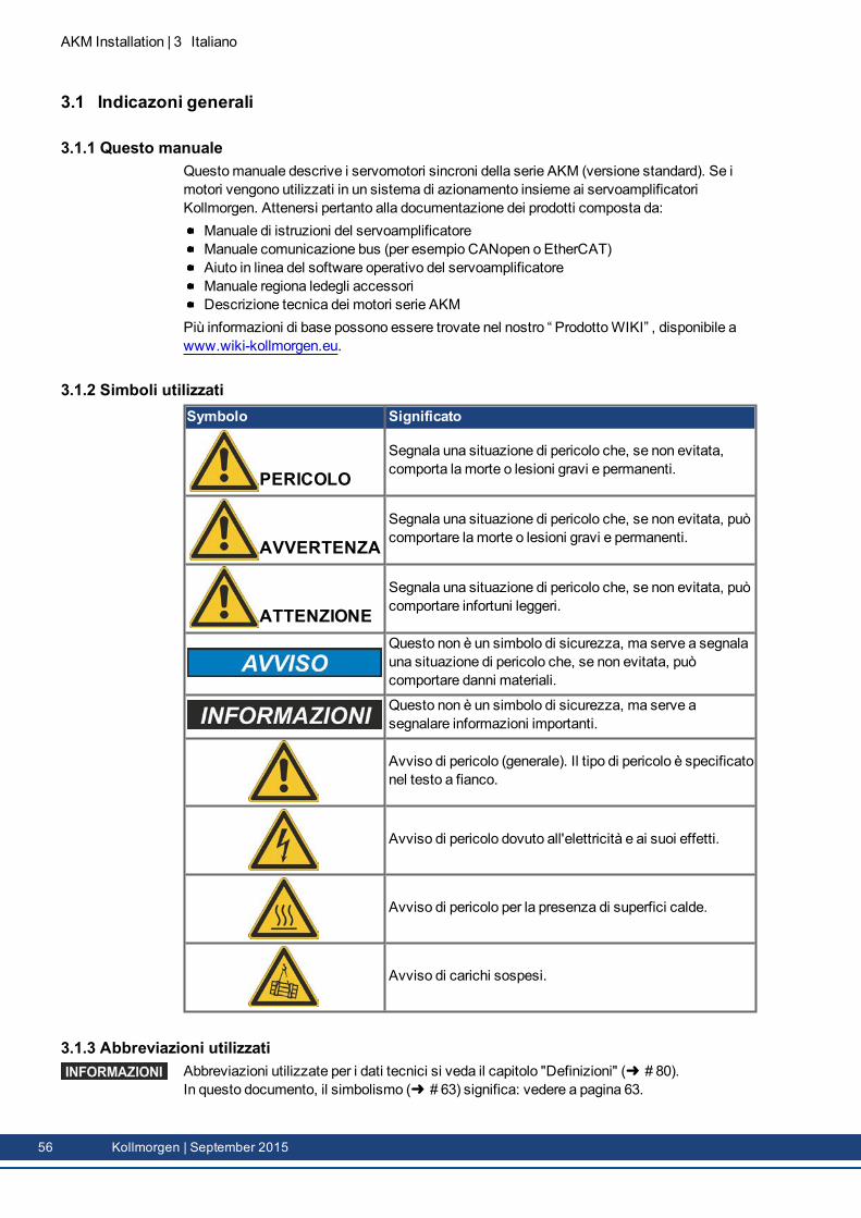
AKM Installation | 3 Italiano
3.1 Indicazoni generali
3.1.1 Questo manualeQuestomanuale descrive i servomotori sincroni della serie AKM (versione standard). Se imotori vengono utilizzati in un sistema di azionamento insieme ai servoamplificatoriKollmorgen. Attenersi pertanto alla documentazione dei prodotti composta da:
Manuale di istruzioni del servoamplificatoreManuale comunicazione bus (per esempio CANopen o EtherCAT)Aiuto in linea del software operativo del servoamplificatoreManuale regiona ledegli accessoriDescrizione tecnica dei motori serie AKM
Più informazioni di base possono essere trovate nel nostro “ ProdottoWIKI” , disponibile a www.wiki-kollmorgen.eu.
3.1.2 Simboli utilizzatiSymbolo Significato
PERICOLOSegnala una situazione di pericolo che, se non evitata,comporta la morte o lesioni gravi e permanenti.
AVVERTENZASegnala una situazione di pericolo che, se non evitata, puòcomportare la morte o lesioni gravi e permanenti.
ATTENZIONESegnala una situazione di pericolo che, se non evitata, puòcomportare infortuni leggeri.
Questo non è un simbolo di sicurezza, ma serve a segnalauna situazione di pericolo che, se non evitata, puòcomportare danni materiali.
Questo non è un simbolo di sicurezza, ma serve asegnalare informazioni importanti.
Avviso di pericolo (generale). Il tipo di pericolo è specificatonel testo a fianco.
Avviso di pericolo dovuto all'elettricità e ai suoi effetti.
Avviso di pericolo per la presenza di superfici calde.
Avviso di carichi sospesi.
3.1.3 Abbreviazioni utilizzatiAbbreviazioni utilizzate per i dati tecnici si veda il capitolo "Definizioni" ( # 80).In questo documento, il simbolismo ( # 63) significa: vedere a pagina 63.
56 Kollmorgen | September 2015
3.2 SicurezzaQuesto capitolo vi aiuta a riconoscere e a evitare pericoli per persone e cose.
3.2.1 Attenersi a queste indicazioni!
È necessario l'intervento di personale tecnico qualificato!I lavori di trasporto, montaggio, messa in funzione emanutenzione si possono affidareesclusivamente a personale tecnico qualificato, che abbia familiarità con il trasporto,l'installazione, il montaggio, la messa in funzione e il funzionamento dei motori e chedisponga di opportune qualifiche per lo svolgimento di tali attività:
Trasporto:solo a cura di personale con nozioni di movimentazione componenti sensibilialle cariche elettrostatiche.Installazionemecc.:solo da parte di meccanicai specializzatiInstallazione elett.:solo a cura di elettricisti qualificati.Configurazione:solo a cura di personale qualificato con nozioni approfondite in materia dielettrotecnica e tecnologia di azionamento.
Il personale tecnico deve conoscere e osservare IEC 60364 / IEC 60664 e disposizioniantinfortunistiche nazionali.
Leggere la documentazione!Leggere prima dell’installazione della documentazione disponibile. L’errata manipolazione delmotore può comportare danni a persone o a cose. L'operatore è quindi tenuto ad assicurarsiche tutto il personale addetto a lavori con i motori abbia letto e compreso il manuale e che leindicazioni di sicurezza riportate nel manuale siano rispettate.
Rispettare i dati tecnici!Osservare i dati tecnici e le indicazioni sulle condizioni di collegamento (targhetta diomologazione e documentazione). Se i valori di tensione e di corrente superano quelliconsentiti, possono verificarsi danni ai motori, per esempio in seguito al surriscaldamento.
Eseguire l'analisi dei rischi!Il produttore è tenuto a realizzare un'analisi dei rischi per il macchinario e ad adottare lemisure necessarie, affinché eventuali movimenti imprevisti non causino danni a persone o acose. L'analisi dei rischi potrebbe comportare la necessità di ulteriori requisiti per il personaletecnico.
Trasportare in modo sicuro!Sollevare e spostaremotori con un peso superiore ai 20 kg (AKM7 e AKM8) solo con l'ausiliodi opportuni dispositivi di sollevamento. Sollevare i motori senza dispositivi ausiliari puòcausare lesioni alla schiena. Attenersi alle indicazioni riportate a ( # 60)
Fissare la chiavetta!Se il motore ruota liberamente rimuovere/fissare l'eventuale chiavetta dell'albero per evitarnel'espulsione con conseguente pericolo di lesioni. Al momento della con- segna, la chiave èprotetta da un cappuccio in plastica.
Superficie calda!Durante il funzionamento i motori possono presentare superfici calde a seconda del lorogrado di protezione. Pericolo di ustioni! La temperatura superficiale può varcare i 100°C.Misurare la temperatura e attendere che il motore abbia raggiunto i 40°C prima di toccarlo.
AKM Installation | 3 Italiano
Kollmorgen | September 2015 57
AKM Installation | 3 Italiano
Messa a terra! Alta tensione!Assicurare la regolaremessa a terra della carcassa del motore con la bandella PE all'internodell'armadio di distribuzione come potenziale di riferimento. Senza unamessa a terra abassa impedenza non viene garantita la sicurezza personale e sussiste pericolo di morte perscosse elettriche.Laman canza di indicazioni ottiche non garantisce l'assenza di tensione. I collegamenti dipotenza possono condurre tensione anche amotore fermo.Non scollegare nessun connettore durante il funzionamento. Rischio di morte o gravi lesionipersonali in caso di contatto con i contatti liberi. I collegamenti di potenza possono condurretensione anche amotore fermo. In casi sfavorevoli possono venire a crearsi archi voltaicicon conseguenti danni a carico di persone e cose.Dopo aver scollegato i servoamplificatori dalle tensioni di alimentazione attendere parecchiminuti prima di toccare i componenti sotto tensione (ad esempio contatti, perni filettati) o diallentare collegamenti.I condensatori nel servoamplificatore conducono tensioni pericolose parecchi minuti dopo ladisinserzione delle tensioni di alimentazione. Per sicurezza, misurare la tensione nel circuitointermedio e attendere fino a quando il valore è sceso al di sotto dei 60V.
Fissare opportunamente i carichi sospesi!I freni di stazionamento integrati non garantiscono la sicurezza funzionale! In presenza dicarichi sospesi (assi verticali) è necessario utilizzare un frenomeccanico esterno aggiuntivoper garantire la sicurezza del personale.
58 Kollmorgen | September 2015
3.2.2 Uso conformeI servomotori sincroni della serie AKM sono stati concepiti in modo particolare comeazionamento per dispositivi di movimentazione, macchine tessili, macchine utensili,confezionatrici e simili con elevati requisiti in termini di dinamica.Azionare i motori solo nel rispetto delle condizioni stabilite nella presentedocumentazione.Il funzionamento dei motoriWashdown in ambienti con soluzioni alcaline e acidi corrosiviè consentito alle condizioni definite a ( # 71).Il funzionamento dei motoriWashdown Food è consentito in applicazioni a contattoindiretto con gli alimenti.I motori della serie AKM sono esclusivamente destinati ad essere comandati daservoamplificatori digitali con regolazione della velocità e/o della coppia.I motori vengonomontati come componenti su impianti o macchine elettrici e possonoesseremessi in funzione solo come componenti integrati dell'impianto.Si richiedono l’analisi e il monitoraggio del termosensore di protezionemontato negliavvolgimenti del motore.I freni di stazionamento sono predisposti come freni di stazionamento e non sono adattiper frenare in modo continuo durante il funzionamento.Garantiamo la conformità del servosistema alle normemenzionate nella EC Declarationof Conformity a ( # 196) solo se vengono utilizzati componenti originali(servoamplificatori, motore, cavi, e così via) di Kollmorgen.
3.2.3 Uso conforme vietatoIl funzionamento di motori standard non è consentito
direttamente dalla rete,in ambienti a rischio di esplosione,a contatto con gli alimenti,in ambienti con oli, vapori, polveri, soluzioni alcaline, acidi corrosivi e/o conduttivi.
Il funzionamento di motoriWashdown non è consentitodirettamente dalla rete,in ambienti a rischio di esplosione,a contatto con gli alimenti,in ambienti con acidi o soluzioni alcaline con un valore del PH inferiore a 2 o superiorea 12,in ambienti con acidi o soluzioni alcaline non testati da Kollmorgen.
Il funzionamento di motoriWashdown Food non è consentitodirettamente dalla rete,in ambienti a rischio di esplosione,a contatto diretto con gli alimenti..
L’uso conforme del motore è vietato quando lamacchina cui è destinatonon è conforme alle disposizioni della DirettivaMacchinenon soddisfa le disposizioni della Direttiva sulla Compatibilità Elettromagneticanon soddisfa le disposizioni della Direttiva Bassa Tensione
Per garantire la sicurezza funzionale non vanno utilizzati i freni di stazionamento senzaulteriori dispositivi.
AKM Installation | 3 Italiano
Kollmorgen | September 2015 59
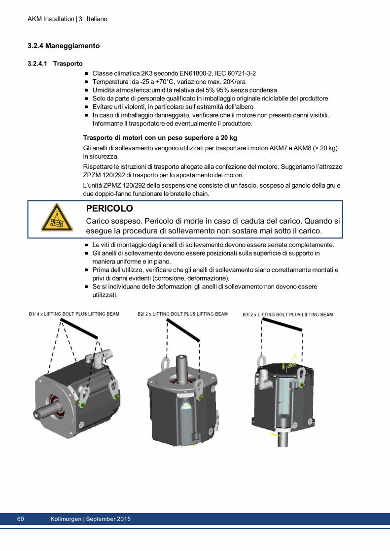
AKM Installation | 3 Italiano
3.2.4 Maneggiamento
3.2.4.1 TrasportoClasse climatica 2K3 secondo EN61800-2, IEC 60721-3-2Temperatura :da -25 a +70°C, variazionemax. 20K/oraUmidità atmosferica:umidità relativa del 5% 95% senza condensaSolo da parte di personale qualificato in imballaggio originale riciclabile del produttoreEvitare urti violenti, in particolare sull'estremità dell'alberoIn caso di imballaggio danneggiato, verificare che il motore non presenti danni visibili.Informarne il trasportatore ed eventualmente il produttore.
Trasporto di motori con un peso superiore a 20 kgGli anelli di sollevamento vengono utilizzati per trasportare i motori AKM7 e AKM8 (> 20 kg)in sicurezza.Rispettare le istruzioni di trasporto allegate alla confezione del motore. Suggeriamo l’attrezzoZPZM 120/292 di trasporto per lo spostamento dei motori.L’unità ZPMZ 120/292 della sospensione consiste di un fascio, sospeso al gancio della gru edue doppio-fanno funzionare le bretelle chain.
PERICOLOCarico sospeso. Pericolo di morte in caso di caduta del carico. Quando siesegue la procedura di sollevamento non sostare mai sotto il carico.
Le viti di montaggio degli anelli di sollevamento devono essere serrate completamente.Gli anelli di sollevamento devono essere posizionati sulla superficie di supporto inmaniera uniforme e in piano.Prima dell'utilizzo, verificare che gli anelli di sollevamento siano correttamentemontati eprivi di danni evidenti (corrosione, deformazione).Se si individuano delle deformazioni gli anelli di sollevamento non devono essereutilizzati.
60 Kollmorgen | September 2015
3.2.4.2 ImballaggioImballaggio del cartone con rivestimento di Instapak®.Potete restituire la parte di plastica al fornitore (veda "Smaltimento")
Tipo Imballaggio Altezza max.d’impilaggio
Tipo Imballaggio Altezza max.d’impilaggio
AKM1 Cartone 10 AKM5 Cartone 5AKM2 Cartone 10 AKM6 Cartone 1AKM3 Cartone 6 AKM7 Cartone 1AKM4 Cartone 6 AKM8 Cartone 1
3.2.4.3 StoccaggioClasse climatica 1K4 secondo EN61800-2, IEC 60721-3-2Temperatura di stoccaggio da -25 a +55°C, variazionemax. 20K/oraUmidità atmosfericaum. rel. del 5% 95% senza condensaSolo in imballaggio originale riciclabile del produttorePer l'altezza d'impilaggio max. ved. tabella nella sezione "Imballaggio"Durata amagazzinoillimitata
3.2.4.4 Manutenzione / PulizaSolo da parte di personale qualificatoDopo 20.000 ore d'esercizio alle condizioni nominali occorre sostituire i cuscinetti a sfere.Controllare il motore ogni 2500 ore d'esercizio o una volta l'anno per verificare larumorosità dei cuscinetti a sfere. Se si riscontrano rumori evitare di utilizzare il motore icuscinetti devono essere sostituiti.L'apertura dei motori comporta l'annullamento della garanzia.Pulizia con isopropanolo o similari, non immergere o nebulizzare
3.2.4.5 Riparazioni / SmaltimentoIl motori può essere riparato unicamente dal fabbricante; l’apertura dell’apparecchio annullaautomaticamente la garanzia. Nell’accordo al WEEE-2002/96/EG-Guidelines prendiamo ivecchi dispositivi ed accessori indietro per eliminazione professionale, se i costi del tansportsono y rilevato il mittente. Trasmetta i dispositivi a:KOLLMORGEN EuropeGmbHPempelfurtstr. 1D-40880 Ratingen
AKM Installation | 3 Italiano
Kollmorgen | September 2015 61
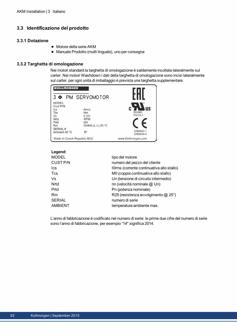
AKM Installation | 3 Italiano
3.3 Identificazione del prodotto
3.3.1 DotazioneMotore della serie AKMManuale Prodotto (multi linguale), uno per consegna
3.3.2 Targhetta di omologazioneNei motori standard la targhetta di omologazione è saldamente incollata lateralmente sulcarter. Nei motori Washdown i dati della targhetta di omologazione sono incisi lateralmentesul carter, per ogni unità di imballaggio è prevista una targhetta supplementare.
Legend:MODEL tipo del motoreCUST P/N numero del pezzo del clienteIcs I0rms (corrente continuativa allo stallo)Tcs M0 (coppia continuativa allo stallo)Vs Un (tensione di circuito intermedio)Nrtd nn (velocità nominale@ Un)Prtd Pn (potenza nominale)Rm R25 (resistenza avvolgimento@ 25°)SERIAL numero di serieAMBIENT temperatura ambientemax.
L’anno di fabbricazione è codificato nel numero di serie: le prime due cifre del numero di seriesono l’anno di fabbricazione, per esempio “14" significa 2014.
62 Kollmorgen | September 2015
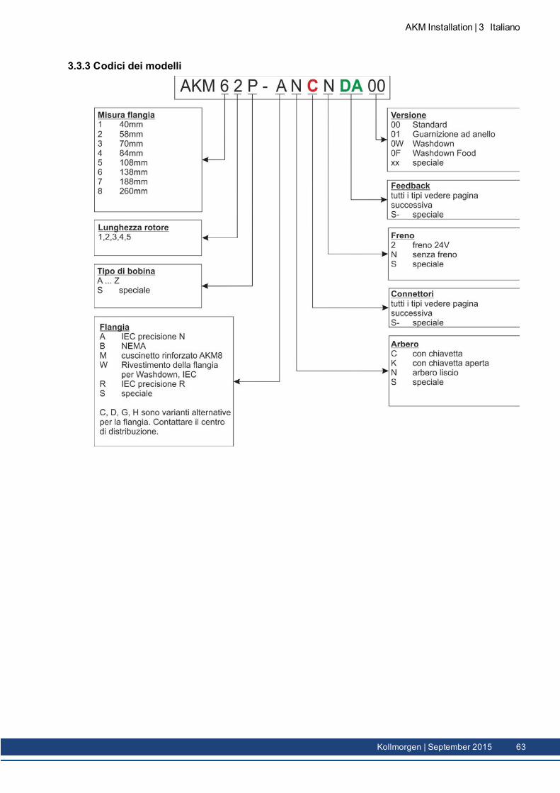
3.3.3 Codici dei modelli
AKM Installation | 3 Italiano
Kollmorgen | September 2015 63
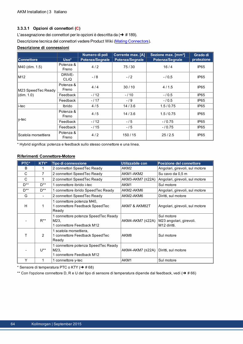
AKM Installation | 3 Italiano
3.3.3.1 Opzioni di connettori (C)L'assegnazione dei connettori per le opzioni è descritta da ( # 189).Descrizione tecnica del connettori vedere Product Wiki (Mating Connectors).Descrizione di connessioni
Numero di poli Corrente max. [A] Sezione max. [mm²] Grado diprotezioneConnettore Uso* Potenza/Segnale Potenza/Segnale Potenza/Segnale
M40 (dim. 1.5) Potenza &Freno 4 / 2 75 / 30 16 / 4 IP65
M12 DRIVE-CLiQ - / 8 - / 2 - / 0,5 IP65
M23 SpeedTec Ready(dim. 1.0)
Potenza &Freno 4 / 4 30 / 10 4 / 1.5 IP65
Feedback - / 12 - / 10 - / 0.5 IP65Feedback - / 17 - / 9 - / 0.5 IP65
i-tec Ibrido 4 / 5 14 / 3.6 1.5 / 0.75 IP65
y-tec
Potenza &Freno 4 / 5 14 / 3.6 1.5 / 0.75 IP65
Feedback - / 12 - / 5 - / 0.75 IP65Feedback - / 15 - / 5 - / 0.75 IP65
Scatola morsettiera Potenza &Freno 4 / 2 150 / 15 25 / 2.5 IP65
* Hybrid significa: potenza e feedback sullo stesso connettore e una linea.
Riferimenti Connettore-MotorePTC* KTY* Tipo di connessione Utilizzabile con Posizione del connettoreB 1 2 connettori SpeedTec Ready AKM2 Angolari, girevoli, sul motoreC 7 2 connettori SpeedTec Ready AKM1-AKM2 Su cavo da 0,5 mC 1 2 connettori SpeedTec Ready AKM3-AKM7 (≤22A) Angolari, girevoli, sul motoreD** D** 1 connettore ibrido i-tec AKM1 Sul motoreD** D** 1 connettore ibrido SpeedTec Ready AKM2-AKM6 Angolari, girevoli, sul motoreG - 2 connettori SpeedTec Ready AKM2-AKM6 Diritti, sul motore
H 11 connettore potenza M40,1 connettore Feedback SpeedTecReady
AKM7 & AKM82T Angolari, girevoli, sul motore
- R**1 connettore potenza SpeedTec ReadyM23,1 connettore Feedback M12
AKM4-AKM7 (≤22A)Sul motoreM23 angolari, girevoli.M12 diritti.
T 21 scatola morsettiera,1 connettore Feedback SpeedTecReady
AKM8 Sul motore
- U**1 connettore potenza SpeedTec ReadyM23,1 connettore Feedback M12
AKM4-AKM7 (≤22A) Diritti, sul motore
Y 1 1 connettore y-tec AKM1 Sul motore
* Sensore di temperatura PTC o KTY ( # 68)** Con l'opzione connettore D, R e U del tipo di sensore di temperatura dipende dal feedback, vedi ( # 66)
64 Kollmorgen | September 2015
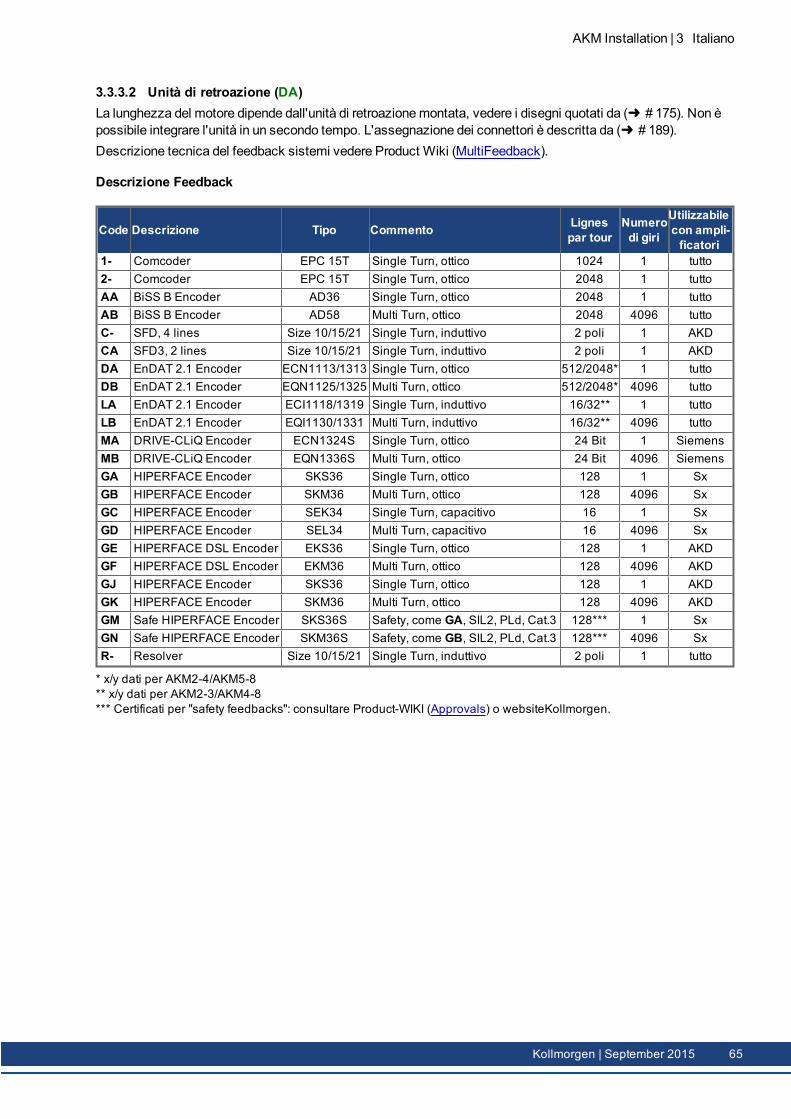
3.3.3.2 Unità di retroazione (DA)La lunghezza del motore dipende dall'unità di retroazionemontata, vedere i disegni quotati da ( # 175). Non èpossibile integrare l'unità in un secondo tempo. L'assegnazione dei connettori è descritta da ( # 189).Descrizione tecnica del feedback sistemi vedere Product Wiki (MultiFeedback).
Descrizione Feedback
Code Descrizione Tipo Commento Lignespar tour
Numerodi giri
Utilizzabilecon ampli-ficatori
1- Comcoder EPC 15T Single Turn, ottico 1024 1 tutto2- Comcoder EPC 15T Single Turn, ottico 2048 1 tuttoAA BiSS B Encoder AD36 Single Turn, ottico 2048 1 tuttoAB BiSS B Encoder AD58 Multi Turn, ottico 2048 4096 tuttoC- SFD, 4 lines Size 10/15/21 Single Turn, induttivo 2 poli 1 AKDCA SFD3, 2 lines Size 10/15/21 Single Turn, induttivo 2 poli 1 AKDDA EnDAT 2.1 Encoder ECN1113/1313 Single Turn, ottico 512/2048* 1 tuttoDB EnDAT 2.1 Encoder EQN1125/1325 Multi Turn, ottico 512/2048* 4096 tuttoLA EnDAT 2.1 Encoder ECI1118/1319 Single Turn, induttivo 16/32** 1 tuttoLB EnDAT 2.1 Encoder EQI1130/1331 Multi Turn, induttivo 16/32** 4096 tuttoMA DRIVE-CLiQ Encoder ECN1324S Single Turn, ottico 24 Bit 1 SiemensMB DRIVE-CLiQ Encoder EQN1336S Multi Turn, ottico 24 Bit 4096 SiemensGA HIPERFACE Encoder SKS36 Single Turn, ottico 128 1 SxGB HIPERFACE Encoder SKM36 Multi Turn, ottico 128 4096 SxGC HIPERFACE Encoder SEK34 Single Turn, capacitivo 16 1 SxGD HIPERFACE Encoder SEL34 Multi Turn, capacitivo 16 4096 SxGE HIPERFACE DSL Encoder EKS36 Single Turn, ottico 128 1 AKDGF HIPERFACE DSL Encoder EKM36 Multi Turn, ottico 128 4096 AKDGJ HIPERFACE Encoder SKS36 Single Turn, ottico 128 1 AKDGK HIPERFACE Encoder SKM36 Multi Turn, ottico 128 4096 AKDGM Safe HIPERFACE Encoder SKS36S Safety, come GA, SIL2, PLd, Cat.3 128*** 1 SxGN Safe HIPERFACE Encoder SKM36S Safety, come GB, SIL2, PLd, Cat.3 128*** 4096 SxR- Resolver Size 10/15/21 Single Turn, induttivo 2 poli 1 tutto
* x/y dati per AKM2-4/AKM5-8** x/y dati per AKM2-3/AKM4-8*** Certificati per "safety feedbacks": consultare Product-WIKI (Approvals) o websiteKollmorgen.
AKM Installation | 3 Italiano
Kollmorgen | September 2015 65
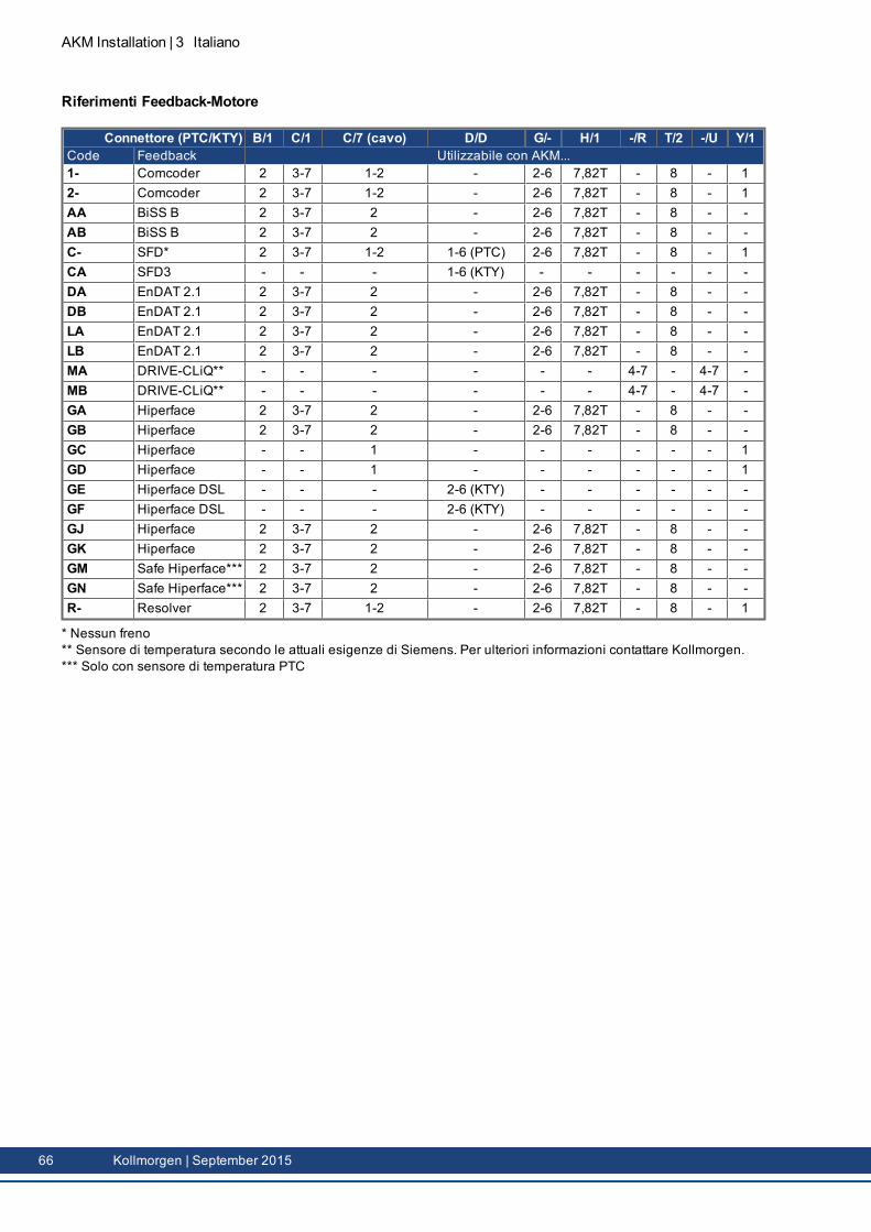
AKM Installation | 3 Italiano
Riferimenti Feedback-Motore
Connettore (PTC/KTY) B/1 C/1 C/7 (cavo) D/D G/- H/1 -/R T/2 -/U Y/1Code Feedback Utilizzabile con AKM...1- Comcoder 2 3-7 1-2 - 2-6 7,82T - 8 - 12- Comcoder 2 3-7 1-2 - 2-6 7,82T - 8 - 1AA BiSS B 2 3-7 2 - 2-6 7,82T - 8 - -AB BiSS B 2 3-7 2 - 2-6 7,82T - 8 - -C- SFD* 2 3-7 1-2 1-6 (PTC) 2-6 7,82T - 8 - 1CA SFD3 - - - 1-6 (KTY) - - - - - -DA EnDAT 2.1 2 3-7 2 - 2-6 7,82T - 8 - -DB EnDAT 2.1 2 3-7 2 - 2-6 7,82T - 8 - -LA EnDAT 2.1 2 3-7 2 - 2-6 7,82T - 8 - -LB EnDAT 2.1 2 3-7 2 - 2-6 7,82T - 8 - -MA DRIVE-CLiQ** - - - - - - 4-7 - 4-7 -MB DRIVE-CLiQ** - - - - - - 4-7 - 4-7 -GA Hiperface 2 3-7 2 - 2-6 7,82T - 8 - -GB Hiperface 2 3-7 2 - 2-6 7,82T - 8 - -GC Hiperface - - 1 - - - - - - 1GD Hiperface - - 1 - - - - - - 1GE Hiperface DSL - - - 2-6 (KTY) - - - - - -GF Hiperface DSL - - - 2-6 (KTY) - - - - - -GJ Hiperface 2 3-7 2 - 2-6 7,82T - 8 - -GK Hiperface 2 3-7 2 - 2-6 7,82T - 8 - -GM Safe Hiperface*** 2 3-7 2 - 2-6 7,82T - 8 - -GN Safe Hiperface*** 2 3-7 2 - 2-6 7,82T - 8 - -R- Resolver 2 3-7 1-2 - 2-6 7,82T - 8 - 1
* Nessun freno** Sensore di temperatura secondo le attuali esigenze di Siemens. Per ulteriori informazioni contattare Kollmorgen.*** Solo con sensore di temperatura PTC
66 Kollmorgen | September 2015
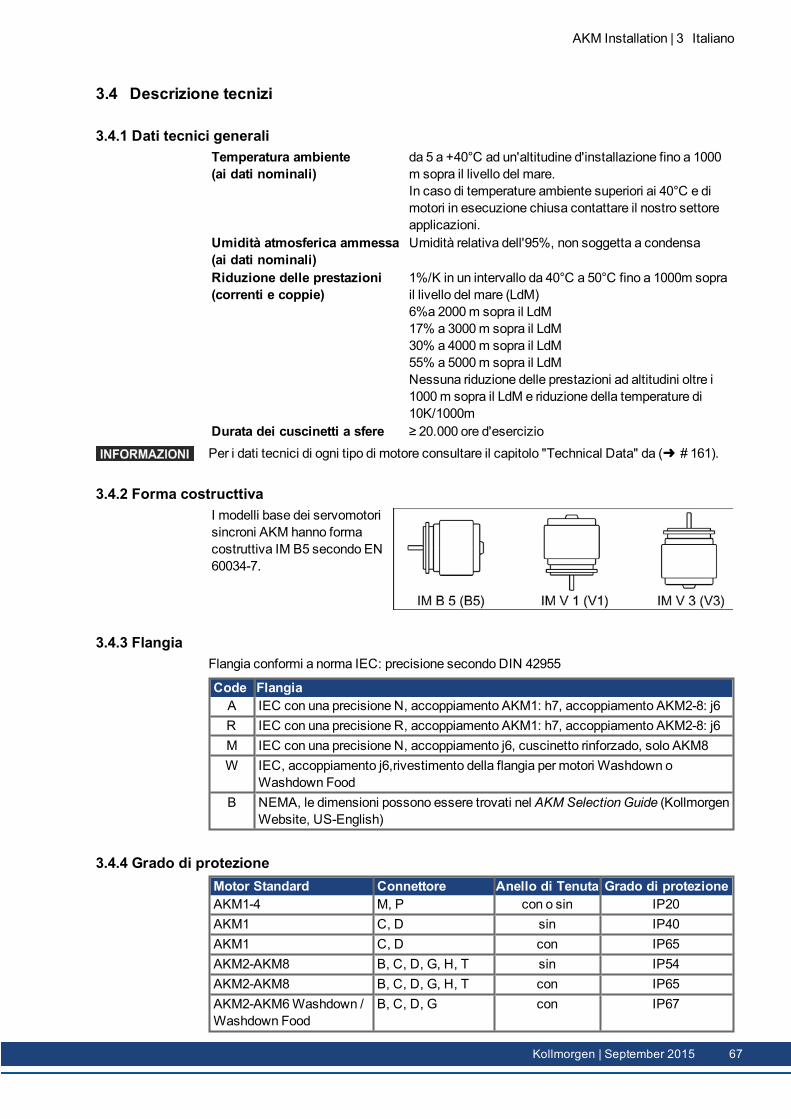
3.4 Descrizione tecnizi
3.4.1 Dati tecnici generaliTemperatura ambiente(ai dati nominali)
da 5 a +40°C ad un'altitudine d'installazione fino a 1000m sopra il livello del mare.In caso di temperature ambiente superiori ai 40°C e dimotori in esecuzione chiusa contattare il nostro settoreapplicazioni.
Umidità atmosferica ammessa(ai dati nominali)
Umidità relativa dell'95%, non soggetta a condensa
Riduzione delle prestazioni(correnti e coppie)
1%/K in un intervallo da 40°C a 50°C fino a 1000m soprail livello del mare (LdM)6%a 2000m sopra il LdM17% a 3000m sopra il LdM30% a 4000m sopra il LdM55% a 5000m sopra il LdMNessuna riduzione delle prestazioni ad altitudini oltre i1000m sopra il LdM e riduzione della temperature di10K/1000m
Durata dei cuscinetti a sfere ≥ 20.000 ore d'esercizioPer i dati tecnici di ogni tipo di motore consultare il capitolo "Technical Data" da ( # 161).
3.4.2 Forma costructtivaI modelli base dei servomotorisincroni AKM hanno formacostruttiva IM B5 secondo EN60034-7.
3.4.3 FlangiaFlangia conformi a norma IEC: precisione secondo DIN 42955
Code FlangiaA IEC con una precisione N, accoppiamento AKM1: h7, accoppiamento AKM2-8: j6R IEC con una precisione R, accoppiamento AKM1: h7, accoppiamento AKM2-8: j6M IEC con una precisione N, accoppiamento j6, cuscinetto rinforzado, solo AKM8W IEC, accoppiamento j6,rivestimento della flangia per motori Washdown o
Washdown FoodB NEMA, le dimensioni possono essere trovati nel AKM Selection Guide (Kollmorgen
Website, US-English)
3.4.4 Grado di protezioneMotor Standard Connettore Anello di Tenuta Grado di protezioneAKM1-4 M, P con o sin IP20AKM1 C, D sin IP40AKM1 C, D con IP65AKM2-AKM8 B, C, D, G, H, T sin IP54AKM2-AKM8 B, C, D, G, H, T con IP65AKM2-AKM6Washdown /Washdown Food
B, C, D, G con IP67
AKM Installation | 3 Italiano
Kollmorgen | September 2015 67
AKM Installation | 3 Italiano
3.4.5 Classe di isolamentoI motori sono conformi alla classe isolante F secondo IEC 60085 (UL 1446 class F)..
3.4.6 SuperficieI motori sono ricoperti di rivestimento della polvere del poliestere nel nero opaco nonresistente ai solventi (tricloroetilene, diluenti o altro).
3.4.7 Estremità di uscita alberoLa trasmissione della forza ha luogo attraverso l'estremità cilindrica di uscita dell'albero,accoppiamento k6 (AKM1: h7) secondo EN 50347 con filettatura di serraggio ma senza sedeper chiavetta. Per la durata dei cuscinetti sono state calcolate come base 20.000 ored'esercizio.
Codice Arbero Disponibile perN Arbero liscio Tutti i tipi, standardC Chiavetta, chiuso AKM 2...8K Chiavetta, aperta AKM 1...8
Forca radialeSe i motori si azionanomediante pignone o cinghie dentate vengono a determinarsi forzeradiali elevate. I valori ammessi sull'estremità dell'albero, in funzione del numero di giri, sonoindicati nei diagrammi nel cap. "Dimensions" ( # 175). I valori massimi si trovano nei datitecnici ( # 161). In caso di applicazione della forza al centro dell'estremità libera dell'albero,il valore di FR può esseremaggiore del 10%.
Forza assialeMentre pignoni o rotelle di montaggio all’asse o nel caso di uso del sistema d’ingranaggiangolare delle forze assiali presenti. I valori massimi si trovano nei dati tecnici.
AccopiamentiCome elementi di accoppiamento idealmente privi di gioco si sono rivelate valide le Pinze adoppio cono eventualmente abbinate a accoppiamenti con attacchi metallici a soffietto.
3.4.8 Dispositivo di protezioneNella versione standard ogni motore dispone di un PTC a potenziale zero. Il punto dicommutazione è a 155°C ± 5%. Questo PTC non offre alcuna protezione nei confronti disovraccarichi brevi molto elevati.In via opzionale il motore può essere dotato di un sensore KTY 84-130 ((vedere opzione dicollegamento 1, 2, 7 e D on ( # 189).Con sistema di feedback digitale SFD, SFD3, DSL (C-, CA, GE, GF) lo stato del sensore ditemperatura è trasmesso digitalmente e valutato nell servoamplificatore.Utilizzando il nostro cavo per feedback preconfezionato il sensore è integrato nel sistema dicontrollo dei servoamplificatori.
3.4.9 Resistenza alle vibrazioniI motori sono eseguiti con resistenza alle vibrazioni A secondo EN 60034-14. Per un campodi velocità compreso tra 600 e 3600 giri/m e un asse di altezza compresa tra 56 e 132mmquesto determina un’ampiezza di oscillazione ammessa di 1,6mm/s come valore efficace.
Velocità [rpm] max. rel. Spostamento Vibratorio [µm] max. Run-out [µm]<= 1800 90 23> 1800 65 16
68 Kollmorgen | September 2015
3.4.10 Guarnizione ad anelloSe AKM su una flangia di macchina con range di frequenza non protetto deve essereaccoppiato, guarnizione ad anello (opzione 01) garantisce la tenuta. La tenuta dell'alberodeve essere un processo di run -in sottoposto a realizzare i dati nominali del motore AKM.Eseguire i passaggi seguenti:
Lasciare 30minuti senza carico alla massima velocità ruotare rotazione in senso orario30minuti raffreddare,Lasciare 30minuti senza carico alla massima velocità ruotare rotazione in sensoantiorario30minuti raffreddare.
Ripetere questo ciclo tre volte.
3.4.11 Sistema di collegamento
3.4.11.1 ConnettoreDescrizioni dei connettori disponibili: ( # 64). Pinout del connettore: ( # 189).
3.4.11.2 Sezioni dei cavi
Cavo di potenza, cavo combinatoI cavi combinati contengono oltre ai 4 fili di potenza anche due fili dei freni schermati.
Sezione Capacità di corrente CommentoCavo Cavo combinato(4x1) (4x1+(2x0.75)) 0A < I0rms ≤ 10.1A Le parentesi (...) indicano la
schermatura.
Capacità di corrente secondoEN60204-1:2006, Tabella 6,colonna B2
(4x1.5) (4x1.5+(2x0.75)) 10.1A < I0rms ≤ 13.1A(4x2.5) (4x2.5+(2x1)) 13.1A < I0rms ≤ 17.4A(4x4) (4x4+(2x1)) 17.4A < I0rms ≤ 23A(4x6) (4x6+(2x1)) 23A < I0rms ≤ 30A(4x10) (4x10+(2x1.5)) 30A < I0rms ≤ 40A(4x16) (4x16+(2x1.5)) 40A < I0rms ≤ 54A(4x25) (4x25+(2x1.5)) 54A < I0rms ≤ 70A
Cavo di retroazione
Tipo Sezione CommentoResolver, SFD (4x2x 0.25)Encoder (7x2x 0.25) BiSS, EnDAT, HIPERFACEComcoder (8x2x 0.25) Encoder incremental + Hall
Cavo ibrido
Tipo Sezione Commento
SFD/SFD3/DSL(4x1.0+(2x0.34)+(2x0.75)) 4 fili di potenza, 4 fili di trasmissione perSFD
o4 fili di potenza & 2 fili di freno &2 fili di trasmissione perSFD3/DSL
(4x1.5+(2x0.34)+(2x0.75))
AKM Installation | 3 Italiano
Kollmorgen | September 2015 69
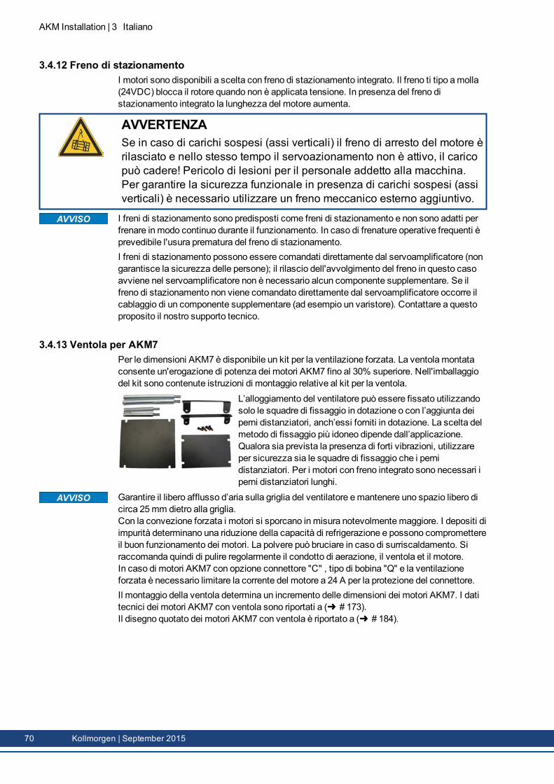
AKM Installation | 3 Italiano
3.4.12 Freno di stazionamentoI motori sono disponibili a scelta con freno di stazionamento integrato. Il freno ti tipo amolla(24VDC) blocca il rotore quando non è applicata tensione. In presenza del freno distazionamento integrato la lunghezza del motore aumenta.
AVVERTENZASe in caso di carichi sospesi (assi verticali) il freno di arresto del motore èrilasciato e nello stesso tempo il servoazionamento non è attivo, il caricopuò cadere! Pericolo di lesioni per il personale addetto alla macchina.Per garantire la sicurezza funzionale in presenza di carichi sospesi (assiverticali) è necessario utilizzare un freno meccanico esterno aggiuntivo.
I freni di stazionamento sono predisposti come freni di stazionamento e non sono adatti perfrenare in modo continuo durante il funzionamento. In caso di frenature operative frequenti èprevedibile l'usura prematura del freno di stazionamento.I freni di stazionamento possono essere comandati direttamente dal servoamplificatore (nongarantisce la sicurezza delle persone); il rilascio dell'avvolgimento del freno in questo casoavviene nel servoamplificatore non è necessario alcun componente supplementare. Se ilfreno di stazionamento non viene comandato direttamente dal servoamplificatore occorre ilcablaggio di un componente supplementare (ad esempio un varistore). Contattare a questoproposito il nostro supporto tecnico.
3.4.13 Ventola per AKM7Per le dimensioni AKM7 è disponibile un kit per la ventilazione forzata. La ventola montataconsente un'erogazione di potenza dei motori AKM7 fino al 30% superiore. Nell'imballaggiodel kit sono contenute istruzioni di montaggio relative al kit per la ventola.
L’alloggiamento del ventilatore può essere fissato utilizzandosolo le squadre di fissaggio in dotazione o con l’aggiunta deiperni distanziatori, anch’essi forniti in dotazione. La scelta delmetodo di fissaggio più idoneo dipende dall’applicazione.Qualora sia prevista la presenza di forti vibrazioni, utilizzareper sicurezza sia le squadre di fissaggio che i pernidistanziatori. Per i motori con freno integrato sono necessari iperni distanziatori lunghi.
Garantire il libero afflusso d’aria sulla griglia del ventilatore emantenere uno spazio libero dicirca 25mm dietro alla griglia.Con la convezione forzata i motori si sporcano inmisura notevolmentemaggiore. I depositi diimpurità determinano una riduzione della capacità di refrigerazione e possono compromettereil buon funzionamento dei motori. La polvere può bruciare in caso di surriscaldamento. Siraccomanda quindi di pulire regolarmente il condotto di aerazione, il ventola et il motore.In caso di motori AKM7 con opzione connettore "C" , tipo di bobina "Q" e la ventilazioneforzata è necessario limitare la corrente del motore a 24 A per la protezione del connettore.Il montaggio della ventola determina un incremento delle dimensioni dei motori AKM7. I datitecnici dei motori AKM7 con ventola sono riportati a ( # 173).Il disegno quotato dei motori AKM7 con ventola è riportato a ( # 184).
70 Kollmorgen | September 2015
3.4.14 Washdown e Washdown FoodQuesta variante viene utilizzata in applicazioni soggette a norme igieniche rigorose, in cui ènecessario evitare la formazione di germi e la corrosione e in cui le macchine devono esserepulite periodicamente.I motori si basano sui modelli standard AKM2 - AKM6 con particolari modifiche per l'utilizzonell'industria di trasformazione degli alimenti o nell'industria di confezionamento. Inoltre laflangia può essere rivestita, sebbene in tal caso non sia possibile garantire la classe ditolleranza N.Nel codice sono definiti separatamente la verniciatura della carcassa del motore (tipi "W" peril Washdown e "F" perWashdown Food) nel modello in questione (ultimi due caratteri) e ilrivestimento della flangia.
Washdown/Washdown Food Motor Opzioni di Connettori Opzioni di FlangiaAKM2 B*, D*, G A, B, W, RAKM3, 4, 6 C*, D*, G A, B, W, RAKM5 C*, D*, G B
* Non accendere il connettore sul motore più di +/- 180 ° , maggiore angolo di rotazionepotrebbe danneggiare le connessioni interne.
3.4.14.1 WashdownAKM^^^-^^^^^-^WAKM^^^-W^^^^^-^W
Washdown senza rivestimento flangiaWashdown con rivestimento flangia IEC di tipo A
I motori Washdown non devono entrare a contatto con alimenti non imballati.
Campo d'applicazione Ambienti difficili, esterniEsempio: Trasporto nel settore degli alimenti e dell'imballaggio senza
alcun contatto con gli alimenti, stazioni radar, turbine eoliche,impianti offshore.
Norme: UL, CE, RohSSuperficie: Rivestimento argentatoResistenza: A detergenti testati ( # 72), resistente alla corrosioneGrado di protezione: IP67Albero: Acciaio inossidabileGuarnizione ad anello: PTFELubrificante: Grasso industriale, non adatto agli alimentiConnettore: Acciaio inossidabile, superficie lisciaViti: Acciaio inossidabileTarghetta diomologazione:
Incisa, per ogni unità di imballaggio è prevista una targhettasupplementare
Dimensioni: AKM2 - AKM6
AKM Installation | 3 Italiano
Kollmorgen | September 2015 71
AKM Installation | 3 Italiano
3.4.14.2 Washdown FoodAKM^^^-^^^^^-^FAKM^^^-W^^^^^-^F
Washdown Food senza rivestimento flangiaWashdown Food con rivestimento flangia IEC di tipo A
La superficie dei motori Washdown Food ha superato tutti i test conformemente ai requisiti dimigrazione globale della FDA relativi al contatto indiretto con gli alimenti. Non è consentito ilcontatto diretto con alimenti non imballati.
Campo d'applicazione Industria degli alimenti e delle bevande, senza contatto direttocon gli alimenti non imballati.
Esempio: Taglio, imballaggio e riempimento senza contatto diretto conalimenti; il motore è a lato o sotto gli alimenti.
Norme: UL, CE, RoHs, FDASuperficie: Rivestimento biancoResistenza: A detergenti testati ( # 72), resistente alla corrosioneGlobal Migration: US FDA Regulations 21 CFR 175.300, Condition of Use EGrado di protezione: IP67Albero: Acciaio inossidabileGuarnizione ad anello: PTFE secondo FDALubrificante: Adatto agli alimenti secondo FDAConnettore: Acciaio inossidabile, superficie lisciaViti: Acciaio inossidabileTarghetta diomologazione:
Incisa, per ogni unità di imballaggio è prevista una targhettasupplementare
Dimensioni: AKM2 - AKM6
3.4.14.3 Analisi e verifica delle proprietà nei confronti dei detergentiNel laboratorio della ECOLAB DeutschlandGmbH è stata analizzata la resistenza dellesuperfici Washdown eWashdown Food nei confronti dei seguenti detergenti industriali:
P3-topactive DESP3-topactive LAP3-topax 56P3-topax 66P3-topax 91
Le superfici sono state immerse per 28 giorni a temperatura ambiente nel rispettivodetergente. Ciò corrisponde a circa 2500 cicli di lavaggio con almeno 15minuti di contattocon il detergente o a 1500 cicli di lavaggio con pulizia e successiva disinfezione.I certificati sono reperibili sul nostro “ProdottoWIKI” alla pagina Approvals .
Kollmorgen fornisce una garanzia sul ciclo di vita dei motori solo se vengono utilizzati idetergenti testati. Su richiesta, Kollmorgen può testare detergenti diversi da quelli indicatisopra ed eventualmente autorizzarne l'uso.
72 Kollmorgen | September 2015
3.4.14.4 Condizioni di montaggio e di utilizzoI motori devono essere utilizzati unicamente a temperature comprese tra la temperaturaambiente e 50°C.Se la flangia anteriore è rivestita, non è garantita la classe di tolleranza N.
Nei motori muniti di flange, senza rivestimento lavabile, la superficie della flangia deveessere protetta dall’azione dei detergenti mediante un opportunomontaggio.
3.4.14.5 Piano di puliziaPiano di pulizia consigliato con i detergenti testati:
Sciacquare con acqua (40°... 50°C)Sciacquare a bassa pressione, dall'alto verso il basso nella direzione di scarico. Pulire loscarico.
Pulizia a schiumaPulire dall'alto verso il basso.Detergenti alcalini P3-topactive LA or P3-topax 66 (2-5%, 15minuti al giorno)Detergenti acidi P3-topax 56 (2%, minuti se necessario)Temperatura: da fredda fino a 40°C
DisinfezioneSpruzzare con acqua (40°... 50°C) a bassa pressione, dall'alto verso il bassoDisinfezione a spruzzo P3-topax 91 (1-2%, 30-60minuti se necessario)Disinfezione a schiuma P3-topactiv DES (1-3%,10-30minuti se necessario)
AKM Installation | 3 Italiano
Kollmorgen | September 2015 73
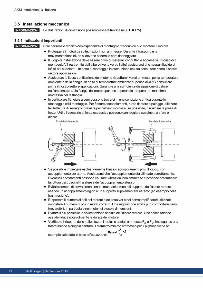
AKM Installation | 3 Italiano
3.5 Installazione meccanicaLe illustrazioni di dimensione possono essere trovate nel ( # 175).
3.5.1 Indicazioni importantiSolo personale tecnico con esperienza di montaggiomeccanico puòmontare il motore.
Proteggere i motori da sollecitazioni non ammesse. Durante il trasporto e lamovimentazione nNon ci devono essere le parti danneggiate.Il luogo di installazione deve essere privo di materiali conduttivi e aggressivi. In caso di ilmontaggio V3 (estremità dell'albero rivolta verso l'alto) assicurarsi che nessun liquido siinfiltri nei cuscinetti. In caso di montaggio in esecuzione chiusa consultare prima il nostrosettore applicazioni.Assicurare la libera ventilazione dei motori e rispettare i valori ammessi per la temperaturaambiente e della flangia. In caso di temperature ambiente superiori ai 40°C consultareprima il nostro settore applicazioni. Garantire una sufficiente dissipazione di calorenell'ambiente e sulla flangia del motore per non superare la temperaturamassimaammessa per la flangia.In particolare flangia e albero possono trovarsi in una condizione critica durante lostoccaggio ed il montaggio. Per fissare accoppiamenti, ruote dentate o pulegge utilizzarela filettatura di serraggio prevista per l'alberomotore e, se possibile, riscaldare le prese diforza. Urti o l'esercizio di forza eccessiva possono danneggiare cuscinetti a sfere ealbero.
Se possibile impiegare esclusivamente Pinze o accoppiamenti privi di gioco, conaccoppiamento per attrito. Assicurarsi che l'accoppiamento sia allineato correttamente.Eventuali spostamenti possono causare vibrazioni non ammesse e possono determinarela rottura dei cuscinetti a sfere e dell'accoppiamento stesso. Evitare sempre di sovradimensionaremeccanicamente il supporto dell'alberomotoreusando un accoppiamento rigido e un supporto supplementare esterno (ad esempio nellatrasmissione).Rispettare il numero di poli del motore e del resolver e nei servoamplificatori utilizzatiimpostare il numero di poli in modo corretto. Una regolazione errata può comportare danniirreversibili, in particolare nei motori di piccole dimensioni.Evitare il più possibile la sollecitazione assiale dell'alberomotore. Una sollecitazioneassiale riduce notevolmente la durata del motore.Verificare il rispetto delle sollecitazioni radiali e assiali ammesse FR e FA. Impiegando anatrasmissione a cinghia dentata, il diametrominimo ammesso per il pignone viene ad
esempio calcolato in base all'equazione:
74 Kollmorgen | September 2015
3.6 Installazione elettricaGli assegnazione dei connettori possono essere trovati nel cap. "Connector Pinout" ( #175). Pinout di servo amplificatore può essere trovato nella manuale d’istruzione diamplificatore.
3.6.1 Indicazioni importantiSolo personale tecnico con esperienza nei collegamenti elettrici può cablare il motore.
PERICOLOMontare e cablare i motori sempre in assenza di tensione, vale a diresenza inserire la tensione d'esercizio degli apparecchi da collegare.In caso di contatto con contatti liberi sussiste rischio di morte o di gravilesioni personali.Assicurarsi che il quadro elettrico venga disinserito in modo sicuro(blocco, cartelli di avvertenza, e così via). Le singole tensioni verrannoinserite solo con la messa in funzione.Non allentare mai i collegamenti elettrici dei motori sotto tensione.Pericolo di scossa elettrica! In casi sfavorevoli possono venire a crearsiarchi voltaici con conseguenti danni a carico di persone e contatti.I condensatori del servoamplificatore possono presentare caricheresidue pericolose fino a 10 minuti dopo l’interruzione della tensione direte. I collegamenti di comando e di potenza possono condurre tensioneanche a motore fermo.Misurare la tensione nel circuito intermedio e attendere fino a quando ilvalore è sceso al di sotto dei 60V.
Il simbolomessa a terra che si trova in tutti gli schemi di collegamento indica cheoccorre provvedere ad un collegamento conduttivo il più ampio possibile tra l'apparecchioidentificato e la piastra di montaggio nel quadro elettrico ad armadio. Tale collegamento deveconsentire la dispersione di interferenze ad alta frequenza e non deve essere confuso con ilsimbolo di terra (misura di protezione secondo EN 60204).
Osservare anche le note negli schemi di collegamento delle manuale di istruzioni delservoamplificatore utilizzato.
AKM Installation | 3 Italiano
Kollmorgen | September 2015 75
AKM Installation | 3 Italiano
3.6.2 Guida ad installazione elettricaVerificare l'abbinamento tra servoamplificatori e motore. Confrontare la tensione nominalee la corrente nominale degli apparecchi. Eseguire il cablaggio in base allo schema dicollegamento riportato sul manuale del servoamplificatore. Il assegnazione dei connettorisono indicati da capitolo "Connector Pinout" ( # 175).Tutti i cavi che conducono correnti elevate devono avere sezione sufficiente secondo EN60204. Le sezioni consigliate sono indicate nei dati tecnici.
Nel caso del motore lungo cavo (>25m) ed il dipendente sul tipo del servoamplificatoreutilizzato una scatola induttore (3YL / 3YLN) deve essere commutato nel cavo del motore(veda il manuale di istruzioni del servoamplificatore ed il manuale accessorio).
Assicurarsi che lamessa a terra di servoamplificatore emotore venga eseguita a regolad'arte. Per una schermatura e unamessa a terra conformi ai requisiti di compatibilitàelettromagnetica si vedano lemanuale del servoamplificatore utilizzato. Collegare a terrala piastra di montaggio e la carcassa del motore.Se il cavo di potenza impiegato per il motore integra i conduttori di comando del frenoquesti ultimi devono essere schermati. La schermatura deve essere collegata suentrambe le estremità (vedere le istruzioni per l'installazione del servoamplificatore).Cablaggio
Se possibile, posare separatamente i cavi di potenza e di comandoCollegare l'unità di retroazione o encoderCollegare i cavi del motore, l'induttore per motore vicino al servoamplificatore leschermature, su entrambe le estremità, ai morsetti o ai connettori EMCCollegare l'eventuale il freno di stazionamento del motore.Posare la schermatura su entrambi i lati
Collegare le schermature in modo da coprire un'ampia superficie (a bassa impedenza),mediante un corpo connettoremetallizzato o connettori filettati per cavi conformi airequisiti sulla compatibilità elettromagnetica.Requisiti a materiale dei cavi:CapacitàCavo di motore: inferiore a 150 pF/mCavodie retroazione: inferiore a 120 pF/m
3.6.3 Collegamento dei motori con cavi preconfezionatiEseguire il cablaggio in base alle disposizioni ed alle norme vigenti.Per il collegamento di potenza e di retroazione utilizzare esclusivamente cavi schermatipreconfezionati di Kollmorgen.Schermature non posizionate correttamente possono portare a interferenze EMV epossono pregiudicare il funzionamento del sistema.Lunghezza dei cavi max.: attenersi manuali d'istruzzione del servoamplificatore.
Per la descrizione dettagliata dei cavie confezionamento consultare il manuale regionali degliaccessori.
76 Kollmorgen | September 2015
3.7 Messa in funzione
3.7.1 Indicazioni importanti
Solo tecnici con ampie conoscenze di elettrotecnica/tecniche di movimentazione possonomettere in funzione l'unità di azionamento con servoamplificatore/motore.
PERICOLOPresenza di tensioni letali fino a 900V. Pericolo di scossa elettrica!Verificare che tutti gli elementi di collegamento sotto tensione sianoprotetti in modo sicuro contro il contatto.Non allentare mai i collegamenti elettrici dei motori sotto tensione. Icondensatori del servoamplificatore possono presentare cariche residuepericolose fino a 10 minuti dopo l’interruzione della tensione di rete.I collegamenti di comando e di potenza possono condurre tensioneanche a motore fermo.Misurare la tensione nel circuito intermedio e attendere fino a quando ilvalore è sceso al di sotto dei 60V.
ATTENZIONELa temperatura superficiale del motore può varcare i 100°C durante ilfunzionamento. Pericolo di ustioni lievi! Verificare (misurare) latemperatura del motore.Prima di toccarlo attendere che abbia raggiunto i 40°C.
ATTENZIONEDurante la messa in funzione non è possibile escludere un movimentoimprevisto dell'azionamento.Assicurarsi che qualsiasi movimento accidentale dell'azionamento nonpossa causare pericolo per persone o cose.Le misure necessarie in questo caso per un'applicazione specificapossono essere desunte dall'analisi dei rischi dell'applicazione.
AKM Installation | 3 Italiano
Kollmorgen | September 2015 77

AKM Installation | 3 Italiano
3.7.2 Guida ad messa in funzioneA titolo di esempio descriviamo la procedura da seguire per la messa in funzione. A secondadell'impiego previsto può risultare opportuna o necessaria una procedura diversa.
Controllare il montaggio e l'orientamento del motore.Verificare che gli elementi di azionamento (accoppiamento, trasmissione, puleggia) sianofissati nella relativa sede e che siano regolati correttamente (rispettare le forze radiali eassiali ammesse).Controllare il cablaggio e i collegamenti sumotore e servoamplificatore. Assicurarsi chelamessa a terra venga effettuata a regola d'arte.Controllare il funzionamento dell'eventuale freno di stazionamento. (Applicando 24V ilfreno deve essere rilasciarsi).Verificare se il rotore del motore può ruotare liberamente (rilasciare prima l'eventualefreno). Prestare attenzione ai rumori di sfregamento.Verificare che siano state adottate tutte le misure di protezione dal contatto necessarieper i componenti mobili e sotto tensione.Eseguire gli ulteriori controlli specifici e necessari per l'impianto in uso.Mettere in funzione l'azionamento in base alle istruzioni per la messa in funzione delservoamplificatore.In caso di sistemi multiassemettere in funzione ogni unità di azionamento delservoamplificatore/motore singolarmente.
78 Kollmorgen | September 2015
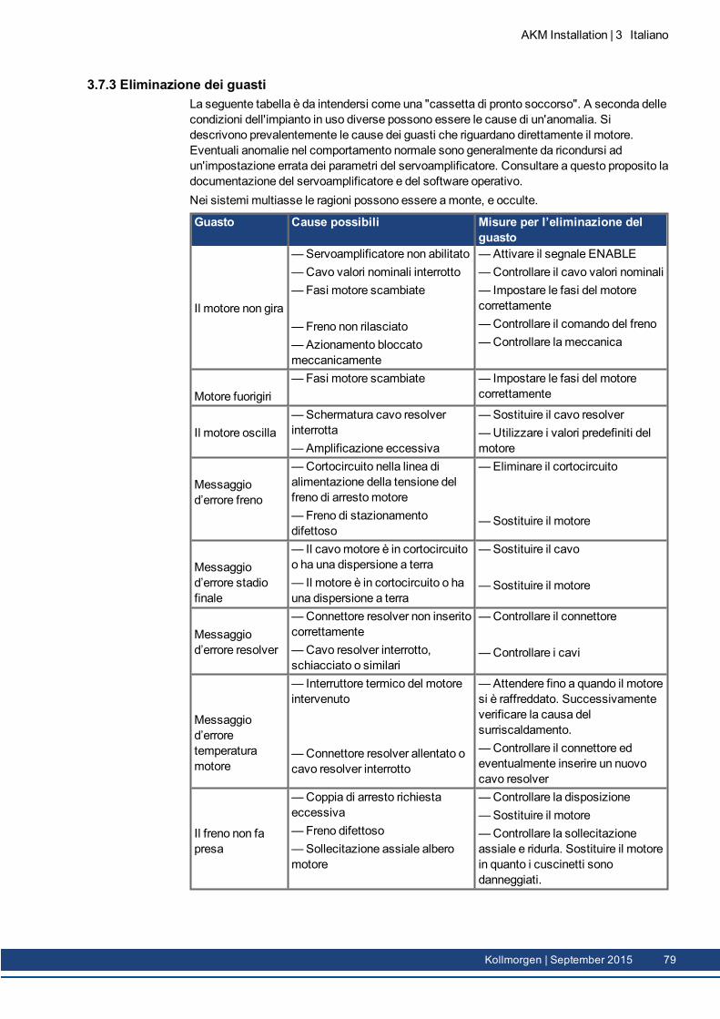
3.7.3 Eliminazione dei guastiLa seguente tabella è da intendersi come una "cassetta di pronto soccorso". A seconda dellecondizioni dell'impianto in uso diverse possono essere le cause di un'anomalia. Sidescrivono prevalentemente le cause dei guasti che riguardano direttamente il motore.Eventuali anomalie nel comportamento normale sono generalmente da ricondursi adun'impostazione errata dei parametri del servoamplificatore. Consultare a questo proposito ladocumentazione del servoamplificatore e del software operativo.Nei sistemi multiasse le ragioni possono essere amonte, e occulte.
Guasto Cause possibili Misure per l’eliminazione delguasto
Il motore non gira
—Servoamplificatore non abilitato—Cavo valori nominali interrotto— Fasi motore scambiate
—Freno non rilasciato—Azionamento bloccatomeccanicamente
—Attivare il segnale ENABLE—Controllare il cavo valori nominali— Impostare le fasi del motorecorrettamente—Controllare il comando del freno—Controllare la meccanica
Motore fuorigiri— Fasi motore scambiate — Impostare le fasi del motore
correttamente
Il motore oscilla—Schermatura cavo resolverinterrotta—Amplificazione eccessiva
—Sostituire il cavo resolver—Utilizzare i valori predefiniti delmotore
Messaggiod’errore freno
—Cortocircuito nella linea dialimentazione della tensione delfreno di arrestomotore—Freno di stazionamentodifettoso
—Eliminare il cortocircuito
—Sostituire il motore
Messaggiod’errore stadiofinale
— Il cavomotore è in cortocircuitoo ha una dispersione a terra— Il motore è in cortocircuito o hauna dispersione a terra
—Sostituire il cavo
—Sostituire il motore
Messaggiod’errore resolver
—Connettore resolver non inseritocorrettamente—Cavo resolver interrotto,schiacciato o similari
—Controllare il connettore
—Controllare i cavi
Messaggiod’erroretemperaturamotore
— Interruttore termico del motoreintervenuto
—Connettore resolver allentato ocavo resolver interrotto
—Attendere fino a quando il motoresi è raffreddato. Successivamenteverificare la causa delsurriscaldamento.—Controllare il connettore edeventualmente inserire un nuovocavo resolver
Il freno non fapresa
—Coppia di arresto richiestaeccessiva—Freno difettoso—Sollecitazione assiale alberomotore
—Controllare la disposizione—Sostituire il motore—Controllare la sollecitazioneassiale e ridurla. Sostituire il motorein quanto i cuscinetti sonodanneggiati.
AKM Installation | 3 Italiano
Kollmorgen | September 2015 79
AKM Installation | 3 Italiano
3.8 Definizioni dei dati tecniciPer i dati tecnici di tipo di motore consultare il capitolo "Technical Data" da ( # 161).
Tutti i dati con la temperatura ambientale 40°C e la temperatura della bobina 100Kaumentano. Determinazione delle date nominali con temperatura di flangia dell’adattatorecostantemente 65°C. I dati possono avere una tolleranza di +/10%.
Coppia continuativa allo stallo M0 [Nm]La coppia continuativa allo stallo viene erogata ad un numero di giri 0<n<100 giri/min ed allecondizioni nominali per un periodo illimitato.
Coppia nominale Mn [Nm]La coppia nominale viene erogata quando il motore assorbe la corrente nominale al numero digiri nominale. La coppia nominale può essere erogata durante il funzionamento continuo (S1)al numero di giri nominale per un periodo illimitato.
Corrente continuativa allo stallo I0rms [A]La corrente continuativa ad un numero di giri 0<n<100 giri/min è la corrente sinodale effettivache il motore assorbe a riposo per poter erogare la coppia continuativa allo stallo.
Corrente di picco (corrente d'impulso) I0max [A]La corrente di picco (valore effettivo sinodale) è varie volte la corrente continuativa allo stallosecondo il motore. La corrente di picco del servoamplificatore utilizzato deve essereinferiore.
Costante di coppia KTrms [Nm/A]La costante di coppia indica in Nm la coppia generata dal motore con una corrente sinodaleeffettiva di 1A. ValeM=I x KT (fino amax. I = 2 x I0)
Costante di tensione KErms [mV/min-1]
La costante di tensione indica la forza elettromotrice indotta riferita al motore a 1000 giri/min.come valore effettivo sinodale tra duemorsetti.
Momento di inerzia del rotore J [kgcm²]La costante J è unamisura della capacità di accelerazione del motore. Con I0 si ottiene adesempio il tempo di accelerazione tb da 0 a 3000 giri/min.:
conM0 in Nm e J in kgcm²
Costante di tempo termica tth [min]La costante tth indica il tempo di riscaldamento del motore freddo con un carico di I0 fino alraggiungimento di una sovratemperatura di 0,63 x 100 Kelvin. In caso di sollecitazione concorrente di picco, il riscaldamento ha luogo in un tempo notevolmente più breve.
Ritardo al rilascio tBRH [ms]/ritardo all'inserzione tBRL [ms] del frenoLe costanti indicano i tempi di reazione del freno di stazionamento applicando la tensionenominale al servoamplificatore.
UNTensione di rete.
Un
Tensione di circuito intermedio.
80 Kollmorgen | September 2015
4 Español
4.1 Generalidades 824.1.1 Sobre estemanual 824.1.2 Símbolos utilizados 824.1.3 Abreviaturas utilizadas 82
4.2 Seguridad 834.2.1 Siga sus instrucciones! 834.2.2 Utilización conforme 854.2.3 Uso indebido 854.2.4Manipulación 86
4.3 Identificación del producto 884.3.1 Volumen de suministro 884.3.2 Placa de identificación 884.3.3 Codificación demodelo 89
4.4 Descripción técnica 934.4.1 Datos técnicos generales 934.4.2 Forma de diseño 934.4.3 Brida 934.4.4 Tipo de protección 934.4.5 Clase dematerial aislante 944.4.6 Superficie 944.4.7 Extremo del eje, lado de accionamiento 944.4.8 Dispositivo protector 944.4.9 Calidad vibracional 944.4.10 Retén radial 954.4.11 Técnica de conexión 954.4.12 Freno de detención 964.4.13 Ventilador para AKM7 964.4.14Washdown y Washdown Food 97
4.5 Instalación mecánica 1004.5.1 Instrucciones importantes 100
4.6 Instalación eléctrica 1014.6.1 Instrucciones importantes 1014.6.2 Guía de instalación eléctrica 1024.6.3 Conexión de los motores con cables confeccionadas 102
4.7 Puesta en funcionamento 1034.7.1 Instrucciones importantes 1034.7.2 Guía de puesta en funcionamento 1044.7.3 Eliminación de perturbaciones 105
4.8 Definiciones de los términos de Datos Técnicos 106
AKM Installation | 4 Español
Kollmorgen | September 2015 81
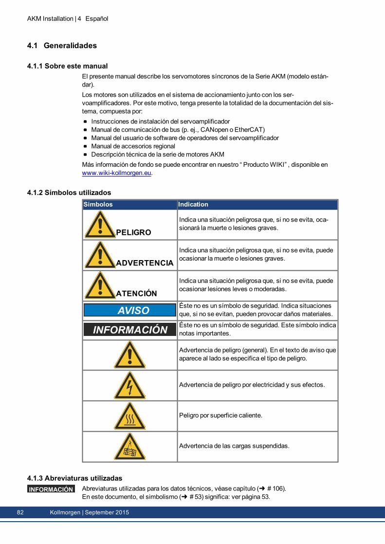
AKM Installation | 4 Español
4.1 Generalidades
4.1.1 Sobre este manualEl presentemanual describe los servomotores síncronos de la Serie AKM (modelo están-dar).Los motores son utilizados en el sistema de accionamiento junto con los ser-voamplificadores. Por estemotivo, tenga presente la totalidad de la documentación del sis-tema, compuesta por:
Instrucciones de instalación del servoamplificadorManual de comunicación de bus (p. ej., CANopen o EtherCAT)Manual del usuario de software de operadores del servoamplificadorManual de accesorios regionalDescripción técnica de la serie demotores AKM
Más información de fondo se puede encontrar en nuestro “ ProductoWIKI” , disponible enwww.wiki-kollmorgen.eu.
4.1.2 Símbolos utilizadosSímbolos Indication
PELIGROIndica una situación peligrosa que, si no se evita, oca-sionará la muerte o lesiones graves.
ADVERTENCIAIndica una situación peligrosa que, si no se evita, puedeocasionar la muerte o lesiones graves.
ATENCIÓNIndica una situación peligrosa que, si no se evita, puedeocasionar lesiones leves omoderadas.
Éste no es un símbolo de seguridad. Indica situacionesque, si no se evitan, pueden provocar daños materiales.
Éste no es un símbolo de seguridad. Este símbolo indicanotas importantes.
Advertencia de peligro (general). En el texto de aviso queaparece al lado se especifica el tipo de peligro.
Advertencia de peligro por electricidad y sus efectos.
Peligro por superficie caliente.
Advertencia de las cargas suspendidas.
4.1.3 Abreviaturas utilizadasAbreviaturas utilizadas para los datos técnicos, véase capítulo ( # 106).En este documento, el simbolismo ( # 53) significa: ver página 53.
82 Kollmorgen | September 2015
4.2 SeguridadEste capítulo le ayudará a identificar y evitar los riesgos a los que están expuestos las per-sonas y los objetos.
4.2.1 Siga sus instrucciones!
¡Se requiere personal cualificado!Las operaciones de transporte, instalación, puesta en funcionamiento y mantenimiento sólopodrán ser realizadas por personal cualificado. Por personal cualificado se entiende las per-sonas que están familiarizadas con el transporte, la instalación, el montaje, la puesta en fun-cionamiento y el manejo del producto y que disponen de las correspondientes calificacionesprofesionales.
Transporte:sólo a cargo de personal con conocimientos demanejo de elementos demon-taje con riesgo electrostáticoInstalaciónmecánica:sólo a cargo de personal especializado con formación en ingenieríamecánicaInstalación eléctrica:sólo a cargo de personal especializado con formación en elec-trotecniaPuesta en funcionamiento: sólo a cargo de personal especializado con amplios cono-cimientos sobre electrotecnia y la técnica de accionamientos
El personal especializado deberá conocer y observar IEC 60364 / IEC 60664 y normativanacional de prevención de accidentes.
¡Lea la documentación!Antes del montaje y de la puesta en funcionamiento, lea detenidamente la presente docu-mentación. Lamanipulación incorrecta del motor puede provocar daños personales omate-riales. Por estemotivo, el operador debe asegurarse de que todas las personas que vayan arealizar trabajos en el motor hayan leído y comprendido el manual, y de que se cumplan lasinstrucciones de seguridad que contiene.
¡Preste atención a los datos técnicos!Conserve los datos técnicos y las indicaciones referentes a las condiciones de conexión(placa de identificación y documentación). Si se superan los valores de tensión o decorriente permitidos, los motores, p. ej., pueden resultar dañados por sobrecalentamiento.
¡Realice una valoración de los riesgos!El fabricante de lamáquina elaborarár un análisis de riesgo de lamáquina y adoptará lasmedidas adecuadas para quemovimientos imprevistos no puedan causar daños personalesni materiales. Es posible que de la valoración de los riesgos se deriven requisitos adicionalespara el personal cualificado.
¡Llevar a cabo un transporte seguro!Para elevar y desplazar motores con un peso superior a 20 kg (AKM7 y AKM8), utilice siem-pre dispositivos elevadores. Si se elevan estas piezas sin la ayuda de herramientas, puedenproducirse lesiones en la espalda. Siga las indicaciones de la págin ( # 86)
¡Asegure la chaveta!Si hay alguna chaveta de eje, retírela o asegúrela cuando el motor vaya a funcionar sin cargapara que no salga despedida y evitar los consiguientes riesgos de lesión. En la entrega, elestado, se asegura la pluma con una tapa de plástico.
AKM Installation | 4 Español
Kollmorgen | September 2015 83
AKM Installation | 4 Español
¡Superficie caliente!Durante el funcionamiento, los motores pueden tener superficies calientes según la clasede protección. Riesgo de quemaduras! La temperatura de las superficies puede alcanzar100°C. Mida la temperatura y, antes de tocar el motor, espere hasta que se haya enfriado a40°C.
¡Toma de tierra, altas tensiones!Asegúrese de la adecuada puesta a tierra del bloque del motor con la barra colectora delarmario de distribución como potencial de referencia. Sin una toma de tierra de baja impe-dancia no se puede garantizar la seguridad personal y existe peligro demuerte por descargaeléctrica.No abra el bastidor de distribuciónmientras estén funcionando los aparatos. La ausencia deindicaciones visuales no supone ninguna garantía de que no haya tensión. Las conexionesde potencia pueden estar activas aunque el motor no esté girando.No extraiga ningún enchufe con el equipo enmarcha. Existe el peligro demuerte o lesionesgraves al tocar los contactos expuestos. Las conexiones pueden llevar tensión, incluso conel motor parado. En circunstancias desfavorables se pueden producir chispazos que dañena las personas y a los contactos.Al desconectar el servoamplificador de la corriente de alimentación, espere varios minutosantes de soltar piezas conductoras de corriente (por ejemplo, contactos, pernos, etc.). Loscondensadores en el servoamplificador conducen tensiones peligrosas hasta unos variosminutos después de cortar la alimentación de corriente. Paramayor seguridad, mida lacorriente en el circuito intermedio y espere a que la corriente se sitúe por debajo de 60V.
¡Asegurar las cargas suspendidas!I freni di stazionamento integrati non garantiscono la sicurezza funcionale! In presenza dicarichi sospesi (assi verticali) è necessario utilizzare un frenomeccanico esterno aggiuntivoper garantire la sicurezza del personale.
84 Kollmorgen | September 2015
4.2.2 Utilización conformeLos servomotores sincrónicos de la Serie AKM están diseñados especialmente para elaccionamiento de equipos demanipulación, maquinaria textil, máquinas-herramientas,maquinaria de embalaje y similares con elevados requerimientos dinámicos.Están solamente autorizados a operar enmotores cumpliendo las condiciones delentorno definidas en la presente documentación.Los motores deWashdown se pueden poner en funcionamiento en entornos con lejías yácidos corrosivos siempre que se respeten las condiciones definidas en página ( # 97).Se permite el uso demotores deWashdown Food en contacto directo con alimentos.Los motores de la Serie AKM está exclusivamente destinados a ser activados medianteservoamplificadores digitales regulados por velocidad y/o por par motor.Los motores semontan como componentes de instalaciones eléctricas omaquinaria ysolamente pueden ser puestos en servicio como componentes integrados.El sensor de protección térmica integrado en las bobinas del motor debe evaluarse ysupervisarse.Los frenos están diseñados como frenos de parada y no son adecuados para operacionesde frenado permanentes durante el servicio.Garantizamos la conformidad del servosistema con los términos de la EC Declaration ofConformity ( # 196), solamente cuando se utilicen los componentes entregados pornosotros (servoamplificador, motor, cables, etc.).
4.2.3 Uso indebidoNo se permite el uso demotores estándar
directamente en la red,en áreas con peligro de explosión,en contacto con alimentos,en entornos con partículas en suspensión, vapores, aceites, lejías o ácidos con-ductores de la electricidad y/o corrosivos.
No se permite el uso demotores deWashdowndirectamente en la red,en áreas con peligro de explosión,en contacto con alimentos,en entornos con ácidos o lejías con un valor de pH inferior a 2 o superior a 12,en entornos con ácidos o lejías que no hayan sido probados por Kollmorgen.
No se permite el uso demotores deWashdown Fooddirectamente en la red,en áreas con peligro de explosión,en contacto directo con alimentos..
Está prohibido utilizar el motor si la máquina en la que está instalado:no cumple las disposiciones de la directiva comunitaria sobremáquinas;no cumple las disposiciones de la directiva sobre compatibilidad electromagnética;no cumple las disposiciones de la directiva sobre equipos de baja tensión.
A fin de garantizar la seguridad funcional, no se deben utilizar frenos de detención inte-grados sin un equipo adicional.
AKM Installation | 4 Español
Kollmorgen | September 2015 85
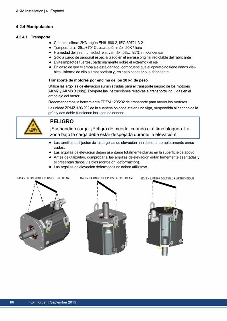
AKM Installation | 4 Español
4.2.4 Manipulación
4.2.4.1 TransporteClase de clima: 2K3 según EN61800-2, IEC 60721-3-2Temperatura: -25...+70° C, oscilaciónmáx. 20K / horaHumedad del aire: humedad relativamáx. 5%... 95% sin condensarSólo a cargo de personal especializado en el envase original reciclable del fabricanteEvite impactos fuertes, particularmente sobre el extremo del ejeEn caso de que el embalaje esté dañado, compruebe que el aparato no tiene daños visi-bles. Informe de ello al transportista y, en caso necesario, al fabricante.
Transporte de motores por encima de los 20 kg de pesoUtilice las argollas de elevación suministradas para el transporte seguro de los motoresAKM7 y AKM8 (>20kg). Respete las instrucciones relativas al transporte incluidas en elembalaje del motor.Recomendamos la herramienta ZPZM 120/292 del transporte paramover los motores..La unidad ZPMZ 120/292 de la suspensión consiste en una viga, suspendida al gancho de lagrúa y dos doble-funcionan las ligas de cadena.
PELIGRO¡Suspendido carga. ¡Peligro de muerte, cuando el último bloqueo. Lazona bajo la carga debe estar despejada durante la elevación!
Los tornillos de fijación de las argollas de elevación han de estar completamente enros-cados.Las argollas de elevación deben asentarse totalmente planas en la superficie de apoyo.Antes de utilizarlas, comprobar si las argollas de elevación están firmemente asentadas ysi presentan daños visibles (corrosión, deformación).Las argollas de elevación deformadas no deben utilizarse.
86 Kollmorgen | September 2015
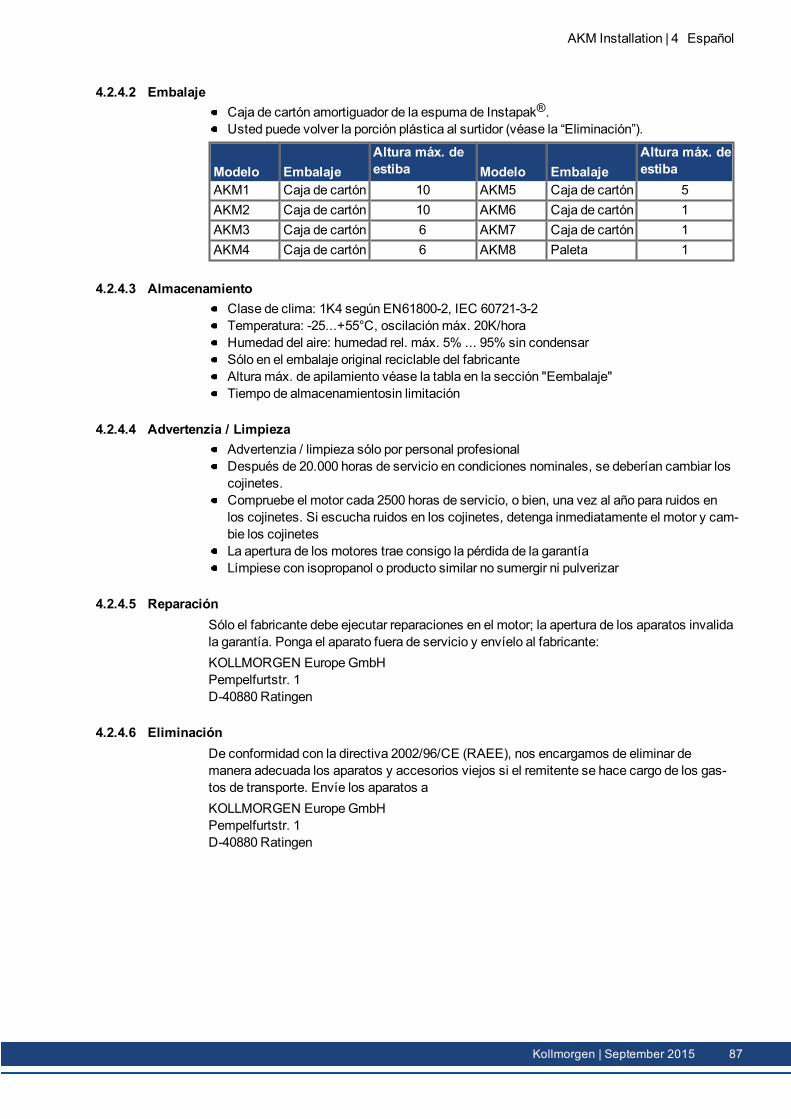
4.2.4.2 EmbalajeCaja de cartón amortiguador de la espuma de Instapak®.Usted puede volver la porción plástica al surtidor (véase la “Eliminación”).
Modelo EmbalajeAltura máx. deestiba Modelo Embalaje
Altura máx. deestiba
AKM1 Caja de cartón 10 AKM5 Caja de cartón 5AKM2 Caja de cartón 10 AKM6 Caja de cartón 1AKM3 Caja de cartón 6 AKM7 Caja de cartón 1AKM4 Caja de cartón 6 AKM8 Paleta 1
4.2.4.3 AlmacenamientoClase de clima: 1K4 según EN61800-2, IEC 60721-3-2Temperatura: -25...+55°C, oscilaciónmáx. 20K/horaHumedad del aire: humedad rel. máx. 5% ... 95% sin condensarSólo en el embalaje original reciclable del fabricanteAlturamáx. de apilamiento véase la tabla en la sección "Eembalaje"Tiempo de almacenamientosin limitación
4.2.4.4 Advertenzia / LimpiezaAdvertenzia / limpieza sólo por personal profesionalDespués de 20.000 horas de servicio en condiciones nominales, se deberían cambiar loscojinetes.Compruebe el motor cada 2500 horas de servicio, o bien, una vez al año para ruidos en los cojinetes. Si escucha ruidos en los cojinetes, detenga inmediatamente el motor y cam-bie los cojinetesLa apertura de los motores trae consigo la pérdida de la garantíaLímpiese con isopropanol o producto similar no sumergir ni pulverizar
4.2.4.5 ReparaciónSólo el fabricante debe ejecutar reparaciones en el motor; la apertura de los aparatos invalidala garantía. Ponga el aparato fuera de servicio y envíelo al fabricante:KOLLMORGEN EuropeGmbHPempelfurtstr. 1D-40880 Ratingen
4.2.4.6 EliminaciónDe conformidad con la directiva 2002/96/CE (RAEE), nos encargamos de eliminar demanera adecuada los aparatos y accesorios viejos si el remitente se hace cargo de los gas-tos de transporte. Envíe los aparatos aKOLLMORGEN EuropeGmbHPempelfurtstr. 1D-40880 Ratingen
AKM Installation | 4 Español
Kollmorgen | September 2015 87
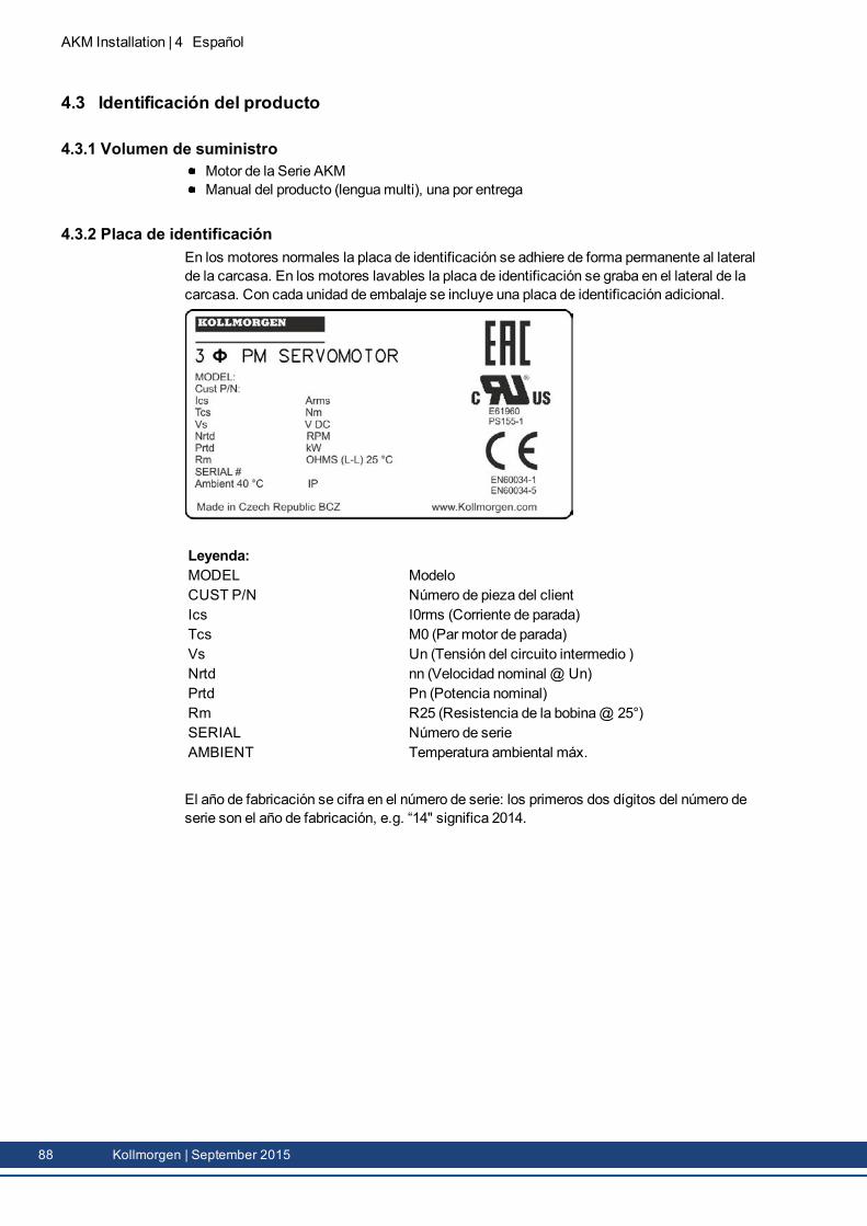
AKM Installation | 4 Español
4.3 Identificación del producto
4.3.1 Volumen de suministroMotor de la Serie AKMManual del producto (lenguamulti), una por entrega
4.3.2 Placa de identificaciónEn los motores normales la placa de identificación se adhiere de forma permanente al lateralde la carcasa. En los motores lavables la placa de identificación se graba en el lateral de lacarcasa. Con cada unidad de embalaje se incluye una placa de identificación adicional.
Leyenda:MODEL ModeloCUST P/N Número de pieza del clientIcs I0rms (Corriente de parada)Tcs M0 (Par motor de parada)Vs Un (Tensión del circuito intermedio )Nrtd nn (Velocidad nominal @ Un)Prtd Pn (Potencia nominal)Rm R25 (Resistencia de la bobina@ 25°)SERIAL Número de serieAMBIENT Temperatura ambiental máx.
El año de fabricación se cifra en el número de serie: los primeros dos dígitos del número deserie son el año de fabricación, e.g. “14" significa 2014.
88 Kollmorgen | September 2015
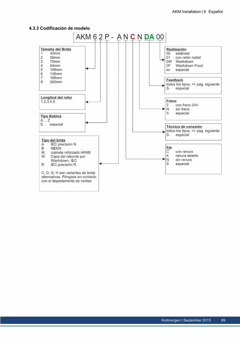
4.3.3 Codificación de modelo
AKM Installation | 4 Español
Kollmorgen | September 2015 89
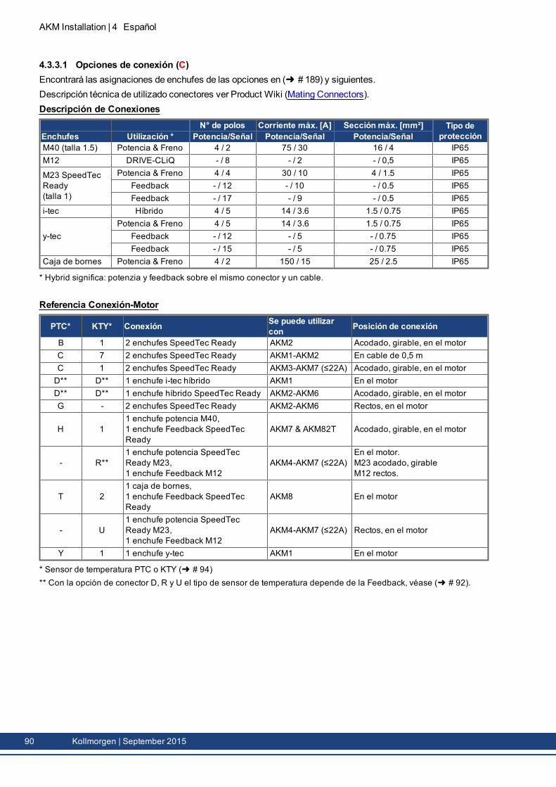
AKM Installation | 4 Español
4.3.3.1 Opciones de conexión (C)Encontrará las asignaciones de enchufes de las opciones en ( # 189) y siguientes.Descripción técnica de utilizado conectores ver Product Wiki (Mating Connectors).Descripción de Conexiones
N° de polos Corriente máx. [A] Sección máx. [mm²] Tipo deprotecciónEnchufes Utilización * Potencia/Señal Potencia/Señal Potencia/Señal
M40 (talla 1.5) Potencia & Freno 4 / 2 75 / 30 16 / 4 IP65M12 DRIVE-CLiQ - / 8 - / 2 - / 0,5 IP65
M23 SpeedTecReady(talla 1)
Potencia & Freno 4 / 4 30 / 10 4 / 1.5 IP65Feedback - / 12 - / 10 - / 0.5 IP65Feedback - / 17 - / 9 - / 0.5 IP65
i-tec Híbrido 4 / 5 14 / 3.6 1.5 / 0.75 IP65
y-tecPotencia & Freno 4 / 5 14 / 3.6 1.5 / 0.75 IP65
Feedback - / 12 - / 5 - / 0.75 IP65Feedback - / 15 - / 5 - / 0.75 IP65
Caja de bornes Potencia & Freno 4 / 2 150 / 15 25 / 2.5 IP65
* Hybrid significa: potenzia y feedback sobre el mismo conector y un cable.
Referencia Conexión-Motor
PTC* KTY* Conexión Se puede utilizarcon Posición de conexión
B 1 2 enchufes SpeedTec Ready AKM2 Acodado, girable, en el motorC 7 2 enchufes SpeedTec Ready AKM1-AKM2 En cable de 0,5 mC 1 2 enchufes SpeedTec Ready AKM3-AKM7 (≤22A) Acodado, girable, en el motorD** D** 1 enchufe i-tec híbrido AKM1 En el motorD** D** 1 enchufe híbrido SpeedTec Ready AKM2-AKM6 Acodado, girable, en el motorG - 2 enchufes SpeedTec Ready AKM2-AKM6 Rectos, en el motor
H 11 enchufe potencia M40,1 enchufe Feedback SpeedTecReady
AKM7 & AKM82T Acodado, girable, en el motor
- R**1 enchufe potencia SpeedTecReady M23,1 enchufe Feedback M12
AKM4-AKM7 (≤22A)En el motor.M23 acodado, girableM12 rectos.
T 21 caja de bornes,1 enchufe Feedback SpeedTecReady
AKM8 En el motor
- U1 enchufe potencia SpeedTecReady M23,1 enchufe Feedback M12
AKM4-AKM7 (≤22A) Rectos, en el motor
Y 1 1 enchufe y-tec AKM1 En el motor
* Sensor de temperatura PTC o KTY ( # 94)** Con la opción de conector D, R y U el tipo de sensor de temperatura depende de la Feedback, véase ( # 92).
90 Kollmorgen | September 2015
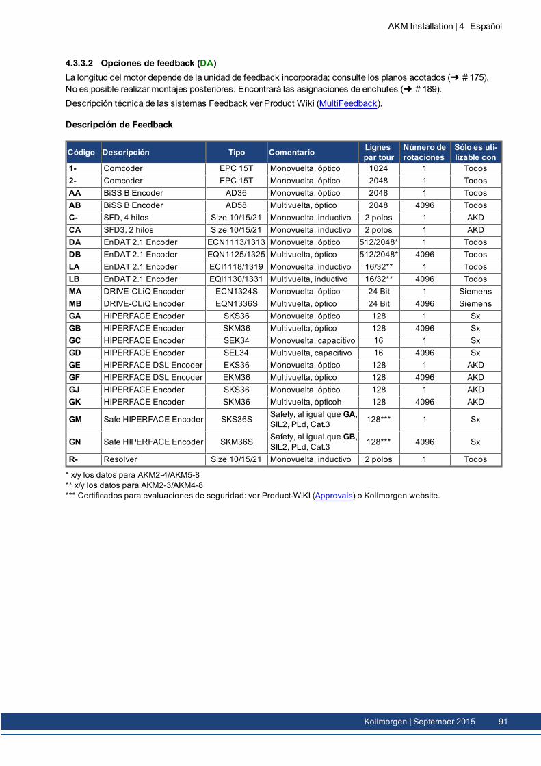
4.3.3.2 Opciones de feedback (DA)La longitud del motor depende de la unidad de feedback incorporada; consulte los planos acotados ( # 175).No es posible realizar montajes posteriores. Encontrará las asignaciones de enchufes ( # 189).Descripción técnica de las sistemas Feedback ver Product Wiki (MultiFeedback).
Descripción de Feedback
Código Descripción Tipo Comentario Lignespar tour
Número derotaciones
Sólo es uti-lizable con
1- Comcoder EPC 15T Monovuelta, óptico 1024 1 Todos2- Comcoder EPC 15T Monovuelta, óptico 2048 1 TodosAA BiSS B Encoder AD36 Monovuelta, óptico 2048 1 TodosAB BiSS B Encoder AD58 Multivuelta, óptico 2048 4096 TodosC- SFD, 4 hilos Size 10/15/21 Monovuelta, inductivo 2 polos 1 AKDCA SFD3, 2 hilos Size 10/15/21 Monovuelta, inductivo 2 polos 1 AKDDA EnDAT 2.1 Encoder ECN1113/1313 Monovuelta, óptico 512/2048* 1 TodosDB EnDAT 2.1 Encoder EQN1125/1325 Multivuelta, óptico 512/2048* 4096 TodosLA EnDAT 2.1 Encoder ECI1118/1319 Monovuelta, inductivo 16/32** 1 TodosLB EnDAT 2.1 Encoder EQI1130/1331 Multivuelta, inductivo 16/32** 4096 TodosMA DRIVE-CLiQ Encoder ECN1324S Monovuelta, óptico 24 Bit 1 SiemensMB DRIVE-CLiQ Encoder EQN1336S Multivuelta, óptico 24 Bit 4096 SiemensGA HIPERFACE Encoder SKS36 Monovuelta, óptico 128 1 SxGB HIPERFACE Encoder SKM36 Multivuelta, óptico 128 4096 SxGC HIPERFACE Encoder SEK34 Monovuelta, capacitivo 16 1 SxGD HIPERFACE Encoder SEL34 Multivuelta, capacitivo 16 4096 SxGE HIPERFACE DSL Encoder EKS36 Monovuelta, óptico 128 1 AKDGF HIPERFACE DSL Encoder EKM36 Multivuelta, óptico 128 4096 AKDGJ HIPERFACE Encoder SKS36 Monovuelta, óptico 128 1 AKDGK HIPERFACE Encoder SKM36 Multivuelta, ópticoh 128 4096 AKD
GM Safe HIPERFACE Encoder SKS36S Safety, al igual que GA,SIL2, PLd, Cat.3 128*** 1 Sx
GN Safe HIPERFACE Encoder SKM36S Safety, al igual que GB,SIL2, PLd, Cat.3 128*** 4096 Sx
R- Resolver Size 10/15/21 Monovuelta, inductivo 2 polos 1 Todos
* x/y los datos para AKM2-4/AKM5-8** x/y los datos para AKM2-3/AKM4-8*** Certificados para evaluaciones de seguridad: ver Product-WIKI (Approvals) o Kollmorgen website.
AKM Installation | 4 Español
Kollmorgen | September 2015 91
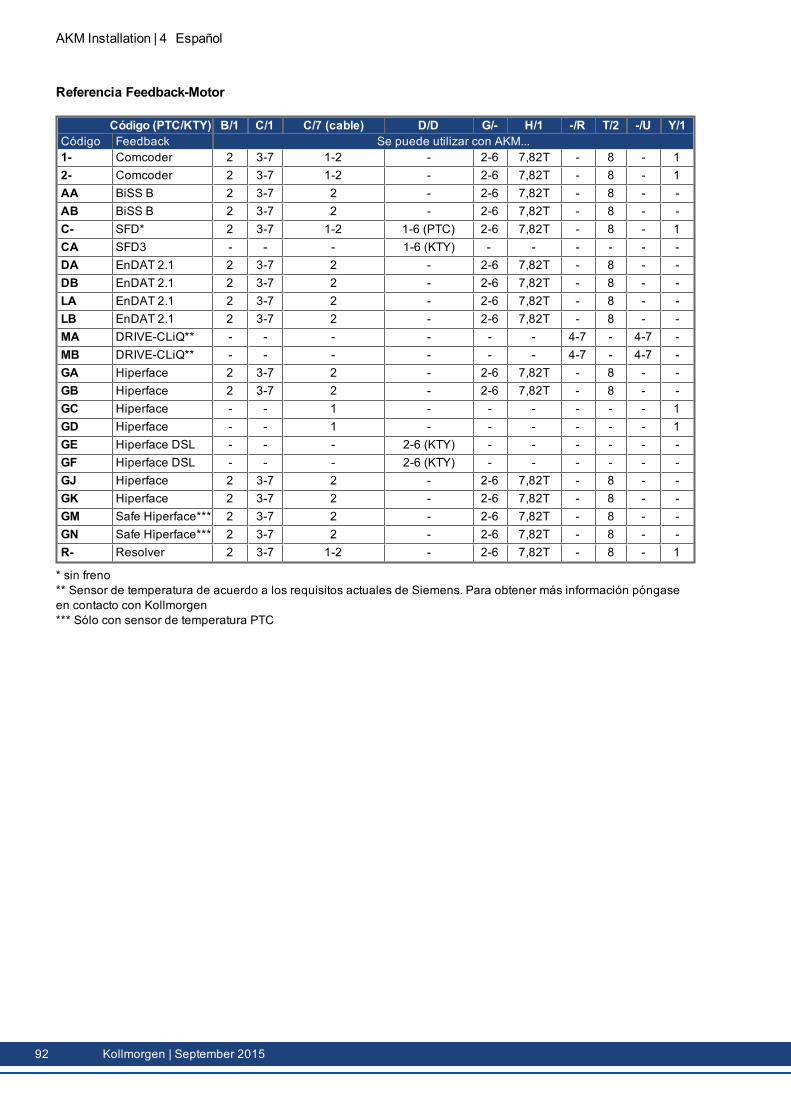
AKM Installation | 4 Español
Referencia Feedback-Motor
Código (PTC/KTY) B/1 C/1 C/7 (cable) D/D G/- H/1 -/R T/2 -/U Y/1Código Feedback Se puede utilizar con AKM...1- Comcoder 2 3-7 1-2 - 2-6 7,82T - 8 - 12- Comcoder 2 3-7 1-2 - 2-6 7,82T - 8 - 1AA BiSS B 2 3-7 2 - 2-6 7,82T - 8 - -AB BiSS B 2 3-7 2 - 2-6 7,82T - 8 - -C- SFD* 2 3-7 1-2 1-6 (PTC) 2-6 7,82T - 8 - 1CA SFD3 - - - 1-6 (KTY) - - - - - -DA EnDAT 2.1 2 3-7 2 - 2-6 7,82T - 8 - -DB EnDAT 2.1 2 3-7 2 - 2-6 7,82T - 8 - -LA EnDAT 2.1 2 3-7 2 - 2-6 7,82T - 8 - -LB EnDAT 2.1 2 3-7 2 - 2-6 7,82T - 8 - -MA DRIVE-CLiQ** - - - - - - 4-7 - 4-7 -MB DRIVE-CLiQ** - - - - - - 4-7 - 4-7 -GA Hiperface 2 3-7 2 - 2-6 7,82T - 8 - -GB Hiperface 2 3-7 2 - 2-6 7,82T - 8 - -GC Hiperface - - 1 - - - - - - 1GD Hiperface - - 1 - - - - - - 1GE Hiperface DSL - - - 2-6 (KTY) - - - - - -GF Hiperface DSL - - - 2-6 (KTY) - - - - - -GJ Hiperface 2 3-7 2 - 2-6 7,82T - 8 - -GK Hiperface 2 3-7 2 - 2-6 7,82T - 8 - -GM Safe Hiperface*** 2 3-7 2 - 2-6 7,82T - 8 - -GN Safe Hiperface*** 2 3-7 2 - 2-6 7,82T - 8 - -R- Resolver 2 3-7 1-2 - 2-6 7,82T - 8 - 1
* sin freno** Sensor de temperatura de acuerdo a los requisitos actuales de Siemens. Para obtener más información póngaseen contacto con Kollmorgen*** Sólo con sensor de temperatura PTC
92 Kollmorgen | September 2015
4.4 Descripción técnica
4.4.1 Datos técnicos generalesTemperatura ambiente(con datos nominales)
5...+40°C con altura de emplaz. hasta 1000m sobre nivel del marCon temperaturas ambiente superiores a 40°C y conmontajeencapsulado de los motores, tome contacto siempre con nuestroDepartamento de Aplicaciones.
Humedad autorizada(con datos nominales)
95% humedad relativa, sin formación de rocío
Reducción de poten-cia(currents and torques)
1%/K en el rango 40°C...50°C hasta 1000m sobre el nivel del mar(Corrientes y momentos) con alturas de emplazamiento supe-riores a 1000m sobre el nivel del mar y 40°C6% a 2000m sobre el nivel del mar17% a 3000m sobre el nivel del mar30% a 4000m sobre el nivel del mar55% a 5000m sobre el nivel del marSin reducción de potencia a alturas de emplazamiento superioresa 1000m sobre el nivel del mar y reducción de temperatura en10k/1000m
Vida útil de cojinetes ≥ 20.000 horas de servicioA partir de la página del capítulo "Technical Data" encontrará los datos técnicos corres-pondientes a cada tipo demotor ( # 161).
4.4.2 Forma de diseñoLa forma básica de diseño de losservomotores AKM es la formaIM B5 según EN 60034-7.
4.4.3 BridaBrida según Norma IEC: precisión según DIN 42955.
Code BridaA IEC con precisión N, ajuste AKM1: h7, ajuste AKM2-8: j6R IEC con precisión R, ajuste AKM1: h7, ajuste AKM2-8: j6M IEC con precisión N, ajuste j6, cojinete reforzado, solo AKM8W IEC, ajuste j6,capo del reborde por motoreWashdown oWashdown FoodB NEMA, Las dimensiones se pueden encontrar en el AKM Selection Guide (Koll-
morgenWebsite, US-English)
4.4.4 Tipo de protecciónModelo estándar Connectador Retén radial Tipo de protecciónAKM1-4 M, P con o sin IP20AKM1 C, D sin IP40AKM1 C, D con IP65AKM2-AKM8 B, C, D, G, H, T sin IP54AKM2-AKM8 B, C, D, G, H, T con IP65AKM2-AKM6Washdown B, C, D, G con IP67AKM2-AKM6Washdown Food B, C, D, G con IP67
AKM Installation | 4 Español
Kollmorgen | September 2015 93
AKM Installation | 4 Español
4.4.5 Clase de material aislanteLos motores cumplen con la clase F demateriales aislantes según IEC 60085 (UL 1446class F).
4.4.6 SuperficieLos motores están cubiertos con la capa del polvo del poliester en negromate, no siendoresistente a disolventes (Tri, diluyentes, etc.).
4.4.7 Extremo del eje, lado de accionamientoLa transmisión de fuerza resulta a través del extremo cilíndrico A, ajuste k6 (AKM1: h7)según EN 50347 con rosca de apriete pero sin ranura del muelle de ajuste. Para la vida útil delos cojinetes se ha partido de 20.000 horas de servicio.
Codificación Eje disponible paraN sin ranura todos los tipos, estandarC ranura cerrado AKM 2...8K ranura abierto AKM 1...8
Fuerza radialSi los motores propulsan a través de piñones o correas dentadas, se presentan elevadas fuer-zas radiales. Los valores autorizados en el extremo del eje, en función de velocidad, se indi-can en los diagramas en capítulo "Dimension Drawings" de ( # 175). Los valores máximospermitidos figuran en los datos técnicos de ( # 161). Con aplicación de fuerza en el centrodel extremo libre del eje FR 10% puede ser mayor.
Fuerza axialCuando semontan piñones o poleas en el eje y se utilizan p. ej. engranajes angulares, se pro-ducen fuerzas axiales. Los valores máximos permitidos figuran en los datos técnicos.
AcoplamientoComo elementos ideales de acoplamiento sin juego han dadomuy buen resultado las tena-zas tensoras, también en unión con acoplamientos de fuelle metálico.
4.4.8 Dispositivo protectorEl modelo estándar del motor va equipado con un PTC sin potencial. El punto de conexión seencuentra a 155°C ± 5%. El PTC no protege contra sobrecargas instantáneas muy altas.También existe la opción de equipar el motor con un sensor KTY 84-130 (vea las opciones deconexión 1, 2, 7 y D en ( # 189).Con sistema de realimentación digital SFD, SFD3, DSL (c, CA, GE, GF) el estado del sen-sor de temperatura es transmitido digitalmente y evaluado en la servoamplificador .Utilizando nuestro conductor feedback preconfeccionado, el dispositivo de termoprotecciónestá integrado en el sistema de control del servoamplificador digital.
4.4.9 Calidad vibracionalLos motores se fabrican con el factor A de calidad vibracional según DIN EN 60034-14. Estoimplica que el nivel de vibraciones permitido como valor efectivo para un rango de velo-cidades de 600-3600 rpm y una altura del eje de entre 56-132mm es de 1,6mm/s.
Velocidad[rpm]
max. rel. Dislocación Vibratoria[µm]
max. Run-out[µm]
<= 1800 90 23> 1800 65 16
94 Kollmorgen | September 2015
4.4.10 Retén radialSi el AKM en un reborde de lamáquina con rango de frecuencia desprotegido es acoplarse,el anillo (opción 01) hermetizadores aseguran el sellado. El sello del eje debe ser un procesode ejecución en el sometido a la consecución de los datos nominales del motor AKM.Realice los siguientes pasos:
Deje 30minutos sin carga a la velocidadmáxima en una rotación en sentido horario,enfriar 30minutos,Deje 30minutos sin carga a la velocidadmáxima la rotación en sentido antihorario,enfriar 30minutos.
Repetir este ciclo tres veces.
4.4.11 Técnica de conexión
4.4.11.1 EnchufesLas descripciones de los conectores disponibles: ( # 90).Pinout de los conectores: ( # 189).
4.4.11.2 Secciones de cable
Cable de potencia, cable combinadoLos cables combinados incluyen, además de los 4 hilos de potencia, dos hilos de freno apan-tallados.
Sección Intensidad de corrientemáxima admisible
RemarksCable Cable combinado(4x1) (4x1+(2x0.75)) 0A < I0rms ≤ 10.1A Los paréntesis (...) hacen refe-
rencia a los apantallamientos.
Intensidad de corrientemáximaadmisible según EN60204-1:2006, Tabla 6, Columna B3.
(4x1.5) (4x1.5+(2x0.75)) 10.1A < I0rms ≤ 13.1A(4x2.5) (4x2.5+(2x1)) 13.1A < I0rms ≤ 17.4A(4x4) (4x4+(2x1)) 17.4A < I0rms ≤ 23A(4x6) (4x6+(2x1)) 23A < I0rms ≤ 30A(4x10) (4x10+(2x1.5)) 30A < I0rms ≤ 40A(4x16) (4x16+(2x1.5)) 40A < I0rms ≤ 54A(4x25) (4x25+(2x1.5)) 54A < I0rms ≤ 70A
Cable de Feedback
Tipo Sección ComentarioResolver, SFD (4x2x 0.25)Encoder (7x2x 0.25) BiSS, EnDAT, HIPERFACEComcoder (8x2x 0.25) Encoder incremental + Hall
Cable híbrido
Tipo Sección Comentario
SFD/SFD3/DSL(4x1.0+(2x0.34)+(2x0.75)) 4 hilos de potencia & 4 hilos de señal para
SFDo bien4 hilos de potencia & 2 hilos de freno &2 hilos de señal paraSFD3/DSL
(4x1.5+(2x0.34)+(2x0.75))
AKM Installation | 4 Español
Kollmorgen | September 2015 95
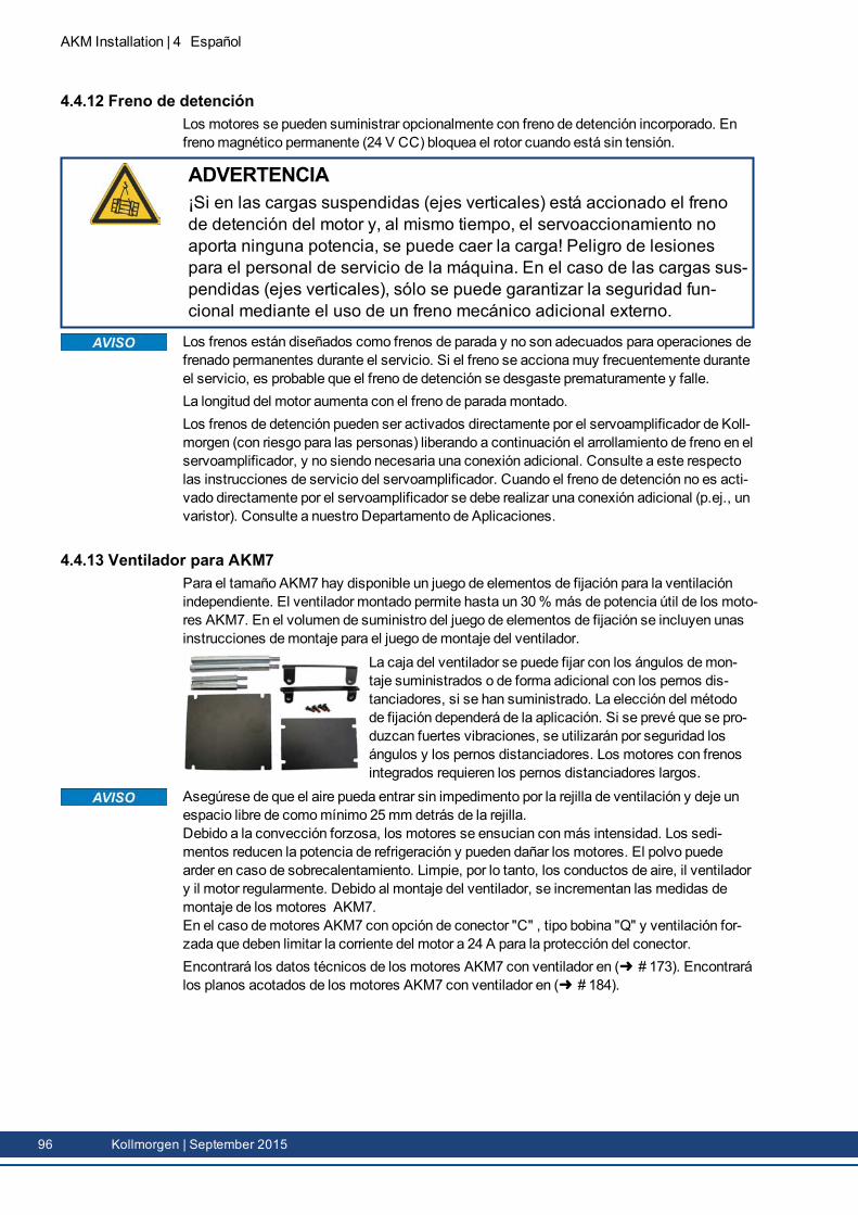
AKM Installation | 4 Español
4.4.12 Freno de detenciónLos motores se pueden suministrar opcionalmente con freno de detención incorporado. Enfrenomagnético permanente (24 V CC) bloquea el rotor cuando está sin tensión.
ADVERTENCIA¡Si en las cargas suspendidas (ejes verticales) está accionado el frenode detención del motor y, al mismo tiempo, el servoaccionamiento noaporta ninguna potencia, se puede caer la carga! Peligro de lesionespara el personal de servicio de la máquina. En el caso de las cargas sus-pendidas (ejes verticales), sólo se puede garantizar la seguridad fun-cional mediante el uso de un freno mecánico adicional externo.
Los frenos están diseñados como frenos de parada y no son adecuados para operaciones defrenado permanentes durante el servicio. Si el freno se accionamuy frecuentemente duranteel servicio, es probable que el freno de detención se desgaste prematuramente y falle.La longitud del motor aumenta con el freno de paradamontado.Los frenos de detención pueden ser activados directamente por el servoamplificador de Koll-morgen (con riesgo para las personas) liberando a continuación el arrollamiento de freno en elservoamplificador, y no siendo necesaria una conexión adicional. Consulte a este respectolas instrucciones de servicio del servoamplificador. Cuando el freno de detención no es acti-vado directamente por el servoamplificador se debe realizar una conexión adicional (p.ej., unvaristor). Consulte a nuestro Departamento de Aplicaciones.
4.4.13 Ventilador para AKM7Para el tamaño AKM7 hay disponible un juego de elementos de fijación para la ventilaciónindependiente. El ventilador montado permite hasta un 30% más de potencia útil de los moto-res AKM7. En el volumen de suministro del juego de elementos de fijación se incluyen unasinstrucciones demontaje para el juego demontaje del ventilador.
La caja del ventilador se puede fijar con los ángulos demon-taje suministrados o de forma adicional con los pernos dis-tanciadores, si se han suministrado. La elección del métodode fijación dependerá de la aplicación. Si se prevé que se pro-duzcan fuertes vibraciones, se utilizarán por seguridad losángulos y los pernos distanciadores. Los motores con frenosintegrados requieren los pernos distanciadores largos.
Asegúrese de que el aire pueda entrar sin impedimento por la rejilla de ventilación y deje unespacio libre de comomínimo 25mm detrás de la rejilla.Debido a la convección forzosa, los motores se ensucian conmás intensidad. Los sedi-mentos reducen la potencia de refrigeración y pueden dañar los motores. El polvo puedearder en caso de sobrecalentamiento. Limpie, por lo tanto, los conductos de aire, il ventiladory il motor regularmente. Debido al montaje del ventilador, se incrementan las medidas demontaje de los motores AKM7.En el caso demotores AKM7 con opción de conector "C" , tipo bobina "Q" y ventilación for-zada que deben limitar la corriente del motor a 24 A para la protección del conector.Encontrará los datos técnicos de los motores AKM7 con ventilador en ( # 173). Encontrarálos planos acotados de los motores AKM7 con ventilador en ( # 184).
96 Kollmorgen | September 2015
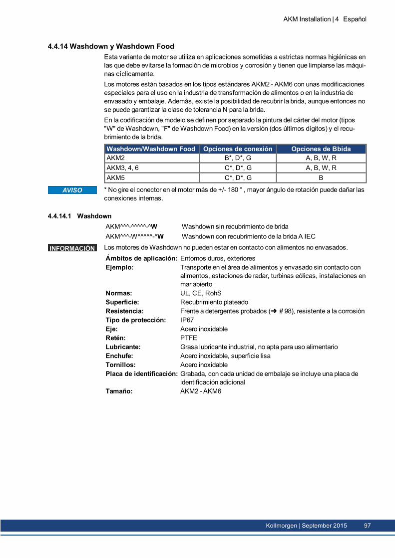
4.4.14 Washdown y Washdown FoodEsta variante demotor se utiliza en aplicaciones sometidas a estrictas normas higiénicas enlas que debe evitarse la formación demicrobios y corrosión y tienen que limpiarse las máqui-nas cíclicamente.Los motores están basados en los tipos estándares AKM2 - AKM6 con unas modificacionesespeciales para el uso en la industria de transformación de alimentos o en la industria deenvasado y embalaje. Además, existe la posibilidad de recubrir la brida, aunque entonces nose puede garantizar la clase de tolerancia N para la brida.En la codificación demodelo se definen por separado la pintura del cárter del motor (tipos"W" deWashdown, "F" deWashdown Food) en la versión (dos últimos dígitos) y el recu-brimiento de la brida.
Washdown/Washdown Food Opciones de conexión Opciones de BbidaAKM2 B*, D*, G A, B, W, RAKM3, 4, 6 C*, D*, G A, B, W, RAKM5 C*, D*, G B
* No gire el conector en el motor más de +/- 180 ° , mayor ángulo de rotación puede dañar lasconexiones internas.
4.4.14.1 WashdownAKM^^^-^^^^^-^WAKM^^^-W^^^^^-^W
Washdown sin recubrimiento de bridaWashdown con recubrimiento de la brida A IEC
Los motores deWashdown no pueden estar en contacto con alimentos no envasados.Ámbitos de aplicación: Entornos duros, exterioresEjemplo: Transporte en el área de alimentos y envasado sin contacto con
alimentos, estaciones de radar, turbinas eólicas, instalaciones enmar abierto
Normas: UL, CE, RohSSuperficie: Recubrimiento plateadoResistencia: Frente a detergentes probados ( # 98), resistente a la corrosiónTipo de protección: IP67Eje: Acero inoxidableRetén: PTFELubricante: Grasa lubricante industrial, no apta para uso alimentarioEnchufe: Acero inoxidable, superficie lisaTornillos: Acero inoxidablePlaca de identificación: Grabada, con cada unidad de embalaje se incluye una placa de
identificación adicionalTamaño: AKM2 - AKM6
AKM Installation | 4 Español
Kollmorgen | September 2015 97
AKM Installation | 4 Español
4.4.14.2 Washdown FoodAKM^^^-^^^^^-^FAKM^^^-W^^^^^-^F
Washdown Food sin recubrimiento de bridaWashdown Food con recubrimiento de la brida A IEC
La superficie del motor deWashdown Food ha superado todas las pruebas en conformidadcon FDA GlobalMigration en lo referente al contacto indirecto con alimentos. No se permiteel contacto directo con alimentos no envasados.Ámbitos de aplicación: Industria alimentaria y de bebidas, sin contacto directo con ali-
mentos no envasados.Ejemplo: Corte, envasado y llenado sin contacto directo con los alimentos,
motor situado al lado o debajo de los alimentosNormas: UL, CE, RoHs, FDASuperficie: Revestimiento blancoResistencia: Frente a detergentes probados ( # 98), resistente a la corrosiónGlobal Migration: US FDA Regulations 21 CFR 175.300, Condition of Use ETipo de protección: IP67Eje: Acero inoxidableRetén: FDA, conformidad con FDALubricante: Apto para uso alimentario en conformidad con FDAEnchufe: Acero inoxidable, superficie lisaTornillos: Acero inoxidablePlaca de identificación: Grabada, con cada unidad de embalaje se incluye una placa de
identificación adicionalTamaño: AKM2 - AKM6
4.4.14.3 Características probadas y confirmadas frente a productos de limpiezaEn el laboratorio de pruebas ECOLAB DeutschlandGmbH se probó la resistencia de lassuperficies de los Washdown y Washdown Food frente a los siguientes productos de lim-pieza industriales:
P3-topactive DESP3-topactive LAP3-topax 56P3-topax 66P3-topax 91
Para ello se sumergieron las superficies en cada producto de limpieza durante 28 días a tem-peratura ambiente. Esto equivale aprox. a 2500 ciclos de limpieza, cada uno de los cualescon 15minutos de contacto con el producto de limpieza, o bien a 1500 ciclos de limpieza conlimpieza y posterior desinfección.Los certificados se encuentran en nuestraWIKI de productos, en la página Approvals .
Kollmorgen solo puede garantizar la vida útil del motor si se utilizan los detergentes pro-bados. Kollmorgen puede probar y, en su caso, autorizar otros detergentes que los citadosprevia solicitud.
98 Kollmorgen | September 2015
4.4.14.4 Condiciones de montaje y aplicaciónLos motores deben utilizarse solamente con una temperatura ambientemáxima de 50°C.Si la brida delantera está recubierta, no se garantiza la clase de tolerancia N.
En los motores con bridas sin revestimiento lavable, la superficie de las bridas se debe pro-teger de la acción de los productos de limpiezamediante una instalación adecuada.
4.4.14.5 Plan de limpiezaPlan de limpieza recomendado (abreviado) con los productos de limpieza probados:
Enjuague con agua (40 °... 50 °C)Enjuague con baja presión. De arriba a abajo en dirección al orificio de drenaje. Limpiar el ori-ficio de drenaje.
Limpieza con espumaFrotar de arriba a abajo.Alcalinos: P3-topactive LA or P3-topax 66 (2-5%, diariamente durante 15min)Ácidos: P3-topax 56 (2%, si es necesario durante 15min)Temperatura: de fría a 40 °C
DesinfecciónPulverizar con agua (40 ... 50 °C) con baja presión. De arriba a abajo.Desinfección por aspersión P3-topax 91 (1-2%, si es necesario durante 30-60min)Desinfección con espuma: P3-topactiv DES (1-3%, si es necesario durante 10-30min)
AKM Installation | 4 Español
Kollmorgen | September 2015 99
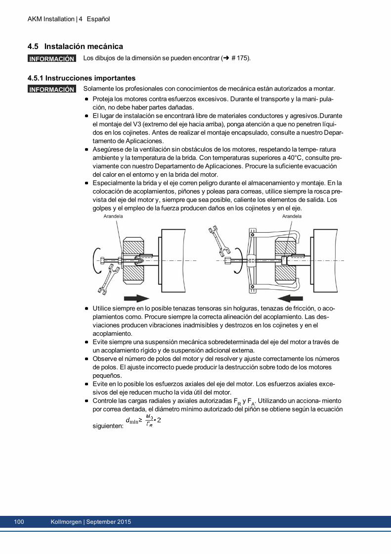
AKM Installation | 4 Español
4.5 Instalación mecánicaLos dibujos de la dimensión se pueden encontrar ( # 175).
4.5.1 Instrucciones importantesSolamente los profesionales con conocimientos demecánica están autorizados amontar.
Proteja los motores contra esfuerzos excesivos. Durante el transporte y la mani- pula-ción, no debe haber partes dañadas.El lugar de instalación se encontrará libre demateriales conductores y agresivos.Duranteel montaje del V3 (extremo del eje hacia arriba), ponga atención a que no penetren líqui-dos en los cojinetes. Antes de realizar el montaje encapsulado, consulte a nuestro Depar-tamento de Aplicaciones.Asegúrese de la ventilación sin obstáculos de los motores, respetando la tempe- raturaambiente y la temperatura de la brida. Con temperaturas superiores a 40°C, consulte pre-viamente con nuestro Departamento de Aplicaciones. Procure la suficiente evacuacióndel calor en el entorno y en la brida del motor.Especialmente la brida y el eje corren peligro durante el almacenamiento y montaje. En lacolocación de acoplamientos, piñones y poleas para correas, utilice siempre la rosca pre-vista del eje del motor y, siempre que sea posible, caliente los elementos de salida. Losgolpes y el empleo de la fuerza producen daños en los cojinetes y en el eje.
Utilice siempre en lo posible tenazas tensoras sin holguras, tenazas de fricción, o aco-plamientos como. Procure siempre la correcta alineación del acoplamiento. Las des-viaciones producen vibraciones inadmisibles y destrozos en los cojinetes y en elacoplamiento.Evite siempre una suspensiónmecánica sobredeterminada del eje del motor a través deun acoplamiento rígido y de suspensión adicional externa.Observe el número de polos del motor y del resolver y ajuste correctamente los númerosde polos. El ajuste incorrecto puede producir la destrucción sobre todo de los motorespequeños.Evite en lo posible los esfuerzos axiales del eje del motor. Los esfuerzos axiales exce-sivos del eje reducenmucho la vida útil del motor.Controle las cargas radiales y axiales autorizadas FR y FA. Utilizando un acciona- mientopor correa dentada, el diámetromínimo autorizado del piñón se obtiene según la ecuación
siguienten:
100 Kollmorgen | September 2015
4.6 Instalación eléctricaEl asignación de enchufes se pueden encontrar en capítulo "Connector Pinout" de ( #175). Pinout del amplificador se puede encontrar en el manual del amplificador.
4.6.1 Instrucciones importantesInstalación eléctrica:sólo a cargo de personal especializado con formación en electrotecnia.
PELIGROEl montaje y cableado de los motores se realizará siempre sin tensión,es decir, ninguna de las tensiones de servicio del aparato a conectardeberá estar activada.Tocar contactos expuestos comporta peligro de muerte y riesgos gravespara la salud.Asegúrese de que la desconexión del armario de distribución sea segura(bloqueo, rótulos de advertencia, etc.). Las diferentes tensiones se conec-tarán en la primera puesta en funcionamiento.No manipule nunca las conexiones eléctricas de los motores cuando seencuentren bajo tensión. Riesgo de choque eléctrico! En caso de acci-dente se pueden generar chispazos que dañen a las personas y a loscontactos.Las cargas residuales en los condensadores del amplificador con nive-les peligrosos de hasta 10 minutos después de desconectar el cable dealimentación. Las conexiones de control y de potencia pueden provocartensión, incluso aunque el motor no esté girando.Mida la tensión en el circuito intermedio y espere hasta que haya des-cendido por debajo de 60 V.
El símbolo demasa , que se encuentra en todos los planos de conexión, indica quedebe asegurarse de realizar una conexión en el armario de distribución con lamayor super-ficie posible conductora de electricidad, entre el aparato que lleva la indicación y la placa demontaje. Esta conexión hará posible la derivación de interferencias de alta frecuencia y nodebe confundirse con lamarca PE (medida de protección según EN 60204). Respetetambién las indicaciones en los planos de conexión de las manual de instalación y de puestaen funcionamiento del servoamplificador utilizado.
AKM Installation | 4 Español
Kollmorgen | September 2015 101
AKM Installation | 4 Español
4.6.2 Guía de instalación eléctricaCompruebe la correspondencia entre el servoamplificador y el motor. Compare la tensiónnominal y la corriente nominal de los aparatos. Realice el cableado conforme al cuadro deconexiones de las Instrucciones de instalación y de puesta en funcionamiento del ser-voamplificador. Las conexiones se encuentran en ( # 175).Realice el tendido de todos las conducciones de alta tensión con sección suficientesegún EN 60204. En los datos técnicos se incluyen las secciones recomendadas.
En función del tipo de servoamplificador utilizado, con cables demotor largos (>25m) debeconectarse una bobina demotor (3YL o 3YLN) en el conductor del motor (véase el manual deproducto del servoamplificador y el manual de accesorios).
Asegúrese de que la toma de tierra del servoamplificador y del motor esté perfectamenteinstalada. Véanse la adecuada protección de compatibilidad electromagnética y depuesta a tierra en las Instrucciones de instalación del servoamplificador utilizado. Pongaa tierra la placa demontaje y el bloque del motor.Utilizando un cale de potencia del motor con conductores demando de freno integrados,estos deberán estar apantallados. La pantalla estará dispuesta por ambos lados (véasemanual de instalación del servoamplificador).Cableado:
Tienda los cables de potencia y de control bien separadosConecte el resolver y el codificadorConecte los cables del motor cerca del servoamplificador.Apantallamientos a ambos lados en bornes de protección o en el enchufe de CEMConecta el freno de detención, si está montado.Coloque el apantallamiento a ambos lados.
Realice apantallamientos de gran superficie (baja resistencia) a través de cajas deenchufemetalizadas, o bien, de uniones de cable roscadas compatibles elec-tromagnéticamente.Requisitos al material de cables:CapacidadCable del motor: menor que 150 pF/mCable Resolver: menor que 120 pF/m
4.6.3 Conexión de los motores con cables confeccionadasRealice el cableado cumpliendo los reglamentos y normas vigentes.Para las conexiones de potencia y de retorno, utilice exclusivamente los cables con-feccionadas y protegidas de Kollmorgen.Los apantallamientos mal colocados producen siempre a interferencias electromagnéticas ydegradar el rendimiento del sistema.La longitudmáxima del conductor se define en el manual de producto del servoamplificadorutilizado.
Para una descripción detallada de cables confeccionadas, refiera por favor a los manualesaccesorios.
102 Kollmorgen | September 2015
4.7 Puesta en funcionamento
4.7.1 Instrucciones importantes
Solamente los profesionales con amplios conocimientos de electrotecnia y de técnicas deaccionamiento están autorizados a la puesta en funcionamiento del conjunto ser-voamplificador-motor.
PELIGROSe producen tensiones peligrosas de hasta 900V. Riesgo de descargaeléctrica! Compruebe que todas las piezas de conexión que conducentensión estén protegidas contra cualquier posible contacto.No manipule nunca las conexiones eléctricas de los motores cuando seencuentren bajo tensión. Las cargas residuales en los condensadoresdel amplificador con niveles peligrosos de hasta 10 minutos después dedesconectar el cable de alimentación.Mida la tensión en el circuito intermedio y espere hasta que haya des-cendido por debajo de 60 V. Las conexiones de control y de potenciapueden provocar tensión, incluso aunque el motor no esté girando.
ATENCIÓNLa temperatura de la superficie del motor puede alcanzar 100 °C duranteel servicio. Peligro de quemaduras leves! Compruebe (mida) la tem-peratura del motor.Espere a que la temperatura haya descendido a 40 °C antes de tocar elmotor con las manos
ATENCIÓNNo hay que descartar que durante la puesta en funcionamiento el accio-namiento realice un movimiento imprevisto.Asegúrese de que cualquier movimiento no deseado de la unidad nopuede causar peligro para personas o bienes.Las medidas que habrá de observar en este aspecto en su aplicaciónresultarán de la valoración de riesgos de dicha aplicación.
AKM Installation | 4 Español
Kollmorgen | September 2015 103

AKM Installation | 4 Español
4.7.2 Guía de puesta en funcionamentoLa forma de proceder en la puesta en accionamiento se describe amodo de ejemplo. Depen-diendo del tipo de puesta en servicio de los aparatos puede ser adecuado o necesario un pro-cedimiento u otro.1. Compruebe el montaje y la alineación del motor.2. Compruebe el firme asiento de los elementos de salida de fuerza (acoplamiento, engra-
naje, polea de la correa) así como el ajuste correcto (respetar las fuerzas radiales y axia-les autorizadas).
3. Compruebe el cableado y las conexiones del motor y del servoamplificador. Compruebela correcta puesta a tierra.
4. Compruebe el funcionamiento del freno de detención, si está montado. (conectar 24V, elfreno se debe soltar).
5. Compruebe si el rotor del motor gira libremente (soltar primero el freno, si está montado).Compruebe si se escuchan ruidos de fricción.
6. Compruebe si se han tomado todas las medidas de protección contra contactos para laspiezas móviles y las conductoras de tensión.
7. Realice todas las comprobaciones específicas y necesarias para su equipo.8. Conforme a las Instrucciones de puesta en funcionamiento del servoamplificador, ponga
ahora enmarcha el accionamiento.9. En sistemas de varios ejes, ponga enmarcha, una a una, cada una de las unidades de
accionamiento servoamplificador-motor.
104 Kollmorgen | September 2015
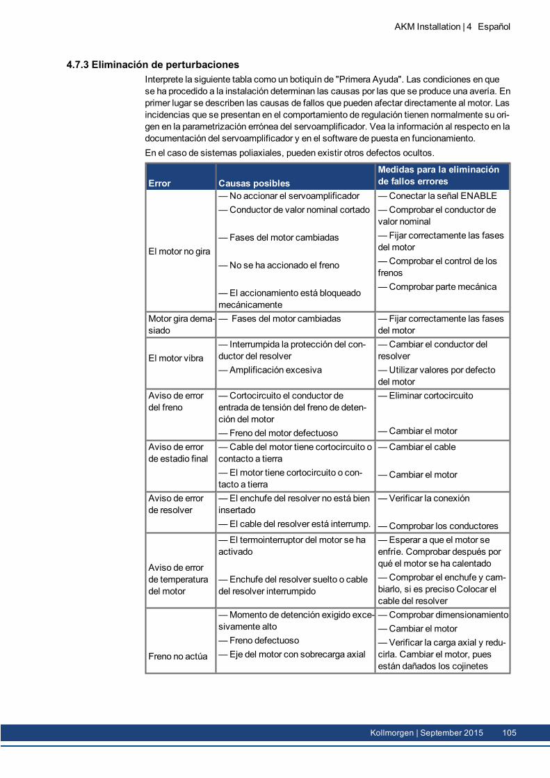
4.7.3 Eliminación de perturbacionesInterprete la siguiente tabla como un botiquín de "Primera Ayuda". Las condiciones en quese ha procedido a la instalación determinan las causas por las que se produce una avería. Enprimer lugar se describen las causas de fallos que pueden afectar directamente al motor. Lasincidencias que se presentan en el comportamiento de regulación tienen normalmente su ori-gen en la parametrización errónea del servoamplificador. Vea la información al respecto en ladocumentación del servoamplificador y en el software de puesta en funcionamiento.En el caso de sistemas poliaxiales, pueden existir otros defectos ocultos.
Error Causas posiblesMedidas para la eliminaciónde fallos errores
El motor no gira
—No accionar el servoamplificador—Conductor de valor nominal cortado
—Fases del motor cambiadas
—No se ha accionado el freno
—El accionamiento está bloqueadomecánicamente
—Conectar la señal ENABLE—Comprobar el conductor devalor nominal— Fijar correctamente las fasesdel motor—Comprobar el control de losfrenos—Comprobar parte mecánica
Motor gira dema-siado
— Fases del motor cambiadas —Fijar correctamente las fasesdel motor
El motor vibra— Interrumpida la protección del con-ductor del resolver—Amplificación excesiva
—Cambiar el conductor delresolver—Utilizar valores por defectodel motor
Aviso de errordel freno
—Cortocircuito el conductor deentrada de tensión del freno de deten-ción del motor— Freno del motor defectuoso
—Eliminar cortocircuito
—Cambiar el motor
Aviso de errorde estadio final
—Cable del motor tiene cortocircuito ocontacto a tierra—El motor tiene cortocircuito o con-tacto a tierra
—Cambiar el cable
—Cambiar el motor
Aviso de errorde resolver
—El enchufe del resolver no está bieninsertado—El cable del resolver está interrump.
—Verificar la conexión
—Comprobar los conductores
Aviso de errorde temperaturadel motor
—El termointerruptor del motor se haactivado
—Enchufe del resolver suelto o cabledel resolver interrumpido
—Esperar a que el motor seenfríe. Comprobar después porqué el motor se ha calentado—Comprobar el enchufe y cam-biarlo, si es preciso Colocar elcable del resolver
Freno no actúa
—Momento de detención exigido exce-sivamente alto— Freno defectuoso—Eje del motor con sobrecarga axial
—Comprobar dimensionamiento—Cambiar el motor—Verificar la carga axial y redu-cirla. Cambiar el motor, puesestán dañados los cojinetes
AKM Installation | 4 Español
Kollmorgen | September 2015 105
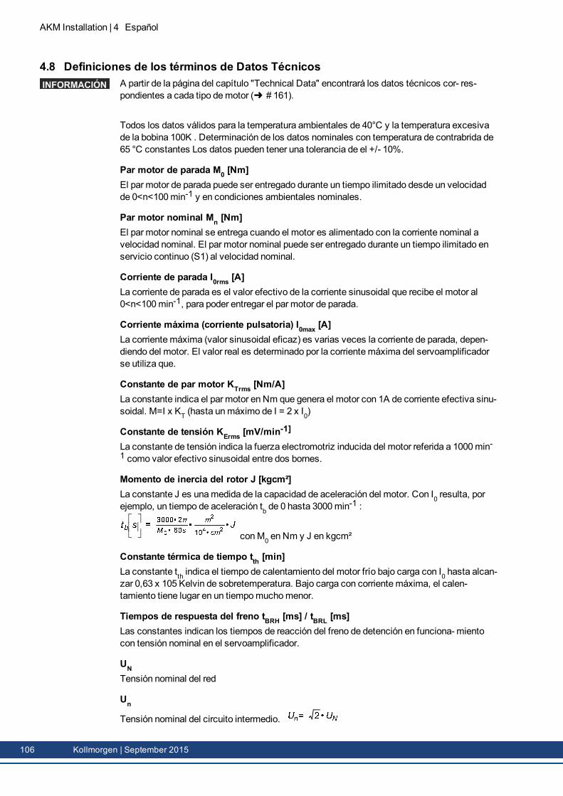
AKM Installation | 4 Español
4.8 Definiciones de los términos de Datos TécnicosA partir de la página del capítulo "Technical Data" encontrará los datos técnicos cor- res-pondientes a cada tipo demotor ( # 161).
Todos los datos válidos para la temperatura ambientales de 40°C y la temperatura excesivade la bobina 100K . Determinación de los datos nominales con temperatura de contrabrida de65 °C constantes Los datos pueden tener una tolerancia de el +/- 10%.
Par motor de parada M0 [Nm]El par motor de parada puede ser entregado durante un tiempo ilimitado desde un velocidadde 0<n<100min-1 y en condiciones ambientales nominales.
Par motor nominal Mn [Nm]El par motor nominal se entrega cuando el motor es alimentado con la corriente nominal avelocidad nominal. El par motor nominal puede ser entregado durante un tiempo ilimitado enservicio continuo (S1) al velocidad nominal.
Corriente de parada I0rms [A]La corriente de parada es el valor efectivo de la corriente sinusoidal que recibe el motor al 0<n<100min-1, para poder entregar el par motor de parada.
Corriente máxima (corriente pulsatoria) I0max [A]La corrientemáxima (valor sinusoidal eficaz) es varias veces la corriente de parada, depen-diendo del motor. El valor real es determinado por la corrientemáxima del servoamplificadorse utiliza que.
Constante de par motor KTrms [Nm/A]La constante indica el par motor en Nm que genera el motor con 1A de corriente efectiva sinu-soidal. M=I x KT (hasta unmáximo de I = 2 x I0)
Constante de tensión KErms [mV/min-1]
La constante de tensión indica la fuerza electromotriz inducida del motor referida a 1000min-1 como valor efectivo sinusoidal entre dos bornes.
Momento de inercia del rotor J [kgcm²]La constante J es unamedida de la capacidad de aceleración del motor. Con I0 resulta, porejemplo, un tiempo de aceleración tb de 0 hasta 3000min
-1 :
conM0 en Nm y J en kgcm²
Constante térmica de tiempo tth [min]La constante tth indica el tiempo de calentamiento del motor frío bajo carga con I0 hasta alcan-zar 0,63 x 10⁵ Kelvin de sobretemperatura. Bajo carga con corrientemáxima, el calen-tamiento tiene lugar en un tiempomuchomenor.
Tiempos de respuesta del freno tBRH [ms] / tBRL [ms]Las constantes indican los tiempos de reacción del freno de detención en funciona- mientocon tensión nominal en el servoamplificador.
UNTensión nominal del red
Un
Tensión nominal del circuito intermedio.
106 Kollmorgen | September 2015
5 Français
5.1 Généralités 1085.1.1 Au sujet de cemanuel 1085.1.2 Symboles utilisés 1085.1.3 Abréviations utilisées 108
5.2 Sécurité 1095.2.1 Consignes de sécurité 1095.2.2 Utilisation conforme 1115.2.3 Utilisation non conforme 1115.2.4Manipulation 112
5.3 Identification de produit 1145.3.1 Fournitures 1145.3.2 Plaque signalétique 1145.3.3 Clé de type 115
5.4 Description technique 1195.4.1 Données techniques générales 1195.4.2 Conception 1195.4.3 Bride 1195.4.4 Indice de protection 1195.4.5 Classe d'isolation 1205.4.6 Surface 1205.4.7 Côté bout d'arbre A 1205.4.8 Dispositif de protection 1205.4.9 Classe vibrationelle 1205.4.10 La bague d'étanchéité 1215.4.11 Technologie de câblage 1215.4.12 Frein demaintien 1225.4.13 Ventilateur pour AKM7 1225.4.14Washdown et Washdown Food 123
5.5 Installation mécanique 1265.5.1 Remarques importantes 126
5.6 Installation électrique 1275.6.1 Remarques Importantes 1275.6.2 Guide d’installation électrique 1285.6.3 Raccordement des moteurs avec câblage prééquipés 128
5.7 Mise en service 1295.7.1 Remarques importantes 1295.7.2 Guide demise en service 1305.7.3 Dépannage 131
5.8 Définitions des concepts de données techniques 132
AKM Installation | 5 Français
Kollmorgen | September 2015 107
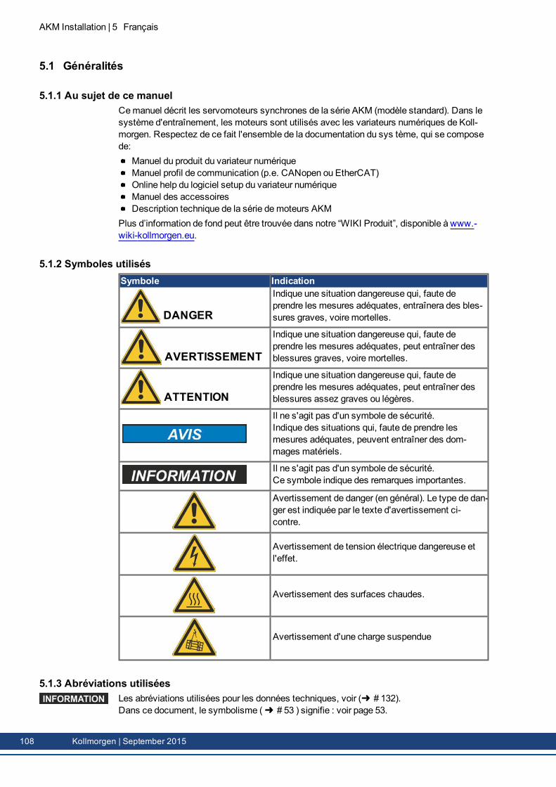
AKM Installation | 5 Français
5.1 Généralités
5.1.1 Au sujet de ce manuelCemanuel décrit les servomoteurs synchrones de la série AKM (modèle standard). Dans lesystème d'entraînement, les moteurs sont utilisés avec les variateurs numériques de Koll-morgen. Respectez de ce fait l'ensemble de la documentation du sys tème, qui se composede:
Manuel du produit du variateur numériqueManuel profil de communication (p.e. CANopen ou EtherCAT)Online help du logiciel setup du variateur numériqueManuel des accessoiresDescription technique de la série demoteurs AKM
Plus d’information de fond peut être trouvée dans notre “WIKI Produit”, disponible à www.-wiki-kollmorgen.eu.
5.1.2 Symboles utilisésSymbole Indication
DANGER
Indique une situation dangereuse qui, faute deprendre les mesures adéquates, entraînera des bles-sures graves, voire mortelles.
AVERTISSEMENT
Indique une situation dangereuse qui, faute deprendre les mesures adéquates, peut entraîner desblessures graves, voire mortelles.
ATTENTION
Indique une situation dangereuse qui, faute deprendre les mesures adéquates, peut entraîner desblessures assez graves ou légères.
Il ne s'agit pas d'un symbole de sécurité.Indique des situations qui, faute de prendre lesmesures adéquates, peuvent entraîner des dom-mages matériels.
Il ne s'agit pas d'un symbole de sécurité.Ce symbole indique des remarques importantes.
Avertissement de danger (en général). Le type de dan-ger est indiquée par le texte d'avertissement ci-contre.
Avertissement de tension électrique dangereuse etl'effet.
Avertissement des surfaces chaudes.
Avertissement d'une charge suspendue
5.1.3 Abréviations utiliséesLes abréviations utilisées pour les données techniques, voir ( # 132).Dans ce document, le symbolisme ( # 53 ) signifie : voir page 53.
108 Kollmorgen | September 2015
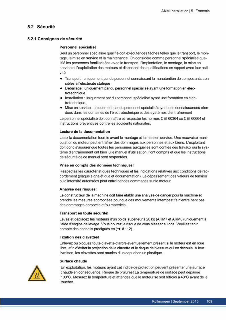
5.2 Sécurité
5.2.1 Consignes de sécurité
Personnel spécialiséSeul un personnel spécialisé qualifié doit exécuter des tâches telles que le transport, le mon-tage, la mise en service et la maintenance. On considère comme personnel spécialisé qua-lifié les personnes familiarisées avec le transport, l'implantation, le montage, la mise enservice et l'exploitation des moteurs et disposant des qualifications en rapport avec leur acti-vité.
Transport : uniquement par du personnel connaissant la manutention de composants sen-sibles à l’électricité statiqueDéballage : uniquement par du personnel spécialisé ayant une formation en élec-trotechniqueInstallation : uniquement par du personnel spécialisé ayant une formation en élec-trotechnique.Mise en service : uniquement par du personnel spécialisé ayant des connaissances éten-dues dans les domaines de l’électrotechnique et des systèmes d’entraînement
Le personnel spécialisé doit connaître et respecter les normes CEI 60364 ou CEI 60664 etinstructions préventives contre les accidents nationales.
Lecture de la documentationLisez la documentation fournie avant le montage et la mise en service. Unemauvaisemani-pulation dumoteur peut entraîner des dommages aux personnes et aux biens. L’exploitantdoit donc s’assurer que toutes les personnes auxquelles sont confiés des travaux sur le sys-tème d'entraînement ont bien lu le manuel d’utilisation, l’ont compris et que les instructionsde sécurité de cemanuel sont respectées.
Prise en compte des données techniques!Respectez les caractéristiques techniques et les indications relatives aux conditions de rac-cordement (plaque signalétique et documentation). Le dépassement des valeurs de tensionou d’intensité autorisées peut entraîner des dommages sur le moteur.
Analyse des risques!Le constructeur de lamachine doit faire établir une analyse de danger pour la machine etprendre les mesures appropriées pour que des mouvements intempestifs n'entraînent pasdes dommages corporels et/oumatériels.
Transport en toute sécurité!Levez et déplacez les moteurs d'un poids supérieur à 20 kg (AKM7 et AKM8) uniquement àl'aide d'engins de levage. Vous courez le risque de vous blesser au dos. Veuillez tenircompte des conseils prodigués en ( # 112) .
Fixation des clavettes!Enlevez ou bloquez toute clavette d'arbre éventuellement présent si le moteur est en rouelibre, afin d'éviter la projection de la clavette et le risque de blessure qui en découle. À leurlivraison, les clavettes sont munies d'un capuchon un plastique.
Surface chaudeEn exploitation, les moteurs ayant cet indice de protection peuvent présenter une surfacechaude en conséquence. Risque de brûlures! La température de surface peut dépasse100°C. Mesurez la température et attendez que lemoteur se soit refroidi à 40°C avant de letoucher.
AKM Installation | 5 Français
Kollmorgen | September 2015 109
AKM Installation | 5 Français
Mise à la terre! Hautes tensions!Assurez-vous de lamise à la terre correcte dumoteur, avec le profilé PE de l’armoire élec-trique comme potentiel de référence. Risque de choc électrique. Faute d’unemise à la terrede faible impédance, la sécurité des personnes n’est pas assurée et il existe un risque dechoc électrique pouvant être mortel.L'absence d'indications visuelles ne garantit pas l'absence de tension. Les connexions depuissance peuvent véhiculer la tension, même quand lemoteur ne tourne pas.Ne tirez aucun connecteur mâle en exploitation. Il ya un danger demort ou de blessuresgraves en cas de contact contacts exposés. Les connexions de puissance peuvent véhi-culer la tensionmême quand lemoteur ne tourne pas. Ne débranchez jamais les connexionsélectriques des moteurs sous tension. Dans des cas défavorables, des arcs électriquespeuvent se former et causer des dommages aux personnes et aux contacts.Attendez plusieurs minutes après que l'amplificateur d'asservissement a été déconnectédes tensions d'alimentation avant de toucher les pièces sous tension (telles que contacts/-boulons filetés) ou de débrancher connexions.Les condensateurs du variateur conduisent des tensions dangereuses pendant plusieursminutes après la déconnexion des tensions d'alimentation. Par sécurité, mesurez la tensiondu circuit intermédiaire et attendez qu'elle soit descendue au-dessous de 60V.
Fixation des charges suspendues!Les freins demaintien incorporés ne garantissent pas la sécurité fonctionelle. Concernantplus particulièrement les charges suspendues (axes verticaux), la sécurité des personnesne peut être garantie qu'avec un frein mécanique externe supplémentaire.
110 Kollmorgen | September 2015
5.2.2 Utilisation conformeLes servomoteurs synchrones de la série AKM sont tout particulièrement conçus pourl'entraînement dematériels demanutention, machines textiles, machines-outils,machines d'emballage et autres ayant des exigences de dynamique élevées.Vous ne devez utiliser les moteurs qu'à condition de respecter les conditions d'en-vironnement définies dans cette documentation.Le fonctionnement des moteurs "Washdown" est autorisé en présence d'acides et desolutions alcalines corrosifs conformément aux conditions définies au ( # 123).Le fonctionnement des moteurs "Washdown Food" est autorisé en cas de contact indi-rect avec les denrées alimentaires.Les moteurs de la série AKM sont exclusivement conçus pour être commandés par desvariateurs numériques à réglage de vitesse ou de couple.Les moteurs sont incorporés comme composants d'installations ou demachines élec-triques et ne doivent être mis en service que comme composants intégrés de l'ins-tallation.Le sensor thermique demise à la terre intégré dans les enroulements dumoteur doit êtreévalué et surveillé.Les freins demaintien sont dimensionnés comme freins d'arrêt et ne se prêtent pas à desprocédures de freinage permanentes et opérationnelles.Nous ne garantissons la conformité du système asservi aux normes indiquées en ( #196)e la EC Declaration of Conformity qu'en cas d'utilisation de composants livrés parnous (variateur numérique, moteur, câbles, etc.).
5.2.3 Utilisation non conformeLe fonctionnement des moteurs Standard est interdit
directement sur le réseau,dans des environnements explosibles,en contact avec des denrées alimentaires,en présence d'acides, de solutions alcalines, d'huiles, de vapeurs et de poussières cor-rosifs et/ou conducteurs.
Le fonctionnement des moteurs "Washdown" est interditdirectement sur le réseau,dans des environnements explosibles,en contact avec des denrées alimentaires,en présence d'acides ou de solutions alcalines affichant un pH inférieur à 2 ou supé-rieur à 12,en présence d’acides ou de solutions alcalines non testés par Kollmorgen.
Le fonctionnement des moteurs "Washdown Food" est interditdirectement sur le réseau,dans des environnements explosibles,en contact direct avec des denrées alimentaires.
L’utilisation dumoteur conforme à la destination est interdite lorsque lamachine danslaquelle il a étémonté,
ne correspond pas aux dispositions de la directivemachines CEne satisfait pas à la disposition de la directive CEMne satisfait pas à la disposition de la directive basse tension
Les freins demaintien incorporés ne peuvent pas être utilisés seuls pour garantir la sécu-rité fonctionelle.
AKM Installation | 5 Français
Kollmorgen | September 2015 111
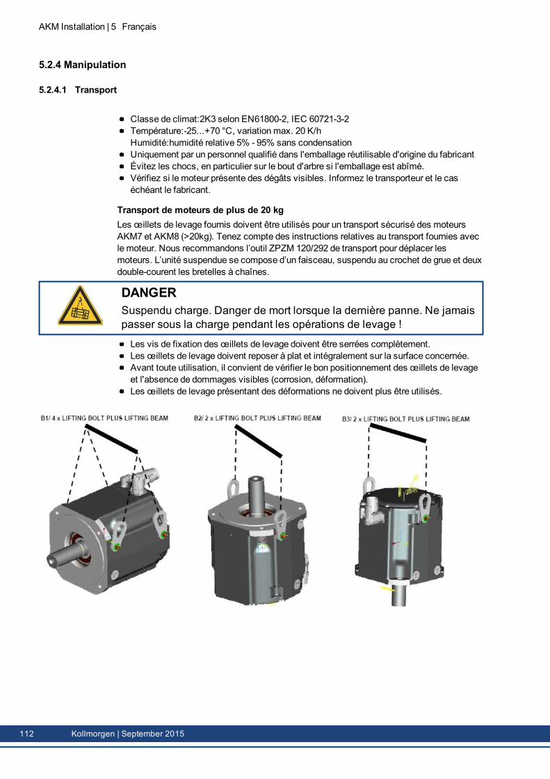
AKM Installation | 5 Français
5.2.4 Manipulation
5.2.4.1 Transport
Classe de climat:2K3 selon EN61800-2, IEC 60721-3-2Température:-25...+70 °C, variationmax. 20 K/hHumidité:humidité relative 5% - 95% sans condensationUniquement par un personnel qualifié dans l'emballage réutilisable d'origine du fabricantÉvitez les chocs, en particulier sur le bout d'arbre si l'emballage est abîmé.Vérifiez si le moteur présente des dégâts visibles. Informez le transporteur et le caséchéant le fabricant.
Transport de moteurs de plus de 20 kgLes œillets de levage fournis doivent être utilisés pour un transport sécurisé des moteursAKM7 et AKM8 (>20kg). Tenez compte des instructions relatives au transport fournies aveclemoteur. Nous recommandons l’outil ZPZM 120/292 de transport pour déplacer lesmoteurs. L’unité suspendue se compose d’un faisceau, suspendu au crochet de grue et deuxdouble-courent les bretelles à chaînes.
DANGERSuspendu charge. Danger de mort lorsque la dernière panne. Ne jamaispasser sous la charge pendant les opérations de levage !
Les vis de fixation des œillets de levage doivent être serrées complètement.Les œillets de levage doivent reposer à plat et intégralement sur la surface concernée.Avant toute utilisation, il convient de vérifier le bon positionnement des œillets de levageet l'absence de dommages visibles (corrosion, déformation).Les œillets de levage présentant des déformations ne doivent plus être utilisés.
112 Kollmorgen | September 2015
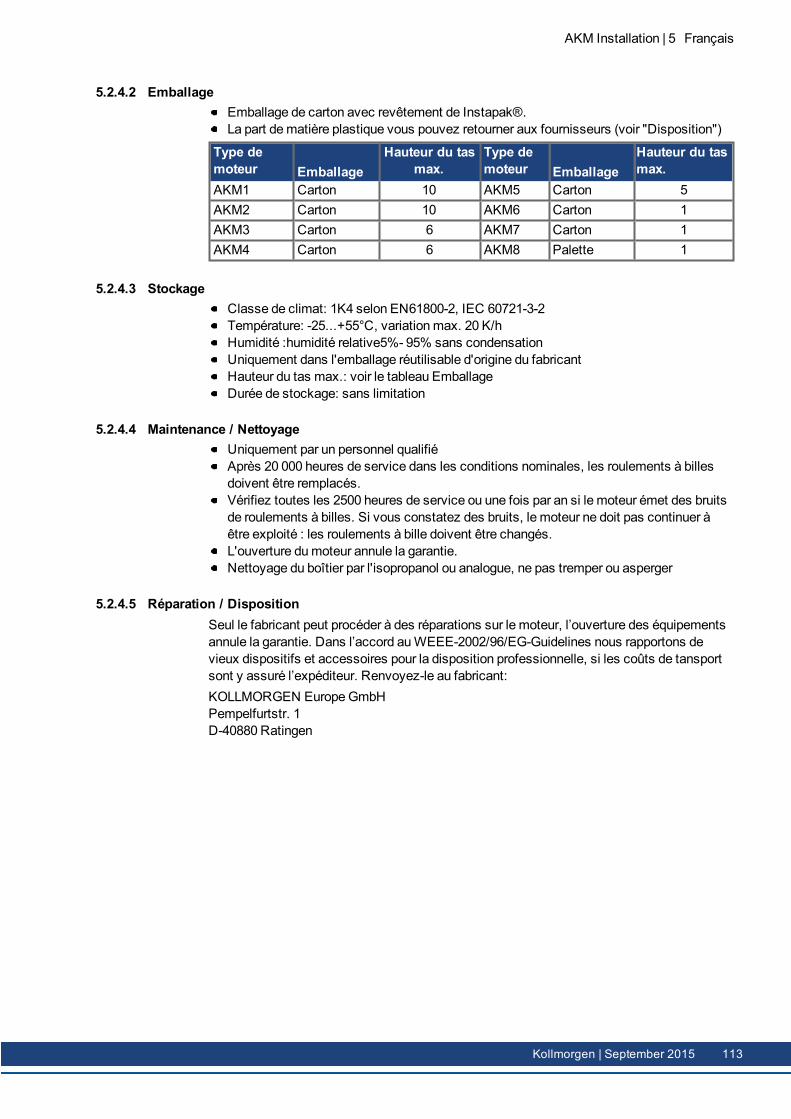
5.2.4.2 EmballageEmballage de carton avec revêtement de Instapak®.La part dematière plastique vous pouvez retourner aux fournisseurs (voir "Disposition")
Type demoteur Emballage
Hauteur du tasmax.
Type demoteur Emballage
Hauteur du tasmax.
AKM1 Carton 10 AKM5 Carton 5AKM2 Carton 10 AKM6 Carton 1AKM3 Carton 6 AKM7 Carton 1AKM4 Carton 6 AKM8 Palette 1
5.2.4.3 StockageClasse de climat: 1K4 selon EN61800-2, IEC 60721-3-2Température: -25...+55°C, variationmax. 20 K/hHumidité :humidité relative5%- 95% sans condensationUniquement dans l'emballage réutilisable d'origine du fabricantHauteur du tas max.: voir le tableau EmballageDurée de stockage: sans limitation
5.2.4.4 Maintenance / NettoyageUniquement par un personnel qualifiéAprès 20 000 heures de service dans les conditions nominales, les roulements à billesdoivent être remplacés.Vérifiez toutes les 2500 heures de service ou une fois par an si le moteur émet des bruitsde roulements à billes. Si vous constatez des bruits, le moteur ne doit pas continuer àêtre exploité : les roulements à bille doivent être changés.L'ouverture dumoteur annule la garantie.Nettoyage du boîtier par l'isopropanol ou analogue, ne pas tremper ou asperger
5.2.4.5 Réparation / DispositionSeul le fabricant peut procéder à des réparations sur le moteur, l’ouverture des équipementsannule la garantie. Dans l’accord auWEEE-2002/96/EG-Guidelines nous rapportons devieux dispositifs et accessoires pour la disposition professionnelle, si les coûts de tansportsont y assuré l’expéditeur. Renvoyez-le au fabricant:KOLLMORGEN EuropeGmbHPempelfurtstr. 1D-40880 Ratingen
AKM Installation | 5 Français
Kollmorgen | September 2015 113
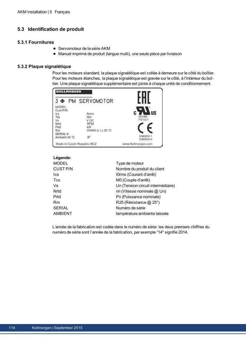
AKM Installation | 5 Français
5.3 Identification de produit
5.3.1 FournituresServomoteur de la série AKMManuel imprimé de produit (languemulti), une seule pièce par livraison
5.3.2 Plaque signalétiquePour les moteurs standard, la plaque signalétique est collée à demeure sur le côté du boîtier.Pour les moteurs étanches, la plaque signalétique est gravée sur le côté, à l'intérieur du boî-tier. Une plaque signalétique supplémentaire est jointe à chaque unité de conditionnement.
Légende:MODEL Type demoteurCUST P/N Nombre du produit du clientIcs I0rms (Courant d'arrêt)Tcs M0 (Couple d'arrêt)Vs Un (Tension circuit intermédiaire)Nrtd nn (Vitesse nominale@ Un)Prtd Pn (Puissance nominale)Rm R25 (Résistance@ 25°)SERIAL Numéro de sérieAMBIENT température ambiante laissée
L’année de la fabrication est codée dans le numéro de série: les deux premiers chiffres dunuméro de série sont l’année de la fabrication, par exemple “14" signifie 2014.
114 Kollmorgen | September 2015
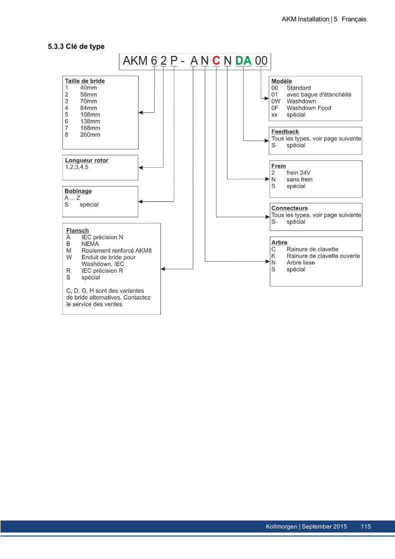
5.3.3 Clé de type
AKM Installation | 5 Français
Kollmorgen | September 2015 115
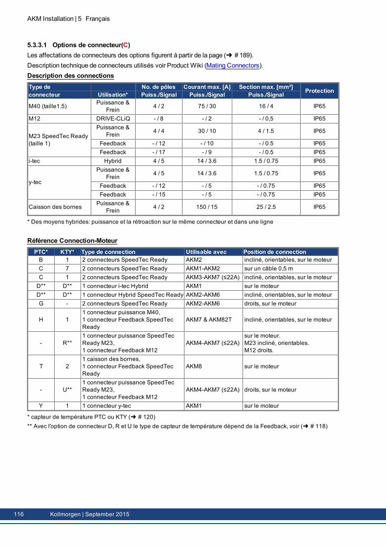
AKM Installation | 5 Français
5.3.3.1 Options de connecteur(C)Les affectations de connecteurs des options figurent à partir de la page ( # 189).Description technique de connecteurs utilisés voir Product Wiki (Mating Connectors).Description des connectionsType de No. de pôles Courant max. [A] Section max. [mm²] Protectionconnecteur Utilisation* Puiss./Signal Puiss./Signal Puiss./Signal
M40 (taille1.5) Puissance &Frein 4 / 2 75 / 30 16 / 4 IP65
M12 DRIVE-CLiQ - / 8 - / 2 - / 0,5 IP65
M23 SpeedTec Ready(taille 1)
Puissance &Frein 4 / 4 30 / 10 4 / 1.5 IP65
Feedback - / 12 - / 10 - / 0.5 IP65Feedback - / 17 - / 9 - / 0.5 IP65
i-tec Hybrid 4 / 5 14 / 3.6 1.5 / 0.75 IP65
y-tec
Puissance &Frein 4 / 5 14 / 3.6 1.5 / 0.75 IP65
Feedback - / 12 - / 5 - / 0.75 IP65Feedback - / 15 - / 5 - / 0.75 IP65
Caisson des bornes Puissance &Frein 4 / 2 150 / 15 25 / 2.5 IP65
* Des moyens hybrides: puissance et la rétroaction sur le même connecteur et dans une ligne
Référence Connection-MoteurPTC* KTY* Type de connection Utilisable avec Position de connectionB 1 2 connecteurs SpeedTec Ready AKM2 incliné, orientables, sur le moteurC 7 2 connecteurs SpeedTec Ready AKM1-AKM2 sur un câble 0,5 mC 1 2 connecteurs SpeedTec Ready AKM3-AKM7 (≤22A) incliné, orientables, sur le moteurD** D** 1 connecteur i-tec Hybrid AKM1 sur le moteurD** D** 1 connecteur Hybrid SpeedTec Ready AKM2-AKM6 incliné, orientables, sur le moteurG - 2 connecteurs SpeedTec Ready AKM2-AKM6 droits, sur le moteur
H 11 connecteur puissance M40,1 connecteur Feedback SpeedTecReady
AKM7 & AKM82T incliné, orientables, sur le moteur
- R**1 connecteur puissance SpeedTecReady M23,1 connecteur Feedback M12
AKM4-AKM7 (≤22A)sur le moteur.M23 incliné, orientables.M12 droits.
T 21 caisson des bornes,1 connecteur Feedback SpeedTecReady
AKM8 sur le moteur
- U**1 connecteur puissance SpeedTecReady M23,1 connecteur Feedback M12
AKM4-AKM7 (≤22A) droits, sur le moteur
Y 1 1 connecteur y-tec AKM1 sur le moteur
* capteur de température PTC ou KTY ( # 120)** Avec l'option de connecteur D, R et U le type de capteur de température dépend de la Feedback, voir ( # 118)
116 Kollmorgen | September 2015
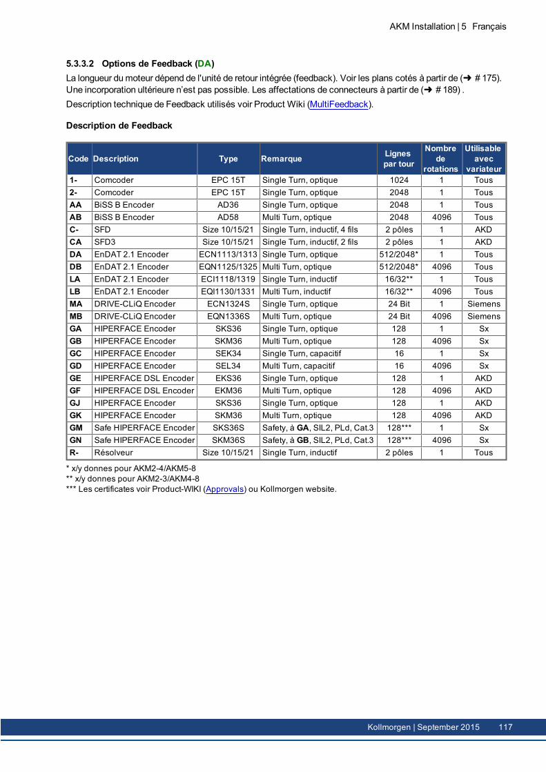
5.3.3.2 Options de Feedback (DA)La longueur dumoteur dépend de l'unité de retour intégrée (feedback). Voir les plans cotés à partir de ( # 175).Une incorporation ultérieure n’est pas possible. Les affectations de connecteurs à partir de ( # 189) .Description technique de Feedback utilisés voir Product Wiki (MultiFeedback).
Description de Feedback
Code Description Type Remarque Lignespar tour
Nombrede
rotations
Utilisableavec
variateur1- Comcoder EPC 15T Single Turn, optique 1024 1 Tous2- Comcoder EPC 15T Single Turn, optique 2048 1 TousAA BiSS B Encoder AD36 Single Turn, optique 2048 1 TousAB BiSS B Encoder AD58 Multi Turn, optique 2048 4096 TousC- SFD Size 10/15/21 Single Turn, inductif, 4 fils 2 pôles 1 AKDCA SFD3 Size 10/15/21 Single Turn, inductif, 2 fils 2 pôles 1 AKDDA EnDAT 2.1 Encoder ECN1113/1313 Single Turn, optique 512/2048* 1 TousDB EnDAT 2.1 Encoder EQN1125/1325 Multi Turn, optique 512/2048* 4096 TousLA EnDAT 2.1 Encoder ECI1118/1319 Single Turn, inductif 16/32** 1 TousLB EnDAT 2.1 Encoder EQI1130/1331 Multi Turn, inductif 16/32** 4096 TousMA DRIVE-CLiQ Encoder ECN1324S Single Turn, optique 24 Bit 1 SiemensMB DRIVE-CLiQ Encoder EQN1336S Multi Turn, optique 24 Bit 4096 SiemensGA HIPERFACE Encoder SKS36 Single Turn, optique 128 1 SxGB HIPERFACE Encoder SKM36 Multi Turn, optique 128 4096 SxGC HIPERFACE Encoder SEK34 Single Turn, capacitif 16 1 SxGD HIPERFACE Encoder SEL34 Multi Turn, capacitif 16 4096 SxGE HIPERFACE DSL Encoder EKS36 Single Turn, optique 128 1 AKDGF HIPERFACE DSL Encoder EKM36 Multi Turn, optique 128 4096 AKDGJ HIPERFACE Encoder SKS36 Single Turn, optique 128 1 AKDGK HIPERFACE Encoder SKM36 Multi Turn, optique 128 4096 AKDGM Safe HIPERFACE Encoder SKS36S Safety, à GA, SIL2, PLd, Cat.3 128*** 1 SxGN Safe HIPERFACE Encoder SKM36S Safety, à GB, SIL2, PLd, Cat.3 128*** 4096 SxR- Résolveur Size 10/15/21 Single Turn, inductif 2 pôles 1 Tous
* x/y donnes pour AKM2-4/AKM5-8** x/y donnes pour AKM2-3/AKM4-8*** Les certificates voir Product-WIKI (Approvals) ou Kollmorgen website.
AKM Installation | 5 Français
Kollmorgen | September 2015 117
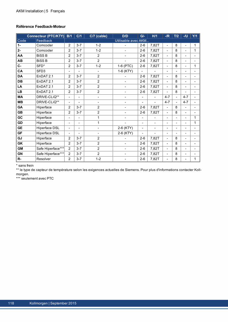
AKM Installation | 5 Français
Référence Feedback-Moteur
Connecteur (PTC/KTY) B/1 C/1 C/7 (cable) D/D G/- H/1 -/R T/2 -/U Y/1Code Feedback Utilisable avec AKM...1- Comcoder 2 3-7 1-2 - 2-6 7,82T - 8 - 12- Comcoder 2 3-7 1-2 - 2-6 7,82T - 8 - 1AA BiSS B 2 3-7 2 - 2-6 7,82T - 8 - -AB BiSS B 2 3-7 2 - 2-6 7,82T - 8 - -C- SFD* 2 3-7 1-2 1-6 (PTC) 2-6 7,82T - 8 - 1CA SFD3 - - - 1-6 (KTY) - - - - - -DA EnDAT 2.1 2 3-7 2 - 2-6 7,82T - 8 - -DB EnDAT 2.1 2 3-7 2 - 2-6 7,82T - 8 - -LA EnDAT 2.1 2 3-7 2 - 2-6 7,82T - 8 - -LB EnDAT 2.1 2 3-7 2 - 2-6 7,82T - 8 - -MA DRIVE-CLiQ** - - - - - - 4-7 - 4-7 -MB DRIVE-CLiQ** - - - - - - 4-7 - 4-7 -GA Hiperface 2 3-7 2 - 2-6 7,82T - 8 - -GB Hiperface 2 3-7 2 - 2-6 7,82T - 8 - -GC Hiperface - - 1 - - - - - - 1GD Hiperface - - 1 - - - - - - 1GE Hiperface DSL - - - 2-6 (KTY) - - - - - -GF Hiperface DSL - - - 2-6 (KTY) - - - - - -GJ Hiperface 2 3-7 2 - 2-6 7,82T - 8 - -GK Hiperface 2 3-7 2 - 2-6 7,82T - 8 - -GM Safe Hiperface*** 2 3-7 2 - 2-6 7,82T - 8 - -GN Safe Hiperface*** 2 3-7 2 - 2-6 7,82T - 8 - -R- Resolver 2 3-7 1-2 - 2-6 7,82T - 8 - 1
* sans frein** le type de capteur de température selon les exigences actuelles de Siemens. Pour plus d'informations contacter Koll-morgen.*** seulement avec PTC
118 Kollmorgen | September 2015
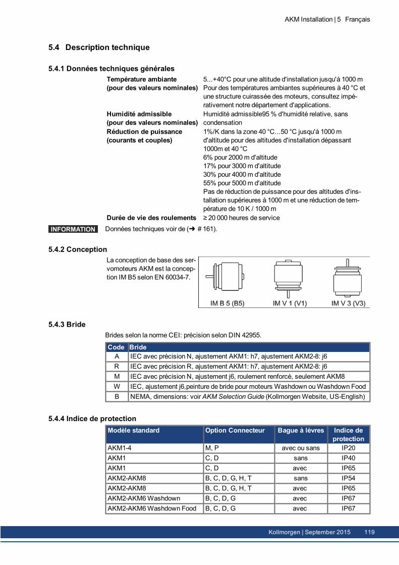
5.4 Description technique
5.4.1 Données techniques généralesTempérature ambiante(pour des valeurs nominales)
5...+40°C pour une altitude d'installation jusqu'à 1000mPour des températures ambiantes supérieures à 40 °C etune structure cuirassée des moteurs, consultez impé-rativement notre département d'applications.
Humidité admissible(pour des valeurs nominales)
Humidité admissible95% d'humidité relative, sanscondensation
Réduction de puissance(courants et couples)
1%/K dans la zone 40 °C...50 °C jusqu'à 1000md'altitude pour des altitudes d'installation dépassant1000m et 40 °C6% pour 2000m d'altitude17% pour 3000m d'altitude30% pour 4000m d'altitude55% pour 5000m d'altitudePas de réduction de puissance pour des altitudes d'ins-tallation supérieures à 1000m et une réduction de tem-pérature de 10 K / 1000m
Durée de vie des roulements ≥ 20 000 heures de serviceDonnées techniques voir de ( # 161).
5.4.2 ConceptionLa conception de base des ser-vomoteurs AKM est la concep-tion IM B5 selon EN 60034-7.
5.4.3 BrideBrides selon la normeCEI: précision selon DIN 42955.
Code BrideA IEC avec précision N, ajustement AKM1: h7, ajustement AKM2-8: j6R IEC avec précision R, ajustement AKM1: h7, ajustement AKM2-8: j6M IEC avec précision N, ajustement j6, roulement renforcé, seulement AKM8W IEC, ajustement j6,peinture de bride pour moteurs Washdown ouWashdown FoodB NEMA, dimensions: voirAKM Selection Guide (KollmorgenWebsite, US-English)
5.4.4 Indice de protectionModèle standard Option Connecteur Bague à lèvres Indice de
protectionAKM1-4 M, P avec ou sans IP20AKM1 C, D sans IP40AKM1 C, D avec IP65AKM2-AKM8 B, C, D, G, H, T sans IP54AKM2-AKM8 B, C, D, G, H, T avec IP65AKM2-AKM6Washdown B, C, D, G avec IP67AKM2-AKM6Washdown Food B, C, D, G avec IP67
AKM Installation | 5 Français
Kollmorgen | September 2015 119
AKM Installation | 5 Français
5.4.5 Classe d'isolationLes moteurs correspondent à la classe d'isolation F selon la norme IEC 60085 (UL1446 classF).
5.4.6 SurfaceLes moteurs sont enduits de l’enduit de poudre de polyester dans le noir mat et ne présententpas de résistance aux solvants (trichloréthylène, diluant ou autres).
5.4.7 Côté bout d'arbre ALa transmission de puissance s'effectue via le bout d'arbre cylindrique A, ajustement k6(AKM1: h7) selon EN 50347 à l'aide du raccord fileté mais sans rainure de clavette. Pour ladurée de vie des paliers, on se fonde sur 20 000 heures de service.
Code d'arbre Arbre Disponible pourN Arbre lisse tous les types, standardC Rainure de clavette, fermé AKM 2...8K Rainure de clavette, ouverte AKM 1...8
Force radialeSi l'entraînement des moteurs s'effectue par pignon ou par courroie dentée, des forcesradiales élevées entrent en jeu. Vous trouverez les valeurs autorisées en bout d'arbre en fonc-tion de la vitesse dans les schémas de ( # 175). Vous trouverez les valeurs maximalesdans les données techniques de ( # 161). En cas d'application d'une force aumilieu dubout d'arbre libre, FR peut s'élever de 10%.
Force AxialeDes forces axiaux apparaissent avec l’assemblage des pignons ou l'arbre et pour l’entreprisep. ex. des boîtes de vitesses d’angle. Vous trouverez les valeurs max. dans les donnéestechniques.
AccouplementsDes pinces de serrage biconiques éventuellement complétées d'accouplements à souffletsmétalliques se sont révélées être des éléments d'accouplement sans jeu idéaux.
5.4.8 Dispositif de protectionDans lemodèle standard, chaquemoteur est équipé d'un PTC à potentiel flottant. Le point decommutation est à 155°C ± 5%. Le PTC n'offre pas de protection contre les surcharges trèsélevées et brèves.Lemoteur peut éventuellement est doté d'un capteur températeur KTY 84-130 (voir lesoptions de raccordement 1, 2, 7 et D ( # 189)).Avec le système de rétroaction numérique SFD, SFD3, DSL (C-, CA, GE, GF) l'état du cap-teur de température est transmis numériquement et évaluée dans le variateur.Le capteur est intégré grâce à notre câble feedback prééquipé dans le système de sur-veillance des variateurs.
5.4.9 Classe vibrationelleLes moteurs sont présentés avec un facteur de qualité vibrationnel A selon EN 60034-14.Cela signifie donc, pour une plage de vitesse de 600 à 3600 rpm et une hauteur d’axe entre 56et 132mm, un niveau de vibration admissible de 1,6mm/s en tant que valeur effective.
Vitesse [rpm] max. rel. Déplacement Vibratoire [µm] max. Run-out [µm]<= 1800 90 23> 1800 65 16
120 Kollmorgen | September 2015
5.4.10 La bague d'étanchéitéSi le AKM doit être couplée à une bride de lamachine à arbre zone non protégée, la bagued'étanchéité (option 01 ) à sceller. La bague d'étanchéité doit être un processus de run-in sou-mis à atteindre les données nominales dumoteur AKM.Effectuez les opérations suivantes:
tourner 30minutes sans charge à vitessemaximale dans le sens horaire,30minutes refroidir,tourner 30minutes sans charge à vitessemaximale dans le sens antihoraire,30minutes refroidir.
Répétez ce cycle trois fois.
5.4.11 Technologie de câblage
5.4.11.1 ConnecteursDescriptions des connecteurs disponibles: ( # 116). Affectation des broches: ( # 189).
5.4.11.2 Sections
Câble Puissance, Câble CombiLes câbles Combi contiennent 4 fils de puissance et deux fils blindés pour le freinage.
Section Intensité maximale admis-sible
RemarquesCâble Câble Combi(4x1) (4x1+(2x0,75)) 0A < I0rms ≤ 10,1A Les parenthèses (…) indiquent
la tresse de blindage.
Intensité maximale admissibleselon la norme EN60204-1:2006, tableau 6, colonne B2
(4x1,5) (4x1.5+(2x0,75)) 10,1A < I0rms ≤ 13,1A(4x2,5) (4x2.5+(2x1)) 13,1A < I0rms ≤ 17,4A(4x4) (4x4+(2x1)) 17.4A < I0rms ≤ 23A(4x6) (4x6+(2x1)) 23A < I0rms ≤ 30A(4x10) (4x10+(2x1,5)) 30A < I0rms ≤ 40A(4x16) (4x16+(2x1,5)) 40A < I0rms ≤ 54A(4x25) (4x25+(2x1,5)) 54A < I0rms ≤ 70A
Câbles Feedback
Type Section RemarquesRésolveur, SFD (4x2x 0,25)Encoder (7x2x 0,25) BiSS, EnDAT, HIPERFACEComcoder (8x2x 0,25) Codeur incremental + Hall
Câbles Hybrides
Type Section Remarques
SFD/SFD3/DSL(4x1,0+(2x0,34)+(2x0,75)) 4 fils puissance & 4 fils signaux pourSFD
ou4 fils puissance & 2 files frein &2 fils signaux pourSFD3/DSL
(4x1,5+(2x0,34)+(2x0,75))
AKM Installation | 5 Français
Kollmorgen | September 2015 121
AKM Installation | 5 Français
5.4.12 Frein de maintienAlternativement, les moteurs sont disponibles avec un frein demaintien incorporé. Le frein depression de ressort (24 V CC) bloque le rotor à l'état hors tension.
AVERTISSEMENTEn présence d'une charge suspendue (axes verticaux), si le frein d'arrêtmoteur est desserré et si la servocommande ne fournit plus de puissance,la charge peut tomber ! Risque de blessure pour les opérateurs de lamachine.Pour les axes verticaux, la sécurité fonctionnelle ne peut être assuréequ'à l'aide d'un frein mécanique externe supplémentaire.
Les freins demaintien sont dimensionnés comme freins d'arrêt et ne se prêtent pas à des pro-cédures de freinage permanentes et opérationnelles. Un freinage fréquent peut entraîner uneusure prématurée et une défaillance du frein demaintien.La longueur dumoteur augmente s'ilya un frein demaintien incorporé.Les freins demaintien peuvent être commandés directement par les variateurs numériques(absence de sécurité pour les personnes !), la démagnétisation des enroulements de freinintervient alors dans le variateur: un circuit de protection supplémentaire n'est pas néces-saire. Si le frein demaintien n'est pas commandé directement par le variateur, un circuit deprotection supplémentaire (par exemple, un varistor) doit être mis en place. Consultez à cesujet notre département des applications.
5.4.13 Ventilateur pour AKM7Un kit de ventilation extérieure est disponible pour le modèle AKM7. Le ventilateur intégré per-met d'augmenter jusqu'à 30 % la puissance des moteurs AKM7. Le kit est livré avec unenotice demontage du ventilateur.
Le boîtier de ventilateur peut uniquement être fixé à l'aide deséquerres de fixation fournies et/ou avec les entretoises éga-lement fournies. Le choix de laméthode de fixation dépend del'application. En cas de fortes vibrations, utilisez les équerreset les entretoises pour plus de sécurité. Les moteurs avecfrein intégré nécessitent les entretoises longues.
Veillez à ne pas obstruer l'arrivée d'air au niveau de la grille du ventilateur et gardez unespace libre d'aumoins 25 mm derrière la grille du ventilateur. En raison de la convection for-cée, les moteurs s'encrassent plus fortement. La présence de dépôts de saletés entraîneune diminution de la puissance de refroidissement et peut nuire aux moteurs. Les dépôts depoussières peuvent s'enflammer en cas de surchauffe. Nettoyez donc régulièrement leconduit d'air, le ventilateur et les moteurs.Lemontage d'un ventilateur augmente les cotes demontage des moteurs AKM7.En cas demoteurs AKM7 avec option de connecteur "C" , la bobinage "Q" et ventilation for-cée vous devez limiter le courant dumoteur à 24 A pour la protection du connecteur.Pour les données techniques des moteurs AKM7 équipés d'un ventilateur, voir ( # 173).Pour le schéma dimensionnel des moteurs AKM7 équipés d'un ventilateur, voir ( # 184).
122 Kollmorgen | September 2015
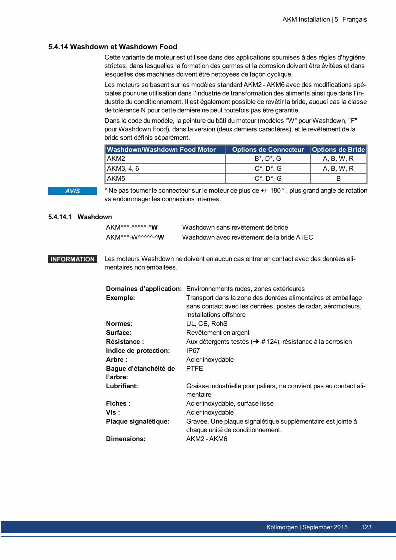
5.4.14 Washdown et Washdown FoodCette variante demoteur est utilisée dans des applications soumises à des règles d'hygiènestrictes, dans lesquelles la formation des germes et la corrosion doivent être évitées et danslesquelles des machines doivent être nettoyées de façon cyclique.Les moteurs se basent sur les modèles standard AKM2 - AKM6 avec des modifications spé-ciales pour une utilisation dans l'industrie de transformation des aliments ainsi que dans l'in-dustrie du conditionnement. Il est également possible de revêtir la bride, auquel cas la classede tolérance N pour cette dernière ne peut toutefois pas être garantie.Dans le code dumodèle, la peinture du bâti dumoteur (modèles "W" pourWashdown, "F"pourWashdown Food), dans la version (deux derniers caractères), et le revêtement de labride sont définis séparément.
Washdown/Washdown Food Motor Options de Connecteur Options de BrideAKM2 B*, D*, G A, B, W, RAKM3, 4, 6 C*, D*, G A, B, W, RAKM5 C*, D*, G B
* Ne pas tourner le connecteur sur le moteur de plus de +/- 180 ° , plus grand angle de rotationva endommager les connexions internes.
5.4.14.1 WashdownAKM^^^-^^^^^-^WAKM^^^-W^^^^^-^W
Washdown sans revêtement de brideWashdown avec revêtement de la bride A IEC
Les moteurs Washdown ne doivent en aucun cas entrer en contact avec des denrées ali-mentaires non emballées.
Domaines d’application: Environnements rudes, zones extérieuresExemple: Transport dans la zone des denrées alimentaires et emballage
sans contact avec les denrées, postes de radar, aéromoteurs,installations offshore
Normes: UL, CE, RohSSurface: Revêtement en argentRésistance : Aux détergents testés ( # 124), résistance à la corrosionIndice de protection: IP67Arbre : Acier inoxydableBague d’étanchéité del’arbre:
PTFE
Lubrifiant: Graisse industrielle pour paliers, ne convient pas au contact ali-mentaire
Fiches : Acier inoxydable, surface lisseVis : Acier inoxydablePlaque signalétique: Gravée. Une plaque signalétique supplémentaire est jointe à
chaque unité de conditionnement.Dimensions: AKM2 - AKM6
AKM Installation | 5 Français
Kollmorgen | September 2015 123
AKM Installation | 5 Français
5.4.14.2 Washdown FoodAKM^^^-^^^^^-^FAKM^^^-W^^^^^-^F
Washdown Food sans revêtement de brideWashdown Food avec revêtement de la bride A IEC
La surface des moteurs Washdown Food respecte tous les tests de l'institut FDA Glo-balMigration pour un contact indirect avec des denrées alimentaires. Un contact direct avecles denrées alimentaires non emballées n'est pas autorisé.
Domaines d’application: Industrie agroalimentaire, sans contact direct avec des denréesnon emballées
Exemple: Coupe, emballage et remplissage sans contact direct avec lesdenrées alimentaires, moteur situé à côté ou sous les denrées.
Normes: UL, CE, RohS, FDASurface: Revêtement blancRésistance : Aux détergents testés ( # 124), résistance à la corrosionGlobal Migration: US FDA Regulations 21 CFR 175.300, Condition of Use EIndice de protection: IP67Arbre : Acier inoxydableBague d’étanchéité del’arbre:
PTFE conformément aux directives de l'institut FDA.
Lubrifiant: Apte à l'utilisation avec des denrées alimentaires conformémentaux directives de l'institut FDA.
Fiches : Acier inoxydable, surface lisseVis : Acier inoxydable, surface lissePlaque signalétique: Gravée. Une plaque signalétique supplémentaire est jointe à
chaque unité de conditionnement.Dimensions: AKM2 - AKM6
5.4.14.3 Propriétés contrôlées et confirmées par rapport aux produits de nettoyageLa résistance des surfaces Washdown et Washdown Food contre les nettoyants industrielssuivants a été contrôlée dans le laboratoire d’ECOLAB DeutschlandGmbH:
P3-topactive DESP3-topactive LAP3-topax 56P3-topax 66P3-topax 91
À cet effet, les surfaces ont été plongées pendant 28 jours à température ambiante danschaque produit de nettoyage. Cela correspond à environ 2 500 cycles de nettoyage avec uncontact de 15minutes avec le produit de nettoyage ou de 1 500 cycles de nettoyage suivisd’une désinfection.Vous trouverez les certificats dans notreWIKI Produit, en page Approvals.
Kollmorgen ne peut garantir la durée de vie des moteurs qu'en cas d'utilisation des déter-gents testés. Les détergents différents de ceux cités ci-dessus peuvent être testés et éven-tuellement autorisés par Kollmorgen sur demande.
124 Kollmorgen | September 2015
5.4.14.4 Conditions de montage et d’utilisationLes moteurs ne doivent être utilisés que dans des températures ambiantes n'excédantpas 50°C.La classe de tolérance N n’est pas garantie si la bride avant est revêtue.
Pour les moteurs à brides sans revêtement étanche, la surface de la bride doit être montéedemanière à être à l'abri des détergents.
5.4.14.5 Plan de nettoyagePlan de nettoyage recommandé (abrégé) avec les produits de nettoyage testés:
Rinçage à l’eau (40 °... 50 °C)Rinçage à basse pression. Du haut vers le bas dans le sens de l'écoulement. Nettoyer l'écou-lement.
Nettoyage à la mousseMousser du haut vers le bas.Alcalin: P3-topactive LA ou P3-topax 66 (2-5%, quotidien 15min)Acide: P3-topax 56 (2%, si nécessaire 15min)Température: froid jusqu’à 40°C
DésinfectionPulvérisation à l’eau (40°... 50°C) à basse pression. Du haut vers le bas.Désinfection par pulvérisation P3-topax 91 (1-2%, si nécessaire 30-60min)Désinfection à lamousse: P3-topactiv DES (1-3%, si nécessaire 10-30min)
AKM Installation | 5 Français
Kollmorgen | September 2015 125
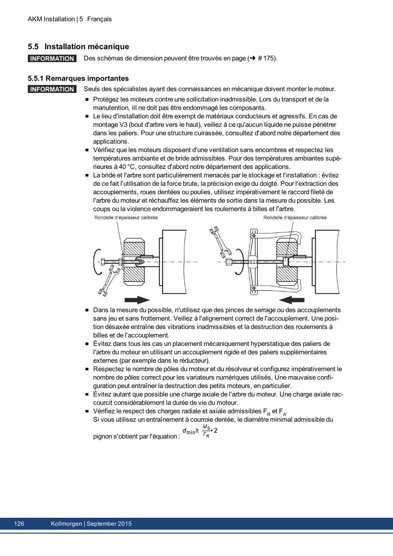
AKM Installation | 5 Français
5.5 Installation mécaniqueDes schémas de dimension peuvent être trouvés en page ( # 175).
5.5.1 Remarques importantesSeuls des spécialistes ayant des connaissances enmécanique doivent monter le moteur.
Protégez les moteurs contre une sollicitation inadmissible. Lors du transport et de lamanutention, iIl ne doit pas être endommagé les composants.Le lieu d'installation doit être exempt dematériaux conducteurs et agressifs. En cas demontage V3 (bout d'arbre vers le haut), veillez à ce qu'aucun liquide ne puisse pénétrerdans les paliers. Pour une structure cuirassée, consultez d'abord notre département desapplications.Vérifiez que les moteurs disposent d'une ventilation sans encombres et respectez lestempératures ambiante et de bride admissibles. Pour des températures ambiantes supé-rieures à 40 °C, consultez d'abord notre département des applications.La bride et l'arbre sont particulièrement menacés par le stockage et l'installation : évitezde ce fait l'utilisation de la force brute, la précision exige du doigté. Pour l'extraction desaccouplements, roues dentées ou poulies, utilisez impérativement le raccord fileté del'arbre dumoteur et réchauffez les éléments de sortie dans lamesure du possible. Lescoups ou la violence endommageraient les roulements à billes et l'arbre.
Dans lamesure du possible, n'utilisez que des pinces de serrage ou des accouplementssans jeu et sans frottement. Veillez à l'alignement correct de l'accouplement. Une posi-tion désaxée entraîne des vibrations inadmissibles et la destruction des roulements àbilles et de l'accouplement.Évitez dans tous les cas un placement mécaniquement hyperstatique des paliers del'arbre dumoteur en utilisant un accouplement rigide et des paliers supplémentairesexternes (par exemple dans le réducteur).Respectez le nombre de pôles dumoteur et du résolveur et configurez impérativement lenombre de pôles correct pour les variateurs numériques utilisés. Unemauvaise confi-guration peut entraîner la destruction des petits moteurs, en particulier.Évitez autant que possible une charge axiale de l'arbre dumoteur. Une charge axiale rac-courcit considérablement la durée de vie dumoteur.Vérifiez le respect des charges radiale et axiale admissibles FR et FA.Si vous utilisez un entraînement à courroie dentée, le diamètreminimal admissible du
pignon s'obtient par l'équation :
126 Kollmorgen | September 2015
5.6 Installation électriqueDes information concernant de connexion peuvent être trouvés en chapitre "Affectation desconnecteurs" de ( # 175). Pour le brochage du côté variateur, reportez-vous aumode d'em-ploi de ce dernier.
5.6.1 Remarques ImportantesSeuls des spécialistes ayant une formation en électrotechnique doivent câbler le moteur.
DANGERMontez et câblez toujours les moteurs dans l'état hors tension, c'est-à-dire qu'aucune des tensions de service d'un appareil à connecter ne doitêtre raccordée.Veillez à un isolement sécurisé de l'armoire électrique (verrouillage,signaux de danger, etc.).Il existe un risque de mort ou de blessures graves si vous touchez lescontacts exposés. Veillez à un isolement sécurisé de l'armoire électrique(verrouillage, signaux de danger, etc.). Ce n'est que lors de la mise enservice que les tensions individuelles sont raccordées.Ne débranchez jamais les connexions électriques des moteurs sous ten-sion. Risque de choc électrique! Dans des cas défavorables, des arcsélectriques peuvent se former et causer des dommages aux personnes etaux contacts.Des charges résiduelles dans les condensateurs de l'amplificateur jus-qu'à 10 minutes après la coupure du réseau avec les niveaux dangereux.Les connexions de commande et de puissance peuvent véhiculer la ten-sion même quand le moteur ne tourne pas.Mesurez la tension du circuit intermédiaire et attendez qu'elle soit des-cendue au-dessous de 60 V.
Le symbole demasse , que vous trouverez dans tous les schémas de connexion,indique que vous devez établir une connexion électriquement conductrice et d'aussi grandesurface que possible entre l'appareil identifié et la plaque demontage de votre armoire élec-trique. Cette connexion doit permettre l'évacuation des perturbations de haute fréquence etne doit pas être confondue avec le symbole de terre de protection PE (mesure de pro-tection selon EN 60204).
Respectez également les remarques des schémas de connexion des instructions d'ins-tallation et demise en service du variateur utilisé.
AKM Installation | 5 Français
Kollmorgen | September 2015 127
AKM Installation | 5 Français
5.6.2 Guide d’installation électriqueVérifier l'affectation du variateur et dumoteur. Comparez les tensions nominales et lescourants nominaux des appareils. Effectuez le câblage d'après le schéma de connexiondes instructions d'installation et demise en service du variateur. L'information deconnexion peuvent être trouvés en "Affectation des connecteurs" de ( # 175).Tous les câbles de courant fort doivent avoir une section suffisante selon EN 60204.Vous trouverez les diamètres recommandés dans les données techniques.
En cas de câbles demoteur deépasse 25m et selon de type de variateur utilisé une bobinedemoteur (3YL ou 3YLN) doit être commutée dans le câble demoteur (voir le manuel de pro-duit de variateur numerique et le manuel des accessoires).
Veillez à la parfaite mise à la terre du variateur et dumoteur. Blindage et mise à la terreconformes CEM : voir les instructions d'installation du variateur utilisé. Mettez à la terre laplaque demontage et le boîtier dumoteur.Si vous utilisez un câble de puissancemoteur avec des fils de commande dufrein intégrés, les fils de commande du frein doivent être blindés. Le blindage doit êtreposé des deux côtés (voir les instructions d'installation du variateur).Cablage:
Posez les câbles de puissance et de commande aussi loin les uns des autresRaccordez le résolveur ou le codeur.Raccordez les câbles moteur, l'inductancemoteur près de variateur.Les tresses de blindage des deux côtés sur les pinces de blindage ou les connecteursCEM.Raccordez le frein demaintien dumoteur s'il est présent.Posez la tresse de blindage des deux côtés
Posez les tresses de blindage en grande surface (basse impédance) sur les boîtiers deconnecteurs métallisés ou les presse-étoupe conformes CEM.Conditions de lamatériel des câbles:CapacitéCâble de puissance: inférieure à 150 pF/mCâble de rétroaction: inférieure à 120 pF/m
5.6.3 Raccordement des moteurs avec câblage prééquipésEffectuez le câblage selon les règlements et normes en vigueur.Pour les connexions de puissance et de retour, utilisez exclusivement câbles prééquipéset blindés de Kollmorgen.La pose incorrecte des tresses de blindage amène inévitablement à des perturbations deCEM et affecter les performances du système.Longueur des câbles max.: voir manuel d'installation du variateur.
Vous trouverez les données techniques des câbles dans lemanuel des accessoires.
128 Kollmorgen | September 2015
5.7 Mise en service
5.7.1 Remarques importantes
Seuls des spécialistes ayant des connaissances étendues dans les domaines de l'élec-trotechnique / des systèmes d'entraînement doivent mettre en service l'unité d'entraînementvariateur / moteur.
DANGERDes tensions mortelles atteignant 900 V entrent en jeu. Risque de chocélectrique! Vérifiez si tous les éléments de connexion sous tension sontprotégés de façon sécurisée contre les contacts.Ne débranchez jamais les connexions électriques des moteurs sous ten-sion. Risque de choc électrique! Des charges résiduelles dans lescondensateurs de l'amplificateur jusqu'à 10 minutes après la coupure duréseau avec les niveaux dangereux.Les connexions de commande et de puissance peuvent véhiculer la ten-sion même quand le moteur ne tourne pas. Mesurez la tension du circuitintermédiaire et attendez qu'elle soit descendue au-dessous de 60 V.
ATTENTIONLa température de surface du moteur peut dépasse 100 °C en exploi-tation. Risque de brûlures! Contrôlez (mesurez) la température dumoteur. Attendez que le moteur se soit refroidi à 40 °C avant de le tou-cher.
ATTENTIONPendant la mise en service, il est possible que l'entraînement se metteen mouvement de manière imprévue.Assurez-vous qu'aucun risque pour les objets ou les personnes ne peutsurvenir, même en cas de mouvement involontaire de l'entraînement.Les mesures de protection à prendre dans votre application découlent del'évaluation des risques de l'application.
AKM Installation | 5 Français
Kollmorgen | September 2015 129

AKM Installation | 5 Français
5.7.2 Guide de mise en serviceLa procédure demise en service est décrite à titre d'exemple. Selon l'utilisation des appa-reils, une autre procédure peut également être raisonnable ou obligatoire.1. Vérifiez le montage et l'alignement dumoteur.2. Vérifiez que les éléments de sortie (accouplement, réducteur, poulie) sont bien calés et
correctement réglés (respectez les forces radiale et axiale admissibles).3. Vérifiez le câblage et les raccordements aumoteur et au variateur. Veillez à unemise à la
terre correcte.4. Vérifiez le fonctionnement du frein demaintien s'il est présent (appliquez 24 V, le frein doit
se desserrer).5. Vérifiez si le rotor dumoteur se laisse tourner librement (desserrez au préalable le frein
éventuellement présent). Faites attention aux bruits de frottement.6. Vérifiez si toutes les mesures obligatoires de protection contre les contacts des pièces
mobiles sous tension ont été prises.7. Exécutez les autres vérifications spécifiques et nécessaires pour votre installation.8. Mettez alors en service le moteur conformément aux indications demise en service du
variateur.9. Pour les systèmes multi-axes, mettez en service individuellement chaque unité d'en-
traînement variateur / moteur
130 Kollmorgen | September 2015
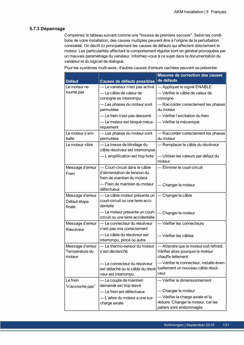
5.7.3 DépannageComprenez le tableau suivant comme une "trousse de premiers secours". Selon les condi-tions de votre installation, des causes multiples peuvent être à l'origine de la perturbationconstatée. On décrit ici principalement les causes de défauts qui affectent directement lemoteur. Les particularités affectant le comportement régulier sont en général provoquées parunmauvais paramétrage du variateur. Informez-vous à ce sujet dans la documentation duvariateur et du logiciel de dialogue.Pour les systèmes multi-axes, d'autres causes d'erreurs cachées peuvent se présenter.
Défaut Causes de défauts possiblesMesures de correction des causesde défauts
Lemoteur netourne pas
— Le variateur n’est pas activé— Le câble de valeur deconsigne es interrompu—Les phases dumoteur sontpermutées— Le frein n’est pas desserré— Lemoteur est bloquéméca-niquement
—Appliquer le signal ENABLE—Vérifier le câble de valeur deconsigne—Raccorder correctement les phasesdumoteur—Vérifier l’excitation du frein—Vérifier la mécanique
Lemoteur s’em-balle
— Les phases dumoteur sontpermutées
—Raccorder correctement les phasesdumoteur
Lemoteur vibre — La tresse de blindage ducâble résolveur est interrompue—L’amplification est trop forte
—Remplacer le câble du résolveur
—Utiliser les valeurs par défaut dumoteur
Message d’erreurFrein
—Court-circuit dans le câbled’alimentation de tension dufrein demaintien dumoteur— Frein demaintien dumoteurdéfectueux
—Éliminer le court-circuit
—Changer le moteur
Message d’erreurDéfaut étapefinale
— Le câblemoteur présente uncourt-circuit ou une terre acci-dentelle— Lemoteur présente un court-circuit ou une terre accidentelle
—Changer le câble
—Changer le moteur
Message d’erreurRésolveur
— Le connecteur du résolveurn’est pas mis correctement— Le câble du résolveur estinterrompu, pincé ou autre
—Vérifier les connecteurs
—Vérifier les câbles
Message d’erreurTempérature dumoteur
— Le thermo-sensor dumoteurs’est déclenché
— Le connecteur du résolveurest détaché ou le câble du résol-veur est interrompu
—Attendre que lemoteur soit refroidi.Vérifier alors pourquoi le moteurchauffe tellement.—Vérifier le connecteur, installe éven-tuellement un nouveau câble résol-veur.
Le frein”n’accroche pas”
— Le couple demaintiendemandé est trop élevé— Le frein est défectueux— L’arbre dumoteur a une sur-charge axiale
—Vérifier le dimensionnement
—Changer le moteur—Vérifier la charge axiale et laréduire. Changer le moteur, car lespaliers sont endommagés
AKM Installation | 5 Français
Kollmorgen | September 2015 131
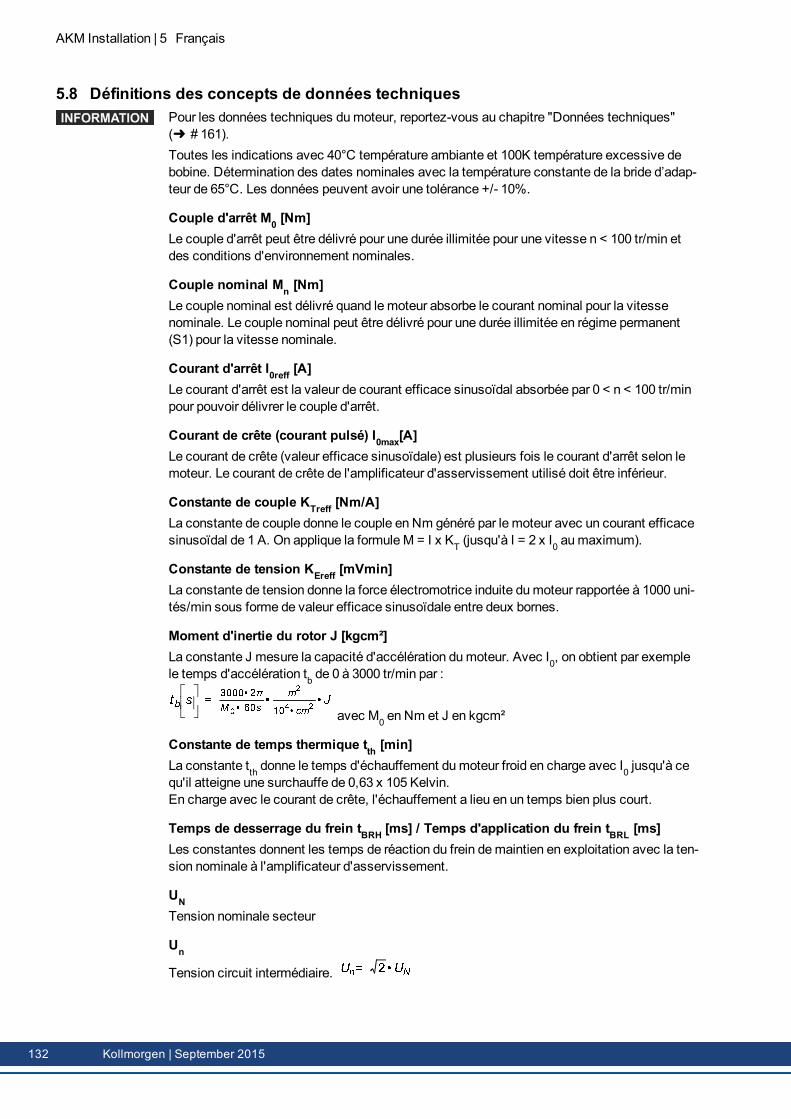
AKM Installation | 5 Français
5.8 Définitions des concepts de données techniquesPour les données techniques dumoteur, reportez-vous au chapitre "Données techniques"( # 161).Toutes les indications avec 40°C température ambiante et 100K température excessive debobine. Détermination des dates nominales avec la température constante de la bride d’adap-teur de 65°C. Les données peuvent avoir une tolérance +/- 10%.
Couple d'arrêt M0 [Nm]Le couple d'arrêt peut être délivré pour une durée illimitée pour une vitesse n < 100 tr/min etdes conditions d'environnement nominales.
Couple nominal Mn [Nm]Le couple nominal est délivré quand lemoteur absorbe le courant nominal pour la vitessenominale. Le couple nominal peut être délivré pour une durée illimitée en régime permanent(S1) pour la vitesse nominale.
Courant d'arrêt I0reff [A]Le courant d'arrêt est la valeur de courant efficace sinusoïdal absorbée par 0 < n < 100 tr/minpour pouvoir délivrer le couple d'arrêt.
Courant de crête (courant pulsé) I0max[A]Le courant de crête (valeur efficace sinusoïdale) est plusieurs fois le courant d'arrêt selon lemoteur. Le courant de crête de l'amplificateur d'asservissement utilisé doit être inférieur.
Constante de couple KTreff [Nm/A]La constante de couple donne le couple en Nm généré par le moteur avec un courant efficacesinusoïdal de 1 A. On applique la formuleM = I x KT (jusqu'à I = 2 x I0 aumaximum).
Constante de tension KEreff [mVmin]La constante de tension donne la force électromotrice induite dumoteur rapportée à 1000 uni-tés/min sous forme de valeur efficace sinusoïdale entre deux bornes.
Moment d'inertie du rotor J [kgcm²]La constante J mesure la capacité d'accélération dumoteur. Avec I0, on obtient par exemplele temps d'accélération tb de 0 à 3000 tr/min par :
avec M0 en Nm et J en kgcm²
Constante de temps thermique tth [min]La constante tth donne le temps d'échauffement dumoteur froid en charge avec I0 jusqu'à cequ'il atteigne une surchauffe de 0,63 x 10⁵ Kelvin.En charge avec le courant de crête, l'échauffement a lieu en un temps bien plus court.
Temps de desserrage du frein tBRH [ms] / Temps d'application du frein tBRL [ms]Les constantes donnent les temps de réaction du frein demaintien en exploitation avec la ten-sion nominale à l'amplificateur d'asservissement.
UNTension nominale secteur
Un
Tension circuit intermédiaire.
132 Kollmorgen | September 2015
6 Русский
6.1 Общие сведения 1346.1.1 Об этом руководстве 1346.1.2 Используемые символы 1346.1.3 Используемые сокращения 134
6.2 Безопасность 1356.2.1 Примите к сведению следующую информацию 1356.2.2 Применение по назначению 1376.2.3 Применение не по назначению 1376.2.4 Обслуживание 138
6.3 Идентификация продукта 1406.3.1 Комплект поставки 1406.3.2 Заводская табличка 1406.3.3 Расшифровка типовых обозначений 141
6.4 Техническое описание 1456.4.1 Общие технические данные 1456.4.2 Конструктивное исполнение 1456.4.3 Фланец 1456.4.4 Степень защиты 1456.4.5 Класс изоляции 1466.4.6 Покрытие 1466.4.7 Приводной конец вала 1466.4.8 Устройство защиты 1466.4.9 Уровень вибрации 1476.4.10 Уплотнение для вала 1476.4.11 Способы подключения 1486.4.12 Стояночный тормоз 1496.4.13 Вентилятор для AKM7 1496.4.14 ИсполнениеWashdown иWashdown Food 150
6.5 Механический монтаж 1536.5.1 Важные указания 153
6.6 Электрический монтаж 1546.6.1 Важные указания 1546.6.2 Инструкции по электромонтажу 1556.6.3 Подключение двигателей при помощифабрично подготовленных кабелей 155
6.7 Ввод в эксплуатацию 1566.7.1 Важные указания 1566.7.2 Инструкции по вводу в эксплуатацию 1576.7.3 Устранение неисправностей 158
6.8 Определения терминов по Технические данные 159
AKM Installation | 6 Русский
Kollmorgen | September 2015 133
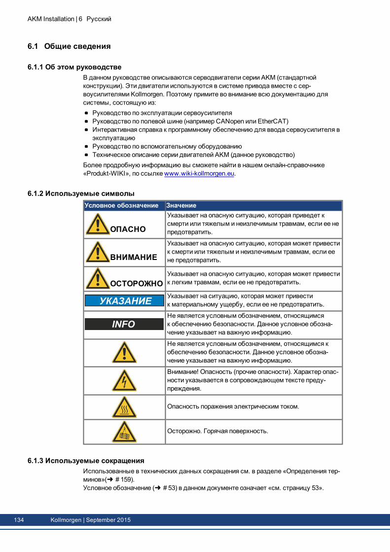
AKM Installation | 6 Русский
6.1 Общие сведения
6.1.1 Об этом руководствеВ данном руководстве описываются серводвигатели серии AKM (стандартнойконструкции). Эти двигатели используются в системе привода вместе с сер-воусилителями Kollmorgen. Поэтому примите во внимание всю документацию длясистемы, состоящую из:
Руководство по эксплуатации сервоусилителяРуководство по полевойшине (например CANopen или EtherCAT)Интерактивная справка к программному обеспечению для ввода сервоусилителя вэксплуатациюРуководство по вспомогательному оборудованиюТехническое описание серии двигателей AKM (данное руководство)
Более продробную информацию вы сможете найти в нашем онлайн-справочнике«Produkt-WIKI», по ссылке www.wiki-kollmorgen.eu.
6.1.2 Используемые символыУсловное обозначение Значение
ОПАСНО
Указывает на опасную ситуацию, которая приведет ксмерти или тяжелым и неизлечимым травмам, если ее непредотвратить.
ВНИМАНИЕ
Указывает на опасную ситуацию, которая может привестик смерти или тяжелым и неизлечимым травмам, если еене предотвратить.
ОСТОРОЖНОУказывает на опасную ситуацию, которая может привестик легким травмам, если ее не предотвратить.
Указывает на ситуацию, которая может привестик материальному ущербу, если ее не предотвратить.
Не является условным обозначением, относящимсяк обеспечению безопасности. Данное условное обозна-чение указывает на важную информацию.
Не является условным обозначением, относящимся кобеспечению безопасности. Данное условное обозна-чение указывает на важную информацию.
Внимание! Опасность (прочие опасности). Характер опас-ности указывается в сопровождающем тексте преду-преждения.
Опасность поражения электрическим током.
Осторожно. Горячая поверхность.
6.1.3 Используемые сокращенияИспользованные в технических данных сокращения см. в разделе «Определения тер-минов»( # 159).Условное обозначение ( # 53) в данном документе означает «см. страницу 53».
134 Kollmorgen | September 2015

6.2 БезопасностьЭта глава поможет Вам распознать и предотвратить опасности.
6.2.1 Примите к сведению следующую информацию
Привлеките квалифицированных специалистов!Работы по транспортировке, монтажу, вводу в эксплуатацию и техническому обслу-живанию могут проводиться только квалифицированными специалистами. Спе-циалисты должны знать и соблюдать следующие стандарты или директивы:
Транспортировка: только персоналом, обладающим знаниями по обращениюс элементами, чувствительными к электростатическому воздействиюРаспаковка: только специалистами с электротехническим образованиемМонтаж: только специалистами с электротехническим образованиемВвод в эксплуатацию: только специалистами с обширными знаниями в областиэлектротехники / приводной техникиов
Обученный персонал должен знать и соблюдать следующие стандарты:EN 60364 и EN 60664, национальные предписания по предотвращению несчастныхслучаев.
Прочтите документацию!Перед монтажом и вводом в эксплуатацию прочитайте данную документацию. Непра-вильное обращение с двигателем может привести к травмам людей или мате-риальному ущербу. Эксплуатирующее предприятие должно гарантировать, что вселица, которым доверено работать с двигателем, прочли и поняли руководство по экс-плуатации продукта, а также обеспечить соблюдение указаний по безопасности,содержащихся в данном руководстве.
Учтите технические данные!Обязательно учитывайте технические данные и рекомендации по монтажу (заводскаятабличка и документация). При превышении указанных значений тока и напряжениядвигатели могут выйти из строя, например из-за перегрева.
Проанализируйте опасные ситуации!Изготовитель машины должен провести анализ опасных ситуаций и принять соот-ветствующие меры, чтобы непредвиденные движения не могли привести к травмамлюдей или материальному ущербу. Исходя из анализа опасных ситуаций возможныдополнительные требования к обслуживающему персоналу.
При транспортировке соблюдать меры предосторожности!Двигатели тяжелее 20 кг (AKM7 и AKM8) поднимайте и перемещайте только с помо-щью подъёмных устройств. Поднятие без вспомогательных средств может привести кповреждениям спины. Соблюдайте указания на ( # 138)
Зафиксируйте шпонку вала!Удалите или зафиксируйтешпонку вала (при ее наличии), если двигатель работает нахолостом ходу, чтобы избежать выбросашпонки и связанных с этим повреждений.При отгрузке двигателя шпонка зафиксирована пластмассовым колпачком.
Горячая поверхность!Во время эксплуатации поверхность серводвигателей в соответствии с их степеньюзащиты может быть горячей. Опасность ожога! Температура поверхностей может пре-вышать 100°C. Измерьте температуру и подождите, пока двигатель не остынет до40°C, прежде чем дотрагиваться до него.
AKM Installation | 6 Русский
Kollmorgen | September 2015 135
AKM Installation | 6 Русский
Заземление / Высокое напряжение!IОбязательно обеспечьте надлежащее заземление корпуса двигателя с помощьюзаземляющейшины в распределительном шкафу в качестве опорного потенциала.Опасность удара электрическим током. Без низкоомного заземления безопасностьлюдей не гарантирована.Во время эксплуатации приборов дверь электрического шкафа должна быть закрыта.Отсутствие оптической индикации не гарантирует отключения приборов от напря-жения. Силовые контакты могут быть под напряжением даже если вал двигателя невращается.Никогда не отсоединяйте электрические контакты двигателя под напряжением. Принеблагоприятных обстоятельствах существует опасность для людей и возможностьповреждения контактов из-за возникновения электрической дуги.После отключения сервоусилителя от питающего напряжения подождите несколькоминут, прежде чем дотрагиваться до токоведущих деталей (например, контактов, вин-тов) или отвинчивать присоединительные элементы. Конденсаторы в сер-воусилителе находятся под опасным напряжением еще в течение нескольких минутпосле отключения питающего напряжения. Для надежности измерьте напряжениезвена постоянного тока и подождите, пока напряжение не опустится ниже 60 В.
Подвешенный груз фиксировать!Встроенный стояночный тормоз не является безопасным для персонала. В осо-бенности в случае висящих грузов (вертикальные оси) безопасность персонала обес-печивается только при использовании дополнительного внешнего механическоготормоза.
136 Kollmorgen | September 2015
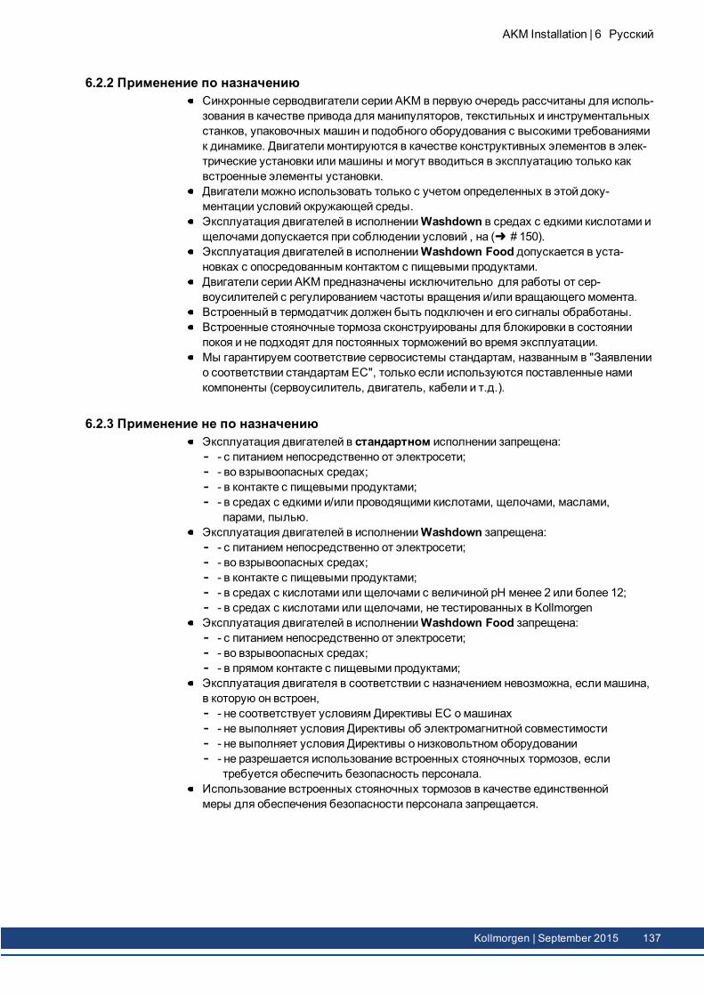
6.2.2 Применение по назначениюСинхронные серводвигатели серии AKM в первую очередь рассчитаны для исполь-зования в качестве привода для манипуляторов, текстильных и инструментальныхстанков, упаковочных машин и подобного оборудования с высокими требованиямик динамике. Двигатели монтируются в качестве конструктивных элементов в элек-трические установки или машины имогут вводиться в эксплуатацию только каквстроенные элементы установки.Двигатели можно использовать только с учетом определенных в этой доку-ментации условий окружающей среды.Эксплуатация двигателей в исполненииWashdown в средах с едкими кислотами ищелочами допускается при соблюдении условий , на ( # 150).Эксплуатация двигателей в исполненииWashdown Food допускается в уста-новках с опосредованным контактом с пищевыми продуктами.Двигатели серии AKM предназначены исключительно для работы от сер-воусилителей с регулированием частоты вращения и/или вращающего момента.Встроенный в термодатчик должен быть подключен и его сигналы обработаны.Встроенные стояночные тормоза сконструированы для блокировки в состояниипокоя и не подходят для постоянных торможений во время эксплуатации.Мы гарантируем соответствие сервосистемы стандартам, названным в "Заявлениио соответствии стандартам ЕС", только если используются поставленные намикомпоненты (сервоусилитель, двигатель, кабели и т.д.).
6.2.3 Применение не по назначениюЭксплуатация двигателей в стандартном исполнении запрещена:
- с питанием непосредственно от электросети;- во взрывоопасных средах;- в контакте с пищевыми продуктами;- в средах с едкими и/или проводящими кислотами, щелочами, маслами,парами, пылью.
Эксплуатация двигателей в исполненииWashdown запрещена:- с питанием непосредственно от электросети;- во взрывоопасных средах;- в контакте с пищевыми продуктами;- в средах с кислотами илищелочами с величиной рН менее 2 или более 12;- в средах с кислотами илищелочами, не тестированных в Kollmorgen
Эксплуатация двигателей в исполненииWashdown Food запрещена:- с питанием непосредственно от электросети;- во взрывоопасных средах;- в прямом контакте с пищевыми продуктами;
Эксплуатация двигателя в соответствии с назначением невозможна, если машина,в которую он встроен,
- не соответствует условиям Директивы ЕС омашинах- не выполняет условия Директивы об электромагнитной совместимости- не выполняет условия Директивы о низковольтном оборудовании- не разрешается использование встроенных стояночных тормозов, еслитребуется обеспечить безопасность персонала.
Использование встроенных стояночных тормозов в качестве единственноймеры для обеспечения безопасности персонала запрещается.
AKM Installation | 6 Русский
Kollmorgen | September 2015 137
AKM Installation | 6 Русский
6.2.4 Обслуживание
6.2.4.1 ТранспортировкаКлиматические условия в соответствии с to EN61800-2, IEC 60721-3-2, класс 2K3Температура при транспортировке: -25..+70°C, макс. колебания 20 градусов в часОтносительная влажность воздуха при транспортировке: 5% - 95% без конденсацииТранспортировка должна проводиться только квалифицированным персоналом и воригинальной упаковке изготовителя, подлежащей вторичной переработкеИзбегайте ударов, особенно по концу валаВ случае поврежденной упаковки обследуйте двигатель на наличие видимых повре-ждений. Проинформируйте транспортную фирму и, при необходимости, изго-товителя.
Транспортировка двигателей массой более 20 кгДля безопасной транспортировки используйте прилагаемые рым-болты. Примите ксведению указания по транспортировке, приложенные к двигателю.В качестве принадлежности для транспортировки двигателей AKM7 и AKM8 (>20kg)мы рекомендуем использование устройства ZPMZ 120/292. Оно состоит из перекла-дины, которая подвешивается на крюк крана, и двух двойных цепей.
ОПАСНОПодвешенный груз. Смертельная опасность при падении груза. Приподъеме груза стоять под ним запрещается!
Рым-болты должны быть вкручены полностью.Рым-болты должны прилегать к опорной площади большой поверхностью.Перед использованием рым-болтов проверьте их на прочность посадки и отсут-ствие видимых повреждений (ржавчина, деформация).Использование деформированных или ржавых рым-болтов запрещается.
138 Kollmorgen | September 2015
6.2.4.2 УпаковкаКартонная коробка с пенными вкладышами Instapak®Пластмассовые части вы можете возвратить поставщику (см. "Утилизация")
Тип дви-гателя
Yпаковка макс. высоташтабелирования
Тип дви-гателя
Yпаковка макс. высоташтабелирования
AKM1 Коробка 10 AKM5 Коробка 5AKM2 Коробка 10 AKM6 Коробка 1AKM3 Коробка 6 AKM7 Коробка 1AKM4 Коробка 6 AKM8 паллета 1
6.2.4.3 Хранение на складеКлиматические условия в соответствии с EN61800-2, IEC 60721-3-2, класс 1K4Температура на складе -25..+55°C, макс. колебания 20 градусов в часОтносительная влажность воздуха 5% - 95% без конденсацииХранить на складе только в оригинальной упаковке изготовителяМакс. высоташтабелирования:см. таблицу "Упаковка"Длительность хранения:без ограничений
6.2.4.4 Техническое обслуживание / чисткаТехобслуживание и чистка проводятся только квалифицированным персоналомПосле 20000 часов работы при номинальных условиях подшипник должен бытьзаменен (изготовителем).Каждые 2500 рабочих часов или же раз в год проверяйте серводвигатель наналичиешумов в подшипнике. Если вы установили наличиешумов, продолжатьэксплуатацию двигателя нельзя— подшипник должен быть заменен (изго-товителем).Вскрытие двигателя означает потерю гарантии.Чистите корпус изопропанолом или подобным веществом, не окунайте и не обрыз-гивайте корпус.
6.2.4.5 Ремонт / УтилизацияРемонт двигателей осуществляется изготовителем, вскрытие двигателя означаетпотерю гарантии. В соответствии с директивамиWEEE-2002/96/EG об утилизацииэлектрического и электронного оборудования мы принимаем обратно отработавшиеустройства и специальное оборудование, если отправитель берет на себя расходы потранспортировке. Посылайте устройства по адресу:KOLLMORGEN EuropeGmbHPempelfurtstr. 1D-40880 Ratingen
AKM Installation | 6 Русский
Kollmorgen | September 2015 139
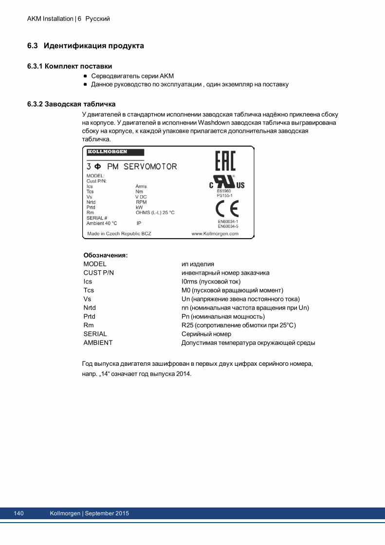
AKM Installation | 6 Русский
6.3 Идентификация продукта
6.3.1 Комплект поставкиСерводвигатель серии AKMДанное руководство по эксплуатации , один экземпляр на поставку
6.3.2 Заводская табличкаУ двигателей в стандартном исполнении заводская табличка надёжно приклеена сбокуна корпусе. У двигателей в исполненииWashdown заводская табличка выгравированасбоку на корпусе, к каждой упаковке прилагается дополнительная заводскаятабличка.
Обозначения:MODEL ип изделияCUST P/N инвентарный номер заказчикаIcs I0rms (пусковой ток)Tcs M0 (пусковой вращающиймомент)Vs Un (напряжение звена постоянного тока)Nrtd nn (номинальная частота вращения при Un)Prtd Pn (номинальная мощность)Rm R25 (сопротивление обмотки при 25°C)SERIAL Серийный номерAMBIENT Допустимая температура окружающей среды
Год выпуска двигателя зашифрован в первых двух цифрах серийного номера,напр. „14“ означает год выпуска 2014.
140 Kollmorgen | September 2015
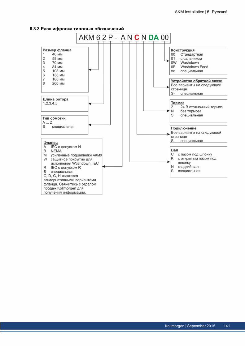
6.3.3 Расшифровка типовых обозначений
AKM Installation | 6 Русский
Kollmorgen | September 2015 141
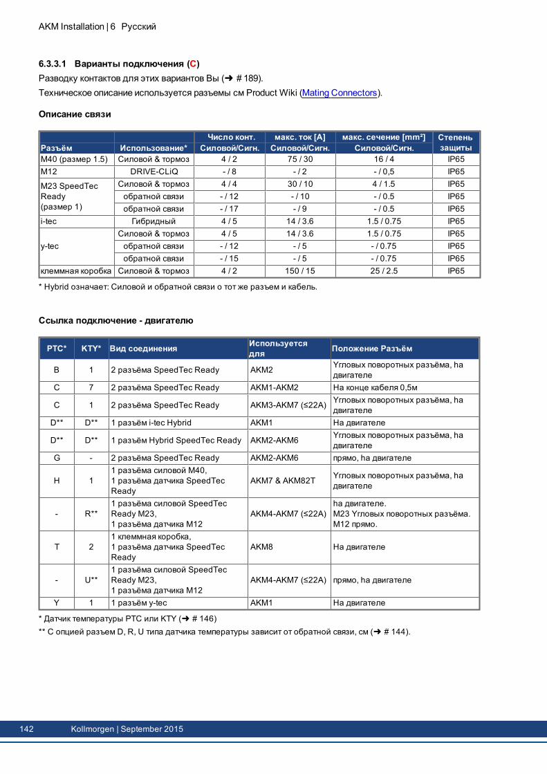
AKM Installation | 6 Русский
6.3.3.1 Варианты подключения (C)Разводку контактов для этих вариантов Вы ( # 189).Техническое описание используется разъемы см Product Wiki (Mating Connectors).
Описание связи
Число конт. макс. ток [A] макс. сечение [mm²] СтепеньзащитыРазъём Использование* Силовой/Сигн. Силовой/Сигн. Силовой/Сигн.
M40 (размер 1.5) Силовой & тормоз 4 / 2 75 / 30 16 / 4 IP65M12 DRIVE-CLiQ - / 8 - / 2 - / 0,5 IP65
M23 SpeedTecReady(размер 1)
Силовой & тормоз 4 / 4 30 / 10 4 / 1.5 IP65обратной связи - / 12 - / 10 - / 0.5 IP65обратной связи - / 17 - / 9 - / 0.5 IP65
i-tec Гибридный 4 / 5 14 / 3.6 1.5 / 0.75 IP65
y-tecСиловой & тормоз 4 / 5 14 / 3.6 1.5 / 0.75 IP65обратной связи - / 12 - / 5 - / 0.75 IP65обратной связи - / 15 - / 5 - / 0.75 IP65
клеммная коробка Силовой & тормоз 4 / 2 150 / 15 25 / 2.5 IP65
* Hybrid означает: Силовой и обратной связи о тот же разъем и кабель.
Ссылка подключение - двигателю
PTC* KTY* Вид соединения Используетсядля Положение Разъём
B 1 2 разъёма SpeedTec Ready AKM2 Yгловых поворотных разъёма, hадвигателе
C 7 2 разъёма SpeedTec Ready AKM1-AKM2 На конце кабеля 0,5м
C 1 2 разъёма SpeedTec Ready AKM3-AKM7 (≤22A) Yгловых поворотных разъёма, hадвигателе
D** D** 1 разъём i-tec Hybrid AKM1 На двигателе
D** D** 1 разъём Hybrid SpeedTec Ready AKM2-AKM6 Yгловых поворотных разъёма, hадвигателе
G - 2 разъёма SpeedTec Ready AKM2-AKM6 прямо, hа двигателе
H 11 разъёма силовой M40,1 разъёма датчика SpeedTecReady
AKM7 & AKM82T Yгловых поворотных разъёма, hадвигателе
- R**1 разъёма силовой SpeedTecReady M23,1 разъёма датчика M12
AKM4-AKM7 (≤22A)hа двигателе.M23 Yгловых поворотных разъёма.M12 прямо.
T 21 клеммная коробка,1 разъёма датчика SpeedTecReady
AKM8 На двигателе
- U**1 разъёма силовой SpeedTecReady M23,1 разъёма датчика M12
AKM4-AKM7 (≤22A) прямо, hа двигателе
Y 1 1 разъём y-tec AKM1 На двигателе
* Датчик температуры PTC или KTY ( # 146)** С опцией разъем D, R, U типа датчика температуры зависит от обратной связи, см ( # 144).
142 Kollmorgen | September 2015
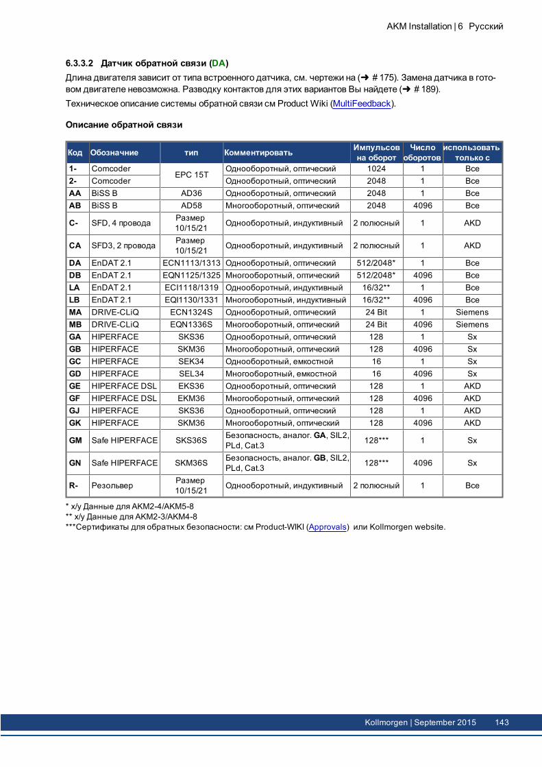
6.3.3.2 Датчик обратной связи (DA)Длина двигателя зависит от типа встроенного датчика, см. чертежи на ( # 175). Замена датчика в гото-вом двигателе невозможна. Разводку контактов для этих вариантов Вы найдете ( # 189).Техническое описание системы обратной связи см Product Wiki (MultiFeedback).
Описание обратной связи
Код Обозначние тип Комментировать Импульсовна оборот
Числооборотов
использоватьтолько с
1- ComcoderEPC 15T
Однооборотный, оптический 1024 1 Все2- Comcoder Однооборотный, оптический 2048 1 ВсеAA BiSS B AD36 Однооборотный, оптический 2048 1 ВсеAB BiSS B AD58 Многооборотный, оптический 2048 4096 Все
C- SFD, 4 провода Размер10/15/21 Однооборотный, индуктивный 2 полюсный 1 AKD
CA SFD3, 2 провода Размер10/15/21 Однооборотный, индуктивный 2 полюсный 1 AKD
DA EnDAT 2.1 ECN1113/1313 Однооборотный, оптический 512/2048* 1 ВсеDB EnDAT 2.1 EQN1125/1325 Многооборотный, оптический 512/2048* 4096 ВсеLA EnDAT 2.1 ECI1118/1319 Однооборотный, индуктивный 16/32** 1 ВсеLB EnDAT 2.1 EQI1130/1331 Многооборотный, индуктивный 16/32** 4096 ВсеMA DRIVE-CLiQ ECN1324S Однооборотный, оптический 24 Bit 1 SiemensMB DRIVE-CLiQ EQN1336S Многооборотный, оптический 24 Bit 4096 SiemensGA HIPERFACE SKS36 Однооборотный, оптический 128 1 SxGB HIPERFACE SKM36 Многооборотный, оптический 128 4096 SxGC HIPERFACE SEK34 Однооборотный, емкостной 16 1 SxGD HIPERFACE SEL34 Многооборотный, емкостной 16 4096 SxGE HIPERFACE DSL EKS36 Однооборотный, оптический 128 1 AKDGF HIPERFACE DSL EKM36 Многооборотный, оптический 128 4096 AKDGJ HIPERFACE SKS36 Однооборотный, оптический 128 1 AKDGK HIPERFACE SKM36 Многооборотный, оптический 128 4096 AKD
GM Safe HIPERFACE SKS36S Безопасность, aналог.GA, SIL2,PLd, Cat.3 128*** 1 Sx
GN Safe HIPERFACE SKM36S Безопасность, aналог.GB, SIL2,PLd, Cat.3 128*** 4096 Sx
R- Резольвер Размер10/15/21 Однооборотный, индуктивный 2 полюсный 1 Все
* x/y Данные для AKM2-4/AKM5-8** x/y Данные для AKM2-3/AKM4-8***Сертификаты для обратных безопасности: см Product-WIKI (Approvals) или Kollmorgen website.
AKM Installation | 6 Русский
Kollmorgen | September 2015 143
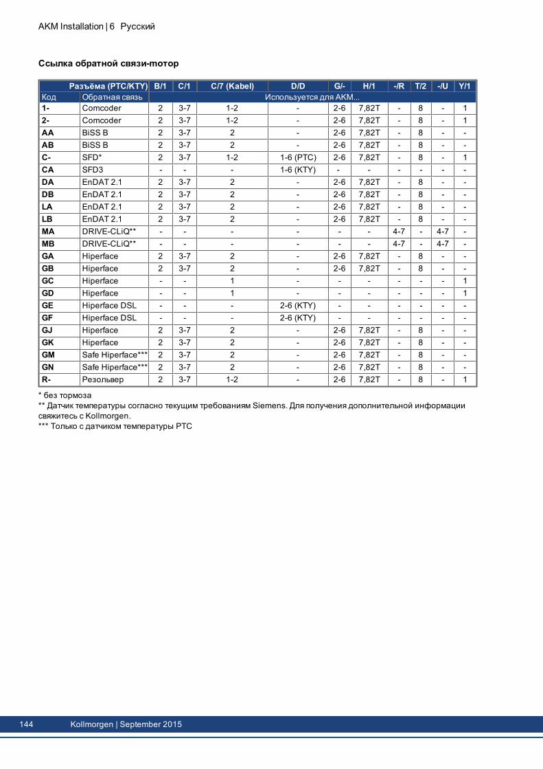
AKM Installation | 6 Русский
Ссылка обратной связи-mотор
Pазъёма (PTC/KTY) B/1 C/1 C/7 (Kabel) D/D G/- H/1 -/R T/2 -/U Y/1Код Обратная связь Используется для AKM...1- Comcoder 2 3-7 1-2 - 2-6 7,82T - 8 - 12- Comcoder 2 3-7 1-2 - 2-6 7,82T - 8 - 1AA BiSS B 2 3-7 2 - 2-6 7,82T - 8 - -AB BiSS B 2 3-7 2 - 2-6 7,82T - 8 - -C- SFD* 2 3-7 1-2 1-6 (PTC) 2-6 7,82T - 8 - 1CA SFD3 - - - 1-6 (KTY) - - - - - -DA EnDAT 2.1 2 3-7 2 - 2-6 7,82T - 8 - -DB EnDAT 2.1 2 3-7 2 - 2-6 7,82T - 8 - -LA EnDAT 2.1 2 3-7 2 - 2-6 7,82T - 8 - -LB EnDAT 2.1 2 3-7 2 - 2-6 7,82T - 8 - -MA DRIVE-CLiQ** - - - - - - 4-7 - 4-7 -MB DRIVE-CLiQ** - - - - - - 4-7 - 4-7 -GA Hiperface 2 3-7 2 - 2-6 7,82T - 8 - -GB Hiperface 2 3-7 2 - 2-6 7,82T - 8 - -GC Hiperface - - 1 - - - - - - 1GD Hiperface - - 1 - - - - - - 1GE Hiperface DSL - - - 2-6 (KTY) - - - - - -GF Hiperface DSL - - - 2-6 (KTY) - - - - - -GJ Hiperface 2 3-7 2 - 2-6 7,82T - 8 - -GK Hiperface 2 3-7 2 - 2-6 7,82T - 8 - -GM Safe Hiperface*** 2 3-7 2 - 2-6 7,82T - 8 - -GN Safe Hiperface*** 2 3-7 2 - 2-6 7,82T - 8 - -R- Резольвер 2 3-7 1-2 - 2-6 7,82T - 8 - 1
* без тормоза** Датчик температуры согласно текущим требованиям Siemens. Для получения дополнительной информациисвяжитесь с Kollmorgen.*** Только с датчиком температуры PTC
144 Kollmorgen | September 2015
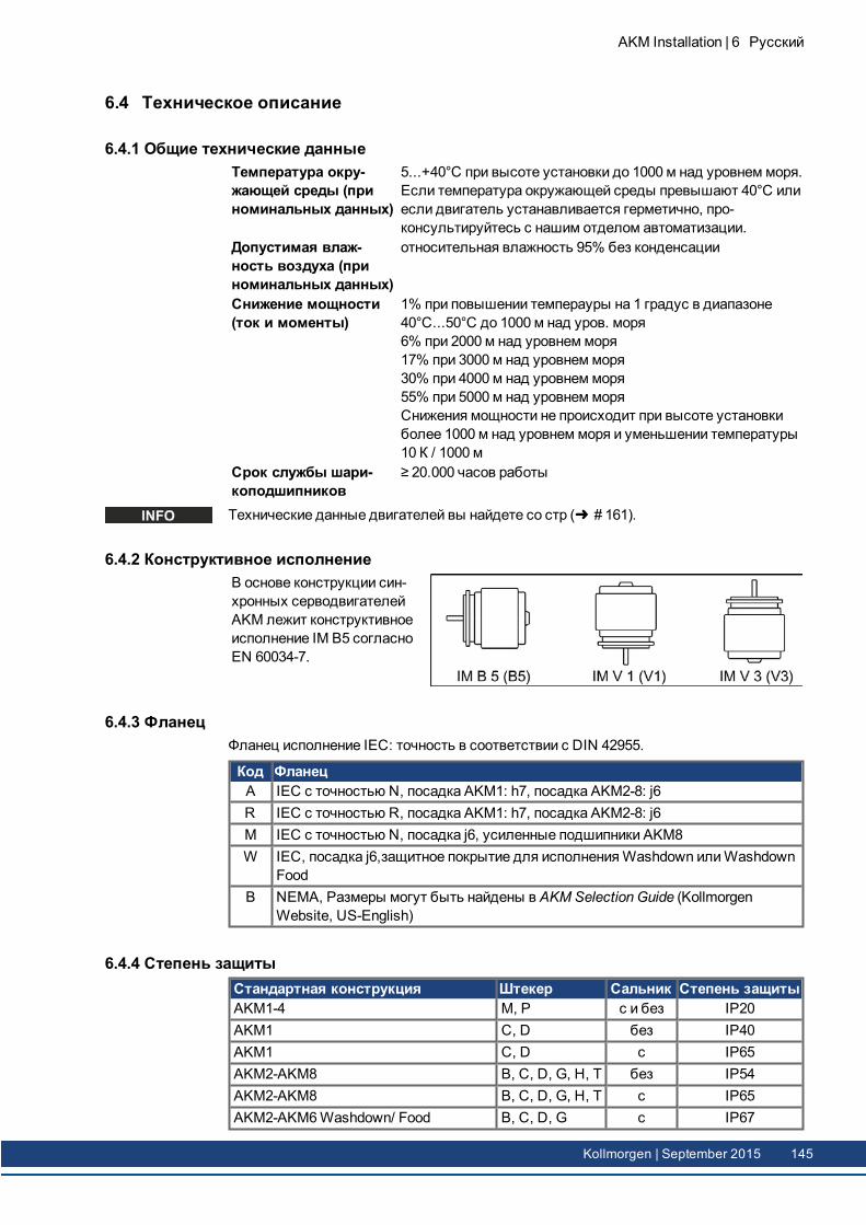
6.4 Техническое описание
6.4.1 Общие технические данныеТемпература окру-жающей среды (приноминальных данных)
5...+40°C при высоте установки до 1000 м над уровнем моря.Если температура окружающей среды превышают 40°C илиесли двигатель устанавливается герметично, про-консультируйтесь с нашим отделом автоматизации.
Допустимая влаж-ность воздуха (приноминальных данных)
относительная влажность 95% без конденсации
Снижение мощности(ток и моменты)
1% при повышении темперауры на 1 градус в диапазоне40°C...50°C до 1000 м над уров. моря6% при 2000 м над уровнем моря17% при 3000 м над уровнем моря30% при 4000 м над уровнем моря55% при 5000 м над уровнем моряСнижения мощности не происходит при высоте установкиболее 1000 м над уровнем моря и уменьшении температуры10 К / 1000 м
Срок службы шари-коподшипников
≥ 20.000 часов работы
Технические данные двигателей вы найдете со стр ( # 161).
6.4.2 Конструктивное исполнениеВ основе конструкции син-хронных серводвигателейAKM лежит конструктивноеисполнение IM B5 согласноEN 60034-7.
6.4.3 ФланецФланец исполнение IEC: точность в соответствии с DIN 42955.
Код ФланецA IEC с точностью N, посадка AKM1: h7, посадка AKM2-8: j6R IEC с точностью R, посадка AKM1: h7, посадка AKM2-8: j6M IEC с точностью N, посадка j6, усиленные подшипники AKM8W IEC, посадка j6,защитное покрытие для исполненияWashdown илиWashdown
FoodB NEMA, Размеры могут быть найдены в AKM Selection Guide (Kollmorgen
Website, US-English)
6.4.4 Степень защитыСтандартная конструкция Штекер Cальник Степень защитыAKM1-4 M, P с и без IP20AKM1 C, D без IP40AKM1 C, D с IP65AKM2-AKM8 B, C, D, G, H, T без IP54AKM2-AKM8 B, C, D, G, H, T с IP65AKM2-AKM6Washdown/ Food B, C, D, G c IP67
AKM Installation | 6 Русский
Kollmorgen | September 2015 145
AKM Installation | 6 Русский
6.4.5 Класс изоляцииДвигатели выполнены с изоляцией класса F согласно стандарту IEC 60085 (UL 1446класс F).
6.4.6 ПокрытиеСерводвигатели имеют матово-черное лакокрасочное покрытие, не обладающее устой-чивостью к растворителям (трихлорэтилен и т.п.).
6.4.7 Приводной конец валаПередача момента происходит через цилиндрический конец вала на стороне привода,посадка k6 (AKM1: h7) согласно DIN 748 с затяжной резьбой, но без паза под приз-матическую шпонку. Срока службы подшипников составляет 20000 часов работы.
Кодирование Bал Доступно дляN гладкий вал Все типы, cтандартC с пазом под шпонку, выходной AKM 2...8K с открытым пазом под шпонку AKM 1...8
Радиальная нагрузкаЕсли двигатели приводят в движение механизмы через шестерни или зубчатые ремни,то возникают большие радиальные нагрузки. Допустимые значения нагрузки на конецвала в зависимости от частоты вращения вы найдете на рисунках ( # 175). Мак-симально допустимые значения вы найдете в технических данных ( # 161). В случаеприложения силы к середине свободного конца вала радиальная нагрузка может бытьна 10% больше.
Осевая нагрузкаВ случае установки на вал шестерен илишкивов и при работе, например коническойпередачи, возникает осевая нагрузка. Максимально допустимые значения вы найдетев технических данных.
МуфтыКак идеальные беззазорные элементы сцепления зарекомендовали себя двух-конусные зажимные муфты, в некоторых случаях в сочетании с металлическими силь-фоннымимуфтами.
6.4.8 Устройство защитыВ стандартном исполнении каждый двигатель оснащен термистором. Температураотключения составляет 155°C ± 5%. Термистор не защищает от кратковременныхочень сильных перегрузок. Опционально встраивается термодатчик KTY 84-130 (см.варианты полключения 1,2, 7 и D на ( # 189). С системой цифровой обратной связиСФР, SFD3, DSL (C-, CA, GE, GF) состояние датчика температуры передается циф-ровой и оценены в дисковод. При использовании нашегофабрично подготовленногокабеля для резольвера термистор интегрирован в систему контроля цифрового сер-воусилителя.
146 Kollmorgen | September 2015
6.4.9 Уровень вибрацииДвигатели соответствуют уровню вибрации А согласно DIN EN 60034-14. Это озна-чает, что при частоте вращения в диапазоне 600-3600 об/мин и высоте оси между 56 и132 мм допустимое эффективное значение скорости колебаний составляет 1,6 мм/с.
Частота вращения[об/мин]
макс. относительное виб-роперемещение [мкм]
макс. биение[мкм]
<= 1800 90 23> 1800 65 16
6.4.10 Уплотнение для валаЕсли AKM на машину фланец с незащищенных частотный диапазон сочетаться, вал,уплотнительное кольцо (опция 01) обеспечивает уплотнение. Уплотнение вала должнабытьприработки подвергается достижения номинальные данные двигателя AKM.Выполните следующие действия:
Дайте 30 минут без нагрузки на максимальной скорости в поворот по часовойстрелке,30 минут остыть,Разрешить 30 минут без нагрузки при максимальной скорости оборота против часо-вой стрелки,30 минут остыть.
Повторите этот цикл три раза.
AKM Installation | 6 Русский
Kollmorgen | September 2015 147
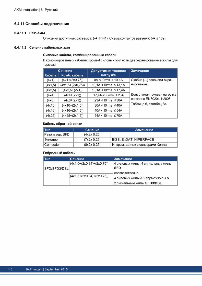
AKM Installation | 6 Русский
6.4.11 Способы подключения
6.4.11.1 РазъёмыОписания доступных разъемов: ( # 141). Схема контактов разъема: ( # 189).
6.4.11.2 Сечение кабельных жил
Силовые кабели, комбинированные кабелиВ комбинированных кабелях кроме 4 силовых жил есть две экранированные жилы длятормоза.
Сечение Допустимая токоваянагрузка
ЗамечаниеКабель Комб. кабель(4x1) (4x1+(2x0,75)) 0A < I0rms ≤ 10,1A Скобки (...) означают экра-
нирование.
Допустимая токовая нагрузкасогласно EN60204-1:2006Таблица 6, столбец B4
(4x1,5) (4x1,5+(2x0,75)) 10,1A < I0rms ≤ 13,1A(4x2,5) (4x2,5+(2x1)) 13,1A < I0rms ≤ 17,4A(4x4) (4x4+(2x1)) 17,4A < I0rms ≤ 23A(4x6) (4x6+(2x1)) 23A < I0rms ≤ 30A(4x10) (4x10+(2x1,5)) 30A < I0rms ≤ 40A(4x16) (4x16+(2x1,5)) 40A < I0rms ≤ 54A(4x25) (4x25+(2x1,5)) 54A < I0rms ≤ 70A
Кабель обратной связи
Тип Сечение ЗамечаниеРезольвер, SFD (4x2x 0,25)Энкодер (7x2x 0,25) BiSS, EnDAT, HIPERFACEComcoder (8x2x 0,25) Инкрем. датчик с сенсорами Холла
Гибридный кабель
Тип Сечение Замечание
SFD/SFD3/DSL(4x1,0+(2x0,34)+(2x0,75)) 4 силовых жилы, 4 сигнальные жилы
SFDсоответственно4 силовых жилы & 2 тормоз жилы &2 сигнальные жилы SFD3/DSL
(4x1,5+(2x0,34)+(2x0,75))
148 Kollmorgen | September 2015
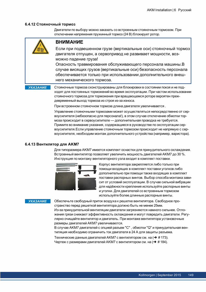
6.4.12 Стояночный тормозДвигатели по выбору можно заказать со встроенным стояночным тормозом. Приотключении напряжения пружинный тормоз (24 В) блокирует ротор.
ВНИМАНИЕЕсли при подвешенном грузе (вертикальные оси) стояночный тормоздвигателя отпущен, а сервопривод не развивает мощности, воз-можно падение груза!Опасность травмирования обслуживающего персонала машины.Вслучае висящих грузов (вертикальные оси) безопасность персоналаобеспечивается только при использовании дополнительного внеш-него механического тормоза.
Стояночные тормоза сконструированы для блокировки в состоянии покоя и не под-ходят для постоянных торможений во время эксплуатации. При частом использованиистояночного тормоза для торможения при вращающемся роторе вероятен преж-девременный выход тормоза из строя из-за износа.При встроенном стояночном тормозе длина двигателя увеличивается .Управление стояночными тормозами может осуществляться непосредственно от сер-воусилителя (небезопасно для персонала!), в этом случае отключение обмотки тор-моза происходит в сервоусилителе—дополнительная проводка не требуется.Примите во внимание указания, содержащиеся в руководстве по эксплуатации сер-воусилителя.Если управление стояночным тормозом происходит не напрямую с сер-воусилителя, необходим монтаж дополнительного устройства (например, варистора).
6.4.13 Вентилятор для AKM7Для типоразмера AKM7 имеется комплект оснастки для принудительного охлаждения.Встроенный вентилятор позволяет увеличить мощность двигателей AKM7 до 30 %.Инструкция по монтажу вентиляторного узла входит в комплект поставки.
Корпус вентилятора закрепляется либо только припомощи входящих в комплект поставки уголков либодополнительно при помощи также входящих в комплектпоставки распорных винтов. Выбор способа монтажа зави-сит от условий эксплуатации. В случае сильной вибрациидля надёжности крепления используйте распорные винтыи уголки. Для двигателей со встроенным тормозомиспользуйте более длинные распорные винты.
Обеспечьте свободный приток воздуха к решетке вентилятора. Свободное про-странство перед решеткой вентилятора должно быть не менее 25мм.Из-за принудительной вентиляции двигатели загрязняются намного сильнее. Отло-жения грязи снижают эффективность охлаждения и могут повредить двигатели. Регу-лярно очищайте вентилятор и двигатель. При монтаже вентилятора установочныеразмеры двигателей AKM7 увеличиваются.В случае AKM7 двигателей с опцией разъем "С" , обмотки "Q" и принудительная вен-тиляция необходимо ограничить ток двигателя в 24 А для защиты разъема.Технические данные двигателей AKM7 с вентилятором см. на ( # 173).Чертеж с размерами двигателей AKM7 с вентилятором см. на ( # 184).
AKM Installation | 6 Русский
Kollmorgen | September 2015 149
AKM Installation | 6 Русский
6.4.14 Исполнение Washdown и Washdown FoodДанное исполнение двигателя используется в случаях, требующих соблюдения стро-гих гигиенических предписаний, не допускающих коррозии и образования центров кри-сталлизации, а также при необходимости периодической очистки машин. Двигателисозданы на базе стандартных типов AKM2 – AKM6, в конструкцию которых внесеныизменения, рассчитанные на применение специально в пищевой или упаковочной про-мышленности. В дополнение к этому также существует возможность нанесения покры-тия нафланец (однако в этом случае допуск N для размеров фланца не может бытьгарантирован). В расшифровке типовых обозначений сведения о лакокрасочном покры-тии корпуса двигателя (тип "W" для исполненияWashdown, "F" для исполненияWasdown Food, см. последние два знака) и о покрытиифланца указаны отдельно.
Washdown/Washdown Food Варианты подключения Варианты ФланецAKM2 B*, D*, G A, B, W, RAKM3, 4, 6 C*, D*, G A, B, W, RAKM5 C*, D*, G B
* Не включайте разъем на двигателе более чем на +/- 180 °, больший угол поворотаможет привести к повреждению внутренних соединений.
6.4.14.1 WashdownAKM^^^-^^^^^-^WAKM^^^-W^^^^^-^W
Washdown-исполнение без покрытия фланцаWashdown-исполнение с покрытием A-фланца IEC
Двигатели в исполненииWashdown не должны иметь контакта с пищевыми про-дуктами без упаковки.
Область при-менения:
агрессивные условия окружающей среды, эксплуатация наоткрытом воздухе
Пример: линии производства продуктов питания и упаковочные линиибез контакта двигателей с продуктами, радиолокационныестанции, ветряные турбины, морские буровые установки
Стандарты: UL, CE, RohSПоверхность: покрытие серого цветаУстойчивость: к проверенным чистящим средствам ( # 151), устойчивость
к коррозииСтепень защиты: IP67Вал: нержавеющая стальРадиальное уплот-нение вала:
политетрафторэтилен
Смазочный мате-риал:
промышленная пластичная смазка для подшипников, контактс продуктами питания не допускается
Штекер: нержавеющая сталь, гладкая поверхностьВинты: нержавеющая стальЗаводская табличка: выгравирована, к каждой упаковке прилагается допол-
нительная заводская табличкаразмер: AKM2 - AKM6
150 Kollmorgen | September 2015
6.4.14.2 Washdown FoodAKM^^^-^^^^^-^FAKM^^^-W^^^^^-^F
Washdown Food-ис полнение без покрытия фланцаWashdown Food -исполнение с покрытием A-фланца IEC
Поверхность двигателей в исполненииWashdown Food успешно прошла все испы-тания согласно требованиям FDA GlobalMigration к опосредованному контакту с пище-выми продуктами. Прямой контакт с пищевыми продуктами без упаковки недопускается.Область применения: производство продуктов питания и напитков при отсутствии
прямого контакта двигателей с пищевыми продуктами безупаковки.
Пример: нарезка, упаковка ифасовка без прямого контакта с про-дуктом, двигатель сбоку или снизу по отношению к продукту.
Стандарты: UL, CE, RoHs, FDAПоверхность: специальное покрытие белого цветаУстойчивость: к проверенным чистящим средствам ( # 151), устойчивость
к коррозииGlobal Migration: US FDA Regulations 21 CFR 175.300, Condition of Use EСтепень защиты: IP67Вал: нержавеющая стальРадиальное уплот-нение вала:
политетрафторэтилен согласно FDA
Смазочный мате-риал:
безвредный для пищевых продуктов согласно FDA
Штекер: нержавеющая сталь, гладкая поверхностьВинты: нержавеющая стальЗаводская табличка: выгравирована, к каждой упаковке прилагается допол-
нительная заводская табличкаPазмер: AKM2 - AKM6
6.4.14.3 Проверенные и подтвержденные характеристики устойчивости по отношению к сред-ствам химической очистки
В контрольной лаборатории компании ECOLAB DeutschlandGmbH была проверенаустойчивость поверхностей двигателейWashdown-исполнения к следующим про-мышленным средствам для химической очистки:
P3-topactive DESP3-topactive LAP3-topax 56P3-topax 66P3-topax 91
При этом поверхности были погружены в соответствующее средство для химическойочистки на 28 дней при комнатной температуре. Это соответствует примерно 2500 цик-лам очистки с 15-минутным контактом с чистящим средством или 1500 циклам очисткис последующей дезинфекцией.Сертификаты вы сможете найти в нашем онлайн-справочнике по продукции (Produkt-WIKI), на странице Approvals.
Kollmorgen гарантирует указанный срок службы двигателя только при использованиипроверенных чистящих средств. Другие (не названные выше) чистящие средства позапросу могут быть проверены в лаборатории Kollmorgen и при необходимости допу-щены к применению.
AKM Installation | 6 Русский
Kollmorgen | September 2015 151
AKM Installation | 6 Русский
6.4.14.4 Условия монтажа и эксплуатацииЭксплуатация двигателей допускается только при температурах окружающейсреды, не превышающих 50 °C.Для фланца с нанесенным покрытием допуск размеров фланца N не гаран-тируется.
У двигателей с фланцем без покрытияWashdown поверхность фланца необходимозащитить от воздействия чистящих средств путём соответствующего монтажа.
6.4.14.5 План очисткиРекомендуемый план очистки (в краткойформе) с использованием протестированныхсредств для химической очистки:
Промывка водой (40 °... 50 °C)Промывайте с небольшим напором, сверху вниз по направлению к сливу. Очиститеслив.
Очистка пенообразующими средствамиНаносите пену сверху вниз.Щелочное средство: P3-topactive LA или P3-topax 66 (2–5 %, ежедневно в течение
15 мин.)Кислотосодержащеесредство:
P3-topax 56 (2 %, по мере необходимости в течение 15 мин.)
Температура: от холодного состояния до 40 °C
ДезинфекцияОпрыскивайте водой (40–50 °C) с небольшим напором, сверху вниз.Дезинфицирующее средство дляопрыскивания:
P3-topax 91 (1-2 %, по мере необходимости втечение 30–60 мин.)
Пенообразующее дез-инфицирующее средство:
P3-topax DES (1-3 %, по мере необходимости втечение 10–30 мин.)
152 Kollmorgen | September 2015
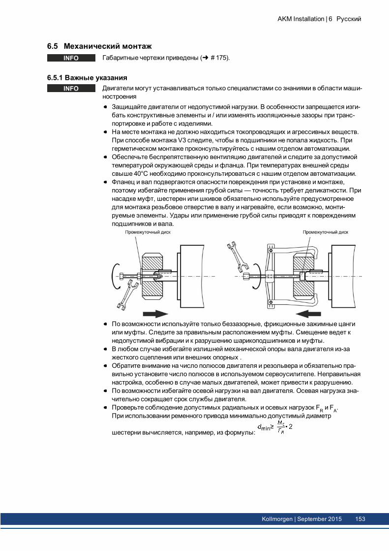
6.5 Механический монтажГабаритные чертежи приведены ( # 175).
6.5.1 Важные указанияДвигатели могут устанавливаться только специалистами со знаниями в области маши-ностроения
Защищайте двигатели от недопустимой нагрузки. В особенности запрещается изги-бать конструктивные элементы и / или изменять изоляционные зазоры при транс-портировке и работе с изделиями.На месте монтажа не должно находиться токопроводящих и агрессивных веществ.При способе монтажа V3 следите, чтобы в подшипники не попала жидкость. Пригерметическом монтаже проконсультируйтесь с нашим отделом автоматизации.Обеспечьте беспрепятственную вентиляцию двигателей и следите за допустимойтемпературой окружающей среды ифланца. При температурах внешней средысвыше 40°C необходимо проконсультироваться с нашим отделом автоматизации.Фланец и вал подвергаются опасности повреждения при установке и монтаже,поэтому избегайте применения грубой силы — точность требует деликатности. Принасадке муфт, шестерен илишкивов обязательно используйте предусмотренноедля монтажа резьбовое отверстие в валу и нагревайте, если возможно, монти-руемые элементы. Удары или применение грубой силы приводят к повреждениямподшипников и вала.
По возможности используйте только беззазорные, фрикционные зажимные цангиили муфты. Следите за правильным расположением муфты. Смещение ведет кнедопустимой вибрации и к разрушению шарикоподшипников и муфты.В любом случае избегайте излишней механической опоры вала двигателя из-зажесткого сцепления или внешних опорных .Обратите внимание на число полюсов двигателя и резольвера и обязательно пра-вильно установите число полюсов в используемом сервоусилителе. Неправильнаянастройка, особенно в случае малых двигателей, может привести к разрушению.По возможности избегайте осевой нагрузки на вал двигателя. Осевая нагрузка зна-чительно сокращает срок службы двигателя.Проверьте соблюдение допустимых радиальных и осевых нагрузок FR и FA.При использовании ременного привода минимально допустимый диаметр
шестерни вычисляется, например, из формулы:
AKM Installation | 6 Русский
Kollmorgen | September 2015 153
AKM Installation | 6 Русский
6.6 Электрический монтажРазводку контактов вы найдете в главе "Connector Pinout" начиная со стр. ( # 189).Разводку контактов сервоусилителя вы найдете в руководстве по эксплуатации сер-воусилителя.
6.6.1 Важные указанияПодключение двигателей может осуществляться только специалистами с элек-тротехническим образованием.
ОПАСНОМонтаж двигателя и подключение кабелей производятся только вобесточенном состоянии, подача напряжения на монтируемыеустройства запрещено. При прикосновнии к токопроводящим кон-тактам существует опасность тяжёлых травм или смерти.Позаботьтесь о надёжном отключении распределительного шкафа(заграждение, предупредительные таблички и т.д.). Напряжение сле-дует подключать только при вводе в эксплуатацию.Никогда не отсоединяйте электрические контакты двигателя поднапряжением. Опасность удара электрическим током! При неблаго-приятных обстоятельствах могут возникать электрические дуги, нано-сящие повреждения людям и электрическим контактам.В конденсаторах сервоусилителя в течение 10 минут после отклю-чения напряжения сети могут сохраняться опасные остаточныезаряды. Силовые и сигнальные контакты могут находиться поднапряжением, даже если двигатель остановлен.Измерьте напряжение звена постоянного тока и подождите, поканапряжение не опустится ниже 60 В.
Значок "корпус" , который можно найти на всех схемах соединений, означает, чтовы должны обеспечить электрическое соединение как можно большей площадимежду обозначенным устройством и монтажной платой в вашем распределительномшкафу. Это соединение должно позволять отводить высокочастотные помехи, и егоне следует путать со значком заземления (защитная мера согласно стандарту EN60204).Примите во внимание также указания на схемах соединений в руководстве по экс-плуатации используемого сервоусилителя.
154 Kollmorgen | September 2015
6.6.2 Инструкции по электромонтажуПроверьте соответствие данных сервоусилителя и двигателя. Сравните номи-нальное напряжение и номинальный ток устройств. Произведите монтаж согласносхеме соединений в руководстве по эксплуатации сервоусилителя. Элек-тромонтаж проводится в соответствии со схемой подключения, приведенной в руко-водстве по эксплуатации сервоусилителя. Разводку контактов для этих вариантовВы найдете в главе "Разводка контактов", ( # 175).Все силовые кабели должны иметь достаточное поперечное сечение в соот-ветствии с EN 60204. Рекомендуемые поперечные сечения вы найдете в тех-нических данных.
В зависимости от типа используемого сервоусилителя, при большой длине кабелядвигателя (> 25 м) должен быть установлен дроссель двигателя (3YL / 3YLN) (см. руко-водство по эксплуатации сервоусилителя и руководство по вспомогательному обо-рудованию).
Обратите внимание на то, чтобы заземление сервоусилителя и двигателя было без-упречным. Информацию об экранировании и заземлении в соответствии с тре-бованиями к электромагнитной совместимости см. в руководстве используемогосервоусилителя. Заземлите монтажную плату и корпус двигателя.Если сигнальные провода для управления тормозом прокладываются совместно ссиловым кабелем, их необходимо экранировать. Экран должен быть подсоединёнк заземлённой поверхности с обеих сторон (см. руководство по эксплуатации сер-воусилителя).Разводка:
Проложите силовые и управляющие кабели по возможности раздельноПодсоедините устройство обратной связиПодсоедините кабель двигателя к сервоусилителю. Дроссель двигателя рас-положите рядом с сервоусилителем.Подсоедините экран с обеих сторон (к клеммам для экрана илиЭМС-штекеру)Подсоедините стояночный тормоз двигателяПодсоедините экран с обеих сторон
Соединение экрана с корпусом штекера илиЭМС-клеммой должно обладатьбольшой площадью контакта (низкоомный контакт)..Требования к материалу кабеля:ЁмкостьКабель двигателя:меньше, чем 150 пФ/мКабель устройства обратной связи:меньше, чем 120 пФ/м
6.6.3 Подключение двигателей при помощи фабрично подготовленных кабелейОсуществляйте монтаж в соответствии с действующими предписаниями и стан-дартами.Используйте для подключения питания и устройства обратной связи исклю-чительно нашифабрично подготовленные кабели.Неправильно наложенные экраны неизбежно ведут к нарушению электромагнитнойсовместимости.Максимальная длина кабеля описана в руководстве по эксплуатации исполь-зуемого сервоусилителя.
Технические характеристики наших фабрично подготовленных кабелей приведены вруководстве по дополнительному оборудованию.
AKM Installation | 6 Русский
Kollmorgen | September 2015 155
AKM Installation | 6 Русский
6.7 Ввод в эксплуатацию
6.7.1 Важные указания
Только специалисты с обширными знаниями в области электротехники / приводнойтехники могут вводить в эксплуатацию компоненты электропривода сервоусилитель идвигатель.
ОПАСНОВозникает опасное для жизни напряжение до 900 В. Опасностьудара электрическим током! Проверьте, все ли находящиеся поднапряжением соединительные детали надежно защищены от при-косновений.Никогда не отсоединяйте штекерные разъёмы двигателя под напря-жением. Опасность удара электрическим током!Конденсаторы в сер-воусилителе находятся под опасным напряжением еще в течениенескольких минут после отключения питающего напряжения. В кон-денсаторах сервоусилителя в течение нескольких минут после отклю-чения напряжения сети могут сохраняться опасные остаточныезаряды.Измерьте напряжение звена постоянного тока и подождите,пока напряжение не опустится ниже 60 В. Силовые и сигнальные кон-такты могут находиться под напряжением, даже если двигатель оста-новлен.
ОСТОРОЖНОВо время эксплуатации температура поверхности двигателя можетпревышать 100 С. Опасность ожога! Измерьте температуру и подо-ждите, пока двигатель не остынет до 40°C, прежде чем дотра-гиваться до него.
ОСТОРОЖНОПри вводе в эксплуатацию не исключается возможность непред-виденного движения привода.Обеспечьте безопасность персонала и машин в случае непроиз-вольного пуска привода.Исходя из анализа опасных ситуаций Вы обязаны принять соот-ветствующие меры для предотвращения физического или мате-риального ущерба.
156 Kollmorgen | September 2015

6.7.2 Инструкции по вводу в эксплуатациюДействия при вводе в эксплуатацию описаны в качестве примера. В зависимости отконкретного применения устройства может быть целесообразен или необходим и дру-гой образ действий.1. Проверьте правильность установки двигателя по уровню.2. Проверьте ведомые элементы (муфту, редуктор, шкив) на прочность посадки и пра-
вильность центровки (обратите внимание на допустимые радиальные и осевыенагрузки).
3. Проверьте кабельную разводку иштекерные разъёмы на двигателе и сер-воусилителе. Обратите внимание на наличие надлежащего заземления.
4. Проверьтефункционирование стояночного тормоза, если таковой имеется.(подключите 24 В, тормоз должен отпуститься).
5. Проверьте свободное вращение ротора двигателя (предварительно отпустите тор-моз при его наличии). Проследите, нет лишумов трения.
6. Проконтролируйте, приняты ли все меры защиты от соприкосновения с дви-жущимися и токопроводящими деталями.
7. Проведите прочие контрольные мероприятия, которые требуются для вашей уста-новки.
8. Теперь введите привод в эксплуатацию согласно инструкции по вводу в экс-плуатациюсервоусилителя.
9. Во многоосевых системах введите в эксплуатацию каждую ось сервоусилитель-двигатель по отдельности.
AKM Installation | 6 Русский
Kollmorgen | September 2015 157
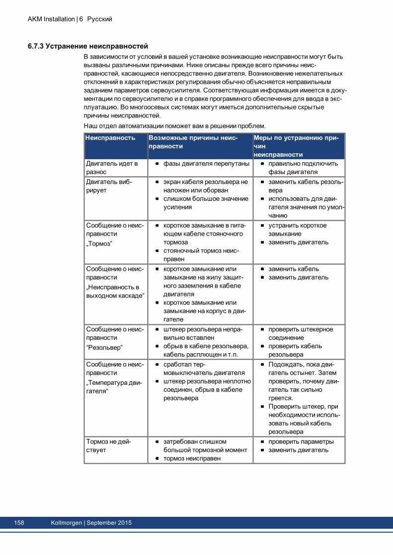
AKM Installation | 6 Русский
6.7.3 Устранение неисправностейВ зависимости от условий в вашей установке возникающие неисправности могут бытьвызваны различными причинами. Ниже описаны прежде всего причины неис-правностей, касающиеся непосредственно двигателя. Возникновение нежелательныхотклонений в характеристиках регулирования обычно объясняется неправильнымзаданием параметров сервоусилителя. Соответствующая информация имеется в доку-ментации по сервоусилителю и в справке программного обеспечения для ввода в экс-плуатацию. Во многоосевых системах могут иметься дополнительные скрытыепричины неисправностей.Наш отдел автоматизации поможет вам в решении проблем.
Неисправность Возможные причины неис-правности
Меры по устранению при-чиннеисправности
Двигатель идет вразнос
фазы двигателя перепутаны правильно подключитьфазы двигателя
Двигатель виб-рирует
экран кабеля резольвера неналожен или оборванслишком большое значениеусиления
заменить кабель резоль-вераиспользовать для дви-гателя значения по умол-чанию
Сообщение о неис-правности„Тормоз”
короткое замыкание в пита-ющем кабеле стояночноготормозастояночный тормоз неис-правен
устранить короткоезамыканиезаменить двигатель
Сообщение о неис-правности„Неисправность ввыходном каскаде“
короткое замыкание илизамыкание на жилу защит-ного заземления в кабеледвигателякороткое замыкание илизамыкание на корпус в дви-гателе
заменить кабельзаменить двигатель
Сообщение о неис-правности“Резольвер”
штекер резольвера непра-вильно вставленобрыв в кабеле резольвера,кабель расплющен и т.п.
проверить штекерноесоединениепроверить кабельрезольвера
Сообщение о неис-правности„Температура дви-гателя“
сработал тер-мовыключатель двигателяштекер резольвера неплотносоединен, обрыв в кабелерезольвера
Подождать, пока дви-гатель остынет. Затемпроверить, почему дви-гатель так сильногреется.Проверить штекер, принеобходимости исполь-зовать новый кабельрезольвера
Тормоз не дей-ствует
затребован слишкомбольшой тормозной моменттормоз неисправен
проверить параметрызаменить двигатель
158 Kollmorgen | September 2015
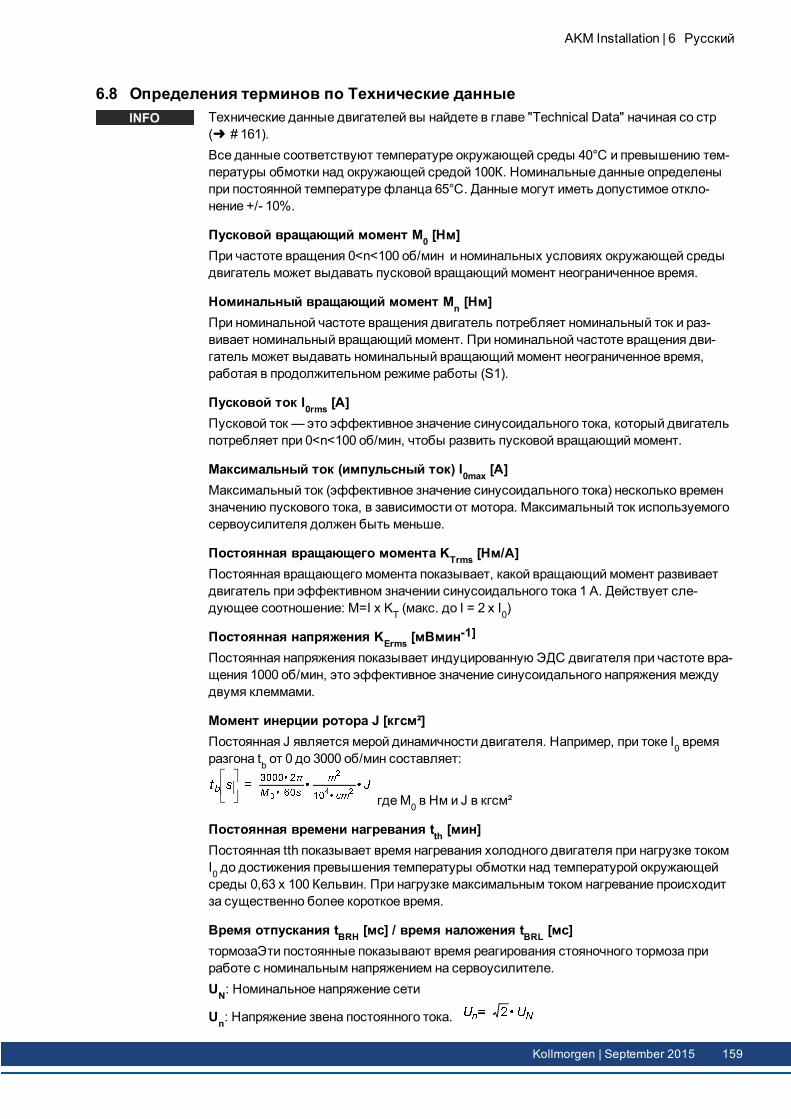
6.8 Определения терминов по Технические данныеТехнические данные двигателей вы найдете в главе "Technical Data" начиная со стр( # 161).Все данные соответствуют температуре окружающей среды 40°С и превышению тем-пературы обмотки над окружающей средой 100К. Номинальные данные определеныпри постоянной температурефланца 65°C. Данные могут иметь допустимое откло-нение +/- 10%.
Пусковой вращающий момент M0 [Нм]При частоте вращения 0<n<100 об/мин и номинальных условиях окружающей средыдвигатель может выдавать пусковой вращающиймомент неограниченное время.
Номинальный вращающий момент Mn [Нм]При номинальной частоте вращения двигатель потребляет номинальный ток и раз-вивает номинальный вращающиймомент. При номинальной частоте вращения дви-гатель может выдавать номинальный вращающиймомент неограниченное время,работая в продолжительном режиме работы (S1).
Пусковой ток I0rms [A]Пусковой ток — это эффективное значение синусоидального тока, который двигательпотребляет при 0<n<100 об/мин, чтобы развить пусковой вращающиймомент.
Максимальный ток (импульсный ток) I0max [A]Максимальный ток (эффективное значение синусоидального тока) несколько времензначению пускового тока, в зависимости от мотора. Максимальный ток используемогосервоусилителя должен быть меньше.
Постоянная вращающего момента KTrms [Нм/A]Постоянная вращающего момента показывает, какой вращающиймомент развиваетдвигатель при эффективном значении синусоидального тока 1 А. Действует сле-дующее соотношение: M=I x KT (макс. до I = 2 x I0)
Постоянная напряжения KErms [мВмин-1]
Постоянная напряжения показывает индуцированную ЭДС двигателя при частоте вра-щения 1000 об/мин, это эффективное значение синусоидального напряжения междудвумя клеммами.
Момент инерции ротора J [кгсм²]Постоянная J является мерой динамичности двигателя. Например, при токе I0 времяразгона tb от 0 до 3000 об/мин составляет:
гдеM0 в Нм и J в кгсм²
Постоянная времени нагревания tth [мин]Постоянная tth показывает время нагревания холодного двигателя при нагрузке токомI0 до достижения превышения температуры обмотки над температурой окружающейсреды 0,63 x 100 Кельвин. При нагрузке максимальным током нагревание происходитза существенно более короткое время.
Время отпускания tBRH [мс] / время наложения tBRL [мс]тормозаЭти постоянные показывают время реагирования стояночного тормоза приработе с номинальным напряжением на сервоусилителе.UN: Номинальное напряжение сети
Un: Напряжение звена постоянного тока.
AKM Installation | 6 Русский
Kollmorgen | September 2015 159

--- / ---
AKM Installation | 6 Русский
160 Kollmorgen | September 2015
7 Technical DataAll data valid for 40°C environmental temperature and 100K overtemperature of the winding. Determination ofnominal dates with constant temperature of adapter flange of 65°C. The data can have a tolerance of +/- 10%.
7.1 Dictionary for technical data tables 1627.2 Technical Data AKM1 1637.3 Technical Data AKM2 1647.4 Technical Data AKM3 1657.5 Technical Data AKM4 1667.6 Technical Data AKM5 1687.7 Technical Data AKM6 1707.8 Technical Data AKM7 without fan 1727.9 Technical Data AKM7 with fan 1737.10 Technical Data AKM8 174
AKM Installation | 7 Technical Data
Kollmorgen | September 2015 161
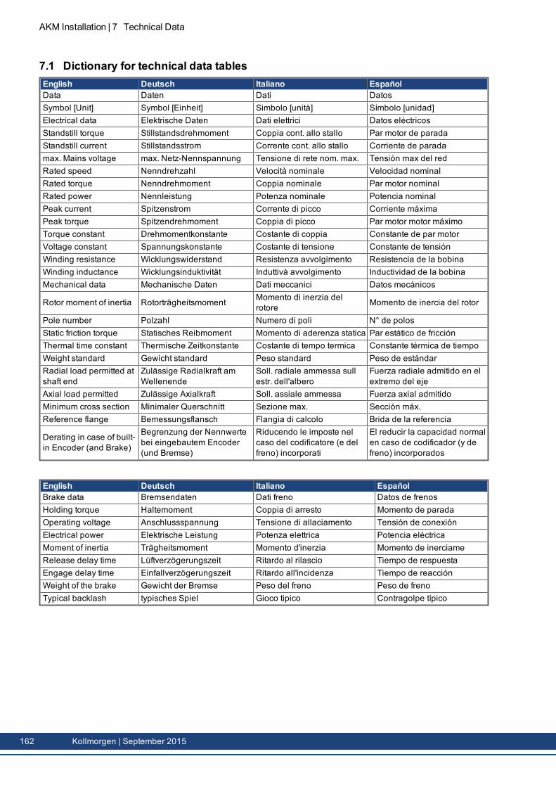
AKM Installation | 7 Technical Data
7.1 Dictionary for technical data tablesEnglish Deutsch Italiano EspañolData Daten Dati DatosSymbol [Unit] Symbol [Einheit] Simbolo [unità] Símbolo [unidad]Electrical data Elektrische Daten Dati elettrici Datos eléctricosStandstill torque Stillstandsdrehmoment Coppia cont. allo stallo Par motor de paradaStandstill current Stillstandsstrom Corrente cont. allo stallo Corriente de paradamax. Mains voltage max. Netz-Nennspannung Tensione di rete nom. max. Tensión max del redRated speed Nenndrehzahl Velocità nominale Velocidad nominalRated torque Nenndrehmoment Coppia nominale Par motor nominalRated power Nennleistung Potenza nominale Potencia nominalPeak current Spitzenstrom Corrente di picco Corriente máximaPeak torque Spitzendrehmoment Coppia di picco Par motor motor máximoTorque constant Drehmomentkonstante Costante di coppia Constante de par motorVoltage constant Spannungskonstante Costante di tensione Constante de tensiónWinding resistance Wicklungswiderstand Resistenza avvolgimento Resistencia de la bobinaWinding inductance Wicklungsinduktivität Induttivà avvolgimento Inductividad de la bobinaMechanical data Mechanische Daten Dati meccanici Datos mecánicos
Rotor moment of inertia Rotorträgheitsmoment Momento di inerzia delrotore Momento de inercia del rotor
Pole number Polzahl Numero di poli N° de polosStatic friction torque Statisches Reibmoment Momento di aderenza statica Par estático de fricciónThermal time constant Thermische Zeitkonstante Costante di tempo termica Constante térmica de tiempoWeight standard Gewicht standard Peso standard Peso de estándarRadial load permitted atshaft end
Zulässige Radialkraft am Wellenende
Soll. radiale ammessa sullestr. dell'albero
Fuerza radiale admitido en elextremo del eje
Axial load permitted Zulässige Axialkraft Soll. assiale ammessa Fuerza axial admitidoMinimum cross section Minimaler Querschnitt Sezione max. Sección máx.Reference flange Bemessungsflansch Flangia di calcolo Brida de la referencia
Derating in case of built-in Encoder (and Brake)
Begrenzung der Nennwertebei eingebautem Encoder(und Bremse)
Riducendo le imposte nelcaso del codificatore (e delfreno) incorporati
El reducir la capacidad normalen caso de codificador (y defreno) incorporados
English Deutsch Italiano EspañolBrake data Bremsendaten Dati freno Datos de frenosHolding torque Haltemoment Coppia di arresto Momento de paradaOperating voltage Anschlussspannung Tensione di allaciamento Tensión de conexiónElectrical power Elektrische Leistung Potenza elettrica Potencia eléctricaMoment of inertia Trägheitsmoment Momento d'inerzia Momento de inerciameRelease delay time Lüftverzögerungszeit Ritardo al rilascio Tiempo de respuestaEngage delay time Einfallverzögerungszeit Ritardo all'incidenza Tiempo de reacciónWeight of the brake Gewicht der Bremse Peso del freno Peso de frenoTypical backlash typisches Spiel Gioco tipico Contragolpe típico
162 Kollmorgen | September 2015
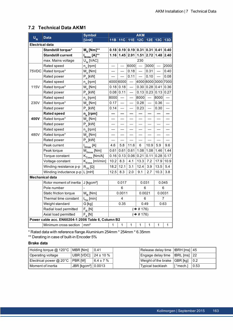
7.2 Technical Data AKM1
UN Data Symbol AKM[Unit] 11B 11C 11E 12C 12E 13C 13D
Electrical dataStandstill torque* M0 [Nm]** 0.18 0.19 0.19 0.31 0.31 0.41 0.40Standstill current I0rms [A]** 1.16 1.45 2.91 1.51 2.72 1.48 2.40max. Mains voltage UN [VAC] 230
75VDCRated speed nn [rpm] — — 6000 — 3000 — 2000Rated torque* Mn [Nm] — — 0.18 — 0.31 — 0.40Rated power Pn [kW] — — 0.11 — 0.10 — 0.08
115VRated speed nn [rpm] 4000 6000 — 4000 8000 3000 7000Rated torque* Mn [Nm] 0.18 0.18 — 0.30 0.28 0.41 0.36Rated power Pn [kW] 0.08 0.11 — 0.13 0.23 0.13 0.27
230VRated speed nn [rpm] 8000 — — 8000 — 8000 —Rated torque* Mn [Nm] 0.17 — — 0.28 — 0.36 —Rated power Pn [kW] 0.14 — — 0.23 — 0.30 —
400VRated speed nn [rpm] — — — — — — —Rated torque* Mn [Nm] — — — — — — —Rated power Pn [kW] — — — — — — —
480VRated speed nn [rpm] — — — — — — —Rated torque* Mn [Nm] — — — — — — —Rated power Pn [kW] — — — — — — —Peak current I0max [A] 4.6 5.8 11.6 6 10.9 5.9 9.6Peak torque M0max [Nm] 0.61 0.61 0.61 1.08 1.08 1.46 1.44Torque constant KTrms [Nm/A] 0.16 0.13 0.06 0.21 0.11 0.28 0.17Voltage constant KErms [mVmin] 10.2 8.3 4.1 13.3 7.2 17.9 10.9Winding resistance p-p R25 [Ω] 18.2 12.1 3.1 12.4 3.9 13.5 5.4Winding inductance p-p L [mH] 12.5 8.3 2.0 9.1 2.7 10.3 3.8
Mechanical dataRotor moment of inertia J [kgcm²] 0.017 0.031 0.045Pole number - 6 6 6Static friction torque MR [Nm] 0.0011 0.0021 0.0031Thermal time constant tTH [min] 4 6 7Weight standard G [kg] 0.35 0.49 0.63Radial load permitted FR [N] ( # 176)Axial load permitted FA [N] ( # 176)
Power cable acc. EN60204-1:2006 Table 6, Column B2Minimum cross section mm² 1 1 1 1 1 1 1
* Rated data with reference flange Aluminium 254mm * 254mm * 6.35mm** Derating in case of built-in Encoder 5%Brake dataHolding torque @ 120°C MBR [Nm] 0.41 Release delay time tBRH [ms] 45Operating voltage UBR [VDC] 24 ± 10 % Engage delay time tBRL [ms] 22Electrical power @ 20°C PBR [W] 6.4 ± 7 % Weight of the brake GBR [kg] 0.2Moment of inertia JBR [kgcm²] 0.0013 Typical backlash [ °mech.] 0.53
AKM Installation | 7 Technical Data
Kollmorgen | September 2015 163
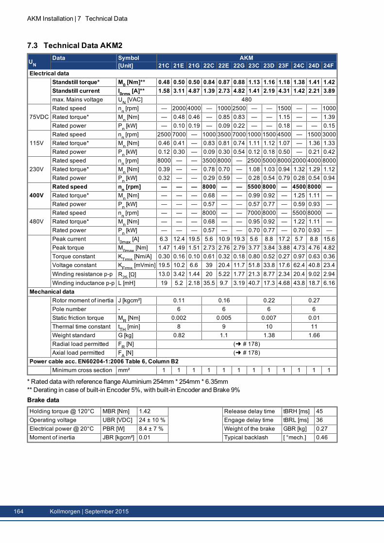
AKM Installation | 7 Technical Data
7.3 Technical Data AKM2
UNData Symbol AKM
[Unit] 21C 21E 21G 22C 22E 22G 23C 23D 23F 24C 24D 24FElectrical data
Standstill torque* M0 [Nm]** 0.48 0.50 0.50 0.84 0.87 0.88 1.13 1.16 1.18 1.38 1.41 1.42Standstill current I0rms [A]** 1.58 3.11 4.87 1.39 2.73 4.82 1.41 2.19 4.31 1.42 2.21 3.89max. Mains voltage UN [VAC] 480
75VDCRated speed nn [rpm] — 2000 4000 — 1000 2500 — — 1500 — — 1000Rated torque* Mn [Nm] — 0.48 0.46 — 0.85 0.83 — — 1.15 — — 1.39Rated power Pn [kW] — 0.10 0.19 — 0.09 0.22 — — 0.18 — — 0.15
115VRated speed nn [rpm] 2500 7000 — 1000 3500 7000 1000 1500 4500 — 1500 3000Rated torque* Mn [Nm] 0.46 0.41 — 0.83 0.81 0.74 1.11 1.12 1.07 — 1.36 1.33Rated power Pn [kW] 0.12 0.30 — 0.09 0.30 0.54 0.12 0.18 0.50 — 0.21 0.42
230VRated speed nn [rpm] 8000 — — 3500 8000 — 2500 5000 8000 2000 4000 8000Rated torque* Mn [Nm] 0.39 — — 0.78 0.70 — 1.08 1.03 0.94 1.32 1.29 1.12Rated power Pn [kW] 0.32 — — 0.29 0.59 — 0.28 0.54 0.79 0.28 0.54 0.94
400VRated speed nn [rpm] — — — 8000 — — 5500 8000 — 4500 8000 —Rated torque* Mn [Nm] — — — 0.68 — — 0.99 0.92 — 1.25 1.11 —Rated power Pn [kW] — — — 0.57 — — 0.57 0.77 — 0.59 0.93 —
480VRated speed nn [rpm] — — — 8000 — — 7000 8000 — 5500 8000 —Rated torque* Mn [Nm] — — — 0.68 — — 0.95 0.92 — 1.22 1.11 —Rated power Pn [kW] — — — 0.57 — — 0.70 0.77 — 0.70 0.93 —Peak current I0max [A] 6.3 12.4 19.5 5.6 10.9 19.3 5.6 8.8 17.2 5.7 8.8 15.6Peak torque M0max [Nm] 1.47 1.49 1.51 2.73 2.76 2.79 3.77 3.84 3.88 4.73 4.76 4.82Torque constant KTrms [Nm/A] 0.30 0.16 0.10 0.61 0.32 0.18 0.80 0.52 0.27 0.97 0.63 0.36Voltage constant KErms [mVmin] 19.5 10.2 6.6 39 20.4 11.7 51.8 33.8 17.6 62.4 40.8 23.4Winding resistance p-p R25 [Ω] 13.0 3.42 1.44 20 5.22 1.77 21.3 8.77 2.34 20.4 9.02 2.94Winding inductance p-p L [mH] 19 5.2 2.18 35.5 9.7 3.19 40.7 17.3 4.68 43.8 18.7 6.16
Mechanical dataRotor moment of inertia J [kgcm²] 0.11 0.16 0.22 0.27Pole number - 6 6 6 6Static friction torque MR [Nm] 0.002 0.005 0.007 0.01Thermal time constant tTH [min] 8 9 10 11Weight standard G [kg] 0.82 1.1 1.38 1.66Radial load permitted FR [N] ( # 178)Axial load permitted FA [N] ( # 178)
Power cable acc. EN60204-1:2006 Table 6, Column B2Minimum cross section mm² 1 1 1 1 1 1 1 1 1 1 1 1
* Rated data with reference flange Aluminium 254mm * 254mm * 6.35mm** Derating in case of built-in Encoder 5%, with built-in Encoder and Brake 9%Brake dataHolding torque @ 120°C MBR [Nm] 1.42 Release delay time tBRH [ms] 45Operating voltage UBR [VDC] 24 ± 10 % Engage delay time tBRL [ms] 36Electrical power @ 20°C PBR [W] 8.4 ± 7 % Weight of the brake GBR [kg] 0.27Moment of inertia JBR [kgcm²] 0.01 Typical backlash [ °mech.] 0.46
164 Kollmorgen | September 2015
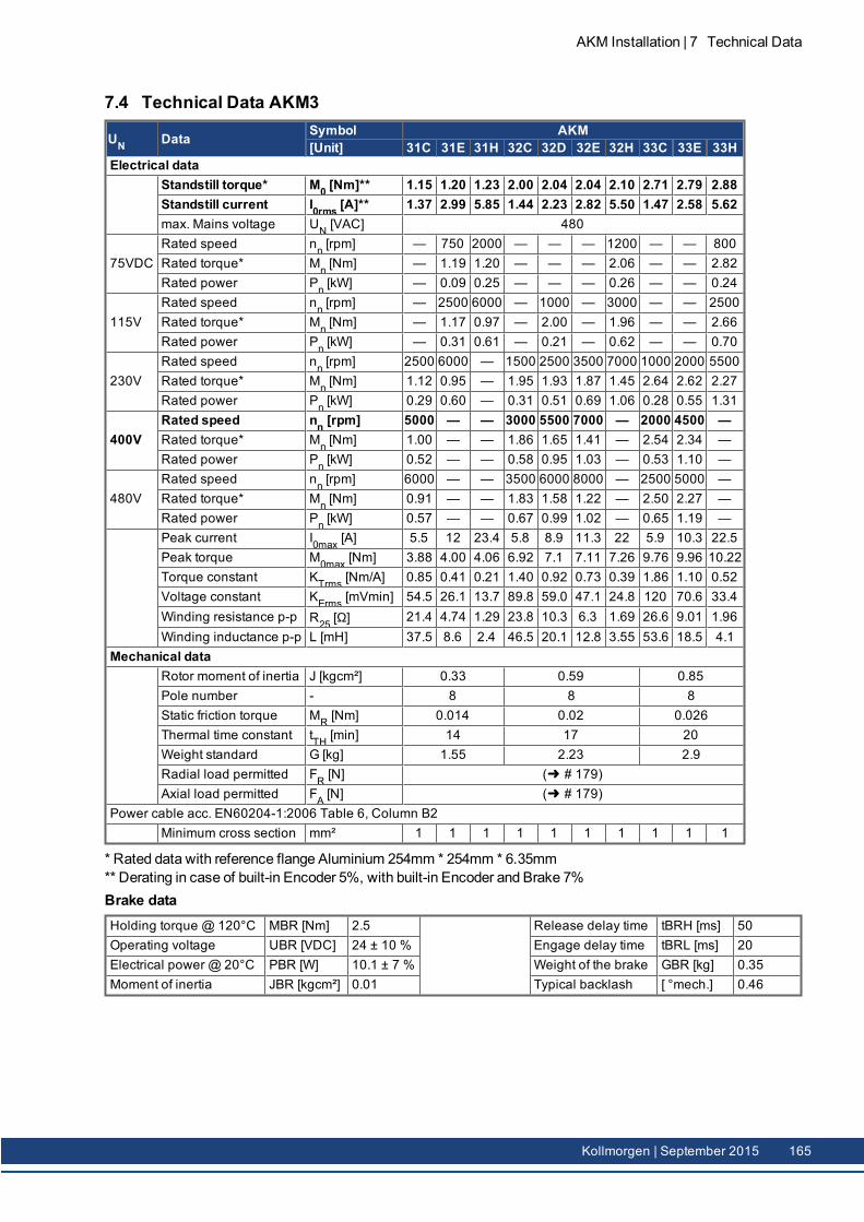
7.4 Technical Data AKM3
UN Data Symbol AKM[Unit] 31C 31E 31H 32C 32D 32E 32H 33C 33E 33H
Electrical dataStandstill torque* M0 [Nm]** 1.15 1.20 1.23 2.00 2.04 2.04 2.10 2.71 2.79 2.88Standstill current I0rms [A]** 1.37 2.99 5.85 1.44 2.23 2.82 5.50 1.47 2.58 5.62max. Mains voltage UN [VAC] 480
75VDCRated speed nn [rpm] — 750 2000 — — — 1200 — — 800Rated torque* Mn [Nm] — 1.19 1.20 — — — 2.06 — — 2.82Rated power Pn [kW] — 0.09 0.25 — — — 0.26 — — 0.24
115VRated speed nn [rpm] — 2500 6000 — 1000 — 3000 — — 2500Rated torque* Mn [Nm] — 1.17 0.97 — 2.00 — 1.96 — — 2.66Rated power Pn [kW] — 0.31 0.61 — 0.21 — 0.62 — — 0.70
230VRated speed nn [rpm] 2500 6000 — 1500 2500 3500 7000 1000 2000 5500Rated torque* Mn [Nm] 1.12 0.95 — 1.95 1.93 1.87 1.45 2.64 2.62 2.27Rated power Pn [kW] 0.29 0.60 — 0.31 0.51 0.69 1.06 0.28 0.55 1.31
400VRated speed nn [rpm] 5000 — — 3000 5500 7000 — 2000 4500 —Rated torque* Mn [Nm] 1.00 — — 1.86 1.65 1.41 — 2.54 2.34 —Rated power Pn [kW] 0.52 — — 0.58 0.95 1.03 — 0.53 1.10 —
480VRated speed nn [rpm] 6000 — — 3500 6000 8000 — 2500 5000 —Rated torque* Mn [Nm] 0.91 — — 1.83 1.58 1.22 — 2.50 2.27 —Rated power Pn [kW] 0.57 — — 0.67 0.99 1.02 — 0.65 1.19 —Peak current I0max [A] 5.5 12 23.4 5.8 8.9 11.3 22 5.9 10.3 22.5Peak torque M0max [Nm] 3.88 4.00 4.06 6.92 7.1 7.11 7.26 9.76 9.96 10.22Torque constant KTrms [Nm/A] 0.85 0.41 0.21 1.40 0.92 0.73 0.39 1.86 1.10 0.52Voltage constant KErms [mVmin] 54.5 26.1 13.7 89.8 59.0 47.1 24.8 120 70.6 33.4Winding resistance p-p R25 [Ω] 21.4 4.74 1.29 23.8 10.3 6.3 1.69 26.6 9.01 1.96Winding inductance p-p L [mH] 37.5 8.6 2.4 46.5 20.1 12.8 3.55 53.6 18.5 4.1
Mechanical dataRotor moment of inertia J [kgcm²] 0.33 0.59 0.85Pole number - 8 8 8Static friction torque MR [Nm] 0.014 0.02 0.026Thermal time constant tTH [min] 14 17 20Weight standard G [kg] 1.55 2.23 2.9Radial load permitted FR [N] ( # 179)Axial load permitted FA [N] ( # 179)
Power cable acc. EN60204-1:2006 Table 6, Column B2Minimum cross section mm² 1 1 1 1 1 1 1 1 1 1
* Rated data with reference flange Aluminium 254mm * 254mm * 6.35mm** Derating in case of built-in Encoder 5%, with built-in Encoder and Brake 7%Brake dataHolding torque @ 120°C MBR [Nm] 2.5 Release delay time tBRH [ms] 50Operating voltage UBR [VDC] 24 ± 10 % Engage delay time tBRL [ms] 20Electrical power @ 20°C PBR [W] 10.1 ± 7 % Weight of the brake GBR [kg] 0.35Moment of inertia JBR [kgcm²] 0.01 Typical backlash [ °mech.] 0.46
AKM Installation | 7 Technical Data
Kollmorgen | September 2015 165
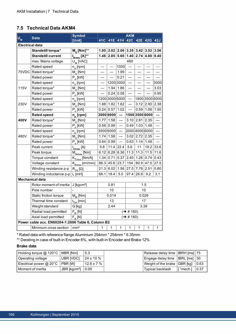
AKM Installation | 7 Technical Data
7.5 Technical Data AKM4
UN Data Symbol AKM[Unit] 41C 41E 41H 42C 42E 42G 42J
Electrical dataStandstill torque* M0 [Nm]** 1.95 2.02 2.06 3.35 3.42 3.53 3.56Standstill current I0rms [A]** 1.46 2.85 5.60 1.40 2.74 4.80 8.40max. Mains voltage UN [VAC] 480
75VDCRated speed nn [rpm] — — 1000 — — — —Rated torque* Mn [Nm] — — 1.99 — — — —Rated power Pn [kW] — — 0.21 — — — —
115VRated speed nn [rpm] — 1200 3000 — — — 3000Rated torque* Mn [Nm] — 1.94 1.86 — — — 3.03Rated power Pn [kW] — 0.24 0.58 — — — 0.95
230VRated speed nn [rpm] 1200 3000 6000 — 1800 3500 6000Rated torque* Mn [Nm] 1.88 1.82 1.62 — 3.12 2.90 2.38Rated power Pn [kW] 0.24 0.57 1.02 — 0.59 1.06 1.50
400VRated speed nn [rpm] 3000 6000 — 1500 3500 6000 —Rated torque* Mn [Nm] 1.77 1.58 — 3.10 2.81 2.35 —Rated power Pn [kW] 0.56 0.99 — 0.49 1.03 1.48 —
480VRated speed nn [rpm] 3500 6000 — 2000 4000 6000 —Rated torque* Mn [Nm] 1.74 1.58 — 3.02 2.72 2.35 —Rated power Pn [kW] 0.64 0.99 — 0.63 1.14 1.48 —Peak current I0max [A] 5.8 11.4 22.4 5.6 11 19.2 33.6Peak torque M0max [Nm] 6.12 6.28 6.36 11.3 11.3 11.5 11.6Torque constant KTrms [Nm/A] 1.34 0.71 0.37 2.40 1.26 0.74 0.43Voltage constant KErms [mVmin] 86.3 45.6 23.7 154 80.9 47.5 27.5Winding resistance p-p R25 [Ω] 21.3 6.02 1.56 27.5 7.78 2.51 0.80Winding inductance p-p L [mH] 66.1 18.4 5.0 97.4 26.8 9.2 3.1
Mechanical dataRotor moment of inertia J [kgcm²] 0.81 1.5Pole number - 10 10Static friction torque MR [Nm] 0.014 0.026Thermal time constant tTH [min] 13 17Weight standard G [kg] 2.44 3.39Radial load permitted FR [N] ( # 180)Axial load permitted FA [N] ( # 180)
Power cable acc. EN60204-1:2006 Table 6, Column B2Minimum cross section mm² 1 1 1 1 1 1 1
* Rated data with reference flange Aluminium 254mm * 254mm * 6.35mm** Derating in case of built-in Encoder 6%, with built-in Encoder and Brake 12%Brake dataHolding torque @ 120°C MBR [Nm] 5.3 Release delay time tBRH [ms] 75Operating voltage UBR [VDC] 24 ± 10 % Engage delay time tBRL [ms] 30Electrical power @ 20°C PBR [W] 12.8 ± 7 % Weight of the brake GBR [kg] 0.63Moment of inertia JBR [kgcm²] 0.09 Typical backlash [ °mech.] 0.37
166 Kollmorgen | September 2015
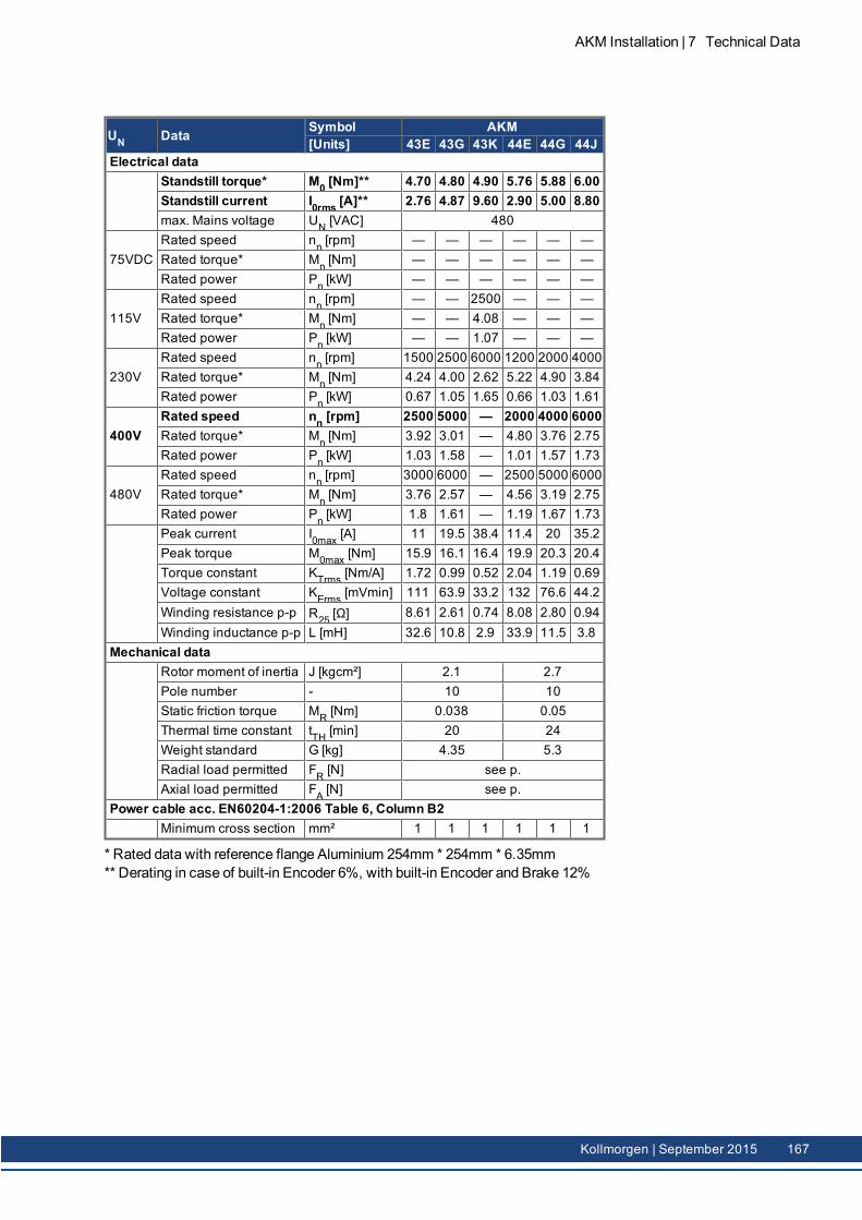
UN Data Symbol AKM[Units] 43E 43G 43K 44E 44G 44J
Electrical dataStandstill torque* M0 [Nm]** 4.70 4.80 4.90 5.76 5.88 6.00Standstill current I0rms [A]** 2.76 4.87 9.60 2.90 5.00 8.80max. Mains voltage UN [VAC] 480
75VDCRated speed nn [rpm] — — — — — —Rated torque* Mn [Nm] — — — — — —Rated power Pn [kW] — — — — — —
115VRated speed nn [rpm] — — 2500 — — —Rated torque* Mn [Nm] — — 4.08 — — —Rated power Pn [kW] — — 1.07 — — —
230VRated speed nn [rpm] 1500 2500 6000 1200 2000 4000Rated torque* Mn [Nm] 4.24 4.00 2.62 5.22 4.90 3.84Rated power Pn [kW] 0.67 1.05 1.65 0.66 1.03 1.61
400VRated speed nn [rpm] 2500 5000 — 2000 4000 6000Rated torque* Mn [Nm] 3.92 3.01 — 4.80 3.76 2.75Rated power Pn [kW] 1.03 1.58 — 1.01 1.57 1.73
480VRated speed nn [rpm] 3000 6000 — 2500 5000 6000Rated torque* Mn [Nm] 3.76 2.57 — 4.56 3.19 2.75Rated power Pn [kW] 1.8 1.61 — 1.19 1.67 1.73Peak current I0max [A] 11 19.5 38.4 11.4 20 35.2Peak torque M0max [Nm] 15.9 16.1 16.4 19.9 20.3 20.4Torque constant KTrms [Nm/A] 1.72 0.99 0.52 2.04 1.19 0.69Voltage constant KErms [mVmin] 111 63.9 33.2 132 76.6 44.2Winding resistance p-p R25 [Ω] 8.61 2.61 0.74 8.08 2.80 0.94Winding inductance p-p L [mH] 32.6 10.8 2.9 33.9 11.5 3.8
Mechanical dataRotor moment of inertia J [kgcm²] 2.1 2.7Pole number - 10 10Static friction torque MR [Nm] 0.038 0.05Thermal time constant tTH [min] 20 24Weight standard G [kg] 4.35 5.3Radial load permitted FR [N] see p.Axial load permitted FA [N] see p.
Power cable acc. EN60204-1:2006 Table 6, Column B2Minimum cross section mm² 1 1 1 1 1 1
* Rated data with reference flange Aluminium 254mm * 254mm * 6.35mm** Derating in case of built-in Encoder 6%, with built-in Encoder and Brake 12%
AKM Installation | 7 Technical Data
Kollmorgen | September 2015 167
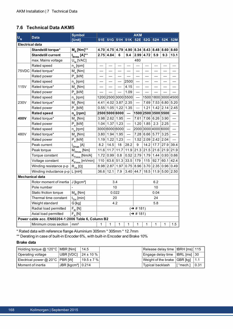
AKM Installation | 7 Technical Data
7.6 Technical Data AKM5
UN Data Symbol AKM[Unit] 51E 51G 51H 51K 52E 52G 52H 52K 52M
Electrical dataStandstill torque* M0 [Nm]** 4.70 4.75 4.79 4.90 8.34 8.43 8.48 8.60 8.60Standstill current I0rms [A]** 2.75 4.84 6 9.4 2.99 4.72 5.9 9.3 13.1max. Mains voltage UN [VAC] 480
75VDCRated speed nn [rpm] — — — — — — — — —Rated torque* Mn [Nm] — — — — — — — — —Rated power Pn [kW] — — — — — — — — —
115VRated speed nn [rpm] — — — 2500 — — — — —Rated torque* Mn [Nm] — — — 4.15 — — — — —Rated power Pn [kW] — — — 1.09 — — — — —
230VRated speed nn [rpm] 1200 2500 3000 5500 — 1500 1800 3000 4500Rated torque* Mn [Nm] 4.41 4.02 3.87 2.35 — 7.69 7.53 6.80 5.20Rated power Pn [kW] 0.55 1.05 1.22 1.35 — 1.21 1.42 2.14 2.45
400VRated speed nn [rpm] 2500 5000 6000 — 1500 2500 3500 5500 —Rated torque* Mn [Nm] 3.98 2.62 1.95 — 7.61 7.06 6.26 3.90 —Rated power Pn [kW] 1.04 1.37 1.23 — 1.20 1.85 2.3 2.25 —
480VRated speed nn [rpm] 3000 6000 6000 — 2000 3000 4000 6000 —Rated torque* Mn [Nm] 3.80 1.94 1.95 — 7.28 6.66 5.77 3.25 —Rated power Pn [kW] 1.19 1.22 1.23 — 1.52 2.09 2.42 2.04 —Peak current I0max [A] 8.2 14.5 18 28.2 9 14.2 17.7 27.9 39.4Peak torque M0max [Nm] 11.6 11.7 11.7 11.9 21.3 21.5 21.6 21.9 21.9Torque constant KTrms [Nm/A] 1.72 0.99 0.8 0.52 2.79 1.79 1.44 0.93 0.66Voltage constant KErms [mVmin] 110 63.6 51.3 33.5 179 115 92.7 60.1 42.4Winding resistance p-p R25 [Ω] 8.98 2.87 1.97 0.75 8.96 3.70 2.35 0.96 0.49Winding inductance p-p L [mH] 36.6 12.1 7.9 3.40 44.7 18.5 11.9 5.00 2.50
Mechanical dataRotor moment of inertia J [kgcm²] 3.4 6.2Pole number - 10 10Static friction torque MR [Nm] 0.022 0.04Thermal time constant tTH [min] 20 24Weight standard G [kg] 4.2 5.8Radial load permitted FR [N] ( # 181)Axial load permitted FA [N] ( # 181)
Power cable acc. EN60204-1:2006 Table 6, Column B2Minimum cross section mm² 1 1 1 1 1 1 1 1 1.5
* Rated data with reference flange Aluminium 305mm * 305mm * 12.7mm** Derating in case of built-in Encoder 6%, with built-in Encoder and Brake 10%Brake dataHolding torque @ 120°C MBR [Nm] 14.5 Release delay time tBRH [ms] 115Operating voltage UBR [VDC] 24 ± 10 % Engage delay time tBRL [ms] 30Electrical power @ 20°C PBR [W] 19.5 ± 7 % Weight of the brake GBR [kg] 1.1Moment of inertia JBR [kgcm²] 0.214 Typical backlash [ °mech.] 0.31
168 Kollmorgen | September 2015
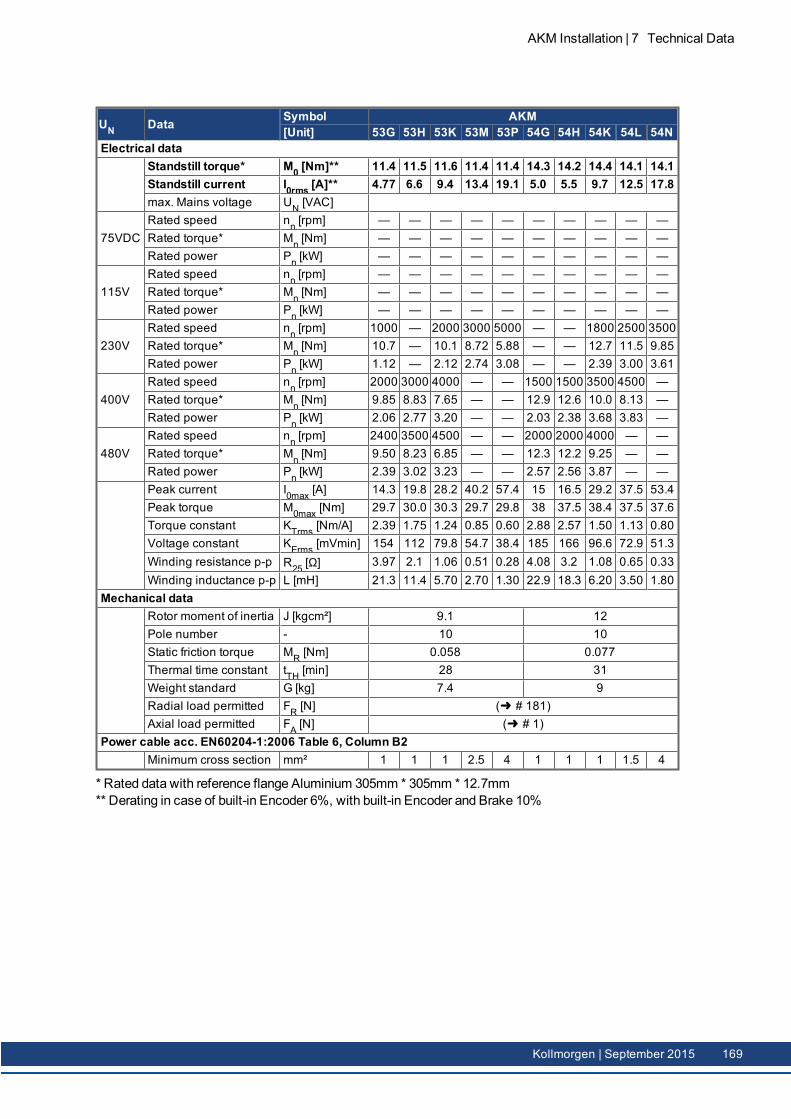
UN Data Symbol AKM[Unit] 53G 53H 53K 53M 53P 54G 54H 54K 54L 54N
Electrical dataStandstill torque* M0 [Nm]** 11.4 11.5 11.6 11.4 11.4 14.3 14.2 14.4 14.1 14.1Standstill current I0rms [A]** 4.77 6.6 9.4 13.4 19.1 5.0 5.5 9.7 12.5 17.8max. Mains voltage UN [VAC]
75VDCRated speed nn [rpm] — — — — — — — — — —Rated torque* Mn [Nm] — — — — — — — — — —Rated power Pn [kW] — — — — — — — — — —
115VRated speed nn [rpm] — — — — — — — — — —Rated torque* Mn [Nm] — — — — — — — — — —Rated power Pn [kW] — — — — — — — — — —
230VRated speed nn [rpm] 1000 — 2000 3000 5000 — — 1800 2500 3500Rated torque* Mn [Nm] 10.7 — 10.1 8.72 5.88 — — 12.7 11.5 9.85Rated power Pn [kW] 1.12 — 2.12 2.74 3.08 — — 2.39 3.00 3.61
400VRated speed nn [rpm] 2000 3000 4000 — — 1500 1500 3500 4500 —Rated torque* Mn [Nm] 9.85 8.83 7.65 — — 12.9 12.6 10.0 8.13 —Rated power Pn [kW] 2.06 2.77 3.20 — — 2.03 2.38 3.68 3.83 —
480VRated speed nn [rpm] 2400 3500 4500 — — 2000 2000 4000 — —Rated torque* Mn [Nm] 9.50 8.23 6.85 — — 12.3 12.2 9.25 — —Rated power Pn [kW] 2.39 3.02 3.23 — — 2.57 2.56 3.87 — —Peak current I0max [A] 14.3 19.8 28.2 40.2 57.4 15 16.5 29.2 37.5 53.4Peak torque M0max [Nm] 29.7 30.0 30.3 29.7 29.8 38 37.5 38.4 37.5 37.6Torque constant KTrms [Nm/A] 2.39 1.75 1.24 0.85 0.60 2.88 2.57 1.50 1.13 0.80Voltage constant KErms [mVmin] 154 112 79.8 54.7 38.4 185 166 96.6 72.9 51.3Winding resistance p-p R25 [Ω] 3.97 2.1 1.06 0.51 0.28 4.08 3.2 1.08 0.65 0.33Winding inductance p-p L [mH] 21.3 11.4 5.70 2.70 1.30 22.9 18.3 6.20 3.50 1.80
Mechanical dataRotor moment of inertia J [kgcm²] 9.1 12Pole number - 10 10Static friction torque MR [Nm] 0.058 0.077Thermal time constant tTH [min] 28 31Weight standard G [kg] 7.4 9Radial load permitted FR [N] ( # 181)Axial load permitted FA [N] ( # 1)
Power cable acc. EN60204-1:2006 Table 6, Column B2Minimum cross section mm² 1 1 1 2.5 4 1 1 1 1.5 4
* Rated data with reference flange Aluminium 305mm * 305mm * 12.7mm** Derating in case of built-in Encoder 6%, with built-in Encoder and Brake 10%
AKM Installation | 7 Technical Data
Kollmorgen | September 2015 169
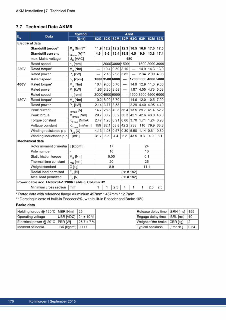
AKM Installation | 7 Technical Data
7.7 Technical Data AKM6
UN Data Symbol AKM[Unit] 62G 62K 62M 62P 63G 63K 63M 63N
Electrical dataStandstill torque* M0 [Nm]** 11.9 12.2 12.2 12.3 16.5 16.8 17.0 17.0Standstill current I0rms [A]** 4.9 9.6 13.4 18.8 4.5 9.9 13.8 17.4max. Mains voltage UN [VAC] 480
230VRated speed nn [rpm] — 2000 3000 4500 — 1500 2000 3000Rated torque* Mn [Nm] — 10.4 9.50 8.10 — 14.9 14.3 13.0Rated power Pn [kW] — 2.18 2.98 3.82 — 2.34 2.99 4.08
400VRated speed nn [rpm] 1800 3500 6000 — 1200 3000 4000 5000Rated torque* Mn [Nm] 10.4 9.00 5.70 — 14.9 12.9 11.3 9.60Rated power Pn [kW] 1.96 3.30 3.58 — 1.87 4.05 4.73 5.03
480VRated speed nn [rpm] 2000 4500 6000 — 1500 3500 4500 6000Rated torque* Mn [Nm] 10.2 8.00 5.70 — 14.6 12.0 10.5 7.00Rated power Pn [kW] 2.14 3.77 3.58 — 2.29 4.40 4.95 4.40Peak current I0max [A] 14.7 28.8 40.3 56.4 13.5 29.7 41.4 52.2Peak torque M0max [Nm] 29.7 30.2 30.2 30.3 42.1 42.6 43.0 43.0Torque constant KTrms [Nm/A] 2.47 1.28 0.91 0.66 3.70 1.71 1.24 0.98Voltage constant KErms [mVmin] 159 82.1 58.8 42.2 238 110 79.9 63.3Winding resistance p-p R25 [Ω] 4.13 1.08 0.57 0.30 5.50 1.14 0.61 0.39Winding inductance p-p L [mH] 31.7 8.5 4.4 2.2 43.5 9.3 4.9 3.1
Mechanical dataRotor moment of inertia J [kgcm²] 17 24Pole number - 10 10Static friction torque MR [Nm] 0.05 0.1Thermal time constant tTH [min] 20 25Weight standard G [kg] 8.9 11.1Radial load permitted FR [N] ( # 182)Axial load permitted FA [N] ( # 182)
Power cable acc. EN60204-1:2006 Table 6, Column B2Minimum cross section mm² 1 1 2.5 4 1 1 2.5 2.5
* Rated data with reference flange Aluminium 457mm * 457mm * 12.7mm** Derating in case of built-in Encoder 8%, with built-in Encoder and Brake 16%Brake dataHolding torque @ 120°C MBR [Nm] 25 Release delay time tBRH [ms] 155Operating voltage UBR [VDC] 24 ± 10 % Engage delay time tBRL [ms] 40Electrical power @ 20°C PBR [W] 25.7 ± 7 % Weight of the brake GBR [kg] 2Moment of inertia JBR [kgcm²] 0.717 Typical backlash [ °mech.] 0.24
170 Kollmorgen | September 2015
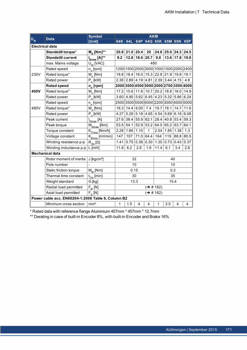
UN Data Symbol AKM[Unit] 64K 64L 64P 64Q 65K 65M 65N 65P
Electrical dataStandstill torque* M0 [Nm]** 20.8 21.0 20.4 20 24.8 25.0 24.3 24.5Standstill current I0rms [A]** 9.2 12.8 18.6 20.7 9.8 13.6 17.8 19.8max. Mains voltage UN [VAC] 480
230VRated speed nn [rpm] 1200 1500 2500 3000 1000 1500 2000 2400Rated torque* Mn [Nm] 18.8 18.4 16.0 15.3 22.8 21.9 19.8 19.1Rated power Pn [kW] 2.36 2.89 4.19 4.81 2.39 3.44 4.15 4.8
400VRated speed nn [rpm] 2000 3000 4500 5000 2000 2700 3500 4000Rated torque* Mn [Nm] 17.2 15.6 11.9 10.7 20.2 18.8 16.0 14.9Rated power Pn [kW] 3.60 4.90 5.62 6.45 4.23 5.32 5.86 6.24
480VRated speed nn [rpm] 2500 3500 5500 6000 2200 3000 4000 5000Rated torque* Mn [Nm] 16.3 14.4 9.00 7.4 19.7 18.1 14.7 11.6Rated power Pn [kW] 4.27 5.28 5.18 4.65 4.54 5.69 6.16 6.08Peak current I0max [A] 27.6 38.4 55.9 62.1 29.4 40.8 53.4 59.3Peak torque M0max [Nm] 53.5 54.1 52.9 53.2 64.5 65.2 63.7 64.1Torque constant KTrms [Nm/A] 2.28 1.66 1.10 1 2.54 1.85 1.38 1.3Voltage constant KErms [mVmin] 147 107 71.0 64.4 164 119 88.8 80.5Winding resistance p-p R25 [Ω] 1.41 0.75 0.36 0.30 1.35 0.73 0.43 0.37Winding inductance p-p L [mH] 11.8 6.2 2.8 1.9 11.4 6.1 3.4 2.8
Mechanical dataRotor moment of inertia J [kgcm²] 32 40Pole number - 10 10Static friction torque MR [Nm] 0.15 0.2Thermal time constant tTH [min] 30 35Weight standard G [kg] 13.3 15.4Radial load permitted FR [N] ( # 182)Axial load permitted FA [N] ( # 182)
Power cable acc. EN60204-1:2006 Table 6, Column B2Minimum cross section mm² 1 1.5 4 4 1 2.5 4 4
* Rated data with reference flange Aluminium 457mm * 457mm * 12.7mm** Derating in case of built-in Encoder 8%, with built-in Encoder and Brake 16%
AKM Installation | 7 Technical Data
Kollmorgen | September 2015 171
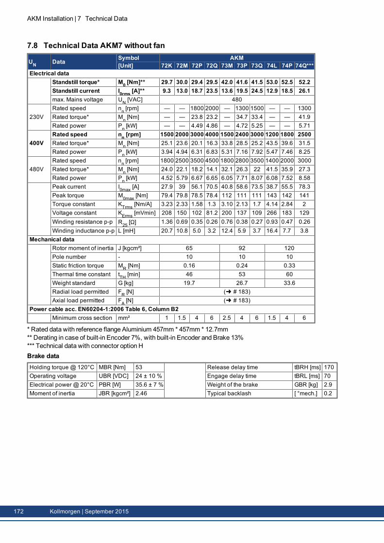
AKM Installation | 7 Technical Data
7.8 Technical Data AKM7 without fan
UN Data Symbol AKM[Unit] 72K 72M 72P 72Q 73M 73P 73Q 74L 74P 74Q***
Electrical dataStandstill torque* M0 [Nm]** 29.7 30.0 29.4 29.5 42.0 41.6 41.5 53.0 52.5 52.2Standstill current I0rms [A]** 9.3 13.0 18.7 23.5 13.6 19.5 24.5 12.9 18.5 26.1max. Mains voltage UN [VAC] 480
230VRated speed nn [rpm] — — 1800 2000 — 1300 1500 — — 1300Rated torque* Mn [Nm] — — 23.8 23.2 — 34.7 33.4 — — 41.9Rated power Pn [kW] — — 4.49 4.86 — 4.72 5.25 — — 5.71
400VRated speed nn [rpm] 1500 2000 3000 4000 1500 2400 3000 1200 1800 2500Rated torque* Mn [Nm] 25.1 23.6 20.1 16.3 33.8 28.5 25.2 43.5 39.6 31.5Rated power Pn [kW] 3.94 4.94 6.31 6.83 5.31 7.16 7.92 5.47 7.46 8.25
480VRated speed nn [rpm] 1800 2500 3500 4500 1800 2800 3500 1400 2000 3000Rated torque* Mn [Nm] 24.0 22.1 18.2 14.1 32.1 26.3 22 41.5 35.9 27.3Rated power Pn [kW] 4.52 5.79 6.67 6.65 6.05 7.71 8.07 6.08 7.52 8.58Peak current I0max [A] 27.9 39 56.1 70.5 40.8 58.6 73.5 38.7 55.5 78.3Peak torque M0max [Nm] 79.4 79.8 78.5 78.4 112 111 111 143 142 141Torque constant KTrms [Nm/A] 3.23 2.33 1.58 1.3 3.10 2.13 1.7 4.14 2.84 2Voltage constant KErms [mVmin] 208 150 102 81.2 200 137 109 266 183 129Winding resistance p-p R25 [Ω] 1.36 0.69 0.35 0.26 0.76 0.38 0.27 0.93 0.47 0.26Winding inductance p-p L [mH] 20.7 10.8 5.0 3.2 12.4 5.9 3.7 16.4 7.7 3.8
Mechanical dataRotor moment of inertia J [kgcm²] 65 92 120Pole number - 10 10 10Static friction torque MR [Nm] 0.16 0.24 0.33Thermal time constant tTH [min] 46 53 60Weight standard G [kg] 19.7 26.7 33.6Radial load permitted FR [N] ( # 183)Axial load permitted FA [N] ( # 183)
Power cable acc. EN60204-1:2006 Table 6, Column B2Minimum cross section mm² 1 1.5 4 6 2.5 4 6 1.5 4 6
* Rated data with reference flange Aluminium 457mm * 457mm * 12.7mm** Derating in case of built-in Encoder 7%, with built-in Encoder and Brake 13%*** Technical data with connector option HBrake dataHolding torque @ 120°C MBR [Nm] 53 Release delay time tBRH [ms] 170Operating voltage UBR [VDC] 24 ± 10 % Engage delay time tBRL [ms] 70Electrical power @ 20°C PBR [W] 35.6 ± 7 % Weight of the brake GBR [kg] 2.9Moment of inertia JBR [kgcm²] 2.46 Typical backlash [ °mech.] 0.2
172 Kollmorgen | September 2015
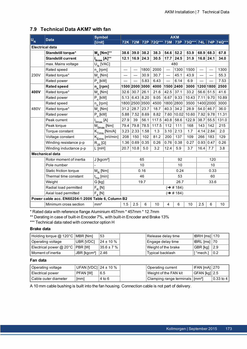
7.9 Technical Data AKM7 with fan
UN Data Symbol AKM[Unit] 72K 72M 72P 72Q*** 73M 73P 73Q*** 74L 74P 74Q***
Electrical dataStandstill torque* M0 [Nm]** 38.6 39.0 38.2 38.3 54.6 52.2 53.9 68.9 68.3 67.8Standstill current I0rms [A]** 12.1 16.9 24.3 30.5 17.7 24.5 31.9 16.8 24.1 34.0max. Mains voltage UN [VAC] 480
230VRated speed nn [rpm] — — 1800 2000 — 1300 1500 — — 1300Rated torque* Mn [Nm] — — 30.9 30.7 — 45.1 43.9 — — 55.3Rated power Pn [kW] — — 5.83 6.43 — 6.14 6.9 — — 7.53
400VRated speed nn [rpm] 1500 2000 3000 4000 1500 2400 3000 1200 1800 2500Rated torque* Mn [Nm] 32.6 30.7 26.1 21.6 42.5 37.1 33.2 56.6 51.5 41.6Rated power Pn [kW] 5.13 6.43 8.20 9.05 6.67 9.33 10.43 7.11 9.70 10.89
480VRated speed nn [rpm] 1800 2500 3500 4500 1800 2800 3500 1400 2000 3000Rated torque* Mn [Nm] 31.2 28.7 23.7 18.7 40.3 34.2 28.9 54.0 46.7 36.0Rated power Pn [kW] 5.88 7.52 8.69 8.82 7.60 10.02 10.60 7.92 9.78 11.31Peak current I0max [A] 27.9 39 56.1 117.5 40.8 58.6 122.9 38.7 55.5 131.0Peak torque M0max [Nm] 79.4 79.8 78.5 117.5 112 111 168 143 142 215Torque constant KTrms [Nm/A] 3.23 2.33 1.58 1.3 3.10 2.13 1.7 4.14 2.84 2.0Voltage constant KErms [mVmin] 208 150 102 81.2 200 137 109 266 183 129Winding resistance p-p R25 [Ω] 1.36 0.69 0.35 0.26 0.76 0.38 0.27 0.93 0.47 0.26Winding inductance p-p L [mH] 20.7 10.8 5.0 3.2 12.4 5.9 3.7 16.4 7.7 3.8
Mechanical dataRotor moment of inertia J [kgcm²] 65 92 120Pole number - 10 10 10Static friction torque MR [Nm] 0.16 0.24 0.33Thermal time constant tTH [min] 46 53 60Weight G [kg] 19.7 26.7 33.6Radial load permitted FR [N] ( # 184)Axial load permitted FA [N] ( # 184)
Power cable acc. EN60204-1:2006 Table 6, Column B2Minimum cross section mm² 1.5 2.5 6 10 4 6 10 2.5 6 10
* Rated data with reference flange Aluminium 457mm * 457mm * 12.7mm** Derating in case of built-in Encoder 7%, with built-in Encoder and Brake 13%*** Technical data rated with connector option HBrake dataHolding torque @ 120°C MBR [Nm] 53 Release delay time tBRH [ms] 170Operating voltage UBR [VDC] 24 ± 10 % Engage delay time tBRL [ms] 70Electrical power @ 20°C PBR [W] 35.6 ± 7 % Weight of the brake GBR [kg] 2.9Moment of inertia JBR [kgcm²] 2.46 Typical backlash [ °mech.] 0.2
Fan dataOperating voltage UFAN [VDC] 24 ± 10 % Operating current IFAN [mA] 270Electrical power PFAN [W] 6.5 Weight of the FAN kit GFAN [kg] 2.5Cable outer diameter [mm] 4 to 6 Clamping range terminals [mm²] 0.33 to 4
A 10mm cable bushing is built into the fan housing. Connection cable is not part of delivery.
AKM Installation | 7 Technical Data
Kollmorgen | September 2015 173
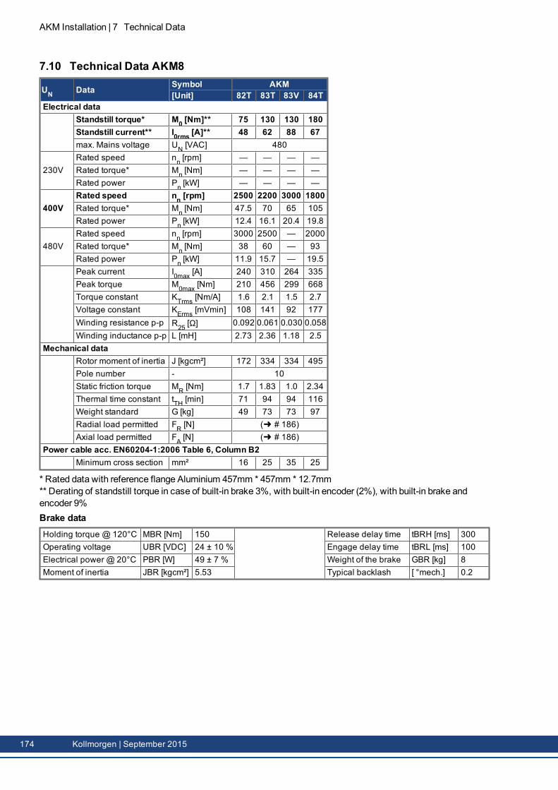
AKM Installation | 7 Technical Data
7.10 Technical Data AKM8
UN Data Symbol AKM[Unit] 82T 83T 83V 84T
Electrical dataStandstill torque* M0 [Nm]** 75 130 130 180Standstill current** I0rms [A]** 48 62 88 67max. Mains voltage UN [VAC] 480
230VRated speed nn [rpm] — — — —Rated torque* Mn [Nm] — — — —Rated power Pn [kW] — — — —
400VRated speed nn [rpm] 2500 2200 3000 1800Rated torque* Mn [Nm] 47.5 70 65 105Rated power Pn [kW] 12.4 16.1 20.4 19.8
480VRated speed nn [rpm] 3000 2500 — 2000Rated torque* Mn [Nm] 38 60 — 93Rated power Pn [kW] 11.9 15.7 — 19.5Peak current I0max [A] 240 310 264 335Peak torque M0max [Nm] 210 456 299 668Torque constant KTrms [Nm/A] 1.6 2.1 1.5 2.7Voltage constant KErms [mVmin] 108 141 92 177Winding resistance p-p R25 [Ω] 0.092 0.061 0.030 0.058Winding inductance p-p L [mH] 2.73 2.36 1.18 2.5
Mechanical dataRotor moment of inertia J [kgcm²] 172 334 334 495Pole number - 10Static friction torque MR [Nm] 1.7 1.83 1.0 2.34Thermal time constant tTH [min] 71 94 94 116Weight standard G [kg] 49 73 73 97Radial load permitted FR [N] ( # 186)Axial load permitted FA [N] ( # 186)
Power cable acc. EN60204-1:2006 Table 6, Column B2Minimum cross section mm² 16 25 35 25
* Rated data with reference flange Aluminium 457mm * 457mm * 12.7mm** Derating of standstill torque in case of built-in brake 3%, with built-in encoder (2%), with built-in brake andencoder 9%Brake dataHolding torque @ 120°C MBR [Nm] 150 Release delay time tBRH [ms] 300Operating voltage UBR [VDC] 24 ± 10 % Engage delay time tBRL [ms] 100Electrical power @ 20°C PBR [W] 49 ± 7 % Weight of the brake GBR [kg] 8Moment of inertia JBR [kgcm²] 5.53 Typical backlash [ °mech.] 0.2
174 Kollmorgen | September 2015
8 Dimension drawingsAll drawings in this chapter are drawings in principle (not scaled). 3D Models are available from www.koll-morgen.com.
8.1 Dimensions/Radial Forces AKM1 (Ax flanges) 1768.2 Dimensions/Radial Forces AKM2 (Ax flanges) 1788.3 Dimensions/Radial Forces AKM3 (Ax flanges) 1798.4 Dimensions/Radial Forces AKM4 (Ax flanges) 1808.5 Dimensions/Radial Forces AKM5 (Ax flanges) 1818.6 Dimensions/Radial Forces AKM6 (Ax flanges) 1828.7 Dimensions/Radial Forces AKM7 (Ax flanges) 1838.8 Dimensions/Radial Forces AKM8 (Ax flanges) 186
AKM Installation | 8 Dimension drawings
Kollmorgen | September 2015 175
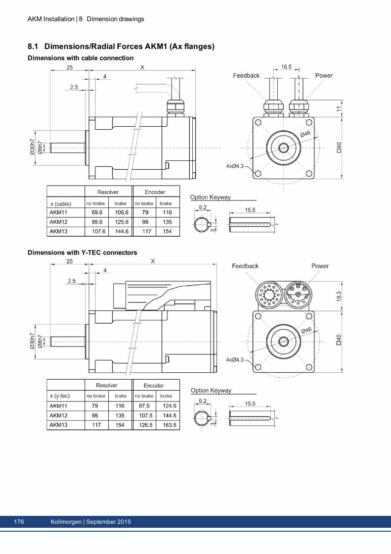
AKM Installation | 8 Dimension drawings
8.1 Dimensions/Radial Forces AKM1 (Ax flanges)Dimensions with cable connection
Dimensions with Y-TEC connectors
176 Kollmorgen | September 2015
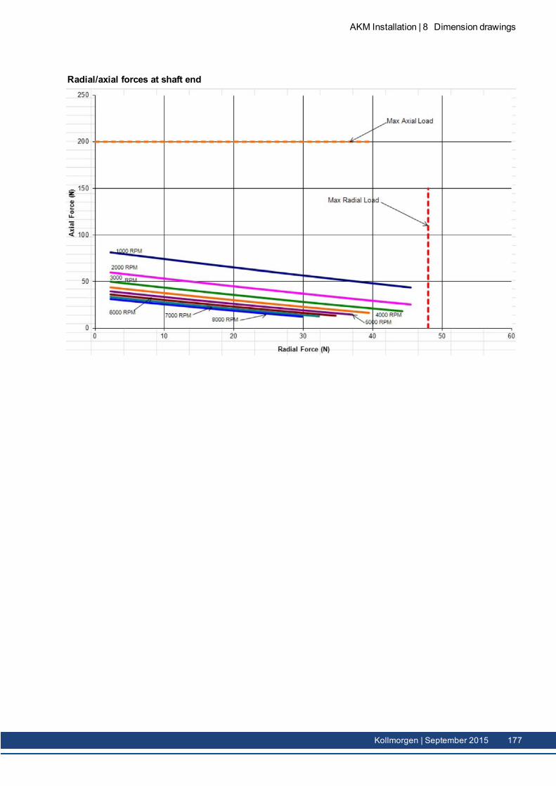
Radial/axial forces at shaft end
AKM Installation | 8 Dimension drawings
Kollmorgen | September 2015 177
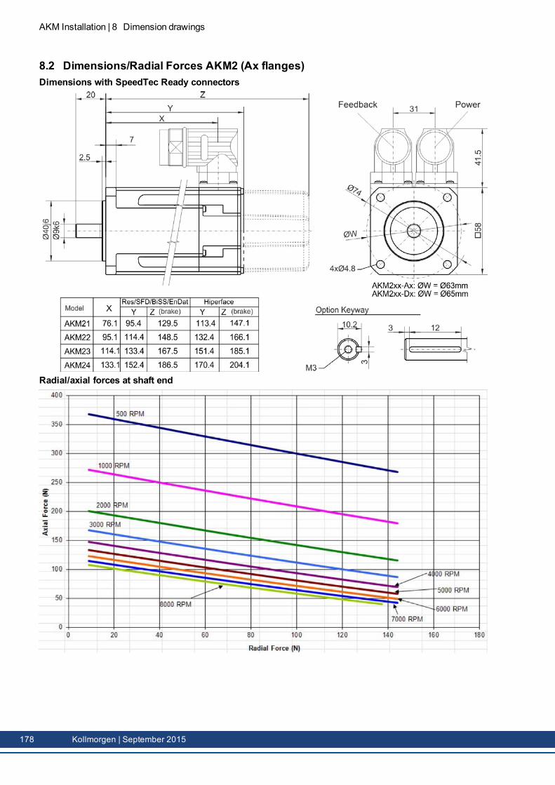
AKM Installation | 8 Dimension drawings
8.2 Dimensions/Radial Forces AKM2 (Ax flanges)Dimensions with SpeedTec Ready connectors
Radial/axial forces at shaft end
178 Kollmorgen | September 2015
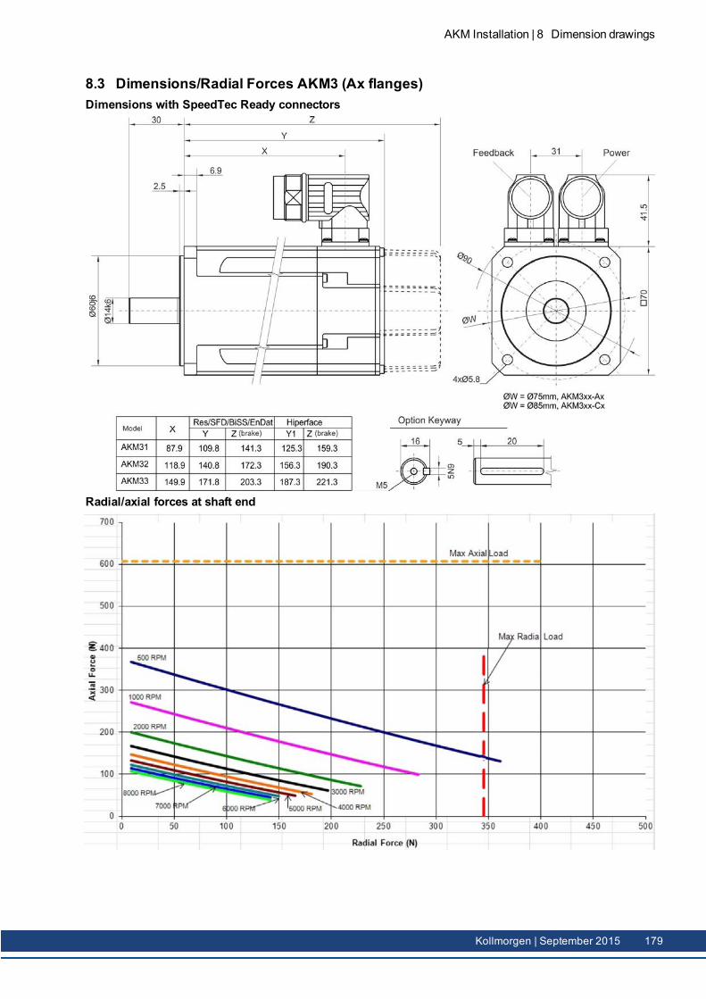
8.3 Dimensions/Radial Forces AKM3 (Ax flanges)Dimensions with SpeedTec Ready connectors
Radial/axial forces at shaft end
AKM Installation | 8 Dimension drawings
Kollmorgen | September 2015 179
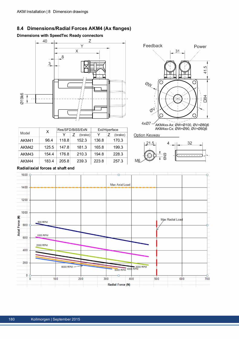
AKM Installation | 8 Dimension drawings
8.4 Dimensions/Radial Forces AKM4 (Ax flanges)Dimensions with SpeedTec Ready connectors
Radial/axial forces at shaft end
180 Kollmorgen | September 2015
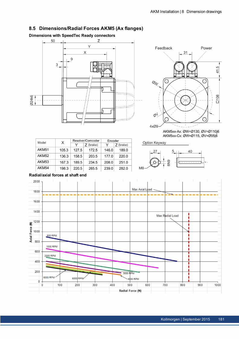
8.5 Dimensions/Radial Forces AKM5 (Ax flanges)Dimensions with SpeedTec Ready connectors
Radial/axial forces at shaft end
AKM Installation | 8 Dimension drawings
Kollmorgen | September 2015 181
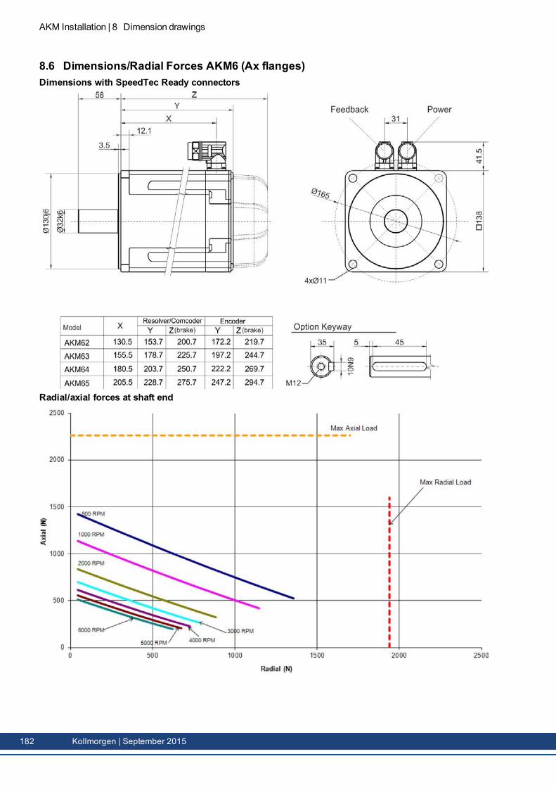
AKM Installation | 8 Dimension drawings
8.6 Dimensions/Radial Forces AKM6 (Ax flanges)Dimensions with SpeedTec Ready connectors
Radial/axial forces at shaft end
182 Kollmorgen | September 2015
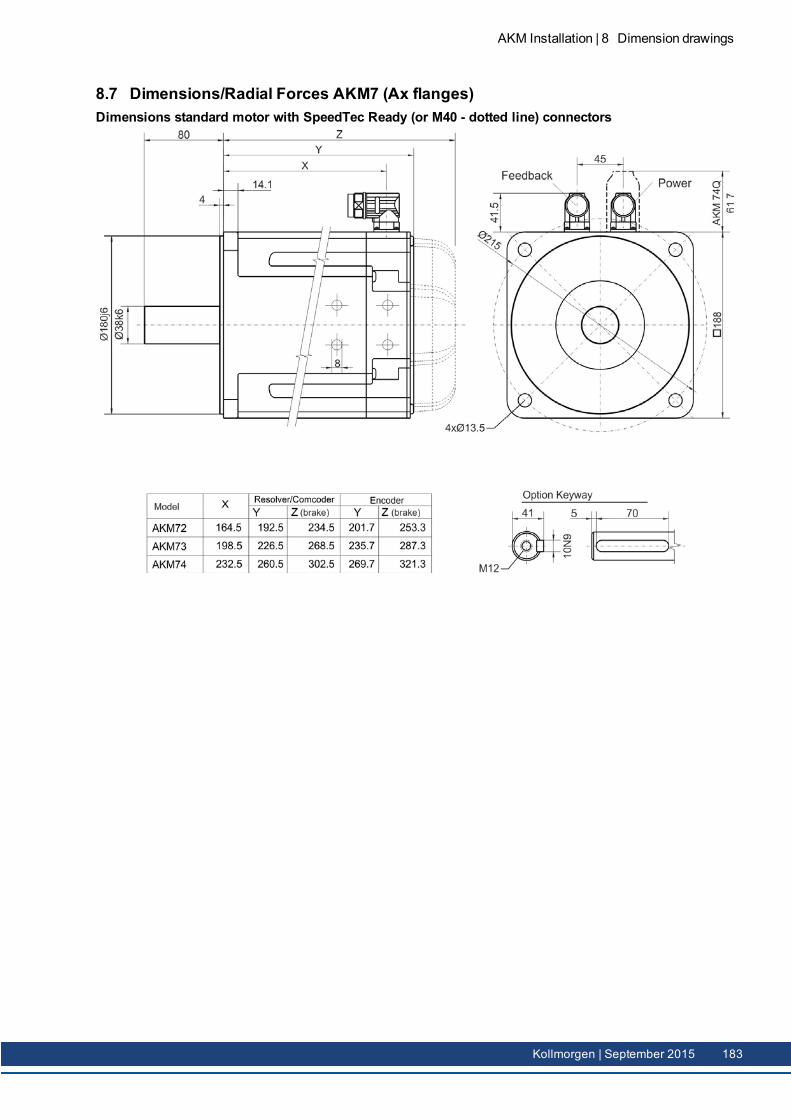
8.7 Dimensions/Radial Forces AKM7 (Ax flanges)Dimensions standard motor with SpeedTec Ready (or M40 - dotted line) connectors
AKM Installation | 8 Dimension drawings
Kollmorgen | September 2015 183
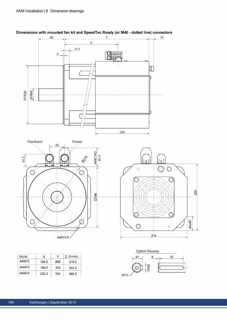
AKM Installation | 8 Dimension drawings
Dimensions with mounted fan kit and SpeedTec Ready (or M40 - dotted line) connectors
184 Kollmorgen | September 2015
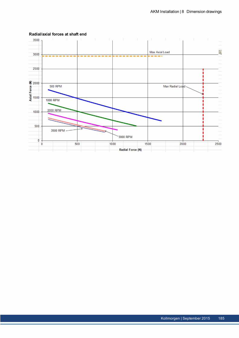
Radial/axial forces at shaft end
AKM Installation | 8 Dimension drawings
Kollmorgen | September 2015 185
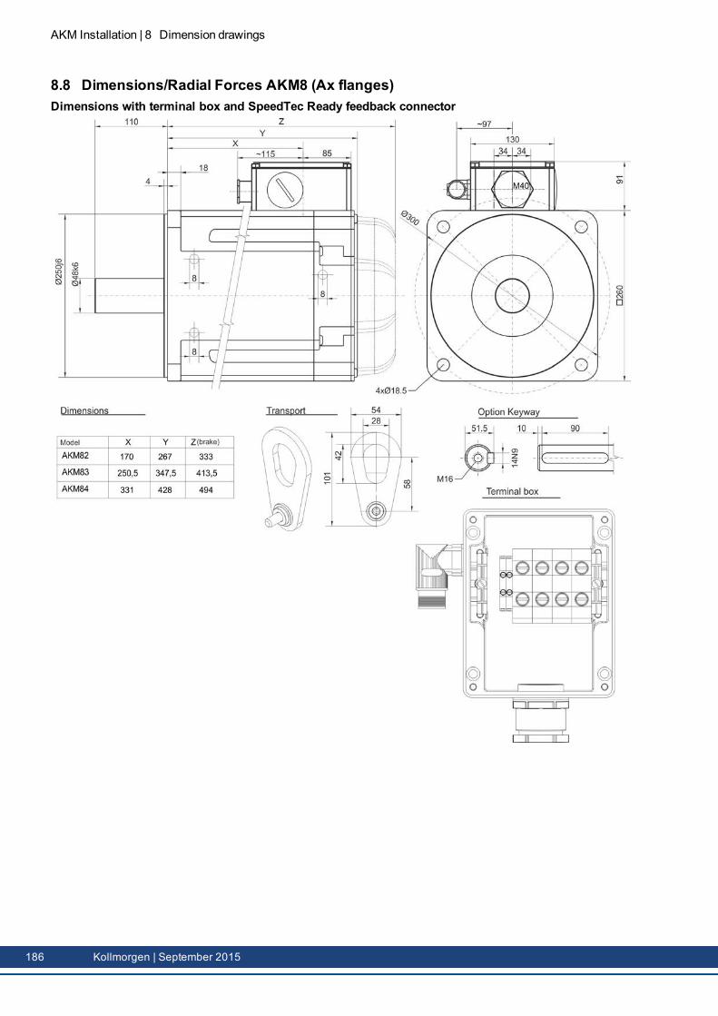
AKM Installation | 8 Dimension drawings
8.8 Dimensions/Radial Forces AKM8 (Ax flanges)Dimensions with terminal box and SpeedTec Ready feedback connector
186 Kollmorgen | September 2015
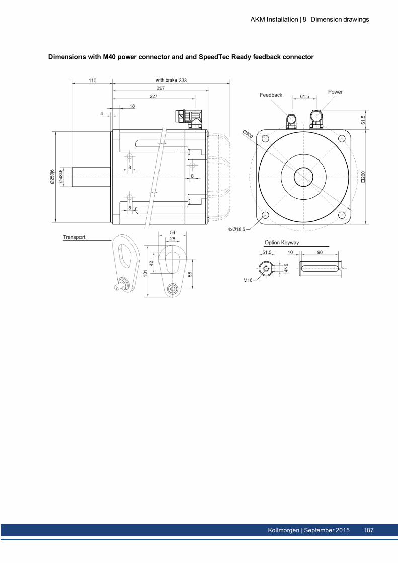
Dimensions with M40 power connector and and SpeedTec Ready feedback connector
AKM Installation | 8 Dimension drawings
Kollmorgen | September 2015 187
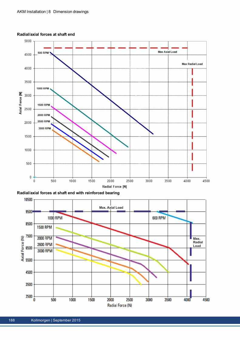
AKM Installation | 8 Dimension drawings
Radial/axial forces at shaft end
Radial/axial forces at shaft end with reinforced bearing
188 Kollmorgen | September 2015
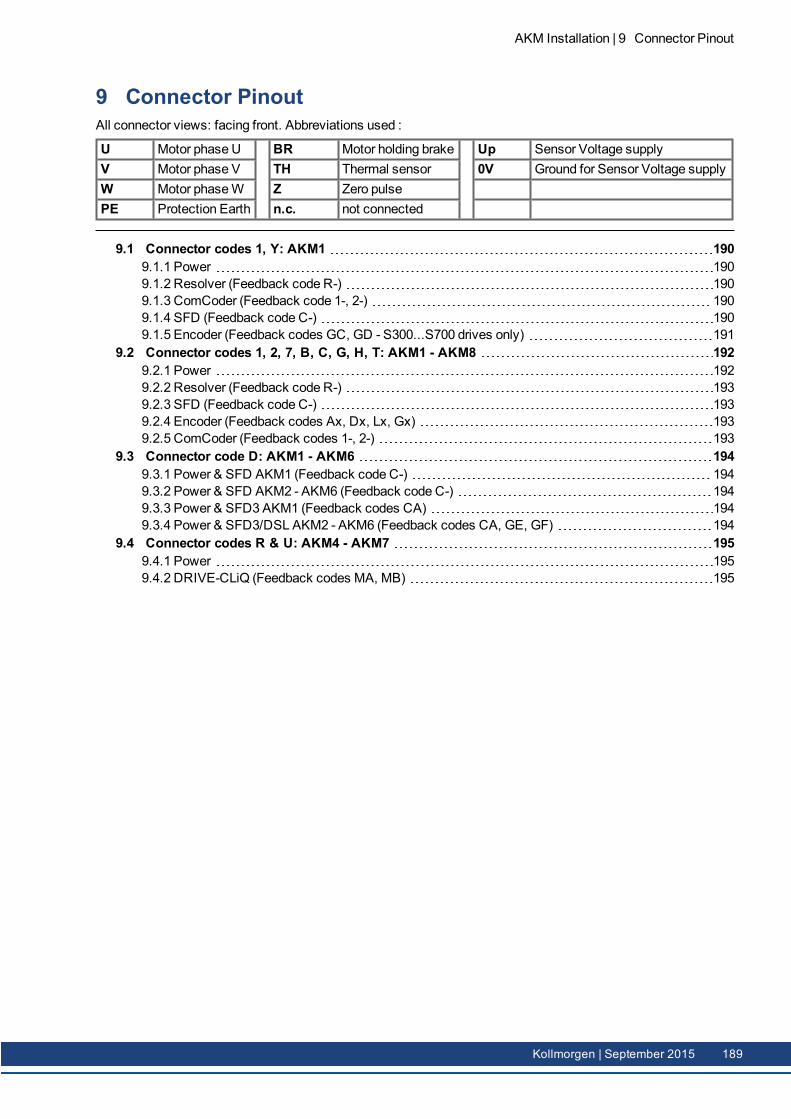
9 Connector PinoutAll connector views: facing front. Abbreviations used :
U Motor phase U BR Motor holding brake Up Sensor Voltage supplyV Motor phase V TH Thermal sensor 0V Ground for Sensor Voltage supplyW Motor phaseW Z Zero pulsePE Protection Earth n.c. not connected
9.1 Connector codes 1, Y: AKM1 1909.1.1 Power 1909.1.2 Resolver (Feedback code R-) 1909.1.3 ComCoder (Feedback code 1-, 2-) 1909.1.4 SFD (Feedback code C-) 1909.1.5 Encoder (Feedback codes GC, GD - S300...S700 drives only) 191
9.2 Connector codes 1, 2, 7, B, C, G, H, T: AKM1 - AKM8 1929.2.1 Power 1929.2.2 Resolver (Feedback code R-) 1939.2.3 SFD (Feedback code C-) 1939.2.4 Encoder (Feedback codes Ax, Dx, Lx, Gx) 1939.2.5 ComCoder (Feedback codes 1-, 2-) 193
9.3 Connector code D: AKM1 - AKM6 1949.3.1 Power & SFD AKM1 (Feedback code C-) 1949.3.2 Power & SFD AKM2 - AKM6 (Feedback code C-) 1949.3.3 Power & SFD3 AKM1 (Feedback codes CA) 1949.3.4 Power & SFD3/DSL AKM2 - AKM6 (Feedback codes CA, GE, GF) 194
9.4 Connector codes R & U: AKM4 - AKM7 1959.4.1 Power 1959.4.2 DRIVE-CLiQ (Feedback codes MA, MB) 195
AKM Installation | 9 Connector Pinout
Kollmorgen | September 2015 189
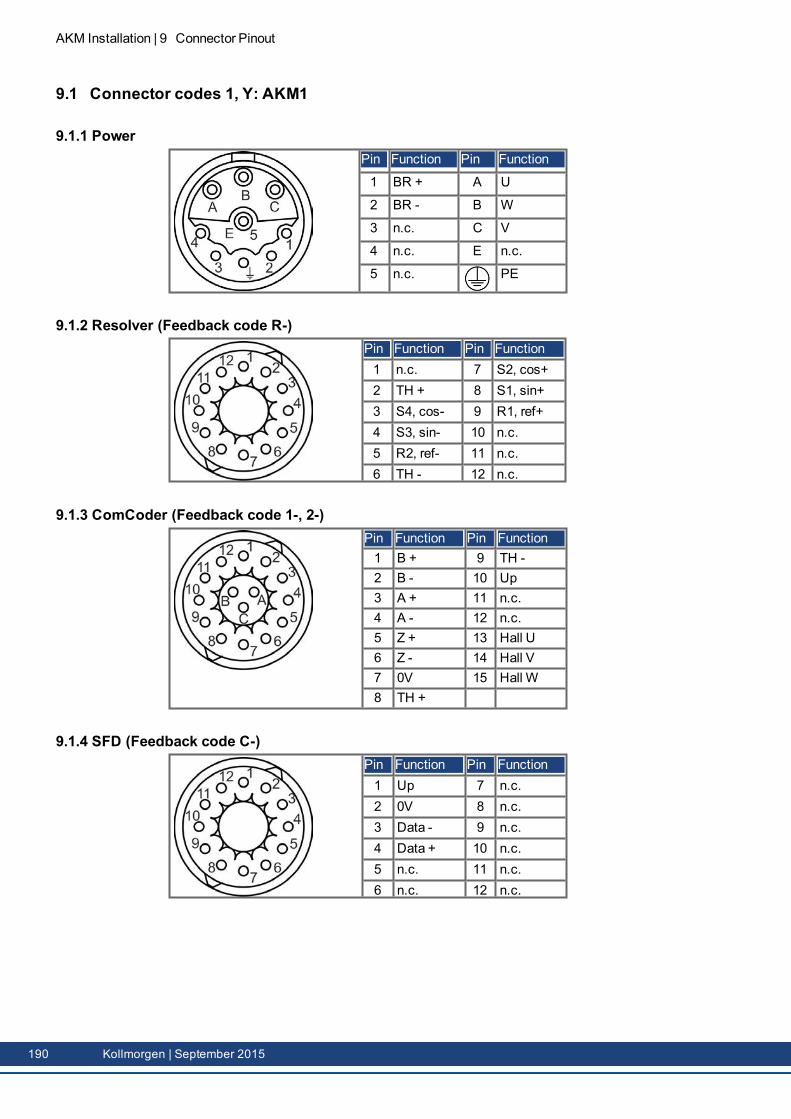
AKM Installation | 9 Connector Pinout
9.1 Connector codes 1, Y: AKM1
9.1.1 PowerPin Function Pin Function
1 BR + A U
2 BR - B W
3 n.c. C V
4 n.c. E n.c.
5 n.c. PE
9.1.2 Resolver (Feedback code R-)Pin Function Pin Function1 n.c. 7 S2, cos+2 TH + 8 S1, sin+3 S4, cos- 9 R1, ref+4 S3, sin- 10 n.c.5 R2, ref- 11 n.c.6 TH - 12 n.c.
9.1.3 ComCoder (Feedback code 1-, 2-)Pin Function Pin Function1 B + 9 TH -2 B - 10 Up3 A + 11 n.c.4 A - 12 n.c.5 Z + 13 Hall U6 Z - 14 Hall V7 0V 15 Hall W8 TH +
9.1.4 SFD (Feedback code C-)Pin Function Pin Function1 Up 7 n.c.2 0V 8 n.c.3 Data - 9 n.c.4 Data + 10 n.c.5 n.c. 11 n.c.6 n.c. 12 n.c.
190 Kollmorgen | September 2015
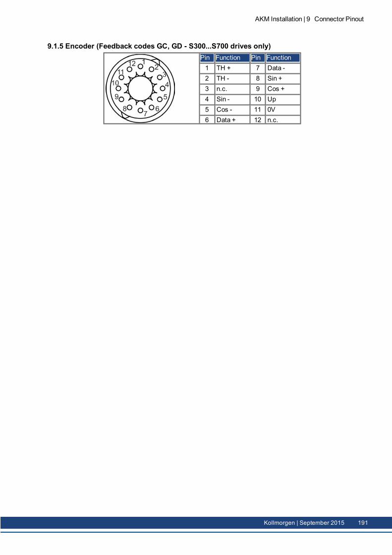
9.1.5 Encoder (Feedback codes GC, GD - S300...S700 drives only)Pin Function Pin Function1 TH + 7 Data -2 TH - 8 Sin +3 n.c. 9 Cos +4 Sin - 10 Up5 Cos - 11 0V6 Data + 12 n.c.
AKM Installation | 9 Connector Pinout
Kollmorgen | September 2015 191
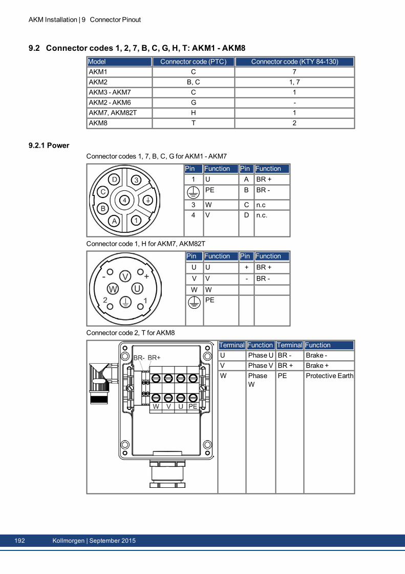
AKM Installation | 9 Connector Pinout
9.2 Connector codes 1, 2, 7, B, C, G, H, T: AKM1 - AKM8Model Connector code (PTC) Connector code (KTY 84-130)AKM1 C 7AKM2 B, C 1, 7AKM3 - AKM7 C 1AKM2 - AKM6 G -AKM7, AKM82T H 1AKM8 T 2
9.2.1 PowerConnector codes 1, 7, B, C, G for AKM1 - AKM7
Pin Function Pin Function1 U A BR +
PE B BR -
3 W C n.c4 V D n.c.
Connector code 1, H for AKM7, AKM82T
Pin Function Pin FunctionU U + BR +V V - BR -W W
PE
Connector code 2, T for AKM8
Terminal Function Terminal FunctionU Phase U BR - Brake -V Phase V BR + Brake +W Phase
WPE Protective Earth
192 Kollmorgen | September 2015
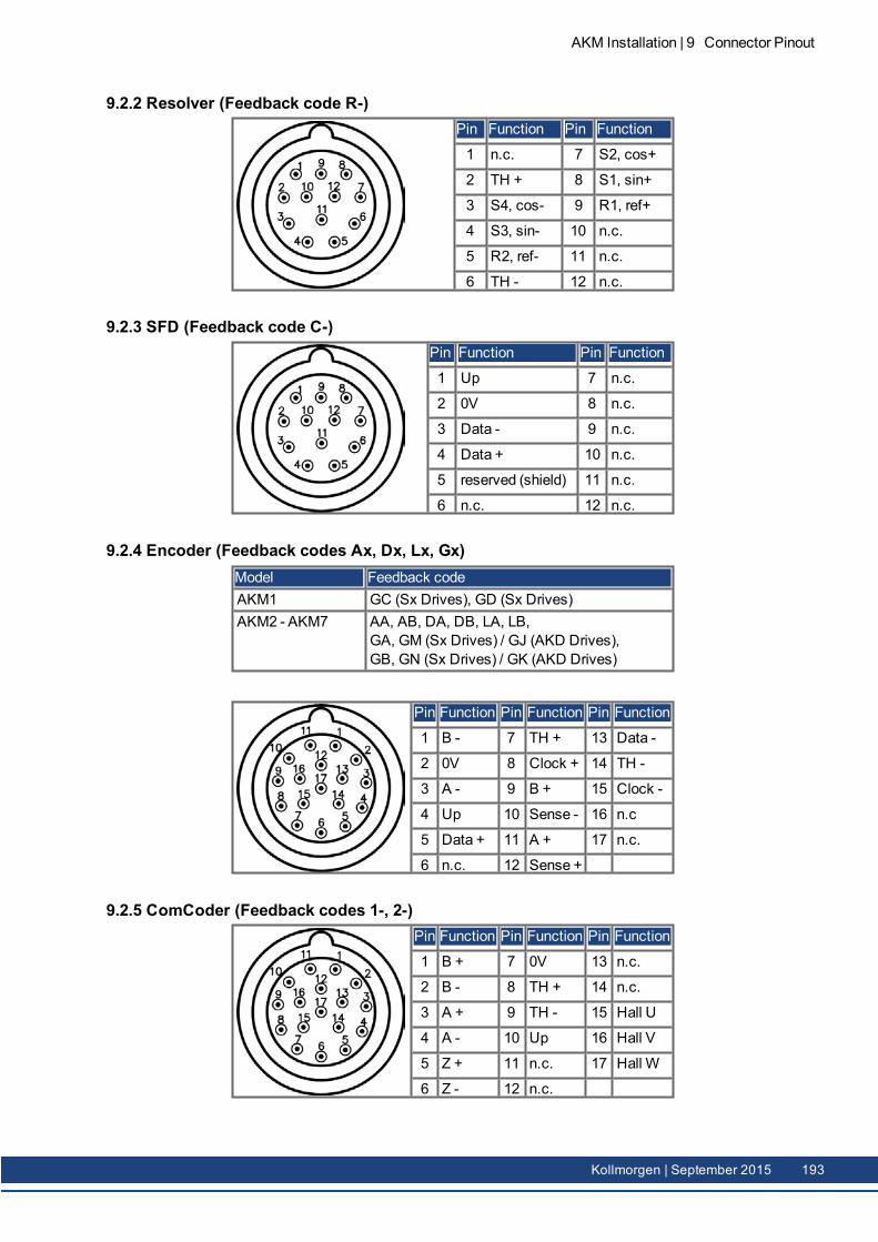
9.2.2 Resolver (Feedback code R-)Pin Function Pin Function
1 n.c. 7 S2, cos+
2 TH + 8 S1, sin+
3 S4, cos- 9 R1, ref+
4 S3, sin- 10 n.c.
5 R2, ref- 11 n.c.
6 TH - 12 n.c.
9.2.3 SFD (Feedback code C-)Pin Function Pin Function
1 Up 7 n.c.
2 0V 8 n.c.
3 Data - 9 n.c.
4 Data + 10 n.c.
5 reserved (shield) 11 n.c.
6 n.c. 12 n.c.
9.2.4 Encoder (Feedback codes Ax, Dx, Lx, Gx)Model Feedback codeAKM1 GC (Sx Drives), GD (Sx Drives)AKM2 - AKM7 AA, AB, DA, DB, LA, LB,
GA, GM (Sx Drives) / GJ (AKD Drives),GB, GN (Sx Drives) / GK (AKD Drives)
Pin Function Pin Function Pin Function
1 B - 7 TH + 13 Data -
2 0V 8 Clock + 14 TH -
3 A - 9 B + 15 Clock -
4 Up 10 Sense - 16 n.c
5 Data + 11 A + 17 n.c.
6 n.c. 12 Sense +
9.2.5 ComCoder (Feedback codes 1-, 2-)Pin Function Pin Function Pin Function
1 B + 7 0V 13 n.c.
2 B - 8 TH + 14 n.c.
3 A + 9 TH - 15 Hall U
4 A - 10 Up 16 Hall V
5 Z + 11 n.c. 17 Hall W
6 Z - 12 n.c.
AKM Installation | 9 Connector Pinout
Kollmorgen | September 2015 193
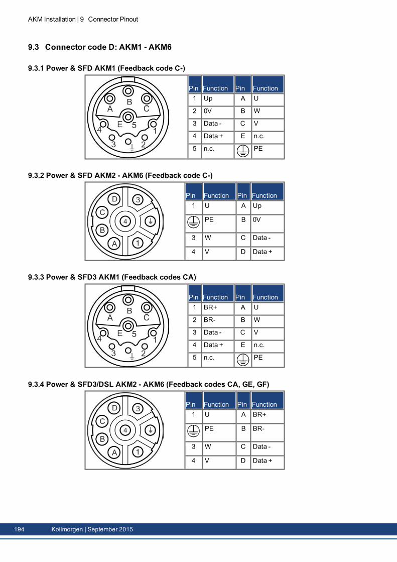
AKM Installation | 9 Connector Pinout
9.3 Connector code D: AKM1 - AKM6
9.3.1 Power & SFD AKM1 (Feedback code C-)
Pin Function Pin Function1 Up A U
2 0V B W
3 Data - C V
4 Data + E n.c.
5 n.c. PE
9.3.2 Power & SFD AKM2 - AKM6 (Feedback code C-)
Pin Function Pin Function1 U A Up
PE B 0V
3 W C Data -
4 V D Data +
9.3.3 Power & SFD3 AKM1 (Feedback codes CA)
Pin Function Pin Function1 BR+ A U
2 BR- B W
3 Data - C V
4 Data + E n.c.
5 n.c. PE
9.3.4 Power & SFD3/DSL AKM2 - AKM6 (Feedback codes CA, GE, GF)
Pin Function Pin Function1 U A BR+
PE B BR-
3 W C Data -
4 V D Data +
194 Kollmorgen | September 2015
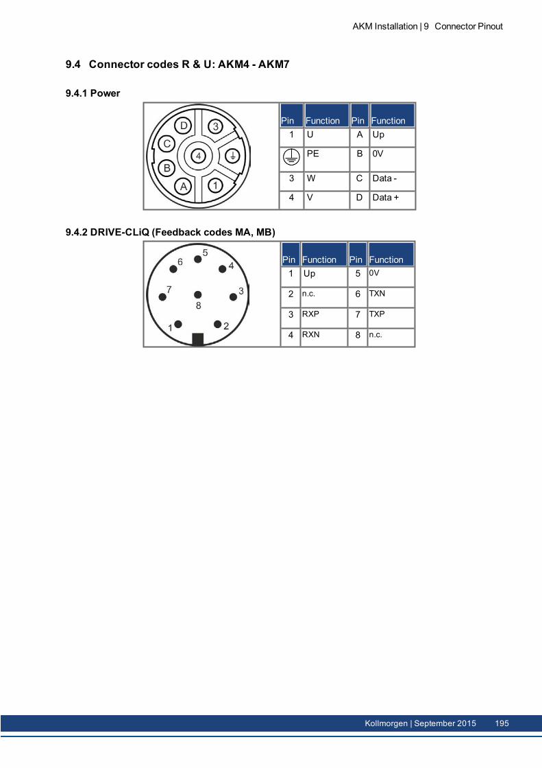
9.4 Connector codes R & U: AKM4 - AKM7
9.4.1 Power
Pin Function Pin Function1 U A Up
PE B 0V
3 W C Data -
4 V D Data +
9.4.2 DRIVE-CLiQ (Feedback codes MA, MB)
Pin Function Pin Function1 Up 5 0V
2 n.c. 6 TXN
3 RXP 7 TXP
4 RXN 8 n.c.
AKM Installation | 9 Connector Pinout
Kollmorgen | September 2015 195
AKM Installation | 10 Approvals
10 ApprovalsCertificates can be found in our Product WIKI on the Approvals page.
10.1 Conformance with UL 19710.2 Conformance with CE 19710.3 Conformance with EAC 19710.4 Conformance with RoHS 19710.5 Conformanced with REACH 197
196 Kollmorgen | September 2015
10.1 Conformance with ULRecognized for USA and Canada in File E61960.
10.2 Conformance with CEThemotors have been tested by an authorized testing laboratory in a defined configuration.Any divergence from the configuration and installation described in this documentationmeans that the user will be responsible for carrying out new measurements to ensure con-formance with regulatory requirements.Feedback systems and contacts must not be tested with high voltage. Feedback systemsare not suitable for high voltage testing, it is allowed to exclude sensitive electronic com-ponents from these tests. Feedback systems might be destroyed during a high voltage test.CE Declaration of Conformity can be found on the Kollmorgen website.Kollmorgen declares the conformity of the product series AKM with the following directives:
EC Directive 2006/95/EC, low voltageEC Directive 2004/108/EC, electromagnetic compatibility
10.3 Conformance with EACEAC is the abbreviation for EurAsian Conformity. Themark is used in the states of the Eur-asian Customs Union (Russia, Belarus, Kazakhstan) similar to the European CE mark.Kollmorgen declares, that the AKM has passed all required conformity procedures in amem-ber state of the Eurasian Customs Union, and that the AKMmeets all technical requirementsrequested in themember states of the Eurasian Customs Union :
Low voltage (TP TC 020/2011)Electromagnetic Compatibility (TP TC 004/2011)
Contact in Russia:Intelligence Automatics LLC. , Bakuninskaya Str. d 14, Building 1, RU-105005Moskau
10.4 Conformance with RoHSDirective 2011/65/EC of the European Union on the restriction of the use of certain haz-ardous substances in electrical and electronic equipment (RoHS) became operative as fromthe 3rd of January, 2013. Following substances namely are involvedLead (Pb), • Cadmium (Cd), Hexavalent chromium (CrVI), Polybrominated biphenyls (PBB),Polybrominated diphenyl ethers (PBDE), Mercury (Hg)The AKMmotor series is manufactured RoHS conformal.
10.5 Conformanced with REACHEU Regulation no. 1907/2006 deals with the registration, evaluation, authorisation and restric-tion of chemical substances 1 (abbreviated to "REACH").AKMmotors do not contain any substances (CMR substances, PBTsubstances, vPvB sub-stances and similar hazardous substances stipulated in individual cases based on scientificcriteria) above 0.1mass percent per product that are included on the candidate list.
AKM Installation | 10 Approvals
Kollmorgen | September 2015 197
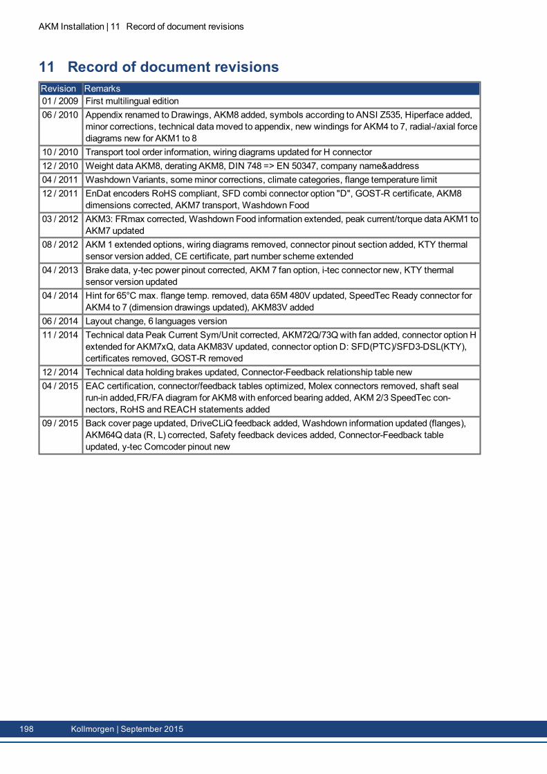
AKM Installation | 11 Record of document revisions
11 Record of document revisionsRevision Remarks01 / 2009 First multilingual edition06 / 2010 Appendix renamed to Drawings, AKM8 added, symbols according to ANSI Z535, Hiperface added,
minor corrections, technical datamoved to appendix, new windings for AKM4 to 7, radial-/axial forcediagrams new for AKM1 to 8
10 / 2010 Transport tool order information, wiring diagrams updated for H connector12 / 2010 Weight data AKM8, derating AKM8, DIN 748 => EN 50347, company name&address04 / 2011 Washdown Variants, someminor corrections, climate categories, flange temperature limit12 / 2011 EnDat encoders RoHS compliant, SFD combi connector option "D", GOST-R certificate, AKM8
dimensions corrected, AKM7 transport, Washdown Food03 / 2012 AKM3: FRmax corrected, Washdown Food information extended, peak current/torque data AKM1 to
AKM7 updated08 / 2012 AKM 1 extended options, wiring diagrams removed, connector pinout section added, KTY thermal
sensor version added, CE certificate, part number scheme extended04 / 2013 Brake data, y-tec power pinout corrected, AKM 7 fan option, i-tec connector new, KTY thermal
sensor version updated04 / 2014 Hint for 65°C max. flange temp. removed, data 65M 480V updated, SpeedTec Ready connector for
AKM4 to 7 (dimension drawings updated), AKM83V added06 / 2014 Layout change, 6 languages version11 / 2014 Technical data Peak Current Sym/Unit corrected, AKM72Q/73Qwith fan added, connector option H
extended for AKM7xQ, data AKM83V updated, connector option D: SFD(PTC)/SFD3-DSL(KTY),certificates removed, GOST-R removed
12 / 2014 Technical data holding brakes updated, Connector-Feedback relationship table new04 / 2015 EAC certification, connector/feedback tables optimized, Molex connectors removed, shaft seal
run-in added,FR/FA diagram for AKM8with enforced bearing added, AKM 2/3 SpeedTec con-nectors, RoHS and REACH statements added
09 / 2015 Back cover page updated, DriveCLiQ feedback added, Washdown information updated (flanges),AKM64Q data (R, L) corrected, Safety feedback devices added, Connector-Feedback tableupdated, y-tec Comcoder pinout new
198 Kollmorgen | September 2015

-- / --
AKM Installation | 11 Record of document revisions
Kollmorgen | September 2015 199

ServiceWeare committed to quality customer service. In order to serve in themost effective way, please contact yourlocal sales representative for assistance.If you are unaware of your local sales representative, please contact the Customer Support.
EuropeKOLLMORGEN Customer Support EuropeInternet: www.kollmorgen.com/ukE-Mail: [email protected].: +49 (0)2102 - 9394 - 0Fax: +49 (0)2102 - 9394 - 3155
KOLLMORGENUKWebsite
EuropeanProduct WIKI
North AmericaKOLLMORGEN Customer Support North AmericaInternet: www.kollmorgen.comE-Mail: [email protected].: +1 - 540 - 633 - 3545Fax: +1 - 540 - 639 - 4162
KOLLMORGENUSWebsite
AsiaKOLLMORGENInternet: www.kollmorgen.cnE-Mail: [email protected]: +86 - 400 661 2802Fax: +86 - 21 6128 9877
KOLLMORGENCHINAWebsite
Related Documents