AIRCRAFT STRUCTURES

Welcome message from author
This document is posted to help you gain knowledge. Please leave a comment to let me know what you think about it! Share it to your friends and learn new things together.
Transcript
AIRCRAFT STRUCTURES
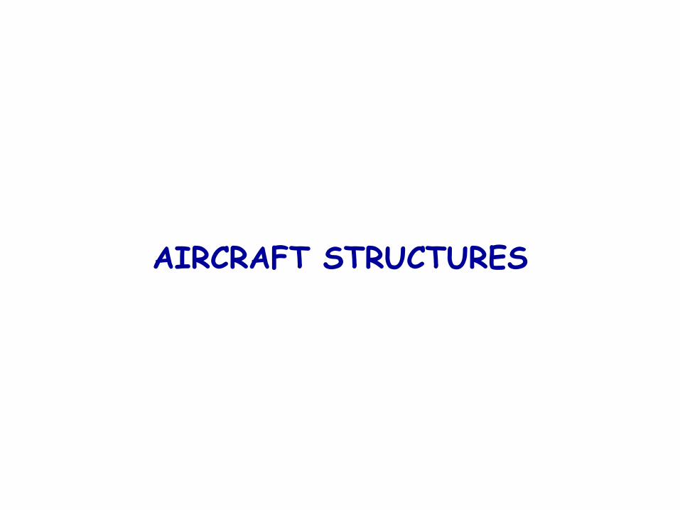
AIRCRAFT STRUCTURAL COMPONENTS
Vertical
Stabiliser
Rudder
ElevatorHorizontal
Stabiliser
Empennage
Right
Wing Right
Aileron
Left
Aileron
Fuselage
Left
Wing
Landing gear
Nacelle
Propeller
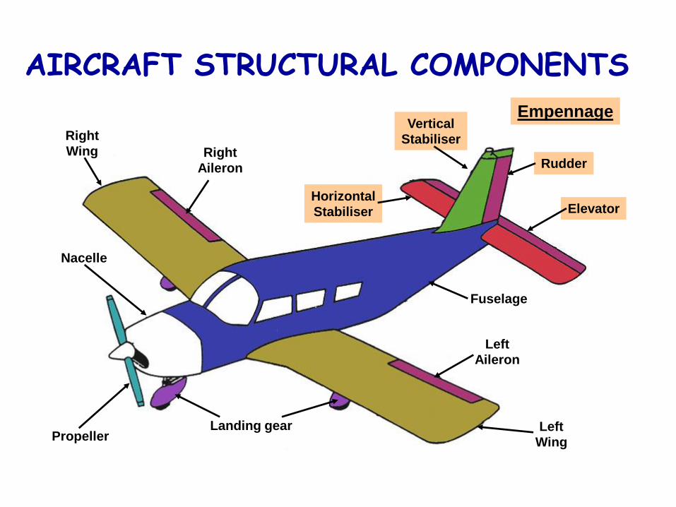
FUNCTIONS OF THE FUSELAGE
• The fuselage is the main structure of the aircraft• It provides:
- Cockpit- Passenger cabin- Cargo holds- Control runs- Mountings for:
WingsEmpennageLanding gearSome engine fitmentsSome fuel tanks
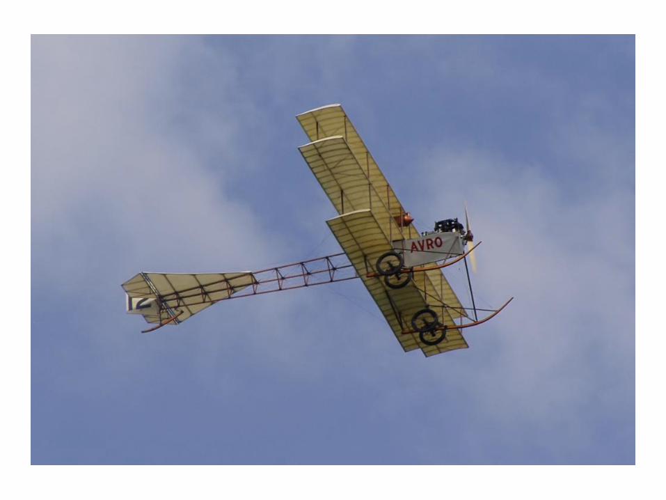
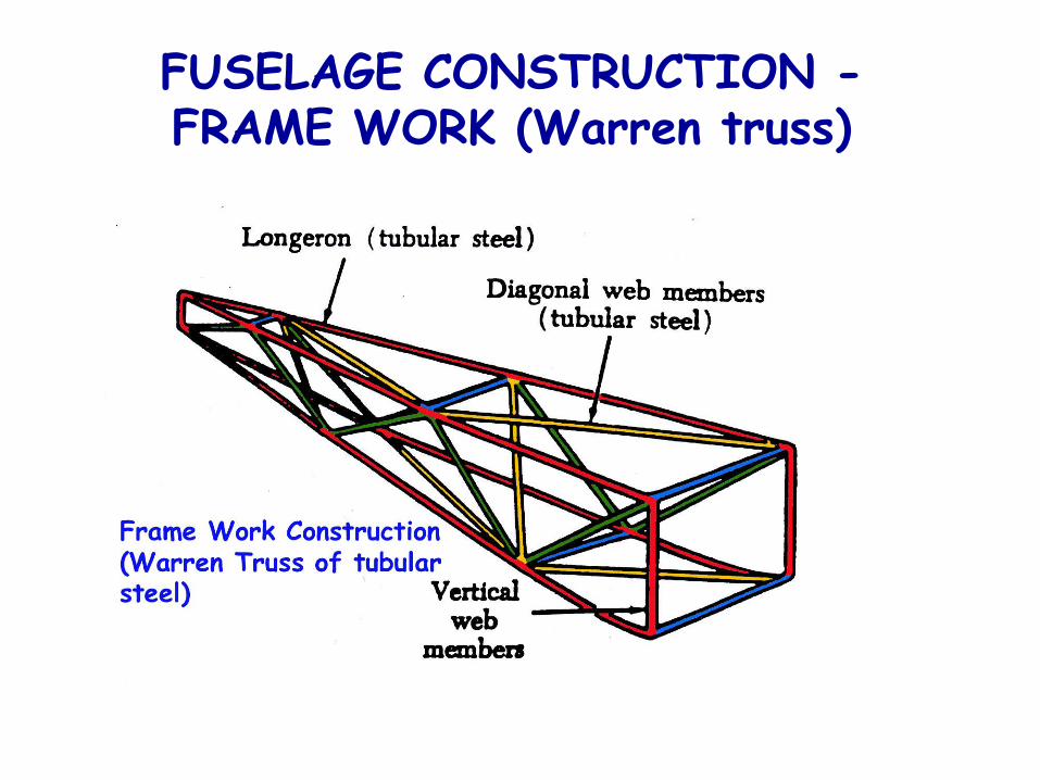
FUSELAGE CONSTRUCTION -FRAME WORK (Warren truss)
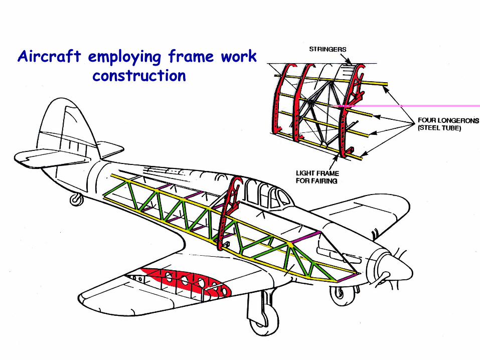
Aircraft employing frame work construction
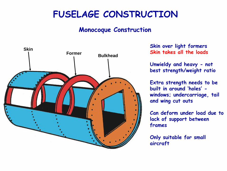
FUSELAGE CONSTRUCTION
Skin over light formersSkin takes all the loads
Unwieldy and heavy - not best strength/weight ratio
Extra strength needs to be built in around ‘holes’ -windows; undercarriage, tail and wing cut outs
Can deform under load due to lack of support between frames
Only suitable for small aircraft
Monocoque Construction
SkinFormer
Bulkhead
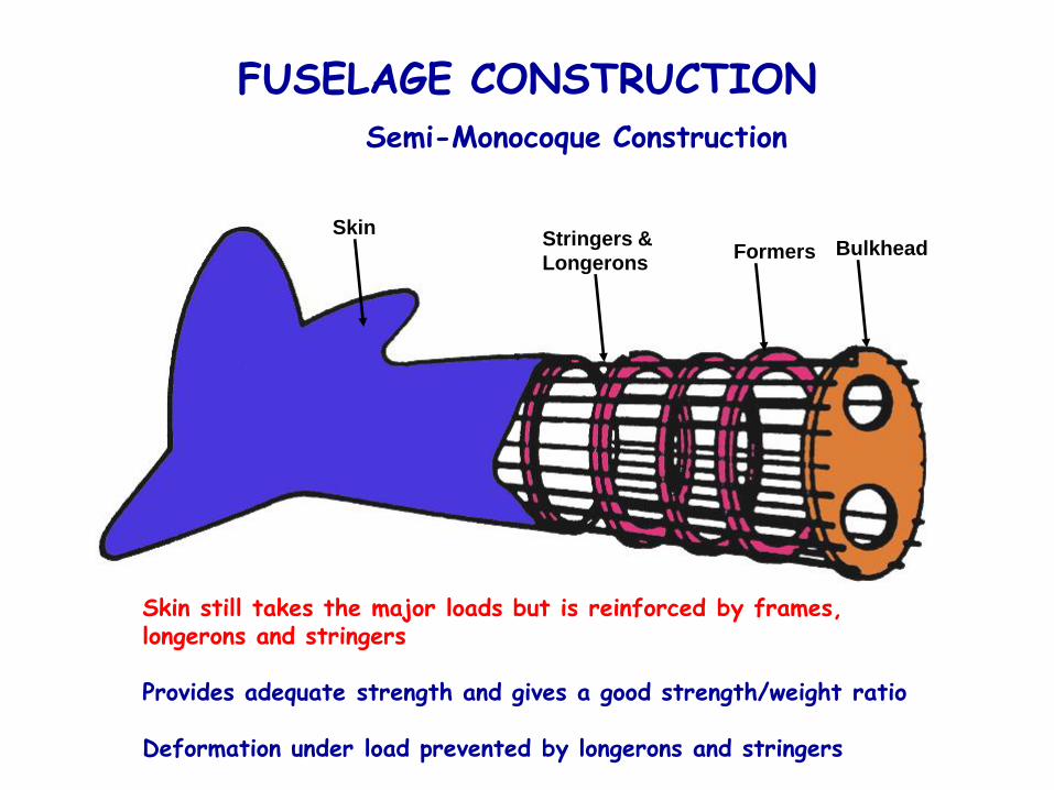
FUSELAGE CONSTRUCTION
Formers BulkheadSkin
Stringers &
Longerons
Semi-Monocoque Construction
Skin still takes the major loads but is reinforced by frames, longerons and stringers
Provides adequate strength and gives a good strength/weight ratio
Deformation under load prevented by longerons and stringers
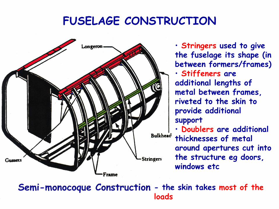
FUSELAGE CONSTRUCTION
• Stringers used to give the fuselage its shape (in between formers/frames)• Stiffeners are additional lengths of metal between frames, riveted to the skin to provide additional support• Doublers are additional thicknesses of metal around apertures cut into the structure eg doors, windows etc
- the skin takes most of the loads
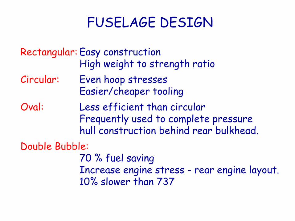
FUSELAGE DESIGN
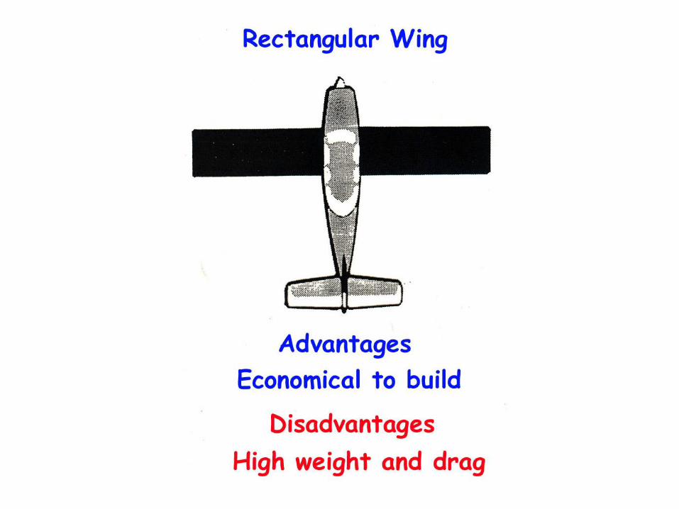
Rectangular: Easy constructionHigh weight to strength ratio
Circular: Even hoop stressesEasier/cheaper tooling
Oval: Less efficient than circularFrequently used to complete pressure hull construction behind rear bulkhead.
Double Bubble:70 % fuel savingIncrease engine stress - rear engine layout.10% slower than 737
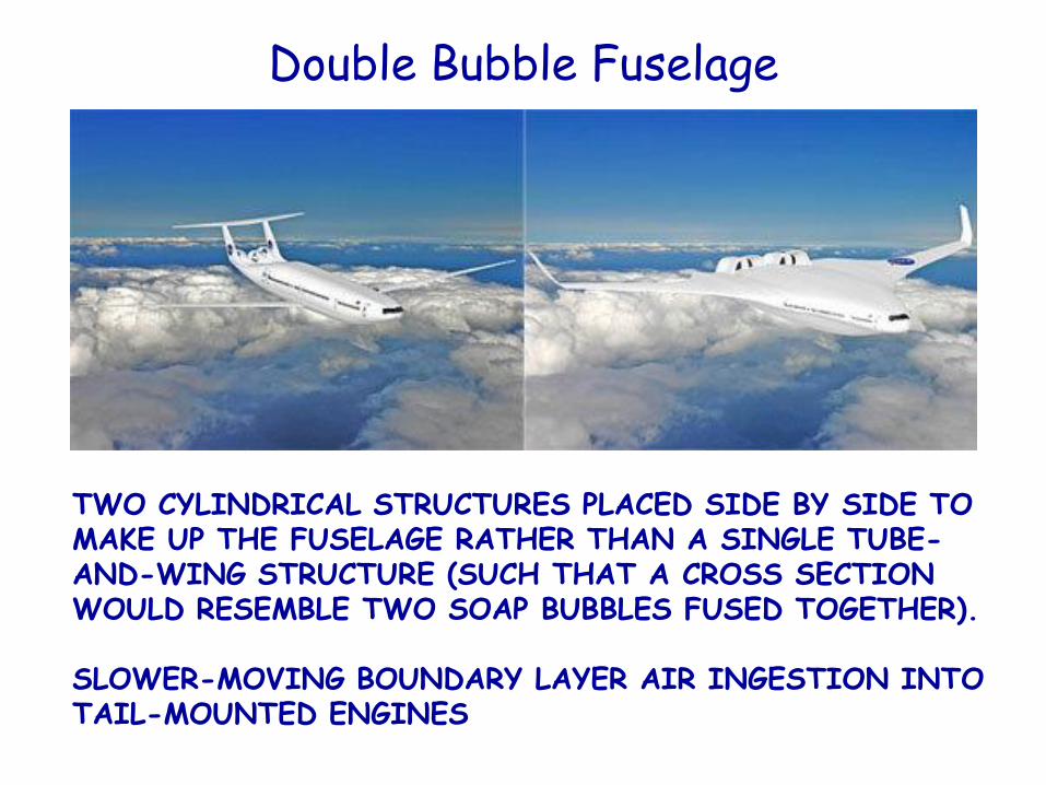
Double Bubble Fuselage
TWO CYLINDRICAL STRUCTURES PLACED SIDE BY SIDE TO MAKE UP THE FUSELAGE RATHER THAN A SINGLE TUBE-AND-WING STRUCTURE (SUCH THAT A CROSS SECTION WOULD RESEMBLE TWO SOAP BUBBLES FUSED TOGETHER).
SLOWER-MOVING BOUNDARY LAYER AIR INGESTION INTO TAIL-MOUNTED ENGINES
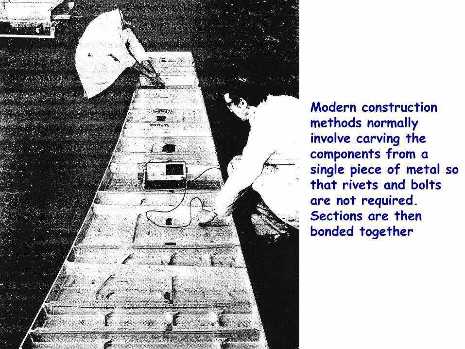
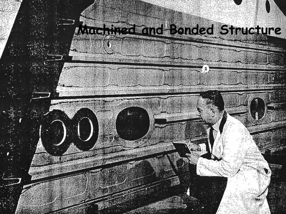
Modern construction methods normally involve carving the components from a single piece of metal so that rivets and bolts are not required. Sections are then bonded together
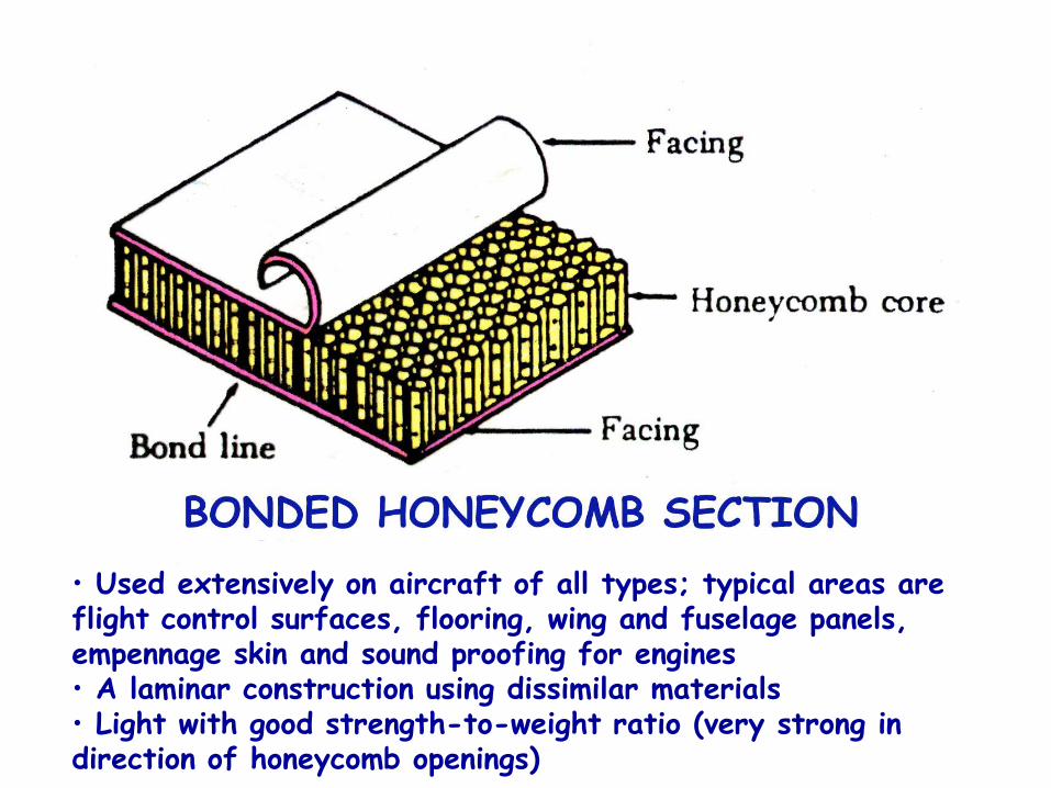
• Used extensively on aircraft of all types; typical areas are flight control surfaces, flooring, wing and fuselage panels, empennage skin and sound proofing for engines• A laminar construction using dissimilar materials• Light with good strength-to-weight ratio (very strong in direction of honeycomb openings)
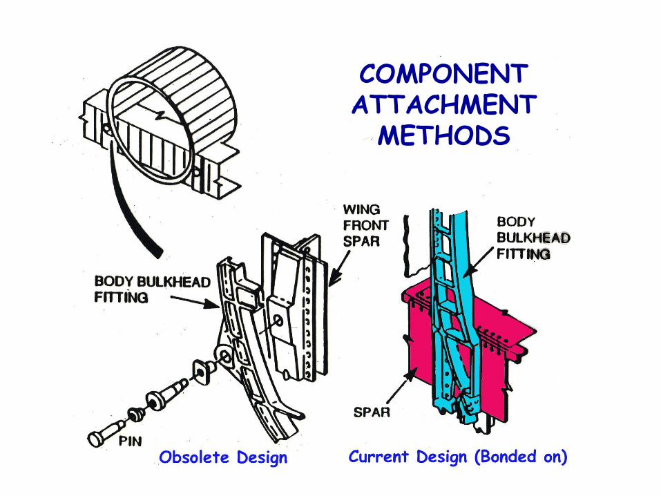
COMPONENT ATTACHMENT
METHODS
MATERIALS
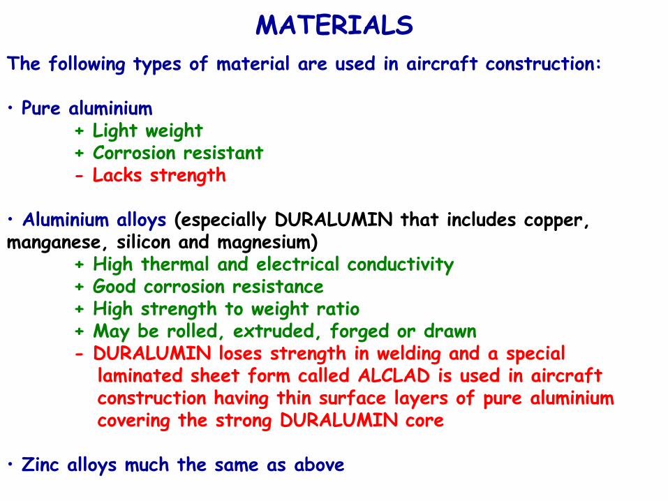
The following types of material are used in aircraft construction:
• Pure aluminium+ Light weight+ Corrosion resistant- Lacks strength
• Aluminium alloys (especially DURALUMIN that includes copper, manganese, silicon and magnesium)
+ High thermal and electrical conductivity+ Good corrosion resistance+ High strength to weight ratio+ May be rolled, extruded, forged or drawn- DURALUMIN loses strength in welding and a special
laminated sheet form called ALCLAD is used in aircraftconstruction having thin surface layers of pure aluminiumcovering the strong DURALUMIN core
• Zinc alloys much the same as above
MATERIALS
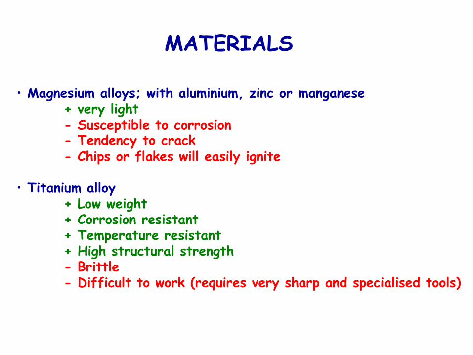
• Magnesium alloys; with aluminium, zinc or manganese+ very light- Susceptible to corrosion- Tendency to crack- Chips or flakes will easily ignite
• Titanium alloy+ Low weight+ Corrosion resistant+ Temperature resistant+ High structural strength- Brittle- Difficult to work (requires very sharp and specialised tools)
MATERIALS
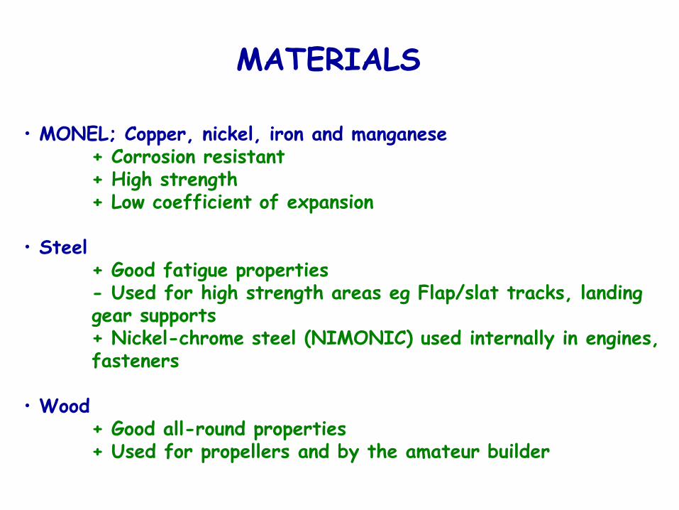
• MONEL; Copper, nickel, iron and manganese+ Corrosion resistant+ High strength+ Low coefficient of expansion
• Steel+ Good fatigue properties- Used for high strength areas eg Flap/slat tracks, landing gear supports+ Nickel-chrome steel (NIMONIC) used internally in engines, fasteners
• Wood+ Good all-round properties+ Used for propellers and by the amateur builder
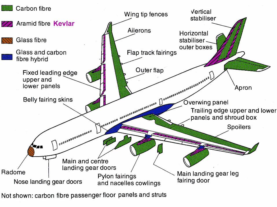
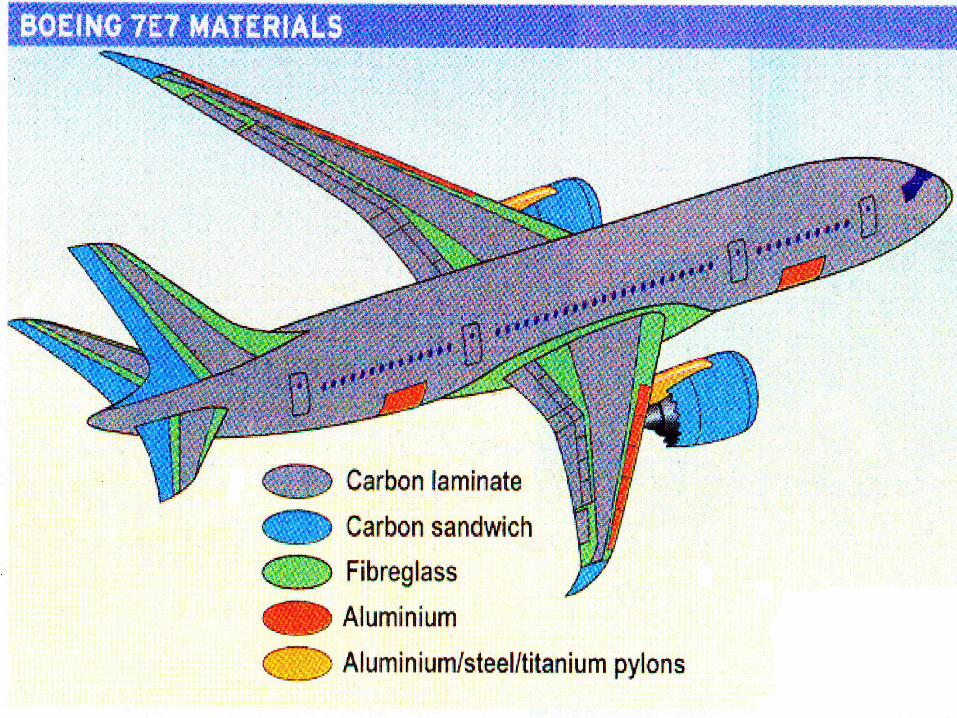
COMPOSITE MATERIALS
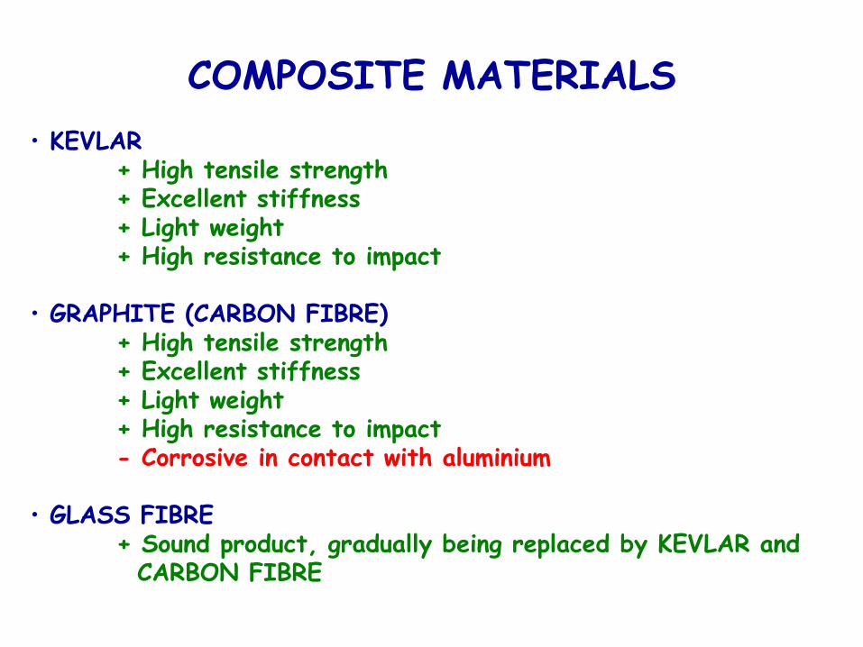
• KEVLAR+ High tensile strength+ Excellent stiffness+ Light weight+ High resistance to impact
• GRAPHITE (CARBON FIBRE)+ High tensile strength+ Excellent stiffness+ Light weight+ High resistance to impact- Corrosive in contact with aluminium
• GLASS FIBRE+ Sound product, gradually being replaced by KEVLAR and CARBON FIBRE
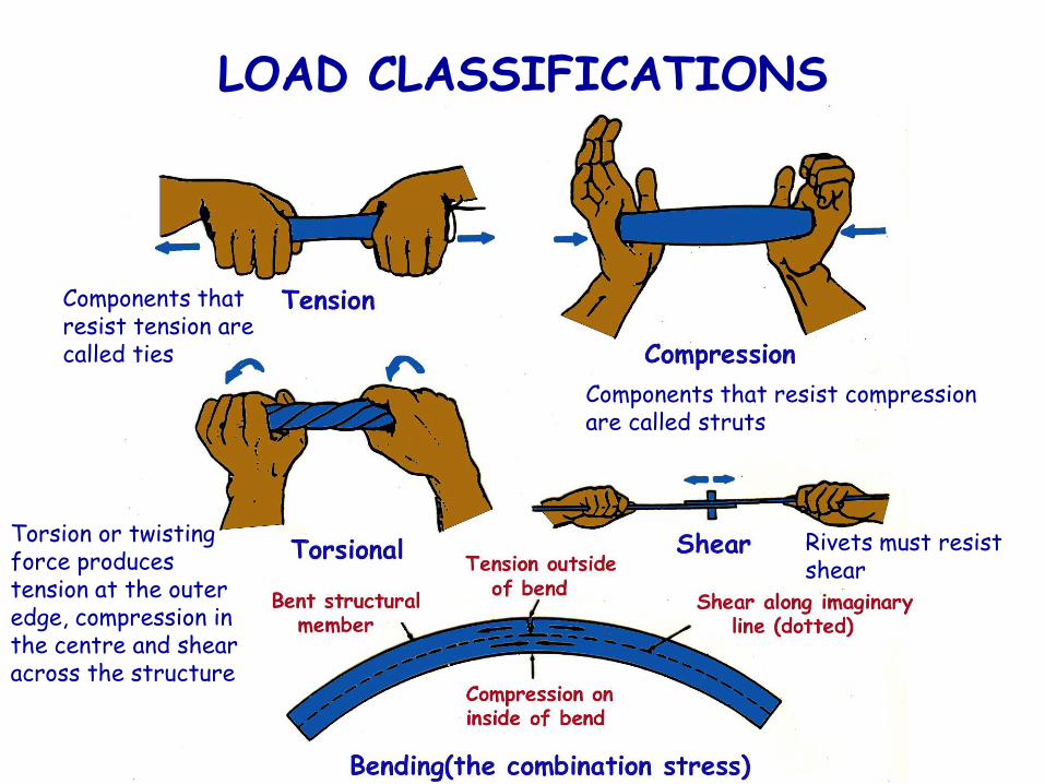
LOAD CLASSIFICATIONS
Components that resist tension are called ties
Components that resist compression are called struts
Rivets must resist shear
Torsion or twisting force produces tension at the outer edge, compression in the centre and shear across the structure
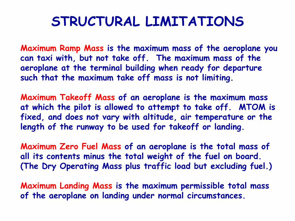
STRUCTURAL LIMITATIONS
Maximum Ramp Mass is the maximum mass of the aeroplane you can taxi with, but not take off. The maximum mass of the aeroplane at the terminal building when ready for departure such that the maximum take off mass is not limiting.
Maximum Takeoff Mass of an aeroplane is the maximum mass at which the pilot is allowed to attempt to take off. MTOM is fixed, and does not vary with altitude, air temperature or the length of the runway to be used for takeoff or landing.
Maximum Zero Fuel Mass of an aeroplane is the total mass of all its contents minus the total weight of the fuel on board. (The Dry Operating Mass plus traffic load but excluding fuel.)
Maximum Landing Mass is the maximum permissible total mass of the aeroplane on landing under normal circumstances.
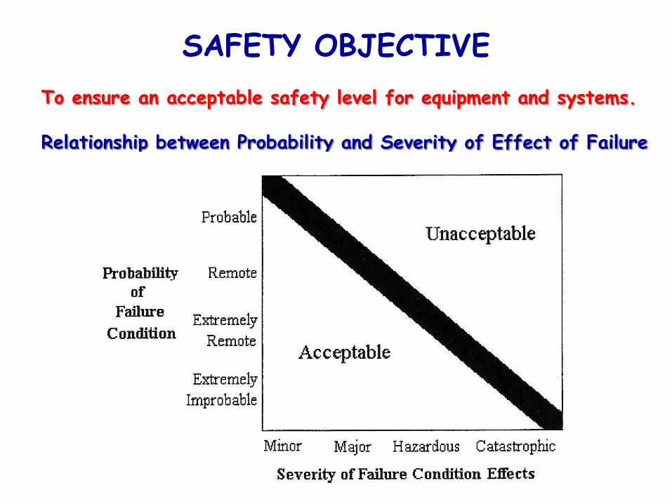
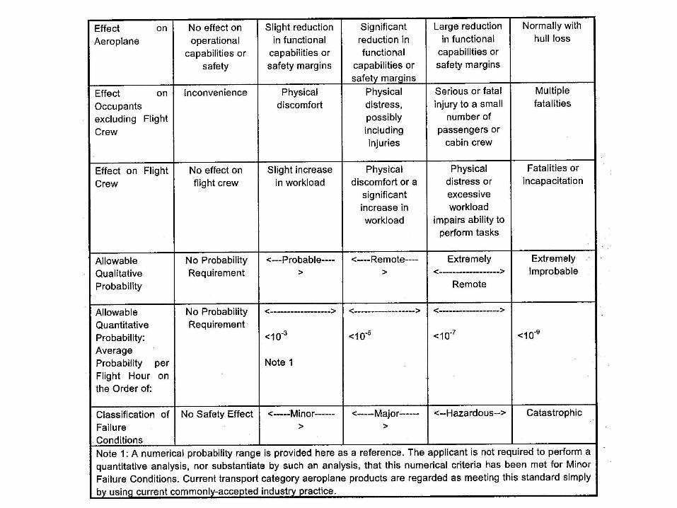
SAFETY OBJECTIVE
To ensure an acceptable safety level for equipment and systems.
Relationship between Probability and Severity of Effect of Failure
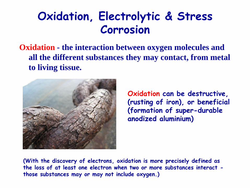
Oxidation, Electrolytic & Stress Corrosion
Oxidation - the interaction between oxygen molecules and
all the different substances they may contact, from metal
to living tissue.
Oxidation can be destructive, (rusting of iron), or beneficial (formation of super-durable anodized aluminium)
(With the discovery of electrons, oxidation is more precisely defined as the loss of at least one electron when two or more substances interact -those substances may or may not include oxygen.)
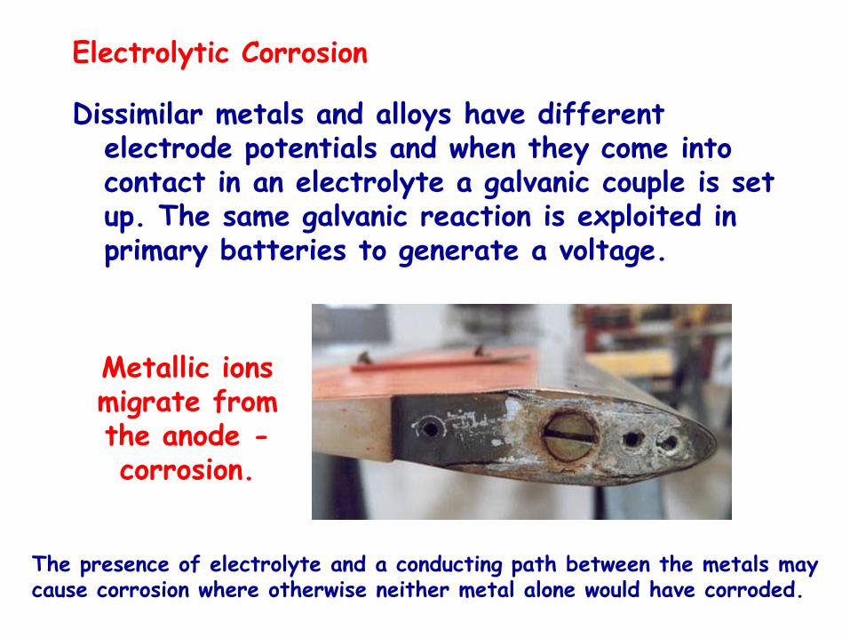
Electrolytic Corrosion
Dissimilar metals and alloys have different electrode potentials and when they come into contact in an electrolyte a galvanic couple is set up. The same galvanic reaction is exploited in primary batteries to generate a voltage.
The presence of electrolyte and a conducting path between the metals may cause corrosion where otherwise neither metal alone would have corroded.
Metallic ions migrate from the anode -corrosion.
Stress corrosion cracking (SCC) is the unexpected sudden failure of normally ductile metals subjected to a tensile stress in a corrosive environment, especially at elevated temperature in the case of metals.
SCC is highly chemically specific in that certain alloys are likely to undergo SCC only when exposed to a small number of chemical environments. The chemical environment that causes SCC for a given alloy is often one which is only mildly corrosive to the metal otherwise. Hence, metal parts with severe SCC can appear bright and shiny, while being filled with microscopic cracks. This factor makes it common for SCC to go undetected prior to failure.
SCC often progresses rapidly, and is more common among alloys than pure metals. The specific environment is of crucial importance, and only very small concentrations of certain highly active chemicals are needed to produce catastrophic cracking, often leading to devastating and unexpected failure.
HEAVY OR OVERWEIGHT LANDINGS• Primary Damage
- Landing gear- Support structure in wings/fuselage- Wing and tailplane attachments
• Secondary Damage
- Fuselage structure- Fuselage upper and lower skin- Wing structure- Wing upper and lower skin
Note: If no damage is found in the primary area, the secondary area need not be inspected
During a landing the undercarriage will be subjected to tension, compression, shear and bending (if there is any side-slip, torsion will also be present)

NOSE WHEEL LANDING
Higher risk with aeroplanes that have no leading-edge lift augmentation devices – HS146
Danger of structural damage to:
Front pressure bulkhead
Nose wheel drag and shock struts
(possibility of nose wheel collapse)
AIRCRAFT LIFE MONITORING
There are 3 philosophical approaches to designing aircraft in order to ensure that they operate safely throughout their operational lives. These approaches are as follows:
• FAIL SAFE- Structures have multiple load paths and if one part fails, other components will take over the load (eg multiple attachment points for rudder)
• SAFE LIFE- The aircraft is built strongly enough to last a pre-determined life based on either flying hours or cycles (landing/take- off/pressurisations)
• DAMAGE TOLERANT- No set life assigned to the aircraft. The concept requires repeated, routine inspections of the structure to evaluate any damage and repair it before return to service
Hard Time & On Condition Maintenance
Hard Time Maintenance
Procedure under which an item must be removed from service before its scheduled maintenance period for inspection or repair
"On-Condition" Maintenance
An inspection/functional check that determines an item's performance and may result in the removal of an item before it fails in service. (not a philosophy of fit until failure or fit and forget)
Applied to items where their continued airworthiness can be made by visual inspection, measurements, tests or other means without disassembly inspection or overhaul.
The condition of an item is monitored either continuously or at specified periods and its performance compared to an appropriate standard to determine if it can continue in service.
FATIGUE• FATIGUE occurs when a material is continually loaded and unloaded. If this cycle goes on long enough, eventually the material will break
- If the load values are low, the material will withstand lots of cycles; if the values are high, then failure will occur following a lower number
• STRAIN is the quantitative deformation caused to structures by stress. The following terms are associated with strain:
ELASTIC LIMIT is the strain to which a material may be subjected and return fully to its original state once the stress is removed
YEILD POINT is the strain that will cause a degree of stretch or deformation
ULTIMATE LOAD is the strain that will cause a material to snap or shear (JAR applies a safety factor of 1.5 to aircraft)
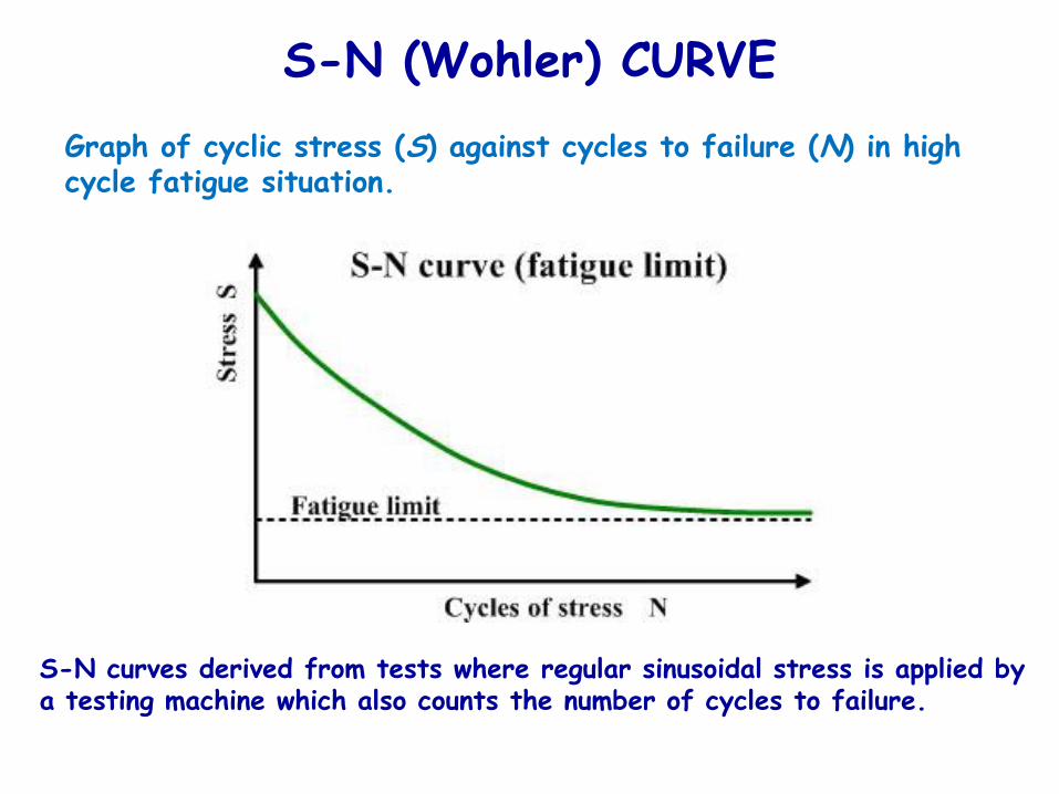
S-N (Wohler) CURVE
S-N curves derived from tests where regular sinusoidal stress is applied by a testing machine which also counts the number of cycles to failure.
Graph of cyclic stress (S) against cycles to failure (N) in high cycle fatigue situation.
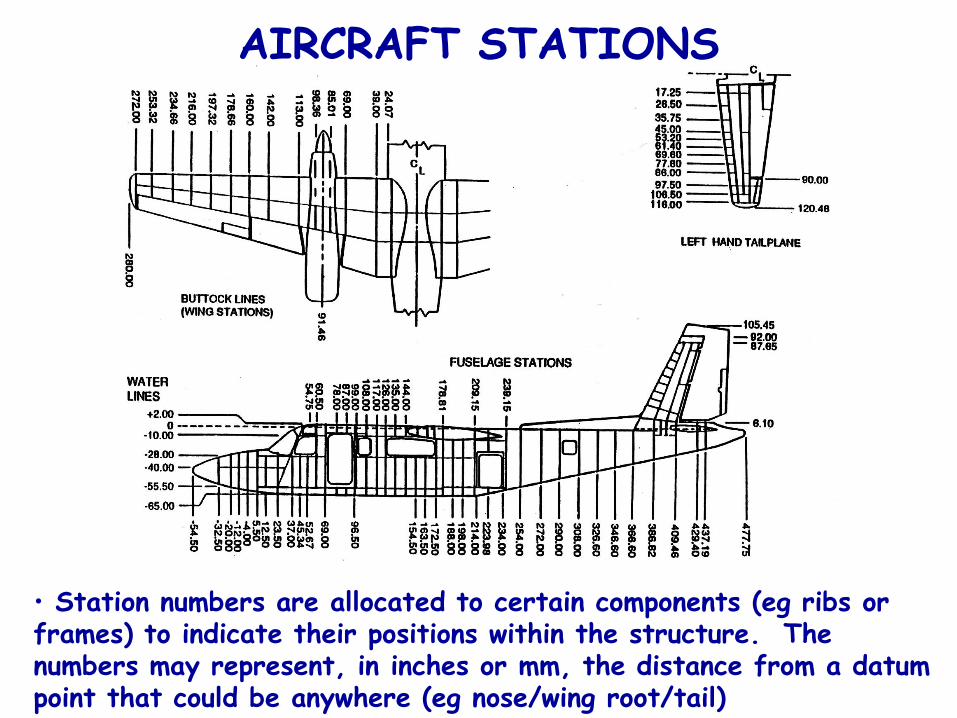
AIRCRAFT STATIONS
• Station numbers are allocated to certain components (eg ribs or frames) to indicate their positions within the structure. The numbers may represent, in inches or mm, the distance from a datum point that could be anywhere (eg nose/wing root/tail)
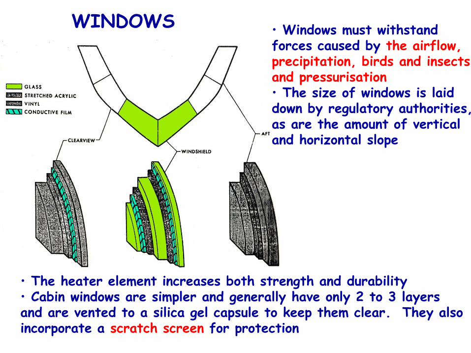
WINDOWS • Windows must withstand forces caused by the airflow, precipitation, birds and insects and pressurisation• The size of windows is laid down by regulatory authorities, as are the amount of vertical and horizontal slope
• The heater element increases both strength and durability• Cabin windows are simpler and generally have only 2 to 3 layers and are vented to a silica gel capsule to keep them clear. They also incorporate a scratch screen for protection
DIRECT VISION (DV) WINDOWS
The first pilot must have a window that:
(i) is openable when the cabin is not pressurised
(ii) provides a sufficiently extensive, clear and undistorted
view, to enable the pilot to safely perform any manoeuvres
within the operating limitations of the aeroplane, including
taxing, take-off, approach and landing.
The windscreen panels in front of the pilot must be arranged
so that, assuming the loss of vision through any one panel, one
or more of the panels remain available for use by the pilot
seated at a pilot station to permit continued safe flight and
landing.
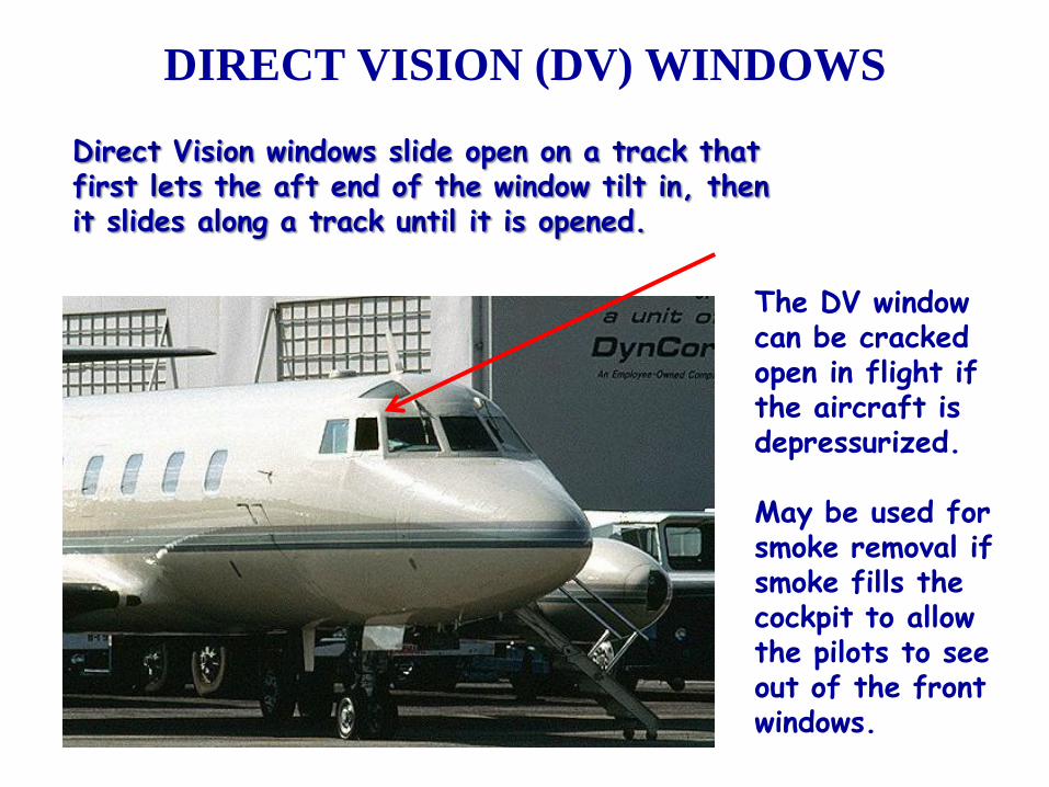
Direct Vision windows slide open on a track that first lets the aft end of the window tilt in, then it slides along a track until it is opened.
The DV window can be cracked open in flight if the aircraft is depressurized.
May be used for smoke removal if smoke fills the cockpit to allow the pilots to see out of the front windows.
DIRECT VISION (DV) WINDOWS
WING CONSTRUCTION
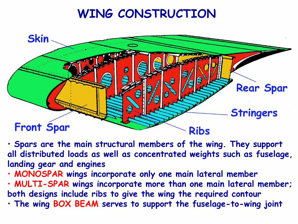
• Spars are the main structural members of the wing. They support all distributed loads as well as concentrated weights such as fuselage, landing gear and engines• MONOSPAR wings incorporate only one main lateral member• MULTI-SPAR wings incorporate more than one main lateral member; both designs include ribs to give the wing the required contour• The wing BOX BEAM serves to support the fuselage-to-wing joint
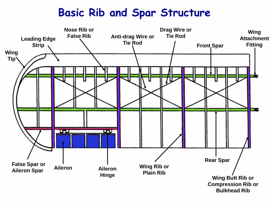
Basic Rib and Spar Structure
Leading Edge
Strip
Rear Spar
Front Spar
Wing Rib or
Plain Rib
False Spar or
Aileron SparAileron
Wing Butt Rib or
Compression Rib or
Bulkhead Rib
Wing
Attachment
Fitting
Drag Wire or
Tie RodAnti-drag Wire or
Tie Rod
Nose Rib or
False Rib
Wing
Tip
Aileron
Hinge
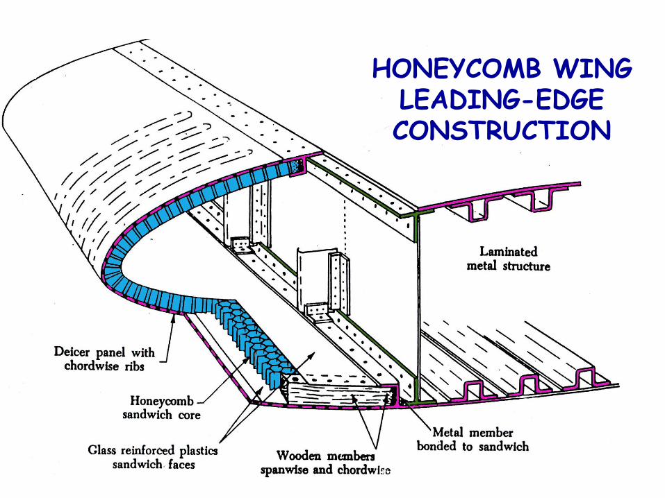
HONEYCOMB WING LEADING-EDGE CONSTRUCTION
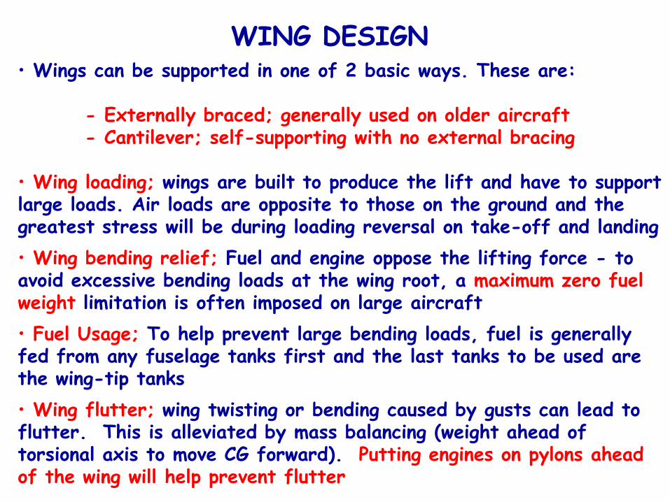
WING DESIGN• Wings can be supported in one of 2 basic ways. These are:
- Externally braced; generally used on older aircraft- Cantilever; self-supporting with no external bracing
• Wing loading; wings are built to produce the lift and have to support large loads. Air loads are opposite to those on the ground and the greatest stress will be during loading reversal on take-off and landing
• Wing bending relief; Fuel and engine oppose the lifting force - to avoid excessive bending loads at the wing root, a maximum zero fuel weight limitation is often imposed on large aircraft
• Fuel Usage; To help prevent large bending loads, fuel is generally fed from any fuselage tanks first and the last tanks to be used are the wing-tip tanks
• Wing flutter; wing twisting or bending caused by gusts can lead to flutter. This is alleviated by mass balancing (weight ahead of torsional axis to move CG forward). Putting engines on pylons ahead of the wing will help prevent flutter
When cracking is reported, resonance should be suspected.
The material does not break due to excessive stresses but due to the many millions of reversed stresses concentrated about a nodes/connection, causing fatigue. The phenomenon is similar to bending a wire back and forth until it breaks.
The break has the characteristics of a pure fatigue failure but has a crystalline appearance and sharp edges.
The Resonance can be damped by modifying the shape of the node/connection.
Fatigue Cracks & Failure Due to Resonance
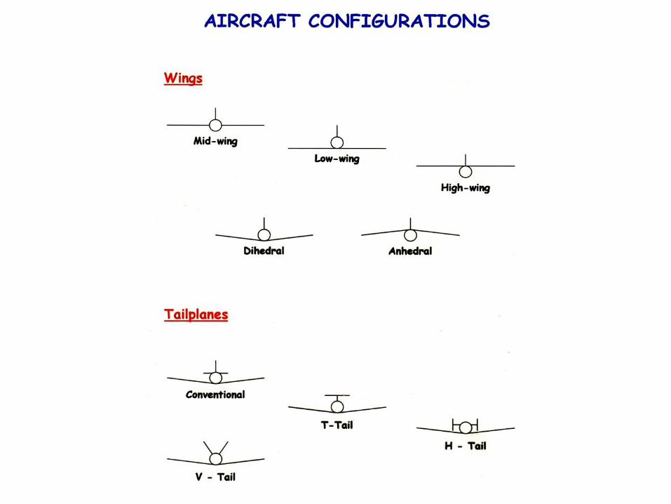
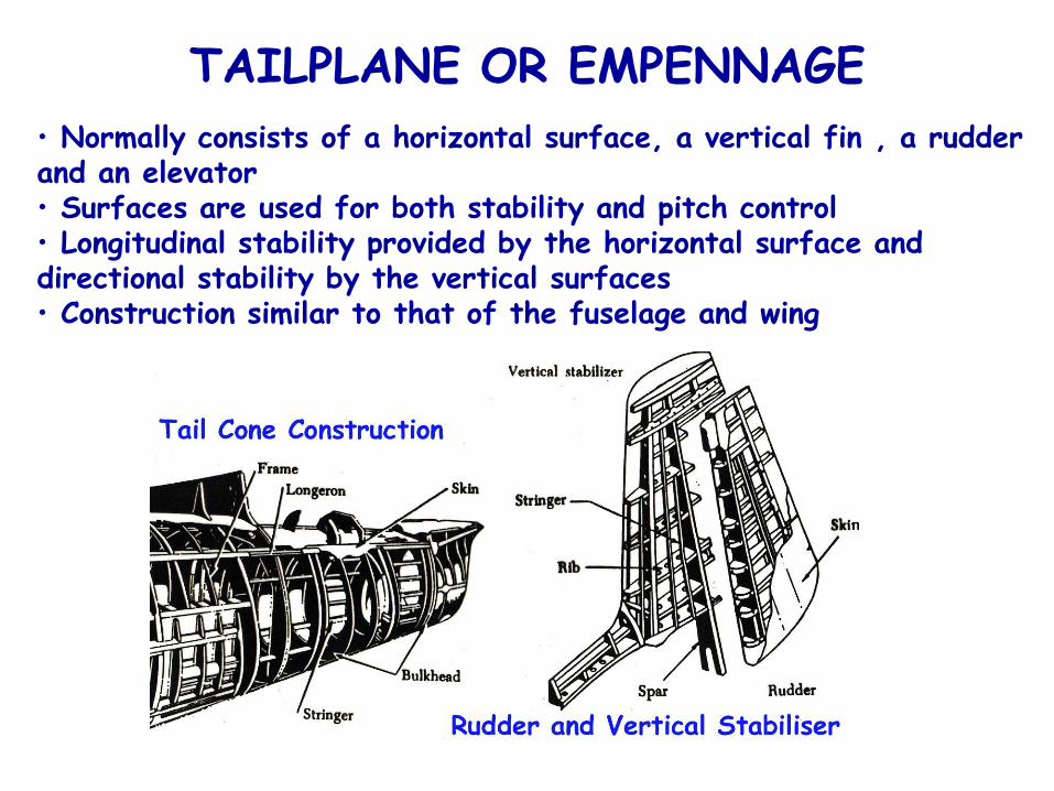
TAILPLANE OR EMPENNAGE
• Normally consists of a horizontal surface, a vertical fin , a rudder and an elevator• Surfaces are used for both stability and pitch control• Longitudinal stability provided by the horizontal surface and directional stability by the vertical surfaces• Construction similar to that of the fuselage and wing
TAIL STRIKE
Higher risk:
Flapless landingsApproach and landing below Vref
Over rotation of any flare to the landing attitude
Danger of structural damage to:
Empennage structure
Rear pressurisation bulkhead
Related Documents