Aircraft Operations This edition incorporates all amendments approved by the Council prior to 3 October 2006 and supersedes, on 23 November 2006, all previous editions of Doc 8168, Volume II. Doc 8168 OPS/611 Procedures for Air Navigation Services International Civil Aviation Organization Volume II Construction of Visual and Instrument Flight Procedures Fifth edition – 2006

Welcome message from author
This document is posted to help you gain knowledge. Please leave a comment to let me know what you think about it! Share it to your friends and learn new things together.
Transcript

Aircraft Operations
This edition incorporates all amendmentsapproved by the Council prior to 3 October 2006and supersedes, on 23 November 2006,all previous editions of Doc 8168, Volume II.
Doc 8168OPS/611
Procedures for
Air Navigation Services
International Civil Aviation Organization
Volume II
Construction of Visual and
Instrument Flight Procedures
Fifth edition – 2006

Orders should be sent to one of the following addresses, together with the appropriate remittance (by bank draft, cheque or money order)in U.S. dollars or the currency of the country in which the order is placed. Credit card orders (American Express, MasterCard and Visa)are accepted at ICAO Headquarters.
International Civil Aviation Organization. Attention: Document Sales Unit, 999 University Street, Montréal, Quebec, Canada H3C 5H7Telephone: +1 (514) 954-8022; Facsimile: +1 (514) 954-6769; Sitatex: YULCAYA; E-mail: [email protected];World Wide Web: http://www.icao.int
Cameroon. KnowHow, 1, Rue de la Chambre de Commerce-Bonanjo, B.P. 4676, Douala / Telephone: +237 343 98 42; Facsimile: +237 343 89 25; E-mail: [email protected]
China. Glory Master International Limited, Room 434B, Hongshen Trade Centre, 428 Dong Fang Road, Pudong, Shanghai 200120Telephone: +86 137 0177 4638; Facsimile: +86 21 5888 1629; E-mail: [email protected]
Egypt. ICAO Regional Director, Middle East Office, Egyptian Civil Aviation Complex, Cairo Airport Road, Heliopolis, Cairo 11776Telephone: +20 (2) 267 4840; Facsimile: +20 (2) 267 4843; Sitatex: CAICAYA; E-mail: [email protected]
Germany. UNO-Verlag GmbH, August-Bebel-Allee 6, 53175 Bonn / Telephone: +49 (0) 228-94 90 2-0; Facsimile: +49 (0) 228-94 90 2-22;E-mail: [email protected]; World Wide Web: http://www.uno-verlag.de
India. Oxford Book and Stationery Co., Scindia House, New Delhi 110001 or 17 Park Street, Calcutta 700016Telephone: +91 (11) 331-5896; Facsimile: +91 (11) 51514284
India. Sterling Book House – SBH, 181, Dr. D. N. Road, Fort, Bombay 400001Telephone: +91 (22) 2261 2521, 2265 9599; Facsimile: +91 (22) 2262 3551; E-mail: [email protected]
Japan. Japan Civil Aviation Promotion Foundation, 15-12, 1-chome, Toranomon, Minato-Ku, TokyoTelephone: +81 (3) 3503-2686; Facsimile: +81 (3) 3503-2689
Kenya. ICAO Regional Director, Eastern and Southern African Office, United Nations Accommodation, P.O. Box 46294, Nairobi Telephone: +254 (20) 7622 395; Facsimile: +254 (20) 7623 028; Sitatex: NBOCAYA; E-mail: [email protected]
Mexico. Director Regional de la OACI, Oficina Norteamérica, Centroamérica y Caribe, Av. Presidente Masaryk No. 29, 3er Piso,Col. Chapultepec Morales, C.P. 11570, México D.F. / Teléfono: +52 (55) 52 50 32 11; Facsímile: +52 (55) 52 03 27 57; Correo-e: [email protected]
Nigeria. Landover Company, P.O. Box 3165, Ikeja, LagosTelephone: +234 (1) 4979780; Facsimile: +234 (1) 4979788; Sitatex: LOSLORK; E-mail: [email protected]
Peru. Director Regional de la OACI, Oficina Sudamérica, Apartado 4127, Lima 100Teléfono: +51 (1) 575 1646; Facsímile: +51 (1) 575 0974; Sitatex: LIMCAYA; Correo-e: [email protected]
Russian Federation. Aviaizdat, 48, Ivan Franko Street, Moscow 121351 / Telephone: +7 (095) 417-0405; Facsimile: +7 (095) 417-0254
Senegal. Directeur régional de l’OACI, Bureau Afrique occidentale et centrale, Boîte postale 2356, DakarTéléphone: +221 839 9393; Fax: +221 823 6926; Sitatex: DKRCAYA; Courriel: [email protected]
Slovakia. Air Traffic Services of the Slovak Republic, Letové prevádzkové sluzby Slovenskej Republiky, State Enterprise, Letisko M.R. Stefánika, 823 07 Bratislava 21 / Telephone: +421 (7) 4857 1111; Facsimile: +421 (7) 4857 2105
South Africa. Avex Air Training (Pty) Ltd., Private Bag X102, Halfway House, 1685, JohannesburgTelephone: +27 (11) 315-0003/4; Facsimile: +27 (11) 805-3649; E-mail: [email protected]
Spain. A.E.N.A. — Aeropuertos Españoles y Navegación Aérea, Calle Juan Ignacio Luca de Tena, 14, Planta Tercera, Despacho 3. 11,28027 Madrid / Teléfono: +34 (91) 321-3148; Facsímile: +34 (91) 321-3157; Correo-e: [email protected]
Switzerland. Adeco-Editions van Diermen, Attn: Mr. Martin Richard Van Diermen, Chemin du Lacuez 41, CH-1807 BlonayTelephone: +41 021 943 2673; Facsimile: +41 021 943 3605; E-mail: [email protected]
Thailand. ICAO Regional Director, Asia and Pacific Office, P.O. Box 11, Samyaek Ladprao, Bangkok 10901Telephone: +66 (2) 537 8189; Facsimile: +66 (2) 537 8199; Sitatex: BKKCAYA; E-mail: [email protected]
United Kingdom. Airplan Flight Equipment Ltd. (AFE), 1a Ringway Trading Estate, Shadowmoss Road, Manchester M22 5LHTelephone: +44 161 499 0023; Facsimile: +44 161 499 0298; E-mail: [email protected]; World Wide Web: http://www.afeonline.com
Catalogue of ICAO Publicationsand Audio-visual Training Aids
Issued annually, the Catalogue lists all publications and audio-visual training aids currently available. Supplements to the Catalogue announce new publications and audio-visual training aids, amendments, supplements, reprints, etc.
Available free from the Document Sales Unit, ICAO.
2/06
Published in separate English, French, Russian and Spanish editions by the International Civil Aviation Organization. Allcorrespondence, except orders and subscriptions, should be addressed to the Secretary General.

Aircraft Operations
This edition incorporates all amendmentsapproved by the Council prior to 3 October 2006and supersedes, on 23 November 2006,all previous editions of Doc 8168, Volume II.
Doc 8168OPS/611
Procedures for
Air Navigation Services
International Civil Aviation Organization
Volume II
Construction of Visual and
Instrument Flight Procedures
Fifth edition – 2006

AMENDMENTS
The issue of amendments is announced regularly in the ICAO Journal and in thesupplements to the Catalogue of ICAO Publications and Audio-visual TrainingAids, which holders of this publication should consult. The space below is providedto keep a record of such amendments.
RECORD OF AMENDMENTS AND CORRIGENDA
AMENDMENTS CORRIGENDA
No. Date Entered by No. Date Entered by
(ii)

(iii) 23/11/06
TABLE OF CONTENTS
Page
FOREWORD ...................................................................................................................................... (xv)
PART I. GENERAL ............................................................................................................................... I-(i)
Section 1. Definitions, abbreviations and units of measurement ................................................. I-1-(i)
Chapter 1. Definitions................................................................................................................. I-1-1-1
Chapter 2. Abbreviations ............................................................................................................ I-1-2-1
Chapter 3. Units of measurement ............................................................................................... I-1-3-1
Section 2. General principles........................................................................................................... I-2-(i)
Chapter 1. General ...................................................................................................................... I-2-1-1
1.1 Introduction................................................................................................................... I-2-1-11.2 Areas ............................................................................................................................. I-2-1-11.3 Obstacle clearance......................................................................................................... I-2-1-21.4 Example calculations .................................................................................................... I-2-1-21.5 Bearings, tracks and radials........................................................................................... I-2-1-21.6 Navigation system use accuracy ................................................................................... I-2-1-21.7 Increased altitudes/heights for mountainous areas ........................................................ I-2-1-31.8 Charting accuracy ......................................................................................................... I-2-1-31.9 Presentation of significant obstacles and spot elevations on charts .............................. I-2-1-31.10 Promulgation................................................................................................................. I-2-1-4
Appendix to Chapter 1. Conversion table for IAS to TAS calculations .............................. I-2-1-App-1
Chapter 2. Terminal area fixes.................................................................................................... I-2-2-1
2.1 General.......................................................................................................................... I-2-2-12.2 Terminal area fixes........................................................................................................ I-2-2-12.3 Fix tolerance and fix tolerance area for intersecting fixes ............................................ I-2-2-12.4 Fix tolerance for other types of navigation instruments................................................ I-2-2-22.5 Fix tolerance overheading a station............................................................................... I-2-2-32.6 Operational application of fixes for flight procedure planning ..................................... I-2-2-42.7 Use of fixes for descent and related obstacle clearance ................................................ I-2-2-52.8 Protection area for VOR and NDB ............................................................................... I-2-2-6

(iv) Procedures — Aircraft Operations — Volume II
Page
23/11/06
Chapter 3. Turn area construction............................................................................................... I-2-3-1
3.1 General.......................................................................................................................... I-2-3-13.2 Turn inner boundary construction................................................................................. I-2-3-23.3 Turn outer boundary construction................................................................................. I-2-3-2
Section 3. Departure procedures .................................................................................................... I-3-(i)
Chapter 1. Introduction to departure procedures ........................................................................ I-3-1-1
1.1 General.......................................................................................................................... I-3-1-11.2 Consultation .................................................................................................................. I-3-1-11.3 Standardization ............................................................................................................. I-3-1-11.4 Economy ...................................................................................................................... I-3-1-11.5 Routes .......................................................................................................................... I-3-1-11.6 Related material ............................................................................................................ I-3-1-21.7 Abnormal and emergency operations............................................................................ I-3-1-2
Chapter 2. General concepts for departure procedures ............................................................... I-3-2-1
2.1 Establishment of a departure procedure ........................................................................ I-3-2-12.2 Design principles .......................................................................................................... I-3-2-12.3 Beginning of the departure procedure........................................................................... I-3-2-22.4 End of the departure procedure ..................................................................................... I-3-2-22.5 Minimum obstacle clearance (MOC)............................................................................ I-3-2-22.6 Obstacle identification surface (OIS)............................................................................ I-3-2-32.7 Procedure design gradient (PDG) ................................................................................. I-3-2-32.8 Average flight path........................................................................................................ I-3-2-32.9 Charting accuracy ......................................................................................................... I-3-2-42.10 Additional specific height/distance information ........................................................... I-3-2-4
Chapter 3. Departure routes ........................................................................................................ I-3-3-1
3.1 General.......................................................................................................................... I-3-3-13.2 Straight departures ........................................................................................................ I-3-3-13.3 Turning departures ........................................................................................................ I-3-3-3
Appendix to Chapter 3. Guidance material on the establishment of the averageflight path of a departure procedure........................................................................................ I-3-3-App-1
Chapter 4. Omnidirectional departures ....................................................................................... I-3-4-1
4.1 General.......................................................................................................................... I-3-4-14.2 Areas ............................................................................................................................. I-3-4-14.3 Obstacle identification .................................................................................................. I-3-4-24.4 Obstacle clearance......................................................................................................... I-3-4-2

Table of Contents (v)
Page
23/11/06
Chapter 5. Published information for departure procedures ....................................................... I-3-5-1
5.1 General.......................................................................................................................... I-3-5-15.2 Omnidirectional departures........................................................................................... I-3-5-15.3 Charted altitudes/flight levels ....................................................................................... I-3-5-25.4 Other requirements........................................................................................................ I-3-5-2
Chapter 6. Simultaneous operations on parallel or near-parallel instrument runways................ I-3-6-1
6.1 Instrument departures from parallel runways................................................................ I-3-6-16.2 Segregated operations on parallel runways ................................................................... I-3-6-1
Section 4. Arrival and approach procedures ................................................................................. I-4-(i)
Chapter 1. General criteria for approach/arrival procedures....................................................... I-4-1-1
1.1 Scope............................................................................................................................. I-4-1-11.2 Procedure construction.................................................................................................. I-4-1-11.3 Fix names ...................................................................................................................... I-4-1-11.4 Segment application...................................................................................................... I-4-1-11.5 Procedure altitude/height .............................................................................................. I-4-1-21.6 Track guidance.............................................................................................................. I-4-1-21.7 Vertical guidance .......................................................................................................... I-4-1-21.8 Categories of aircraft..................................................................................................... I-4-1-21.9 Descent gradients .......................................................................................................... I-4-1-4
Chapter 2. Arrival segment......................................................................................................... I-4-2-1
2.1 Standard instrument arrivals ......................................................................................... I-4-2-12.2 Omnidirectional or sector arrivals................................................................................. I-4-2-3
Chapter 3. Initial approach segment ........................................................................................... I-4-3-1
3.1 General.......................................................................................................................... I-4-3-13.2 Altitude selection .......................................................................................................... I-4-3-13.3 Initial approach segments (other than radar vectors) utilizing straight tracks
and DME arcs ............................................................................................................... I-4-3-23.4 Initial approach segment using a racetrack procedure .................................................. I-4-3-33.5 Initial approach segment using a reversal procedure .................................................... I-4-3-43.6 Racetrack and reversal procedure areas ........................................................................ I-4-3-63.7 Maximum descent/nominal outbound timing relationship for a reversal
or racetrack procedure................................................................................................... I-4-3-93.8 Obstacle clearance......................................................................................................... I-4-3-9
Appendix A to Chapter 3. Initial approach using dead reckoning (DR).......................... I-4-3-App A-1
Appendix B to Chapter 3. Reduction of the width of a straight initial approach areaafter the IAF and interface between straight initial approach area and reversalprocedure areas................................................................................................................... I-4-3-App B-1

(vi) Procedures — Aircraft Operations — Volume II
Page
23/11/06
Appendix C to Chapter 3. Construction of obstacle clearance areas for reversal andholding procedures ............................................................................................................. I-4-3-App C-1
Chapter 4. Intermediate approach segment................................................................................. I-4-4-1
4.1 General.......................................................................................................................... I-4-4-14.2 Altitude/height selection ............................................................................................... I-4-4-14.3 Intermediate approach segment based on a straight track alignment ............................ I-4-4-14.4 Intermediate segment within a reversal or racetrack procedure .................................... I-4-4-3
Chapter 5. Final approach segment............................................................................................. I-4-5-1
5.1 General.......................................................................................................................... I-4-5-15.2 Alignment ..................................................................................................................... I-4-5-15.3 Descent gradient............................................................................................................ I-4-5-25.4 Obstacle clearance altitude/height (OCA/H)................................................................. I-4-5-35.5 Promulgation................................................................................................................. I-4-5-7
Appendix to Chapter 5. Calculations for OCA/H in non-aligned straight-in approaches .......................................................................................................................... I-4-5-App-1
Chapter 6. Missed approach segment ......................................................................................... I-4-6-1
6.1 General.......................................................................................................................... I-4-6-16.2 Climb gradient and MOC.............................................................................................. I-4-6-36.3 Straight missed approach .............................................................................................. I-4-6-56.4 Turning missed approach .............................................................................................. I-4-6-66.5 Promulgation................................................................................................................. I-4-6-12
Appendix to Chapter 6. Refined method for calculating MAPt and transitional tolerancesfor a missed approach point defined by a distance from the FAF .......................................... I-4-6-App-1
Chapter 7. Visual manoeuvring (circling) area........................................................................... I-4-7-1
7.1 General.......................................................................................................................... I-4-7-17.2 Alignment and area ....................................................................................................... I-4-7-17.3 Obstacle clearance......................................................................................................... I-4-7-27.4 Method for reducing OCA/H ........................................................................................ I-4-7-37.5 Missed approach associated with the visual manoeuvre ............................................... I-4-7-37.6 Promulgation................................................................................................................. I-4-7-3
Appendix to Chapter 7. Visual manoeuvring using prescribed track .................................. I-4-7-App-1
Chapter 8. Minimum sector altitudes (MSA).............................................................................. I-4-8-1
8.1 General.......................................................................................................................... I-4-8-18.2 Obstacles in buffer area................................................................................................. I-4-8-18.3 Sector orientation .......................................................................................................... I-4-8-18.4 Combining sectors for adjacent facilities ...................................................................... I-4-8-28.5 Sectors centered on a VOR/DME or NDB/DME.......................................................... I-4-8-2

Table of Contents (vii)
Page
23/11/06
Chapter 9. Charting/AIP ............................................................................................................. I-4-9-1
9.1 General.......................................................................................................................... I-4-9-19.2 Charted altitudes/flight levels ....................................................................................... I-4-9-19.3 Arrival ........................................................................................................................... I-4-9-19.4 Approach....................................................................................................................... I-4-9-19.5 Procedure naming for arrival and approach charts........................................................ I-4-9-3
Section 5. Quality assurance ........................................................................................................... I-5-(i)(To be developed)
PART II. CONVENTIONAL PROCEDURES ................................................................................... II-(i)
Section 1. Precision approaches...................................................................................................... II-1-(i)
Chapter 1. Instrument landing system (ILS)............................................................................... II-1-1-1
1.1 Introduction................................................................................................................... II-1-1-11.2 Initial approach segment ............................................................................................... II-1-1-41.3 Intermediate approach segment..................................................................................... II-1-1-41.4 Precision segment ......................................................................................................... II-1-1-61.5 Missed approach segment ............................................................................................. II-1-1-141.6 Simultaneous precision approaches to parallel or near-parallel instrument runways.... II-1-1-181.7 Promulgation................................................................................................................. II-1-1-18
Appendix A to Chapter 1. ILS: Turning missed approach associated with aprecision approach.............................................................................................................. II-1-1-App A-1
Appendix B to Chapter 1. Steep glide path angle approaches ......................................... II-1-1-App B-1
Appendix C to Chapter 1. Determining ILS glidepath descent/MLS elevationheights and distances .......................................................................................................... II-1-1-App C-1
Appendix D to Chapter 1. Independent parallel approaches to closely spacedparallel runways.................................................................................................................. II-1-1-App D-1
Appendix E to Chapter 1. Calculation of obstacle assessment surface height................. II-1-1-App E-1
Chapter 2. Offset ILS.................................................................................................................. II-1-2-1
2.1 Use of ILS CAT I with offset localizer alignment ........................................................ II-1-2-12.2 Obstacle clearance criteria ............................................................................................ II-1-2-1
Chapter 3. MLS .......................................................................................................................... II-1-3-1
3.1 Introduction................................................................................................................... II-1-3-13.2 Initial approach segment ............................................................................................... II-1-3-4

(viii) Procedures — Aircraft Operations — Volume II
Page
23/11/06
3.3 Intermediate approach segment..................................................................................... II-1-3-53.4 Precision segment ......................................................................................................... II-1-3-63.5 Missed approach segment ............................................................................................. II-1-3-153.6 Simultaneous precision approaches to parallel or near-parallel instrument runways.... II-1-3-183.7 Promulgation................................................................................................................. II-1-3-19
Chapter 4. Offset MLS ............................................................................................................... II-1-4-1
4.1 Use of MLS CAT I with offset azimuth alignment....................................................... II-1-4-14.2 Obstacle clearance criteria ............................................................................................ II-1-4-1
Chapter 5. PAR........................................................................................................................... II-1-5-1
5.1 Arrival phase operations ............................................................................................... II-1-5-15.2 Intermediate approach................................................................................................... II-1-5-15.3 Final approach............................................................................................................... II-1-5-25.4 Missed approach ........................................................................................................... II-1-5-25.5 Arrival and initial approach areas and obstacle clearances ........................................... II-1-5-25.6 Intermediate and final approach area and obstacle clearances ...................................... II-1-5-35.7 Missed approach area and obstacle clearance ............................................................... II-1-5-4
Section 2. Non-precision approaches.............................................................................................. II-2-(i)
Chapter 1. LLZ only ................................................................................................................... II-2-1-1
1.1 General.......................................................................................................................... II-2-1-11.2 Intermediate approach................................................................................................... II-2-1-11.3 Final approach segment ................................................................................................ II-2-1-1
Chapter 2. MLS azimuth only..................................................................................................... II-2-2-1
2.1 General.......................................................................................................................... II-2-2-12.2 Intermediate approach................................................................................................... II-2-2-12.3 Final approach segment ................................................................................................ II-2-2-12.4 Promulgation................................................................................................................. II-2-2-2
Chapter 3. VOR or NDB with no FAF ....................................................................................... II-2-3-1
3.1 General.......................................................................................................................... II-2-3-13.2 Initial approach segment ............................................................................................... II-2-3-13.3 Intermediate segment .................................................................................................... II-2-3-13.4 Final approach segment ................................................................................................ II-2-3-13.5 Descent gradient............................................................................................................ II-2-3-23.6 Use of stepdown fix ...................................................................................................... II-2-3-23.7 Missed approach point (MAPt)..................................................................................... II-2-3-3
Chapter 4. VOR or NDB with FAF ............................................................................................ II-2-4-1
4.1 General.......................................................................................................................... II-2-4-14.2 Initial approach segment ............................................................................................... II-2-4-1

Table of Contents (ix)
Page
23/11/06
4.3 Intermediate approach segment..................................................................................... II-2-4-14.4 Final approach segment ................................................................................................ II-2-4-14.5 Missed approach point (MAPt)..................................................................................... II-2-4-24.6 Promulgation................................................................................................................. II-2-4-3
Chapter 5. DF ............................................................................................................................. II-2-5-1
5.1 General.......................................................................................................................... II-2-5-15.2 Descent gradient............................................................................................................ II-2-5-15.3 Initial approach segment ............................................................................................... II-2-5-15.4 Intermediate segment .................................................................................................... II-2-5-25.5 Final approach segment ................................................................................................ II-2-5-25.6 Missed approach segment ............................................................................................. II-2-5-3
Chapter 6. SRE ........................................................................................................................... II-2-6-1
6.1 General.......................................................................................................................... II-2-6-16.2 Initial approach segment ............................................................................................... II-2-6-16.3 Intermediate approach segment..................................................................................... II-2-6-26.4 Final approach segment ................................................................................................ II-2-6-36.5 Missed approach segment ............................................................................................. II-2-6-4
Section 3. En-route criteria ............................................................................................................. II-3-(i)
Chapter 1. VOR and NDB routes ............................................................................................... II-3-1-1
1.1 General.......................................................................................................................... II-3-1-11.2 Obstacle clearance areas ............................................................................................... II-3-1-11.3 Obstacle clearance......................................................................................................... II-3-1-21.4 Construction of areas for VOR and NDB routes........................................................... II-3-1-31.5 Minimum altitudes for signal reception ........................................................................ II-3-1-51.6 Promulgation................................................................................................................. II-3-1-6
Appendix A to Chapter 1. VOR and NDB routes — Refined method for theconstruction of obstacle clearance areas............................................................................. II-3-1-App A-1
Appendix B to Chapter 1. Statistical calculations for primary and secondary areasand their angles of splay ..................................................................................................... II-3-1-App B-1
Section 4. Holding criteria............................................................................................................... II-4-(i)
Chapter 1. Holding criteria ......................................................................................................... II-4-1-1
1.1 Shape and terminology associated with holding pattern ............................................... II-4-1-11.2 Entry and holding procedures ....................................................................................... II-4-1-11.3 Construction of holding areas ....................................................................................... II-4-1-31.4 Special conditions for planning VOR/DME holding procedures and construction
of associated areas......................................................................................................... II-4-1-71.5 Promulgation................................................................................................................. II-4-1-8

(x) Procedures — Aircraft Operations — Volume II
Page
23/11/06
Appendix A to Chapter 1. Parameters for holding area construction .............................. II-4-1-App A-1
Appendix B to Chapter 1. Determination of additional obstacle clearance requirementsfor minimum holding levels in areas of high terrain or in mountainous areas.................... II-4-1-App B-1
Attachment to Part II. ILS: Background information on ILS obstacle clearance and onairborne and ground equipment performance values associated with categories I and IIobstacle assessment surfaces used in the mathematical model............................................... II-Att-1
PART III. RNAV PROCEDURES AND SATELLITE-BASED PROCEDURES ........................... III-(i)
Section 1. Underlying principles .................................................................................................... III-1-(i)
Chapter 1. Fixes .......................................................................................................................... III-1-1-1
1.1 Fix identification ........................................................................................................... III-1-1-11.2 Satisfactory fixes........................................................................................................... III-1-1-1
Chapter 2. Basic GNSS RNAV .................................................................................................. III-1-2-1
2.1 General.......................................................................................................................... III-1-2-12.2 Equipment functionality for basic GNSS...................................................................... III-1-2-12.3 System use accuracy for basic GNSS RNAV procedures............................................. III-1-2-22.4 Flight technical tolerance (FTT) ................................................................................... III-1-2-22.5 XTT, ATT and area semi-width.................................................................................... III-1-2-2
Chapter 3. DME/DME RNAV.................................................................................................... III-1-3-1
3.1 General.......................................................................................................................... III-1-3-13.2 Airborne and ground equipment requirements for DME/DME procedures.................. III-1-3-13.3 DME/DME RNAV system use accuracy ...................................................................... III-1-3-23.4 Flight technical tolerance .............................................................................................. III-1-3-33.5 System computational tolerance ................................................................................... III-1-3-33.6 XTT, ATT and area semi-width.................................................................................... III-1-3-33.7 Viability check of the procedure ................................................................................... III-1-3-43.8 Reversion mode checks................................................................................................. III-1-3-4
Appendix to Chapter 3. Derivation and calculation of ATT, XTT and areasemi-width .......................................................................................................................... III-1-3-App-1
Chapter 4. VOR/DME RNAV.................................................................................................... III-1-4-1
4.1 General.......................................................................................................................... III-1-4-14.2 VOR/DME RNAV system use accuracy ...................................................................... III-1-4-14.3 Flight technical tolerance .............................................................................................. III-1-4-24.4 System computation tolerance ...................................................................................... III-1-4-24.5 XTT, ATT and area semi-width.................................................................................... III-1-4-2

Table of Contents (xi)
Page
23/11/06
Chapter 5. SBAS RNAV ............................................................................................................ III-1-5-1
Chapter 6. GBAS RNAV............................................................................................................ III-1-6-1(To be developed)
Chapter 7. RNP........................................................................................................................... III-1-7-1
7.1 Equipment requirements ............................................................................................... III-1-7-17.2 Fix tolerance areas ........................................................................................................ III-1-7-17.3 Flight technical tolerance .............................................................................................. III-1-7-17.4 RNP values.................................................................................................................... III-1-7-17.5 XTT, ATT and area semi-width.................................................................................... III-1-7-2
Section 2. General criteria.............................................................................................................. III-2-(i)
Chapter 1. Minimum length of a segment limited by two turning waypoints............................. III-2-1-1
1.1 General.......................................................................................................................... III-2-1-11.2 Determination of the minimum length of the RNAV segment ..................................... III-2-1-11.3 Particular case of the segment: DER — First waypoint................................................ III-2-1-31.4 Minimum stabilization distance .................................................................................... III-2-1-3
Chapter 2. Turn protection and obstacle assessment .................................................................. III-2-2-1(To be developed)
Chapter 3. RNAV T- or Y-bar procedure construction............................................................... III-2-3-1
3.1 General concept ............................................................................................................ III-2-3-13.2 Initial approach segment ............................................................................................... III-2-3-13.3 Intermediate approach segment..................................................................................... III-2-3-23.4 Final approach segment ................................................................................................ III-2-3-33.5 Missed approach segment ............................................................................................. III-2-3-3
Chapter 4. Terminal arrival altitude (TAA) ................................................................................ III-2-4-1
4.1 General.......................................................................................................................... III-2-4-14.2 Construction.................................................................................................................. III-2-4-14.3 Buffer area .................................................................................................................... III-2-4-14.4 TAA step-down arcs and subsectors ............................................................................. III-2-4-14.5 Promulgation................................................................................................................. III-2-4-2
Section 3. Procedure construction .................................................................................................. III-3-(i)
Chapter 1. Departure procedures ................................................................................................ III-3-1-1
1.1 General.......................................................................................................................... III-3-1-11.2 Straight departures ........................................................................................................ III-3-1-21.3 Area width at the beginning of the departure ................................................................ III-3-1-21.4 Turning departures ........................................................................................................ III-3-1-2

(xii) Procedures — Aircraft Operations — Volume II
Page
23/11/06
Chapter 2. Arrival and approach procedures .............................................................................. III-3-2-1
2.1 General.......................................................................................................................... III-3-2-12.2 Arrival routes ................................................................................................................ III-3-2-22.3 Initial approach segment ............................................................................................... III-3-2-32.4 Intermediate approach segment..................................................................................... III-3-2-62.5 Turning missed approach .............................................................................................. III-3-2-72.6 End of the missed approach segment — MAHF........................................................... III-3-2-7
Chapter 3. Non-precision approach procedures.......................................................................... III-3-3-1
3.1 Final approach segment ................................................................................................ III-3-3-13.2 Initial and intermediate missed approach segment........................................................ III-3-3-2
Chapter 4. APV/Barometric vertical navigation (BARO/VNAV).............................................. III-3-4-1
4.1 General.......................................................................................................................... III-3-4-14.2 Standard conditions....................................................................................................... III-3-4-14.3 APV segment ................................................................................................................ III-3-4-34.4 Determination of OCH for approach and missed approach obstacles........................... III-3-4-64.5 Promulgation................................................................................................................. III-3-4-7
Appendix A to Chapter 4. Temperature correction ......................................................... III-3-4-App A-1
Appendix B to Chapter 4. Algorithm for calculating the height of surface definedby four points in space........................................................................................................ III-3-4-App B-1
Chapter 5. APV I/II procedures .................................................................................................. III-3-5-1(To be developed)
Chapter 6. Precision approach procedures — GBAS ................................................................. III-3-6-1
6.1 Introduction................................................................................................................... III-3-6-16.2 Initial approach segment ............................................................................................... III-3-6-46.3 Intermediate approach segment..................................................................................... III-3-6-46.4 Precision segment ......................................................................................................... III-3-6-56.5 Missed approach after the precision segment (final missed approach) ......................... III-3-6-146.6 Simultaneous ILS and/or MLS precision approaches to parallel or near-parallel
instrument runways ....................................................................................................... III-3-6-176.7 GBAS CAT I with offset azimuth final approach track alignment ............................... III-3-6-186.8 Promulgation................................................................................................................. III-3-6-18
Chapter 7. Holding procedures ................................................................................................... III-3-7-1
7.1 General.......................................................................................................................... III-3-7-17.2 Types of RNAV holding for VOR/DME, DME/DME and GNSS procedures ............. III-3-7-17.3 Entry procedures for VOR/DME, DME/DME and GNSS procedures ......................... III-3-7-27.4 Fix tolerance.................................................................................................................. III-3-7-27.5 Holding area construction for VOR/DME, DME/DME and GNSS procedures ........... III-3-7-37.6 Holding area construction for RNP............................................................................... III-3-7-4

Table of Contents (xiii)
Page
23/11/06
Appendix to Chapter 7. Example of alternative area navigation (RNAV) holdingentries for reduced holding entry areas................................................................................... III-3-7-App-1
Chapter 8. En-route procedures .................................................................................................. III-3-8-1
8.1 General.......................................................................................................................... III-3-8-1
Section 4. Quality assurance ........................................................................................................... III-4-(i)(To be developed)
Section 5. Publication....................................................................................................................... III-5-(i)
Chapter 1. RNAV database path terminator concept .................................................................. III-5-1-1
Chapter 2. Waypoint names........................................................................................................ III-5-2-1(To be developed)
Chapter 3. Procedure naming...................................................................................................... III-5-3-1
3.1 General.......................................................................................................................... III-5-3-13.2 RNAV departures.......................................................................................................... III-5-3-13.3 RNAV arrivals .............................................................................................................. III-5-3-13.4 RNAV approach............................................................................................................ III-5-3-2
PART IV. HELICOPTERS.................................................................................................................... IV-(i)
Chapter 1. Area navigation (RNAV) point-in-space (PinS) approach proceduresfor helicopters using basic GNSS receivers................................................................................... IV-1-1
1.1 General.......................................................................................................................... IV-1-11.2 GNSS RNAV system accuracy..................................................................................... IV-1-11.3 Arrival routes ................................................................................................................ IV-1-21.4 Terminal criteria............................................................................................................ IV-1-21.5 Initial approach segment ............................................................................................... IV-1-21.6 Intermediate approach segment..................................................................................... IV-1-31.7 Final approach segment ................................................................................................ IV-1-41.8 Missed approach segment ............................................................................................. IV-1-41.9 Promulgation................................................................................................................. IV-1-5
PANS-OPS OAS CD-ROM .......................................................................................................... Enclosure
___________________

(xv) 23/11/06
FOREWORD
1. INTRODUCTION
1.1 The Procedures for Air Navigation Services — Aircraft Operations (PANS-OPS) consists of two volumes asfollows:
Volume I — Flight ProceduresVolume II — Construction of Visual and Instrument Flight Procedures
The division of the PANS-OPS into the two volumes was accomplished in 1979 as a result of an extensive amendmentto the obstacle clearance criteria and the construction of approach-to-land procedures (Amendments 13 and 14). Priorto 1979, all PANS-OPS material was contained in a single document. Table A shows the origin of amendmentstogether with a list of the principal subjects involved and the dates on which the PANS-OPS and the amendments wereapproved by the Council and when they became applicable.
1.2 Volume I — Flight Procedures describes operational procedures recommended for the guidance of flightcrew and flight operations personnel. It also outlines the various parameters on which the criteria in Volume II arebased so as to illustrate the need to adhere strictly to the published procedures in order to achieve and maintain anacceptable level of safety in operations.
1.3 Volume II — Construction of Visual and Instrument Flight Procedures is intended for the guidance ofprocedures specialists and describes the essential areas and obstacle clearance requirements for the achievement of safe,regular instrument flight operations. It provides the basic guidelines to States, and those operators and organizationsproducing instrument flight charts that will result in uniform practices at all aerodromes where instrument flightprocedures are carried out.
1.4 Both volumes present coverage of operational practices that are beyond the scope of Standards andRecommended Practices but with respect to which a measure of international uniformity is desirable.
1.5 The design of procedures in accordance with PANS-OPS criteria assumes normal operations. It is theresponsibility of the operator to provide contingency procedures for abnormal and emergency operations.
2. COMMENTARY ON THE MATERIALCONTAINED IN VOLUME II
2.1 Part I — General
2.1.1 This part contains the general criteria that apply to both conventional as well as RNAV and satellite-basedprocedures.
2.1.2 Section 1 describes the terminology to assist in the interpretation of terms which are used in the proceduresand have a particular technical meaning. In some cases, the terms are defined in other ICAO documents. A list ofabbreviations is also provided.

(xvi) Procedures — Aircraft Operations — Volume II
23/11/06
2.1.3 Section 2 provides the general criteria that apply to all phases of flight. In Amendment 12 to the 4th edition,criteria for the procedure identification were included.
2.1.4 Section 3 contains the departure procedures. The specifications concerning instrument departure procedureswere first developed by the Obstacle Clearance Panel (OCP) in 1983. The material contained in Volume II wasprepared for the use of the procedure design specialists and corresponding material for the use of flight operationspersonnel including flight crews is contained in Volume I.
2.1.5 In 1990 as a result of the work of an air navigation study group, new material was included concerningspecifications, procedures and guidance material relating to the simultaneous operations on parallel or near-parallelrunways, including the minimum distances between the runways.
2.1.6 Section 4 contains the general arrival and approach procedures. These procedures were first developed bythe Operations Division in 1949 and issued in 1951 and have since been amended a number of times. In 1966, theObstacle Clearance Panel (OCP) was created to update these procedures for application to all types of aeroplanestaking into account requirements for subsonic multi-jet aeroplanes and technical developments with respect to standardradio navigation aids. As a result of this work, instrument approach procedures criteria were completely revised. Thenew criteria were incorporated in 1979 in the First Edition of Volume II of PANS-OPS (Amendment 13).
2.2 Part II — Conventional procedures
2.2.1 This part decribes the procedures for conventional navigation that are specific to the sensor.
2.2.2 Section 1 contains the criteria for precision approaches. The (ILS) precision approaches are more precisethan those formerly used for non-precision approach and are based on a scientifically validated method. This has beenachieved by means of:
a) a collection of data on aircraft ILS precision approach performance measured during actual instrumentmeteorological conditions;
b) the development of a mathematical model reflecting the total ILS system performance and the matching of thatmodel against the data collected under a) above;
c) the use of the model to extrapolate ILS precision approach performance in order to establish obstacleassessment surfaces;
d) the development of a model of the missed approach manoeuvre based on aircraft dynamics and matched againstobserved data, and the use of this model to extrapolate suitable margins for use in conjunction with theapproach surfaces described in c); and
e) the combination of the ILS approach and the missed approach mathematical models into an integrated modelcovering the whole ILS procedure and able to provide an assessment of the risk of collision with obstacles instated conditions.
2.2.3 A new concept of obstacle clearance for ILS has been incorporated in the new criteria in that the previouslyused obstacle clearance limit (OCL) concept has been replaced by the new obstacle clearance altitude/height (OCA/H)concept. Three methods of deriving OCA/H values are included which, in turn, involve progressive increases in thedegree of sophistication in the treatment and accountability of obstacles. The first two methods employ the use ofsurfaces and the third uses a collision risk model (CRM) to derive OCA/H. The CRM is designed for use where anevaluation of the specific risk within the obstacle environment is needed to obtain the lowest obstacle clearance valuescompatible with the required level of safety. A computer programme has been developed for the CRM and is availablefor use through ICAO.

Foreword (xvii)
23/11/06
2.2.4 The precision approach criteria were expanded to MLS category I, II and III in 1994 and GBAS category Iin 2004.
2.2.5 Section 2 contains the non-precision approach criteria. The obstacle clearance criteria for non-precisionapproaches, as amended by Amendment 13, have not been developed to the same degree of sophistication as theprecision approach obstacle clearance criteria because the level of safety generally associated with the higher operatingminima of non-precision approach procedures is already considered to be acceptable. The procedures, therefore,continue to be based upon available experience and the judgements of experts. They, however, were amended toprovide a high degree of flexibility designed to assist the procedures specialist in obtaining the maximum operationaladvantage compatible with safety.
2.2.6 Based mainly on the experience gained by some States during trial application of the new criteria and as aresult of the ICAO PANS-OPS workshop series held from 1980-1984, the criteria were amended twice (Amendments 1and 4). The changes fall into three general categories as follows:
— editorial amendments to ease the understanding of the criteria
— simplification of calculations which have proved, in practice, to contain a high error potential
— removal of discrepancies which could have made the document difficult to apply and operationally penalizing.
Amendment 1 also aligned the presentation of units with Annex 5, Fourth Edition.
2.2.7 Section 3 contains the criteria for enroute operations for VOR and NDB. These criteria were added to thePANS-OPS in 1996. In 2004 simplified criteria were added to allow for less time consuming effort in large airspaces.
2.2.8 Section 4 contains the criteria for holding procedures. Holding procedures were first developed by theOperations Division in 1949 and issued in 1951. A major revision of these procedures was accomplished in 1965 as aresult of the work of the Holding Procedures Panel (HOP). The material developed by the HOP was subsequentlydivided in 1979 and that part of the material concerning holding procedures was incorporated in PANS-OPS, Volume Iand the material covering the construction of holding procedures incorporated in Volume II.
2.2.9 In 1982 as a result of the work of the Obstacle Clearance Panel (OCP) new material and changes to the oldmaterial were introduced concerning VOR/DME holding, use of holding procedures by helicopters, buffer areas andentry procedures. In 1986, changes were introduced concerning the VOR TO/FROM indication error zone, theminimum usable DME distance and holding speeds, particularly above 4 250 m (14 000 ft).
2.3 Part III — RNAV procedures and satellite based procedures
2.3.1 The first RNAV departure procedures were incorporated in PANS-OPS with the introduction of areanavigation (RNAV) departure procedures based on VOR/DME in 1993 arising from the Ninth Meeting of the ObstacleClearance Panel. Departure procedures for DME/DME, basic GNSS followed in 1998, Procedures for RNP and SBASdeparture procedures were introduced in 2001 and 2004 respectively.
Arrival and approach procedures
2.3.2 Similar to the departure procedures, Area navigation (RNAV) criteria for instrument approach procedureswere introduced for VOR/DME in 1993. Approach procedures for DME/DME, basic GNSS followed in 1998.Procedures for RNP 0.3 were introduced in 2001. As a result of a CFIT safety initiative, Baro-VNAV criteria based onDME/DME or Basic GNSS sensors were included in the document in 2001.

(xviii) Procedures — Aircraft Operations — Volume II
23/11/06
2.3.3 In 2004, GLS Cat I (ILS look alike) criteria based on GBAS receivers were introduced in PANS-OPS. GLSCat II/III criteria can be expected after the Annex 10 SARPs have been finalized.
2.3.4 The T/Y bar concept was introduced for Basic GNSS in 1998 and made applicable for RNAV approachprocedures in general in 2004. To facilitate pilots flying a T/Y bar approach, the Terminal Arrival Altitude (TAA)concept was also included.
Holding procedures
2.3.5 Area navigation (RNAV) criteria for holding procedures were included in 1993 arising from the ninthmeeting of the Obstacle Clearance Panel. RNP holding procedures were added in 1998. In the 5th edition of PANS-OPS, as a result of the rewrite of PANS-OPS, the VOR/DME criteria were generalized to include DME/DME and basicGNSS as well.
2.4 PART IV — Helicopters
Part IV contains the criteria applicable for Helicopter Point-in-space procedures based on a Basic GNSS receiver whichwere introduced in 2004.
3. STATUS
Procedures for Air Navigation Services (PANS) do not have the same status as Standards and Recommended Practices.While the latter are adopted by Council in pursuance of Article 37 of the Convention and are subject to the fullprocedure of Article 90, PANS are approved by Council and are recommended to Contracting States for worldwideapplication.
4. IMPLEMENTATION
The implementation of procedures is the responsibility of Contracting States; they are applied in actual operations onlyafter, and in so far as States have enforced them. However, with a view to facilitating their processing towardsimplementation by States, they have been prepared in a language which will permit direct use by operations personnel.While uniform application of the basic procedures in this document is very desirable, latitude is permitted for thedevelopment of detailed procedures which may be needed to satisfy local conditions.
5. PUBLICATION OF DIFFERENCES
5.1 The PANS do not carry the status afforded to Standards adopted by the Council as Annexes to the Conventionand, therefore, do not come within the obligation imposed by Article 38 of the Convention to notify differences in theevent of non-implementation.
5.2 However, attention of States is drawn to the provisions of Annex 15 related to the publication in theiraeronautical information publications of lists of significant differences between their procedures and the related ICAOprocedures.

Foreword (xix)
23/11/06
6. PROMULGATION OF INFORMATION
The establishment and withdrawal of and changes to facilities, services and procedures affecting aircraft operationsprovided in accordance with the procedures specified in this document should be notified and take effect in accordancewith the provisions of Annex 15.
7. UNITS OF MEASUREMENT
Units of measurement are given in accordance with the provisions contained in Annex 5. In those cases where the useof an alternative non-SI unit is permitted, the non-SI unit is shown in brackets immediately following the primary SIunit. In all cases the value of the non-SI unit is considered to be operationally equivalent to the primary SI unit in thecontext in which it is applied. Unless otherwise indicated, the allowable tolerance (accuracy) is indicated by the numberof significant figures given and, in this regard, it is to be understood in this document that all zero digits, either to theright or left of the decimal marker, are significant figures.

(xx) Procedures — Aircraft Operations — Volume II
23/11/06
Table A. Amendments to the PANS-OPS
Amendment Source(s) Subject(s)ApprovedApplicable
(1st Edition) Council Action Previous operations procedures brought together into asingle document.
26 June 19611 October 1961
1 Internal ICAO action toresolve inconsistencies
Alignment of the definition of “Final approach” andprovisions relating to intermediate and final approachprocedures.
27 June 19621 July 1962
2 AIS/MAP DivisionalMeeting (1959)
Minimum sector altitudes. 14 December 19621 November 1963
3 Second Meeting ofHolding Procedures Panel(1964)
Updating of holding procedures. 5 April 19655 May 1966
4 Meteorology andOperational DivisionalMeeting (1964)
Addition of meteorological information for flightoperations.
7 June 1965(advisory material)
5(2nd Edition)
Fourth Air NavigationConference (1965) andAmendment 8 to Annex 2
ILS Category I procedures, radar approach procedures,introduction of ILS Category II procedures, altimetersetting procedures.
12 December 196624 August 1967
6 Fifth Air NavigationConference (1967), FirstMeeting of ObstacleClearance Panel (1968)and Air NavigationCommission
QNH altimeter setting procedures for take-off and landing,new advisory material relating to instrument approachprocedures for offset facilities and editorial changes.
23 January 196918 September 1969
7 Sixth Air NavigationConference (1969)
Operating procedures for the use of secondary surveillanceradar (SSR) transponders.
15 May 19704 February 1971
8(3rd Edition)
Second Meeting of theObstacle Clearance Panel(1970)
New profile diagrams and editorial changes. 19 March 19716 January 1972
9 Third Meeting of theObstacle Clearance Panel(1971)
Editorial changes relating to special procedures, areas andobstacle clearances — Precision Aids — ILS with glidepath inoperative.
15 November 197216 August 1973
10 Council action inpursuance of AssemblyResolutions A17-10 andA18-10
Practices to be followed in the event of unlawfulinterference.
7 December 197323 May 1974
11 Air NavigationCommission study
Practice to be followed in the event of unlawfulinterference.
12 December 197312 August 1976
12 Ninth Air NavigationConference (1976)
Definitions of flight level and transition altitude,operational use of transponders, advisory material onground exchange of operational meteorologicalinformation.
9 December 197710 August 1978

Foreword (xxi)
23/11/06
Amendment Source(s) Subject(s)ApprovedApplicable
13(Volume II,1st Edition)
Sixth Meeting of theObstacle Clearance Panel(1978)
Complete revision of material related to procedureconstruction and obstacle clearance criteria for instrumentapproach procedures. Editorial rearrangement of the PANS-OPS into two volumes.
29 June 197925 November 1982
1(Volume II,2nd Edition)
Seventh Meeting of theObstacle Clearance Panel(1981)
Modification and clarification of Part III and alignment ofpresentation of units with Annex 5, Fourth Edition.
8 February 198225 November 1982
2 Seventh Meeting of theObstacle Clearance Panel(1981); Fourth Meeting ofthe Operations Panel(1981)
Changes to the holding criteria, e.g. introduction ofVOR/DME holding criteria and a new holding areaconstruction method in Part IV. Introduction of new Part Vfor helicopter procedures.
30 March 198324 November 1983
3 Seventh Meeting of theObstacle Clearance Panel(1981)
Introduction of criteria for departure procedures 25 November 198322 November 1984
4(Volume II,3rd Edition)
Recommendationsdeveloped by the ObstacleClearance Panel throughcorrespondence and at itseighth meeting and by theCommunications/Operations DivisionalMeeting (COM/OPS/1985)
Part III. — Introduction of a provision related to earliestlocation of MAPt; deletion of TP defined by a distance(timing); deletion of dz min between SOC and TP inprecision missed approach; amalgamation of provisionsrelated to the protection of holding and racetrackprocedures; refinement of ILS turning missed approachcriteria; introduction of MLS interim criteria for ILS-typeapproaches; editorial amendments.Part IV. — VOR TO/FROM indication error zone; holdingspeeds; deletion of word “standard” in relation to holding;editorial amendments.
7 May 198620 November 1986
5 Obstacle Clearance Panel,Fourth Meeting of theHelicopter Operations(HELIOPS) Panel, AirNavigation Commission
Introduction of a new Chapter 5 related to simultaneousoperations on parallel or near-parallel instrument runways;introduction in Part V of a new Chapter 2 — ProceduresSpecified for Use by Helicopters Only; editorialamendments.
23 March 199015 November 1990
6(Volume II,4th Edition)
Ninth Meeting of theObstacle Clearance Panel(1990), Fifth Meeting ofthe Operations Panel(1989) and Amendment 69to Annex 10.
Amendment of the definitions of minimum descentaltitude/height (MDA/H), obstacle clearance altitude/height (OCA/H) and minimum sector altitude and inclusionof the definitions of decision altitude/ height (DA/H), areanavigation (RNAV) and waypoint. Introduction in Part II ofa new Chapter 7 related to area navigation (RNAV)departure procedures based on VOR/DME. Amendment toPart II concerning departure criteria to include secondaryareas; clarify the application of the gradient criteria; includethe concept of close-in obstacles and deletion of theacceleration segment. Amendment to Part III, Chapter 5 toinclude a reference to the MLS in the text of the generalcriteria for the intermediate approach segment. Amendmentto Part III, Chapter 7 related to missed approach segment.Amendment to Part III, Chapter 9 related to minimumsector altitudes. Amendment to Part III, Chapter 24 relatedto the procedures based on tactical vectoring. Introductionin Part III of a new Chapter 31 related to area navigation(RNAV) approach procedures based on VOR/DME.Amendment to Part III, Attachment C related to VOR/DMEentry procedures. Amendment to Part III, Attachment K
3 March 199311 November 1993

(xxii) Procedures — Aircraft Operations — Volume II
23/11/06
Amendment Source(s) Subject(s)ApprovedApplicable
concerning the en-route approach interface to update itscontents with the RNAV related material. Amendment toPart III, Attachment M related to MLS criteria for ILS-typeapproaches. Introduction in Part III of a new Attachment Nrelated to visual manoeuvring using a prescribed track.Introduction in Part IV of a new Chapter 2 related toRNAV holding procedures based on VOR/DME.Amendment of the DME fix tolerances to reflect currentDME/N accuracy characteristics.
7 Air NavigationCommission
Simultaneous operations on parallel or near-parallelinstrument runways
13 March 19959 November 1995
8 Tenth Meeting ofthe ObstacleClearance Panel(1994)
Introduction of new definitions and abbreviations in Part I,Chapter 1. Modification of the provisions concerningdeparture procedures in Part II, Chapter 2, and departureprocedures published information in Part II, Chapter 5.Modification of the area navigation (RNAV) departureprovisions based on VOR/DME in Part II, Chapter 7.Modification of and new provisions concerning criteria forstandard instrument arrivals in Part III, Chapter 3.Modification of the initial approach segments usingreversal procedures in Part III, Chapter 4. Modification ofthe intermediate approach segment in Part III, Chapter 5.Modification of the missed approach segment in Part III,Chapter 7. Modification of the ILS criteria in Part III,Chapter 21. Modification of the localizer only procedure inPart III, Chapter 22. Revision of the radar procedure in PartIII, Chapter 24. Modification of the VOR procedures withfinal approach fix in Part III, Chapter 26. Introduction ofnew chapters in Part III concerning MLS Categories I, IIand III (Chapter 30), azimuth only or MLS with glide pathinoperative (Chapter 30A) and MLS Category I with non-standard azimuth alignment (Chapter 30B). Revision of thearea navigation approach procedures in Part III, Chapter 31.Modification of the holding procedures in Part IV, Chapter1. Modification of the area navigation (RNAV) holdingprocedures based on VOR/DME in Part IV, Chapter 2.Introduction in Part VI of new obstacle clearance criteriafor en-route. Revision of the background information onILS in Attachment A to Part III. Revision of the examplesof OAS calculations in Attachment B to Part III. Additionsand editorial amendments to protection areas of RNAVholding procedures based on VOR/DME in Attachment Cto Part III. Introduction of an example of alternative areanavigation (RNAV) holding entries for reduced holdingentry areas in Attachment C to Part IV.
4 March 19967 November 1996
9 Tenth Meetingof the ObstacleClearance Panel(1994)
Amendment to Part II, paragraph 7.4 concerningRNAV departure turns based on fly-by waypoints.
12 March 19976 November 1997

Foreword (xxiii)
23/11/06
Amendment Source(s) Subject(s)ApprovedApplicable
10 Eleventh Meeting of theObstacle Clearance Panel,Amendment 51 to Annex 4and Amendment 38 toAnnex 11
Introduction of new and amended definitions in Part I.Introduction of average flight path in Part II, Chapter 2.Modification of the turning departure parameters in Part II,Chapter 3. Introduction of a new Part II, Chapter 8 on areanavigation (RNAV) departure procedures based onDME/DME. Introduction of new Attachment A to Part IIon average flight path for departure procedures.Amendments to the standard instrument arrivals in Part III,Chapter 3. Modification of the final approach segmentalignment and descent gradients in Part III and introductionof new criteria for steep angle approaches. Introduction of anew Part III, Chapter 32 on area navigation (RNAV)approach procedures based on DME/DME. Introduction ofa new Part III, Chapter 33 on area navigation (RNAV)approach procedures for basic GNSS receivers. Inclusion ofobstacle clearance area for RNP holdings in Attachment Cto Part III. Introduction of RNAV material in Attachment Kto Part III. Inclusion of new material related to thecalculation of minimum length of segments limited bywaypoints in Attachment M to Part III.
1 May 19985 November 1998
Introduction of material related to approval ofdocumentation for flight management systems inAttachment O to Part III. Introduction of formulas for thecalculation of DME/DME fix tolerances and area widths inAttachment P to Part III. Introduction of material on basicGNSS receiver specifications in Attachment Q to Part III.Introduction of new material on steep angle approaches inAttachment R to Part III. Introduction of a new Part IV,Chapter 3 on RNP holding procedures. Introduction of anew Part VI, Chapter 2 on RNAV/RNP routes. Editorialamendments.
11 Amendment 52 to Annex4, Eleventh Meeting of theObstacle Clearance Panel,Twelfth Meeting of theObstacle Clearance Panel
Introduction of new definitions and abbreviations in Part I.Introduction in Parts II and III of required navigationperformance (RNP) procedures for departure, arrival andapproach procedures, including criteria for fixed radiusturns and basic GNSS departure and arrival procedures.Introduction in Part III of material with regard to theportrayal of terrain and minimum flight altitudes, aspecification of maximum descent rate for the finalapproach segment for non-precision approach (NPA)procedures, barometric vertical navigation (baro-VNAV)criteria, and RNAV database path terminator concept.Amendment in Part III of basic GNSS approach proceduresand DME/DME procedures to account for reversion.Deletion of Part V, Chapters 1 and 2. Integration ofhelicopter criteria throughout the document.
29 June 2001November 2001

(xxiv) Procedures — Aircraft Operations — Volume II
23/11/06
Amendment Source(s) Subject(s)ApprovedApplicable
12 Thirteenth meeting of theObstacle Clearance Panel(OCP/13)
Foreword — introduction of a phrase to amplify the notionthat PANS-OPS applies to normal operations; Part I —introduction of new definitions and abbreviations; Part II— introduction of altitude depiction requirements,provisions to procedure identification on charts,improvements in the size of the area width of the obstacleprotection area for distance measuring equipmentDME/DME and required navigation performance (RNP)procedures, introduction of SBAS procedures; Part III —introduction of altitude depiction requirements, provisionsto procedure identification on charts, amendment to thebasis of categorization of aircraft, introduction of theprocedure altitude concept to address CFIT, the T/Y barapproach layout for RNAV procedures, the TAA concept,amendment to the standard aircraft dimensions fordetermination of DA/H, improvements in the size of thearea width of the obstacle protection area for distancemeasuring equipment DME/DME and required navigationperformance (RNP) procedures, a complete revision ofAPV/Baro-VNAV criteria, introduction of GBAS CategoryI criteria, replacement of Attachment I with a PANS-OPSobstacle assessment surface (OAS0 CD-ROM; Part V —introduction of RNAV point-in-space (PinS) approachprocedures for helicopters using basic GNSS receivers;Part VI — amendment to en-route criteria to include asimplified method.
27 April 200425 November 2004
13(Volume II,5th Edition)
Eleventh meeting ofthe ObstacleClearance Panel(OCP/11)
Editorial amendment to provide a more logical layout andimprove the consistency and clarity of the document inorder to:
a) facilitate correct implementation; and
b) provide a better framework for future development.
2 October 200623 November 2006
___________________

I-(i)
Procedures forAir Navigation Services
AIRCRAFT OPERATIONS
Part I
GENERAL

I-1-(i)
Section 1
DEFINITIONS, ABBREVIATIONS ANDUNITS OF MEASUREMENT

I-1-1-1 23/11/06
Chapter 1
DEFINITIONS
When the following terms are used in this document, they have the following meanings:
Aerodrome elevation. The elevation of the highest point of the landing area.
Along-track tolerance (ATT). A fix tolerance along the nominal track resulting from the airborne and groundequipment tolerances.
Altitude. The vertical distance of a level, a point or an object considered as a point, measured from mean sea level(MSL).
Area minimum altitude (AMA). The lowest altitude to be used under instrument meteorological conditions (IMC)which will provide a minimum vertical clearance of 300 m (1 000 ft) or in designated mountainous terrain 600 m(2 000 ft) above all obstacles located in the area specified, rounded up to the nearest (next higher) 30 m (100 ft).
Note.— In the exact calculation 984 feet can be used as an equivalent to 300 metres.
Area navigation (RNAV). A method of navigation which permits aircraft operation on any desired flight path withinthe coverage of the station-referenced navigation aids or within the limits of the capability of self-contained aids, ora combination of these.
Base turn. A turn executed by the aircraft during the initial approach between the end of the outbound track and thebeginning of the intermediate or final approach track. The tracks are not reciprocal.
Note.— Base turns may be designated as being made either in level flight or while descending, according to thecircumstances of each individual procedure.
Change-over point. The point at which an aircraft navigating on an ATS route segment defined by reference to veryhigh frequency omnidirectional radio ranges is expected to transfer its primary navigational reference from thefacility behind the aircraft to the next facility ahead of the aircraft.
Note.— Change-over points are established to provide the optimum balance in respect of signal strength andquality between facilities at all levels to be used and to ensure a common source of azimuth guidance for all aircraftoperating along the same portion of a route segment.
Circling approach. An extension of an instrument approach procedure which provides for visual circling of theaerodrome prior to landing.
Contour line. A line on a map or chart connecting points of equal elevation.
Cross-track tolerance (XTT). A fix tolerance measured perpendicularly to the nominal track resulting from theairborne and ground equipment tolerances and the flight technical tolerance (FTT).

I-1-1-2 Procedures — Aircraft Operations — Volume II
23/11/06
Datum crossing point (DCP). The DCP is a point on the glide path directly above the LTP or FTP at a height specifiedby the RDH.
Dead reckoning (DR) navigation. The estimating or determining of position by advancing an earlier known positionby the application of direction, time and speed data.
Decision altitude (DA) or decision height (DH). A specified altitude or height in the precision approach or approachwith vertical guidance at which a missed approach must be initiated if the required visual reference to continue theapproach has not been established.
Note 1.— Decision altitude (DA) is referenced to mean sea level and decision height (DH) is referenced to thethreshold elevation.
Note 2.— The required visual reference means that section of the visual aids or of the approach area which shouldhave been in view for sufficient time for the pilot to have made an assessment of the aircraft position and rate of changeof position, in relation to the desired flight path. In Category III operations with a decision height the required visualreference is that specified for the particular procedure and operation.
Note 3.— For convenience where both expressions are used they may be written in the form “decisionaltitude/height” and abbreviated “DA/H”.
Dependent parallel approaches. Simultaneous approaches to parallel or near-parallel instrument runways where radarseparation minima between aircraft on adjacent extended runway centre lines are prescribed.
Descent fix. A fix established in a precision approach at the FAP to eliminate certain obstacles before the FAP, whichwould otherwise have to be considered for obstacle clearance purposes.
DME distance. The line of sight distance (slant range) from the source of a DME signal to the receiving antenna.
Elevation. The vertical distance of a point or a level, on or affixed to the surface of the earth, measured from mean sealevel.
Fictitious threshold point (FTP). The FTP is a point over which the final approach segment path passes at a relativeheight specified by the reference datum height. It is defined by the WGS-84 latitude, longitude and ellipsoid height.The FTP replaces the LTP when the final approach course is not aligned with the runway extended centreline orwhen the threshold is displaced from the actual runway threshold. For non-aligned approaches the FTP lies on theintersection of the perpendicular from the FAS to the runway threshold. The FTP elevation is the same as the actualrunway threshold elevation.
Final approach and take-off area (FATO). A defined area over which the final phase of the approach manoeuvre tohover or landing is completed and from which the take-off manoeuvre is commenced. Where the FATO is to beused by performance Class 1 helicopters, the defined area includes the rejected take-off area available.
Final approach segment. That segment of an instrument approach procedure in which alignment and descent forlanding are accomplished.
Final approach track. The flight track in the final approach segment that is normally aligned with the runwaycentreline. For offset final approach segments, the final approach track is aligned with the orientation of the FTPand the FPAP.
Flight level (FL). A surface of constant atmospheric pressure which is related to a specific pressure datum,1 013.2 hectopascals (hPa), and is separated from other such surfaces by specific pressure intervals.

Part I — Section 1, Chapter 1 I-1-1-3
23/11/06
Note 1.— A pressure type altimeter calibrated in accordance with the Standard Atmosphere:
a) when set to a QNH altimeter setting, will indicate altitude;
b) when set to a QFE altimeter setting, will indicate height above the QFE reference datum;
c) when set to a pressure of 1 013.2 hPa, may be used to indicate flight levels.
Note 2.— The terms “height” and “altitude”, used in Note 1 above, indicate altimetric rather than geometricheights and altitudes.
Flight path alignment point (FPAP). The FPAP is a point in the same lateral plane as the LTP or FTP that is used todefine the alignment of the final approach segment. For approaches aligned with the runway centreline, the FPAP islocated at or beyond the opposite threshold of the runway. The delta length offset from the opposite threshold of therunway defines its location.
GBAS azimuth reference point (GARP). The GARP is defined to be beyond the FPAP along the procedure centrelineby a fixed offset of 305 m (1 000 ft). It is used to establish the lateral deviation display limits.
Geoid. The equipotential surface in the gravity field of the Earth, which coincides with the undisturbed mean sea level(MSL) extended continuously through the continents.
Note.— The geoid is irregular in shape because of local gravitational disturbances (wind tides, salinity, current,etc.) and the direction of gravity is perpendicular to the geoid at every point.
Geoid undulation. The distance of the geoid above (positive) or below (negative) the mathematical reference ellipsoid.
Note.— In respect to the World Geodetic System — 1984 (WGS-84) defined ellipsoid, the difference between theWGS-84 ellipsoidal height and orthometric height represents WGS-84 geoid undulation.
Heading. The direction in which the longitudinal axis of an aircraft is pointed, usually expressed in degrees from North(true, magnetic, compass or grid).
Height. The vertical distance of a level, a point or an object considered as a point, measured from a specified datum.
Holding procedure. A predetermined manoeuvre which keeps an aircraft within a specified airspace while awaitingfurther clearance.
Independent parallel approaches. Simultaneous approaches to parallel or near-parallel instrument runways whereradar separation minima between aircraft on adjacent extended runway centre lines are not prescribed.
Independent parallel departures. Simultaneous departures from parallel or near-parallel instrument runways.
Initial approach fix (IAF). A fix that marks the beginning of the initial segment and the end of the arrival segment, ifapplicable.
Initial approach segment. That segment of an instrument approach procedure between the initial approach fix and theintermediate approach fix or, where applicable, the final approach fix or point.

I-1-1-4 Procedures — Aircraft Operations — Volume II
23/11/06
Instrument approach procedure (IAP). A series of predetermined manoeuvres by reference to flight instruments withspecified protection from obstacles from the initial approach fix, or where applicable, from the beginning of adefined arrival route to a point from which a landing can be completed and thereafter, if a landing is not completed,to a position at which holding or en-route obstacle clearance criteria apply. Instrument approach procedures areclassified as follows:
Non-precision approach (NPA) procedure. An instrument approach procedure which utilizes lateral guidancebut does not utilize vertical guidance.
Approach procedure with vertical guidance (APV). An instrument procedure which utilizes lateral and verticalguidance but does not meet the requirements established for precision approach and landing operations.
Precision approach (PA) procedure. An instrument approach procedure using precision lateral and verticalguidance with minima as determined by the category of operation.
Note.— Lateral and vertical guidance refers to the guidance provided either by:
a) a ground-based navigation aid; or
b) computer generated navigation data.
Intermediate approach segment. That segment of an instrument approach procedure between either the intermediateapproach fix and the final approach fix or point, or between the end of a reversal, racetrack or dead reckoning trackprocedure and the final approach fix or point, as appropriate.
Intermediate fix (IF). A fix that marks the end of an initial segment and the beginning of the intermediate segment.
Landing threshold point (LTP). The LTP is a point over which the glide path passes at a relative height specified bythe reference datum height. It is defined by the WGS-84 latitude, longitude and ellipsoid height. The LTP isnormally located at the intersection of the runway centreline and threshold.
Level. A generic term relating to the vertical position of an aircraft in flight and meaning variously, height, altitude orflight level.
Minimum descent altitude (MDA) or minimum descent height (MDH). A specified altitude or height in a non-precision approach or circling approach below which descent must not be made without the required visualreference.
Note 1.— Minimum descent altitude (MDA) is referenced to mean sea level and minimum descent height (MDH) isreferenced to the aerodrome elevation or to the threshold elevation if that is more than 2 m (7 ft) below the aerodromeelevation. A minimum descent height for a circling approach is referenced to the aerodrome elevation.
Note 2.— The required visual reference means that section of the visual aids or of the approach area which shouldhave been in view for sufficient time for the pilot to have made an assessment of the aircraft position and rate of changeof position, in relation to the desired flight path. In the case of a circling approach the required visual reference is therunway environment.
Note 3.— For convenience when both expressions are used they may be written in the form “minimum descentaltitude/height” and abbreviated “MDA/H”.
Minimum sector altitude (MSA). The lowest altitude which may be used which will provide a minimum clearance of300 m (1 000 ft) above all objects located in an area contained within a sector of a circle of 46 km (25 NM) radiuscentred on a radio aid to navigation.

Part I — Section 1, Chapter 1 I-1-1-5
23/11/06
Minimum stabilization distance (MSD). The minimum distance to complete a turn manoeuvre and after which a newmanoeuvre can be initiated. The minimum stabilization distance is used to compute the minimum distance betweenwaypoints.
Missed approach holding fix (MAHF). A fix used in RNAV applications that marks the end of the missed approachsegment and the centre point for the missed approach holding.
Missed approach point (MAPt). That point in an instrument approach procedure at or before which the prescribedmissed approach procedure must be initiated in order to ensure that the minimum obstacle clearance is notinfringed.
Missed approach procedure. The procedure to be followed if the approach cannot be continued.
Missed approach turning fix (MATF). A fix different from MAPt that marks a turn in the missed approach segment.
Mountainous area. An area of changing terrain profile where the changes of terrain elevation exceed 900 m (3 000 ft)within a distance of 18.5 km (10.0 NM).
Near-parallel runways. Non-intersecting runways whose extended centre lines have an angle of convergence/diver-gence of 15 degrees or less.
No transgression zone (NTZ). In the context of independent parallel approaches, a corridor of airspace of defineddimensions located centrally between the two extended runway centre lines, where a penetration by an aircraftrequires a controller intervention to manoeuvre any threatened aircraft on the adjacent approach.
Obstacle assessment surface (OAS). A defined surface intended for the purpose of determining those obstacles to beconsidered in the calculation of obstacle clearance altitude/height for a specific ILS facility and procedure.
Obstacle clearance altitude (OCA) or obstacle clearance height (OCH). The lowest altitude or the lowest heightabove the elevation of the relevant runway threshold or the aerodrome elevation as applicable, used in establishingcompliance with appropriate obstacle clearance criteria.
Note 1.— Obstacle clearance altitude is referenced to mean sea level and obstacle clearance height is referenced tothe threshold elevation or in the case of non-precision approaches to the aerodrome elevation or the thresholdelevation if that is more than 2 m (7 ft) below the aerodrome elevation. An obstacle clearance height for a circlingapproach is referenced to the aerodrome elevation.
Note 2.— For convenience when both expressions are used they may be written in the form “obstacle clearancealtitude/height” and abbreviated “OCA/H”.
Note 3.— See Part I, Section 4, Chapter 5, 5.4 for specific applications of this definition.
Note 4.— See Part IV, Chapter 1 for Area navigation (RNAV) point-in-space (PinS) approach procedures forhelicopters using basic GNSS receivers, Part IV, Chapter 1. The general criteria for OCA/H apply (Part I, Section 4,Chapter 5, 5.4) with the addition that the OCH is above the highest terrain/surface within 1.6 km (0.86 NM) of theMAPt.
Obstacle free zone (OFZ). The airspace above the inner approach surface, inner transitional surfaces, and balkedlanding surface and that portion of the strip bounded by these surfaces, which is not penetrated by any fixedobstacle other than a low-mass and frangibly mounted one required for air navigation purposes.

I-1-1-6 Procedures — Aircraft Operations — Volume II
23/11/06
Point-in-space approach (PinS). The point-in-space approach is based on a basic GNSS non-precision approachprocedure designed for helicopters only. It is aligned with a reference point located to permit subsequent flightmanoeuvring or approach and landing using visual manoeuvring in adequate visual conditions to see and avoidobstacles.
Point-in-space reference point (PRP). Reference point for the point-in-space approach as identified by the latitude andlongitude of the MAPt.
Precision approach procedure. An instrument approach procedure utilizing azimuth and glide path informationprovided by ILS or PAR.
Primary area. A defined area symmetrically disposed about the nominal flight track in which full obstacle clearance isprovided. (See also Secondary area.)
Procedure altitude/height. A specified altitude/height flown operationally at or above the minimum altitude/height andestablished to accommodate a stabilized descent at a prescribed descent gradient/angle in the intermediate/finalapproach segment.
Procedure turn. A manoeuvre in which a turn is made away from a designated track followed by a turn in the oppositedirection to permit the aircraft to intercept and proceed along the reciprocal of the designated track.
Note 1.— Procedure turns are designated “left” or “right” according to the direction of the initial turn.
Note 2.— Procedure turns may be designated as being made either in level flight or while descending, according tothe circumstances of each individual procedure.
Racetrack procedure. A procedure designed to enable the aircraft to reduce altitude during the initial approach segmentand/or establish the aircraft inbound when the entry into a reversal procedure is not practical.
Reference datum height (RDH). The height of the extended glide path or a nominal vertical path at the runwaythreshold.
Required navigation performance (RNP). A statement of the navigation performance necessary for operation within adefined airspace.
Note.— Navigation performance and requirements are defined for a particular RNP type and/or application.
Reversal procedure. A procedure designed to enable aircraft to reverse direction during the initial approach segment ofan instrument approach procedure. The sequence may include procedure turns or base turns.
Secondary area. A defined area on each side of the primary area located along the nominal flight track in whichdecreasing obstacle clearance is provided. (See also Primary area.)
Segregated parallel operations. Simultaneous operations on parallel or near-parallel instrument runways in which onerunway is used exclusively for approaches and the other runway is used exclusively for departures.
Significant obstacle. Any natural terrain feature or man-made fixed object, permanent or temporary, which has verticalsignificance in relation to adjacent and surrounding features and which is considered a potential hazard to the safepassage of aircraft in the type of operation for which the individual procedure is designed.
Note.— The term “significant obstacle” is used in this document solely for the purpose of specifying the objectsconsidered in calculations of relevant elements of the procedure and intended to be presented on an appropriate chartseries.

Part I — Section 1, Chapter 1 I-1-1-7
23/11/06
Standard instrument arrival (STAR). A designated instrument flight rule (IFR) arrival route linking a significant point,normally on an ATS route, with a point from which a published instrument approach procedure can be commenced.
Standard instrument departure (SID). A designated instrument flight rule (IFR) departure route linking the aerodromeor a specified runway of the aerodrome with a specified significant point, normally on a designated ATS route, atwhich the en-route phase of a flight commences.
Station declination. The angle between the 360°R of the VOR and true north.
Terminal arrival altitude (TAA). The lowest altitude that will provide a minimum clearance of 300 m (1 000 ft) aboveall objects located in an arc of a circle defined by a 46 km (25 NM) radius centred on the initial approach fix (IAF),or where there is no IAF on the intermediate approach fix (IF), delimited by straight lines joining the extremity ofthe arc to the IF. The combined TAAs associated with an approach procedure shall account for an area of360 degrees around the IF.
Threshold (THR). The beginning of that portion of the runway usable for landing.
Track. The projection on the earth’s surface of the path of an aircraft, the direction of which path at any point is usuallyexpressed in degrees from North (true, magnetic or grid).
Vertical path angle (VPA). Angle of the published final approach descent in Baro-VNAV procedures.
Visual manoeuvring (circling) area. The area in which obstacle clearance should be taken into consideration foraircraft carrying out a circling approach.
Waypoint. A specified geographical location used to define an area navigation route or the flight path of an aircraftemploying area navigation. Waypoints are identified as either:
Fly-by waypoint. A waypoint which requires turn anticipation to allow tangential interception of the next segmentof a route or procedure, or
Flyover waypoint. A waypoint at which a turn is initiated in order to join the next segment of a route or procedure.
___________________

I-1-2-1 23/11/06
Chapter 2
ABBREVIATIONS
(used in this document)
AMA Area minimum altitudeANP Actual navigation performanceAOB Angle of bankARP Aerodrome reference pointAPV Approach procedures with vertical guidanceATC Air traffic controlATS Air traffic servicesATT Along-track toleranceAZM AzimuthCAT CategoryC/L Centre lineCDI Course deviation indicatorCOP Change-over pointCRM Collision risk modelDA/H Decision altitude/heightDCP Datum crossing pointDER Departure end of the runwayDF Direction findingDME Distance measuring equipmentDR Dead reckoningEDA Elevation differential areaEUROCAE European Organization for Civil Aviation EquipmentFAF Final approach fixFAP Final approach pointFATO Final approach and take-off areaFMC Flight management computerFMS Flight management systemFPAP Flight path alignment pointFTP Fictitious threshold pointFTT Flight technical toleranceFL Flight levelGARP GBAS azimuth reference pointGBAS Ground-based augmentation systemGP Glide pathGNSS Global navigation satellite systemGPWS Ground proximity warning systemHL Height lossIAC Instrument Approach ChartIAF Initial approach fixIAP Instrument approach procedureIAS Indicated airspeed

I-1-2-2 Procedures — Aircraft Operations — Volume II
23/11/06
IF Intermediate approach fixIFR Instrument flight rulesILS Instrument landing systemIMAL Integrity monitor alarmIMC Instrument meteorological conditionsISA International standard atmosphereKIAS Knots indicated airspeedLDAH Landing distance available — helicoptersLLZ LocalizerLORAN Long range air navigation systemLTP Landing threshold pointMAHF Missed approach holding fixMAPt Missed approach pointMATF Missed approach turning fixMDA/H Minimum descent altitude/heightMLS Microwave landing systemMM Middle markerMOC Minimum obstacle clearanceMSA Minimum sector altitudeMSD Minimum stabilization distanceMSL Mean sea levelNDB Non-directional beaconNTZ No transgression zoneOAS Obstacle assessment surfaceOCA/H Obstacle clearance altitude/heightOCA/Hfm OCA/H for the final approach and straight missed approachOCA/Hps OCA/H for the precision segmentOCS Obstacle clearance surfaceOFZ Obstacle free zoneOIS Obstacle identification surfaceOM Outer markerPA Precision approachPAPI Precision approach path indicatorPAR Precision approach radarPDG Procedure design gradientPinS Point-in-space approachPRP Point-in-space reference pointR Rate of turnRAIM Receiver autonomous integrity monitoringRASS Remote altimeter setting sourceRDH Reference datum height (for APV and PA)RNAV Area navigationRNP Required navigation performanceRSR En-route surveillance radarRSS Root sum squareSBAS Satellite-based augmentation systemSD Standard deviationSI International system of unitsSID Standard instrument departureSOC Start of climbSST Supersonic transportST System computation toleranceSTAR Standard instrument arrival

Part I — Section 1, Chapter 2 I-1-2-3
23/11/06
TAA Terminal arrival altitudeTNA/H Turn altitude/heightTAR Terminal area surveillance radarTAS True airspeedTHR ThresholdTMA Terminal control areaTP Turning pointTTT Template tracing techniqueVASIS Visual approach slope indicator systemVDF Very high frequency direction-finding stationVHF Very high frequencyVOR Very high frequency omnidirectional radio rangeVPA Vertical path angleWGS World geodetic systemXTT Cross-track tolerance
___________________

I-1-3-1 23/11/06
Chapter 3
UNITS OF MEASUREMENT
3.1 Units of measurement are expressed to conform with Annex 5. The conversion of the non-SI value to the SIvalue has been accomplished by the use of the appropriate conversion factor listed in Annex 5 and by roundingnormally to the nearest integer in SI-units.
3.2 Where a critical parameter is involved, rounding is done to obtain an accuracy of the same order. Where aparameter directly affects the flight crew in its control of the aircraft, rounding is normally to the nearest multiple offive. In addition, slope gradients are expressed in percentages. For slope gradients in other units, see Instrument FlightProcedures Construction Manual (Doc 9368).
3.3 The units of measurement for precision approach are stated in metres only. If these basic dimensions areconverted to feet and rounded according to the normal ICAO practice before they are scaled to obtain OAS boundariesand heights, then significant anomalies will arise.
3.4 To prevent such anomalies, there are two alternatives. Either the boundaries and heights must be calculated inmetres, converted to feet (× 3.2808) and then rounded up/down as necessary, or all tabulated dimensions must bemultiplied by 3.2808, after which all subsequent calculations are in feet.
3.5 Calculations of area dimensions not related to ILS or MLS should be rounded up to 0.01 km (0.01 NM).Dimensions of areas related to ILS or MLS should be calculated and then rounded up to 1.0 m (1.0 ft).
___________________

I-2-(i)
Section 2
GENERAL PRINCIPLES

I-2-1-1 23/11/06
Chapter 1
GENERAL
1.1 INTRODUCTION
1.1.1 The specifications in this part have been formulated with a view to achieving a reasonable degree ofstandardization although the improbability of being able to achieve worldwide uniformity of procedure, areas andobstacle clearance for any single type of facility is fully recognized. It is intended therefore that States should take intoaccount their local conditions, in relation to these criteria, when establishing procedures, areas and obstacle clearances.
1.1.2 Only one procedure should be specified for each type of radio aid in relation to a particular runway.Exceptions to this should be permitted only after joint consideration by the State authorities and the operatorsconcerned. The attention of States is particularly drawn, therefore, to the general and basic criteria on which thespecifications have been based and the manner in which these criteria should be applied.
1.1.3 Obstacle clearance is the primary safety consideration in developing instrument approach procedures, andbecause of variable factors such as terrain, aircraft characteristics and pilot ability, the detailed procedures set out inthis part are based on present standard equipment and practices. However, the obstacle clearance included in thespecifications are considered to be the minimum: they have been evolved taking into consideration the COM and AGAspecifications and it is considered that they cannot be reduced with safety.
1.1.4 In the interest of efficiency, regularity and economy, every effort should be made to ensure that equipmentis sited and procedures are evolved so as to keep to the minimum consistent with safety, both the time taken inexecuting an instrument approach and the airspace necessary for the associated manoeuvres.
1.2 AREAS
1.2.1 Each segment has an associated area. Normally the area is symmetrical on both sides of the intended track.In principle, this area is subdivided into primary and secondary areas. However, in some cases, only primary areas arepermitted. When secondary areas are permitted, the outer half of each side of the area (normally 25 per cent of the totalwidth) is designated as secondary area. See Figure I-2-1-1.
1.2.2 Calculating secondary area width at a given point. The width of the secondary areas at any point (p)between two fixes may be obtained by linear interpolation from the widths at these fixes according to the equationbelow (see Figure I-2-1-2):
Wsp = Ws1 + Dp/L (Ws2 – Ws1)
where: Ws1 = width of secondary area at first fix
Ws2 = width of secondary area at second fix
Wsp = width of secondary area at point p

I-2-1-2 Procedures — Aircraft Operations — Volume II
23/11/06
Dp = distance of point p from first fix, measured along the nominal track
L = distance between the two fixes, measured along the nominal track
1.3 OBSTACLE CLEARANCE
Full obstacle clearance is provided throughout the entire area unless secondary areas are identified. In this case fullobstacle clearance is provided in the primary area and in the secondary area the obstacle clearance is reduced linearlyfrom the full clearance at the inner edge to zero at the outer edge. See Figure I-2-1-1.
The MOC in the secondary areas may be obtained by a linear interpolation from the full MOC at the outer edge of theprimary area to zero, according to the equation below (see Figure I-2-1-3):
MOCsy = MOCp*(1 – Y/Ws)
where: MOCp = MOC in primary area
MOCsy = MOC in secondary area for obstacle at distance Y from outer edge of primary area
Ws = Width of secondary area
Y = Distance of obstacle from the edge of the primary area, measured perpendicularly to thenominal track
1.4 EXAMPLE CALCULATIONS
All example calculations in this document are based on an altitude of 600 m (2 000 ft) above mean sea level (MSL) anda temperature of ISA + 15°C unless otherwise stated. For speed conversion the factors in the Appendix to Chapter 1 areused.
1.5 BEARINGS, TRACKS AND RADIALS
In planning procedures, degrees true shall be used. However, all published procedures shall be in degrees magnetic inaccordance with Annex 4. Radials shall also be expressed in degrees magnetic, and shall further be identified as radialsby prefixing the letter “R” to the magnetic bearing from the facility, for example, R-027 or R-310. The published radialshall be that radial which defines the desired flight track. In areas of magnetic unreliability (i.e. in the vicinity of theearth’s magnetic poles) procedures may be established in degrees true.
1.6 NAVIGATION SYSTEM USE ACCURACY
1.6.1 The system accuracies used in the development of obstacle clearance criteria are based on minimum systemperformance factors. Where it can be shown that one or more of the parameters affecting these values are confidentlymaintained better than the minimum, smaller accuracy values may be used. The accuracy values result from the rootsum square (RSS) of the system tolerances.

Part I — Section 2, Chapter 1 I-2-1-3
23/11/06
1.6.2 When a navigation aid is used to provide track guidance, the tolerance of the intersection fix is based on 2sigma confidence limits (95 per cent) while the splay of the instrument approach/missed approach procedure areas isbased on 3 sigma confidence limits (99.7 per cent). For VOR/NDB tolerances, see Chapter 2, Table I-2-2-1 and FiguresI-2-2-9 and I-2-2-11.
1.7 INCREASED ALTITUDES/HEIGHTS FOR MOUNTAINOUS AREAS
1.7.1 When procedures are designed for use in mountainous areas, consideration must be given to inducedaltimeter error and pilot control problems which result when winds of 37 km/h (20 kt) or more move over such areas.Where these conditions are known to exist, MOC should be increased by as much as 100 per cent.
1.7.2 Procedures specialists and approving authorities should be aware of the hazards involved and make properaddition, based on their experience and judgement, to limit the time in which an aircraft is exposed to lee-sideturbulence and other weather phenomena associated with mountainous areas. This may be done by increasing theminimum altitude/height over the intermediate and final approach fixes so as to preclude prolonged flight at a lowheight above the ground. The operator’s comments should also be solicited to obtain the best local information. Suchincreases should be included in the State’s Aeronautical Information Publication (AIP), Section GEN 3.3.5, “Minimumflight altitude”. See Annex 15, Appendix 1 (Contents of Aeronautical Information Publication).
1.8 CHARTING ACCURACY
1.8.1 Charting tolerance should be added to the height and location of the controlling terrain feature or obstaclewhen instrument approach procedures are developed. Vertical tolerance is added to the depicted height or elevation ofthe object. Horizontal tolerance is added to the perimeter of the controlling terrain feature or obstacle.
1.8.2 When the application of these tolerances creates an unacceptable operational penalty, additional surveyinformation should be used to refine the obstacle location and height data.
1.9 PRESENTATION OF SIGNIFICANT OBSTACLESAND SPOT ELEVATIONS ON CHARTS
To avoid the overloading of charts with information that may potentially obscure important navigation information,careful consideration must be given by the procedures specialists when providing the following information to thecartographers:
a) significant obstacles considered in the calculations of the relevant segments of the procedure; and
b) appropriate spot elevations required to improve the situational awareness of the underlying terrain.
Note.— Specifications for portraying relief and significant obstacles on the Instrument Approach Chart — ICAOare set forth in Annex 4, Chapter 11.

I-2-1-4 Procedures — Aircraft Operations — Volume II
23/11/06
1.10 PROMULGATION
1.10.1 In planning procedures, degrees true shall be used. However, all published procedures shall be in degreesmagnetic in accordance with Annex 4. Radials shall also be expressed in degrees magnetic, and shall further beidentified as radials by prefixing the letter “R” to the magnetic bearing from the facility, for example, R-027 or R-310.The published radial shall be that radial which defines the desired flight track. In areas of magnetic unreliability (i.e. inthe vicinity of the earth’s magnetic poles) procedures may be established in degrees true.
1.10.2 Category H procedures shall not be promulgated on the same instrument approach chart (IAC) as jointhelicopter/aeroplane procedures.
1.10.3 Where different values are used they should be promulgated. However, for DME the values in Chapter 2,2.4.4, “DME” should always be used.
Figure I-2-1-1. Cross-section of straight segment area showing primary and secondary areas
Assumed lowest flight path
MOCMOC
Secondary areaSecondary area
1/4 of1/4 of
totaltotal
Primary area
1/2 oftotal
Total width

Part I — Section 2, Chapter 1 I-2-1-5
23/11/06
Figure I-2-1-2. Width of secondary area
Figure I-2-1-3. Obstacle clearance in secondary areas
— — — — — — — —
FIX2
WSP WP
FIX1
WS1
DP
L
WS2
MOCSy
MOCPObstacle
Y
WS

I-2-1-App-1 23/11/06
Appendix to Chapter 1
CONVERSION TABLE FOR IAS TO TAS CALCULATIONS
1. This appendix provides conversion factors for the conversion of indicated airspeed to true airspeed for altitudesfrom 0 to 7 500 m (0 to 24 000 ft) and at temperatures from ISA – 30°C to ISA + 30°C.
2. To find true airspeed, simply multiply the indicated airspeed by the conversion factor at the given altitude andtemperature. For example:
a) assume an altitude of 4 500 m, an indicated airspeed of 400 km/h and a temperature of ISA + 20°C. Then
TAS = 400 × 1.3034 = 521 km/h.
b) assume an altitude of 10 000 ft, an indicated airspeed of 220 kt and a temperature of ISA + 10°C. Then
TAS = 220 × 1.1852 = 261 kt.
3. For altitudes and temperatures not listed in Tables I-2-1-App-1 and Tables I-2-1-App-2, the formula presentedbeneath each table can be used to determine true airspeed.
4. Because compressibility was not considered in these tables, the speeds to which the conversion factors may beapplied should be limited to those listed in Tables I-4-1-1 and I-4-1-2.

I-2-1-App-2 Procedures — Aircraft Operations — Volume II
23/11/06
Table I-2-1-App-1
Conversion factorAltitude(metres) ISA30 ISA20 ISA10 ISA ISA+10 ISA+15 ISA+20 ISA+30
0
500.0
1 000.0
1 500.0
2 000.0
2 500.0
3 000.0
3 500.0
4 000.0
4 500.0
5 000.0
5 500.0
6 000.0
6 500.0
7 000.0
7 500.0
0.9465
0.9690
0.9922
1.0163
1.0413
1.0672
1.0940
1.1219
1.1507
1.1807
1.2119
1.2443
1.2779
1.3130
1.3494
1.3873
0.9647
0.9878
1.0118
1.0366
1.0623
1.0890
1.1167
1.1455
1.1753
1.2063
1.2385
1.2720
1.3068
1.3430
1.3808
1.4201
0.9825
1.0063
1.0309
1.0565
1.0830
1.1105
1.1390
1.1686
1.1993
1.2313
1.2645
1.2991
1.3350
1.3725
1.4115
1.4521
1.0000
1.0244
1.0497
1.0760
1.1032
1.1315
1.1608
1.1912
1.2229
1.2558
1.2900
1.3256
1.3627
1.4013
1.4415
1.4835
1.0172
1.0423
1.0682
1.0952
1.1231
1.1521
1.1822
1.2135
1.2460
1.2798
1.3150
1.3516
1.3897
1.4295
1.4709
1.5141
1.0257
1.0511
1.0774
1.1046
1.1329
1.1623
1.1928
1.2245
1.2574
1.2917
1.3273
1.3644
1.4031
1.4434
1.4854
1.5292
1.0341
1.0598
1.0864
1.1140
1.1426
1.1724
1.2032
1.2353
1.2687
1.3034
1.3395
1.3771
1.4163
1.4572
1.4998
1.5442
1.0508
1.0770
1.1043
1.1325
1.1618
1.1923
1.2239
1.2568
1.2910
1.3266
1.3636
1.4022
1.4424
1.4843
1.5281
1.5737
The following formula is used for values not listed in the table:TAS = IAS × 171233 [(288 ±VAR) − 0.006496H]0.5 ÷ (288 – 0.006496H)2.628
where: VAR = Temperature variation about ISA in °C, H = Altitude in metres.

Part I — Section 2, Chapter 1, Appendix I-2-1-App-3
23/11/06
Table I-2-1-App-2
Conversion factorAltitude(feet) ISA30 ISA20 ISA10 ISA ISA+10 ISA+15 ISA+20 ISA+30
0
1 000.0
2 000.0
3 000.0
4 000.0
5 000.0
6 000.0
7 000.0
8 000.0
9 000.0
10 000.0
11 000.0
12 000.0
13 000.0
14 000.0
15 000.0
16 000.0
17 000.0
18 000.0
19 000.0
20 000.0
21 000.0
22 000.0
23 000.0
24 000.0
0.9465
0.9601
0.9740
0.9882
1.0027
1.0175
1.0327
1.0481
1.0639
1.0801
1.0967
1.1136
1.1309
1.1485
1.1666
1.1852
1.2041
1.2235
1.2434
1.2637
1.2846
1.3059
1.3278
1.3502
1.3731
0.9647
0.9787
0.9930
1.0076
1.0225
1.0378
1.0534
1.0694
1.0857
1.1024
1.1194
1.1369
1.1547
1.1730
1.1917
1.2108
1.2304
1.2505
1.2710
1.2921
1.3136
1.3357
1.3584
1.3816
1.4054
0.9825
0.9969
1.0116
1.0266
1.0420
1.0577
1.0738
1.0902
1.1070
1.1242
1.1418
1.1597
1.1781
1.1970
1.2162
1.2360
1.2562
1.2769
1.2981
1.3198
1.3421
1.3649
1.3883
1.4123
1.4369
1.0000
1.0148
1.0299
1.0453
1.0611
1.0773
1.0938
1.1107
1.1279
1.1456
1.1637
1.1822
1.2011
1.2205
1.2403
1.2606
1.2814
1.3028
1.3246
1.3470
1.3700
1.3935
1.4176
1.4424
1.4677
1.0172
1.0324
1.0479
1.0637
1.0799
1.0965
1.1134
1.1307
1.1485
1.1666
1.1852
1.2042
1.2236
1.2435
1.2639
1.2848
1.3062
1.3281
1.3506
1.3736
1.3973
1.4215
1.4463
1.4718
1.4980
1.0257
1.0411
1.0567
1.0728
1.0892
1.1059
1.1231
1.1406
1.1586
1.1770
1.1958
1.2150
1.2347
1.2549
1.2755
1.2967
1.3184
1.3406
1.3634
1.3868
1.4107
1.4353
1.4605
1.4863
1.5128
1.0341
1.0497
1.0655
1.0818
1.0984
1.1153
1.1327
1.1505
1.1686
1.1872
1.2063
1.2258
1.2457
1.2661
1.2871
1.3085
1.3305
1.3530
1.3761
1.3998
1.4240
1.4489
1.4745
1.5007
1.5276
1.0508
1.0667
1.0829
1.0995
1.1165
1.1339
1.1517
1.1699
1.1885
1.2075
1.2270
1.2470
1.2674
1.2884
1.3098
1.3318
1.3544
1.3775
1.4011
1.4254
1.4503
1.4759
1.5021
1.5290
1.5566
The following formula is used for values not listed in the table:TAS = IAS × 171233 [(288 ±VAR) − 0.00198H]0.5 ÷ (288 – 0.00198H)2.628
where: VAR = Temperature variation about ISA in °C, H = Altitude in feet.
___________________

I-2-2-1 23/11/06
Chapter 2
TERMINAL AREA FIXES
2.1 GENERAL
2.1.1 Because all navigation facilities and waypoints have accuracy limitations, the geographic point which isidentified is not precise, but may be anywhere within an area which surrounds the nominal point. The nominal pointcan be defined by:
a) an intersection (see 2.3, “Fix tolerance and fix tolerance area for intersecting fixes”);
b) overheading a facility (see 2.5, “Fix tolerance overheading a VOR or NDB”);
c) an RNAV waypoint; and
d) other kinds of navigation aids (see 2.4, “Fix tolerance for other types of navigation instruments”).
2.1.2 As an example, Figure I-2-2-1 illustrates the intersection of an arc and a radial from the same VOR/DMEfacility, as well as the intersection of two radials or bearings from different navigation facilities. The area ofintersection formed in this way is referred to in this document as the “fix tolerance area”.
2.2 TERMINAL AREA FIXES
2.2.1 Terminal area fixes include, but are not limited to:
a) the initial approach fix (IAF);
b) the intermediate approach fix (IF);
c) the final approach fix (FAF); and
d) the holding fix,
and when necessary, a fix to mark the missed approach point (MAPt), or the turning point (TP).
2.2.2 Terminal area fixes should be based on similar navigation systems. The use of mixed type (as VHF/LF)fixes should be limited to those intersections where no satisfactory alternative exists.
2.3 FIX TOLERANCE AND FIX TOLERANCE AREA FOR INTERSECTING FIXES
The fix tolerance and fix tolerance area are obtained by using navigation information from either collocated or non-collocated facilities as shown in Figure I-2-2-1.

I-2-2-2 Procedures — Aircraft Operations — Volume II
23/11/06
2.3.1 Fix tolerance areas
The fix tolerance areas are formed by the boundaries obtained from system use accuracies of the homing andintersecting radials (or arcs as appropriate) with respect to the nominal fix position. As the system use accuracy isexpressed in angles, the size of the fix tolerance area is dependent on the distance of the fix to navigation aids.
2.3.2 Fix tolerance
The fix tolerance determines the operational acceptability of a fix. Fix tolerance is a distance measured along thenominal track and relative to the nominal fix position. It is defined by the intersections of the nominal track with theearliest and latest limits of the fix tolerance area, measured along the nominal track. The tolerance is expressed as aplus or minus value around the nominal fix. See Figures I-2-2-5 and I-2-2-6. Fix tolerance and system use accuraciesare based on a 95 per cent probability of containment (2 SD).
2.3.3 System use accuracy for VOR, NDB and LLZ
System use accuracy is based on a root sum square calculation using the following tolerances:
a) ground system tolerance;
b) airborne receiving system tolerance; and
c) flight technical tolerance.
Difference between the overall system use accuracy of the intersecting facility and the along track facility is accountedfor by the fact that flight technical tolerance is not applied to the former. See Table I-2-2-1 for system use accuraciesand Table I-2-2-2 for the tolerances on which these values are based.
2.4 FIX TOLERANCE FOR OTHER TYPES OF NAVIGATION INSTRUMENTS
2.4.1 Terminal area radar
Radar fix accuracies need to consider:
a) mapping accuracies (normally 150 m (492 ft) or 3 per cent of the distance to the antenna);
b) azimuth resolutions of the radar (reduced to some extent to account for the controller interpretation of targetcentre);
c) flight technical tolerance (which recognizes communication lag as well as speed of the aircraft); and
d) controller technical tolerance (which recognizes sweep speed of the antenna and the speed of the aircraft).
The total fix tolerance is the result of a combination, on a root sum square (RSS) basis, as in Table I-2-2-3.

Part I — Section 2, Chapter 2 I-2-2-3
23/11/06
2.4.2 Radar fixes
Radar should not normally be the primary method of fix identification. However, where air traffic control (ATC) canprovide the service, terminal area radar (TAR) within the limitations specified in 2.4.1, “Terminal area radar” may beused to identify any terminal area fix. En-route surveillance radar (RSR) may be used for initial approach andintermediate approach fixes.
2.4.3 Fixes for VOR or NDB with DME
2.4.3.1 VOR/DME fixes use radial and distance information derived normally from facilities with collocatedazimuth and DME antennas. However, where it is necessary to consider a VOR/DME fix derived from separatefacilities, the fix is only considered satisfactory where the angles subtended by the facilities at the fix results in anacceptable fix tolerance area. See Figure I-2-2-1.
2.4.3.2 Where the DME antenna is not collocated with the VOR and NDB providing track guidance, themaximum divergence between the fix, the tracking facility and the DME shall not be more than 23 degrees.
2.4.3.3 For the use of DME with ILS, see Part II, Section 1, Chapter 1, 1.4.4, “Glide path verification check”.
2.4.4 DME
The accuracy is ± (0.46 km (0.25 NM) + 1.25 per cent of the distance to the antenna). This value is the RSS total ofminimum accuracy, monitor tolerance and flight technical tolerance, the latter two being so small as to be completelydominated by the larger airborne value.
Note 1.— No reduction can be justified based on flight test information.
Note 2.— Tolerance values assume that published procedures will take into account slant range distance.
2.4.5 75 MHz marker beacon
Use Figure I-2-2-2 to determine the fix tolerance for ILS and “Z” markers during approach procedures.
If the facility defines the MAPt, the fixed value of zero is used (see Section 4, Chapter 6, 6.1.6.2.1, “MAPt tolerancewhen MAPt is defined by a navigation facility or fix”).
2.5 FIX TOLERANCE OVERHEADING A STATION
2.5.1 VOR
Fix tolerance areas should be determined using a cone effect area based on a circular cone of ambiguity, generated by astraight line passing through the facility and making an angle of 50 degrees from the vertical. However, where a Statehas determined that a lesser angle is appropriate, fix tolerance areas may be adjusted using either of the formulaecontained in 6.4 of Part II, Section 4, Chapter 1, Appendix A. Entry into the cone is assumed to be achieved withinsuch an accuracy from the prescribed track as to keep the lateral deviation abeam the VOR:
d = 0.2 h (d and h in km)

I-2-2-4 Procedures — Aircraft Operations — Volume II
23/11/06
or d = 0.033 h (d in NM, h in thousands of feet).
For a cone angle of 50 degrees, the accuracy of entry is ± 5°. From the points of entry, tracking through the cone isassumed to be achieved within an accuracy of ± 5°. Passage over the VOR is assumed to be indicated within the limitsof the cone of ambiguity. See Figure I-2-2-3. If the facility defines the MAPt or the turning point in the missedapproach, fixed values are used (see Section 4, Chapter 6, 6.1.6.1.2 and 6.4.6.2).
2.5.2 NDB
A cone effect area based upon an inverted cone of ambiguity extending at an angle of 40 degrees either side of thefacility should be used in calculating the areas. Entry into the cone is assumed to be achieved within an accuracy of± 15° from the prescribed inbound track. From the points of entry, tracking through the cone is assumed to be achievedwithin an accuracy of ± 5°. See Figure I-2-2-4. If the facility defines the MAPt or the turning point in the missedapproach, fixed values are used (see Section 4, Chapter 6, 6.1.6.2.1 and 6.4.6.2).
2.6 OPERATIONAL APPLICATION OF FIXES FOR FLIGHT PROCEDURE PLANNING
2.6.1 Minimum usable ground distance to a VOR/DME fix
The minimum usable ground distance to a VOR/DME fix can be determined from the following equations.
dm = hl tan 55°
where: hl = height above the facility in thousands of metres; and
dm = minimum usable DME ground distance in kilometers
or dm = 0.164 hl tan 55°
where: hl = height above the facility in thousands of feet; and
dm = minimum usable DME ground distance in nautical miles.
2.6.2 Initial/Intermediate approach fix
To be satisfactory as an intermediate or initial approach fix, the fix tolerance (along track tolerance (ATT) for RNAV)must not be larger than ± 3.7 km (± 2.0 NM) with the following exception. When the FAF is a VOR, NDB orVOR/DME fix, the fix tolerance may be increased to not greater than ± 25 per cent of the corresponding segment’slength (intermediate or initial, as appropriate).
Example: If the intermediate or initial segment is 10 NM in length, then the fix tolerance may be 2.5 NM.
Measurements are made from the nominal fix positions along the nominal flight track. See Figure I-2-2-5.

Part I — Section 2, Chapter 2 I-2-2-5
23/11/06
2.6.3 Final approach fix for non-precision approaches
For use as a FAF, the fix shall be located not farther than 19 km (10 NM) from the landing surface. The fix tolerance atthe FAF crossing level should not exceed ± 1.9 km (1.0 NM). See Figure I-2-2-6.
2.6.4 Missed approach fixes
2.6.4.1 General
A missed approach fix may be used in non-precision approaches. The fix tolerance shall not exceed the longitudinaltolerance of the MAPt calculated assuming that the MAPt is defined by a distance from the FAF. See Section 4,Chapter 6.
2.6.4.2 Use of 75 MHz marker beacon
The use of an ILS 75 MHz marker as an MAPt is limited to the case of ILS approach with glide path unserviceable. SeePart II, Section 2, Chapter 1, “Localizer only”.
2.6.5 Limiting radials/DME distances
Where no missed approach track guidance is available a turn point can be defined by the intersection of the nominaltrack with a limiting VOR radial, NDB bearing or DME distance. Although this is not a fix, the missed approachcalculations are made by assuming a fix tolerance area drawn as shown on Figure I-2-2-7 (see Section 4, Chapter 6,6.4.6 and Part II, Section 1, Chapter 1, 1.5.3.3 for turn area).
2.7 USE OF FIXES FOR DESCENT AND RELATED OBSTACLE CLEARANCE
2.7.1 Distance available for descent
When applying descent gradient criteria to an approach segment (initial, intermediate or final approach areas), thegradient is calculated between the nominal positions of the related fixes. See Figure I-2-2-8.
2.7.2 Obstacle clearance after passing a fix
It is assumed that descent will begin at the earliest point within the fix tolerance area of the first fix and will end at thenominal position of the second fix. Obstacle clearance appropriate to the segment being entered shall be provided:
a) within the fix tolerance area of the first fix; and
b) between the nominal positions of the two fixes.
See Figure I-2-2-9 for an example of an intermediate approach segment.

I-2-2-6 Procedures — Aircraft Operations — Volume II
23/11/06
2.7.3 Stepdown fix
2.7.3.1 A stepdown fix permits additional descent within a segment by identifying a point at which a controllingobstacle has been safely overflown. Preferably, only one stepdown fix should be established in the final approachsegment, except in the case where the fix can be provided by radar or DME. In this case no more than two stepdownfixes should be specified. See Figure I-2-2-10.
2.7.3.2 The use of the stepdown fix in the final approach segment shall be limited to aircraft capable ofsimultaneous reception of the flight track and a crossing indication unless otherwise specified. Where a stepdown fix isused in the final approach segment, an OCA/H shall be specified both with and without the stepdown fix.
2.7.3.3 A stepdown fix should meet the criteria which apply to the fix associated with that segment. That is:
a) the criteria for the IAF and the IF in the initial and intermediate approach segments respectively; and
b) the criteria for the FAF in the final approach segment.
The criteria for the IAF and the IF are shown in 2.6.2 above. The criteria for the FAF are shown in 2.6.3.
2.7.3.4 Where fixes can be provided by a suitably located DME, a series of descending steps on a specified trackor within a specified sector converging to the aerodrome of landing may be constructed. This procedure shall bedesigned to provide obstacle clearance appropriate to the segment in which the fix is located, from the en-route phaseof flight through the final approach segment.
2.7.4 Obstacle close to a final approach fix or stepdown fix
Obstacles which are within the fix tolerance area and are no more than 9.3 km (5.0 NM) past the earliest point of the fixtolerance area need not be considered in establishing the OCA/H or the minimum altitude/height of the followingsegment provided that these obstacles are found under a plane:
a) perpendicular to the vertical plane containing the nominal final approach flight path and on a 15 per centhorizontal gradient (Cat H, 15 per cent or descent gradient of the nominal track multiplied by 2.5, whichever isgreater); and
b) passing through the earliest point of the fix tolerance area at an altitude/height equal to the minimumaltitude/height required at the fix, minus the obstacle clearance required for the segment preceding the fix. (SeeFigure I-2-2-11.)
2.8 PROTECTION AREA FOR VOR AND NDB
The values for protection areas are based on the system use accuracies (2 SD) shown in Table I-2-2-1 and areextrapolated to a 3 SD value (99.7 per cent probability of containment).
VOR splay:Terminal = 7.8°NDB splay:Terminal = 10.3°

Part I — Section 2, Chapter 2 I-2-2-7
23/11/06
Table I-2-2-1. System use accuracy (2SD) of facility providing track guidance andfacility not providing track guidance
VOR1 ILS NDB
System use accuracy of facility NOT providing track +/– 4.5° +/– 1.4° +/– 6.2°
System use accuracy of facility providing track +/– 5.2° +/– 2.4° +/– 6.9°
1. The VOR values of +/– 5.2° and +/– 4.5° may be modified according to the value of a) in Table I-2-2-2, resulting from flight tests.
Table I-2-2-2. Tolerances on which system use accuracies are based
The values in Table I-2-2-1 are the result of a combination, on a rootsum square basis, of the following tolerances
VOR ILS NDB
a) ground system tolerance +/– 3. 6° +/– 1°1 +/– 3°
b) airborne receiving tolerance +/– 2.7° +/– 1° +/– 5.4°
c) light technical tolerance2 +/– 2.5° +/– 2° +/– 3°
1. Includes beam bends.
2. Flight technical tolerance is only applied to navigation aids providing track. It is not applied to fix intersecting navigation aids.
Table I-2-2-3.
Parameter
TAR
within 37 km (20 NM)
RSR
within 74 km (40 NM)
Video map accuracy 1.1 km 0.6 NM 2.2 km 1.2 NM
Azimuth accuracy 0.7 km 0.4 NM 1.5 km 0.8 NM
Flight technicaltolerance
0.7 km(5 s at 500 km/h)
0.3 NM(5 s at 250 kt)
1.4 km(10 s at 500 km/h)
0.7 NM(10 s at 250 kt)
Controller technicaltolerance 0.6 km 0.3 NM 1.1 km 0.6 NM
Total fix tolerance (RSS'd) ± 1.6 km ± 0.8 NM ± 3.2 km ± 1.7 NM

I-2-2-8 Procedures — Aircraft Operations — Volume II
23/11/06
Figure I-2-2-1. Intersection fix tolerance areas
Non-collated facilities
Nominalfix
Nominalfix
Flightdirection
VOR/DME fixtolerance area
Fix tolerance areaon a track using
intersecting radialor bearing
VOR or NDB
Intersecting radial orbearing accuracy
VOR/DMEor
NDB with DME
Angle ofdivergence(max 23°)
Collocated facilities
VOR/DME fixtolerance area
Flightdirection
VOR/DME
Intersecting radial accuracy
VOR/DME fix tolerance area
Direction of flight on DME arc
DMEaccuracy
Nominal
distance

Part I — Section 2, Chapter 2 I-2-2-9
23/11/06
Figure I-2-2-2. ILS or “Z” marker coverage
0
1 000
2 000
3 000
4 000
5 000
6 000
0
500
1 000
1 500
2 000
1.0 0.5 0 0.5 1.0 NMFix tolerance
2121 km
Direction of flight
ILS marker (minor axis)or “z” marker
Note.— This figure is based on the use of modern aircraft antenna systems with a receiver sensitivitysetting of 1 000 V up to 1 800 m (5 905 ft) above the facility.μ
Height (ft) Height (m)

I-2-2-10 Procedures — Aircraft Operations — Volume II
23/11/06
Figure I-2-2-3. Fix tolerance area overhead a VOR
Figure I-2-2-4. Fix tolerance area overhead an NDB
15º15º
5º
5º
NDB
d
Coneeffect area
Position fixtolerance area
Track of maximumleft tolerance
d = Radius of NDB cone
Track of maximumright tolerance
Inbound holding trackor intended entry track
A
Trackas flown
Inboundtrack of the
holding patternor intendedentry track
Position fixtolerance area
Cone effect areaat the crossing altitude
A
10º 5º
Initial track as flown
Intended inbound
track
h
50º
VORAll tolerances
are plus or minusbut shown hereas most adverse
relative to theVOR cone of ambiguity
Point A is the point where pilot recognizescone effect (full scale deflection) and fromthis point makes good a track within 5ºof the inbound or intended entry track
VOR
5º
5º
�
�
Note.— Example with a cone angle of 50°.

Part I — Section 2, Chapter 2 I-2-2-11
23/11/06
Figure I-2-2-5. Fix tolerance in the immediate approach segment
Figure I-2-2-6. Final approach fix (FAF) tolerance
100% of intermediate segment length
Nominal flight trackIF FAF
Fix tolerance: max 3.7 km (2.0 NM) or25% of segment length if FAF is afacility or a VOR/DME fix
max 19 km (10 NM)
Facility
Facility
Final approach fix tolerance(1.9 km (1.0 NM) max)

I-2-2-12 Procedures — Aircraft Operations — Volume II
23/11/06
Figure I-2-2-7. Assumed fix tolerance areas for limiting radial/bearing or DME distance
Figure I-2-2-8. Distance between fixes
Flightdirection
Fix tolerancefor VOR
radial
Fix tolerancefor DME
23° max angle of divergence(from DME facility)
Nominal missedapproach track(without track
guidance)
Missed approach area boundary
Limiting
VOR
radial
Limiting
DME
distance
Distance
Nominal fixposition

Part I — Section 2, Chapter 2 I-2-2-13
23/11/06
Figure I-2-2-9. Area requiring obstacle clearance
Figure I-2-2-10. Stepdown fix with dual OCA/H
FAF
MOC
MOC
Stepdownfix
OCA/H
OCA/H when stepdownfix not received
Procedure
Altitude/Height
StabilizedDescent Path
FAFIF
±5.2°
±6.2°
±6.2°
7.8°
VOR
Fix tolerancearea
Intermediate segment
NDB

I-2-2-14 Procedures — Aircraft Operations — Volume II
23/11/06
Figure I-2-2-11. Area where obstacles need not be considered
___________________
Max 9.3 km (5.0 NM)
Minimumaltitude
MOC
MOC
OCA/H
Obstacle in this area need not to be considered indetermining OCA/H after passing the fix
Fix tolerance area
Descent gradient 15%
IF FAF
9.3 km(5.0 NM)

I-2-3-1 23/11/06
Chapter 3
TURN AREA CONSTRUCTION
3.1 GENERAL
3.1.1 This chapter describes the general criteria for the construction of turn areas for use in the different segmentsof instrument flight procedures. The methodologies presented — wind spiral and bounding circle — apply to the phasesof flight shown below. All other turns are constructed by means of arcs (see the appropriate chapters).
a) Departure.
b) Missed approach.
c) Final approach fix (turns > 10 degrees).
d) RNAV turns at the IAF and IF (turns > 30 degrees).
3.1.2 Turn parameters
3.1.2.1 This section shows the parameters on which the turn areas are based, together with the variables whichrepresent them in the drawings. The values for the following parameters vary according to the phase of flight. Theirvalues are listed in Table I-2-3-1, “Turn construction parameter summary”. For the specific application of theparameters in the table, see the applicable chapters. Tables I-2-3-2 and I-2-3-3 show example calculations of variousturning parameters for a selection of IAS.
a) Altitude.
b) Indicated airspeed (IAS).
c) Wind.
d) Bank angle.
e) Flight technical tolerances.
3.1.2.2 Other turn factors and calculations used in turn construction
a) Fix tolerance. As appropriate for the type of fix. See Section 2, Chapter 2, “Terminal area fixes”. See alsoPart II, Section 3, “En-route criteria”.
b) Rate of turn (R) in degrees/second. This is calculated as follows:
1) R = (6 355 tan α)/π V, where V is the TAS in km/h; and

I-2-3-2 Procedures — Aircraft Operations — Volume II
23/11/06
2) R = (3 431 tan α)/πV, where V is the TAS in kt;
up to a maximum value of 3 degrees/second.
c) Radius of turn (r) at a designated angle of bank in still air, in km or NM as appropriate. The turn radius for agiven value of R is derived as follows:
r = V/(20 π R) where V is the TAS.
d) Wind effect (Eθ) for the time taken to change heading θ degrees, in km or NM as appropriate.
e) Gravity. The value used implicitly in the formulae is 9.80665 m/s2 (68 625 NM/hour2).
f) c = 6 seconds pilot reaction time.
3.2 TURN INNER BOUNDARY CONSTRUCTION
3.2.1 Turn at an altitude/height
The inner boundary normally originates at the beginning of the turn initiation area from whichever edge of the areaprovides the best lateral protection (inner edge if turn < 75°, outer edge if turn ≥ 75°). It then diverges outwards in thedirection of the nominal track with a splay of 15 degrees (see Figures I-2-3-1 a) and b)).
3.2.2 Turns at a designated turning point
On the inner edge of the turn, the primary area boundary starts at the K-line. The edges of the primary and secondaryareas are connected to their counterparts in the subsequent sections. For these connections, the following rules apply:
a) if the point to connect is outside the protection area associated with the subsequent section, then the boundaryconverges with the nominal track after the turn at an angle equal to half the angle of turn (A/2); and
b) if the point to connect is inside the protection area associated with the subsequent section, then the boundarydiverges from the nominal track at an angle of 15 degrees.
3.3 TURN OUTER BOUNDARY CONSTRUCTION
3.3.1 Construction is as follows:
a) Point A (see Figure I-2-3-2) is where the curve begins. The parameters that determine its location are:
1) fix tolerance; and
2) flight technical tolerance;
b) from this point there are two methods for constructing the curving portion of the turn outer boundary:

Part I — Section 2, Chapter 3 I-2-3-3
23/11/06
1) by calculating the wind spiral. (See 3.3.2, “Turn area using wind spiral”); or
2) by drawing bounding circles (simplified method). See 3.3.3, “Turn area using bounding circles”; and
c) at point P where the tangent of the area becomes parallel to the nominal track after the turn the boundary isformed as follows:
1) if no track guidance is available, the outer boundary starts to splay at 15 degrees relative to the nominaltrack (see Figure I-2-3-3 a); and
2) if track guidance is available, see 3.3.4, “Additional track guidance”.
3.3.2 Turn area using wind spiral
3.3.2.1 In the wind spiral method, the area is based on a radius of turn calculated for a specific value of trueairspeed (TAS) and bank angle. The outer boundary of the turn area is constructed using a spiral derived from theradius of turn (r). The spiral results from applying wind effect Eθ to the ideal flight path. See Figure I-2-3-4.
The wind effect is calculated using the formula shown below:
Eθ = (θ/R) * (w/3600) km (NM)
where θ is the angle of turn.
Note.— An automated version of the wind effect calculation appears on the PANS-OPS Software CD ROM(CD-101) under the Tools menu.
3.3.2.2 Example of wind spiral construction template
Figure I-2-3-5 has been calculated assuming:
a) an omnidirectional wind of 56 km/h (30 kt);
b) an altitude of 600 m (1 970 ft) above mean sea level (MSL); and
c) a final missed approach speed of 490 km/h (265 kt).
3.3.3 Turn area using bounding circles
As an alternative to the wind spiral, a simplified method can be used in which circles are drawn to bound the turningarea. See Figure I-2-3-6.
Unlike the wind spiral method, the wind effect (E) used here is always that of a course change of 90°.
The construction method is:
1. Start at point A on the outer edge of the area.
2. At a distance r from point A, abeam the nominal flight path, construct a circle having radius E.

I-2-3-4 Procedures — Aircraft Operations — Volume II
23/11/06
3. From point X, draw an arc having the following radius:
2 2r E+
This begins the boundary for turns between 0 and 90 degrees.
4. Start at point A' on the inner edge of the turn.
5. At a distance r from point A' , abeam the nominal flight path, construct a second circle having radius E.
6. From point X', draw an arc having the following radius:
2 2r E+
This completes the boundary for turns between 0 and 90 degrees.
7. Connect the two arcs described in steps 3 and 6.
8. From point Y, draw an arc having the following radius:
r + E
This extends the boundary for turns between 90 and 180 degrees.
9. From point Z, draw an arc having the following radius:
r + 2E
This extends the boundary for turns between 180 and 270 degrees.
Note.— An automated version of the wind effect calculation appears on the PANS-OPS Software CD ROM(CD-101) under the tools menu.
3.3.4 Additional track guidance
3.3.4.1 After the turn an operational advantage may be obtained by using suitably located facilities to reduce thedimensions of the area. Examples of typical turning areas with additional track guidance are shown in Figure I-2-3-3 b)to d).
3.3.4.2 If the point (P) where the tangent of the wind spiral or bounding circle becomes parallel to the nominaltrack after the turn is:
a) outside the navigation aid tolerance:
1) for flights towards the navigation aid: connect the outer boundary to the edge of the navigation aid toleranceat the navigation aid location. (See Figure I-2-3-3 b));
2) for flights away from the navigation aid: connect the outer boundary to the edge of the navigation aidtolerance with a line parallel to the nominal track. (See Figure I-2-3-3 c)); and
b) inside the navigation aid tolerance: connect the outer boundary to the edge of the navigation aid tolerance with aline splayed from the nominal track at an angle of 15 degrees. (See Figure I-2-3-3 d).)

Part I — Section 2, Chapter 3 I-2-3-5
23/11/06
3.3.5 Secondary areas with additional track guidance
3.3.5.1 A secondary area can be created on the outer side of the turn as soon as the aircraft has track guidance. Onthe outer edge of the turn this area is based on a 30º line from the nominal track up to the point (P) where the tangentbecomes parallel to the nominal track after the turn.
3.3.5.2 The same principle applies for the area on the inner side of the turn, except that the 30º line from thenominal track is up to the point from whichever edge of the area provides the best lateral protection. See Figure I-2-3-7.

I-2-3-6 Procedures — Aircraft Operations — Volume II
23/11/06
Tab
leI-
2-3-
1.T
urn
cons
truc
tion
para
met
er
FTT
(sec
onds
)
c(s
econ
ds)
Segm
ento
rfix
oftu
rnlo
cati
onSp
eed
(IA
S)1
Alt
itud
e/he
ight
Win
dB
ank
angl
e2
Ban
kes
tabl
ishm
ent
tim
e
Pil
otre
actio
nti
me
Out
boun
dti
min
gto
lera
nce
Hea
ding
tole
ranc
e
Dep
artu
reFi
nalm
isse
dap
proa
chIA
S+
10%
,see
Tab
leI-
4-1-
1or
I-4-
1-23
Tur
nat
altit
ude/
heig
ht:
Spec
ifie
dal
titud
e/he
ight
Tur
nat
turn
poin
t:A
/Del
evat
ion
+he
ight
base
don
10%
clim
bfr
omD
ER
95%
omni
-di
rect
iona
lwin
dor
56km
/h(3
0kt
)fo
rw
ind
spir
als
15º
until
305
m(1
000
ft)
20ºb
etw
een
305
(100
0ft
)an
d91
5m
(300
0ft
)
25ºa
bove
915m
(300
0ft
)
33
N/A
N/A
En-
rout
e58
5km
/h(3
15kt
s)Sp
ecif
ied
altit
ude
95%
prob
abili
tyw
ind,
orIC
AO
stan
dard
win
d4
15º
510
N/A
N/A
Hol
ding
Tab
leII
-4-1
-11
Spec
ifie
dal
titud
eIC
AO
stan
dard
win
d423
ºN
/A5
N/A
N/A
Init
iala
ppro
ach
–re
vers
alan
dra
cetr
ack
proc
edur
es
Tab
leI-
4-1-
1or
I-4-
1-2
Spec
ifie
dal
titud
eIC
AO
stan
dard
win
d4or
stat
istic
alw
ind
25º
50-
610
5
Init
iala
ppro
ach
–D
Rtr
ack
proc
edur
es
CA
TA
,B–
165
to33
5km
/h(9
0to
180
kts)
CA
TC
,D,E
–33
5to
465
km/h
(180
to25
0kt
s)
CA
TA
,B15
00m
(500
0ft
)
CA
TC
,D,E
-30
00m
(10
000
ft)
ICA
Ost
anda
rdw
ind4
DR
leg;
–56
km/h
(30
kts)
25º
50-
6N
/A5

Part I — Section 2, Chapter 3 I-2-3-7
23/11/06
FTT
(sec
onds
)
c(s
econ
ds)
Segm
ento
rfix
oftu
rnlo
cati
onSp
eed
(IA
S)1
Alt
itud
e/he
ight
Win
dB
ank
angl
e2
Ban
kes
tabl
ishm
ent
tim
e
Pil
otre
actio
nti
me
Out
boun
dti
min
gto
lera
nce
Hea
ding
tole
ranc
e
IAF,
IFFA
FSe
eT
able
I-4-
1-1
and
I-4-
1-2
Use
init
ial
appr
oach
spee
dfo
rtu
rnat
IAF
orIF
Use
max
imum
fina
lapp
roac
hsp
eed
for
turn
atFA
F.
Spec
ifie
dal
titud
e95
%om
ni-
dire
ctio
nalw
ind
or56
km/h
(30
kt)
25º
33
N/A
N/A
Mis
sed
appr
oach
Tab
leI-
4-1-
1or
I-4-
1-23
A/D
elev
atio
n+
300
m(1
000
ft)
56km
/h(3
0kt
)15
º3
3N
/AN
/A
Vis
ualm
anoe
uvri
ngus
ing
pres
crib
edtr
ack
See
Tab
leI-
4-1-
1an
dI-
4-1-
2A
/Del
evat
ion
+30
0m
(100
0ft
)46
km/h
(25
kt)
25º
N/A
N/A
N/A
N/A
Cir
clin
gSe
eT
able
I-4-
1-1
and
I-4-
1-2
A/D
elev
atio
n+
300
m(1
000
ft)
46km
/h(2
5kt
)20
ºN
/AN
/AN
/AN
/A
GE
NE
RA
LN
OT
ES:
1.F
orth
esp
ecif
icap
plic
atio
nof
the
para
met
ers
inth
eta
ble,
see
the
appl
icab
lech
apte
rs.
2.T
hera
teof
turn
asso
ciat
edw
ith
the
stat
edba
nkan
gle
valu
esin
this
tabl
esh
alln
otbe
grea
ter
than
3º/s
.
Not
e1.
—W
here
oper
atio
nall
yre
quir
edto
avoi
dob
stac
les,
redu
ced
spee
dsas
slow
asth
eIA
Sfo
rin
term
edia
tem
isse
dap
proa
chm
aybe
used
,pr
ovid
edth
epr
oced
ure
isan
nota
ted
“Mis
sed
appr
oach
turn
lim
ited
to__
____
_km
/h(k
t)IA
Sm
axim
um.”
Not
e2.
—T
heco
nver
sion
from
IAS
toT
AS
isde
term
ined
usin
ga
tem
pera
ture
equa
lto
ISA
atth
eco
rres
pond
ing
alti
tude
plus
15º
C.
Hol
ding
proc
edur
esar
ean
exce
ptio
n;th
eca
lcul
atio
nfo
rmul
ain
clud
esco
rrec
tion
for
com
pres
sibi
lity
and
appe
ars
inP
artI
I,Se
ctio
n4,
App
endi
xto
Cha
pter
1.
Not
e3.
—W
here
oper
atio
nall
yre
quir
edto
avoi
dob
stac
les,
redu
ced
spee
dsas
slow
asth
eIA
Sta
bula
ted
for
“in
term
edia
tem
isse
dap
proa
ch”
inT
able
sI-
4-1-
1an
dI-
4-1-
2in
crea
sed
by10
per
cent
may
beus
ed,p
rovi
ded
the
proc
edur
eis
anno
tate
d“
Dep
artu
retu
rnli
mit
edto
____
____
__km
/h(k
t)IA
Sm
axim
um”
.In
orde
rto
veri
fyth
eop
erat
iona
lef
fect
ofa
desi
red
spee
dli
mit
atio
n,th
esp
eed
valu
esh
ould
beco
mpa
red
wit
hth
est
atis
tica
lsp
eed
aspu
blis
hed
inSe
ctio
n3,
App
endi
xto
Cha
pter
3.
Not
e4.
—IC
AO
stan
dard
win
d=
12h
+87
km/h
(hin
100
0m
),2
h+
47kt
s(h
in1
000
ft)

I-2-3-8 Procedures — Aircraft Operations — Volume II
23/11/06
Table I-2-3-2. Example of calculations of various turning parameters for a selection ofIAS (calculated for 600 m MSL) (for abbreviations, see 3.1.2, “Turn parameters”)
IAS(km/h)
TAS(600 m, ISA + 15)
IAS conversionfactor*(km/h)
c6 seconds
(TAS + 56) 63 600(km)
R542TAS
(deg/s)
rTAS
62.8R(km)
E1.4R
(km)
205 217 0.46 2.50 1.38 0.56
280 296 0.59 1.83 2.57 0.76
345 364 0.70 1.49 3.89 0.94
400 422 0.80 1.28 5.23 1.09
445 470 0.88 1.15 6.49 1.21
490 518 0.96 1.05 7.85 1.34
510 539 0.99 1.01 8.54 1.39
* For conversion from IAS to TAS, see the Appendix to Chapter 1.
Table I-2-3-3. Example of calculations of various turning parameters for a selection ofIAS (calculated for 2 000 ft MSL) (for abbreviations, see 3.1.2, “Turn parameters”)
IAS(kt)
TAS(2 000 ft, ISA + 15)
IAS conversionfactor*
(kt)
c6 seconds
(TAS + 30) 63 600(NM)
R293TAS
(deg/s)
rTAS
62.8R(NM)
E0.75
R(NM)
110 116 0.24 2.53 0.73 0.30
150 159 0.32 1.84 1.37 0.41
185 195 0.38 1.50 2.07 0.50
200 211 0.40 1.39 2.42 0.54
240 254 0.47 1.15 3.51 0.65
265 280 0.52 1.05 4.25 0.72
275 291 0.54 1.01 4.60 0.74
* For conversion from IAS to TAS, see the Appendix to Chapter 1.

Part I — Section 2, Chapter 3 I-2-3-9
23/11/06
Figure I-2-3-1 Turn inner boundary protection
K
K
K
K
15°
15°
Turn less than 75°
Turn more than 75°
Direction nominal route
Turn
initi
atio
nar
eaTu
rnin
itiatio
nar
ea
Direction nominal route
a)
b)

I-2-3-10 Procedures — Aircraft Operations — Volume II
23/11/06
Figure I-2-3-2 Start of construction of outer boundary
Figure I-2-3-3 a) and b) Turn outer boundary construction after Point P
Nominal track
Nominal track
P P
15°
A. No track guidance B. Track guidanceoutside navigation aidtowards navaid or fix
Navaidorfix
Track XXX
K ABoundary
Fix toleranceFlight technical tolerance

Part I — Section 2, Chapter 3 I-2-3-11
23/11/06
Figure I-2-3-3 c) and d) Track guidance outside navigation aid from navaid or fix/Track guidance inside navigation aid or fix
PPNom
inal track
Nominal track
15°
C. Track guidance outsidenavigation aid fromnavaid or fix
D. Track guidanceinside navigation
navaid or fixaid
Navaidorfix

I-2-3-12 Procedures — Aircraft Operations — Volume II
23/11/06
Figure I-2-3-4 Wind spiral
Wind spiral
E
Eθ
Still air track
r
θ
r is the still air radius of turn in km (NM)is the wind effect for the time taken to change heading by degreesEθ θ
E = X km (NM)θ θR
w3 600
where R is the rate of turn in °/sand w the wind speed in km/h (kt)

Part I — Section 2, Chapter 3 I-2-3-13
23/11/06
Figure I-2-3-5 Template for plotting omnidirectional wind (wind spiral)
0
0
1 2 3 4 5 6 7 8 9 10
1 2 3 4 5
km
NM
b
a
a1
h1
h
g4.46 km(2.41 NM)
1.34 km(0.72 NM)
cc1
b 1
d1
d
2.01 km(1.09 NM)
e
e1
f
g1
f 1

I-2-3-14 Procedures — Aircraft Operations — Volume II
23/11/06
Figure I-2-3-6 Outer turn boundary construction
Figure I-2-3-7 Connection of secondary areas with additional track guidance
___________________
15°
P
Z
Y
X′r + E
r + 2E
A′A
r r EE
X
r + E2 2
r + E2 2
Nomina
l trac
k
P
K
K′
15°
30°
30°
15°
Nominal track

I-3-(i)
Section 3
DEPARTURE PROCEDURES

I-3-1-1 23/11/06
Chapter 1
INTRODUCTION TO DEPARTURE PROCEDURES
1.1 GENERAL
A departure procedure designed in accordance with this section provides obstacle clearance immediately after take-offuntil the aircraft intercepts an en-route segment. Departure procedures include, but are not limited to, standarddeparture routes and associated procedures (Annex 11, Appendix 3).
1.2 CONSULTATION
A departure procedure may also be required for air traffic control, airspace management or other reasons (e.g. noiseabatement) and the departure route or procedure may not be determined by obstacle clearance requirements alone.Departure procedures should be developed in consultation with the operators, ATC and other parties concerned. (SeeVolume I, Part I, Section 7 for noise abatement considerations.)
1.3 STANDARDIZATION
The specifications contained in this section are based on conventional navigation equipment and operating practicesand have been formulated with a view to achieving a reasonable degree of standardization. Exceptions should bepermitted only after joint consideration by the State authority and the operators concerned. For RNAV departures, referalso to the requirements in Part III.
1.4 ECONOMY
In the interest of efficiency and economy, every effort should be made to ensure that procedures are designed,consistent with safety, to minimize both the time taken in executing a departure and the airspace required.
1.5 ROUTES
Departure procedures may be published as specific routes (see Chapter 3) or as omnidirectional departures (seeChapter 4).

I-3-1-2 Procedures — Aircraft Operations — Volume II
23/11/06
1.6 RELATED MATERIAL
For the construction of obstacle clearance areas associated with turns, reference should be made to the standardtechniques contained in Section 2, Chapter 3, “Turn area construction”. Navigation aid characteristics and fixtolerances are specified in Section 2, Chapter 2, “Terminal area fixes”.
1.7 ABNORMAL AND EMERGENCY OPERATIONS
1.7.1 The design of procedures in accordance with this section assumes normal operations and that all engines areoperating.
1.7.2 It is the responsibility of the operator to conduct an examination of all relevant obstacles and to ensure thatthe performance requirements of Annex 6 are met by the provision of contingency procedures for abnormal andemergency operations. Where terrain and/or obstacle considerations permit, the contingency procedure routing shouldfollow that of the departure procedure.
1.7.3 It is the responsibility of the State to make available the obstacle information described in Annexes 4 and 6,and any additional information used in the design of departures in accordance with this Section.
___________________

I-3-2-1 23/11/06
Chapter 2
GENERAL CONCEPTS FOR DEPARTURE PROCEDURES
2.1 ESTABLISHMENT OF A DEPARTURE PROCEDURE
2.1.1 For each runway at aerodromes where instrument departures are expected to be used, a departure procedureshall be established and promulgated.
2.1.2 A departure procedure should be designed to accommodate all aircraft categories where possible. Wheredepartures are limited to specific categories, the departure chart shall clearly identify the applicable categories. (SeeSection 4, Chapter 1, 1.8.7, “Restrictions on category and IAS”).
2.2 DESIGN PRINCIPLES
2.2.1 Departures may be designed as straight departures or turning departures (see Chapter 3).
2.2.2 An omnidirectional departure procedure may be designed that permits a turn in any direction after reachinga specified altitude/height (see Chapter 4).
2.2.3 A straight departure may permit a turn of 15° or less.
2.2.4 An aircraft will maintain the runway direction until reaching a minimum height of 120 m (294 ft) (Cat H, 90m (295 ft)) above the runway/FATO before commencing a turn.
2.2.5 A turning departure will specify a turn either at a turn point or an altitude/height.
2.2.6 The standard procedure design gradient (PDG) is 3.3 per cent (Cat H, 5.0 per cent). The PDG begins at apoint 5 m (16 ft) above the departure end of the runway (DER).
2.2.7 The standard PDG provides an additional clearance of 0.8 per cent of the distance flown from the DER,above an obstacle identification surface (OIS). The OIS has a gradient of 2.5 per cent (Cat H, 4.2 per cent).
2.2.8 Where an obstacle penetrates the OIS, a steeper PDG may be promulgated to provide obstacle clearance of0.8 per cent of the distance flown from the DER.
2.2.9 Before any turn greater than 15° may be executed, a minimum obstacle clearance of 90 m (295 ft) (Cat H,80 m (265 ft)) must be reached. Alternatively, 0.8 per cent of the distance from the DER may be used, if this value ishigher. This minimum obstacle clearance must be maintained during subsequent flight.

I-3-2-2 Procedures — Aircraft Operations — Volume II
23/11/06
2.3 BEGINNING OF THE DEPARTURE PROCEDURE
2.3.1 Aeroplanes
2.3.1.1 For aeroplanes the departure procedure begins at the departure end of the runway (DER), which is the endof the area declared suitable for take-off (i.e. the end of the runway or clearway as appropriate.)
2.3.1.2 Since the point of lift-off will vary, and in order to protect for turns prior to the DER, the protected areabegins at a point 600 m from the start of runway. This is based on the assumption that the minimum turn height of120 m (394 ft) above the elevation of the DER could be reached 600 m from the start of runway.
Note.— The elevation of the DER is the elevation of the end of the runway or the elevation of the end of theclearway, whichever is higher.
2.3.2 Helicopters
2.3.2.1 For helicopters, the departure procedure begins at the departure end of the runway (DER). The DER is theend of the area declared suitable for take-off (i.e. end of the runway or clearway or the end of the final approach andtake-off (FATO) area).
2.3.2.2 To account for the climb performance of helicopters, and to protect for early turns, the protected areacommences at the beginning of the runway or area available for take-off based on the assumption that the minimumturn height of 90 m (295 ft) above the elevation of the DER could be reached overhead the start of takeoff (seeFigure II-3-2-1).
Note.— The elevation of the DER is the higher of the elevations of the beginning and end of the runway/FATO.
2.4 END OF THE DEPARTURE PROCEDURE
The departure procedure ends at the point where the PDG reaches the minimum altitude/height authorized for the nextphase of flight (i.e. en-route, holding or approach).
2.5 MINIMUM OBSTACLE CLEARANCE (MOC)
2.5.1 The minimum obstacle clearance (MOC) in the primary area is 0.8 per cent of the distance flown from theDER. The MOC is zero at the DER.
2.5.2 The MOC is provided above an obstacle identification surface or, where an obstacle penetrates the OIS,above the elevation of the obstacle.
2.5.3 In addition to the above prior to the commencement of a turn of more than 15 degrees, MOC of 90 m(295 ft) (Cat H, 80 m (265 ft)) is required.
2.5.4 Where mountainous terrain is a factor, consideration shall be given to increasing the minimum obstacleclearance (see Section 2, Chapter 1, 1.7, “Increased altitudes/heights for mountainous areas”).

Part I — Section 3, Chapter 2 I-3-2-3
23/11/06
2.6 OBSTACLE IDENTIFICATION SURFACE (OIS)
2.6.1 The obstacle identification surface (OIS) is a sloping surface used to identify obstacles in the departure area.For straight departures the origin of the OIS is 5 m (16 ft) above the DER. For omnidirectional departures several OISare considered as described in Chapter 4, “Omnidirectional Departures.” The OIS gradient is 2.5 per cent (Cat H,4.2 per cent).
2.6.2 Survey of OIS
2.6.2.1 The OIS should be surveyed at regular intervals to validate obstacle information so that the minimumobstacle clearance is assured and the integrity of departure procedures is safeguarded. The competent authority shouldbe notified whenever an object is erected that penetrates the OIS.
Note.— Yearly checks are considered to meet the requirement for “regular intervals.”
2.6.2.2 Distances to obstacles should be referenced to the DER.
2.7 PROCEDURE DESIGN GRADIENT (PDG)
2.7.1 The procedure design gradient (PDG) is the published climb gradient measured from the origin of the OIS(5 m (16 ft) above DER). Provided no obstacles penetrate the OIS the procedure design gradient (PDG) is the OISgradient plus 0.8 per cent. (3.3 per cent, Cat H 4.2 per cent).
2.7.2 Where the 2.5 per cent OIS is penetrated, the departure route should be adjusted to avoid the penetration. Ifthis is not possible then the PDG may be increased to provide the minimum obstacle clearance above the penetration(0.8 per cent of the distance from the DER). ( See Figure I-3-2-2.)
2.7.3 A PDG in excess of 3.3 per cent and the altitude to which the increased gradient extends shall bepromulgated.
2.7.4 Where the PDG is increased to avoid a penetrating obstacle, the PDG shall be reduced to 3.3 per cent at thepoint past the critical obstacle where obstacle clearance of 0.8 per cent of the distance from the DER can be provided.(See Figure I-3-2-2.)
2.7.5 An increased gradient that is required to a height of 60 m (200 ft) or less, (normally due to low, close-inobstacles) shall not be promulgated (see Figure I-3-2-3). The position and elevation/height of close-in obstaclespenetrating the OIS shall be promulgated (see Chapter 5, “Published information for departure procedures”).
2.8 AVERAGE FLIGHT PATH
2.8.1 When close conformance to the nominal track is important (for noise abatement/ATC constraints, etc.),actual flight track data may be used to determine the average flight path.
2.8.2 Guidance material (based on statistical data) on how to establish an average flight path is given inChapter 3, Appendix. The aircraft performance used to determine the average flight path must not be used for obstacleclearance calculation purposes.

I-3-2-4 Procedures — Aircraft Operations — Volume II
23/11/06
2.9 CHARTING ACCURACY
Charting accuracy must be taken into account by applying vertical and horizontal tolerances, as described in Section 2,Chapter 1, 1.8, “Charting accuracy”. When the application of these tolerances creates an unacceptable operationalpenalty, additional survey information should be used to refine the obstacle location and height data.
2.10 ADDITIONAL SPECIFIC HEIGHT/DISTANCE INFORMATION
Whenever a suitably located DME exists, or when suitably located RNAV fixes can be established, additional specificheight/distance information intended for obstacle avoidance should be published in order to provide a means ofmonitoring aircraft position relative to critical obstacles.
Figure I-3-2-1. Beginning of the departure procedure — helicopters
1.7 km(0.9 NM)
1.7 km(0.9 NM)
15° 15°
15° 15°Area 1 Area 1
Area 2
Area 2
45 m
Ear
liest
limit
forD
ER
Late
stlim
itfo
rDE
R

Part I — Section 3, Chapter 2 I-3-2-5
23/11/06
Figure I-3-2-2. Procedure design gradient
Figure I-3-2-3. Close-in obstacles
___________________
2.5%
2.5%OIS4.
5%3.7
%
DER Obstacle
5 m (16 ft)
Aerodrome elevation
3.3%
This altitude/height and gradientto be promulgated if more than60 m (200 ft) (see 2.2.3)
DER A B
MOCHeight H2
Height H1
60 m(200 ft)
5 m (16 ft)
P %1
MOC
3.3%
P %2
OIS
PDG P due to obstacle A is not published because H 60 m (200 ft).PDG P due to obstacle B is published because H2 > 60 m (200 ft).Both obstacles A and B must be published.
1 1
2
≤

I-3-3-1 23/11/06
Chapter 3
DEPARTURE ROUTES
3.1 GENERAL
3.1.1 There are two basic types of departure route: straight and turning.
3.1.2 Track guidance shall be provided:
a) within 20.0 km (10.8 NM) from the departure end of the runway (DER) for straight departures; and
b) within 10.0 km (5.4 NM) after completion of turns for turning departures.
3.1.3 Surveillance radar may be used to provide track guidance.
3.2 STRAIGHT DEPARTURES
3.2.1 General
3.2.1.1 A departure in which the initial departure track is within 15° of the alignment of the runway centre line isa straight departure. Wherever practical, the departure track should be the extended runway centre line (seeFigure I-3-3-1).
3.2.1.2 For helicopters, the departure track must intersect the runway centre line within 1.7 km (0.9 NM) from theDER, or the departure track must be within 90 m laterally from the runway centre line at the DER.
3.2.2 Types of straight departure
Straight departures are divided into two main categories, depending upon the availability of initial track guidance:
a) straight departure without track guidance:
1) departure with no track adjustment;
2) departure with track adjustment (track adjustment point not specified); and
3) departure with track adjustment (track adjustment point specified); and

I-3-3-2 Procedures — Aircraft Operations — Volume II
23/11/06
b) straight departure with track guidance:
1) facility ahead or behind; and
2) offset (track parallel/track offset/track crossing).
3.2.3 Track adjustment
In the construction of areas it is assumed that any track adjustments will take place no further along the track than apoint at which the PDG reaches 120 m (394 ft) (Cat H, 90 m (295 ft)) above the elevation of the DER, or at a specifiedtrack adjustment point.
3.2.4 Straight departure without track guidance
3.2.4.1 Departure with no track adjustment
The area begins at the DER and has an initial width of 300 m (Cat H, 90 m). It is centred on the runway centre line andsplays at an angle of 15° on each side of the extended runway center line (see Figure I-3-3-1). The area terminates atthe end of the departure procedure as specified in Chapter 2, 2.4, “End of the departure procedure.”
3.2.4.2 Departure with track adjustment
3.2.4.2.1 The initial departure track may be adjusted by 15° or less. When adjusted, the splay of the area boundaryon the side of the track adjustment is increased by the track adjustment angle, starting at the DER.
3.2.4.2.2 On the side opposite the track adjustment, the boundary is adjusted by the same amount at a point wherethe PDG reaches 120 m (394 ft) (Cat H, 90 m (295 ft)). This distance is nominally 3.5 km/1.9 NM (Cat H, 1.7 km/0.9NM) from the DER for a 3.3 per cent PDG (Cat H, 5.0 per cent) (see Figure I-3-3-2).
3.2.4.2.3 Track adjustment point specified. If a track adjustment point is specified (see Figure I-3-3-3):
a) the splay of the area boundary on the side of the track adjustment is increased by the track adjustment angle,from the earliest tolerance of the track adjustment point; and
b) the splay of the area boundary on the side opposite the track adjustment is reduced by the track adjustmentangle from the latest tolerance of the track adjustment point.
3.2.5 Straight departure with track guidance
3.2.5.1 General
The area is constructed as described in 3.2.4, “Straight departure without track guidance” and extended to thepoint where the boundaries intercept the area associated with the navigation aid providing the track guidance (seeFigures I-3-3-4 to I-3-3-8).

Part I — Section 3, Chapter 3 I-3-3-3
23/11/06
3.2.5.2 Areas associated with a navigation aid
The areas associated with a navigation aid other than a localizer consist of appropriate portions of the trapezoidsspecified in Part II, Section 2, Chapters 4 and 6. The general principle of secondary areas is applied.
3.3 TURNING DEPARTURES
3.3.1 General
3.3.1.1 A departure incorporating a turn of more than 15° is a turning departure. Turns may be specified at analtitude/height, or at a fix or at a facility.
3.3.1.2 Straight flight is assumed until reaching a height of at least 120 m (394 ft) (Cat H, 90 m (295 ft)) abovethe elevation of the DER. No provision is made for turning departures which require a turn below 120 m (394 ft)(Cat H, 90 m (295 ft)) above the elevation of the DER. Where the location and/or height of obstacles makes itimpossible to construct turning departures which satisfy the minimum turn height criterion, departure proceduresshould be developed on a local basis in consultation with the operators concerned.
3.3.1.3 The areas considered in the design of turning departures are defined as:
a) the turn initiation area; and
b) the turn area.
The turn initiation area is an area within which the aircraft conducts a straight climb in order to reach the MOCrequired prior to the beginning of a turn (90 m (295 ft) (Cat H, 80 m (265 ft)). The turn area is the area in which theaircraft is considered to be turning.
3.3.2 Turn initiation area
3.3.2.1 For aeroplanes, the turn initiation area starts at a point 600 m from the start of runway. For helicopters theturn initiation area starts at the beginning of the area available for runway or the start of runway. From the start of theturn initiation area to the DER, the area is 300 m wide (Cat H, 90 m).
3.3.2.2 Where the departure chart prohibits turns prior to the DER the turn initiation area starts at the DER. Forhelicopters, an earliest limit for a turning departure may be located at an appropriate position along the runway/FATO.
3.3.2.3 The turn initiation area terminates at the TP. The TP may be defined by:
a) the earliest fix tolerance of the TP fix (turn at designated turn point); or
b) the position at which the PDG reaches the specified turn altitude/height.
3.3.2.4 The TP may be located no closer to the DER than the distance required at the PDG to reach the higher of120 m (394 ft) (Cat H, 90 m (295 ft)) or the specified turn altitude/height. The turn initiation area is identical to the areaassociated with a straight departure with no track guidance as described in 3.2.4, “Straight departure without trackguidance.”
(See Figures I-3-3-9 and I-3-3-10.)

I-3-3-4 Procedures — Aircraft Operations — Volume II
23/11/06
3.3.3 Turn area
The turn area is constructed in the same manner as the turning missed approach area (see Section 4, Chapter 6, 6.4,“Turning missed approach”). The inner and outer boundaries of the turn area are constructed as specified in 3.2, “Turninner boundary construction” and 3.3, “Turn outer boundary construction” in Section 2, Chapter 3, “Turn areaconstruction”.
3.3.4 Turn parameters
The parameters on which turn areas are based are:
a) altitude:
1) turn designated at an altitude/height: turn altitude/height;
2) turn at a designated turning point: aerodrome elevation plus 10 per cent of the distance from the DER to theTP (i.e. allowing for a 10 per cent climb);
b) temperature: ISA + 15°C corresponding to a) above;
c) indicated airspeed: the speed tabulated for “final missed approach” in Section 4, Chapter 1, Tables I-4-1-1 andI-4-1-2 for the applicable aircraft category, increased by 10 per cent to account for increased aircraft mass atdeparture. However, where operationally required to avoid obstacles, reduced speeds not less than 1.1 times theIAS tabulated for “intermediate missed approach” in Section 4, Chapter 1, Tables I-4-1-1 and I-4-1-2 may beused, provided the procedure is annotated “Departure turn limited to __________ km/h (kt) IAS maximum”. Inorder to verify the operational effect of a speed limitation, the speed should be compared with the statisticalspeed as published in the Appendix to Chapter 3.
d) true airspeed: the IAS in c) above adjusted for altitude a) and temperature b);
e) wind: maximum 95 per cent probability wind on an omnidirectional basis, where statistical wind data areavailable. Where no wind data are available, an omnidirectional 56 km/h (30 kt) wind should be used;
f) bank angle: 15° average achieved;
g) fix tolerance: as appropriate for the type of fix;
h) flight technical tolerances: a distance equivalent to 6 seconds of flight (3 second pilot reaction and 3 secondbank establishing time) at the specified speed. (See c) above. This value is represented by the letter c in thischapter); and
i) secondary areas: secondary areas are applied where track guidance is available.
3.3.5 Turn at a specified altitude/height
3.3.5.1 General
A turn may be prescribed upon reaching a specified altitude/height to accommodate the situation where there is:
a) an obstacle located in the direction of the straight departure that must be avoided; and/or
b) an obstacle located abeam the straight departure track that must be overflown after the turn.

Part I — Section 3, Chapter 3 I-3-3-5
23/11/06
3.3.5.2 Turning altitude or height calculations
A turn altitude/height is selected which results in a turning point that ensures that the aircraft avoids the straight aheadobstacle or overflies the abeam obstacle with the required MOC. Turn height (TNH) is computed by:
TNH = drPDG + 5 m (16 ft)
where: dr is the horizontal distance from DER to the TP; and
PDG is the procedure design gradient.
3.3.5.3 Obstacle clearance calculation
a) Turn initiation area. The minimum obstacle clearance in the turn initiation area is calculated using thehorizontal distance from the DER measured along the nominal track, at the design PDG. (See Chapter 2, 2.5,“Minimum obstacle clearance”.) Note that a turn may be commenced at the specified turn altitude, and thatnormal aircraft performance will often result in this altitude being reached before the end of the turn initiationarea (TP). Therefore, the minimum obstacle clearance for turning must also be provided above all obstacles inthe turn initiation area. This criterion will be met if the maximum obstacle elevation in the turn initiation area is:
1) maximum obstacle elevation/height = TNA/H – 90 m (295 ft) for aeroplanes; and
2) maximum obstacle elevation/height = TNA/H – 80 m (265 ft) for helicopters.
b) Turn area. The minimum obstacle clearance in the turn area is calculated as follows.
1) Obstacles located before the TP (K-line). MOC is the greater of the minimum MOC for turning (90 m(295 ft) (Cat H, 80 m/265 ft)) and 0.008 (dr* + do) where:
dr* is the distance measured along the departure track corresponding to the point on the turn initiation areaboundary where the distance do is measured, and
do is the shortest distance from the turn initiation area boundary to the obstacle.
2) Obstacles located after the TP (K-line). MOC is the greater of the minimum MOC for turning (90 m (295 ft)(Cat H, 80 m/265 ft)), and 0.008 (dr + do) where:
dr is the horizontal distance from DER to the K-line, and
do is the shortest distance from the turn initiation area boundary to the obstacle.
See Figures I-3-3-9 and I-3-3-10.
The maximum permissible elevation/height of an obstacle in the turn area can be computed by:
Maximum obstacle elevation/height = TNA/H + do PDG – MOC

I-3-3-6 Procedures — Aircraft Operations — Volume II
23/11/06
3.3.6 Turn at a designated TP
3.3.6.1 General
A designated TP is selected to allow the aircraft to avoid an obstacle straight ahead. The straight departure criteriaapply up to the earliest TP.
3.3.6.2 Turn point tolerance
3.3.6.2.1 The longitudinal limits of the TP tolerance are:
a) earliest limit, the end of the turn initiation area (K-line); and
b) latest limit, determined by:
1) K-line plus;
2) TP fix tolerance plus; and
3) flight technical tolerance c, where c is calculated in accordance with 3.3.4 h).
3.3.6.2.2 Where the TP is defined by passage over a navigation aid, the fix tolerance is computed at the elevationof the DER plus 10 per cent of the distance from the DER to the TP (i.e. allowing for a 10 per cent climb gradient).Where the TP is defined by a DME distance, the maximum angle that a line joining the TP and the DME may makewith the nominal departure track shall not be more than 23°. (See Section 2, Chapter 2, 2.4.2, “Fixes for VOR or NDBwith DME” and Figure I-2-2-1.)
3.3.6.3 Construction
a) Inner boundary. The inner boundary of the turn area is constructed in accordance with Section 2, Chapter 3,“Turn area construction”.
b) Outer boundary. The outer boundary of the turn area:
1) begins at the latest TP tolerance (see also Figures I-3-3-11, a) b) c) and d)); and
2) continues along the wind spiral or bounding circles constructed in accordance with Section 2, Chapter 3,“Turn area construction”; and up to the point (P) where the tangent becomes parallel to the nominal trackafter the turn. Examples of turns with track guidance after the turn, flying to or from a facility are providedin Figures I-3-3-11 c) and d) respectively.
c) For turns more than 90° the area after the turn is constructed as shown on Figure I-3-3-12.
3.3.6.4 Obstacle clearance in the turn area
In order to ensure that the minimum obstacle clearance in the turn area has been provided, use the following equation tocheck the maximum height of an obstacle in the turn area above the elevation of the DER:
Maximum height of obstacle = PDG(dr + do) + H – MOC

Part I — Section 3, Chapter 3 I-3-3-7
23/11/06
where: do = shortest distance from obstacle to line K-K (see Figure I-3-3-11 c)
dr = horizontal distance from DER to line K-K (earliest TP)
PDG = promulgated procedure design gradient
H = OIS height at DER (5 m or 16 ft)
MOC = the greater of 0.008 (dr + do) and 90 m (295 ft) (Cat H, 80 m (265 ft))

I-3-3-8 Procedures — Aircraft Operations — Volume II
23/11/06
Figure I-3-3-1. Straight departure area without track guidance
Figure I-3-3-2. Straight departure area with track adjustment(track adjustment point not specified)
150 m(Cat H, 45 m)
150 m(Cat H, 45 m)
DER
15°
15°
Track guidanceavailable within 20.0 km (10.8 NM)
Departure track
= Distance to obstacle
150 m(Cat H, 45 m)
150 m(Cat H, 45 m)
DER
15°
15°
3.5 km (1.9 NM)(Cat H, 1.7 km (0.9 NM))
C/L
= Track adjustmentangle ( 15°)
Nominal track
= Boundaries when departure trackcoincides with extended runway C/L

Part I — Section 3, Chapter 3 I-3-3-9
23/11/06
Figure I-3-3-3. Straight departure area with a specifiedtrack adjustment point
Figure I-3-3-4. Straight departure (facility ahead)
15°
15°
DE
R
Nominal track
Track adjustmentpoint tolerancearea
C/L
Specified trackadjustment point
Track adjustmentangle ( 15°)
150 m(Cat H, 45 m)
150 m(Cat H, 45 m)
150 m(Cat H, 45 m)
DER
15°Departure track
VOR 7.8° /NDB 10.3°
3.7 km (2.0 NM)/VOR4.6 km (2.5 NM)/NDB
A
A

I-3-3-10 Procedures — Aircraft Operations — Volume II
23/11/06
Figure I-3-3-5. Straight departure (facility behind)
Figure I-3-3-6. Straight departure with offset departure track(track parallel to runway heading)
VOR 7.8° /NDB 10.3°
DER
3.7 km (2.0 NM)/VOR4.6 km (2.5 NM)/NDB
15°Departure track En-route
dimension
150 m (Cat H, 45 m)
15°
15°
max 300 m(Cat H,90 m)
VO
R/N
DB
DER
3.7 km (2.0 NM)/VOR4.6 km (2.5 NM)/NDB
C/LDeparture track
VOR 7.8°/NDB 10.3°
150 m(Cat H, 45 m)
150 m(Cat H, 45 m)

Part I — Section 3, Chapter 3 I-3-3-11
23/11/06
Figure I-3-3-7. Straight departure with offset departure track(track diverging from runway heading)
VOR 7.8° /NDB 10.3°
150 m
150 m
max 300 mmax 15°
15°
15°
VOR
/ND
B
3.7 km (2.0 NM)/VOR4.6 km (2.5 NM)/NDB
C/L
Departure track
(Cat H, 45 m)
(Cat H, 45 m)
(Cat H, 90 m)

I-3-3-12 Procedures — Aircraft Operations — Volume II
23/11/06
Figure I-3-3-8. Straight departure with offset departure track(track crossing runway heading)
VOR 7.8°/NDB 10.3°
150 m
max 300 m(Cat H, 90 m)
150 m (Cat H, 45 m)VOR
/ND
B
3.7 km (2.0 NM)/VOR4.6 km (2.5 NM) NDB
C/L
15°
15°
Departure track
(Cat H, 45 m)

Part I — Section 3, Chapter 3 I-3-3-13
23/11/06
Figure I-3-3-9. Turning departure — turn at an altitude
7.8º/10.3º
7.8º
/10.
3º
3.7 km (2.0 NM)/VOR4.6 km (2.5 NM)/NDB
Outer boundary of turn initiation area(at the turn altitude)
* Track guidance shall be availablewithin 10.0 km (5.4 NM) after completion of the turn
Track guidanceavailable beyond
this line
C/L
15º
Max* 10
.0km
(5.4 NM)
latest TP TP
DER
150 m
600 m Earliest TP(Normal departure)
Area which may be excludedif turns before DER are notaccommodated
Parallel todeparture track
Earliest turning point ifturns before DER are notaccommodated
KK
15º
do
do
do
do
drdr
*
c
P

I-3-3-14 Procedures — Aircraft Operations — Volume II
23/11/06
Figure I-3-3-10. Turning departure — turn at an altitude
15º
3.7 km (2.0 NM)/VOR4.6 km (2.5 NM)/NDB* Track guidance shall be acquired not further than
10.0 km (5.4 NM) after completion of the turn
7.8º
/ 10.
3º
7.8 º
/ 10.
3 º
VORNDB
Max* 10.0 km (5.4 NM)
DR trackC/L
Latest TP TPK
K
Earliest turning pointif turns before DER
are not accommodated
DER
15º
150 m
600 m Earliest TP(Normal departure)
Parallel toDR track
Area which could beexcluded if turnsbefore DER are notaccommodated
15º
do
do
do
dr
dr*
Track guidanceavailable beyondthis line
c
Trackguidance
availablebeyond
thisline
Dep
artu
retra
ck
P

Part I — Section 3, Chapter 3 I-3-3-15
23/11/06
Figure I-3-3-11 a). Turning departure not overheading a facility —turning point tolerance area defined by intersecting radial
DER
150 m
dr
K
A d0
d0
C/L15
°
Depar
ture tra
ck15°
K
VOR/NDB4.5° (VOR)6.2° (NDB)
TPto
lera
nce
Rad
ial/b
earin
gto
lera
nce
CRadial or bearing
P

I-3-3-16 Procedures — Aircraft Operations — Volume II
23/11/06
Figure I-3-3-11 b). Turning point not defined by overheading a facility(or RNAV fix)
DER
150 m
dr
K
do
do
C/L
15°
Departure
track
15°
K
TPto
lera
nce
DM
Eto
lera
nce
c
DME
Max23°
P
A

Part I — Section 3, Chapter 3 I-3-3-17
23/11/06
Figure I-3-3-11 c). Turning departure — turn at a fix
30º30º 3.7 km (2.0 NM)/VOR4.6 km (2.5 NM)/NDB
7.8º/10.3º7.8º/1
0.3º
Area 2
Departure track
15º
15º
C/L
A
KK
Fix
tole
ranc
e
Area 1
15º 15º
DER150 m
dodo
dr
c

I-3-3-18 Procedures — Aircraft Operations — Volume II
23/11/06
Figure I-3-3-11 d). Turning departure — turn over a facility
Figure I-3-3-12. Turning departure — turn at more than 90°
— — — — — — — —
KA
15°
15° Departure track
Area 1
30°
Departure track
Area 2
Parallel to the
nominal track
15º30º
30º
Outer edge of thearea associatedwith the nominaltrack inbound tothe facility
do
15º15º
DER
Fix tolerance
K
K
3.7 km (2.0 NM)/VOR4.6 km (2.5 NM)/NDB
do
do
do
dr
Note. — The nominal track back to the facility must be specified.
c
15º

I-3-3-App-1 23/11/06
Appendix to Chapter 3
GUIDANCE MATERIAL ON THE ESTABLISHMENTOF THE AVERAGE FLIGHT PATH OF A DEPARTURE PROCEDURE
1. INTRODUCTION
When close conformance to an accurate track, especially for turning departures, is important (for noise abatement/ATCconstraints, etc.), statistical data on aircraft performance can be used to determine the procedure with the average flightpath. The aircraft performances used to determine the average flight path must not be used for obstacle clearancecalculation purposes. Although the data in Table I-3-3-App-1 is based on Cat D type of aircraft, it may also be appliedto procedures for aircraft of lower category, causing an acceptable additional margin. In order to show the effect of thismethod, the average flight path is drawn on Figures I-3-3-App-1, I-3-3-App-2, I-3-3-App-3 and I-3-3-App-4.
2. CONSTRUCTION OF THE DESIRED AVERAGE FLIGHT PATH
2.1 Purpose
For the departure, the desired average flight path to deal with restrictions such as noise or ATC constraints can be drawnaccording to the speed/distance/bank angle in Table I-3-3-App-1. The purpose of the table is to give guidance for arealistic speed. For example it can be verified whether a proposed speed limitation would cause an operational problem.For RNAV procedure design, this table can be used as guidance for the minimum stabilization distance determination.
2.2 Table description
2.1.1 The indicated airspeed (IAS), bank angle and height above aerodrome can be found as a function of thedistance from the DER. Apply the “along track” distance from the DER to the turning point/waypoint. When a speedrestriction lower than the speed corresponding to a given distance in the speed table is required, this speed supersedesthe value in the table.
2.2.2 For conversion from IAS to TAS (using Section 2, Appendix to Chapter 1), the climb of the aircraft must betaken into account. Use the altitude value from Table I-3-3-App-1 in the Appendix to Chapter 1 to convert IAS to TAS.A seven per cent climb gradient is applied originating from the DER. If a procedure design gradient higher than 7 percent is used for obstacle clearance purposes or if a higher air traffic services (ATS) climb gradient is required, thatclimb gradient supersedes the assumed gradient in the table.
2.2.3 Due to probable limitation of bank angles as a function of altitude in the initial phase of the departureprocedure:
a) a 15° bank angle is applied until 305 m (1 000 ft); and
b) a 25° bank angle from 915 m (3 000 ft) onwards.
As the resulting turn radii are influenced by a different bank angle, for a smooth transition a 20° bank angle is usedbetween 305 m (1 000 ft) and 915 m (3 000 ft).

I-3-3-App-2 Procedures — Aircraft Operations — Volume II
23/11/06
Tab
leI-
3-3-
App
-1.
Ave
rage
flig
htpa
thde
term
inat
ion
(Dis
tanc
ein
km(N
M),
heig
htin
m(f
t),b
ank
angl
ein
degr
ees,
spee
din
km/h
(kt)
IAS)
�������
�� �
���
���
���
���
���
���
���
���
���
���
���
����
���
��
���
����
���
����
���
����
����
����
����
����
����
����
����
����
����
����
����
����
����
����
����
����
����
����
����
��
����
����
����
����
����
����
����
����
����
����
����
���
�
�! "
�#$
���
�����
���
�����
���
������
���
������
���
������
���
������
���
������
����
������
����
������
����
������
����
������
����
������
����
������
����
������
����
������
����
������
����
������
����
������
����
������
����
������
����
������
����
������
����
������
����
�������
����
�������
%��&
���'
��
��
��
��
��
��
��
��
��
��
��
��
��
��
��
��
��
��
��
��
��
��
��
��
��
()*
���
�����
���
�����
���
�����
���
�����
���
�����
���
�����
���
�����
���
�����
���
�����
���
�����
���
�����
���
�����
���
�����
���
�����
���
�����
���
�����
���
�����
���
�����
���
�����
���
�����
���
�����
���
�����
���
�����
���
�����
���
�����
Not
e.—
The
spee
dsh
alln
otbe
high
erth
anth
em
axim
umsp
eed
asin
dica
ted
inTa
ble
I-4-
1-1
and
I-4-
1-2.
Exa
mpl
e:
App
licab
leda
ta:
1—
Alti
tude
aero
drom
e:71
5m
(234
6ft
)M
SL2
—R
equi
red
turn
afte
r31
.5km
(17
NM
)tr
ack-
mil
esfl
own
Find
from
the
tabl
e:1
—A
ssum
edhe
ight
airc
raft
:220
4m
(722
9ft
)ab
ove
fiel
del
evat
ion
2—
Ban
kan
gle
25°
3—
Spee
d:49
8km
/h(2
69kt
)IA
S
Cal
cula
tetu
rnra
dius
:1
—A
ltitu
deai
rcra
ftis
715
m(2
346
ft)
(aer
odro
me
elev
atio
n)+
220
4m
(722
9ft
)(h
eigh
tair
craf
t)=
291
9m
(957
5ft
)M
SL2
—T
AS
conv
ersi
onfa
ctor
(Sec
tion
2,A
ppen
dix
toC
hapt
er1)
roun
ded
upto
1000
0ft
:1.1
958
3—
TA
S:26
9×
1.19
58=
596
km/h
(322
kt)
4—
Tur
nra
dius
aver
age
flig
htpa
th6.
00km
(3.2
4N
M)
(ref
erto
Sect
ion
2,C
hapt
er3,
para
grap
h2,
“rad
ius
oftu
rn”)
.

Part I — Section 3, Chapter 3, Appendix I-3-3-App-3
23/11/06
Figure I-3-3-App-1. Turn at a designatedturning altitude — procedure without
application of statistical data
Figure I-3-3-App-2. Turn at a designatedturning altitude — procedure with
application of statistical data
Noise-sensitive area
Designed flight path
Actual average flight path
Actual averageflight path
Noise-sensitive area
Designed flight path
2 000 ft actuallyreached earlier
610 m(2 000 ft)
457 m (1 500 ft)reached accordingto design criteria
Designed (for obstacle clearance purpose)flight path seems to avoid the noise-sensitive area. Actual
average flight path may fly through the area.
Effect of applying statistical data.Turning altitude should be reconsidered in obstacle
clearance criteria.
457 m(1 500 ft)
r
r
r�
r�

I-3-3-App-4 Procedures — Aircraft Operations — Volume II
23/11/06
Figure I-3-3-App-3. Turn at a designatedTP — procedure without
application of statistical data
Figure I-3-3-App-4. Turn at a designatedTP — procedure with
application of statistical data
___________________
Noise sensitive area
Noise sensitive area
Designed flight path
Designed flight path
Actual average flight path
Actual averageflight path
*TP
*TP�
* TP calculated according toobstacle clearance criteria(climb rate/speed, etc.)
* Relocated TPbased on statistical data
Designed flight path seems to avoid the noise sensitivearea. Actual average flight path may fly through the area.
Effect of applying statistical data.Location of TP needs to be reconsidered in obstacle clearance
criteria.
r
r�

I-3-4-1 23/11/06
Chapter 4
OMNIDIRECTIONAL DEPARTURES
4.1 GENERAL
4.1.1 At many aerodromes, a departure route is not required for ATC purposes or to avoid particular obstacles.Nevertheless, there may be obstacles in the vicinity of the aerodrome which affect departures and an omnidirectionaldeparture procedure is a convenient and flexible method of ensuring g obstacle clearance.
4.1.2 An omnidirectional departure procedure is designed on the basis that an aircraft maintains runway directionuntil a height of 120 m (394 ft) (Cat H, 90 m (295 ft) above the elevation of the DER before commencing a turn.
4.1.3 Where additional height is required for obstacle clearance the straight departure is continued until reachingthe required turn altitude/height. A turn of no more than 15° is permitted during this extension of the straight departure.On reaching the specified turn altitude/height a turn in any direction may be made to join an en-route segment.
4.1.4 An omnidirectional departure may specify sectors with altitude or PDG limitations or may specify sectors tobe avoided. Omnidirectional departures shall be published in accordance with Chapter 5.
4.2 AREAS
4.2.1 Turn initiation area
In omnidirectional turns, the turn initiation area is divided into two areas: Area 1 and Area 2.
4.2.1.1 Area 1
The turn initiation area is as described in Chapter 3 up to the point at which the PDG reaches the minimum turn height(120 m/394 ft, Cat H, 90 m/295 ft). This is Area 1. (See Figure I-3-4-1.)
4.2.1.2 Area 2
Past that point the turn initiation area splays at an angle of 30° to the departure track until the specified turnaltitude/height is reached. This is Area 2 (see Figure I-3-4-1). Track adjustments of 15° or less may be made.
4.2.2 Turn area (Area 3)
4.2.2.1 The turn area (Area 3) provides for departures involving turns more than 15° (see Figure I-3-4-2). Itcovers the remaining portion of a circle centred on a point on the runway centre line 600 m from the start of takeoff(Cat H, the beginning of the runway or the FATO).

I-3-4-2 Procedures — Aircraft Operations — Volume II
23/11/06
4.2.2.2 The radius of the circle is determined by the distance required at the PDG to reach the next en-routesegment level or MSA.
4.3 OBSTACLE IDENTIFICATION
4.3.1 Turn initiation area OIS
A 2.5 per cent (Cat H, 4.2 per cent) OIS extends from 5 m (16 ft) above the elevation of the DER to the end of the turninitiation area.
4.3.2 Identification of obstacles in the turn area
4.3.2.1 An obstacle in the turn area shall be considered if it penetrates a 2.5 per cent gradient (Cat H, 4.2 per cent)which starts at the boundary of the turn initiation area at a height of 90 m/295 ft (Cat H, 80 m/265 ft) above theelevation of the DER. The gradient is computed using the shortest distance from the boundary of the turn initiation areato the obstacle.
4.3.2.2 Unless the procedure prohibits turns prior to the DER, an area beginning 600 m from the start of takeoff tothe DER extending 150 m either side of the runway centerline shall be included in the turn initiation area for thispurpose. (For helicopters this area commences at the start of the runway or the area available for takeoff and extends45 m either side of the runway/FATO.) (See dotted boundary in Figure I-3-4-2.)
4.4 OBSTACLE CLEARANCE
4.4.1 Obstacle clearance in the turn initiation area
Obstacle clearance in the turn initiation area is as required in Chapter 3 for a turn at a specified altitude.
4.4.2 Obstacle clearance in the turn area
a) The minimum obstacle clearance in the turn area is the greater of:
1) 90 m (295 ft) (Cat H, 80 m/265 ft); and
2) 0.008 (dr* + do), where:
dr* is the distance measured along the departure track corresponding to the point on the turn initiation areaboundary where the distance do is measured; and
do is the shortest distance from the turn initiation area boundary to the obstacle.
b) The maximum permissible elevation/height of an obstacle in the turn area can be computed by:
Maximum obstacle elevation/height = TNA/H + do PDG – MOC

Part I — Section 3, Chapter 4 I-3-4-3
23/11/06
Figure I-3-4-1. Areas 1 and 2 and turn initiation areafor omnidirectional departure
15° 15°
DER
Run
way
600 m
Area bounded by the dotted lineis the turn initiation area
150 m150 m
3.5 km(1.9 NM)
or less(See 4.2.1)
Area 1
Area 2
30°
C/L
dr

I-3-4-4 Procedures — Aircraft Operations — Volume II
23/11/06
Figure I-3-4-2. Area 3 for omnidirectional departure
___________________
Runway centre line
Area 2
Area 1
DER
600 m
Area 3
Distance necessaryfor the departure
do
do
do
d =o
do
obstacleshortest distancefrom obstacle toboundary of turninitiation area
=
Centre line

I-3-5-1 23/11/06
Chapter 5
PUBLISHED INFORMATION FOR DEPARTURE PROCEDURES
5.1 GENERAL
The minimum information to be published for a departure procedure is as follows:
a) all tracks, points, fixes and altitudes/heights (including turn altitudes/heights) required by the procedure;
b) all navigation facilities, fixes, waypoints, radials and DME distances used to define route segments;
c) significant obstacles which penetrate the obstacle identification surfaces (OIS);
d) the position and height of close-in obstacles penetrating the OIS. A note shall be included on the departure chartwherever close-in obstacles exist which were not considered in the determination of the published proceduredesign gradient (PDG) (see Figure II-3-2-3 in Chapter 2);
e) the highest obstacle in the departure area, and any significant obstacle outside that area controlling the design ofthe procedure;
f) a PDG greater than 3.3 per cent and the altitude/height to which it applies;
g) the altitude/height or fix at which a gradient in excess of 3.3 per cent (Cat H, 5.0 per cent) ceases to be required(see Figure I-3-5-1);
h) where an increased procedure design gradient is required by airspace restrictions only, a note stating thatcondition e.g. “4% climb gradient required due airspace restrictions only”;
i) altitude/heights to be achieved at significant points in the departure, identified by navigation aids or fixes; and
j) when close conformance to a track is important (e.g. noise abatement/ATC constraints) a note stating that theaverage flight path is designed using statistical aircraft performance data (for construction of the average flightpath, see the Appendix to Chapter 3).
Note.— Principles governing the identification of standard departure routes are contained in Annex 11,Appendix 3. Specifications for standard instrument departure charts are contained in Annex 4.
5.2 OMNIDIRECTIONAL DEPARTURES
An omnidirectional departure that restricts turn altitudes/heights and/or procedure design gradients to sectors shall bepromulgated as follows:
a) restrictions shall be shown as sectors in which minimum altitudes and minimum turn altitudes/heights arespecified, or in which stated procedure design gradients are required;

I-3-5-2 Procedures — Aircraft Operations — Volume II
23/11/06
b) sectors may be defined in which flight is not permitted;
c) sectors shall be described by bearings and distance from the centre of the turn area;
d) sectors shall diverge at least 15° either side of the controlling obstacle; and
e) when more than one sector is published, the promulgated gradient shall be the highest PDG required in anysector that may be entered. The altitude/height to which the gradient applies must permit the subsequent use of a3.3 per cent gradient (Cat H, 5.0 per cent) through that sector, a succeeding sector, or to an altitude/heightauthorized for another phase of flight (i.e. en-route holding or approach). A fix may also be designated to markthe point at which a gradient in excess of 3.3 per cent (Cat H, 5.0 per cent) ceases.
5.3 CHARTED ALTITUDES/FLIGHT LEVELS
Departure procedures may be developed to procedurally separate air traffic. In doing so, the procedure may beaccompanied by altitudes/flight levels that are not associated with any obstacle clearance requirements, but aredeveloped to separate arriving and departing air traffic procedurally. These altitudes/flight levels shall be charted asindicated in Table I-3-5-1. The method of charting of altitudes/flight levels to correctly depict the designed proceduremay differ between avionics manufacturers.
5.4 OTHER REQUIREMENTS
a) When departures are limited to a particular category(ies) of aircraft, the procedure shall be clearly annotated.
b) Where a suitable fix is available, a procedure design gradient requirement may be promulgated by specifying aDME distance/altitude or position/altitude restriction (e.g. “reach 5000 ft by DME 15” or “reach 3500 ft byVWXYZ”).
c) A turn may be specified at a fix or an altitude/height, e.g. “at DME 4 turn right, track 170°” or “at 2 500 ft turnleft track to VWXYZ”.
d) When it is necessary, after a turn, to track to intercept a specified radial/bearing, the procedure will specify:
1) the turning point;
2) the track to be made good; and
3) the radial/bearing to be intercepted;
(e.g. “at DME 4 turn left, track 340° to intercept BNE R020 (VOR)”; or “at DME 2 turn left, track 340° tointercept 010° track to STN (NDB)”).
e) Where a PDG in excess of the standard gradient is required to provide obstacle clearance, an alternativeprocedure using a lower PDG may be published for operations in VMC only.
f) Gradients to a height of 60 m (200 ft) or less due to close-in obstacles shall not be promulgated. A note shall bepublished stating that close-in obstacles exist.

Part I — Section 3, Chapter 5 I-3-5-3
23/11/06
g) Where a suitably located DME exists, or when suitably located RNAV fixes can be established, additionalspecific height/distance information intended for obstacle avoidance should be published in order to provide ameans of monitoring aircraft position relative to critical obstacles.
h) Where turns prior to the DER are not accommodated, and the procedure design is based upon the turn initiationarea commencing at the DER, the departure procedure shall include a note that turns are not permitted prior tothe DER.
Table I-3-5-1. Charted altitudes/flight levels
Altitude/Flight level “Window”17 000 FL220
10 000 10 000
“At or above” altitude/flight level 7 000 FL60
“At or below” altitude/flight level 5 000 FL50
“Mandatory” altitude/flight level 3 000 FL30
“Recommended” procedure altitude/flight level 5 000 FL50
“Expected” altitude/flight level Expect 5 000 Expect FL50

I-3-5-4 Procedures — Aircraft Operations — Volume II
23/11/06
Figure I-3-5-1. Climb gradient reduction in departure
___________________
MOC
Minimum obstacle clearance(MOC) is 0.8% of the horizontaldistance (d) from DER
ADERd
0.8%
This gradient willbe promulgated
This height/altitude anddistance will bepromulgated
2.5% OIS
0.8%
3.3%
2.5% 2.5%
Because of obstacle B, the gradient cannot be reduced to 3.3% (2.5% + 0.8%) (Cat H, 5.0 per cent) just after passing obstacle A.The altitude/height or fix at which a gradient in excess of 3.3% (Cat H, 5.0 per cent) is no longer required is promulgated inthe procedure.
Obstacles A and B will be promulgated. Mountain promulgated on Aerodrome Obstacle Chart Type C.
5 m (16 ft)
B

I-3-6-1 23/11/06
Chapter 6
SIMULTANEOUS OPERATIONS ON PARALLEL ORNEAR-PARALLEL INSTRUMENT RUNWAYS
Note.— Guidance material is contained in the Manual on Simultaneous Operations on Parallel or Near-ParallelInstrument Runways (Doc 9643).
6.1 INSTRUMENT DEPARTURES FROM PARALLEL RUNWAYS
When it is intended to use two instrument departure procedures from parallel runways simultaneously, the nominaldeparture tracks shall diverge by at least 15 degrees immediately after take-off (see Chapter 3, “Departure routes”).
6.2 SEGREGATED OPERATIONS ON PARALLEL RUNWAYS
When it is intended to use an instrument departure procedure and an instrument approach procedure in the samedirection on parallel runways simultaneously, the nominal tracks of the departure procedure and of the missed approachprocedure shall diverge by at least 30 degrees as soon as practicable (see Part II, Section 1, Chapter 1, “ILS”).
___________________

I-4-(i)
Section 4
ARRIVAL AND APPROACH PROCEDURES

I-4-1-1 23/11/06
Chapter 1
GENERAL CRITERIA FOR APPROACH/ARRIVAL PROCEDURES
1.1 SCOPE
Section 4 contains criteria common to all types of instrument arrival and approach procedures. Criteria which apply tospecific types of facilities, such as ILS, are located in the chapters which deal with these kinds of guidance. Criteriawhich are specific to their implementation, as well as additions and exceptions to the general criteria, can be found inPart II, “Conventional procedures”, and in Part III, “RNAV procedures and satellite-based procedures”. Criteria forhelicopters to runways are found in Parts I, II and III. Criteria for helicopters to heliports are found in Part IV.
Where characteristics of radio facilities are provided in this document, they are intended solely for the construction ofprocedures, and they do not replace or supplement corresponding material in Annex 10.
1.2 PROCEDURE CONSTRUCTION
An instrument approach procedure may have five separate segments. They are the arrival, initial, intermediate, finaland missed approach segments. In addition, an area for circling the aerodrome under visual conditions should beconsidered. The approach segments begin and end at designated fixes. However, under some circumstances certainsegments may begin at specified points where no fixes are available (or necessary). For example, the final approachsegment of a precision approach may originate at the point of intersection of the designated intermediate flightaltitude/height with the nominal glide path; the intermediate segment may begin at the end of the inbound turn.
1.3 FIX NAMES
The fixes are named according to the segment they precede. For example, the intermediate segment begins at theintermediate fix. Where no fix is available, as mentioned above in 1.2, “Procedure construction”, the segments beginand end at specified points (e.g. the point where the glide path intersects the nominal intermediate altitude and the pointwhere the glide path intersects the nominal DA/H). This document discusses the segments in the order in which thepilot would fly them in a complete procedure, that is from arrival through initial and intermediate to a final approachand, if necessary, the missed approach.
1.4 SEGMENT APPLICATION
Only those segments that are required by local conditions need be included in a procedure. In constructing theprocedure, the final approach track should be identified first because it is the least flexible and most critical of all thesegments. When the final approach has been determined, the other necessary segments should be blended with it toproduce an orderly manoeuvring pattern which is responsive to the local traffic flow. See Figure I-4-1-1.

I-4-1-2 Procedures — Aircraft Operations — Volume II
23/11/06
1.5 PROCEDURE ALTITUDE/HEIGHT
1.5.1 The aviation industry has identified that the majority of large aircraft accidents occur lined up with andwithin 19 km (10 NM) of the landing runway. To support the Controlled Flight Into Terrain (CFIT) preventioninitiatives, instrument approach charts shall not only provide altitudes/heights to ensure appropriate obstacle clearancebut also procedure altitudes/heights. Procedure altitudes/heights are intended to place the aircraft above any minimumaltitude associated with obstacle clearance and to support a stabilized prescribed descent gradient/angle in the finalsegment.
1.5.2 All non-precision instrument approach procedures shall be developed to include not only the minimumaltitudes/heights to ensure obstacle clearance, but also procedure altitudes/heights. Procedure altitudes/heights shall bedeveloped to place the aircraft at altitudes/heights that would normally be flown to intercept and fly the prescribeddescent gradient/angle in the final approach segment to a 15 m (50 ft) threshold crossing. In no case shall a procedurealtitude/height be less than any OCA/H.
1.6 TRACK GUIDANCE
1.6.1 Track guidance should normally be provided for all phases of flight through the arrival, initial, intermediate,final and missed approach segments. When track guidance is provided, the appropriate segment shall lie within theestablished coverage of the navigation facility on which the track guidance is based.
1.6.2 When track guidance is not provided the obstacle clearance area shall be expanded as prescribed for deadreckoning (DR) segments in Chapter 3, “Initial approach segment” and in Appendix A to Chapter 3, “Initial approachusing dead reckoning (DR)”. Terminal area surveillance radar (TAR), when available, may be used to provide vectorsto the final approach (see Part II, Section 2, Chapter 6, “SRE”). En-route surveillance radar (RSR) may be used toprovide track guidance through initial approach segments up to and including the intermediate fix. Criteria for theconstruction of areas for missed approaches without track guidance are provided in Chapter 6, “Missed approachsegment”.
Note.— Detailed procedures regarding the use of primary radar in the approach control service are set forth in thePANS-ATM, Doc 4444, Procedures for Air Navigation Services — Air Traffic Management.
1.7 VERTICAL GUIDANCE
Optimum and maximum descent gradients are specified depending on the type of procedure and the segment of theapproach. At least in the case of the final approach segment for non-precision approach procedures and, preferably, alsofor other approach segments where appropriate, the descent gradient(s) used in the construction of the procedure shallbe published. Where distance information is available, descent profile advisory information for the final approachshould be provided to assist the pilot to maintain the calculated descent gradient. This should be a table showingaltitudes/heights through which the aircraft should be passing at each 2 km or 1 NM as appropriate.
1.8 CATEGORIES OF AIRCRAFT
1.8.1 Aircraft performance differences have a direct effect on the airspace and visibility required for manoeuvressuch as circling approach, turning missed approach, final approach descent and manoeuvring to land (including baseand procedure turns). The most significant factor in performance is speed. Accordingly, five categories of typicalaircraft (see 1.8.4) have been established to provide a standardized basis for relating aircraft manoeuvrability to specificinstrument approach procedures.

Part I — Section 4, Chapter 1 I-4-1-3
23/11/06
1.8.2 The criteria taken into consideration for the classification of aeroplanes by categories is the indicatedairspeed at threshold (Vat) which is equal to the stall speed Vso multiplied by 1.3 or stall speed Vs1g multiplied by 1.23in the landing configuration at the maximum certificated landing mass. If both Vso and Vs1g are available, the higherresulting Vat shall be used.
1.8.3 The landing configuration which is to be taken into consideration shall be defined by the operator or by theaeroplane manufacturer.
1.8.4 Aircraft categories will be referred to throughout this document by their letter designations as follows:
Category A — less than 169 km/h (91 kt) indicated airspeed (IAS)
Category B — 169 km/h (91 kt) or more but less than 224 km/h (121 kt) IAS
Category C — 224 km/h (121 kt) or more but less than 261 km/h (141 kt) IAS
Category D — 261 km/h (141 kt) or more but less than 307 km/h (166 kt) IAS
Category E — 307 km/h (166 kt) or more but less than 391 km/h (211 kt) IAS
Category H — see 1.8.8, “Helicopters”.
1.8.5 The ranges of speeds (IAS) in Tables I-4-1-1 and I-4-1-2 are to be used in calculating procedures. Forconversion of these speeds to TAS, see Part I, Section 1, Appendix to Chapter 1.
1.8.6 Permanent change of category (maximum landing mass). An operator may impose a permanent, lower,landing mass, and use of this mass for determining Vat if approved by the State of the Operator. The category definedfor a given aeroplane shall be a permanent value and thus independent of changing day-to-day operations.
1.8.7 Restrictions on category and IAS. Where airspace requirements are critical for a specific category ofaircraft, procedures may be based on lower speed category aircraft, provided use of the procedure is restricted to thosecategories. Alternatively the procedure may be designated as limited to a specific maximum IAS for a particularsegment without reference to category.
1.8.8 Helicopters
a) The stall speed method of calculating aircraft category does not apply to helicopters. Where helicopters areoperated as aeroplanes, the procedure may be classified as Category A. However, specific procedures may bedeveloped for helicopters and these shall be clearly designated “H”. Category H procedures shall not bepromulgated on the same instrument approach chart (IAC) as joint helicopter/aeroplane procedures.
b) Helicopter-only procedures should be designed using the same conventional techniques and practices as thosepertaining to Category A aeroplanes. Some criteria such as minimum airspeeds and descent gradients may bedifferent, but the principles are the same.
c) The specifications for Category A aeroplane procedure design apply equally to helicopters, except asspecifically modified herein. The criteria that are changed for helicopter-only procedures are appropriatelyindicated throughout the text.
1.8.9 For precision approach procedures, the dimensions of the aircraft are also a factor for the calculation of theOCH. For Category DL aircraft, additional OCA/H is provided, when necessary, to take into account the specificdimensions of these aircraft (see Part II, Section 1, Chapters 1 and 3 and Part III, Section 3, Chapter 6 (GBAS Cat I)).

I-4-1-4 Procedures — Aircraft Operations — Volume II
23/11/06
1.9 DESCENT GRADIENTS
Throughout the document, optimum and maximum descent gradients are specified. The optimum is the operationallypreferred descent gradient. This should only be exceeded where alternative means of satisfying obstacle clearancerequirements are impracticable. The maximum gradient shall not be exceeded. (See also Section 4, Chapter 9.)
Table I-4-1-1. Speeds (IAS) for procedure calculations in kilometres per hour (km/h)
Aircraft category Vat
Range ofspeeds for
initial approach
Range offinal approach
speeds
Max speedsfor visual
manoeuvring(circling)
Max speeds formissed approach
Intermediate Final
A <169 165/280(205*) 130/185 185 185 205
B 169/223 220/335(260*) 155/240 250 240 280
C 224/260 295/445 215/295 335 295 445
D 261/306 345/465 240/345 380 345 490
E 307/390 345/467 285/425 445 425 510
H N/A 130/220** 110/165*** N/A 165 165
Cat H (PinS)*** N/A 130/220 110/165 N/A 130 or 165 130 or 165
Vat Speed at threshold based on 1.3 times stall speed Vso or 1.23 times stall speed Vslg in the landing configuration at maximumcertificated landing mass. (Not applicable to helicopters.)
* Maximum speed for reversal and racetrack procedures.
** Maximum speed for reversal and racetrack procedures up to and including 6 000 ft is 185 km/h and maximum speed for reversaland racetrack procedures above 6 000 ft is 205 km/h.
*** Helicopter point-in-space procedures based on basic GNSS may be designed using maximum speeds of 220 km/h for initial andintermediate segments and 165 km/h on final and missed approach segments or 165 km/h for initial and intermediate segmentsand 130 km/h on final and missed approach based on operational need. Refer to Part IV, Chapter 1.
Note.— The Vat speeds given in Column 1 of this table are converted exactly from those in Table I-4-1-2, since they determine thecategory of aircraft. The speeds given in the remaining columns are converted and rounded to the nearest multiple of five for operationalreasons and from the standpoint of operational safety are considered to be equivalent.

Part I — Section 4, Chapter 1 I-4-1-5
23/11/06
Table I-4-1-2. Speeds (IAS) for procedure calculations in knots (kt)
Aircraftcategory Vat
Range ofspeeds for
initial approach
Range offinal approach
speeds
Max speedsfor visual
manoeuvring(circling)
Max speeds formissed approach
Intermediate Final
A <91 90/150(110*) 70/100 100 100 110
B 91/120 120/180(140*) 85/130 135 130 150
C 121/140 160/240 115/160 180 160 240
D 141/165 185/250 130/185 205 185 265
E 166/210 185/250 155/230 240 230 275
H N/A 70/120** 60/90*** N/A 90 90
Cat H (PinS)*** N/A 70/120 60/90 NA 70 or 90 70 or 90
Vat Speed at threshold based on 1.3 times stall speed Vso or 1.23 times stall speed Vslg in the landing configuration at maximumcertificated landing mass. (Not applicable to helicopters.)
* Maximum speed for reversal and racetrack procedures.
** Maximum speed for reversal and racetrack procedures up to and including 6 000 ft is 100 kt and maximum speed for reversal andracetrack procedures above 6 000 ft is 110 kt.
*** Helicopter point-in-space procedures based on basic GNSS may be designed using maximum speeds of 120 KIAS for initial andintermediate segments and 90 KIAS on final and missed approach segments or 90 KIAS for initial and intermediate segments and70 KIAS on final and missed approach based on operational need. Refer to Part IV, Chapter 1.
Note.— The Vat speeds given in Column 1 of Table I-4-1-1 are converted exactly from those in this table, since they determine thecategory of aircraft. The speeds given in the remaining columns are converted and rounded to the nearest multiple of five for operationalreasons and from the standpoint of operational safety are considered to be equivalent.

I-4-1-6 Procedures — Aircraft Operations — Volume II
23/11/06
Figure I-4-1-1. Segment of instrument approach
___________________
Arrival route
Arriv
alro
ute
IAF
Initial IF FAPMAPt
Missedapproach
FinalIntermediate

I-4-2-1 23/11/06
Chapter 2
ARRIVAL SEGMENT
2.1 STANDARD INSTRUMENT ARRIVALS
2.1.1 General
This section contains criteria applicable to all standard instrument arrivals.
2.1.1.1 In some cases it is necessary to designate arrival routes from the en-route structure to the initial approachfix. Only those routes which provide an operational advantage shall be established and published. These should takelocal air traffic flow into consideration. The length of the arrival route shall not exceed the operational service range ofthe facilities which provide navigation guidance.
2.1.1.2 Standard instrument arrival routes (STARs) should be simple and easily understood and only thosenavigation facilities, fixes or waypoints essential to define the flight path of an aircraft and for Air Traffic Services(ATS) purposes will be included in the procedure.
2.1.1.3 A STAR should accommodate as many aircraft categories as possible.
2.1.1.4 A STAR should begin at a fix, e.g. radio navigation facility, intersection, distance measuring equipment(DME) fix or waypoint.
2.1.1.5 A STAR should permit transition from the en-route phase to the approach phase by linking a significantpoint normally on an ATS route with a point from which an instrument approach procedure is initiated.
2.1.1.6 A STAR should be designed to permit aircraft to navigate along the routes reducing the need for radarvectoring.
2.1.1.7 A STAR may serve one or more airports within a terminal area.
2.1.1.8 Airspeed and altitude/level restrictions, if any, should be included. These should take into account theoperational capabilities of the aircraft category involved, in consultation with the operators.
2.1.1.9 Whenever possible, STARs should be designed with DME fixes or waypoints instead of intersections.
Note 1.— Material relating to the principles governing the identification of standard arrival routes and associatedprocedures are contained in Annex 11, Appendix 3.
Note 2.— Material relating to the publication of the Standard Arrival Chart — Instrument (STAR) — ICAO iscontained in Annex 4, Chapter 10.
2.1.1.10 A DME arc may provide track guidance for all or a portion of an arrival route. The minimum arc radiusshall be 18.5 km (10.0 NM).

I-4-2-2 Procedures — Aircraft Operations — Volume II
23/11/06
An arc may join a straight track at or before the initial approach fix. In this case, the angle of intersection of the arc andthe track should not exceed 120°.
When the angle exceeds 70°, a lead radial which provides at least a distance “d” of lead shall be identified to assist in
leading the turn (d = r.tan( )
2
α; r = radius of turn; α = angle of turn).
2.1.2 Area construction
2.1.2.1 Arrival routes 46 km or longer (25 NM)
When the length of the arrival route is greater than or equal to 46 km (25 NM), en-route criteria apply to the 46 km(25 NM) prior to the initial approach fix (IAF). The area width decreases from 46 km (25 NM) with aconvergence angle of 30° each side of the axis, until reaching the width determined by the initial approach criteria. SeeFigure I-4-2-1.
2.1.2.2 Arrival routes less than 46 km (25 NM)
When the length of the arrival route is less than 46 km (25 NM), the area width decreases from the beginning of thearrival route with a convergence angle of 30° each side of the axis, until reaching the width determined by the initialapproach criteria. See Figure I-4-2-2.
2.1.2.3 Turn protection
Turns will be protected by using:
a) en-route criteria for distances greater than 46 km (25 NM) from the IAF; and
b) initial approach criteria for distances of 46 km (25 NM) or less from the IAF.
2.1.2.4 Arrival based on a DME arc
In case of an arrival based on a DME arc, 2.1.2.1 and 2.1.2.2 apply with the following exceptions:
a) the distance is measured along the DME arc; and
b) the tapering is over a distance of 9.6 km (5.2 NM), measured along the DME arc.
The construction method is as follows. From the centre of the DME arc (point O), draw lines OA and OB whichintersect the limits at A1, A2, A3, A4 and B1, B2, B3, B4. Then, draw lines joining corresponding points A to B.See Figures I-4-2-3 and I-4-2-4.
2.1.2.5 Basic GNSS receivers
2.1.2.5.1 In addition to the general arrival criteria, the following criteria apply. Cross-track tolerance (XTT),along-track tolerance (ATT) and area semi-width for basic GNSS receivers are determined according to the formulaedefined in Part III, Section 1, Chapter 2, 2.5, “XTT, ATT and area semi-width”.

Part I — Section 4, Chapter 2 I-4-2-3
23/11/06
2.1.2.5.2 The area width tapers at an angle of 30° each side of the axis, perpendicular to the point where the30 NM (56 km) arc from the aerodrome reference point (ARP) intercepts the nominal track. Contrary to the generalarrival criteria, the en-route width shall be used when more than 30 NM (56 km) from the ARP. See Figures I-4-2-5and I-4-2-6.
2.1.3 Obstacle clearance
The obstacle clearance in the primary area shall be a minimum of 300 m (984 ft). In the secondary area 300 m (984 ft)of obstacle clearance shall be provided at the inner edge, reducing linearly to zero at the outer edge. See Figure I-4-1-2in Chapter 1. For calculating obstacle clearance at a given point see Section 2, Chapter 1, 1.3, “Obstacle clearance”.
2.1.4 Procedure altitude/height
The procedure altitude/height shall not be less than the OCA/H and shall be developed in coordination with air trafficcontrol requirements. The arrival segment procedure altitude/height may be established to allow the aircraft to interceptthe prescribed final approach segment descent gradient/angle from within the intermediate segment.
2.2 OMNIDIRECTIONAL OR SECTOR ARRIVALS
Omnidirectional or sector arrivals can be provided taking into account the minimum sector altitudes (MSA) (seeChapter 9, “Minimum sector altitudes”), or terminal arrival altitudes (TAA) (see Part III, Section 2, Chapter 4,“Terminal arrival altitude (TAA)”).

I-4-2-4 Procedures — Aircraft Operations — Volume II
23/11/06
Figure I-4-2-1. Arrival segment — protection area(length of the arrival segment greater than or equal to 46 km (25 NM))
Figure I-4-2-2. Arrival segment — protection area(length of the arrival segment less than 46 km (25 NM))
IAF
30°
46 km(25 NM)
wid
tho
fth
ein
itia
la
pp
roa
cha
rea
pro
tect
ion
are
abeginning of the arrival route
length of the arrival segment greater thanor equal to 46 km (25 NM)
wid
thof
the
“en
rout
e”
46 km(25 NM)
IAF
30°
beginning of the arrival route
length of the arrival segmentless than 46 km (25 NM)

Part I — Section 4, Chapter 2 I-4-2-5
23/11/06
Figure I-4-2-3. DME arc — length of the arrivalsegment greater than or equal to 46 km (25 NM)
Figure I-4-2-4. DME arc — length of the arrivalsegment less than 46 km (25 NM)
O
A1
A2
A
A3
A4
B1
B
B4
IAF
9.3 km
9.3 km (5.0 NM)
(5.0 NM)
9.6 km
(5.2 NM)14.8km
14.8 km
(8.0NM
)
(8.0NM
)
point at 46 km (25 NM)before the IAF(measured alongthe DME arc)
B2
B3
O
14.8km
14.8km
(8.0N
M)
(8.0N
M)
beginning ofthe arrival route
A1
A2
A
A3
A4
9.6 km
(5.2 NM)
B1
B2
B
B3
B4
IAF
9.3
km
9.3
km
(5.0
NM)
(5.0
NM)

I-4-2-6 Procedures — Aircraft Operations — Volume II
23/11/06
Figure I-4-2-5. GNSS arrival criteria, IAF beyond 30 NM ARP: 8 NM ½ AW prior to30 NM from ARP then 5 NM ½ AW
Note.— This example is based on 5 seconds roll anticipation 16 000 ft, 300 kt, 15° AOB, ISA + 10°C at en-routewaypoint 6 000 ft, 250 kt, 25° AOB, ISA + 10°C at IAF.
IAF
30 NM from ARP
30°

Part I — Section 4, Chapter 2 I-4-2-7
23/11/06
Figure I-4-2-6. GNSS arrival criteria, IAF within 30 NM ARP: 8 NM ½ AW prior to30 NM (46 km) from ARP then 5 NM ½ AW
Note.— This example is based on 5 seconds roll anticipation 16 000 ft, 300 kt, 15° AOB, ISA + 10°C at en-routewaypoint 15 000 ft, 250 kt, 25° AOB, ISA + 10°C at IAF.
___________________
IAF
30 NM from ARP
30°

I-4-3-1 23/11/06
Chapter 3
INITIAL APPROACH SEGMENT
3.1 GENERAL
3.1.1 The initial approach segment starts at the initial approach fix (IAF). In the initial approach the aircraft ismanoeuvring to enter the intermediate segment. When the intermediate fix (IF) is part of the en-route structure, it maynot be necessary to designate an initial approach segment. In this case the instrument approach procedure begins at theintermediate fix and intermediate segment criteria apply. An initial approach may be made along a VOR radial, NDBbearing, specified radar vector or a combination thereof. Where none of these is possible, a DME arc or a specifiedheading may be used.
3.1.2 Reversal and racetrack procedures as well as holding pattern descents are considered initial segments untilthe aircraft is established on the intermediate approach track. Where holding is required prior to entering the initialapproach segment, the holding fix and initial approach fix should coincide. When this is not possible, the initialapproach fix shall be located within the holding pattern on the inbound holding track.
3.1.3 Normally track guidance is required except that dead reckoning tracks may be used for distances notexceeding 19 km (10 NM). Although more than one initial approach may be established for a procedure, the numbershould be limited to that which is justified by traffic flow or other operational requirements.
3.2 ALTITUDE SELECTION
3.2.1 Minimum altitudes
Minimum altitudes in the initial approach segment shall be established in 100-ft or 50-m increments as appropriate. Thealtitude selected shall not be below the reversal or racetrack procedure altitude where such a procedure is required. Inaddition, altitudes specified in the initial approach segment must not be lower than any altitude specified for anyportion of the intermediate or final approach segments.
3.2.2 Minimum altitudes for different aircraft categories
When different minimum altitudes are specified for different categories of aircraft, separate procedures shall bepublished.
3.2.3 Procedure altitude/height
All initial approach segments shall have procedure altitudes/heights established and published. Procedurealtitudes/heights shall not be less than the OCA/H and shall be developed in coordination with air traffic controlrequirements. The initial segment procedure altitude/height should be established to allow the aircraft to intercept thefinal approach segment descent gradient/angle from within the intermediate segment.

I-4-3-2 Procedures — Aircraft Operations — Volume II
23/11/06
3.3 INITIAL APPROACH SEGMENTS (OTHER THAN RADAR VECTORS)UTILIZING STRAIGHT TRACKS AND DME ARCS
3.3.1 Tracks
The angle of intersection between the initial approach track and the intermediate track should not exceed 120°. Whenthe angle exceeds 70°, a radial, bearing, radar vector or DME information providing at least 4 km (2 NM) of lead(Cat H, 1.9 km (1 NM)) shall be identified to assist in leading the turn onto the intermediate track (see Figure I-4-3-1).When the angle exceeds 120°, the use of a racetrack or reversal procedure or dead reckoning (DR) track should beconsidered. Criteria for such procedures are in 3.4, “Initial approach segment using a racetrack procedure”, 3.5, “Initialapproach segment using a reversal procedure” and 3.3.3.3, “Area associated with dead reckoning (DR) trackprocedures”.
3.3.2 DME arcs
An arc may provide track guidance for all or for a portion of an initial approach. The minimum arc radius shall be13 km (7 NM) (Cat H, 9.3 km (5 NM)). An arc may join a track at or before the intermediate fix. When joining a track,the angle of intersection of the arc and the track should not exceed 120°. When the angle exceeds 70°, a radial whichprovides at least 4 km (2 NM) (Cat H, 1.9 km (1 NM)) of lead shall be identified to assist in leading the turn onto theintermediate track.
3.3.3 Area
3.3.3.1 The initial approach segment has no standard length. The length shall be sufficient to permit the altitudechange required by the procedure. The width is divided into:
a) a primary area which extends laterally 4.6 km (2.5 NM) on each side of the track; and
b) a secondary area which adds an additional 4.6 km (2.5 NM) on each side of the primary area.(See Figure I-4-3-2.)
3.3.3.2 Area splay
Where, because of an operational requirement, any portion of the initial approach is more than 69 km (37 NM) from theVOR or 52 km (28 NM) from the NDB providing track guidance, the area will start splaying at these distances at anangle of 7.8° for VOR or 10.3° for NDB. Within this splayed area, the width of the primary area shall remain one halfof the total width of the area. (See Figure I-4-3-3.) For calculating secondary area width at a given point, see Section 2,Chapter 1, 1.2.1, “Calculating secondary area width at a given point”.
Note.— See also Appendix B, “Reduction of the width of a straight initial approach area after the IAF and interfacebetween straight initial approach area and reversal procedure areas” for possible reduction of the width of straightinitial approach area.
3.3.3.3 Area associated with dead reckoning (DR) track procedures
Where DR track procedures are utilized, the area allocated for the turning portions of the dead reckoning segment shallbe calculated to accommodate omnidirectional wind speed (w) derived by the following equation:

Part I — Section 4, Chapter 3 I-4-3-3
23/11/06
w = (12h + 87) km/h, where h is altitude in thousands of metres; or
w = (2h + 47) kt, where h is altitude in thousands of feet.
The area associated with the straight portion shall be expanded to account for the maximum drift from an unrecognizedbeam wind component of ± 56 km/h (± 30 kt) in addition to ± 5° heading tolerance, since the pilot is expected to haveappraised the wind speed within ± 30 kt (56 km/h) on the previous segments. The minimum length of the intermediatetrack being intercepted shall provide sufficient additional distance to accommodate these tolerances and the associatedfix tolerances. See Appendix A, “Initial approach using dead reckoning (DR)”.
3.3.4 Obstacle clearance
The obstacle clearance in the initial approach primary area shall be a minimum of 300 m (984 ft). In the secondaryarea, 300 m (984 ft) of obstacle clearance shall be provided at the inner edge, reducing linearly to zero at the outeredge. See Figure I-2-1-1 in Chapter 1. For calculating obstacle clearance at a given point, see Chapter 1, 1.6, “Obstacleclearance”.
3.3.5 Descent gradient
The optimum descent gradient in the initial approach is 4.0 per cent (Cat H, 6.5 per cent). Where a higher descentgradient is necessary to avoid obstacles, the maximum permissible is 8.0 per cent (Cat H, 10 per cent).
3.4 INITIAL APPROACH SEGMENT USING A RACETRACK PROCEDURE
3.4.1 General
Racetrack procedures are used where sufficient distance is not available in a straight segment to accommodate therequired loss of altitude and when entry into a reversal procedure is not practical. Racetrack procedures may also bespecified as an alternative to reversal procedures to increase operational flexibility.
3.4.2 Shape of a racetrack procedure
The racetrack procedure has the same shape as a holding pattern but with different operating speeds and outboundtiming. The inbound track normally becomes the intermediate or final segment of the approach procedure.
3.4.3 Starting point
The racetrack procedure starts at a designated facility or fix.
3.4.4 Entry
3.4.4.1 Entry into a racetrack procedure shall be similar to entry procedures for holding patterns as specified inPart II, Section 4, Chapter 1, 2.1, with the following additional considerations:

I-4-3-4 Procedures — Aircraft Operations — Volume II
23/11/06
a) offset entry from Sector 2 shall limit the time on the 30° offset track to 1 min 30 s. After this time the pilotshould turn to a heading parallel to the outbound track for the remainder of the outbound time. If the outboundtime is only 1 min, the time on the 30° offset track shall be 1 min also; and
b) parallel entry shall not return directly to the facility without first intercepting the inbound track (whenproceeding onto the final approach segment).
3.4.4.2 Restricted entry
Where necessary to conserve airspace (or for other reasons), entry may be restricted to specific routes. When sorestricted, the entry route(s) shall be specified in the procedure. Examples of restricted entries are shown inAppendix C.
3.4.5 Outbound time
3.4.5.1 The duration of the outbound flight of a racetrack procedure may be 1 to 3 minutes (specified in 1/2 minincrements) to allow increased descent. This time may vary according to aircraft categories (see Tables I-4-1-1 andI-4-1-2 of Section 4, Chapter 1 in order to reduce the overall length of the protected area in cases where airspace iscritical (see 3.4.5.2, “Timings for different categories of aircraft”). If airspace is critical and extension beyond 1 minuteis not possible, the descent may involve more than one orbit in the racetrack according to descent/time relationshipspecified in 3.7 (Table I-4-3-1).
3.4.5.2 Timings for different categories of aircraft
Where different timings are specified for different categories of aircraft, separate procedures shall be published.
3.4.6 Limitation of length of outbound track
The length of the outbound track of a racetrack procedure may be limited by specifying a DME distance or aradial/bearing from a suitably located facility (see 3.6.6, “Use of DME or intersecting radial/bearing”).
3.5 INITIAL APPROACH SEGMENT USING A REVERSAL PROCEDURE
3.5.1 General
Reversal procedures are used to establish the aircraft inbound on an intermediate or final approach track at the desiredaltitude. There are two types of reversal procedure: procedure turns and base turns. Both of these consist of anoutbound track followed by a turning manoeuvre which reverses direction onto the inbound track. Reversal proceduresare used when:
a) the initial approach is initiated from a facility (or fix in the case of a procedure turn) that is located on or nearthe aerodrome; or
b) a turn of more than 70° would be required at the IF, and a radial, bearing, radar vector, DR track, or DMEinformation is not available to assist in leading the turn on to the intermediate track; or

Part I — Section 4, Chapter 3 I-4-3-5
23/11/06
c) a turn of more than 120° (90° for ILS, see Part II, Section 1, Chapter 1, 1.2.2, “Initial approach segmentalignment” would be required at the IF.
Specifics of each reversal procedure are described below.
3.5.2 Starting point
The starting point for a base turn shall be a facility. The starting point for a procedure turn shall be a facility or a fix.The reversal procedure may be preceded by manoeuvring in a suitably located holding pattern.
3.5.3 Entry
Entry into a reversal procedure should be from a track within ± 30° of the outbound track (see Figures I-4-3-4 andI-4-3-5). Where entry is desired from tracks outside these limits, suitably protected airspace must be provided to allowthe pilot to manoeuvre onto the outbound track. This manoeuvring will be in accordance with the entry proceduresassociated with a suitably located holding pattern, which must be shown on the approach chart (see Figure I-4-3-6).
3.5.4 Types of reversal procedures
The types of procedures permitted are illustrated in Figure I-4-3-7 and are described as follows.
3.5.4.1 45°/180° procedure turns start at a facility or fix and consist of:
a) a straight leg with track guidance; this straight leg may be timed or may be limited by a radial or DME distance(see 3.5.5, “Outbound time” and 3.5.6, “Limitation of length of outbound tracks”);
b) a 45° turn;
c) a straight leg without track guidance. This straight leg is timed; it shall be:
1) 1 minute from the start of the turn for Categories A, B and H aircraft; and
2) 1 minute and 15 seconds from the start of the turn for Categories C, D and E aircraft; and
d) a 180° turn in the opposite direction to intercept the inbound track.
3.5.4.2 80°/260° procedure turns start at a facility or fix and consist of:
a) a straight leg with track guidance; this straight leg may be timed or may be limited by a radial or DME distance(see 3.5.5, “Outbound time” and 3.5.6, “Limitation of length of outbound tracks”);
b) an 80° turn; and
c) a 260° turn in the opposite direction to intercept the inbound track.
CAUTION: The 45°/180° and the 80°/260° procedure turns are alternatives to each other and the protection area shouldbe constructed to accommodate both procedures unless one is specifically excluded (see 3.6.4).

I-4-3-6 Procedures — Aircraft Operations — Volume II
23/11/06
3.5.4.3 Base turns consist of a specified outbound track which may be timed or may be limited by a radial orDME distance (see 3.5.5, “Outbound time” and 3.5.6, “Limitation of length of outbound tracks”) , followed by a turn tointercept the inbound track. The divergence between the outbound and inbound track (ϕ) shall be calculated as follows:
a) for true airspeed (TAS) less than or equal to 315 km/h (170 kt): ϕ = 36/t; and
b) for TAS exceeding 315 km/h (170 kt):
ϕ = (0.116 × TAS)/t where TAS is in km/h
ϕ = (0.215 × TAS)/t where TAS is in kt
where t is the time in minutes specified for the outbound leg, and TAS corresponds to the maximum indicated airspeed(IAS) specified for the procedure.
3.5.4.4 Outbound tracks or timing for different aircraft categories. Where different outbound tracks or timing arespecified for different categories of aircraft, separate procedures shall be published.
3.5.5 Outbound time
Where appropriate, outbound time of reversal procedures shall be specified. Normally it should be specified as a timebetween 1 and 3 minutes using 1/2 minute increments. It may be varied in accordance with aircraft categories (seeTables I-4-1-1 and I-4-1-2 of Section 4, Chapter 1) in order to reduce the overall length of the protected area in caseswhere airspace is critical. Extension of the outbound timing beyond 3 minutes must only be considered in exceptionalcircumstances.
3.5.6 Limitation of length of outbound tracks
The length of the outbound track of a reversal procedure may be limited by specifying a DME distance or aradial/bearing from a suitably located facility (see 3.6.6, “Use of DME or intersecting radial/bearing”).
3.6 RACETRACK AND REVERSAL PROCEDURE AREAS
3.6.1 General
The areas required to accommodate both the racetrack and reversal procedures described in 3.4 and 3.5 shall be basedon the application of the area parameters specified in 3.6.2 below. These may be applied either on an additive tolerancebasis or using statistical methods.
3.6.2 Area parameters
The parameters on which both racetrack and reversal procedures are based are:
a) altitude (h): the specified altitude for which the area is designed;
b) temperature: International standard atmosphere (ISA) for the specified altitude plus 15°C;
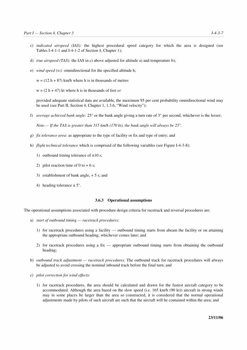
Part I — Section 4, Chapter 3 I-4-3-7
23/11/06
c) indicated airspeed (IAS): the highest procedural speed category for which the area is designed (seeTables I-4-1-1 and I-4-1-2 of Section 4, Chapter 1);
d) true airspeed (TAS): the IAS in c) above adjusted for altitude a) and temperature b);
e) wind speed (w): omnidirectional for the specified altitude h;
w = (12 h + 87) km/h where h is in thousands of metres
w = (2 h + 47) kt where h is in thousands of feet or
provided adequate statistical data are available, the maximum 95 per cent probability omnidirectional wind maybe used (see Part II, Section 4, Chapter 1, 1.3.6, “Wind velocity”);
f) average achieved bank angle: 25° or the bank angle giving a turn rate of 3° per second, whichever is the lesser;
Note.— If the TAS is greater than 315 km/h (170 kt), the bank angle will always be 25°.
g) fix tolerance area: as appropriate to the type of facility or fix and type of entry; and
h) flight technical tolerance which is comprised of the following variables (see Figure I-4-3-8):
1) outbound timing tolerance of ±10 s;
2) pilot reaction time of 0 to + 6 s;
3) establishment of bank angle, + 5 s; and
4) heading tolerance ± 5°.
3.6.3 Operational assumptions
The operational assumptions associated with procedure design criteria for racetrack and reversal procedures are:
a) start of outbound timing — racetrack procedures:
1) for racetrack procedures using a facility — outbound timing starts from abeam the facility or on attainingthe appropriate outbound heading, whichever comes later; and
2) for racetrack procedures using a fix — appropriate outbound timing starts from obtaining the outboundheading;
b) outbound track adjustment — racetrack procedures. The outbound track for racetrack procedures will alwaysbe adjusted to avoid crossing the nominal inbound track before the final turn; and
c) pilot correction for wind effects:
1) for racetrack procedures, the area should be calculated and drawn for the fastest aircraft category to beaccommodated. Although the area based on the slow speed (i.e. 165 km/h (90 kt)) aircraft in strong windsmay in some places be larger than the area so constructed, it is considered that the normal operationaladjustments made by pilots of such aircraft are such that the aircraft will be contained within the area; and

I-4-3-8 Procedures — Aircraft Operations — Volume II
23/11/06
2) for base and procedure turns, however, the area for 165 km/h (90 kt) should be checked. An additionaltemplate for these procedures is incorporated in the Template Manual for Holding, Reversal and RacetrackProcedures (Doc 9371).
3.6.4 Area construction
3.6.4.1 Statistical area construction
If statistical methods are used to combine the variables and then to extrapolate distributions to develop areas, theprobability level associated with that extrapolation should meet an acceptable level of safety.
3.6.4.2 Additive tolerance area construction
A variety of methods may be used to construct areas. Whichever method is selected, the procedure design criteriaspecified in 3.5, “Initial approach segment using a reversal procedure”, and the area parameters specified in 3.6.2,“Area parameters”, apply. One additive tolerance method, the template tracing technique (TTT), is described inAppendix C.
Note.— For applications where airspace is not critical, a method of constructing a simplified rectangular area(based on the TTT areas) is also contained in Appendix C.
3.6.5 Area reduction
The area may be reduced under special circumstances. Methods of reduction include:
a) reduction of the maximum speed(s) specified for the procedure. Speeds below the minimum value for initialapproach in a given aircraft category shall not be specified (see Tables I-4-1-1 and I-4-1-2 of Section 4,Chapter 1). If procedures are developed which exclude specific aircraft categories due to speed, this must bestated explicitly;
b) restricting use of the procedure to specified categories of aircraft;
c) restricting procedure entry to specific track(s); and
d) use of DME or radial/bearing to limit outbound track (see 3.6.6, “Use of DME or intersecting radial/bearing”).
3.6.6 Use of DME or intersecting radial/bearing
If a DME distance or an intersecting radial or bearing is used to limit the outbound leg, the area may be reduced byapplying the appropriate adjustments described in Appendix C, in this case the limiting distance or radial/bearing shallallow adequate time for the descent specified. The distance on the outbound track is thereby limited by the timing or byreaching the limiting DME distance or radial/bearing, whichever occurs first.
3.6.7 Secondary areas
Secondary areas shall be added to the outer boundary of all areas calculated using the criteria in 3.6.4, “Areaconstruction”. The width of the secondary area is 4.6 km (2.5 NM).

Part I — Section 4, Chapter 3 I-4-3-9
23/11/06
Note.— See Appendix B, “Reduction of the width of a straight initial approach area after the IAF and interfacebetween straight initial approach area and reversal procedure areas” for possible reduction of secondary area width.
3.7 MAXIMUM DESCENT/NOMINAL OUTBOUND TIMING RELATIONSHIPFOR A REVERSAL OR RACETRACK PROCEDURE
3.7.1 General
Because the actual length of the track will vary, it is not possible to specify a descent gradient for the racetrack orreversal procedures. Instead, the maximum descents which can be specified on the outbound and inbound tracks of theprocedure are listed in Table I-4-3-1 as a function of nominal outbound time.
Note.— Where a 45° procedure turn is specified, an additional 1 minute may be added to the nominal outboundtime in calculating the maximum descent outbound.
Example: Reversal procedure with 2.5 minutes outbound track (Category A and B aircraft):
a) maximum descent to be specified on outbound track = 612 m (2 010 ft); and
b) maximum descent to be specified on inbound track = 500 m (1 638 ft).
3.7.2 Turns
In calculating maximum descents, no descent shall be considered as having taken place during turns.
3.8 OBSTACLE CLEARANCE
The prescribed minimum altitudes for either the racetrack or the reversal procedure shall not be less than 300 m (984 ft)above all obstacles within the appropriate primary areas. In the secondary area the minimum obstacle clearance shall be300 m (984 ft) at the inner edge, reducing linearly to zero at the outer edge. See Chapter 1, 1.6, “Obstacle clearance”.

I-4-3-10 Procedures — Aircraft Operations — Volume II
23/11/06
Table I-4-3-1. Maximum/minimum descent to be specified on a reversal or racetrack procedure
Maximum* Minimum*
Cat A/B 245 m/min (804 ft/min) N/AOutbound trackCat C/D/E/H 365 m/min (1 197 ft/min) N/A
Cat A/B 200 m/min (655 ft/min) 120 m/min (394 ft/min)Inbound track Cat H 230 m/min (755 ft/min) N/A
Cat C/D/E 305 m/min (1 000 ft/min) 180 m/min (590 ft/min)
* Maximum/minimum descent for 1 minute nominal outbound time in m(ft). For maximum descent ratesrelated to a final approach segment, see Chapter 5, 5.3.
Figure I-4-3-1. Lead radial for turns greater than 70°
FAFMAPt
Final
Intermediate
Lead radialMax turn 120°
Initial approach track
4 km (2 NM) (Cat H, 1.9 km (1 NM))of lead with angle of interception 70°and beyond
IF

Part I — Section 4, Chapter 3 I-4-3-11
23/11/06
Figure I-4-3-2. Typical segments (plan view)
Secondary area
Secondary area
Finalsegment
Intermediatesegment
Initialsegment 4.6 km
(2.5 NM)
4.6 km(2.5 NM)
IF FAF
Secondary
Final segment
Intermediatesegment
Intermediatesegment
Initialsegment
4.6 km(2.5 NM)
4.6 km(2.5 NM)
4.6 km (2.5 NM)
IF
FAF
Extended final approach area
IF
FAFFinal segment
Initialsegment

I-4-3-12 Procedures — Aircraft Operations — Volume II
23/11/06
Figure I-4-3-3. Initial approach area utilizing straight tracks
Figure I-4-3-4. Entry to procedure turn
Figure I-4-3-5. Entry to base turn
4.6 km(2.5 NM)
52 km(28 NM)
69 km(37 NM)
10.3° NDB
7.8° VOR
10.3° NDBVOR/NDB
Secondary areaPrimary area
7.8° VOR
Facility
Procedure turn
Direct entry within±30° sector
Facility
Base turn
30°
30°Entrysector

Part I — Section 4, Chapter 3 I-4-3-13
23/11/06
Figure I-4-3-6. Example of omnidirectional arrival using a holdingprocedure in association with a reversal procedure
30°
30°Sector 1 Sector 2
Sector 1: Arrivals from this sector may enterthe reversal procedure directly
Sector 2: Arrivals from this sector must enter theholding prior to the reversal procedure
HoldingProcedure turn
Nominal flight path
FAFProfile view

I-4-3-14 Procedures — Aircraft Operations — Volume II
23/11/06
Figure I-4-3-7. Types of reversal and racetrack procedures
*
B. 80° /260° procedure turn
1 to 3 min
1 to 3 min 1 minCAT A
& B
1 m inCAT A
& B(TIM ING)
(TIM ING)
A. 45 /180 procedure turn° °
Start of turndefined by a fix
Start of turndefined by a fix
End of outbound legdefined by a radialor DME distancefrom a suitablylocated facili ty(see Section 2,Chapter 2, 2.4.3,"F ixes for VOR orNDB with DME".)
C. Base turns
End of outbound leg lim ited by a radia l or DMEdis tance from a suitably located facili ty (
)see Section 2,
Chapter 2, 2.4.3, "F ixes for VOR or NDB with DME ".
track guidance
no track guidance* For the start of timing in a racetrack procedure based on a facility, see 3.6.3 a).
D. Racetrack procedures
CAT C, D&
E
CAT C, D&
E
1 m in 2 min 3 min
3 m in2 min1 min
1 min15 s
1 min1 5 s

Part I — Section 4, Chapter 3 I-4-3-15
23/11/06
Figure I-4-3-8. Application of flight technical tolerance
— — — — — — — —
6 s
6 s
5 s
5 s
End of outbound leg limited by a radial or DMEdistance from a suitably located facility (
)see Section 2,
Chapter 2, 2.4.3, "Fixes for VOR or NDB with DME".
5 s 6 s
Start of turn definedby a fix.
FIX
6 s
6 s
6 s
1 to 3 min
1 to 3 min
1 to 3 min
10 s
10 s
10s
10 s
10s
5 s
5 s
5s
5 s
5s
5 s
5 s
5 s
5 s5 s
5 s
1m
in15
s(C
ATC, D, E
)
1m
in15
s(C
ATC, D, E)
45°/180°procedure turn
Example of an outbound flighttimed from a facili ty
80°/260° procedure turn
Example of an outbound flighttimed from a facili ty
6 s
6 s
toleranceof the fix
toleranceof the fix
Base turn
FIX
End of outbound leg defined by a radial or DMEdistance from a suitably located facility (see Section 2,Chapter 2, 2.4.3, "Fixes for VOR or NDB with DME".)
1 to 3 min
Facility intersection toleranceVOR = 4.5°, °NDB = 6.2
Racetrack
Note._ Commencement of outbound timing; outbound timing shouldstart from abeam the facili ty or on attaining the appropriate outboundheading, whichever comes later.
intersectingtolerance
10 s 5 s
(1m
inC
ATA
&B
&H)
(1m
inCAT
A&
B&
H)
The fl ight technical tolerances shown on this figure are:— outbound tolerance (+/–10s)— establishment of bank angle (5s)— pilot reaction time (6s)

I-4-3-App A-1 23/11/06
Appendix A to Chapter 3
INITIAL APPROACH USING DEAD RECKONING (DR)
1. GENERAL
1.1 Purpose
1.1.1 A dead reckoning (DR) track procedure may be used to reduce the angle of turn onto the final approachtrack where such a turn would otherwise exceed the limits specified in Part II, Section 1, Chapter 1, “Initial approachsegment alignment”. Its main purposes are:
a) to save time and airspace by avoiding a reversal manoeuvre;
b) to provide pilots with a comfortable flight pattern. The chances of overshooting the final approach track in caseof a suitably designed intercepting DR track are less than in the case of a large turn initiated by a lead radial;and
c) to provide air traffic control (ATC) with flexibility by designing DR track segments of different length toaccommodate two ranges of speeds. This will allow a slower aircraft followed by a faster one to be assigned toa shorter track to the advantage of both aircraft.
1.1.2 Several DR tracks may be designed using the criteria in this attachment. This allows ATC to vary the initialtrack of the aircraft under radar surveillance by assigning a track number to the aircraft. And if radar vectoring isrequired, this track will provide the ATC with a reference (on the radar scope) which shows the most appropriate wayto proceed from the initial approach fix (IAF) to the final approach point (FAP).
1.2 Required navigation facilities
This type of procedure requires either two VORs or a VOR/DME to define the fix from which the DR track begins.Track guidance on final and intermediate approach may be provided either by VOR, NDB or localizer (LLZ). Becausethis procedure is intended for use at major airports, it has been illustrated for the instrument landing system (ILS) case.When any portion of DR segment between the nominal position of start point and the localizer course lies outside of theservice volume of the localizer, a homing facility close to the final approach track (for example at the airport) isrequired.
Note.— In case of non-precision approach, the areas shall be adapted to the type of facility providing guidance onfinal approach.

I-4-3-App A-2 Procedures — Aircraft Operations — Volume II
23/11/06
2. PARAMETERS
2.1 Aircraft speed
— Aircraft Categories A and B: Indicated airspeed (IAS) from 165 to 335 km/h (90 to 180 kt); and
— Aircraft Categories C, D and E: IAS from 335 to 465 km/h (180 to 250 kt).
The corresponding true airspeeds (TAS) are calculated taking into account the following factors:
a) temperature: International standard atmosphere (ISA) + 15°C; and
b) altitude: 1 500 m (5 000 ft) and 3 000 m (10 000 ft).
2.2 Wind speed
An omnidirectional wind shall be used. The wind speed (w) in km/h (kt) is determined by the formula:
w = (12 h + 87) km/h where h is in thousands of metres
w = (2 h + 47) kt where h is in thousands of feet.
However, for the straight part of the dead reckoning segment an omnidirectional wind of 56 km/h (30 kt) shall be takeninto account. This assumes that the pilot is given the wind speed at the aerodrome and has appraised the wind within56 km/h (30 kt) on the previous leg, the length of which shall be specified on approach charts.
2.3 Flight technical tolerances
a) Bank angle. 25° or the angle corresponding to a rate of turn of 3° per second, whichever is the lesser.
b) Tolerances:
1) pilot reaction time: 0 to + 6 s;
2) bank establishment time: + 5 s; and
3) heading tolerance: ±5°.
2.4 Fix tolerances
These are established taking into account the accuracy of the facility used:
a) VOR facility providing track guidance: ±5.2°;
b) VOR intersecting facility: ±4.5°; and
c) DME distance indications: 0.46 km (0.25 NM) + 1.25 per cent of the distance to the antenna.

Part I — Section 4, Chapter 3, Appendix A I-4-3-App A-3
23/11/06
2.5 Table of basic values
See Table I-4-3-App A-1.
3. TRACK CONSTRUCTION
3.1 General
3.1.1 Types of procedures. A distinction should be made between two types of procedures:
a) the U-type procedures (see Figure I-4-3-App A-1) in which the turn preceding the dead reckoning segment andthe turn joining the final approach track are made in the same direction; and
b) the so-called S-type procedures (see Figure I-4-3-App A-2) in which these two turns are in opposite directions.
3.1.2 Components of procedures. These two procedures can be broken down as follows.
a) First leg of the initial approach. This track is defined by a VOR radial. In order to limit the tolerance areaassociated with the start point of the turn preceding the dead reckoning segment, the length of this track shouldnot exceed 56 km (30 NM).
b) Dead reckoning segment
1) Orientation. In all cases the angle between the dead reckoning track and the final approach path shall be45°.
2) Length. The maximum length is 19 km (10 NM). The minimum length is calculated so that an aircraftmeeting the most adverse wind conditions is able to complete the turn preceding the dead reckoningsegment before initiating the turn onto the final approach track. The minimum length depends on the type ofprocedure.
c) Intermediate approach segment. The intermediate approach segment begins where the DR track intercepts theintermediate approach track. An intermediate fix is required at this point. The minimum length of theintermediate approach segment depends upon speed and altitude (see Table I-4-3-App A-3). The minimumlength of this segment is calculated to allow an aircraft arriving at an angle of 45° — without any indication ofthe start of the joining turn other than the ILS information — to join and stabilize on the intermediate approachtrack even in the most adverse conditions.
3.2 Characteristics of the S-type procedures
3.2.1 This type of procedure introduces fewer constraints than the preceding one (see Figure I-4-3-App A-2).
3.2.2 Start point of the turn onto the DR track. The start point shall be defined by a fix for which the toleranceshall not exceed ±3.7 km (±2.0 NM).
3.2.3 Minimum length of the DR segment. The minimum length of the dead reckoning segment to be adopted willbe one of the two following values:
a) start point of the turn defined by VOR intersection: 9 km (5 NM); and

I-4-3-App A-4 Procedures — Aircraft Operations — Volume II
23/11/06
b) start point of the turn defined by VOR/DME indication: 7 km (4 NM).
These values are adequate provided that the length of the first leg does not exceed 19 km (10 NM); otherwise, theyshould be increased by 15 per cent of the distance in excess of 19 km (10 NM). Example: Start point of the turndefined by VOR intersection; for a 37 km (20 NM) first leg, the length of the DR segment shall not be less than10.5 km or 6.5 NM.
3.3 Characteristics of the U-type procedures
3.3.1 Position of the initial approach fix (IAF). The IAF can be a facility (VOR or VOR/DME) or a fix fromwhich track guidance is available. This fix or facility shall be located outside a sector contained between the finalapproach path and a straight line L (see Figure I-4-3-App A-1). Line L is determined as follows:
a) from the FAP draw line D at an angle � to the final approach path.
The length of D varies with the type of facility. Lengths for each type appear in Table I-4-3-App A-3; and
b) at the end point of line D, draw line L perpendicular to line D.
3.3.1.1 Values for � were determined as follows:
a) take the angle (45°) between the dead reckoning segment and the ILS axis;
b) add the maximum angle between the first leg of the initial segment and the dead reckoning segment:
1) 45° + 120° = 165° for VOR/DME; and
2) 45° + 105° = 150° for VOR/VOR;
c) take the total from steps 1 and 2, and subtract this from 180. This gives the maximum angle between the firstleg of the initial segment and the reverse of ILS axis:
1) 180° – 165° = 15° for VOR/DME; and
2) 180° – 150° = 30° for VOR/VOR;
d) subtract the value obtained in c) from 90° in order to have the direction of the perpendicular:
1) 90° – 15° = 75° for VOR/DME; and
2) 90° – 30° = 60° for VOR/VOR; and
e) subtract a buffer value of 5° for technical tolerance to give the following values:
1) 70° for VOR/DME; and
2) 55° for VOR/VOR.

Part I — Section 4, Chapter 3, Appendix A I-4-3-App A-5
23/11/06
3.3.2 Limitation of the angle of turn preceding the dead reckoning segment
a) Start point of turn defined by an intersection of VOR radials. The angle between the first leg of the initialapproach and the dead reckoning segment should not exceed 105°. The angle of intersection of VOR radialsshould not be less than 45° (See Figure I-4-3-App A-1); and
b) Start point of turn defined by a VOR/DME fix. In this case the angle of turn should not exceed 120°.
Note.— If a homing facility located on the final approach track in the vicinity of the FAP allows the pilot to controlthe development of the turn preceding the DR segment, the conditions specified in 3.3.1, “Position of the initialapproach fix (IAF)” and 3.3.2, “Limitation of the angle of turn preceding the dead reckoning segment” may berelaxed.
3.3.3 Minimum length of the dead reckoning segment
The minimum length of the dead reckoning segment depends on the following parameters:
a) the speed of the aircraft;
b) the angle of turn;
c) the definition of the point of start of turn;
d) the altitude; and
e) the length of the first leg of the initial approach.
Segment lengths appropriate for selected angles of turn are shown in Tables I-4-3-App A-4 through I-4-3-App A-7.Linear interpolation can be applied to determine intermediate values.
Note.— All values shown in the tables are adequate provided the length of the first leg does not exceed 19 km(10 NM). Otherwise these values should be increased by 10 per cent of the distance in excess of 19 km (10 NM).Example: Table I-4-3-App A-7, angle of turn: <45°. If the first leg is 22 km (12 NM) long, the minimum lengths of theDR segment become 6.3 and 9.3 km or 3.7 and 5.2 NM.
4. AREAS
4.1 Areas associated with the U-type procedures (see Figures I-4-3-App A-3 and I-4-3-App A-4)
4.1.1 Initial approach area for the first leg. This is established according to the criteria in Part III, Chapter 3,3.3.3, “Area”.
4.1.2 Area for the turn and for the dead reckoning segment.
a) Inner edge, primary area. Join point A to point B.
1) Point A is on the OAS “X” surface abeam the FAP, on the side of the DR segment.
2) Point B is located on the first leg of the initial approach at a distance D before the nominal start point of theturn where:

I-4-3-App A-6 Procedures — Aircraft Operations — Volume II
23/11/06
D = 4.6 km (2.5 NM) when it is defined by the intersection of VOR radials;
D = 1.9 km (1.0 NM) when it is defined by the VOR/DME indication.
b) Inner edge, secondary area. The secondary area associated with the first leg of the initial approach will end onthe inside of the turn over this straight line.
c) Outer edge, primary area. This is defined by:
1) an arc of a circle centred on the start point of the turn whose radius R is a function of aircraft speed andaltitude. Tables I-4-3-App A-8 and I-4-3-App A-9 give the values of the radius R;
2) a straight line which is tangent to the arc of circle and which splays outward at an angle θ to the deadreckoning track according to speed where:
θ = 22° for IAS 165/335 km/h (90/180 kt);
θ = 14° for IAS 335/465 km/h (180/250 kt);
3) a straight line from point A to point C, splayed at an angle of 15° from the intermediate approach trackwhere:
Point A is on the OAS X surface abeam the final approach point (FAP); and
Point C is abeam the intermediate approach fix (IF); and
4) a straight line originating from point C parallel to the intermediate approach track.
d) Outer edge, secondary area. The secondary area is located outside of the turn preceding the dead reckoningsegment. It is extended up to the outer limit of the protection area defined above.
4.2 Areas associated with the S-type procedures (see Figures I-4-3-App A-5 and I-4-3-App A-6)
a) Area for the first leg of the initial approach. See Part III, Chapter 4, 4.3.3, “Area”.
b) Area for the turn and the dead reckoning segment.
1) Outer edge. This is formed by a straight line joining point A to point S. Point A is located abeam the FAPon the OAS X surface; point S is located abeam the start point of turn on the outer edge of the initialapproach area.
2) Inner edge.
i) First locate point B' on the first leg at a distance from the start point of the turn equal to:
1.9 km (1.0 NM) if the start point is defined by VOR/DME reference;
3.7 km (2.0 NM) if the start point is defined by VOR intersection.
ii) Identify point B abeam B' at a distance of 9.3 km (5.0 NM).

Part I — Section 4, Chapter 3, Appendix A I-4-3-App A-7
23/11/06
iii) From point B, draw a straight line splaying apart from the DR track at a 22° angle (heading toleranceplus maximum drift angle for the lowest speed category).
iv) Locate A' on the OAS X surface abeam the FAF.
v) From A' draw a straight line splaying at 15° from the intermediate approach track to a point C abeamthe IF.
vi) From C draw a straight line parallel to the intermediate approach track.
Table I-4-3-App A-1. Basic values
IAS km/h(kt)
165(90)
335(180)
465(250)
TAS at 1 500 m km/h(5 000 ft) (kt)
185(100)
370(199)
510(276)
TAS at 3 000 m km/h(10 000 ft)(kt)
400(216)
555(299)
Turn radius km(NM)
1.05(0.57)
2.30(1.24)
2.70(1.46)
4.42(2.39)
5.18(2.80)
Bank angle 17° 25° 25° 25° 25°
Rate of turn (°/s) 3 2.55 2.35 1.84 1.70
Maximum drift for a windof 56 km/h (30 kt) 17° 9° 8° 6° 6°
Heading tolerance +max drift angle 22° 14° 13° 11° 11°
11 s of flight at km(TAS + W)(NM)
0.89(0.48)
1.35(0.78)
1.61(0.87)
1.89(1.02)
2.07(1.12)
Table I-4-3-App A-2. Length of the intermediate approach segment
IASkm/h (kt)
Altitude165/335(90/180)
335/465(180/250)
1 500 m (5 000 ft) 11 km (6 NM) 17 km (9 NM)
3 000 m (10 000 ft) 12 km (6.5 NM) 20 km (11 NM)
Note.— For the intermediate attitudes, linear interpolation can be applied.

I-4-3-App A-8 Procedures — Aircraft Operations — Volume II
23/11/06
Table I-4-3-App A-3. Lengths of line D for types of facility and airspeed
Facility � D for IAS < 335 km/h (180 kt) D for IAS < 465 km/h (250 kt)
VOR/VOR 55° 16 km (8.5 NM) 23 km (12.5 NM)
VOR/DME 70° 12 km (6.5 NM) 18 km (9.5 NM)
Table I-4-3-App A-4. Minimum length of the DR segmentStart point defined by VOR intersection — Altitude: 1 500 m (5 000 ft)
Angle of turn
IASkm/h (kt) <45° 60° 90° 105°
165/335 km/h(90/180 kt)
10 km(5.5 NM)
11 km(6 NM)
12 km(6.5 NM)
12 km(6.5 NM)
335/465 km/h(180/250 kt)
13 km(7 NM)
14 km(7.5 NM)
15 km(8 NM)
16 km(8.5 NM)
Table I-4-3-App A-5. Minimum length of the DR segmentStart point defined by VOR intersection — Altitude: 3 000 m (10 000 ft)
Angle of turn
IASkm/h (kt) <45° 60° 90° 105°
165/335 km/h(90/180 kt)
11 km(6 NM)
12 km(6.5 NM)
13 km(7 NM)
14 km(8.5 NM)
335/465 km/h(180/250 kt)
15 km(8 NM)
16 km(8.5 NM)
18 km(9.5 NM)
19 km(10 NM)

Part I — Section 4, Chapter 3, Appendix A I-4-3-App A-9
23/11/06
Table I-4-3-App A-6. Minimum length of the DR segmentStart point defined by VOR/DME fix — Altitude: 1 500 m (5 000 ft)
Angle of turn
IASkm/h (kt) <45° 60° 90° 105°
165/335 km/h(90/180 kt)
6 km(3.5 NM)
8 km(4.5 NM)
9 km(5 NM)
10 km(5.5 NM)
335/465 km/h(180/250 kt)
9 km(4.5 NM)
11 km(5.5 NM)
13 km(6.5 NM)
15 km(7.5 NM)
Table I-4-3-App A-7. Minimum length of the DR segmentStart point defined by VOR/DME fix — Altitude: 3 000 m (10 000 ft)
Angle of turn
IASkm/h (kt) <45° 60° 90° 105°
165/335 km/h(90/180 kt)
6 km(3.5 NM)
9 km(5 NM)
11 km(6 NM)
12 km(6.5 NM)
335/465 km/h(180/250 kt)
9 km(5 NM)
11 km(6 NM)
15 km(8 NM)
18 km(9.5 NM)
Note.— All values shown in the tables are adequate provided the length of the first leg does not exceed 19 km(10 NM). Otherwise these values should be increased by 10 per cent of the distance in excess of 19 km (10 NM).Example: Table I-4-3-App A-7, angle of turn: <45°. If the first leg is 22 km (12 NM) long the minimum lengths of theDR segment become 6.3 and 9.3 km or 3.7 and 5.2 NM.
Table I-4-3-App A-8. R values for a start point of turndefined by VOR intersection
Altitude
IASkm/h (kt)
1 500 m(5 000 ft)
3 000 m(10 000 ft)
165/335 km/h(90/180 kt)
10.2 km(5.5 NM)
11.1 km(6 NM)
335/465 km/h(180/250 kt)
12.0 km(6.5 NM)
13.9 km(7.5 NM)

I-4-3-App A-10 Procedures — Aircraft Operations — Volume II
23/11/06
Table I-4-3-App A-9. R values for a start point of turndefined by VOR/DME
Altitude
IASkm/h (kt)
1 500 m(5 000 ft)
3 000 m(10 000 ft)
165/335 km/h(90/180 kt)
9.3 km(5.0 NM)
9.3 km(5.0 NM)
335/465 km/h(180/250 kt)
10.2 km(5.5 NM)
12.0 km(6.5 NM)
Figure I-4-3-App A-1. U-type procedure conditions for locating the IAF
VOR-DME
IAFVOR-DME
VOR-DME
φ1
1
= 70°IAS <335 km/h (180 kt) D = 12 km (6.5 NM)IAS <465 km/h (250 kt) D = 18 km (9.5 NM)1
φ1
2
= 55°IAS <335 km/h (180 kt) D = 16 km (8.5 NM)IAS <465 km/h (250 kt) D = 23 km (12.5 NM)2
DME ARC
120° max
IF 45°
45°
LLZ
VOR
VOR
φ1
φ2
D 1
FAP
X
X
Dead reckoning segment notpossible if IAF is locatedwithin these areas
D2
105° max
Dead reckoning segment
First leg of initial approach
IAF

Part I — Section 4, Chapter 3, Appendix A I-4-3-App A-11
23/11/06
Figure I-4-3-App A-2. S-type procedure
45°
45°FAP
Dead reckoning segment
IF
DME
arc
IAF
First leg ofinitial approach
IAF VOR
VOR
LLZ
VOR-DME

I-4-3-App A-12 Procedures — Aircraft Operations — Volume II
23/11/06
Figure I-4-3-App A-3. U-type VOR/VOR procedure constructionof protection areas
LLZ
IAF
VOR
A
A'
Intermediate approacharea
15°
Initial approach area
φ
C
B
4.6 km(2.5 NM)
Prim
ary ar
ea
Altitude
Altitude
km/h
km/h
IAS
IAS
(kt)
(kt)
1 500 m (5 000 ft)3 000 m (10 000 ft)
1 500 m (5 000 ft)3 000 m (10 000 ft)
10.2 km (5.5 NM)11.1 km (6 NM)
22°
12.0 km (6.5 NM)13.9 km (7.5 NM)
Values of R
Values of φ
165/335 km/h(90/180 kt)
165/335 km/h(90/180 kt)
335/465 km/h(180/250 kt)
335/465 km/h(180/250 kt)
14°
FAP
VOR
4.6 km(2.5 NM)
IF
R
Secon
dary
area
4.6
km(2
.5NM
)

Part I — Section 4, Chapter 3, Appendix A I-4-3-App A-13
23/11/06
Figure I-4-3-App A-4. U-type VOR/DME procedure constructionof protection areas
FAP
LLZ
IAFVOR-DME
DME
Range
A
A'
Intermediate approacharea
IF
150 m (500 ft) MOC
15° Initial approach area
φ
300 m(1 000 ft)
MOC
R
B 1.9 km
(1.0 NM)
4.6 km
(2.5 NM)
4.6 km
(2.5 NM)
Primary area
Altitude
Altitude
km/h
km/h
IAS
IAS
(kt)
(kt)
1 500 m (5 000 ft)3 000 m (10 000 ft)
1 500 m (5 000 ft)3 000 m (10 000 ft)
9.3 km (5.0 NM)9.3 km (5.0 NM)
22°
10.2 km (5.5 NM)12.0 km (6.5 NM)
Values of R
Values of φ
165/335 km/h(90/180 kt)
165/335 km/h(90/180 kt)
335/465 km/h(180/250 kt)
335/465 km/h(180/250 kt)
14°
Secondary area
C

I-4-3-App A-14 Procedures — Aircraft Operations — Volume II
23/11/06
Figure I-4-3-App A-5. S-type VOR/VOR procedure constructionof protection areas
FAP
VOR
VOR
A
A'
Intermediate approach area
IF
150 m(500 ft)MOC
15°
Initial approach area
300 m(1 000 ft)
MOC
Secondary area
22°
B
3.7 km(2.0NM)
S
Primary areaB'
4.6 km
(2.5 NM)
4.6 km
(2.5 NM)
IAF
X SurfacesW Surface
C

Part I — Section 4, Chapter 3, Appendix A I-4-3-App A-15
23/11/06
Figure I-4-3-App A-6. S-type VOR/DME procedure constructionof protection areas
— — — — — — — —
FAP
A
W Surface
X Surfaces
VOR-DMEIAF
15°22°
B
A'
C
Intermediate approach area
IF
Initial approach area
1.9 km(1.0 NM)
Primary area
DM
Erange
B
S
Secondary area
4.6 km(2.5 NM)
4.6 km(2.5 NM)

I-4-3-App B-1 23/11/06
Appendix B to Chapter 3
REDUCTION OF THE WIDTH OF A STRAIGHT INITIAL APPROACHAREA AFTER THE IAF AND INTERFACE BETWEEN STRAIGHT
INITIAL APPROACH AREA AND REVERSAL PROCEDURE AREAS
(see Chapter 3, 3.3.2)
1. REDUCTION OF THE WIDTH OF A STRAIGHT INITIALAPPROACH AREA AFTER THE IAF
1.1 General
Where the initial approach includes a straight segment ending at an intermediate approach fix (IF) defined by a VOR,NDB or RNAV waypoint, its width at the IF is reduced from the appropriate en-route width to:
a) ± 3.7 km (2.0 NM) at a VOR;
b) ± 4.6 km (2.5 NM) at an NDB; or
c) the calculated area width for an RNAV waypoint.
1.2 Justification
The guidance provided is considered sufficient. The cone effect area radius is:
a) 3.7 km (2.0 NM) for a VOR at 3 000 m (10 000 ft); and
b) 4.6 km (2.5 NM) for an NDB at 5 500 m (18 000 ft).
The area width at the IF for the RNAV case can be calculated. It is assumed that the flight technical tolerance isdiminishing after the aircraft has passed the initial approach fix (IAF).
1.3 VOR cases
1.3.1 The IAF is at a distance of more than 40.5 km (21.9 NM) from the VOR. From a distance of 40.5 km (21.9NM) from the VOR and up to the VOR, the width of the area on each side of the nominal track is reduced linearly from9.3 km (5.0 NM) to 3.7 km (2.0 NM), the outer boundary of the area converging at an angle of 7.8° with the nominaltrack (Figure I-4-3-App B-1).

I-4-3-App B-2 Procedures — Aircraft Operations — Volume II
23/11/06
1.3.2 The IAF is at a distance of less than 40.5 km (21.9 NM) from the VOR. The width of the area on each side ofthe nominal track is reduced linearly from 9.3 km (5.0 NM) at the IAF to 3.7 km (2.0 NM) at the VOR (Figure I-4-3-App B-2).
1.4 NDB cases
1.4.1 The IAF is at a distance of more than 25.5 km (13.8 NM) from the NDB. From a distance of 25.5 km (13.8NM) from the NDB and up to the NDB the width of the area on each side of the nominal track is reduced linearly from9.3 km (5.0 NM) to 4.6 km (2.5 NM), the outer boundary of the area converging at an angle of 10.3° with the nominaltrack (Figure I-4-3-App B-3).
1.4.2 The IAF is at a distance of less than 25.5 km (13.8 NM) from the NDB. The width of the area on each side ofthe nominal track is reduced linearly from 9.3 km (5.0 NM) at the IAF to 4.6 km (2.5 NM) at the NDB (Figure I-4-3-App B-4).
1.5 RNAV case
1.5.1 Requirements. The RNAV system shall meet the following requirements:
a) the accuracy (including position determination, RNAV computation and CDI centering) shall be better or equalto 0.4 km (0.2 NM) (2 sigma value);
b) the equipment shall include a system to provide integrity with a maximum alarm limit of 1.9 km (1.0 NM) and amaximum time to alarm of 10 seconds; and
c) the CDI sensitivity shall be better than or equal to 1.9 km (1.0 NM) (full-scale deflection).
1.5.2 Area. The width of the area on each side of the nominal track is reduced linearly from 9.3 km (5.0 NM) atthe initial approach waypoint (IAF) to 5.6 km (3.0 NM) at the next waypoint (Figure I-4-3-App B-5). If the distance (d)between the IAF and the next waypoint is less than 6.5 km (3.5 NM), an area width of 5-0.577d shall be used in placeof 5.6 km (3.0 NM) in order to limit the angle of convergence to 30° (Figure I-4-3-App B-6).
1.5.3 Figure I-4-3-App B-7 illustrates the combination of turn protection and area narrowing.
Note.— Reduction of the initial approach segment width should only be considered for GNSS receivers whichprovide an input to an integrated navigation system, i.e. FMS/multi-sensor systems.
2. PROTECTION OF A TURN AT THE IF
Where a turn at the IF greater than 10° is specified, the intermediate approach area should be widened on the outer sideof the turn, using the method described in Chapter 6, 6.4.6.3.3 based on a bank angle of 25° (or on that angle giving aturn rate of 3°/s, whichever is the lesser) and on the maximum initial speed for the aircraft category. FigureI-4-3-App B-8 shows an example of this additional area to protect the turn.

Part I — Section 4, Chapter 3, Appendix B I-4-3-App B-3
23/11/06
3. INTERFACE BETWEEN STRAIGHT INITIAL APPROACH AREAAND REVERSAL PROCEDURE AREAS
The secondary area width of a reversal procedure is:
a) 1.9 km (1.0 NM) if it is based on a VOR; and
b) 2.3 km (1.25 NM) if it is based on an NDB.
The corresponding areas are related as shown in Figure I-4-3-App B-9.
Note.— In Figure I-4-3-App B-9 the VOR facility marks the turning point in the initial approach segment. Theintermediate approach segment starts only after completion of the reversal procedure turn.
Figure I-4-3-App B-1. Case where the IAF is more than 40.5 km (21.9 NM) from the VOR
Figure I-4-3-App B-2. Case where the IAF is less than 40.5 km (21.9 NM) from the VOR
40.5 km (21.9 NM)
7.8°
3.7 km (2.0 NM)
VOR
IF
IAF
9.3 km (5.0 NM)
3.7 km (2.0 NM)
VOR
IF
IAF
9.3 km (5.0 NM)

I-4-3-App B-4 Procedures — Aircraft Operations — Volume II
23/11/06
Figure I-4-3-App B-3. Case where the IAF is more than 25.5 km (13.8 NM) from the NDB
Figure I-4-3-App B-4. Case where the IAF is less than 25.5 km (13.8 NM) from the NDB
25.5 km (13.8 NM)
10.3°
4.6 km (2.5 NM)
NDB
IF
IAF
9.3 km (5.0 NM)
4.6 km (2.5 NM)
NDB
IF
IAF
9.3 km (5.0 NM)

Part I — Section 4, Chapter 3, Appendix B I-4-3-App B-5
23/11/06
Figure I-4-3-App B-5. RNAV area
Figure I-4-3-App B-6. RNAV area
D > 6.5 km (3.5 NM)
IAF IF9.3
km(5
.0N
M)
9.3
km(5
.0N
M)
5.6
km5.
6km
(3.0
NM
)(3
.0N
M)
9 .3
km( 5
.0N
M)
9 .3
km( 5
.0N
M)
d < 6.5 km(3.5 NM)
IAF IF
30º
5-05
77d
5-05
77d

I-4-3-App B-6 Procedures — Aircraft Operations — Volume II
23/11/06
Figure I-4-3-App B-7. RNAV turn protection
d
d
IF
FAF
IAF
9.3km
(5.0NM)
9.3km
(5.0NM)
d′d′
d = r tg (A /2) + ATTd = r tg (A /2) – ATT – d(6 sec)
d = r tg (A/2) + ATTd = r tg (A/2) – ATT – d(6 sec)
′ ′ ′′ ′ ′��
1
2
1
2
1
1
2
2

Part I — Section 4, Chapter 3, Appendix B I-4-3-App B-7
23/11/06
Figure I-4-3-App B-8. Reduction in area widths — initial segment jointed tointermediate segment by a turn
3.7 km(2.0 NM)
3.7 km(2.0 NM)
IF
VOR
IAF
9.3 km(5.0 NM)
VOR
FAF
1.9 km (1 NM)VOR
Wind spiral
30°
c

I-4-3-App B-8 Procedures — Aircraft Operations — Volume II
23/11/06
Figure I-4-3-App B-9 Interface between primary and secondary areas of initialapproach and reversal procedures (example with a VOR)
— — — — — — — —
Primary area
1.9 km (1.0 NM)
VOR
3.7 km (2.0 NM)
IAFSecondary area

I-4-3-App C-1 23/11/06
Appendix C to Chapter 3
CONSTRUCTION OF OBSTACLE CLEARANCEAREAS FOR REVERSAL AND HOLDING PROCEDURES
1. INTRODUCTION
The construction of obstacle clearance areas for reversal procedures (Part III, Section 3, Chapter 7) is based on thedirect application of the tolerance criteria specified in Part I, Section 2, Chapter 2. These may be applied either on anadditive tolerance basis, or using statistical methods.
2. STATISTICAL AREA CONSTRUCTION
If statistical methods are used to combine the variables and then to extrapolate distributions to develop areas, theprobability level associated with that extrapolation should meet an acceptable level of safety.
3. ADDITIVE TOLERANCE AREA CONSTRUCTION
A variety of methods may be used; whichever method is used, the criteria and parameters given in 3.5 of Part III,Section 3, Chapter 7 apply. The method described in this attachment is the template tracing technique (TTT).
3.1 Protection area of a base turn
3.1.1 General
The primary area of a base turn can be drawn either by applying the construction method of the template specified in3.1.2 of this attachment or by using one of the precalculated templates contained in the Template Manual for Holding,Reversal and Racetrack Procedures (Doc 9371) for the appropriate timing, speed and altitude. This template caters forall factors which can cause an aircraft to deviate from the nominal track, tolerances of the navigational facility, flighttechnical tolerances and wind effect, so that it represents the primary area of the base turn.
3.1.2 Construction of the base turn template3.1.2 (Reference Table I-4-3-App C-1 and3.1.2 Diagram I-4-3-App C-1)
3.1.2.1 Draw a line representing the axis of the procedure and locate point “a” on the fix — draw the nominaloutbound leg and inbound turn:
— angle between outbound leg and procedure axis: θ (Table I-4-3-App C-l, line 10)

I-4-3-App C-2 Procedures — Aircraft Operations — Volume II
23/11/06
— outbound leg length: L (Table I-4-3-App C-l, line 13)
— radius of turn: r (Table I-4-3-App C-l, line 5).
3.1.2.2 Protection of the outbound leg From “a” draw two lines at an angle of 5.2° for a VOR and 6.9° for anNDB on each side of the nominal outbound leg. Locate points bl, b2, b3 and b4 on these lines (Table I-4-3-App C-l,lines 14 and 15). These points determine the area containing the beginning of the inbound turn.
3.1.2.3 Protection of the inbound turn
3.1.2.3.1 With a centre on c2 at a distance r from b2 on the perpendicular to the nominal outbound leg and aradius r, draw an arc beginning at b2. Locate points d and e after 50 and 100 degrees of turn after b2. Similarly, drawan arc beginning at b4 and locate point f after 100 degrees of turn after b4 and draw an arc beginning at b3 and locatepoints i and j after 190 and 235 degrees of turn after b3.
3.1.2.3.2 Influence of the wind
a) The wind effect is calculated for each point of the turn by multiplying E, the wind effect during one degree, bythe number of degrees of turn;
b) draw arcs with centres d, e, f, i and j and radii Wd, We,Wf , Wi and Wj (Table I-4-3-App C-1, lines 16 to 19).The arc centred on f is called arc f;
c) draw a line tangent to the arc centred on e (or f if more conservative) making an angle d (Table I-4-3-App C-1,line 20) with the perpendicular to the inbound track and locate point k at its intersection with the inbound track.With a centre on C5 at a distance r from k on the nominal inbound track, and a radius r, draw an arc beginningat k. Locate points g and h after 50 and 100 degrees of turn after k; and
d) draw arcs with centres g and h and radii Wg and Wh (Table I-4-3-App C-1, lines 16 and 17).
3.1.2.4 Drawing of the protection area of the base turn. The outline of the protection area is composed of:
a) the spiral envelope of the arcs centred on “d” and “e”;
b) the spiral envelope of the arcs centred on “g” and “h”;
c) the spiral envelope of the arcs centred on “i” and “j”;
d) the tangent to the spiral a) passing through “a”;
e) the tangent to the spirals a) and b) or the tangent to the spiral a) and arc f, a portion of arc f, and the tangent toarc f and b);
f) the tangent to the spirals b) and c); and
g) the tangent to the spiral c) passing through “a”.
Note.— If point a lies within spiral c), the outbound time should be increased.

Part I — Section 4, Chapter 3, Appendix C I-4-3-App C-3
23/11/06
3.1.2.5 Protection of the entry
3.1.2.5.1 Entry along a straight segment (see 3.2.5)
3.1.2.5.2 Entry along a holding or racetrack procedure (see Diagram I-4-3-App C-2)
3.1.2.5.2.1 Let ø be the angle between the inbound track of the holding or racetrack procedure and the outboundtrack of the base turn. From a, draw line E making an angle α from the nominal outbound track and draw the positionfix tolerance area with reference to that line, as described in 3.3.2.2.4.4 for a VOR and 3.3.2.2.4.5 for an NDB.
3.1.2.5.2.2 Draw line E’ parallel to E passing through V3 (respectively N3) and locate point l (Table I-4-3-App C-1, line 21). Draw an arc of 100° with a radius r tangent to line E’ at l and locate points m and n after 50° and 100° ofturn from l. Draw arcs with centres l, m and n and radii Wl, Wm and Wn (Table I-4-3-App C-1, lines 22, 23 and 24).
3.1.2.5.2.3 Draw the spiral envelope of the arcs centred on l, m and n and its tangent from V3 (respectively N3).
3.1.2.5.2.4 Draw the tangent between the entry spiral above and the protection area of the base turn.
3.1.3 Secondary area
Draw the secondary area limit at a distance of 4.6 km (2.5 NM) from the boundary of the primary area.
Note.— See Appendix B to Chapter 3 for a possible reduction of the width of the secondary area.
3.2 Protection area of a procedure turn
3.2.1 General
The construction of the protection area of a procedure turn is made in two steps.
a) The first is to construct a procedure turn template (see 3.2.2 or 3.2.3) or to use one of the precalculatedtemplates contained in the Template Manual for Holding, Reversal and Racetrack Procedures (Doc 9371) forthe appropriate speed and altitude. This template caters for all factors which can cause an aircraft to deviatefrom the nominal track, except those which define the tolerance area of the beginning of the outbound track.
b) The second step is to draw the protection area of the procedure turn by moving the template point “a” aroundthe tolerance area of the beginning of the outbound turn as described in 3.2.4 of this attachment.
3.2.2 Construction of the 45° — 180° procedure turn template3.2.2 (Reference Table I-4-3-App C-2 and3.2.2 Diagram I-4-3-App C-3)
3.2.2.1 Nominal track. Draw a line representing the axis of the procedure and locate points “a” and “b” on it(Table I-4-3-App C-2, line 10). Beginning at “b” and ending at “c”, draw the nominal outbound turn of 45°. Drawbetween “c” and “d” the nominal outbound leg and beginning at “d” the nominal inbound turn of 180°.
— radius of the turns: r (Table I-4-3 App C-2, line 5)
— outbound leg length: cd (Table I-4-3 App C-2, line 11).

I-4-3-App C-4 Procedures — Aircraft Operations — Volume II
23/11/06
3.2.2.2 Influence of the flight technical tolerances
a) From “c” draw two lines at 5 degrees on each side of the nominal outbound leg.
b) Locate points “d1”, “d2”, “d3” and “d4” on these lines (Table I-4-3 App C-2, lines 12 and 13).
c) With a centre on “e2” at a distance r from “d2” on the perpendicular line to the nominal outbound leg (linepassing through d2 and d4), and a radius r, draw the inbound turn beginning at “d2”. Locate points “f” and “g”after 50 and 100 degrees of turn from “d2”. With centres on “e3” and “e4”, draw the corresponding arcsbeginning at “d3” and “d4”. Locate points “h”, “i” and “j” after 100, 150 and 200 degrees from “d4” and points“k” and “l” after 200 and 250 degrees of turn from “d3”.
3.2.2.3 Influence of the wind
a) The wind effect is calculated for each point by multiplying the wind speed w by the flying time from point “a”.
b) Draw arcs with centres “c”, “d2”, “f”, “g”, “h”, “i”, “j”, “k” and “l” and radii Wc, Wd2, Wf, Wg, Wh, Wi, Wj, Wk
and Wl (Table I-4-3 App C-2, lines 14 to 21).
3.2.2.4 Drawing of the outline of the template. The outline of the template is composed of:
a) the tangent passing through “a” to the arc centred on “c”;
b) the common tangent to the arcs centred on “c” and “d2”;
c) the spiral envelope of the arcs centred on “d2”, “f” and “g”;
d) the spiral envelope of the arcs centred on “h”, “i” and “j”;
e) the spiral envelope of the arcs centred on “k” and “l”;
f) the common tangent to the spirals c) and d);
g) the common tangent to the spirals d) and e); and
h) the tangent passing through “a” to the spiral e).
3.2.3 Construction of the 80° — 260° procedure turn template3.2.3 (Reference Table I-4-3-App C-3 and3.2.3 Diagram I-4-3-App C-4)
3.2.3.1 Nominal track. Draw a line representing the axis of the procedure and locate points “a” and “b” on it(Table I-4-3-App C-3, line 10). With a centre “c” at a distance r (Table I-4-3-App C-3, line 5) from “b” on theperpendicular line to the procedure axis passing through “b”, draw the nominal outbound turn of 80° and locate point“d” at the end of this turn. From “d” draw the tangent to the nominal outbound turn and locate point “e” on this tangent(Table I-4-3-App C-3, line 11). With a centre on “f” and a radius r, draw the nominal inbound turn of 260° beginningat “e”.

Part I — Section 4, Chapter 3, Appendix C I-4-3-App C-5
23/11/06
3.2.3.2 Influence of the flight technical tolerances
a) On the nominal outbound turn, locate points “dl” and “d2” after 75 and 85 degrees of turn from “b”.
b) From “dl” and “d2”, draw the tangents to the outbound turn and locate points “el” and “e2” on these tangents(Table III-C-3, line 11).
c) With a centre on “f2” at a distance r from “e2” on the perpendicular line to d2e2, draw the inbound turn at “e2”.Locate points “g”, “h”, “i” and “j” after 45, 90, 135 and 180 degrees of turn from “e2”.
d) With a centre on “fl”, draw the inbound turn beginning at “el” and locate points “k”, “l” and “m” after 180, 225and 270 degrees of turn from “el”.
3.2.3.3 Influence of the wind
a) The wind effect is calculated for each point by multiplying the wind speed w by the flying time from the point“a”, beginning of the turn.
b) Draw arcs with centres “e2”, “g”, “h”, “i”, “j”, “k”, “l” and “m” and radii We2, Wg, Wh, Wi, Wj, Wk and Wl
(Table I-4-3-App C-3, lines 12 to 19).
3.2.3.4 Drawing of the outline of the template. The outline of the template is composed of:
a) the spiral envelope of the arcs centred on “e2”, “g”, “h”, “i” and “j”;
b) the spiral envelope of the arcs centred on “k”, “l” and “m”;
c) the common tangent to the spirals a) and b);
d) the tangent passing through “a” to the spiral a); and
e) the tangent passing through “a” to the spiral b).
3.2.4 Drawing of the protection area of the procedure turn3.2.4 (Reference Diagram I-4-3-App C-5)
3.2.4.1 Tolerance area of the beginning of the outbound turn
3.2.4.1.1 From the facility, point 0, draw the radial of the procedure and its two protection lines. These lines makean angle of 6.9° if the facility is NDB, 5.2° if the facility is a VOR, or 2.4° if the facility is a localizer, on each side ofthe radial.
3.2.4.1.2 Locate point A on the nominal beginning of the outbound turn.
3.2.4.1.3 According to the type of facility at 0 and eventually at A or 0, draw the tolerance area of point A Al A2A3 A4 as described on the Figures I-4-3-App C-1 to I-4-3-App C-5.

I-4-3-App C-6 Procedures — Aircraft Operations — Volume II
23/11/06
Note.— Units in following formulas:
SI units Non-SI units
t s sv and w’ km/s NM/sDistances Km NM
The values of v, w’ and h are given by Table I-4-3-App C-1 (lines 3, 8 and 6 respectively). D is the specified DMEdistance expressed in km (NM) and d1 is the tolerance of this DME indication:
d1 = 0.46 km (0.25 NM) + 0.0125 D
3.2.4.2 Primary area
a) Place the template point “a” on “Al”, with the template procedure axis parallel to the inbound track, and drawthe curve “l” (part of the outline of the template).
b) In the same manner, place the template point “a” successively on “A2”, “A3” and “A4” to draw curves “2”, “3”and “4”.
c) Draw the common tangents to curves “1” and “2”, “2” and “4”, “3” and “4” and the tangent from “0” to curve“l” and from “0” to curve “3”.
3.2.4.3 Secondary area. Draw the secondary area limit at a distance of 4.6 km (2.5 NM) from the boundary of theprimary area.
3.2.5 Interface between initial segment area and base and procedure turn areas
3.2.5.1 General. The primary area of the initial segment, the boundaries of which are 4.6 km (2.5 NM) apart fromthe nominal path, shall be blended with the primary area of the turn procedure, which is described above in 3.1.2 (baseturn) and 3.2.4 (procedure turn). The secondary areas of the two phases of the procedure shall be blended so that aconstant width of 4.6 km (2.5 NM) is respected.
3.2.5.2 Construction of the secondary area outerboundary (see Figures I-4-3-App C-6 and I-4-3-App C-7). Onone side of the initial segment path the outer boundaries of the two secondary areas will intersect. On the other side ofthe initial segment path, the outer boundary of the secondary area consists of an arc of circle, 9.2 km (5 NM) from thefacility, and the tangent to that circle and the outer boundary of the secondary area of the turn.
3.2.5.3 Construction of the primary area boundary. The boundary of the primary area is drawn in 4.6 km(2.5 NM) from the outer boundary of the secondary area.
3.3 Protection area of racetrack and holding procedures
3.3.1 General
Note.— The methods described in this paragraph are related to right turn procedures. For left turn procedures, thecorresponding areas are symmetrical with respect to the inbound track.

Part I — Section 4, Chapter 3, Appendix C I-4-3-App C-7
23/11/06
3.3.1.1 The protection area of a racetrack procedure consists of a primary area and a secondary area; theprotection area of a holding procedure consists of an area and a buffer area. Since the construction of the primary areaof a racetrack and of the area of a holding is the same, they are referred to by the same term hereafter — the basic areaof the procedure.
3.3.1.2 The construction of the basic area of the procedure is made in two steps.
3.3.1.2.1 The first step is to construct a template or to take a precalculated one from the Template Manual forHolding, Reversal and Racetrack Procedures (Doc 9371), for the appropriate time, speed and altitude. This templatecaters for all factors which can cause an aircraft to deviate from the nominal pattern except those related to the fixtolerance area. It is applicable to all types of procedures including VOR or NDB overhead, intersection of VOR radials,VOR/DME and their entries.
3.3.1.2.2 The second step is to draw the basic area of the procedure by moving the template-origin around the fixtolerance area for procedures overhead a facility or at the intersection of VOR radials, or by using it as described in3.3.4 for VOR/DME procedures, and by adding areas to protect entries as required.
3.3.1.3 Finally, a secondary area of 4.6 km (2.5 NM) is added around the basic area for a racetrack, and a bufferarea of 9.3 km (5.0 NM) is added around the basic area for a holding.
3.3.2 First step: construction of the template3.3.2 (Reference Table I-4-3-App C-4 and Diagram I-4-3-App C-6)
3.3.2.1 The parameters used in the construction of the template are contained in Chapter 3, 3.6.2 for the racetrackand in Part II, Section 4, Chapter 1, 1.3, “Construction of holding areas”, for the holding procedures.
3.3.2.2 After completion of the calculations indicated in Table I-4-3-App C-4, the template is constructed asfollows.
3.3.2.2.1 Draw a line representing the axis of the procedure and the nominal pattern. Locate point “a” atthe procedure fix. (The radius of turn r is given at line 5 and the outbound length L is given at line 11 ofTable I-4-3-App C-4.)
3.3.2.2.2 Influence of the navigation tolerances
3.3.2.2.2.1 Locate points “b” and “c” on the procedure axis (Table I-4-3-App C-4, lines 12 and 13); “b” and “c”represent the earliest (5 s after “a”) and the latest (11 s after “a”) still air positions of the beginning of the outboundturn.
3.3.2.2.2.2 Draw an arc of 180° with a radius r tangent to the procedure axis at “c”, which represents the lateststill air outbound turn. Locate points “d”, “e”, “f” and “g” after 45, 90, 135 and 180° of turn from “c”.
3.3.2.2.2.3 Draw an arc of 270° with a radius r tangent to the procedure axis at “b”, which represents the earlieststill air outbound turn. Locate points “h”, “o” and “p” after 180, 225 and 270° of turn from “b”.
3.3.2.2.2.4 From “g” draw two lines at 5° on each side of the nominal outbound leg. Locate points “il”, “i2”, “i3”and “i4’” on these lines (Table I-4-3-App C-4, lines 14 and 15). “i1” and “i3” are plotted (60T – 5) seconds after “g”;“i2” and “i4” should be (60T + 15) seconds after “h”, but for the sake of simplification they are plotted (60T + 21)seconds after “g”. il i2 i3 i4 determine the area containing the still air position of the beginning of the inbound turn.

I-4-3-App C-8 Procedures — Aircraft Operations — Volume II
23/11/06
3.3.2.2.2.5 With a centre at a distance r below “i2” on the perpendicular line to the nominal outbound leg, and aradius r draw an arc of 180° beginning at “i2” and ending at “n2”. Locate points “j” and “k” after 45 and 90° of turnfrom “i2”. Draw the corresponding arc beginning at “i4” and ending at “n4”. Locate points “1” and “m” after 90 and135° of turn from “i4”.
3.3.2.2.2.6 The end of the inbound turn in still air conditions is contained in the area nl n2 n3 n4 reduced from ili2 i3 i4 by a translation of one diameter of nominal turn.
3.3.2.2.3 Influence of the wind
3.3.2.2.3.1 The wind effect is calculated for each point by multiplying the wind speed (Table I-4-3-App C-4,line 7) with the flying time from “a” to the point.
3.3.2.2.3.2 Influence of the wind during the outbound turn: Draw arcs with centres “b”, “c”, “d”, “e” and “f” andradii Wb, Wc, Wd, We and Wf (Table I-4-3-App C-4, lines 16 to 20).
3.3.2.2.3.3 The area containing the end of the outbound turn is determined by two arcs with centres ‘‘g’’ and ‘‘h’’and radii Wg and Wh (Table I-4-3-App C-4, lines 21 and 22) and their common tangents.
3.3.2.2.3.4 The area containing the beginning of the inbound turn is determined by the four arcs with the centres‘‘i1’’, ‘‘i2’’, ‘‘i3’’ and ‘‘i4’’ and radii Wi1, Wi2, Wi3 and Wi4 (Table I-4-3-App C-4, lines 25 and 26) and their fourcommon tangents.
3.3.2.2.3.5 Influence of the wind during the inbound turn: Draw arcs with centres ‘‘j’’, ‘‘k’’, ‘‘l’’, ‘‘m’’, ‘‘n4’’and ‘‘n3’’ and radii Wj, Wk, Wl, Wm, Wn4 and Wn3 (Table I-4-3-App C-4, lines 27 to 31).
3.3.2.2.3.6 Draw arcs with centres ‘‘o’’ and ‘‘p’’ and radii Wo and Wp (Table I-4-3-App C-4, lines 23 and 24).
3.3.2.2.4 Drawing of the template
3.3.2.2.4.1 The outline of the template is composed of:
a) the spiral envelope of the arcs centred on ‘‘c’’, ‘‘d’’, ‘‘e’’, ‘‘f’’ and ‘‘g’’;
b) the arc centred on ‘‘il’’ and the common tangent to this arc and the spiral a);
c) the common tangent to the arcs centred on ‘‘i1’’ and ‘‘i2’’;
d) the spiral envelope of the arcs centred on “i2”, “j” and “k”, the spiral envelope of the arc centred on “l”, “m”and “n4” and their common tangent;
e) the arcs centred on “n3” and “n4” and their common tangent; and
f) the tangent to the arc centred on “n3” and to the spiral a).
3.3.2.2.4.2 The protection of the outbound leg in the direction of the D axis is represented by the commontangents to the arcs centred on “g”, “i3” and “i4”, called line “3” (see Diagrams I-4-3-App C-6, I-4-3-App C-7 andI-4-3-App C-8).

Part I — Section 4, Chapter 3, Appendix C I-4-3-App C-9
23/11/06
3.3.2.2.4.3 The protection of a turn of more than 180° is represented by:
a) the spiral envelope of the arcs centred on “c”, “d”, “e”, “f” and the tangent to this spiral passing through “a”;and
b) the spiral envelope of the arcs centred on “h”, “o” and “p” and the tangent to this spiral and to the area drawn in3.3.2.2.3.3.
3.3.2.2.4.4 VOR position fix tolerance area
a) Manual construction. The VOR position fix tolerance area Vl V2 V3 V4 is determined as follows (seeFigure I-4-3-App C-8):
1) draw a circle with centre on the VOR and a radius of zV:
zV = h tan α where α is 50° or a lesser value, as determined by the appropriate authority (see Part I, Section 2, Chapter 2,
2.5.1), corresponding to the cone effect;
2) draw two lines 5° from the perpendicular to the inbound track;
3) draw two lines perpendicular to lines 2) at a distance qV on each side of the inbound track:
qV = 0.2 h (h in km and qV in km)qV = 0.033 h (h in thousands of feet and qV in NM);
4) locate points Vl, V2, V3, V4 at the four intersections of lines 3) with the circle 1).
b) Use of template. See the Template Manual for Holding, Reversal and Racetrack Procedures (Doc 9371).
3.3.2.2.4.5 NDB position fix tolerance area
a) Manual construction. The NDB position fix tolerance area Nl N2 N3 N4 is determined as follows (seeFigure I-4-3-App C-9):
1) draw a circle with centre on the NDB (point “a”) and a radius zN = h tan 40° to obtain the cone effect area;
2) draw the parallel lines at a distance qN = zN sin 15° on each side of the inbound track;
3) draw two lines making an angle of 5° with the precedents on the points “N2” and “N4”; and
4) locate points “Nl” and “N3” at the intersections of the lines 3) and the circle 1).
b) Use of template. See the Template Manual for Holding, Reversal and Racetrack Procedures (Doc 9371).
3.3.2.2.4.6 Point “R”. This point is used to determine the lowest position of the limiting radial, so that this radialdoes not cross the area containing the end of the outbound turn. It is located as follows:
a) draw the tangent to the area containing the end of the outbound turn passing through the intersection point ofthe outline of the template with the C axis; and
b) locate point “R” at the intersection of this tangent with the curve drawn in 3.3.2.2.4.3 b).
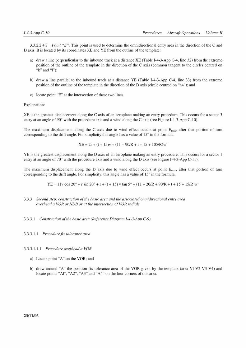
I-4-3-App C-10 Procedures — Aircraft Operations — Volume II
23/11/06
3.3.2.2.4.7 Point “E”. This point is used to determine the omnidirectional entry area in the direction of the C andD axis. It is located by its coordinates XE and YE from the outline of the template:
a) draw a line perpendicular to the inbound track at a distance XE (Table I-4-3-App C-4, line 32) from the extremeposition of the outline of the template in the direction of the C axis (common tangent to the circles centred on“k” and “l”);
b) draw a line parallel to the inbound track at a distance YE (Table I-4-3-App C-4, line 33) from the extremeposition of the outline of the template in the direction of the D axis (circle centred on “n4”); and
c) locate point “E” at the intersection of these two lines.
Explanation:
XE is the greatest displacement along the C axis of an aeroplane making an entry procedure. This occurs for a sector 3entry at an angle of 90° with the procedure axis and a wind along the C axis (see Figure I-4-3-App C-10).
The maximum displacement along the C axis due to wind effect occurs at point Emax, after that portion of turncorresponding to the drift angle. For simplicity this angle has a value of 15° in the formula.
XE = 2r + (t + 15)v + (11 + 90/R + t + 15 + 105/R)w’
YE is the greatest displacement along the D axis of an aeroplane making an entry procedure. This occurs for a sector 1entry at an angle of 70° with the procedure axis and a wind along the D axis (see Figure I-4-3-App C-11).
The maximum displacement along the D axis due to wind effect occurs at point Emax, after that portion of turncorresponding to the drift angle. For simplicity, this angle has a value of 15° in the formula.
YE = 11v cos 20° + r sin 20° + r + (t + 15) v tan 5° + (11 + 20/R + 90/R + t + 15 + 15/R)w’
3.3.3 Second step: construction of the basic area and the associated omnidirectional entry area3.3.3 overhead a VOR or NDB or at the intersection of VOR radials
3.3.3.1 Construction of the basic area (Reference Diagram I-4-3-App C-9)
3.3.3.1.1 Procedure fix tolerance area
3.3.3.1.1.1 Procedure overhead a VOR
a) Locate point “A” on the VOR; and
b) draw around “A” the position fix tolerance area of the VOR given by the template (area Vl V2 V3 V4) andlocate points “Al”, “A2”, “A3” and “A4” on the four corners of this area.

Part I — Section 4, Chapter 3, Appendix C I-4-3-App C-11
23/11/06
3.3.3.1.1.2 Procedure overhead an NDB
a) Locate point “A” on the NDB; and
b) draw around “A” the position fix tolerance area of the NDB given by the template (area Nl N2 N3 N4) andlocate points “Al”, “A2”, “A3” and “A4” on the four corners of this area.
3.3.3.1.1.3 Procedure at the intersection of VOR radials
a) Locate point “A” at the intersection of the homing and intersecting radials; and
b) draw around “A” the position fix tolerance area determined by the tolerances of the homing and intersectingradials Part I, Section 2, Chapter 2, 2.3.3, “System use accuracy” and locate points “Al”, “A2”, “A3” and “A4”on the four corners of this area.
3.3.3.1.2 Construction of the procedure area
3.3.3.1.2.1 Place the template point “a” on A3, with the template procedure axis parallel to the inbound track, anddraw the curve “3” (part of the outline of the template) and the line “3” (protection of the outbound leg in the directionof the D axis).
3.3.3.1.2.2 Place the template point “a” successively on “Al”, “A2” and “A4” to draw curves “l”, “2” and “4”.
3.3.3.1.2.3 Draw the common tangents to curves “l” and “2”, “2” and “4”, “3” and “4”, “3” and “1”.
3.3.3.2 Construction of the entry area
3.3.3.2.1 Construction of the entry area assuming omnidirectional entry overhead a VOR or an NDB3.3.3.2.1 (Reference Diagrams I-4-3-App C-10, I-4-3-App C-11 and I-4-3-App C-12)
3.3.3.2.1.1 Draw the circle centred on “A” passing through “Al” and “A3”.
3.3.3.2.1.2 Locate point “E” on a series of points along this circle (with the template axis parallel to the inboundtrack) and for each point draw a curve at the outer limit of the template in the direction of the C and D axis; curve “5” isthe envelope of these curves.
3.3.3.2.1.3 Draw the limit of the entry sectors 1 and 3 (line making an angle of 70° with the inbound track). Withthe template axis on this line, draw the entry fix tolerance area El E2 E3 E4 given by the template for the VOR or theNDB.
3.3.3.2.1.4 Place the template point “a” on El and E3 (with the template axis parallel to the separating line of thesectors 1 and 3) and draw curves “6” and “7” and their common tangent.
3.3.3.2.1.5 With a centre on “A”, draw the arc tangent to curve “6” until intersecting curve “1”.
3.3.3.2.1.6 Line 8 is the symmetric of lines 6 and 7 about the 70° dividing line. Draw common tangents to curves“5”, “6”, “7” and “8” as appropriate.

I-4-3-App C-12 Procedures — Aircraft Operations — Volume II
23/11/06
3.3.3.2.2 Construction of the entry area assuming entries along the homing and intersecting radial3.3.3.2.2 in the case of a procedure based on the intersection of VOR radials3.3.3.2.2 (Reference Diagram I-4-3-App C-14)
3.3.3.2.2.1 Protection of the entry along the reciprocal of the inbound track. Place the template point “E” on“A2” and “A4” (with the template axis parallel to the inbound track) and draw curves “5” and “6” (parts of the outlineof the template) and their common tangent.
3.3.3.2.2.2 Protection of the entries along the intersecting radial. In addition to the area provided by the curves“5” and “6” above, if the intersecting VOR is located in sector 2 or in the part of sector 3 opposite to sector 2 theprotection area is determined as follows.
3.3.3.2.2.2.1 Determine the entry fix tolerance area El E2 E3 E4 by applying the tolerance for a homing VOR(Part I, Section 2, Chapter 2, Table I-2-2-1) to the intersecting radial and the tolerance for an intersecting VOR (Part I,Section 2, Chapter 2, Table I-2-2-1) to the homing radial.
3.3.3.2.2.2.2 Place the template point “a” on E3 and E4 (with the template axis parallel to the intersecting radial) anddraw curves “7” and “8” (protection of a turn of more than 180°: inner curve of the template) and their commontangent.
3.3.3.3 Area reduction for a procedure overhead a facility when entries from Sector 1 are not permitted3.3.3.3 (Reference Diagram I-4-3-App C-13)
3.3.3.3.1 If the aircraft intercepts the procedure radial before the end of the outbound leg, the pilot is assumed tofollow the indications of this radial without drifting any further from the procedure axis.
3.3.3.3.2 If line 3 intersects the protection line of the procedure axis (VOR or NDB along track errors) the areamay be reduced as shown on Diagram I-4-3-App C-13; rotate the template 180° and place point “a” on the protectionline of the procedure axis, tangent to the area in the direction of the C axis; draw a parallel line to the protection line,tangent to the entry curve. The area under that parallel, in the direction of the D axis, may be eliminated.
3.3.3.3.3 This reduction is allowed only when entries from Sector 1 are not permitted.
3.3.4 Construction of the basic area and the associated along-the-radial entry area for VOR/DME procedure
3.3.4.1 Procedure towards the station (Reference Diagram I-4-3-App C-15)
3.3.4.1.1 Construction of the basic area
3.3.4.1.1.1 Selection and calculation of the distance parameters (see Figure I-4-3-App C-12). The distanceparameters are chosen and calculated in the following sequence:
a) choice of the nominal distance: D
D is the slant range between the VOR/DME facility and the procedure point at the specified altitude;
b) choice of the outbound distance: ds
ds is the horizontal length of the outbound leg; ds should conform to the relationship ds > vt, where t is theoutbound timing, as specified in Chapter 3, 3.5.5, “Outbound time” for racetrack procedures and in Part II,Section 4, Chapter 1, 1.3.2.2, “Outbound timing” for holding procedures;

Part I — Section 4, Chapter 3, Appendix C I-4-3-App C-13
23/11/06
c) calculation of the horizontal distance: Ds
Ds is the distance between the VOR/DME facility (S) and the projection of the procedure point on thehorizontal plane passing through S (point A)
2 2Ds = D hl−
(Ds, D and hl in km); or
2 2DS = D 0.027 hl−
(Ds and D in NM and hl in thousands of feet)
d) calculation of the limiting outbound distance: DL
DL is the slant range between the VOR/DME facility and the end of the outbound track at the specified altitude
2 2 2DL = (Ds + ds) 4r + hl+
(DL, Ds, ds, r, hl in km); or
2 2 2DL = (Ds + ds) 4r + 0.027 hl+
(DL, Ds, ds, r in NM and hl in thousands of feet)
DL is then rounded to the next higher km (or NM), unless the decimal part is less than 0.25 km (or NM) in thecase of a procedure at or below 4 250 m (or 14 000 ft) or 0.5 km (or NM) in the case of a procedure above4 250 m (or 14 000 ft), in which case it is rounded to the next lower km (or NM);
e) calculation of the horizontal limiting outbound distance: DLs
DLs is the distance between the VOR/DME facility and the vertical projection of the end of the outbound trackonto the horizontal plane passing through S
2 2DLs = DL hl−
(DLs, DL, hl in km); or
2 2DLs = DL 0.027 hl−
(DLs, DL in NM and hl in thousands of feet)
3.3.4.1.1.2 Fix tolerance area and limiting outbound distance
a) Draw from S the procedure radial “RP” and two lines “RP1” and “RP2” making an angle α (tolerance for ahoming VOR, Part I, Section 2, Chapter 2, Table I-2-2-1) with RP on each side of it;

I-4-3-App C-14 Procedures — Aircraft Operations — Volume II
23/11/06
b) with a centre on S, draw arcs “Ds” with a radius Ds, “Dl” with a radius Ds – dl, “D2” with a radius Ds + dl,“DLs”, “DL1” and “DL2” with radii DLs, DLs – d2 and DLs + d2
where dl and d2 are the DME tolerance associated with D and DL:dl is 0.46 km (0.25 NM) + 0.0125 D;d2 is 0.46 km (0.25NM) + 0.0125 DL
c) locate points “A” at the intersection of “RP” and “Ds”“Al” and “A2” at the intersections of “RP1”with “Dl” and “D2”“A3” and “A4” at the intersections of “RP2”with “D1” and “D2”.
3.3.4.1.1.3 Protection of the outbound turn and outbound leg
a) Place racetrack template point “a” on Al, with axis parallel to the inbound track, and draw curve “1” (part of theoutline of the template);
b) place template point “a” on A3, with axis parallel to the inbound track, and draw curve “2” (part of the outlineof the template) and line “3” (protection of the outbound leg on the non-manoeuvring side); and
c) draw the common tangent to curves “1” and “2” and extend the straight part of curve “1” and the line “3” in thedirection of the outbound end.
3.3.4.1.1.4 Area containing the end of the outbound leg
a) Locate points Cl and C’3 at the intersection of the extension of curve “l” with the arcs DL1 and DL2;
b) locate point C2 between Cl and C’3 at a distance (dl + d2 – 1.8) km or (dl + d2 – 1) NM from C’3;
c) draw a parallel line to the inbound track through C2 and locate points C3 at the intersection of this line with arcDL2;
d) do the same thing as in a), b) and c) with the line “3” instead of curve “l” and points C4, C’6, C5 and C6 insteadof Cl, C’3, C2 and C3 (see Figure I-4-3-App C-13 a)); and
e) if the aircraft intercepts the VOR radial before reaching the limiting outbound distance, the pilot is assumed tofollow the indications of the VOR without drifting any further from the procedure axis, so:
where C5 and C6 are further from the procedure axis than RP2 (see Figure I-4-3-App C-13 b)), replace C5 andC6 by the intersections of RP2 with line “3” and DL2, and the end of the outbound leg is contained in the areaCl, C2, C3, C4, C5 and C6; and
where C4, C5 and C6 are further from the procedure axis than RP2 (see Figure I-4-3-App C-13 c)), replace C4and C6 by the intersections of RP2 with DL1 and DL2, and the end of the outbound leg is contained in the areaCl, C2, C3, C4 and C6.
3.3.4.1.1.5 Protection of the inbound turn. Rotate the template 180°, then:
a) place template point “a” on C2 and C3, with axis parallel to the inbound track, and draw curves “4” and “5”(part of the protection line of a turn of more than 180°) and their common tangent;

Part I — Section 4, Chapter 3, Appendix C I-4-3-App C-15
23/11/06
b) move the template point “a” along arc DL2 from C3 to C6 (with axis parallel and opposite to the inbound track)and draw curve “6”;
c) place template point “a” on C6, C4 and eventually on C5 and draw curves “7”, “8” and eventually “9” and theircommon tangent; and
d) draw the tangent to curves “8” and “2”.
3.3.4.1.2 Construction of the entry areas
3.3.4.1.2.1 Arrival to a VOR/DME holding pattern may be:
— along the axis of the inbound track;
— along a published track;
— by radar vectoring, when aircraft must be established on prescribed protected flight paths;
and the entry point may be either:
a) the holding fix; or
b) the fix at the end of the outbound leg.
When the entry point is at the holding fix, two cases may be considered:
Case 1.1 — arrival via the VOR radial for the inbound leg;
Case 1.2 — arrival via the DME arc defining the holding fix.
When the entry point is at the fix at the end of the outbound leg, the only case is arrival via the VOR radial passingthrough the fix at the end of the outbound leg.
3.3.4.1.2.2 It is also possible to make use of guidance from another radio facility (e.g. NDB); in that case,protection of the entry should be the subject of a special study based on general criteria.
3.3.4.1.2.3 The radius of a DME arc used as guidance for arrival at a VOR/DME holding should be not less than18.5 km (10 NM).
3.3.4.1.2.4 The minimum length for the last segment of the arrival track terminating at the entry point is afunction of the angle (θ) between the penultimate segment or radar path and the last segment. The values are shown inthe following table:
θ
0° – 70° 71° – 90° 91° – 105° 106° – 120°
Minimum distancein km (NM) 7.5 (4) 9.5 (5) 13 (7) 16.5 (9)

I-4-3-App C-16 Procedures — Aircraft Operations — Volume II
23/11/06
3.3.4.1.2.5 Method of arrival at a VOR/DME holding and the corresponding entry procedures. The methods aredescribed in more detail as follows:
Case 1 — entry at the holding fix;
Case 1.1 — entry at the holding fix via a radial forming the fix:
a) Arrival on the VOR radial for the inbound leg, on the same heading as the inbound track. The arrival path (orlast segment thereof) is aligned with the inbound track and follows the same heading. The entry consists offollowing the holding pattern (see Figure I-4-3-App C-14 a)).
Protection of the entry: The entry is protected by the holding protection area.
b) Arrival on the VOR radial for the inbound leg, on a heading reciprocal to the inbound track. On arrival over theholding fix, the aircraft turns onto the holding side on a track making an angle of 30° with the reciprocal of theinbound track, until reaching the DME outbound limiting distance, at which point it turns to intercept theinbound track. In the case of a VOR/DME holding entry away from the facility with a limiting radial, if theaircraft encounters the radial ahead of the DME distance, it must turn and follow it until reaching the DMEoutbound limiting distance, at which point it turns to join the inbound track (see Figure I-4-3-App C-14 b)).
Case 1.2 — entry at the holding fix via the DME arc forming the fix:
a) Arrival on the DME arc defining the holding fix, from the holding side. On arrival over the holding fix, theaircraft turns and follows a track parallel to and reciprocal to the inbound track, until reaching the DME limitingoutbound distance, at which point it turns to intercept the inbound track (see Figure I-4-3-App C-14 c)).
b) Arrival on the DME arc defining the holding fix, from the non-holding side. On arrival over the holdingfix, the aircraft turns and follows a track parallel to and on the same heading as the outbound track,until reaching the DME outbound limiting distance, at which point it turns to intercept the inbound track (seeFigure I-4-3-App C-14 d)).
An arrival track leading to a Case 1.2 a) entry should not be specified unless absolutely necessary, particularlyin a VOR/DME holding procedure away from the facility. If an appropriate DME distance is chosen, this typeof arrival can actually be replaced by one on a DME arc terminating in the extension of the inbound track (seeFigures I-4-3-App C-14 e) and f)).
Case 2 — entry at the fix at the end of the outbound leg via a radial forming the limiting fix:
a) outbound from the facility;
b) inbound from the facility.
On arrival over the fix at the end of the outbound leg, the aircraft turns and follows the holding pattern.
3.3.4.1.2.6 The sector 1 entry along the DME arc is protected as follows:
a) take a tracing of the template, turn it over and place point “a” on A3 with axis on the line Al, A3 to draw curve“13”;
b) draw the line “14” parallel to line “3” (used in the construction of the basic area) and tangent to curve “13”, andlocate point C10 at the intersection of this line with arc DL2;

Part I — Section 4, Chapter 3, Appendix C I-4-3-App C-17
23/11/06
c) place point “a” of the tracing on C10, with axis parallel and opposite to the inbound track and move it alongDL2 up to the intersection of DL2 and RP1 to draw curve “15”.
3.3.4.1.2.7 Protection of sector 2 entry procedure
3.3.4.1.2.7.1 It is assumed that having passed the fix, the pilot makes good (±5° error) a track making an angle of30° with the inbound track on the manoeuvring side and reaching the limiting outbound distance, turns inbound. Inaddition, the flying time on the 30° offset track is limited to 1 min 30 s after which the pilot is expected to turn to aheading parallel to the outbound track until reaching the limiting outbound distance, where the pilot turns inbound.
3.3.4.1.2.7.2 For a procedure with outbound of more than 1 min 30 s the protection of sector 2 entry procedure isassured by the basic area.
3.3.4.1.2.7.3 For a procedure with outbound of 1 min or 1 min 30 s, the protection area of sector 2 entry is drawnas follows:
a) from Al draw a line making an angle of 30° + 5° with RP and locate C7 at its intersection with DL2;
b) from A4 draw a line making an angle of 30° – 5° with RP and locate C8 at its intersection with DL2;
c) place template point “a” on C7 and move it along DL2 to C8, with axis making an angle of 30° with RP, todraw curve “11”;
d) draw the common tangents to the curves “10” and “11” and to the basic area.
3.3.4.1.3 Construction of the entry area for a reciprocal direct entry to a secondary point3.3.4.1.3 (Reference Diagram I-4-3-App C-16)
3.3.4.1.3.1 It is assumed that reciprocal direct entries are made along the entry radial (RE) joining the VOR/DMEstation (S) to the secondary point (I) where the turn to inbound is initiated.
3.3.4.1.3.2 This direct entry area is drawn as follows:
a) measure the angle made by the procedure radial (RP) and the radial joining the VOR/DME station to the end ofthe nominal outbound leg (line SC) and round its value to the nearest entire degree to obtain the entry radial(RE) to be published;
b) locate point “I” at the intersection of RE and DLs;
c) from S draw the lines “RE1” and “RE2” making an angle α (tolerance for homing VOR; Part I, Section 2,Chapter 2, Table I-2-2-1) with RE on each side of it;
d) locate points “I1” and “I2” at the intersections of RE1 with DL1 and DL2 and points “I3” and “I4” at theintersections of RE2 with DL1 and DL2; and
e) place template point “a” on I2, with axis parallel to RE and move it along DL2 from I2 to I4 to draw curve“13”.

I-4-3-App C-18 Procedures — Aircraft Operations — Volume II
23/11/06
3.3.4.2 Procedure away from the station(Reference Diagram I-4-3-App C-17)
3.3.4.2.1 Construction of the basic area
3.3.4.2.1.1 Selection and calculation of the distance parameters (see Figure I-4-3-App C-15). The distanceparameters are chosen and calculated in the following sequence:
a) choice of the nominal distance: D
D is the slant range between VOR/DME facility and the procedure point at the specified altitude;
b) choice of the outbound distance: ds
ds is the horizontal length of the outbound leg
ds should conform to the relationship ds � vt, where t is the outbound timing, as specified in Chapter 3, 3.5.5,“Outbound time” for racetrack procedures and in Part II, Section 4, Chapter 1, 1.3.2.2, “Outbound timing”, forholding procedures;
c) calculation of the horizontal distance: Ds
Ds is the distance between the VOR/DME facility (S) and the vertical projection of the procedure point on thehorizontal plane through S
2 2Ds = D hl−
(Ds, D and hl in km); or
2 2DS = D 0.027 hl−
(Ds and D in NM and hl in thousands of feet)
d) calculation of the limiting outbound distance: DL
DL is the slant range between the VOR/DME facility and the end of the outbound track at the specified altitude
2 2 2DL = (Ds + ds) 4r + hl+Dsds–()
(DL, Ds, ds, r, hl in km); or
2 2 2DL = (Ds + ds) 4r + 0.027 hl+
(DL, Ds, ds, r in NM and hl in thousands of feet)
DL is then rounded to the next lower km or NM, unless the decimal part is greater than 0.75 km or NM in thecase of a procedure at or below 4 250 m (or 14 000 ft) or 0.5 km or NM in the case of a procedure above4 250 m (or 14 000 ft), in which case it is rounded to the next higher km or NM;

Part I — Section 4, Chapter 3, Appendix C I-4-3-App C-19
23/11/06
e) calculation of the horizontal limiting outbound distance: DLs
DLs is the distance between the VOR/DME facility and the vertical projection of the end of the outbound trackonto the horizontal plane passing through S
2 2DLs = DL hl−DL2
(DL, hl in km); or
2 2DLs = DL 0.027 hl−
(DLs, DL in NM and hl in thousands of feet)
3.3.4.2.1.2 Fix tolerance area and limiting outbound distance
a) Draw from S the procedure radial “RP” and two lines, “RP1” and “RP2”, making an angle α (tolerance for ahoming VOR, Part I, Section 2, Chapter 2, Table I-2-2-1) with RP on each side of it;
b) with a centre on S, draw arcs “Ds” with a radius Ds, “Dl” with a radius Ds + dl, “D2” with a radius Ds – dl,“DLs”, “DL1” and “DL2” with radii DLs, DLs + d2 and DLs – d2
where dl and d2 are the DME tolerances associated with D and DL:
d1 is 0.46 km (0.25 NM) + 0.125 D; and
d2 is 0.46 km (0.25 NM) + 0.0125 DL; and
c) locate points “A” at the intersection of RP and Ds:
“A1” and “A2” at the intersections of RP1 with D1 and D2; and
“A3” and “A4” at the intersections of RP2 with D1 and D2.
3.3.4.2.1.3 Protection of the outbound turn and outbound leg
a) Place template point “a” on Al, with axis parallel to the inbound track, and draw curve “l” (part of the outline ofthe template);
b) place template point “a” on A3, with axis parallel to the inbound track, and draw curve “2” (part of the outlineof the template) and line “3” (protection of the outbound leg in the direction of the non-manoeuvring side); and
c) draw the common tangent to curves “l” and “2” and extend the straight part of curve “l” and the line “3” in thedirection of the outbound end.
3.3.4.2.1.4 Area containing the end of the outbound leg
a) Locate points C1 and C’3 at the intersections of the extensions of curve “l” with the arcs DL1 and DL2. If nointersection occurs a limiting radial shall be specified (see 3.3.4.3 of this appendix);
b) locate point C2 between C1 and C’3 at a distance (dl + d2 – 1.8) km or (dl + d2 – 1) NM from C’3;

I-4-3-App C-20 Procedures — Aircraft Operations — Volume II
23/11/06
c) draw a parallel line to the inbound track through C2 and locate point C3 at the intersection of this line with arcDL2;
d) do the same thing as in a), b) and c) above, with the line “3” instead of curve “l” and points C4, C’6, C5 and C6instead of C1, C’3, C2 and C3 (see Figure I-4-3-App C-16 a)); and
e) if the aeroplane intercepts the VOR radial before reaching the limiting outbound distance, the pilot is assumedto follow the indications of the VOR without drifting any further from the procedure axis, so:
where C5 and C6 are further from the procedure axis than RP2 (see Figure I-4-3-App C-16 b)), replace C5 andC6 by the intersections of RP2 with line “3” and DL2, and the end of the outbound leg is contained in the areaC1, C2, C3, C4, C5, and C6;
where C4, C5 and C6 are further from the procedure axis than RP2 (see Figure I-4-3-App C-16 c)), replace C4and C6 by the intersections of RP2 with DL1 and DL2, and the end of the outbound leg is contained in the areaCl, C2, C3, C4, and C6.
3.3.4.2.1.5 Protection of the inbound turn. Rotate the template 180°, then:
a) place template point “a” on C2 and C3, with axis parallel to the inbound track, and draw curves “4” and “5”(part of the protection line of a turn of more than 180°) and their common tangent;
b) move the template point “a” along arc DL2 from C3 to C6, with axis parallel to the inbound track, and drawcurve “6”;
c) place template point “a” on C6, C4 and eventually on C5 and draw curves “7”, “8” and eventually “9” and theircommon tangents; and
d) draw the tangent to curves “8” and “2”.
3.3.4.2.2 Construction of the entry area. It is assumed that all entries are executed along the VOR radial or theDME arc defining the fix. The entries made along the radial inbound to the fix or along the DME arc from the non-manoeuvring side are protected by the basic area. The protection of the entries made along the reciprocal to inbound oralong the DME arc from the manoeuvring side needs, in addition to the basic area, the area constructed as follows. Theentry along the DME arc from the manoeuvring side is a sector 1 entry procedure. As the reciprocal to the inboundtrack is the dividing line between entry sectors 1 and 2, it is assumed that both sector 1 and sector 2 entry proceduresmay be executed when entering along the reciprocal to inbound.
3.3.4.2.2.1 Protection of sector 1 entry procedure. When entering along the DME arc, it is assumed that havingpassed the fix the aircraft turns and follows a track parallel to the inbound track and on reaching the DME limitingoutbound distance, turns inbound onto the manoeuvring side. For entries along the DME arc, the entry area is drawn asfollows:
a) take a tracing of the template, turn it over and place point “a” on A3 with axis on the line Al A3 to draw curve“14”;
b) draw the line “15” parallel to line “3” (used in the construction of the basic area) and tangent to curve “14”, andlocate point C10 at the intersection of this line with arc DL2; and
Note.— If no intersection occurs, either the specified DME distances should be adjusted or the sector 1entry along the DME arc shall not be allowed.

Part I — Section 4, Chapter 3, Appendix C I-4-3-App C-21
23/11/06
c) place point “a” of the tracing on C10, with axis parallel and opposite to the inbound track, and move it alongDL2 up to the intersection of DL2 and RP1 to draw curve “16”.
3.3.4.2.2.2 Protection of sector 2 entry procedure. It is assumed that having passed the fix, the pilot makes good(with ± 5° error) a track making an angle of 30° with the inbound track on the manoeuvring side and reaching thelimiting outbound distance, turns inbound. In addition, the flying time on the 30° offset track is limited to 1 min 30 safter which the pilot is expected to turn to a heading parallel to the outbound track until reaching the limiting outbounddistance, where the pilot turns inbound.
3.3.4.2.2.2.1 For a procedure with outbound of more than 1 min 30 s the protection of sector 2 entry procedure isassured by the basic area.
3.3.4.2.2.2.2 For a procedure with outbound of 1 min or 1 min 30 s, the protection area of sector 2 entry is drawnas follows:
a) from Al draw a line making an angle of 30° + 5° with RP and locate C7 at its intersection with DL2. If nointersection occurs, a limiting radial must be specified according to 3.3.4.3;
b) from A4 draw a line making an angle of 30° – 5° with RP and locate C8 at its intersection with DL2;
c) place template point “a” on C7 and move it along DL2 to C8, with axis making an angle of 30° with RP, todraw curve “10”; and
d) draw the common tangents to the curve “10” and to the basic area.
3.3.4.2.3 Construction of the entry area for a reciprocal direct entry to a secondary point3.3.4.2.3 (Reference Diagram I-4-3-App C-18)
3.3.4.2.3.1 The reciprocal direct entry is made along the entry radial (RE) joining the VOR/DME station (S) to thesecondary point (I) where the turn to inbound is initiated.
3.3.4.2.3.2 The protection of this entry procedure is assured by the basic area.
3.3.4.2.3.3 The entry radial is determined as follows: Measure the angle made by the procedure radial (RP) andthe radial joining the VOR/DME station to the end of the nominal outbound leg (line SC) and round its value to thenearest entire degree to obtain the entry radial (RE) to be published.
3.3.4.3 Procedure away from the station with a limiting radial3.3.4.3 (Reference Diagram I-4-3-App C-19)
3.3.4.3.1 Construction of the basic area
3.3.4.3.1.1 Selection and calculation of the distance parameters (see Figure I-4-3-App C-15). The distanceparameters are chosen and calculated in the same manner as in 3.3.4.2.1.1 above.
3.3.4.3.1.2 Fix tolerance area, limiting outbound distance and limiting radial. The fix tolerance area and thelimiting outbound distance are drawn in the same manner as in 3.3.4.2.1.2:
a) place template point “a” on A2 and locate the point “R” given by the template;

I-4-3-App C-22 Procedures — Aircraft Operations — Volume II
23/11/06
b) measure the angle between the line joining R and S and RP, add β (tolerance for an intersecting VOR, seePart I, Section 2, Chapter 2, Table I-2-2-1) and round the result to the next higher degree; and
c) from S draw line RL making an angle of the rounded value of c) with RP and line RL2 making the angle β withRL.
3.3.4.3.1.3 Protection of the outbound turn and outbound leg. Protection of the outbound turn and outbound leg isdrawn in the same manner as in 3.3.4.2.1.3 above.
3.3.4.3.1.4 Area containing the end of the outbound leg
a) If the intersection of extension of curve 1 and RL2 is nearer to Al than the intersection of extension of curve 1and DL1 (case of Diagram I-4-3-App C-19), locate point Cl at the intersection of extension of curve 1 with lineRL2 and C2 and C3 at the intersections of RL2 with DL1 and DL2;
b) if the intersection of extension of curve 1 and RL2 is between the intersections of the same extension with DL1and DL2, locate points Cl and C2 at the intersections of the extension of curve 1 with arc DL1 and line RL2 andpoint C3 at the intersection of RL2 with DL2;
c) if the intersection of extension of curve 1 and RL2 is further from Al than the intersection of the same extensionwith DL2, do the same as in 3.3.4.2.1.4 a), b) and c); and
d) locate points C4, C6 and eventually C5 in the same manner as explained in 3.3.4.2.1.4 d) and e).
3.3.4.3.1.5 Protection of the inbound turn. Rotate the template 180°, then:
a) place the template point “a” on Cl, C2 and C3, with axis parallel to the inbound track, and draw curves “4”, “5”and “6” (part of the protection line of a turn of more than 180°) and their common tangents;
b) move template point “a” along arc DL2 from C3 to C6, with axis parallel to the inbound track, and draw curve“7”;
c) place template point “a” on C6, C4 and eventually on C5, with axis parallel to the inbound track, and drawcurves “8”, “9” and eventually “10” and their common tangents; and
d) draw the tangent to curves “9” and “2”.
3.3.4.3.2 Construction of the entry area
3.3.4.3.2.1 Protection of sector 1 entry procedures. For the protection of sector 1 entry procedure see 3.3.4.2.2.1above.
3.3.4.3.2.2 Protection of sector 2 entry procedures. It is assumed that having passed the fix, the pilot makes gooda track (with ±5° error) making an angle of 30° with the inbound track on the manoeuvring side and reaching thelimiting outbound distance, turns inbound. In addition, the flying time on the 30° offset track is limited to 1 min 30 safter which the pilot is expected to turn a heading parallel to the inbound track until reaching the limiting outbounddistance, where the pilot turns inbound.
3.3.4.3.2.2.1 For a procedure with outbound of more than 1 min 30 s the protection of sector 2 entry procedure isassured by the basic area.

Part I — Section 4, Chapter 3, Appendix C I-4-3-App C-23
23/11/06
3.3.4.3.2.2.2 For a procedure with outbound of 1 min or 1 min 30 s, the protection area of sector 2 entry is drawnas follows:
a) from Al draw a line making an angle of 30° + 5° with RP and locate C7 at its intersection with DL2 or RL2,whichever is the nearer to Al;
b) from A4 draw a line making an angle of 30° – 5° with RP and locate C8 at its intersection with DL2;
c) place template point “a” on C7, with axis making an angle of 30° with RP, and draw curve “11” (part of theprotection line of a turn of more than 180°);
d) move template point “a” from C7 to C8 along arc DL2, or along line RL2 and then arc DL2 if C7 is on RL2,keeping the axis of the template making an angle of 30° with RP, to draw curve “12”; and
e) draw the common tangents to the curves “11” and “12” and to the basic area.
3.4 Area reduction for holding andracetrack procedures
3.4.1 Area reduction by use of DME or limiting radial/bearing. If a DME distance or an intersection of radial orbearing is used to limit the outbound leg of a procedure, the area may be reduced by applying the racetrack or holdingtemplate for the altitude in question in the following way:
a) construct the protection area in accordance with 3.3;
b) with the centre on S (= position of the DME station) draw arcs “DL” and “DL2” on the end of the outbound leg.The radius DL is the distance from S to the end of the nominal outbound legs. The radius DL2 is DL plus DMEtolerance d2; d2 is 0.46 km (0.25 NM) + 0.0125 DL;
c) from S (= position of VOR or NDB) draw line “RL” through the end of the nominal outbound leg representingthe intersecting radial or bearing. Draw line “RL2” by adding the respective tolerance of the intersecting facility(Part I, Section 2, Chapter 2, 2.3); and
d) place template point “a” on the intersection of “DL2” or “RL2” with the boundary of the protection areaconstructed in a).
The axis of the template has to be parallel to the nominal outbound track. Move template point “a” along “DL2” or“RL2” respectively drawing curve “R”. The area between curve “R” and the outbound end of the area protected inaccordance with a) can be deleted (see Figure I-4-3-App C-17).
3.4.2 Area reduction for racetrack or holding procedures by limitation of entry routes. If entry to a procedure isrestricted to entry along the inbound radial, the basic area may be used without the additional areas required foromnidirectional entry (see examples in Figures I-4-3-App C-18 and I-4-3-App C-19).
3.5 Simplified area construction method forreversal and racetrack procedures
3.5.1 General. Reversal and racetrack procedure areas may be defined by simple rectangles. The dimensions ofthe rectangle for each type of procedure may easily be calculated from the equations given in this section. The rectanglewill, in all cases, include or be slightly larger than the area constructed using the more detailed TTT method. The TTTmethod should be used to obtain maximum benefit wherever airspace is critical.

I-4-3-App C-24 Procedures — Aircraft Operations — Volume II
23/11/06
3.5.2 Frame of reference. The dimensions of the rectangles are related to a conventional x, y coordinate system,with its origin at the facility (see Figure I-4-3-App C-20). The x axis is parallel to the inbound track. Negative values ofx are measured from the facility in the direction of the inbound track, positive values are measured from the facilityagainst the direction of the inbound track. Positive values of y are measured on that side of the x axis containing theoutbound track or manoeuvre of the reversal procedure/racetrack. The y axis is at right angles to the x axis.
3.5.3 Area calculation.
a) Decide the values of IAS and height for the reversal/racetrack procedure. Calculate the TAS at ISA + 15°C forthe specified height (Attachment F). Calculate the wind speed (ICAO or statistical wind for the heightspecified).
b) Decide the type of procedure required:
Procedure turn (45/180) — Table I-4-3-App C-5 a)Procedure turn (80/260) — Table I-4-3-App C-5 b)Base turn — Table I-4-3-App C-5 c)Racetrack — Table I-4-3-App C-5 d).
c) Note the equations from Table I-4-3-App C-5.
d) Substitute the values of TAS and wind speed calculated in a) above into the equations and calculate the requiredx and y values.
e) Adjust the values to account for fix tolerance.
f) Plot the area rectangle to the scale required.
g) Add the appropriate buffer area.

Part I — Section 4, Chapter 3, Appendix C I-4-3-App C-25
23/11/06
Table I-4-3-App C-1. Calculations associated with the construction ofthe base turn template
DATASI UNITS NON-SI UNITS
IAS 260 km/h 140 ktAltitude 1 850 m 6 000 ftT 2 min 2 minNDB at 0 m at 0 ftTemperature ISA + 15°C ISA + 15°C
CALCULATIONS USING SI UNITS CALCULATIONS USING NON-SI UNITS
Line Parameter Formula Value Formula Value
1 K Conversion factor for1 850 m and ISA + 15°C(see Part I, Section 2,Chapter 1, Appendix)
1.1244 Conversion factor for6 000 ft and ISA + 15°C(see Part I, Section 2,Chapter 1, Appendix)
1.1231
2 V V = K × IAS 292.34 km/h V = K × IAS 157.23 kt
3 v v = V ÷ 3 600 0.0812 km/s v = V ÷ 3 600 0.0437 NM/s
4 R R = 943.27 ÷ V, or 3°/s,whichever is less
(3.23)3°/s
R = 509.26 ÷ V, or 3°/s,whichever is less
(3.24)3°/s
5 r r = V ÷ 62.83 R 1.55 km r = V ÷ 62.83 R 0.83 NM
6 h in thousands of metres 1.85 in thousands of feet 6
7 w w′ = 12h + 87 109.2 km/h w′ = 2h + 47 59 kt
8 w′ w′ = w ÷ 3 600 0.03 km/s w′ = w ÷ 3 600 0.0164 NM/s
9 E E = w′ ÷ R 0.01 km/° E = w′ ÷ R 0.00546 NM/°
10 φ for V � 315 km/h:φ = 36 ÷ T
for V > 315 km/h:φ = 0.116 V ÷ T
18° for V � 170 kt:φ = 36 ÷ T
for V > 170 kt:φ = 0.215 V ÷ T
18°
11 zN *zN = h tan 40° 1.55 km **zN = 0.164 h tan 40° 0.83 NM
12 t t = 60T 120 s t = 60T 120 s
13 L L = vt 9.74 km L = vt 5.24 NM
14 ab1 = ab3 ***ab1 = ab3 =(t – 5)(v – w′) – zN
4.34 km ***ab1 = ab3 =(t – 5)(v – w′) – zN
2.31 NM
15 ab2 = ab4 ***ab2 = ab4 =(t + 21)(v + w′) + zN
17.23 km ***ab2 = ab4 =(t + 21)(v + w′) + zN
9.30 NM
16 Wd = Wg Wd = Wg = 50 E 0.5 km Wd = Wg = 50 E 0.27 NM
17 We = Wf = Wh We = Wf = Wh = 100 E 1.0 km We = Wf = Wh = 100 E 0.55 NM
18 Wi Wi = 190 E 1.9 km Wi = 190 E 1.04 NM
19 Wj Wj = 235 E 2.35 km Wj = 235 E 1.28 NM

I-4-3-App C-26 Procedures — Aircraft Operations — Volume II
23/11/06
CALCULATIONS USING SI UNITS CALCULATIONS USING NON-SI UNITS
Line Parameter Formula Value Formula Value
20 drift angle d d = arc sin (w ÷ V) 23° d = arc sin (w ÷ V) 23°
21 N3l N3l = 11 v 0.9 km N3l = 11 v 0.48 NM
22 Wl W l = 11 w′ 0.33 km Wl = 11 w′ 0.18 ΝΜ
23 Wm Wm = Wl + 50 E 0.83 km Wm = Wl + 50 E 0.45 NM
24 Wn Wn = Wl + 100 E 1.33 km Wn = Wl + 100 E 0.73 NM
* In case of a VOR base turn, line 11 reads zV = h tan 50°.** In case of a VOR base turn, line 11 reads zV = 0.164 h tan 50°.*** In case of VOR/DME base turn, where D is the specified DME distance limiting the outbound leg and d1 is
the tolerance of the DME indication (d1 is 0.46 km (0.25 NM) + 0.0125 D), lines 14 and 15 read:ab1 = ab3 = D – d1 + 5 (v – w′)ab2 = ab4 = D + d1 + 11 (v + w′)
In case of a VOR base turn, lines 14 and 15 read:ab1 = ab3 = (t – 5) (v – w) ′ – zVab2 = ab4 = (t + 21) (v + w′) + zV

Part I — Section 4, Chapter 3, Appendix C I-4-3-App C-27
23/11/06
Table I-4-3-App C-2. Calculations associated with the construction ofthe 45°-180° procedure turn template
DATASI UNITS NON-SI UNITS
IAS 260 km/h 140 ktAltitude 1 850 m 6 000 ftT 60 s (1 min for Cat A and B; 60 s (1 min for Cat A and B;
1.25 min for Cat C, D and E) 1.25 min for Cat C, D and E)Temperature ISA + 15°C ISA + 15°C
CALCULATIONS USING SI UNITS CALCULATIONS USING NON-SI UNITS
Line Parameter Formula Value Formula Value
1 K Conversion factor for1 850 m and ISA + 15°C(see Part I, Section 2,Chapter 1, Appendix)
1.1244 Conversion factor for6 000 ft and ISA + 15°C(see Part I, Section 2,Chapter 1, Appendix)
1.1231
2 V V = K IAS 292.34 km/h V = K IAS 157.23 kt
3 v v = V ÷ 3 600 0.0812 km/s v = V ÷ 3 600 0.0437 NM/s
4 R R = 943.27 ÷ V, or 3°/s,whichever is less
(3.23)3°/s
R = 509.26 ÷ V, or 3°/s,whichever is less
(3.24)3°/s
5 r r = V ÷ 62.83 R 1.55 km r = V ÷ 62.83 R 0.83 NM
6 h in thousands of metres 1.85 in thousands of feet 6
7 w w = 12h + 87 109.2 km/h w = 2h + 47 59 kt
8 w′ w′ = w ÷ 3 600 0.03 km/s w′ = w ÷ 3 600 0.0164 NM/s
9 E E = w′ ÷ R 0.01 km/° E = w′ ÷ R 0.00546 NM/°
10 ab ab = 5v 0.41 km ab = 5v 0.22 NM
11 cd cd = (t – 5 – 45 ÷ R) v 3.25 km cd = (t – 5 – 45 ÷ R) v 1.75 NM
12 cd1, cd3 cd1 = cd3 = cd – 5v 2.84 km cd1 = cd3 = cd – 5v 1.53 NM
13 cd2, cd4 cd2 = cd4 = cd + 15v 4.47 km cd2 = cd4 = cd + 15v 2.41 NM
14 Wc Wc = 5w′ + 45 E 0.60 km Wc = 5w′ + 45 E 0.33 NM
15 Wd2, Wd4 Wd2 = Wd4 = (t + 15) w′ 2.25 km Wd2 = Wd4 = (t + 15) w′ 1.23 ΝΜ
16 Wf Wf = Wd2 + 50 E 2.75 km Wf = Wd2 + 50 E 1.50 NM
17 Wg, Wh Wg = Wh = Wd2 + 100 E 3.25 km Wg = Wh = W d2 + 100 E 1.78 NM
18 Wi Wi = Wd2 + 150 E 3.75 km Wi = Wd2 + 150 E 2.05 NM
19 Wj Wj = Wd2 + 200 E 4.25 km Wj = Wd2 + 200 E 2.32 NM
20 Wk Wk = (t – 5)w′ + 200 E 3.65 km Wk = (t – 5)w′ + 200 E 1.99 NM
21 Wl Wl = Wk + 50 E 4.15 km Wl = Wk + 50 E 2.27 NM

I-4-3-App C-28 Procedures — Aircraft Operations — Volume II
23/11/06
Table I-4-3-App C-3. Calculations associated with the construction ofthe 80°-260° procedure turn template
DATASI UNITS NON-SI UNITS
IAS 405 km/h 220 ktAltitude 1 850 m 6 000 ftTemperature ISA + 15°C ISA + 15°C
CALCULATIONS USING SI UNITS CALCULATIONS USING NON-SI UNITS
Line Parameter Formula Value Formula Value
1 K Conversion factor for1 850 m and ISA + 15°C(see Part I, Section 2,Chapter 1, Appendix)
1.1244 Conversion factor for6 000 ft and ISA + 15°C(see Part I, Section 2,Chapter 1, Appendix)
1.1231
2 V V = K × IAS 455.38 km/h V = K × IAS 247.08 kt
3 v v = V ÷ 3 600 0.1265 km/s v = V ÷ 3 600 0.0686 NM/s
4 R R = 943.27 ÷ V, or 3°/s,whichever is less
2.07°/s R = 509.26 ÷ V, or 3°/s,whichever is less
2.06°/s
5 r r = V ÷ 62.83 R 3.5 km r = V ÷ 62.83 R 1.91 NM
6 h in thousands of metres 1.85 in thousands of feet 6
7 w w = 12h + 87 109.2 km/h w = 2h + 47 59 kt
8 w′ w′ = w ÷ 3 600 0.03 km/s w = w ÷ 3 600 0.0164 NM/s
9 E E = w′ ÷ R 0.0145 km/° E = w′ ÷ R 0.00796 NM/°
10 ab ab = 5v 0.63 km ab = 5v 0.34 NM
11 de, d1e1, d2e2 de = d1e1 = d2e2 = 10v 1.27 km de = d1e1 = d2e2 = 10v 0.69 NM
12 We2 We2 = 15w′ + 85 E 1.68 km We2 = 15w′ + 85 E 0.92 NM
13 Wg Wg = 15w′ + 130 E 2.34 km Wg = 15w′ + 130 E 1.28 NM
14 Wh Wh = 15w′ + 175 E 2.99 km Wh = 15w′ + 175 E 1.64 NM
15 Wi Wi = 15w′ + 220 E 3.64 km Wi = 15w′ + 220 E 2.00 NM
16 Wj Wj = 15w′ + 265 E 4.29 km Wj = 15w′ + 265 E 2.36 NM
17 Wk Wk = 15w′ + 255 E 4.15 km Wk = 15w′ + 255 E 2.28 NM
18 Wl Wl = 15w′ + 300 E 4.80 km Wl = 15w′ + 300 E 2.63 NM
19 Wm Wm = 15w′ + 345 E 5.45 km Wm = 15w′ + 345 E 2.99 NM

Part I — Section 4, Chapter 3, Appendix C I-4-3-App C-29
23/11/06
Table I-4-3-App C-4. Calculations associated with the construction ofthe holding and racetrack template
DATASI UNITS NON-SI UNITS
IAS 405 km/h 220 ktAltitude 3 050 m 10 000 ftT 1 min 1 minTemperature ISA + 15°C ISA + 15°C
CALCULATIONS USING SI UNITS CALCULATIONS USING NON-SI UNITS
Line Parameter Formula Value Formula Value
1 K Conversion factor for3 050 m and ISA + 15°C(see Part I, Section 2,Chapter 1, Appendix)
1.1960 Conversion factor for10 000 ft and ISA + 15°C(see Part I, Section 2,Chapter 1, Appendix)
1.1958
2 V V = K × IAS* 484.38 km/h V = K × IAS* 263.08 kt
* The true airspeed may also be deduced fromPart II, Section 1, Chapter 1, Appendix A.
* The true airspeed may also be deduced fromPart II, Section 1, Chapter 1, Appendix A.
3 v v = V ÷ 3 600 0.1346 km/s v = V ÷ 3 600 0.07308 NM/s
4 R R = 943.27 ÷ V, or 3°/s,whichever is less
1.95°/s R = 509.26 ÷ V, or 3°/s,whichever is less
1.94°/s
5 r r = V ÷ 62.83 R 3.96 km r = V ÷ 62.83 R 2.16 NM
6 h in thousands of metres 3.05 in thousands of feet 10
7 w w = 12h + 87 123.6 km/h w = 2h + 47 67 kt
8 w′ w′ = w ÷ 3 600 0.03433 km/s w′ = w ÷ 3 600 0.0186 NM/s
9 E45 E45 = 45w′ ÷ R 0.792 km E45 = 45w′ ÷ R 0.431 NM
10 t t = 60T 60 s t = 60T 60 s
11 L L = v t 8.08 km L = v t 4.38 NM
12 ab ab = 5v 0.67 km ab = 5v 0.37 NM
13 ac ac = 11v 1.48 km ac = 11v 0.80 NM
14 gi1 = gi3 gi1 = gi3 = (t – 5)v 7.40 km gi1 = gi3 = (t – 5)v 4.02 NM
15 gi2 = gi4 gi2 = gi4 = (t + 21)v 10.90 km gi2 = gi4 = (t + 21)v 5.92 NM
16 Wb Wb = 5w′ 0.17 km Wb= 5w′ 0.09 ΝΜ
17 Wc Wc = 11w′ 0.38 km Wc = 11w′ 0.20 ΝΜ
18 Wd Wd = Wc + E45 1.17 km Wd = Wc + E45 0.64 NM
19 We We = Wc + 2E45 1.96 km We = Wc + 2E45 1.07 NM
20 Wf Wf = Wc + 3E45 2.75 km Wf = Wc + 3E45 1.50 NM
21 Wg Wg = Wc + 4E45 3.55 km Wg = Wc + 4E45 1.93 NM

I-4-3-App C-30 Procedures — Aircraft Operations — Volume II
23/11/06
CALCULATIONS USING SI UNITS CALCULATIONS USING NON-SI UNITS
Line Parameter Formula Value Formula Value
1 K Conversion factor for3 050 m and ISA + 15°C(see Part I, Section 2,Chapter 1, Appendix)
1.1960 Conversion factor for10 000 ft and ISA + 15°C(see Part I, Section 2,Chapter 1, Appendix)
1.1958
22 Wh Wh = Wb + 4E45 3.34 km Wh = Wb + 4E45 1.82 NM
23 Wo Wo = Wb + 5E45 4.13 km Wo = Wb + 5E45 2.25 NM
24 Wp Wp = Wb + 6E45 4.92 km Wp = Wb + 6E45 2.69 NM
25 Wi1 = Wi3 Wi1 = Wi3 = (t + 6)w′ +4E45
5.43 km Wi1 = Wi3 = (t + 6)w′ +4E45
2.96 NM
26 Wi2 = Wi4 Wi2 = Wi4 = Wi1 + 14w′ 5.91 km Wi2 = Wi4 = Wi1 + 14w′ 3.22 ΝΜ
27 Wj Wj = Wi2 + E45 6.71 km Wj = Wi2 + E45 3.65 NM
28 Wk = Wl Wk = Wl = Wi2 + 2E45 7.50 km Wk = Wl = Wi2 + 2E45 4.08 NM
29 Wm Wm = Wi2 + 3E45 8.29 km Wm = Wi2 + 3E45 4.51 NM
30 Wn3 Wn3 = Wi1 + 4E45 8.60 km Wn3 = Wi1 + 4E45 4.68 NM
31 Wn4 Wn4 = Wi2 + 4E45 9.08 km Wn4 = Wi2 + 4E45 4.94 NM
32 XE XE = 2r + (t + 15)v +(t + 26 + 195 ÷ R)w′
24.38 km XE = 2r + (t + 15)v +(t + 26 + 195 ÷ R)w′
13.27 ΝΜ
33 YE YE = 11 v cos 20° +r(1 + sin 20°) +(t + 15)v tan 5° +(t + 26 + 125 ÷ R)w′
12.73 km YE = 11 v cos 20° +r(1 + sin 20°) +(t + 15)v tan 5° +(t + 26 + 125 ÷ R)w′
6.93 NM

Part I — Section 4, Chapter 3, Appendix C I-4-3-App C-31
23/11/06
Table I-4-3-App C-5. Rectangle equations
WARNING: This table is based on a range of TAS values from 165 to 540 km/h (90 to 290 kt), wind speeds up to120 km/h (65 kt), and for nominal outbound timing between 1 and 3 minutes. This table should not be used outsidethese ranges.
SI UNITS(distances in km; speeds in km/h; time in minutes)
NON-SI UNITS(distances in NM; speeds in kt; time in minutes)
a) equations for 45/180 procedure turnxmax TAS(0.0165t + 0.0431) + W(0.0165t + 0.0278) + 3.4 TAS(0.0165t + 0.0431) + W(0.0165t + 0.0278) + 1.8ymax TAS(0.002t + 0.022) + W(0.002t + 0.0333) – 0.74 TAS(0.002t + 0.022) + W(0.002t + 0.0333) – 0.4ymin TAS(–0.002t – 0.0137) + W(0.002t – 0.0594) + 1.67 TAS(–0.002t – 0.0137) + W(–0.002t – 0.0594) + 0.9b) equations for 80/260 procedure turnxmax TAS(0.0165t + 0.0421) + W(0.0165t + 0.0489) – 3.34 TAS(0.0165t + 0.0421) + W(0.0165t + 0.0489) – 1.8ymax TAS(0.002t + 0.0263) + W(0.002t + 0.0322) – 1.85 TAS(0.002t + 0.0263) + W(0.002t + 0.0322) – 1.0ymin TAS(–0.002t – 0.01) + W(0.002t – 0.0591) + 1.3 TAS(–0.002t – 0.01) + W(–0.002t – 0.0591) + 0.7c) equations for base turnxmax TAS(0.0173t + 0.0181) + W(0.0166t + 0.0209) – 0.93 TAS(0.0173t + 0.0181) + W(0.0166t + 0.0209) – 0.5ymax TAS(–0.0004t + 0.0373) + W(–0.0072t + 0.0404) +
0.164t – 3.15TAS(–0.0004t + 0.0373) + W(–0.0072t + 0.0404) +0.0887t – 1.7
ymin TAS(–0.0122) + W(0.0151t – 0.0639) – 0.1845t +1.48
TAS(–0.0122) + W(0.0151t – 0.0639) – 0.0996t + 0.8
d) equations for racetrackxmax TAS(0.0167t + 0.0297) + W(0.0167t + 0.0381) – 1.67 TAS(0.0167t + 0.0297) + W(0.0167t + 0.0381) – 0.9xmin TAS(–0.0241) + W(–0.037) + 2.04 TAS(–0.0241) + W(–0.037) + 1.1ymax TAS(0.0012t + 0.0266) + W(0.0158t + 0.0368) +
0.843t – 5.37TAS(0.0012t + 0.0266) + W(0.0158t + 0.0368) +0.455t – 2.9
ymin TAS(–0.0015t – 0.0202) + W(–0.0167t – 0.027) + 1.3 TAS(–0.0015t – 0.0202) + W(–0.0167t – 0.027) + 0.7
EXAMPLE (SI UNITS)Specification: 2 min base turn for 260 km/h IAS, altitude 1 850 m, ICAO wind, VOR facility with a cone of
ambiguity of 50°:TAS = 260 × 1.1243 = 292 km/hW = 12 × 1.85 + 87 = 109 km/hFix error = 1.85 × tan 50 = 2.20 km
Calculation (equations from c) above):xmax = 292(0.0173 × 2 + 0.0181) + 109(0.0166 × 2 + 0.0209) – 0.93 = 20.36 km/hymax = 292(–0.0004 × 2 + 0.0373) + 109(–0.0072 × 2 + 0.0404) + 0.164 × 2 – 3.15 = 10.67 km/hymin = 292(–0.0122) + 109(0.0151 × 2 – 0.0639) – 0.1845 × 2 + 1.48 = –6.12 km
Template plotting values (including addition for fix error of 2.20 km):xmax = 22.6 kmymax = 12.9 kmymin = –8.3 km

I-4-3-App C-32 Procedures — Aircraft Operations — Volume II
23/11/06
EXAMPLE (NON-SI UNITS):Specification: 1 min 45/180 procedure turn for 140 kt IAS, altitude 6 000 ft, ICAO wind, NDB facility.
TAS = 140 × 1.1231 = 157 ktW = 2 × 6 + 47 = 59 ktFix error = 0.164 × 6 tan 40 = 0.83 NM
Calculation (equations from a) above):xmax = 157(0.0165 × 1 + 0.0431) + 59(0.0165 × 1 + 0.0278) + 1.8 = 13.77 NMymax = 157(0.002 × 1 + 0.022) + 59(0.002 × 1 + 0.0333) – 0.4 = 5.45 NMymin = 157(–0.002 × 1 – 0.0137) + 59(–0.002 × 1 – 0.0594) + 0.9 = –5.19 NM
Template plotting values (including addition of fix error of 0.83 NM):xmax = 14.6 NMymax = 6.3 NMymin = –6.0 NM

Part I — Section 4, Chapter 3, Appendix C I-4-3-App C-33
23/11/06
Figure I-4-3-App C-1. VOR or NDB at 0 — time from 0 to A
Figure I-4-3-App C-2. VOR/DME at 0
Figure I-4-3-App C-3. VOR at 0 and VOR at 0'
0
A1
A3
A2
A4
A’2
A’4
O A = DO A1 = O A3 = D-d1O A’2 = O A’4 = D+d1A2 A’2 = A4 A’4 = 6 (v+w’)
5.2°
A
5.2° A3
A1 A’2A2
A4A’4
4.5°
0’
0
A2 A’2 = A4 A’4 = 6 (v+w’)
A
0
A1
A3
A2
A4
a = fix tolerance of the facility at 0 (see Part I, Section 2, Chapter 2, 2.5)
�� = 5.2° (VOR); 6.9° (NDB)
O A = vtO A1 = O A3 = (v-w’) (t-10) -aO A2 = O A4 = (v+w’) (t+10)+aA

I-4-3-App C-34 Procedures — Aircraft Operations — Volume II
23/11/06
Figure I-4-3-App C-4. VOR at 0 and NDB or locator at A
Figure I-4-3-App C-5. Localizer at 0 and marker at A
A
zNA3
A1A’2
A2
A4A’45.2°
0
or:
A2 A’2 = A4 A’4 = 6 (v+w’)
zN = h x tan 40°
AzN
5.2°
5.2°0
A1 A’2A2
A4A’4
A3
2.4°
A1 A’2 A2
A3 A’4 A4
zMzM
0
zM given by Figure I-2-2-2
A2 A’2 = A4 A’4 = 6 (v+w’)A

Part I — Section 4, Chapter 3, Appendix C I-4-3-App C-35
23/11/06
Figure I-4-3-App C-6. Interface between initial segment areasand procedure turn areas
Figure I-4-3-App C-7. Interface between initial segment areasand base turn areas
1 min. /45-180Procedure turn area
4.6 km (2.5 NM)
4.6 km (2.5 NM)
4.6 km (2.5 NM)
4.6 km (2.5 NM)
4.6km
(2.5NM
)
4.6km
(2.5NM
)
4.6km
(2.5NM
)
4.6km
(2.5NM
)
4.6 km (2.5 NM)
Secondary area
4.6 km (2.5 NM) 4.6 km (2.5 NM)
4.6 km (2.5 NM)
4.6 km (2.5 NM)4.6
km
(2.5NM
)
4.6km
(2.5NM
)
4.6km
(2.5NM
)
4.6km
(2.5NM
)
4.6 km (2.5 NM)
Secondary area
VOR base turn area
VOR

I-4-3-App C-36 Procedures — Aircraft Operations — Volume II
23/11/06
Figure I-4-3-App C-8.
Figure I-4-3-App C-9.
qV
zV
5°
5°
V4
V2V1
V3
Track of maximum right tolerance
Inbound track
Cone effect area
Position fix tolerance area
5°
5°
N4
N2N1
N3
Track of maximum right tolerance
Inbound track of the holding pattern
Cone effect area
Position fix tolerance area
qN
zN

Part I — Section 4, Chapter 3, Appendix C I-4-3-App C-37
23/11/06
Figure I-4-3-App C-10.
Figure I-4-3-App C-11.
B
11 s
A a
r t + 15 s rwind effect from ato E max
E max
C
15°
70°
B
aA11 s
20°
Wind effectfrom a to Emax
Emax
5°r
r sin 20°
11 v cos 20°
(t + 15)v tan 5°
C
D

I-4-3-App C-38 Procedures — Aircraft Operations — Volume II
23/11/06
Figure I-4-3-App C-12.
Figure I-4-3-App C-13.
hl
dsB
r
C
DASlanterror
Ds
DLs
DL
D
VOR/DME
S
a
cb
RP
RP2
C5
C6
C’6
C4line “3”
DL2
DL1
C5 C5
RP2
RP2
RP RP
line “3”
line “3”
DL1
DL1
DL2
DL 2
C6 C6
C’6 C’6
C4 C4

Part I — Section 4, Chapter 3, Appendix C I-4-3-App C-39
23/11/06
Figure I-4-3-App C-14.
A
EB
FC
D
Minimum distance
Arrivals
�
Holding fix,entry point
Holding fix,entry point
DME outboundlimiting distance
DME outboundlimiting distance
30º
Holding fix, entry point
Arrival
DME outboundlimiting distance
Holding fix,entry point
TP
Holding fix,entry point VOR/DME holding away
from the facility
TP
VOR/DME holdingtowards the facility
Holding fix,entry point
VOR/DME
Limiting radial
VOR
VOR

I-4-3-App C-40 Procedures — Aircraft Operations — Volume II
23/11/06
Figure I-4-3-App C-15.
Figure I-4-3-App C-16.
dsB
hl
AD
C
S
VOR/DME
r
Slanterror
Ds
D
DL
DLs
a
cb
RP
RP2C5
C6
C’6
C4
line “3”
DL2D
L1
C5 C5
RP2RP2
RP RP
line “3” line “3”
DL1 DL1
DL 2 D
L 2
C6 C6C’6 C’6
C4C4

Part I — Section 4, Chapter 3, Appendix C I-4-3-App C-41
23/11/06
Figure I-4-3-App C-17. Example for area reduction using DME orintersecting radial or bearing
End of outbound leg
End of outbound leg
DME tolerance
(R)
DLDL2
This area may be eliminated
This area may be eliminated
(R)
RL2
RL
Radial bearing tolerance

I-4-3-App C-42 Procedures — Aircraft Operations — Volume II
23/11/06
Figure I-4-3-App C-18. Example of racetrack entry via standard/omnidirectional entryat higher altitude (racetrack area reduced for “on axis’’ entry)
Figure I-4-3-App C-19. Example of restricted racetrack entry via restricted orspecified track(s) (racetrack area reduced for “on axis’’ entry)
Nominal flight path
Standard omnidirectionalentry area
Standard omnidirectionalentry area
Racetrack area based ondirect entry on inbound track
Racetrack area based ondirect entry on inbound track
Racetrack area Holding fix tobe within30° of theracetrack axis
Standard omnidirectionalholding area
FAF
Racetrack area
Nominal flight path
Holding fix
Holding area

Part I — Section 4, Chapter 3, Appendix C I-4-3-App C-43
23/11/06
Figure I-4-3-App C-20. Construction of simplified area —example showing rectangle for procedure turn
y max
y min
x max+ x
y–
– x
+ y
Facil i ty
o

I-4-3-App C-44 Procedures — Aircraft Operations — Volume II
23/11/06
Diagram I-4-3-App C-1. NDB base turn area
b1
b3
b2
b4
c2
c3
ij
a
d
e
k
h gc5
c4f
d
Primary area
Secondary area
See Diagram B1-2
E
NDB base turn protected for:
Altitude: 1 850 m (6 000 ft)IAS: 260 km/h (140 kt)Outbound time: 2 min
4.6km
2.5N
M
Scale
0
0 1 2 3 4 5 6
321 NM
km

Part I — Section 4, Chapter 3, Appendix C I-4-3-App C-45
23/11/06
Diagram I-4-3-App C-2. Protection of the entry to a base turn
N3
a
l
mn
E′α
E
φ

I-4-3-App C-46 Procedures — Aircraft Operations — Volume II
23/11/06
Diagram I-4-3-App C-3. 45° — 180° procedure turn template
e2
e4
e3
f
g
h
i
j
kl
c
ba
d1
d2
d3
d4
45° — 180° procedure turn protected for:
Altitude: 1 850 m (6 000 ft)IAS: 260 km/h (140 kt)
Scale
0
0 1 2 3 4 5
21 NM
km

Part I — Section 4, Chapter 3, Appendix C I-4-3-App C-47
23/11/06
Diagram I-4-3-App C-4. 80° — 260° procedure turn template
Turn protected for:
Altitude: 1 850 m (6 000 ft)IAS: 405 km/h (220 kt)
c
a b
f2
f
f1d1
dd2
e1
ee2
g
h
i
j
k
lm
Scale
0
0 1 2 3 4 5
21 NM
km

I-4-3-App C-48 Procedures — Aircraft Operations — Volume II
23/11/06
Diagram I-4-3-App C-5. VOR 45° — 180° procedure turn
0
A1
A3A
A2
A4
Not to scale
Secondary area
4
Primary area
3
4.6 km
(2.5 NM)
12
Turn protected for:
Altitude: 1 850 m (6 000 ft)IAS: 260 km/h (140 kt)OA : 1 minute

Part I — Section 4, Chapter 3, Appendix C I-4-3-App C-49
23/11/06
Diagram I-4-3-App C-6. Holding/racetrack template with associated construction points
D
A C
B
R
j
k
l
i2
i4i3
i1
fg h
o
pe
d+E
bca
Line 3
mn4
n3
Scale
0 1 2 3 NM
km0 654321
Procedure protected for:
Altitude: 3 050 m (10 000 ft)IAS: 450 km/h (220 kt)Outbound time: 1 min

I-4-3-App C-50 Procedures — Aircraft Operations — Volume II
23/11/06
Diagram I-4-3-App C-7. Holding template extracted from the Template Manual forHolding, Reversal and Racetrack Procedures (Doc 9371)
Diagram I-4-3-App C-8. Racetrack template extracted from the Template Manual forHolding, Reversal and Racetrack Procedures (Doc 9371)
E
425 km/h (230 kt)3 050 m (10 000 ft)1 min
1/ 250 000
25 NM
km45
20
403530
15
2520
10
1510
5
50
0
NDB
VOR
E
405 km/h (220 kt)3 050 m (10 000 ft)1 min
25 NM
km45
20
403530
15
2520
10
1510
5
50
0
NDB
VOR
CA
UTIO
N:
DO
NO
TU
SETH
ISR
EPR
OD
UC
TION
FOR
AC
TUA
LAR
EAD
ESIGN

Part I — Section 4, Chapter 3, Appendix C I-4-3-App C-51
23/11/06
Diagram I-4-3-App C-9. Construction of the basic area
Diagram I-4-3-App C-10. Construction of the entry area; use of point E,the axis of the template being parallel to the procedure axis
A A2
A4
A1
A3
3
12
4
A
E E
a
5
C
D

I-4-3-App C-52 Procedures — Aircraft Operations — Volume II
23/11/06
Diagram I-4-3-App C-11. Construction of the entry area; the axis of the templatemaking an angle of 70° with the procedure axis
70°
A
A1
A2A4
A3
E1
E3
E2
E4
8
7
6

Part I — Section 4, Chapter 3, Appendix C I-4-3-App C-53
23/11/06
Diagram I-4-3-App C-12. Basic area with omnidirectional entry areas; procedureoverhead a facility
AA2
A4
A1
A3
3
1
2
4
7
85
6 E3
E2
E1
E4
70°

I-4-3-App C-54 Procedures — Aircraft Operations — Volume II
23/11/06
Diagram I-4-3-App C-13. Area reduction for a procedure overhead an NDB whenentries from Sector 1 are not permitted
a
6.9°
A
Parallel lines
Entries from Sector 1not permitted
Area reduction

Part I — Section 4, Chapter 3, Appendix C I-4-3-App C-55
23/11/06
Diagram I-4-3-App C-14. Procedure at the intersection of VOR radials — Basic area andthe associated entry area assuming entries along the procedure track
and intersecting radial
intersecting VOR
A
7 3
8
A1 A2
A3 A4
E1 E2
E3 E4
��
4
6
homingVOR
1
2
5

I-4-3-App C-56 Procedures — Aircraft Operations — Volume II
23/11/06
Diagram I-4-3-App C-15. VOR/DME procedure towards the facility —basic area and associated area for entries
Protection ofsector 1 entry
Protection ofsector 2 entry
Procedure protected for:
Altitude: 4 250 m (14 000 ft)IAS: 405 km/h (220 kt)Nominal distance: 55 km (30 NM)Limiting distance: 65 km (35 NM)
1
C1
C2C’3
C345
RP1
RP
RP2
A1 A2
D1
D2D
s
DLs
DL1
DL2
6
11
CBA
3
C4 C5 C6C’6A4A3
2
13
14
C108
9
15
7
Scale:0 1 2 3 4 5 NM
1 2 3 4 5 6 7 8 9 km
C7

Part I — Section 4, Chapter 3, Appendix C I-4-3-App C-57
23/11/06
Diagram I-4-3-App C-16. VOR/DME procedure towards the facility — basic area andassociated area for reciprocal direct entry to the secondary point
C1
C2C’3
C34
5
1
RE1
I2I1
DL2D
L1
DLs
C
13
6A1 A2
D1
Ds D2 I 3 I 4
A
C4 C5 C6C’6A3 A4
3
RE
RP1
RP2
RE2
RPS 2
78
9
Scale:0 1 2 3 4 5 NM
1 2 3 4 5 6 7 8 9 km
Procedure protected for:
Altitude: 4 250 m (14 000 ft)IAS: 405 km/h (220 kt)Nominal distance: 55 km (30 NM)Limiting distance: 65 km (35 NM)Angle between RE and RP: 8°
I

I-4-3-App C-58 Procedures — Aircraft Operations — Volume II
23/11/06
Diagram I-4-3-App C-17. VOR/DME procedure away from the facility — basicarea and associated area for entries
1
C1
C2C’3
C34
5
C7
A1 A2 10RP1 6
RP
RP2C8
C6C5
DL1
DLs DL2
D2
Ds
D1
A
3
C4
A4
2
A3
14
15 167
C109
8
Scale:0 1 2 3 4 5 NM
1 2 3 4 5 6 7 8 9 km
Procedure protected for:
Altitude: 4 250 m (14 000 ft)IAS: 405 km/h (220 kt)Nominal distance: 55 km (30 NM)Limiting distance: 48 km (26 NM)

Part I — Section 4, Chapter 3, Appendix C I-4-3-App C-59
23/11/06
Diagram I-4-3-App C-18. VOR/DME procedure from the facility — basic areaand the associated area for reciprocal direct entry to the secondary point
1
C’3
C3 4C2
C1
5
I1I2
RE1
RE
RE2
CI
I3 I4A1 A2
D1
Ds
D2
DL1 DLs DL2
A3
C6C4
A3 A4
2
S
S
RP1
RP
RP2
6
7
8Scale:0 1 2 3 4 5 NM
1 2 3 4 5 6 7 8 9 km
Procedure protected for:
Altitude: 4 250 m (14 000 ft)IAS: 405 km/h (220 kt)Nominal distance: 55 km (30 NM)Limiting 48 km (26 NM)Angle between RE and RP: 12°
distance:

I-4-3-App C-60 Procedures — Aircraft Operations — Volume II
23/11/06
Diagram I-4-3-App C-19. VOR/DME procedure away from the facility with alimiting radial — basic area and associated area for entries
___________________
45
6
C1
C2
C3
RL2
RL+R
1
C7
11
7
RP1
RP
RP2
A1 A2
A
D1
Ds
D2
DL1 DLs DL2
3
C4C5
C6A4A3
12
8
10
9
2
Scale:0 1 2 3 4 5 NM
1 2 3 4 5 6 7 8 9 km
Procedure protected for:
Altitude: 4 250 m (14 000 ft)IAS: 405 km/h (220 kt)Nominal distance: 55 km (30 NM)Limiting 48 km (26 NM)Angle between RP and RL: 25°
distance:
C8

I-4-4-1 23/11/06
Chapter 4
INTERMEDIATE APPROACH SEGMENT
4.1 GENERAL
4.1.1 The intermediate approach segment blends the initial approach segment into the final approach segment. Itis the segment in which aircraft configuration, speed, and positioning adjustments are made for entry into the finalapproach segment.
4.1.2 There are two types of intermediate approach segments:
a) one which begins at a designated intermediate approach fix (IF); and
b) one which begins upon completion of a dead reckoning (DR) track, a reversal or a racetrack procedure.
4.1.3 In both cases, track guidance shall be provided inbound to the final approach fix (FAF) where theintermediate approach segment ends. See Figure I-4-3-2 of Chapter 3 for typical intermediate approach segments.
4.2 ALTITUDE/HEIGHT SELECTION
The minimum altitude/height in the intermediate approach segment shall be established in 100-ft increments or 50-mincrements as appropriate.
4.3 INTERMEDIATE APPROACH SEGMENT BASED ON ASTRAIGHT TRACK ALIGNMENT
The track to be flown in the intermediate approach segment should normally be the same as the final approach track.Where this is not practicable and the final approach fix in a non-precision procedure is a navigation facility, theintermediate track shall not differ from the final approach track by more than 30° (Cat H, 60°). Where the turn at theFAF is greater than 10° the final approach area should be widened on the outer side of the turn as described inChapter 6, 6.4.6.3.3, “TP marked by a facility (NDB or VOR)”.
4.3.1 Area
This section deals with the construction of the area of an intermediate approach segment based on a straight trackalignment.

I-4-4-2 Procedures — Aircraft Operations — Volume II
23/11/06
4.3.1.1 Length
4.3.1.1.1 The length of the intermediate approach segment shall not be more than 28 km (15 NM) (Cat H, 9.3 km(5.0 NM)), or less than 9.3 km (5.0 NM) (Cat H, 3.7 km (2 NM)), (except as provided for in ILS, MLS, RNAV[DME/DME, VOR/DME, GNSS] and radar sections), measured along the track to be flown.
4.3.1.1.2 The optimum length is 19 km (10 NM) (Cat H, 9.3 km (5.0 NM)). A distance greater than 19 km(10 NM) should not be used unless an operational requirement justifies a greater distance. When the angle at which theinitial approach track joins the intermediate approach track exceeds 90° (Cat H, 60°), the minimum length of theintermediate approach track is as shown in Table I-4-4-1.
4.3.1.2 Width
In a straight-in approach, the width of the intermediate approach segment tapers from a maximum width of 19 km(5 NM) at the IF to its minimum width at the FAF (or FAP). The segment is divided longitudinally as follows:
a) a primary area which extends laterally on each side of the track; and
b) a secondary area on each side of the primary area. (See Figure I-4-3-2 of Chapter 3.)
For calculating secondary area width at a given point, see Section 2, Chapter 1, 1.2.2, “Calculating secondary areawidth at a given point”.
Note.— See also Appendix B to Chapter 3, “Reduction of the width of a straight initial approach area after the IAFand interface between straight initial approach area and reversal procedure areas” for possible reduction of the width ofthe initial approach area.
4.3.2 Obstacle clearance
4.3.2.1 A minimum of 150 m (492 ft) of obstacle clearance shall be provided in the primary area of theintermediate approach segment. In the secondary area, 150 m (492 ft) of obstacle clearance shall be provided at theinner edge, reducing to zero at the outer edge. See Figure I-4-1-2 of Chapter 1. For calculating obstacle clearance at agiven point, see Section 2, Chapter 1, 1.3, “Obstacle clearance”.
4.3.2.2 The altitudes/heights selected by application of the obstacle clearance specified shall be rounded upwardsto the next 50 m or 100 ft as appropriate.
4.3.3 Procedure altitude/height and descent gradient
4.3.3.1 Because the intermediate approach segment is used to prepare the aircraft speed and configuration forentry into the final approach segment, this segment should be flat or at least have a flat section contained within thesegment.
4.3.3.2 If a descent is necessary the maximum permissible gradient will be 5.2 per cent (Cat H, 10 per cent). Inthis case, a horizontal segment with a minimum length of 2.8 km (1.5 NM) should be provided prior to the finalapproach for Cat C and D aircraft. For procedures specific to Cat A and B aircraft, this minimum length may bereduced to 1.9 km (1.0 NM). This should allow sufficient distance for aircraft to decelerate and carry out anyconfiguration changes necessary before final approach segment.
4.3.3.3 Procedure altitudes/heights in the intermediate segment shall be established to allow the aircraft tointercept a prescribed final approach descent.

Part I — Section 4, Chapter 4 I-4-4-3
23/11/06
4.4 INTERMEDIATE SEGMENT WITHIN A REVERSAL ORRACETRACK PROCEDURE
4.4.1 General
The intermediate approach segment begins upon interception of the intermediate approach track. Criteria are the sameas those shown in 4.3, “Intermediate approach segment based on a straight track alignment”, except as specified in theparagraphs below.
4.4.2 Area width
When used with the reversal or racetrack procedure, the intermediate segment width expands uniformly from the widthof the final approach segment at the navigation facility to 9.3 km (5.0 NM) on each side of the track at 28 km (15 NM)from the facility, for a total width of 18.6 km (10 NM). Beyond 28 km (15 NM) the area remains 19 km (10 NM) wide.See Figure I-4-4-2.
The intermediate approach area is divided into primary and secondary areas as specified in Section 2, Chapter 1, 1.2,“Areas”.
4.4.3 Area length
When an IF is available the intermediate approach segment is normally 19 km (10 NM) long (Cat H, maximum lengthof 9.3 km (5 NM)). See Figure I-4-4-1.When no IF is available, the intermediate approach area shall extend to the farboundary of the reversal procedure primary area. See Figures I-4-4-2 and I-4-4-3.
4.4.4 Turn not at the facility
If the reversal or racetrack procedure is predicated on a FAF which is not located at the facility, the intermediateapproach area extends 9.3 km (5.0 NM) on each side of the intermediate track at 28 km (15 NM) from the facility, andtapers uniformly to the width of the final approach area at the FAF. See Figure I-4-4-3.
4.4.5 Descent gradient
The constraints specified for the inbound track in Table I-4-3-1 apply.
Table I-4-4-1. Minimum intermediate track length
Interception angle(degrees) Minimum track length
91 — 9697 — 102
103 — 108109 — 114115 — 120
11 km (6 NM)13 km (7 NM)15 km (8 NM)17 km (9 NM)
19 km (10 NM)
Cat H
61 — 9091 — 120
5.6 km (3 NM)7.4 km (4 NM)

I-4-4-4 Procedures — Aircraft Operations — Volume II
23/11/06
Figure I-4-4-1. Intermediate approach area within reversalor racetrack procedure with a fix
Figure I-4-4-2. Intermediate approach area within reversalor racetrack procedure with no IF
This area not used
9.3 km(5.0 NM)
IF
Area boundary for reversal orracetrack procedure
Limit of the primary area of thereversal or racetrack procedureOptimum 19 km (10 NM)
Intermediate approach area
28 km (15 NM)
(Cat H, max 9.3 km (5 NM))
9.3 km(5.0 NM)
Intermediate approach areabegins at this point
Limit of the primary area of thereversal or racetrack procedure
28 km (15 NM)
FAF
Distance to limit of area forreversal or racetrack procedure
Primary area
Secondary area
Secondary area

Part I — Section 4, Chapter 4 I-4-4-5
23/11/06
Figure I-4-4-3. Intermediate approach area within reversalor racetrack procedure based on FAF
(not the facility)
___________________
9.3 km(5.0 NM)
Intermediate approach areabegins at this point
Limit of the primary area of thereversal or racetrack procedure
28 km (15 NM)
FAF
Distance to limit of area forreversal or racetrack procedure
Primary area
Secondary area
Secondary area
Intermediate approach areaFinal approach
area

I-4-5-1 23/11/06
Chapter 5
FINAL APPROACH SEGMENT
5.1 GENERAL
5.1.1 In the final approach segment, alignment and descent for landing are carried out. The instrument part of thefinal approach segment begins at the final approach fix, and ends at the missed approach point (MAPt). Track guidanceshall be provided for the instrument phase of the final approach segment. Final approach may be made:
a) to a runway for a straight-in landing; or
b) to an aerodrome for a circling approach.
5.1.2 The final approach segment should be aligned with a runway whenever possible. All final approaches with aFAF have an optimum length of 9.3 km (5 NM). Other than this, however, the alignment and dimensions of the finalapproach segment, as well as minimum obstacle clearance (MOC) vary with the location and type of navigation aid.For this reason, criteria specific to each type are contained in the applicable sections.
5.2 ALIGNMENT
5.2.1 The final approach and its track guidance should be aligned with a runway whenever possible. When this isnot possible it may be offset up to 5 degrees without OCA/H penalty (see 5.4.3.1, “Aligned straight-in approach”).Above that value, a category-dependent penalty is applied (see 5.4.3.2, “Non-aligned straight-in approach”). Beyondthese limits (or where other requirements cannot be met) a circling approach shall be used.
5.2.2 Straight-in approach
5.2.2.1 This paragraph contains the alignment criteria for non-precision approaches. The alignment criteria forapproaches other than non-precision are found in the applicable sections.
5.2.2.2 Final approach with track not intersecting the extended runway centre line. A final approach which doesnot intersect the extended centre line of the runway (� equal to or less than 5°) may also be established, provided suchtrack lies within 150 m laterally of the extended runway centre line at a distance of 1 400 m outward from the runwaythreshold (see Figure I-4-5-1).
5.2.2.3 Final approach with track intersecting the extended runway centre line.
5.2.2.3.1 Maximum angle. For a straight-in approach, the angle formed by the final approach track and the runwaycentre line shall not exceed:
a) 30° for procedures restricted to Cat A and B aircraft ; and
b) 15° for other aircraft categories.

I-4-5-2 Procedures — Aircraft Operations — Volume II
23/11/06
5.2.2.3.2 Minimum distance. The distance between the runway threshold and the point at which the final approachtrack intersects the runway centre line shall not be less than 1 400 m (see Figure I-4-5-1).
5.2.2.4 Final approach track angle for helicopters. For helicopters, the final approach track shall intersect thefinal approach and take-off area (FATO) axis at an angle not exceeding 30° and at a distance not less than 400 m fromthe FATO. When the final approach track does not intersect the extended axis of the FATO, the track shall lie within75 m of it laterally at a point 400 m from the FATO.
5.2.3 Circling approach
The circling approach contains the visual phase of flight after completing an instrument approach, to bring an aircraftinto position for landing on a runway that for operational reasons is not suitably located for straight-in approach. Inaddition, when the final approach track alignment or the descent gradient does not meet the criteria for a straight-inlanding, only a circling approach shall be authorized and the track alignment should ideally be made to the centre of thelanding area. When necessary, the final approach track may be aligned to pass over some portion of the usable landingsurface. In exceptional cases, it may be aligned beyond the aerodrome boundary, but in no case beyond 1.9 km(1.0 NM) from the usable landing surface (see Figure I-4-5-2).
5.3 DESCENT GRADIENT
5.3.1 Gradient/angle limits
5.3.1.1 Minimum/optimum descent gradient/angle. The minimum/optimum descent gradient is 5.2 per cent for thefinal approach segment of a non-precision approach with FAF (3° for a precision approach or approach with verticalguidance). Descent gradients steeper than the optimum should not be used unless all other means to avoid obstacleshave been attempted since these steeper descent gradients may result in rates of descent which exceed therecommended limits for some aircraft on final approach.
5.3.1.2 Maximum descent gradient/angle. The maximum descent gradient is:
a) for non-precision procedures with FAF:
6.5 per cent for a non-precision approach for Cat A and B aircraft (Cat H: 10 per cent); and
6.1 per cent for Cat C, D and E aircraft;
b) for a non-precision approach with no FAF, see Table I-4-5-1;
c) 3.5° for an approach with vertical guidance; and
d) for precision approaches:
3.5° for a Cat I precision approach; and
3° for Cat II and III precision approaches.

Part I — Section 4, Chapter 5 I-4-5-3
23/11/06
5.3.2 Determination of the descent gradient for a non-precision approach with FAF
The descent gradient (g) for a non-precision approach with FAF is computed using the equation: g = h/d. The values forh and d are defined as follows:
a) For a straight-in approach use:
d = the horizontal distance from the FAF to the threshold (Cat H, LDAH); and
h = the vertical distance between the altitude/height over the FAF and the elevation 15 m (50 ft) (Cat H, 10.7 m(35 ft) over the threshold).
b) For a circling approach use:
d = the distance from the FAF to the first usable portion of the landing surface; and
h = the vertical distance between the altitude/height over the FAF and the circling OCA/H.
c) For an approach where a stepdown fix (SDF) is used in the final segment, two descent gradients are calculated(g1 and g2).
1) In calculating the gradient (g1) between the FAF and the stepdown fix:
d1 = the horizontal distance from the FAF to the SDF; and
h1 = vertical distance between the height of the FAF and the height of the SDF.
2) In calculating the gradient (g2) between the stepdown fix and the approach runway threshold:
d2 = the horizontal distance from the SDF to the threshold; and
h2 = the vertical distance between the altitude/height at the SDF and the elevation 15 m (50 ft) (Cat H,10.7 m (35 ft) over the threshold).
5.4 OBSTACLE CLEARANCE ALTITUDE/HEIGHT (OCA/H)
5.4.1 General
5.4.1.1 This paragraph describes the application of OCA/H for the different types of approach and its relationshipto the aerodrome operating minima. The OCA/H is based on clearing obstacles by a specified minimum obstacleclearance (MOC). In some situations, an additional margin is added to the MOC, or an absolute lower limit should beapplied, which will override the OCA/H. See 5.4.5, “MOC and OCA/H adjustments”, and Figure I-4-5-3 a) to c).Table I-4-5-2 does not apply to helicopter procedures.
5.4.1.2 Precision approach procedures/approach procedures with vertical guidance (APV)
a) OCA/H. In a precision approach procedure (or APV), the OCA/H is defined as the lowest altitude/height atwhich a missed approach must be initiated to ensure compliance with the appropriate obstacle clearance designcriteria.

I-4-5-4 Procedures — Aircraft Operations — Volume II
23/11/06
b) Reference datum. The OCA is referenced to mean sea level (MSL). The OCH is referenced to the elevation ofthe relevant runway threshold.
5.4.1.3 Non-precision approach procedure (straight-in)
a) OCA/H. In a non-precision approach procedure, the OCA/H is defined as the lowest altitude or alternatively thelowest height below which the aircraft cannot descend without infringing the appropriate obstacle clearancecriteria.
b) Reference datum. The OCA is referenced to mean sea level (MSL). The OCH is referenced to
1) aerodrome elevation; or
2) runway threshold elevation when the threshold elevation is more than 2 m (7 ft) below the aerodromeelevation.
5.4.1.4 Visual manouevring (circling) procedure
a) OCA/H. Same as in the non-precision approach procedure.
b) Reference datum. The OCA is referenced to mean sea level (MSL). The OCH is referenced to the aerodromeelevation.
5.4.1.5 Aerodrome operating minima
OCA/H is one of the factors taken into account in establishing operating minima for an aerodrome in accordance withAnnex 6. See Figure I-4-5-3 a) to c).
5.4.2 OCA/H for precision approaches and approach procedureswith vertical guidance
The determination of OCA/H in precision approaches and approach procedures with vertical guidance is described inPart II, Section 1 and Part III, Section 3, Chapters 4 to 6.
5.4.3 OCA/H for non-precision approach (straight-in)
5.4.3.1 Aligned straight-in approach
The OCA/H for a straight-in, non-precision approach where the angle between the track and the extended runwaycentre line does not exceed 5 degrees shall provide the following minimum obstacle clearance (MOC) over theobstacles in the final approach area:
a) 75 m (246 ft) with FAF; and
b) 90 m (295 ft) without FAF.
The OCA/H shall also ensure that missed approach obstacle clearance is provided. See Chapter 6, “Obstacleclearance”. A straight-in OCA/H shall not be published where final approach alignment or descent gradient criteria arenot met. In this case, only circling OCA/H shall be published.

Part I — Section 4, Chapter 5 I-4-5-5
23/11/06
5.4.3.2 Non-aligned straight-in approach
For a final approach where the track intersects the extended runway centre line, OCA/H varies according to theinterception angle. The OCH of the procedure shall be equal to or greater than the lower limits shown in Table I-4-5-2.The calculations used to arrive at these values appear in the Appendix to this chapter. For nominal descent gradientsabove 5.2 per cent, increase by 18 per cent the lower limits shown in the table for each per cent of gradient above5.2 per cent.
5.4.4 OCA/H for visual manoeuvring (circling)
The OCA/H for visual manoeuvring (circling) shall provide the minimum obstacle clearance (MOC) over the highestobstacle in the visual manoeuvring (circling) area as specified in Table I-4-7-3 of Chapter 7. It shall also be:
a) above the lower limits (also specified in Table I-4-7-3); and
b) not less than the OCA/H calculated for the instrument approach procedure which leads to the circlingmanoeuvre. See Chapter 7, “ Visual manouevring (circling) area”.
Circling procedures are not provided for helicopters. When a helicopter instrument approach is followed by visualmanoeuvring, the OCH shall not be less than 75 m (246 ft). See Chapter 7.
5.4.5 MOC and OCA/H adjustments
5.4.5.1 In certain cases the MOC and/or the OCA/H must be increased. This may involve:
a) an additional margin that is added to MOC;
b) a percentage increase in OCA/H; and
c) applying a lower limit (a minimum value) to OCA/H; as described below.
5.4.5.2 Additional margin applied to MOC
a) Mountainous areas. See 1.7, “Increased altitudes/heights for mountainous areas” in Section 2, Chapter 1 forguidance on increased MOC in mountainous areas.
b) Excessive length of final approach. When a FAF is incorporated in a non-precision approach procedure, and thedistance from the fix to the runway threshold for which the procedure is designed exceeds 11 km (6 NM), theobstacle clearance shall be increased at the rate of 1.5 m (5 ft) for each 0.2 km in excess of 11 km (0.1 NM inexcess of 6 NM).
5.4.5.2.1 Where a stepdown fix is incorporated in the final approach segment, the basic obstacle clearance may beapplied between the stepdown fix and the MAPt, provided the fix is within 11 km (6 NM) of the runway threshold.
5.4.5.2.2 These criteria are applicable to non-precision approach procedures only.

I-4-5-6 Procedures — Aircraft Operations — Volume II
23/11/06
5.4.5.3 Percentage increase in OCA/H
5.4.5.3.1 Remote altimeter setting. When the altimeter setting is derived from a source other than the aerodrome,and more than 9 km (5 NM) remote from the threshold, the OCA/H shall be increased at a rate of 0.8 m for eachkilometre in excess of 9 km (5 ft for each nautical mile in excess of 5 NM) or a higher value if determined by localauthority. In mountainous areas or other areas where reasonably homogenous weather cannot always be expected, aprocedure based on a remote altimeter setting source should not be provided. In all cases where the source of thealtimeter setting is more than 9 km (5 NM) from the threshold, a cautionary note should be inserted on the instrumentapproach chart identifying the altimeter setting source.
5.4.5.3.2 Remote altimeter setting source (RASS) in mountainous areas
a) The use of RASS in mountainous areas requires additional calculations to determine the correct OCA/H. Thecalculation uses the formula
OCA/H = 2.3x + 0.14z (non SI)
OCA/H = 0.4x + 0.14z (SI)
where: OCA/H is the RASS increased altitude/height value (m/ft);
x is the distance from the RASS to the landing area (km/NM); and
z is the difference in elevation between the RASS and the landing area (m/ft).
These formulas are used where no intervening terrain adversely influences atmospheric pressure patterns. Theuse of this criteria is limited to a maximum distance of 138 km (75 NM) laterally or an elevation differential of1 770 m (6 000 ft) between the RASS and the landing area. An example calculation in nautical miles and feet isillustrated in Figure I-4-5-4.
b) Where intervening terrain adversely influences atmospheric pressure patterns, the OCA/H shall be evaluated inan Elevation Differential Area (EDA). The EDA is defined as the area within 9 km (5 NM) each side of a lineconnecting the RASS and the landing area, including a circular area enclosed by a 9 km (5 NM) radius at eachend of the line. In this case, z becomes the terrain elevation difference (m/ft) between the highest and lowestterrain elevation points contained in the EDA. An example of a calculation in nautical miles and feet isillustrated in Figure I-4-5-5.
5.4.5.4 Lower limit (a minimum value) applied to OCA/H
a) Forecast altimeter setting. When the altimeter setting to be used with procedures is a forecast value obtainedfrom the appropriate meteorological office, the OCA/H shall be increased by a value corresponding to theforecasting tolerance for the location as agreed by the meteorological office for the time periods involved.Procedures which require the use of forecast altimeter setting shall be suitably annotated on the approach charts.
b) Final approach track intersecting the extended runway centre line between 5º and 30º. When the final approachtrack intersects the extended runway centre line between 5º and 30º a lower limit is applied to OCA/H (5.4.3.2,“Non-aligned straight-in approach”).
c) Final approach track intersecting the extended runway centre line at more than 30º or descent gradientexceeding 6.5 per cent. When the final approach track intersects the extended runway centre line at more than30º, or the descent gradient exceeds 6.5 per cent, the OCA/H for visual manoeuvring (circling) becomes thelower limit and is applied to the approach procedure.

Part I — Section 4, Chapter 5 I-4-5-7
23/11/06
d) Visual manoeuvring (circling). For visual manoeuvring (circling) a lower limit consisting of the OCA/H for theassociated instrument approach procedure is applied (see 5.4.4, “OCA/H for visual manoeuvring (circling)”).
5.5 PROMULGATION
5.5.1 Descent gradients/angles for charting. Descent gradients/angles for charting shall be promulgated to thenearest one-tenth of a percent/degree. Descent gradients/angles shall originate at a point 15 m (50 ft) above the landingrunway threshold. For precision approaches different origination points may apply (see RDH in specific chapters).Earth curvature is not considered in determining the descent gradient/angle.
5.5.2 Descent angles for database coding. Paragraph 5.5.1 applies with the exception that descent angles shall bepublished to the nearest one-hundredth of a degree.
5.5.3 FAF altitude-procedure altitude/height. The descent path reaches a certain altitude at the FAF. In order toavoid overshooting the descent path, the FAF published procedure altitude/height should be 15 m (50 ft) below thisaltitude. The procedure altitude/height shall not be less than the OCA/H of the segment preceding the final approachsegment. See Figure I-4-5-6.
5.5.4 Both the procedure altitude/height and the minimum altitude for obstacle clearance shall be published. In nocase shall the procedure altitude/height be lower than the minimum altitude for obstacle clearance.
5.5.5 The designed stabilized descent path shall clear the step-down fix minimum obstacle clearance altitude.This can be achieved by increasing the descent gradient by:
a) increasing the procedure altitude/height at the FAF; or (if a) is not possible)
b) moving the FAF toward the landing threshold.
5.5.6 Publication of OCA/H. An OCA and/or an OCH shall be published for each instrument approach andcircling procedure. For non-precision approach procedures, either value shall be expressed in 5-m or 10-ft incrementsby rounding up as appropriate.
Table I-4-5-1. Rate of descent in the finalapproach segment of a non-precision procedure with no FAF
Rate of descent
Aircraft categories Minimum Maximum
Cat A/B 200 m/min (655 ft/min) 120 m/min (394 ft/min)
Cat H 230 m/min (755 ft/min) N/A
Cat C/D/E 305 m/min (1 000 ft/min) 180 m/min (590 ft/min)

I-4-5-8 Procedures — Aircraft Operations — Volume II
23/11/06
Table I-4-5-2. Lower limit on OCH
Aircraftcategory Lower limit on OCH (m (ft))
5° < θ � 15° 15° < θ � 30°
A 105 (340) 115 (380)
B 115 (380) 125 (410)
C 125 (410)
D 130 (430)
E 145 (480)
Figure I-4-5-1. Final straight-in approach alignment
( equal to or less than 5º)��
� �� more than 5º)
Maximumangle (Max )�
30º for proceduresrestricted to Cat A/B;
15º for other aircraft categories
VOR, NDBDF or LLZfacility
THR Runway
1 400 m minimum
Runway centre line
Final approach track
�
�
Final approach track
Runway centre line
150 m
VOR, NDBDF or LLZfacility
RunwayTHR
1 400 m

Part I — Section 4, Chapter 5 I-4-5-9
23/11/06
Figure I-4-5-2. Final circling approach alignment
1.9km
(1.0
NM)
Maximumlimit
Desirable limit
Ideal final approach track Desi
rabl
elim
it
1.9 km(1.0 NM)
Maximum limit
VOR, NDB, DF or LLZ facility

I-4-5-10 Procedures — Aircraft Operations — Volume II
23/11/06
Figure I-4-5-3 a). Relationship of obstacle clearance altitude/height (OCA/H)to decision altitude/height (DA/H) for precision approaches
This figure does not apply to Category H. See Section 4, Chapter 7.
DH
OCA
OCH
DA
Thresholdelevation
Mean sea level
The height of the highest approach obstacleor of the highest equivalent missed approachobstacle, whichever is greater.
Obstacle clearancealtitude (OCA)
orObstacle clearance
height (OCH)
Marginor
lower limit
Based on operational consideration of:– category of operation– ground/airborne equipment characteristics
– aircraft performance– meteorological conditions– aerodrome characteristics– terrain profile/radio altimeter– pressure error/pressure altimeter– etc. For details see Annex 6.
– crew qualifications
Decision altitude (DA)or
Decision height (DH)
PRECISION APPROACHAltitude
Note.— Identification of obstacles is dependenton:
Margin. The margin is dependent on aircraftapproach speed, height loss and altimetry and isadjustable for the steep glide paths and high levelaerodromes.
– category of operation– ILS geometry (glide path angle, distance
from localizer antenna to runway threshold,reference datum height and localizer coursewidth)
– aircraft dimensions– missed approach climb gradient– missed approach turnpoint– use of autopilot (CAT II operations only).

Part I — Section 4, Chapter 5 I-4-5-11
23/11/06
Figure I-4-5-3 b). Relationship of obstacle clearance altitude/height (OCA/H)to minimum descent altitude/height (MDA/H) for non-precision approaches
(example with a controlling obstacle in the final approach)
MDH
OCA
OCH
MDA
Aerodrome or thresholdelevation if more than 2 m (7 ft)below the aerodrome elevation
elevation
Mean sea level
The height of the highest obstaclein the final approach.
Fixed margin for all aircraft90 m (295 ft) without FAF75 m (246 ft) with FAF(FAF = final approach fix)
Note.— MOC may include an additionalmargin in mountainous terrain and isincreased for excessive length of finalapproach segment and for remote andforecast altimeter settings.
Obstacle clearance altitude (OCA)or
Obstacle clearance height (OCH)
Additional marginor
Lower limit
Based on the operator’s consideration of:– ground/airborne equipment characteristics
– aircraft performance– meteorological conditions– aerodrome characteristics– location of guidance aid relative to runway– etc. For details see Annex 6.
– crew qualifications
Minimum descent altitude (MDA)or
Minimum descent height (MDH)
NON-PRECISION APPROACH
Altitude
Minimum obstacle clearance (MOC)for the final segment
Note.— Identification of obstaclesaccording to areas associated with typeof facility used in the procedure.

I-4-5-12 Procedures — Aircraft Operations — Volume II
23/11/06
Figure I-4-5-3 c). Relationship of obstacle clearance altitude/height (OCA/H)to minimum descent altitude/height (MDA/H) for visual manoeuvres (circling)
MDH
OCA
OCH
MDA
Aerodromeelevation
Mean sea level
Height of highest obstaclein circling area
Minimum obstacle clearance (MOC)Category A & B 90 m (295 ft)Category C & D 120 m (394 ft)Category E 150 m (492 ft)
Note.— MOC may include an additional margin inmountainous terrain and is increased for remote andforecast altimeter settings.
Obstacle clearance altitude (OCA)or
Obstacle clearance height (OCH)
The OCH shall not be less than:Category A 120 m (394 ft)Category B 150 m (492 ft)Category C 180 m (591 ft)Category D 210 m (689 ft)Category E 240 m (787 ft)
Additional marginor
Lower limit
Based on the operator’s consideration of:– aircraft characteristics– meteorological conditions– crew qualifications– aerodrome characteristics– etc. For details see Annex 6.
Minimum descent altitudefor circling (MDA)
orMinimum descent height
for circling (MDH)
VISUAL MANOEUVRING (CIRCLING)
Altitude

Part I — Section 4, Chapter 5 I-4-5-13
23/11/06
Figure I-4-5-4. Remote altimeter setting source (RASS) in mountainous areas
Figure I-4-5-5. Elevation differential area (EDA)
Airport ARP
HRPHeliport
Heliport HRP
RASSDistance example
5 800�
2 800�
AirportARP
RASS
3 500�
Airport: OCA/H = 2.3 x 25 + 0.14 x (3 500 2 800) = 156 ftHeliport: OCA/H = 2.3 x 15 + 0.14 x (5 800 3 500) = 356 ft
��
Δ Δ
x = 25 NM
x = 15 NM
H
Airport: OCA/H = 2.3 x 25 + 0.14 x 5 000 = 758 ftHeliport: OCA/H = 2.3 x 15 + 0.14 x 5 000 = 735 ft
Δ Δ
EDA
5 NM
5 NM
5NM
800′
Heliport
Heliport
5 800′
5 NM
5 NM
5 NM
HAirport
Highest elevation
Airport2 800′
Stream800′ RASS
2 800′
RASS
5 800′EDA

I-4-5-14 Procedures — Aircraft Operations — Volume II
23/11/06
Figure I-4-5-6. Procedure altitude descent path
___________________
Published descent path 15 m (50 ft)
Procedure altitude/height
Minimum altitude/height
OCA/H

I-4-5-App-1 23/11/06
Appendix to Chapter 5
CALCULATIONS FOR OCA/H IN NON-ALIGNEDSTRAIGHT-IN APPROACHES
The values shown in Table I-4-5-2 in Chapter 5 are based on the following calculations:
Minimum OCH = 15 m + Total distance × descent gradient
Total distance = dintercept + dAdd + dTurn
where:
Minimum intercept distance (dintercept) = 1 400 m
Additional flight time distance (dAdd) = TASCat * 5/3 600
TASCat = TAS corresponding to the maximum final approach IAS for each aircraft category + 19 km/h (10 kt)tailwind, based on a 600 m (2 000 ft) aerodrome elevation.
Additional flight time before crossing centreline = 5 seconds
Turn distance (dTurn) = rCat* tan(�max/2)
rCat = Radius of turn calculated for TASCat
Maximum turn angle (�max) = 15 degrees (for 5 < � � 15) or 30 degrees (for 15 < � � 30)
___________________

I-4-6-1 23/11/06
Chapter 6
MISSED APPROACH SEGMENT
6.1 GENERAL
6.1.1 Requirements
6.1.1.1 A missed approach procedure shall be established for each instrument approach and shall specify a pointwhere the procedure begins and a point where it ends. The missed approach procedure is initiated:
a) at the decision altitude height (DA/H) in precision approach procedures or approach with vertical guidance(APV); or
b) at the missed approach point (MAPt) in non-precision approach procedures.
6.1.1.2 The missed approach procedure shall terminate at an altitude/height sufficient to permit:
a) initiation of another approach; or
b) return to a designated holding pattern; or
c) resumption of en-route flight.
Only one missed approach procedure shall be established for each approach procedure.
Note.— This chapter contains general criteria which apply to all types of instrument landing procedures, as well ascriteria specific to non-precision procedures. For the details regarding precision approaches and approaches withvertical guidance, see the applicable chapters.
6.1.2 Phases of missed approach segment
In principle the missed approach segment starts at the MAPt and includes the following three phases (seeFigure I-4-6-4):
a) initial phase — begins at the earliest MAPt, and extends until the Start of Climb (SOC);
b) intermediate phase — extends from the SOC to the point where 50 m (164 ft) (Cat H, 40 m (132 ft)) obstacleclearance is first obtained and can be maintained; and
c) final phase — extends to the point at which a new approach, holding or return to en-route flight is initiated.Turns may be carried out during this phase.

I-4-6-2 Procedures — Aircraft Operations — Volume II
23/11/06
6.1.3 Types of missed approach
There are two types of missed approach:
a) straight missed approach (includes turns less than or equal to 15 degrees); and
b) turning missed approach.
6.1.4 Missed approach area
The area considered for the missed approach shall start at the earliest MAPt tolerance, with a width equal to that of thefinal approach segment at that point. The subsequent size and shape of the area depends on the missed approachprocedure, including the point at which a turn is initiated, if applicable, and the extent of the turn.
6.1.5 Missed approach point (MAPt)
6.1.5.1 General. A missed approach begins at the missed approach point (MAPt) and only applies to non-precision approaches. For non-precision approaches, the MAPt shall be defined as follows:
a) procedures without a FAF — by a navigation facility or fix; and
b) procedures with a FAF — the MAPt shall be defined by one of the following three cases:
1) by timing over the distance from the nominal FAF to the nominal MAPt, where the MAPt is not defined bya facility or fix; or
2) by a navigation facility or fix at the MAPt, in which case the procedure must be annotated “timing notauthorized for defining the MAPt”; or
3) by both timing over the distance from the nominal FAF to the nominal MAPt, as well as a facility or fix atthe missed approach point. In this case a single OCA/H, which shall be the higher of the OCA/H for thespecified distance and the OCA/H for the facility or fix, shall be published. However, when an operationaladvantage can be achieved, both may be published.
Note.— The optimum location of the MAPt is the runway threshold. However, where obstacles in the missedapproach require an MAPt before the threshold, the MAPt may be located closer to the FAF. It should be moved nofarther than necessary and normally should not be located before the point where the OCH intersects the path of anominal 5.2 per cent descent gradient to the runway.
6.1.5.2 Determining earliest and latest MAPt for an MAPt determined by distance. When the MAPt is determinedby timing over the distance from the FAF, the total MAPt tolerance (Y) may be determined by taking the values fromTable I-4-6-1 and applying them as shown in Figure I-4-6-3. For the refined calculations see the appendix to thischapter.
6.1.6 Calculating start of climb (SOC)
6.1.6.1 There are two methods for calculating SOC. The method used depends on whether:
a) the MAPt is defined by a navigation facility or fix; or
b) the MAPt is defined by a specified distance from the FAF.

Part I — Section 4, Chapter 6 I-4-6-3
23/11/06
6.1.6.2 Determining SOC with an MAPt defined by a navigation facility or fix. When the MAPt is defined by anavigation facility or fix (see Figure I-4-6-1), SOC is determined by the sum of :
a) the MAPt tolerance; and
b) the transitional distance (X).
6.1.6.2.1 MAPt tolerance when MAPt is defined by a navigation facility or fix. When the MAPt is defined by anavigation facility or fix (see Figure I-4-6-1), the MAPt longitudinal tolerance is defined by the sum of :
a) the full tolerance of the facility/fix; plus
b) a distance (d), allowing for pilot reaction time. This value corresponds to 3 seconds of flight at the maximumfinal approach speed for the specific aircraft category, plus a tail wind factor of 19 km/h (10 kt). Examplevalues of d for each aircraft category (calculated for a 600 m (2 000 ft) aerodrome elevation) appear inTable I-4-6-3.
If the MAPt is defined by overheading a navigation facility (VOR, NDB or 75 MHz marker beacon) the fix tolerance is0 km (NM).
6.1.6.2.2 Transitional distance with an MAPt defined by a navigation facility or fix. Transitional distance (X) withan MAPt defined by a navigation facility or fix is based on 15 seconds (Cat H, 5 seconds) of flight at a TAS based onthe highest final approach speed for each aircraft category (see Tables I-4-1-1 and I-4-1-2 of Chapter 1), at theaerodrome elevation with a temperature of ISA + 15°C and a tailwind of 19 km/h (10 kt). These values are applied asshown in Figure I-4-6-1.
6.1.6.3 Determining SOC with an MAPt defined by a distance from the FAF (simplified method). For determiningSOC with an MAPt defined by a distance from the FAF, a simplified method can be used as an estimate for altitudes upto 4 000 m (13 000 ft), see Figure I-4-6-2. In this case SOC is determined by the sum of:
a) the distance from the nominal FAF to the nominal MAPt; and
b) transitional distance (X).
6.1.6.3.1 Transitional distance with an MAPt defined by distance. Transitional distance with an MAPt defined bydistance is based on 15 seconds (Cat H, 5 seconds) of flight at the appropriate TAS, at the aerodrome elevation with atemperature of ISA + 15°C and a tailwind of 19 km/h (10 kt). See Table I-4-6-2 for computation of transitional distance(X).
6.1.6.4 Determining SOC with an MAPt defined by a distance from the FAF (refined method). The refined methodshall be used for altitudes over 4 000 m (13 000 ft), and may give an operational advantage in some conditions under4 000 m (13 000 ft). This method is shown in the appendix.
6.2 CLIMB GRADIENT AND MOC
6.2.1 Initial phase
6.2.1.1 The initial phase begins at the earliest missed approach point (MAPt) and ends at the start of climb point(SOC). The manoeuvre during this phase requires the concentrated attention of the pilot, especially when establishingthe climb and the changes in configuration, and it is assumed that guidance equipment is not utilized during thesemanoeuvres. No turns may be specified during this phase.

I-4-6-4 Procedures — Aircraft Operations — Volume II
23/11/06
6.2.1.2 Climb gradient in the initial phase. In the initial phase the flight track is horizontal.
6.2.1.3 Obstacle clearance in the initial phase. In the initial missed approach area, the minimum obstacleclearance shall be the same as for the last part of the final approach area except where the extension of the intermediatemissed approach surface backwards towards the missed approach point requires less clearance. (See Figures I-4-6-4and I-4-6-5.)
6.2.2 Intermediate phase
6.2.2.1 The intermediate phase begins at the SOC. The climb is continued at stabilized speeds up to the first pointwhere 50 m (164 ft) (Cat H, 40 m (132 ft)) obstacle clearance is obtained and can be maintained. In the construction ofthis phase it is assumed that advantage may be taken of available navigation guidance. During the intermediate phase,the missed approach track may be changed from that of the initial phase by a maximum of 15°.
6.2.2.2 Climb gradient in the intermediate phase. The nominal climb gradient (tan Z) of the missed approachsurface is 2.5 per cent. A gradient of 2 per cent may be used if the necessary survey and safeguarding can be provided.Additional climb gradients of 3, 4 or 5 per cent may also be specified. These may be used by aircraft whose climbperformance permits the operational advantage of the lower OCA/H associated with these gradients, with the approvalof the competent authority.
Note.— In case of non-precision approach, any intermediate values (e.g. 3.4 per cent) between 2 and 5 per centmay be considered.
6.2.2.3 Obstacle clearance in the intermediate phase
6.2.2.3.1 In the intermediate missed approach phase, the minimum obstacle clearance shall be 30 m (98 ft) in theprimary area, and in the secondary area the minimum obstacle clearance shall be 30 m (98 ft) at the inner edge,reducing linearly to zero at the outer edge. See Section 2, Chapter 1, 1.3, “Obstacle clearance”.
6.2.2.3.2 The OCA/H for the nominal 2.5 per cent must always be published on the instrument approach chart. Ifadditional gradients are specified in the construction of the missed approach procedure, they and their associatedOCA/H values must be published as alternative options.
Note.— MOC may be obtained by increasing the OCA/H or by a longitudinal adjustment of the MAPt or both.
6.2.3 Final phase
The final phase begins at the point where 50 m (164 ft) (Cat H, 40 m (132 ft)) obstacle clearance is first obtained andcan be maintained. It ends at the point at which a new approach, holding or return to en-route flight is initiated. Turnsmay be carried out during this phase.
6.2.3.1 Climb gradient in the final phase. The criteria of the intermediate phase apply.
6.2.3.2 Obstacle clearance in the final phase
6.2.3.2.1 In the final missed approach phase of a straight missed approach the minimum obstacle clearance shallbe 50 m (164 ft) (Cat H, 40 m (132 ft)) in the primary area, reducing linearly to zero at the outer edge of the secondaryarea. See Figure I-4-6-4.

Part I — Section 4, Chapter 6 I-4-6-5
23/11/06
6.2.3.2.2 Turning missed approaches have specific criteria for MOC and for the arrangement and extent ofsecondary areas (see 6.4, “Turning missed approach”).
Note.— MOC may be obtained by increasing the OCA/H or by a longitudinal adjustment of the MAPt or both. Inaddition, obstacles may be excluded from consideration by defining a turn.
6.3 STRAIGHT MISSED APPROACH
6.3.1 This section contains the criteria for a straight missed approach. It includes turns less than or equal to15 degrees.
6.3.2 Area for straight missed approach
6.3.2.1 The straight missed approach area has a width at its origin equal to that of the final approach area at thatpoint. Thereafter it splays at an angle:
a) determined by the accuracy of the tracking navigation aid used (10.3° for NDB, 7.8° for VOR) (seeFigure I-4-6-6); or
b) with a divergence of 15° where no reference to a navigation aid is available.
6.3.2.2 The area extends a sufficient distance to ensure that an aircraft executing a missed approach has reachedan altitude at which obstacle clearances for subsequent procedures (such as for en-route or holding) can be observed.The initial phase of the missed approach surface is horizontal, and is based on the lowest assumed flight path at theOCA/H. The start of climb (SOC) for the intermediate and final phases originates immediately beyond the transitionaldistance (see 6.1.6.2.2, “Transitional distance with an MAPt defined by a navigation facility or fix” and 6.1.6.3.1,“Transitional distance with an MAPt defined by distance”). The intermediate and final phases ascend uniformly withthe gradient of the missed approach surface, as specified in 6.2, “Climb gradient and MOC”.
6.3.2.3 Additional track guidance. An operational advantage may be obtained during the development of themissed approach procedure by using suitably located facilities to reduce the dimensions of the final phase. In this casethe boundaries of the final phase are continued until they intersect the appropriate boundaries for the facility provided:
a) for a VOR ± 1.9 km (± 1.0 NM) with a splay (towards the MAPt) of 7.8°; and
b) for an NDB ± 2.3 km (± 1.25 NM) with a splay of 10.3°.
Figures I-4-6-7 and I-4-6-8 show missed approach areas both with and without additional track guidance.
6.3.2.4 Continuous track guidance. When the track guidance for missed approach is a continuation of guidancefrom the facility used on the final approach, the missed approach area is a continuation of the area(s) defined for thatfacility. See Figure I-4-6-9.
6.3.3 Primary and secondary area
The general criteria apply.

I-4-6-6 Procedures — Aircraft Operations — Volume II
23/11/06
6.3.4 Alignment
Wherever practical the missed approach track should be a continuation of the final approach track. Missed approachesinvolving turns are permitted (see 6.4, “Turning missed approach”), but should only be employed when an operationaladvantage may be obtained.
6.3.5 Obstacle clearance for the straight missed approach
The general criteria apply as stated in 6.2, “Climb gradient and MOC”.
6.4 TURNING MISSED APPROACH
6.4.1 This section contains the criteria for a turning missed approach for turns of more than 15 degrees. For turnsless than or equal to 15 degrees, the criteria for a straight missed approach apply. See 6.3, “Straight missed approach”,above. Turns may be defined as occurring at:
a) an altitude/height;
b) a fix or facility; or
c) the MAPt.
6.4.2 General
If a turn from the final approach track is specified, turning missed approach areas must be constructed. The criteria in6.3, “Straight missed approach” above remain in effect until the following:
a) the turning point (TP) for turns specified by altitude/height (see 6.4.5, “Turn initiated at a designatedaltitude/height”); and
b) the earliest TP for turns at a designated TP (see 6.4.6, “Turn initiated at a designated turning point”). To obtainthe minimum OCA/H it may be necessary to adjust the designated turn altitude or turning point (TP). Thenumber of variables is such that this may involve a trial and error process.
Note.— All calculations in this chapter are made for the 2.5 per cent nominal gradient. See 6.2.2 for use ofgradients other than 2.5 per cent.
6.4.3 Turn parameters
This section shows the parameters on which the turn areas are based, together with the variables which represent themin the drawings.
a) Altitude: Aerodrome altitude plus 300 m (1 000 ft) or the defined turn altitude.
b) Temperature: ISA + 15°C corresponding to a) above.

Part I — Section 4, Chapter 6 I-4-6-7
23/11/06
c) Indicated airspeed (IAS): The speed for final missed approach is shown in Tables I-4-1-1 and I-4-1-2 ofChapter 1. However, where operationally required to avoid obstacles, reduced speeds as slow as the IASfor intermediate missed approach may be used, provided the procedure is annotated “Missed approach turnlimited to _______ km/h (kt) IAS maximum.”
d) True airspeed: The IAS in c) above adjusted for altitude a) and temperature b).
e) Wind: Maximum 95 per cent probability wind on an omnidirectional basis, where statistical wind data isavailable. Where no wind data is available, an omnidirectional 56 km/h (30 kt) wind should be used.
f) Average achieved bank angle: 15°.
g) Fix tolerance: As appropriate for the type of fix. See Section 1, Chapter 2, “Terminal area fixes”.
h) Flight technical tolerances:
1) c = a distance equivalent to 6 seconds of flight (3-second pilot reaction and 3-second bank establishing time)at the final missed approach speed (for maximum published missed approach speed) plus 56 km/h (30 kt)tailwind; and
2) see also the turning parameters shown as examples in Tables I-4-6-5 and I-4-6-6.
i) do = Distance to an obstacle.
j) dz = Shortest distance to an obstacle or datum measured from SOC parallel to the straight missed approachtrack.
k) Oi = Obstacle (subscript indicates the specific obstacle).
l) tan Z = Tangent of the angle of the missed approach surface with the horizontal plane.
m) R = Rate of turn.
n) r = Turn radius.
o) E = Wind effect.
6.4.4 Secondary areas
6.4.4.1 In the turn area, the secondary area always applies on the outer side of the turn, as a continuation of thestraight missed approach secondary area (see Figures I-4-6-13 to I-4-6-19 for a turn designated at a turn point). Thesecondary areas resume as soon as the aircraft has track guidance.
6.4.4.2 Additional track guidance. After the turn an operational advantage may be obtained during thedevelopment of the missed approach procedure, by using suitably located facilities to reduce the dimensions of the finalmissed approach area. Examples of typical turning missed approach areas with additional track guidance are shown inFigures I-4-6-15 and I-4-6-19.

I-4-6-8 Procedures — Aircraft Operations — Volume II
23/11/06
6.4.5 Turn initiated at a designated altitude/height
6.4.5.1 General
A turn is prescribed upon reaching a specified altitude to cope with two kinds of penalizing obstacles:
a) an obstacle located in the direction of the straight missed approach and which must be avoided; and
b) an obstacle located abeam the straight missed approach track and which must be overflown after the turn withthe appropriate margin.
A turning missed approach at a designated altitude requires a climb to a specified altitude/height before initiating a turnto a specified heading or towards a fix/facility.
6.4.5.2 Areas
6.4.5.2.1 Turn initiation area
6.4.5.2.1.1 The point where the designated altitude/height is reached is not fixed. It depends on the climbperformance of the aircraft and the point from which the missed approach is initiated. The aircraft may reach thedesignated turn altitude/height:
a) as early as the earliest MAPt when the procedure prohibits turning before the MAPt or as early as the earliestFAF when no restrictions are provided; and
b) after a climb using the minimum required gradient from the SOC to the point where it reaches the specifiedaltitude height. This point is called the Turn Point (TP).
6.4.5.2.1.2 Procedure design should take both extremes into account. Therefore the area where the aircraft caninitiate its turn is bounded by:
a) the distance from the earliest MAPt or earliest FAF to the TP; and
b) the edges of the secondary areas of the initial and intermediate phases.
This area is called the turn initiation area. The line which marks the end of the turn initiation area is defined by KK (seeFigures I-4-6-11 and I-4-6-12).
6.4.5.2.2 Turn area
The turn area’s boundaries are constructed to protect aircraft in the two extreme cases described above:
a) inner boundary construction:
1) for turns less than 75 degrees, the inner boundary originates at the inner edge of the earliest MAPt(Figure I-4-6-11) and splays at an angle of 15 degrees relative to the nominal track after the turn; and
2) for turns more than 75 degrees, the inner boundary originates at the outer edge of the earliest MAPt(Figure I-4-6-12) and splays at an angle of 15 degrees relative to the nominal track after the turn; and

Part I — Section 4, Chapter 6 I-4-6-9
23/11/06
b) outer boundary construction:
1) on the outer edge of the turn initiation area, add a tolerance to account for pilot reaction time (c: a distanceequivalent to 6 seconds of flight (See 6.4.3, “Turn parameters”)). This establishes point A; and
2) from point A, construct the outer boundary as described in Section 2, Chapter 3, “Turn area construction”.
6.4.5.3 Obstacle clearance for turns at a designated altitude
a) Obstacle clearance in the turn initiation area. The straight missed approach obstacle clearance criteria apply upto the TP. This allows the calculation of OCA/H for final approach and straight missed approach segments(OCA/Hfm) (see 6.3.5, “Obstacle clearance for the straight missed approach”). An additional obstacleassessment must be made to assure that the obstacle elevation/height in the turn initiation area shall be less than
TNA/H – 50 m (164 ft)
(Cat H, TNA/H – 40 m (132 ft))
b) Obstacle clearance in the turn area. Obstacle elevation/height in the turn area shall be less than:
TNA/H + do tan Z – MOC
where: do is measured from the obstacle to the nearest point on the turn initiation area boundary; and
MOC is 50 m (164 ft) (Cat H, 40 m (132 ft)) reducing linearly to zero at the outer edge of thesecondary areas, if any.
6.4.5.4 Establishment of turn altitude/height
The choice of the turn altitude/height (TNA/H) and associated turn point (TP) is an iterative process. The TP must belocated so that the obstacle clearance criteria in both the turn initiation area and turn area are satisfied. Once SOC andOCA/Hfm are determined, turn altitude/height (TNA/H) may be computed from the following relationship:
TNA/H = OCA/Hfm + dz tan Z
where dz is the horizontal distance from SOC to the TP.
If the latest TP has to be located at or before the SOC calculated for the final and straight missed approach, then theMAPt shall be moved back and, if necessary, the OCA/H increased. (See 6.1.5.1.)
6.4.5.5 Turn altitude/height adjustments
If the criteria specified in 6.4.5.3, “Obstacle clearance for turns at a designated altitude” cannot be met, the turnaltitude/height shall be adjusted. This can be done in three ways:
a) adjust TNA/H without changing OCA/H. This means that the latest TP will be moved and the areas redrawnaccordingly;

I-4-6-10 Procedures — Aircraft Operations — Volume II
23/11/06
b) move SOC back to increase dz. This means that the MAPt and consequently earliest TP will be moved and theturn areas extended accordingly; and
c) increase OCA/H.
6.4.5.6 Safeguarding of early turns
If the procedure does not prohibit turns before the MAPt, then an additional area outside the final approach area mustbe considered (see Figure I-4-6-14). In this area obstacle elevation shall be less than:
TNA/H + do tan Z – 50 m (164 ft)
(Cat H, TNA/H + do tan Z – 40 m (132 ft))
where do is measured from the obstacle to the nearest point on the edge of the final approach area. If this criterioncannot be met, then the procedure must prohibit turns before the MAPt and a note must be added on the profile view ofthe approach chart.
6.4.6 Turn initiated at a designated turning point
6.4.6.1 General. A designated TP shall be defined by a fix (see Section 2, Chapter 2, 2.3 and 2.4), or by a limitingradial, bearing or DME distance (see Section 2, Chapter 2, 2.6.5). It is chosen to allow the aircraft to avoid an obstaclestraight ahead. The straight missed approach criteria apply up to the earliest TP. This allows the calculation of OCA/Hfor final and straight missed approach (OCA/Hfm) (see 6.2 “Climb gradient and MOC”). SOC is then determined.
6.4.6.2 Turning point tolerance area. The length of the TP tolerance area is determined by:
a) the limits of the fix tolerance area, plus;
b) an additional distance c (pilot reaction and bank establishing time) equivalent to 6 seconds of flight at finalmissed approach (or maximum published missed approach) speed plus 56 km/h (30 kt) tailwind (seeFigure I-4-6-15). Some example values of c are shown in Tables I-4-6-5 and I-4-6-6.
If the TP is defined by overheading a facility (e.g. VOR, NDB) the TP fix tolerance can be taken as ± 0.9 km(± 0.5 NM) up to a height above the facility of:
i) 750 m (2 500 ft) for a VOR (with a cone angle of 50°); and
ii) 1 100 m (3 600 ft) for an NDB.
6.4.6.3 Construction of the turn area
6.4.6.3.1 Turns are executed in the final missed approach area. This area begins at point A, which is located at thelatest limit of the TP tolerance area (defined above). Its sides begin at the edges of the straight missed approach area.
6.4.6.3.2 TP defined by a fix or by a limiting radial, bearing or DME distance.
a) Outer boundary:
1) On the outside edge of the missed approach area, determine point A (see Figure I-4-6-15).

Part I — Section 4, Chapter 6 I-4-6-11
23/11/06
2) From point A, construct the outer boundary as described in Section 2, Chapter 3, “Turn area construction”.
b) Inner boundary:
1) On the inner edge of the missed approach area, at the earliest TP tolerance, determine point K.
2) From point K, draw a line splayed outward at an angle of 15° from the nominal track after the turn.
c) Particular cases: for particular cases (turns more than 90°, return to the FAF), draw the area after that turn asshown on Figures I-4-6-16, I-4-6-17 and I-4-6-18.
6.4.6.3.3 TP marked by a facility (NDB or VOR). When the turning point is marked by a facility (NDB or VOR)the area is constructed as follows.
a) Inner boundary: the boundary which is associated with tracking outbound from this facility after the turn.
b) Outer boundary: in order to accommodate the overshoot when turning over a navaid, the boundary on the outerside of the turn must be widened as follows:
1) determine the latest TP tolerance (point A);
2) from point A, construct the outer boundary (see Section 2, Chapter 3, “Turn area construction”) up to thepoint where its tangent becomes parallel to the nominal track after the turn; and
3) from this point the area boundary remains parallel to the nominal track until it intersects the area associatedwith the navaid (see Figure I-4-6-19).
6.4.6.4 Obstacle clearance in the turn area
Obstacle elevation in the turn area shall be less than:
OCA/Hfm + do tan z – MOC
where: do = dz + shortest distance from obstacle to line K-K,
dz = horizontal distance from SOC to earliest TP (line K-K)
and MOC is 50 m (164 ft) (Cat H, 40 m (132 ft)) for turns more than 15° reducing linearly to zero at the outer edge ofthe secondary areas, if any.
6.4.7 Turn specified at the MAPt
Where the turn is specified at the MAPt which means that the pilot is supposed to establish the aeroplane on a climbingpath and then to turn, the OCA/H will be taken as the turn altitude/height and the turn initiation area will extend fromthe earliest MAPt to the SOC (see Figure I-4-6-20).

I-4-6-12 Procedures — Aircraft Operations — Volume II
23/11/06
6.5 PROMULGATION
6.5.1 If safeguarding of early turns is not provided a note must be added on the profile view of the approach chart:“No turn before MAPt”.
6.5.2 The OCA/H for the nominal 2.5 per cent must always be published on the instrument approach chart. Ifadditional gradients are specified in the construction of the missed approach procedure, they and their associatedOCA/H values must be published as alternative options.
Table I-4-6-1. Values for Z (Earliest and latest MAPt for MAPtdetermined by distance from the FAF)
Aircraft category Distance from nominal MAPt to earliest and latest MAPt
Category A max {2463; 0.3897D + 1086}
Category B max {2463; 0.2984D + 1408}
Category C max {2463; 0.1907D + 1787}
Category D max {2463; 0.1562D + 1908}
Where D = distance from nominal FAF to nominal MAPt (km). The values in the table areSI units (meters).
Table I-4-6-2. Computation of transitional distance
Aircraft category Transitional distance (X)
Category A max {0.0875D + 2591; 0.3954D + 1604}
Category B max {0.0681D + 3352; 0.3246D +1653}
Category C max {0.0567D + 3794; 0.2328D + 1945}
Category D max {0.0495D + 4153; 0.2055D + 2073}
Where D = distance from nominal FAF to nominal MAPt (km). The values inthe table are in SI units (meters).
Table I-4-6-3. Example: Distance d corresponding to 600 m (2 000 ft) above MSL
Aircraft category A B C D E H
d 0.18 km 0.23 km 0.28 km 0.32 km 0.39 km 0.16 km
(0.10 NM) (0.12 NM) (0.15 NM) (0.17 NM) (0.21 NM) (0.09 NM)

Part I — Section 4, Chapter 6 I-4-6-13
23/11/06
Table I-4-6-4. Example: Distance of transitional tolerance
Aircraft category A B C D E H
X 0.89 km 1.14 km 1.38 km 1.60 km 1.95 km 0.27 km
(computed at 600 m (0.48 NM) (0.61 NM) (0.75 NM) (0.86 NM) (1.05 NM) (0.15 NM)
(2 000 ft) above MSL)
Table I-4-6-5. Examples of the values of the parameters used in the turning missed approacharea construction (calculated for 600 m MSL) (for abbreviations, see 6.4.3)
IAS
(km/h)
TAS(600 m, ISA + 15)IAS × conversion
factor*(km/h)
c6 seconds
(TAS + 56) ×(km)
R
542TAS
(deg/s)
r
TAS62.8R(km)
E
1.4R
(km)
205 217 0.46 2.50 1.38 0.56
280 296 0.59 1.83 2.57 0.76
345 364 0.70 1.49 3.89 0.94
400 422 0.80 1.28 5.23 1.09
445 470 0.88 1.15 6.49 1.21
490 518 0.96 1.05 7.85 1.34
510 539 0.99 1.01 8.54 1.39
* For conversion from IAS to TAS, see Part I, Section 2, Chapter 1, Appendix.
6
3 600

I-4-6-14 Procedures — Aircraft Operations — Volume II
23/11/06
Table I-4-6-6 Examples of the values of the parameters used in the turning missed approacharea construction (calculated for 2 000 ft MSL) (for abbreviations, see 6.4.3)
IAS
(kt)
TAS(2 000 ft, ISA + 15)
IAS �conversionfactor*
(kt)
c6 seconds
(TAS + 30) ×(NM)
R
293TAS
(deg/s)
r
TAS62.8R(NM)
E
0.75R
(NM)
110 116 0.24 2.53 0.73 0.30
150 159 0.32 1.84 1.37 0.41
185 195 0.38 1.50 2.07 0.50
200 211 0.40 1.39 2.42 0.54
240 254 0.47 1.15 3.51 0.65
265 280 0.52 1.05 4.25 0.72
275 291 0.54 1.01 4.60 0.74
* For conversion from IAS to TAS, see Part I, Section 2, Chapter 1, Appendix.
Figure I-4-6-1. Determining SOC with an MAPt defined by a navigation facility or fix
6
3 600
MAPt tolerance
MAPt
FAF
SOC
X = Transitional distance
X
Flight Path
s
Facility
fixtolerance d
d = pilot reaction time

Part I — Section 4, Chapter 6 I-4-6-15
23/11/06
Figure I-4-6-2. Determining SOC with an MAPt defined by a distance from the FAF
Flight Path
MAPt
FAF
D
NominalMAPt
SOC
X = Transitional distance.
X
D = Distance from nominal FAF to nominal MAPt

I-4-6-16 Procedures — Aircraft Operations — Volume II
23/11/06
Figure I-4-6-3. Distance from nominal MAPt to earliest and latest MAPt
Flight path
MAPt
FAF
D
NominalMAPt
D = Distance from FAF to Nominal MAPtZ = Earliest MAPt to Nominal MAPt
orNominal MAPt to Latest MAPt
Y = total MAPt tolerance
Z
EarliestMAPt
Z
LatestMAPt
Y

Part I — Section 4, Chapter 6 I-4-6-17
23/11/06
Figure I-4-6-4. Obstacle clearance for final missed approach phase
Figure I-4-6-5. Case where the extension of the missed approach surfacecovers the initial missed approach phase entirely
SOC 2.5%
Finalapproach
MOC
Missed approach MOCMAPt
MAPt
Intermediate missed approach Finalmissed
approach
50 m (164 ft)(Cat H, 40 m (132 ft))
30 m (98 ft)2.5%
2.5%Finalapproach
MOC
SOCX
Initial missed approach
lates
t MAPt
earlie
stMAPt

I-4-6-18 Procedures — Aircraft Operations — Volume II
23/11/06
Figure I-4-6-6. Area for straight missed approach
Nominal MAPt
VOR
NDB
7.8° (VOR)
10.3° (NDB)
Secondary area
SOC2.5%
Primary area
Secondary area
Earliest MAPt
Initial phase

Part I — Section 4, Chapter 6 I-4-6-19
23/11/06
Figure I-4-6-7. Area associated with additional track guidance forMAPt defined by a navigation facility
MAPt
MAPt
7.8°7.8°
VOR
NDB
VOR 7.8°
VOR 7.8°
NDB 10.3°
NDB 10.3°
VOR± 1.9 km (1.0 NM)
VOR± 1.9 km (1.0 NM)
NDB± 2.3 km (1.25 NM)
NDB± 2.3 km (1.25 NM)
Final approach
Final approach
± 1.9 km (1.0 NM)
± 2.3 km (1.25 NM)
VOR approach, MAPt overhead the facility(with and without additional missedapproach guidance)
NDB approach, MAPt overhead the facility(with and without additional missedapproach guidance)
10.3°10.3°
Missed approach
Missed approach

I-4-6-20 Procedures — Aircraft Operations — Volume II
23/11/06
Figure I-4-6-8. Areas associated with additional track guidance forMAPt not at a facility
MAPt
MAPt
7.8°
Final
Final
VOR
NDB
VOR 7.8°
VOR 7.8°
NDB 10.3°
NDB 10.3°
Missed approach
Missed approach
VOR± 1.9 km (1.0 NM)
VOR± 1.9 km (1.0 NM)
NDB± 2.3 km (1.25 NM)
NDB± 2.3 km (1.25 NM)
Intermediate approach
Intermediate approach
1.9 km (1.0 NM)
2.3 km (1.25 NM)
Off airport VOR-MAPt not overhead the facility(with or without additional missed approach guidance)
Off airport NDB-MAPt not overhead the facility(with or without additional missed approach guidance)
10.3°

Part I — Section 4, Chapter 6 I-4-6-21
23/11/06
Figure I-4-6-9. Example of area where the track guidance formissed approach is a continuation of guidance from
the facility used on the final approach
Figure I-4-6-10. Missed approach turn 15° or less at the MAPt
MAPt
FAF
NDB2.3 km
(1.25 NM)�
VOR1.9 km
(1.0 NM)�
NDB 10.3°VOR 7.8°Intersection
or DME-FIX
15° splay
Turn
15° splay
Secondary area
MAPt
EarliestMAPt
SOC
c
o
o
dodo
Turn initiationarea

I-4-6-22 Procedures — Aircraft Operations — Volume II
23/11/06
Figure I-4-6-11. Turn less than 75° at an altitude
NominalMAPt
FAF
P
15°
2.5%2.5%
2.5%
2.5%
A
Latest TP
K KTPc
Turn
initi
atio
nar
ea
15°
Y
X
SOC
Y = Longitudinal tolerance of MAPtX = Transitional tolerance
Horizontal surface
Secondary area

Part I — Section 4, Chapter 6 I-4-6-23
23/11/06
Figure I-4-6-12. Turn more than 75° at an altitude
NominalMAPt
FAF
P 15°
2.5%
2.5%
2.5%
A
Latest TP
K KTPc
15°
Y
X
SOC
Y = Longitudinal tolerance of MAPtX = Transitional tolerance
Horizontal surface
Secondary area

I-4-6-24 Procedures — Aircraft Operations — Volume II
23/11/06
Figure I-4-6-13. Obstacle clearance within turn initiation
K
d 3O
d 3O
d 3O
2.5%
x
Criteria for straightmissed approach apply
TP
O3
O3
O2
O1
O2
Horizontal plane50 m (164 ft) below
turn altitudeK c
latestTP
Obstacle clearance surfaces
50 m(164 ft)
(Cat H, 40 m (132 ft))30 m(98 ft) 2.5%
2.5%
TP
Missed approach pathTransitionaltolerance
X
SOC
OCA/HFinal
approachobstacle
clearance
TURNING ALTITUDE/HEIGHT
Dotted outlines show the altitudewhich obstacles may reach at the outeredge of the secondary areas.
Turn initiation area
Earliest MAPt
Horizontal surface
Secondary area

Part I — Section 4, Chapter 6 I-4-6-25
23/11/06
Figure I-4-6-14. Limitation of early turns — additional safeguarding requirement
FAFFAF tolerance
MAPt
Earliest MAPt Additional area to be safeguardedif turns are not prohibited beforethe MAPt 15°
Parallel to the nominal trackafter the turn

I-4-6-26 Procedures — Aircraft Operations — Volume II
23/11/06
Figure I-4-6-15. Turning missed approach with DME as TP fix
VOR/DME
Nominal flight path
10.3° NDB2.30
km
1.25N
M
15°
A
cFixtolerance
15°
KK
30°30°
2.5%
TP DME FIX50 m (164 ft) obstacle clearancerequirement applies in this area.
dz
SOC
MAPt
FAF
7.8°
7.8°
3.7 km (2.0 NM)

Part I — Section 4, Chapter 6 I-4-6-27
23/11/06
Figure I-4-6-16. 180° turning missed approach with DME as TP fix
15°
FAF
MAPtY
VOR/DME
X
SOC
15°
Ko
o
do
do
dz
TP (DME)FIX
Latest TP
cA
Earliest TP

I-4-6-28 Procedures — Aircraft Operations — Volume II
23/11/06
Figure I-4-6-17. Turning missed approach with TP fix andreturn to the facility with track back
A
c (6 s)
r r
rK K
TP
30°
15°
Tangentpoint
Parallel to nominaltrack back
Outer edge of the areaassociated with thenavigation aid
When outer edge does notintercept 15°splay line, connectarea from tangent point toabeam navigation aid
Note.— The nominal track back to the facility is specified.
MAPt
FAF
SOC
dz

Part I — Section 4, Chapter 6 I-4-6-29
23/11/06
Figure I-4-6-18. Turning missed approach with TP fix andreturn to the facility without track back
r r
r
A
K K
TPc (6 s)
Fixtolerance
dz
SOC
MAPt
FAF
Centre line of the areaassociated with the
navigation aid
Tangentpoint to centre lineof the areaassociated with thenavigation aid
15°
Note.— No track back to the facility is specified.

I-4-6-30 Procedures — Aircraft Operations — Volume II
23/11/06
Figure I-4-6-19. Turning missed approach involvingturns over a facility
SOC
dz
K
cNavaidtolerance
A30°
MAPt
Nomin
altra
ck
Parall
elto
the
nom
inal tr
ack
K

Part I — Section 4, Chapter 6 I-4-6-31
23/11/06
Figure I-4-6-20. Missed approach turn more than 15° at the MAPt
— — — — — — — —
15°do
dodo
o
oo
MAPt
Turn initiationarea
EarliestMAPt
15°
K
SOC
K C

I-4-6-App-1 23/11/06
Appendix to Chapter 6
REFINED METHOD FOR CALCULATING MAPt ANDTRANSITIONAL TOLERANCES FOR A MISSED APPROACH POINT
DEFINED BY A DISTANCE FROM THE FAF
1. INTRODUCTION
1.1 This appendix shows the full Root Sum Square (RSS) method for calculating:
a) distance from earliest MAPt to nominal MAPt;
b) distance from nominal MAPt to latest MAPt; and
c) distance from nominal MAPt to SOC,
when the MAPt is defined by a distance from the FAF.
1.2 The criteria contained in Part I, Section 4, Chapter 6, 6.1.6.3, “Determining SOC with an MAPt defined by adistance from the FAF (simplified method)” are conservative in certain cases. To overcome this conservatism,distances may be calculated precisely using the formulas in this appendix.
1.3 The equations shown in Chapter 6, Table I-4-6-1, “Values for Z (Earliest and latest MAPt for MAPtdetermined by distance from the FAF)” and Chapter 6, Table I-4-6-2, “Computation of transitional distance” werederived by linear interpolation from the accurate RSS calculations at the extreme values quoted (i.e. aircraft CategoriesA to D and for all aerodrome elevations up to 4 000 m (13 000 ft)).
2. CALCULATION
2.1 General
The calculation of each of the relevant distances is done in two steps, using the maximum and minimum final approachspeeds for the category of aircraft. The considered distance is the higher of the two found.
2.2 Factors
The empirical RSS method takes into account the following factors:
a) the fix tolerance at the FAF (assumed as 1.9 km (1.0 NM) to develop the simplified equations in the body ofthis chapter);
b) the minimum permissible speed at ISA – 10°C or the maximum permissible speed at ISA + 15°C, whichever isthe more critical for each category of aircraft considered;

I-4-6-App-2 Procedures — Aircraft Operations — Volume II
23/11/06
c) the effect of a wind of ± 56 km/h (± 30 kt); and
d) a timing tolerance of – 10 to + 13 seconds which includes a pilot timing tolerance of ± 10 seconds and a pilotreaction time of 0 to +3 seconds.
Note.— The value in c) corresponds to the effect of a ±56 km/h (± 30 kt) unaccounted for wind throughout the finalapproach segment. This is different from the 19 km/h (10 kt) wind effect considered in the calculation of d and Xtolerances. In the latter case the aeroplane path is very close to the ground and the actual wind cannot be muchdifferent from the wind reported for the aerodrome.
2.3 Parameters
2.3.1
a = distance from the earliest point of the FAF tolerance to the FAF;
b = distance from the FAF to the latest point of the FAF tolerance;
D = distance from FAF to nominal MAPt;
TASMIN = slowest final approach IAS for the relevant aircraft category (Tables I-4-1-1 and I-4-1-2 inChapter 1) converted to TAS, allowing for aerodrome elevation and temperature ISA – 10;
TASMAX = fastest final approach IAS for the relevant aircraft category (Tables I-4-1-1 and I-4-1-2 in Chapter 1)converted to TAS, allowing for aerodrome elevation and temperature ISA + 15.
2.3.2 Distance from earliest MAPt to nominal MAPt
SI units
X1 = (a2 + (TASMIN × 10/3600)2 + (56 × D/TASMIN)2)0.5
X2 = (a2 + (TASMAX × 10/3600)2 + (56 × D/TASMAX)2)0.5
Non-SI units
X1 = (a2 + (TASMIN × 10/3600)2 + (30 × D/TASMIN)2)0.5
X2 = (a2 + (TASMAX × 10/3600)2 + (30 × D/TASMAX)2)0.5
Distance from earliest MAPt to nominal MAPt = max {X1; X2}
2.3.3 Distance from nominal MAPt to latest MAPt
SI units
X3 = (b2 + (TASMIN × 13/3600)2 + (56 × D/TASMIN)2)0.5
X4 = (b2 + (TASMAX × 13/3600)2 + (56 × D/TASMAX)2)0.5
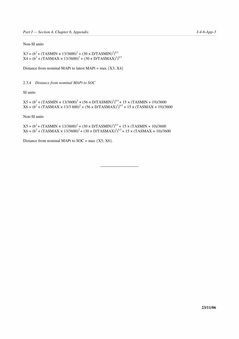
Part I — Section 4, Chapter 6, Appendix I-4-6-App-3
23/11/06
Non-SI units
X3 = (b2 + (TASMIN × 13/3600)2 + (30 × D/TASMIN)2)0.5
X4 = (b2 + (TASMAX × 13/3600)2 + (30 × D/TASMAX)2)0.5
Distance from nominal MAPt to latest MAPt = max {X3; X4}
2.3.4 Distance from nominal MAPt to SOC
SI units
X5 = (b2 + (TASMIN × 13/3600)2 + (56 × D/TASMIN)2)0.5 + 15 × (TASMIN + 19)/3600X6 = (b2 + (TASMAX × 13/3 600)2 + (56 × D/TASMAX)2)0.5 + 15 × (TASMAX + 19)/3600
Non-SI units
X5 = (b2 + (TASMIN × 13/3600)2 + (30 × D/TASMIN)2)0.5 + 15 × (TASMIN + 10)/3600X6 = (b2 + (TASMAX × 13/3600)2 + (30 × D/TASMAX)2)0.5 + 15 × (TASMAX + 10)/3600
Distance from nominal MAPt to SOC = max {X5; X6}.
___________________

I-4-7-1 23/11/06
Chapter 7
VISUAL MANOEUVRING (CIRCLING) AREA
7.1 GENERAL
7.1.1 Definition of terms
Visual manoeuvring (circling) is the term used to describe the visual phase of flight after completing an instrumentapproach, which brings an aircraft into position for landing on a runway which is not suitably located for straight-inapproach, i.e. one where the criteria for alignment or descent gradient cannot be met.
7.1.2 Area to be considered for obstacle clearance
The visual manoeuvring (circling) area is the area in which obstacle clearance shall be considered for aircraftmanoeuvring visually (circling).
7.1.3 Visual manoeuvring for helicopters
This chapter does not apply to Category H. In an instrument approach where the landing axis does not permit a straight-in approach, helicopters must conduct a visual manoeuvre under meteorological conditions adequate for seeing andavoiding obstacles in the vicinity of the FATO. The OCA/H for helicopter visual manoeuvring shall not be less than75 m (246 ft).
7.1.4 Prescribed track for visual manoeuvring
In those locations where clearly defined visual features permit, and if it is operationally desirable, a specific track forvisual manoeuvring may be prescribed (in addition to the circling area). See the Appendix to this chapter.
7.2 ALIGNMENT AND AREA
7.2.1 Method for defining the area
7.2.1.1 The size of the visual manoeuvring (circling) area varies with the category of the aircraft. To define thelimits of the area:
a) draw an arc from the centre of the threshold of each usable runway with a radius appropriate to the aircraftcategory. Example values appear in Tables I-4-7-1 and I-4-7-2;

I-4-7-2 Procedures — Aircraft Operations — Volume II
23/11/06
b) from the extremities of the adjacent arcs draw lines tangent to the arcs; and
c) connect the tangent lines.
The area thus enclosed is the visual manoeuvring (circling) area. See Figures I-4-7-1 and I-4-7-2.
7.2.1.2 Note that in Figure I-4-7-1, as an example, the radius for Category E aircraft is used. An operationaladvantage is gained by casting arcs only from those runways usable by Category E aircraft.
7.2.1.3 In Figure I-4-7-2 all runways are used because they are available to Category A aircraft. However, sincethe radius for Category A is less than that for Category E the total area for all aircraft is slightly smaller than it wouldbe if Category E criteria were applied completely.
7.2.2 Parameters
The parameters on which visual manoeuvring (circling) radii are based are as follows:
a) speed: speed for each category as shown in Tables I-4-1-1 and I-4-1-2 in Chapter 1;
b) wind: ± 46 km/h (25 kt) throughout the turn; and
c) bank: 20° average achieved or the bank angle producing a turn rate of 3° per second, whichever is the lesserbank. (See Figures II-4-1-App A-2 and II-4-1-App A-3 in Part II, Section 4, Appendix A to Chapter 1,“Parameters for holding area construction”).
7.2.3 Determination method
The radius is determined using the formulas in Section 2, Chapter 3, “Turn area construction”, by applying a 46 km/h(25 kt) wind to the true airspeed (TAS) for each category of aircraft using the visual manoeuvring IAS fromTables I-4-1-1 and I-4-1-2 in Chapter 1. The TAS is based on:
a) altitude: aerodrome elevation + 300 m (1 000 ft); and
b) temperature: ISA + 15°.
7.2.4 Visibility and lowest OCA/H
It is assumed that the minimum visibility available to the pilot at the lowest OCA/H will be as shown in Table I-4-7-3.This information is not required for the development of the procedure, but is included as a basis for the development ofoperating minima.
7.3 OBSTACLE CLEARANCE
See 5.4.4, “OCA/H for visual manoeuvring (circling)”, and Table I-4-7-3.

Part I — Section 4, Chapter 7 I-4-7-3
23/11/06
7.4 METHOD FOR REDUCING OCA/H
7.4.1 Area which can be ignored
A sector in the circling area where a prominent obstacle exists may be ignored for OCA/H calculations if it is outsidethe final approach and missed approach areas. This sector is bounded by the dimensions of the Annex 14 instrumentapproach surfaces. (See Figure I-4-7-3.)
7.4.2 Promulgation
When this option is exercised, the published procedure must prohibit the pilot from circling within the total sectorwhere the obstacle exists. (See Figure I-4-7-4.)
7.5 MISSED APPROACH ASSOCIATED WITH THE VISUAL MANOEUVRE
A missed approach area specific to the visual manoeuvre is not constructed.
7.6 PROMULGATION
The general criteria in Chapter 9, “Charting/AIP” apply. The instrument approach chart for a visual manoeuvre shall beidentified by the navigation aid type used for final approach lateral guidance, followed by a single letter suffix, startingwith the letter A. The suffix letter shall not be used again for any procedures at that airport, at any other airport servingthe same city or at any other airport in the same State, serving a city with the same name. The OCA/H values for theprocedure shall be the OCA/H for approach or missed approach, whichever is greater and shall be published inaccordance with Chapter 5, 5.5.6, “Publication of OCA/H” and 5.4.4, “OCA/H for visual manoeuvring (circling)”.
Table I-4-7-1. Example of determining radii for visual manoeuvring (circling) areafor aerodromes at 300 m MSL (SI-units)
Category of aircraft/IAS (km/h) A/185 B/250 C/335 D/380 E/445
TAS at 600 m MSL + 46 km/hwind factor (km/h)
241 310 404 448 516
Radius (r) of turn (km) 1.28 2.08 3.46 4.34 5.76
Straight segment (km)(this is a constant value independentof aerodrome elevation)
0.56 0.74 0.93 1.11 1.30
Radius (R) from threshold (km) 3.12 4.90 7.85 9.79 12.82
Note.— Radius from threshold (R) = 2r + straight segment.

I-4-7-4 Procedures — Aircraft Operations — Volume II
23/11/06
Table I-4-7-2. Example of determining radii for visual manoeuvring (circling) areafor aerodromes at 1 000 ft MSL (non-SI units)
Category of aircraft/IAS (kt) A/100 B/135 C/180 D/205 E/240
TAS at 2 000 ftMSL + 25 kt wind factor (kt)
131 168 215 242 279
Radius (r) of turn (NM) 0.69 1.13 1.85 2.34 3.12
Straight segment (NM)(this is a constant value independentof aerodrome elevation)
0.30 0.40 0.50 0.60 0.70
Radius (R) from threshold (NM) 1.68 2.66 4.20 5.28 6.94
Note.— Radius from threshold (R) = 2r + straight segment.
Table I-4-7-3. MOC and OCA/H for visual manoeuvring (circling) approach
Aircraft category
Minimum obstacleclearance
m (ft)
Lower limit for OCHabove aerodromeelevation m (ft)
Minimum visibilitykm (NM)
A 90 (295) 120 (394) 1.9 (1.0)
B 90 (295) 150 (492) 2.8 (1.5)
C 120 (394) 180 (591) 3.7 (2.0)
D 120 (394) 210 (689) 4.6 (2.5)
E 150 (492) 240 (787) 6.5 (3.5)

Part I — Section 4, Chapter 7 I-4-7-5
23/11/06
Figure I-4-7-1. Construction of visual manoeuvring (circling) area
Figure I-4-7-2. Visual manoeuvring (circling) area
R
R R
R
Category EaircraftR = 12.2 kmor 6.94 NM(at 600 m(2 000 ft) MSL)
R
R
RR
R
RR
Category AaircraftR = 3.16 kmor 1.68 NM(at 600 m(2 000 ft) MSL)

I-4-7-6 Procedures — Aircraft Operations — Volume II
23/11/06
Figure I-4-7-3. Visual manoeuvring (circling) area — obstacle clearance
Obstacle
Finalapproach
area
Annex 14instrument approach
surface
VOR
Missedapproach
area
Sector in whichobstacle may beignored when determiningOCA/H for circling

Part I — Section 4, Chapter 7 I-4-7-7
23/11/06
Figure I-4-7-4. Visual manoeuvring (circling) area — prohibition on circling
— — — — — — — —
VOR
Finalapproach
Obstacle
No circling inthis area
Annex 14instrument approach
surface

I-4-7-App-1 23/11/06
Appendix to Chapter 7
VISUAL MANOEUVRING USING PRESCRIBED TRACK
1. GENERAL
1.1 In those locations where clearly defined visual features permit, and if it is operationally desirable, a specifictrack for visual manoeuvring may be prescribed (in addition to the circling area). This track should be included insidethe limits of the circling area designed for the same aircraft categories. When it is not the case, the procedure should benamed: “VISUAL approach procedure” instead of “VISUAL manoeuvering.”
1.2 The visual features used to define the track and (if necessary) altitude changing points on the track may becomplemented with radio fixes (i.e. VOR radial, DME distance, etc.). The tolerance of the radio fix must be equal to orbetter than the tolerance of the visual feature. A radio fix cannot be used if the corresponding visual feature does notexist.
1.3 At the end of the visual manoeuvring track, a go-around procedure for a second prescribed track manoeuvringis provided. In some cases, the go-around procedure can join the instrument missed approach procedure.
2. TRACK
2.1 Several kinds of tracks have to be considered and the more common cases are illustrated inFigure I-4-7-App-1.
2.2 Gathering together of the tracks. It is possible to develop one track for each aircraft category, but for the sakeof simplicity, it is recommended that one track be used for all the categories or one for Cat A and B and another for CatC, D, E, if this does not lead to operational constraints.
2.3 Diverging point. This point must be defined with a clearly identifiable visual feature (complemented ifnecessary by a radio fix with a tolerance less than 0.5 NM, i.e. middle marker or DME distance).
2.4 Diverging segment
2.4.1 This segment joins the final instrument approach segment to the downwind leg of the prescribed track.In some cases, this segment can be replaced by a turn (see Figure I-4-7-App-1 e)) or an S-type manoeuvre (seeFigure I-4-7-App-1 c)).
2.4.2 In the case of Figure I-4-7-App-2, it is recommended that the end of the diverging segment occur before thepoint abeam the threshold used for the prescribed track.

I-4-7-App-2 Procedures — Aircraft Operations — Volume II
23/11/06
2.4.3 The angle between the diverging segment and the runway used for the prescribed track must be less than orequal to 45°.
2.4.4 The length and magnetic orientation of the diverging segment must be published.
2.5 “Downwind” leg
This segment is parallel to the runway axis; its length is determined by the position of the diverging segment and thelength of the final segment of the prescribed track. The length and magnetic orientation of the “downwind” leg must bepublished.
2.6 Radius of turn
The speed should be the true airspeed, calculated from the maximum indicated airspeed for visual manoeuvring(Tables I-4-1-1 and I-4-1-2 in Chapter 1) for:
a) altitude: aerodrome elevation + 300 m (1 000 ft); and
b) temperature: ISA + 15°C.
Note.— If necessary (because constraining obstacles have to be avoided) the indicated airspeed may be reduced tonot less than the maximum indicated airspeed for the final segment (Tables I-4-1-1 and I-4-1-2) for the aircraftcategory. In such a case, the maximum indicated speed must be published on the chart.
2.7 Final segment (of the prescribed track)
The length of the final segment of the prescribed track is based on 30 s of flight at a speed which should be the trueairspeed calculated from the maximum indicated airspeed for final approach (Tables I-4-1-1 and I-4-1-2) for:
a) altitude: aerodrome elevation + 300 m (1 000 ft); and
b) temperature: ISA + 15°C.
When a minimum altitude has to be maintained at the beginning of this segment, the procedures designer should checkits length to allow a final descent gradient less than 10 per cent (optimum: 5.2 per cent/3°).
2.8 Bank
25° average achieved bank angle.
2.9 Go-around track
In all cases, the prescribed track provides for a go-around trajectory. In general, this manoeuvre consists of a 180° turnstarting at the end of the runway and reaching the “downwind” leg of the prescribed track. When this kind of procedureis not appropriate, if there is a constraining obstacle under the 180° turn manoeuvre or if there is a special kind ofprescribed track (Figure I-4-7-App-3), a go-around procedure to join the instrument missed approach will beprescribed.

Part I — Section 4, Chapter 7, Appendix I-4-7-App-3
23/11/06
3. AREA ASSOCIATED WITH PRESCRIBED TRACK
This area is based on the nominal track, plus a buffer area of width (w) on the outside of the nominal track. The bufferarea starts at the “diverging” point and follows the track, including a go-around for a second visual manoeuvre withprescribed track. (See Table I-4-7-App-1 and Figure I-4-7-App-4.)
4. MINIMUM OBSTACLE CLEARANCE AND OCA/H
The OCA/H for visual manoeuvring on prescribed tracks shall provide the minimum obstacle clearance (MOC) overthe highest obstacle within the prescribed track area. It shall also conform to the limits specified at Table I-4-7-App-2and be not less than the OCA/H calculated for the instrument approach procedure which leads to the visual manoeuvre.
5. VISUAL AIDS
Visual aids associated with the runway used for the prescribed track (i.e. sequenced flashing lights, PAPI, VASIS) areshown on the approach chart with their main characteristics (i.e. slope of the PAPI or VASIS). Lighting on obstacles isspecified on the approach chart.
Table I-4-7-App-1. Semi-width of the corridor
Aircraft category A B C D E
semi-width of the corridor (w)metres(feet)
1 4004 593
1 5004 921
1 8005 905
2 1006 890
2 6008 530
Table I-4-7-App-2. Minimum OCA/H for visual manoeuvringusing prescribed tracks
Aircraftcategory
Obstacleclearance
m (ft)
Lower limitfor OCH
aboveaerodromeelevation
m (ft)
Minimumvisibilitykm (NM)
A 90 (295) 120 (394) 1.9 (1.0)
B 90 (295) 150 (492) 2.8 (1.5)
C 120 (394) 180 (591) 3.7 (2.0)
D 120 (394) 210 (689) 4.6 (2.5)
E 150 (492) 240 (787) 6.5 (3.5)

I-4-7-App-4 Procedures — Aircraft Operations — Volume II
23/11/06
Figure I-4-7-App-1. Common cases of tracks
General case
A B
C
D E
Visual feature

Part I — Section 4, Chapter 7, Appendix I-4-7-App-5
23/11/06
Figure I-4-7-App-2. Standard track general case
Figure I-4-7-App-3. Prescribed track for go-around
Figure I-4-7-App-4. Area
___________________
VOR
Go-around track
45°max
Go-around track
Diverging pointVisual final segment
Diverging segmentAbeam threshold
Maximum limit for the divergingsegment position
Nominal track
W
WW

I-4-8-1 23/11/06
Chapter 8
MINIMUM SECTOR ALTITUDES (MSA)
8.1 GENERAL
8.1.1 Minimum sector altitudes shall be established for each aerodrome where instrument approach procedureshave been established. Each minimum sector altitude shall be calculated by:
a) taking the highest elevation in the sector concerned;
b) adding a clearance of at least 300 m (1 000 ft); and
c) rounding the resulting value up to the next higher 50-m or 100-ft increment, as appropriate.
8.1.2 If the difference between sector altitudes is insignificant (i.e. in the order of 100 m or 300 ft as appropriate)a minimum altitude applicable to all sectors may be established.
8.1.3 A minimum altitude shall apply within a radius of 46 km (25 NM) of the homing facility on which theinstrument approach is based. The minimum obstacle clearance when flying over mountainous areas should beincreased by as much as 300 m (1 000 ft).
8.2 OBSTACLES IN BUFFER AREA
Obstacles within a buffer zone of 9 km (5 NM) around the boundaries of any given sector shall be considered as well.If such obstacles are higher than the highest obstacle within the sector, then the minimum sector altitude shall becalculated by:
a) taking the highest elevation in the buffer area concerned;
b) adding a clearance of at least 300 m (1 000 ft); and
c) rounding the resulting value up to the nearest 50 m (100 ft).
8.3 SECTOR ORIENTATION
The sectors should normally coincide with the quadrants of the compass. However, when topographical or otherconditions make it desirable, the boundaries of the sectors may be chosen to obtain the most favourable minimumsector altitudes. See Figure I-4-8-1.

I-4-8-2 Procedures — Aircraft Operations — Volume II
23/11/06
8.4 COMBINING SECTORS FOR ADJACENT FACILITIES
8.4.1 Where more than one facility provides instrument approaches to an aerodrome, and several minimum sectoraltitude diagrams are involved, individual diagrams shall be produced and minimum sector altitudes calculated.
8.4.2 If such facilities are located less than 9 km (5 NM) apart, the minimum sector altitude for any given sectorshould be the highest of all altitudes calculated for that specific sector for every facility serving the aerodrome.
8.5 SECTORS CENTERED ON A VOR/DME OR NDB/DME
8.5.1 In sectors centred on a VOR/DME or NDB/DME, it is possible to define an additional boundary (DME arc)within a sector, dividing the sector into two subsectors with the lower MSA in the inner area.
8.5.2 The DME arc radius (R) used should be between 19 and 28 km (10 and 15 NM) in order to avoid the use ofa subsector of too small a size. The width of the buffer area between the subsectors remains 9 km (5 NM) (seeFigure I-4-8-2).

Part I — Section 4, Chapter 8 I-4-8-3
23/11/06
Figure I-4-8-1. Sector orientation
Figure I-4-8-2. Case of VOR/DME subsectors delimited by a DME arc___________________
Homing facility
(VOR, NDB, VDF)
Homing facility(VOR, NDB, VDF)
RunwayRunway
Sector selected with respect to topography and obstaclesSector based on the quadrants of the compass(Magnetic)
(5 NM)
(5 NM)
9 km
9 km
(5 NM)
9 km
BUFFERZO
NE
46 km (25 NM)
VOR/DME
R

I-4-9-1 23/11/06
Chapter 9
CHARTING/AIP
9.1 GENERAL
Material relating to the publication of charts is contained in Annex 4 as follows:
a) Standard Departure Chart — Instrument (SID) — ICAO, in Annex 4, Chapter 9;
b) Standard Arrival Chart — Instrument (STAR) — ICAO, in Annex 4, Chapter 10; and
c) Instrument Approach Chart — ICAO, in Annex 4, Chapter 11.
9.2 CHARTED ALTITUDES/FLIGHT LEVELS
Altitude depiction. Arrival procedures may be developed to procedurally separate air traffic. In doing so, the proceduremay be accompanied with altitudes/flight levels that are not associated with any obstacle clearance requirements, butare developed to separate arriving and departing air traffic procedurally. These altitudes/flight levels shall be charted asindicated in Table I-4-9-1. The method of charting of altitudes/flight levels to correctly depict the designed proceduremay differ between avionics manufacturers.
9.3 ARRIVAL
In some cases it is necessary to designate arrival routes from the en-route structure to the initial approach fix. Onlythose routes which provide an operational advantage shall be established and published. These should take local airtraffic flow into consideration.
9.4 APPROACH
9.4.1 General
9.4.1.1 Optimum and maximum descent gradients and angles are specified depending on the type of procedureand the segment of the approach. The descent gradient(s)/angles used in the construction of the procedure shall bepublished for the final approach segment. It is preferable that they also be published for the other approach segments,where appropriate.
9.4.1.2 Where distance information is available, descent profile advisory information for the final approachshould be provided to assist the pilot to maintain the calculated descent gradient. This should be a table showingaltitudes/heights through which the aircraft should be passing at each 2 km or 1 NM as appropriate.

I-4-9-2 Procedures — Aircraft Operations — Volume II
23/11/06
9.4.2 Initial approach segment
9.4.2.1 Separate procedures shall be published when:
a) different minimum altitudes;
b) different timings; or
c) different outbound tracks
are specified for different categories of aircraft.
9.4.2.2 Speeds below the minimum value for initial approach in a given aircraft category shall not be specified(see Tables I-4-1-1 and I-4-1-2 of Chapter 1). If procedures are developed which exclude specific aircraft categoriesdue to speed, this must be stated explicitly.
9.4.3 Final approach segment
9.4.3.1 An OCA and/or an OCH shall be published for each instrument approach and circling procedure. For non-precision approach procedures, values shall be expressed in 5-m or 10-ft increments by rounding up as appropriate.
9.4.3.2 A straight-in OCA/H shall not be published where final approach alignment or descent gradient criteriaare not met. In this case, only circling OCA/H shall be published.
9.4.3.3 Procedures which require the use of forecast altimeter setting shall be suitably annotated on the approachcharts.
9.4.4 Missed approach segment
9.4.4.1 Only one missed approach procedure shall be published for each approach procedure.
9.4.4.2 If the MAPt is defined by a facility or fix at the MAPt, the procedure must be annotated “timing notauthorized for defining the MAPt”.
9.4.4.3 If the MAPt is defined by a combination of timing over the distance from the nominal FAF to the nominalMAPt, in addition to a facility or fix at the missed approach point, the OCA/Hs for both timing and fix shall bepublished if an operational advantage can be obtained in this way. Alternatively a single OCA/H shall be published(which shall be the higher of the two).
9.4.4.4 The OCA/H for the nominal 2.5 per cent must always be published on the instrument approach chart. Ifadditional gradients are specified in the construction of the missed approach procedure, they and their associatedOCA/H values must be published as alternative options.
9.4.4.5 The speed for final missed approach is shown in Tables I-4-1-1 and I-4-1-2 of Chapter 1. However, whereoperationally required to avoid obstacles, reduced speeds as slow as the IAS for intermediate missed approach may beused, provided the procedure is annotated “Missed approach turn limited to _______ km/h (kt) IAS maximum.”
9.4.4.6 When a gradient other than the nominal gradient is used in the construction of the missed approachprocedure this must be indicated in the instrument approach chart and, in addition to the OCA/H for the specificgradient, the OCA/H applicable to the nominal gradient must also be shown.

Part I — Section 4, Chapter 9 I-4-9-3
23/11/06
9.4.5 Visual manoeuvring
9.4.5.1 A sector in the circling area where a prominent obstacle exists may be ignored for OCA/H calculations ifit meets the criteria listed in Chapter 7, 7.4.1, “Area which can be ignored”.
9.4.5.2 When this option is exercised, the published procedure must prohibit the pilot from circling within thetotal sector where the obstacle exists.
9.4.6 Visual manoeuvring with prescribed track
9.4.6.1 The length and magnetic orientation of the diverging segment must be published.
9.4.6.2 The length and magnetic orientation of the ‘‘downwind’’ leg must be published.
9.4.6.3 Radius of turn. If necessary (because constraining obstacles have to be avoided) the indicated airspeedmay be reduced to not less than the maximum indicated airspeed for the final segment (Tables I-4-1-1 and I-4-1-2 ofChapter 1) for the aircraft category. In such a case, the maximum indicated speed must be published on the chart.
9.5 PROCEDURE NAMING FOR ARRIVAL AND APPROACH CHARTS
9.5.1 Instrument Flight Procedure Naming Convention
This paragraph describes the general aspects of instrument procedure naming. Specific aspects are covered in theappropriate chapters. A standardized naming convention is required to avoid ambiguity between charts, electroniccockpit displays and ATC clearances. This convention affects the following charting aspects:
a) procedure identification;
b) additional equipment requirements; and
c) minimum boxes.
9.5.2 Procedure identification
9.5.2.1 General. The procedure identification shall only contain the name describing the type of radio navigationaid providing the final approach lateral guidance. Precision approach systems such as ILS or MLS shall be identified bythe system name (ILS, MLS, etc.). If two radio navigation aids are used for final approach lateral guidance, the titleshall only include the last radio navigation aid used. For example:
if an NDB is used as the final approach fix and a VOR is used as the last navaid on the final approach to runway 06,the procedure shall be identified as VOR Rwy 06. If a VOR is used for the initial approach followed by a finalapproach to Rwy 24 using an NDB, the procedure shall be identified as NDB Rwy 24.
9.5.2.2 Additional navaids. If additional navigation aids are required (such as fix formations or transition routes)for the approach procedure, they shall be specified on the plan view of the chart, but not in the title.

I-4-9-4 Procedures — Aircraft Operations — Volume II
23/11/06
9.5.2.3 Multiple procedures. A single approach chart may portray more than one approach procedure when theprocedures for the intermediate, approach, final approach and missed approach segments are identical. If more than oneapproach procedure is depicted on the same chart, the title shall contain the names of all the types of navigation aidsused for final approach lateral guidance, separated by the word “or”. There shall be no more than three types ofapproach procedure on one chart. For example:
ILS or NDB Rwy 35L
9.5.2.4 Helicopter approach. Helicopter approaches to a runway shall be identified in the same way as fixed wingapproaches, with the Category H included in the Minimum Box. A helicopter approach to a point in space or a helipadshall be identified by the navigation aid type used for final approach guidance, followed by the final approach track orradial. For example:
VOR 235
9.5.2.5 Circling approach. When on a chart only circling minima are provided, the approach procedure shall beidentified by the last navaid providing final approach guidance followed by a single letter, starting with the letter A.When there are two or more approaches at an airport (or a nearby airport), a different letter shall be used. If the IFRportion of the procedure is the same but there are different circling tracks for the same procedure, only one procedurewith one title should be promulgated and the different circling procedures indicated in the procedure. The suffix lettershall not be used again for any procedures at that airport, at any other airport serving the same city, or at any otherairport in the same State, serving a city with the same name. For example:
VOR-a
VOR-b
NDB-c
9.5.3 Duplicate procedure identification
9.5.3.1 A single letter suffix, starting with the letter Z following the radio navigation aid type shall be used if twoor more procedures to the same runway cannot be distinguished by the radio navigation aid type only. For example:
VOR y Rwy 20
VOR z Rwy 20
9.5.3.2 The single letter suffix shall be used when:
a) two or more navigation aids of the same type are used to support different approaches to the same runway;
b) two or more missed approaches are associated with a common approach, each approach being identified by asingle letter suffix;
c) different approach procedures using the same radio navigation type are provided for different aircraftcategories;
d) two or more arrivals are used to a common approach and are published on different charts, each approach beingidentified by a single letter suffix. If additional radio navigation aids are required for the arrival they shall bespecified on the chart's plan view. For example:

Part I — Section 4, Chapter 9 I-4-9-5
23/11/06
ILS y RWY 20 (“CAB VOR Arrival” shown in the plan view)
ILS z RWY 20 (“DNA VOR Arrival” shown in the plan view)
9.5.4 Additional equipment requirements
9.5.4.1 All navigation equipment that is required for the execution of the approach procedure and not mentionedin the procedure identification shall be identified in notes on the chart. For example:
“VOR required” on an NDB approach;
“Dual ADF required”, when required on an NDB approach where two ADFs are required;
“When inbound from XXX NDB, change over to YYY NDB at midpoint”;
“DME required” on a VOR/DME arc approach.
9.5.4.2 Optional carriage of equipment that may support lower minima shall be evident from the Minimum Box.In such a case it is not necessary to provide a note on the chart. See 9.5.2.4.
9.5.5 Minimum boxes
The OCA/H for each aircraft category shall be published in the minimum box on the chart. Where an OCA/H ispredicated on a specific navigation aid (e.g. stepdown fixes), or a specific RNAV functionality (e.g. LNAV/VNAV), oran RNP value, this shall be clearly identified. For example:
OCA/(OCH) CAT A CAT B CAT C CAT D CAT HLNAV/VNAV 560 (250) 560 (250) 630 (320) 630 (320) 560 (250)LNAV 710 (400) 710 (400) 810 (500) 810 (500) 710 (400)
or
OCA/(OCH) CAT A CAT B CAT C CAT D CAT HVOR/DME 610 (300) 610 (300) 610 (300) 610 (300) 610 (300)VOR 660 (350) 660 (350) 660 (350) 660 (350) 660 (350)
or
OCA/(OCH) CAT A CAT B CAT C CAT D CAT HCAT I 210 (170) 210 (170) 220 (180) 230 (190) 210 (170)RNP 0.3 290 (250) 290 (250) 290 (250) 290 (250) 290 (250)

I-4-9-6 Procedures — Aircraft Operations — Volume II
23/11/06
Table I-4-9-1. Charted altitudes/flight levels
Altitude/flight level “Window” 17 000 FL22010 000 10 000
“At or above” altitude/flight level 7 000 FL60
“At or below” altitude/flight level 5 000 FL50
“Mandatory” altitude/flight level 3 000 FL30
“Recommended” procedure altitude/flight level 5 000 FL50
“Expected” altitude/flight level Expect 5 000 Expect FL50
___________________

I-5-(i)
Section 5
QUALITY ASSURANCE
(To be developed)

II-(i)
Procedures forAir Navigation Services
AIRCRAFT OPERATIONS
Part II
CONVENTIONAL PROCEDURES

II-1-(i)
Section 1
PRECISION APPROACHES

II-1-1-1 23/11/06
Chapter 1
INSTRUMENT LANDING SYSTEM (ILS)
1.1 INTRODUCTION
1.1.1 Application
The ILS criteria detailed in this chapter are related to the ground and airborne equipment performance and integrityrequired to meet the Category I, II and III operational objectives described in Annex 10.
1.1.2 Procedure construction
The procedure from enroute to the precision segment of the approach and in the final missed approach phase conformswith the general criteria as presented in Part I, Section 1, 2 and 4. The differences are found in the physicalrequirements for the precision segment which contains the final approach segment as well as the initial andintermediate phases of the missed approach segment. These requirements are related to the performance of Cat I, II andIII systems.
1.1.3 Standard conditions
The following list contains the standard assumptions on which procedures are developed. Provisions are made foradjustments where appropriate. Adjustments are mandatory when conditions differ adversely from standard conditionsand are optional when so specified (see 1.4.8.7, “Adjustment of constants”).
a) Maximum aircraft dimensions are assumed to be the following:
Aircraft category Wing span
Vertical distance between the flightpaths of the wheels and the GP antenna
(m)
H 30 3
A, B 60 6
C, D 65 7
DL 80 8
Note 1.— OCA/H for Cat DL aircraft is published when necessary.
Note 2.— The dimensions shown are those which encompass current aircraft types. They are chosen to facilitateOCA/H calculations and promulgation of aircraft category related minima. It is assumed that these dimensions are notintended to be used for other purposes than the OCA/H calculations in other ICAO documents. The use of OAS

II-1-1-2 Procedures — Aircraft Operations — Volume II
23/11/06
surfaces to calculate OCA/H may result in significant differences between aircraft categories because of smalldifferences in size. For this reason, it is always preferable to use the Collision Risk Model (1.4.9) which will allow formore realistic assessment for both height and position of obstacles.
Note 3.— Current Category E aircraft are not normally civil transport aircraft and their dimensions are notnecessarily related to Vat at maximum landing mass. For this reason, they should be treated separately on an individualbasis.
b) Category II flown with flight director.
c) Missed approach climb gradient 2.5 per cent.
d) ILS sector width 210 m at threshold.
e) Glide path angle:
1) minimum: 2.5°;
2) optimum: 3.0°;
3) maximum: 3.5° (3° for Cat II/III operations).
f) ILS reference datum height 15 m (50 ft).
g) All obstacle heights are referenced to threshold elevation.
h) For Cat II and Cat III operations the Annex 14 inner approach, inner transitional and balked landing surfaceshave not been penetrated. Where the Cat II OCA/H is higher than the level of the inner horizontal surface, butbelow 60 m, the inner approach and balked landing surfaces should be extended to the Cat II OCA/H level toaccommodate Cat III operations.
1.1.4 Obstacle clearance altitude/height (OCA/H)
1.1.4.1 The ILS criteria enable an OCA/H to be calculated for each category of aircraft. See Part I, Section 4,Chapter 1, 1.8, “Categories of aircraft”. Where statistical calculations were involved, the OCA/H values were designedagainst an overall safety target of 1 × 10⁻⁷ (1 in 10 million) per approach for risk of collision with obstacles.
1.1.4.2 The OCA/H ensures clearance of obstacles from the start of the final approach to the end of theintermediate missed approach segment.
Note.— This OCA/H is only one of the factors to be taken into account in determining decision height as defined inAnnex 6.
1.1.4.3 Additional material is included to allow operational benefit to be calculated for the improved beamholding performance of autopilots meeting national certification standards (as opposed to flight directors) in Cat II, andfor improved missed approach climb performance in Cat I, II and III.
1.1.4.4 Benefit may also be calculated for aircraft with dimensions other than the standard size assumed in thebasic calculations. An OCA/H is not associated with Cat III operations. These are supported by the obstacle limitationsurfaces defined in Annex 14, in association with overlapping protection from the Cat II criteria.

Part II — Section 1, Chapter 1 II-1-1-3
23/11/06
1.1.5 Methods of calculating OCA/H
1.1.5.1 General. Three methods of calculating OCA/H are presented, which involve progressive increases in thedegree of sophistication in the treatment of obstacles. Standard conditions (as specified in 1.1.3) are assumed to existunless adjustments for non-standard conditions have been made.
1.1.5.2 First method. The first method involves a set of surfaces derived from the Annex 14 precision approachobstacle limitation surfaces and a missed approach surface described in 1.4.7.2, “Definition of basic ILS surfaces”.From this point forward, these are termed “basic ILS surfaces”. Where the standard conditions exist as specified in1.1.3 and where the basic ILS surfaces are free of penetrations (see 1.4.7.1), the OCA/H for Cat I and Cat II is definedby aircraft category margins, and there are no restrictions on Cat III operations. If the basic ILS surfaces are penetrated,then the OCA/H is calculated as described in 1.4.7.3, “Determination of OCA/H with ILS”.
1.1.5.3 Second method. The second method involves a set of obstacle assessment surfaces (OAS) above the basicILS surfaces (see 1.4.8.4, “Definition of obstacle assessment surfaces (OAS). If the OAS are not penetrated —andprovided the obstacle density below the OAS is operationally acceptable (see 1.4.8.9, “Effect of obstacle density onOCA/H”) — the OCA/H for Cat I and Cat II is still defined by the aircraft category margins, and Cat III operationsremain unrestricted. However, if the OAS are penetrated, then an aircraft category-related margin is added to the heightof the highest approach obstacle, or to the adjusted height of the largest missed approach penetration, whichever isgreater. This value becomes the OCA/H.
1.1.5.4 Third method. The third method, using a collision risk model (CRM), is employed either as an alternativeto the use of the OAS criteria (second method) or when the obstacle density below the OAS is considered to beexcessive. The CRM accepts all objects as an input and assesses, for any specific OCA/H value, both the risk due toindividual obstacles and the accumulated risk due to all the obstacles. It is intended to assist operational judgment in thechoice of an OCA/H value.
Note.— The CRM does not take into account the characteristics of helicopters. The CRM can be used but themethod should be conservative.
1.1.6 References
The following appendices relate to and amplify the material contained in this chapter:
a) background information relating to the derivation of the OAS material (Attachment to Part II, paragraph 1) andto airborne and ground equipment performance assumed in the derivation of the OAS (Attachment to Part II,paragraph 2);
b) turning missed approach after precision approach (Appendix A);
c) independent parallel approaches to closely spaces parallel runways (Appendix D);
d) determining ILS glide path descents/MLS elevation heights and distances (Appendix C); and
e) PANS-OPS OAS CD-ROM.
Examples of OCA/H calculations can be found in the Instrument Flight Procedures Construction Manual (Doc 9368).

II-1-1-4 Procedures — Aircraft Operations — Volume II
23/11/06
1.1.7 ILS with glide path inoperative
The ILS with glide path inoperative is a non-precision approach procedure. The principles of Section 2, Chapter 1,“LLZ only”, apply.
1.2 INITIAL APPROACH SEGMENT
1.2.1 General
The initial approach segment must ensure that the aircraft is positioned within the operational service volume of thelocalizer on a heading that will facilitate localizer interception. For this reason, the general criteria which apply to theinitial segment (see Part I, Section 4, Chapter 3) are modified in accordance with 1.2.2, “Initial approach segmentalignment” and 1.2.3, “Initial Approach Segment Area”. For RNAV initial approach segments, the criteria in theapplicable RNAV chapters apply.
1.2.2 Initial approach segment alignment
The angle of interception between the initial approach track and the intermediate track should not exceed 90°. In orderto permit the autopilot to couple on to the localizer, an interception angle not exceeding 30° is desirable. When theangle exceeds 70° a radial, bearing, radar vector, or DME or RNAV information providing at least 4 km (2 NM) (CatH, 1.9 km (1 NM)) of lead shall be identified to assist the turn onto the intermediate track. When the angle exceeds 90°,the use of a reversal, racetrack, or dead reckoning (DR) track procedure should be considered (see Part I, Section 4,Chapter 3, “Initial Approach Segment” and Part I, Section 4, Appendix A to Chapter 3, “Initial approach using deadreckoning”).
1.2.3 Initial approach segment area
The area is as described in the general criteria (see Part I, Section 4, Chapter 3, 3.3.3, “Area”). The difference is that theintermediate approach fix (IF) must be located within the service volume of the ILS localizer course signal, andnormally at a distance not exceeding 46 km (25 NM) from the localizer antenna. When radar is used to provide trackguidance to the IF, the area shall be in accordance with 6.2,”Initial approach segment” (Section 2, Chapter 6, “SRE”).
1.3 INTERMEDIATE APPROACH SEGMENT
1.3.1 General
1.3.1.1 The intermediate approach segment for ILS differs from the general criteria in that:
a) the alignment coincides with the localizer course;
b) the length may be reduced; and
c) in certain cases the secondary areas may be eliminated.

Part II — Section 1, Chapter 1 II-1-1-5
23/11/06
1.3.1.2 The primary and secondary areas at the FAP are defined in terms of the ILS surfaces. Consequently, thegeneral criteria in Part I, Section 4, Chapter 4, “Intermediate Approach Segment” are applied except as modified oramplified in the paragraphs below with regards to alignment, area length and width, and for obstacle clearance. ForRNAV initial approach segments, the criteria in the applicable RNAV chapters apply.
1.3.2 Intermediate approach segment alignment
The intermediate approach segment of an ILS procedure shall be aligned with the localizer course.
1.3.3 Intermediate approach segment length
1.3.3.1 The optimum length of the intermediate approach segment is 9 km (5 NM) (Cat H, 3.7 km (2 NM)). Thissegment shall allow interception with the localizer course and with the glide path.
1.3.3.2 Segment length should be sufficient to permit the aircraft to stabilize and establish on the localizer courseprior to intercepting the glide path, taking into consideration the angle of interception with the localizer course.
1.3.3.3 Minimum values for distance between localizer and interception of glide path are specified inTable II-1-1-1; however, these minimum values should only be used if usable airspace is restricted. The maximumlength of the segment is governed by the requirement that it be located wholly within the service volume of thelocalizer signal and normally at a distance not exceeding 46 km (25 NM) from the localizer antenna.
1.3.4 Intermediate approach segment area width
1.3.4.1 The total width at the beginning of the intermediate approach segment is defined by the final total width ofthe initial approach segment. It tapers uniformly to match the horizontal distance between the OAS X surfaces at theFAP (see 1.4.8.4, “Definition of obstacle assessment surfaces (OAS)”).
1.3.4.2 For obstacle clearance purposes the intermediate approach segment is usually divided into a primary areabounded on each side by a secondary area. However, when a DR track is used in the initial approach segment, theprimary area of the intermediate approach segment extends across its full width and secondary areas are not applied.
1.3.4.3 The primary area is determined by joining the primary initial approach area with the final approachsurfaces (at the FAP). At the interface with the initial approach segment the width of each secondary area equals halfthe width of the primary area. The secondary area width decreases to zero at the interface with the final approachsurfaces. See Figures II-1-1-1, II-1-1-2 and II-1-1-3.
1.3.4.4 Where a racetrack or reversal manoeuvre is specified prior to intercepting the localizer course theprovisions in Part I, Section 4, Chapter 4, 4.4.4, “Turn not at the facility” apply, the facility being the localizer itselfand the FAF being replaced by the FAP. (See Figure II-1-1-4.)
1.3.5 Intermediate approach segment obstacle clearance
The obstacle clearance is the same as defined in Part I, Section 4, Chapter 4, “Intermediate approach segment” exceptwhere the procedure permits a straight-in approach in which the aircraft is stabilized on the localizer course prior tocrossing the IF. In this case, obstacles in the secondary areas need not be considered for the purpose of obstacleclearance.

II-1-1-6 Procedures — Aircraft Operations — Volume II
23/11/06
1.4 PRECISION SEGMENT
1.4.1 General
The precision segment is aligned with the localizer course and contains the final descent for landing as well as theinitial and intermediate phases of the missed approach segment See Figure II-1-1-5.
1.4.2 Origin
The precision segment starts at the final approach point (FAP), that is, the intersection of the nominal glide path and theminimum altitude specified for the preceding segment. The FAP should not normally be located more than 18.5 km(10.0 NM) before threshold, unless adequate glide path guidance beyond the minimum specified in Annex 10 isprovided.
1.4.3 Descent fix
1.4.3.1 A descent fix may be located at the FAP to overcome certain obstacles located before the FAP as analternative to increasing the glide path (GP) angle. When so located, it becomes the final approach fix. The extension ofthe precision surfaces into the precision segment is then terminated. The descent fix should not normally be locatedmore than 18.5 km (10.0 NM) before threshold, unless adequate GP guidance beyond the minimum specified in Annex10 is provided. The maximum fix tolerance is ± 0.9 km (± 0.5 NM). Where DME is used to identify the fix, the rangeshall be stated in tenths of kilometres (nautical miles).
Note.— Guidance material for determining the distance to the descent fix from the threshold is contained inAppendix C.
1.4.3.2 Obstacle clearance at the descent fix. When a descent fix is provided, the precision approach surfaces startat the earliest point of the FAF tolerance area (see Figure II-1-1-2). The provisions of Part I, Section 2, Chapter 2, 2.7.4,“Obstacle close to a final approach fix or stepdown fix” which allow obstacles close to the fix to be ignored, apply inthe area below the 15 per cent gradient within the precision surfaces (Cat H, 15 per cent gradient or the nominalgradient multiplied by 2.5, whichever is greater). Where a descent fix is not provided at the FAP, no curtailment of theprecision surfaces is permitted (see Figure II-1-1-3). If the precision surfaces are extended into the preceding segment,they shall not be extended beyond the intermediate approach segment.
1.4.4 Glide path verification check
A fix (outer marker or DME) is necessary so as to permit comparison between the indicated glide path and the aircraftaltimeter information. The fix shall not have a fix tolerance exceeding ± 0.9 km (± 0.5 NM). When DME is used toidentify the fix, the range shall be stated in tenths of kilometres (nautical miles).
Note.— Guidance material for determining the height crossing the outer marker is contained in Appendix C.
1.4.5 Missed approach
The missed approach point is defined by the intersection of the nominal glide path and the decision altitude/height(DA/H). The DA/H is set at or above the OCA/H, which is determined as specified in 1.4.7 to 1.4.9 and 1.5.

Part II — Section 1, Chapter 1 II-1-1-7
23/11/06
1.4.6 Termination
The precision segment normally terminates at the point where the final phase of the missed approach commences (seePart I, Section 4, Chapter 6, 6.1.2, “Phases of missed approach segment”) or where the missed approach climb surfaceZ (starting 900 m past threshold) reaches a height of 300 m (984 ft) above threshold, whichever is lower.
1.4.7 Obstacle clearance of the precision segmentapplication of basic ILS surfaces
1.4.7.1 General. The area required for the precision segment is bounded overall by the basic ILS surfaces definedin 1.4.7.2, below. In standard conditions there is no restriction on objects beneath these surfaces (see 1.1.3, “Standardconditions”). Objects or portions of objects that extend above these surfaces must be either:
a) minimum mass and frangible; or
b) taken into account in the calculation of the OCA/H.
1.4.7.2 Definition of basic ILS surfaces. The surfaces to be considered correspond to a subset of Annex 14obstacle limitation surfaces as specified for precision approach runway code numbers 3 or 4 (see Figure II-1-1-6).These are:
a) the approach surface continuing to the final approach point (FAP) (first section 2 per cent gradient, secondsection 2.5 per cent as described in Annex 14);
b) the runway strip assumed to be horizontal at the elevation of the threshold;
c) the missed approach surface. This is a sloping surface which:
1) starts at a point 900 m past the threshold (Cat H, a starting point of 700 m past the threshold can beconsidered if necessary) at threshold elevation;
2) rises at a 2.5 per cent gradient; and
3) splays so as to extend between the transitional surfaces. It extends with constant splay to the level of theinner horizontal surface. Thereafter, it continues at the same gradient but with a 25 per cent splay until thetermination of the precision segment; and
d) the extended transitional surfaces, which continue longitudinally along the sides of the approach and missedapproach surfaces and up to a height of 300 m above threshold elevation.
1.4.7.3 Determination of OCA/H with basic ILS surfaces
1.4.7.3.1 Where the basic ILS surfaces specified in 1.4.7.2 are not penetrated, the OCA/H for Category I andCategory II is defined by the margins specified in Table II-1-1-2, and Category III operations are not restricted.Obstacles may be excluded when they are below the transitional surface defined by Annex 14 for runways with codenumbers 3 and 4, regardless of the actual runway code number (i.e., the surfaces for code numbers 3 and 4 are used forthe obstacle assessment on runways with code numbers 1 and 2).
1.4.7.3.2 If the basic ILS surfaces listed above are penetrated by objects other than those listed in Table II-1-1-3,the OCA/H may be calculated directly by applying height loss/altimeter margins to obstacles (see 1.4.8.8,“Determination of OCA/H with OAS or basic ILS surfaces”).

II-1-1-8 Procedures — Aircraft Operations — Volume II
23/11/06
1.4.7.3.3 The obstacles in Table II-1-1-3 may only be exempted if the following two criteria are met:
a) the localizer course sector has the standard width of 210 m (see 1.1.3, “Standard conditions”); and
b) the Category I decision height is not less than 60 m (200 ft) or the Category II decision height is not less than30 m (100 ft).
1.4.7.3.4 An object that penetrates any of the basic ILS surfaces and becomes the controlling obstacle, but mustbe maintained because of its function with regards to air navigation requirements, may be ignored under certaincircumstances in calculating the OCA/H, with the following provision. It must be established by the appropriateauthority that the portion which penetrates the surface is of minimum mass and frangibly mounted and would notadversely affect the safety of aircraft operations.
1.4.8 Obstacle clearance of the precision segment using obstacle assessment surface (OAS) criteria
1.4.8.1 General
1.4.8.1.1 This section describes the OAS surfaces, the constants which are used to define these surfaces, and theconditions under which adjustments may or must be made. The OAS dimensions are related to:
a) the ILS geometry (localizer-threshold distance, glide path angle, ILS RDH, localizer sector width);
b) the category of ILS operation; and
c) other factors, including aircraft geometry, missed approach climb gradient.
Thus, a table of OCA/H values for each aircraft category may be calculated for Cat I and II ILS operations at theparticular airfield.
1.4.8.1.2 Additional material is included to enable appropriate authorities to assess realistic benefits for claims ofimproved performance and associated conditions. See 1.4.8.7, “Adjustment of OAS constants”.
1.4.8.1.3 Note that the OAS are not intended to replace Annex 14 surfaces as planning surfaces for unrestrictedobstacle growth. The obstacle density between the basic ILS surfaces and the OAS must be accounted for (see 1.4.8.9,“Effect of obstacle density on OCA/H”).
1.4.8.2 Frame of reference
Positions of obstacles are related to a conventional x, y, z coordinate system with its origin at threshold. SeeFigure II-1-1-10. The x-axis is parallel to the precision segment track: positive x is distance before threshold andnegative x is distance after threshold. The y-axis is at right angles to the x-axis. Although shown conventionally inFigure II-1-1-10, in all calculations associated with OAS geometry, the y coordinate is always counted as positive. Thez-axis is vertical, heights above threshold being positive. All dimensions connected with the OAS are specified inmetres only. The dimensions should include any adjustments necessary to cater for tolerances in survey data (see Part I,Section 2, Chapter 1, 1.8, “Charting accuracy”).
1.4.8.3 OAS constants — specification
For Category I and II operations the constants A, B and C for each sloping surface are obtained from the PANS-OPSOAS CD-ROM. The PANS-OPS OAS CD-ROM gives coefficients for glide path angles between 2.5 and 3.5 degreesin 0.1 degree steps, and for any localizer-threshold distance between 2 000 m and 4 500 m. Extrapolation outside these

Part II — Section 1, Chapter 1 II-1-1-9
23/11/06
limits is not permitted. If a localizer threshold distance outside this range is entered, the PANS-OPS OAS CD-ROMgives the coefficients for 2 000 m or 4 500 m as appropriate, which must be used. For an example of the PANS-OPSOAS CD-ROM results see Figure II-1-1-12.
1.4.8.4 Definition of obstacle assessment surfaces (OAS)
1.4.8.4.1 The OAS consist of six sloping plane surfaces (denoted by letters W, X, Y, and Z) arrangedsymmetrically about the precision segment track, together with the horizontal plane which contains the threshold (seeFigures II-1-1-8 and II-1-1-9). The geometry of the sloping surfaces is defined by four linear equations of the formz = Ax + By + C. In these equations x and y are position coordinates and z is the height of the surface at that position(see Figure II-1-1-7).
1.4.8.4.2 For each surface a set of constants (A, B and C) are obtained from the PANS-OPS OAS CD-ROM forthe operational range of localizer threshold distances and glide path angles. Separate sets of constants are specified forCategory I and II. These constants may be modified by the programme (see 1.4.8.7, “Adjustment of OAS constants”).
1.4.8.4.3 The Category I OAS are limited by the length of the precision segment and, except for the W and Xsurfaces, by a maximum height of 300 m. The Category II OAS are limited by a maximum height of 150 m.
1.4.8.4.4 Where the Annex 14 approach and transitional obstacle limitation surfaces for code numbers 3 and 4precision approach runways penetrate inside the OAS, the Annex 14 surfaces become the OAS (i.e. the surfaces forcode numbers 3 and 4 are used for obstacle assessment on runways with code numbers 1 and 2). The Annex 14 innerapproach, inner transitional and balked landing obstacle limitation surfaces protect Category III operations, providedthe Category II OCA/H is at or below the top of those surfaces which may be extended up to 60 m if necessary) (seeFigure II-1-1-6).
1.4.8.5 Calculation of OAS heights
To calculate the height z of any of the sloping surfaces at a location x’, y’, the appropriate constants should be firstobtained from the PANS-OPS OAS CD-ROM. These values are then substituted in the equation z = Ax’ + By’ + C. Ifit is not clear which of the OAS surfaces is above the obstacle location this should be repeated for the other slopingsurfaces. The OAS height is the highest of the plane heights (zero if all the plane heights are negative).
Note.— The PANS-OPS OAS CD-ROM also contains an OCH calculator that will show the height of the OASsurface z above any x, y location. It includes all the adjustments specified for ILS geometry, aircraft dimensions, missedapproach climb gradient and ILS reference datum height.
1.4.8.6 OAS template construction
1.4.8.6.1 Templates, or plan views of the OAS contours to map scale, are sometimes used to help identifyobstacles for detail survey (see Figure II-1-1-11). The OAS data in the PANS-OPS CD-ROM includes the coordinatesof the points of intersection:
a) of the sloping surfaces at threshold level. The intersection coordinates are labeled as C, D and E(Figure II-1-1-9);
b) at 300 m above threshold level for Cat I; and
c) at 150 m for Cat II.

II-1-1-10 Procedures — Aircraft Operations — Volume II
23/11/06
1.4.8.7 Adjustment of OAS constants
1.4.8.7.1 General. The following paragraphs describe the adjustments that the PANS-OPS OAS CD-ROMprogramme makes to the OAS constants. These adjustments are mandatory when the standard conditions are not met(see 1.1.3, “Standard conditions”). Optional adjustments may be made when so specified. For examples of calculationssee the Instrument Flight Procedures Construction Manual (Doc 9368).
1.4.8.7.2 Reasons for adjusting constants. The constants may be modified to account for the following:
a) missed approach climb gradient (see 1.4.8.7.7, below);
b) dimensions of specific aircraft (see 1.4.8.7.3, below);
c) the height of the ILS reference datum (see 1.4.8.7.4, below);
d) improved beam holding performance due to use of autopilots certified for Category II operations (see 1.4.8.7.6,below); and
e) certain Category I localizers having a sector width greater than the nominal 210 m at threshold (see 1.4.8.7.5,below).
1.4.8.7.3 Specific aircraft dimensions. An adjustment is mandatory where aircraft dimensions exceed thosespecified in 1.1.3, “Standard conditions” and is optional for aircraft with smaller dimensions. The PANS-OPS OASCD-ROM adjust the OAS coefficients and template coordinates for the standard dimensions of Category A, B, C, Dand DL aircraft automatically. It will do the same for specific aircraft dimensions in any category. It uses the followingcorrection formula to adjust the coefficient C for the W, W*, X and Y surfaces:
W surface: Cwcorr = Cw – (t – 6)
W* surface: Cw*corr = Cw* – (t – 6)
X surface: Cxcorr = Cx – Bx · P
Y surface: Cycorr = Cy – By . P
where:x x
t t-3P= or S + , whichever is the maximum
B B
� �� �� � x x
6 3– or 30 + , whichever is the maximum
B B
� �� �� �
and s = semi-span
t = vertical distance between paths of the GP antenna and the lowest part of the wheels.
1.4.8.7.4 Height of the ILS reference datum (RDH). This is based on a reference datum height (RDH) of 15 m. Anadjustment to the OAS constants is mandatory for an RDH less than 15 m, and is optional for an RDH greater than 15m. The PANS-OPS OAS CD-ROM adjusts the OAS coefficients and template coordinates by correcting the tabulatedvalues of the coefficient C for the W, W*, X and Y surfaces as follows:
Ccorr = C + (RDH – 15)
where: Ccorr = corrected value of coefficient C for the appropriate surface
C = tabulated value.

Part II — Section 1, Chapter 1 II-1-1-11
23/11/06
1.4.8.7.5 Modification for Cat I localizers with course width greater than 210 m at threshold. Where the ILSlocalizer sector width at threshold is greater than the nominal value of 210 m, the collision risk model (CRM) methoddescribed in 1.4.9 shall be used. Adjustments for sector widths less than 210 m shall not be made, and are inhibited inthe PANS-OPS OAS CD-ROM.
1.4.8.7.6 Use of autopilot (autocoupled) in Cat II. The Cat II OAS may be reduced to reflect the improved beamholding of autopilots where these are certificated for the operation by the appropriate authority. This reduction isachieved in the PANS-OPS OAS CD-ROM by the use of modified A, B and C constants for the X surface, and theintroduction of an extra surface (denoted by W*) (see Figure II-1-1-11 c)). The use of these reduced surfaces should notbe authorized for non-autocoupled approaches.
1.4.8.7.7 Missed approach climb gradient. If equipment is capable of missed approach climb gradients better thanthe nominal 2.5 per cent, the Y and Z surfaces may be adjusted. This is done by using the desired missed approachclimb gradient in the PANS-OPS OAS CD-ROM. The programme then adjusts the Y and Z surface coefficients.
1.4.8.8 Determination of OCA/H with OAS or basic ILS surfaces
1.4.8.8.1 General. The OCA/H is determined by accounting for all obstacles which penetrate the basic ILSsurfaces defined in 1.4.7.2 and the OAS surfaces applicable to the ILS category of operation being considered. Theexemptions listed in 1.4.7.3, “Determination of OCA/H with basic ILS surfaces” for obstacles penetrating the basicILS surfaces may be applied to obstacles penetrating the OAS, providing the criteria listed in that paragraph are met.The surfaces which apply to each category of operations are:
a) ILS Cat I: ILS Cat I OAS;
b) ILS Cat II: ILS Cat II OAS and those portions of ILS Cat I which lie above the limits of ILS Cat II; and
c) ILS Cat III: Same as ILS Cat II.
1.4.8.8.2 Calculation of OCA/H values with OAS. Accountable obstacles, as determined below in 1.4.8.8.2.3,“OCA/H Calculation steps” are divided into approach and missed approach obstacles. The standard method ofcategorization is as follows: Approach obstacles are those between the FAP and 900 m after threshold (Cat H, 700 m ifnecessary). Missed approach obstacles are those in the remainder of the precision segment (see Figure II-1-1-13).However, in some cases this categorization of obstacles may produce an excessive penalty for certain missed approachobstacles (see Attachment to Part II, 1.9). Where desired by the appropriate authority, missed approach obstacles maybe defined as those above a plane surface parallel to the plane of the glide path and with origin at –900 m (Cat H, –700m if necessary) (see Figure II-1-1-14), i.e. obstacle height greater than [(900 + x) tan�θ].
1.4.8.8.2.1 OCA/H Calculation steps
a) Determine the height of the highest approach obstacle.
b) Convert the heights of all missed approach obstacles (hma) to the heights of equivalent approach obstacles (ha)by the formula given below, and determine the highest equivalent approach obstacle.
c) Determine which of the obstacles identified in steps a) and b) is the highest. This is the controlling obstacle.
d) Add the appropriate aircraft category related margin (Table II-1-1-2) to the height of the controlling obstacle.
hma cot Z + (xz + x)ha =
cot Z + cotθ

II-1-1-12 Procedures — Aircraft Operations — Volume II
23/11/06
where: ha = height of equivalent approach obstacle
hma = height of missed approach obstacle
θ = angle of glide path (elevation angle)
Z = angle of missed approach surface
x = range of obstacle relative to threshold (negative after threshold)
xz = distance from threshold to origin of Z surface (900 m (700 m Cat H))
1.4.8.8.3 Adjustment for high airfield elevations and steep glide path angles
1.4.8.8.3.1 Height loss (HL)/altimeter margins. The margins in Table II-1-1-2 shall be adjusted as follows:
a) for airfield elevation higher than 900 m (2 953 ft), the tabulated allowances shall be increased by 2 per cent ofthe radio altimeter margin per 300 m (984 ft) airfield elevation; and
b) for glide path angles greater than 3.2° in exceptional cases, the allowances shall be increased by 5 per cent ofthe radio altimeter margin per 0.1° increase in glide path angle between 3.2° and 3.5°.
1.4.8.8.3.1.1 Procedures involving glide paths greater than 3.5° or any angle when the nominal rate of descent (Vat
for the aircraft type x´ the sine of the glide path angle) exceeds 5 m/sec (1 000 ft/min), are non-standard. They requirethe following:
a) increase of height loss margin (which may be aircraft type specific);
b) adjustment of the origin of the missed approach surface;
c) adjustment of the slope of the W surface;
d) re-survey of obstacles; and
e) the application of related operational constraints.
Such procedures are normally restricted to specifically approved operators and aircraft, and are associated withappropriate aircraft and crew restrictions. They are not to be used as a means to introduce noise abatement procedures.
1.4.8.8.3.1.2 Appendix B shows the procedure design changes required and the related operational/certificationconsiderations.
Example: Aircraft Category C — Aerodrome elevation: 1 650 m above MSL; glide path angle 3.5°.
Tabulated allowances: radio altimeter 22 m
(Table II-1-1-2) pressure altimeter 46 m
Correction for aerodrome elevation:
2 1 65022 2.42 m
100 300× × =

Part II — Section 1, Chapter 1 II-1-1-13
23/11/06
Correction for glide path angle:
5 3.5 – 3.222 3.30 m
100 0.1× × =
Total correction 5.72 m rounded up to 6 m.
Corrected radio altimeter margin 22 + 6 = 28 m.
Corrected pressure altimeter margin 46 + 6 = 52 m.
1.4.8.8.3.2 Exceptions and adjustments to values in Table II-1-1-2. Values in Table II-1-1-2 are calculated toaccount for aircraft using normal manual overshoot procedures from OCA/H on the nominal approach path. The valuesin Table II-1-1-2 do not apply to Cat III operations. The values do not consider the lateral displacement of an obstaclenor the probability of an aircraft being so displaced. If consideration of these joint probabilities is required, then theCRM discussed in 1.4.9 shall be used. Values in Table II-1-1-2 may be adjusted for specific aircraft types whereadequate flight and theoretical evidence is available, i.e. the height loss value corresponding to a probability of 1 × 10⁻⁵
(based on a missed approach rate 10-2).
1.4.8.8.3.3 Radio altimeter verification. If the radio altimeter OCA/H is promulgated, operational checks shallhave confirmed the repeatability of radio altimeter information.
1.4.8.8.3.4 Height loss (HL)/altimeter margins for a specific speed at threshold. If a height loss/altimeter marginis required for a specific Vat, the following formulae apply (see also Table II-1-1-4):
Use of radio altimeter:
Margin = (0.096 Vat – 3.2) metres where Vat in km/h
Margin = (0.177 Vat – 3.2) metres where Vat in kt
Use of pressure altimeter:
Margin = (0.068 Vat + 28.3) metres where Vat in km/h
Margin = (0.125 Vat + 28.3) metres where Vat in kt
where Vat is the speed at threshold based on 1.3 times stall speed in the landing configuration at maximum certificatedlanding mass.
Note.— The equations assume the aerodynamic and dynamic characteristics of the aircraft are directly related tothe speed category. Thus, the calculated height loss/altimeter margins may not realistically represent small aircraftwith VAT at maximum landing mass exceeding 165 kt.
1.4.8.8.3.5 Height loss (HL)/altimeter margins for a specific speed at threshold (Helicopters). For helicopteroperations the concept of Vat is not applicable. Height loss margins are listed in Table II-1-1-2.
1.4.8.9 Effect of obstacle density on OCA/H. To assess the acceptability of obstacle density below the OAS, theCRM described in 1.4.9 may be used. This can provide assistance by comparing aerodrome environments and byassessing risk levels associated with given OCA/H values. It is emphasized that it is not a substitute for operationaljudgement.

II-1-1-14 Procedures — Aircraft Operations — Volume II
23/11/06
1.4.9 Obstacle clearance of the precision segment — application of collision risk model (CRM)
1.4.9.1 General. The CRM is a computer programme that establishes the numerical risk which can be comparedto the target level of safety for aircraft operating to a specified OCA/H height. A description of the programme andinstructions on its use, including the precise format of both the data required as input and the output results, are given inthe Manual on the Use of the Collision Risk Model (CRM) for ILS Operations (Doc 9274).
1.4.9.2 Input. The CRM requires the following data as input:
a) aerodrome details: name, runway threshold position and runway orientation in threshold elevation above MSL,details of proceeding segment;
b) ILS parameters: category, glide slope angle, localizer-threshold distance, localizer course width, height of ILSreference datum above threshold;
c) missed approach parameters: decision height (obstacle clearance height) and missed approach turn point;
d) aircraft parameters: type, wheel height (antenna to bottom of wheel), and wing semi-span, aircraft category (A,B, C, D or DL) missed approach climb gradient; and
Note.— The CRM does not consider Category E aircraft.
e) obstacle data: obstacle boundaries (either as x and y coordinates relative to the runway threshold or as map gridcoordinates) and obstacle height (either above threshold elevation or above MSL). For density assessment, allobstacles penetrating the basic ILS surfaces described in 1.4.7.2 must be included.
1.4.9.3 Output and application. The output of the programme is:
a) the overall (total) risk of collision with obstacles for aircraft operating to a specified OCA/H; and
b) the minimum OCA/H which will provide the target level of safety.
The user, by rerunning the CRM with the appropriate parameters, can assess the effect on the safety of operations ofany alteration in the parameters, typically varying the glide path angle or remaining obstacles.
1.5 MISSED APPROACH SEGMENT
1.5.1 General
1.5.1.1 The criteria for the final missed approach are based on those for the general criteria (see Part I, Section 4,Chapter 6). Certain modifications have been made to allow for the different areas and surfaces associated with theprecision segment and for the possible variation in OCA/H for that segment with aircraft category. Area construction isaccording to the navigation system specified for the missed approach.
1.5.1.2 The datum used for calculation of distances and gradients in obstacle clearance calculations is termed“start of climb” (SOC). It is defined by the height and range at which the plane GP’— a plane parallel with the glidepath and with origin at –900 m (Cat H, –700 m) at threshold level — reaches the altitude OCA/H – HL. OCA/H andHL must both relate to the same category of aircraft.

Part II — Section 1, Chapter 1 II-1-1-15
23/11/06
1.5.1.3 If obstacles identified in the final missed approach segment result in an increase in any of the OCA/Hcalculated for the precision segment, a higher gradient of the missed approach surface (Z) may be specified in additionif this will provide clearance over those obstacles at a specified lower OCA/H (see Part I, Section 4, Chapter 6, 6.2.3.1,“Climb gradient in the final phase”).
1.5.2 Straight missed approach
1.5.2.1 General. The precision segment terminates at the point where the Z surface reaches a height 300 m abovethreshold. The width of the Z surface at that distance defines the initial width of the final missed approach area whichsplays at an angle of 15 degrees from that point, as shown in Figure II-1-1-15. There are no secondary areas.
1.5.2.2 Straight missed approach obstacle clearance. (See Figure II-1-1-16.) Obstacle elevation/height in thisfinal missed approach area shall be less than
(OCA/Hps – HL) + do tan Z
where:
a) OCA/H of the precision segment (OCA/Hps) and HL (Table II-1-1-2 value) both relate to the same aircraftcategory.
b) do is measured from SOC parallel to the straight missed approach track; and
c) Z is the angle of the missed approach surface with the horizontal plane.
If this requirement cannot be met, a turn shall be prescribed to avoid the obstacle in question. If a turn is not practical,the OCA/H shall be raised.
1.5.3 Turning missed approach
1.5.3.1 General. Turns may be prescribed at a designated turning point (TP), at a designated altitude/height, or “assoon as practicable”. The criteria used depend on the location of the turn relative to the normal termination of theprecision segment (see 1.4.6, “Termination”) and are as follows:
a) turn after normal termination of the precision segment. If a turn is prescribed after normal termination of theprecision segment, the general criteria of Part I, Section 4, Chapter 6, 6.4.5, “Turn initiated at a designatedaltitude/height” and Part I, Section 4, Chapter 6, 6.4.6, “Turn initiated at a designated turning point” apply withthe following exceptions:
1) OCA/H is replaced by (OCA/H – HL) as in 1.5.2.2, “Straight missed approach obstacle clearance”; and
2) because SOC is related to OCA/H, it is not possible to obtain obstacle clearance by the means used in non-precision approaches (that is, by independent adjustment of OCA/H or MAPt); and
b) turn before normal termination of the precision segment. If a turn is prescribed at a designated altitude/heightwhich is less than 300 m above threshold, or at a designated TP such that the earliest TP is within the normaltermination range, the criteria specified in 1.5.3.2 and 1.5.3.3 below shall be applied.
Note.— Adjustments to designated TP location or to the designated turn altitude may involve redrawing theassociated areas and recalculating the clearances. This can exclude some obstacles or introduce new ones. Thus, whenit is necessary to obtain the minimum value of OCA/H – particularly when constraints due to obstacles are very high —it may be necessary to adjust the designated TP or turn altitude by trial and error. (See Appendix A).

II-1-1-16 Procedures — Aircraft Operations — Volume II
23/11/06
1.5.3.2 Turn at a designated altitude/height less than 300 m above threshold
1.5.3.2.1 The general criteria apply (see Part I, Section 4, Chapter 6, 6.4.5, “Turn initiated at a designatedaltitude/height”) as amplified and modified by the contents of this section. Construction of the turn initiation area andthe subsequent turn are illustrated in Figure II-1-1-17.
1.5.3.2.2 Turn altitude/height
The general criteria apply, modified as follows. The precision segment terminates (and the final missed approachsegment begins) at the TP. This allows the calculation of OCA/Hps and (OCA/Hps – HL). SOC is then determined, andturn altitude/height (TNA/H) is computed from the following relationship:
TNA/H = OCA/Hps – HL + dz tan Z
where: dz is the horizontal distance from SOC to the TP and
OCA/Hps = OCA/H calculated for the precision segment.
If the TP is located at the SOC, the chart shall be annotated “turn as soon as practicable to ... (heading or facility)” andshall include sufficient information to identify the position and height of the obstacles dictating the turn requirement.
1.5.3.2.3 Areas
1.5.3.2.3.1 Turn initiation area. (See Figure II-1-1-17). The turn initiation area is bounded by the 300 m CategoryI Y surface contour, and terminates at the TP.
Note.— The earliest TP is considered to be at the beginning of the 300 m Category I Y surface contour (point D”)unless a fix is specified to limit early turns (see 1.5.3.2.6, “Safeguarding of early turns”).
1.5.3.2.3.2 Turn boundary construction. Turn boundaries are constructed as specified in Section 2, Chapter 3,“Turn area construction”
1.5.3.2.4 Obstacle clearance
a) Obstacle clearance in the turn initiation area. Obstacle elevation/height in the turn initiation area shall beless than:
1) turn altitude/height – 50 m (164 ft) (Cat H, 40 m (132 ft)) for turns more than 15°; and
2) turn altitude/height – 30 m (98 ft) for turns 15° or less,
except that obstacles located under the Y surface on the outer side of the turn need not be considered whencalculating turn altitude/height.
b) Obstacle clearance in the turn area. Obstacle elevation/height in the turn area and subsequently shall beless than:
turn altitude/height + do tan Z – MOC

Part II — Section 1, Chapter 1 II-1-1-17
23/11/06
where do is measured from the obstacle to the nearest point on the turn initiation area boundary and MOC is:
1) 50 m (164 ft) (Cat H, 40 m (132 ft)) for turns more than 15°; and
2) 30 m (98 ft) for turns 15° or less,
reducing linearly to zero at the outer edge of the secondary areas, if any.
1.5.3.2.5 Turn altitude/height adjustments. If the criteria specified in 1.5.3.2.4, “Obstacle clearance”, abovecannot be met, the turn altitude/height shall be adjusted. This can be done in two ways:
a) adjust turn altitude/height without changing OCA/H: this means that the TP will be moved and the areasredrawn accordingly; and
b) raise turn altitude/height by increasing OCA/H: this results in a higher turn altitude over the same TP. The turnareas remain unchanged.
1.5.3.2.6 Safeguarding of early turns. Where the published procedure does not specify a fix to limit turns foraircraft executing a missed approach from above the designated turn altitude/height, an additional check of obstaclesshall be made. The general criteria of Part I, Section 4, Chapter 6, 6.4.5.6, “Safeguarding of early turns” and generalprinciples of Part I, Section 4, Chapter 6, Figure I-4-6-14 apply with the following modifications:
a) the limit of the final approach area is replaced by the line DD” of the OAS surfaces and its extension;
b) the FAF is replaced by the FAP;
c) the earliest MAPt is replaced by the line D”D” (earliest limit of the turn initiation area); and
d) if the criterion cannot be met, then the procedure must prohibit turns before a point equivalent to the MAPt anda note must be added on the profile view of the approach chart.
1.5.3.3 Turn at a designated TP with earliest TP before normal termination of precision segment
1.5.3.3.1 Where a turn is specified at a designated TP, and the earliest TP is before the normal termination rangeof the precision segment, the precision segment terminates at the earliest TP. This allows the calculation of OCA/Hps
and (OCA/Hps – HL); SOC is then determined.
1.5.3.3.2 Turn area. The turn area is constructed as specified in Part I, Section 4, Chapter 6, 6.4.6.3, “Constructionof the turn area” except that it is based on the width of the 300 m OAS Y surface contours at the earliest and latest TP(see Figure II-1-1-18).
1.5.3.3.3 Obstacle clearance. Obstacle elevation/height shall be less than:
(OCA/Hps – HL) + do tan Z – MOC
where: do = dz + shortest distance from obstacle to line K-K,
dz = horizontal distance from SOC to the earliest TP,

II-1-1-18 Procedures — Aircraft Operations — Volume II
23/11/06
and MOC is:
50 m (164 ft) (Cat H, 40 m (132 ft)) for turns more than 15° and
30 m (98 ft) for turns 15° or less.
If the obstacle elevation/height exceeds this value, the OCA/H must be increased, or the TP moved to obtain therequired clearance (see Appendix A).
1.6 SIMULTANEOUS PRECISION APPROACHES TO PARALLEL ORNEAR-PARALLEL INSTRUMENT RUNWAYS
Note.— Guidance material is contained in the Manual on Simultaneous Operations on Parallel or Near-ParallelInstrument Runways (Doc 9643).
1.6.1 General
When it is intended to use precision approach procedures to parallel runways simultaneously, the following additionalcriteria shall be applied in the design of both procedures:
a) the maximum intercept angle with the final approach course is 30°. The point of intercepting final approachcourse should be located at least 3.7 km (2.0 NM) prior to the point of intercepting the glide path;
b) the minimum altitudes of the intermediate approach segments of the two procedures differ by at least 300 m(1 000 ft); and
c) the nominal tracks of the two missed approach procedures diverge by at least 30°. Associated missed approachturns shall be specified as “as soon as practicable”.
1.6.2 Obstacle clearance
The obstacle clearance criteria for precision approaches, as specified in the designated chapters apply for each of theparallel precision procedures. In addition to these criteria, a check of obstacles shall be made in the area on the far sideof the parallel runway in order to safeguard early turns required to avoid potential intruding aircraft from the adjacentrunway. This check can be made using a set of separately defined parallel approach obstacle assessment surfaces(PAOAS). An example of a method to assess obstacles for these procedures is included in Appendix D.
1.7 PROMULGATION
1.7.1 General
1.7.1.1 The general criteria in Part I, Section 2, Chapter 1, 1.9, “Promulgation” apply. The instrument approachchart for an ILS approach procedure shall be identified by the title ILS Rwy XX. If Category II and/or III minima areincluded on the chart, the title shall read ILS Rwy XX CAT II or ILS Rwy XX CAT II & III, as appropriate. If morethan one ILS approach is published for the same runway, the Duplicate Procedure Title convention shall be applied,with the approach having the lowest minima being identified as ILS Z RWY XX.

Part II — Section 1, Chapter 1 II-1-1-19
23/11/06
1.7.1.2 If more than one ILS approach is published for the same runway and some segments of the twoapproaches are not equal, the Duplicate Procedure Title convention shall be applied. As an example, when consideringtwo ILS approaches to the same runway that have different missed approach procedures, the Duplicate Procedure Titleconvention shall be applied. When two different approaches to the same runway are published, the approach having thelowest minima should be identified as ILS Z Rwy XX.
1.7.1.3 When a final approach fix is identified at the FAP, a warning shall be appended to the procedure statingthat descent on the glidepath below the FAF altitude is not permitted until passing the FAF.
1.7.2 Promulgation of OCA/H values
1.7.2.1 Promulgation of OCA/H for Cat I and II approach procedures
1.7.2.1.1 The OCA or OCH values, as appropriate, shall be promulgated for those categories of aircraft for whichthe procedure is designed. The values shall be based on the following standard conditions:
a) Cat I flown with pressure altimeter;
b) Cat II flown autocoupled with radio altimeter;
c) standard aircraft dimensions (see 1.1.3, “Standard conditions”); and
d) 2.5 per cent missed approach climb gradient.
1.7.2.1.2 Additional values of OCA/H may be agreed upon between operators and the appropriate authority andbe promulgated, provided that modifications have been carried out using the guidelines and algorithms defined in1.4.8.7, “Adjustment of OAS constants”.
1.7.2.1.3 Use of OCA/H values for Category I approach procedures based on radio altimeter height loss marginsmay be agreed upon between operators and the appropriate authority, and the values promulgated, if the requirement of1.4.8.8.3.3, “Radio altimeter verification” is met.
1.7.2.2 Promulgation of Category III approach procedures
Category III operations may be permitted subject to the appropriate Category II OCA/H being below the height of theAnnex 14 inner horizontal surface. Category III operations may also be permitted with a Category II OCA/H betweenthe height of the inner horizontal surface and 60 m provided the Annex 14 Category II inner approach, innertransitional and balked landing surfaces are extended to protect that OCA/H.
1.7.3 Turn at a designated altitude/height (missed approach)
If the TP is located at the SOC, the chart shall be annotated “turn as soon as practicable to ... (heading or facility)” andshall include sufficient information to identify the position and height of the obstacles dictating the turn requirement.
1.7.4 Turn at a designated TP (missed approach)
Where the procedure requires that a turn be executed at a designated TP, the following information must be publishedwith the procedure:

II-1-1-20 Procedures — Aircraft Operations — Volume II
23/11/06
a) the TP, when it is designated by a fix; or
b) the intersecting VOR radial, NDB bearing, or DME distance where there is no track guidance (see Part I,Section 2, Chapter 2, 2.6.5, “Missed approach fixes”).
1.7.5 Procedures involving non-standard glide path angles
Procedures involving glide paths greater than 3.5° or any angle when the nominal rate of descent exceeds 5 m/sec(1 000 ft/min), are non-standard and subject to restrictions (see 1.4.8.8.3.1, “Height loss (HL)/altimeter margins”. Theyare normally restricted to specifically approved operators and aircraft, and are promulgated with appropriate aircraftand crew restrictions annotated on the approach chart.
1.7.6 Additional gradient for the final missed approach segment
If obstacles identified in the final missed approach segment result in an increase in any of the OCA/H calculated for theprecision segment, a higher gradient of the missed approach surface (Z) may be specified in addition if this will provideclearance over those obstacles at a specified lower OCA/H (see Part I, Section 4, Chapter 6, 6.2.3.1, “Climb gradient inthe final phase”).

Part II — Section 1, Chapter 1 II-1-1-21
23/11/06
Table II-1-1-1. Minimum distance between localizer and glide path interceptions
Intercept angle with localizer(degrees) Cat A/B/H Cat C/D/E
0 — 15 2.8 km (1.5 NM) 2.8 km (1.5 NM)
16 —30 3.7 km (2.0 NM) 3.7 km (2.0 NM)
31 — 60 3.7 km (2.0 NM) 4.6 km (2.5 NM)
61 — 90or within a racetrackor reversal procedure
3.7 km (2.0 NM) 5.6 km (3.0 NM)
Table II-1-1-2. Height loss/altimeter margin
Margin using radio altimeter Margin using pressure altimeter
Aircraft category (Vat) Metres Feet Metres Feet
A – 169 km/h (90 kt) 13 42 40 130
B – 223 km/h (120 kt) l8 59 43 142
C – 260 km/h (140 kt) 22 71 46 150
D – 306 km/h (165 kt) 26 85 49 161
H – 167 km/h (90 kt) 8 25 35 115
Note 1.— Cat H speed is the maximum final approach speed, not Vat.
Note 2.— For Category E aircraft refer directly to the equations given in 1.4.8.8.3.4.
Table II-1-1-3. Objects which may be ignored in OCA/H calculations
Maximum height abovethreshold
Minimum lateral distancefrom runway centre line
GP antenna 17 m (55 ft) 120 m
Aircraft taxiing 22 m (72 ft) 150 m
A/C in holding bay or in taxi holding position at arange between threshold and –250 m 22 m (72 ft) 120 m
A/C in holding bay or in taxi holding position at arange between threshold and –250 m (Cat I only) 15 m (50 ft) 75 m

II-1-1-22 Procedures — Aircraft Operations — Volume II
23/11/06
Table II-1-1-4. Height loss altimeter setting vs. speed
90 100 110 120 130 140 150 160
170 180 190 200 210 220 230 240 250 260 270 280 290 300
53
52
26
25
5124
23 50
22 49
21 48
4720
19 46
4518
17
16
44
43
42
41
15
14
13
85
80
165
160
155
150
145
140
135
130
50
45
40
55
60
65
70
75
Height loss inmetres
Height loss infeet
Rad
ioa l
timet
er
Rad
ioa l
time t
er
Pre
ssur
eal
timet
er
Pre
ssur
ea l
timet
er
Speed in knots
Radioal tim
eter
Pressurealt im
eter
Speed in km/h

Part II — Section 1, Chapter 1 II-1-1-23
23/11/06
Figure II-1-1-1. Interface — final approach/preceding segment perspective view
GP
Y
X
FAP
C/L

II-1-1-24 Procedures — Aircraft Operations — Volume II
23/11/06
Figure II-1-1-2. Final approach fix defined by descent fixlocated at final approach point
15%
300 m(984 ft)MOC
150 m (492 ft)
“ ”X
IF
15%
W surface
Intermediate segment Precision segment
Secondaryarea
Primary area150 m (492 ft) MOC
X surface
W surface
X surface
FAP&
Descent fix
Obstacle assessment surfaces
(CatH
,greaterof15%or2.5
nominalgradient)
��
OM
Fix tolerance area
Nominal glide path

Part II — Section 1, Chapter 1 II-1-1-25
23/11/06
Figure II-1-1-3. Precision segment with no final approach fix
150 m (492 ft)
IF
Intermediatesegment
Precision segmentFAP OM or DME distance
Precision surfacesextended below primary area
Primary area150 m (492 ft) MOC

II-1-1-26 Procedures — Aircraft Operations — Volume II
23/11/06
Figure II-1-1-4. Intermediate approach area. ILS approach usingreversal or racetrack procedure
28 km (15 NM)
FAPLLZ antenna
Extendedprecision segmentPrimary area
9.3
km(5
.0N
M)
(Shading represents secondary area)

Part II — Section 1, Chapter 1 II-1-1-27
23/11/06
Figure II-1-1-5. Precision segment
Figure II-1-1-6. Illustration of basic ILS surfaces as described in 1.4.7.2
FAPOM
MM
OCA/H
Precision segment
300 m (984 ft), orthe minimum height fora turn, if applicable
Transit ional surfaces 14.3%
2% approach sur face
2.5% approach surface
extended to start of precision
(segment)
300 m above th reshold
2.5% missed
approach sur face
300 m above threshold

II-1-1-28 Procedures — Aircraft Operations — Volume II
23/11/06
Figure II-1-1-7. Surface equations — basic ILS surfaces
9 600 m
3 060 m
900 m60 m
150 m
1 800 m
10 200 m
+60 –2 700
z = 0
–12 900
+12 660 +3 060
25%
14.3%
14.3%
14.3%
14.3%
2.5%2.5%
Direction of flight SCHEMATIC
17.48%
z = 0.00355x + 0.143y 36.66–
z = 0.00145x + 0.143y 21.36–
z = 0.143y 21.45–z = 0.01075x + 0.143y + 7.58
z = 0.025x 16.5– z = 0.025x 22.5– –
z = 0.02x 1.2–
Note. The surface equations shown use the same frame of reference and notation as the OAS.See 1.4.8.2, 1.4.8.3 and 1.4.8.5. The equations assume the runway is horizontal. (All values arein metres.)
�
15%
2%
17.48%
14.3%

Part II — Section 1, Chapter 1 II-1-1-29
23/11/06
Figure II-1-1-8. Illustrations of ILS obstacle assessment surfaces
Z
Y X W X YY X
W
Z
Y
YX
XW
END VIEW
Direction of flight
PLAN
SIDE VIEW

II-1-1-30 Procedures — Aircraft Operations — Volume II
23/11/06
Figure II-1-1-9. Illustrations of ILS obstacle assessmentsurfaces — perspective view
Figure II-1-1-10. System of coordinates
X
W
CD
E
Y
Z
Landing threshold
Glide path
Final approach course
–X–Y +Z
+X+Y

Part II — Section 1, Chapter 1 II-1-1-31
23/11/06
Figure II-1-1-11. Typical OAS contours for standard size aircraft
D
D
E
E
C
C
Y
Y
LLZ Z
2.5%
E�
E�
D�
D�
C�
C� X
X
W
D
D
E
E
C
C
Y
Y
LLZ Z
4%
E�
E�
D�
D�
C�
C� X
X
W
D
D
E
E
C
C
Y
Y
LLZZ
2.5%
E�
E�
D�
D�
C�
C�X
X
W*WC��
C��
A. Category I/GP angle 3º/LLZ-THR 3 000 m/missed approach gradient 2.5 per cent.
B. Category I/GP angle 3º/LLZ-THR 3 000 m/missed approach gradient 4 per cent.
C. Category II Autopilot/GP angle 3º/LLZ-THR 3 000 m/missed approach gradient 2.5 per cent
Equations of the obstacle assessment surfaces:
W I z = 0.0285x – 8.01X I z = 0.027681x + 0.1825y – 16.72Y I z = 0.023948x + 0.210054y – 21.51
= –0.025x – 22.50Z I z
Equations of the obstacle assessment surfaces:
W I z = 0.0285x – 8.01X I z = 0.027681x + 0.1825y – 16.72Y I z = 0.020158x + 0.238021y – 26.37Z I z = –0.04x – 36.00
Equations of the obstacle assessment surfaces:
W I z = 0.0358x – 6.19W* I z = 0.042xX I z = 0.041370x + 0.2752y – 25.32Y I z = 0.031955x + 0.280291y – 28.70Z I z = –0.025x –22.50
– 12.39
Coordinates of points C, D, E, C� � �, D , E , (m)
Coordinates of points C, D, E, C� � �, D , E , (m)
Coordinates of points C, D, E, C� �� � �, C , D , E , (m)
xyz
xyz
xyz
281 -286 -90049 135 205
0 0 0
281 -286 -90049 135 1870 0 0
173 -286 -90066 135 2050 0 0
10 807 5 438 -12 90096 910 3 001
300 300 300
10 807 5 438 -8 40096 910 2 082
300 300 300
3 866 -13 -6 90055 639 1 424
150 150 150
C
C
C
D
D
D
E
E
E
C�
C�
C�C��
D�
D�
D�
E�
E�
E�
1 0004929.6

II-1-1-32 Procedures — Aircraft Operations — Volume II
23/11/06
Figure II-1-1-12. OAS output data generated by the PANS-OPS OAS CD-ROM

Part II — Section 1, Chapter 1 II-1-1-33
23/11/06
Figure II-1-1-13. Missed approach obstacle after range –900 m
Figure II-1-1-14 Missed approach obstacle before range –900 m
–900 m(Cat H, 700 m)–
Z0 0
OCA/H Cat D a/c
OCA/H Cat A a/c
Approach obstacles Missed approachobstacles
ha
hma
GP
Z0 0
Missed approach
obstacles
Approach obstacles
hma
ha
GP
–900 m(Cat H, 700 m)–THR

II-1-1-34 Procedures — Aircraft Operations — Volume II
23/11/06
Figure II-1-1-15. Final segment of straight missed approach
Figure II-1-1-16. Straight missed approach obstacle clearance
SOC 15°
15°
Width of Z surfaceat 300 m height
“ ”
do
GP'GP
HL
0 –900 m
300 m OAS contour
start of climb(SOC)OCA
datum for measuring
OAS Z surface
termination ofprecision segment
Z
do

Part II — Section 1, Chapter 1 II-1-1-35
23/11/06
Figure II-1-1-17. Turn at a designated altitude
15°
D"
D" 300 m
300 mGP GP'
15°
SOCTNA/H
50 m (164 ft)OCA/H HL
C
Note.— Obstacles located under the “Y” surface onthe outer side of the turn (shaded area) need not beconsidered when calculating turn altitude/height.
Turn area
Turn initiation area
Y surface contour
End of precision segment: TPLatest TPEarliest TP
O3
O1
O1
O2
O2
O4
O4

II-1-1-36 Procedures — Aircraft Operations — Volume II
23/11/06
Figure II-1-1-18. Turn at designated TP (with TP fix)
— — — — — — — —
D"
C
K
K
TP
D E
–900 m0
MOC
SOCHL
(OCA/H - HL)
OCA/H
GPGP'
earliest TP latest TP
fixtolerance
Note 1.— d = d + shortest distance from obstacle to line K-K.o z
Note 2.— Obstacles located under the “Y” surface (shaded area) need not be considered.
earliest TP
300 m Y surface contour
dz

II-1-1-App A-1 23/11/06
Appendix A to Chapter 1
ILS: TURNING MISSED APPROACH ASSOCIATEDWITH A PRECISION APPROACH
(see Chapter 1, 1.5.3, “Turning missed approach”)
1. INTRODUCTION
1.1 This appendix contains some guidance material about the way to adjust the turn altitude or the TP location inthe case of turning missed approach associated with a precision approach, and it gives some simple formulae to usewhen the OCA/H has to be increased.
1.2 This appendix also describes a method of treating a turn at an altitude from within the precision segmentwhich reduces the penalty some obstacles cause when the more general techniques of Chapter 1, 1.5.3, “Turningmissed approach” are used.
2. TURN ALTITUDE/TP LOCATION ADJUSTMENTS
2.1 Turn at an altitude
2.1.1 Assume that a turn at an altitude has been designed to avoid obstacle 01.
2.1.2 Obstacle straight ahead in the turn area (see Figure II-1-1-App A-1). If an obstacle in the turn area, locatedat 02, cannot be overflown with the adequate margin, the options to solve the problem are:
a) lower the turn altitude in order to exclude 02 from the turn area. In this case obstacles in the turn initiation area(like 03) might become a problem. This means that it might not be possible to lower the turn altitude as much asneeded (since turn altitude must be at least the elevation of obstacle 03 + MOC applicable to turns);
b) restrict the final missed approach speed. Then the radius of turn will be reduced and the turn area might exclude02. (Of course, if speed restriction is applied, the published speed shall be kept above the intermediate missedapproach speed); and
c) increase OCA/H. This will raise the turn altitude without moving the latest TP. New OCA/H can be found byusing the method described in paragraph 3.
2.1.3 Obstacle in the turn initiation area. If an obstacle in the turn initiation area (like 03) is higher than the turnaltitude less the margin applicable to turns, then the turn altitude has to be increased. The options are:
a) increase the turn altitude by moving the latest TP further from the SOC. This is acceptable to the extent that 01still remains outside the turn area;

II-1-1-App A-2 Procedures — Aircraft Operations — Volume II
23/11/06
b) if this does not appear to be possible, the final missed approach speed might be restricted, to reduce the radiusof turn and keep 01 outside the turn area; and
c) increase OCA/H without moving the latest TP. New OCA/H can be found by using the formula in paragraph 3.
2.1.4 Obstacle in the turn area abeam the straight ahead missed approach track. If an obstacle in the turn area,like 04, cannot be overflown with the appropriate margin, the options a) or b) presented in 2.1.3, “Obstacle in the turninitiation area” above, will be used.
2.2 Turn at a designated TP
2.2.1 Obstacle straight ahead in the turn area. If an obstacle straight ahead in the turn area cannot be overflownwith the appropriate margin (like 02 in Figure II-1-1-App A-2), the options are:
a) move the TP closer to the SOC in order to exclude 02 from the turn area. The difficulty in this case is that itmight then be difficult to get the vertical margin applicable to turns at the earliest TP (which will occur at alower point of the nominal flight path);
b) if this cannot be solved, the final missed approach speed might be restricted in order to decrease the radius ofturn and exclude 02 from the area; and
c) increase OCA/H by using the method shown in paragraph 3.
2.2.2 Obstacle abeam the straight ahead missed approach track (and before the earliest TP range). If an obstaclelike 04 (see Figure II-1-1-App A-2) cannot be overflown with the appropriate margin, the options to solve the problemare:
a) move the TP further from the SOC. This will increase the nominal altitude over the obstacle and could evenexclude 04 from the turn area. Of course this is acceptable to the extent obstacle 01 (see Figure II-1-1-App A-2)can be kept outside the area;
b) if this is not possible, then the final missed approach speed might be restricted; and
c) increase OCA/H by using the method shown in paragraph 3.
3. CALCULATION OF OCA/H
3.1 Calculation of OCH from obstacle data (ho, do)
Whenever there are obstacles in the turn area it is possible to find the OCH compatible with these obstacles by usingthe formula:
(ho + MOC) cot Z – dOCH =
cot Z + cot θ+ 900 + HL
where: h o is the height (in meters) of the obstacle above threshold
θ is the glide path angle

Part II — Section 1, Chapter 1, Appendix A II-1-1-App A-3
23/11/06
MOC is the margin applicable to turns (in metres) and
d (in metres) = distance (threshold to TP) + do
In the case of a turn at an altitude:
do is the shortest distance from obstacle to the turn initiation area boundary and
d = distance (threshold to earliest TP) + do
In the case of turn at a designated TP:
do is the shortest distance from the obstacle to the earliest TP (line K-K).
3.2 Calculation of OCH from an amount ofaltitude missing above an obstacle
This method is applicable whenever it has been established that one obstacle is a problem. This means that the nominalaltitude above the obstacle will not be adequate for an airplane climbing at the SOC from the previously calculatedOCH. If we express the difference in altitude as dif (alt), the necessary increase of OCH (dif (OCH)) will be obtainedby the formula:
dif (alt) cot Zdif (OCH) =
cot Z + cot θ
This method may also be applied for turns at altitude, when an obstacle in the turn initiation area is higher than (turnaltitude – MOC). Then the necessary increase of OCH (see 2.1.3, “Obstacle in the turn initiation area”, item b)) will beobtained by the formula above where:
dif (alt) = obstacle elevation + MOC – previous turn altitude.
4. TECHNIQUE FOR REDUCTION OF THE TURN AREA FOR A TURN ATAN ALTITUDE FROM INSIDE THE PRECISION SEGMENT
4.1 Turn initiation area
The turn initiation area can be more precisely defined by plotting an area which consists of two parts. The first part isthe area enclosed by the turn altitude OAS contour truncated at the turn point as described in Chapter 1, 1.5.3.2.1. Thesecond part of the area is bounded by:
a) the 300 m OAS contour truncated by the line joining the D” points; and
b) two lines DTL defined as follows:
DT = (HL – RDH) cot θ + 900 m SI units
where DT is the distance from a missed approach point on GP to the corresponding SOC on GP'.

II-1-1-App A-4 Procedures — Aircraft Operations — Volume II
23/11/06
The distance DT is then plotted from each D” point in the direction of E” to points Y and V. Lines DTL are thenconstructed through points Y and V from the 300 m OAS contour to the turn altitude OAS contour so that they areparallel to the lines DD”. The area enclosed by the two parts of the construction is the turn initiation area (seeFigure II-1-1-App A-3).
4.2 Turn area
The turn area outer boundary may now be constructed from the turn initiation area described above using the principlesand techniques detailed in Part I, Section 2, Chapter 3, “Turn area construction” and applying them to points D”, V, Wand X. However, when the outer boundary (line B — see Figure II-1-1-App A-4) becomes parallel to line DTL and forturns through all greater angles, a turn spiral from point Y must also be considered.
4.3 Obstacle clearance for turns less than 75°
4.3.1 Turn areas for turns less than 75°. The turn area is divided into four areas for application of obstacleclearance. Area 1 is contained within the turn height OAS contour truncated by the turn point line. The other areas aredefined by the turn area boundaries — and lines 1 and 2 in Figure II-1-1-App A-5 which are drawn parallel to the earlyturn boundary and from the most penalistic point of the turn height OAS contour and the turn point line respectively.The areas are numbered from 1 to 4 as shown in Figure II-1-1-App A-5.
4.3.2 Area 1. In area 1, the obstacle elevation/height shall be less than:
Turn altitude/height – MOC
MOC = 50 m (164 ft) for turns over 15° and
MOC = 30 m (98 ft) for turns of 15° or less.
4.3.3 Area 2. In area 2, the obstacle elevation/height shall be less than:
Turn altitude/height + do tan Z – MOC
where: do = shortest distance from the obstacle to the turn point line (see Figure II-1-1-App A-6)
Z = angle of missed approach surface
MOC = 50 m (164 ft) for turns over 15° and 30 m (98 ft) for turns of 15° or less.
4.3.4 Area 3. In area 3, the obstacle elevation/height shall be less than:
Turn altitude/height + do tan Z – MOC
where: do = distance from the obstacle to the turn altitude OAS contour measured along a line parallel to theearly turn boundary (see Figure II-1-1-App A-6)
Z = angle of the missed approach surface
MOC = 50 m (164 ft) for turns over 15° and 30 m (98 ft) for turns of 15° or less.

Part II — Section 1, Chapter 1, Appendix A II-1-1-App A-5
23/11/06
4.3.5 Area 4. In area 4, the obstacle height shall be less than:
AwXM + Cw + do tan Z – MOC
where: Aw = W surface OAS coefficient A
XM = OAS X coordinate for point M
Cw = W surface OAS coefficient C
do = distance from the obstacle to the W OAS surface measured along a line parallel to the earlyturn boundary (see Figure II-1-1-App A-6)
Z = angle of the missed approach surface
MOC = 50 m (164 ft) for turns over 15° and 30 m (98 ft) for turns of 15° or less.
4.3.6 Obstacles not considered. Obstacles in the shaded area of Figure II-1-1-App A-6 do not requireconsideration as missed approach obstacles because the precision segment has considered their missed approachsignificance and because the missed approach turns the aircraft away from them. The inner boundaries of this area arethe turn point line extended, the turn altitude OAS contour and the W OAS surface.
4.4 Obstacle clearance for turns greater than 75°
4.4.1 Turn areas for turns greater than 75°. The turn area is divided into two areas for application of obstacleclearance. The first area is that contained within the turn altitude OAS contour truncated by the turn point line asdescribed in 4.3.1, “Turn areas for turns less than 75°” above. In this area the obstacle elevation/height shall be lessthan:
Turn altitude/height – 50 m
In the remainder of the area , the obstacle elevation/height shall be less than:
Turn altitude/height + do γ – 50 m
where: do = shortest distance from the obstacle to the turn altitude OAS contour or the turn point line (seeFigure II-1-1-App A-7)
γ = either the climb gradient of the missed approach surface or the OAS W surface coefficient A,whichever is the lesser.
4.4.2 Obstacles not considered. Obstacles beneath the portion of the outer Y surface which is bounded by:
a) the 300 m contour;
b) the turn altitude OAS contour;
c) the turn point line extended; and
d) the DD” line;
need not be considered as missed approach obstacles (see the shaded portion of Figure II-1-1-App A-7).

II-1-1-App A-6 Procedures — Aircraft Operations — Volume II
23/11/06
4.5 OCH greater than 140 m
The constructions described in 4.3.1, “Turn areas for turns less than 75°” and 4.4.1, “Turn areas for turns greater than75°” above will not be possible when the OCH is greater than approximately 140 m. Figures II-1-1-App A-6 andII-1-1-App A-7 are then modified as shown in Figures II-1-1-App A-8 and II-1-1-App A-9 respectively.
5. PROMULGATION
If, for a turn at altitude, the final missed approach speed is restricted in order to reduce the radius of turn and exclude anobstacle, then the published speed shall be kept above the intermediate missed approach speed.

Part II — Section 1, Chapter 1, Appendix A II-1-1-App A-7
23/11/06
Figure II-1-1-App A-1. Turn at an altitude
Figure II-1-1-App A-2. Turn at a designated turning point
Figure II-1-1-App A-3. Turn initiation area (turn height 90 m)
04
d 04
D
03
D” d 0202
01
TP
04
D 04
02
01
TP
K
earliestTP
K
300 m OAS contour
D TL
D T
D"
D"
Y
V
DD
X
W
TP
Turn height OAS contour

II-1-1-App A-8 Procedures — Aircraft Operations — Volume II
23/11/06
Figure II-1-1-App A-4. Turn area (TNH = 90 m)
Figure II-1-1-App A-5. Areas for the application of obstacle clearance(TNH = 90 m)
D"
D"
Y
V
DD
X
W
Early tur
n boun
dary
Area 4 Area 3
Line 2
Line 1
Parallel lines
Area 1Area 2
D TLD"
D"
Y
V
DD
X
W
90 m OAS contour
Note.— If TNH exceeds 140 m, see 4.5 and Figure II-1-1-App A-8
B

Part II — Section 1, Chapter 1, Appendix A II-1-1-App A-9
23/11/06
Figure II-1-1-App A-6. Measurement of distances do to obstacles(turn less than 75°)
Figure II-1-1-App A-7. Measurement of distances do to obstacles(turn more than 75°)
D"
D"
DD
Early tur
n boun
dary Area 4 Area 3
Line 2
Line 1
Area 1 Area 2
do
do
dodo
do
M
O
O
O
O
O
Obstacles in this area not considered
D"
D"
Y
V
D
X
W
do do
dodo
OO
O
O
Obstacles in this area not considered

II-1-1-App A-10 Procedures — Aircraft Operations — Volume II
23/11/06
Figure II-1-1-App A-8. Case when TNH is above 140 m approximately(turn less than 75°)
Figure II-1-1-App A-9. Case when TNH is above 140 m approximately(turn more than 75°)
— — — — — — — —
D
D"
D"
D
dodo
o
oArea 4
M
Area 3
Line 1Early turn boundary
D
D
D
D
dodo
do
oo
o

II-1-1-App B-1 23/11/06
Appendix B to Chapter 1
STEEP GLIDE PATH ANGLE APPROACHES
1. GENERAL
Glide path angles above 3.5° should be used in approach procedure design only for obstacle clearance purposes andmust not be used as a means to introduce noise abatement procedures. Such procedures are non-standard and require aspecial approval.
2. PROCEDURE DESIGN
2.1 Obstacle clearance criteria
The following obstacle clearance criteria should be adjusted for specific glide path angle:
a) the W surface of the OAS;
b) origin of the Z surface of the OAS; and
c) height loss/altimeter margin (see paragraph 3).
2.2 Determination of the OAS coefficients
W surface: Coefficient AW is determined by the formula
AW = 0.0239 + 0.0092 (θ – 2.5)
where θ is the glide path angle in degrees.
Coefficient CW = –6.45
X and Y surfaces: The X and Y surface coefficients for 3.5° glide path at the appropriate localizer/threshold distanceare used for all glide path angles greater than 3.5°.
Z surface: The coefficient Cz for the Z surface is determined by the formula
CZ = –AZ XZO
where AZ is the A coefficient for the selected missed approach gradient; and Xzo is the new co-ordinate of the Z surfaceorigin:
XZO = –900 – 50 (θ – 3.5°)/0.1°

II-1-1-App B-2 Procedures — Aircraft Operations — Volume II
23/11/06
2.3 Determination of the height of equivalent approach obstacle
Use the formula:
ha = [hma cot Z + (x – Xzo)]/(cot Z + cot θ)
where: ha = height of equivalent approach obstacle
hma = height of missed approach obstacle
θ = glide path angle
Z = angle of missed approach surface
Xzo = new co-ordinate of Z surface origin
x = range of obstacle relative to threshold (negative after threshold).
Note.— In using criteria specified in the text and drawings of paragraphs 1.5 and Chapter 3, 3.5, “Missedapproach segment” use the newly calculated co-ordinate of “Z” surface origin (Xzo) instead of the value of –900 m.
2.4 Re-survey of obstacles
As the configuration of the OAS is changed, a re-survey of obstacles may be required.
2.5 Promulgation
A special note shall be included on the instrument approach chart stating that appropriate aircraft and crewqualifications are required to use such a procedure (see Annex 4, 11.10.8.6).
3. HEIGHT LOSS MARGIN AND OTHER CONSIDERATIONS
3.1 Height loss margins for glide paths greater than 3.5° or less than 3.5°
The height loss margin can be obtained by extrapolation from the formulas in 1.4.8.8.3.1 and Chapter 3, 3.4.8.8.3.1,both entitled “Height loss (HL)/altimeter margins”. However, this extrapolation may not be valid for glide paths greaterthan 3.5° or less than 3.5° when the nominal rate of descent (Vat for the aircraft type × the sine of the glide path angle)exceeds 5 m/sec (1 000 ft/min), unless certification on flight trials has verified the effects of:
a) minimum drag configuration;
b) effect of wind shear;
c) control laws;
d) handling characteristics;
e) minimum power for anti-icing;

Part II — Section 1, Chapter 1, Appendix B II-1-1-App B-3
23/11/06
f) GPWS modification;
g) use of flight director/autopilot;
h) engine spin-up time; and
i) Vat increase for handling considerations.
3.2 Additional operational considerations for height loss margin
In addition, the height loss margin may be inadequate unless operational consideration is given to configuration,engine-out operation, maximum tail wind — minimum head wind limits, GPWS, weather minima, visual aids and crewqualifications, etc.
— — — — — — — —

II-1-1-App C-1 23/11/06
Appendix C to Chapter 1
DETERMINING ILS GLIDE PATH DESCENT/MLS ELEVATIONHEIGHTS AND DISTANCES
1. ILS/MLS glide path heights (H) and horizontal distances (D) from the threshold are calculated by solving aright-angle triangle:
SI units
H = h + 1 000 D tan θ and D = 0.001(H – h) cot θ
where: H = height in metres
h = reference datum height in metres
D = distance from the threshold in kilometres
θ = glide path angle in degrees
Non-SI units
H = h + 6 076 D tan θ and D = 0.0001646(H – h) cot θ
where: H = height in feet
h = reference datum height in feet
D = distance from the threshold in nautical miles
θ = glide path angle in degrees
2. The influence of the curvature of the earth’s surface should be considered in order to check that the heights anddistances to the threshold determined in this manner meet the Annex 10 and PANS-OPS requirements. To perform sucha check, Tables II-1-1-App C-1 and II-1-1-App C-2 may be used. For intermediate distances, heights and glide pathangles, the linear interpolation method is used.
For reference datum heights (h) other than 15 m (49 ft):
a) the values obtained from Table II-1-1-App C-1 should be corrected by adding ΔH where:
SI units: ΔH = h – 15 (Table II-1-1-App C-1a))
and
Non-SI units: ΔH = h – 49 (Table II-1-1-App C-1b))

II-1-1-App C-2 Procedures — Aircraft Operations — Volume II
23/11/06
b) the values obtained from Table II-1-1-App C-2 should be corrected by adding ΔD where:
SI units: ΔD = 0.00092(15 – h) cot θ (Table II-1-1-App C-2a))
and
Non-SI units: ΔD = 0.0001514(49 – h) cot θ (Table II-1-1-App C-2b))
The following formulae may be used for intermediate distances, heights and glide path angles as well as for valueswhich are greater than the maximum values indicated in Tables II-1-1-App C-1 and II-1-1-App C-2:
SI units: H = h + 1 000 D tan θ + 0.0785 D2
and
Non-SI units: H = h + 6 076 D tan θ + 0.8833 D2
3. Heights are rounded up to the nearest multiple of 5 m (10 ft), and distances are rounded to the nearest tenth of akilometre (nautical mile).
Note 1.— When heights are rounded up to the nearest multiple of 5 m (10 ft), the check referred to in paragraph 2will not result in significant differences from the conventional geometric right-angle triangle calculation for thresholddistances of less than 8 km or 4 NM. This also applies when distances are rounded to the nearest tenth of a kilometre(NM) for heights less than 500 m or 2 100 ft.
Note 2.— To determine glide path heights at the outer marker fix or other fix, unrounded height values are used.

Part II — Section 1, Chapter 1, Appendix C II-1-1-App C-3
23/11/06
Tab
leII
-1-1
-App
C-1
a).
Fix
heig
htov
erth
resh
old
inm
etre
sta
king
acco
unt
ofth
ecu
rvat
ure
ofth
eea
rth
(ref
eren
ceda
tum
heig
htof
15m
)—
SIun
its
Fix
dist
ance
from
thre
shol
d(k
m)
Glid
epa
than
gle
12
34
56
78
910
1112
1314
1516
1718
1920
2.5°
5910
314
719
123
528
032
436
941
445
950
555
059
664
268
873
478
082
687
392
0
2.6°
6010
615
219
824
429
033
738
343
047
752
457
161
866
671
476
281
085
890
695
5
2.7°
6211
015
720
525
330
134
939
744
649
454
359
264
169
174
079
083
988
993
999
0
2.8°
6411
316
221
226
231
136
141
146
251
256
261
366
471
576
681
886
992
197
21
024
2.9°
6611
716
821
927
032
237
342
547
752
958
263
468
774
079
284
689
995
21
006
106
0
3.0°
6712
017
322
627
933
238
643
949
354
760
165
571
076
481
987
492
998
41
039
109
4
3.1°
6912
417
823
328
834
339
845
350
956
462
067
673
278
884
590
295
81
015
107
21
130
3.2°
7112
718
324
029
635
341
046
752
458
263
969
775
581
387
193
098
81
047
110
61
164
3.3°
7313
118
924
730
536
442
248
154
059
965
971
877
883
889
895
81
018
107
81
139
120
0
3.4°
7413
419
425
431
537
443
549
555
661
767
873
980
186
292
498
61
048
111
01
172
123
5
3.5°
7613
819
926
132
338
544
750
957
263
469
776
082
388
795
01
014
107
71
141
120
51
270
Fix
dist
ance
from
thre
shol
d(k
m)
Glid
epa
than
gle
2122
2324
2526
2728
2930
3132
3334
3536
3738
3940
2.5°
966
101
41
061
110
81
156
120
31
251
129
91
347
139
51
444
149
21
541
159
01
639
168
81
738
178
71
837
188
7
2.6°
100
31
052
110
11
150
119
91
249
129
81
348
139
81
448
149
81
548
159
91
650
170
01
751
180
31
854
190
51
957
2.7°
104
01
090
114
11
192
124
31
294
134
61
397
144
91
500
155
21
604
165
71
709
176
21
814
186
71
920
197
42
027
2.8°
107
71
129
118
11
234
128
71
340
139
31
446
149
91
553
160
61
660
171
41
769
182
31
877
193
21
987
204
22
097
2.9°
111
31
167
122
21
276
133
01
385
144
01
495
155
01
605
166
11
716
177
21
828
188
41
940
199
72
053
211
02
167
3.0°
115
01
206
126
21
318
137
41
431
148
71
544
160
11
657
171
51
772
183
01
888
194
52
003
206
22
120
217
82
237
3.1°
118
71
244
130
21
360
141
81
476
153
41
593
165
21
710
176
91
828
188
81
947
200
72
066
212
62
186
224
62
307
3.2°
122
41
283
134
21
402
146
21
522
158
21
642
170
21
763
182
41
884
194
52
007
206
82
129
219
12
253
231
52
377
3.3°
126
01
322
138
31
444
150
61
567
162
91
691
175
31
815
187
81
940
200
32
066
212
92
192
225
62
319
238
32
447
3.4°
129
71
360
142
31
486
154
91
613
167
61
740
180
41
868
193
21
996
206
12
126
219
02
256
232
12
386
245
12
517
3.5°
133
41
398
146
31
528
159
31
658
172
41
789
185
41
920
198
62
052
211
92
185
225
22
318
238
52
452
252
02
587

II-1-1-App C-4 Procedures — Aircraft Operations — Volume II
23/11/06
Tab
leII
-1-1
-App
C-1
b).
Fix
heig
htov
erth
resh
old
infe
etta
king
acco
unt
ofth
ecu
rvat
ure
ofth
eea
rth
(ref
eren
ceda
tum
heig
htof
49ft
)—
Non
-SI
unit
s
Fix
dist
ance
from
thre
shol
d(N
M)
Glid
epa
than
gle
12
34
56
78
910
1112
1314
1516
1718
1920
2.5°
315
583
853
112
41
398
167
21
949
222
82
508
279
03
074
336
03
647
393
64
227
452
04
814
511
05
408
570
8
2.6°
326
604
885
116
71
451
173
62
024
231
32
604
289
63
191
348
73
785
408
54
386
469
04
994
530
25
610
592
0
2.7°
336
626
916
120
91
504
180
02
098
239
82
699
300
33
308
361
53
923
423
44
546
486
05
175
549
35
812
613
3
2.8°
347
647
948
125
21
557
186
42
172
248
32
795
310
93
425
374
24
061
438
24
705
503
05
356
568
46
014
634
6
2.9°
357
668
980
129
41
610
192
82
247
256
82
891
321
53
542
387
04
200
453
14
865
520
05
537
587
66
216
655
8
3.0°
368
689
101
21
336
166
31
991
232
12
653
298
63
322
365
93
997
433
84
680
502
45
370
571
86
067
641
86
771
3.1°
379
711
104
41
379
171
62
055
239
62
738
308
23
428
377
64
125
447
64
829
518
35
540
589
86
258
662
06
984
3.2°
390
732
107
61
422
177
02
119
247
02
823
317
83
534
389
24
253
461
44
978
534
35
710
607
96
450
682
27
196
3.3°
400
753
110
81
464
182
32
183
254
52
908
327
43
640
401
04
380
475
35
127
550
25
880
626
06
641
702
47
409
3.4°
411
774
114
01
507
187
62
247
261
92
993
336
93
747
412
74
508
489
15
276
566
26
051
644
16
833
722
67
622
3.5°
422
796
117
21
550
192
92
310
269
43
078
346
53
854
424
44
636
502
95
425
582
26
221
662
27
024
742
87
835

Part II — Section 1, Chapter 1, Appendix C II-1-1-App C-5
23/11/06
Tab
leII
-1-1
-App
C-2
a).D
ista
nce
offi
nala
ppro
ach
poin
t/de
scen
tfi
xbe
fore
thre
shol
din
kilo
met
res
taki
ngac
coun
tof
the
curv
atur
eof
the
eart
h(r
efer
ence
datu
mhe
ight
of15
m)
—SI
unit
s
Fina
lapp
roac
hpo
int/d
esce
ntfix
heig
htov
erth
resh
old
(m)
Glid
epa
than
gle
100
200
300
400
500
600
700
800
900
100
01
100
120
01
300
140
01
500
2.5°
194
14
207
645
58
686
1089
913
096
1527
617
440
1958
821
721
2383
925
942
2803
130
105
3216
6
2.6°
186
64
047
621
28
361
1049
412
613
1471
716
806
1888
120
942
2299
025
024
2704
529
053
3104
9
2.7°
179
83
899
598
68
059
1011
812
164
1419
616
215
1822
120
215
2219
724
166
2612
428
069
3000
4
2.8°
173
43
761
577
67
778
976
811
745
1371
015
663
1760
519
536
2145
523
363
2526
027
147
2902
3
2.9°
167
43
633
558
07
516
944
011
353
1325
515
147
1702
818
899
2075
922
610
2445
026
281
2810
2
3.0°
161
93
513
539
77
270
913
310
986
1282
914
663
1648
718
301
2010
621
901
2368
925
467
2723
6
3.1°
156
63
400
522
57
040
884
610
642
1243
014
208
1597
817
739
1949
221
236
2297
224
700
2641
9
3.2°
151
83
295
506
46
824
857
510
318
1205
313
780
1549
917
209
1891
220
608
2229
523
976
2564
8
3.3°
147
23
196
491
26
620
832
110
013
1169
913
376
1504
716
710
1836
620
015
2165
723
292
2492
0
3.4°
142
93
102
476
96
428
808
19
726
1134
412
995
1462
016
238
1784
919
454
2105
222
644
2423
0
3.5°
138
83
014
463
46
247
785
49
454
1104
812
635
1421
615
791
1736
018
923
2048
022
031
2357
6
Fina
lapp
roac
hpo
int/d
esce
ntfix
heig
htov
erth
resh
old
(m)
Glid
epa
than
gle
160
01
700
180
01
900
200
02
100
220
02
300
240
02
500
260
02
700
280
02
900
300
0
2.5°
3421
236
246
3826
740
274
4227
044
252
4622
348
182
5012
952
064
5398
955
902
5780
459
696
6157
7
2.6°
3303
235
003
3696
338
910
4084
642
771
4468
546
588
4848
050
361
5223
254
093
5594
457
785
5961
6
2.7°
3192
733
839
3574
037
630
3951
041
380
4323
945
088
4692
848
758
5057
852
389
5419
155
983
5776
7
2.8°
3088
932
745
3459
136
427
3825
440
071
4187
843
677
4546
647
247
4901
850
781
5253
654
282
5602
0
2.9°
2991
431
717
3351
035
295
3707
138
838
4059
642
346
4408
745
821
4754
649
263
4809
252
674
5436
8
3.0°
2899
630
749
3249
234
228
3595
537
674
3938
641
089
4278
544
473
4615
447
827
4949
351
152
5280
3
3.1°
2813
129
835
3153
133
220
3490
136
575
3824
139
901
4155
343
198
4483
646
467
4009
249
710
5132
1
3.2°
2731
428
972
3062
332
268
3390
435
535
3715
938
776
4038
641
990
4358
145
178
4676
348
341
4991
4
3.3°
2654
128
156
2976
431
366
3296
134
550
3613
337
709
3928
040
844
4240
243
955
4550
147
042
4857
7
3.4°
2580
927
383
2895
030
511
3206
633
616
3515
936
697
3822
939
756
4127
742
792
4430
245
807
4730
6
3.5°
2511
626
649
2817
729
700
3121
732
728
3423
535
736
3723
138
722
4020
741
687
4316
244
632
4609
7

II-1-1-App C-6 Procedures — Aircraft Operations — Volume II
23/11/06
Tab
leII
-1-1
-App
C-2
b).D
ista
nce
offi
nala
ppro
ach
poin
t/de
scen
tfi
xbe
fore
thre
shol
din
naut
ical
mile
sta
king
acco
unt
ofth
ecu
rvat
ure
ofth
eea
rth
(ref
eren
ceda
tum
heig
htof
49ft
)—
Non
-SI
unit
s
Fina
lapp
roac
hpo
int/d
esce
ntfix
heig
htov
erth
resh
old
(ft)
Glid
epa
than
gle
300
600
900
120
01
500
180
02
100
240
02
700
300
03
300
360
03
900
420
04
500
2.5°
943
206
33
175
427
85
374
646
27
543
861
69
682
1074
111
793
1283
813
877
1490
915
934
2.6°
907
198
53
055
411
85
174
622
37
265
830
19
330
1035
311
370
1238
013
385
1438
415
376
2.7°
874
191
22
944
396
94
988
600
07
007
800
89
003
999
210
976
1195
312
926
1389
314
855
2.8°
843
184
42
840
383
04
814
579
36
766
773
48
697
965
410
606
1155
412
496
1343
314
366
2.9°
814
178
12
743
370
04
652
559
96
541
747
88
410
933
810
261
1117
912
093
1300
213
907
3.0°
786
172
22
653
357
94
501
541
86
330
723
88
142
904
19
936
1082
711
714
1259
713
475
3.1°
761
166
72
569
346
64
359
524
86
132
706
37
890
876
29
631
1049
611
358
1221
513
069
3.2°
738
161
52
489
335
94
225
508
85
946
680
17
652
850
09
344
1018
411
022
1185
512
685
3.3°
715
156
72
414
325
94
100
493
75
771
660
17
428
825
29
073
989
011
704
1151
512
323
3.4°
694
152
12
344
316
43
981
479
55
605
641
37
217
801
88
818
961
210
404
1119
411
980
3.5°
674
147
72
278
307
53
869
466
05
449
623
47
017
779
78
574
934
910
120
1088
911
655
Fina
lapp
roac
hpo
int/d
esce
ntfix
heig
htov
erth
resh
old
(ft)
Glid
epa
than
gle
480
05
100
540
05
700
600
06
300
660
06
900
720
07
500
780
08
100
840
08
700
900
0
2.5°
1695
417
967
1897
419
975
2097
021
960
2299
423
922
2489
525
862
2682
427
781
2873
329
680
3062
2
2.6°
1636
417
345
1832
119
292
2025
721
217
2217
223
121
2406
625
006
2594
126
871
2779
628
717
2963
3
2.7°
1581
216
764
1771
018
651
1958
820
520
2144
722
369
2328
724
200
2510
926
014
2691
427
810
2870
2
2.8°
1529
416
217
1713
618
050
1895
919
864
2076
521
662
2255
423
442
2432
625
206
2608
226
454
2782
3
2.9°
1480
815
704
1659
617
484
1836
819
247
2012
320
995
2186
322
727
2358
824
444
2529
726
147
2699
2
3.0°
1435
015
221
1608
816
951
1781
018
666
1951
820
366
2121
122
052
2289
023
724
2455
525
383
2620
7
3.1°
1391
914
766
1560
916
448
1728
418
117
1894
619
772
2059
521
414
2223
023
043
2385
324
660
2546
3
3.2°
1351
214
336
1515
615
973
1678
717
598
1840
519
210
2001
120
810
2160
522
398
2318
723
974
2475
8
3.3°
1312
813
930
1472
815
524
1631
717
106
1789
318
677
1945
820
237
2101
321
786
2255
623
324
2408
9
3.4°
1276
413
545
1432
315
098
1587
116
641
1740
818
172
1893
419
694
2045
021
205
2195
722
706
2345
3
3.5°
1241
913
180
1393
814
694
1544
816
198
1694
717
693
1843
619
177
1991
620
652
2138
622
118
2284
8
— — — — — — — —

II-1-1-App D-1 23/11/06
Appendix D to Chapter 1
INDEPENDENT PARALLEL APPROACHES TOCLOSELY SPACED PARALLEL RUNWAYS
1. INTRODUCTION
1.1 Independent parallel approaches to closely spaced parallel runways are allowed when the distance betweenrunways is not less than 1 035 m. To guarantee the safety of such operations, an obstacle assessment has to be carriedout to protect a lateral break-out manoeuvre, which may need to be executed to avoid collision with a potentialblundering aircraft. This will provide obstacle clearance from obstacles in the areas adjacent to the final approachsegments.
1.2 The following method provides an example for the assessment of these obstacles and was derived from anexisting procedure used by one State. This section includes the considerations made in developing the basis for theassessment.
1.3 It was considered that a difference exists between the current precision approach procedures described inChapter 1, “Instrument landing system (ILS)” and Chapter 3, “MLS”, and the break-out procedures. For the approachprocedures, an extensive data collection could be performed from which statistical probabilities of aircraft distributionscould be obtained. In establishing a target level of safety (TLS) of 10-7, obstacle assessment surfaces (OAS) and thecollision risk model (CRM) are derived. For the assessment surfaces of the break-out manoeuvre, this type of methodwas not considered feasible due to the low probability of occurrence of a break-out manoeuvre. From one State’sreport, it was learned that the occurrence of a break-out during simultaneous approaches was initially assumed to be inthe order of 10-4 and 10-5 per approach and may even be lower.
1.4 In order to find obstacle clearance criteria for break-out manoeuvres, other methods were considered. Oneway was to use the existing missed approach criteria. However, these criteria are based on an occurrence of 10-2 whichmay be unduly restrictive at some aerodromes, and missed approaches are not primarily designed for break-outmanoeuvres.
2. PARALLEL APPROACH OBSTACLE ASSESSMENT SURFACES (PAOAS)
2.1 The proposed method for the obstacle assessment for simultaneous parallel approaches was based on existingcriteria provided by one State (FAA Order 8260.41). An evaluation was carried out by the Obstacle Clearance Panel(OCP). This evaluation was made by means of certification and operational criteria contained in the FAR/JAR 23/25minimum climb requirements with all engines operating, together with the operational assumptions made by the ICAOStudy Group on Simultaneous Operations on Parallel or Near-parallel Instrument Runways (SOIR), which establishedthe minimum runway separation for use with simultaneous independent precision approaches (Cir 207). The evaluationconsidered that the initial part of the break-out manoeuvre would be executed in the landing configuration, followed bya climb gradient of 8.3 per cent within a height of 120 m (400 ft) above the break-out altitude/height. This evaluationindicated, in general, that the following restrictions to the break-out manoeuvres were necessary:
a) no break-out manoeuvres below 120 m (400 ft); and

II-1-1-App D-2 Procedures — Aircraft Operations — Volume II
23/11/06
b) maximum 45° break-out angle.
2.2 Due to the nature of the surfaces, these two parameters are interdependent. During the evaluation, it wasfound that the lower the break-out was considered, the earlier the assessment surfaces would be penetrated, causing thebreak-out angle to be reduced, e.g. a minimum break-out height of 60 m (200 ft) would result in a break-out angle of20°, and a minimum break-out height of 300 m (1 000 ft) would result in a break-out angle of 65°.
2.3 It was considered necessary to restrict the minimum break-out altitude/height. One reason was that break-outmanoeuvres at too low heights could be considered unsafe. Moreover, considering the maximum assumed blunderangle of 30° and approach speed of 150 kt, it could be assumed that below a certain height the blundering aircraft couldnot reach the threatened aircraft before it landed. and therefore it would be of no use to protect for these low heights.
2.4 Information available in respect of flight and simulator tests conducted by one State for these manoeuvresshowed that phraseology used by the air traffic services (ATS) was similar to that contained in the PANS-ATM,Chapter 12, on independent parallel approaches. Following the instructions from air traffic services, the pilot actuallyfirst arrested the descent and then established climb, crossing the glide path (if below) before turning. This informationsupported the assumptions used to validate the proposed obstacle assessment criteria.
2.5 The evaluation report further indicated that it was not considered convenient to provide additional obstacleassessment surface (OAS) constant tables in PANS-OPS for these cases for each localizer-threshold distancecombination. The proposed surfaces are based on operational rather than statistical considerations. Therefore, it wasproposed to use one set of surfaces for all combinations of localizer-threshold distances. These surfaces wouldguarantee protection for aircraft following the assumed operational scenario.
2.6 A mathematical match was made from the surfaces for an average runway length/localizer distance containedin the Federal Aviation Administration (FAA) Order (8260.41). This approach was considered acceptable for theassessment of rare events for which statistical analysis was not feasible.
3. APPLICATION OF PARALLEL APPROACH OBSTACLEASSESSMENT SURFACE (PAOAS) CRITERIA
3.1 General
In addition to the application of OAS criteria specified in Chapter 1, 1.4.8, “Obstacle clearance of the precisionsegment using (OAS) criteria,” parallel approach obstacle assessment surfaces (PAOAS) are defined to safeguard theexecution of an immediate climb and turn manoeuvre to the assigned heading and altitude/height. PAOAS criteria areused to demonstrate obstacle clearance, accommodating turns up to 45° from the approach path and a lowest break-outmanoeuvre initiation of 120 m (400 ft) above threshold elevation. PAOAS criteria are valid for all categories ofinstrument landing system/microwave landing system (ILS/MLS) approaches.
3.2 Definition of surfaces.
3.2.1 The PAOAS consists mainly of two sloping plane surfaces (denoted P1 and P2) positioned on the side of therunway opposite to the adjacent runway. The geometry of the sloping surfaces is defined, similar to the OAS surfaces(see Chapter 1, 1.4.8.4, “Definition of obstacle assessment surfaces (OAS)”) by a linear equation of the form z = Ax +By + C. The constants are related to the glide path angle only. They are independent of the category of ILS/MLSoperations and localizer-threshold distance. The constants are given in Table II-1-1-App D-1.

Part II — Section 1, Chapter 1, Appendix D II-1-1-App D-3
23/11/06
3.2.2 Where the OAS surfaces are below P1 or P2, they become the PAOAS. Where the Z surface is above thePAOAS, it becomes the PAOAS. A typical example of the layout of combined OAS and PAOAS surfaces is depictedin Figure II-1-1-App D-1. The surfaces terminate at a height of 300 m (1 000 ft) below minimum altitude/heightassociated with tactical radar vectoring.
3.3 Calculation of PAOAS height
To calculate the height z of P1 or P2 surfaces at a location x’, y’, the appropriate constants should be obtained fromTable II-1-1-App D-1 and substituted in the equation z = Ax’ + By’ + C. Similarly, the height of the OAS surfacesshould be calculated according to Chapter 1, 1.4.8. The height of the PAOAS is then determined as specified in 3.2,“Definition of surfaces,” above.
3.4 Obstacle assessment
3.4.1 The obstacle elevation/height in the area to be considered shall be less than the PAOAS height as specifiedin 3.2, “Definition of surfaces,” above. Obstacles below the Z surface, or its extension, need not be considered. PAOASpenetrations shall be identified and considered for electronic mapping on controller displays.
3.4.2 If possible, obstacles should be removed. Where obstacle removal is not feasible, air traffic operational rulesshall be established to avoid obstacles, and a risk assessment shall be required to provide guidance on whetherindependent simultaneous ILS/MLS operations to parallel runways should be approved.
Table II-1-1-App D-1. Constants for calculation of PAOAS
PAOAS A B C
P1P2
tan θ0
0.0910.091
515
θ = ILS glide path angle or MLS elevation angle
PAOAS coordinates in metres

II-1-1-App D-4 Procedures — Aircraft Operations — Volume II
23/11/06
Figure II-1-1-App D-1. Example of typical PAOAS andOAS contours for standard size aircraft
— — — — — — — —
600 m contour
600 m contour
300 m contour
300 m contour
H�
H�
H��
H��
E�
E�
z 2.5%LLZC D E
P2
P2
P1
P1
G��
G�
G�
9.1%
9.1%
Y
Y
F�
F�
D�
D�
x
x
C��
C��
C� W
G��
Category I/GP angle 3°/LLZ-THR 3 000 m/missed approach gradient 2.5 percent
Equations of the obstacle assessment surfaces:OAS:W I z = .0285x – 8.01X I z = .027681x + .1825y – 16.72Y I z = .023984x + .210054y – 21.51Z I z = – .025x – 22.50PAOAS:PIIz = .05241x + .091y + 5P2I z = .091y + 15
Coordinates of points C, D, E, C , D , E , F , G , H (m):� � � � � ��
Coordinates of points C , F , H (m):�� �� ��
C D E C D E F G H
x 281 –286 –900 10 807 5 438 –12 900 3 707 191 –12 900
y 49 135 205 96 910 3 001 1 108 3 135 3 135
z 0 0 0 300 300 300 300 300 300
� � � � � ����
C G H
x 10 807 2 099 –12 900y 315 6 424 6 424
z 600 600 600
�� �� ��
oo
Note.— OAS contours between parallel runways not drawn.

II-1-1-App E-1 23/11/06
Appendix E to Chapter 1
CALCULATION OF OBSTACLEASSESSMENT SURFACE HEIGHT
Editorial Note.— The table previously contained in Attachment I has been replaced by the PANS-OPS OAS CD-ROM which is enclosed in this document.
The PANS-OPS OAS CD-ROM provides the calculation of the Obstacle Assessment Surfaces (OAS) parameters forspecific ILS/MLS/GLS geometry, aircraft dimensions and missed approach climb gradient, and calculates the height ofthe OAS surface (Z) above a specific location (X, Y) for the selected system and aircraft parameters. The programmeprints the parameters and results for any specific set of conditions and also all or any individual pages of the tablepreviously contained in Attachment I to Part III (Doc 8168, Volume II, Amdt. 11).
___________________

II-1-2-1 23/11/06
Chapter 2
OFFSET ILS
2.1 USE OF ILS CAT I WITH OFFSET LOCALIZER ALIGNMENT
2.1.1 In certain cases it may not be physically practicable to align the localizer with the runway centre linebecause of siting problems, or because airfield construction work demands a temporary offset location. An offsetcourse shall not be established as a noise abatement measure.
2.1.2 The localizer course line shall intersect the runway extended centre line:
a) at an angle not exceeding 5°; and
b) at a point where the nominal glide path reaches a height of at least 55 m (180 ft) above threshold. This is calledintercept height.
2.1.3 The procedure shall be annotated: “localizer offset ... degrees” (tenth of degrees). The general arrangementis shown in Figure II-1-2-1.
2.2 OBSTACLE CLEARANCE CRITERIA
The provisions contained in Chapter 1 apply except that:
a) all the obstacle clearance surfaces and calculations are based on a fictitious runway aligned with the localizercourse. This fictitious runway has the same length, the same threshold elevation, and the same distancethreshold to intercept point as the real one. The localizer course width and the ILS reference datum height arebased on the threshold of the fictitious runway; and
b) the OCA/H for this procedure shall be at least: intercept altitude/height + 20 m (66 ft).
Figure II-1-2-1. Offset localizer___________________
max 5° Intercept point
Fictitious threshold LLZ
Straight ahead missedapproach track

II-1-3-1 23/11/06
Chapter 3
MLS
3.1 INTRODUCTION
3.1.1 Application
The MLS criteria in this part are based on ILS criteria and are related to the ground and airborne equipmentperformance and integrity required to meet the Standards and Recommended Practices described in Annex 10. Thefollowing criteria apply to MLS Category I, II and III procedures based on the zero-degree azimuth and a glide path(elevation angle) of the MLS ground equipment and are intended for application pending the introduction of specificMLS criteria to be developed on the basis of further operational experience.
3.1.2 Procedure construction
The procedure from en-route to the precision segment of the MLS approach conforms to the general criteria in as Part I,Sections 1, 2 and 4. The differences are found in the MLS precision segment which contains the final approachsegment and the initial/intermediate phases of the missed approach segment. The final approach track for the MLSprocedure is always specified and promulgated in degrees magnetic. Figure II-1-3-l (for MLS Category I, II and III)shows a typical layout where the final approach track is defined by the MLS zero-degree azimuth and is aligned withthe runway extended centre line.
3.1.3 Standard conditions
The following list contains the standard assumptions on which procedures are developed. Provisions are made foradjustments where appropriate. Adjustments are mandatory when conditions differ adversely from standard conditions(see 3.4.8.7, “Adjustment of OAS constants”).
a) Maximum aircraft dimensions are assumed to be the following:
Aircraft category Wing span
Vertical distance between the flightpaths of the wheels and the
GP antenna(m)
H 30 3
A, B 60 6
C, D 65 7
DL 80 8
Note 1.— OCA/H for DL aircraft is published when necessary.

II-1-3-2 Procedures — Aircraft Operations — Volume II
23/11/06
Note 2.— The dimensions shown are those which encompass current aircraft types. They are chosen tofacilitate OCA/H calculations and promulgation of aircraft category related minima. It is assumed that thesedimensions are not intended to be used for other purposes than the OCA/H calculations in other ICAOdocuments. The use of OAS surfaces to calculate OCA/H may result in significant differences between aircraftcategories because of small differences in size. For this reason, it is always preferable to use the Collision RiskModel (3.4.9) which will allow for more realistic assessment for both height and position of obstacles.
Note 3.— Current Category E aircraft are not normally civil transport aircraft and their dimensions are notnecessarily related to Vat at maximum landing mass. For this reason, they should be treated separately on anindividual basis.
b) Category II/III is flown autocoupled (for Category II flown with flight director, see 3.4.8.7.6).
c) Missed approach climb gradient 2.5 per cent.
d) The approach azimuth deviation information is displayed using sensitivity characteristics in accordance with thefollowing table (Annex 10, Volume I, Attachment G to Part I, 7.4.1.1).
Approach azimuth antennato threshold distance (ATT) Nominal course width
0 – 400 m ± 3.6 degrees
500 – 1 900 m ± 3.0 degrees
2 000 – 4 100 m(105)
arctan degreesATT
±
4 200 – 6 300 m ± 1.5 degrees
Note.— The displacement sensitivity characteristics given above for the ATT distances from 2 000 m to4 100 m are based upon a nominal course width of 210 m at the MLS approach reference datum.
e) Glide path (elevation angle):
1) minimum: 2.5°;
2) optimum: 3.0°; and
3) maximum: 3.5° (3° for Cat II/III operations).
Note.— The glide path angle of the procedure must be greater than or equal to the minimum glide path(see Annex 10, Part I, 3.11.1 — Definitions).
f) MLS approach reference datum height 15 m (50 ft).
g) All obstacle heights are referenced to threshold elevation.
h) For Cat II and Cat III operations the Annex 14 inner approach, inner transitional and balked landing surfaceshave not been penetrated. Where the Cat II OCA/H is higher than the level of the inner horizontal surface, butbelow 60 m, the inner approach and balked landing surfaces should be extended to the Cat II OCA/H level toaccommodate Cat III operations.

Part II — Section 1, Chapter 3 II-1-3-3
23/11/06
When azimuth antenna to threshold distance is less than 2 000 m, the obstacle assessment surface (OAS) tables for a2 000 m localizer to threshold are to be used. When using the ILS CRM or the OAS table, the ATT distances anddisplacement sensitivity characteristics shown in 3.1.3 d) above are to be used.
3.1.4 Obstacle clearance altitude/height (OCA/H)
3.1.4.1 The MLS criteria enable an OCA/H to be calculated for each category of aircraft. See Part I, Section 4,Chapter 1, 1.8, “Categories of aircraft”. Where statistical calculations were involved, the OCA/H values were designedagainst an overall safety target of 1 × 10⁻⁷ (1 in 10 million) per approach for risk of collision with obstacles.
3.1.4.2 The OCA/H ensures clearance of obstacles from the start of the final approach to the end of theintermediate missed approach segment.
Note.— This OCA/H is only one of the factors to be taken into account in determining decision height as defined inAnnex 6.
3.1.4.3 Additional material is included to allow operational benefit to be calculated for the improved missedapproach climb performance in Cat I, II and III.
3.1.4.4 Benefit may also be calculated for aircraft with dimensions smaller than the standard size assumed in thebasic calculations and adjustments must be made for larger aircraft. An OCA/H is not associated with Cat IIIoperations. These are supported by the obstacle limitation surfaces defined in Annex 14, in association withoverlapping protection from the Cat II criteria.
3.1.5 Methods of calculating OCA/H
3.1.5.1 General. Three methods of calculating OCA/H are presented, which involve progressive increases in thedegree of sophistication in the treatment of obstacles. Standard conditions (as specified in 3.1.3) are assumed to existunless adjustments for non-standard conditions have been made.
3.1.5.2 First method. The first method involves a set of surfaces derived from the Annex 14 precision approachobstacle limitation surfaces and a missed approach surface described in 3.4.7.2, “Definition of basic ILS surfaces”.From this point forward, these are termed “basic ILS surfaces”. Where the standard conditions exist as specified in3.1.3 and where the basic ILS surfaces are free of penetrations (see 3.4.7.1), the OCA/H for Cat I and Cat II is definedby aircraft category margins, and there are no restrictions on Cat III operations. If the basic ILS surfaces are penetrated,then the OCA/H is calculated as described in 3.4.7.3, “Determination of OCA/H with basic ILS surfaces”.
3.1.5.3 Second method. The second method involves a set of obstacle assessment surfaces (OAS) above the basicILS surfaces (see 3.4.8.3, “Definition of basic ILS surfaces”.If the OAS are not penetrated, — and provided theobstacle density below the OAS is operationally acceptable (see 3.4.8.9, “Effect of obstacle density on OCA/H”) — theOCA/H for Cat I and Cat II is still defined by the aircraft category margins, and Cat III operations remain unrestricted.However, if the OAS are penetrated, then an aircraft category-related margin is added to the height of the highestapproach obstacle, or to the adjusted height of the largest missed approach penetration, whichever is greater. This valuebecomes the OCA/H.
3.1.5.4 Third method. The third method, using the ILS collision risk model (CRM), is employed either as analternative to the use of the OAS criteria (second method) or when the obstacle density below the OAS is considered tobe excessive. The ILS CRM accepts all objects as an input and assesses, for any specific OCA/H value, both the riskdue to individual obstacles and the accumulated risk due to all the obstacles. In this way it assists operationaljudgement in the choice of an OCA/H value which will ensure that the hazard due to obstacles, both individually andcollectively, can be contained within the overall safety target.

II-1-3-4 Procedures — Aircraft Operations — Volume II
23/11/06
3.1.6 References
The following appendices relate to and amplify the material contained in this chapter:
a) background information relating to the derivation of the OAS material (Attachment to Part II, paragraph 1) andto airborne and ground equipment performance assumed in the derivation of the OAS (Attachment to Part II,paragraph 2);
b) turning missed approach after precision approach (Appendix A to Chapter 1);
c) independent parallel approaches to closely spaced parallel runways (Appendix D to Chapter 1);
d) determining ILS glide path descents/MLS elevation heights and distances (Appendix C to Chapter 1); and
e) PANS-OPS OAS CD-ROM.
Examples of OCA/H calculation for ILS can be found in Instrument Flight Procedures Construction Manual(Doc 9368).
3.1.7 MLS with glide path inoperative
The MLS with glide path inoperative is a non-precision approach procedure. The principles of Section 2, Chapter 2,“Offset MLS”, apply.
3.2 INITIAL APPROACH SEGMENT
3.2.1 General
The initial approach segment for MLS must ensure that the aircraft is positioned within the operational service volumeof the azimuth on a track that will facilitate azimuth interception. Consequently, the general criteria applicable to theinitial segment (see Part I, Section 4, Chapter 3) are modified in accordance with 3.2.2, “Initial approach segmentalignment” and 3.2.3, “Initial approach segment area”, below. For RNAV initial approach segments, the criteria in theapplicable RNAV chapters apply.
3.2.2 Initial approach segment alignment
The angle of interception between the initial approach track and the intermediate track should not exceed 90°. In orderto permit the autopilot to couple on to the azimuth, an interception angle not exceeding 30° is desirable. When the angleexceeds 70°, a radial, bearing, radar vector, or DME or RNAV information providing at least 4 km (2 NM) of lead shallbe identified to assist the turn onto the intermediate track. When the angle exceeds 90°, the use of a reversal, racetrack,or dead reckoning (DR) track procedure should be considered (see Part I, Section 4, Chapter 4, “Initial approachsegment” and Part I, Section 4, Appendix A to Chapter 3, “Initial approach using dead reckoning track procedure”).
3.2.3 Initial approach segment area
The area is as described in the general criteria (see Part I, Section 4, Chapter 3, 3.3.3, “Area”). The difference is that theintermediate approach fix (IF) must be located within the service volume of the MLS azimuth signal, and normally at a

Part II — Section 1, Chapter 3 II-1-3-5
23/11/06
distance not exceeding 41.7 km (22.5 NM) from the azimuth antenna. When radar is used to provide track guidance tothe IF, the area shall be in accordance with 6.2, “Initial approach segment” (Section 2, Chapter 6, “SRE”).
3.3 INTERMEDIATE APPROACH SEGMENT
3.3.1 General
3.3.1.1 The intermediate approach segment for MLS differs from the general criteria in that:
a) the alignment coincides with the MLS azimuth specified for final approach track;
b) the length may be reduced; and
c) in certain cases the secondary areas may be eliminated.
3.3.1.2 The primary and secondary areas at the FAP are defined in terms of the ILS surfaces. Consequently, thegeneral criteria in Part I, Section 4, Chapter 4, “Intermediate approach segment” are applied except as modified oramplified in the paragraphs below with regards to alignment, area length and width, and for obstacle clearance. ForRNAV initial approach segments, the criteria in the applicable RNAV chapters apply.
3.3.2 Intermediate approach segment alignment
The intermediate approach segment of an MLS procedure shall be aligned with the MLS azimuth specified for the finalapproach track.
3.3.3 Intermediate approach segment length
3.3.3.1 The optimum length of the intermediate approach segment is 9 km (5 NM). This segment shall allowinterception with the final approach track and with the glide path (MLS elevation angle).
3.3.3.2 Segment length should be sufficient to permit the aircraft to stabilize and establish its course on the finalapproach track prior to intercepting the glide path (MLS elevation angle), taking into consideration the angle ofinterception of the final approach track.
3.3.3.3 Minimum values for distance between interception of final approach track and interception of glide pathare specified in Table II-1-3-1; however, these minimum values should only be used if usable airspace is restricted. Themaximum length of the segment is governed by the requirement that it be located wholly within the operationalcoverage region of the approach azimuth, and normally at a distance not exceeding 37 km (20 NM) from the runwaythreshold.
3.3.4 Intermediate approach segment area width
3.3.4.1 The total width at the beginning of the intermediate approach segment is defined by the final total width ofthe initial approach segment. It tapers uniformly to match the horizontal distance between the OAS X surfaces at theFAP (see 3.4.8.3, “Definition of obstacle assessment surfaces (OAS)”).

II-1-3-6 Procedures — Aircraft Operations — Volume II
23/11/06
3.3.4.2 For obstacle clearance purposes the intermediate approach segment is usually divided into a primary areabounded on each side by a secondary area. However, when a DR track is used in the initial approach segment, theprimary area of the intermediate approach segment extends across its full width and secondary areas are not applied.
3.3.4.3 The primary area is determined by joining the primary initial approach area with the final approachsurfaces (at the FAP). At the interface with the initial approach segment the width of each secondary area equals halfthe width of the primary area. The secondary area width decreases to zero at the interface with the final approachsurfaces. See Figures II-1-3-2, II-1-3-3 and II-1-3-4.
3.3.4.4 Where a racetrack or reversal manoeuvre is specified prior to intercepting the final approach track, theprovisions in 5.7.4, “Turn not at the facility” apply, the facility being the MLS azimuth itself and the FAF beingreplaced by the FAP (see Figure II-1-3-5).
3.3.5 Intermediate approach segment obstacle clearance
The obstacle clearance is the same as defined in Part I, Section 4, Chapter 4, “Intermediate approach segment” exceptwhere the procedure permits a straight-in approach in which the aircraft is stabilized on the final approach track prior tocrossing the IF. In this case, obstacles in the secondary areas need not be considered for the purpose of obstacleclearance.
3.4 PRECISION SEGMENT
3.4.1 General
The precision segment for MLS is aligned with the specified MLS azimuth and contains the final descent for landing aswell as the initial and intermediate phases of the missed approach segment. Criteria are generally the same as for ILS,except as amended below. See Figure II-1-3-6.
3.4.2 Origin
The precision segment starts at the final approach point (FAP), that is, the intersection of the glide path (elevationangle) and the minimum altitude specified for the preceding segment. The FAP should not normally be located morethan 18.5 km (10.0 NM) before threshold. This distance may be extended for operational requirements provided that:
a) adequate guidance is available; and
b) obstacle clearance requirements are not compromised (extension of the W and X surfaces of the OAS).
3.4.3 Descent fix
3.4.3.1 A descent fix may be located at the FAP to overcome certain obstacles located before the FAP as analternative to increasing the glide path (GP) angle. When so located, it becomes the final approach fix, linking theMOC in the preceding segment smoothly with the precision surfaces. The descent fix should not normally be locatedmore than 18.5 km (10.0 NM) before threshold, unless adequate glide path guidance beyond the minimum specified inAnnex 10 is provided. The maximum fix tolerance is ± 0.9 km (± 0.5 NM). The range shall be stated in tenths ofkilometres (nautical miles).

Part II — Section 1, Chapter 3 II-1-3-7
23/11/06
Note.— Guidance material for determining the distance to the descent fix from the threshold is contained inChapter 1, Appendix C.
3.4.3.2 Obstacle clearance at the descent fix. When a descent fix is provided , the precision approach surfacesstart at the earliest point of the FAF tolerance area (see Figure II-1-3-3). The provisions of Part I, Section 2, Chapter 2,2.7.4, “Obstacle close to a final approach fix or stepdown fix” which allow obstacles close to the fix to be ignored,apply in the area below the 15 per cent gradient within the precision surfaces (Cat H, 15 per cent gradient or thenominal gradient multiplied by 2.5, whichever is greater). Where a descent fix is not provided at the FAP, nocurtailment of the precision surfaces is permitted (see Figure II-1-3-4). If the precision surfaces are extended into thepreceding segment, they shall not be extended beyond the intermediate approach segment.
3.4.4 Glide path verification check
A DME fix is necessary so as to permit comparison between the indicated glide path (elevation angle) and the aircraftaltimeter information. The fix shall not have a fix tolerance exceeding ± 0.9 km (± 0.5 NM). The range shall be statedin tenths of kilometres (nautical miles).
Note.— Guidance material for determining the height crossing the DME fix is contained in Chapter 1, Appendix C.
3.4.5 Missed approach
The missed approach point is defined by the intersection of the nominal glide path and the decision altitude/height(DA/H). The DA/H is set at or above the OCA/H, which is determined as specified in 3.4.7 to 3.4.9 and 3.5.
3.4.6 Termination
The precision segment normally terminates at the point where the final phase of the missed approach commences (seePart I, Section 4, Chapter 6, 6.1.2, “Phases of missed approach segment”) or where the missed approach climb surfaceZ (starting 900 m past threshold) reaches a height of 300 m (984 ft) above threshold, whichever is lower.
3.4.7 Obstacle clearance in the precision segment application of basic ILS surfaces
3.4.7.1 General. The area required for the precision segment is bounded overall by the basic ILS surfaces definedin 3.4.7.2, below. In standard conditions there is no restriction on objects beneath these surfaces (see 3.1.3, “Standardconditions”). Objects or portions of objects that extend above these surfaces must be either:
a) minimum mass and frangible; or
b) taken into account in the calculation of the OCA/H.
3.4.7.2 Definition of basic ILS surfaces. The surfaces to be considered correspond to a subset of Annex 14obstacle limitation surfaces as specified for precision approach runway code numbers 3 or 4 (see Figure II-1-3-7).These are:
a) the approach surface, continuing to the final approach point (FAP) (first section 2 per cent gradient, secondsection 2.5 per cent as described in Annex 14);
b) the runway strip assumed to be horizontal at the elevation of the threshold;

II-1-3-8 Procedures — Aircraft Operations — Volume II
23/11/06
c) the missed approach surface. This is a sloping surface which:
1) starts at a point 900 m past threshold at threshold elevation;
2) rises at a 2.5 per cent gradient; and
3) splays so as to extend between the transitional surfaces.
It extends with constant splay to the level of the inner horizontal surface. Thereafter, it continues at the samegradient but with a 25 per cent splay until the termination of the precision segment; and
d) the extended transitional surfaces, which continue longitudinally along the sides of the approach and missedapproach surfaces and up to a height of 300 m above threshold elevation.
3.4.7.3 Determination of OCA/H with basic ILS surfaces
3.4.7.3.1 Where the basic ILS surfaces specified in 3.4.7.2 are not penetrated, the OCA/H for Category I andCategory II is defined by the margins specified in Table II-1-3-2, and Category III operations are not restricted.Obstacles may be excluded when they are below the transitional surface defined by Annex 14 for runways with codenumbers 3 and 4, regardless of the actual runway code number (i.e., the surfaces for code numbers 3 and 4 are used forthe obstacle assessment on runways with code numbers 1 and 2).
3.4.7.3.2 If the basic ILS surfaces listed above are penetrated by objects other than those listed in Table II-1-3-3the OCA/H may be calculated directly by applying height loss/altimeter margins to obstacles (see 3.4.8.8.2,“Calculation of OCA/H values with OAS”).
3.4.7.3.3 The obstacles in Table II-1-3-3 may only be exempted if the following two criteria are met:
a) the nominal course has the standard width of 210 m (see 3.1.3, “Standard conditions”); and
b) the MLS Category I decision height is not less than 60 m (200 ft) or the MLS Category II decision height is notless than 30 m (100 ft).
3.4.7.3.4 An object which penetrates any of the basic ILS surfaces and becomes the controlling obstacle, butwhich must be maintained because of its function with regards to air navigation requirements, may be ignored undercertain circumstances in calculating the OCA/H with the following provision. It must be established by the appropriateauthority that the portion which penetrates the surface is of minimum mass and frangibly mounted and would notadversely affect the safety of aircraft operations.
3.4.8 Obstacle clearance in the precision segment using obstacleassessment surface (OAS) criteria
3.4.8.1 General
3.4.8.1.1 This section describes the OAS surfaces, the constants which are used to define these surfaces, and theconditions under which adjustments may or must be made. The OAS dimensions are related to:
a) the MLS geometry (azimuth antenna-threshold distance, MLS RDH, azimuth antenna sector width), glide path(elevation angle);
b) the category of MLS operation; and

Part II — Section 1, Chapter 3 II-1-3-9
23/11/06
c) other factors, including aircraft geometry, missed approach climb gradient.
Thus, a table of OCA/H values for each aircraft category may be calculated for Cat I and II MLS operations at theparticular airfield.
3.4.8.1.2 Additional material is included to enable appropriate authorities to assess realistic benefits for claims ofimproved performance and associated conditions. See 3.4.8.7, “Adjustment of OAS constants”.
3.4.8.1.3 Note that the OAS are not intended to replace Annex 14 surfaces as planning surfaces for unrestrictedobstacle growth. The obstacle density between the basic ILS surfaces and the OAS must be accounted for (see 3.4.8.9,“Effect of obstacle density on OCA/H”).
3.4.8.2 Frame of reference
Positions of obstacles are related to a conventional x, y, z coordinate system with its origin at threshold. SeeFigure II-1-3-11. The x axis is parallel to the precision segment track: positive x is distance before threshold andnegative x is distance after threshold. The y axis is at right angles to the x axis. Although shown conventionally inFigure II-1-3-11, in all calculations associated with OAS geometry, the y coordinate is always counted as positive. Thez axis is vertical, heights above threshold being positive. All dimensions connected with the OAS are specified inmetres only. The dimensions should include any adjustments necessary to cater for tolerances in survey data (see Part I,Section 2, Chapter 1, 1.8, “Charting accuracy”).
3.4.8.3 Definition of obstacle assessment surfaces (OAS)
3.4.8.3.1 The OAS consist of six sloping plane surfaces (denoted by letters W, X, Y and Z) arrangedsymmetrically about the precision segment track, together with the horizontal plane which contains the threshold (seeFigures II-1-3-9 and II-1-3-10). The geometry of the sloping surfaces is defined by four linear equations of the formz = Ax + By + C. In these equations x and y are position coordinates and z is the height of the surface at that position(see Figure II-1-3-8).
3.4.8.3.2 For each surface a set of constants (A, B and C) are obtained from the PANS-OPS OAS CD-ROM foroperational range of localizer threshold distances and glide path angles. Separate sets of constants are provided forCategory I and II. These constants may be modified by the programme as specified (see 3.4.8.7, “Adjustment of OASconstants”
3.4.8.3.3 The Category I OAS are limited by the length of the precision segment and, except for the W and Xsurfaces, by a maximum height of 300 m. The Category II OAS are limited by a maximum height of 150 m.
3.4.8.3.4 Where the Annex 14 approach and transitional obstacle limitation surfaces for code number 3 and 4precision approach runways penetrate the OAS, the Annex 14 surfaces become the OAS (i.e. the surfaces for codenumbers 3 and 4 are used for obstacle assessment on runways with code numbers 1 and 2).
3.4.8.3.5 The Annex 14 inner approach, inner transitional and balked landing obstacle limitation surfaces protectCategory III operations, provided the Category II OCA/H is at or below the top of those surfaces, which may beextended up to 60 m if necessary (see Figure II-1-3-7).
3.4.8.4 OAS constants — specification
For Category I and II operations the constants A, B and C for each sloping surface are obtained from the PANS-OPSOAS CD-ROM with the constraint that the Category II flight director constants shall be used for MLS Category II

II-1-3-10 Procedures — Aircraft Operations — Volume II
23/11/06
autocoupled operations. The PANS-OPS OAS CD-ROM gives coefficients for glidepath angles between 2.5° and 3.5°in 0.1° steps, and for any azimuth-threshold distance between 2 000 m and 4 500 m. Extrapolation outside these limitsis not permitted. If an azimuth-threshold distance outside this range is entered, the PANS-OPS OAS CD-ROM givesthe coefficients for 2 000 m or 4 500 m as appropriate, which must be used. For an example of the PANS-OPS OASCD-ROM results, see Figure II-1-3-13.
3.4.8.5 Calculation of OAS heights
To calculate the height z of any of the sloping surfaces at a location x’, y’, the appropriate constants should be firstobtained from the PANS-OPS OAS CD-ROM. These values are then substituted in the equation z = Ax’ + By’ + C. Ifit is not clear which of the OAS surfaces is above the obstacle location, this should be repeated for the other slopingsurfaces. The OAS height is the highest of the plane heights (zero if all the plane heights are negative).
Note.— The PANS-OPS OAS CD-ROM also contains an OCH calculator that will show the height of the OASsurface z above any x, y location. It includes all the adjustments specified for MLS geometry, aircraft dimensions,missed approach climb gradient and MLS approach reference datum height.
3.4.8.6 OAS template construction
Templates, or plan views of the OAS contours to map scale, are sometimes used to help identify obstacles for detailsurvey (see Figure II-1-3-12). The OAS data in the PANS-OPS CD-ROM includes the coordinates of the points ofintersection:
a) of the sloping surfaces at threshold level. The intersection coordinates are labeled as C, D and E(Figure II-1-3-12);
b) at 300 m above threshold level for Cat I; and
c) at 150 m for Cat II.
3.4.8.7 Adjustment of OAS constants
3.4.8.7.1 General. The following paragraphs describe the adjustments that the PANS-OPS OAS CD-ROM makesto the OAS constants. These adjustments are mandatory when the standard conditions are not met (see 3.1.3, “Standardconditions”). Optional adjustments may be made when so specified. For examples of calculations see the InstrumentFlight Procedures Construction Manual (Doc 9368).
3.4.8.7.2 Reasons for adjusting constants. The constants may be modified to account for the following:
a) dimensions of specific aircraft (see 3.4.8.7.3, below);
b) the height of the MLS approach reference datum above the nominal value (see 3.4.8.7.4, below);
c) Category I azimuths having a sector width greater than 210 m at threshold (see 3.4.8.7.5, below);
d) use of flight director (manually flown) in Cat II (see 3.4.8.7.6, below); and
e) missed approach climb gradient (see 3.4.8.7.7, below).

Part II — Section 1, Chapter 3 II-1-3-11
23/11/06
3.4.8.7.3 Specific aircraft dimensions. An adjustment is mandatory where aircraft dimensions exceed thosespecified in 3.1.3, “Standard Conditions” and is optional for aircraft with smaller dimensions. The PANS-OPS OASCD-ROM adjust the OAS coefficients and template coordinates for the standard dimensions of Category A, B, C, Dand DL aircraft automatically. It will do the same for specific aircraft dimensions in any category. It uses the followingcorrection formula to adjust the coefficient C for the W, X and Y surfaces:
W surface: Cwcorr= Cw – (t – 6)
X surface: Cxcorr = Cx – Bx . P
Y surface: Cycorr = Cy – By . P
where:
x x
t t – 3P = or S + , whichever is the maximum
B B
� �� �� � x x
6 3– or 30 + , whichever is the maximum
B B
� �� �� �
and: s = semi-span
t = vertical distance between paths of the GP antenna and the lowest part of the wheels.
3.4.8.7.4 Height of the MLS approach reference datum. The constants are based on an MLS approach referencedatum height (RDH) of 15 m. An adjustment to the OAS constants is mandatory for an RDH less than 15 m, and isoptional for an RDH greater than 15 m. The PANS-OPS OAS CD-ROM adjusts the OAS coefficients and templatecoordinates by correcting the tabulated values of the coefficient C for the W, X and Y surfaces as follows:
Ccorr = C + (RDH – 15)
where: Ccorr = corrected value of coefficient C for the appropriate surface
C = tabulated value.
3.4.8.7.5 Modification for Cat I azimuths with nominal course width greater than 210 m at threshold. Where theMLS azimuth sector width at threshold is greater than the nominal value of 210 m, the ILS collision risk model (CRM)method described in 3.4.9 shall be used. Adjustments for sector widths less than 210 m shall not be made and areinhibited in the PANS-OPS OAS CD-ROM.
3.4.8.7.6 Use of flight director (manually flown) in Cat II. The Cat I OAS shall be used.
3.4.8.7.7 Missed approach gradient. If equipment is capable of missed approach climb gradients better than thenominal 2.5 per cent, the Y and Z surfaces may be adjusted. This adjustment is achieved by selecting the desiredmissed approach climb gradient in the PANS-OPS OAS CD-ROM. The programme then adjusts the Y and Z surfacecoefficients.
3.4.8.8 Determination of OCA/H with OAS or basic ILS surfaces
3.4.8.8.1 General. The OCA/H is determined by accounting for all obstacles which penetrate the basic ILSsurfaces defined in 3.4.7.2 and the OAS surfaces applicable to the ILS category of operation being considered. Theexemptions listed in 3.4.7.3, “Determination of OCA/H with basic ILS surfaces” for obstacles penetrating the basic ILSsurfaces may be applied to obstacles penetrating the OAS, providing the criteria listed in that paragraph are met. Thesurfaces which apply to each MLS category of operations are:

II-1-3-12 Procedures — Aircraft Operations — Volume II
23/11/06
a) MLS Cat I: ILS Cat I OAS;
b) MLS Cat II flight director: ILS Cat I OAS;
c) MLS Cat II autocoupled: ILS Cat II OAS, using flight director and those portions of ILS Cat I which lie abovethe limits of ILS Cat II; and
d) MLS Cat III autocoupled: Same as MLS Cat II autocoupled.
3.4.8.8.2 Calculation of OCA/H values with OAS. Accountable obstacles, as determined below in 3.4.8.8.2.1,“OCA/H calculation steps” are divided into approach and missed approach obstacles. The standard method ofcategorization is as follows: Approach obstacles are those between the FAP and 900 m after threshold. Missedapproach obstacles are those in the remainder of the precision segment (see Figure II-1-3-14). However, in some casesthis categorization of obstacles may produce an excessive penalty for certain missed approach obstacles (seeAttachment to Part II, 1.9). Where desired by the appropriate authority, missed approach obstacles may be defined asthose above a plane surface parallel to the plane of the glide path (elevation angle) and with origin at –900 m (seeFigure II-1-3-15), i.e. obstacle height greater than [(900 + x) tan θ].
3.4.8.8.2.1 OCA/H calculation steps
a) Determine the height of the highest approach obstacle.
b) Convert the heights of all missed approach obstacles (hma) to the heights of equivalent approach obstacles (ha)by the formula given below, and determine the highest equivalent approach obstacle.
c) Determine which of the obstacles identified in steps a) and b) is the highest. This is the controlling obstacle.
d) Add the appropriate aircraft category related margin (Table II-1-3-2) to the height of the controlling obstacle.
hma cot Z + (xz + x)ha =
cot Z + cot θ
where: ha = height of equivalent approach obstacle
hma = height of missed approach obstacle
θ = angle of glide path (elevation angle)
Z = angle of missed approach surface
x = range of obstacle relative to threshold (negative after threshold)
xz = distance from threshold to origin of Z surface (900 m (700 m Cat H))
3.4.8.8.3 Adjustment for high airfield elevations and steep glide path angles
3.4.8.8.3.1 Height loss (HL)/altimeter margins. The margins in Table II-1-3-2 shall be adjusted as follows:
a) for airfield elevation higher than 900 m (2 953 ft), the tabulated allowances shall be increased by 2 per cent ofthe radio altimeter margin per 300 m (984 ft) airfield elevation; and

Part II — Section 1, Chapter 3 II-1-3-13
23/11/06
b) for glide path (elevation angles) greater than 3.2° in exceptional cases, the allowances shall be increased by5 per cent of the radio altimeter margin per 0.1° increase in glide path (elevation angle) between 3.2° and 3.5°.
3.4.8.8.3.1.1 Procedures involving glide paths greater than 3.5° or any angle when the nominal rate of descent (Vat
for the aircraft type × the sine of the glide path angle) exceeds 5 m/sec (1 000 ft/min), are non-standard. They requirethe following:
a) increase of height loss margin (which may be aircraft type specific);
b) adjustment of the origin of the missed approach surface;
c) adjustment of the slope of the W surface;
d) re-survey of obstacles; and
e) the application of related operational constraints.
Such procedures are normally restricted to specifically approved operators and aircraft, and are associated withappropriate aircraft and crew restrictions. They are not to be used as a means to introduce noise abatement procedures.
3.4.8.8.3.1.2 Appendix B to Chapter 1 shows the procedure design changes required and the relatedoperational/certification considerations.
Example: Aircraft Category C — Aerodrome elevation: 1 650 m above MSL; glide path angle 3.5°.
Tabulated allowances: radio altimeter 22 m
(Table II-1-3-2) pressure altimeter 46 m
Correction for aerodrome elevation:
2 1 65022 2.42 m
100 300× × =
Correction for glide path angle:
5 3.5 – 3.222 3.30 m
100 0.1× × =
Total correction 5.72 m rounded up to 6 m.
Corrected radio altimeter margin 22 + 6 = 28 m.
Corrected pressure altimeter margin 46 + 6 = 52 m.
3.4.8.8.3.2 Exceptions and adjustments to values in Table II-1-3-2. Values in Table II-1-3-2 are calculated toaccount for a aircraft using normal manual overshoot procedures from OCA/H on the nominal approach path. Thevalues in Table II-1-3-2 do not apply to Cat III operations. The values do not consider the lateral displacement of anobstacle nor the probability of an aircraft being so displaced. If consideration of these joint probabilities is required,then the ILS CRM discussed in 3.4.9 shall be used. Values in Table II-1-3-2 may be adjusted for specific aircraft typeswhere adequate flight and theoretical evidence is available, i.e. the height loss value corresponding to a probability of1 × 10-5 (based on a missed approach rate of 10-2).

II-1-3-14 Procedures — Aircraft Operations — Volume II
23/11/06
3.4.8.8.3.3 Radio altimeter verification. If the radio altimeter OCA/H is promulgated, operational checks shallhave confirmed the repeatability of radio altimeter information.
3.4.8.8.3.4 Height loss (HL)/altimeter margins for a specific speed at threshold. If a height loss/altimeter marginis required for a specific Vat, the following formulae apply (see also Table II-1-3-4):
Use of radio altimeter:
Margin = (0.096 Vat – 3.2) metres where Vat in km/h
Margin = (0.177 Vat – 3.2) metres where Vat in kt
Use of pressure altimeter:
Margin = (0.068 Vat + 28.3) metres where Vat in km/h
Margin = (0.125 Vat + 28.3) metres where Vat in kt
where Vat is the speed at threshold based on 1.3 times stall speed in the landing configuration at maximum certificatedlanding mass.
Note.— The equations assume the aerodynamic and dynamic characteristics of the aircraft are directly related tothe speed category. Thus, the calculated height loss/altimeter margins may not realistically represent small aircraftwith Vat at maximum landing mass exceeding 165 kt.
3.4.8.9 Effect of obstacle density on OCA/H. To assess the acceptability of obstacle density below the OAS, theILS CRM described in 3.4.9 may be used. This can provide assistance by comparing aerodrome environments and byassessing risk levels associated with given OCA/H values. It is emphasized that it is not a substitute for operationaljudgement.
3.4.9 Obstacle clearance in the precision segment — application of the ILS collision risk model(CRM) to MLS operations
3.4.9.1 General. The ILS CRM is a computer program that establishes the numerical risk which can be comparedto the target level of safety for aircraft operating to a specified OCA/H height. A description of the programme andinstructions on its use, including the precise format of both the data required as input and the output results, are given inthe Manual on the Use of the Collision Risk Model (CRM) for ILS Operations (Doc 9274).
3.4.9.2 Input. When applied to MLS operations, the ILS CRM requires the following data as input:
a) aerodrome details: name, runway threshold position and runway orientation in map grid coordinates (optional),threshold elevation above MSL;
b) MLS parameters: category (the appropriate ILS category as defined in 3.4.8.8.1), glide path (elevation angle),azimuth-threshold distance, azimuth nominal course width, height of MLS reference datum above threshold;
c) missed approach parameters: decision height (obstacle clearance height) and missed approach turn point;
d) aircraft parameters: type, wheel height (antenna to bottom of wheel), and wing semi-span, aircraft category (A,B, C, D or DL) missed approach climb gradient; and
Note.— The CRM does not consider Category E aircraft.

Part II — Section 1, Chapter 3 II-1-3-15
23/11/06
e) obstacle data: obstacle boundaries (either as x and y coordinates relative to the runway threshold or as map gridcoordinates) and obstacle height (either above threshold elevation or above MSL). For density assessment, allobstacles penetrating the basic ILS surfaces described in 3.4.7.2 must be included.
3.4.9.3 Output and application. The output of the programme is:
a) the overall (total) risk of collision with obstacles for aircraft operating to a specified OCA/H; and
b) the minimum OCA/H which will provide the target level of safety.
These options are detailed in Doc 9274, Manual on the Use of the Collision Risk Model (CRM) for ILS Operations. Theuser, by rerunning the ILS CRM with the appropriate parameters, can assess the effect on the safety of operations ofany alteration in the parameters, typically varying the glide path, elevation angle or remaining obstacles.
3.5 MISSED APPROACH SEGMENT
3.5.1 General
3.5.1.1 The criteria for the final missed approach are based on those for the general criteria (see Part I, Section 4,Chapter 6). Certain modifications have been made to allow for the different areas and surfaces associated with the MLSprecision segment and for the possible variation in OCA/H for that segment with aircraft category. Area construction isaccording to the navigation system specified for the missed approach.
3.5.1.2 The datum used for calculation of distances and gradients in obstacle clearance calculations is termed“start of climb” (SOC). It is defined by the height and range at which the plane GP’ — a plane parallel with the glidepath (elevation angle) and with origin at –900 m at threshold level — reaches an altitude OCA/H – HL (OCA/H andHL must both relate to the same category of aircraft).
3.5.1.3 Where obstacles identified in the final missed approach segment result in an increase in any of the OCA/Hcalculated for the precision segment, a higher gradient of the missed approach surface (Z) may be specified in additionif this will provide clearance over those obstacles at a specified lower OCA/H (see Part I, Section 4, Chapter 6, 6.2.2.1,“Climb gradient in the intermediate phase”).
3.5.2 Straight missed approach
3.5.2.1 General. The precision segment terminates at the point where the Z surface reaches a height 300 m abovethreshold. The width of the Z surface at that distance defines the initial width of the final missed approach area whichsplays at an angle of 15 degrees from that point, as shown in Figure II-1-3-16. There are no secondary areas.
3.5.2.2 Straight missed approach obstacle clearance. (See Figure II-1-3-17.) Obstacle elevation/height in thisfinal missed approach area shall be less than
(OCA/Hps – HL) + do tan Z
where:
a) OCA/H of the precision segment (OCA/Hps) and HL (Table II-1-3-2 value) both relate to the same aircraftcategory;

II-1-3-16 Procedures — Aircraft Operations — Volume II
23/11/06
b) do is measured from SOC parallel to the straight missed approach track; and
c) Z is the angle of the missed approach surface with the horizontal plane.
If this requirement cannot be met, a turn shall be prescribed to avoid the obstacle in question. If a turn is not practical,the OCA/H shall be raised.
3.5.3 Turning missed approach
3.5.3.1 General. Turns may be prescribed at a designated turning point (TP), at a designated altitude/height, or “assoon as practicable”. The criteria used depend on the location of the turn relative to the normal termination of theprecision segment (see 3.4.6, “Termination”) and are as follows:
a) turn after normal termination of the precision segment. If a turn is prescribed after normal termination of theprecision segment, the general criteria of Part I, Section 4, Chapter 6, 6.4.5, “Turn initiated at a designatedaltitude/height” and Part I, Section 4, Chapter 6, 6.4.6, “Turn initiated at a designated turning point (TP)” applywith the following exceptions:
1) OCA/H is replaced by (OCA/H – HL) as in 3.5.2.2, “Straight missed approach obstacle clearance”; and
2) because SOC is related to OCA/H, it is not possible to obtain obstacle clearance by the means used in non-precision approaches (that is, by independent adjustment of OCA/H or MAPt); and
b) turn before normal termination of the precision segment. If a turn is prescribed at a designated altitude/heightwhich is less than 300 m above threshold, or at a designated TP such that the earliest TP is within the normaltermination range, the criteria specified in 3.5.3.2 and 3.5.3.3 below shall be applied.
Note.— Adjustments to designated TP location or to the designated turn altitude may involve redrawing theassociated areas and recalculating the clearances. This can exclude some obstacles or introduce new ones. Thus, whenit is necessary to obtain the minimum value of OCA/H – particularly when constraints due to obstacles are very high —it may be necessary to adjust the designated TP or turn altitude by trial and error. (See Section 1, Appendix A toChapter 1).
3.5.3.2 Turn at a designated altitude/height less than 300 m above threshold
3.5.3.2.1 The general criteria apply (see Part I, Section 4, Chapter 6, 6.4.5, “Turn initiated at a designatedaltitude/height”) as amplified and modified by the contents of this section. Construction of the turn initiation area andthe subsequent turn are illustrated in Figure II-1-3-18.
3.5.3.2.2 Turn altitude/height. The general criteria apply, modified as follows. The precision segment terminates(and the final missed approach segment begins) at the TP. This allows the calculation of OCA/Hps and (OCA/Hps –HL). SOC is then determined, and turn altitude/height (TNA/H) is computed from the following relationship:
TNA/H = OCA/Hps – HL + dz tan Z
where: dz is the horizontal distance from SOC to the TP; and
OCA/Hps = OCA/H calculated for the precision segment.
If the TP is located at the SOC, the chart shall be annotated “turn as soon as practicable to ... (heading or facility)” andshall include sufficient information to identify the position and height of the obstacles dictating the turn requirement.

Part II — Section 1, Chapter 3 II-1-3-17
23/11/06
3.5.3.2.3 Areas
3.5.3.2.3.1 Turn initiation area (See Figure II-1-3-18). The turn initiation area is bounded by the 300 mCategory I Y surface contour, and terminates at the TP.
Note.— The earliest TP is considered to be at the beginning of the 300 m Category I Y surface contour (point D”)unless a fix is specified to limit early turns (see 3.5.3.2.4.2), “Safeguarding of early turns”).
3.5.3.2.3.2 Turn boundary construction. Turn boundaries are constructed as specified in Part I, Section 2,Chapter 3, “Turn area construction”
3.5.3.2.4 Obstacle clearance
a) Obstacle clearance in the turn initiation area. Obstacle elevation/height in the turn initiation area shall be lessthan:
1) turn altitude/height – 50 m (164 ft) for turns more than 15°; and
2) turn altitude/height – 30 m (98 ft) for turns 15° or less,
except that obstacles located under the Y surface on the outer side of the turn need not be considered whencalculating turn altitude/height.
b) Obstacle clearance in the turn area. Obstacle elevation/height in the turn area and subsequently shall be lessthan:
turn altitude/height + do tan Z – MOC
where do is measured from the obstacle to the nearest point on the turn initiation area boundary and MOC is:
1) 50 m (164 ft) for turns more than 15°; and
2) 30 m (98 ft) for turns 15° or less,
reducing linearly to zero at the outer edge of the secondary areas, if any.
3.5.3.2.4.1 Turn altitude/height adjustments. If the criteria specified in 3.5.3.2.4, “Obstacle clearance”, abovecannot be met, the turn altitude/height shall be adjusted. This can be done in two ways:
a) adjust turn altitude/height without changing OCA/H: this means that the TP will be moved and the areasredrawn accordingly; and
b) raise turn altitude/height by increasing OCA/H: this results in a higher turn altitude over the same TP. The turnareas remain unchanged.
3.5.3.2.4.2 Safeguarding of early turns. Where the published procedure does not specify a fix to limit turns foraircraft executing a missed approach from above the designated turn altitude/height, an additional check of obstaclesshall be made The general criteria of Part I, Section 4, Chapter 6, 6.4.5.6, “Safeguarding of early turns” and generalprinciples of Part I, Section 4, Chapter 6, Figure I-4-6-14 apply with the following modifications:
a) the limit of the final approach area is replaced by the line DD” of the OAS surfaces and its extension;
b) the FAF is replaced by the FAP;

II-1-3-18 Procedures — Aircraft Operations — Volume II
23/11/06
c) the earliest MAPt is replaced by the line D”D” (earliest limit of the turn initiation area); and
d) if the criterion cannot be met, then the procedure must prohibit turns before a point equivalent to the MAPt anda note must be added on the profile view of the approach chart.
3.5.3.3 Turn at a designated TP with earliest TP before normal termination of precision segment
3.5.3.3.1 Where a turn is specified at a designated TP, and the earliest TP is before the normal termination rangeof the precision segment, the precision segment terminates at the earliest TP. This allows the calculation of OCA/Hps
and (OCA/Hps – HL); SOC is then determined.
3.5.3.3.2 Turn area. The turn area is constructed as specified in Part I, Section 4, Chapter 6, 6.4.6.3,“Construction of the turn area” except that it is based on the width of the 300 m OAS Y surface contours at the earliestand latest TP (see Figure II-1-3-19).
3.5.3.3.3 Obstacle clearance. Obstacle elevation/height shall be less than:
(OCA/Hps – HL) + do tan Z – MOC
where:
do = dz + shortest distance from obstacle to line K-K,
dz = horizontal distance from SOC to the earliest TP,
and MOC is:
50 m (164 ft) for turns more than 15° and
30 m (98 ft) for turns 15° or less.
If the obstacle elevation/height exceeds this value, the OCA/H must be increased, or the TP moved to obtain therequired clearance (see Appendix A to Chapter 1).
3.6 SIMULTANEOUS PRECISION APPROACHES TO PARALLELOR NEAR-PARALLEL INSTRUMENT RUNWAYS
Note.— Guidance material is contained in the Manual on Simultaneous Operations on Parallel or Near-ParallelInstrument Runways (Doc 9643).
3.6.1 General
When it is intended to use precision approach procedures to parallel runways simultaneously, the following additionalcriteria shall be applied in the design of both procedures:
a) the maximum intercept angle with the final approach course is 30°. The point of intercepting final approachcourse should be located at least 3.7 km (2.0 NM) prior to the point of intercepting the glide path;
b) the minimum altitudes of the intermediate approach segments of the two procedures differ by at least 300 m(1 000 ft); and

Part II — Section 1, Chapter 3 II-1-3-19
23/11/06
c) the nominal tracks of the two missed approach procedures diverge by at least 30°. Associated missed approachturns shall be specified as “as soon as practicable”.
3.6.2 Obstacle clearance
The obstacle clearance criteria for precision approaches, as specified in the designated chapters apply for each of theparallel precision procedures. In addition to these criteria, a check of obstacles shall be made in the area on the far sideof the parallel runway in order to safeguard early turns required to avoid potential intruding aircraft from the adjacentrunway. This check can be made using a set of separately defined parallel approach obstacle assessment surfaces(PAOAS). An example of a method to assess obstacles for these procedures is included in Appendix D to Chapter 1.
3.7 PROMULGATION
3.7.1 General
3.7.1.1 The general criteria in Part I, Section 2, Chapter 1, 1.9, “Promulgation” apply. The instrument approachchart for an MLS approach procedure shall be identified by the title MLS Rwy XX. If Category II and/or III minima areincluded on the chart, the title shall read MLS Rwy XX CAT II or MLS Rwy XX CAT II & III, as appropriate. If morethan one MLS approach is published for the same runway, the Duplicate Procedure Title convention shall be applied,with the approach having the lowest minima being identified as MLS Z Rwy XX.
3.7.1.2 If more than one MLS approach is published for the same runway and some segments of the twoapproaches are not equal, the Duplicate Procedure Title convention shall be applied. As an example, when consideringtwo MLS approaches to the same runway that have different missed approach procedures, the Duplicate ProcedureTitle convention shall be applied. When two different approaches to the same runway are published, the approachhaving the lowest minima should be identified as MLS Z Rwy XX.
3.7.1.3 When a final approach fix is identified at the FAP, a warning shall be appended to the procedure statingthat descent on the glidepath below the FAF altitude is not permitted until passing the FAF.
3.7.2 Promulgation of OCA/H values
3.7.2.1 Promulgation of OCA/H for MLS Cat I and II approach procedures
3.7.2.1.1 The OCA or OCH values, as appropriate, shall be promulgated for those categories of aircraft for whichthe procedure is designed. The values shall be based on the following standard conditions:
a) Cat I flown with pressure altimeter;
b) Cat II flown autocoupled with radio altimeter;
c) Cat II flown with radio altimeter and flight director;
d) standard aircraft dimensions (see 3.1.3, “Standard conditions”); and
e) 2.5 per cent missed approach climb gradient.

II-1-3-20 Procedures — Aircraft Operations — Volume II
23/11/06
3.7.2.1.2 Additional values of OCA/H may be agreed upon between operators and the appropriate authority andpromulgated, on the basis of evidence supporting the modifications defined in 3.4.8.7, “Adjustment of OAS constants”.
3.7.2.1.3 Use of OCA/H values for MLS Category I approach procedures based on radio altimeter height lossmargins may be agreed upon between operators and the appropriate authority, and the values promulgated, if therequirement of 3.4.8.8.3.3, “Radio altimeter verification” is met.
3.7.2.2 Promulgation of MLS Category III approach procedures
Category III operations may be permitted subject to the appropriate Category II OCA/H being below the height of theAnnex 14 inner horizontal surface. Category III operations may also be permitted with a Category II OCA/H betweenthe height of the inner horizontal surface and 60 m provided the Annex 14 Category II inner approach, innertransitional and balked landing surfaces are extended to protect that OCA/H.
3.7.3 Degrees magnetic
The final approach track for the MLS procedure is always specified and promulgated in degrees magnetic.
3.7.4 Turn at a designated altitude/height (missed approach)
If the TP is located at the SOC, the chart shall be annotated “turn as soon as practicable to ... (heading or facility)” andshall include sufficient information to identify the position and height of the obstacles dictating the turn requirement.
3.7.5 Turn at a designated TP (missed approach)
Where the procedure requires that a turn be executed at a designated TP, the following information must be publishedwith the procedure:
a) the TP, when it is designated by a fix; or
b) the intersecting VOR radial, NDB bearing, or DME distance where there is no track guidance (see Part I,Section 2, Chapter 2, 2.6.5, “Missed approach fixes”).
3.7.6 Procedures involving non-standard glide path angles
Procedures involving glide paths greater than 3.5° or any angle when the nominal rate of descent exceeds 5 m/sec(1 000 ft/min), are non-standard and subject to restrictions (see 3.4.8.8.3.1, “Height loss (HL)/altimeter margins”. Theyare normally restricted to specifically approved operators and aircraft, and are promulgated with appropriate aircraftand crew restrictions annotated on the approach chart.
3.7.7 Additional gradient for the final missed approach segment
If obstacles identified in the final missed approach segment result in an increase in any of the OCA/H calculated for theprecision segment, an additional steeper gradient may also be specified for the gradient of the missed approach surface(Z) for the purposes of lowering the OCA/H (see Part I, Section 4, Chapter 6, 6.2.3.1, “Climb gradient in the finalphase”).

Part II — Section 1, Chapter 3 II-1-3-21
23/11/06
Table II-1-3-1. Minimum length of intermediate segment
Intercept angle with the finalApproach track (degree)
Minimum distance between theinterception of the final approach trackand the interception of the glide path
Cat A/B Cat C/D/E
0 – 15 2.8 km(1.5 NM)
2.8 km(1.5 NM)
16 – 30 3.7 km(2.0 NM)
3.7 km(2.0 NM)
31 – 60 3.7 km(2.0 NM)
4.6 km(2.5 NM)
61 – 90or within a racetrackor reversal procedure
3.7 km(2.0 NM)
5.6 km(3.0 NM)
Table II-1-3-2. Height loss/altimeter margin
Aircraft category (Vat) Margin using radio altimeter Margin using pressure altimeter
Metres Feet Metres Feet
A — 169 km/h (90 kt) 13 42 40 130B — 223 km/h (120 kt) 18 59 43 142C — 260 km/h (140 kt) 22 71 46 150D — 306 km/h (165 kt) 26 85 49 161

II-1-3-22 Procedures — Aircraft Operations — Volume II
23/11/06
Table II-1-3-3. Objects which may be ignored in OCA/H calculations
Maximum heightabove threshold
Minimum lateral distancefrom runway centre line
EL antenna 17 m (55 ft) 120 m
Aircraft taxiing 22 m (72 ft) 150 m
A/C in holding bay or in taxi holding position at a rangebetween threshold and -250 m
22 m (72 ft) 120 m
A/C in holding bay or in taxi holding position at a rangebetween threshold and -250 m (Cat I only)
15 m 75 m
Table II-1-3-4. Height loss altimeter setting vs. speed
90 100 110 120 130 140 150 160
170 180 190 200 210 220 230 240 250 260 270 280 290 300
53
52
26
25
5124
23 50
22 49
21 48
4720
19 46
4518
17
16
44
43
42
41
15
14
13
85
80
165
160
155
150
145
140
135
130
50
45
40
55
60
65
70
75
Height loss inmetres
Height loss infeet
Rad
ioa l
timet
er
Rad
ioa l
time t
er
Pre
ssur
eal
timet
er
Pre
ssur
ea l
timet
er
Speed in knots
Radioal tim
eter
Pressurealt im
eter
Speed in km/h

Part II — Section 1, Chapter 3 II-1-3-23
23/11/06
Figure II-1-3-1. Site arrangements suitable for MLS criteria application
40°
40°
10°
10°
Approachazimuthlocation
Total coverage (minimum)
Runway extended centre line0°azimuth
Approachtrack
Elevation unit location
Proportional coverage (minimum)
Typical site arrangement azimuth on runway centre line�

II-1-3-24 Procedures — Aircraft Operations — Volume II
23/11/06
Figure II-1-3-2. Interface — final approach/preceding segment perspective view
GP
Y
X
FAP
C/L

Part II — Section 1, Chapter 3 II-1-3-25
23/11/06
Figure II-1-3-3. Final approach fix defined by descent fix located at final approach point
15%
300 m(984 ft)MOC
150 m (492 ft)
� �X
IF
15%
Fix tolerancearea
W surface
Obstacle assessment surfaces
Intermediate segment Precision segmentOM or DME distance
Secondaryarea
Primary area150 m (492 ft) MOC
X surface
W surface
X surface
FAP&
descent fix
Nominal glidepath

II-1-3-26 Procedures — Aircraft Operations — Volume II
23/11/06
Figure II-1-3-4. Precision segment with no final approach fix
150 m (492 ft)
FAP OM or DME distance
Intermediatesegment
Precision segment
Precision surfacesextended below primary area
Primary area150 m (492 ft) MOC

Part II — Section 1, Chapter 3 II-1-3-27
23/11/06
Figure II-1-3-5. Intermediate approach area. MLS approach usingreversal or racetrack procedure
28 km (15 NM)
FAPAZM antenna
Extendedprecision segmentPrimary area
Secondary area
Secondary area
9.3
km(5
.0N
M)

II-1-3-28 Procedures — Aircraft Operations — Volume II
23/11/06
Figure II-1-3-6. Precision segment
Figure II-1-3-7. Illustration of basic ILS surfaces as described in 3.4.7.2
FAPOM
MM
OCA/H
Precision segment
300 m (984 ft), orthe minimum height fora turn, if applicable
Transit ional surfaces 14.3%
2% approach sur face
2.5% approach surface
extended to start of precision
(segment)
300 m above th reshold
2.5% missed
approach sur face
300 m above threshold

Part II — Section 1, Chapter 3 II-1-3-29
23/11/06
Figure II-1-3-8. Surface equations — basic ILS surfaces
9 600 m
3 060 m
900 m60 m
150 m
1 800 m
10 200 m
+60 –2 700
z = 0
–12 900
+12 660 +3 060
25%
14.3%
14.3%
14.3%
14.3%
2.5%2.5%
Direction of flight SCHEMATIC
17.48%
z = 0.00355x + 0.143y 36.66–
z = 0.00145x + 0.143y 21.36–
z = 0.143y 21.45–z = 0.01075x + 0.143y + 7.58
z = 0.025x 16.5– z = 0.025x 22.5– –
z = 0.02x 1.2–
Note. The surface equations shown use the same frame of reference and notation as the OAS.See 3.4.8.2, 3.4.8.3 and 3.4.8.5. The equations assume the runway is horizontal. (All values arein metres.)
�
15%
2%
17.48%
14.3%

II-1-3-30 Procedures — Aircraft Operations — Volume II
23/11/06
Figure II-1-3-9. Illustrations of ILS obstacle assessment surfaces
Z
Y XW X YY X
W
Z
Y
YX
XW
END VIEW
Direction of flight
PLAN
SIDE VIEW

Part II — Section 1, Chapter 3 II-1-3-31
23/11/06
Figure II-1-3-10. Illustrations of ILS obstacle assessment surfaces — perspective view
Figure II-1-3-11. System of coordinates
GPX
W
C DE
Y
Z
C/L
Threshold
–X–Y +Z
+X+Y

II-1-3-32 Procedures — Aircraft Operations — Volume II
23/11/06
Figure II-1-3-12. Typical OAS contours for standard size aircraft
C
C
D
D
E
E
C"
C"
D"
D"
E"
E"
WC"
C"
D"
D"
X
X
C
C
D
D
E
E
Y
Y
AZM Z
E"
C
C
D
D
E
E
Y
Y
AZM Z
E"
C"
C"
W
D"
D"
X
X
E"
4%
A. Category I/GP angle 3° /AZM THR 3 000 m/missed approach gradient 2.5 per cent.
x 281 286 900 10 807 5 438 12 900y 49 135 205 96 910 3 001z 0 0 0 300 300 300
– – –
x 281 286 900 10 807 5 438 8 400y 49 135 187 96 910 2 082z 0 0 0 300 300 300
– – –
Coordinates of points C, D, E, C", D", E" (m):
Coordinates of points C, D, E, C", D", E" (m):
Equations of the obstacle assessment surfaces:
W I z = 0.0285x – 8.01X I z = 0.027681x + 0.1825y – 16.72Y I z = 0.023948x + 0.210054y – 21.51Z I z = –0.025x – 22.50
Equations of the obstacle assessment surfaces:
W I z = 0.0285x – 8.01X I z = 0.027681x + 0.1825y – 16.72Y I z = 0.020158x + 0.238021y – 26.37Z I z = –0.04x – 36.00
B. Category I/GP angle 3° /AZM THR 3 000 m/missed approach gradient 4 per cent.
2.5%
E"

Part II — Section 1, Chapter 3 II-1-3-33
23/11/06
Figure II-1-3-13. OAS output data generated by the PANS-OPS OAS CD-ROM

II-1-3-34 Procedures — Aircraft Operations — Volume II
23/11/06
Figure II-1-3-14. Missed approach obstacle after range -900 m
Figure II-1-3-15. Missed approach obstacle before range -900 m
–900 m
Z
GP
Missed approach
obstacles
Approach obstacles
hma
ha
–900 m
Z
GP
OCA/H Cat D a/c
OCA/H Cat A a/c
Approach obstacles Missed approachobstacles
ha
hma

Part II — Section 1, Chapter 3 II-1-3-35
23/11/06
Figure II-1-3-16. Final segment of straight missed approach
Figure II-1-3-17. Straight missed approach obstacle clearance
SOC 15°
15°
Width of Z surfaceat 300 m height
“ ”
do
GP'GP
HL
0 –900 m
300 m OAS contour
start of climb(SOC)OCA
datum for measuring
OAS Z surface
termination ofprecision segment
Z
do

II-1-3-36 Procedures — Aircraft Operations — Volume II
23/11/06
Figure II-1-3-18. Turn at a designated altitude
15°
D"
D" 300 m
300 mGP GP'
15°
SOCTNA/H
50 m (164 ft)OCA/H HL
C
Note.— Obstacles located under the “Y” surface onthe outer side of the turn (shaded area) need not beconsidered when calculating turn altitude/height.
Turn area
Turn initiation area
Y surface contour
End of precision segment: TPLatest TPEarliest TP
O3
O1
O1
O2
O2
O4
O4

Part II — Section 1, Chapter 3 II-1-3-37
23/11/06
Figure II-1-3-19. Turn at designated TP (with TP fix)
___________________
D"
C
K
K
TP
D E
–900 m0
MOC
SOCHL
(OCA/H - HL)
OCA/H
GPGP'
earliest TP latest TP
fixtolerance
Note 1: d = d + shortest distance from obstacle to line K-K.
earliest TP
Note 2: Obstacles located under the “Y” surface (shaded area) need not be considered.
300 m Y surface contour
dz
o z

II-1-4-1 23/11/06
Chapter 4
OFFSET MLS
4.1 USE OF MLS CAT I WITH OFFSET AZIMUTH ALIGNMENT
4.1.1 In certain cases it may not be physically practicable to align the azimuth with the runway centre line becauseof siting problems, or because airfield construction work demands a temporary offset location. An offset azimuth shallnot be established as a noise abatement measure.
4.1.2 The zero-degree azimuth shall intersect the runway extended centre line:
a) at an angle not exceeding 5°; and
b) at a point where the nominal glide path (elevation angle) reaches a height of at least 55 m (180 ft) abovethreshold. This is called intercept height.
4.1.3 The procedure shall be annotated: “azimuth offset ... degrees” (tenth of degrees). The general arrangement isshown in Figure II-1-4-1.
4.2 OBSTACLE CLEARANCE CRITERIA
The provisions contained in Chapter 3 apply except that:
a) all the obstacle clearance surfaces and calculations are based on a fictitious runway aligned with the azimuthspecified for the final approach track. This fictitious runway has the same length, the same threshold elevation,and the same distance threshold to intercept point as the real one. The azimuth sector width and the MLSapproach reference datum height are based on the threshold of the fictitious runway; and
b) the OCA/H for this procedure shall be at least: intercept altitude/height + 20 m (66 ft).

II-1-4-2 Procedures — Aircraft Operations — Volume II
23/11/06
Figure II-1-4-1. Site arrangements suitable for MLS criteria application
___________________
40°
40°
10°
10°
Approachazimuthlocation(offset)
Total coverage (minimum)
Proportional coverage (minimum)
Runway extended centre line
0°azimuth
Approachtrack5°maximum
Elevation unit location
Typical si te arrangement — offset azimuth

II-1-5-1 23/11/06
Chapter 5
PAR
Note.— Only PAR approaches down to OCA/H of the order of 60 m (200 ft) have been considered.
5.1 ARRIVAL PHASE OPERATIONS
The arrival phase operations through initial and intermediate approach to the extended centre line of the runway willnormally be made from an associated en-route navigation facility or within a radar vectoring area. This approach willbe made on pre-determined tracks between such fixes or as directed by radar controllers within the radar vectoring areafollowing radar identification. The time of flight from the last known fix should be sufficient to ensure that the radaridentification procedure may be completed. In the event of radar contact not being established, or of the pilot becominguncertain of his or her position, a return to the last fix should be prescribed.
5.2 INTERMEDIATE APPROACH
5.2.1 General
The interception with the descent path should be established at least 4 km (2 NM) inside the coverage of the radar.
5.2.2 Intermediate approach utilizing a suitable navigation facility orfix on or offset from the extended centre line of the runway
Routes shall be specified from the navigation facility, fix, predetermined tracks, or as directed by the radar controller,to intercept the extended centre line such that the aircraft, when aligned on the inbound track, is in a position fromwhich the final approach can be started. The distance between the point of interception with the extended centre lineand the interception with the descent path should be sufficient to permit the aircraft to stabilize (speed andconfiguration) and establish on the extended centre line prior to intercepting the descent path.
5.2.3 Length
The optimum length of the intermediate segment is 9 km (5 NM) (Cat H, 3.7 km (2 NM)). The minimum lengthdepends upon the angle at which it is intercepted by the initial approach track and is specified in Table II-1-5-1.However, these minimum values should be used only if usable airspace is restricted.

II-1-5-2 Procedures — Aircraft Operations — Volume II
23/11/06
5.2.4 Intermediate approach utilizing a suitable navigation facility orfix on the extended centre line of the runway
If a straight-in approach using such a facility on the extended centre line of the runway is possible, no specialintermediate approach procedure is required other than radar identification.
5.2.5 Intermediate approach with no fix
Where no suitable navigation facility or fix is available for the procedures in 5.2.2 and 5.2.4 the procedure shall:
a) ensure a track is available from the last positive fix at a suitable level above the MDA/H for the segments inquestion; and
b) allow for identification turns in accordance with ATC instructions.
5.3 FINAL APPROACH
The procedure shall ensure that an aircraft on the inbound track of the extended runway centre line intercepts the glidepath (minimum 2.5°, optimum 3.0°, maximum 3.5°) following radar control instructions at the altitude/height specifiedfor the procedure which shall be at least 150 m (500 ft) above the horizontal part of the obstacle clearance surface(OCS). (See Figure II-1-5-1.) When instructed by radar of interception of descent path, descent is made in accordancewith the radar controllers’ instructions to the OCA/H.
Note.— The term obstacle clearance surface (OCS) is used only in precision approach radar procedures on thefinal approach.
5.4 MISSED APPROACH
The missed approach should normally be a track which is as near as possible a continuation of the final approach trackafter due consideration of obstructions, terrain and other factors influencing the safety of the operation (see 5.7).
5.5 ARRIVAL AND INITIAL APPROACH AREAS AND OBSTACLE CLEARANCES
5.5.1 Arrival and initial approach areas
The arrival and initial approach areas shall be at least 19 km (10 NM) wide (9.3 km (5.0 NM) either side of thepredetermined track). Where navigation facilities are available which provide a very accurate track on initial approach,the distance of 9.3 km (5.0 NM) specified above may be reduced to a minimum of 5.6 km (3.0 NM). See Section 2,Chapter 6, 6.2.2, “Procedures based on predetermined tracks”.

Part II — Section 1, Chapter 5 II-1-5-3
23/11/06
5.5.2 Arrival and initial approach obstacle clearances
The arrival and initial approaches shall not be made below an altitude which provides a clearance of 300 m (1 000 ft)above all obstacles within the area defined in Section 2, Chapter 6, 6.2.2, “Procedures based on predetermined tracks”.However, this altitude should not be lower than the altitude at which the glide path will be intercepted, and if aprocedure turn is required not lower than the procedure turn altitude.
5.6 INTERMEDIATE AND FINAL APPROACH AREA AND OBSTACLE CLEARANCES
5.6.1 Combined intermediate and final approach area
5.6.1.1 This is an area symmetrical about the extended centre line extending from a point situated at a distance ofD calculated as in 5.6.2.1 b) from the threshold to the point at which the final approach is commenced. Theintermediate approach shall normally be commenced at a distance not exceeding 28 km (15 NM) from the threshold.The intermediate approach transforms into the final approach at the point where the aircraft intercepts the descent path.
5.6.1.2 The area has a constant width of 600 m from its origin at the distance D from the threshold as in 5.6.2.1b), to a point 1 060 m before the threshold. From this point the area widens with a splay of 15 per cent on either side toa total width of 7.4 km (4.0 NM) at a distance of 24 km (13 NM) from the threshold, thence maintaining a constantwidth to the outer boundary of the joint intermediate/final approach area, normally not more than 28 km (15 NM) fromthe threshold (see Figures II-1-5-2, II-1-5-3 and II-1-5-4). Where the Annex 14 approach surface penetrates theapproach surfaces and the initial missed approach surface shown in Figure II-1-5-2, the Annex 14 surface is used as theobstacle clearance surface.
Note 1.— In the event of D becoming greater than 1 060 m the figure of 1 060 m will be used.
Note 2.— The combined intermediate/final approach area corresponds to the extended area for instrument runwaysspecified in Annex 14.
Note 3.— The length of the final approach area is limited by the convergence of the radar.
5.6.2 Intermediate and final approach obstacle clearances
5.6.2.1 The minimum obstacle clearance above obstacles within the limits of the intermediate and final approacharea shall be as specified herein:
a) from the beginning of intermediate approach, the obstacle clearance surface shall be the horizontal plane whoseheight is equal to that of the highest obstacle in the intermediate approach area, to the point where this surfaceintersects the plane described under b) hereafter; the obstacle clearance above this plane shall not be less than150 metres (500 feet) up to a point where the obstacle clearance intersects the plane described under b); and
b) thereafter, within the final approach area, the obstacle clearance surface is contained in a plane inclined at anangle not greater than 0.6 θ. This plane intersects the horizontal plane through the threshold in a line at rightangles to the runway centre line, at a distance D before the threshold, where:
30 HD =
tan 0.6 θ –tan θ (D and H in metres)
or

II-1-5-4 Procedures — Aircraft Operations — Volume II
23/11/06
98 HD =
tan 0.6 θ –tan θ (D and H in feet)
where: θ = nominal glide path angle;
0.6 θ = worst assumed descent path angle; and
H = height of the nominal descent path over the threshold.
5.6.2.2 The final approach OCA/H is obtained by adding the values for pressure altimeter from Section 1,Chapter 1, Table II-1-1-2 to the highest obstruction penetrating the plane defined in 5.6.2.1 b), or to the highestobstruction in the initial missed approach area, whichever is higher. (See Figure II-1-5-5.) It must also assure missedapproach obstacle clearance is provided (see 5.7.2.2).
5.7 MISSED APPROACH AREA AND OBSTACLE CLEARANCE
5.7.1 Missed approach area
The initial phase of the missed approach area starts at the MAPt which is at the end of the final approach area (i.e. at adistance D before the threshold). The initial phase continues from there with a constant width of 600 m, there being300 m on either side of the runway centre line, to a distance of not less than 900 m nor normally, more than 1 800 mbeyond the threshold. At this point, the intermediate phase of the missed approach area commences. This intermediatephase is an area symmetrical about the missed approach track extending a sufficient distance to ensure that an aircraftclimbing at a gradient of 2.5 per cent has reached an altitude at which a major turn can be initiated, acceleration maycommence or obstacle clearances (such as for en route or holding) become effective. (See Part I, Section 4, Chapter 6,6.2.2, “Intermediate phase”). The width of the intermediate phase of the missed approach area is 600 m until it reaches1 800 m beyond the threshold or reaches the runway end, whichever is the least, then widening with a splay of 15° oneither side. The final phase shall be in accordance with criteria contained in Part I, Section 4, Chapter 6. Where positiveradar guidance is provided throughout the missed approach procedure, the splay may be reduced to a minimum of 10°.Criteria for additional track guidance is contained in Part I, Section 4, Chapter 6, 6.3.2.3, “Additional track guidance”.
Note.— In determining the missed approach area for a particular runway, the following considerations arepertinent:
a) the maximum distance from the threshold of 1 800 m for the commencement of the assumed gradient of 2.5 percent may be unduly restrictive for certain aircraft operations and where this is so, this point may be varied tosuit the conditions existing, but in any case the commencing point should not be less than 900 m from thethreshold; and
b) the angular deviations of 10° and 15° allow for pilot ability to maintain track during missed approach with orwithout radar guidance.
5.7.2 Missed approach obstacle clearance
5.7.2.1 The minimum vertical clearance above all obstacles in the missed approach area shall be 30 m (98 ft).
5.7.2.2 The OCA/H for the intermediate phase of the missed approach area is determined by assuming a missedapproach climb gradient that clears all obstacles in the intermediate phase of the missed approach area by at least 30 m(98 ft). This OCA/H for missed approach shall be the height at which a 2.5 per cent plane, passing at least 30 m (98 ft)

Part II — Section 1, Chapter 5 II-1-5-5
23/11/06
above any object in the intermediate phase of the missed approach area intersects in a horizontal line a vertical plane atright angles to the runway centre line and situated at the beginning of the intermediate phase of the missed approacharea. The OCA/H shall also assure that MOC in the final phase of the missed approach is provided. See Part I,Section 4, Chapter 6.
5.7.3 Obstacle clearance altitude/height
The OCA/H published for the procedure shall be the higher of the values calculated in 5.6.3.1 and 5.7.2.1, but it shallnot be less than 60 m (200 ft). See Figures II-1-5-1 and II-1-5-5.
Table II-1-5-1. Minimum length of intermediate segment
Intercept anglewith localizer
(degrees)Minimum distance between localizer
and glide path interceptions
Cat A to E Cat H
0 – 15 2.8 km (1.5 NM) 2.8 km (1.5 NM)
16 – 30 3.7 km (2.0 NM) 3.7 km (2.0 NM)
31 – 60 4.6 km (2.5 NM) 3.7 km (2.0 NM)
61 – 90 5.6 km (3.0 NM) 3.7 km (2.0 NM)

II-1-5-6 Procedures — Aircraft Operations — Volume II
23/11/06
Figure II-1-5-1. Determination of final approach OCA/H for PAR
Figure II-1-5-2. Final approach and missed approach areas and surfaces
Precision approach radar (PAR) Final missedapproach surface
Initial missedapproach surface
600 m
Approachsurface
D1 060 m Initial missed
approach area
Final missed
approach area
Final approach area
Prescribed minimum approachaltitude will not be less than thatwhich provides specified obstacleclearance prior to interceptingdecent path 150 m
492 ft
PAR descent path
Obstacle clearancesurface (OCS)
*
Calculated finalapproach OCA/H
Protrusion through OCS raises OCA/Hto ensure prescribed clearance
Minimum OAC/H ifno obstructions60 m (200 ft)
0.6 θ
D THRMetres01 0002 0003 0004 0005 0006 0007 000
* Height loss from Section 1, Chapter 1, Table II-1-1-2
100
200
300

Part II — Section 1, Chapter 5 II-1-5-7
23/11/06
Figure II-1-5-3. Intermediate approach area precision approach radar
Figure II-1-5-4. Final and initial missed approach areas precision approach radar
Final approach area
Initial part missed approach area
D
1 060 m
600
m
For last part of thefinal approach andmissed approach areas,see Figure II-1-5-4
Runway
Start ofdescent path
Combined intermediate andfinal approach area
7.4
km(4
.0NM
)
Not greater than 28 km (15 NM)
Note.— The length of the final approach area is limited by theconvergence of the radar.
Threshold

II-1-5-8 Procedures — Aircraft Operations — Volume II
23/11/06
Figure II-1-5-5. Determination of missed approach OCA/H for PAR
___________________
Where there is a difference in the heightof the OCA/H determined for the finalapproach and the missed approach then thehighest value shall be declared as theOCA/H for the procedure
2.5%
2.5%30 m (98 ft)
30 m (98 ft)
B
Final phaseof the missed
approach See Part I,Section 4, Chapter 6
Intermediate phase of missed approach
A
Initial phaseof missedapproach
OCA/H for procedureOCA/H based on obstruction BFinal approach OCA/HOCA/H based on obstruction A

II-2-(i)
Section 2
NON-PRECISION APPROACHES

II-2-1-1 23/11/06
Chapter 1
LLZ only
1.1 GENERAL
The localizer only procedure is a non-precision approach procedure. The general criteria apply with the followingexceptions.
1.2 INTERMEDIATE APPROACH
The intermediate approach segment shall terminate at the FAF (outer marker or any fix meeting the FAF requirements).The width of the primary and secondary areas shall meet the criteria specified in Section 1, Chapter 1, 1.3.3,“Intermediate approach segment area width”, the FAP being replaced by the FAF.
1.3 FINAL APPROACH SEGMENT
1.3.1 Beginning and end
The final approach segment shall start at the FAF. It shall terminate at the MAPt, which shall not be beyond thethreshold.
1.3.2 Alignment
In general, the localizer antenna is sited on the runway centre line; nevertheless, in some cases this is not possible. Inthis case, the alignment of the final approach track with the runway centre line determines whether a straight-in orcircling approach may be established. (See general criteria of Part I, Section 4, Chapter 5, 5.2, “Alignment”.)
1.3.3 Areas
1.3.3.1 The final approach/initial missed approach area is defined by the outer edges of the OAS X surfacesappropriate to the ILS Category I procedure between the FAF and the distance where those edges reach a height 300 m(984 ft) above threshold level. After that point, the area shall be equal in width to the 300 m (984 ft) Y surface contour(see Figure II-2-1-1).
1.3.3.2 Where there is no glide path a 3° glide path angle shall be used when determining the 300 m (984 ft) OAScontour.
1.3.3.3 The X and Y surfaces mentioned above may be replaced by the approach and extended transitionalsurfaces defined in items a) and c) of Section 1, Chapter 1, 1.4.7.2, “Definition of basic ILS surfaces”.

II-2-1-2 Procedures — Aircraft Operations — Volume II
23/11/06
1.3.3.4 In the final approach and missed approach areas, those areas bounded by the lines joining points D, D”, E”and E are treated as secondary areas.
1.3.3.5 The final approach/initial missed approach areas terminate at the end of the transitional tolerance area asdetermined in the general criteria (see Part I, Section 4, Chapter 6; see also Part I, Section 2, Chapter 2, 2.6.4.2, “Use of75 MHz marker beacon” and Part I, Section 4, Chapter 6, 6.1.6.2, “Determining SOC with an MAPt defined by anavigation facility or fix” for use of markers as missed approach points).
1.3.3.6 For turning missed approaches the general criteria in Part I, Section 4, Chapter 6, 6.4, “Turning missedapproach” may be applied from the end of the transitional tolerance area.
1.3.3.7 The straight missed approach area is defined by the width of the 300 m (984 ft) Y surface contour to pointE” (see Figure II-2-1-1) after which the splay increases to 15 degrees.
1.3.4 Obstacle clearance
The MOC is 75 m (246 ft) in the primary area, reducing to zero at the outer edges of the secondary areas. The generalcriteria apply except that obstacles in the secondary areas underlying the OAS Y surfaces are only considered if theypenetrate those surfaces, in which case the required obstacle clearance is determined as in Part I, Section 2, Chapter 1,Figure I-2-1-3, and Figure II-2-1-2. See item b) in Part I, Section 4, Chapter 5, 5.4.5, “MOC and OCA/H adjustments”for increased MOC due to excessive length of final segment and Part I, Section 2, Chapter 1, 1.5, “Increasedaltitudes/heights for mountainous areas” regarding increased altitudes/heights for mountainous areas.
1.3.5 Descent gradient for an ILS procedure with glide path inoperative
This type of procedure is associated with glide path failure. Therefore it is recommended, when possible, to specify thesame descent gradient for both the ILS procedure with glide path inoperative and the corresponding ILS procedure (seeAnnex 4, 11.10.8.5).
1.3.6 Promulgation
1.3.6.1 The general criteria in Part I, Section 2, Chapter 1, 1.10, “Promulgation” apply. The instrument approachchart for a localizer-only approach procedure shall be identified by the title LLZ RWY XX. If the localizer-onlyapproach is published on the same chart as the ILS approach, the chart shall be entitled ILS or LLZ RWY XX. If aDME is required it shall be indicated in a note on the chart.
1.3.6.2 For promulgation of procedure altitudes/heights and the descent gradient/angle for an ILS procedure withglide path inoperative, see Part I, Section 4, Chapter 5, 5.5, “Promulgation”.

Part II — Section 2, Chapter 1 II-2-1-3
23/11/06
Figure II-2-1-1. Localizer-only procedure — areas
Figure II-2-1-2. Localizer-only procedure — obstacle clearance and procedure altitude
___________________
01
02
03IF
D"
D"
D
D
E
E
E"
E"
FAFIntermediateapproach area
Extension of line DD"
Secondaryarea
300 m (984 ft)Y surface contour
MAPt
IFOMFAF MAPt
75 m(246 ft)
75 m(246 ft)
150 m(492 ft)
01 02 03
Stepdown fix
2.5%
Procedure
Altitude Descent Path to clear step-down

II-2-2-1 23/11/06
Chapter 2
MLS AZIMUTH ONLY
2.1 GENERAL
The azimuth-only procedure is a non-precision approach procedure. The general criteria apply with the followingexceptions.
2.2 INTERMEDIATE APPROACH
The intermediate approach segment shall terminate at the FAF (outer marker or any fix meeting the FAF requirements).The width of the primary and secondary areas shall meet the criteria specified in Section 1, Chapter 3, 3.3.4,“Intermediate approach segment area width”, the FAP being replaced by the FAF.
2.3 FINAL APPROACH SEGMENT
2.3.1
The final approach segment shall start at the FAF. It shall terminate at the MAPt, which shall not be beyond thethreshold.
2.3.2 Alignment
In general, the azimuth antenna is sited on the runway centre line; nevertheless, in some cases this is not possible. In thiscase, the alignment of the final approach track with the runway centre line determines whether a straight-in or circlingapproach may be established (see general criteria of Part I, Section 4, Chapter 5, 5.2, “Alignment”).
2.3.3 Areas
2.3.3.1 The final approach/initial missed approach area is defined by the outer edges of the ILS OAS X surfacesappropriate to the MLS Category I procedure from the FAF to the range where those edges reach a height 300 m(984 ft) above threshold level. After that range the area shall be equal in width to the 300 m (984 ft) Y surface contour(see Figure II-2-2-1).
2.3.3.2 Where there is no glide path a 3° glide path angle shall be used when determining the 300 m (984 ft) OAScontour.
2.3.3.3 The X and Y surfaces may be replaced by the approach and extended transitional surfaces defined in itemsa) and c) of Section 1, Chapter 3, 3.4.7.2, “Definition of basic ILS surfaces”.

II-2-2-2 Procedures — Aircraft Operations — Volume II
23/11/06
2.3.3.4 In the final approach and missed approach areas, those areas bounded by the lines joining points D, D”, E”and E are treated as secondary areas.
2.3.3.5 The final approach/initial missed approach areas terminate at the end of the transitional tolerance area asdetermined in the general criteria (see Part I, Section 4, Chapter 6; see also Part I, Section 2, Chapter 2, 2.6.4.2, “Use of75 MHz marker beacon” and Part I, Section 4, Chapter 6, 6.1.6.2, “Determining SOC with an MAPt defined by anavigational facility or fix” for use of markers as missed approach points).
2.3.3.6 For turning missed approaches the general criteria in Part I, Section 4, Chapter 6, 6.4, “Turning MissedApproach” may be applied from the end of the transitional tolerance area.
2.3.3.7 The straight missed approach area is defined by the width of the 300 m (984 ft) Y surface contour to pointE” (see Figure II-2-2-1) after which the splay increases to 15 degrees.
2.3.4 Obstacle clearance
The MOC is 75 m (246 ft) in the primary area, reducing to zero at the outer edges of the secondary areas. The generalcriteria apply except that obstacles in the secondary areas underlying the OAS Y surfaces are only considered if theypenetrate those surfaces, in which case the required obstacle clearance is determined as in Part I, Section 2, Chapter 1,Figure I-2-1-3, and Figure II-2-2-2. See item b) in Part I, Section 4, Chapter 5, 5.4.6, “MOC and OCA/H adjustments”for increased MOC due to excessive length of final segment and Part I, Section 2, Chapter 1, 1.5, “Increasedaltitudes/heights for mountainous areas” regarding increased altitudes/heights for mountainous areas.
2.3.5 Descent gradient for an MLS procedure with glide path inoperative
This type of procedure is associated with glide path failure. Therefore it is recommended, when possible, to specify thesame descent gradient for both the MLS procedure with glide path unserviceable and the corresponding MLS procedure(see Annex 4, 11.10.8.5).
2.4 PROMULGATION
2.4.1 The general criteria in Part I, Section 2, Chapter 1, 1.10, “Promulgation” apply. The instrument approachchart for an azimuth-only approach procedure shall be identified by the title LLZ Rwy XX. If the azimuth-onlyapproach is published on the same chart as the MLS approach, the chart shall be entitled MLS or LLZ Rwy XX. If aDME is required it shall be indicated in a note on the chart.
2.4.2 For promulgation of procedure altitudes/heights and the descent gradient/angle for an MLS procedure withazimuth-only, see Part I, Section 4, Chapter 5, 5.5, “Promulgation”.

Part II — Section 2, Chapter 2 II-2-2-3
23/11/06
Figure II-2-2-1. Azimuth-only procedure — areas
Figure II-2-2-2. Azimuth-only procedure — obstacle clearance and procedure altitude
___________________
0
0
0IF
D"
D"
D
D
E
E
E"
E"
FAFIntermediateapproach area
Extension of line DD"
Secondaryarea
300 m (984 ft)Y surface contour
1
2
3
IFOMFAF MAPt
75 m(246 ft)
75 m(246 ft)
150 m(492 ft)
01 02 03
Stepdown fix
2.5%
Procedure
Altitude Descent path to clear step-down

II-2-3-1 23/11/06
Chapter 3
VOR OR NDB WITH NO FAF
Note.— A no-FAF instrument approach procedure does not easily support a stable final approach descent profileand therefore may contribute to unstabilized flight profiles. Therefore, the development of approach procedures in thischapter are not encouraged, and shall only be considered when a specific need to accommodate non-RNAV equippedaircraft exists.
3.1 GENERAL
This chapter deals with the specific criteria of procedures based on a VOR or NDB facility located on an aerodrome inwhich no FAF is established. An on-aerodrome facility is one which is located within 1.9 km (1.0 NM) of the nearestportion of the usable landing surface. These procedures must incorporate a reversal or racetrack procedure. The generalcriteria in Part I, Sections 1, 2 and 4 apply as amplified or modified herein.
3.2 INITIAL APPROACH SEGMENT
The initial approach fix (IAF) is defined by overheading the navigation facility. The initial approach is a reversal orracetrack procedure.
3.3 INTERMEDIATE SEGMENT
This type of procedure has no intermediate segment. Upon completion of the reversal or racetrack procedure, theaircraft is on final approach.
3.4 FINAL APPROACH SEGMENT
3.4.1 General
The final approach begins where the reversal or racetrack procedure intersects the final approach track inbound.
3.4.2 Alignment
The alignment of the final approach track with the runway centre line determines whether a straight-in or circlingapproach may be established (see Part I, Section 4, Chapter 5, 5.2, “Alignment”).

II-2-3-2 Procedures — Aircraft Operations — Volume II
23/11/06
3.4.3 Area
3.4.3.1 Figure II-2-3-1 illustrates the final approach primary and secondary areas. The area is longitudinallycentred on the final approach track. For VOR or NDB on-aerodrome procedures where there is no FAF a reversal orracetrack procedure must be executed before the final approach and the final approach area shall extend to the farboundary of the area for reversal or racetrack procedure.
3.4.3.2 VOR Area
The final approach area is 3.7 km (2.0 NM) wide at the facility and splays at an angle of 7.8° on either side. Asecondary area, comprising 25 per cent of the total width, lies on each side of the primary area, which comprises 50 percent of the total (see Part I, Section 2, Chapter 1, 1.2, “Areas”).
3.4.3.3 NDB Area
The area is 4.6 km (2.5 NM) wide at the facility and splays at an angle of 10.3° on either side. A secondary area,comprising 25 per cent of the total width lies on each side of the primary area, which comprises 50 per cent of the total(see Part I, Section 2, Chapter 1, 1.2, “Areas”).
3.4.4 Obstacle clearance
3.4.4.1 Straight-in approach
The minimum obstacle clearance in the primary area is 90 m (295 ft). In the secondary area 90 m (295 ft) of obstacleclearance shall be provided at the inner edge, reducing uniformly to zero at the outer edge.
3.4.4.2 Circling approach
3.4.4.2.1 Obstacle clearance in the visual manoeuvring (circling) area shall be as prescribed in Part I, Section 4,Chapter 7, Table I-4-7-3 (see also Part I, Section 4, Chapter 5, 5.4.4, “OCA/H for visual manoeuvring (circling)” forOCA/H calculation).
3.4.4.2.2 A circling approach is not prescribed for helicopters. When the final approach track alignment does notmeet the criteria for a straight-in landing, the helicopter must manoeuvre visually to join the FATO axis. The trackalignment should ideally be made to the centre of the FATO. In exceptional cases it may be aligned to a point in space.
3.5 DESCENT GRADIENT
The descent gradient relates to the length of time specified for the reversal or racetrack procedure. Criteria in Part I,Section 4, Chapter 3, 3.7.1, “General” apply to the initial segment. Rates of descent in the final approach phase aregiven in Part I, Section 4, Chapter 5, 5.3, “Descent gradient”.
3.6 USE OF STEPDOWN FIX
3.6.1 The use of a stepdown fix (Part I, Section 2, Chapter 2, 2.7.3) is permitted. Where a stepdown fix isprovided then the obstacle clearance may be reduced to 75 m (246 ft) between the stepdown fix and the MAPt so longas the distance from the fix to the threshold does not exceed 11 km (6 NM). See Figure II-2-3-2.

Part II — Section 2, Chapter 3 II-2-3-3
23/11/06
3.6.2 If the distance from the fix to the threshold exceeds 11 km (6 NM), obstacle clearance penalties will beincurred (see Part I, Section 4, Chapter 5, 5.4.5.2 b), “Excessive length of final approach”).
3.7 MISSED APPROACH POINT (MAPt)
The MAPt is located at the facility or defined by an adequate fix. The missed approach area shall commence at theMAPt.
Figure II-2-3-1. Final approach area (VOR)
Vor3.7 km(2.0 NM)
Distance to limit of areafor reversal or racetrack procedure
Secondary area
Final
Primary area
Splay 7.8°
Limit of the primary areaof the reversal or
racetrack procedure
Final approachbegins at this point
MAPt

II-2-3-4 Procedures — Aircraft Operations — Volume II
23/11/06
Figure II-2-3-2. Stepdown fix with dual OCA/H
___________________
VOR
RWY
Maximum distance
11 km (6 NM)
if reduced obstacle
clearance applied
Stepdownfix
Procedureturn
CL
Procedureturn
Final
Stepdownfix
MOC
OCA/H if stepdown fixnot received
OCA/HMAPt
Maximum distance11 km (6 NM)
if reduced obstacleclearance applied
VOR Reducedobstacleclearance

II-2-4-1 23/11/06
Chapter 4
VOR or NDB with FAF
4.1 GENERAL
This chapter deals with the specific criteria of procedures based on a VOR or an NDB facility in which a FAF isincorporated. The general criteria in Part I, Sections 1, 2 and 4 apply, as amplified or modified herein.
4.2 INITIAL APPROACH SEGMENT
The general criteria in Part I, Section 4, Chapter 3 apply.
4.3 INTERMEDIATE APPROACH SEGMENT
The general criteria in Part I, Section 4, Chapter 4 apply.
4.4 FINAL APPROACH SEGMENT
4.4.1 The final approach may be made either “from” or “toward” the VOR. The final approach segment begins atthe FAF and ends at the MAPt. See Figures II-2-4-1, II-2-4-2 and II-2-4-3 for typical approach segments.
4.4.2 Alignment
The alignment of the final approach track with the runway centre line determines whether a straight-in or circling onlyapproach may be established. (See Part I, Section 4, Chapter 5, 5.2, “Alignment”)
4.4.3 Descent gradient
4.4.3.1 The descent gradient criteria of Part I, Section 4, Chapter 5, 5.3, “Descent gradient” apply.
4.4.3.2 Profile descent with DME. Where a DME is suitably located, it may be used to define the distance/heightrelationship for the descent path angle required. This information may be published on the appropriate approach chart,preferably in increments of 2 km (1 NM).

II-2-4-2 Procedures — Aircraft Operations — Volume II
23/11/06
4.4.4 Area
4.4.4.1 The area considered for obstacle clearance in the final approach segment starts at the FAF and ends at theMAPt. It is a portion of a 37 km (20 NM) (NDB: 28 km (15 NM)) long trapezoid which is made up of primary andsecondary areas. The area is centred longitudinally on the final approach track. It is 3.7 km (2.0 NM) wide at the facilityand splays uniformly at an angle of 7.8° either side of the area to 37 km (20 NM) from the VOR (28 km (15 NM) fromthe NDB). The inner 50 per cent of the area is the primary area, while the outer 25 per cent on each side of the primaryarea is the secondary area.
4.4.4.2 Final approach may be made to aerodromes which are a maximum of 37 km (20 NM) from the VOR(28 km (15 NM) from the NDB). However, only that portion of the 37 km (20 NM) (NDB: 28 km (15 NM)) trapezoidwhich falls between the FAF and the MAPt shall be considered as the final approach segment for obstacle clearancepurposes. See Figure II-2-4-4.
4.4.4.3 The optimum length of the final approach segment is 9 km (5 NM) (Cat H, 3.7 km (2 NM)). Themaximum length should not normally be greater than 19 km (10 NM) (see Part I, Section 4, Chapter 5, 5.4.5.2 b),“Excessive length of final approach” for excessive length consideration). The minimum length shall provide adequatedistance for an aircraft to make the required descent, and to regain track alignment when a turn is required over theFAF. Table II-2-4-1 shall be used to determine the minimum length needed to regain the track after a turn over the FAF.
4.4.4.4 If the turn at the FAF is greater than 10° the final approach area should be widened on the outer side of theturn as specified in Part I, Section 4, Chapter 6, 6.4.6.3.2, “TP marked by a facility (NDB or VOR)”.
4.4.5 Station providing track guidance
When more than one facility is on the final approach track, the facility to be used for track guidance for final approachshall be clearly identified.
4.4.6 Obstacle clearance
4.4.6.1 Straight-in approach. The minimum obstacle clearance in the primary area is 75 m (246 ft). In thesecondary area 75 m (246 ft) of clearance shall be provided over all obstacles at the inner edge, tapering uniformly tozero at the outer edge. See Part I, Section 4, Chapter 5, 5.4.5.2 b), “Excessive length of final approach” for increasedMOC due to excessive length of final segment and Part I, Section 2, Chapter 1, 1.7, “Increased altitudes/heights formountainous areas”.
4.4.6.2 Circling approach. Obstacle clearance in the visual manoeuvring area shall be as described in Part I,Section 4, Chapter 7, “Visual manoeuvring (circling) area”.
4.5 MISSED APPROACH POINT (MAPt)
4.5.1 Off-aerodrome facility — Straight-in approach
The MAPt is located at a point on the final approach track which is not farther from the FAF than the threshold. SeeFigure II-2-4-4.

Part II — Section 2, Chapter 4 II-2-4-3
23/11/06
4.5.2 Off-aerodrome facility — Circling approach
The MAPt is located at a point on the final approach track which is not farther from the FAF than the first usableportion of the landing surface.
4.5.3 On-aerodrome facility
The MAPt is located at a point on the final approach track which is not farther from the FAF than the facility.
4.6 PROMULGATION
The general criteria in Part I, Section 2, Chapter 1, 1.10, “Promulgation” apply. The instrument approach chart for aVOR approach procedure shall be identified by the title VOR RWY XX. If a DME is required it shall be indicated in anote on the chart. When a DME has been used to obtain lower minima, no additional note is required as this shall beshown in the minimum boxes. If a DME is used to define the distance/height relationship for a profile descent, theinformation shall be published on the chart, preferably in increments of 2 km (1 NM). If separate approach charts arepublished for different aircraft categories, the Duplicate Procedure Title convention shall be applied, with the approachhaving the lowest minima being identified as ILS RWY XX, LLZ RWY XX, VOR Z RWY XX, NDB Y RWY XX, etc.A note shall be included on the chart detailing the applicable aircraft categories.
Table II-2-4-1. Minimum length of final approach segmentafter a turn over the FAF
Aircraft category Magnitude of turn over FAF
10° 20° 30° 60°
A 1.9 km (1.0 NM) 2.8 km (1.5 NM) 3.7 km (2.0 NM) —
B 2.8 km (1.5 NM) 3.7 km (2.0 NM) 4.6 km (2.5 NM) —
C 3.7 km (2.0 NM) 4.6 km (2.5 NM) 5.6 km (3.0 NM) —
D 4.6 km (2.5 NM) 5.6 km (3.0 NM) 6.5 km (3.5 NM) —
E 5.6 km (3.0 NM) 6.5 km (3.5 NM) 7.4 km (4.0 NM) —
H 1.9 km (1.0 NM) 2.8 km (1.5 NM) 3.7 km (2.0 NM) 5.6 km (3.0 NM)
This table may be interpolated. If turns of more than 30° (Cat H, 60°) are required, or if the minimumlengths specified in the table are not available for the procedure, straight-in minimums are not authorized.

II-2-4-4 Procedures — Aircraft Operations — Volume II
23/11/06
Figure II-2-4-1. Typical approach segments (with DME arcs)
4.6 km (2.5 m)
4.6 km (2.5 m)
IAF
IAF
IF
IF
Primary area
Primary area
Prim
ary
area
Prim
ary
area
Secondary area
Secondary area
Seco
ndar
yar
ea
Seco
ndar
yar
ea
FAF
FAF
R
R
R1
R1
Initial - Approach - Segment
Initial - Approach - Segment
Inte
rmed
iate
Inte
rmed
iate
Fina
l
Fina
l
MAPt
MAPt
Lead
Lead
Radi
al
Radi
al
VOR/DME
VOR/DME R = 4.6 km (2.5 m)R1 = 2R

Part II — Section 2, Chapter 4 II-2-4-5
23/11/06
Figure II-2-4-2. Typical approach segments (straight and >90° turn)
IAF
4.6 km(2.5 NM)
4.6 km(2.5 NM)
IAF
VOR
Primary area
Primaryarea
IF
FAF
Secondary area
Secondary area
MAPt
Final
Intermediate
Initial approachsegment
Prim
ary
area Primaryarea
FAF
Seco
ndar
yar
ea
MAPt
Fina
l
Inte
rmed
iate
Secondary area
Initial - Approach - Segment
VOR
IF
R
R1
Leadradial
Max
imum
inter
cepti
on
angle
120°
4.6 km(2.5 NM)
4.6 km(2.5 NM)
R = 4.6 km (2.5 NM)R1 = 2R

II-2-4-6 Procedures — Aircraft Operations — Volume II
23/11/06
Figure II-2-4-3. Typical approach segment (45° and 90° turns)
IAFPrimary area
FAF
Seco
ndar
yar
ea
MAPt
Fina
lIn
term
ediat
e
Secondary area
VOR
IF
RR1
R = 4.6 km (2.5 NM)R1 = 2R
Initial approach segment
4.6 km (2.5 NM)
4.6 km (2.5 NM)
4.6 km (2.5 NM)
4.6 km (2.5 NM)
4.6km
(2.5 NM)
4.6km
(2.5 NM)
IAF
Primary
area
Prim
ary
area
FAF
Seco
ndar
yare
a
MAPt
Fina
lIn
term
edia
teSeco
ndary
area
VOR
IFRR1
Initial
appro
achseg
ment

Part II — Section 2, Chapter 4 II-2-4-7
23/11/06
Figure II-2-4-4. Final approach segment (VOR/NDB)
___________________
FAFVOR/NDB
facility MAPt
Limit for final approach segment
Approach to facility
Approach from facility
Approach to facility
VOR/NDBfacility
FAF
Farthest limit for MAPt
Splay 7.8º/10.3°Final approach segment
VOR/NDBfacility
Final approach segment
FAFFarthest limit for MAPt

II-2-5-1 23/11/06
Chapter 5
DF
5.1 GENERAL
This chapter deals with the specifics of procedures based on a very high frequency direction-finding (VDF) stationlocated on or close to an aerodrome, that is, within 2 km (1 NM) of the nearest portion of the usable landing surface.These procedures must incorporate a base turn (see Part I, Section 4, Chapter 3, 3.5.4, “Types of reversal procedures”).The general criteria in Part I, Sections 1, 2 and 4 apply, as amplified or modified herein.
5.2 DESCENT GRADIENT
The rates of descent in the initial and final approach segments shall be as specified in Part I, Section 4, Chapter 3,Table I-4-3-1.
5.3 INITIAL APPROACH SEGMENT
5.3.1 General
5.3.1.1 The initial approach fix (IAF) is received by overheading the navigation facility. The initial approach is abase turn.
5.3.1.2 Time of flight outbound. The time of flight outbound should be limited to the period sufficient to ensure thatthe base turn is completed at a distance which permits descent from the base turn altitude/height to the MDA/Hspecified.
Note.— The angle between the outbound and inbound tracks is determined by the formula 36/t for Category A andB and 54/t for Category C, D, and E aircraft, where t is the outbound specified time expressed in minutes. Theoutbound track should be sufficient to ensure that at least 2 minutes are allowed inbound to permit properestablishment of track.
5.3.2 Area
The area is a sector of a circle centred on the navigation facility, symmetrical about the bisector of the inbound andoutbound tracks, with an angle of:
a) 20° + 36/t for Category A and B; and
b) 20° + 54/t for Category C, D and E aircraft,
having a radius D for all aircraft.

II-2-5-2 Procedures — Aircraft Operations — Volume II
23/11/06
D is described by the following equation:
D = (V
60+ 1.9)t + 2.8 km
[D = (V
60+ 1.0)t + 1.5 NM]
where: D = the radius in km [NM]
V = true aircraft speed in km/h [kt]
t = outbound time in minutes.
This sector shall be extended in all directions by a margin of 3.7 km (2.0 NM). (See Figure II-2-5-1.)
5.3.3 Obstacle clearance in the initial approach
The obstacle clearance in the initial approach area shall be 300 m (984 ft).
5.4 INTERMEDIATE SEGMENT
This type of procedure has no intermediate segment. Upon completion of the base turn, the aircraft is on final approach.
5.5 FINAL APPROACH SEGMENT
5.5.1 General
The final approach begins where the base turn intersects the final approach track inbound.
5.5.2 Alignment
5.5.2.1 The alignment of the final approach track with respect to:
a) the facility;
b) the runway centre line; and
c) the runway threshold,
will determine whether a straight-in or circling approach may be established. (See Part I, Section 4, Chapter 5, 5.2,“Alignment”.)

Part II — Section 2, Chapter 5 II-2-5-3
23/11/06
5.5.2.2 Alignment — Helicopter procedures. When the final approach track alignment of a helicopter procedure doesnot meet the criteria for a straight-in landing, the helicopter must be manoeuvred visually to join the FATO axis. Trackalignment should ideally be made to the centre of the FATO. In exceptional cases it may be aligned to a point in space.
5.5.3 Area
Figure II-2-5-2 illustrates the final approach area. There are no secondary areas. The area is symmetrical about the finalapproach track. It is 5.6 km (3.0 NM) wide at the facility and expands at an angle of 10° either side. It extends to the farboundary of the base turn area.
5.5.4 Obstacle clearance in the final approach
5.5.4.1 Straight-in. The minimum obstacle clearance in the final approach area is 90 m (295 ft). See Part I,Section 4, Chapter 5, 5.4.5.2 b), “Excessive length of final approach” for increased MOC due to excessive length offinal segment and Part I, Section 2, Chapter 1, 1.7, “Increased altitudes/heights for mountainous areas”.
5.5.4.2 Visual manoeuvring (circling). In addition to the minimum requirement specified in 5.5.4.1 above,obstacle clearance in the visual manoeuvring (circling) area shall be as prescribed in Part I, Section 4, Chapter 7,“Visual manoeuvring (circling) area”.
5.6 MISSED APPROACH SEGMENT
The MAPt is located at the facility. The missed approach area shall commence at the MAPt. The longitudinal toleranceof the MAPt area shall be calculated as in Part I, Section 4, Chapter 6, “Missed approach segment” and for the purposeof this calculation, the FAF tolerance error shall be ± 1.9 km (1.0 NM).

II-2-5-4 Procedures — Aircraft Operations — Volume II
23/11/06
Figure II-2-5-1. D/F facility (on or close to an aerodrome)
D
Ø
Inbound track
Outbound track
3.7 km (2.0 NM)
3.7 km (2.0 NM)
10°
10°
TAS less than or equal 315 km/h (170 kt)Ø = 36
TAS exceeding 315 km/h (170 kt)Ø = (0.116 x TAS) (TAS in km/h)
(Ø = (0.215 x TAS) (TAS in kt))
t
t
t
where D = radius in kmV = TAS in km/ht = time outbound/min.
where D = radius in NMV = TAS in ktst = time outbound (min)
D = (V + 1.9)t + 2.8 D = (V/60 + 1)t + 1.560
OR:

Part II — Section 2, Chapter 5 II-2-5-5
23/11/06
Figure II-2-5-2. Final approach area
___________________
10°
10°
15°
15°
2.8 km (1.5 NM)
2.8 km (1.5 NM)
D + 3.7 km (2.0 NM)
1.8 km(1.0 NM) MAPt
tolerance area
SOCXd
MAPt

II-2-6-1 23/11/06
Chapter 6
SRE
6.1 GENERAL
Surveillance radar may be used to provide primary navigation guidance within the operational coverage of the radar.Straight-in and circling approaches may be authorized to aerodromes where the quality of radar coverage and targetresolution are adequate to support the procedure (see Figure II-2-6-1).
Note.— Detailed procedures regarding the use of primary radar in the approach control service are set forth in thePANS-ATM, Doc 4444, Procedures for Air Navigation Services — Air Traffic Management.
6.2 INITIAL APPROACH SEGMENT
6.2.1 General
The initial segment begins at the initial approach fix (IAF), which is defined as the position at which radar contact withthe aircraft for the purpose of executing an approach has been established. It ends at the IF. In this segment, radarvectoring may be provided along predetermined tracks (6.2.2) or on a tactical basis (6.2.3).
Note.— See the PANS-ATM, Chapter 12, for identification procedures.
6.2.2 Procedures based on predetermined tracks
The establishment of radar procedure patterns requires the following:
a) Area. The area width on each side of the predetermined radar track is 9.3 km (5.0 NM). The area has no specificmaximum or minimum length; however, it should be long enough to permit the altitude loss required by theprocedure at the authorized descent gradient.
Note.— The width of the area may be reduced to 5.6 km (3.0 NM) on each side of the track within 37 km(20 NM) of the radar antenna depending upon the accuracy of the radar equipment, as determined by theappropriate authority. See the PANS-ATM, Chapter 12.
b) Obstacle clearance. A minimum of 300 m (984 ft) of clearance shall be provided over all obstacles in the initialapproach area. Clearance over a prominent obstacle, if displayed as a permanent echo on the radar scope may bediscontinued after the aircraft has been observed to pass the obstacle.

II-2-6-2 Procedures — Aircraft Operations — Volume II
23/11/06
6.2.3 Procedures based on tactical vectoring
The following restrictions apply:
a) Area. The area considered for obstacle clearance shall be the entire area within the operational coverage of theradar. This area may be subdivided to gain relief from obstacles which are clear of the area in which flight is tobe conducted. There is no prescribed limit on the size, shape or orientation of these subdivisions; however, in allcases the boundary of the subdivision must be located at a distance not less than 5.6 km (3 NM) from anobstacle which is to be avoided or from another area over which flights are prohibited. The subdivisionboundaries are depicted on video map and designed to emphasize simplicity and safety in radar ATCapplication. (See note under 6.1.)
b) Obstacle clearance. A minimum of 300 m (984 ft) of clearance shall be provided over all obstacles within thearea or approximate subdivision where subdivisions have been established. Levels established for use shall alsoprovide 300 m (984 ft) of clearance over all obstacles within 5.6 km (3.0 NM) of the area boundary when up to37 km (20 NM) from the radar antenna, or within 9.3 km (5.0 NM) of the boundary at distances greater than37 km (20 NM) from the antenna.
c) Minimum vectoring altitudes. Minimum vectoring altitudes shall be corrected for cold temperature. The coldtemperature shall be based on seasonal or annual minimum temperature records. See PANS-OPS, Volume I,Part III, Section 1, Chapter 4, Tables III-1-4-1 a) and b).
6.2.4 Descent gradients
The optimum descent gradient in the initial approach is 4.0 per cent (Cat H, 6.5 per cent). Where a higher descent rateis necessary, the maximum permissible gradient is 8.0 per cent (Cat H, 10 per cent).
6.3 INTERMEDIATE APPROACH SEGMENT
6.3.1 General
The intermediate segment begins at the radar fix where the initial approach track intersects the intermediate approachtrack. The point of intersection is the IF. The intermediate segment extends along the intermediate track inbound to thepoint where it intersects the final approach track. This point is the FAF.
6.3.2 Alignment
The intermediate track shall not differ from the final approach track by more than 30°.
6.3.3 Area
The width of the intermediate area is determined by the width of the initial area at the IF, tapering to the width of thefinal area at the FAF. The length of the intermediate segment shall not exceed 28 km (15 NM) (Cat H, 9.3 km (5 NM)).The optimum length of the intermediate segment is 9 km (5 NM) (Cat H, 3.7 km (2 NM)). The minimum lengthdepends upon the angle at which it is intercepted by the initial approach track and is specified in Table II-2-6-1.However, these minimum values should be used only if usable airspace is restricted. The maximum angle ofinterception shall be 90°.

Part II — Section 2, Chapter 6 II-2-6-3
23/11/06
6.3.4 Obstacle clearance
A minimum of 150 m (500 ft) of clearance shall be provided over all obstacles in the intermediate area.
6.3.5 Descent gradient
Because the intermediate segment is used to prepare the aircraft speed and configuration for entry into the finalapproach segment, the gradient should be flat (Cat H, 6.5 per cent). Where a higher gradient is necessary the maximumpermissible gradient is 5.0 per cent (Cat H, 10 per cent).
6.4 FINAL APPROACH SEGMENT
6.4.1 General
The final approach segment begins at the FAF, which is a radar fix on the final approach track.
6.4.2 Alignment
For straight-in approaches, the final approach track shall coincide with the extended runway centre line. For circlingapproaches, the final approach track shall be aligned to cross the aerodrome manoeuvring area or to intercept thedownwind leg of the visual manoeuvring (circling) pattern.
6.4.3 Area
The area to be considered for obstacle clearance begins at the FAF and ends at the MAPt or the runway thresholdwhichever occurs last and is centred on the final approach track (see Figure II-2-6-2). The minimum length of the finalapproach area shall be 6 km (3 NM) (Cat H, 1.9 km (1 NM)). The length shall be established by taking account of thepermissible descent gradient. See 6.4.5. The maximum length should not exceed 11 km (6 NM). Where a turn isrequired over the FAF, Table II-2-4-1 of Chapter 4 applies. The width of the area is proportional to the distance fromthe radar antenna, according to the following formula:
W/2 = (1.9 + 0.1 D) km
[W/2 = (1.0 + 0.1 D) NM]
where: W = width in km [NM]
D = distance from antenna to track in km [NM]
Maximum value for D is 37 km (20 NM) subject to the accuracy of the radar equipment as determined by theappropriate authority.
6.4.4 Obstacle clearance
The minimum obstacle clearance is 75 m (246 ft).

II-2-6-4 Procedures — Aircraft Operations — Volume II
23/11/06
6.4.5 Descent gradient
The general criteria of Part III, Chapter 6, 6.3 apply.
6.4.6 Computation of altitudes/heights
Altitudes/heights through which the aircraft should pass to maintain the required descent path should be computed foreach 2 or 1 km (1 or 1/2 NM) from touchdown assuming a 15 m (50 ft) height at the runway threshold. The resultantaltitudes/heights should be rounded out to whole 10 m or 100 ft increments, except for distances less than 4 km (2 NM)from touchdown, where they should be rounded up to the next whole 10 m or 10 ft increment as appropriate.Precomputed altitudes/heights should be available to the radar controller and published in aeronautical informationpublications.
6.5 MISSED APPROACH SEGMENT
A surveillance radar approach shall be terminated 4 km (2 NM) before the threshold, except that when approved by theappropriate authority, it may be continued to a point not later than the runway threshold when the accuracy of the radarpermits. The missed approach point (MAPt) is located at the point where the radar approach terminates. SeeFigure II-2-6-3 and Part I, Section 4, Chapter 6 for missed approach criteria.
Table II-2-6-1. Minimum length of intermediate segment
Intercept anglewith localizer
(degrees)Minimum distance between localizer
and glide path interceptions
Cat A to E Cat H
0 – 15 2.8 km (1.5 NM) 2.8 km (1.5 NM)
16 – 30 3.7 km (2.0 NM) 3.7 km (2.0 NM)
31 – 60 4.6 km (2.5 NM) 3.7 km (2.0 NM)
61 – 90 5.6 km (3.0 NM) 3.7 km (2.0 NM)

Part II — Section 2, Chapter 6 II-2-6-5
23/11/06
Figure II-2-6-1. Surveillance radar approach segments
Max 28 km (15 NM)
6 km (3 NM) to11 km (6 NM)
MAPt
FINAL75 m
(250 ft)RWY FAF
INTERMEDIATE
150 m(500 ft)
INITIAL
300 m(1 000 ft)
IF
9.3 km (5.0 NM)*
9.3 km (5.0 NM)*
W
Width varieswith D
*Note.— The width of the area may be reduced to 5.6 km (3.0 NM) on each side of the track within 37 km (20 NM) of theradar antenna, depending upon the accuracy of the radar equipment, as determined by the appropriate authority.See PANS-ATM, Chapter 12.

II-2-6-6 Procedures — Aircraft Operations — Volume II
23/11/06
Figure II-2-6-2. Examples of surveillance radar final approach
RWY
RWY
RWY
RWY
RWY
MAPT
MAPT
MAPT
MAPT
MAPT
FAF
FAF FAF
FAF
FAF
W
9km
(5NM
) 19km
(10NM)
37 km(20 NM)
28 km(15 NM)
31 km (17 NM)
Radarantenna
31 km (17 NM)
37km
(20 N
M)
28km
(15
NM)

Part II — Section 2, Chapter 6 II-2-6-7
23/11/06
Figure II-2-6-3. Surveillance radar approach
___________________
MAPt
FAF
YX
1/2W
1/2W
0 to 4 km(0 to 2NM)
D1 D2
Radarantenna
15°
Y = Longitudinal tolerance of MAPtX = Transitional tolerance1/2 W = (1.9 + 0.1D) km [(1 + 0.1D) NM], whereD = distance from antenna in km [ NM ]
(maximum 37 km [ 20 NM ])

II-3-(i)
Section 3
EN-ROUTE CRITERIA

II-3-1-1 23/11/06
Chapter 1
VOR AND NDB ROUTES
1.1 GENERAL
1.1.1 Scope
The areas associated with en-route criteria extend over very large surfaces; in some regions, the number of obstacles toconsider is very high. Moreover, at crossing points, it may happen that several possibilities are offered to continue theflight, which can raise difficulties for the protection of all possible turns. For these reasons, two methods have beendeveloped:
a) a simplified method, presented in this chapter and retained as the standard method; and
b) a refined method, described in Appendix A, which can be used when the simplified method is too constraining.
1.1.2 Segments
A route is generally composed of several segments. Each segment begins and ends at a designated fix.
1.2 OBSTACLE CLEARANCE AREAS
1.2.1 General
This section contains the description of the areas used for en-route obstacle clearance purposes.
1.2.2 Straight segment
The obstacle clearance areas consist of a primary area and a buffer area. The width of the primary and buffer areas isconstant from their width abeam the facility until a specified distance from the system giving track. From this point, theareas splay as a function of the angular tolerance lines of the applicable facility, as described below in 1.4.2.3, “Angularlimits”. (See also Figure II-3-1-2 and Figure II-3-1-3.)
1.2.3 Area without track guidance
When track guidance is not provided, for example outside the coverage of navigation facilities along the route, theprimary area splays each side at an angle of 15° from its width at the last point where track guidance was available. Thewidth of the buffer area is progressively reduced to zero, ending in an area without track guidance where the full MOCis applied (see Figure II-3-1-8).

II-3-1-2 Procedures — Aircraft Operations — Volume II
23/11/06
1.2.4 Maximum area width
There is no maximum area width for routes within the coverage of the facilities defining the route. Outside coverage ofthe facilities defining the route, the area splays each side at 15°, as specified above in 1.2.3, “Area without trackguidance”.
1.2.5 Turn area
The obstacle clearance areas consist of a primary area; no buffer areas are applied. Turn area construction is describedin 1.4, “Construction of areas for VOR and NDB routes”.
1.3 OBSTACLE CLEARANCE
1.3.1 Minimum obstacle clearance (MOC)
1.3.1.1 The minimum obstacle clearance value to be applied in the primary area for the en-route phase of an IFRflight is 300 m (984 ft). In the buffer area, the minimum obstacle clearance is equal to half the value of the primary areaMOC (see Figure II-3-1-1).
1.3.1.2 A minimum altitude is determined and published for each segment of the route. Charting accuracies mustbe taken into account when establishing minimum altitudes by adding both a vertical and a horizontal tolerance to thedepicted objects on the chart, as specified in Part I, Section 2, Chapter 1, 1.7, “Increased altitude/heights formountainous areas”.
1.3.2 MOC in mountainous areas
1.3.2.1 In mountainous areas, the MOC shall be increased, depending on variation in terrain elevation as shown inthe table below. The MOC in the buffer area is half the value of the primary area MOC (see Figure II-3-1-1).
Elevation MOC
Between 900 m (3 000 ft) and 1 500 m (5 000 ft) 450 m (1 476 ft)Greater than 1 500 m (5 000 ft) 600 m (1 969 ft)
1.3.2.2 Mountainous areas shall be identified by the State and promulgated in the State Aeronautical InformationPublication (AIP), section GEN 3.3.5, “The criteria used to determine minimum flight altitudes”.
1.3.3 MOC for turns
The full MOC applies over the total width of the turning area as shown in Figure II-3-1-5. There is no buffer area.
1.3.4 MOC when no track guidance provided
When track guidance is not provided, for example outside the coverage of navigation facilities along the route, theprimary area splays each side at an angle of 15° from its width at the last point where track guidance was available. The

Part II — Section 3, Chapter 1 II-3-1-3
23/11/06
width of the buffer area is progressively reduced to zero, ending in an area without track guidance where the full MOCis applied (see Figure II-3-1-8).
1.4 CONSTRUCTION OF AREAS FOR VOR AND NDB ROUTES
1.4.1 General
This section contains methods for calculating the areas used for en-route obstacle clearance purposes. The statisticalderivation of these calculations, which are based on a root sum square method of the navigation system use accuracy,appears in Appendix B.
1.4.2 Straight areas
1.4.2.1 Area descriptions. The obstacle clearance areas consist of a primary area and two lateral buffer areas oneach side.
1.4.2.2 Width abeam the facility. Abeam the facility, the total area has a constant width of 18.5 km (10.0 NM),which is comprised of the primary area and a buffer area. The primary area maintains a constant width of 9.3 km(5.0 NM) on either side of the nominal track. The buffer area also maintains a constant width of 9.3 km (5.0 NM) oneither side of the primary area.
1.4.2.3 Angular limits. When the distance from the facility is greater than:
a) 92.3 km (49.8 NM) for VOR; and
b) 60 km (32 NM) for NDB,
the areas diverge, following the angular tolerance lines of their respective facilities (See Table II-3-1-1).
1.4.2.4 Width after the point of divergence. After the limiting distance stated in 1.4.2.3, “Angular limits”, thewidth of the primary area is increased by the angle of splay. The buffer area is determined by the angle of splay plus anadditional fixed width on the outside of the buffer area, parallel to its edge (see Figures II-3-1-2 and II-3-1-3). Thiswidth is:
a) 3.7 km (2.0 NM) for VOR; and
b) 4.6 km (2.5 NM) for NDB.
1.4.2.5 Longitudinal limits. The longitudinal limits of the area associated with a straight segment are determinedas follows:
a) the earliest limit of the area is a half circle, centred on the first fix and tangent to the lateral limits of the totalarea; and
b) the latest limit of the area is a half circle, centred on the second fix and tangent to the lateral limits of the totalarea.
1.4.2.6 Combination of VOR and NDB criteria. In case of a straight segment based on a VOR at one end and anNDB at the other end, the area is designed as shown in Figure II-3-1-4.

II-3-1-4 Procedures — Aircraft Operations — Volume II
23/11/06
1.4.2.7 Offset change-over point (COP). If the change-over point between two facilities is offset due to facilityperformance problems the system accuracy limits must be drawn from the farthest facility to a point abeam the COPand then joined by lines drawn directly from the nearer facility, which in this case have no specific angles (seeFigure II-3-1-7). The COP will be published.
1.4.3 Protection areas associated with turns
1.4.3.1 Turns can be executed overhead a facility or at a fix.
1.4.3.2 Fix or facility tolerances.
a) 4.5° (7.9 %) for VOR angular intersecting tolerance.
b) 6.2° (10.9 % ) for NDB angular intersecting tolerance.
c) If available, DME can be used as a turning point fix. For DME accuracy values, see Part I, Section 2, Chapter 2,2.4.4, “DME”.
d) Facility tolerances — See Part I, Section 2, Chapter 2, 2.5, “Fix tolerance overheading a station”.
1.4.3.3 Turn parameters. The following turn parameters are applied:
a) altitude — an altitude at or above which the area is designed;
b) temperature — ISA for the specified altitude plus 15° C;
c) indicated airspeed — 585 km/h (315 kt);
d) wind — omnidirectional for the altitude h, w = (12 h + 87) km/h, where h is in kilometres, [w = (2 h + 47) kt,where h is in thousands of feet];
e) average achieved bank angle: 15°;
f) maximum pilot reaction time: 10 s;
g) bank establishment time: 5 s; and
h) turn anticipation distance: r*tan (α/2), where α is the angle of the course change.
1.4.3.4 Turn area construction. Turn area construction (see Figure II 3-1-5) is comprised of the following four steps:
a) Start of turn area. The turn area starts at line K-K. Line K-K is perpendicular to the nominal track and is locatedat a distance of:
1) r*tan (α/2), plus
2) the fix tolerance before the nominal fix or facility
where: α = angle of course change
r = radius of turn

Part II — Section 3, Chapter 1 II-3-1-5
23/11/06
b) Outer edge of the turn. The outer edge of the turn area is composed of:
1) a straight extension of the outer edge of the segment before the turn;
2) the arc of a circle having a radius of T, which is centred on the turning point (nominal fix or facility); and
3) the tangent of the arc of this circle which makes an angle of 30° with the following segment.
The value of T is described by the following equation:
T = SA + 2*r + E165°
where: r = radius of turn
E165° = wind effect to account for 120° course change plus 30° convergence angle plus 15° drift
SA = area semi-width
This method is based on the assumption that the size of the tolerance associated with the turn point is includedin the area corresponding to a straight segment.
Note 1.— Use the highest minimum altitude of all the segments intersecting at the turning point.
Note 2.— Maximum turn angle is 120°.
Note 3.— A constant wind effect (E165°) needs to be applied for all turn angles.
Example calculation for an altitude of 4 500 m. Given the turn parameters as stated in 1.4.3.3, “Turnparameters” and area semi-width of 18.5 km, it follows that:
the radius of turn (r) = 16.77
wind effect (E165°) = 9.00
T = 18.5 + 33.54 + 9.00 = 61.04 km
c) Inner edge of the turn. From point K of the turn, draw a line making an angle of α/2 with the nominal track insegment 2 (the segment following the turn). This line ends where it intersects the edge of segment 2.
d) End of turn area. The arc as described under (2) also denotes the end of the turn area.
1.4.3.5 Bidirectional routes. The method of construction of the turn area assumes a direction of flight. When theroute is to be flown in both directions, it is necessary to construct both turn areas to account for both directions of flightand to apply the minimum obstacle clearance over the whole combined turn area (see Figure II-3-1-6).
1.5 MINIMUM ALTITUDES FOR SIGNAL RECEPTION
The minimum altitude en route based on VOR or NDB navigation, providing a minimum obstacle clearance, shallallow a proper reception of the relevant facilities. The following formula can be used for planning purposes.

II-3-1-6 Procedures — Aircraft Operations — Volume II
23/11/06
D = 4.1√H where distance (D) is in km and the minimum height (H) is in metres
D= 1.2√H where D is in NM and H is in feet
Note.— The formulae given may be optimistic where high terrain exists in the area of the facility or en route.
1.6 PROMULGATION
1.6.1 Minimum altitude
A minimum altitude is determined and published for each segment of the route.
1.6.2 Mountainous areas
Mountainous areas shall be identified by the State and promulgated in the State Aeronautical Information Publication(AIP), section GEN 3.3.5, “The criteria used to determine minimum flight altitudes”.
1.6.3 Offset change-over point (COP)
If the change-over point between two facilities is offset due to facility performance problems the system accuracylimits must be drawn from the farthest facility to a point abeam the COP and then joined by lines drawn directly fromthe nearer facility, which in this case have no specific angles (see Figure II-3-1-7). The COP will be published.
Table II-3-1-1. Primary and Buffer area splay
Primary area splay Buffer area splay
VOR 5.7° (10%) 9.1° (15.86%)
NDB 7.95° (14%) 13.0° (23%)

Part II — Section 3, Chapter 1 II-3-1-7
23/11/06
Figure II-3-1-1. En-route MOC — Primary and buffer areas
En-route altitudein mountainous areas
En-route minimum altitude
MOC
1/2 MOC
Primaryarea
Bufferarea

II-3-1-8 Procedures — Aircraft Operations — Volume II
23/11/06
Figure II-3-1-2. Obstacle clearance areas for VORen-route navigation. Straight segment
Primary area
9.3 km (5 NM)
Less than 184.5 km (99.6 NM)
18.5 km(10.0 NM)
VOR
10%16%
Primary area VOR
More than 184.5 km (99.6 NM)
Buffer area
3.7 km
(2.0 NM)
Buffer area
VOR VOR
9.3 km
18.5 km(10.0 NM)
(5 NM)

Part II — Section 3, Chapter 1 II-3-1-9
23/11/06
Figure II-3-1-3. Obstacle clearance areas for NDBen-route navigation. Straight segment
Primary area
9.3 km (5 NM)
Less than 120 km (65 NM)
18.5 km(10.0 NM)
NDB
14%23%
Primary area NDB
More than 120 km (65 NM)
Buffer area
4.6 km
(2.5 NM)
Buffer area
NDB NDB
9.3 km
18.5 km(10.0 NM)
(5 NM)

II-3-1-10 Procedures — Aircraft Operations — Volume II
23/11/06
Figure II-3-1-4. Combination of VOR and NDB criteria
Primary area
9.3 km (5 NM)
Less than 152 km (82.3 NM)
18.5 km(10.0 NM)
VOR
10%16%
Primary area NDB
More than 152 km (82.3 NM)
Buffer area
3.7 km
(2.0 NM)
Buffer area
VOR NDB
9.3 km
18.5 km(10.0 NM)
(5 NM)
4.6 km(2.5 NM)
14%23%

Part II — Section 3, Chapter 1 II-3-1-11
23/11/06
Figure II-3-1-5. Turn overhead a facility or at an intersection fix
30°
Bufferarea
Bufferarea
Primaryarea
Primaryarea
Primaryarea
α/2
Segment 2 Tangent to
the circle
Arc of circle
α≈angle of turn
T = radius of the arc of circle
α
(r)
Segment 1 VORNDB
or intersection fix
Bufferarea
Bufferarea
Simplified protectionarea
Earliest limitof segment 2
Latest limitof segment 1
Fix tolerance
r.tan ( )/2α

II-3-1-12 Procedures — Aircraft Operations — Volume II
23/11/06
Figure II-3-1-6. Combination of turn areas for both directions of flight
Bufferarea
Bufferarea
Bufferarea
Bufferarea
Primaryarea
Primaryarea
Primaryarea
Segment A
Segment B
Facility orintersection fix
Protection area of segment A
Protection area of segment B
Obstacle in this area must be takeninto account for the two segments

Part II — Section 3, Chapter 1 II-3-1-13
23/11/06
Figure II-3-1-7. Offset changeover point.Example with two VORs
Figure II-3-1-8. Area without track guidance
___________________
VOR
10%16%
VOR
3.7 km(2.0 NM)
120 km (65 NM)
COP93 km (50 NM)
No track guidancePrimary area
15°
15°
Buffer area
Buffer area

II-3-1-App A-1 23/11/06
Appendix A to Chapter 1
VOR AND NDB ROUTES — REFINED METHOD FORTHE CONSTRUCTION OF OBSTACLE CLEARANCE AREAS
1. GENERAL
1.1 Scope
The “refined method” presented in this appendix, related to obstacle clearance criteria for the en-route phase of an IFRflight, can be used when the criteria contained in Chapter 1 are not sufficient to address particular obstacle constraints.The criteria presented in this appendix amplify and/or modify the criteria as presented in Chapter 1.
2. OBSTACLE CLEARANCE AREAS
2.1 Primary and secondary areas
The obstacle clearance area is divided into a central primary area and two lateral secondary areas which replace thebuffer areas in the standard method as described in Chapter 1.
2.2 Reductions to secondary area widths
Secondary areas for en-route operations may be reduced when justified by factors such as:
a) when there is relevant information on flight operational experience;
b) regular flight inspection of facilities to ensure better than standard signals; and/or
c) radar surveillance.
3. OBSTACLE CLEARANCE
The criteria as contained in Chapter 1 apply. The MOC of the secondary area tapers from the full MOC of the primaryarea to zero at the outer edge.

II-3-1-App A-2 Procedures — Aircraft Operations — Volume II
23/11/06
4. CONSTRUCTION OF AREAS FOR VOR AND NDB ROUTES
4.1 VOR
4.1.1 Constant width starting abeam the facility. In Annex 11, Attachment A, values are indicated for the width ofATS routes navigated by VOR. Abeam the facility, values of ± 7.4 km (4 NM) and ± 11.1 km (6 NM) correspondrespectively to 95 per cent and 99.7 per cent of probability of containment. The first value is specified for the limits ofthe primary area; the second value plus an additional value of 3.7 km (2.0 NM) is applied for the limits of thesecondary area.
4.1.2 Angular limits. For distances greater than 70 km (38 NM) from the facility, the angular tolerances will causethe area width to increase. (See Figure II-3-1-App A-1.)
4.2 NDB
4.2.1 Constant width starting abeam the facility. To determine the width of the areas abeam the NDB, a factor of1.25 is applied to the values specified in the VOR case, as in Part II, Section 2, Chapters 2 and 3. The resulting valuesare ± 9.3 km (5.0 NM) and ± 18.5 km (10.0 NM). (See Figure II-3-1-App A-2.)
4.2.2 Angular limits. For distances greater than 60 km (32 NM) from the facility, the angular tolerances will causethe area width to increase. (See Figure II-3-1-App A-2.)
4.3 Protection areas associated with turns
4.3.1 Turns can be executed overhead a facility or at a fix.
4.3.2 Turn parameters. The turn is constructed based on the parameters specified in Chapter 1, 1.4.3.3, “Turnparameters” and the following additional parameters:
a) maximum pilot reaction time: 10 s; and
b) bank establishment time: 5 s.
4.3.3 The turn area is constructed as follows (see Figures II-3-1-App A-3 and II-3-1-App A-4):
a) on the outer edge of the turn, a wind spiral is constructed at the limit of the primary area and starting at adistance after the nominal turn point corresponding to the fix tolerance plus 15 seconds of flight at the nominalTAS plus a maximum tail wind. (See Part I, Section 2, Chapter 3 for the construction of the wind spiral); theconvergence angle after the turn is 30°; the secondary area width is constant throughout the turn; and
b) on the inner edge of the turn, the primary area splays from a point located at a distance equal to r*tan (α/2) priorto the fix tolerance of the nominal turn point, at an angle of half the angle of turn. The secondary area width isconstant during the turn.
If on one edge of the turn, the convergence angle cannot be used because the area of the segment being enteredis already too wide, a splay angle of 15° is applied instead, measured from the nominal track of the segmentbeing entered (see Figure II-3-1-App A-4).

Part II — Section 3, Chapter 1, Appendix A II-3-1-App A-3
23/11/06
5. PROMULGATION
5.1 Minimum altitude
A minimum altitude is determined and published for each segment of the route.
5.2 Navigation system use accuracy
Smaller accuracy values may be used provided they are based on sufficient statistical data. Where different values areused they should be promulgated.

II-3-1-App A-4 Procedures — Aircraft Operations — Volume II
23/11/06
Figure II-3-1-App A-1. Obstacle clearance areas forVOR en-route navigation
Primary area
7.4 km (4.0 NM)
Less than 139 km (75 NM)
14.8 km(8.0 NM)
VOR 7.4 km (4.0 NM)
10%
16%
Primary area
VOR14.8 km (8.0 NM)
More than 139 km (75 NM)
Secondary area
3.7 km(2.0 NM)
Secondary area
VOR VOR

Part II — Section 3, Chapter 1, Appendix A II-3-1-App A-5
23/11/06
Figure II-3-1-App A-2. Obstacle clearance areas forNDB en-route navigation
Primary area
9.3 km (5.0 NM)
Less than 120 km (65 NM)
18.5 km(10.0 NM)
NDB 9.3 km (5.0 NM)
14%23%
Primary area
NDB18.5 km (10.0 NM)
More than 120 km (65 NM)
Secondary area
4.6 km(2.5 NM)
NDBNDB
Secondary area

II-3-1-App A-6 Procedures — Aircraft Operations — Volume II
23/11/06
Figure II-3-1-App A-3. Turn overhead a facility
Primary area
r tan α/2
Fix tolerance
15 s of flight
α/2
α
Wind spiral
30°
Secondary area
Sec
onda
ryar
eaEarliest limit of the segmentfollowing the turn
Latest l imit of the segmentpreceding the turn
α = angle of turn

Part II — Section 3, Chapter 1, Appendix A II-3-1-App A-7
23/11/06
Figure II-3-1-App A-4. Turn at an intersection fix
___________________
30°
15°
VOR
VOR
More than 70 km (38 NM)
Earliest limit of the segmentfollowing the turn
Wind spiral
Primary area
15 s
10%
16%Secondary area
14.8
km(8
.0NM
)
r tan/2α
Fix tolerance
α = angle of turnLatest limit of the segmentpreceding the turn
α

II-3-1-App B-1 23/11/06
Appendix B to Chapter 1
STATISTICAL CALCULATIONS FOR PRIMARYAND SECONDARY AREAS AND THEIR ANGLES OF SPLAY
1. GENERAL
The obstacle clearance area is divided into a central primary area and two buffer areas on either side. The primary arearepresents 95 per cent probability of containment (2 SD), as calculated on a root sum square basis from the system useaccuracy. The buffer/secondary area represents 99.7 per cent probability of containment (3 SD), calculated in the samefashion.
2. NAVIGATION SYSTEM USE ACCURACY
2.1 The system accuracies used in the development of obstacle clearance criteria are based on minimum systemperformance factors. The various accuracy values, when considered as statistically independent, are combined on a rootsum square (RSS) basis to produce limits corresponding to approximately 95 per cent probability of containment (2SD) and limits corresponding to approximately 99.7 per cent probability of containment (3 SD).
2.2 The following system use accuracy values apply to VOR:
a) ± 3.5° ground system tolerance;
b) ± 2.7° receiver tolerance;
c) ± 3.5° flight technical tolerance; and
d) ± 1.0° monitoring tolerance.
2.3 The following system use accuracy values apply to NDB:
a) ± 3° ground equipment;
b) ± 5.4° airborne equipment; and
c) ± 5° flight technical tolerance.
2.4 Fix or facility tolerances
2.4.1 VOR intersecting tolerance. The VOR angular intersecting tolerance, calculated without the flight technicaltolerance, results in 7.9 per cent (4.5°).
2.4.2 NDB intersecting tolerance. The NDB angular intersecting tolerance, calculated without the flight technicaltolerance, results in 10.9 per cent (6.2°).

II-3-1-App B-2 Procedures — Aircraft Operations — Volume II
23/11/06
2.4.3 Use of DME. If available, DME can be used as a turning point fix. For DME accuracy values, see Part I,Section 2, Chapter 2, 2.4.4, “DME”.
2.4.4 Facility tolerances – To be developed
3. SPLAY
3.1 Primary area splay
3.1.1 The primary area splays at an angle of:
a) 5.7° (10%) — VOR; and
b) 7.95° (14%) — NDB.
3.1.2 Primary area splay calculations. These values are calculated as the root sum square of the system useaccuracies values as given in 2.2 and 2.3. This gives a 95 per cent probability of containment (2 SD) of ± 9.87 per cent(5.64°) in the case of VOR, and ± 13.96 per cent (7.95°) in the case of NDB. The value of the primary area limit isrounded up to ± 10 per cent (5.7°) in the case of VOR. The value of the primary area limit is rounded up to ± 14 percent (8.0°) in the case of NDB.
3.2 Buffer area/secondary area splay. The buffer area/secondary area splays at an angle of:
a) 9.1° (15.86%) — VOR; and
b) 13.0° (23%) — NDB.
3.3 VOR buffer area/secondary area splay calculations. In the calculation of the 99.7 per cent probability ofcontainment (3 SD), the value of ± 1.0° for the monitor tolerance is taken into account to replace 1.5 x 3.5° for theground system tolerance by a maximum value of 3.5° + 1.0° = 4.5°. The combination on a root sum square basis givesa 3 SD limit of ± 14.08 per cent (8.01°). An additional value of ± 1.0° is added, resulting in a total area limit of ±15.86per cent (9.01°). The splay of the total area is rounded up to ± 16 per cent (9.1°). (See Figure II-3-1-2 of Chapter 3.)
3.4 NDB buffer area/secondary area splay calculations. The calculation of the 99.7 per cent probability ofcontainment (3 SD) and the addition of a ± 1.0° buffer results in a total area limit of ± 22.94 per cent (12.92°). Thesplay of the total area is rounded up to ± 23 per cent (13.0°).
___________________

II-4-(i)
Section 4
HOLDING CRITERIA

II-4-1-1 23/11/06
Chapter 1
HOLDING CRITERIA
Note 1.— Guidance on parameters relating to holding areas for supersonic transport (SST) aircraft is contained inthe “Statement of Operational Requirements” in ICAO Circular 126.
Note 2.— The criteria contained in this part are related to right turns holding patterns. If no operationalconsiderations prevail, right turns holding patterns should be established. For left turns holding patterns, thecorresponding entry and holding procedures are symmetrical with respect to the inbound holding track.
1.1 SHAPE AND TERMINOLOGY ASSOCIATED WITH HOLDING PATTERN
The shape and terminology associated with the holding pattern are given in Figure II-4-1-1.
1.2 ENTRY AND HOLDING PROCEDURES
The construction of a holding pattern shall be based on the following entry and holding procedures.
1.2.1 Entry procedures
Note.— Variations of the basic procedure to meet local conditions may be authorized by States after appropriateconsultation with operators concerned.
1.2.1.1 Entry sectors
1.2.1.1.1 The entry into the holding pattern shall be according to heading, as it relates to the three entry sectorsshown in Figure II-4-1-2. There is a zone of flexibility of 5° on either side of the sector boundaries.
1.2.1.1.2 In the case of holding on VOR intersections or VOR/DME fixes, entries will be limited to the radials.The criteria also provide for the protection of entries along DME arcs, but these should only be designed if there is aspecific operational difficulty which makes the use of other entry procedures impossible.
1.2.1.2 Sector 1 procedure (parallel entry)
a) Overhead the fix, the aircraft is turned onto an outbound heading (to a track parallel to the inbound track) forthe appropriate period of time or distance; then
b) turned left onto the holding side to intercept the inbound track or to return to the fix.

II-4-1-2 Procedures — Aircraft Operations — Volume II
23/11/06
1.2.1.3 Sector 2 procedure (offset entry)
a) Overhead the fix, the aircraft is turned onto a heading so that the track makes an angle of 30° from thereciprocal of the inbound track on the holding side; and
b) flown outbound:
1) for the appropriate period of time, where timing is specified; or
2) until the appropriate DME distance is attained, where distance is specified; or
3) where a limiting radial is also specified, either:
i) until the radial is encountered; or
ii) until the appropriate DME distance is reached, whichever occurs first; and then
c) turned right to intercept the inbound track to the holding fix.
1.2.1.4 Sector 3 procedure (direct entry)
Overhead the fix, the aircraft is turned right and follows the holding pattern.
1.2.1.5 Special VOR/DME holding entry procedure
1.2.1.5.1 For entry into a VOR/DME holding pattern an entry radial to a secondary fix at the end of the outboundleg may be established (see Figure II-4-1-3 a) and b)). In this case Sector 1 and Sector 2 entries are not authorized.
1.2.1.5.2 The holding pattern will be entered directly along the entry radial or by the Sector 3 entry procedure.Having reached the secondary fix, the aircraft will turn right and follow the holding pattern. In this case the entry radialshall be published and clearly depicted.
1.2.2 Holding procedures
1.2.2.1 After completion of the sector entry, and overhead the fix for the second time (or on completion of asubsequent holding pattern) the aircraft is turned to fly an outbound track:
a) for the appropriate period of time, if timing is specified; or
b) until the appropriate DME distance is reached if distance is specified; and that
c) on completion of the outbound leg the aircraft will be positioned for the turn onto the inbound track,allowing for the effect of wind; and then
turned to intercept the inbound track to the holding fix.
1.2.2.2 See 1.3.2, “Timing and distance” for the application of timing and distance limitations.

Part II — Section 4, Chapter 1 II-4-1-3
23/11/06
1.3 CONSTRUCTION OF HOLDING AREAS
1.3.1 Method of construction
1.3.1.1 Holding areas shall be constructed by a method which uses the input parameters and conditions specifiedin this part. One practical method is to construct a holding template that accommodates all the factors which may causethe aircraft to deviate from the nominal holding pattern. The limits of the holding area are then defined by applying thistemplate to the boundaries of the fix tolerance area.
1.3.1.2 Details of the construction and application of this holding template method are described in Part I,Section 4, Chapter 3, Appendix A and typical templates are contained in the Template Manual for Holding, Reversaland Racetrack Procedures (Doc 9371).
1.3.1.3 The calculations associated with the construction of basic holding areas and the respective omnidirectionalentry areas require the use of the parameters given in 1.3.2 to 1.3.10.
1.3.1.4 Aircraft holding at 520 km/h (280 kt)/0.8 Mach. The possibility of aircraft having to hold at 520 km/h(280 kt)/0.8 Mach indicated airspeed in conditions of turbulence shall be taken into account. Whenever the holding areacannot accommodate aircraft required to hold at 520 km/h (280 kt)/0.8 Mach, suitable air traffic control (ATC)procedures should be established to handle aircraft requesting this speed.
Note.— Such ATC procedures might take the form of action to protect additional airspace or issue an alternativeclearance, including holding outside the normal holding areas, or diversion.
1.3.2 Timing and distance
1.3.2.1 Start of timing
Outbound timing starts abeam the fix or on attaining the outbound heading, whichever comes later.
1.3.2.2 Outbound timing
1.3.2.2.1 Aeroplane timing. In constructing the outbound leg length based on time flown, the outbound timingshould be:
a) one minute up to and including 4 250 m (14 000 ft); and
b) one and one-half minutes above 4 250 m (14 000 ft);
however, it may be increased provided the protected airspace is adjusted in accordance with the principles contained inthis chapter.
1.3.2.2.2 Helicopter timing. The outbound timing should be:
a) one minute up to and including 1 830 m (6 000 ft); and
b) Category A fixed-wing aeroplane criteria above 1 830 m (6 000 ft).

II-4-1-4 Procedures — Aircraft Operations — Volume II
23/11/06
1.3.2.3 Outbound distance
The specified DME outbound distance should be expressed in terms of distance equivalent to at least one minute offlight time at the selected true air speed (TAS). When this is done, make certain that:
a) at least 30 seconds will be available on the inbound track after completion of the inbound turn; and that
b) slant range is taken into account.
1.3.2.4 Limiting radial
In the case of holding away from the station, if the distance from the holding fix to the VOR/DME station is so shortthat there is no chance of even the most adverse outbound track or Sector 2 entry track intersecting the limiting DMEdistance, a limiting radial shall be specified. A limiting radial may also be specified where airspace conservation isessential.
Note.— The limiting radial shall be a radial from the VOR/DME on which the holding is based. (See 4.4.)
1.3.3 Indicated airspeed
1.3.3.1 General
1.3.3.1.1 Areas should be calculated and drawn to accommodate the fastest aircraft category. The indicatedairspeeds shown in Table II-4-1-2 should be used in calculating holding areas.
1.3.3.1.2 Although the area based on the slow speed (i.e. 165 km/h (90 kt)) aircraft in strong winds may in someplaces be larger than the area constructed in this manner, the normal operational adjustments made by the pilots of suchaircraft should keep the aircraft within the area.
1.3.3.1.3 For conversion from indicated airspeeds to true airspeeds, see temperature considerations in 1.3.7,“Temperature” and Appendix A to this chapter.
Note.— The speeds given in Table II-4-1-2 are converted and rounded to the nearest multiple of five for operationalreasons and from the standpoint of operational safety are considered to be equivalent.
1.3.3.2 Airspeeds
The speeds upon which the holding area is based should be published.
1.3.3.3 Entry speeds under limited position fixing capabilities
Where position fixing capabilities preceding the holding fix are limited, the competent authority should considerplanning holding areas to accommodate initial entry speeds greater than prescribed.

Part II — Section 4, Chapter 1 II-4-1-5
23/11/06
1.3.4 Angle of bank or rate of turn
The angle of bank to be taken into consideration should be 25°. The formula for deriving rate of turn from angle ofbank is contained in Appendix A to this chapter. Graphs for deriving rate of turn from angle of bank appear atAppendix A to this chapter, Figures II-4-1-App A-1 and II-4-1-App A-2.
1.3.5 Navigation accuracy
Accuracy values for constructing holding areas are given in Part I, Section 2, Chapter 2, 2.3.3, “System use accuracy”.
1.3.6 Wind velocity
3.6.1 Where statistical wind data are available, the maximum wind speed within 95 per cent probability should beused on an omnidirectional basis for calculations. However, component wind velocities derived from the 95 per centstatistical data may be used instead of omnidirectional winds.
3.6.2 Where statistical wind data are not available, omnidirectional winds calculated from either of the formulaecontained in Appendix A to this chapter, 6.6, or read from the graph at Appendix A to this chapter (Figure II-4-1-AppA-4) should be used.
Note.— Where two adjacent holding pattern areas overlap, it may be possible to designate these patterns aslaterally separated. In such cases the State concerned establishes that winds from different directions would berequired in order for conflict to occur. The basic holding area plus the entry area should be applied in determininglateral separation between each pattern and other adjacent areas of probability, e.g. air routes.
1.3.7 Temperature
Where climatological data are available the maximum temperature within the 95 per cent probability should be used forcalculations. Where adequate climatological data are not available, the international standard atmosphere(ISA) plus 15° Celsius temperature gradient should be used. ISA + 15°C graph is in Appendix A to this chapter(Figure II-4-1-App A-5). Tables of conversion from indicated airspeeds to true airspeeds at ISA + 15°C are containedat Appendix A to this chapter (Tables II-4-1-App A-1 and II-4-1-App A-2).
1.3.8 Flight levels
Where a holding area is to be applied to a block of flight levels it should be applied only to the level for which plottedor below.
1.3.9 Flight technical tolerance
The tolerances in this section are applied as shown in Part I, Section 4, Chapter 3, Figure I-4-3-8.
1.3.9.1 Fix tolerance. On passage over the fix, an overall tolerance of 11 seconds shall be applied to the fixposition tolerance area. This is comprised of:
a) 6 seconds tolerance for pilot reaction; and
b) 5 seconds for establishment of bank.

II-4-1-6 Procedures — Aircraft Operations — Volume II
23/11/06
1.3.9.2 Outbound leg tolerance. On the outbound leg, an overall tolerance of + 15 seconds to – 5 seconds shall beapplied. This is comprised of:
a) ± 10 seconds tolerance for timing; and
b) 5 seconds for establishment of bank.
1.3.9.3 DME distance tolerance. In cases where DME is utilized a tolerance of 11 seconds should be applied tothe DME distance tolerance.
1.3.10 Heading tolerance
A tolerance of ± 5° in heading should be allowed for on the outbound leg of the pattern.
1.3.11 Effect of entry track on the dimension of the basic holding area
The area of holding patterns shall be adjusted for the various types of entries by applying the parameters in 3.2 through3.10 to the entry procedures. This generally requires additional airspace to the basic area (see 1.3.12, “Obstacleclearance”).
1.3.12 Obstacle clearance
1.3.12.1 Holding area components. The holding area includes the basic holding area, the entry area, and thebuffer area.
a) The basic holding area at any particular level is the airspace required at that level for a standard holding patternbased on the allowances for aircraft speed, wind effect, timing errors, holding fix characteristics, etc.
b) The entry area includes the airspace required to accommodate the specified entry procedures.
c) The buffer area extends 9.3 km (5.0 NM) (Cat H, 3.7 km (2 NM) at or below 1 830 m (6 000 ft)) beyond theboundary of the holding area. In this buffer area the height and nature of obstacles shall be taken intoconsideration when determining the minimum usable holding level in the holding pattern.
1.3.12.2 MOC
1.3.12.2.1 The minimum permissible holding level shall provide a clearance of at least:
a) 300 m (984 ft) above obstacles in the holding area; and
b) the appropriate value from Table II-4-4-1 above obstacles in the buffer area. This value decreases stepwiseoutward.
1.3.12.2.2 Obstacle clearance over high terrain. Over high terrain or in mountainous areas, obstacle clearance upto a total of 600 m (1 969 ft) shall be provided to accommodate the possible effects of turbulence, down draughts andother meteorological phenomena on the performance of altimeters, as indicated in the guidance material in Part II,Section 4, Chapter 1, Appendix B. (See also Figure II-4-1-4. For Cat H, see Figure II-4-1-5.)

Part II — Section 4, Chapter 1 II-4-1-7
23/11/06
1.4 SPECIAL CONDITIONS FOR PLANNING VOR/DME HOLDING PROCEDURESAND CONSTRUCTION OF ASSOCIATED AREAS
1.4.1 General
The general provisions of sections 1.1, 1.2 and 1.3 of this chapter apply. Information contained in Part I, Section 4,Chapter 3, Appendix A should be used for calculating and constructing the holding area.
1.4.2 VOR/DME system requirements
The use of the VOR/DME system is limited by the following requirements:
a) the holding area must lie within the designated operational coverage of the VOR and DME;
b) the cone of ambiguity of the VOR:
1) must not overlap the holding area for holding away from the station; and
2) must not overlap the holding fix in the case of holding towards the station;
c) the minimum usable DME ground distance must overlap neither the holding fix nor the limiting distance of theoutbound leg; and
d) the VOR and DME facilities must be collocated and the inbound track aligned on the specified VOR radial.
The minimum usable ground distance to a VOR/DME fix for holding is subject to the limitations given in Part I,Section 2, Chapter 2, 2.6.1, “Minimum usable ground distance to a VOR/DME fix”.
1.4.3 DME arc radius
1.4.3.1 If DME arc is used to provide track guidance for entry to the holding pattern, the arc radius shall not beless than 13 km (7 NM).
1.4.3.2 Variations, to meet local conditions, may be authorized after appropriate consultation with the operatorconcerned.
1.4.4 Operationally-preferred procedures
The following procedures should be used, if possible:
a) the inbound track should be towards the facility. However, if it is necessary to hold away from the station, theholding distance should be chosen so as to avoid the necessity for a limiting radial; and
b) the entry to the pattern should be along the inbound track to the holding fix.
Note 1.— The entry may be assisted by radar, by establishment of a navigation fix beyond the holding pattern onthe extended inbound track, etc.

II-4-1-8 Procedures — Aircraft Operations — Volume II
23/11/06
Note 2.— Entries on DME arcs should only be designed if there is a specific operational difficulty which makes theuse of other entry procedures impossible.
Note 3.— Entry procedures from other navigation facilities may require additional protected airspace.
1.4.5
In calculations of the VOR cone effect area and DME slant range conversions, the height above the facility (hl) is to beused (see Appendix A to this Chapter, 6.4 and 6.5).
1.5 PROMULGATION
1.5.1 Special VOR/DME holding entry procedure
1.5.1.1 For entry into a VOR/DME holding pattern an entry radial to a secondary fix at the end of the outboundleg may be established (see Figure II-4-1-3 a) and b)). In this case Sector 1 and Sector 2 entries are not authorized.
1.5.1.2 The holding pattern will be entered directly along the entry radial or by the Sector 3 entry procedure.Having reached the secondary fix, the aircraft will turn right and follow the holding pattern. In this case the entry radialshall be published and clearly depicted.
1.5.2 Airspeeds
1.5.2.1 The speeds upon which the holding area is based should be published.
1.5.2.2 Slant range distances for VOR/DME holding
1.5.2.2.1 The distance of holding fix and the limiting outbound distance shall be expressed in whole kilometres(nautical miles) as the slant-range from the DME station.
1.5.2.2.2 Slant-range distances together with the limiting radial (where specified), shall be published on theappropriate aeronautical chart to be used by the pilot.

Part II — Section 4, Chapter 1 II-4-1-9
23/11/06
Table II-4-4-1. Minimum obstacle clearance in the buffer areaover low flat terrain
Distance beyondthe boundary
of the holding area
Minimum obstacleclearance overlow flat terrain
Kilometres Nautical miles Metres Feet
0 to 1.9 0 to 1.0 300 984
1.9 to 3.7 1.0 to 2.0 150 492
3.7 to 5.6 2.0 to 3.0 120 394
5.6 to 7.4 3.0 to 4.0 90 294
7.4 to 9.3 4.0 to 5.0 60 197
Category H
0. to 3.7 0 to 2.0 linear linear
300 to 0 984 to 0
Table II-4-1-2. Airspeeds for holding area construction
Levels1 Normal conditions Turbulence conditions
Helicopters up to 1 830 m (6 000 ft)inclusive
185 km/h (100 kt)
up to 4 250 m (14 000 ft) inclusive 425 km/h (230 kt)2
315 km/h (170 kt)4520 km/h (280 kt)3
315 km/h (170 kt)4
above 4 250 m (14 000 ft) to6 100 m (20 000 ft) inclusiveabove 6 100 m (20 000 ft) to10 350 m (34 000 ft) inclusive
445 km/h (240 kt)5
490 km/h (265 kt)5
520 km/h (280 kt)or
0.8 Mach,whichever is less3
above 10 350 m (34 000 ft) 0.83 Mach 0.83 Mach
1. The levels tabulated represent altitudes or corresponding flight levels depending upon the altimetersetting in use.
2. When the holding procedure is followed by the initial segment of an instrument approach procedurepromulgated at a speed higher than 425 km/h (230 kt), the holding should also be promulgated at thishigher speed wherever possible.
3. See 1.3.1.4, “Aircraft holding at 520 km/h (280 kt)/0.8 Mach”.4. For holdings limited to Cat A and B aircraft only and Cat H above 1 830 m (6 000 ft).5. Wherever possible, 520 km/h (280 kt) should be used for holding procedures associated with airway
route structures.

II-4-1-10 Procedures — Aircraft Operations — Volume II
23/11/06
Figure II-4-1-1. Shape and terminology associated with right turns holding pattern
A. Holding pattern (right turns)
Abeam
Outbound
Inbound Holding side
Non-holding sideHolding fix
Limitingradial Limiting
outbounddistance
Outbound
Inbound
Holding distanceHoldingfix
Limitingoutbounddistance
Outbound
Inbound
Holding fixHolding distance
B. VOR/DME-holding towards the station C. VOR/DME-holding away from the station
Outbound end

Part II — Section 4, Chapter 1 II-4-1-11
23/11/06
Figure II-4-1-2. Entry sectors
Figure II-4-1-3. Entry to a VOR/DME fix on the outbound leg
1
2 3
3
30º
70º
70º
Holding fixHolding fix
A. VOR/DME-holding towards the station B. VOR/DME-holding away from the stationEntry radial
Secondary fix
Secondaryfix

II-4-1-12 Procedures — Aircraft Operations — Volume II
23/11/06
Figure II-4-1-4. Minimum holding level as determined by the obstacle clearancesurface related to the holding area and the buffer area
Figure II-4-1-5. Holding area up to 1 830 m (6 000 ft) for helicopters
Holding pattern
Holding pattern
Holding level over high terrain or mountainous areas (see 1.3.12.2.2)
Holding area
Lowest holding level (see 1.3.12.2.1)
Obstacle clearance surface
VOR
0
500 150
1 000 300
2 000 600
Feet Metres
0
Bufferarea
Bufferarea
9.3 km5.0 NM
9.3 km5.0 NM
Holding pattern
Holding pattern
Holding level over high terrain or mountainous areas (see 1.3.12.2.2)
Holding area
Lowest holding level (see 1.3.12.2.1)
Obstacle clearance surface
VOR
0
500 150
1 000 300
2 000 600
Feet Metres
0
Bufferarea
Bufferarea
3.7 km2 NM
3.7 km2 NM

II-4-1-App A-1 23/11/06
Appendix A to Chapter 1
PARAMETERS FOR HOLDING AREA CONSTRUCTION
The material in this attachment provides general information on some of the parameters used for holding areaconstruction. Parameters for which information is provided are as follows:
1. Turn parameters
2. Accountable wind vs. altitude
3. Temperature vs. altitude
4. DME slant range vs. ground distance
5. True airspeed (TAS) vs. indicated airspeed (IAS) and altitude
6. Formulae for basic holding area parameter calculations.
1. TURN PARAMETERS(See also Part I, Section 2, Chapter 3)
Applicable turn parameters are given in Figures II-4-1-App A-1, II-4-1-App A-2 and II-4-1-App A-3.
2. ACCOUNTABLE WIND VS. ALTITUDE
The accountable omnidirectional wind speed given in Figure II-4-1-App A-4 for specified altitude is calculatedaccording to the following formula:
w = (12 h + 87) km/h, where h is in thousands of metres,
or
w = (2 h + 47) kt, where h is in thousands of feet.
3. TEMPERATURE VS. ALTITUDE
See Figure II-4-1-App A-5.

II-4-1-App A-2 Procedures — Aircraft Operations — Volume II
23/11/06
4. DME SLANT RANGE VS. GROUND DISTANCE
See Figures II-4-1-App A-6 and II-4-1-App A-7.
5. TRUE AIRSPEED (TAS) VS. INDICATED AIRSPEED (IAS) AND ALTITUDE
Table II-4-1-App A-1 gives the true airspeed in km/h and Table II-4-1-App A-2 gives the true airspeed in kt attemperature ISA + 15°C including correction for the compressibility effect. For calculation formula, see 6.1 of thisattachment.
Note.— These tables are only to be used in the construction of holding areas.
6. FORMULAE FOR BASIC HOLDING AREA PARAMETER CALCULATIONS
6.1 True airspeed calculation formula (including compressibility effect)
2 2IAS IASV = 102.06 T 1+0.00067515 1+ – 1
P 6003025
� ��
where: T = temperature in K at ISA + 15;
P = pressure in hPa;
IAS = indicated airspeed in km/h; and
V = true airspeed in km/h
or
2 2IAS IASV = 55.1088 T 1+0.0023157 1+ – 1
P 1750200
� ��
where: T = temperature in K at ISA + 15;
P = pressure in hPa;
IAS = indicated airspeed in kt; and
V = true airspeed in kt.
For values of P and T, see the Manual of ICAO Standard Atmosphere (Doc 7488).
6.2 Rate of turn calculation formula
tanR =
0.055V
α

Part II — Section 4, Chapter 1, Appendix A II-4-1-App A-3
23/11/06
where: α = angle of bank in degrees;
V = true airspeed in metres per second; and
R = rate of turn in degrees per second.
ortan
R =0.055V
where: α = angle of bank in degrees;
V = true airspeed in nautical miles per minute; and
R = rate of turn in degrees per second.
6.3 Radius of turn (r)
0.18Vr =
Rπ
where: V = true airspeed in metres per second;
R = rate of turn; and
r = radius of turn in kilometres
or3V
r =Rπ
where: V = true airspeed in nautical miles per minute;
R = rate of turn; and
r = radius of turn in nautical miles.
6.4 Cone effect area radius calculation formula
z = hl tan γl
where: hl = height above the facility in thousands of metres;
γl = 1/2 cone angle in degrees; and
z = radius of the cone effect area in kilometres
or
z = 0.164 h1 tan γ1

II-4-1-App A-4 Procedures — Aircraft Operations — Volume II
23/11/06
where: h1 = height above facility in thousands of feet;
γl = 1/2 cone angle in degrees; and
z = radius of the cone effect area in nautical miles.
6.5 Minimum usable DME ground distance calculation formula
dm = hl tan 55°
where: hl = height above the facility in thousands of metres; and
dm = minimum usable DME ground distance in kilometres
or
dm = 0.164 hl tan 55°
where: hl = height above the facility in thousands of feet; and
dm = minimum usable DME ground distance in nautical miles.
6.6 Wind velocity calculation formula
w = 12 h + 87
where: h = altitude in thousands of metres;
w = wind speed in kilometres per hour (up to 220)
or
w = 2 h + 47
where: w = wind speed in knots (up to 120); and
h = altitude in thousands of feet.

Part II — Section 4, Chapter 1, Appendix A II-4-1-App A-5
23/11/06
Table II-4-1-App A-1. True airspeed (TAS) vs. indicated airspeed (IAS)and altitude (SI units)
Altitude(metres) 315 km/h 425 km/h 445 km/h 490 km/h 520 km/h 0.8 M 0.83 M
300600900
1 2001 500
327.6332.28337.32342.0347.4
442.10448.42454.86461.43468.13
540.72548.28556.2564.12571.68
1 8002 1002 4002 7003 000
352.8357.48362.88369.0374.4
474.97481.95489.04496.33503.75
580.32588.6596.88605.88614.52
3 3003 6003 9004 2004 500
380.52385.92391.68398.52
511.31519.04526.92534.97
568.08623.52632.88641.88651.6661.68
4 8005 1005 4005 7006 000
577.08585.72595.08604.08613.8
671.4681.48691.92702.72713.52
6 3006 6006 9007 2007 500
684.15694.83705.74716.86728.21
724.32735.48747.0758.5770.4
7 8008 1008 4008 7009 000
739.80751.62763.68775.99788.55
782.28794.8807.48820.08833.4
9 3009 6009 90010 20010 500
801.37814.45827.79841.41
846.2860.4
863.90860.14
888.48
10 80011 100
and above
884.55881.67

II-4-1-App A-6 Procedures — Aircraft Operations — Volume II
23/11/06
Table II-4-1-App A-2. True airspeed (TAS) vs. indicated airspeed (IAS)and altitude (non-SI units)
Altitude(feet) 170 kt 230 kt 240 kt 265 kt 280 kt 0.8 M 0.83 M
1 0002 0003 0004 0005 000
177.0179.4182.4184.8187.8
239.26242.68246.16249.72253.34
291.0295.2299.4304.2308.4
6 0007 0008 0009 00010 000
190.8193.2196.2199.2202.8
257.04260.82264.67268.60272.61
312.6317.4322.2327.0331.8
11 00012 00013 00014 00015 000
205.8208.8212.4215.4
276.71280.88285.15289.50
307.8336.6342.0346.8352.2357.6
16 00017 00018 00019 00020 000
312.6317.4322.2327.6333.0
363.0368.4374.4380.4386.4
21 00022 00023 00024 00025 000
369.98375.76381.65387.67393.81
392.4398.4405.0411.0417.6
26 00027 00028 00029 00030 000
400.07406.46412.98419.63426.42
424.2431.4438.0445.2452.4
31 00032 00033 00034 00035 000
433.35440.42447.64455.00
460.2467.4
466.47464.44
479.74
36 00037 000
and above
477.62476.06

Part II — Section 4, Chapter 1, Appendix A II-4-1-App A-7
23/11/06
Figure II-4-1-App A-1. Angle of bank, rate of turn, radius of turn and g valuesat varying airspeeds (SI units)
Rate of turn (degrees per second)
Radius (kilometres)V = 417 km/h30° bankRate of turn = 2.8 degrees/secondradius of turn = 2.4 km
kilometresdegrees per
second
300 400 500 600 700 800
0
1
2
3
4
5
6
7
8
9
10
11
12
13
14
0
1
2
3
4
5
6
7
True airspeed
30° Bank
25° Bank
20° Bank
20° Ba
nk
25° Ban
k
30° Ban
k
G=
1.064
2 g
G= 1.1
034 g
G= 1.1
547 g
Example:

II-4-1-App A-8 Procedures — Aircraft Operations — Volume II
23/11/06
Figure II-4-1-App A-2. Angle of bank, rate of turn, radius of turn and g valuesat varying airspeeds (non-SI units)
Rate of turn (degrees per second)
Radius (nautical miles)
degrees/s or NMas applicable
150 200 500 300 450 knots
0
1
2
3
4
5
6
7
0
1
2
3
4
5
6
7
True airspeed
30° Bank
25° Bank20° Bank
20° Ba
nk
25° Ban
k30
° Bank
G=
1.06
42g
G= 1.1
034 g
G= 1.1
547 g
400350250
degrees/s or NMas applicable
V = 225 knots30° bankRate of turn = 2.8 degrees/secondRadius of turn = 1.25 NM
Example:

Part II — Section 4, Chapter 1, Appendix A II-4-1-App A-9
23/11/06
Figure II-4-1-App A-3. Rate of turn, in terms of bank and true airspeed
30
25
20
2.5
3.0
3.5
4.0
4.5
5.0
5.5
6.0
6.5
7.0
7.5
1.0
1.5
2.0
2.5
3.0
3.5
4.0
Rate of turndegrees/second
Bankdegrees
True airspeedm/s NM/min
Example: TAS = 130 metres per second(4.2 nautical miles per minute0
� = 30 degrees
Rate of turn = 2.5 degrees per second

II-4-1-App A-10 Procedures — Aircraft Operations — Volume II
23/11/06
Figure II-4-1-App A-4. Accountable wind vs. altitude
50 60 70 80 90 100 110 120 knotsMetresx 1 000
11
10
9
8
7
6
5
4
3
2
1
0
Feetx 1 000
36
34
32
30
28
26
24
22
20
0
2
4
6
8
10
12
14
16
18
Example 1: 3 000 metres, 123 kilometres per hourExample 2: 32 000 feet, 111 knots
100 120 140 160 180 200 220 knots/h

Part II — Section 4, Chapter 1, Appendix A II-4-1-App A-11
23/11/06
Figure II-4-1-App A-5. Temperature vs. altitude
115
105
95
85
75
65
55
45
35
25
15
5
+30 °C+20+100–10–20–30–40–50
1
3
5
7
9
11
13
15
17
19
21
23
25
27
29
31
33
35
37
3839
ISA = 15° – 0.65 h where ISA is in °C and h in hundreds of metres.
ISA = 15° – 1.9812 h where ISA is in °C and h in thousands of feet.
International standardatm
osphere+
15° C(ISA
+15° C)
International standardatm
osphereISA

II-4-1-App A-12 Procedures — Aircraft Operations — Volume II
23/11/06
Figure II-4-1-App A-6. DME slant range vs. ground distance/Minimum usable ground distance to a VOR/DME fix (SI units)
Example Number 1
Example Number 3
Example Number 2
0 1 2 3 4 5 6 7 8 9 10
1
2
3
4
5
6
77
6
5
4
3
2
1
0
Distance in kilometres
Altit
ude
inth
ousa
nds
ofm
etre
s
Slant range
0
For distances over 10 km and/or altitudes in excess of 7 000 m, multiply chart values by 10 (e.g. read as1.7 km at 1 200 m or as 17 km at 12 000 m).
To determine slant range, extend altitude line to a point vertically above ground distance. Follow arc down tobase line and read slant range (Example No. 1).
To determine ground distance, read slant range arc upward to selected altitude line. Follow vertically down toground distance line (Example No. 2).
To determine minimum usable ground distance to VOR/DME fix, enter with the maximum altitude for theprocedure. Ground distance is found vertically below intersection with diagonal (Example No. 3).
55°

Part II — Section 4, Chapter 1, Appendix A II-4-1-App A-13
23/11/06
Figure II-4-1-App A-7. DME slant range vs. ground distance/Minimum usable ground distance to a VOR/DME fix (non-SI units)
___________________
Example Number 1
Example Number 3
Example Number 2
0 1 2 3 4 5 6 7 8 9 10
6
12
18
24
30
36
4242
36
30
24
18
12
6
0
Distance in nautical miles
Altit
ude
inth
ousa
nds
ofm
etre
s
Slant range
0
For distances over 10 miles and/or altitudes in excess of 35 000 ft, multiply chart values by 10 (e.g. read as1 mile at 4 000 ft, or as 10 miles at 40 000 ft).
To determine slant range, extend altitude line to a point vertically above ground distance. Follow arc down tobase line and read slant range (Example No. 1).
To determine ground distance, read slant range arc upward to selected altitude line. Follow vertically down toground distance line (Example No. 2).
To determine minimum usable ground distance to VOR/DME fix, enter with the maximum altitude for theprocedure. Ground distance is found vertically below intersection with diagonal (Example No. 3).
Altitudefeet
x 1 000
Altitudefeet
x 1 000
3
9
15
21
27
33
39
3
9
15
21
27
33
39
55°

II-4-1-App B-1 23/11/06
Appendix B to Chapter 1
DETERMINATION OF ADDITIONAL OBSTACLE CLEARANCEREQUIREMENTS FOR MINIMUM HOLDING LEVELS IN AREAS OF
HIGH TERRAIN OR IN MOUNTAINOUS AREAS
1. When winds of 37 km/h (20 kt) or more move over precipitous terrain, lee or windward side turbulence can becreated, varying in intensity. The degree of this turbulence is the result of many variables, such as wind speed, winddirection in relation to the terrain, atmospheric eddies, vortices, waves and other weather phenomena. One side effectof such turbulence is its associated effect on altimeter performance which can result in errors from a few to many feetdepending upon the severity of the disturbance.
2. Criteria for establishing minimum holding altitudes in mountainous areas should take into considerationBernoulli effect and precipitous terrain turbulence. A typical example which could produce Bernoulli effect, turbulenceand associated altimeter error is shown in Figure II-4-1-App B-1.
3. Due to the many variables associated with such phenomena in mountainous areas it is impracticable to providespecific guidance that will cater to each situation. However, when establishing holding patterns in mountainous areasand when determining holding levels as a result of obstacle clearance considerations the following should be taken intoaccount:
a) areas characterized by precipitous terrain;
b) weather phenomena peculiar to a particular area (including extreme down draughts); and
c) phenomena conducive to steep local pressure gradients.
4. In areas where it is believed that the conditions described above may exist, or in areas where high altitudeholding is required because of high terrain, the minimum holding altitude should be at a level which minimizes theaircraft’s exposure to obstacles due to the possible effect on altimeter performance of the meteorological phenomenamentioned. This level will vary from a minimum of 300 m (984 ft) above obstructions within the holding area to 600 m(1 969 ft) or more whenever experience indicates a history of turbulence or other associated phenomena in the areaincluding the associated buffer area.

II-4-1-App B-2 Procedures — Aircraft Operations — Volume II
23/11/06
Figure II-4-1-App B-1
___________________
Ridge average drop-off 300 – 600 m (1 000 – 2 000 ft).Peaks along track of holding pattern cause turbulence,Bernoulli effect and altimeter error.

II-Att-1 23/11/06
Attachment to Part II
ILS: BACKGROUND INFORMATION ON ILS OBSTACLE CLEARANCEAND ON AIRBORNE AND GROUND EQUIPMENT PERFORMANCEVALUES ASSOCIATED WITH CATEGORIES I AND II OBSTACLE
ASSESSMENT SURFACES USED IN THE MATHEMATICAL MODEL
1. ILS OBSTACLE CLEARANCE
1.1 The ILS obstacle assessment surfaces differ in concept from the obstacle clearance surfaces defined for otherinstrument approach aids. In the calculation of minimum heights for other aids, the OCS are raised above the groundlevel until they are clear of obstacles, whereas the OAS remain fixed relative to the ground. The OAS remain fixedrelative to threshold and are used to divide obstacles into two classes — accountable and non-accountable. Non-accountable obstacles are those which, although penetrating the basic Annex 14 surfaces, do not penetrate the OAS. Nodirect operating penalty is created by these obstacles provided their density is not considered excessive. In this respectthe recommendations of Annex 14 (limiting penetrations of the defined surfaces) apply in the same way as with earlierILS obstacle clearance surfaces. Recognizing that Annex 14 obstacle limitation surfaces are not always free ofpenetrations, a mathematical method (collision risk model) was developed to assess such obstacle penetrations in termsof risk. See OAS CD-ROM.
1.2 The collision risk model and the related obstacle assessment surfaces were designed to meet a level ofoperational safety of 1 × 10⁻⁷ per approach. This value was based loosely on the concept used by one State to determinemean time between failures for the ILS ground and airborne equipment. In that concept, the overall target level was setat one order better than the then current world accident rate (1 × 10⁻⁶). This was arbitrarily divided between failures andperformance, which should logically have resulted in a value of 5 × 10⁻⁸ for PANS-OPS. However, such precision wasnot matched by the accuracy of the data, and a ‘round number’ of 1 × 10⁻⁷ was considered more appropriate. It was alsoagreed that only items resulting in a change in probability exceeding one order should be treated as independentvariables. The practical effect of a half-order change would have been a small increase in the dimensions of theiso-probability contours, plus an increase of about 2 m in the height loss element in both OAS and CRM. Furtherconsiderations included:
a) additional protection was already provided by the Annex 14 surfaces;
b) certification risk is measured against time and operations whereas the risk in approach is measured per sector,and must be factored by whether the flight involves an instrument approach and the percentage of occasions thatthe approach is in instrument conditions with weather conditions near minima; and
c) to apportion risk for pilot/system performance at the sub-order level was cosmetic rather than practical.
It thus appeared appropriate to accept a target level of safety of 10-7 for the performance related criteria in PANS-OPS.
1.3 The basic geometry of the OAS was defined by the approach surfaces. These were developed using a data-matched mathematical model. This model predicted aircraft position as a function of the main error-producingcomponents of the total system and matched this against the results of a data collection programme. In the matchingprocess equipment values appropriate to the sites in the collection programme were used in the model, and both

II-Att-2 Procedures — Aircraft Operations — Volume II
23/11/06
equipment values and data were classed into Category I and Category II operations. Because the observed Category IIautopilot performance was significantly better than that for Category II flight directors, the two were treated separately.
1.4 The data matched model produced lateral and vertical distributions at selected ranges in the final approach.These were combined to produce isoprobability contours at those ranges. Three factors defined the selection of anisoprobability contour for practical application. Firstly, the total risk summed over all ranges in the final approach wasspecified to lie within the overall safety target of 1 × 10⁻⁷. Secondly, the isoprobability contours predicted the risk ofbeing outside the contour at the range selected, whereas theoretical studies and data measurement suggested that therisk of being outside that contour at other ranges during the whole approach was about one order higher. Thirdly, it wasrecognized that the previous surfaces and any new surfaces should not be assumed to be solid walls. The existingprovisions of Annex 14 were in no way reduced by the new criteria, and it was accepted that a probability of between0.1 and 0.01 represented a realistic assessment of the risk of hitting an object between the Annex 14 surface and theOAS. These constraints led to the use of the isoprobability contour for 10-7 at the selected ranges as the basis for fittingpractical surfaces. These surfaces, being planar, provided some additional safety.
1.5 The OAS were therefore constrained to contain the 10-7 isoprobability contours at all ranges. In addition, theywere constrained to contain the minimum cross-selectional area; to protect aircraft within them climbing a 2.5 per centgradient with a 20 per cent splay and to preclude those anomalies between categories of operation which wouldotherwise arise due to the use of simple planar surfaces.
1.6 An attempt was made to adjust the contours and surfaces to reflect the poorer performance theoreticallypossible according to one interpretation of Annex 10. The result was that the surfaces had to be expanded outside theprevious PANS-OPS surfaces. The difference between the basic data-matched surfaces and those based on the poorerperformance interpretation of Annex 10 was of the order of 10-2 in terms of probability. However, it was concluded thatthis increased risk was apparent rather than real and was due to the generous nature of both Annex 10 and theinterpretation used. The practical surfaces were therefore based on the data-matched contours.
1.7 The Category I approach surfaces were extended to glide path intercept level, since the data showed a linearvariation of approach performance with range. This was not the case with the Category II data, however. Because ofthis and because Category II operational performance constraints were often height related, the Category II surfaceswere only extended up to 150 m (492 ft) above threshold.
1.8 The remaining surfaces were related to the previous PANS-OPS missed approach surface, there being littleevidence upon which to base any change. However, to enable benefit to be obtained for aircraft having superior missedapproach performance, provision was made for adjusting its gradient. To define the width of the missed approachsurface, side planes were projected above and forward of the intersection of the approach surfaces and the plane of theglide path. These planes were adjusted to contain a 20 per cent splay combined with the gradient specified for themissed approach, and logically became the transitional surfaces linking approach and missed approach protection. Theywere not extended above 300 m (984 ft) for Cat I and 150 m (492 ft) for Cat II, the plan area covered at that level beingconsidered adequate for even early missed approaches.
1.9 Having defined the accountable approach and missed approach obstacles, a suitable margin had to be added toensure clearance of those obstacles. For approach obstacles, a simple model of the missed approach manoeuvre wasdeveloped. This related the height loss to vertical rate, the increment of normal acceleration applied by the pilot, andthe inertia and aerodynamic characteristics of the aircraft. This model was incorporated into a computer programmewhich combined the relevant variables. By using input distributions obtained from flight tests and instrument tests, themodel was used to predict the probability of height loss exceeding specified values. These probability distributionswere matched against real flight missed approach data. This included that element of wind shear experienced in normaloperations; other than this no specific allowance for wind shear was included. No allowance was included for groundeffect. The results were scaled to relate to aircraft with other values of the speed at threshold, and the results weretabulated by aircraft category. An adjustment was found necessary for the radio altimeter case due to the higher thannormal rates of descent resulting from steep glide path angles and high level airfields. Missed approach obstacles were

Part II — Attachment II-Att-3
23/11/06
defined as those located beyond 900 m after threshold. By that range all aircraft were considered to be climbing, andthe margin above obstacles accounted for the fact that an increase in OCA/H also increased the distance available toclimb prior to reaching a given obstacle.
1.10 The partitioning of approach/missed approach obstacles by range was the simplest method to produce thedesired operational penalty differential and was safe in all cases. However, the resulting OCA/H could be such that the‘on glide path’ OCA/H point was so far before the obstacle that it should be more correctly treated as a missedapproach obstacle. Provision was therefore made for a more complex partitioning by defining approach/missedapproach obstacles relative to a plane surface originating 900 m after threshold, and sloping upwards into the approacharea parallel to the plane of the glide path.
1.11 The higher of the heights necessary for clearance of approach or missed approach obstacles was then takenas the obstacle clearance altitude/height to be applied in calculating operating minima as specified in Annex 6.
1.12 The use of obstacle assessment surfaces in calculating OCA/H involved applying the same margin above allobstacles without regard to the location of obstacles relative to the flight path. To account for this, and to provide ameans of assessing obstacle density, a ‘‘collision risk model’’ was developed. This was a computer programmecontaining data describing the spread of aircraft about their intended path, both in the approach and instrument missedapproach. The programme used these distributions to evaluate the risk or collision probability associated withindividual obstacles. To allow for the fact that only a proportion of the approaches results in a missed approach, thecomputed risk of each obstacle in the missed approach region was factored by a missed approach rate. Taking accountof the variability in missed approach rate experienced over different periods of time and at different locations, one percent was deemed to be representative of the general order of missed approach rates likely to be experienced and wasused in the CRM. Risks associated with individual obstacles were then accumulated to produce a total risk for thecomplete set of obstacles of interest. This final value, representing a probability of collision per approach, could then becompared with a predetermined target level of safety. In this way the effects of operational adjustments (i.e. reductionin obstacle density, increase in OCA/H, change of GP angle) could be assessed on an objective basis.
2. AIRBORNE AND GROUND EQUIPMENT PERFORMANCE VALUESASSOCIATED WITH CATEGORIES I AND II OBSTACLE ASSESSMENT
SURFACES USED IN THE MATHEMATICAL MODEL
2.1 Airborne and ground equipment valuesused in the mathematical model
Details of the equipment (ground and air) values associated with the Categories I and II obstacle assessment surfacesare contained in Tables II-Att-1 and II-Att-2. This is background information only and cannot be used directly as ameans of assessing changes in equipment performance. It represents the actual performance of the systems observed. Itis included as a permanent record of the values used to match the model with the observed aircraft positions and toprovide a complete reference for any future revision. Guidance material relating to equipment performancecharacteristics is contained in Annex 10, Volume I, Part I, Attachment C.
2.2 Beam holding
The approach surfaces were based on observed displacement data rather than on indicated deviations. However, whenthe mathematical model was matched to predict the actual approach path envelopes it was found that a good fit couldbe obtained by assuming that pilots attempt to limit indicated deviations at 75 μA on both localizer and glide path. Forthe Cat I surfaces this was factored by the value 1.4.

II-Att-4 Procedures — Aircraft Operations — Volume II
23/11/06
2.3 Category II system failures
It has been assumed that failure of any part of the Category II system when the aircraft is below the relevant Category Imissed approach level will be followed by the immediate initiation of a missed approach.
Table II-Att-1. Category I performance values used in the mathematical model(See 2.1)
Item Distribution shape Nominal value Standard deviation Truncation Units
Localizer
Beam centring normal 0 2.3 9.6 metres (m)
Beam sensitivity normal 14.4× 10⁻⁴ 6 × 10⁻⁵ ±2.448 × 10⁻⁴ DDM/m
Receiver centring double sidedexponential
0 5 ±7 SD microamps (μA)
Receiver sensitivity single exponential 968 (maximum) 32.3 484 μA/DDM
Beam bends normal 0 3 at 1 200 m8.5 at 7 800 m
±3.5 SD μA
Beam holding double sidedexponential
0 from data matching mean 105SD 15
μA
Glide path
Beam centring normal 0 0.018 ±0.075 Unit �θ (GP angle)
Beam sensitivity normal 0.625 0.039 ±0.156 DDM/unit �θ
Receiver centring double sidedexponential
0 5 ±7 SD μA
Receiver sensitivity single exponential 859 (maximum) 28.6 430 μA/DDM
Beam bends normal 0 10 ±3 SD μA
Beam holding double sidedexponential
0 from data matching mean 105SD 15
μA
This is background information only and cannot be used directly as a means of assessing changes in equipment performance.

Part II — Attachment II-Att-5
23/11/06
Table II-Att-2. Category II performance values used in the mathematical model(See 2.1)
Item Distribution shape Nominal value Standard deviation Truncation Units
Localizer
Beam centring normal 0 1.52 ±7.62 metres (m)
Beam sensitivity normal 14.4 × 10⁻⁴ 4.8 × 10⁻⁵ ±2.451 × 10⁻⁴ DDM/m
Receiver centring double sidedexponential
0 3 ±9 SD microampsμA)
Receiver sensitivity single exponential 968 (maximum) 32.3 484 μA/DDM
Beam bends normal 0 2 ±7 μA
Beam holding double sidedexponential
0 from data matching mean 75SD 15
μA
Glide path
Beam centring normal 0 0.015 ±0.075 Unit �θ (GP angle)
Beam sensitivity normal 0.625 0.0344 ±0.156 DDM/unit �θ
Receiver centring double sidedexponential
0 5 ±9 SD μA
Receiver sensitivity single exponential 859 (maximum) 28.6 430 μA/DDM
Beam bends normal 0 8 ±28 μA
Beam holding double sidedexponential
0 from data matching mean 75SD 15
μA
This is background information only and cannot be used directly as a means of assessing changes in equipment performance.
___________________

III-(i)
Procedures forAir Navigation Services
AIRCRAFT OPERATIONS
Part III
RNAV PROCEDURES ANDSATELLITE-BASED PROCEDURES

III-1-(i)
Section 1
UNDERLYING PRINCIPLES

III-1-1-1 23/11/06
Chapter 1
FIXES
1.1 FIX IDENTIFICATION
The fixes used are those in the general criteria. Each fix shall be determined as a waypoint as specified in Annex 15.
1.2 SATISFACTORY FIXES
1.2.1 Initial and intermediate fixes
See Part I, Section 2, Chapter 2, 2.6.2, “Initial/intermediate approach fix”.
1.2.2 Final, stepdown or missed approach fixes
To be satisfactory as a final approach fix, a stepdown fix, or a missed approach fix, the along-track tolerances of a fixshall be no greater than ± 3.7 km (2.0 NM). However, the along-track tolerance may be increased to not more than25 per cent of the length of the final segment.
Note.— Contrary to the maximum tolerance of 1.9 km (1.0 NM) specified in Part I, Section 2, Chapter 2, 2.6.3,“Final approach fix for non-precision approaches”, RNAV fix tolerance may reach a maximum of 3.7 km (2.0 NM). Incase of a conventional fix based on a crossing radial or DME, the maximum fix tolerance is based on the nominalflight track. The wider corners of the fix tolerance area are not taken into account. In case of an RNAV-designedprocedure, the along-track tolerance is based on a more conservative calculation method based on the RSS of thealong-track tolerance and the cross-track tolerance (see Part III, Section 1, Chapter 4). Based on this moreconservative approach, the less demanding tolerance limitation of 3.7 km (2.0 NM) is considered adequate.
1.2.3 Stepdown fixes
Criteria contained in Part I, Section 2, Chapter 2, 2.7.3, “Stepdown fix” and 2.7.4, “Obstacle close to a final approachfix or stepdown fix” relative to stepdown fixes apply.
___________________

III-1-2-1 23/11/06
Chapter 2
BASIC GNSS RNAV
2.1 GENERAL
Area navigation systems which use the procedure must be controlled through a navigation database.
2.2 EQUIPMENT FUNCTIONALITY FOR BASIC GNSS
2.2.1 General
2.2.1.1 The term “Basic GNSS receiver” designates the GNSS avionics that at least meet the requirements for aGPS receiver as outlined in Annex 10, Volume I and the specifications of RTCA/DO-208 or EUROCAE ED-72A, asamended by United States Federal Aviation Administration FAA TSO-C129A or European Aviation Safety AgencyETSO-C129A (or equivalent).
2.2.1.2 These documents specify the minimum performance standard that GNSS receivers must meet in order tocomply with en-route, terminal area and non-precision approach procedures developed specifically for GNSS.
2.2.2 GNSS receiver capabilities
The main requirement of these standards is for the GNSS receiver to have the following capabilities incorporated:
a) integrity monitoring routines, for example RAIM — Receiver Autonomous Integrity Monitoring;
b) turn anticipation; and
c) capability for approach procedure retrieved from the read-only electronic navigation database.
2.2.3 Basic GNSS functionality
2.2.3.1 Basic GNSS has three modes: en-route, terminal and approach mode. Each mode has an associated RAIMalarm limit and CDI sensitivity. (See Table III-1-2-1.)
2.2.3.2 Departure. It is assumed that the terminal mode is selected (automatically or manually) before take-off orwhen the system is armed until the distance of 56 km (30 NM) from the reference point of the aerodrome (ARP) isreached. After 56 km (30 NM), it is assumed that the system is in the en-route mode.
2.2.3.3 Arrival/Approach. Up until 56 km (30 NM) from the ARP, it is assumed that the system is in the en-routemode. If properly armed, the system automatically changes to terminal mode sensitivity at 56 km (30 NM). On reachinga distance of 3.7 km (2.0 NM) from the FAF, the system switches to approach mode.

III-1-2-2 Procedures — Aircraft Operations — Volume II
23/11/06
2.3 SYSTEM USE ACCURACY FOR BASIC GNSS RNAV PROCEDURES
2.3.1 General
2.3.1.1 Despite the inherent accuracy of the GNSS space segment position, the usability of a fix is also affected bythe number of satellites available and their orientation with respect to the GNSS receiver. These factors vary from placeto place and time to time. The ability of a receiver to detect and alert the pilot to these factors when they areunfavourable is a measure of the navigation system’s operational capability.
2.3.1.2 To qualify for use as a non-precision approach navigation system, GNSS receivers must incorporate anintegrity monitoring routine which alerts the pilot when the fixing information does not meet the required level ofconfidence. For integrity monitoring alarm limits see 2.3.3.2, “Integrity monitoring alarm limits”.
2.3.2 Horizontal accuracy
The agreed level of horizontal accuracy of the GNSS space segment is assumed to be 100 m (328 ft) at the 95 per centconfidence level.
2.3.3 Navigation system accuracy/tolerances
2.3.3.1 The factors on which the navigation system accuracy of GNSS RNAV depends are:
a) inherent space segment accuracy;
b) airborne receiving system tolerance;
c) system computational tolerance; and
d) flight technical tolerance.
See Table III-1-2-2 for values.
2.3.3.2 Integrity monitoring alarm limits. The values of the space elements (including control element) and theairborne system tolerances (including system computation tolerance) are taken into account within the integritymonitoring alarm limits for basic GNSS systems. See Table III-1-2-2 for values.
2.4 FLIGHT TECHNICAL TOLERANCE (FTT)
FTT defines the total system cross-track tolerance (XTT). The FTT will vary with the type of position indicator used inthe cockpit instrumentation. FTT contributions to cross-track tolerance are listed in Table III-1-2-2.
2.5 XTT, ATT AND AREA SEMI-WIDTH
The values specified in 2.3.3.1 and 2.4 define the total system ATT and XTT according to the following equations:

Part III — Section 1, Chapter 2 III-1-2-3
23/11/06
ATT = integrity monitor alarm limit (IMAL)XTT = IMAL + FTTarea semi-width = 2XTT
Results of calculations for applicable fixes are listed in Table III-1-2-2.
Table III-1-2-1.
RAIM alarm limit CDI sensitivity
Enroute 3.7 km (2.0 NM) 9.3 km ( 5.0 NM)
Terminal 1.9 km (1.0 NM) 1.9 km (1.0 NM)
Approach 0.6 km (0.3 NM) 0.6 km (0.3 NM)

III-1-2-4 Procedures — Aircraft Operations — Volume II
23/11/06
Table III-1-2-2. Total system tolerances and area semi-widths for basic GNSS receivers
IAF/ MAHF(1)
(km/NM)
IAF/ MAHF(2)
(km/NM)
Fix ininitial
segment(km/NM)
IF(km/NM)
FAF(km/NM)
MAPt(km/NM)
Fix inmissed
approachsegment ordepartureprocedure
(km/NM) (2)
Fix inmissed
approachsegment ordepartureprocedure
(km/NM) (1)
NavigationSystemAccuracy (3)
0.23/0.12 0.23/0.12 0.23/0.12 0.23/0.12 0.23/0.12 0.23/0.12 0.23/0.12 0.23/0.12
IntegrityMonitor alarmLimit (3)
3.70/2.00 1.85/1.00 1.85/1.00 1.85/1.00 0.56/0.30 0.56/0.30 1.85/1.00 3.70/2.00
Time to alarm 30 sec 10 sec 10 sec 10 sec 10 sec 10 sec 10 sec 30 sec
FTT 3.70/2.00 0.93/0.50 0.93/0.50 0.93/0.50 0.56/0.30 0.37/0.20 0.85/0.50 3.70/2.00
ATT 3.70/2.00 1.85/1.00 1.85/1.00 1.85/1.00 0.56/0.30 0.56/0.30 1.85/1.00 3.70/2.00
XTT 7.41/4.00 2.78/1.50 2.78/1.50 2.78/1.50 1.11/0.60 0.93/0.50 2.78/1.50 7.41/4.00
AreaSemiwidth (6)
14.82/8.00 9.26/5.00(4)
9.26/5.00(4)
9.26/5.00(4)
3.70/2.00(5)
1.85/1.00 9.26/5.00(4)
14.82/8.00
Notes.—1. IAF and missed approach segment or departure procedure fix positioned outside 56 km (30 NM) radial distance
from the destination/departure airport ARP.2. IAF and missed approach segment or departure procedure fix positioned within 56 km (30 NM) radial distance
from the destination/departure airport ARP.3. Includes all system computation tolerances.4. Based on flight trials, which included turns onto the initial approach segment, the operational assessment leads to
retain 9.26 km (5.00 NM) in place of 2 XTT when using basic GNSS receivers except when provisions of Part I,Section 4, Chapter 3, Appendix B are employed. Part I, Section 4, Chapter 3, Appendix B contains material for thepossible reduction of the basic GNSS area width of the initial approach segment.
5. Based on flight trials.6. Area semi-widths are determined according to the formulae defined in 2.5, “XTT, ATT and Area Semi-width”.
___________________

III-1-3-1 23/11/06
Chapter 3
DME/DME RNAV
3.1 GENERAL
3.1.1 Area navigation systems which use the procedure must be controlled through a navigation database.
3.1.2 Reference facilities
3.1.2.1 As it is not possible to know which DME facilities the airborne system will use for a position update, acheck should be made to ensure the appropriate DME coverage is available throughout the proposed route, based uponat least two selected facilities (the coverage of DME stations is given in Figure III-1-3-1). This check should include:
a) the promulgated maximum range of the DME facility, taking the theoretical maximum radio horizon of thestation into account (maximum 370 km/200 NM);
b) maximum and minimum intersection angle of the DME stations (between 30° and 150°); and
c) promulgated DME sectorization (if any).
3.1.2.2 Alternatively, the route may be assessed using a computer model that replicates the airborne system. Thefacilities selected should be published.
Note.— Airborne systems normally place all DME facilities within a maximum range (normally 370 km (200 NM))in an update file. From that file systems use various algorithms to determine the most suitable facilities to use todetermine the most probable position.
3.2 AIRBORNE AND GROUND EQUIPMENT REQUIREMENTSFOR DME/DME PROCEDURES
3.2.1 For procedures based on DME/DME, the calculation of cross-track tolerance (XTT), along-track tolerance(ATT) and area semi-widths are obtained from a conservative assumption that the chosen DME facility for positionupdate may be located at a maximum reception range. To meet these criteria, the minimum equipment requirementsmust be satisfied, as listed below.
3.2.2 The standard assumptions for airborne and ground equipment on which DME/DME procedures are basedare as follows.
a) For airborne equipment, either,
1) at least a single FMC capable of DME/DME navigation and capable of automatic reversion to updated IRSnavigation. This FMC shall be approved for operations within the TMA; or

III-1-3-2 Procedures — Aircraft Operations — Volume II
23/11/06
2) at least a single FMC, capable of DME/DME navigation. This FMC shall be approved for operations withinthe TMA;
and, for both alternatives,
3) a navigation database with stored waypoints with coordinates based on WGS-84 (including speed andvertical constraints) containing the procedures to be flown that can automatically be loaded into the FMCflight plan.
Note 1.— Examples of requirements can be found in FAA AC25-15 and AC20-130 and in EUROCAE ED-76 and77 and in ARINC 424.
Note 2.—The flight management system (FMS) is an integrated system consisting of airborne sensor, receiver andcomputer with both navigation and aircraft performance databases which provides optimum performance guidance toa display and automatic flight control system. The term is also used to describe any system which provides some kindof advisory or direct control capability for navigation, fuel management, route planning, etc. These systems are alsodescribed as performance management systems, flight management control systems and navigation managementsystems. The use of the term FMC in this chapter does not intend to cover anything other than the navigation part ofthe system.
b) For ground equipment, either,
1) two DME stations only. In this case, a larger protected airspace is used (aircraft without IRS navigationcapability will not be able to fly these procedures); or
2) more than two DME stations. In this case, smaller protected airspace is used;
and, for both alternatives,
3) waypoints and DME station coordinates meeting the WGS-84 requirements.
3.3 DME/DME RNAV SYSTEM USE ACCURACY
3.3.1 The system use accuracy (DTT) of DME ground station and airborne receiving system for DME/DMERNAV procedures are ± (0.46 km (0.25 NM) + 1.25 per cent of the theoretical maximum radio horizon), based on thespecified altitude/height at the waypoints. Use of the maximum error ensures that any DME facility within coverage canbe safely used by aircraft flight management systems.
3.3.2 For procedures based on two DME stations only, the maximum DME system use accuracy is multiplied by1.29 in order to take into account both the effects of track orientation relative to the DME facilities and the intersectangle between the two DME stations.
3.3.3 For procedures based on more than two DME stations, a 90° intersect angle is assumed and the maximumDME tolerance is not factored.
Note.— Theoretical maximum radio horizon in km is 4.11 √h, where h is in metres. Theoretical maximum radiohorizon in NM is 1.23 √h, where h is in feet.

Part III — Section 1, Chapter 3 III-1-3-3
23/11/06
3.4 FLIGHT TECHNICAL TOLERANCE
The flight technical tolerance (FTT) will vary with the type of position indicator used in the cockpit instrumentation.For the arrival phase, the FTT also depends on the location of the IAF. It is assumed that the FTT has the followingcontributions to the cross-track tolerance:
a) departures:
1) ±0.19 km (±0.10 NM) at the DER; and
2) 0.93 km (0.50 NM) for all other fixes;
b) arrival:
1) FAF located more that 46 km (25 NM) from IAF: 3.70 km (2.00 NM); and
2) FAF located within 46 km (25 NM) of IAF: 1.85 km (1.00 NM);
c) initial and intermediate approach: ± 1.85 km (1.00 NM); and
d) final and missed approach: ± 0.93 km (0.50 NM).
3.5 SYSTEM COMPUTATIONAL TOLERANCE
The system computational tolerance (ST) is ±0.46 km (0.25 NM). This tolerance is based on the implementation ofWGS-84.
3.6 XTT, ATT AND AREA SEMI-WIDTH
3.6.1 XTT and ATT
3.6.1.1 The combination of the tolerances specified in 3.3 to 3.5 on a root sum square basis gives the cross-trackand along-track tolerance of any fix defined by waypoints as follows.
XTT = ± (DTT2 + FTT2 + ST2)½
ATT = ± (DTT2 + ST2)½
where: DTT = DME system use accuracyST = System computation toleranceFTT = Flight technical tolerance
3.6.1.2 Results of calculations of XTT, ATT for enroute, IAF, IF, FAF, MAPt, and TP are presented inTables III-1-3-1, III-1-3-2, III-1-3-3 and III-1-3-4. For departures, the XTT and ATT can be derived from columnFAF/MAPt/TP. A fix coincidental with the DER needs a special calculation taking into account an FTT of ±0.185 km(±0.1 NM) (see formulas in the Appendix).
3.6.1.3 In departures the area width at the first waypoint depends on the assumed height of the aircraft. Adeparture climb gradient of 3.3 per cent or equal to the procedure design gradient if greater than 3.3 per cent should beapplied to obtain this height.

III-1-3-4 Procedures — Aircraft Operations — Volume II
23/11/06
3.6.2 Area semi-width
3.6.2.1 Area semi-width (1/2 A/W) at a waypoint is determined by the following equation:
½A/W = XTT x 1.5 + BV
where: 1.5 XTT corresponds to 3 sigma
BV = Buffer value (for values see Table III-1-3-5)
3.6.2.2 Results of calculations of the semi-width are shown in Tables III-1-3-1, III-1-3-2, III-1-3-3 and III-1-3-4.For example calculations see the appendix to this chapter. For departures, the area semi-width can be derived fromcolumn FAF/MAPt/TP (see example calculations in the appendix to this chapter).
3.7 VIABILITY CHECK OF THE PROCEDURE
3.7.1 Viability check
A theoretical and operational viability check should be made of the route, including the effect of the waypoints’ locationand the (DME) environment on FMC performance.
3.7.2 Initial evaluation
An initial evaluation should be made using flight simulators and/or FMC simulation software tools to check thepredicted flight path for continuity and repeatability of the route. Such evaluations should include the effect of minimumand maximum IAS, winds, and type of aircraft and FMC. The procedure should, where appropriate, be flown fromdifferent directions, since the facilities used for update depend on the direction of the flight.
3.7.3 Pre-promulgation flight check
The pre-promulgation flight check should include an analysis of the update history (use of DME stations for update). Ifthe FMC uses DME stations outside their promulgated radio range, an additional check on the effect of the use of thosestations should be made.
3.8 REVERSION MODE CHECKS
3.8.1 VOR/DME. The navigation computer mode may change from the DME/DME mode to the VOR/DME mode.It is assumed that the VOR/DME station closest to the route will be selected by the navigation computer for thispurpose. Since the accuracy of that station may differ from the DME/DME accuracy, a check must be made of the effectof the navigation reversion mode. Therefore, for each segment along the route, the ½ AW must be determined based ontangent point distance (D1) and distance to tangent point (D2) from the VOR/DME station within range which is closestto the route. See Chapter 4, 4.5, “XTT, ATT and area semi-width”.
3.8.2 Basic GNSS. Chapter 2, 2.5, “XTT, ATT and area semi-width” gives equivalent information for basic GNSSareas, which must also be checked if this is an option for the procedure.

Part III — Section 1, Chapter 3 III-1-3-5
23/11/06
3.8.3 If the resulting ½ AW is more than that resulting from the DME/DME or basic GNSS (if applicable)criteria, two options are available:
a) the identification must specify the sensor(s) allowed for the procedure. Pilots are expected to abandon theprocedure in the event of a reversion to VOR/DME; or
b) the wider ½ AW is applied for that segment of the route where VOR/DME reversion may take place. In that casethe identification of the route remains “RNAV”, without a sensor suffix.
Table III-1-3-1. XTT, ATT, area semi-width for en-routephase of flight, IAF, IF, FAF, MAPt and TP fixes (km)
Table based on availability of two DME update stations (See Note 2)
En-route IAF/IF FAF/MAPt/ TPAltitude(m)
(Note 1) XTT ATTSemi-width XTT ATT
Semi-width XTT ATT
Semi-width
4 500 For all altitudes 5.39 5.06 9.944 200 7.56 6.59 15.04 5.25 4.91 9.733 900 5.11 4.76 9.513 600 4.96 4.60 9.293 300 4.80 4.43 9.053 000 4.64 4.25 8.81 4.35 4.25 7.452 700 4.47 4.07 8.56 4.17 4.07 7.182 400 4.29 3.87 8.29 3.98 3.87 6.902 100 4.11 3.66 8.01 3.78 3.66 6.591 800 3.91 3.44 7.71 3.56 3.44 6.271 500 3.70 3.20 7.39 3.33 3.20 5.921 200 3.47 2.93 7.05 3.07 2.93 5.54900 3.21 2.63 6.67 2.79 2.63 5.10600 2.93 2.27 6.24 2.45 2.27 4.60300 2.59 1.81 5.73 2.03 1.81 3.97150 1.75 1.48 3.55

III-1-3-6 Procedures — Aircraft Operations — Volume II
23/11/06
Table III-1-3-2. XTT, ATT, area semi-width for en-route phase of flight,IAF, IF, FAF, MAPt and TP fixes (km)
Table based on availability of more than two DME update stations (See Note 3)
En-route IAF/IF FAF/MAPt/ TPAltitude(m)
(Note 1) XTT ATTSemi-width XTT ATT
Semi-width XTT ATT
Semi-width
4 500 For all altitudes 4.35 3.94 8.384 200 6.31 5.11 13.18 4.25 3.82 8.223 900 4.14 3.70 8.063 600 4.03 3.58 7.893 300 3.91 3.45 7.723 000 3.79 3.31 7.54 3.44 3.31 6.082 700 3.67 3.17 7.35 3.30 3.17 5.872 400 3.54 3.02 7.16 3.15 3.02 5.662 100 3.40 2.86 6.96 3.00 2.86 5.431 800 3.26 2.68 6.74 2.84 2.68 5.181 500 3.11 2.50 6.51 2.66 2.50 4.921 200 2.95 2.29 6.27 2.47 2.29 4.63900 2.77 2.06 6.00 2.26 2.06 4.31600 2.57 1.78 5.71 2.01 1.78 3.94300 2.34 1.43 5.36 1.70 1.43 3.48150 1.50 1.19 3.18
Table III-1-3-3. XTT, ATT, area semi-width for en-routephase of flight, IAF, IF FAF, MAPt AND TP fixes (NM)
Table based on availability of two DME update stations (See Note 2)
En-route IAF/IF FAF/MAPt/ TPAltitude(ft)
(Note 1) XTT ATTSemi-width XTT ATT
Semi-width XTT ATT
Semi-width
15 000 For all altitudes 2.94 2.76 5.4114 000 4.08 3.56 8.10 2.86 2.68 5.2913 000 2.78 2.60 5.1712 000 2.70 2.51 5.0511 000 2.61 2.42 4.9210 000 2.53 2.32 4.79 2.37 2.32 4.069 000 2.43 2.22 4.65 2.27 2.22 3.918 000 2.34 2.11 4.50 2.17 2.11 3.757 000 2.23 2.00 4.35 2.06 2.00 3.596 000 2.13 1.88 4.19 1.94 1.88 3.415 000 2.01 1.74 4.01 1.81 1.74 3.224 000 1.88 1.60 3.83 1.67 1.60 3.013 000 1.75 1.43 3.62 1.52 1.43 2.772 000 1.59 1.24 3.38 1.33 1.24 2.501 000 1.40 0.98 3.10 1.10 0.98 2.15500 0.95 0.81 1.92

Part III — Section 1, Chapter 3 III-1-3-7
23/11/06
Table III-1-3-4. XTT, ATT, area semi-width for en-route phase of flight,IAF, IF, FAF, MAPt and TP fixes (NM)
Table based on availability of more than two DME update stations (See Note 3)
En-route IAF/IF FAF/MAPt/ TPAltitude(ft)
(Note 1) XTT ATTSemi-width XTT ATT
Semi-width XTT ATT
Semi-width
15 000 For all altitudes 2.37 2.15 4.5514 000 3.40 2.67 7.10 2.31 2.08 4.4713 000 2.25 2.02 4.3812 000 2.19 1.95 4.2911 000 2.13 1.88 4.1910 000 2.06 1.80 4.10 1.87 1.80 3.319 000 2.00 1.72 3.99 1.80 1.73 3.208 000 1.92 1.64 3.89 1.72 1.64 3.087 000 1.85 1.56 3.78 1.63 1.56 2.956 000 1.77 1.46 3.66 1.55 1.46 2.825 000 1.69 1.36 3.53 1.45 1.36 2.674 000 1.60 1.25 3.40 1.34 1.25 2.523 000 1.50 1.12 3.25 1.23 1.12 2.342 000 1.39 0.97 3.09 1.09 0.97 2.141 000 1.27 0.78 2.90 0.92 0.78 1.89500 0.82 0.64 1.72
Notes referring to the tables above.—
1. The altitude applied for the calculation is assumed to be the minimum altitude (rounded up to the next highervalue) of the previous segment of the procedure in case of an arrival/approach phase of flight. In case of a turn altitudefor departure/missed approach procedure, a climb gradient of 3.3 per cent or equal to the lowest specified climbgradient if greater than 3.3 per cent is assumed. For specific cases, e.g. high altitude airports, the assumed height ofthe aircraft is applied, instead of the altitude. In that case, the height must be related to the lowest DME station locatedwithin the maximum range of DME reception.
2. A minimum altitude/minimum climb gradient is assumed because at such altitude, the system must be able touse at least two DME stations. The tolerances (XTT, ATT) and the semi-width can be calculated at this altitude. Whenthe aircraft is at a higher altitude, the system can receive some other DME stations but there is no reason for thesystem to choose a less accurate navigation solution. The calculation done at the minimum altitude remains valid.
3. Tables to be used only for aircraft meeting navigation requirements as indicated in 3.2.2 a)1).
4. Tables to be used for aircraft meeting navigation requirements as indicated in 3.2.2 a)2).
5. For derivation of the values refer to 3.6, “XTT, ATT and area semi-width”. For calculation examples see theAppendix.

III-1-3-8 Procedures — Aircraft Operations — Volume II
23/11/06
Table III-1-3-5. DME/DME area semi-width
Area semi-width
Departure 1.5XTT + 0.93 km (0.50 NM)
En-route and arrival segment 1 1.5XTT + 3.70 km (2.00 NM)
Arrival segment 2 1.5XTT + 1.85 km (1.00 NM)
IAF and IF 1.5XTT + 1.85 km (1.00 NM)
FAF, MAPt and TP 1.5XTT + 0.93 km (0.50 NM)
Holding3
1. Routes which start more than 46 km (25 NM) from the IAF (XTT is determined withBV = 3.70 km (2.00 NM)).
2. Routes which start 46 km (25 NM) or less from the IAF (XTT is determined withBV = 1.85 km (1.00 NM)).
3. Holding areas use different principles (see Section 3, Chapter 7).

Part III — Section 1, Chapter 3 III-1-3-9
23/11/06
Figure III-1-3-1. Maximum update area of two DME stations A and B
___________________
Desi
gnat
edop
erational coverage of DME A Designated operational coverage
of DM
EB
A D
D
D
B
30°
30°30°
Non-update zones(radius: 1.85 km/1.00 NM)
Update-area where the 30° /150° rule is applicable
DME/DME UPDATE AREA FOR 2 DME STATIONS LOCATED AT ADISTANCE ‘D’ APART
Step 1 —
Step 2 —
Step 3 —
A circle centred on each station with a radius equal to the Designated Operational Coverage(DOC) with a maximum of370.4 km (200.0 NM) must be drawn.
The 30 - 150° DME intercept circles with a radius equal to the distance ‘D’ on either side of both DMEstationsmust bedrawn.
Then the no-update zone circles of1.9 km (1.0 NM) centred on both DME stations are drawn.
The areawith dual DME update iscomprised within an area where both the following conditionsexist:1. thearea within the DOC/370.4km (200.0 NM) and2. thearea of the 30/150 degrees intersect angle.
Excluded from DME/DMEcoverage is the area comprised within:
1. theno update zone circles and2. thearea between the two DMEstations.

III-1-3-App-1 23/11/06
Appendix to Chapter 3
DERIVATION AND CALCULATION OF ATT, XTT ANDAREA SEMI-WIDTH
1. CALCULATION EXAMPLES FOR DME/DME XTT AND ATT AND THE AREA SEMI-WIDTHWHEN DME STATIONS COMMISSIONED PRIOR TO 1 JANUARY 1989 ARE USED
1.1 Calculation examples in case of two DME stations available
Area semi-width en-route:(Maximum DME distance of 370.4 km (200 NM) is applicable)
SI units Non-SI units
DTT = (0.0125 x 370.4) + 0.463 = 5.09 km DTT = (0.0125 x 200.0) + 0.250 = 2.75 NM
ST = 0.46 km ST = 0.25 NM
FTT = 3.70 km FTT = 2.00 NM
BV = 3.70 km BV = 2.00 NM
ATT = [(1.29d)2 + 0.462]½ = 6.58 km ATT = [(1.29d)2 + 0.252]½ = 3.56 NM
XTT = [(1.29d)2 + 3.72 + 0.462]½ = 7.55 km XTT = [(1.29d)2 + 2.02 + 0.252]½ = 4.08 NM
½A/W = 1.5 x XTT + BV = 15.03 km ½A/W = 1.5 x XTT + BV = 8.12 NM
Area semi-width at initial approach 1 500 m (5 000 ft):
SI units Non-SI units
DTT = 0.0125 x 4.11 (1 500)½ + 0.463 = 2.45 km DTT = 0.0125 x 1.23 (5 000)½ + 0.25 = 1.34 NM
ST = 0.46 km ST = 0.25 NM
FTT = 1.90 km FTT = 1.00 NM
BV = 1.90 km BV = 1.00 NM
ATT = 3.19 km ATT = 1.75 NM
XTT = 3.69 km XTT = 2.01 NM
½A/W = 7.39 km ½A/W = 4.02 NM

III-1-3-App-2 Procedures — Aircraft Operations — Volume II
23/11/06
Area semi-width at the MAPt, 150 m (500 ft):
SI units Non-SI units
DTT = 0.0125 x 4.11 (150)½ + 0.463 = 1.09 km DTT = 0.0125 x 1.23 (500)½ + 0.25 = 0.59 NM
ST = 0.46 km ST = 0.25 NM
FTT = 0.93 km FTT = 0.05 NM
BV = 0.93 km BV = 0.05 NM
ATT = 1.48 km ATT = 0.81 NM
XTT = 1.75 km XTT = 0.94 NM
½A/W = 3.55 km ½A/W = 1.91 NM
1.2 Calculation examples in case of more than two DME stations available
Area semi-width en-route:(Maximum DME distance of 370.4 km (200.0 NM) is applicable)
SI units Non-SI units
DTT = (0.0125 + 370.4) + 0.463 = 5.09 km DTT = (0.0125 + 200) + 0.25 = 2.75 NM
ST = 0.46 km ST = 0.25 NM
FTT = 3.70 km FTT = 2.0 NM
BV = 3.70 km BV = 2.0 NM
ATT = [(d)2 + 0.462]½ = 5.11 km ATT = [(d)2 + 0.252]½ = 2.76 NM
XTT = [(d)2 + 3.72 + 0.462]½ = 6.31 km XTT = [(d)2 + 2.02 + 0.252]½ = 3.41 NM
½A/W = 1.5 x XTT + BV = 13.17 km ½A/W = 1.5 x XTT + BV = 7.12 NM
Area semi-width at initial approach 1 500 m (5 000 ft):
SI units Non-SI units
DTT = 0.0125 x 4.11 (1 500)½ + 0.463 = 2.45 km DTT = 0.0125 x 1.23 (5 000)½ + 0.25 = 1.34 NM
ST = 0.46 km ST = 0.25 NM
FTT = 1.90 km FTT = 1.00 NM
BV = 1.90 km BV = 1.00 NM
ATT = 2.49 km ATT = 1.36 NM
XTT = 3.11 km XTT = 1.69 NM
½A/W = 6.52 km ½A/W = 3.54 NM

Part III — Section 1, Chapter 3, Appendix III-1-3-App-3
23/11/06
Area semi-width at the MAPt, 150 m (500 ft):
SI units Non-SI units
DTT = 0.0125 x 4.11 (1 500)½ + 0.463 = 1.09 km DTT = 0.0125 x 1.23 (500)½ + 0.25 = 0.59 NM
ST = 0.46 km ST = 0.25 NM
FTT = 0.93 km FTT = 0.50 NM
BV = 0.93 km BV = 0.50 NM
ATT = 1.18 km ATT = 0.64 NM
XTT = 1.50 km XTT = 0.81 NM
½A/W = 3.18 km ½A/W = 1.72 NM
2. FORMULAS AND EXAMPLES FOR THE CALCULATION OF THE DME/DME ATT, XTTAND THE AREA SEMI-WIDTH WHEN DME STATIONS COMMISSIONED
AFTER 1 JANUARY 1989 ARE USED
2.1 Formulas
2.1.1 DME stations commissioned after 1 January 1989 must adhere to more stringent requirements compared toDME stations installed prior to 1 January 1989. Annex 10, Volume I, 3.5.3.1.3.3 specifies the total system error to be0.2 NM, (RSS 0.1 NM of the ground station and 0.17 NM of the airborne interrogator) without a distance-relatedcomponent.
2.1.2 When a route is supported by DME stations commissioned after 1 January 1989 and operational benefitscould be obtained, the following values can be applied for XTT, ATT and the area semi-width.
2.1.3 If the coverage of the DME stations is based on 2 stations, the DME tolerance value as part of thecalculation, has been factored by 1.29 to cover the less than optimum 90-degree intersect angle, as calculated above.
Formulas:
XTT = ± (TSE² + FTT² + ST²)½ATT = ± (TSE² + ST²)½½A/W = XTT x 1.5 + BV
ATT, XTT and ½A/W:
En route phase of flight:
ATT = 0.32 NM (0.56 km) (0.36 NM (0.67 km) in case of 2 DME stations only)XTT = 2.03 NM (3.76 km)Area semi-width = 5.05 NM (9.35 km)
Arrival, initial and intermediate approach:
ATT = 0.32 NM (0.74 km) (0.36 NM (0.67 km) in case of 2 DME stations only)

III-1-3-App-4 Procedures — Aircraft Operations — Volume II
23/11/06
XTT = 1.05 NM (1.94 km)Area semi-width = 2.58 NM (4.77 km) (2.6 NM (4.8 km) in case of 2 DME stations only)
Final approach, missed approach and departure:
ATT = 0.32 NM (0.59 km) (0.36 NM (0.67 km) in case of 2 DME stations only)XTT = 0.59 NM (1.09 km)Area semi-width = 1.39 NM (2.57 km).
Note.— A check must be made using the line of sight formula as given in the note to Chapter 3, 3.3 to verify that noDME or TACAN stations may be used for update that does not comply with the mentioned Annex 10 requirements. Ifsuch a station is found within the update range, the values of the Tables III-1-3-1 through III-1-3-4 must be applieduntil a point on the route where it is likely that station is not used for update. If a TACAN not meeting the Annex 10criteria falls within the possible update range, action must be taken to delete this station from the civil AIP. Thisprevents storage of this station in a navigation database used for position update.
2.2 DERIVATION OF ATT, XTT AND ½A/W, WHEN DME STATIONSCOMMISSIONED ON OR AFTER 1 JANUARY 1989 ARE USED
(Only two DME stations available)
(To be developed)
2.3 DERIVATION OF ATT, XTT AND ½A/W, WHEN DME STATIONSCOMMISSIONED AFTER 1 JANUARY 1989 ARE USED
(More than 2 DME stations available)
En-route phase of flight:
SI unit Non SI units
TSE = 0.37 km TSE = 0.2 NM
ST = 0.46 km ST = 0.25 NM
FTT = 3.70 km FTT = 2.0 NM
BV = 3.70 km BV = 2.0 NM
ATT = (0.3702 + 0.4632)½ = 0.57 km ATT = (0.22 + 0.252)½ = 0.32 NM
XTT = (0.3702 + 0.4632 + 3.7042)½ = 3.8 km XTT = (0.22 + 0.252 + 22)½ = 2.0 NM
½A/W = 1.5 x XTT + BV = 9.3 km ½A/W = 1.5 x XTT + BV = 5.0 NM

Part III — Section 1, Chapter 3, Appendix III-1-3-App-5
23/11/06
Arrival route, initial and intermediate approach:
SI unit Non SI units
TSE = 0.37 km TSE = 0.2 NM
ST = 0.46 km ST = 0.25 NM
FTT = 1.85 km FTT = 1.0 NM
BV = 1.85 km BV = 1.0 NM
ATT = (0.370² + 0.463²)½ = 0.59 km ATT = (0.2² + 0.25²)½ = 0.32 NM
XTT = (0.370² + 0.463² + 1.852²)½ = 1.94 km XTT = (0.2² + 0.25² + 1.0²)½ = 1.1 NM
½A/W = 1.5 x XTT + BV = 4.77 km ½A/W = 1.5 x XTT + BV = 2.6 NM
Final, missed approach and departure:
SI unit Non SI units
TSE = 0.37 km TSE = 0.2 NM
ST = 0.46 km ST = 0.25 NM
FTT = 0.93 km FTT = 0.5 NM
BV = 0.93 km BV = 0.5 NM
ATT = (0.370² + 0.463²)½ = 0.59 km ATT = (0.2² + 0.25²)½ = 0.32 NM
XTT = (0.370² + 0.463² + 0.9326²)½ = 1.1 km XTT = (0.2² + 0.25² + 0.5²)½ = 0.59 NM
½A/W = 1.5 x XTT + BV = 2.58 km ½A/W = 1.5 x XTT + BV = 1.39 NM
___________________

III-1-4-1 23/11/06
Chapter 4
VOR/DME RNAV
4.1 GENERAL
4.1.1 Area navigation systems which use the procedure must be controlled through a navigation database.
4.1.2 Reference facility. Criteria in this chapter apply to procedures based on one reference facility composed of aVOR and collocated DME equipment. This facility shall be published.
4.2 VOR/DME RNAV SYSTEM USE ACCURACY
4.2.1 Accuracy
The operational performances of the area navigation equipment shall be such that the tolerances which determine thesystem use accuracy remain within the values specified in 4.2.2 through 4.3 below. These values are based on 2 sigma(95 per cent) confidence limits.
4.2.2 Navigation accuracy factors
The factors on which the navigation accuracy of VOR/DME RNAV depends are:
a) ground station tolerance;
b) airborne receiving system tolerance;
c) flight technical tolerance;
d) system computation tolerance; and
e) distance from the reference facility.
4.2.3 System use accuracies
4.2.3.1 The system use accuracy of the VOR is equal to the VOR system use accuracy of the facility not providingtrack, which is equal to ± 4.5 degrees (see Part I, Section 2, Chapter 2).
4.2.3.2 The system use accuracy of the DME is equal to the DME system use accuracy (DTT) of the facility notproviding track, which is equal to ± (0.46 km (0.25 NM) + 1.25 per cent of the distance to the antenna). (See Annex 10,Volume I, 3.5.3.1.3.2.)
4.2.3.3 For further information see Part I, Section I, Chapter 2, “Terminal area fixes”.

III-1-4-2 Procedures — Aircraft Operations — Volume II
23/11/06
4.3 FLIGHT TECHNICAL TOLERANCE
The flight technical tolerance (FTT) will vary with the type of position indicator used in the cockpit instrumentation.For the arrival phase, the FTT also depends on the location of the IAF. It is assumed that the FTT has the followingcontributions to the cross-track tolerance:
a) departures:
1) ±0.19 km (±0.10 NM) at the DER; and
2) 0.93 km (0.50 NM) for all other fixes;
b) arrival:
1) FAF located more than 46 km (25 NM) from IAF: 3.70 km (2.00 NM); and
2) FAF located within 46 km (25 NM) of IAF: 1.85 km (1.00 NM);
c) initial and intermediate approach: ± 1.85 km (1.00 NM); and
d) final and missed approach: ± 0.93 km (0.50 NM).
4.4 SYSTEM COMPUTATION TOLERANCE
The system computation tolerance (ST) is assumed to be 0.93 km (0.50 NM).
4.5 XTT, ATT AND AREA SEMI-WIDTH
4.5.1 XTT and ATT
4.5.1.1 The combination of the tolerances specified in 4.2.2 to 4.4 on a root sum square basis gives the cross-tracktolerance (XTT) and the along-track tolerance (ATT) of any fix as follows:
XTT = ± [VT2 + DT2 + FTT2 + ST2]1/2
ATT = ± [AVT2 + ADT2 + ST2]1/2
(see Figures III-1-4-1 and III-1-4-2)
where:
D is the distance from the reference facility to the waypoint; D = [D12 + D22]1/2
D1 is the tangent point distance. The tangent point is the perpendicular projection of the reference facility ontothe nominal track. The tangent point distance (D1) is the distance from the reference facility to the tangent point.
D2 is the distance to the tangent point. This is the distance from the waypoint to the tangent point (seeFigure III-1-4-1).

Part III — Section 1, Chapter 4 III-1-4-3
23/11/06
α = VOR system use accuracy (degrees)DTT = DME system use accuracyθ = arctan (D2/D1) (degrees) (if D1 = 0, θ = 90°)VT = D1 – D cos (θ + α)DT = DTT cos θAVT = D2 – D sin (θ – α)ADT = DTT sin θ
Note.— ATT does not contain an FTT component.
4.5.1.2 Results of calculations of XTT and ATT for FAF, SDF, TP, IF and IAF are presented in Tables III-1-4-1,and III-1-4-2. Where ground facility performance is demonstrated to be consistently better than in 4.2.3, “System useaccuracies” the total system tolerance may be reduced by using the formulae.
4.5.2 Area semi-width
Area semi-width (1/2 A/W) at a waypoint is the greater of the following:
(1.5 × XTT + BV) or the appropriate fixed value as shown in Table III-1-4-5
where: 1.5 XTT corresponds to 3 sigma
BV is the buffer value.
Table III-1-4-5 shows the criteria for determining area semi-width at the various fixes and at the beginning of eachsegment. See also Tables III-1-4-3, and III-1-4-4 as well as 4.5.1, “XTT and ATT”
4.5.3 ATT and XTT track dependency
ATT and XTT are track dependent. Thus when a turn is specified at a fix, the ATT and XTT are different before andafter the turn due to the individual fix geometry.

III-1-4-4 Procedures — Aircraft Operations — Volume II
23/11/06
Table III-1-4-1. VOR/DME area navigation tolerances for IAF and IF (FTT = 1.9 km (1.0 NM))
Note.— Figures which do not comply with satisfactory fixes (see Chapter 1, 1.2.1 and 1.2.2) are shaded.
Kilometres (km)
D1 (km) D2 (km) 0.0 10.0 20.0 30.0 40.0 50.0 60.0 70.0 80.0 90.0 100.0
0.0 XTTATT
2.11.0
2.21.1
2.61.2
3.11.3
3.81.3
4.41.4
5.11.5
5.91.6
6.61.7
7.41.9
8.12.0
10.0 XTTATT
2.21.2
2.31.3
2.61.4
3.21.5
3.81.6
4.51.7
5.21.8
5.91.9
6.62.0
7.42.1
8.12.2
20.0 XTTATT
2.21.8
2.31.9
2.72.0
3.22.0
3.82.1
4.52.2
5.22.3
5.92.4
6.72.5
7.42.6
8.22.7
30.0 XTTATT
2.22.5
2.42.6
2.82.6
3.32.7
3.92.8
4.62.9
5.32.9
6.03.0
6.73.1
7.53.2
8.23.3
40.0 XTTATT
2.33.3
2.53.3
2.83.4
3.33.4
4.03.5
4.63.6
5.33.6
6.03.7
6.83.8
7.53.9
8.33.9
50.0 XTTATT
2.34.0
2.54.1
2.94.1
3.44.2
4.04.2
4.74.3
5.44.4
6.14.4
6.84.5
7.64.6
8.34.6
60.0 XTTATT
2.44.8
2.64.8
3.04.9
3.54.9
4.15.0
4.75.0
5.45.1
6.15.2
6.95.2
7.65.3
8.45.4
70.0 XTTATT
2.55.6
2.75.6
3.05.6
3.55.7
4.15.7
4.85.8
5.55.8
6.25.9
6.96.0
7.76.0
8.46.1
80.0 XTTATT
2.56.3
2.76.4
3.16.4
3.66.5
4.26.5
4.96.6
5.56.6
6.26.7
7.06.7
7.76.8
8.56.9
90.0 XTTATT
2.67.1
2.87.2
3.27.2
3.77.2
4.37.3
4.97.3
5.67.4
6.37.4
7.07.5
7.87.5
8.57.6
100.0 XTTATT
2.77.9
2.97.9
3.38.0
3.88.0
4.48.1
5.08.1
5.78.1
6.48.2
7.18.2
7.88.3
8.68.4
Nautical miles (NM)
D1 (NM) D2 (NM) 0.0 5.0 10.0 15.0 20.0 25.0 30.0 35.0 40.0 45.0 50.0
0.0 XTTATT
1.10.6
1.20.6
1.40.6
1.60.7
1.90.7
2.30.8
2.60.8
3.00.9
3.30.9
3.71.0
4.11.0
5.0 XTTATT
1.20.6
1.20.7
1.40.7
1.60.8
1.90.8
2.30.9
2.60.9
3.01.0
3.31.0
3.71.1
4.11.1
10.0 XTTATT
1.20.9
1.21.0
1.41.0
1.71.0
2.01.1
2.31.1
2.61.2
3.01.2
3.41.3
3.71.3
4.11.4
15.0 XTTATT
1.21.3
1.31.3
1.41.3
1.71.4
2.01.4
2.31.4
2.71.5
3.01.5
3.41.6
3.81.6
4.11.7
20.0 XTTATT
1.21.6
1.31.7
1.51.7
1.71.7
2.01.8
2.31.8
2.71.8
3.01.9
3.41.9
3.81.9
4.22.0
25.0 XTTATT
1.32.0
1.32.0
1.52.1
1.82.1
2.12.1
2.42.2
2.72.2
3.12.2
3.42.3
3.82.3
4.22.3
30.0 XTTATT
1.32.4
1.42.4
1.52.4
1.82.5
2.12.5
2.42.5
2.72.6
3.12.6
3.52.6
3.82.7
4.22.7
35.0 XTTATT
1.32.8
1.42.8
1.62.8
1.82.9
2.12.9
2.42.9
2.82.9
3.13.0
3.53.0
3.93.0
4.23.1

Part III — Section 1, Chapter 4 III-1-4-5
23/11/06
Nautical miles (NM)
D1 (NM) D2 (NM) 0.0 5.0 10.0 15.0 20.0 25.0 30.0 35.0 40.0 45.0 50.0
40.0 XTTATT
1.43.2
1.43.2
1.63.2
1.93.2
2.23.3
2.53.3
2.83.3
3.23.3
3.53.4
3.93.4
4.23.4
45.0 XTTATT
1.43.6
1.53.6
1.73.6
1.93.6
2.23.6
2.53.7
2.83.7
3.23.7
3.53.7
3.93.8
4.33.8
50.0 XTTATT
1.44.0
1.54.0
1.74.0
1.94.0
2.24.0
2.54.1
2.94.1
3.24.1
3.64.1
3.94.2
4.34.2
Table III-1-4-2. VOR/DME area navigation tolerances for FAF, SDF and TP (FTT = 0.93 km (0.5 NM))
Note.— Figures which do not comply with satisfactory fixes (see Chapter 1, 1.2.1 and 1.2.2) are shaded.
Kilometres (km)
D1 (km) D2 (km) 0.0 5.0 10.0 15.0 20.0 25.0 30.0 35.0 40.0 45.0 50.0
0.0 XTTATT
1.31.0
1.41.1
1.51.1
1.81.1
2.01.2
2.41.2
2.71.3
3.01.3
3.41.3
3.81.4
4.11.4
5.0 XTTATT
1.41.0
1.41.1
1.61.2
1.81.2
2.11.2
2.41.3
2.71.3
3.11.4
3.41.4
3.81.5
4.21.5
10.0 XTTATT
1.41.2
1.51.3
1.61.3
1.81.4
2.11.4
2.41.5
2.71.5
3.11.6
3.41.6
3.81.7
4.21.7
15.0 XTTATT
1.51.5
1.51.5
1.71.6
1.91.6
2.11.7
2.41.7
2.81.8
3.11.8
3.51.8
3.81.9
4.21.9
20.0 XTTATT
1.51.8
1.61.8
1.71.9
1.91.9
2.22.0
2.52.0
2.82.0
3.12.1
3.52.1
3.82.2
4.22.2
25.0 XTTATT
1.52.2
1.62.2
1.72.2
1.92.3
2.22.3
2.52.3
2.82.4
3.22.4
3.52.4
3.92.5
4.22.5
30.0 XTTATT
1.62.5
1.62.5
1.82.6
2.02.6
2.22.6
2.52.7
2.92.7
3.22.7
3.52.8
3.92.8
4.32.9
35.0 XTTATT
1.62.9
1.72.9
1.82.9
2.03.0
2.33.0
2.63.0
2.93.1
3.23.1
3.63.1
3.93.2
4.33.2
40.0 XTTATT
1.63.3
1.73.3
1.93.3
2.13.3
2.33.4
2.63.4
2.93.4
3.33.5
3.63.5
4.03.5
4.33.6
45.0 XTTATT
1.73.7
1.73.7
1.93.7
2.13.7
2.43.7
2.73.8
3.03.8
3.33.8
3.63.9
4.03.9
4.43.9
50.0 XTTATT
1.74.0
1.84.0
1.94.1
2.24.1
2.44.1
2.74.1
3.04.2
3.34.2
3.74.2
4.04.3
4.44.3
Nautical miles (NM)
D1 (NM) D2 (NM) 0.0 2.0 4.0 6.0 8.0 10.0 12.0 14.0 16.0 18.0 20.0
0.0 XTTATT
0.70.6
0.70.6
0.80.6
0.80.6
0.90.6
1.10.6
1.20.6
1.30.7
1.40.7
1.60.7
1.70.7
2.0 XTTATT
0.80.5
0.80.6
0.80.6
0.90.6
1.00.6
1.10.6
1.20.7
1.30.7
1.40.7
1.60.7
1.70.7

III-1-4-6 Procedures — Aircraft Operations — Volume II
23/11/06
Nautical miles (NM)
D1 (NM) D2 (NM) 0.0 2.0 4.0 6.0 8.0 10.0 12.0 14.0 16.0 18.0 20.0
4.0 XTTATT
0.80.6
0.80.6
0.80.6
0.90.7
1.00.7
1.10.7
1.20.7
1.30.7
1.50.8
1.60.8
1.70.8
6.0 XTTATT
0.80.7
0.80.7
0.80.7
0.90.7
1.00.8
1.10.8
1.20.8
1.30.8
1.50.8
1.60.9
1.70.9
8.0 XTTATT
0.80.8
0.80.8
0.80.8
0.90.8
1.00.9
1.10.9
1.20.9
1.30.9
1.50.9
1.61.0
1.81.0
10.0 XTTATT
0.80.9
0.80.9
0.91.0
0.91.0
1.01.0
1.11.0
1.21.0
1.41.0
1.51.1
1.61.1
1.81.1
12.0 XTTATT
0.81.1
0.81.1
0.91.1
0.91.1
1.01.1
1.11.1
1.31.1
1.41.2
1.51.2
1.61.2
1.81.2
14.0 XTTATT
0.81.2
0.81.2
0.91.2
1.01.2
1.11.2
1.21.3
1.31.3
1.41.3
1.51.3
1.71.3
1.81.3
16.0 XTTATT
0.81.4
0.91.4
0.91.4
1.01.4
1.11.4
1.21.4
1.31.4
1.41.4
1.51.4
1.71.5
1.81.5
18.0 XTTATT
0.91.5
0.91.5
0.91.5
1.01.5
1.11.5
1.21.5
1.31.6
1.41.6
1.51.6
1.71.6
1.81.6
20.0 XTTATT
0.91.6
0.91.7
0.91.7
1.01.7
1.11.7
1.21.7
1.31.7
1.41.7
1.61.7
1.71.7
1.81.8
Table III-1-4-3. VOR/DME area navigation area semi-widthand ATT for IAF and IF (FTT = 2 km (1 NM))
Note.— Figures which do not comply with satisfactory fixes (Chapter 1, 1.2.1 and 1.2.2) are shaded.
Kilometres (km)
D1 (km) D2 (km) 0.0 10.0 20.0 30.0 40.0 50.0 60.0 70.0 80.0 90.0 100.0
0.0 1/2 A/WATT
5.01.0
5.21.1
5.71.2
6.61.3
7.51.3
8.51.4
9.61.5
10.71.6
11.81.7
12.91.9
14.02.0
10.0 1/2 A/WATT
5.11.2
5.31.3
5.81.4
6.61.5
7.51.6
8.61.7
9.61.8
10.71.9
11.82.0
13.02.1
14.12.2
20.0 1/2 A/WATT
5.11.8
5.41.9
5.92.0
6.72.0
7.62.1
8.62.2
9.72.3
10.82.4
11.92.5
13.02.6
14.12.7
30.0 1/2 A/WATT
5.22.5
5.42.6
6.02.6
6.82.7
7.72.8
8.72.9
9.72.9
10.83.0
11.93.1
13.13.2
14.23.3
40.0 1/2 A/WATT
5.33.3
5.53.3
6.13.4
6.93.4
7.83.5
8.83.6
9.83.6
10.93.7
12.03.8
13.13.9
14.23.9
50.0 1/2 A/WATT
5.44.0
5.64.1
6.24.1
7.04.2
7.94.2
8.94.3
9.94.4
11.04.4
12.14.5
13.24.6
14.34.6
60.0 1/2 A/WATT
5.54.8
5.74.8
6.34.9
7.14.9
8.05.0
8.95.0
10.05.1
11.15.2
12.15.2
13.35.3
14.45.4
70.0 1/2 A/WATT
5.65.6
5.85.6
6.45.6
7.25.7
8.15.7
9.05.8
10.15.8
11.15.9
12.26.0
13.36.0
14.56.1
80.0 1/2 A/WATT
5.76.3
6.06.4
6.56.4
7.36.5
8.26.5
9.16.6
10.26.6
11.26.7
12.36.7
13.46.8
14.56.9

Part III — Section 1, Chapter 4 III-1-4-7
23/11/06
Kilometres (km)
D1 (km) D2 (km) 0.0 10.0 20.0 30.0 40.0 50.0 60.0 70.0 80.0 90.0 100.0
90.0 1/2 A/WATT
5.87.1
6.17.2
6.67.2
7.47.2
8.37.3
9.27.3
10.37.4
11.37.4
12.47.5
13.57.5
14.67.6
100.0 1/2 A/WATT
5.97.9
6.27.9
6.88.0
7.58.0
8.48.1
9.38.1
10.48.1
11.48.2
12.58.2
13.68.3
14.78.4
Nautical miles (NM)
D1 (NM) D2 (NM) 0.0 5.0 10.0 15.0 20.0 25.0 30.0 35.0 40.0 45.0 50.0
0.0 1/2 A/WATT
2.70.6
2.80.6
3.00.6
3.40.7
3.90.7
4.40.8
4.90.8
5.40.9
6.00.9
6.61.0
7.11.0
5.0 1/2 A/WATT
2.70.6
2.80.7
3.10.7
3.50.8
3.90.8
4.40.9
4.90.9
5.51.0
6.01.0
6.61.1
7.11.1
10.0 1/2 A/WATT
2.80.9
2.91.0
3.11.0
3.51.0
3.91.1
4.41.1
5.01.2
5.51.2
6.01.3
6.61.3
7.21.4
15.0 1/2 A/WATT
2.81.3
2.91.3
3.21.3
3.51.4
4.01.4
4.51.4
5.01.5
5.51.5
6.11.6
6.61.6
7.21.7
20.0 1/2 A/WATT
2.81.6
3.01.7
3.21.7
3.61.7
4.01.8
4.51.8
5.01.8
5.61.9
6.11.9
6.71.9
7.22.0
25.0 1/2 A/WATT
2.92.0
3.02.0
3.32.1
3.62.1
4.12.1
4.62.2
5.12.2
5.62.2
6.12.3
6.72.3
7.32.3
30.0 1/2 A/WATT
3.02.4
3.12.4
3.32.4
3.72.5
4.12.5
4.62.5
5.12.6
5.62.6
6.22.6
6.72.7
7.32.7
35.0 1/2 A/WATT
3.02.8
3.12.8
3.42.8
3.72.9
4.22.9
4.72.9
5.22.9
5.73.0
6.23.0
6.83.0
7.33.1
40.0 1/2 A/WATT
3.03.2
3.23.2
3.43.2
3.83.2
4.23.3
4.73.3
5.23.3
5.73.3
6.33.4
6.83.4
7.43.4
45.0 1/2 A/WATT
3.13.6
3.23.6
3.53.6
3.93.6
4.33.6
4.83.7
5.33.7
5.83.7
6.33.7
6.93.8
7.43.8
50.0 1/2 A/WATT
3.14.0
3.34.0
3.54.0
3.94.0
4.34.0
4.84.1
5.34.1
5.84.1
6.44.1
6.94.2
7.54.2
Table III-1-4-4. VOR/DME area navigation semi-width forFAF, SDF, MAPt and TP (FTT = 0.9 km (0.5 NM)
Note.— Figures which do not comply with satisfactory fixes (see Chapter 1, 1.2.1 and 1.2.2) are shaded.
Kilometres (km)
D1 (km) D2 (km) 0.0 5.0 10.0 15.0 20.0 25.0 30.0 35.0 40.0 45.0 50.0
0 ½ A/WATT
2.91.0
3.01.1
3.21.1
3.61.1
4.01.2
4.51.2
5.01.3
5.51.3
6.01.3
6.61.4
7.11.4
5 ½ A/WATT
3.01.0
3.11.1
3.31.2
3.61.2
4.01.2
4.51.3
5.01.3
5.51.4
6.11.4
6.61.5
7.21.5
10 ½ A/WATT
3.11.2
3.11.3
3.31.3
3.71.4
4.11.4
4.51.5
5.01.5
5.51.6
6.11.6
6.61.7
7.21.7

III-1-4-8 Procedures — Aircraft Operations — Volume II
23/11/06
Kilometres (km)
D1 (km) D2 (km) 0.0 5.0 10.0 15.0 20.0 25.0 30.0 35.0 40.0 45.0 50.0
15 ½ A/WATT
3.11.5
3.21.5
3.41.6
3.71.6
4.11.7
4.61.7
5.11.8
5.61.8
6.11.8
6.71.9
7.21.9
20 ½ A/WATT
3.21.8
3.31.8
3.51.9
3.81.9
4.22.0
4.62.0
5.12.0
5.62.1
6.22.1
6.72.2
7.22.2
25 ½ A/WATT
3.22.2
3.32.2
3.52.2
3.82.3
4.22.3
4.72.3
5.22.4
5.72.4
6.22.4
6.72.5
7.32.5
30 ½ A/WATT
3.32.5
3.42.5
3.62.6
3.92.6
4.32.6
4.72.7
5.22.7
5.72.7
6.22.8
6.82.8
7.32.9
35 ½ A/WATT
3.32.9
3.42.9
3.62.9
4.03.0
4.43.0
4.83.0
5.33.1
5.83.1
6.33.1
6.83.2
7.43.2
40 ½ A/WATT
3.43.3
3.53.3
3.73.3
4.03.3
4.43.4
4.93.4
5.33.4
5.83.5
6.33.5
6.93.5
7.43.6
45 ½ A/WATT
3.43.7
3.53.7
3.83.7
4.13.7
4.53.7
4.93.8
5.43.8
5.93.8
6.43.9
6.93.9
7.53.9
50 ½ A/WATT
3.54.0
3.64.0
3.84.1
4.24.1
4.54.1
5.04.1
5.44.2
5.94.2
6.44.2
7.04.3
7.54.3
Nautical miles (NM)
D1 (NM) D2 (NM) 0.0 2.0 4.0 6.0 8.0 10.0 12.0 14.0 16.0 18.0 20.0
0.0 ½ A/WATT
1.60.6
1.60.6
1.70.6
1.80.6
1.90.6
2.10.6
2.30.6
2.50.7
2.70.7
2.90.7
3.10.7
2.0 ½ A/WATT
1.60.5
1.60.6
1.70.6
1.80.6
1.90.6
2.10.6
2.30.7
2.50.7
2.70.7
2.90.7
3.10.7
4.0 ½ A/WATT
1.70.6
1.70.6
1.70.6
1.80.7
2.00.7
2.10.7
2.30.7
2.50.7
2.70.8
2.90.8
3.10.8
6.0 ½ A/WATT
1.70.7
1.70.7
1.70.7
1.80.7
2.00.8
2.10.8
2.30.8
2.50.8
2.70.8
2.90.9
3.10.9
8.0 ½ A/WATT
1.70.8
1.70.8
1.80.8
1.90.8
2.00.9
2.20.9
2.30.9
2.50.9
2.70.9
2.91.0
3.11.0
10.0 ½ A/WATT
1.70.9
1.70.9
1.81.0
1.91.0
2.01.0
2.21.0
2.41.0
2.51.0
2.71.1
3.01.1
3.11.1
12.0 ½ A/WATT
1.71.1
1.81.1
1.81.1
1.91.1
2.11.1
2.21.1
2.41.1
2.61.2
2.81.2
3.01.2
3.21.2
14.0 ½ A/WATT
1.71.2
1.81.2
1.81.2
1.91.2
2.11.2
2.21.3
2.41.3
2.61.3
2.81.3
3.01.3
3.21.3
16.0 ½ A/WATT
1.81.4
1.81.4
1.91.4
2.01.4
2.11.4
2.31.4
2.41.4
2.61.4
2.81.4
3.01.5
3.21.5
18.0 ½ A/WATT
1.81.5
1.81.5
1.91.5
2.01.5
2.11.5
2.31.5
2.41.6
2.61.6
2.81.6
3.01.6
3.21.6
20.0 ½ A/WATT
1.81.6
1.81.7
1.91.7
2.01.7
2.11.7
2.31.7
2.51.7
2.61.7
2.81.7
3.01.7
3.21.8

Part III — Section 1, Chapter 4 III-1-4-9
23/11/06
Table III-1-4-5. VOR/DME area semi-width
1/2A/W is the greater of these values
Departure 1.85 km (1.00 NM) 1.5 XTT + 0.93 km (0.50 NM)
En-route and arrival segment 1 9.26 km (5.00 NM) 1.5 XTT + 3.70 km (2.00 NM)
Arrival segment 2 9.26 km (5.00 NM) 1.5 XTT + 1.85 km (1.00 NM)
IAF and IF 3.70 km (2.00 NM) 1.5 XTT + 1.85 km (1.00 NM)
FAF, MAPt and TP 1.85 km (1.00 NM) 1.5 XTT + 0.93 km (0.50 NM)
Holding3
1. Routes which start more than 46 km (25 NM) from the IAF (XTT is determined with BV = 3.70 km (2.00 NM)).2. Routes which start 46 km (25 NM) or less from the IAF (XTT is determined with BV = 1.85 km (1.00 NM)).3. Holding areas use different principles (see Section 3, Chapter 7).

III-1-4-10 Procedures — Aircraft Operations — Volume II
23/11/06
Figure III-1-4-1. Identification of waypoints
�� D
��
ATT ATT
XTT
XTT
WaypointNominal track
Referencefaci lity
D : distance from the reference faci li ty tothe waypoint
D1: distance from the reference facili ty tothe tangent point
D2: distance from the waypoint tothe tangent point.

Part III — Section 1, Chapter 4 III-1-4-11
23/11/06
Figure III-1-4-2. Calculation of waypoint tolerances
___________________
θC
D
VT
DTT
DT
AVT
ADT
��
��
VOR/DME
Nominal track
Waypoint
D : distance from the reference faci lity to the waypoint.D1: distance from the reference facili ty to the tangent point.D2: distance from the waypoint to the tangent po int.

III-1-5-1 23/11/06
Chapter 5
SBAS RNAV
5.1.1 SBAS departure criteria are based on the following procedures and equipment functionalities.
5.1.1.1 The departure guidance is selected before take-off. Once the departure procedure is activated, it isassumed that the equipment provide non-precision approach accuracy and integrity and that the display sensitivity isequal to 0.6 km (0.3 NM) until the turn initiation point of the first waypoint of the departure procedure.
5.1.1.2 Departure criteria assume SBAS GNSS receivers with departure function.
Note.— SBAS GNSS Receiver — GNSS avionics that at least meet requirements for an SBAS receiver in Annex 10,Volume I, and specifications of RTCA DO-229C, as amended by FAA TSO-C145A/146A (or equivalent).
5.1.1.3 After the turn initiation point of the first waypoint of the departure procedure it is assumed that the systemis in terminal mode with a display sensitivity equal to 1.9 km (1.0 NM).
5.1.2 XTT, ATT and area semi-width. For departures ATT = 0.56 km (0.30 NM)
___________________

III-1-6-1 23/11/06
Chapter 6
GBAS RNAV
(To be developed)

III-1-7-1 23/11/06
Chapter 7
RNP
7.1 EQUIPMENT REQUIREMENTS
Area navigation systems which use the procedure must be controlled through a navigation database.
7.2 FIX TOLERANCE AREAS
It is assumed that the entire RNP 95 per cent error distribution is contained within a circle of radius equal to the RNPvalue. Fix tolerance areas are defined by circles with radius equal to the RNP value.
7.3 FLIGHT TECHNICAL TOLERANCE
It is assumed the system provides information which the pilot monitors and uses to intervene and thus limit excursionsof the flight technical error (FTE) to values within those taken into account during the system certification process.
7.4 RNP VALUES
7.4.1 The four basic parameters used to define the total system performance requirements are accuracy, integrity,continuity and availability. However, the values included after the term RNP in this chapter provide only the accuracyparameter (expressed in nautical miles).
7.4.2 Departure procedures are normally based on RNP 1. Where necessary and appropriate, they may be basedon RNP 0.5 or RNP 0.3. Departures are not associated with an RNP less than RNP 0.3.
7.4.3 Non-precision approach procedures are normally based on:
a) RNP 0.5 (initial approach only); or
b) RNP 0.3 (initial, intermediate, final approach).
Non-precision approach procedures are not associated with an RNP less than RNP 0.3.
7.4.4 En-route procedures are normally based on RNP 4 or higher. Where necessary and appropriate, they may bebased on RNP 1.

III-1-7-2 Procedures — Aircraft Operations — Volume II
23/11/06
7.5 XTT, ATT AND AREA SEMI-WIDTH
Cross-track and along-track tolerances (XTT and ATT) are equal to the RNP value.
RNP area semi-width is determined by the formula:
2 × XTT + BV
where:
BV = buffer value (see Table III-1-7-1)
Note — The buffer values are derived from an assessment of the worst case maximum excursion beyond the ANPalarm limits generated by the RNP system.
Example calculation
The calculation for RNP 1 departures is shown below.
XTT = 1.85 km (1.00 NM)
BV= 0.56 km (0.30 NM)
area semi-width =
2 × 1.85 + 0.56 = 4.26 km
2 × 1.00 +0.30 = 2.30 NM
Table III-1-7-1. RNP buffer values
Segment Buffer value (BV)
Departure 0.93 km (0.50 NM)
En route1 and arrival2 1.85 km (1.00 NM)
Arrival3/initial/intermediate approach 0.93 km (0.50 NM)
Final 0.37 km (0.20 NM)
Missed approach 0.56 km (0.30 NM)
Holding4
1. For all RNP types equal to or exceeding RNP 1.2. Arrival up to 46 km (25 NM) before the IAF.3. Arrival closer than 46 km (25 NM) to the IAF.4. Holding areas use different principles.
Note.— The buffer values in Table III-1-7-1 are derived from an assessment of the worst case maximum excursionbeyond the ANP alarm limits generated by the RNP system.
___________________

III-2-(i)
Section 2
GENERAL CRITERIA

III-2-1-1 23/11/06
Chapter 1
MINIMUM LENGTH OF A SEGMENT LIMITED BYTWO TURNING WAYPOINTS
1.1 GENERAL
1.1.1 To prevent turning waypoints being placed so close that RNAV systems are forced to bypass them, aminimum distance between successive turning waypoints must be taken into account. Two types of waypoints areconsidered:
a) fly-by waypoint; and
b) flyover waypoint.
1.1.2 Four sequences are possible for a segment limited by two waypoints:
a) two fly-by waypoints;
b) fly-by waypoint, then flyover waypoint;
c) two flyover waypoints; and
d) flyover waypoint, then fly-by waypoint.
In addition, the particular case of the segment “DER — first waypoint” must also be considered.
1.1.3 The following method is based on theoretical studies combined with the results of simulations. Somedifferences may exist between RNAV systems; algorithms used by these systems are complex. For these reasons,simplifications were made when establishing theoretical formulae.
1.1.4 The aim of the method is not to determine a protection area, but to determine a minimum distance betweentwo waypoints on a nominal trajectory. For this reason, wind effect and waypoint tolerances are not taken into accountin the theoretical calculations. When it is necessary, greater values may be chosen.
1.2 DETERMINATION OF THE MINIMUM LENGTH OF THE RNAV SEGMENT
1.2.1 General
For each waypoint a minimum stabilization distance is determined. This is the distance between the waypoint and thepoint where the trajectory joins tangentially with the nominal track (Figure III-2-1-1). For successive waypoints, theminimum distance between them is the sum of both minimum stabilization distances. The tables in this chapter showminimum stabilization distances for various values of true airspeed and course change (at the waypoint).

III-2-1-2 Procedures — Aircraft Operations — Volume II
23/11/06
1.2.2 Minimum stabilization distance tables
Tables III-2-1-1 through III-2-1-20 show minimum stabilization distance. These tables are organized according to thefollowing three parameters:
a) units (SI or non-SI);
b) type of waypoint (fly-by or flyover); and
c) value of bank angle (15°, 20°, 25°).
Use the table below to locate the table which applies.
Organization of minimum stabilization distance tables
Units Type of waypoint Bank angle Table numberAeroplane
(SI) Fly-by 15º III-2-1-120º III-2-1-225º III-2-1-3
Flyover 15º III-2-1-420º III-2-1-525º III-2-1-6
(Non-SI) Fly-by 15º III-2-1-720º III-2-1-825º III-2-1-9
Flyover 15º III-2-1-1020º III-2-1-1125º III-2-1-12
Helicopter(SI)� Fly-by� 15º� III-2-1-13�
20º III-2-1-14� Flyover� 15º� III-2-1-15�� � 20º� III-2-1-16�
(Non-SI)� Fly-by� 15º� III-2-1-17�� � 20º� III-2-1-18�� Flyover� 15º� III-2-1-19�� � 20º� III-2-1-20
1.2.3 Determination of indicated and true airspeeds
1.2.3.1 Airspeeds for approach procedures. Use speeds shown in Table I-4-1-1 or I-4-1-2 of Part I, Section 4,Chapter 1. If a speed limitation is needed, use the limited speed. Convert the indicated airspeed into true airspeed,taking into account the altitude for which the procedure is protected.
1.2.3.2 Airspeeds for departure procedures. Use speeds defined in Part I, Section 3, Chapter 3. If a speedlimitation is needed, use Table I-3-3-App-1 in Part I, Section 3, Appendix to Chapter 3 to check if this speed limitationis not lower than operationally acceptable. Convert the indicated airspeed into true airspeed, taking into account analtitude resulting from a 7 per cent climb gradient originating from the DER.

Part III — Section 2, Chapter 1 III-2-1-3
23/11/06
1.2.4 Choice of bank angle
1.2.4.1 For approach phases, the bank angle is 25°/(or 3°/s), except in the missed approach phase where a 15°bank angle is assumed. See the criteria in Part I, Section 4.
1.2.4.2 For departure phases, according to the choice of criteria made in 2.3.2, “Airspeeds for departureprocedures”, the bank angle will be:
a) 15° if Part II, Section 3, Chapter 3 criteria are used; and
b) 15°, 20°, 25° according to the along track distance from the DER if the criteria in Part I, Section 3, Appendix toChapter 3 are used.
1.2.5 Examples
1.2.5.1 Two fly-by waypoints (Figure III-2-1-2). For the first waypoint (WP1), find the minimum stabilizationdistance (A1), in the table, according to the bank angle and the true airspeed. For the second waypoint (WP2), find theminimum stabilization distance (A2) in the table, according to the bank angle and the true airspeed. The minimumdistance between WP1 and WP2 = A1 + A2.
1.2.5.2 Fly-by, then flyover waypoint (Figure III-2-1-3). For the first waypoint (WP1), find the minimumstabilization distance (A1) according to the bank angle and the true airspeed. As the second waypoint (WP2) is a flyoverway-point, the minimum distance between WP1 and WP2 is equal to A1 + 0 = A1.
1.2.5.3 Two flyover waypoints (Figure III-2-1-4). For the first waypoint (WP1), find the minimum stabilizationdistance (B1), according to the bank angle and the true airspeed. As the second waypoint is a flyover waypoint, theminimum distance between WP1 and WP2 is equal to B1 + 0 = B1.
1.2.5.4 Flyover, then fly-by waypoint (Figure III-2-1-5). For the first waypoint (WP1), find the minimumstabilization distance (B1), according to the bank angle and the true airspeed. For the second waypoint (WP2), find theminimum stabilization distance (A2), according to the bank angle and the true airspeed. The minimum distance betweenWP1 and WP2 is equal to B1 + A2.
1.3 PARTICULAR CASE OF THE SEGMENT: DER — FIRST WAYPOINT
The location of the first waypoint must provide a minimum distance of 3.5 km (1.9 NM) between the DER and theearliest turning point (K-line of Section 3, Chapter 1, Figure III-3-1-4). A shorter distance can be used when the PDG ishigher than 3.3 per cent (see Part I, Section 3, Chapter 4, 4.1) (Figure III-2-1-6).
1.4 MINIMUM STABILIZATION DISTANCE(Tables III-2-1-1 to III-2-1-20)
1.4.1 Flyover waypoint
1.4.1.1 Components of the flyover turn. A flyover turn is broken down into the following components for thepurpose of calculating the minimum stabilization distance:

III-2-1-4 Procedures — Aircraft Operations — Volume II
23/11/06
a) an initial roll-in at the flyover point; followed by
b) a straight 30° intercept course with the next leg;
c) a roll-out at the new course; and
d) a 10-second delay to account for bank establishing time.
1.4.1.2 Model of the flyover turn. In order to model the flyover turn procedure, its length is divided into fivesegments, L1 through L5 (see Figure III-2-1-7). The total length of the procedure is the sum of the five segments.
L1 = r1 × sin θL2 = r1× cos θ × tan αL3 = r1 (1/sin α – 2 cos θ/sin (90° - α))L4 = r2 tan (α/2)L5 = c × V/3600L5 = 5V/3600 (for Cat H)
where: α = 30 degree intercept course with the next leg; θ = turn angle;
c = 10 second bank establishment time;r1 = roll-in radius; andr2 = roll-out radius.
In the above equations,
if distances and turn radii are in NM, V is in kt;if distances and turn radii are in km, V is in km/h.
1.4.1.3 Bank angle of flyover turn. For course changes equal to or less than 50°, the bank angle of both the roll-inand the roll-out are considered to be half of the course change. For course changes of more than 50°, the bank angleequals:
a) 15°, 20° or 25° according to the phases of flight for the roll-in (r1); and
b) 15° for the roll-out (r2).
For Category H aircraft, the minimum turn angle to be considered is 30º, the provision for course changes equal to orless than 50º does not apply.
1.4.2 Fly-by waypoint
1.4.2.1 Model of the fly-by turn. The model for calculating minimum stabilization distance for the fly-by waypointis designed in a fashion similar to the flyover waypoint, as shown in Figure III-2-1-8. The model consists of a level turnwith a constant radius r. The total length of the segment is the sum of L1 and L2, where:
L1 is the distance between the waypoint and the start of the turn.

Part III — Section 2, Chapter 1 III-2-1-5
23/11/06
L2 is a five-second delay to take into account the bank establishing time. The delay time is less than in the case of theflyover waypoint because the number of course changes is less.
L1 = r × tan (θ/2)L2 = c × V/3600L2 = 3V/3600 (for Cat H)
Where: c = 5 second bank establishment time;r = turn radius; and
θ = turn angle.
In the above equations,
if distances and turn radii are in NM, V is in kt; orif distances and turn radii are in km, V is in km/h.
1.4.2.2 Bank angle of fly-by turn. For course changes equal to or less than 50°, the bank angle of the roll isconsidered to be half of the established course change. For course changes of more than 50° the bank angle is equal to15°, 20° or 25°, according to the phase of flight. For Category H aircraft, the minimum turn angle to be considered is30º, the provision for course changes equal to or less than 50º does not apply.
Table III-2-1-1. Minimum stabilization distance between fly-by waypoints(SI units, 15° bank angle)
True airspeed (km/h)Coursechange*
(Degrees)
< or =
240 260 280 300 320 340 360 380 400 440 480 520 560 600 640
50 1.1 1.3 1.5 1.6 1.8 2.1 2.3 2.5 2.7 3.3 3.8 4.4 5.1 5.8 6.555 1.2 1.4 1.6 1.8 2.0 2.2 2.5 2.7 3.0 3.6 4.2 4.9 5.6 6.3 7.260 1.3 1.5 1.7 1.9 2.2 2.4 2.7 3.0 3.3 3.9 4.6 5.3 6.1 6.9 7.865 1.4 1.6 1.9 2.1 2.4 2.6 2.9 3.2 3.5 4.2 5.0 5.8 6.6 7.6 8.670 1.5 1.8 2.0 2.3 2.5 2.8 3.2 3.5 3.8 4.6 5.4 6.3 7.2 8.2 9.375 1.6 1.9 2.2 2.4 2.8 3.1 3.4 3.8 4.2 5.0 5.9 6.8 7.8 8.9 10.180 1.8 2.0 2.3 2.6 3.0 3.3 3.7 4.1 4.5 5.4 6.3 7.4 8.5 9.7 11.085 1.9 2.2 2.5 2.8 3.2 3.6 4.0 4.4 4.9 5.8 6.9 8.0 9.2 10.5 11.990 2.0 2.3 2.7 3.1 3.5 3.9 4.3 4.8 5.3 6.3 7.4 8.7 10.0 11.4 12.995 2.2 2.5 2.9 3.3 3.7 4.2 4.7 5.2 5.7 6.8 8.1 9.4 10.8 12.4 14.0
100 2.3 2.7 3.1 3.6 4.0 4.5 5.0 5.6 6.2 7.4 8.7 10.2 11.8 13.4 15.2105 2.5 2.9 3.4 3.9 4.4 4.9 5.5 6.1 6.7 8.0 9.5 11.1 12.8 14.6 16.6110 2.7 3.2 3.7 4.2 4.7 5.3 5.9 6.6 7.3 8.7 10.3 12.1 13.9 15.9 18.1115 3.0 3.5 4.0 4.6 5.2 5.8 6.5 7.2 7.9 9.5 11.3 13.2 15.2 17.4 19.8120 3.3 3.8 4.4 5.0 5.7 6.4 7.1 7.9 8.7 10.5 12.4 14.5 16.7 19.1 21.7
* Use the value of 50° for course changes lower than 50°.

III-2-1-6 Procedures — Aircraft Operations — Volume II
23/11/06
Table III-2-1-2. Minimum stabilization distance between fly-by waypoints(SI units, 20° bank angle*)
True airspeed (km/h)Coursechange**(Degrees)
< or =
240 260 280 300 320 340 360 380 400 440 480 520 560 600 640
50 0.9 1.0 1.2 1.3 1.5 1.6 1.8 2.0 2.2 2.6 3.0 3.4 3.9 4.5 5.055 1.0 1.1 1.3 1.4 1.6 1.8 2.0 2.2 2.4 2.8 3.3 3.8 4.3 4.9 5.560 1.1 1.2 1.4 1.5 1.7 1.9 2.1 2.3 2.6 3.0 3.5 4.1 4.7 5.3 6.065 1.1 1.3 1.5 1.7 1.9 2.1 2.3 2.5 2.8 3.3 3.8 4.4 5.1 5.8 6.570 1.2 1.4 1.6 1.8 2.0 2.2 2.5 2.7 3.0 3.5 4.2 4.8 5.5 6.3 7.175 1.3 1.5 1.7 1.9 2.1 2.4 2.6 2.9 3.2 3.8 4.5 5.2 6.0 6.8 7.780 1.4 1.6 1.8 2.0 2.3 2.6 2.9 3.1 3.5 4.1 4.8 5.6 6.5 7.4 8.385 1.5 1.7 1.9 2.2 2.5 2.8 3.1 3.4 3.7 4.4 5.2 6.1 7.0 8.0 9.090 1.6 1.8 2.1 2.4 2.7 3.0 3.3 3.6 4.0 4.8 5.6 6.6 7.6 8.6 9.795 1.7 2.0 2.2 2.5 2.9 3.2 3.6 3.9 4.3 5.2 6.1 7.1 8.2 9.3 10.6
100 1.9 2.1 2.4 2.7 3.1 3.5 3.8 4.2 4.7 5.6 6.6 7.7 8.9 10.1 11.4105 2.0 2.3 2.6 3.0 3.3 3.7 4.2 4.6 5.1 6.1 7.2 8.3 9.6 11.0 12.4110 2.2 2.4 2.8 3.2 3.6 4.0 4.5 5.0 5.5 6.6 7.8 9.1 10.5 11.9 13.5115 2.3 2.7 3.0 3.5 3.9 4.4 4.9 5.4 6.0 7.2 8.5 9.9 11.4 13.0 14.8120 2.5 2.9 3.3 3.8 4.3 4.8 5.4 5.9 6.5 7.9 9.3 10.8 12.5 14.3 16.2
* 20° or 3°/s** Use the value of 50° for course changes lower than 50°.
Table III-2-1-3 Minimum stabilization distance between fly-by waypoints(SI units, 25° bank angle*)
True airspeed (km/h)Coursechange**(Degrees)
< or =
240 260 280 300 320 340 360 380 400 440 480 520 560 600 640
50 0.9 1.0 1.1 1.2 1.3 1.4 1.5 1.7 1.8 2.1 2.5 2.8 3.2 3.7 4.155 1.0 1.1 1.2 1.2 1.3 1.5 1.6 1.8 2.0 2.3 2.7 3.1 3.5 4.0 4.560 1.1 1.2 1.2 1.3 1.4 1.6 1.8 1.9 2.1 2.5 2.9 3.4 3.8 4.3 4.965 1.1 1.2 1.3 1.4 1.5 1.7 1.9 2.1 2.3 2.7 3.1 3.6 4.1 4.7 5.370 1.2 1.3 1.4 1.5 1.7 1.8 2.0 2.2 2.4 2.9 3.4 3.9 4.5 5.1 5.775 1.3 1.4 1.5 1.6 1.8 2.0 2.2 2.4 2.6 3.1 3.6 4.2 4.8 5.5 6.280 1.4 1.5 1.6 1.8 1.9 2.1 2.3 2.6 2.8 3.4 3.9 4.6 5.2 5.9 6.785 1.5 1.6 1.8 1.9 2.0 2.3 2.5 2.8 3.0 3.6 4.2 4.9 5.6 6.4 7.290 1.6 1.7 1.9 2.0 2.2 2.4 2.7 3.0 3.3 3.9 4.6 5.3 6.1 6.9 7.895 1.7 1.9 2.0 2.2 2.3 2.6 2.9 3.2 3.5 4.2 4.9 5.7 6.6 7.5 8.4
100 1.9 2.0 2.2 2.3 2.5 2.8 3.1 3.4 3.8 4.5 5.3 6.2 7.1 8.1 9.1105 2.0 2.2 2.3 2.5 2.7 3.0 3.3 3.7 4.1 4.9 5.7 6.7 7.7 8.7 9.9110 2.2 2.3 2.5 2.7 2.9 3.3 3.6 4.0 4.4 5.3 6.2 7.2 8.3 9.5 10.8115 2.3 2.5 2.7 2.9 3.2 3.5 3.9 4.4 4.8 5.7 6.8 7.9 9.1 10.4 11.7120 2.5 2.7 3.0 3.2 3.4 3.9 4.3 4.7 5.2 6.3 7.4 8.6 9.9 11.4 12.9
* 25° or 3°/s** Use the value of 50° for course changes lower than 50°.

Part III — Section 2, Chapter 1 III-2-1-7
23/11/06
Table III-2-1-4. Minimum stabilization distance between flyover waypoints(SI units, 15° bank angle)
True airspeed (km/h)Course
change*(Degrees)
< or =
240 260 280 300 320 340 360 380 400 440 480 520 560 600 640
50 3.9 4.5 5.2 5.9 6.7 7.5 8.3 9.2 10.1 12.1 14.3 16.7 19.2 22.0 24.955 4.2 4.9 5.6 6.4 7.2 8.0 9.0 9.9 10.9 13.1 15.5 18.1 20.8 23.8 27.060 4.5 5.2 6.0 6.8 7.7 8.6 9.6 10.7 11.8 14.1 16.7 19.4 22.4 25.6 29.165 4.8 5.6 6.4 7.3 8.2 9.2 10.3 11.4 12.6 15.1 17.9 20.8 24.0 27.5 31.170 5.1 5.9 6.8 7.7 8.8 9.8 11.0 12.1 13.4 16.1 19.0 22.2 25.6 29.3 33.275 5.4 6.3 7.2 8.2 9.3 10.4 11.6 12.9 14.2 17.1 20.2 23.6 27.2 31.1 35.380 5.7 6.6 7.6 8.6 9.8 11.0 12.2 13.6 15.0 18.0 21.3 24.9 28.7 32.9 37.385 5.9 6.9 7.9 9.1 10.2 11.5 12.8 14.3 15.7 18.9 22.4 26.2 30.2 34.6 39.290 6.2 7.2 8.3 9.5 10.7 12.0 13.4 14.9 16.5 19.8 23.4 27.4 31.6 36.2 41.195 6.4 7.5 8.6 9.9 11.2 12.5 14.0 15.5 17.2 20.6 24.4 28.6 33.0 37.8 42.9
100 6.7 7.8 9.0 10.2 11.6 13.0 14.5 16.1 17.8 21.4 25.4 29.7 34.3 39.2 44.5105 6.9 8.0 9.3 10.6 12.0 13.4 15.0 16.7 18.4 22.2 26.2 30.7 35.5 40.6 46.1110 7.1 8.3 9.5 10.9 12.3 13.8 15.5 17.2 19.0 22.8 27.0 31.6 36.6 41.8 47.5115 7.3 8.5 9.8 11.2 12.6 14.2 15.9 17.6 19.5 23.4 27.8 32.5 37.5 43.0 48.8120 7.4 8.7 10.0 11.4 12.9 14.5 16.2 18.0 19.9 24.0 28.4 33.2 38.4 44.0 49.9
* Use the value of 50° for course changes lower than 50°.
Table III-2-1-5. Minimum stabilization distance between flyover waypoints(SI units, 20° bank angle*)
True airspeed (km/h)Coursechange**(Degrees)
< or =
240 260 280 300 320 340 360 380 400 440 480 520 560 600 640
50 3.2 3.7 4.2 4.8 5.4 6.0 6.6 7.3 8.1 9.7 11.4 13.2 15.2 17.4 19.655 3.4 3.9 4.5 5.1 5.7 6.4 7.1 7.9 8.7 10.4 12.2 14.2 16.4 18.7 21.260 3.7 4.2 4.8 5.4 6.1 6.9 7.6 8.4 9.3 11.1 13.1 15.3 17.6 20.1 22.765 3.9 4.4 5.1 5.8 6.5 7.3 8.1 9.0 9.9 11.8 14.0 16.3 18.8 21.4 24.270 4.1 4.7 5.4 6.1 6.9 7.7 8.6 9.5 10.5 12.6 14.8 17.3 19.9 22.8 25.875 4.3 4.9 5.7 6.4 7.3 8.1 9.1 10.0 11.1 13.3 15.7 18.3 21.1 24.1 27.380 4.5 5.2 5.9 6.8 7.6 8.6 9.5 10.6 11.7 14.0 16.5 19.3 22.2 25.4 28.885 4.7 5.4 6.2 7.1 8.0 9.0 10.0 11.1 12.2 14.7 17.3 20.2 23.3 26.6 30.290 4.9 5.6 6.5 7.4 8.3 9.4 10.4 11.6 12.7 15.3 18.1 21.1 24.4 27.8 31.695 5.1 5.9 6.7 7.7 8.7 9.7 10.8 12.0 13.3 15.9 18.8 22.0 25.4 29.0 32.9
100 5.3 6.1 7.0 7.9 9.0 10.1 11.2 12.4 13.7 16.5 19.5 22.8 26.3 30.1 34.1105 5.5 6.2 7.2 8.2 9.3 10.4 11.6 12.9 14.2 17.0 20.2 23.5 27.2 31.1 35.2110 5.6 6.4 7.4 8.4 9.5 10.7 11.9 13.2 14.6 17.5 20.7 24.2 28.0 32.0 36.3115 5.8 6.6 7.6 8.6 9.7 10.9 12.2 13.6 15.0 18.0 21.3 24.8 28.7 32.8 37.2120 5.9 6.7 7.7 8.8 10.0 11.2 12.5 13.8 15.3 18.4 21.7 25.4 29.3 33.5 38.1
* 20° or 3°/s** Use the value of 50° for course changes lower than 50°.

III-2-1-8 Procedures — Aircraft Operations — Volume II
23/11/06
Table III-2-1-6. Minimum stabilization distance between flyover waypoints(SI units, 25° bank angle*)
True airspeed (km/h)Coursechange**(Degrees)
< or =
240 260 280 300 320 340 360 380 400 440 480 520 560 600 640
50 3.2 3.5 3.8 4.2 4.5 5.1 5.6 6.2 6.8 8.1 9.6 11.1 12.8 14.5 16.455 3.4 3.8 4.1 4.4 4.8 5.4 6.0 6.6 7.3 8.7 10.2 11.9 13.7 15.6 17.660 3.7 4.0 4.4 4.7 5.1 5.8 6.4 7.1 7.8 9.3 10.9 12.7 14.6 16.6 18.865 3.9 4.3 4.6 5.0 5.5 6.1 6.8 7.5 8.2 9.8 11.6 13.5 15.5 17.7 20.070 4.1 4.5 4.9 5.3 5.7 6.4 7.2 7.9 8.7 10.4 12.3 14.3 16.4 18.8 21.275 4.3 4.7 5.1 5.5 6.0 6.8 7.5 8.3 9.2 11.0 12.9 15.1 17.3 19.8 22.480 4.5 5.0 5.4 5.8 6.3 7.1 7.9 8.7 9.6 11.5 13.6 15.8 18.2 20.8 23.585 4.7 5.2 5.6 6.1 6.6 7.4 8.2 9.1 10.1 12.0 14.2 16.6 19.1 21.8 24.790 4.9 5.4 5.9 6.3 6.9 7.7 8.6 9.5 10.5 12.5 14.8 17.3 19.9 22.7 25.795 5.1 5.6 6.1 6.6 7.1 8.0 8.9 9.9 10.9 13.0 15.4 17.9 20.7 23.6 26.8
100 5.3 5.8 6.3 6.8 7.4 8.3 9.2 10.2 11.2 13.5 15.9 18.6 21.4 24.5 27.7105 5.5 6.0 6.5 7.0 7.6 8.5 9.5 10.5 11.6 13.9 16.4 19.2 22.1 25.2 28.6110 5.6 6.1 6.6 7.2 7.8 8.7 9.7 10.8 11.9 14.3 16.9 19.7 22.7 26.0 29.4115 5.8 6.3 6.8 7.3 8.0 9.0 10.0 11.1 12.2 14.6 17.3 20.2 23.3 26.6 30.1120 5.9 6.4 6.9 7.5 8.1 9.1 10.2 11.3 12.4 14.9 17.7 20.6 23.8 27.2 30.8
* 25° or 3°/s** Use the value of 50° for course changes lower than 50°.
Table III-2-1-7. Minimum stabilization distance between fly-by waypoints(Non-SI units, 15° bank angle)
True airspeed (kt)Coursechange*
(Degrees)
< or =
130 140 150 160 170 180 190 200 210 220 240 260 280 300 340
50 0.6 0.7 0.8 0.9 1.0 1.1 1.2 1.3 1.4 1.5 1.8 2.1 2.4 2.7 3.455 0.7 0.7 0.8 0.9 1.1 1.2 1.3 1.4 1.5 1.7 2.0 2.3 2.6 3.0 3.760 0.7 0.8 0.9 1.0 1.1 1.3 1.4 1.5 1.7 1.8 2.1 2.5 2.9 3.2 4.165 0.8 0.9 1.0 1.1 1.2 1.4 1.5 1.7 1.8 2.0 2.3 2.7 3.1 3.5 4.570 0.8 0.9 1.1 1.2 1.3 1.5 1.6 1.8 2.0 2.1 2.5 2.9 3.4 3.8 4.975 0.9 1.0 1.1 1.3 1.4 1.6 1.8 1.9 2.1 2.3 2.7 3.2 3.7 4.2 5.380 1.0 1.1 1.2 1.4 1.6 1.7 1.9 2.1 2.3 2.5 3.0 3.4 4.0 4.5 5.785 1.0 1.2 1.3 1.5 1.7 1.9 2.1 2.3 2.5 2.7 3.2 3.7 4.3 4.9 6.290 1.1 1.3 1.4 1.6 1.8 2.0 2.2 2.5 2.7 2.9 3.5 4.0 4.7 5.3 6.895 1.2 1.4 1.5 1.7 2.0 2.2 2.4 2.7 2.9 3.2 3.8 4.4 5.0 5.8 7.3
100 1.3 1.5 1.7 1.9 2.1 2.3 2.6 2.9 3.1 3.4 4.1 4.7 5.5 6.2 8.0105 1.4 1.6 1.8 2.0 2.3 2.5 2.8 3.1 3.4 3.7 4.4 5.2 5.9 6.8 8.7110 1.5 1.7 2.0 2.2 2.5 2.8 3.1 3.4 3.7 4.1 4.8 5.6 6.5 7.4 9.5115 1.6 1.9 2.1 2.4 2.7 3.0 3.3 3.7 4.1 4.4 5.3 6.1 7.1 8.1 10.3120 1.8 2.0 2.3 2.6 3.0 3.3 3.7 4.0 4.4 4.9 5.8 6.7 7.8 8.9 11.4
* Use the value of 50° for course changes lower than 50°.

Part III — Section 2, Chapter 1 III-2-1-9
23/11/06
Table III-2-1-8. Minimum stabilization distance between fly-by waypoints(Non-SI units, 20° bank angle*)
True airspeed (kt)Coursechange**(Degrees)
< or =
130 140 150 160 170 180 190 200 210 220 240 260 280 300 340
50 0.5 0.6 0.6 0.7 0.8 0.9 0.9 1.0 1.1 1.2 1.4 1.6 1.9 2.1 2.655 0.5 0.6 0.7 0.8 0.8 0.9 1.0 1.1 1.2 1.3 1.5 1.8 2.0 2.3 2.960 0.6 0.6 0.7 0.8 0.9 1.0 1.1 1.2 1.3 1.4 1.7 1.9 2.2 2.5 3.165 0.6 0.7 0.8 0.9 1.0 1.1 1.2 1.3 1.4 1.5 1.8 2.1 2.4 2.7 3.470 0.7 0.7 0.8 0.9 1.0 1.2 1.3 1.4 1.5 1.7 1.9 2.3 2.6 2.9 3.775 0.7 0.8 0.9 1.0 1.1 1.2 1.4 1.5 1.6 1.8 2.1 2.4 2.8 3.2 4.080 0.8 0.9 1.0 1.1 1.2 1.3 1.5 1.6 1.8 1.9 2.3 2.6 3.0 3.4 4.485 0.8 0.9 1.0 1.2 1.3 1.4 1.6 1.7 1.9 2.1 2.4 2.8 3.3 3.7 4.790 0.9 1.0 1.1 1.2 1.4 1.5 1.7 1.9 2.1 2.2 2.6 3.1 3.5 4.0 5.195 0.9 1.1 1.2 1.3 1.5 1.7 1.8 2.0 2.2 2.4 2.8 3.3 3.8 4.3 5.5
100 1.0 1.1 1.3 1.4 1.6 1.8 2.0 2.2 2.4 2.6 3.1 3.6 4.1 4.7 6.0105 1.1 1.2 1.4 1.6 1.7 1.9 2.1 2.4 2.6 2.8 3.3 3.9 4.5 5.1 6.5110 1.2 1.3 1.5 1.7 1.9 2.1 2.3 2.6 2.8 3.1 3.6 4.2 4.9 5.6 7.1115 1.3 1.4 1.6 1.8 2.1 2.3 2.5 2.8 3.1 3.3 4.0 4.6 5.3 6.1 7.7120 1.4 1.6 1.8 2.0 2.2 2.5 2.8 3.1 3.3 3.7 4.3 5.0 5.8 6.7 8.5
* 20° or 3°/s** Use the value of 50° for course changes lower than 50°.
Table III-2-1-9. Minimum stabilization distance between fly-by waypoints(Non-SI units, 25° bank angle*)
True airspeed (kt)Coursechange**(Degrees)
< or =
130 140 150 160 170 180 190 200 210 220 240 260 280 300 340
50 0.5 0.5 0.6 0.6 0.7 0.7 0.8 0.9 0.9 1.0 1.2 1.3 1.5 1.7 2.255 0.5 0.6 0.6 0.7 0.7 0.8 0.9 0.9 1.0 1.1 1.3 1.5 1.7 1.9 2.460 0.5 0.6 0.7 0.7 0.8 0.8 0.9 1.0 1.1 1.2 1.4 1.6 1.8 2.0 2.665 0.5 0.7 0.7 0.8 0.8 0.9 1.0 1.1 1.2 1.3 1.5 1.7 1.9 2.2 2.870 0.6 0.7 0.8 0.8 0.9 1.0 1.1 1.2 1.3 1.4 1.6 1.8 2.1 2.4 3.075 0.6 0.8 0.8 0.9 0.9 1.0 1.1 1.2 1.3 1.5 1.7 2.0 2.3 2.6 3.280 0.7 0.8 0.9 0.9 1.0 1.1 1.2 1.3 1.4 1.6 1.8 2.1 2.4 2.8 3.585 0.7 0.9 0.9 1.0 1.1 1.2 1.3 1.4 1.6 1.7 2.0 2.3 2.6 3.0 3.890 0.7 0.9 1.0 1.1 1.1 1.3 1.4 1.5 1.7 1.8 2.1 2.5 2.8 3.2 4.195 0.8 1.0 1.1 1.1 1.2 1.4 1.5 1.6 1.8 2.0 2.3 2.7 3.1 3.5 4.4
100 0.8 1.1 1.2 1.2 1.3 1.5 1.6 1.8 1.9 2.1 2.5 2.9 3.3 3.8 4.8105 0.9 1.2 1.2 1.3 1.4 1.6 1.7 1.9 2.1 2.3 2.7 3.1 3.6 4.1 5.2110 1.0 1.3 1.3 1.4 1.5 1.7 1.9 2.1 2.3 2.5 2.9 3.4 3.9 4.4 5.6115 1.1 1.4 1.5 1.6 1.7 1.8 2.0 2.2 2.5 2.7 3.2 3.7 4.2 4.8 6.1120 1.2 1.5 1.6 1.7 1.8 2.0 2.2 2.4 2.7 2.9 3.5 4.0 4.6 5.3 6.7
* 25° or 3°/s** Use the value of 50° for course changes lower than 50°.

III-2-1-10 Procedures — Aircraft Operations — Volume II
23/11/06
Table III-2-1-10. Minimum stabilization distance between flyover waypoints(Non-SI units, 15° bank angle)
True airspeed (kt)Coursechange*
(Degrees)
< or =
130 140 150 160 170 180 190 200 210 220 240 260 280 300 340
50 2.1 2.4 2.8 3.1 3.5 3.9 4.3 4.7 5.2 5.7 6.7 7.8 9.0 10.2 13.055 2.3 2.6 3.0 3.4 3.8 4.2 4.6 5.1 5.6 6.1 7.2 8.4 9.7 11.1 14.160 2.4 2.8 3.2 3.6 4.0 4.5 5.0 5.5 6.0 6.6 7.8 9.1 10.4 11.9 15.265 2.6 3.0 3.4 3.8 4.3 4.8 5.3 5.9 6.4 7.0 8.3 9.7 11.2 12.8 16.370 2.8 3.2 3.6 4.1 4.6 5.1 5.7 6.2 6.9 7.5 8.9 10.3 11.9 13.6 17.475 2.9 3.4 3.8 4.3 4.8 5.4 6.0 6.6 7.3 7.9 9.4 11.0 12.7 14.5 18.580 3.1 3.5 4.0 4.6 5.1 5.7 6.3 7.0 7.7 8.4 9.9 11.6 13.4 15.3 19.585 3.2 3.7 4.2 4.8 5.4 6.0 6.6 7.3 8.0 8.8 10.4 12.2 14.1 16.1 20.590 3.4 3.9 4.4 5.0 5.6 6.3 6.9 7.7 8.4 9.2 10.9 12.7 14.7 16.8 21.595 3.5 4.0 4.6 5.2 5.8 6.5 7.2 8.0 8.8 9.6 11.4 13.3 15.3 17.5 22.4
100 3.6 4.2 4.8 5.4 6.1 6.8 7.5 8.3 9.1 10.0 11.8 13.8 15.9 18.2 23.3105 3.7 4.3 4.9 5.6 6.3 7.0 7.8 8.6 9.4 10.3 12.2 14.3 16.5 18.9 24.1110 3.9 4.4 5.1 5.7 6.4 7.2 8.0 8.8 9.7 10.6 12.6 14.7 17.0 19.4 24.8115 4.0 4.6 5.2 5.9 6.6 7.4 8.2 9.1 10.0 10.9 12.9 15.1 17.4 20.0 25.5120 4.0 4.7 5.3 6.0 6.8 7.5 8.4 9.3 10.2 11.1 13.2 15.4 17.8 20.4 26.1
* Use the value of 50° for course changes lower than 50°.
Table III-2-1-11. Minimum stabilization distance between flyover waypoints(Non-SI units, 20° bank angle*)
True airspeed (kt)Coursechange**(Degrees)
< or =
130 140 150 160 170 180 190 200 210 220 240 260 280 300 340
50 1.7 2.0 2.2 2.5 2.8 3.1 3.4 3.8 4.1 4.5 5.3 6.2 7.1 8.1 10.355 1.9 2.1 2.4 2.7 3.0 3.3 3.7 4.1 4.4 4.9 5.7 6.6 7.6 8.7 11.160 2.0 2.2 2.5 2.9 3.2 3.6 3.9 4.3 4.8 5.2 6.1 7.1 8.2 9.3 11.965 2.1 2.4 2.7 3.0 3.4 3.8 4.2 4.6 5.1 5.5 6.5 7.6 8.7 10.0 12.770 2.2 2.5 2.9 3.2 3.6 4.0 4.4 4.9 5.4 5.9 6.9 8.1 9.3 10.6 13.575 2.3 2.6 3.0 3.4 3.8 4.2 4.7 5.2 5.7 6.2 7.3 8.5 9.8 11.2 14.380 2.5 2.8 3.2 3.6 4.0 4.5 4.9 5.4 6.0 6.5 7.7 9.0 10.3 11.8 15.185 2.6 2.9 3.3 3.7 4.2 4.7 5.2 5.7 6.2 6.8 8.1 9.4 10.9 12.4 15.890 2.7 3.0 3.4 3.9 4.4 4.9 5.4 5.9 6.5 7.1 8.4 9.8 11.3 13.0 16.595 2.8 3.1 3.6 4.0 4.5 5.1 5.6 6.2 6.8 7.4 8.8 10.2 11.8 13.5 17.2
100 2.9 3.3 3.7 4.2 4.7 5.2 5.8 6.4 7.0 7.7 9.1 10.6 12.2 14.0 17.8105 3.0 3.4 3.8 4.3 4.8 5.4 6.0 6.6 7.3 7.9 9.4 10.9 12.6 14.4 18.4110 3.0 3.4 3.9 4.4 5.0 5.6 6.2 6.8 7.5 8.2 9.7 11.3 13.0 14.9 19.0115 3.1 3.5 4.0 4.5 5.1 5.7 6.3 7.0 7.7 8.4 9.9 11.6 13.3 15.3 19.5120 3.2 3.6 4.1 4.6 5.2 5.8 6.4 7.1 7.8 8.5 10.1 11.8 13.6 15.6 19.9
* 20° or 3°/s** Use the value of 50° for course changes lower than 50°.

Part III — Section 2, Chapter 1 III-2-1-11
23/11/06
Table III-2-1-12. Minimum stabilization distance between flyover waypoints(Non-SI units, 25° bank angle*)
True airspeed (kt)Coursechange**(Degrees)
< or =130 140 150 160 170 180 190 200 210 220 240 260 280 300 340
50 1.7 1.9 2.1 2.2 2.4 2.6 2.9 3.2 3.5 3.8 4.5 5.2 6.0 6.8 8.655 1.9 2.0 2.2 2.4 2.5 2.8 3.1 3.4 3.7 4.1 4.8 5.6 6.4 7.3 9.260 2.0 2.2 2.3 2.5 2.7 3.0 3.3 3.6 4.0 4.3 5.1 5.9 6.8 7.8 9.965 2.1 2.3 2.5 2.7 2.9 3.2 3.5 3.9 4.2 4.6 5.4 6.3 7.2 8.3 10.570 2.2 2.4 2.6 2.8 3.0 3.3 3.7 4.1 4.5 4.9 5.7 6.7 7.7 8.7 11.175 2.3 2.5 2.7 3.0 3.2 3.5 3.9 4.3 4.7 5.1 6.0 7.0 8.1 9.2 11.780 2.5 2.7 2.9 3.1 3.3 3.7 4.1 4.5 4.9 5.4 6.3 7.4 8.5 9.7 12.385 2.6 2.8 3.0 3.2 3.5 3.9 4.3 4.7 5.1 5.6 6.6 7.7 8.9 10.1 12.990 2.7 2.9 3.1 3.4 3.6 4.0 4.4 4.9 5.4 5.9 6.9 8.0 9.3 10.6 13.595 2.8 3.0 3.2 3.5 3.7 4.2 4.6 5.1 5.6 6.1 7.2 8.4 9.6 11.0 14.0
100 2.9 3.1 3.4 3.6 3.9 4.3 4.8 5.2 5.8 6.3 7.4 8.6 10.0 11.4 14.5105 3.0 3.2 3.5 3.7 4.0 4.4 4.9 5.4 5.9 6.5 7.7 8.9 10.3 11.7 15.0110 3.0 3.3 3.6 3.8 4.1 4.5 5.0 5.6 6.1 6.7 7.9 9.2 10.6 12.1 15.4115 3.1 3.4 3.6 3.9 4.2 4.7 5.2 5.7 6.2 6.8 8.1 9.4 10.8 12.4 15.8120 3.2 3.4 3.7 4.0 4.3 4.8 5.3 5.8 6.4 7.0 8.2 9.6 11.1 12.6 16.1
* 25° or 3°/s** Use the value of 50° for course changes lower than 50°.
Table III-2-1-13. Minimum stabilization distance between fly-by waypoints(SI units, 15º bank angle*)
True airspeed (km/h)Course change**(degrees) � 130 150 170 190 210 230 240
30 0.29 0.34 0.38 0.44 0.52 0.61 0.6535 0.33 0.38 0.43 0.49 0.58 0.68 0.7340 0.36 0.41 0.47 0.54 0.65 0.76 0.8245 0.39 0.45 0.52 0.60 0.71 0.84 0.9050 0.43 0.50 0.56 0.65 0.78 0.92 0.9955 0.47 0.54 0.61 0.71 0.85 1.00 1.0860 0.51 0.58 0.66 0.77 0.92 1.09 1.1865 0.55 0.63 0.72 0.83 1.00 1.18 1.2870 0.59 0.68 0.77 0.90 1.08 1.28 1.3875 0.64 0.74 0.83 0.97 1.17 1.38 1.5080 0.69 0.79 0.90 1.05 1.26 1.50 1.6285 0.74 0.85 0.97 1.13 1.36 1.62 1.7590 0.80 0.92 1.04 1.22 1.47 1.74 1.8995 0.86 0.99 1.13 1.32 1.59 1.89 2.05
100 0.93 1.07 1.22 1.42 1.72 2.04 2.22105 1.01 1.16 1.32 1.54 1.86 2.22 2.40110 1.09 1.26 1.43 1.67 2.02 2.41 2.62115 1.19 1.37 1.56 1.82 2.21 2.63 2.85

III-2-1-12 Procedures — Aircraft Operations — Volume II
23/11/06
True airspeed (km/h)Course change**(degrees) � 130 150 170 190 210 230 240
120 1.30 1.50 1.70 1.99 2.42 2.88 3.13
* 15º or 3º/s** Use the value 30º for course changes lower than 30º
Table III-2-1-14. Minimum stabilization distance between fly-by waypoints(SI units, 20º bank angle*)
True airspeed (km/h)Course change**(degrees) � 130 150 170 190 210 230 240
30 0.29 0.34 0.38 0.43 0.47 0.52 0.54
35 0.33 0.38 0.43 0.48 0.53 0.58 0.60
40 0.36 0.41 0.47 0.53 0.58 0.64 0.66
45 0.39 0.45 0.52 0.58 0.64 0.70 0.73
50 0.43 0.50 0.56 0.63 0.69 0.76 0.79
55 0.47 0.54 0.61 0.68 0.75 0.83 0.86
60 0.51 0.58 0.66 0.74 0.82 0.90 0.94
65 0.55 0.63 0.72 0.80 0.88 0.97 1.01
70 0.59 0.68 0.77 0.86 0.96 1.05 1.09
75 0.64 0.74 0.83 0.93 1.03 1.13 1.18
80 0.69 0.79 0.90 1.00 1.11 1.22 1.27
85 0.74 0.85 0.97 1.08 1.20 1.31 1.37
90 0.80 0.92 1.04 1.17 1.29 1.41 1.47
95 0.86 0.99 1.13 1.26 1.39 1.52 1.59
100 0.93 1.07 1.22 1.36 1.50 1.65 1.72
105 1.01 1.16 1.32 1.47 1.63 1.78 1.86
110 1.09 1.26 1.43 1.60 1.77 1.93 2.02
115 1.19 1.37 1.56 1.74 1.92 2.11 2.20
120 1.30 1.50 1.70 1.90 2.10 2.31 2.41
* 20º or 3º/s** Use the value 30º for course changes lower than 30º

Part III — Section 2, Chapter 1 III-2-1-13
23/11/06
Table III-2-1-15. Minimum stabilization distance between flyover waypoints(SI units, 15º bank angle*)
True airspeed (km/h)Course change**(degrees) � 130 150 170 190 210 230 240
30 1.06 1.22 1.38 1.61 1.93 2.29 2.48
35 1.16 1.34 1.52 1.77 2.13 2.53 2.74
40 1.27 1.47 1.66 1.94 2.34 2.78 3.01
45 1.39 1.60 1.81 2.12 2.56 3.04 3.29
50 1.51 1.74 1.97 2.30 2.78 3.30 3.58
55 1.62 1.87 2.12 2.48 3.00 3.57 3.87
60 1.74 2.01 2.28 2.67 3.23 3.84 4.17
65 1.86 2.15 2.44 2.85 3.45 4.11 4.46
70 1.98 2.29 2.59 3.04 3.68 4.38 4.76
75 2.10 2.43 2.75 3.22 3.90 4.65 5.04
80 2.22 2.56 2.90 3.39 4.11 4.90 5.33
85 2.33 2.69 3.04 3.56 4.32 5.16 5.60
90 2.43 2.81 3.18 3.73 4.52 5.40 5.86
95 2.54 2.93 3.32 3.88 4.71 5.62 6.11
100 2.63 3.04 3.44 4.03 4.89 5.84 6.34
105 2.72 3.14 3.56 4.17 5.06 6.04 6.56
110 2.80 3.23 3.66 4.29 5.21 6.22 6.76
115 2.87 3.32 3.76 4.40 5.35 6.39 6.94
120 2.94 3.39 3.84 4.50 5.47 6.53 7.10
* 15º or 3º/s** Use the value 30º for course changes lower than 30º

III-2-1-14 Procedures — Aircraft Operations — Volume II
23/11/06
Table III-2-1-16. Minimum stabilization distance between flyover waypoints(SI units, 20º bank angle*)
True airspeed (km/h)Course change**(degrees) � 130 150 170 190 210 230 240
30 1.06 1.22 1.38 1.56 1.75 1.96 2.0635 1.16 1.34 1.52 1.71 1.93 2.14 2.26
40 1.27 1.47 1.66 1.87 2.10 2.34 2.46
45 1.39 1.60 1.81 2.04 2.29 2.54 2.67
50 1.51 1.74 1.97 2.21 2.48 2.75 2.89
55 1.62 1.87 2.12 2.39 2.67 2.96 3.11
60 1.74 2.01 2.28 2.56 2.87 3.18 3.33
65 1.86 2.15 2.44 2.74 3.06 3.39 3.55
70 1.98 2.29 2.59 2.91 3.25 3.60 3.78
75 2.10 2.43 2.75 3.09 3.44 3.81 3.99
80 2.22 2.56 2.90 3.25 3.63 4.01 4.20
85 2.33 2.69 3.04 3.42 3.81 4.21 4.41
90 2.43 2.81 3.18 3.57 3.98 4.40 4.61
95 2.54 2.93 3.32 3.72 4.14 4.58 4.79
100 2.63 3.04 3.44 3.86 4.30 4.74 4.97105 2.72 3.14 3.56 3.99 4.44 4.90 5.13
110 2.80 3.23 3.66 4.11 4.57 5.05 5.28
115 2.87 3.32 3.76 4.22 4.69 5.18 5.42
120 2.94 3.39 3.84 4.31 4.80 5.29 5.54
* 20º or 3º/s** Use the value 30º for course changes lower than 30º
Table III-2-1-17. Minimum stabilization distance between fly-by waypoints(Non-SI units, 15º bank angle*)
True airspeed (km/h)Course change**(degrees) � 70 80 90 100 110 120 130
30 0.16 0.18 0.20 0.23 0.27 0.31 0.35
35 0.18 0.20 0.23 0.25 0.30 0.35 0.40
40 0.19 0.22 0.25 0.28 0.33 0.39 0.44
45 0.21 0.24 0.27 0.31 0.36 0.42 0.49
50 0.23 0.26 0.30 0.34 0.40 0.47 0.54
55 0.25 0.29 0.32 0.37 0.43 0.51 0.59
60 0.27 0.31 0.35 0.40 0.47 0.55 0.64
65 0.29 0.34 0.38 0.43 0.51 0.60 0.69
70 0.32 0.36 0.41 0.46 0.55 0.65 0.75
75 0.34 0.39 0.44 0.50 0.60 0.70 0.81

Part III — Section 2, Chapter 1 III-2-1-15
23/11/06
True airspeed (km/h)Course change**(degrees) � 70 80 90 100 110 120 130
80 0.37 0.42 0.48 0.54 0.64 0.76 0.88
85 0.40 0.46 0.51 0.58 0.69 0.82 0.95
90 0.43 0.49 0.55 0.63 0.75 0.88 1.03
95 0.46 0.53 0.60 0.68 0.81 0.95 1.11
100 0.50 0.57 0.64 0.73 0.88 1.03 1.20
105 0.54 0.62 0.70 0.79 0.95 1.12 1.31
110 0.59 0.67 0.76 0.86 1.03 1.22 1.42
115 0.64 0.73 0.82 0.94 1.12 1.33 1.55
120 0.70 0.80 0.90 1.03 1.23 1.46 1.70
* 15º or 3º/s** Use the value 30º for course changes lower than 30º
Table III-2-1-18. Minimum stabilization distance between fly-by waypoints(Non-SI units, 20º bank angle*)
True airspeed (km/h)Course change**(degrees) � 70 80 90 100 110 120 130
30 0.16 0.18 0.20 0.23 0.25 0.27 0.2935 0.18 0.20 0.23 0.25 0.28 0.30 0.3340 0.19 0.22 0.25 0.28 0.30 0.33 0.3645 0.21 0.24 0.27 0.30 0.33 0.36 0.39
50 0.23 0.26 0.30 0.33 0.36 0.40 0.43
55 0.25 0.29 0.32 0.36 0.40 0.43 0.47
60 0.27 0.31 0.35 0.39 0.43 0.47 0.51
65 0.29 0.34 0.38 0.42 0.46 0.51 0.55
70 0.32 0.36 0.41 0.45 0.50 0.55 0.59
75 0.34 0.39 0.44 0.49 0.54 0.59 0.64
80 0.37 0.42 0.48 0.53 0.58 0.63 0.69
85 0.40 0.46 0.51 0.57 0.63 0.68 0.74
90 0.43 0.49 0.55 0.61 0.68 0.74 0.80
95 0.46 0.53 0.60 0.66 0.73 0.79 0.86
100 0.50 0.57 0.64 0.72 0.79 0.86 0.93
105 0.54 0.62 0.70 0.77 0.85 0.93 1.01
110 0.59 0.67 0.76 0.84 0.93 1.01 1.09
115 0.64 0.73 0.82 0.92 1.01 1.10 1.19120 0.70 0.80 0.90 1.00 1.10 1.20 1.30
* 20º or 3º/s** Use the value 30º for course changes lower than 30º

III-2-1-16 Procedures — Aircraft Operations — Volume II
23/11/06
Table III-2-1-19. Minimum stabilization distance between flyover waypoints(Non-SI units, 15º bank angle*)
True airspeed (km/h)Course change**(degrees) � 70 80 90 100 110 120 130
30 0.57 0.65 0.73 0.83 0.99 1.16 1.3535 0.63 0.71 0.80 0.91 1.09 1.28 1.49
40 0.69 0.78 0.88 1.00 1.20 1.41 1.64
45 0.75 0.85 0.96 1.09 1.30 1.54 1.79
50 0.81 0.93 1.04 1.18 1.42 1.67 1.95
55 0.87 1.00 1.12 1.28 1.53 1.81 2.10
60 0.94 1.07 1.21 1.37 1.65 1.94 2.27
65 1.00 1.15 1.29 1.47 1.76 2.08 2.43
70 1.07 1.22 1.37 1.56 1.87 2.21 2.58
75 1.13 1.29 1.46 1.65 1.99 2.35 2.74
80 1.19 1.36 1.53 1.74 2.10 2.48 2.89
85 1.25 1.43 1.61 1.83 2.20 2.60 3.04
90 1.31 1.50 1.69 1.92 2.30 2.73 3.18
95 1.37 1.56 1.76 2.00 2.40 2.84 3.32
100 1.42 1.62 1.82 2.07 2.49 2.95 3.45
105 1.46 1.67 1.88 2.14 2.58 3.05 3.56
110 1.51 1.72 1.94 2.21 2.65 3.14 3.67
115 1.55 1.77 1.99 2.26 2.72 3.23 3.77120 1.58 1.81 2.03 2.31 2.79 3.30 3.86
* 15º or 3º/s** Use the value 30º for course changes lower than 30º
Table III-2-1-20. Minimum stabilization distance between flyover waypoints(Non-SI units, 20º bank angle*)
True airspeed (km/h)Course change**(degrees) � 70 80 90 100 110 120 130
30 0.57 0.65 0.73 0.82 0.91 1.01 1.12
35 0.63 0.71 0.80 0.90 1.00 1.11 1.22
40 0.69 0.78 0.88 0.98 1.10 1.21 1.33
45 0.75 0.85 0.96 1.07 1.19 1.32 1.45
50 0.81 0.93 1.04 1.16 1.29 1.43 1.57
55 0.87 1.00 1.12 1.25 1.39 1.54 1.69
60 0.94 1.07 1.21 1.35 1.50 1.65 1.81
65 1.00 1.15 1.29 1.44 1.60 1.76 1.93
70 1.07 1.22 1.37 1.53 1.70 1.87 2.05
75 1.13 1.29 1.46 1.62 1.80 1.98 2.16

Part III — Section 2, Chapter 1 III-2-1-17
23/11/06
True airspeed (km/h)Course change**(degrees) � 70 80 90 100 110 120 130
80 1.19 1.36 1.53 1.71 1.90 2.09 2.28
85 1.25 1.43 1.61 1.79 1.99 2.19 2.39
90 1.31 1.50 1.69 1.88 2.08 2.29 2.50
95 1.37 1.56 1.76 1.95 2.17 2.38 2.60
100 1.42 1.62 1.82 2.03 2.25 2.47 2.69
105 1.46 1.67 1.88 2.10 2.32 2.55 2.78
110 1.51 1.72 1.94 2.16 2.39 2.63 2.86
115 1.55 1.77 1.99 2.21 2.45 2.69 2.94
120 1.58 1.81 2.03 2.26 2.51 2.75 3.00
* 20º or 3º/s** Use the value 30º for course changes lower than 30º

III-2-1-18 Procedures — Aircraft Operations — Volume II
23/11/06
Figure III-2-1-1. Determining the minimum stabilization distance
Figure III-2-1-2. Two fly-by waypoints
Minimum stabilization distance
fly-by waypoint flyover way point
A1 A2
WP1 WP2

Part III — Section 2, Chapter 1 III-2-1-19
23/11/06
Figure III-2-1-3. Fly-by, then flyover waypoint
Figure III-2-1-4. Two flyover waypoints
A1
WP1 WP2
B1
WP1 WP2

III-2-1-20 Procedures — Aircraft Operations — Volume II
23/11/06
Figure III-2-1-5. Flyover, then fly-by waypoint
Figure III-2-1-6. Minimum stabilization distance, DER — first waypoint
B1 A2
WP1 WP2
WP1
WP1
fly-by waypoint
A1
ATT ATT
DER
Minimum 3.5 km(1.9 NM).When the PDG ishigher than 3.3 per centsee Part I, Section 3,Chapter 2
Minimum 3.5 km(1.9 NM).When the PDG ishigher than 3.3 per centsee Part I, Section 3,Chapter 2
flyover waypoint
S
DER

Part III — Section 2, Chapter 1 III-2-1-21
23/11/06
Figure III-2-1-7. Minimum stabilization distance — flyover waypoint
θ
r1 b 30º
60º
L1 L2 L3 L4L5
30º
30º
r2

III-2-1-22 Procedures — Aircraft Operations — Volume II
23/11/06
Figure III-2-1-8. Minimum stabilization distance — fly-by waypoint
___________________
θ
θ2
r
L1 L2

III-2-2-1 23/11/06
Chapter 2
TURN PROTECTION AND OBSTACLE ASSESSMENT
(To be developed)
___________________

III-2-3-1 23/11/06
Chapter 3
RNAV T- or Y-BAR PROCEDURE CONSTRUCTION
3.1 GENERAL CONCEPT
3.1.1 Introduction. An RNAV non-precision approach procedure or APV incorporating a T- or Y-bar arrangementis based on a runway aligned final segment preceded by an intermediate segment and up to three initial segmentsarranged either side of and along the final approach track to form a T or a Y (see Figure III-2-3-1 and Figure III-2-3-2).
3.1.2 Capture region. A T- or Y-bar arrangement permits direct entry to the procedure from any direction,provided entry is made from within the capture region associated with an IAF. A capture region is defined in terms ofan included angle at the IAF (see Figure III-2-3-1 and Figure III-2-3-2).
3.1.3 The lateral initial segments are based on course differences of 70° to 90° from the intermediate segmenttrack. This arrangement ensures that entry from within a capture region requires a change of course at the IAF notgreater than 110°.
3.1.4 The central initial segment may commence at the IF.
3.1.5 Where one or both offset IAFs are not provided, a direct entry will not be available from all directions. Insuch cases a holding pattern may be provided at the IAF to enable entry to the procedure via a procedure turn.
3.1.6 Terminal Arrival Altitudes (TAAs) may be provided to facilitate descent and entry to the procedure. (SeeChapter 4.)
3.1.7 The IAF, IF and FAF are defined by fly-by waypoints. The missed approach segment starts with a flyoverwaypoint (MAPt) and ends at a missed approach holding fix (MAHF). For turning missed approaches a missedapproach turning fix (MATF) may also be established to define the turn point.
3.1.8 Area widths are determined in accordance with the tolerances applicable to the navigation system associatedwith the procedure.
3.2 INITIAL APPROACH SEGMENT
3.2.1 Alignment. Offset IAFs are located such that a course change of 70° to 90° is required at the IF. The captureregion for tracks inbound to the offset IAF extends 180° about the IAFs, providing a direct entry when the coursechange at the IF is 70° or more. The central IAF is normally aligned with the intermediate segment. Its capture region is70° to 90° either side of the initial segment track, the angle being identical to the course change at the IF for thecorresponding offset IAF. (See Figure III-2-3-1 and Figure III-2-3-2). For turns greater than 110° at the IAFs, Sector 1or 2 entries should be used (see Figure III-2-3-3).
3.2.2 Length. The initial approach segments have no maximum length. The optimum length is 9.3 km (5.0 NM)(Cat H, 5.5 km (3.0 NM)). The minimum segment length shall be not less than the distance required by the highestinitial approach speed (see Tables III-2-3-1 and III-2-3-2) for the fastest category of aircraft for which the approach is

III-2-3-2 Procedures — Aircraft Operations — Volume II
23/11/06
designed. This distance is the sum of the minimum stabilization distances required at the IAF and IF and can be derivedfrom Table III-2-1-3 or Table III-2-1-9.
Note.— The optimum length of 9.3 km (5.0 NM) ensures that the minimum segment length for aircraft IAS up to390° km/h (210 kt) below 3 050 m (10 000 ft) will be accommodated.
3.2.3 Descent gradient. The optimum descent gradient is 4% (Cat H, 6.5%). Where a higher gradient is necessaryto avoid obstacles, the maximum permissible is 8% (Cat H, 10%). Descent gradient is based on the shortest possibletrack distance (TRD) for the fastest category of aircraft, and not the segment length.
3.2.4 Calculation of track distance (TRD). The TRD between two fly-by waypoints is defined as the segmentlength reduced by the stabilization distance at both turns (r tan �/2) and increased by the distance flown in the turn fromabeam the waypoint to the tangent point (2r × 0.5�/360).
TRD = segment length – r(tan �1/2 + tan �2/2) + � r (�1 + �2)/360
where:
�1 = turn angle (degrees) at the beginning of the segment�2 = turn angle (degrees) at the end of the segmentr = turn radius at 25° bank angle
Example for a first 110° turn and a second 70° turn:
TRD = segment length – 0.56r
3.2.5 Shortest initial approach segments. For the offset initial approach segments, the shortest possible trackdistance will occur when a 110° turn is made at the IAF and a 70° turn is made at the IF for a Y-bar procedure and whena 90° turn is made at either the IAF or the IF for a T-bar procedure. For the central initial approach segment, theshortest possible track distance will occur when a 90° turn is made at the IAF.
3.2.6 Procedure entry altitude. The procedure is entered at the 46 km (25 NM) minimum sector altitude orterminal arrival altitude. Where the initial approach waypoint forms part of an air route, the procedure should be enteredat the minimum en-route altitude applicable to the route segment.
3.2.7 Reversal procedures. When all three initial segment legs are implemented there is no need for reversalprocedures. Should one of the legs not be implemented, a racetrack pattern may be established at either or both of theother IAFs. In the event that the central IAF leg is one of the remaining legs, its capture region is adjusted toaccommodate normal sector entries into a reversal procedure (see Figure III-2-3-3).
3.2.8 Holding. A holding pattern may be provided at any IAF and should be aligned with the initial segment track.
3.3 INTERMEDIATE APPROACH SEGMENT
3.3.1 Alignment. The intermediate approach segment should be aligned with the final approach segment wheneverpossible. If a turn at the FAF is necessary it shall not exceed 30°.

Part III — Section 2, Chapter 3 III-2-3-3
23/11/06
3.3.2 Length. The intermediate segment consists of two components — a turning component abeam the IFfollowed by a straight component immediately before the FAF. The length of the turning component is the minimumstabilization distance for the turn angle at the IF and can be determined from the tables in Chapter 1. The length of thestraight component is variable but shall not be less than 3.7 km (2.0 NM) allowing the aircraft to be stabilized prior tothe FAF.
3.3.3 Descent gradient. The general criteria at Part I, Section 4, Chapter 4, 4.3.3, “Procedure altitude/height anddescent gradient” apply. Where a descent is required, the descent gradient shall be calculated for the shortest possibletrack distance for the fastest category of aircraft, and not the segment length. (For calculation of TRD see 3.2.4).
3.3.4 Where a track change occurs at the FAF, the reduction in track distance may be ignored as the difference isnegligible. (Maximum angle of turn is 30°.)
3.4 FINAL APPROACH SEGMENT
3.4.1 Alignment. The optimum alignment of the final approach segment is the runway centre line. If this is notpossible, the general criteria apply.
3.4.2 Length. The optimum length of the final approach segment is 9.3 km (5.0 NM) (Cat H, 3.7 km (2.0 NM)).
3.4.3 Descent gradient. The general criteria in Part I, Section 4, Chapter 5, 5.3, “Descent gradient” apply.
3.5 MISSED APPROACH SEGMENT
3.5.1 Missed approach point. The missed approach point shall be defined by a fly-over waypoint.
3.5.2 Location of MAPt. For a runway-aligned approach, the missed approach point shall be located at or beforethe threshold. Where the final segment is not aligned with the runway centreline, the optimum location is theintersection of the final approach track and the extended runway centreline. (See Figure III-3-3-1.) In order to provideobstacle clearance in the missed approach area the MAPt may be positioned closer to the FAF but no further thannecessary and not beyond the point where the OCH intersects the path of a nominal 5.2 per cent/3° descent gradient tothe runway.

III-2-3-4 Procedures — Aircraft Operations — Volume II
23/11/06
Figure III-2-3-1. T-bar general arrangement
Capture region
90° 90°
IAF
90°
IFCapture region Capture regionIAF IAF
Optimum length9.3 km (5.0 NM)
Opt
imum
leng
th9.
3km
(5.0
NM
)M
inim
umle
ngth
3.7
km(2
.0N
M)
+M
SD
Opt
imum
leng
th9.
3km
(5.0
NM
)
FAF
MAPt
MAHF

Part III — Section 2, Chapter 3 III-2-3-5
23/11/06
Figure III-2-3-2. Y-bar general arrangement
Capture region
Capture regionCapture region
70° 70°
70°
70°
70°
IAF
IAF
IF
MAPt
FAF
Optimum length9.3 km (5.0 NM)
Opt
imum
leng
thM
inim
umle
ngth
Opt
imum
leng
th9.
3km
(5.0
NM
)3.
7km
(2.0
NM
)+
MS
D9.
3km
(5.0
NM
)
IAF
MAHF

III-2-3-6 Procedures — Aircraft Operations — Volume II
23/11/06
Figure III-2-3-3. Reversal procedures where offset initial not provided
___________________
70°70°
Direct entry
70° 70°
70°
70°
Capture regionadjustment
Procedure turnrequired
Procedure turnrequired
IAF
IFIF
IAF
FAF
Direct entry

III-2-4-1 23/11/06
Chapter 4
TERMINAL ARRIVAL ALTITUDE (TAA)
4.1 GENERAL
4.1.1 Terminal Arrival Altitudes (TAAs) are associated with an RNAV procedure based upon the T or Yarrangement described in Chapter 3.
4.1.2 TAAs shall be established for each aerodrome where RNAV instrument approach procedures have beenestablished.
4.1.3 The TAA reference points are the initial approach and/or intermediate fixes.
4.1.4 Each TAA shall be calculated by taking the highest elevation in the area concerned, adding a clearance of atleast 300 m (1 000 ft) and rounding the resulting value up to the next higher 50-m or 100-ft increment, as appropriate. Ifthe difference between adjacent TAAs is insignificant (i.e. in the order of 100 m or 300 ft as appropriate) a minimumaltitude applicable to all TAAs may be established.
4.1.5 A minimum altitude shall apply within a radius of 46 km (25 NM) of the RNAV waypoints on which theinstrument approach is based. The minimum obstacle clearance when flying over mountainous areas should beincreased by as much as 300 m (1 000 ft).
4.2 CONSTRUCTION
4.2.1 The standard arrangement consists of three TAAs: straight-in, right and left base.
4.2.2 TAA lateral boundaries are defined by the extension of the left and right base initial segments. The outerarea boundaries are determined by arcs of 46 km (25 NM) radius centered on each of the three IAFs or on the two basearea IAFs and the IF where the central initial segment is not provided. (See Figure III-2-4-1 and Figure III-2-4-2).
4.3 BUFFER AREA
Each TAA is surrounded by a buffer area of 9 km (5 NM). If obstacles within the buffer area are higher than the highestobstacle within the TAA area, then the minimum altitude shall be calculated by taking the highest elevation in the bufferarea, adding a clearance of at least 300 m (1 000 ft) and rounding the resulting value to the nearest 50 m or 100 ft.
4.4 TAA STEP-DOWN ARCS AND SUBSECTORS
4.4.1 To accommodate terrain diversity, operational constraints or excessive descent gradients, an additionalcircular boundary or “step-down arc” may be defined dividing a terminal arrival altitude (TAA) into two areas with

III-2-4-2 Procedures — Aircraft Operations — Volume II
23/11/06
the lower altitude in the inner area. Additionally, the straight-in TAA may be divided into radial subsectors (seeFigures III-2-4-3 to III-2-4-5).
4.4.2 Step-down arcs are limited to one per TAA. A step-down arc should be no closer than 19 km (10 NM) fromthe fix upon which the arc is centred and a minimum of 19 km (10 NM) from the 25 NM TAA boundary, in order toavoid too small a subsector.
4.4.3 The straight-in TAA area may also be divided radially into subsectors. The minimum size of any straight-inTAA subsector that also contains a step-down arc shall be no less than 45 arc degrees. The minimum size of anystraight-in TAA subsector that does not contain a step-down arc shall not be less than 30 arc degrees.
4.4.4 Left and right TAA base areas may only have step-down arcs, and shall not be further divided into radialsubsectors.
4.4.5 The width of the buffer area between adjacent step-down arcs and adjacent subsectors is 9 km (5 NM).
4.5 PROMULGATION
4.5.1 TAAs shall be depicted on the plan view of approach charts by the use of “icons” which identify the TAAreference point (IAF or IF), the radius from the reference point, and the bearings of the TAA boundaries. The icon foreach TAA area will be located and oriented on the plan view with respect to the direction of arrival to the approachprocedure, and will show all TAA minimum altitudes and step-downs arcs for that area.
4.5.2 The IAF for each TAA is identified by the waypoint name to help the pilot orient the icon to the approachprocedure. The IAF name and the distance of the TAA area boundary from the IAF are included on the outside arc ofthe TAA area icon. TAA icons also identify where necessary the location of the intermediate fix by the letters “IF” andnot the IF waypoint identifier to avoid misidentification of the TAA reference point and to assist in situationalawareness. (See Figures III-2-4-3, III-2-4-4, III-2-4-5.)

Part III — Section 2, Chapter 4 III-2-4-3
23/11/06
Figure III-2-4-1. TAA Y-bar arrangement
IF
FAF
IF IF
FAF FAF
MAPt MAPt
MAPt
Buffer 9 km (5 NM)
Straight-in areaIAF
46 km
25 NM46
km25
NM 46
km
25N
M
Left baseIAF
Right baseIAF
Buffer 9 km (5 NM) Buffer 9 km (5 NM)

III-2-4-4 Procedures — Aircraft Operations — Volume II
23/11/06
Figure III-2-4-2. TAA T-bar arrangement
Buffer 9 km (5 NM)
Straight-in areaIAF
46 km
25 NM46
km
25N
M46km
25N
M
IF
IF IF
FAF
FAF FAF
MAPt
MAPt MAPt
Left baseIAF
Right baseIAF
Buffer 9 km (5 NM) Buffer 9 km (5 NM)

Part III — Section 2, Chapter 4 III-2-4-5
23/11/06
Figure III-2-4-3. TAA Y-bar icon arrangement
COMNDCOMNE
COMNG
COMNM
COMNH
COMNF
(IF)
(IAF)(IAF)
(FAF)
(IAF)
8 000COMND
IF
125°
015°
25N
Mto
CO
MN
D
8 000
IF265°
125°
25 NM to COMNE
COMNE
13°
125°
6NM
195°
6N
M
265°5 NM
195°
7N
M
3 NM
IF COMNG
265°5 600
7 000
015°
15 NM
25 NM to COMNG
5 NM0Scale 1:500 000
3N
M
COMN
040°

III-2-4-6 Procedures — Aircraft Operations — Volume II
23/11/06
Figure III-2-4-4. TAA T-bar icon arrangement
15
NM
25N
Mto
IPEME
IPEME IPEME
2 800
3 800
129°
309°
(IAF)
219°
039°
4 NM
IF
(IF)BRAND
220
0
200
0
2 200
2200
039°
039°
309°
129°
5NM
5NM
5 NM
5NM
(IAF)GEVUQ
GEVUQIF
2 800
309°
219° 25
NM
toG
EV
UQ
(IAF)AQXAT
(FAF)UHIZO
IF
1 117OTTIF
253°073°
4 NM
(7.9)
099°883
795
769
RW04694 ±
659
039°(3.2)
UJJEK
926
AQXAT
3 600
129°
219°
25 NM to AQXAT

Part III — Section 2, Chapter 4 III-2-4-7
23/11/06
Figure III-2-4-5. TAA T-bar icon arrangement without centre initial
___________________
15
NM
25N
Mto
IPEME
IPEME
IPEME
2 800
3 800
129°
309°
(IAF)
219°
039°
4 NM
200
0
2 200
2200
039°
309°
129°
5NM
5 NM
5NM
(IAF)GEVUQ
GEVUQIF
2 800
309°
219° 25
NM
toG
EV
UQ
(IAF)AQXAT
(FAF)UHIZO
IF
1 177OTTIF
253°073°
4 NM
(7.9)
099°883
795
769
RW04694 ±
659 ±
039°(3.2)
UJJEK
926
AQXAT
3 600129°
219°
25 NM to AQXAT

III-3-(i)
Section 3
PROCEDURE CONSTRUCTION

III-3-1-1 23/11/06
Chapter 1
DEPARTURE PROCEDURES
1.1 GENERAL
1.1.1 Application
1.1.1.1 This chapter describes the departure criteria for RNAV and RNP procedures.
1.1.1.2 The general criteria of Part I, Section 3 and Part III, Sections 1 and 2 as amplified or modified by thecriteria in this chapter apply to RNAV and RNP departure procedures.
1.1.2 Secondary areas
The principle of secondary areas applies to straight segments (see Part I, Section 2, Chapter 1, 1.2 and 1.3). Secondaryareas are limited to the part of the procedure where the total width of the primary area is at least equal to the area semi-width at the first waypoint, as shown in Table III-3-1-1. See Figure III-3-1-1.
1.1.3 Minimum segment length
Minimum segment length distances are listed in the tables in Section 2, Chapter 1. For construction of the averageflight path see Part I, Section 3, Appendix to Chapter 3.
1.1.4 Area widths
1.1.4.1 For RNAV based on VOR/DME, DME/DME or GNSS the total area width results from joining thevarious area widths at the relevant fixes. For the calculation of area widths and the underlying tolerances involved inthese calculations, see the paragraph entitled “XTT, ATT and area semi-width” in Section 1 for the appropriate sensor.These are:
a) VOR/DME, Section 1, Chapter 4, 4.5;
b) DME/DME, Section 1, Chapter 3, 3.6;
c) basic GNSS, Section 1, Chapter 2, 2.5; and
d) SBAS, Section 1, Chapter 5, 5.1.2.
1.1.4.2 For RNAV based on RNP when the promulgated RNP value decreases in a point of a procedure the totalarea width as defined in Section 1, Chapter 7, 7.5, “XTT, ATT and area semi-width” decreases from the initial value tothe final value with a convergence angle of 30° each side of the axis.

III-3-1-2 Procedures — Aircraft Operations — Volume II
23/11/06
1.2 STRAIGHT DEPARTURES
The alignment of the initial departure track ( � 15°) is determined by the position of the first waypoint located afterthe departure end of the runway (DER).
1.3 AREA WIDTH AT THE BEGINNING OF THE DEPARTURE
1.3.1 For the construction of the area width at the beginning of the departure, the general criteria apply (see Part I,section 3) until the splaying boundaries reach the outer boundary of the fictitious area (see Figure III-3-1-1) from whereit follows the width of the fictitious area until the first waypoint of the departure procedure. The fictitious area begins atthe DER and extends to the first waypoint. The area semi-width of this area at the DER and at the first waypoint variesaccording to sensor type (see Table III-3-1-1).
1.3.2 Basic GNSS area semi-width remains constant after the initial splay at the DER until the distance of 56 km(30 NM) from the reference point of the aerodrome is reached. At 56 km (30 NM), the area splays a second time (at anangle of 15°) until the area semi-width is (14.82 km (8.00 NM)). See Figure III-3-1-3.
1.4 TURNING DEPARTURES
1.4.1 General
1.4.1.1 Four kinds of turns can be prescribed:
a) turn at a “fly-by” waypoint;
b) turn at a “flyover” waypoint (which corresponds to a turn at a designated TP);
c) turn at an altitude/height (avoid with RNP procedures); and
d) fixed radius turn (RNP only).
Note 1.— For some GNSS systems “turns at an altitude/height” cannot be coded in the database, but if there is anoperational need, a turn at an altitude/height can be defined and executed manually.
Note 2.— Turns for SBAS can only be specified as fly-by or flyover.
1.4.1.2 Wherever obstacle clearance and other considerations permit, turn at a “fly-by” waypoint is preferred.Whenever possible, use of a turn at an altitude/height should be avoided, in order to preclude dispersion of tracks afterthe turn.
1.4.1.3 In order for the aircraft to properly execute the turn, each single specified turn should be at least 5° andmust not exceed 120°. However, the maximum value of 120° does not apply to the case of a turn (at eitheraltitude/height or at a designated TP) with a free turn back to a waypoint.
1.4.1.4 It is assumed that the navigation equipment is capable of anticipating the turn so that the 3-secondallowance for the establishment of bank is not required and that only a pilot reaction time of 3 seconds has to be takeninto account.
1.4.1.5 For SBAS the maximum area width on the straight segment on the turn is 11.10 km (6.00 NM).

Part III — Section 3, Chapter 1 III-3-1-3
23/11/06
1.4.2 Turn at a fly-by waypoint
1.4.2.1 General
A turn at a fly-by waypoint takes into account turn anticipation by adding a distance rtan (A/2) before the waypoint.This determines point S (see Figure III-3-1-4). The earliest turning point (on the K-line) is located at a distance ATTbefore point S.
The criteria of 1.3, “Area width at the beginning of the departure” apply until:
a) a distance of ATT + c after point S for the outer side of the turn; and
b) the earliest TP (a distance of ATT before point S) for the inner side of the turn,
where c is a distance corresponding to a 3-second pilot reaction time.
1.4.2.2 Turn outer boundary
1.4.2.2.1 On the outside of the turn, turn construction starts from the limits of the primary area at the followingdistance before the waypoint:
a) rtan (A/2) – ATT – c for turn angles less than or equal to 90 degrees; and
b) r – ATT – c for turn angles more than 90 degrees,
where: c is a distance corresponding to a 3-second pilot reaction timer is the radius of the turn
1.4.2.2.2 From these points wind spirals or bounding circles are constructed as described in Part I, Section 2,Chapter 3, “Turn area construction “ to define the primary area associated to the turn.
1.4.2.2.3 Additionally, in order to protect the aircraft within the required range of speeds, the outer limit of theprimary area is extended until it intersects with that tangent of the wind spiral (or bounding circle) which is parallel tothe nominal track after the turn. After the turn, the primary area is connected to the primary area of the subsequentsegment by a line converging at an angle of 30° with the nominal track after the turn.
1.4.2.2.4 The secondary area has a constant width during the turn
1.4.2.2.5 If the limit of the primary or the secondary area associated to the turn remains inside the correspondingprotection area associated to the subsequent segment, this limit splays at an angle of 15° apart from the nominal trackafter the turn.
1.4.2.3 Turn inner boundary
On the inner edge of the turn, the primary area boundary starts at the K-line. The edges of the primary and secondaryareas are connected to their counterparts in the subsequent sections. For these connections, the following rules apply:
a) if the point to connect is outside the protection area associated with the subsequent section, then the boundaryconverges with the nominal track after the turn at an angle equal to half the angle of turn (A/2); and
b) if the point to connect is inside the protection area associated with the subsequent section, then the boundarydiverges from the nominal track at an angle of 15 degrees.

III-3-1-4 Procedures — Aircraft Operations — Volume II
23/11/06
1.4.3 Turn at a flyover waypoint
1.4.3.1 The turning point (TP) is identified by a “flyover” waypoint. The criteria of 1.3, “Area width at thebeginning of the departure” apply until:
a) distance of ATT + c after the nominal waypoint for the outer side of the turn; and
b) the earliest TP located at a distance equivalent to the ATT before the nominal waypoint for the inner side of theturn
where c is a distance corresponding to a 3-second pilot reaction time. (See Figure III-3-1-5.)
1.4.3.2 Turn inner and outer boundary. On the outside of the turn, wind spirals are constructed from a distanceequal to ATT + c(3 s) after the TP. A secondary area with a constant width is applied during the turn, which joins thesecondary area of the following waypoint. For inner boundary construction, see 1.4.2.3, “Turn inner boundary”.
1.4.4 Turn at an altitude/height
1.4.4.1 This type of turn does not apply to RNP. The general criteria of 1.3, “Area width at the beginning of thedeparture” apply within the turn initiation area. Then, the general criteria for non-RNAV departures with a turn at analtitude/height apply during the turn.
1.4.4.2 The inner boundary of the turn is constructed as follows:
a) from point (P) located laterally 150 m from the runway centre line and perpendicular to the centre line, 600 mbeyond the beginning of the runway, extend a straight line passing through the target waypoint; and
b) from the first point (P) , draw the RNAV width perpendicular to this straight line, on the turn side.
1.4.4.3 From the new point (P') thus obtained, extend a tangent to a circle on the target waypoint. The radius ofthis circle shall be the ½ A/W which is calculated using the XTT of the next waypoint on the flight path. (SeeFigure III-3-1-6.)
1.4.5 Radius to fix turn
1.4.5.1 This paragraph only applies to RNP departures. A radius to fix turn (also called an RF leg) is a constantradius circular path (see Figure III-3-1-7) defined by the:
a) tangential point at the end of the turn;
b) centre of the turn; and
c) turn radius.
1.4.5.2 For this kind of turn, the aircraft must be able to make variations of bank angle in order to compensate forwind effects and to follow the pre-determined trajectory with a navigation accuracy related to the RNP. For this reason,the value of the turn radius, r, will be determined as follows:
(V+Vw)2
r =68626.tan θ r in NM; V and Vw in kt

Part III — Section 3, Chapter 1 III-3-1-5
23/11/06
(V+Vw)2
r =127094.tan �
r in km; V and Vw in km/h
where: V is the aircraft maximum true airspeed.Vw is the maximum wind speed.� is the maximum bank angle of the phase of flight. (It is assumed that the maximum bank angle is equal tothe average achieved bank angle, as defined in the various chapters for the different phases of flight,plus 5°.)
1.4.5.3 Turn boundary construction. RF turns are constructed by first delimiting the edges of the primary area,and then adding a secondary area to both sides.
a) Outer boundary of the primary area. The outer edge of the primary area is defined by the segment of a circle:
1) centred on point O;
2) having the radius r + [ ATT + 0.46 km (0.25 NM)] / cos 45°]; and
3) delimited by the edges of the adjacent straight segments (points J and M) (see Figure III-3-1-7).
b) Inner boundary of the primary area. The inner edge of the primary area is defined by the segment of a circle:
1) having the radius r;
2) centred on point I at a distance of [ATT + 0.46 km (0.25 NM)] / cos 45°] from the centre of the turn(point O); and
3) delimited by the edges of the adjacent straight segments (points P and R).
c) Secondary areas within the turn. Secondary areas are added to edges of the primary area to establish the turnouter and inner boundaries. The secondary areas maintain a constant width of ATT + 0.46 km (0.25 NM).
Table III-3-1-1. Area semi-width of the fictitious area
Procedure type Area semi-width
RNP 2 × XTT + 0.93 km (0.50 NM)
SBAS 1.85 km (1.00 NM)
Basic GNSS 9.26 km (5.00 NM)
VOR/DME or DME/DME The greater of these values• 1.5 × XTT + 0.93 km (0.50 NM)• 1.85 km (1.00 NM)

III-3-1-6 Procedures — Aircraft Operations — Volume II
23/11/06
Figure III-3-1-1. Straight departure. Case where the limitsof the first part of the area intersect the limits of the fictitious area
before the first waypoint
Figure III-3-1-2. Straight departure. Case where the limitsof the first part of the area do not attain the limits of the fictitious area
before the first waypoint
DER
± 150 m
15°+
15°
Track XXX°
3 500 m (1.9 NM)Secondary
area
Primaryarea
Secondaryarea
Limit of the RNAVdeparture area.
Constant width(2A/W)associated withRNP
Area semi-widthfictitious area
3 500 m (1.9 NM)
Secondaryarea
Firstwaypoint
Secondaryarea
Track XXX°
Primaryarea
DER
�150 m
Constant width(2A/W)
15°+
15°

Part III — Section 3, Chapter 1 III-3-1-7
23/11/06
Figure III-3-1-3. GNSS straight departure
Figure III-3-1-4. Turn at a fly-by waypoint
First waypoint
18.5 km(10.0 NM)
9.3 km (5.0 NM)
14.8 km (8.0 NM)
29.6 km (16.0 NM)
55.6 km (30.0 NM)
Track XXX°
Limit of GNSS departure area
± 150 m
DER15° +
3.5 km (1.9 NM)
15°
150 m
DER
15°
dr
K
Track XXX°
cATT Fly-by waypoint
K´
A
A/2
Wind spirals
Primaryarea
Secondaryarea
TrackYYY°
30°
Tangent to the wind spiralparallel to the nominaltrack after the turn
Line K K´ is located at a distance of:r tan (A/2) + ATT before the waypoint.
The start of the wind spiral is located at:{min [r, r tan (A/2)] – ATT – c}before the waypoint.
c = distance corresponding to 3 sfor pilot reaction time.
S

III-3-1-8 Procedures — Aircraft Operations — Volume II
23/11/06
Figure III-3-1-5. Turn at a flyover waypoint
± 150 mDER
15° Track XXX°
dr
K
cATT
K´ do
Track YYY°
15°
do
30°
Primaryarea
Wind spiral
Flyover waypoint
Secondaryarea
55.6 km (30.0 NM)from ARP
15°
9.3 km(5.0 NM)
18.5km
(10.0NM)
14.8 km(8.
0 NM)

Part III — Section 3, Chapter 1 III-3-1-9
23/11/06
Figure III-3-1-6. Turn at an altitude/height towards a waypoint(Example for Basic GNSS)
d *r TP
dr c
15 °Primary area
Latest TP
Obstacles in this area must be consideredtwice:
1) in the straight segment, use of reducedmargins associated with secondary area;
2) in the turns, use of full marginsassociated with turns.
Outer boundary of turn anticipation area (at the turn altitude)
Wind spiral
Waypoint
rSecondary area
Secondary area
9.3 km (5.0 NM)
18.5 km (10.0 NM)
55.6 km (30.0 NM)from ARP
do
do
14.8 km (8.0 NM)15°
15°

III-3-1-10 Procedures — Aircraft Operations — Volume II
23/11/06
Figure III-3-1-7. Turning departure — radius to fix turn (RF turn)
___________________
S
P
Y/2
Y
O
I
R
M
K
L
J2RNP + 0.93 km
(0.5 NM)
r

III-3-2-1 23/11/06
Chapter 2
ARRIVAL AND APPROACH PROCEDURES
2.1 GENERAL
2.1.1 Application
2.1.1.1 This chapter describes the arrival, approach and final missed approach criteria for RNAV and RNPprocedures. The criteria for the final approach, initial and intermediate missed approach are specific to the approachclassification (NPA, APV and precision) and are dealt with in separate chapters.
2.1.1.2 The general criteria of Part I and Part III, Sections 1 and 2, as amplified or modified by the criteria in thischapter, apply to RNAV and RNP approach procedures.
2.1.1.3 No more than nine waypoints shall be employed in an RNAV approach procedure, from the initialapproach point to the waypoint which concludes the missed approach segment.
2.1.2 Secondary areas
The general criteria for secondary areas apply (see Part I, Section 2, Chapter 1, 1.2 and 1.3).
2.1.3 Minimum segment length
Minimum segment length distances are listed in the tables in Section 2, Chapter 1.
2.1.4 Area widths
For the calculations of area widths and the underlying tolerances involved in these calculations, see the paragraphentitled “XTT, ATT and Area Semi-width” in Section 1 for the appropriate sensor. These are:
a) VOR/DME, Section 1, Chapter 4, 4.5;
b) DME/DME, Section 1, Chapter 3, 3.6;
c) GNSS, Section 1, Chapter 2, 2.5; and
d) for RNAV based on RNP when the promulgated RNP value decreases in a point of a procedure the total areawidth as defined in Section 1, Chapter 7, 7.5, “XTT, ATT and area semi-width” decreases from the initial valueto the final value with a convergence angle of 30° each side of the axis.

III-3-2-2 Procedures — Aircraft Operations — Volume II
23/11/06
2.1.5 Y- or T-bar design concept for RNAV procedures
For a detailed description of non-precision approach procedures based on the Y- or T-bar concept, refer to Section 2,Chapter 3, Y- or T-bar procedure construction”.
2.2 ARRIVAL ROUTES
2.2.1 General
Arrival obstacle clearance criteria shall apply up to the initial or intermediate approach fix (see Part I, Section 4,Chapter 2).
2.2.2 Minimum sector altitude/terminal arrival altitude
For terminal arrival altitude see Section 2, Chapter 4, “TAA”. Where TAAs are not provided, a minimum sectoraltitude shall be published. The provisions of Part I, Section 4, Chapter 8, “Minimum sector altitudes (MSA)” applyexcept that only a single omnidirectional sector shall be established in the case of GNSS. The sector is centred on thelatitude and longitude of the aerodrome reference point.
2.2.3 Area width for VOR/DME and DME/DME
2.2.3.1 With VOR/DME, DME/DME the area tapers evenly from the beginning of the arrival segment to thewidth at the IAF (or IF, as appropriate) at a maximum convergence angle of 30°. See Figure III-3-2-1.
2.2.3.2 The area width at the beginning of the segment differs according to its distance from the IAF (or IF, asappropriate).
a) Arrival routes which start more than 46 km (25 NM) from the IAF. The ½ A/W at the beginning of this area isthe greater of the following values:
1) 9.26 km (5.00 NM); or
2) (1.5 XTT + 3.70 km (2.00 NM)) where XTT is determined with FTT = 3.70 km (2.00 NM).
b) Arrival routes which start 46 km (25 NM) or less from the IAF. The ½ A/W at the beginning of this area is thegreater of the following values:
1) 9.26 km (5.00 NM); or
2) (1.5 XTT + 1.85 km (1.00 NM)) where XTT is determined with FTT = 1.85 km (1.00 NM).
2.2.4 Area width for basic GNSS
In addition to the general arrival criteria, Part I, Section 4, Chapter 2 , the following criteria apply. For basic GNSS areasemi-width see Section 1, Chapter 2, 2.5, “XTT, ATT and area semi-width”. The area width tapers at an angle of 30°each side of the axis, perpendicular to the point where the 56 km (30 NM) arc from the aerodrome reference point(ARP) intercepts the nominal track. Contrary to the general arrival criteria, the en-route width shall be used when morethan 56 km (30 NM) from the ARP. See Figures III-3-2-2 and III-3-2-3.

Part III — Section 3, Chapter 2 III-3-2-3
23/11/06
2.2.5 Area width for RNP
RNP arrivals use:
a) en-route area semi-widths up to a distance of 46 km (25 NM) before the IAF; and
initial approach area semi-widths 46 km (25 NM) and closer to the IAF.
The area semi-width is as shown in Part I, Section 1, Chapter 7, 7.5, “XTT, ATT and area semi-width”.
The area width decreases from the “en-route” value to the “initial” value with a convergence angle of 30° each side ofthe axis. See Figure III-3-2-4 a) and b).
2.3 INITIAL APPROACH SEGMENT
2.3.1 Straight segments
2.3.1.1 Initial approach alignment. The angle of interception between an initial approach track and another initialtrack or with the intermediate track shall not exceed 120°.
2.3.1.2 Initial approach area length. For basic GNSS the optimum length of the initial approach segment is 9 km(5 NM) (Cat H, 6 km (3 NM)). If the initial segment is preceded by an arrival route, the minimum length is 11.1 km(6.0 NM) to allow for blending.
2.3.1.3 Initial approach area width. The general criteria in Part I, Section 4, Chapter 3, 3.3.3, “Area”, apply asmodified in this chapter. The total area width results from joining the various area widths at the relevant fixes. Theprinciple of secondary areas applies. For area widths, see 2.1.4, “Area widths”.
2.3.2 Turn at a fly-by waypoint (VOR/DME, DME/DME and RNP)
2.3.2.1 For RNP, the general RNAV criteria apply, taking into account the constant area width associated with thestraight RNP segments. Where a turn less than or equal to 30° is specified at an IAF or an IF, the outer boundary isdefined by an arc equal to the area semi-width of the inbound segment and tangent to the outer boundary of the inboundand the outbound segments. Where a turn greater than 30° is specified at an IAF or an IF, the construction of theprotection area is based on the following criteria.
The nominal turn begins r tan (A/2) before the fix, where:
r is the radius of turn and
A is the angle of turn.
Note.—It is assumed that the navigation equipment is capable of anticipating the turn. As a consequence, the5 seconds allowance for the establishment of bank is not required.
See Figures III-3-2-5 for VOR/DME and DME/DME, Figure III-3-2-6 for RNP.

III-3-2-4 Procedures — Aircraft Operations — Volume II
23/11/06
2.3.2.2 Turn outer boundary
2.3.2.2.1 On the outside of the turn, turn construction starts from the limits of the primary area at the followingdistance before the waypoint:
a) r tan (A/2) – ATT – c for turn angles less than or equal to 90 degrees; and
b) r – ATT – c for turn angles more than 90 degrees
where: c is a distance corresponding to a 6-second pilot reaction timer is the radius of the turn
2.3.2.2.2 From these points wind spirals or bounding circles are constructed as described in Section 2, Chapter 3,“Turn area construction”, to define the primary area associated with the turn.
2.3.2.2.3 Additionally, in order to protect the aircraft within the required range of speeds, the outer limit of theprimary area is extended until it intersects with that tangent of the wind spiral (or bounding circle) which is parallel tothe nominal track after the turn. After the turn, the primary area is connected to the primary area of the subsequentsegment by a line converging at an angle of 30° with the nominal track after the turn.
2.3.2.2.4 The secondary area has a constant width during the turn.
2.3.2.2.5 If the boundary of the primary or the secondary area associated with the turn remains inside thecorresponding protection area associated with the subsequent segment, then the boundary splays at an angle of 15°from the nominal track after the turn.
2.3.2.3 Turn inner boundary
On the inner edge of the turn, the primary and the secondary area boundaries start at the K-Line. The edges of theprimary and secondary areas are connected to their counterparts in the subsequent section.For these connections the following principles apply:
a) if the point to connect is outside the protection area associated with the subsequent segment, then the boundaryconverges at an angle of half the angle of turn (A/2) with the nominal track after the turn; and
b) if the point to connect is inside the protection area associated with the subsequent segment then the boundarydiverges from the nominal track at an angle of 15 degrees.
2.3.2.4 Obstacle assessment when descent fix is used
2.3.2.4.1 To assess an obstacle, reference is made to the earliest descent fix.
2.3.2.4.2 Fly-by waypoint. The earliest descent fix is not co-located with the earliest turning point (the K-line).The earliest descent fix is defined by the intersection of the following two lines:
a) Line N-N’. This line is perpendicular to the inbound track, displaced by a distance ATT before point D (seeFigure III-3-2-5), where
D = the intersection of the bisector of the turn with the nominal track; and
Note.— The perpendicular distance from WP to Line N-N’ is equal to: ATT + r[tan(A/2) – sin(A/2)].

Part III — Section 3, Chapter 2 III-3-2-5
23/11/06
b) Line N-N’. This line is parallel to the bisector of the turn, displaced by a distance ATT before the bisector of theturn perpendicularly to this bisector (see Figure III-3-2-5).
2.3.2.4.3 Obstacles that are close-in, located at a distance do < 9.3 km (5.0 NM), need not be considered in thedetermination of the minimum altitude/height (MA/H) of the segment after the fly-by waypoint when the elevation ofobstacle 01 (A01 ) is less than or equal to:
MA/H – ( d0 x 0.15 + MOC)
where: MA/H = minimum altitude/height of the segment preceding the fly-by waypointd0 = distance of the obstacle to the N-N’-N’’ line measured perpendicularly to the bisector of the turnMOC = MOC of the primary area of the earliest segment
2.3.3 Turn at a fly-by waypoint (Basic GNSS)
For turn protection at the IF, see Figure III-3-2-7.
2.3.4 Turn at a fly-over waypoint (VOR/DME, DME/DME, and RNP)
2.3.4.1 The turning point (TP) is identified by a “flyover” waypoint. The turn criteria start at:
a) a distance of ATT + c after the waypoint, for the outer side of the turn; and
b) the earliest TP, located at a distance equivalent to the ATT before the nominal waypoint, for the inner side ofthe turn,
where c is a distance corresponding to a 3-second pilot reaction time.
(See Figures III-3-2-8 and III-3-2-9 for VOR/DME and DME/DME, Figure III-3-2-10 for RNP.)
2.3.4.2 Turn inner and outer boundary. On the outside of the turn, wind spirals are constructed from a distanceequal to ATT + c (3 s) after the TP. A secondary area with a constant width is applied during the turn, which joins thesecondary area of the following waypoint. For inner boundary construction, see 2.3.2.3, “Turn inner boundary”.
2.3.5 Fixed radius turn
2.3.5.1 This paragraph only applies to RNP procedures. A fixed radius turn is a constant radius circular path (seeFigure III-3-2-11) designated by:
a) the tangential point at the end of the turn; and
b) the centre of the turn and the turn radius.
2.3.5.2 For this kind of turn, the aircraft must be able to make variations of bank angle to compensate for windeffects and to follow the pre-determined trajectory with a navigation accuracy related to the RNP. For this reason, thevalue of the turn radius will be determined as follows:
(V+w)2
r =68626.tan �
r in NM; V and w in kt

III-3-2-6 Procedures — Aircraft Operations — Volume II
23/11/06
(V+w)2
r =127094.tan �
r in km; V and w in km/h
where: V is the aircraft maximum true airspeed.w is the maximum wind speed.� is the maximum bank angle of the phase of flight. (It is assumed that the maximum bank angle is equalto the average achieved bank angle as defined in the various chapters for the different phases of flight,plus 5°.)
2.3.5.3 Turn boundary construction. RF turns are constructed by first delimiting the edges of the primary area,and then adding a secondary area to both sides. In the text which follows, BV is the buffer value for the applicablesegment as listed in Part I, Section 1, Chapter 7, 7.5, “XTT, ATT and area semi-width”.
a) Outer boundary of the primary area. The outer edge of the primary area is defined by the segment of a circle:
1) centred on point O;
2) having the radius r + [ ATT + (BV/2)] / cos 45 ]; and
3) delimited by the edges of the adjacent straight segments (points J and M) (See Figure III-3-2-11).
b) Inner boundary of the primary area. The inner edge of the primary area is defined by the segment of a circle:
1) having the radius r;
2) centred on point I at a distance of [ ATT + (BV/2)] / cos 45 ] from the centre of the turn (point O); and
3) delimited by the edges of the adjacent straight segments (points P and R).
c) Secondary areas within the turn. Secondary areas are added to edges of the primary area to establish the turnouter and inner boundaries. The secondary areas maintain a constant width of ATT + (BV/2).
2.3.6 Reversal procedures
Basic GNSS procedures should be so designed as to avoid the need for reversal procedures. However, when aprocedure requires a track reversal, a racetrack pattern shall be established.
2.4 INTERMEDIATE APPROACH SEGMENT
2.4.1 Intermediate approach alignment
The intermediate approach segment should be aligned with the final approach segment whenever possible. If a turn atFAF is considered necessary it shall not exceed:
a) VOR/DME and DME/DME: 45°;
b) Basic GNSS: 30° (Cat H, 60°); and
c) RNP: 30° (Cat H, 60°).

Part III — Section 3, Chapter 2 III-3-2-7
23/11/06
2.4.2 Intermediate approach length
2.4.2.1 The intermediate segment may consist of two components:
a) a turning component (where used) abeam the intermediate waypoint; followed by
b) a straight component immediately before the final approach waypoint.
2.4.2.2 The length of the straight component is variable but will not be less than 3.70 km (2.00 NM). This allowsthe aircraft to be stabilized prior to overflying the final approach waypoint. The length of the turning component is theminimum stabilization distance for the turn angle at the IF and can be determined from Section 2, Chapter 1,Table III-2-1-3 or III-2-1-9.
2.4.3 Intermediate approach area width
The total area width results from joining the area widths at the IF and the FAF. The principle of secondary areasapplies. For area widths see 2.1.4, “Area widths”.
2.4.4 Protection of turns at the FAF
Where a turn at the FAF is greater than 10°, the area should be widened as in 2.3.2 and 2.3.4 using a wind spiral basedon the maximum final approach speed.
2.5 TURNING MISSED APPROACH
2.5.1 The general criteria in Part I, Section 4, Chapter 6, 6.4.2, “General” and 6.4.3, “Turn parameters” apply, asdoes Part 1, Section 1, Chapter 3, “Turn area construction”. See also sections 6.4.6, “Turn initiated at a designatedturning point (TP)” and 6.4.7, “Turn specified at the MAPt”.
2.5.2 A missed approach with a turn at the MAPt for VOR/DME and DME/DME is shown in Figure III-3-2-5. Amissed approach with a turn at the MAPt for basic GNSS is shown in Figure III-3-2-12.
2.6 END OF THE MISSED APPROACH SEGMENT — MAHF
A waypoint (MAHF) defining the end of the missed approach segment shall be located at or after the point where theaircraft, climbing at the minimum prescribed gradient for each segment, reaches the minimum altitude for en route orholding, whichever is appropriate.

III-3-2-8 Procedures — Aircraft Operations — Volume II
23/11/06
Figure III-3-2-1. RNAV arrival
46 km(25 NM)
46 km(25 NM)
IAF
IAF
Beginning of the arrival route
Beginning of the arrival route
X
X
max 30°
a) RNAV arrival [length of the arrival segment greater than or equal to 46 km (25 NM)]
b) RNAV arrival [length of the arrival segment less than 46 km (25 NM)]

Part III — Section 3, Chapter 2 III-3-2-9
23/11/06
Figure III-3-2-2. GNSS arrival criteria, IAF beyond 30 NM ARP: 8 NM ½ AWprior to 30 NM from ARP then 5 NM ½ AW
Note.— This example is based on 5 seconds roll anticipation 16 000 ft, 300 kt, 15° AOB, ISA + 10°C at en-routewaypoint 6 000 ft, 200 kt, 25° AOB, ISA + 10°C at IAF.
14.8 km(8 NM)
14.8 km(8 NM)
IAF
56 km (30 NM) from ARP
30°
9.3 km(5 NM)

III-3-2-10 Procedures — Aircraft Operations — Volume II
23/11/06
Figure III-3-2-3. GNSS arrival criteria IAF within 30 NM (46 km) ARP : 8 NM ½ AWprior to 30 NM (46 km) from ARP then 5 NM ½ AW
Note.— This example is based on 5 seconds roll anticipation 16 000 ft, 300 kt, 15° AOB, ISA + 10°C at en-routewaypoint 15 000 ft, 250 kt, 25° AOB, ISA + 10°C at IAF.
14.8 km(8 NM)
9.3 km(5 NM)
IAF
46 km (30 NM) from ARP
30°

Part III — Section 3, Chapter 2 III-3-2-11
23/11/06
Figure III-3-2-4 a). Arrival segment based on RNP. Protection area.Length of the arrival segment greater than or equal to 46 km (25 NM)
IAF
30°
46 km(25 NM)
ap
pro
ach
are
a
pro
tect
ion
are
aBeginning of the arrival route
Length of the arrival segment greater thanor equal to 46 km (25 NM)
Wid
thof
the
“en-
rout
e”
2M + 1.85 km(1.0 NM) 2N + 0.93 km (0.5 NM)
RNP “N”RNP “M” W
idth
ofth
ein
itial

III-3-2-12 Procedures — Aircraft Operations — Volume II
23/11/06
Figure III-3-2-4 b). Arrival segment based on RNP. Protection area.Length of the arrival segment less than 46 km (25 NM)
(Required RNP: “M” on the en-route segment and “N” on the arrival segment)
46 km(25 NM)
IAF
30°
Beginning of the arrival route
Length of the arrival segmentless than 46 km (25 NM)
2 M + 1.85 km (1.0 NM)
RNP “M”
2N + 0.93 km (0.5NM)
RNP “N”

Part III — Section 3, Chapter 2 III-3-2-13
23/11/06
Figure III-3-2-5. Turn at a fly-by waypoint
ATTATT
ATT
cd2
d1
K K’
Dd o
d o
O1
WPA O2
K” ATT
30°
A/2
Wind spiral
ATTATT
c
Kd o
O1 D
ATTK�
d o
O2
A/2
WP A
Wind spiral
K��
d
ATT
30°
d2
d1

III-3-2-14 Procedures — Aircraft Operations — Volume II
23/11/06
Figure III-3-2-6. Turn at a fly-by waypoint
cRNP
Fly-by waypoint
Wind spiral
S
A/2
30º
Constant width(2A/W) associatedwith RNP
2X + B
Track XXX°
Primary area
Secondaryarea
Secondaryarea
Track YYY°

Part III — Section 3, Chapter 2 III-3-2-15
23/11/06
Figure III-3-2-7. Turn protection and area blendingat the IWP (offset initial segment)
Outer turn boundaries (circle arcs)
FAF
IAF
IF
* Division between initial andintermediate segments — see Figure III-3-2-5
Secondary area
Secondaryarea
Secondary area
Secondary
area½A
½A
d (earliest TP) from
Figure III-3-2-51

III-3-2-16 Procedures — Aircraft Operations — Volume II
23/11/06
Figure III-3-2-8. Turning missed approach flyover waypoint — turn up to and including 90°
MAPt
SOC
dz
XXX
°
30°
YYY°
d o
A/2
do
O
15°
MATF
O
Wind spiral
ATT
ATT
do
d

Part III — Section 3, Chapter 2 III-3-2-17
23/11/06
Figure III-3-2-9. Turning missed approach flyover waypoint — turn more than 90°
30°YYY°
Wind spiral
XXX°
MAPt
15°
ATT
ATT
d(6 s)
d o
do
O
SOC
dz
MATF
O

III-3-2-18 Procedures — Aircraft Operations — Volume II
23/11/06
Figure III-3-2-10. Turn at a flyover waypoint
A/2
K
d
d
TP
K
TrackYYY°
Windspiral
WP1 (flyover waypoint)c
Secondaryarea
Track XXX°
Primaryarea
Secondaryarea
WP2Constant width(2A/W)associated withRNP
2XTT + BV
A
ATTATT

Part III — Section 3, Chapter 2 III-3-2-19
23/11/06
Figure III-3-2-11. Fixed radius turn
X
S
P
Y/2
Y
O
I
R
M
K
L
J2X + B
r

III-3-2-20 Procedures — Aircraft Operations — Volume II
23/11/06
Figure III-3-2-12. Turning missed approach for basic GNSS
___________________
FAF
Seco
ndar
ya r
ea
Secondary
area
Earliest TP
d
x
c
Latest TP
MAPtd 1o
d 2o
SOCMAHF
O1
O2
5N
M
5N
M
15°
15°

III-3-3-1 23/11/06
Chapter 3
NON-PRECISION APPROACH PROCEDURES
3.1 FINAL APPROACH SEGMENT
3.1.1 Final approach alignment
The final approach track should be aligned with the runway centre line; if this is not possible, the criteria in Part I,Section 4, Chapter 5, 5.2, “Alignment” apply.
3.1.2 Final approach length
3.1.2.1 The optimum length is 9.3 km (5.0 NM) (Cat H, 3.7 km (2 NM)), but it should normally not exceed18.5 km (10.0 NM). For lengths greater than 11.1 km (6.0 NM) the provisions of Part I, Section 4, Chapter 5, 5.4.6.2 b)apply.
3.1.2.2 The minimum length for VOR/DME and DME/DME is determined according to Section 1, Chapter 4,Table III-1-4-2 and to the criteria in Section 1, Chapter 1, 1.2, “Satisfactory fixes”.
3.1.3 Final approach area width
3.1.3.1 The principle of secondary area applies.
3.1.3.2 The final approach segment width is derived from joining the primary and secondary area boundaries atthe FAF and the MAPt.
3.1.3.3 For area widths see Section 1.
3.1.4 Obstacle clearance
The minimum obstacle clearance in the primary area is 75 m (246 ft), increased as specified in Part I, Section 4,Chapter 5, 5.4.6.2 b), “Excessive length of final approach”, in case of excessive length of the final segment.
3.1.5 Descent gradient
The general criteria of Part I, Section 4, Chapter 5, 5.3, “Descent gradient”, apply.

III-3-3-2 Procedures — Aircraft Operations — Volume II
23/11/06
3.2 INITIAL AND INTERMEDIATE MISSED APPROACH SEGMENT
General criteria apply as modified by this paragraph.
3.2.1 Missed approach point (MAPt)
The missed approach point (MAPt) shall be defined by a flyover waypoint.
3.2.2 Location of MAPt
For a runway-aligned approach, the missed approach point shall be located at or before the threshold. Where the finalsegment is not aligned with the runway centreline, the optimum location is the intersection of the final approach trackand the extended runway centreline. (See Figure III-3-3-1.) In order to provide obstacle clearance in the missedapproach area the MAPt may be positioned closer to the FAF but no further than necessary and not beyond the pointwhere the OCH intersects an optimum 5.2 per cent/3° descent gradient to the runway.
3.2.3 Missed approach area length
Minimum segment length distances between the MAPt and the MATF or the MAHF are contained in Table III-2-1-4 orIII-2-1-10.
3.2.4 Missed approach area width for VOR/DME and DME/DME
3.2.4.1 The earliest missed approach point (MAPt) is determined by the value of ATT at the MAPt. For ATTvalues, see Section 1, Chapter 4, 4.5.1 for VOR/DME and Section 1, Chapter 3, 3.6.1 for DME/DME.
3.2.4.2 From this point the area splays at 15° on each side of the missed approach track until it reaches the widthof the area at the earliest MATF (primary area plus secondary areas). See Figure III-3-3-2.
3.2.4.3 If the MATF is close to the MAPt, the splay should be increased as required to ensure the area reaches thewidth of the whole area (primary area plus secondary areas) at the earliest MATF. See Figure III-3-3-2.
3.2.4.4 If the width of the whole area at the turning point is equal to or less than the area width at the earliestMAPt, the total area width is obtained as follows:
a) apply a 15° splay on each side of the missed approach track until the SOC; and
b) join the area width at the SOC to the latest MAPt and the latest MATF. See Figure III-3-3-2.
3.2.5 Missed approach area width for basic GNSS
3.2.5.1 The missed approach area shall commence at the beginning of the MAPt longitudinal tolerance at a widthequal to the final approach area at that point (see Figure III-3-3-3).
3.2.5.2 After the earliest fixed tolerance area of the MAPt, the area splays at 15° on each side of the missedapproach course from 1.85 km (1.00 NM), to a total width of ± 9.26 km (5.00 NM) to account for the decrease inGNSS receiver display sensitivity from 0.6 km (0.3 NM).

Part III — Section 3, Chapter 3 III-3-3-3
23/11/06
3.2.5.3 This last width may be reduced to ±5.56 km (3.00 NM) if the provisions of Part I, Section 4, Appendix Bto Chapter 3 are employed.
3.2.5.4 Missed approach secondary areas for basic GNSS. Until further operational experience is obtained withbasic GNSS receivers — some of which may not provide continuous track guidance after the MAPt — the full MOCapplicable to the primary area should be applied to the full width of the missed approach area. That is, the principle ofsecondary areas does not apply. On the other hand, if a procedure is designed exclusively for use by aircraft equippedwith multi-sensor systems, the missed approach criteria in 7.3.5, “Turn initiated at a designated turning point (TP)”apply, and the approach procedure shall be so annotated.
3.2.5.5 Straight missed approach for basic GNSS. The criteria governing straight missed approaches apply (seePart I, Section 4, Chapter 6, 6.3, “Straight missed approach”). Note that the 15° splay provided for the basic GNSSreceiver is limited by the width of the area defined by the subsequent waypoint in the missed approach (MATF orMAHF). See Figure III-3-3-3.
3.2.6 Missed approach area width for RNP
See Section 1, Chapter 7, 7.5, “XTT, ATT and area semi-width”.

III-3-3-4 Procedures — Aircraft Operations — Volume II
23/11/06
Figure III-3-3-1. Location of MAPt
Final approach runway aligned
MAPt
MAPt
Final approach offset from runway centre line
Alignment inaccordance withPart I, Section 4,Chapter 5

Part III — Section 3, Chapter 3 III-3-3-5
23/11/06
Figure III-3-3-2. Straight-in segment of a missed approach
Earliest limit(of the MAPt tolerance area) Secondary
area
Primaryarea
MAPt
a) area width at the MATF greater thanthe area width at the MAPt
c) area width at the MATF equal to or less thanthe area width at the MAPt
b) area width at the MATF greater thanthe area width at the MAPtMATF close to the MAPt
MATF
Earliest limit(of the MAPt tolerance area)
Earliest limit(of the MAPt tolerance area)
MAPt MATF
MAPt MATFSOC
15°
15°

III-3-3-6 Procedures — Aircraft Operations — Volume II
23/11/06
Figure III-3-3-3. Straight missed approach showing intermediate and central initial segments
___________________
FAF
MAPt
Angle = 15º
Seco
ndar
yar
eaSecondary
area
MAHF

III-3-4-1 23/11/06
Chapter 4
APV/BAROMETRIC VERTICAL NAVIGATION(BARO-VNAV)
Note 1.— Barometric vertical navigation (Baro-VNAV) is a navigation system that presents to the pilot computedvertical guidance referenced to a specified vertical path angle (VPA), nominally 3o. The computer-resolved verticalguidance is based on barometric altitude and is specified as a vertical path angle from RDH.
Note 2.— In this chapter, distances and heights related to obstacle clearance surfaces are all in SI units. Distancesand heights are measured relative to threshold (positive before/above threshold, negative after/below threshold). Ifnon-SI units are required, the appropriate conversions must be made as in the GBAS criteria (see Chapter 6).
4.1 GENERAL
4.1.1 The general criteria and Sections 1, 2 and 3, Chapter 2, as amplified or modified by criteria in this chapter,apply to area navigation (RNAV) approach procedures using barometric vertical navigation (Baro-VNAV).
4.1.2 Baro-VNAV approach procedures are classified as instrument procedures in support of approach andlanding operations with vertical guidance (APV). They utilize a DA/H and not an MDA/H, and neither a FAF nor amissed approach point (MAPt) are identified. They use obstacle assessment surfaces similar to those for ILS, but basedon the specific lateral guidance system.
4.1.3 Baro-VNAV procedures are used in association with LNAV-only procedures. The LNAV-only FAF andMAPt are used to define the areas but are not part of the VNAV procedure.
4.1.4 Baro-VNAV procedures shall not be authorized with a remote altimeter setting.
4.1.5 The construction of a Baro-VNAV procedure involves three steps:
a) determination of VPA and final approach surface (FAS);
b) construction of the APV-OAS; and
c) calculation of the OCA/H based on obstacles penetrating the APV-OAS.
4.2 STANDARD CONDITIONS
Note.— Acceptable means of compliance can be found in documents such as Federal Aviation Administration(FAA) AC 90-97 (Use of Barometric Vertical Navigation (VNAV) for instrument Approach Operations using DecisionAltitude), which references FAA AC 20-1381, AC 20-130A2 and AC 20-1293. Examples of database quality
1. Airworthiness Approval of Global Positioning System Navigation Equipment for use as a VFR and IFR Supplemental NavigationSystem (FAA).

III-3-4-2 Procedures — Aircraft Operations — Volume II
23/11/06
requirements can be found in the ICAO World Geodetic System — 1984 (WGS-84) Manual (Doc 9674) and RadioTechnical Commission for Aeronautics (RTCA) Do-201A4/European Organization for Civil Aviation Equipment(EUROCAE) ED 775 and RTCA Do-200A6/EUROCAE ED 767, AC120-29A/ Criteria for Approval of Category I andCategory II Weather Minima for Approach, AC25-15/Approval of Flight Management Systems in Transport CategoryAirplanes and RTCA Do 229C/Minimum operational performance standards for global positioning systems/wide areaaugmentation system airborne.
4.2.1 Use of Baro-VNAV procedures developed in accordance with this chapter assume that the aircraft isequipped with at least the following:
a) a VNAV system certificated for approach operations including the ability to have timely changeover to positivecourse guidance for missed approach; and
Note.— See AC120-29A, paragraph 4.3.1.8a(2), AC 25-15, paragraph 5.e(1) (ii) (B) (1) and RTCA Do-229C.
b) an LNAV system with a certificated along- and across-track performance (TSE), equal to or less than 0.6 km(0.3 NM), 95 per cent probability (see also 4.2.2). The following systems are deemed to meet this requirement:
1) GNSS navigation equipment certificated for approach operations; or
2) multi-sensor systems using inertial reference units in conjunction with DME/DME or GNSS certificated forapproach operations; or
3) RNP systems approved for RNP 0.3 approach operations or less; and
c) a navigation database containing the waypoints and associated RNAV and VNAV information (RDH and VPA)for the procedure and the missed approach that is automatically loaded into the navigation system flight planwhen selected by the crew.
4.2.2 Use of Baro-VNAV procedures developed in accordance with this chapter assume:
a) that no obstacles penetrate a visual protection surface. This surface is defined by:
1) the lateral dimensions of the Annex 14 runway code No. 3/4 first and second section approach surfaces,starting 60 m before threshold and terminating at a distance before threshold equal to (OCH-RDH) /tan VPA+ ATT;
2) a slope of 3.33 per cent originating 60 m before threshold at threshold level; and
3) that portion of the runway strip between the above surfaces and threshold;
If such obstacles exist, no Baro-VNAV procedure may be promulgated. However, obstacles with a height lessthan 5 m above threshold may be disregarded when assessing the visual protection surface. See Figure III-3-4-1;
b) that a lower limit is applied to OCA/H as follows:
2. Airworthiness Approval of Navigation and Flight Management Systems integrating multiple navigation sensors (FAA)�3. Airworthiness Approval of Vertical Navigation (VNAV) Systems for use in the United States National Airspace System (NAS) and
Alaska�4. Industry Standards for Aeronautical Information (RTCA)�5. Standards for Aeronautical Information (EUROCAE)�6. Standards for Processing Aeronautical Information (RTCA)�7. Standards for Processing Aeronautical data (EUROCAE)�

Part III — Section 3, Chapter 4 III-3-4-3
23/11/06
1) 75 m provided that the Annex 14 inner approach, inner transitional and balked landing surfaces have beenassessed and have not been penetrated; and
2) 90 m in all other cases.
4.2.3 The optimum promulgated VPA shall be 3°; it shall not be less than 3° or greater than 3.5°. See 4.3.5.2.2,“Determination of minimum promulgated temperature”.
4.2.4 The reference datum height shall be 15 m (50 ft).
4.2.5 All obstacle heights are referenced to threshold elevation.
4.3 APV SEGMENT
4.3.1 General. The APV segment for Baro-VNAV is aligned with the extended runway centreline and containsthe final descent segment for landing, and the initial, intermediate and final segments of the missed approach.
4.3.2 APV OAS. The APV OAS start at the final approach point (FAP) which is located at the intersection of thevertical path and the minimum height specified for the preceding segment. The FAP should not normally be locatedmore than 19 km (10 NM) before the threshold. The APV OAS ends at the MAHF or MATF, whichever is first. TheLNAV FAF and MAPt are primarily used to define the geometry of the areas and surfaces. Once the procedure hasbeen designed, the FAF and MAPt of the associated LNAV procedure are solely used for database coding purposes.
4.3.3 Relation of APV-OAS surface with LNAV criteria. The upper/outer edges of the APV-OAS side surfaces arebased on the outer edges of the secondary areas of the LNAV system providing the final approach guidance. Thelower/inner edges of the APV-OAS side surfaces are based on the edges of the primary area of the LNAV systemproviding the final and missed approach guidance (see Figures III-3-4-2 to III-3-4-4). The outer edges of the sidesurfaces are as follows:
a) MOCapp value above the inner edge for side surfaces attached to the FAS;
b) 30 m above the inner edge for side surfaces attached to the intermediate missed approach surfaces; and
Note.— The height of the outer edge of the side surface joining the FAS to the intermediate missed approachsurface will change from MOCapp value to 30 m throughout its length.
c) 50 m above the inner edges attached to the final missed approach surface.
4.3.4 Frame of reference. See Chapter 6, 6.4.8.2, “Frame of reference”.
4.3.5 Definition of the OAS
4.3.5.1 The OAS are used to identify accountable obstacles and consist of the following surfaces:
a) final approach surface (FAS);
b) horizontal plane; and
c) intermediate and final missed approach surfaces (Zi and Zf respectively).

III-3-4-4 Procedures — Aircraft Operations — Volume II
23/11/06
Each has associated side surfaces.
Note.— The initial missed approach segment is contained within the calculation of the OAS Zi and Zf surfaces.
4.3.5.2 Final approach surface (FAS). The origin of the final approach surface is at threshold level and located ata distance before threshold equal to the point where the vertical path reaches a height of MOCapp above threshold, plusa longitudinal distance of 556 m (ATT). The final approach surface extends to the range of the nominal FAP + ATTwith an angle as defined in 4.3.5.2.2. (See Figure III-3-4-5).
4.3.5.2.1 The final approach surface is bounded laterally by the edges of the LNAV primary area. The inner edgesof the associated side surfaces are defined by the edges of the LNAV primary area at the FAS elevation and the outeredges of the LNAV secondary areas MOCapp value above the FAS elevation.
Note.— The calculation of VPA given a desired FAS (to eliminate a significant obstacle) is complicated by theinterdependence of height at FAP, and temperature correction. Because of this, it is preferable to start the calculationwith the optimum 3° VPA and calculate the associated FAS. If the FAS has to be raised to overcome significantobstacles, increase the VPA and/or reduce the height at the FAP until an optimum solution is found.
4.3.5.2.2 Determination of minimum promulgated temperature. Determine the minimum probable temperature(the temperature correction is obtained from Appendix A to this chapter) and round it down to the next lower 5°Cincrement. Then:
a) the FAS for that temperature shall be calculated (see 4.3.5.2.3) and, if less than 2.5°, the promulgated VPA shallbe increased to ensure the FAS at minimum temperature is equal to or greater than 2.5°; and
b) the length of the preceding segment shall be reviewed to ensure it meets the relevant requirements for minimumdistance before vertical path intercept.
Note 1.— One suitable method of obtaining the minimum temperature is to obtain the mean low temperature of thecoldest month of the year for the last five years of data at the aerodrome elevation. Round this temperature down to thenext lower 5°C increment for promulgation. Obtain the cold temperature correction applicable for this temperature,the aerodrome elevation, and FAP height using the criteria in the appendix to this chapter.
Note 2.— No minimum temperature restrictions apply to aircraft with flight management systems incorporatingfinal approach temperature compensation.
Note 3.— No minimum temperature restrictions apply to aircraft with flight management systems incorporatingapproved final approach temperature compensation, provided the minimum temperature is not below that for which theequipment is certificated.
4.3.5.2.3 Calculation of final approach surface angle and origin. The angle of the final approach surface (FAS)can be determined as follows:
(height at FAP – temp. correction) × tan VPAtan-1αFAS =
(height at FAP)
The origin of the final approach surface at threshold level can be determined as follows:
MOCapp - RDHXFAS =
tan VPA+ ATT

Part III — Section 3, Chapter 4 III-3-4-5
23/11/06
The height of the final approach surface (hFAS) at range x relative to threshold can be determined as follows:
hFAS = (x – xFAS) × tan α FAS
where: MOCapp = approach MOCRDH = reference datum height (m)ATT = along track tolerance (556 m)
For temperature correction see Appendix A.
4.3.5.3 Horizontal plane. The horizontal plane is defined by a surface at threshold level bounded by the LNAVprimary area between the origin of the FAS (see 4.3.5.2.3) and the origin of the missed approach surface. Thelower/inner edges of the side surfaces are defined by the edges of the LNAV primary area at threshold level. Theupper/outer edges of the associated side surfaces are defined by the outer edges of the LNAV secondary areas at thevalue of MOCapp above threshold at the origin of the FAS and the outer edges of the LNAV area 30 m above thresholdat the origin of the intermediate missed approach surface at a distance Zi relative to threshold (positive before, negativeafter).
Note.— Appendix B to this chapter provides the equations needed to calculate the height of any x, y location inthese side surfaces given the four x, y coordinates and heights of the surface vertices.
4.3.5.4 Missed approach (Z) surfaces
Note. — The criteria in this chapter however, assumes use of an appropriately certificated VNAV and LNAV system(including the ability to have timely change over to positive course guidance for missed approach), to allow the use ofsecondary areas.
4.3.5.4.1 Intermediate missed approach surface. The origin of the intermediate missed approach surface (Zi) is atthreshold level at a distance XZi relative to threshold. It ends at the first point at which 50 m MOC is obtained andmaintained. It has a nominal gradient of 2.5 per cent. Given evidence of capability to achieve missed approach climbgradients greater than the nominal 2.5 per cent, the Z surface and associated side surfaces may be adjusted for gradientsof 3, 4 and 5 per cent. It is bounded laterally by the LNAV primary area. The lower/inner edges of the associated sidesurfaces are defined by the edges of the LNAV missed approach primary area and the outer edges of the LNAVsecondary areas 30 m above the intermediate missed approach (Zi) surface (see Figure III-3-4-6).
4.3.5.4.1.1 Calculation of the range of the start of the intermediate missed approach surface (XZi)
XZi = (MOCapp – RDH) / tan VPA – ATT – d – X + (MOCapp – 30) / tan Z
where: XZi = origin of intermediate missed approach surfaceMOCapp = MOC for the approachRDH = vertical path reference heightATT = along track tolerancetan Z = gradient of missed approach surface (2.5 per cent, optionally additional values of 3, 4 and
5 per cent)
4.3.5.4.2 Final missed approach surface. The final missed approach surface (Zf) starts at the first point at which50 m MOC can be obtained and maintained. At and after that point it is defined by a surface with origin at thresholdlevel at a distance XZf relative to threshold. It ends at the termination of the APV segment. It has a nominal gradient of2.5 per cent. Given evidence of capability to achieve missed approach climb gradients greater than the nominal 2.5 percent, the Z surface and associated side surfaces may be adjusted together with the intermediate missed approach surface

III-3-4-6 Procedures — Aircraft Operations — Volume II
23/11/06
for gradients of 3, 4 and 5 per cent. It is bounded laterally by the LNAV primary area. The lower/inner edges of theassociated side surfaces are defined by the edges of the LNAV missed approach primary area and the outer edges of theLNAV secondary areas 50 m above the final missed approach (Zf) surface.
4.3.5.4.2.1 Calculation of the start of the final missed approach surface (XZf)
XZf = (MOCapp – RDH) / tan VPA – ATT – d – X + (MOCapp – 50) / tan Z
4.3.6 Termination of the APV segment. The APV segment terminates at the MAPt if a turn is specified at theMAPt, at the MATF or the MAHF, whichever is earliest.
4.3.7 Determination of minimum promulgated temperature. Determine the minimum probable temperature andround it down to the next lower 5°C increment. Use this value to calculate the minimum VPA and the final approachsurface (see 4.3.5 and 4.5.2). The resulting minimum VPA shall not be less than 2.5° at this temperature. If necessary,the published VPA shall be increased to achieve this minimum angle.
4.4 DETERMINATION OF OCH FOR APPROACH ANDMISSED APPROACH OBSTACLES
4.4.1 Minimum obstacle clearance (MOC)
a) The MOC in the final approach (MOCapp) is 75 m. It shall be increased in accordance with the provisions ofPart I, Section 4, Chapter 5, 5.4.6.2 a) and b), regarding increased margins for excessive length of the finalapproach, and for mountainous areas.
b) The MOC in the missed approach (MOCma) is 30 m for the intermediate and 50 m for the final missed approach.This margin is included in the construction of the Zi and Zf surfaces, which start at XZi and XZf.
4.4.2 Approach and missed approach obstacles. Accountable obstacles are those penetrating the APV-OAS. Theyare divided into approach and missed approach obstacles as follows.
4.4.2.1 The simplest method is by range: approach obstacles are those between the FAP and XZi, and missedapproach obstacles are those after XZi. However in some cases this may produce an excessive penalty for certain missedapproach obstacles (see Attachment to Part II, 1.9). Where desired by the appropriate Authority, missed approachobstacles may be defined as those above a plane parallel to the plane of the vertical path and with origin at XZi (SeeFigure III-3-4-7), i.e. obstacle height greater than [(XZi + x) tan VPA].
4.4.3 Calculation of OCA/H within the APV segment. OCA/H calculation involves a set of obstacle assessmentsurfaces (APV-OAS). If the APV-OAS are not penetrated, the OCA/H is defined by the lower limit of 75 m or 90 m(see 4.2.2 b)). However, if the APV-OAS are penetrated, the MOCapp (adjusted for side surface penetrations ifappropriate) is added to the height of the highest approach obstacle, or the adjusted height of the largest missedapproach penetration, whichever is greater. This value becomes the OCA/H.
4.4.3.1 First, determine the height of the highest approach obstacle penetrating the FAS or the horizontal plane asidentified in 4.4.2. Next, reduce the heights of all missed approach obstacles to the height of equivalent approachobstacles by the formula given below:
ha = hma cot Z + (X – Xz)
cot z + cot VPA

Part III — Section 3, Chapter 4 III-3-4-7
23/11/06
where:ha = height of the equivalent approach obstaclehma = height of the missed approach obstaclecot Z = cotangent of the Z surface anglecot VPA = cotangent of the VPAXZ = origin of the intermediate missed approach surface (Zi) or final missed approach surface (Zf)
as appropriate relative to threshold (positive before, negative after).X = Obstacle distance from threshold (positive before, negative after).
4.4.3.2 When calculating OCH in the final step above, the value of MOCapp can be modified to account forobstacles that penetrate the side surfaces as follows:
MOCapp = min {MOCapp; 2 x MOCapp x (1 – ABS(y))/SW}
4.4.3.3 Determine OCH for the final approach, initial and intermediate missed approach segments by addingMOCapp to the height of the highest approach obstacle (real or equivalent). See Figure III-3-4-3.
OCH = ha + MOCapp
4.4.3.4 Final missed approach. Recalculate ha for obstacles penetrating the final missed approach surface (Zf) anddetermine the OCH for these obstacles. If the OCH is greater than that already calculated, either adjust the turn orholding fix location, or increase the OCH to the new value.
Note.— For lower limit on OCA/H see 4.2.2.
4.5 PROMULGATION
4.5.1 The general criteria in Part I, Section 4, Chapter 9, 9.5, “Procedure naming for arrival and approach charts”apply. The instrument approach chart shall be entitled RNAV(GNSS) Rwy XX or RNAV(DME/DME). The minimum box onthe chart shall include OCA/H values for LNAV and LNAV/VNAV operations and shall include the RNP value whereapplicable.
4.5.2 OCA/H shall be published in accordance with Part I, Section 4, Chapter 5, 5.5, “Promulgation”. In no casewill the OCA/H be lower than the values given in 4.2.2.
4.5.3 In addition, the following shall be promulgated:
a) RDH (waypoint coordinates, height);
b) VPA (degrees and hundredths of a degree for databases/degrees and tenths of a degree for charting);
c) the minimum temperature for which Baro-VNAV operations are authorized; and
d) for database coding purposes only, the LNAV, FAF and MAPt.
4.5.4 The optimum promulgated VPA is 3°; it shall not be less than 3° or greater than 3.5°. See 4.3.5.2.2,“Determination of minimum promulgated temperature”.

III-3-4-8 Procedures — Aircraft Operations — Volume II
23/11/06
Figure III-3-4-1. Visual protection surface
Figure III-3-4-2. Baro-VNAV area — APV OAS in plan view
Visual protection surface
Gradient 3.33%
Splay at 15%
60 m
150m
Shade area, withinwhich obstacles below5 m in height may be
disregarded.
Origin of surfaceZi
MATF or MAHF
LNAV earliest MAPtFAS origin at threshold level
Zi surfaceZf surface
FAS
Side surface
Side surface
Edges of LNAVprimary area(encloses FAS,horizontal andmissed approachareas)
MOC + height of FASapp
MOCapp above THR
Horizontalsurface
30 m aboveTHR
30 m + heightof surfaceZi
50 m + heightof Z surfacei
Threshold

Part III — Section 3, Chapter 4 III-3-4-9
23/11/06
Figure III-3-4-3. Baro-VNAV — Profile view
Figure III-3-4-4. Representation of APV OAS surfaces
Range FAP + ATT
Threshold level origin offinal approach surface
X origin of Z surfaceZi i
X origin of Z surfaceZf f
FAS MOCapp
MOCapp
30 m50 m
GPFAPMAHF or MATF
FAP
Earliest point in associated LNAVFAF tolerance area
Horizontalplane
Z surfacef
Z sufacei
Threshold
FAS
Height of FASabove thresholdat FAP

III-3-4-10 Procedures — Aircraft Operations — Volume II
23/11/06
Figure III-3-4-5. VNAV final approach surface and minimum VPA
Figure III-3-4-6. Calculation of XZ
Nominal VPA
Minimum VPA
Temperature correction
Nominal FAP*
MOCapp
ATT
MOCapp
THR
Final approach surface
* The range of the FAP will differ from the nominal FAP depending on the actual temperature error fromISA and the temperature compensation applied by the pilot in the intermediate segment. Systems unableto intercept a vertical angle from RDH will continue to the computed nominal FAP and smoothly interceptthe VPA from above.
ATT + d + X
RDH
30m
50m
Z surfacei
MO
Cap
p
Xzf
(MOCapp - RDH) / tan VPA
Xzi Threshold
(MOCapp - 30) /tan Z
(MOCapp - 50) /tan Z

Part III — Section 3, Chapter 4 III-3-4-11
23/11/06
Figure III-3-4-7. Calculation of ha from hma
— — — — — — — —
VPA
haZ
hma
Range XZ Rangex
h = h cot Z + (X –X )
cot z + cot VPAma za
Note.— XZ depends on the aircraft category

III-3-4-App A-1 23/11/06
Appendix A to Chapter 4
TEMPERATURE CORRECTION
1.1 Requirement for temperature correction
The calculated minimum safe altitudes/heights must be adjusted when the ambient temperature on the surface is muchlower than that predicted by the standard atmosphere.
1.2 Tabulated corrections
For FAS angle calculation the cold temperature correction should be obtained from Tables III-3-4-App A-1 and III-3-4-App A-2. These tables are calculated for a sea level aerodrome. They are therefore conservative when applied at higheraerodromes (see paragraph 3).
1.3 Calculation of corrections
1.3.1 To calculate the corrections for specific aerodrome elevations, altimeter setting sources above sea level, orfor values not tabulated, use Equation 24 from Engineering Science Date Unit Publication, Performance Volume 2,Item Number 770221. This assumes an off-Standard atmosphere.
ΔhCORRECTION = ΔhPAirplane – ΔhGAirplane = (–ΔTstd/Lo)ln[1+Lo ΔhPAirplane / (To + Lo.hPAerodrome)]
where: ΔhPAirplane = Aircraft height above aerodrome (pressure)ΔhGAirplane = Aircraft height above aerodrome (geopotential)ΔTstd = temperature deviation from the standard day (ISA) temperatureLo = standard temperature lapse rate with pressure altitude in the first layer (sea level to
tropopause) of the ISATo = standard temperature at sea level
Note.— Geopotential height includes a correction to account for the variation of g (average 9.8067 m sec2) withheights. However, the effect is negligible at the minimum altitudes considered for obstacle clearance: the differencebetween geometric height and geopotential height increases from zero at mean sea level to –59 ft at 36 000 ft.
1.3.2 The above equation cannot be solved directly in terms of ΔhGAirplane, and an iterative solution is required.This can be done with a simple computer or spreadsheet programme.
1. Reprinted by permission of ESDU International plc., 27 Corsham Street, London, N1 6UA, UK.

III-3-4-App A-2 Procedures — Aircraft Operations — Volume II
23/11/06
1.4 Assumption regarding temperature lapse rates
The above equation assumes a constant “off-standard” temperature lapse rate. The actual lapse rate may varyconsiderably from the assumed standard, depending on latitude and time of year. However, the corrections derivedfrom the calculation method are valid up to 11 000 m (36 000 ft).
Table III-3-4-App A-1. Temperature correction to be used in calculating the FAS angle (m)
Note.— T = aerodrome temperature (°C) and H = height above threshold (m).
T°C\H 300 450 600 750 900 1 200 1 300 1 400 1 500
0 17 25 33 42 50 67 73 78 84
–10 29 43 58 72 87 116 126 136 146
–20 42 63 84 105 126 169 183 198 212
–30 56 84 112 141 169 226 246 265 285
–40 77 107 143 179 216 289 314 339 364
–50 88 132 176 222 267 358 388 419 450
Table III-3-4-App A-2. Temperature correction to be used in calculating the FAS angle (ft)
Note.— T = aerodrome temperature (°C) and H = height above threshold (ft).
T°C\H 1 000 1 500 2 000 2 500 3 000 3 500 4 000 4 500 5 000
0 55 83 111 139 167 195 223 251 280
–10 96 144 192 240 289 337 387 436 485
–20 139 201 279 350 421 492 563 635 708
–30 186 280 374 469 564 659 755 852 949
–40 237 357 477 580 719 842 965 1 088 1 212
–50 293 441 590 739 890 1 041 1 193 1 347 1 500
— — — — — — — —

III-3-4-App B-1 23/11/06
Appendix B to Chapter 4
ALGORITHM FOR CALCULATING THE HEIGHT OF SURFACEDEFINED BY FOUR POINTS IN SPACE
The height (Z) of a point in the OAS side surface located at (X, Y), between the origin of the FAS at threshold level(XFAS) and the origin of the Zi surface (XZi) at threshold level, could be calculated using the four vertices of the surface(X1, Y1, Z1), (X2, Y2, Z2), (X3, Y3, Z3), (X4, Y4, Z4) and the following formulae (see Figure III-3-4-App B-1):
Calculation of Z at (X,Y):
X5 = XY5 = Y1 + (Y2 - Y1) × ((X1 - X) / (X1 - X2))Z5 = Z1 + (Z2 - Z1) × ((X1 - X) / (X1 - X2))
X6 = XY6 = Y3 + (Y4 - Y3) × ((X3 - X) / (X3 - X4))Z6 = Z3 + (Z4 - Z3) × ((X3 - X) / (X3 - X4))
Finally, calculate the required height Z as follows:
Z = Z5 + (Z6 - Z5) × ((Y - Y5) / (Y6 - Y5))
Definitions of verticesX1= X3 = XFAS
X2 = X4 = XZi
Y1 and Y2 = distance of edge of primary area at XFAS and XZi respectivelyY3 and Y4 = distance of edge of secondary area at XFAS and XZi respectivelyZ1 = Z2 = 0Z3 = MOCapp
Z4 = 30m

Part III — Section 3, Chapter 4 III-3-4-2
23/11/06
Figure III-3-4-App B-1.
___________________
(Runway THR) y-axis
(X2, Y2, Z2) (X4, Y4, Z4)
(X3, Y3, Z3)(X1, Y1, Z1)
Edge primary areaEdge secondary area
x-axis(Runway C/L)
XFAS
XZi

III-3-5-1 23/11/06
Chapter 5
APV I/II PROCEDURES
(To be developed)
___________________

III-3-6-1 23/11/06
Chapter 6
PRECISION APPROACH PROCEDURES — GBAS
6.1 INTRODUCTION
6.1.1 Application
The GBAS criteria in this chapter are based on ILS criteria and are related to the ground and airborne equipmentperformance and integrity required to meet the Category I operational objectives described in Annex 10. An illustrationof the specific definitions used in this chapter is given in Figure III-3-6-1.
Note.— While specific GBAS Category I criteria are in preparation, the criteria contained in this chapter are basedon an ILS Category I equivalency method. Development of Annex 10 requirements for Category II and III approachesis in progress; pending their finalization, procedure design criteria will be made available.
6.1.2 Procedure construction
The procedure from en route to the GBAS final approach segment and in the final missed approach phase conformswith the general criteria. The differences are found in the physical requirements for the GBAS precision segment whichcontains the final approach segment as well as the initial and intermediate phases of the missed approach segment.These requirements are related to the performance of the GBAS Cat I system.
6.1.3 Standard conditions
The following list contains the standard assumptions on which procedures are developed. Provisions are made foradjustments where appropriate. Adjustments are mandatory when conditions differ adversely from standard conditionsand are optional when so specified (see 6.4.8.7, “Adjustment of OAS constants”).
a) Maximum aircraft dimensions are assumed to be the following:
Aircraft category Wing span
Vertical distance between the flightpaths of the wheels and the GBAS antenna
(m)
H 30 3
A, B 60 6
C, D 65 7
DL 80 8
Note 1.— OCA/H for Cat DL aircraft is published when necessary.

III-3-6-2 Procedures — Aircraft Operations — Volume II
23/11/06
Note 2.— The dimensions shown are those which encompass current aircraft types They are chosen to facilitateOCA/H calculations and promulgation of aircraft category related minima. It is assumed that these dimensions are notintended to be used for other purposes than the OCA/H calculations in other ICAO documents. The use of OASsurfaces to calculate OCA/H may result in significant differences between aircraft categories because of smalldifferences in size. For this reason, it is always preferable to use the Collision Risk Model (6.4.9) which will allow formore realistic assessment for both height and position of obstacles.
Note 3.— Current Category E aircraft are not normally civil transport aircraft and their dimensions are notnecessarily related to Vat at maximum landing mass. For this reason, they should be treated separately on anindividual basis.
b) Missed approach climb gradient: 2.5 per cent.
c) GBAS course width: 210 m at threshold.
d) Glide path angle:
1) minimum/optimum: 3.0°;
2) maximum: 3.5°;
e) GBAS reference datum height: 15 m (50 ft).
f) All obstacle heights are referenced to threshold elevation. A declaration by the procedure designer shall bemade for the value of undulation (N) at each runway threshold.
g) The delta length offset is zero.
6.1.3.1 Final approach segment (FAS) data. The final approach segment is defined by data prepared by theprocedure designer. The accuracy of the path is therefore totally dependent on the accuracy and integrity of the originaldata on the runway and calculations carried out by the designer. The total description of the path, including theglide-path, lateral guidance sector width, alignment and all other parameters describing the path are originated by thedesigner and are not affected by the location of ground facilities. The path parameters are designed using geodetic andgeometric calculations and the parameters are formatted into a FAS data block in electronic media as described in theappendix to this chapter. Data are then added to provide a cyclic redundancy check (CRC), and the complete block istransferred to users to insure the integrity of the data throughout the process leading to inclusion of the path data in theGBAS system for transmission to user airborne systems. A complete description of the FAS data block is included inDoc 9368, Instrument Flight Procedures Construction Manual, Attachment C.5, along with an example of the processand product.
6.1.4 Obstacle clearance altitude/height (OCA/H)
The GBAS criteria enable an OCA/H to be calculated for each category of aircraft. See Part I, Section 4, Chapter 1, 1.8,“Categories of aircraft”. Where statistical calculations were involved, the OCA/H values were designed against anoverall safety target for risk of collision with obstacles of 1 × 10⁻⁷, i.e. 1 in 10 million per approach. The OCA/Hensures clearance of obstacles from the start of the final approach to the end of the intermediate missed approachsegment.
Note.— This OCA/H is only one of the factors to be taken into account in determining decision height as defined inAnnex 6.

Part III — Section 3, Chapter 6 III-3-6-3
23/11/06
6.1.5 Methods of calculating OCA/H
6.1.5.1 General. Three methods of calculating OCA/H are presented, which in turn involve progressive increasesin the degree of sophistication in the treatment of obstacles. Standard conditions (as specified in 6.1.3) are assumed toexist unless adjustments for non-standard conditions have been made.
6.1.5.2 First method. The first method involves a set of surfaces derived from the Annex 14 precision approachobstacle limitation surfaces and a missed approach surface described in 6.4.7.2, “Definition of basic ILS surfaces” andfrom this point forward termed “Basic ILS surfaces”. Where the standard conditions exist as specified in 6.1.3 andwhere the basic ILS surfaces are free of penetrations (see 6.4.7.1, “General”) the OCA/H for Cat I is defined by aircraftcategory margins. If the basic ILS surfaces are penetrated, then the OCA/H is calculated as described in 6.4.7.3,“Determination of OCA/H with basic ILS surfaces”.
6.1.5.3 Second method. The second method involves a set of obstacle assessment surfaces (OAS) above the basicILS surfaces (see 6.4.8.3, “Definition of OAS”). If the OAS are not penetrated, and provided the obstacle density belowthe OAS is operationally acceptable (see 6.4.8.9, “Effect of obstacle density on OCA/H”), the OCA/H for Cat I is stilldefined by the aircraft category margins. However, if the OAS are penetrated, then the aircraft category related marginis added to the height of the highest approach obstacle, or to the adjusted height of the largest missed approachpenetration, whichever is greater. This value becomes the OCA/H.
6.1.5.4 Third method. The third method, using a collision risk model (CRM), is employed either as an alternativeto the use of the OAS criteria (second method) or when the obstacle density below the OAS is considered to beexcessive. The CRM accepts all objects as an input and assesses, for any specific OCA/H value, both the risk due toindividual obstacles and the accumulated risk due to all the obstacles. It is intended to assist operational judgement inthe choice of an OCA/H value.
Note 1.— While specific GBAS distributions for the existing CRM are being developed, use should be made of thecurrent ILS CRM.
Note 2.— The CRM does not take into account the characteristics of helicopters. The CRM can be used but themethod should be conservative.
6.1.6 References
The following relate to and amplify the material contained in this chapter:
a) background information relating to the derivation of the OAS material (Attachment to Part II, paragraph 1) andto airborne and ground equipment performance assumed in the derivation of the OAS (paragraph 2);
b) turning missed approach after precision approach (Part II, Section 1, Chapter 1, Appendix A);
c) independent parallel approaches to closely spaced parallel runways (Part II, Section 1, Chapter 1, Appendix D);
d) determining ILS glide path descents/MLS elevation heights and distances (Part II, Section 1, Chapter 1,Appendix C); and
e) PANS-OPS OAS CD-ROM.
Examples of OCA/H calculations can be found in the Instrument Flight Procedures Construction Manual (Doc 9368).

III-3-6-4 Procedures — Aircraft Operations — Volume II
23/11/06
6.1.7 GBAS with glide path inoperative
The GBAS with glide path inoperative is a non-precision approach procedure. The principles of Chapter 3, “Non-precision approach procedures” apply.
6.2 INITIAL APPROACH SEGMENT
6.2.1 General
The initial approach segment for GBAS must ensure that the aircraft is positioned within the operational servicevolume of the GBAS on a track or heading that will facilitate final approach course interception. For this reason, thegeneral criteria, which apply to the initial segment (see Chapter 2), are modified in accordance with 6.2.2, “Alignment”and 6.2.3, “Area”. For RNAV initial approach segments, the criteria in the applicable RNAV chapters apply.
6.2.2 Initial approach segment alignment
The angle of interception between the initial approach track and the intermediate track should not exceed 90°. In orderto permit the auto pilot to couple on to the final approach course, an interception angle not exceeding 30° is desirable.When the angle exceeds 70° a radial, bearing, radar vector, DME or RNAV information providing at least 4 km (2 NM)(Cat H, 1.9 km (1 NM)) of lead shall be identified to assist the turn onto the intermediate track. When the angle exceeds90°, the use of a reversal, racetrack, or dead reckoning (DR) track procedure (see Part I, Section 4, Chapter 3,Appendix A, “Initial approach using dead reckoning (DR)”) should be considered.
6.2.3 Initial approach segment area
The area is as described in the general criteria (see 4.3.3) The only exception to these criteria is that the intermediateapproach fix (IF), must be located within the service volume of the GBAS, and normally at a distance not exceeding 37km (20 NM) from the landing threshold point (LTP). When radar is used to provide track guidance to the IF, the areashall be in accordance with Part II, Section 2, Chapter 6, 6.2, “Initial approach segment”.
6.3 INTERMEDIATE APPROACH SEGMENT
6.3.1 General
6.3.1.1 The intermediate approach segment for GBAS differs from the general criteria in that:
a) the alignment coincides with the final approach course;
b) the length may be reduced; and
c) in certain cases the secondary areas may be eliminated.
6.3.1.2 The primary and secondary areas at the FAP are defined in terms of the ILS surfaces. Consequently, thecriteria in Chapter 5 are applied except as noted for alignment, area length, width and obstacle clearance in 6.3.2through 6.3.5 below. For RNAV intermediate approach segments, the criteria in the applicable RNAV chapters apply.

Part III — Section 3, Chapter 6 III-3-6-5
23/11/06
6.3.2 Intermediate approach segment alignment
The intermediate approach segment of a GBAS procedure shall be aligned with the final approach course.
6.3.3 Intermediate approach segment length
6.3.3.1 The optimum length of the intermediate approach segment is 9 km (5 NM) (Cat H, 3.7 km (2 NM)). Thissegment shall allow interception with the final approach course and with the glide path.
6.3.3.2 The segment length should be sufficient to permit the aircraft to stabilize and establish on the finalapproach course prior to intercepting the glide path, taking into consideration the angle of interception with the finalapproach course.
6.3.3.3 Minimum values for distance between final approach and interception of the glide path are specified inTable III-3-6-1; however, these minimum values should only be used if usable airspace is restricted. The maximumlength of the segment is governed by the requirement that it be located wholly within the service volume of the GBAS,and normally at a distance not exceeding 37 km (20 NM) from the landing threshold point (LTP).
6.3.4 Intermediate approach segment area width
6.3.4.1 The total width at the beginning of the intermediate approach segment is defined by the total width of theinitial approach segment and tapers uniformly to match the horizontal distance between the OAS X surfaces at the FAP(see 6.4.8.3, “Definition of OAS”).
6.3.4.2 For obstacle clearance purposes the intermediate approach segment is divided into a primary area boundedon each side by a secondary area. However, when a DR track is used in the initial approach segment, the primary areaof the intermediate segment extends across the full width and secondary areas are not applied.
6.3.4.3 The primary area is determined by joining the primary initial approach area with the final approachsurfaces (at the FAP). At the interface with the initial approach segment the width of each secondary area equals halfthe width of the primary area. The secondary area width decreases to zero at the interface with the final approachsurfaces. See Figure III-3-6-2.
6.3.4.4 Where a racetrack or reversal manoeuvre is specified prior to intercepting the final approach course, theprovisions in Part I, Section 4, Chapter 4, 4.4.4, “Turn not at the facility” apply, the facility being the GARP itself andthe FAF being replaced by the FAP. (See Figure III-3-6-3).
6.3.5 Intermediate approach segment obstacle clearance
The obstacle clearance is the same as defined in Part I, Section 4, Chapter 4, except where the procedure permits astraight-in approach in which the aircraft is stabilized on the final approach course prior to crossing the IF. In this case,obstacles in the secondary areas need not be considered for the purpose of obstacle clearance.
6.4 PRECISION SEGMENT
6.4.1 General
The precision segment for GBAS is aligned with the final approach course and contains the final descent for landing,the initial and the intermediate missed approach. See Figure III-3-6-4.

III-3-6-6 Procedures — Aircraft Operations — Volume II
23/11/06
6.4.2 Origin
The precision segment starts at the final approach point, that is the intersection of the nominal glide path and theminimum altitude specified for the preceding segment. The FAP should not normally be located more than 18.5 km(10.0 NM) before threshold, unless adequate glide path guidance beyond the minimum specified in Annex 10 isprovided.
6.4.3 Glide path verification check
A fix at the FAP is necessary so as to permit comparison between the indicated glide path and the aircraft altimeterinformation.
6.4.4 Descent fix
A descent fix shall be located to start the final approach segment and it becomes the final approach point linking theMOC in the preceding segment smoothly with the precision surfaces. The descent fix should not normally be locatedmore than 18.5 km (10.0 NM) before threshold, unless adequate glide path guidance beyond the minimum specified inAnnex 10 is provided. The tolerance of the descent fix does not need to be considered due to accuracy.
Note.— Guidance material for determining the distance to the descent fix from the landing threshold is contained inPart II, Section 1, Chapter 1, Appendix C.
6.4.4.1 The provisions of Part I, Section 2, Chapter 2, 2.7.4 which allow obstacles close to the fix to be ignored,apply in the area below the 15 per cent gradient within the precision surfaces.
6.4.5 Missed approach
The missed approach shall be initiated no lower than the intersection of the nominal glide path with the decisionaltitude/height (DA/H). The DA/H is set at or above the OCA/H, which is determined as specified in 6.4.7 to 6.4.9 and6.5.
6.4.6 Termination
The precision segment normally terminates at the point where the final phase of the missed approach commences (seePart I, Section 4, Chapter 6, 6.2.3, “Final phase”) or where the missed approach climb surface Z starting 900 m pastthreshold reaches a height of 300 m (1 000 ft) above threshold, whichever is lower.
6.4.7 Obstacle clearance of the precision segment using basicILS surfaces for GBAS operations
6.4.7.1 General. The area required for the precision segment is bounded overall by the basic ILS surfaces definedin 6.4.7.2. In standard conditions there is no restriction on objects beneath these surfaces (see 6.1.3, “StandardConditions”). Objects or portions of objects that extend above these surfaces must be either:
a) minimum mass and frangible; or
b) taken into account in the calculation of the OCA/H.

Part III — Section 3, Chapter 6 III-3-6-7
23/11/06
6.4.7.2 Definition of basic ILS surfaces. The surfaces to be considered correspond to a subset of Annex 14obstacle limitation surfaces specified for precision approach runway code numbers 3 or 4. These are (seeFigure III-3-6-5):
a) the approach surface continuing to the final approach point (first section 2 per cent gradient, second section2.5 per cent gradient as described in Annex 14);
b) the runway strip assumed to be horizontal at the elevation of the threshold;
c) the missed approach surface. This is a sloping surface which:
1) starts at a point 900 m past the threshold (Cat H, a starting point of 700 m past the threshold can beconsidered if necessary) at threshold elevation;
2) rises at a 2.5 per cent gradient; and
3) splays so as to extend between the transitional surfaces. It extends with constant splay to the level of theinner horizontal surface, and thereafter, continues at the same gradient but with a 25 per cent splay until thetermination of the precision segment; and
d) the extended transitional surfaces, which continue longitudinally along the sides of the approach and missedapproach surfaces and to a height of 300 m above threshold elevation.
6.4.7.3 Determination of OCA/H with basic ILS surfaces.
6.4.7.3.1 Where the basic ILS surfaces specified in 6.4.7.2 are not penetrated, the OCA/H for Category I isdefined by the margins specified in Table III-3-6-3. Obstacles may be excluded when they are below the transitionalsurface defined by Annex 14 for runways with code numbers 3 and 4, regardless of the actual runway code number(i.e., the surfaces for code numbers 3 and 4 are used for the obstacle assessment on runways with code numbers 1and 2).
6.4.7.3.2 If the basic ILS surfaces listed above are penetrated by objects other than those tabulated inTable III-3-6-2 the OCA/H may be calculated directly by applying height loss/altimeter margins to obstacles (see6.4.8.8). The obstacles in Table III-3-6-2 may only be exempted if the GBAS course width meets the standardcondition of 210 m (see 6.1.3).
6.4.7.3.3 An object which penetrates any of the basic ILS surfaces and becomes the controlling obstacle, butwhich must be maintained because of its function with regard to air navigation requirements, may be ignored undercertain circumstances in calculating the OCA/H, with the following provision. It must be established by the appropriateauthority that the portion which penetrates the surface is of minimum mass and frangibly mounted and would notadversely affect the safety of aircraft operations.
6.4.8 Obstacle clearance of the precision segment using obstacle assessmentsurfaces (OAS) criteria for GBAS operations
6.4.8.1 General
6.4.8.1.1 This section describes the OAS surfaces, the constants which are used to define these surfaces, and theconditions under which adjustments may be made. The OAS dimensions are related to the GBAS geometry (GARP –LTP distance, glide path angle), and the category of operation. (For GBAS only Category I apply). A table of OCA/Hvalues for each aircraft category may be promulgated for GBAS Cat I operations at the particular airfield.

III-3-6-8 Procedures — Aircraft Operations — Volume II
23/11/06
6.4.8.1.2 Additional material is included to enable appropriate authorities to assess realistic benefits for claims ofimproved performance and associated conditions (see 6.4.8.7, “Adjustment of OAS constants”).
6.4.8.1.3 Note that the OAS are not intended to replace Annex 14 surfaces as planning surfaces for unrestrictedobstacle growth. The obstacle density between the basic ILS surfaces and the OAS must be accounted for (see 6.4.8.9,“Effect of obstacle density on OCA/H”).
6.4.8.2 Frame of reference
Positions of obstacles are related to a conventional x, y, z coordinate system with its origin at threshold. See Figure III-3-6-9. The x-axis is parallel to the precision segment track, positive x coordinates measured before landing thresholdand negative x coordinates measured after landing threshold. The y-axis is at right angles to the x-axis. Although shownconventionally in Figure III-3-6-9, in all calculations associated with OAS geometry, the y-coordinate is alwayscounted as positive. The z-axis is vertical, heights above threshold being positive. All dimensions connected with theOAS are specified in metres only. The dimensions should include any adjustments necessary to cater for tolerances insurvey data (see Part I, Section 2, Chapter 1, 1.8).
6.4.8.3 Definition of obstacle assessment surfaces (OAS)
6.4.8.3.1 The OAS consist of six sloping plane surfaces (denoted by letters W, X, Y, and Z) arrangedsymmetrically about the precision segment track, together with the horizontal plane which contains the threshold (seeFigures III-3-6-7 and III-3-6-8). The geometry of the sloping surfaces is precisely defined by four simple linearequations of the form z = Ax + By + C. In these equations x and y are position coordinates and z is the height of thesurface at that position (see Figure III-3-6-6).
6.4.8.3.2 For each surface a set of constants A, B and C are obtained from PANS-OPS OAS CD-ROM for theoperational range of GARP- threshold distances and glide path angles. These constants may be modified as specified in6.4.8.7, “Adjustment of OAS constants”.
6.4.8.3.3 The Category I OAS are limited by the length of the precision segment and, except for the W and Xsurfaces, by a maximum height of 300 m.
6.4.8.3.4 Where the Annex 14 approach and transitional obstacle limitation surfaces for code numbers 3 and 4precision approach runways penetrate inside the OAS, the Annex 14 surfaces become the OAS (i.e. the surfaces forcode numbers 3 and 4 are used for obstacle assessment on runways with code numbers 1 and 2). The Annex 14 innerapproach, inner transitional and balked landing obstacle limitation surfaces protect Category III operations provided theCategory II OCA/H is at or below the top of those surfaces, which may be extended up to 60 m if necessary (seeFigure III-3-6-5).
6.4.8.4 OAS constants – specification
For Category I operations the constants A, B and C for each sloping surface are obtained from the PANS-OPS OASCD-ROM. The PANS-OPS OAS CD-ROM gives coefficients for glidepath angles between 2.5 and 3.5 degrees in 0.1degree steps, and for any GARP-LTP distance between 2 000 m and 4 500 m. Extrapolation outside these limits is notpermitted. if a GARP-LTP distance outside this range is entered, the PANS-OPS CD ROM gives the coefficients for 2000 m or 4 500 m as appropriate, which must be used. For an example of the PANS-OPS OAS CD-ROM results seeFigure III-3-6-11.

Part III — Section 3, Chapter 6 III-3-6-9
23/11/06
6.4.8.5 Calculation of OAS heights
To calculate the height z of any of the sloping surfaces at a location x’, y’, the appropriate constants should be firstobtained from the PANS-OPS OAS CD-ROM. These values are then substituted in the equation z = Ax' + By' + C. If itis not clear which of the OAS surfaces is above the obstacle location, this should be repeated for the other slopingsurfaces. The OAS height is the highest of the plane heights (zero if all the plane heights are negative).
Note.— The PANS-OPS OAS CD-ROM also contains an OCH calculator that will show the height of OAS surfaceZ above any X, Y location. It includes all the adjustments specified for ILS geometry, aircraft dimensions, missedapproach climb gradient and GBAS RDH.
6.4.8.6 OAS template construction
Templates, or plan views of the OAS contours to map scale, are sometimes used to help identify obstacles for detailsurvey (see Figure III-3-6-10). The OAS data on the PANS-OPS OAS CD-ROM includes the coordinates of the pointsof intersection of the sloping surfaces at threshold level and at 300 m above threshold level for Cat I (see Figure III-3-6-11). The intersection coordinates at threshold level are labelled as C, D and E.
6.4.8.7 Adjustment of OAS constants
6.4.8.7.1 General. The following paragraphs describe the adjustments which may be made to the OAS constants.These adjustments are mandatory when the standard conditions are not met (See 6.1.3, “Standard Conditions”).Optional adjustments may be made when so specified. For examples of calculations see Instrument Flight ProceduresConstruction Manual (Doc 9368).
6.4.8.7.2 Reasons for adjusting constants. The constants may be modified by the PANS-OPS OAS CD-ROM toaccount for the following:
a) dimensions of specific aircraft;
b) the height of the GBAS DCP;
c) GBAS course width greater than 210 m at threshold; and
d) missed approach climb gradient.
6.4.8.7.3 Specific aircraft dimensions. An adjustment is mandatory where aircraft dimensions exceed thosespecified in 6.1.3, “Standard conditions” and is optional for aircraft with smaller dimensions. The PANS-OPS OASCD-ROM adjusts the OAS coefficients and template coordinates for the standard dimensions of category A, B, C, D,and DL aircraft automatically. It will do the same for specific aircraft dimensions in any category. It uses the followingcorrection formula to adjust the coefficient C for the W, W*, X and Y surfaces:
W surface: Cwcorr = Cw – (t – 6)
W* surface: Cw*corr = Cw* – (t – 6)
X surface:Cxcorr = Cx – Bx × P
Y surface:Cycorr = Cy – By × P

III-3-6-10 Procedures — Aircraft Operations — Volume II
23/11/06
where:
P = [t/Bx or s + (t-3)/Bx ), whichever is the maximum] – [6/Bx or 30 + 3/Bx , whichever is the maximum]; and
s = semi-span
t = vertical distance between paths of the GP antenna and the lowest part of the wheels.
6.4.8.7.4 Height of the datum crossing point (RDH). The constants are based on a reference datum height (RDH)of 15 m. An adjustment to the OAS constants is mandatory for an RDH less than 15 m, and is optional for an RDHgreater than 15 m. The PANS-OPS OAS CD-ROM adjusts the OAS coefficients and template co-ordinates bycorrecting the tabulated values of the coefficient C for the W, W*, X and Y surfaces as follows:
Ccorr = C + (RDH – 15)
where: Ccorr = corrected value of coefficient C for the appropriate surface
C = tabulated value.
6.4.8.7.5 GBAS course width greater than 210 m at threshold. Where the GBAS course width at threshold isgreater than the nominal value of 210 m, the collision risk model (CRM) method described in 6.4.9 shall be used.Adjustments for sector widths less than 210 m shall not be made, and are inhibited on the PANS-OPS OAS CD-ROM.
6.4.8.7.6 Missed approach gradient. If missed approach climb gradients better than the nominal 2.5 per cent canbe achieved, the Y and Z surfaces may be adjusted. This is done by selecting the desired missed approach climbgradient in the PANS-OPS OAS CD-ROM. The programme then adjusts the Y and Z surface constants.
6.4.8.8 Determination of OCA/H with OAS
6.4.8.8.1 General. The OCA/H is determined by accounting for all obstacles which penetrate the basic ILSsurfaces defined in 6.4.7.2 and the OAS applicable to the GBAS Category I operation being considered. Theexemptions listed in 6.4.7.3, “Determination of OCA/H with basic ILS surfaces” for obstacles penetrating the basic ILSsurfaces may be applied to obstacles penetrating the OAS, providing the criteria listed in that paragraph are met. ForGBAS Category I operations ILS Cat I OAS apply.
6.4.8.8.2 Calculation of OCA/H values with OAS. Accountable obstacles, as determined below in 6.4.8.8.2.1,“OCA/H calculation steps”, are divided into approach and missed approach obstacles. The standard method ofcategorization is as follows. Approach obstacles are those between the FAP and 900 m after threshold (Cat H, 700 m ifnecessary). Missed approach obstacles are those in the remainder of the precision segment (see Figure III-3-6-12).However, in some cases this categorization may produce an excessive penalty for certain missed approach obstacles(see Attachment to Part II, 1.9). Where desired by the appropriate authority, missed approach obstacles may be definedas those above a plane surface parallel to the plane of the glide path and with origin at -900 m (Cat H, –700 m ifnecessary) (see Figure III-3-6-13), i.e. obstacle height greater than (900 + x) tan θ.
6.4.8.8.2.1 OCA/H calculation steps
a) Determine the height of the highest approach obstacle.
b) Convert the heights of all missed approach obstacles (hma) to the heights of equivalent approach obstacles (ha)by the formula given below, and determine the highest equivalent approach obstacle.

Part III — Section 3, Chapter 6 III-3-6-11
23/11/06
c) Determine which of the obstacles identified in steps a) and b) is the highest. This will give the controllingobstacle.
d) Add the appropriate aircraft category related margin (Table III-3-6-3) to the height of the highest controllingobstacle.
hma cot Z + (–xz + x)ha =
cot Z + cot θ
where: ha = height of equivalent approach obstacle
hma = height of missed approach obstacle
θ = glide path angle
Z = angle of missed approach surface
x = range of obstacle relative to landing threshold point (negative after LTP)
xz = distance from threshold to origin of Z surface (–900 m, –700 m for Cat H)
6.4.8.8.3 Adjustments for high airfield elevations and steep glide path angles.
6.4.8.8.3.1 The margins shall be adjusted as follows:
a) for airfield elevation higher than 900 m (2 953 ft), the allowances shall be increased by 2 per cent of the radioaltimeter margin per 300 m (1 000 ft) airfield elevation; and
b) for glide path angles greater than 3.2° in exceptional cases, the allowances shall be increased by the 5 per centof the radio altimeter margin per 0.1° increase in glide path angle between 3.2° and 3.5°.
6.4.8.8.3.1.1 Procedures involving glide paths greater than 3.5° or any angle when the nominal rate of descent (Vat
for the aircraft type × the sine of the glide path angle) exceeds 5 m/sec (1 000 ft/min), are non-standard. They requirethe following:
a) increase of height loss margin (which may be aircraft type specific);
b) adjustment of the origin of the missed approach surface;
c) adjustment of the slope of the W surface;
d) re-survey of obstacles; and
e) the application of related operational constraints.
Such procedures are normally restricted to specifically approved operators and aircraft, and are associated withappropriate aircraft and crew restrictions. They are not to be used as a means to introduce noise abatement procedures.
6.4.8.8.3.1.2 Part II, Section 1, Chapter 1, Appendix B shows the procedure design changes required and therelated operational/certification considerations.

III-3-6-12 Procedures — Aircraft Operations — Volume II
23/11/06
Example: Aircraft Category C — Aerodrome elevation:
1 650 m above MSL; glide path angle 3.5°
Tabulated allowances: radio altimeter 22 m
(Table III-3-6-3) pressure altimeter 46 m
Correction for aerodrome elevation:
22 × 2/100 × 1 650/300 = 2.42 m
Correction for glide path angle:
22 × 5/100 × (3.5–3.2)/0.1 = 3.30 m
Total correction 5.72 m rounded up to 6 m
Corrected radio altimeter margin 22 + 6 = 28 m
Corrected pressure altimeter margin 46 + 6 = 52 m
6.4.8.8.3.2 Exceptions and adjustments to values in Table III-3-6-3. Values in Table III-3-6-3 are calculated toaccount for aircraft using normal manual overshoot procedures from OCA/H on the nominal approach path. The valuesdo not consider the lateral displacement of an obstacle nor the probability of an aircraft being so displaced. Ifconsideration of these joint probabilities is required, then the CRM discussed in 6.4.9 shall be used. Values in Table III-3-6-3 may be adjusted for specific aircraft types where adequate flight and theoretical evidence is available, i.e. theheight loss value corresponding to a probability of 1 × 10⁻⁵ (based on a missed approach rate 10-2).
6.4.8.8.3.3 Radio altimeter verification. If the radio altimeter OCA/H are promulgated, operational checks shallhave confirmed the repeatability of radio altimeter information.
6.4.8.8.3.4 Height loss (HL)/altimeter margins for a specific speed at threshold. If a height loss/altimeter marginis required for a specific Vat, the following formulae apply (see also Table III-3-6-4):
Use of radio altimeter:
Margin = (0.096 Vat – 3.2) metres where Vat in km/h
Margin = (0.177 Vat – 3.2) metres where Vat in kt
Use of pressure altimeter:
Margin = (0.068 Vat + 28.3) metres where Vat in km/h
Margin = (0.125 Vat + 28.3) metres where Vat in kt
where Vat is the speed at threshold based on 1.3 times stall speed in the landing configuration at maximumcertificated landing mass.
Note.— The equations assume the aerodynamic and dynamic characteristics of the aircraft are directly related tothe speed category. Thus, the calculated height loss/altimeter margins may not realistically represent small aircraftwith Vat at maximum landing mass exceeding 165 kt.

Part III — Section 3, Chapter 6 III-3-6-13
23/11/06
6.4.8.8.3.5 Height loss (HL)/altimeter margins for a specific speed at threshold (Helicopters). For helicopteroperations the concept of Vat is not applicable. Height loss margins are listed in Table III-3-6-3.
6.4.8.9 Effect of obstacle density on OCA/H. To assess the acceptability of obstacle density below the OAS, theCRM described in 6.4.9 may be used. This can provide assistance by comparing aerodrome environments and assessingrisk levels associated with given OCA/H values. It is emphasized that it is not a substitute for operational judgement.
6.4.9 Obstacle clearance of the precision segment — application ofcollision risk model (CRM) for GBAS operations
Note.— A specific GBAS implementation of the CRM is in preparation.
6.4.9.1 General. The ILS CRM is a computer programme that establishes the numerical risk which can becompared to the target level of safety for aircraft operating to a specified OCA/H height. This ILS CRM can be used forGBAS Category I operations while the specific GBAS CRM is in preparation. A description of the ILS CRMprogramme and instructions on its use, including the precise format of both the data required as input and the outputresults, are given in the Manual on the Use of the Collision Risk Model (CRM) for ILS Operations (Doc 9274).
6.4.9.2 Input. The CRM requires the following data as input:
a) Aerodrome details: name, runway threshold position and runway orientation, threshold elevation above MSL,details of preceding segment;
b) GBAS parameters: category (Cat I only), glide path angle, GARP – LTP distance, GBAS course width andheight of DCP;
c) Missed approach parameters: decision height/altitude (obstacle clearance height) and missed approach turnpoint;
d) Aircraft parameters: type, wheel height (antenna to bottom of wheel), and wing semi-span, aircraft category (A,B, C, D or DL) and missed approach climb gradient; and
Note.— The CRM does not consider Category E aircraft.
e) Obstacle data: obstacle boundaries (either as x and y coordinates relative to the runway threshold or as mapgrid coordinates) and obstacle height (either above threshold elevation or above MSL). For density assessment,all obstacles penetrating the basic ILS surfaces described in 6.4.7.2 must be included.
6.4.9.3 Output and application. The output of the programme is the overall (total) risk of collision with obstaclesto the aircraft of operating to the specified OCA/H and through the missed approach. Other information may also beproduced using various output options.
6.4.9.3.1 For example, the risks associated with individual obstacles may be given, and these risks can be ordered,either in terms of obstacle range, or more usefully in terms of risk magnitude, so that the user may see at a glancewhich obstacles are the major contributors to the total risk.
6.4.9.3.2 The user, by rerunning the CRM with the appropriate parameters, can assess the effect on the safety ofoperations of any alteration in the parameters, typically varying the glide path angle, or increasing/reducing theOCA/H. The computed risk is compared with a prespecified acceptable level of risk (not worse than 1 × 10⁻⁷ perapproach) which meets the overall safety target.

III-3-6-14 Procedures — Aircraft Operations — Volume II
23/11/06
6.4.9.4 Determination of OCA/H. The determination of OCA/H is a process in which the CRM is successivelyrerun with changing values of OCA/H until the computed risk meets the target level of safety (i.e. better than 1 x 10⁻⁷
per approach).
6.5 MISSED APPROACH AFTER THE PRECISION SEGMENT(FINAL MISSED APPROACH)
6.5.1 General
The criteria for the final missed approach are based on those for the general criteria (see Chapter 7). Certainmodifications have been made to allow for the different areas and surfaces associated with the GBAS precisionsegment and the possible variation in OCA/H for that segment with aircraft category.
6.5.1.1 The datum used for calculation of distances and gradients in obstacle clearance calculations is termed“start of climb” (SOC). It is defined by the height and range at which the plane GP’ (a plane parallel with the glide pathand with origin at –900 m (Cat H, –700 m) at threshold level) reaches an altitude OCA/H – HL. Area construction isaccording to the navigation system specified for the missed approach (where OCA/H and HL both relate to the samecategory of aircraft).
6.5.1.2 If obstacles identified in the final missed approach segment result in an increase in any of the OCA/Hcalculated for the precision segment, an additional steeper gradient may also be specified for the missed approachsurface (Z) for the purpose of lowering the OCA/H (see Part I, Section 4, Chapter 6, 6.2.2.2, “Climb gradient in theintermediate phase”).
6.5.2 Straight missed approach
6.5.2.1 General. The precision segment terminates at the range where the Z surface reaches a height 300 m abovethreshold LTP. The width of the Z surface at that range defines the initial width of the final missed approach area whichis developed as shown in Figure III-3-6-14. There are no secondary areas.
6.5.2.2 Straight missed approach obstacle clearance. (See Figure III-3-6-15.) Obstacle elevation/height in thisfinal missed approach area shall be less than
(OCA/Hps – HL) + do tan Z
where: OCA/H for precision segment (OCA/Hps) and HL (Table III-3-6-3) both relate to the same aircraftcategory;
do is measured from SOC parallel to the straight missed approach track; and
Z is the angle of the missed approach surface with the horizontal plane.
If this requirement cannot be met, a turn shall be prescribed to avoid the obstacle in question. If a turn is notpractical, the OCA/H shall be raised.
6.5.3 Turning missed approach
6.5.3.1 General. Turns may be prescribed at a designated TP, at a designated altitude/height, or “as soon aspracticable”. The criteria used depend on the location of the turn relative to the normal termination of the precisionsegment and are as follows:

Part III — Section 3, Chapter 6 III-3-6-15
23/11/06
a) turn after normal termination of the precision segment. If a turn is prescribed after the normal termination rangeof the precision segment, the criteria of Part I, Section 4, Chapter 6, 6.4.5, “Turn initiated at a designatedaltitude/height” apply with the following exceptions:
1) OCA/H is replaced by (OCA/H – HL) as in 6.5.2.2, “Obstacle clearance”; and
2) Because SOC is related to OCA/H, it is not possible to obtain obstacle clearance by the means used innon-precision approaches by independent adjustment of OCA/H or MAPt; and
b) turn before normal termination of the precision segment. If a turn is prescribed at a designated altitude/heightless than 300 m above threshold or at a designated TP such that the earliest TP is within the normal terminationrange, the criteria specified in 6.5.3.2 and 6.5.3.3 below shall be applied.
Note.— Adjustments to designated TP location or to the designated turn altitude may involve redrawing theassociated areas and recalculating the clearances. This can exclude some obstacles or introduce new ones. Thus, toobtain the minimum value of OCA/H it may be necessary to adjust the designated TP or turn altitude by trial and error.(See Part II, Section 1, Chapter 1, Appendix A.)
6.5.3.2 Turn at a designated altitude/height less than 300 m above threshold.
6.5.3.2.1 The general criteria apply (see Part I, Section 4, Chapter 6, 6.4.5, “Turn initiated at a designatedaltitude/height”) as amplified or modified by the contents of this section. Construction of the turn initiation area and thesubsequent turn are illustrated in Figure III-3-6-16.
6.5.3.2.2 Turn altitude/height. The precision segment terminates at the TP. This allows the calculation ofOCA/Hps and (OCA/Hps – HL). SOC is then determined, and turn altitude/height (TNA/H) is computed from thefollowing relationship:
TNA/H = OCA/Hps – HL + dz tan Z
where: dz = is the horizontal distance from SOC to the TP
OCA/Hps = OCA/H calculated for the precision segment
If the TP is located at the SOC, the chart shall be annotated “turn as soon as practicable to... (heading or facility)”and include sufficient information to identify the position and height of the obstacles dictating the turn requirement.
6.5.3.2.3 Areas
6.5.3.2.3.1 Turn initiation area. (See Figure III-3-6-16). The turn initiation area is bounded by the 300 mCategory I Y surface contour, and it terminates at the range of the TP.
Note.— The earliest TP is considered to be at the beginning of the 300 m Category I Y surface contour (point D”)unless a fix is specified to limit early turns (see 6.5.3.2.6, “Safeguarding of early turns”).
6.5.3.2.3.2 Turn area. The turn area is constructed as specified in the general criteria (Part I, Section 4, Chapter 6,6.4.3, “Turn boundary construction”).

III-3-6-16 Procedures — Aircraft Operations — Volume II
23/11/06
6.5.3.2.4 Obstacle clearance
a) Obstacle clearance in the turn initiation area. Obstacle elevation/height in the turn initiation area shall be lessthan:
1) turn altitude/height –50 m (164 ft) (Cat H, 40 m (132 ft)) for turns more than 15°; and
2) turn altitude/height –30 m (98 ft) for turns 15° or less except that obstacles located under the Y surface onthe outer side of the turn need not be considered when calculating turn altitude/height.
b) Obstacle clearance in the turn area. Obstacle elevation/height in the turn area and subsequently shall be lessthan:
turn altitude/height + do tan Z – MOC
where do is measured from the obstacle to the nearest point on the turn initiation area boundary and MOC is:
1) 50 m (164 ft) (Cat H, 40 m (132 ft)) for turns more than 15°; and
2) 30 m (98 ft) for turns 15° or less,
reducing linearly to zero at the outer edge of the secondary areas, if any.
6.5.3.2.5 Turn altitude/height adjustments. If the criteria specified in 6.5.3.2.3 a) and/or b) above cannot be met,the turn altitude/height shall be adjusted. This can be done in two ways:
a) adjust turn altitude/height without changing OCA/H: this means that the TP will be moved and the areasredrawn accordingly; and
b) raise turn altitude/height by increasing OCA/H: this results in a higher turn altitude over the same TP. The turnareas remain unchanged.
6.5.3.2.6 Safeguarding of early turns. Where the published procedure does not specify a fix to limit turns foraircraft executing a missed approach from above the designated turn altitude/height, an additional check of obstaclesshall be made (see Part I, Section 4, Chapter 6, 6.4.5.6, “Safeguarding of early turns”).
6.5.3.3 Turn at a designated TP with earliest TP before normal termination of precision segment
3.5.3.3.1 Where a turn is specified at a designated TP, and the earliest TP is before the normal termination rangeof the precision segment, the precision segment terminates at the earliest TP. This allows the calculation of OCA/Hps
and (OCA/Hps –HL); SOC is then determined.
6.5.3.3.2 Where the procedure requires that a turn be executed at a designated TP, the following information mustbe published with the procedure:
a) the TP, when it is designated by a fix; or
b) the intersecting VOR radial NDB bearing DME distance where there is no track guidance (see Part I, Section 2,Chapter 2, 2.6.4, “Missed approach fixes”).
6.5.3.3.3 Turn area. The turn area is constructed as specified in Part I, Section 4, Chapter 6, 6.4.6.3, except that itis based on the width of the 300 m OAS Y surface contours at the earliest and latest TP (see Figure III-3-6-17).

Part III — Section 3, Chapter 6 III-3-6-17
23/11/06
6.5.3.3.4 Obstacle clearance. Obstacle elevation/height shall be less than:
(OCA/Hps – HL) + do tan Z – MOC
where: do = dz + shortest distance from obstacle to line K-K,
dz = horizontal distance from SOC to the earliest TP,
and MOC is:
50 m (164 ft) (Cat H, 40 m (132 ft)) for turns more than 15° and30 m (98 ft) for turns 15° or less.
If the obstacle elevation/height exceeds this value, the OCA/H must be increased, or the TP moved to obtain therequired clearance (see Part II, Section 1, Chapter 1, Appendix A).
6.6 SIMULTANEOUS ILS AND/OR MLS PRECISIONAPPROACHES TO PARALLEL OR NEAR-PARALLEL
INSTRUMENT RUNWAYS
Note.— Guidance material is contained in the Manual on Simultaneous Operations on Parallel or Near-ParallelInstrument Runways (Doc 9643).
6.6.1 General
When it is intended to use precision approach procedures to parallel runways simultaneously, the following additionalcriteria shall be applied in the design of both procedures:
a) the maximum intercept angle with the final approach course approach track is 30°. The point of intercepting thefinal approach track course should be located at least 3.7 km (2.0 NM) prior to the point of intercepting theglide path;
b) the minimum altitudes of the intermediate segments of the two procedures differ by at least 300 m (1 000 ft);and
c) the nominal tracks of the two missed approach procedures diverge by at least 30°, the associated missedapproach turns being specified as “as soon as practicable” which may involve the construction of (a) missedapproach procedure(s).
A single GBAS is capable of serving both runways, however, a separate safety study needs to be carried out when itis intended to use GBAS for both runways.
6.6.2 Obstacle clearance
The obstacle clearance criteria for precision approaches, as specified in the designated chapters, apply for each ofthe parallel precision procedures. In addition to these criteria a check of obstacles shall be made in the area on the sideopposite the other parallel runway, in order to safeguard early turns required to avoid potential intruding aircraft fromthe adjacent runway. This check can be made using a set of separately defined parallel approach obstacle assessmentsurfaces (PAOAS). An example of a method to assess obstacles for these procedures is included in Part II, Section 1,Chapter 1, Appendix D.

III-3-6-18 Procedures — Aircraft Operations — Volume II
23/11/06
6.7 GBAS CAT I WITH OFFSET AZIMUTH FINAL APPROACH TRACK ALIGNMENT
6.7.1 Use of GBAS Cat I with offset azimuth final approach track alignment
In certain cases it may not be physically practicable to align the final approach track with the runway centre linebecause of obstacle problems. An offset final approach track shall not be established as a noise abatement measure. Thefinal approach track shall intersect the runway extended centre line:
a) at an angle not exceeding 5°; and
b) at a point where the nominal glide path reaches a height called intercept height of at least 55 m (180 ft) abovethreshold elevation. The procedure shall be annotated: “final approach track offset... degrees” (tenth of degrees).
The general arrangement is shown in Figure III-3-6-18.
6.7.2 Obstacle clearance criteria
The provisions contained in 6.1 to 6.6 apply except that:
a) all the obstacle clearance surfaces and calculations are based on a fictitious runway aligned with the finalapproach track. This fictitious runway has the same length and the same landing threshold elevation as the realone. The FTP is analogous to the LTP for aligned procedures. The GBAS course width at the FTP is the sameas at the LTP. The DCP is located 15 m (50 ft) above the FTP; and
b) the OCA/H for this procedure shall be at least: intercept altitude/height + 20 m (66 ft).
6.8 PROMULGATION
6.8.1 General
The general criteria in Part I, Section 4, Chapter 9, 9.5 apply. The instrument approach chart for a GBAS approachprocedure shall be identified by the title GLS Rwy XX. If more than one GBAS approach is published for the samerunway, the Duplicate Procedure Title convention shall be applied, with the approach having the lowest minima beingidentified as GLS Z Rwy XX.
6.8.2 Promulgation of OCA/H values
Promulgation of OCA/H for GBAS Cat I approach procedures. The OCA or OCH values, as appropriate, shall bepromulgated for those categories of aircraft for which the procedure is designed. The values shall be based on thefollowing standard conditions:
a) Cat I flown with pressure altimeter;
b) standard aircraft dimensions (see 6.1.3); and
c) 2.5 per cent missed approach climb gradient.
Additional values of OCA/H may be agreed between operators and the appropriate authority and promulgated, onthe basis of evidence supporting the modifications defined in 6.4.8.7.

Part III — Section 3, Chapter 6 III-3-6-19
23/11/06
6.8.3 Minima box
A table of OCA/H values for each aircraft category may be promulgated for Cat I operations at the particular airfield.
6.8.4 Procedures involving non-standard glide path angles
Procedures involving glide paths greater than 3.5 degrees or any angle when the nominal rate of descent exceeds 5 m/s(1 000 ft/min), are non-standard and subject to restrictions (see 6.4.8.8.3.1). They are normally restricted to specificallyapproved operators and aircraft, and are promulgated with appropriate aircraft and crew restrictions annotated on theapproach chart.
6.8.5 Additional gradient for the final missed approach segment
If obstacles identified in the final missed approach segment result in an increase in any of the OCA/H calculated for theprecision segment, an additional steeper gradient may also be specified for the gradient of the missed approach surface(Z) for the purpose of lowering the OCA/H (see Part I, Section 4, Chapter 6, 6.2.2.2, “Climb gradient in theintermediate phase”).
6.8.6 Turns
6.8.6.1 Turn at a designated altitude/height. If the turn point is located at the SOC, the chart shall be annotated“turn as practicable to... (heading or facility)” and shall include sufficient information to identify the position andheight of the obstacles dictating the turn requirement.
6.8.6.2 Turn at a designated TP. Where the procedure requires that a turn be executed at a designated TP, thefollowing information must be published with the procedure:
a) the TP, when it is designated by a fix; or
b) the intersecting VOR radial, NDB bearing, or DME distance where there is no track guidance (see Part I,Section 2, Chapter 2, 2.6.4, “Missed approach fixes”).
Table III-3-6-1. Minimum distance between final approach and glide path interceptions
Intercept angle withfinal approach (degrees) Cat A/B/H Cat C/D/DL/E
0 — 15 2.8 km (1.5 NM) 2.8 km (1.5 NM)
16 — 30 3.7 km (2.0 NM) 3.7 km (2.0 NM)
31 — 60 3.7 km (2.0 NM) 4.6 km (2.5 NM)
61 — 90or within a racetrackor reversal procedure
3.7 km (2.0 NM) 5.6 km (3.0 NM)

III-3-6-20 Procedures — Aircraft Operations — Volume II
23/11/06
Table III-3-6-2. Objects which may be ignored in OCA/H calculations
Maximum height abovelanding threshold
Minimum lateral distancefrom runway centre line
Landing system antenna 17 m (55 ft) 120 m
Aircraft taxiing 22 m (72 ft) 150 m
A/C in holding bay or in taxi holding position at arange between threshold and 250 m (Cat I only)
15 m (50 ft) 75 m
Table III-3-6-3. Height loss/altimeter margin
Margin using radio altimeter Margin using pressure altimeter
Aircraft category (Vat) Metres Feet Metres FeetA - 169 km/h (90 kt) 13 42 40 130B - 223 km/h (120 kt) 18 59 43 142C - 260 km/h (140 kt) 22 71 46 150
D/DL - 306 km/h (165 kt) 26 85 49 161H - 167 km/h (90 kt) 8 25 35 115
Note 1 — Cat H speed is the maximum final approach speed, not Vat
Note 2 — For Category E aircraft refer directly to the equations given in 6.4.8.8.3.4

Part III — Section 3, Chapter 6 III-3-6-21
23/11/06
Figure III-3-6-1. Illustration of definitions
Plan view:
LTP/FTP Runway
Course width305 mΔLength
offset
GARPFPAP
D
Profile view:
Glide path
Glide pathangle
RDH
LTPRunway
Intersection of glide path withthe physical runway
GPIP (Intersection with a planeat the same ellipsoid height as the LTP)
FPAPGARP
FPAP and GARP have sameellipsoid height as LTP
Angle of full scale deflection = tan-1
DCP
Course widthD
D = distance LTP – GARP

III-3-6-22 Procedures — Aircraft Operations — Volume II
23/11/06
Figure III-3-6-2. Final approach point defined by descent fix
15%
300 m(984 ft)MOC
150 m (492 ft)
� �X
15%
W surface
Obstacle assessment surfaces
Intermediate segment Precision segment
Secondaryarea
Primary area150 m (492 ft) MOC
X surface
W surface
X surface
Glide path
(CatH
-greaterof15%
2.5x
nominal
gradient)
IFFAP
&Descent fix

Part III — Section 3, Chapter 6 III-3-6-23
23/11/06
Figure III-3-6-3. Intermediate approach area. GBAS approach using reversal or racetrack procedure
28 km (15 NM)
FAP
Extendedprecision segmentPrimary area
9.3
km(5
.0N
M)
GARP
(Shading represents secondary area)

III-3-6-24 Procedures — Aircraft Operations — Volume II
23/11/06
Figure III-3-6-4. Precision segment
Figure III-3-6-5. Illustration of basic ILS surfacesas described in Part III, Section 3, Chapter 6, 6.4.7.2
FAP
OCA/H
Precision segment
300 m (984 ft), orthe minimum height fora turn, if applicable
Transit ional surfaces 14.3%
2% approach sur face
2.5% approach surface
extended to start of precision
(segment)
300 m above th reshold
2.5% missed
approach sur face
300 m above threshold

Part III — Section 3, Chapter 6 III-3-6-25
23/11/06
Figure III-3-6-6. Surface equations — basic ILS surfaces
9 600 m
3 060 m
900 m60 m
150 m
1 800 m
10 200 m
+60 –2 700
z = 0
–12 900
+12 660 +3 060
25%
14.3%
14.3%
14.3%
14.3%
2.5%2.5%
Direction of flight SCHEMATIC
17.48%
z = 0.00355x + 0.143y 36.66–
z = 0.00145x + 0.143y 21.36–
z = 0.143y 21.45–z = 0.01075x + 0.143y + 7.58
z = 0.025x 16.5– z = 0.025x 22.5– –
z = 0.02x 1.2–
Note. The surface equations shown use the same frame of reference and notation as the OAS.See 6.4.8.2, 6.4.8.3 and 6.4.8.5. The equations assume the runway is horizontal. (All values arein metres.)
�
15%
2%
17.48%
14.3%

III-3-6-26 Procedures — Aircraft Operations — Volume II
23/11/06
Figure III-3-6-7. Illustration of ILS obstacle assessment surfacesfor GBAS operations
Z
Y XW X YY X
W
Z
Y
YX
XW
END VIEW
Direction of flight
PLAN
SIDE VIEW

Part III — Section 3, Chapter 6 III-3-6-27
23/11/06
Figure III-3-6-8. Illustration of ILS obstacle assessment surfacesfor GBAS operations — perspective view
Figure III-3-6-9. System of coordinates
X
W
CD
E
Y
Z
Landing threshold
Glide path
Final approach course
–X–Y +Z
+X+Y

III-3-6-28 Procedures — Aircraft Operations — Volume II
23/11/06
Figure III-3-6-10. Typical OAS contours for standard size aircraft
C
C
D
D
E
E
C"
C"
D"
D"
E"
E"
WC"
C"
D"
D"
X
X
C
C
D
D
E
E
Y
Y
AZM Z
E"
C
C
D
D
E
E
Y
Y
AZM Z
E"
C"
C"
W
D"
D"
X
X
E"
4%
A. Category I/GP angle 3° /AZM THR 3 000 m/missed approach gradient 2.5 per cent.
x 281 286 900 10 807 5 438 12 900y 49 135 205 96 910 3 001z 0 0 0 300 300 300
– – –
x 281 286 900 10 807 5 438 8 400y 49 135 187 96 910 2 082z 0 0 0 300 300 300
– – –
Coordinates of points C, D, E, C", D", E" (m):
Coordinates of points C, D, E, C", D", E" (m):
Equations of the obstacle assessment surfaces:
W I z = 0.0285x – 8.01X I z = 0.027681x + 0.1825y – 16.72Y I z = 0.023948x + 0.210054y – 21.51Z I z = –0.025x – 22.50
Equations of the obstacle assessment surfaces:
W I z = 0.0285x – 8.01X I z = 0.027681x + 0.1825y – 16.72Y I z = 0.020158x + 0.238021y – 26.37Z I z = –0.04x – 36.00
B. Category I/GP angle 3° /AZM THR 3 000 m/missed approach gradient 4 per cent.
2.5%
E"

Part III — Section 3, Chapter 6 III-3-6-29
23/11/06
Figure III-3-6-11. OAS output data generated by the PANS-OPS OAS CD-ROM
Figure III-3-6-12. Missed approach obstacle after range –900 m
–900 m(Cat H, 700 m)–
Z0 0
OCA/H Cat D a/c
OCA/H Cat A a/c
Approach obstacles Missed approachobstacles
ha
hm a
GP

III-3-6-30 Procedures — Aircraft Operations — Volume II
23/11/06
Figure III-3-6-13. Missed approach obstacle before range –900 m
Figure III-3-6-14. Final segment of straight missed approach
Z0 0
Missed approach
obstacles
Approach obstacles
hma
ha
GP
–900 m(Cat H, 700 m)–
SOC 15°
15°
Width of Z surfaceat 300 m height
“ ”
do

Part III — Section 3, Chapter 6 III-3-6-31
23/11/06
Figure III-3-6-15. Straight missed approach obstacle clearance
GP'GP
HL
0 –900 m(Cat H, -700 m)
300 m OAS contour
start of climb(SOC)OCA
datum for measuring
OAS Z surface
termination ofprecision segment
Z
do
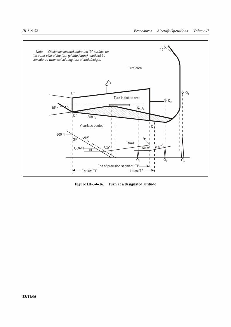
III-3-6-32 Procedures — Aircraft Operations — Volume II
23/11/06
Figure III-3-6-16. Turn at a designated altitude
15°
D"
D" 300 m
300 mGP GP'
15°
SOCTNA/H
50 m (164 ft)OCA/H HL
C
Note.— Obstacles located under the “Y” surface onthe outer side of the turn (shaded area) need not beconsidered when calculating turn altitude/height.
Turn area
Turn initiation area
Y surface contour
End of precision segment: TPLatest TPEarliest TP
O3
O1
O1
O2
O2
O4
O4

Part III — Section 3, Chapter 6 III-3-6-33
23/11/06
Figure III-3-6-17. Turn at designated TP (with TP fix)
D"
C
K
K
TP
D E
–900 m0
MOC
SOCHL
(OCA/H - HL)
OCA/H
GPGP'
earliest TP latest TP
fixtolerance
Note 1: d = d + shortest distance from obstacle to line K-K.
earliest TP
Note 2: Obstacles located under the “Y” surface (shaded area) need not be considered.
300 m Y surface contour
dz
o z

III-3-6-34 Procedures — Aircraft Operations — Volume II
23/11/06
Figure III-3-6-18. GBAS Cat I with offset azimuthfinal approach course alignment
___________________
Course widthD
Angle of full scale deflection = tan-1
Runway
Course widthFTP
D
GARP
FPAP
305 m
D = distance FTP – GARP

III-3-7-1 23/11/06
Chapter 7
HOLDING PROCEDURES
7.1 GENERAL
7.1.1 This chapter contains the criteria for RNAV holding procedures. Aircraft equipped with RNAV systemshave the flexibility to hold on tracks which are defined by the RNAV equipment and to use procedures which are lessrigid than those used in conventional holdings. The benefits of using this technique include the optimum utilization ofairspace with regard to the siting and alignment of holding areas as well as, under certain circumstances, a reduction ofholding area airspace.
7.1.2 Flight management systems are normally controlled through a navigation database.
7.1.3 Location and number of holding patterns. To avoid congestion only one holding pattern should beestablished for each procedure. The normal location would be at one of the IAFs. RNAV holding waypoints shall belocated so that they are referenced to and verifiable from specified radio navigation facilities. The holding waypoint(MAHF) is a fly-over waypoint.
7.2 TYPES OF RNAV HOLDING FOR VOR/DME, DME/DME ANDGNSS PROCEDURES
7.2.1 The following three types of RNAV holding may be established:
a) one waypoint RNAV holding;
b) two waypoint RNAV holding; and
c) area holding.
The criteria contained in Part I, Section 4, Chapter 3, Appendix C for conventional holding using an outbound legdefined by distance apply as modified by the criteria listed under each holding type.
7.2.2 One waypoint RNAV holding(See Figure III-3-7-1 a))
a) It is assumed that the RNAV system is able to compensate for the effect of a wind coming from the outside ofthe outbound turn by a reduction of the bank angle.
b) The length of the outbound leg of the holding pattern is at least equal to one diameter of turn.
c) It is assumed that the RNAV system is able to correct the drift on straight segments.

III-3-7-2 Procedures — Aircraft Operations — Volume II
23/11/06
d) No heading tolerance is taken into account on the straight segments.
7.2.3 Two waypoint RNAV holding. This type of holding is similar to one waypoint RNAV holding with theaddition of a second waypoint to define the end of the outbound leg (see Figure III-3-7-1 b)). Inclusion of this secondwaypoint results in a reduction in required airspace by:
a) reducing the basic protection area; and
b) reducing the omnidirectional entry protection areas.
Note.— Flight management systems designed only for single waypoint holding procedures will normally requiresoftware modifications to cater for two waypoint holding procedures. Procedure designers are advised that not allFMS will be so modified, and provision will always be required for aircraft with unmodified systems.
7.2.4 Area holding. This type of holding provides a circular area, centred on a designated waypoint, large enoughto contain a standard racetrack holding pattern in any orientation. (See Figure III-3-7-1 c).)
7.3 ENTRY PROCEDURES FOR VOR/DME, DME/DME ANDGNSS PROCEDURES
7.3.1 One waypoint RNAV holding
Entry procedures to one waypoint RNAV holding shall be the same as those used for conventional holding.
7.3.2 Two waypoint RNAV holding
The line passing through the two waypoints divides the area into two sectors. An entry from a given sector shall bemade through the corresponding waypoint. After passing the waypoint, the aircraft shall turn to follow the procedure.(See Figure III-3-7-2.)
7.3.3 Area holding
Any entry procedure which is contained within the given area is permissible.
7.4 FIX TOLERANCE
7.4.1 Fix tolerance depends on the sensors on which the holding procedure is based. DME/DME and GNSS fixtolerance are described in Section 1, Chapter 3, 3.5 and Chapter 2, 2.5 respectively. For RNP procedures the fixtolerance does not apply in the design of the procedure. For VOR/DME fix tolerance the following two paragraphsapply.
7.4.2 Fix tolerance — one waypoint and two waypoint holding. The waypoint tolerances for the construction ofone waypoint and two waypoint fix tolerance areas (VT, DT, AVT, ADT) are calculated as shown in Section 1,Chapter 4, 4.5, “XTT and ATT”. (See also Figure III-3-7-3.)

Part III — Section 3, Chapter 7 III-3-7-3
23/11/06
7.4.3 Fix tolerance — area holding. In order to achieve a circular holding area it is necessary to construct acircular waypoint fix tolerance area centred on the holding waypoint. The radius (Rt) of this tolerance area is given by:
Rt = max(DTT, D sin )
where: = VOR system use accuracyDTT = DME system use accuracyD = distance from holding waypoint to VOR/DME.
(See Figure III-3-7-3.)
7.5 HOLDING AREA CONSTRUCTION FOR VOR/DME,DME/DME AND GNSS PROCEDURES
7.5.1 One waypoint holding area
The holding area is constructed by applying the basic holding area, defined in Part II, Section 4, Chapter 1,“Construction of holding areas” to the waypoint tolerance area.
7.5.2 Details of protection area construction (one waypoint holding area)
7.5.2.1 General. The general criteria described in 3.3, “Protection area of racetrack and holding procedures” ofPart I, Section 4, Chapter 3, Appendix C, “Initial approach segment” apply as modified by the criteria in this paragraph.The criteria are broken down into the following three steps:
a) construction of the RNAV template;
b) basic area construction; and
c) construction of entry area.
7.5.2.2 Step one — Construction of the RNAV template. Construct the RNAV template using the followingguidelines (see Figure III-3-7-4 as an example):
a) choose the outbound distance: D is the length of the outbound leg; D shall be at least equal to one diameter ofturn) rounded to the next higher km (NM);
b) draw the nominal trajectory; locate point “i” at the end of the outbound leg;
c) draw the protection of a turn of more than 180° as for a conventional template (see Diagram I-4-3-App C-6 inPart I, Section 4, Chapter 3, Appendix C);
d) draw a parallel to the outbound track tangent to line (2);
e) from “i”, draw a perpendicular to the outbound track;
f) lines (3) and (4) intercept at i1;
g) place conventional template point “a” on “i”, then on “i1”, with axis parallel to the outbound leg and, in bothcases, draw the protection of a turn of more than 180°; draw the tangent T to these protections;

III-3-7-4 Procedures — Aircraft Operations — Volume II
23/11/06
h) draw the tangent T1 between line (6) and line (2);
i) draw the tangent T2 between line (2) and (6); and
j) locate point E on the template (see Part I, Section 4, Chapter 3, Appendix C, 3.3.2.2.4.7) and use the followingformulas for XE and YE (which are different from those in Part I, Section 4, Chapter 3, Appendix C,3.3.2.2.4.7):
(See Figures III-3-7-5 a) and III-3-7-5 b).)
XE = 2r + D + 11v +90 105
11 + 11 W'R R
� + + ��
YE = 11v.cos 20° + r.sin 20° + r +20 90 15
11 + 11 W'R R R
� + + + ��
7.5.2.3 Step two — Construction of the basic area (one waypoint holding case).
7.5.2.3.1 Holding point tolerance area. Draw around holding point A the RNAV fix tolerance associated with thispoint.
7.5.2.3.2 Construction of the basic area. (See Figure III-3-7-6). Move the RNAV template origin “a” around theRNAV tolerance area of the holding point “A”.
7.5.2.4 Step three—Construction of the entry area (See Figure III-3-7-7). Draw the circle centred on “A” passingthrough A1 and A3; apply the same method as explained in Part I, Section 4, Chapter 3, Appendix C, 3.3.3.2.
7.5.3 Two waypoint holding area
The holding area is constructed by applying the techniques of Part II, Section 4, Chapter 1, “Construction of holdingareas” to each waypoint as if it were a holding fix. The techniques of Part II, Section 4, Chapter 1, are used until theoutbound turn from each waypoint is protected. These protection curves are then joined by their common tangents andthe area thus enclosed is the holding area. The protection required for the entry manoeuvre is described by the areaenclosed by wind spirals applied successively to the most penalistic points of the waypoint tolerance area and thecommon tangents to those spirals.
7.5.4 Area holding
The holding area shall contain the basic holding protection area rotated about the waypoint fix tolerance area describedin 7.4.3. (See Figures III-3-7-1 c) and III-3-7-3.)
7.6 HOLDING AREA CONSTRUCTION FOR RNP
7.6.1 Parameters that define the maximum RNP holding pattern
The maximum RNP holding pattern is defined by:

Part III — Section 3, Chapter 7 III-3-7-5
23/11/06
a) a holding waypoint in WGS-84 latitude and longitude;
b) a minimum and maximum altitude;
c) a maximum holding indicated airspeed;
d) an inbound track to the holding fix;
e) length (d1) of the inbound track;
f) diameter of turn (d2);
g) the RNP value (d3); and
h) the distance (d4) used to draw the protection limit for sector 4 entries.
See Figures III-3-7-8 and III-3-7-9.
7.6.2 Diameter of turn
The diameter of turn (d2) is defined as that which can be followed throughout the turn at the defined IAS at ISA + 15°,taking into account:
a) the maximum wind speed (w) at the maximum holding altitude, assumed to be a tail wind throughout the turn;and
b) a defined bank angle (α = 23° for FL < 245 and 15° for FL > 245).
(TAS + w)2
d2 =34313 tan
d2 in NM; TAS and w in kt
(TAS + w)2
d2 =63547 tan
d2 in km; TAS and w in km/h
7.6.3 RNP holding plus Sector 4 entries limit
The RNP “holding plus sector 4 entries” limit results from combining the RNP holding pattern with the sector 4protection limit (see Figure III-3-7-8).
This distance (d4) is used to draw the protection limit for sector 4 entries and is calculated using the formula:
( )d2 1– sin �d4 =
2 cos �
Where � is equal to 20°, defined as the perpendicular to the inbound track
See the Appendix for the definition of RNAV sectors.

III-3-7-6 Procedures — Aircraft Operations — Volume II
23/11/06
7.6.4 Obstacle clearance
7.7.1.1 RNP holding area. The holding area includes the basic RNP holding area and the additional protection forentries from Sector 4 (see above). Holding area protection (See Figure III-3-7-9) consists of two parts: primary area andbuffer area. These are applied to the maximum track defined in Figure III-3-7-8 as described below.
a) Primary area. On the straight segments, a value (d3) equal to the RNP is applied around the maximum track.On curved segments, a value of √2 RNP is applied.
b) Buffer area. A buffer area is applied to the outside of the primary area. The width of the buffer area is thegreater of the following values:
XTT + 3.70 km (2.00 NM)9.26 km (5.00 NM)
On the curved segments, the criteria in Chapter 8, 8.1.6, “Controlled turn (for RNP 1 routes)” are applied. Obstacleclearance and buffer areas shall be provided as described in Part II, Section 4, Chapter 1, 1.3.12, “Obstacle clearance”.

Part III — Section 3, Chapter 7 III-3-7-7
23/11/06
Figure III-3-7-1. Types of RNAV holding procedures
Waypoint Waypoint A
Waypoint B
VOR/DME
VOR/DME
VOR/DME
A. One waypoint RNAV holding B. Two waypoint RNAV holding
Holdingwaypoin t
Waypointtolerance area
C. RNAV area holding

III-3-7-8 Procedures — Aircraft Operations — Volume II
23/11/06
Figure III-3-7-2. Sector construction for two waypoint RNAV holding
Waypoint A
Waypoint B
Sector B
Sector A
D. Entry sectors for twowaypoint RNAV holding

Part III — Section 3, Chapter 7 III-3-7-9
23/11/06
Figure III-3-7-3. Construction of waypoint tolerance areas
α°
���
���
α
������
�
�

III-3-7-10 Procedures — Aircraft Operations — Volume II
23/11/06
Figure III-3-7-4. RNAV template
0 1 2 3 4 5 6
0 1 2 3
km
NMD
A
T2
(3)
6
T
6T1
an3
(4)
i2(1)
(2)
g ho
p
c b
d
e
f
B
i1
i
+
E
Scale
distance D
Altitude: 3 050 m (10 000 ft)IAS: 405 km/h (220 kt)Outbound distance: 7.7 km (4.2 NM)

Part III — Section 3, Chapter 7 III-3-7-11
23/11/06
Figure III-3-7-5 a). RNAV holding: XE calculation
r D 11 s rwind effect from
a to E max
B
D
A
11 s
C
15°E max
a

III-3-7-12 Procedures — Aircraft Operations — Volume II
23/11/06
Figure III-3-7-5 b). RNAV holding: YE calculation
70°
20°
B
A a
11.v.cos 20°
r.sin 20°
wind effect froma to E max
15°
r
D
E max

Part III — Section 3, Chapter 7 III-3-7-13
23/11/06
Figure III-3-7-6. RNAV basic area
A
RNAV tolerance ofthe holding point

III-3-7-14 Procedures — Aircraft Operations — Volume II
23/11/06
Figure III-3-7-7. RNAV holding area including protection of entry procedures
A
RNAV tolerance ofthe holding point

Part III — Section 3, Chapter 7 III-3-7-15
23/11/06
Figure III-3-7-8. Maximum track of an RNP holding
Figure III-3-7-9. RNP holding area — obstacle clearance area
— — — — — — — —
d4d2
d1
Hold waypoint Inbound track
Buffer area width =
Greater of:XTT + 3.7 km (2.0 NM)
9.3 km (5.0 NM)
d = RNP = X3
d1
d4
d2
Holding area
1.414 XTT( = 1.414 d )3
Holdwaypoint

III-3-7-App-1 23/11/06
Appendix to Chapter 7
EXAMPLE OF ALTERNATIVE AREA NAVIGATION (RNAV)HOLDING ENTRIES FOR REDUCED HOLDING ENTRY AREAS
1.1 INTRODUCTION
1.1.1 Conventional entries described in Part II, Section 4, Chapter 1 are based on the fact that for VOR or NDBprocedures, it is necessary to overfly the station or holding fix at the beginning of the entry. This requires additionalprotection for entry procedures with these types of holdings.
1.1.2 With a suitable RNAV system, it is no longer necessary to overfly the station or holding waypoint. ThisAttachment gives an example of alternative entries which are less ‘‘space consuming’’ than the conventional ones. Thismaterial is presented for the purpose of information to manufacturers. A date for operational use will be established inthe future.
1.2 DEFINING THE ENTRY SECTORS
a) Draw the outline of the holding pattern (see Figure III-3-7-App-1); and
b) draw a line making an angle of 70° with the axis of the inbound leg through the holding waypoint.
These two lines divide the space into four sectors: (1, 2, 3 and 4) as shown.

III-3-7-App-2 Procedures — Aircraft Operations — Volume II
23/11/06
Figure III-3-7-App-1. Entry sectors
— — — — — — — —
1
2 3
470°
A
(C1) (C2)

III-3-8-1 23/11/06
Chapter 8
EN-ROUTE PROCEDURES
8.1 GENERAL
8.1.1 Application
The criteria assume the use of any kind of sensor (such as VOR/DME, DME/DME, etc.). The general criteria of Part II,Section 3, “Enroute criteria” apply with the following modification: on the straight segments, the area has a constantwidth (angular limits do not apply).
Note.— For RNP applicable to the en-route phase of flight, see the Manual on Required Navigation Performance(RNP) (Doc 9613).
8.1.2 Standard conditions
8.1.2.1 RNAV procedures. The standard assumptions for RNAV systems which are not RNP-approved are that theRNAV system must be approved for the en-route phase and must comply with the navigation accuracy to followconventional routes (VOR, NDB).
8.1.2.2 RNP procedures. The standard assumptions on which RNP en-route procedures are developed are:
a) the fix tolerance area of the waypoint is a circle of radius equal to the en-route RNP;
b) the system provides information which the pilot monitors and uses to keep the FTT within the limits set duringsystem certification; and
c) en-route procedures are normally based on RNP 4 or higher. Where necessary and appropriate, they may bebased on RNP 1.
8.1.3 Secondary areas
For areas based on RNP criteria, the general principle of secondary areas is applied. For RNAV procedures, the criteriaof Part II, Section 3, “Enroute criteria” apply.
8.1.4 Definition of turns
Two kinds of enroute turns are specified:
a) the turn at a fly-by waypoint;
b) the controlled turn (for RNP 1 routes only).

III-3-8-2 Procedures — Aircraft Operations — Volume II
23/11/06
8.1.5 Turn at a fly-by waypoint
8.1.5.1 General
8.1.5.1.1 A turn at a fly-by waypoint takes into account turn anticipation by adding a distance rtan (A/2) beforethe waypoint. This determines point S (see Figure III-3-8-1). The earliest turning point (K-line) is located at a distanceATT before point S.
8.1.5.1.2 The criteria for the straight segment (RNAV and RNP) apply until:
a) a distance of ATT + c after point S for the outer side of the turn; and
b) the earliest TP (a distance of ATT before point S) for the inner side of the turn;
where c is a distance corresponding to a 10-second pilot reaction time.
8.1.5.2 Turn outer boundary
8.1.5.2.1 On the outside of the turn, turn construction starts from the limits of the primary area at the followingdistance before the waypoint:
a) rtan (A/2) – ATT – c for turn angles less than or equal to 90 degrees; and
b) r –ATT–c for turn angles more than 90 degrees;
where c is a distance corresponding to a 10-second pilot reaction timer is the radius of the turn
8.1.5.2.2 From these points wind spirals or bounding circles are constructed as described in Part I, Section 2,Chapter 3, “Turn area construction”.
8.1.5.2.3 Additionally, in order to protect the aircraft within the required range of speeds, the outer limit of theprimary area is extended until it intersects with that tangent of the wind spiral (or bounding circle) which is parallel tothe nominal track after the turn.
8.1.5.2.4 The secondary area has a constant width during the turn.
8.1.5.3 Turn inner boundary
8.1.5.3.1 On the inner edge of the turn, the primary area boundary starts at the earliest TP (K-line), and makes anangle of half the angle of turn (A/2) with the nominal track after the turn.
8.1.5.3.2 If this boundary does not connect to the boundary of the next segment, the area boundaries make anangle of 15 degrees splay with the nominal track of the next segment.
8.1.6 Controlled turn (for RNP 1 routes)
8.1.6.1 This paragraph only applies to RNP. The radius of a controlled (fixed radius) turn for RNP 1 routes isequal to:

Part III — Section 3, Chapter 8 III-3-8-3
23/11/06
a) 28 km (15 NM) at and below FL 190; and
b) 41.7 km (22.5 NM) at and above FL 200.
See Annex 11, Appendix 1, 2.4.
8.1.6.2 Turn boundary construction
Fixed radius turns are constructed by first delimiting the edges of the primary area, and then adding a secondary area toboth sides (see Figure III-3-8-2).
a) Outer boundary of the primary area. The outer edge of the primary area is defined by the segment of a circle:
1) centred on point O;
2) having the radius r + [ATT + 1.9 km (1.0 NM)] / cos 45]; and
3) delimited by the edges of the adjacent straight segments (points J and M).
b) Inner boundary of the primary area. The inner edge of the primary area is defined by the segment of a circle:
1) having the radius r;
2) centred on point I at a distance of [ATT +1.9 km (1.0 NM)] / cos 45] from the centre of the turn (point O);and
3) delimited by the edges of the adjacent straight segments (points P and R).
c) Secondary areas within the turn. Secondary areas are added to edges of the primary area to establish the turnouter and inner boundaries. The secondary areas maintain a constant width of ATT + 1.9 km (1.0 NM).

III-3-8-4 Procedures — Aircraft Operations — Volume II
23/11/06
Figure III-3-8-1. Turn at a fly-by waypoint
r
CATT
Fly-by waypoint
Wind spiral
K'
S
r
A
A/2
30°
Constant width(A/W)
S = start of nominal turnr = radius of turnc = 10 s (en-route pilot reaction time)
K

Part III — Section 3, Chapter 8 III-3-8-5
23/11/06
Figure III-3-8-2. Obstacle clearance area associated with a controlled turn___________________
X + 1.9 km (1.0 NM)
X + 1.9 km (1.0 NM)
X
S
P
Y/2
Y
O
I
X = RNP
R
M
K
L
J

III-4-(i)
Section 4
QUALITY ASSURANCE
(To be developed)

III-5-(i)
Section 5
PUBLICATION

III-5-1-1 23/11/06
Chapter 1
RNAV DATABASE PATH TERMINATOR CONCEPT
RNAV procedure designers should use the following aviation industry guidelines:
a) every route segment should proceed from a waypoint to a waypoint;
b) avoid large angle changes (greater than 90°) ;
c) do not use conditional transitions, such as “climb to XXXX feet by an XX DME”, or “at XX DME but notbelow XXXX feet, turn right direct to (waypoint)”;
d) procedures should be developed in such a way that they can easily and properly be coded into the appropriatepath terminator and route type;
e) all details of any specific restrictions applied to a procedure shall be published; and
f) procedure textual description should comply with the applicable path terminator as shown below:
Published procedure description Path terminator used Path terminator meaning
From (navaid to waypoint) IF Initial fix
To (point) on track XXX° CF Course to fix
Direct to (waypoint) DF Direct to fix
To (waypoint) TF Track to fix
Via (fixed radius) left/right turn to (waypoint,centred on latitude/longitude, radius in NM)*
RF Radius to fix
From (waypoint) to (altitude/flight level) ontrack XXX°
FA Fix to altitude (climb)
* This particular leg type has not been fully implemented. It will likely be used in RNP but not RNAV procedures.
___________________

III-5-2-1 23/11/06
Chapter 2
WAYPOINT NAMES
(To be developed)
___________________

III-5-3-1 23/11/06
Chapter 3
PROCEDURE NAMING
3.1 GENERAL
The criteria of Part I, Section 4, Chapter 9, “Charting/AIP” apply as modified by the contents of this chapter.
3.2 RNAV DEPARTURES
3.2.1 For RNAV departures, a text description shall be published clearly stating the intent and requirements of theprocedure. (This is to ensure that database coding will be executed correctly.) For an example of appropriate textualdescription, see Figure III-5-3-1.
Note.— Unless otherwise stated, all waypoints are fly-by waypoints.
3.2.2 RNAV departure charts shall include the term RNAV in the title. If the departure routes are restricted tospecific sensor types, these radio navigation aid types shall be included, in subscript parentheses, in the title. Forexample:
RNAV (GNSS , DME/DME) STANDARD INSTRUMENT DEPARTURES
Note.— The sensor does not form part of the ATC clearance.
3.2.3 Separate charts should only be published if the routes differ laterally or vertically. When operationallyrequired, separate charts may be published for each sensor or for a combination of sensors.
3.2.4 RNP departures shall include the term RNAV in the title, for example: RNAV STANDARD INSTRUMENTDEPARTURES. The RNP value shall be published on the chart either above each leg of the procedure or, if the sameRNP value applies to all legs, as a single text block, for example: “RNP 1 required for all procedures”.
3.3 RNAV ARRIVALS
3.3.1 RNAV arrivals shall include the word RNAV in the title. If the routes are restricted to specific sensor types,these radio navigation aid types shall be included, in subscript parentheses, in the title. For example:
RNAV (GNSS , DME/DME) STAR
Note. — The sensor does not form part of the ATC clearance.
3.3.2 Separate charts should only be published if the routes differ laterally or vertically. When operationallyrequired, separate charts may be published for each sensor or for a combination of sensors.

III-5-3-2 Procedures — Aircraft Operations — Volume II
23/11/06
3.3.3 RNP arrivals shall include the word RNAV in the title, for example:
RNAV STAR
3.3.4 The RNP value shall be published on the chart either above each leg of the procedure or, if the same RNPvalue applies to all legs, as a single text block, for example: RNP 1 required for all procedures.
3.4 RNAV APPROACH
3.4.1 RNAV approaches shall be identified by the term RNAV in the title. The radio navigation aid upon whichthe approach procedure is based shall be included, in subscript parentheses, in the title, for example:
RNAV (GNSS) Rwy 20 or RNAV (GNSS CLASS B and C only) Rwy 20
Note.— The sensor does not form part of the ATC clearance.
3.4.2 The minimum box on the chart shall include OCA/H values for each applicable navigation type.
3.4.3 RNP approaches shall include the term RNAV in the title, for example:
RNAV Rwy 36L.
The minimum box on the chart shall include OCA/H values for each applicable RNP value.
Figure III-5-3-1. Text description
___________________
LU001
LU007
183°
MTL
009°
(Departure): Climb on runway axis. At the LU007 flyover waypoint, turn left towards the LU001fly-by waypoint and join the route LU001/MTL.

IV-(i)
Procedures forAir Navigation Services
AIRCRAFT OPERATIONS
Part IV
HELICOPTERS

IV-1-1 23/11/06
Chapter 1
AREA NAVIGATION (RNAV) POINT-IN-SPACE (PinS)APPROACH PROCEDURES FOR HELICOPTERS
USING BASIC GNSS RECEIVERS
1.1 GENERAL
1.1.1 The general criteria in Part I, Section 4, as well as Part III, Section 2, Chapter 2, as amplified or modified bythe criteria in this chapter apply to area navigation (RNAV) approach procedures for basic GNSS receivers. Thesespecified instrument procedures may be developed for the use of helicopters. It is intended that these specifiedprocedures be designed using the same conventional techniques and practices for aeroplane categories as thoseexplained elsewhere in this document.
1.1.2 Helicopter specific parameters. Parameters such as airspeed, fix tolerances, area widths and descent andclimb gradients are specified in this chapter for exclusive use in designing helicopter procedures. These specificationshave been defined in accordance with the helicopter performance characteristics and the operational requirements toperform the procedure.
1.1.3 Approach speeds. When the helicopter reaches the obstacle clearance altitude/height (OCA/H), it must havea sufficient distance to decelerate and transition to flight by visual reference. The greater the approach speed on final,the larger the required deceleration distance. Criteria are provided in this chapter to accommodate helicopters flying thefinal and missed approach segments at speeds not to exceed 90 KIAS and for those flying the final and missedapproach segments at speeds not to exceed 70 KIAS. The missed approach airspeed limitation applies until thehelicopter is established on the inbound course to the missed approach holding waypoint or clearance limit.
1.1.4 Fix identification. Part III, Section 1, Chapter 1, 1.1, “Fix identification” applies.
1.1.5 Secondary areas. The general criteria for secondary areas apply as modified or amplified in this chapter.
1.1.6 Certification/operational approval. The aircraft equipped with a basic GNSS receiver as described in PartIII, Section 1, Chapter 2, that have been approved by the national authority for the operator for the appropriate level ofGNSS operations may use these systems to carry out approaches.
1.2 GNSS RNAV SYSTEM ACCURACY
1.2.1 The criteria in Part III, Section 1, Chapter 2, apply as modified or amplified in this chapter. The total systemtolerance components are listed in Table IV-1-1.

IV-1-2 Procedures — Aircraft Operations — Volume II
23/11/06
1.3 ARRIVAL ROUTES
1.3.1 The provisions of Part III, Chapter 3 apply, using an area semi-width of 14.82 km (8.00 NM) if the IAF ismore than 55.56 km (30.00 NM) from the PRP or 4.63 km (2.50 NM) if the IAF is less than 55.56 km (30.00 NM) fromPRP. See Figure IV-1-1 for arrival routes and initial approach segment widths.
1.3.2 Minimum sector altitude/terminal arrival altitude. For the application of the minimum sector altitude, theprovisions of Part III, Chapter 9 apply except that only a single omnidirectional sector shall be established. The sectoris centered on the PRP/MAPt. The PRP/MAPt must be provided in the database as the reference point serving the samepurpose as the ARP in approaches to aerodromes. For the application of the terminal area altitude the provisions of PartIII, Section 2, Chapter 4 apply.
1.4 TERMINAL CRITERIA
1.4.1 Approach configuration. The basic T/Y approach configuration affords flexibility and standardization ofprocedure design and should therefore be considered as the first option in procedure design.
1.4.2 Holding. For holding patterns, the track specified for the inbound leg should be the same as the track for theinitial segment if the holding fix is the IAF or the intermediate segment if the holding fix is the IF. The track for theinbound leg should not differ from the initial or the intermediate track, as appropriate, by more than 30º.
1.4.3 The initial and intermediate segments have minimum lengths to accommodate turn distance/minimumstabilization distance (MSD). The length of the turning component is the minimum stabilization distance for the angleturn at the IAF and IF can be determined from the formulas in Part III, Section 2, Chapter 1.
1.4.4 The outer boundary of turn areas is designed using a wind spiral or a bounding circle derived by applying anomnidirectional wind to the ideal flight path. On the outer edge of the turn, and after the turn in the case of anovershoot, wind spirals are constructed from the limits of the primary area, based on the parameters of Part I, Section 4,Chapter 3, 3.6.2 a) through g), and at a distance equal to: [min(r, r tan( �/2)) - ATT - d(s)] before the waypoint.Additionally, in order to protect the aircraft within the required range of speeds, the outer limit of the primary area isexpanded as shown in Figure IV-1-2, and a constant secondary area is applied during the turn.
1.5 INITIAL APPROACH SEGMENT
1.5.1 The initial approach segment begins at the IAF and ends at the IF.
1.5.2 Alignment. The initial track shall not differ from the intermediate segment track by more than 120°.
1.5.3 Area. See Figure IV-1-2 for the areas of initial, intermediate and final approach segments.
1.5.3.1 Length. The initial approach segment should not exceed 18.52 km (10.00 NM), unless operationalrequirements make a longer segment necessary. Construct the IAF within 46.30 km (25.00 NM) of the PRP. Theminimum length is governed by the magnitude of the turn required at the IAF. The initial approach segment is designedfor helicopters flying the procedure at speeds up to 220 km/h (120 KIAS). Where an operational requirement exists, thesegment may be designed for an airspeed not exceeding 165 km/h (90 KIAS), in which case the approach plate will beannotated “Speed limited to 165 km/h (90 KIAS)”.

Part IV — Chapter 1 IV-1-3
23/11/06
1.5.3.2 Area width. The area semi-width is 14.82 km (8.00 NM) for regions where the nominal track is more than55.56 km (30.00 NM) from the PRP and 4.63 km (2.50 NM) for regions where the nominal track is equal to or less than55.56 km (30.00 NM) from PRP. The area boundaries converge at an angle of 30º to the track beginning at the pointwhere the nominal track crosses within 55.56 km (30.00 NM) of the PRP and continuing until reaching ±4.63 km(2.50 NM).
1.5.4 Obstacle clearance. The area considered for obstacle clearance extends from the earliest IAF to the nominalposition of IF. The general criteria for obstacle clearance applies, see Part I, Section 4, Chapter 3, 3.3.4. Obstacleclearance required in the primary area is 300 m (1 000 ft), tapering uniformly to zero from the edge of the primary areato the outer edge of the secondary area.
1.5.5 Descent gradient. Optimum descent gradient is 6.5 per cent (400 ft/NM). Where a higher descent gradient isrequired, the recommended maximum is 10 per cent (600 ft/NM); however, where an operational requirement exists, agradient of as much as 13.2 per cent (800 ft/NM) may be authorized, provided the gradient used is depicted onapproach charts.
1.6 INTERMEDIATE APPROACH SEGMENT
1.6.1 The intermediate segment begins at the IF and ends at the FAF. A fly-by waypoint is recommended at the IFunless an operational imperative exists to use a flyover waypoint.
Note.— The FAF is always defined by a fly-by waypoint, even if there is no turn over the FAF.
1.6.2 The intermediate approach segment should be aligned with the final approach segment. If a turn at the FAFis necessary, it shall not exceed 60°.
1.6.3 Area. See Figure IV-1-3, Intermediate and final segments.
1.6.3.1 Length. The optimum length is 5.56 km (3.00 NM). It shall not be less than 3.70 km (2.00 NM), and shallnot exceed 18.52 km (10.00 NM). The minimum length is governed by the magnitude of the turn required at the IF.The intermediate approach segment is designed for helicopters flying the procedure at speeds up to 220 km/h (120KIAS). Where an operational requirement exists, the segment may be designed for an airspeed not exceeding 165 km/h(90 KIAS), in which case the approach plate will be annotated “Speed limited to 165 km/h (90 KIAS)”.
1.6.3.2 Width. The area width is formed by joining the boundaries of the initial area of the IF and the final area atthe nominal FAF.
1.6.4 Obstacle clearance. The area considered for obstacle clearance extends from the earliest IF to the nominalposition of FAF. The general criteria for obstacle clearance applies, see Part I, Section 4, Chapter 4, 4.3.2, “Obstacleclearance”. The obstacle clearance in the primary area is 150 m (492 ft), tapering uniformly to zero from the edge ofthe primary area to the outer edge of the secondary area.
1.6.5 Descent gradient. Because the intermediate approach segment is used to prepare the aircraft speed andconfiguration for entry into the final approach segment, this segment should be flat. If a descent gradient is necessary,the maximum permissible gradient will be 10 per cent (600 ft/NM). When an operational requirement exists, a gradientof as much as 13.2 per cent (800 ft/NM) may be authorized, provided the gradient used is depicted on approach charts.The descent gradient should be calculated in accordance with Part III, Section 2, Chapter 3, 3.3.3, “Descent gradient”.

IV-1-4 Procedures — Aircraft Operations — Volume II
23/11/06
1.7 FINAL APPROACH SEGMENT
1.7.1 The final approach segment begins at the FAF (fly-by) and ends at the MAPt (flyover). All approaches willbe to a point in space where the pilot should have sufficient visual reference to continue the approach and landing to theintended landing site or initiate a missed approach.
1.7.2 Alignment. For point-in-space approaches there are no alignment requirements in the final approachsegment.
1.7.3 Area. See Figure IV-1-3.
1.7.3.1 The area considered for obstacle clearance begins at the earliest FAF position and ends at the nominalposition of the MAPt.
1.7.3.2 Length. The optimum length is 5.92 km (3.20 NM). The minimum length is governed by the magnitude ofthe turn required at the FAF. Procedures are normally designed for helicopters flying the approach up to 130 km/h (70KIAS). For specific cases, where the final may be designed to accommodate speeds up to 165 km/h (90 KIAS), themissed approach must also be designed to accommodate 165 km/h (90 KIAS). The maximum speed for which the finaland missed approach segments are designed must be clearly annotated on the approach chart.
1.7.3.3 Width. The area semi-width begins at 1.85 km (1.00 NM) at the nominal position of the FAF and tapers to1.67 km (0.90 NM) at the nominal position of the MAPt. For procedures designed to accommodate 165 km/h (90KIAS) final approach speed the area semi-width begins at ± 2.23 km (1.20 NM) at the nominal FAF and reaches ± 2.04km (1.10 NM) at the nominal position of MAPt.
Note.— The width of the area semi-width at the MAPt is slightly greater than the one corresponding to the fixed-wing GNSS criteria as the maximum authorized angle at the FAF is 60° instead of 30°.
1.7.4 Obstacle Clearance. Primary area minimum obstacle clearance (MOC) is 75 metres (246 ft) taperinguniformly to zero from the edge of the primary area to the outer edge of the secondary area.
1.7.5 Descent gradient. Optimum descent gradient is 6.5 per cent (400 ft/NM). Where a higher descent gradient isnecessary, the recommended maximum is 10 per cent (600 ft/NM). However, where an operational imperative exists,and the magnitude of turn at the FAF is less than or equal to 30°, a gradient of as much as 13.2 per cent (800 ft/NM)may be authorized, provided the gradient used is depicted on approach charts. The final segment gradient is calculatedfrom the FAF altitude at the plotted position of the FAF to the OCA/H at the plotted position of the MAPt.
1.8 MISSED APPROACH SEGMENT
1.8.1 General. The missed approach segment begins at the earliest MAPt (flyover) position and ends at a holdingpoint designated by an MAHF (flyover) or to a clearance limit. Optimum routing is straight ahead to a direct entry intoholding at the MAHF.
1.8.2 Longitudinal tolerance of the MAPt. The longitudinal tolerance of the MAPt will be calculated as describedat Part I, Section 4, Chapter 6, 6.1.6.2.1, “MAPt tolerance when MAPt defined by a navigational facility or fix”.
1.8.3 Calculation of start of climb (SOC). The SOC point will be calculated as described at Part I, Section 4,Chapter 6, 6.1.6.2, “Determining SOC with an MAPt defined by a navigation facility or fix”, except that the transitionaltolerance (X) is the distance a helicopter traverses during 5 seconds of flight at 130 km/h (70 KIAS) or 165 km/h (90KIAS) converted to TAS.

Part IV — Chapter 1 IV-1-5
23/11/06
1.8.4 Missed approach area. The missed approach area shall commence at the beginning of the MAPtlongitudinal tolerance at a width equal to the final approach area at that point. At that point, the area splays at 15° oneach side of the missed approach course, to account for the decrease in GNSS receiver display sensitivity from ± 0.56km (0.30 NM) to ± 1.85 km (1.00 NM) to a total width of ± 4.63 km (2.50 NM). If the first waypoint is reached prior tothe area reaching ± 4.63 km (2.50 NM) the splay continues to 4.63 km (2.50 NM). For missed approach procedureswith GNSS receivers which do not provide continuous track guidance after the MAPt see Figures IV-1-4 and IV-1-5.Turning missed approach with track specified to MAHF should be restricted to systems providing continuous trackguidance after the missed approach waypoint and the approach procedure should be clearly annotated. SeeFigure IV-1-6.
1.8.5 Straight missed approach. The criteria governing straight missed approach apply (see Part I, Section 4,Chapter 6, 6.3, “Straight missed approach”). Note also that track guidance is available for the missed approach by thenomination of a GNSS fix(es).
1.8.6 Turning missed approach. The turn calculations are based on the turn parameters in Part I, Section 4,Chapter 6, 6.4.2. The wind spiral or bounding circle is applied to the boundary of the primary area, and the outerboundary of the secondary area is constructed by applying a constant width area. For missed approach procedures withGNSS receivers which do not provide continuous track guidance after the MAPt, see Figures IV-1-4 and IV-1-5.Turning missed approach with track specified to MAHF should be restricted to systems providing continuous trackguidance after the missed approach waypoint and the approach procedure should be clearly annotated. SeeFigure IV-1-6.
1.8.6.1 Turn parameters.
1.8.6.1.1 Indicated airspeed. The speed for the final missed approach is 165 km/h (90 KIAS). However, whereoperationally required to avoid obstacles, reduced speeds as slow as 130 km/h (70 KIAS) may be used, provided theprocedure is annotated “Missed approach turn limited to 130 km/h (70 KIAS) maximum”.
1.8.6.1.2 Alignment. The maximum difference between the inbound track and outbound track at MATF is amaximum of 120º.
1.8.6.1.3 Length. Where an operational requirement exists to avoid obstacles, an MATF may be used. In this case,the MSD for the turn point must be applied after SOC. The minimum length after the turn is determined by the MSDrequired for the outbound segment. Refer to the method in Part III, Section 2, Chapter 1.
1.8.7 Climb gradient. The nominal climb gradient of the missed approach surface is 4.2 per cent (24:1). Highergradients may be considered with operational approval when an operational requirement exists. When a gradient otherthan the nominal gradient is used in the construction of the missed approach procedure the gradient required must beannotated on the instrument approach chart. In addition to the OCA/H for the specified gradient, the OCA/H applicableto the nominal gradient must also be shown.
1.8.8 The MOC is 40 m (130 ft) for turns exceeding 15°. (See Part I, Section 4, Chapter 6.)
1.9 PROMULGATION
1.9.1 Procedure identification. For helicopter point-in-space approaches, the title of the IAC should include thefinal approach course (three numeric characters); e.g., RNAV (GNSS) 036. If the approach is restricted to Class B andC receivers this shall be included in sub-script parentheses, in the title. For example:
RNAV (GNSS Class B &C only) 023

IV-1-6 Procedures — Aircraft Operations — Volume II
23/11/06
The term “CAT H” should be prominently displayed in the plan view but not be included in the title, and the minimumsshould include the term CAT H. The point-in-space approach procedures shall not be published on the same IAP chartas aeroplane (CAT A, B, C, D) and helicopter (CAT H) procedures to runways.
Note.— The sensor does not form part of the ATC clearance.
1.9.2 For point-in-space approaches annotated “Proceed visually from (MAPt)” any number of heliports may beserved by the procedure. Enter the heliport name(s), heliport elevation(s), and the bearing (to the nearest degree) anddistance (to the nearest two-tenths of a kilometer (tenth NM)) from MAPt to the Aerodrome Reference Point (ARP) ofthe heliport; e.g. MCCURTAIN MEMORIAL HOSPITAL, ELEV 693’, 123/3.2.
1.9.3 Speed limitation. The speed limitation must be clearly indicated on the published IAP chart. For example“The final and missed approach airspeed must not exceed xx KIAS”.
1.9.4 Descent gradient. Where an operational requirement exists, a gradient of as much as 13.2 per cent(800 ft/NM) may be authorized, provided that the gradient used is depicted on the approach chart.
Table IV-1-1. Total system tolerances and area semi-widths for basic GNSS receivers
IAF (1) �� 30 NM
fromPRP
IAF (2)< 30 NM
fromPRP
Fix ininitial
segment IF FAF MAPt
Fix in missedapproach or
departure< 30 NMfrom PRP
Fix in missedapproach or
departure� 30 NMfrom PRP
Navigation systemaccuracy (3)(km/NM)
0.23/0.12 0.23/0.12 0.23/0.12 0.23/0.12 0.23/0.12 0.23/0.12 0.23/0.12 0.23/0.12
Integrity monitor alarmlimit(km/NM)
3.70/2.00 1.85/1.00 1.85/1.00 1.85/1.00 0.56/0.30 0.56/0.30 1.85/1.00 3.70/2.00
Time to alarm 30 sec 10 sec 10 sec 10 sec 10 sec 10 sec 10 sec 30 sec
FTT(km/NM)
3.70/2.0 0.46/0.25 0.46/0.25 0.46/0.25 0.37/0.20 0.28/0.15 0.46/0.25 3.70/2.00
ATT(km/NM)
3.70/2.00 1.85/1.00 1.85/1.00 1.85/1.00 0.56/0.30 0.56/0.30 1.85/1.00 3.70/2.00
XTT(km/NM)
7.41/4.00 2.32/1.25 2.32/1.25 2.32/1.25 0.93/0.50 0.84/0.45 2.32/1.25 7.41/4.00
Area semi-width(km/NM)
14.82/8.00 4.63/2.50(4)
4.63/2.50(4)
4.63/2.50(4)
1.85/1.00(5)
1.67/0.90(4) (5)
4.63/2.50(4)
14.82/8.00(4)
ATT = integrity monitor alarm limit (IMAL)XTT = IMAL + FTTarea semi width = 2XTT
(1) IAF positioned outside 55.56 km (30.00 NM) radial distance from the destination point-in-space reference point (PRP).(2) IAF positioned within 55.56 km (30.00 NM) radial distance from the destination PRP.(3) Includes all system computation tolerances.(4) Based on helicopter flight trials and operational experience, which included turns onto the initial approach segment, the operational
assessment leads the use of 2XTT when using basic GNSS receivers.(5) For approach speeds greater than 130 km/h (70 KIAS) but less than or equal to 165 km/h (90 KIAS), the semi-width at FAF is 2.22 km
(1.20 NM), and the semi-width at the MAPt is 2.04 km (1.10 NM).

Part IV — Chapter 1 IV-1-7
23/11/06
Figure IV-1-1. Arrival routes, initial approach segment widths and fix tolerance
2.00 NM
3.70 km
8.00
NM
14.8
2km
1.00 NM
1.85 km
2.50
NM
4.63
km
2.50
NM
4.63
km
IF IAF� �30 NM 30 NM

IV-1-8 Procedures — Aircraft Operations — Volume II
23/11/06
Figure IV-1-2. Initial, intermediate and final approach segments
2.50 NM4.63 km
Early TP (d1)
K
K′
K′′
D
ATT
2.50
NM4.
63km
90°Bisector
Bisector30°
30°
1.00 NM1.85 km
Early TP (d1)
Late TP (d2)Wind spiral connecting tofollowing segment via a 30°line
0.90 NM
1.67 km
Wind spiral
Late TP (d2)
d1 = r tan (A/2) + ATTif turn < = 90°
d2 = r tan (A/2) ATT cif turn > 90°
d2 = r ATT cNote: If (d2) is negative,d2 is measured after the FIX
� �
� �
If 30°connection falls outsidefollowing segment outer edge,connect via a line direct toabeam fix
Perpendicular tobisector. If does notintercept followingsegment, connect toabeam fix.
D is defined bythe intersectionof bisector and radius r
K to K is at ATTdistance from D
K to K is at ATTdistance frombisector
′
′ ′′
Equidistant toprimary wind spiral
Parallel to inbound track
Parallel to outboard track

Part IV — Chapter 1 IV-1-9
23/11/06
Figure IV-1-3. Intermediate and final segments
2.50 NM4.63 km
1.8
5km
1.00
NM
1.00 NM
1.85 km
MAPt
0.90 NM
1.67 km
0.30
NM
0.56
km
FAF0.56
km
0.30
NM
IF

IV-1-10 Procedures — Aircraft Operations — Volume II
23/11/06
Figure IV-1-4. Turning missed approach
0.90 NM1.67 km
FAF
1.00 NM1.85 km
0.30 NM0.56 km
0.30 NM0.56 km MAPt
tolerance
c
Wind spiral
SOCMAPt
Earliest “nominal track”
Latest “nominal track”
15°
15°
2.50
NM
4.63
km
Turn at MAPtNote: No track specified to the MAHF
MAHF

Part IV — Chapter 1 IV-1-11
23/11/06
Figure IV-1-5. Turning missed approach with turn more than 90°
0.90 NM1.67 km
FAF
1.00 NM1.85 km
0.30 NM0.56 km
0.30 NM0.56 km
c
Wind spiral
MAPttoleranceMAPt
Earliest “nominal track”
Latest “nominal track”15°
15°
2.50N
M
4.63km
Turn at MAPtNote: No track specified to the MAHFTurning missed approach with turn more than 90°
MAHF
SOC

IV-1-12 Procedures — Aircraft Operations — Volume II
23/11/06
Figure IV-1-6. Turning missed approach with turn less than or equal to 90°
— END —
0.90 NM1.67 km
FAF
1.00 NM1.85 km
0.30 NM0.56 km
0.30 NM0.56 km MAPt
tolerance
c
Wind spiral
SOCMAPt
15°
15°
2.50
NM
2.50
NM
4.63
km
4.63
km
30°
MAHF
Track XXX°

ICAO TECHNICAL PUBLICATIONS
The following summary gives the status, and alsodescribes in general terms the contents of the variousseries of technical publications issued by theInternational Civil Aviation Organization. It does notinclude specialized publications that do not fallspecifically within one of the series, such as theAeronautical Chart Catalogue or the MeteorologicalTables for International Air Navigation.
International Standards and RecommendedPractices are adopted by the Council in accordance withArticles 54, 37 and 90 of the Convention onInternational Civil Aviation and are designated, forconvenience, as Annexes to the Convention. Theuniform application by Contracting States of thespecifications contained in the International Standards isrecognized as necessary for the safety or regularity ofinternational air navigation while the uniformapplication of the specifications in the RecommendedPractices is regarded as desirable in the interest ofsafety, regularity or efficiency of international airnavigation. Knowledge of any differences between thenational regulations or practices of a State and thoseestablished by an International Standard is essential tothe safety or regularity of international air navigation. Inthe event of non-compliance with an InternationalStandard, a State has, in fact, an obligation, underArticle 38 of the Convention, to notify the Council ofany differences. Knowledge of differences fromRecommended Practices may also be important for thesafety of air navigation and, although the Conventiondoes not impose any obligation with regard thereto, theCouncil has invited Contracting States to notify suchdifferences in addition to those relating to InternationalStandards.
Procedures for Air Navigation Services (PANS)are approved by the Council for worldwide application.They contain, for the most part, operating proceduresregarded as not yet having attained a sufficient degree of
maturity for adoption as International Standards andRecommended Practices, as well as material of a morepermanent character which is considered too detailed forincorporation in an Annex, or is susceptible to frequentamendment, for which the processes of the Conventionwould be too cumbersome.
Regional Supplementary Procedures (SUPPS)have a status similar to that of PANS in that they areapproved by the Council, but only for application in therespective regions. They are prepared in consolidatedform, since certain of the procedures apply tooverlapping regions or are common to two or moreregions.
The following publications are prepared by authorityof the Secretary General in accordance with theprinciples and policies approved by the Council.
Technical Manuals provide guidance andinformation in amplification of the InternationalStandards, Recommended Practices and PANS, theimplementation of which they are designed to facilitate.
Air Navigation Plans detail requirements forfacilities and services for international air navigation inthe respective ICAO Air Navigation Regions. They areprepared on the authority of the Secretary General onthe basis of recommendations of regional air navigationmeetings and of the Council action thereon. The plansare amended periodically to reflect changes inrequirements and in the status of implementation of therecommended facilities and services.
ICAO Circulars make available specializedinformation of interest to Contracting States. Thisincludes studies on technical subjects.

© ICAO 200610/06
Published by ICAO
Related Documents