ISSUED REVISED P.O. Box 90 Mobile Alabama 36601 251-436-8299 PAGE NO REVISION MO DAY YEAR MO DAY YEAR 1 of 16 H 06 13 94 07 27 2016 MSB94-4 ©2016 Continental Motors, Inc. CONTINENTAL MOTORS ® AIRCRAFT ENGINE MANDATORY SERVICE BULLETIN Subject Matter of This Document may be Incorporated, in Whole or in Part, in an FAA Issued Airworthiness Directive SUBJECT: STARTER ADAPTER SHAFTGEAR AND CRANKSHAFT GEAR INSPECTION PURPOSE: Since issuance of CSB94-4A, CM has investigated instances of damaged starter adapter shaft gear and crankshaft gear teeth where there was no record of previous compliance with CSB94-4 or later revision. CSB94-4D was reissued as a Mandatory Service Bulletin, MSB94-4E, in conjunction with the issuance of a FAA Airworthiness Directive to. This bulletin provides inspection and replacement procedures for the starter adapter assembly and crankshaft gear. These procedures are intended to preclude the possibility of a gear failure. Instructions are also provided for the replacement of needle bearing P/N 537721 with bushing P/N 654472. These required inspections must be continued on a repetitive basis until further notice. Service kits EQ 6642 (New) or EQ 6642R (Rebuilt) and bushing P/N 654472 are available at a special exchange price. Refer page 16 of this bulletin for special ordering instructions. WARNING Compliance with this bulletin is required to prevent possible failure of the starter adapter shaftgear and/or crankshaft gear, which can result in metal contamination and/or engine failure. COMPLIANCE: 1. Unscheduled maintenance inspection due to rough engine operation (Part 1). 2. At every 100 hour or annual inspection (which ever occurs first) perform the inspections detailed in Part 2, “STARTER ADAPTER VISCOUS DAMPER and SHAFTGEAR BACKLASH INSPECTION”. 3. Starter adapters with less than 400-hours total time in service must be inspected in accordance with the "VISUAL INSPECTION PROCEDURE" set forth in Part 3 of this bulletin upon the accumulation of 400-hours total time in service and every 400-hours’ time-in-service thereafter. 4. Starter adapters with more than 400-hours total time in service must be inspected in accordance with the "VISUAL INSPECTION PROCEDURES" set forth in Part 3 of this bulletin within the next 25 hours of operation and every 400 hours thereafter. 5. If needle bearing P/N 537721 is installed in the crankcase, it must be removed and replaced with bushing P/N 654472. Refer to Part 3, paragraph 9 and also Part 4 on page 10 for installation instruction. Order bushing P/N 654472 separately, if required. 6. If service kit P/N EQ 6642R has not been installed prior to engine overhaul it must be installed at the next engine overhaul or at the time of starter adapter CATEGORY 1 MSB94-4H FAA APPROVED SUPERSEDES MSB94-4G

Welcome message from author
This document is posted to help you gain knowledge. Please leave a comment to let me know what you think about it! Share it to your friends and learn new things together.
Transcript
ISSUED REVISED
P.O. Box 90 Mobile Alabama 36601 251-436-8299
PAGE NO REVISION MO DAY YEAR MO DAY YEAR 1 of 16 H
06 13 94 07 27 2016 MSB94-4
©2016 Continental Motors, Inc.
CONTINENTAL MOTORS ® AIRCRAFT ENGINE
MANDATORY SERVICE BULLETIN Subject Matter of This Document may be Incorporated, in Whole or in Part, in an FAA Issued Airworthiness Directive
SUBJECT: STARTER ADAPTER SHAFTGEAR AND CRANKSHAFT GEAR INSPECTION
PURPOSE: Since issuance of CSB94-4A, CM has investigated instances of damaged starter adapter shaft gear and crankshaft gear teeth where there was no record of previous compliance with CSB94-4 or later revision. CSB94-4D was reissued as a Mandatory Service Bulletin, MSB94-4E, in conjunction with the issuance of a FAA Airworthiness Directive to. This bulletin provides inspection and replacement procedures for the starter adapter assembly and crankshaft gear. These procedures are intended to preclude the possibility of a gear failure. Instructions are also provided for the replacement of needle bearing P/N 537721 with bushing P/N 654472. These required inspections must be continued on a repetitive basis until further notice.
Service kits EQ 6642 (New) or EQ 6642R (Rebuilt) and bushing P/N 654472 are available at a special exchange price. Refer page 16 of this bulletin for special ordering instructions.
WARNING
Compliance with this bulletin is required to prevent possible failure of the starter adapter shaftgear and/or crankshaft gear, which can result in metal contamination and/or engine failure.
COMPLIANCE: 1. Unscheduled maintenance inspection due to rough engine operation (Part 1).
2. At every 100 hour or annual inspection (which ever occurs first) perform the inspections detailed in Part 2, “STARTER ADAPTER VISCOUS DAMPER and SHAFTGEAR BACKLASH INSPECTION”.
3. Starter adapters with less than 400-hours total time in service must be inspected in accordance with the "VISUAL INSPECTION PROCEDURE" set forth in Part 3 of this bulletin upon the accumulation of 400-hours total time in service and every 400-hours’ time-in-service thereafter.
4. Starter adapters with more than 400-hours total time in service must be inspected in accordance with the "VISUAL INSPECTION PROCEDURES" set forth in Part 3 of this bulletin within the next 25 hours of operation and every 400 hours thereafter.
5. If needle bearing P/N 537721 is installed in the crankcase, it must be removed and replaced with bushing P/N 654472. Refer to Part 3, paragraph 9 and also Part 4 on page 10 for installation instruction. Order bushing P/N 654472 separately, if required.
6. If service kit P/N EQ 6642R has not been installed prior to engine overhaul it must be installed at the next engine overhaul or at the time of starter adapter
CATEGORY 1
MSB94-4H FAA APPROVED SUPERSEDES MSB94-4G
ISSUED REVISED
P.O. Box 90 Mobile Alabama 36601 251-436-8299
PAGE NO REVISION MO DAY YEAR MO DAY YEAR 2 of 16 H
06 13 94 07 27 2016 MSB94-4
replacement, whichever occurs first. Refer to the latest revision of CM M-0, Standard Practice Maintenance Manual or mandatory replacement parts. Refer to Part 5 for instructions for installing service kit EQ 6642R.
NOTE: Both the crankshaft gear and the starter adapter assembly, included in EQ6642R, must be replaced at the same time if the tooth wear of either the crankshaft gear or the starter adapter shaft gear is unacceptable in accordance with this bulletin.
MODELS AFFECTED: All GTSIO-520 and GIO-550 engine models. REASON FOR REVISION: Availability of kit EQ 6642 in new or used configuration
GENERAL INFORMATION Read this bulletin in its entirety prior to performing any inspections, repairs or replacements. If, after reading this bulletin, you are uncertain about the procedures or actions required to comply with this bulletin, contact your CM Service Representative or CM Customer Service at 251-436-8299. This service bulletin provides maintenance, inspection and replacement information for all GTSIO-520 and GIO-550 engine starter adapter shaft gears and crankshaft gears. Continued operation of GTSIO-520 and GIO-550 series engines with starter adapter viscous dampers that have been overheated can lead to distress and possible failure of the starter adapter shaft gear and crankshaft gear teeth. Overheating of the starter adapter viscous damper can be caused by exhaust gas leakage in the nacelle area and in particular, the engine accessory section of the engine nacelle. Operation of a rough running engine as a result of, but not limited to, ignition system misfiring will cause overheating of the starter adapter viscous damper.
WARNING
Any report of rough engine operation requires inspection of the starter adapter shaft gear, crankshaft gear and viscous damper.
PART 1 UNSCHEDULED MAINTENANCE INSPECTION: ROUGH ENGINE Any report of rough engine operation requires inspection of the starter adapter shaftgear and crankshaft gear in accordance with Part 3 of this bulletin. In addition, perform the following inspections.
NOTE: an engine is considered rough if there is a sudden increase in the perceived vibration levels that cannot be cleared by adjustment of the engine controls. Particularly the fuel mixture setting. Reference the aircraft manufacturer’s AFM/POH.
WARNING
To prevent the possibility of serious bodily injury or death, before moving the propeller accomplish the following:
a. Verify aircraft master and magneto switches are in the OFF position. b. Throttle Position CLOSED c. Mixture control to IDLE CUT-OFF d. Set brakes and block aircraft wheels. e. Insure that aircraft tie-downs are installed and verify that the cabin
door latch is open. f. Do not stand within arc of the propeller blades while turning the propeller.

ISSUED REVISED
P.O. Box 90 Mobile Alabama 36601 251-436-8299
PAGE NO REVISION MO DAY YEAR MO DAY YEAR 3 of 16 H
06 13 94 07 27 2016 MSB94-4
1. Remove the engine cowling to provide access to the engine and starter adapter.
2. Disconnect all spark plug leads and remove the lower spark plugs.
3. Remove, induction system components as required to gain access to the magnetos.
4. Remove attaching hardware for the left and right magneto.
5. Remove the left and right magnetos and discard the magneto gaskets.
CAUTION…Magnetos must be overhauled every four (4) calendar years or at engine TBO, whichever occurs first. Additionally, all magnetos require a 500 hour periodic inspection. Refer to CM’s Ignition Systems Master Manual Form X40000.
6. Remove the left and right magneto drive gear assemblies.
7. Inspect the left and right magneto drive rubber bushings for damage. Refer to Figure 1 on page 3 for typical wear signatures.
If there is no visible damage to the magneto rubber drive bushings, lubricate the magneto drive gear needle bearing with Molyshield Grease, P/N 656817, and reinstall the left and right magneto drive gear assemblies and magnetos in the reverse order of removal. Time the magnetos to the engine in accordance with the instructions detailed in the latest revision of CM Mandatory Service Bulletin MSB94-8. Torque attaching hardware to the values specified in the latest revision of M-0, Standard Practice Maintenance Manual.
If there is visible damage to the magneto rubber drive bushings, proceed with step number 8.
8. Remove the propeller from the engine in accordance with the aircraft manufacturer’s instructions.
FIGURE 1. MAGNETO DRIVE RUBBER BUSHINGS
9. Remove the hardware that secures the quill shaft cover plate to the left and right crankcase halves and remove the quill shaft cover plate.
10. Remove the snap ring that secures the quill shaft in the reduction gear. Refer to Figure 3 on page 5.
11. Remove the quill shaft from the engine by pulling the quill shaft forward.
Acceptable Wear Indications
ISSUED REVISED
P.O. Box 90 Mobile Alabama 36601 251-436-8299
PAGE NO REVISION MO DAY YEAR MO DAY YEAR 4 of 16 H
06 13 94 07 27 2016 MSB94-4
WARNING
Do not rotate the engine with the quill shaft removed.
12. Visually inspect the quill shaft for discoloration and perform a magnetic particle inspection of the quill shaft in accordance with ASTM E 1444, wet continuous method using full wave rectified alternating current and fluorescent particles.
13. If there is no discoloration of the quill shaft and no indications of abnormalities during magnetic particle inspection, reinstall the quill shaft, cover plate and propeller in the reverse order of removal.
Replace the magneto drive rubber bushings with new bushings. Insure that the rubber bushings are installed with the beveled edge facing out. Lubricate the magneto drive gear needle bearing with Molyshield Grease, CM P/N 656817, and reinstall the left and right magneto drive gear assemblies and magnetos in the reverse order of removal. Time the magnetos to the engine in accordance with the instructions detailed in the latest revision of CM Mandatory Service Bulletin MSB94-8. Torque all hardware to the values specified in the latest revision of M-0, Standard Practice Maintenance Manual.
Install and torque the propeller hardware in accordance with the aircraft manufacturer’s instructions.
14. If the quill shaft is discolored, or magnetic particle inspection reveals any abnormalities, completely disassemble the engine for inspection of the counterweights, propeller drive, and reduction gear teeth. Additionally, replace starter adapter assembly, viscous damper and crankshaft gear by installing Kit EQ 6642R.
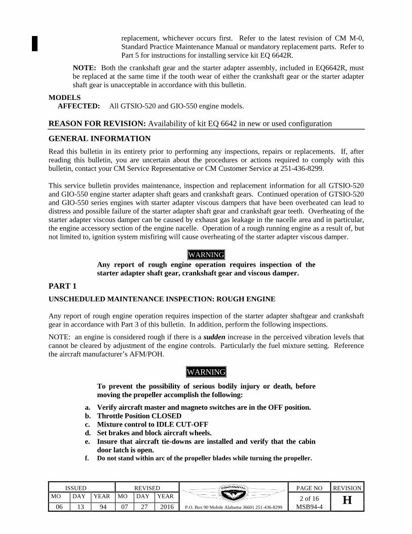
NOTE…. Ensure that the quill shaft is installed with the two timing marks on the quill shaft straddling the timing mark on the reduction gear. See Figure 2 on page 4. Install retaining plate and torque bolts to 90 – 110 in. lbs. Install snap ring in propeller drive gear snap ring slot with flat side facing out. Ensure snap ring is completely seated. See Figure 3 on page 5.
FIGURE 2. QUILL SHAFT & REDUCTION GEAR TIMING MARKS
Reduction Gear Timing Mark
Quill Shaft Timing Marks

ISSUED REVISED
P.O. Box 90 Mobile Alabama 36601 251-436-8299
PAGE NO REVISION MO DAY YEAR MO DAY YEAR 5 of 16 H
06 13 94 07 27 2016 MSB94-4
FIGURE 3. QUILL SHAFT INSTALLATION PART 2 STARTER ADAPTER VISCOUS DAMPER and SHAFTGEAR BACKLASH INSPECTION
Perform this inspection every 100 hours of engine operation.
WARNING
To prevent the possibility of serious bodily injury or death, before moving the propeller accomplish the following:
a. Verify aircraft master switch and magneto switches are in the OFF position.
b. Throttle Position CLOSED c. Mixture control to IDLE CUT-OFF d. Set brakes and block aircraft wheels. e. Insure that aircraft tie-downs are installed and verify that the cabin
door latch is open. f. Do not stand within arc of the propeller blades while turning the
propeller.
A. Visual Inspection of Damper
1. Remove the engine cowling to provide access to the engine and starter adapter.
2. Disconnect all spark plug leads and remove the lower spark plugs.
3. Visually inspect the starter adapter viscous damper for blistered paint, exhaust stains and residue. If any of these conditions are present comply with Part 1 and Part 3 of this service bulletin. Also repair or replace exhaust system component(s) as necessary to eliminate leakage of exhaust gases in the engine nacelle area. If the starter adapter viscous damper is free of blistered paint, exhaust stains, or residue proceed to step 4.
Typical Quill Shaft Installation. Remove Snap ring, then remove quill shaft and retaining plate.

ISSUED REVISED
P.O. Box 90 Mobile Alabama 36601 251-436-8299
PAGE NO REVISION MO DAY YEAR MO DAY YEAR 6 of 16 H
06 13 94 07 27 2016 MSB94-4
4. Using a clean shop towel and acetone, thoroughly clean the entire O.D. of the starter adapter viscous damper.
5. Fabricate a wire pointer from one sixteenth (1/16) inch brazing rod, or similar material, approximately 6-inches long. Make a loop on one end of the wire and sharpen the other end into a pointer.
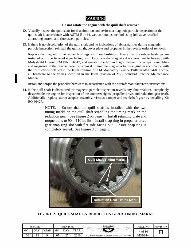
6. Loosen the starter adapter bolt at the 12 o’clock position. Secure the looped end of the wire under the bolt head and position the pointer over the center of the viscous damper OD. Moderately snug the bolt to hold the pointer stationary. See Figure 4 on page 7.
7. Fabricate a measuring strip 1-inch long, graduated in .02 inch increments, from heavy paper stock. Then secure the measuring strip to the previously cleaned OD of the viscous damper using Scotch Tape. See Figure 4 on page 7.
8. Measure the amount of gear backlash by rotating the viscous damper by hand through its full range of travel. Record the maximum gear backlash measured and remove the graduated measuring strip.
9. Rotate the propeller by hand to reposition the viscous damper approximately 90 degrees from the previous measurement.
10. Reinstall the graduated measuring strip and repeat steps 8 & 9, until four backlash measurements have been made at increments of 90 degrees.
11. If none of the four measurements exceeded .06 inches, proceed to step 13.
12. If any of the four measurements exceed .06 inches, remove the starter adapter and perform the inspection specified in Part 3, “VISUAL INSPECTION PROCEDURE” section of this bulletin.
13. Remove the graduated measuring strip from the viscous damper and the pointer from under the bolt head. Torque the loosened starter adapter bolt to 155-175 inch pounds.
14. Lubricate spark plug threads with Champion Thread Lubricant No. 2612. Using new spark plug gaskets reinstall the 6 lower spark plugs removed in step 2. Torque spark plugs to 300 - 360 inch lbs.
15. Reinstall all spark plugs leads and torque “B” nuts to 110 to 120 inch lbs.
16. Reinstall any other engine or aircraft components that may have been removed to facilitate this inspection.
17. Reinstall engine cowling in accordance with the aircraft manufacturer’s instructions.
18. Make an engine logbook entry recording the 4 backlash measurements and compliance with PART 2 of MSB94-4G. Specify the time of the next 100-hour and 400-hour inspections required by this Mandatory Service Bulletin.
ISSUED REVISED
P.O. Box 90 Mobile Alabama 36601 251-436-8299
PAGE NO REVISION MO DAY YEAR MO DAY YEAR 7 of 16 H
06 13 94 07 27 2016 MSB94-4
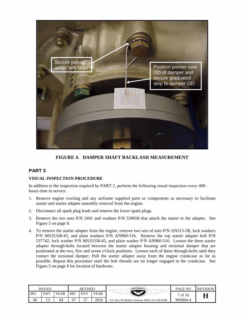
FIGURE 4. DAMPER SHAFT BACKLASH MEASUREMENT PART 3 VISUAL INSPECTION PROCEDURE
In addition to the inspection required by PART 2, perform the following visual inspection every 400-hours time in service.
1. Remove engine cowling and any airframe supplied parts or components as necessary to facilitate starter and starter adapter assembly removal from the engine.
2. Disconnect all spark plug leads and remove the lower spark plugs.
3. Remove the two nuts P/N 2441 and washers P/N 539058 that attach the starter to the adapter. See Figure 5 on page 8.
4. To remove the starter adapter from the engine, remove two sets of nuts P/N AN315-5R, lock washers P/N MS35338-45, and plain washers P/N AN960-516. Remove the top starter adapter bolt P/N 537742, lock washer P/N MS35338-45, and plain washer P/N AN960-516. Loosen the three starter adapter through-bolts located between the starter adapter housing and torsional damper that are positioned at the two, five and seven o'clock positions. Loosen each of these through-bolts until they contact the torsional damper. Pull the starter adapter away from the engine crankcase as far as possible. Repeat this procedure until the bolt threads are no longer engaged in the crankcase. See Figure 5 on page 8 for location of hardware.
Secure pointer under bolt head Position pointer over
OD of damper and secure graduated strip to damper OD.

ISSUED REVISED
P.O. Box 90 Mobile Alabama 36601 251-436-8299
PAGE NO REVISION MO DAY YEAR MO DAY YEAR 8 of 16 H
06 13 94 07 27 2016 MSB94-4
FIGURE 5. STARTER ADAPTER ASSEMBLY
5. Remove the starter adapter from the engine. Using a clean, lint free cloth, wipe the oil from crankshaft gear and starter adapter gear teeth to allow inspection.
6. Visually inspect the starter adapter shaft gear and crankshaft gear teeth using an inspection light and 10X magnifying glass for evidence of heavy spalling, pitting or wear that alters the gear tooth profile.
7. If the starter adapter shaft gear or crankshaft gear exhibits unacceptable tooth wear as indicated in Figure 6 on page 9, CM service kit (P/N EQ6642R) must be installed prior to further flight. Proceed to Part 5 of this Mandatory Service Bulletin.
WARNING
The crankshaft gear, starter adapter assembly and viscous damper must be replaced at the same time if the tooth wear of either gear is unacceptable in accordance with this bulletin.
8. If the condition of the crankshaft gear and starter adapter shaft gear teeth are acceptable, as indicated in Figure 7 on page 9, they may be continued in service. Comply with the recurring inspections listed in the “COMPLIANCE” section of this bulletin.
TELEDYNECONTINENTAL
PIN, IDLERGEAR SUPPORT
2473 WASHERMS35338-45 WASHER537742 SCREW
539058 WASHER2441 NUT
STARTER ADAPTERTHROUGH BOLTS
2473 WASHERMS3538-45 WASHER2439 NUT
MS35337-44 WASHER646605 NUTMS35338-44 WasherAN 315-4R NutTorque 90-100 in.lbs.
534728 Pin, Idler Gear Support652189 Gasket, Idler Pin
AN 960-516 WasherMS 35338-45 Lock WasherAN 315-5R NutTorque 180-220 in.lbs.
AN960-516 washerMS35338-45 Lock Washer537742 BoltTorque 155-175 in.lbs.
Starter Adapter Through BoltsTorque 155-175 in.lbs.
MS9021-038 O-Ring539058 Washer2441 NutTorque 200-220 in.lbs.

ISSUED REVISED
P.O. Box 90 Mobile Alabama 36601 251-436-8299
PAGE NO REVISION MO DAY YEAR MO DAY YEAR 9 of 16 H
06 13 94 07 27 2016 MSB94-4
UNACCEPTABLE HEAVY WEAR, SPALLING AND PITTING FULL TOOTH WIDTH
UNACCEPTABLE HEAVY WEAR, SPALLING AND
PITTING PARTIAL WIDTH
FIGURE 6
ACCEPTABLE LIGHT WEAR LINE, FULL TOOTH WIDTH UP TO .01 INCH WIDE
ACCEPTABLE MODERATE WEAR LINE, NO MORE THAN 50% TOOTH LENGTH AND .05 INCH WIDE
FIGURE 7
ISSUED REVISED
P.O. Box 90 Mobile Alabama 36601 251-436-8299
PAGE NO REVISION MO DAY YEAR MO DAY YEAR 10 of 16 H
06 13 94 07 27 2016 MSB94-4
9. If needle bearing P/N 537721 is installed, replace it with bushing P/N 654472 prior to reinstalling the starter adapter assembly. Refer to Part 4 for bushing installation instructions.
10. If previously installed, inspect bushing P/N 654472 for signs of damage or distress. Replace the bushing if any signs of damage or distress are evident. Refer to Part 4 for bushing installation instructions.
11. Using a new gasket reinstall starter adapter in the reverse order of removal. Reinstall starter motor using new O-ring. Refer to Figure 5 on page 8 for attaching hardware torque values.
12. Reinstall the 6 lower spark plugs removed in step 2. Lubricate spark plug threads with Champion Thread Lubricant No. 2612 or equivalent. Install new spark plug gaskets and torque spark plugs 300 to 360 in lbs.
13. Reinstall all spark plug leads and torque “B” nuts to 110 - 120 inch lbs.
14. Install all airframe supplied parts and accessories that were removed to facilitate the inspection / replacement requirements PART 3 of this Mandatory Service Bulletin. Torque all airframe attaching hardware to the values provided by the aircraft manufacturer. For engine torque values not provided in this Mandatory Service Bulletin, refer to the latest revision of M-0, Standard Practice Maintenance Manual.
15. Install the engine cowling and perform a complete engine ground run-up, including magneto check, in accordance with the aircraft manufacturer’s maintenance manual and AFM / POH.
16. Perform a complete visual inspection of the engine and engine accessory area for fuel, oil and hydraulic leaks. Verify the security of all components and accessories.
17. Correct any discrepancies noted and repeat steps 15 and 16.
18. Make an engine logbook entry showing compliance with PART 3 of MSB 94-4G. Record the engine time of the next 100-hour and 400-hour inspections required by this Mandatory Service Bulletin.
PART 4 STARTER ADAPTER SHAFTGEAR BUSHING INSTALLATION
1. Remove existing needle bearing P/N 537721 or bushing P/N 654472 using a 1 (one) inch blind bushing/bearing remover and a slide hammer.
2. Clean bushing bore in crankcase using lint free towel dampened with solvent.
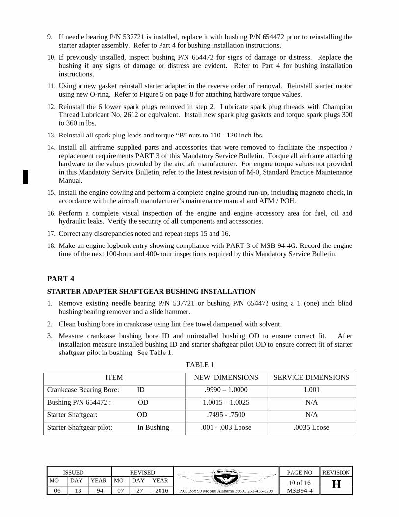
3. Measure crankcase bushing bore ID and uninstalled bushing OD to ensure correct fit. After installation measure installed bushing ID and starter shaftgear pilot OD to ensure correct fit of starter shaftgear pilot in bushing. See Table 1.
TABLE 1
ITEM NEW DIMENSIONS SERVICE DIMENSIONS
Crankcase Bearing Bore: ID .9990 – 1.0000 1.001
Bushing P/N 654472 : OD 1.0015 – 1.0025 N/A
Starter Shaftgear: OD .7495 - .7500 N/A
Starter Shaftgear pilot: In Bushing .001 - .003 Loose .0035 Loose
ISSUED REVISED
P.O. Box 90 Mobile Alabama 36601 251-436-8299
PAGE NO REVISION MO DAY YEAR MO DAY YEAR 11 of 16 H
06 13 94 07 27 2016 MSB94-4
4. To facilitate installation of bushing P/N 654472, place bushing on installation tool and submerse bushing in a container of Al-Co-Sol. Place the container of Al-Co-Sol with driver and submersed bushing in dry ice for 15 minutes prior to installation.
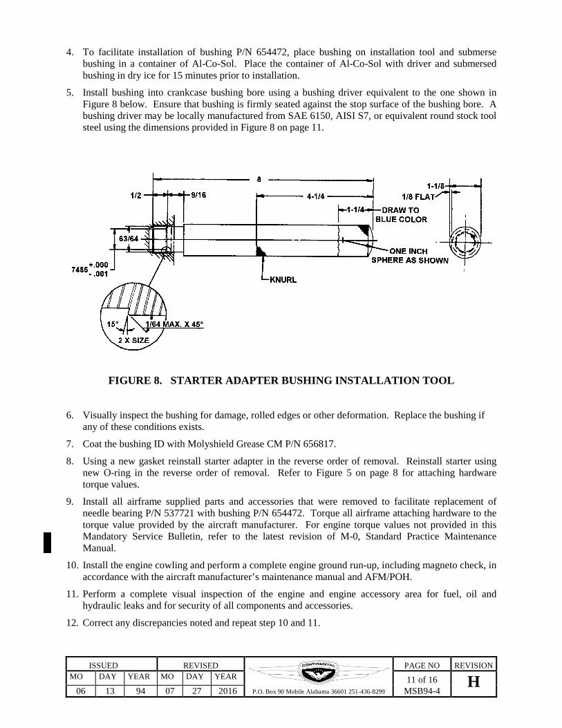
5. Install bushing into crankcase bushing bore using a bushing driver equivalent to the one shown in Figure 8 below. Ensure that bushing is firmly seated against the stop surface of the bushing bore. A bushing driver may be locally manufactured from SAE 6150, AISI S7, or equivalent round stock tool steel using the dimensions provided in Figure 8 on page 11.
FIGURE 8. STARTER ADAPTER BUSHING INSTALLATION TOOL
6. Visually inspect the bushing for damage, rolled edges or other deformation. Replace the bushing if any of these conditions exists.
7. Coat the bushing ID with Molyshield Grease CM P/N 656817.
8. Using a new gasket reinstall starter adapter in the reverse order of removal. Reinstall starter using new O-ring in the reverse order of removal. Refer to Figure 5 on page 8 for attaching hardware torque values.
9. Install all airframe supplied parts and accessories that were removed to facilitate replacement of needle bearing P/N 537721 with bushing P/N 654472. Torque all airframe attaching hardware to the torque value provided by the aircraft manufacturer. For engine torque values not provided in this Mandatory Service Bulletin, refer to the latest revision of M-0, Standard Practice Maintenance Manual.
10. Install the engine cowling and perform a complete engine ground run-up, including magneto check, in accordance with the aircraft manufacturer’s maintenance manual and AFM/POH.
11. Perform a complete visual inspection of the engine and engine accessory area for fuel, oil and hydraulic leaks and for security of all components and accessories.
12. Correct any discrepancies noted and repeat step 10 and 11.
ISSUED REVISED
P.O. Box 90 Mobile Alabama 36601 251-436-8299
PAGE NO REVISION MO DAY YEAR MO DAY YEAR 12 of 16 H
06 13 94 07 27 2016 MSB94-4
13. Make an engine logbook entry indicating compliance with PART 4 of MSB94-4G and the time of the next 100-hour and 400-hour inspections required by this Mandatory Service Bulletin.
PART 5
SERVICE KIT EQ 6642 INSTALLATION INSTRUCTIONS
Verify that starter adapter shaftgear support bushing P/N 654472 is installed. If not, complete Part 4 of this Mandatory Service Bulletin prior to proceeding with Part 5.
The following instructions are provided as a guide for installation of service kit EQ6642. You will find it necessary to refer to the aircraft manufacturer’s maintenance manual and CM’s GTSIO-520 engine overhaul manual, Form X30045A, for additional information to complete this installation. If you find that you require technical assistance, contact your local CM service representative or factory service department at (251) 436-8299 or 888-826-5465.
1. Insure that the master switch and magneto switches are in the OFF position.
2. Remove the engine cowling.
3. Remove induction system components as required to gain access to the magnetos and starter adapter.
4. Remove the lower spark plug in each cylinder.
5. Remove the magnetos and discard the gaskets.
6. Remove the left and right magneto drive bushings, retainers and gear assemblies. Clearly identify the location from which these items were removed so that they may be reinstalled in their original position.
7. Remove the starter from the starter adapter. Refer to Part 3, Step 3.
8. Remove the starter adapter from the engine. Refer to Part 3, Step 4.
9. Remove and discard the safety wire from the crankshaft gear bolts. Rotate the crankshaft until the timing marks on the crankshaft gear and camshaft gear align. Continue to rotate the crankshaft until the dowel pin is located in the three o'clock position. Remove the crankshaft gear bolts P/N 536379 and discard.
WARNING
Do not move the propeller after the crank gear is removed. Rotation of the propeller / crankshaft after removal of the crankshaft gear will result in loss of internal engine timing, damage to internal engine components and possible engine failure.
10. Install the two .250-28 bolts P/N 24251 in the tapped holes of the crank gear that are located 180 degrees apart. Tighten bolts alternately to remove the gear from the crankshaft. Light tapping on the gear with a rubber mallet will assist in the removal process. Once the gear is loose from the crankshaft, remove the gear from the crankcase by holding the gear aft against the crankcase and rotate the gear clockwise to the right. Remove the gear through the starter adapter mount location on the rear of the crankcase. With the crankshaft gear removed from the crankcase, proceed to paragraphs 11 through 29. If difficulty is experienced in the removal of the crank gear due to crankcase interference, proceed as follows:
A. Remove the components, (vacuum pump, hydraulic pump, etc.) that are attached to the left and right accessory drives. Remove the four sets of nuts and washers that attach the two accessory drives to the crankcase. Remove the accessory drive assemblies and discard the gaskets.

ISSUED REVISED
P.O. Box 90 Mobile Alabama 36601 251-436-8299
PAGE NO REVISION MO DAY YEAR MO DAY YEAR 13 of 16 H
06 13 94 07 27 2016 MSB94-4
B. Remove the two nuts P/N AN315-4R and lock washers P/N MS35338-44 that retain the idler gear support pin. Remove the idler gear support pin by applying pressure on both sides of the pin flange simultaneously while keeping the flange holes centered on the studs. Tapping the pin back in after it has moved out a small amount with a soft mallet will assist in loosening the pin for removal. After the pin is removed, discard the pin flange gasket.
C. With the pin removed, hold the idler gear toward the top of the accessory case to allow for additional clearance to remove the crankshaft gear. Remove the crankshaft gear as instructed in paragraph 10.
If the crankshaft gear can not be removed from the engine due to the gear contacting the interior of the crankcase prior to clearing the end of the crankshaft proceed with the following:
a. Inspect the crankcase interior at the left and right crankcase half split line. You will notice that one crankcase half will be slightly forward of the other. To facilitate removal of the crankshaft gear, material will need to be removed from the most forward (thicker) crankcase half.
b. Place clean shop towels into the crankcase to prevent material from contaminating the engine interior.
c. Using a die grinder or equivalent tool and a fine grinding stone, removed only enough material from the most forward (thicker) crankcase half so that it blends with the opposite half.
d. Smooth surface with 400 wet/dry sandpaper.
e. Using a shop vacuum, carefully clean foreign debris from engine interior.
f. Remove shop towels from engine interior.
g. Remove the crankshaft gear from the crankcase by holding the gear aft against the crankcase and rotate the gear clockwise to the right. Remove the gear through the starter adapter mount location on the rear of the crankcase.
11. With the crankshaft gear removed, clean the gear end of the crankshaft to ensure positive seating of the replacement gear.
12. Heat the replacement crankshaft gear P/N 653580 to 300°F for one hour. Using a suitable pair of insulating gloves, install the gear onto the crankshaft by rotating the gear counterclockwise and to the left so that it is positioned properly with the crankshaft dowel pin. Ensure that the gear seats tightly against the end of the crankshaft by tapping lightly with a brass hammer.
WARNING Do not heat the crankshaft gear longer than the time specified. Damage to the gear will result, and engine failure may occur.
13. Install new crank gear bolts P/N 536379 and torque in an alternating sequence to 380 - 420 inch pounds.
14. Verify correct cam to crank timing by positioning the number two cylinder piston at top dead center on the compression stroke. With the piston in this position, the timing marks must be aligned between the crankshaft and camshaft gears. Refer to Figure 9 on page 14. Remove and reposition the crankshaft gear if alignment of the timing marks is incorrect.
15. With the camshaft gear correctly timed with the crankshaft gear and the crankshaft gear bolts correctly torqued, safety wire the crankshaft gear bolts per the latest revision of M-0, Standard Practice Maintenance Manual.

ISSUED REVISED
P.O. Box 90 Mobile Alabama 36601 251-436-8299
PAGE NO REVISION MO DAY YEAR MO DAY YEAR 14 of 16 H
06 13 94 07 27 2016 MSB94-4
16. Align the idler gear with the idler pin bore in the crankcase. Install new gasket P/N 652189 onto the idler pin and insert the pin into the crankcase and through the idler gear until the pin flange is seated against the crankcase. Install the attaching lock washers P/N MS35338-44 and nuts P/N AN315-4R and torque to 90 - 100 inch pounds.
17. Install new gaskets P/N 649955 onto the accessory drive assemblies and install the assemblies onto the crankcase. Install the attaching washers and nuts and torque the 5/16-24 nuts to 180 - 220 inch pounds and the 3/8-24 nuts to 275 - 325 inch pounds.
18. Rotate the crankshaft in the direction of normal rotation until the piston in the number one cylinder is at its full advance firing position. Remove the timing inspection window from the top of each magneto. Rotate each magneto shaft until the painted timing marks on the distributor gears are aligned in the center of the inspection window.
19. Install accessory drive gear(s) P/N 632799 into their position and mesh gear(s) with idler gear.
20. Install magneto drive coupling retainers onto the magneto drive gears. Install the magneto drive rubber bushings into retainers with the large radius or taper facing out. Lubricate rubber bushings and magneto drive gear needle bearings with Molyshield grease (CM P/N 656817).
21. Install the magneto drive gears, with magneto drive bushings and retainers installed, into their respective accessory drive gears. Position magneto drive gear to allow the magnetos to be installed horizontally and allow clearance for the induction system manifold/inter-cooler. Mesh magneto drive gears with their respective idler gear.
CRANKSHAFT TIMING MARKS
CAMSHAFT TIMING MARK
FIGURE 9
ISSUED REVISED
P.O. Box 90 Mobile Alabama 36601 251-436-8299
PAGE NO REVISION MO DAY YEAR MO DAY YEAR 15 of 16 H
06 13 94 07 27 2016 MSB94-4
22. With gears positioned properly, place new gaskets P/N 649954 onto the magnetos and install the magnetos onto the engine using the retaining plates, lock washers and nuts. Moderately snug magneto attach nuts. Time magnetos to engine in accordance with the latest revision of CM Bulletin MSB94-8. Torque magneto retaining nuts to 100-120 inch pounds. Install spark plugs and torque to 300 - 360 inch pounds. Install and torque ignition harness lead “B” nuts to 110-120 inch. pounds.
23. Install starter adapter assembly using new gasket P/N 653749 in the reverse order in which it was removed. Torque starter adapter and starter motor attaching hardware to values provided in Figure 5.
24. Install all airframe supplied parts and accessories that were removed to facilitate the inspection/ replacement requirements of this Mandatory Service Document. Torque all airframe attaching hardware to the torque value provided by the aircraft manufacturer. For engine torque values not provided in the Mandatory Service Bulletin, refer to the latest revision of M-0, Standard Practice Maintenance Manual.
25. Install the engine cowling and perform a complete engine ground run-up, including magneto check, in accordance with the aircraft manufacturer’s maintenance manual, AFM/POH.
26. Perform a complete visual inspection of the engine and engine accessory area for fuel, oil and hydraulic leaks and for security of all components and accessories.
27. Correct any discrepancies noted and repeat steps 28 and 29.
28. Make a log book entry showing compliance with the applicable PARTS (1,2,3,4 and 5) of this Mandatory Service Bulletin. Document in the logbook entry all applicable component serial numbers and part numbers.
29. Specify in the logbook the engine time and aircraft total time of the next 100-hour damper backlash inspection and 400-hour visual inspection of the crankshaft gear and starter adapter shaft gear.
WARRANTY COVERAGE
Warranty coverage for performance of the maintenance and inspection procedures required by this bulletin will only be applicable to engines currently covered by the Continental Motor’s New Engine or Rebuilt Engine warranty policies. Verification of warranty coverage can be made by contacting CM’s Customer Service Department at 251-436-8610 or 888-826-5465. Have the engine model, serial number and total time in service available for the Customer Service Representative.
If warranty coverage is applicable, labor will be paid at the following rates:
Inspection Only…………………………………………………………….Up to1 hour per starter adapter.
Starter Adapter and Crankgear Replacement……………………….Up to 6 hours per adapter and gear.
All labor will be paid at no more than the posted shop rate.
ISSUED REVISED
P.O. Box 90 Mobile Alabama 36601 251-436-8299
PAGE NO REVISION MO DAY YEAR MO DAY YEAR 16 of 16 H
06 13 94 07 27 2016 MSB94-4
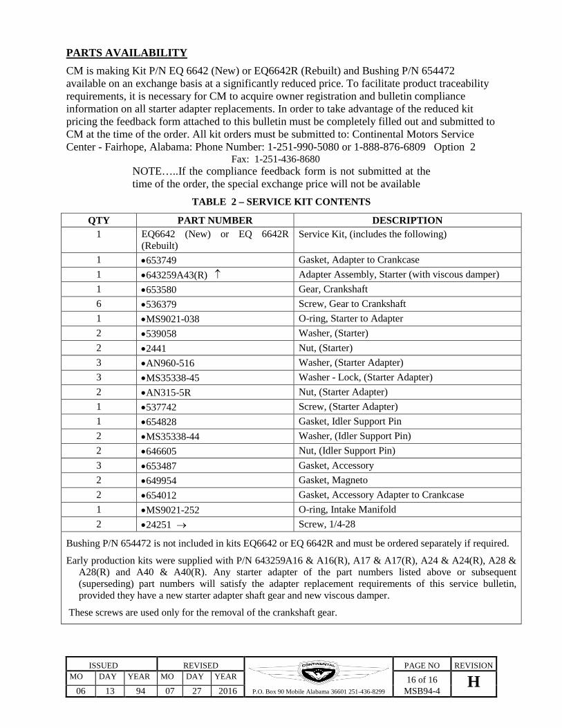
PARTS AVAILABILITY CM is making Kit P/N EQ 6642 (New) or EQ6642R (Rebuilt) and Bushing P/N 654472 available on an exchange basis at a significantly reduced price. To facilitate product traceability requirements, it is necessary for CM to acquire owner registration and bulletin compliance information on all starter adapter replacements. In order to take advantage of the reduced kit pricing the feedback form attached to this bulletin must be completely filled out and submitted to CM at the time of the order. All kit orders must be submitted to: Continental Motors Service Center - Fairhope, Alabama: Phone Number: 1-251-990-5080 or 1-888-876-6809 Option 2 Fax: 1-251-436-8680
NOTE…..If the compliance feedback form is not submitted at the time of the order, the special exchange price will not be available
TABLE 2 – SERVICE KIT CONTENTS
QTY PART NUMBER DESCRIPTION 1 EQ6642 (New) or EQ 6642R
(Rebuilt) Service Kit, (includes the following)
1 •653749 Gasket, Adapter to Crankcase 1 •643259A43(R) ↑ Adapter Assembly, Starter (with viscous damper) 1 •653580 Gear, Crankshaft 6 •536379 Screw, Gear to Crankshaft 1 •MS9021-038 O-ring, Starter to Adapter 2 •539058 Washer, (Starter) 2 •2441 Nut, (Starter) 3 •AN960-516 Washer, (Starter Adapter) 3 •MS35338-45 Washer - Lock, (Starter Adapter) 2 •AN315-5R Nut, (Starter Adapter) 1 •537742 Screw, (Starter Adapter) 1 •654828 Gasket, Idler Support Pin 2 •MS35338-44 Washer, (Idler Support Pin) 2 •646605 Nut, (Idler Support Pin) 3 •653487 Gasket, Accessory 2 •649954 Gasket, Magneto 2 •654012 Gasket, Accessory Adapter to Crankcase 1 •MS9021-252 O-ring, Intake Manifold 2 •24251 → Screw, 1/4-28
Bushing P/N 654472 is not included in kits EQ6642 or EQ 6642R and must be ordered separately if required.
Early production kits were supplied with P/N 643259A16 & A16(R), A17 & A17(R), A24 & A24(R), A28 & A28(R) and A40 & A40(R). Any starter adapter of the part numbers listed above or subsequent (superseding) part numbers will satisfy the adapter replacement requirements of this service bulletin, provided they have a new starter adapter shaft gear and new viscous damper.
These screws are used only for the removal of the crankshaft gear.

Related Documents