REBALLASTING THE KC-135 FLEET FOR FUEL EFFICIENCY THESIS Philip G. Morrison, Major, USAF AFIT/IMO/ENS/10-10 DEPARTMENT OF THE AIR FORCE AIR UNIVERSITY AIR FORCE INSTITUTE OF TECHNOLOGY Wright-Patterson Air Force Base, Ohio APPROVED FOR PUBLIC RELEASE; DISTRIBUTION UNLIMITED

Welcome message from author
This document is posted to help you gain knowledge. Please leave a comment to let me know what you think about it! Share it to your friends and learn new things together.
Transcript

REBALLASTING THE KC-135 FLEET FOR
FUEL EFFICIENCY
THESIS
Philip G. Morrison, Major, USAF
AFIT/IMO/ENS/10-10
DEPARTMENT OF THE AIR FORCE AIR UNIVERSITY
AIR FORCE INSTITUTE OF TECHNOLOGY
Wright-Patterson Air Force Base, Ohio
APPROVED FOR PUBLIC RELEASE; DISTRIBUTION UNLIMITED

ii
The views expressed in this thesis are those of the author and do not reflect the official policy or position of the United States Air Force, Department of Defense, or the United States Government.
iii
AFIT/IMO/ENS/10-10
REBALLASTING THE KC-135 FLEET FOR FUEL EFFICIENCY
THESIS
Presented to the Faculty
Department of Systems and Engineering Management
Graduate School of Engineering and Management
Air Force Institute of Technology
Air University
Air Education and Training Command
In Partial Fulfillment of the Requirements for the
Degree of Master of Science in Logistics
Philip G. Morrison, BS, MS
Major, USAF
April 2010
APPROVED FOR PUBLIC RELEASE; DISTRIBUTION UNLIMITED.

iv
AFIT/IMO/ENS/10-10
REBALLASTING THE KC-135 FLEET FOR FUEL EFFICIENCY
Philip G. Morrison, BS, MS Major, USAF
Approved: //SIGNED// 10 JUNE 2010 ____________________________________ Daniel D. Mattioda, Maj, USAF, Ph.D. (Advisor) date //SIGNED// 10 JUNE 2010 ____________________________________ Christopher M. Shearer, Lt Col, USAF, Ph.D. (Reader) date

iv
AFIT/IMO/ENS/10-10
Abstract
The KC-135 was subject to numerous changes over its first 50 years of service as
it has adapted to new and expanded mission requirements. These changes have added a
large amount of weight to the aircraft, much of it focused in the rear of the airframe
which created an aft Center of Gravity (CG). Boeing accounts for this aft CG by
requiring that ballast fuel be carried in the forward body tank to maintain a CG forward
of the aft limit.
An Engineering Analysis (EA) recently performed by Boeing states that 3,500 lbs
of fuel is to be left in the forward body tank strictly for ballast, with no other purpose.
Using fuel in the forward body tank for ballast has two significant drawbacks; the
forward body tank has a very short moment-arm necessitating more weight than that of
ballast on a longer moment-arm, and ballast fuel displaces fuel that could be used for
mission purposes by using the tank to hold ballast weight.
Reducing aircraft gross weight is a cost issue, because excess weight incurs a
“carriage cost”. The “carriage cost” for weight on the KC-135 is 4.97% of the weight in
pounds of fuel burned per hour. This thesis focuses on the cost recoupment horizon for
reballasting the KC-135 fleet and whether the cost will justify the fuel efficiency and
increased mission capability. Specifically, this research examines replacement of fuel
ballast with lead ballast on a longer moment arm and/or weight with a mission purpose,
in the form of cockpit armor, to minimize ballast weight requirements. This will reduce
aircraft gross weight and generate increased fuel efficiency.

v
AFIT/IMO/ENS/10-10
To my loving wife, my two sons,
to the crews who have maintained and flown the KC-135 for more than a half century
and those who will fly the mighty “Stratotanker” well into the coming decades.

vi
Acknowledgments
I would like to express my sincere appreciation to my faculty advisor, Major Dan
Mattioda, for his guidance and support throughout the course of this thesis effort and to
my technical reader Lt Col Christopher Shearer. Their insight and experience was
certainly appreciated. I would, also, like to thank my sponsor, Col Kevin “Nuke” Trayer,
from the Air Mobility Command, Fuel Efficiency Office for both the support and latitude
provided to me in this endeavor.
I am also indebted to the KC-135 Systems Group who provided me with much of
the vital data needed to make this project a reality and to Mr. Michael Lombardi, the
Boeing Corporate historian who supplied me with a lot of the original KC-135 technical
data. Special thanks go to Mr. Gary Mott, who always took time out of his busy schedule
to answer all my tough KC-135 questions and his active solicitation of others to do the
same.
Philip G. Morrison

vii
Table of Contents
Page Abstract ................................................................................................................................................ iv Dedication .............................................................................................................................................. v Acknowledgements .............................................................................................................................. vi Table of Contents ................................................................................................................................ vii List of Figures ..................................................................................................................................... viii List of Tables ........................................................................................................................................ ix I. Introduction .......................................................................................................................................1 Background, Motivation and Problem Statement ..............................................................................1 Assumptions and Limitations ............................................................................................................8 II. Literature Review ........................................................................................................................... 13 III. Methodology ................................................................................................................................. 23 Instrument Development ................................................................................................................. 23 Data and Constraints ........................................................................................................................ 23 Instrument Administration ............................................................................................................... 29 IV. Results and Analysis...................................................................................................................... 36
Empty Aircraft ................................................................................................................................ 36 Aircraft (No Ballast) with Minimum Fuel (600 lbs in Main Tanks 1-4) ........................................ 39 Aircraft with Minimum Main Tank Fuel & Cockpit Armor (No Trim Ballast) ............................. 41 Aircraft with Minimum Main Tank Fuel & Minimum Weight Ballast (No Armor) ...................... 44 Aircraft with Minimum Main Tank Fuel & Minimum Trim Ballast (with Armor) ........................ 47 Aircraft, Minimum Fuel & 3,500 lbs of Fuel in Fwd Body (current configuration)....................... 50 Aircraft, Minimum Fuel & 2,000 lbs of Fuel in Fwd Body (Block 40) .......................................... 52 Modification Calculations .............................................................................................................. 53 Solution Sets ................................................................................................................................... 55 Average Aircraft Weight Difference by Solution Set ..................................................................... 57 Recoupment Horizon Calculation by Solution Set ......................................................................... 60 V. Discussion ....................................................................................................................................... 63
Objective Evaluation ...................................................................................................................... 63 Recommendation for Implementation ............................................................................................ 65 Areas for Future Research .............................................................................................................. 67 Conclusion ...................................................................................................................................... 67 Bibliography ........................................................................................................................................... 69 Vita ......................................................................................................................................................... 72

viii
List of Figures
Figure Page Figure 1. Current “Zero Fuel” Configuration ................................................................................................. 5
Figure 2. KC-135 Station Locations ..............................................................................................................10
Figure 3. Station Location Relative to Mean Aerodynamic Chord (MAC) ...................................................11
Figure 4. Tail Modification ...........................................................................................................................15
Figure 5. Location of Upper Deck Tank ........................................................ Error! Bookmark not defined.
Figure 6. Location of APUs ...........................................................................................................................20
Figure 7. Horizontal Stabilizer Growth .........................................................................................................21
Figure 8. Blow up of KC-135 Weight and Balance Calculator .....................................................................31
Figure 9. Screen Shot of KC-135 Weight and Balance Calculator ................................................................32
Figure 10. Weight and Moment Columns Screen Shot .................................................................................33
Figure 11. Solver Screen Shot .......................................................................................................................34
Figure 12. Solver “Solved” Screen Shot........................................................................................................35

ix
List of Tables
Table Page Table 1. List of Terms .................................................................................................................................... 4
Table 2. Mean Aircraft Weight Growth During First Ten Years...................................................................14
Table 3. Treatments .......................................................................................................................................28
Table 4. Fleet Segments ..............................................................................................................................299
Table 5. Empty Aircraft Block 30 .................................................................................................................36
Table 6. Empty Aircraft Block 40 .................................................................................................................36
Table 7. Minimum Fuel Block 30 .................................................................................................................39
Table 8. Minimum Fuel Block 40 .................................................................................................................40
Table 9. Minimum Fuel Block 30 Converted ................................................................................................40
Table 10. Armor Analysis without Trim Ballast Block 30 ............................................................................42
Table 11. Armor Analysis without Trim Ballast Block 40 ............................................................................42
Table 12. Armor Analysis without Trim Ballast Block 30 Converted ..........................................................42
Table 13. Aircraft when Equipped with Armor Requiring Trim Ballast .......................................................44
Table 14. Treatment C Block 30 ...................................................................................................................45
Table 15. Treatment C Block 40 ...................................................................................................................45
Table 16. Treatment C Block 30 Converted ..................................................................................................46
Table 17. Treatment B Block 30 ...................................................................................................................47
Table 18. Treatment B Block 40 ...................................................................................................................48
Table 19. Treatment B Block 30 Converted ..................................................................................................48
Table 20. Treatment A Block 30 (3,500 lbs) .................................................................................................50
Table 21. Treatment A Block 40 (3,500 lbs) .................................................................................................51
Table 22. Treatment A Block 30 Converted (3,500 lbs)................................................................................51
Table 23. Treatment A Block 40 (2,000 lbs) .................................................................................................52
x
Table 24. Treatment A Block 30 Converted (2,000 lbs)................................................................................53
Table 25. Fleet Segment Ballast Requirements .............................................................................................54
Table 26. Recoupment Horizons ...................................................................................................................63
1
REBALLASTING THE KC-135 FLEET FOR FUEL EFFICIENCY
I. Introduction
Background, Motivation and Problem Statement The KC-135 aircraft has and continues to be crucial to the modern defense of the
United States (Hopkins, 1997: 11). Despite the tanker recapitalization effort, better
known as the “KC-X” program, the KC-135 is projected to continue as a vital and viable
provider of global air refueling through FY 2040 with the help of the KC-135 Aircraft
Extension Program (AEP) (Air Mobility Command, 2008: 80).
The history of the KC-135 is punctuated by numerous modifications that resulted
in a heavier and more poorly ballasted aircraft (Hopkins, 1997: 35-50). The means of
maintaining aircraft Center of Gravity (CG), within prescribed longitudinal requirements,
hinges on the use of fuel to provide ballast trim (Boeing Aero, 2009: 70). Recent analysis
by Boeing has identified a strict requirement to maintain 3,500 lbs of fuel in the forward-
most tank (Forward Body Tank), specifically to meet this requirement (Boeing Aero,
2009: 3). Prior to this study, Boeing asserted that the aircraft not be operated below
7,000 lbs total fuel, undoubtedly a combination of fuel required to feed engines and
ballast the airframe, but with no explanation of the fuel’s specific purpose (Boeing,
2009).
The use of “tankered fuel” to provide ballast is horribly inefficient because it
utilizes a very short moment-arm to balance the aircraft; this requires a greater amount of
weight than that of ballast applied to a longer moment-arm. Additionally, using fuel to

2
ballast the airframe renders the fuel unusable, because it must be present for the entire
flight or the aircraft will reach an unsafe aft CG. This unusable ballast fuel displaces
other-wise usable fuel that could increase mission capability if the aircraft needs to be
loaded to tank capacity.
The surge in oil prices in 2007, increasing global pressure to limit Green House
Gas (GHG) emissions, and national desire to decrease foreign energy dependence led to a
nation-wide reexamination of energy consumption. The charge was led by non-other
than President George W. Bush on January 24, 2007 when he signed Executive Order
13423 (EO 13423) (Bush, 2007: 3-7). The goals set forth in EO 13423, by the President,
were reasserted most recently by the Secretary of the Air Force (SECAF), Michael B.
Donley in his Air Force Policy Memorandum 10-1 (AFPM 10-1) dated June 16, 2009.
Secretary Donley stated, in AFPM 10-1, “the Air Force goal of reducing aviation fuel-use
per hour of operation by 10% (from a 2005 base line) by 2015” (Donley, 2009: 9).
Executive Order 13423, AFPM 10-1 and numerous other similar decrees from the
civilian leadership have spurred research into the use of aviation fuel and the
development of programs to mitigate fuel use by the Air Force and other branches of the
military. One such research project was conducted by Cyintech, a defense contractor
hired by Air Mobility Command (AMC), to calculate the Cost of Weight (CoW) for their
fleet of mobility aircraft. The results from this research were astounding; in the case of
the KC-135R the CoW was determined to be an average of 4.97% per hour (Cyintech,
2008: 8). This average CoW was determined by averaging the excess fuel burned for
weight carried on short, medium and long duration flights (short flights are subject to a
higher hourly burn rate penalty and longer flights subject to a lesser burn rate). This

3
means on average that for every 100 lbs of weight loaded onto the aircraft 4.97 lbs of fuel
are required to keep it airborne for 1 hour, in the case of just a 5 hour flight almost 25 lbs
of fuel are required to transport 100 lbs! The knowledge of CoW and restrictions levied
upon the service led to an AMC-wide effort to eliminate excess weight from its aircraft
(Kelly, 2007: 1). Although, many weight reduction efforts were started before
Cyintech’s results were published, the merit of weight reduction was determined earlier
through benchmarking the airline industry, the results from Cyintech armed AMC policy
makers with a quantifiable metric.
One of the earlier pursuits by AMC was a thorough examination of fuel loading
on mobility aircraft. This was a logical starting point because it could be enacted quickly
and yield large increases in efficiency. AMC hired a consultant to help translate the
airline industry’s efforts into a plan that could be executed in the Air Force. This
consultant was Mr. Jim Barnes, a United Airlines pilot who helped develop the fuel
efficiency programs at United. He helped model the AMC investigation of fuel
efficiency after that of United and other commercial airline carriers.
As part of the fuel loading examination, the Subject Matter Experts (SMEs) for
each of AMCs aircraft were asked to dissect the fuel loaded onto their aircraft and
determine its specific purpose. While most of the fuel loaded onto each airframe was
very strictly regulated and well defined, what differed significantly were the
manufactures’ definitions of when the respective aircraft were empty. In the case of the
KC-135 the minimum landing fuel, as determined by Boeing, was 7,000 lbs of fuel
(Boeing, 2009), far more than any other aircraft in the mobility fleet including much
larger aircraft like the C-5 aircraft. This discovery spurred the Air Force to order an

4
examination by Boeing into the purpose for such a high “zero fuel” weight. See Table 1
for list of frequently used terms and their definitions.
Table 1. List of Terms
Zero Fuel Weight Minimum fuel weight required for safe operation of aircraft, includes fuel required for ballast and engine feeding, fuel level below this will result in engine flameout and/or unsafe center of gravity
Weight Ballast Weight applied at the forward most position strictly for the purpose of ballasting the airframe
Equipment Ballast Equipment added to the forward portion of the aircraft that serves to ballast the airframe
Trim Ballast Weight Ballast added to achieve the aft CG constraint, this weight is in addition to Equipment Ballast for those aircraft that require it
Tankered Fuel Fuel transported from point of departure to destination, for convenience or follow-on mission requirement, but not designated for burn on current mission leg
The examination of KC-135 “zero fuel” was conducted by Boeing Aero as
Engineering Analysis (EA) 08-043-135AMC and it is the results of this analysis that
confirmed the suspicions of the crews that had been flying the KC-135. The crews had
been hauling fuel around simply to balance the aircraft and keep it from tipping on its
tail. One such crewmember who suspected this was the case, Lt Col Lanson Ross, went
so far as to propose a solution. He suggested instead of carrying fuel in the forward
body, the Air Force examine placing weights in the nose of the aircraft, this “weight
ballast” will take advantage of a longer moment-arm and decrease total weight required,
similar to the way the KC-135T was ballasted for its configuration (see discussion in
Literature Review) (Ross, 2008: 1).
Unfortunately, when Lt Col Ross proposed his solution the fuel carried on the
KC-135 as ballast had not been delineated as such and many of his “rough estimates”
could not be substantiated. The results of EA 08-043-135AMC in 2009 paved the way
5
for a serious examination of his proposal and it is the combination of the two that serve as
the cornerstone to this project (Boeing Aero, 2009: 70).
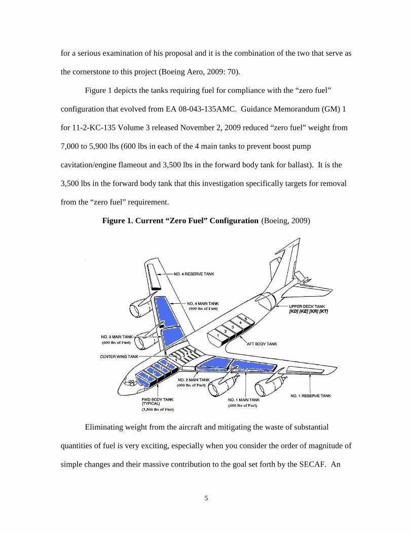
Figure 1 depicts the tanks requiring fuel for compliance with the “zero fuel”
configuration that evolved from EA 08-043-135AMC. Guidance Memorandum (GM) 1
for 11-2-KC-135 Volume 3 released November 2, 2009 reduced “zero fuel” weight from
7,000 to 5,900 lbs (600 lbs in each of the 4 main tanks to prevent boost pump
cavitation/engine flameout and 3,500 lbs in the forward body tank for ballast). It is the
3,500 lbs in the forward body tank that this investigation specifically targets for removal
from the “zero fuel” requirement.
Figure 1. Current “Zero Fuel” Configuration (Boeing, 2009)
Eliminating weight from the aircraft and mitigating the waste of substantial
quantities of fuel is very exciting, especially when you consider the order of magnitude of
simple changes and their massive contribution to the goal set forth by the SECAF. An
6
additional possibility is using equipment, which enhances the aircraft mission and ballasts
the aircraft. The idea of making constructive use of ballast weight is even more
fascinating. This “equipment ballast” could be achieved by adding equipment in a
strategic position so as to both ballast the plane and enhance the mission by providing
increased capability. The concept of adding equipment on an aircraft and incurring the
subsequent weight penalties has long been regarded as a necessary evil, for mission
accomplishment. The penalty often serves to curtail the addition of certain equipment
when it is deemed cost prohibitive. The aerospace industry at large is acutely aware of
this and as a consequence endeavors to find lighter and lighter materials to reduce this
“cost of ownership” for their customers.
The “equipment ballast” option is somewhat unique, because the opposite would
be true, if equipment was placed appropriately. It could be considered that adding weight
with the appropriate moment-arm has a relative “negative carriage cost” because it allows
for the elimination of excess ballast fuel, which only serves as “dead weight”. This
appropriately placed “equipment ballast” would net a fuel cost mitigation and serves to
enhance mission capability. This is one of the fascinating possibilities that this project
will consider. In the case of the KC-135, such equipment would have to meet a couple of
key constraints; it would have to be placed far enough forward to take advantage of an
extended moment-arm and it would have to be heavy enough to contribute significantly
to the ballast of the plane and subsequent weight reduction. While “weight ballast” can
prevent the expense of fuel waste, increase payload capability, minimize pollution and
GHG emissions; “equipment ballast” can do all this and provide additional mission
capabilities.

7
One candidate for “equipment ballast” that appears to present itself as an option,
by nature of its weight and required station location on the flight deck, is cockpit armor.
While studies have been conducted to examine the feasibility of adding armor to the KC-
135 flight deck (Boeing Aero, 2002: 1-4), cockpit armor was ironically dismissed
because of its added weight and cost.
Although the equipment ballast option offers additional mission capability it will
have some drawbacks when considered against the weight ballast option. Weight ballast
will allow for the longest moment-arm, which will require the least amount of ballast
weight, resulting in the greatest gross weight reduction. The cost of installing simple
weight, whether it is lead, depleted uranium or some other form of dense material,
represents a slightly cheaper manner of balancing the aircraft than installing equipment
for the purpose of ballast. Additionally, if equipment ballast is used a small portion of
the fleet will still require weight ballast be added to “trim-out” remaining aircraft balance
requirements. A careful consideration of mission value must be weighed against the
initial cost outlay required for equipment ballast to determine its value as an option.
The costs associated with both weight ballast and equipment ballast options and
the recoupment horizons for aircraft modification and equipment purchase will be
calculated to frame the discussion. The outlay of funds is critical to any investment, but
the relationship between initial cost and return on investment is of greater concern. This
investigation is not just about making a simple financial argument; it involves money,
mission capability, environmental impact and compliance with stated goals. The unusual
possibility that exists here is the potential to align these desperately different and quite
often competing objectives and potentially make a case for all or most of them at least in

8
part.
The fact that the KC-135 is a “legacy aircraft” is not ignored in this examination.
It is for this reason that “recoupment horizons” are the focus of the financial examination
so they can be considered against future service life of the KC-135 airframe. It is the fact
that the KC-135 is an “old workhorse” knitted into the fabric of military strategy that
makes this study so crucial. Implications for a range of strategic missions must be
considered, especially those that could significantly benefit from the increased offload
capability of up to 3,500 pounds of fuel per KC-135 mission!
Assumptions and Limitations
This study is built upon numerous Engineering Analyses (EAs) which have made
examination of this subject possible. Without the delineation by EA 08-043-135AMC of
what fuel was required for what purpose on the aircraft, it would be impossible to discuss
eliminating ballast fuel. It would be equally difficult to calculate fuel costs associated
with excess weight without the research conducted on CoW for the KC-135 or to discuss
adding cockpit armor without the weight and moment data that came from EA 02-048-
135OTH. The feasibility and costs associated with cockpit armor are in fact known, it
was even tested on the KC-135 airframe. The current cost of a KC-135 cockpit armor kit,
as advertised by QinetiQ North (the manufacturer of LAST armor) is $82,500 (recurring
cost) with a non-recurring engineering cost of $82,500 (coincidentally the cost of one kit)
(Norris, 2010). The cost estimates for armor will be calculated using these quotes.
Ballasting the nose of the KC-135 is also not an original concept, and has been
proven to work for almost 50 years on the KC-135Q (now T-models). Unfortunately, the
9
engineering data from the original feasibility study has not survived and cost data; even if
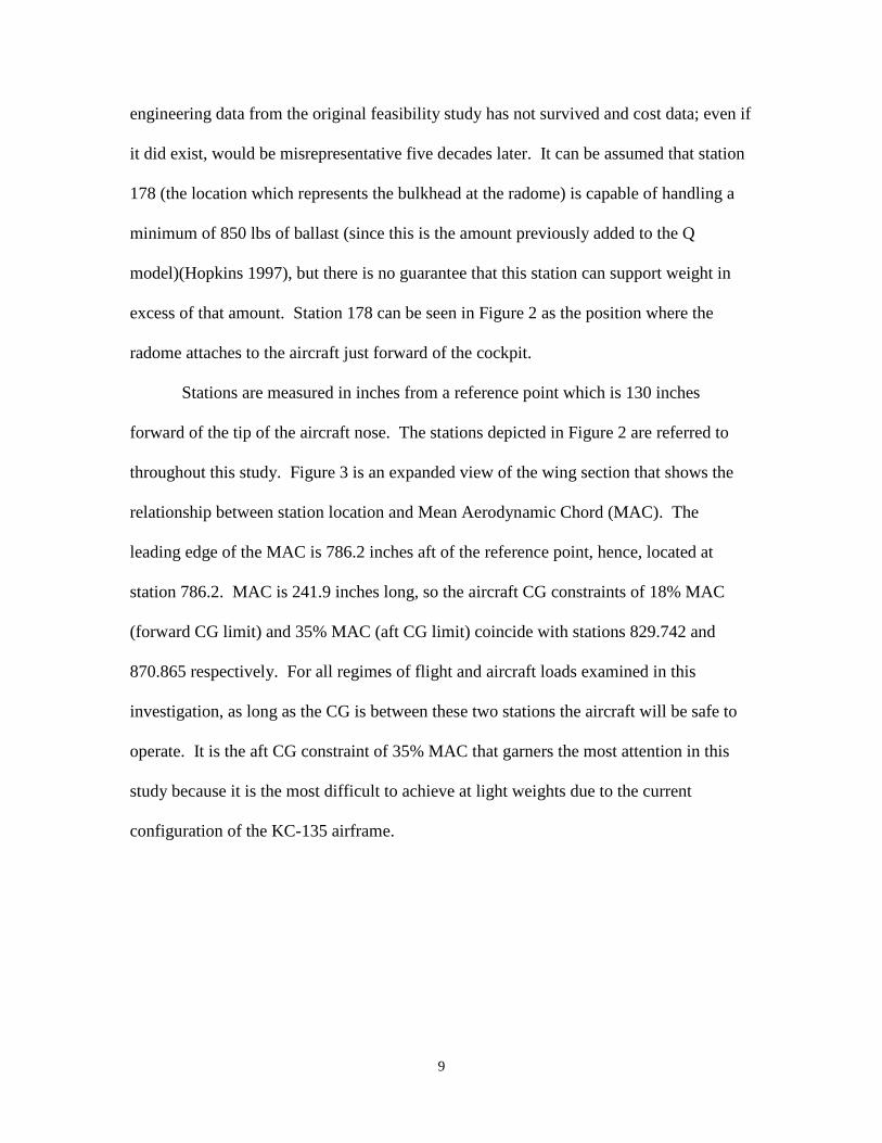
it did exist, would be misrepresentative five decades later. It can be assumed that station
178 (the location which represents the bulkhead at the radome) is capable of handling a
minimum of 850 lbs of ballast (since this is the amount previously added to the Q
model)(Hopkins 1997), but there is no guarantee that this station can support weight in
excess of that amount. Station 178 can be seen in Figure 2 as the position where the
radome attaches to the aircraft just forward of the cockpit.
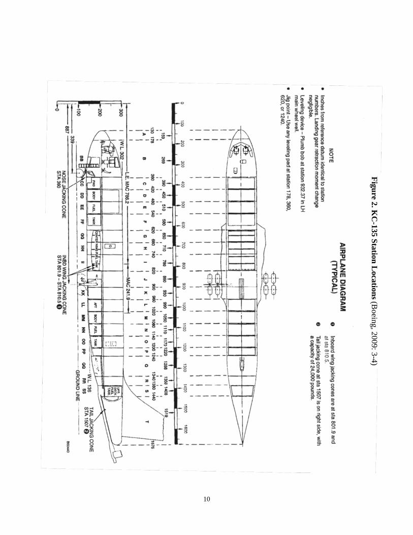
Stations are measured in inches from a reference point which is 130 inches
forward of the tip of the aircraft nose. The stations depicted in Figure 2 are referred to
throughout this study. Figure 3 is an expanded view of the wing section that shows the
relationship between station location and Mean Aerodynamic Chord (MAC). The
leading edge of the MAC is 786.2 inches aft of the reference point, hence, located at
station 786.2. MAC is 241.9 inches long, so the aircraft CG constraints of 18% MAC
(forward CG limit) and 35% MAC (aft CG limit) coincide with stations 829.742 and
870.865 respectively. For all regimes of flight and aircraft loads examined in this
investigation, as long as the CG is between these two stations the aircraft will be safe to
operate. It is the aft CG constraint of 35% MAC that garners the most attention in this
study because it is the most difficult to achieve at light weights due to the current
configuration of the KC-135 airframe.
10
Figure 2
Figure 2. KC
-135 Station Locations (B
oeing, 2009: 3-4)

11
Figure 3. Station Location Relative to Mean Aerodynamic Chord (MAC) (Boeing 2009: 3-4)
At this time the Boeing Corporation is engaged in an EA (EA 09-031-135AMC)
to determine the feasibility of adding nose ballast to the KC-135 at station 178 up to
1,800 lbs with instructions to determine the next forward-most position and its capacity,
if it is found that station 178 cannot handle that amount. Additionally, the feasibility
study will deliver a cost estimate for accomplishing the reballasting project. Since the

12
results of the analysis by Boeing are not scheduled for release until after this study is
released, a cost estimate is used for analysis. This analysis assumes a capacity of 1414
lbs of ballast at station 178 (under the radome), enough to satisfy the worst ballasted KC-
135 in the fleet with a minimum fuel load (600 lbs per main tank). If this assumption is
discovered to be false, for the purpose of implementation additional ballast should be
placed in the location furthest forward with capacity, there are ample options with
similarly long moment-arms in the proximity of station 220.
The cost estimate developed for this study is based on the assumption that
modification would be conducted during aircraft scheduled depot maintenance. An
estimate of KC-135 depot maintenance cost (FY08) is $230/hour (Boyd, 2010), based on
a 200 man-hour completion estimate per aircraft, labor can be projected at $46,000. If
engineering costs, above those already funded in the existing EA, are rolled into
materials, which consist of simple metal brackets, ballasting material (lead, depleted
uranium or any other appropriately dense material) nuts, bolts and washers, a
conservative estimate would be $5,000 per aircraft. The sum of labor and
parts/engineering totaling $51,000 is used as an estimate for applying ballast at station
178 throughout this analysis regardless of the amount of weight applied to the individual
airframe.
The calculation of fuel mitigation will be primarily conducted in terms of pounds
of fuel. Fuel estimates will be converted to a fuel cost mitigation value for the purpose of
calculating recoupment horizons. The (FY10) price of JP-8 aviation fuel effective
January 1, 2010 is $3.22 a gallon (or $0.47 per pound) (Defense Energy Support Center,
2010) and will be used throughout this analysis.

13
The estimate of KC-135 flying hours per year is based solely on past flying hours
reported by the 618th Tanker Airlift Control Center (618 TACC), the global air
operations center responsible for execution of the Air Force mobility fleet. The 618
TACC/XOND recorded 200,367 KC-135 flying hours globally (FY08), this number can
be treated as a conservative estimate due to a substantial year over year growth in flying
hours (618 TACC/XOND, 2009).
Today’s KC-135 fleet is horribly ballasted due to numerous modifications that
have resulted in a tail heavy aircraft. The current solution to this problem is to leave fuel
in the forward body tank to compensate. This study looks at alternate solutions to this
problem that will reduce overall aircraft operating weight and increase mission capability
and effectiveness.
Chapter 2 presents a literature review of the KC-135 and Chapter 3 details
research methodology used to examine alternate solutions, the results and analysis of the
study are presented in Chapter 4, followed by a discussion of the information gleaned
from the research in Chapter 5.
II. Literature Review
The KC-135R as an airframe has evolved over the course of 55 years. The
Boeing 367-80 or “Dash-80” was the prototype of both the KC-135 and Boeing 707.
Since the Dash-80’s first flight, July 15, 1954 (Schiff, 1967: 3-5) numerous changes have
been made to the airframe. These changes have led to greater operational capability,
keeping it a viable platform as requirements have changed, but many changes have also
increased the weight and changed the airframe balance.

14
The KC-135A had a production basic weight of 97,000 lbs, equipped with its J57-
P-43W titanium engines (Hopkins, 1997: 35), but average basic weight of the USAF KC-
135R fleet in 2009 is 119,213 lbs (excluding Multi-Point Refueling System (MPRS)
aircraft which have an average basic weight of 120,370 lbs) and the average basic weight
of a KC-135T is 120,293 lbs (Boeing, 2009).
Even in the very beginning of the KC-135 production cycle, Boeing engineers
were cognizant of the rapidly increasing weight of the “Stratotanker”. Table 2 developed
by Boeing in 1965, shows the growing average weight of the KC-135A over the first 10
years of production.
Table 2. Mean Aircraft Weight Growth During First Ten Years (Boeing Aircraft Corporation, 1965)

15
The weight gain experienced by the KC-135 airframe over the course of its 55
year life cannot be attributed to any one event. The changes made to the airframe during
the conversions from KC-135As to KC-135Rs and KC-135Qs to KC-135Ts were
significant, but they were neither the first nor the last changes that had major impact on
this weight issue. One such major modification made to the KC-135 was in 1962, when
“Boeing engineers redesigned the vertical stabilizer, increasing its height by 40 in[ches]
and increasing the surface area of the rudder” (Hopkins, 1997: 40). This modification
was made to increase lateral control, but added weight to the tail with a long moment-arm
shifting CG further aft. Figure 4 shows the smaller original tall (shaded) superimposed
over the current “tall tail”.
Figure 4. Tail Modification (Boeing, 2009)

16
Other structural improvements were made to reinforce the aircraft tail structure in
the early years. The addition of sonic straps or “belly bands” in 1958 stiffened the aft
fuselage, an area prone to sonic stress from the J57 engines during water injection, by
bonding “25 circumferential bands 2in (5cm) wide … onto the exterior of the airplane aft
of the wing root” (Hopkins, 1997: 40).
In 1966 the development of the SR-71, which burned PF-1 fuel, required the
redesignation and reengineering of 21 KC-135As turning them into KC-135Qs, to
provide the newest spy plane with PF-1 air refueling support (later an additional 33
aircraft were converted for a total of 54). The fuel system on these new “Q-models”
allowed for separation of PF-1 from JP-4, the fuel burned by the KC-135’s J57 engines,
in the “Q-model” tanks. In addition to replumbing the aircraft to prevent fuel mixing,
ceramic tank liners were added to the KC-135Q body tanks “impervious to PF-1, adding
considerable weight to the aircraft” (Hopkins, 1997: 68-69). “To account for changes in
the airplane’s center-of-gravity (cg) during SR-71 refueling operations, 850 lbs (385Kg)
of ballast was added to the lower nose compartment” (Hopkins, 1997: 69) this
counteracted the added weight associated with these heavy ceramic panels. Later the
ceramic panels were removed, but the 850 lbs of ballast remain on the KC-135Q aircraft.
The “Q-models” were then subject to many of the same modifications that the rest of the
KC-135 fleet experienced. The 850 lbs of ballast served to counteract the aft CG
tendency that many of these modifications introduced.
Despite reengining, which changed the designation of the KC-135Q to the KC-
135T, the addition of dual APUs and all of the structural changes that her “R-model”
sisters also experienced the KC-135T model today has an average CG of 35.3% MAC (at

17
basic weight) (Boeing, 2009). This, when compared to the average 37.5% MAC (at basic
weight) found in the KC-135R fleet, is very well balanced; especially when one considers
that the KC-135 dash-1 aft CG limit is 35% MAC for almost all flight regimes (Boeing,
2009).
The major modifications made to the KC-135A and KC-135Q models during their
conversion to KC-135R and KC-135T models were the addition of the CFM56-2 (F-108
military designation) engines, increased surface area on the horizontal stabilizers and the
addition of new bigger APUs (Hopkins, 1997: 71). The original KC-135A engines were
Pratt & Whitney J57-P-29W turbojet engines which are rated at 12,100 lbs of thrust
(Smithsonian Air and Space Museum, 2009: A19810155000), installed on the first three
aircraft only; followed by J57-P-31W, J57-P43W and finally J57-P/F-59W (Hopkins,
1997: 43-44). It was the heavier J57-P/F-59W that was eventually replaced during “A to
R-model” conversion with CFM International CFM56-2 turbofan engines, rated at 22,000
lbs of thrust (Smithsonian Air & Space Museum, 2009: A19900042000). This increase
in vital thrust and fuel efficiency increased the KC-135 offload capability from 40,000 lbs
of fuel on a 4,000 mile round trip mission to 70,000 lbs of fuel (Hopkins, 1997: 71), but
the engines also added weight to the airframe.
The J57-P-43W turbojet engine, which became the standard production engine,
was built out of titanium and weighs approximately 400 lbs less than the original (Flight
Magazine, 1959: 408) J57-P-29W engine, which was built out of steel and weighs 4,285
lbs (Smithsonian Air & Space Museum, 2009: A19810155000). It was with the titanium
J57-P-43W engine, weighing approximately 3,885 lbs, that the KC-135 achieved its light
production weight of 97,000 lbs. The eventual replacement of this power plant with the

18
far more powerful and heavier CFM56-2 turbofan engine, which weighs 4,635 lbs
(Smithsonian Air and Space Museum, 2009: A19900042000), resulted in a 750 lb
increase in weight per engine or a 3,000 lbs net gain in gross weight for all four engines.
While this explains 3,000 lbs of the weight gain atop the airframe’s production baseline
weight, it does not appear to have contributed to the aircraft’s aft CG, since the engines
are located approximately at the aircraft’s 35% MAC. Specifically, engines 1 and 4 are
slightly aft of the 35% MAC and engines 2 and 3 are located slightly forward of the 35%
MAC (Boeing, 2009: 3-3 - 3-4).
The most likely culprits in the aircraft’s aft CG problems are the modifications
made near the tail. The addition of the dual APUs during reengining (see Figure 6) and
the addition of the upper deck tank (see Error! Reference source not found.) are
prime candidates for scrutiny. Although these modifications were not the largest weight
additions to the airframe, the associated moment-arms are very long, amplifying their
effect on the aircraft’s CG. The upper deck fuel tank which has an empty bladder weight
of 92 lbs (station 1414.3) has an average moment 543 inches aft of the 35% MAC
(station 870.8). Error! Reference source not found. shows the location of the upper
deck fuel tank (shaded) relative to the rest of the airframe.
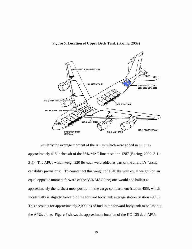
19
Figure 5. Location of Upper Deck Tank (Boeing, 2009)
Similarly the average moment of the APUs, which were added in 1956, is
approximately 416 inches aft of the 35% MAC line at station 1287 (Boeing, 2009: 3-1 -
3-5). The APUs which weigh 920 lbs each were added as part of the aircraft’s “arctic
capability provisions”. To counter act this weight of 1840 lbs with equal weight (on an
equal opposite moment forward of the 35% MAC line) one would add ballast at
approximately the furthest most position in the cargo compartment (station 455), which
incidentally is slightly forward of the forward body tank average station (station 490.3).
This accounts for approximately 2,000 lbs of fuel in the forward body tank to ballast out
the APUs alone. Figure 6 shows the approximate location of the KC-135 dual APUs
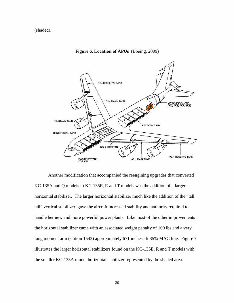
20
(shaded).
Figure 6. Location of APUs (Boeing, 2009)
Another modification that accompanied the reengining upgrades that converted
KC-135A and Q models to KC-135E, R and T models was the addition of a larger
horizontal stabilizer. The larger horizontal stabilizer much like the addition of the “tall
tail” vertical stabilizer, gave the aircraft increased stability and authority required to
handle her new and more powerful power plants. Like most of the other improvements
the horizontal stabilizer came with an associated weight penalty of 160 lbs and a very
long moment arm (station 1543) approximately 671 inches aft 35% MAC line. Figure 7
illustrates the larger horizontal stabilizers found on the KC-135E, R and T models with
the smaller KC-135A model horizontal stabilizer represented by the shaded area.
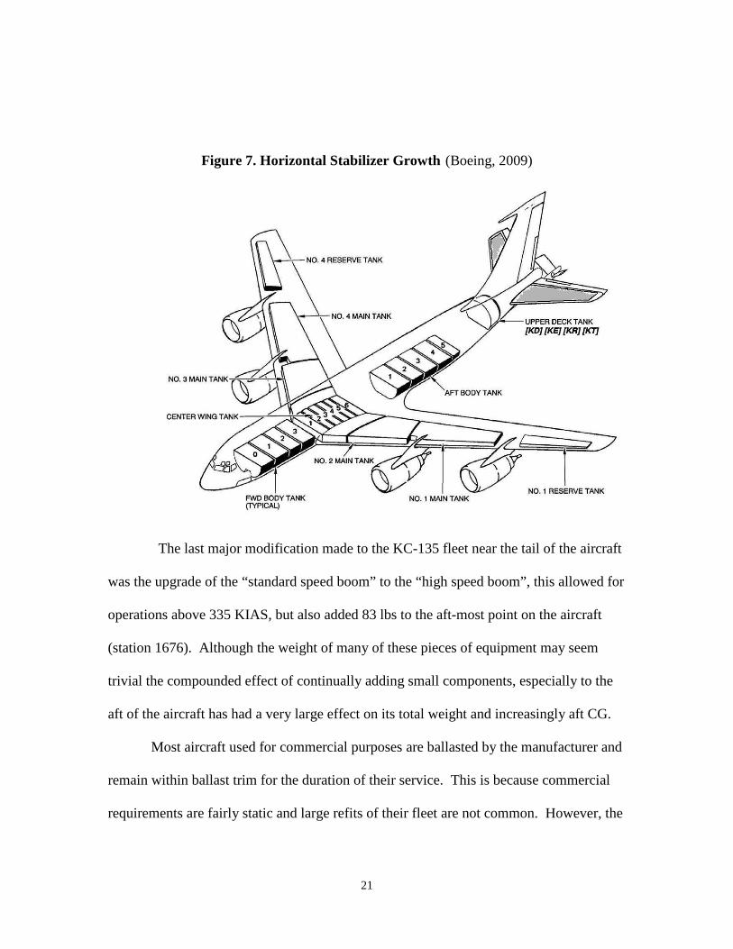
21
Figure 7. Horizontal Stabilizer Growth (Boeing, 2009)
The last major modification made to the KC-135 fleet near the tail of the aircraft
was the upgrade of the “standard speed boom” to the “high speed boom”, this allowed for
operations above 335 KIAS, but also added 83 lbs to the aft-most point on the aircraft
(station 1676). Although the weight of many of these pieces of equipment may seem
trivial the compounded effect of continually adding small components, especially to the
aft of the aircraft has had a very large effect on its total weight and increasingly aft CG.
Most aircraft used for commercial purposes are ballasted by the manufacturer and
remain within ballast trim for the duration of their service. This is because commercial
requirements are fairly static and large refits of their fleet are not common. However, the
22
military often refits existing airframes to accomplish new mission sets. Reengineering
often entails removal of equipment for old mission requirements and the addition of new
equipment for the new mission requirements. This rarely results in a balanced airframe.
A historic example of reballasting a military aircraft for a new mission set is the
development of the RF-86F. In 1952, the USAF Far East Material Command took three
F-86F fighter aircraft and converted them into RF-86Fs by removing all armament, radars
and gun sights, replacing them with a camera suite. The resultant aircraft was horribly
unbalanced, so the decision was made to add “ballast totaling almost 750 lbs, needed to
re-align the aircraft center of gravity…to the forward fuselage” (Davis, 1998). This is
very similar to the changes that occurred in the KC-135, but instead of occurring all at
once they were spread over more than five decades.
The KC-135 has had multiple changes made to its physical structure and its
onboard equipment. Many of these changes have been small, but the cumulative effect
has had an insidious detriment to its weight and CG. The culture that has developed
around the KC-135, like many “legacy aircraft”, has become tantamount to religion,
making it difficult to question why things are done the way they have always been done.
This is compounded by the fact that the original engineers who developed the aircraft
have all long-since retired or in many cases died, which makes gaining access to the logic
behind many of their actions speculative. By questioning the reality behind the
procedures and thoroughly examining the evolution of the machine it is possible to
develop better methods for doing business.
Chapter 3 discusses the methods used to evaluate the proposed solutions and the
treatment of data that deliver the results found in Chapter 4.

23
III. Methodology
Instrument Development
This investigation employs a rudimentary weight and moment-arm construct. The
KC-135 much like a see-saw has a balance point along each of its axes. This particular
investigation is only concerned with the longitudinal axis and its management through
weight application at counter-balance points to achieve equilibrium. The distance from
the fulcrum to these counter-balance points is in direct inverse proportion to the weight
required to achieve equilibrium. In short, the further from the balance point ballast
weight is applied the less weight that is required to balance the aircraft longitudinally.
The less weight used to ballast the airframe the lighter the total balanced aircraft weighs.
Figure 2, an excerpt from T.O. 1C-135-5-1, shows the moment stations as they relate to
the airframe longitudinal axis for reference.
Data and Constraints
The investigation of reballasting the KC-135 fleet, due to fleet size and variation,
was subject to certain constraints and categorization to maintain a manageable focus.
The weight and balance data used in this study supplied the weights for 439 KC-135s.
Only USAF active aircraft tails were considered in this examination. This eliminated all
Foreign Military Sales (FMS) KC-135s that are either owned or on long-term lease to
foreign governments. Additionally, USAF owned aircraft that are in the bone yard, under
mothball or retired status, and static display aircraft tails were not considered when they

24
could be identified. Only the active flying USAF KC-135 R-model and T-model aircraft
were considered. This constraint is important not only for focus but also for relevance of
the data since the U.S. government would not commit funds to reballast foreign aircraft
nor aircraft that are not programmed to fly.
Even within this restricted community there are some variations that are examined
individually due to substantial structural and/or mission differences. While all of these
aircraft are equipped with CFM56-2 engines the primary difference between R-model
and T-model aircraft is the capability of the KC-135T to partition different types of fuel
within its tanks and most importantly the 850 lbs of installed ballast in the aircraft’s nose.
While T-model aircraft are structurally unique they are not currently used to fulfill a
unique mission, although the capability remains for future mission expansion at present
they are used interchangeable with their R-model sisters. Within the KC-135R model
designation there are two subgroups, Multi-Point Refueling System (MPRS) tails and Air
to Air Refuelable (AAR) tails. MPRS aircraft are unique because they are plumbed to
allow for the attachment of “probe and drogue” refueling pod receptacles on each wing
tip and AAR aircraft as the name suggests can be refueled in flight through boom
refueling. Both MPRS and AAR tails are capable and tasked with expanded mission sets
due to their capabilities, so both their physical differences with regard to weight and
balance and their capabilities and missions are considered separately from the general
population of KC-135R aircraft.
The weight and balance source data used to calculate ballast requirements in this
investigation comes from the most recent aircraft depot weigh-in, accomplished post
Program Depot Maintenance (PDM), for each individual aircraft as of the end of 2008.

25
This data was provided by the KC-135 Systems Group (SG) at the 550 ACSS where it is
maintained. The KC-135 is currently undergoing an upgrade from Block 30 to Block 40,
an avionics upgrade that provides Global Air Traffic Management (GATM) capability.
This upgrade was discovered to have an appreciable effect on weight and CG (discussed
later). All aircraft were weighed in basic configuration, all removable equipment was
absent, and no fuel was present in the tanks.
Despite, the origin of the weight and balance data some validation was performed
to ensure the highest level of accuracy possible. First the entire data set of 439 aircraft
was compared side by side with the production list of KC-135 tails produced to reveal 3
known phantom tail numbers (clerical errors, such as typos or the wrong year associated
with last 4 digits of tail number resulting in a double entry). Following the validation of
the aircrafts’ existence all known FMS aircraft that the SG data base had weight and
balance data on were eliminated. This left 421 aircraft 367 KC-135Rs (including 20
MPRS and 7 AAR) and 54 KC-135Ts. Unfortunately, the number of KC-135s in the
fleet is known to have some minor inaccuracies. The actively commissioned fleet of
USAF KC-135s is officially 419 aircraft (417 used as tankers to include 54 T-models, 20
MPRS and 8 AAR tails; and two special use KC-135Rs the “Ice Tanker” test bed 61-
0320 and the “Speckled Trout” aircraft 63-7980 used for transporting the CSAF) as of
February 15, 2010 (Mott, 2010). While the T-model and MPRS aircraft are all accounted
for, the SG was missing the weight and balance for one AAR aircraft. In addition to
having one less AAR aircraft in our records there are 3 additional KC-135R (non-MPRS
and non-AAR) aircraft in the database. These aircraft were discovered after data analysis
to have recently attrited from the fleet (63-8886, 57-1470 and 57-1418, they all appear in
26
the KC-135R Block 30 fleet segment) (Mott, 2010). Despite, the inclusion of these three
recently destroyed aircraft (none of which were unusual in their weight and balance
characteristics) and the absence of the one AAR tail the data presented can be treated
with a high level of confidence. For the purposes of this study the USAF KC-135 fleet
population is treated as 421 aircraft.
The final step in preparing the weight and balance data was to use the GATM
schedule to validate the date all Block 40 aircraft were upgraded from Block 30
configuration. The weigh dates from the weight and balance data base were then cross-
referenced with the upgrade dates to determine at the time of weighing if each individual
tail was in Block 30 or Block 40 configuration. The knowledge of the individual
aircraft’s configuration at time of weighing is of vital importance since T.C.T.O. 1C-135-
1547 (Block 30 to Block 40 conversion) removes 2,105 lbs of equipment with an average
moment of 758.44 * 103 inch pounds and adds 3,221.9 lbs of equipment with an average
moment of 1,226.82 * 103 inch pounds, resulting in a net weight gain of 1,116.9 lbs and a
moment of 468.48 * 103
The calculation of weight and balance for this investigation builds upon the basic
weight and balance provided by the KC-135 SG. Fuel weight and moment were added to
model minimum fuel, as determined by Boeing EA 08-043-135AMC, which prevents
boost pump cavitation during normal operation in each of the main tanks. The specific
amounts prescribed by EA 08-043-135AMC were 513 lbs indicated for main tanks 1 and
4 and 502 lbs for main tanks 2 and 3. These quantities where calculated to account for
potential fuel probe error, but due to display limitations the crew can only read quantities
inch pounds (Amaya, 2009). This moves the aircraft CG
forward because the enhance avionics suite acts as equipment ballast.

27
in 100 lb increments. Policy change levied by AMC GM 1 to 11-2-KC-135 Vol. 3
dictated 600 lbs per main tank to account for this fuel panel fidelity issue. The ballast
fuel of 3,500 lbs in the forward body tank, prescribed by EA 08-043-135AMC (Data
Revision) was replaced in this analysis with the “required minimum ballast” to maintain a
CG forward of 35% MAC, the aft CG limit per T.O.1C-135-1-1.
EA 08-043-135AMC was initially released to the Air Force to include the weight
and balance data points for the entire KC-135R/T fleet, to include FMS aircraft. Many
FMS aircraft have additional equipment not found on USAF aircraft. The control aircraft
for EA 08-043-135AMC was a KC-135R that belongs to the Singapore Air Force. EA
08-043-135AMC (Data Revision) was a rework of the initial data that excluded FMS
aircraft. The controlling aircraft with the largest ballast requirement for this revised data
(57-1462) required 3,410 lbs of fuel to maintain a CG forward of 35% MAC. The
method used for determining this amount during EA 08-043-135AMC (Data Revision)
varies slightly from the method used in this investigation. EA 08-043-135AMC (Data
Revision) placed the entire crew at the aft most position within the plane (station 1300),
while this study did not calculate crew weight at that position. While it is arguably more
conservative to apply the 3 person crew’s weight at the least advantageous position it is
both unrealistic and overly conservative since actual tip-back doesn’t occur until 41.67%
MAC on the ground (Boeing Aero, 2009) and all 3 crew members would never be at
station 1300 in flight.
GM 1 to 11-2-KC-135 Vol. 3 rounded the fuel quantity required for ballast in the
forward tank up to 3,500 lbs to account for fuel panel fidelity issues. “Required
minimum ballast” for the purpose of this examination is determined based on the

28
individual treatment conducted and its individual constraints. Table 3 lists the types of
treatments applied to the Fleet Segments listed in Table 4.
Table 3. Treatments
Treatment A. Use “fuel ballast” to maintain CG limits
Treatment B. Use “equipment ballast” supplemented by “trim ballast” to maintain CG limits
Treatment C. Use “weight ballast” to maintain CG limits
The data analysis was conducted by first ballasting every aircraft in the fleet
individually for each treatment. Then fuel cost mitigation analysis was determined with
regard to average weight reduction across various segments of the fleet. This use of
average should not be confused with a blanket prescription. Averages serve effectively to
model weight and cost savings in the absence of aircraft tail number specific programmed
flying hours. While data of this specificity may be available for very small fleets the
USAF flying hours are programmed primarily at the fleet level. The CoW fuel
determined to calculate pollution/GHG mitigation were based on aggregate fleet flying
hours multiplied by the product of delta (Δ) weight average (for the particular fleet
segment and treatment) and the KC-135 CoW. This approach does not account for
differences in flying hours from one aircraft to another and it was recognized as a
limitation of the data available. Active fleet management; however, does aggressively
target rotation of aircraft tails to balance out airframe hours which minimizes this
assumption’s variability, especially over the remaining 30 plus years of aircraft life
expectancy (Air Mobility Command, 2008).
29
Table 4. Fleet Segments
Block 30 Block 40 Simulated Block 40
KC-135R (non-MPRS and non-AAR)
Fleet Segment I. Fleet Segment II. Fleet Segment III.
KC-135R (MPRS) Fleet Segment IV. Fleet Segment V. Fleet Segment VI.
KC-135R (AAR) Fleet Segment VII. Fleet Segment VIII. Fleet Segment IX.
KC-135T Fleet Segment X. Fleet Segment XI. Fleet Segment XII.
Each of the fleet segments was individually subjected to the various treatments
(Treatment A, B and C), as they were appropriate for examination. Simulated Block 40
aircraft (Block 30 aircraft with weight and moment prescribed by GATM upgrade
T.C.T.O. to simulate upgrade to Block 40) segments were principally used to validate
that Block 40 segment findings would not be invalidated by subsequent Block upgrade of
Block 30 aircraft as they joined the Block 40 segments. Since this segment was added,
decisions made specific to Block 40 aircraft will remain valid across the entire expanding
population, despite airframe upgrades.
This investigation encompasses the entire USAF KC-135 fleet and is not simply a
statistical representation. Solutions found will account for every aircraft in the fleet and
the raw data can be used prescriptively to fix the weight and balance issues of every
USAF KC-135 by individual tail number.
Instrument Administration

30
The approach used in this investigation to determine ballast requirements was
based on aircraft individual requirements not fleet-wide blanket solutions. Currently the
use of 3,500 lbs of fuel in the forward body fuel tank, as ballast, is a fleet-wide solution.
This solution was developed to account for the worst case scenario, specifically aircraft
57-1462, as determined by EA 08-043-135AMC (Data Revision). The use of fuel for
ballast does not lend itself to tailored solutions since tailored guidance for fuel carriage
would need to specify individual aircraft tails. Policy that specific can easily lead to
confusion for aircrew and ground crew members, who change from one aircraft to the
next on a routine basis. It is for this reason that aircraft 57-1462’s weight and ballast
situation, as the controlling aircraft, dictates the carriage of 3,500 lbs of ballast fuel by
aircraft 59-1509 despite the fact that it’s CG (at basic weight) is 35.8% MAC as opposed
to 57-1462’s CG which is 38.4% MAC (at basic weight). The fuel load of 500 lbs in the
forward body tank would be sufficient to ballast aircraft 59-1509, but because of the one-
size-fits-all approach inherent to fuel ballast, that aircraft carries an additional 3,000 lbs
of “dead weight.” The unique advantage to deliberate ballast, accomplished with weight
ballast or equipment and trim ballast, is it can be done on an individual aircraft basis and
eliminates this type of excess.
In this investigation, the application of weight ballast was systematically managed
to maximize moment-arm advantage. Except for ballast with mission enhancement value
(deemed to override a less advantageous moment-arm advantage) all ballast was applied
at the station with the longest mechanical advantage possible (station 178 in the case of
weight ballast), in the smallest amount necessary to obtain a CG of 35% MAC or less.
The discrete nature of equipment ballast does not lend itself to “trimming out” the ballast

31
to an exact value; however, since the forward CG limit for the KC-135 is 18% MAC and
armor ballast did not put any aircraft in a CG regime anywhere close to that during the
analysis treatments, it is safe to say CG of 35% MAC or less is a satisfactory result.
Specifically, the fleet was examined within the Excel© based, KC-135 weight and
balance calculator, developed for this study. The properties to be examined for each
treatment were inputted by attributing the appropriate weight at the appropriate station
location (represented by a specific column in the spreadsheet). In the example below
illustrated in Figure 8, cockpit armor is applied by placing 850 lbs in the column titled
Station 269 Armor; this automatically generates a moment arm for that equipment in the
column directly to the right. In this calculator, fuel is represented the same way as
equipment ballast and weight ballast, as a weight applied at an appropriate average
station. Figure 8 demonstrates how minimum main tank fuel is inputted as 1200 lbs in
both the column titled 1/4 Main Station 890.9 and the column titled 2/3 Main Station
796.2, because tanks 1 and 4 are symmetrical along the longitudinal axis and share an
average station location the 600 lbs of fuel for each tank is combined and applied once as
1200 lbs, the same is true for tanks 2 and 4. Each row represents a specific aircraft by tail
number.
Figure 8. Blow up of KC-135 Weight and Balance Calculator
Station 178
Ballast Moment
Arm Station (220)
Ballast Moment
Arm Station (269)
Armor Moment
Arm
Station (468.48) GATM
Upgrade
Moment Arm
Fwd Body
Station 490.3
Moment Arm
1/4 Main Station 890.9
Moment Arm
2/3 Main Station 796.2
Moment Arm
178 220 269
468.48 490.3 890.9
796.2
0.00 0 0 850 228650 0 0 0 0 1200 1069080 1200 955440
0.00 0 0 850 228650 0 0 0 0 1200 1069080 1200 955440
0.00 0 0 850 228650 0 0 0 0 1200 1069080 1200 955440
0.00 0 0 850 228650 0 0 0 0 1200 1069080 1200 955440

32
0.00 0 0 850 228650 0 0 0 0 1200 1069080 1200 955440
0.00 0 0 850 228650 0 0 0 0 1200 1069080 1200 955440
0.00 0 0 850 228650 0 0 0 0 1200 1069080 1200 955440
0.00 0 0 850 228650 0 0 0 0 1200 1069080 1200 955440
Figure 9 is a screen shot taken of the KC-135T model Block 40 aircraft (fleet
segment XI) during a cockpit armor and minimum main tank fuel treatment. The
individual aircraft operational weights can be seen in column “AK” and the CGs can be
seen in column “AO”.
Figure 9. Screen Shot of KC-135 Weight and Balance Calculator
The KC-135 weight and balance calculator works by converting the weights
applied in the appropriate columns into moments (in the columns directly to the right of
each weight column) then summing the individual moments and adding them to the basic
moment for that particular aircraft (see Figure 10. Weight and Moment Columns Screen
Shot). In Figure 10, the data in column “A” through column “I” is data supplied by the

33
SG, all columns past column “I” were developed to calculate the result of applying
weight on top of the basic airframe.
Figure 10. Weight and Moment Columns Screen Shot
The calculation of “weight ballast” required at station 178 was calculated by first
simulating the other constraints (main tank fuel, forward body fuel, cockpit armor, etc.),
then using Solver© to populate the ballast weight required for each individual aircraft tail
at station 178 (by placing the appropriate weight in column “O”). Solver© is used to
examine weight ballast required for the MPRS Block 40 (fleet segment V) during the
treatment B data collection (Figure 11). The target cell in Solver© is “O13” (the column
total for Block 40 weight at station 178), and Solver© is instructed to minimize the value
in that cell (this minimizes total weight used). Solver© is authorized to manipulate the
weight placed in cells “O3” through “O12” (representing individual aircraft ballast
needed) to accomplish its objective, given the constraint that all the values in cells “AO3”
Basic Moment (tail 58-0050)
Basic Weight (tail 58-0050)

34
through “AO12” (the CG in % MAC) are less than or equal to 35.
Figure 11. Solver Screen Shot
Figure 12 shows the results after Solver© has been run for the scenario in Figure
11. The values in column “O” are the specific weights required to ballast each individual
aircraft (using station 178) given the specific treatment of this fleet segment. Column
“AO” in Figure 12 shows how the weights applied in column “O” created ballasted
aircraft with respective CGs of 35% MAC or less.
Once the individual treatments were run for each fleet segment, descriptive
statistics were gathered for aircraft CG (column “AO”), aircraft operating weight (column
“AK”), and finally ballast weight applied at station 178 (column “O”) when applicable.
It is this data organized by fleet segment and treatment that populates the tables in this
report.

35
Figure 12. Solver “Solved” Screen Shot
The calculation of both fuel mitigation, reported in pounds of JP-8, and fuel cost
mitigation, reported in U.S. 2010 dollars, was determined by comparing “zero fuel”
weights of the ballasted airframes with the current configuration “zero fuel” weight
(directed by GM 1 to 11-2-KC-135 Vol. 3). The average difference in aircraft weight by
fleet segment was then combined (using a weighted average due to difference in fleet
segment sizes) to determine an average weight difference per aircraft across the entire
fleet. This average weight difference was multiplied by the CoW for the KC-135 to
determine average fuel mitigation in pounds of JP-8 per hour. The average fuel
mitigation in pounds per hour was multiplied across the annual KC-135 flying hours to
determine annual fleet fuel mitigation. Fuel cost mitigation was calculated by
multiplying annual fleet fuel mitigation by the cost of fuel. The cost of aircraft

36
modifications prescribed was totaled for each solution set and divided by the annual fuel
cost mitigation to determine a recoupment horizon for each solution set.
IV. Results and Analysis
Empty Aircraft
Analysis of the KC-135 fleet without fuel on board or any form of ballast is given
in Table 5 and Table 6.
Table 5. Empty Aircraft Block 30
R-Model T-Model MPRS ARR
Block 30
CG Mean 37.5710967 Mean 35.541147 Mean 37.456899 Mean 36.40134
CG Minimum 35.9308172 Minimum 34.708476 Minimum 36.360758 Minimum 35.97779
CG Maximum 38.5391706 Maximum 37.424979 Maximum 38.026555 Maximum 36.93265
CG AC w/CG >35.0 285
AC w/CG >35.0 30
AC w/CG >35.0 10
AC w/CG >35.0 5
Weight Mean 119106.295 Mean 120048.38 Mean 119949.96 Mean 120572.9
Weight Minimum 116840 Minimum 118918 Minimum 118311 Minimum 120047
Weight Maximum 122501 Maximum 121133 Maximum 120970.6 Maximum 120934
Weight Count 285 Count 33 Count 10 Count 5
Table 6. Empty Aircraft Block 40
R-Model T-Model MPRS ARR
Block 40
CG Mean 36.9440527 Mean 34.94009 Mean 36.901044 Mean 36.03344
CG Minimum 35.847272 Minimum 34.063204 Minimum 36.095907 Minimum 35.88955
CG Maximum 37.8598048 Maximum 36.926869 Maximum 37.319457 Maximum 36.17733
CG AC w/CG >35.0 55
AC w/CG >35.0 6
AC w/CG >35.0 10
AC w/CG >35.0 2
Weight Mean 119739.969 Mean 120679.01 Mean 120790.43 Mean 121608.3
Weight Minimum 118316 Minimum 119626 Minimum 119978 Minimum 121244.5
Weight Maximum 120855 Maximum 121204.6 Maximum 121609 Maximum 121972
Weight Count 55 Count 21 Count 10 Count 2

37
Quick comparison of the mean CGs (reported as % MAC) demonstrates some
basic traits of the fleet segments with regard to weight and balance. The T-model KC-
135s are not surprisingly the best ballasted aircraft in the fleet, demonstrated by the
lowest % MAC value among the Block 30 aircraft (fleet segment X) and among the
Block 40 aircraft (fleet segment XI). This is logical due to the ballast of 850 lbs added to
station 178 to these aircraft in the 1960s. The MPRS and KC-135R (non-MPRS and non-
AAR) aircraft have very similar CGs both among Block 30 (fleet segments IV and I) and
Block 40 aircraft (fleet segments V and II). The AAR aircraft have an average CG less
than the other KC-135R models (MPRS and non-MPPRS), but they are not ballasted
quite as well as the KC-135T aircraft. The better average ballast of the AAR aircraft
(compared to the other R-models) was expected, due to the equipment and plumbing on
these aircraft over the cockpit for receiver air-to-air refueling, which provides them with
some forward equipment ballast.
When each category (KC-135R, KC-135T, MPRS and AAR) compares its Block
30 component to its Block 40 component the Block 40 aircraft are always better
ballasted. This stands to reason because of the known addition of forward ballast to these
aircraft during the upgrade process.
Quick analysis of the aircraft weight produces some similarly expected results.
The weight difference between KC-135R (non-MPRS and Non-AAR) and KC-135T
aircraft is approx 940 lbs (found in comparison both among Block 30 and Block 40
aircraft). This is logical because as stated earlier the T-model aircraft have 850 lbs of
ballast already, the additional 90 lb difference can be explained by additional valves and
equipment required to partition body fuel in the T-models. The MPRS aircraft proved to

38
be consistently heavier than the KC-135R (non-MPRS and non-AAR) aircraft, by an
average of approximately 840 lbs for the Block 30 and approximately 1,050 lbs for the
Block 40 aircraft. The greater weight of the MPRS aircraft is explained by an additional
fuel manifold that runs the length of the wings that supplies the MPRS pods (the
difference between Block 30 (fleet segment IV) and Block 40 (fleet segment V) appears
to be due to a small MPRS aircraft population; only 10, Block 30 and 10, Block 40,
giving greater statistical authority to individual aircraft anomalies in weight). The
additional fuel manifold present on the MPRS aircraft is located in the forward portion of
the aircraft’s wing which appears to minimize its effect on CG in these aircraft. The
heaviest aircraft by fleet segment are the AAR airframes (fleet segments VII and VIII)
weighing between 500 and 1,000lbs more than either the T-model (fleet segments X and
XI) or MPPRS aircraft (fleet segments IV and V).
The differences within each category between Block 30 and Block 40 aircraft
average weights were somewhat surprising considering the knowledge of the exact
equipment weight change as described by the modification instructions (1,116.9 lbs).
The weight difference within both the KC-135R (fleet segments I and II) and KC-135T
(fleet segments X and XI) categories were only about 630 lbs, significantly less than the
expected 1,116.9 lbs, despite a fairly large population of KC-135R Block 40 aircraft (55
total in fleet segment II). The differences among the MPRS (fleet segments IV and V)
and AAR (fleet segments VII and VIII) categories were also slightly smaller than
expected but closer to the 1,116.9 lb mark (MPRS 840 lb difference and AAR 1,035 lb
difference). Explanation of this smaller than expected weight change is purely
speculative; however, it may be possible that Block 40 upgrade schedule indirectly

39
favored lighter aircraft. The selection of aircraft by production year could potentially do
this if substitute materials with slightly different weights where used during the long
production cycle. Regardless of the observed variation, the validity of the weight and
balance information for T.C.T.O. 1C-135-1547 provided by the KC-135 Weight and
Balance Authority Office is maintained throughout this study, because this observed data
is subject to numerous variables.
Aircraft (No Ballast) with Minimum Fuel (600 lbs in main tanks 1-4)
The minimum main tank fuel option applied across the entire fleet yielded the
following results by fleet segment. Table 7 shows the results for Block 30 aircraft, Table
8 shows the Block 40 aircraft results and Table 9 shows the results for all Block 30
aircraft simulating conversion to Block 40 (using weight and balance correction). It is
important to note that “minimum fuel” refers to fuel required to run the engines and is a
component of “zero fuel”, but not necessarily the same. In the case of fuel ballast used in
treatment A zero fuel is the compilation of minimum fuel and fuel ballast.
Table 7. Minimum Fuel Block 30
R-Model T-Model MPRS ARR
Block 30
CG Mean 37.297271 Mean 35.309211 Mean 37.187242 Mean 36.15362
CG Minimum 35.6848056 Minimum 34.492381 Minimum 36.109197 Minimum 35.73845
CG Maximum 38.2541892 Maximum 37.153623 Maximum 37.747047 Maximum 36.67497
CG AC w/CG >35.0 285
AC w/CG >35.0 27
AC w/CG >35.0 10
AC w/CG >35.0 5
Weight Mean 121506.295 Mean 122448.38 Mean 122349.96 Mean 122972.9
Weight Minimum 119240 Minimum 121318 Minimum 120711 Minimum 122447
Weight Maximum 124901 Maximum 123533 Maximum 123370.6 Maximum 123334
Weight Count 285 Count 33 Count 10 Count 5
40
Table 8. Minimum Fuel Block 40
R-Model T-Model MPRS ARR
Block 40
CG Mean 36.6839701 Mean 34.721057 Mean 36.644019 Mean 35.79491
CG Minimum 35.6059294 Minimum 33.861638 Minimum 35.854518 Minimum 35.6531
CG Maximum 37.5825523 Maximum 36.669851 Maximum 37.054918 Maximum 35.93672
CG AC w/CG >35.0 55
AC w/CG >35.0 3
AC w/CG >35.0 10
AC w/CG >35.0 2
Weight Mean 122139.969 Mean 123079.01 Mean 123190.43 Mean 124008.3
Weight Minimum 120716 Minimum 122026 Minimum 122378 Minimum 123644.5
Weight Maximum 123255 Maximum 123604.6 Maximum 124009 Maximum 124372
Weight Count 55 Count 21 Count 10 Count 2
Table 9. Minimum Fuel Block 30 Converted
R-Model
T-Model
MPRS
ARR
Block 30 converted
CG Mean 35.761186 Mean 33.802816 Mean 35.662632 Mean 34.64602
CG Minimum 34.1347994 Minimum 32.990038 Minimum 34.574015 Minimum 34.23532
CG Maximum 36.7510401 Maximum 35.616525 Maximum 36.224764 Maximum 35.16509
CG AC w/CG >35.0 275
AC w/CG >35.0 1
AC w/CG >35.0 8
AC w/CG >35.0 2
Weight Mean 122623.195 Mean 123565.28 Mean 123466.86 Mean 124089.8
Weight Minimum 120356.9 Minimum 122434.9 Minimum 121827.9 Minimum 123563.9
Weight Maximum 126017.9 Maximum 124649.9 Maximum 124487.5 Maximum 124450.9
Weight Count 285 Count 33 Count 10 Count 5
The change in CG from an empty aircraft to an aircraft carrying the minimum fuel
load of 600 lbs in each of the main tanks is a consistent shift forward of approximately
.25% MAC, within all fleet segments. The minimum main tank fuel (600 lbs in main
tanks 1-4) is used as the base line for comparison throughout the remainder of this study
since there is no operational situation that would result in anything less. The comparison

41
between empty and minimum fuel is used to illustrate the minimal (but worth
considering) shift in CG that occurs in a relatively uniform manner across the fleet. It is a
consideration, for those rare maintenance situations (outside depot maintenance) that
require all fuel be drained, that a small additional ballast weight may need to be applied
for the duration of the maintenance operation, but the enormous “pet rocks” (2 ton pieces
of concrete placed in the forward section of the cargo bay) currently employed during
depot maintenance would no longer be required to replace the 3,500 lbs of ballast fuel
assuming treatment B or C is used.
The inclusion of Table 9 which depicts Block 30 aircraft converted to Block 40 is
to help demonstrate how policy directed at Block 40 aircraft can be validated before
complete conversion has occurred within the fleet. This table serves a base-line within
the study for comparison with equipment and weight ballast tables for individual fleet
segments.
Aircraft with Minimum Main Tank Fuel & Cockpit Armor (No Trim Ballast)
Aircraft examined by fleet segment with minimum fuel in the main tanks (600 lbs
in main tanks 1-4) and 850 lbs of armor (the weight of 110 sq ft of LAST© armor, such
as that previously tested on the KC-135 airframe) applied at the determined average
station of 269, garnered the following results. Table 10 shows the results for Block 30
aircraft, Table 11 shows the Block 40 aircraft results and Table 12 shows the results for
all Block 30 aircraft simulating conversion to Block 40.

42
Table 10. Armor Analysis without Trim Ballast Block 30
R-Model T-Model MPRS ARR
Block 30
CG Mean 35.5528212 Mean 33.591807 Mean 35.455471 Mean 34.43773
CG Minimum 33.9188939 Minimum 32.776795 Minimum 34.361686 Minimum 34.02624
CG Maximum 36.550407 Maximum 35.407529 Maximum 36.019826 Maximum 34.95824
CG AC w/CG >35.0 265
AC w/CG >35.0 1
AC w/CG >35.0 7
AC w/CG >35.0 0
Weight Mean 122356.295 Mean 123298.38 Mean 123199.96 Mean 123822.9
Weight Minimum 120090 Minimum 122168 Minimum 121561 Minimum 123297
Weight Maximum 125751 Maximum 124383 Maximum 124220.6 Maximum 124184
Weight Count 285 Count 33 Count 10 Count 5
Table 11. Armor Analysis without Trim Ballast Block 40
R-Model T-Model MPRS ARR
Block 40
CG Mean 34.9527619 Mean 33.016437 Mean 34.92775 Mean 34.09567
CG Minimum 33.8620101 Minimum 32.165898 Minimum 34.143327 Minimum 33.94988
CG Maximum 35.8502624 Maximum 34.956808 Maximum 35.339958 Maximum 34.24147
CG AC w/CG >35.0 22
AC w/CG >35.0 0
AC w/CG >35.0 5
AC w/CG >35.0 0
Weight Mean 122989.969 Mean 123929.01 Mean 124040.43 Mean 124858.3
Weight Minimum 121566 Minimum 122876 Minimum 123228 Minimum 124494.5
Weight Maximum 124105 Maximum 124454.6 Maximum 124859 Maximum 125222
Weight Count 55 Count 21 Count 10 Count 2
Table 12. Armor Analysis without Trim Ballast Block 30 Converted
R-Model T-Model MPRS ARR
Block 30 converted
CG Mean 34.0430919 Mean 32.111122 Mean 33.956847 Mean 32.95572
CG Minimum 32.3960301 Minimum 31.300175 Minimum 32.853052 Minimum 32.54864
CG Maximum 35.0723283 Maximum 33.896847 Maximum 34.523347 Maximum 33.47394
CG AC w/CG >35.0 1
AC w/CG >35.0 0
AC w/CG >35.0 0
AC w/CG >35.0 0
Weight Mean 123473.195 Mean 124415.28 Mean 124316.86 Mean 124939.8
Weight Minimum 121206.9 Minimum 123284.9 Minimum 122677.9 Minimum 124413.9
Weight Maximum 126867.9 Maximum 125499.9 Maximum 125337.5 Maximum 125300.9
Weight Count 285 Count 33 Count 10 Count 5
43
Table 10, Table 11 and Table 12 clearly depict a significant forward shift in
aircraft CG when cockpit armor is added. Cockpit armor moves CG forward by more
than 1.7% MAC among the Block 30 aircraft, across all fleet categories (R-model fleet
segment I, T-model fleet segment X, MPRS fleet segment IV and ARR fleet segment
VII). Significantly, even among Block 30 aircraft this pushes the average CG for T-
model (fleet segment X) and ARR aircraft (fleet segment VII) forward of the critical 35%
MAC and even brings the R-model (fleet segment I) and MPRS (fleet segment IV)
categories average CGs very close to that mark.
The Block 40 aircraft, which also experience a forward shift in CG of 1.7% or
more from the addition of cockpit armor, saw the average CG in all categories move
ahead of the crucial 35% MAC threshold. Table 12 demonstrates that like the Block 40
aircraft, the remaining Block 30 aircraft when converted to Block 40 will experience
similar results that will bring the average CGs in all categories forward of the 35% MAC
mark.
Although average CGs are very good at describing trends within the fleet, it is
critical that each individual aircraft meet the requirements for safe flight. Table 13 shows
exactly how many aircraft would still have CGs of greater than 35% MAC, with
minimum main tank fuel and cockpit armor only.
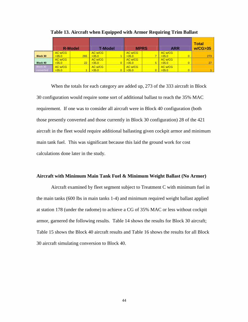
44
Table 13. Aircraft when Equipped with Armor Requiring Trim Ballast
R-Model T-Model MPRS ARR
Total w/CG>35
Block 30 AC w/CG >35.0 265
AC w/CG >35.0 1
AC w/CG >35.0 7
AC w/CG >35.0 0 273
Block 40 AC w/CG >35.0 22
AC w/CG >35.0 0
AC w/CG >35.0 5
AC w/CG >35.0 0 27
Block 30 converted
AC w/CG >35.0 1
AC w/CG >35.0 0
AC w/CG >35.0 0
AC w/CG >35.0 0 1
When the totals for each category are added up, 273 of the 333 aircraft in Block
30 configuration would require some sort of additional ballast to reach the 35% MAC
requirement. If one was to consider all aircraft were in Block 40 configuration (both
those presently converted and those currently in Block 30 configuration) 28 of the 421
aircraft in the fleet would require additional ballasting given cockpit armor and minimum
main tank fuel. This was significant because this laid the ground work for cost
calculations done later in the study.
Aircraft with Minimum Main Tank Fuel & Minimum Weight Ballast (No Armor)
Aircraft examined by fleet segment subject to Treatment C with minimum fuel in
the main tanks (600 lbs in main tanks 1-4) and minimum required weight ballast applied
at station 178 (under the radome) to achieve a CG of 35% MAC or less without cockpit
armor, garnered the following results. Table 14 shows the results for Block 30 aircraft;
Table 15 shows the Block 40 aircraft results and Table 16 shows the results for all Block
30 aircraft simulating conversion to Block 40.

45
Table 14. Treatment C Block 30
R-Model T-Model MPRS ARR
Block 30
CG Mean 34.9999864 Mean 34.961868 Mean 35.0 Mean 35.0
CG Minimum 34.99508 Minimum 34.492381 Minimum 35.0 Minimum 35.0
CG Maximum 35.0 Maximum 35.0 Maximum 35.0 Maximum 35.0
CG AC w/CG >35.0 0
AC w/CG >35.0 0
AC w/CG >35.0 0
AC w/CG >35.0 0
Weight Mean 122480.912 Mean 122596.8 Mean 123278.54 Mean 123466.7
Weight Minimum 119526.792 Minimum 121500.47 Minimum 121177.04 Minimum 122821.5
Weight Maximum 126315.337 Maximum 123860.96 Maximum 124131.77 Maximum 124029.4 Ballast
Weight Mean 974.616875 Mean 148.41831 Mean 928.58334 Mean 493.7514 Ballast
Weight Minimum 286.7916 Minimum 0 Minimum 466.04049 Minimum 316.6394 Ballast
Weight Maximum 1414.33688 Maximum 912.18159 Maximum 1168.8853 Maximum 716.6742 Ballast
Weight Count 285 Count 33 Count 10 Count 5 Ballast
Weight AC req ballast 285
AC req ballast 27
AC req ballast 10
AC req ballast 5
Table 15. Treatment C Block 40
R-Model T-Model MPRS ARR
Block 40
CG Mean 34.9966408 Mean 34.562938 Mean 35.0 Mean 35.0
CG Minimum 34.9952447 Minimum 33.861638 Minimum 35.0 Minimum 35.0
CG Maximum 35.0 Maximum 35.0 Maximum 35.0 Maximum 35.0
CG AC w/CG >35.0 0
AC w/CG >35.0 0
AC w/CG >35.0 0
AC w/CG >35.0 0
Weight Mean 122859.548 Mean 123146.84 Mean 123893.95 Mean 124351.9
Weight Minimum 120972.944 Minimum 122551.1 Minimum 123114.32 Minimum 123926
Weight Maximum 123917.486 Maximum 124150.51 Maximum 124772.63 Maximum 124777.7 Ballast
Weight Mean 719.578595 Mean 67.826258 Mean 703.52104 Mean 343.6284 Ballast
Weight Minimum 256.94441 Minimum 0 Minimum 366.65113 Minimum 281.5162 Ballast
Weight Maximum 1103.60107 Maximum 715.50723 Maximum 880.33874 Maximum 405.7406 Ballast
Weight Count 55 Count 21 Count 10 Count 2 Ballast
Weight AC req ballast 55
AC req ballast 3
AC req ballast 10
AC req ballast 2

46
Table 16. Treatment C Block 30 Converted
R-Model T-Model MPRS ARR
Block 30 converted
CG Mean 34.9855964 Mean 33.784172 Mean 34.942764 Mean 34.58993
CG Minimum 34.1347994 Minimum 32.990038 Minimum 34.574015 Minimum 34.23532
CG Maximum 34.9996743 Maximum 35.0 Maximum 35.0 Maximum 34.99996
CG AC w/CG >35.0 0
AC w/CG >35.0 0
AC w/CG >35.0 0
AC w/CG >35.0 0
Weight Mean 122955.298 Mean 123573.25 Mean 123777.93 Mean 124114.2
Weight Minimum 120356.9 Minimum 122560.9 Minimum 121827.9 Minimum 123563.9
Weight Maximum 126789.694 Maximum 124649.9 Maximum 124605.79 Maximum 124501 Ballast
Weight Mean 332.103209 Mean 7.9694923 Mean 311.07185 Mean 24.35418 Ballast
Weight Minimum 0 Minimum 0 Minimum 0 Minimum 0 Ballast
Weight Maximum 771.793865 Maximum 262.99325 Maximum 528.65822 Maximum 71.65119 Ballast
Weight Count 285 Count 33 Count 10 Count 5 Ballast
Weight AC req ballast 275
AC req ballast 1
AC req ballast 8
AC req ballast 2
In many regards the CGs and weights in Table 14 and Table 15 are a reflection of
Table 7 and Table 8 (which show minimum fuel only); however, the addition of ballast
weight at the bottom of these tables adds information about how much weight would
need to be added to the various fleet categories by block type (weight added to station
178). If the feasibility report currently being conducted by Boeing, were to determine the
capacity of station 178 is less than 1,414 lbs (maximum requirement for weight ballast)
and there was no other suitable location to place that much ballast a reexamination of the
Block 30 aircraft ballast would need to be conducted, assuming no equipment ballast was
to be used. Similarly the maximum ballast requirement in the Block 40 aircraft is slightly
less at approx 1,103 lbs (Table 15). Not surprisingly all of these maximum ballast
weights are required by aircraft in the KC-135R fleet category.
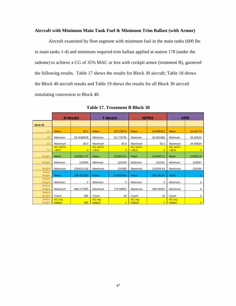
47
Aircraft with Minimum Main Tank Fuel & Minimum Trim Ballast (with Armor)
Aircraft examined by fleet segment with minimum fuel in the main tanks (600 lbs
in main tanks 1-4) and minimum required trim ballast applied at station 178 (under the
radome) to achieve a CG of 35% MAC or less with cockpit armor (treatment B), garnered
the following results. Table 17 shows the results for Block 30 aircraft; Table 18 shows
the Block 40 aircraft results and Table 19 shows the results for all Block 30 aircraft
simulating conversion to Block 40.
Table 17. Treatment B Block 30
R-Model T-Model MPRS ARR
Block 30
CG Mean 35.0 Mean 33.579474 Mean 34.898422 Mean 34.43773
CG Minimum 33.9188939 Minimum 32.776795 Minimum 34.361686 Minimum 34.02624
CG Maximum 35.0 Maximum 35.0 Maximum 35.0 Maximum 34.95824
CG AC w/CG >35.0 0
AC w/CG >35.0 0
AC w/CG >35.0 0
AC w/CG >35.0 0
Weight Mean 122591.747 Mean 123303.64 Mean 123440.11 Mean 123822.9
Weight Minimum 120090 Minimum 122294 Minimum 121561 Minimum 123297
Weight Maximum 126419.218 Maximum 124383 Maximum 124249.43 Maximum 124184 Ballast
Weight Mean 235.452329 Mean 5.2602583 Mean 240.15145 Mean 0 Ballast
Weight Minimum 0 Minimum 0 Minimum 0 Minimum 0 Ballast
Weight Maximum 668.217905 Maximum 173.58852 Maximum 439.56562 Maximum 0 Ballast
Weight Count 285 Count 33 Count 10 Count 5 Ballast
Weight AC req ballast 265
AC req ballast 1
AC req ballast 7
AC req ballast 0
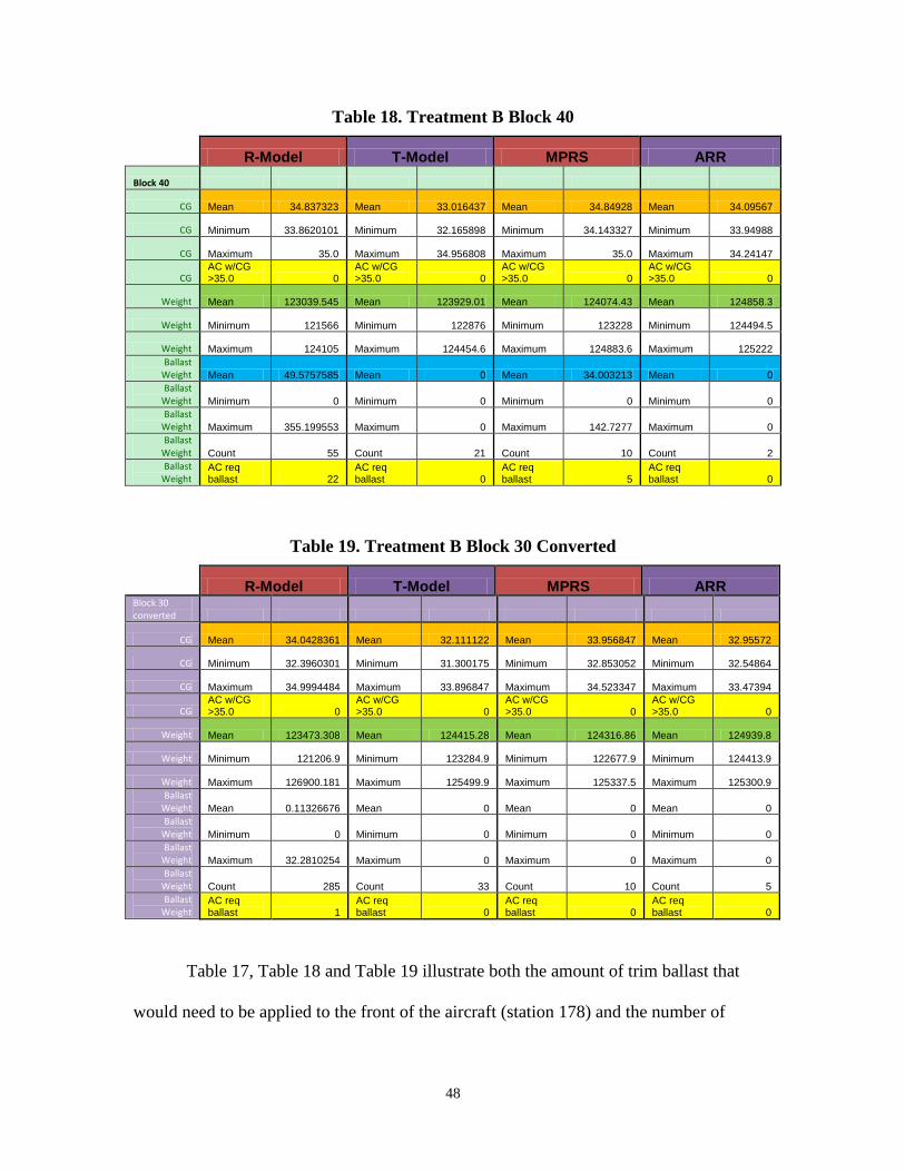
48
Table 18. Treatment B Block 40
R-Model T-Model MPRS ARR
Block 40
CG Mean 34.837323 Mean 33.016437 Mean 34.84928 Mean 34.09567
CG Minimum 33.8620101 Minimum 32.165898 Minimum 34.143327 Minimum 33.94988
CG Maximum 35.0 Maximum 34.956808 Maximum 35.0 Maximum 34.24147
CG AC w/CG >35.0 0
AC w/CG >35.0 0
AC w/CG >35.0 0
AC w/CG >35.0 0
Weight Mean 123039.545 Mean 123929.01 Mean 124074.43 Mean 124858.3
Weight Minimum 121566 Minimum 122876 Minimum 123228 Minimum 124494.5
Weight Maximum 124105 Maximum 124454.6 Maximum 124883.6 Maximum 125222 Ballast
Weight Mean 49.5757585 Mean 0 Mean 34.003213 Mean 0 Ballast
Weight Minimum 0 Minimum 0 Minimum 0 Minimum 0 Ballast
Weight Maximum 355.199553 Maximum 0 Maximum 142.7277 Maximum 0 Ballast
Weight Count 55 Count 21 Count 10 Count 2 Ballast
Weight AC req ballast 22
AC req ballast 0
AC req ballast 5
AC req ballast 0
Table 19. Treatment B Block 30 Converted
R-Model T-Model MPRS ARR
Block 30 converted
CG Mean 34.0428361 Mean 32.111122 Mean 33.956847 Mean 32.95572
CG Minimum 32.3960301 Minimum 31.300175 Minimum 32.853052 Minimum 32.54864
CG Maximum 34.9994484 Maximum 33.896847 Maximum 34.523347 Maximum 33.47394
CG AC w/CG >35.0 0
AC w/CG >35.0 0
AC w/CG >35.0 0
AC w/CG >35.0 0
Weight Mean 123473.308 Mean 124415.28 Mean 124316.86 Mean 124939.8
Weight Minimum 121206.9 Minimum 123284.9 Minimum 122677.9 Minimum 124413.9
Weight Maximum 126900.181 Maximum 125499.9 Maximum 125337.5 Maximum 125300.9 Ballast
Weight Mean 0.11326676 Mean 0 Mean 0 Mean 0 Ballast
Weight Minimum 0 Minimum 0 Minimum 0 Minimum 0 Ballast
Weight Maximum 32.2810254 Maximum 0 Maximum 0 Maximum 0 Ballast
Weight Count 285 Count 33 Count 10 Count 5 Ballast
Weight AC req ballast 1
AC req ballast 0
AC req ballast 0
AC req ballast 0
Table 17, Table 18 and Table 19 illustrate both the amount of trim ballast that
would need to be applied to the front of the aircraft (station 178) and the number of
49
aircraft that would require ballast above and beyond cockpit armor. The Block 30
aircraft would require the greatest amount of average ballast and the greatest number of
aircraft requiring this “trim weight” resides in this fleet segment. In fleet segment I (KC-
135R Block 30) 265 of 285 aircraft equipped with cockpit armor would require additional
ballast, the most poorly ballasted aircraft requiring an additional 668 lbs be applied at
station 178. In fleet segment X (KC-135T Block 30) only 1 of 33 aircraft requires weight
be applied at station 178 (173 lbs), when cockpit armor is used. The fleet segment IV
(MPRS Block 30) aircraft when equipped with armor require that 7 of the 10 aircraft
receive additional ballast to bring the CG forward of 35% MAC. The only Block 30 fleet
segment that does not require any additional ballasting, when cockpit armor is used is
fleet segment VII (AAR) all 5 aircraft have a CG forward of 35% MAC. Interestingly
enough if all of the Block 30 fleet segment aircraft are converted to Block 40 aircraft
cockpit armor satisfies the requirement of producing a CG forward of 35% MAC in 332
of the 333 aircraft. The remaining aircraft can be ballasted with approximately 32 lbs of
ballast at station 178.
The Block 40 aircraft responded more favorably to the application of cockpit
armor than the Block 30 aircraft. Within fleet segment II (KC-135R Block 40) only 22 of
the 55 aircraft required additional ballast to bring the airframes within limits and none of
the fleet segment XI and VIII (KC-135T Block 40 and AAR Block 40) aircraft required
additional ballast beyond cockpit armor. The fleet segment V (MPRS Block 40) aircraft
found 5 of the 10 aircraft still required additional ballast.
If one were to assume all Block 40 aircraft (both those currently in this block
configuration and the Block 30 aircraft, following their planned upgrade) and the use of

50
cockpit armor on all of these aircraft, only 28 aircraft in the entire KC-135 fleet would
require additional ballast at station 178! If assuming an all Block 40 aircraft solution, it
is also notable that the maximum required ballast weight is reduced to approximately 355
lbs at station 178, this eliminates any capacity concerns for station 178, based on T-model
ballast.
Aircraft, Minimum Fuel & 3,500 lbs of Fuel in Fwd Body (current configuration)
Research results for aircraft by fleet segment with minimum fuel in the main
tanks (600 lbs in main tanks 1-4) and 3,500 lbs of fuel in the forward body tank for
ballast (treatment A) as prescribed by EA 08-043-135AMC (Data Revision). Table 20
shows the results for Block 30 aircraft; Table 21 shows the Block 40 aircraft results and
Table 22 shows the results for all Block 30 aircraft simulating conversion to Block 40.
Table 20. Treatment A Block 30 (3,500 lbs)
R-Model T-Model MPRS ARR
Block 30
CG Mean 32.8280129 Mean 30.928653 Mean 32.750964 Mean 31.76794
CG Minimum 31.1791165 Minimum 30.125021 Minimum 31.644909 Minimum 31.36636
CG Maximum 33.8771117 Maximum 32.681759 Maximum 33.316297 Maximum 32.28174
CG AC w/CG >35.0 0
AC w/CG >35.0 0
AC w/CG >35.0 0
AC w/CG >35.0 0
Weight Mean 125006.295 Mean 125948.38 Mean 125849.96 Mean 126472.9
Weight Minimum 122740 Minimum 124818 Minimum 124211 Minimum 125947
Weight Maximum 128401 Maximum 127033 Maximum 126870.6 Maximum 126834
Weight Count 285 Count 33 Count 10 Count 5

51
Table 21. Treatment A Block 40 (3,500 lbs)
R-Model T-Model MPRS ARR
Block 40
CG Mean 32.2543743 Mean 30.378611 Mean 32.252266 Mean 31.45466
CG Minimum 31.1560018 Minimum 29.550391 Minimum 31.483744 Minimum 31.30437
CG Maximum 33.1407943 Maximum 32.285907 Maximum 32.662156 Maximum 31.60496
CG AC w/CG >35.0 0
AC w/CG >35.0 0
AC w/CG >35.0 0
AC w/CG >35.0 0
Weight Mean 125639.969 Mean 126579.01 Mean 126690.43 Mean 127508.3
Weight Minimum 124216 Minimum 125526 Minimum 125878 Minimum 127144.5
Weight Maximum 126755 Maximum 127104.6 Maximum 127509 Maximum 127872
Weight Count 55 Count 21 Count 10 Count 2
Table 22. Treatment A Block 30 Converted (3,500 lbs)
R-Model T-Model MPRS ARR
Block 30 converted
CG Mean 31.3741373 Mean 29.50226 Mean 31.307414 Mean 30.34009
CG Minimum 29.7135418 Minimum 28.702624 Minimum 30.192385 Minimum 29.9427
CG Maximum 32.4523285 Maximum 31.22704 Maximum 31.874577 Maximum 30.85162
CG AC w/CG >35.0 0
AC w/CG >35.0 0
AC w/CG >35.0 0
AC w/CG >35.0 0
Weight Mean 126123.195 Mean 127065.28 Mean 126966.86 Mean 127589.8
Weight Minimum 123856.9 Minimum 125934.9 Minimum 125327.9 Minimum 127063.9
Weight Maximum 129517.9 Maximum 128149.9 Maximum 127987.5 Maximum 127950.9
Weight Count 285 Count 33 Count 10 Count 5
The CGs found on these tables are all forward of 35% MAC, this is in fact the
current configuration. The inclusion of these tables is primarily as a reference point or
control treatment against which all other treatments will be compared. The mean weights
are of the greatest interest, because they represent the starting point for all weight
reduction proposed in this study. The current fuel use and costs will be calculated using
this data for each fleet segment for comparison with those of the different treatments to
determine fuel and cost mitigation. The aft-most CG found on Table 20 is 33.87% MAC

52
(aircraft 57-1462) and not 35% MAC because EA 08-043-135AMC (Data Revision)
applied the entire weight of a 3 person crew at station 1300 and this study did not.
Aircraft, Minimum Fuel & 2,000 lbs of Fuel in Fwd Body (Block 40)
The following is an examination of Block 40 and Block 30 aircraft simulating
conversion to Block 40 aircraft by fleet segment with minimum fuel in the main tanks
(600 lbs in main tanks 1-4) and 2,000 lbs of fuel in the forward body tank for ballast
(treatment A). Since the controlling aircraft (57-1462) driving the requirement for 3,500
lbs of fuel in the forward body as prescribed by EA 08-043-135AMC (Data Revision)
was a Block 30 it seemed logical to find out what the minimum fuel requirement would
be for a Block 40 only fleet. Table 23 shows the results for Block 40 aircraft and Table
24 shows the results for all Block 30 aircraft simulating conversion to Block 40 (using
weight and balance correction).
Table 23. Treatment A Block 40 (2,000 lbs)
R-Model T-Model MPRS ARR
Block 40
CG Mean 34.1221867 Mean 32.2099 Mean 34.104376 Mean 33.28524
CG Minimum 33.0320319 Minimum 31.368575 Minimum 33.327001 Minimum 33.13844
CG Maximum 35.0 Maximum 34.134784 Maximum 34.514763 Maximum 33.43205
CG AC w/CG >35.0 0
AC w/CG >35.0 0
AC w/CG >35.0 0
AC w/CG >35.0 0
Weight Mean 124139.969 Mean 125079.01 Mean 125190.43 Mean 126008.3
Weight Minimum 122716 Minimum 124026 Minimum 124378 Minimum 125644.5
Weight Maximum 125255 Maximum 125604.6 Maximum 126009 Maximum 126372
Weight Count 55 Count 21 Count 10 Count 2

53
Table 24. Treatment A Block 30 Converted (2,000 lbs)
R-Model T-Model MPRS ARR
Block 30 converted
CG Mean 33.2241259 Mean 31.315998 Mean 33.14418 Mean 32.15622
CG Minimum 31.5773944 Minimum 30.510756 Minimum 32.039896 Minimum 31.75323
CG Maximum 34.2658515 Maximum 33.078012 Maximum 33.709364 Maximum 32.67097
CG AC w/CG >35.0 0
AC w/CG >35.0 0
AC w/CG >35.0 0
AC w/CG >35.0 0
Weight Mean 124623.195 Mean 125565.28 Mean 125466.86 Mean 126089.8
Weight Minimum 122356.9 Minimum 124434.9 Minimum 123827.9 Minimum 125563.9
Weight Maximum 128017.9 Maximum 126649.9 Maximum 126487.5 Maximum 126450.9
Weight Count 285 Count 33 Count 10 Count 5
Table 23 and Table 24 simply serve to prove that should a “fuel solution”
continue to be pursued to ballast the KC-135 fleet that 2,000 lbs of fuel instead of 3,500
lbs of fuel is adequate for all Block 40 aircraft. This is logical due to the additional
equipment added to all Block 40 aircraft, 1,116.9 lbs with a longer moment-arm than the
forward body tank. It can be considered that Block 40 equipment serves as a partial
equipment ballast solution 1,116.9 lbs added to remove 1,500 lbs of fuel, saving approx
383 lbs total weight.
Modification Calculations
Table 25 shows the number of aircraft requiring additional ballast by fleet
segment, given various conditions. These numbers are used to determine fleet
modification cost.

54
Table 25. Fleet Segment Ballast Requirements
R-Model T-Model MPRS ARR
Total w/CG>35
Empty (no ballast) Block 30
AC w/CG >35.0 285
AC w/CG >35.0 30
AC w/CG >35.0 10
AC w/CG >35.0 5 330
Empty (no ballast) Block 40
AC w/CG >35.0 55
AC w/CG >35.0 6
AC w/CG >35.0 10
AC w/CG >35.0 2 73
Min Fuel in Mains (no ballast) Block 30
AC w/CG >35.0 285
AC w/CG >35.0 27
AC w/CG >35.0 10
AC w/CG >35.0 5 327
Min Fuel in Mains (no ballast) Block 40
AC w/CG >35.0 55
AC w/CG >35.0 3
AC w/CG >35.0 10
AC w/CG >35.0 2 70
Min Fuel in Mains (no ballast)
Block 30 converted
AC w/CG >35.0 275
AC w/CG >35.0 1
AC w/CG >35.0 8
AC w/CG >35.0 2 286
Min Fuel in Mains/cockpit armor & no additional ballast Block 30
AC w/CG >35.0 265
AC w/CG >35.0 1
AC w/CG >35.0 7
AC w/CG >35.0 0 273
Min Fuel in Mains/cockpit armor & no additional ballast Block 40
AC w/CG >35.0 22
AC w/CG >35.0 0
AC w/CG >35.0 5
AC w/CG >35.0 0 27
Min Fuel in Mains/cockpit armor & no additional ballast
Block 30 converted
AC w/CG >35.0 1
AC w/CG >35.0 0
AC w/CG >35.0 0
AC w/CG >35.0 0 1
Min Fuel in Mains and 3500 lbs of fuel in Fwd Body tank (current config) Block 30
AC w/CG >35.0 0
AC w/CG >35.0 0
AC w/CG >35.0 0
AC w/CG >35.0 0 0
Min Fuel in Mains and 3500 lbs of fuel in Fwd Body tank (current config) Block 40
AC w/CG >35.0 0
AC w/CG >35.0 0
AC w/CG >35.0 0
AC w/CG >35.0 0 0
Due to the ongoing upgrade of aircraft within all categories from Block 30 to
Block 40, it would be difficult to calculate modification and return on investment for the
Block 30 fleet. What does make sense is to calculate the modification and return based
on an all Block 40 fleet. This was done by using the Block 40 and Block 30 (converted)
data. To operationally execute these potential solutions, Block 40 guidance with regard
to fuel loading will have to diverge from Block 30 guidance until all remaining Block 30
aircraft are upgraded or retired.

55
Solution Sets
Based on the Block 40 only scenario, the solution sets are:
1.) Continue using 3,500 lbs of fuel ballast in the Forward Body tank
2.) Reduce Forward Body tank fuel ballast to 2,000 lbs
3.) Equip the entire KC-135 fleet with cockpit armor (421 aircraft) and apply
ballast “trim weight” to 28 aircraft
4.) Use “weight ballast” to ballast the entire fleet requiring ballasting (356
aircraft)
5.) Hybrid solution of equipping all MPRS and AAR aircraft with cockpit
armor (27 aircraft) and applying “trim weight” to the 5 MPRS birds that
would still require more ballast and then using “weight ballast” to reballast
the rest of the fleet requiring ballast (334 aircraft)
Modification cost for each solution set calculated as:
1.) Continue using 3,500 lbs of fuel ballast in the Forward Body tank
3,500 lbs X $0.47 per pound = $1,647 per aircraft
$1,647 per aircraft X 421aircraft =
(Cost of fuel used to ballast aircraft must be considered because like any other
form of ballast it cannot be used for any other purpose)
$692,545 total solution 1 modification cost
(also total control modification cost)
2.) Reduce Forward Body tank fuel ballast to 2,000 lbs
2,000 lbs X $0.47 per pound = $940 per aircraft
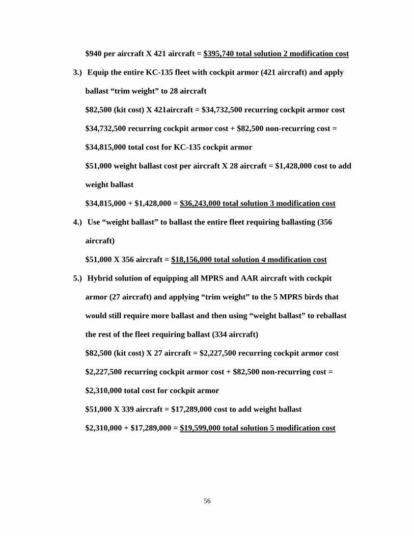
56
$940 per aircraft X 421 aircraft =
3.) Equip the entire KC-135 fleet with cockpit armor (421 aircraft) and apply
ballast “trim weight” to 28 aircraft
$395,740 total solution 2 modification cost
$82,500 (kit cost) X 421aircraft = $34,732,500 recurring cockpit armor cost
$34,732,500 recurring cockpit armor cost + $82,500 non-recurring cost =
$34,815,000 total cost for KC-135 cockpit armor
$51,000 weight ballast cost per aircraft X 28 aircraft = $1,428,000 cost to add
weight ballast
$34,815,000 + $1,428,000 =
4.) Use “weight ballast” to ballast the entire fleet requiring ballasting (356
aircraft)
$36,243,000 total solution 3 modification cost
$51,000 X 356 aircraft = $18,156,000 total solution 4 modification cost
5.) Hybrid solution of equipping all MPRS and AAR aircraft with cockpit
armor (27 aircraft) and applying “trim weight” to the 5 MPRS birds that
would still require more ballast and then using “weight ballast” to reballast
the rest of the fleet requiring ballast (334 aircraft)
$82,500 (kit cost) X 27 aircraft = $2,227,500 recurring cockpit armor cost
$2,227,500 recurring cockpit armor cost + $82,500 non-recurring cost =
$2,310,000 total cost for cockpit armor
$51,000 X 339 aircraft = $17,289,000 cost to add weight ballast
$2,310,000 + $17,289,000 =
$19,599,000 total solution 5 modification cost

57
Average Aircraft Weight Difference by Solution Set
The aircraft weight differences for each solution set are calculated by determining
the population’s mean weight in our control group (µcontrol weight) then subtracting the new
population mean weight (µsolution x weight) to determine weight difference for the solution
set (Δ solution x weight
Equation 1
). Since aircraft weight means are calculated by fleet segment, the
following equation is used to calculate weighted means (not to be confused with mean
weights):
where
xi
w
= mean aircraft weight given fleet segment i
i
Equation 2
= number of aircraft in fleet segment i
where
Once weight difference for the solution set (Δ solution x weight) is determined, hourly
fuel mitigation can be determined in lbs of fuel (JP-8) by multiplying weight difference
by CoW for the KC-135 (CoWKC-135
Equation 3
):
Δ solution x weight X CoWKC-135
and
= Solution x Hourly Fuel Mitigation
CoWKC-135 = .0497 lbs of fuel burned per lb carried per hr of flight

58
Solution x fuel cost mitigation is the product of Solution x hourly fuel mitigation
and the cost per pound of JP-8:
Equation 4
Solution x Hourly Fuel Mitigation X $0.47 per lb of fuel = Solution x Hourly Fuel Cost
Mitigation
1.) Continue using 3,500 lbs of fuel ballast in the Forward Body tank
This solution set is also the control, so population’s mean weight in our
control group (µcontrol weight), will equal solution 1 population mean weight (µsolution
1 weight Table 21). Mean fleet segment weights used below come from Block 40
aircraft and Table 22 Block 30 aircraft simulating conversion to Block 40 (using
weight and balance).
µcontrol weight
Δ
= 126,214.15 lbs (Equation 1)
solution 1 weight
0 lbs of fuel per hr = Solution 1 Hourly Fuel Mitigation (Equation 3)
= 0 lbs (by definition) (Equation 2)
$0.00 per hour = Solution 1 Hourly Fuel Cost Mitigation (Equation 4)
2.) Reduce Forward Body tank fuel ballast to 2,000 lbs
Mean fleet segment weights used below come from Table 23 and Table
24.
µsolution 2 weight = 124,714.15 lbs (Equation 1)
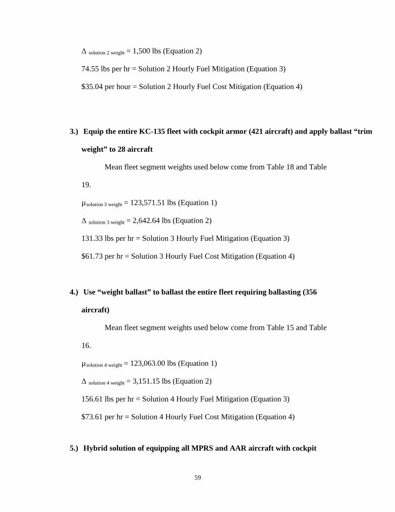
59
Δ solution 2 weight
74.55 lbs per hr = Solution 2 Hourly Fuel Mitigation (Equation 3)
= 1,500 lbs (Equation 2)
$35.04 per hour = Solution 2 Hourly Fuel Cost Mitigation (Equation 4)
3.) Equip the entire KC-135 fleet with cockpit armor (421 aircraft) and apply ballast “trim
weight” to 28 aircraft
Mean fleet segment weights used below come from Table 18 and Table
19.
µsolution 3 weight
Δ
= 123,571.51 lbs (Equation 1)
solution 3 weight
131.33 lbs per hr = Solution 3 Hourly Fuel Mitigation (Equation 3)
= 2,642.64 lbs (Equation 2)
$61.73 per hr = Solution 3 Hourly Fuel Cost Mitigation (Equation 4)
4.) Use “weight ballast” to ballast the entire fleet requiring ballasting (356
aircraft)
Mean fleet segment weights used below come from Table 15 and Table
16.
µsolution 4 weight
Δ
= 123,063.00 lbs (Equation 1)
solution 4 weight
156.61 lbs per hr = Solution 4 Hourly Fuel Mitigation (Equation 3)
= 3,151.15 lbs (Equation 2)
$73.61 per hr = Solution 4 Hourly Fuel Cost Mitigation (Equation 4)
5.) Hybrid solution of equipping all MPRS and AAR aircraft with cockpit

60
armor (27 aircraft) and applying “trim weight” to the 5 MPRS birds that
would still require more ballast and then using “weight ballast” to reballast
the rest of the fleet requiring ballast (334 aircraft)
Mean fleet segment weights used below come from Table 15 for fleet
segments II and XI (KC-135R and KC-135T) aircraft, Table 18 for fleet segments
V and VIII (MPRS and AAR) aircraft, Table 16 for fleet segments III and XII
(KC-135R and KC-135T) aircraft and Table 19 for fleet segments VI and IX
(MPRS and AAR) aircraft. The fleet segmentation approach allows this type of
hybrid solution to be examined by using the mean weight from the applicable
tables and compiling them into a weighted mean.
µsolution 5 weight
Δ
= 123,092.30 lbs (Equation 1)
solution 5 weight
155.15 lbs per hr = Solution 5 Hourly Fuel Mitigation (Equation 3)
= 3,121.85 lbs (Equation 2)
$72.92 per hr = Solution 5 Hourly Fuel Cost Mitigation (Equation 4)
Recoupment Horizon Calculation by Solution Set
Fiscal analysis must evaluate each solution set against the same parallel and
quantifiable scale. The metric chosen for this study was the recoupment horizon. The
recoupment horizon determines the number of years of operation, given increased
efficiency; it takes for each solution set’s requisite modifications to pay for themselves.
This simply measures money and does not consider non-monetary considerations which
are discussed later.
Recoupment horizons for each solution set were calculated using Equation 5.
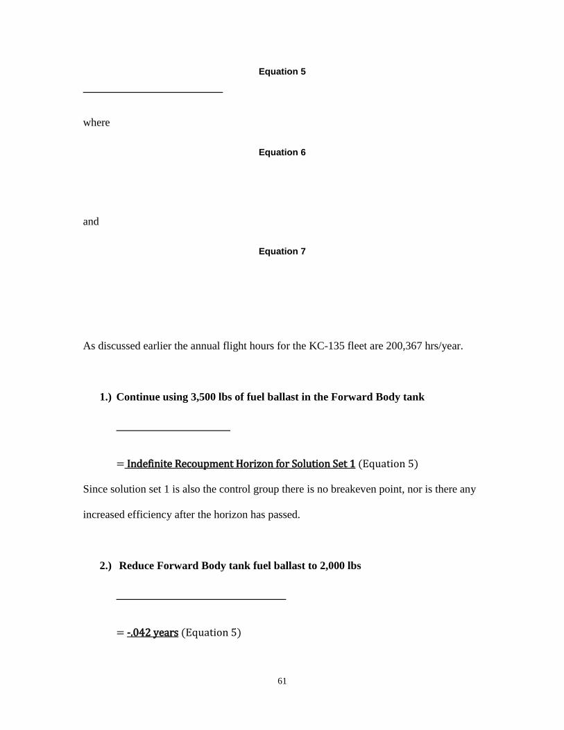
61
Equation 5
where
Equation 6
and
Equation 7
As discussed earlier the annual flight hours for the KC-135 fleet are 200,367 hrs/year.
1.) Continue using 3,500 lbs of fuel ballast in the Forward Body tank
= Indefinite Recoupment Horizon for Solution Set 1
Since solution set 1 is also the control group there is no breakeven point, nor is there any
increased efficiency after the horizon has passed.
(Equation 5)
2.) Reduce Forward Body tank fuel ballast to 2,000 lbs
= -.042 years (Equation 5)

62
Because solution set 2 is less expensive to enact than the control group and there is an
increased efficiency over the control group the recoupment horizon is negative.
3.) Equip the entire KC-135 fleet with cockpit armor (421 aircraft) and apply
ballast “trim weight” to 28 aircraft
= 2.874 years
Since the modification costs associated with this solution set are the highest the
recoupment horizon’s longer duration is logical.
(Equation 5)
4.) Use “weight ballast” to ballast the entire fleet requiring ballasting (356
aircraft)
= 1.184 years
The relatively short recoupment horizon for this solution set is due to the highest solution
fuel cost mitigation rate.
(Equation 5)
5.) Hybrid solution of equipping all MPRS and AAR aircraft with cockpit
armor (27 aircraft) and applying “trim weight” to the 5 MPRS birds that
would still require more ballast and then using “weight ballast” to reballast
the rest of the fleet requiring ballast (334 aircraft)

63
= 1.294 years
Solution set 5 has a slightly longer recoupment horizon than solution set 4 due to a
marginally higher modification cost and slightly lower fuel cost mitigation rate. A
synopsis of recoupment horizons is shown in Table 26.
(Equation 5)
Table 26. Recoupment Horizons
Solution Set Recoupment Horizon
1 N/A
2 -.042 years
3 2.874 years
4 1.184 years
5 1.294 years
V. Discussion
Objective Evaluation
The analysis of this study must include more than just consideration of
recoupment horizons, while a valuable and quantifiable metric, mitigating cost was only
one of the objectives stated. The other objectives were to increase mission capability,
decrease U.S. dependence on foreign energy, mitigate pollution/GHG emissions, and
compliance with stated goals set forth by President Bush and Air Force Secretary Donley.
Evaluation of the solution sets against each of these criteria helps frame overall validity

64
of the solution.
The discussion of mission capability as it pertains to this study is multi-faceted.
There are numerous mission capability implications found among the various solution
sets. The most dramatic are increased fuel offload capability, lighter aircraft gross-
weight for a given mission (decreasing runway length requirements), and increased
aircrew protection from cockpit armor (allowing for forward deployment of aircraft).
The increased offload capability offered by solution sets 3, 4 and 5 is an
additional 3,500 lbs of fuel per mission; this is due to removing the requirement to store
unusable fuel in the forward body tank. Solution set 2 increases offload capability by
1,500 lbs of fuel by reducing the requirement to store fuel in the forward body tank from
3,500 lbs to 2,000 lbs. The increased offload capability is further increased by the
decreased burn rate that each of these solution sets offer over the course of each
individual mission. Additionally, the possibility exists that by increasing fuel offload
capability it may be possible to decrease the number of sorties needed to deliver fuel
required in some cases.
Decreased aircraft gross weight, offered by solution sets 3, 4, 5, and to a lesser
extent solution set 2, accomplishes more than just reducing fuel burn rate. Lighter
aircraft are capable of taking off and landing on shorter airfields and climbing at
increased rates. The capability to operate out of shorter air fields and air fields requiring
a higher climb gradient increases basing options for planners and may decrease mission
duration if it results in closer options.
The aircrew protection from cockpit armor offered by solution sets 3 and 5 when
combined with large aircraft infrared countermeasures (LAIRCM), already planned for

65
the KC-135 fleet (beginning with 22 KC-135s to support special missions), satisfies
Threat Working Group (TWG) requirements for defensive systems for high threat
airfields (Air Mobility Command, 2008: 80). This will increase the KC-135 forward
operation capability significantly, decreasing average mission duration and further
increasing offload capability.
Decreased U.S. dependence on foreign energy, mitigation of pollution/GHG
emissions, and compliance with stated goals all are a direct correlation to the decreased
fuel burn rates offered by solution sets 2, 3, 4, and 5. Irrespective of recoupment horizon,
which considers initial modification costs and fuel cost, these objective are best evaluated
against solution hourly fuel mitigation listed below:
74.55lb/hr = Solution 2 Hourly Fuel Mitigation
131.33lb/hr = Solution 3 Hourly Fuel Mitigation
156.61lb/hr = Solution 4 Hourly Fuel Mitigation
155.15lb/hr = Solution 5 Hourly Fuel Mitigation
Obviously solution set 4 closely followed by solution set 5 do the best job of
complying with these objectives, but it must be noted that solution set 3 still offers a
marked improvement over the control group while making a mission valuable
contribution with its ballast.
Recommendation for Implementation
The need to implement some measure to correct the vast inefficiencies created by
the slow and insidious weight and CG creep experienced by the KC-135 airframe is clear,
but which measure should be taken? Numerous options are posited within this study in
the form of solution sets, but any number of hybrid solutions could be developed along

66
fleet segment lines to meet various objectives. The author’s suggestion for
implementation is a phased approach comprised of a short-term, mid-term and long-term
fix.
Short-term:
Issue Block 40 specific guidance (GM to 11-2-KC-135 Vol. 3) reducing the “zero fuel”
requirement on Block 40 aircraft to 4,400 lbs (2 000 lbs in the forward body for ballast)
while keeping the Block 30 requirement at 5,900 lbs. In addition to this change, the GM
should provide a clearer explanation as to the makeup of the “zero fuel” prescribed,
specifying 600 lbs per main tank and the amount that must remain in the forward body
for ballast (this was not made clear enough in GM1). This will increase efficiency,
decrease operating cost, increase offload capability and requires no modification to the
aircraft (Solution Set 2).
Mid-term:
Equip all MPRS and AAR Block 40 aircraft with cockpit armor and add nose-ballast to
those few that require it, and then issue a GM to reducing “zero fuel” to 2,400 lbs of fuel
for those fleet segments. This will expand the operational capability of these aircraft and
make them even more capable in their diverse missions supporting international, joint
and special operations forces. This will increase efficiency within the MPRS and AAR
Block 40 fleet segments as well as vastly increasing mission capability. This is a low
cost solution since only a handful of aircraft require modification and will serve to
validate increased operational capability.
Long-term:
Equip the entire Block 40 fleet with cockpit armor and use trim ballast to “trim” aircraft

67
requiring it. Once the entire fleet is ballasted and “tankering fuel” for ballast is
eliminated, the full benefit described by solution set 3 can be realized. While this
solution is the most expensive approximately $38M it can be spread over a couple of
years, once all current Block 40 aircraft are armored and ballasted the process will be tied
to the Block upgrade of all remaining aircraft.
Areas for Future Research
The future programmed “block upgrades” to the KC-135, Block 45 and Block 50,
will require weight and balance evaluation, when the equipment to be included in those
upgrades is finalized. This analysis should become part of all aircraft upgrades to ensure
situations, such as the one created in the KC-135 community, do not occur in the future.
An evaluation of aircraft fleet compliance with the SECAF’s goal stated in AFPM 10-1
“of reducing aviation fuel-use per hour of operation by 10% (from a 2005 base line) by
2015” (Donley, 2009) should be conducted to determine the Air Force’s progress.
If solution set 3 is implemented, a study should be conducted to evaluate mission
sortie duration of forward based tankers and an examination of shorter field length
capabilities. A potential classified study could be conducted to determine if Operational
Plans (OPLANS) could be modified based on increased KC-135 mission capabilities,
specifically increased offload capability.
Conclusion
The KC-135 has been the backbone of the USAFs global reach for over half a
century. The small adjustments required to return the weight and balance of this airframe

68
to where it needs to be will pay for themselves financially in a very short period of time
and increase the capability of this “old warhorse” to fight the nation’s wars well into the
future. The problems that led up to the current CG issues are the result of numerous
small changes, this study supports making one more small change to fix the cumulative
unintended consequences of those previous changes. The times when fuel was cheap and
the USAF had excess air refueling capability are behind us, today it is vital that we make
efficient use of the resources we have at our disposal. This study has endeavored to
provide the tools to Air Force leadership to make informed and insightful decisions
regarding the KC-135 fleet so that it may be used both more efficiently and effectively in
the future. The increased fuel offload provided by fleet modification can offer every
Combatant Commander who requires tanker support more of a resource that is in
critically short supply.
69
Bibliography
618 TACC/XOND. KC-135 FY08 Flying Hours. Scott AFB. 8 Sept 2009.
Air Mobility Command. "Air Mobility Master Plan." 2008.
Amaya, Paul. KC-135 Weight and Balance Authority, Air Force Material Command.
Oklahoma City, OK, E-mail. 30 November 2009.
Bennett, Richard L. Analysis of the Effects of Removing Nose Ballast from the F-15
Eagle. Wright Patterson: Air Force Institute of Technology, 1991.
Betti, Maria. "Civil use of depleted uranium." Journal of Environmental Radioactivity,
2001: 113-119.
Blackwell, Kristine E. The Department of Defense: Reducing Its Reliance on Fossil-
Based Aviation Fuel –Issues for Congress. District of Columbia: Congressional
Research Service, 2007.
-135 Weight Disk Report. 993k, disk. Computer file. Boeing, Oklahoma City, OK, 2009.
Boeing Aero. "EA 02-048-135OTH." Analysis of Cockpit Floor Structure with Aircrew
Armor Protection (AAP) Installed. Oklahoma City, OK. 12 August 2002.
Boeing Aero. "EA 08-043-135AMC (Data Revision)." Report to Air Mobility Command
A3V. 2009.
Boeing Aero. "EA 08-043-135AMC." Minimum Fuel Levels. Report to Air Mobility
Command A3V. 15 April 2009.
Boeing Aircraft Corporation. KC-135A Weight 1955-1965. Boeing Archives, 1965.
Boeing. KC-135 Flight Manual , T.O. 1C-135-1-1. 2009.

70
Boeing. Basic Weight Checklist, Maintenance Data, Loading Data, and Fuel Loading
Data. T.O. 1C-135-5-1. 2009.
Boyd, Daniel S. Cost Analysis, Air Force Material Command. Wright-Patterson AFB,
OH, E-mail. 12 Feb 2010
Bush, George W. "Executive Order 13423." Strengthening Federal Environmental,
Energy, and Transportation Management. District of Columbia, 24 January
2007.
Cyintech. Fuel Data Analysis Cost of Weight (CoW). 2008.
Davis, Larry. "RF-86F Haymaker." Sabre Jet Classics, 1998, Summer ed.
Defense Energy Support Center. "DESC-RB (standard Prices)." Defense Energy Support
Center website. 1 January 2010.
Department of Defense. "Department of Defense Annual Energy Report." District of
Columbia, 2007.
Donley, Michael B. Air Force Energy Program Policy Memorandum. AFPM 10-1.1..
District of Columbia, 16 June 2009.
Flight Magazine. "Aero Engines 1959...." Flight, 20 March 1959: 408.
Hopkins, Robert S. Boeing KC-135 Stratotanker: More than just a Tanker. Leicester:
Midland Publishing Limited, 1997.
Kelly, Christoper A. "AMC Fuel Efficiency Policy." 7 December 2007.
Mott, Gary. C/KC-135 Flight Manual Manager, Air Force Material Command, Oklahoma
City, OK. E-mail. 16 February 2010.
Norris, Tom. Senior Program manager, QinetiQ North. E-mail. 12 January 2010.
71
Ross, Lanson. KC-135 Gross Weight Reduction through proper ballast. AF Form 1067.
8 October 2008.
Schiff, Barry J. The Boeing 707. New York: Arco Publishing Company, 1967.
Smithsonian Air & Space Museum. "Collections Database." Washington, D.C.,
12 November 2009.
Smithsonian Air and Space Museum. "Collections Database." Pratt & Whitney J57-P-
29W Turbojet Engine. Washington, D.C., 12 November 2009.

72
Vita
Major Philip G. Morrison is a graduate of the United States Air Force Academy,
where he earned a B.S. in Military History in 1998. After graduating from the USAF
Academy he attended Undergraduate Pilot Training at Columbus AFB earning his wings
in 1999. Major Morrison has served two operational tours flying the KC-135 at Grand
Forks AFB, ND and MacDill AFB, FL. He has also worked as a Tanker Planner at the
618 TACC and most recently as the Chief KC-135 Command Evaluator for AMC. While
working in his last position Major Morrison was tasked with evaluating Air Mobility
Command’s fuel efficiency and developing ways of mitigating fuel use by the USAF
mobility fleet. He holds an M.S. in International Relations from Troy University and is
currently a student enrolled in the Air Force Institute of Technology’s M.S. in Logistics
program as part of the Advanced Study of Air Mobility professional education course.
Major Morrison’s next assignment is to the Pentagon, where he will be the Air Force
Tanker Requirements Branch Chief.

73
BLue Dart Submission Form
First Name: __Philip_______________ Last Name: __Morrison_________________ Rank (Military, AD, etc.): __Major_________ Designator #AFIT/IMO/ENS/10-10 Student’s Involved in Research for Blue Dart:___________________________________ ________________________________________________________________________ Position/Title: __Student _____________________________________________ Phone Number: _(609) 754-7749________ E-mail: [email protected] School/Organization: _Advanced Study of Air Mobility (ASAM)__________________ Status: [X ] Student [ ] Faculty [ ] Staff [ ] Other Optimal Media Outlet (optional): ____________________________________________ Optimal Time of Publication (optional): ______________________________________ General Category / Classification: [ ] core values [ ] command [ ] strategy [ ] war on terror [ ] culture & language [ ] leadership & ethics [ ] warfighting [ ] international security [ ] doctrine [ X] other (specify): Enhanced Efficiency and Effectiveness of High Demand Resources Suggested Headline: How flying lead bricks around can save fuel and increase the offload capability of the KC-135 fleet_____________________________ Keywords: Fuel Efficiency, KC-135, Ballast, Cockpit Armor and Increased Fuel Offload Capability Blue Dart: Every time a KC-135 takes off its mission is handicapped and it costs the
taxpayers far more than it should. This isn’t as one may assume because it is an old
aircraft that lacks the technological advances that a newer aircraft enjoys, ironically it is
because great care has been taken to keep the KC-135 a viable mission platform that it
suffers this penalty. The good news is a very old fashioned remedy can fix the problem
74
saving tens of millions of dollars a year and increase offload capability by almost two
percent.
The KC-135 was subject to numerous changes over its first 50 years of service as
it has adapted to new and expanded mission requirements. These changes have added a
large amount of weight to the aircraft, much of it focused in the rear of the airframe
which created an aft Center of Gravity (CG). Boeing accounts for this aft CG by
requiring that ballast fuel be carried in the forward body tank to maintain a CG forward
of the aft limit.
An Engineering Analysis (EA) recently performed by Boeing states that 3,500 lbs
of fuel is to be left in the forward body tank strictly for ballast, with no other purpose.
Using fuel in the forward body tank for ballast has two significant drawbacks; the
forward body tank has a very short moment-arm necessitating more weight than that of
ballast on a longer moment-arm, and ballast fuel displaces fuel that could be used for
mission purposes by using the tank to hold ballast weight.
Reducing aircraft gross weight is a cost issue, because excess weight incurs a
“carriage cost”. The “carriage cost” for weight on the KC-135 is 4.97% of the weight in
pounds of fuel burned per hour. Research shows that replacement of fuel ballast with
lead ballast on a longer moment arm or using weight with a mission purpose, in the form
of cockpit armor, minimizes ballast weight requirements. This reduces aircraft gross
weight and generates increased fuel efficiency.
To equip the KC-135 fleet with simple ballast in the form of lead bricks it would
cost just over $18M, but increased efficiency would pay for that fleet-wide modification
in 1.1 years. If the Air Force chose to use cockpit armor to ballast out the KC-135

75
instead, it would cost just over $36M and take approximately 2.8 years to recoup
modification costs. The concern that the KC-135 is a legacy aircraft is valid. Pouring
money into a 55 year old airplane may seem wasteful, but Air Mobility Command (the
agency responsible for programming the KC-135 fleet) projects the KC-135 fleet will be
flying for at least another 30 years and even the most extravagant reballasting proposal
would pay for itself in less than 3 years. Those who suggest we don’t modify the KC-135
are essentially saying 27 years of saving $12-18M a year isn’t fiscally sound!
The question of whether to use cockpit armor to ballast the KC-135 fleet or to use
the cheaper method utilizing lead bricks to ballast the aircraft, hinges on what capability
the KC-135 needs. The KC-135 has been placed increasingly further forward in an effort
to enhance the effectiveness of its vital air refueling capability, but with no increased
defenses. Large Aircraft Infrared Counter Measures (LAIRCM) are now being purchased
for the KC-135 fleet, the addition of cockpit armor in concert with LAIRCM would allow
for an even greater forward basing option.
Regardless of which ballast option is used, the removal of 3,500 lbs of ballast fuel
allows for an additional offload capability of 3,500 lbs of fuel in addition to the fuel cost
savings. The tax payers deserve more capability for less money, the simple common
sense solutions available to solve this problem are painfully obvious and the supporting
data can demonstrate at the individual aircraft level and the fleet level why we need to
make these modifications.
The views expressed in this article are those of the author and do not reflect the official policy or position of the United States Air Force, Department of Defense, or the US Government.
Apr 10
76
REPORT DOCUMENTATION PAGE Form Approved OMB No. 074-0188
The public reporting burden for this collection of information is estimated to average 1 hour per response, including the time for reviewing instructions, searching existing data sources, gathering and maintaining the data needed, and completing and reviewing the collection of information. Send comments regarding this burden estimate or any other aspect of the collection of information, including suggestions for reducing this burden to Department of Defense, Washington Headquarters Services, Directorate for Information Operations and Reports (0704-0188), 1215 Jefferson Davis Highway, Suite 1204, Arlington, VA 22202-4302. Respondents should be aware that notwithstanding any other provision of law, no person shall be subject to an penalty for failing to comply with a collection of information if it does not display a currently valid OMB control number. PLEASE DO NOT RETURN YOUR FORM TO THE ABOVE ADDRESS. 1. REPORT DATE (DD-MM-YYYY) 18-06-2010
2. REPORT TYPE Graduate Research Project
3. DATES COVERED (From – To) May 2009 – Jun 2010
4. TITLE AND SUBTITLE
REBALLASTING THE KC-135 FLEET FOR FUEL EFFICIENCY
5a. CONTRACT NUMBER
5b. GRANT NUMBER 5c. PROGRAM ELEMENT NUMBER
6. AUTHOR(S) Philip G. Morrison, Major, USAF
5d. PROJECT NUMBER If funded, enter ENR # 5e. TASK NUMBER
5f. WORK UNIT NUMBER
7. PERFORMING ORGANIZATION NAMES(S) AND ADDRESS(S) Air Force Institute of Technology Graduate School of Engineering and Management (AFIT/EN) 2950 Hobson Way WPAFB OH 45433-7765
8. PERFORMING ORGANIZATION REPORT NUMBER AFIT/IMO/ENS/10-10
9. SPONSORING/MONITORING AGENCY NAME(S) AND ADDRESS(ES) AMC Fuel Efficiency Office Col Kevin Trayer Bldg 1600 Scott AFB, IL 62225 e-mail: [email protected] phone: (618) 229-1337
10. SPONSOR/MONITOR’S ACRONYM(S) 11. SPONSOR/MONITOR’S REPORT NUMBER(S)
12. DISTRIBUTION/AVAILABILITY STATEMENT APPROVED FOR PUBLIC RELEASE; DISTRIBUTION UNLIMITED.
13. SUPPLEMENTARY NOTES 14. ABSTRACT The KC-135 airframe suffers from an aft Center of Gravity (CG). Boeing accounts for this aft CG by requiring that ballast fuel be carried in the forward body tank to maintain a CG forward of the aft limit. Boeing has analyzed the issue and states that 3,500 lbs of fuel is to be left in the forward body tank strictly for ballast. Using fuel in the forward body tank for ballast has two significant drawbacks; the forward body tank has a very short moment-arm necessitating more weight than that of ballast on a longer moment-arm, and ballast fuel displaces fuel that could be used for mission purposes by using the tank to hold ballast weight. Reducing aircraft gross weight is a cost issue, because excess weight incurs a “carriage cost”. The “carriage cost” for weight on the KC-135 is 4.97% of the weight in pounds of fuel burned per hour. This thesis focuses on the cost recoupment horizon for reballasting the KC-135 fleet and whether the cost will justify the fuel efficiency and increased mission capability. Specifically, this research examines replacement of fuel ballast with lead ballast on a longer moment arm and/or weight with a mission purpose, in the form of cockpit armor, to minimize ballast weight requirements. This will reduce aircraft gross weight and generate increased fuel efficiency. 15. SUBJECT TERMS
16. SECURITY CLASSIFICATION OF:
17. LIMITATION OF ABSTRACT UU
18. NUMBER OF PAGES 84
19a. NAME OF RESPONSIBLE PERSON Daniel D. Mattioda, Major, USAF
REPORT U
ABSTRACT U
c. THIS PAGE U
19b. TELEPHONE NUMBER (Include area code) (937) 255-3636 X7946; e-mail: [email protected]
Related Documents