Greg Gianforte, Governor I Chris Dorrington, Director I P.O. Box 200901 I Helena, MT 59620-0901 I (406) 444-2544 I www.deq.mt.gov PRELIMINARY DETERMINATION ON PERMIT APPLICATION Date of Mailing: September 22, 2021 Name of Applicant: Montana Renewables Inc. – Subsidiary of Calumet Specialty Products Partners Source: Calumet Specialty Products Partners, LLP – Renewable Diesel Project Proposed Action: The Department of Environmental Quality (Department) proposes to issue a permit, with conditions, to the above-named applicant. The application was assigned Permit Application Number 5263-00. Proposed Conditions: See attached. Public Comment: Any member of the public desiring to comment must submit such comments in writing to the Air Quality Bureau (Bureau) of the Department at the address in the footer of this cover letter. Comments may address the Department's analysis and determination, or the information submitted in the application. In order to be considered, comments on this Preliminary Determination are due by October 7, 2021. Copies of the application and the Department's analysis may be inspected at the Bureau's office in Helena. For more information, you may contact the Department. Departmental Action: The Department intends to make a decision on the application after expiration of the Public Comment period described above. A copy of the decision may be obtained at the Bureau's office in Helena. The permit shall become final on the date stated in the Department’s Decision on this permit, unless an appeal is filed with the Board of Environmental Review (Board). Procedures for Appeal: Any person jointly or severally adversely affected by the final action may request a hearing before the Board. Any appeal must be filed by the date stated in the Department’s Decision on this permit. The request for a hearing shall contain an affidavit setting forth the grounds for the request. Any hearing will be held under the provisions of the Montana Administrative Procedures Act. Submit requests for a hearing in triplicate to: Chairman, Board of Environmental Review, P.O. Box 200901, Helena, MT 59620. For the Department, Julie A. Merkel Craig Henrikson Permitting Services Section Supervisor Environmental Engineer Air Quality Bureau Air Quality Bureau (406) 444-3626 (406) 444-6711 Enclosures Air, Energy & Mining Division

Welcome message from author
This document is posted to help you gain knowledge. Please leave a comment to let me know what you think about it! Share it to your friends and learn new things together.
Transcript
Greg Gianforte, Governor I Chris Dorrington, Director I P.O. Box 200901 I Helena, MT 59620-0901 I (406) 444-2544 I www.deq.mt.gov
PRELIMINARY DETERMINATION ON PERMIT APPLICATION
Date of Mailing: September 22, 2021 Name of Applicant: Montana Renewables Inc. – Subsidiary of Calumet Specialty Products Partners Source: Calumet Specialty Products Partners, LLP – Renewable Diesel Project Proposed Action: The Department of Environmental Quality (Department) proposes to issue a permit, with conditions, to the above-named applicant. The application was assigned Permit Application Number 5263-00. Proposed Conditions: See attached. Public Comment: Any member of the public desiring to comment must submit such comments in writing to the Air Quality Bureau (Bureau) of the Department at the address in the footer of this cover letter. Comments may address the Department's analysis and determination, or the information submitted in the application. In order to be considered, comments on this Preliminary Determination are due by October 7, 2021. Copies of the application and the Department's analysis may be inspected at the Bureau's office in Helena. For more information, you may contact the Department. Departmental Action: The Department intends to make a decision on the application after expiration of the Public Comment period described above. A copy of the decision may be obtained at the Bureau's office in Helena. The permit shall become final on the date stated in the Department’s Decision on this permit, unless an appeal is filed with the Board of Environmental Review (Board). Procedures for Appeal: Any person jointly or severally adversely affected by the final action may request a hearing before the Board. Any appeal must be filed by the date stated in the Department’s Decision on this permit. The request for a hearing shall contain an affidavit setting forth the grounds for the request. Any hearing will be held under the provisions of the Montana Administrative Procedures Act. Submit requests for a hearing in triplicate to: Chairman, Board of Environmental Review, P.O. Box 200901, Helena, MT 59620. For the Department,
Julie A. Merkel Craig Henrikson Permitting Services Section Supervisor Environmental Engineer Air Quality Bureau Air Quality Bureau (406) 444-3626 (406) 444-6711 Enclosures
Air, Energy & Mining Division

5263-00 1 PD: 9/22/2021
MONTANA AIR QUALITY PERMIT
Issued to: Montana Renewables Inc.
1900 Street NE Great Falls, Montana 59404
MAQP: #5263-00 Application Received: July 23, 2021 Application Complete: August 27, 2021 Preliminary Determination: Sept. 22, 2021 Department’s Decision: Permit Final:
A Montana Air Quality Permit (MAQP), with conditions, is hereby granted to Montana Renewables Inc. (MRI) pursuant to Sections 75-2-204 and 211 of the Montana Code Annotated (MCA), as amended, and Administrative Rules of Montana (ARM) 17.8.740, et seq., as amended, for the following: Section I: Permitted Facilities
Renewable Diesel Unit (RDU): The existing Mild Hydrocracker (MHC) transferred from the Calumet Montana Refinery (CMR) will be the RDU.
• RDU Combined Feed Heater (H-4101) Hydrogen Plant #3: The CMR Great Falls Refinery's Hydrogen Plant #3 will be transferred to MRI, and this hydrogen plant will supply hydrogen feedstock to the RDU.
• Reformers H-3815A and H-3815B which have been transferred from CMR and given new emitting unit numbers
Hydrogen Plant #4 will be installed at the MRI plant to supply hydrogen feedstock to the RDU.
• Hydrogen Plant #4 Reformer Heater (H-4801) • Piping fugitive components and • Wastewater components
Tanks (Transferred from CMR)
• Tank #29 • Tank #50 • Tank #102 • Tank #112 • Tank #116 • Tank #125 • Tank #128 and • Tank #140
5263-00 2 PD: 9/22/2021
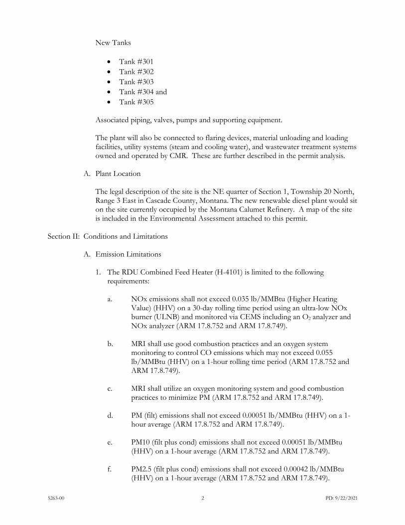
New Tanks
• Tank #301 • Tank #302 • Tank #303 • Tank #304 and • Tank #305
Associated piping, valves, pumps and supporting equipment. The plant will also be connected to flaring devices, material unloading and loading facilities, utility systems (steam and cooling water), and wastewater treatment systems owned and operated by CMR. These are further described in the permit analysis.
A. Plant Location
The legal description of the site is the NE quarter of Section 1, Township 20 North, Range 3 East in Cascade County, Montana. The new renewable diesel plant would sit on the site currently occupied by the Montana Calumet Refinery. A map of the site is included in the Environmental Assessment attached to this permit.
Section II: Conditions and Limitations
A. Emission Limitations
1. The RDU Combined Feed Heater (H-4101) is limited to the following requirements: a. NOx emissions shall not exceed 0.035 lb/MMBtu (Higher Heating
Value) (HHV) on a 30-day rolling time period using an ultra-low NOx burner (ULNB) and monitored via CEMS including an O2 analyzer and NOx analyzer (ARM 17.8.752 and ARM 17.8.749).
b. MRI shall use good combustion practices and an oxygen system monitoring to control CO emissions which may not exceed 0.055 lb/MMBtu (HHV) on a 1-hour rolling time period (ARM 17.8.752 and ARM 17.8.749).
c. MRI shall utilize an oxygen monitoring system and good combustion practices to minimize PM (ARM 17.8.752 and ARM 17.8.749).
d. PM (filt) emissions shall not exceed 0.00051 lb/MMBtu (HHV) on a 1-hour average (ARM 17.8.752 and ARM 17.8.749).
e. PM10 (filt plus cond) emissions shall not exceed 0.00051 lb/MMBtu (HHV) on a 1-hour average (ARM 17.8.752 and ARM 17.8.749).
f. PM2.5 (filt plus cond) emissions shall not exceed 0.00042 lb/MMBtu (HHV) on a 1-hour average (ARM 17.8.752 and ARM 17.8.749).

5263-00 3 PD: 9/22/2021
g. MRI shall utilize an oxygen monitoring system and good combustion
practices to minimize VOCs (ARM 17.8.752 and ARM 17.8.749).
h. The annual average firing rate of H-4101 shall not exceed 25 MMBtu/hr (HHV basis) (ARM 17.8.752 and ARM 17.8.749).
i. MRI shall conduct the work practice standards for minimizing CO
required under 40 CFR 63 Subpart DDDDD (40 CFR 63 Subpart DDDDD, ARM 17.8.749 and ARM 17.8.342).
j. MRI shall comply with the emission control requirements of 40 CFR
63.2455 for each RDU Group 1 continuous process vent (40 CFR 63, Subpart FFFF, ARM 17.8.342 and ARM 17.8.749).
k. H-4101 shall only combust natural gas and RDU off-gas (ARM 17.8.749).
l. The heater shall not combust RDU off-gas fuel containing H2S in excess
of 162 ppmv H2S on a 3-hour rolling average basis and 60 ppmv on a 365 successive calendar day rolling average basis (ARM 17.8.749.)
2. Hydrogen Plant #3 (Reformers H-3815A and H-3815B)
a. The annual average firing rate of each heater (H-3815A and H-3815B)
shall not exceed 67.0 MMBtu/hr (HHV) (ARM 17.8.749).
b. NOx emissions from each heater shall be controlled by ULNBs and the combined NOx emissions from the two heaters shall not exceed 0.051 lb/MMBtu (HHV) based a 30-day rolling average and monitored via CEMS an O2 analyzer and NOx analyzer (ARM 17.8.752 and ARM 17.8.749).
c. MRI shall control particulate matter (PM), PM with an aerodynamic
diameter of 10 microns or less (PM10), and PM with an aerodynamic diameter of 2.5 microns or less (PM2.5) emissions from each heater by utilizing good combustion practices and only combusting low sulfur fuels (ARM 17.8.752 and ARM 17.8.749):
i. PM/PM10 emissions shall not exceed 0.00051 lb/MMBtu (HHV).
ii. PM2.5 emission shall not exceed 0.00042 lb/MMBtu (HHV).
d. MRI shall control CO emissions using good combustion practices and
CO emissions shall not exceed 0.03 lb/MMBtu (HHV) (ARM 17.8.752 and ARM 17.8.749).
e. Opacity shall not exceed 20% averaged over any 6 consecutive minutes
(ARM 17.8.304).
5263-00 4 PD: 9/22/2021
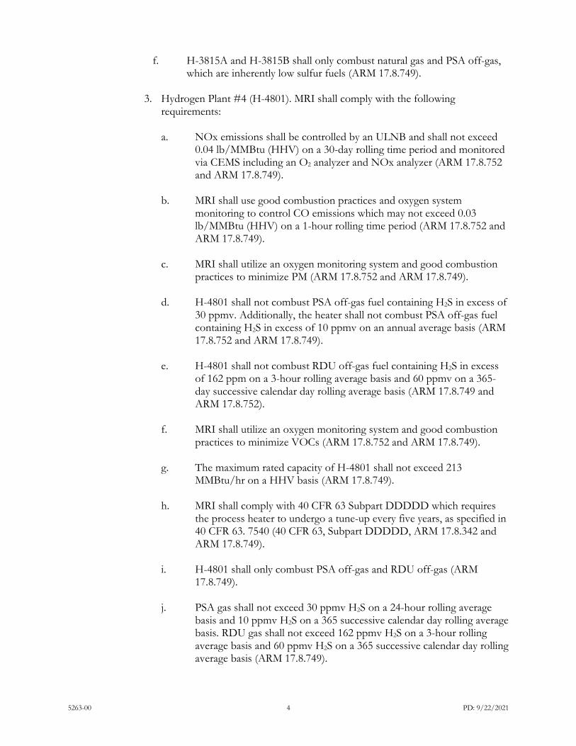
f. H-3815A and H-3815B shall only combust natural gas and PSA off-gas, which are inherently low sulfur fuels (ARM 17.8.749).
3. Hydrogen Plant #4 (H-4801). MRI shall comply with the following
requirements:
a. NOx emissions shall be controlled by an ULNB and shall not exceed 0.04 lb/MMBtu (HHV) on a 30-day rolling time period and monitored via CEMS including an O2 analyzer and NOx analyzer (ARM 17.8.752 and ARM 17.8.749).
b. MRI shall use good combustion practices and oxygen system monitoring to control CO emissions which may not exceed 0.03 lb/MMBtu (HHV) on a 1-hour rolling time period (ARM 17.8.752 and ARM 17.8.749).
c. MRI shall utilize an oxygen monitoring system and good combustion
practices to minimize PM (ARM 17.8.752 and ARM 17.8.749).
d. H-4801 shall not combust PSA off-gas fuel containing H2S in excess of 30 ppmv. Additionally, the heater shall not combust PSA off-gas fuel containing H2S in excess of 10 ppmv on an annual average basis (ARM 17.8.752 and ARM 17.8.749).
e. H-4801 shall not combust RDU off-gas fuel containing H2S in excess
of 162 ppm on a 3-hour rolling average basis and 60 ppmv on a 365-day successive calendar day rolling average basis (ARM 17.8.749 and ARM 17.8.752).
f. MRI shall utilize an oxygen monitoring system and good combustion
practices to minimize VOCs (ARM 17.8.752 and ARM 17.8.749).
g. The maximum rated capacity of H-4801 shall not exceed 213 MMBtu/hr on a HHV basis (ARM 17.8.749).
h. MRI shall comply with 40 CFR 63 Subpart DDDDD which requires
the process heater to undergo a tune-up every five years, as specified in 40 CFR 63. 7540 (40 CFR 63, Subpart DDDDD, ARM 17.8.342 and ARM 17.8.749).
i. H-4801 shall only combust PSA off-gas and RDU off-gas (ARM
17.8.749).
j. PSA gas shall not exceed 30 ppmv H2S on a 24-hour rolling average basis and 10 ppmv H2S on a 365 successive calendar day rolling average basis. RDU gas shall not exceed 162 ppmv H2S on a 3-hour rolling average basis and 60 ppmv H2S on a 365 successive calendar day rolling average basis (ARM 17.8.749).

5263-00 5 PD: 9/22/2021
4. New Tanks #301, #302, #303, #304 and #305 (For renewable feed, renewable
diesel, naphtha or RDU slop oil:
a. MRI shall control VOC emissions from Tank #301, #302, #303, and #305 by equipping it with a fixed roof and submerged fill design (ARM 17.8.752 and ARM 17.8.749).
b. MRI shall control VOC emissions from Tank #304 by equipping it with an external floating roof (ARM 17.8.752. and 40 CFR 60, Subpart Kb, ARM 17.8.340 and ARM 17.8.749).
c. Tanks #301 and #302 shall only be used to store renewable feed oil or
an equivalent product with equal or lower vapor pressure (ARM 17.8.749).
d. Tank #303 shall only be used to store slop oil or an equivalent product
with equal or lower vapor pressure (ARM 17.8.749).
e. Tank #304 shall only be used to store renewable naphtha or an equivalent product with equal or lower vapor pressure (ARM 17.8.749).
f. Tank #305 shall only be used to store renewable diesel or an equivalent
product with equal or lower vapor pressure (ARM 17.8.749).
g. MRI shall comply with the monitoring requirements of 40 CFR 63.2455 for each applicable RDU Group 2 continuous process vent (40 CFR 63, Subpart FFFF, ARM 17.8.342 and ARM 17.8.749).
5. MRI shall utilize equipment design, and Leak Detection and Repair (LDAR)
practices to control VOCs on the RDU, Hydrogen Plant #4, and Storage Tank Piping Fugitive Components (ARM 17.8.752 and ARM 17.8.749).
a. RDU piping fugitive components “in VOC service” shall comply with the equipment leak provisions found in 40 CFR 60.482-1a through 60.482-10a. Pursuant to NESHAP Subpart FFFF, the RDU piping fugitive components “in organic HAP service” shall comply with the new source equipment leak provisions found in 40 CFR 63.2480) (ARM 17.8.749).
b. Hydrogen Plant #4 piping fugitive components “in VOC service” shall comply with the equipment leak provisions found in 40 CFR 60.482-1a through 60.482-10a (ARM 17.8.749).
c. Storage Tank piping fugitive components “in VOC service” shall
comply with the equipment leak provisions found in40 CFR 60.482-1a through 60.482.-10a. Pursuant to NESHAP Subpart FFFF, the Storage Tank piping fugitive components in “organic HAP service” shall comply with the new source equipment leak provisions found in 40 CFR 63.2480 (ARM 17.8.749).

5263-00 6 PD: 9/22/2021
6. MRI shall follow the applicable requirements under 40 CFR 63, Subpart FFFF
for all existing and new tanks depending upon whether each specific tank is in Group 1 or Group 2 (ARM 17.8.749, ARM 17.8.342 and 40 CFR 63, Subpart FFFF).
7. MRI shall not cause or authorize emissions to be discharged into the outdoor atmosphere from any sources installed after November 23, 1968, that exhibit an opacity of 20% or greater averaged over 6 consecutive minutes (ARM 17.8.304).
8. MRI shall not cause or authorize the use of any street, road, or parking lot
without taking reasonable precautions to control emissions of airborne particulate matter (ARM 17.8.308).
9. MRI shall treat all unpaved portions of the access roads with water and/or
chemical dust suppressant as necessary to maintain compliance with the reasonable precautions limitation in Section II.A.8 (ARM 17.8.749).
B. Testing Requirements
1. The RDU Combined Feed Heater (H-4101) shall be tested for CO and NOx concurrently and the results submitted to the Department in order to demonstrate compliance with the emission limits contained in Section II.A.1. The initial testing shall occur within 180 days of transfer of this heater from CMR to MRI. Test procedures shall use EPA Reference Methods 10 and 7E or equivalent, as approved by the Department (ARM 17.8.105 and ARM 17.8.106).
2. Reformers H-3815A and H-3815B shall each be tested in the common exhaust stack for CO and NOx concurrently and the results submitted to the Department in order to demonstrate compliance with the emission limits contained in Section II.A.2. The initial testing shall occur within 180 days of transfer of these heaters from CMR to MRI. Test procedures shall use EPA Reference Methods 10 and 7E or equivalent, as approved by the Department (ARM 17.8.105 and ARM 17.8.106).
3. Hydrogen Plant #4 (H-4801) shall be tested for CO and NOx concurrently and
the results submitted to the Department in order to demonstrate compliance with the emission limits contained in Section II.A.3. The initial testing shall occur within 180 days of startup. Test procedures shall use EPA Reference Methods 10 and 7E or equivalent, as approved by the Department (ARM 17.8.105 and ARM 17.8.106).
4. MRI shall sample and analyze the concentration (dry basis) of H2S in the
Hydrogen Plant #4 PSA off-gas fuel at least once per week, in order to demonstrate compliance with the limit in Section II.A.3.d (ARM 17.8.749).
5. The NOx and O2 CEMS on the RDU Combined Feed Heater (H-4101),
Hydrogen Plant #3 Reformer Heaters (H-31815A/H-3815B), Hydrogen Plant #4 Reformer Heater (H-4801) shall comply with 40 CFR 60.1 and 40 CFR 60 Appendices B and F (ARM 17.8.749)

5263-00 7 PD: 9/22/2021
6. All compliance source tests shall conform to the requirements of the Montana
Source Test Protocol and Procedures Manual (ARM 17.8.106). 7. The Department may require further testing (ARM 17.8.105).
C. Operational Reporting Requirements
1. MRI shall supply the Department with annual production information for all emission points, as required by the Department in the annual emission inventory request. The request will include, but is not limited to, all sources of emissions identified in the emission inventory contained in the permit analysis.
Production information shall be gathered on a calendar-year basis and submitted to the Department by the date required in the emission inventory request. Information shall be in the units required by the Department. This information may be used to calculate operating fees, based on actual emissions from the facility, and/or to verify compliance with permit limitations (ARM 17.8.505).
2. MRI shall document, by month, the total MMBtu’s combusted for each of the heaters (RDU Combined Feed Heater (H-4101), Reformer Heaters H-3815A and H-3815B, and Hydrogen Plant #4 Reformer Heater H-4801) and apply the appropriate emission factors on a lb/MMBtu basis to calculate the monthly emissions. The information for each of the previous months shall be submitted annually to the Department along with the annual emission inventory (ARM 17.8.749).
3. MRI shall notify the Department of any construction or improvement project
conducted, pursuant to ARM 17.8.745, that would include the addition of a new emissions unit, change in control equipment, stack height, stack diameter, stack flow, stack gas temperature, source location, or fuel specifications, or would result in an increase in source capacity above its permitted operation. The notice must be submitted to the Department, in writing, 10 days prior to startup or use of the proposed de minimis change, or as soon as reasonably practicable in the event of an unanticipated circumstance causing the de minimis change, and must include the information requested in ARM 17.8.745(l)(d) (ARM 17.8.745).
4. All records compiled in accordance with this permit must be maintained by MRI
as a permanent business record for at least 5 years following the date of the measurement, must be available at the plant site for inspection by the Department, and must be submitted to the Department upon request. These records may be stored at a location other than the plant site upon approval by the Department (ARM 17.8.749).
D. Notification
MRI shall provide the Department with written notification of the following information within the specified time periods (ARM 17.8.749):

5263-00 8 PD: 9/22/2021
1. Start-up date of the RDU Combined Feed Heater at MRI within 15 working days of the start-up date.
2. Startup date of the Hydrogen Plant #4 Reformer Heater H-4801 within 15 working days of the startup date.
3. Startup dates of for each of the following tanks #301, #302, #303, #304 and #305,
within 15 working days of the startup date of each tank.
4. Dates of transfer of the Hydrogen Plant #3 from CMR to MRI and dates of transfer of each of the existing tanks (#29, #50, #102, #112, #116, #125, #128 and #140) within 15 working of transfer of each.
SECTION III: General Conditions
A. Inspection – MRI shall allow the Department’s representatives access to the source at all reasonable times for the purpose of making inspections or surveys, collecting samples, obtaining data, auditing any monitoring equipment such as Continuous Emission Monitoring Systems (CEMS) or Continuous Emission Rate Monitoring Systems (CERMS), or observing any monitoring or testing, and otherwise conducting all necessary functions related to this permit.
B. Waiver – The permit and the terms, conditions, and matters stated herein shall be
deemed accepted if MRI fails to appeal as indicated below.
C. Compliance with Statutes and Regulations – Nothing in this permit shall be construed as relieving MRI of the responsibility for complying with any applicable federal or Montana statute, rule, or standard, except as specifically provided in ARM 17.8.740, et seq. (ARM 17.8.756).
D. Enforcement – Violations of limitations, conditions and requirements contained
herein may constitute grounds for permit revocation, penalties, or other enforcement action as specified in Section 75-2-401, et seq., MCA.
E. Appeals – Any person or persons jointly or severally adversely affected by the
Department’s decision may request, within 15 days after the Department renders its decision, upon affidavit setting forth the grounds therefor, a hearing before the Board of Environmental Review (Board). A hearing shall be held under the provisions of the Montana Administrative Procedures Act. The filing of a request for a hearing does not stay the Department’s decision, unless the Board issues a stay upon receipt of a petition and a finding that a stay is appropriate under Section 75-2-211(11)(b), MCA. The issuance of a stay on a permit by the Board postpones the effective date of the Department’s decision until conclusion of the hearing and issuance of a final decision by the Board. If a stay is not issued by the Board, the Department’s decision on the application is final 16 days after the Department’s decision is made.
F. Permit Inspection – As required by ARM 17.8.755, Inspection of Permit, a copy of the
air quality permit shall be made available for inspection by the Department at the location of the source.

5263-00 9 PD: 9/22/2021
G. Permit Fee – Pursuant to Section 75-2-220, MCA, failure to pay the annual operation fee by MRI may be grounds for revocation of this permit, as required by that section and rules adopted thereunder by the Board.
H. Duration of Permit – Construction or installation must begin or contractual
obligations entered into that would constitute substantial loss within 3 years of permit issuance and proceed with due diligence until the project is complete or the permit shall expire (ARM 17.8.762).

5263-00 1 PD: 9/22/2021
Montana Air Quality Permit (MAQP) Analysis Montana Renewables Inc.
MAQP #5263-00
I. Introduction/Process Description
A. Permitted Equipment
Montana Renewables Incorporated (MRI) proposes to install and operate the following new equipment: Hydrogen Plant #4 will be installed at the MRI plant to supply hydrogen feedstock to the Renewable Diesel Unit (RDU) • Hydrogen Plant #4 Reformer Heater (H-4801) • Piping fugitive components and • Wastewater components New Tanks storing either renewable feed or renewable diesel • Tank #301 • Tank #302 • Tank #303 • Tank #304 and • Tank #305 MRI also proposes to transfer existing equipment from Calumet Montana Refinery (CMR), refurbish as necessary, and operate the following equipment: RDU Combined Feed Heater (H-4101) Hydrogen Plant #3: (Reformers H-3815A and H-3815B transferred from CMR and given new emitting unit numbers).
Tanks (Transferred from CMR)
• Tank #29 • Tank #50 • Tank #102 • Tank #112 • Tank #116 • Tank #125 • Tank #128 and • Tank #140
Associated piping, valves, pumps and supporting equipment.

5263-00 2 PD: 9/22/2021
B. Source Description The equipment described would operate at the site currently known as the Calumet Montana Refinery. Montana Renewable Inc. (MRI) would operate as a subsidiary as does the Calumet Montana Refinery to Calumet Specialty Products Partners. The equipment operating at the project site would not be a petroleum refinery and the numerous regulatory requirements for petroleum refineries would not apply to any of the new or transferred equipment operating under MAQP #5263-00. The renewable diesel product and naphtha that is produced would be marketed into Canadian and West Coast U.S. markets.
C. Response to Public Comments (only if there are comments received)
Person/Group Commenting
Permit Reference
Comment Department Response
II. Applicable Rules and Regulations
The following are partial explanations of some applicable rules and regulations that apply to the facility. The complete rules are stated in the Administrative Rules of Montana (ARM) and are available, upon request, from the Department of Environmental Quality (Department). Upon request, the Department will provide references for location of complete copies of all applicable rules and regulations or copies where appropriate.
A. ARM 17.8, Subchapter 1 – General Provisions, including but not limited to:
1. ARM 17.8.101 Definitions. This rule includes a list of applicable definitions used in this chapter, unless indicated otherwise in a specific subchapter.
2. ARM 17.8.105 Testing Requirements. Any person or persons responsible for the
emission of any air contaminant into the outdoor atmosphere shall, upon written request of the Department, provide the facilities and necessary equipment (including instruments and sensing devices) and shall conduct tests, emission or ambient, for such periods of time as may be necessary using methods approved by the Department.
3. ARM 17.8.106 Source Testing Protocol. The requirements of this rule apply to any
emission source testing conducted by the Department, any source or other entity as required by any rule in this chapter, or any permit or order issued pursuant to this chapter, or the provisions of the Clean Air Act of Montana, 75-2-101, et seq., Montana Code Annotated (MCA).
MRI shall comply with the requirements contained in the Montana Source Test Protocol and Procedures Manual, including, but not limited to, using the proper test methods and supplying the required reports. A copy of the Montana Source Test Protocol and Procedures Manual is available from the Department upon request.
4. ARM 17.8.110 Malfunctions. (2) The Department must be notified promptly by
telephone whenever a malfunction occurs that can be expected to create emissions in

5263-00 3 PD: 9/22/2021
excess of any applicable emission limitation or to continue for a period greater than 4 hours.
5. ARM 17.8.111 Circumvention. (1) No person shall cause or permit the installation or
use of any device or any means that, without resulting in reduction of the total amount of air contaminant emitted, conceals or dilutes an emission of air contaminant that would otherwise violate an air pollution control regulation. (2) No equipment that may produce emissions shall be operated or maintained in such a manner as to create a public nuisance.
B. ARM 17.8, Subchapter 2 – Ambient Air Quality, including, but not limited to the
following:
1. ARM 17.8.204 Ambient Air Monitoring 2. ARM 17.8.210 Ambient Air Quality Standards for Sulfur Dioxide 3. ARM 17.8.211 Ambient Air Quality Standards for Nitrogen Dioxide 4. ARM 17.8.212 Ambient Air Quality Standards for Carbon Monoxide 5. ARM 17.8.213 Ambient Air Quality Standard for Ozone 6. ARM 17.8.214 Ambient Air Quality Standard for Hydrogen Sulfide 7. ARM 17.8.220 Ambient Air Quality Standard for Settled Particulate Matter 8. ARM 17.8.221 Ambient Air Quality Standard for Visibility 9. ARM 17.8.222 Ambient Air Quality Standard for Lead 10. ARM 17.8.223 Ambient Air Quality Standard for PM10 11. ARM 17.8.230 Fluoride in Forage
MRI must maintain compliance with the applicable ambient air quality standards.
C. ARM 17.8, Subchapter 3 – Emission Standards, including, but not limited to:
1. ARM 17.8.304 Visible Air Contaminants. This rule requires that no person may cause or authorize emissions to be discharged into the outdoor atmosphere from any source installed after November 23, 1968, that exhibit an opacity of 20% or greater averaged over 6 consecutive minutes.
2. ARM 17.8.308 Particulate Matter, Airborne. (1) This rule requires an opacity
limitation of less than 20% for all fugitive emission sources and that reasonable precautions be taken to control emissions of airborne particulate matter. (2) Under this rule, MRI shall not cause or authorize the use of any street, road, or parking lot without taking reasonable precautions to control emissions of airborne particulate matter.
3. ARM 17.8.309 Particulate Matter, Fuel Burning Equipment. This rule requires that no
person shall cause, allow, or permit to be discharged into the atmosphere particulate matter caused by the combustion of fuel in excess of the amount determined by this rule.
4. ARM 17.8.310 Particulate Matter, Industrial Process. This rule requires that no person
shall cause, allow, or permit to be discharged into the atmosphere particulate matter in excess of the amount set forth in this rule.

5263-00 4 PD: 9/22/2021
5. ARM 17.8.316 Incinerators. This rule requires that no person may cause or authorize emissions to be discharged into the outdoor atmosphere from any incinerator, particulate matter in excess of 0.10 grains per standard cubic foot of dry flue gas, adjusted to 12% carbon dioxide and calculated as if no auxiliary fuel had been used. Further, no person shall cause or authorize to be discharged into the outdoor atmosphere from any incinerator emissions that exhibit an opacity of 10% or greater averaged over 6 consecutive minutes.
6. ARM 17.8.322 Sulfur Oxide Emissions--Sulfur in Fuel. Sulfur Oxide Emissions-
Sulfur in Fuel. This rule requires that no person shall cause, allow or permit to be discharged into the atmosphere particulate matter in excess of the amount set forth in this rule.
7. ARM 17.8.324 Hydrocarbon Emissions--Petroleum Products. (3) No person shall
load or permit the loading of gasoline into any stationary tank with a capacity of 250 gallons or more from any tank truck or trailer, except through a permanent submerged fill pipe, unless such tank is equipped with a vapor loss control device as described in (1) of this rule.
8. ARM 17.8.340 Standard of Performance for New Stationary Sources and Emission
Guidelines for Existing Sources. This rule incorporates, by reference, 40 CFR Part 60, Standards of Performance for New Stationary Sources (NSPS). MRI is considered an NSPS affected facility under 40 CFR Part 60 (portions of the transferred and shared equipment was already subject) and is subject to the requirements of the following subparts.
a. 40 CFR 60, Subpart A – General Provisions apply to all equipment or facilities
subject to an NSPS Subpart as listed below:
b. 40 CFR 60, Subpart Kb – Standards of Performance for Volatile Organic Liquid Storage Vessels (Including Petroleum Liquid Storage Vessels) for Which Construction, Reconstruction, or Modification Commenced after July 23, 1984.
9. ARM 17.8.341 Emission Standards for Hazardous Air Pollutants. This source shall
comply with the standards and provisions of 40 CFR Part 61, as appropriate.
a. 40 CFR 61, Subpart A – General Provisions apply to all equipment or facilities subject to a NESHAP Subpart as listed below:
b. 40 CFR 61, Subpart M – National Emission Standard for Asbestos. Any demolition occurring would fall under this subpart as applicable.
c. 40 CFR 61, Subpart FF – National Emission Standard for Benzene Waste
Operations
10. ARM 17.8.342 – Emission Standards for Hazardous Air Pollutants for Source Categories. The source, as defined and applied in 40 CFR Part 63, shall comply with the requirements of 40 CFR Part 63, as listed below:

5263-00 5 PD: 9/22/2021
a. 40 CFR 63, Subpart A – General Provisions apply to all equipment or facilities subject to a NESHAP Subpart as listed below:
b. 40 CFR 63, Subpart FFFF – National Emission Standards for Hazardous Air Pollutants: Miscellaneous Organic Chemical Manufacturing
c. 40 CFR 63, Subpart DDDDD – National Emission Standards for Hazardous Air
Pollutants for Major Sources: Industrial, Commercial, and Institutional Boilers and Process Heaters
D. ARM 17.8, Subchapter 4 – Stack Height and Dispersion Techniques, including, but not
limited to:
1. ARM 17.8.401 Definitions. This rule includes a list of definitions used in this chapter, unless indicated otherwise in a specific subchapter.
2. ARM 17.8.402 Requirements. MRI must demonstrate compliance with the ambient
air quality standards with a stack height that does not exceed Good Engineering Practices (GEP).
E. ARM 17.8, Subchapter 5 – Air Quality Permit Application, Operation, and Open Burning
Fees, including, but not limited to:
1. ARM 17.8.504 Air Quality Permit Application Fees. This rule requires that an applicant submit an air quality permit application fee concurrent with the submittal of an air quality permit application. A permit application is incomplete until the proper application fee is paid to the Department. MRI submitted the appropriate permit application fee for the current permit action.
2. ARM 17.8.505 Air Quality Operation Fees. An annual air quality operation fee must,
as a condition of continued operation, be submitted to the Department by each source of air contaminants holding an air quality permit (excluding an open burning permit) issued by the Department. The air quality operation fee is based on the actual or estimated actual amount of air pollutants emitted during the previous calendar year.
An air quality operation fee is separate and distinct from an air quality permit application fee. The annual assessment and collection of the air quality operation fee, described above, shall take place on a calendar-year basis. The Department may insert into any final permit issued after the effective date of these rules, such conditions as may be necessary to require the payment of an air quality operation fee on a calendar-year basis, including provisions that prorate the required fee amount.
F. ARM 17.8, Subchapter 7 – Permit, Construction, and Operation of Air Contaminant
Sources, including, but not limited to: 1. ARM 17.8.740 Definitions. This rule is a list of applicable definitions used in this
chapter, unless indicated otherwise in a specific subchapter. 2. ARM 17.8.743 Montana Air Quality Permits--When Required. This rule requires a
person to obtain an air quality permit or permit modification to construct, modify, or

5263-00 6 PD: 9/22/2021
use any air contaminant sources that have the potential to emit (PTE) greater than 25 tons per year of any pollutant. MRI has a PTE greater than 25 tons per year of NOx, CO and VOCs, therefore an air quality permit is required.
3. ARM 17.8.744 Montana Air Quality Permits--General Exclusions. This rule identifies
the activities that are not subject to the Montana Air Quality Permit program.
4. ARM 17.8.745 Montana Air Quality Permits--Exclusion for De Minimis Changes. This rule identifies the de minimis changes at permitted facilities that do not require a permit under the Montana Air Quality Permit Program.
5. ARM 17.8.748 New or Modified Emitting Units--Permit Application Requirements.
(1) This rule requires that a permit application be submitted prior to installation, modification, or use of a source. MRI submitted the required permit application for the current permit action. (7) This rule requires that the applicant notify the public by means of legal publication in a newspaper of general circulation in the area affected by the application for a permit. MRI submitted an affidavit of publication of public notice for July 29, August 5, and August 12, 2021, in the Great Falls Tribune, as proof of compliance with the public notice requirements.
6. ARM 17.8.749 Conditions for Issuance or Denial of Permit. This rule requires that
the permits issued by the Department must authorize the construction and operation of the facility or emitting unit subject to the conditions in the permit and the requirements of this subchapter. This rule also requires that the permit must contain any conditions necessary to assure compliance with the Federal Clean Air Act (FCAA), the Clean Air Act of Montana, and rules adopted under those acts.
7. ARM 17.8.752 Emission Control Requirements. This rule requires a source to install
the maximum air pollution control capability that is technically practicable and economically feasible, except that BACT shall be utilized. The required BACT analysis is included in Section III of this permit analysis.
8. ARM 17.8.755 Inspection of Permit. This rule requires that air quality permits shall be
made available for inspection by the Department at the location of the source.
9. ARM 17.8.756 Compliance with Other Requirements. This rule states that nothing in the permit shall be construed as relieving MRI of the responsibility for complying with any applicable federal or Montana statute, rule, or standard, except as specifically provided in ARM 17.8.740, et seq.
10. ARM 17.8.759 Review of Permit Applications. This rule describes the Department’s
responsibilities for processing permit applications and making permit decisions on those permit applications that do not require the preparation of an environmental impact statement.
11. ARM 17.8.760 Additional Review of Permit Applications. This rule describes the
Department’s responsibilities for processing permit applications and making permit decisions on those applications that require an environmental impact statement.

5263-00 7 PD: 9/22/2021
12. ARM 17.8.762 Duration of Permit. An air quality permit shall be valid until revoked or modified, as provided in this subchapter, except that a permit issued prior to construction of a new or modified source may contain a condition providing that the permit will expire unless construction is commenced within the time specified in the permit, which in no event may be less than 1 year after the permit is issued.
13. ARM 17.8.763 Revocation of Permit. An air quality permit may be revoked upon
written request of the permittee, or for violations of any requirement of the Clean Air Act of Montana, rules adopted under the Clean Air Act of Montana, the FCAA, rules adopted under the FCAA, or any applicable requirement contained in the Montana State Implementation Plan (SIP).
14. ARM 17.8.764 Administrative Amendment to Permit. An air quality permit may be
amended for changes in any applicable rules and standards adopted by the Board of Environmental Review (Board) or changed conditions of operation at a source or stack that do not result in an increase of emissions as a result of those changed conditions. The owner or operator of a facility may not increase the facility’s emissions beyond permit limits unless the increase meets the criteria in ARM 17.8.745 for a de minimis change not requiring a permit, or unless the owner or operator applies for and receives another permit in accordance with ARM 17.8.748, ARM 17.8.749, ARM 17.8.752, ARM 17.8.755, and ARM 17.8.756, and with all applicable requirements in ARM Title 17, Chapter 8, Subchapters 8, 9, and 10.
15. ARM 17.8.765 Transfer of Permit. This rule states that an air quality permit may be
transferred from one person to another if written notice of intent to transfer, including the names of the transferor and the transferee, is sent to the Department.
16. ARM 17.8.770 Additional Requirements for Incinerators. This rule specifies the
additional information that must be submitted to the Department for incineration facilities subject to 75-2-215, Montana Code Annotated (MCA).
G. ARM 17.8, Subchapter 8 – Prevention of Significant Deterioration of Air Quality,
including, but not limited to:
1. ARM 17.8.801 Definitions. This rule is a list of applicable definitions used in this subchapter.
2. ARM 17.8.818 Review of Major Stationary Sources and Major Modifications--Source
Applicability and Exemptions. The requirements contained in ARM 17.8.819 through ARM 17.8.827 shall apply to any major stationary source and any major modification, with respect to each pollutant subject to regulation under the FCAA that it would emit, except as this subchapter would otherwise allow.
This facility is not a major stationary source because this facility is a listed source but the facility's PTE is below 100 tons per year of any pollutant (excluding fugitive emissions).
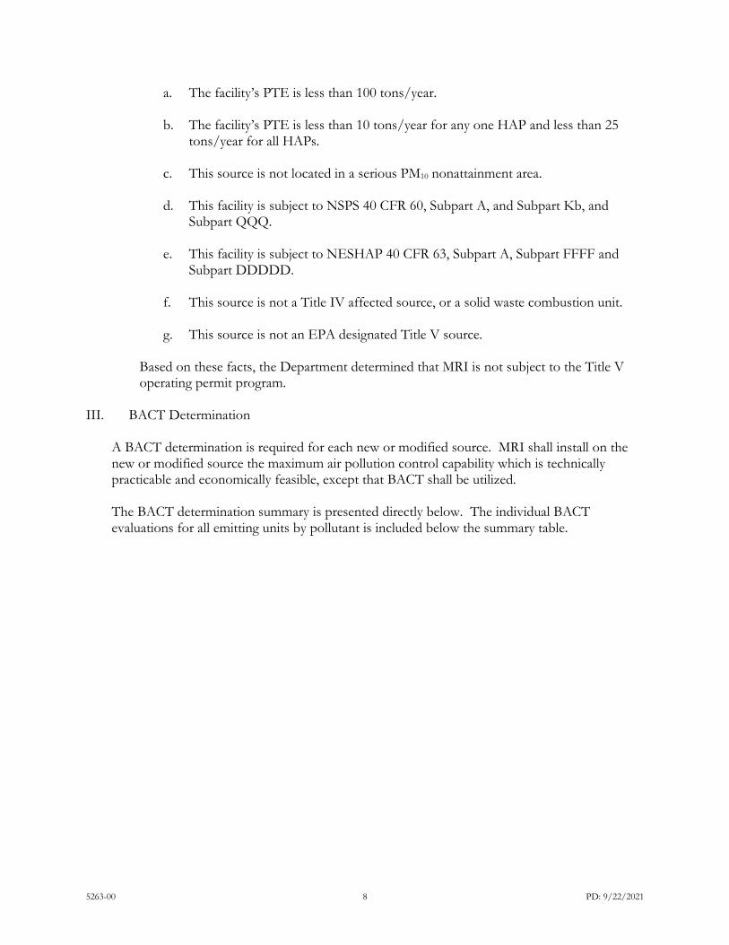
H. ARM 17.8.1204 Air Quality Operating Permit Program. (1) Title V of the FCAA amendments of 1990 requires that all sources, as defined in ARM 17.8.1204(1), obtain a Title V Operating Permit. In reviewing and issuing MAQP #5263-00 for MRI, the following conclusions were made:
5263-00 8 PD: 9/22/2021
a. The facility’s PTE is less than 100 tons/year. b. The facility’s PTE is less than 10 tons/year for any one HAP and less than 25
tons/year for all HAPs.
c. This source is not located in a serious PM10 nonattainment area.
d. This facility is subject to NSPS 40 CFR 60, Subpart A, and Subpart Kb, and Subpart QQQ.
e. This facility is subject to NESHAP 40 CFR 63, Subpart A, Subpart FFFF and
Subpart DDDDD.
f. This source is not a Title IV affected source, or a solid waste combustion unit.
g. This source is not an EPA designated Title V source.
Based on these facts, the Department determined that MRI is not subject to the Title V operating permit program.
III. BACT Determination
A BACT determination is required for each new or modified source. MRI shall install on the new or modified source the maximum air pollution control capability which is technically practicable and economically feasible, except that BACT shall be utilized. The BACT determination summary is presented directly below. The individual BACT evaluations for all emitting units by pollutant is included below the summary table.
5263-00 9 PD: 9/22/2021
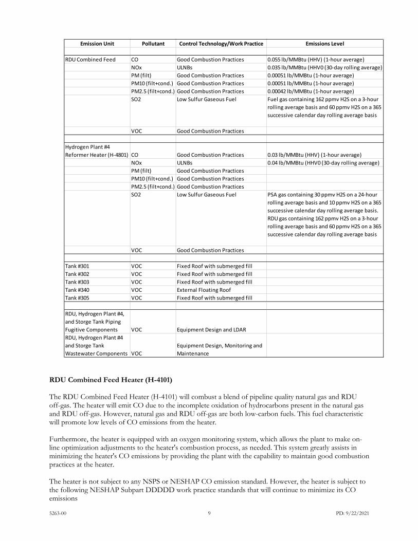
RDU Combined Feed Heater (H-4101) The RDU Combined Feed Heater (H-4101) will combust a blend of pipeline quality natural gas and RDU off-gas. The heater will emit CO due to the incomplete oxidation of hydrocarbons present in the natural gas and RDU off-gas. However, natural gas and RDU off-gas are both low-carbon fuels. This fuel characteristic will promote low levels of CO emissions from the heater. Furthermore, the heater is equipped with an oxygen monitoring system, which allows the plant to make on-line optimization adjustments to the heater's combustion process, as needed. This system greatly assists in minimizing the heater's CO emissions by providing the plant with the capability to maintain good combustion practices at the heater. The heater is not subject to any NSPS or NESHAP CO emission standard. However, the heater is subject to the following NESHAP Subpart DDDDD work practice standards that will continue to minimize its CO emissions
Emission Unit Pollutant Control Technology/Work Practice Emissions Level
RDU Combined Feed CO Good Combustion Practices 0.055 lb/MMBtu (HHV) (1-hour average)NOx ULNBs 0.035 lb/MMBtu (HHV0 (30-day rolling average)PM (filt) Good Combustion Practices 0.00051 lb/MMBtu (1-hour average)PM10 (filt+cond.) Good Combustion Practices 0.00051 lb/MMBtu (1-hour average)PM2.5 (filt+cond.) Good Combustion Practices 0.00042 lb/MMBtu (1-hour average)SO2 Low Sulfur Gaseous Fuel Fuel gas containing 162 ppmv H2S on a 3-hour
rolling average basis and 60 ppmv H2S on a 365 successive calendar day rolling average basis
VOC Good Combustion Practices
Hydrogen Plant #4 Reformer Heater (H-4801) CO Good Combustion Practices 0.03 lb/MMBtu (HHV) (1-hour average)
NOx ULNBs 0.04 lb/MMBtu (HHV0 (30-day rolling average)PM (filt) Good Combustion Practices PM10 (filt+cond.) Good Combustion Practices PM2.5 (filt+cond.) Good Combustion Practices SO2 Low Sulfur Gaseous Fuel PSA gas containing 30 ppmv H2S on a 24-hour
rolling average basis and 10 ppmv H2S on a 365 successive calendar day rolling average basis. RDU gas containing 162 ppmv H2S on a 3-hour rolling average basis and 60 ppmv H2S on a 365 successive calendar day rolling average basis
VOC Good Combustion Practices
Tank #301 VOC Fixed Roof with submerged fillTank #302 VOC Fixed Roof with submerged fillTank #303 VOC Fixed Roof with submerged fillTank #340 VOC External Floating RoofTank #305 VOC Fixed Roof with submerged fill
RDU, Hydrogen Plant #4, and Storge Tank Piping Fugitive Components VOC Equipment Design and LDARRDU, Hydrogen Plant #4 and Storge Tank Wastewater Components VOC
Equipment Design, Monitoring and Maintenance

5263-00 10 PD: 9/22/2021
• Pursuant to 40 CFR 63. 7540(a)(10)(i), MRI will inspect the heater's burner(s), and clean or replace
any components of the burner(s) as necessary.
• Pursuant to 40 CFR 63. 7540(a)(10)(ii), MRI will inspect the flame pattern of the heater's burner(s) and adjust the burner(s) as necessary to optimize the flame pattern, consistent with the manufacturer's specifications.
• Pursuant to 40 CFR 63.7540(a)(10)(iv), MRI will optimize total emissions of CO. This optimization
is consistent with the manufacturer's specifications and the NOx emission limitation to which the heater is subject.
• Pursuant to 40 CFR 63. 7540(a)(10)(v), MRI will measure the CO and oxygen concentrations in the
heater's exhaust stream before and after making the adjustments referenced above. Additionally, the heater is subject to the following MT DEQ maximum air pollution control capability CO emission standard in the CMR MAQP #2161-35.
• Pursuant to ARM 17.8.752 CO emissions from the heater shall not exceed 0.055 lb/MMBtu. CO BACT Determination Step 1: Identify Control Technologies The following are available CO emission control technologies for the RDU Combined Feed Heater (H-4101). • Good Combustion Practices • Thermal Oxidation • Catalytic Oxidation Below these technologies are generally described. Good Combustion Practices Good combustion practices for a gaseous fuel enclosed combustion device provide a properly set and controlled air-to-fuel ratio and appropriate combustion zone residence time, temperature, and turbulence parameters essential to achieving low CO emission levels. Incomplete combustion of fuel hydrocarbons can occur because of improper combustion mechanisms, which may result from poor burner/combustion device design, operation, and/or maintenance. However, a heater is designed and typically operated to maximize fuel combustion efficiency so that its fuel usage cost is minimized while maximizing process heating performance. Good combustion practices can be achieved by following a combustion device manufacturer's operating procedures and guidelines, as well as complying with NESHAP Subpart DDDDD work practice standards, which require a combustion device to undergo regular tune-ups. Thermal Oxidation Thermal oxidation can be used to reduce CO contained in a source's exhaust stream by maintaining the stream at a high enough temperature in the presence of oxygen, resulting in the oxidation of CO to CO2. Thermal oxidation of a CO exhaust stream can be achieved by routing the stream to a flare, afterburner, or regenerative or recuperative thermal oxidizer. The effectiveness of all thermal oxidation processes is influenced by residence time, mixing, and temperature. Auxiliary fuel is typically required to achieve the temperature needed to ensure proper CO exhaust stream oxidation in a thermal oxidation device or process. The necessary amount of auxiliary fuel is dependent on the CO content of the exhaust stream, as well as the amount of hydrocarbon that may be present in the exhaust stream. The use of auxiliary fuel is considered an extra energy impact for the evaluation.

5263-00 11 PD: 9/22/2021
Catalytic Oxidation Catalytic oxidation makes use of catalysts, such as the precious metals platinum, palladium, or rhodium, without the addition of any chemical reagents to reduce the temperature at which CO oxidizes to CO2. The effectiveness of catalytic oxidation is dependent on the exhaust stream temperature and the presence of potentially poisoning contaminants in the exhaust stream. The amount of catalyst volume is dependent upon the exhaust stream flow rate, CO content, and temperature, as well as the desired CO removal efficiency. The catalyst will experience activity loss over time due to physical deterioration or chemical deactivation. Therefore, the catalyst must be periodically replaced. Catalyst life varies from manufacturer-to-manufacturer, but three to six-year windows are not uncommon. Periodic testing of the catalyst is necessary to monitor its activity (i.e., oxidation promoting effectiveness) and predict its remaining life. Catalyst disposal is considered a negative impact for this technology. Step 2: Eliminate Technically Infeasible Options The technical feasibility of the CO emission control technologies determined to be available for the RDU Combined Feed Heater (H-4101) is evaluated below. Good Combustion Practices Good combustion practices are an integral component of the design and operation of the heater. Therefore, this option is technically feasible for the heater. Thermal Oxidation Thermal oxidation is not technically feasible for the control of CO emissions from the heater due to the very low concentration of CO in its exhaust stream. The application of thermal oxidation to reduce the heater's CO emission rate would require the combustion of a considerable amount of fuel to achieve the elevated temperature necessary to promote the oxidation of the small amount of CO that will be present in the heater's exhaust stream. This fuel combustion would generate additional combustion pollutants, including CO. Thus, the CO emission reduction effectiveness of the thermal oxidation system would be reduced, if not negated, because of the CO generated by the thermal oxidation process. Emission control technology application data sets indicates thermal oxidation has not been used to control CO emissions from a comparable heater. Based on these factors, MRI determined that it is not technically feasible to use thermal oxidation to control the heater's CO emissions. Catalytic Oxidation Catalytic oxidation is not technically feasible for the control of CO emissions from the heater because its exhaust gas temperature is too low for the effective operation of the oxidation catalyst. The optimum temperature range for catalytic oxidation is 850 to 1,100°F. Below temperatures of 500 to 600°F, the CO removal efficiency of the oxidation catalyst is considerably reduced. The heater's convection section incorporates a considerable amount of heat recovery to heat an RDU feed oil and hydrogen mixture in one set of coils and water in a separate set of coils. Specifically, the convection section incorporates a feed preheat coil and a boiler feedwater coil. The exhaust gas temperature after these heat recovery operations is approximately 460°F. Therefore, the exhaust gas temperature of the heater is too low for the effective operation of catalytic oxidation. Moreover, due to the considerably low concentration of CO in the heater's exhaust stream, the potential effectiveness of a catalytic oxidation system in this case would be limited. Step 3: Rank Remaining Control Technologies by Control Effectiveness The only remaining available CO emission control technology for the RDU Combined Feed Heater (H-4101) is good combustion practices. Step 4: Evaluate Most Effective Control Options and Document Results The only remaining available CO emission control technology for the RDU Combined Feed Heater (H-4101) is good combustion practices. Step 5: Select BACT

5263-00 12 PD: 9/22/2021
MRI determined that good combustion practices represent the maximum air pollution control capability for CO emissions from the RDU Combined Feed Heater (H-4101). Therefore, MRI will control CO emissions from the heater by using good combustion practices and complying with the following emission limitation: CO emissions from the RDU Combined Feed Heater (H-4101) shall not exceed 0.055 lb/MMBtu (HHV), based on a 1-hour average. NOx The RDU Combined Feed Heater (H-4101) will emit NOx, primarily due to the thermal and prompt NOx generation mechanisms because the heater's fuel will not contain appreciable amounts of organo-nitrogen compounds that result in fuel NOx emissions. Thermal NOx results from the high temperature thermal dissociation and subsequent reaction of combustion air molecular nitrogen and oxygen, and it tends to be generated in the high temperature zone near the burner of an external combustion device. The rate of thermal NOx generation is affected by the following three factors: oxygen concentration, peak flame temperature, and duration at peak flame temperature. As these three factors increase in value, the rate of thermal NOx generation increases. Prompt NOx occurs at the flame front through the relatively fast reaction between combustion air nitrogen and oxygen molecules and fuel hydrocarbon radicals, which are intermediate species formed during the combustion process. Prompt NOx may represent a meaningful portion of the NOx emissions resulting from low NOx burners (LNBs) and ULNBs due to the relatively low levels of thermal NOx generated by these burners. The heater is currently subject to the following NSPS Subpart Ja NOx emission standard.
• Pursuant to NSPS Subpart Ja, NOx emissions from the heater shall not exceed 40 ppmvd at 0% oxygen or 0.040 lb/MMBtu (HHV), both based on a 30-day rolling average determined daily.
However, the heater will not be an affected facility under NSPS Subpart Ja after the MHC is converted to the RDU. The heater is also subject to the following MT DEQ maximum air pollution control capability NOx emission standard and Consent Decree (MAQP #2161-35) NOx control technology requirement.
• Pursuant to ARM 17.8.752, NOx emissions from the heater shall not exceed 0.035 lb/MMBtu (HHV), based on a 30-day rolling average.
• Pursuant to Paragraph 16.F of the Consent Decree, the heater shall be equipped with "Next
Generation ULNBs." Step 1: Identify Control Technologies The following are available NOx emission control technologies for the RDU Combined Feed Heater (H-4101). • LNBs/ULNBs • SCR • SNCR • Non-Selective Catalytic Reduction (NSCR) Below these technologies are generally described.

5263-00 13 PD: 9/22/2021
LNBs/ULNBs LNBs/ULNBs are available in a variety of configurations and burner types, and they may incorporate one or more of the following concepts: lower flame temperatures; fuel rich conditions at the maximum flame temperature; and decreased residence times for oxidation conditions. These burners are often designed so that fuel and air are pre-mixed prior to combustion, resulting in lower and more uniform flame temperatures. Pre-mix burners may require the aid of a blower to mix the fuel with air before combustion takes place. Additionally, an LNB/ULNB may be designed so that a portion of a combustion device's flue gas is recycled back into the burner in order to reduce the burner's flame temperature. However, instead of recycled flue gas, steam can also be used to reduce a burner's flame temperature. Furthermore, LNBs/ULNBs may use staged combustion, which involves creating a fuel rich zone to start combustion and stabilize a burner's flame, followed by a fuel lean zone to complete combustion and reduce the burner's peak flame temperature. SCR SCR is a post-combustion treatment technology that promotes the selective catalytic chemical reduction of NOx (both nitric oxide and nitrogen dioxide) to molecular nitrogen and water. SCR technology involves the mixing of a reducing agent (aqueous or anhydrous ammonia or urea) with NOx-containing combustion gases and the resulting mixture is passed through a catalyst bed, which catalyst serves to lower the activation energy of the NOx reduction reactions. In the catalyst bed, the NOx and ammonia contained in the combustion gas-reagent mixture are adsorbed onto the SCR catalyst surface to form an activated complex and then the catalytic reduction of NOx occurs, resulting in the production of nitrogen and water from NOx. The nitrogen and water products of the SCR reaction are desorbed from the catalyst surface into the combustion exhaust gas passing through the catalyst bed. From the SCR catalyst bed, the treated combustion exhaust gas is emitted to the atmosphere. SCR systems can effectively operate at a temperature above 350°F and below 1,100°F, with a more refined temperature window dependent on the composition of the catalyst used in the SCR system. SNCR SNCR is a post-combustion treatment technology that is effectively a partial SCR system. A reducing agent (aqueous or anhydrous ammonia or urea) is mixed with NOx-containing combustion gases and a portion of the NOx reacts with the reducing agent to form molecular nitrogen and water. As indicated by the name of this technology, SNCR unlike SCR does not utilize a catalyst to promote the chemical reduction of NOx. Because a catalyst is not used with SNCR, the NOx reduction reactions occur at high temperatures. SNCR typically requires thorough mixing of the reagent in the combustion chamber of an external combustion device because this technology requires at least 0.5 seconds of residence time at a temperature above 1,600°F and below 2,100°F. A combustion device equipped with SNCR technology may require multiple reagent injection locations because the optimum location (temperature profile) for reagent injection may change depending on the load at which the combustion device is operating. At temperatures below 1,600°F, the desired NOx reduction reactions will not effectively occur and much of the injected reagent will be emitted to the atmosphere along with the mostly uncontrolled NOx emissions. At temperatures above 2,100°F, the desired NOx reduction reactions will not effectively occur, and the ammonia or urea reagent will begin to react with available oxygen to produce additional NOx emissions. NSCR NSCR is a post-combustion treatment technology that promotes the catalytic chemical reduction of NOx (both nitric oxide and nitrogen dioxide) to molecular nitrogen and water. NSCR technology has been applied to nitric acid plants and rich burn and stoichiometric internal combustion engines to reduce NOx emissions. NSCR technology uses a reducing agent (hydrocarbon, hydrogen, or CO), which can be inherently contained in the exhaust gas due to rich combustion conditions or injected into the exhaust gas, to react in the presence of a catalyst with a portion of the NOx contained in the source's exhaust gas to generate molecular nitrogen and water. NSCR systems can effectively operate at a temperature above 725°F and below 1,200°F, with a more refined temperature window dependent on the source type and composition of the catalyst used in the NSCR system. Step 2: Eliminate Technically Infeasible Options

5263-00 14 PD: 9/22/2021
The technical feasibility of the NOx emission control technologies determined to be available for the RDU Combined Feed Heater (H-4101) is evaluated below. LNBs/ULNBs The heater is already equipped with ULNBs. Therefore, this option is technically feasible and was incorporated into the baseline emissions for the heater. SCR This option is technically feasible for the heater. SNCR Due to the temperature and mixing profile sensitivities of an SNCR system, these systems often have not achieved the expected amounts of theoretical NOx emission reduction, especially in turndown modes of operation. However, MRI conservatively estimated SNCR is technically feasible to control the heater's NOx emissions. NSCR NSCR technology is not technically feasible for the control of NOx emissions from the heater because it does not operate at the 0.5% or less excess oxygen concentration necessary to ensure NOx reduction with NSCR. Instead, the heater operates with an excess oxygen concentration of approximately 3%. This excess oxygen concentration promotes both low levels of CO and high combustion (thermal) efficiency, while also providing for safe heater operations during variations in fuel gas operating conditions (e.g., fuel gas composition changes, fuel gas supply pressure variations) that may occur at the plant. Furthermore, research of emission control technology application data sets indicated NSCR has not been used to control NOx emissions from a comparable heater. These factors indicate it is not technically feasible to use NSCR to control the heater's NOx emissions. Step 3: Rank Remaining Control Technologies by Control Effectiveness The remaining available NOx emission control technologies for the RDU Combined Feed Heater (H-4101) are listed below from the highest to lowest potential emission control relative to the emissions unit's baseline emissions. • SCR • SNCR • ULNBs: this control technology was incorporated into the emissions unit's baseline emissions because the unit is already equipped with ULNBs. Step 4: Evaluate Most Effective Control Options and Document Results Below we evaluate the cost effectiveness of the installation and operation of the NOx emission control technologies that were determined to be technically feasible for the RDU Combined Feed Heater (H-4101) but not already included in its base design. SCR As indicated in the application, MRI estimated that the installation and operation of an SCR system on the heater would result in a cost effectiveness equal to approximately $82,977 per ton of NOx emission reduction, which is not cost effective. 61 Also, the installation of an SCR system on the heater would require additional energy to operate the SCR system's electrical equipment (e.g., pumps, heaters/vaporizers, instrumentation) and provide fan power to overcome the pressure drop across the SCR catalyst bed(s). This increase in electricity usage at the plant would result in increased GHG and non-GHG emission rates at one or more power generating stations, reducing the net environmental benefit of the SCR system. Furthermore, the SCR catalyst would require periodic replacement, which would result in a spent catalyst waste stream. This waste stream may represent hazardous waste depending on the composition of the catalyst and the heater's combustion products collected on the catalyst. Lastly, an SCR system would experience ammonia slip

5263-00 15 PD: 9/22/2021
during operation, resulting in ammonia emissions from the heater's stack, which may negatively impact regional haze due to an increase in the amount of atmospheric ammonia available to generate visibility impairing ammonium nitrates and ammonium sulfates. In summary, MRI determined that it would not be cost effective to equip the heater with an SCR system, and the operation of an SCR system on the heater would result in collateral emissions of GHG and non-GHG pollutants, as well as the generation of an additional solid. For these reasons, MRI eliminated an SCR system from consideration as the maximum air pollution control capability for the heater's NOx emissions. SNCR As indicated in Appendix 2, MRI estimated that the installation and operation of an SNCR system on the heater would result in a cost effectiveness equal to approximately $54,966 per ton of NOx emission reduction, which is not cost effective. 62 Also, the installation of an SNCR system on the heater would require additional energy to operate the SNCR system's electrical equipment (e.g., pumps, heaters/vaporizers, instrumentation). This increase in electricity usage at the site would result in increased GHG and non-GHG emission rates at one or more power generating stations, reducing the net environmental benefit of the SNCR system. Furthermore, an SNCR system would experience ammonia slip during operation, resulting in ammonia emissions from the heater's stack, which may negatively impact regional haze due to an increase in the amount of atmospheric ammonia available to generate visibility impairing ammonium nitrates and ammonium sulfates. In summary, MRI determined that it would not be cost effective to equip the heater with an SNCR system, and the operation of an SNCR system on the heater would result in collateral emissions of GHG and non-GHG pollutants. For these reasons, MRI eliminated an SNCR system from consideration as the maximum air pollution control capability for the heater's NOx emissions. Step 5: Select Maximum Air Pollution Control Capability MRI determined that ULNBs represent the maximum air pollution control capability for the NOx emissions from the RDU Combined Feed Heater (H-4101). The heater is already equipped with ULNBs and MRI will continue to comply with the following emission limitation that was previously determined to reflect the performance of the maximum air pollution control capability for this unit: NOx emissions from the RDU Combined Feed Heater (H- 4101) shall not exceed 0.035 lb/MMBtu (HHV), based on a 30-day rolling average. PM/PM10/PM2.5 The RDU Combined Feed Heater (H-4101) will emit PM10 and PM2.5 comprised of filterable and condensable portions. A gaseous fuel combustion device can emit PM10 and PM2.5 at elevated levels due to the incomplete combustion of higher molecular weight hydrocarbons present in the device's gaseous fuel. However, the heater will combust pipeline quality natural gas and RDU off-gas, which are primarily comprised of hydrogen and relatively low molecular weight hydrocarbons. Therefore, elevated PM10 and PM2.5 emissions from the heater as a result of the incomplete combustion of high molecular weight hydrocarbons are not expected to occur. Additionally, the referenced fuels will contain low levels of sulfur, further minimizing the generation of PM10 and PM2.5 when they are combusted. The heater is not subject to any NSPS or NESHAP PM, PM10, or PM2.5 emission standard. However, it is subject to the following MT DEQ opacity and maximum air pollution control capability PM, PM10, and PM2.5 standards:
• Pursuant to ARM 17.8.304(2), emissions from the heater shall not exceed an opacity of 20% or greater averaged over six consecutive minutes.
• Pursuant to ARM 17.8.752, PM emissions from the heater shall not exceed 0.00051 lb/MMBtu.
5263-00 16 PD: 9/22/2021
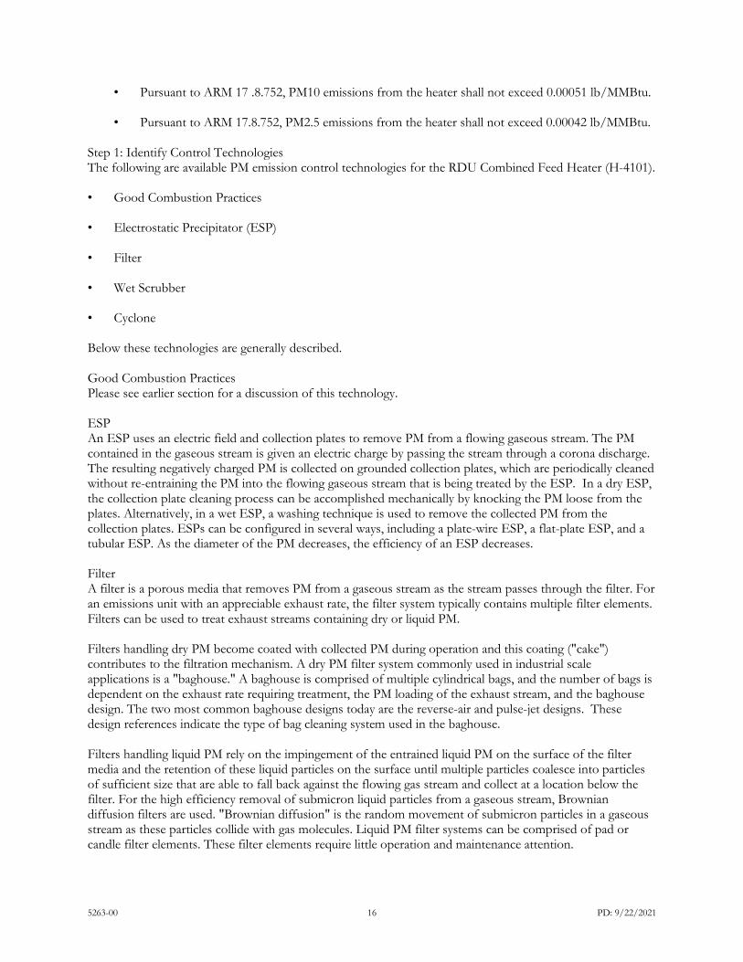
• Pursuant to ARM 17 .8.752, PM10 emissions from the heater shall not exceed 0.00051 lb/MMBtu.
• Pursuant to ARM 17.8.752, PM2.5 emissions from the heater shall not exceed 0.00042 lb/MMBtu.
Step 1: Identify Control Technologies The following are available PM emission control technologies for the RDU Combined Feed Heater (H-4101). • Good Combustion Practices • Electrostatic Precipitator (ESP) • Filter • Wet Scrubber • Cyclone Below these technologies are generally described. Good Combustion Practices Please see earlier section for a discussion of this technology. ESP An ESP uses an electric field and collection plates to remove PM from a flowing gaseous stream. The PM contained in the gaseous stream is given an electric charge by passing the stream through a corona discharge. The resulting negatively charged PM is collected on grounded collection plates, which are periodically cleaned without re-entraining the PM into the flowing gaseous stream that is being treated by the ESP. In a dry ESP, the collection plate cleaning process can be accomplished mechanically by knocking the PM loose from the plates. Alternatively, in a wet ESP, a washing technique is used to remove the collected PM from the collection plates. ESPs can be configured in several ways, including a plate-wire ESP, a flat-plate ESP, and a tubular ESP. As the diameter of the PM decreases, the efficiency of an ESP decreases. Filter A filter is a porous media that removes PM from a gaseous stream as the stream passes through the filter. For an emissions unit with an appreciable exhaust rate, the filter system typically contains multiple filter elements. Filters can be used to treat exhaust streams containing dry or liquid PM. Filters handling dry PM become coated with collected PM during operation and this coating ("cake") contributes to the filtration mechanism. A dry PM filter system commonly used in industrial scale applications is a "baghouse." A baghouse is comprised of multiple cylindrical bags, and the number of bags is dependent on the exhaust rate requiring treatment, the PM loading of the exhaust stream, and the baghouse design. The two most common baghouse designs today are the reverse-air and pulse-jet designs. These design references indicate the type of bag cleaning system used in the baghouse. Filters handling liquid PM rely on the impingement of the entrained liquid PM on the surface of the filter media and the retention of these liquid particles on the surface until multiple particles coalesce into particles of sufficient size that are able to fall back against the flowing gas stream and collect at a location below the filter. For the high efficiency removal of submicron liquid particles from a gaseous stream, Brownian diffusion filters are used. "Brownian diffusion" is the random movement of submicron particles in a gaseous stream as these particles collide with gas molecules. Liquid PM filter systems can be comprised of pad or candle filter elements. These filter elements require little operation and maintenance attention.

5263-00 17 PD: 9/22/2021
Wet Scrubber A wet scrubber uses absorption to remove PM from a gaseous stream. Absorption is primarily a physical process, though it can also include a chemical component, in which a pollutant in a gas phase contacts a scrubbing liquid and is dissolved in the liquid. A key factor dictating the performance of a wet scrubber is the solubility of the pollutant of concern in the scrubbing liquid. Water is commonly used as the scrubbing liquid in a wet scrubber used for PM emission control, but other liquids can be used depending on the type of PM or other pollutant(s) to be removed from the gaseous stream undergoing treatment. There are several types of wet scrubbers, including packed-bed counterflow scrubbers, packed-bed cross-flow scrubbers, bubble plate scrubbers, and tray scrubbers. Cyclone A cyclone is the most common type of inertial separator used to collect medium-sized and coarse PM from gaseous streams. The PM contained in a gaseous stream treated in a cyclone moves outward under the influence of centrifugal force until it contacts the wall of the cyclone. The PM is then carried downward by gravity along the wall of the cyclone and collected in a hopper located at the bottom of the cyclone. Although cyclones provide a relatively low cost, mechanically simple option for the removal of larger diameter PM from gaseous streams, alone they do not typically provide adequate PM removal, especially when the gaseous stream contains smaller diameter PM. Instead, these devices are typically used to preclean a gaseous stream by removing larger diameter PM upstream of PM emission control devices that are more effective at removing smaller diameter PM. Eliminate Technically Infeasible Options The technical feasibility of the PM emission control technologies determined to be available for the RDU Combined Feed Heater (H-4101) is evaluated below. Good Combustion Practices Good combustion practices are already an integral component of the design and operation of the heater. Therefore, this option is technically feasible for the heater. ESP MRI estimated that the PM emitted by the heater will be PM10 only, which is a characteristic that would limit the control effectiveness of an ESP. Additionally, the PM10 concentration in the heater's exhaust stream is below the concentration typically seen in an ESP's exhaust stream. Thus, an ESP would not lower the heater's PM10 emissions by any appreciable amount. Furthermore, research of emission control technology application data sets indicates an ESP has not been used to control PM emissions from a comparable heater. These factors indicate it would not be technically feasible to use an ESP to control PM emissions from the heater. Filter The PM10-only profile of the heater's PM emissions would limit the control effectiveness of a filter. Additionally, the PM10 concentration in the heater's exhaust stream is below the concentration typically seen in a filter's exhaust stream. Thus, a filter would not lower the heater's PM10 emissions by any appreciable amount. Furthermore, research of emission control technology application data sets indicates a filter has not been used to control PM emissions from a comparable heater. These factors indicate it would not be technically feasible to use a filter to control PM emissions from the heater. Wet Scrubber The PM10-only profile of the heater's PM emissions indicates a wet scrubber would require a considerable pressure drop to effectively reduce the heater's PM emissions. Additionally, the PM10 concentration in the heater's exhaust stream is below the concentration typically seen in a wet scrubber's exhaust stream. Furthermore, the liquid carryover in the exhaust stream from a wet scrubber contains dissolved and suspended solids, which would result in a new PM emission mechanism, reducing any negligible PM10 control effectiveness of the wet scrubber in this application. Moreover, research of emission control technology application data sets indicates a wet scrubber has not been used to control PM emissions from a

5263-00 18 PD: 9/22/2021
comparable heater. These factors indicate it would not be technically feasible to use a wet scrubber to control PM emissions from the heater. Cyclone The PM10-only profile of the heater's PM emissions would limit the control effectiveness of a cyclone. Additionally, the PM10 concentration in the heater's exhaust stream is below the concentration typically seen in a cyclone's exhaust stream. Thus, a cyclone would not lower the heater's PM10 emissions by any appreciable amount. Furthermore, research of emission control technology application data sets indicates a cyclone has not been used to control PM emissions from a comparable heater. These factors indicate it would not be technically feasible to use a cyclone to control PM emissions from the heater. Step 3: Rank Remaining Control Technologies by Control Effectiveness The only remaining available PM, PM10, and PM2.5 emission control technology for the RDU Combined Feed Heater (H-4101) is good combustion practices. Step 4: Evaluate Most Effective Control Options and Document Results The only remaining available PM, PM10, and PM2.5 emission control technology for the RDU Combined Feed Heater (H-4101) is good combustion practices. Step 5: Select Maximum Air Pollution Control Capability MRI determined that good combustion practices represent the maximum air pollution control capability for the PM, PM10, and PM2.5 emissions from the RDU Combined Feed Heater (H-4101). Therefore, MRI will continue to control PM, PM10, and PM2.5 emissions from the heater by using good combustion practices and continuing to comply with the following emission limitations that were previously determined to reflect the performance of the maximum air pollution control capability for this unit:
• PM emissions from the heater shall not exceed 0.00051 lb/MMBtu (HHV), based on a 1-hour
average;
• PM10 emissions from the heater shall not exceed 0.00051 lb/MMBtu (HHV), based on a 1-hour average; and
• PM2.5 emissions from the heater shall not exceed 0.00042 lb/MMBtu (HHV), based on a 1-hour
average. SO2 The RDU Combined Feed Heater (H-4101) will combust a blend of pipeline quality natural gas and RDU off-gas. The natural gas will contain a negligible amount of H2S. Additionally, the RDU off-gas will be treated to minimize its H2S content. Therefore, the heater will emit only a small amount of SO2. The heater is currently subject to the following NSPS Subpart Ja SO2 emission standards.
• Pursuant to NSPS Subpart Ja, the heater shall not burn any refinery fuel gas that · contains H2S in excess of 162 ppmv on a 3-hour rolling average basis and 60 ppmv on a 365 successive calendar day rolling average basis.
However, the heater will not be an affected facility under NSPS Subpart Ja after the MHC is converted to the RDU. The heater is also subject to the following MT DEQ SO2 emission standard, which will continue to apply to the heater.

5263-00 19 PD: 9/22/2021
• Pursuant to ARM 17.8.322(5), the heater shall not burn any gaseous fuel containing sulfur compounds in excess of 60 grains per 100 ft3 of gaseous fuel, calculated as H2S at standard conditions (or approximately 808 ppmv H2S).
Step 1: Identify Control Technologies The following are available SO2 emission control technologies for the RDU Combined Feed Heater (H-4101). • Low Sulfur Fuel • Flue Gas Desulfurization Below these technologies are generally described. Low Sulfur Fuel A gaseous fuel may inherently contain low levels of sulfur compounds, or it may be treated to remove sulfur compounds using absorption or adsorption technologies. For example, pipeline quality natural gas may be from a well that produces inherently low sulfur gas, or it may be treated using absorption or adsorption technology to lower its sulfur content. Low sulfur gaseous fuels result in low levels of SO2 emissions when they are combusted. Flue Gas Desulfurization Flue gas desulfurization is commonly used to reduce SO2 emissions from coal-fired and oil fired combustion sources due to the relatively high concentration of SO2 (thousands of ppmv) contained in the flue gas generated by these sources. Flue gas desulfurization can be accomplished using wet, semi-dry, and dry scrubbers, although wet scrubbers are normally capable of higher SO2 removal efficiencies than semi-dry and dry scrubbers. In a wet scrubber, an aqueous slurry of sorbent is injected into a source's flue gas and the SO2 contained in the gas dissolves into the slurry droplets where it reacts with an alkaline compound present in the slurry. The treated flue gas is then emitted to the atmosphere after passing through a mist eliminator that is designed to remove any entrained slurry droplets, while the falling slurry droplets make their way to the bottom of the scrubber where they are collected and either regenerated and recycled or removed as a waste or byproduct. Semi-dry scrubbers are like wet scrubbers, but the slurry used in a semi-dry scrubber has a higher sorbent concentration, which results in the complete evaporation of the slurry water and the formation of a dry spent sorbent material that is entrained in the treated flue gas. This dry spent sorbent is removed from the flue gas using a baghouse or ESP. In a dry scrubber, a dry sorbent material is pneumatically injected into a source's flue gas and the dry spent sorbent material entrained in the treated flue gas is removed using a baghouse or ESP. Step 2: Eliminate Technically Infeasible Options The technical feasibility of the SO2 emission control technologies determined to be available for the RDU Combined Feed Heater (H-4101) is evaluated below. Low Sulfur Fuel Low sulfur fuel is technically feasible for the heater. Flue Gas Desulfurization The heater will emit SO2 at concentrations less than 15 ppmv, which are below the concentrations oftentimes seen in a wet scrubber's exhaust stream. Additionally, the liquid carryover in the exhaust stream from a wet scrubber or the solid carryover in the exhaust stream from a semi-dry or dry scrubber would result in a new PM emission mechanism for the heater. Moreover, research of emission control technology application data sets indicated wet, semi-dry, and dry scrubbers have not been used to control SO2 emissions from a

5263-00 20 PD: 9/22/2021
comparable heater. These factors indicate it would not be technically feasible to use flue gas desulfurization technologies to control SO2 emissions from the heater. Step 3: Rank Remaining Control Technologies by Control Effectiveness The only remaining available SO2 emission control technology for the RDU Combined Feed Heater (H-4101) is low sulfur fuel. Step 4: Evaluate Most Effective Control Options and Document Results The only remaining available SO2 emission control technology for the RDU Combined Feed Heater (H-4101) is low sulfur fuel. Step 5: Select Maximum Air Pollution Control Capability MRI determined that combusting low sulfur gaseous fuel represents the maximum air pollution control capability for the SO2 emissions from the RDU Combined Feed Heater (H- 4101). Specifically, MRI shall control SO2 emissions from the RDU Combined Feed Heater (H-4101) by combusting gaseous fuel meeting the following H2S standards: 162 ppmv H2S on a 3-hour rolling average basis and 60 ppmv H2S on a 365 successive calendar day rolling average basis. VOC The RDU Combined Feed Heater (H-4101) will emit VOC due to the incomplete oxidation of hydrocarbons present in the heater's gaseous fuel. However, the low molecular weight characteristic of the hydrocarbons in the fuel will promote low levels of VOC emissions from the heater. Furthermore, the heater is equipped with an oxygen monitoring system, which allows the plant to make on-line optimization adjustments to the heater's combustion process, as needed. This system greatly assists in minimizing the heater's VOC emissions by providing the plant with the capability to maintain good combustion practices at the heater. The heater is not subject to any NSPS or NESHAP VOC emission standard. However, the heater is subject to the following NESHAP Subpart DDDDD work practice standards that will continue to minimize its VOC emissions.
• Pursuant to 40 CFR 63. 7540(a)(10)(i), MRI will inspect the heater's burner(s), and clean or replace any components of the burner(s) as necessary.
• Pursuant to 40 CFR 63. 7540(a)(10)(ii), MRI will inspect the flame pattern of the heater's burner(s)
and adjust the burner(s) as necessary to optimize the flame pattern, consistent with the manufacturer's specifications.
Step 1: Identify Control Technologies The following are available VOC emission control technologies for the RDU Combined Feed Heater (H-4101). • Good Combustion Practices • Thermal Oxidation • Catalytic Oxidation Below these technologies are generally described. Good Combustion Practices Please see earlier section for discussion of this technology.

5263-00 21 PD: 9/22/2021
Thermal Oxidation Please see earlier section for discussion of this technology. Catalytic Oxidation Please see earlier section for a discussion of this technology. Step 2: Eliminate Technically Infeasible Options The technical feasibility of the VOC emission control technologies determined to be available for the RDU Combined Feed Heater (H-4101) is evaluated below. Good Combustion Practices Good combustion practices are an integral component of the design and operation of the heater. Therefore, this option is technically feasible for the heater. Thermal Oxidation Thermal oxidation is not technically feasible for the control of VOC emissions from the heater due to the very low concentration of VOC in its exhaust stream. The application of thermal oxidation to reduce the heater's VOC emission rate would require the combustion of a considerable amount of fuel to achieve the elevated temperature necessary to promote the oxidation of the small amount of VOC that will be present in the heater's exhaust stream. This fuel combustion would generate additional combustion pollutants, including VOC. Thus, the VOC emission reduction effectiveness of the thermal oxidation system would be reduced, if not negated, because of the VOC generated by the thermal oxidation process. In summary, the addition of a second thermal oxidation process to the heater system may not reduce the heater's VOC emissions by any appreciable amount, if at all, and this add-on control technology would considerably increase the energy requirements of the heater system while notably increasing the amount of combustion pollutants, such as NOx and CO2, emitted into the atmosphere. Furthermore, research of emission control technology application data sets indicated thermal oxidation has not been used to control VOC emissions from a comparable heater. These factors indicate it is not technically feasible to use thermal oxidation to control VOC emissions from the heater. Catalytic Oxidation Catalytic oxidation is not technically feasible for the control of VOC emissions from the heater because its exhaust gas temperature is too low for the effective operation of the oxidation catalyst. The optimum temperature range for catalytic oxidation is 850 to 1,100°F. Below temperatures of 500 to 600°F, the VOC removal efficiency of the oxidation catalyst is considerably reduced. As previously discussed, the heater's convection section incorporates a considerable amount of heat recovery to heat an RDU feed oil and hydrogen mixture in one set of coils and water in a separate set of coils. The exhaust gas temperature after these heat recovery operations is approximately 460°F. Therefore, the exhaust gas temperature of the heater is too low for the effective operation of catalytic oxidation. Moreover, due to the considerably low concentration of VOC in the heater's exhaust stream, the potential effectiveness of a catalytic oxidation system would be limited in this case. Step 3: Rank Remaining Control Technologies by Control Effectiveness The only remaining available VOC emission control technology for the RDU Combined Feed Heater (H-4101) is good combustion practices. Step 4: Evaluate Most Effective Control Options and Document Results The only remaining available VOC emission control technology for the RDU Combined Feed Heater (H-4101) is good combustion practices. Step 5: Select Maximum Air Pollution Control Capability MRI determined that good combustion practices represent the maximum air pollution control capability for the VOC emissions from the RDU Combined Feed Heater (H-4101). Therefore, MRI will control VOC emissions from the heater by using good combustion practices.

5263-00 22 PD: 9/22/2021
Hydrogen Plant #4 Reformer Heater (H-4801} The Hydrogen Plant #4 Reformer Heater (H-4801) will combust PSA off-gas and RDU off gas. As previously noted, the PSA off-gas will be mainly comprised of CH4, hydrogen, CO, CO2, CO2 water, and nitrogen, and the primary constituents of the RDU off-gas will typically be CH4, ethane, propane, butanes, pentanes, and hydrogen. The heater will emit CO due to the incomplete oxidation of hydrocarbons present in its gaseous fuels. However, the PSA off-gas and RDU off-gas will be low-carbon fuels. This fuel characteristic will promote low levels of CO emissions from the heater. Furthermore, the heater will be equipped with an oxygen monitoring system, which will allow the plant to make on-line optimization adjustments to the heater's combustion process, as needed. This system will greatly assist in minimizing the heater's CO emissions by providing the site with the capability to maintain good combustion practices at the heater. The heater will not be subject to any NSPS or NESHAP CO emission standard. However, the heater will be subject to the following NESHAP Subpart DDDDD work practice standards that will minimize its CO emissions. • Pursuant to 40 CFR 63. 7540(a)(l0)(i), MRI will inspect the heater's burner(s), and clean or replace any
components of the burner(s) as necessary. • Pursuant to 40 CFR 63. 7540(a)(l0)(ii), MRI will inspect the flame pattern of the heater's burner(s) and
adjust the burner(s) as necessary to optimize the flame pattern, consistent with the manufacturer's specifications.
• Pursuant to 40 CFR 63. 7540(a)(10)(iv), MRI will optimize total emissions of CO. This optimization will
be consistent with the manufacturer's specifications and any NOx emission limitation requirement to which the heater is subject.
• Pursuant to 40 CFR 63. 7540(a)(10)(v), MRI will measure the CO and oxygen concentrations in the
heater's exhaust stream before and after making the adjustments referenced above. Step 1: Identify Control Technologies The following are available CO emission control technologies for the Hydrogen Plant #4 Reformer Heater (H-4801). • Good Combustion Practices • Thermal Oxidation • Catalytic Oxidation Below these technologies are generally described. Good Combustion Practices Please see earlier section for a discussion of this technology. Thermal Oxidation Please see earlier section for a discussion of this technology. Catalytic Oxidation Please see earlier section for a discussion of this technology. Step 2: Eliminate Technically Infeasible Options

5263-00 23 PD: 9/22/2021
The technical feasibility of the CO emission control technologies determined to be available for the Hydrogen Plant #4 Reformer Heater (H-4801) is evaluated below. Good Combustion Practices Good combustion practices will be an integral component of the design and operation of the heater. Therefore, this option is technically feasible for the heater. Thermal Oxidation Thermal oxidation is not technically feasible for the control of CO emissions from the heater due to the very low concentration of CO in its exhaust stream. The application of thermal oxidation to reduce the heater's CO emission rate would require the combustion of a considerable amount of fuel to achieve the elevated temperature necessary to promote the oxidation of the small amount of CO that will be present in the heater's exhaust stream. This fuel combustion would generate additional combustion pollutants, including CO. Thus, the CO emission reduction effectiveness of the thermal oxidation system would be reduced, if not negated, because of the CO generated by the thermal oxidation process. In summary, the addition of a second thermal oxidation process to the heater system may not reduce the heater's CO emissions by any appreciable amount, if at all, and this add-on control technology would considerably increase the energy requirements of the heater system while notably increasing the amount of combustion pollutants, such as NOx and CO2, emitted into the atmosphere. Furthermore, research of emission control technology application data sets indicates thermal oxidation has not been used to control CO emissions from a comparable heater. Based on these factors, MRI determined that it is not technically feasible to use thermal oxidation to control the heater's CO emissions. Catalytic Oxidation Catalytic oxidation is not technically feasible for the control of CO emissions from the heater because its exhaust gas temperature would be too low for the effective operation of the oxidation catalyst. The optimum temperature range for catalytic oxidation is 850 to 1,100°F. Below temperatures of 500 to 600°F, the CO removal efficiency of the oxidation catalyst is considerably reduced. The heater's convection section will incorporate a considerable amount of heat recovery to heat process material, water, and steam in five different heat exchangers. The exhaust gas temperature after these heat recovery operations will be approximately 340°F. Therefore, the exhaust gas temperature of the heater will be too low for the effective operation of catalytic oxidation. Moreover, due to the considerably low concentration of CO in the heater's exhaust stream, the potential effectiveness of a catalytic oxidation system in this case would be limited. Step 3: Rank Remaining Control Technologies by Control Effectiveness The only remaining available CO emission control technology for the Hydrogen Plant #4 Reformer Heater (H-4801) is good combustion practices. Step 4: Evaluate Most Effective Control Options and Document Results The only remaining available CO emission control technology for the Hydrogen Plant #4 Reformer Heater (H-4801) is good combustion practices. Step 5: Select Maximum Air Pollution Control Capability MRI determined that good combustion practices represent the maximum air pollution control capability for CO emissions from the Hydrogen Plant #4 Reformer Heater (H-4801). Therefore, MRI will control CO emissions from the heater by using good combustion practices and complying with the following emission limitation: CO emissions from the Hydrogen Plant #4 Reformer Heater (H-4801) shall not exceed 0.03 lb/MMBtu (HHV), based on a 1-hour average. NOx The Hydrogen Plant #4 Reformer Heater (H-4801) will emit NOx, primarily due to the thermal and prompt NOx generation mechanisms because the heater's PSA off-gas and RDU off-gas fuels will not contain appreciable amounts of organo-nitrogen compounds that result in fuel NOx emissions. Thermal NOx results from the high temperature thermal dissociation and subsequent reaction of combustion air molecular

5263-00 24 PD: 9/22/2021
nitrogen and oxygen, and it tends to be generated in the high temperature zone near the burner of an external combustion device. The rate of thermal NOx generation is affected by the following three factors: oxygen concentration, peak flame temperature, and the duration at peak flame temperature. As these three factors increase in value, the rate of thermal NOx generation increases. Prompt NOx occurs at the flame front through the relatively fast reaction between combustion air nitrogen and oxygen molecules and fuel hydrocarbon radicals, which are intermediate species formed during the combustion process. Prompt NOx may represent a meaningful portion of the NOx emissions resulting from LNBs and ULNBs. The Hydrogen Plant #4 Reformer Heater (H-4801) will not be subject to any NSPS NOx emission standard. However, it will be subject to the following Consent Decree NOx control technology requirement.
• Pursuant to Paragraph 16.F of the Consent Decree, the heater shall be equipped with "Next Generation ULNBs."
Step 1: Identify Control Technologies The following are available NOx emission control technologies for the Hydrogen Plant #4 Reformer Heater (H-4801). • LNBs/ULNBs • SCR • SNCR • NSCR Below these technologies are generally described. LNBs/ULNBs Please see earlier section for a discussion of this technology. SCR Please see earlier section for a discussion of this technology. SNCR Please see earlier section for a discussion of this technology. NSCR Please see earlier section for a discussion of this technology. Step 2: Eliminate Technically Infeasible Options The technical feasibility of the NOx emission control technologies determined to be available for the Hydrogen Plant #4 Reformer Heater (H-4801) is evaluated below. LNBs/ULNBs This option is technically feasible for the heater. SCR This option is technically feasible for the heater. SNCR Due to the temperature and mixing profile sensitivities of an SNCR system, these systems often have not achieved the expected amounts of theoretical NOx emission reduction, especially in turndown modes of

5263-00 25 PD: 9/22/2021
operation. In consideration of the optimal SNCR temperature profiles, reagent injection points would likely be evaluated for installation in the firebox of the heater. In fact, the designer of the heater, TechnipFMC, has evaluated the application of SNCR on its reformer heaters and determined that the SNCR reagent would need to be injected into the heater's firebox to achieve the residence time necessary for the reagent to react with NOx. However, the very high temperatures in the firebox region that would provide an acceptable residence time would also lead to the oxidation of reagent and the generation of additional NOx. Therefore, it is not technically feasible to use SNCR to control the heater's NOx emissions. NSCR NSCR technology is not technically feasible for the control of NOx emissions from the heater because it will not operate at the 0.5% or less excess oxygen concentration necessary to ensure NOx reduction with NSCR. Instead, the heater will operate with an excess oxygen concentration between approximately 2 and 2.5%. This range of excess oxygen concentrations will promote both low levels of CO and high combustion (thermal) efficiency, while also providing for safe heater operations during variations in fuel gas operating conditions (e.g., fuel gas composition changes, fuel gas supply pressure variations) that may occur at the plant. Furthermore, research of emission control technology application data sets indicated NSCR has not been used to control NOx emissions from a comparable heater. These factors indicate it is not technically feasible to use NSCR to control the heater's NOx emissions. Step 3: Rank Remaining Control Technologies by Control Effectiveness The remaining available NOx emission control technologies for the Hydrogen Plant #4 Reformer Heater (H-4801) are listed below from the highest to lowest potential emission control relative to the emissions unit's baseline emissions. • SCR
• ULNBs: this control technology was incorporated into the emissions unit's baseline emissions because the unit will be equipped with "Next Generation ULNBs" pursuant to the Consent Decree.
Step 4: Evaluate Most Effective Control Options and Document Results Be-low we evaluate the cost effectiveness of the installation and operation of the NOx emission control technologies that were determined to be technically feasible for the Hydrogen Plant #4 Reformer Heater (H-4801) but not already included in its base design. SCR As indicated in Appendix 2, MRI estimated that the installation and operation of an SCR system on the heater would result in a cost effectiveness equal to approximately $19,228 per ton of NOx emission reduction, which is not cost effective. 63 Also, the installation of an SCR system on the heater would require additional energy to operate the SCR system's electrical equipment (e.g., pumps, heaters/vaporizers, instrumentation) and provide additional fan power to the heater's mechanical draft system to overcome the pressure drop across the SCR catalyst bed(s). This increase in electricity usage at the plant would result in increased GHG and non-GHG emission rates at one or more power generating stations, reducing the net environmental benefit of the SCR system. Furthermore, the SCR catalyst would require periodic replacement, which would result in a spent catalyst waste stream. This waste stream may represent hazardous waste depending on the composition of the catalyst and the heater's combustion products collected on the catalyst. Lastly, an SCR system would experience ammonia slip during operation, resulting in ammonia emissions from the heater's stack, which may negatively impact regional haze due to an increase in the amount of atmospheric ammonia available to generate visibility impairing ammonium nitrates and ammonium sulfates. In summary, MRI determined that it would not be cost effective to equip the heater with an SCR system, and the operation of an SCR system on the heater would result in collateral emissions of GHG and non-GHG pollutants, as well as the generation of an additional solid waste stream at the site. For these reasons, MRI

5263-00 26 PD: 9/22/2021
eliminated an SCR system from consideration as the maximum air pollution control capability for the heater's NOx emissions. Step 5: Select Maximum Air Pollution Control Capability MRI determined that ULNBs represent the maximum air pollution control capability for the NOx emissions from the Hydrogen Plant #4 Reformer Heater (H-4801). Therefore, MRI will control NOx emissions from the heater by equipping it with ULNBs and complying with the following emission limitation: NOx emissions from the Hydrogen Plant #4 Reformer Heater (H-4801) shall not exceed 0.04 lb/MMBtu (HHV), based on a 30-day rolling average. PM/PM10/PM2.5 The Hydrogen Plant #4 Reformer Heater (H-4801) will emit PM10 and PM2.5 comprised of filterable and condensable portions. The heater will combust PSA off-gas and RDU off-gas, which contain relatively low levels of high molecular weight hydrocarbons. Therefore, elevated PM10 and PM2.5 emissions from the heater as a result of the incomplete combustion of high molecular weight hydrocarbons are not expected to occur. Additionally, the referenced gaseous fuels will be treated to reduce their H2S concentrations to low levels, further minimizing the generation of PM10 and PM2.5 when they are combusted. The heater will not be subject to any NSPS or NESHAP PM, PM10, or PM2.5 emission standard. However, it will be subject to the following MT DEQ opacity and PM standards.
• Pursuant to ARM 17.8.304(2), emissions from the heater shall not exceed an opacity of 20% or greater averaged over 6 consecutive minutes.
• Pursuant to ARM 17 .8.309, PM emissions from the heater shall not exceed 0.29 lb/MMBtu.
Step 1: Identify Control Technologies The following are available PM, PM10, and PM2.5 emission control technologies for the Hydrogen Plant #4 Reformer Heater (H-4801). • Good Combustion Practices • ESP • Filter • Wet Scrubber • Cyclone Below these technologies are generally described. Good Combustion Practices Please see earlier section for a discussion of this technology. ESP Please see earlier section for a discussion of this technology. Filter Please see earlier section for a discussion of this technology. Wet Scrubber Please see earlier section for a discussion of this technology.

5263-00 27 PD: 9/22/2021
Cyclone Please see earlier section for a discussion of this technology. Step 2: Eliminate Technically Infeasible Options The technical feasibility of the PM, PM10, and PM2.5 emission control technologies determined to be available for the Hydrogen Plant #4 Reformer Heater (H-4801) is evaluated below. Good Combustion Practices Good combustion practices will be an integral component of the design and operation of the heater. Therefore, this option is technically feasible for the heater. ESP MRI estimated that the PM emitted by the heater will be PM10 only, which is a characteristic that would limit the control effectiveness of an ESP. Additionally, the PM10 concentration in the heater's exhaust stream will be below the concentration typically seen in an ESP's exhaust stream. Thus, an ESP would not lower the heater's PM10 emissions by any appreciable amount. Furthermore, research of emission control technology application data sets indicates an ESP has not been used to control PM emissions from a comparable heater. These factors indicate it would not be technically feasible to use an ESP to control PM emissions from the heater. Filter The PM10-only profile of the heater's PM emissions would limit the control effectiveness of a filter. Additionally, the PM10 concentration in the heater's exhaust stream will be below the concentration typically seen in a filter's exhaust stream. Thus, a filter would not lower the heater's PM10 emissions by any appreciable amount. Furthermore, research of emission control technology application data sets indicates a filter has not been used to control PM emissions from a comparable heater. These factors indicate it would not be technically feasible to use a filter to control PM emissions from the heater. Wet Scrubber The PM10-only profile of the heater's PM emissions indicates a wet scrubber would require a considerable pressure drop to effectively reduce the heater's PM emissions. Additionally, the PM10 concentration in the heater's exhaust stream will be below the concentration typically seen in a wet scrubber's exhaust stream. Furthermore, the liquid carryover in the exhaust stream from a wet scrubber contains dissolved and suspended solids, which would result in a new PM emission mechanism, reducing any negligible PM10 control effectiveness of the wet scrubber in this application. Moreover, research of emission control technology application data sets indicates a wet scrubber has not been used to control PM emissions from a comparable heater. These factors indicate it would not be technically feasible to use a wet scrubber to control PM emissions from the heater. Cyclone The PM10-only profile of the heater's PM emissions would limit the control effectiveness of a cyclone. Additionally, the PM10 concentration in the heater's exhaust stream will be below the concentration typically seen in a cyclone's exhaust stream. Thus, a cyclone would not lower the heater's PM10 emissions by any appreciable amount. Furthermore, research of emission control technology application data sets indicates a cyclone has not been used to control PM emissions from a comparable heater. These factors indicate it would not be technically feasible to use a cyclone to control PM emissions from the heater. Step 3: Rank Remaining Control Technologies by Control Effectiveness The only remaining available PM, PM10, and PM2.5 emission control technology for the Hydrogen Plant #4 Reformer Heater (H-4801) is good combustion practices.

5263-00 28 PD: 9/22/2021
Step 4: Evaluate Most Effective Control Options and Document Results The only remaining available PM, PM10, and PM2.5 emission control technology for the Hydrogen Plant #4 Reformer Heater (H-4801) is good combustion practices. Step 5: Select Maximum Air Pollution Control Capability MRI determined that good combustion practices represent the maximum air pollution control capability for the PM, PM10, and PM2.5 emissions from the Hydrogen Plant #4 Reformer Heater (H-4801). Therefore, MRI will control PM, PM10, and PM2.5 emissions from the heater by using good combustion practices. SO2 The Hydrogen Plant #4 Reformer Heater (H-4801) will combust PSA off-gas and RDU off gas. RDU purge gas will be routed to the Hydrogen Plant #4 PSA system to recover hydrogen from that gas stream. The RDU purge gas will contain H2S, which will be mostly captured by the PSA system, but then released from the system as part of the PSA off-gas that will be generated when the system is regenerated. As a result, the PSA off-gas combusted in the heater will contain H2S. However, MRI plans to treat the RDU purge gas to minimize the H2S content of the PSA off-gas. Therefore, the heater will emit only a small amount of SO2 due to the combustion of PSA off-gas. The RDU off-gas will contain H2S, but it will be treated to minimize its H2S content. As a result, the heater will emit only a small amount of SO2 due to the combustion of RDU off gas. The Hydrogen Plant #4 Reformer Heater (H-4801) will be subject to the following MT DEQ SO2 emission standard.
• Pursuant to ARM 17.8.322(5), the heater shall not burn any gaseous fuel containing sulfur compounds in excess of 50 grains per 100 ft3 of gaseous fuel, calculated as H2S at standard conditions (or approximately 808 ppmv H2S).
Step 1: Identify Control Technologies The following are available SO2 emission control technologies for the Hydrogen Plant #4 Reformer Heater (H-4801). • Low Sulfur Fuel • Flue Gas Desulfurization Below these technologies are generally described. Low Sulfur Fuel Please see earlier section for a discussion of this technology. Flue Gas Desulfurization Please see earlier section for a discussion of this technology. Step 2: Eliminate Technically Infeasible Options The technical feasibility of the SO2 emission control technologies determined to be available for the Hydrogen Plant #4 Reformer Heater (H-4801) is evaluated below. Low Sulfur Fuel Low sulfur fuel is technically feasible for the heater. Flue Gas Desulfurization The heater will emit SO2 at concentrations less than 15 ppmv, which are below the concentrations oftentimes seen in a wet scrubber's exhaust stream. Additionally, the liquid carryover in the exhaust stream from a wet scrubber or the solid carryover in the exhaust stream from a semi-dry or dry scrubber would result in a new

5263-00 29 PD: 9/22/2021
PM emission mechanism for the heater. Moreover, research of emission control technology application data sets indicated wet, semi-dry, and dry scrubbers have not been used to control SO2 emissions from a comparable heater. These factors indicate it would not be technically feasible to use flue gas desulfurization technologies to control SO2 emissions from the heater. Step 3: Rank Remaining Control Technologies by Control Effectiveness The only remaining available SO2 emission control technology for the Hydrogen Plant #4 Reformer Heater (H-4801) is low sulfur fuel. Step 4: Evaluate Most Effective Control Options and Document Results The only remaining available SO2 emission control technology for the Hydrogen Plant #4 Reformer Heater (H-4801) is low sulfur fuel. Step 5: Select Maximum Air Pollution Control Capability MRI determined that combusting low sulfur gaseous fuel represents the maximum air pollution control capability for the SO2 emissions from the Hydrogen Plant #4 Reformer Heater (H-4801). Specifically, MRI shall control SO2 emissions from the heater by combusting PSA off-gas and RDU off-gas that meet the following H2S standards, respectively:
• PSA off-gas shall contain 30 ppmv H2S on a 24-hour rolling average basis and 10 ppmv H2S on a 365 successive calendar day rolling average basis; and
• RDU off-gas shall contain 5162 ppmv H2S on a 3-hour rolling average basis and 60 ppmv H2S on a
365 successive calendar day rolling average basis. VOC The Hydrogen Plant #4 Reformer Heater (H-4801) will emit VOC due to the incomplete oxidation of hydrocarbons present in its gaseous fuels. However, the low molecular weight characteristic of the hydrocarbons in the PSA off-gas and RDU off-gas will promote low levels of VOC emissions from the heater. Furthermore, the heater will be equipped with an oxygen monitoring system, which will allow the plant to make on-line optimization adjustments to the heater's combustion process, as needed. This system will greatly assist in minimizing the heater's VOC emissions by providing the site with the capability to maintain good combustion practices at the heater. The heater will not be subject to any NSPS or NESHAP VOC emission standard. However, the heater will be subject to the following NESHAP Subpart DDDDD work practice standards that will minimize its VOC emissions.
• Pursuant to 40 CFR 63. 7540(a)(l0)(i), MRI will inspect the heater's burner(s), and clean or replace any components of the burner(s) as necessary.
• Pursuant to 40 CFR 63. 7540(a)(l0)(ii), MRI will inspect the flame pattern of the heater's burner(s)
and adjust the burner(s) as necessary to optimize the flame pattern, consistent with the manufacturer's specifications.
Step 1: Identify Control Technologies The following are available VOC emission control technologies for the Hydrogen Plant #4 Reformer Heater (H-4801). • Good Combustion Practices • Thermal Oxidation

5263-00 30 PD: 9/22/2021
• Catalytic Oxidation Below these technologies are generally described. Good Combustion Practices Please see earlier section for a discussion of this technology. Thermal Oxidation Please see earlier section for a discussion of this technology. Catalytic Oxidation Please see earlier section for a discussion of this technology. Step 2: Eliminate Technically Infeasible Options The technical feasibility of the VOC emission control technologies determined to be available for the Hydrogen Plant #4 Reformer Heater (H-4801) is evaluated below. Good Combustion Practices Good combustion practices will be an integral component of the design and operation of the heater. Therefore, this option is technically feasible for the heater. Thermal Oxidation Thermal oxidation is not technically feasible for the control of VOC emissions from the heater due to the very low concentration of VOC in its exhaust stream. The application of thermal oxidation to reduce the heater's VOC emission rate would require the combustion of a considerable amount of fuel to achieve the elevated temperature necessary to promote the oxidation of the small amount of VOC that will be present in the heater's exhaust stream. This fuel combustion would generate additional combustion pollutants, including VOC. Thus, the VOC emission reduction effectiveness of the thermal oxidation system would be reduced, if not negated, because of the VOC generated by the thermal oxidation process. In summary, the addition of a second thermal oxidation process to the heater system may not reduce the heater's VOC emissions by any appreciable amount, if at all, and this add-on control technology would considerably increase the energy requirements of the heater system while notably increasing the amount of combustion pollutants, such as NOx and CO2, emitted into the atmosphere. Furthermore, research of emission control technology application data sets indicated thermal oxidation has not been used to control VOC emissions from a comparable heater. These factors indicate it is not technically feasible to use thermal oxidation to control VOC emissions from the heater. Catalytic Oxidation Catalytic oxidation is not technically feasible for the control of VOC emissions from the heater because its exhaust gas temperature would be too low for the effective operation of the oxidation catalyst. The optimum temperature range for catalytic oxidation is 850 to 1,100°F. Below temperatures of 500 to 600°F, the VOC removal efficiency of the oxidation catalyst is considerably reduced. As previously discussed, the heater's convection section will incorporate a considerable amount of heat recovery to heat process material, water, and steam. The exhaust gas temperature after these heat recovery operations will be approximately 340°F. Therefore, the exhaust gas temperature of the heater will be too low for the effective operation of catalytic oxidation. Moreover, due to the considerably low concentration of VOC in the heater's exhaust stream, the potential effectiveness of a catalytic oxidation system would be limited in this case. Step 3: Rank Remaining Control Technologies by Control Effectiveness The only remaining available VOC emission control technology for the Hydrogen Plant #4 Reformer Heater (H-4801) is good combustion practices. Step 4: Evaluate Most Effective Control Options and Document Results

5263-00 31 PD: 9/22/2021
The only remaining available VOC emission control technology for the Hydrogen Plant #4 Reformer Heater (H-4801) is good combustion practices. Step 5: Select Maximum Air Pollution Control Capability MRI determined that good combustion practices represent the maximum air pollution control capability for the VOC emissions from the Hydrogen Plant #4 Reformer Heater (H- 4801). Therefore, MRI will control VOC emissions from the heater by using good combustion practices. Tank #301 The maximum air pollution control capability determinations made for this emissions unit pursuant to ARM 17.8.752 are presented below. VOC Tank #301 will be an atmospheric fixed roof storage tank storing a VOC-containing material. The emissions mechanisms for the storage tank will be the following two mechanisms: (1) the contraction and expansion of the vapor in the vapor space of the tank caused by operating temperature fluctuations; and (2) the hydraulic displacement of vapor caused by cyclic increases in the tank's liquid level. The first mechanism results in breathing emissions, while the second mechanism results in working emissions. The tank will not be subject to any NSPS or NESHAP VOC emission standard. Step 1: Identify Control Technologies The following are available VOC emission control technologies for Tank #301. • Internal Floating Roof (IFR) Storage Tank with Vapor Collection System and Control Device • Fixed Roof Storage Tank with Vapor Collection System and Control Device • IFR Storage Tank • External Floating Roof (EFR) Storage Tank • Fixed Roof Storage Tank with Submerged Fill Below these technologies are generally described. IFR Storage Tank with Vapor Collection System and Control Device An IFR storage tank is equipped with two roofs - a fixed roof connected to the top of the storage tank wall and a floating roof (the IFR) that rests on the surface of the liquid contained in the storage tank. In general, a floating roof design effectively eliminates the breathing and working emissions that result from a fixed roof storage tank because the floating roof eliminates the vapor space that would be present in a fixed roof tank by directly contacting nearly all of the liquid surface area. Additionally, certain emissions mechanisms and floating roof operating and maintenance risks that exist for an EFR tank (a tank where the floating roof is exposed to the atmosphere) do not exist for an IFR tank because the IFR tank's floating roof is not directly exposed to the atmosphere since the tank's fixed roof is located above the floating roof. Because an IFR tank incorporates a fixed roof above a floating roof, the vapor between the floating roof and fixed roof can be collected and routed to a control device to reduce VOC emissions to the atmosphere. The following are examples of the types of control devices that can be used to reduce VOC emissions from the vapor collected from an IFR tank: • Condenser; • Thermal oxidizer; and • Carbon adsorption.

5263-00 32 PD: 9/22/2021
Fixed Roof Storage Tank with Vapor Collection System and Control Device A fixed roof storage tank contains a vapor space between the surface of the liquid contained in the tank and the roof of the tank, and this vapor space is partially comprised of the compounds making up the liquid contained in the tank. A portion of the vapor contained in the vapor space of an atmospheric fixed roof storage tank is routinely vented to the atmosphere because of the breathing and working emissions mechanisms described above. A fixed roof tank can be equipped with a vapor collection system to collect the vapor vented from the tank. This collected vapor can then be routed to a control device to reduce VOC emissions to the atmosphere. The following are examples of the types of control devices that can be used to reduce VOC emissions from the vapor collected from a fixed roof tank: • Condenser; • Thermal oxidizer; and • Carbon adsorption. IFR Storage Tank As discussed above, an IFR storage tank is equipped with two roof structures - a fixed roof located above a floating roof (the IFR). In general, a floating roof design effectively eliminates the breathing and working emissions that result from a fixed roof storage tank because the floating roof eliminates the vapor space that would be present in a fixed roof tank by directly contacting nearly all of the liquid surface area. Additionally, certain emissions mechanisms and floating roof operating and maintenance risks that exist for an EFR tank do not exist for an IFR tank because the IFR tank's floating roof is not directly exposed to the atmosphere since the tank's fixed roof is located above its floating roof. As a result, emissions from an IFR tank are typically lower than the emissions that would occur from an otherwise identical EFR tank containing the same material at the same storage conditions. EFR Storage Tank An EFR storage tank is equipped with a roof structure that rests on the surface of the liquid contained in the storage tank, and this floating roof is exposed to the atmosphere. As discussed above for an IFR tank, a floating roof design effectively eliminates the breathing and working emissions that result from a fixed roof storage tank. However, emissions from an EFR tank tend to be higher than from an IFR tank because the rim seal and openings of an EFR tank are directly exposed to the atmosphere and, therefore, the emissions from these seals and openings are influenced by wind conditions. Fixed Roof Storage Tank with Submerged Fill As discussed above, there are two mechanisms that result in emissions from a fixed roof storage tank. The first mechanism results in breathing emissions, while the second mechanism results in working emissions. By incorporating submerged fill into the design of a fixed roof storage tank, the saturation level of the vapor space between the surface of the liquid contained in the tank and the roof of the tank can be reduced versus the level that would occur if the liquid were introduced into the tank under splash loading conditions. Therefore, by reducing the saturation level of the vapor space, the vapor vented from the storage tank contains less VOC, which means lower VOC emissions to the atmosphere. 2 Step 2: Eliminate Technically Infeasible Options Below we evaluate the technical feasibility of the VOC emission control technologies determined to be available for Tank #301. IFR Storage Tank with Vapor Collection System and Control Device This option is technically feasible for the tank. Fixed Roof Storage Tank with Vapor Collection System and Control Device This option is technically feasible for the tank.

5263-00 33 PD: 9/22/2021
IFR Storage Tank This option is technically feasible for the tank. EFR Storage Tank This option is technically feasible for the tank. Fixed Roof Storage Tank with Submerged Fill Fixed roof with submerged fill will be an integral component of the design and operation of the tank. Therefore, this option is technically feasible for the tank. Step 3: Rank Remaining Control Technologies by Control Effectiveness The remaining available VOC emission control technologies for the tank are listed below from the highest to lowest potential emission control relative to the emissions unit's baseline emissions. • IFR Storage Tank with Vapor Collection System and Control Device • Fixed Roof Storage Tank with Vapor Collection System and Control Device • IFR Storage Tank • EFR Storage Tank • Fixed Roof Storage Tank with Submerged Fill Step 4: Evaluate Most Effective Control Options and Document Results Below we evaluate the cost effectiveness of the installation and operation of the VOC emission control technologies that were determined to be technically feasible for the tank but not already included in its base design. IFR Storage Tank with Vapor Collection System and Control Device MRI estimated that an IFR storage tank would cost approximately $1,240,000 mor to install compared to a fixed roof tank. Also, the plant would be required to expend at least $500,000 to $1,000,000 to install piping, associated equipment (e.g., valves and instrumentation), and a thermal oxidizer to collect and control the IFR tank's VOC emissions. In consideration of the small 0.26 tpy VOC emission rate calculated for a fixed roof version of the tank and the elevated capital cost estimated for the installation of an IFR storage tank and vapor collection and control system on the IFR tank, MRI concluded that it would not be cost effective to install an IFR storage tank equipped with a vapor collection and control system. Therefore, MRI eliminated an IFR storage tank with a vapor collection system and control device from consideration as the maximum air pollution control capability for the tank's VOC emissions. Fixed Roof Storage Tank with Vapor Collection System and Control Device MRI estimated that the installation of piping, associated equipment (e.g., valves and instrumentation), and a thermal oxidizer to collect and control the tank's VOC emissions would cost at least $500,000 to $1,000,000, which is not cost effective in consideration of the small 0.26 tpy VOC emission rate calculated for a fixed roof version of the tank without any vapor collection system and control device. Therefore, MRI eliminated a vapor collection system and control device from consideration as the maximum air pollution control capability for the tank's VOC emissions. IFR Storage Tank MRI estimated that an IFR storage tank would cost approximately $1,240,000 more to install compared to a fixed roof tank, which is not cost effective in consideration of the small 0.26 tpy VOC emission rate calculated for a fixed roof version of the tank. Therefore, MRI eliminated an IFR storage tank from consideration as the maximum air pollution control capability for the tank's VOC emissions.

5263-00 34 PD: 9/22/2021
EFR Storage Tank MRI estimated that an EFR storage tank would cost approximately $620,000 more to install compared to a fixed roof tank. In consideration of the small 0.26 tpy VOC emission rate calculated for a fixed roof version of the tank and the elevated capital cost estimated for the installation of an EFR storage tank rather than a fixed roof tank, MRI concluded that it would not be cost effective to install an EFR storage tank. Therefore, MRI eliminated an EFR storage tank from consideration as the maximum air pollution control capability for the tank's VOC emissions. Step 5: Select Maximum Air Pollution Control Capability MRI determined that a fixed roof with submerged fill represents the maximum air pollution control capability for the VOC emissions from Tank #301. Therefore, MRI will control VOC emissions from the tank by equipping it with a fixed roof and submerged fill design. Tank #302 The maximum air pollution control capability determinations made for this emissions unit pursuant to ARM 17.8.752 are presented below. VOC Tank #302 will be an atmospheric fixed roof storage tank storing a VOC-containing material. The emissions mechanisms for the storage tank will be the following two mechanisms: (1) the contraction and expansion of the vapor in the vapor space of the tank caused by operating temperature fluctuations; and (2) the hydraulic displacement of vapor caused by cyclic increases in the tank's liquid level. The first mechanism results in breathing emissions, while the second mechanism results in working emissions. The tank will not be subject to any NSPS or NESHAP VOC emission standard. Step 1: Identify Control Technologies The following are available VOC emission control technologies for Tank #302. • IFR Storage Tank with Vapor Collection System and Control Device • Fixed Roof Storage Tank with Vapor Collection System and Control Device • IFR Storage Tank • EFR Storage Tank • Fixed Roof Storage Tank with Submerged Fill Below these technologies are generally described. IFR Storage Tank with Vapor Collection System and Control Device Please see earlier section for a discussion of this technology. Fixed Roof Storage Tank with Vapor Collection System and Control Device Please see earlier section for a discussion of this technology. IFR Storage Tank Please see earlier section for a discussion of this technology. EFR Storage Tank Please see earlier section for a discussion of this technology. Fixed Roof Storage Tank with Submerged Fill Please see earlier section for a discussion of this technology. Step 2: Eliminate Technically Infeasible Options

5263-00 35 PD: 9/22/2021
Below we evaluate the technical feasibility of the VOC emission control technologies determined to be available for Tank #302. IFR Storage Tank with Vapor Collection System and Control Device This option is technically feasible for the tank. Fixed Roof Storage Tank with Vapor Collection System and Control Device This option is technically feasible for the tank. IFR Storage Tank This option is technically feasible for the tank. EFR Storage Tank This option is technically feasible for the tank. Fixed Roof Storage Tank with Submerged Fill Fixed roof with submerged fill will be an integral component of the design and operation of the tank. Therefore, this option is technically feasible for the tank. Step 3: Rank Remaining Control Technologies by Control Effectiveness The remaining available VOC emission control technologies for the tank are listed below from the highest to lowest potential emission control relative to the emissions unit's baseline emissions. • IFR Storage Tank with Vapor Collection System and Control Device • Fixed Roof Storage Tank with Vapor Collection System and Control Device • IFR Storage Tank • EFR Storage Tank • Fixed Roof Storage Tank with Submerged Fill Step 4: Evaluate Most Effective Control Options and Document Results Below we evaluate the cost effectiveness of the installation and operation of the VOC emission control technologies that were determined to be technically feasible for the tank but not already included in its base design. IFR Storage Tank with Vapor Collection System and Control Device MRI estimated that an IFR storage tank would cost approximately $600,000 more to install compared to a fixed roof tank. 68 Also, the plant would be required to expend at least $500,000 to $1,000,000 to install piping, associated equipment (e.g., valves and instrumentation), and a thermal oxidizer to collect and control the IFR tank's VOC emissions. 6, 9 7 0 In consideration of the small 0.20 tpy VOC emission rate calculated for a fixed roof version of the tank and the elevated capital cost estimated for the installation of an IFR storage tank and vapor collection and control system on the IFR tank, MRI concluded that it would not be cost effective to install an IFR storage tank equipped with a vapor collection and control system. Therefore, MRI eliminated an IFR storage tank with a vapor collection system and control device from consideration as the maximum air pollution control capability for the tank's VOC emissions. Fixed Roof Storage Tank with Vapor Collection System and Control Device MRI estimated that the installation of piping, associated equipment (e.g., valves and instrumentation), and a thermal oxidizer to collect and control the tank's VOC emissions would cost at least $500,000 to $1,000,000, which is not cost effective in consideration of the small 0.20 tpy VOC emission rate calculated for a fixed roof version of the tank without any vapor collection system and control device. Therefore, MRI eliminated a

5263-00 36 PD: 9/22/2021
vapor collection system and control device from consideration as the maximum air pollution control capability for the tank's VOC emissions. IFR Storage Tank MRI estimated that an IFR storage tank would cost approximately $600,000 more to install compared to a fixed roof tank, which is not cost effective in consideration of the small 0.20 tpy VOC emission rate calculated for a fixed roof version of the tank. Therefore, MRI eliminated an IFR storage tank from consideration as the maximum air pollution control capability for the tank's VOC emissions. EFR Storage Tank MRI estimated that an EFR storage tank would cost approximately $375,000 more to install compared to a fixed roof tank. 71 In consideration of the small 0.20 tpy VOC emission rate calculated for a fixed roof version of the tank and the elevated capital cost estimated for the installation of an EFR storage tank rather than a fixed roof tank, MRI concluded that it would not be cost effective to install an EFR storage tank. Therefore, MRI eliminated an EFR storage tank from consideration as the maximum air pollution control capability for the tank's VOC emissions. Step 5: Select Maximum Air Pollution Control Capability MRI determined that a fixed roof with submerged fill represents the maximum air pollution control capability for the VOC emissions from Tank #302. Therefore, MRI will control VOC emissions from the tank by equipping it with a fixed roof and submerged fill design. Tank #303 The maximum air pollution control capability determinations made for this emissions unit pursuant to ARM 17.8.752 are presented below. VOC Tank #303 will be an atmospheric fixed roof storage tank storing a VOC-containing material. The emissions mechanisms for the storage tank will be the following two mechanisms: (1) the contraction and expansion of the vapor in the vapor space of the tank caused by operating temperature fluctuations; and (2) the hydraulic displacement of vapor caused by cyclic increases in the tank's liquid level. The first mechanism results in breathing emissions, while the second mechanism results in working emissions. The tank will not be subject to any NSPS or NESHAP VOC emission standard. Step 1: Identify Control Technologies The following are available VOC emission control technologies for Tank #303. • IFR Storage Tank with Vapor Collection System and Control Device • Fixed Roof Storage Tank with Vapor Collection System and Control Device • IFR Storage Tank • EFR Storage Tank • Fixed Roof Storage Tank with Submerged Fill Below these technologies are generally described. IFR Storage Tank with Vapor Collection System and Control Device Please see earlier section for a discussion of this technology. Fixed Roof Storage Tank with Vapor Collection System and Control Device Please see earlier section for a discussion of this technology.

5263-00 37 PD: 9/22/2021
IFR Storage Tank Please see earlier section for a discussion of this technology. EFR Storage Tank Please see earlier section for a discussion of this technology. Fixed Roof Storage Tank with Submerged Fill Please see earlier section for a discussion of this technology. Step 2: Eliminate Technically Infeasible Options Below we evaluate the technical feasibility of the VOC emission control technologies determined to be available for Tank #303. IFR Storage Tank with Vapor Collection System and Control Device This option is technically feasible for the tank. Fixed Roof Storage Tank with Vapor Collection System and Control Device This option is technically feasible for the tank. IFR Storage Tank This option is technically feasible for the tank. EFR Storage Tank This option is technically feasible for the tank. Fixed Roof Storage Tank with Submerged Fill Fixed roof with submerged fill will be an integral component of the design and operation of the tank. Therefore, this option is technically feasible for the tank. Step 3: Rank Remaining Control Technologies by Control Effectiveness The remaining available VOC emission control technologies for the tank are listed below from the highest to lowest potential emission control relative to the emissions unit's baseline emissions. • IFR Storage Tank with Vapor Collection System and Control Device • Fixed Roof Storage Tank with Vapor Collection System and Control Device • IFR Storage Tank • EFR Storage Tank • Fixed Roof Storage Tank with Submerged Fill Step 4: Evaluate Most Effective Control Options and Document Results Below we evaluate the cost effectiveness of the installation and operation of the VOC emission control technologies that were determined to be technically feasible for the tank but not already included in its base design. IFR Storage Tank with Vapor Collection System and Control Device MRI estimated that an IFR storage tank would cost approximately $600,000 more to install compared to a fixed roof tank. 72 Also, the plant would be required to expend at least $500,000 to $1,000,000 to install piping, associated equipment (e.g., valves and instrumentation), and a thermal oxidizer to collect and control the IFR tank's VOC' emissions. 73 74 In consideration of the small 1.33 tpy VOC emission rate calculated for a fixed roof version of the tank and the elevated capital cost estimated for the installation of an IFR storage

5263-00 38 PD: 9/22/2021
tank and vapor collection and control system on the IFR tank, MRI concluded that it would not be cost effective to install an IFR storage tank equipped with a vapor collection and control system. Therefore, MRI eliminated an IFR storage tank with a vapor collection system and control device from consideration as the maximum air pollution control capability for the tank's VOC emissions. Fixed Roof Storage Tank with Vapor Collection System and Control Device MRI estimated that the installation of piping, associated equipment (e.g., valves and instrumentation), and a thermal oxidizer to collect and control the tank's VOC emissions would cost at least $500,000 to $1,000,000, which is not cost effective in consideration of the small 1.33 tpy VOC emission rate calculated for a fixed roof version of the tank without any vapor collection system and control device. Therefore, MRI eliminated a vapor collection system and control device from consideration as the maximum air pollution control capability for the tank's VOC emissions. IFR Storage Tank MRI estimated that an IFR storage tank would cost approximately $600,000 more to install compared to a fixed roof tank, which is not cost effective in consideration of the small 1.33 tpy VOC emission rate calculated for a fixed roof version of the tank. Therefore, MRI eliminated an IFR storage tank from consideration as the maximum air pollution control capability for the tank's VOC emissions. EFR Storage Tank MRI estimated that an EFR storage tank would cost approximately $375,000 more to install compared to a fixed roof tank. 75 In consideration of the small 1.33 tpy VOC emission rate calculated for a fixed roof version of the tank and the elevated capital cost estimated for the installation of an EFR storage tank rather than a fixed roof tank, MRI concluded that it would not be cost effective to install an EFR storage tank. Therefore, MRI eliminated an EFR storage tank from consideration as the maximum air pollution control capability for the tank's VOC emissions. Step 5: Select Maximum Air Pollution Control Capability MRI determined that a fixed roof with submerged fill represents the maximum air pollution control capability for the VOC emissions from Tank #303. Therefore, MRI will control VOC emissions from the tank by equipping it with a fixed roof and submerged fill design. Tank #304 The maximum air pollution control capability determinations made for this emissions unit pursuant to ARM 17.8.752 are presented below. VOC Tank #304 will be an EFR storage tank storing a VOC-containing material. VOC emissions will occur from the storage tank because of: (1) gaps in the floating roof's rim seal, which is designed to minimize emissions from the annular space between the edge of the floating roof and the wall of the storage tank; (2) openings in the floating roof that are necessary for certain tank equipment, such as gauges and floating roof deck legs, to properly operate; and (3) the volatilization of stored material that clings to the exposed walls of the tank as the liquid level in the tank decreases. The tank will be subject to NSPS Subpart Kb VOC emission standards, and it will be equipped with an appropriately designed EFR to comply with those standards. Step 1: Identify Control Technologies The following are available VOC emission control technologies for Tank #304. • IFR Storage Tank with Vapor Collection System and Control Device • Fixed Roof Storage Tank with Vapor Collection System and Control Device • IFR Storage Tank

5263-00 39 PD: 9/22/2021
• EFR Storage Tank • Fixed Roof Storage Tank with Submerged Fill Below these technologies are generally described. IFR Storage Tank with Vapor Collection System and Control Device Please see earlier section for a discussion of this technology. Fixed Roof Storage Tank with Vapor Collection System and Control Device Please see earlier section for a discussion of this technology. IFR Storage Tank Please see earlier section for a discussion of this technology. EFR Storage Tank Please see earlier section for a discussion of this technology. Fixed Roof Storage Tank with Submerged Fill Please see earlier section for a discussion of this technology. Step 2: Eliminate Technically Infeasible Options Below we evaluate the technical feasibility of the VOC emission control technologies determined to be available for Tank #304. Storage Tank with Vapor Collection System and Control Device This option is technically feasible for the tank. Fixed Roof Storage Tank with Vapor Collection System and Control Device This option is technically feasible for the tank. IFR Storage Tank This option is technically feasible for the tank. EFR Storage Tank The tank will be equipped with an EFR. Therefore, this option is technically feasible for the tank. Fixed Roof Storage Tank with Submerged Fill This option is technically feasible for the tank, but it will be equipped with a more effective EFR. Therefore, this option will not be further evaluated. Step 3: Rank Remaining Control Technologies by Control Effectiveness The remaining available VOC emission control technologies for the tank are listed below from the highest to lowest potential emission control relative to the emissions unit's baseline emissions. • IFR Storage Tank with Vapor Collection System and Control Device • Fixed Roof Storage Tank with Vapor Collection System and Control Device • IFR Storage Tank • EFR Storage Tank Step 4: Evaluate Most Effective Control Options and Document Results

5263-00 40 PD: 9/22/2021
Below we evaluate the cost effectiveness of the installation and operation of the VOC emission control technologies that were determined to be technically feasible for the tank but not already included in its base design. IFR Storage Tank with Vapor Collection System and Control Device MRI estimated that an IFR storage tank would cost approximately $113,000 more to install compared to an EFR tank. Also, the plant would be required to expend at least $500,000 to $1,000,000 to install piping, associated equipment (e.g., valves and instrumentation), and a thermal oxidizer to collect and control the IFR tank's VOC emissions. In consideration of the small 3.48 tpy VOC emission rate calculated for an EFR version of the tank and the elevated capital cost estimated for the installation of an IFR storage tank and vapor collection and control system on the IFR tank, MRI concluded that it would not be cost effective to install an IFR storage tank equipped with a vapor collection and control system. Therefore, MRI eliminated an IFR storage tank with a vapor collection system and control device from consideration as the maximum air pollution control capability for the tank's VOC emissions. Fixed Roof Storage Tank with Vapor Collection System and Control Device MRI estimated that the installation of piping, associated equipment (e.g., valves and instrumentation), and a thermal oxidizer to collect and control the tank's VOC emissions would cost at least $500,000 to $1,000,000, which is not cost effective in consideration of the small 3.48 tpy VOC emission rate calculated for an EFR version of the tank. Therefore, MRI eliminated a vapor collection system and control device from consideration as the maximum air pollution control capability for the tank's VOC emissions. IFR Storage Tank MRI estimated that an IFR storage tank would cost approximately $113,000 more to install compared to an EFR tank, which is not cost effective in consideration of the small amount of VOC emission reductions (approximately 1 to 2 tpy, depending on the IFR tank fitting and rim seal specifications) that would potentially be achieved by installing an IFR tank versus an EFR tank. Additionally, IFR tank fitting and rim seal inspections have high health and safety risks because these inspections are performed in a confined space, which requires the inspector to be equipped with a fresh air supply. Alternatively, EFR tank fitting and rim seal inspections can be more safely performed outside of the tank in a non-confined space environment. For these cost and personnel health and safety reasons, MRI eliminated an Step 5: Select Maximum Air Pollution Control Capability MRI determined that an EFR storage tank represents the maximum air pollution control capability for the VOC emissions from Tank #304. Therefore, MRI will control VOC emissions from the tank by equipping it with an EFR. Tank #305 The maximum air pollution control capability determinations made for this emissions unit pursuant to ARM 17.8.752 are presented below. VOC Tank #305 will be an atmospheric fixed roof storage tank storing a VOC-containing material. The emissions mechanisms for the storage tank will be the following two mechanisms: (1) the contraction and expansion of the vapor in the vapor space of the tank caused by operating temperature fluctuations; and (2) the hydraulic displacement of vapor caused by cyclic increases in the tank's liquid level. The first mechanism results in breathing emissions, while the second mechanism results in working emissions. The tank will not be subject to any NSPS or NESHAP VOC emission standard. Step 1: Identify Control Technologies The following are available VOC emission control technologies for Tank #305. • IFR Storage Tank with Vapor Collection System and Control Device

5263-00 41 PD: 9/22/2021
• Fixed Roof Storage Tank with Vapor Collection System and Control Device • IFR Storage Tank • EFR Storage Tank • Fixed Roof Storage Tank with Submerged Fill Below these technologies are generally described. IFR Storage Tank with Vapor Collection System and Control Device Please see earlier section for a discussion of this technology. Fixed Roof Storage Tank with Vapor Collection System and Control Device Please see earlier section for a discussion of this technology. IFR Storage Tank Please see earlier section for a discussion of this technology. EFR Storage Tank Please see earlier section for a discussion of this technology. Fixed Roof Storage Tank with Submerged Fill Please see earlier for a discussion of this technology. Step 2: Eliminate Technically Infeasible Options Below we evaluate the technical feasibility of the VOC emission control technologies determined to be available for Tank #305. IFR Storage Tank with Vapor Collection System and Control Device This option is technically feasible for the tank. Fixed Roof Storage Tank with Vapor Collection System and Control Device This option is technically feasible for the tank. IFR Storage Tank This option is technically feasible for the tank. EFR Storage Tank This option is technically feasible for the tank. Fixed Roof Storage Tank with Submerged Fill Fixed roof with submerged fill will be an integral component of the design and operation of the tank. Therefore, this option is technically feasible for the tank. Step 3: Rank Remaining Control Technologies by Control Effectiveness The remaining available VOC emission control technologies for the tank are listed below from the highest to lowest potential emission control relative to the emissions unit's baseline emissions. • IFR Storage Tank with Vapor Collection System and Control Device • Fixed Roof Storage Tank with Vapor Collection System and Control Device • IFR Storage Tank • EFR Storage Tank

5263-00 42 PD: 9/22/2021
• Fixed Roof Storage Tank with Submerged Fill Step 4: Evaluate Most Effective Control Options and Document Results Below we evaluate the cost effectiveness of the installation and operation of the VOC emission control technologies that were determined to be technically feasible for the tank but not already included in its base design. IFR Storage Tank with Vapor Collection System and Control Device MRI estimated that an IFR storage tank would cost approximately $960,000 more to install compared to a fixed roof tank. Also, the plant would be required to expend at least $500,000 to $1,000,000 to install piping, associated equipment (e.g., valves and instrumentation), and a thermal oxidizer to collect and control the IFR tank's VOC emissions. In consideration of the small 1.49 tpy VOC emission rate calculated for a fixed roof version of the tank and the elevated capital cost estimated for the installation of an IFR storage tank and vapor collection and control system on the IFR tank, MRI concluded that it would not be cost effective to install an IFR storage tank equipped with a vapor collection and control system. Therefore, MRI eliminated an IFR storage tank with a vapor collection system and control device from consideration as the maximum air pollution control capability for the tank's VOC emissions. Fixed Roof Storage Tank with Vapor Collection System and Control Device MRI estimated that the installation of piping, associated equipment (e.g., valves and instrumentation), and a thermal oxidizer to collect and control the tank's VOC emissions would cost at least $500,000 to $1,000,000, which is not cost effective in consideration of the small 1.49 tpy VOC emission rate calculated for a fixed roof version of the tank without any vapor collection system and control device. Therefore, MRI eliminated a vapor collection system and control device from consideration as the maximum air pollution control capability for the tank's VOC emissions. IFR Storage Tank MRI estimated that an IFR storage tank would cost approximately $960,000 more to install compared to a fixed roof tank, which is not cost effective in consideration of the small 1.49 tpy VOC emission rate calculated for a fixed roof version of the tank. Therefore, MRI eliminated an IFR storage tank from consideration as the maximum air pollution control capability for the tank's VOC emissions. EFR Storage Tank MRI estimated that an EFR storage tank would cost approximately $720,000 more to install compared to a fixed roof tank. In consideration of the small 1.49 tpy VOC emission rate calculated for a fixed roof version of the tank and the elevated capital cost estimated for the installation of an EFR storage tank rather than a fixed roof tank, MRI concluded that it would not be cost effective to install an EFR storage tank. Therefore, MRI eliminated an EFR storage tank from consideration as the maximum air pollution control capability for the tank's VOC emissions. Step 5: Select Maximum Air Pollution Control Capability MRI determined that a fixed roof with submerged fill represents the maximum air pollution control capability for the VOC emissions from Tank #305. Therefore, MRI will control VOC emissions from the tank by equipping it with a fixed roof and submerged fill design RDU, Hydrogen Plant #4, and Storage Tank Piping Fugitive Components The maximum air pollution control capability determinations made for these sources pursuant to ARM 17.8.752 are presented below. VOC Some of the RDU, Hydrogen Plant #4, and Storage Tank piping fugitive components (pumps, compressors, pressure relief devices, sampling connection systems, open-ended valves or lines, valves, and flanges or other connectors) will handle material that contains VOC. These components will have the potential to emit VOC

5263-00 43 PD: 9/22/2021
if they develop a leak to the atmosphere. For example, valves and pumps can develop leaks because of the degradation or failure of seal systems that are designed to prevent material handled by these components from leaking to the atmosphere. A valve's seal system is associated with its stem, which is used to adjust the valve's position. A pump's seal system is associated with its shaft, which is used to provide the pump's pumping action. The RDU piping fugitive components are currently subject to the following NSPS Subpart GGGa and NESHAP Subpart CC requirements. • Pursuant to NSPS Subpart GGGa, the components "in VOC service" are required to comply with the equipment leak provisions found in 40 CFR 60.482-la through 60.482-l0a. • Pursuant to NESHAP Subpart CC, the components "in organic HAP service" are required to comply with the existing source equipment leak provisions found in 40 CFR 63.648 through 649. However, the RDU piping fugitive components will not be affected facilities under NSPS Subpart GGGa or part of an affected source under NESHAP Subpart CC after the MHC is converted to the RDU. Instead, these components will only be part of an affected source under NESHAP Subpart FFFF. The Hydrogen Plant #4 piping fugitive components will not be subject to any NSPS or NESHAP. The Storage Tank piping fugitive components are currently subject to the following NESHAP Subpart CC requirements. • Pursuant to NESHAP Subpart CC, the components "in organic HAP service" are required to comply with the existing source equipment leak provisions found in 40 CFR 63.648 through 649. However, the Storage Tank piping fugitive components will not be part of an affected source under NESHAP Subpart CC after the MHC is converted to the RDU. Instead, these components will be part of an affected source under NESHAP Subpart FFFF. Step 1: Identify Control Technologies MRI determined that equipment design and leak detection and repair (LDAR) practices are available VOC emission control technologies for the RDU, Hydrogen Plant #4, and Storage Tank piping fugitive components. A general description of these technologies is provided below. Equipment Design and LDAR Equipment design examples used to minimize piping component leaks include: (1) a cap, plug, or second valve on an open-ended line; (2) a dual mechanical seal on a pump; and (3) a rupture disk assembly on a pressure relief valve. These types of design features are reasonably priced and tend to be relatively easy and efficient to operate and maintain. LDAR programs are used to identify piping components leaking material at a level warranting component repair (or replacement), and the effectiveness of these programs has been well established throughout many different industries over several decades. The primary features of an LDAR program are leak monitoring frequency, leak detection level, and timely leak repair requirements. A piping component may be checked for leakage by visual, audible, olfactory, or instrument techniques. For example, visual inspections may be used to identify leaks of heavy liquid material from connectors, valves, and pumps. Alternatively, a portable hydrocarbon detection instrument is typically used to identify (and measure) leaks of gases and light liquid materials from piping components. After a leak is detected, then the leak must typically be repaired within a specific time period, followed by a subsequent leak inspection to ensure the leaking component was properly repaired.

5263-00 44 PD: 9/22/2021
For comparison to these practical equipment designs and LDAR practices, the use of a control device (e.g., flare, thermal oxidizer, carbon adsorption device) to control emissions from hundreds or thousands of connectors, valves, and pumps located across a wide area in a process unit is not reasonably applicable because a substantial amount of piping and ductwork would be required to collect the component leaks, the positive pressure leak collection piping and ductwork would have the potential to leak to the atmosphere, and potentially substantial amounts of collateral combustion emissions or solid waste would be generated by the control device(s). Therefore, this type of collection and control scheme is not further evaluated. Step 2: Eliminate Technically Infeasible Options The technical feasibility of the VOC emission control technologies that were determined to be available for the RDU, Hydrogen Plant #4, and Storage Tank piping fugitive components is evaluated below. Equipment Design and LDAR Equipment design and LDAR will be used for the RDU, Hydrogen Plant #4, and Storage Tank piping fugitive components. Therefore, this option is technically feasible. Step 3: Rank Remaining Control Technologies by Control Effectiveness The only remaining available VOC emission control technology for the RDU, Hydrogen Plant #4, and Storage Tank piping fugitive components is the combination of equipment design and LDAR. Step 4: Evaluate Most Effective Control Options and Document Results The only remaining available VOC emission control technology for the RDU, Hydrogen Plant #4, and Storage Tank piping fugitive components is the combination of equipment design and LDAR. Step 5: Select Maximum Air Pollution Control Capability MRI determined that a combination of equipment design and LDAR represents the maximum air pollution control capability for the RDU, Hydrogen Plant #4, and Storage Tank piping fugitive component VOC emissions pursuant to ARM 17.8.752. Specifically, MRI will control VOC emissions from the RDU, Hydrogen Plant #4, and Storage Tank piping fugitive components by complying with the following equipment design and LDAR requirements.
o The RDU piping fugitive components will comply with the following requirements.
o The components "in VOC service" will comply with the equipment leak provisions found in 40 CFR 60.482-1a through 60.482-10a.
o Pursuant to NESHAP Subpart FFFF, the components "in organic HAP service" will comply
with the new source equipment leak provisions found in 40 CFR 63.2480.
o The Hydrogen Plant #4 piping fugitive components will comply with the following requirements.
o The components "in VOC service" will comply with the equipment leak provisions found in
40 CFR 60.482-1a through 60.482-l0a.
o The Storage Tank piping fugitive components will comply with the following requirements.
o The components "in VOC service" will comply with the equipment leak provisions found in 40 CFR 60.482-1a through 60.482-l0a.
o Pursuant to NESHAP Subpart FFFF, the components "in organic HAP service" will comply
with the new source equipment leak provisions found in 40 CFR 63.2480. RDU, Hydrogen Plant #4, and Storage Tank Piping Fugitive Components

5263-00 45 PD: 9/22/2021
The maximum air pollution control capability determinations made for these sources pursuant to ARM 17.8.752 are presented below. VOC Some of the RDU, Hydrogen Plant #4, and Storage Tank piping fugitive components (pumps, compressors, pressure relief devices, sampling connection systems, open-ended valves or lines, valves, and flanges or other connectors) will handle material that contains VOC. These components will have the potential to emit VOC if they develop a leak to the atmosphere. For example, valves and pumps can develop leaks because of the degradation or failure of seal systems that are designed to prevent material handled by these components from leaking to the atmosphere. A valve's seal system is associated with its stem, which is used to adjust the valve's position. A pump's seal system is associated with its shaft, which is used to provide the pump's pumping action. The RDU piping fugitive components are currently subject to the following NSPS Subpart GGGa and NESHAP Subpart CC requirements. • Pursuant to NSPS Subpart GGGa, the components "in VOC service" are required to comply with the equipment leak provisions found in 40 CFR 60.482-1a through 60.482-l0a. • Pursuant to NESHAP Subpart CC, the components "in organic HAP service" are required to comply with the existing source equipment leak provisions found in 40 CFR 63.648 through 649. However, the RDU piping fugitive components will not be affected facilities under NSPS Subpart GGGa or part of an affected source under NESHAP Subpart CC after the MHC is converted to the RDU. Instead, these components will only be part of an affected source under NESHAP Subpart FFFF. The Hydrogen Plant #4 piping fugitive components will not be subject to any NSPS or NESHAP. The Storage Tank piping fugitive components are currently subject to the following NESHAP Subpart CC requirements. • Pursuant to NESHAP Subpart CC, the components "in organic HAP service" are required to comply with the existing source equipment leak provisions found in 40 CFR 63.648 through 649. However, the Storage Tank piping fugitive components will not be part of an affected source under NESHAP Subpart CC after the MHC is converted to the RDU. Instead, these components will be part of an affected source under NESHAP Subpart FFFF. Step 1: Identify Control Technologies MRI determined that equipment design and leak detection and repair (LDAR) practices are available VOC emission control technologies for the RDU, Hydrogen Plant #4, and Storage Tank piping fugitive components. A general description of these technologies is provided below. Equipment Design and LDAR Equipment design examples used to minimize piping component leaks include: (1) a cap, plug, or second valve on an open-ended line; (2) a dual mechanical seal on a pump; and (3) a rupture disk assembly on a pressure relief valve. These types of design features are reasonably priced and tend to be relatively easy and efficient to operate and maintain. LDAR programs are used to identify piping components leaking material at a level warranting component repair (or replacement), and the effectiveness of these programs has been well established throughout many different industries over several decades. The primary features of an LDAR program are leak monitoring frequency, leak detection level, and timely leak repair requirements. A piping component may be checked for leakage by visual, audible, olfactory, or instrument techniques. For example, visual inspections may be used to

5263-00 46 PD: 9/22/2021
identify leaks of heavy liquid material from connectors, valves, and pumps. Alternatively, a portable hydrocarbon detection instrument is typically used to identify (and measure) leaks of gases and light liquid materials from piping components. After a leak is detected, then the leak must typically be repaired within a specific time period, followed by a subsequent leak inspection to ensure the leaking component was properly repaired. For comparison to these practical equipment designs and LDAR practices, the use of a control device (e.g., flare, thermal oxidizer, carbon adsorption device) to control emissions from hundreds or thousands of connectors, valves, and pumps located across a wide area in a process unit is not reasonably applicable because a substantial amount of piping and ductwork would be required to collect the component leaks, the positive pressure leak collection piping and ductwork would have the potential to leak to the atmosphere, and potentially substantial amounts of collateral combustion emissions or solid waste would be generated by the control device(s). Therefore, this type of collection and control scheme is not further evaluated. Step 2: Eliminate Technically Infeasible Options The technical feasibility of the VOC emission control technologies that were determined to be available for the RDU, Hydrogen Plant #4, and Storage Tank piping fugitive components is evaluated below. Equipment Design and LDAR Equipment design and LDAR will be used for the RDU, Hydrogen Plant #4, and Storage Tank piping fugitive components. Therefore, this option is technically feasible. Step 3: Rank Remaining Control Technologies by Control Effectiveness The only remaining available VOC emission control technology for the RDU, Hydrogen Plant #4, and Storage Tank piping fugitive components is the combination of equipment design and LDAR. Step 4: Evaluate Most Effective Control Options and Document Results The only remaining available VOC emission control technology for the RDU, Hydrogen Plant #4, and Storage Tank piping fugitive components is the combination of equipment design and LDAR. Step 5: Select Maximum Air Pollution Control Capability MRI determined that a combination of equipment design and LDAR represents the maximum air pollution control capability for the RDU, Hydrogen Plant #4, and Storage Tank piping fugitive component VOC emissions pursuant to ARM 17.8.752. Specifically, MRI will control VOC emissions from the RDU, Hydrogen Plant #4, and Storage Tank piping fugitive components by complying with the following equipment design and LDAR requirements.
o The RDU piping fugitive components will comply with the following requirements.
o The components "in VOC service" will comply with the equipment leak provisions found in 40 CFR 60.482-1a through 60.482-10a.
o Pursuant to NESHAP Subpart FFFF, the components "in organic HAP service" will comply with
the new source equipment leak provisions found in 40 CFR 63.2480.
o The Hydrogen Plant #4 piping fugitive components will comply with the following requirements.
o The components "in VOC service" will comply with the equipment leak provisions found in 40 CFR 60.482-1a through 60.482-l0a.
o The Storage Tank piping fugitive components will comply with the following requirements.
o The components "in VOC service" will comply with the equipment leak provisions found in 40 CFR
60.482-1a through 60.482-l0a.

5263-00 47 PD: 9/22/2021
o o Pursuant to NESHAP Subpart FFFF, the components "in organic HAP service" will comply with the new source equipment leak provisions found in 40 CFR 63.2480.
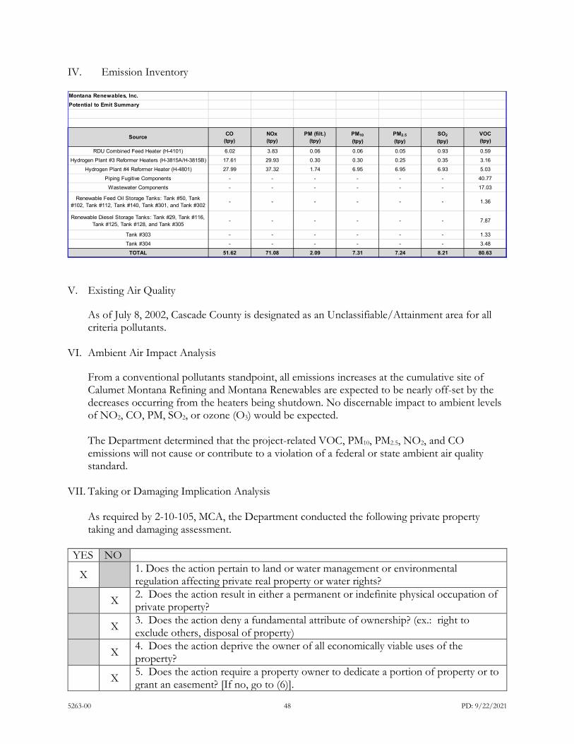
5263-00 48 PD: 9/22/2021
IV. Emission Inventory
V. Existing Air Quality
As of July 8, 2002, Cascade County is designated as an Unclassifiable/Attainment area for all criteria pollutants.
VI. Ambient Air Impact Analysis From a conventional pollutants standpoint, all emissions increases at the cumulative site of Calumet Montana Refining and Montana Renewables are expected to be nearly off-set by the decreases occurring from the heaters being shutdown. No discernable impact to ambient levels of NO2, CO, PM, SO2, or ozone (O3) would be expected. The Department determined that the project-related VOC, PM10, PM2.5, NO2, and CO emissions will not cause or contribute to a violation of a federal or state ambient air quality standard.
VII. Taking or Damaging Implication Analysis
As required by 2-10-105, MCA, the Department conducted the following private property taking and damaging assessment.
YES NO
X 1. Does the action pertain to land or water management or environmental regulation affecting private real property or water rights?
X 2. Does the action result in either a permanent or indefinite physical occupation of private property?
X 3. Does the action deny a fundamental attribute of ownership? (ex.: right to exclude others, disposal of property)
X 4. Does the action deprive the owner of all economically viable uses of the property?
X 5. Does the action require a property owner to dedicate a portion of property or to grant an easement? [If no, go to (6)].
Montana Renewables, Inc. Potential to Emit Summary
Source CO(tpy)
NOx(tpy)
PM (filt.)(tpy)
PM10(tpy)
PM2.5(tpy)
SO2(tpy)
VOC(tpy)
RDU Combined Feed Heater (H-4101) 6.02 3.83 0.06 0.06 0.05 0.93 0.59Hydrogen Plant #3 Reformer Heaters (H-3815A/H-3815B) 17.61 29.93 0.30 0.30 0.25 0.35 3.16
Hydrogen Plant #4 Reformer Heater (H-4801) 27.99 37.32 1.74 6.95 6.95 6.93 5.03Piping Fugitive Components - - - - - - 40.77
Wastewater Components - - - - - - 17.03
Renewable Feed Oil Storage Tanks: Tank #50, Tank #102, Tank #112, Tank #140, Tank #301, and Tank #302
- - - - - - 1.36
Renewable Diesel Storage Tanks: Tank #29, Tank #116, Tank #125, Tank #128, and Tank #305
- - - - - - 7.87
Tank #303 - - - - - - 1.33Tank #304 - - - - - - 3.48
TOTAL 51.62 71.08 2.09 7.31 7.24 8.21 80.63
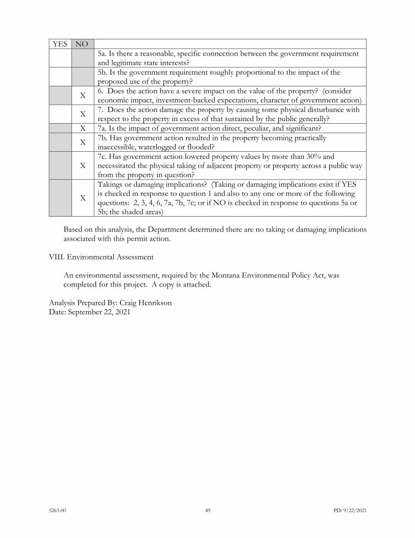
5263-00 49 PD: 9/22/2021
YES NO
5a. Is there a reasonable, specific connection between the government requirement and legitimate state interests?
5b. Is the government requirement roughly proportional to the impact of the proposed use of the property?
X 6. Does the action have a severe impact on the value of the property? (consider economic impact, investment-backed expectations, character of government action)
X 7. Does the action damage the property by causing some physical disturbance with respect to the property in excess of that sustained by the public generally?
X 7a. Is the impact of government action direct, peculiar, and significant?
X 7b. Has government action resulted in the property becoming practically inaccessible, waterlogged or flooded?
X 7c. Has government action lowered property values by more than 30% and necessitated the physical taking of adjacent property or property across a public way from the property in question?
X
Takings or damaging implications? (Taking or damaging implications exist if YES is checked in response to question 1 and also to any one or more of the following questions: 2, 3, 4, 6, 7a, 7b, 7c; or if NO is checked in response to questions 5a or 5b; the shaded areas)
Based on this analysis, the Department determined there are no taking or damaging implications associated with this permit action.
VIII. Environmental Assessment
An environmental assessment, required by the Montana Environmental Policy Act, was completed for this project. A copy is attached.
Analysis Prepared By: Craig Henrikson Date: September 22, 2021

5263-00 1 EA: 09/22/2021
DEPARTMENT OF ENVIRONMENTAL QUALITY Air, Energy & Mining Division
Air Quality Bureau P.O. Box 200901, Helena, Montana 59620
(406) 444-3490
Montana Renewables Inc.
Draft Environmental Assessment for
Montana Air Quality Permit #5263-00
Montana Department of Environmental Quality Air Quality Bureau
Air Permitting Services Section ENVIRONMENTAL ASSESSMENT
APPLICANT: Montana Renewables Inc. SITE NAME: Great Falls Montana Renewables Inc. (MRI) PROPOSED PERMIT NUMBER: Montana Air Quality Permit Number 5263-00 APPLICATION DATE: Received on 07/23/2021, Application Deemed Complete on 08/27/2021 LOCATION: Lat/Long 47.522981, -111.295454 COUNTY: Cascade PROPERTY OWNERSHIP:
FEDERAL ____ STATE ____ PRIVATE _X___
EA PREPARER: Craig Henrikson EA DATE:
09/22/2021
COMPLIANCE WITH THE MONTANA ENVIRONMENTAL POLICY ACT The Montana Department of Environmental Quality (DEQ) prepared this Environmental Assessment (EA) in accordance with requirements of the Montana Environmental Policy Act (MEPA). An EA functions to determine the need to prepare an EIS through an initial evaluation and determination of the significance of impacts associated with the proposed action. However, an agency is required to prepare an EA whenever, as here, statutory requirements do not allow sufficient time for the agency to prepare an EIS (ARM 17.4.607.3.c). This document may disclose impacts over which DEQ has no regulatory authority. COMPLIANCE WITH THE CLEAN AIR ACT OF MONTANA The state law that regulates air quality permitting in Montana is the Clean Air Act of Montana, §§ 75-2-101, et seq., (CAA) Montana Code Annotated (MCA). DEQ may not approve a proposed project contained in an application for an air quality permit unless the project complies with the requirements set forth in the CAA of Montana and the administrative rules adopted thereunder, ARMs 17.8.101 et. seq. The project is subject to approval by the DEQ Air Quality Bureau (AQB) as the potential project emissions exceed 25 tons per year for regulated pollutants (ARM 17.8.743.1.e). DEQ’s approval of an air quality permit application does not relieve MRI from complying with any other applicable federal, state, or county laws, regulations, or ordinances. MRI is responsible for obtaining any other permits,
5263-00 2 EA: 09/22/2021
licenses, or approvals (from DEQ or otherwise) that are required for any part of the proposed project. Any action DEQ takes at this time is limited to the pending air quality permit application currently before DEQ’s AQB and the authority granted to DEQ under the CAA of Montana—it is not indicative of any other action DEQ may take on any future (unsubmitted) applications made pursuant to any other authority (e.g. Montana’s Water Protection Act). DEQ will decide whether to issue the pending air quality permit pursuant to the requirements of the CAA of Montana alone. DEQ may not withhold, deny, or impose conditions on the permit based on the information contained in this Environmental Assessment. § 75-1-201(4), MCA.
SUMMARY OF THE PROPOSED ACTION: MRI has applied for a Montana air quality permit under the CAA of Montana for the following equipment. The permit action has been assigned Montana Air Quality Permit (MAQP) Number 5263-00. The proposed project would allow MRI to construct and operate a renewable diesel plant with a projected capacity of 15,000 barrels per day (bpd) with the following emitting units:
Renewable Diesel Unit: The existing Mild Hydrocracker (MHC) unit transferred from the Calumet Montana Refinery (CMR) would be identified as the RDU.
• RDU Combined Feed Heater (H-4101) Hydrogen Plant #3: The CMR Great Falls Refinery's Hydrogen Plant #3 would be transferred to MRI, and this hydrogen plant would supply hydrogen feedstock to the RDU. (Reformers H-3815A and H-3815B which would be transferred from CMR and given these new emitting unit numbers). Hydrogen Plant #4 would be installed at the MRI plant to supply hydrogen feedstock to the RDU.
• Hydrogen Plant #4 Reformer Heater (H-4801) • Piping fugitive components • Wastewater components
The proposed action would also include both existing tanks and new tanks which have volatile organic compounds (VOC) emissions. Tanks (Transferred from CMR)
• Tank #29 • Tank #50 • Tank #102 • Tank #112 • Tank #116 • Tank #125 • Tank #128 • Tank #140

5263-00 3 EA: 09/22/2021
New Tanks
• Tank #301 • Tank #302 • Tank #303 • Tank #304 • Tank #305
MRI also plans to install an emergency stack at the plant that would provide the capability to vent purified hydrogen (H2) from Hydrogen Plants #1, #2 and #3. Hydrogen is not a regulated pollutant under the CAA of Montana.
Emission estimates for the project are located in Section IV. Emission Inventory in the Permit Analysis. Emissions for all pollutants would be less than 100 tons per year (tpy) with the highest emission level being VOCs, secondly, oxides of nitrogen (NOx) and third, carbon monoxide (CO). Particulate matter species and sulfur dioxide (SO2) would each be less than 10 tpy.
The proposed action would be located on private land, within the City of Great Falls, Montana. All information included in the EA is derived from the permit application, discussions with the applicant, analysis of aerial photography, topographic maps, consultation with DEQ staff, and other research tools.
PURPOSE AND BENEFIT FOR PROPOSED ACTION: DEQ's purpose in conducting this environmental review is to act upon MRI’s air quality permit application (MAQP #5263-00) for the purpose of producing renewable diesel for commercial sale.
The benefits of the proposed action, if approved, would allow MRI to construct and operate the proposed equipment at the proposed site. Authority to operate the proposed equipment would continue until the permit was revoked, either at the request of MRI or by DEQ because of non-compliance with the conditions within the air quality permit.
REGULATORY RESPONSIBILITIES: In accordance with ARM 17.4.609(3)(c), DEQ must list any federal, state, or local, authorities that have concurrent or additional jurisdiction or environmental review responsibility for the proposed action and the permits, licenses, and other authorizations required.
MRI must conduct its operations according to the terms of its permit, the CAA of Montana, §§ 75-2-101, et seq., MCA, and ARMs 17.8.101, et seq.
Upon review of the air quality permit application, MRI would not have to obtain a Title V Operating Permit as emissions are below permitting thresholds for Title V applicability. No other permit applications have been submitted by MRI to DEQ at the time of this EA. MRI is a subsidiary of Calumet Specialty Products Partners, L.P. However, Calumet Montana Refining (CMR) also a subsidiary of Calumet Specialty Products Partners, L.P has also submitted an air quality permit application to transfer the equipment identified within the MRI air quality permit application. The CMR application requests removal of the equipment to be transferred from the existing MAQP

5263-00 4 EA: 09/22/2021
#2161-35. The revised CMR MAQP would be issued under MAQP #2161-36. The equipment cannot be completely removed from the existing MAQP #2161-35 until the MRI MAQP #5263-00 has been issued, otherwise, the authority to operate the equipment would no longer be valid. Once the transferred equipment and new equipment is commissioned under MAQP #5263-00, the transferred equipment would be removed from MAQP #2161-36 under a future permit action. If for any reason, the MRI project was not completed, the transferred equipment would remain eligible for operation under MAQP #2161-36. The exact details of this transfer would be covered in MAQP #2161-36. MRI must cooperate fully with, and follow the directives of any federal, state, or local entity that may have authority over MRI’s Renewable Diesel Plant. These permits, licenses, and other authorizations may include: City of Great Falls, Cascade County Weed Control Board, OSHA (worker safety), DEQ AQB (air quality) and Water Protection Bureau groundwater and surface water discharge; stormwater, and MDT and Cascade County (road access). MRI has requested the air quality permit would use property that is currently owned by CMR. New processing equipment would also be constructed and operated on this same site. The parcel identified is a 44.46 acre site located adjacent to the Missouri River as well as adjacent to the City of Great Falls Wastewater Treatment Plant. The proposed action would result in a disturbance of approximately 12 acres.
Table 1: Proposed Action Details
Summary of Proposed Action
General Overview
MRI’s air quality permit application consists of the following equipment: Refurbished RDU Combined Feed Heater (H-4101) Existing Hydrogen Plant #3 with existing heaters H-3815A and H-3815B New Hydrogen Plant #4 with new heater (H-4801) The project also includes the transfer of existing tanks and construction of new tanks as the tanks are sources of VOC emissions. Each tank would be considered an emitting unit. Tanks transferred from CMR
• Tank #29, #50, #102, #112, #116, #125, #128 and #140 New Tanks
• Tank #301, #302, #303, #304, and #305
There are also fugitive VOC emissions which would occur from piping components and the wastewater handling system. The facility would be permitted to emit from this equipment until MRI requested permit revocation or until the permit were revoked by DEQ due to gross non-compliance with the permit conditions.

5263-00 5 EA: 09/22/2021
Proposed Action Estimated Disturbance
Disturbance Disturbance for construction would be approximately 12 acres. Disturbance after construction would be approximately 12 acres.
Proposed Action
Duration
Construction: Construction or commencement could start within three years of issuance of the final air quality permit otherwise the authority to construct expires. Current plans would be to begin construction in the fall of 2021. Construction Period: The construction period could begin as soon as the air quality permit (and any other required permits) were in place. Seasonal construction activities are allowed once a Department Application Completeness Determination has been issued. This Completeness Determination was issued on August 31, 2021. The application estimates construction would begin in the fall of 2021. The construction period is expected to last one year and conclude in 2022. Operation Life: Renewable diesel equipment would be expected to last at least thirty years.
Construction Equipment Typical construction equipment, including cranes, earth moving equipment (bulldozer, grader, frontend loader, trackhoe, etc.), forklifts, telehandlers, boring and drilling rigs.
Personnel Onsite Construction: Approximately 200 to 300 construction personnel Operations: Ten to twenty permanent staff during operation
Location and Analysis Area
Location: The proposed project is located on existing Calumet Montana Refining property with an address of 1900 10th Street NE, Great Falls Montana 59404. This parcel is located within Section 1 of Township 20 North, Range 03 East. Adjacent and within the existing Calumet Refinery footprint as specified in Figure 1. Areas bordered in red represent disturbance areas and transferred equipment. Analysis Area: The area being analyzed as part of this environmental review includes the immediate project area (Figure 1), as well as neighboring lands surrounding the analysis area, as reasonably appropriate for the impacts being considered.
Air Quality The Draft EA will be attached to the Preliminary Determination Air Quality Permit which would include all enforceable conditions for operation of the emitting units
Conditions incorporated into the Proposed Action
The conditions developed in the Preliminary Determination of the Montana Air Quality Permit dated September 22, 2021, set forth in Sections II.A-D.
Figure 1: Map of general location of the proposed project.
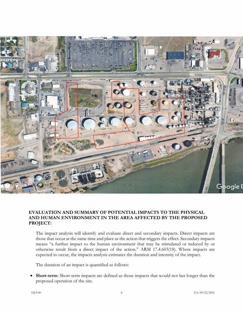
5263-00 6 EA: 09/22/2021
EVALUATION AND SUMMARY OF POTENTIAL IMPACTS TO THE PHYSICAL AND HUMAN ENVIRONMENT IN THE AREA AFFECTED BY THE PROPOSED PROJECT:
The impact analysis will identify and evaluate direct and secondary impacts. Direct impacts are those that occur at the same time and place as the action that triggers the effect. Secondary impacts means “a further impact to the human environment that may be stimulated or induced by or otherwise result from a direct impact of the action.” ARM 17.4.603(18). Where impacts are expected to occur, the impacts analysis estimates the duration and intensity of the impact.
The duration of an impact is quantified as follows:
• Short-term: Short-term impacts are defined as those impacts that would not last longer than the proposed operation of the site.

5263-00 7 EA: 09/22/2021
• Long-term: Long-term impacts are defined as impacts that would remain or occur following shutdown of the proposed facility.
The severity of an impact is measured using the following:
• No impact: There would be no change from current conditions. • Negligible: An adverse or beneficial effect would occur but would be at the lowest levels of
detection. • Minor: The effect would be noticeable but would be relatively small and would not affect the
function or integrity of the resource. • Moderate: The effect would be easily identifiable and would change the function or integrity of
the resource. • Major: The effect would alter the resource.
1. TOPOGRAPHY, GEOLOGY AND SOIL QUALITY, STABILITY AND MOISTURE: The site is located on the north-side of the Missouri River on Calumet Montana Refining property adjacent to the river. The parcel proposed for the MRI operation is located approximately 370 feet from the river’s edge. The elevation is approximately 3,323 feet as referenced by the nearest topographic map on the Montana DEQ GIS website which has a topographic elevation marked very close to the Burlington Northern Santa Fe railway track. The Calumet Montana Refinery (Site or CMR) is located on Pleistocene age glacial lake deposits, which overlie the consolidated Kootenai Formation. Lemke (1977) calls these sediments Deposits of Glacial Lake Great Falls. Lemke (1977) describes two subunits as an upper stratigraphic unit consisting predominantly of non-plastic fine sand and silt and a lower stratigraphic unit consisting mostly of laminated to non-laminated plastic clay and minor amounts of silt. Previous investigation activities at the CMR facility have documented the presence of unconsolidated Pleistocene fluvial and lake deposits and various fill material at the surface and immediately beneath the Site. These surficial units have been encountered at variable depths across the site that range as much as 10 to 20 ft below ground surface. The Pleistocene deposits are generally saturated but yield minimal quantities of water to wells because of their low hydraulic conductivity (Wilke 1983). (Directly from MRI – email dated 8/31/2021 from Casey Mueller). Underlying the Pleistocene glacial lake deposits is the Cretaceous-age Kootenai formation that has been differentiated into the fifth (upper) and fourth (lower) members. The fifth member of the Kootenai formation is encountered sitewide immediately beneath the surficial Pleistocene deposits and/or fill material and is distinguished by red-weathered mudstone that contains lenses and beds of brownish-gray and greenish-gray, cross-bedded, micaceous sandstone and light gray nodular limestone concretions. The lower part contains a dark-gray shale and lignite bed with a significant pre-angiosperm flora. The bottom of the Kootenai formation’s upper member occurs at 60-100 feet below ground level near the Site. Groundwater in this unit beneath the site occurs under semi-confined conditions. Direct Impacts: Proposed Action: The information provided above is based on the information that DEQ had available to it at the time of completing this EA and provided by the applicant as part of the permit

5263-00 8 EA: 09/22/2021
application detailing the proposed site. Available information includes the permit application, analysis of aerial photography, topographic maps, and other research tools. None of the planned disturbance at the site is considered first time disturbance. Soils would be disturbed during construction and operation of the proposed action, approximately 12 acres of disturbance would occur for the life of the project. There is no impact expected to topography and geology.
Secondary Impacts:
Proposed Action: No secondary impacts to topography, geology, stability, and moisture would be expected.
2. WATER QUALITY, QUANTITY, AND DISTRIBUTION: The Missouri River is approximately 370 feet to the south. No wetlands have been identified on the site. There is a long narrow parcel of property owned by CMR between the parcel proposed for the MRI facility and the Missouri River. Available information includes the permit application, analysis of aerial photography, topographic maps, and other research tools. Direct Impacts: Proposed Action: The information provided above is based on the information that DEQ had available to it at the time of completing this EA and provided by the applicant for the purpose of obtaining the pending air quality permit. MRI has not submitted any water quality or MPDES permit applications to DEQ. MRI has indicated within the application that additional permits are not planned except for a renewal for their wastewater pretreatment permit with the City of Great Falls (Wastewater Treatment Plant). This permit limits the allowable discharge of flow, pH, solids and metals from the CMR/MRI site as well as oil and grease. The permit limits are not expected to change with the addition of the MRI equipment. Based on this information, DEQ does not anticipate an impact to surface water features and water quality, quantity, and distribution management. Five new tanks are proposed for the site and these tanks would alter the site by covering some of the land surface. Total disturbance for the project was estimated by MRI at 12 acres both for during construction and 12 acres once the project is completed. The proposed project would not change the direction of surface water migration from the site. Precipitation and surface water would generally be expected to infiltrate into the subsurface, however, any surface water that may leave the site could carry sediment from the disturbed site. Soil disturbances and storm water during construction would be managed under the Montana Pollutant Discharge Elimination System (MPDES) General Permit for Storm Water Discharges associated with construction activity as MRI would be required for construction and potentially during operations. The applicant would need to obtain authorization to discharge under the General Permit for Storm Water Discharges associated with construction activity prior to ground disturbance. MRI would manage erosion control using a variety of Best Management Practices (BMP) including but not limited to non-draining excavations, containment, diversion and control of surface run off, flow attenuation, revegetation, earthen berms, silt fences, and gravel packs. This plan would minimize any stormwater impacts to surface water in the vicinity of the project. The proposed action would require MRI to obtain a stormwater discharge plan during construction and potentially during operations. This plan would minimize any stormwater impacts to surface water in the vicinity of the project.

5263-00 9 EA: 09/22/2021
Because MRI has not applied for (and does not anticipate applying for any other MPDES discharge permits, no other discharges to surface or groundwater from the facility is expected No fragile or unique water resources or values are present. Impacts to water quality and quantity, which are resources of significant statewide and societal importance are not expected. Secondary Impacts:
Proposed Action: No secondary impacts to water quality, quantity and distribution would be expected. No secondary impacts from storm water runoff would be expected.
3. AIR QUALITY: As of July 8, 2002, Cascade County is designated as an Unclassifiable/Attainment area for all criteria pollutants according to 40 CFR 81.327. Any new stationary source falling under one of the 28 source categories listed in the "major stationary source" definition at ARM 17.8.801(22) would be a major stationary source if it emits, or has the potential to emit, 100 tpy or more of any regulated Prevention of Significant Deterioration (PSD) pollutant, except for (greenhouse gases) GHGs. The plant would be a “chemical process plant”, which is one of the 28 source categories. Therefore, the PSD major source threshold for the plant is 100 tpy. Historical wind patterns at the Great Falls International Airport which is located 4.6 miles to the southwest from MRI, indicates prevailing westerly winds from February thru October, and November thru January winds are most often from the south. A local micro-climate along the Missouri flowing directly to the east would also provide a tendency for easterly air flow.
Direct Impacts:
Proposed Action:
Emissions expected from the proposed action as submitted in the air quality permit application would be as follows:
Renewal Diesel Plant Pollutant Potential to Emit Summary
Pollutant
Potential to Emit {tpy)
PSD Major
Source Threshold
{tpy)
Subject to
PSD Review {Yes/No)

5263-00 10 EA: 09/22/2021
CO 51.62 100 No
NOx 71.08 100 No
PM (filterable only)
2.09 100 No
PM10 7.31 100 No
PM2.5 7.24 100 No
SO2 8.21 100 No
VOC 80.63 100 No
GHGs, as CO2e N/A N/A N/A
As each pollutant is less than 100 tpy, the proposed facility would not be a major PSD facility. No analysis of greenhouse gases is required for a non-major PSD facility.
Dust particulate would be produced or become airborne during site preparation and construction. Air quality standards, set by the federal government and DEQ AQB and enforced by the AQB, allow for pollutants at the levels permitted within the air quality permit. During construction, heavy equipment and site preparation would occur. Once the site is fully constructed, emissions from the renewable diesel plant would include particulate matter (PM) species, oxides of nitrogen (NOx), carbon monoxide (CO), sulfur dioxide (SO2), carbon dioxide (CO2.) Residual volatile organic compounds (VOCs) would leak as fugitives from piping, valves, pumps and other process piping. Air pollution control equipment must be operated at the maximum design for which it is intended ARM 17.8.752(2). Limitations would be placed on the allowable emissions for the renewable diesel plant. As part of the air quality permit application, MRI submitted a Best Available Control Technology (BACT) analysis for each emitting unit. These proposed limits were reviewed and incorporated into MAQP #5263-00 as federally enforceable conditions. These permit limits cover NOx, VOCs, particulate matter and CO with associated ongoing compliance demonstrations, as required by the Department.
Some fugitive road dust may occur on the access routes to the construction areas. Pursuant to ARM 17.8.304(2), fugitive dust emissions would need to meet an operational visible opacity of standard or 20 percent or less averaged over 6 consecutive minutes. Pursuant to ARM 17.8.308(1), MRI is required to take reasonable precautions to control emissions of airborne particulate matter from all phases of operation including material transport. Reasonable precautions would include items such the use of water during construction periods to minimize dust emissions. Air quality standards are also regulated by the federal Clean Air Act, 42 U.S.C. 7401 et seq. (1970) and Montana’s Clean Indoor Air Act, Mont. Code Ann. § 50-40-101 et seq., and are implemented and enforced by DEQ’s AQB. As stated above, MRI is required to comply with all applicable state and federal laws. For all the above reasons, impacts to air quality from the proposed project are anticipated to be short-term and minor.
5263-00 11 EA: 09/22/2021
Secondary Impacts: Proposed Action: Criteria pollutants that would be released disperse into the atmosphere and travel with the wind direction, decreasing in concentration as the pollutants are diluted with ambient air. Concentrations of these pollutants would not be allowed to exceed ambient air quality standards where the public has access which usually is considered to be the property boundary of the industrial facility. Therefore, DEQ does not anticipate impacts to air quality in the area outside the property boundary including the adjacent areas of the City of Great Falls.
4. VEGETATION COVER, QUANTITY AND QUALITY: There are no known rare or sensitive plants or cover types present in the site area. No fragile or unique resources or values, or resources of statewide or societal importance, are present. Petroleum refining has been conducted at this site since the early 1920’s. An air quality permit for the site was first issued in 1985. The Department conducted research using the Montana Natural Heritage Program (MTNHP) website and ran the query titled “Environmental Summary Report” dated August 24, 2021. The proposed action is located at an existing refinery in an urban and industrial setting where the vegetation is limited.
Direct Impacts:
Proposed Action: The information provided above is based on the information that DEQ had available to it at the time of completing this EA and provided by the applicant. Available information includes the permit application, analysis of aerial photography, topographic maps, geologic maps, soil maps, and other research tools. As the proposed project would be located on the existing Calumet Refinery site, the vegetation is very limited at the site. The aerial photo contained in the air quality permit application does appear to show some vegetation in the northwest corner of the parcel but upon further review, new tanks were installed as part of a recent refinery modification, and a review of a newer aerial map no longer shows vegetation at the northwest location. No impacts to vegetation cover, quantity and quality would be expected.
Secondary Impacts:
Proposed Action: Land disturbance at the site would leave little bare ground not occupied by tanks and process equipment.
5. TERRESTRIAL, AVIAN AND AQUATIC LIFE AND HABITATS: Petroleum refining has been conducted at this site since the early 1920s. As described earlier in Section 4. Vegetation Cover, the larger polygon area is represented by commercial and industrial operations and the Department conducted research using the Montana Natural Heritage Program (MTNHP) website and ran the query titled “Environmental Summary Report” dated August 24, 2021. However, avian population are not likely to exist on the property due to the existing industrial nature of the property. Avian species may be in the proximity of the proposed project due to the Missouri River.
Direct Impacts: Proposed Action:. The potential impact (including cumulative impacts) to terrestrial, avian and aquatic life and habitats would be negligible.

5263-00 12 EA: 09/22/2021
A list of species of concern is also identified within in Section 6. Unique, Endangered, Fragile or Limited Environmental Resources as reported from the MTNHP report on unique and endangered resources.
Secondary Impacts: Proposed Action: No secondary impacts to terrestrial, avian and aquatic life and habitats stimulated or induced by the direct impacts analyzed above would be expected.
6. UNIQUE, ENDANGERED, FRAGILE OR LIMITED ENVIRONMENTAL
RESOURCES: DEQ conducted a search using the Montana Natural Heritage Program (MTNHP) webpage. As discussed earlier the polygon selected was the 44.46 acre site. Species of concern (SOC) from the MTNHP identified the following species: Spiny Softshell, Bald Eagle, Great Blue Heron, Golden Eagle, Black Crowned Night-Heron, Black Tern, Common Tern, Swift Fox, Horned Grebe, Ferruginous Hawk, Franklin’s Gull, Piping Plover, Foster’s Tern, Caspian Tern, American White Pelican, Common Loon, Trumpeter Swan, Harlequin Duck, Sedge Wren, Black-tailed Prairie Dog, Black-foot Ferret, and Gray-crowned Rosy-Finch. Many of these species listed as SOC have not been observed within the search polygon. The one exception noted is that Bald Eagles have been observed. Direct Impacts: Proposed Action: The majority species of concern from the MTNHP list are associated with the riverine habitat on the Missouri River, which is approximately 370 feet to the south of proposed action. These species would not be displaced by the proposed action as the site is completely industrial and the parcel in question does not contact the river or river banks. The potential impact (including cumulative impacts) to species present including bald eagles would be negligible. Secondary Impacts: Proposed Action: The proposed action would not have secondary impacts to endangered species because the permit conditions are protective of human and animal health.

5263-00 13 EA: 09/22/2021
7. HISTORICAL AND ARCHAEOLOGICAL SITES: The Montana State Historic Preservation Office (SHPO) was notified of the application. SHPO conducted a file search and provided a letter dated August 25, 2021. The SHPO searched was conducted for Section 1 T20N R3E. Further a review of the project area was conducted by the DEQ archeologist on August 25, 2021. The file search identified 19 cultural resource sites within the search area criteria. After review, nine of the sites were further evaluated due to proximity to the project area. Direct Impacts: Proposed Action: Further evaluation of existing site forms identified three of the 19 sites indicate a potential for impacts to Historic Properties, which is defined as any site that is eligible or potentially eligible to the National Register of Historic Places (NRHP). These are detailed and addressed below. Site 24CA0656 is a NRHP eligible prehistoric processing site located within less than 300 meters of the project area. The current site status us unknown but given the distance of the project area from the site, there will be no adverse effect to Historic Properties. Site 24CA0371 is a section of the Cascade County Portion of the Great Northern Railroad which is determined eligible for the NRHP. Though the line exists within the current project boundary, the line will not be physically disturbed, nor does the site retain or rely on aspects of visual integrity that would diminish its eligibility. Therefore, there will be no adverse effects to this Historic Property. Site 24CA1751 is a historic dump located within the banks of the Missouri River. The site is currently listed as Undetermined for its NRHP status, which qualifies it as a Historic Property until otherwise evaluated. The site is outside of the proposed project area, therefore there will be no adverse effect to this Historic Property. Due to the limited nature of the proposed disturbance for the project, and the lack of potential from visual elements, there will be no adverse effects to Historic Properties. If resources were discovered during operations resources, it would be MRI’s responsibility to determine next steps as required by law.
Secondary Impacts: Proposed Action: No secondary impacts to historical and archaeological sites are anticipated.

5263-00 14 EA: 09/22/2021
8. SAGE GROUSE EXECUTIVE ORDER: The project would not be in core, general or connectivity sage grouse habitat, as designated by the Sage Grouse Habitat Conservation Program (Program) at: http://sagegrouse.mt.gov. Direct Impacts: The proposed action is not located within Sage Grouse habitat, no direct impacts would occur. Secondary Impacts: No secondary impacts to sage grouse or sage grouse habitat would be expected.
9. AESTHETICS: The site is located in an area mostly surrounded by industrial private property. Of the 1,280 acres in the larger MTNHP polygon, 1,095 acres are indicated as either private or unknown ownership. The project would occur on private land. The nearest residents to the proposed action reside to the northwest at a distance of approximately 500 feet. There are other houses located directly east of the refinery site starting at about 850 feet from eastern property boundary. It is not expected that the nearest residences to the proposed site would experience any noticeable change in noise levels. Standard noise reducing methods would be employed to minimize the risk that noise levels would rise above current baseline levels. An example of noise minimization would include compressors and pumps being enclosed. The noise levels at the property boundary of the proposed action would not be expected to change.
Direct Impacts: Proposed Action: There would be temporary construction with building activities including noise and dust. Equipment planned for construction would likely include cranes, backhoes, graders/dozers, passenger trucks, delivery trucks, cement trucks, and various other types of smaller equipment. The use of the various types of equipment would be spread out over the duration of the expected schedule beginning in the fall of 2021 and continuing thru the end of 2022. Once the proposed action is constructed, no discernable change in noise level would be expected. New tanks and other equipment would be visible from Smelter Avenue (Highway 87) located to the north of the refinery property. Impacts would be negligible and short-term. Rail traffic is controlled by Burlington Northern and Santa Fe (BNSF) Railway and is expected to occur at two switches per day. Secondary Impacts: Proposed Action: The refinery profile would change slightly with the erection of new tanks and equipment. Noise increases are not expected beyond the proposed action parcel boundary.
10. DEMANDS ON ENVIRONMENTAL RESOURCES OF LAND, WATER, AIR OR ENERGY: The site is located in an area characterized by heavy industry and commercial businesses. Direct Impacts: Proposed Action: During construction of the proposed action there would be minor increase in energy use to construct the proposed action. Once operational, energy and electric demands would continue for the duration of the facility’s lifetime. Renewable diesel would provide fuel for emerging markets where non-fossil fuels are preferred and or required. The MRI production capacity would be approximately 15,000 barrels per day (bpd) and at the same time the capacity of CMR would be reduced by approximately the same amount. See the Air Quality
5263-00 15 EA: 09/22/2021
and Water Quality sections of the EA to see the potential impacts from the proposed action regarding Air and Water resources. Secondary Impacts: Proposed Action: During operations, the proposed action would deliver renewable diesel via railcar and trucks to Canadian and west coast U.S. markets. These shipping deliveries would utilize highway and rail infrastructure for product delivery.
11. IMPACTS ON OTHER ENVIRONMENTAL RESOURCES: The site is immediately surrounded by commercial and industrial properties. Direct Impacts: Proposed Action: DEQ did not identify any other nearby activities that may affect the project. Therefore, impacts on other environmental resources are not likely to occur as result of this project.
Secondary Impacts: Proposed Action: No secondary impacts to other environmental resources are anticipated as a result of the proposed project.
12. HUMAN HEALTH AND SAFETY: The applicant would be required to adhere to all applicable state and federal safety laws. Some of the existing employees at Calumet Refining would likely become employees at MRI. The access to the public would be restricted to this property with techniques currently used by the Refinery to limit unrestricted access Direct Impacts: Proposed Action: Impacts to human health and safety are anticipated to be short-term and minor as a result of this project. Tanker and rail car deliveries of feedstock would be made to the site and product shipments of renewable diesel would occur using both truck and rail. Tanker and rail shipping are regulated by other state and federal laws to ensure they are operated safely. This would result in increased tanker traffic on the route to and from the site. When the facility would shut down in the future, the direct impacts would cease to exist. Secondary Impacts: Proposed Action: No secondary impacts to human health and safety are anticipated as a result of the proposed project.
13. INDUSTRIAL, COMMERCIAL AND AGRICULTURAL ACTIVITIES AND
PRODUCTION: The site is currently zoned heavy industrial as is reflected by the existing Calumet refinery, and other industrial and commercial properties. There is no agricultural activity at the site. CMR currently has a capacity of approximately 30,000 bpd of Canadian crude oil mostly supplied via pipeline. With the proposed project, the CMR capacity would be cut by approximately 15,000 bpd as the capacity of MRI would become 15,000 bpd. Direct Impacts: Proposed Action: A minor decrease on land un-occupied by equipment would occur with approximately 12 acres of disturbance for the proposed action. Most of the rest of the CMR property is already covered by equipment and access roads on the property. More of the property would be being utilized for industrial production. Impacts on the industrial, commercial, and agricultural activities and production in the area would be minor and short-

5263-00 16 EA: 09/22/2021
term. An increase in rail and truck traffic bringing in raw materials including feedstock such as canola oil would occur. Secondary Impacts: Proposed Action: No secondary impacts to industrial, commercial, water conveyance structures, and agricultural activities and production are anticipated as a result of the proposed project.
14. QUANTITY AND DISTRIBUTION OF EMPLOYMENT: There currently are approximately 187 permanent jobs located at the Calumet Refinery. Some of the existing employees would likely become employees of MRI.
Direct Impacts: Proposed Action: New employment opportunities would occur with this project. The proposed project would be expected to have only minor impacts on the distribution of employment. During construction approximately 200 - 300 temporary contractor jobs would be created and after construction approximately 10 to 20 permanent jobs would remain. The duration of employment would be minor and short-term.
Secondary Impacts: Proposed Action: Minor increases in in distribution of employment are anticipated as a result of the proposed project. This would be the result of employment created for tanker truck deliveries of feedstock and product deliveries of renewable diesel.
15. LOCAL AND STATE TAX BASE AND TAX REVENUES: The proposed action would be expected to have minor impacts on the local and state tax base and tax revenue. The construction project would provide approximately xx temporary contractor jobs after which approximately 10 to 20 permanent jobs would be created.
Direct Impacts: Proposed Action: Local, state and federal governments would be responsible for appraising the property, setting tax rates, collecting taxes, from the companies, employees, or landowners benefitting from this operation.
Secondary Impacts: Proposed Action: No secondary impacts to local and state tax base and tax revenues are anticipated as a result of the proposed action.
16. DEMAND FOR GOVERNMENT SERVICES: The proposed action is in a heavy industrial and commercial area.
Direct Impacts: Proposed Action: Compliance review and assistance oversight by DEQ AQB would be conducted in concert with other area activity when in the vicinity. Occasional increases in construction-related traffic would occur but this would only last for the duration of the construction project estimated from the fall of 2021 thru 2022. Oversight by DEQ AQB would be minor and short-term.
Secondary Impacts: Proposed Action: Local traffic would likely increase with the new permanent employees and feedstock and product transportation. Impacts would be short-term and minor.
17. LOCALLY ADOPTED ENVIRONMENTAL PLANS AND GOALS: A review was also conducted of the City of Great Falls website On August 25, 2021. A zoning map was located and the proposed project would be located on an I-2 Heavy Industrial Zone

5263-00 17 EA: 09/22/2021
parcel. Additional review of the City’s Planning page revealed a Growth Policy was completed in 2013. Other Planning documents were also viewed one of which was a Missouri River Urban Corridor Plan (Plan). This document was dated 2004. The MRI property near the Missouri River is unlikely to be an area where the preservation of river frontage is addressed by the Plan.
Direct Impacts: Proposed Action:. MRI is proposing the renewable diesel plant on property which is already zoned as Heavy Industrial. No impacts from the proposed action would be expected relative to any locally adopted community planning goals. Secondary Impacts: Proposed Action: No secondary impacts to the locally-adopted environmental plans and goals are anticipated as a result of the proposed action.
18. ACCESS TO AND QUALITY OF RECREATIONAL AND WILDERNESS ACTIVITIES: The current site of the proposed action is in an area of industrial use. Recreation opportunities are located to the south of the proposed action via water-activities on the Missouri River. No wilderness areas or other recreational sites are in the vicinity.
Direct Impacts: Proposed Action: There would be no impacts to the access to wilderness activities as none are in the vicinity of the proposed action. Recreationalists on the Missouri River would likely be able to see some of the new tanks. These recreationalists might be river rafters, fishermen and others drawn to the river. The noise would be similar in nature to the existing CMR Refinery nearby. If a receptor were to increase their distance from the proposed action, noise and visual impacts would decrease. Duration would be expected to be negligible and short-term.
Secondary Impacts: Proposed Action: No secondary impacts to access and quality of recreational and wilderness activities are anticipated as a result of the proposed project.
19. DENSITY AND DISTRIBUTION OF POPULATION AND HOUSING: The proximity of the proposed action to the City of Great Falls would easily be able to handle all housing needs for temporary workers. Direct Impacts: Proposed Action: The project would not add to the population or require additional housing, therefore, no impacts to density and distribution of population and housing are anticipated. The temporary construction workers would use the existing housing in the surrounding communities for the duration of the construction schedule. The 10 to 20 permanent workers would not be expected to create a housing shortage in the surrounding communities. As identified elsewhere, the construction schedule is estimated to last from the fall of 2021 thru the 2022. The duration of the on-going employment would be minor and short-term. Secondary Impacts: Proposed Action: No secondary impacts to density and distribution of population and housing are anticipated as a result of the proposed action.
20. SOCIAL STRUCTURES AND MORES:
Based on the required information provided by MRI, DEQ is not aware of any native cultural concerns that would be affected by the proposed activity.
5263-00 18 EA: 09/22/2021
Direct Impacts: Proposed Action: This proposed action is located on an existing industrial site, no disruption of native or traditional lifestyles would be expected, therefore, no impacts to social structure and mores are anticipated. Secondary Impacts: Proposed Action: No secondary impacts to social structures and mores are anticipated as a result of the proposed operations.
21. CULTURAL UNIQUENESS AND DIVERSITY: Based on the required information provided by MRI, DEQ is not aware of any unique qualities of the area that would be affected by the proposed activity.
Direct Impacts: Proposed Action: No impacts to cultural uniqueness and diversity are anticipated from this project. Secondary Impacts: Proposed Action: No secondary impacts to cultural uniqueness and diversity are anticipated as a result of the proposed project.
22. PRIVATE PROPERTY IMPACTS: The proposed project would take place on privately-owned land. The analysis done in response to the Private Property Assessment Act indicates no impact. DEQ does not plan to deny the application or impose conditions that would restrict the regulated person’s use of private property so as to constitute a taking. (See Attached Private Property Assessment Act (PPAA) Checklist. Further, if the application is complete, DEQ must take action on the permit pursuant to § 75-2-218(2), MCA. Therefore, DEQ does not have discretion to take the action in another way that would have less impact on private property—its action is bound by a statute.
There are private residences in the area of the proposed project. The closest residence is located approximately 500 feet to the northwest from the western property boundary. Other residences are located approximately 850 feet directly to the east from the eastern property boundary.
23. OTHER APPROPRIATE SOCIAL AND ECONOMIC CIRCUMSTANCES: Due to the nature of the proposed action, no further direct or secondary impacts are anticipated from this project.
ADDITIONAL ALTERNATIVES CONSIDERED:
No Action Alternative: In addition to the proposed action, DEQ is considering a “no action” alternative. The “no action” alternative would deny the approval of the proposed action. The applicant would lack the authority to conduct the proposed activity. Any potential impacts that would result from the proposed action would not occur. The no action alternative forms the baseline from which the impacts of the proposed action can be measured.
Other Ways to Accomplish the Action:
In order to meet the project objective of producing renewable diesel and renewable naphtha, specific raw materials and energy inputs are necessary, and while the configuration for these processes could

5263-00 19 EA: 09/22/2021
be modified for a different physical layout, the relative disturbed area and energy inputs and therefore the associated emissions would not be substantially different than the proposed action.
If the applicant demonstrates compliance with all applicable rules and regulations as required for approval, the “no action” alternative would not be appropriate. Pursuant to, § 75-1-201(4)(a), (MCA) DEQ “may not withhold, deny, or impose conditions on any permit or other authority to act based on” an environmental assessment.
CUMULATIVE IMPACTS:
Cumulative impacts are the collective impacts on the human environment within the borders of Montana of the proposed action when considered in conjunction with other past and present actions related to the proposed action by location and generic type. Related future actions must also be considered when these actions are under concurrent consideration by any state agency through preimpact statement studies, separate impact statement evaluation, or permit processing procedures. There is currently an air quality permit application from CMR requesting transfer of equipment to ownership under MRI. There are currently no other permit applications for this facility pending before DEQ. Although additional permits may be necessary for this facility in the future, without a pending permit application containing the requisite information, DEQ cannot speculate about which permits may be necessary or which permits may be granted or denied. For example, at this time DEQ does not have sufficient information to determine whether or not a MPDES permit would be required although MRI does not anticipate needing one, and therefore cannot predict whether there would be a discharge associated with this facility. There may, therefore, be additional cumulative impacts (e.g. to water) associated with this facility in the future, but those impacts would be analyzed by future environmental reviews associated with those later permitting actions. (For example, if MRI applies for a MPDES permit DEQ will analyze the cumulative impacts of the already issued air quality permit and the then-pending MPDES permit.) This environmental review analyzes only the proposed action submitted by MRI, which is the air quality permit regulating the emissions from the equipment as listed in the “proposed action” section, above.
There are other sources of industrial emissions in the vicinity. CMR is known to have emissions including CO, VOCs, SO2, NOx and particulate matter and currently operates under MAQP #2161-35. These emissions are limited thru enforceable conditions within their air quality permit. There is also the City of Great Falls Wastewater Treatment facility that like any treatment plant would have emissions. The Wastewater Plant operates under MAQP #4176-00 and has limits in place for both NOx and VOCs. Additionally, there is an incinerator operated in the area by the Montana Highway Patrol. MAQP #5174-00 is held by the Montana Highway Patrol for the purpose of destruction of drugs. The Highway Patrol incinerator is approximately 0.7 mile away. The incinerator is restricted on particulate matter emissions and opacity. Finally, Grain Craft (MAQP #2885-01) operates a flour milling operation to the southeast which is approximately 0.8 mile away and is limited only on opacity. Collectively, these sources and the proposed action can all contribute to the ambient air quality and when future permit actions occur at either MRI or CMR, these actions may require future analysis, depending upon the magnitude of future emission increases. Since the proposed action is not major for PSD, a review of existing permitted sources is not required. The proposed action would not be expected to have any discernable impact as the emission increases under the proposed action are off-set by emissions decreases at CMR. No change in the EPA air quality designation would be expected. As of July 8, 2002, Cascade County was designated as an Unclassifiable/Attainment area for all criteria pollutants.

5263-00 20 EA: 09/22/2021
A review was also conducted of the City of Great Falls Growth Policy which appears to have been updated in 2013. Several elements which are addressed in the Growth Policy include provisions to guide land-use, transportation, economic development, housing needs and population projections.
DEQ considered potential impacts related to this project and potential secondary impacts. Due to the limited activities in the analysis area, cumulative impacts related to this project would be minor and short-term. The cumulative table for any direct and secondary impacts is located at the very end of this EA. See Table II.
PUBLIC INVOLVEMENT: Scoping for this proposed action consisted of internal efforts to identify substantive issues and/or concerns related to the proposed operation. Internal scoping consisted of internal review of the environmental assessment document by DEQ Air Permitting staff. Internal efforts also included queries to the following websites/ databases/ personnel: • Montana State Historic Preservation Office • Montana Department of Environmental Quality (DEQ) • Cascade County Website • Montana Natural Heritage Program • Montana Cadastral Mapping Program OTHER GOVERNMENTAL AGENCIES WITH JURSIDICTION:
The proposed project would be fully located on privately-owned land. All applicable local, state, and federal rules must be adhered to, which, at some level, may also include other local, state, federal, or tribal agency jurisdiction. Other Governmental Agencies which May Have Overlapping or Sole Jurisdiction include, but may not be limited to: City of Great Falls, Cascade County Commission or County Planning Department (zoning), Cascade County Weed Control Board, OSHA (worker safety), DEQ AQB (air quality) and Water Protection Bureau (groundwater and surface water discharge; stormwater), DNRC (water rights), and MDT and Cascade County (road access).
NEED FOR FURTHER ANALYSIS AND SIGNIFICANCE OF POTENTIAL IMPACTS
Under ARM 17.4.608, DEQ is required to determine the significance of impacts associated with the proposed action. This determination is the basis for the agency’s decision concerning the need to prepare an environmental impact statement and also refers to DEQ’s evaluation of individual and cumulative impacts. DEQ is required to consider the following criteria in determining the significance of each impact on the quality of the human environment:
1. The severity, duration, geographic extent, and frequency of the occurrence of the impact; “Severity” is analyzed as the density of the potential impact while “extent” is described as the area where the impact is likely to occur. An example could be that a project may propagate ten noxious weeds on a surface area of 1 square foot. In this case, the impact may be a high severity over a low extent. If those ten noxious weeds were located over ten acres there may be a low severity over a larger extent.
5263-00 21 EA: 09/22/2021
“Duration” is analyzed as the time period in which the impact may occur while “frequency” is analyzed as how often the impact may occur. For example, an operation that occurs throughout the night may have impacts associated with lighting that occur every night (frequency) over the course of the one season project (duration).
2. The probability that the impact will occur if the proposed action occurs; or conversely, reasonable assurance in keeping with the potential severity of an impact that the impact will not occur;
3. Growth-inducing or growth-inhibiting aspects of the impact, including the relationship or contribution of the impact to cumulative impacts;
4. The quantity and quality of each environmental resource or value that would be affected, including the uniqueness and fragility of those resources and values;
5. The importance to the state and to society of each environmental resource or value that would be affected;
6. Any precedent that would be set as a result of an impact of the proposed action that would commit the department to future actions with significant impacts or a decision in principle about such future actions; and
7. Potential conflict with local, state, or federal laws, requirements, or formal plans.
The significance determination is made by giving weight to these criteria in their totality. For example, impacts with moderate or major severity may be determined to be not significant if the duration of the impacts is considered to be short-term. As another example, however, moderate or major impacts of short-term duration may be considered to be significant if the quantity and quality of the resource is limited and/or the resource is considered to be unique or fragile. As a final example, moderate or major impacts to a resource may be determined to be not significant if the quantity of that resource is high or the quality of the resource is not unique or fragile.
Pursuant to ARM 17.4.607, preparation of an environmental assessment is the appropriate level of environmental review under MEPA if statutory requirements do not allow sufficient time for an agency to prepare an environmental impact statement. An agency determines whether sufficient time is available to prepare an environmental impact statement by comparing statutory requirements that establish when the agency must make its decision on the proposed action with the time required to obtain public review of an environmental impact statement plus a reasonable period to prepare a draft environmental review and, if required, a final environmental impact statement.

5263-00 22 EA: 09/22/2021
SIGNIFICANCE DETERMINATION The severity, duration, geographic extent and frequency of the occurrence of the impacts associated with the proposed action would be limited. MRI proposes to construct and operate the proposed renewable diesel plant on portions of a CMR parcel located on private land, within the city limits of Great Falls, Montana. The estimated construction disturbance would be about 12 acres during construction. And the on-going disturbed acreage once operational would also be 12 acres. Once operational, the 12 acres includes the area that would be occupied by new equipment including the large storage tanks. DEQ has not identified any significant impacts associated with the proposed action for any environmental resource. Approving MRI’s Air Quality Application would not set precedent that commits DEQ to future actions with significant impacts or a decision in principle about such future actions. DEQ also has received an air quality application from Calumet Montana Refining related to the current MRI application. The Calumet application requests transfer of equipment to MRI ownership. If MRI submits another permit application, DEQ is not committed to approve those applications. DEQ would conduct a new environmental review for any subsequent air quality permit applications sought by MRI. DEQ would make a decision on MRI’s subsequent application based on the criteria set forth in the CAA of Montana.
DEQ’s issuance of an Air Quality Permit to MRI for this proposed operation does not set a precedent for DEQ’s review of other applications, including the level of environmental review. The level of environmental review decision is made based on a case-specific consideration of the criteria set forth in ARM 17.4.608.
DEQ does not believe that the proposed action has any growth-inducing or growth-inhibiting aspects or that it conflicts with any local, state, or federal laws, requirements, or formal plans. Based on a consideration of the criteria set forth in ARM 17.4.608, the proposed state action is not predicted to significantly impact the quality of the human environment. Therefore, at this time, preparation of an environmental assessment is determined to be the appropriate level of environmental review under the Montana Environmental Protection Act.
Environmental Assessment and Significance Determination Prepared By: Craig Henrikson Environmental Engineer, P.E. Name Title EA Reviewed By: xJulie Merkel x Permitting Services Section Supervisor Name Title

5263-00 23 EA: 09/22/2021
References Air Quality Permit Application Received July 23, 2021 Response to Incompleteness DEQ Letter Air Received August 27, 2021 Montana State Historical Preservation Office (SHPO) Report Received August 25, 2021 Montana Natural Heritage Program (Website Search Downloads) Last Download Aug 15, 2021 Montana Cadastral GIS Layer – Through-Out Project Up Until Draft Issuance Air Quality Bureau Permitted Source List-GIS Layer Air Quality Permit MAQP #2885-01 Air Quality Permit MAQP #4176-00 Air Quality Permit MAQP #5174-00 Air Quality Permit MAQP #2161-35 City of Great Falls Website – Planning Documents Wind Rose Information – Great Falls International Airport

5263-00 24 EA: 09/22/2021
Table 1: Summary of potential impacts that could result from the Renewable Diesel Project. Definitions are quantified as follows: • Short-term: Short-term impacts are defined as those impacts that would not last longer than the proposed operation of the site. • Long-term: Long-term impacts are defined as impacts that would remain or occur following shutdown of the proposed facility. The severity of an impact is measured using the following: • No impact: There would be no change from current conditions. • Negligible: An adverse or beneficial effect would occur but would be at the lowest levels of detection. • Minor: The effect would be noticeable but would be relatively small and would not affect the function or integrity of the resource. • Moderate: The effect would be easily identifiable and would change the function or integrity of the resource. • Major: The effect would alter the resource. 1. Severity describes the density at which the impact may occur. Levels used are low, medium, high. 2. Extent describes the land area over which the impact may occur. Levels used are small, medium, and large. 3. Duration describes the time period over which the impact may occur. Descriptors used are discrete time increments (day, month, year,
and season). 4. Frequency describes how often the impact may occur. 5. Probability describes how likely it is that the impact may occur without mitigation. Levels used are: impossible, unlikely, possible,
probable, certain

5263-00 25 EA: 09/22/2021
Potential Impact
Affected Resource and
Section Reference
Severity1, Extent2, Duration3, Frequency4, Uniqueness and Fragility (U/F)
Probability5
impact would occur
Cumulative Impacts Measures to reduce impact as proposed by applicant
Significance (yes/no)
Soil Disturbance/Fugitive Dust
I. TOPOGRAPHY, GEOLOGY AND SOIL QUALITY, STABILITY AND MOISTURE. II. WATER QUALITY, QUANTITY, AND DISTRIBUTION III. AIR QUALITY
S-medium: The 12-acre disturbance both during construction and following construction, could be susceptible to erosion and fugitive dust. E-medium: Total surface disturbance would be 12 acres. D-The entire construction project would occur within approximately one year. There is no existing vegetation on the site. F-During occasional moisture events or high wind events. U/F-Not unique or particularly fragile.
Certain
The construction period of approximately one year limits the possible duration and extent of and erosion or fugitive dust. The majority of the site is currently already paved. Once constructed, there would no longer be exposed soils as those areas would be occupied by equipment pads.
MRI would be required to follow reasonable precautions for storm run-off and fugitive dust.
No
VOC, NOx, CO, PM emission release as well as fugitive dust
II. AIR QUALITY
S-low: Emissions released from MRI would largely be off-set by decreases occurring at CMR E-small: Total surface disturbance is estimated at 12 acres. D- The entire construction project would occur within approximately one year. Emissions from combustion processes would be on-going for the duration of the facility life. F-Daily during normal operation U/F-Not unique or particularly fragile.
Certain
The emission increases that would occur at MRI would largely be off-set by emission decreases at CMR. Discernable changes in ambient air quality would not be expected.
Emission control technologies such as ultra-low NOx burners, Best Available Control Technology (BACT) limits, federal NESHAP requirements
No
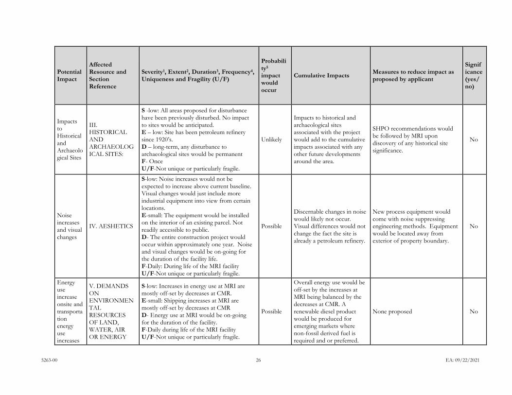
5263-00 26 EA: 09/22/2021
Potential Impact
Affected Resource and Section Reference
Severity1, Extent2, Duration3, Frequency4, Uniqueness and Fragility (U/F)
Probability5 impact would occur
Cumulative Impacts Measures to reduce impact as proposed by applicant
Significance (yes/no)
Impacts to Historical and Archaeological Sites
III. HISTORICAL AND ARCHAEOLOGICAL SITES:
S -low: All areas proposed for disturbance have been previously disturbed. No impact to sites would be anticipated. E – low: Site has been petroleum refinery since 1920’s. D – long-term, any disturbance to archaeological sites would be permanent F- Once U/F-Not unique or particularly fragile.
Unlikely
Impacts to historical and archaeological sites associated with the project would add to the cumulative impacts associated with any other future developments around the area.
SHPO recommendations would be followed by MRI upon discovery of any historical site significance.
No
Noise increases and visual changes
IV. AESHETICS
S-low: Noise increases would not be expected to increase above current baseline. Visual changes would just include more industrial equipment into view from certain locations. E-small: The equipment would be installed on the interior of an existing parcel. Not readily accessible to public. D- The entire construction project would occur within approximately one year. Noise and visual changes would be on-going for the duration of the facility life. F-Daily: During life of the MRI facility U/F-Not unique or particularly fragile.
Possible
Discernable changes in noise would likely not occur. Visual differences would not change the fact the site is already a petroleum refinery.
New process equipment would come with noise suppressing engineering methods. Equipment would be located away from exterior of property boundary.
No
Energy use increase onsite and transportation energy use increases
V. DEMANDS ON ENVIRONMENTAL RESOURCES OF LAND, WATER, AIR OR ENERGY
S-low: Increases in energy use at MRI are mostly off-set by decreases at CMR. E-small: Shipping increases at MRI are mostly off-set by decreases at CMR D- Energy use at MRI would be on-going for the duration of the facility. F-Daily during life of the MRI facility U/F-Not unique or particularly fragile.
Possible
Overall energy use would be off-set by the increases at MRI being balanced by the decreases at CMR. A renewable diesel product would be produced for emerging markets where non-fossil derived fuel is required and or preferred.
None proposed No
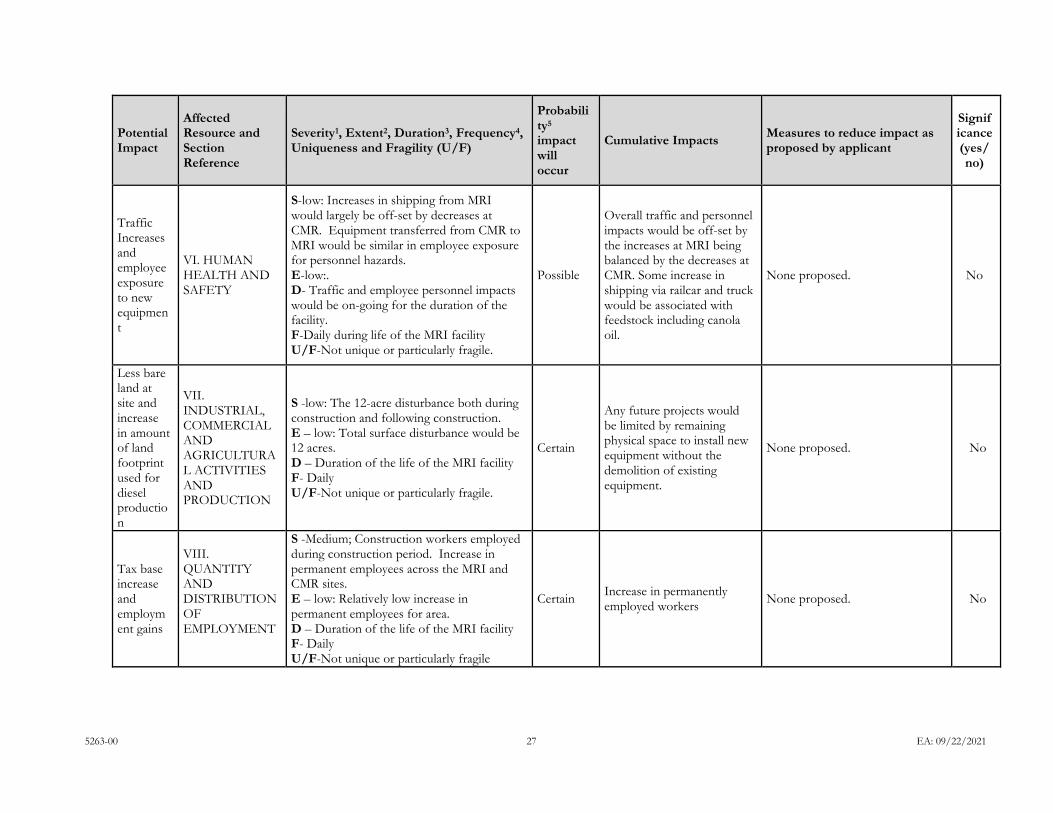
5263-00 27 EA: 09/22/2021
Potential Impact
Affected Resource and Section Reference
Severity1, Extent2, Duration3, Frequency4, Uniqueness and Fragility (U/F)
Probability5 impact will occur
Cumulative Impacts Measures to reduce impact as proposed by applicant
Significance (yes/no)
Traffic Increases and employee exposure to new equipment
VI. HUMAN HEALTH AND SAFETY
S-low: Increases in shipping from MRI would largely be off-set by decreases at CMR. Equipment transferred from CMR to MRI would be similar in employee exposure for personnel hazards. E-low:. D- Traffic and employee personnel impacts would be on-going for the duration of the facility. F-Daily during life of the MRI facility U/F-Not unique or particularly fragile.
Possible
Overall traffic and personnel impacts would be off-set by the increases at MRI being balanced by the decreases at CMR. Some increase in shipping via railcar and truck would be associated with feedstock including canola oil.
None proposed. No
Less bare land at site and increase in amount of land footprint used for diesel production
VII. INDUSTRIAL, COMMERCIAL AND AGRICULTURAL ACTIVITIES AND PRODUCTION
S -low: The 12-acre disturbance both during construction and following construction. E – low: Total surface disturbance would be 12 acres. D – Duration of the life of the MRI facility F- Daily U/F-Not unique or particularly fragile.
Certain
Any future projects would be limited by remaining physical space to install new equipment without the demolition of existing equipment.
None proposed. No
Tax base increase and employment gains
VIII. QUANTITY AND DISTRIBUTION OF EMPLOYMENT
S -Medium; Construction workers employed during construction period. Increase in permanent employees across the MRI and CMR sites. E – low: Relatively low increase in permanent employees for area. D – Duration of the life of the MRI facility F- Daily U/F-Not unique or particularly fragile
Certain Increase in permanently employed workers None proposed. No
Related Documents