2008 HVAC Air Conditioning - RAV4 AIR CONDITIONING SYSTEM (FOR AUTOMATIC AIR CONDITIONING SYSTEM) PRECAUTION 1. IF ANY OF FOLLOWING CONDITIONS ARE MET, KEEP ENGINE IDLING WITH A/C ON (ENGINE SPEED AT LESS THAN 2000 RPM) FOR AT LEAST 1 MINUTE: Refrigerant gas has been refilled or A/C parts have been replaced. A long time has elapsed since the engine was stopped. 2. DO NOT HANDLE REFRIGERANT IN ENCLOSED AREAS OR NEAR OPEN FLAMES 3. ALWAYS WEAR EYE PROTECTION Fig. 1: Precaution For Handle Refrigerant In Enclosed Area Courtesy of TOYOTA MOTOR SALES, U.S.A., INC. 4. BE CAREFUL NOT TO GET LIQUID REFRIGERANT IN YOUR EYES OR ON YOUR SKIN NOTE: If the engine speed exceeds 2,000 rpm, the A/C compressor may be damaged. 2008 Toyota RAV4 2008 HVAC Air Conditioning - RAV4

Welcome message from author
This document is posted to help you gain knowledge. Please leave a comment to let me know what you think about it! Share it to your friends and learn new things together.
Transcript
2008 HVAC
Air Conditioning - RAV4
AIR CONDITIONING SYSTEM (FOR AUTOMATIC AIR CONDITIONING SYSTEM)
PRECAUTION
1. IF ANY OF FOLLOWING CONDITIONS ARE MET, KEEP ENGINE IDLING WITH A/C ON (ENGINE SPEED AT LESS THAN 2000 RPM) FOR AT LEAST 1 MINUTE:
Refrigerant gas has been refilled or A/C parts have been replaced.
A long time has elapsed since the engine was stopped.
2. DO NOT HANDLE REFRIGERANT IN ENCLOSED AREAS OR NEAR OPEN FLAMES
3. ALWAYS WEAR EYE PROTECTION
Fig. 1: Precaution For Handle Refrigerant In Enclosed Area Courtesy of TOYOTA MOTOR SALES, U.S.A., INC.
4. BE CAREFUL NOT TO GET LIQUID REFRIGERANT IN YOUR EYES OR ON YOUR SKIN
NOTE: If the engine speed exceeds 2,000 rpm, the A/C compressor may be damaged.
2008 Toyota RAV4
2008 HVAC Air Conditioning - RAV4
2008 Toyota RAV4
2008 HVAC Air Conditioning - RAV4
Microsoft
Tuesday, August 18, 2009 3:53:52 PM Page 1 © 2005 Mitchell Repair Information Company, LLC.
Microsoft
Tuesday, August 18, 2009 3:54:02 PM Page 1 © 2005 Mitchell Repair Information Company, LLC.
If liquid refrigerant gets in your eyes or on your skin:
a. Wash the area with lots of cold water.
b. Apply clean petroleum jelly to the skin.
c. Go immediately to a physician or hospital for professional treatment.
Fig. 2: Precaution For Liquid Refrigerant Eyes On Skin Courtesy of TOYOTA MOTOR SALES, U.S.A., INC.
5. NEVER HEAT CONTAINER OR EXPOSE IT TO OPEN FLAME
6. BE CAREFUL NOT TO DROP CONTAINER OR SUBJECT IT TO PHYSICAL SHOCKS
7. DO NOT OPERATE COMPRESSOR WITH INSUFFICIENT REFRIGERANT IN REFRIGERANT SYSTEM
If there is not enough refrigerant in the refrigerant system, oil lubrication will be insufficient and compressor burnout may occur. Necessary care should be taken to avoid this.
Fig. 3: Identifying Correct And Incorrect Connection Of Valves Courtesy of TOYOTA MOTOR SALES, U.S.A., INC.
CAUTION: Do not rub your eyes or skin.
2008 Toyota RAV4
2008 HVAC Air Conditioning - RAV4
Microsoft
Tuesday, August 18, 2009 3:53:52 PM Page 2 © 2005 Mitchell Repair Information Company, LLC.
8. DO NOT OPEN HIGH PRESSURE MANIFOLD VALVE WHILE COMPRESSOR IS OPERATING
Open and close only the low pressure valve. Opening and closing the high pressure valve could cause the charging cylinder to rupture.
9. BE CAREFUL NOT TO OVERCHARGE SYSTEM WITH REFRIGERANT
If the refrigerant is overcharged, it causes problems such as insufficient cooling, poor fuel economy and engine overheating.
10. DO NOT OPERATE ENGINE AND COMPRESSOR WITHOUT REFRIGERANT
PARTS LOCATION
Fig. 4: Identifying Air Conditioning System Components Location (1 Of 3) Courtesy of TOYOTA MOTOR SALES, U.S.A., INC.
Fig. 5: Identifying Air Conditioning System Components Location (2 Of 3) Courtesy of TOYOTA MOTOR SALES, U.S.A., INC.
NOTE: This may damage the inside of the compressor.
2008 Toyota RAV4
2008 HVAC Air Conditioning - RAV4
Microsoft
Tuesday, August 18, 2009 3:53:52 PM Page 3 © 2005 Mitchell Repair Information Company, LLC.
Fig. 6: Identifying Air Conditioning System Components Location (3 Of 3) Courtesy of TOYOTA MOTOR SALES, U.S.A., INC.
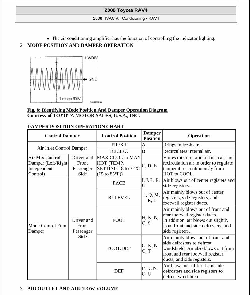
SYSTEM DIAGRAM
Fig. 7: Air Conditioning System Diagram Courtesy of TOYOTA MOTOR SALES, U.S.A., INC.
Communication table
COMMUNICATION CHART
Sender Receiver SignalCommunication
Line
Air conditioning amplifier
ECM
A/C compressor control signal
CAN
Idle up request signalExternal variable control solenoid current signalCooling fan motor driving request signalAmbient temperature signal
Air conditioning amplifier
Air conditioning control assembly
Front panel indication signal
LIN
AUTO indication signalA/C indication signalMODE indication signalREC indication signalFRS indication signal
2008 Toyota RAV4
2008 HVAC Air Conditioning - RAV4
Microsoft
Tuesday, August 18, 2009 3:53:52 PM Page 4 © 2005 Mitchell Repair Information Company, LLC.
SYSTEM DESCRIPTION
1. GENERAL
a. The air conditioning system has the following features:
In accordance with the temperature set using the temperature control switch, the air conditioning amplifier determines the outlet temperature based on the input signals from various sensors. In addition, corrections are made in accordance with the signals from the water temperature sensor to control the outlet air temperature.
Controls the blower motor in accordance with the airflow volume determined by the air conditioning amplifier based on the input signals from various sensors.
Automatically changes the outlets in accordance with the outlet mode ratio that is determined by the air conditioning amplifier based on the input signals from various sensors.
Based on the signals from the ambient temperature sensor, this system calculates the outside temperature and indicates it in the multi-information display in the combination meter assembly.
The left/right independent temperature control and neural network control make air conditioner control available to suit the persons in the driver seat and in the passenger seat.
Turns the rear defogger and outside rear mirror heaters on for 15 minutes when the rear defogger switch is pressed. Turns them off if the switch is pressed while they are operating.
Checks the sensors in accordance with the operation of the air conditioner switches.
RDEF indication signalBlower level indication signalSet temperature indication signal
Combination meter assembly
Air conditioning amplifier
Vehicle speed signalCAN
Ambient temperature signal
ECMAir conditioning
amplifier
Engine revolution speed signal
CAN
Engine coolant temperature signal
A/C control cut signalVariable control prohibition signal
Air conditioning control assembly
Air conditioning amplifier
AUTO switch signal
LIN
OFF switch signalA/C switch signalDEF switch signalMODE switch signalRDEF switch signalBlower switch signal (FAN+, FAN-)Set temperature switch signal (UP, DOWN)
2008 Toyota RAV4
2008 HVAC Air Conditioning - RAV4
Microsoft
Tuesday, August 18, 2009 3:53:52 PM Page 5 © 2005 Mitchell Repair Information Company, LLC.
The air conditioning amplifier has the function of controlling the indicator lighting.
2. MODE POSITION AND DAMPER OPERATION
Fig. 8: Identifying Mode Position And Damper Operation Diagram Courtesy of TOYOTA MOTOR SALES, U.S.A., INC.
DAMPER POSITION OPERATION CHART
3. AIR OUTLET AND AIRFLOW VOLUME
Control Damper Control PositionDamper Position Operation
Air Inlet Control DamperFRESH A Brings in fresh air.RECIRC B Recirculates internal air.
Air Mix Control Damper (Left/Right Independent Control)
Driver and Front
Passenger Side
MAX COOL to MAX HOT (TEMP. SETTING 18 to 32°C (65 to 85°F))
C, D, E
Varies mixture ratio of fresh air and recirculation air in order to regulate temperature continuously from HOT to COOL.
Mode Control Film Damper
Driver and Front
Passenger Side
FACEI, J, L, P, U
Air blows out of center registers and side registers.
BI-LEVELI, Q, M,
R, T
Air mainly blows out of center registers, side registers, and footwell register ducts.
FOOT H, K, N, O, S
Air mainly blows out of front and rear footwell register ducts. In addition, air blows out slightly from front and side defrosters, and side registers.
FOOT/DEFG, K, N, O, T
Air mainly blows out of front and side defrosters to defrost windshield. Air also blows out from front and rear footwell register ducts, and side registers.
DEF F, K, N, O, U
Air blows out of front and side defrosters and side registers to defrost windshield.
2008 Toyota RAV4
2008 HVAC Air Conditioning - RAV4
Microsoft
Tuesday, August 18, 2009 3:53:52 PM Page 6 © 2005 Mitchell Repair Information Company, LLC.
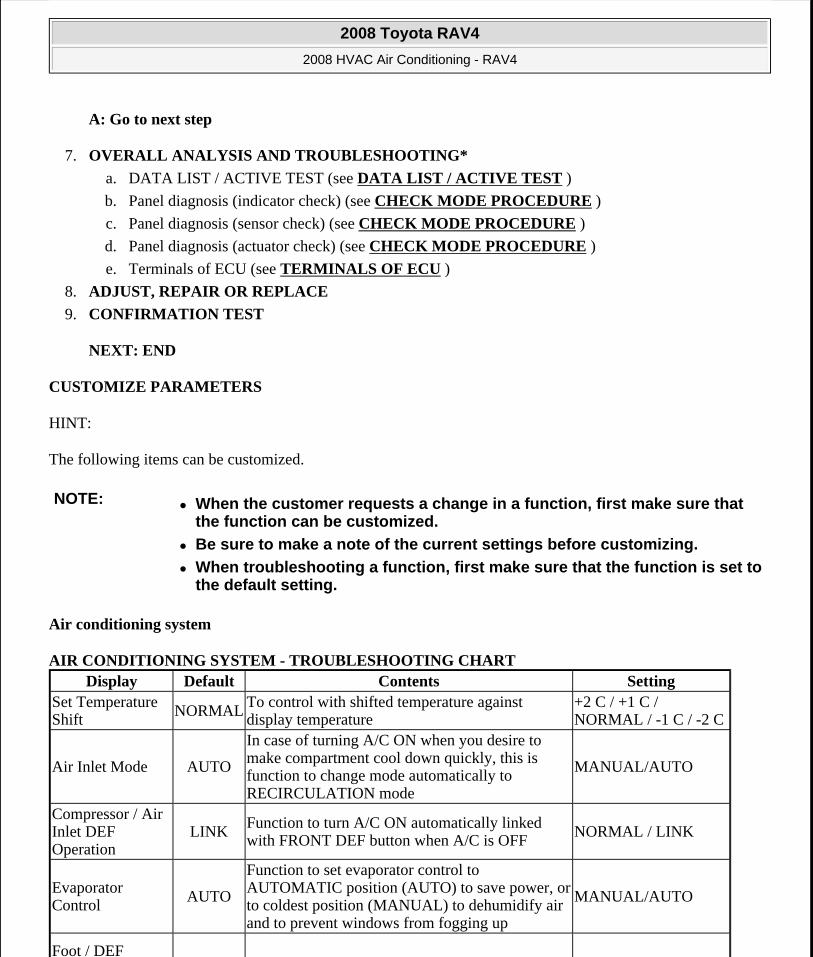
Fig. 9: Identifying Air Outlet And Airflow Courtesy of TOYOTA MOTOR SALES, U.S.A., INC.
The circle size (O) indicates the proportion of the flow volume.
Fig. 10: Air Outlet Position Symbol Chart Courtesy of TOYOTA MOTOR SALES, U.S.A., INC.
HOW TO PROCEED WITH TROUBLESHOOTING
HINT:
Use these procedures to troubleshoot the air conditioning system.
*: Use Techstream.
1. VEHICLE BROUGHT TO WORKSHOP
2. CUSTOMER PROBLEM ANALYSIS AND SYMPTOM CHECK
3. INSPECT BATTERY VOLTAGE
Standard voltage:
11 to 14 V
If the voltage is below 11 V, recharge or replace the battery before proceeding.
4. CHECK CAN COMMUNICATION SYSTEM*
a. Use Techstream to check if the CAN communication system is functioning.
2008 Toyota RAV4
2008 HVAC Air Conditioning - RAV4
Microsoft
Tuesday, August 18, 2009 3:53:52 PM Page 7 © 2005 Mitchell Repair Information Company, LLC.

Result
RESULT REFERENCE
B: Go to CAN COMMUNICATION SYSTEM
A: Go to next step
5. CHECK DTC OR CHECK SENSOR CHECK CODE THROUGH PANEL DIAGNOSIS*
a. Check DTCs or sensor check codes.
1. Write down the DTCs or sensor check codes.
b. Clear the DTCs or sensor check codes.
c. Check whether the DTCs or sensor check codes recur.
1. Reproduce the problem symptoms in accordance with the DTCs or sensor check codes that were written down, and check whether the DTCs or sensor check codes recur.
HINT:
Refer to the DTC chart when any DTCs or sensor check codes are output.
Result
RESULT REFERENCE
B: Go to step 8
A: Go to next step
6. REFER TO PROBLEM SYMPTOMS TABLE
Result
RESULT REFERENCE
B: Go to step 8
Result Proceed toCAN DTC is not output ACAN DTC is output B
Result Proceed toDTC or sensor check code is not output ADTC or sensor check code is output B
Result Proceed toFault is not listed in problem symptoms table AFault is listed in problem symptoms table B
2008 Toyota RAV4
2008 HVAC Air Conditioning - RAV4
Microsoft
Tuesday, August 18, 2009 3:53:53 PM Page 8 © 2005 Mitchell Repair Information Company, LLC.
A: Go to next step
7. OVERALL ANALYSIS AND TROUBLESHOOTING*
a. DATA LIST / ACTIVE TEST (see DATA LIST / ACTIVE TEST )
b. Panel diagnosis (indicator check) (see CHECK MODE PROCEDURE )
c. Panel diagnosis (sensor check) (see CHECK MODE PROCEDURE )
d. Panel diagnosis (actuator check) (see CHECK MODE PROCEDURE )
e. Terminals of ECU (see TERMINALS OF ECU )
8. ADJUST, REPAIR OR REPLACE
9. CONFIRMATION TEST
NEXT: END
CUSTOMIZE PARAMETERS
HINT:
The following items can be customized.
Air conditioning system
AIR CONDITIONING SYSTEM - TROUBLESHOOTING CHART
NOTE: When the customer requests a change in a function, first make sure that the function can be customized.
Be sure to make a note of the current settings before customizing.
When troubleshooting a function, first make sure that the function is set to the default setting.
Display Default Contents SettingSet Temperature Shift NORMAL
To control with shifted temperature against display temperature
+2 C / +1 C / NORMAL / -1 C / -2 C
Air Inlet Mode AUTO
In case of turning A/C ON when you desire to make compartment cool down quickly, this is function to change mode automatically to RECIRCULATION mode
MANUAL/AUTO
Compressor / Air Inlet DEF Operation
LINKFunction to turn A/C ON automatically linked with FRONT DEF button when A/C is OFF
NORMAL / LINK
Evaporator Control AUTO
Function to set evaporator control to AUTOMATIC position (AUTO) to save power, or to coldest position (MANUAL) to dehumidify air and to prevent windows from fogging up
MANUAL/AUTO
Foot / DEF
2008 Toyota RAV4
2008 HVAC Air Conditioning - RAV4
Microsoft
Tuesday, August 18, 2009 3:53:53 PM Page 9 © 2005 Mitchell Repair Information Company, LLC.
PROBLEM SYMPTOMS TABLE
HINT:
Use the table below to help determine the cause of the problem symptom. The potential causes of the symptoms are listed in order of probability in the "Suspected area" column of the table. Check each symptom by checking the suspected areas in the order they are listed. Replace parts as necessary.
Inspect the fuses and relays related to this system before inspecting the suspected areas below.
Air conditioning system
PROBLEM SYMPTOMS CHART
Automatic Blow up Function
ONFunction to change blower level automatically when defroster is ON
OFF/ON
Ambient Temperature Shift
NormalTo control with shifted ambient temperature against display ambient temperature.
+3 C / +2 C / +1 C / Normal / -1 C / -2 C / -3 C
Symptom Suspected area See
No functions of A/C panel operate
1. LIN communication line
-
2. Air conditioning control assembly
AIR CONDITIONING CONTROL PANEL DOES NOT OPERATE
3. Air conditioning amplifier TERMINALS OF ECU
No functions of A/C system operate
1. ECU-IG2 fuse -2. Air conditioning control assembly
AIR CONDITIONING CONTROL PANEL DOES NOT OPERATE
3. Air conditioning amplifier
TERMINALS OF ECU
4. Wire harness or connector
-
Airflow Control: No blower control (Blower motor does not operate)
1. HTR fuse -2. Blower motor circuit BLOWER MOTOR CIRCUIT3. Air conditioning amplifier
TERMINALS OF ECU
4. Air conditioning control assembly
AIR CONDITIONING CONTROL PANEL DOES NOT OPERATE
5. Wire harness or connector
-
Airflow Control: No blower control (Blower motor does not change speed)
1. Blower motor circuit BLOWER MOTOR CIRCUIT2. Air conditioning amplifier
TERMINALS OF ECU
3. Air conditioning AIR CONDITIONING CONTROL
2008 Toyota RAV4
2008 HVAC Air Conditioning - RAV4
Microsoft
Tuesday, August 18, 2009 3:53:53 PM Page 10 © 2005 Mitchell Repair Information Company, LLC.
control assembly PANEL DOES NOT OPERATE
Temperature Control: No cool air comes out
1. Refrigerant volume -2. Refrigerant pressure -3. Air conditioning pressure sensor
DTC B1423/23 PRESSURE SENSOR CIRCUIT
4. Compressor and pulley (for 2AZ-FE)
DTC B1451/51 COMPRESSOR SOLENOID CIRCUIT
5. Compressor and magnetic clutch (for 2GR-FE)
DTC B1451/51 COMPRESSOR SOLENOID CIRCUIT
6. Compressor circuit (for 2GR-FE)
COMPRESSOR CIRCUIT
7. Driver side air mix damper control servo motor circuit
DTC B1446/46 AIR MIX DAMPER CONTROL SERVO MOTOR CIRCUIT (DRIVER SIDE)
8. Passenger side air mix damper control servo motor circuit
DTC B1441/41 AIR MIX DAMPER CONTROL SERVO MOTOR CIRCUIT (PASSENGER SIDE)
9. Evaporator temperature sensor circuit
DTC B1413/13 EVAPORATOR TEMPERATURE SENSOR CIRCUIT
10. Room temperature sensor circuit
DTC B1411/11 ROOM TEMPERATURE SENSOR CIRCUIT
11. Ambient temperature sensor circuit
DTC B1412/12 AMBIENT TEMPERATURE SENSOR CIRCUIT
12. Expansion valve -13: Air conditioning amplifier
TERMINALS OF ECU
14. Air conditioning control assembly
AIR CONDITIONING CONTROL PANEL DOES NOT OPERATE
15. ECM (for 2AZ-FE) SFI SYSTEM 16. ECM (for 2GR-FE) SFI SYSTEM 17. LIN communication line
-
18. CAN communication system
CAN COMMUNICATION SYSTEM
1. Driver side air mix damper control servo motor circuit
DTC B1446/46 AIR MIX DAMPER CONTROL SERVO MOTOR CIRCUIT (DRIVER SIDE)
2. Passenger side air mix damper control servo motor circuit
DTC B1441/41 AIR MIX DAMPER CONTROL SERVO MOTOR CIRCUIT (PASSENGER SIDE)
3. Air conditioning harness
-
4. Room temperature DTC B1411/11 ROOM
2008 Toyota RAV4
2008 HVAC Air Conditioning - RAV4
Microsoft
Tuesday, August 18, 2009 3:53:53 PM Page 11 © 2005 Mitchell Repair Information Company, LLC.

Temperature Control: No warm air comes out
sensor circuit TEMPERATURE SENSOR CIRCUIT5. Air conditioning amplifier TERMINALS OF ECU
6. Air conditioning control assembly
AIR CONDITIONING CONTROL PANEL DOES NOT OPERATE
7. ECM (for 2AZ-FE) SFI SYSTEM 8. ECM (for 2GR-FE) SFI SYSTEM 9. LIN communication line
-
10. CAN communication system
CAN COMMUNICATION SYSTEM
Temperature Control: Output air is warmer or cooler than set temperature or response is slow
1. Driver side solar sensor circuit
DTC B1424/24 SOLAR SENSOR CIRCUIT (DRIVER SIDE)
2. Passenger side solar sensor circuit
DTC B1421/21 SOLAR SENSOR CIRCUIT (PASSENGER SIDE)
3. Room temperature sensor circuit
DTC B1411/11 ROOM TEMPERATURE SENSOR CIRCUIT
4. Air inlet damper control servo motor circuit
DTC B1442/42 AIR INLET DAMPER CONTROL SERVO MOTOR CIRCUIT
5. Heater radiator -6. Expansion valve -7. Air conditioning amplifier
TERMINALS OF ECU
8. Air conditioning control assembly
AIR CONDITIONING CONTROL PANEL DOES NOT OPERATE
9. ECM (for 2AZ-FE) SFI SYSTEM 10. ECM (for 2GR-FE) SFI SYSTEM 11. LIN communication line
-
12. CAN communication system CAN COMMUNICATION SYSTEM
Temperature Control: No temperature control (Only Max. cool or Max. warm)
1. Driver side solar sensor circuit
DTC B1424/24 SOLAR SENSOR CIRCUIT (DRIVER SIDE)
2. Passenger side solar sensor circuit
DTC B1421/21 SOLAR SENSOR CIRCUIT (PASSENGER SIDE)
3. Air conditioning amplifier TERMINALS OF ECU
4. Air conditioning control assembly
AIR CONDITIONING CONTROL PANEL DOES NOT OPERATE
5. LIN communication line
-
1. Air conditioning AIR CONDITIONING CONTROL
2008 Toyota RAV4
2008 HVAC Air Conditioning - RAV4
Microsoft
Tuesday, August 18, 2009 3:53:53 PM Page 12 © 2005 Mitchell Repair Information Company, LLC.
TERMINALS OF ECU
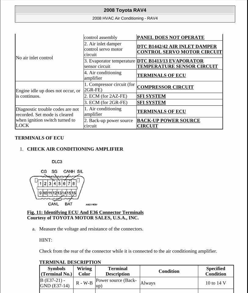
1. CHECK AIR CONDITIONING AMPLIFIER
Fig. 11: Identifying ECU And E36 Connector Terminals Courtesy of TOYOTA MOTOR SALES, U.S.A., INC.
a. Measure the voltage and resistance of the connectors.
HINT:
Check from the rear of the connector while it is connected to the air conditioning amplifier.
TERMINAL DESCRIPTION
No air inlet control
control assembly PANEL DOES NOT OPERATE2. Air inlet damper control servo motor circuit
DTC B1442/42 AIR INLET DAMPER CONTROL SERVO MOTOR CIRCUIT
3. Evaporator temperature sensor circuit
DTC B1413/13 EVAPORATOR TEMPERATURE SENSOR CIRCUIT
4. Air conditioning amplifier
TERMINALS OF ECU
Engine idle up does not occur, or is continuos.
1. Compressor circuit (for 2GR-FE)
COMPRESSOR CIRCUIT
2. ECM (for 2AZ-FE) SFI SYSTEM 3. ECM (for 2GR-FE) SFI SYSTEM
Diagnostic trouble codes are not recorded. Set mode is cleared when ignition switch turned to LOCK
1. Air conditioning amplifier
TERMINALS OF ECU
2. Back-up power source circuit
BACK-UP POWER SOURCE CIRCUIT
Symbols (Terminal No.)
Wiring Color
Terminal Description
Condition Specified Condition
B (E37-21) - GND (E37-14) R - W-B
Power source (Back-up) Always 10 to 14 V
2008 Toyota RAV4
2008 HVAC Air Conditioning - RAV4
Microsoft
Tuesday, August 18, 2009 3:53:53 PM Page 13 © 2005 Mitchell Repair Information Company, LLC.
SOL+ (E37-2) - GND (E37-14)
GR - W-BA/C compressor operation signal
Engine idling Pulse generation (see awaveform
1)Blower switch LO
A/C switch ON
BLW (E37-23) - GND (E37-14)
R - W-BBlower motor control signal
Ignition switch ON Pulse generation (see bwaveform
2)Blower switch LO
PRE (E37-9) - SG-2 (E37-13)
L - GAir conditioning pressure sensor signal
Refrigerant pressure: Normal 0.76 to 4.74 V
PRE (E37-9) - SG-2 (E37-13) L - G
Air conditioning pressure sensor signal
Refrigerant pressure: Abnormal (less than 0.196 MPa [2.0 kgf/cm2 , 28 psi])
Below 0.76 V
PRE (E37-9) - SG-2 (E37-13)
L - G Air conditioning pressure sensor signal
Refrigerant pressure: Abnormal (more than 3.14 MPa [32 kgf/cm2 , 455 psi])
4.74 V or higher
TSD (E37-33) - S5-4 (E37-31)
L - LGDriver side solar sensor signal
Ignition switch ON0.8 to 4.3 VSolar sensor subject to
electric light
TSP (E37-32) - S5-4 (E37-31)
P - LG Passenger side solar sensor signal
Ignition switch ON0.8 to 4.3 VSolar sensor subject to
electric light
TR (E37-29) - SG-1 (E37-34) GR - V
Room temperature sensor signal
Ignition switch ON1.8 to 2.2 VVehicle interior temperature:
25°C (77°F)SG-1 (E37-34) - Body ground
V - Body ground
Ground for room temperature sensor
Always Below 1 ohms
GND (E37-14) - Body ground
W-B - Body
ground
Ground for main power supply
Always Below 1 ohms
IG+ (E37-1) - GND (E37-14)
Y - W-B Power source (IG) Ignition switch ON 10 to 14 V
S5-3 (E37-10) - GND (E37-14) B - W-B
Power supply for pressure sensor Ignition switch ON 4.5 to 5.5 V
CANH (E37-11) - GND (E37-14)
V - W-BHi-level CAN bus line
Ignition switch ONPulse generation (see cwaveform
3)
CANL(E37-12) - GND (E37-14) W - W-B
Lo-level CAN bus line Ignition switch ON
Pulse generation (see dwaveform
4)SG-2 (E37-13) - Body ground
G - Body ground
Ground for pressure sensor Always Below 1 ohms
RDFG (E37-38) - GND (E37-14)
B - W-BRear defogger switch signal
Ignition switch ON Rear defogger switch OFF
10 to 14 V
RDFG (E37-38) B - W-B Rear defogger switch Ignition switch ON Rear Below 1 V
2008 Toyota RAV4
2008 HVAC Air Conditioning - RAV4
Microsoft
Tuesday, August 18, 2009 3:53:53 PM Page 14 © 2005 Mitchell Repair Information Company, LLC.
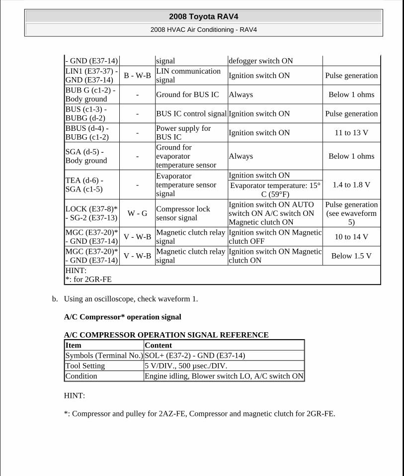
b. Using an oscilloscope, check waveform 1.
A/C Compressor* operation signal
A/C COMPRESSOR OPERATION SIGNAL REFERENCE
HINT:
*: Compressor and pulley for 2AZ-FE, Compressor and magnetic clutch for 2GR-FE.
- GND (E37-14) signal defogger switch ONLIN1 (E37-37) - GND (E37-14) B - W-B
LIN communication signal Ignition switch ON Pulse generation
BUB G (c1-2) - Body ground
- Ground for BUS IC Always Below 1 ohms
BUS (c1-3) - BUBG (d-2)
- BUS IC control signal Ignition switch ON Pulse generation
BBUS (d-4) - BUBG (c1-2) -
Power supply for BUS IC Ignition switch ON 11 to 13 V
SGA (d-5) - Body ground -
Ground for evaporator temperature sensor
Always Below 1 ohms
TEA (d-6) - SGA (c1-5)
-Evaporator temperature sensor signal
Ignition switch ON1.4 to 1.8 VEvaporator temperature: 15°
C (59°F)
LOCK (E37-8)* - SG-2 (E37-13) W - G
Compressor lock sensor signal
Ignition switch ON AUTO switch ON A/C switch ON Magnetic clutch ON
Pulse generation (see ewaveform
5)MGC (E37-20)* - GND (E37-14) V - W-B
Magnetic clutch relay signal
Ignition switch ON Magnetic clutch OFF 10 to 14 V
MGC (E37-20)* - GND (E37-14)
V - W-BMagnetic clutch relay signal
Ignition switch ON Magnetic clutch ON
Below 1.5 V
HINT: *: for 2GR-FE
Item ContentSymbols (Terminal No.) SOL+ (E37-2) - GND (E37-14)Tool Setting 5 V/DIV., 500 µsec./DIV.Condition Engine idling, Blower switch LO, A/C switch ON
2008 Toyota RAV4
2008 HVAC Air Conditioning - RAV4
Microsoft
Tuesday, August 18, 2009 3:53:53 PM Page 15 © 2005 Mitchell Repair Information Company, LLC.
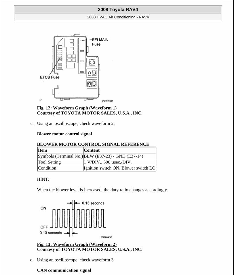
Fig. 12: Waveform Graph (Waveform 1) Courtesy of TOYOTA MOTOR SALES, U.S.A., INC.
c. Using an oscilloscope, check waveform 2.
Blower motor control signal
BLOWER MOTOR CONTROL SIGNAL REFERENCE
HINT:
When the blower level is increased, the duty ratio changes accordingly.
Fig. 13: Waveform Graph (Waveform 2) Courtesy of TOYOTA MOTOR SALES, U.S.A., INC.
d. Using an oscilloscope, check waveform 3.
CAN communication signal
Item ContentSymbols (Terminal No.) BLW (E37-23) - GND (E37-14)Tool Setting 1 V/DIV., 500 µsec./DIV.Condition Ignition switch ON, Blower switch LO
2008 Toyota RAV4
2008 HVAC Air Conditioning - RAV4
Microsoft
Tuesday, August 18, 2009 3:53:53 PM Page 16 © 2005 Mitchell Repair Information Company, LLC.
CAN COMMUNICATION SIGNAL REFERENCE
HINT:
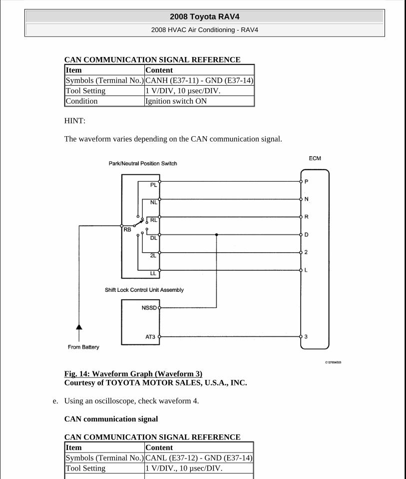
The waveform varies depending on the CAN communication signal.
Fig. 14: Waveform Graph (Waveform 3) Courtesy of TOYOTA MOTOR SALES, U.S.A., INC.
e. Using an oscilloscope, check waveform 4.
CAN communication signal
CAN COMMUNICATION SIGNAL REFERENCE
Item ContentSymbols (Terminal No.) CANH (E37-11) - GND (E37-14)Tool Setting 1 V/DIV, 10 µsec/DIV.Condition Ignition switch ON
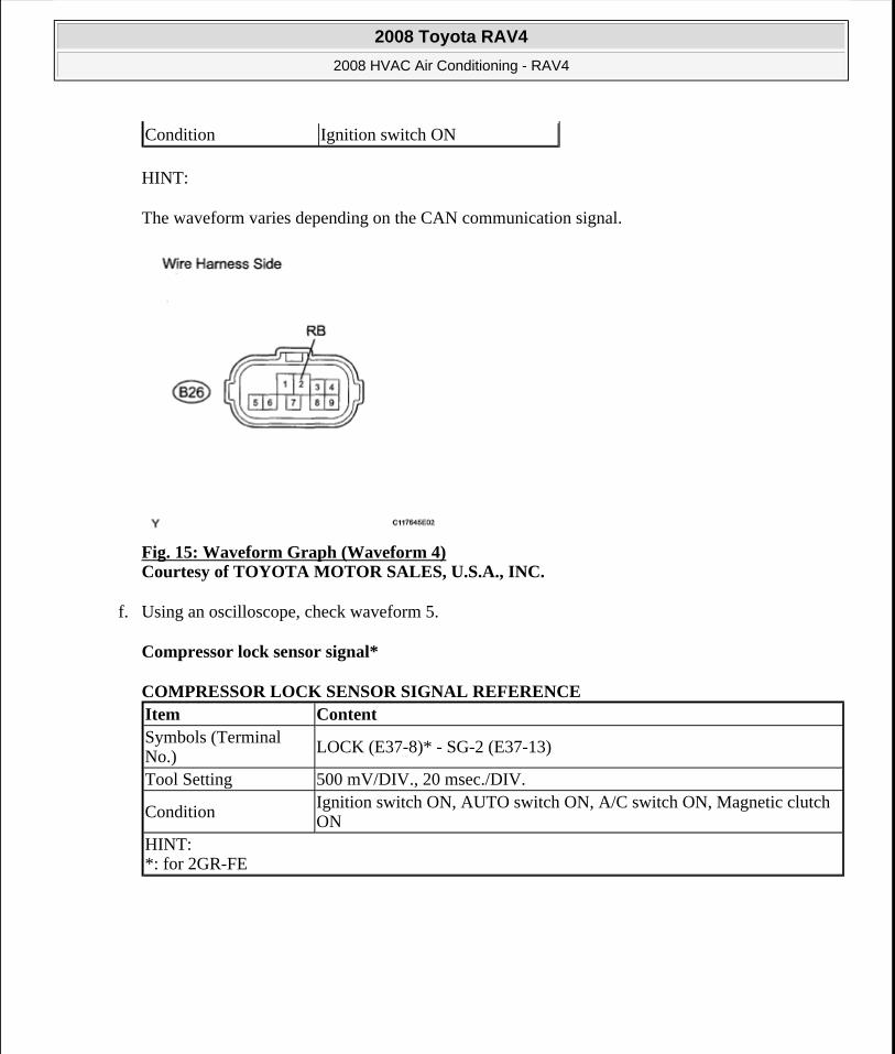
Item ContentSymbols (Terminal No.) CANL (E37-12) - GND (E37-14)Tool Setting 1 V/DIV., 10 µsec/DIV.
2008 Toyota RAV4
2008 HVAC Air Conditioning - RAV4
Microsoft
Tuesday, August 18, 2009 3:53:53 PM Page 17 © 2005 Mitchell Repair Information Company, LLC.
HINT:
The waveform varies depending on the CAN communication signal.
Fig. 15: Waveform Graph (Waveform 4) Courtesy of TOYOTA MOTOR SALES, U.S.A., INC.
f. Using an oscilloscope, check waveform 5.
Compressor lock sensor signal*
COMPRESSOR LOCK SENSOR SIGNAL REFERENCE
Condition Ignition switch ON
Item ContentSymbols (Terminal No.)
LOCK (E37-8)* - SG-2 (E37-13)
Tool Setting 500 mV/DIV., 20 msec./DIV.
ConditionIgnition switch ON, AUTO switch ON, A/C switch ON, Magnetic clutch ON
HINT: *: for 2GR-FE
2008 Toyota RAV4
2008 HVAC Air Conditioning - RAV4
Microsoft
Tuesday, August 18, 2009 3:53:53 PM Page 18 © 2005 Mitchell Repair Information Company, LLC.
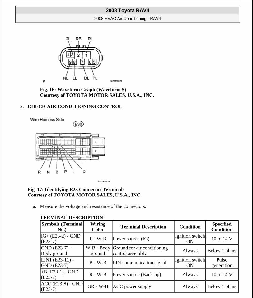
Fig. 16: Waveform Graph (Waveform 5) Courtesy of TOYOTA MOTOR SALES, U.S.A., INC.
2. CHECK AIR CONDITIONING CONTROL
Fig. 17: Identifying E23 Connector Terminals Courtesy of TOYOTA MOTOR SALES, U.S.A., INC.
a. Measure the voltage and resistance of the connectors.
TERMINAL DESCRIPTION Symbols (Terminal
No.)Wiring Color
Terminal Description ConditionSpecified Condition
IG+ (E23-2) - GND (E23-7)
L - W-B Power source (IG) Ignition switch ON
10 to 14 V
GND (E23-7) - Body ground
W-B - Body ground
Ground for air conditioning control assembly
Always Below 1 ohms
LIN1 (E23-11) - GND (E23-7)
B - W-B LIN communication signalIgnition switch
ONPulse
generation+B (E23-1) - GND (E23-7)
R - W-B Power source (Back-up) Always 10 to 14 V
ACC (E23-8) - GND (E23-7)
GR - W-B ACC power supply Always Below 1 ohms
2008 Toyota RAV4
2008 HVAC Air Conditioning - RAV4
Microsoft
Tuesday, August 18, 2009 3:53:53 PM Page 19 © 2005 Mitchell Repair Information Company, LLC.
DIAGNOSIS SYSTEM
1. DESCRIPTION
a. Air conditioning system data and the Diagnostic Trouble Codes (DTCs) can be read through the Data Link Connector 3 (DLC3) of the vehicle. When the system seems to be malfunctioning, use Techstream to check for malfunctions and perform troubleshooting.
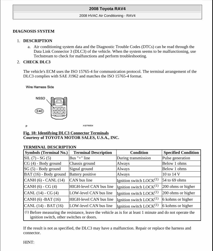
2. CHECK DLC3
The vehicle's ECM uses the ISO 15765-4 for communication protocol. The terminal arrangement of the DLC3 complies with SAE J1962 and matches the ISO 15765-4 format.
Fig. 18: Identifying DLC3 Connector Terminals Courtesy of TOYOTA MOTOR SALES, U.S.A., INC.
TERMINAL DESCRIPTION
If the result is not as specified, the DLC3 may have a malfunction. Repair or replace the harness and connector.
HINT:
Symbols (Terminal No.) Terminal Description Condition Specified ConditionSIL (7) - SG (5) Bus "+" line During transmission Pulse generationCG (4) - Body ground Chassis ground Always Below 1 ohmsSG (5) - Body ground Signal ground Always Below 1 ohmsBAT (16) - Body ground Battery positive Always 10 to 14 V
CANH (6) - CANL (14) CAN bus line Ignition switch LOCK(1) 54 to 69 ohms
CANH (6) - CG (4) HIGH-level CAN bus line Ignition switch LOCK(1) 200 ohms or higher
CANL (14) - CG (4) LOW-level CAN bus line Ignition switch LOCK(1) 200 ohms or higher
CANH (6) -BAT (16) HIGH-level CAN bus line Ignition switch LOCK(1) 6 kohms or higher
CANL (14) - BAT (16) LOW-level CAN bus line Ignition switch LOCK(1) 6 kohms or higher
(1) Before measuring the resistance, leave the vehicle as is for at least 1 minute and do not operate the ignition switch, other switches or doors.
2008 Toyota RAV4
2008 HVAC Air Conditioning - RAV4
Microsoft
Tuesday, August 18, 2009 3:53:53 PM Page 20 © 2005 Mitchell Repair Information Company, LLC.
Connect the cable of Techstream to the DLC3, turn the ignition switch ON and attempt to use the tester. If the display indicates that a communication error has occurred, there is a problem either with the vehicle or with the tester.
If communication is normal when the tester is connected to another vehicle, inspect the DLC3 of the original vehicle.
If communication is still not possible when the tester is connected to another vehicle, the problem may be in the tester itself. Consult the Service Department listed in the tester's instruction article.
DTC CHECK / CLEAR
1. CHECK DTC
a. Connect Techstream to the DLC3.
b. Turn the ignition switch ON and turn Techstream ON.
c. Read the DTC by following the prompts on the tester screen.
HINT:
Refer to Techstream operator's article for further details.
2. CLEAR DTC
a. Connect Techstream to the DLC3.
b. Turn the ignition switch ON and turn Techstream ON.
c. Clear the DTC by following the prompts on the tester screen.
HINT:
Refer to Techstream operator's article for further details.
CHECK MODE PROCEDURE
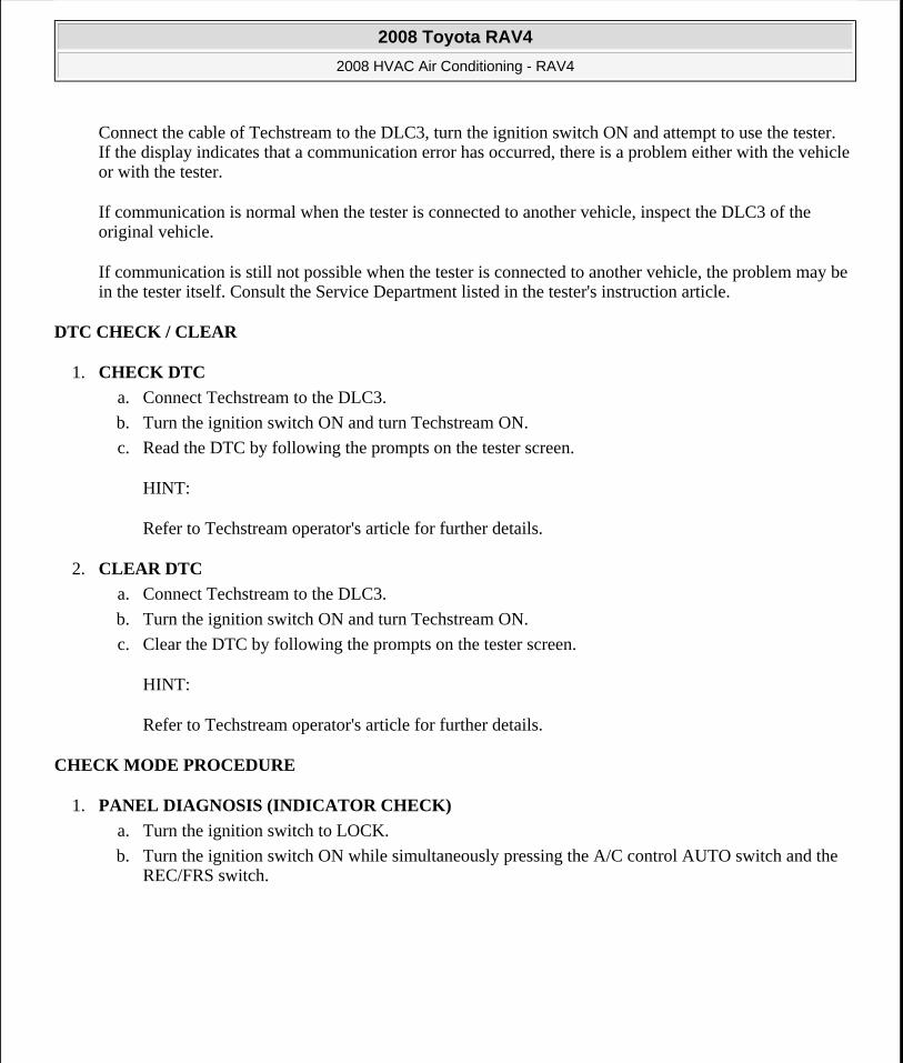
1. PANEL DIAGNOSIS (INDICATOR CHECK)
a. Turn the ignition switch to LOCK.
b. Turn the ignition switch ON while simultaneously pressing the A/C control AUTO switch and the REC/FRS switch.
2008 Toyota RAV4
2008 HVAC Air Conditioning - RAV4
Microsoft
Tuesday, August 18, 2009 3:53:53 PM Page 21 © 2005 Mitchell Repair Information Company, LLC.
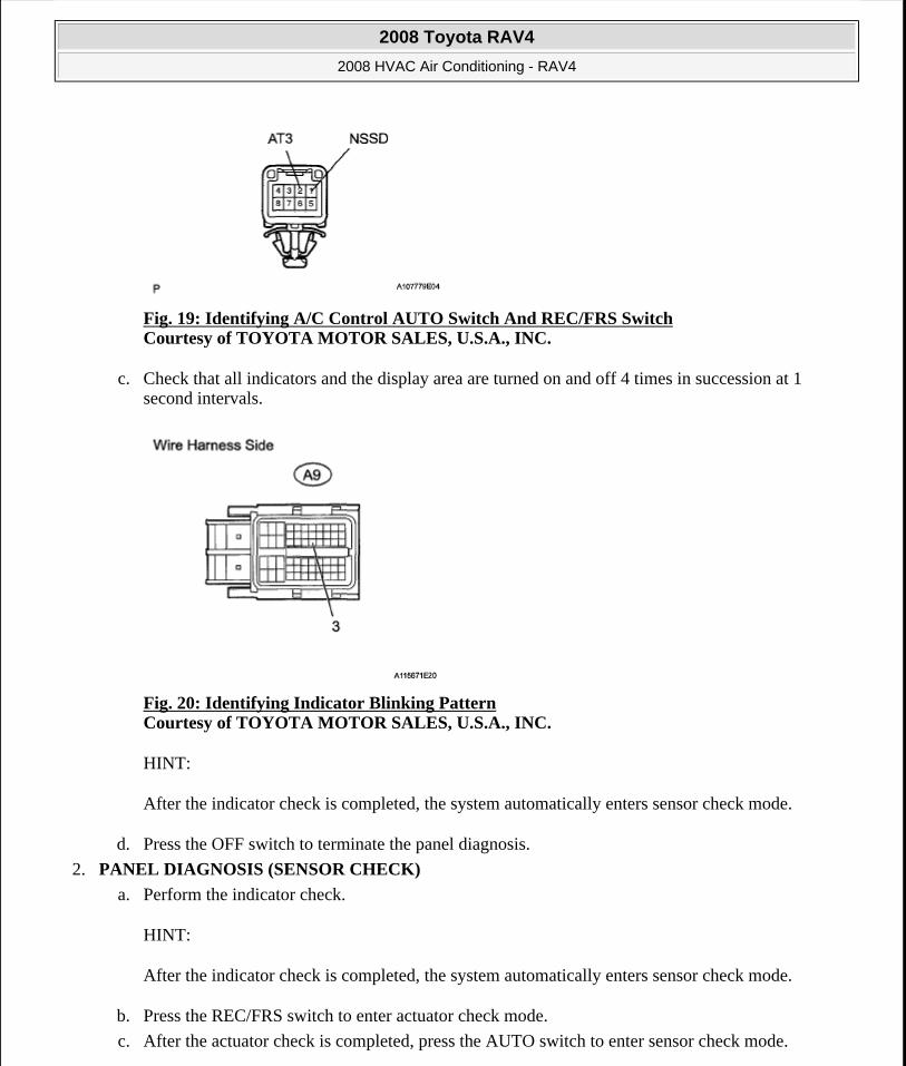
Fig. 19: Identifying A/C Control AUTO Switch And REC/FRS Switch Courtesy of TOYOTA MOTOR SALES, U.S.A., INC.
c. Check that all indicators and the display area are turned on and off 4 times in succession at 1 second intervals.
Fig. 20: Identifying Indicator Blinking Pattern Courtesy of TOYOTA MOTOR SALES, U.S.A., INC.
HINT:
After the indicator check is completed, the system automatically enters sensor check mode.
d. Press the OFF switch to terminate the panel diagnosis.
2. PANEL DIAGNOSIS (SENSOR CHECK)
a. Perform the indicator check.
HINT:
After the indicator check is completed, the system automatically enters sensor check mode.
b. Press the REC/FRS switch to enter actuator check mode.
c. After the actuator check is completed, press the AUTO switch to enter sensor check mode.
2008 Toyota RAV4
2008 HVAC Air Conditioning - RAV4
Microsoft
Tuesday, August 18, 2009 3:53:53 PM Page 22 © 2005 Mitchell Repair Information Company, LLC.
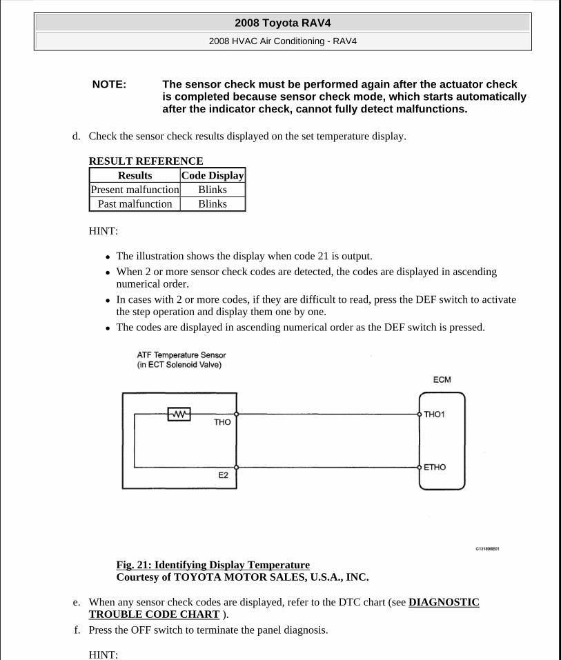
d. Check the sensor check results displayed on the set temperature display.
RESULT REFERENCE
HINT:
The illustration shows the display when code 21 is output.
When 2 or more sensor check codes are detected, the codes are displayed in ascending numerical order.
In cases with 2 or more codes, if they are difficult to read, press the DEF switch to activate the step operation and display them one by one.
The codes are displayed in ascending numerical order as the DEF switch is pressed.
Fig. 21: Identifying Display Temperature Courtesy of TOYOTA MOTOR SALES, U.S.A., INC.
e. When any sensor check codes are displayed, refer to the DTC chart (see DIAGNOSTIC TROUBLE CODE CHART ).
f. Press the OFF switch to terminate the panel diagnosis.
HINT:
NOTE: The sensor check must be performed again after the actuator check is completed because sensor check mode, which starts automatically after the indicator check, cannot fully detect malfunctions.
Results Code DisplayPresent malfunction Blinks
Past malfunction Blinks
2008 Toyota RAV4
2008 HVAC Air Conditioning - RAV4
Microsoft
Tuesday, August 18, 2009 3:53:53 PM Page 23 © 2005 Mitchell Repair Information Company, LLC.
Pressing the REC/FRS switch returns the system to actuator check mode.
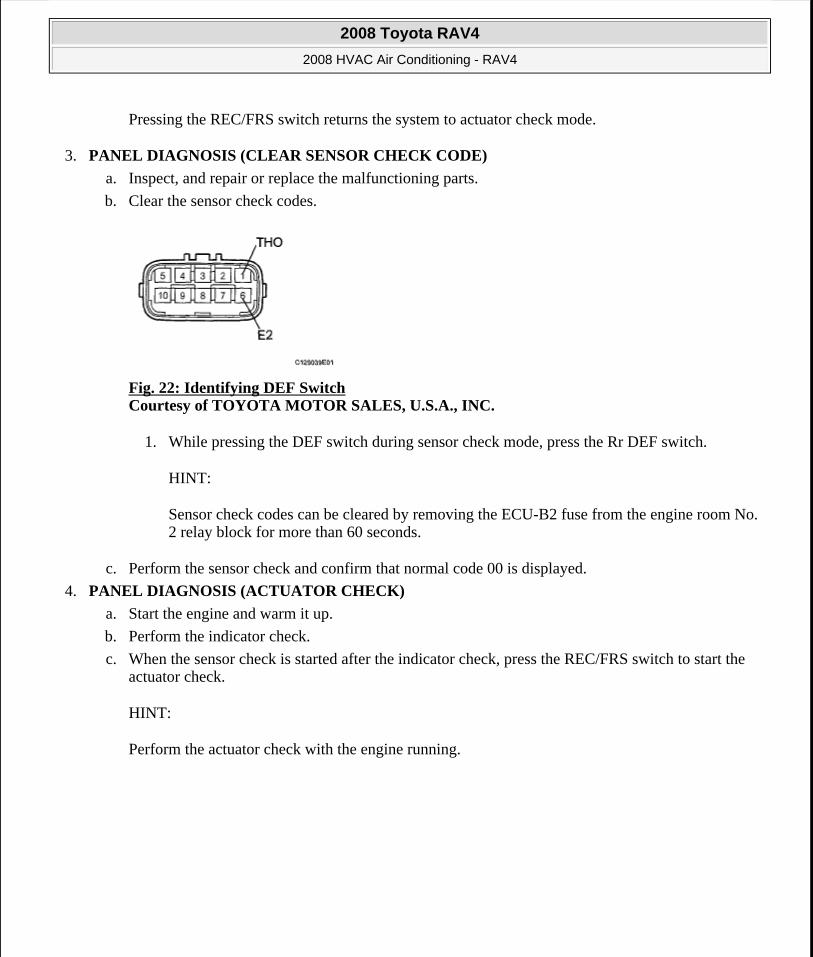
3. PANEL DIAGNOSIS (CLEAR SENSOR CHECK CODE)
a. Inspect, and repair or replace the malfunctioning parts.
b. Clear the sensor check codes.
Fig. 22: Identifying DEF Switch Courtesy of TOYOTA MOTOR SALES, U.S.A., INC.
1. While pressing the DEF switch during sensor check mode, press the Rr DEF switch.
HINT:
Sensor check codes can be cleared by removing the ECU-B2 fuse from the engine room No. 2 relay block for more than 60 seconds.
c. Perform the sensor check and confirm that normal code 00 is displayed.
4. PANEL DIAGNOSIS (ACTUATOR CHECK)
a. Start the engine and warm it up.
b. Perform the indicator check.
c. When the sensor check is started after the indicator check, press the REC/FRS switch to start the actuator check.
HINT:
Perform the actuator check with the engine running.
2008 Toyota RAV4
2008 HVAC Air Conditioning - RAV4
Microsoft
Tuesday, August 18, 2009 3:53:53 PM Page 24 © 2005 Mitchell Repair Information Company, LLC.
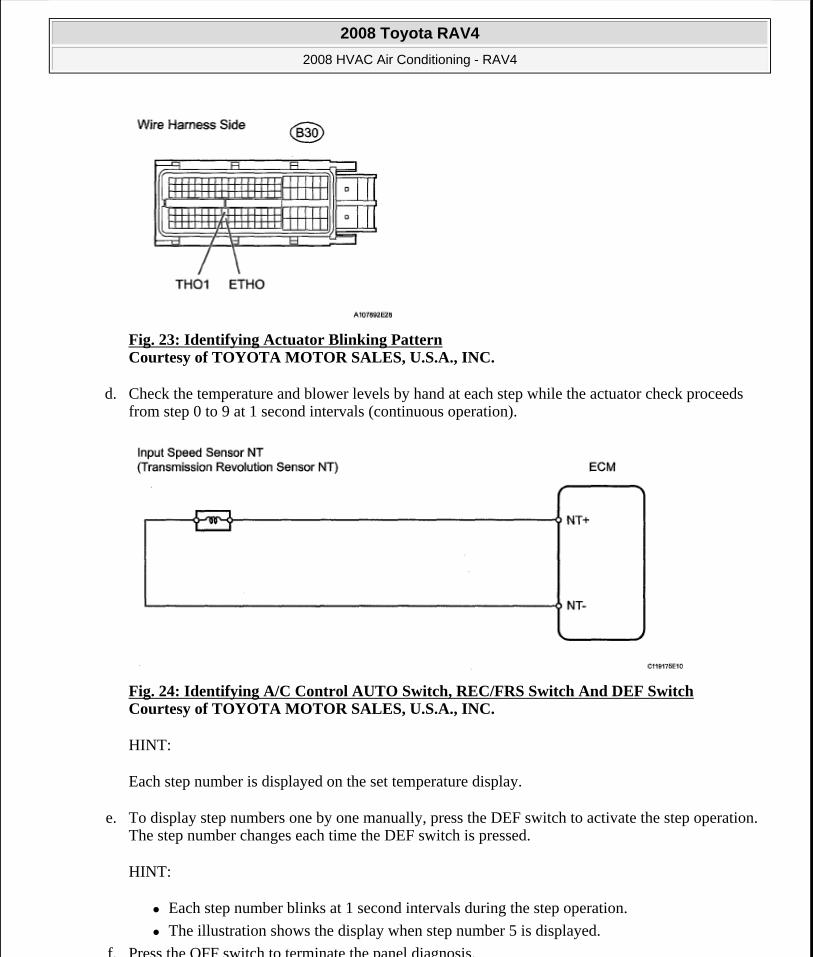
Fig. 23: Identifying Actuator Blinking Pattern Courtesy of TOYOTA MOTOR SALES, U.S.A., INC.
d. Check the temperature and blower levels by hand at each step while the actuator check proceeds from step 0 to 9 at 1 second intervals (continuous operation).
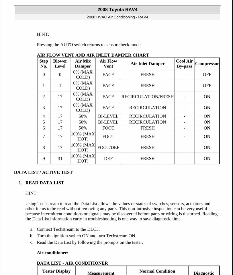
Fig. 24: Identifying A/C Control AUTO Switch, REC/FRS Switch And DEF Switch Courtesy of TOYOTA MOTOR SALES, U.S.A., INC.
HINT:
Each step number is displayed on the set temperature display.
e. To display step numbers one by one manually, press the DEF switch to activate the step operation. The step number changes each time the DEF switch is pressed.
HINT:
Each step number blinks at 1 second intervals during the step operation.
The illustration shows the display when step number 5 is displayed.
f. Press the OFF switch to terminate the panel diagnosis.
2008 Toyota RAV4
2008 HVAC Air Conditioning - RAV4
Microsoft
Tuesday, August 18, 2009 3:53:53 PM Page 25 © 2005 Mitchell Repair Information Company, LLC.
HINT:
Pressing the AUTO switch returns to sensor check mode.
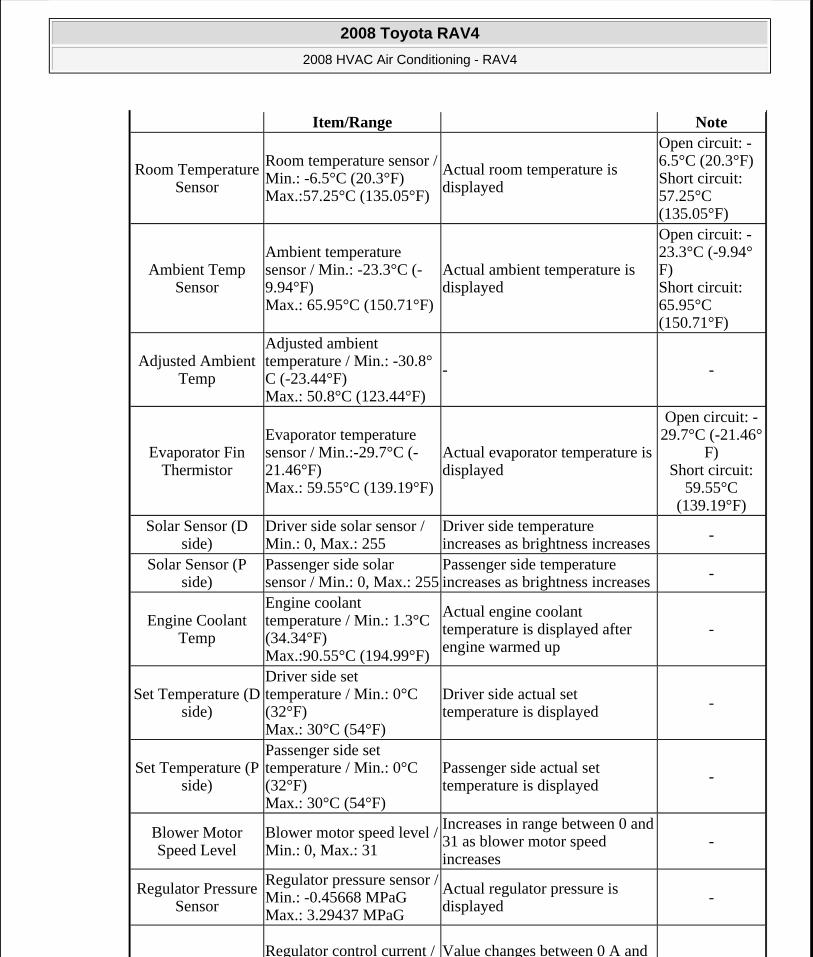
AIR FLOW VENT AND AIR INLET DAMPER CHART
DATA LIST / ACTIVE TEST
1. READ DATA LIST
HINT:
Using Techstream to read the Data List allows the values or states of switches, sensors, actuators and other items to be read without removing any parts. This non-intrusive inspection can be very useful because intermittent conditions or signals may be discovered before parts or wiring is disturbed. Reading the Data List information early in troubleshooting is one way to save diagnostic time.
a. Connect Techstream to the DLC3.
b. Turn the ignition switch ON and turn Techstream ON.
c. Read the Data List by following the prompts on the tester.
Air conditioner:
DATA LIST - AIR CONDITIONER
Step No.
Blower Level
Air Mix Damper
Air Flow Vent
Air Inlet DamperCool Air By-pass
Compressor
0 00% (MAX
COLD)FACE FRESH - OFF
1 1 0% (MAX COLD)
FACE FRESH - OFF
2 170% (MAX
COLD)FACE RECIRCULATION/FRESH - ON
3 170% (MAX
COLD)FACE RECIRCULATION - ON
4 17 50% BI-LEVEL RECIRCULATION - ON5 17 50% BI-LEVEL RECIRCULATION - ON6 17 50% FOOT FRESH - ON
7 17100% (MAX
HOT)FOOT FRESH - ON
8 17 100% (MAX HOT)
FOOT/DEF FRESH - ON
9 31100% (MAX
HOT) DEF FRESH - ON
Tester Display Measurement Normal Condition Diagnostic
2008 Toyota RAV4
2008 HVAC Air Conditioning - RAV4
Microsoft
Tuesday, August 18, 2009 3:53:53 PM Page 26 © 2005 Mitchell Repair Information Company, LLC.
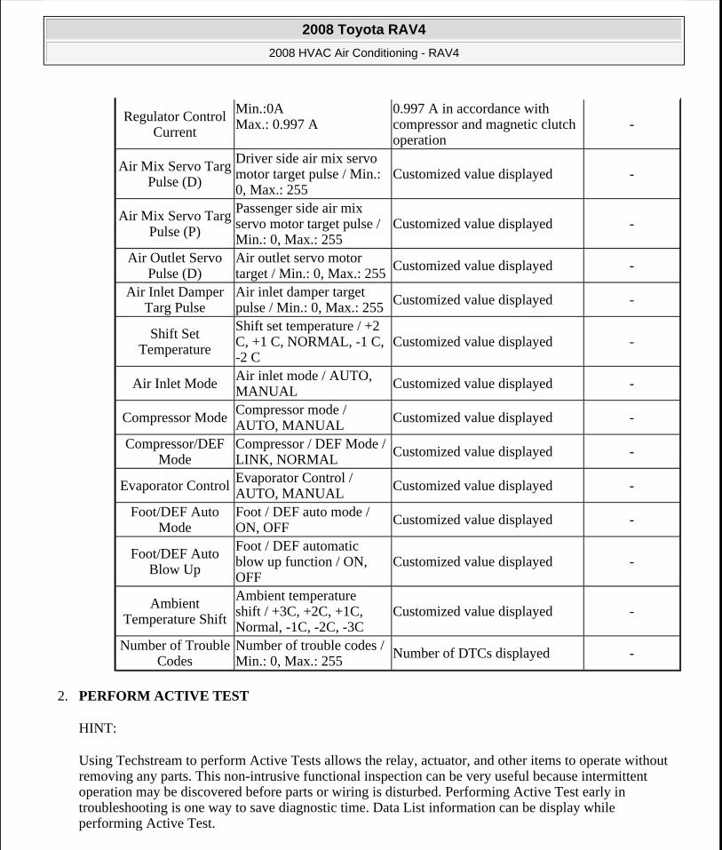
Item/Range Note
Room Temperature Sensor
Room temperature sensor / Min.: -6.5°C (20.3°F) Max.:57.25°C (135.05°F)
Actual room temperature is displayed
Open circuit: -6.5°C (20.3°F)Short circuit: 57.25°C (135.05°F)
Ambient Temp Sensor
Ambient temperature sensor / Min.: -23.3°C (-9.94°F) Max.: 65.95°C (150.71°F)
Actual ambient temperature is displayed
Open circuit: -23.3°C (-9.94°F) Short circuit: 65.95°C (150.71°F)
Adjusted Ambient Temp
Adjusted ambient temperature / Min.: -30.8°C (-23.44°F) Max.: 50.8°C (123.44°F)
- -
Evaporator Fin Thermistor
Evaporator temperature sensor / Min.:-29.7°C (-21.46°F) Max.: 59.55°C (139.19°F)
Actual evaporator temperature is displayed
Open circuit: -29.7°C (-21.46°
F) Short circuit:
59.55°C (139.19°F)
Solar Sensor (D side)
Driver side solar sensor / Min.: 0, Max.: 255
Driver side temperature increases as brightness increases
-
Solar Sensor (P side)
Passenger side solar sensor / Min.: 0, Max.: 255
Passenger side temperature increases as brightness increases -
Engine Coolant Temp
Engine coolant temperature / Min.: 1.3°C (34.34°F) Max.:90.55°C (194.99°F)
Actual engine coolant temperature is displayed after engine warmed up
-
Set Temperature (D side)
Driver side set temperature / Min.: 0°C (32°F) Max.: 30°C (54°F)
Driver side actual set temperature is displayed -
Set Temperature (P side)
Passenger side set temperature / Min.: 0°C (32°F) Max.: 30°C (54°F)
Passenger side actual set temperature is displayed
-
Blower Motor Speed Level
Blower motor speed level / Min.: 0, Max.: 31
Increases in range between 0 and 31 as blower motor speed increases
-
Regulator Pressure Sensor
Regulator pressure sensor / Min.: -0.45668 MPaG Max.: 3.29437 MPaG
Actual regulator pressure is displayed
-
Regulator control current / Value changes between 0 A and
2008 Toyota RAV4
2008 HVAC Air Conditioning - RAV4
Microsoft
Tuesday, August 18, 2009 3:53:53 PM Page 27 © 2005 Mitchell Repair Information Company, LLC.
2. PERFORM ACTIVE TEST
HINT:
Using Techstream to perform Active Tests allows the relay, actuator, and other items to operate without removing any parts. This non-intrusive functional inspection can be very useful because intermittent operation may be discovered before parts or wiring is disturbed. Performing Active Test early in troubleshooting is one way to save diagnostic time. Data List information can be display while performing Active Test.
Regulator Control Current
Min.:0A Max.: 0.997 A
0.997 A in accordance with compressor and magnetic clutch operation
-
Air Mix Servo Targ Pulse (D)
Driver side air mix servo motor target pulse / Min.: 0, Max.: 255
Customized value displayed -
Air Mix Servo Targ Pulse (P)
Passenger side air mix servo motor target pulse / Min.: 0, Max.: 255
Customized value displayed -
Air Outlet Servo Pulse (D)
Air outlet servo motor target / Min.: 0, Max.: 255
Customized value displayed -
Air Inlet Damper Targ Pulse
Air inlet damper target pulse / Min.: 0, Max.: 255 Customized value displayed -
Shift Set Temperature
Shift set temperature / +2 C, +1 C, NORMAL, -1 C, -2 C
Customized value displayed -
Air Inlet ModeAir inlet mode / AUTO, MANUAL Customized value displayed -
Compressor ModeCompressor mode / AUTO, MANUAL
Customized value displayed -
Compressor/DEF Mode
Compressor / DEF Mode / LINK, NORMAL
Customized value displayed -
Evaporator ControlEvaporator Control / AUTO, MANUAL Customized value displayed -
Foot/DEF Auto Mode
Foot / DEF auto mode / ON, OFF
Customized value displayed -
Foot/DEF Auto Blow Up
Foot / DEF automatic blow up function / ON, OFF
Customized value displayed -
Ambient Temperature Shift
Ambient temperature shift / +3C, +2C, +1C, Normal, -1C, -2C, -3C
Customized value displayed -
Number of Trouble Codes
Number of trouble codes / Min.: 0, Max.: 255
Number of DTCs displayed -
2008 Toyota RAV4
2008 HVAC Air Conditioning - RAV4
Microsoft
Tuesday, August 18, 2009 3:53:53 PM Page 28 © 2005 Mitchell Repair Information Company, LLC.
a. Connect Techstream to the DLC3.
b. Turn the ignition switch ON and turn Techstream ON.
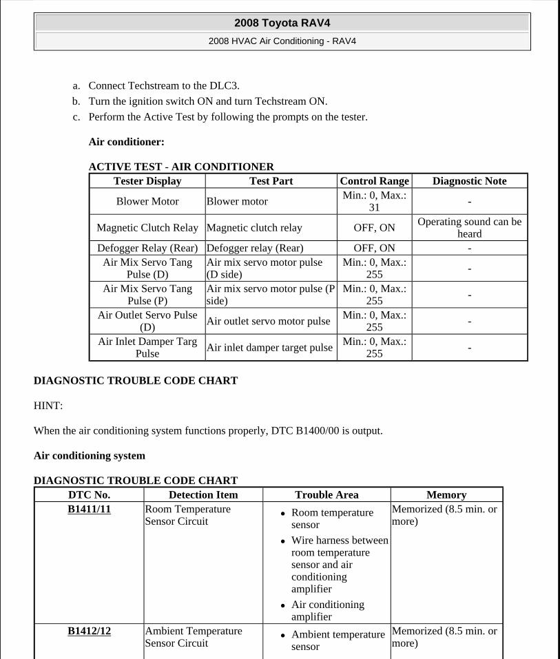
c. Perform the Active Test by following the prompts on the tester.
Air conditioner:
ACTIVE TEST - AIR CONDITIONER
DIAGNOSTIC TROUBLE CODE CHART
HINT:
When the air conditioning system functions properly, DTC B1400/00 is output.
Air conditioning system
DIAGNOSTIC TROUBLE CODE CHART
Tester Display Test Part Control Range Diagnostic Note
Blower Motor Blower motorMin.: 0, Max.:
31-
Magnetic Clutch Relay Magnetic clutch relay OFF, ON Operating sound can be heard
Defogger Relay (Rear) Defogger relay (Rear) OFF, ON -Air Mix Servo Tang
Pulse (D)Air mix servo motor pulse (D side)
Min.: 0, Max.: 255 -
Air Mix Servo Tang Pulse (P)
Air mix servo motor pulse (P side)
Min.: 0, Max.: 255
-
Air Outlet Servo Pulse (D)
Air outlet servo motor pulseMin.: 0, Max.:
255-
Air Inlet Damper Targ Pulse
Air inlet damper target pulse Min.: 0, Max.: 255
-
DTC No. Detection Item Trouble Area MemoryB1411/11 Room Temperature
Sensor Circuit Room temperature
sensor
Wire harness between room temperature sensor and air conditioning amplifier
Air conditioning amplifier
Memorized (8.5 min. or more)
B1412/12 Ambient Temperature Sensor Circuit
Ambient temperature sensor
Memorized (8.5 min. or more)
2008 Toyota RAV4
2008 HVAC Air Conditioning - RAV4
Microsoft
Tuesday, August 18, 2009 3:53:53 PM Page 29 © 2005 Mitchell Repair Information Company, LLC.
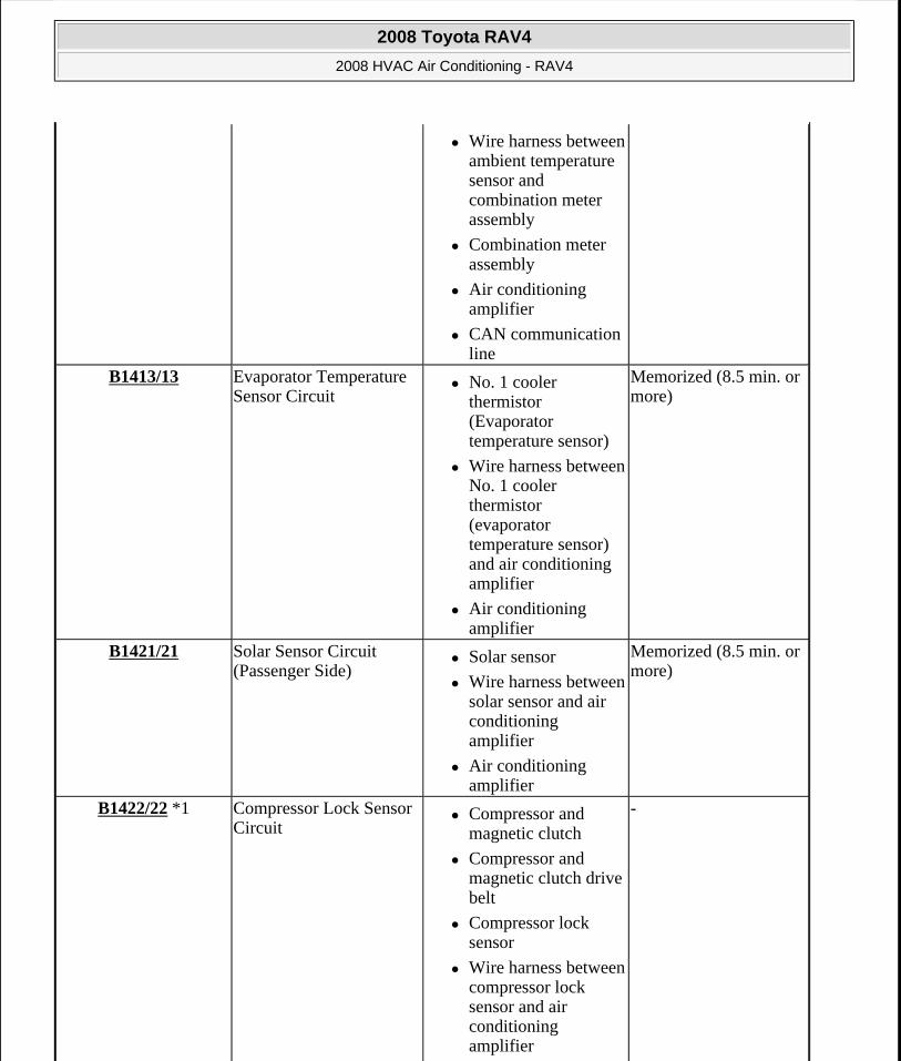
Wire harness between ambient temperature sensor and combination meter assembly
Combination meter assembly
Air conditioning amplifier
CAN communication line
B1413/13 Evaporator Temperature Sensor Circuit
No. 1 cooler thermistor (Evaporator temperature sensor)
Wire harness between No. 1 cooler thermistor (evaporator temperature sensor) and air conditioning amplifier
Air conditioning amplifier
Memorized (8.5 min. or more)
B1421/21 Solar Sensor Circuit (Passenger Side)
Solar sensor
Wire harness between solar sensor and air conditioning amplifier
Air conditioning amplifier
Memorized (8.5 min. or more)
B1422/22 *1 Compressor Lock Sensor Circuit
Compressor and magnetic clutch
Compressor and magnetic clutch drive belt
Compressor lock sensor
Wire harness between compressor lock sensor and air conditioning amplifier
-
2008 Toyota RAV4
2008 HVAC Air Conditioning - RAV4
Microsoft
Tuesday, August 18, 2009 3:53:53 PM Page 30 © 2005 Mitchell Repair Information Company, LLC.
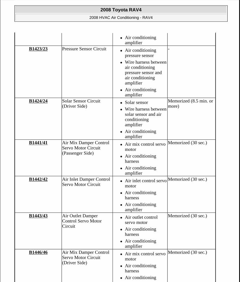
Air conditioning amplifier
B1423/23 Pressure Sensor Circuit Air conditioning pressure sensor
Wire harness between air conditioning pressure sensor and air conditioning amplifier
Air conditioning amplifier
-
B1424/24 Solar Sensor Circuit (Driver Side)
Solar sensor
Wire harness between solar sensor and air conditioning amplifier
Air conditioning amplifier
Memorized (8.5 min. or more)
B1441/41 Air Mix Damper Control Servo Motor Circuit (Passenger Side)
Air mix control servo motor
Air conditioning harness
Air conditioning amplifier
Memorized (30 sec.)
B1442/42 Air Inlet Damper Control Servo Motor Circuit
Air inlet control servo motor
Air conditioning harness
Air conditioning amplifier
Memorized (30 sec.)
B1443/43 Air Outlet Damper Control Servo Motor Circuit
Air outlet control servo motor
Air conditioning harness
Air conditioning amplifier
Memorized (30 sec.)
B1446/46 Air Mix Damper Control Servo Motor Circuit (Driver Side)
Air mix control servo motor
Air conditioning harness
Air conditioning
Memorized (30 sec.)
2008 Toyota RAV4
2008 HVAC Air Conditioning - RAV4
Microsoft
Tuesday, August 18, 2009 3:53:53 PM Page 31 © 2005 Mitchell Repair Information Company, LLC.
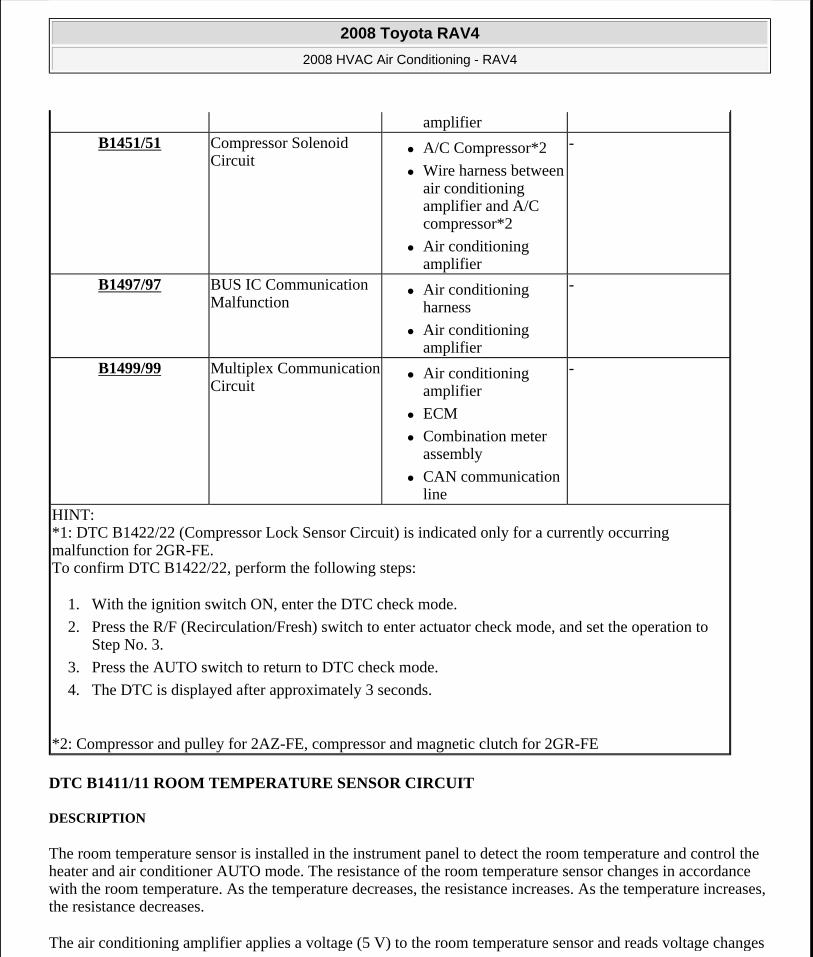
DTC B1411/11 ROOM TEMPERATURE SENSOR CIRCUIT
DESCRIPTION
The room temperature sensor is installed in the instrument panel to detect the room temperature and control the heater and air conditioner AUTO mode. The resistance of the room temperature sensor changes in accordance with the room temperature. As the temperature decreases, the resistance increases. As the temperature increases, the resistance decreases.
The air conditioning amplifier applies a voltage (5 V) to the room temperature sensor and reads voltage changes
amplifier B1451/51 Compressor Solenoid
Circuit A/C Compressor*2
Wire harness between air conditioning amplifier and A/C compressor*2
Air conditioning amplifier
-
B1497/97 BUS IC Communication Malfunction
Air conditioning harness
Air conditioning amplifier
-
B1499/99 Multiplex Communication Circuit
Air conditioning amplifier
ECM
Combination meter assembly
CAN communication line
-
HINT: *1: DTC B1422/22 (Compressor Lock Sensor Circuit) is indicated only for a currently occurring malfunction for 2GR-FE. To confirm DTC B1422/22, perform the following steps:
1. With the ignition switch ON, enter the DTC check mode.
2. Press the R/F (Recirculation/Fresh) switch to enter actuator check mode, and set the operation to Step No. 3.
3. Press the AUTO switch to return to DTC check mode.
4. The DTC is displayed after approximately 3 seconds.
*2: Compressor and pulley for 2AZ-FE, compressor and magnetic clutch for 2GR-FE
2008 Toyota RAV4
2008 HVAC Air Conditioning - RAV4
Microsoft
Tuesday, August 18, 2009 3:53:53 PM Page 32 © 2005 Mitchell Repair Information Company, LLC.
as changes in the resistance of the room temperature sensor.
DTC DETECTION CONDITION AND TROUBLE AREA REFERENCE
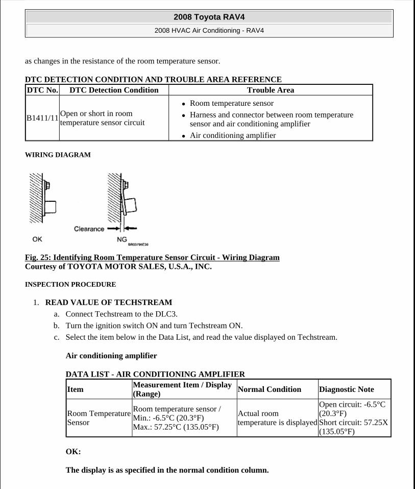
WIRING DIAGRAM
Fig. 25: Identifying Room Temperature Sensor Circuit - Wiring Diagram Courtesy of TOYOTA MOTOR SALES, U.S.A., INC.
INSPECTION PROCEDURE
1. READ VALUE OF TECHSTREAM
a. Connect Techstream to the DLC3.
b. Turn the ignition switch ON and turn Techstream ON.
c. Select the item below in the Data List, and read the value displayed on Techstream.
Air conditioning amplifier
DATA LIST - AIR CONDITIONING AMPLIFIER
OK:
The display is as specified in the normal condition column.
DTC No. DTC Detection Condition Trouble Area
B1411/11Open or short in room temperature sensor circuit
Room temperature sensor
Harness and connector between room temperature sensor and air conditioning amplifier
Air conditioning amplifier
ItemMeasurement Item / Display (Range) Normal Condition Diagnostic Note
Room Temperature Sensor
Room temperature sensor / Min.: -6.5°C (20.3°F) Max.: 57.25°C (135.05°F)
Actual room temperature is displayed
Open circuit: -6.5°C (20.3°F) Short circuit: 57.25X (135.05°F)
2008 Toyota RAV4
2008 HVAC Air Conditioning - RAV4
Microsoft
Tuesday, August 18, 2009 3:53:53 PM Page 33 © 2005 Mitchell Repair Information Company, LLC.
Result
RESULT REFERENCE
B: PROCEED TO NEXT CIRCUIT INSPECTION SHOWN IN PROBLEM SYMPTOMS TABLE
C: REPLACE AIR CONDITIONING AMPLIFIER ASSEMBLY
A: Go to next step
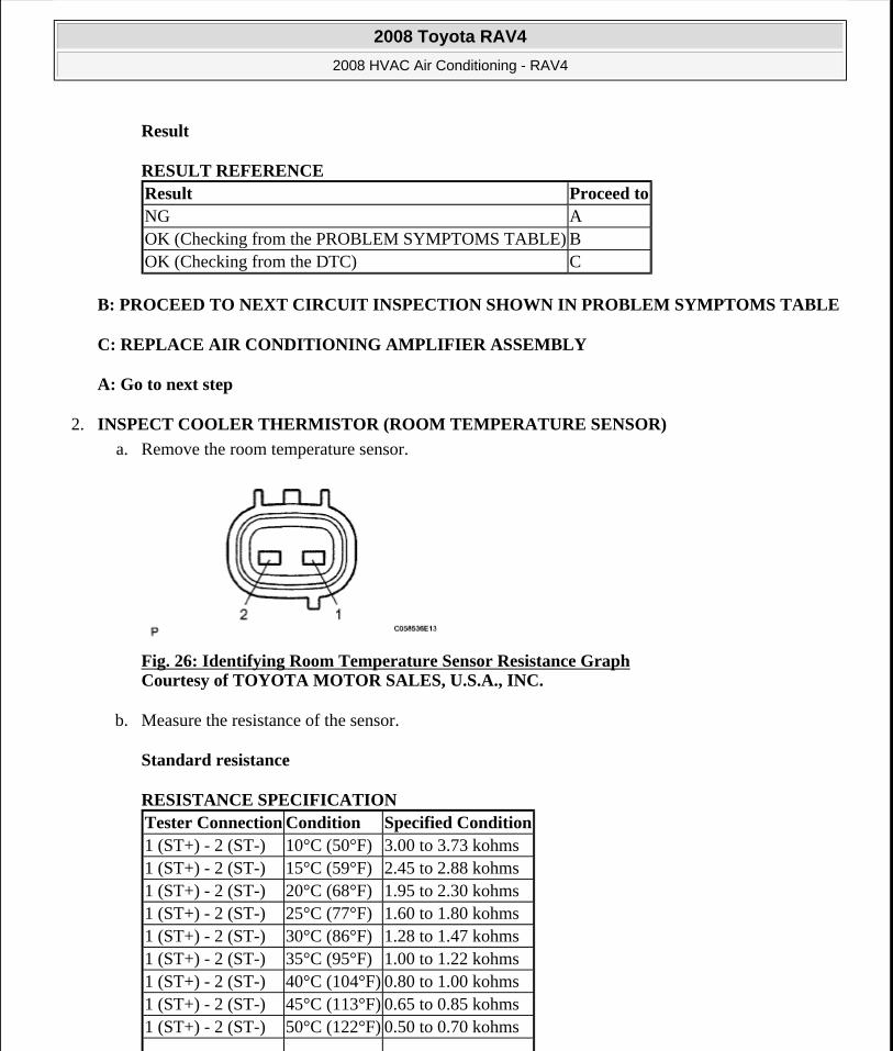
2. INSPECT COOLER THERMISTOR (ROOM TEMPERATURE SENSOR)
a. Remove the room temperature sensor.
Fig. 26: Identifying Room Temperature Sensor Resistance Graph Courtesy of TOYOTA MOTOR SALES, U.S.A., INC.
b. Measure the resistance of the sensor.
Standard resistance
RESISTANCE SPECIFICATION
Result Proceed toNG AOK (Checking from the PROBLEM SYMPTOMS TABLE) BOK (Checking from the DTC) C
Tester Connection Condition Specified Condition1 (ST+) - 2 (ST-) 10°C (50°F) 3.00 to 3.73 kohms1 (ST+) - 2 (ST-) 15°C (59°F) 2.45 to 2.88 kohms1 (ST+) - 2 (ST-) 20°C (68°F) 1.95 to 2.30 kohms1 (ST+) - 2 (ST-) 25°C (77°F) 1.60 to 1.80 kohms1 (ST+) - 2 (ST-) 30°C (86°F) 1.28 to 1.47 kohms1 (ST+) - 2 (ST-) 35°C (95°F) 1.00 to 1.22 kohms1 (ST+) - 2 (ST-) 40°C (104°F) 0.80 to 1.00 kohms1 (ST+) - 2 (ST-) 45°C (113°F) 0.65 to 0.85 kohms1 (ST+) - 2 (ST-) 50°C (122°F) 0.50 to 0.70 kohms
2008 Toyota RAV4
2008 HVAC Air Conditioning - RAV4
Microsoft
Tuesday, August 18, 2009 3:53:53 PM Page 34 © 2005 Mitchell Repair Information Company, LLC.
HINT:
As the temperature increases, the resistance decreases (see the graph ).
NG: REPLACE COOLER THERMISTOR (ROOM TEMPERATURE SENSOR)
OK: Go to next step
3. CHECK WIRE HARNESS (ROOM TEMPERATURE SENSOR - AIR CONDITIONING AMPLIFIER)
a. Disconnect the E21 sensor connector.
b. Disconnect the E37 amplifier connector.
Fig. 27: Identifying E21 And E37 Amplifier Connector Terminals Courtesy of TOYOTA MOTOR SALES, U.S.A., INC.
c. Measure the resistance of the wire harness side connectors.
Standard resistance
RESISTANCE SPECIFICATION
1 (ST+) - 2 (ST-) 55°C (131°F) 0.44 to 0.60 kohms1 (ST+) - 2 (ST-) 60°C (140°F) 0.36 to 0.50 kohms
NOTE: Touching the sensor even slightly may change the resistance value. Be sure to hold the connector of the sensor.
When measuring, the sensor temperature must be the same as the ambient temperature.
Tester Connection Specified ConditionE21-1 (ST+) - E37-29 (TR) Below 1 ohmsE21-2 (ST-) - E37-34 (SG-1) Below 1 ohms
2008 Toyota RAV4
2008 HVAC Air Conditioning - RAV4
Microsoft
Tuesday, August 18, 2009 3:53:53 PM Page 35 © 2005 Mitchell Repair Information Company, LLC.
NG: REPAIR OR REPLACE HARNESS AND CONNECTOR
OK: REPLACE AIR CONDITIONING AMPLIFIER ASSEMBLY
DTC B1412/12 AMBIENT TEMPERATURE SENSOR CIRCUIT
DESCRIPTION
The ambient temperature sensor is installed in the front part of the condenser to detect the ambient temperature and control the air conditioner. The sensor is connected to the combination meter and detects fluctuations in the ambient temperature. This data is used for controlling the room temperature. The sensor sends a signal to the air conditioning amplifier via the combination meter. The resistance of the ambient temperature sensor changes in accordance with the ambient temperature. As the temperature decreases, the resistance increases. As the temperature increases, the resistance decreases.
The air conditioning amplifier applies a voltage (5 V) to the ambient temperature sensor and reads voltage changes as changes in the resistance of the ambient temperature sensor. The combination meter sends the read signal to the air conditioning amplifier via CAN communication.
DTC DETECTION CONDITION AND TROUBLE AREA REFERENCE
WIRING DIAGRAM
E21-1 (ST+) - Body ground 1 Mohms or higherE21-2 (ST-) - Body ground 1 Mohms or higher
DTC No. DTC Detection Condition Trouble Area
B1412/12Open or short in ambient temperature sensor circuit
Ambient temperature sensor
Harness and connector between ambient temperature sensor and combination meter assembly
Combination meter
Air conditioning amplifier
CAN communication line
2008 Toyota RAV4
2008 HVAC Air Conditioning - RAV4
Microsoft
Tuesday, August 18, 2009 3:53:53 PM Page 36 © 2005 Mitchell Repair Information Company, LLC.
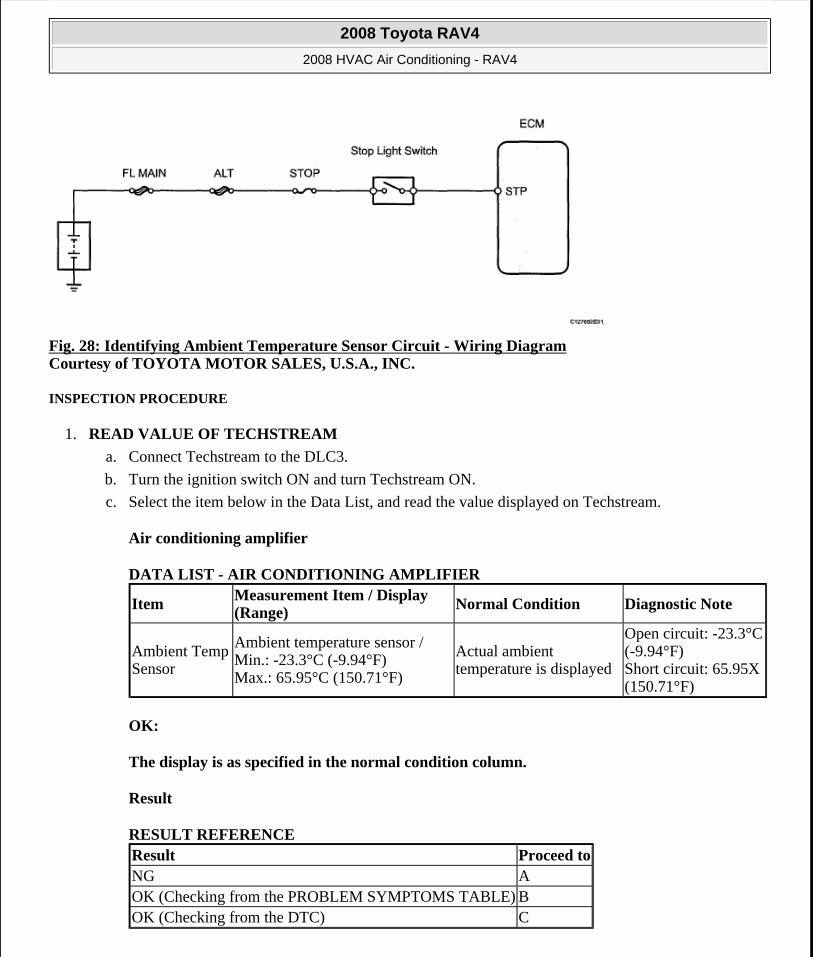
Fig. 28: Identifying Ambient Temperature Sensor Circuit - Wiring Diagram Courtesy of TOYOTA MOTOR SALES, U.S.A., INC.
INSPECTION PROCEDURE
1. READ VALUE OF TECHSTREAM
a. Connect Techstream to the DLC3.
b. Turn the ignition switch ON and turn Techstream ON.
c. Select the item below in the Data List, and read the value displayed on Techstream.
Air conditioning amplifier
DATA LIST - AIR CONDITIONING AMPLIFIER
OK:
The display is as specified in the normal condition column.
Result
RESULT REFERENCE
ItemMeasurement Item / Display (Range) Normal Condition Diagnostic Note
Ambient Temp Sensor
Ambient temperature sensor / Min.: -23.3°C (-9.94°F) Max.: 65.95°C (150.71°F)
Actual ambient temperature is displayed
Open circuit: -23.3°C (-9.94°F) Short circuit: 65.95X (150.71°F)
Result Proceed toNG AOK (Checking from the PROBLEM SYMPTOMS TABLE) BOK (Checking from the DTC) C
2008 Toyota RAV4
2008 HVAC Air Conditioning - RAV4
Microsoft
Tuesday, August 18, 2009 3:53:53 PM Page 37 © 2005 Mitchell Repair Information Company, LLC.
B: PROCEED TO NEXT CIRCUIT INSPECTION SHOWN IN PROBLEM SYMPTOMS TABLE
C: REPLACE AIR CONDITIONING AMPLIFIER
A: Go to next step
2. INSPECT AMBIENT TEMPERATURE SENSOR
a. Remove the ambient temperature sensor.
b. Measure the resistance of the sensor.
Standard resistance
RESISTANCE SPECIFICATION
HINT:
As the temperature increases, the resistance decreases (see the graph ).
Tester Connection Condition Specified Condition1 - 2 10°C (50°F) 3.00 to 3.73 kohms1 - 2 15°C (50°F) 2.45 to 2.88 kohms1 - 2 20°C (68°F) 1.95 to 2.30 kohms1 - 2 25°C (77°F) 1.60 to 1.80 kohms1 - 2 30°C (86°F) 1.28 to 1.47 kohms1 - 2 35°C (95°F) 1.00 to 1.22 kohms1 - 2 40°C (104°F) 0.80 to 1.00 kohms1 - 2 45°C (113°F) 0.65 to 0.85 kohms1 - 2 50°C (122°F) 0.50 to 0.70 kohms1 - 2 55°C (131°F) 0.44 to 0.60 kohms1 - 2 60°C (140°F) 0.36 to 0.50 kohms
NOTE: Touching the sensor even slightly may change the resistance value. Be sure to hold the connector of the sensor.
When measuring, the sensor temperature must be the same as the ambient temperature.
2008 Toyota RAV4
2008 HVAC Air Conditioning - RAV4
Microsoft
Tuesday, August 18, 2009 3:53:53 PM Page 38 © 2005 Mitchell Repair Information Company, LLC.
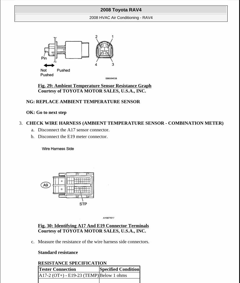
Fig. 29: Ambient Temperature Sensor Resistance Graph Courtesy of TOYOTA MOTOR SALES, U.S.A., INC.
NG: REPLACE AMBIENT TEMPERATURE SENSOR
OK: Go to next step
3. CHECK WIRE HARNESS (AMBIENT TEMPERATURE SENSOR - COMBINATION METER)
a. Disconnect the A17 sensor connector.
b. Disconnect the E19 meter connector.
Fig. 30: Identifying A17 And E19 Connector Terminals Courtesy of TOYOTA MOTOR SALES, U.S.A., INC.
c. Measure the resistance of the wire harness side connectors.
Standard resistance
RESISTANCE SPECIFICATION Tester Connection Specified ConditionA17-2 (OT+) - E19-23 (TEMP) Below 1 ohms
2008 Toyota RAV4
2008 HVAC Air Conditioning - RAV4
Microsoft
Tuesday, August 18, 2009 3:53:53 PM Page 39 © 2005 Mitchell Repair Information Company, LLC.
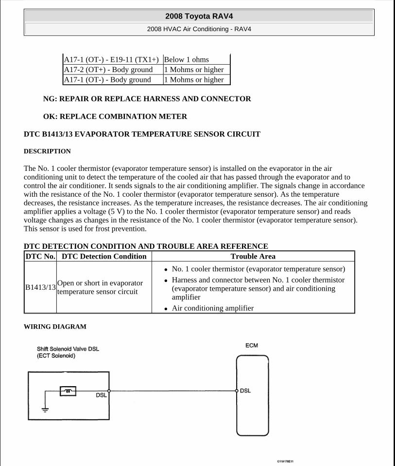
NG: REPAIR OR REPLACE HARNESS AND CONNECTOR
OK: REPLACE COMBINATION METER
DTC B1413/13 EVAPORATOR TEMPERATURE SENSOR CIRCUIT
DESCRIPTION
The No. 1 cooler thermistor (evaporator temperature sensor) is installed on the evaporator in the air conditioning unit to detect the temperature of the cooled air that has passed through the evaporator and to control the air conditioner. It sends signals to the air conditioning amplifier. The signals change in accordance with the resistance of the No. 1 cooler thermistor (evaporator temperature sensor). As the temperature decreases, the resistance increases. As the temperature increases, the resistance decreases. The air conditioning amplifier applies a voltage (5 V) to the No. 1 cooler thermistor (evaporator temperature sensor) and reads voltage changes as changes in the resistance of the No. 1 cooler thermistor (evaporator temperature sensor). This sensor is used for frost prevention.
DTC DETECTION CONDITION AND TROUBLE AREA REFERENCE
WIRING DIAGRAM
A17-1 (OT-) - E19-11 (TX1+) Below 1 ohmsA17-2 (OT+) - Body ground 1 Mohms or higherA17-1 (OT-) - Body ground 1 Mohms or higher
DTC No. DTC Detection Condition Trouble Area
B1413/13Open or short in evaporator temperature sensor circuit
No. 1 cooler thermistor (evaporator temperature sensor)
Harness and connector between No. 1 cooler thermistor (evaporator temperature sensor) and air conditioning amplifier
Air conditioning amplifier
2008 Toyota RAV4
2008 HVAC Air Conditioning - RAV4
Microsoft
Tuesday, August 18, 2009 3:53:53 PM Page 40 © 2005 Mitchell Repair Information Company, LLC.
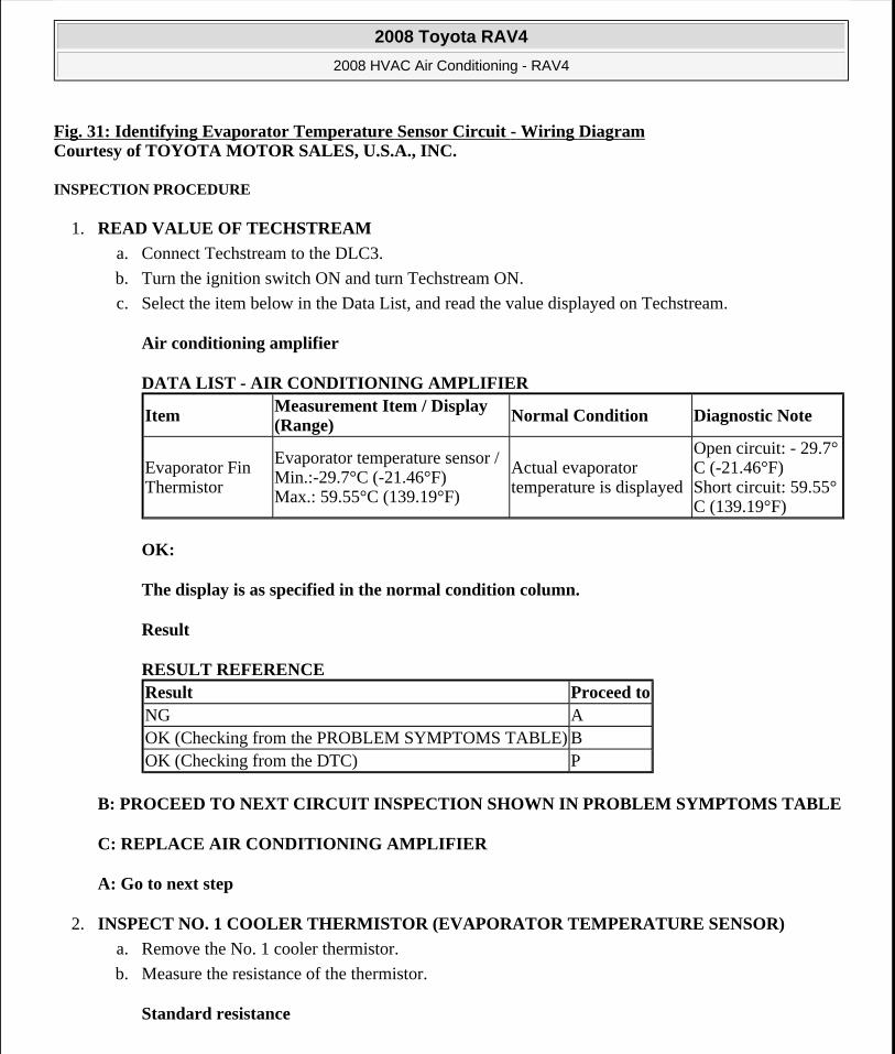
Fig. 31: Identifying Evaporator Temperature Sensor Circuit - Wiring Diagram Courtesy of TOYOTA MOTOR SALES, U.S.A., INC.
INSPECTION PROCEDURE
1. READ VALUE OF TECHSTREAM
a. Connect Techstream to the DLC3.
b. Turn the ignition switch ON and turn Techstream ON.
c. Select the item below in the Data List, and read the value displayed on Techstream.
Air conditioning amplifier
DATA LIST - AIR CONDITIONING AMPLIFIER
OK:
The display is as specified in the normal condition column.
Result
RESULT REFERENCE
B: PROCEED TO NEXT CIRCUIT INSPECTION SHOWN IN PROBLEM SYMPTOMS TABLE
C: REPLACE AIR CONDITIONING AMPLIFIER
A: Go to next step
2. INSPECT NO. 1 COOLER THERMISTOR (EVAPORATOR TEMPERATURE SENSOR)
a. Remove the No. 1 cooler thermistor.
b. Measure the resistance of the thermistor.
Standard resistance
ItemMeasurement Item / Display (Range)
Normal Condition Diagnostic Note
Evaporator Fin Thermistor
Evaporator temperature sensor / Min.:-29.7°C (-21.46°F) Max.: 59.55°C (139.19°F)
Actual evaporator temperature is displayed
Open circuit: - 29.7°C (-21.46°F) Short circuit: 59.55°C (139.19°F)
Result Proceed toNG AOK (Checking from the PROBLEM SYMPTOMS TABLE) BOK (Checking from the DTC) P
2008 Toyota RAV4
2008 HVAC Air Conditioning - RAV4
Microsoft
Tuesday, August 18, 2009 3:53:53 PM Page 41 © 2005 Mitchell Repair Information Company, LLC.
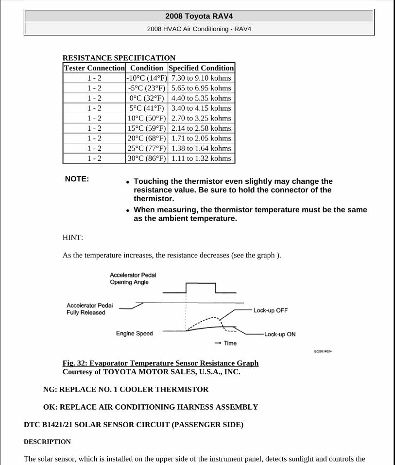
RESISTANCE SPECIFICATION
HINT:
As the temperature increases, the resistance decreases (see the graph ).
Fig. 32: Evaporator Temperature Sensor Resistance Graph Courtesy of TOYOTA MOTOR SALES, U.S.A., INC.
NG: REPLACE NO. 1 COOLER THERMISTOR
OK: REPLACE AIR CONDITIONING HARNESS ASSEMBLY
DTC B1421/21 SOLAR SENSOR CIRCUIT (PASSENGER SIDE)
DESCRIPTION
The solar sensor, which is installed on the upper side of the instrument panel, detects sunlight and controls the
Tester Connection Condition Specified Condition1 - 2 -10°C (14°F) 7.30 to 9.10 kohms1 - 2 -5°C (23°F) 5.65 to 6.95 kohms1 - 2 0°C (32°F) 4.40 to 5.35 kohms1 - 2 5°C (41°F) 3.40 to 4.15 kohms1 - 2 10°C (50°F) 2.70 to 3.25 kohms1 - 2 15°C (59°F) 2.14 to 2.58 kohms1 - 2 20°C (68°F) 1.71 to 2.05 kohms1 - 2 25°C (77°F) 1.38 to 1.64 kohms1 - 2 30°C (86°F) 1.11 to 1.32 kohms
NOTE: Touching the thermistor even slightly may change the resistance value. Be sure to hold the connector of the thermistor.
When measuring, the thermistor temperature must be the same as the ambient temperature.
2008 Toyota RAV4
2008 HVAC Air Conditioning - RAV4
Microsoft
Tuesday, August 18, 2009 3:53:53 PM Page 42 © 2005 Mitchell Repair Information Company, LLC.
air conditioning AUTO mode. The output voltage from the solar sensor varies in accordance with the amount of sunlight. When the sunlight increases, the output voltage increases. As the sunlight decreases, the output voltage decreases.
The air conditioning amplifier detects changes in the output voltage from the solar sensor.
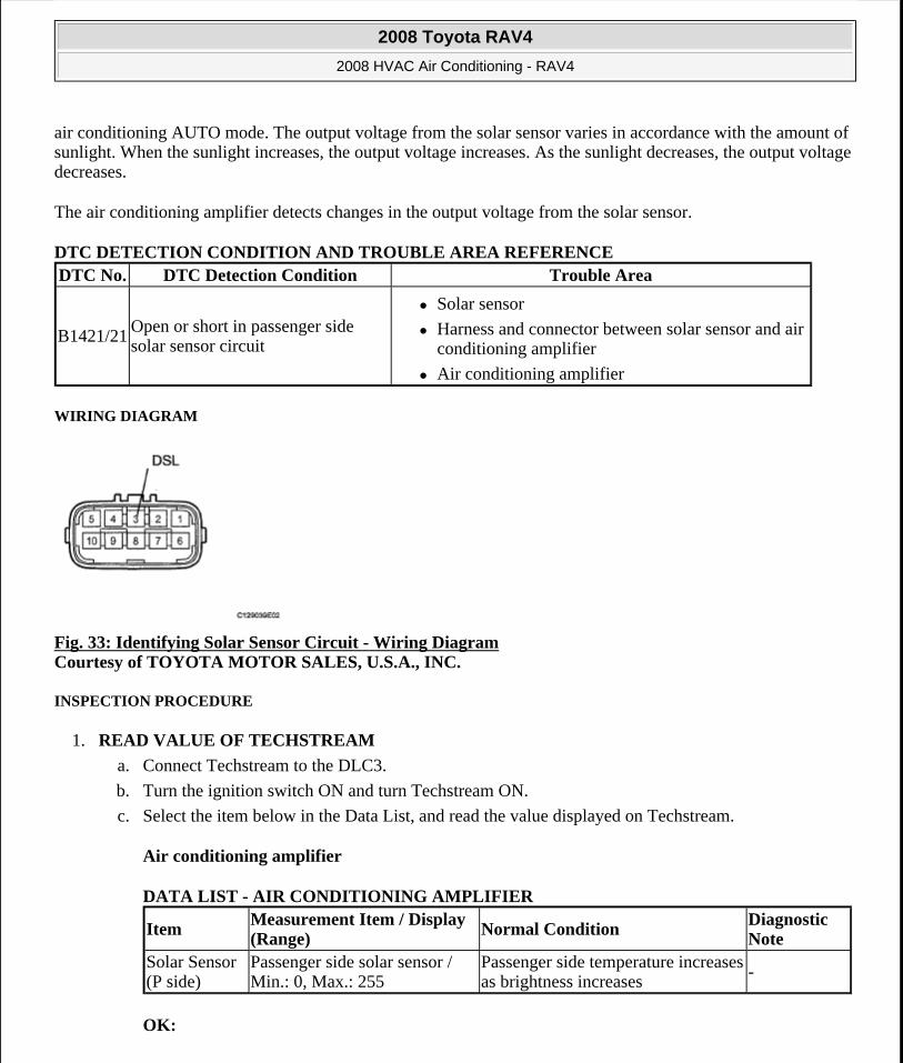
DTC DETECTION CONDITION AND TROUBLE AREA REFERENCE
WIRING DIAGRAM
Fig. 33: Identifying Solar Sensor Circuit - Wiring Diagram Courtesy of TOYOTA MOTOR SALES, U.S.A., INC.
INSPECTION PROCEDURE
1. READ VALUE OF TECHSTREAM
a. Connect Techstream to the DLC3.
b. Turn the ignition switch ON and turn Techstream ON.
c. Select the item below in the Data List, and read the value displayed on Techstream.
Air conditioning amplifier
DATA LIST - AIR CONDITIONING AMPLIFIER
OK:
DTC No. DTC Detection Condition Trouble Area
B1421/21Open or short in passenger side solar sensor circuit
Solar sensor
Harness and connector between solar sensor and air conditioning amplifier
Air conditioning amplifier
ItemMeasurement Item / Display (Range)
Normal ConditionDiagnostic Note
Solar Sensor (P side)
Passenger side solar sensor / Min.: 0, Max.: 255
Passenger side temperature increases as brightness increases
-
2008 Toyota RAV4
2008 HVAC Air Conditioning - RAV4
Microsoft
Tuesday, August 18, 2009 3:53:53 PM Page 43 © 2005 Mitchell Repair Information Company, LLC.
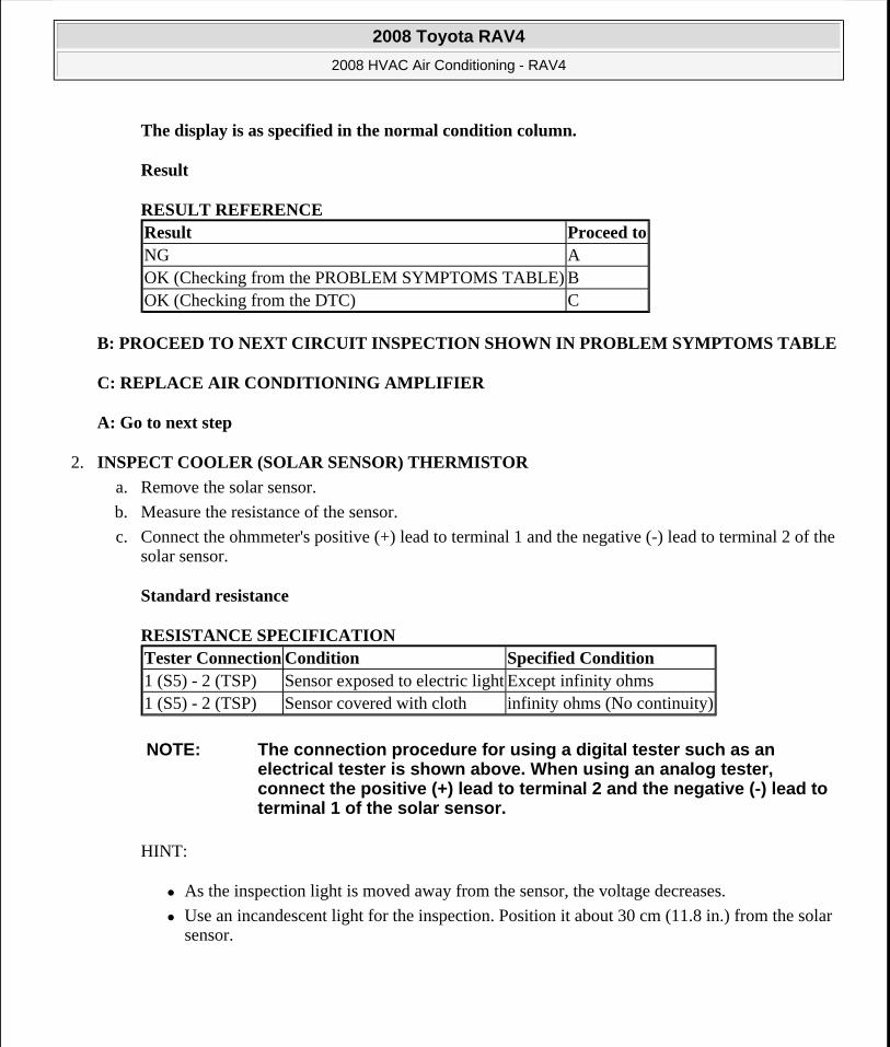
The display is as specified in the normal condition column.
Result
RESULT REFERENCE
B: PROCEED TO NEXT CIRCUIT INSPECTION SHOWN IN PROBLEM SYMPTOMS TABLE
C: REPLACE AIR CONDITIONING AMPLIFIER
A: Go to next step
2. INSPECT COOLER (SOLAR SENSOR) THERMISTOR
a. Remove the solar sensor.
b. Measure the resistance of the sensor.
c. Connect the ohmmeter's positive (+) lead to terminal 1 and the negative (-) lead to terminal 2 of the solar sensor.
Standard resistance
RESISTANCE SPECIFICATION
HINT:
As the inspection light is moved away from the sensor, the voltage decreases.
Use an incandescent light for the inspection. Position it about 30 cm (11.8 in.) from the solar sensor.
Result Proceed toNG AOK (Checking from the PROBLEM SYMPTOMS TABLE) BOK (Checking from the DTC) C
Tester Connection Condition Specified Condition1 (S5) - 2 (TSP) Sensor exposed to electric light Except infinity ohms1 (S5) - 2 (TSP) Sensor covered with cloth infinity ohms (No continuity)
NOTE: The connection procedure for using a digital tester such as an electrical tester is shown above. When using an analog tester, connect the positive (+) lead to terminal 2 and the negative (-) lead to terminal 1 of the solar sensor.
2008 Toyota RAV4
2008 HVAC Air Conditioning - RAV4
Microsoft
Tuesday, August 18, 2009 3:53:53 PM Page 44 © 2005 Mitchell Repair Information Company, LLC.
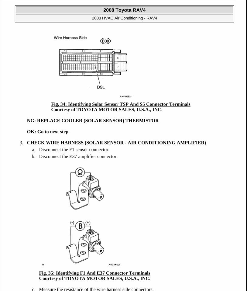
Fig. 34: Identifying Solar Sensor TSP And S5 Connector Terminals Courtesy of TOYOTA MOTOR SALES, U.S.A., INC.
NG: REPLACE COOLER (SOLAR SENSOR) THERMISTOR
OK: Go to next step
3. CHECK WIRE HARNESS (SOLAR SENSOR - AIR CONDITIONING AMPLIFIER)
a. Disconnect the F1 sensor connector.
b. Disconnect the E37 amplifier connector.
Fig. 35: Identifying F1 And E37 Connector Terminals Courtesy of TOYOTA MOTOR SALES, U.S.A., INC.
c. Measure the resistance of the wire harness side connectors.
2008 Toyota RAV4
2008 HVAC Air Conditioning - RAV4
Microsoft
Tuesday, August 18, 2009 3:53:53 PM Page 45 © 2005 Mitchell Repair Information Company, LLC.
Standard resistance
RESISTANCE SPECIFICATION
NG: REPAIR OR REPLACE HARNESS AND CONNECTOR
OK: REPLACE AIR CONDITIONING AMPLIFIER
DTC B1422/22 COMPRESSOR LOCK SENSOR CIRCUIT
DESCRIPTION
This sensor sends 1 pulse per engine revolution to the air conditioning amplifier. If the ratio of the compressor speed divided by the engine speed is smaller than a predetermined value, the air conditioning amplifier turns the compressor off, and the indicator blinks at approximately 1 second intervals.
DTC DETECTION CONDITION AND TROUBLE AREA REFERENCE
WIRING DIAGRAM
Tester Connection Specified ConditionE37-32 (TSP) - F1 - 2 (TSP) Below 1 ohmsE37-31 (S5-4) - F1-1 (S5) Below 1 ohmsE37-32 (TSP) - Body ground 1 Mohms or higherE37-31 (S5-4) - Body ground 1 Mohms or higher
DTC No. DTC Detection Condition Trouble Area
B1422/22
Open or short in compressor lock sensor circuit All conditions below are detected for 3 seconds or more:
1. Engine speed: 450 rpm or more
2. Ratio between engine and compressor speed deviates 20% or more in comparison to normal operation
Compressor and magnetic clutch
Compressor and magnetic clutch drive belt
Compressor lock sensor
Wire harness between compressor lock sensor and air conditioning amplifier
Air conditioning amplifier
2008 Toyota RAV4
2008 HVAC Air Conditioning - RAV4
Microsoft
Tuesday, August 18, 2009 3:53:53 PM Page 46 © 2005 Mitchell Repair Information Company, LLC.
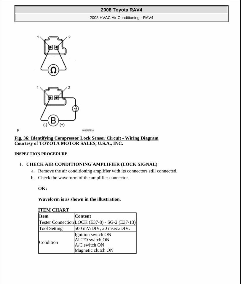
Fig. 36: Identifying Compressor Lock Sensor Circuit - Wiring Diagram Courtesy of TOYOTA MOTOR SALES, U.S.A., INC.
INSPECTION PROCEDURE
1. CHECK AIR CONDITIONING AMPLIFIER (LOCK SIGNAL)
a. Remove the air conditioning amplifier with its connectors still connected.
b. Check the waveform of the amplifier connector.
OK:
Waveform is as shown in the illustration.
ITEM CHART Item ContentTester Connection LOCK (E37-8) - SG-2 (E37-13)Tool Setting 500 mV/DIV, 20 msec./DIV.
Condition
Ignition switch ON AUTO switch ON A/C switch ON Magnetic clutch ON
2008 Toyota RAV4
2008 HVAC Air Conditioning - RAV4
Microsoft
Tuesday, August 18, 2009 3:53:53 PM Page 47 © 2005 Mitchell Repair Information Company, LLC.

Fig. 37: Air Conditioning Amplifier Waveform Graph Courtesy of TOYOTA MOTOR SALES, U.S.A., INC.
Result
RESULT REFERENCE
B: PROCEED TO NEXT CIRCUIT INSPECTION SHOWN IN PROBLEM SYMPTOMS TABLE
C: REPLACE AIR CONDITIONING AMPLIFIER
A: Go to next step
2. INSPECT COMPRESSOR LOCK SENSOR
a. Disconnect the B47 compressor lock sensor connector.
Result Proceed toNG AOK (Checking from the PROBLEM SYMPTOMS TABLE) BOK (Checking from the DTC) C
2008 Toyota RAV4
2008 HVAC Air Conditioning - RAV4
Microsoft
Tuesday, August 18, 2009 3:53:53 PM Page 48 © 2005 Mitchell Repair Information Company, LLC.
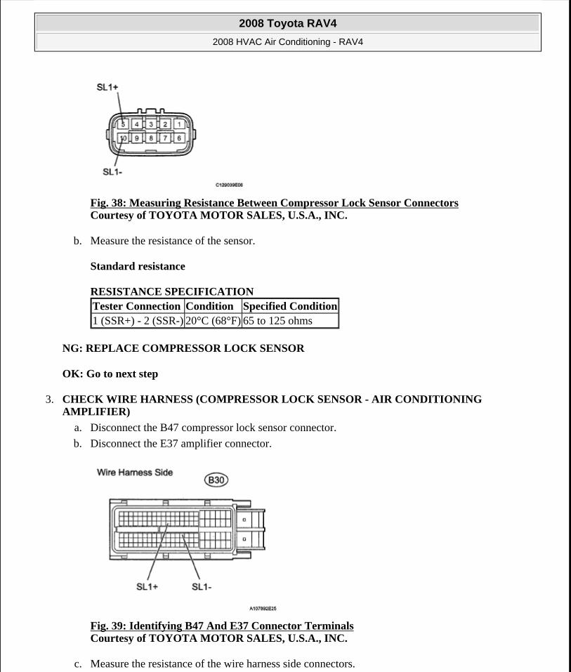
Fig. 38: Measuring Resistance Between Compressor Lock Sensor Connectors Courtesy of TOYOTA MOTOR SALES, U.S.A., INC.
b. Measure the resistance of the sensor.
Standard resistance
RESISTANCE SPECIFICATION
NG: REPLACE COMPRESSOR LOCK SENSOR
OK: Go to next step
3. CHECK WIRE HARNESS (COMPRESSOR LOCK SENSOR - AIR CONDITIONING AMPLIFIER)
a. Disconnect the B47 compressor lock sensor connector.
b. Disconnect the E37 amplifier connector.
Fig. 39: Identifying B47 And E37 Connector Terminals Courtesy of TOYOTA MOTOR SALES, U.S.A., INC.
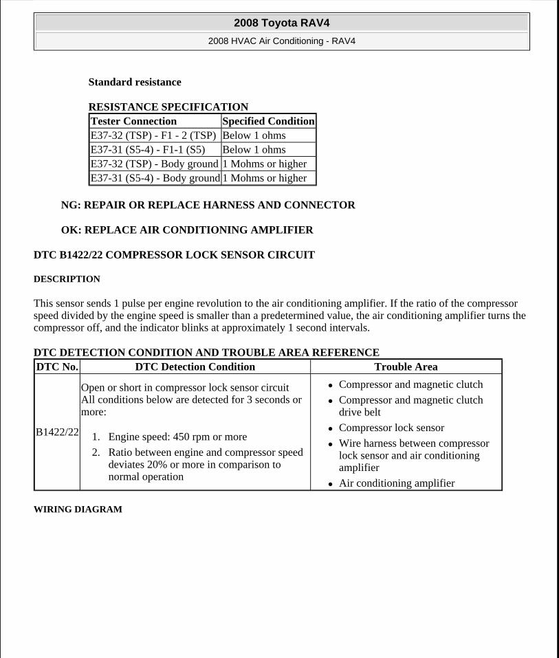
c. Measure the resistance of the wire harness side connectors.
Tester Connection Condition Specified Condition1 (SSR+) - 2 (SSR-) 20°C (68°F) 65 to 125 ohms
2008 Toyota RAV4
2008 HVAC Air Conditioning - RAV4
Microsoft
Tuesday, August 18, 2009 3:53:53 PM Page 49 © 2005 Mitchell Repair Information Company, LLC.
Standard resistance
RESISTANCE SPECIFICATION
NG: REPAIR OR REPLACE HARNESS AND CONNECTOR
OK: REPLACE AIR CONDITIONING AMPLIFIER
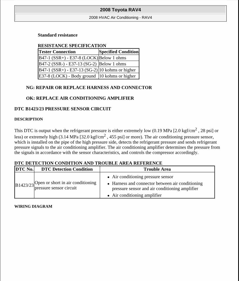
DTC B1423/23 PRESSURE SENSOR CIRCUIT
DESCRIPTION
This DTC is output when the refrigerant pressure is either extremely low (0.19 MPa [2.0 kgf/cm2 , 28 psi] or less) or extremely high (3.14 MPa [32.0 kgf/cm2 , 455 psi] or more). The air conditioning pressure sensor, which is installed on the pipe of the high pressure side, detects the refrigerant pressure and sends refrigerant pressure signals to the air conditioning amplifier. The air conditioning amplifier determines the pressure from the signals in accordance with the sensor characteristics, and controls the compressor accordingly.
DTC DETECTION CONDITION AND TROUBLE AREA REFERENCE
WIRING DIAGRAM
Tester Connection Specified ConditionB47-1 (SSR+) - E37-8 (LOCK) Below 1 ohmsB47-2 (SSR-) - E37-13 (SG-2) Below 1 ohmsB47-1 (SSR+) - E37-13 (SG-2) 10 kohms or higherE37-8 (LOCK) - Body ground 10 kohms or higher
DTC No. DTC Detection Condition Trouble Area
B1423/23Open or short in air conditioning pressure sensor circuit
Air conditioning pressure sensor
Harness and connector between air conditioning pressure sensor and air conditioning amplifier
Air conditioning amplifier
2008 Toyota RAV4
2008 HVAC Air Conditioning - RAV4
Microsoft
Tuesday, August 18, 2009 3:53:53 PM Page 50 © 2005 Mitchell Repair Information Company, LLC.
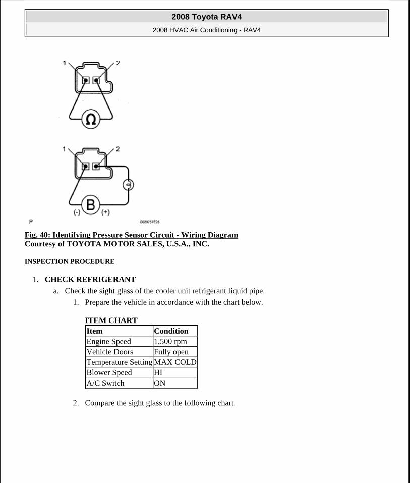
Fig. 40: Identifying Pressure Sensor Circuit - Wiring Diagram Courtesy of TOYOTA MOTOR SALES, U.S.A., INC.
INSPECTION PROCEDURE
1. CHECK REFRIGERANT
a. Check the sight glass of the cooler unit refrigerant liquid pipe.
1. Prepare the vehicle in accordance with the chart below.
ITEM CHART
2. Compare the sight glass to the following chart.
Item ConditionEngine Speed 1,500 rpmVehicle Doors Fully openTemperature Setting MAX COLDBlower Speed HIA/C Switch ON
2008 Toyota RAV4
2008 HVAC Air Conditioning - RAV4
Microsoft
Tuesday, August 18, 2009 3:53:53 PM Page 51 © 2005 Mitchell Repair Information Company, LLC.
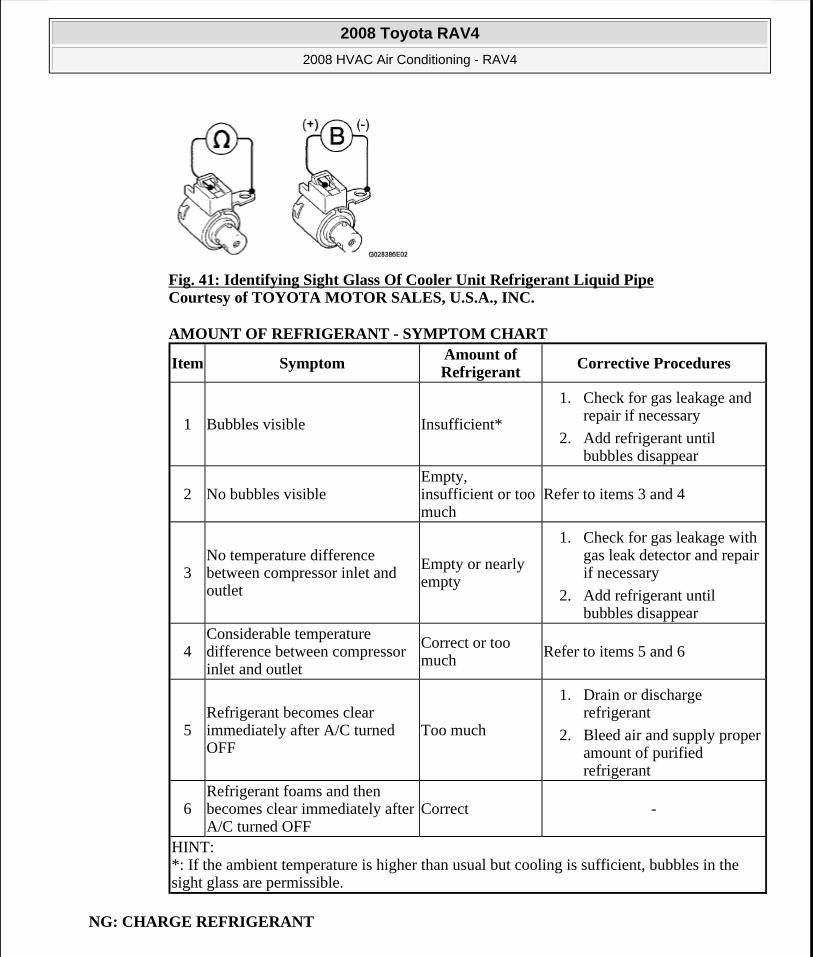
Fig. 41: Identifying Sight Glass Of Cooler Unit Refrigerant Liquid Pipe Courtesy of TOYOTA MOTOR SALES, U.S.A., INC.
AMOUNT OF REFRIGERANT - SYMPTOM CHART
NG: CHARGE REFRIGERANT
Item SymptomAmount of Refrigerant
Corrective Procedures
1 Bubbles visible Insufficient*
1. Check for gas leakage and repair if necessary
2. Add refrigerant until bubbles disappear
2 No bubbles visibleEmpty, insufficient or too much
Refer to items 3 and 4
3No temperature difference between compressor inlet and outlet
Empty or nearly empty
1. Check for gas leakage with gas leak detector and repair if necessary
2. Add refrigerant until bubbles disappear
4Considerable temperature difference between compressor inlet and outlet
Correct or too much
Refer to items 5 and 6
5Refrigerant becomes clear immediately after A/C turned OFF
Too much
1. Drain or discharge refrigerant
2. Bleed air and supply proper amount of purified refrigerant
6Refrigerant foams and then becomes clear immediately after A/C turned OFF
Correct -
HINT: *: If the ambient temperature is higher than usual but cooling is sufficient, bubbles in the sight glass are permissible.
2008 Toyota RAV4
2008 HVAC Air Conditioning - RAV4
Microsoft
Tuesday, August 18, 2009 3:53:53 PM Page 52 © 2005 Mitchell Repair Information Company, LLC.
OK: Go to next step
2. READ VALUE OF TECHSTREAM
a. Connect Techstream to the DLC3.
b. Turn the ignition switch ON and turn Techstream ON.
c. Select the item below in the Data List, and read the value displayed on Techstream.
Air conditioning amplifier
DATA LIST - AIR CONDITIONING AMPLIFIER
OK:
The display is as specified in the normal condition column.
Result
RESULT REFERENCE
B: PROCEED TO NEXT CIRCUIT INSPECTION SHOWN IN PROBLEM SYMPTOMS TABLE
C: REPLACE AIR CONDITIONING AMPLIFIER
A: Go to next step
3. CHECK WIRE HARNESS (PRESSURE SENSOR - AIR CONDITIONING AMPLIFIER)
a. Disconnect the A21 pressure sensor connector.
b. Disconnect the E37 amplifier connector.
Item Measurement Item / Display (Range)
Normal Condition Diagnostic Note
Regulator Pressure Sensor
Regulator pressure sensor / Min.: -0.45668 MPaG Max.: 3.29437 MPaG
Actual regulator pressure is displayed -
Result Proceed toNG AOK (Checking from the PROBLEM SYMPTOMS TABLE) BOK (Checking from the DTC) C
2008 Toyota RAV4
2008 HVAC Air Conditioning - RAV4
Microsoft
Tuesday, August 18, 2009 3:53:53 PM Page 53 © 2005 Mitchell Repair Information Company, LLC.
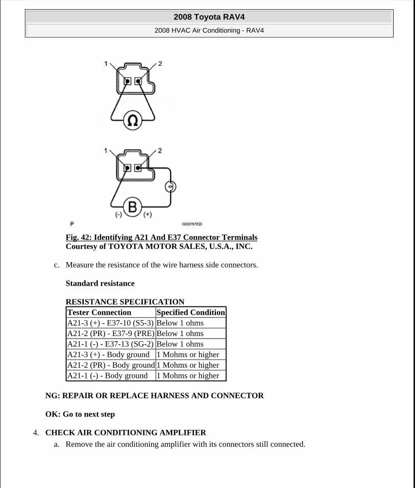
Fig. 42: Identifying A21 And E37 Connector Terminals Courtesy of TOYOTA MOTOR SALES, U.S.A., INC.
c. Measure the resistance of the wire harness side connectors.
Standard resistance
RESISTANCE SPECIFICATION
NG: REPAIR OR REPLACE HARNESS AND CONNECTOR
OK: Go to next step
4. CHECK AIR CONDITIONING AMPLIFIER
a. Remove the air conditioning amplifier with its connectors still connected.
Tester Connection Specified ConditionA21-3 (+) - E37-10 (S5-3) Below 1 ohmsA21-2 (PR) - E37-9 (PRE) Below 1 ohmsA21-1 (-) - E37-13 (SG-2) Below 1 ohmsA21-3 (+) - Body ground 1 Mohms or higherA21-2 (PR) - Body ground 1 Mohms or higherA21-1 (-) - Body ground 1 Mohms or higher
2008 Toyota RAV4
2008 HVAC Air Conditioning - RAV4
Microsoft
Tuesday, August 18, 2009 3:53:53 PM Page 54 © 2005 Mitchell Repair Information Company, LLC.
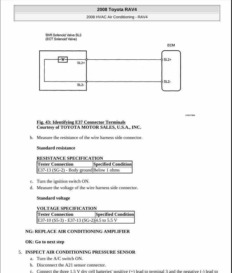
Fig. 43: Identifying E37 Connector Terminals Courtesy of TOYOTA MOTOR SALES, U.S.A., INC.
b. Measure the resistance of the wire harness side connector.
Standard resistance
RESISTANCE SPECIFICATION
c. Turn the ignition switch ON.
d. Measure the voltage of the wire harness side connector.
Standard voltage
VOLTAGE SPECIFICATION
NG: REPLACE AIR CONDITIONING AMPLIFIER
OK: Go to next step
5. INSPECT AIR CONDITIONING PRESSURE SENSOR
a. Turn the A/C switch ON.
b. Disconnect the A21 sensor connector.
c. Connect the three 1.5 V dry cell batteries' positive (+) lead to terminal 3 and the negative (-) lead to
Tester Connection Specified ConditionE37-13 (SG-2) - Body ground Below 1 ohms
Tester Connection Specified ConditionE37-10 (S5-3) - E37-13 (SG-2) 4.5 to 5.5 V
2008 Toyota RAV4
2008 HVAC Air Conditioning - RAV4
Microsoft
Tuesday, August 18, 2009 3:53:54 PM Page 55 © 2005 Mitchell Repair Information Company, LLC.

terminal 1. Then connect the voltmeter's positive (+) lead to terminal 2 and the negative (-) lead to terminal 1. Measure the voltage.
OK:
The voltage changes in accordance with the refrigerant pressure as shown in the graph.
Fig. 44: Measuring Resistance Between Air Conditioning Amplifier Terminals Courtesy of TOYOTA MOTOR SALES, U.S.A., INC.
NG: REPLACE AIR CONDITIONING PRESSURE SENSOR
OK: REPLACE AIR CONDITIONING AMPLIFIER
DTC B1424/24 SOLAR SENSOR CIRCUIT (DRIVER SIDE)
DESCRIPTION
The solar sensor, which is installed on the upper side of the instrument panel, detects sunlight and controls the air conditioning AUTO mode. The output voltage from the solar sensor varies in accordance with the amount of sunlight. When the sunlight increases, the output voltage increases. As the sunlight decreases, the output voltage decreases.
The air conditioning amplifier detects changes in the output voltage from the solar sensor.
DTC DETECTION CONDITION AND TROUBLE AREA REFERENCE
WIRING DIAGRAM
DTC No. DTC Detection Condition Trouble Area
B1424/24Open or short in passenger side solar sensor circuit
Solar sensor
Harness and connector between solar sensor and air conditioning amplifier
Air conditioning amplifier
2008 Toyota RAV4
2008 HVAC Air Conditioning - RAV4
Microsoft
Tuesday, August 18, 2009 3:53:54 PM Page 56 © 2005 Mitchell Repair Information Company, LLC.
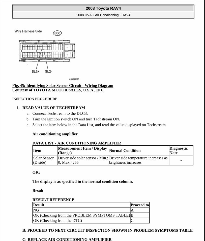
Fig. 45: Identifying Solar Sensor Circuit - Wiring Diagram Courtesy of TOYOTA MOTOR SALES, U.S.A., INC.
INSPECTION PROCEDURE
1. READ VALUE OF TECHSTREAM
a. Connect Techstream to the DLC3.
b. Turn the ignition switch ON and turn Techstream ON.
c. Select the item below in the Data List, and read the value displayed on Techstream.
Air conditioning amplifier
DATA LIST - AIR CONDITIONING AMPLIFIER
OK:
The display is as specified in the normal condition column.
Result
RESULT REFERENCE
B: PROCEED TO NEXT CIRCUIT INSPECTION SHOWN IN PROBLEM SYMPTOMS TABLE
C: REPLACE AIR CONDITIONING AMPLIFIER
Item Measurement Item / Display (Range)
Normal Condition Diagnostic Note
Solar Sensor (D side)
Driver side solar sensor / Min.: 0, Max.: 255
Driver side temperature increases as brightness increases -
Result Proceed toNG AOK (Checking from the PROBLEM SYMPTOMS TABLE) BOK (Checking from the DTC) C
2008 Toyota RAV4
2008 HVAC Air Conditioning - RAV4
Microsoft
Tuesday, August 18, 2009 3:53:54 PM Page 57 © 2005 Mitchell Repair Information Company, LLC.
A: Go to next step
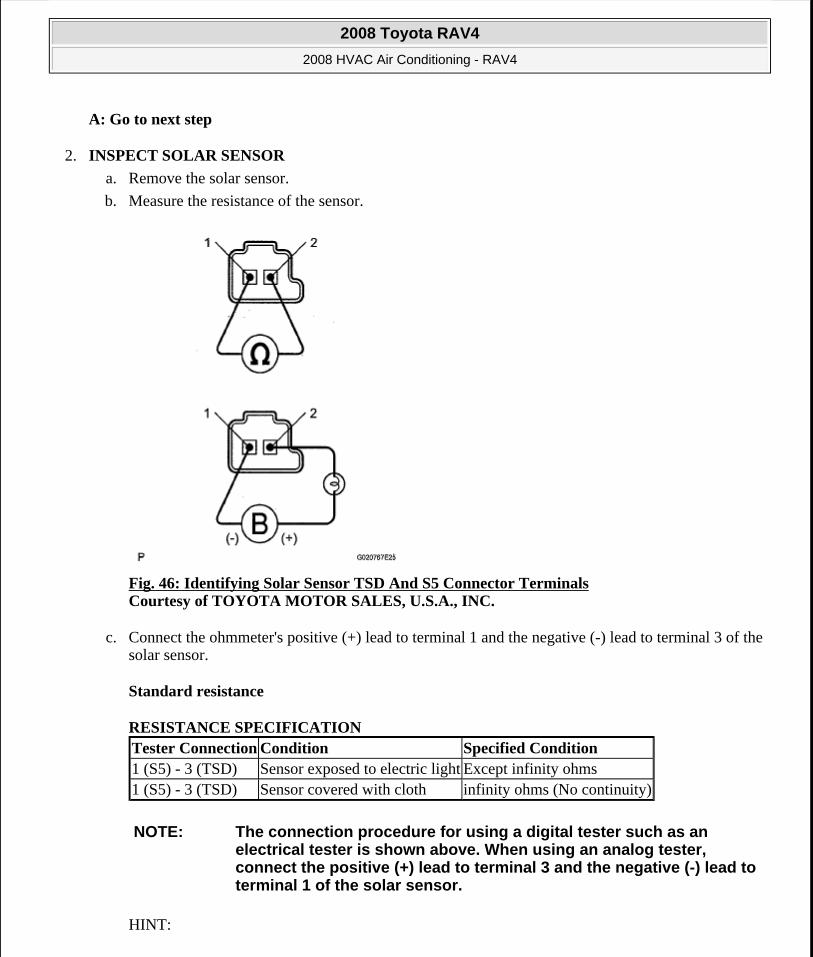
2. INSPECT SOLAR SENSOR
a. Remove the solar sensor.
b. Measure the resistance of the sensor.
Fig. 46: Identifying Solar Sensor TSD And S5 Connector Terminals Courtesy of TOYOTA MOTOR SALES, U.S.A., INC.
c. Connect the ohmmeter's positive (+) lead to terminal 1 and the negative (-) lead to terminal 3 of the solar sensor.
Standard resistance
RESISTANCE SPECIFICATION
HINT:
Tester Connection Condition Specified Condition1 (S5) - 3 (TSD) Sensor exposed to electric light Except infinity ohms1 (S5) - 3 (TSD) Sensor covered with cloth infinity ohms (No continuity)
NOTE: The connection procedure for using a digital tester such as an electrical tester is shown above. When using an analog tester, connect the positive (+) lead to terminal 3 and the negative (-) lead to terminal 1 of the solar sensor.
2008 Toyota RAV4
2008 HVAC Air Conditioning - RAV4
Microsoft
Tuesday, August 18, 2009 3:53:54 PM Page 58 © 2005 Mitchell Repair Information Company, LLC.
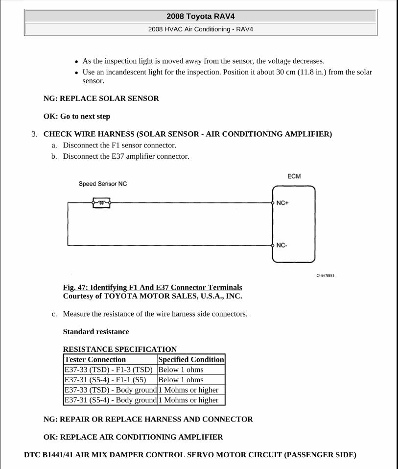
As the inspection light is moved away from the sensor, the voltage decreases.
Use an incandescent light for the inspection. Position it about 30 cm (11.8 in.) from the solar sensor.
NG: REPLACE SOLAR SENSOR
OK: Go to next step
3. CHECK WIRE HARNESS (SOLAR SENSOR - AIR CONDITIONING AMPLIFIER)
a. Disconnect the F1 sensor connector.
b. Disconnect the E37 amplifier connector.
Fig. 47: Identifying F1 And E37 Connector Terminals Courtesy of TOYOTA MOTOR SALES, U.S.A., INC.
c. Measure the resistance of the wire harness side connectors.
Standard resistance
RESISTANCE SPECIFICATION
NG: REPAIR OR REPLACE HARNESS AND CONNECTOR
OK: REPLACE AIR CONDITIONING AMPLIFIER
DTC B1441/41 AIR MIX DAMPER CONTROL SERVO MOTOR CIRCUIT (PASSENGER SIDE)
Tester Connection Specified ConditionE37-33 (TSD) - F1-3 (TSD) Below 1 ohmsE37-31 (S5-4) - F1-1 (S5) Below 1 ohmsE37-33 (TSD) - Body ground 1 Mohms or higherE37-31 (S5-4) - Body ground 1 Mohms or higher
2008 Toyota RAV4
2008 HVAC Air Conditioning - RAV4
Microsoft
Tuesday, August 18, 2009 3:53:54 PM Page 59 © 2005 Mitchell Repair Information Company, LLC.
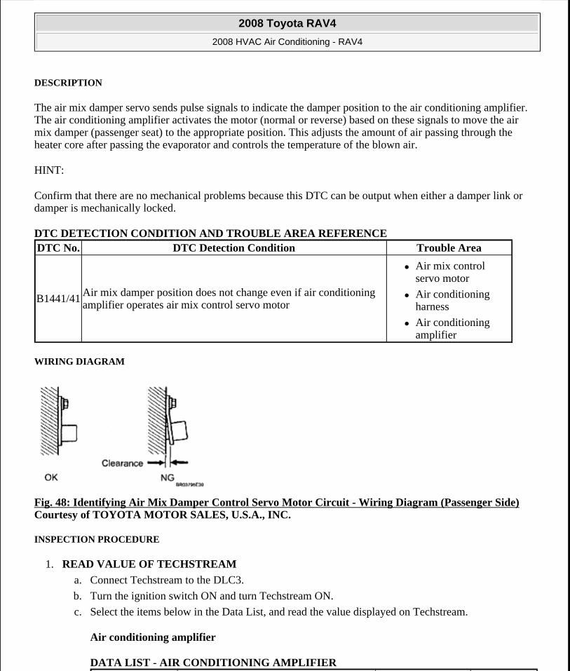
DESCRIPTION
The air mix damper servo sends pulse signals to indicate the damper position to the air conditioning amplifier. The air conditioning amplifier activates the motor (normal or reverse) based on these signals to move the air mix damper (passenger seat) to the appropriate position. This adjusts the amount of air passing through the heater core after passing the evaporator and controls the temperature of the blown air.
HINT:
Confirm that there are no mechanical problems because this DTC can be output when either a damper link or damper is mechanically locked.
DTC DETECTION CONDITION AND TROUBLE AREA REFERENCE
WIRING DIAGRAM
Fig. 48: Identifying Air Mix Damper Control Servo Motor Circuit - Wiring Diagram (Passenger Side) Courtesy of TOYOTA MOTOR SALES, U.S.A., INC.
INSPECTION PROCEDURE
1. READ VALUE OF TECHSTREAM
a. Connect Techstream to the DLC3.
b. Turn the ignition switch ON and turn Techstream ON.
c. Select the items below in the Data List, and read the value displayed on Techstream.
Air conditioning amplifier
DATA LIST - AIR CONDITIONING AMPLIFIER
DTC No. DTC Detection Condition Trouble Area
B1441/41Air mix damper position does not change even if air conditioning amplifier operates air mix control servo motor
Air mix control servo motor
Air conditioning harness
Air conditioning amplifier
2008 Toyota RAV4
2008 HVAC Air Conditioning - RAV4
Microsoft
Tuesday, August 18, 2009 3:53:54 PM Page 60 © 2005 Mitchell Repair Information Company, LLC.
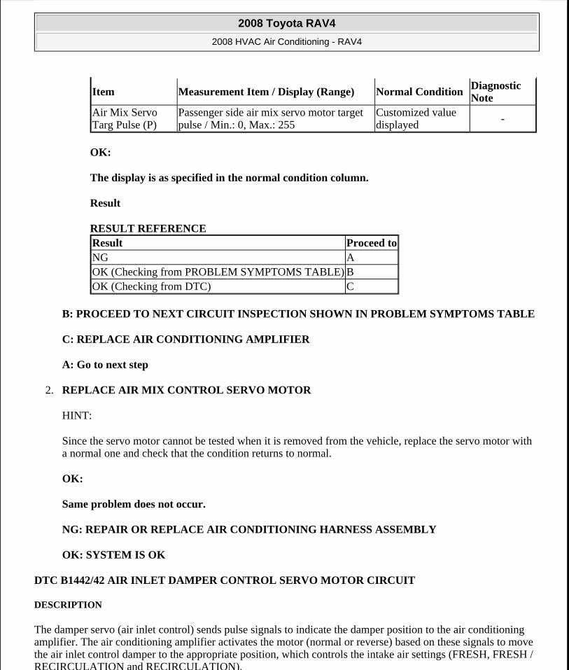
OK:
The display is as specified in the normal condition column.
Result
RESULT REFERENCE
B: PROCEED TO NEXT CIRCUIT INSPECTION SHOWN IN PROBLEM SYMPTOMS TABLE
C: REPLACE AIR CONDITIONING AMPLIFIER
A: Go to next step
2. REPLACE AIR MIX CONTROL SERVO MOTOR
HINT:
Since the servo motor cannot be tested when it is removed from the vehicle, replace the servo motor with a normal one and check that the condition returns to normal.
OK:
Same problem does not occur.
NG: REPAIR OR REPLACE AIR CONDITIONING HARNESS ASSEMBLY
OK: SYSTEM IS OK
DTC B1442/42 AIR INLET DAMPER CONTROL SERVO MOTOR CIRCUIT
DESCRIPTION
The damper servo (air inlet control) sends pulse signals to indicate the damper position to the air conditioning amplifier. The air conditioning amplifier activates the motor (normal or reverse) based on these signals to move the air inlet control damper to the appropriate position, which controls the intake air settings (FRESH, FRESH / RECIRCULATION and RECIRCULATION).
Item Measurement Item / Display (Range) Normal ConditionDiagnostic Note
Air Mix Servo Targ Pulse (P)
Passenger side air mix servo motor target pulse / Min.: 0, Max.: 255
Customized value displayed
-
Result Proceed toNG AOK (Checking from PROBLEM SYMPTOMS TABLE) BOK (Checking from DTC) C
2008 Toyota RAV4
2008 HVAC Air Conditioning - RAV4
Microsoft
Tuesday, August 18, 2009 3:53:54 PM Page 61 © 2005 Mitchell Repair Information Company, LLC.
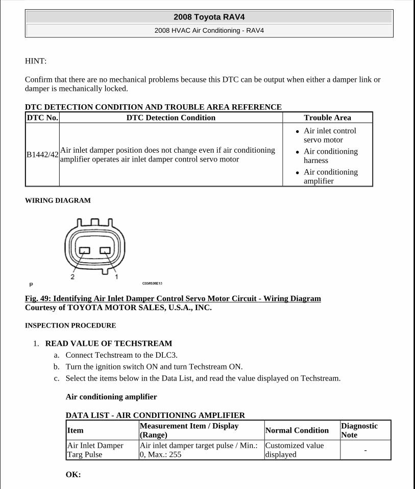
HINT:
Confirm that there are no mechanical problems because this DTC can be output when either a damper link or damper is mechanically locked.
DTC DETECTION CONDITION AND TROUBLE AREA REFERENCE
WIRING DIAGRAM
Fig. 49: Identifying Air Inlet Damper Control Servo Motor Circuit - Wiring Diagram Courtesy of TOYOTA MOTOR SALES, U.S.A., INC.
INSPECTION PROCEDURE
1. READ VALUE OF TECHSTREAM
a. Connect Techstream to the DLC3.
b. Turn the ignition switch ON and turn Techstream ON.
c. Select the items below in the Data List, and read the value displayed on Techstream.
Air conditioning amplifier
DATA LIST - AIR CONDITIONING AMPLIFIER
OK:
DTC No. DTC Detection Condition Trouble Area
B1442/42Air inlet damper position does not change even if air conditioning amplifier operates air inlet damper control servo motor
Air inlet control servo motor
Air conditioning harness
Air conditioning amplifier
Item Measurement Item / Display (Range)
Normal Condition Diagnostic Note
Air Inlet Damper Targ Pulse
Air inlet damper target pulse / Min.: 0, Max.: 255
Customized value displayed -
2008 Toyota RAV4
2008 HVAC Air Conditioning - RAV4
Microsoft
Tuesday, August 18, 2009 3:53:54 PM Page 62 © 2005 Mitchell Repair Information Company, LLC.

The display is as specified in the normal condition column.
Result
RESULT REFERENCE
B: PROCEED TO NEXT CIRCUIT INSPECTION SHOWN IN PROBLEM SYMPTOMS TABLE
C: REPLACE AIR CONDITIONING AMPLIFIER
A: Go to next step
2. REPLACE DAMPER SERVO SUB-ASSEMBLY
HINT:
Since the servo motor cannot be tested when it is removed from the vehicle, replace the servo motor with a normal one and check that the condition returns to normal.
OK:
Same problem does not occur.
NG: REPAIR OR REPLACE AIR CONDITIONING HARNESS ASSEMBLY
OK: SYSTEM IS OK
DTC B1443/43 AIR OUTLET DAMPER CONTROL SERVO MOTOR CIRCUIT
DESCRIPTION
The damper servo sends pulse signals to indicate the damper position to the air conditioning amplifier. The air conditioning amplifier activates the motor (normal or reverse) based on these signals to move the mode damper to the appropriate position, which controls the air outlet modes.
HINT:
Confirm that there are no mechanical problems because this DTC can be output when either a damper link or damper is mechanically locked.
DTC DETECTION CONDITION AND TROUBLE AREA REFERENCE
Result Proceed toNG AOK (Checking from PROBLEM SYMPTOMS TABLE) BOK (Checking from DTC) C
DTC No. DTC Detection Condition Trouble Area
2008 Toyota RAV4
2008 HVAC Air Conditioning - RAV4
Microsoft
Tuesday, August 18, 2009 3:53:54 PM Page 63 © 2005 Mitchell Repair Information Company, LLC.
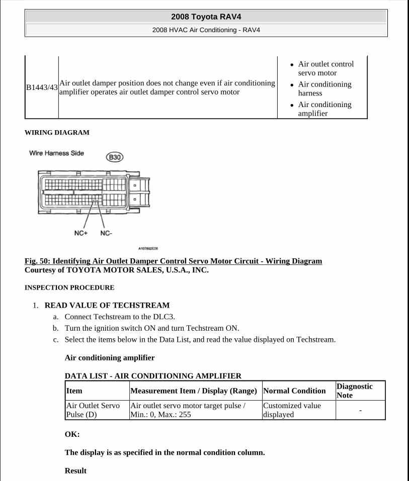
WIRING DIAGRAM
Fig. 50: Identifying Air Outlet Damper Control Servo Motor Circuit - Wiring Diagram Courtesy of TOYOTA MOTOR SALES, U.S.A., INC.
INSPECTION PROCEDURE
1. READ VALUE OF TECHSTREAM
a. Connect Techstream to the DLC3.
b. Turn the ignition switch ON and turn Techstream ON.
c. Select the items below in the Data List, and read the value displayed on Techstream.
Air conditioning amplifier
DATA LIST - AIR CONDITIONING AMPLIFIER
OK:
The display is as specified in the normal condition column.
Result
B1443/43 Air outlet damper position does not change even if air conditioning amplifier operates air outlet damper control servo motor
Air outlet control servo motor
Air conditioning harness
Air conditioning amplifier
Item Measurement Item / Display (Range) Normal ConditionDiagnostic Note
Air Outlet Servo Pulse (D)
Air outlet servo motor target pulse / Min.: 0, Max.: 255
Customized value displayed
-
2008 Toyota RAV4
2008 HVAC Air Conditioning - RAV4
Microsoft
Tuesday, August 18, 2009 3:53:54 PM Page 64 © 2005 Mitchell Repair Information Company, LLC.
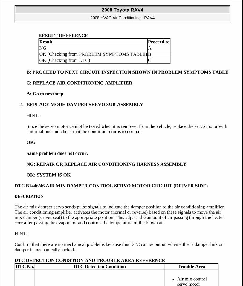
RESULT REFERENCE
B: PROCEED TO NEXT CIRCUIT INSPECTION SHOWN IN PROBLEM SYMPTOMS TABLE
C: REPLACE AIR CONDITIONING AMPLIFIER
A: Go to next step
2. REPLACE MODE DAMPER SERVO SUB-ASSEMBLY
HINT:
Since the servo motor cannot be tested when it is removed from the vehicle, replace the servo motor with a normal one and check that the condition returns to normal.
OK:
Same problem does not occur.
NG: REPAIR OR REPLACE AIR CONDITIONING HARNESS ASSEMBLY
OK: SYSTEM IS OK
DTC B1446/46 AIR MIX DAMPER CONTROL SERVO MOTOR CIRCUIT (DRIVER SIDE)
DESCRIPTION
The air mix damper servo sends pulse signals to indicate the damper position to the air conditioning amplifier. The air conditioning amplifier activates the motor (normal or reverse) based on these signals to move the air mix damper (driver seat) to the appropriate position. This adjusts the amount of air passing through the heater core after passing the evaporator and controls the temperature of the blown air.
HINT:
Confirm that there are no mechanical problems because this DTC can be output when either a damper link or damper is mechanically locked.
DTC DETECTION CONDITION AND TROUBLE AREA REFERENCE
Result Proceed toNG AOK (Checking from PROBLEM SYMPTOMS TABLE) BOK (Checking from DTC) C
DTC No. DTC Detection Condition Trouble Area
Air mix control servo motor
2008 Toyota RAV4
2008 HVAC Air Conditioning - RAV4
Microsoft
Tuesday, August 18, 2009 3:53:54 PM Page 65 © 2005 Mitchell Repair Information Company, LLC.
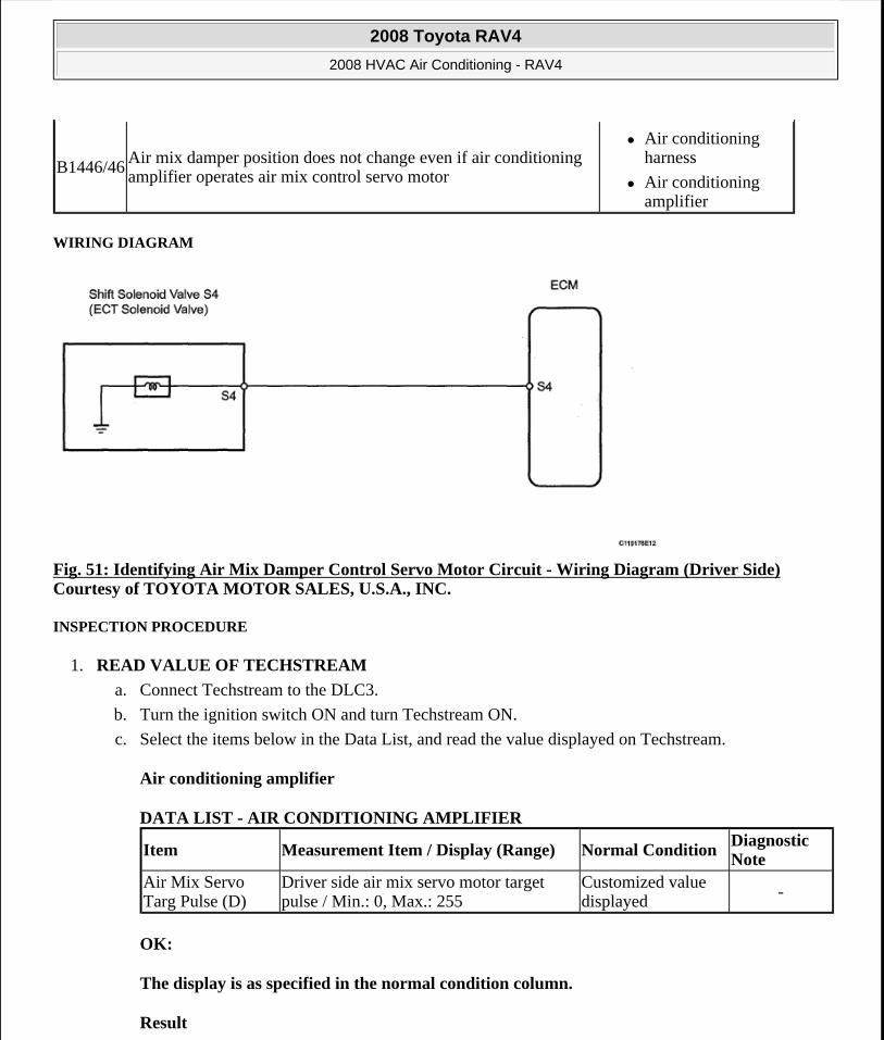
WIRING DIAGRAM
Fig. 51: Identifying Air Mix Damper Control Servo Motor Circuit - Wiring Diagram (Driver Side) Courtesy of TOYOTA MOTOR SALES, U.S.A., INC.
INSPECTION PROCEDURE
1. READ VALUE OF TECHSTREAM
a. Connect Techstream to the DLC3.
b. Turn the ignition switch ON and turn Techstream ON.
c. Select the items below in the Data List, and read the value displayed on Techstream.
Air conditioning amplifier
DATA LIST - AIR CONDITIONING AMPLIFIER
OK:
The display is as specified in the normal condition column.
Result
B1446/46Air mix damper position does not change even if air conditioning amplifier operates air mix control servo motor
Air conditioning harness
Air conditioning amplifier
Item Measurement Item / Display (Range) Normal ConditionDiagnostic Note
Air Mix Servo Targ Pulse (D)
Driver side air mix servo motor target pulse / Min.: 0, Max.: 255
Customized value displayed
-
2008 Toyota RAV4
2008 HVAC Air Conditioning - RAV4
Microsoft
Tuesday, August 18, 2009 3:53:54 PM Page 66 © 2005 Mitchell Repair Information Company, LLC.

RESULT REFERENCE
B: PROCEED TO NEXT CIRCUIT INSPECTION SHOWN IN PROBLEM SYMPTOMS TABLE
C: REPLACE AIR CONDITIONING AMPLIFIER
A: Go to next step
2. REPLACE AIR MIX CONTROL SERVO MOTOR
HINT:
Since the servo motor cannot be tested when it is removed from the vehicle, replace the servo motor with a normal one and check that the condition returns to normal.
OK:
Same problem does not occur.
NG: REPAIR OR REPLACE AIR CONDITIONING HARNESS
OK: SYSTEM IS OK
DTC B1451/51 COMPRESSOR SOLENOID CIRCUIT
DESCRIPTION
In this circuit, the compressor receives a refrigerant compression demand signal from the air conditioning amplifier. Based on this signal, the compressor changes the degree of refrigerant compression.
DTC DETECTION CONDITION AND TROUBLE AREA REFERENCE
WIRING DIAGRAM
Result Proceed toNG AOK (Checking from PROBLEM SYMPTOMS TABLE) BOK (Checking from DTC) C
DTC No. DTC Detection Condition Trouble Area
B1451/51Open or short in solenoid of externally changeable compressor circuit
A/C compressor*
Wire harness and connector between air conditioning amplifier and A/C compressor*
Air conditioning amplifier HINT: *: Compressor and pulley for 2AZ-FE, compressor and magnetic clutch for 2GR-FE
2008 Toyota RAV4
2008 HVAC Air Conditioning - RAV4
Microsoft
Tuesday, August 18, 2009 3:53:54 PM Page 67 © 2005 Mitchell Repair Information Company, LLC.
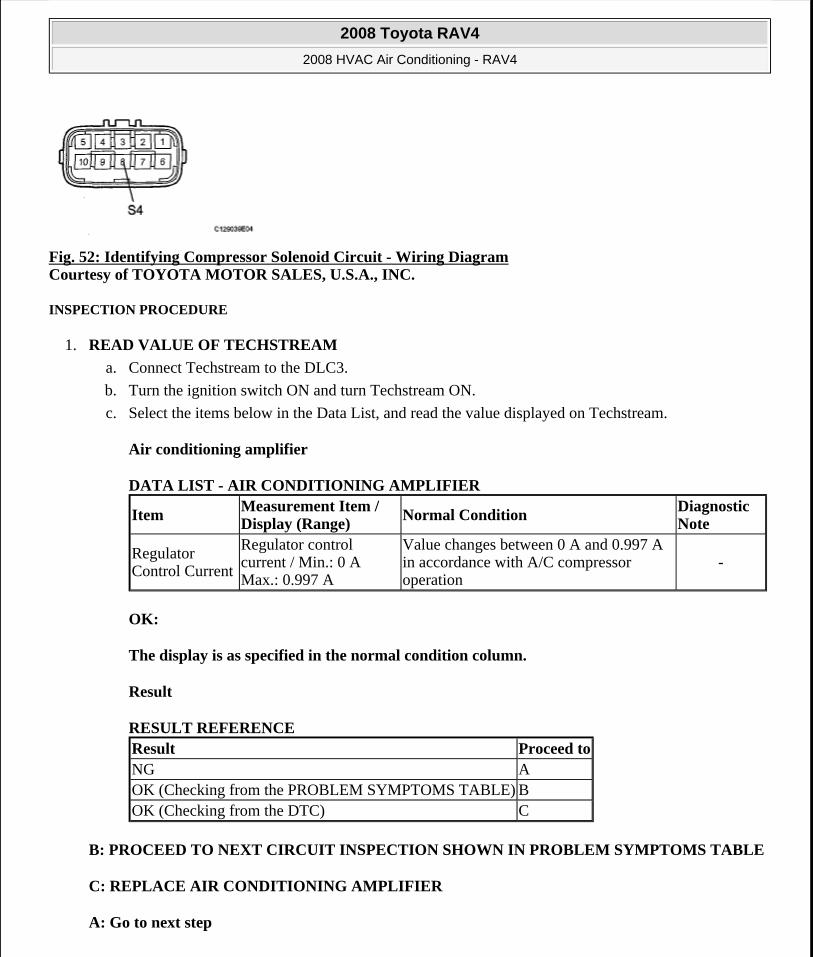
Fig. 52: Identifying Compressor Solenoid Circuit - Wiring Diagram Courtesy of TOYOTA MOTOR SALES, U.S.A., INC.
INSPECTION PROCEDURE
1. READ VALUE OF TECHSTREAM
a. Connect Techstream to the DLC3.
b. Turn the ignition switch ON and turn Techstream ON.
c. Select the items below in the Data List, and read the value displayed on Techstream.
Air conditioning amplifier
DATA LIST - AIR CONDITIONING AMPLIFIER
OK:
The display is as specified in the normal condition column.
Result
RESULT REFERENCE
B: PROCEED TO NEXT CIRCUIT INSPECTION SHOWN IN PROBLEM SYMPTOMS TABLE
C: REPLACE AIR CONDITIONING AMPLIFIER
A: Go to next step
ItemMeasurement Item / Display (Range)
Normal ConditionDiagnostic Note
Regulator Control Current
Regulator control current / Min.: 0 A Max.: 0.997 A
Value changes between 0 A and 0.997 A in accordance with A/C compressor operation
-
Result Proceed toNG AOK (Checking from the PROBLEM SYMPTOMS TABLE) BOK (Checking from the DTC) C
2008 Toyota RAV4
2008 HVAC Air Conditioning - RAV4
Microsoft
Tuesday, August 18, 2009 3:53:54 PM Page 68 © 2005 Mitchell Repair Information Company, LLC.
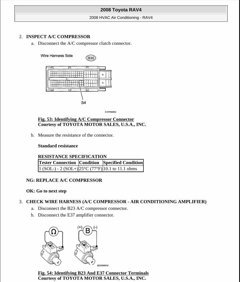
2. INSPECT A/C COMPRESSOR
a. Disconnect the A/C compressor clutch connector.
Fig. 53: Identifying A/C Compressor Connector Courtesy of TOYOTA MOTOR SALES, U.S.A., INC.
b. Measure the resistance of the connector.
Standard resistance
RESISTANCE SPECIFICATION
NG: REPLACE A/C COMPRESSOR
OK: Go to next step
3. CHECK WIRE HARNESS (A/C COMPRESSOR - AIR CONDITIONING AMPLIFIER)
a. Disconnect the B23 A/C compressor connector.
b. Disconnect the E37 amplifier connector.
Fig. 54: Identifying B23 And E37 Connector Terminals Courtesy of TOYOTA MOTOR SALES, U.S.A., INC.
Tester Connection Condition Specified Condition1 (SOL-) - 2 (SOL+) 25°C (77°F) 10.1 to 11.1 ohms
2008 Toyota RAV4
2008 HVAC Air Conditioning - RAV4
Microsoft
Tuesday, August 18, 2009 3:53:54 PM Page 69 © 2005 Mitchell Repair Information Company, LLC.
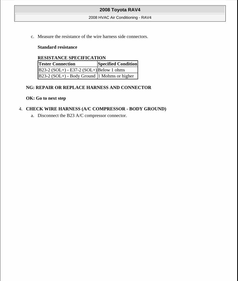
c. Measure the resistance of the wire harness side connectors.
Standard resistance
RESISTANCE SPECIFICATION
NG: REPAIR OR REPLACE HARNESS AND CONNECTOR
OK: Go to next step
4. CHECK WIRE HARNESS (A/C COMPRESSOR - BODY GROUND)
a. Disconnect the B23 A/C compressor connector.
Tester Connection Specified ConditionB23-2 (SOL+) - E37-2 (SOL+) Below 1 ohmsB23-2 (SOL+) - Body Ground 1 Mohms or higher
2008 Toyota RAV4
2008 HVAC Air Conditioning - RAV4
Microsoft
Tuesday, August 18, 2009 3:53:54 PM Page 70 © 2005 Mitchell Repair Information Company, LLC.
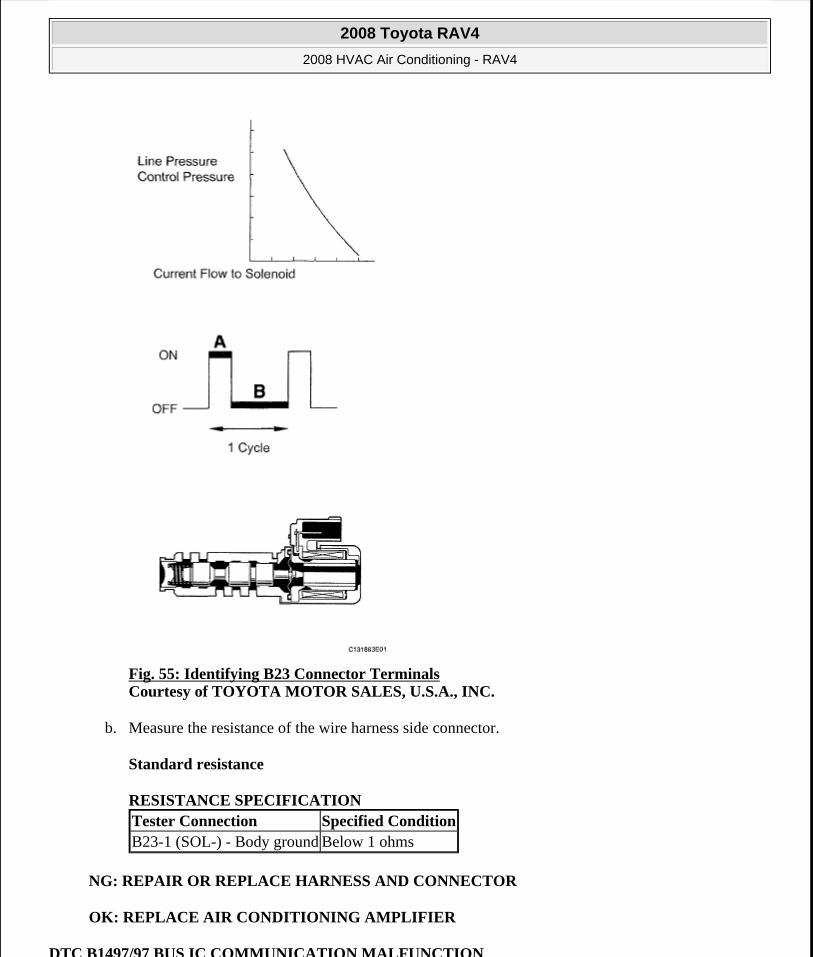
Fig. 55: Identifying B23 Connector Terminals Courtesy of TOYOTA MOTOR SALES, U.S.A., INC.
b. Measure the resistance of the wire harness side connector.
Standard resistance
RESISTANCE SPECIFICATION
NG: REPAIR OR REPLACE HARNESS AND CONNECTOR
OK: REPLACE AIR CONDITIONING AMPLIFIER
DTC B1497/97 BUS IC COMMUNICATION MALFUNCTION
Tester Connection Specified ConditionB23-1 (SOL-) - Body ground Below 1 ohms
2008 Toyota RAV4
2008 HVAC Air Conditioning - RAV4
Microsoft
Tuesday, August 18, 2009 3:53:54 PM Page 71 © 2005 Mitchell Repair Information Company, LLC.
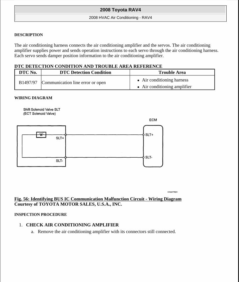
DESCRIPTION
The air conditioning harness connects the air conditioning amplifier and the servos. The air conditioning amplifier supplies power and sends operation instructions to each servo through the air conditioning harness. Each servo sends damper position information to the air conditioning amplifier.
DTC DETECTION CONDITION AND TROUBLE AREA REFERENCE
WIRING DIAGRAM
Fig. 56: Identifying BUS IC Communication Malfunction Circuit - Wiring Diagram Courtesy of TOYOTA MOTOR SALES, U.S.A., INC.
INSPECTION PROCEDURE
1. CHECK AIR CONDITIONING AMPLIFIER
a. Remove the air conditioning amplifier with its connectors still connected.
DTC No. DTC Detection Condition Trouble Area
B1497/97 Communication line error or open Air conditioning harness
Air conditioning amplifier
2008 Toyota RAV4
2008 HVAC Air Conditioning - RAV4
Microsoft
Tuesday, August 18, 2009 3:53:54 PM Page 72 © 2005 Mitchell Repair Information Company, LLC.
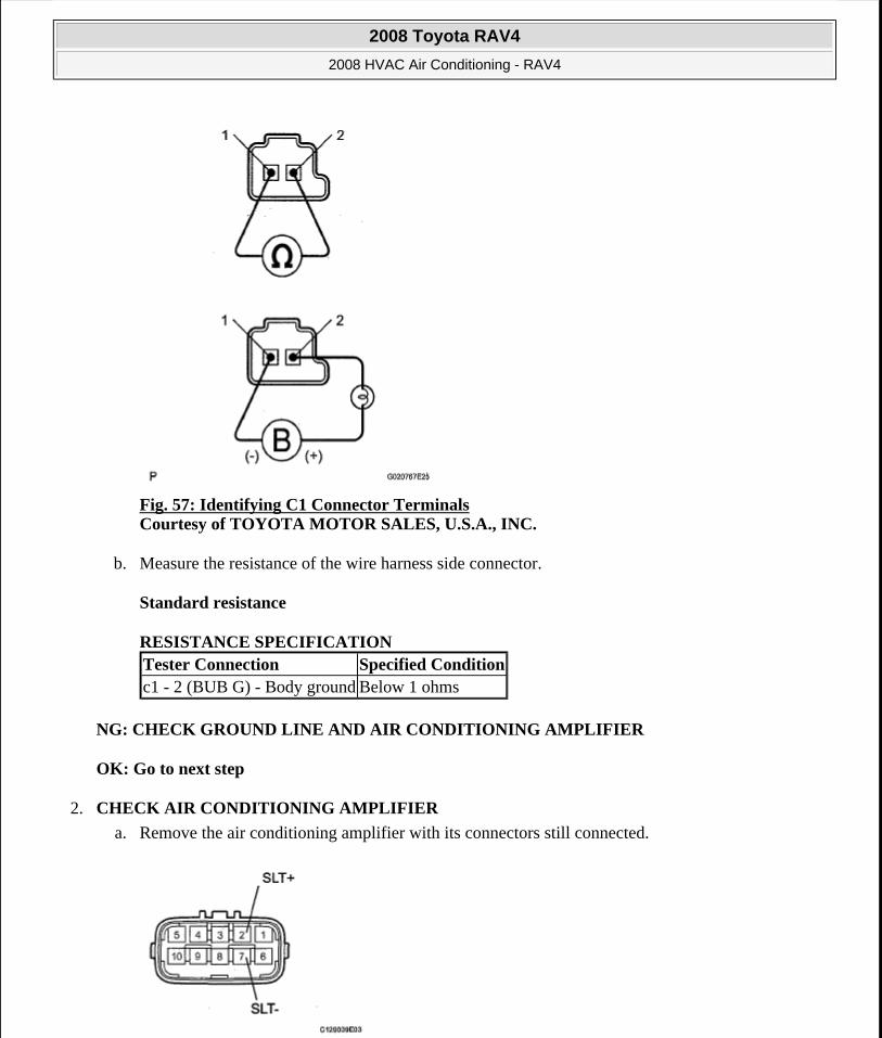
Fig. 57: Identifying C1 Connector Terminals Courtesy of TOYOTA MOTOR SALES, U.S.A., INC.
b. Measure the resistance of the wire harness side connector.
Standard resistance
RESISTANCE SPECIFICATION
NG: CHECK GROUND LINE AND AIR CONDITIONING AMPLIFIER
OK: Go to next step
2. CHECK AIR CONDITIONING AMPLIFIER
a. Remove the air conditioning amplifier with its connectors still connected.
Tester Connection Specified Conditionc1 - 2 (BUB G) - Body ground Below 1 ohms
2008 Toyota RAV4
2008 HVAC Air Conditioning - RAV4
Microsoft
Tuesday, August 18, 2009 3:53:54 PM Page 73 © 2005 Mitchell Repair Information Company, LLC.
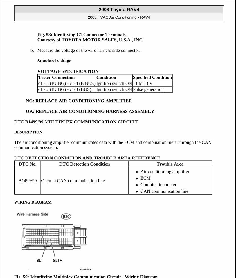
Fig. 58: Identifying C1 Connector TerminalsCourtesy of TOYOTA MOTOR SALES, U.S.A., INC.
b. Measure the voltage of the wire harness side connector.
Standard voltage
VOLTAGE SPECIFICATION
NG: REPLACE AIR CONDITIONING AMPLIFIER
OK: REPLACE AIR CONDITIONING HARNESS ASSEMBLY
DTC B1499/99 MULTIPLEX COMMUNICATION CIRCUIT
DESCRIPTION
The air conditioning amplifier communicates data with the ECM and combination meter through the CAN communication system.
DTC DETECTION CONDITION AND TROUBLE AREA REFERENCE
WIRING DIAGRAM
Fig. 59: Identifying Multiplex Communication Circuit - Wiring Diagram
Tester Connection Condition Specified Conditionc1 - 2 (BUBG) - c1-4 (B BUS) Ignition switch ON 11 to 13 Vc1 - 2 (BUBG) - c1-3 (BUS) Ignition switch ON Pulse generation
DTC No. DTC Detection Condition Trouble Area
B1499/99 Open in CAN communication line
Air conditioning amplifier
ECM
Combination meter
CAN communication line
2008 Toyota RAV4
2008 HVAC Air Conditioning - RAV4
Microsoft
Tuesday, August 18, 2009 3:53:54 PM Page 74 © 2005 Mitchell Repair Information Company, LLC.
Courtesy of TOYOTA MOTOR SALES, U.S.A., INC.
INSPECTION PROCEDURE
1. CHECK DTC
a. Clear the DTC (see DTC CHECK / CLEAR ).
b. Read the DTC (see DTC CHECK / CLEAR ).
Result
RESULT REFERENCE
B: SYSTEM IS OK
A: GO TO CAN COMMUNICATION SYSTEM
AIR CONDITIONING CONTROL PANEL DOES NOT OPERATE
DESCRIPTION
This circuit consists of the air conditioning control and the air conditioning amplifier. When the air conditioning control is operated, signals are transmitted to the air conditioning amplifier through the LIN communication system.
If the LIN communication system malfunctions, the air conditioning amplifier does not operate even if the air conditioning control is operated.
WIRING DIAGRAM
Result Proceed toDTC (B1499/99) is output A (see CAN COMMUNICATION SYSTEM )DTC (B1499/99) is not output B
2008 Toyota RAV4
2008 HVAC Air Conditioning - RAV4
Microsoft
Tuesday, August 18, 2009 3:53:54 PM Page 75 © 2005 Mitchell Repair Information Company, LLC.
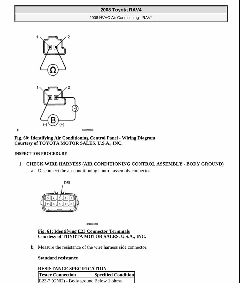
Fig. 60: Identifying Air Conditioning Control Panel - Wiring Diagram Courtesy of TOYOTA MOTOR SALES, U.S.A., INC.
INSPECTION PROCEDURE
1. CHECK WIRE HARNESS (AIR CONDITIONING CONTROL ASSEMBLY - BODY GROUND)
a. Disconnect the air conditioning control assembly connector.
Fig. 61: Identifying E23 Connector Terminals Courtesy of TOYOTA MOTOR SALES, U.S.A., INC.
b. Measure the resistance of the wire harness side connector.
Standard resistance
RESISTANCE SPECIFICATION Tester Connection Specified ConditionE23-7 (GND) - Body ground Below 1 ohms
2008 Toyota RAV4
2008 HVAC Air Conditioning - RAV4
Microsoft
Tuesday, August 18, 2009 3:53:54 PM Page 76 © 2005 Mitchell Repair Information Company, LLC.
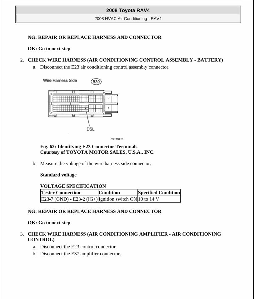
NG: REPAIR OR REPLACE HARNESS AND CONNECTOR
OK: Go to next step
2. CHECK WIRE HARNESS (AIR CONDITIONING CONTROL ASSEMBLY - BATTERY)
a. Disconnect the E23 air conditioning control assembly connector.
Fig. 62: Identifying E23 Connector Terminals Courtesy of TOYOTA MOTOR SALES, U.S.A., INC.
b. Measure the voltage of the wire harness side connector.
Standard voltage
VOLTAGE SPECIFICATION
NG: REPAIR OR REPLACE HARNESS AND CONNECTOR
OK: Go to next step
3. CHECK WIRE HARNESS (AIR CONDITIONING AMPLIFIER - AIR CONDITIONING CONTROL)
a. Disconnect the E23 control connector.
b. Disconnect the E37 amplifier connector.
Tester Connection Condition Specified ConditionE23-7 (GND) - E23-2 (IG+) Ignition switch ON 10 to 14 V
2008 Toyota RAV4
2008 HVAC Air Conditioning - RAV4
Microsoft
Tuesday, August 18, 2009 3:53:54 PM Page 77 © 2005 Mitchell Repair Information Company, LLC.
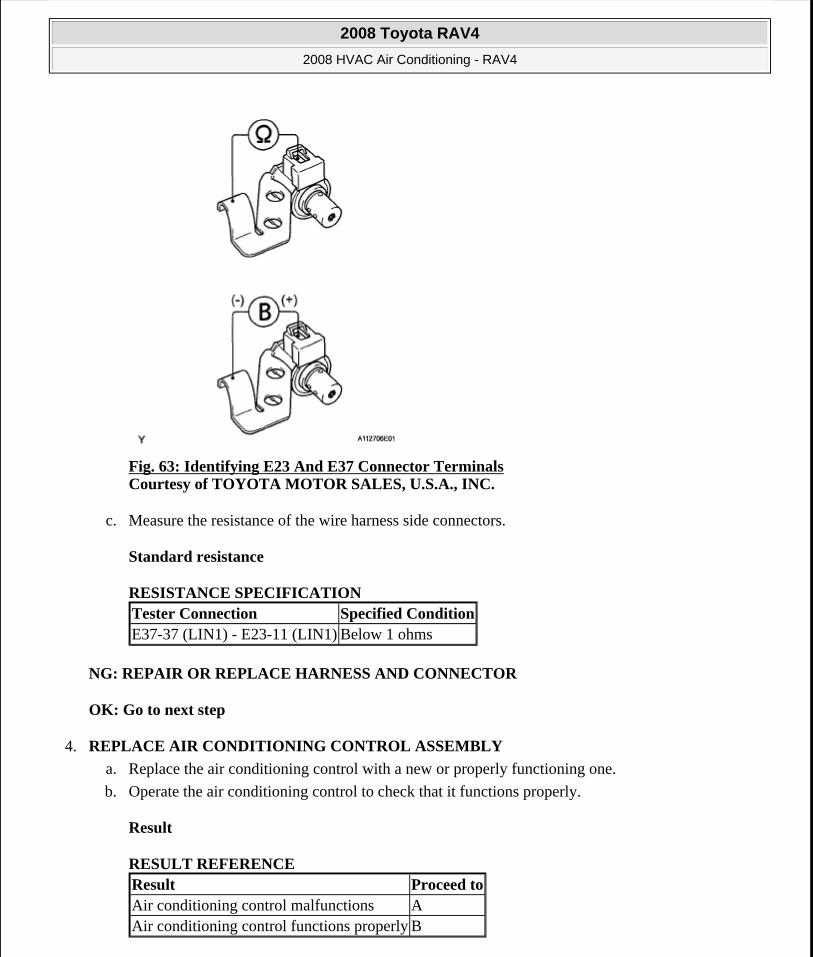
Fig. 63: Identifying E23 And E37 Connector Terminals Courtesy of TOYOTA MOTOR SALES, U.S.A., INC.
c. Measure the resistance of the wire harness side connectors.
Standard resistance
RESISTANCE SPECIFICATION
NG: REPAIR OR REPLACE HARNESS AND CONNECTOR
OK: Go to next step
4. REPLACE AIR CONDITIONING CONTROL ASSEMBLY
a. Replace the air conditioning control with a new or properly functioning one.
b. Operate the air conditioning control to check that it functions properly.
Result
RESULT REFERENCE
Tester Connection Specified ConditionE37-37 (LIN1) - E23-11 (LIN1) Below 1 ohms
Result Proceed toAir conditioning control malfunctions AAir conditioning control functions properly B
2008 Toyota RAV4
2008 HVAC Air Conditioning - RAV4
Microsoft
Tuesday, August 18, 2009 3:53:54 PM Page 78 © 2005 Mitchell Repair Information Company, LLC.

B: END (AIR CONDITIONING CONTROL ASSEMBLY IS FAULTY)
A: REPLACE AIR CONDITIONING AMPLIFIER
BLOWER MOTOR CIRCUIT
DESCRIPTION
The blower motor is operated by signals from the air conditioning amplifier. Blower motor speed signals are transmitted in accordance with changes in the duty ratio.
Fig. 64: Identifying Blower Motor Speed Signals Courtesy of TOYOTA MOTOR SALES, U.S.A., INC.
WIRING DIAGRAM
2008 Toyota RAV4
2008 HVAC Air Conditioning - RAV4
Microsoft
Tuesday, August 18, 2009 3:53:54 PM Page 79 © 2005 Mitchell Repair Information Company, LLC.
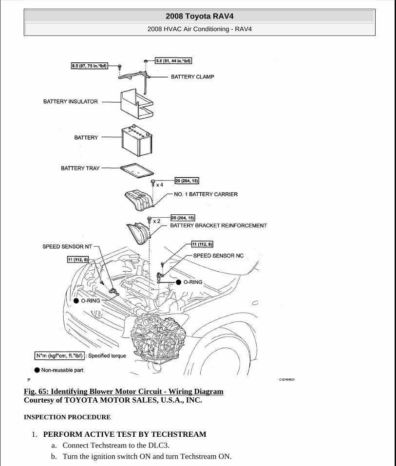
Fig. 65: Identifying Blower Motor Circuit - Wiring Diagram Courtesy of TOYOTA MOTOR SALES, U.S.A., INC.
INSPECTION PROCEDURE
1. PERFORM ACTIVE TEST BY TECHSTREAM
a. Connect Techstream to the DLC3.
b. Turn the ignition switch ON and turn Techstream ON.
2008 Toyota RAV4
2008 HVAC Air Conditioning - RAV4
Microsoft
Tuesday, August 18, 2009 3:53:54 PM Page 80 © 2005 Mitchell Repair Information Company, LLC.
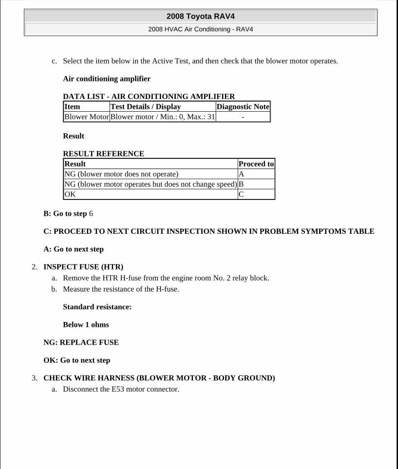
c. Select the item below in the Active Test, and then check that the blower motor operates.
Air conditioning amplifier
DATA LIST - AIR CONDITIONING AMPLIFIER
Result
RESULT REFERENCE
B: Go to step 6
C: PROCEED TO NEXT CIRCUIT INSPECTION SHOWN IN PROBLEM SYMPTOMS TABLE
A: Go to next step
2. INSPECT FUSE (HTR)
a. Remove the HTR H-fuse from the engine room No. 2 relay block.
b. Measure the resistance of the H-fuse.
Standard resistance:
Below 1 ohms
NG: REPLACE FUSE
OK: Go to next step
3. CHECK WIRE HARNESS (BLOWER MOTOR - BODY GROUND)
a. Disconnect the E53 motor connector.
Item Test Details / Display Diagnostic NoteBlower Motor Blower motor / Min.: 0, Max.: 31 -
Result Proceed toNG (blower motor does not operate) ANG (blower motor operates but does not change speed) BOK C
2008 Toyota RAV4
2008 HVAC Air Conditioning - RAV4
Microsoft
Tuesday, August 18, 2009 3:53:54 PM Page 81 © 2005 Mitchell Repair Information Company, LLC.
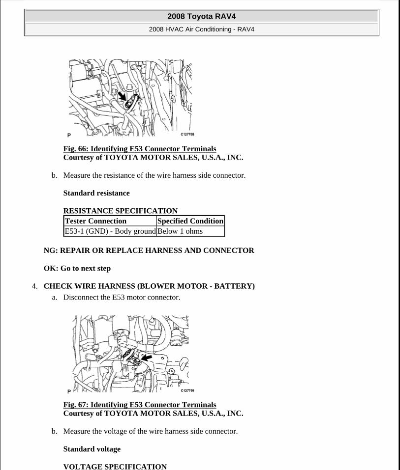
Fig. 66: Identifying E53 Connector Terminals Courtesy of TOYOTA MOTOR SALES, U.S.A., INC.
b. Measure the resistance of the wire harness side connector.
Standard resistance
RESISTANCE SPECIFICATION
NG: REPAIR OR REPLACE HARNESS AND CONNECTOR
OK: Go to next step
4. CHECK WIRE HARNESS (BLOWER MOTOR - BATTERY)
a. Disconnect the E53 motor connector.
Fig. 67: Identifying E53 Connector Terminals Courtesy of TOYOTA MOTOR SALES, U.S.A., INC.
b. Measure the voltage of the wire harness side connector.
Standard voltage
VOLTAGE SPECIFICATION
Tester Connection Specified ConditionE53-1 (GND) - Body ground Below 1 ohms
2008 Toyota RAV4
2008 HVAC Air Conditioning - RAV4
Microsoft
Tuesday, August 18, 2009 3:53:54 PM Page 82 © 2005 Mitchell Repair Information Company, LLC.
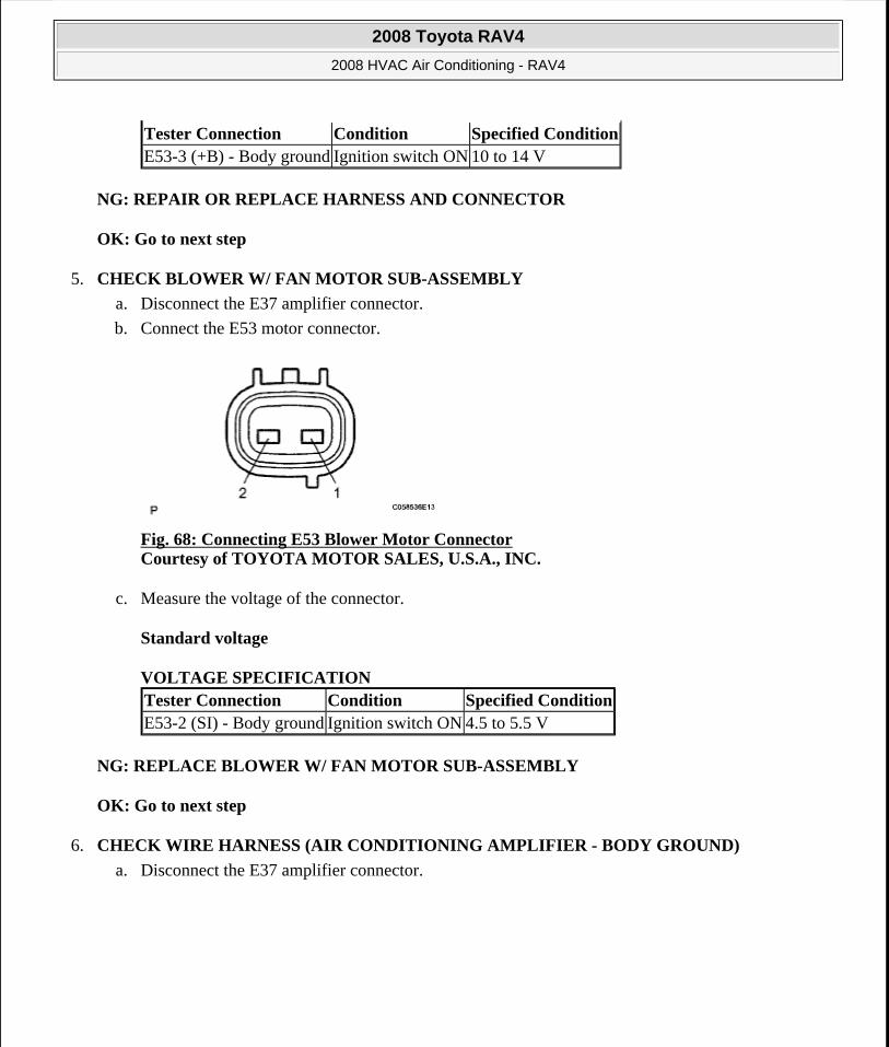
NG: REPAIR OR REPLACE HARNESS AND CONNECTOR
OK: Go to next step
5. CHECK BLOWER W/ FAN MOTOR SUB-ASSEMBLY
a. Disconnect the E37 amplifier connector.
b. Connect the E53 motor connector.
Fig. 68: Connecting E53 Blower Motor Connector Courtesy of TOYOTA MOTOR SALES, U.S.A., INC.
c. Measure the voltage of the connector.
Standard voltage
VOLTAGE SPECIFICATION
NG: REPLACE BLOWER W/ FAN MOTOR SUB-ASSEMBLY
OK: Go to next step
6. CHECK WIRE HARNESS (AIR CONDITIONING AMPLIFIER - BODY GROUND)
a. Disconnect the E37 amplifier connector.
Tester Connection Condition Specified ConditionE53-3 (+B) - Body ground Ignition switch ON 10 to 14 V
Tester Connection Condition Specified ConditionE53-2 (SI) - Body ground Ignition switch ON 4.5 to 5.5 V
2008 Toyota RAV4
2008 HVAC Air Conditioning - RAV4
Microsoft
Tuesday, August 18, 2009 3:53:54 PM Page 83 © 2005 Mitchell Repair Information Company, LLC.
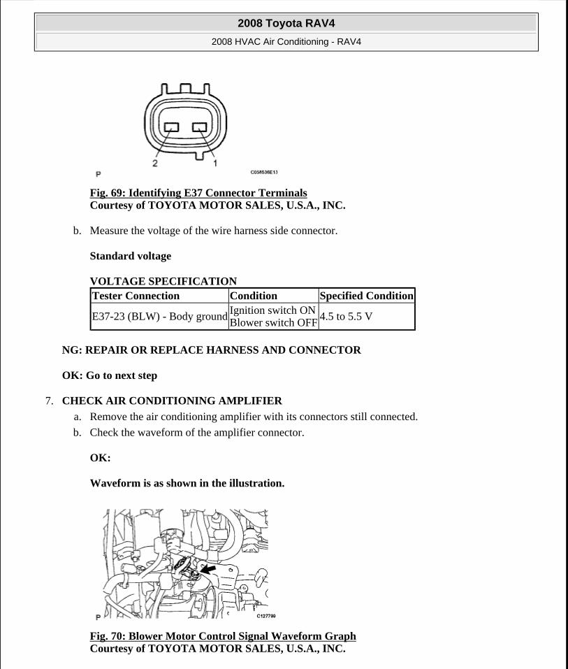
Fig. 69: Identifying E37 Connector Terminals Courtesy of TOYOTA MOTOR SALES, U.S.A., INC.
b. Measure the voltage of the wire harness side connector.
Standard voltage
VOLTAGE SPECIFICATION
NG: REPAIR OR REPLACE HARNESS AND CONNECTOR
OK: Go to next step
7. CHECK AIR CONDITIONING AMPLIFIER
a. Remove the air conditioning amplifier with its connectors still connected.
b. Check the waveform of the amplifier connector.
OK:
Waveform is as shown in the illustration.
Fig. 70: Blower Motor Control Signal Waveform Graph Courtesy of TOYOTA MOTOR SALES, U.S.A., INC.
Tester Connection Condition Specified Condition
E37-23 (BLW) - Body ground Ignition switch ONBlower switch OFF
4.5 to 5.5 V
2008 Toyota RAV4
2008 HVAC Air Conditioning - RAV4
Microsoft
Tuesday, August 18, 2009 3:53:54 PM Page 84 © 2005 Mitchell Repair Information Company, LLC.
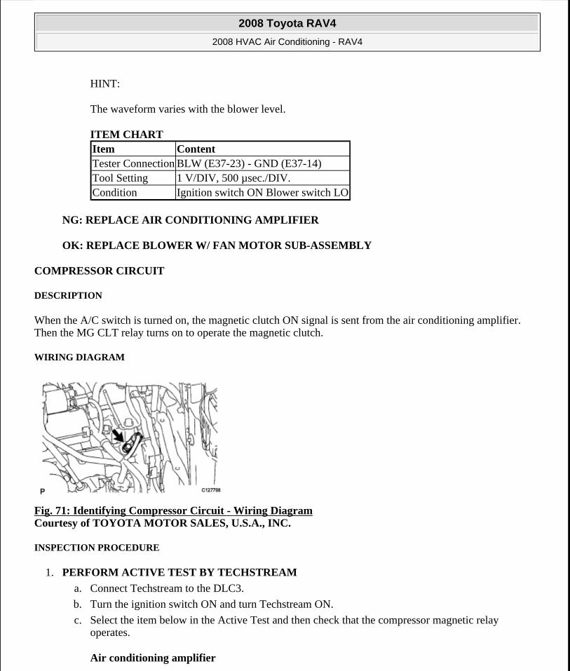
HINT:
The waveform varies with the blower level.
ITEM CHART
NG: REPLACE AIR CONDITIONING AMPLIFIER
OK: REPLACE BLOWER W/ FAN MOTOR SUB-ASSEMBLY
COMPRESSOR CIRCUIT
DESCRIPTION
When the A/C switch is turned on, the magnetic clutch ON signal is sent from the air conditioning amplifier. Then the MG CLT relay turns on to operate the magnetic clutch.
WIRING DIAGRAM
Fig. 71: Identifying Compressor Circuit - Wiring Diagram Courtesy of TOYOTA MOTOR SALES, U.S.A., INC.
INSPECTION PROCEDURE
1. PERFORM ACTIVE TEST BY TECHSTREAM
a. Connect Techstream to the DLC3.
b. Turn the ignition switch ON and turn Techstream ON.
c. Select the item below in the Active Test and then check that the compressor magnetic relay operates.
Air conditioning amplifier
Item ContentTester Connection BLW (E37-23) - GND (E37-14)Tool Setting 1 V/DIV, 500 µsec./DIV.Condition Ignition switch ON Blower switch LO
2008 Toyota RAV4
2008 HVAC Air Conditioning - RAV4
Microsoft
Tuesday, August 18, 2009 3:53:54 PM Page 85 © 2005 Mitchell Repair Information Company, LLC.
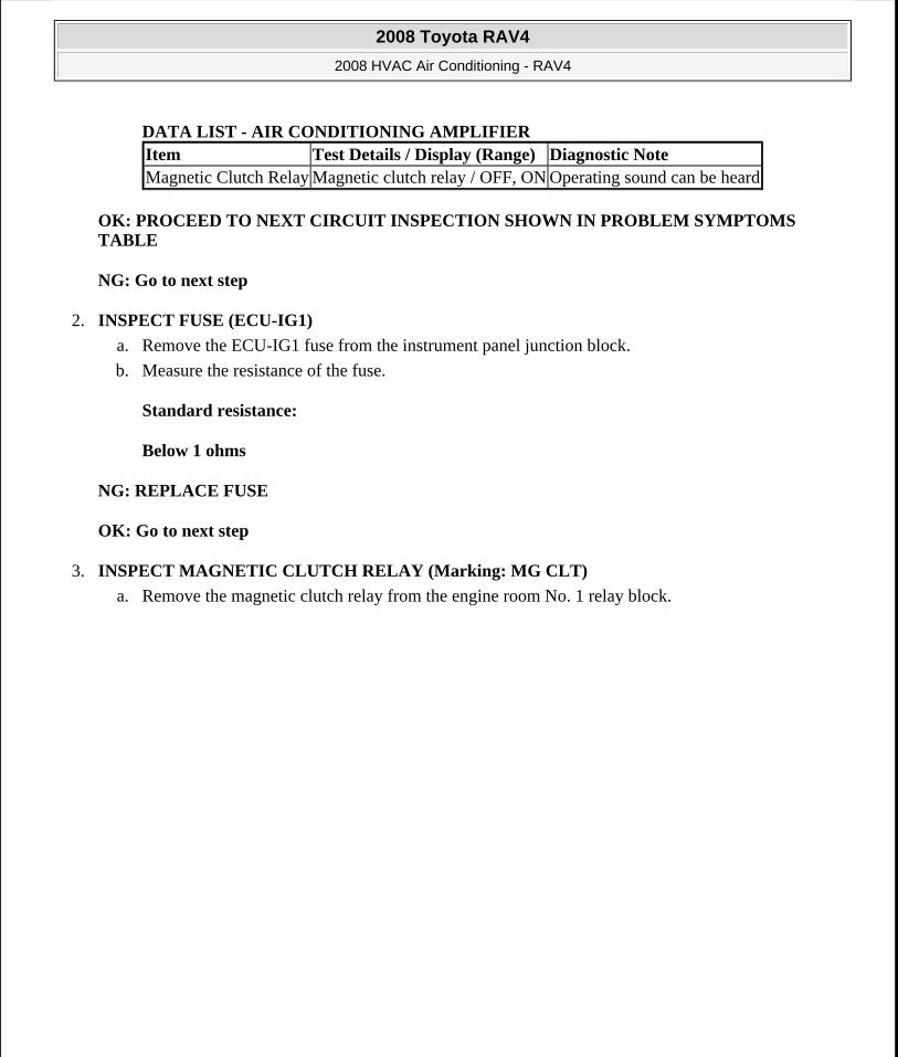
DATA LIST - AIR CONDITIONING AMPLIFIER
OK: PROCEED TO NEXT CIRCUIT INSPECTION SHOWN IN PROBLEM SYMPTOMS TABLE
NG: Go to next step
2. INSPECT FUSE (ECU-IG1)
a. Remove the ECU-IG1 fuse from the instrument panel junction block.
b. Measure the resistance of the fuse.
Standard resistance:
Below 1 ohms
NG: REPLACE FUSE
OK: Go to next step
3. INSPECT MAGNETIC CLUTCH RELAY (Marking: MG CLT)
a. Remove the magnetic clutch relay from the engine room No. 1 relay block.
Item Test Details / Display (Range) Diagnostic NoteMagnetic Clutch Relay Magnetic clutch relay / OFF, ON Operating sound can be heard
2008 Toyota RAV4
2008 HVAC Air Conditioning - RAV4
Microsoft
Tuesday, August 18, 2009 3:53:54 PM Page 86 © 2005 Mitchell Repair Information Company, LLC.
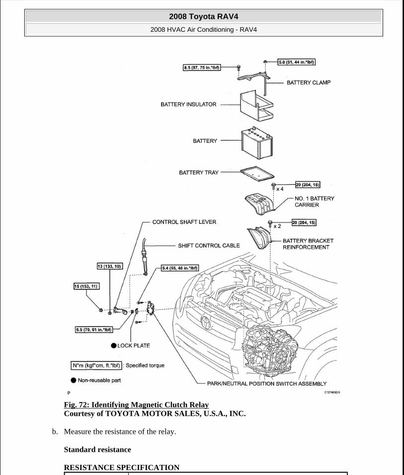
Fig. 72: Identifying Magnetic Clutch Relay Courtesy of TOYOTA MOTOR SALES, U.S.A., INC.
b. Measure the resistance of the relay.
Standard resistance
RESISTANCE SPECIFICATION
2008 Toyota RAV4
2008 HVAC Air Conditioning - RAV4
Microsoft
Tuesday, August 18, 2009 3:53:54 PM Page 87 © 2005 Mitchell Repair Information Company, LLC.
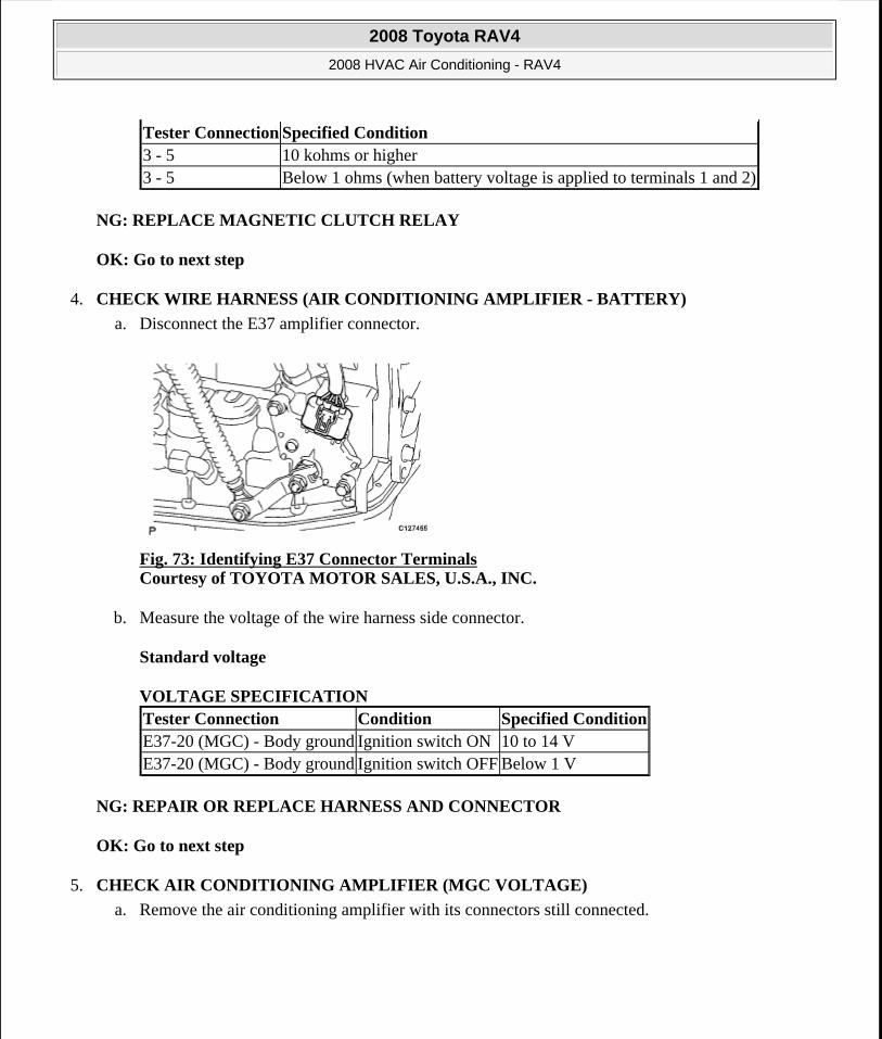
NG: REPLACE MAGNETIC CLUTCH RELAY
OK: Go to next step
4. CHECK WIRE HARNESS (AIR CONDITIONING AMPLIFIER - BATTERY)
a. Disconnect the E37 amplifier connector.
Fig. 73: Identifying E37 Connector Terminals Courtesy of TOYOTA MOTOR SALES, U.S.A., INC.
b. Measure the voltage of the wire harness side connector.
Standard voltage
VOLTAGE SPECIFICATION
NG: REPAIR OR REPLACE HARNESS AND CONNECTOR
OK: Go to next step
5. CHECK AIR CONDITIONING AMPLIFIER (MGC VOLTAGE)
a. Remove the air conditioning amplifier with its connectors still connected.
Tester Connection Specified Condition3 - 5 10 kohms or higher3 - 5 Below 1 ohms (when battery voltage is applied to terminals 1 and 2)
Tester Connection Condition Specified ConditionE37-20 (MGC) - Body ground Ignition switch ON 10 to 14 VE37-20 (MGC) - Body ground Ignition switch OFF Below 1 V
2008 Toyota RAV4
2008 HVAC Air Conditioning - RAV4
Microsoft
Tuesday, August 18, 2009 3:53:54 PM Page 88 © 2005 Mitchell Repair Information Company, LLC.
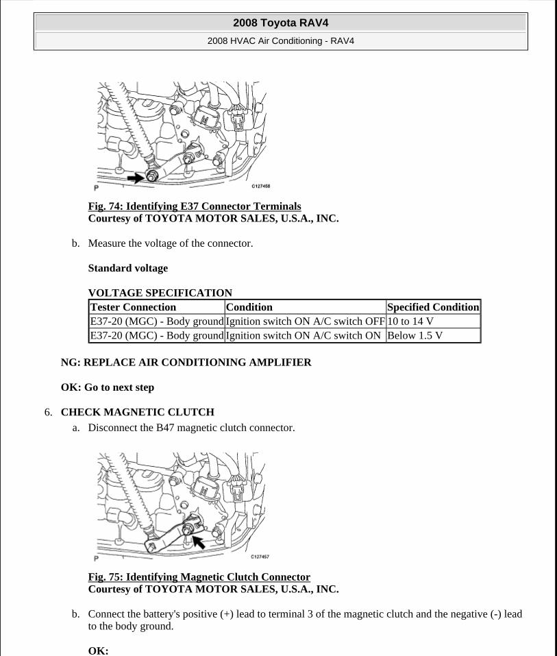
Fig. 74: Identifying E37 Connector Terminals Courtesy of TOYOTA MOTOR SALES, U.S.A., INC.
b. Measure the voltage of the connector.
Standard voltage
VOLTAGE SPECIFICATION
NG: REPLACE AIR CONDITIONING AMPLIFIER
OK: Go to next step
6. CHECK MAGNETIC CLUTCH
a. Disconnect the B47 magnetic clutch connector.
Fig. 75: Identifying Magnetic Clutch Connector Courtesy of TOYOTA MOTOR SALES, U.S.A., INC.
b. Connect the battery's positive (+) lead to terminal 3 of the magnetic clutch and the negative (-) lead to the body ground.
OK:
Tester Connection Condition Specified ConditionE37-20 (MGC) - Body ground Ignition switch ON A/C switch OFF 10 to 14 VE37-20 (MGC) - Body ground Ignition switch ON A/C switch ON Below 1.5 V
2008 Toyota RAV4
2008 HVAC Air Conditioning - RAV4
Microsoft
Tuesday, August 18, 2009 3:53:54 PM Page 89 © 2005 Mitchell Repair Information Company, LLC.
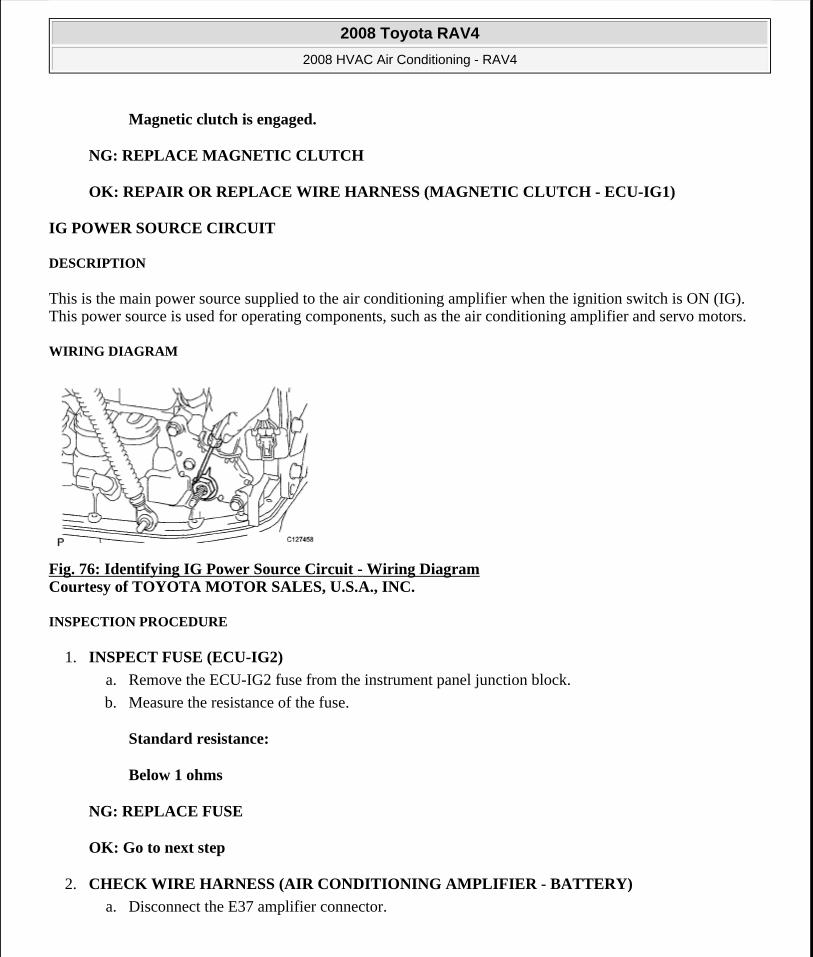
Magnetic clutch is engaged.
NG: REPLACE MAGNETIC CLUTCH
OK: REPAIR OR REPLACE WIRE HARNESS (MAGNETIC CLUTCH - ECU-IG1)
IG POWER SOURCE CIRCUIT
DESCRIPTION
This is the main power source supplied to the air conditioning amplifier when the ignition switch is ON (IG). This power source is used for operating components, such as the air conditioning amplifier and servo motors.
WIRING DIAGRAM
Fig. 76: Identifying IG Power Source Circuit - Wiring Diagram Courtesy of TOYOTA MOTOR SALES, U.S.A., INC.
INSPECTION PROCEDURE
1. INSPECT FUSE (ECU-IG2)
a. Remove the ECU-IG2 fuse from the instrument panel junction block.
b. Measure the resistance of the fuse.
Standard resistance:
Below 1 ohms
NG: REPLACE FUSE
OK: Go to next step
2. CHECK WIRE HARNESS (AIR CONDITIONING AMPLIFIER - BATTERY)
a. Disconnect the E37 amplifier connector.
2008 Toyota RAV4
2008 HVAC Air Conditioning - RAV4
Microsoft
Tuesday, August 18, 2009 3:53:54 PM Page 90 © 2005 Mitchell Repair Information Company, LLC.

Fig. 77: Identifying E37 Connector Terminals Courtesy of TOYOTA MOTOR SALES, U.S.A., INC.
b. Measure the voltage of the wire harness side connector.
Standard voltage
VOLTAGE SPECIFICATION
NG: REPAIR OR REPLACE HARNESS AND CONNECTOR
OK: Go to next step
3. CHECK WIRE HARNESS (AIR CONDITIONING AMPLIFIER - BODY GROUND)
a. Disconnect the E37 amplifier connector.
Fig. 78: Identifying E37 Connector Terminals Courtesy of TOYOTA MOTOR SALES, U.S.A., INC.
b. Measure the resistance of the wire harness side connector.
Standard resistance
RESISTANCE SPECIFICATION
Tester Connection Condition Specified ConditionE37-1 (IG+) - Body ground Ignition switch ON 10 to 14 V
2008 Toyota RAV4
2008 HVAC Air Conditioning - RAV4
Microsoft
Tuesday, August 18, 2009 3:53:54 PM Page 91 © 2005 Mitchell Repair Information Company, LLC.
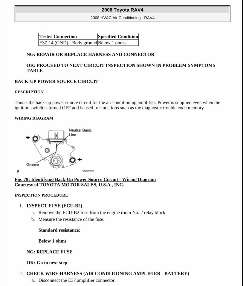
NG: REPAIR OR REPLACE HARNESS AND CONNECTOR
OK: PROCEED TO NEXT CIRCUIT INSPECTION SHOWN IN PROBLEM SYMPTOMS TABLE
BACK-UP POWER SOURCE CIRCUIT
DESCRIPTION
This is the back-up power source circuit for the air conditioning amplifier. Power is supplied even when the ignition switch is turned OFF and is used for functions such as the diagnostic trouble code memory.
WIRING DIAGRAM
Fig. 79: Identifying Back-Up Power Source Circuit - Wiring Diagram Courtesy of TOYOTA MOTOR SALES, U.S.A., INC.
INSPECTION PROCEDURE
1. INSPECT FUSE (ECU-B2)
a. Remove the ECU-B2 fuse from the engine room No. 2 relay block.
b. Measure the resistance of the fuse.
Standard resistance:
Below 1 ohms
NG: REPLACE FUSE
OK: Go to next step
2. CHECK WIRE HARNESS (AIR CONDITIONING AMPLIFIER - BATTERY)
a. Disconnect the E37 amplifier connector.
Tester Connection Specified ConditionE37-14 (GND) - Body ground Below 1 ohms
2008 Toyota RAV4
2008 HVAC Air Conditioning - RAV4
Microsoft
Tuesday, August 18, 2009 3:53:54 PM Page 92 © 2005 Mitchell Repair Information Company, LLC.

Fig. 80: Identifying E37 Connector Terminals Courtesy of TOYOTA MOTOR SALES, U.S.A., INC.
b. Measure the voltage of the wire harness side connector.
Standard voltage
VOLTAGE SPECIFICATION
NG: REPAIR OR REPLACE HARNESS AND CONNECTOR
OK: Go to next step
3. CHECK WIRE HARNESS (AIR CONDITIONING AMPLIFIER - BODY GROUND)
a. Disconnect the E37 amplifier connector.
Fig. 81: Identifying E37 Connector Terminals Courtesy of TOYOTA MOTOR SALES, U.S.A., INC.
b. Measure the resistance of the wire harness side connector.
Standard resistance
RESISTANCE SPECIFICATION
Tester Connection Specified ConditionE37-21 (B) - Body ground 10 to 14 V
2008 Toyota RAV4
2008 HVAC Air Conditioning - RAV4
Microsoft
Tuesday, August 18, 2009 3:53:54 PM Page 93 © 2005 Mitchell Repair Information Company, LLC.
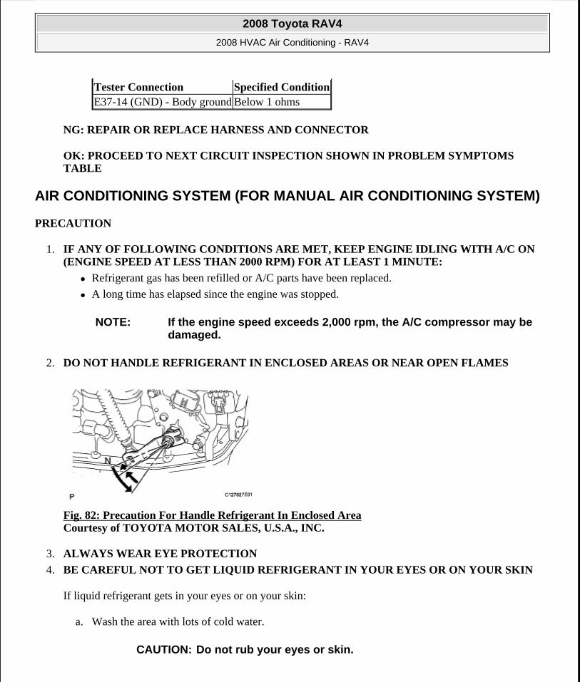
NG: REPAIR OR REPLACE HARNESS AND CONNECTOR
OK: PROCEED TO NEXT CIRCUIT INSPECTION SHOWN IN PROBLEM SYMPTOMS TABLE
AIR CONDITIONING SYSTEM (FOR MANUAL AIR CONDITIONING SYSTEM)
PRECAUTION
1. IF ANY OF FOLLOWING CONDITIONS ARE MET, KEEP ENGINE IDLING WITH A/C ON (ENGINE SPEED AT LESS THAN 2000 RPM) FOR AT LEAST 1 MINUTE:
Refrigerant gas has been refilled or A/C parts have been replaced.
A long time has elapsed since the engine was stopped.
2. DO NOT HANDLE REFRIGERANT IN ENCLOSED AREAS OR NEAR OPEN FLAMES
Fig. 82: Precaution For Handle Refrigerant In Enclosed Area Courtesy of TOYOTA MOTOR SALES, U.S.A., INC.
3. ALWAYS WEAR EYE PROTECTION
4. BE CAREFUL NOT TO GET LIQUID REFRIGERANT IN YOUR EYES OR ON YOUR SKIN
If liquid refrigerant gets in your eyes or on your skin:
a. Wash the area with lots of cold water.
Tester Connection Specified ConditionE37-14 (GND) - Body ground Below 1 ohms
NOTE: If the engine speed exceeds 2,000 rpm, the A/C compressor may be damaged.
CAUTION: Do not rub your eyes or skin.
2008 Toyota RAV4
2008 HVAC Air Conditioning - RAV4
Microsoft
Tuesday, August 18, 2009 3:53:54 PM Page 94 © 2005 Mitchell Repair Information Company, LLC.
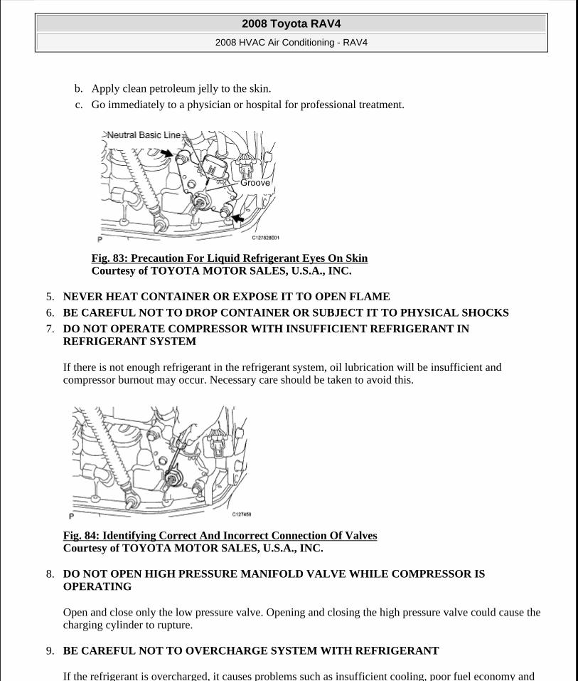
b. Apply clean petroleum jelly to the skin.
c. Go immediately to a physician or hospital for professional treatment.
Fig. 83: Precaution For Liquid Refrigerant Eyes On Skin Courtesy of TOYOTA MOTOR SALES, U.S.A., INC.
5. NEVER HEAT CONTAINER OR EXPOSE IT TO OPEN FLAME
6. BE CAREFUL NOT TO DROP CONTAINER OR SUBJECT IT TO PHYSICAL SHOCKS
7. DO NOT OPERATE COMPRESSOR WITH INSUFFICIENT REFRIGERANT IN REFRIGERANT SYSTEM
If there is not enough refrigerant in the refrigerant system, oil lubrication will be insufficient and compressor burnout may occur. Necessary care should be taken to avoid this.
Fig. 84: Identifying Correct And Incorrect Connection Of Valves Courtesy of TOYOTA MOTOR SALES, U.S.A., INC.
8. DO NOT OPEN HIGH PRESSURE MANIFOLD VALVE WHILE COMPRESSOR IS OPERATING
Open and close only the low pressure valve. Opening and closing the high pressure valve could cause the charging cylinder to rupture.
9. BE CAREFUL NOT TO OVERCHARGE SYSTEM WITH REFRIGERANT
If the refrigerant is overcharged, it causes problems such as insufficient cooling, poor fuel economy and
2008 Toyota RAV4
2008 HVAC Air Conditioning - RAV4
Microsoft
Tuesday, August 18, 2009 3:53:54 PM Page 95 © 2005 Mitchell Repair Information Company, LLC.
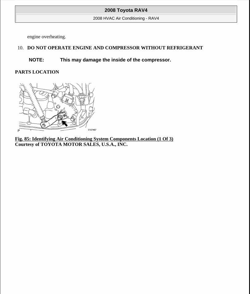
engine overheating.
10. DO NOT OPERATE ENGINE AND COMPRESSOR WITHOUT REFRIGERANT
PARTS LOCATION
Fig. 85: Identifying Air Conditioning System Components Location (1 Of 3) Courtesy of TOYOTA MOTOR SALES, U.S.A., INC.
NOTE: This may damage the inside of the compressor.
2008 Toyota RAV4
2008 HVAC Air Conditioning - RAV4
Microsoft
Tuesday, August 18, 2009 3:53:54 PM Page 96 © 2005 Mitchell Repair Information Company, LLC.
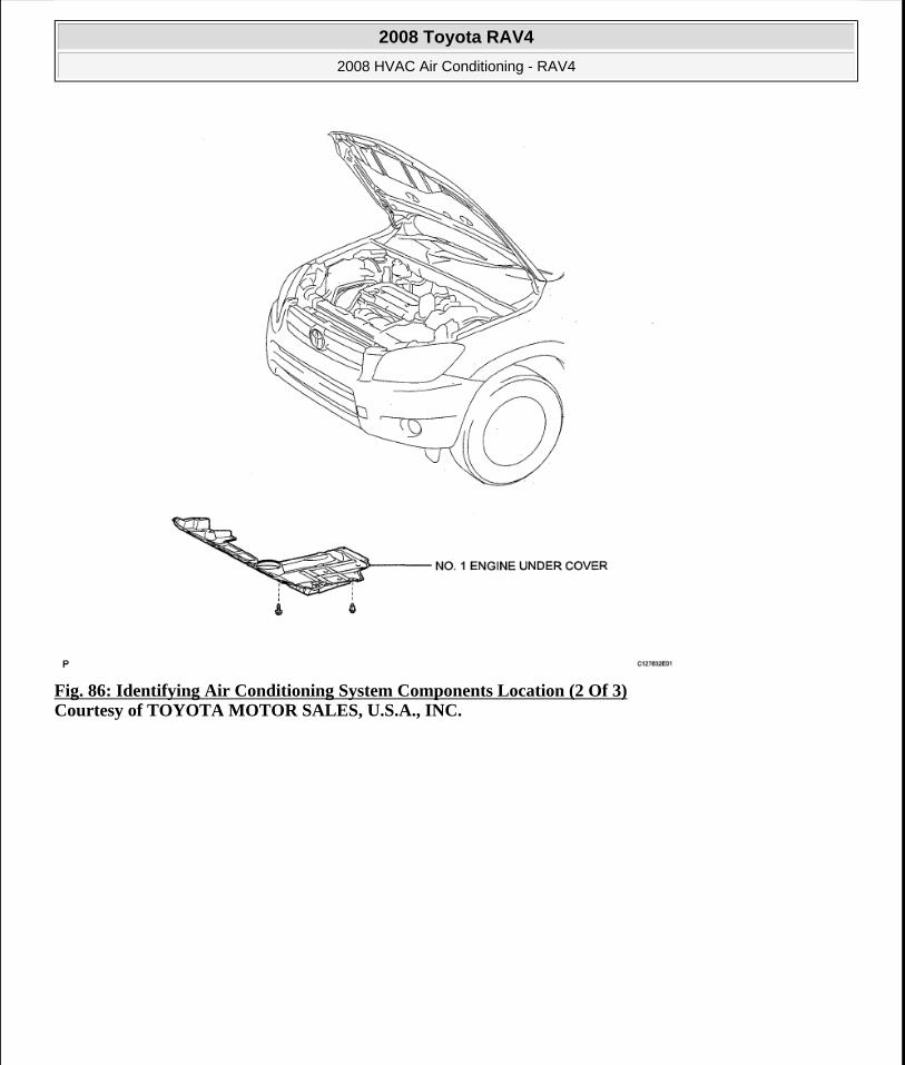
Fig. 86: Identifying Air Conditioning System Components Location (2 Of 3) Courtesy of TOYOTA MOTOR SALES, U.S.A., INC.
2008 Toyota RAV4
2008 HVAC Air Conditioning - RAV4
Microsoft
Tuesday, August 18, 2009 3:53:54 PM Page 97 © 2005 Mitchell Repair Information Company, LLC.
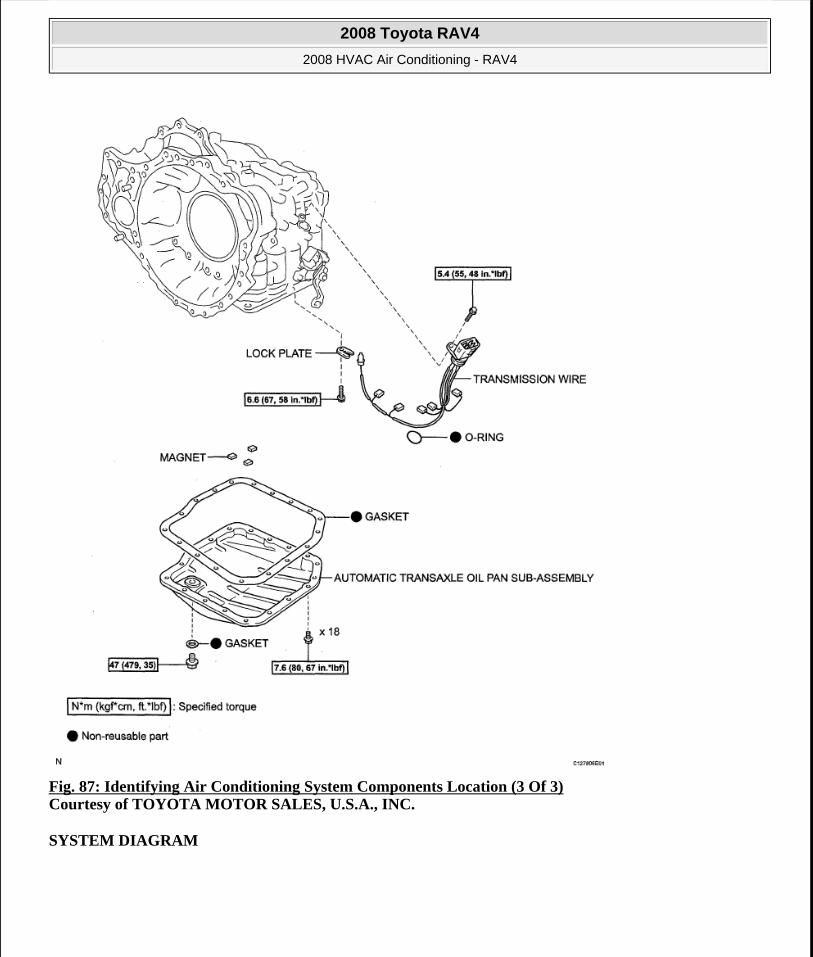
Fig. 87: Identifying Air Conditioning System Components Location (3 Of 3) Courtesy of TOYOTA MOTOR SALES, U.S.A., INC.
SYSTEM DIAGRAM
2008 Toyota RAV4
2008 HVAC Air Conditioning - RAV4
Microsoft
Tuesday, August 18, 2009 3:53:55 PM Page 98 © 2005 Mitchell Repair Information Company, LLC.
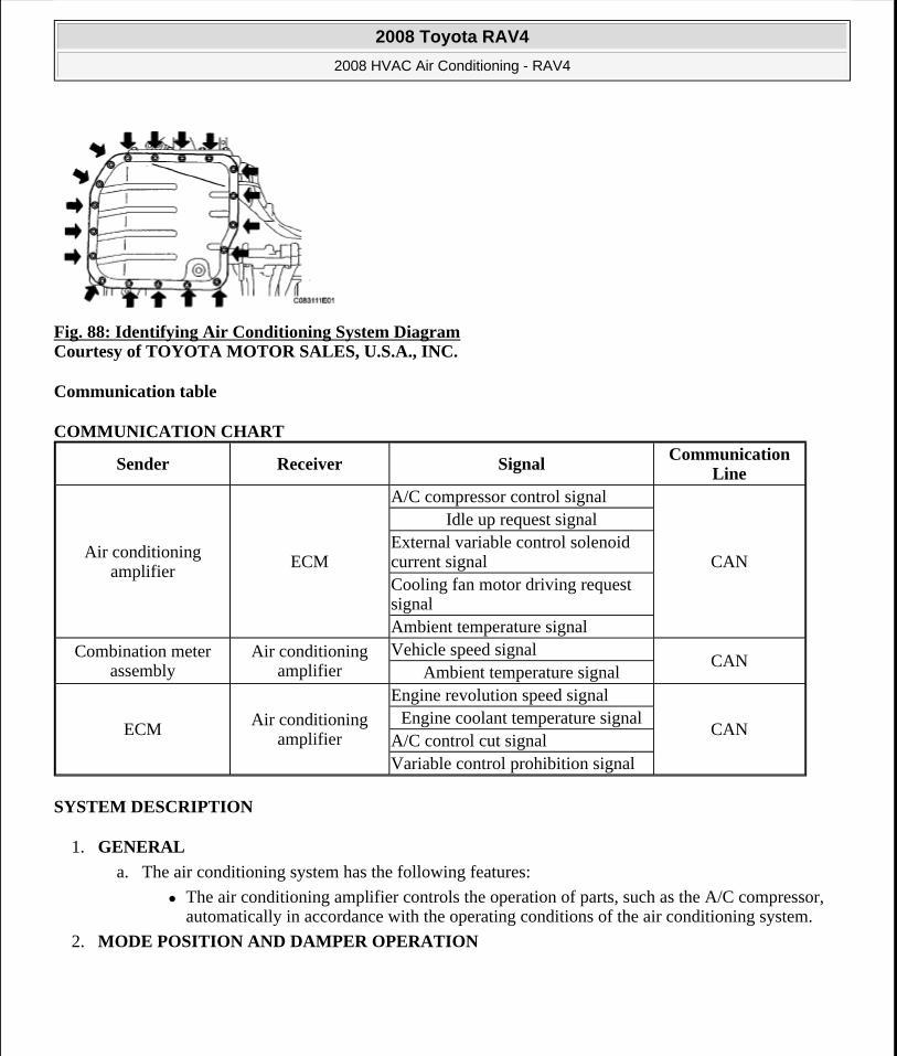
Fig. 88: Identifying Air Conditioning System Diagram Courtesy of TOYOTA MOTOR SALES, U.S.A., INC.
Communication table
COMMUNICATION CHART
SYSTEM DESCRIPTION
1. GENERAL
a. The air conditioning system has the following features:
The air conditioning amplifier controls the operation of parts, such as the A/C compressor, automatically in accordance with the operating conditions of the air conditioning system.
2. MODE POSITION AND DAMPER OPERATION
Sender Receiver SignalCommunication
Line
Air conditioning amplifier
ECM
A/C compressor control signal
CAN
Idle up request signalExternal variable control solenoid current signalCooling fan motor driving request signalAmbient temperature signal
Combination meter assembly
Air conditioning amplifier
Vehicle speed signalCAN
Ambient temperature signal
ECMAir conditioning
amplifier
Engine revolution speed signal
CANEngine coolant temperature signal
A/C control cut signalVariable control prohibition signal
2008 Toyota RAV4
2008 HVAC Air Conditioning - RAV4
Microsoft
Tuesday, August 18, 2009 3:53:55 PM Page 99 © 2005 Mitchell Repair Information Company, LLC.
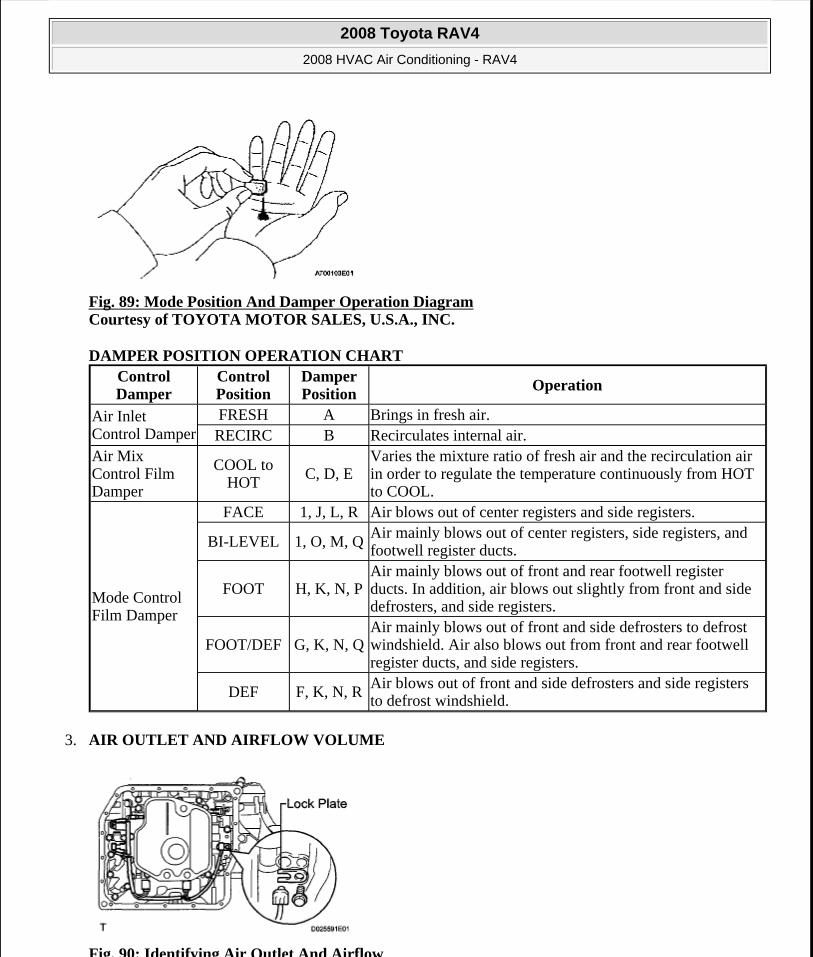
Fig. 89: Mode Position And Damper Operation Diagram Courtesy of TOYOTA MOTOR SALES, U.S.A., INC.
DAMPER POSITION OPERATION CHART
3. AIR OUTLET AND AIRFLOW VOLUME
Fig. 90: Identifying Air Outlet And Airflow
Control Damper
Control Position
Damper Position
Operation
Air Inlet Control Damper
FRESH A Brings in fresh air.RECIRC B Recirculates internal air.
Air Mix Control Film Damper
COOL to HOT C, D, E
Varies the mixture ratio of fresh air and the recirculation air in order to regulate the temperature continuously from HOT to COOL.
Mode Control Film Damper
FACE 1, J, L, R Air blows out of center registers and side registers.
BI-LEVEL 1, O, M, QAir mainly blows out of center registers, side registers, and footwell register ducts.
FOOT H, K, N, PAir mainly blows out of front and rear footwell register ducts. In addition, air blows out slightly from front and side defrosters, and side registers.
FOOT/DEF G, K, N, QAir mainly blows out of front and side defrosters to defrost windshield. Air also blows out from front and rear footwell register ducts, and side registers.
DEF F, K, N, RAir blows out of front and side defrosters and side registers to defrost windshield.
2008 Toyota RAV4
2008 HVAC Air Conditioning - RAV4
Microsoft
Tuesday, August 18, 2009 3:53:55 PM Page 100 © 2005 Mitchell Repair Information Company, LLC.
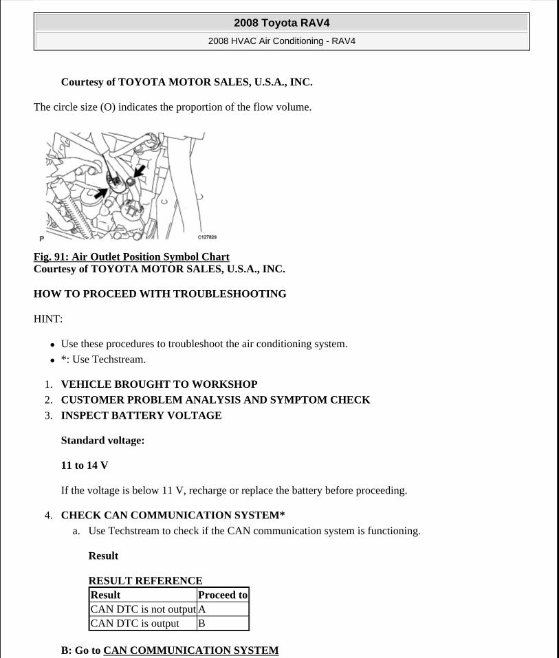
Courtesy of TOYOTA MOTOR SALES, U.S.A., INC.
The circle size (O) indicates the proportion of the flow volume.
Fig. 91: Air Outlet Position Symbol Chart Courtesy of TOYOTA MOTOR SALES, U.S.A., INC.
HOW TO PROCEED WITH TROUBLESHOOTING
HINT:
Use these procedures to troubleshoot the air conditioning system.
*: Use Techstream.
1. VEHICLE BROUGHT TO WORKSHOP
2. CUSTOMER PROBLEM ANALYSIS AND SYMPTOM CHECK
3. INSPECT BATTERY VOLTAGE
Standard voltage:
11 to 14 V
If the voltage is below 11 V, recharge or replace the battery before proceeding.
4. CHECK CAN COMMUNICATION SYSTEM*
a. Use Techstream to check if the CAN communication system is functioning.
Result
RESULT REFERENCE
B: Go to CAN COMMUNICATION SYSTEM
Result Proceed toCAN DTC is not output ACAN DTC is output B
2008 Toyota RAV4
2008 HVAC Air Conditioning - RAV4
Microsoft
Tuesday, August 18, 2009 3:53:55 PM Page 101 © 2005 Mitchell Repair Information Company, LLC.
A: Go to next step
5. CHECK DTC*
a. Check for DTCs and write down any DTCs that are output.
b. Clear the DTCs.
c. Recheck for DTCs. Based on the DTCs output above, try to cause output of the air conditioning system DTC by simulating the operation indicated by the DTC.
Result
RESULT REFERENCE
B: Go to step 8
A: Go to next step
6. REFER TO PROBLEM SYMPTOMS TABLE
Result
RESULT REFERENCE
B: Go to step 8
A: Go to next step
7. OVERALL ANALYSIS AND TROUBLESHOOTING*
a. DATA LIST / ACTIVE TEST (see DATA LIST / ACTIVE TEST )
b. Terminals of ECU (see TERMINALS OF ECU )
8. ADJUST, REPAIR OR REPLACE
9. CONFIRMATION TEST
NEXT: END
PROBLEM SYMPTOMS TABLE
HINT:
Result Proceed toDTC is not output ADTC is output B
Result Proceed toFault is not listed in problem symptoms table AFault is listed in problem symptoms table B
2008 Toyota RAV4
2008 HVAC Air Conditioning - RAV4
Microsoft
Tuesday, August 18, 2009 3:53:55 PM Page 102 © 2005 Mitchell Repair Information Company, LLC.
Use the table below to help determine the cause of the problem symptom. The potential causes of the symptoms are listed in order of probability in the "Suspected area" column of the table. Check each symptom by checking the suspected areas in the order they are listed. Replace parts as necessary.
Inspect the fuses and relays related to this system before inspecting the suspected areas below.
Air conditioning system
PROBLEM SYMPTOMS CHART Symptom Suspected Area See
No functions of A/C system operate
1. ECU-IG2 fuse -2. Wire harness or connector
-
3. Air conditioning amplifier
TERMINALS OF ECU
Airflow Control: Blower motor does not operate
1. HTR, ECU-IG1 fuse -2. Blower motor circuit BLOWER MOTOR CIRCUIT3. Blower motor BLOWER MOTOR4. Wire harness or connector
-
Airflow Control: Blower motor does not change speed
1. Blower resistor BLOWER RESISTOR2. Blower motor BLOWER MOTOR
3. Heater control (blower switch)
AIR CONDITIONING PANEL (FOR MANUAL AIR CONDITIONING SYSTEM)
Temperature Control: No cool air comes out
1. Refrigerant volume -2. Refrigerant pressure -3. Air conditioning pressure sensor circuit
DTC B1423/23 PRESSURE SENSOR CIRCUIT
4. Heater control base (A/C switch)
AIR CONDITIONING PANEL (FOR MANUAL AIR CONDITIONING SYSTEM)
5. Compressor and pulley (for 2AZ-FE)
COMPRESSOR AND PULLEY (FOR 2AZ-FE)
6. Compressor and magnetic clutch (for 2GR-FE)
COMPRESSOR AND PULLEY (FOR 2GR-FE)
7. Compressor circuit COMPRESSOR CIRCUIT8. Expansion valve -9. Air conditioning amplifier
TERMINALS OF ECU
10. ECM (for 2AZ-FE) SFI SYSTEM 11. ECM (for 2GR-FE) SFI SYSTEM 12. CAN communication CAN COMMUNICATION SYSTEM
2008 Toyota RAV4
2008 HVAC Air Conditioning - RAV4
Microsoft
Tuesday, August 18, 2009 3:53:55 PM Page 103 © 2005 Mitchell Repair Information Company, LLC.
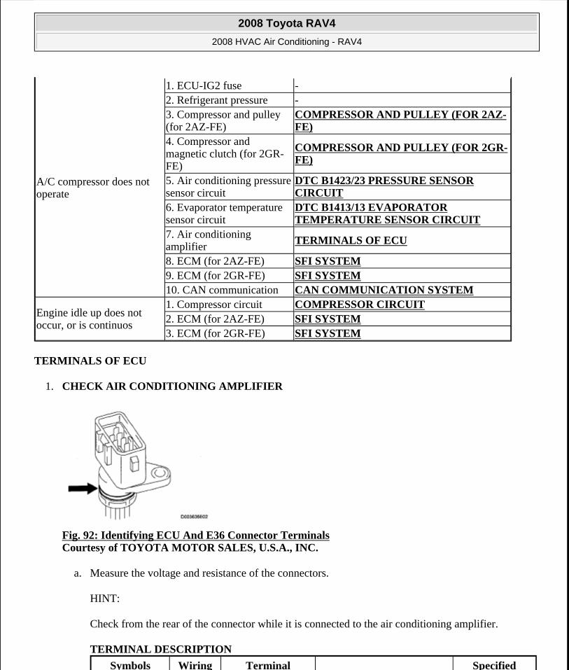
TERMINALS OF ECU
1. CHECK AIR CONDITIONING AMPLIFIER
Fig. 92: Identifying ECU And E36 Connector Terminals Courtesy of TOYOTA MOTOR SALES, U.S.A., INC.
a. Measure the voltage and resistance of the connectors.
HINT:
Check from the rear of the connector while it is connected to the air conditioning amplifier.
TERMINAL DESCRIPTION
A/C compressor does not operate
1. ECU-IG2 fuse -2. Refrigerant pressure -3. Compressor and pulley (for 2AZ-FE)
COMPRESSOR AND PULLEY (FOR 2AZ-FE)
4. Compressor and magnetic clutch (for 2GR-FE)
COMPRESSOR AND PULLEY (FOR 2GR-FE)
5. Air conditioning pressure sensor circuit
DTC B1423/23 PRESSURE SENSOR CIRCUIT
6. Evaporator temperature sensor circuit
DTC B1413/13 EVAPORATOR TEMPERATURE SENSOR CIRCUIT
7. Air conditioning amplifier
TERMINALS OF ECU
8. ECM (for 2AZ-FE) SFI SYSTEM 9. ECM (for 2GR-FE) SFI SYSTEM 10. CAN communication CAN COMMUNICATION SYSTEM
Engine idle up does not occur, or is continuos
1. Compressor circuit COMPRESSOR CIRCUIT2. ECM (for 2AZ-FE) SFI SYSTEM 3. ECM (for 2GR-FE) SFI SYSTEM
Symbols Wiring Terminal Specified
2008 Toyota RAV4
2008 HVAC Air Conditioning - RAV4
Microsoft
Tuesday, August 18, 2009 3:53:55 PM Page 104 © 2005 Mitchell Repair Information Company, LLC.
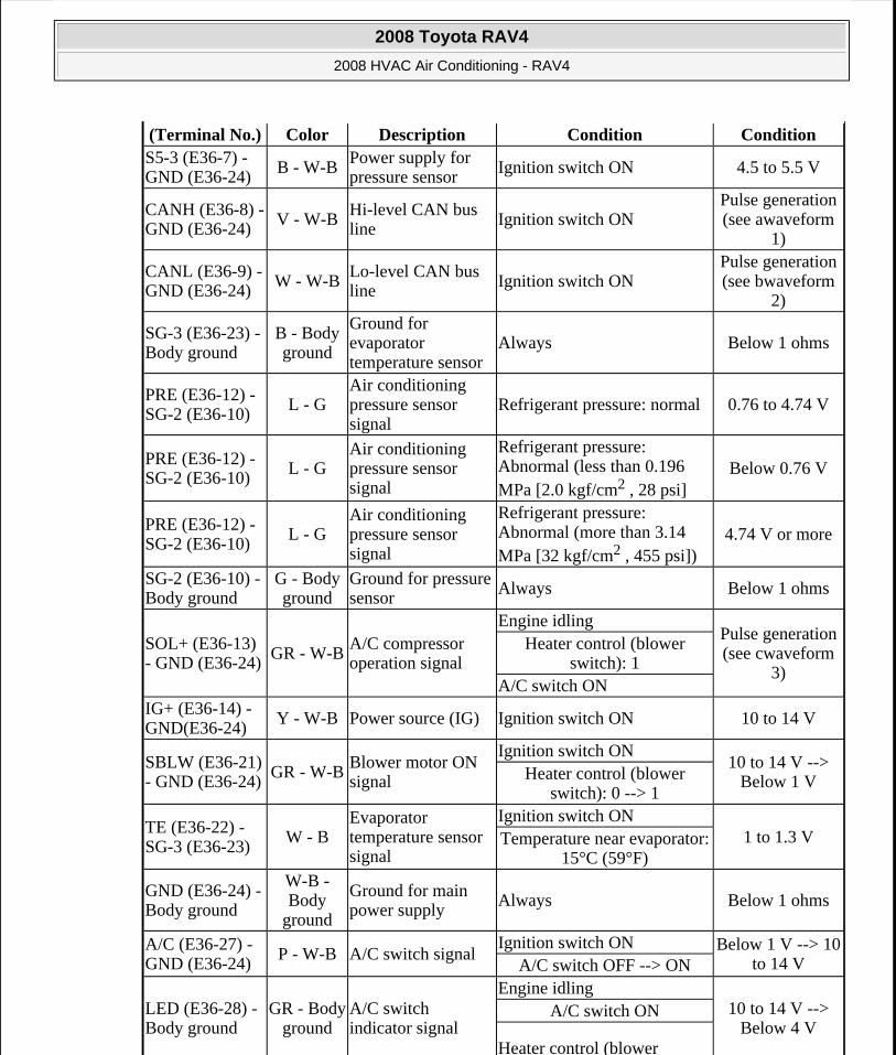
(Terminal No.) Color Description Condition ConditionS5-3 (E36-7) - GND (E36-24) B - W-B
Power supply for pressure sensor Ignition switch ON 4.5 to 5.5 V
CANH (E36-8) - GND (E36-24) V - W-B
Hi-level CAN bus line Ignition switch ON
Pulse generation (see awaveform
1)
CANL (E36-9) - GND (E36-24) W - W-B
Lo-level CAN bus line Ignition switch ON
Pulse generation (see bwaveform
2)
SG-3 (E36-23) - Body ground
B - Body ground
Ground for evaporator temperature sensor
Always Below 1 ohms
PRE (E36-12) - SG-2 (E36-10)
L - GAir conditioning pressure sensor signal
Refrigerant pressure: normal 0.76 to 4.74 V
PRE (E36-12) - SG-2 (E36-10)
L - GAir conditioning pressure sensor signal
Refrigerant pressure: Abnormal (less than 0.196 MPa [2.0 kgf/cm2 , 28 psi]
Below 0.76 V
PRE (E36-12) - SG-2 (E36-10)
L - GAir conditioning pressure sensor signal
Refrigerant pressure: Abnormal (more than 3.14 MPa [32 kgf/cm2 , 455 psi])
4.74 V or more
SG-2 (E36-10) - Body ground
G - Body ground
Ground for pressure sensor Always Below 1 ohms
SOL+ (E36-13) - GND (E36-24) GR - W-B
A/C compressor operation signal
Engine idlingPulse generation (see cwaveform
3)
Heater control (blower switch): 1
A/C switch ONIG+ (E36-14) - GND(E36-24)
Y - W-B Power source (IG) Ignition switch ON 10 to 14 V
SBLW (E36-21) - GND (E36-24) GR - W-B
Blower motor ON signal
Ignition switch ON10 to 14 V -->
Below 1 VHeater control (blower switch): 0 --> 1
TE (E36-22) - SG-3 (E36-23)
W - BEvaporator temperature sensor signal
Ignition switch ON1 to 1.3 VTemperature near evaporator:
15°C (59°F)
GND (E36-24) - Body ground
W-B - Body
ground
Ground for main power supply
Always Below 1 ohms
A/C (E36-27) - GND (E36-24)
P - W-B A/C switch signalIgnition switch ON Below 1 V --> 10
to 14 VA/C switch OFF --> ON
LED (E36-28) - Body ground
GR - Body ground
A/C switch indicator signal
Engine idling10 to 14 V -->
Below 4 VA/C switch ON
Heater control (blower
2008 Toyota RAV4
2008 HVAC Air Conditioning - RAV4
Microsoft
Tuesday, August 18, 2009 3:53:55 PM Page 105 © 2005 Mitchell Repair Information Company, LLC.
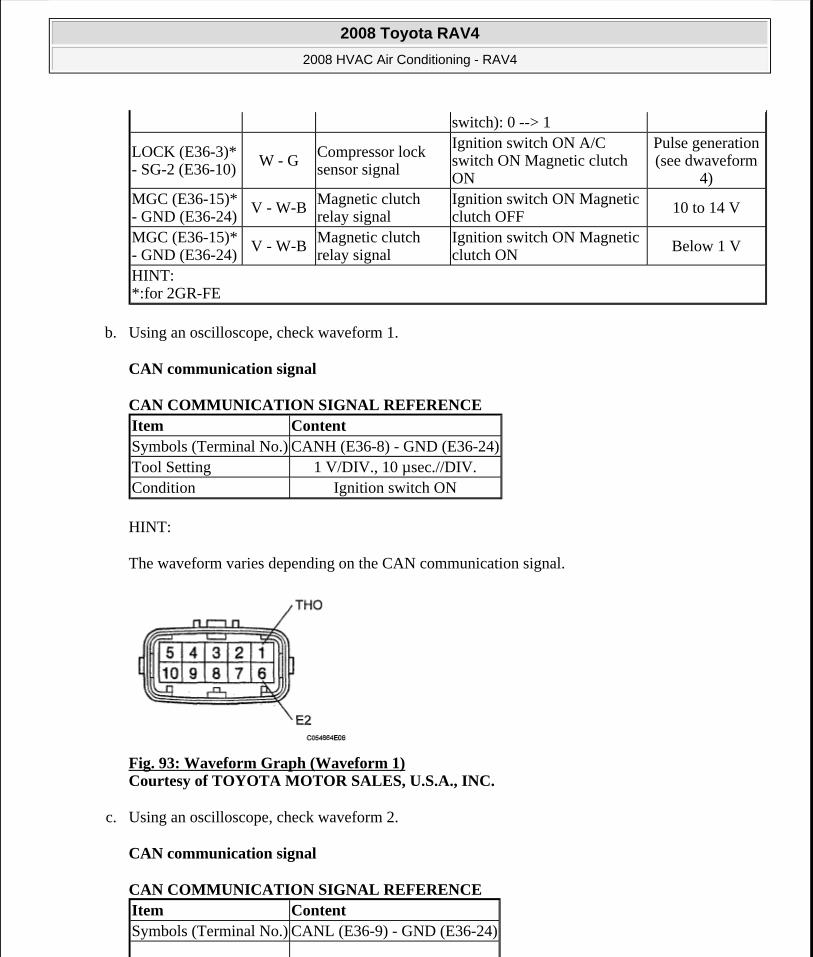
b. Using an oscilloscope, check waveform 1.
CAN communication signal
CAN COMMUNICATION SIGNAL REFERENCE
HINT:
The waveform varies depending on the CAN communication signal.
Fig. 93: Waveform Graph (Waveform 1) Courtesy of TOYOTA MOTOR SALES, U.S.A., INC.
c. Using an oscilloscope, check waveform 2.
CAN communication signal
CAN COMMUNICATION SIGNAL REFERENCE
switch): 0 --> 1
LOCK (E36-3)* - SG-2 (E36-10)
W - G Compressor lock sensor signal
Ignition switch ON A/C switch ON Magnetic clutch ON
Pulse generation (see dwaveform
4)MGC (E36-15)* - GND (E36-24)
V - W-B Magnetic clutch relay signal
Ignition switch ON Magnetic clutch OFF
10 to 14 V
MGC (E36-15)* - GND (E36-24)
V - W-BMagnetic clutch relay signal
Ignition switch ON Magnetic clutch ON
Below 1 V
HINT: *:for 2GR-FE
Item ContentSymbols (Terminal No.) CANH (E36-8) - GND (E36-24)Tool Setting 1 V/DIV., 10 µsec.//DIV.Condition Ignition switch ON
Item ContentSymbols (Terminal No.) CANL (E36-9) - GND (E36-24)
2008 Toyota RAV4
2008 HVAC Air Conditioning - RAV4
Microsoft
Tuesday, August 18, 2009 3:53:55 PM Page 106 © 2005 Mitchell Repair Information Company, LLC.
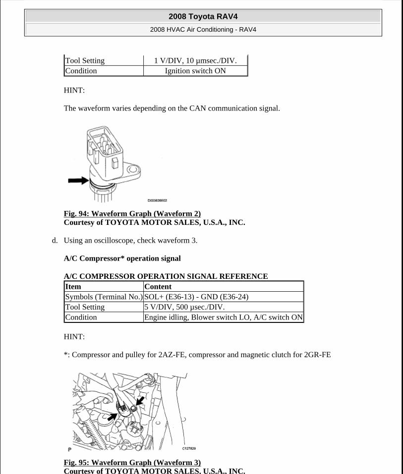
HINT:
The waveform varies depending on the CAN communication signal.
Fig. 94: Waveform Graph (Waveform 2) Courtesy of TOYOTA MOTOR SALES, U.S.A., INC.
d. Using an oscilloscope, check waveform 3.
A/C Compressor* operation signal
A/C COMPRESSOR OPERATION SIGNAL REFERENCE
HINT:
*: Compressor and pulley for 2AZ-FE, compressor and magnetic clutch for 2GR-FE
Fig. 95: Waveform Graph (Waveform 3) Courtesy of TOYOTA MOTOR SALES, U.S.A., INC.
Tool Setting 1 V/DIV, 10 µmsec./DIV.Condition Ignition switch ON
Item ContentSymbols (Terminal No.) SOL+ (E36-13) - GND (E36-24)Tool Setting 5 V/DIV, 500 µsec./DIV.Condition Engine idling, Blower switch LO, A/C switch ON
2008 Toyota RAV4
2008 HVAC Air Conditioning - RAV4
Microsoft
Tuesday, August 18, 2009 3:53:55 PM Page 107 © 2005 Mitchell Repair Information Company, LLC.

e. Using an oscilloscope, check waveform 4.
Compressor lock sensor signal*
COMPRESSOR LOCK SENSOR SIGNAL REFERENCE
Fig. 96: Waveform Graph (Waveform 4) Courtesy of TOYOTA MOTOR SALES, U.S.A., INC.
DIAGNOSIS SYSTEM
1. DESCRIPTION
a. Air conditioning system data and the Diagnostic Trouble Codes (DTCs) can be read through the Data Link Connector 3 (DLC3) of the vehicle. When the system seems to be malfunctioning, use Techstream to check for malfunctions and perform troubleshooting.
2. CHECK DLC3
The vehicle's ECM uses the ISO 15765-4 for communication protocol. The terminal arrangement of the DLC3 complies with SAE J1962 and matches the ISO 15765-4 format.
Item ContentSymbols (Terminal No.) LOCK (E36-3)* - SG-2 (E36-10)Tool Setting 500 mV/DIV, 20 msec./DIV.Condition Ignition switch ON, A/C switch ON, Magnetic clutch ONHINT: *: for 2GR-FE
2008 Toyota RAV4
2008 HVAC Air Conditioning - RAV4
Microsoft
Tuesday, August 18, 2009 3:53:55 PM Page 108 © 2005 Mitchell Repair Information Company, LLC.

Fig. 97: Identifying DLC3 Connector TerminalsCourtesy of TOYOTA MOTOR SALES, U.S.A., INC.
TERMINAL DESCRIPTION
If the result is not as specified, the DLC3 may have a malfunction. Repair or replace the harness and connector.
HINT:
Connect the cable of Techstream to the DLC3, turn the ignition switch ON and attempt to use the tester. If the display indicates that a communication error has occurred, there is a problem either with the vehicle or with the tester.
If communication is normal when the tester is connected to another vehicle, inspect the DLC3 of the original vehicle.
If communication is still not possible when the tester is connected to another vehicle, the problem may be in the tester itself. Consult the Service Department listed in the tester's instruction article.
DTC CHECK / CLEAR
1. CHECK DTC
a. Connect Techstream to the DLC3.
b. Turn the ignition switch ON and turn Techstream ON.
c. Read the DTC by following the prompts on the tester screen.
HINT:
Refer to Techstream operator's article for further details.
Symbols (Terminal No.) Terminal Description Condition Specified ConditionSIL (7) - SG(5) Bus "+" line During transmission Pulse generationCG (4) - Body ground Chassis ground Always Below 1 ohmsSG (5) - Body ground Signal ground Always Below 1 ohmsBAT (16) - Body ground Battery positive Always 10 to 14 V
CANH (6) - CANL (14) CAN bus line Ignition switch LOCK(1) 54 to 69 ohms
CANH (6) - CG (4) HIGH-level CAN bus line Ignition switch LOCK(1) 200 ohms or higher
CANL (14) - CG (4) LOW-level CAN bus line Ignition switch LOCK(1) 200 ohms or higher
CANH (6) - BAT (16) HIGH-level CAN bus line Ignition switch LOCK(1) 6 kohms or higher
CANL (14) - BAT (16) LOW-level CAN bus line Ignition switch LOCK(1) 6 kohms or higher
(1) Before measuring the resistance, leave the vehicle as is for at least 1 minute and do not operate the ignition switch, other switches or doors.
2008 Toyota RAV4
2008 HVAC Air Conditioning - RAV4
Microsoft
Tuesday, August 18, 2009 3:53:55 PM Page 109 © 2005 Mitchell Repair Information Company, LLC.
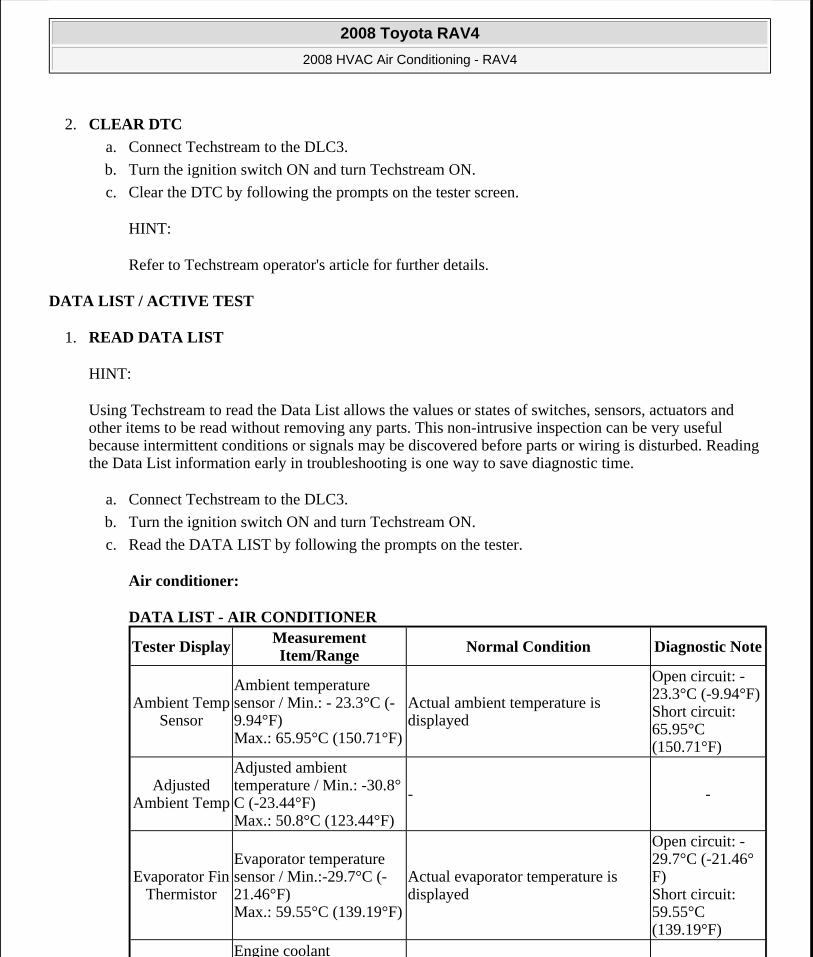
2. CLEAR DTC
a. Connect Techstream to the DLC3.
b. Turn the ignition switch ON and turn Techstream ON.
c. Clear the DTC by following the prompts on the tester screen.
HINT:
Refer to Techstream operator's article for further details.
DATA LIST / ACTIVE TEST
1. READ DATA LIST
HINT:
Using Techstream to read the Data List allows the values or states of switches, sensors, actuators and other items to be read without removing any parts. This non-intrusive inspection can be very useful because intermittent conditions or signals may be discovered before parts or wiring is disturbed. Reading the Data List information early in troubleshooting is one way to save diagnostic time.
a. Connect Techstream to the DLC3.
b. Turn the ignition switch ON and turn Techstream ON.
c. Read the DATA LIST by following the prompts on the tester.
Air conditioner:
DATA LIST - AIR CONDITIONER
Tester DisplayMeasurement Item/Range
Normal Condition Diagnostic Note
Ambient Temp Sensor
Ambient temperature sensor / Min.: - 23.3°C (-9.94°F) Max.: 65.95°C (150.71°F)
Actual ambient temperature is displayed
Open circuit: - 23.3°C (-9.94°F)Short circuit: 65.95°C (150.71°F)
Adjusted Ambient Temp
Adjusted ambient temperature / Min.: -30.8°C (-23.44°F) Max.: 50.8°C (123.44°F)
- -
Evaporator Fin Thermistor
Evaporator temperature sensor / Min.:-29.7°C (-21.46°F) Max.: 59.55°C (139.19°F)
Actual evaporator temperature is displayed
Open circuit: - 29.7°C (-21.46°F) Short circuit: 59.55°C (139.19°F)
Engine coolant
2008 Toyota RAV4
2008 HVAC Air Conditioning - RAV4
Microsoft
Tuesday, August 18, 2009 3:53:55 PM Page 110 © 2005 Mitchell Repair Information Company, LLC.
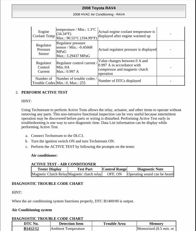
2. PERFORM ACTIVE TEST
HINT:
Using Techstream to perform Active Tests allows the relay, actuator, and other items to operate without removing any parts. This non-intrusive functional inspection can be very useful because intermittent operation may be discovered before parts or wiring is disturbed. Performing Active Test early in troubleshooting is one way to save diagnostic time. Data List information can be display while performing Active Test.
a. Connect Techstream to the DLC3.
b. Turn the ignition switch ON and turn Techstream ON.
c. Perform the ACTIVE TEST by following the prompts on the tester.
Air conditioner:
ACTIVE TEST - AIR CONDITIONER
DIAGNOSTIC TROUBLE CODE CHART
HINT:
When the air conditioning system functions properly, DTC B1400/00 is output.
Air Conditioning system
DIAGNOSTIC TROUBLE CODE CHART
Engine Coolant Temp
temperature / Min.: 1.3°C (34.34°F) Max.: 90.55°C (194.99°F)
Actual engine coolant temperature is displayed after engine warmed up -
Regulator Pressure Sensor
Regulator pressure sensor / Min.: -0.45668 MPaG Max.: 3.29437 MPaG
Actual regulator pressure is displayed -
Regulator Control Current
Regulator control current / Min.:0A Max.: 0.997 A
Value changes between 0 A and 0.997 A in accordance with compressor and magnetic clutch operation
-
Number of Trouble Codes
Number of trouble codes / Min.: 0, Max.: 255
Number of DTCs displayed -
Tester Display Test Part Control Range Diagnostic NoteMagnetic Clutch Relay Magnetic clutch relay OFF, ON Operating sound can be heard
DTC No. Detection Item Trouble Area MemoryB1412/12 Ambient Temperature Memorized (8.5 min. or
2008 Toyota RAV4
2008 HVAC Air Conditioning - RAV4
Microsoft
Tuesday, August 18, 2009 3:53:55 PM Page 111 © 2005 Mitchell Repair Information Company, LLC.
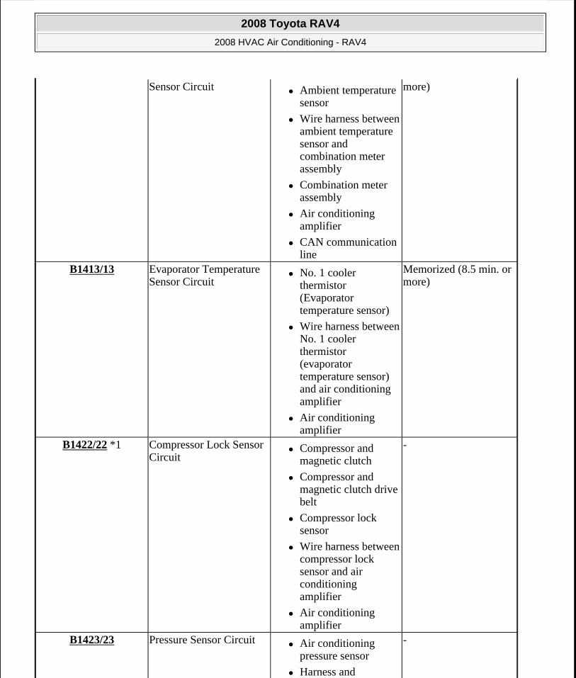
Sensor Circuit Ambient temperature sensor
Wire harness between ambient temperature sensor and combination meter assembly
Combination meter assembly
Air conditioning amplifier
CAN communication line
more)
B1413/13 Evaporator Temperature Sensor Circuit
No. 1 cooler thermistor (Evaporator temperature sensor)
Wire harness between No. 1 cooler thermistor (evaporator temperature sensor) and air conditioning amplifier
Air conditioning amplifier
Memorized (8.5 min. or more)
B1422/22 *1 Compressor Lock Sensor Circuit
Compressor and magnetic clutch
Compressor and magnetic clutch drive belt
Compressor lock sensor
Wire harness between compressor lock sensor and air conditioning amplifier
Air conditioning amplifier
-
B1423/23 Pressure Sensor Circuit Air conditioning pressure sensor
Harness and
-
2008 Toyota RAV4
2008 HVAC Air Conditioning - RAV4
Microsoft
Tuesday, August 18, 2009 3:53:55 PM Page 112 © 2005 Mitchell Repair Information Company, LLC.
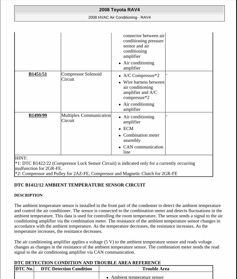
DTC B1412/12 AMBIENT TEMPERATURE SENSOR CIRCUIT
DESCRIPTION
The ambient temperature sensor is installed in the front part of the condenser to detect the ambient temperature and control the air conditioner. The sensor is connected to the combination meter and detects fluctuations in the ambient temperature. This data is used for controlling the room temperature. The sensor sends a signal to the air conditioning amplifier via the combination meter. The resistance of the ambient temperature sensor changes in accordance with the ambient temperature. As the temperature decreases, the resistance increases. As the temperature increases, the resistance decreases.
The air conditioning amplifier applies a voltage (5 V) to the ambient temperature sensor and reads voltage changes as changes in the resistance of the ambient temperature sensor. The combination meter sends the read signal to the air conditioning amplifier via CAN communication.
DTC DETECTION CONDITION AND TROUBLE AREA REFERENCE
connector between air conditioning pressure sensor and air conditioning amplifier
Air conditioning amplifier
B1451/51 Compressor Solenoid Circuit
A/C Compressor*2
Wire harness between air conditioning amplifier and A/C compressor*2
Air conditioning amplifier
-
B1499/99 Multiplex Communication Circuit
Air conditioning amplifier
ECM
Combination meter assembly
CAN communication line
-
HINT: *1: DTC B1422/22 (Compressor Lock Sensor Circuit) is indicated only for a currently occurring malfunction for 2GR-FE. *2: Compressor and Pulley for 2AZ-FE, Compressor and Magnetic Clutch for 2GR-FE
DTC No. DTC Detection Condition Trouble Area
Ambient temperature sensor
2008 Toyota RAV4
2008 HVAC Air Conditioning - RAV4
Microsoft
Tuesday, August 18, 2009 3:53:55 PM Page 113 © 2005 Mitchell Repair Information Company, LLC.
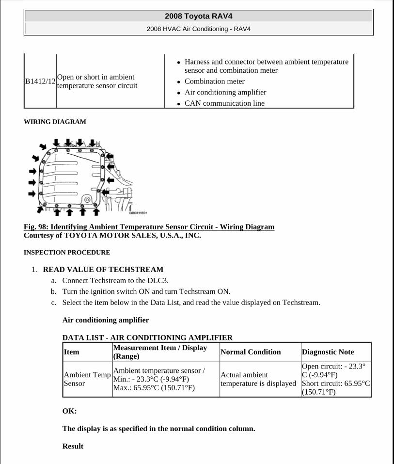
WIRING DIAGRAM
Fig. 98: Identifying Ambient Temperature Sensor Circuit - Wiring Diagram Courtesy of TOYOTA MOTOR SALES, U.S.A., INC.
INSPECTION PROCEDURE
1. READ VALUE OF TECHSTREAM
a. Connect Techstream to the DLC3.
b. Turn the ignition switch ON and turn Techstream ON.
c. Select the item below in the Data List, and read the value displayed on Techstream.
Air conditioning amplifier
DATA LIST - AIR CONDITIONING AMPLIFIER
OK:
The display is as specified in the normal condition column.
Result
B1412/12Open or short in ambient temperature sensor circuit
Harness and connector between ambient temperature sensor and combination meter
Combination meter
Air conditioning amplifier
CAN communication line
Item Measurement Item / Display (Range)
Normal Condition Diagnostic Note
Ambient Temp Sensor
Ambient temperature sensor / Min.: - 23.3°C (-9.94°F) Max.: 65.95°C (150.71°F)
Actual ambient temperature is displayed
Open circuit: - 23.3°C (-9.94°F) Short circuit: 65.95°C (150.71°F)
2008 Toyota RAV4
2008 HVAC Air Conditioning - RAV4
Microsoft
Tuesday, August 18, 2009 3:53:55 PM Page 114 © 2005 Mitchell Repair Information Company, LLC.
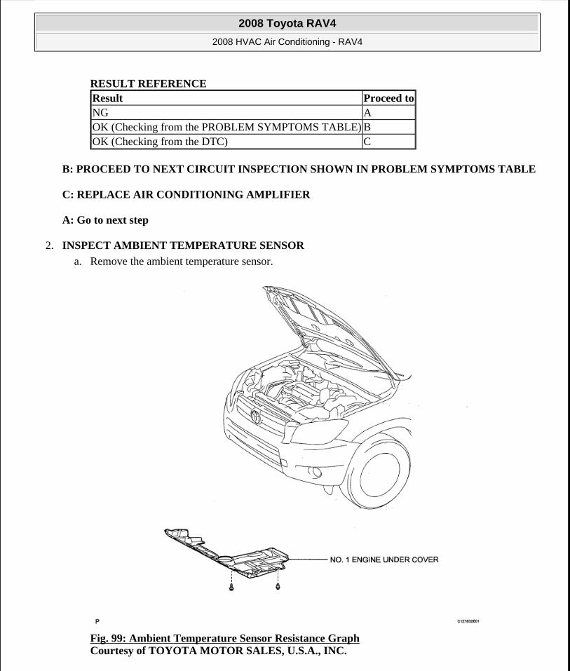
RESULT REFERENCE
B: PROCEED TO NEXT CIRCUIT INSPECTION SHOWN IN PROBLEM SYMPTOMS TABLE
C: REPLACE AIR CONDITIONING AMPLIFIER
A: Go to next step
2. INSPECT AMBIENT TEMPERATURE SENSOR
a. Remove the ambient temperature sensor.
Fig. 99: Ambient Temperature Sensor Resistance Graph Courtesy of TOYOTA MOTOR SALES, U.S.A., INC.
Result Proceed toNG AOK (Checking from the PROBLEM SYMPTOMS TABLE) BOK (Checking from the DTC) C
2008 Toyota RAV4
2008 HVAC Air Conditioning - RAV4
Microsoft
Tuesday, August 18, 2009 3:53:55 PM Page 115 © 2005 Mitchell Repair Information Company, LLC.
b. Measure the resistance of the sensor.
Standard resistance
RESISTANCE SPECIFICATION
HINT:
As the temperature increases, the resistance decreases (see the graph ).
NG: REPLACE AMBIENT TEMPERATURE SENSOR
OK: Go to next step
3. CHECK WIRE HARNESS (AMBIENT TEMPERATURE SENSOR - COMBINATION METER)
a. Disconnect the A17 sensor connector.
b. Disconnect the E19 meter connector.
Tester Connection Condition Specified Condition1 - 2 10°C (50°F) 3.00 to 3.73 kohms1 - 2 15°C (50°F) 2.45 to 2.88 kohms1 - 2 20°C (68°F) 1.95 to 2.30 kohms1 - 2 25°C (77°F) 1.60 to 1.80 kohms1 - 2 30°C (86°F) 1.28 to 1.47 kohms1 - 2 35°C (95°F) 1.00 to 1.22 kohms1 - 2 40°C (104°F) 0.80 to 1,00 kohms1 - 2 45°C (113°F) 0.65 to 0.85 kohms1 - 2 50°C (122°F) 0.50 to 0.70 kohms1 - 2 55°C (131°F) 0.44 to 0.60 kohms1 - 2 60°C (140°F) 0.36 to 0.50 kohms
NOTE: Touching the sensor even slightly may change the resistance value. Be sure to hold the connector of the sensor.
When measuring, the sensor temperature must be the same as the ambient temperature.
2008 Toyota RAV4
2008 HVAC Air Conditioning - RAV4
Microsoft
Tuesday, August 18, 2009 3:53:55 PM Page 116 © 2005 Mitchell Repair Information Company, LLC.
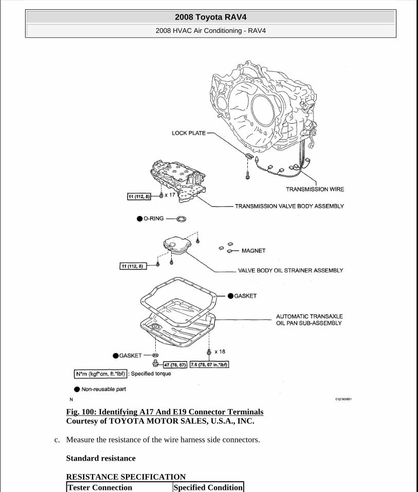
Fig. 100: Identifying A17 And E19 Connector Terminals Courtesy of TOYOTA MOTOR SALES, U.S.A., INC.
c. Measure the resistance of the wire harness side connectors.
Standard resistance
RESISTANCE SPECIFICATION Tester Connection Specified Condition
2008 Toyota RAV4
2008 HVAC Air Conditioning - RAV4
Microsoft
Tuesday, August 18, 2009 3:53:55 PM Page 117 © 2005 Mitchell Repair Information Company, LLC.
NG: REPAIR OR REPLACE HARNESS AND CONNECTOR
OK: REPLACE COMBINATION METER
DTC B1413/13 EVAPORATOR TEMPERATURE SENSOR CIRCUIT
DESCRIPTION
The No. 1 cooler thermistor (evaporator temperature sensor) is installed on the evaporator in the air conditioning unit to detect the temperature of the cooled air that has passed through the evaporator and to control the air conditioner. It sends signals to the air conditioning amplifier. The signals change in accordance with the resistance of the No. 1 cooler thermistor (evaporator temperature sensor). As the temperature decreases, the resistance increases. As the temperature increases, the resistance decreases. The air conditioning amplifier applies a voltage (5 V) to the No. 1 cooler thermistor (evaporator temperature sensor) and reads voltage changes as changes in the resistance of the No. 1 cooler thermistor (evaporator temperature sensor). This sensor is used for frost prevention.
DTC DETECTION CONDITION AND TROUBLE AREA REFERENCE
WIRING DIAGRAM
Fig. 101: Identifying Evaporator Temperature Sensor Circuit - Wiring Diagram Courtesy of TOYOTA MOTOR SALES, U.S.A., INC.
A17-2 (OT+) - E19-23 (TEMP) Below 1 ohmsA17-1 (OT-) - E19-11 (TX1+) Below 1 ohmsA17-2 (OT+) - Body ground 1 Mohms or higherA17-1 (OT-) - Body ground 1 Mohms or higher
DTC No. DTC Detection Condition Trouble Area
B1413/13Open or short in evaporator temperature sensor circuit
No. 1 cooler thermistor (evaporator temperature sensor)
Harness and connector between No. 1 cooler thermistor (evaporator temperature sensor) and air conditioning amplifier
Air conditioning amplifier
2008 Toyota RAV4
2008 HVAC Air Conditioning - RAV4
Microsoft
Tuesday, August 18, 2009 3:53:55 PM Page 118 © 2005 Mitchell Repair Information Company, LLC.
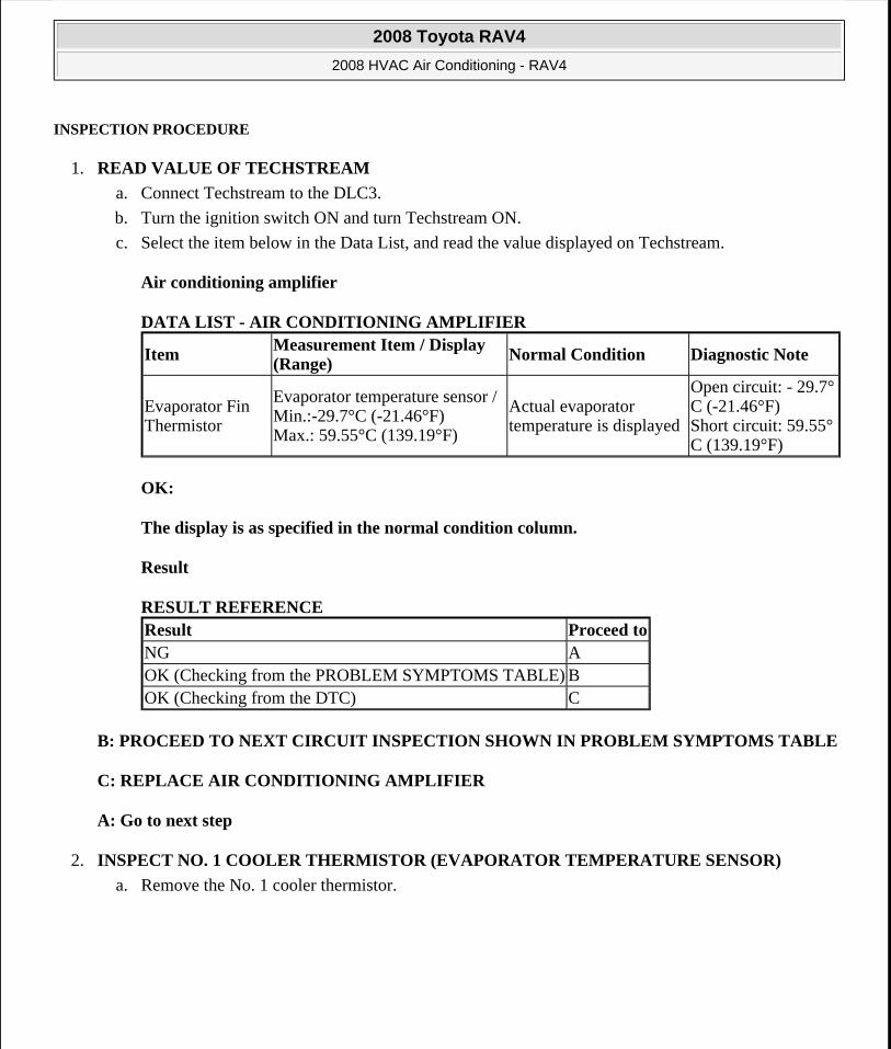
INSPECTION PROCEDURE
1. READ VALUE OF TECHSTREAM
a. Connect Techstream to the DLC3.
b. Turn the ignition switch ON and turn Techstream ON.
c. Select the item below in the Data List, and read the value displayed on Techstream.
Air conditioning amplifier
DATA LIST - AIR CONDITIONING AMPLIFIER
OK:
The display is as specified in the normal condition column.
Result
RESULT REFERENCE
B: PROCEED TO NEXT CIRCUIT INSPECTION SHOWN IN PROBLEM SYMPTOMS TABLE
C: REPLACE AIR CONDITIONING AMPLIFIER
A: Go to next step
2. INSPECT NO. 1 COOLER THERMISTOR (EVAPORATOR TEMPERATURE SENSOR)
a. Remove the No. 1 cooler thermistor.
ItemMeasurement Item / Display (Range) Normal Condition Diagnostic Note
Evaporator Fin Thermistor
Evaporator temperature sensor / Min.:-29.7°C (-21.46°F) Max.: 59.55°C (139.19°F)
Actual evaporator temperature is displayed
Open circuit: - 29.7°C (-21.46°F) Short circuit: 59.55°C (139.19°F)
Result Proceed toNG AOK (Checking from the PROBLEM SYMPTOMS TABLE) BOK (Checking from the DTC) C
2008 Toyota RAV4
2008 HVAC Air Conditioning - RAV4
Microsoft
Tuesday, August 18, 2009 3:53:55 PM Page 119 © 2005 Mitchell Repair Information Company, LLC.
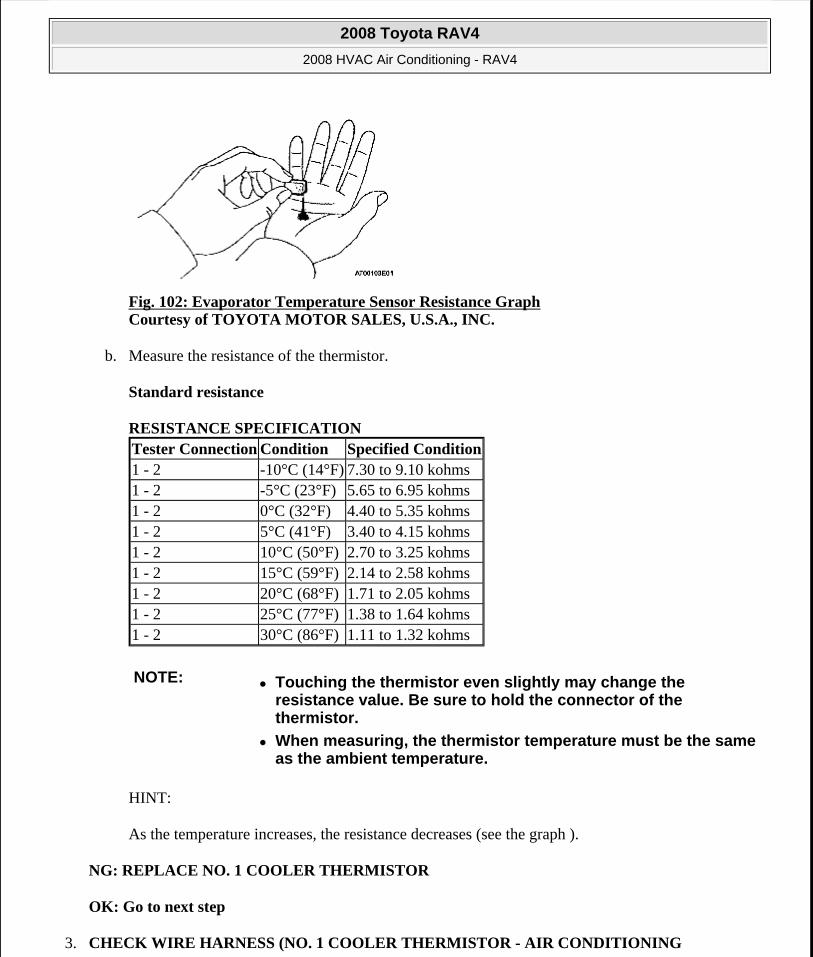
Fig. 102: Evaporator Temperature Sensor Resistance Graph Courtesy of TOYOTA MOTOR SALES, U.S.A., INC.
b. Measure the resistance of the thermistor.
Standard resistance
RESISTANCE SPECIFICATION
HINT:
As the temperature increases, the resistance decreases (see the graph ).
NG: REPLACE NO. 1 COOLER THERMISTOR
OK: Go to next step
3. CHECK WIRE HARNESS (NO. 1 COOLER THERMISTOR - AIR CONDITIONING
Tester Connection Condition Specified Condition1 - 2 -10°C (14°F) 7.30 to 9.10 kohms1 - 2 -5°C (23°F) 5.65 to 6.95 kohms1 - 2 0°C (32°F) 4.40 to 5.35 kohms1 - 2 5°C (41°F) 3.40 to 4.15 kohms1 - 2 10°C (50°F) 2.70 to 3.25 kohms1 - 2 15°C (59°F) 2.14 to 2.58 kohms1 - 2 20°C (68°F) 1.71 to 2.05 kohms1 - 2 25°C (77°F) 1.38 to 1.64 kohms1 - 2 30°C (86°F) 1.11 to 1.32 kohms
NOTE: Touching the thermistor even slightly may change the resistance value. Be sure to hold the connector of the thermistor.
When measuring, the thermistor temperature must be the same as the ambient temperature.
2008 Toyota RAV4
2008 HVAC Air Conditioning - RAV4
Microsoft
Tuesday, August 18, 2009 3:53:55 PM Page 120 © 2005 Mitchell Repair Information Company, LLC.

AMPLIFIER)
a. Disconnect the E33 No. 1 cooler thermistor connector.
b. Disconnect the E36 amplifier connector.
Fig. 103: Identifying E33 And E36 Connector Terminals Courtesy of TOYOTA MOTOR SALES, U.S.A., INC.
c. Measure the resistance of the wire harness side connectors.
Standard resistance
RESISTANCE SPECIFICATION
NG: REPAIR OR REPLACE HARNESS AND CONNECTOR
OK: REPLACE AIR CONDITIONING AMPLIFIER
DTC B1422/22 COMPRESSOR LOCK SENSOR CIRCUIT
DESCRIPTION
This sensor sends 1 pulse per engine revolution to the air conditioning amplifier. If the ratio of the compressor speed divided by the engine speed is smaller than a predetermined value, the air conditioning amplifier turns the compressor off, and the indicator blinks at approximately 1 second intervals.
DTC DETECTION CONDITION AND TROUBLE AREA REFERENCE
Tester Connection Specified ConditionE33-1 - E36-22 (TE) Below 1 ohmsE33-2 - E36-23 (SG-3) Below 1 ohmsE33-1 - Body ground 1 Mohms or higherE33-2 - Body ground 1 Mohms or higher
DTC No. DTC Detection Condition Trouble Area
Open or short in compressor lock sensor circuit All conditions below are detected for 3 seconds or more:
Compressor and magnetic clutch
Compressor and magnetic clutch drive belt
2008 Toyota RAV4
2008 HVAC Air Conditioning - RAV4
Microsoft
Tuesday, August 18, 2009 3:53:55 PM Page 121 © 2005 Mitchell Repair Information Company, LLC.
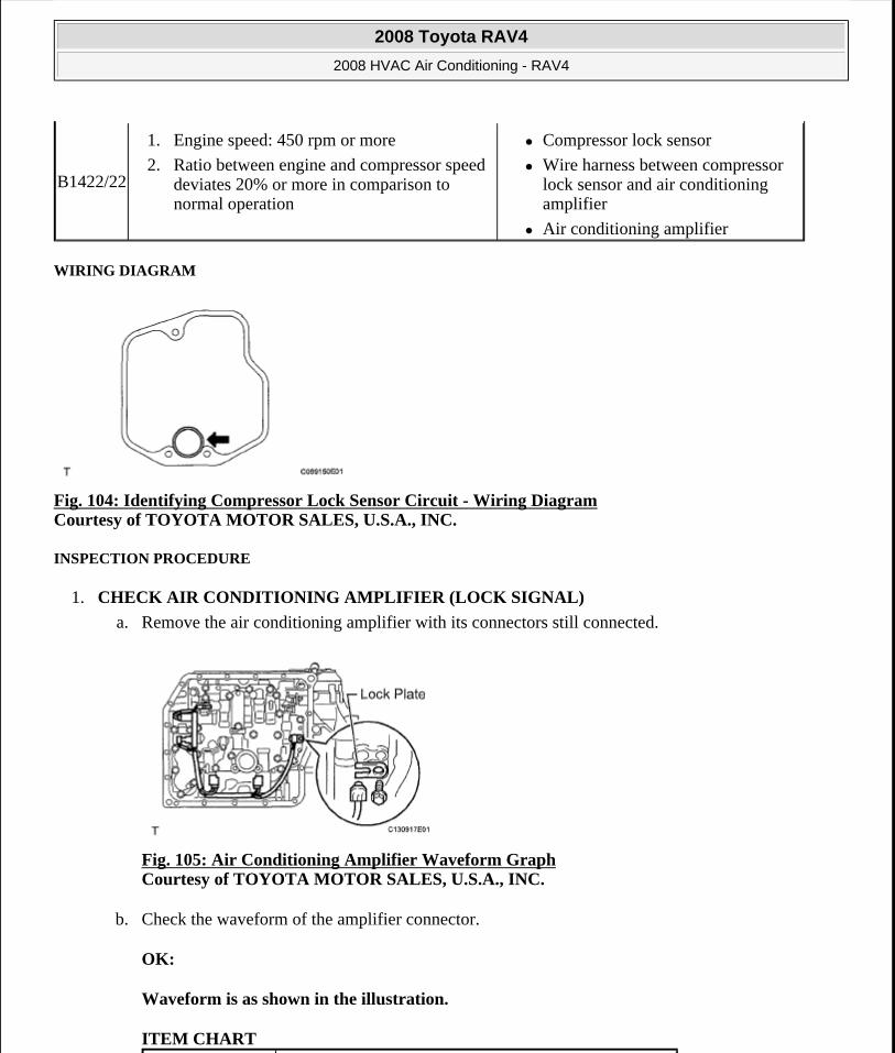
WIRING DIAGRAM
Fig. 104: Identifying Compressor Lock Sensor Circuit - Wiring Diagram Courtesy of TOYOTA MOTOR SALES, U.S.A., INC.
INSPECTION PROCEDURE
1. CHECK AIR CONDITIONING AMPLIFIER (LOCK SIGNAL)
a. Remove the air conditioning amplifier with its connectors still connected.
Fig. 105: Air Conditioning Amplifier Waveform Graph Courtesy of TOYOTA MOTOR SALES, U.S.A., INC.
b. Check the waveform of the amplifier connector.
OK:
Waveform is as shown in the illustration.
ITEM CHART
B1422/22
1. Engine speed: 450 rpm or more
2. Ratio between engine and compressor speed deviates 20% or more in comparison to normal operation
Compressor lock sensor
Wire harness between compressor lock sensor and air conditioning amplifier
Air conditioning amplifier
2008 Toyota RAV4
2008 HVAC Air Conditioning - RAV4
Microsoft
Tuesday, August 18, 2009 3:53:55 PM Page 122 © 2005 Mitchell Repair Information Company, LLC.
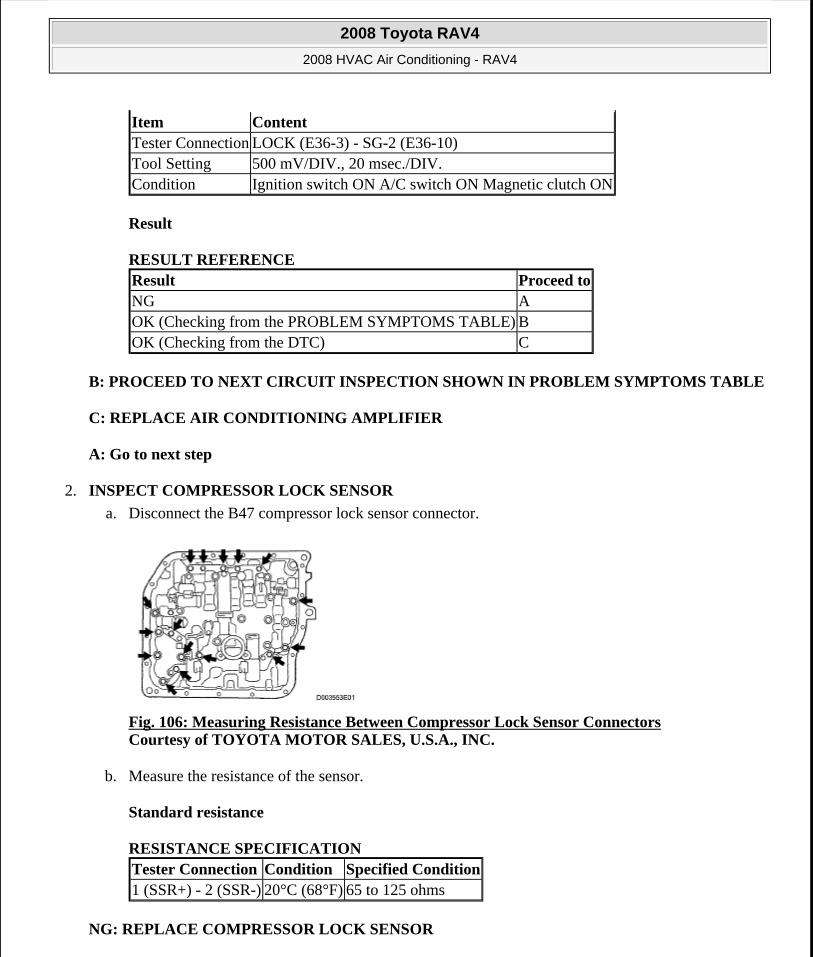
Result
RESULT REFERENCE
B: PROCEED TO NEXT CIRCUIT INSPECTION SHOWN IN PROBLEM SYMPTOMS TABLE
C: REPLACE AIR CONDITIONING AMPLIFIER
A: Go to next step
2. INSPECT COMPRESSOR LOCK SENSOR
a. Disconnect the B47 compressor lock sensor connector.
Fig. 106: Measuring Resistance Between Compressor Lock Sensor Connectors Courtesy of TOYOTA MOTOR SALES, U.S.A., INC.
b. Measure the resistance of the sensor.
Standard resistance
RESISTANCE SPECIFICATION
NG: REPLACE COMPRESSOR LOCK SENSOR
Item ContentTester Connection LOCK (E36-3) - SG-2 (E36-10)Tool Setting 500 mV/DIV., 20 msec./DIV.Condition Ignition switch ON A/C switch ON Magnetic clutch ON
Result Proceed toNG AOK (Checking from the PROBLEM SYMPTOMS TABLE) BOK (Checking from the DTC) C
Tester Connection Condition Specified Condition1 (SSR+) - 2 (SSR-) 20°C (68°F) 65 to 125 ohms
2008 Toyota RAV4
2008 HVAC Air Conditioning - RAV4
Microsoft
Tuesday, August 18, 2009 3:53:55 PM Page 123 © 2005 Mitchell Repair Information Company, LLC.
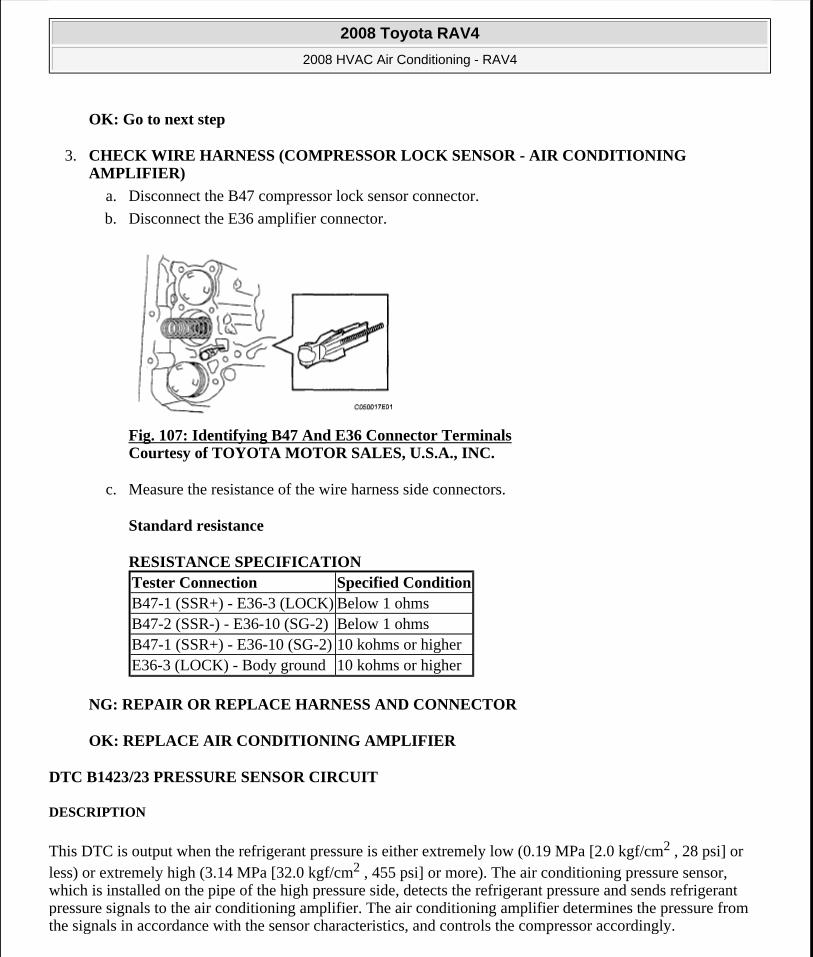
OK: Go to next step
3. CHECK WIRE HARNESS (COMPRESSOR LOCK SENSOR - AIR CONDITIONING AMPLIFIER)
a. Disconnect the B47 compressor lock sensor connector.
b. Disconnect the E36 amplifier connector.
Fig. 107: Identifying B47 And E36 Connector Terminals Courtesy of TOYOTA MOTOR SALES, U.S.A., INC.
c. Measure the resistance of the wire harness side connectors.
Standard resistance
RESISTANCE SPECIFICATION
NG: REPAIR OR REPLACE HARNESS AND CONNECTOR
OK: REPLACE AIR CONDITIONING AMPLIFIER
DTC B1423/23 PRESSURE SENSOR CIRCUIT
DESCRIPTION
This DTC is output when the refrigerant pressure is either extremely low (0.19 MPa [2.0 kgf/cm2 , 28 psi] or less) or extremely high (3.14 MPa [32.0 kgf/cm2 , 455 psi] or more). The air conditioning pressure sensor, which is installed on the pipe of the high pressure side, detects the refrigerant pressure and sends refrigerant pressure signals to the air conditioning amplifier. The air conditioning amplifier determines the pressure from the signals in accordance with the sensor characteristics, and controls the compressor accordingly.
Tester Connection Specified ConditionB47-1 (SSR+) - E36-3 (LOCK) Below 1 ohmsB47-2 (SSR-) - E36-10 (SG-2) Below 1 ohmsB47-1 (SSR+) - E36-10 (SG-2) 10 kohms or higherE36-3 (LOCK) - Body ground 10 kohms or higher
2008 Toyota RAV4
2008 HVAC Air Conditioning - RAV4
Microsoft
Tuesday, August 18, 2009 3:53:55 PM Page 124 © 2005 Mitchell Repair Information Company, LLC.
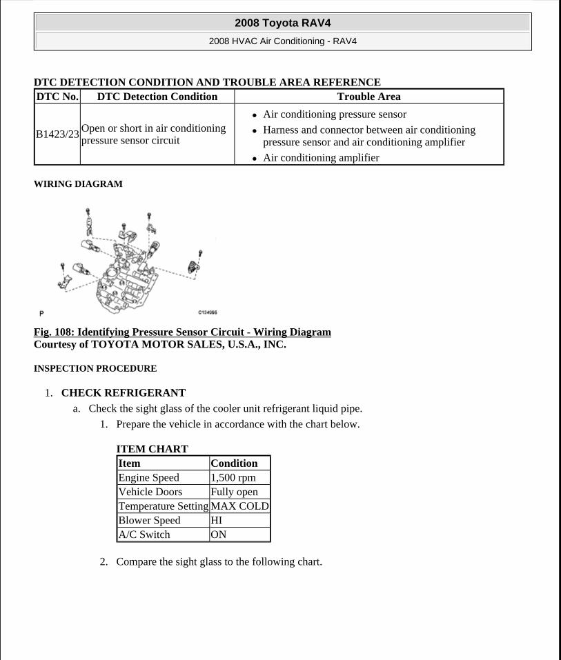
DTC DETECTION CONDITION AND TROUBLE AREA REFERENCE
WIRING DIAGRAM
Fig. 108: Identifying Pressure Sensor Circuit - Wiring Diagram Courtesy of TOYOTA MOTOR SALES, U.S.A., INC.
INSPECTION PROCEDURE
1. CHECK REFRIGERANT
a. Check the sight glass of the cooler unit refrigerant liquid pipe.
1. Prepare the vehicle in accordance with the chart below.
ITEM CHART
2. Compare the sight glass to the following chart.
DTC No. DTC Detection Condition Trouble Area
B1423/23 Open or short in air conditioning pressure sensor circuit
Air conditioning pressure sensor
Harness and connector between air conditioning pressure sensor and air conditioning amplifier
Air conditioning amplifier
Item ConditionEngine Speed 1,500 rpmVehicle Doors Fully openTemperature Setting MAX COLDBlower Speed HIA/C Switch ON
2008 Toyota RAV4
2008 HVAC Air Conditioning - RAV4
Microsoft
Tuesday, August 18, 2009 3:53:55 PM Page 125 © 2005 Mitchell Repair Information Company, LLC.

Fig. 109: Identifying Sight Glass Of Cooler Unit Refrigerant Liquid Pipe Courtesy of TOYOTA MOTOR SALES, U.S.A., INC.
AMOUNT OF REFRIGERANT - SYMPTOM CHART
NG: CHARGE REFRIGERANT
Item Symptom Amount of Refrigerant
Corrective Procedures
1 Bubbles visible Insufficient*
1. Check for gas leakage and repair if necessary
2. Add refrigerant until bubbles disappear
2 No bubbles visibleEmpty, insufficient or too much
Refer to items 3 and 4
3No temperature difference between compressor inlet and outlet
Empty or nearly empty
1. Check for gas leakage with gas leak detector and repair if necessary
2. Add refrigerant until bubbles disappear
4Considerable temperature difference between compressor inlet and outlet
Correct or too much
Refer to items 5 and 6
5Refrigerant becomes clear immediately after A/C turned OFF
Too much
1. Drain or discharge refrigerant
2. Bleed air and supply proper amount of purified refrigerant
6Refrigerant foams and then becomes clear immediately after A/C turned OFF
Correct -
HINT: *: If the ambient temperature is higher than usual but cooling is sufficient, bubbles in the sight glass are permissible.
2008 Toyota RAV4
2008 HVAC Air Conditioning - RAV4
Microsoft
Tuesday, August 18, 2009 3:53:55 PM Page 126 © 2005 Mitchell Repair Information Company, LLC.

OK: Go to next step
2. READ VALUE OF TECHSTREAM
a. Connect Techstream to the DLC3.
b. Turn the ignition switch ON and turn Techstream ON.
c. Select the item below in the Data List, and read the value displayed on Techstream.
Air conditioning amplifier
DATA LIST - AIR CONDITIONING AMPLIFIER
OK:
The display is as specified in the normal condition column.
Result
RESULT REFERENCE
B: PROCEED TO NEXT CIRCUIT INSPECTION SHOWN IN PROBLEM SYMPTOMS TABLE
C: REPLACE AIR CONDITIONING AMPLIFIER
A: Go to next step
3. CHECK WIRE HARNESS (PRESSURE SENSOR - AIR CONDITIONING AMPLIFIER)
a. Disconnect the A21 pressure sensor connector.
b. Disconnect the E36 amplifier connector.
Item Measurement Item / Display (Range)
Normal Condition Diagnostic Note
Regulator Pressure Sensor
Regulator pressure sensor / Min.: -0.45668 MPaG Max.: 3.29437 MPaG
Actual regulator pressure is displayed -
Result Proceed toNG AOK (Checking from the PROBLEM SYMPTOMS TABLE) BOK (Checking from the DTC) C
2008 Toyota RAV4
2008 HVAC Air Conditioning - RAV4
Microsoft
Tuesday, August 18, 2009 3:53:55 PM Page 127 © 2005 Mitchell Repair Information Company, LLC.
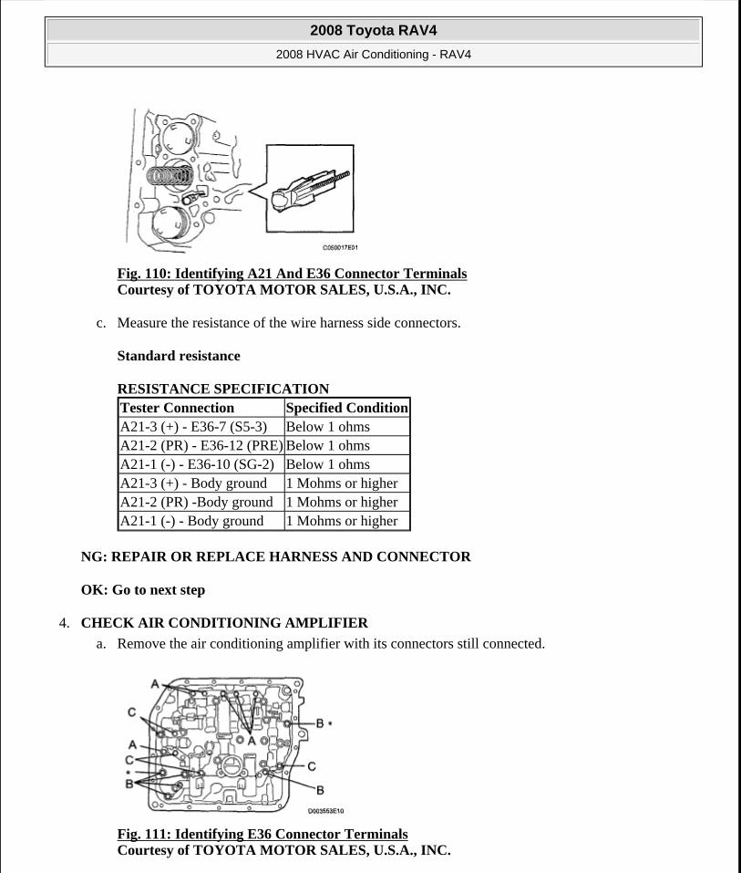
Fig. 110: Identifying A21 And E36 Connector Terminals Courtesy of TOYOTA MOTOR SALES, U.S.A., INC.
c. Measure the resistance of the wire harness side connectors.
Standard resistance
RESISTANCE SPECIFICATION
NG: REPAIR OR REPLACE HARNESS AND CONNECTOR
OK: Go to next step
4. CHECK AIR CONDITIONING AMPLIFIER
a. Remove the air conditioning amplifier with its connectors still connected.
Fig. 111: Identifying E36 Connector Terminals Courtesy of TOYOTA MOTOR SALES, U.S.A., INC.
Tester Connection Specified ConditionA21-3 (+) - E36-7 (S5-3) Below 1 ohmsA21-2 (PR) - E36-12 (PRE) Below 1 ohmsA21-1 (-) - E36-10 (SG-2) Below 1 ohmsA21-3 (+) - Body ground 1 Mohms or higherA21-2 (PR) -Body ground 1 Mohms or higherA21-1 (-) - Body ground 1 Mohms or higher
2008 Toyota RAV4
2008 HVAC Air Conditioning - RAV4
Microsoft
Tuesday, August 18, 2009 3:53:55 PM Page 128 © 2005 Mitchell Repair Information Company, LLC.
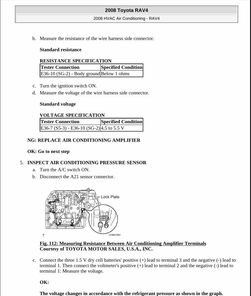
b. Measure the resistance of the wire harness side connector.
Standard resistance
RESISTANCE SPECIFICATION
c. Turn the ignition switch ON.
d. Measure the voltage of the wire harness side connector.
Standard voltage
VOLTAGE SPECIFICATION
NG: REPLACE AIR CONDITIONING AMPLIFIER
OK: Go to next step
5. INSPECT AIR CONDITIONING PRESSURE SENSOR
a. Turn the A/C switch ON.
b. Disconnect the A21 sensor connector.
Fig. 112: Measuring Resistance Between Air Conditioning Amplifier Terminals Courtesy of TOYOTA MOTOR SALES, U.S.A., INC.
c. Connect the three 1.5 V dry cell batteries' positive (+) lead to terminal 3 and the negative (-) lead to terminal 1. Then connect the voltmeter's positive (+) lead to terminal 2 and the negative (-) lead to terminal 1: Measure the voltage.
OK:
The voltage changes in accordance with the refrigerant pressure as shown in the graph.
Tester Connection Specified ConditionE36-10 (SG-2) - Body ground Below 1 ohms
Tester Connection Specified ConditionE36-7 (S5-3) - E36-10 (SG-2) 4.5 to 5.5 V
2008 Toyota RAV4
2008 HVAC Air Conditioning - RAV4
Microsoft
Tuesday, August 18, 2009 3:53:55 PM Page 129 © 2005 Mitchell Repair Information Company, LLC.
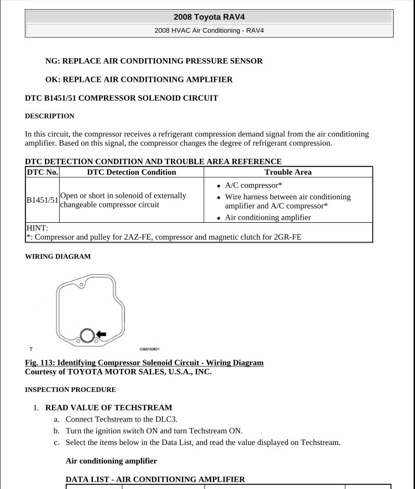
NG: REPLACE AIR CONDITIONING PRESSURE SENSOR
OK: REPLACE AIR CONDITIONING AMPLIFIER
DTC B1451/51 COMPRESSOR SOLENOID CIRCUIT
DESCRIPTION
In this circuit, the compressor receives a refrigerant compression demand signal from the air conditioning amplifier. Based on this signal, the compressor changes the degree of refrigerant compression.
DTC DETECTION CONDITION AND TROUBLE AREA REFERENCE
WIRING DIAGRAM
Fig. 113: Identifying Compressor Solenoid Circuit - Wiring Diagram Courtesy of TOYOTA MOTOR SALES, U.S.A., INC.
INSPECTION PROCEDURE
1. READ VALUE OF TECHSTREAM
a. Connect Techstream to the DLC3.
b. Turn the ignition switch ON and turn Techstream ON.
c. Select the items below in the Data List, and read the value displayed on Techstream.
Air conditioning amplifier
DATA LIST - AIR CONDITIONING AMPLIFIER
DTC No. DTC Detection Condition Trouble Area
B1451/51Open or short in solenoid of externally changeable compressor circuit
A/C compressor*
Wire harness between air conditioning amplifier and A/C compressor*
Air conditioning amplifier HINT: *: Compressor and pulley for 2AZ-FE, compressor and magnetic clutch for 2GR-FE
2008 Toyota RAV4
2008 HVAC Air Conditioning - RAV4
Microsoft
Tuesday, August 18, 2009 3:53:55 PM Page 130 © 2005 Mitchell Repair Information Company, LLC.
OK:
The display is as specified in the normal condition column.
Result
RESULT REFERENCE
B: PROCEED TO NEXT CIRCUIT INSPECTION SHOWN IN PROBLEM SYMPTOMS TABLE
C: REPLACE AIR CONDITIONING AMPLIFIER
A: Go to next step
2. INSPECT A/C COMPRESSOR
a. Disconnect the A/C compressor connector.
Fig. 114: Identifying A/C Compressor Connector Courtesy of TOYOTA MOTOR SALES, U.S.A., INC.
b. Measure the resistance of the connector.
Standard resistance
RESISTANCE SPECIFICATION
ItemMeasurement Item / Display (Range)
Normal ConditionDiagnostic Note
Regulator Control Current
Regulator control current / Min.:0A Max.: 0.997 A
Value changes between 0 A and 0.997 A in accordance with A/C compressor operation
-
Result Proceed toNG AOK (Checking from the PROBLEM SYMPTOMS TABLE) BOK (Checking from the DTC) C
Tester Connection Condition Specified Condition
2008 Toyota RAV4
2008 HVAC Air Conditioning - RAV4
Microsoft
Tuesday, August 18, 2009 3:53:55 PM Page 131 © 2005 Mitchell Repair Information Company, LLC.
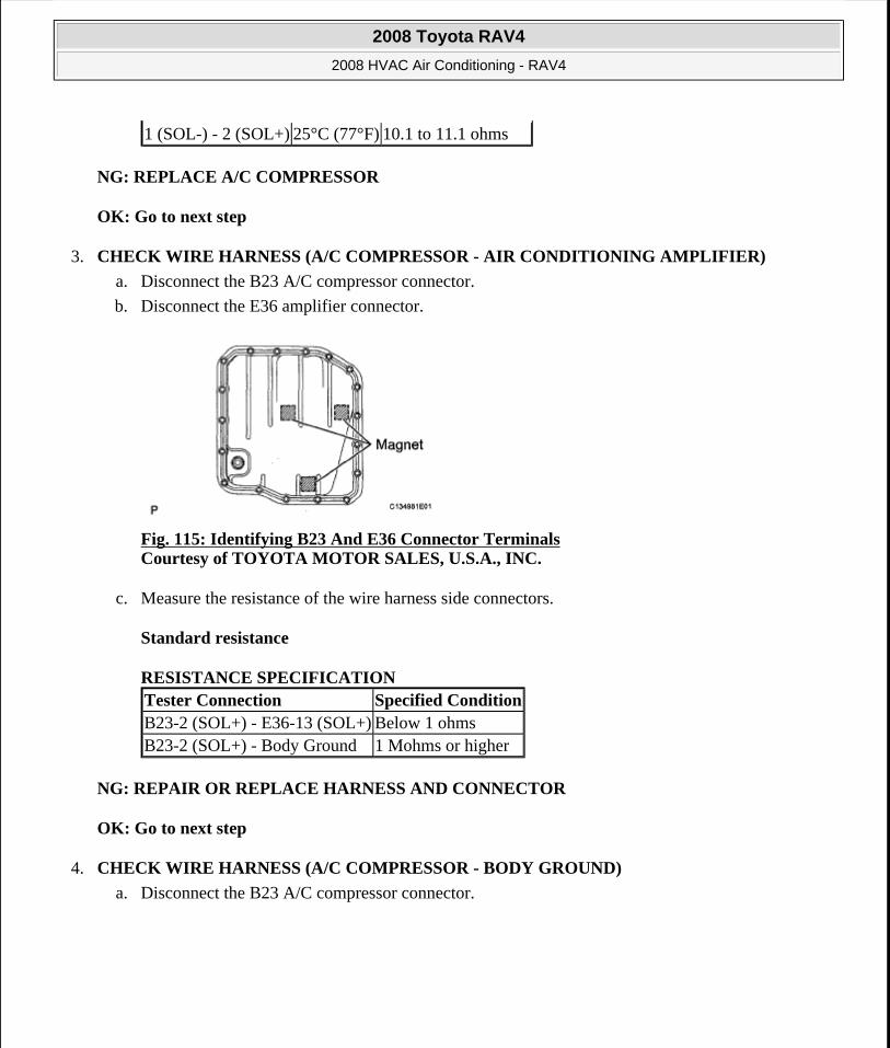
NG: REPLACE A/C COMPRESSOR
OK: Go to next step
3. CHECK WIRE HARNESS (A/C COMPRESSOR - AIR CONDITIONING AMPLIFIER)
a. Disconnect the B23 A/C compressor connector.
b. Disconnect the E36 amplifier connector.
Fig. 115: Identifying B23 And E36 Connector Terminals Courtesy of TOYOTA MOTOR SALES, U.S.A., INC.
c. Measure the resistance of the wire harness side connectors.
Standard resistance
RESISTANCE SPECIFICATION
NG: REPAIR OR REPLACE HARNESS AND CONNECTOR
OK: Go to next step
4. CHECK WIRE HARNESS (A/C COMPRESSOR - BODY GROUND)
a. Disconnect the B23 A/C compressor connector.
1 (SOL-) - 2 (SOL+) 25°C (77°F) 10.1 to 11.1 ohms
Tester Connection Specified ConditionB23-2 (SOL+) - E36-13 (SOL+) Below 1 ohmsB23-2 (SOL+) - Body Ground 1 Mohms or higher
2008 Toyota RAV4
2008 HVAC Air Conditioning - RAV4
Microsoft
Tuesday, August 18, 2009 3:53:55 PM Page 132 © 2005 Mitchell Repair Information Company, LLC.
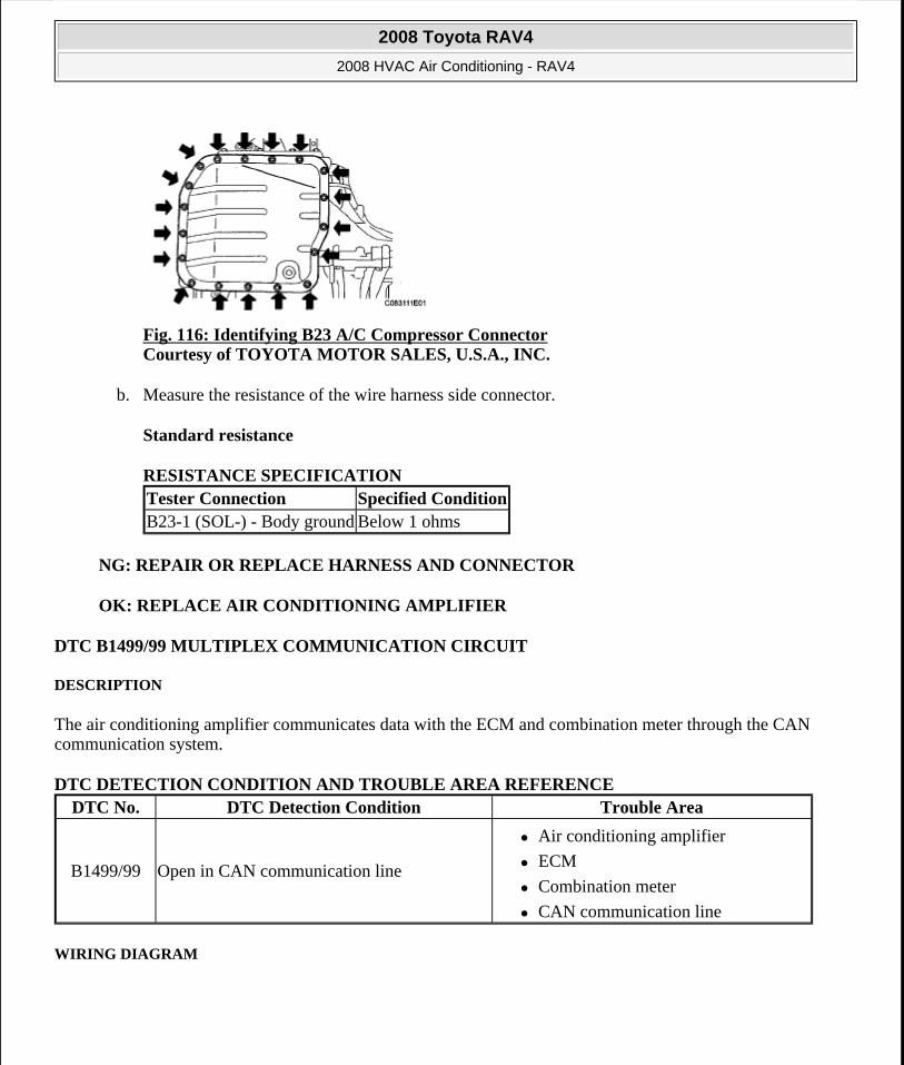
Fig. 116: Identifying B23 A/C Compressor Connector Courtesy of TOYOTA MOTOR SALES, U.S.A., INC.
b. Measure the resistance of the wire harness side connector.
Standard resistance
RESISTANCE SPECIFICATION
NG: REPAIR OR REPLACE HARNESS AND CONNECTOR
OK: REPLACE AIR CONDITIONING AMPLIFIER
DTC B1499/99 MULTIPLEX COMMUNICATION CIRCUIT
DESCRIPTION
The air conditioning amplifier communicates data with the ECM and combination meter through the CAN communication system.
DTC DETECTION CONDITION AND TROUBLE AREA REFERENCE
WIRING DIAGRAM
Tester Connection Specified ConditionB23-1 (SOL-) - Body ground Below 1 ohms
DTC No. DTC Detection Condition Trouble Area
B1499/99 Open in CAN communication line
Air conditioning amplifier
ECM
Combination meter
CAN communication line
2008 Toyota RAV4
2008 HVAC Air Conditioning - RAV4
Microsoft
Tuesday, August 18, 2009 3:53:55 PM Page 133 © 2005 Mitchell Repair Information Company, LLC.
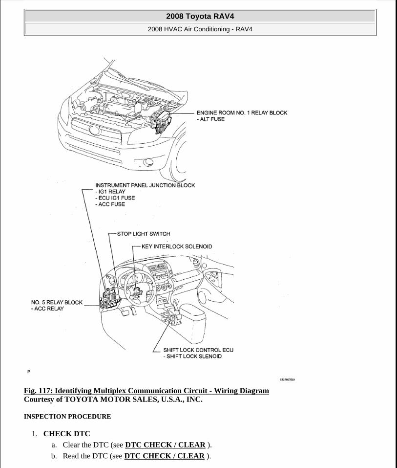
Fig. 117: Identifying Multiplex Communication Circuit - Wiring Diagram Courtesy of TOYOTA MOTOR SALES, U.S.A., INC.
INSPECTION PROCEDURE
1. CHECK DTC
a. Clear the DTC (see DTC CHECK / CLEAR ).
b. Read the DTC (see DTC CHECK / CLEAR ).
2008 Toyota RAV4
2008 HVAC Air Conditioning - RAV4
Microsoft
Tuesday, August 18, 2009 3:53:55 PM Page 134 © 2005 Mitchell Repair Information Company, LLC.
Result
RESULT REFERENCE
B: SYSTEM IS OK
A:GO TO CAN COMMUNICATION SYSTEM
BLOWER MOTOR CIRCUIT
DESCRIPTION
When the heater control (blower switch) is set to position 1 or higher, the contact of the HTR relay is closed, current flows to the blower motor, and the blower motor operates. The blower motor speed can be changed by exchanging the ground and the blower resistor circuit with the heater control (blower switch).
WIRING DIAGRAM
Result Proceed toDTC (B1499/99) is output A (see CAN COMMUNICATION SYSTEM )DTC (B1499/99) is not output B
2008 Toyota RAV4
2008 HVAC Air Conditioning - RAV4
Microsoft
Tuesday, August 18, 2009 3:53:55 PM Page 135 © 2005 Mitchell Repair Information Company, LLC.
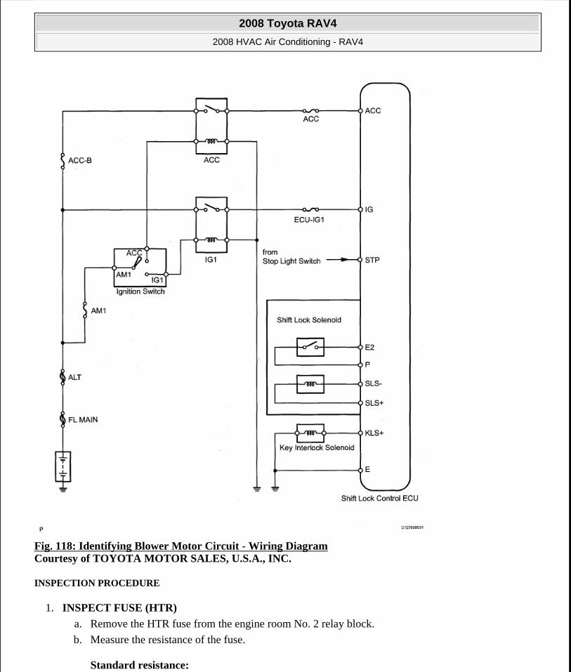
Fig. 118: Identifying Blower Motor Circuit - Wiring Diagram Courtesy of TOYOTA MOTOR SALES, U.S.A., INC.
INSPECTION PROCEDURE
1. INSPECT FUSE (HTR)
a. Remove the HTR fuse from the engine room No. 2 relay block.
b. Measure the resistance of the fuse.
Standard resistance:
2008 Toyota RAV4
2008 HVAC Air Conditioning - RAV4
Microsoft
Tuesday, August 18, 2009 3:53:55 PM Page 136 © 2005 Mitchell Repair Information Company, LLC.
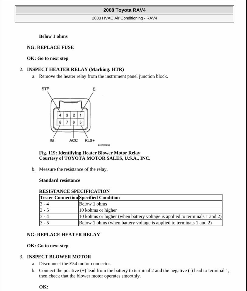
Below 1 ohms
NG: REPLACE FUSE
OK: Go to next step
2. INSPECT HEATER RELAY (Marking: HTR)
a. Remove the heater relay from the instrument panel junction block.
Fig. 119: Identifying Heater Blower Motor Relay Courtesy of TOYOTA MOTOR SALES, U.S.A., INC.
b. Measure the resistance of the relay.
Standard resistance
RESISTANCE SPECIFICATION
NG: REPLACE HEATER RELAY
OK: Go to next step
3. INSPECT BLOWER MOTOR
a. Disconnect the E54 motor connector.
b. Connect the positive (+) lead from the battery to terminal 2 and the negative (-) lead to terminal 1, then check that the blower motor operates smoothly.
OK:
Tester Connection Specified Condition3 - 4 Below 1 ohms3 - 5 10 kohms or higher3 - 4 10 kohms or higher (when battery voltage is applied to terminals 1 and 2)3 - 5 Below 1 ohms (when battery voltage is applied to terminals 1 and 2)
2008 Toyota RAV4
2008 HVAC Air Conditioning - RAV4
Microsoft
Tuesday, August 18, 2009 3:53:55 PM Page 137 © 2005 Mitchell Repair Information Company, LLC.
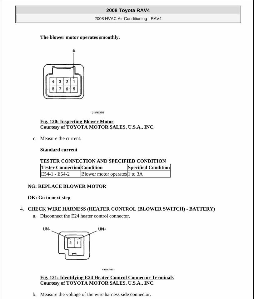
The blower motor operates smoothly.
Fig. 120: Inspecting Blower Motor Courtesy of TOYOTA MOTOR SALES, U.S.A., INC.
c. Measure the current.
Standard current
TESTER CONNECTION AND SPECIFIED CONDITION
NG: REPLACE BLOWER MOTOR
OK: Go to next step
4. CHECK WIRE HARNESS (HEATER CONTROL (BLOWER SWITCH) - BATTERY)
a. Disconnect the E24 heater control connector.
Fig. 121: Identifying E24 Heater Control Connector Terminals Courtesy of TOYOTA MOTOR SALES, U.S.A., INC.
b. Measure the voltage of the wire harness side connector.
Tester Connection Condition Specified ConditionE54-1 - E54-2 Blower motor operates 1 to 3A
2008 Toyota RAV4
2008 HVAC Air Conditioning - RAV4
Microsoft
Tuesday, August 18, 2009 3:53:55 PM Page 138 © 2005 Mitchell Repair Information Company, LLC.
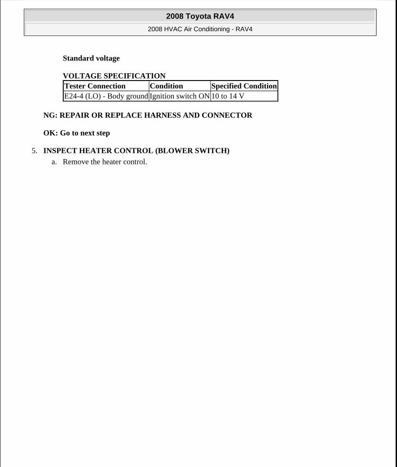
Standard voltage
VOLTAGE SPECIFICATION
NG: REPAIR OR REPLACE HARNESS AND CONNECTOR
OK: Go to next step
5. INSPECT HEATER CONTROL (BLOWER SWITCH)
a. Remove the heater control.
Tester Connection Condition Specified ConditionE24-4 (LO) - Body ground Ignition switch ON 10 to 14 V
2008 Toyota RAV4
2008 HVAC Air Conditioning - RAV4
Microsoft
Tuesday, August 18, 2009 3:53:56 PM Page 139 © 2005 Mitchell Repair Information Company, LLC.
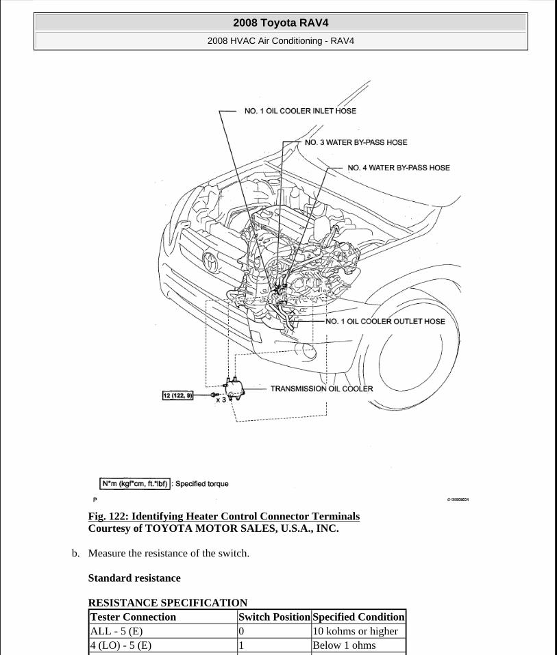
Fig. 122: Identifying Heater Control Connector Terminals Courtesy of TOYOTA MOTOR SALES, U.S.A., INC.
b. Measure the resistance of the switch.
Standard resistance
RESISTANCE SPECIFICATION Tester Connection Switch Position Specified ConditionALL - 5 (E) 0 10 kohms or higher4 (LO) - 5 (E) 1 Below 1 ohms
2008 Toyota RAV4
2008 HVAC Air Conditioning - RAV4
Microsoft
Tuesday, August 18, 2009 3:53:56 PM Page 140 © 2005 Mitchell Repair Information Company, LLC.
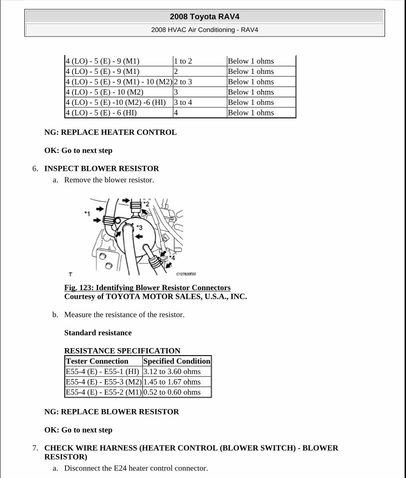
NG: REPLACE HEATER CONTROL
OK: Go to next step
6. INSPECT BLOWER RESISTOR
a. Remove the blower resistor.
Fig. 123: Identifying Blower Resistor Connectors Courtesy of TOYOTA MOTOR SALES, U.S.A., INC.
b. Measure the resistance of the resistor.
Standard resistance
RESISTANCE SPECIFICATION
NG: REPLACE BLOWER RESISTOR
OK: Go to next step
7. CHECK WIRE HARNESS (HEATER CONTROL (BLOWER SWITCH) - BLOWER RESISTOR)
a. Disconnect the E24 heater control connector.
4 (LO) - 5 (E) - 9 (M1) 1 to 2 Below 1 ohms4 (LO) - 5 (E) - 9 (M1) 2 Below 1 ohms4 (LO) - 5 (E) - 9 (M1) - 10 (M2) 2 to 3 Below 1 ohms4 (LO) - 5 (E) - 10 (M2) 3 Below 1 ohms4 (LO) - 5 (E) -10 (M2) -6 (HI) 3 to 4 Below 1 ohms4 (LO) - 5 (E) - 6 (HI) 4 Below 1 ohms
Tester Connection Specified ConditionE55-4 (E) - E55-1 (HI) 3.12 to 3.60 ohmsE55-4 (E) - E55-3 (M2) 1.45 to 1.67 ohmsE55-4 (E) - E55-2 (M1) 0.52 to 0.60 ohms
2008 Toyota RAV4
2008 HVAC Air Conditioning - RAV4
Microsoft
Tuesday, August 18, 2009 3:53:56 PM Page 141 © 2005 Mitchell Repair Information Company, LLC.
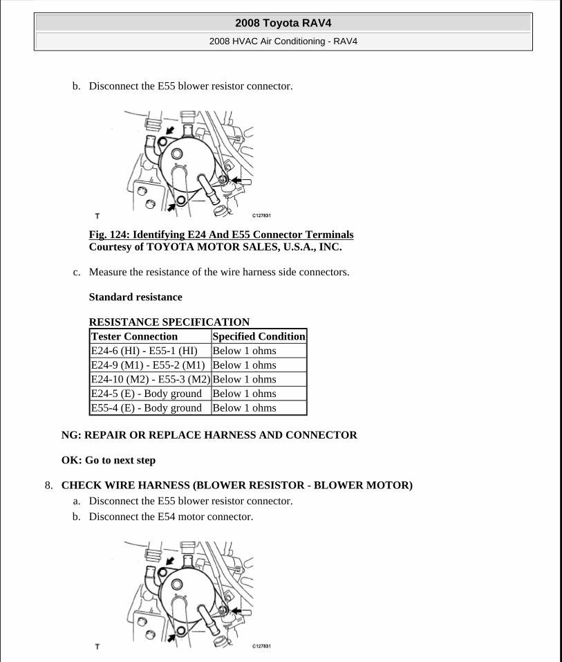
b. Disconnect the E55 blower resistor connector.
Fig. 124: Identifying E24 And E55 Connector Terminals Courtesy of TOYOTA MOTOR SALES, U.S.A., INC.
c. Measure the resistance of the wire harness side connectors.
Standard resistance
RESISTANCE SPECIFICATION
NG: REPAIR OR REPLACE HARNESS AND CONNECTOR
OK: Go to next step
8. CHECK WIRE HARNESS (BLOWER RESISTOR - BLOWER MOTOR)
a. Disconnect the E55 blower resistor connector.
b. Disconnect the E54 motor connector.
Tester Connection Specified ConditionE24-6 (HI) - E55-1 (HI) Below 1 ohmsE24-9 (M1) - E55-2 (M1) Below 1 ohmsE24-10 (M2) - E55-3 (M2) Below 1 ohmsE24-5 (E) - Body ground Below 1 ohmsE55-4 (E) - Body ground Below 1 ohms
2008 Toyota RAV4
2008 HVAC Air Conditioning - RAV4
Microsoft
Tuesday, August 18, 2009 3:53:56 PM Page 142 © 2005 Mitchell Repair Information Company, LLC.
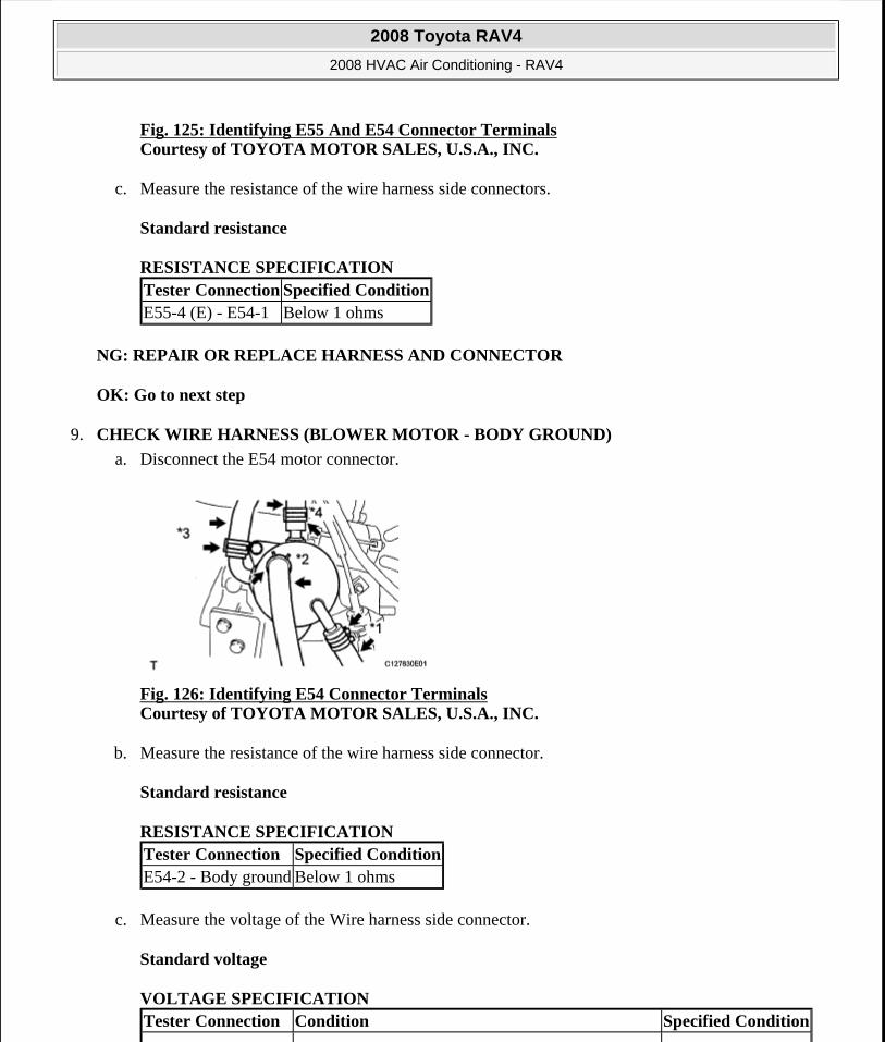
Fig. 125: Identifying E55 And E54 Connector TerminalsCourtesy of TOYOTA MOTOR SALES, U.S.A., INC.
c. Measure the resistance of the wire harness side connectors.
Standard resistance
RESISTANCE SPECIFICATION
NG: REPAIR OR REPLACE HARNESS AND CONNECTOR
OK: Go to next step
9. CHECK WIRE HARNESS (BLOWER MOTOR - BODY GROUND)
a. Disconnect the E54 motor connector.
Fig. 126: Identifying E54 Connector Terminals Courtesy of TOYOTA MOTOR SALES, U.S.A., INC.
b. Measure the resistance of the wire harness side connector.
Standard resistance
RESISTANCE SPECIFICATION
c. Measure the voltage of the Wire harness side connector.
Standard voltage
VOLTAGE SPECIFICATION
Tester Connection Specified ConditionE55-4 (E) - E54-1 Below 1 ohms
Tester Connection Specified ConditionE54-2 - Body ground Below 1 ohms
Tester Connection Condition Specified Condition
2008 Toyota RAV4
2008 HVAC Air Conditioning - RAV4
Microsoft
Tuesday, August 18, 2009 3:53:56 PM Page 143 © 2005 Mitchell Repair Information Company, LLC.
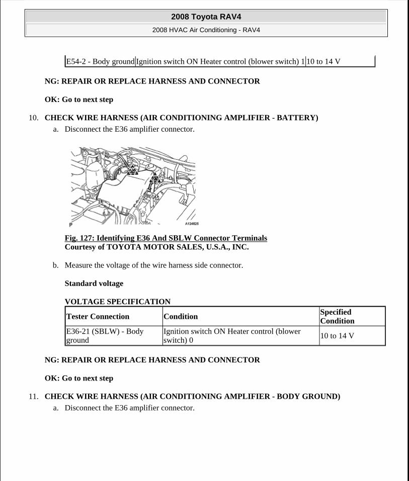
NG: REPAIR OR REPLACE HARNESS AND CONNECTOR
OK: Go to next step
10. CHECK WIRE HARNESS (AIR CONDITIONING AMPLIFIER - BATTERY)
a. Disconnect the E36 amplifier connector.
Fig. 127: Identifying E36 And SBLW Connector Terminals Courtesy of TOYOTA MOTOR SALES, U.S.A., INC.
b. Measure the voltage of the wire harness side connector.
Standard voltage
VOLTAGE SPECIFICATION
NG: REPAIR OR REPLACE HARNESS AND CONNECTOR
OK: Go to next step
11. CHECK WIRE HARNESS (AIR CONDITIONING AMPLIFIER - BODY GROUND)
a. Disconnect the E36 amplifier connector.
E54-2 - Body ground Ignition switch ON Heater control (blower switch) 1 10 to 14 V
Tester Connection Condition Specified Condition
E36-21 (SBLW) - Body ground
Ignition switch ON Heater control (blower switch) 0 10 to 14 V
2008 Toyota RAV4
2008 HVAC Air Conditioning - RAV4
Microsoft
Tuesday, August 18, 2009 3:53:56 PM Page 144 © 2005 Mitchell Repair Information Company, LLC.
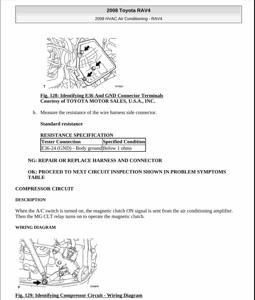
Fig. 128: Identifying E36 And GND Connector Terminals Courtesy of TOYOTA MOTOR SALES, U.S.A., INC.
b. Measure the resistance of the wire harness side connector.
Standard resistance
RESISTANCE SPECIFICATION
NG: REPAIR OR REPLACE HARNESS AND CONNECTOR
OK: PROCEED TO NEXT CIRCUIT INSPECTION SHOWN IN PROBLEM SYMPTOMS TABLE
COMPRESSOR CIRCUIT
DESCRIPTION
When the A/C switch is turned on, the magnetic clutch ON signal is sent from the air conditioning amplifier. Then the MG CLT relay turns on to operate the magnetic clutch.
WIRING DIAGRAM
Fig. 129: Identifying Compressor Circuit - Wiring Diagram
Tester Connection Specified ConditionE36-24 (GND) - Body ground Below 1 ohms
2008 Toyota RAV4
2008 HVAC Air Conditioning - RAV4
Microsoft
Tuesday, August 18, 2009 3:53:56 PM Page 145 © 2005 Mitchell Repair Information Company, LLC.
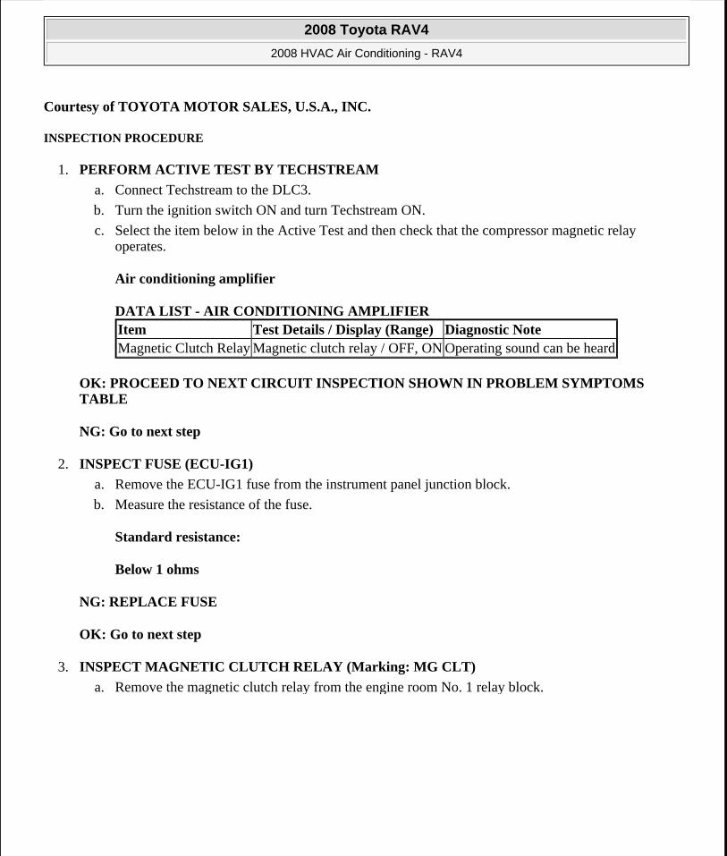
Courtesy of TOYOTA MOTOR SALES, U.S.A., INC.
INSPECTION PROCEDURE
1. PERFORM ACTIVE TEST BY TECHSTREAM
a. Connect Techstream to the DLC3.
b. Turn the ignition switch ON and turn Techstream ON.
c. Select the item below in the Active Test and then check that the compressor magnetic relay operates.
Air conditioning amplifier
DATA LIST - AIR CONDITIONING AMPLIFIER
OK: PROCEED TO NEXT CIRCUIT INSPECTION SHOWN IN PROBLEM SYMPTOMS TABLE
NG: Go to next step
2. INSPECT FUSE (ECU-IG1)
a. Remove the ECU-IG1 fuse from the instrument panel junction block.
b. Measure the resistance of the fuse.
Standard resistance:
Below 1 ohms
NG: REPLACE FUSE
OK: Go to next step
3. INSPECT MAGNETIC CLUTCH RELAY (Marking: MG CLT)
a. Remove the magnetic clutch relay from the engine room No. 1 relay block.
Item Test Details / Display (Range) Diagnostic NoteMagnetic Clutch Relay Magnetic clutch relay / OFF, ON Operating sound can be heard
2008 Toyota RAV4
2008 HVAC Air Conditioning - RAV4
Microsoft
Tuesday, August 18, 2009 3:53:56 PM Page 146 © 2005 Mitchell Repair Information Company, LLC.
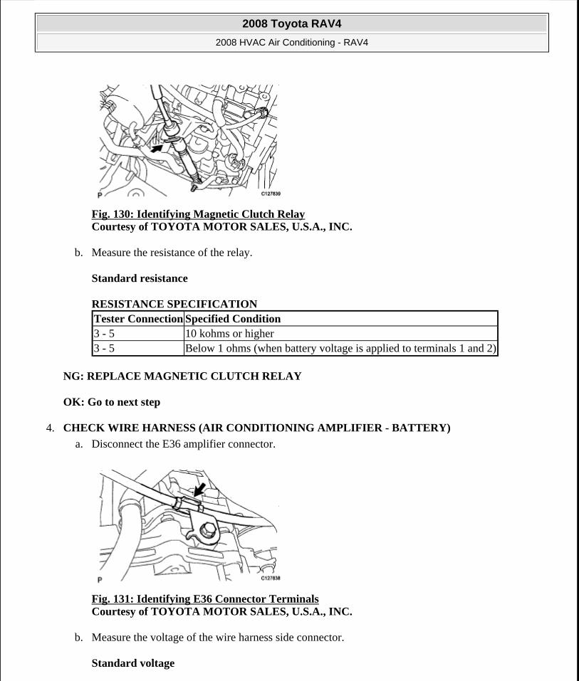
Fig. 130: Identifying Magnetic Clutch Relay Courtesy of TOYOTA MOTOR SALES, U.S.A., INC.
b. Measure the resistance of the relay.
Standard resistance
RESISTANCE SPECIFICATION
NG: REPLACE MAGNETIC CLUTCH RELAY
OK: Go to next step
4. CHECK WIRE HARNESS (AIR CONDITIONING AMPLIFIER - BATTERY)
a. Disconnect the E36 amplifier connector.
Fig. 131: Identifying E36 Connector Terminals Courtesy of TOYOTA MOTOR SALES, U.S.A., INC.
b. Measure the voltage of the wire harness side connector.
Standard voltage
Tester Connection Specified Condition3 - 5 10 kohms or higher3 - 5 Below 1 ohms (when battery voltage is applied to terminals 1 and 2)
2008 Toyota RAV4
2008 HVAC Air Conditioning - RAV4
Microsoft
Tuesday, August 18, 2009 3:53:56 PM Page 147 © 2005 Mitchell Repair Information Company, LLC.
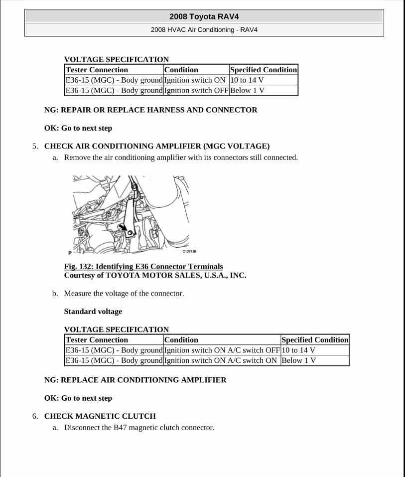
VOLTAGE SPECIFICATION
NG: REPAIR OR REPLACE HARNESS AND CONNECTOR
OK: Go to next step
5. CHECK AIR CONDITIONING AMPLIFIER (MGC VOLTAGE)
a. Remove the air conditioning amplifier with its connectors still connected.
Fig. 132: Identifying E36 Connector Terminals Courtesy of TOYOTA MOTOR SALES, U.S.A., INC.
b. Measure the voltage of the connector.
Standard voltage
VOLTAGE SPECIFICATION
NG: REPLACE AIR CONDITIONING AMPLIFIER
OK: Go to next step
6. CHECK MAGNETIC CLUTCH
a. Disconnect the B47 magnetic clutch connector.
Tester Connection Condition Specified ConditionE36-15 (MGC) - Body ground Ignition switch ON 10 to 14 VE36-15 (MGC) - Body ground Ignition switch OFF Below 1 V
Tester Connection Condition Specified ConditionE36-15 (MGC) - Body ground Ignition switch ON A/C switch OFF 10 to 14 VE36-15 (MGC) - Body ground Ignition switch ON A/C switch ON Below 1 V
2008 Toyota RAV4
2008 HVAC Air Conditioning - RAV4
Microsoft
Tuesday, August 18, 2009 3:53:56 PM Page 148 © 2005 Mitchell Repair Information Company, LLC.
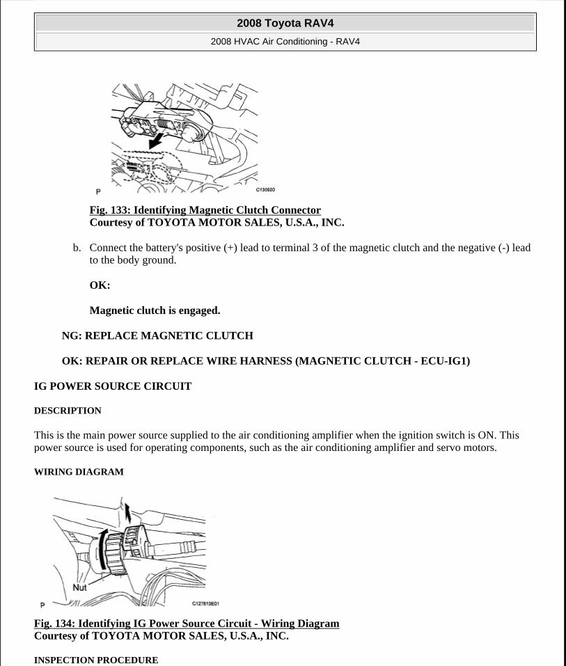
Fig. 133: Identifying Magnetic Clutch Connector Courtesy of TOYOTA MOTOR SALES, U.S.A., INC.
b. Connect the battery's positive (+) lead to terminal 3 of the magnetic clutch and the negative (-) lead to the body ground.
OK:
Magnetic clutch is engaged.
NG: REPLACE MAGNETIC CLUTCH
OK: REPAIR OR REPLACE WIRE HARNESS (MAGNETIC CLUTCH - ECU-IG1)
IG POWER SOURCE CIRCUIT
DESCRIPTION
This is the main power source supplied to the air conditioning amplifier when the ignition switch is ON. This power source is used for operating components, such as the air conditioning amplifier and servo motors.
WIRING DIAGRAM
Fig. 134: Identifying IG Power Source Circuit - Wiring Diagram Courtesy of TOYOTA MOTOR SALES, U.S.A., INC.
INSPECTION PROCEDURE
2008 Toyota RAV4
2008 HVAC Air Conditioning - RAV4
Microsoft
Tuesday, August 18, 2009 3:53:56 PM Page 149 © 2005 Mitchell Repair Information Company, LLC.
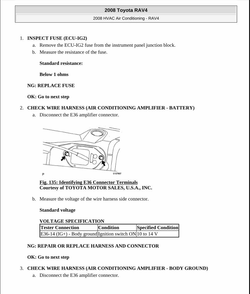
1. INSPECT FUSE (ECU-IG2)
a. Remove the ECU-IG2 fuse from the instrument panel junction block.
b. Measure the resistance of the fuse.
Standard resistance:
Below 1 ohms
NG: REPLACE FUSE
OK: Go to next step
2. CHECK WIRE HARNESS (AIR CONDITIONING AMPLIFIER - BATTERY)
a. Disconnect the E36 amplifier connector.
Fig. 135: Identifying E36 Connector Terminals Courtesy of TOYOTA MOTOR SALES, U.S.A., INC.
b. Measure the voltage of the wire harness side connector.
Standard voltage
VOLTAGE SPECIFICATION
NG: REPAIR OR REPLACE HARNESS AND CONNECTOR
OK: Go to next step
3. CHECK WIRE HARNESS (AIR CONDITIONING AMPLIFIER - BODY GROUND)
a. Disconnect the E36 amplifier connector.
Tester Connection Condition Specified ConditionE36-14 (IG+) - Body ground Ignition switch ON 10 to 14 V
2008 Toyota RAV4
2008 HVAC Air Conditioning - RAV4
Microsoft
Tuesday, August 18, 2009 3:53:56 PM Page 150 © 2005 Mitchell Repair Information Company, LLC.
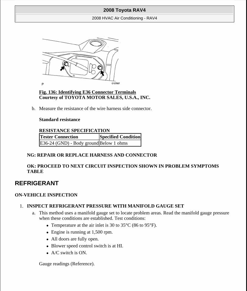
Fig. 136: Identifying E36 Connector Terminals Courtesy of TOYOTA MOTOR SALES, U.S.A., INC.
b. Measure the resistance of the wire harness side connector.
Standard resistance
RESISTANCE SPECIFICATION
NG: REPAIR OR REPLACE HARNESS AND CONNECTOR
OK: PROCEED TO NEXT CIRCUIT INSPECTION SHOWN IN PROBLEM SYMPTOMS TABLE
REFRIGERANT
ON-VEHICLE INSPECTION
1. INSPECT REFRIGERANT PRESSURE WITH MANIFOLD GAUGE SET
a. This method uses a manifold gauge set to locate problem areas. Read the manifold gauge pressure when these conditions are established. Test conditions:
Temperature at the air inlet is 30 to 35°C (86 to 95°F).
Engine is running at 1,500 rpm.
All doors are fully open.
Blower speed control switch is at HI.
A/C switch is ON.
Gauge readings (Reference).
Tester Connection Specified ConditionE36-24 (GND) - Body ground Below 1 ohms
2008 Toyota RAV4
2008 HVAC Air Conditioning - RAV4
Microsoft
Tuesday, August 18, 2009 3:53:56 PM Page 151 © 2005 Mitchell Repair Information Company, LLC.
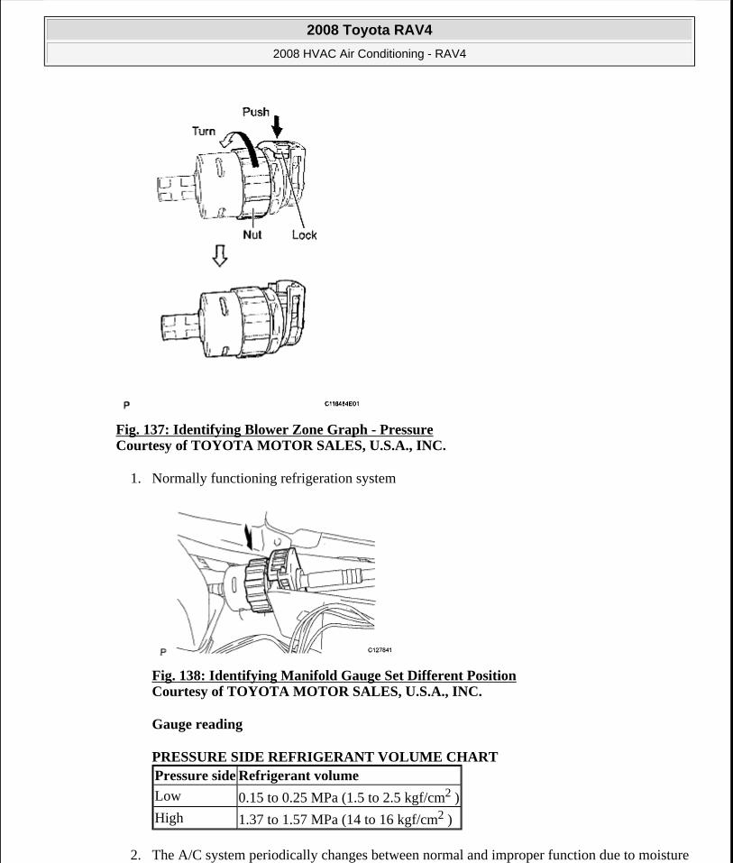
Fig. 137: Identifying Blower Zone Graph - Pressure Courtesy of TOYOTA MOTOR SALES, U.S.A., INC.
1. Normally functioning refrigeration system
Fig. 138: Identifying Manifold Gauge Set Different Position Courtesy of TOYOTA MOTOR SALES, U.S.A., INC.
Gauge reading
PRESSURE SIDE REFRIGERANT VOLUME CHART
2. The A/C system periodically changes between normal and improper function due to moisture
Pressure side Refrigerant volume
Low 0.15 to 0.25 MPa (1.5 to 2.5 kgf/cm2 )
High 1.37 to 1.57 MPa (14 to 16 kgf/cm2 )
2008 Toyota RAV4
2008 HVAC Air Conditioning - RAV4
Microsoft
Tuesday, August 18, 2009 3:53:56 PM Page 152 © 2005 Mitchell Repair Information Company, LLC.

in the refrigerant system.
Fig. 139: Checking Refrigerant Pressure (Moisture In Refrigerant System) Courtesy of TOYOTA MOTOR SALES, U.S.A., INC.
SYMPTOMS CHART
3. The A/C system does not function effectively due to insufficient cooling.
Fig. 140: Checking Refrigerant Pressure (Insufficient Cooling) Courtesy of TOYOTA MOTOR SALES, U.S.A., INC.
SYMPTOMS CHART
Symptoms Probable Cause Diagnosis Corrective Actions
During operation, pressure on low pressure side cycles between normal and vacuum
Moisture in refrigeration system freezes at expansion valve orifice, causing temporary stop of cycle. However, when melted, normal state is restored.
Drier is overly saturated
Moisture in refrigeration system freezes at expansion valve orifice and blocks refrigerant circulation
1. Replace cooler drier
2. Remove moisture from cycle by repeatedly evacuating air
3. Supply appropriate volume of new refrigerant
2008 Toyota RAV4
2008 HVAC Air Conditioning - RAV4
Microsoft
Tuesday, August 18, 2009 3:53:56 PM Page 153 © 2005 Mitchell Repair Information Company, LLC.
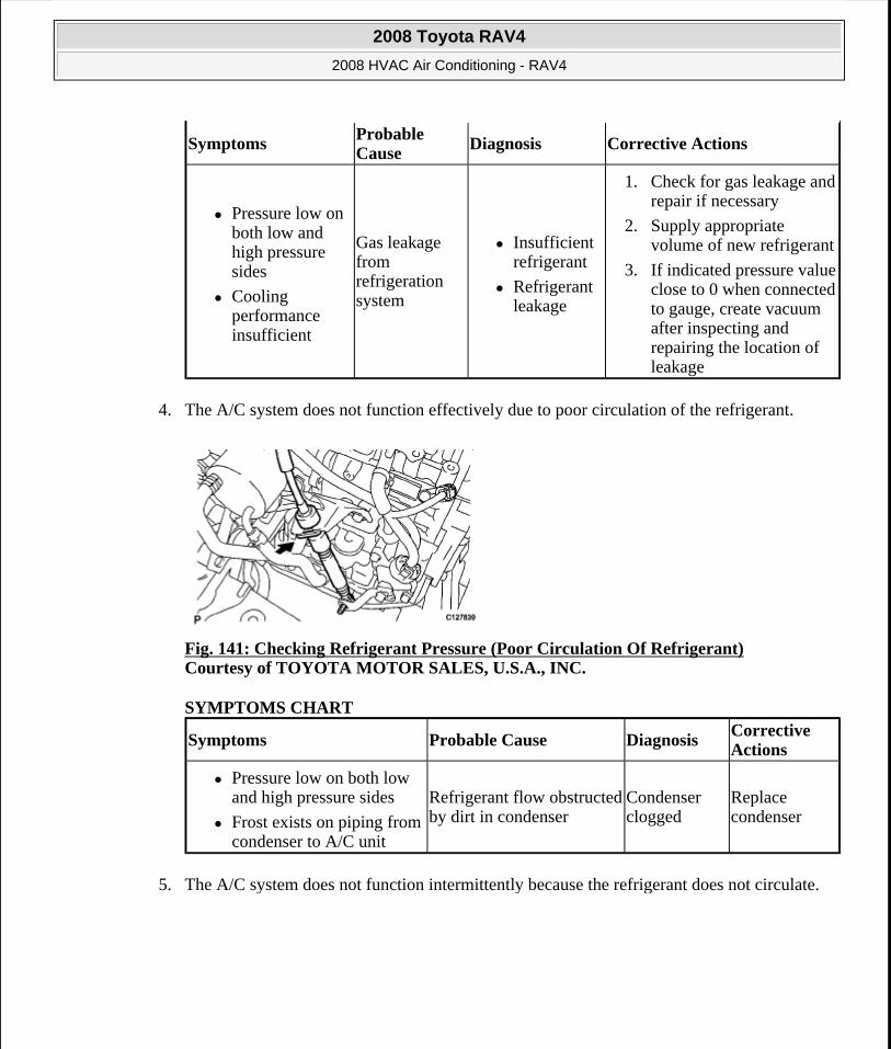
4. The A/C system does not function effectively due to poor circulation of the refrigerant.
Fig. 141: Checking Refrigerant Pressure (Poor Circulation Of Refrigerant) Courtesy of TOYOTA MOTOR SALES, U.S.A., INC.
SYMPTOMS CHART
5. The A/C system does not function intermittently because the refrigerant does not circulate.
SymptomsProbable Cause
Diagnosis Corrective Actions
Pressure low on both low and high pressure sides
Cooling performance insufficient
Gas leakage from refrigeration system
Insufficient refrigerant
Refrigerant leakage
1. Check for gas leakage and repair if necessary
2. Supply appropriate volume of new refrigerant
3. If indicated pressure value close to 0 when connected to gauge, create vacuum after inspecting and repairing the location of leakage
Symptoms Probable Cause DiagnosisCorrective Actions
Pressure low on both low and high pressure sides
Frost exists on piping from condenser to A/C unit
Refrigerant flow obstructed by dirt in condenser
Condenser clogged
Replace condenser
2008 Toyota RAV4
2008 HVAC Air Conditioning - RAV4
Microsoft
Tuesday, August 18, 2009 3:53:56 PM Page 154 © 2005 Mitchell Repair Information Company, LLC.
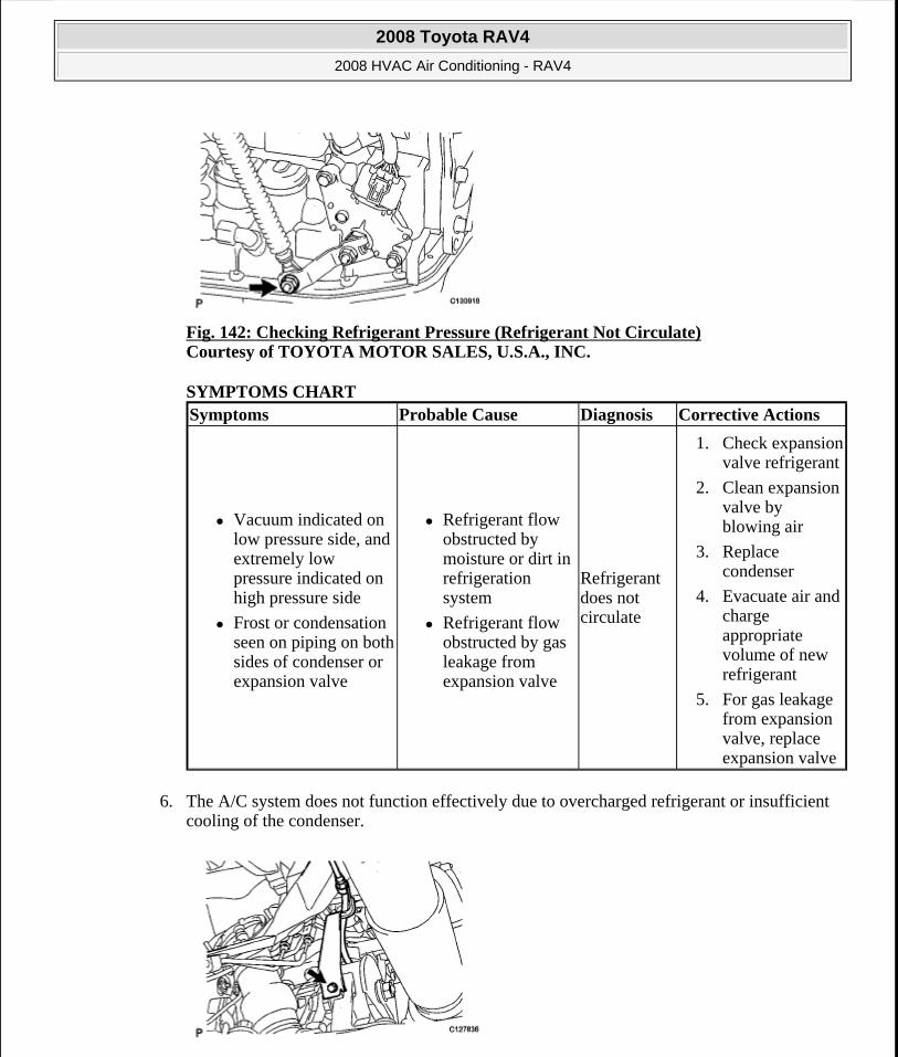
Fig. 142: Checking Refrigerant Pressure (Refrigerant Not Circulate) Courtesy of TOYOTA MOTOR SALES, U.S.A., INC.
SYMPTOMS CHART
6. The A/C system does not function effectively due to overcharged refrigerant or insufficient cooling of the condenser.
Symptoms Probable Cause Diagnosis Corrective Actions
Vacuum indicated on low pressure side, and extremely low pressure indicated on high pressure side
Frost or condensation seen on piping on both sides of condenser or expansion valve
Refrigerant flow obstructed by moisture or dirt in refrigeration system
Refrigerant flow obstructed by gas leakage from expansion valve
Refrigerant does not circulate
1. Check expansion valve refrigerant
2. Clean expansion valve by blowing air
3. Replace condenser
4. Evacuate air and charge appropriate volume of new refrigerant
5. For gas leakage from expansion valve, replace expansion valve
2008 Toyota RAV4
2008 HVAC Air Conditioning - RAV4
Microsoft
Tuesday, August 18, 2009 3:53:56 PM Page 155 © 2005 Mitchell Repair Information Company, LLC.

Fig. 143: Checking Refrigerant Pressure (Overcharged Refrigerant Or Insufficient Cooling Of Condenser) Courtesy of TOYOTA MOTOR SALES, U.S.A., INC.
SYMPTOMS CHART
7. The A/C system does not function due to air in the refrigeration system.
Fig. 144: Identifying Manifold Gauge Set Different Position Courtesy of TOYOTA MOTOR SALES, U.S.A., INC.
SYMPTOMS CHART
Symptoms Probable Cause Diagnosis Corrective Actions
Pressure extremely high on both low and high-pressure sides
Excessive refrigerant
Cooling performance of condenser insufficient
Condenser is dirty
Condenser fan motor is malfunctioning
Excessive refrigerant
1. Clean condenser
2. Check condenser fan motor operation
3. If 1 and 2 normal, check the amount of refrigerant and supply appropriate volume of refrigerant
CAUTION: The low-pressure piping may be very hot and cause serious burns.
SymptomsProbable Cause
Diagnosis Corrective Actions
Pressure extremely high on both low and high-pressure sides
Low-pressure piping is too hot to touch
Air in refrigeration system
Air in refrigeration system
Vacuum purging insufficient
1. Check if compressor oil is dirty or insufficient
2. Evacuate air and charge new refrigerant
2008 Toyota RAV4
2008 HVAC Air Conditioning - RAV4
Microsoft
Tuesday, August 18, 2009 3:53:56 PM Page 156 © 2005 Mitchell Repair Information Company, LLC.

8. The A/C system does not function effectively due to an expansion valve malfunction.
Fig. 145: Checking Refrigerant Pressure (Expansion Valve Malfunction) Courtesy of TOYOTA MOTOR SALES, U.S.A., INC.
SYMPTOMS CHART
9. The A/C system does not function due to a defective compressor.
Fig. 146: Checking Refrigerant Pressure (Defective Compressor) Courtesy of TOYOTA MOTOR SALES, U.S.A., INC.
SYMPTOMS CHART
SymptomsProbable Cause Diagnosis
Corrective Actions
Pressure extremely high on both low and high-pressure sides
Frost or condensation on piping on low-pressure side
Problem with expansion valve
Excessive refrigerant in low pressure piping
Expansion valve too wide open
Replace expansion valve
SymptomsProbable Cause
DiagnosisCorrective Actions
Pressure extremely high on both low and Compression failure
2008 Toyota RAV4
2008 HVAC Air Conditioning - RAV4
Microsoft
Tuesday, August 18, 2009 3:53:56 PM Page 157 © 2005 Mitchell Repair Information Company, LLC.
REPLACEMENT
1. DISCHARGE REFRIGERANT FROM REFRIGERATION SYSTEM
a. Start up the engine.
b. Turn the A/C switch ON.
c. Operate the cooler compressor with an engine speed of approximately 1,000 rpm for 5 to 6 minutes to circulate the refrigerant and collect the compressor oil remaining in each component into the cooler compressor.
d. Stop the engine.
e. Recover the refrigerant from the A/C system using a refrigerant recovery unit,
2. CHARGE REFRIGERANT
a. Perform vacuum purging using a vacuum pump.
b. Charge refrigerant HFC-134a (R134a).
SST 09985-20010 (09985-02010, 09985-02050, 09985-02060, 09985-02070, 09985-02080, 09985-02090, 09985-02110, 09985-02130, 09985-02140, 09985-02150)
Standard:
430+-30g(15.2+-1.1 oz.)
high-pressure sides
Pressure extremely low on high pressure side
Internal leakage in compressor
Leakage from damaged valve or broken sliding parts
Repair or replace compressor
2008 Toyota RAV4
2008 HVAC Air Conditioning - RAV4
Microsoft
Tuesday, August 18, 2009 3:53:56 PM Page 158 © 2005 Mitchell Repair Information Company, LLC.
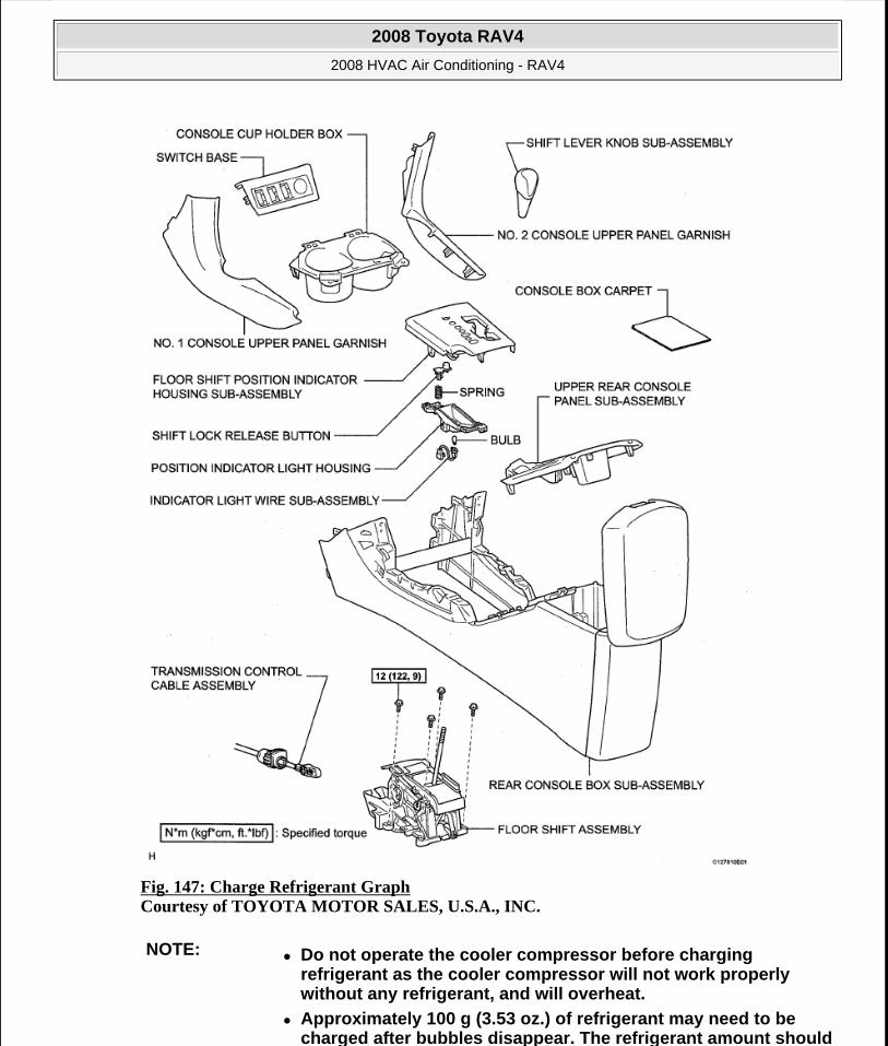
Fig. 147: Charge Refrigerant Graph Courtesy of TOYOTA MOTOR SALES, U.S.A., INC.
NOTE: Do not operate the cooler compressor before charging refrigerant as the cooler compressor will not work properly without any refrigerant, and will overheat.
Approximately 100 g (3.53 oz.) of refrigerant may need to be charged after bubbles disappear. The refrigerant amount should
2008 Toyota RAV4
2008 HVAC Air Conditioning - RAV4
Microsoft
Tuesday, August 18, 2009 3:53:56 PM Page 159 © 2005 Mitchell Repair Information Company, LLC.
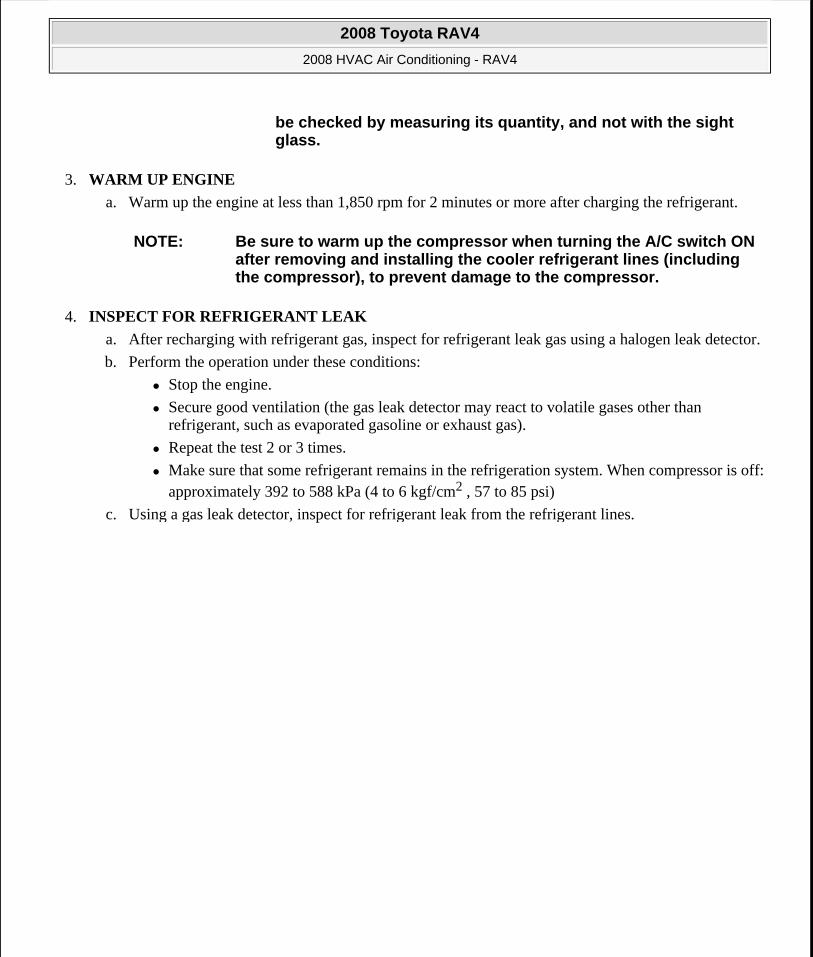
3. WARM UP ENGINE
a. Warm up the engine at less than 1,850 rpm for 2 minutes or more after charging the refrigerant.
4. INSPECT FOR REFRIGERANT LEAK
a. After recharging with refrigerant gas, inspect for refrigerant leak gas using a halogen leak detector.
b. Perform the operation under these conditions:
Stop the engine.
Secure good ventilation (the gas leak detector may react to volatile gases other than refrigerant, such as evaporated gasoline or exhaust gas).
Repeat the test 2 or 3 times.
Make sure that some refrigerant remains in the refrigeration system. When compressor is off: approximately 392 to 588 kPa (4 to 6 kgf/cm2 , 57 to 85 psi)
c. Using a gas leak detector, inspect for refrigerant leak from the refrigerant lines.
be checked by measuring its quantity, and not with the sight glass.
NOTE: Be sure to warm up the compressor when turning the A/C switch ON after removing and installing the cooler refrigerant lines (including the compressor), to prevent damage to the compressor.
2008 Toyota RAV4
2008 HVAC Air Conditioning - RAV4
Microsoft
Tuesday, August 18, 2009 3:53:56 PM Page 160 © 2005 Mitchell Repair Information Company, LLC.

Fig. 148: Inspecting Refrigerant Leak From Refrigerant Lines Courtesy of TOYOTA MOTOR SALES, U.S.A., INC.
d. If a gas leak is not detected on the drain hose, remove the blower motor control (blower resistor) from the cooling unit. Insert the gas leak detector sensor into the unit and perform the test.
e. Disconnect the connector and leave the pressure switch on for approximately 20 minutes. Bring the gas leak detector close to the pressure switch and perform the test.
REFRIGERANT LINE
COMPONENTS
2008 Toyota RAV4
2008 HVAC Air Conditioning - RAV4
Microsoft
Tuesday, August 18, 2009 3:53:56 PM Page 161 © 2005 Mitchell Repair Information Company, LLC.
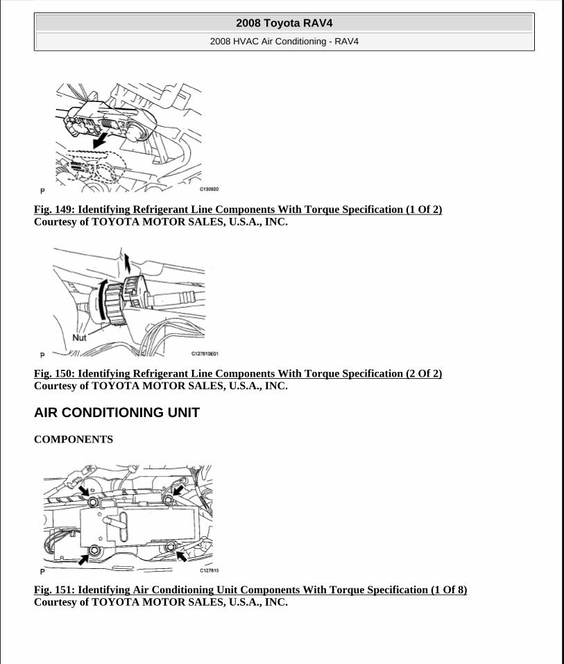
Fig. 149: Identifying Refrigerant Line Components With Torque Specification (1 Of 2) Courtesy of TOYOTA MOTOR SALES, U.S.A., INC.
Fig. 150: Identifying Refrigerant Line Components With Torque Specification (2 Of 2) Courtesy of TOYOTA MOTOR SALES, U.S.A., INC.
AIR CONDITIONING UNIT
COMPONENTS
Fig. 151: Identifying Air Conditioning Unit Components With Torque Specification (1 Of 8) Courtesy of TOYOTA MOTOR SALES, U.S.A., INC.
2008 Toyota RAV4
2008 HVAC Air Conditioning - RAV4
Microsoft
Tuesday, August 18, 2009 3:53:56 PM Page 162 © 2005 Mitchell Repair Information Company, LLC.
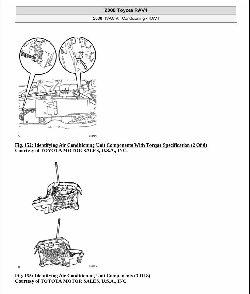
Fig. 152: Identifying Air Conditioning Unit Components With Torque Specification (2 Of 8) Courtesy of TOYOTA MOTOR SALES, U.S.A., INC.
Fig. 153: Identifying Air Conditioning Unit Components (3 Of 8) Courtesy of TOYOTA MOTOR SALES, U.S.A., INC.
2008 Toyota RAV4
2008 HVAC Air Conditioning - RAV4
Microsoft
Tuesday, August 18, 2009 3:53:56 PM Page 163 © 2005 Mitchell Repair Information Company, LLC.
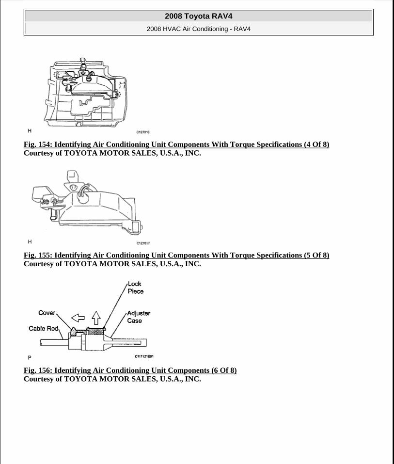
Fig. 154: Identifying Air Conditioning Unit Components With Torque Specifications (4 Of 8) Courtesy of TOYOTA MOTOR SALES, U.S.A., INC.
Fig. 155: Identifying Air Conditioning Unit Components With Torque Specifications (5 Of 8) Courtesy of TOYOTA MOTOR SALES, U.S.A., INC.
Fig. 156: Identifying Air Conditioning Unit Components (6 Of 8) Courtesy of TOYOTA MOTOR SALES, U.S.A., INC.
2008 Toyota RAV4
2008 HVAC Air Conditioning - RAV4
Microsoft
Tuesday, August 18, 2009 3:53:56 PM Page 164 © 2005 Mitchell Repair Information Company, LLC.

Fig. 157: Identifying Air Conditioning Unit Components With Torque Specification(7 Of 8) Courtesy of TOYOTA MOTOR SALES, U.S.A., INC.
Fig. 158: Identifying Air Conditioning Unit Components With Torque Specification (8 Of 8) Courtesy of TOYOTA MOTOR SALES, U.S.A., INC.
REMOVAL
1. DISCHARGE REFRIGERANT FROM REFRIGERATION SYSTEM (See REPLACEMENT )
2. DISCONNECT CABLE FROM NEGATIVE BATTERY TERMINAL
3. REMOVE TUBE SUB-ASSEMBLY
a. Remove the bolt.
b. Remove plate, as shown in the illustration.
CAUTION: Wait at least 90 seconds after disconnecting the cable from the negative (-) battery terminal to prevent airbag and seat belt pretensioner activation.
2008 Toyota RAV4
2008 HVAC Air Conditioning - RAV4
Microsoft
Tuesday, August 18, 2009 3:53:56 PM Page 165 © 2005 Mitchell Repair Information Company, LLC.
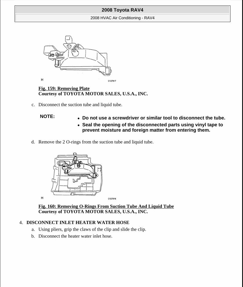
Fig. 159: Removing Plate Courtesy of TOYOTA MOTOR SALES, U.S.A., INC.
c. Disconnect the suction tube and liquid tube.
d. Remove the 2 O-rings from the suction tube and liquid tube.
Fig. 160: Removing O-Rings From Suction Tube And Liquid Tube Courtesy of TOYOTA MOTOR SALES, U.S.A., INC.
4. DISCONNECT INLET HEATER WATER HOSE
a. Using pliers, grip the claws of the clip and slide the clip.
b. Disconnect the heater water inlet hose.
NOTE: Do not use a screwdriver or similar tool to disconnect the tube.
Seal the opening of the disconnected parts using vinyl tape to prevent moisture and foreign matter from entering them.
2008 Toyota RAV4
2008 HVAC Air Conditioning - RAV4
Microsoft
Tuesday, August 18, 2009 3:53:56 PM Page 166 © 2005 Mitchell Repair Information Company, LLC.
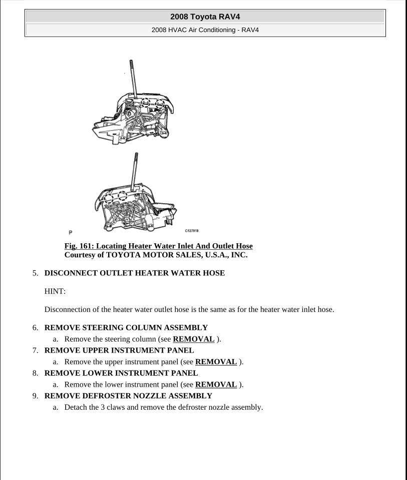
Fig. 161: Locating Heater Water Inlet And Outlet Hose Courtesy of TOYOTA MOTOR SALES, U.S.A., INC.
5. DISCONNECT OUTLET HEATER WATER HOSE
HINT:
Disconnection of the heater water outlet hose is the same as for the heater water inlet hose.
6. REMOVE STEERING COLUMN ASSEMBLY
a. Remove the steering column (see REMOVAL ).
7. REMOVE UPPER INSTRUMENT PANEL
a. Remove the upper instrument panel (see REMOVAL ).
8. REMOVE LOWER INSTRUMENT PANEL
a. Remove the lower instrument panel (see REMOVAL ).
9. REMOVE DEFROSTER NOZZLE ASSEMBLY
a. Detach the 3 claws and remove the defroster nozzle assembly.
2008 Toyota RAV4
2008 HVAC Air Conditioning - RAV4
Microsoft
Tuesday, August 18, 2009 3:53:56 PM Page 167 © 2005 Mitchell Repair Information Company, LLC.
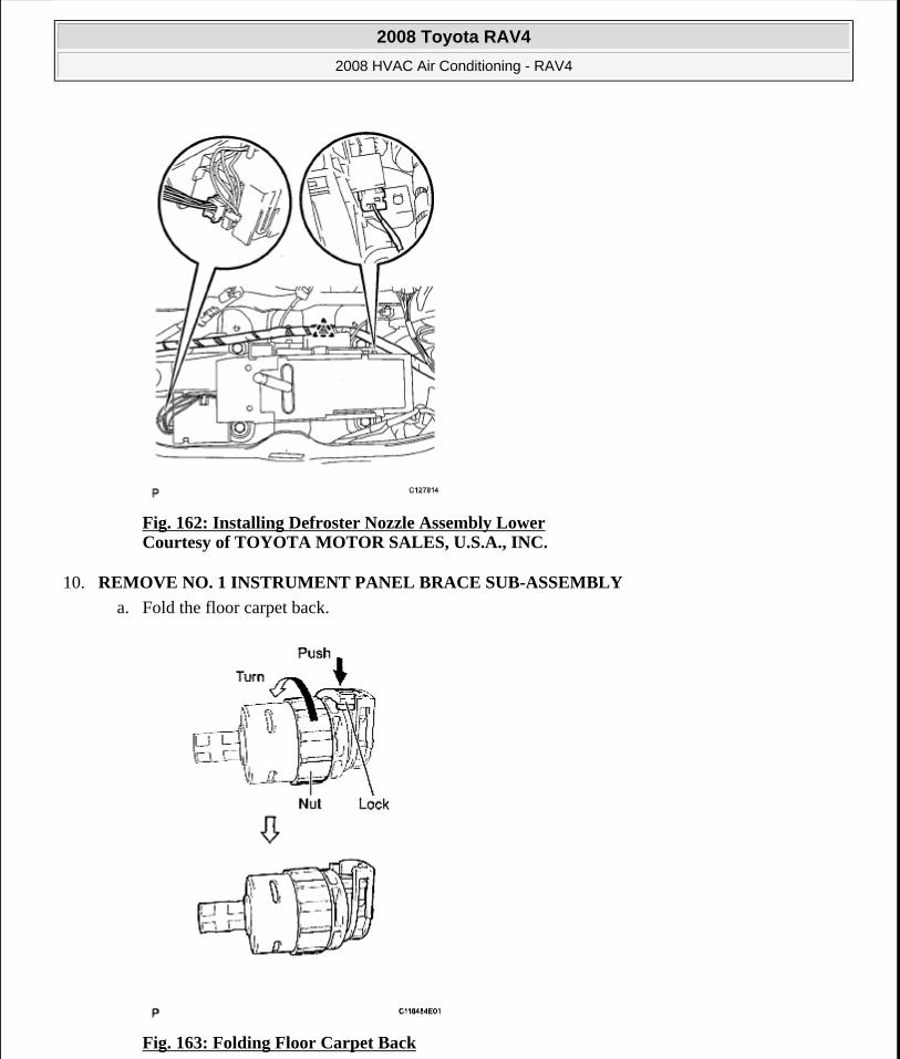
Fig. 162: Installing Defroster Nozzle Assembly Lower Courtesy of TOYOTA MOTOR SALES, U.S.A., INC.
10. REMOVE NO. 1 INSTRUMENT PANEL BRACE SUB-ASSEMBLY
a. Fold the floor carpet back.
Fig. 163: Folding Floor Carpet Back
2008 Toyota RAV4
2008 HVAC Air Conditioning - RAV4
Microsoft
Tuesday, August 18, 2009 3:53:56 PM Page 168 © 2005 Mitchell Repair Information Company, LLC.
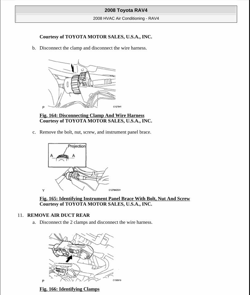
Courtesy of TOYOTA MOTOR SALES, U.S.A., INC.
b. Disconnect the clamp and disconnect the wire harness.
Fig. 164: Disconnecting Clamp And Wire Harness Courtesy of TOYOTA MOTOR SALES, U.S.A., INC.
c. Remove the bolt, nut, screw, and instrument panel brace.
Fig. 165: Identifying Instrument Panel Brace With Bolt, Nut And Screw Courtesy of TOYOTA MOTOR SALES, U.S.A., INC.
11. REMOVE AIR DUCT REAR
a. Disconnect the 2 clamps and disconnect the wire harness.
Fig. 166: Identifying Clamps
2008 Toyota RAV4
2008 HVAC Air Conditioning - RAV4
Microsoft
Tuesday, August 18, 2009 3:53:56 PM Page 169 © 2005 Mitchell Repair Information Company, LLC.
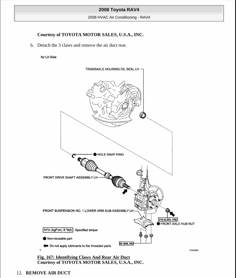
Courtesy of TOYOTA MOTOR SALES, U.S.A., INC.
b. Detach the 3 claws and remove the air duct rear.
Fig. 167: Identifying Claws And Rear Air Duct Courtesy of TOYOTA MOTOR SALES, U.S.A., INC.
12. REMOVE AIR DUCT
2008 Toyota RAV4
2008 HVAC Air Conditioning - RAV4
Microsoft
Tuesday, August 18, 2009 3:53:56 PM Page 170 © 2005 Mitchell Repair Information Company, LLC.

a. Detach the 2 claws and remove the air duct.
Fig. 168: Identifying Claws And Air Duct Courtesy of TOYOTA MOTOR SALES, U.S.A., INC.
13. REMOVE AIR CONDITIONING AMPLIFIER ASSEMBLY
a. Detach the 2 clamps.
b. Disconnect the connector.
2008 Toyota RAV4
2008 HVAC Air Conditioning - RAV4
Microsoft
Tuesday, August 18, 2009 3:53:56 PM Page 171 © 2005 Mitchell Repair Information Company, LLC.
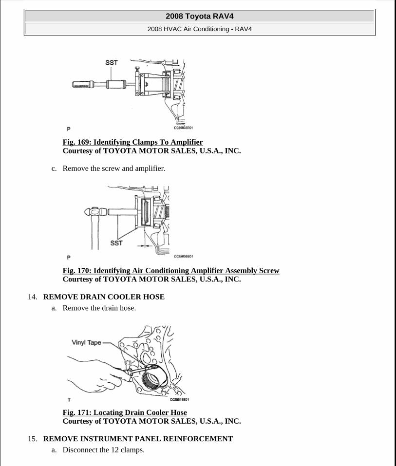
Fig. 169: Identifying Clamps To Amplifier Courtesy of TOYOTA MOTOR SALES, U.S.A., INC.
c. Remove the screw and amplifier.
Fig. 170: Identifying Air Conditioning Amplifier Assembly Screw Courtesy of TOYOTA MOTOR SALES, U.S.A., INC.
14. REMOVE DRAIN COOLER HOSE
a. Remove the drain hose.
Fig. 171: Locating Drain Cooler Hose Courtesy of TOYOTA MOTOR SALES, U.S.A., INC.
15. REMOVE INSTRUMENT PANEL REINFORCEMENT
a. Disconnect the 12 clamps.
2008 Toyota RAV4
2008 HVAC Air Conditioning - RAV4
Microsoft
Tuesday, August 18, 2009 3:53:56 PM Page 172 © 2005 Mitchell Repair Information Company, LLC.
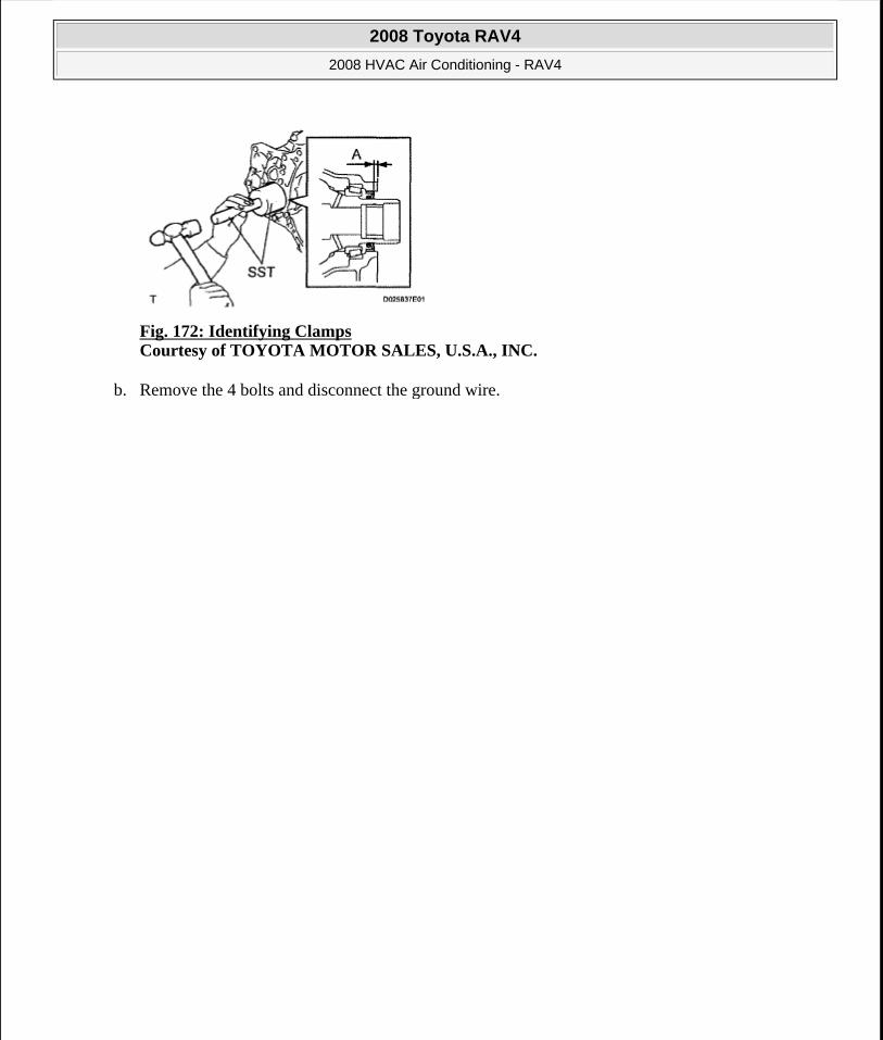
Fig. 172: Identifying Clamps Courtesy of TOYOTA MOTOR SALES, U.S.A., INC.
b. Remove the 4 bolts and disconnect the ground wire.
2008 Toyota RAV4
2008 HVAC Air Conditioning - RAV4
Microsoft
Tuesday, August 18, 2009 3:53:56 PM Page 173 © 2005 Mitchell Repair Information Company, LLC.
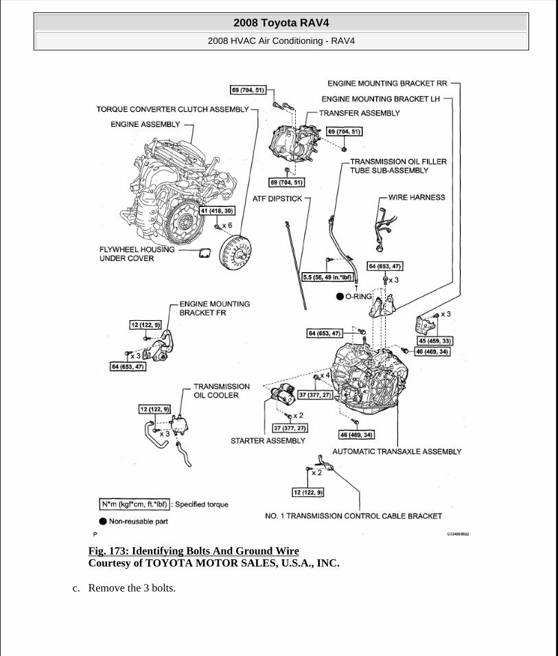
Fig. 173: Identifying Bolts And Ground Wire Courtesy of TOYOTA MOTOR SALES, U.S.A., INC.
c. Remove the 3 bolts.
2008 Toyota RAV4
2008 HVAC Air Conditioning - RAV4
Microsoft
Tuesday, August 18, 2009 3:53:56 PM Page 174 © 2005 Mitchell Repair Information Company, LLC.
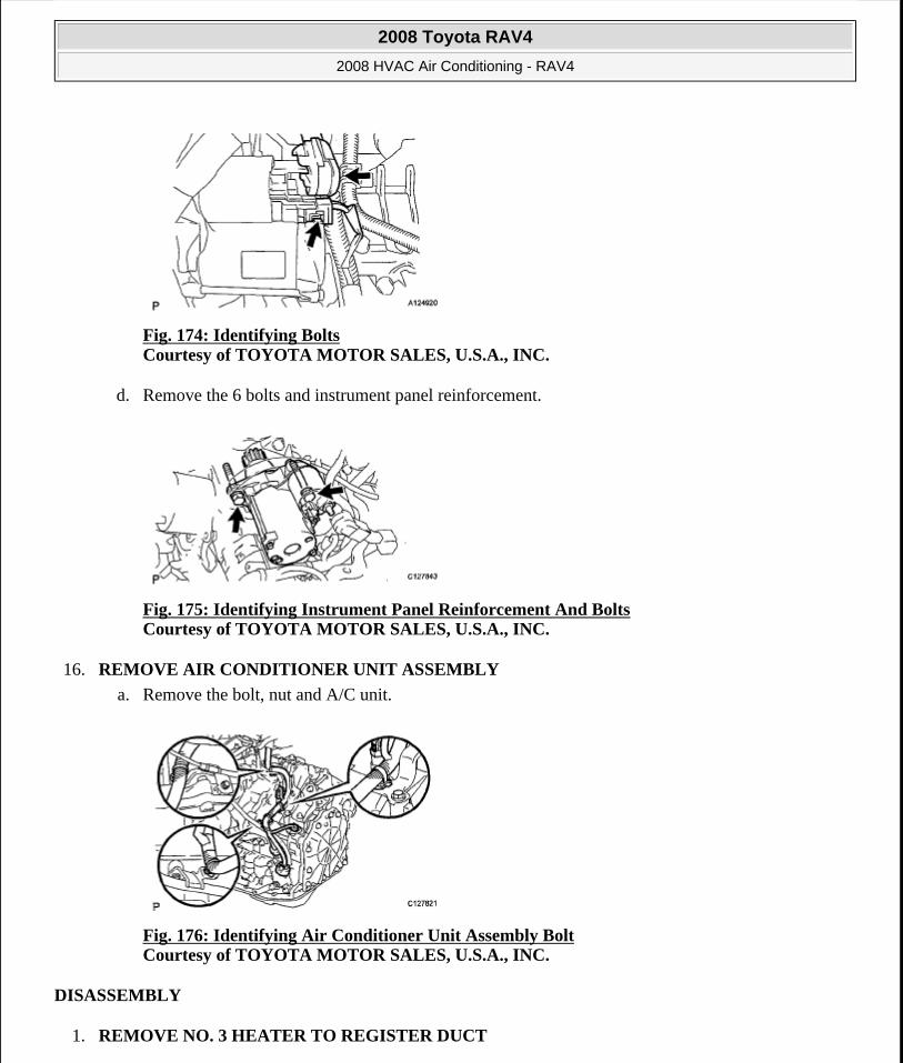
Fig. 174: Identifying Bolts Courtesy of TOYOTA MOTOR SALES, U.S.A., INC.
d. Remove the 6 bolts and instrument panel reinforcement.
Fig. 175: Identifying Instrument Panel Reinforcement And Bolts Courtesy of TOYOTA MOTOR SALES, U.S.A., INC.
16. REMOVE AIR CONDITIONER UNIT ASSEMBLY
a. Remove the bolt, nut and A/C unit.
Fig. 176: Identifying Air Conditioner Unit Assembly Bolt Courtesy of TOYOTA MOTOR SALES, U.S.A., INC.
DISASSEMBLY
1. REMOVE NO. 3 HEATER TO REGISTER DUCT
2008 Toyota RAV4
2008 HVAC Air Conditioning - RAV4
Microsoft
Tuesday, August 18, 2009 3:53:56 PM Page 175 © 2005 Mitchell Repair Information Company, LLC.
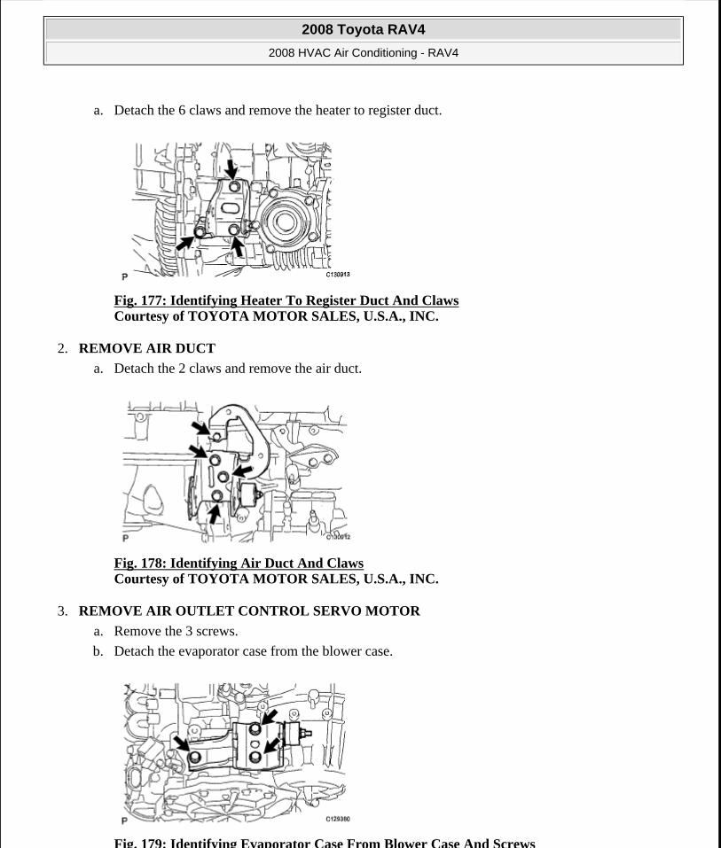
a. Detach the 6 claws and remove the heater to register duct.
Fig. 177: Identifying Heater To Register Duct And Claws Courtesy of TOYOTA MOTOR SALES, U.S.A., INC.
2. REMOVE AIR DUCT
a. Detach the 2 claws and remove the air duct.
Fig. 178: Identifying Air Duct And Claws Courtesy of TOYOTA MOTOR SALES, U.S.A., INC.
3. REMOVE AIR OUTLET CONTROL SERVO MOTOR
a. Remove the 3 screws.
b. Detach the evaporator case from the blower case.
Fig. 179: Identifying Evaporator Case From Blower Case And Screws
2008 Toyota RAV4
2008 HVAC Air Conditioning - RAV4
Microsoft
Tuesday, August 18, 2009 3:53:56 PM Page 176 © 2005 Mitchell Repair Information Company, LLC.

Courtesy of TOYOTA MOTOR SALES, U.S.A., INC.
c. Remove the 3 screws and disconnect the connector.
d. Remove the air outlet control servo motor.
Fig. 180: Identifying Screws And Connector Courtesy of TOYOTA MOTOR SALES, U.S.A., INC.
4. REMOVE AIR MIX CONTROL SERVO MOTOR
a. Remove the 3 screws and disconnect the connector.
b. Remove the air mix control servo motor.
Fig. 181: Identifying Air Mix Control Servo Motor Screws Courtesy of TOYOTA MOTOR SALES, U.S.A., INC.
5. REMOVE MODE CONTROL CABLE ASSEMBLY (for Manual Air Conditioning System)
a. Remove the 3 screws.
b. Detach the evaporator case from the blower case.
2008 Toyota RAV4
2008 HVAC Air Conditioning - RAV4
Microsoft
Tuesday, August 18, 2009 3:53:56 PM Page 177 © 2005 Mitchell Repair Information Company, LLC.
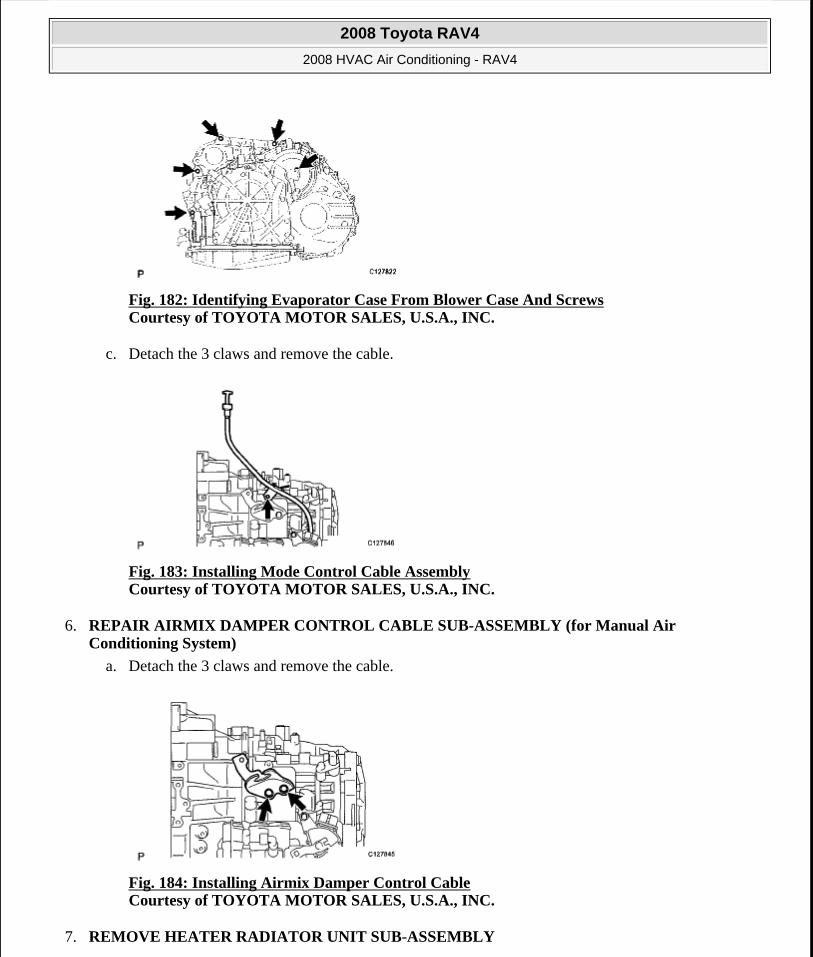
Fig. 182: Identifying Evaporator Case From Blower Case And Screws Courtesy of TOYOTA MOTOR SALES, U.S.A., INC.
c. Detach the 3 claws and remove the cable.
Fig. 183: Installing Mode Control Cable Assembly Courtesy of TOYOTA MOTOR SALES, U.S.A., INC.
6. REPAIR AIRMIX DAMPER CONTROL CABLE SUB-ASSEMBLY (for Manual Air Conditioning System)
a. Detach the 3 claws and remove the cable.
Fig. 184: Installing Airmix Damper Control Cable Courtesy of TOYOTA MOTOR SALES, U.S.A., INC.
7. REMOVE HEATER RADIATOR UNIT SUB-ASSEMBLY
2008 Toyota RAV4
2008 HVAC Air Conditioning - RAV4
Microsoft
Tuesday, August 18, 2009 3:53:56 PM Page 178 © 2005 Mitchell Repair Information Company, LLC.
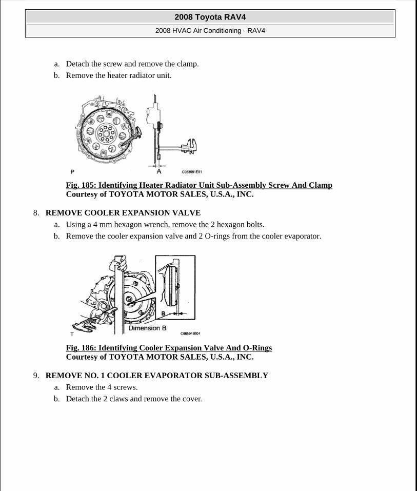
a. Detach the screw and remove the clamp.
b. Remove the heater radiator unit.
Fig. 185: Identifying Heater Radiator Unit Sub-Assembly Screw And Clamp Courtesy of TOYOTA MOTOR SALES, U.S.A., INC.
8. REMOVE COOLER EXPANSION VALVE
a. Using a 4 mm hexagon wrench, remove the 2 hexagon bolts.
b. Remove the cooler expansion valve and 2 O-rings from the cooler evaporator.
Fig. 186: Identifying Cooler Expansion Valve And O-Rings Courtesy of TOYOTA MOTOR SALES, U.S.A., INC.
9. REMOVE NO. 1 COOLER EVAPORATOR SUB-ASSEMBLY
a. Remove the 4 screws.
b. Detach the 2 claws and remove the cover.
2008 Toyota RAV4
2008 HVAC Air Conditioning - RAV4
Microsoft
Tuesday, August 18, 2009 3:53:57 PM Page 179 © 2005 Mitchell Repair Information Company, LLC.
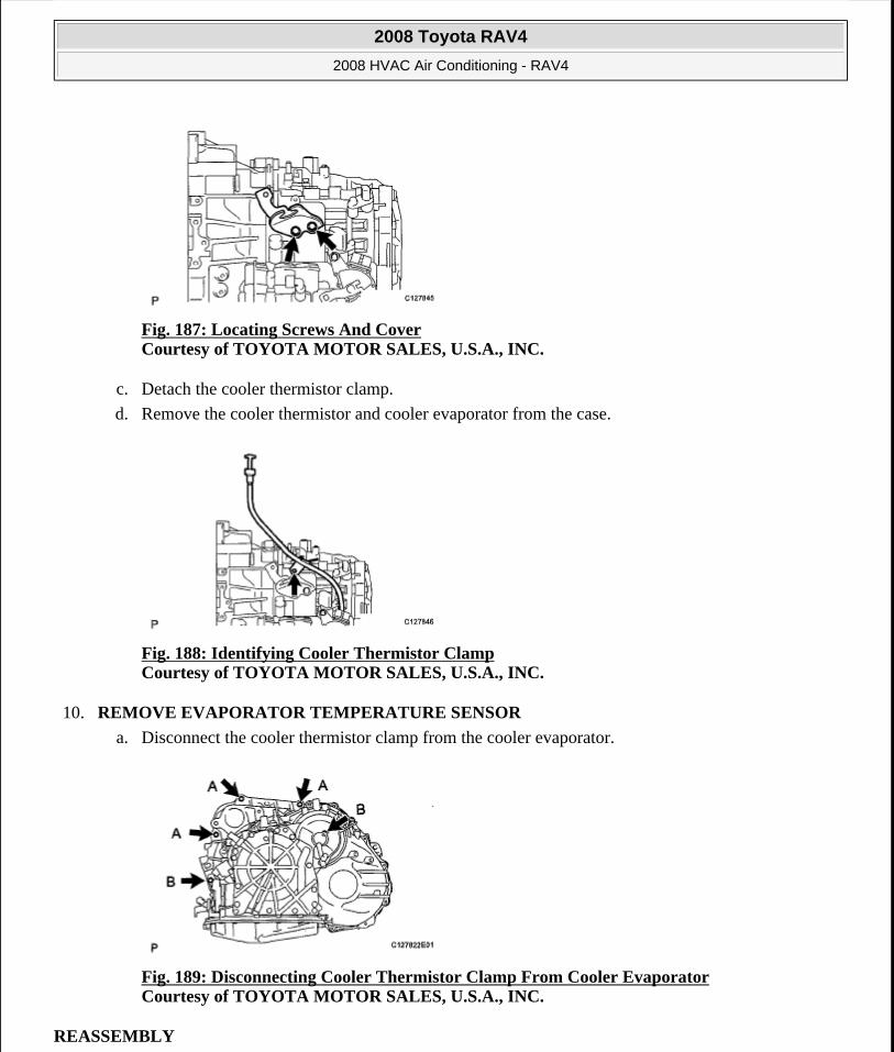
Fig. 187: Locating Screws And Cover Courtesy of TOYOTA MOTOR SALES, U.S.A., INC.
c. Detach the cooler thermistor clamp.
d. Remove the cooler thermistor and cooler evaporator from the case.
Fig. 188: Identifying Cooler Thermistor Clamp Courtesy of TOYOTA MOTOR SALES, U.S.A., INC.
10. REMOVE EVAPORATOR TEMPERATURE SENSOR
a. Disconnect the cooler thermistor clamp from the cooler evaporator.
Fig. 189: Disconnecting Cooler Thermistor Clamp From Cooler Evaporator Courtesy of TOYOTA MOTOR SALES, U.S.A., INC.
REASSEMBLY
2008 Toyota RAV4
2008 HVAC Air Conditioning - RAV4
Microsoft
Tuesday, August 18, 2009 3:53:57 PM Page 180 © 2005 Mitchell Repair Information Company, LLC.
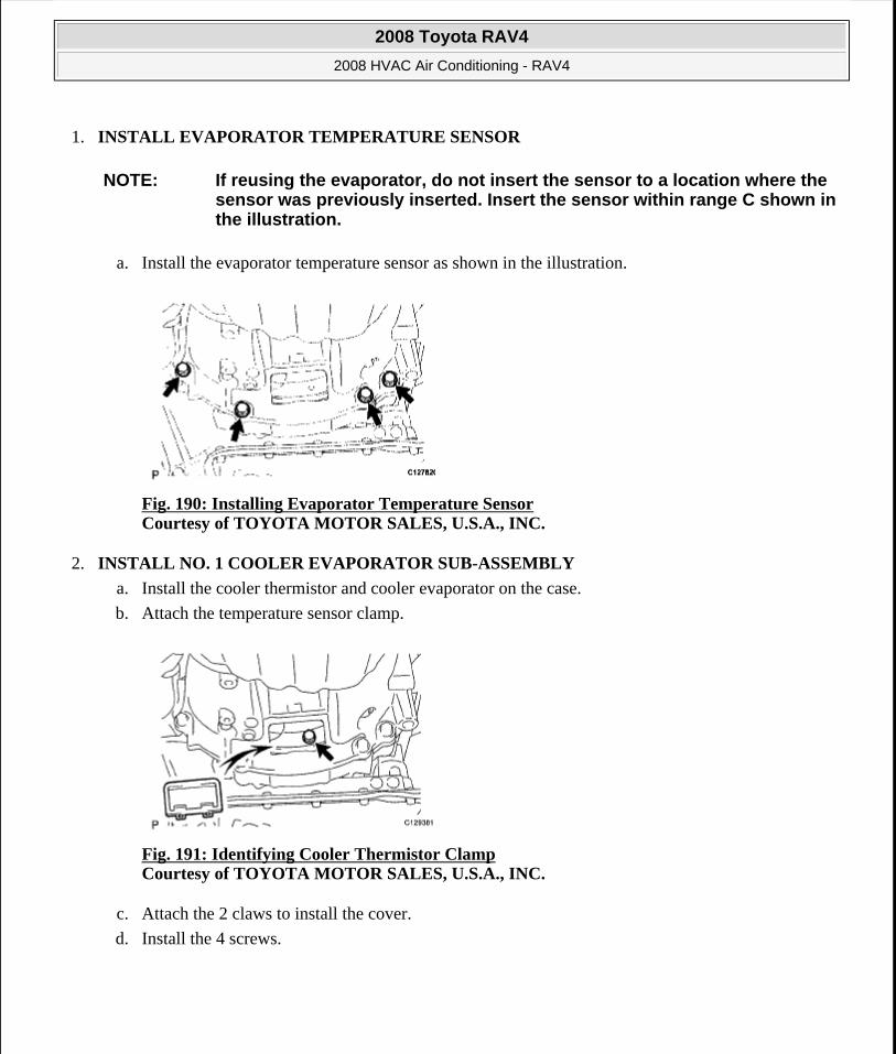
1. INSTALL EVAPORATOR TEMPERATURE SENSOR
a. Install the evaporator temperature sensor as shown in the illustration.
Fig. 190: Installing Evaporator Temperature Sensor Courtesy of TOYOTA MOTOR SALES, U.S.A., INC.
2. INSTALL NO. 1 COOLER EVAPORATOR SUB-ASSEMBLY
a. Install the cooler thermistor and cooler evaporator on the case.
b. Attach the temperature sensor clamp.
Fig. 191: Identifying Cooler Thermistor Clamp Courtesy of TOYOTA MOTOR SALES, U.S.A., INC.
c. Attach the 2 claws to install the cover.
d. Install the 4 screws.
NOTE: If reusing the evaporator, do not insert the sensor to a location where the sensor was previously inserted. Insert the sensor within range C shown in the illustration.
2008 Toyota RAV4
2008 HVAC Air Conditioning - RAV4
Microsoft
Tuesday, August 18, 2009 3:53:57 PM Page 181 © 2005 Mitchell Repair Information Company, LLC.
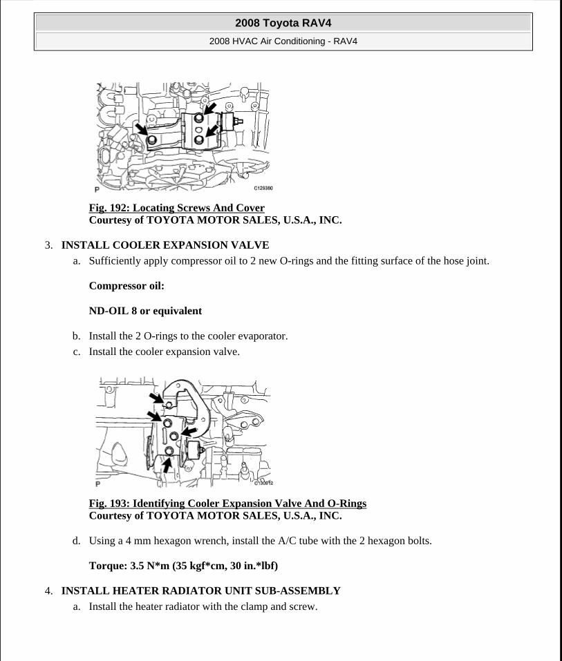
Fig. 192: Locating Screws And Cover Courtesy of TOYOTA MOTOR SALES, U.S.A., INC.
3. INSTALL COOLER EXPANSION VALVE
a. Sufficiently apply compressor oil to 2 new O-rings and the fitting surface of the hose joint.
Compressor oil:
ND-OIL 8 or equivalent
b. Install the 2 O-rings to the cooler evaporator.
c. Install the cooler expansion valve.
Fig. 193: Identifying Cooler Expansion Valve And O-Rings Courtesy of TOYOTA MOTOR SALES, U.S.A., INC.
d. Using a 4 mm hexagon wrench, install the A/C tube with the 2 hexagon bolts.
Torque: 3.5 N*m (35 kgf*cm, 30 in.*lbf)
4. INSTALL HEATER RADIATOR UNIT SUB-ASSEMBLY
a. Install the heater radiator with the clamp and screw.
2008 Toyota RAV4
2008 HVAC Air Conditioning - RAV4
Microsoft
Tuesday, August 18, 2009 3:53:57 PM Page 182 © 2005 Mitchell Repair Information Company, LLC.
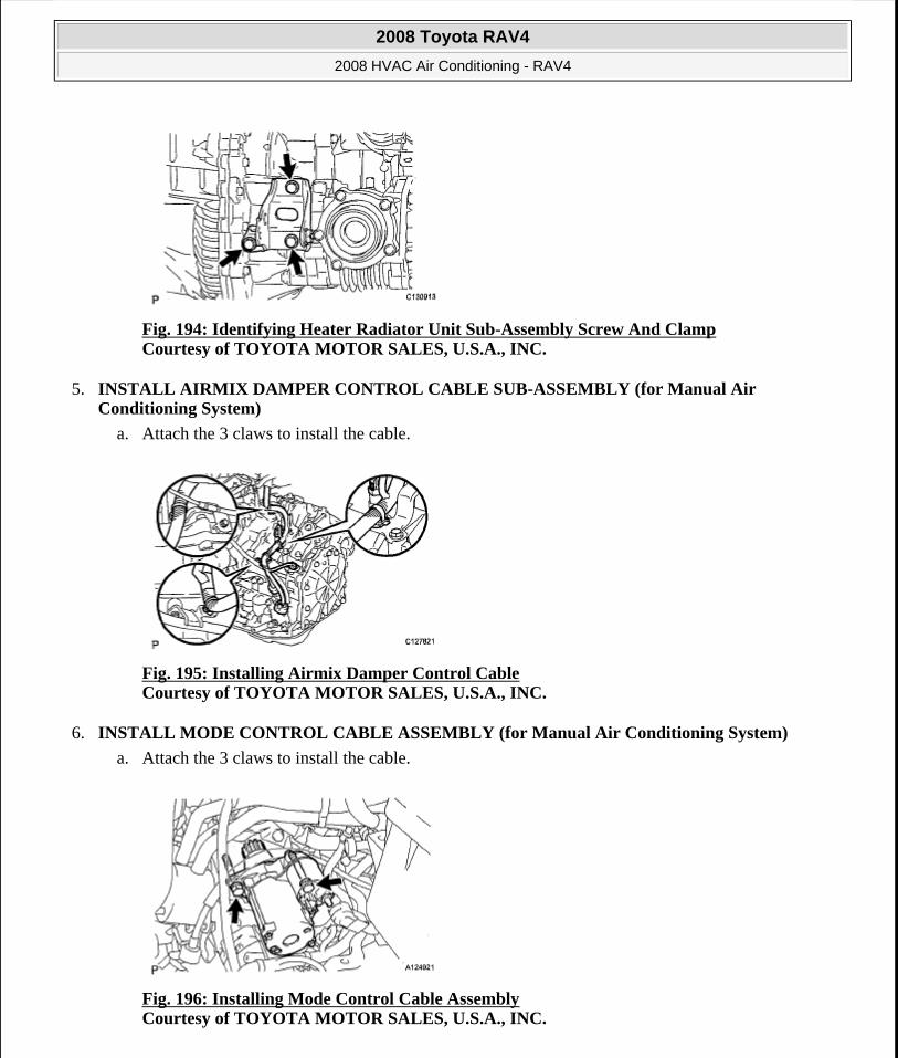
Fig. 194: Identifying Heater Radiator Unit Sub-Assembly Screw And Clamp Courtesy of TOYOTA MOTOR SALES, U.S.A., INC.
5. INSTALL AIRMIX DAMPER CONTROL CABLE SUB-ASSEMBLY (for Manual Air Conditioning System)
a. Attach the 3 claws to install the cable.
Fig. 195: Installing Airmix Damper Control Cable Courtesy of TOYOTA MOTOR SALES, U.S.A., INC.
6. INSTALL MODE CONTROL CABLE ASSEMBLY (for Manual Air Conditioning System)
a. Attach the 3 claws to install the cable.
Fig. 196: Installing Mode Control Cable Assembly Courtesy of TOYOTA MOTOR SALES, U.S.A., INC.
2008 Toyota RAV4
2008 HVAC Air Conditioning - RAV4
Microsoft
Tuesday, August 18, 2009 3:53:57 PM Page 183 © 2005 Mitchell Repair Information Company, LLC.
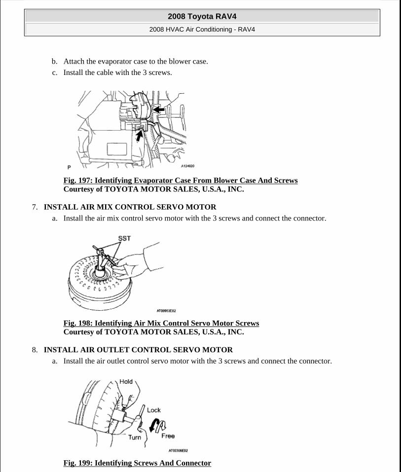
b. Attach the evaporator case to the blower case.
c. Install the cable with the 3 screws.
Fig. 197: Identifying Evaporator Case From Blower Case And Screws Courtesy of TOYOTA MOTOR SALES, U.S.A., INC.
7. INSTALL AIR MIX CONTROL SERVO MOTOR
a. Install the air mix control servo motor with the 3 screws and connect the connector.
Fig. 198: Identifying Air Mix Control Servo Motor Screws Courtesy of TOYOTA MOTOR SALES, U.S.A., INC.
8. INSTALL AIR OUTLET CONTROL SERVO MOTOR
a. Install the air outlet control servo motor with the 3 screws and connect the connector.
Fig. 199: Identifying Screws And Connector
2008 Toyota RAV4
2008 HVAC Air Conditioning - RAV4
Microsoft
Tuesday, August 18, 2009 3:53:57 PM Page 184 © 2005 Mitchell Repair Information Company, LLC.

Courtesy of TOYOTA MOTOR SALES, U.S.A., INC.
b. Attach the evaporator case to the blower case.
c. Install the 3 screws.
Fig. 200: Identifying Evaporator Case From Blower Case And Screws Courtesy of TOYOTA MOTOR SALES, U.S.A., INC.
9. INSTALL AIR DUCT
a. Attach the 2 claws and install the air duct.
Fig. 201: Identifying Air Duct And Claws Courtesy of TOYOTA MOTOR SALES, U.S.A., INC.
10. INSTALL NO. 3 HEATER TO REGISTER DUCT
a. Attach the 6 claws and install the heater to register duct.
2008 Toyota RAV4
2008 HVAC Air Conditioning - RAV4
Microsoft
Tuesday, August 18, 2009 3:53:57 PM Page 185 © 2005 Mitchell Repair Information Company, LLC.
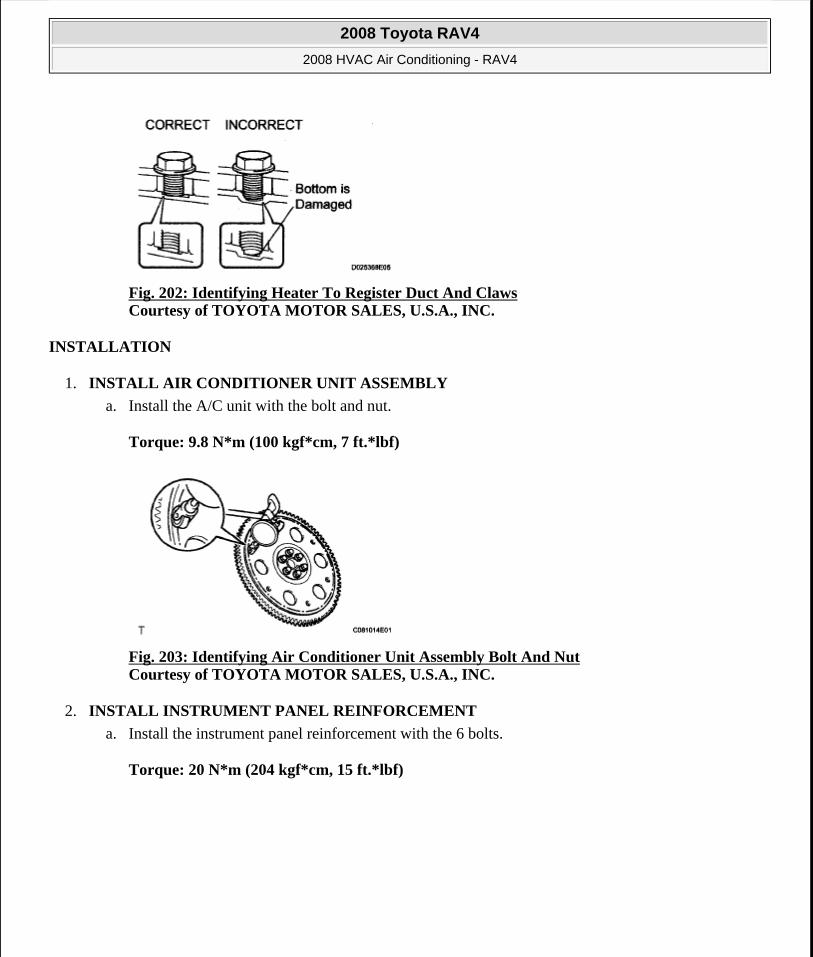
Fig. 202: Identifying Heater To Register Duct And Claws Courtesy of TOYOTA MOTOR SALES, U.S.A., INC.
INSTALLATION
1. INSTALL AIR CONDITIONER UNIT ASSEMBLY
a. Install the A/C unit with the bolt and nut.
Torque: 9.8 N*m (100 kgf*cm, 7 ft.*lbf)
Fig. 203: Identifying Air Conditioner Unit Assembly Bolt And Nut Courtesy of TOYOTA MOTOR SALES, U.S.A., INC.
2. INSTALL INSTRUMENT PANEL REINFORCEMENT
a. Install the instrument panel reinforcement with the 6 bolts.
Torque: 20 N*m (204 kgf*cm, 15 ft.*lbf)
2008 Toyota RAV4
2008 HVAC Air Conditioning - RAV4
Microsoft
Tuesday, August 18, 2009 3:53:57 PM Page 186 © 2005 Mitchell Repair Information Company, LLC.
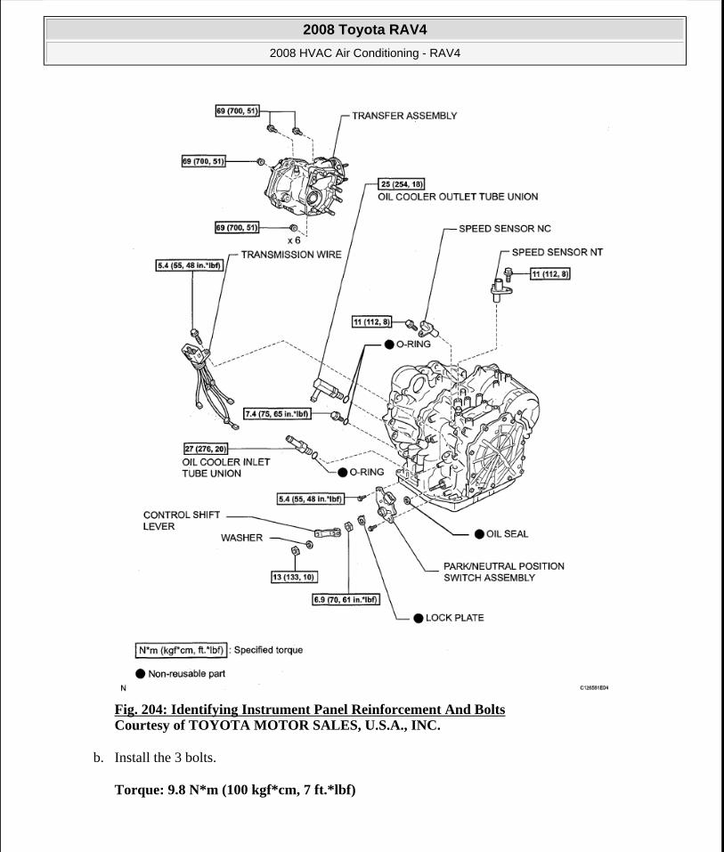
Fig. 204: Identifying Instrument Panel Reinforcement And Bolts Courtesy of TOYOTA MOTOR SALES, U.S.A., INC.
b. Install the 3 bolts.
Torque: 9.8 N*m (100 kgf*cm, 7 ft.*lbf)
2008 Toyota RAV4
2008 HVAC Air Conditioning - RAV4
Microsoft
Tuesday, August 18, 2009 3:53:57 PM Page 187 © 2005 Mitchell Repair Information Company, LLC.

Fig. 205: Identifying Bolts Courtesy of TOYOTA MOTOR SALES, U.S.A., INC.
c. Install the 4 bolts and connect the ground wire.
2008 Toyota RAV4
2008 HVAC Air Conditioning - RAV4
Microsoft
Tuesday, August 18, 2009 3:53:57 PM Page 188 © 2005 Mitchell Repair Information Company, LLC.

Fig. 206: Identifying Bolts And Ground Wire Courtesy of TOYOTA MOTOR SALES, U.S.A., INC.
d. Attach the 12 clamps.
2008 Toyota RAV4
2008 HVAC Air Conditioning - RAV4
Microsoft
Tuesday, August 18, 2009 3:53:57 PM Page 189 © 2005 Mitchell Repair Information Company, LLC.
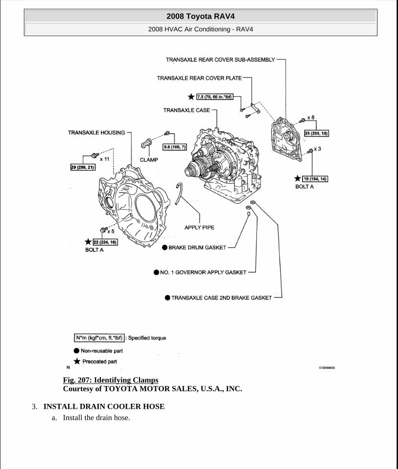
Fig. 207: Identifying Clamps Courtesy of TOYOTA MOTOR SALES, U.S.A., INC.
3. INSTALL DRAIN COOLER HOSE
a. Install the drain hose.
2008 Toyota RAV4
2008 HVAC Air Conditioning - RAV4
Microsoft
Tuesday, August 18, 2009 3:53:57 PM Page 190 © 2005 Mitchell Repair Information Company, LLC.
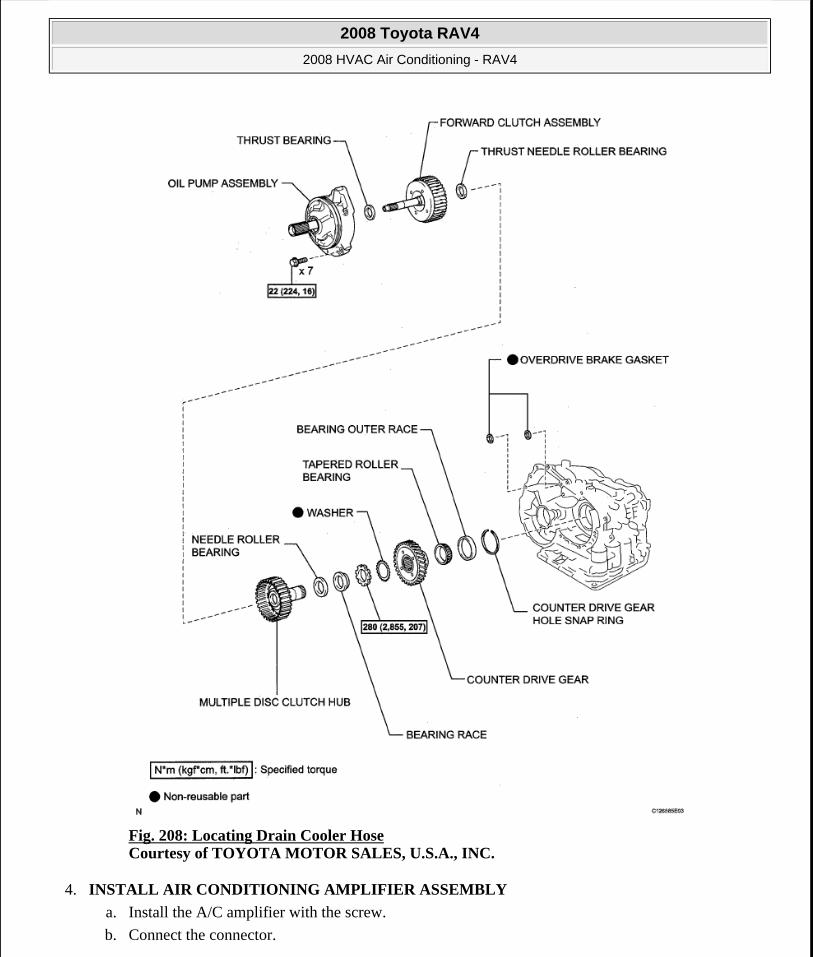
Fig. 208: Locating Drain Cooler Hose Courtesy of TOYOTA MOTOR SALES, U.S.A., INC.
4. INSTALL AIR CONDITIONING AMPLIFIER ASSEMBLY
a. Install the A/C amplifier with the screw.
b. Connect the connector.
2008 Toyota RAV4
2008 HVAC Air Conditioning - RAV4
Microsoft
Tuesday, August 18, 2009 3:53:57 PM Page 191 © 2005 Mitchell Repair Information Company, LLC.
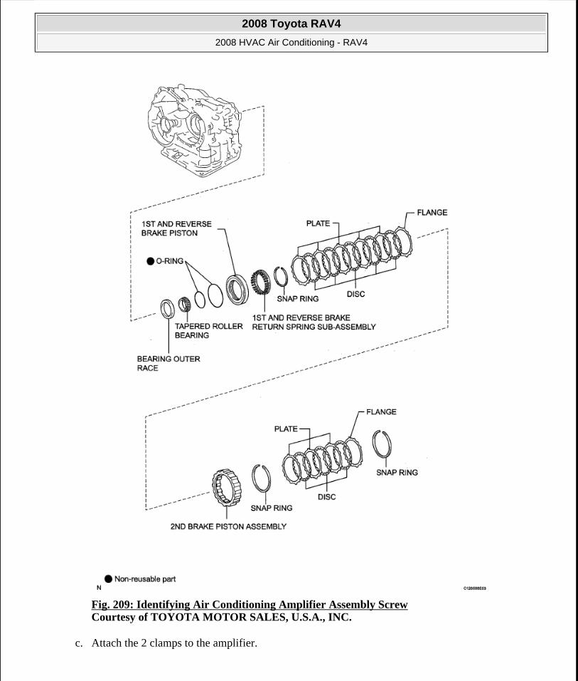
Fig. 209: Identifying Air Conditioning Amplifier Assembly Screw Courtesy of TOYOTA MOTOR SALES, U.S.A., INC.
c. Attach the 2 clamps to the amplifier.
2008 Toyota RAV4
2008 HVAC Air Conditioning - RAV4
Microsoft
Tuesday, August 18, 2009 3:53:57 PM Page 192 © 2005 Mitchell Repair Information Company, LLC.
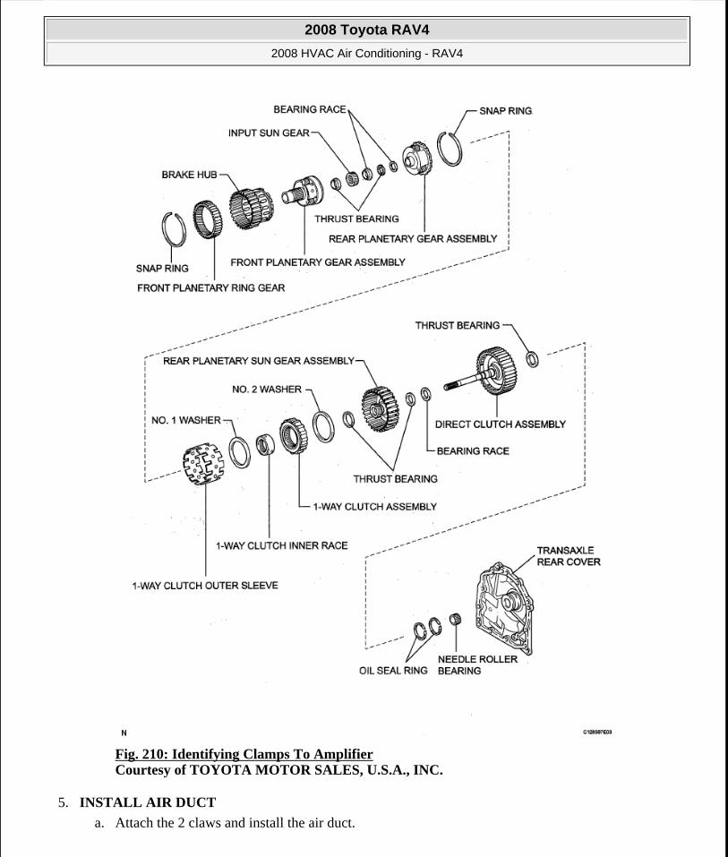
Fig. 210: Identifying Clamps To Amplifier Courtesy of TOYOTA MOTOR SALES, U.S.A., INC.
5. INSTALL AIR DUCT
a. Attach the 2 claws and install the air duct.
2008 Toyota RAV4
2008 HVAC Air Conditioning - RAV4
Microsoft
Tuesday, August 18, 2009 3:53:57 PM Page 193 © 2005 Mitchell Repair Information Company, LLC.
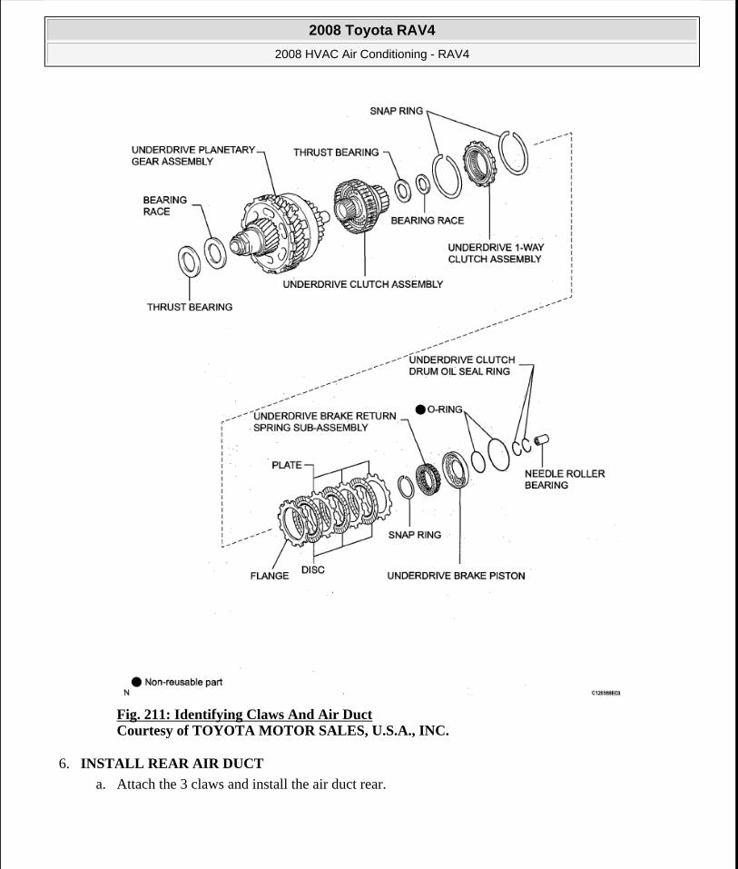
Fig. 211: Identifying Claws And Air Duct Courtesy of TOYOTA MOTOR SALES, U.S.A., INC.
6. INSTALL REAR AIR DUCT
a. Attach the 3 claws and install the air duct rear.
2008 Toyota RAV4
2008 HVAC Air Conditioning - RAV4
Microsoft
Tuesday, August 18, 2009 3:53:57 PM Page 194 © 2005 Mitchell Repair Information Company, LLC.
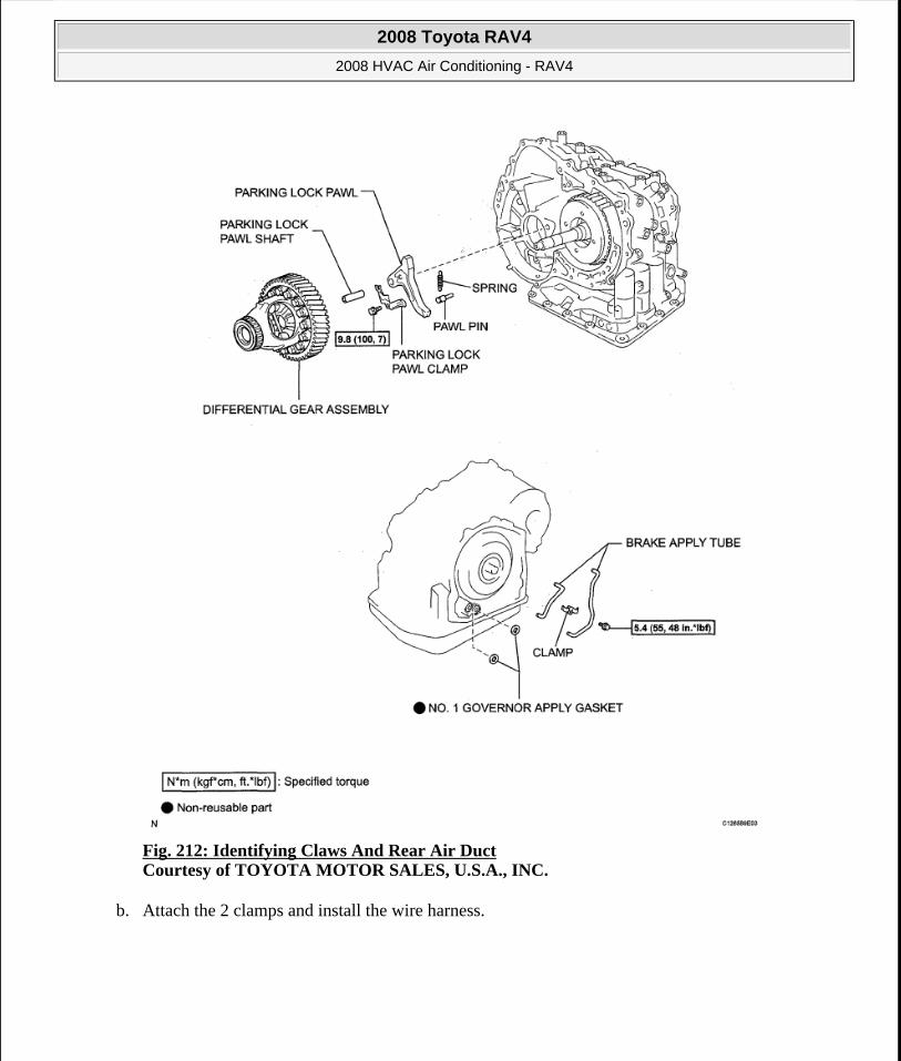
Fig. 212: Identifying Claws And Rear Air Duct Courtesy of TOYOTA MOTOR SALES, U.S.A., INC.
b. Attach the 2 clamps and install the wire harness.
2008 Toyota RAV4
2008 HVAC Air Conditioning - RAV4
Microsoft
Tuesday, August 18, 2009 3:53:57 PM Page 195 © 2005 Mitchell Repair Information Company, LLC.
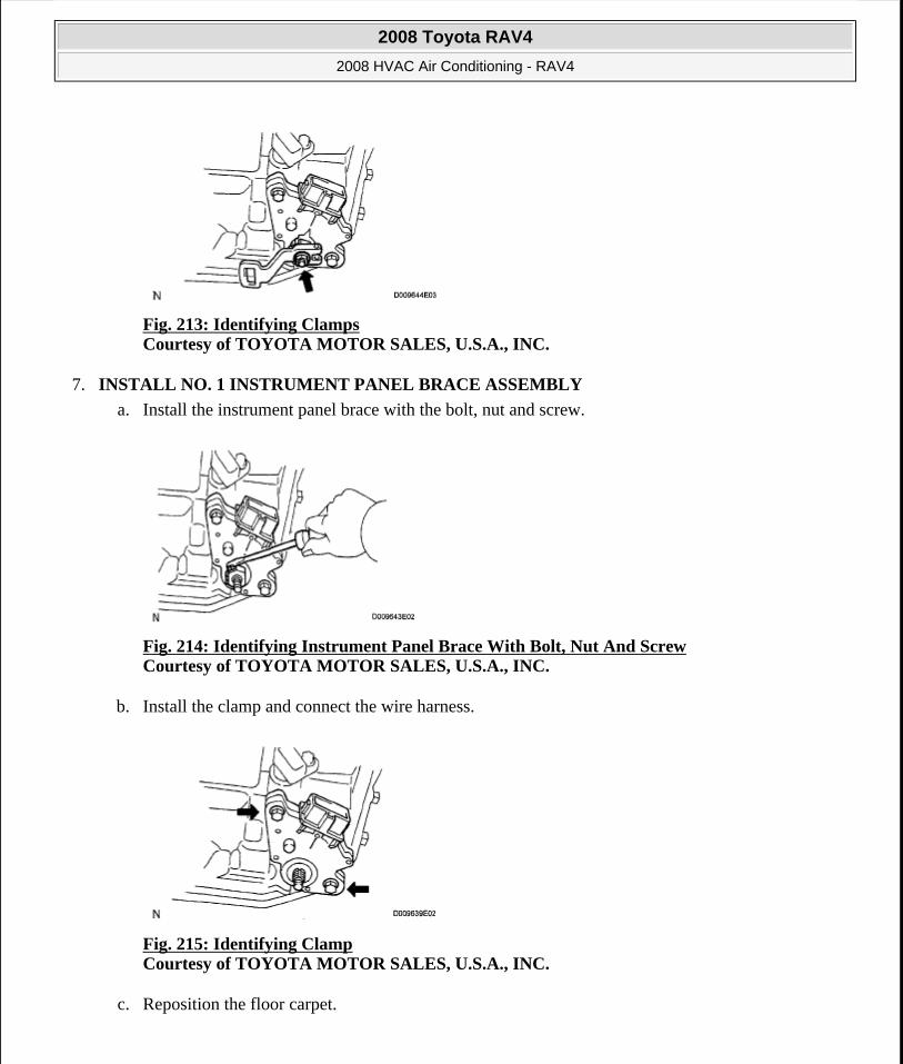
Fig. 213: Identifying Clamps Courtesy of TOYOTA MOTOR SALES, U.S.A., INC.
7. INSTALL NO. 1 INSTRUMENT PANEL BRACE ASSEMBLY
a. Install the instrument panel brace with the bolt, nut and screw.
Fig. 214: Identifying Instrument Panel Brace With Bolt, Nut And Screw Courtesy of TOYOTA MOTOR SALES, U.S.A., INC.
b. Install the clamp and connect the wire harness.
Fig. 215: Identifying Clamp Courtesy of TOYOTA MOTOR SALES, U.S.A., INC.
c. Reposition the floor carpet.
2008 Toyota RAV4
2008 HVAC Air Conditioning - RAV4
Microsoft
Tuesday, August 18, 2009 3:53:57 PM Page 196 © 2005 Mitchell Repair Information Company, LLC.
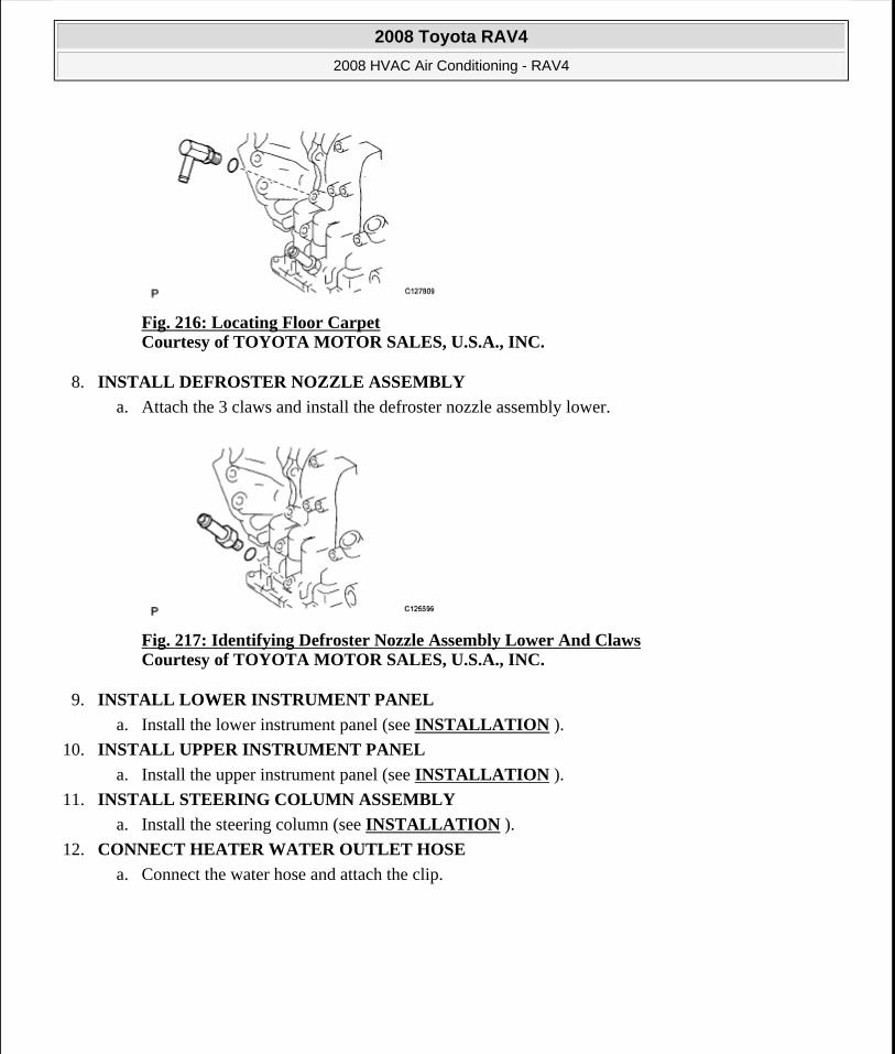
Fig. 216: Locating Floor Carpet Courtesy of TOYOTA MOTOR SALES, U.S.A., INC.
8. INSTALL DEFROSTER NOZZLE ASSEMBLY
a. Attach the 3 claws and install the defroster nozzle assembly lower.
Fig. 217: Identifying Defroster Nozzle Assembly Lower And Claws Courtesy of TOYOTA MOTOR SALES, U.S.A., INC.
9. INSTALL LOWER INSTRUMENT PANEL
a. Install the lower instrument panel (see INSTALLATION ).
10. INSTALL UPPER INSTRUMENT PANEL
a. Install the upper instrument panel (see INSTALLATION ).
11. INSTALL STEERING COLUMN ASSEMBLY
a. Install the steering column (see INSTALLATION ).
12. CONNECT HEATER WATER OUTLET HOSE
a. Connect the water hose and attach the clip.
2008 Toyota RAV4
2008 HVAC Air Conditioning - RAV4
Microsoft
Tuesday, August 18, 2009 3:53:57 PM Page 197 © 2005 Mitchell Repair Information Company, LLC.
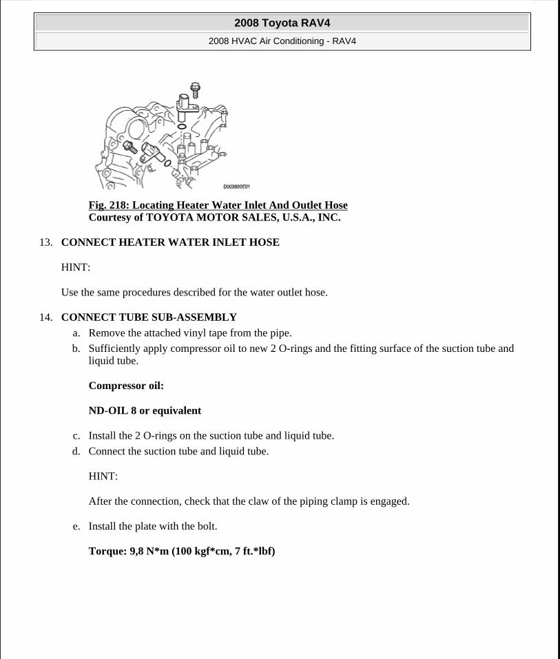
Fig. 218: Locating Heater Water Inlet And Outlet Hose Courtesy of TOYOTA MOTOR SALES, U.S.A., INC.
13. CONNECT HEATER WATER INLET HOSE
HINT:
Use the same procedures described for the water outlet hose.
14. CONNECT TUBE SUB-ASSEMBLY
a. Remove the attached vinyl tape from the pipe.
b. Sufficiently apply compressor oil to new 2 O-rings and the fitting surface of the suction tube and liquid tube.
Compressor oil:
ND-OIL 8 or equivalent
c. Install the 2 O-rings on the suction tube and liquid tube.
d. Connect the suction tube and liquid tube.
HINT:
After the connection, check that the claw of the piping clamp is engaged.
e. Install the plate with the bolt.
Torque: 9,8 N*m (100 kgf*cm, 7 ft.*lbf)
2008 Toyota RAV4
2008 HVAC Air Conditioning - RAV4
Microsoft
Tuesday, August 18, 2009 3:53:57 PM Page 198 © 2005 Mitchell Repair Information Company, LLC.
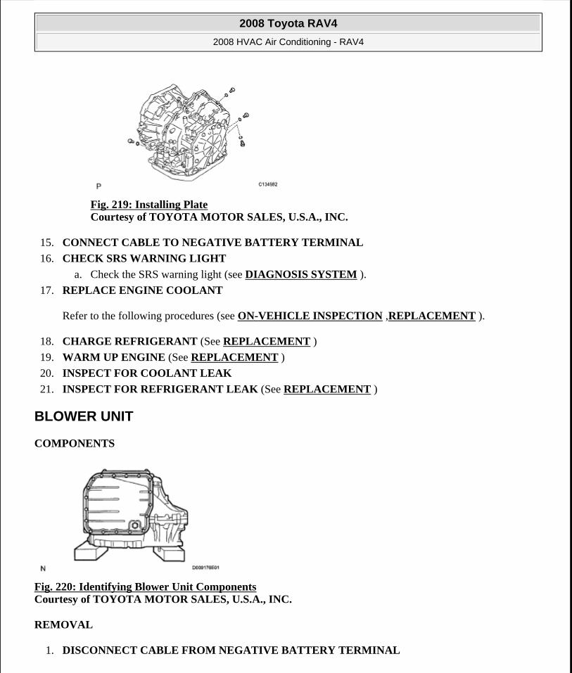
Fig. 219: Installing Plate Courtesy of TOYOTA MOTOR SALES, U.S.A., INC.
15. CONNECT CABLE TO NEGATIVE BATTERY TERMINAL
16. CHECK SRS WARNING LIGHT
a. Check the SRS warning light (see DIAGNOSIS SYSTEM ).
17. REPLACE ENGINE COOLANT
Refer to the following procedures (see ON-VEHICLE INSPECTION ,REPLACEMENT ).
18. CHARGE REFRIGERANT (See REPLACEMENT )
19. WARM UP ENGINE (See REPLACEMENT )
20. INSPECT FOR COOLANT LEAK
21. INSPECT FOR REFRIGERANT LEAK (See REPLACEMENT )
BLOWER UNIT
COMPONENTS
Fig. 220: Identifying Blower Unit Components Courtesy of TOYOTA MOTOR SALES, U.S.A., INC.
REMOVAL
1. DISCONNECT CABLE FROM NEGATIVE BATTERY TERMINAL
2008 Toyota RAV4
2008 HVAC Air Conditioning - RAV4
Microsoft
Tuesday, August 18, 2009 3:53:57 PM Page 199 © 2005 Mitchell Repair Information Company, LLC.
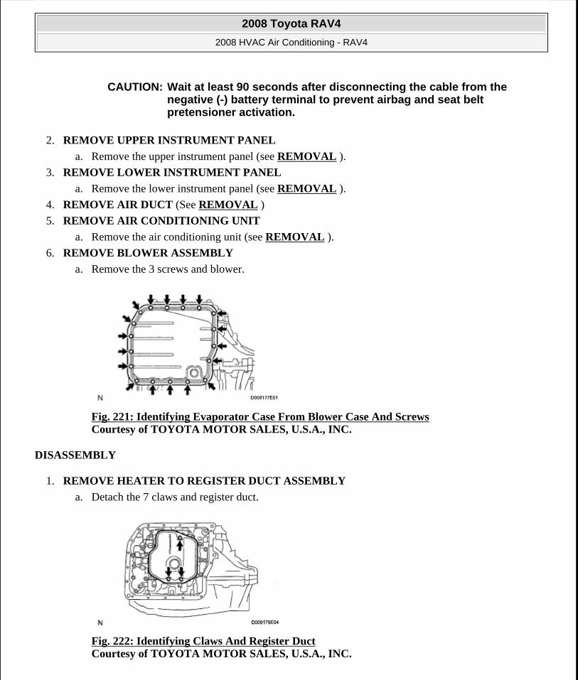
2. REMOVE UPPER INSTRUMENT PANEL
a. Remove the upper instrument panel (see REMOVAL ).
3. REMOVE LOWER INSTRUMENT PANEL
a. Remove the lower instrument panel (see REMOVAL ).
4. REMOVE AIR DUCT (See REMOVAL )
5. REMOVE AIR CONDITIONING UNIT
a. Remove the air conditioning unit (see REMOVAL ).
6. REMOVE BLOWER ASSEMBLY
a. Remove the 3 screws and blower.
Fig. 221: Identifying Evaporator Case From Blower Case And Screws Courtesy of TOYOTA MOTOR SALES, U.S.A., INC.
DISASSEMBLY
1. REMOVE HEATER TO REGISTER DUCT ASSEMBLY
a. Detach the 7 claws and register duct.
Fig. 222: Identifying Claws And Register Duct Courtesy of TOYOTA MOTOR SALES, U.S.A., INC.
CAUTION: Wait at least 90 seconds after disconnecting the cable from the negative (-) battery terminal to prevent airbag and seat belt pretensioner activation.
2008 Toyota RAV4
2008 HVAC Air Conditioning - RAV4
Microsoft
Tuesday, August 18, 2009 3:53:57 PM Page 200 © 2005 Mitchell Repair Information Company, LLC.
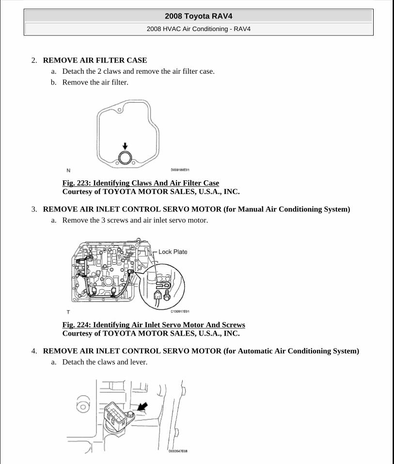
2. REMOVE AIR FILTER CASE
a. Detach the 2 claws and remove the air filter case.
b. Remove the air filter.
Fig. 223: Identifying Claws And Air Filter Case Courtesy of TOYOTA MOTOR SALES, U.S.A., INC.
3. REMOVE AIR INLET CONTROL SERVO MOTOR (for Manual Air Conditioning System)
a. Remove the 3 screws and air inlet servo motor.
Fig. 224: Identifying Air Inlet Servo Motor And Screws Courtesy of TOYOTA MOTOR SALES, U.S.A., INC.
4. REMOVE AIR INLET CONTROL SERVO MOTOR (for Automatic Air Conditioning System)
a. Detach the claws and lever.
2008 Toyota RAV4
2008 HVAC Air Conditioning - RAV4
Microsoft
Tuesday, August 18, 2009 3:53:57 PM Page 201 © 2005 Mitchell Repair Information Company, LLC.
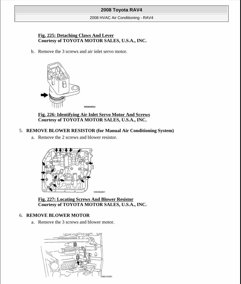
Fig. 225: Detaching Claws And LeverCourtesy of TOYOTA MOTOR SALES, U.S.A., INC.
b. Remove the 3 screws and air inlet servo motor.
Fig. 226: Identifying Air Inlet Servo Motor And Screws Courtesy of TOYOTA MOTOR SALES, U.S.A., INC.
5. REMOVE BLOWER RESISTOR (for Manual Air Conditioning System)
a. Remove the 2 screws and blower resistor.
Fig. 227: Locating Screws And Blower Resistor Courtesy of TOYOTA MOTOR SALES, U.S.A., INC.
6. REMOVE BLOWER MOTOR
a. Remove the 3 screws and blower motor.
2008 Toyota RAV4
2008 HVAC Air Conditioning - RAV4
Microsoft
Tuesday, August 18, 2009 3:53:57 PM Page 202 © 2005 Mitchell Repair Information Company, LLC.
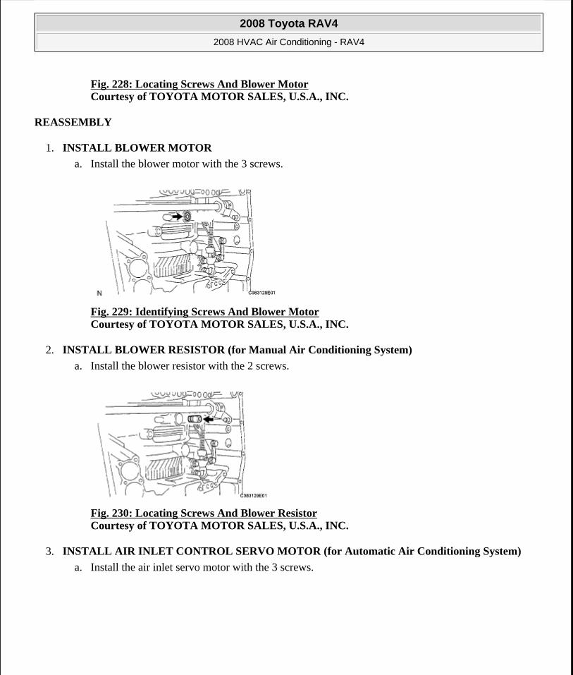
Fig. 228: Locating Screws And Blower MotorCourtesy of TOYOTA MOTOR SALES, U.S.A., INC.
REASSEMBLY
1. INSTALL BLOWER MOTOR
a. Install the blower motor with the 3 screws.
Fig. 229: Identifying Screws And Blower Motor Courtesy of TOYOTA MOTOR SALES, U.S.A., INC.
2. INSTALL BLOWER RESISTOR (for Manual Air Conditioning System)
a. Install the blower resistor with the 2 screws.
Fig. 230: Locating Screws And Blower Resistor Courtesy of TOYOTA MOTOR SALES, U.S.A., INC.
3. INSTALL AIR INLET CONTROL SERVO MOTOR (for Automatic Air Conditioning System)
a. Install the air inlet servo motor with the 3 screws.
2008 Toyota RAV4
2008 HVAC Air Conditioning - RAV4
Microsoft
Tuesday, August 18, 2009 3:53:57 PM Page 203 © 2005 Mitchell Repair Information Company, LLC.
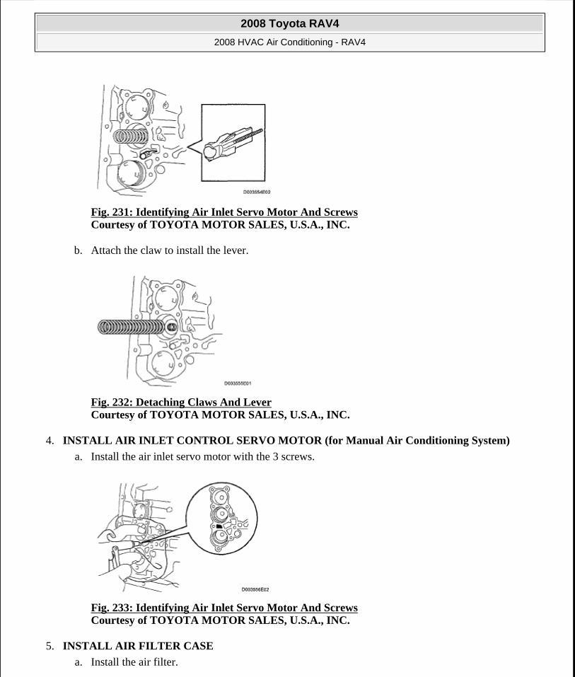
Fig. 231: Identifying Air Inlet Servo Motor And Screws Courtesy of TOYOTA MOTOR SALES, U.S.A., INC.
b. Attach the claw to install the lever.
Fig. 232: Detaching Claws And Lever Courtesy of TOYOTA MOTOR SALES, U.S.A., INC.
4. INSTALL AIR INLET CONTROL SERVO MOTOR (for Manual Air Conditioning System)
a. Install the air inlet servo motor with the 3 screws.
Fig. 233: Identifying Air Inlet Servo Motor And Screws Courtesy of TOYOTA MOTOR SALES, U.S.A., INC.
5. INSTALL AIR FILTER CASE
a. Install the air filter.
2008 Toyota RAV4
2008 HVAC Air Conditioning - RAV4
Microsoft
Tuesday, August 18, 2009 3:53:57 PM Page 204 © 2005 Mitchell Repair Information Company, LLC.
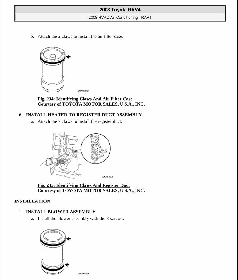
b. Attach the 2 claws to install the air filter case.
Fig. 234: Identifying Claws And Air Filter Case Courtesy of TOYOTA MOTOR SALES, U.S.A., INC.
6. INSTALL HEATER TO REGISTER DUCT ASSEMBLY
a. Attach the 7 claws to install the register duct.
Fig. 235: Identifying Claws And Register Duct Courtesy of TOYOTA MOTOR SALES, U.S.A., INC.
INSTALLATION
1. INSTALL BLOWER ASSEMBLY
a. Install the blower assembly with the 3 screws.
2008 Toyota RAV4
2008 HVAC Air Conditioning - RAV4
Microsoft
Tuesday, August 18, 2009 3:53:57 PM Page 205 © 2005 Mitchell Repair Information Company, LLC.
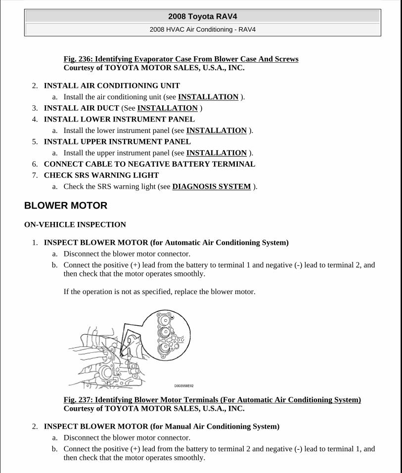
Fig. 236: Identifying Evaporator Case From Blower Case And Screws Courtesy of TOYOTA MOTOR SALES, U.S.A., INC.
2. INSTALL AIR CONDITIONING UNIT
a. Install the air conditioning unit (see INSTALLATION ).
3. INSTALL AIR DUCT (See INSTALLATION )
4. INSTALL LOWER INSTRUMENT PANEL
a. Install the lower instrument panel (see INSTALLATION ).
5. INSTALL UPPER INSTRUMENT PANEL
a. Install the upper instrument panel (see INSTALLATION ).
6. CONNECT CABLE TO NEGATIVE BATTERY TERMINAL
7. CHECK SRS WARNING LIGHT
a. Check the SRS warning light (see DIAGNOSIS SYSTEM ).
BLOWER MOTOR
ON-VEHICLE INSPECTION
1. INSPECT BLOWER MOTOR (for Automatic Air Conditioning System)
a. Disconnect the blower motor connector.
b. Connect the positive (+) lead from the battery to terminal 1 and negative (-) lead to terminal 2, and then check that the motor operates smoothly.
If the operation is not as specified, replace the blower motor.
Fig. 237: Identifying Blower Motor Terminals (For Automatic Air Conditioning System) Courtesy of TOYOTA MOTOR SALES, U.S.A., INC.
2. INSPECT BLOWER MOTOR (for Manual Air Conditioning System)
a. Disconnect the blower motor connector.
b. Connect the positive (+) lead from the battery to terminal 2 and negative (-) lead to terminal 1, and then check that the motor operates smoothly.
2008 Toyota RAV4
2008 HVAC Air Conditioning - RAV4
Microsoft
Tuesday, August 18, 2009 3:53:57 PM Page 206 © 2005 Mitchell Repair Information Company, LLC.
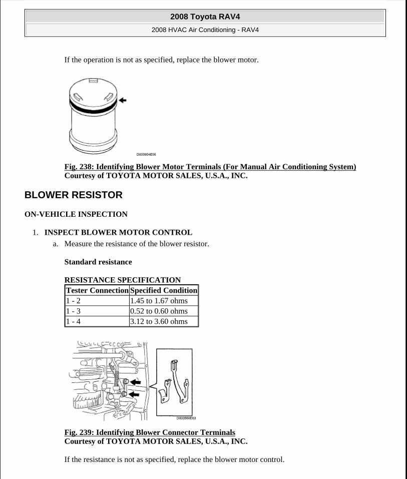
If the operation is not as specified, replace the blower motor.
Fig. 238: Identifying Blower Motor Terminals (For Manual Air Conditioning System) Courtesy of TOYOTA MOTOR SALES, U.S.A., INC.
BLOWER RESISTOR
ON-VEHICLE INSPECTION
1. INSPECT BLOWER MOTOR CONTROL
a. Measure the resistance of the blower resistor.
Standard resistance
RESISTANCE SPECIFICATION
Fig. 239: Identifying Blower Connector Terminals Courtesy of TOYOTA MOTOR SALES, U.S.A., INC.
If the resistance is not as specified, replace the blower motor control.
Tester Connection Specified Condition1 - 2 1.45 to 1.67 ohms1 - 3 0.52 to 0.60 ohms1 - 4 3.12 to 3.60 ohms
2008 Toyota RAV4
2008 HVAC Air Conditioning - RAV4
Microsoft
Tuesday, August 18, 2009 3:53:57 PM Page 207 © 2005 Mitchell Repair Information Company, LLC.
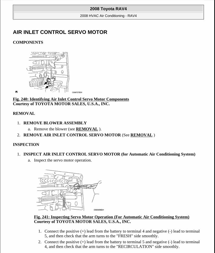
AIR INLET CONTROL SERVO MOTOR
COMPONENTS
Fig. 240: Identifying Air Inlet Control Servo Motor Components Courtesy of TOYOTA MOTOR SALES, U.S.A., INC.
REMOVAL
1. REMOVE BLOWER ASSEMBLY
a. Remove the blower (see REMOVAL ).
2. REMOVE AIR INLET CONTROL SERVO MOTOR (See REMOVAL )
INSPECTION
1. INSPECT AIR INLET CONTROL SERVO MOTOR (for Automatic Air Conditioning System)
a. Inspect the servo motor operation.
Fig. 241: Inspecting Servo Motor Operation (For Automatic Air Conditioning System) Courtesy of TOYOTA MOTOR SALES, U.S.A., INC.
1. Connect the positive (+) lead from the battery to terminal 4 and negative (-) lead to terminal 5, and then check that the arm turns to the "FRESH" side smoothly.
2. Connect the positive (+) lead from the battery to terminal 5 and negative (-) lead to terminal 4, and then check that the arm turns to the "RECIRCULATION" side smoothly.
2008 Toyota RAV4
2008 HVAC Air Conditioning - RAV4
Microsoft
Tuesday, August 18, 2009 3:53:57 PM Page 208 © 2005 Mitchell Repair Information Company, LLC.
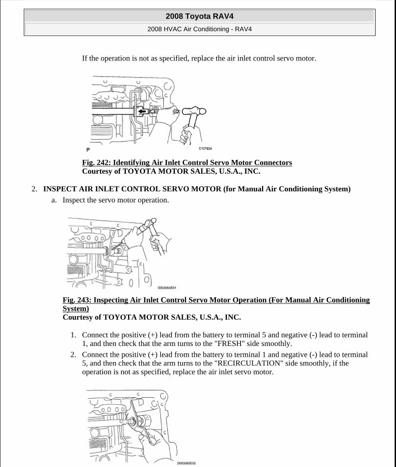
If the operation is not as specified, replace the air inlet control servo motor.
Fig. 242: Identifying Air Inlet Control Servo Motor Connectors Courtesy of TOYOTA MOTOR SALES, U.S.A., INC.
2. INSPECT AIR INLET CONTROL SERVO MOTOR (for Manual Air Conditioning System)
a. Inspect the servo motor operation.
Fig. 243: Inspecting Air Inlet Control Servo Motor Operation (For Manual Air Conditioning System) Courtesy of TOYOTA MOTOR SALES, U.S.A., INC.
1. Connect the positive (+) lead from the battery to terminal 5 and negative (-) lead to terminal 1, and then check that the arm turns to the "FRESH" side smoothly.
2. Connect the positive (+) lead from the battery to terminal 1 and negative (-) lead to terminal 5, and then check that the arm turns to the "RECIRCULATION" side smoothly, if the operation is not as specified, replace the air inlet servo motor.
2008 Toyota RAV4
2008 HVAC Air Conditioning - RAV4
Microsoft
Tuesday, August 18, 2009 3:53:57 PM Page 209 © 2005 Mitchell Repair Information Company, LLC.

Fig. 244: Identifying Air Inlet Control Servo Motor Connectors Courtesy of TOYOTA MOTOR SALES, U.S.A., INC.
INSTALLATION
1. INSTALL AIR INLET CONTROL SERVO MOTOR (See INSTALLATION )
2. INSTALL BLOWER ASSEMBLY
a. Install the blower (see INSTALLATION ).
AIR OUTLET CONTROL SERVO MOTOR (FOR AUTOMATIC AIR CONDITIONING SYSTEM)
COMPONENTS
Fig. 245: Identifying Air Outlet Control Servo Motor Components Courtesy of TOYOTA MOTOR SALES, U.S.A., INC.
REMOVAL
1. REMOVE AIR CONDITIONING UNIT
a. Remove the air conditioning radiator (see REMOVAL ).
2. REMOVE AIR OUTLET CONTROL SERVO MOTOR (See DISASSEMBLY )
INSPECTION
1. INSPECT AIR OUTLET CONTROL SERVO MOTOR
a. Inspect the servo motor operation.
2008 Toyota RAV4
2008 HVAC Air Conditioning - RAV4
Microsoft
Tuesday, August 18, 2009 3:53:57 PM Page 210 © 2005 Mitchell Repair Information Company, LLC.

Fig. 246: Inspecting Air Outlet Control Servo Motor Operation Courtesy of TOYOTA MOTOR SALES, U.S.A., INC.
1. Connect the positive (+) lead from the battery to terminal 4 and negative (-) lead to terminal 5, and then check that the lever turns to the "FACE" position smoothly.
2. Connect the positive (+) lead from the battery to terminal 5 and negative (-) lead to terminal 4, and then check that the lever turns to the "DEF" position smoothly.
If the operation is not as specified, replace the air outlet control servo motor.
Fig. 247: Identifying Air Outlet Control Servo Motor Connectors Courtesy of TOYOTA MOTOR SALES, U.S.A., INC.
INSTALLATION
1. INSTALL AIR OUTLET CONTROL SERVO MOTOR (See INSTALLATION )
2. INSTALL AIR CONDITIONING UNIT
a. Install the air conditioning radiator (see INSTALLATION ).
AIR MIX CONTROL SERVO MOTOR (FOR AUTOMATIC AIR CONDITIONING SYSTEM)
COMPONENTS
2008 Toyota RAV4
2008 HVAC Air Conditioning - RAV4
Microsoft
Tuesday, August 18, 2009 3:53:57 PM Page 211 © 2005 Mitchell Repair Information Company, LLC.

Fig. 248: Identifying Air Mix Control Servo Motor Components Courtesy of TOYOTA MOTOR SALES, U.S.A., INC.
REMOVAL
1. REMOVE AIR CONDITIONING UNIT
a. Remove the air conditioning radiator (see REMOVAL ).
2. REMOVE AIR MIX CONTROL SERVO MOTOR (See DISASSEMBLY )
INSPECTION
1. INSPECT AIR MIX CONTROL SERVO MOTOR
a. Inspect the servo motor operation.
Fig. 249: Inspecting Air Mix Control Servo Motor Operation (For Automatic Air Conditioning System) Courtesy of TOYOTA MOTOR SALES, U.S.A., INC.
1. Connect the positive (+) lead from the battery to terminal 4 and negative (-) lead to terminal 5, and then check that the lever turns to the "MAX HOT" position smoothly.
2. Connect the positive (+) lead from the battery to terminal 5 and negative (-) lead to terminal 4, and then check that the lever turns to the "MAX COOL" position smoothly.
If the operation is not as specified, replace the air mix control servo motor.
2008 Toyota RAV4
2008 HVAC Air Conditioning - RAV4
Microsoft
Tuesday, August 18, 2009 3:53:57 PM Page 212 © 2005 Mitchell Repair Information Company, LLC.
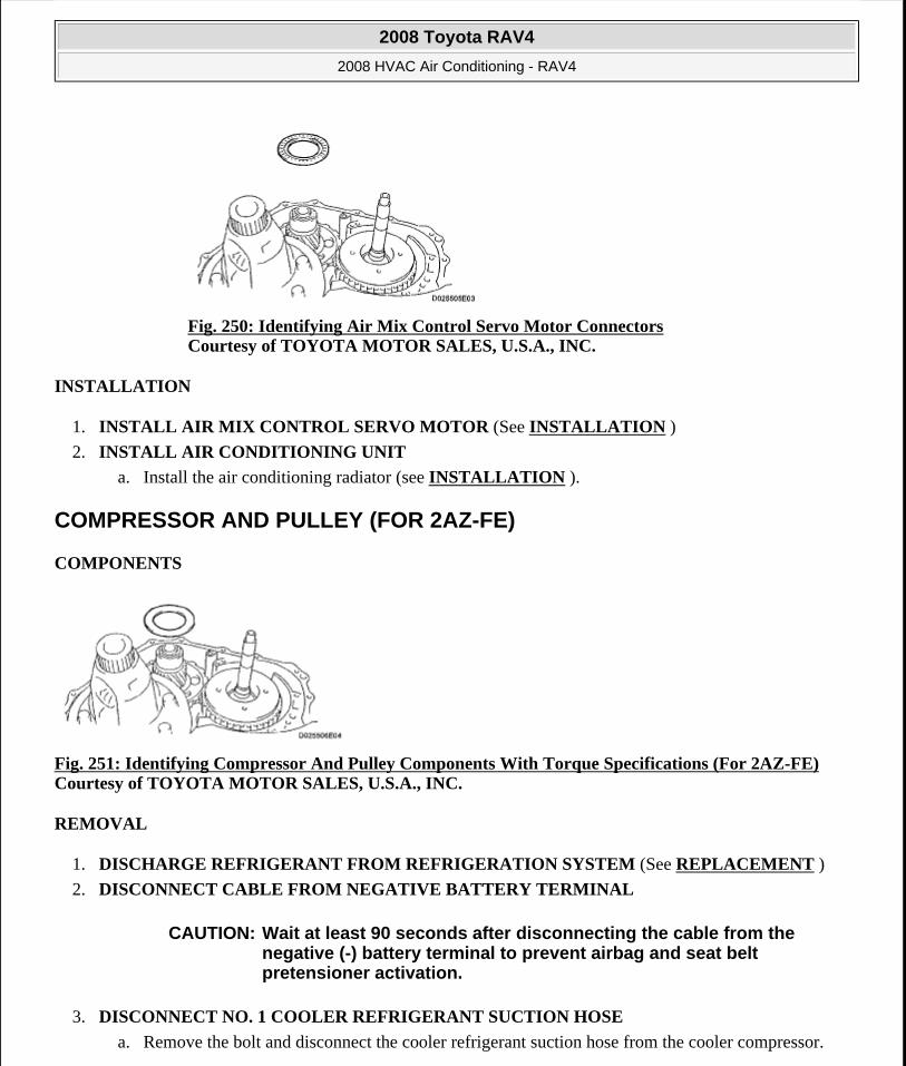
Fig. 250: Identifying Air Mix Control Servo Motor Connectors Courtesy of TOYOTA MOTOR SALES, U.S.A., INC.
INSTALLATION
1. INSTALL AIR MIX CONTROL SERVO MOTOR (See INSTALLATION )
2. INSTALL AIR CONDITIONING UNIT
a. Install the air conditioning radiator (see INSTALLATION ).
COMPRESSOR AND PULLEY (FOR 2AZ-FE)
COMPONENTS
Fig. 251: Identifying Compressor And Pulley Components With Torque Specifications (For 2AZ-FE) Courtesy of TOYOTA MOTOR SALES, U.S.A., INC.
REMOVAL
1. DISCHARGE REFRIGERANT FROM REFRIGERATION SYSTEM (See REPLACEMENT )
2. DISCONNECT CABLE FROM NEGATIVE BATTERY TERMINAL
3. DISCONNECT NO. 1 COOLER REFRIGERANT SUCTION HOSE
a. Remove the bolt and disconnect the cooler refrigerant suction hose from the cooler compressor.
CAUTION: Wait at least 90 seconds after disconnecting the cable from the negative (-) battery terminal to prevent airbag and seat belt pretensioner activation.
2008 Toyota RAV4
2008 HVAC Air Conditioning - RAV4
Microsoft
Tuesday, August 18, 2009 3:53:57 PM Page 213 © 2005 Mitchell Repair Information Company, LLC.
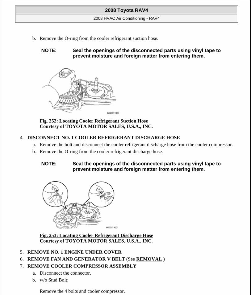
b. Remove the O-ring from the cooler refrigerant suction hose.
Fig. 252: Locating Cooler Refrigerant Suction Hose Courtesy of TOYOTA MOTOR SALES, U.S.A., INC.
4. DISCONNECT NO. 1 COOLER REFRIGERANT DISCHARGE HOSE
a. Remove the bolt and disconnect the cooler refrigerant discharge hose from the cooler compressor.
b. Remove the O-ring from the cooler refrigerant discharge hose.
Fig. 253: Locating Cooler Refrigerant Discharge Hose Courtesy of TOYOTA MOTOR SALES, U.S.A., INC.
5. REMOVE NO. 1 ENGINE UNDER COVER
6. REMOVE FAN AND GENERATOR V BELT (See REMOVAL )
7. REMOVE COOLER COMPRESSOR ASSEMBLY
a. Disconnect the connector.
b. w/o Stud Bolt:
Remove the 4 bolts and cooler compressor.
NOTE: Seal the openings of the disconnected parts using vinyl tape to prevent moisture and foreign matter from entering them.
NOTE: Seal the openings of the disconnected parts using vinyl tape to prevent moisture and foreign matter from entering them.
2008 Toyota RAV4
2008 HVAC Air Conditioning - RAV4
Microsoft
Tuesday, August 18, 2009 3:53:57 PM Page 214 © 2005 Mitchell Repair Information Company, LLC.
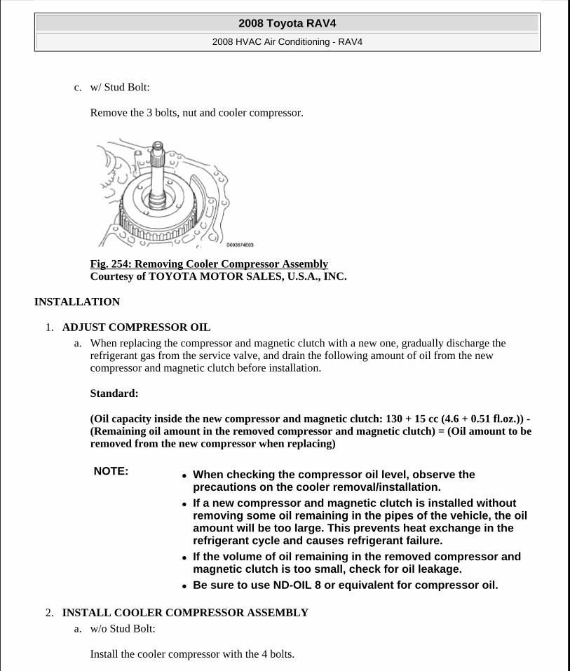
c. w/ Stud Bolt:
Remove the 3 bolts, nut and cooler compressor.
Fig. 254: Removing Cooler Compressor Assembly Courtesy of TOYOTA MOTOR SALES, U.S.A., INC.
INSTALLATION
1. ADJUST COMPRESSOR OIL
a. When replacing the compressor and magnetic clutch with a new one, gradually discharge the refrigerant gas from the service valve, and drain the following amount of oil from the new compressor and magnetic clutch before installation.
Standard:
(Oil capacity inside the new compressor and magnetic clutch: 130 + 15 cc (4.6 + 0.51 fl.oz.)) - (Remaining oil amount in the removed compressor and magnetic clutch) = (Oil amount to be removed from the new compressor when replacing)
2. INSTALL COOLER COMPRESSOR ASSEMBLY
a. w/o Stud Bolt:
Install the cooler compressor with the 4 bolts.
NOTE: When checking the compressor oil level, observe the precautions on the cooler removal/installation.
If a new compressor and magnetic clutch is installed without removing some oil remaining in the pipes of the vehicle, the oil amount will be too large. This prevents heat exchange in the refrigerant cycle and causes refrigerant failure.
If the volume of oil remaining in the removed compressor and magnetic clutch is too small, check for oil leakage.
Be sure to use ND-OIL 8 or equivalent for compressor oil.
2008 Toyota RAV4
2008 HVAC Air Conditioning - RAV4
Microsoft
Tuesday, August 18, 2009 3:53:57 PM Page 215 © 2005 Mitchell Repair Information Company, LLC.
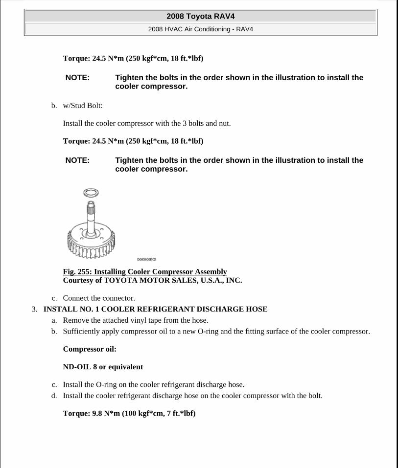
Torque: 24.5 N*m (250 kgf*cm, 18 ft.*lbf)
b. w/Stud Bolt:
Install the cooler compressor with the 3 bolts and nut.
Torque: 24.5 N*m (250 kgf*cm, 18 ft.*lbf)
Fig. 255: Installing Cooler Compressor Assembly Courtesy of TOYOTA MOTOR SALES, U.S.A., INC.
c. Connect the connector.
3. INSTALL NO. 1 COOLER REFRIGERANT DISCHARGE HOSE
a. Remove the attached vinyl tape from the hose.
b. Sufficiently apply compressor oil to a new O-ring and the fitting surface of the cooler compressor.
Compressor oil:
ND-OIL 8 or equivalent
c. Install the O-ring on the cooler refrigerant discharge hose.
d. Install the cooler refrigerant discharge hose on the cooler compressor with the bolt.
Torque: 9.8 N*m (100 kgf*cm, 7 ft.*lbf)
NOTE: Tighten the bolts in the order shown in the illustration to install the cooler compressor.
NOTE: Tighten the bolts in the order shown in the illustration to install the cooler compressor.
2008 Toyota RAV4
2008 HVAC Air Conditioning - RAV4
Microsoft
Tuesday, August 18, 2009 3:53:57 PM Page 216 © 2005 Mitchell Repair Information Company, LLC.
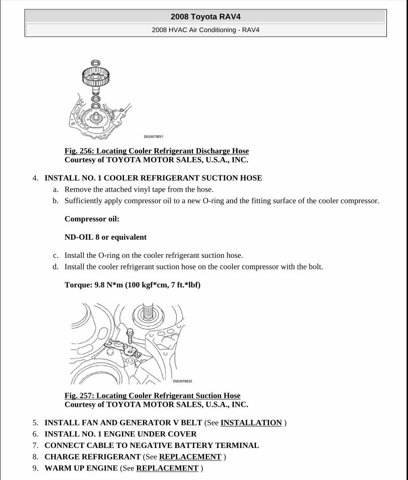
Fig. 256: Locating Cooler Refrigerant Discharge Hose Courtesy of TOYOTA MOTOR SALES, U.S.A., INC.
4. INSTALL NO. 1 COOLER REFRIGERANT SUCTION HOSE
a. Remove the attached vinyl tape from the hose.
b. Sufficiently apply compressor oil to a new O-ring and the fitting surface of the cooler compressor.
Compressor oil:
ND-OIL 8 or equivalent
c. Install the O-ring on the cooler refrigerant suction hose.
d. Install the cooler refrigerant suction hose on the cooler compressor with the bolt.
Torque: 9.8 N*m (100 kgf*cm, 7 ft.*lbf)
Fig. 257: Locating Cooler Refrigerant Suction Hose Courtesy of TOYOTA MOTOR SALES, U.S.A., INC.
5. INSTALL FAN AND GENERATOR V BELT (See INSTALLATION )
6. INSTALL NO. 1 ENGINE UNDER COVER
7. CONNECT CABLE TO NEGATIVE BATTERY TERMINAL
8. CHARGE REFRIGERANT (See REPLACEMENT )
9. WARM UP ENGINE (See REPLACEMENT )
2008 Toyota RAV4
2008 HVAC Air Conditioning - RAV4
Microsoft
Tuesday, August 18, 2009 3:53:57 PM Page 217 © 2005 Mitchell Repair Information Company, LLC.
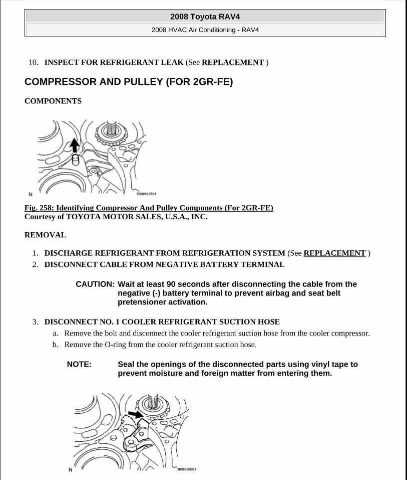
10. INSPECT FOR REFRIGERANT LEAK (See REPLACEMENT )
COMPRESSOR AND PULLEY (FOR 2GR-FE)
COMPONENTS
Fig. 258: Identifying Compressor And Pulley Components (For 2GR-FE) Courtesy of TOYOTA MOTOR SALES, U.S.A., INC.
REMOVAL
1. DISCHARGE REFRIGERANT FROM REFRIGERATION SYSTEM (See REPLACEMENT )
2. DISCONNECT CABLE FROM NEGATIVE BATTERY TERMINAL
3. DISCONNECT NO. 1 COOLER REFRIGERANT SUCTION HOSE
a. Remove the bolt and disconnect the cooler refrigerant suction hose from the cooler compressor.
b. Remove the O-ring from the cooler refrigerant suction hose.
CAUTION: Wait at least 90 seconds after disconnecting the cable from the negative (-) battery terminal to prevent airbag and seat belt pretensioner activation.
NOTE: Seal the openings of the disconnected parts using vinyl tape to prevent moisture and foreign matter from entering them.
2008 Toyota RAV4
2008 HVAC Air Conditioning - RAV4
Microsoft
Tuesday, August 18, 2009 3:53:57 PM Page 218 © 2005 Mitchell Repair Information Company, LLC.
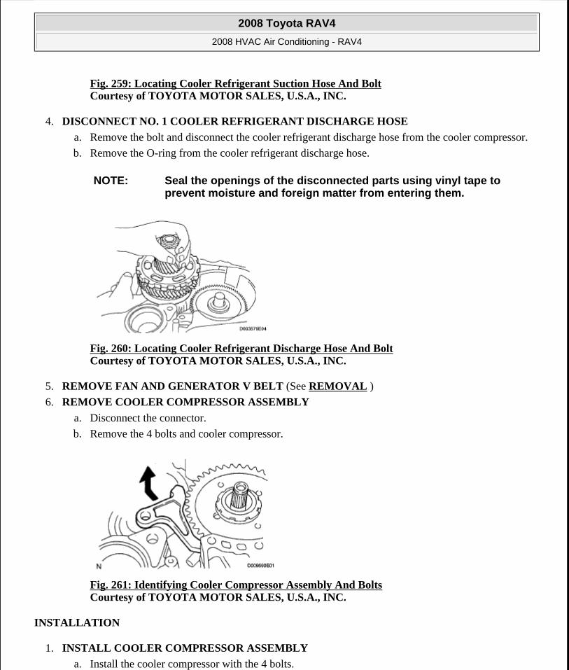
Fig. 259: Locating Cooler Refrigerant Suction Hose And BoltCourtesy of TOYOTA MOTOR SALES, U.S.A., INC.
4. DISCONNECT NO. 1 COOLER REFRIGERANT DISCHARGE HOSE
a. Remove the bolt and disconnect the cooler refrigerant discharge hose from the cooler compressor.
b. Remove the O-ring from the cooler refrigerant discharge hose.
Fig. 260: Locating Cooler Refrigerant Discharge Hose And Bolt Courtesy of TOYOTA MOTOR SALES, U.S.A., INC.
5. REMOVE FAN AND GENERATOR V BELT (See REMOVAL )
6. REMOVE COOLER COMPRESSOR ASSEMBLY
a. Disconnect the connector.
b. Remove the 4 bolts and cooler compressor.
Fig. 261: Identifying Cooler Compressor Assembly And Bolts Courtesy of TOYOTA MOTOR SALES, U.S.A., INC.
INSTALLATION
1. INSTALL COOLER COMPRESSOR ASSEMBLY
a. Install the cooler compressor with the 4 bolts.
NOTE: Seal the openings of the disconnected parts using vinyl tape to prevent moisture and foreign matter from entering them.
2008 Toyota RAV4
2008 HVAC Air Conditioning - RAV4
Microsoft
Tuesday, August 18, 2009 3:53:57 PM Page 219 © 2005 Mitchell Repair Information Company, LLC.
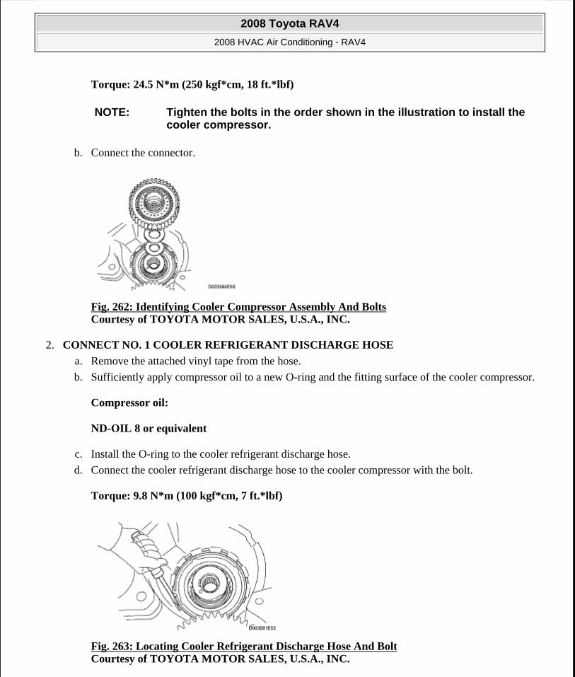
Torque: 24.5 N*m (250 kgf*cm, 18 ft.*lbf)
b. Connect the connector.
Fig. 262: Identifying Cooler Compressor Assembly And Bolts Courtesy of TOYOTA MOTOR SALES, U.S.A., INC.
2. CONNECT NO. 1 COOLER REFRIGERANT DISCHARGE HOSE
a. Remove the attached vinyl tape from the hose.
b. Sufficiently apply compressor oil to a new O-ring and the fitting surface of the cooler compressor.
Compressor oil:
ND-OIL 8 or equivalent
c. Install the O-ring to the cooler refrigerant discharge hose.
d. Connect the cooler refrigerant discharge hose to the cooler compressor with the bolt.
Torque: 9.8 N*m (100 kgf*cm, 7 ft.*lbf)
Fig. 263: Locating Cooler Refrigerant Discharge Hose And Bolt Courtesy of TOYOTA MOTOR SALES, U.S.A., INC.
NOTE: Tighten the bolts in the order shown in the illustration to install the cooler compressor.
2008 Toyota RAV4
2008 HVAC Air Conditioning - RAV4
Microsoft
Tuesday, August 18, 2009 3:53:57 PM Page 220 © 2005 Mitchell Repair Information Company, LLC.
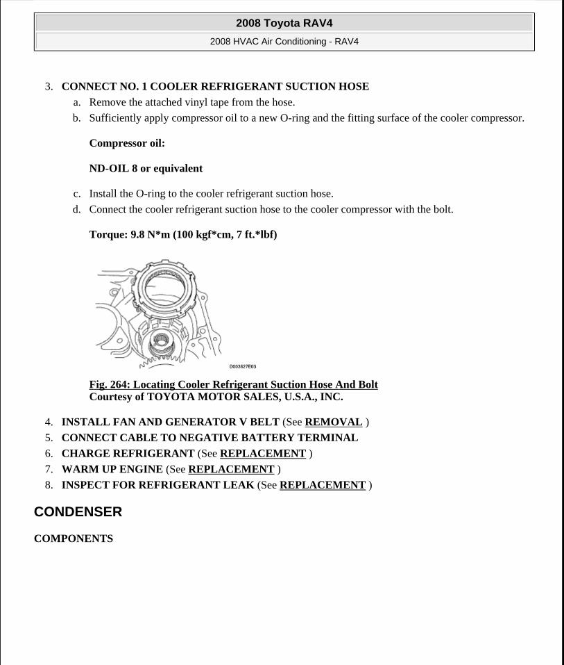
3. CONNECT NO. 1 COOLER REFRIGERANT SUCTION HOSE
a. Remove the attached vinyl tape from the hose.
b. Sufficiently apply compressor oil to a new O-ring and the fitting surface of the cooler compressor.
Compressor oil:
ND-OIL 8 or equivalent
c. Install the O-ring to the cooler refrigerant suction hose.
d. Connect the cooler refrigerant suction hose to the cooler compressor with the bolt.
Torque: 9.8 N*m (100 kgf*cm, 7 ft.*lbf)
Fig. 264: Locating Cooler Refrigerant Suction Hose And Bolt Courtesy of TOYOTA MOTOR SALES, U.S.A., INC.
4. INSTALL FAN AND GENERATOR V BELT (See REMOVAL )
5. CONNECT CABLE TO NEGATIVE BATTERY TERMINAL
6. CHARGE REFRIGERANT (See REPLACEMENT )
7. WARM UP ENGINE (See REPLACEMENT )
8. INSPECT FOR REFRIGERANT LEAK (See REPLACEMENT )
CONDENSER
COMPONENTS
2008 Toyota RAV4
2008 HVAC Air Conditioning - RAV4
Microsoft
Tuesday, August 18, 2009 3:53:57 PM Page 221 © 2005 Mitchell Repair Information Company, LLC.
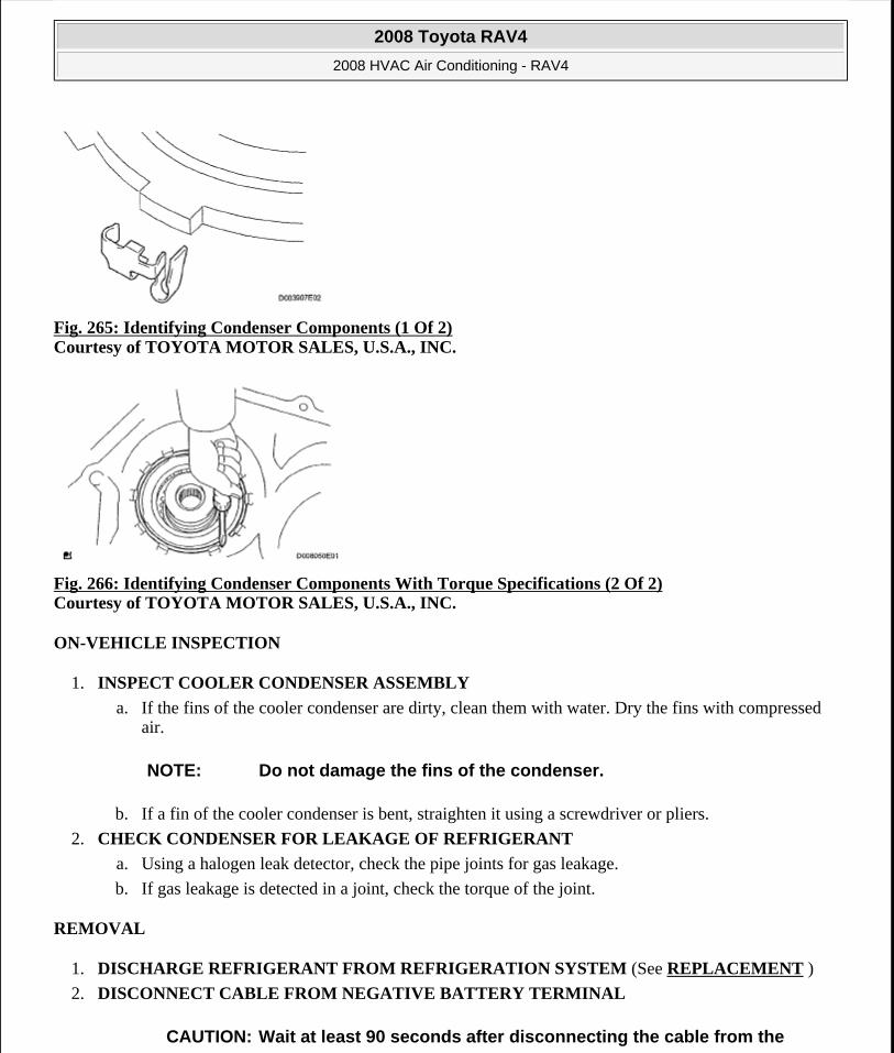
Fig. 265: Identifying Condenser Components (1 Of 2) Courtesy of TOYOTA MOTOR SALES, U.S.A., INC.
Fig. 266: Identifying Condenser Components With Torque Specifications (2 Of 2) Courtesy of TOYOTA MOTOR SALES, U.S.A., INC.
ON-VEHICLE INSPECTION
1. INSPECT COOLER CONDENSER ASSEMBLY
a. If the fins of the cooler condenser are dirty, clean them with water. Dry the fins with compressed air.
b. If a fin of the cooler condenser is bent, straighten it using a screwdriver or pliers.
2. CHECK CONDENSER FOR LEAKAGE OF REFRIGERANT
a. Using a halogen leak detector, check the pipe joints for gas leakage.
b. If gas leakage is detected in a joint, check the torque of the joint.
REMOVAL
1. DISCHARGE REFRIGERANT FROM REFRIGERATION SYSTEM (See REPLACEMENT )
2. DISCONNECT CABLE FROM NEGATIVE BATTERY TERMINAL
NOTE: Do not damage the fins of the condenser.
CAUTION: Wait at least 90 seconds after disconnecting the cable from the
2008 Toyota RAV4
2008 HVAC Air Conditioning - RAV4
Microsoft
Tuesday, August 18, 2009 3:53:57 PM Page 222 © 2005 Mitchell Repair Information Company, LLC.
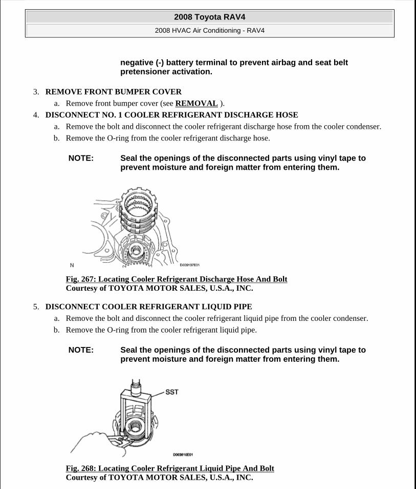
3. REMOVE FRONT BUMPER COVER
a. Remove front bumper cover (see REMOVAL ).
4. DISCONNECT NO. 1 COOLER REFRIGERANT DISCHARGE HOSE
a. Remove the bolt and disconnect the cooler refrigerant discharge hose from the cooler condenser.
b. Remove the O-ring from the cooler refrigerant discharge hose.
Fig. 267: Locating Cooler Refrigerant Discharge Hose And Bolt Courtesy of TOYOTA MOTOR SALES, U.S.A., INC.
5. DISCONNECT COOLER REFRIGERANT LIQUID PIPE
a. Remove the bolt and disconnect the cooler refrigerant liquid pipe from the cooler condenser.
b. Remove the O-ring from the cooler refrigerant liquid pipe.
Fig. 268: Locating Cooler Refrigerant Liquid Pipe And Bolt Courtesy of TOYOTA MOTOR SALES, U.S.A., INC.
negative (-) battery terminal to prevent airbag and seat belt pretensioner activation.
NOTE: Seal the openings of the disconnected parts using vinyl tape to prevent moisture and foreign matter from entering them.
NOTE: Seal the openings of the disconnected parts using vinyl tape to prevent moisture and foreign matter from entering them.
2008 Toyota RAV4
2008 HVAC Air Conditioning - RAV4
Microsoft
Tuesday, August 18, 2009 3:53:57 PM Page 223 © 2005 Mitchell Repair Information Company, LLC.

6. REMOVE RADIATOR SUPPORT UPPER BRACKET
a. Remove the 2 bolts and 2 brackets.
Fig. 269: Identifying Radiator Support Upper Bracket And Bolts Courtesy of TOYOTA MOTOR SALES, U.S.A., INC.
7. REMOVE NO. 2 FAN SHROUD
a. Remove the 2 bolts and fan shroud.
Fig. 270: Identifying Fan Shroud And Bolts Courtesy of TOYOTA MOTOR SALES, U.S.A., INC.
8. REMOVE COOLER CONDENSER ASSEMBLY
a. Remove the cooler condenser.
Fig. 271: Removing Cooler Condenser Assembly Courtesy of TOYOTA MOTOR SALES, U.S.A., INC.
2008 Toyota RAV4
2008 HVAC Air Conditioning - RAV4
Microsoft
Tuesday, August 18, 2009 3:53:57 PM Page 224 © 2005 Mitchell Repair Information Company, LLC.
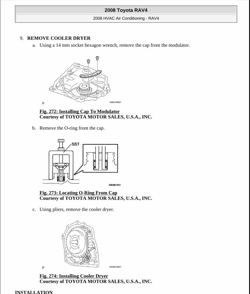
9. REMOVE COOLER DRYER
a. Using a 14 mm socket hexagon wrench, remove the cap from the modulator.
Fig. 272: Installing Cap To Modulator Courtesy of TOYOTA MOTOR SALES, U.S.A., INC.
b. Remove the O-ring from the cap.
Fig. 273: Locating O-Ring From Cap Courtesy of TOYOTA MOTOR SALES, U.S.A., INC.
c. Using pliers, remove the cooler dryer.
Fig. 274: Installing Cooler Dryer Courtesy of TOYOTA MOTOR SALES, U.S.A., INC.
INSTALLATION
2008 Toyota RAV4
2008 HVAC Air Conditioning - RAV4
Microsoft
Tuesday, August 18, 2009 3:53:57 PM Page 225 © 2005 Mitchell Repair Information Company, LLC.
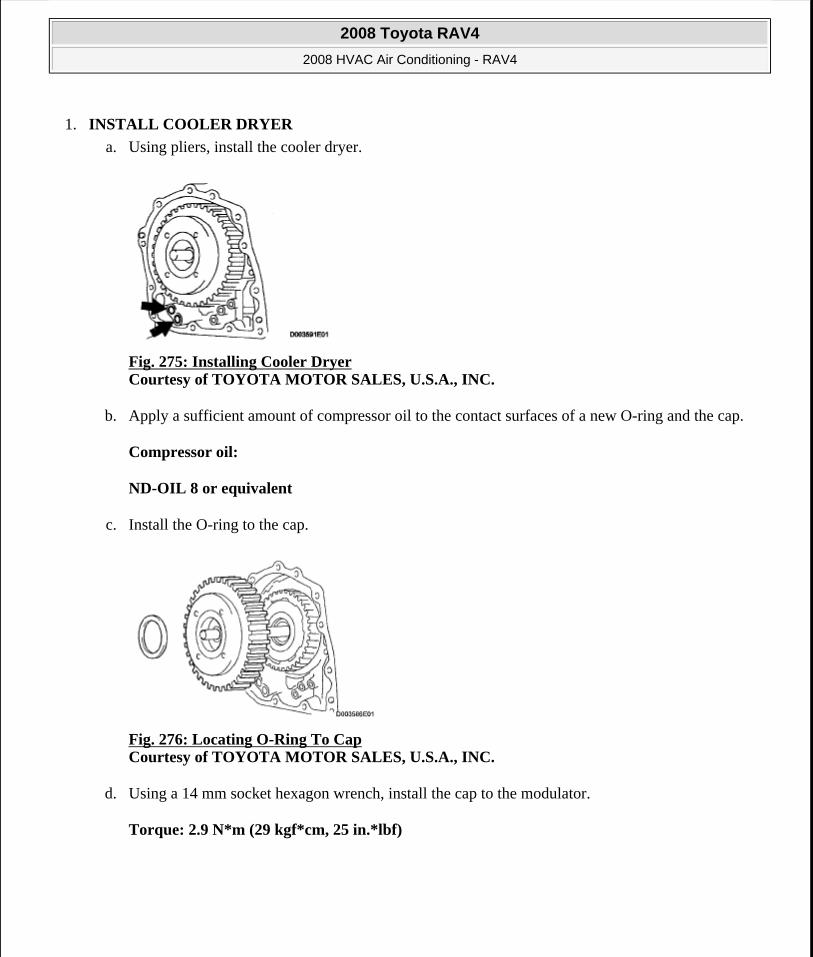
1. INSTALL COOLER DRYER
a. Using pliers, install the cooler dryer.
Fig. 275: Installing Cooler Dryer Courtesy of TOYOTA MOTOR SALES, U.S.A., INC.
b. Apply a sufficient amount of compressor oil to the contact surfaces of a new O-ring and the cap.
Compressor oil:
ND-OIL 8 or equivalent
c. Install the O-ring to the cap.
Fig. 276: Locating O-Ring To Cap Courtesy of TOYOTA MOTOR SALES, U.S.A., INC.
d. Using a 14 mm socket hexagon wrench, install the cap to the modulator.
Torque: 2.9 N*m (29 kgf*cm, 25 in.*lbf)
2008 Toyota RAV4
2008 HVAC Air Conditioning - RAV4
Microsoft
Tuesday, August 18, 2009 3:53:58 PM Page 226 © 2005 Mitchell Repair Information Company, LLC.
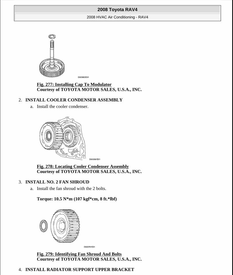
Fig. 277: Installing Cap To Modulator Courtesy of TOYOTA MOTOR SALES, U.S.A., INC.
2. INSTALL COOLER CONDENSER ASSEMBLY
a. Install the cooler condenser.
Fig. 278: Locating Cooler Condenser Assembly Courtesy of TOYOTA MOTOR SALES, U.S.A., INC.
3. INSTALL NO. 2 FAN SHROUD
a. Install the fan shroud with the 2 bolts.
Torque: 10.5 N*m (107 kgf*cm, 8 ft.*lbf)
Fig. 279: Identifying Fan Shroud And Bolts Courtesy of TOYOTA MOTOR SALES, U.S.A., INC.
4. INSTALL RADIATOR SUPPORT UPPER BRACKET
2008 Toyota RAV4
2008 HVAC Air Conditioning - RAV4
Microsoft
Tuesday, August 18, 2009 3:53:58 PM Page 227 © 2005 Mitchell Repair Information Company, LLC.
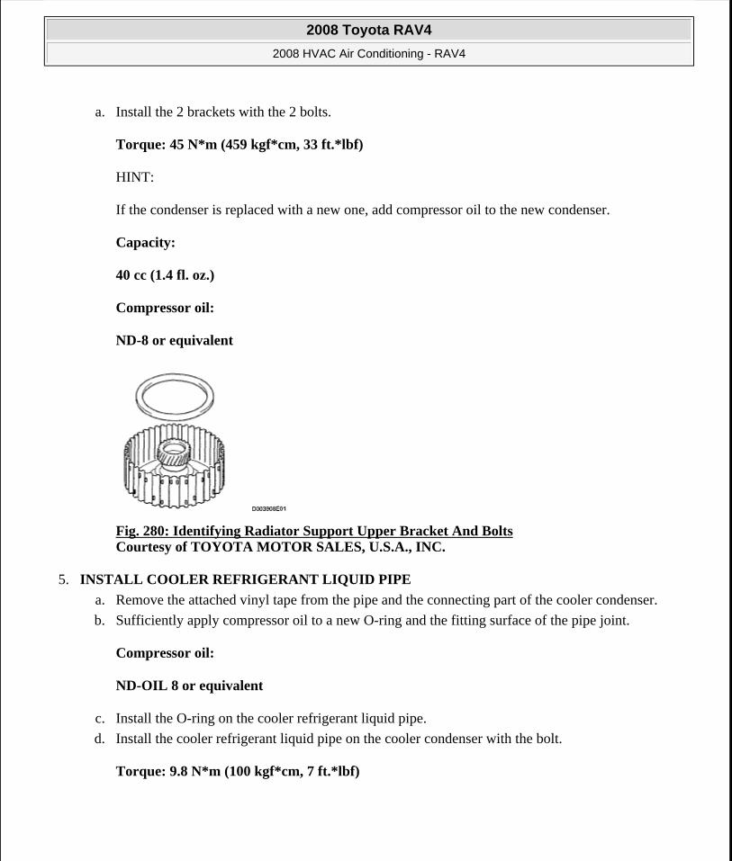
a. Install the 2 brackets with the 2 bolts.
Torque: 45 N*m (459 kgf*cm, 33 ft.*lbf)
HINT:
If the condenser is replaced with a new one, add compressor oil to the new condenser.
Capacity:
40 cc (1.4 fl. oz.)
Compressor oil:
ND-8 or equivalent
Fig. 280: Identifying Radiator Support Upper Bracket And Bolts Courtesy of TOYOTA MOTOR SALES, U.S.A., INC.
5. INSTALL COOLER REFRIGERANT LIQUID PIPE
a. Remove the attached vinyl tape from the pipe and the connecting part of the cooler condenser.
b. Sufficiently apply compressor oil to a new O-ring and the fitting surface of the pipe joint.
Compressor oil:
ND-OIL 8 or equivalent
c. Install the O-ring on the cooler refrigerant liquid pipe.
d. Install the cooler refrigerant liquid pipe on the cooler condenser with the bolt.
Torque: 9.8 N*m (100 kgf*cm, 7 ft.*lbf)
2008 Toyota RAV4
2008 HVAC Air Conditioning - RAV4
Microsoft
Tuesday, August 18, 2009 3:53:58 PM Page 228 © 2005 Mitchell Repair Information Company, LLC.
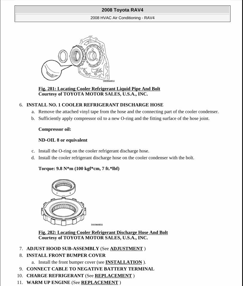
Fig. 281: Locating Cooler Refrigerant Liquid Pipe And Bolt Courtesy of TOYOTA MOTOR SALES, U.S.A., INC.
6. INSTALL NO. 1 COOLER REFRIGERANT DISCHARGE HOSE
a. Remove the attached vinyl tape from the hose and the connecting part of the cooler condenser.
b. Sufficiently apply compressor oil to a new O-ring and the fitting surface of the hose joint.
Compressor oil:
ND-OIL 8 or equivalent
c. Install the O-ring on the cooler refrigerant discharge hose.
d. Install the cooler refrigerant discharge hose on the cooler condenser with the bolt.
Torque: 9.8 N*m (100 kgf*cm, 7 ft.*lbf)
Fig. 282: Locating Cooler Refrigerant Discharge Hose And Bolt Courtesy of TOYOTA MOTOR SALES, U.S.A., INC.
7. ADJUST HOOD SUB-ASSEMBLY (See ADJUSTMENT )
8. INSTALL FRONT BUMPER COVER
a. Install the front bumper cover (see INSTALLATION ).
9. CONNECT CABLE TO NEGATIVE BATTERY TERMINAL
10. CHARGE REFRIGERANT (See REPLACEMENT )
11. WARM UP ENGINE (See REPLACEMENT )
2008 Toyota RAV4
2008 HVAC Air Conditioning - RAV4
Microsoft
Tuesday, August 18, 2009 3:53:58 PM Page 229 © 2005 Mitchell Repair Information Company, LLC.
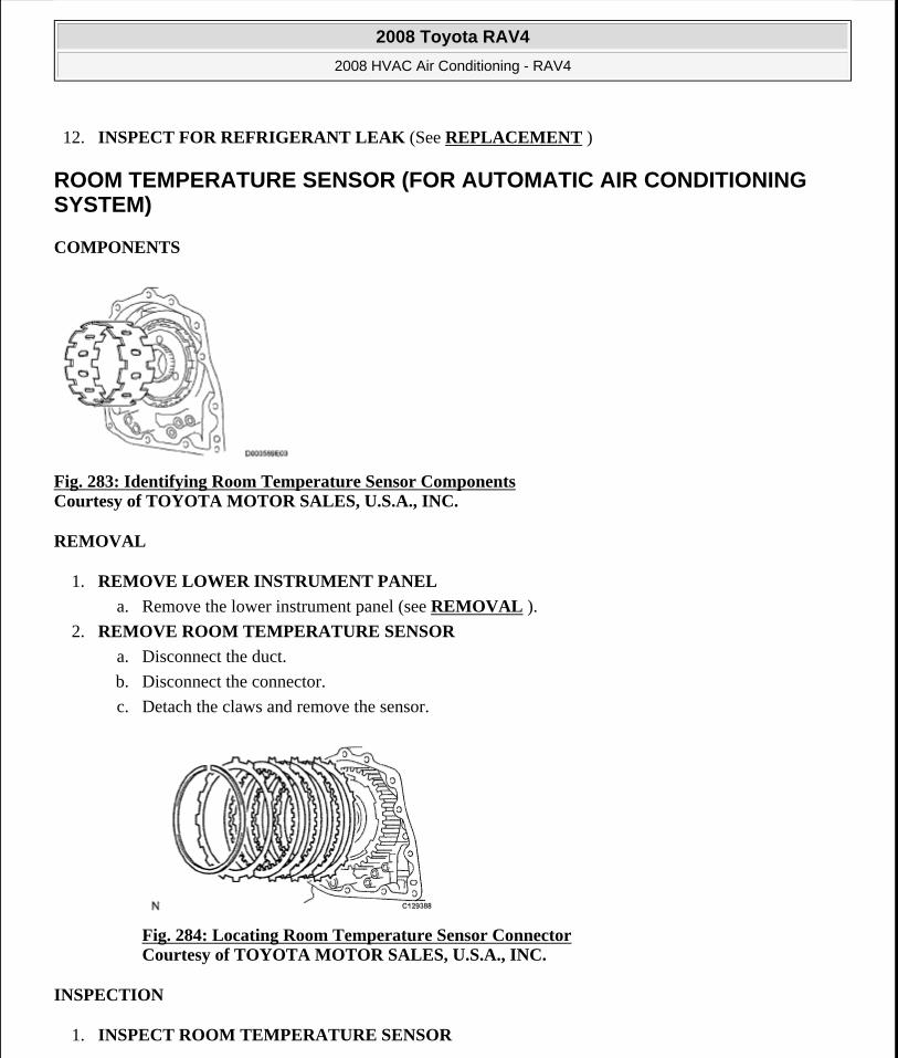
12. INSPECT FOR REFRIGERANT LEAK (See REPLACEMENT )
ROOM TEMPERATURE SENSOR (FOR AUTOMATIC AIR CONDITIONING SYSTEM)
COMPONENTS
Fig. 283: Identifying Room Temperature Sensor Components Courtesy of TOYOTA MOTOR SALES, U.S.A., INC.
REMOVAL
1. REMOVE LOWER INSTRUMENT PANEL
a. Remove the lower instrument panel (see REMOVAL ).
2. REMOVE ROOM TEMPERATURE SENSOR
a. Disconnect the duct.
b. Disconnect the connector.
c. Detach the claws and remove the sensor.
Fig. 284: Locating Room Temperature Sensor Connector Courtesy of TOYOTA MOTOR SALES, U.S.A., INC.
INSPECTION
1. INSPECT ROOM TEMPERATURE SENSOR
2008 Toyota RAV4
2008 HVAC Air Conditioning - RAV4
Microsoft
Tuesday, August 18, 2009 3:53:58 PM Page 230 © 2005 Mitchell Repair Information Company, LLC.
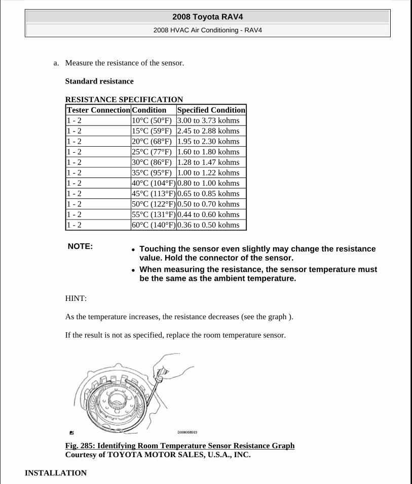
a. Measure the resistance of the sensor.
Standard resistance
RESISTANCE SPECIFICATION
HINT:
As the temperature increases, the resistance decreases (see the graph ).
If the result is not as specified, replace the room temperature sensor.
Fig. 285: Identifying Room Temperature Sensor Resistance Graph Courtesy of TOYOTA MOTOR SALES, U.S.A., INC.
INSTALLATION
Tester Connection Condition Specified Condition1 - 2 10°C (50°F) 3.00 to 3.73 kohms1 - 2 15°C (59°F) 2.45 to 2.88 kohms1 - 2 20°C (68°F) 1.95 to 2.30 kohms1 - 2 25°C (77°F) 1.60 to 1.80 kohms1 - 2 30°C (86°F) 1.28 to 1.47 kohms1 - 2 35°C (95°F) 1.00 to 1.22 kohms1 - 2 40°C (104°F) 0.80 to 1.00 kohms1 - 2 45°C (113°F) 0.65 to 0.85 kohms1 - 2 50°C (122°F) 0.50 to 0.70 kohms1 - 2 55°C (131°F) 0.44 to 0.60 kohms1 - 2 60°C (140°F) 0.36 to 0.50 kohms
NOTE: Touching the sensor even slightly may change the resistance value. Hold the connector of the sensor.
When measuring the resistance, the sensor temperature must be the same as the ambient temperature.
2008 Toyota RAV4
2008 HVAC Air Conditioning - RAV4
Microsoft
Tuesday, August 18, 2009 3:53:58 PM Page 231 © 2005 Mitchell Repair Information Company, LLC.
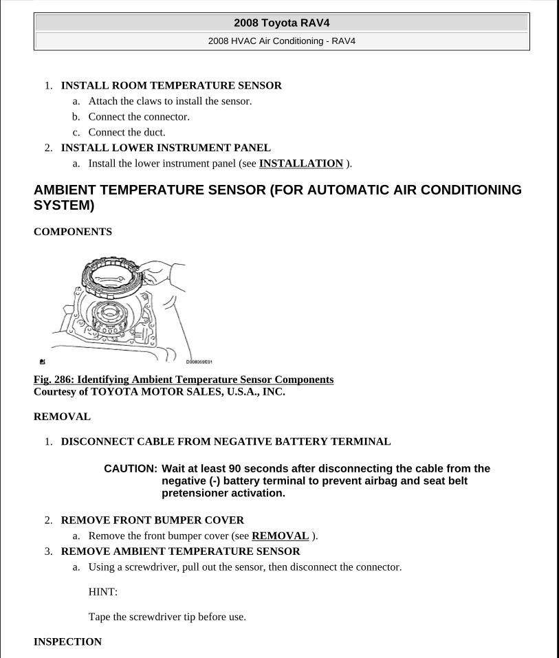
1. INSTALL ROOM TEMPERATURE SENSOR
a. Attach the claws to install the sensor.
b. Connect the connector.
c. Connect the duct.
2. INSTALL LOWER INSTRUMENT PANEL
a. Install the lower instrument panel (see INSTALLATION ).
AMBIENT TEMPERATURE SENSOR (FOR AUTOMATIC AIR CONDITIONING SYSTEM)
COMPONENTS
Fig. 286: Identifying Ambient Temperature Sensor Components Courtesy of TOYOTA MOTOR SALES, U.S.A., INC.
REMOVAL
1. DISCONNECT CABLE FROM NEGATIVE BATTERY TERMINAL
2. REMOVE FRONT BUMPER COVER
a. Remove the front bumper cover (see REMOVAL ).
3. REMOVE AMBIENT TEMPERATURE SENSOR
a. Using a screwdriver, pull out the sensor, then disconnect the connector.
HINT:
Tape the screwdriver tip before use.
INSPECTION
CAUTION: Wait at least 90 seconds after disconnecting the cable from the negative (-) battery terminal to prevent airbag and seat belt pretensioner activation.
2008 Toyota RAV4
2008 HVAC Air Conditioning - RAV4
Microsoft
Tuesday, August 18, 2009 3:53:58 PM Page 232 © 2005 Mitchell Repair Information Company, LLC.
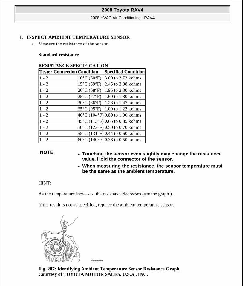
1. INSPECT AMBIENT TEMPERATURE SENSOR
a. Measure the resistance of the sensor.
Standard resistance
RESISTANCE SPECIFICATION
HINT:
As the temperature increases, the resistance decreases (see the graph ).
If the result is not as specified, replace the ambient temperature sensor.
Fig. 287: Identifying Ambient Temperature Sensor Resistance Graph Courtesy of TOYOTA MOTOR SALES, U.S.A., INC.
Tester Connection Condition Specified Condition1 - 2 10°C (50°F) 3.00 to 3.73 kohms1 - 2 15°C (59°F) 2.45 to 2.88 kohms1 - 2 20°C (68°F) 1.95 to 2.30 kohms1 - 2 25°C (77°F) 1.60 to 1.80 kohms1 - 2 30°C (86°F) 1.28 to 1.47 kohms1 - 2 35°C (95°F) 1.00 to 1.22 kohms1 - 2 40°C (104°F) 0.80 to 1.00 kohms1 - 2 45°C (113°F) 0.65 to 0.85 kohms1 - 2 50°C (122°F) 0.50 to 0.70 kohms1 - 2 55°C (131°F) 0.44 to 0.60 kohms1 - 2 60°C (140°F) 0.36 to 0.50 kohms
NOTE: Touching the sensor even slightly may change the resistance value. Hold the connector of the sensor.
When measuring the resistance, the sensor temperature must be the same as the ambient temperature.
2008 Toyota RAV4
2008 HVAC Air Conditioning - RAV4
Microsoft
Tuesday, August 18, 2009 3:53:58 PM Page 233 © 2005 Mitchell Repair Information Company, LLC.
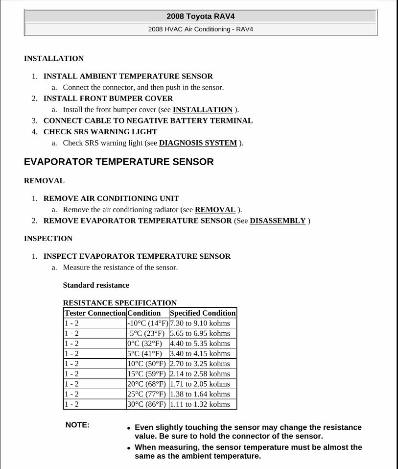
INSTALLATION
1. INSTALL AMBIENT TEMPERATURE SENSOR
a. Connect the connector, and then push in the sensor.
2. INSTALL FRONT BUMPER COVER
a. Install the front bumper cover (see INSTALLATION ).
3. CONNECT CABLE TO NEGATIVE BATTERY TERMINAL
4. CHECK SRS WARNING LIGHT
a. Check SRS warning light (see DIAGNOSIS SYSTEM ).
EVAPORATOR TEMPERATURE SENSOR
REMOVAL
1. REMOVE AIR CONDITIONING UNIT
a. Remove the air conditioning radiator (see REMOVAL ).
2. REMOVE EVAPORATOR TEMPERATURE SENSOR (See DISASSEMBLY )
INSPECTION
1. INSPECT EVAPORATOR TEMPERATURE SENSOR
a. Measure the resistance of the sensor.
Standard resistance
RESISTANCE SPECIFICATION Tester Connection Condition Specified Condition1 - 2 -10°C (14°F) 7.30 to 9.10 kohms1 - 2 -5°C (23°F) 5.65 to 6.95 kohms1 - 2 0°C (32°F) 4.40 to 5.35 kohms1 - 2 5°C (41°F) 3.40 to 4.15 kohms1 - 2 10°C (50°F) 2.70 to 3.25 kohms1 - 2 15°C (59°F) 2.14 to 2.58 kohms1 - 2 20°C (68°F) 1.71 to 2.05 kohms1 - 2 25°C (77°F) 1.38 to 1.64 kohms1 - 2 30°C (86°F) 1.11 to 1.32 kohms
NOTE: Even slightly touching the sensor may change the resistance value. Be sure to hold the connector of the sensor.
When measuring, the sensor temperature must be almost the same as the ambient temperature.
2008 Toyota RAV4
2008 HVAC Air Conditioning - RAV4
Microsoft
Tuesday, August 18, 2009 3:53:58 PM Page 234 © 2005 Mitchell Repair Information Company, LLC.
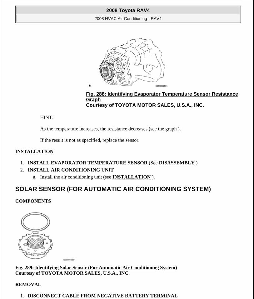
HINT:
As the temperature increases, the resistance decreases (see the graph ).
If the result is not as specified, replace the sensor.
INSTALLATION
1. INSTALL EVAPORATOR TEMPERATURE SENSOR (See DISASSEMBLY )
2. INSTALL AIR CONDITIONING UNIT
a. Install the air conditioning unit (see INSTALLATION ).
SOLAR SENSOR (FOR AUTOMATIC AIR CONDITIONING SYSTEM)
COMPONENTS
Fig. 289: Identifying Solar Sensor (For Automatic Air Conditioning System) Courtesy of TOYOTA MOTOR SALES, U.S.A., INC.
REMOVAL
1. DISCONNECT CABLE FROM NEGATIVE BATTERY TERMINAL
Fig. 288: Identifying Evaporator Temperature Sensor Resistance Graph Courtesy of TOYOTA MOTOR SALES, U.S.A., INC.
2008 Toyota RAV4
2008 HVAC Air Conditioning - RAV4
Microsoft
Tuesday, August 18, 2009 3:53:58 PM Page 235 © 2005 Mitchell Repair Information Company, LLC.
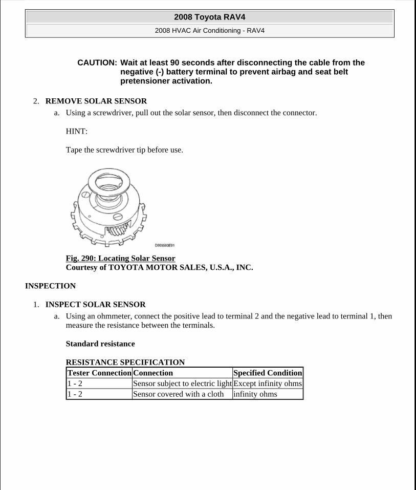
2. REMOVE SOLAR SENSOR
a. Using a screwdriver, pull out the solar sensor, then disconnect the connector.
HINT:
Tape the screwdriver tip before use.
Fig. 290: Locating Solar Sensor Courtesy of TOYOTA MOTOR SALES, U.S.A., INC.
INSPECTION
1. INSPECT SOLAR SENSOR
a. Using an ohmmeter, connect the positive lead to terminal 2 and the negative lead to terminal 1, then measure the resistance between the terminals.
Standard resistance
RESISTANCE SPECIFICATION
CAUTION: Wait at least 90 seconds after disconnecting the cable from the negative (-) battery terminal to prevent airbag and seat belt pretensioner activation.
Tester Connection Connection Specified Condition1 - 2 Sensor subject to electric light Except infinity ohms1 - 2 Sensor covered with a cloth infinity ohms
2008 Toyota RAV4
2008 HVAC Air Conditioning - RAV4
Microsoft
Tuesday, August 18, 2009 3:53:58 PM Page 236 © 2005 Mitchell Repair Information Company, LLC.
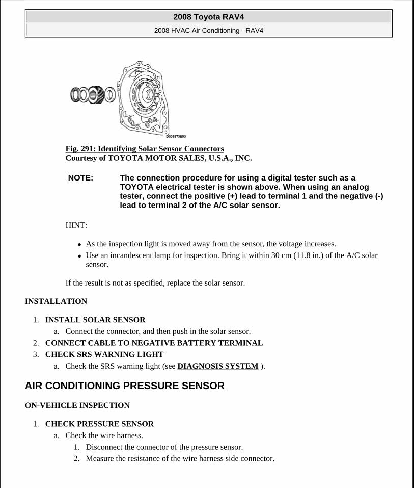
Fig. 291: Identifying Solar Sensor Connectors Courtesy of TOYOTA MOTOR SALES, U.S.A., INC.
HINT:
As the inspection light is moved away from the sensor, the voltage increases.
Use an incandescent lamp for inspection. Bring it within 30 cm (11.8 in.) of the A/C solar sensor.
If the result is not as specified, replace the solar sensor.
INSTALLATION
1. INSTALL SOLAR SENSOR
a. Connect the connector, and then push in the solar sensor.
2. CONNECT CABLE TO NEGATIVE BATTERY TERMINAL
3. CHECK SRS WARNING LIGHT
a. Check the SRS warning light (see DIAGNOSIS SYSTEM ).
AIR CONDITIONING PRESSURE SENSOR
ON-VEHICLE INSPECTION
1. CHECK PRESSURE SENSOR
a. Check the wire harness.
1. Disconnect the connector of the pressure sensor.
2. Measure the resistance of the wire harness side connector.
NOTE: The connection procedure for using a digital tester such as a TOYOTA electrical tester is shown above. When using an analog tester, connect the positive (+) lead to terminal 1 and the negative (-) lead to terminal 2 of the A/C solar sensor.
2008 Toyota RAV4
2008 HVAC Air Conditioning - RAV4
Microsoft
Tuesday, August 18, 2009 3:53:58 PM Page 237 © 2005 Mitchell Repair Information Company, LLC.
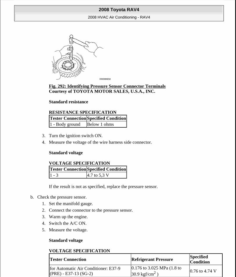
Fig. 292: Identifying Pressure Sensor Connector Terminals Courtesy of TOYOTA MOTOR SALES, U.S.A., INC.
Standard resistance
RESISTANCE SPECIFICATION
3. Turn the ignition switch ON.
4. Measure the voltage of the wire harness side connector.
Standard voltage
VOLTAGE SPECIFICATION
If the result is not as specified, replace the pressure sensor.
b. Check the pressure sensor.
1. Set the manifold gauge.
2. Connect the connector to the pressure sensor.
3. Warm up the engine.
4. Switch the A/C ON.
5. Measure the voltage.
Standard voltage
VOLTAGE SPECIFICATION
Tester Connection Specified Condition1 - Body ground Below 1 ohms
Tester Connection Specified Condition1 - 3 4.7 to 5,3 V
Tester Connection Refrigerant PressureSpecified Condition
for Automatic Air Conditioner: E37-9 (PRE) - E37-13 (SG-2)
0.176 to 3.025 MPa (1.8 to 30.9 kgf/cm2 )
0.76 to 4.74 V
2008 Toyota RAV4
2008 HVAC Air Conditioning - RAV4
Microsoft
Tuesday, August 18, 2009 3:53:58 PM Page 238 © 2005 Mitchell Repair Information Company, LLC.

If the result is not as specified, replace the pressure sensor.
Fig. 293: Identifying Voltage Graph Courtesy of TOYOTA MOTOR SALES, U.S.A., INC.
HEATER RELAY
ON-VEHICLE INSPECTION
1. INSPECT RELAY (Marking: HTR)
a. Measure the resistance of the HTR relay.
Standard resistance
RESISTANCE SPECIFICATION
Fig. 294: Identifying Heater Blower Motor Relay Courtesy of TOYOTA MOTOR SALES, U.S.A., INC.
If the result is not as specified, replace the relay.
for Manual Air Conditioner: E36-12 (PRE) - E36-10 (SG-2)
0.176 to 3.025 MPa (1.8 to 30.9 kgf/cm2 )
0.76 to 4.74 V
Tester Connection Specified Condition3 - 4 Below 1 ohms3 - 5 10 kohms or higher3 - 5 Below 1 ohms (when battery voltage is applied to terminals 1 and 2)
2008 Toyota RAV4
2008 HVAC Air Conditioning - RAV4
Microsoft
Tuesday, August 18, 2009 3:53:58 PM Page 239 © 2005 Mitchell Repair Information Company, LLC.
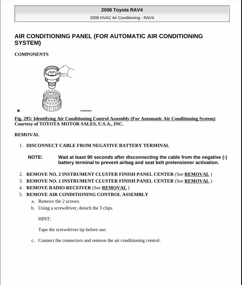
AIR CONDITIONING PANEL (FOR AUTOMATIC AIR CONDITIONING SYSTEM)
COMPONENTS
Fig. 295: Identifying Air Conditioning Control Assembly (For Automatic Air Conditioning System) Courtesy of TOYOTA MOTOR SALES, U.S.A., INC.
REMOVAL
1. DISCONNECT CABLE FROM NEGATIVE BATTERY TERMINAL
2. REMOVE NO. 2 INSTRUMENT CLUSTER FINISH PANEL CENTER (See REMOVAL )
3. REMOVE NO. 1 INSTRUMENT CLUSTER FINISH PANEL CENTER (See REMOVAL )
4. REMOVE RADIO RECEIVER (See REMOVAL )
5. REMOVE AIR CONDITIONING CONTROL ASSEMBLY
a. Remove the 2 screws.
b. Using a screwdriver, detach the 3 clips.
HINT:
Tape the screwdriver tip before use.
c. Connect the connectors and remove the air conditioning control.
NOTE: Wait at least 90 seconds after disconnecting the cable from the negative (-) battery terminal to prevent airbag and seat belt pretensioner activation.
2008 Toyota RAV4
2008 HVAC Air Conditioning - RAV4
Microsoft
Tuesday, August 18, 2009 3:53:58 PM Page 240 © 2005 Mitchell Repair Information Company, LLC.
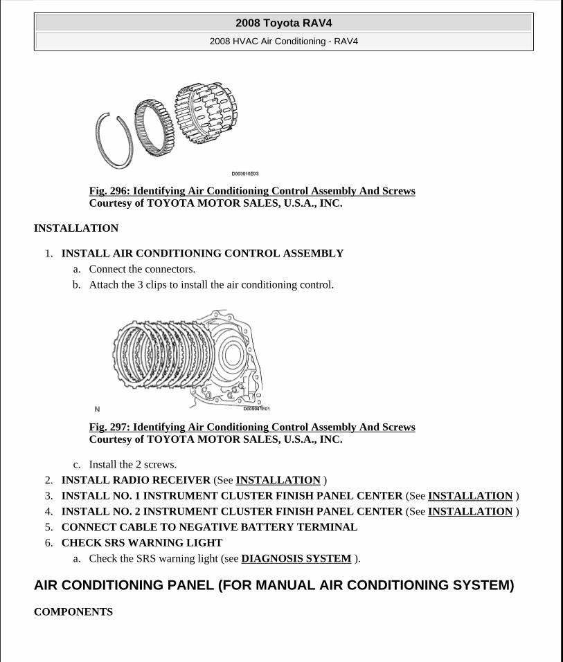
Fig. 296: Identifying Air Conditioning Control Assembly And Screws Courtesy of TOYOTA MOTOR SALES, U.S.A., INC.
INSTALLATION
1. INSTALL AIR CONDITIONING CONTROL ASSEMBLY
a. Connect the connectors.
b. Attach the 3 clips to install the air conditioning control.
Fig. 297: Identifying Air Conditioning Control Assembly And Screws Courtesy of TOYOTA MOTOR SALES, U.S.A., INC.
c. Install the 2 screws.
2. INSTALL RADIO RECEIVER (See INSTALLATION )
3. INSTALL NO. 1 INSTRUMENT CLUSTER FINISH PANEL CENTER (See INSTALLATION )
4. INSTALL NO. 2 INSTRUMENT CLUSTER FINISH PANEL CENTER (See INSTALLATION )
5. CONNECT CABLE TO NEGATIVE BATTERY TERMINAL
6. CHECK SRS WARNING LIGHT
a. Check the SRS warning light (see DIAGNOSIS SYSTEM ).
AIR CONDITIONING PANEL (FOR MANUAL AIR CONDITIONING SYSTEM)
COMPONENTS
2008 Toyota RAV4
2008 HVAC Air Conditioning - RAV4
Microsoft
Tuesday, August 18, 2009 3:53:58 PM Page 241 © 2005 Mitchell Repair Information Company, LLC.
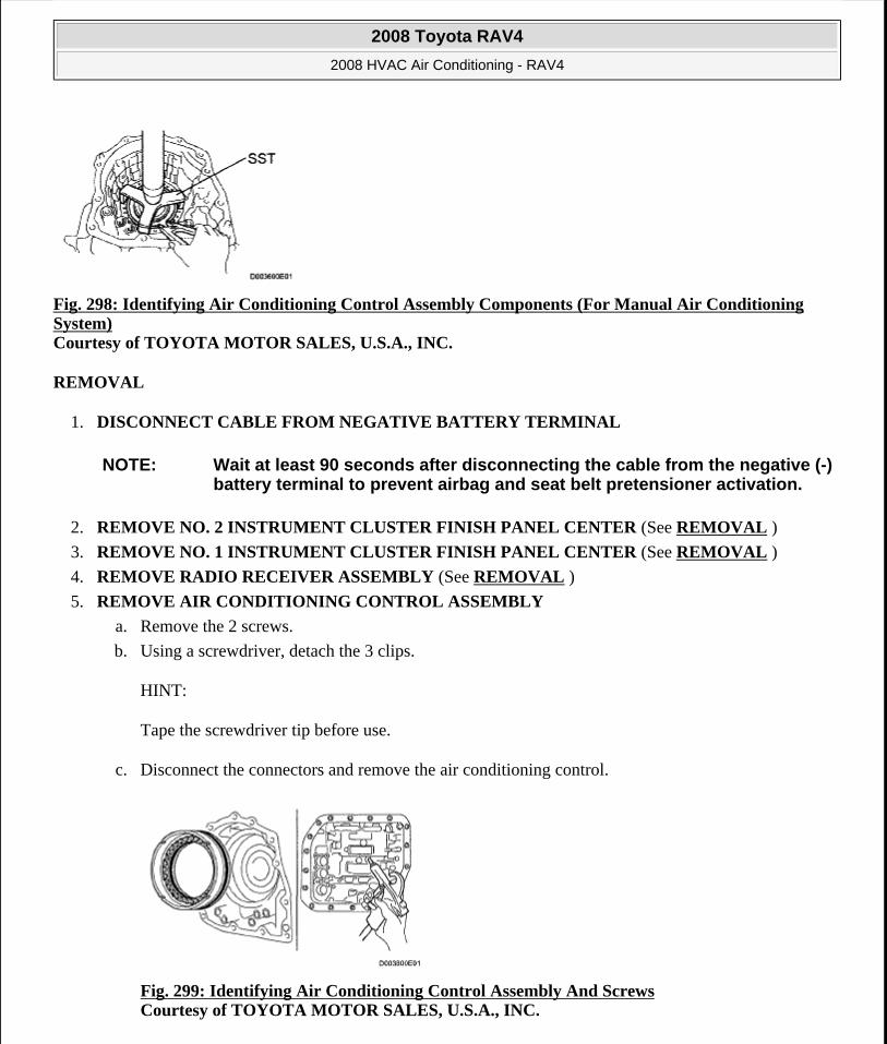
Fig. 298: Identifying Air Conditioning Control Assembly Components (For Manual Air Conditioning System) Courtesy of TOYOTA MOTOR SALES, U.S.A., INC.
REMOVAL
1. DISCONNECT CABLE FROM NEGATIVE BATTERY TERMINAL
2. REMOVE NO. 2 INSTRUMENT CLUSTER FINISH PANEL CENTER (See REMOVAL )
3. REMOVE NO. 1 INSTRUMENT CLUSTER FINISH PANEL CENTER (See REMOVAL )
4. REMOVE RADIO RECEIVER ASSEMBLY (See REMOVAL )
5. REMOVE AIR CONDITIONING CONTROL ASSEMBLY
a. Remove the 2 screws.
b. Using a screwdriver, detach the 3 clips.
HINT:
Tape the screwdriver tip before use.
c. Disconnect the connectors and remove the air conditioning control.
Fig. 299: Identifying Air Conditioning Control Assembly And Screws Courtesy of TOYOTA MOTOR SALES, U.S.A., INC.
NOTE: Wait at least 90 seconds after disconnecting the cable from the negative (-) battery terminal to prevent airbag and seat belt pretensioner activation.
2008 Toyota RAV4
2008 HVAC Air Conditioning - RAV4
Microsoft
Tuesday, August 18, 2009 3:53:58 PM Page 242 © 2005 Mitchell Repair Information Company, LLC.
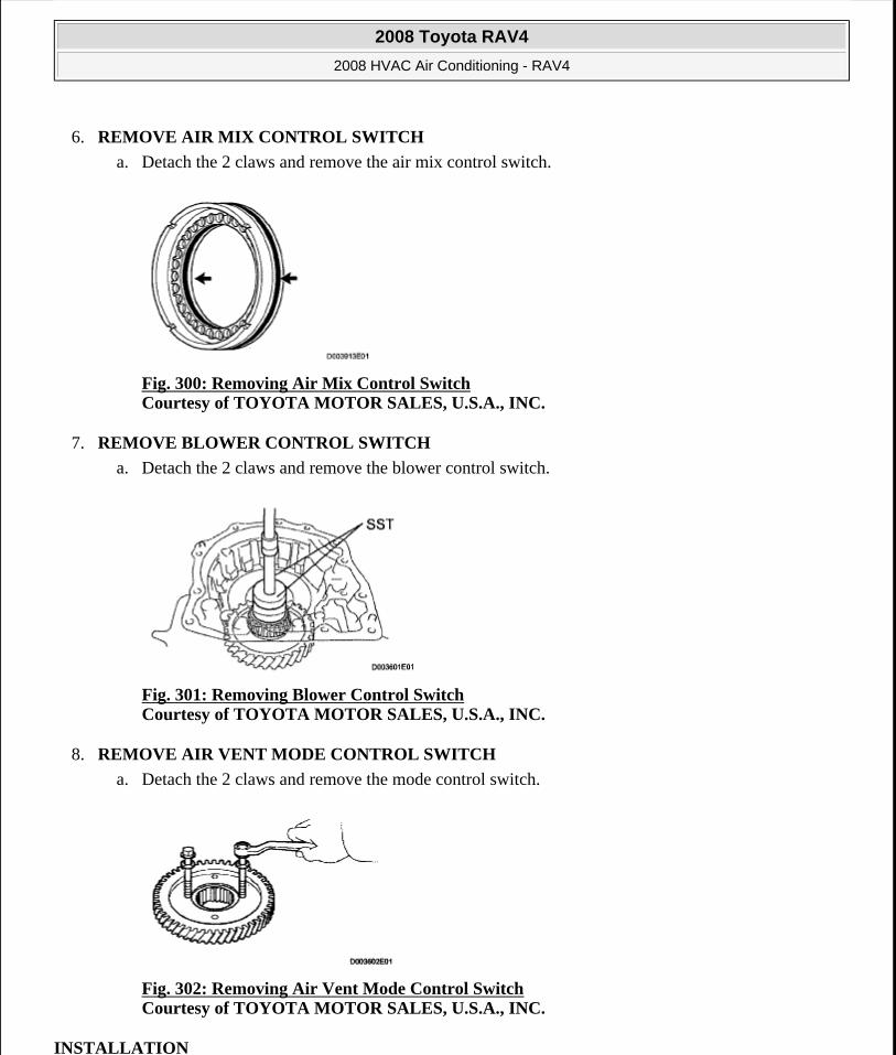
6. REMOVE AIR MIX CONTROL SWITCH
a. Detach the 2 claws and remove the air mix control switch.
Fig. 300: Removing Air Mix Control Switch Courtesy of TOYOTA MOTOR SALES, U.S.A., INC.
7. REMOVE BLOWER CONTROL SWITCH
a. Detach the 2 claws and remove the blower control switch.
Fig. 301: Removing Blower Control Switch Courtesy of TOYOTA MOTOR SALES, U.S.A., INC.
8. REMOVE AIR VENT MODE CONTROL SWITCH
a. Detach the 2 claws and remove the mode control switch.
Fig. 302: Removing Air Vent Mode Control Switch Courtesy of TOYOTA MOTOR SALES, U.S.A., INC.
INSTALLATION
2008 Toyota RAV4
2008 HVAC Air Conditioning - RAV4
Microsoft
Tuesday, August 18, 2009 3:53:58 PM Page 243 © 2005 Mitchell Repair Information Company, LLC.
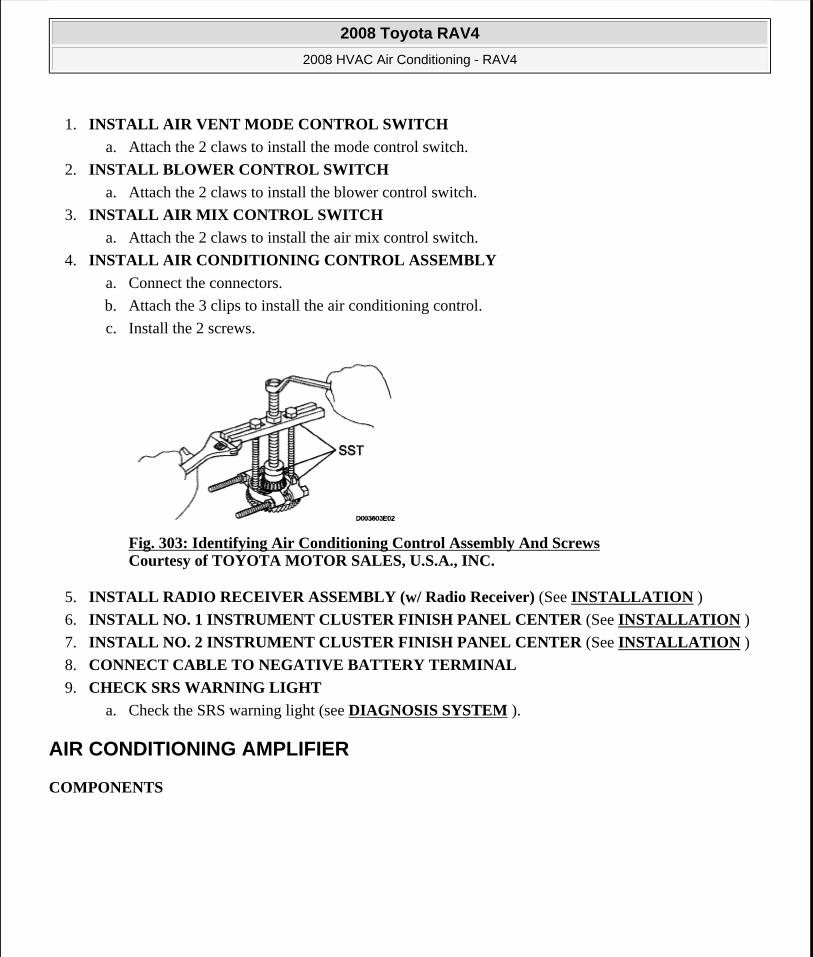
1. INSTALL AIR VENT MODE CONTROL SWITCH
a. Attach the 2 claws to install the mode control switch.
2. INSTALL BLOWER CONTROL SWITCH
a. Attach the 2 claws to install the blower control switch.
3. INSTALL AIR MIX CONTROL SWITCH
a. Attach the 2 claws to install the air mix control switch.
4. INSTALL AIR CONDITIONING CONTROL ASSEMBLY
a. Connect the connectors.
b. Attach the 3 clips to install the air conditioning control.
c. Install the 2 screws.
Fig. 303: Identifying Air Conditioning Control Assembly And Screws Courtesy of TOYOTA MOTOR SALES, U.S.A., INC.
5. INSTALL RADIO RECEIVER ASSEMBLY (w/ Radio Receiver) (See INSTALLATION )
6. INSTALL NO. 1 INSTRUMENT CLUSTER FINISH PANEL CENTER (See INSTALLATION )
7. INSTALL NO. 2 INSTRUMENT CLUSTER FINISH PANEL CENTER (See INSTALLATION )
8. CONNECT CABLE TO NEGATIVE BATTERY TERMINAL
9. CHECK SRS WARNING LIGHT
a. Check the SRS warning light (see DIAGNOSIS SYSTEM ).
AIR CONDITIONING AMPLIFIER
COMPONENTS
2008 Toyota RAV4
2008 HVAC Air Conditioning - RAV4
Microsoft
Tuesday, August 18, 2009 3:53:58 PM Page 244 © 2005 Mitchell Repair Information Company, LLC.
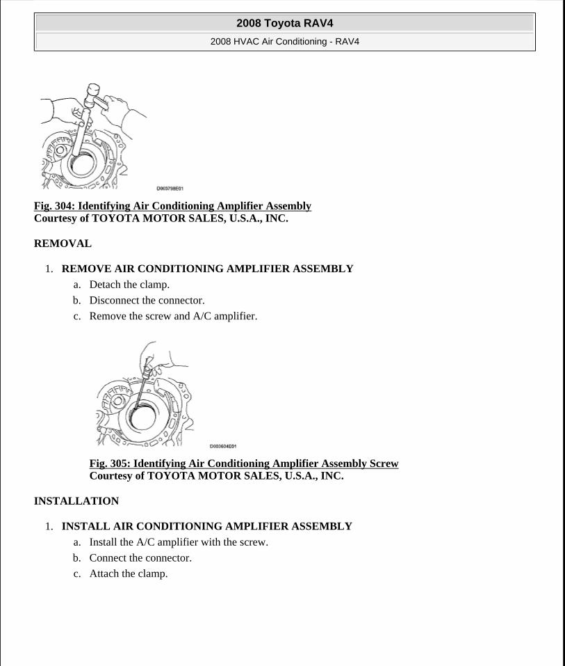
Fig. 304: Identifying Air Conditioning Amplifier Assembly Courtesy of TOYOTA MOTOR SALES, U.S.A., INC.
REMOVAL
1. REMOVE AIR CONDITIONING AMPLIFIER ASSEMBLY
a. Detach the clamp.
b. Disconnect the connector.
c. Remove the screw and A/C amplifier.
Fig. 305: Identifying Air Conditioning Amplifier Assembly Screw Courtesy of TOYOTA MOTOR SALES, U.S.A., INC.
INSTALLATION
1. INSTALL AIR CONDITIONING AMPLIFIER ASSEMBLY
a. Install the A/C amplifier with the screw.
b. Connect the connector.
c. Attach the clamp.
2008 Toyota RAV4
2008 HVAC Air Conditioning - RAV4
Microsoft
Tuesday, August 18, 2009 3:53:58 PM Page 245 © 2005 Mitchell Repair Information Company, LLC.

Fig. 306: Identifying Air Conditioning Amplifier Assembly Screw Courtesy of TOYOTA MOTOR SALES, U.S.A., INC.
2008 Toyota RAV4
2008 HVAC Air Conditioning - RAV4
Microsoft
Tuesday, August 18, 2009 3:53:58 PM Page 246 © 2005 Mitchell Repair Information Company, LLC.
Related Documents