Welcome message from author
This document is posted to help you gain knowledge. Please leave a comment to let me know what you think about it! Share it to your friends and learn new things together.
Transcript


This page intentionally left blank
Air Conditioningand
RefrigerationREX MILLERProfessor Emeritus
State University College at BuffaloBuffalo, New York
MARK R. MILLERProfessor, Industrial TechnologyThe University of Texas at Tyler
Tyler, Texas
McGraw-HillNew York Chicago San Francisco Lisbon London
Madrid Mexico City Milan New Delhi San JuanSeoul Singapore Sydney Toronto

Copyright © 2006 by The McGraw-Hill Companies, Inc. All rights reserved. Manufactured in the United States of America. Except as permitted under theUnited States Copyright Act of 1976, no part of this publication may be reproduced or distributed in any form or by any means, or stored in a database orretrieval system, without the prior written permission of the publisher.
0-07-148741-7
The material in this eBook also appears in the print version of this title: 0-07-146788-2.
All trademarks are trademarks of their respective owners. Rather than put a trademark symbol after every occurrence of a trademarked name, we use names inan editorial fashion only, and to the benefit of the trademark owner, with no intention of infringement of the trademark. Where such designations appear in thisbook, they have been printed with initial caps.
McGraw-Hill eBooks are available at special quantity discounts to use as premiums and sales promotions, or for use in corporate training programs. For moreinformation, please contact George Hoare, Special Sales, at [email protected] or (212) 904-4069.
TERMS OF USE
This is a copyrighted work and The McGraw-Hill Companies, Inc. (“McGraw-Hill”) and its licensors reserve all rights in and to the work. Use of this work issubject to these terms. Except as permitted under the Copyright Act of 1976 and the right to store and retrieve one copy of the work, you may not decompile,disassemble, reverse engineer, reproduce, modify, create derivative works based upon, transmit, distribute, disseminate, sell, publish or sublicense the work orany part of it without McGraw-Hill’s prior consent. You may use the work for your own noncommercial and personal use; any other use of the work is strictlyprohibited. Your right to use the work may be terminated if you fail to comply with these terms.
THE WORK IS PROVIDED “AS IS.” McGRAW-HILL AND ITS LICENSORS MAKE NO GUARANTEES OR WARRANTIES AS TO THE ACCURACY,ADEQUACY OR COMPLETENESS OF OR RESULTS TO BE OBTAINED FROM USING THE WORK, INCLUDING ANY INFORMATION THAT CANBE ACCESSED THROUGH THE WORK VIA HYPERLINK OR OTHERWISE, AND EXPRESSLY DISCLAIM ANY WARRANTY, EXPRESS ORIMPLIED, INCLUDING BUT NOT LIMITED TO IMPLIED WARRANTIES OF MERCHANTABILITY OR FITNESS FOR A PARTICULAR PURPOSE.McGraw-Hill and its licensors do not warrant or guarantee that the functions contained in the work will meet your requirements or that its operation will beuninterrupted or error free. Neither McGraw-Hill nor its licensors shall be liable to you or anyone else for any inaccuracy, error or omission, regardless of cause,in the work or for any damages resulting therefrom. McGraw-Hill has no responsibility for the content of any information accessed through the work. Underno circumstances shall McGraw-Hill and/or its licensors be liable for any indirect, incidental, special, punitive, consequential or similar damages that resultfrom the use of or inability to use the work, even if any of them has been advised of the possibility of such damages. This limitation of liability shall apply toany claim or cause whatsoever whether such claim or cause arises in contract, tort or otherwise.
DOI: 10.1036/0071467882

We hope you enjoy thisMcGraw-Hill eBook! If
you’d like more information about this book,its author, or related books and websites,please click here.
Professional
Want to learn more?
Voltmeter 25Ohmmeter 26Multimeter 26Wattmeter 27
Other instruments 28Air–Filter Efficiency Gages 28Air-Measurement Instruments 28Humidity-Measurement Instruments 29Vibration and Sound Meters 29
Service Tools 30Special Tools 31Vacuum Pumps 32
Vacuum Pump Maintenance 34Vacuum Pump Oil Problems 34Operating Instructions 34Evacuating a System 35
Charging Cylinder 35Charging Oil 36Changing Oil 37Mobile Charging Stations 37Tubing 37
Soft Copper Tubing 37Hard-Drawn Copper Tubing 38Cutting Copper Tubing 39Flaring Copper Tubing 40Constricting Tubing 41Swaging Copper Tubing 41Forming Refrigerant Tubing 42Fitting Copper Tubing by Compression 43
Soldering 43Soft Soldering 44Silver Soldering or Brazing 46
Testing for leaks 47Cleaning and Degreasing Solvents 47Review Questions 47
2 Development of RefrigerationPerformance Objectives 50Historical Development 50
ContentsPreface xvAcknowledgments xvii
1 Air-Conditioning andRefrigeration Toolsand InstrumentsPerformance Objectives 2Tools and Equipment 2
Pliers and Clippers 2Fuse Puller 2Screwdrivers 2Wrenches 3Soldering Equipment 3Drilling Equipment 4Knives and Other Insulation-Stripping Tools 5Meters and Test Prods 6Tool Kits 7
Gages and Instruments 9Pressure Gages 9Gage Selection 10Line Pressure 11Effects of Temperature on Gage Performance 12Care of Gages 12Gage Recalibration 12
Thermometers 13Pocket Thermometer 13Bimetallic Thermometers 15Thermocouple Thermometers 16Resistance Thermometers 16Superheat Thermometer 17
Superheat Measurement Instruments 17Halide Leak Detectors 21
Setting Up 21Lighting 22Leak Testing the Setup 22Adjusting the Flame 22Detecting Leaks 22Maintenance 22
Electrical Instruments 23Ammeter 23
v
For more information about this title, click here

Structure of Matter 50Elements 51Atom 51
Properties of Matter 51Pressure 52
Pressure Indicating Devices 52Pressure of Liquids and Gases 53Atmospheric Pressure 53Gage Pressure 53Absolute Pressure 53Compression Ratio 54
Temperature and Heat 54Specific Heat 55Heat Content 55Sensible Heat 55Latent Heat 55Other Sources of Heat 56
Refrigeration Systems 56Refrigeration from Vaporization
(Open System) 56Basic Refrigeration Cycle 56Capacity 57Refrigerants 57Refrigerant Replacements and the Atmosphere 58
Review Questions 59
3 Voltage, Current, andResistancePerformance Objectives 62Ohm’s Law 62Series Circuits 62Parallel Circuits 64
Current in a Parallel Circuit 64Resistance in a Parallel Circuit 65
AC and DC Power 65Phase 66Power in DC Circuits 66
Power Rating of Equipment 67Capacitors 67
How a Capacitor Works 68Capacity of a Capacitor 69Dielectric Failure 69Basic Units of Capacitance 69Working with Capacitive Values 69Capacitor Types 70Capacitor Tolerances 73
The AC Circuit and the Capacitor 73Uses of Capacitors 75
Inductance 75Four Methods of Changing Inductance 75Self-Inductance 75Mutual Inductance 76Inductive Reactance 77Uses of Inductive Reactances 77
Transformers 77Transformer Construction 77
Turns Ratio 78Transformer Applications 78
Semiconductors 78Diodes 78Transistors 79Silicon-controlled Rectifier (SCR) 80
Bridge circuits 80Wheatstone Bridges 80Variable Resistor 81
Sensors 81Temperature Elements 82Humidity Elements 82
Controllers 83Single-Element Controllers 84Dual-Element Controllers 86
Actuators 86Electro-Hydraulic Actuators 86Thermal Actuators 87
Auxiliary Devices 88Electronic Compressor Motor Protection 88
Operation 88Troubleshooting the Control 89Restoring Service 91
Review Questions 91
4 Solenoids and ValvesPerformance Objectives 94Industrial Solenoids 94
Tubular Solenoids 94Frame Solenoids 94
Applications 97Solenoids as Electromagnets 97Solenoid Coils 97Servicing Coils 97
Solenoid Valves in Circuits 98Refrigeration Valve 99
Review Questions 100
5 Electric Motors: Selection,Operational Characteristics,and ProblemsPerformance Objectives 102Construction of an Induction Motor 102
Single-Phase Motors 103Shaded-Pole Motor 103Split-Phase Motor 103Capacitor-Start Motor 104
Sizes of Motors 104Cooling and Mounting Motors 105Direction of Rotation 106Synchronous Motor 107
Theory of Operation 107Synchronous Motor Advantages 108Properties of the Synchronous Motor 108
vi Contents
Bimetallic Thermostats 146Thermostat Construction and Wiring 147
Defrost Controls 147Defrost Timer Operation 147Hot-Gas Defrosting 148
Motor Burnout Cleanup 148Procedure for Small Tonnage Systems 148Procedure for Large Tonnage
Systems 150Reading a Schematic 150Review Questions 152
6 Refrigerants: New and OldPerformance Objectives 156Classification of Refrigerants 156
Common Refrigerants 156Freon Refrigerants 158
Molecular Weights 158Flammability 158Toxicity 158Skin Effects 158Oral Toxicity 158Central Nervous System (CNS) Effects 159Cardiac Sensitization 161Thermal Decomposition 162
Applications of Freon Refrigerants 162Reaction of Freon to Various Materials
Found in Refrigeration Systems 165Metals 165Plastics 165
Refrigerant Properties 166Pressure 166Temperature 166Volume 166Density 167Enthalpy 167Flammability 168Capability of Mixing with Oil 168Moisture and Refrigerants 168Odor 168Toxicity 169Tendency to Leak 169
Detecting Leaks 169Sulfur Dioxide 169Carbon Dioxide 169Ammonia 170Methyl Chloride 170
Ban on Production and Importsof Ozone-Depleting Refrigerants 170
Phase-out Schedule for HCFCs,Including R-22 170
Availability of R-22 171Cost of R-22 171
Alternatives to R-22 171Servicing Existing Units 171Installing New Units 171
Electric Motors 109Starting the Motor 109
Repulsion-Induction Motor 110Capacitor-Start Motor 111Permanent Split-Capacitor Motor 112Shaded-Pole Motor 112Split-Phase Motor 114Polyphase-Motor Starters 115Reduced-Voltage Starting Methods 116
Primary-Resistor Starting 116Autotransformer Starting 119Part-winding Starting 120Wye-delta or Star-delta Starters 121Multispeed Starters 123
Consequent-Pole Motor Controller 124Full-Voltage Controllers 127
Starting Sequence 129Protection Against Low Voltage 129Time-Delay Protection 129
Electric Motors: Their Uses, Operation,and Characteristics 132
Motor Rotation 133Variable-Speed Drives 133
Troubleshooting Electric Motors witha Volt-Ammeter 133
Split-Core AC Volt-Ammeter 134Testing for Grounds 135Testing for Opens 135Checking for Shorts 136Testing Squirrel-Cage Rotors 136Testing the Centrifugal Switch in a Split-Phase
Motor 136Test for Short Circuit Between Run and
StartWindings 136Test for Capacitors 136
Using the Megohmmeter forTroubleshooting 138
Insulation-Resistance Testing 138Measuring Insulation Resistance 139Power Tools and Small Appliances 139
Hermetic Compressor Systems 140Circuit Breakers and Switches 140Coils and Relays 140
AC Motor Control 140Motor Controller 141
AC Squirrel-Cage Motor 141Enclosures 142Code 142Protection of the Motor 142
Contactors, Starters, and Relays 142Motor-Overload Protector 142Motor-Winding Relays 143
Solenoid Valves 143Refrigeration Valve 144
Application 144Operation 144Installation 145Temperature Controls 145
Contents vii
Servicing Your System 172Purchasing New Systems 172
Air Conditioning and Working with Halon 172General Information 172
Leak Repair 173Trigger Rates 173When Additional Time Is Necessary 173Relief from Retrofit/Retirement 173System Mothballing 174
EPA-Certified Refrigerant Reclaimers 174Newer Refrigerants 174Freon Refrigerants 174
Classifications 174Properties of Freons 175Physical Properties 175
Refrigerant Characteristics 176Critical Temperature 176Latent Heat of Evaporation 177Specific Heat 177Power Consumption 177Volume of Liquid Circulated 178
Handling Refrigerants 178Storing and Handling Refrigerant Cylinders 178
Lubricants 178R-134a Refrigerant 179
R-134a Applications 180R-12 Systems—General Considerations 180
R-12 Medium/High Temperature Refrigeration(>0°F evap) 180
R-12 Low Temperature Refrigeration(<20°F evap) 180
R-401B 180R-402A 180R-402B 181
Reclaiming Refrigerant 181Description 181Compressor 182Oil Separator 182Condenser 183Filter Drier 183Accumulator/Oil Trap 183
Operation of the Unit 183Recovery Plus/Recovery Operations 184Storage Cylinder Cooling 185Recycle Operation 185Recharge Operation 187Service Operation 187Test Operation 187Control Circuits 187
Troubleshooting 189Troubleshooting Approach 189
Review Questions 189
7 Refrigeration CompressorsPerformance Objectives 192Condensers 192
Air-Cooled Condensers 194Water-Cooled Condensers 194
Hermetic Compressors 194Compressor Types 194
Newer Models Designations and Coding 202Hermetic Compressor Motor Types 205
Resistance Start-Induction Run 205Capacitor Start-induction Run 206Capacitor Start and Run 206Permanent Split Capacitor 206
Compressor Motor Relays 207Current-type Relay 207Potential-type Relay 207
Compressor Terminals 207Built-up Terminals 208Glass Quick-Connect Terminals 209Motor Mounts 209Crankcase Heaters 209Electrical Systems for Compressor
Motors 212Normal-Starting Torque Motors (RSIR) with a
Current-Type Relay 212High-Starting Torque Motors (CSIR) with a
Current-Type Relay 215High-Starting Torque Motors (CSIR) with aTwo-Terminal External Overload and aRemote-Mounted Potential Relay 219
High-Starting Torque Motors (CSR) withThree-Terminal Overloads andRemote-Mounted Relays 222
PSC Motor with a Two-Terminal ExternalOverload and Run Capacitor 223
PSC Motor with an Internal Overload(Line Breaker) 224
CSR or PSC Motor with the Start Componentsand an Internal Overload or LineBreaker 225
Compressors with Internal Thermostat, RunCapacitor, and Supplementary Overload 226
CSR or PSC Motor with Start Components,Internal Thermostat, and SupplementaryExternal Overload 227
Compressor Connections and Tubes 230Process Tubes 230Other Manufacturers of Compressors 230
Rotary Compressors 230Stationary Blade Rotary Compressors 230Rotating Blade Rotary Compressors 233
Screw Compressors 233Single Screw 235Twin Screw 238
Making the Rotors 238Scroll Compressors 238
Scroll-Compression Process 238Operation 239Scroll Compressor Models 239
Review Questions 239
viii Contents
Application of Controls for Hot-GasDefrost of Ammonia Evaporators 275
Direct-Expansion Systems 277Cooling Cycle 277
Direct Expansion with Top Hot-GasFeed 279
Direct Expansion with Bottom Hot-GasFeed 279
Flooded Liquid Systems 279Flooded-gas Leg Shutoff (Bottom Hot-Gas
Feed) 279Flooded-Ceiling Evaporator—Liquid-Leg
Shutoff (Bottom Hot-Gas Feed) 280Flooded-Ceiling Evaporator—Liquid-Leg
Shutoff (Top Hot-Gas Feed) 280Flooded-Ceiling Blower(Top Hot-Gas Feed) 282
Flooded-Ceiling Blower (Hot-Gas Feedthrough Surge Drum) 283
Flooded Floor-Type Blower (Gas andLiquid-Leg Shutoff) 283
Flooded Floor-Type Blower(Gas Leg Shutoff) 283
Liquid-Recirculating Systems 284Flooded Recirculator(Bottom Hot-Gas Feed) 285
Flooded Recirculator (Top-Gas Feed) 285Low-Temperature Ceiling Blower 285
Year–Round Automatic ConstantLiquid-Pressure Control System 286
Dual-Pressure Regulator 287Valves and Controls for Hot-Gas Defrost ofAmmonia-Type Evaporators 288
Back-Pressure Regulator Applications ofControls 290
Refrigerant-Powered Compensating-TypePilot Valve 291
Air-Compensating Back-PressureRegulator 291
Electric-Compensating Back-PressureRegulator 292
Valve Troubleshooting 292Noise in Hot-Gas Lines 297
Review Questions 298
11 Refrigerant: Flow ControlPerformance Objectives 300Metering Devices 300
Hand-Expansion Valve 300Automatic-Expansion Valve 300Thermostatic-Expansion Valve 300Capillary Tubing 301Float Valve 301
Fittings and Hardware 301Copper Tubing 301
8 Condensers, Chillers, andCooling TowersPerformance Objectives 242Condensers 242
Air-Cooled Condensers 242Water-Cooled Condensers 243
Chillers 246Refrigeration Cycle 246Motor-Cooling Cycle 247Dehydrator Cycle 247Lubrication Cycle 249
Controls 249Solid-State Capacity Control 250
Cooling Towers 250Cooling Systems Terms 251Design of Cooling Towers 251
Evaporative Condensers 252New Developments 253Temperature Conversion 253Types of Towers 254
Crossflow Towers 254Fluid Cooler 254
Review Questions 257
9 Working with Water-CoolingProblemsPerformance Objectives 260Pure Water 260Fouling, Scaling, and Corrosion 260
Prevention of Scaling 261Scale Identification 262Field Testing 262Corrosion 263
Control of Algae, Slime, and Fungi 264Bacteria 264The Problem of Scale 265
Evaporative Systems 265Scale Formation 265
How to Clean Cooling Towers and EvaporativeCondensers 266
Determining the Amount of Water in theSump 266
Determining the Amount of Water in the Tank 266Total Water Volume 266Chilled Water Systems 268
How to Clean Shell (Tube or Coil) Condensers 269Safety 270Solvents and Detergents 270Review Questions 270
10 EvaporatorsPerformance Objectives 274Coiled Evaporator 274
Contents ix

Line 302Solder 302Suction Line P-Traps 302Compressor Valves 303Line Valves 304
Driers, Line Strainers, and Filters 305Driers 305Line Strainers and Filters 306
Liquid Indicators 307Construction 308Installation 309Bypass Installations 309Excess Oil and the Indicator 309Alcohol 309Leak Detectors 309Liquid Water 309Hermetic-Motor Burnouts 309Hardware and Fittings 309
Thermostatic-Expansion Valve (TEV) 309Valve Location 312Bulb Location 312External Equalizer 314Field Service 314
Crankcase Pressure-RegulatingValves 315
Operation of the Valve 315Valve Location 315Strainer 316Brazing Procedures 316Test and Operating Pressures 316Adjusting the Pressure 316Service 317
Evaporator Pressure-Regulating Valves 317Operation 317Type of System 317Valve Location 318Test and Operating Pressures 318Service 319
Head-Pressure Control Valves 319Operation 319ORO-Valve Operation 320ORD Valve Operation 320Installation 321Brazing Procedures 321Test and Operating Pressures 321Service 321Nonadjustable ORO/ORD SystemOperation 322
Discharge Bypass Valves 323Operation 323Application 323Externally Equalized Bypass Valves 324Bypass to Evaporator Inlet withoutDistributor 324
Installation 324Special Considerations 325Testing and Operating Pressures 325
Hot Gas 326Malfunctions 326
Level Control Valves 326Capillary Tubes 326Float Valve 327
Level-Master Control 329Installation 330Electrical Connections 330Hand Valves 330Oil Return 330Oil and Ammonia Systems 330Oil and Halocarbon Systems 331Conclusions 334
Other Types of Valves 334Service Valves on Sealed Units 334Water Valves 334Check Valves 334Receiver Valves 335
Accumulators 335Purpose 335Rating Data 336Minimum Evaporator Temperature and
Minimum Temperature of Suction Gas atthe Accumulator 336
Installation of the Accumulator 336Review Questions 336
12 Servicing and SafetyPerformance Objectives 340Safety 340
Handling Cylinders 340Pressurizing 340Working with Refrigerants 341Lifting 341Electrical Safety 341
Servicing the Refrigerator Section 341Sealed Compressor and Motor 342Condenser 342Filter Drier 342Capillary Tube 342Heat Exchanger 343Freezer-Compartment and Provision-
Compartment Assembly 343Compressor Replacement 343Troubleshooting Compressors 343Troubleshooting RefrigeratorComponents 343
Compressor Will Not Run 343Compressor Runs, but There Is No
Refrigeration 345Compressor Short Cycles 345Compressor Runs Too Much or100 Percent 345
Noise 346To Replace the Compressor 346
x Contents
Maximum Length of InterconnectingTubing 368
Condensing Unit Installed BelowEvaporator 368
Condensing Unit Installed AboveEvaporator 369
Tubing Installation 370Tubing Connections 370Leak Testing 370Flow-Check Piston 371Evacuation Procedure 372Checking Refrigerant Charge 373
Charging by Superheat 373Charging by Liquid Pressure 373Charging by Weight 373
Final Leak Testing 374Service 374
Operation 374Single-Pole Compressor Contactor (CC)
374Compressor Crankcase Heat (CCH) 374Hard Start Components (SC and SR) 374Time Delay Control (TDC) 374Low Ambient Control (LAC) 374High- and Low-Pressure Controls
(HPC or LPC) 374Electrical Wiring 375
Power Wiring 375Control Wiring 375
Start-up and Performance 376Troubleshooting 376Review Questions 377
13 FreezersPerformance Objectives 380Types of Freezers 380Installing a Freezer 381Freezer Components 382
Wrapped Condenser 382Cold-Ban Trim 382Shelf Fronts 383Vacuum Release 383Lock Assembly 383Hinges 383Lid 384Thermostats 384Drain System 386Wrapper Condenser 386Evaporator Coil 387
Replacing the Compressor 387Repairing the Condenser 387Installing the Drier Coil 387Complete Recharge of Refrigerant 389Overcharge of Refrigerant 389
Restricted Capillary Tube 389
Compressor Motor Burnout 347Cleaning System After Burnout 347Replacing the Filter Drier 347Replacing the Condenser 349Replacing the Heat Exchanger 349Repairing the Perimeter Tube (Fiberglass
Insulated) 349Top-Freezer and Side-by-Side Models 349Foam-Insulated 12 and 14 ft3, Top-Freezer
Models 351Foam-Insulated 19 ft3 Side-by-SideModels 353
Replacing the Evaporator-Heat ExchangerAssembly 354
Top-Freezer, No-Frost Models 354Side-by-Side Models 354
Adding Refrigerant 354Low-Side Leak or Slight Undercharge 355High-Side Leak or Slight Undercharge 355Overcharge of Refrigerant 355
Testing for Refrigerant Leaks 355Service Diagnosis 356
On the Initial Contact 356Before Starting a Test Procedure 356Thermostat Cut-Out and Cut-InTemperatures 357
Freezer- and Provision-Compartment AirTemperatures 357
Line Voltage 358Wattage 358Compressor Efficiency 358Refrigerant Shortage 358Restrictions 359Defrost-Timer Termination 359Computing Percent Run Time 359
Start and Run Capacitors 359Capacitor Ratings 359Start Capacitor and Bleeder Resistors 360Run Capacitors 360
Permanent Split-Capacitor (PSC)Compressor Motors 360
Field Testing Hermetic Compressors 361Warranty Test Procedure 363
Method of Testing 363Resistance Checks 364Testing Electrical Components 364
Installing an Air-Cooled Condensing Unit 365General Information 365Checking Product Received 365Corrosive Environment 365Locating Unit 366Unit Mounting 366Refrigerant Connections 368Replacement Units 368Evaporator Coil 368
Interconnecting Tubing 368Suction and Liquid Lines 368
Contents xi

Testing for Refrigerant Leaks 389Troubleshooting Freezers 390
Portable Freezers 390Review Questions 394
14 Temperature, Psychrometrics,and Air ControlPerformance Objectives 398Temperature 398
Degrees Fahrenheit 398Degrees Celsius 398Absolute Temperature 398
Converting Temperatures 399Psychrometrics 399Pressures 399
Gage Pressure 399Atmospheric Pressure 399
Pressure Measuring Devices 399Hygrometer 401
Properties of Air 401People and Moisture 404
Psychrometric Chart 404Air Movement 404
Convection, Conduction, and Radiation 404Comfort Conditions 406
Velocity 406Terminology 408Designing a Perimeter System 410
Locating and Sizing Returns 411Airflow Distribution 411
Selection of Diffusers and Grilles 412Air-Volume Requirement 413Throw Requirement 413Pressure Requirement 413Sound Requirement 414
Casing Radiated Noise 414Locating Terminal Boxes 414Controlling Casing Noise 415Vortex Shedding 415
Return Grilles 415Performance 415Return Grille Sound Requirement 416
Types of Registers and Grilles 416Fire and Smoke Dampers 416
Smoke Dampers for High-RiseBuildings 416
Ceiling Supply Grilles and Registers 416Ceiling Diffusers 417
Antismudge Rings 418Air-Channel Diffusers 418Luminaire Diffusers 418Room Air Motion 419
Linear Grilles 419Fans and Mechanical Ventilation 419
Air Volume 419
Fans and Blowers 419Air Volume 421Horsepower Requirements 421Fan Driving Methods 421Selecting a Fan 422Applications of Fans 422Operation of Fans 423Installation of Attic Fans 423Routine Fan Operation 424
Ventilation Methods 425Review Questions 425
15 Comfort Air ConditioningPerformance Objectives 428Window Units 428
Mounting 428Electrical Plugs 429Maintenance 430Low-Voltage Operation 430Troubleshooting 431Evaporator Maintenance 431Automatic Defrosting 431
Evaporators for Add-on Residential Use 433Troubleshooting 435
Remote Systems 435Single-Package Rooftop Units 437
Smoke Detectors 437Firestats 437Return-Air Systems 438Acoustical Treatment 438Volume Dampers 439Refrigerant Piping 439Troubleshooting 439
Refrigerant Pipe Sizes 441Liquid-Line Sizing 441Suction-Line Sizing 442Troubleshooting 444
Mobile Homes 444Troubleshooting 445
Wall-Mounted Ductless Air Conditioners 445Fan Control Mode 446Restart Function 447Rotary Compressor 447
Review Questions 447
16 Commercial Air-ConditioningSystemsPerformance Objectives 450Expansion-Valve Air-Conditioning
System 450Compressor 450Condenser 450
Expansion-Valve Kit 450Troubleshooting 450
xii Contents
Defrost Cycle 484Balance Point 484Using the Heat Pump 484
Review Questions 486
18 Estimating Load andInsulating PipesPerformance Objectives 488Refrigeration and Air-Conditioning
Load 488Running Time 488Calculating Cooling Load 488
Wall Gain Load 489Air Change Load 489Product Load 489Miscellaneous Loads 489
Calculating Heat Leakage 489Calculating Product Cooling Load 490
Capacity of the MachinesUsed in the System 490
Air Doors 491Insulation 492
Sheet Insulation 492Tubing Insulation 492Pipe Insulation 494
Refrigeration Piping 494Pressure-Drop Considerations 495Liquid Refrigerant Lines 495Interconnection of Suction Lines 496Discharge Lines 496Water Valves 496Multiple-Unit Installation 497
Piping Insulation 498Cork Insulation 498Rock-Cork Insulation 498Wool-Felt Insulation 499Hair-Felt Insulation 499
Review Questions 500
19 Installing and ControllingElectrical Power forAir-Conditioning UnitsPerformance Objectives 502Choosing Wire Size 502
Limiting Voltage Loss 502Minimum Wire Size 502Wire Selection 502
Wire Size and Low Voltage 502Voltage Drop Calculations 503
The Effects of Voltage Variationson AC Motors 503
Selecting Proper Wire Size 505Unacceptable Motor Voltages 505
Packaged Cooling Units 451Rooftop Heating and Cooling Units 452
Electrical 453Sequence of Operation 454Compressor Safety Devices 455Maintenance 455Troubleshooting 456
Direct Multizone System 456Troubleshooting 458
Evaporative Cooling System 458Absorption-Type Air-Conditioning
Systems 459Chilled Water Air Conditioning 459
Refrigerant Cycle 460Control System 463
Chillers 463Reciprocating Chillers 464Components Used with Chillers 464
Console-Type Air-ConditioningSystems 466
Installation 466Service 467Troubleshooting 467
Review Questions 467
17 Various Types of AirConditioners andHeat PumpsPerformance Objectives 470Gas Air Conditioning 470
Absorption Cooling Cycle 470Ammonia Refrigerant in a Gas-FiredSystem 471
Gas-Fired Chillers 471Chiller-Heater 472
Changeover Sequence for Chilled WaterOperation 472
Changeover Sequence for Hot WaterOperation 472
Self-Leveling Feature 472Absorption Refrigeration Machine 472
Absorption Operation Cycle 472Solar Air Conditioners 476
History of Solar Cooling 476Systems of Solar Cooling 477Lithium-Bromide Water Absorption
Cycle 477Solar Cooling Research Centers 477
Heat Pumps 480Operation 482Defrost 482Outdoor Thermostat 482Special Requirements of Heat PumpSystems 483
Sizing Equipment 484
Contents xiii
Calculating Starting Current Values andInrush Voltage Drops 507
Single-Phase Current 507Three-Phase Circuits 507Inrush Voltage Drop 507
Code Limitations on Amperesper Conductor 508
Heat Generated within Conductors 508Circuit Protection 509
Standard Rule 509Fuses 509
One-Time Single-Element Fuses 509Time-Delay Two-element Fuses 509
Types of Fuses 509Thermostats 510
Thermostat as a Control Switch 510Service 511Start Kits 512
Single-Phase Line Monitors 513Time Delays 513Head Pressure Control 513Pressure Controls 516
Line-Voltage Head Pressure Controls 516Three-Phase Line-Voltage Monitor 516Current Sensing 519
Review Questions 522
20 Air-Conditioning andRefrigeration CareersPerformance Objectives 524Industries that Employ Air-Conditioning
and Refrigeration Mechanics 524Job Qualifications 525The Future 526Pay and Benefits 527
Teaching as a Career 528Sources of Additional Information 528Review Questions 529
AppendicesA. Some New Refrigerants 531B. Electrical and Electronic Symbols Used
in Schematics 539C. Programming Thermostats 549D. Tools of the Trade (Plus Frequently
Asked Questions with Answers) 569
Glossary 581Index 591
xiv Contents
This textbook has been prepared to aid in instruc-tional programs in high schools, technical schools,trade schools, and community colleges. Adult eveningclasses and apprenticeship programs may also find ituseful. This book provides a thorough knowledge ofthe basics and a sound foundation for anyone enteringthe air-conditioning and refrigeration field.
The authors would like to give a special thanks toMr. Burt Wallace who is an instructor in the air condi-tioning and refrigeration program in Tyler Junior Collegeand Mr. Andy Bugg an AC Applications Engineer for oneof the largest air conditioning manufacturers for theirmost valuable contributions to the book. Both live in Tyler,Texas.
REX MILLER
MARK R. MILLER
An introduction to the basic principles and practices ofthe air-conditioning and refrigeration industry is morethan just a review of the facts and figures. It requires acomplete look at the industry. This text presents thebasics of all types of refrigeration. It explains theequipment that makes it possible for us to live com-fortably in air-conditioned spaces and enjoy a widevariety of foods.
Up-to-date methods of equipment maintenanceare stressed. The latest tools are shown. The applica-tions of the newer types of units are emphasized. Thefield of air-conditioning technology is still growingand will continue to grow far into the future. Newtechnicians will need to be aware of the fact thatchange is inevitable. They will have to continue tokeep up with the latest developments as long as theystay in the field.
xv
Preface
Copyright © 2006 by The McGraw-Hill Companies, Inc. Click here for terms of use.

This page intentionally left blank

xvii
Kodak CorporationLennox Industries, Inc. Lima Register Co.Marley CompanyMarsh Instrument Company, Division of General SignalMitsubishi Electric, HVAC Advanced Products DivisionMueller Brass Company National RefrigerantsPackless Industries, Inc. Parker-Hannifin Corporation Penn Controls, Inc. Rheem Manufacturing CompanySchaefer CorporationSears, Roebuck and Company Snap-on Tools, Inc.Sporlan Valve Company Superior Electric Company Tecumseh Products Company Thermal Engineering Company Trane CompanyTurner Division of Clean-weld Products, Inc. Tuttle & Bailey Division of Allied Thermal CorporationTyler Refrigeration CompanyUnion Carbide Company, Linde DivisionUniversal-Nolin Division of UMC Industries, Inc.Virginia Chemicals, Inc.Wagner Electric Motors Weksler Instrument Corporation Westinghouse Electric Corp.Worthington Compressors
No author works without being influenced and aidedby others. Every book reflects this fact. This book isno exception. A number of people cooperated in pro-viding technical data and illustrations. For this we aregrateful.
We would like to thank those organizations that sogenerously contributed information and illustrations.The following have been particularly helpful:
Admiral Group of Rockwell International Air Conditioning and Refrigeration Institute Air Temp Division of Chrysler Corp.Americold Compressor CorporationAmprobe Instrument Division of SOS
Consolidated, Inc.Arkla Industries, Inc.Bryant Manufacturing Company Buffalo NewsCalgon CorporationCarrier Air Conditioning Company E.I. DuPont de Nemours & Co., Inc. Dwyer Instruments, Inc.Ernst Instruments, Inc.General Controls Division of ITT General Electric Co. (Appliance Division) Haws Drinking Faucet Company Hubbell CorporationHussman Refrigeration, Inc. Johnson Controls, Inc. Karl-Kold, Inc.
Acknowledgments
Copyright © 2006 by The McGraw-Hill Companies, Inc. Click here for terms of use.
ABOUT THE AUTHORS
Rex Miller is Professor Emeritus of Industrial Technology at State University College at Buffalo and has taughttechnical curriculum at the college level for more than 40 years. He is the coauthor of the best-selling Carpentry &Construction, now in its fourth edition, and the author of more than 80 texts for vocational and industrial arts programs.He lives in Round Rock, Texas.
Mark R. Miller is Professor of Industrial Technology at the University of Texas at Tyler. He teaches constructioncourses for future middle managers in the trade. He is coauthor of several technical books, including the best-sellingCarpentry & Construction, now in its fourth edition. He lives in Tyler, Texas.
Copyright © 2006 by The McGraw-Hill Companies, Inc. Click here for terms of use.

Air Conditioningand
Refrigeration

This page intentionally left blank

Air-Conditioningand
RefrigerationTools
and Instruments
1CHAPTER
Copyright © 2006 by The McGraw-Hill Companies, Inc. Click here for terms of use.
PERFORMANCE OBJECTIVESAfter studying this chapter the reader should be able to:
1. Understand how tools and instruments make itpossible to install, operate, and troubleshoot air-conditioning and refrigeration equipment.
2. Know how electricity is measured.
3. Know how to use various tools specially made forair-conditioning and refrigeration work.
4. Know how to identify by name the tools used in thetrade.
5. Know the difference between volt, ampere, andohm and how to measure each.
6. Know how to work with air-conditioning and refrig-eration equipment safely.
TOOLS AND EQUIPMENT The air-conditioning technician must work with elec-tricity. Equipment that has been wired may have to bereplaced or rewired. In any case, it is necessary to iden-tify and use safely the various tools and pieces ofequipment. Special tools are needed to install andmaintain electrical service to air-conditioning units.Wires and wiring should be installed according to theNational Electrical Code (NEC). However, it is possi-ble that this will not have been done. In such a case, theelectrician will have to be called to update the wiring tocarry the extra load of the installation of new air-condi-tioning or refrigeration equipment.
This section deals only with interior wiring. Fol-lowing is a brief discussion of the more important toolsused by the electrician in the installation of air-condi-tioning and refrigeration equipment.
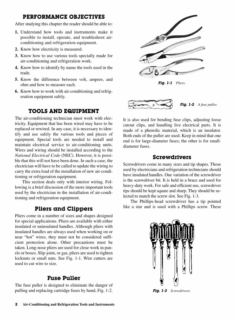
Pliers and ClippersPliers come in a number of sizes and shapes designedfor special applications. Pliers are available with eitherinsulated or uninsulated handles. Although pliers withinsulated handles are always used when working on ornear “hot” wires, they must not be considered suffi-cient protection alone. Other precautions must betaken. Long-nose pliers are used for close work in pan-els or boxes. Slip-joint, or gas, pliers are used to tightenlocknuts or small nuts. See Fig. 1-1. Wire cutters areused to cut wire to size.
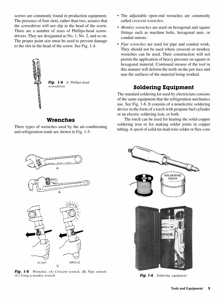
Fuse PullerThe fuse puller is designed to eliminate the danger ofpulling and replacing cartridge fuses by hand, Fig. 1-2.
It is also used for bending fuse clips, adjusting loosecutout clips, and handling live electrical parts. It ismade of a phenolic material, which is an insulator.Both ends of the puller are used. Keep in mind that oneend is for large-diameter fuses; the other is for small-diameter fuses.
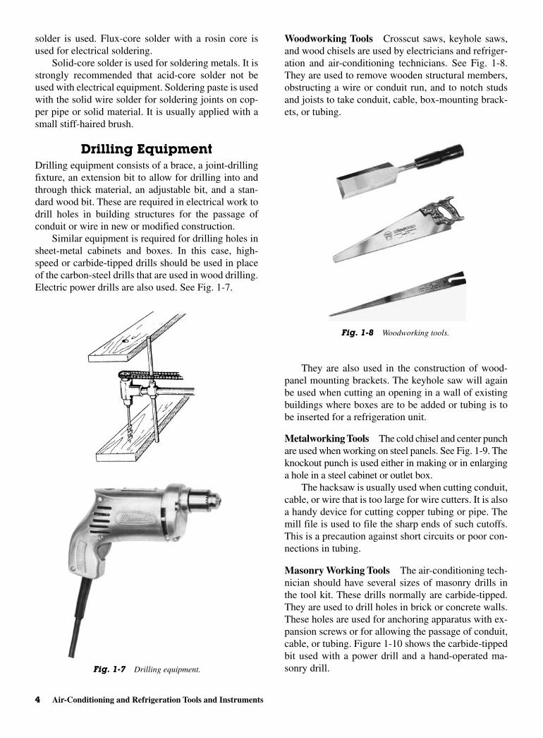
ScrewdriversScrewdrivers come in many sizes and tip shapes. Thoseused by electricians and refrigeration technicians shouldhave insulated handles. One variation of the screwdriveris the screwdriver bit. It is held in a brace and used forheavy-duty work. For safe and efficient use, screwdrivertips should be kept square and sharp. They should be se-lected to match the screw slot. See Fig. 1-3.
The Phillips-head screwdriver has a tip pointedlike a star and is used with a Phillips screw. These
2 Air-Conditioning and Refrigeration Tools and Instruments
Fig. 1-1 Pliers.
Fig. 1-2 A fuse puller.
Fig. 1-3 Screwdrivers.
• The adjustable open-end wrenches are commonlycalled crescent wrenches.
• Monkey wrenches are used on hexagonal and squarefittings such as machine bolts, hexagonal nuts, orconduit unions.
• Pipe wrenches are used for pipe and conduit work.They should not be used where crescent or monkeywrenches can be used. Their construction will notpermit the application of heavy pressure on square orhexagonal material. Continued misuse of the tool inthis manner will deform the teeth on the jaw face andmar the surfaces of the material being worked.
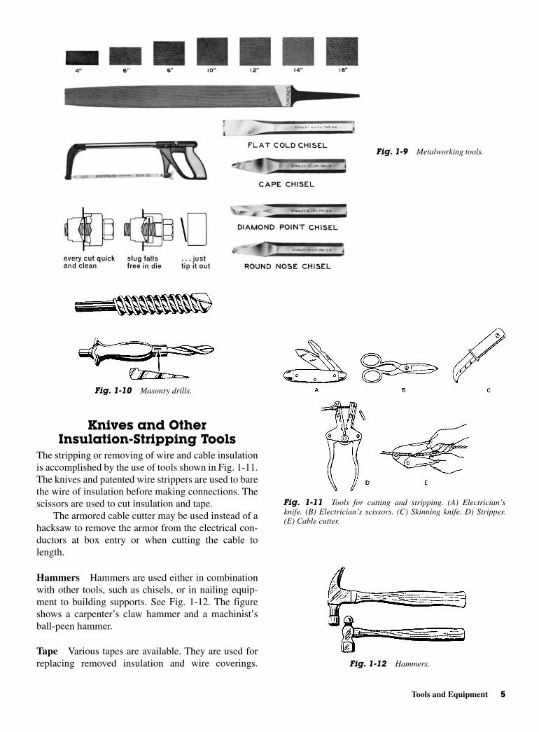
Soldering EquipmentThe standard soldering kit used by electricians consistsof the same equipment that the refrigeration mechanicsuse. See Fig. 1-6. It consists of a nonelectric solderingdevice in the form of a torch with propane fuel cylinderor an electric soldering iron, or both.
The torch can be used for heating the solid-coppersoldering iron or for making solder joints in coppertubing. A spool of solid tin-lead wire solder or flux-core
screws are commonly found in production equipment.The presence of four slots, rather than two, assures thatthe screwdriver will not slip in the head of the screw.There are a number of sizes of Phillips-head screw-drivers. They are designated as No. 1, No. 2, and so on.The proper point size must be used to prevent damageto the slot in the head of the screw. See Fig. 1-4.
WrenchesThree types of wrenches used by the air-conditioningand refrigeration trade are shown in Fig. 1-5.
Tools and Equipment 3
Fig. 1-4 A Phillips-headscrewdriver.
Fig. 1-5 Wrenches. (A) Crescent wrench. (B) Pipe wrench.(C) Using a monkey wrench. Fig. 1-6 Soldering equipment.
solder is used. Flux-core solder with a rosin core isused for electrical soldering.
Solid-core solder is used for soldering metals. It isstrongly recommended that acid-core solder not beused with electrical equipment. Soldering paste is usedwith the solid wire solder for soldering joints on cop-per pipe or solid material. It is usually applied with asmall stiff-haired brush.
Drilling EquipmentDrilling equipment consists of a brace, a joint-drillingfixture, an extension bit to allow for drilling into andthrough thick material, an adjustable bit, and a stan-dard wood bit. These are required in electrical work todrill holes in building structures for the passage ofconduit or wire in new or modified construction.
Similar equipment is required for drilling holes insheet-metal cabinets and boxes. In this case, high-speed or carbide-tipped drills should be used in placeof the carbon-steel drills that are used in wood drilling.Electric power drills are also used. See Fig. 1-7.
Woodworking Tools Crosscut saws, keyhole saws,and wood chisels are used by electricians and refriger-ation and air-conditioning technicians. See Fig. 1-8.They are used to remove wooden structural members,obstructing a wire or conduit run, and to notch studsand joists to take conduit, cable, box-mounting brack-ets, or tubing.
They are also used in the construction of wood-panel mounting brackets. The keyhole saw will againbe used when cutting an opening in a wall of existingbuildings where boxes are to be added or tubing is tobe inserted for a refrigeration unit.
Metalworking Tools The cold chisel and center punchare used when working on steel panels. See Fig. 1-9. Theknockout punch is used either in making or in enlarginga hole in a steel cabinet or outlet box.
The hacksaw is usually used when cutting conduit,cable, or wire that is too large for wire cutters. It is alsoa handy device for cutting copper tubing or pipe. Themill file is used to file the sharp ends of such cutoffs.This is a precaution against short circuits or poor con-nections in tubing.
Masonry Working Tools The air-conditioning tech-nician should have several sizes of masonry drills inthe tool kit. These drills normally are carbide-tipped.They are used to drill holes in brick or concrete walls.These holes are used for anchoring apparatus with ex-pansion screws or for allowing the passage of conduit,cable, or tubing. Figure 1-10 shows the carbide-tippedbit used with a power drill and a hand-operated ma-sonry drill.
4 Air-Conditioning and Refrigeration Tools and Instruments
Fig. 1-7 Drilling equipment.
Fig. 1-8 Woodworking tools.
Knives and OtherInsulation-Stripping Tools
The stripping or removing of wire and cable insulationis accomplished by the use of tools shown in Fig. 1-11.The knives and patented wire strippers are used to barethe wire of insulation before making connections. Thescissors are used to cut insulation and tape.
The armored cable cutter may be used instead of ahacksaw to remove the armor from the electrical con-ductors at box entry or when cutting the cable tolength.
Hammers Hammers are used either in combinationwith other tools, such as chisels, or in nailing equip-ment to building supports. See Fig. 1-12. The figureshows a carpenter’s claw hammer and a machinist’sball-peen hammer.
Tape Various tapes are available. They are used forreplacing removed insulation and wire coverings.
Tools and Equipment 5
Fig. 1-9 Metalworking tools.
Fig. 1-10 Masonry drills.
Fig. 1-11 Tools for cutting and stripping. (A) Electrician’sknife. (B) Electrician’s scissors. (C) Skinning knife. D) Stripper.(E) Cable cutter.
Fig. 1-12 Hammers.
Friction tape is a cotton tape impregnated with an in-sulating adhesive compound. It provides weather resis-tance and limited mechanical protection to a splicealready insulated.
Rubber tape or varnished cambric tape may beused as an insulator when replacing wire covering.
Plastic electrical tape is made of a plastic materialwith an adhesive on one side of the tape. It has replacedfriction and rubber tape in the field for 120- and 208-Vcircuits. It serves a dual purpose in taping joints. It ispreferred over the former tapes.
Ruler and Measuring Tape The technician shouldhave a folding rule and a steel tape. Both of these areaids to cutting to exact size.
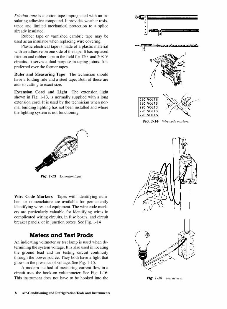
Extension Cord and Light The extension lightshown in Fig. 1-13, is normally supplied with a longextension cord. It is used by the technician when nor-mal building lighting has not been installed and wherethe lighting system is not functioning.
Wire Code Markers Tapes with identifying num-bers or nomenclature are available for permanentlyidentifying wires and equipment. The wire code mark-ers are particularly valuable for identifying wires incomplicated wiring circuits, in fuse boxes, and circuitbreaker panels, or in junction boxes. See Fig. 1-14
Meters and Test ProdsAn indicating voltmeter or test lamp is used when de-termining the system voltage. It is also used in locatingthe ground lead and for testing circuit continuitythrough the power source. They both have a light thatglows in the presence of voltage. See Fig. 1-15.
A modern method of measuring current flow in acircuit uses the hook-on voltammeter. See Fig. 1-16.This instrument does not have to be hooked into the
6 Air-Conditioning and Refrigeration Tools and Instruments
Fig. 1-13 Extension light.
Fig. 1-14 Wire code markers.
Fig. 1-15 Test devices.
ohmmeter is used. The ohmmeter uses leads to com-plete the circuit to the device under test.
Use of the voltammeter is a quick way of testingthe air-conditioning or refrigeration unit motor that isdrawing too much current. A motor that is drawing toomuch current will overheat and burn out.
Tool KitsSome tool manufacturers make up tool kits for the re-frigeration and appliance trade. See Fig. 1-17 for agood example. In the Snap-on tool kit, the leak detec-tor is part of the kit. The gages are also included. Anadjustable wrench, tubing cutter, hacksaw, flaring tool,and ball-peen hammer can be hung on the wall and re-placed when not in use. One of the problems for any re-pairperson is keeping track of tools. Markings on aboard will help locate at a glance when one is missing.
Figure 1-18 shows a portable tool kit. Figure 1-18Jshows a pulley puller. This tool is used to remove the
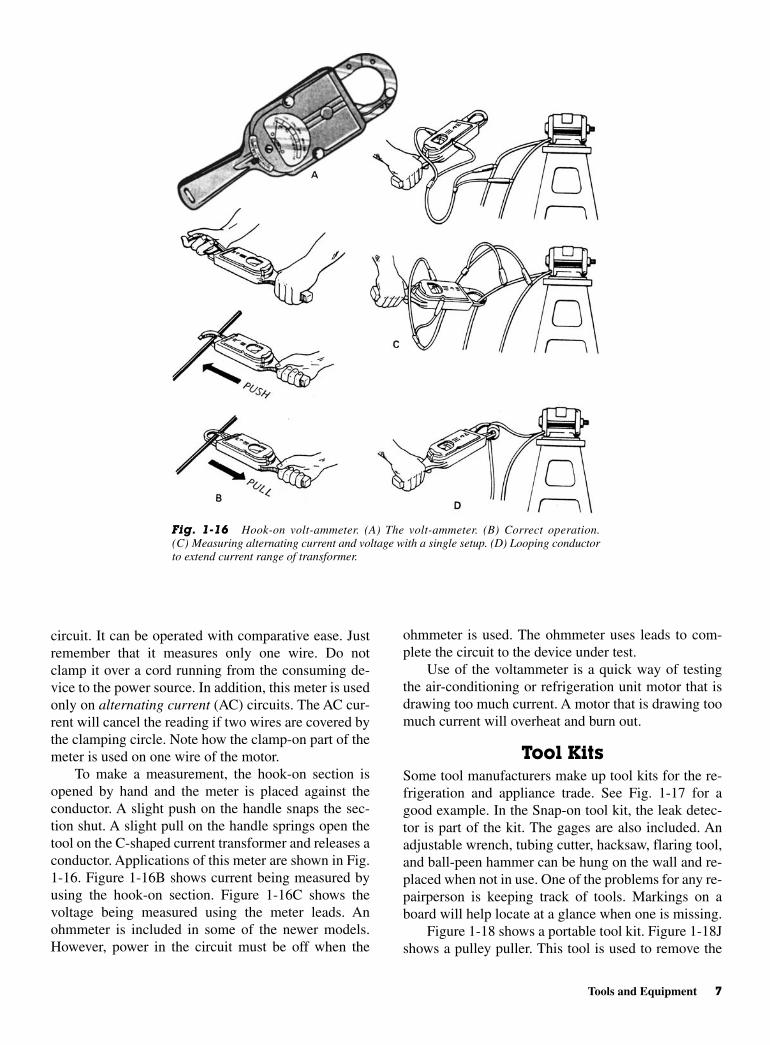
circuit. It can be operated with comparative ease. Justremember that it measures only one wire. Do notclamp it over a cord running from the consuming de-vice to the power source. In addition, this meter is usedonly on alternating current (AC) circuits. The AC cur-rent will cancel the reading if two wires are covered bythe clamping circle. Note how the clamp-on part of themeter is used on one wire of the motor.
To make a measurement, the hook-on section isopened by hand and the meter is placed against theconductor. A slight push on the handle snaps the sec-tion shut. A slight pull on the handle springs open thetool on the C-shaped current transformer and releases aconductor. Applications of this meter are shown in Fig.1-16. Figure 1-16B shows current being measured byusing the hook-on section. Figure 1-16C shows thevoltage being measured using the meter leads. Anohmmeter is included in some of the newer models.However, power in the circuit must be off when the
Tools and Equipment 7
Fig. 1-16 Hook-on volt-ammeter. (A) The volt-ammeter. (B) Correct operation.(C) Measuring alternating current and voltage with a single setup. (D) Looping conductorto extend current range of transformer.
8 Air-Conditioning and Refrigeration Tools and Instruments
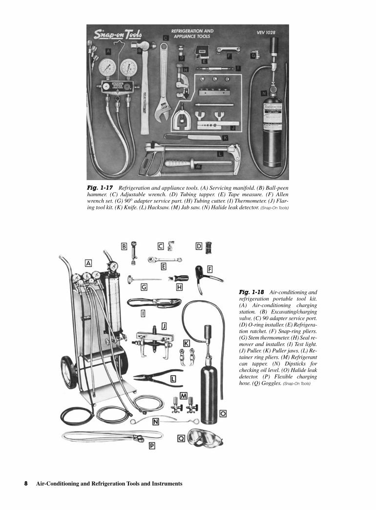
Fig. 1-17 Refrigeration and appliance tools. (A) Servicing manifold. (B) Ball-peenhammer. (C) Adjustable wrench. (D) Tubing tapper. (E) Tape measure. (F) Allenwrench set. (G) 90° adapter service part. (H) Tubing cutter. (I) Thermometer. (J) Flar-ing tool kit. (K) Knife. (L) Hacksaw. (M) Jab saw. (N) Halide leak detector. (Snap-On Tools)
Fig. 1-18 Air-conditioning andrefrigeration portable tool kit.(A) Air-conditioning chargingstation. (B) Excavating/chargingvalve. (C) 90 adapter service port.(D) O-ring installer. (E) Refrigera-tion ratchet. (F) Snap-ring pliers.(G) Stem thermometer. (H) Seal re-mover and installer. (I) Test light.(J) Puller. (K) Puller jaws. (L) Re-tainer ring pliers. (M) Refrigerantcan tapper. (N) Dipsticks forchecking oil level. (O) Halide leakdetector. (P) Flexible charginghose. (Q) Goggles. (Snap-On Tools)

GAGES AND INSTRUMENTSIt is impossible to install or service air-conditioning andrefrigeration units and systems without using gages andinstruments.
A number of values must be measured accuratelyif air-conditioning and refrigeration equipment is tobe operated properly. Refrigeration and air-conditioningunits must be properly serviced and monitored if theyare to give the maximum efficiency for the energyexpended. Here, the use of gages and instrumentsbecomes important. It is not possible to analyze asystem’s operation without the proper equipment andprocedures. In some cases, it takes thousands ofdollars worth of equipment to troubleshoot ormaintain modern refrigeration and air-conditioningsystem.
Instruments are used to measure and record suchvalues as temperature, humidity, pressure, airflow,electrical quantities, and weight. Instruments and mon-itoring tools can be used to detect incorrectly operatingequipment. They can also be used to check efficiency.Instruments can be used on a job, in the shop, or in thelaboratory. If properly cared for and correctly used,modern instruments are highly accurate.
Pressure GagesPressure gages are relatively simple in function. SeeFig. 1-21. They read positive pressure or negative pres-sure, or both. See Fig. 1-22. Gage components are
pulley if necessary to get to the seals. A cart (A) is in-cluded so that the refrigerant and vacuum pump can beeasily handled in large quantities. The goggles (Q) pro-tect the eyes from escaping refrigerant.
Figure 1-19 shows a voltmeter probe. It detects thepresence of 115 to 750 V. The handheld meter is usedto find whether the voltage is AC or DC and what thepotential difference is. It is rugged and easy to handle.This meter is useful when working around unknownpower sources in refrigeration units.
Figure 1-20 shows a voltage and current recorder. Itcan be left hooked to the line for an extended period. Useof this instrument can be used to determine the exactcause of a problem, since voltage and current changescan affect the operation of air-conditioning and refrigera-tion units.
Gages and Instruments 9
Fig. 1-19 AC and DC voltage probe voltmeter. (Amprobe)
Fig. 1-20 Voltage and current recorder. (Amprobe)
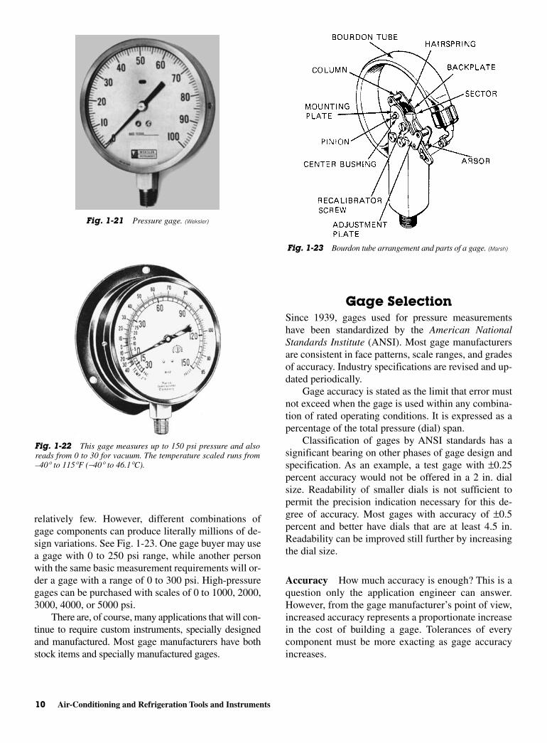
relatively few. However, different combinations ofgage components can produce literally millions of de-sign variations. See Fig. 1-23. One gage buyer may usea gage with 0 to 250 psi range, while another personwith the same basic measurement requirements will or-der a gage with a range of 0 to 300 psi. High-pressuregages can be purchased with scales of 0 to 1000, 2000,3000, 4000, or 5000 psi.
There are, of course, many applications that will con-tinue to require custom instruments, specially designedand manufactured. Most gage manufacturers have bothstock items and specially manufactured gages.
Gage SelectionSince 1939, gages used for pressure measurementshave been standardized by the American NationalStandards Institute (ANSI). Most gage manufacturersare consistent in face patterns, scale ranges, and gradesof accuracy. Industry specifications are revised and up-dated periodically.
Gage accuracy is stated as the limit that error mustnot exceed when the gage is used within any combina-tion of rated operating conditions. It is expressed as apercentage of the total pressure (dial) span.
Classification of gages by ANSI standards has asignificant bearing on other phases of gage design andspecification. As an example, a test gage with ±0.25percent accuracy would not be offered in a 2 in. dialsize. Readability of smaller dials is not sufficient topermit the precision indication necessary for this de-gree of accuracy. Most gages with accuracy of ±0.5percent and better have dials that are at least 4.5 in.Readability can be improved still further by increasingthe dial size.
Accuracy How much accuracy is enough? This is aquestion only the application engineer can answer.However, from the gage manufacturer’s point of view,increased accuracy represents a proportionate increasein the cost of building a gage. Tolerances of everycomponent must be more exacting as gage accuracyincreases.
10 Air-Conditioning and Refrigeration Tools and Instruments
Fig. 1-21 Pressure gage. (Weksler)
Fig. 1-22 This gage measures up to 150 psi pressure and alsoreads from 0 to 30 for vacuum. The temperature scaled runs from–40∞ to 115∞F (-40∞ to 46.1∞C).
Fig. 1-23 Bourdon tube arrangement and parts of a gage. (Marsh)
exceed 75 percent of the full-scale range. For the bestperformance, gages should be graduated to twice thenormal system-operating pressure.
This extra margin provides a safety factor in pre-venting overpressure damage. It also helps avoid a per-manent set of the Bourdon tube. For applications withsubstantial pressure fluctuations, this extra margin isespecially important. In general, the lower the Bour-don tube pressure, the greater the overpressure per-centage it will absorb without damage. The higher theBourdon tube pressure, the less overpressure it willsafely absorb.
Pulsation causes pointer flutter, which makes gagereading difficult. Pulsation also can drastically shortengage life by causing excessive wear of the movementgear teeth. A pulsating pressure is defined as a pressurevariation of more than 0.1 percent full-scale per sec-ond. Following are conditions often encountered andsuggested means of handling them.
The restrictor is a low-cost means of combatingpulsation problems. This device reduces the pressureopening. The reduction of the opening allows less ofthe pressure change to reach the Bourdon tube in agiven time interval. This dampening device protectsthe Bourdon tube by the retarding overpressure surges.It also improves gage readability by reducing pointerflutter. When specifying gages with restrictors, indi-cate whether the pressure medium is liquid or gas.The medium determines the size of the orifice. In ad-dition, restrictors are not recommended for dirty linefluids. Dirty materials in the line can easily clog theorifice. For such conditions, diaphragm seals shouldbe specified.
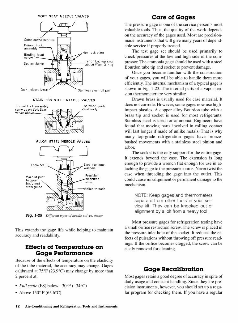
The needle valve is another means of handlingpulsation if used between the line and the gage. SeeFig. 1-25. The valve is throttled down to a point wherepulsation ceases to register on the gage.
In addition, to the advantage of precise throttling,needle valves also offer complete shutoff, an importantsafety factor in many applications. Use of a needlevalve can greatly extend the life of the gage by allow-ing it to be used only when a reading is needed.
Liquid-filled gages are another very effective wayto handle line pulsation problems. Because the move-ment is constantly submerged in lubricating fluid, re-action to pulsating pressure is dampened and thepointer flutter is practically eliminated.
Silicone-oil-treated movements dampen oscilla-tions caused by line pressure pulsations and/or me-chanical oscillation. The silicone oil, applied to themovement, bearings, and gears, acts as a shock absorber.
Time is needed for technicians to calibrate thegage correctly. A broad selection of precision instru-ments is available and grades A (±1 percent), 2A (±0.5percent), and 3A (±0.25 percent) are examples of tol-erances available.
With the advent of modern electronic gages andmore sophisticated equipment it is possible to obtainheretofore undreamed of accuracy automatically withequipment used in the field.
Medium In every gage selection, the medium to bemeasured must be evaluated for potential corrosive-ness to the Bourdon tube of the gage.
There is no ideal material for Bourdon tubes. Nosingle material adapts to all applications. Bourdon tubematerials are chosen for their elasticity, repeatability,ability to resist “set” and corrosion resistance to thefluid mediums.
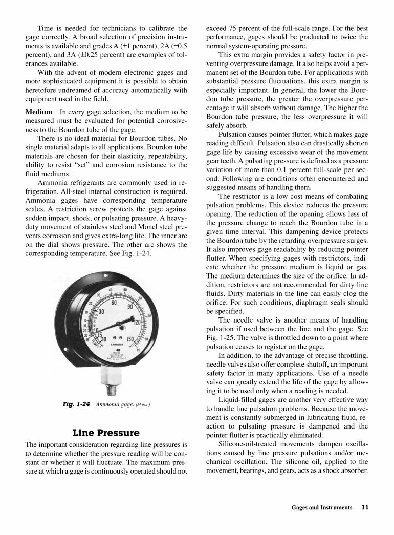
Ammonia refrigerants are commonly used in re-frigeration. All-steel internal construction is required.Ammonia gages have corresponding temperaturescales. A restriction screw protects the gage againstsudden impact, shock, or pulsating pressure. A heavy-duty movement of stainless steel and Monel steel pre-vents corrosion and gives extra-long life. The inner arcon the dial shows pressure. The other arc shows thecorresponding temperature. See Fig. 1-24.
Line PressureThe important consideration regarding line pressures isto determine whether the pressure reading will be con-stant or whether it will fluctuate. The maximum pres-sure at which a gage is continuously operated should not
Gages and Instruments 11
Fig. 1-24 Ammonia gage. (Marsh)
This extends the gage life while helping to maintainaccuracy and readability.
Effects of Temperature onGage Performance
Because of the effects of temperature on the elasticityof the tube material, the accuracy may change. Gagescalibrated at 75°F (23.9°C) may change by more than2 percent at:
• Full scale (FS) below −30°F (−34°C)
• Above 150° F (65.6°C)
Care of GagesThe pressure gage is one of the service person’s mostvaluable tools. Thus, the quality of the work dependson the accuracy of the gages used. Most are precision-made instruments that will give many years of depend-able service if properly treated.
The test gage set should be used primarily tocheck pressures at the low and high side of the com-pressor. The ammonia gage should be used with a steelBourdon tube tip and socket to prevent damage.
Once you become familiar with the constructionof your gages, you will be able to handle them moreefficiently. The internal mechanism of a typical gage isshown in Fig. 1-23. The internal parts of a vapor ten-sion thermometer are very similar.
Drawn brass is usually used for case material. Itdoes not corrode. However, some gages now use high-impact plastics. A copper alloy Bourdon tube with abrass tip and socket is used for most refrigerants.Stainless steel is used for ammonia. Engineers havefound that moving parts involved in rolling contactwill last longer if made of unlike metals. That is whymany top-grade refrigeration gages have bronze-bushed movements with a stainless steel pinion andarbor.
The socket is the only support for the entire gage.It extends beyond the case. The extension is longenough to provide a wrench flat enough for use in at-taching the gage to the pressure source. Never twist thecase when threading the gage into the outlet. Thiscould cause misalignment or permanent damage to themechanism.
NOTE: Keep gages and thermometersseparate from other tools in your ser-vice kit. They can be knocked out ofalignment by a jolt from a heavy tool.
Most pressure gages for refrigeration testing havea small orifice restriction screw. The screw is placed inthe pressure inlet hole of the socket. It reduces the ef-fects of pulsations without throwing off pressure read-ings. If the orifice becomes clogged, the screw can beeasily removed for cleaning.
Gage RecalibrationMost gages retain a good degree of accuracy in spite ofdaily usage and constant handling. Since they are pre-cision instruments, however, you should set up a regu-lar program for checking them. If you have a regular
12 Air-Conditioning and Refrigeration Tools and Instruments
Fig. 1-25 Different types of needle valves. (Marsh)
If remote readings are necessary, then the vaportension thermometer is best. It has a closed, filledBourdon tube. A bulb is at one end for temperaturesensing. Changes in the temperature at the bulb resultin pressure changes in the fill medium. Remote readingthermometers are equipped with 6 ft of capillary tub-ing as standard. Other lengths are available on specialorder.
The location of direct or remote reading is im-portant when choosing a thermometer. Four com-mon types of thermometers are used to measuretemperature:
• Pocket thermometer
• Bimetallic thermometer
• Thermocouple thermometer
• Resistance thermometer
Pocket ThermometerThe pocket thermometer depends upon the even ex-pansion of a liquid. The liquid may be mercury or col-ored alcohol. This type of thermometer is versatile. Itcan be used to measure temperatures of liquids, air,gas, and solids. It can be strapped to the suction lineduring a superheat measurement. For practical pur-poses, it can operate wet or dry. This type of ther-mometer can withstand extremely corrosive solutionsand atmospheres.
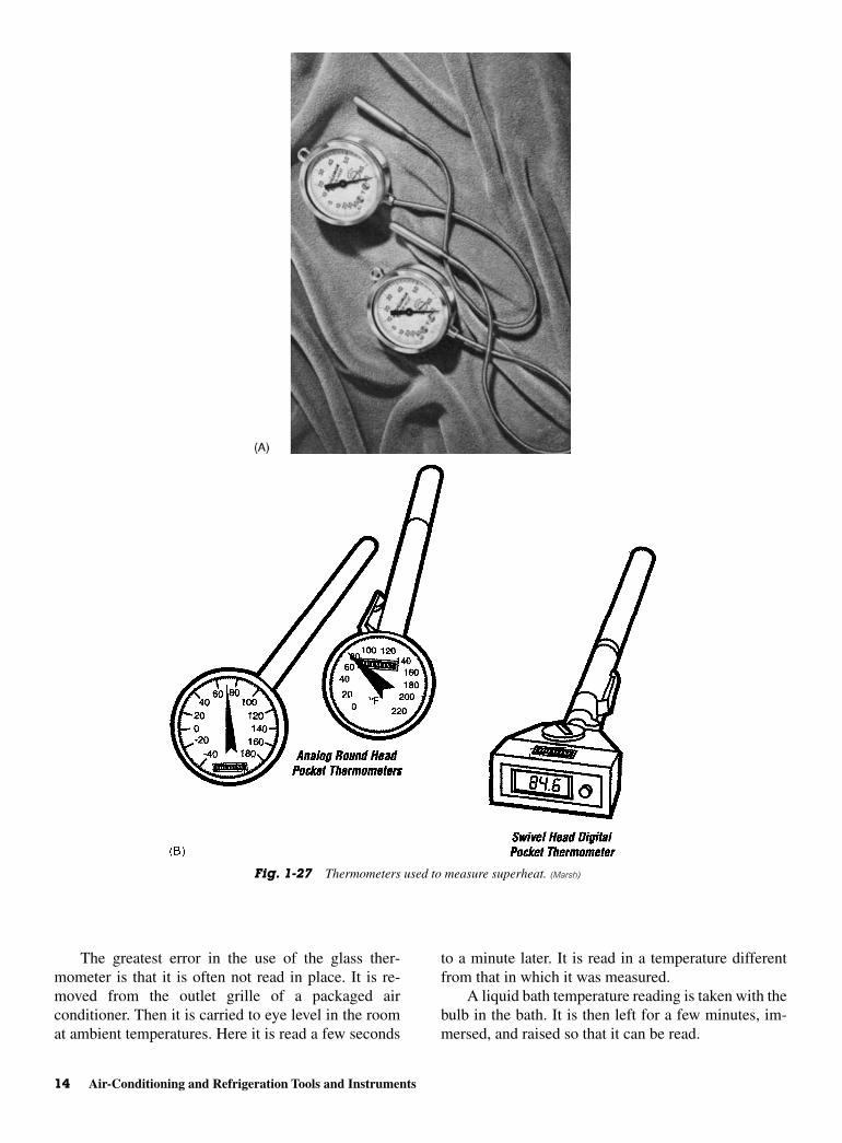
When the glass thermometer is read in place, tem-peratures are accurate if proper contact is made betweenthe stem and the medium being measured. Refrigerationservice persons are familiar with the need to attach thethermometer firmly to the suction line when taking su-perheat readings. See Fig. 1-27A and B. Clamps areavailable for this purpose. One thing should be kept inmind, that is, the depth at which the thermometer is to beimmersed in the medium being measured. Most instruc-tion sheets point out that for liquid measurements thethermometer should be immersed so many inches.When used in a duct, a specified length of stem shouldbe in the airflow. Dipping only the bulb into a glass ofwater does not give the same readings as immersing tothe prescribed length.
Shielding is frequently overlooked in the appli-cation of the simple glass thermometer. The instru-ment should be shielded from radiated heat. Heatingrepairpersons often measure air temperature in thefurnace bonnet. Do not place the thermometer in aposition where it receives direct radiation from theheat exchanger surfaces. This causes erroneousreadings.
program, you can be sure that you are working with ac-curate instruments.
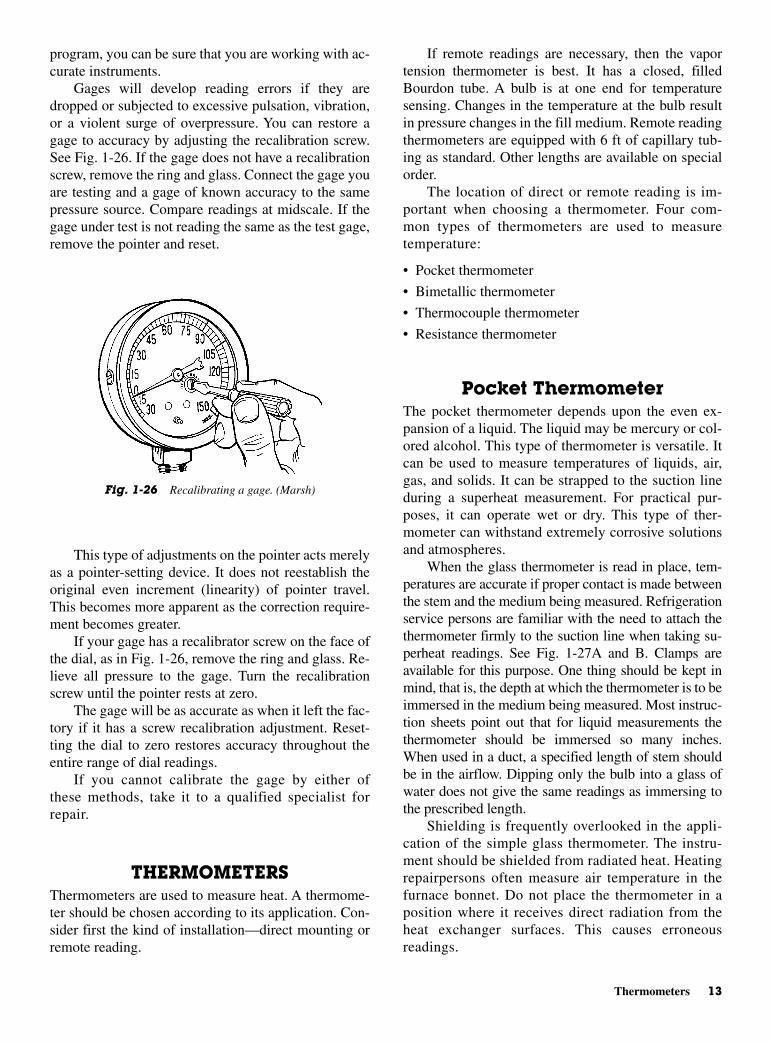
Gages will develop reading errors if they aredropped or subjected to excessive pulsation, vibration,or a violent surge of overpressure. You can restore agage to accuracy by adjusting the recalibration screw.See Fig. 1-26. If the gage does not have a recalibrationscrew, remove the ring and glass. Connect the gage youare testing and a gage of known accuracy to the samepressure source. Compare readings at midscale. If thegage under test is not reading the same as the test gage,remove the pointer and reset.
This type of adjustments on the pointer acts merelyas a pointer-setting device. It does not reestablish theoriginal even increment (linearity) of pointer travel.This becomes more apparent as the correction require-ment becomes greater.
If your gage has a recalibrator screw on the face ofthe dial, as in Fig. 1-26, remove the ring and glass. Re-lieve all pressure to the gage. Turn the recalibrationscrew until the pointer rests at zero.
The gage will be as accurate as when it left the fac-tory if it has a screw recalibration adjustment. Reset-ting the dial to zero restores accuracy throughout theentire range of dial readings.
If you cannot calibrate the gage by either ofthese methods, take it to a qualified specialist forrepair.
THERMOMETERSThermometers are used to measure heat. A thermome-ter should be chosen according to its application. Con-sider first the kind of installation—direct mounting orremote reading.
Thermometers 13
Fig. 1-26 Recalibrating a gage. (Marsh)
The greatest error in the use of the glass ther-mometer is that it is often not read in place. It is re-moved from the outlet grille of a packaged airconditioner. Then it is carried to eye level in the roomat ambient temperatures. Here it is read a few seconds
to a minute later. It is read in a temperature differentfrom that in which it was measured.
A liquid bath temperature reading is taken with thebulb in the bath. It is then left for a few minutes, im-mersed, and raised so that it can be read.
14 Air-Conditioning and Refrigeration Tools and Instruments
Fig. 1-27 Thermometers used to measure superheat. (Marsh)
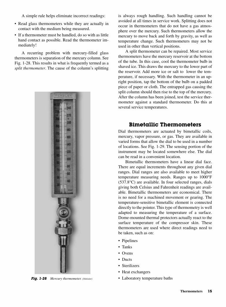
is always rough handling. Such handling cannot beavoided at all times in service work. Splitting does notoccur in thermometers that do not have a gas atmos-phere over the mercury. Such thermometers allow themercury to move back and forth by gravity, as well astemperature change. Such thermometers may not beused in other than vertical positions.
A split thermometer can be repaired. Most servicethermometers have the mercury reservoir at the bottomof the tube. In this case, cool the thermometer bulb inshaved ice. This draws the mercury to the lower part ofthe reservoir. Add more ice or salt to lower the tem-perature, if necessary. With the thermometer in an up-right position, tap the bottom of the bulb on a paddedpiece of paper or cloth. The entrapped gas causing thesplit column should then rise to the top of the mercury.After the column has been joined, test the service ther-mometer against a standard thermometer. Do this atseveral service temperatures.
Bimetallic ThermometersDial thermometers are actuated by bimetallic coils,mercury, vapor pressure, or gas. They are available invaried forms that allow the dial to be used in a numberof locations. See Fig. 1-29. The sensing portion of theinstrument may be located somewhere else. The dialcan be read in a convenient location.
Bimetallic thermometers have a linear dial face.There are equal increments throughout any given dialranges. Dial ranges are also available to meet highertemperature measuring needs. Ranges up to 1000°F(537.8°C) are available. In four selected ranges, dialsgiving both Celsius and Fahrenheit readings are avail-able. Bimetallic thermometers are economical. Thereis no need for a machined movement or gearing. Thetemperature-sensitive bimetallic element is connecteddirectly to the pointer. This type of thermometry is welladapted to measuring the temperature of a surface.Dome-mounted thermal protectors actually react to thesurface temperature of the compressor skin. Thesethermometers are used where direct readings need tobe taken, such as on:
• Pipelines
• Tanks
• Ovens
• Ducts
• Sterilizers
• Heat exchangers
• Laboratory temperature baths
A simple rule helps eliminate incorrect readings:
• Read glass thermometers while they are actually incontact with the medium being measured.
• If a thermometer must be handled, do so with as littlehand contact as possible. Read the thermometer im-mediately!
A recurring problem with mercury-filled glassthermometers is separation of the mercury column. SeeFig. 1-28. This results in what is frequently termed as asplit thermometer. The cause of the column’s splitting
Thermometers 15
Fig. 1-28 Mercury thermometer. (Weksler)

The simplest type of dial thermometer is a stem.The stem is inserted into the medium to be mea-sured. With the stem immersed 2 in. in liquids and 4 in.in gases, this thermometer gives reasonably accuratereadings.
Although dial thermometers have many uses, thereare some limitations. They are not as universally ap-plicable as the simple glass thermometer. When order-ing a dial thermometer, specify the stem length, scalerange, and medium in which it will be used.
One of the advantages of bimetallic thermometryis that the thermometer can be applied directly to sur-faces. It can be designed to take temperatures of pipesfrom 0.5 through 2 in.
In operation, the bimetallic spiral is closely cou-pled to the heated surface that is to be measured. Thethermometer is held fast by two permanent magnets.One manufacturer claims their type of thermometerreaches stability within 3 min. Its accuracy is said to beplus or minus 2 percent in working ranges.
A simple and inexpensive type of bimetallic ther-mometer scribes temperature travel on a load of food in
transit. It can be used also to check temperature varia-tions in controlled industrial areas. The replacementchart gives a permanent record of temperature varia-tions during the test period.
Bimetallic drives are also used in control devices.For example, thermal overload sensors for motors andother electrical devices use bimetallic elements. Otherexamples will be discussed later.
Thermocouple ThermometersThermocouples are made of two dissimilar metals.Once the metals are heated, they give off an EMF(electromotive force or voltage). This electrical energycan be measured with a standard type of meter de-signed to measure small amounts of current. The metercan be calibrated in degrees, instead of amperes, mil-liamperes, or microamperes.
In use, the thermocouples are placed in themedium that is to be measured. Extension wires runfrom the thermocouple to the meter. The meter thengives the temperature reading at the remote location.
The extension wires may be run outside closedchests and rooms. There is no difficulty in closing a door,and the wires will not be pinches. On air-conditioningwork, one thermocouple may be placed in the supplygrille and another in the return grille. Readings can betaken seconds apart without handling a thermometer.
Thermocouples are easily taped onto the surface ofpipes to check the inside temperature. It is a good idea toinsulate the thermocouple from ambient and radiatedheat. Although this type of thermometer is rugged, itshould be handled with care. It should not be handledroughly. Thermocouples should be protected form corro-sive chemicals and fumes. Manufacturer’s instructionsfor protection and use are supplied with the instrument.
Resistance ThermometersOne of the newer ways to check temperature is with athermometer that uses a resistance- sending element. Anelectrical sensing unit may be made of a thermistor. Athermistor is a piece of material that changes resistancerapidly when subjected to temperature changes. Whenheated, the thermistor lowers its resistance. This de-crease in resistance makes a circuit increase its current.A meter can be inserted in the circuit. The change in cur-rent can be calibrated against a standard thermometer.The scale can be marked to read temperature in degreesCelsius or degrees Fahrenheit.
Another type of resistance thermometer indi-cates the temperature by an indicating light. The
16 Air-Conditioning and Refrigeration Tools and Instruments
Fig. 1-29 Dial-type thermometer. (Weksler)

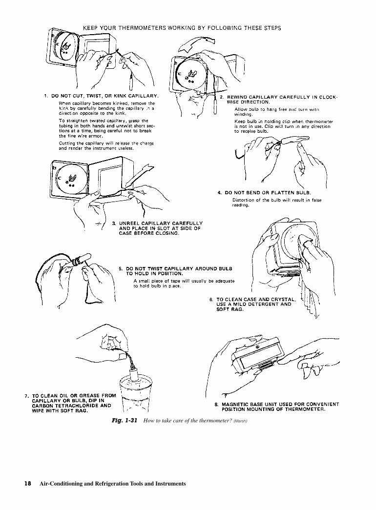
Preventing kinks in the capillary is important. Keep thecapillary clean by removing grease and oil. Clean thecase and crystal with a mild detergent.
SUPERHEAT MEASUREMENTINSTRUMENTS
Superheat plays an important role in refrigeration andair-conditioning service. For example, the thermostaticexpansion valve operates on the principle of superheat.In charging capillary tube systems, the superheat mea-surement must be carefully watched. The suction linesuperheat is an indication of whether the liquid refrig-erant is flooding the compressor from the suction side.A measurement of zero superheat is a definite indicatorthat liquid is reaching the compressor. A measurementof 6 to 10°F (−14.4 to −12.2°C) for the expansion valvesystem and 20°F (6.7°C) for capillary tube system in-dicates that all refrigerant is vaporized before enteringthe compressor.
The superheat at any point in a refrigeration sys-tem is found by first measuring the actual refrigeranttemperature at that point using an electronic ther-mometer. Then the boiling point temperature of the re-frigerant is found by connecting a compound pressuregage to the system and reading the boiling temperaturefrom the center of the pressure gage. The difference be-tween the actual temperature and the boiling point tem-perature is superheat. If the superheat is zero, therefrigerant must be boiling inside. Then, there is a goodchance that some of the refrigerant is still liquid. If thesuperheat is greater than zero, by at least 5°F or better,then the refrigerant is probably past the boiling pointstage and is all vapor.
The method of measuring superheat described herehas obvious faults. If there is no attachment for a pres-sure gage at the point in the system where you are mea-suring superheat, the hypothetical boiling temperaturecannot be found. To determine the superheat at such apoint, the following method can be used. This methodis particularly useful for measuring the refrigerant su-perheat in the suction line.
Instead of using a pressure gage, the boiling pointof the refrigerant in the evaporator can be determinedby measuring the temperature in the line just after theexpansion valve where the boiling is vigorous. Thiscan be done with any electronic thermometer. SeeFig. 1-32. As the refrigerant heats up through the evap-orator and the suction line, the actual temperature ofthe refrigerant can be measured at any point along thesuction line. Comparison of these two temperaturesgives a superheat measurement sufficient for field service
resistance-sensing bulb is placed in the medium to bemeasured. The bridge circuit is adjusted until the lightcomes on. The knob that adjusts the bridge circuit iscalibrated in degrees Celsius or degrees Fahrenheit.The knob then shows the temperature. The sensing ele-ment is just one of the resistors in the bridge circuit.The bridge circuit is described in detail in Chap. 3.
There is the possibility of having practical preci-sion of ±1°F (0.5°C). In this type of measurement, therange covered is –325 to 250°F (−198 to 121°C). A unitmay be used for deep freezer testing, for air-conditioningunits, and for other work. Response is rapid. Specialbulbs are available for use in rooms, outdoors, immer-sion, on surfaces, and in ducts.
Superheat ThermometerThe superheat thermometer is used to check for correcttemperature differential of the refrigerator gas. The in-let and outlet side of the evaporator coil have to be mea-sured to obtain the two temperatures. The difference isobtained by subtracting.
Test thermometers are available in boxes. SeeFig. 1-30. The box protects the thermometer. It is impor-tant to keep the thermometer in operating condition. Severalguidelines must be followed. Figure 1-31 illustrates howto keep the test thermometer in good working condition.
Superheat Measurement Instruments 17
Fig. 1-30 Test thermometer. (Marsh)
18 Air-Conditioning and Refrigeration Tools and Instruments
Fig. 1-31 How to take care of the thermometer? (Marsh)
unless a distributor-metering device is used or theevaporator is very large with a great amount of pres-sure drop across the evaporator.
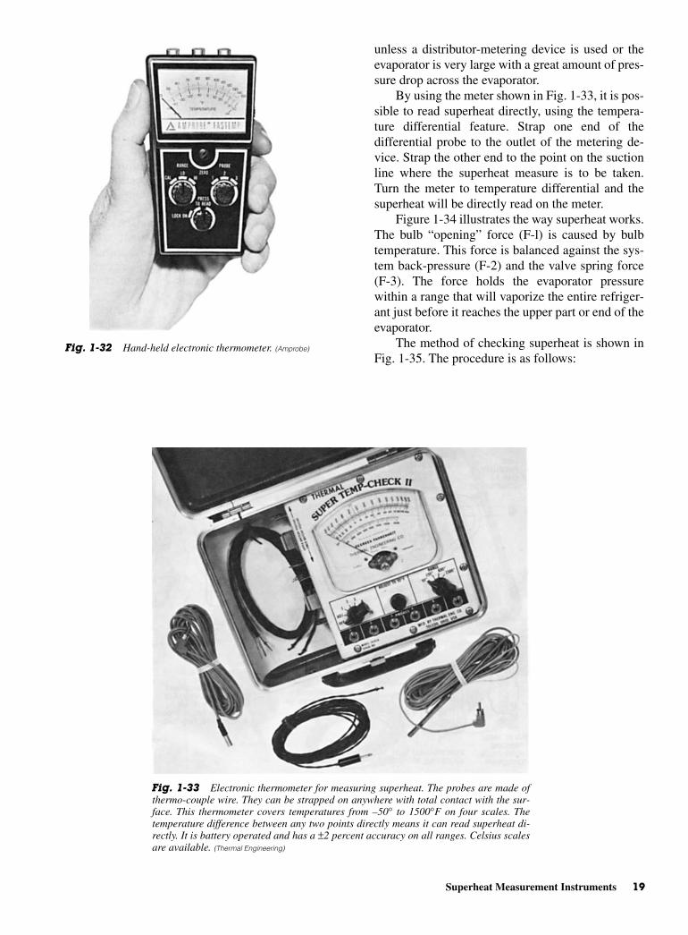
By using the meter shown in Fig. 1-33, it is pos-sible to read superheat directly, using the tempera-ture differential feature. Strap one end of thedifferential probe to the outlet of the metering de-vice. Strap the other end to the point on the suctionline where the superheat measure is to be taken.Turn the meter to temperature differential and thesuperheat will be directly read on the meter.
Figure 1-34 illustrates the way superheat works.The bulb “opening” force (F-l) is caused by bulbtemperature. This force is balanced against the sys-tem back-pressure (F-2) and the valve spring force(F-3). The force holds the evaporator pressurewithin a range that will vaporize the entire refriger-ant just before it reaches the upper part or end of theevaporator.
The method of checking superheat is shown inFig. 1-35. The procedure is as follows:
Superheat Measurement Instruments 19
Fig. 1-32 Hand-held electronic thermometer. (Amprobe)
Fig. 1-33 Electronic thermometer for measuring superheat. The probes are made ofthermo-couple wire. They can be strapped on anywhere with total contact with the sur-face. This thermometer covers temperatures from –50° to 1500°F on four scales. Thetemperature difference between any two points directly means it can read superheat di-rectly. It is battery operated and has a ±2 percent accuracy on all ranges. Celsius scalesare available. (Thermal Engineering)
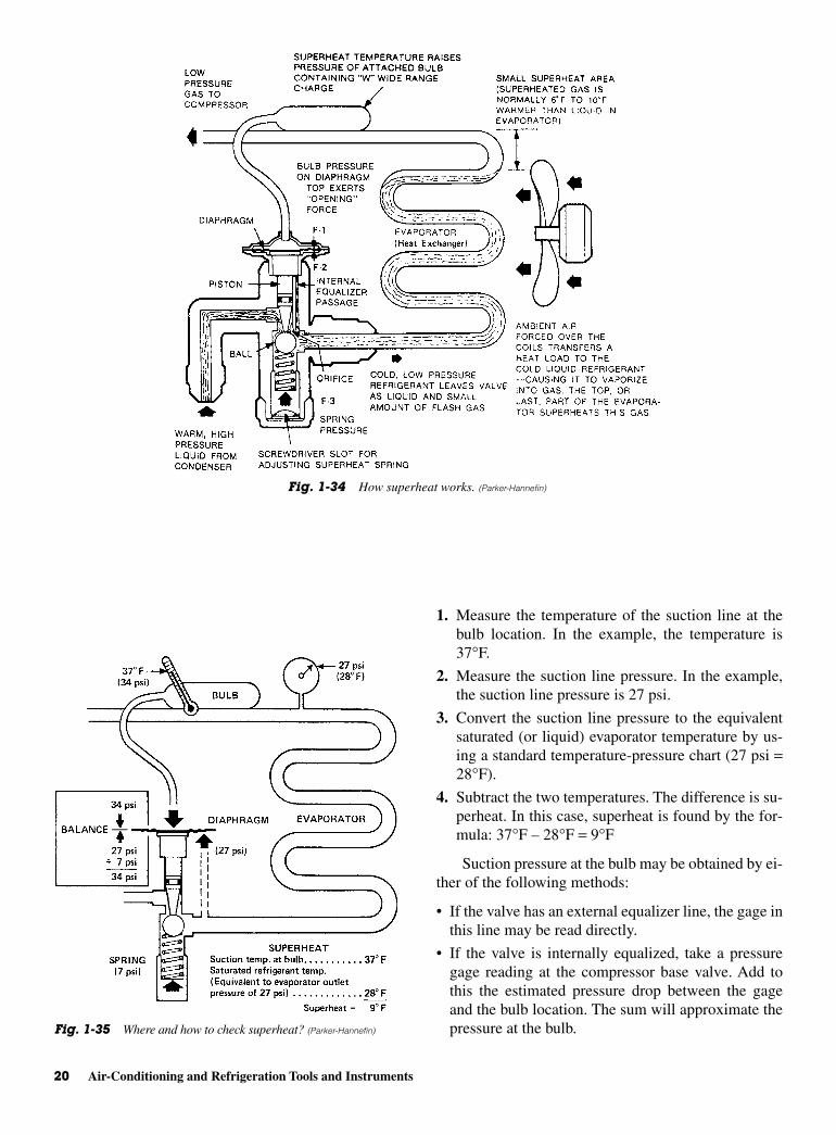
1. Measure the temperature of the suction line at thebulb location. In the example, the temperature is37°F.
2. Measure the suction line pressure. In the example,the suction line pressure is 27 psi.
3. Convert the suction line pressure to the equivalentsaturated (or liquid) evaporator temperature by us-ing a standard temperature-pressure chart (27 psi =28°F).
4. Subtract the two temperatures. The difference is su-perheat. In this case, superheat is found by the for-mula: 37°F – 28°F = 9°F
Suction pressure at the bulb may be obtained by ei-ther of the following methods:
• If the valve has an external equalizer line, the gage inthis line may be read directly.
• If the valve is internally equalized, take a pressuregage reading at the compressor base valve. Add tothis the estimated pressure drop between the gageand the bulb location. The sum will approximate thepressure at the bulb.
20 Air-Conditioning and Refrigeration Tools and Instruments
Fig. 1-34 How superheat works. (Parker-Hannefin)
Fig. 1-35 Where and how to check superheat? (Parker-Hannefin)
The system should be operating normally whenthe superheat is between 6 and 10°F (−14.4 and−12.2°C).
HALIDE LEAK DETECTORSNot too long ago leaks were detected by using soapbubbles and water. If possible, the area of the suspectedleak was submerged in soap water. Bubbles pinpointedthe leak area. If the unit or suspected area was not eas-ily submerged in water then it was coated with soap so-lution. In addition, where the leak was covered withsoap, bubbles would be produced. These indicated thelocation of the leak. These methods are still used todayin some cases. However, it is now possible to obtainbetter indications of leaks with electronic equipmentwith halide leak detectors.
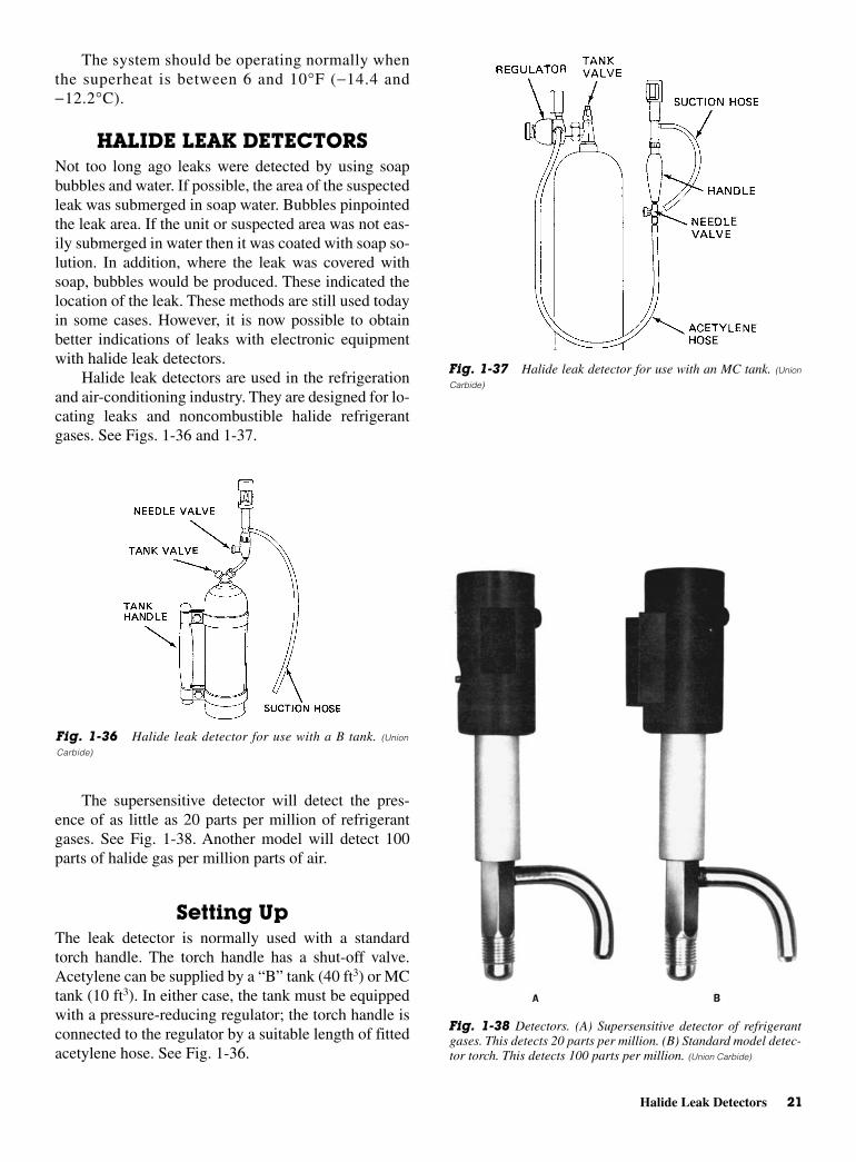
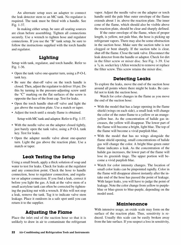
Halide leak detectors are used in the refrigerationand air-conditioning industry. They are designed for lo-cating leaks and noncombustible halide refrigerantgases. See Figs. 1-36 and 1-37.
The supersensitive detector will detect the pres-ence of as little as 20 parts per million of refrigerantgases. See Fig. 1-38. Another model will detect 100parts of halide gas per million parts of air.
Setting UpThe leak detector is normally used with a standardtorch handle. The torch handle has a shut-off valve.Acetylene can be supplied by a “B” tank (40 ft3) or MCtank (10 ft3). In either case, the tank must be equippedwith a pressure-reducing regulator; the torch handle isconnected to the regulator by a suitable length of fittedacetylene hose. See Fig. 1-36.
Halide Leak Detectors 21
Fig. 1-37 Halide leak detector for use with an MC tank. (Union
Carbide)
Fig. 1-38 Detectors. (A) Supersensitive detector of refrigerantgases. This detects 20 parts per million. (B) Standard model detec-tor torch. This detects 100 parts per million. (Union Carbide)
Fig. 1-36 Halide leak detector for use with a B tank. (Union
Carbide)
An alternate setup uses an adapter to connectthe leak detector stem to an MC tank. No regulator isrequired. The tank must be fitted with a handle. SeeFig. 1-37.
In making either setup, be sure all seating sourcesare clean before assembling. Tighten all connectionssecurely. Use a wrench to tighten hose and regulatorconnections. If you use the “B” tank setup, be sure tofollow the instructions supplied with the torch handleand regulator.
LightingSetup with tank, regulator, and torch handle. Refer toFig. 1-36.
• Open the tank valve one-quarter turn, using a P-O-Ltank key.
• Be sure the shut-off valve on the torch handle isclosed. Then, adjust the regulator to deliver 10 psi. Dothis by turning in the pressure-adjusting screw untilthe “C” marking on the flat surfaces of the screw isopposite the face of the front cap. Test for leaks.
• Open the torch handle shut-off valve and light thegas above the reaction plate. Use a match or taper.
• Adjust the torch until a steady flame is obtained.
Setup with MC tank and adaptor. Refer to Fig. 1-37.
• With the needle valve on the adaptor closed tightly,just barely open the tank valve, using a P-O-L tankkey. Test for leaks.
• Open the adapter needle valve about one-quarterturn. Light the gas above the reaction plate. Use amatch or taper.
Leak Testing the SetupUsing a small brush, apply a thick solution of soap andwater to test for leaks. Check for leaks at the regulatorand any connection point. Check the hose to handleconnection, hose to regulator connection, and regula-tor or adaptor connection. If you find a leak, correct itbefore you light the gas. A leak at the valve stem of asmall acetylene tank can often be corrected by tighten-ing the packing nut with a wrench. If this will not stopa leak, remove the tank. Tag it to indicate valve stemleakage. Place it outdoors in a safe spot until you canreturn it to the supplier.
Adjusting the FlamePlace the inlet end of the suction hose so that it isunlikely to draw in air to contaminate the refrigerant
vapor. Adjust the needle valve on the adapter or torchhandle until the pale blue outer envelope of the flameextends about 1 in. above the reaction plate. The innercone of the flame, which should also be visible abovethe reaction plate, should be clear and sharply defined.
If the outer envelope of the flame, when of properlength, is yellow, not pale blue, the hose is picking uprefrigerant vapors. There may also be some obstructionin the suction hose. Make sure the suction tube is notclogged or bent sharply. If the suction tube is clear,shut off the flame. Close the tank valve. Disconnect theleak detector from the handle or adaptor. Check for dirtin the filter screw or mixer disc. See Fig. 1-39. Usea 1/8 in. socket key (Allen wrench) to remove or replacethe filter screw. This screw retains the mixer disc.
Detecting LeaksTo explore the leaks, move the end of the suction hosearound all points where there might be leaks. Be care-ful not to kink the suction hose.
Watch for color changes in the flame as you movethe end of the suction hose:
• With the model that has a large opening in the flameshield (wings on each side), a small leak will changethe color of the outer flame to a yellow or an orange-yellow hue. As the concentration of halide gas in-creases, the yellow will disappear. The lower part ofthe flame will become a bright, light blue. The top ofthe flame will become a vivid purplish blue.
• With the model that has no wings alongside theflame shield opening, small concentrations of halidegas will change the color. A bright blue-green outerflame indicates a leak. As the concentration of thehalide gas increases, the lower part of the flame willlose its greenish tinge. The upper portion will be-come a vivid purplish blue.
• Watch for color intensity changes. The location ofsmall color leaks can be pinpointed rapidly. Color inthe flame will disappear almost instantly after the in-take end of the hose has passed the point of leakage.With larger leaks, you will have to judge the point ofleakage. Note the color change from yellow to purple-blue or blue-green to blue-purple, depending on themodel used.
MaintenanceWith intensive usage, an oxide scale may form on thesurface of the reaction plate. Thus, sensitivity is re-duced. Usually this scale can be easily broken awayfrom the late surface. If you suspect a loss in sensitivity,
22 Air-Conditioning and Refrigeration Tools and Instruments
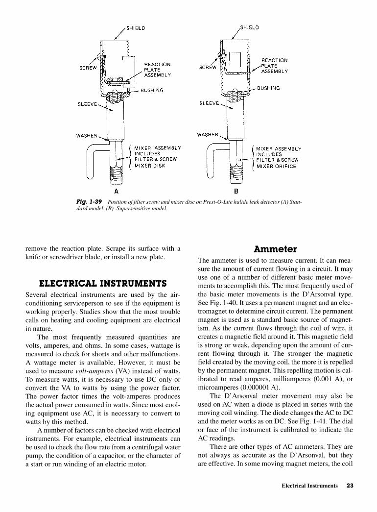
AmmeterThe ammeter is used to measure current. It can mea-sure the amount of current flowing in a circuit. It mayuse one of a number of different basic meter move-ments to accomplish this. The most frequently used ofthe basic meter movements is the D’Arsonval type.See Fig. 1-40. It uses a permanent magnet and an elec-tromagnet to determine circuit current. The permanentmagnet is used as a standard basic source of magnet-ism. As the current flows through the coil of wire, itcreates a magnetic field around it. This magnetic fieldis strong or weak, depending upon the amount of cur-rent flowing through it. The stronger the magneticfield created by the moving coil, the more it is repelledby the permanent magnet. This repelling motion is cal-ibrated to read amperes, milliamperes (0.001 A), ormicroamperes (0.000001 A).
The D’Arsonval meter movement may also beused on AC when a diode is placed in series with themoving coil winding. The diode changes the AC to DCand the meter works as on DC. See Fig. 1-41. The dialor face of the instrument is calibrated to indicate theAC readings.
There are other types of AC ammeters. They arenot always as accurate as the D’Arsonval, but theyare effective. In some moving magnet meters, the coil
remove the reaction plate. Scrape its surface with aknife or screwdriver blade, or install a new plate.
ELECTRICAL INSTRUMENTSSeveral electrical instruments are used by the air-conditioning serviceperson to see if the equipment isworking properly. Studies show that the most troublecalls on heating and cooling equipment are electricalin nature.
The most frequently measured quantities arevolts, amperes, and ohms. In some cases, wattage ismeasured to check for shorts and other malfunctions.A wattage meter is available. However, it must beused to measure volt-amperes (VA) instead of watts.To measure watts, it is necessary to use DC only orconvert the VA to watts by using the power factor.The power factor times the volt-amperes producesthe actual power consumed in watts. Since most cool-ing equipment use AC, it is necessary to convert towatts by this method.
A number of factors can be checked with electricalinstruments. For example, electrical instruments canbe used to check the flow rate from a centrifugal waterpump, the condition of a capacitor, or the character ofa start or run winding of an electric motor.
Electrical Instruments 23
Fig. 1-39 Position of filter screw and mixer disc on Prest-O-Lite halide leak detector (A) Stan-dard model. (B) Supersensitive model.
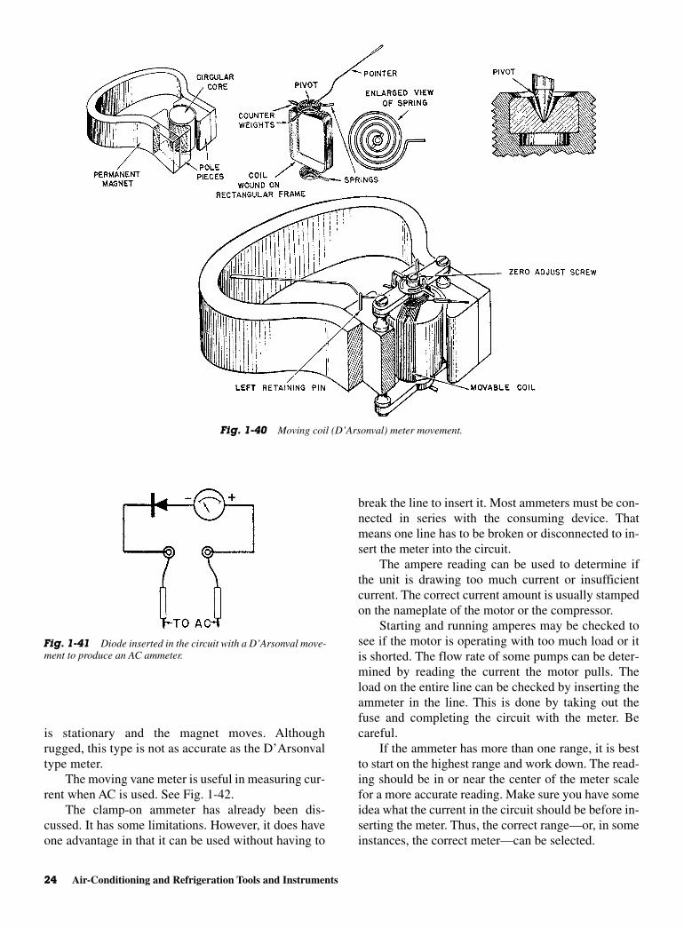
is stationary and the magnet moves. Althoughrugged, this type is not as accurate as the D’Arsonvaltype meter.
The moving vane meter is useful in measuring cur-rent when AC is used. See Fig. 1-42.
The clamp-on ammeter has already been dis-cussed. It has some limitations. However, it does haveone advantage in that it can be used without having to
break the line to insert it. Most ammeters must be con-nected in series with the consuming device. Thatmeans one line has to be broken or disconnected to in-sert the meter into the circuit.
The ampere reading can be used to determine ifthe unit is drawing too much current or insufficientcurrent. The correct current amount is usually stampedon the nameplate of the motor or the compressor.
Starting and running amperes may be checked tosee if the motor is operating with too much load or itis shorted. The flow rate of some pumps can be deter-mined by reading the current the motor pulls. Theload on the entire line can be checked by inserting theammeter in the line. This is done by taking out thefuse and completing the circuit with the meter. Becareful.
If the ammeter has more than one range, it is bestto start on the highest range and work down. The read-ing should be in or near the center of the meter scalefor a more accurate reading. Make sure you have someidea what the current in the circuit should be before in-serting the meter. Thus, the correct range—or, in someinstances, the correct meter—can be selected.
24 Air-Conditioning and Refrigeration Tools and Instruments
Fig. 1-40 Moving coil (D’Arsonval) meter movement.
Fig. 1-41 Diode inserted in the circuit with a D’Arsonval move-ment to produce an AC ammeter.
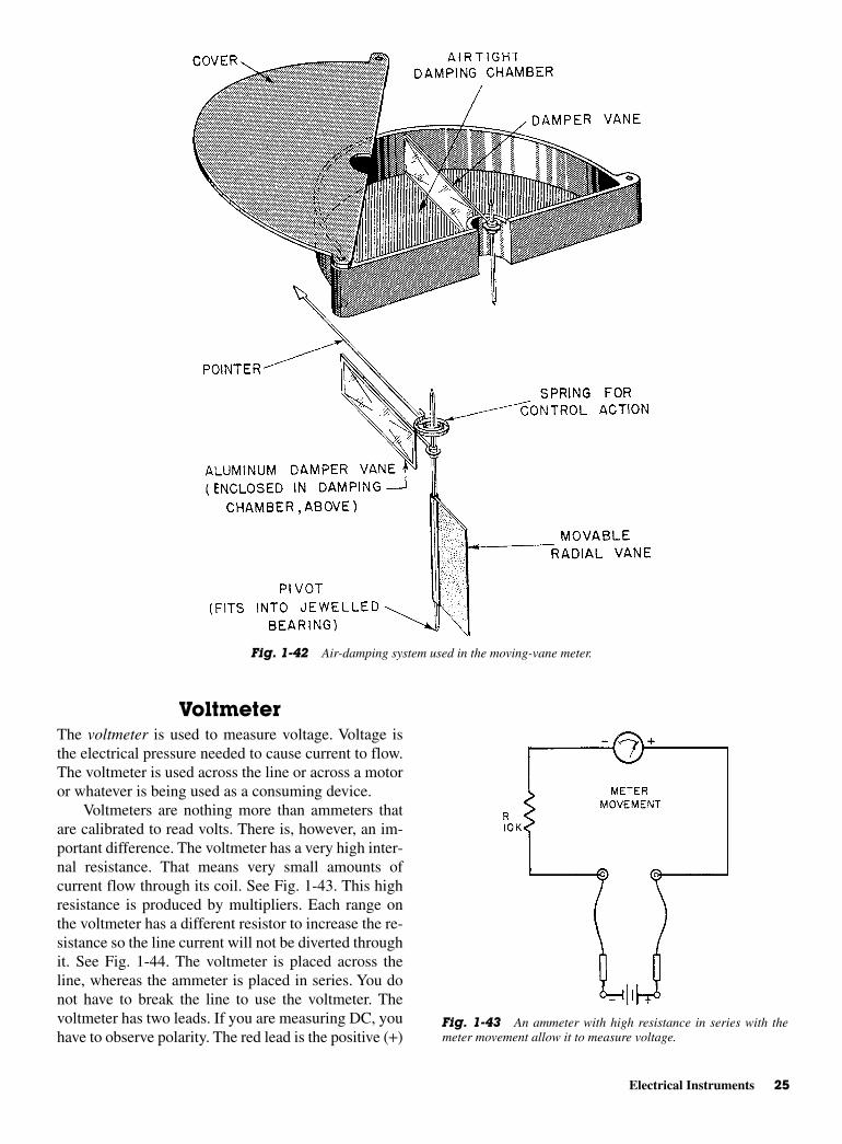
VoltmeterThe voltmeter is used to measure voltage. Voltage isthe electrical pressure needed to cause current to flow.The voltmeter is used across the line or across a motoror whatever is being used as a consuming device.
Voltmeters are nothing more than ammeters thatare calibrated to read volts. There is, however, an im-portant difference. The voltmeter has a very high inter-nal resistance. That means very small amounts ofcurrent flow through its coil. See Fig. 1-43. This highresistance is produced by multipliers. Each range onthe voltmeter has a different resistor to increase the re-sistance so the line current will not be diverted throughit. See Fig. 1-44. The voltmeter is placed across theline, whereas the ammeter is placed in series. You donot have to break the line to use the voltmeter. Thevoltmeter has two leads. If you are measuring DC, youhave to observe polarity. The red lead is the positive (+)
Electrical Instruments 25
Fig. 1-42 Air-damping system used in the moving-vane meter.
Fig. 1-43 An ammeter with high resistance in series with themeter movement allow it to measure voltage.
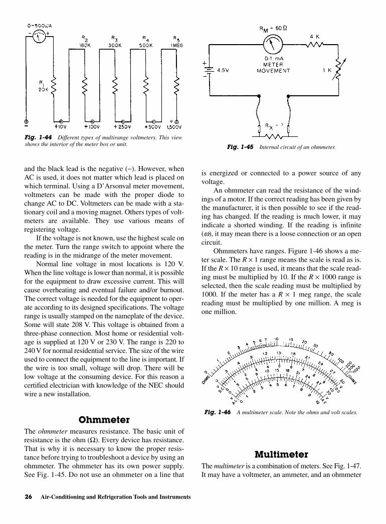
and the black lead is the negative (−). However, whenAC is used, it does not matter which lead is placed onwhich terminal. Using a D’Arsonval meter movement,voltmeters can be made with the proper diode tochange AC to DC. Voltmeters can be made with a sta-tionary coil and a moving magnet. Others types of volt-meters are available. They use various means ofregistering voltage.
If the voltage is not known, use the highest scale onthe meter. Turn the range switch to appoint where thereading is in the midrange of the meter movement.
Normal line voltage in most locations is 120 V.When the line voltage is lower than normal, it is possiblefor the equipment to draw excessive current. This willcause overheating and eventual failure and/or burnout.The correct voltage is needed for the equipment to oper-ate according to its designed specifications. The voltagerange is usually stamped on the nameplate of the device.Some will state 208 V. This voltage is obtained from athree-phase connection. Most home or residential volt-age is supplied at 120 V or 230 V. The range is 220 to240 V for normal residential service. The size of the wireused to connect the equipment to the line is important. Ifthe wire is too small, voltage will drop. There will below voltage at the consuming device. For this reason acertified electrician with knowledge of the NEC shouldwire a new installation.
OhmmeterThe ohmmeter measures resistance. The basic unit ofresistance is the ohm (Ω). Every device has resistance.That is why it is necessary to know the proper resis-tance before trying to troubleshoot a device by using anohmmeter. The ohmmeter has its own power supply.See Fig. 1-45. Do not use an ohmmeter on a line that
is energized or connected to a power source of anyvoltage.
An ohmmeter can read the resistance of the wind-ings of a motor. If the correct reading has been given bythe manufacturer, it is then possible to see if the read-ing has changed. If the reading is much lower, it mayindicate a shorted winding. If the reading is infinite(w), it may mean there is a loose connection or an opencircuit.
Ohmmeters have ranges. Figure 1-46 shows a me-ter scale. The R × 1 range means the scale is read as is.If the R × 10 range is used, it means that the scale read-ing must be multiplied by 10. If the R × 1000 range isselected, then the scale reading must be multiplied by1000. If the meter has a R × 1 meg range, the scalereading must be multiplied by one million. A meg isone million.
MultimeterThe multimeter is a combination of meters. See Fig. 1-47.It may have a voltmeter, an ammeter, and an ohmmeter
26 Air-Conditioning and Refrigeration Tools and Instruments
Fig. 1-44 Different types of multirange voltmeters. This viewshows the interior of the meter box or unit. Fig. 1-45 Internal circuit of an ohmmeter.
Fig. 1-46 A multimeter scale. Note the ohms and volt scales.
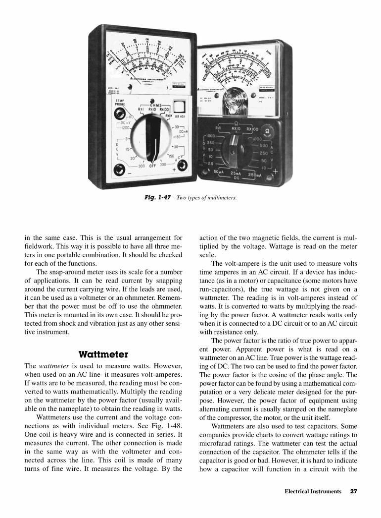
action of the two magnetic fields, the current is mul-tiplied by the voltage. Wattage is read on the meterscale.
The volt-ampere is the unit used to measure voltstime amperes in an AC circuit. If a device has induc-tance (as in a motor) or capacitance (some motors haverun-capacitors), the true wattage is not given on awattmeter. The reading is in volt-amperes instead ofwatts. It is converted to watts by multiplying the read-ing by the power factor. A wattmeter reads watts onlywhen it is connected to a DC circuit or to an AC circuitwith resistance only.
The power factor is the ratio of true power to appar-ent power. Apparent power is what is read on awattmeter on an AC line. True power is the wattage read-ing of DC. The two can be used to find the power factor.The power factor is the cosine of the phase angle. Thepower factor can be found by using a mathematical com-putation or a very delicate meter designed for the pur-pose. However, the power factor of equipment usingalternating current is usually stamped on the nameplateof the compressor, the motor, or the unit itself.
Wattmeters are also used to test capacitors. Somecompanies provide charts to convert wattage ratings tomicrofarad ratings. The wattmeter can test the actualconnection of the capacitor. The ohmmeter tells if thecapacitor is good or bad. However, it is hard to indicatehow a capacitor will function in a circuit with the
in the same case. This is the usual arrangement forfieldwork. This way it is possible to have all three me-ters in one portable combination. It should be checkedfor each of the functions.
The snap-around meter uses its scale for a numberof applications. It can be read current by snappingaround the current carrying wire. If the leads are used,it can be used as a voltmeter or an ohmmeter. Remem-ber that the power must be off to use the ohmmeter.This meter is mounted in its own case. It should be pro-tected from shock and vibration just as any other sensi-tive instrument.
WattmeterThe wattmeter is used to measure watts. However,when used on an AC line it measures volt-amperes.If watts are to be measured, the reading must be con-verted to watts mathematically. Multiply the readingon the wattmeter by the power factor (usually avail-able on the nameplate) to obtain the reading in watts.
Wattmeters use the current and the voltage con-nections as with individual meters. See Fig. 1-48.One coil is heavy wire and is connected in series. Itmeasures the current. The other connection is madein the same way as with the voltmeter and con-nected across the line. This coil is made of manyturns of fine wire. It measures the voltage. By the
Electrical Instruments 27
Fig. 1-47 Two types of multimeters.

voltage applied. This is why testing with the wattmeteris preferred.
OTHER INSTRUMENTSMany types of meters and gages are available to test al-most any quantity or condition. For example:
• Air–filter efficiency gages
• Air-measurement gages
• Humidity-measuring devices
• Moisture analyzers
• British thermal unit (Btu) meters
Vibration and sound meters and recorders are alsoavailable.
Air–Filter Efficiency GagesAir measurements are taken in an air-distribution sys-tem. They often reveal the existence and location of un-intentionally closed or open dampers and obstructions.Leaks in the ductwork and sharp bends are located thisway.
Air measurements frequently show the existence of ablocked filter. Dirty and blocked filters can upset the bal-ance of either a heating or cooling system. This is impor-tant whether it is in the home or in a large building.
Certain indicators and gages can be mounted in airplenums. They can be used to show that the filter hasreached a point where it is restricting the airflow. Anair plenum is a large space above the furnace heating orcooling unit.
Air-Measurement InstrumentsThe volume and velocity of air are important measure-ments in the temperature control industries. Properamounts of air are indispensable to the best functioningof refrigeration cycles, regardless of the size of the sys-tem. Air-conditioning units and systems also rely uponvolume and velocity for proper distribution of condi-tioned air.
Only a small number of contractors are equippedto measure volume and velocity correctly. The compa-nies that are doing the job properly are in great de-mand. Professional handling of air volume andvelocity ensures the efficient use of equipment. Largebuildings are very much in need of the skills of air-balancing teams.
Some people attempt to obtain proper airflow bymeasuring air temperature. They adjust dampers andblowers speeds. However, they usually fail in their at-tempts to balance the airflow properly.
There are instruments available to measure air ve-locity and volume. Such instruments can accurately
28 Air-Conditioning and Refrigeration Tools and Instruments
Fig. 1-48 (A) Wattmeter connection for measuring input power. (B) Alternatewattmeter connection. (C) With load disconnected, uncompensated wattmeter measuresits own power loss.

Thin-film sensors are now available, which use anabsorbent deposited on a silicon substrate such that theresistance or capacitance varies with relative humidity.They are quite accurate in the range of ±3 to 5 percent.They also have low maintenance requirements.
Stationary Psychrometers Stationary psychrome-ters take the same measurements as sling psychrome-ters. They do not move. However, they use a blower orfan to move the air over the thermometer bulbs.
For approximate rh readings, there are metered de-vices. They are used on desks and walls. They are notaccurate enough to be used in engineering work
Humidistats, which are humidity controls, are usedto control humidifiers. They operate the same way asthermometers in closing contacts to complete a circuit.They do not use the same sensing element, however.
Moisture Analyzers It is sometimes necessary toknow the percentage of water in a refrigerant. The wa-ter vapor or moisture is measured in parts per million.The necessary measuring instrument is still used pri-marily in the laboratory. Instruments for measuring hu-midity are not used here.
Btu Meters The Btu is used to indicate the amountof heat present. Meters are especially designed to indi-cate the Btu in a chilled water line, a hot water line, ora natural gas line. Specially designed, they are used byskilled laboratory personnel at present.
Vibration and Sound MetersMore cities are now prohibiting conditioning unitsthat make too much noise. In most cases, vibration isthe main problem. However, it is not an easy task tolocate the source of vibration. However, special me-ters have been designed to aid in the search for vibra-tion noise.
Portable noise meters are available. The dB, ordecibel, is the unit for the measurement of sound. Thereare a couple of bands on the noise meters. The dB-Ascale corresponds roughly to the human hearing range.Other scales are available for special applications.
More emphasis is now being placed on noise levelsin factories, offices, and schools. The OccupationalSafety and Hazards Act (OSHA) lays down strictguidelines regarding noise levels. There are penaltiesfor noncompliance. Thus, it will be necessary for allnew and previously installed units to be checked fornoise.
High-velocity air systems—used in large buildings—are engineered to reduce noise to levels set by theOSHA. For example, there are chambers to lower the
measure the low pressures and differentials involved inair distribution.
Draft gages do measure pressure. However, theirspecific application to air control makes it more appro-priate to discuss them here, rather than under pressuregages. They measure pressure in inches of water. Theycome in several styles. The most familiar is the slantedtype. It may be used either in the field or in the shop.
Meter type draft gages are better for fieldwork.They can be carried easily. They can sample air at var-ious locations, with the meter box in one location.
Besides air pressure, it is frequently necessary tomeasure air volume, which is measured in cubic feetper minute or cfm. Air velocity is measured in feet perminute or fpm. The measure of airflow is still some-what difficult. However, newer instruments are mak-ing accurate measurements possible.
Humidity-MeasurementInstruments
Many hygroscopic (moisture absorbing) materials canbe used as relative-humidity sensors. Such materialsabsorb or lose moisture until a balance is reached withthe surrounding air. A change in material moisturecontent causes a dimensional change, and this changecan be used as an input signal to a controller. Com-monly used materials include:
• Human hair
• Wood
• Biwood combinations similar in action to a bimetal-lic temperature sensor
• Organic films
• Some fabrics, especially certain synthetic fabrics
All these have the drawbacks of slow response andlarge hysteresis effects. Accuracy also tends to bequestionable unless they are frequently calibrated.Field calibration of humidity sensors is difficult.
Humidity is read in rh or relative humidity. To ob-tain the rh, it is necessary to use two thermometers.One thermometer is a dry bulb, the other is a wet bulb.The device used to measure rh is the sling psychrome-ter. It has two glass-stem thermometers. The wet bulbthermometer is moistened by a wick attached to thebulb. As the dual thermometers are whirled, air passesover them. The dry and wet bulb temperatures arerecorded. Relative humidity is determined by:
• Graphs
• Slide rules
• Similar devices
Other Instruments 29
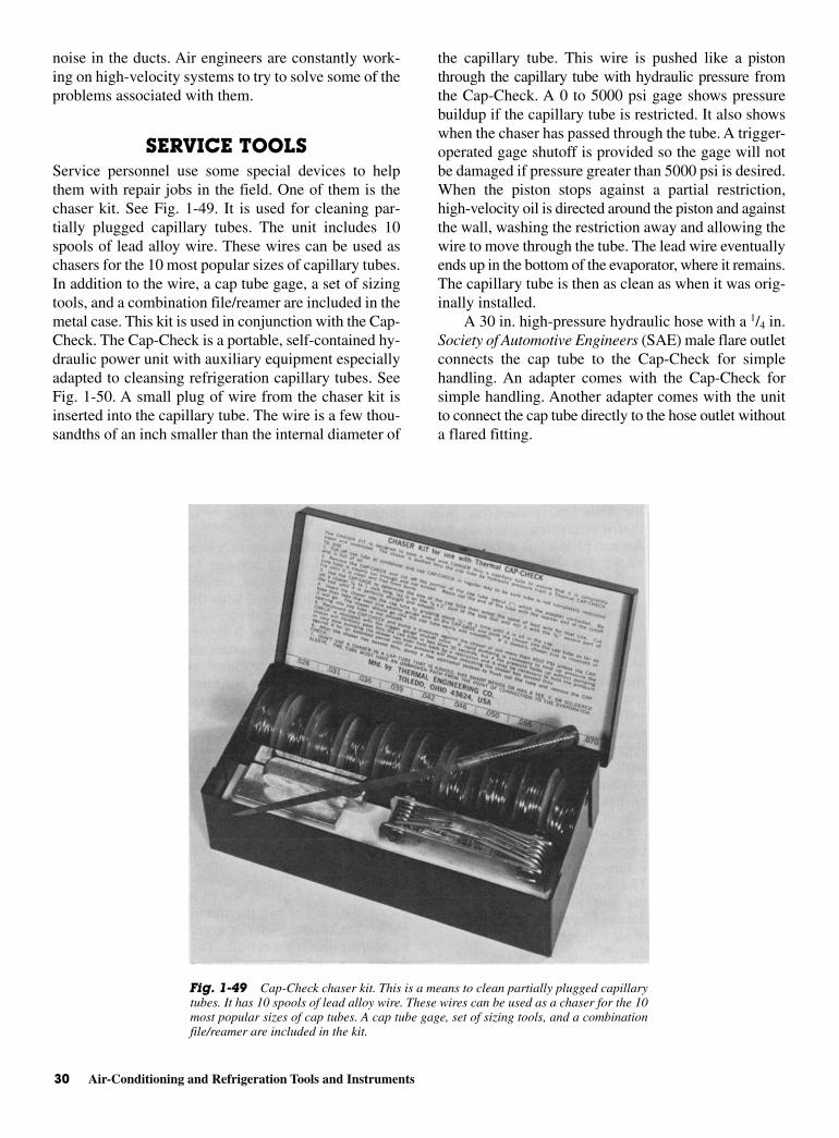
noise in the ducts. Air engineers are constantly work-ing on high-velocity systems to try to solve some of theproblems associated with them.
SERVICE TOOLSService personnel use some special devices to helpthem with repair jobs in the field. One of them is thechaser kit. See Fig. 1-49. It is used for cleaning par-tially plugged capillary tubes. The unit includes 10spools of lead alloy wire. These wires can be used aschasers for the 10 most popular sizes of capillary tubes.In addition to the wire, a cap tube gage, a set of sizingtools, and a combination file/reamer are included in themetal case. This kit is used in conjunction with the Cap-Check. The Cap-Check is a portable, self-contained hy-draulic power unit with auxiliary equipment especiallyadapted to cleansing refrigeration capillary tubes. SeeFig. 1-50. A small plug of wire from the chaser kit isinserted into the capillary tube. The wire is a few thou-sandths of an inch smaller than the internal diameter of
the capillary tube. This wire is pushed like a pistonthrough the capillary tube with hydraulic pressure fromthe Cap-Check. A 0 to 5000 psi gage shows pressurebuildup if the capillary tube is restricted. It also showswhen the chaser has passed through the tube. A trigger-operated gage shutoff is provided so the gage will notbe damaged if pressure greater than 5000 psi is desired.When the piston stops against a partial restriction,high-velocity oil is directed around the piston and againstthe wall, washing the restriction away and allowing thewire to move through the tube. The lead wire eventuallyends up in the bottom of the evaporator, where it remains.The capillary tube is then as clean as when it was orig-inally installed.
A 30 in. high-pressure hydraulic hose with a 1/4 in.Society of Automotive Engineers (SAE) male flare outletconnects the cap tube to the Cap-Check for simplehandling. An adapter comes with the Cap-Check forsimple handling. Another adapter comes with the unitto connect the cap tube directly to the hose outlet withouta flared fitting.
30 Air-Conditioning and Refrigeration Tools and Instruments
Fig. 1-49 Cap-Check chaser kit. This is a means to clean partially plugged capillarytubes. It has 10 spools of lead alloy wire. These wires can be used as a chaser for the 10most popular sizes of cap tubes. A cap tube gage, set of sizing tools, and a combinationfile/reamer are included in the kit.
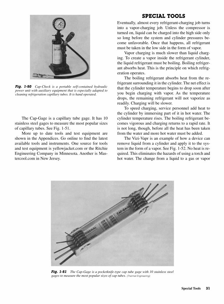
SPECIAL TOOLSEventually, almost every refrigerant-charging job turnsinto a vapor-charging job. Unless the compressor isturned on, liquid can be charged into the high side onlyso long before the system and cylinder pressures be-come unfavorable. Once that happens, all refrigerantmust be taken in the low side in the form of vapor.
Vapor charging is much slower than liquid charg-ing. To create a vapor inside the refrigerant cylinder,the liquid refrigerant must be boiling. Boiling refriger-ant absorbs heat. This is the principle on which refrig-eration operates.
The boiling refrigerant absorbs heat from the re-frigerant surrounding it in the cylinder. The net effect isthat the cylinder temperature begins to drop soon afteryou begin charging with vapor. As the temperaturedrops, the remaining refrigerant will not vaporize asreadily. Charging will be slower.
To speed charging, service personnel add heat tothe cylinder by immersing part of it in hot water. Thecylinder temperature rises. The boiling refrigerant be-comes vigorous and charging returns to a rapid rate. Itis not long, though, before all the heat has been takenfrom the water and more hot water must be added.
The Vizi-Vapr is an example of how a device canremove liquid from a cylinder and apply it to the sys-tem in the form of a vapor. See Fig. 1-52. No heat is re-quired. This eliminates the hazards of using a torch andhot water. The change from a liquid to a gas or vapor
The Cap-Gage is a capillary tube gage. It has 10stainless steel gages to measure the most popular sizesof capillary tubes. See Fig. 1-51.
More up to date tools and test equipment areshown in the Appendices. Go online to find the latestavailable tools and instruments. One source for toolsand test equipment is yellowjacket.com or the RitchieEngineering Company in Minnesota. Another is Mas-tercool.com in New Jersey.
Special Tools 31
Fig. 1-51 The Cap-Gage is a pocketknife-type cap tube gage with 10 stainless steelgages to measure the most popular sizes of cap tubes. (Thermal Engineering)
Fig. 1-50 Cap-Check is a portable self-contained hydraulicpower unit with auxiliary equipment that is especially adapted tocleaning refrigeration capillary tubes. It is hand operated.

takes place in the Vizi-Vapr. It restricts the chargingline between the cylinder and compressor. This restric-tion is much like an expansion valve in that it maintainshigh cylinder pressure behind it to hold the refrigerantas a liquid.
However, it has a large pressure drop across it tostart evaporation. Heat required to vaporize refrigerantis taken from the air surrounding the unit, not from theremaining refrigerant. This produces a dense, saturatedvapor.
The amount of restriction in the unit is very criti-cal. Too much restriction will slow charging consider-ably. It also will allow liquid to go through and causeliquid slugging in the compressor. The restriction set-ting is different for each size system, for differenttypes of refrigerants and even for different ambienttemperatures.
VACUUM PUMPSUse of the vacuum pump may be the single most im-portant development in refrigeration and air-conditioningservicing. The purpose of a vacuum pump is to removethe undesirable materials that create pressure in a re-frigeration system. These include:
• Moisture
• Air (oxygen)
• Hydrochloric acid
In addition, there are other materials that will va-porize at low micron range. These, along with a widevariety of solid materials, are pulled into the vacuumpump in the same way a vacuum cleaner sucks updirt.
Evacuation is being routinely performed onalmost every service call on which recharging isrequired.
NOTE: It is no longer permitted to sim-ply add refrigerant to the system withone end open for evacuation into the at-mosphere. This shortcut was a favoriteof many service technicians over theyears since it was quick and the refrig-erant was inexpensive.
Vacuum levels formerly unheard of for field evac-uations are being accomplished daily by service per-sons who are knowledgeable regarding vacuumequipment. These service persons have found throughexperience that the two-stage pump is much better thanthe single-stage pump for deep evacuations. SeeFigs. 1-53 and 1-54. It was devised as a laboratory in-strument and with minor alterations; it has beenadapted to the refrigeration field. It is the proper toolfor vacuum evacuations in the field. The latest in vac-uum pumps is shown in Appendix 4.
32 Air-Conditioning and Refrigeration Tools and Instruments
Fig. 1-52 The Vizi-Vapr is a device that allows rapid charging of a compressor with-out heating the cylinder of refrigerant. (Thermal Engineering)
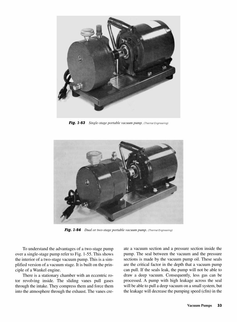
ate a vacuum section and a pressure section inside thepump. The seal between the vacuum and the pressuresections is made by the vacuum pump oil. These sealsare the critical factor in the depth that a vacuum pumpcan pull. If the seals leak, the pump will not be able todraw a deep vacuum. Consequently, less gas can beprocessed. A pump with high leakage across the sealwill be able to pull a deep vacuum on a small system, butthe leakage will decrease the pumping speed (cfm) in the
To understand the advantages of a two-stage pumpover a single-stage pump refer to Fig. 1-55. This showsthe interior of a two-stage vacuum pump. This is a sim-plified version of a vacuum stage. It is built on the prin-ciple of a Wankel engine.
There is a stationary chamber with an eccentric ro-tor revolving inside. The sliding vanes pull gasesthrough the intake. They compress them and force theminto the atmosphere through the exhaust. The vanes cre-
Vacuum Pumps 33
Fig. 1-53 Single-stage portable vacuum pump. (Thermal Engineering)
Fig. 1-54 Dual or two-stage portable vacuum pump. (Thermal Engineering)

deep vacuum region. Long pull-down times will result.There are three oil seals in a single-stage vacuum pump.Each seal must hold against a high pressure on one sideand a deep vacuum on the other side. This places a greatdeal of strain on the oil seal. A two-stage vacuum pumpcuts the pressure strain on the oil seal in half. Such apump uses two chambers instead of one to evacuate asystem. The first chamber is called the deep vacuumchamber. It pulls in the vacuum gases from the deep vac-uum and exhausts them into the second chamber at amoderate vacuum. The second chamber, or stage, bringsin these gases at a moderate vacuum and exhausts theminto the atmosphere. By doing this, the work of a singlechamber is split between two chambers. This, in turn,cuts in half the strain on each oil seal, which reduces theleakage up to 90 percent.
A two-stage vacuum pump is more effective than asingle-stage vacuum pump. For example, a single-stage vacuum pump rated for 1.5 cfm capacity will takeone and one-half hours to evacuate one drop of water.A two-stage vacuum pump with the same rating willevacuate the drop in 12 min.
For evacuation of a 5-ton system saturated withmoisture, a minimum of 15 h evacuation time is re-quired in using a single-stage vacuum pump. A two-stage pump with the same cfm rating could do the jobin as little as 2 h.
Another advantage of the two-stage pump is relia-bility. As you can see, if the oil seal is to be effective,the tolerances in these vacuum pumps must be veryclose between rotor and stator. If the tolerances are notcorrect, the oil seal will not be effective. Slippage oftolerance due to wear is the major cause of vacuumpump failure. With a single-stage pump, when the tol-erance is in the stage slips, the pump loses effective-
ness. With a two-stage pump, if one stage loses toler-ance, the other one will still pull the vacuum of a sin-gle-stage pump.
Larger cfm, two-stage vacuum pumps are pre-ferred to the single-stage vacuum pumps. The cost dif-ference between the two is not great. In addition, thetime saved by using the two-stage pump is evident onthe first evacuation.
Vacuum Pump MaintenanceThe purpose of vacuum pump oil is to lubricate thepump and act as a seal. To perform this function the oilmust have:
• A low vapor pressure that does not materially in-crease up to 125°F (51.7°C)
• A viscosity sufficiently low for use at 60°F (15.6°C)yet constant up to 125°F (51.7°C)
These requirements are easily met by using a lowvapor pressure, paraffin-based oil having a viscosity ofapproximately 300 SSU (shearing stress units) at100°F (37.8°C) and a viscosity index in the range of95 to 100. This type of uninhibited oil is readily ob-tainable. It is the material provided by virtually all sell-ers of vacuum pump oil to the refrigeration trade.
Vacuum Pump Oil ProblemsThe oils used in vacuum pumps are designed to lubricateand seal. Many of the oils available for other jobs are notdesigned to clean as they lubricate. Neither are they de-signed to keep in suspension the solids freed by thecleaning action of the oil. In addition, the oil is not usu-ally heavily inhibited against the action of oxygen.Therefore, the vacuum pump must be run with flushingoil periodically to clean it. Otherwise, its efficiency willbe reduced. The use of flushing oils is recommended bypump manufacturers.
If hydrochloric acid has been pulled into the pump,water, solids, and oil will bond together to form sludgeor slime that may be acidic. The oil also may deterioratedue to oxidation (action on the oil by oxygen in airpulled through the pump). This results in a pump thatwill not pull a proper vacuum, may wear excessively, se-riously corrode, or rust internally.
Operating InstructionsUse vacuum-pump oil in the pump when new. After 5to 10 h of running time, change the oil. Make sure all ofthe original oil is removed from the pump. Thereafter,change the oil after every 30 h of operation when theoil becomes dark due to suspended solids drawn into
34 Air-Conditioning and Refrigeration Tools and Instruments
Fig. 1-55 Two-stage vacuum pump showing seals and intake,exhaust and vacuum section. (Thermal Engineering)
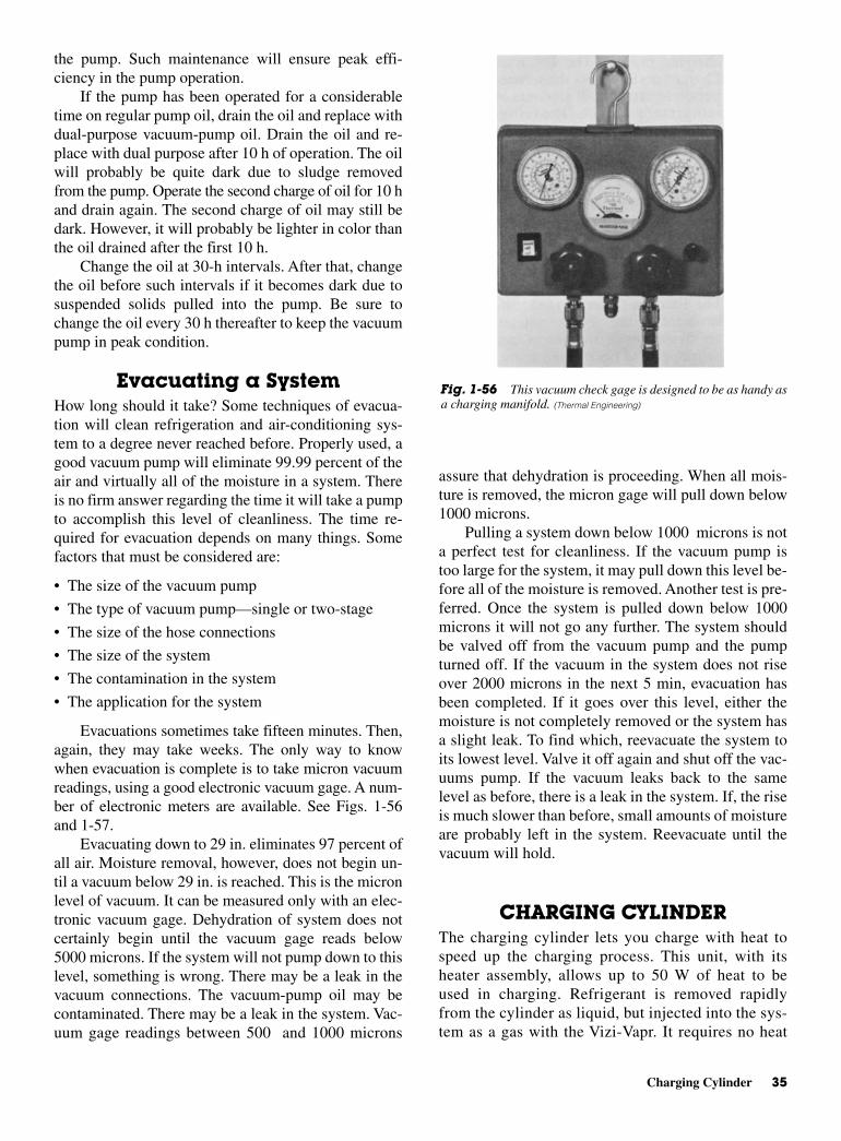
assure that dehydration is proceeding. When all mois-ture is removed, the micron gage will pull down below1000 microns.
Pulling a system down below 1000 microns is nota perfect test for cleanliness. If the vacuum pump istoo large for the system, it may pull down this level be-fore all of the moisture is removed. Another test is pre-ferred. Once the system is pulled down below 1000microns it will not go any further. The system shouldbe valved off from the vacuum pump and the pumpturned off. If the vacuum in the system does not riseover 2000 microns in the next 5 min, evacuation hasbeen completed. If it goes over this level, either themoisture is not completely removed or the system hasa slight leak. To find which, reevacuate the system toits lowest level. Valve it off again and shut off the vac-uums pump. If the vacuum leaks back to the samelevel as before, there is a leak in the system. If, the riseis much slower than before, small amounts of moistureare probably left in the system. Reevacuate until thevacuum will hold.
CHARGING CYLINDERThe charging cylinder lets you charge with heat tospeed up the charging process. This unit, with itsheater assembly, allows up to 50 W of heat to beused in charging. Refrigerant is removed rapidlyfrom the cylinder as liquid, but injected into the sys-tem as a gas with the Vizi-Vapr. It requires no heat
the pump. Such maintenance will ensure peak effi-ciency in the pump operation.
If the pump has been operated for a considerabletime on regular pump oil, drain the oil and replace withdual-purpose vacuum-pump oil. Drain the oil and re-place with dual purpose after 10 h of operation. The oilwill probably be quite dark due to sludge removedfrom the pump. Operate the second charge of oil for 10 hand drain again. The second charge of oil may still bedark. However, it will probably be lighter in color thanthe oil drained after the first 10 h.
Change the oil at 30-h intervals. After that, changethe oil before such intervals if it becomes dark due tosuspended solids pulled into the pump. Be sure tochange the oil every 30 h thereafter to keep the vacuumpump in peak condition.
Evacuating a SystemHow long should it take? Some techniques of evacua-tion will clean refrigeration and air-conditioning sys-tem to a degree never reached before. Properly used, agood vacuum pump will eliminate 99.99 percent of theair and virtually all of the moisture in a system. Thereis no firm answer regarding the time it will take a pumpto accomplish this level of cleanliness. The time re-quired for evacuation depends on many things. Somefactors that must be considered are:
• The size of the vacuum pump
• The type of vacuum pump—single or two-stage
• The size of the hose connections
• The size of the system
• The contamination in the system
• The application for the system
Evacuations sometimes take fifteen minutes. Then,again, they may take weeks. The only way to knowwhen evacuation is complete is to take micron vacuumreadings, using a good electronic vacuum gage. A num-ber of electronic meters are available. See Figs. 1-56and 1-57.
Evacuating down to 29 in. eliminates 97 percent ofall air. Moisture removal, however, does not begin un-til a vacuum below 29 in. is reached. This is the micronlevel of vacuum. It can be measured only with an elec-tronic vacuum gage. Dehydration of system does notcertainly begin until the vacuum gage reads below5000 microns. If the system will not pump down to thislevel, something is wrong. There may be a leak in thevacuum connections. The vacuum-pump oil may becontaminated. There may be a leak in the system. Vac-uum gage readings between 500 and 1000 microns
Charging Cylinder 35
Fig. 1-56 This vacuum check gage is designed to be as handy asa charging manifold. (Thermal Engineering)

during the charging process. The Extracta-Chargedevice allows the serviceperson to carry smallamounts of refrigerant to the job. The refrigerant canbe bought in large drums and stored at the shop. TheExtracta-Charge comes in a rugged, steel carryingcase to protect it from tough use. It provides amethod for draining refrigerant even from capillarytube, sealed systems.
It is now mandatory to capture the escaping refrig-erant. The Extracta-Charge is the instrument to use.When systems are overcharged, the excess can betransported back to the drum. The amount removed canbe measured also. A leak found after the charging op-eration usually means the loss of the full charge. Usingthis device, the serviceperson can extract the chargeand save it for use after the leak has been found andrepaired.
CHARGING OILIn charging a compressor with oil, there is danger ofdrawing air and moisture into the refrigeration system.Use of the pump shown in Fig. 1-58 eliminates thisdanger. This pump reduces charging time by over 70percent without pumping down the compressor. Thepump fits the can with a cap seal, so the pump need not
be removed until the can is empty. It is a piston-typehigh-pressure pump designed to operate at pressuresup to 250 psi. It pumps one quart in 20 full strokes ofthe piston. The pump can be connected to the compres-sor by a refrigerant charging line or copper tubing froma 1/2 in. male flare fitting.
36 Air-Conditioning and Refrigeration Tools and Instruments
Fig. 1-57 An electronic high-vacuum gage that reads directly in microns. (Thermal Engi-
neering)
Fig. 1-58 Oil charging pump. (Thermal Engineering)
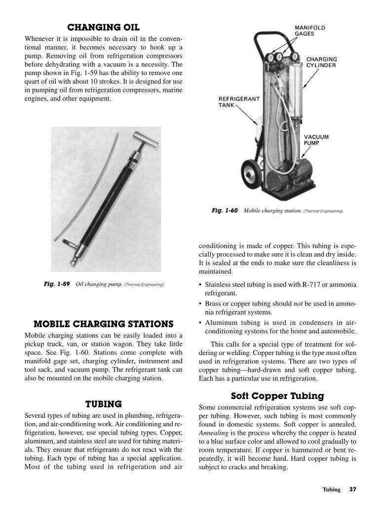
conditioning is made of copper. This tubing is espe-cially processed to make sure it is clean and dry inside.It is sealed at the ends to make sure the cleanliness ismaintained.
• Stainless steel tubing is used with R-717 or ammoniarefrigerant.
• Brass or copper tubing should not be used in ammo-nia refrigerant systems.
• Aluminum tubing is used in condensers in air-conditioning systems for the home and automobile.
This calls for a special type of treatment for sol-dering or welding. Copper tubing is the type most oftenused in refrigeration systems. There are two types ofcopper tubing—hard-drawn and soft copper tubing.Each has a particular use in refrigeration.
Soft Copper TubingSome commercial refrigeration systems use soft cop-per tubing. However, such tubing is most commonlyfound in domestic systems. Soft copper is annealed.Annealing is the process whereby the copper is heatedto a blue surface color and allowed to cool gradually toroom temperature. If copper is hammered or bent re-peatedly, it will become hard. Hard copper tubing issubject to cracks and breaking.
CHANGING OILWhenever it is impossible to drain oil in the conven-tional manner, it becomes necessary to hook up apump. Removing oil from refrigeration compressorsbefore dehydrating with a vacuum is a necessity. Thepump shown in Fig. 1-59 has the ability to remove onequart of oil with about 10 strokes. It is designed for usein pumping oil from refrigeration compressors, marineengines, and other equipment.
MOBILE CHARGING STATIONSMobile charging stations can be easily loaded into apickup truck, van, or station wagon. They take littlespace. See Fig. 1-60. Stations come complete withmanifold gage set, charging cylinder, instrument andtool sack, and vacuum pump. The refrigerant tank canalso be mounted on the mobile charging station.
TUBINGSeveral types of tubing are used in plumbing, refrigera-tion, and air-conditioning work. Air conditioning and re-frigeration, however, use special tubing types. Copper,aluminum, and stainless steel are used for tubing materi-als. They ensure that refrigerants do not react with thetubing. Each type of tubing has a special application.Most of the tubing used in refrigeration and air
Tubing 37
Fig. 1-59 Oil changing pump. (Thermal Engineering)
Fig. 1-60 Mobile charging station. (Thermal Engineering)
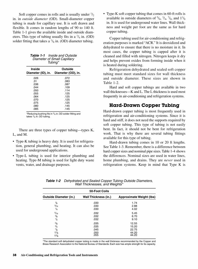
Soft copper comes in rolls and is usually under 1/2
in. in outside diameter (OD). Small-diameter coppertubing is made for capillary use. It is soft drawn andflexible. It comes in random lengths of 90 to 140 ft.Table 1-1 gives the available inside and outside diam-eters. This type of tubing usually fits in a 1/4 in. (OD)solder fitting that takes a 1/8 in. (OD) diameter tubing.
There are three types of copper tubing—types K,L, and M.
• Type-K tubing is heavy duty. It is used for refrigera-tion, general plumbing, and heating. It can also beused for underground applications.
• Type-L tubing is used for interior plumbing andheating. Type-M tubing is used for light duty wastevents, water, and drainage purposes.
• Type-K soft copper tubing that comes in 60-ft rolls isavailable in outside diameters of 5/8, 3/4, 7/8, and 11/8
in. It is used for underground water lines. Wall thick-ness and weight per foot are the same as for hardcopper tubing.
Copper tubing used for air-conditioning and refrig-eration purposes is marked “ACR.” It is deoxidized anddehydrated to ensure that there is no moisture in it. Inmost cases, the copper tubing is capped after it iscleaned and filled with nitrogen. Nitrogen keeps it dryand helps prevent oxides from forming inside when itis heated during soldering.
Refrigeration dehydrated and sealed soft coppertubing must meet standard sizes for wall thicknessand outside diameter. These sizes are shown inTable 1-2.
Hard and soft copper tubings are available in twowall thicknesses—K and L. The L thickness is used mostfrequently in air-conditioning and refrigeration systems.
Hard-Drawn Copper TubingHard-drawn copper tubing is most frequently used inrefrigeration and air-conditioning systems. Since it ishard and stiff, it does not need the supports required bysoft copper tubing. This type of tubing is not easilybent. In fact, it should not be bent for refrigerationwork. That is why there are several tubing fittingsavailable for this type of tubing.
Hard-drawn tubing comes in 10 or 20 ft lengths.See Table 1-3. Remember, there is a difference betweenhard copper sizes and nominal pipe sizes. Table 1-4 showsthe differences. Nominal sizes are used in water lines,home plumbing, and drains. They are never used inrefrigeration systems. Keep in mind that Type K is
38 Air-Conditioning and Refrigeration Tools and Instruments
Table 1-1 Inside and OutsideDiameter of Small Capillary
Tubing*
Inside Outside Diameter (ID), in. Diameter (OD), in.
.026 .072
.31 .083
.036 .087
.044 .109
.050 .114
.055 .125
.064 .125
.070 .125
.075 .125
.080 .145
.085 .145
*Reducing bushing fits in 3/8 in. OD solder fitting andtakes 3/8 in. OD tubing.
Table 1-2 Dehydrated and Sealed Copper Tubing Outside Diameters,Wall Thicknesses, and Weights*
50-Foot Coils
Outside Diameter (in.) Wall Thickness (in.) Approximate Weight (lbs)
1/8 .030 1.743/16 .030 2.881/4 .030 4.025/16 .032 5.453/8 .032 6.701/2 .032 9.105/8 .035 12.553/4 .035 15.207/8 .045 22.7511/8 .050 44.2013/8 .055 44.20
*The standard soft dehydrated copper tubing is made in the wall thickness recommended by the Copper andBrass Research Association to the National Bureau of Standards. Each size has ample strength for its capacity.
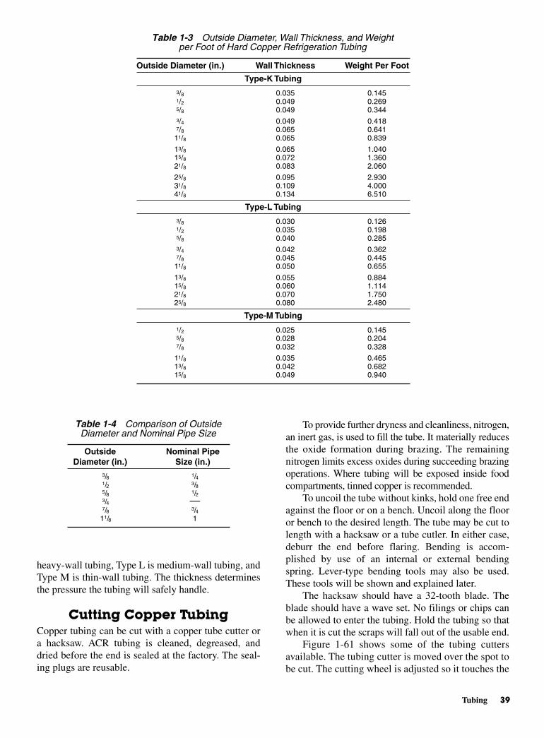
To provide further dryness and cleanliness, nitrogen,an inert gas, is used to fill the tube. It materially reducesthe oxide formation during brazing. The remainingnitrogen limits excess oxides during succeeding brazingoperations. Where tubing will be exposed inside foodcompartments, tinned copper is recommended.
To uncoil the tube without kinks, hold one free endagainst the floor or on a bench. Uncoil along the flooror bench to the desired length. The tube may be cut tolength with a hacksaw or a tube cutler. In either case,deburr the end before flaring. Bending is accom-plished by use of an internal or external bendingspring. Lever-type bending tools may also be used.These tools will be shown and explained later.
The hacksaw should have a 32-tooth blade. Theblade should have a wave set. No filings or chips canbe allowed to enter the tubing. Hold the tubing so thatwhen it is cut the scraps will fall out of the usable end.
Figure 1-61 shows some of the tubing cuttersavailable. The tubing cutter is moved over the spot tobe cut. The cutting wheel is adjusted so it touches the
heavy-wall tubing, Type L is medium-wall tubing, andType M is thin-wall tubing. The thickness determinesthe pressure the tubing will safely handle.
Cutting Copper TubingCopper tubing can be cut with a copper tube cutter ora hacksaw. ACR tubing is cleaned, degreased, anddried before the end is sealed at the factory. The seal-ing plugs are reusable.
Tubing 39
Table 1-3 Outside Diameter, Wall Thickness, and Weightper Foot of Hard Copper Refrigeration Tubing
Outside Diameter (in.) Wall Thickness Weight Per Foot
Type-K Tubing3/8 0.035 0.1451/2 0.049 0.2695/8 0.049 0.3443/4 0.049 0.4187/8 0.065 0.641
11/8 0.065 0.839
13/8 0.065 1.04015/8 0.072 1.36021/8 0.083 2.060
25/8 0.095 2.93031/8 0.109 4.00041/8 0.134 6.510
Type-L Tubing3/8 0.030 0.1261/2 0.035 0.1985/8 0.040 0.2853/4 0.042 0.3627/8 0.045 0.445
11/8 0.050 0.655
13/8 0.055 0.88415/8 0.060 1.11421/8 0.070 1.75025/8 0.080 2.480
Type-M Tubing1/2 0.025 0.1455/8 0.028 0.2047/8 0.032 0.328
11/8 0.035 0.46513/8 0.042 0.68215/8 0.049 0.940
Table 1-4 Comparison of OutsideDiameter and Nominal Pipe Size
Outside Nominal PipeDiameter (in.) Size (in.)
3/8 1/41/2 3/85/8 1/23/4 —7/8 3/4
11/8 1

copper. A slight pressure is applied to the tighteningknob on the cutter to penetrate the copper slightly.Then the knob is rotated around the tubing. Oncearound, it is tightened again to make a deeper cut.Rotate again to make a deeper cut. Do this by degreesso that the tubing is not crushed during the cuttingoperation.
After the tubing is cut through, it will have acrushed end. The crushed end is prepared for flaringby filing and reaming. See Fig. 1-62. A file and the
deburring attachment on the cutting tool can also beused. After the tubing is cut to length, it probably willrequire flaring or soldering.
Flaring Copper TubingA flaring tool is used to spread the end of the cut cop-per tubing outward. Two types of tools are designedfor this operation. See Fig. 1-63. The flaring process isshown in Fig. 1-64. Note that the flaring is done byholding the end of the tubing rigid at a point slightlybelow the protruding part of the tube. This protrudingpart allows for the stretching of the copper.
A flare is important for a strong, solid, leak-proofjoint. The flares shown in Fig. 1-64 are single flares.These are used in most refrigeration systems. Theother type of flare is the double flare. Here the metal isdoubled over to make a stronger joint. They are used incommercial refrigeration and automobile air condi-tioners. Figure 1-65 shows how the double flare ismade. The tool used is called a block-and-punch.
40 Air-Conditioning and Refrigeration Tools and Instruments
Fig. 1-61 Three types of tubing cutters. (Mueller Brass)
Fig. 1-62 The three steps in removing a burr after the tubinghas been cut with a tubing cutter. (A) The end of the cut tubing.(B) Squaring with a file produces a flat end. (C) The tube has beenfiled and reamed. It can now be flared.
Fig. 1-63 Two types of flaring tools for soft copper tubing.
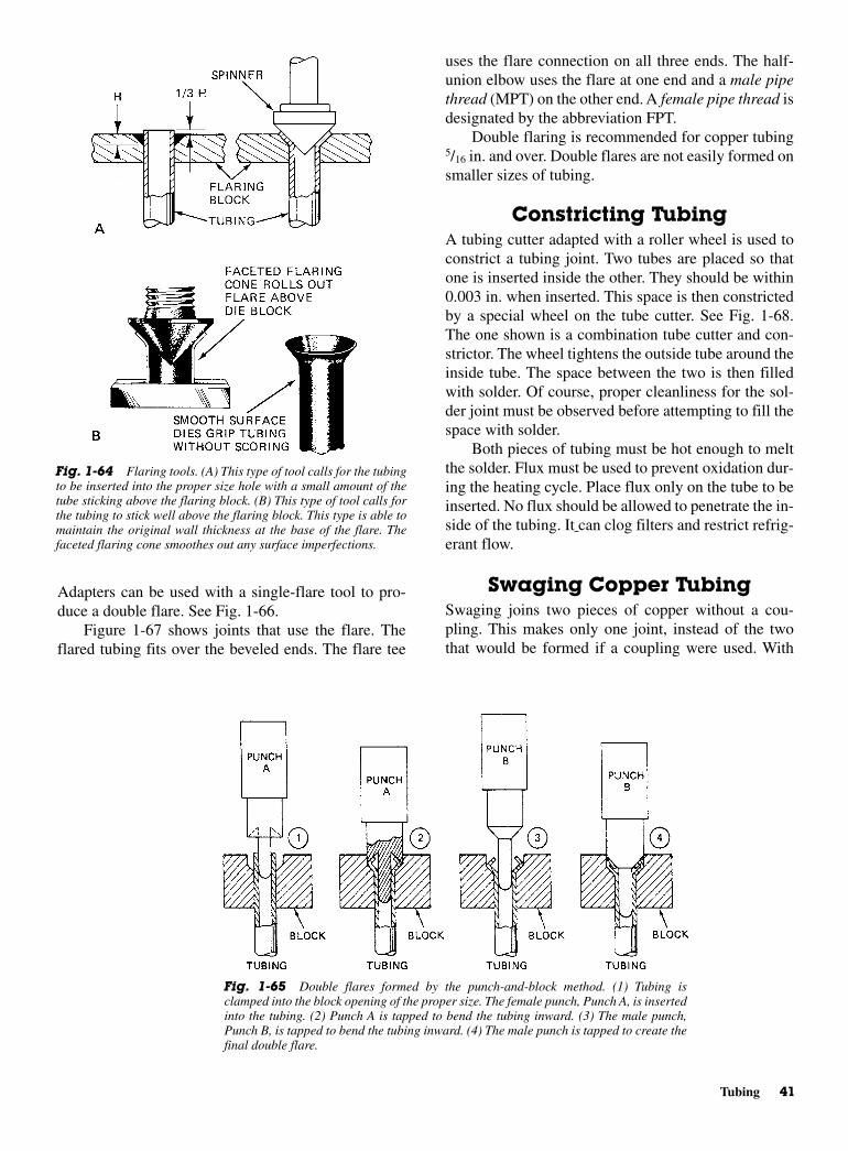
uses the flare connection on all three ends. The half-union elbow uses the flare at one end and a male pipethread (MPT) on the other end. A female pipe thread isdesignated by the abbreviation FPT.
Double flaring is recommended for copper tubing5/16 in. and over. Double flares are not easily formed onsmaller sizes of tubing.
Constricting TubingA tubing cutter adapted with a roller wheel is used toconstrict a tubing joint. Two tubes are placed so thatone is inserted inside the other. They should be within0.003 in. when inserted. This space is then constrictedby a special wheel on the tube cutter. See Fig. 1-68.The one shown is a combination tube cutter and con-strictor. The wheel tightens the outside tube around theinside tube. The space between the two is then filledwith solder. Of course, proper cleanliness for the sol-der joint must be observed before attempting to fill thespace with solder.
Both pieces of tubing must be hot enough to meltthe solder. Flux must be used to prevent oxidation dur-ing the heating cycle. Place flux only on the tube to beinserted. No flux should be allowed to penetrate the in-side of the tubing. It can clog filters and restrict refrig-erant flow.
Swaging Copper TubingSwaging joins two pieces of copper without a cou-pling. This makes only one joint, instead of the twothat would be formed if a coupling were used. With
Adapters can be used with a single-flare tool to pro-duce a double flare. See Fig. 1-66.
Figure 1-67 shows joints that use the flare. Theflared tubing fits over the beveled ends. The flare tee
Tubing 41
Fig. 1-64 Flaring tools. (A) This type of tool calls for the tubingto be inserted into the proper size hole with a small amount of thetube sticking above the flaring block. (B) This type of tool calls forthe tubing to stick well above the flaring block. This type is able tomaintain the original wall thickness at the base of the flare. Thefaceted flaring cone smoothes out any surface imperfections.
Fig. 1-65 Double flares formed by the punch-and-block method. (1) Tubing isclamped into the block opening of the proper size. The female punch, Punch A, is insertedinto the tubing. (2) Punch A is tapped to bend the tubing inward. (3) The male punch,Punch B, is tapped to bend the tubing inward. (4) The male punch is tapped to create thefinal double flare.
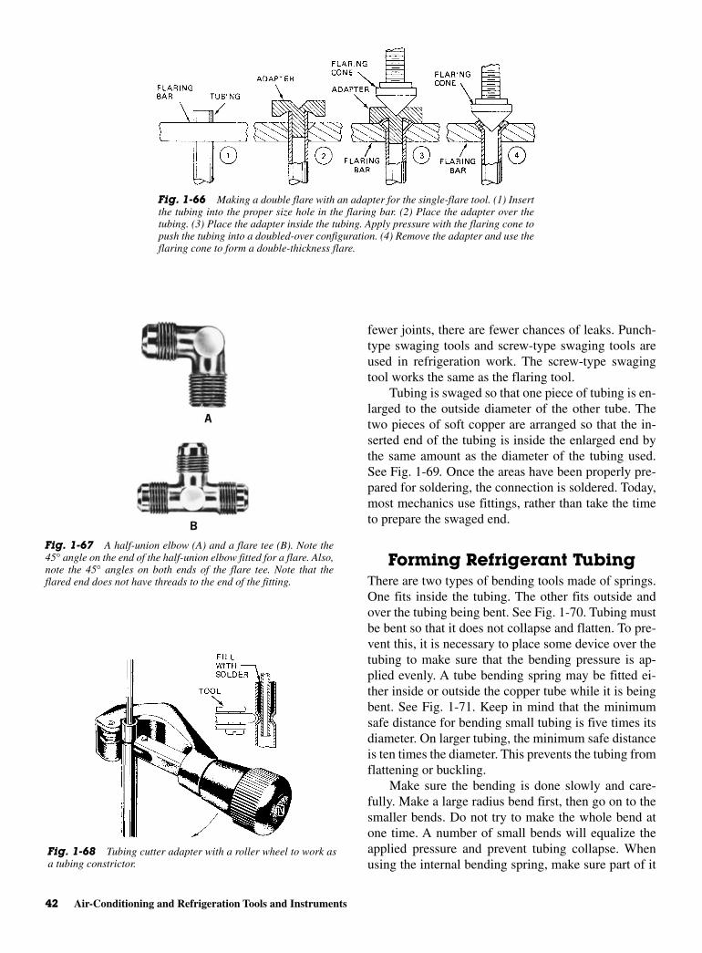
fewer joints, there are fewer chances of leaks. Punch-type swaging tools and screw-type swaging tools areused in refrigeration work. The screw-type swagingtool works the same as the flaring tool.
Tubing is swaged so that one piece of tubing is en-larged to the outside diameter of the other tube. Thetwo pieces of soft copper are arranged so that the in-serted end of the tubing is inside the enlarged end bythe same amount as the diameter of the tubing used.See Fig. 1-69. Once the areas have been properly pre-pared for soldering, the connection is soldered. Today,most mechanics use fittings, rather than take the timeto prepare the swaged end.
Forming Refrigerant TubingThere are two types of bending tools made of springs.One fits inside the tubing. The other fits outside andover the tubing being bent. See Fig. 1-70. Tubing mustbe bent so that it does not collapse and flatten. To pre-vent this, it is necessary to place some device over thetubing to make sure that the bending pressure is ap-plied evenly. A tube bending spring may be fitted ei-ther inside or outside the copper tube while it is beingbent. See Fig. 1-71. Keep in mind that the minimumsafe distance for bending small tubing is five times itsdiameter. On larger tubing, the minimum safe distanceis ten times the diameter. This prevents the tubing fromflattening or buckling.
Make sure the bending is done slowly and care-fully. Make a large radius bend first, then go on to thesmaller bends. Do not try to make the whole bend atone time. A number of small bends will equalize theapplied pressure and prevent tubing collapse. Whenusing the internal bending spring, make sure part of it
42 Air-Conditioning and Refrigeration Tools and Instruments
Fig. 1-66 Making a double flare with an adapter for the single-flare tool. (1) Insertthe tubing into the proper size hole in the flaring bar. (2) Place the adapter over thetubing. (3) Place the adapter inside the tubing. Apply pressure with the flaring cone topush the tubing into a doubled-over configuration. (4) Remove the adapter and use theflaring cone to form a double-thickness flare.
Fig. 1-67 A half-union elbow (A) and a flare tee (B). Note the45° angle on the end of the half-union elbow fitted for a flare. Also,note the 45° angles on both ends of the flare tee. Note that theflared end does not have threads to the end of the fitting.
Fig. 1-68 Tubing cutter adapter with a roller wheel to work asa tubing constrictor.
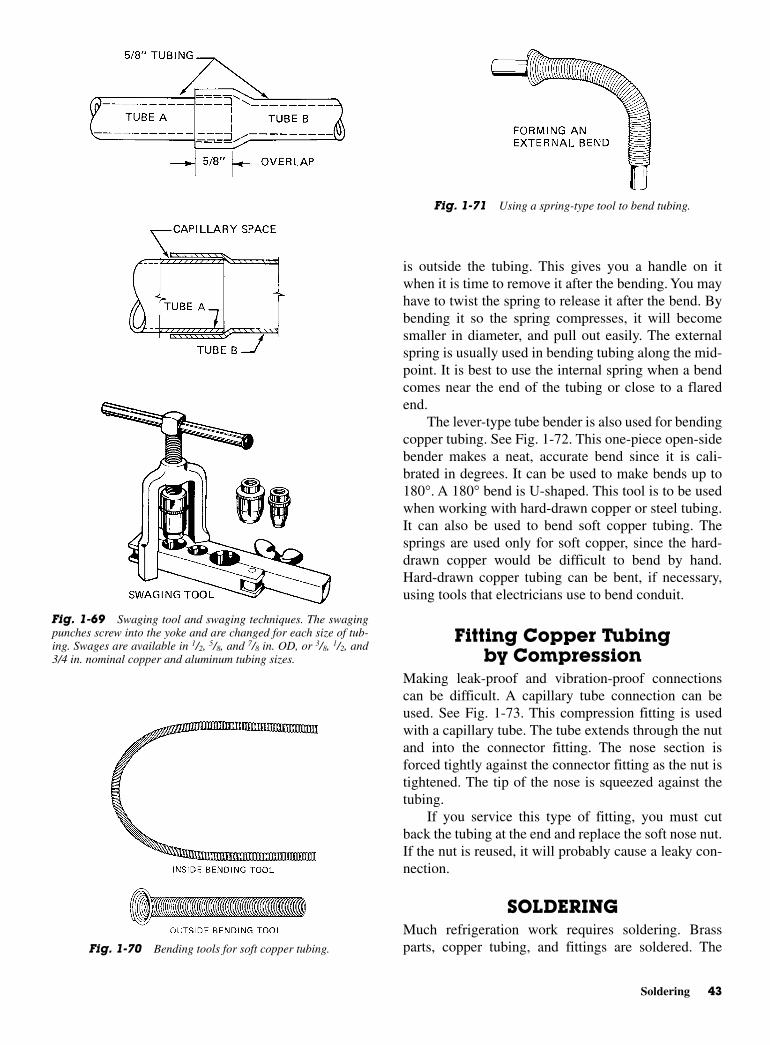
is outside the tubing. This gives you a handle on itwhen it is time to remove it after the bending. You mayhave to twist the spring to release it after the bend. Bybending it so the spring compresses, it will becomesmaller in diameter, and pull out easily. The externalspring is usually used in bending tubing along the mid-point. It is best to use the internal spring when a bendcomes near the end of the tubing or close to a flaredend.
The lever-type tube bender is also used for bendingcopper tubing. See Fig. 1-72. This one-piece open-sidebender makes a neat, accurate bend since it is cali-brated in degrees. It can be used to make bends up to180°. A 180° bend is U-shaped. This tool is to be usedwhen working with hard-drawn copper or steel tubing.It can also be used to bend soft copper tubing. Thesprings are used only for soft copper, since the hard-drawn copper would be difficult to bend by hand.Hard-drawn copper tubing can be bent, if necessary,using tools that electricians use to bend conduit.
Fitting Copper Tubingby Compression
Making leak-proof and vibration-proof connectionscan be difficult. A capillary tube connection can beused. See Fig. 1-73. This compression fitting is usedwith a capillary tube. The tube extends through the nutand into the connector fitting. The nose section isforced tightly against the connector fitting as the nut istightened. The tip of the nose is squeezed against thetubing.
If you service this type of fitting, you must cutback the tubing at the end and replace the soft nose nut.If the nut is reused, it will probably cause a leaky con-nection.
SOLDERINGMuch refrigeration work requires soldering. Brassparts, copper tubing, and fittings are soldered. The
Soldering 43
Fig. 1-69 Swaging tool and swaging techniques. The swagingpunches screw into the yoke and are changed for each size of tub-ing. Swages are available in 1/2, 5/8, and 7/8 in. OD, or 3/8, 1/2, and3/4 in. nominal copper and aluminum tubing sizes.
Fig. 1-70 Bending tools for soft copper tubing.
Fig. 1-71 Using a spring-type tool to bend tubing.
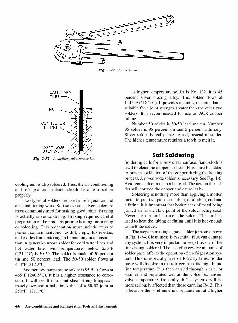
cooling unit is also soldered. Thus, the air-conditioningand refrigeration mechanic should be able to solderproperly.
Two types of solders are used in refrigeration andair-conditioning work. Soft solder and silver solder aremost commonly used for making good joints. Brazingis actually silver soldering. Brazing requires carefulpreparation of the products prior to heating for brazingor soldering. This preparation must include steps toprevent contaminants such as dirt, chips, flux residue,and oxides from entering and remaining in an installa-tion. A general-purpose solder for cold water lines andhot water lines with temperatures below 250°F(121.1°C) is 50-50. The solder is made of 50 percenttin and 50 percent lead. The 50-50 solder flows at414°F (212.2°C).
Another low-temperature solder is 95-5. It flows at465°F (240.5°C). It has a higher resistance to corro-sion. It will result in a joint shear strength approxi-mately two and a half times that of a 50-50 joint at250°F (121.1°C).
A higher temperature solder is No. 122. It is 45percent silver brazing alloy. This solder flows at1145°F (618.2°C). It provides a joining material that issuitable for a joint strength greater than the other twosolders. It is recommended for use on ACR coppertubing.
Number 50 solder is 50-50 lead and tin. Number95 solder is 95 percent tin and 5 percent antimony.Silver solder is really brazing rod, instead of solder.The higher temperature requires a torch to melt it.
Soft SolderingSoldering calls for a very clean surface. Sand-cloth isused to clean the copper surfaces. Flux must be addedto prevent oxidation of the copper during the heatingprocess. A no-corrode solder is necessary. See Fig. 1-6.Acid-core solder must not be used. The acid in the sol-der will corrode the copper and cause leaks.
Soldering is nothing more than applying a moltenmetal to join two pieces of tubing or a tubing end anda fitting. It is important that both pieces of metal beingjoined are at the flow point of the solder being used.Never use the torch to melt the solder. The torch isused to heat the tubing or fitting until it is hot enoughto melt the solder.
The steps in making a good solder joint are shownin Fig. 1-74. Cleanliness is essential. Flux can damageany system. It is very important to keep flux out of thelines being soldered. The use of excessive amounts ofsolder paste affects the operation of a refrigeration sys-tem. This is especially true of R-22 systems. Solderpaste will dissolve in the refrigerant at the high liquidline temperature. It is then carried through a drier orstrainer and separated out at the colder expansionvalve temperature. Generally, R-22 systems will bemore seriously affected than those carrying R-12. Thisis because the solid materials separate out at a higher
44 Air-Conditioning and Refrigeration Tools and Instruments
Fig. 1-72 A tube bender.
Fig. 1-73 A capillary tube connection.
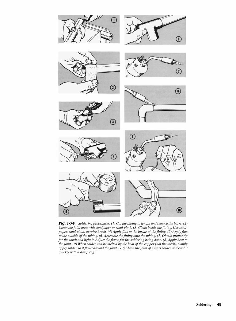
Soldering 45
Fig. 1-74 Soldering procedures. (1) Cut the tubing to length and remove the burrs. (2)Clean the joint area with sandpaper or sand-cloth. (3) Clean inside the fitting. Use sand-paper, sand-cloth, or wire brush. (4) Apply flux to the inside of the fitting. (5) Apply fluxto the outside of the tubing. (6) Assemble the fitting onto the tubing. (7) Obtain proper tipfor the torch and light it. Adjust the flame for the soldering being done. (8) Apply heat tothe joint. (9) When solder can be melted by the heat of the copper (not the torch), simplyapply solder so it flows around the joint. (10) Clean the joint of excess solder and cool itquickly with a damp rag.

temperature. Sound practice would indicate the use ofonly enough solder paste to secure a good joint. Thepaste should be applied according to directions speci-fied by the manufacturer.
Silver Soldering or BrazingSilver solder melts at about 1120°F (604.4°C) andflows at 1145°F (618°C). An acetylene torch is neededfor the high heat. It is used primarily on hard-drawncopper tubing.
CAUTION: Before using silver solder,make sure it does not contain cadmium.Cadmium fumes are very poisonous.Make sure you work in a very well-ventilated room. The fumes should notcontact your skin or eyes. Do not breathethe fumes from the cadmium type ofsilver solder. Most manufacturers will listthe contents on the container.
Silver soldering also calls for a clean joint area.Use the same procedures as shown previously for sol-dering. See Fig. 1-74. Figure 1-75 shows good andpoor design characteristics. No flux should enter thesystem being soldered. Make your plans carefully toprevent any flux entering the tubing being soldered.
Nitrogen or carbon dioxide can be used to fill therefrigeration system during brazing. This will preventany explosion or the creation of phosgene when thejoint has been cleaned with carbon tetrachloride.
In silver soldering, you need a tip that is severalsizes larger than the one used for soft soldering. Thepieces should be heated sufficiently to have the silversolder adhere to them. Never hold the torch in oneplace. Keep it moving. Use a slight feather on the innercone of the flame to make sure you have the properheat. A large soft flame may be used to make sure thetip does not burn through the fitting or the tubing beingsoldered.
It is necessary to disassemble sweat-type valveswhen soldering to the connecting lines. In solderingsweat-type valves where they connect to a line, makesure the torch flame is directed away from the valve.Avoid excessive heat on the valve diaphragm. As anextra precaution, a damp cloth may be wrapped aroundthe diaphragm during the soldering operation. Thesame is true for soldering thermostatic expansionvalves to the distributor.
Either soft or hard solder or silver brazing is ac-ceptable in soldering thermostatic expansion valves.Keep the flame at the fittings and away from the valvebody and distributor tube joints. Do not overheat. Al-ways solder the outside diameter (OD) of the distribu-tor, never the inside diameter (ID).
46 Air-Conditioning and Refrigeration Tools and Instruments
Fig. 1-75 Designs that are useful in silver soldering copper tubing. Here, the clear-ances between the copper tubing are exaggerated for the sake of illustration. They shouldbe much less than shown here. (Handy and Harmon)
only with extreme caution. A measureof its harmful nature is indicated by thefact that it bears a poison label. Itshould never be placed in a containerthat is not labeled “poison.” It is for in-dustrial use only.
While occasional deaths result from swallowingcarbon tetrachloride, the vast majority of deaths arecaused by breathing its vapors. When exposure is verygreat, the symptoms will be headache, dizziness, nausea,vomiting, and abdominal cramping. The person maylose consciousness. While the person seems to recoverfrom breathing too much of the vapor, a day or twolater he or she again becomes ill. Now there is evidenceof severe injury to the liver and kidneys. In many cases,this delayed injury may develop after repeated smallexposures or after a single exposure not sufficient tocause illness at the time of exposure. The delayed ill-ness is much more common and more severe amongthose who drink alcoholic beverages. In some episodeswhere several persons were equally exposed to carbontetrachloride, the only one who became ill or the onewho became most seriously ill was the person whostopped for a drink or two on the way home. Whenoverexposure to carbon tetrachloride results in liverand kidney damage, the patient begins a fight for lifewithout the benefit of an antidote. The only sure pro-tection against such serious illness is not to breathe thevapors or allow contact with the skin.
Human response to carbon tetrachloride is not pre-dictable. A person may occasionally use carbon tetra-chloride in the same job in the same way withoutapparent harm. Then, one day severe illness may result.This unpredictability of response is one factor thatmakes the use of “carbon tet” so dangerous.
Other solvents will do a good job of cleaning anddegreasing. It is much safer to select one of those sol-vents for regular use rather than to expose yourself tothe potential dangers of carbon tetrachloride.
REVIEW QUESTIONS1. What does NEC stand for?
2. What type of solder core is preferred for electricalwork?
3. What type of tips must masonry drill bits have?
4. What is a thermocouple?
5. What is a thermistor?
6. What is superheat?
7. What symbol identifies infinite resistance on anohmmeter?
TESTING FOR LEAKSNever use oxygen to test a joint for leaks. Any oil incontact with oxygen under pressure will form an explo-sive mixture.
Do not use emery cloth to clean a copper joint.Emery cloth contains oil. This may hinder the makingof a good soldering joint. Emery cloth is made of sili-con carbide, which is a very hard substance. Any grainsof this abrasive in the refrigeration mechanism or linescan damage a compressor. Use a brush to help clean thearea after sanding.
CLEANING AND DEGREASINGSOLVENTS
Solvents, including carbon tetrachloride (CCl4), arefrequently used in the refrigeration industry for clean-ing and degreasing equipment. No solvent is absolutelysafe. There are several which may be used with relativesafety. Carbon tetrachloride is not one of them. Use ofone of the safer solvents will reduce the likelihood ofserious illness developing in the course of daily use.Some of these solvents are stabilized methyl chloro-form, methylene chloride, trichlorethylene, and per-chloroethylene. Some petroleum solvents are available.These are flammable in varying degrees.
Most solvents may be used safely if certain rulesare followed.
• Use no more solvent than the job requires. This helpskeep solvent vapor concentrations low in the workarea.
• Use the solvent in a well-ventilated area and avoidbreathing the vapors as much as possible. If the sol-vents are used in shop degreasing, it is wise to have aventilated degreasing unit to keep the level of solventvapors as low as possible.
• Keep the solvents off the skin as much as possible.All solvents are capable of removing the oils andwaxes that keep the skin soft and moist. When theseoils and waxes are removed, the skin becomes irri-tated, dry, and cracked. A skin rash may developmore easily.
CAUTION: While commonly used sol-vent, carbon tetrachloride has manyvirtues as a solvent, it has causedmuch illness among those who use it.Each year several deaths result from itsuse. Usually, these occur in the smallshop or the home. Most large industrieshave discontinued its use. It is used
Review Questions 47
8. What is a draft gage?
9. What is the difference between a sling psychrometerand a stationary psychrometer?
10. Where are humidistats used?
11. What is a British thermal unit (Btu)?
12. What is a capillary tube?
13. Why is vapor charging slower than liquid charging?
14. What is the purpose of a vacuum pump?
15. What is a micron?
16. What type of tubing is needed with R-717 orammonia refrigerant?
17. Name the three types of copper tubing and de-scribe each.
18. What does ACR on a piece of copper tubing signify?
19. How do you shape or form copper tubing withoutcollapsing it?
20. What is swaging?
21. At what temperature does silver solder melt?
48 Air-Conditioning and Refrigeration Tools and Instruments

2CHAPTER
Developmentof
Refrigeration
Copyright © 2006 by The McGraw-Hill Companies, Inc. Click here for terms of use.
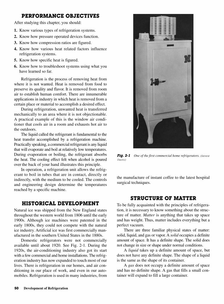
50 Development of Refrigeration
PERFORMANCE OBJECTIVESAfter studying this chapter, you should:
1. Know various types of refrigeration systems.
2. Know how pressure operated devices function.
3. Know how compression ratios are figured.
4. Know how various heat related factors influencerefrigeration systems.
5. Know how specific heat is figured.
6. Know how to troubleshoot systems using what youhave learned so far.
Refrigeration is the process of removing heat fromwhere it is not wanted. Heat is removed from food topreserve its quality and flavor. It is removed from roomair to establish human comfort. There are innumerableapplications in industry in which heat is removed from acertain place or material to accomplish a desired effect.
During refrigeration, unwanted heat is transferredmechanically to an area where it is not objectionable.A practical example of this is the window air condi-tioner that cools air in a room and exhausts hot air tothe outdoors.
The liquid called the refrigerant is fundamental to theheat transfer accomplished by a refrigeration machine.Practically speaking, a commercial refrigerant is any liquidthat will evaporate and boil at relatively low temperatures.During evaporation or boiling, the refrigerant absorbsthe heat. The cooling effect felt when alcohol is pouredover the back of your hand illustrates this principle.
In operation, a refrigeration unit allows the refrig-erant to boil in tubes that are in contact, directly orindirectly, with the medium to be cooled. The controlsand engineering design determine the temperaturesreached by a specific machine.
HISTORICAL DEVELOPMENTNatural ice was shipped from the New England statesthroughout the western world from 1806 until the early1900s. Although ice machines were patented in theearly 1800s, they could not compete with the naturalice industry. Artificial ice was first commercially man-ufactured in the southern United States in the 1880s.
Domestic refrigerators were not commerciallyavailable until about 1920. See Fig. 2-1. During the1920s, the air-conditioning industry also got its startwith a few commercial and home installations. The refrig-eration industry has now expanded to touch most of ourlives. There is refrigeration in our homes, and air con-ditioning in our place of work, and even in our auto-mobiles. Refrigeration is used in many industries, from
the manufacture of instant coffee to the latest hospitalsurgical techniques.
STRUCTURE OF MATTER To be fully acquainted with the principles of refrigera-tion, it is necessary to know something about the struc-ture of matter. Matter is anything that takes up spaceand has weight. Thus, matter includes everything but aperfect vacuum.
There are three familiar physical states of matter:solid, liquid, and gas or vapor. A solid occupies a definiteamount of space. It has a definite shape. The solid doesnot change in size or shape under normal conditions.
A liquid takes up a definite amount of space, butdoes not have any definite shape. The shape of a liquidis the same as the shape of its container.
A gas does not occupy a definite amount of spaceand has no definite shape. A gas that fills a small con-tainer will expand to fill a large container.
Fig. 2-1 One of the first commercial home refrigerators. (General
Electric)
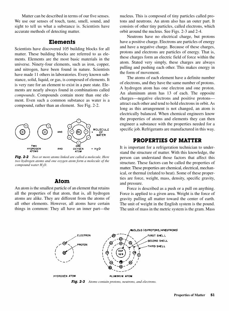
Properties of Matter 51
Matter can be described in terms of our five senses.We use our senses of touch, taste, smell, sound, andsight to tell us what a substance is. Scientists haveaccurate methods of detecting matter.
ElementsScientists have discovered 105 building blocks for allmatter. These building blocks are referred to as ele-ments. Elements are the most basic materials in theuniverse. Ninety-four elements, such as iron, copper,and nitrogen, have been found in nature. Scientistshave made 11 others in laboratories. Every known sub-stance, solid, liquid, or gas, is composed of elements. Itis very rare for an element to exist in a pure state. Ele-ments are nearly always found in combinations calledcompounds. Compounds contain more than one ele-ment. Even such a common substance as water is acompound, rather than an element. See Fig. 2-2.
AtomAn atom is the smallest particle of an element that retainsall the properties of that atom, that is, all hydrogenatoms are alike. They are different from the atoms ofall other elements. However, all atoms have certainthings in common: They all have an inner part—the
nucleus. This is composed of tiny particles called pro-tons and neutrons. An atom also has an outer part. Itconsists of other tiny particles, called electrons, whichorbit around the nucleus. See Figs. 2-3 and 2-4.
Neutrons have no electrical charge, but protonshave a positive charge. Electrons are particles of energyand have a negative charge. Because of these charges,protons and electrons are particles of energy. That is,these charges form an electric field of force within theatom. Stated very simply, these charges are alwayspulling and pushing each other. This makes energy inthe form of movement.
The atoms of each element have a definite numberof electrons, and they have the same number of protons.A hydrogen atom has one electron and one proton.An aluminum atom has 13 of each. The oppositecharges—negative electrons and positive protons—attract each other and tend to hold electrons in orbit. Aslong as this arrangement is not changed, an atom iselectrically balanced. When chemical engineers knowthe properties of atoms and elements they can thenengineer a substance with the properties needed for aspecific job. Refrigerants are manufactured in this way.
PROPERTIES OF MATTERIt is important for a refrigeration technician to under-stand the structure of matter. With this knowledge, theperson can understand those factors that affect thisstructure. These factors can be called the properties ofmatter. These properties are chemical, electrical, mechan-ical, or thermal (related to heat). Some of these proper-ties are force, weight, mass, density, specific gravity,and pressure.
Force is described as a push or a pull on anything.Force is applied to a given area. Weight is the force ofgravity pulling all matter toward the center of earth.The unit of weight in the English system is the pound.The unit of mass in the metric system is the gram. Mass
Fig. 2-2 Two or more atoms linked are called a molecule. Heretwo hydrogen atoms and one oxygen atom form a molecule of thecompound water H2O.
Fig. 2-3 Atoms contain protons, neutrons, and electrons.

The unit of measurement of pressure in the Englishsystem is the pound per square foot or pounds persquare inch (psi). The metric unit of pressure is thekilopascal (kPa). Pressure measuring elements trans-late changes or differences in pressure into motion. Thethree types most commonly used are the diaphragm,the bellows, and the Bourbon spring tube.
Pressure Indicating DevicesPressure indicating devices are most important in therefrigeration field. It is necessary to know the pressuresin certain parts of a system to locate trouble spots.
The diaphragm is a flexible sheet of material heldfirmly around its perimeter so there can be no leakagefrom one side to the other. See Fig. 2-5. Force appliedto one side of the diaphragm will cause it to move orflex. Diaphragms, in some cases, are a made of a flatsheet of material with a limited range of motion. Other
52 Development of Refrigeration
is the amount of matter present in a quantity of anysubstance. Mass is not dependent on location. A bodyhas the same mass whether here on earth, on the moon,or anywhere else. The weight does change at otherlocations. In the metric system, the kilogram (symbol kg)is the unit of mass. In the English system, the slug isthe unit of mass.
Density is the mass per unit of volume. Densitiesare comparative figures, that is, the density of water isused as a base and is set at 1.00. All other substancesare either more or less dense than water.
The densities of gases are determined by a com-parison of volumes. The volume of 1 lb of air is com-pared to the volume of 1 lb of another gas. Both gasesare under standard conditions of temperature andpressure.
The specific gravity of a substance is its densitycompared to the density of water. Specific gravity hasmany uses. It can be used as an indicator of the amountof water in a refrigeration system. Testing methods arediscussed in later chapters.
PRESSUREPressure is a force that acts on an area. Stated in a for-mula, it becomes:
where F = forceA = areaP = pressure
PFA
=
Fig. 2-4 Molecular structure.
Fig. 2-5 Pressure sensing element, diaphragm type.
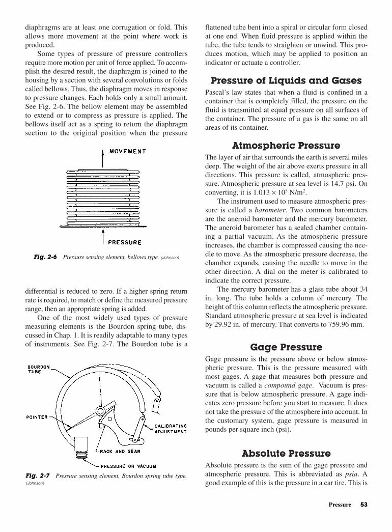
flattened tube bent into a spiral or circular form closedat one end. When fluid pressure is applied within thetube, the tube tends to straighten or unwind. This pro-duces motion, which may be applied to position anindicator or actuate a controller.
Pressure of Liquids and Gases Pascal’s law states that when a fluid is confined in acontainer that is completely filled, the pressure on thefluid is transmitted at equal pressure on all surfaces ofthe container. The pressure of a gas is the same on allareas of its container.
Atmospheric PressureThe layer of air that surrounds the earth is several milesdeep. The weight of the air above exerts pressure in alldirections. This pressure is called, atmospheric pres-sure. Atmospheric pressure at sea level is 14.7 psi. Onconverting, it is 1.013 × 10⁵ N/m2.
The instrument used to measure atmospheric pres-sure is called a barometer. Two common barometersare the aneroid barometer and the mercury barometer.The aneroid barometer has a sealed chamber contain-ing a partial vacuum. As the atmospheric pressureincreases, the chamber is compressed causing the nee-dle to move. As the atmospheric pressure decrease, thechamber expands, causing the needle to move in theother direction. A dial on the meter is calibrated toindicate the correct pressure.
The mercury barometer has a glass tube about 34in. long. The tube holds a column of mercury. Theheight of this column reflects the atmospheric pressure.Standard atmospheric pressure at sea level is indicatedby 29.92 in. of mercury. That converts to 759.96 mm.
Gage PressureGage pressure is the pressure above or below atmos-pheric pressure. This is the pressure measured withmost gages. A gage that measures both pressure andvacuum is called a compound gage. Vacuum is pres-sure that is below atmospheric pressure. A gage indi-cates zero pressure before you start to measure. It doesnot take the pressure of the atmosphere into account. Inthe customary system, gage pressure is measured inpounds per square inch (psi).
Absolute PressureAbsolute pressure is the sum of the gage pressure andatmospheric pressure. This is abbreviated as psia. Agood example of this is the pressure in a car tire. This is
diaphragms are at least one corrugation or fold. Thisallows more movement at the point where work isproduced.
Some types of pressure of pressure controllersrequire more motion per unit of force applied. To accom-plish the desired result, the diaphragm is joined to thehousing by a section with several convolutions or foldscalled bellows. Thus, the diaphragm moves in responseto pressure changes. Each holds only a small amount.See Fig. 2-6. The bellow element may be assembledto extend or to compress as pressure is applied. Thebellows itself act as a spring to return the diaphragmsection to the original position when the pressure
differential is reduced to zero. If a higher spring returnrate is required, to match or define the measured pressurerange, then an appropriate spring is added.
One of the most widely used types of pressuremeasuring elements is the Bourdon spring tube, dis-cussed in Chap. 1. It is readily adaptable to many typesof instruments. See Fig. 2-7. The Bourdon tube is a
Pressure 53
Fig. 2-6 Pressure sensing element, bellows type. (Johnson)
Fig. 2-7 Pressure sensing element, Bourdon spring tube type.(Johnson)

usually 28 psi. That would be 42.7 psia. For example:
The abbreviation for pounds per square inch gageis psig. The abbreviation for pounds per square inchabsolute is psia. Absolute is found by adding 14.7 tothe psig. However, the atmospheric pressure does varywith altitude. In some cases, it is necessary to convertto the atmospheric pressure at the altitude where thepressure is being measured. This small difference canmake a tremendous difference in correct readings ofpsia. To convert psi to kPa (kilopascals), the metric unitof pressure, multiply psi by 6.9.
Compression RatioCompression ratio is defined as the absolute head pres-sure divided by the absolute suction pressure.
Example 1When the gage reading is 0 or above.
Absolute head pressure = gage reading+ 15 lbs (14.7 actually)
Absolute suction pressure = gage reading+ 15 lbs (14.7 actually)
Example 2When the low side reading is in vacuum range.
Absolute head pressure = gage reading+ 15 lbs (14.7 actually)
The calculation of compression ratio can be illus-trated by the following.
Example 1
Head pressure = 160 lbs
Suction pressure = 10 lbs
Compression ratioabsolute head pressure
absolute suction pressure160 1510 15
=
= ++ = =175
257 1:
Absolute suction pressure
30 gage reading in inches2
=−
Compression ratioabsolute head pressure
absolute suction pressure=
psi (gage) 28 psi
Atmospheric pressure 14.7 psi
Absolute pressure 42.7 psi
===
Example 2
Head pressure = 160 lbs
Suction pressure = 10 in. of vacuum
Absolute head pressure = 160 + 15 = 175 lbs
The preceding examples show the influence ofback pressure on the compression ratio. A change inthe head pressure does not produce such a dramaticeffect. If the head pressure in both cases were 185 lb,the compression ratio in Example 1 would be 8:1, andin Example 2 it would be 20:1.
A high compression ratio will make a refrigerationsystem run hot. A system with a very high compressionratio may show a discharge temperature as much as150°F [65.6°C] above normal. The rate of a chemicalreaction approximately doubles with each 18°F (7.8°C)rise in temperature. Thus, a system running an abnor-mally high head temperature will develop more prob-lems than, a properly adjusted system. The relationshipbetween head pressure and back (suction) pressure,wherever possible, should be well within the acceptedindustry bounds of a 10:1 compression ratio.
It is interesting to compare, assuming a 175-lb heatpressure in both cases: Refrigerant 12 (R-12) versusRefrigerant 22 (R-22) operating at −35°F (−37°C) coil.At a −35°F (−37°C) coil, as described, the R-22 systemwould show a 10.9:1 compression ratio while the R-12 sys-tem would be at 17.4:1. The R-22 system is a borderlinecase. The R-12 system is not in the safe range and it wouldrun very hot with all of the accompanying problems.
A number of other factors will produce serioushigh-temperature conditions. However, high compres-sion ratio alone is enough to cause serious trouble. Thethermometer shown in Fig. 2-8 reads temperature as afunction of pressure. This device reads the pressure ofR-22 and R-12. It also indicates the temperature indegrees Fahrenheit on the outside scale.
TEMPERATURE AND HEATThe production of excess heat in a system will causeproblems. Normally, matter expands when heated.This is the principle of thermal expansion. The linear
Compression ratioabsolute head pressure
absolute suction pressure
17510
17.5:1
=
= =
Absolute suction pressure30 10
2202
10= − = =
54 Development of Refrigeration
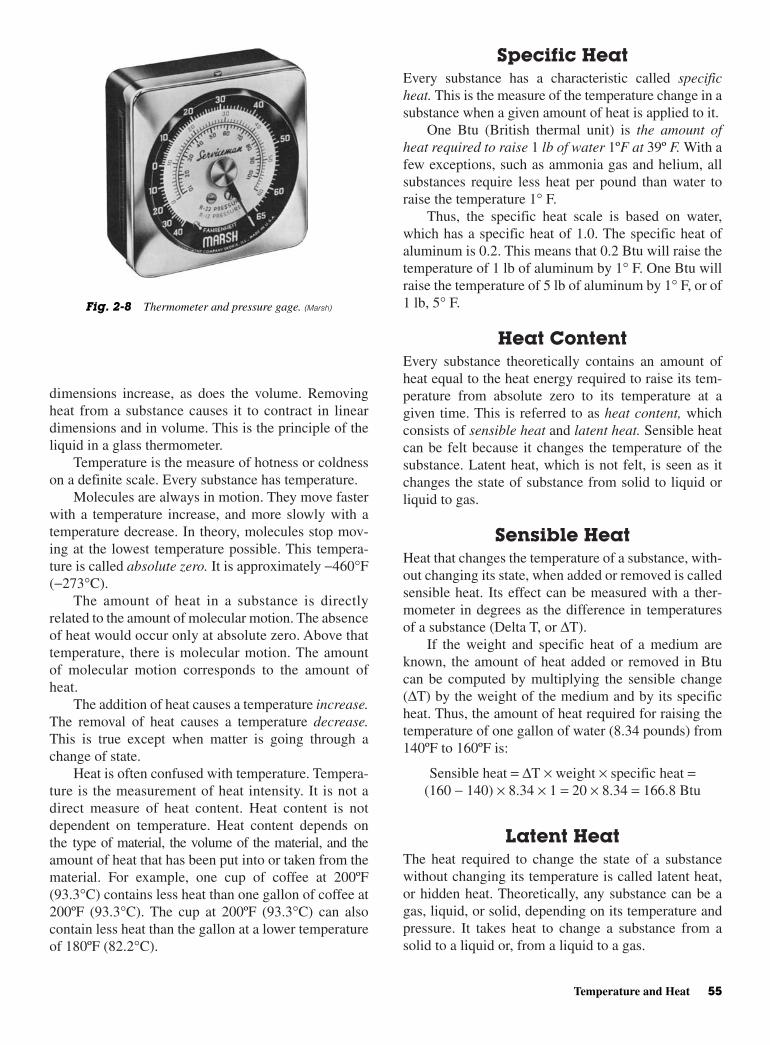
Specific HeatEvery substance has a characteristic called specificheat. This is the measure of the temperature change in asubstance when a given amount of heat is applied to it.
One Btu (British thermal unit) is the amount ofheat required to raise 1 lb of water 1ºF at 39º F. With afew exceptions, such as ammonia gas and helium, allsubstances require less heat per pound than water toraise the temperature 1° F.
Thus, the specific heat scale is based on water,which has a specific heat of 1.0. The specific heat ofaluminum is 0.2. This means that 0.2 Btu will raise thetemperature of 1 lb of aluminum by 1° F. One Btu willraise the temperature of 5 lb of aluminum by 1° F, or of1 lb, 5° F.
Heat ContentEvery substance theoretically contains an amount ofheat equal to the heat energy required to raise its tem-perature from absolute zero to its temperature at agiven time. This is referred to as heat content, whichconsists of sensible heat and latent heat. Sensible heatcan be felt because it changes the temperature of thesubstance. Latent heat, which is not felt, is seen as itchanges the state of substance from solid to liquid orliquid to gas.
Sensible HeatHeat that changes the temperature of a substance, with-out changing its state, when added or removed is calledsensible heat. Its effect can be measured with a ther-mometer in degrees as the difference in temperaturesof a substance (Delta T, or ∆T).
If the weight and specific heat of a medium areknown, the amount of heat added or removed in Btucan be computed by multiplying the sensible change(∆T) by the weight of the medium and by its specificheat. Thus, the amount of heat required for raising thetemperature of one gallon of water (8.34 pounds) from140ºF to 160ºF is:
Sensible heat = ∆T × weight × specific heat =(160 − 140) × 8.34 × 1 = 20 × 8.34 = 166.8 Btu
Latent HeatThe heat required to change the state of a substancewithout changing its temperature is called latent heat,or hidden heat. Theoretically, any substance can be agas, liquid, or solid, depending on its temperature andpressure. It takes heat to change a substance from asolid to a liquid or, from a liquid to a gas.
dimensions increase, as does the volume. Removingheat from a substance causes it to contract in lineardimensions and in volume. This is the principle of theliquid in a glass thermometer.
Temperature is the measure of hotness or coldnesson a definite scale. Every substance has temperature.
Molecules are always in motion. They move fasterwith a temperature increase, and more slowly with atemperature decrease. In theory, molecules stop mov-ing at the lowest temperature possible. This tempera-ture is called absolute zero. It is approximately −460°F(−273°C).
The amount of heat in a substance is directlyrelated to the amount of molecular motion. The absenceof heat would occur only at absolute zero. Above thattemperature, there is molecular motion. The amountof molecular motion corresponds to the amount ofheat.
The addition of heat causes a temperature increase.The removal of heat causes a temperature decrease.This is true except when matter is going through achange of state.
Heat is often confused with temperature. Tempera-ture is the measurement of heat intensity. It is not adirect measure of heat content. Heat content is notdependent on temperature. Heat content depends onthe type of material, the volume of the material, and theamount of heat that has been put into or taken from thematerial. For example, one cup of coffee at 200ºF(93.3°C) contains less heat than one gallon of coffee at200ºF (93.3°C). The cup at 200ºF (93.3°C) can alsocontain less heat than the gallon at a lower temperatureof 180ºF (82.2°C).
Temperature and Heat 55
Fig. 2-8 Thermometer and pressure gage. (Marsh)
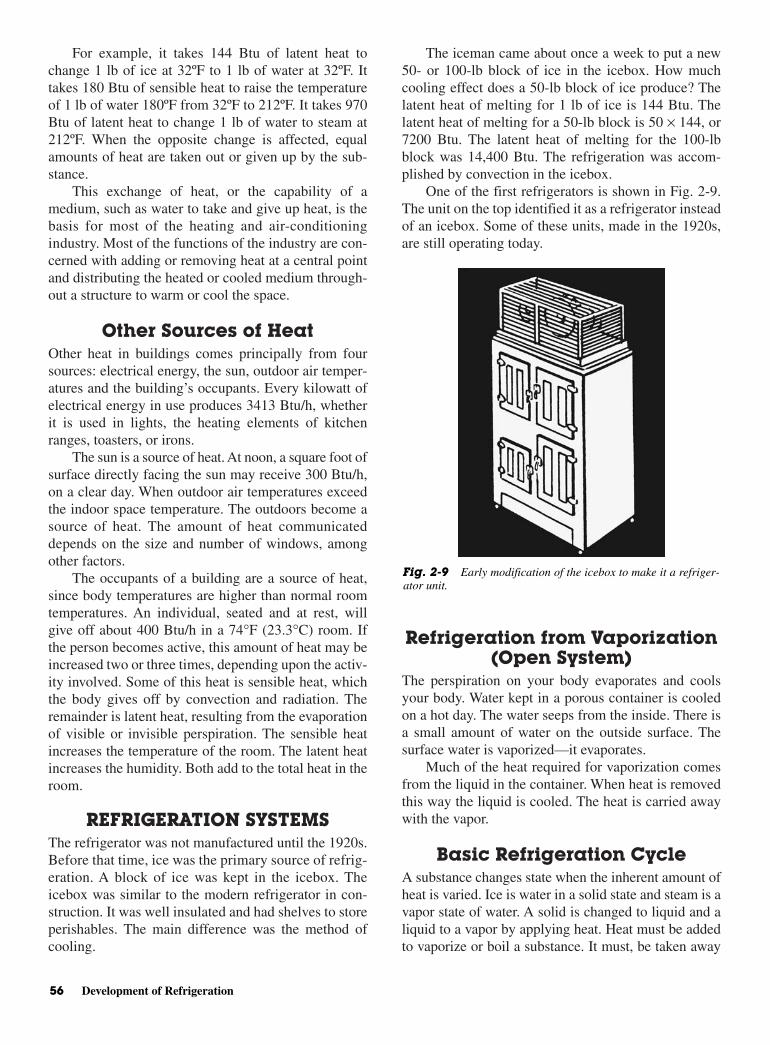
For example, it takes 144 Btu of latent heat tochange 1 lb of ice at 32ºF to 1 lb of water at 32ºF. Ittakes 180 Btu of sensible heat to raise the temperatureof 1 lb of water 180ºF from 32ºF to 212ºF. It takes 970Btu of latent heat to change 1 lb of water to steam at212ºF. When the opposite change is affected, equalamounts of heat are taken out or given up by the sub-stance.
This exchange of heat, or the capability of amedium, such as water to take and give up heat, is thebasis for most of the heating and air-conditioningindustry. Most of the functions of the industry are con-cerned with adding or removing heat at a central pointand distributing the heated or cooled medium through-out a structure to warm or cool the space.
Other Sources of HeatOther heat in buildings comes principally from foursources: electrical energy, the sun, outdoor air temper-atures and the building’s occupants. Every kilowatt ofelectrical energy in use produces 3413 Btu/h, whetherit is used in lights, the heating elements of kitchenranges, toasters, or irons.
The sun is a source of heat. At noon, a square foot ofsurface directly facing the sun may receive 300 Btu/h,on a clear day. When outdoor air temperatures exceedthe indoor space temperature. The outdoors become asource of heat. The amount of heat communicateddepends on the size and number of windows, amongother factors.
The occupants of a building are a source of heat,since body temperatures are higher than normal roomtemperatures. An individual, seated and at rest, willgive off about 400 Btu/h in a 74°F (23.3°C) room. Ifthe person becomes active, this amount of heat may beincreased two or three times, depending upon the activ-ity involved. Some of this heat is sensible heat, whichthe body gives off by convection and radiation. Theremainder is latent heat, resulting from the evaporationof visible or invisible perspiration. The sensible heatincreases the temperature of the room. The latent heatincreases the humidity. Both add to the total heat in theroom.
REFRIGERATION SYSTEMSThe refrigerator was not manufactured until the 1920s.Before that time, ice was the primary source of refrig-eration. A block of ice was kept in the icebox. Theicebox was similar to the modern refrigerator in con-struction. It was well insulated and had shelves to storeperishables. The main difference was the method ofcooling.
The iceman came about once a week to put a new50- or 100-lb block of ice in the icebox. How muchcooling effect does a 50-lb block of ice produce? Thelatent heat of melting for 1 lb of ice is 144 Btu. Thelatent heat of melting for a 50-lb block is 50 × 144, or7200 Btu. The latent heat of melting for the 100-lbblock was 14,400 Btu. The refrigeration was accom-plished by convection in the icebox.
One of the first refrigerators is shown in Fig. 2-9.The unit on the top identified it as a refrigerator insteadof an icebox. Some of these units, made in the 1920s,are still operating today.
Refrigeration from Vaporization(Open System)
The perspiration on your body evaporates and coolsyour body. Water kept in a porous container is cooledon a hot day. The water seeps from the inside. There isa small amount of water on the outside surface. Thesurface water is vaporized—it evaporates.
Much of the heat required for vaporization comesfrom the liquid in the container. When heat is removedthis way the liquid is cooled. The heat is carried awaywith the vapor.
Basic Refrigeration CycleA substance changes state when the inherent amount ofheat is varied. Ice is water in a solid state and steam is avapor state of water. A solid is changed to liquid and aliquid to a vapor by applying heat. Heat must be addedto vaporize or boil a substance. It must, be taken away
56 Development of Refrigeration
Fig. 2-9 Early modification of the icebox to make it a refriger-ator unit.
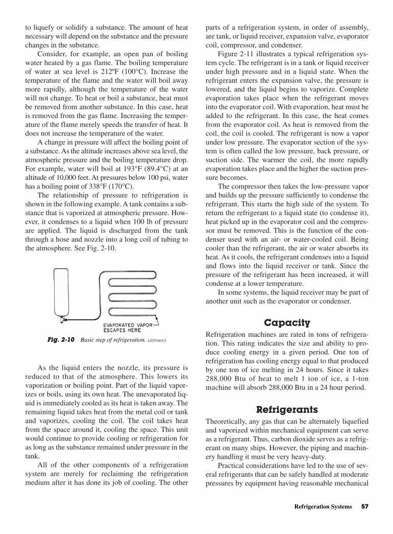
parts of a refrigeration system, in order of assembly,are tank, or liquid receiver, expansion valve, evaporatorcoil, compressor, and condenser.
Figure 2-11 illustrates a typical refrigeration sys-tem cycle. The refrigerant is in a tank or liquid receiverunder high pressure and in a liquid state. When therefrigerant enters the expansion valve, the pressure islowered, and the liquid begins to vaporize. Completeevaporation takes place when the refrigerant movesinto the evaporator coil. With evaporation, heat must beadded to the refrigerant. In this case, the heat comesfrom the evaporator coil. As heat is removed from thecoil, the coil is cooled. The refrigerant is now a vaporunder low pressure. The evaporator section of the sys-tem is often called the low pressure, back pressure, orsuction side. The warmer the coil, the more rapidlyevaporation takes place and the higher the suction pres-sure becomes.
The compressor then takes the low-pressure vaporand builds up the pressure sufficiently to condense therefrigerant. This starts the high side of the system. Toreturn the refrigerant to a liquid state (to condense it),heat picked up in the evaporator coil and the compres-sor must be removed. This is the function of the con-denser used with an air- or water-cooled coil. Beingcooler than the refrigerant, the air or water absorbs itsheat. As it cools, the refrigerant condenses into a liquidand flows into the liquid receiver or tank. Since thepressure of the refrigerant has been increased, it willcondense at a lower temperature.
In some systems, the liquid receiver may be part ofanother unit such as the evaporator or condenser.
CapacityRefrigeration machines are rated in tons of refrigera-tion. This rating indicates the size and ability to pro-duce cooling energy in a given period. One ton ofrefrigeration has cooling energy equal to that producedby one ton of ice melting in 24 hours. Since it takes288,000 Btu of heat to melt 1 ton of ice, a 1-tonmachine will absorb 288,000 Btu in a 24 hour period.
RefrigerantsTheoretically, any gas that can be alternately liquefiedand vaporized within mechanical equipment can serveas a refrigerant. Thus, carbon dioxide serves as a refrig-erant on many ships. However, the piping and machin-ery handling it must be very heavy-duty.
Practical considerations have led to the use of sev-eral refrigerants that can be safely handled at moderatepressures by equipment having reasonable mechanical
to liquefy or solidify a substance. The amount of heatnecessary will depend on the substance and the pressurechanges in the substance.
Consider, for example, an open pan of boilingwater heated by a gas flame. The boiling temperatureof water at sea level is 212ºF (100°C). Increase thetemperature of the flame and the water will boil awaymore rapidly, although the temperature of the waterwill not change. To heat or boil a substance, heat mustbe removed from another substance. In this case, heatis removed from the gas flame. Increasing the temper-ature of the flame merely speeds the transfer of heat. Itdoes not increase the temperature of the water.
A change in pressure will affect the boiling point ofa substance. As the altitude increases above sea level, theatmospheric pressure and the boiling temperature drop.For example, water will boil at 193°F (89.4°C) at analtitude of 10,000 feet. At pressures below 100 psi, waterhas a boiling point of 338°F (170°C).
The relationship of pressure to refrigeration isshown in the following example. A tank contains a sub-stance that is vaporized at atmospheric pressure. How-ever, it condenses to a liquid when 100 lb of pressureare applied. The liquid is discharged from the tankthrough a hose and nozzle into a long coil of tubing tothe atmosphere. See Fig. 2-10.
As the liquid enters the nozzle, its pressure isreduced to that of the atmosphere. This lowers itsvaporization or boiling point. Part of the liquid vapor-izes or boils, using its own heat. The unevaporated liq-uid is immediately cooled as its heat is taken away. Theremaining liquid takes heat from the metal coil or tankand vaporizes, cooling the coil. The coil takes heatfrom the space around it, cooling the space. This unitwould continue to provide cooling or refrigeration foras long as the substance remained under pressure in thetank.
All of the other components of a refrigerationsystem are merely for reclaiming the refrigerationmedium after it has done its job of cooling. The other
Refrigeration Systems 57
Fig. 2-10 Basic step of refrigeration. (Johnson)

strength and with lines of normal size and wall thick-ness. While no substance possesses all the properties ofan ideal refrigerant, the hydrocarbon (Freon) refriger-ants come quite close.
Refrigerant 12 is made of carbon (C), chlorine(Cl), and fluorine (F). Its formula is CC12F2. It is madeof a combination of elements. Refrigerant 22 is madeof carbon (C), hydrogen (H), chlorine (Cl), and fluo-rine (F). Its formula CHClF2 is slightly different fromthat of R-12.
Each of these manufactured refrigerants has itsown characteristics, such as odor and boiling pressure.
Refrigerants are the vital working fluids in refrig-eration systems. They transfer heat from one place toanother for cooling air or water in air-conditioninginstallations.
Many substances can be used as refrigerants,including water under certain conditions. The follow-ing are some common refrigerants:
• Ammonia. The oldest commonly used refrigerant,still used in some systems. It is very toxic.
• Sulphur dioxide. First to replace ammonia and to beused in small domestic machines. It is very toxic.
• Refrigerant 12 . The first synthetic refrigerant to beused commonly. Used in a large number of recipro-cating machines operating in the air-conditioningrange. It is nontoxic.
• Refrigerant 22. Used in many of the same applica-tions as R-12. Its lower boiling point and higher la-tent heat permit the use of smaller compressors andrefrigerant lines. It is nontoxic.
• Refrigerant 40. Methylchloride is used in thecommercial refrigeration field, particularly in small
installations. Today it is no longer used. It will explodewhen allowed to combine with air. It is nontoxic.
Refrigerant Replacements andthe Atmosphere
Refrigerants such as ammonia are used for low-temperature systems. These include food and processcooling, ice rinks, and so forth. Propane has been usedfor some special applications. Now that chlorinatedhydrocarbons have been determined to be harmful tothe earth’s ozone layer, R-11 (CCl3F), R-12 (CCl2F2),and other similar compounds that were in common usealong with the less harmful refrigerant R-22 (CHClF2)have had much attention in the press. Recent interna-tional protocols (standards) have set schedules for theelimination of damaging refrigerants from commercialuse. Replacements have been, and are being, devel-oped. Part of the challenge is technical and part is eco-nomic. First, to find a fluid that has optimal characteristicsand is safe is a challenge. Second, to encourage manu-facture in sufficient quantities to produce and distributethe fluid at an affordable price is another. R-123(CHCl2CF3) has been developed as a near-equivalentreplacement for R-11, with R-134a (CH2FCF3) replac-ing R-12. R-123 still comes under criticism for havingsome chlorine in it. R-134a can be bought at auto sup-plies stores for automobile air conditioners. Most newcars are required to have R-134a in their A/C systems.
R-22 is used widely in residential and commercial air-conditioning scroll compressor systems. It too will bephased out someday (probably during the period2020–2030). However, finding a suitable, widely acceptedreplacement has not come as quickly as first thought.
58 Development of Refrigeration
Low pressure High pressure
Liquidreceiver
Condenser
Evaporator
Fig. 2-11 High and low sides of a refrigeration system.
9. What is absolute zero?
10. What is specific heat?
11. What is sensible heat?
12. What is latent heat?
13. How much heat is produced by a kilowatt-hour ofelectrical energy?
14. What amount of heat is needed to melt 1 ton of icein 24 hours?
15. What is absolute pressure?
REVIEW QUESTIONS1. Define refrigeration.
2. Define refrigerant.
3. What is a compound?
4. What is an atom?
5. What is a Bourdon spring?
6. What is the difference between an aneroid barom-eter and a mercury barometer?
7. Describe gage pressure.
8. Describe Pascal’s law.
Review Questions 59

This page intentionally left blank

3CHAPTER
Voltage, Current, and Resistance
Copyright © 2006 by The McGraw-Hill Companies, Inc. Click here for terms of use.
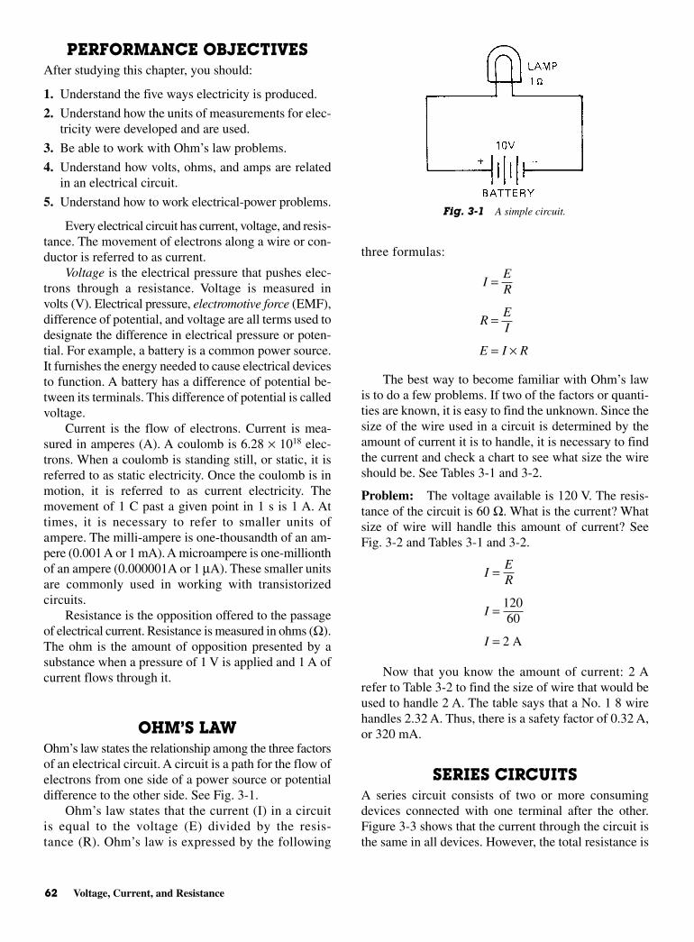
PERFORMANCE OBJECTIVESAfter studying this chapter, you should:
1. Understand the five ways electricity is produced.
2. Understand how the units of measurements for elec-tricity were developed and are used.
3. Be able to work with Ohm’s law problems.
4. Understand how volts, ohms, and amps are relatedin an electrical circuit.
5. Understand how to work electrical-power problems.
Every electrical circuit has current, voltage, and resis-tance. The movement of electrons along a wire or con-ductor is referred to as current.
Voltage is the electrical pressure that pushes elec-trons through a resistance. Voltage is measured involts (V). Electrical pressure, electromotive force (EMF),difference of potential, and voltage are all terms used todesignate the difference in electrical pressure or poten-tial. For example, a battery is a common power source.It furnishes the energy needed to cause electrical devicesto function. A battery has a difference of potential be-tween its terminals. This difference of potential is calledvoltage.
Current is the flow of electrons. Current is mea-sured in amperes (A). A coulomb is 6.28 × 10¹⁸ elec-trons. When a coulomb is standing still, or static, it isreferred to as static electricity. Once the coulomb is inmotion, it is referred to as current electricity. Themovement of 1 C past a given point in 1 s is 1 A. Attimes, it is necessary to refer to smaller units ofampere. The milli-ampere is one-thousandth of an am-pere (0.001 A or 1 mA). A microampere is one-millionthof an ampere (0.000001A or 1 µA). These smaller unitsare commonly used in working with transistorizedcircuits.
Resistance is the opposition offered to the passageof electrical current. Resistance is measured in ohms (Ω).The ohm is the amount of opposition presented by asubstance when a pressure of 1 V is applied and 1 A ofcurrent flows through it.
OHM’S LAWOhm’s law states the relationship among the three factorsof an electrical circuit. A circuit is a path for the flow ofelectrons from one side of a power source or potentialdifference to the other side. See Fig. 3-1.
Ohm’s law states that the current (I) in a circuitis equal to the voltage (E) divided by the resis-tance (R). Ohm’s law is expressed by the following
three formulas:
The best way to become familiar with Ohm’s lawis to do a few problems. If two of the factors or quanti-ties are known, it is easy to find the unknown. Since thesize of the wire used in a circuit is determined by theamount of current it is to handle, it is necessary to findthe current and check a chart to see what size the wireshould be. See Tables 3-1 and 3-2.
Problem: The voltage available is 120 V. The resis-tance of the circuit is 60 Ω. What is the current? Whatsize of wire will handle this amount of current? SeeFig. 3-2 and Tables 3-1 and 3-2.
Now that you know the amount of current: 2 Arefer to Table 3-2 to find the size of wire that would beused to handle 2 A. The table says that a No. 1 8 wirehandles 2.32 A. Thus, there is a safety factor of 0.32 A,or 320 mA.
SERIES CIRCUITSA series circuit consists of two or more consumingdevices connected with one terminal after the other.Figure 3-3 shows that the current through the circuit isthe same in all devices. However, the total resistance is
IER
I
I
=
=
=
12060
2 A
IER
REI
E I R
=
=
= ×
62 Voltage, Current, and Resistance
Fig. 3-1 A simple circuit.

Since the total current in a series circuit is the currentthrough each resistance, the individual light bulbs willhave the same current through them. Or,
I = =105
2V
AΩ
found by adding the resistances. Thus, RT = R1 + R2 +R3 + ....Therefore, if a resistance of 1 Ω and a resistanceof 4 Ω are connected in series, the total resistance is5 Ω. To find the total current, divide the total resistanceinto the voltage (in this case 10 V). That gives Ohm’slaw another use—finding the total current in the circuit.
Series Circuits 63
Fig. 3-2 A circuit with one resistor.
Fig. 3-3 A series circuit with two bulbs.
Table 3-1 Current-Carrying Ability of Copper Wire with Different Types ofInsulation Coating
In Conduit or Cable In Free Air
Wire Type RHW* Type RHW* Weather-Proofsize THW* Type TW, R* THW* Type TW, R* Wire
14 15A 15 20 20 3012 20A 20 25 25 4010 30A 30 40 40 558 45A 40 65 55 706 65A 55 95 80 1004 85A 70 125 105 1303 100A 80 145 120 1502 115A 95 170 140 1751 130A 110 195 165 2050 150A 125 230 195 235
00 175A 145 265 225 275000 200A 165 310 260 320
*Types “RHW,” “THW,” “TW,” or “R” are identified by markings on outer cover.
Actual size of copper conductors. Note the larger the gage number, the smaller the diameter of the wire.
Table 3-2 Wire Size and Current-CarryingCapacity
Wire Size Current-CarryingA.W.G. (B & S) Capacity at 700 cm/A
8 23.610 14.812 9.3314 5.8716 3.6918 2.3220 1.4622 .91824 .57726 .36328 .22830 .14432 .09034 .05736 .03638 .02240 .014

There are three basic laws regarding series circuits:
• Current is the same in all parts of the circuit.
• Voltage drop across each resistance varies accordingto the resistance of the individual device.
• Resistance is added to equal the total. Or, RT = R1 +R2 + R3 + ⋅ ⋅ ⋅
Another example of how series circuit laws andOhm’s law can be of assistance follows:
In a circuit with 120 V and a current of 5 A, what is theresistance?
In a circuit with 20 A and 40 Ω, what is the voltageneeded for normal operation?
Suppose you have a series circuit for which youknow the voltage (120 V), the current (4 A), and the re-sistance of one of the two resistors (20 Ω). How do youfind the value of the other resistor in the circuit?
Use Ohm’s law and the laws of a series circuit:
Subtract the known resistance of 20 Ω from the total of30 Ω. This gives 10 Ω for the missing resistor value.
PARALLEL CIRCUITSParallel circuits are the most common type of circuit.They are used for wiring lights in a house or for con-necting equipment that must operate on the same volt-age as the power source.
A parallel circuit consists of two or more resistorsconnected as in Fig. 3-4. Both resistors have the samevoltage available as furnished by the battery. Thus, ifthe battery puts out 12 V, the resistors will have 12 Vacross them.
REI
R
R
=
=120
4= 30 Ω
E I R
E
E
=
= 20 40
= 800 V
××
REI
R
R
=
=120
5
= 24 Ω
There are three basic laws regarding parallelcircuits:
1. The voltage is the same across each resistor.
2. The current divides according to the resistance.
3. There are two ways of finding total resistance.
This formula can be used for only two resistors:
This formula can be used for any number of resistors:
Current in a Parallel CircuitThe current divides according to the resistance. Forexample:
If the voltage is 60 V, then the following method isused to determine the current through each resistor.
Voltage across each resistor is the same (60 V).Therefore, the resistance and the voltage are known. UseOhm’s law and find the current through each resistor:
Since current is divided according to the resistanceof the individual resistor, the total current is found byadding the individual currents:
I I I IR R R RT= + +
1 2 3
IE
RI
IE
RI
IE
RI
RR
R
RR
R
RR
R
1
1
1
2
2
2
3
3
3
1
2
3
6010
6
6020
3
6030
2
= = =
= = =
= = =
or A
or A
or A
R
R
R
1
3
= 10
= 20
= 30 2
ΩΩΩ
1 1 1 1
1 2 3R R R RT= + +
RR RR RT = ×
+1 2
1 2
64 Voltage, Current, and Resistance
Fig. 3-4 A parallel circuit.
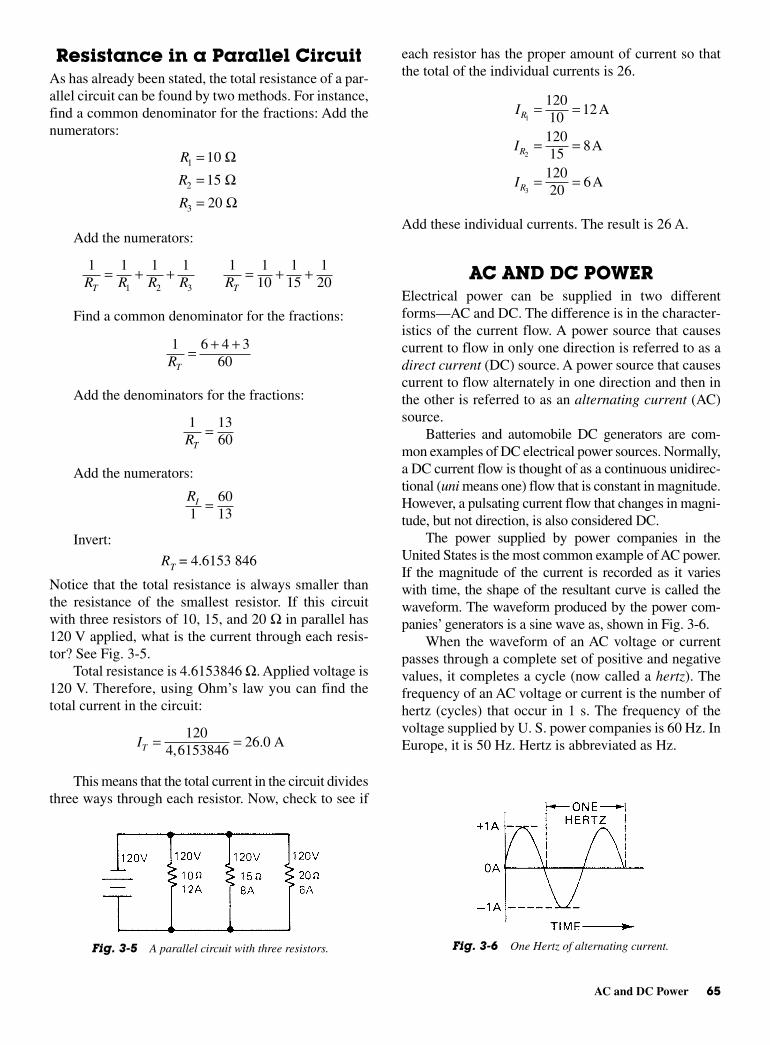
each resistor has the proper amount of current so thatthe total of the individual currents is 26.
Add these individual currents. The result is 26 A.
AC AND DC POWERElectrical power can be supplied in two differentforms—AC and DC. The difference is in the character-istics of the current flow. A power source that causescurrent to flow in only one direction is referred to as adirect current (DC) source. A power source that causescurrent to flow alternately in one direction and then inthe other is referred to as an alternating current (AC)source.
Batteries and automobile DC generators are com-mon examples of DC electrical power sources. Normally,a DC current flow is thought of as a continuous unidirec-tional (uni means one) flow that is constant in magnitude.However, a pulsating current flow that changes in magni-tude, but not direction, is also considered DC.
The power supplied by power companies in theUnited States is the most common example of AC power.If the magnitude of the current is recorded as it varieswith time, the shape of the resultant curve is called thewaveform. The waveform produced by the power com-panies’ generators is a sine wave as, shown in Fig. 3-6.
When the waveform of an AC voltage or currentpasses through a complete set of positive and negativevalues, it completes a cycle (now called a hertz). Thefrequency of an AC voltage or current is the number ofhertz (cycles) that occur in 1 s. The frequency of thevoltage supplied by U. S. power companies is 60 Hz. InEurope, it is 50 Hz. Hertz is abbreviated as Hz.
I
I
I
R
R
R
1
2
3
12010
12
12015
8
12020
6
= =
= =
= =
A
A
A
Resistance in a Parallel CircuitAs has already been stated, the total resistance of a par-allel circuit can be found by two methods. For instance,find a common denominator for the fractions: Add thenumerators:
Add the numerators:
Find a common denominator for the fractions:
Add the denominators for the fractions:
Add the numerators:
Invert:
RT = 4.6153 846
Notice that the total resistance is always smaller thanthe resistance of the smallest resistor. If this circuitwith three resistors of 10, 15, and 20 Ω in parallel has120 V applied, what is the current through each resis-tor? See Fig. 3-5.
Total resistance is 4.6153846 Ω. Applied voltage is120 V. Therefore, using Ohm’s law you can find thetotal current in the circuit:
This means that the total current in the circuit dividesthree ways through each resistor. Now, check to see if
IT = =1204 6153846
26 0,
. A
RI
16013
=
1 1360RT
=
1 6 4 360RT
= + +
1 1 1 1 1 110
115
1201 2 3R R R R RT T
= + + = + +
R
R
R
1
3
===
10
15
202
ΩΩΩ
AC and DC Power 65
Fig. 3-5 A parallel circuit with three resistors. Fig. 3-6 One Hertz of alternating current.

All calculations using AC voltage are based on sinewaves. Four values of sine waves are of particular im-portance.
Instantaneous value. The voltage or current in an ACcircuit is continuously changing. The value variesfrom zero to maximum and back to zero. If you mea-sure the value at any given instant, you will obtainthe instantaneous voltage or current value.
Maximum value. For two brief instants in each Hertz thesine wave reaches a maximum value. One is a positivemaximum and the other is a negative maximum. Max-imum value is often referred to as peak value. The twoterms have identical meanings and are interchangeable.
Average value. The positive and negative halves of asine wave are identical. Thus, the average value canbe found by determining the area below the wave,and calculating what DC value would enclose thesame area over the same amount of time. For eitherthe positive or negative, half of the sine wave, the av-erage value is 0.636 times the maximum value.
Effective. The effective value is often referred to as rms(root-mean-square). The effective value is the sameas a DC voltage or current required providing thesame average power or heating effect. The heatingeffect is independent of the direction of electronflow. The effective value of an AC sine wave is equalto 0.7071 times the maximum value. Thus, the alter-nating current of a sine wave, having a maximumvalue of 10 A, produces in a circuit the amount ofheat produced by a DC current of 7.071 A.
The heating effect varies with the square of thevoltage or current. If we square the instantaneous val-ues of a voltage or current sine wave, we obtain a wavethat is proportional to the instantaneous power, or heat-ing effect of the original sine wave. The average of thisnew waveform represents the average power that willbe supplied. The square root of this average value is thevoltage or current that represents the heating effect ofthe original sine wave of voltage or current. This is theeffective value of the wave, or the rms value, the squareroot of the average of the squared waveform.
The effective values of voltage and current aremore important than instantaneous, maximum, or aver-age values. Most AC voltmeters and ammeters are cal-ibrated to read in rms values.
PhaseThe phase of an AC voltage refers to the relationship ofits instantaneous polarity to that of another AC voltage.Figure 3-7 shows two AC sine waves in phase, but
unequal in amplitude. Figure 3-8 shows the two sinewaves 45° out-of-phase. Figure 3-9 shows the two sinewaves 180° out-of-phase.
The length of a sine wave can be measured in an-gular degrees because each hertz is a repetition of theprevious one. One complete cycle (hertz) of a sinewave is 360.
Power in DC CircuitsWhenever a force causes motion, work is performed.Electrical force is expressed as voltage. When voltagecauses a movement of electrons (current) from onepoint to another, energy is expended. The rate of work,or the rate of producing, transforming, or expendingenergy, is generally expressed in watts or kilowatts. Akilowatt (kW) is 1000 W. In a DC circuit, 1 V forcing acurrent of 1 A through a 1-Ω resistance results in 1 Wof power being expended. The formula for this is:
P (watts) = E (volts) × I (amperes)
66 Voltage, Current, and Resistance
Fig. 3-7 Two AC waveforms, unequal in amplitude, but in-phase.
Fig. 3-8 Two AC waveforms, out-of-phase by 45°.
Fig. 3-9 Two AC waveforms, out-of-phase by 180°.
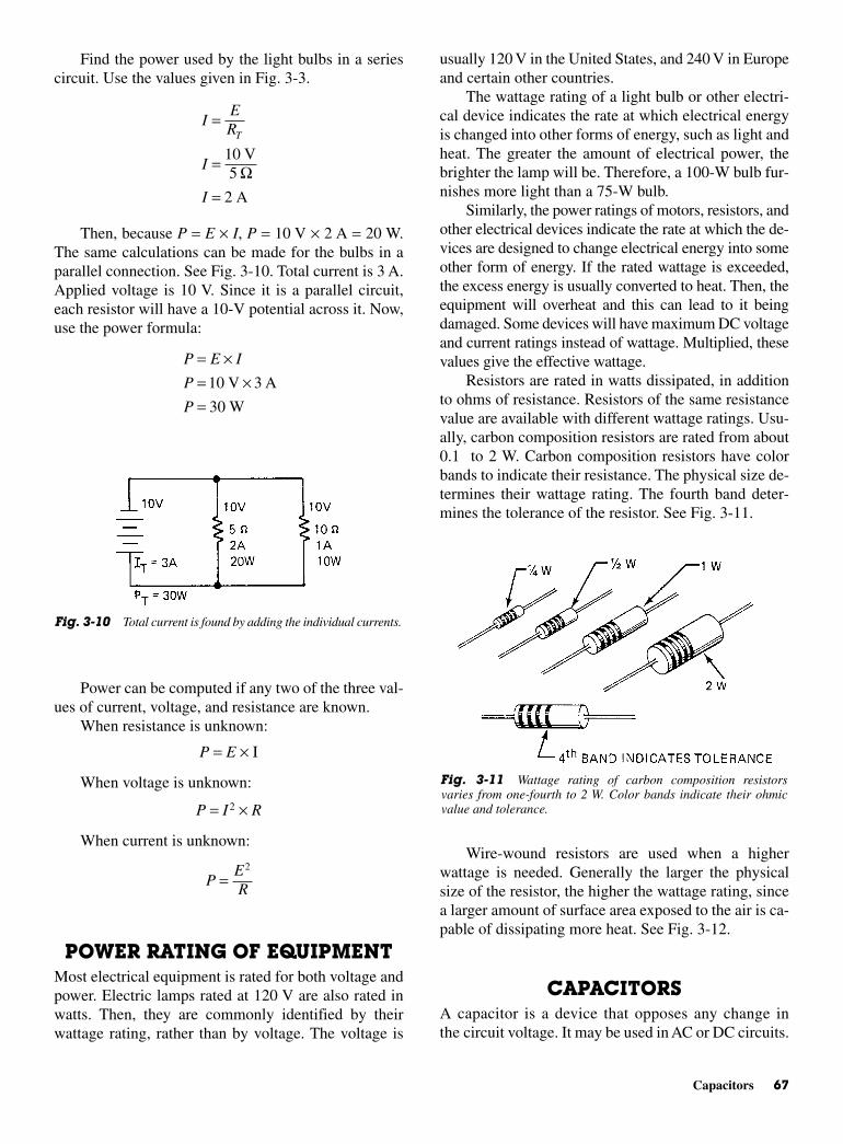
usually 120 V in the United States, and 240 V in Europeand certain other countries.
The wattage rating of a light bulb or other electri-cal device indicates the rate at which electrical energyis changed into other forms of energy, such as light andheat. The greater the amount of electrical power, thebrighter the lamp will be. Therefore, a 100-W bulb fur-nishes more light than a 75-W bulb.
Similarly, the power ratings of motors, resistors, andother electrical devices indicate the rate at which the de-vices are designed to change electrical energy into someother form of energy. If the rated wattage is exceeded,the excess energy is usually converted to heat. Then, theequipment will overheat and this can lead to it beingdamaged. Some devices will have maximum DC voltageand current ratings instead of wattage. Multiplied, thesevalues give the effective wattage.
Resistors are rated in watts dissipated, in additionto ohms of resistance. Resistors of the same resistancevalue are available with different wattage ratings. Usu-ally, carbon composition resistors are rated from about0.1 to 2 W. Carbon composition resistors have colorbands to indicate their resistance. The physical size de-termines their wattage rating. The fourth band deter-mines the tolerance of the resistor. See Fig. 3-11.
Wire-wound resistors are used when a higherwattage is needed. Generally the larger the physicalsize of the resistor, the higher the wattage rating, sincea larger amount of surface area exposed to the air is ca-pable of dissipating more heat. See Fig. 3-12.
CAPACITORSA capacitor is a device that opposes any change inthe circuit voltage. It may be used in AC or DC circuits.
Find the power used by the light bulbs in a seriescircuit. Use the values given in Fig. 3-3.
Then, because P = E × I, P = 10 V × 2 A = 20 W.The same calculations can be made for the bulbs in aparallel connection. See Fig. 3-10. Total current is 3 A.Applied voltage is 10 V. Since it is a parallel circuit,each resistor will have a 10-V potential across it. Now,use the power formula:
Power can be computed if any two of the three val-ues of current, voltage, and resistance are known.
When resistance is unknown:
P = E × I
When voltage is unknown:
P = I 2 × R
When current is unknown:
POWER RATING OF EQUIPMENTMost electrical equipment is rated for both voltage andpower. Electric lamps rated at 120 V are also rated inwatts. Then, they are commonly identified by theirwattage rating, rather than by voltage. The voltage is
PER
=2
P E I
P
P
= ×= ×=
10 3
30
V A
W
IER
I
I
T=
=
=
10
2
V5
A
Ω
Capacitors 67
Fig. 3-10 Total current is found by adding the individual currents.
Fig. 3-11 Wattage rating of carbon composition resistorsvaries from one-fourth to 2 W. Color bands indicate their ohmicvalue and tolerance.
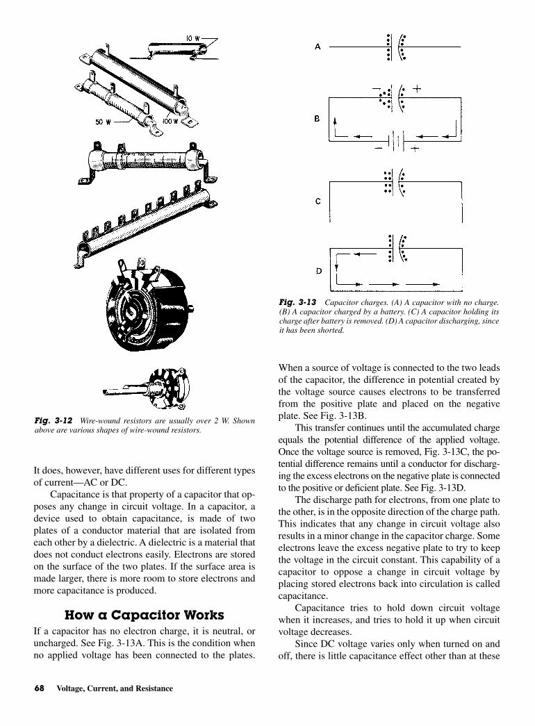
It does, however, have different uses for different typesof current—AC or DC.
Capacitance is that property of a capacitor that op-poses any change in circuit voltage. In a capacitor, adevice used to obtain capacitance, is made of twoplates of a conductor material that are isolated fromeach other by a dielectric. A dielectric is a material thatdoes not conduct electrons easily. Electrons are storedon the surface of the two plates. If the surface area ismade larger, there is more room to store electrons andmore capacitance is produced.
How a Capacitor WorksIf a capacitor has no electron charge, it is neutral, oruncharged. See Fig. 3-13A. This is the condition whenno applied voltage has been connected to the plates.
When a source of voltage is connected to the two leadsof the capacitor, the difference in potential created bythe voltage source causes electrons to be transferredfrom the positive plate and placed on the negativeplate. See Fig. 3-13B.
This transfer continues until the accumulated chargeequals the potential difference of the applied voltage.Once the voltage source is removed, Fig. 3-13C, the po-tential difference remains until a conductor for discharg-ing the excess electrons on the negative plate is connectedto the positive or deficient plate. See Fig. 3-13D.
The discharge path for electrons, from one plate tothe other, is in the opposite direction of the charge path.This indicates that any change in circuit voltage alsoresults in a minor change in the capacitor charge. Someelectrons leave the excess negative plate to try to keepthe voltage in the circuit constant. This capability of acapacitor to oppose a change in circuit voltage byplacing stored electrons back into circulation is calledcapacitance.
Capacitance tries to hold down circuit voltagewhen it increases, and tries to hold it up when circuitvoltage decreases.
Since DC voltage varies only when turned on andoff, there is little capacitance effect other than at these
68 Voltage, Current, and Resistance
Fig. 3-12 Wire-wound resistors are usually over 2 W. Shownabove are various shapes of wire-wound resistors.
Fig. 3-13 Capacitor charges. (A) A capacitor with no charge.(B) A capacitor charged by a battery. (C) A capacitor holding itscharge after battery is removed. (D) A capacitor discharging, sinceit has been shorted.
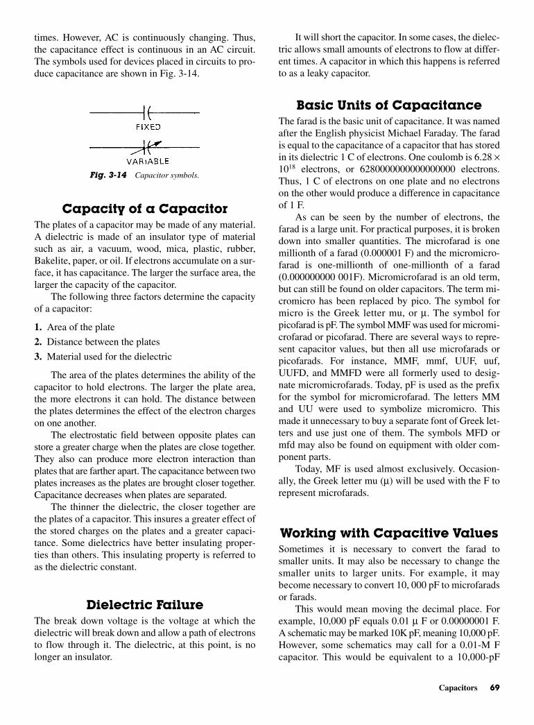
It will short the capacitor. In some cases, the dielec-tric allows small amounts of electrons to flow at differ-ent times. A capacitor in which this happens is referredto as a leaky capacitor.
Basic Units of Capacitance The farad is the basic unit of capacitance. It was namedafter the English physicist Michael Faraday. The faradis equal to the capacitance of a capacitor that has storedin its dielectric 1 C of electrons. One coulomb is 6.28 ×10¹⁸ electrons, or 6280000000000000000 electrons.Thus, 1 C of electrons on one plate and no electronson the other would produce a difference in capacitanceof 1 F.
As can be seen by the number of electrons, thefarad is a large unit. For practical purposes, it is brokendown into smaller quantities. The microfarad is onemillionth of a farad (0.000001 F) and the micromicro-farad is one-millionth of one-millionth of a farad(0.000000000 001F). Micromicrofarad is an old term,but can still be found on older capacitors. The term mi-cromicro has been replaced by pico. The symbol formicro is the Greek letter mu, or µ. The symbol forpicofarad is pF. The symbol MMF was used for micromi-crofarad or picofarad. There are several ways to repre-sent capacitor values, but then all use microfarads orpicofarads. For instance, MMF, mmf, UUF, uuf,UUFD, and MMFD were all formerly used to desig-nate micromicrofarads. Today, pF is used as the prefixfor the symbol for micromicrofarad. The letters MMand UU were used to symbolize micromicro. Thismade it unnecessary to buy a separate font of Greek let-ters and use just one of them. The symbols MFD ormfd may also be found on equipment with older com-ponent parts.
Today, MF is used almost exclusively. Occasion-ally, the Greek letter mu (µ) will be used with the F torepresent microfarads.
Working with Capacitive ValuesSometimes it is necessary to convert the farad tosmaller units. It may also be necessary to change thesmaller units to larger units. For example, it maybecome necessary to convert 10, 000 pF to microfaradsor farads.
This would mean moving the decimal place. Forexample, 10,000 pF equals 0.01 µ F or 0.00000001 F.A schematic may be marked 10K pF, meaning 10,000 pF.However, some schematics may call for a 0.01-M Fcapacitor. This would be equivalent to a 10,000-pF
times. However, AC is continuously changing. Thus,the capacitance effect is continuous in an AC circuit.The symbols used for devices placed in circuits to pro-duce capacitance are shown in Fig. 3-14.
Capacity of a CapacitorThe plates of a capacitor may be made of any material.A dielectric is made of an insulator type of materialsuch as air, a vacuum, wood, mica, plastic, rubber,Bakelite, paper, or oil. If electrons accumulate on a sur-face, it has capacitance. The larger the surface area, thelarger the capacity of the capacitor.
The following three factors determine the capacityof a capacitor:
1. Area of the plate
2. Distance between the plates
3. Material used for the dielectric
The area of the plates determines the ability of thecapacitor to hold electrons. The larger the plate area,the more electrons it can hold. The distance betweenthe plates determines the effect of the electron chargeson one another.
The electrostatic field between opposite plates canstore a greater charge when the plates are close together.They also can produce more electron interaction thanplates that are farther apart. The capacitance between twoplates increases as the plates are brought closer together.Capacitance decreases when plates are separated.
The thinner the dielectric, the closer together arethe plates of a capacitor. This insures a greater effect ofthe stored charges on the plates and a greater capaci-tance. Some dielectrics have better insulating proper-ties than others. This insulating property is referred toas the dielectric constant.
Dielectric FailureThe break down voltage is the voltage at which thedielectric will break down and allow a path of electronsto flow through it. The dielectric, at this point, is nolonger an insulator.
Capacitors 69
Fig. 3-14 Capacitor symbols.
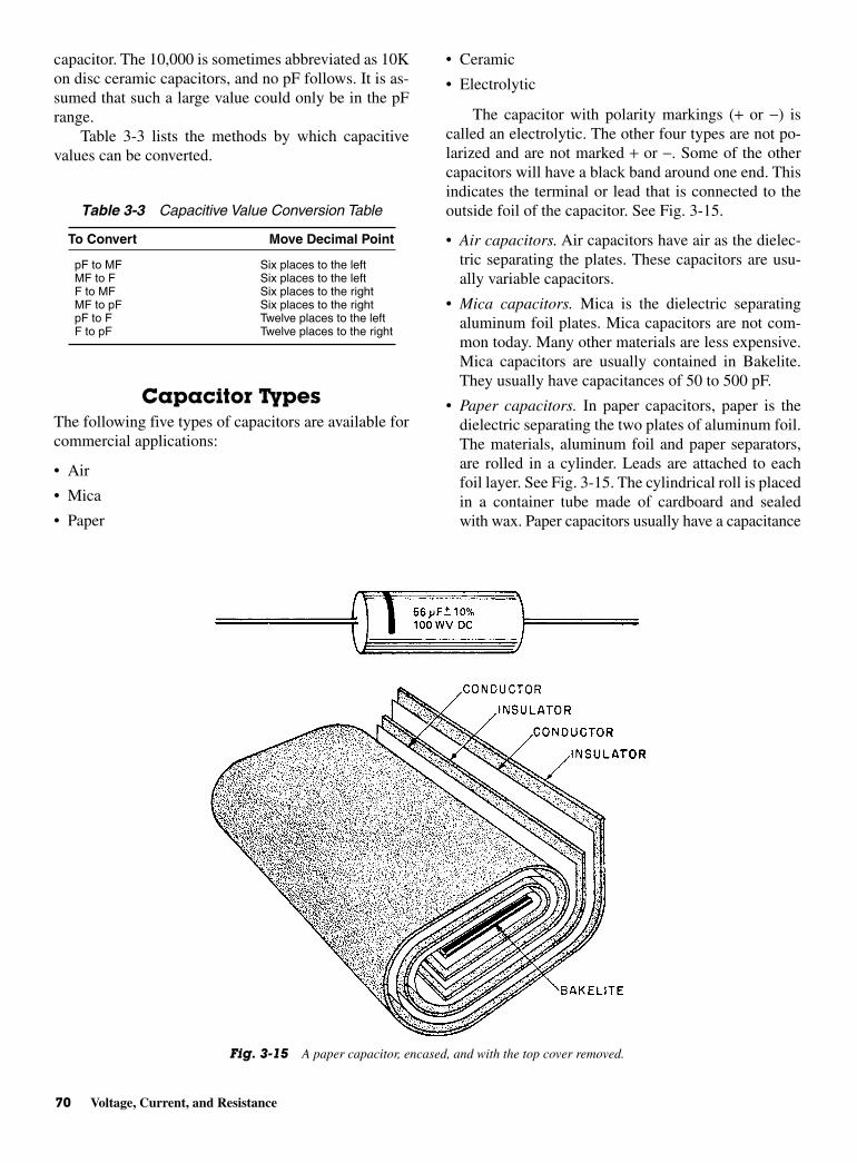
capacitor. The 10,000 is sometimes abbreviated as 10Kon disc ceramic capacitors, and no pF follows. It is as-sumed that such a large value could only be in the pFrange.
Table 3-3 lists the methods by which capacitivevalues can be converted.
Capacitor TypesThe following five types of capacitors are available forcommercial applications:
• Air
• Mica
• Paper
• Ceramic
• Electrolytic
The capacitor with polarity markings (+ or −) iscalled an electrolytic. The other four types are not po-larized and are not marked + or −. Some of the othercapacitors will have a black band around one end. Thisindicates the terminal or lead that is connected to theoutside foil of the capacitor. See Fig. 3-15.
• Air capacitors. Air capacitors have air as the dielec-tric separating the plates. These capacitors are usu-ally variable capacitors.
• Mica capacitors. Mica is the dielectric separatingaluminum foil plates. Mica capacitors are not com-mon today. Many other materials are less expensive.Mica capacitors are usually contained in Bakelite.They usually have capacitances of 50 to 500 pF.
• Paper capacitors. In paper capacitors, paper is thedielectric separating the two plates of aluminum foil.The materials, aluminum foil and paper separators,are rolled in a cylinder. Leads are attached to eachfoil layer. See Fig. 3-15. The cylindrical roll is placedin a container tube made of cardboard and sealedwith wax. Paper capacitors usually have a capacitance
70 Voltage, Current, and Resistance
Table 3-3 Capacitive Value Conversion Table
To Convert Move Decimal Point
pF to MF Six places to the leftMF to F Six places to the leftF to MF Six places to the rightMF to pF Six places to the rightpF to F Twelve places to the leftF to pF Twelve places to the right
Fig. 3-15 A paper capacitor, encased, and with the top cover removed.
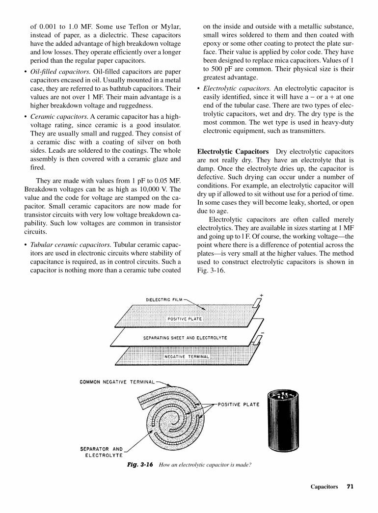
on the inside and outside with a metallic substance,small wires soldered to them and then coated withepoxy or some other coating to protect the plate sur-face. Their value is applied by color code. They havebeen designed to replace mica capacitors. Values of 1to 500 pF are common. Their physical size is theirgreatest advantage.
• Electrolytic capacitors. An electrolytic capacitor iseasily identified, since it will have a − or a + at oneend of the tubular case. There are two types of elec-trolytic capacitors, wet and dry. The dry type is themost common. The wet type is used in heavy-dutyelectronic equipment, such as transmitters.
Electrolytic Capacitors Dry electrolytic capacitorsare not really dry. They have an electrolyte that isdamp. Once the electrolyte dries up, the capacitor isdefective. Such drying can occur under a number ofconditions. For example, an electrolytic capacitor willdry up if allowed to sit without use for a period of time.In some cases they will become leaky, shorted, or opendue to age.
Electrolytic capacitors are often called merelyelectrolytics. They are available in sizes starting at 1 MFand going up to l F. Of course, the working voltage—thepoint where there is a difference of potential across theplates—is very small at the higher values. The methodused to construct electrolytic capacitors is shown inFig. 3-16.
of 0.001 to 1.0 MF. Some use Teflon or Mylar,instead of paper, as a dielectric. These capacitorshave the added advantage of high breakdown voltageand low losses. They operate efficiently over a longerperiod than the regular paper capacitors.
• Oil-filled capacitors. Oil-filled capacitors are papercapacitors encased in oil. Usually mounted in a metalcase, they are referred to as bathtub capacitors. Theirvalues are not over 1 MF. Their main advantage is ahigher breakdown voltage and ruggedness.
• Ceramic capacitors. A ceramic capacitor has a high-voltage rating, since ceramic is a good insulator.They are usually small and rugged. They consist ofa ceramic disc with a coating of silver on bothsides. Leads are soldered to the coatings. The wholeassembly is then covered with a ceramic glaze andfired.
They are made with values from 1 pF to 0.05 MF.Breakdown voltages can be as high as 10,000 V. Thevalue and the code for voltage are stamped on the ca-pacitor. Small ceramic capacitors are now made fortransistor circuits with very low voltage breakdown ca-pability. Such low voltages are common in transistorcircuits.
• Tubular ceramic capacitors. Tubular ceramic capac-itors are used in electronic circuits where stability ofcapacitance is required, as in control circuits. Such acapacitor is nothing more than a ceramic tube coated
Capacitors 71
Fig. 3-16 How an electrolytic capacitor is made?
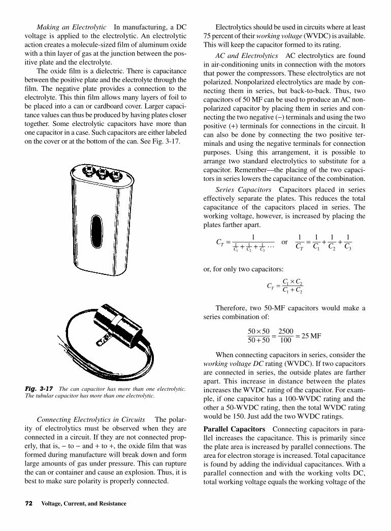
Making an Electrolytic In manufacturing, a DCvoltage is applied to the electrolytic. An electrolyticaction creates a molecule-sized film of aluminum oxidewith a thin layer of gas at the junction between the pos-itive plate and the electrolyte.
The oxide film is a dielectric. There is capacitancebetween the positive plate and the electrolyte through thefilm. The negative plate provides a connection to theelectrolyte. This thin film allows many layers of foil tobe placed into a can or cardboard cover. Larger capaci-tance values can thus be produced by having plates closertogether. Some electrolytic capacitors have more thanone capacitor in a case. Such capacitors are either labeledon the cover or at the bottom of the can. See Fig. 3-17.
Connecting Electrolytics in Circuits The polar-ity of electrolytics must be observed when they areconnected in a circuit. If they are not connected prop-erly, that is, − to − and + to +, the oxide film that wasformed during manufacture will break down and formlarge amounts of gas under pressure. This can rupturethe can or container and cause an explosion. Thus, it isbest to make sure polarity is properly connected.
Electrolytics should be used in circuits where at least75 percent of their working voltage (WVDC) is available.This will keep the capacitor formed to its rating.
AC and Electrolytics AC electrolytics are foundin air-conditioning units in connection with the motorsthat power the compressors. These electrolytics are notpolarized. Nonpolarized electrolytics are made by con-necting them in series, but back-to-back. Thus, twocapacitors of 50 MF can be used to produce an AC non-polarized capacitor by placing them in series and con-necting the two negative (−) terminals and using the twopositive (+) terminals for connections in the circuit. Itcan also be done by connecting the two positive ter-minals and using the negative terminals for connectionpurposes. Using this arrangement, it is possible toarrange two standard electrolytics to substitute for acapacitor. Remember—the placing of the two capaci-tors in series lowers the capacitance of the combination.
Series Capacitors Capacitors placed in serieseffectively separate the plates. This reduces the totalcapacitance of the capacitors placed in series. Theworking voltage, however, is increased by placing theplates farther apart.
or, for only two capacitors:
Therefore, two 50-MF capacitors would make aseries combination of:
When connecting capacitors in series, consider theworking voltage DC rating (WVDC). If two capacitorsare connected in series, the outside plates are fartherapart. This increase in distance between the platesincreases the WVDC rating of the capacitor. For exam-ple, if one capacitor has a 100-WVDC rating and theother a 50-WVDC rating, then the total WVDC ratingwould be 150. Just add the two WVDC ratings.
Parallel Capacitors Connecting capacitors in para-llel increases the capacitance. This is primarily sincethe plate area is increased by parallel connections. Thearea for electron storage is increased. Total capacitanceis found by adding the individual capacitances. With aparallel connection and with the working volts DC,total working voltage equals the working voltage of the
50 5050 50
2500100
25×+ = = MF
CC CC CT =
×+
1 2
1 2
CC C C CT
C C C T= + + = + +1 1 1 1 1
1 1 11 2 31 2 3
or
72 Voltage, Current, and Resistance
Fig. 3-17 The can capacitor has more than one electrolytic.The tubular capacitor has more than one electrolytic.
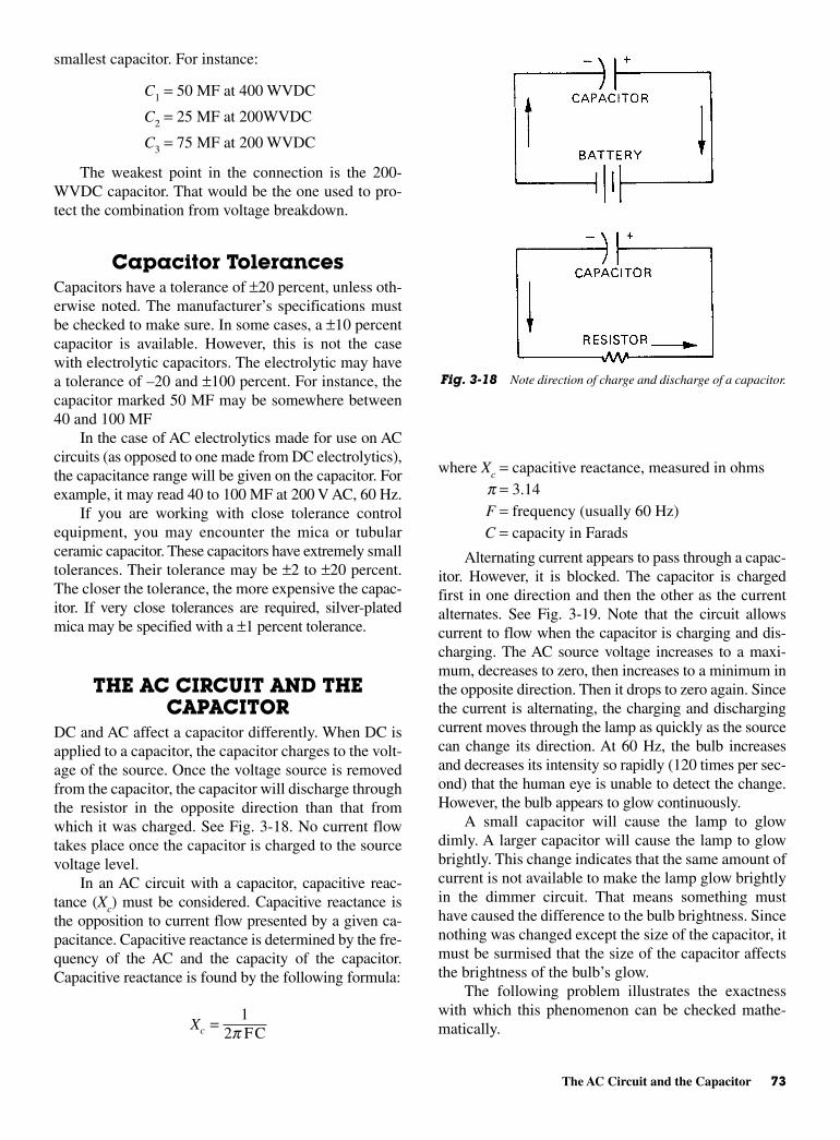
where Xc = capacitive reactance, measured in ohmsp = 3.14F = frequency (usually 60 Hz) C = capacity in Farads
Alternating current appears to pass through a capac-itor. However, it is blocked. The capacitor is chargedfirst in one direction and then the other as the currentalternates. See Fig. 3-19. Note that the circuit allowscurrent to flow when the capacitor is charging and dis-charging. The AC source voltage increases to a maxi-mum, decreases to zero, then increases to a minimum inthe opposite direction. Then it drops to zero again. Sincethe current is alternating, the charging and dischargingcurrent moves through the lamp as quickly as the sourcecan change its direction. At 60 Hz, the bulb increasesand decreases its intensity so rapidly (120 times per sec-ond) that the human eye is unable to detect the change.However, the bulb appears to glow continuously.
A small capacitor will cause the lamp to glowdimly. A larger capacitor will cause the lamp to glowbrightly. This change indicates that the same amount ofcurrent is not available to make the lamp glow brightlyin the dimmer circuit. That means something musthave caused the difference to the bulb brightness. Sincenothing was changed except the size of the capacitor, itmust be surmised that the size of the capacitor affectsthe brightness of the bulb’s glow.
The following problem illustrates the exactnesswith which this phenomenon can be checked mathe-matically.
smallest capacitor. For instance:
C1 = 50 MF at 400 WVDC
C2 = 25 MF at 200WVDC
C3 = 75 MF at 200 WVDC
The weakest point in the connection is the 200-WVDC capacitor. That would be the one used to pro-tect the combination from voltage breakdown.
Capacitor TolerancesCapacitors have a tolerance of ±20 percent, unless oth-erwise noted. The manufacturer’s specifications mustbe checked to make sure. In some cases, a ±10 percentcapacitor is available. However, this is not the casewith electrolytic capacitors. The electrolytic may havea tolerance of –20 and ±100 percent. For instance, thecapacitor marked 50 MF may be somewhere between40 and 100 MF
In the case of AC electrolytics made for use on ACcircuits (as opposed to one made from DC electrolytics),the capacitance range will be given on the capacitor. Forexample, it may read 40 to 100 MF at 200 V AC, 60 Hz.
If you are working with close tolerance controlequipment, you may encounter the mica or tubularceramic capacitor. These capacitors have extremely smalltolerances. Their tolerance may be ±2 to ±20 percent.The closer the tolerance, the more expensive the capac-itor. If very close tolerances are required, silver-platedmica may be specified with a ±1 percent tolerance.
THE AC CIRCUIT AND THECAPACITOR
DC and AC affect a capacitor differently. When DC isapplied to a capacitor, the capacitor charges to the volt-age of the source. Once the voltage source is removedfrom the capacitor, the capacitor will discharge throughthe resistor in the opposite direction than that fromwhich it was charged. See Fig. 3-18. No current flowtakes place once the capacitor is charged to the sourcevoltage level.
In an AC circuit with a capacitor, capacitive reac-tance (Xc) must be considered. Capacitive reactance isthe opposition to current flow presented by a given ca-pacitance. Capacitive reactance is determined by the fre-quency of the AC and the capacity of the capacitor.Capacitive reactance is found by the following formula:
Xc = 12p FC
The AC Circuit and the Capacitor 73
Fig. 3-18 Note direction of charge and discharge of a capacitor.
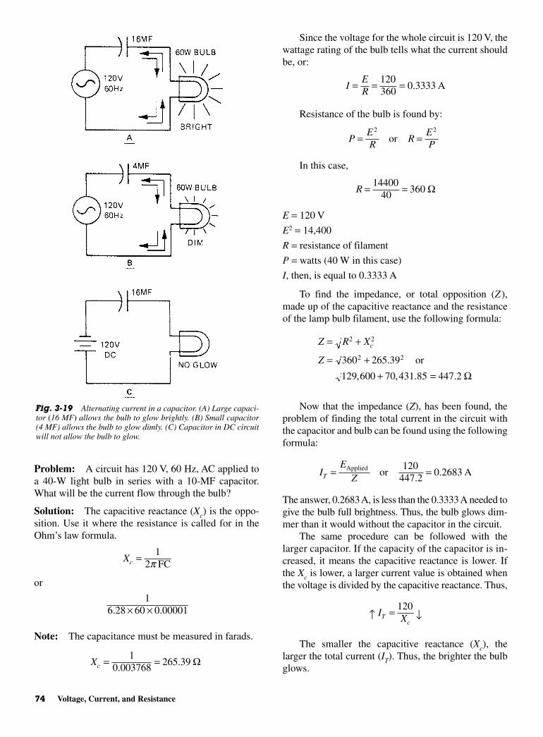
Problem: A circuit has 120 V, 60 Hz, AC applied toa 40-W light bulb in series with a 10-MF capacitor.What will be the current flow through the bulb?
Solution: The capacitive reactance (Xc) is the oppo-sition. Use it where the resistance is called for in theOhm’s law formula.
or
Note: The capacitance must be measured in farads.
Xc = =10 003768
265 39.
. Ω
16 28 60 0 00001. .× ×
Xc = 12p FC
Since the voltage for the whole circuit is 120 V, thewattage rating of the bulb tells what the current shouldbe, or:
Resistance of the bulb is found by:
In this case,
E = 120 V
E2 = 14,400
R = resistance of filament
P = watts (40 W in this case)
I, then, is equal to 0.3333 A
To find the impedance, or total opposition (Z),made up of the capacitive reactance and the resistanceof the lamp bulb filament, use the following formula:
Now that the impedance (Z), has been found, theproblem of finding the total current in the circuit withthe capacitor and bulb can be found using the followingformula:
The answer, 0.2683 A, is less than the 0.3333 A needed togive the bulb full brightness. Thus, the bulb glows dim-mer than it would without the capacitor in the circuit.
The same procedure can be followed with thelarger capacitor. If the capacity of the capacitor is in-creased, it means the capacitive reactance is lower. Ifthe Xc is lower, a larger current value is obtained whenthe voltage is divided by the capacitive reactance. Thus,
The smaller the capacitive reactance (Xc), thelarger the total current (IT). Thus, the brighter the bulbglows.
↑ = ↓IXT
c
120
IE
ZT = =Applied or A120
447 20 2683
..
Z R X
Z
c= +
= ++ =
2 2
2 2360 265 39
129 600 70 431 85 447 2
.
, , . .
or
Ω
R = =1440040
360 Ω
PER
REP
= =2 2
or
IER
= = =120360
0 3333. A
74 Voltage, Current, and Resistance
Fig. 3-19 Alternating current in a capacitor. (A) Large capaci-tor (16 MF) allows the bulb to glow brightly. (B) Small capacitor(4 MF) allows the bulb to glow dimly. (C) Capacitor in DC circuitwill not allow the bulb to glow.
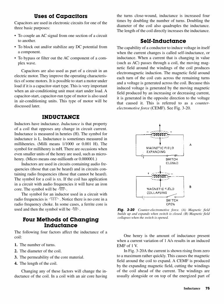
the turns close-wound, inductance is increased fourtimes by doubling the number of turns. Doubling thediameter of the coil also quadruples the inductance.The length of the coil directly increases the inductance.
Self-InductanceThe capability of a conductor to induce voltage in itselfwhen the current changes is called self-inductance, orinductance. When a current that is changing in value(such as AC) passes through a coil, the moving mag-netic field around the windings of the coil produceselectromagnetic induction. The magnetic field aroundeach turn of the coil cuts across the remaining turnsand a voltage is generated across the coil. Because thisinduced voltage is generated by the moving magneticfield produced by an increasing or decreasing current,it is generated in the opposite direction to the voltagethat caused it. This is referred to as a counter-electromotive force (CEMF). See Fig. 3-20.
One henry is the amount of inductance presentwhen a current variation of 1 A/s results in an inducedEMF of 1 V.
In Fig. 3-20A the current is shown rising from zeroto a maximum rather quickly. This causes the magneticfield around the coil to expand. A CEMF is producedby the expanding magnetic field, cutting the windingsof the coil ahead of the current. The windings areusually alongside or on top of the energized part of
Uses of Capacitors Capacitors are used in electronic circuits for one of thethree basic purposes:
• To couple an AC signal from one section of a circuitto another.
• To block out and/or stabilize any DC potential froma component.
• To bypass or filter out the AC component of a com-plex wave.
Capacitors are also used as part of a circuit in anelectric motor. They improve the operating characteris-tics of some motors. It is possible to start a motor underload if it is a capacitor-start type. This is very importantwhen an air-conditioning unit must start under load. Acapacitor-start, capacitor-run type of motor is also usedin air-conditioning units. This type of motor will bediscussed later.
INDUCTANCE Inductors have inductance. Inductance is that propertyof a coil that opposes any change in circuit current.Inductance is measured in henries (H). The symbol forinductance is L. Inductance is sometimes measured inmillihenries. (Milli means 1/1000 or 0.001 H). Thesymbol for millihenry is mH. There are occasions wheneven smaller units of the henry are used, such as micro-henry. (Micro means one-millionth or 0.000001.)
Inductors are used in circuits containing audio fre-quencies (those that can be heard) and in circuits con-taining radio frequencies (those that cannot be heard).The symbol for a coil is xx. If the coil has applicationin a circuit with audio frequencies it will have an ironcore. The symbol will be .
The symbol for an inductor used in a circuit withradio frequencies is . Notice there is no core in aradio frequency choke. In some cases, a ferrite core isused and then the symbol will be .
Four Methods of ChangingInductance
The following four factors affect the inductance of acoil:
1. The number of turns.
2. The diameter of the coil.
3. The permeability of the core material.
4. The length of the coil.
Changing any of these factors will change the in-ductance of the coil. In a coil with an air core having
Inductance 75
Fig. 3-20 Counter-electromotive force. (A) Magnetic fieldbuilds up and expands when switch is closed. (B) Magnetic fieldcollapses when the switch is opened.
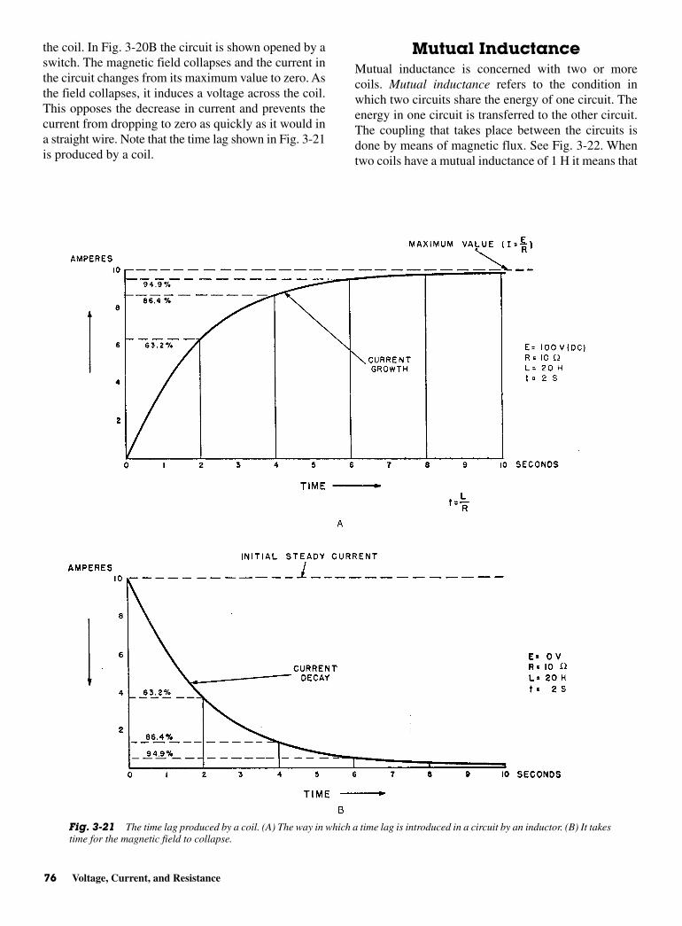
the coil. In Fig. 3-20B the circuit is shown opened by aswitch. The magnetic field collapses and the current inthe circuit changes from its maximum value to zero. Asthe field collapses, it induces a voltage across the coil.This opposes the decrease in current and prevents thecurrent from dropping to zero as quickly as it would ina straight wire. Note that the time lag shown in Fig. 3-21is produced by a coil.
Mutual Inductance Mutual inductance is concerned with two or morecoils. Mutual inductance refers to the condition inwhich two circuits share the energy of one circuit. Theenergy in one circuit is transferred to the other circuit.The coupling that takes place between the circuits isdone by means of magnetic flux. See Fig. 3-22. Whentwo coils have a mutual inductance of 1 H it means that
76 Voltage, Current, and Resistance
Fig. 3-21 The time lag produced by a coil. (A) The way in which a time lag is introduced in a circuit by an inductor. (B) It takestime for the magnetic field to collapse.
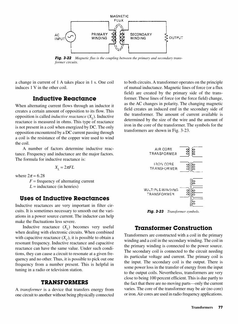
to both circuits. A transformer operates on the principleof mutual inductance. Magnetic lines of force (or a fluxfield) are created by the primary side of the trans-former. These lines of force (or the force field) change,as the AC changes in polarity. The changing magneticfield creates an induced emf in the secondary side ofthe transformer. The amount of current available isdetermined by the size of the wire and the amount ofiron in the core of the transformer. The symbols for thetransformers are shown in Fig. 3-23.
Transformer ConstructionTransformers are constructed with a coil in the primarywinding and a coil in the secondary winding. The coil inthe primary winding is connected to the power source.The secondary coil is connected to the circuit needingits particular voltage and current. The primary coil isthe input. The secondary coil is the output. There issome power loss in the transfer of energy from the inputto the output coils. Nevertheless, transformers are veryclose to being 100 percent efficient. This is due partly tothe fact that there are no moving parts—only the currentvaries. The core of the transformer may be air (no core)or iron. Air cores are used in radio frequency applications.
a change in current of 1 A takes place in 1 s. One coilinduces 1 V in the other coil.
Inductive ReactanceWhen alternating current flows through an inductor itcreates a certain amount of opposition to its flow. Thisopposition is called inductive reactance (XL). Inductivereactance is measured in ohms. This type of reactanceis not present in a coil when energized by DC. The onlyopposition encountered by a DC current passing througha coil is the resistance of the copper wire used to windthe coil.
A number of factors determine inductive reac-tance. Frequency and inductance are the major factors.The formula for inductive reactance is:
XL = 2pFL
where 2p = 6.28F = frequency of alternating currentL = inductance (in henries)
Uses of Inductive ReactancesInductive reactances are very important in filter cir-cuits. It is sometimes necessary to smooth out the vari-ations in a power source current. The inductor can helpmake the fluctuations less severe.
Inductive reactance (XL) becomes very usefulwhen dealing with electronic circuits. When combinedwith capacitive reactance (XC), it is possible to obtain aresonant frequency. Inductive reactance and capacitivereactance can have the same value. Under such condi-tions, they can cause a circuit to resonate at a given fre-quency and no other. Thus, it is possible to pick out onefrequency from a number present. This is helpful intuning in a radio or television station.
TRANSFORMERSA transformer is a device that transfers energy fromone circuit to another without being physically connected
Transformers 77
Fig. 3-22 Magnetic flux is the coupling between the primary and secondary trans-former circuits.
Fig. 3-23 Transformer symbols.
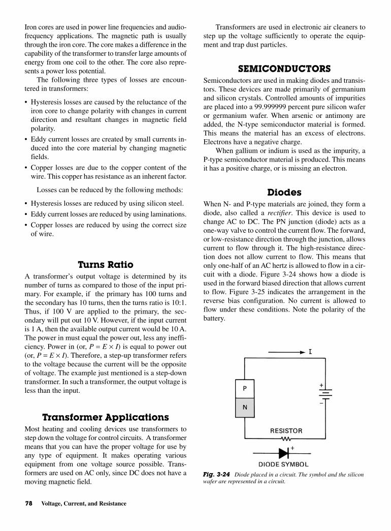
Iron cores are used in power line frequencies and audio-frequency applications. The magnetic path is usuallythrough the iron core. The core makes a difference in thecapability of the transformer to transfer large amounts ofenergy from one coil to the other. The core also repre-sents a power loss potential.
The following three types of losses are encoun-tered in transformers:
• Hysteresis losses are caused by the reluctance of theiron core to change polarity with changes in currentdirection and resultant changes in magnetic fieldpolarity.
• Eddy current losses are created by small currents in-duced into the core material by changing magneticfields.
• Copper losses are due to the copper content of thewire. This copper has resistance as an inherent factor.
Losses can be reduced by the following methods:
• Hysteresis losses are reduced by using silicon steel.
• Eddy current losses are reduced by using laminations.
• Copper losses are reduced by using the correct sizeof wire.
Turns RatioA transformer’s output voltage is determined by itsnumber of turns as compared to those of the input pri-mary. For example, if the primary has 100 turns andthe secondary has 10 turns, then the turns ratio is 10:1.Thus, if 100 V are applied to the primary, the sec-ondary will put out 10 V. However, if the input currentis 1 A, then the available output current would be 10 A.The power in must equal the power out, less any ineffi-ciency. Power in (or, P = E × I) is equal to power out(or, P = E × I). Therefore, a step-up transformer refersto the voltage because the current will be the oppositeof voltage. The example just mentioned is a step-downtransformer. In such a transformer, the output voltage isless than the input.
Transformer ApplicationsMost heating and cooling devices use transformers tostep down the voltage for control circuits. A transformermeans that you can have the proper voltage for use byany type of equipment. It makes operating variousequipment from one voltage source possible. Trans-formers are used on AC only, since DC does not have amoving magnetic field.
Transformers are used in electronic air cleaners tostep up the voltage sufficiently to operate the equip-ment and trap dust particles.
SEMICONDUCTORSSemiconductors are used in making diodes and transis-tors. These devices are made primarily of germaniumand silicon crystals. Controlled amounts of impuritiesare placed into a 99.999999 percent pure silicon waferor germanium wafer. When arsenic or antimony areadded, the N-type semiconductor material is formed.This means the material has an excess of electrons.Electrons have a negative charge.
When gallium or indium is used as the impurity, aP-type semiconductor material is produced. This meansit has a positive charge, or is missing an electron.
DiodesWhen N- and P-type materials are joined, they form adiode, also called a rectifier. This device is used tochange AC to DC. The PN junction (diode) acts as aone-way valve to control the current flow. The forward,or low-resistance direction through the junction, allowscurrent to flow through it. The high-resistance direc-tion does not allow current to flow. This means thatonly one-half of an AC hertz is allowed to flow in a cir-cuit with a diode. Figure 3-24 shows how a diode isused in the forward biased direction that allows currentto flow. Figure 3-25 indicates the arrangement in thereverse bias configuration. No current is allowed toflow under these conditions. Note the polarity of thebattery.
78 Voltage, Current, and Resistance
Fig. 3-24 Diode placed in a circuit. The symbol and the siliconwafer are represented in a circuit.
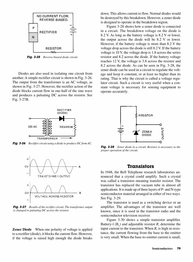
down. This allows current to flow. Normal diodes wouldbe destroyed by this breakdown. However, a zener diodeis designed to operate in the breakdown region.
Figure 3-28 shows how a zener diode is connectedin a circuit. The breakdown voltage on the diode is8.2 V. As long as the battery voltage is 8.2 V or lower,the output across the diode will be 8.2 V or lower.However, if the battery voltage is more than 8.2 V thevoltage drop across the diode is still 8.2 V. If the batteryvoltage is 10 V, the voltage drop is 1.8 across the seriesresistor and 8.2 across the diode. If the battery voltagereaches 12 V, the voltage is 3.8 across the resistor and8.2 across the diode. As can be seen in Fig. 3-28, thezener diode can be used in a circuit to regulate the volt-age and keep it constant, or at least no higher than itsrating. That is why the circuit is called a voltage regu-lator circuit. Such a circuit is very useful when a con-stant voltage is necessary for sensing equipment tooperate accurately.
TransistorsIn 1948, the Bell Telephone research laboratories an-nounced that a crystal could amplify. Such a crystalwas called a transistor–meaning transfer resistor. Thetransistor has replaced the vacuum tube in almost allapplications. It is made up of three layers of P- and N-typesemiconductor material arranged in either of two ways.See Fig. 3-29.
The transistor is used as a switching device or anamplifier. The advantages of the transistor are wellknown, since it is used in the transistor radio and thesemiconductor television receiver.
Figure 3-30 shows a simple transistor amplifier.Battery-l (B1) and adjustable resistor R, determine theinput current to the transistor. When R, is high in resis-tance, the current flowing from the base to the emitteris very small. When the base-to-emitter current is small,
Diodes are also used in isolating one circuit fromanother. A simple rectifier circuit is shown in Fig. 3-26.The output from the transformer is an AC voltage, asshown in Fig. 3-27. However, the rectifier action of thediode blocks current flow in one-half of the sine waveand produces a pulsating DC across the resistor. SeeFig. 3-27B.
Zener Diode When one polarity of voltage is appliedto a rectifier (diode), it blocks the current flow. However,if the voltage is raised high enough the diode breaks
Semiconductors 79
Fig. 3-25 Reverse-biased diode circuit.
Fig. 3-26 Rectifier circuit using a diode to produce DC from AC.
Fig. 3-27 Results of the rectifier circuit. The transformer outputis changed to pulsating DC across the resistor.
Fig. 3-28 Zener diode in a circuit. Resistor is necessary to theproper operation of the circuit.

the collector-to-emitter resistance appears as a veryhigh resistance. This limits the current flow from bat-tery 2(B2). The result is a limiting of the voltage dropacross R2.
As the resistance of R1 is lowered, the current flow-ing through the base-to-emitter junction increases. Asthe base-to-emitter current is increased, the resistanceof the transistor from collector to emitter is decreased.More current is flowing from B2 through R2 and thevoltage drop across R2 is increased. A very smallchange in the current from B1 causes a large change inthe current from B2. The ratio of the large change to thesmall change is defined as the gain of the transistor.
Silicon-controlledRectifier (SCR)
The silicon-controlled rectifier (SCR) is a four-layeredPNPN device. The SCR can be defined as a high-speedsemiconductor switch. It requires only a short pulse toturn it on. It remains on as long as current is flowingthrough it.
Look at the circuit shown in Fig. 3-31. Assume thatthe SCR is off. (It would then have a very high resis-tance.) No current would be flowing through the resis-tor. When switch S2 is closed just long enough to turn
on the SCR (which then has a very low resistance) acurrent will flow through the resistor and the SCR. TheSCR will remain on until switch S2 stops the flow ofcurrent through the resistor and SCR. Then the SCRwill turn off. When S2 is again closed, the resistance ofthe SCR remains high. No current will flow throughthe resistor until S1 is reclosed. Figure 3-32A shows anSCR represented schematically. Figure 3-32B showsthe arrangement of the layers of P- and N-type materi-als that produce the SCR effect. The anode is the pos-itive terminal. The gate is the terminal used to turn onthe SCR. The cathode is the negative terminal.
BRIDGE CIRCUITSWheatstone Bridges
A bridge circuit is a network of resistances and capaci-tive or inductive impedances. The bridge circuit is usu-ally used to make precise measurements. The mostcommon bridge circuit is the Wheatstone bridge. Thisconsists of variable and fixed resistances. Simply, it is
80 Voltage, Current, and Resistance
Fig. 3-29 Arrangement of wafers of silicon or germanium toproduce a PNP or NPN transistor.
Fig. 3-30 A simple transistor amplifier.
Fig. 3-31 A silicon controlled rectifier (SCR) circuit.
Fig. 3-32 A silicon controlled rectifier. (A) Schematic represen-tation of an SCR. (B) Wafer arrangement needed to produce aSCR.

balanced bridge. The relationship is usually expressedas a ratio of
The actual resistance values are not important.What is important is that this ratio is maintained andthe bridge is balanced.
Variable ResistorIn Fig. 3-35, the value of the variable resistor R4 is950 Ω. The other resistors have the same value. UsingOhm’s law, the voltage drop across R4 is found to be4.9 V. The remaining voltage, 5.1 V, is dropped acrossR3. As shown in Fig. 3-35, the voltmeter measures thesum of the voltage drops across R2 and R3 as 5 V (+ to −)and 5.1 V (− to +). It registers a total of −0.1 V.
In Fig. 3-36, the converse is true. The value of R4 is1050 Ω. The voltage drop across R3 is 4.9 V. The volt-meter senses the sum of 5 V (+ to −) and 4.9 V (− to + ),or + 0.1 V.
When R4 changes the same amount, above or be-low the balanced bridge resistance, the magnitude ofthe DC output, measured by the voltmeter, is the same.However, the polarity is reversed.
SENSORSThe sensor in a control system is a resistance elementthat varies in resistance value with changes in the vari-able it is measuring. These resistance changes are
RR
RR
1
2
3
4=
a series-parallel circuit. Redrawn, as shown in Fig. 3-33,is a Wheatstone bridge circuit. The branches of the cir-cuit forming the diamond shape are called “legs.”
If 10 V DC were applied to the bridge shown inFig. 3-34, one current would flow through R1, and R2,and another through R3 and R4. Since R1, and R2 areboth fixed 1000-Ω resistors, the current through themis constant. Each resistor will drop one-half of the bat-tery voltage, or 5 V. Five volts is dropped across eachresistor. The voltmeter senses the sum of the voltagedrops across R2 and R3. Both are 5 V. However, the R2voltage drop is a positive (+) to negative (−) drop. TheR3 drop is a negative to positive drop. They are oppo-site in polarity and cancel each other. This is called a
Sensors 81
Fig. 3-33 Two ways of drawing a bridge circuit.
Fig. 3-34 Operation of a bridge circuit.
Fig. 3-35 Operation of a bridge circuit.
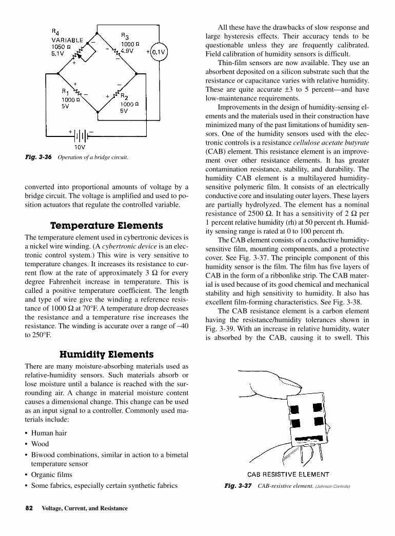
converted into proportional amounts of voltage by abridge circuit. The voltage is amplified and used to po-sition actuators that regulate the controlled variable.
Temperature ElementsThe temperature element used in cybertronic devices isa nickel wire winding. (A cybertronic device is an elec-tronic control system.) This wire is very sensitive totemperature changes. It increases its resistance to cur-rent flow at the rate of approximately 3 Ω for everydegree Fahrenheit increase in temperature. This iscalled a positive temperature coefficient. The lengthand type of wire give the winding a reference resis-tance of 1000 Ω at 70°F. A temperature drop decreasesthe resistance and a temperature rise increases theresistance. The winding is accurate over a range of −40to 250°F.
Humidity ElementsThere are many moisture-absorbing materials used asrelative-humidity sensors. Such materials absorb orlose moisture until a balance is reached with the sur-rounding air. A change in material moisture contentcauses a dimensional change. This change can be usedas an input signal to a controller. Commonly used ma-terials include:
• Human hair
• Wood
• Biwood combinations, similar in action to a bimetaltemperature sensor
• Organic films
• Some fabrics, especially certain synthetic fabrics
All these have the drawbacks of slow response andlarge hysteresis effects. Their accuracy tends to bequestionable unless they are frequently calibrated.Field calibration of humidity sensors is difficult.
Thin-film sensors are now available. They use anabsorbent deposited on a silicon substrate such that theresistance or capacitance varies with relative humidity.These are quite accurate ±3 to 5 percent—and havelow-maintenance requirements.
Improvements in the design of humidity-sensing el-ements and the materials used in their construction haveminimized many of the past limitations of humidity sen-sors. One of the humidity sensors used with the elec-tronic controls is a resistance cellulose acetate butyrate(CAB) element. This resistance element is an improve-ment over other resistance elements. It has greatercontamination resistance, stability, and durability. Thehumidity CAB element is a multilayered humidity-sensitive polymeric film. It consists of an electricallyconductive core and insulating outer layers. These layersare partially hydrolyzed. The element has a nominalresistance of 2500 Ω. It has a sensitivity of 2 Ω per1 percent relative humidity (rh) at 50 percent rh. Humid-ity sensing range is rated at 0 to 100 percent rh.
The CAB element consists of a conductive humidity-sensitive film, mounting components, and a protectivecover. See Fig. 3-37. The principle component of thishumidity sensor is the film. The film has five layers ofCAB in the form of a ribbonlike strip. The CAB mater-ial is used because of its good chemical and mechanicalstability and high sensitivity to humidity. It also hasexcellent film-forming characteristics. See Fig. 3-38.
The CAB resistance element is a carbon elementhaving the resistance/humidity tolerances shown inFig. 3-39. With an increase in relative humidity, wateris absorbed by the CAB, causing it to swell. This
82 Voltage, Current, and Resistance
Fig. 3-36 Operation of a bridge circuit.
Fig. 3-37 CAB-resistive element. (Johnson Controls)

swelling of the polymer matrix causes the suspendedcarbon particles to move farther apart from each other.This results in an increased element resistance.
When relative humidity decreases, water is given upby the CAB. The contraction of the polymer causes thecarbon particles to come closer together. This, in turn,makes the element more conductive, or less resistive.
CONTROLLERSThe sensing bridge is the section of the controller circuitthat contains the temperature-sensitive element or ele-ments. The potentiometer for establishing the “set point”is also part of the control system. The bridges are ener-gized with a DC voltage. This permits long wire runs insensing circuits without the need for compensatingwires or for other capacitive compensating schemes.
Both integral (room) and remote-sensing elementcontrollers produce a proportional 0- to 16-V DCoutput signal in response to a measured temperaturechange. Controllers can be wired to provide direct orreverse action. Direct-acting operation provides an in-creasing output signal in response to an increase intemperature. Reverse-acting operation provides an
Controllers 83
Fig. 3-38 A hydrolyzed humidity element.
Fig. 3-39 Operational characteristics of a humidity element.(Johnson Controls)
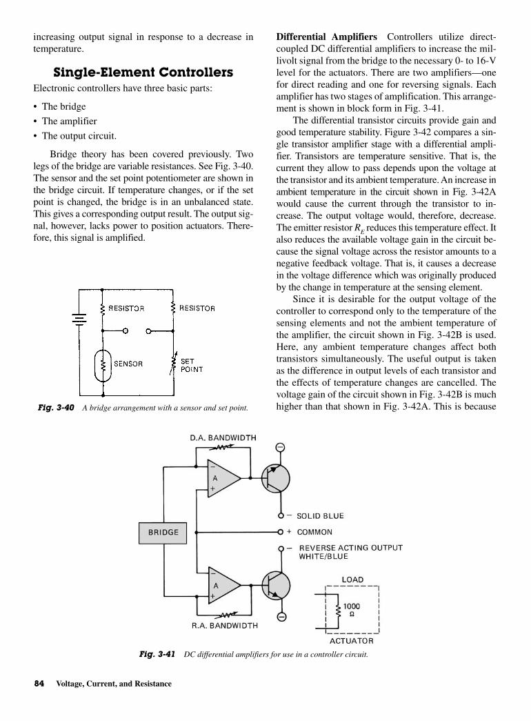
increasing output signal in response to a decrease intemperature.
Single-Element ControllersElectronic controllers have three basic parts:
• The bridge
• The amplifier
• The output circuit.
Bridge theory has been covered previously. Twolegs of the bridge are variable resistances. See Fig. 3-40.The sensor and the set point potentiometer are shown inthe bridge circuit. If temperature changes, or if the setpoint is changed, the bridge is in an unbalanced state.This gives a corresponding output result. The output sig-nal, however, lacks power to position actuators. There-fore, this signal is amplified.
Differential Amplifiers Controllers utilize direct-coupled DC differential amplifiers to increase the mil-livolt signal from the bridge to the necessary 0- to 16-Vlevel for the actuators. There are two amplifiers—onefor direct reading and one for reversing signals. Eachamplifier has two stages of amplification. This arrange-ment is shown in block form in Fig. 3-41.
The differential transistor circuits provide gain andgood temperature stability. Figure 3-42 compares a sin-gle transistor amplifier stage with a differential ampli-fier. Transistors are temperature sensitive. That is, thecurrent they allow to pass depends upon the voltage atthe transistor and its ambient temperature. An increase inambient temperature in the circuit shown in Fig. 3-42Awould cause the current through the transistor to in-crease. The output voltage would, therefore, decrease.The emitter resistor RE reduces this temperature effect. Italso reduces the available voltage gain in the circuit be-cause the signal voltage across the resistor amounts to anegative feedback voltage. That is, it causes a decreasein the voltage difference which was originally producedby the change in temperature at the sensing element.
Since it is desirable for the output voltage of thecontroller to correspond only to the temperature of thesensing elements and not the ambient temperature ofthe amplifier, the circuit shown in Fig. 3-42B is used.Here, any ambient temperature changes affect bothtransistors simultaneously. The useful output is takenas the difference in output levels of each transistor andthe effects of temperature changes are cancelled. Thevoltage gain of the circuit shown in Fig. 3-42B is muchhigher than that shown in Fig. 3-42A. This is because
84 Voltage, Current, and Resistance
Fig. 3-40 A bridge arrangement with a sensor and set point.
Fig. 3-41 DC differential amplifiers for use in a controller circuit.
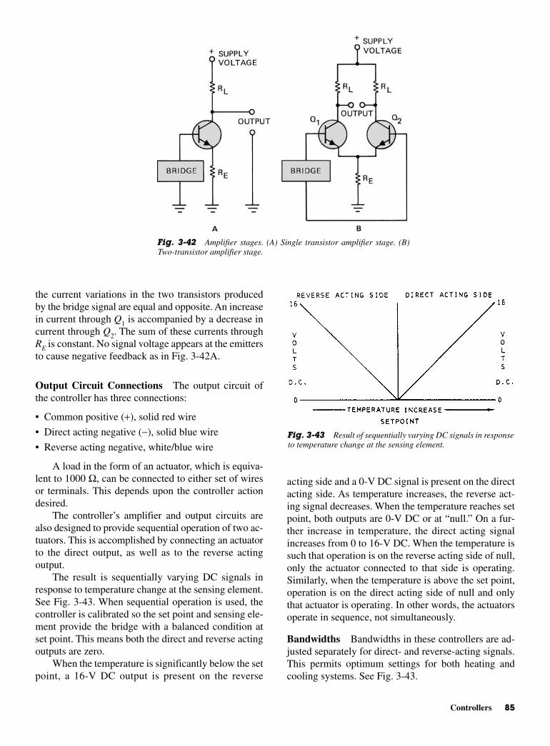
acting side and a 0-V DC signal is present on the directacting side. As temperature increases, the reverse act-ing signal decreases. When the temperature reaches setpoint, both outputs are 0-V DC or at “null.” On a fur-ther increase in temperature, the direct acting signalincreases from 0 to 16-V DC. When the temperature issuch that operation is on the reverse acting side of null,only the actuator connected to that side is operating.Similarly, when the temperature is above the set point,operation is on the direct acting side of null and onlythat actuator is operating. In other words, the actuatorsoperate in sequence, not simultaneously.
Bandwidths Bandwidths in these controllers are ad-justed separately for direct- and reverse-acting signals.This permits optimum settings for both heating andcooling systems. See Fig. 3-43.
the current variations in the two transistors producedby the bridge signal are equal and opposite. An increasein current through Q1 is accompanied by a decrease incurrent through Q2. The sum of these currents throughRE is constant. No signal voltage appears at the emittersto cause negative feedback as in Fig. 3-42A.
Output Circuit Connections The output circuit ofthe controller has three connections:
• Common positive (+), solid red wire
• Direct acting negative (−), solid blue wire
• Reverse acting negative, white/blue wire
A load in the form of an actuator, which is equiva-lent to 1000 Ω, can be connected to either set of wiresor terminals. This depends upon the controller actiondesired.
The controller’s amplifier and output circuits arealso designed to provide sequential operation of two ac-tuators. This is accomplished by connecting an actuatorto the direct output, as well as to the reverse actingoutput.
The result is sequentially varying DC signals inresponse to temperature change at the sensing element.See Fig. 3-43. When sequential operation is used, thecontroller is calibrated so the set point and sensing ele-ment provide the bridge with a balanced condition atset point. This means both the direct and reverse actingoutputs are zero.
When the temperature is significantly below the setpoint, a 16-V DC output is present on the reverse
Controllers 85
Fig. 3-42 Amplifier stages. (A) Single transistor amplifier stage. (B)Two-transistor amplifier stage.
Fig. 3-43 Result of sequentially varying DC signals in responseto temperature change at the sensing element.
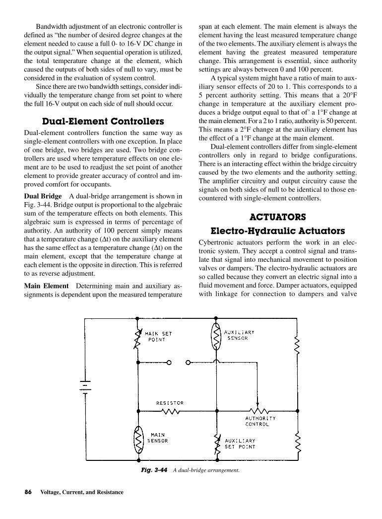
Bandwidth adjustment of an electronic controller isdefined as “the number of desired degree changes at theelement needed to cause a full 0- to 16-V DC change inthe output signal.” When sequential operation is utilized,the total temperature change at the element, whichcaused the outputs of both sides of null to vary, must beconsidered in the evaluation of system control.
Since there are two bandwidth settings, consider indi-vidually the temperature change from set point to wherethe full 16-V output on each side of null should occur.
Dual-Element ControllersDual-element controllers function the same way assingle-element controllers with one exception. In placeof one bridge, two bridges are used. Two bridge con-trollers are used where temperature effects on one ele-ment are to be used to readjust the set point of anotherelement to provide greater accuracy of control and im-proved comfort for occupants.
Dual Bridge A dual-bridge arrangement is shown inFig. 3-44. Bridge output is proportional to the algebraicsum of the temperature effects on both elements. Thisalgebraic sum is expressed in terms of percentage ofauthority. An authority of 100 percent simply meansthat a temperature change (∆t) on the auxiliary elementhas the same effect as a temperature change (∆t) on themain element, except that the temperature change ateach element is the opposite in direction. This is referredto as reverse adjustment.
Main Element Determining main and auxiliary as-signments is dependent upon the measured temperature
span at each element. The main element is always theelement having the least measured temperature changeof the two elements. The auxiliary element is always theelement having the greatest measured temperaturechange. This arrangement is essential, since authoritysettings are always between 0 and 100 percent.
A typical system might have a ratio of main to aux-iliary sensor effects of 20 to 1. This corresponds to a5 percent authority setting. This means that a 20°Fchange in temperature at the auxiliary element pro-duces a bridge output equal to that of’ a 1°F change atthe main element. For a 2 to 1 ratio, authority is 50 percent.This means a 2°F change at the auxiliary element hasthe effect of a 1°F change at the main element.
Dual-element controllers differ from single-elementcontrollers only in regard to bridge configurations.There is an interacting effect within the bridge circuitrycaused by the two elements and the authority setting.The amplifier circuitry and output circuitry cause thesignals on both sides of null to be identical to those en-countered with single-element controllers.
ACTUATORS
Electro-Hydraulic ActuatorsCybertronic actuators perform the work in an elec-tronic system. They accept a control signal and trans-late that signal into mechanical movement to positionvalves or dampers. The electro-hydraulic actuators areso called because they convert an electric signal into afluid movement and force. Damper actuators, equippedwith linkage for connection to dampers and valve
86 Voltage, Current, and Resistance
Fig. 3-44 A dual-bridge arrangement.

The servo valve represents the load of 1000 Ωrequired by the controller to cause a variation of 0- to16-V DC output signal. Two actuators can be con-nected in parallel across the output terminals of anelectronic controller. However, this will provide only500 Ω resistance, which the controller also can handle.
Thermal ActuatorsThermal actuators should more properly be calledelectro-thermal actuators. This is because they take a 0- to16-V DC signal and convert the signal into heat. Thethermal damper actuator has linkage for connection toa damper. The thermal-valve actuator is directly con-nected to the valve body.
Operation of a Thermal Actuator A thermal actua-tor is shown in Fig. 3-46. A small electrical control cir-cuit is encapsulated in the electrical cable about 12 in.from the thermal unit. The 0- to 16-V DC signal fromthe controller and the 24-V AC supply voltage are fedinto the control circuit. The circuit allows the 0- to16-V DC signal to control the amount of current fromthe 24-V supply to the actuator.
Inside the actuator, the controlled current from the24-V source heats up a small heater that is embeddedin wax. When the wax reaches approximately 180°F itchanges from solid to liquid. During this change, waxexpands. This is the point at which the motion of thedevice is controlled.
As the wax expands, the power element shaft isforced out to move the piston. This, in turn compresses
actuators, having a yoke and linkage to facilitate mount-ing on a valve body, are available.
Operation of Actuators Two voltages are applied tothe actuator. See Fig. 3-45. A 0- to 16-V DC controlsignal regulates or controls the servo valve. Then a 24-or 120-V AC signal, depending on the unit, operatesthe oil pump. The oil pump moves oil from the upperchamber to the lower chamber. The servo valve con-trols pressure at the diaphragm by varying the returnflow from the lower to the upper chamber.
When there is no DC voltage applied to the servovalve, the flapper is pushed off the servo port by way ofthe hydraulic pressure developed by the pump. The openservo port allows the pump to move all the oil throughthe lower chamber back into the upper chamber.
When the voltage on the servo increases, a mag-netic force is developed. This magnetic force holds theflapper down over the servo port. The pump continuesto pump oil into the lower chamber. But, the returnflow to the upper chamber is stopped by the blockedservo port. Pressure is built up in the lower chamberuntil the magnetic force on the flapper is overcome andthe flapper is pushed away from the servo port. Thisequalizes the flow through the pump and servo valve,while maintaining a pressure in the lower chamber.
Each increase in DC voltage results in a hydraulicpressure increase in the lower chamber. The increasedpressure begins to overcome the opposing pressurefrom the return spring, and forces out the actuatorshaft. Each further increase in DC voltage causes an in-creased extension of the actuator shaft.
Actuators 87
Fig. 3-45 An elctro-hydraulic actuator.
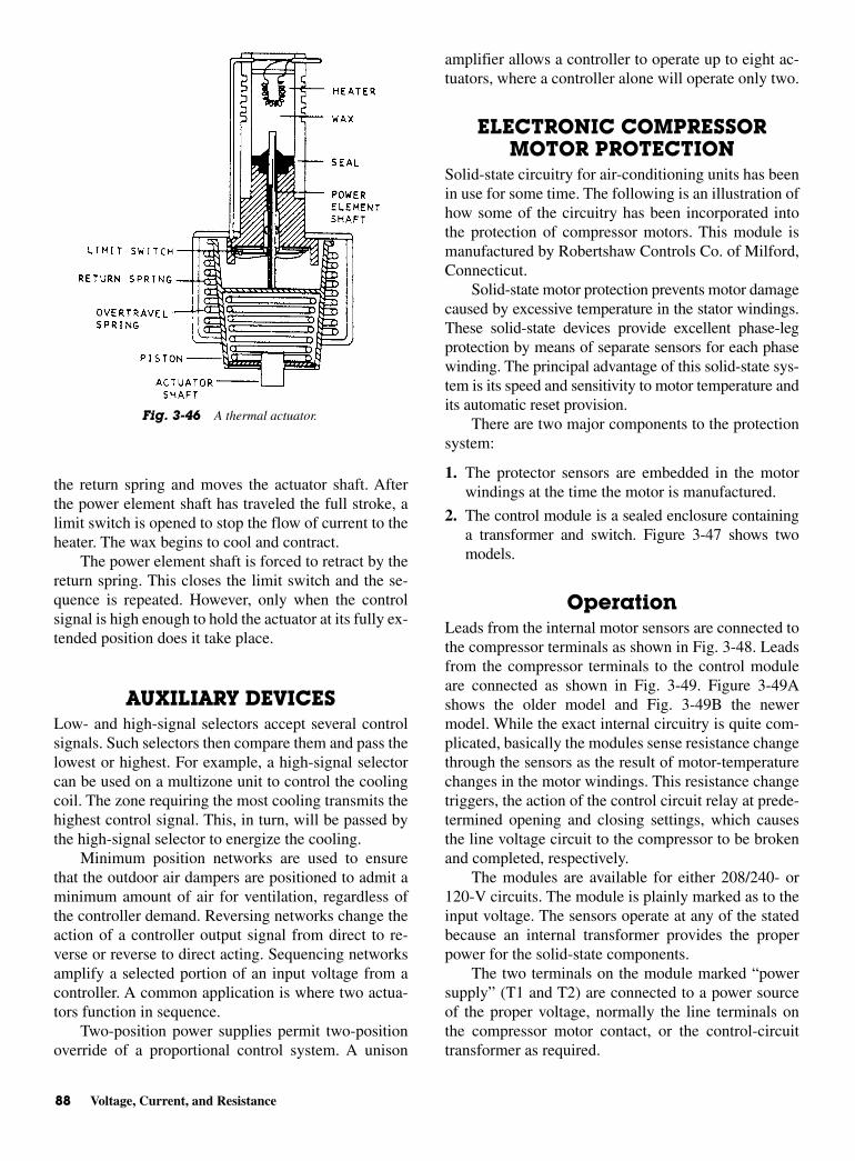
the return spring and moves the actuator shaft. Afterthe power element shaft has traveled the full stroke, alimit switch is opened to stop the flow of current to theheater. The wax begins to cool and contract.
The power element shaft is forced to retract by thereturn spring. This closes the limit switch and the se-quence is repeated. However, only when the controlsignal is high enough to hold the actuator at its fully ex-tended position does it take place.
AUXILIARY DEVICESLow- and high-signal selectors accept several controlsignals. Such selectors then compare them and pass thelowest or highest. For example, a high-signal selectorcan be used on a multizone unit to control the coolingcoil. The zone requiring the most cooling transmits thehighest control signal. This, in turn, will be passed bythe high-signal selector to energize the cooling.
Minimum position networks are used to ensurethat the outdoor air dampers are positioned to admit aminimum amount of air for ventilation, regardless ofthe controller demand. Reversing networks change theaction of a controller output signal from direct to re-verse or reverse to direct acting. Sequencing networksamplify a selected portion of an input voltage from acontroller. A common application is where two actua-tors function in sequence.
Two-position power supplies permit two-positionoverride of a proportional control system. A unison
amplifier allows a controller to operate up to eight ac-tuators, where a controller alone will operate only two.
ELECTRONIC COMPRESSORMOTOR PROTECTION
Solid-state circuitry for air-conditioning units has beenin use for some time. The following is an illustration ofhow some of the circuitry has been incorporated intothe protection of compressor motors. This module ismanufactured by Robertshaw Controls Co. of Milford,Connecticut.
Solid-state motor protection prevents motor damagecaused by excessive temperature in the stator windings.These solid-state devices provide excellent phase-legprotection by means of separate sensors for each phasewinding. The principal advantage of this solid-state sys-tem is its speed and sensitivity to motor temperature andits automatic reset provision.
There are two major components to the protectionsystem:
1. The protector sensors are embedded in the motorwindings at the time the motor is manufactured.
2. The control module is a sealed enclosure containinga transformer and switch. Figure 3-47 shows twomodels.
OperationLeads from the internal motor sensors are connected tothe compressor terminals as shown in Fig. 3-48. Leadsfrom the compressor terminals to the control moduleare connected as shown in Fig. 3-49. Figure 3-49Ashows the older model and Fig. 3-49B the newermodel. While the exact internal circuitry is quite com-plicated, basically the modules sense resistance changethrough the sensors as the result of motor-temperaturechanges in the motor windings. This resistance changetriggers, the action of the control circuit relay at prede-termined opening and closing settings, which causesthe line voltage circuit to the compressor to be brokenand completed, respectively.
The modules are available for either 208/240- or120-V circuits. The module is plainly marked as to theinput voltage. The sensors operate at any of the statedbecause an internal transformer provides the properpower for the solid-state components.
The two terminals on the module marked “powersupply” (T1 and T2) are connected to a power sourceof the proper voltage, normally the line terminals onthe compressor motor contact, or the control-circuittransformer as required.
88 Voltage, Current, and Resistance
Fig. 3-46 A thermal actuator.
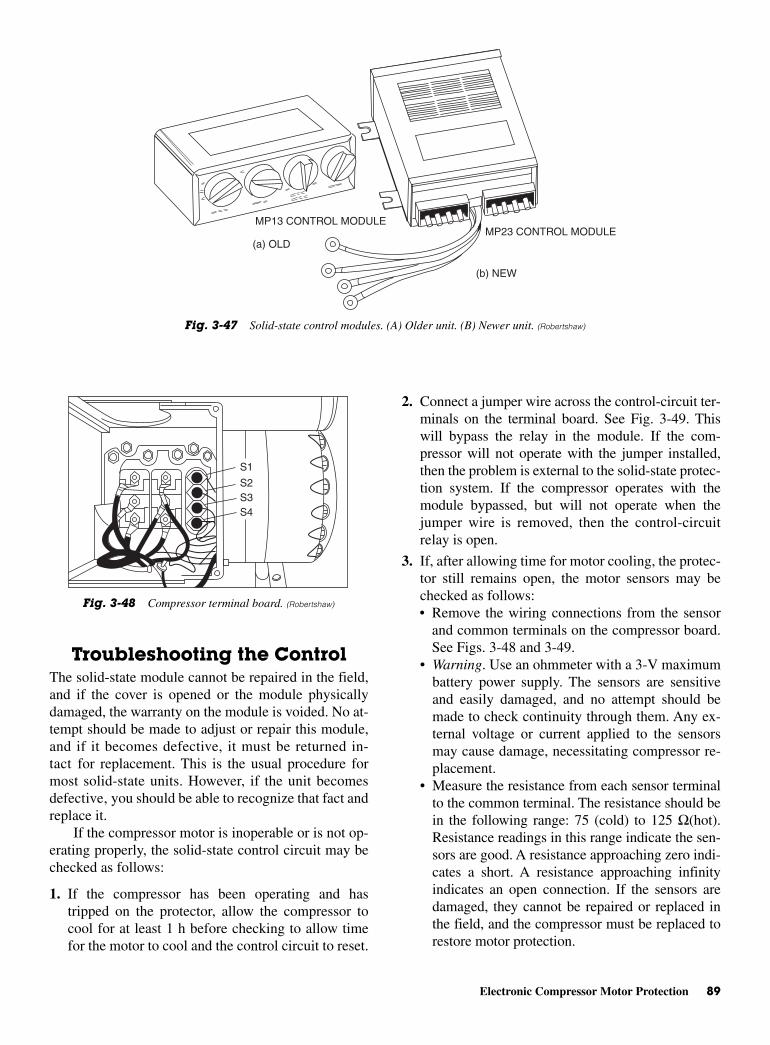
2. Connect a jumper wire across the control-circuit ter-minals on the terminal board. See Fig. 3-49. Thiswill bypass the relay in the module. If the com-pressor will not operate with the jumper installed,then the problem is external to the solid-state protec-tion system. If the compressor operates with themodule bypassed, but will not operate when thejumper wire is removed, then the control-circuitrelay is open.
3. If, after allowing time for motor cooling, the protec-tor still remains open, the motor sensors may bechecked as follows:• Remove the wiring connections from the sensor
and common terminals on the compressor board.See Figs. 3-48 and 3-49.
• Warning. Use an ohmmeter with a 3-V maximumbattery power supply. The sensors are sensitiveand easily damaged, and no attempt should bemade to check continuity through them. Any ex-ternal voltage or current applied to the sensorsmay cause damage, necessitating compressor re-placement.
• Measure the resistance from each sensor terminalto the common terminal. The resistance should bein the following range: 75 (cold) to 125 Ω(hot).Resistance readings in this range indicate the sen-sors are good. A resistance approaching zero indi-cates a short. A resistance approaching infinityindicates an open connection. If the sensors aredamaged, they cannot be repaired or replaced inthe field, and the compressor must be replaced torestore motor protection.
Troubleshooting the ControlThe solid-state module cannot be repaired in the field,and if the cover is opened or the module physicallydamaged, the warranty on the module is voided. No at-tempt should be made to adjust or repair this module,and if it becomes defective, it must be returned in-tact for replacement. This is the usual procedure formost solid-state units. However, if the unit becomesdefective, you should be able to recognize that fact andreplace it.
If the compressor motor is inoperable or is not op-erating properly, the solid-state control circuit may bechecked as follows:
1. If the compressor has been operating and hastripped on the protector, allow the compressor tocool for at least 1 h before checking to allow timefor the motor to cool and the control circuit to reset.
Electronic Compressor Motor Protection 89
(a) OLD
MP13 CONTROL MODULEMP23 CONTROL MODULE
(b) NEW
Fig. 3-47 Solid-state control modules. (A) Older unit. (B) Newer unit. (Robertshaw)
S1
S2S3S4
Fig. 3-48 Compressor terminal board. (Robertshaw)
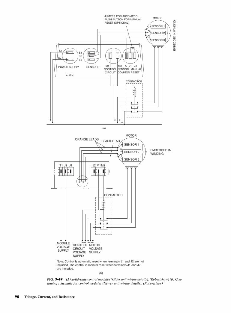
90 Voltage, Current, and Resistance
S1S1
MOTOR
SENSOR 1
SENSOR 2
SENSOR 3
JUMPER FOR AUTOMATICPUSH BUTTON FOR MANUALRESET (OPTIONAL)
S2S3
V. A.C
S2
EM
BE
DD
ED
IN W
IND
ING
POWER SUPPLY SENSORSCONTROLCIRCUIT
SENSORCOMMON
MANUALRESET
CONTACTOR
(a)
M1 M2 C J1 J2
Fig. 3-49 (A) Solid-state control modules (Older unit wiring details). (Robertshaw) (B) Con-tinuing schematic for control modules (Newer unit wiring details). (Robertshaw)
SENSOR 1
MOTORORANGE LEADS BLACK LEAD
T1 J2 J2 M1M2J1
SENSOR 2
SENSOR 3
EMBEDDED INWINDING
CONTACTOR
MODULEVOLTAGESUPPLY
CONTROLCIRCUITVOLTAGESUPPLY
Note: Control is automatic reset when terminals J1 and J2 are notincluded. The control is manual reset when terminals J1 and J2are included.
MOTORVOLTAGESUPPLY
(b)
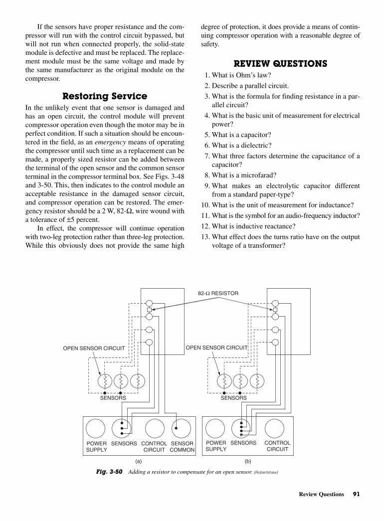
degree of protection, it does provide a means of contin-uing compressor operation with a reasonable degree ofsafety.
REVIEW QUESTIONS1. What is Ohm’s law?
2. Describe a parallel circuit.
3. What is the formula for finding resistance in a par-allel circuit?
4. What is the basic unit of measurement for electricalpower?
5. What is a capacitor?
6. What is a dielectric?
7. What three factors determine the capacitance of acapacitor?
8. What is a microfarad?
9. What makes an electrolytic capacitor differentfrom a standard paper-type?
10. What is the unit of measurement for inductance?
11. What is the symbol for an audio-frequency inductor?
12. What is inductive reactance?
13. What effect does the turns ratio have on the outputvoltage of a transformer?
If the sensors have proper resistance and the com-pressor will run with the control circuit bypassed, butwill not run when connected properly, the solid-statemodule is defective and must be replaced. The replace-ment module must be the same voltage and made bythe same manufacturer as the original module on thecompressor.
Restoring ServiceIn the unlikely event that one sensor is damaged andhas an open circuit, the control module will preventcompressor operation even though the motor may be inperfect condition. If such a situation should be encoun-tered in the field, as an emergency means of operatingthe compressor until such time as a replacement can bemade, a properly sized resistor can be added betweenthe terminal of the open sensor and the common sensorterminal in the compressor terminal box. See Figs. 3-48and 3-50. This, then indicates to the control module anacceptable resistance in the damaged sensor circuit,and compressor operation can be restored. The emer-gency resistor should be a 2 W, 82-Ω, wire wound witha tolerance of ±5 percent.
In effect, the compressor will continue operationwith two-leg protection rather than three-leg protection.While this obviously does not provide the same high
Review Questions 91
POWERSUPPLY
SENSORS
SENSORS SENSORS
CONTROLCIRCUIT
SENSORCOMMON
POWERSUPPLY
SENSORS CONTROLCIRCUIT
OPEN SENSOR CIRCUIT OPEN SENSOR CIRCUIT
82-Ω RESISTOR
(a) (b)
Fig. 3-50 Adding a resistor to compensate for an open sensor. (Robertshaw)
14. What is a zener diode?
15. What do the letters SCR stand for?
16. What is a bridge circuit?
17. What are the three parts of electronic controllers?
18. What is a thermal actuator?
19. What does the word semiconductor mean?
20. What are the two materials used for semiconductordevices?
21. What is a diode?
22. What is the PN junction diode used for?
23. What are the uses for diodes?
24. What are the two main uses for transistors?
25. What is an SCR? Where is it used?
26. What are the two main uses for a thermister?
27. What is a PNP transistor?
28. What is an integrated circuit?
29. What does CAB stand for in a humidity circuit?
30. What is a bridge circuit?
31. How do balanced and unbalanced bridge circuitsdiffer?
32. What is a sensor?
33. How is a sensing bridge connected?
34. What is an actuator?
35. What is a differential amplifier used for?
92 Voltage, Current, and Resistance

4CHAPTER
Solenoidsand Valves
Copyright © 2006 by The McGraw-Hill Companies, Inc. Click here for terms of use.
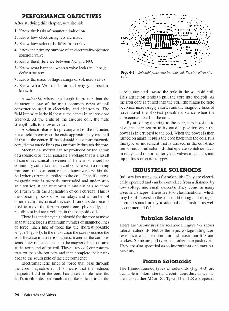
PERFORMANCE OBJECTIVESAfter studying this chapter, you should:
1. Know the basis of magnetic induction.
2. Know how electromagnets are made.
3. Know how solenoids differ from relays.
4. Know the primary purpose of an electrically-operatedsolenoid valve.
5. Know the difference between NC and NO.
6. Know what happens when a valve leaks in a hot-gasdefrost system.
7. Know the usual voltage ratings of solenoid valves.
8. Know what VA stands for and why you need toknow it.
A solenoid, where the length is greater than thediameter is one of the most common types of coilconstruction used in electricity and electronics. Thefield intensity is the highest at the center in an iron-coresolenoid. At the ends of the air-core coil, the fieldstrength falls to a lower value.
A solenoid that is long, compared to the diameter,has a field intensity at the ends approximately one-halfof that at the center. If the solenoid has a ferromagneticcore, the magnetic lines pass uniformly through the core.
Mechanical motion can be produced by the actionof a solenoid or it can generate a voltage that is a resultof some mechanical movement. The term solenoid hascommonly come to mean a coil of wire with a movingiron core that can center itself lengthwise within thecoil when current is applied to the coil. Then if a ferro-magnetic core is properly suspended and under suit-able tension, it can be moved in and out of a solenoidcoil form with the application of coil current. This isthe operating basis of some relays and a number ofother electromechanical devices. If an outside force isused to move the ferromagnetic core physically, it ispossible to induce a voltage in the solenoid coil.
There is a tendency in a solenoid for the core to moveso that it encloses a maximum number of magnetic linesof force. Each line of force has the shortest possiblelength (Fig. 4-1). In the illustration the core is outside thecoil. Because it is a ferromagnetic material, the coil pre-sents a low-reluctance path to the magnetic lines of forceat the north end of the coil. These lines of force concen-trate on the soft-iron core and then complete their pathsback to the south pole of the electromagnet.
Electromagnetic lines of force that pass throughthe core magnetize it. This means that the inducedmagnetic field in the core has a south pole near thecoil’s north pole. Inasmuch as unlike poles attract, the
core is attracted toward the hole in the solenoid coil.This attraction tends to pull the core into the coil. Asthe iron core is pulled into the coil, the magnetic fieldbecomes increasingly shorter and the magnetic lines offorce travel the shortest possible distance when thecore centers itself in the coil.
By attaching a spring to the core, it is possible tohave the core return to its outside position once thepower is interrupted to the coil. When the power is thenturned on again, it pulls the core back into the coil. It isthis type of movement that is utilized in the construc-tion of industrial solenoids that operate switch contactsin relays and motor starters, and valves in gas, air, andliquid lines of various types.
INDUSTRIAL SOLENOIDSIndustry has many uses for solenoids. They are electri-cally operated and can be controlled from a distance bylow voltage and small currents. They come in manysizes and shapes. There are two classifications, whichmay be of interest to the air-conditioning and refriger-ation personnel in any residential or industrial as wellas commercial field.
Tubular SolenoidsThere are various uses for solenoids. Figure 4-2 showstubular solenoids. Notice the type, voltage rating, coilresistance, and the minimum and maximum lifts andstrokes. Some are pull types and others are push types.They are also specified as to intermittent and continu-ous duty.
Frame SolenoidsThe frame-mounted types of solenoids (Fig. 4-3) areavailable in intermittent and continuous duty as well asusable on either AC or DC. Types 11 and 28 can operate
94 Solenoids and Valves
Fig. 4-1 Solenoid pulls core into the coil. Sucking effect of acoil.
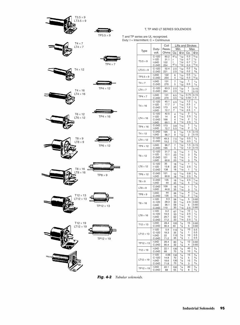
Industrial Solenoids 95
T4 × 7LT4 × 7
T4 × 12
T4 × 16LT4 × 16
T6 × 12LT6 × 12
T8 × 9LT8 × 9
T8 × 16LT8 × 16
T12 × 13LT12 × 13
T12 × 19LT12 × 19
T3.5 × 9LT3.5 × 9
TP3.5 × 9
TP4 × 7
TP4 × 12
TP4 × 16
TP6 × 12
TP8 × 9
TP12 × 13
TP12 × 19
Lifts and Strokes
Oz. Oz.@in @inMin. Max.
CoilResis. Ohms
Duty-volt.
Type
C-12DI-12DI-24DC-24D
C-12DI-12DC-24DI-24D
I-12DC-12DI-24DC-24DI-12DC-12DI-24DC-24D
I-12DC-12DI-24DC-24D
I-12DC-12DI-24DC-24D
I-24DC-24D
I-24DC-24D
I-24DC-24D
I-24DC-24D
C-12DI-12DC-24DI-24D
C-12DI-12DC-24DI-24D
C-24DI-24D
C-24DI-24D
C-24DI-24D
I-24DC-24D
C-12DI-12DC-24D
I-24DC-24DI-24DC-24D
I-24DC-24D
C-24DI-24DC-24DI-24D
C-12DC-24D
C-12DC-24D
C-12DC-24D
I-24DC-24D
60.2 31.1 122254 52.4 221122254131270
131270
45.1 17.7 173 72.7 42.5 14 168 69.1
31.7 12.1 121 60.6
173 72.7195 96.7
96.7 195
49.319.2
4.574.57
4848
3.85.5
7.57.5
75
15231523
183518
1218
1845
1835
361458305830
67336233
10040
11035
11035
8032
13070
10055
22.168
13070
13070
4.66 14.818.671.8
35 13.8 138
121 60.6
135 44
109 44.6 44 135
9.3 28.3 36.1 110
6.2 19.3 29.7 77.2
28.490.4
28.490.4
22.168
5.9 18.32271.2
122.5102.5155
124
4010
101
101
155
153
308
0.50.50.50.5
52.55
2.5
0.600.600.600.60
0.600.60
0.600.60
69
1.22.51.22.52
2.52
2.512
1.52
0.50.5
1.51.0
13131
2.51
0.82.52.55
1342
63.3 264
64
75
2.52.5
2.52.5
6.53.5
41/27741/2
1/321/321/321/32
1/161/161/161/16
1/161/161/161/16
1/161/161/161/16
1/161/161/161/16
1/81/81/81/8
1/81/81/81/8
1/161/161/161/16
1/81/8
1/81/8
1/81/8
1/81/8
1/161/161/16
1/161/16
7/167/16
7/167/16
1/161/16
1/161/161/161/16
1/161/16
1/321/321/321/32
1/321/32
1/321/32
1/321/32
1/321/321/321/321/321/32
3/83/8
5/161/21/25/16
1/21/21/21/2
1/21/21/21/2
1/21/21/2
1/21/2
3/43/43/43/4
3/43/4
3/43/4
3/43/4
3/43/43/43/4
1/21/2
1/21/2
1/211/21
1/25/16
1/41/4
0.30.70.70.30.20.20.50.3 1
0.5
0.750.50
11
0.150.15
0.150.15
0.150.15
0.151.5
T3.5 × 9
T4 × 7
T4 × 12
T6 × 12
T8 × 9
T8 × 16
T12 × 13
T12 × 19
TP12 × 19
LT12 × 19
TP12 × 13
LT12 × 13
LT8 × 16
TP8 × 9
LT8 × 9
LT6 × 12
TP6 × 12
LT4 × 12
TP4 × 12
TP4 × 7
T4 × 16
LT4 × 16
TP4 × 16
LT4 × 7
TP3.5 × 9
LT3.5 × 9
T, TP AND LT SERIES SOLENOIDS
T and TP series are UL recognized. Duty: I = Intermittent. C = Continuous
Fig. 4-2 Tubular solenoids.

96 Solenoids and Valves
Type 2
Type 11
Type 12
Type 14
Type 11HD
Type 18
Type 28
Type 16
Type 22
Type 24
Type 2HD Type 4 Type 4HD
Type Duty Volts OhmsOz. @inch of stroke
Minimum Maximum
DC Voltage Model Solenoids
2HD2HD
11HD11HD11P
4HD4HD4HD4HD
4444
11111111
22222222
282828282828
IntermittentContinuous
Intermittent ContinuousContinuous
IntermittentContinuous Intermittent Continuous
Intermittent Continuous Intermittent Continuous
Intermittent Continuous Intermittent Continuous
Intermittent Continuous Intermittent Continuous
Intermittent Continuous Intermittent Continuous Intermittent Continuous
2424
22.671
15.8 61.3 296 1215
18.9 57.5 354 1140
24 24 110110
24 24 110110
6 6 2424
1.88 4.69 29.193.1
5.8 11.5 93.2 182
3.03 7.5 11.9 29.8 47.4 116
6 6 2424
6 6 12122424
2424
29.376.3
24 93.1
96@1/8"48@1/8"
15@1/2" 5@1/2"
20@1" 7@4/5"
20@1"7@4/5"
25@3/4"5@3/4"
25@3/4"5@3/4"
10@1/2" 4@1/2"10@1/2" 4@1/2"
3@1/2"2@1/2"3@1/2"2@1/2"3@1/2"2@1/2"
5@3/4"2@3/4"
3.2@1/2"
[email protected]"[email protected]"[email protected]"[email protected]"
100@60@1/8"
100@1/8"60@1/8"
130@1/8"80@1/8"
130@1/8"80@1/8"
45@1/8"30@45@1/8"30@1/8"
17@1/16"11@1/16"17@1/16"11@1/16"
40@1/16"23@1/16"40@1/16"23@1/16"40@1/16"23@1/16"
70@1/8"30@1/8"24@1/8"
2HD2HD
11HD11P
22
120120
60 166
36 113 37 133 85 200
100150
1118
4185
8.8 19.74578
41 85 350
165200
120120120120120120120120
12024120
120120
120120
120120
120120
120120240
120120240240
441111
1212
1414161616
18181818
16P16P
2828
18P18P24
Intermittent Continuous
Intermittent ContinuousIntermittent ContinuousIntermittent Continuous
Intermittent Continuous
ContinuousContinuous Continuous
Intermittent Continuous
Intermittent Continuous
Intermittent Continuous
IntermittentContinuous Intermittent Continuous
Intermittent Continuous Continuous
ContinuousContinuous
45@1/8"14@1/8"
11@7/8" 3@7/8"
11@3/4" 6@3/4"
4.8@3/4"
28@3/4"15@3/4"15@3/4"
16@3/4" 6@3/4"
9@7/8"6@7/8"
22.5@ 12@208@7/8"100@7/8"208@7/8"100@7/8"
187@7/8" 90@7/8"
2@5/8"5@5/8"5@1/2"
56@11/2"40@11/2"
26@1" 7@1"
31/2@1"
70@1/8"25@1/8"
21@1/8"12@1/8"
48@1/8"28@1/8"
108@1/8" 75@1/8"
350@1/8"152@1/8"350@1/8"150@1/8"
88@1/8"50.5@1/8"
315@1/8"137@1/8"10@1/16"24@1/16"24@1/16"
110@1/8" 63@1/8" 63@1/8"
12@1/8"9.6@1/8"
36@1/8" 8@1/8"
AC Voltage Model Solenoids
8.8 19.7500
17.4 400
These intermittent and continuous duty solenoids are available in AC and DC versions, and in three constructions: box frame, U-frame and laminated. Types 2, 2HD, 4, 4HD, 11, 11HD, 11P, 22 and 28 are box frame. Types 12, 14, 16,16P, 18 and 18P are laminated. Type 24 is U-frame. Suffix P indicates a push type model. Suffix HD indicates a heavy duty model. All box frame models have quick connect terminals.
All models are UL recognized
"3/4"3/4
1/8"
1/81/8"
Fig. 4-3 Frame solenoids.
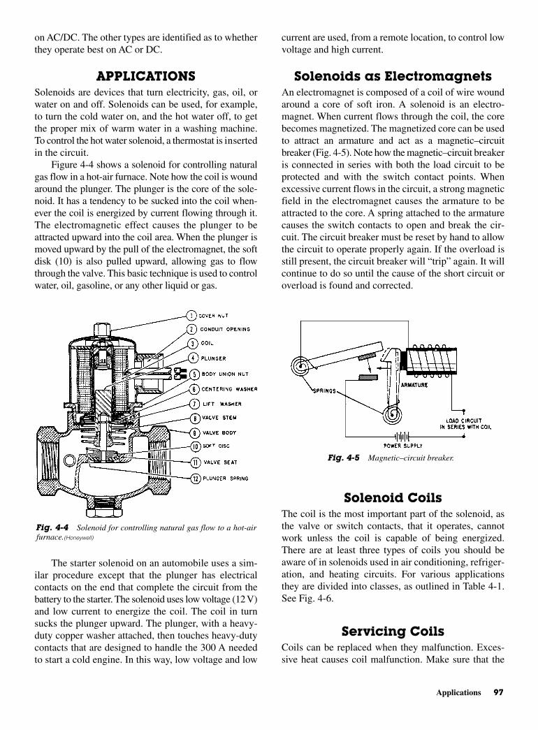
Applications 97
on AC/DC. The other types are identified as to whetherthey operate best on AC or DC.
APPLICATIONSSolenoids are devices that turn electricity, gas, oil, orwater on and off. Solenoids can be used, for example,to turn the cold water on, and the hot water off, to getthe proper mix of warm water in a washing machine.To control the hot water solenoid, a thermostat is insertedin the circuit.
Figure 4-4 shows a solenoid for controlling naturalgas flow in a hot-air furnace. Note how the coil is woundaround the plunger. The plunger is the core of the sole-noid. It has a tendency to be sucked into the coil when-ever the coil is energized by current flowing through it.The electromagnetic effect causes the plunger to beattracted upward into the coil area. When the plunger ismoved upward by the pull of the electromagnet, the softdisk (10) is also pulled upward, allowing gas to flowthrough the valve. This basic technique is used to controlwater, oil, gasoline, or any other liquid or gas.
The starter solenoid on an automobile uses a sim-ilar procedure except that the plunger has electricalcontacts on the end that complete the circuit from thebattery to the starter. The solenoid uses low voltage (12 V)and low current to energize the coil. The coil in turnsucks the plunger upward. The plunger, with a heavy-duty copper washer attached, then touches heavy-dutycontacts that are designed to handle the 300 A neededto start a cold engine. In this way, low voltage and low
current are used, from a remote location, to control lowvoltage and high current.
Solenoids as ElectromagnetsAn electromagnet is composed of a coil of wire woundaround a core of soft iron. A solenoid is an electro-magnet. When current flows through the coil, the corebecomes magnetized. The magnetized core can be usedto attract an armature and act as a magnetic–circuitbreaker (Fig. 4-5). Note how the magnetic–circuit breakeris connected in series with both the load circuit to beprotected and with the switch contact points. Whenexcessive current flows in the circuit, a strong magneticfield in the electromagnet causes the armature to beattracted to the core. A spring attached to the armaturecauses the switch contacts to open and break the cir-cuit. The circuit breaker must be reset by hand to allowthe circuit to operate properly again. If the overload isstill present, the circuit breaker will “trip” again. It willcontinue to do so until the cause of the short circuit oroverload is found and corrected.
Solenoid CoilsThe coil is the most important part of the solenoid, asthe valve or switch contacts, that it operates, cannotwork unless the coil is capable of being energized.There are at least three types of coils you should beaware of in solenoids used in air conditioning, refriger-ation, and heating circuits. For various applicationsthey are divided into classes, as outlined in Table 4-1.See Fig. 4-6.
Servicing CoilsCoils can be replaced when they malfunction. Exces-sive heat causes coil malfunction. Make sure that the
Fig. 4-4 Solenoid for controlling natural gas flow to a hot-airfurnace.(Honeywell)
Fig. 4-5 Magnetic–circuit breaker.
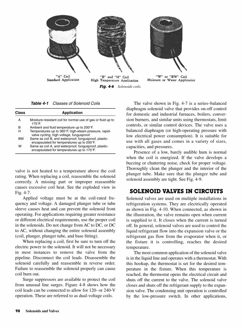
98 Solenoids and Valves
valve is not heated to a temperature above the coilrating. When replacing a coil, reassemble the solenoidcorrectly. A missing part or improper reassemblecauses excessive coil heat. See the exploded view inFig. 4-7.
Applied voltage must be at the coil-rated fre-quency and voltage. A damaged plunger tube or tubesleeve causes heat and can prevent the solenoid frontoperating. For applications requiring greater resistanceor different electrical requirements, use the proper coilin the solenoids. Do not change from AC to DC, or DCto AC, without changing the entire solenoid assembly(coil, plunger, plunger tube, and base fitting).
When replacing a coil, first be sure to turn off theelectric power to the solenoid. It will not be necessaryin most instances to remove the valve from thepipeline. Disconnect the coil leads. Disassemble thesolenoid carefully and reassemble in reverse order.Failure to reassemble the solenoid properly can causecoil burn out.
Surge suppressors are available to protect the coilfrom unusual line surges. Figure 4-8 shows how thecoil leads can be connected to allow for 120- or 240-Voperation. These are referred to as dual-voltage coils.
The valve shown in Fig. 4-7 is a series–balanceddiaphragm solenoid valve that provides on-off controlfor domestic and industrial furnaces, boilers, conver-sion burners, and similar units using thermostats, limitcontrols, or similar control devices. The valve uses abalanced diaphragm (or high-operating pressure withlow electrical power consumption). It is suitable foruse with all gases and comes in a variety of sizes,capacities, and pressures.
Presence of a low, barely audible hum is normalwhen the coil is energized. If the valve develops abuzzing or chattering noise, check for proper voltage.Thoroughly clean the plunger and the interior of theplunger tube. Make sure that the plunger tube andsolenoid assembly are tight. See Fig. 4-9.
SOLENOID VALVES IN CIRCUITSSolenoid valves are used on multiple installations inrefrigeration systems. They are electrically operatedas shown in Fig. 4-10. When connected, as shown inthe illustration, the valve remains open when currentis supplied to it. It closes when the current is turnedoff. In general, solenoid valves are used to control theliquid refrigerant flow into the expansion valve or therefrigerant gas flow from the evaporator when it, orthe fixture it is controlling, reaches the desiredtemperature.
The most common application of the solenoid valveis in the liquid line and operates with a thermostat. Withthis hookup, the thermostat is set for the desired tem-perature in the fixture. When this temperature isreached, the thermostat opens the electrical circuit andshuts off the current to the valve. The solenoid valvecloses and shuts off the refrigerant supply to the expan-sion valve. The condensing unit operation is controlledby the low-pressure switch. In other applications,
Table 4-1 Classes of Solenoid Coils
Class Application
A Moisture-resistant coil for normal use of gas or fluid up to 175°F.
B Ambient and fluid temperature up to 200°F.H Temperatures up to 365°F, high-steam pressure, rapid-
valve cycling, high voltage, fungusproof.BW Same as coil B, and waterproof, fungusproof, plastic-
encapsulated for temperatures up to 200°F.W Same as coil A, and waterproof, fungusproof, plastic-
encapsulated for temperatures up to 175°F.
Fig. 4-6 Solenoids coils.
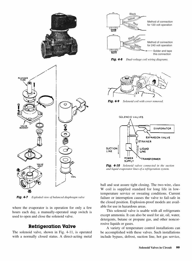
Solenoid Valves in Circuit 99
where the evaporator is in operation for only a fewhours each day, a manually-operated snap switch isused to open and close the solenoid valve.
Refrigeration ValveThe solenoid valve, shown in Fig. 4-11, is operatedwith a normally closed status. A direct-acting metal
ball and seat assure tight closing. The two-wire, classW coil is supplied standard for long life in low-temperature service or sweating conditions. Currentfailure or interruption causes the valve to fail-safe inthe closed position. Explosion-proof models are avail-able for use in hazardous areas.
This solenoid valve is usable with all refrigerantsexcept ammonia. It can also be used for air, oil, water,detergents, butane or propane gas, and other noncor-rosive liquids or gases.
A variety of temperature control installations canbe accomplished with these valves. Such installationsinclude bypass, defrost, suction line, hot gas service,
Fig. 4-7 Exploded view of balanced diaphragm valve
Method of connection for 120 volt operation
Method of connection for 240 volt operation
Solder and tape this connection
Black
Black
Green
Red
Red
Green
Yellow
Yellow
Fig. 4-8 Dual-voltage coil wiring diagrams.
Fig. 4-9 Solenoid coil with cover removed.
Fig. 4-10 Solenoid valves connected in the suctionand liquid evaporator lines of a refrigeration system.

100 Solenoids and Valves
humidity control, alcohols, unloading, reverse cycle,chilled water, cooling tower, brine, and liquid–line stopinstallations and ice makers.
The valves are held in the normally closed positionby the weight of the plunger assembly and fluid pres-sure on top of the valve ball. The valve is opened byenergizing the coil. This magnetically lifts the plungerand allows full flow by the valve ball. Deenergizing thecoil permits the plunger and valve ball to return to theclosed position.
REVIEW QUESTIONS 1. Define solenoid.
2. What is meant by the term sucking effect of asolenoid?
3. What does the armature of an electromagnet do?
4. What is the most important part of the solenoid?
5. List the five classes of solenoids.
6. What are dual-voltage coils? How are they wired?
7. Where are series-balanced diaphragm solenoidvalves used?
8. What does a barely audible hum indicate when acoil is energized?
9. Where are solenoid valves used?
10. How are valves made fail-safe?
Fig. 4-11 Schematic illustration of a refrigeration installation.

5CHAPTER
Electric Motors:Selection,
OperationalCharacteristics,and Problems
Copyright © 2006 by The McGraw-Hill Companies, Inc. Click here for terms of use.

102 Electric Motors: Selection, Operational Characteristics, and Problems
Fig. 5-1 Note how the windings are inserted in a motor frame.
PERFORMANCE OBJECTIVES1. Know the principle of operation of a DC motor.
2. Know how motors operate.
3. Know how to start a motor.
4. Know different types of motors.
5. Know how AC/DC motors differ one from the other.
6. Know how to select the proper type and size ofmotor for a specific job.
7. Know how to troubleshoot motors using the proba-ble cause-remedy chart.
8. Know how to use a V-O-M to test a refrigerationmotor circuit.
9. Know how contactors, starters, and relays operate.
10. Know how motor-overload protectors operate.
11. Know how thermostats work electrically.
12. Know how hot-gas defrosting works.
13. Know how to read a “ladder” schematic.
It is often necessary for the air conditioning andrefrigeration repair or service individual to work on theelectric motors that move the air and refrigerant in asystem. In some cases it is the movement of water inthe chiller system.
The individual who services these machines mustbe able to understand how they work and why they areused where they are in the system. And, of course, it isvery necessary to be able to recognize any symptomthat indicates trouble and correct it at once.
CONSTRUCTION OF ANINDUCTION MOTOR
In an induction motor, the stationary portion of themachine is called a stator. The rotating member is calleda rotor. Instead of salient poles in the stator, distributed
windings are used. These are placed in slots around theperiphery of the stator. See Fig. 5-1.
It is not usually possible to determine the numberof poles from visual inspection of an induction motor.A look at the nameplate will usually tell the number ofpoles. The nameplate also gives the rpm, the voltagerequired, and the current needed. This rated speed isusually less than the synchronous speed because of theslip. Slip is due to the inability of the rotor to keep upwith the rotating field. To determine the number ofpoles per phase of the motor, divide 120 times the fre-quency by the rated speed:
P = number of poles per phasef = frequency in hertz (Hz)
N = rated speed in rpm 120 = constant
The result is very nearly the number of poles perphase. For example, consider a 60-Hz, three-phasemachine rated with a speed of 1750 rpm. In this case:
Therefore, the motor has four poles per phase. Ifthe number of poles per phase is given on the name-plate, the synchronous speed can be determined. Divide120 times the frequency by the number of poles perphase. In the example just given, the synchronousspeed is equal to 7200 divided by 4, or 1800 rpm.
The rotor of an induction motor consists of an ironcore with longitudinal slots around its circumference, inwhich heavy copper or aluminum bars are embedded inthe slots. These bars are welded to a heavy ring of highconductivity on either end. This composite structure issometimes called a “squirrel cage.” Motors containing
P = × = =120 601750
72001750
4 1.
Pf
N= ×120

Construction of an Induction Motor 103
Fig. 5-3 Shaded-pole motors used for fans and clocks.
such a rotor are called squirrel-cage induction motors.See Fig. 5-1.
Single-Phase MotorsThe field of a single-phase motor, instead of rotatingmerely pulsates. No rotation of the rotor takes place. Asingle-phase pulsating field may be visualized as tworotating fields revolving at the same speed, but in oppo-site directions. It follows, therefore, that the rotor willrevolve in either direction at nearly synchronousspeed—if, it is given an initial impetus in either onedirection or the other. The exact value of this initialrotational velocity varies widely with different machines.A velocity higher than 15 percent of the synchronousspeed is usually sufficient to cause the rotor to acceler-ate to the rated or running speed. A single-phase motorcan be made self-starting if means can be provided togive the effect of a rotating field.
Shaded-Pole MotorThe shaded-pole motor resulted from one of the firstefforts to make a self-starting single-phase self-startingmotor. See Fig. 5-2. This motor has salient poles. Aportion of each pole is encircled by a heavy copperring. The presence of the ring causes the magnetic fieldthrough the ringed portion of the pole face to lag behindthat through the other portion of the pole face. SeeFig. 5-3.
The effect is the production of a slight componentof rotation of the field. That slight component of rota-tion is sufficient to cause the rotor to revolve. As therotor accelerates, the torque increases until the ratedspeed is obtained. Such motors have low-startingtorque. Their greatest use is in small fans where theinitial torque is low. They are also used in clocks,inexpensive record players, and some electric typewrit-ers. See Fig. 5-3.
Split-Phase Motor Many types of split-phase motors have been made. Suchmotors have a start winding that is displaced 90 electri-cal degrees from the main or run winding. In some types,the start winding has a fairly high resistance. This causesthe current in it to be out-of-phase with the current in therun winding.
This condition produces, in effect, a rotating fieldand the rotor revolves. A centrifugal switch is used todisconnect the start winding automatically after the rotorhas attained approximately 75 percent of its rated speed.See Fig. 5-4.
Fig. 5-2 Shaded-pole motor.
Fig. 5-4 Split-phase motor.
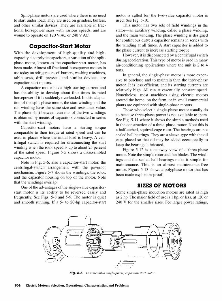
104 Electric Motors: Selection, Operational Characteristics, and Problems
Split-phase motors are used where there is no needto start under load. They are used on grinders, buffers,and other similar devices. They are available in frac-tional horsepower sizes with various speeds, and arewound to operate on 120 V AC or 240 V AC.
Capacitor-Start MotorWith the development of high-quality and high-capacity electrolytic capacitors, a variation of the split-phase motor, known as the capacitor-start motor, hasbeen made. Almost all fractional-horsepower motors inuse today on refrigerators, oil burners, washing machines,table saws, drill presses, and similar devices, arecapacitor-start motors.
A capacitor motor has a high starting current andhas the ability to develop about four times its ratedhorsepower if it is suddenly overloaded. In this adapta-tion of the split-phase motor, the start winding and therun winding have the same size and resistance value.The phase shift between currents of the two windingsis obtained by means of capacitors connected in serieswith the start winding.
Capacitor-start motors have a starting torquecomparable to their torque at rated speed and can beused in places where the initial load is heavy. A cen-trifugal switch is required for disconnecting the startwinding when the rotor speed is up to about 25 percentof the rated speed. Figure 5-5 shows a disassembledcapacitor motor.
Note in Fig. 5-6, also a capacitor-start motor, thecentrifugal-switch arrangement with the governormechanism. Figure 5-7 shows the windings, the rotor,and the capacitor housing on top of the motor. Notethat the windings overlap.
One of the advantages of the single-value capacitor-start motor is its ability to be reversed easily andfrequently. See Figs. 5-8 and 5-9. The motor is quietand smooth running. If a 5- to 20-hp capacitor-start
motor is called for, the two-value capacitor motor isused. See Fig. 5-10.
This motor has two sets of field windings in thestator—an auxiliary winding, called a phase winding,and the main winding. The phase winding is designedfor continuous duty; a capacitor remains in series withthe winding at all times. A start capacitor is added tothe phase current to increase starting torque.
However, it is disconnected by a centrifugal switchduring acceleration. This type of motor is used in manyair-conditioning applications where the unit is 2 to 4tons.
In general, the single-phase motor is more expen-sive to purchase and to maintain than the three-phasemotor. It is less efficient, and its starting currents arerelatively high. All run at essentially constant speed.Nonetheless, most machines using electric motorsaround the home, on the farm, or in small commercialplants are equipped with single-phase motors.
Those who select a single-phase motor usually doso because three-phase power is not available to them.See Fig. 5-11 where it shows the simple methods usedin the construction of a three-phase motor. Note this isa half-etched, squirrel-cage rotor. The bearings are notsealed ball bearings. They are a sleeve-type with the oilcaps placed so that oil may be added occasionally tokeep the bearings lubricated.
Figure 5-12 is a cutaway view of a three-phasemotor. Note the simple rotor and fan blades. The wind-ings and the sealed ball bearings make it simple formaintenance. This is an almost maintenance-freemotor. Figure 5-13 shows a polyphase motor that hasbeen made explosion-proof.
SIZES OF MOTORSSome single-phase induction motors are rated as highas 2 hp. The major field of use is 1 hp, or less, at 120 or240 V for the smaller sizes. For larger power ratings,
Fig. 5-5 Disassembled single-phase, capacitor-start motor.
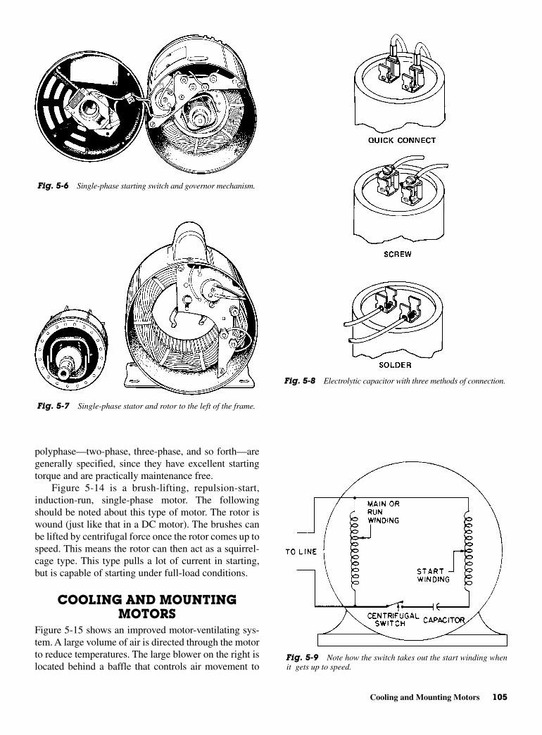
Cooling and Mounting Motors 105
polyphase—two-phase, three-phase, and so forth—aregenerally specified, since they have excellent startingtorque and are practically maintenance free.
Figure 5-14 is a brush-lifting, repulsion-start,induction-run, single-phase motor. The followingshould be noted about this type of motor. The rotor iswound (just like that in a DC motor). The brushes canbe lifted by centrifugal force once the rotor comes up tospeed. This means the rotor can then act as a squirrel-cage type. This type pulls a lot of current in starting,but is capable of starting under full-load conditions.
COOLING AND MOUNTINGMOTORS
Figure 5-15 shows an improved motor-ventilating sys-tem. A large volume of air is directed through the motorto reduce temperatures. The large blower on the right islocated behind a baffle that controls air movement to
Fig. 5-6 Single-phase starting switch and governor mechanism.
Fig. 5-7 Single-phase stator and rotor to the left of the frame.
Fig. 5-8 Electrolytic capacitor with three methods of connection.
Fig. 5-9 Note how the switch takes out the start winding whenit gets up to speed.
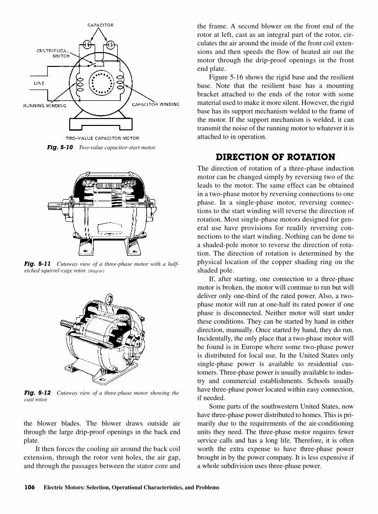
106 Electric Motors: Selection, Operational Characteristics, and Problems
the blower blades. The blower draws outside airthrough the large drip-proof openings in the back endplate.
It then forces the cooling air around the back coilextension, through the rotor vent holes, the air gap,and through the passages between the stator core and
the frame. A second blower on the front end of therotor at left, cast as an integral part of the rotor, cir-culates the air around the inside of the front coil exten-sions and then speeds the flow of heated air out themotor through the drip-proof openings in the frontend plate.
Figure 5-16 shows the rigid base and the resilientbase. Note that the resilient base has a mountingbracket attached to the ends of the rotor with somematerial used to make it more silent. However, the rigidbase has its support mechanism welded to the frame ofthe motor. If the support mechanism is welded, it cantransmit the noise of the running motor to whatever it isattached to in operation.
DIRECTION OF ROTATIONThe direction of rotation of a three-phase inductionmotor can be changed simply by reversing two of theleads to the motor. The same effect can be obtainedin a two-phase motor by reversing connections to onephase. In a single-phase motor, reversing connec-tions to the start winding will reverse the direction ofrotation. Most single-phase motors designed for gen-eral use have provisions for readily reversing con-nections to the start winding. Nothing can be done toa shaded-pole motor to reverse the direction of rota-tion. The direction of rotation is determined by thephysical location of the copper shading ring on theshaded pole.
If, after starting, one connection to a three-phasemotor is broken, the motor will continue to run but willdeliver only one-third of the rated power. Also, a two-phase motor will run at one-half its rated power if onephase is disconnected. Neither motor will start underthese conditions. They can be started by hand in eitherdirection, manually. Once started by hand, they do run.Incidentally, the only place that a two-phase motor willbe found is in Europe where some two-phase poweris distributed for local use. In the United States onlysingle-phase power is available to residential cus-tomers. Three-phase power is usually available to indus-try and commercial establishments. Schools usuallyhave three-phase power located within easy connection,if needed.
Some parts of the southwestern United States, nowhave three-phase power distributed to homes. This is pri-marily due to the requirements of the air-conditioningunits they need. The three-phase motor requires fewerservice calls and has a long life. Therefore, it is oftenworth the extra expense to have three-phase powerbrought in by the power company. It is less expensive ifa whole subdivision uses three-phase power.
Fig. 5-10 Two-value capacitor-start motor.
Fig. 5-11 Cutaway view of a three-phase motor with a half-etched squirrel-cage rotor. (Wagner)
Fig. 5-12 Cutaway view of a three-phase motor showing thecast rotor.
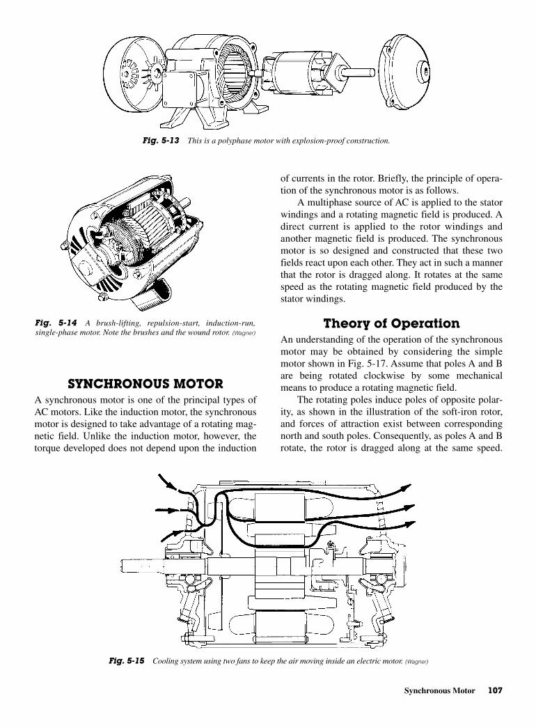
Synchronous Motor 107
SYNCHRONOUS MOTORA synchronous motor is one of the principal types ofAC motors. Like the induction motor, the synchronousmotor is designed to take advantage of a rotating mag-netic field. Unlike the induction motor, however, thetorque developed does not depend upon the induction
of currents in the rotor. Briefly, the principle of opera-tion of the synchronous motor is as follows.
A multiphase source of AC is applied to the statorwindings and a rotating magnetic field is produced. Adirect current is applied to the rotor windings andanother magnetic field is produced. The synchronousmotor is so designed and constructed that these twofields react upon each other. They act in such a mannerthat the rotor is dragged along. It rotates at the samespeed as the rotating magnetic field produced by thestator windings.
Theory of OperationAn understanding of the operation of the synchronousmotor may be obtained by considering the simplemotor shown in Fig. 5-17. Assume that poles A and Bare being rotated clockwise by some mechanicalmeans to produce a rotating magnetic field.
The rotating poles induce poles of opposite polar-ity, as shown in the illustration of the soft-iron rotor,and forces of attraction exist between correspondingnorth and south poles. Consequently, as poles A and Brotate, the rotor is dragged along at the same speed.
Fig. 5-13 This is a polyphase motor with explosion-proof construction.
Fig. 5-14 A brush-lifting, repulsion-start, induction-run,single-phase motor. Note the brushes and the wound rotor. (Wagner)
Fig. 5-15 Cooling system using two fans to keep the air moving inside an electric motor. (Wagner)
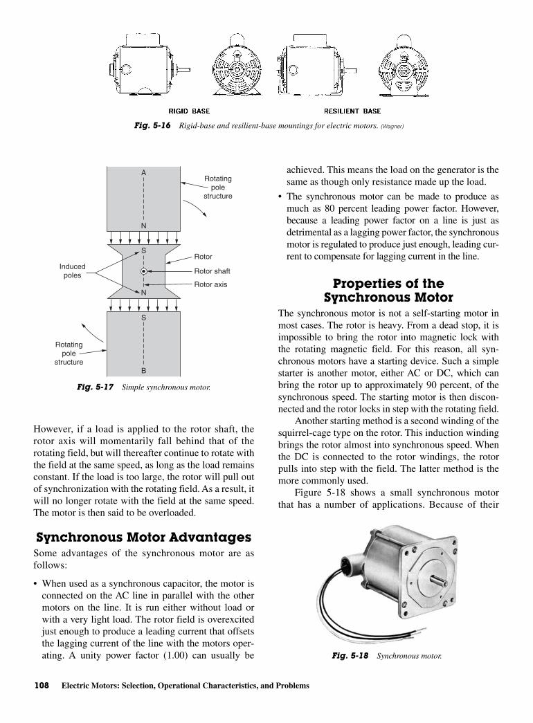
108 Electric Motors: Selection, Operational Characteristics, and Problems
However, if a load is applied to the rotor shaft, therotor axis will momentarily fall behind that of therotating field, but will thereafter continue to rotate withthe field at the same speed, as long as the load remainsconstant. If the load is too large, the rotor will pull outof synchronization with the rotating field. As a result, itwill no longer rotate with the field at the same speed.The motor is then said to be overloaded.
Synchronous Motor AdvantagesSome advantages of the synchronous motor are asfollows:
• When used as a synchronous capacitor, the motor isconnected on the AC line in parallel with the othermotors on the line. It is run either without load orwith a very light load. The rotor field is overexcitedjust enough to produce a leading current that offsetsthe lagging current of the line with the motors oper-ating. A unity power factor (1.00) can usually be
achieved. This means the load on the generator is thesame as though only resistance made up the load.
• The synchronous motor can be made to produce asmuch as 80 percent leading power factor. However,because a leading power factor on a line is just asdetrimental as a lagging power factor, the synchronousmotor is regulated to produce just enough, leading cur-rent to compensate for lagging current in the line.
Properties of the Synchronous Motor
The synchronous motor is not a self-starting motor inmost cases. The rotor is heavy. From a dead stop, it isimpossible to bring the rotor into magnetic lock withthe rotating magnetic field. For this reason, all syn-chronous motors have a starting device. Such a simplestarter is another motor, either AC or DC, which canbring the rotor up to approximately 90 percent, of thesynchronous speed. The starting motor is then discon-nected and the rotor locks in step with the rotating field.
Another starting method is a second winding of thesquirrel-cage type on the rotor. This induction windingbrings the rotor almost into synchronous speed. Whenthe DC is connected to the rotor windings, the rotorpulls into step with the field. The latter method is themore commonly used.
Figure 5-18 shows a small synchronous motorthat has a number of applications. Because of their
Fig. 5-16 Rigid-base and resilient-base mountings for electric motors. (Wagner)
N
A
N
S
B
S
Rotatingpole
structure
Rotor
Rotor shaft
Rotor axis
Inducedpoles
Rotatingpole
structure
Fig. 5-17 Simple synchronous motor.
Fig. 5-18 Synchronous motor.
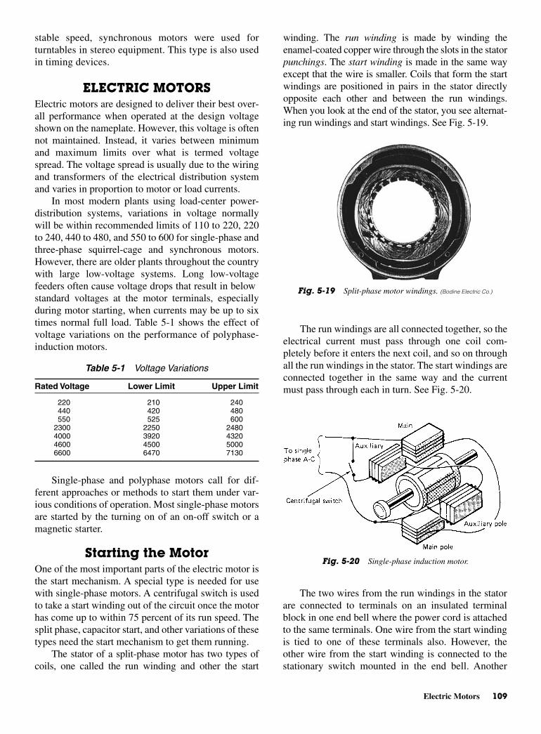
Electric Motors 109
stable speed, synchronous motors were used forturntables in stereo equipment. This type is also usedin timing devices.
ELECTRIC MOTORSElectric motors are designed to deliver their best over-all performance when operated at the design voltageshown on the nameplate. However, this voltage is oftennot maintained. Instead, it varies between minimumand maximum limits over what is termed voltagespread. The voltage spread is usually due to the wiringand transformers of the electrical distribution systemand varies in proportion to motor or load currents.
In most modern plants using load-center power-distribution systems, variations in voltage normallywill be within recommended limits of 110 to 220, 220to 240, 440 to 480, and 550 to 600 for single-phase andthree-phase squirrel-cage and synchronous motors.However, there are older plants throughout the countrywith large low-voltage systems. Long low-voltagefeeders often cause voltage drops that result in belowstandard voltages at the motor terminals, especiallyduring motor starting, when currents may be up to sixtimes normal full load. Table 5-1 shows the effect ofvoltage variations on the performance of polyphase-induction motors.
Single-phase and polyphase motors call for dif-ferent approaches or methods to start them under var-ious conditions of operation. Most single-phase motorsare started by the turning on of an on-off switch or amagnetic starter.
Starting the MotorOne of the most important parts of the electric motor isthe start mechanism. A special type is needed for usewith single-phase motors. A centrifugal switch is usedto take a start winding out of the circuit once the motorhas come up to within 75 percent of its run speed. Thesplit phase, capacitor start, and other variations of thesetypes need the start mechanism to get them running.
The stator of a split-phase motor has two types ofcoils, one called the run winding and other the start
winding. The run winding is made by winding theenamel-coated copper wire through the slots in the statorpunchings. The start winding is made in the same wayexcept that the wire is smaller. Coils that form the startwindings are positioned in pairs in the stator directlyopposite each other and between the run windings.When you look at the end of the stator, you see alternat-ing run windings and start windings. See Fig. 5-19.
The run windings are all connected together, so theelectrical current must pass through one coil com-pletely before it enters the next coil, and so on throughall the run windings in the stator. The start windings areconnected together in the same way and the currentmust pass through each in turn. See Fig. 5-20.
Table 5-1 Voltage Variations
Rated Voltage Lower Limit Upper Limit
220 210 240440 420 480550 525 600
2300 2250 24804000 3920 43204600 4500 50006600 6470 7130
Fig. 5-19 Split-phase motor windings. (Bodine Electric Co.)
Fig. 5-20 Single-phase induction motor.
The two wires from the run windings in the statorare connected to terminals on an insulated terminalblock in one end bell where the power cord is attachedto the same terminals. One wire from the start windingis tied to one of these terminals also. However, theother wire from the start winding is connected to thestationary switch mounted in the end bell. Another
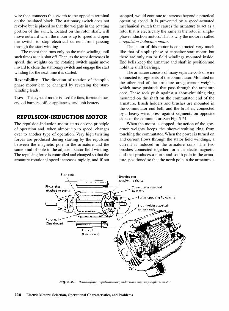
110 Electric Motors: Selection, Operational Characteristics, and Problems
wire then connects this switch to the opposite terminalon the insulated block. The stationary switch does notrevolve but is placed so that the weights in the rotatingportion of the switch, located on the rotor shaft, willmove outward when the motor is up to speed and openthe switch to stop electrical current from passingthrough the start winding.
The motor then runs only on the main winding untilsuch times as it is shut off. Then, as the rotor decreases inspeed, the weights on the rotating switch again moveinward to close the stationary switch and engage the startwinding for the next time it is started.
Reversibility The direction of rotation of the split-phase motor can be changed by reversing the start-winding leads.
Uses This type of motor is used for fans, furnace blow-ers, oil burners, office appliances, and unit heaters.
REPULSION-INDUCTION MOTORThe repulsion-induction motor starts on one principleof operation and, when almost up to speed, changesover to another type of operation. Very high twistingforces are produced during starting by the repulsionbetween the magnetic pole in the armature and thesame kind of pole in the adjacent stator field winding.The repulsing force is controlled and changed so that thearmature rotational speed increases rapidly, and if not
stopped, would continue to increase beyond a practicaloperating speed. It is prevented by a speed-actuatedmechanical switch that causes the armature to act as arotor that is electrically the same as the rotor in single-phase induction motors. That is why the motor is calleda repulsion-induction motor.
The stator of this motor is constructed very muchlike that of a split-phase or capacitor-start motor, butthere are only run or field windings mounted inside.End bells keep the armature and shaft in position andhold the shaft bearings.
The armature consists of many separate coils of wireconnected to segments of the commutator. Mounted onthe other end of the armature are governor weightswhich move pushrods that pass through the armaturecore. These rods push against a short-circuiting ringmounted on the shaft on the commutator end of thearmature. Brush holders and brushes are mounted inthe commutator end bell, and the brushes, connectedby a heavy wire, press against segments on oppositesides of the commutator. See Fig. 5-21.
When the motor is stopped, the action of the gov-ernor weights keeps the short-circuiting ring fromtouching the commutator. When the power is turned onand current flows through the stator field windings, acurrent is induced in the armature coils. The twobrushes connected together form an electromagneticcoil that produces a north and south pole in the arma-ture, positioned so that the north pole in the armature is
Fig. 5-21 Brush-lifting, repulsion-start, induction- run, single-phase motor.
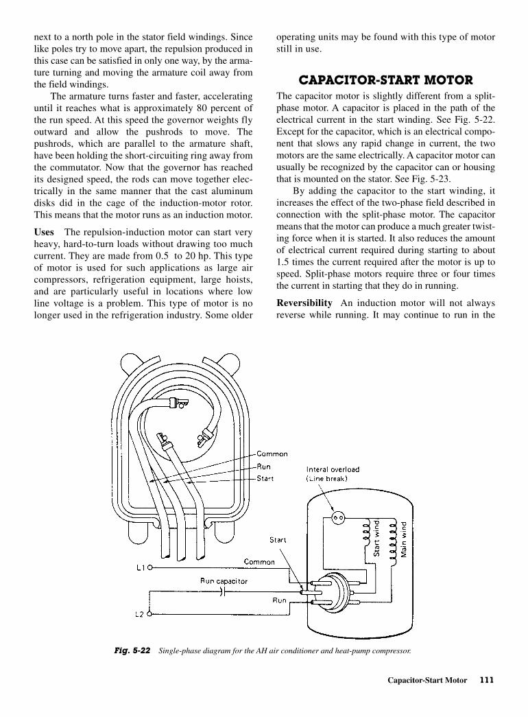
Capacitor-Start Motor 111
next to a north pole in the stator field windings. Sincelike poles try to move apart, the repulsion produced inthis case can be satisfied in only one way, by the arma-ture turning and moving the armature coil away fromthe field windings.
The armature turns faster and faster, acceleratinguntil it reaches what is approximately 80 percent ofthe run speed. At this speed the governor weights flyoutward and allow the pushrods to move. Thepushrods, which are parallel to the armature shaft,have been holding the short-circuiting ring away fromthe commutator. Now that the governor has reachedits designed speed, the rods can move together elec-trically in the same manner that the cast aluminumdisks did in the cage of the induction-motor rotor.This means that the motor runs as an induction motor.
Uses The repulsion-induction motor can start veryheavy, hard-to-turn loads without drawing too muchcurrent. They are made from 0.5 to 20 hp. This typeof motor is used for such applications as large aircompressors, refrigeration equipment, large hoists,and are particularly useful in locations where lowline voltage is a problem. This type of motor is nolonger used in the refrigeration industry. Some older
operating units may be found with this type of motorstill in use.
CAPACITOR-START MOTORThe capacitor motor is slightly different from a split-phase motor. A capacitor is placed in the path of theelectrical current in the start winding. See Fig. 5-22.Except for the capacitor, which is an electrical compo-nent that slows any rapid change in current, the twomotors are the same electrically. A capacitor motor canusually be recognized by the capacitor can or housingthat is mounted on the stator. See Fig. 5-23.
By adding the capacitor to the start winding, itincreases the effect of the two-phase field described inconnection with the split-phase motor. The capacitormeans that the motor can produce a much greater twist-ing force when it is started. It also reduces the amountof electrical current required during starting to about1.5 times the current required after the motor is up tospeed. Split-phase motors require three or four timesthe current in starting that they do in running.
Reversibility An induction motor will not alwaysreverse while running. It may continue to run in the
Fig. 5-22 Single-phase diagram for the AH air conditioner and heat-pump compressor.
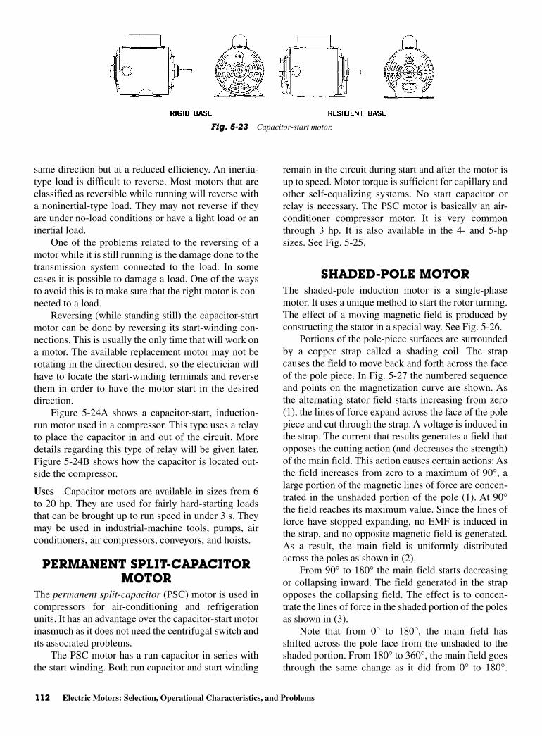
112 Electric Motors: Selection, Operational Characteristics, and Problems
same direction but at a reduced efficiency. An inertia-type load is difficult to reverse. Most motors that areclassified as reversible while running will reverse witha noninertial-type load. They may not reverse if theyare under no-load conditions or have a light load or aninertial load.
One of the problems related to the reversing of amotor while it is still running is the damage done to thetransmission system connected to the load. In somecases it is possible to damage a load. One of the waysto avoid this is to make sure that the right motor is con-nected to a load.
Reversing (while standing still) the capacitor-startmotor can be done by reversing its start-winding con-nections. This is usually the only time that will work ona motor. The available replacement motor may not berotating in the direction desired, so the electrician willhave to locate the start-winding terminals and reversethem in order to have the motor start in the desireddirection.
Figure 5-24A shows a capacitor-start, induction-run motor used in a compressor. This type uses a relayto place the capacitor in and out of the circuit. Moredetails regarding this type of relay will be given later.Figure 5-24B shows how the capacitor is located out-side the compressor.
Uses Capacitor motors are available in sizes from 6to 20 hp. They are used for fairly hard-starting loadsthat can be brought up to run speed in under 3 s. Theymay be used in industrial-machine tools, pumps, airconditioners, air compressors, conveyors, and hoists.
PERMANENT SPLIT-CAPACITORMOTOR
The permanent split-capacitor (PSC) motor is used incompressors for air-conditioning and refrigerationunits. It has an advantage over the capacitor-start motorinasmuch as it does not need the centrifugal switch andits associated problems.
The PSC motor has a run capacitor in series withthe start winding. Both run capacitor and start winding
remain in the circuit during start and after the motor isup to speed. Motor torque is sufficient for capillary andother self-equalizing systems. No start capacitor orrelay is necessary. The PSC motor is basically an air-conditioner compressor motor. It is very commonthrough 3 hp. It is also available in the 4- and 5-hpsizes. See Fig. 5-25.
SHADED-POLE MOTORThe shaded-pole induction motor is a single-phasemotor. It uses a unique method to start the rotor turning.The effect of a moving magnetic field is produced byconstructing the stator in a special way. See Fig. 5-26.
Portions of the pole-piece surfaces are surroundedby a copper strap called a shading coil. The strapcauses the field to move back and forth across the faceof the pole piece. In Fig. 5-27 the numbered sequenceand points on the magnetization curve are shown. Asthe alternating stator field starts increasing from zero(1), the lines of force expand across the face of the polepiece and cut through the strap. A voltage is induced inthe strap. The current that results generates a field thatopposes the cutting action (and decreases the strength)of the main field. This action causes certain actions: Asthe field increases from zero to a maximum of 90°, alarge portion of the magnetic lines of force are concen-trated in the unshaded portion of the pole (1). At 90°the field reaches its maximum value. Since the lines offorce have stopped expanding, no EMF is induced inthe strap, and no opposite magnetic field is generated.As a result, the main field is uniformly distributedacross the poles as shown in (2).
From 90° to 180° the main field starts decreasingor collapsing inward. The field generated in the strapopposes the collapsing field. The effect is to concen-trate the lines of force in the shaded portion of the polesas shown in (3).
Note that from 0° to 180°, the main field hasshifted across the pole face from the unshaded to theshaded portion. From 180° to 360°, the main field goesthrough the same change as it did from 0° to 180°.
Fig. 5-23 Capacitor-start motor.
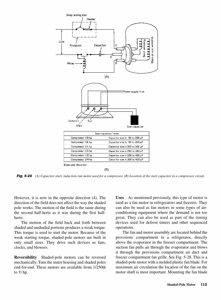
Shaded-Pole Motor 113
However, it is now in the opposite direction (4). Thedirection of the field does not affect the way the shadedpole works. The motion of the field is the same duringthe second half-hertz as it was during the first half-hertz.
The motion of the field back and forth betweenshaded and unshaded portions produces a weak torque.This torque is used to start the motor. Because of theweak starting torque, shaded-pole motors are built inonly small sizes. They drive such devices as fans,clocks, and blowers.
Reversibility Shaded-pole motors can be reversedmechanically. Turn the stator housing and shaded polesend-for-end. These motors are available from 1/250thto 1/2 hp.
Uses As mentioned previously, this type of motor isused as a fan motor in refrigerators and freezers. Theycan also be used as fan motors in some types of air-conditioning equipment where the demand is not toogreat. They can also be used as part of the timingdevices used for defrost timers and other sequencedoperations.
The fan and motor assembly are located behind theprovisions compartment in a refrigerator, directlyabove the evaporator in the freezer compartment. Thesuction fan pulls air through the evaporator and blowsit through the provisions compartment air duct andfreezer compartment fan grille. See Fig. 5-28. This is ashaded-pole motor with a molded plastic fan blade. Formaximum air circulation the location of the fan on themotor shaft is most important. Mounting the fan blade
Fig. 5-24 (A) Capacitor-start, induction-run motor used for a compressor. (B) Location of the start capacitor in a compressor circuit.

114 Electric Motors: Selection, Operational Characteristics, and Problems
too far back or too far forward on the motor shaft, inrelation to the evaporator cover, will result in improperair circulation. The freezer compartment fan must bepositioned with the lead edge of the fan 1/4 in. in front ofthe evaporator cover.
The fan assembly shown in Fig. 5-29 is used onthe top-freezer, no-frost, fiberglass–insulated modelrefrigerators. The freezer fan and motor assembly islocated in the divider partition directly under the freezerair duct.
SPLIT-PHASE MOTORInstead of rotating, the field of a single-phase motormerely pulsates. No rotation of the rotor takes place. Asingle-phase pulsating field may be visualized astwo rotating fields revolving at the same speed but inopposite directions. It therefore follows that the rotorwill revolve in either direction at nearly synchronousspeed—if it is given an initial impetus in either onedirection or the other. The exact value of this initialrotational velocity varies widely with different machines.
Fig. 5-25 Permanent split-capacitor motor schematic.
Fig. 5-26 Shading of the poles of a shaded-pole motor.
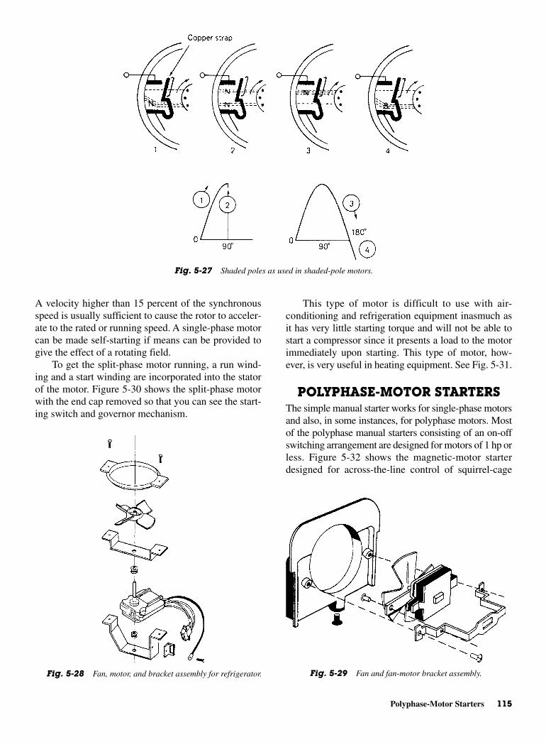
Polyphase-Motor Starters 115
A velocity higher than 15 percent of the synchronousspeed is usually sufficient to cause the rotor to acceler-ate to the rated or running speed. A single-phase motorcan be made self-starting if means can be provided togive the effect of a rotating field.
To get the split-phase motor running, a run wind-ing and a start winding are incorporated into the statorof the motor. Figure 5-30 shows the split-phase motorwith the end cap removed so that you can see the start-ing switch and governor mechanism.
This type of motor is difficult to use with air-conditioning and refrigeration equipment inasmuch asit has very little starting torque and will not be able tostart a compressor since it presents a load to the motorimmediately upon starting. This type of motor, how-ever, is very useful in heating equipment. See Fig. 5-31.
POLYPHASE-MOTOR STARTERSThe simple manual starter works for single-phase motorsand also, in some instances, for polyphase motors. Mostof the polyphase manual starters consisting of an on-offswitching arrangement are designed for motors of 1 hp orless. Figure 5-32 shows the magnetic-motor starterdesigned for across-the-line control of squirrel-cage
Fig. 5-27 Shaded poles as used in shaded-pole motors.
Fig. 5-28 Fan, motor, and bracket assembly for refrigerator. Fig. 5-29 Fan and fan-motor bracket assembly.
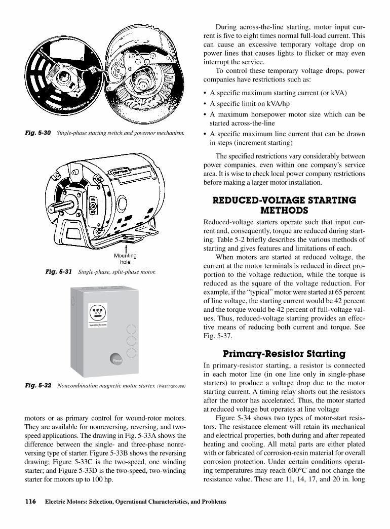
116 Electric Motors: Selection, Operational Characteristics, and Problems
motors or as primary control for wound-rotor motors.They are available for nonreversing, reversing, and two-speed applications. The drawing in Fig. 5-33A shows thedifference between the single- and three-phase nonre-versing type of starter. Figure 5-33B shows the reversingdrawing; Figure 5-33C is the two-speed, one windingstarter; and Figure 5-33D is the two-speed, two-windingstarter for motors up to 100 hp.
During across-the-line starting, motor input cur-rent is five to eight times normal full-load current. Thiscan cause an excessive temporary voltage drop onpower lines that causes lights to flicker or may eveninterrupt the service.
To control these temporary voltage drops, powercompanies have restrictions such as:
• A specific maximum starting current (or kVA)
• A specific limit on kVA/hp
• A maximum horsepower motor size which can bestarted across-the-line
• A specific maximum line current that can be drawnin steps (increment starting)
The specified restrictions vary considerably betweenpower companies, even within one company’s servicearea. It is wise to check local power company restrictionsbefore making a larger motor installation.
REDUCED-VOLTAGE STARTINGMETHODS
Reduced-voltage starters operate such that input cur-rent and, consequently, torque are reduced during start-ing. Table 5-2 briefly describes the various methods ofstarting and gives features and limitations of each.
When motors are started at reduced voltage, thecurrent at the motor terminals is reduced in direct pro-portion to the voltage reduction, while the torque isreduced as the square of the voltage reduction. Forexample, if the “typical” motor were started at 65 percentof line voltage, the starting current would be 42 percentand the torque would be 42 percent of full-voltage val-ues. Thus, reduced-voltage starting provides an effec-tive means of reducing both current and torque. SeeFig. 5-37.
Primary-Resistor StartingIn primary-resistor starting, a resistor is connectedin each motor line (in one line only in single-phasestarters) to produce a voltage drop due to the motorstarting current. A timing relay shorts out the resistorsafter the motor has accelerated. Thus, the motor startedat reduced voltage but operates at line voltage
Figure 5-34 shows two types of motor-start resis-tors. The resistance element will retain its mechanicaland electrical properties, both during and after repeatedheating and cooling. All metal parts are either platedwith or fabricated of corrosion-resin material for overallcorrosion protection. Under certain conditions operat-ing temperatures may reach 600°C and not change theresistance value. These are 11, 14, 17, and 20 in. long
Fig. 5-30 Single-phase starting switch and governor mechanism.
Fig. 5-31 Single-phase, split-phase motor.
Reset
Fig. 5-32 Noncombination magnetic motor starter. (Westinghouse)

Reduced-Voltage Starting Methods 117
Fig. 5-33 (A) Nonreversing single-phase and nonreversing three-phase wiring diagrams. (B) Reversing three-phasewiring diagram. (C) Two-speed, one winding, three-phase delta. (D) Two-speed, two-winding, three-phase starter diagram.(Westinghouse)
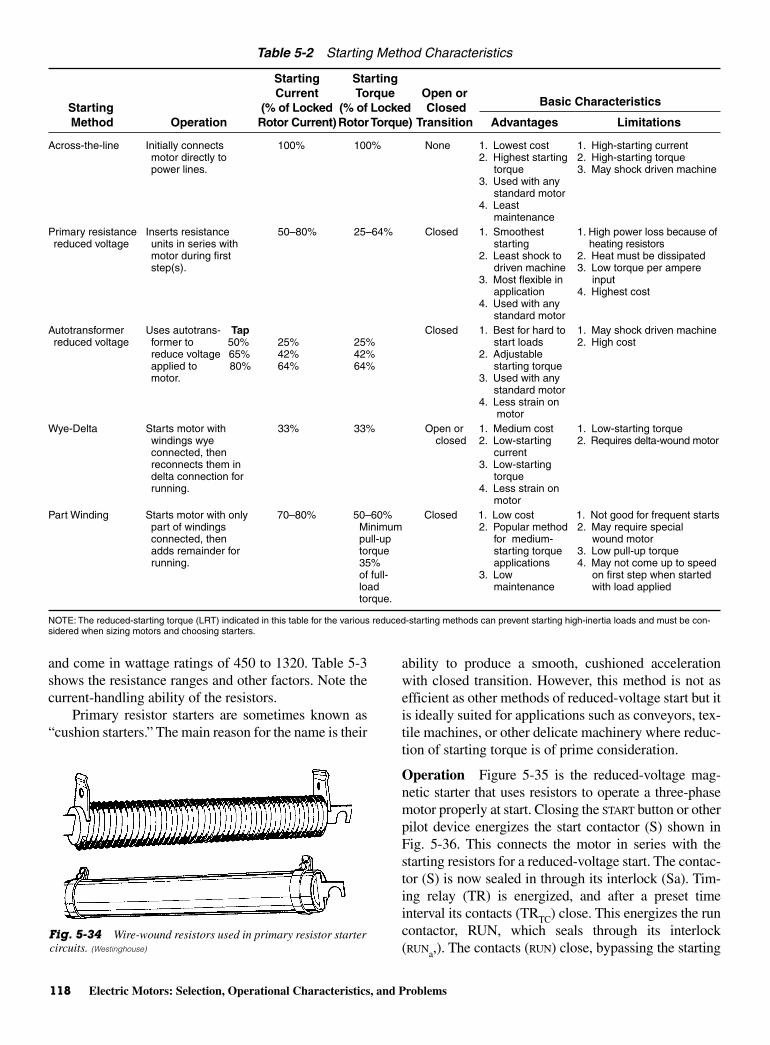
118 Electric Motors: Selection, Operational Characteristics, and Problems
and come in wattage ratings of 450 to 1320. Table 5-3shows the resistance ranges and other factors. Note thecurrent-handling ability of the resistors.
Primary resistor starters are sometimes known as“cushion starters.” The main reason for the name is their
ability to produce a smooth, cushioned accelerationwith closed transition. However, this method is not asefficient as other methods of reduced-voltage start but itis ideally suited for applications such as conveyors, tex-tile machines, or other delicate machinery where reduc-tion of starting torque is of prime consideration.
Operation Figure 5-35 is the reduced-voltage mag-netic starter that uses resistors to operate a three-phasemotor properly at start. Closing the START button or otherpilot device energizes the start contactor (S) shown inFig. 5-36. This connects the motor in series with thestarting resistors for a reduced-voltage start. The contac-tor (S) is now sealed in through its interlock (Sa). Tim-ing relay (TR) is energized, and after a preset timeinterval its contacts (TRTC) close. This energizes the runcontactor, RUN, which seals through its interlock(RUNa,). The contacts (RUN) close, bypassing the starting
Table 5-2 Starting Method Characteristics
Starting StartingCurrent Torque Open or
Starting (% of Locked (% of Locked Closed Method Operation Rotor Current) Rotor Torque) Transition Advantages Limitations
Across-the-line Initially connects 100% 100% None 1. Lowest cost 1. High-starting currentmotor directly to 2. Highest starting 2. High-starting torquepower lines. torque 3. May shock driven machine
3. Used with any standard motor
4. Least maintenance
Primary resistance Inserts resistance 50–80% 25–64% Closed 1. Smoothest 1. High power loss because ofreduced voltage units in series with starting heating resistors
motor during first 2. Least shock to 2. Heat must be dissipatedstep(s). driven machine 3. Low torque per ampere
3. Most flexible in inputapplication 4. Highest cost
4. Used with any standard motor
Autotransformer Uses autotrans- Tap Closed 1. Best for hard to 1. May shock driven machinereduced voltage former to 50% 25% 25% start loads 2. High cost
reduce voltage 65% 42% 42% 2. Adjustable applied to 80% 64% 64% starting torquemotor. 3. Used with any
standard motor4. Less strain on
motorWye-Delta Starts motor with 33% 33% Open or 1. Medium cost 1. Low-starting torque
windings wye closed 2. Low-starting 2. Requires delta-wound motorconnected, then currentreconnects them in 3. Low-startingdelta connection for torquerunning. 4. Less strain on
motorPart Winding Starts motor with only 70–80% 50–60% Closed 1. Low cost 1. Not good for frequent starts
part of windings Minimum 2. Popular method 2. May require special connected, then pull-up for medium- wound motoradds remainder for torque starting torque 3. Low pull-up torquerunning. 35% applications 4. May not come up to speed
of full- 3. Low on first step when started load maintenance with load appliedtorque.
NOTE: The reduced-starting torque (LRT) indicated in this table for the various reduced-starting methods can prevent starting high-inertia loads and must be con-sidered when sizing motors and choosing starters.
Fig. 5-34 Wire-wound resistors used in primary resistor startercircuits. (Westinghouse)
Basic Characteristics
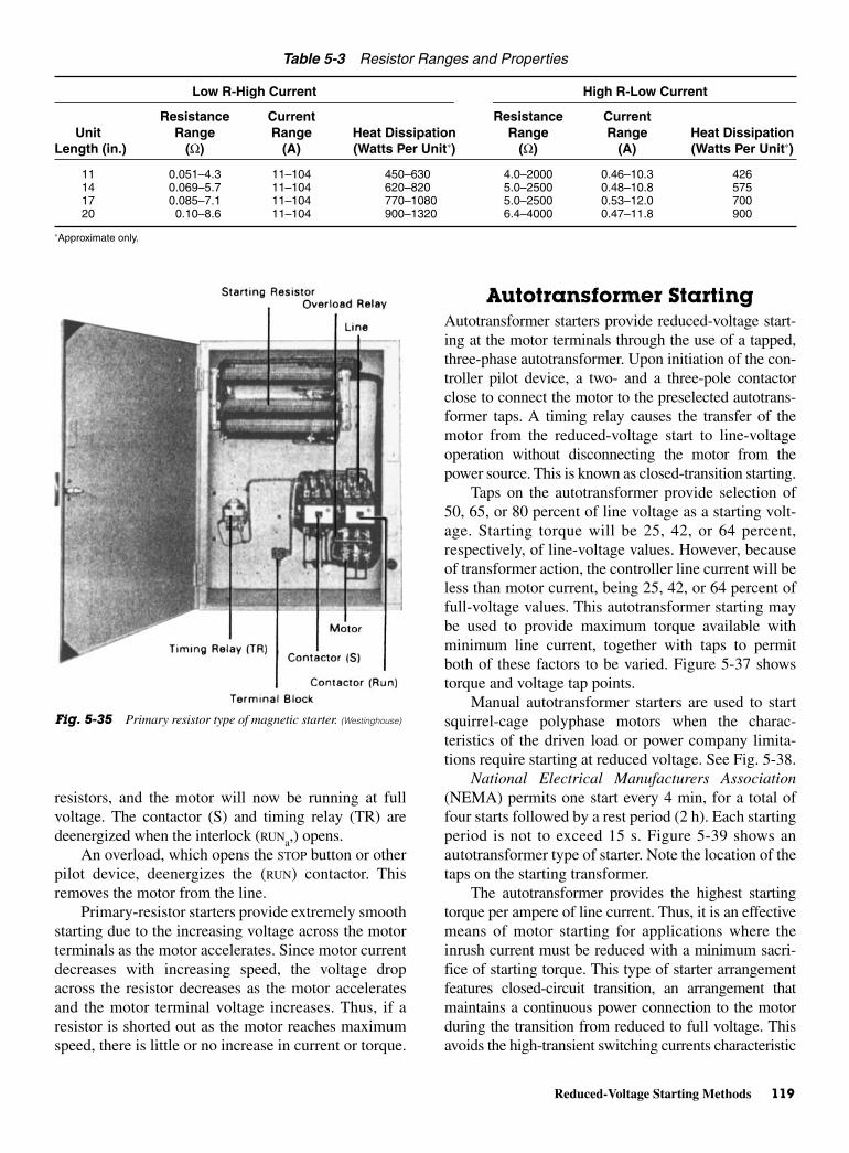
Reduced-Voltage Starting Methods 119
resistors, and the motor will now be running at fullvoltage. The contactor (S) and timing relay (TR) aredeenergized when the interlock (RUNa,) opens.
An overload, which opens the STOP button or otherpilot device, deenergizes the (RUN) contactor. Thisremoves the motor from the line.
Primary-resistor starters provide extremely smoothstarting due to the increasing voltage across the motorterminals as the motor accelerates. Since motor currentdecreases with increasing speed, the voltage dropacross the resistor decreases as the motor acceleratesand the motor terminal voltage increases. Thus, if aresistor is shorted out as the motor reaches maximumspeed, there is little or no increase in current or torque.
Autotransformer StartingAutotransformer starters provide reduced-voltage start-ing at the motor terminals through the use of a tapped,three-phase autotransformer. Upon initiation of the con-troller pilot device, a two- and a three-pole contactorclose to connect the motor to the preselected autotrans-former taps. A timing relay causes the transfer of themotor from the reduced-voltage start to line-voltageoperation without disconnecting the motor from thepower source. This is known as closed-transition starting.
Taps on the autotransformer provide selection of50, 65, or 80 percent of line voltage as a starting volt-age. Starting torque will be 25, 42, or 64 percent,respectively, of line-voltage values. However, becauseof transformer action, the controller line current will beless than motor current, being 25, 42, or 64 percent offull-voltage values. This autotransformer starting maybe used to provide maximum torque available withminimum line current, together with taps to permitboth of these factors to be varied. Figure 5-37 showstorque and voltage tap points.
Manual autotransformer starters are used to startsquirrel-cage polyphase motors when the charac-teristics of the driven load or power company limita-tions require starting at reduced voltage. See Fig. 5-38.
National Electrical Manufacturers Association(NEMA) permits one start every 4 min, for a total offour starts followed by a rest period (2 h). Each startingperiod is not to exceed 15 s. Figure 5-39 shows anautotransformer type of starter. Note the location of thetaps on the starting transformer.
The autotransformer provides the highest startingtorque per ampere of line current. Thus, it is an effectivemeans of motor starting for applications where theinrush current must be reduced with a minimum sacri-fice of starting torque. This type of starter arrangementfeatures closed-circuit transition, an arrangement thatmaintains a continuous power connection to the motorduring the transition from reduced to full voltage. Thisavoids the high-transient switching currents characteristic
Table 5-3 Resistor Ranges and Properties
Low R-High Current High R-Low Current
Resistance Current Resistance CurrentUnit Range Range Heat Dissipation Range Range Heat Dissipation
Length (in.) (Ω) (A) (Watts Per Unit∗) (Ω) (A) (Watts Per Unit∗)
11 0.051–4.3 11–104 450–630 4.0–2000 0.46–10.3 42614 0.069–5.7 11–104 620–820 5.0–2500 0.48–10.8 57517 0.085–7.1 11–104 770–1080 5.0–2500 0.53–12.0 70020 0.10–8.6 11–104 900–1320 6.4–4000 0.47–11.8 900
∗Approximate only.
Fig. 5-35 Primary resistor type of magnetic starter. (Westinghouse)

120 Electric Motors: Selection, Operational Characteristics, and Problems
of starters using open-circuit transition. It providessmoother acceleration as well.
Operation Operating an external START button, orpilot device, closes the neutral and start contactors,applying reduced voltage to the motor through theautotransformer. After a preset interval, the timer con-tacts drop out the neutral contactor, breaking the auto-transformer connection but leaving part of thewindings connected to the motor as a series reactor.The RUN contactor then closes to short out this reac-tance and apply full voltage to the motor. Transitionfrom reduced to full voltage is accomplished withoutopening the motor circuit.
For starters rated up to 200 hp you should allow a15-s operation out of every 4 min for 1 h followed by arest period of 2 h. For starters rated above 200 hp, youshould allow three 30-s operations separated by 30-sintervals followed by a rest period of 1 h. The majordisadvantages of this type of starter are its expense forlower horsepower ratings and its low power factor.
Part-winding StartingPart-winding motors have two sets of identical windings—intended to be operated in parallel—which can beenergized in sequence to provide reduced starting cur-rent and reduced starting torque. Most (but not all)
Fig. 5-36 Wiring diagram for a primary resistor type starter. (Westinghouse)
Full-voltage torque
80% volts – 64% torque
Normal-ratedload torque
Load torque
65% volts – 42% torque
50% volts – 25% torque
Motor speed holds here untilconnected to full-line voltage
Torq
ue
Fig. 5-37 Autotransformer starting—speed versus torque. (Lincoln Electric Co.)
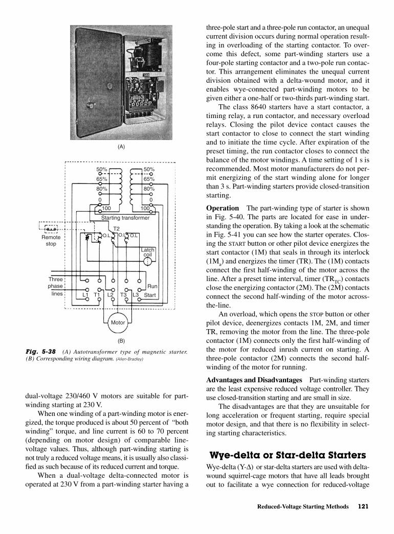
Reduced-Voltage Starting Methods 121
dual-voltage 230/460 V motors are suitable for part-winding starting at 230 V.
When one winding of a part-winding motor is ener-gized, the torque produced is about 50 percent of “bothwinding” torque, and line current is 60 to 70 percent(depending on motor design) of comparable line-voltage values. Thus, although part-winding starting isnot truly a reduced voltage means, it is usually also classi-fied as such because of its reduced current and torque.
When a dual-voltage delta-connected motor isoperated at 230 V from a part-winding starter having a
three-pole start and a three-pole run contactor, an unequalcurrent division occurs during normal operation result-ing in overloading of the starting contactor. To over-come this defect, some part-winding starters use afour-pole starting contactor and a two-pole run contac-tor. This arrangement eliminates the unequal currentdivision obtained with a delta-wound motor, and itenables wye-connected part-winding motors to begiven either a one-half or two-thirds part-winding start.
The class 8640 starters have a start contactor, atiming relay, a run contactor, and necessary overloadrelays. Closing the pilot device contact causes thestart contactor to close to connect the start windingand to initiate the time cycle. After expiration of thepreset timing, the run contactor closes to connect thebalance of the motor windings. A time setting of 1 s isrecommended. Most motor manufacturers do not per-mit energizing of the start winding alone for longerthan 3 s. Part-winding starters provide closed-transitionstarting.
Operation The part-winding type of starter is shownin Fig. 5-40. The parts are located for ease in under-standing the operation. By taking a look at the schematicin Fig. 5-41 you can see how the starter operates. Clos-ing the START button or other pilot device energizes thestart contactor (1M) that seals in through its interlock(1Ma) and energizes the timer (TR). The (1M) contactsconnect the first half-winding of the motor across theline. After a preset time interval, timer (TRTC) contactsclose the energizing contactor (2M). The (2M) contactsconnect the second half-winding of the motor across-the-line.
An overload, which opens the STOP button or otherpilot device, deenergizes contacts 1M, 2M, and timerTR, removing the motor from the line. The three-polecontactor (1M) connects only the first half-winding ofthe motor for reduced inrush current on starting. Athree-pole contactor (2M) connects the second half-winding of the motor for running.
Advantages and Disadvantages Part-winding startersare the least expensive reduced voltage controller. Theyuse closed-transition starting and are small in size.
The disadvantages are that they are unsuitable forlong acceleration or frequent starting, require specialmotor design, and that there is no flexibility in select-ing starting characteristics.
Wye-delta or Star-delta StartersWye-delta (Y-∆) or star-delta starters are used with delta-wound squirrel-cage motors that have all leads broughtout to facilitate a wye connection for reduced-voltage
50%
65%
80%
50%
65%
80%
100 100
Starting transformer
Remotestop
O.L O.L O.LT2
Latchcoil
Run
StartL3L2L1 T3T1
Motor
phaselines
Three
(B)
(A)
00
Fig. 5-38 (A) Autotransformer type of magnetic starter.(B) Corresponding wiring diagram. (Allen-Bradley)
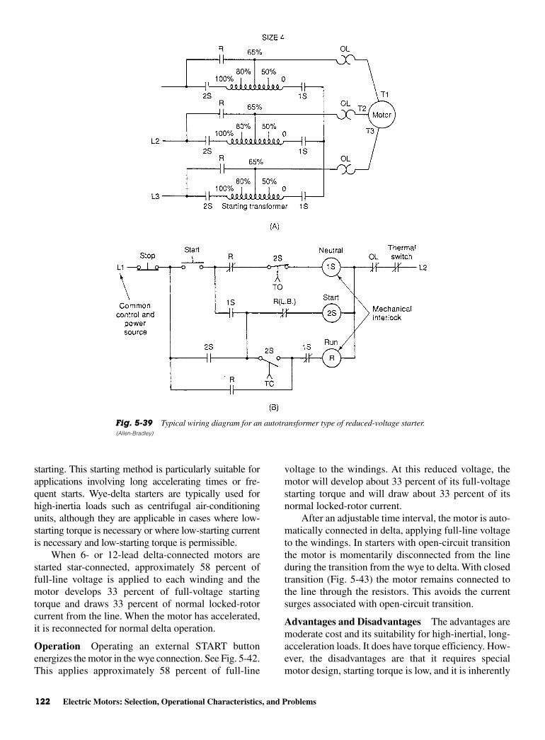
122 Electric Motors: Selection, Operational Characteristics, and Problems
starting. This starting method is particularly suitable forapplications involving long accelerating times or fre-quent starts. Wye-delta starters are typically used forhigh-inertia loads such as centrifugal air-conditioningunits, although they are applicable in cases where low-starting torque is necessary or where low-starting currentis necessary and low-starting torque is permissible.
When 6- or 12-lead delta-connected motors arestarted star-connected, approximately 58 percent offull-line voltage is applied to each winding and themotor develops 33 percent of full-voltage startingtorque and draws 33 percent of normal locked-rotorcurrent from the line. When the motor has accelerated,it is reconnected for normal delta operation.
Operation Operating an external START buttonenergizes the motor in the wye connection. See Fig. 5-42.This applies approximately 58 percent of full-line
voltage to the windings. At this reduced voltage, themotor will develop about 33 percent of its full-voltagestarting torque and will draw about 33 percent of itsnormal locked-rotor current.
After an adjustable time interval, the motor is auto-matically connected in delta, applying full-line voltageto the windings. In starters with open-circuit transitionthe motor is momentarily disconnected from the lineduring the transition from the wye to delta. With closedtransition (Fig. 5-43) the motor remains connected tothe line through the resistors. This avoids the currentsurges associated with open-circuit transition.
Advantages and Disadvantages The advantages aremoderate cost and its suitability for high-inertial, long-acceleration loads. It does have torque efficiency. How-ever, the disadvantages are that it requires specialmotor design, starting torque is low, and it is inherently
Fig. 5-39 Typical wiring diagram for an autotransformer type of reduced-voltage starter.(Allen-Bradley)
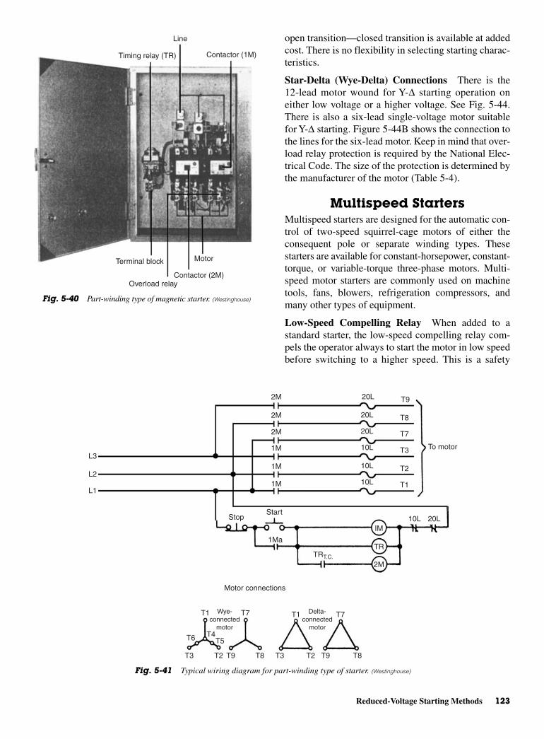
Reduced-Voltage Starting Methods 123
open transition—closed transition is available at addedcost. There is no flexibility in selecting starting charac-teristics.
Star-Delta (Wye-Delta) Connections There is the12-lead motor wound for Y-∆ starting operation oneither low voltage or a higher voltage. See Fig. 5-44.There is also a six-lead single-voltage motor suitablefor Y-∆ starting. Figure 5-44B shows the connection tothe lines for the six-lead motor. Keep in mind that over-load relay protection is required by the National Elec-trical Code. The size of the protection is determined bythe manufacturer of the motor (Table 5-4).
Multispeed StartersMultispeed starters are designed for the automatic con-trol of two-speed squirrel-cage motors of either theconsequent pole or separate winding types. Thesestarters are available for constant-horsepower, constant-torque, or variable-torque three-phase motors. Multi-speed motor starters are commonly used on machinetools, fans, blowers, refrigeration compressors, andmany other types of equipment.
Low-Speed Compelling Relay When added to astandard starter, the low-speed compelling relay com-pels the operator always to start the motor in low speedbefore switching to a higher speed. This is a safety
L3
L1
L2
2M
2M
2M
1M
1M
1M
20L
20L
20L
10L
10L
10L
T9
T8
T7
T3
T2
T1
IM
TR
2M
To motor
StopStart
1Ma
TRT.C.
10L 20L
Motor connections
T1 T7Wye-connected
motor
Delta-connected
motorT4
T5T6
T3 T2 T9 T8 T3 T2 T9
T7T1
T8
Fig. 5-41 Typical wiring diagram for part-winding type of starter. (Westinghouse)
Line
Timing relay (TR) Contactor (1M)
Terminal block
Overload relayContactor (2M)
Motor
Fig. 5-40 Part-winding type of magnetic starter. (Westinghouse)
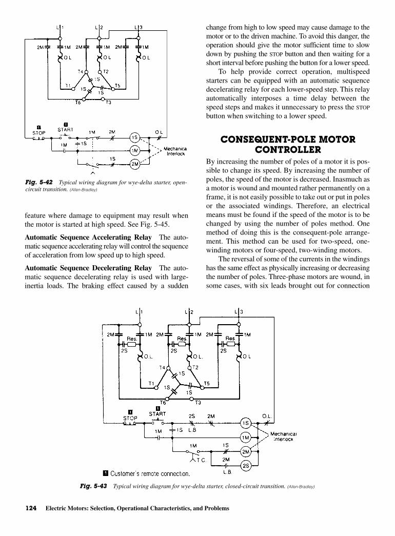
124 Electric Motors: Selection, Operational Characteristics, and Problems
feature where damage to equipment may result whenthe motor is started at high speed. See Fig. 5-45.
Automatic Sequence Accelerating Relay The auto-matic sequence accelerating relay will control the sequenceof acceleration from low speed up to high speed.
Automatic Sequence Decelerating Relay The auto-matic sequence decelerating relay is used with large-inertia loads. The braking effect caused by a sudden
change from high to low speed may cause damage to themotor or to the driven machine. To avoid this danger, theoperation should give the motor sufficient time to slowdown by pushing the STOP button and then waiting for ashort interval before pushing the button for a lower speed.
To help provide correct operation, multispeedstarters can be equipped with an automatic sequencedecelerating relay for each lower-speed step. This relayautomatically interposes a time delay between thespeed steps and makes it unnecessary to press the STOP
button when switching to a lower speed.
CONSEQUENT-POLE MOTORCONTROLLER
By increasing the number of poles of a motor it is pos-sible to change its speed. By increasing the number ofpoles, the speed of the motor is decreased. Inasmuch asa motor is wound and mounted rather permanently on aframe, it is not easily possible to take out or put in polesor the associated windings. Therefore, an electricalmeans must be found if the speed of the motor is to bechanged by using the number of poles method. Onemethod of doing this is the consequent-pole arrange-ment. This method can be used for two-speed, one-winding motors or four-speed, two-winding motors.
The reversal of some of the currents in the windingshas the same effect as physically increasing or decreasingthe number of poles. Three-phase motors are wound, insome cases, with six leads brought out for connection
Fig. 5-43 Typical wiring diagram for wye-delta starter, closed-circuit transition. (Allen-Bradley)
Fig. 5-42 Typical wiring diagram for wye-delta starter, open-circuit transition. (Allen-Bradley)
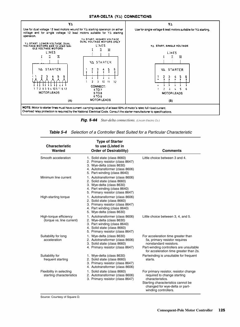
Consequent-Pole Motor Controller 125
Fig. 5-44 Star-delta connections. (Lincoln Electric Co.)
Table 5-4 Selection of a Controller Best Suited for a Particular Characteristic
Type of StarterCharacteristic to use (Listed in
Wanted Order of Desirability) Comments
Smooth acceleration 1. Solid state (class 8660) Little choice between 3 and 4.2. Primary resistor (class 8647)3. Wye-delta (class 8630)4. Autotransformer (class 8606)5. Part-winding (class 8640)
Minimum line current 1. Autotransformer (class 8606)2. Solid state (class 8660)3. Wye-delta (class 8630)4. Part winding (class 8640)5. Primary resistor (class 8647)
High-starting torque 1. Autotransformer (class 8606)2. Solid state (class 8660)3. Primary resistor (class 8647)4. Part winding (class 8640)5. Wye-delta (class 8630)
High-torque efficiency 1. Autotransformer (class 8606) Little choice between 3, 4, and 5.(torque vs. line current) 2. Wye-delta (class 8630)
3. Part winding (class 8640)4. Solid state (class 8660)5. Primary resistor (class 8647)
Suitability for long 1. Wye-delta (class 8630) For acceleration time greater than acceleration 2. Autotransformer (class 8606) 5s, primary resistor requires
3. Solid state (class 8660) nonstandard resistors.4. Primary resistor (class 8647) Part-winding controllers are unsuitable
for acceleration time greater than 2s.Suitability for 1. Wye-delta (class 8630) Partwinding is unsuitable for frequent
frequent starting 2. Solid state (class 8660) starts.3. Primary resistor (class 8647)4. Autotransformer (class 8606)
Flexibility in selecting 1. Solid state (class 8660) For primary resistor, resistor change starting characteristics 2. Autotransformer (class 8606) required to change starting
3. Primary resistor (class 8647) characteristics.Starting characteristics cannot be
changed for wye-delta or part-winding controllers.
Source: Courtesy of Square D.
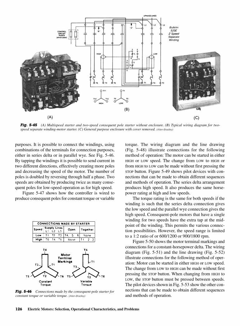
126 Electric Motors: Selection, Operational Characteristics, and Problems
purposes. It is possible to connect the windings, usingcombinations of the terminals for connection purposes,either in series delta or in parallel wye. See Fig. 5-46.By tapping the windings it is possible to send current intwo different directions, effectively creating more polesand decreasing the speed of the motor. The number ofpoles is doubled by reversing through half a phase. Twospeeds are obtained by producing twice as many conse-quent poles for low-speed operation as for high speed.
Figure 5-47 shows how the controller is wired toproduce consequent poles for constant torque or variable
torque. The wiring diagram and the line drawing(Fig. 5-48) illustrate connections for the followingmethod of operation: The motor can be started in eitherHIGH or LOW speed. The change from LOW to HIGH orfrom HIGH to LOW can be made without first pressing theSTOP button. Figure 5-49 shows pilot devices with con-nections that can be made to obtain different sequencesand methods of operation. The series delta arrangementproduces high speed. It also produces the same horse-power rating at high and low speeds.
The torque rating is the same for both speeds if thewinding is such that the series delta connection givesthe low speed and the parallel wye connection gives thehigh speed. Consequent-pole motors that have a singlewinding for two speeds have the extra tap at the mid-point of the winding. This permits the various connec-tion possibilities. However, the speed range is limitedto a 1:2 ratio of or 600/1200 or 900/1800 rpm.
Figure 5-50 shows the motor terminal markings andconnections for a constant-horsepower delta. The wiringdiagram (Fig. 5-51) and the line drawing (Fig. 5-52)illustrate connections for the following method of oper-ation: Motor can be started in either HIGH or LOW speed.The change from LOW to HIGH can be made without firstpressing the STOP button. When changing from HIGH toLOW, the STOP button must be pressed between speeds.The pilot devices shown in Fig. 5-53 show the other con-nections that can be made to obtain different sequencesand methods of operation.
Fig. 5-46 Connections made by the consequent-pole starter forconstant torque or variable torque. (Allen-Bradley)
Fig. 5-45 (A) Multispeed starter and two-speed consequent pole starter without enclosure. (B) Typical wiring diagram for two-speed separate winding-motor starter. (C) General purpose enclosure with cover removed. (Allen-Bradley)
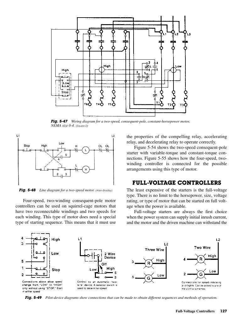
Full-Voltage Controllers 127
Four-speed, two-winding consequent-pole motorcontrollers can be used on squirrel-cage motors thathave two reconnectable windings and two speeds foreach winding. This type of motor does need a specialtype of starting sequence. This means that it must use
the properties of the compelling relay, acceleratingrelay, and decelerating relay to operate correctly.
Figure 5-54 shows the two-speed consequent-polestarter with variable-torque and constant-torque con-nections. Figure 5-55 shows how the four-speed, two-winding controller is connected for the possiblearrangements using this type of motor.
FULL-VOLTAGE CONTROLLERSThe least expensive of the starters is the full-voltagetype. There is no limit to the horsepower, size, voltagerating, or type of motor that can be started on full volt-age when the power is available.
Full-voltage starters are always the first choicewhen the power system can supply initial inrush current,and the motor and the driven machine can withstand the
Fig. 5-48 Line diagram for a two-speed motor. (Allen-Bradley)
Fig. 5-49 Pilot-device diagrams show connections that can be made to obtain different sequences and methods of operation.
Fig. 5-47 Wiring diagram for a two-speed, consequent-pole, constant-horsepower motor,NEMA size 0-4. (Square D)
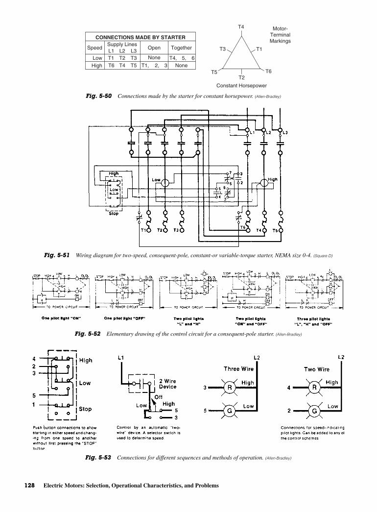
128 Electric Motors: Selection, Operational Characteristics, and Problems
Fig. 5-52 Elementary drawing of the control circuit for a consequent-pole starter. (Allen-Bradley)
Fig. 5-53 Connections for different sequences and methods of operation. (Allen-Bradley)
CONNECTIONS MADE BY STARTER
Speed
LowHigh
Supply LinesL1
T6
L2T2T1 T4, 5, 6T4
L3T3T5
Open Together
None
NoneT1, 2, 3
T4
T1T3
T5 T6T2
Constant Horsepower
Motor-TerminalMarkings
Fig. 5-50 Connections made by the starter for constant horsepower. (Allen-Bradley)
Fig. 5-51 Wiring diagram for two-speed, consequent-pole, constant-or variable-torque starter, NEMA size 0-4. (Square D)

large and small motors are to be started on a commonpower system, best results are obtained by starting thelargest sizes first. This gives larger motors the advan-tage of full-line capacity. If synchronous motors are onthe system with other types of AC motors, the synchro-nous units should always be started first since they pro-vide voltage stability for starting the induction motors.
Protection Against Low VoltageLow-voltage protection is needed while the motors arerunning even though systematic starting permits allmotors to be started without excessive line-voltagedrop. When three-wire control circuits are used, a severedip in line voltage or a momentary complete outagebreaks the control-sealing circuits, and the controllerdrops out and stops the motor. This provides low-voltage protection and prevents simultaneous accelerationof all motors to full speed after being slowed down bya voltage dip. However, all motors are disconnectedfrom the line during the voltage dip, and each must berestarted.
Time-Delay ProtectionIt is possible to wire the circuitry so that a time-delayunder-voltage arrangement can be used. This permitsdropout of the controllers on low-voltage dips butallows restarting automatically if normal voltage isrestored within a preset time delay. The usual timedelay is 2 s or less.
Time-delay under-voltage protection on control-lers will prevent some complete shutdowns but shouldbe applied with caution. If used on all motor control-lers, restoration of voltage within the time-delay setting
sudden starting shock. Examples of this are machinesthat start unloaded, as well as those that require littletorque; or machines may be equipped with some formof unloading device to reduce starting torque, as in theuse of an unloader valve in a compressor. A clutch maybe inserted between a machine and motor so that themotor may be started unloaded. When the motor is upto speed, the clutch is engaged. Clutches are sometimesused on large machines so that maximum horsepowercan be exerted during breakaway without seriouspower-system disturbance. Use of clutches also per-mits using motors with lower torque and locked-rotorcurrents. In most instances, up-to-date installations usesolid-state motor controllers to better advantage. Manyof the older types of starters are still in use and willcontinue to provide good service for many more years.As they deteriorate, they are usually replaced by asolid-state type of starter so that the clutch arrange-ments are unnecessary.
Figure 5-56 shows the general-purpose enclosurefor a full-voltage starter. This type of starter is designedfor full-voltage starting of polyphase squirrel-cagemotors and primary control of slip-ring motors. Thistype of starter may be operated by remote control withpush buttons, float switches, thermostats, pressureswitches, snap switches, limit switches, or any othersuitable two- or three-wire pilot device.
Starting SequenceIf full-voltage starting produces excessive currentdemands on the distribution system, motors should bestarted individually or in blocks of permissible size byusing some method of time delay, such as motor driver,pneumatic, or mercury plunger timing relays. When
Full-Voltage Controllers 129
Fig. 5-54 (A) Typical wiring diagram for two-speed consequent-pole starter (Wye). (B) Typical wiring diagram for two-speedconsequent-pole starter (Delta).

130 Electric Motors: Selection, Operational Characteristics, and Problems
Fig. 5-55 Elementary diagram of a four-speed, two-winding controller and the possible arrangements for motor connections.(Allen-Bradley)
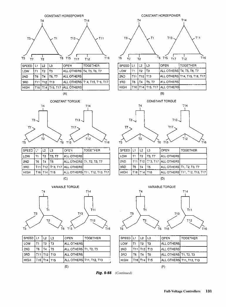
Full-Voltage Controllers 131
Fig. 5-55 (Continued)
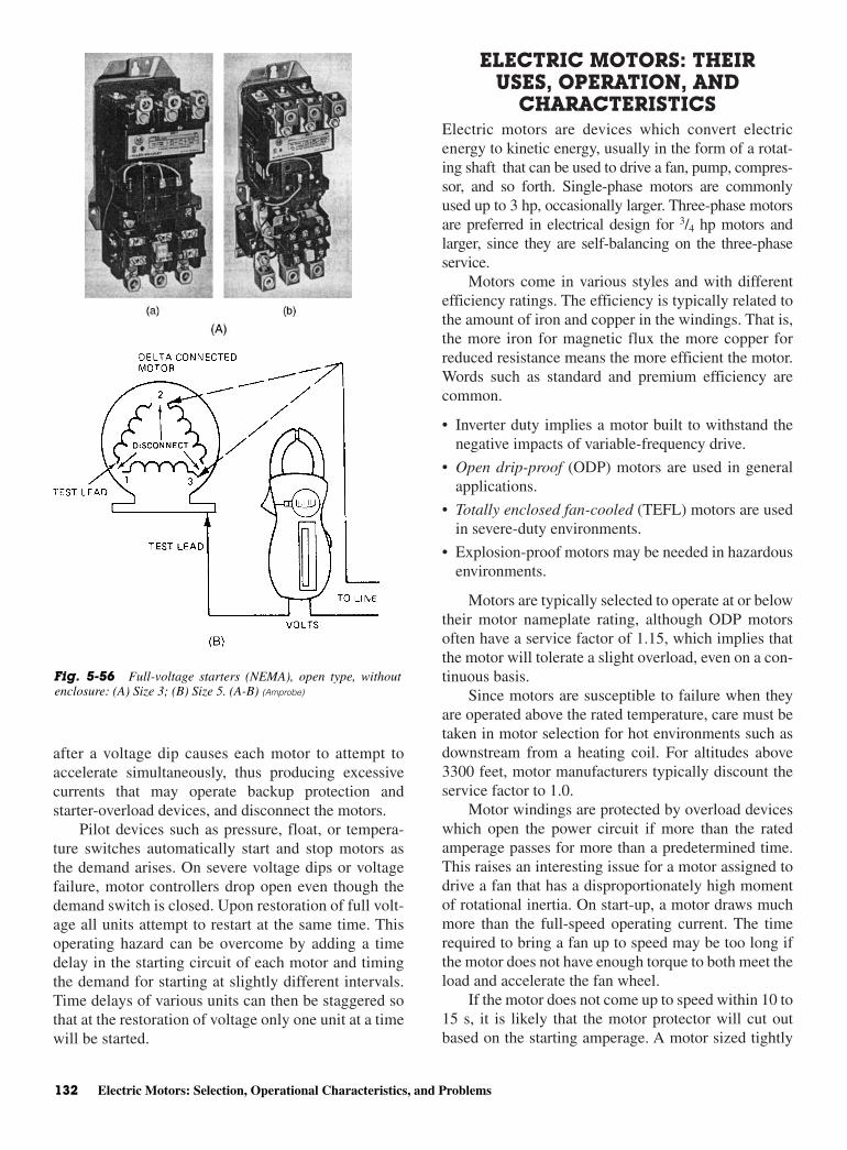
after a voltage dip causes each motor to attempt toaccelerate simultaneously, thus producing excessivecurrents that may operate backup protection andstarter-overload devices, and disconnect the motors.
Pilot devices such as pressure, float, or tempera-ture switches automatically start and stop motors asthe demand arises. On severe voltage dips or voltagefailure, motor controllers drop open even though thedemand switch is closed. Upon restoration of full volt-age all units attempt to restart at the same time. Thisoperating hazard can be overcome by adding a timedelay in the starting circuit of each motor and timingthe demand for starting at slightly different intervals.Time delays of various units can then be staggered sothat at the restoration of voltage only one unit at a timewill be started.
ELECTRIC MOTORS: THEIRUSES, OPERATION, AND
CHARACTERISTICSElectric motors are devices which convert electricenergy to kinetic energy, usually in the form of a rotat-ing shaft that can be used to drive a fan, pump, compres-sor, and so forth. Single-phase motors are commonlyused up to 3 hp, occasionally larger. Three-phase motorsare preferred in electrical design for 3/4 hp motors andlarger, since they are self-balancing on the three-phaseservice.
Motors come in various styles and with differentefficiency ratings. The efficiency is typically related tothe amount of iron and copper in the windings. That is,the more iron for magnetic flux the more copper forreduced resistance means the more efficient the motor.Words such as standard and premium efficiency arecommon.
• Inverter duty implies a motor built to withstand thenegative impacts of variable-frequency drive.
• Open drip-proof (ODP) motors are used in generalapplications.
• Totally enclosed fan-cooled (TEFL) motors are usedin severe-duty environments.
• Explosion-proof motors may be needed in hazardousenvironments.
Motors are typically selected to operate at or belowtheir motor nameplate rating, although ODP motorsoften have a service factor of 1.15, which implies thatthe motor will tolerate a slight overload, even on a con-tinuous basis.
Since motors are susceptible to failure when theyare operated above the rated temperature, care must betaken in motor selection for hot environments such asdownstream from a heating coil. For altitudes above3300 feet, motor manufacturers typically discount theservice factor to 1.0.
Motor windings are protected by overload deviceswhich open the power circuit if more than the ratedamperage passes for more than a predetermined time.This raises an interesting issue for a motor assigned todrive a fan that has a disproportionately high momentof rotational inertia. On start-up, a motor draws muchmore than the full-speed operating current. The timerequired to bring a fan up to speed may be too long ifthe motor does not have enough torque to both meet theload and accelerate the fan wheel.
If the motor does not come up to speed within 10 to15 s, it is likely that the motor protector will cut outbased on the starting amperage. A motor sized tightly
132 Electric Motors: Selection, Operational Characteristics, and Problems
Fig. 5-56 Full-voltage starters (NEMA), open type, withoutenclosure: (A) Size 3; (B) Size 5. (A-B) (Amprobe)
above 90°F, and humid condensing environments areall threatening to drive life expectancy.
• The drive should be matched to the driven motor.Reduced motor speeds relate to reduced motor cool-ing while internal motor energy losses may be highin an inappropriately configured motor. High effi-ciency or inverter duty motors are typically preferredfor VFD service.
• Drives and motors may be altitude-sensitive or maybe affected by other local conditions. Drive andmotor selection should be confirmed in every case bythe drive vendor.
• Some drives use a carrier frequency in the audiblerange, whirl may be emitted at the drive and/or atthe motor. The noise may be objectionable. This isa difficult problem to abate in some applications.Some newer drives allow the carrier frequency tobe set above the normal hearing range, whicheliminates the noise problem, but shorten motorlife expectancy.
• Some variable-speed drives impose “garbage” wave-forms on the incoming utility lines or create har-monic distortions which affect the current flow in theneutral conductor of a three-phase power supply. Iso-lation transformers are not always effective in elimi-nating harmonic distortion back to the line.
Harmonic distortions are also implicated in pre-mature fan shaft bearing failures, where vagrant cur-rents overwhelm the insulating qualities of bearinggrease to arc from inner to outer bearing races, vio-lating the normally smooth rolling surfaces withmetal deposits.
• If VFDs are applied to critical loads, it may be helpfulto have bypass circuitry to run the motor at full speedin the event of a drive outage. This creates a concernfor pressure control since the full-speed operationwill develop a maximum pressure condition whetherneeded or not. Relief dampers may be considered.
• Most VFDs can accept a remote input signal of 4 to20 mA, or 0 to 10 V DC, derived from pressuretransducers or flow meters. The drives typicallyhave a manual speed-selection option if an occa-sional or seasonal speed change is all that is needed.The manual setting is also useful in a test-and-balance period.
TROUBLESHOOTING ELECTRICMOTORS WITH A VOLT-AMMETERElectrical equipment is designed to operate at a spe-cific voltage and current. Usually the equipment will
to a fan load may never get started. Therefore, it isimportant to size a motor for, both load and fan-wheelinertia. Fan vendors can help with this concern. Thisproblem is particularly common on large boiler induced-draft fans where the dense-air, cold-start-up conditionrequires much more driver power than the hot-operatingcondition.
Motor RotationIn single-phase motors, the direction of motor rotationis determined by the factory-established internalwiring characteristics of the motor. Changing the con-nection of leads to the power source may have no effecton the direction of rotation. To make a change requiresa change in an internal connection as directed by themanufacturer.
In polyphase motors, a lead sequence is estab-lished at the power plant. The motor presents three setsof lead wires, which are connected to the three phasesof the service. If a three-phase motor is found runningbackward, all that is needed to change the direction isto exchange any two leads.
Variable-Speed DrivesOne of the most useful electrical developments inrecent years has been the AC variable frequency drive(VFD) for motor speed control. Electric speed controlof motors is not a new concept—dc drives have beenused for decades in the industrial environment—butlow cost AC drives suitable for the HVAC market are arelatively new product. These new drives typically useelectronic circuitry to vary the output frequency whichin turn varies the speed of the motor.
Since the power required to drive a centrifugal fanor centrifugal pump is proportional to the cube of thefan or pump speed, large reductions in power con-sumption are obtained at reduced speed. These savingsare used to pay for the added cost of the VFD on a lifecycle cost basis. A quality VFD usually obtains greaterenergy savings than does a variable-pitch inlet vane orother mechanical-flow volume control. In low-budgetprojects, the owner may have elected to forgo thehigher-quality VFD service in favor of the lower-first-cost inlet vane damper for fans, or modulating-valvedifferential pressure control for pumps.
In applying a VFD to a duty, several factors have tobe considered:
• The VFD needs to be in a relatively clean, air-conditioned environment. Since it is a sophisticatedelectronic device, particulates in the ambient air,wide swings in ambient air conditions, temperatures
Troubleshooting Electric Motors with a Volt-Ammeter 133
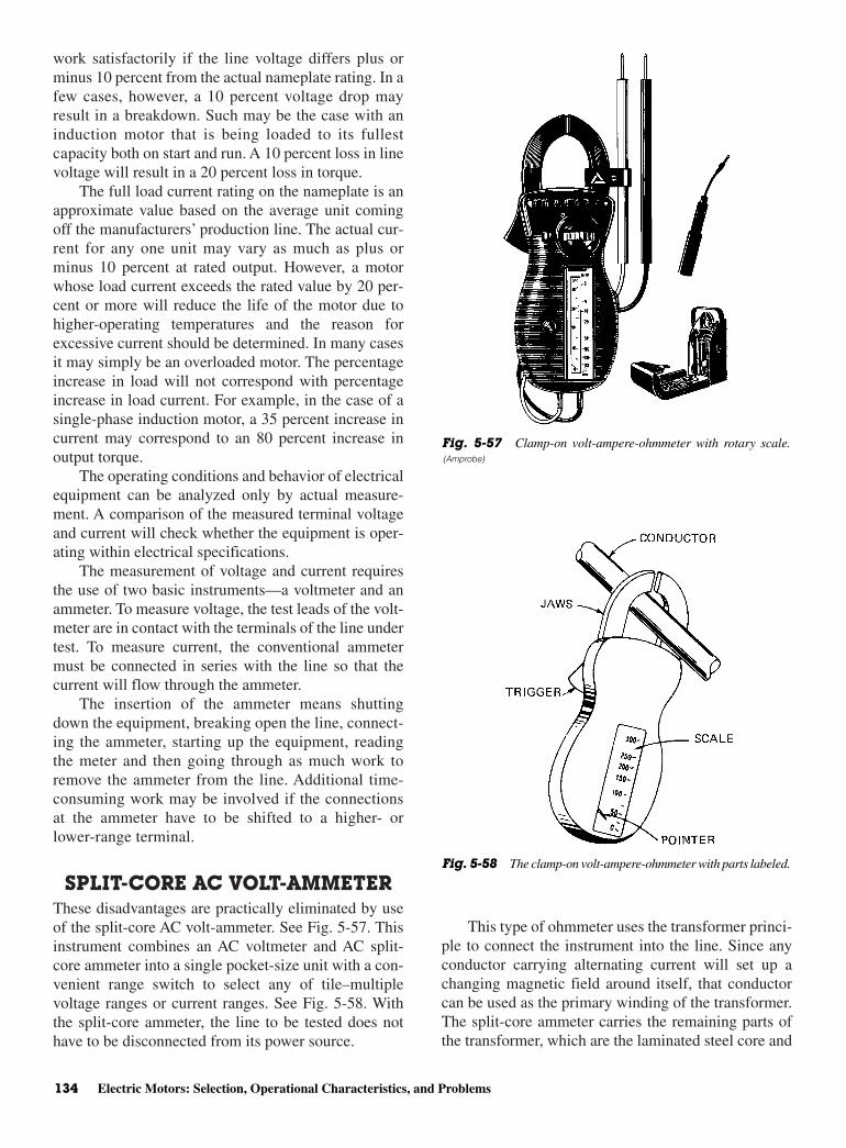
work satisfactorily if the line voltage differs plus orminus 10 percent from the actual nameplate rating. In afew cases, however, a 10 percent voltage drop mayresult in a breakdown. Such may be the case with aninduction motor that is being loaded to its fullestcapacity both on start and run. A 10 percent loss in linevoltage will result in a 20 percent loss in torque.
The full load current rating on the nameplate is anapproximate value based on the average unit comingoff the manufacturers’ production line. The actual cur-rent for any one unit may vary as much as plus orminus 10 percent at rated output. However, a motorwhose load current exceeds the rated value by 20 per-cent or more will reduce the life of the motor due tohigher-operating temperatures and the reason forexcessive current should be determined. In many casesit may simply be an overloaded motor. The percentageincrease in load will not correspond with percentageincrease in load current. For example, in the case of asingle-phase induction motor, a 35 percent increase incurrent may correspond to an 80 percent increase inoutput torque.
The operating conditions and behavior of electricalequipment can be analyzed only by actual measure-ment. A comparison of the measured terminal voltageand current will check whether the equipment is oper-ating within electrical specifications.
The measurement of voltage and current requiresthe use of two basic instruments—a voltmeter and anammeter. To measure voltage, the test leads of the volt-meter are in contact with the terminals of the line undertest. To measure current, the conventional ammetermust be connected in series with the line so that thecurrent will flow through the ammeter.
The insertion of the ammeter means shuttingdown the equipment, breaking open the line, connect-ing the ammeter, starting up the equipment, readingthe meter and then going through as much work toremove the ammeter from the line. Additional time-consuming work may be involved if the connectionsat the ammeter have to be shifted to a higher- orlower-range terminal.
SPLIT-CORE AC VOLT-AMMETERThese disadvantages are practically eliminated by useof the split-core AC volt-ammeter. See Fig. 5-57. Thisinstrument combines an AC voltmeter and AC split-core ammeter into a single pocket-size unit with a con-venient range switch to select any of tile–multiplevoltage ranges or current ranges. See Fig. 5-58. Withthe split-core ammeter, the line to be tested does nothave to be disconnected from its power source.
This type of ohmmeter uses the transformer princi-ple to connect the instrument into the line. Since anyconductor carrying alternating current will set up achanging magnetic field around itself, that conductorcan be used as the primary winding of the transformer.The split-core ammeter carries the remaining parts ofthe transformer, which are the laminated steel core and
134 Electric Motors: Selection, Operational Characteristics, and Problems
Fig. 5-57 Clamp-on volt-ampere-ohmmeter with rotary scale.(Amprobe)
Fig. 5-58 The clamp-on volt-ampere-ohmmeter with parts labeled.
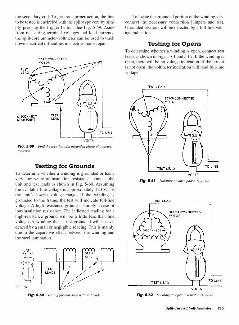
To locate the grounded portion of the winding, dis-connect the necessary connection jumpers and test.Grounded sections will be detected by a full-line volt-age indication.
Testing for OpensTo determine whether a winding is open, connect testleads as shown in Figs. 5-61 and 5-62. If the winding isopen, there will be no voltage indication. If the circuitis not open, the voltmeter indication will read full-linevoltage.
the secondary coil. To get transformer action, the lineto be tested is encircled with the split-type core by sim-ply pressing the trigger button. See Fig. 5-59. Asidefrom measuring terminal voltages and load currents,the split-core ammeter-voltmeter can be used to trackdown electrical difficulties in electric-motor repair.
Testing for GroundsTo determine whether a winding is grounded or has avery low value of insulation resistance, connect theunit and test leads as shown in Fig. 5-60. Assumingthe available line voltage is approximately 120 V, usethe unit’s lowest voltage range. If the winding isgrounded to the frame, the test will indicate full-linevoltage. A high-resistance ground is simply a case oflow-insulation resistance. The indicated reading for ahigh-resistance ground will be a little less than linevoltage. A winding that is not grounded will he evi-denced by a small or negligible reading. This is mainlydue to the capacitive effect between the winding andthe steel lamination.
Split-Core AC Volt-Ammeter 135
Fig. 5-60 Testing for and open with test leads.
Fig. 5-59 Find the location of a grounded phase of a motor.(Amprobe)
Fig. 5-61 Isolating an open phase. (Amprobe)
Fig. 5-62 Locating an open in a motor. (Amprobe)
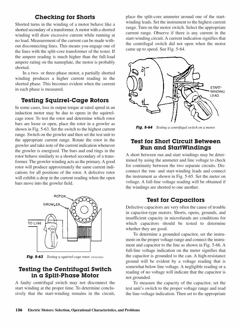
Checking for ShortsShorted turns in the winding of a motor behave like ashorted secondary of a transformer. A motor with a shortedwinding will draw excessive current while running atno load. Measurement of the current can be made with-out disconnecting lines. This means you engage one ofthe lines with the split-core transformer of the tester. Ifthe ampere reading is much higher than the full-loadampere rating on the nameplate, the motor is probablyshorted.
In a two- or three-phase motor, a partially shortedwinding produces a higher current reading in theshorted phase. This becomes evident when the currentin each phase is measured.
Testing Squirrel-Cage RotorsIn some cases, loss in output torque at rated speed in aninduction motor may be due to opens in the squirrel-cage rotor. To test the rotor and determine which rotorbars are loose or open, place the rotor in a growler asshown in Fig. 5-63. Set the switch to the highest currentrange. Switch on the growler and then set the test unit tothe appropriate current range. Rotate the rotor in thegrowler and take note of the current indication wheneverthe growler is energized. The bars and end rings in therotor behave similarly to a shorted secondary of a trans-former. The growler winding acts as the primary. A goodrotor will produce approximately the same current indi-cations for all positions of the rotor. A defective rotorwill exhibit a drop in the current reading when the openbars move into the growler field.
Testing the Centrifugal Switchin a Split-Phase Motor
A faulty centrifugal switch may not disconnect thestart winding at the proper time. To determine conclu-sively that the start-winding remains in the circuit,
place the split-core ammeter around one of the start-winding leads. Set the instrument to the highest currentrange. Turn on the motor switch. Select the appropriatecurrent range. Observe if there is any current in thestart-winding circuit. A current indication signifies thatthe centrifugal switch did not open when the motorcame up to speed. See Fig. 5-64.
Test for Short Circuit BetweenRun and StartWindings
A short between run and start windings may be deter-mined by using the ammeter and line voltage to checkfor continuity between the two separate circuits. Dis-connect the run- and start-winding leads and connectthe instrument as shown in Fig. 5-65. Set the meter onvoltage. A full-line voltage reading will be obtained ifthe windings are shorted to one another.
Test for CapacitorsDefective capacitors are very often the cause of troublein capacitor-type motors. Shorts, opens, grounds, andinsufficient capacity in microfarads are conditions forwhich capacitors should be tested to determinewhether they are good.
To determine a grounded capacitor, set the instru-ment on the proper voltage range and connect the instru-ment and capacitor to the line as shown in Fig. 5-66. Afull-line voltage indication on the meter signifies thatthe capacitor is grounded to the can. A high-resistanceground will be evident by a voltage reading that issomewhat below line voltage. A negligible reading or areading of no voltage will indicate that the capacitor isnot grounded.
To measure the capacity of the capacitor, set thetest unit’s switch to the proper voltage range and readthe line-voltage indication. Then set to the appropriate
136 Electric Motors: Selection, Operational Characteristics, and Problems
Fig. 5-63 Testing a squirrel-cage rotor. (Amprobe)
Fig. 5-64 Testing a centrifugal switch on a motor.
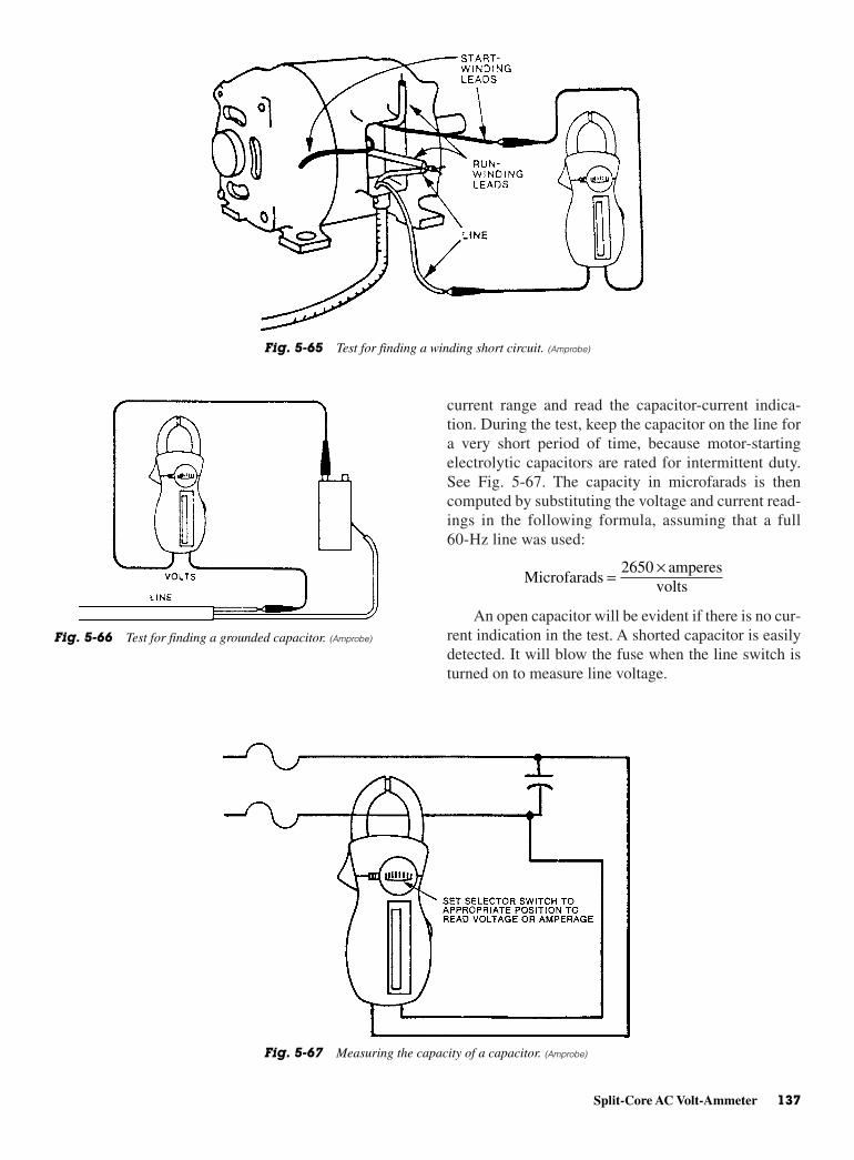
current range and read the capacitor-current indica-tion. During the test, keep the capacitor on the line fora very short period of time, because motor-startingelectrolytic capacitors are rated for intermittent duty.See Fig. 5-67. The capacity in microfarads is thencomputed by substituting the voltage and current read-ings in the following formula, assuming that a full60-Hz line was used:
An open capacitor will be evident if there is no cur-rent indication in the test. A shorted capacitor is easilydetected. It will blow the fuse when the line switch isturned on to measure line voltage.
Microfarads2650 amperes
volts= ×
Split-Core AC Volt-Ammeter 137
Fig. 5-65 Test for finding a winding short circuit. (Amprobe)
Fig. 5-66 Test for finding a grounded capacitor. (Amprobe)
Fig. 5-67 Measuring the capacity of a capacitor. (Amprobe)

USING THE MEGOHMMETER FORTROUBLESHOOTING
The megohmmeter (sometimes called a megger) is adevice that can be used to measure millions of ohms.See Fig. 5-68. Meg means “million.” The equipmentusually uses high voltage to push a small amount of’current through the insulator being measured. The insu-lation resistance is very important in the proper oper-ation of motors, compressors, and other electricalequipment.
Some meggers use batteries. Others use a crankthat turns a small coil of wire in a magnetic field. Turn-ing the crank handle causes the coil of wire to generatean EMF. The EMF is usually of high voltage. Thus, themegger can shock you if you touch the lead ends whenthe handle is cranked. There is very low current, sothere may be little actual damage caused by the electri-cal energy through your body. Needless to say, read theinstructions and follow them closely. Do not use amegger in an explosive atmosphere.
Equipment under test with the megohmmeter maybuild up a capacitive charge from the testing. One modelhas a “press to read” button. When it is released it auto-matically discharges the capacitive charge. With othermodels you must wait a few minutes for the charge todissipate or remove the test lead from the earth (ground)jack on the tester and touch to the equipment terminalthat the other test lead, line, is connected to. Never usethe megger on a live circuit. Since it has a self-containedpower, it is not necessary to draw current from the line.
There are two possible conducting or leakage pathsin the insulation of all electrical apparatus-one through
the insulating material and the other over its surface.By using the guard terminal, the surface leakage can beseparated and a direct measurement made of the insu-lation itself. See Fig. 5-69.
INSULATION-RESISTANCETESTING
The primary purpose of insulation is to keep electricityflowing in the desired path. The perfect insulationwould have infinite resistance, which would preventthe flow of any current through the insulation toground. However, there is no perfect insulation mater-ial. Thus, there is always some current flow. Goodinsulation is one that has and keeps a high-resistancevalue to minimize the current flow.
Unless there is an accidental damage, insulationfailure is generally gradual, rather than sudden. This isbecause failure is generally the result of repeated heating
138 Electric Motors: Selection, Operational Characteristics, and Problems
Fig. 5-68 Megohmmeters. (A) Megger or megohmmeter with a hand crank. (B) Megger ormegohmmeter with a battery for power. (Amprobe)
Fig. 5-69 Hand-cranked model used to test insulation of a cable.

is 1.5 for 221° F [105°C] (class A) insulation systemsand 2.0 for 266°F [130°C] (class B) insulation systems.
Power Tools And SmallAppliances
For double-insulated power tools, the megohmmeterlead shown connected to the housing would be con-nected to some metal part of the tool (such as the chuckor blade). See Fig. 5-70. The switch of the power toolmust be in the “on” position.
Motors For testing (AC), disconnect the motor fromthe line by disconnecting the wires at the motor terminalsor by opening the main switch. If the main switch is usedand the motor also has a starter, then the starter must beheld in the on position. In the latter case, the measuredresistance will include the resistances of the motor, wire,and all other components between the motor and themain switch. If a weakness is indicated, the motor andother components should be checked individually.
If the motor is disconnected at the motor terminals,connect one megohmmeter lead to the grounded motorhousing. Connect the other lead to one of the motorleads. See Fig. 5-71. For testing (DC), disconnect themotor from the line. To test the brush rigging, field
and cooling, the related expansion and contraction,and dirt, physical abrasion, vibration, moisture, andchemicals.
When insulation starts to fail, its resistance decreases.This allows more current to flow through the insula-tion. If the resistance continues to decrease, the condi-tion of the insulation may reach a point where it maypermit through the insulation a current flow, largeenough to cause the blowing of a fuse, equipment dam-age, or fatal shock.
Measuring InsulationResistance
Insulation-resistance measurements are affected by anumber of factors. Temperature and the duration of themeasurement are two primary ones. Humidity mayalso affect readings. Thus, it is a good idea to make anote as to whether the air is dry or humid at the time ofthe measurement. You may find that insulation resistancereadings are lower on humid days and higher on drydays. Wet or flooded equipment should be dried andcleaned as much as possible before measurements aretaken. Lastly, dirt and other contaminants (corrosion,chemicals, and so forth) can also affect readings. Youshould be certain that the contact points at which mea-surements are to be taken are reasonably clean.
The duration of the resistance measurement alsoaffects the reading. If the insulation is good, the readingwill continually increase as long as the megohmmeter isconnected to the insulation. The most common meggermeasurement is taken at the end of a 60-s interval. Thistime period generally gives a satisfactory measurementof the insulation resistance.
A second test involves taking a reading after 30 sand 60 ss. The 60-s reading divided by the 30-s readingis known as the dielectric absorption ratio. Comparingperiodic ratios may prove more useful than comparing1 minmin readings.
Generally speaking, a ratio of 1.25 is the bottomlimit for borderline insulation. An extension of this testinvolves readings taken after 60 s and 10 min. The ratioof the 10-min reading to the 60-s reading is referred toas the polarization index. The resistance measurementtaken at the end of 10 min should be considerablyhigher than that taken at 60 s. The measured insulationresistance of a dry winding in good condition shouldreach a relatively steady value in 10 min. If the windingis wet or dirty, the steady value will usually be reachedin 1 or 2 min. The index is helpful in evaluating thewinding dryness and fitness for over-potential testing.
As a guide, the recommended minimum value ofthe polarization index for AC and DC rotating machines
Insulation-Resistance Testing 139
Fig. 5-70 Using a megohmmeter to check insulation of a smallhand drill.
Fig. 5-71 Using a megohmmeter to check the insulation of thewindings of a motor.
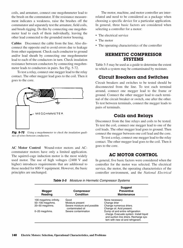
coils, and armature, connect one megohmmeter lead tothe brush on the commutator. If the resistance measure-ment indicates a weakness, raise the brushes off thecommutator and separately test the armature, field coils,and brush rigging. Do this by connecting one megohm-meter lead to each of them individually, leaving theother lead connected to the grounded motor housing.
Cables Disconnect the cable from the line. Also dis-connect the opposite end to avoid errors due to leakagefrom other equipment. Check each conductor to groundand/or lead sheath by connecting one megohmmeterlead to each of the conductors in turn. Check insulationresistance between conductors by connecting megohm-meter leads to conductors in pairs. See Fig. 5-72.
To test a relay, connect one megger lead to the relaycontact. The other megger lead goes to the coil. Then itgoes to the core.
AC Motor Control Wound-rotor motors and AC-commutator motors have only a limited application.The squirrel-cage induction motor is the most widelyused motor. The use of high voltages (2400 V andhigher) introduces requirements that are additional tothose needed for 600-V equipment. However, the basicprinciples are unchanged.
The motor, machine, and motor controller are inter-related and need to be considered as a package whenchoosing a specific device for a particular application.In general, three basic factors are considered whenselecting a controller for a motor:
• The electrical service
• The motor
• The operating characteristics of the controller
HERMETIC COMPRESSORSYSTEMS
Table 5-5 may be used as a guide to determine the extentto which a system may be contaminated by moisture.
Circuit Breakers and SwitchesCircuit breakers and switches to be tested should bedisconnected from the line. To test each terminalaround, connect one megger lead to the frame orground. Connect the other megger lead to each termi-nal of the circuit breaker or switch, one after the other.To test between terminals, connect the megger leads topairs of terminals.
Coils and RelaysDisconnect from the line relays and coils to be tested.To test the coil, connect one megger lead to one of thecoil leads. The other megger lead goes to ground. Thenconnect the megger between one coil lead and the core.
To test a relay, connect one megger lead to the relaycontact. The other megger lead goes to the coil. Then itgoes to the core.
AC MOTOR CONTROLIn general, five basic factors were considered when thecontroller for the motor was selected. The electricalservice, the motor, the operating characteristics of thecontroller environment, and the National Electrical
140 Electric Motors: Selection, Operational Characteristics, and Problems
Fig. 5-72 Using a megohmmeter to check the insulation quali-ties of wires between conductors.
Table 5-5 Moisture in Hermetic Compressor Systems
SuggestMegger Compressor PreventiveReading Condition Maintenance
100 megohms–infinity. Good None necessary50–100 megohms. Moisture present Change drier20–50 megohms. Severe moisture and possible Change numerous driers.
contaminated oil Change oil. Acid present.0–20 megohms. Severe contamination Dump oil and entire refrigeration
charge. Evacuate system. Install liquidand suction line driers. Recharge sys-tem with new oil and refrigerant.
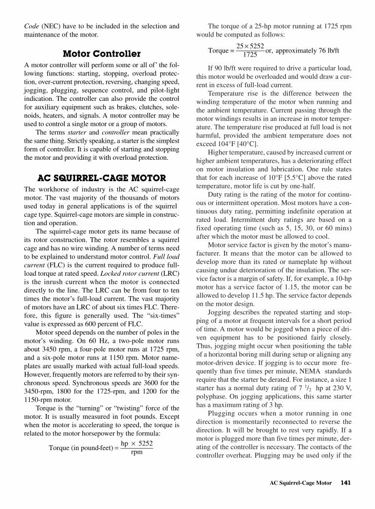
The torque of a 25-hp motor running at 1725 rpmwould be computed as follows:
If 90 lb/ft were required to drive a particular load,this motor would be overloaded and would draw a cur-rent in excess of full-load current.
Temperature rise is the difference between thewinding temperature of the motor when running andthe ambient temperature. Current passing through themotor windings results in an increase in motor temper-ature. The temperature rise produced at full load is notharmful, provided the ambient temperature does notexceed 104°F [40°C].
Higher temperature, caused by increased current orhigher ambient temperatures, has a deteriorating effecton motor insulation and lubrication. One rule statesthat for each increase of 10°F [5.5°C] above the ratedtemperature, motor life is cut by one-half.
Duty rating is the rating of the motor for continu-ous or intermittent operation. Most motors have a con-tinuous duty rating, permitting indefinite operation atrated load. Intermittent duty ratings are based on afixed operating time (such as 5, 15, 30, or 60 mins)after which the motor must be allowed to cool.
Motor service factor is given by the motor’s manu-facturer. It means that the motor can be allowed todevelop more than its rated or nameplate hp withoutcausing undue deterioration of the insulation. The ser-vice factor is a margin of safety. If, for example, a 10-hpmotor has a service factor of 1.15, the motor can beallowed to develop 11.5 hp. The service factor dependson the motor design.
Jogging describes the repeated starting and stop-ping of a motor at frequent intervals for a short periodof time. A motor would be jogged when a piece of dri-ven equipment has to be positioned fairly closely.Thus, jogging might occur when positioning the tableof a horizontal boring mill during setup or aligning anymotor-driven device. If jogging is to occur more fre-quently than five times per minute, NEMA standardsrequire that the starter be derated. For instance, a size 1starter has a normal duty rating of 7 1/2 hp at 230 V,polyphase. On jogging applications, this same starterhas a maximum rating of 3 hp.
Plugging occurs when a motor running in onedirection is momentarily reconnected to reverse thedirection. It will be brought to rest very rapidly. If amotor is plugged more than five times per minute, der-ating of the controller is necessary. The contacts of thecontroller overheat. Plugging may be used only if the
Torque =25 5252
1725or, approximately 76 lb/ft
×
Code (NEC) have to be included in the selection andmaintenance of the motor.
Motor ControllerA motor controller will perform some or all of’ the fol-lowing functions: starting, stopping, overload protec-tion, over-current protection, reversing, changing speed,jogging, plugging, sequence control, and pilot-lightindication. The controller can also provide the controlfor auxiliary equipment such as brakes, clutches, sole-noids, heaters, and signals. A motor controller may beused to control a single motor or a group of motors.
The terms starter and controller mean practicallythe same thing. Strictly speaking, a starter is the simplestform of controller. It is capable of starting and stoppingthe motor and providing it with overload protection.
AC SQUIRREL-CAGE MOTORThe workhorse of industry is the AC squirrel-cagemotor. The vast majority of the thousands of motorsused today in general applications is of the squirrelcage type. Squirrel-cage motors are simple in construc-tion and operation.
The squirrel-cage motor gets its name because ofits rotor construction. The rotor resembles a squirrelcage and has no wire winding. A number of terms needto be explained to understand motor control. Full loadcurrent (FLC) is the current required to produce full-load torque at rated speed. Locked rotor current (LRC)is the inrush current when the motor is connecteddirectly to the line. The LRC can be from four to tentimes the motor’s full-load current. The vast majorityof motors have an LRC of about six times FLC. There-fore, this figure is generally used. The “six-times”value is expressed as 600 percent of FLC.
Motor speed depends on the number of poles in themotor’s winding. On 60 Hz, a two-pole motor runsabout 3450 rpm, a four-pole motor runs at 1725 rpm,and a six-pole motor runs at 1150 rpm. Motor name-plates are usually marked with actual full-load speeds.However, frequently motors are referred to by their syn-chronous speed. Synchronous speeds are 3600 for the3450-rpm, 1800 for the 1725-rpm, and 1200 for the1150-rpm motor.
Torque is the “turning” or “twisting” force of themotor. It is usually measured in foot pounds. Exceptwhen the motor is accelerating to speed, the torque isrelated to the motor horsepower by the formula:
Torque (in pound-feet)hp 5252
rpm= ×
AC Squirrel-Cage Motor 141
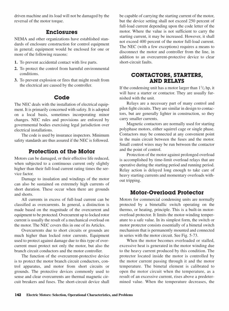
driven machine and its load will not be damaged by thereversal of the motor torque.
EnclosuresNEMA and other organizations have established stan-dards of enclosure construction for control equipmentin general; equipment would be enclosed for one ormore of the following reasons:
1. To prevent accidental contact with live parts.
2. To protect the control from harmful environmentalconditions.
3. To prevent explosion or fires that might result fromthe electrical are caused by the controller.
CodeThe NEC deals with the installation of electrical equip-ment. It is primarily concerned with safety. It is adoptedon a local basis, sometimes incorporating minorchanges. NEC rules and provisions are enforced bygovernmental bodies exercising legal jurisdiction overelectrical installations.
The code is used by insurance inspectors. Minimumsafety standards are thus assured if the NEC is followed.
Protection of the MotorMotors can be damaged, or their effective life reduced,when subjected to a continuous current only slightlyhigher than their full-load current rating times the ser-vice factor.
Damage to insulation and windings of the motorcan also be sustained on extremely high currents ofshort duration. These occur when there are groundsand shorts.
All currents in excess of full-load current can beclassified as overcurrents. In general, a distinction ismade based on the magnitude of the overcurrent andequipment to be protected. Overcurrent up to locked rotorcurrent is usually the result of a mechanical overload onthe motor. The NEC covers this in one of its Articles.
Overcurrents due to short circuits or grounds aremuch higher than locked rotor currents. Equipmentused to protect against damage due to this type of over-current must protect not only the motor, but also thebranch circuit conductors and the motor controller.
The function of the overcurrent-protective deviceis to protect the motor branch circuit conductors, con-trol apparatus, and motor from short circuits orgrounds. The protective devices commonly used tosense and clear overcurrents are thermal magnetic cir-cuit breakers and fuses. The short-circuit device shall
be capable of carrying the starting current of the motor,but the device setting shall not exceed 250 percent offull-load current depending upon the code letter of themotor. Where the value is not sufficient to carry thestarting current, it may be increased. However, it shallnot exceed 400 percent of the motor full-load current.The NEC (with a few exceptions) requires a means todisconnect the motor and controller from the line, inaddition to an overcurrent-protective device to clearshort-circuit faults.
CONTACTORS, STARTERS,AND RELAYS
If the condensing unit has a motor larger than 11/2 hp, itwill have a starter or contactor. They are usually fur-nished with the unit.
Relays are a necessary part of many control andpilot-light circuits. They are similar in design to contac-tors, but are generally lighter in construction, so theycarry smaller currents.
Magnetic contactors are normally used for startingpolyphase motors, either squirrel cage or single phase.Contactors may be connected at any convenient pointin the main circuit between the fuses and the motor.Small control wires may be run between the contactorand the point of control.
Protection of the motor against prolonged overloadis accomplished by time-limit overload relays that areoperative during the starting period and running period.Relay action is delayed long enough to take care ofheavy starting currents and momentary overloads with-out tripping.
Motor-Overload Protector Motors for commercial condensing units are normallyprotected by a bimetallic switch operating on thethermo, or heating, principle. This is a built-in motor-overload protector. It limits the motor-winding temper-ature to a safe value. In its simplest form, the switch ormotor protector consists essentially of a bimetal switchmechanism that is permanently mounted and connectedin series with the motor circuit. See Fig. 5-73.
When the motor becomes overloaded or stalled,excessive heat is generated in the motor winding dueto the heavy current produced by this condition. Theprotector located inside the motor is controlled bythe motor current passing through it and the motortemperature. The bimetal element is calibrated toopen the motor circuit when the temperature, as aresult of an excessive current, rises above a predeter-mined value. When the temperature decreases, the
142 Electric Motors: Selection, Operational Characteristics, and Problems
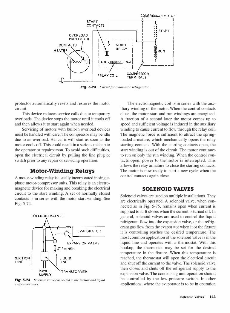
The electromagnetic coil is in series with the aux-iliary winding of the motor. When the control contactsclose, the motor start and run windings are energized.A fraction of a second later the motor comes up tospeed and sufficient voltage is induced in the auxiliarywinding to cause current to flow through the relay coil.The magnetic force is sufficient to attract the spring-loaded armature, which mechanically opens the relaystarting contacts. With the starting contacts open, thestart winding is out of the circuit. The motor continuesto run on only the run winding. When the control con-tacts open, power to the motor is interrupted. Thisallows the relay armature to close the starting contacts.The motor is now ready to start a new cycle when thecontrol contacts again close.
SOLENOID VALVESSolenoid valves are used on multiple installations. Theyare electrically operated. A solenoid valve, when con-nected as in Fig. 5-75, remains open when current issupplied to it. It closes when the current is turned off. Ingeneral, solenoid valves are used to control the liquidrefrigerant flow into the expansion valve, or the refrig-erant gas flow from the evaporator when it or the fixtureit is controlling reaches the desired temperature. Themost common application of the solenoid valve is in theliquid line and operates with a thermostat. With thishookup, the thermostat may be set for the desiredtemperature in the fixture. When this temperature isreached, the thermostat will open the electrical circuitand shut off the current to the valve. The solenoid valvethen closes and shuts off the refrigerant supply to theexpansion valve. The condensing unit operation shouldbe controlled by the low-pressure switch. In otherapplications, where the evaporator is to be in operation
protector automatically resets and restores the motorcircuit.
This device reduces service calls due to temporaryoverloads. The device stops the motor until it cools offand then allows it to start again when needed.
Servicing of motors with built-in overload devicesmust be handled with care. The compressor may be idledue to an overload. Hence, it will start as soon as themotor cools off. This could result in a serious mishap tothe operator or repairperson. To avoid such difficulties,open the electrical circuit by pulling the line plug orswitch prior to any repair or servicing operation.
Motor-Winding RelaysA motor-winding relay is usually incorporated in single-phase motor-compressor units. This relay is an electro-magnetic device for making and breaking the electricalcircuit to the start winding. A set of normally closedcontacts is in series with the motor start winding. SeeFig. 5-74.
Solenoid Valves 143
Fig. 5-73 Circuit for a domestic refrigerator.
Fig. 5-74 Solenoid valve connected in the suction and liquidevaporator lines.

for only a few hours each day, a manually operated snapswitch may be used to open and close the solenoidvalve.
REFRIGERATION VALVEThe solenoid valve in Fig. 5-76 is operated with a nor-mally closed status. A direct-acting metal ball and seatassure tight closing, The two-wire, class-W, coil is sup-plied standard for long life on low-temperature serviceor sweating conditions. Current failure or interruptionwill cause the valve to fail-safe in the closed position.The solenoid cover can be rotated 360° for easyinstallation. Explosion-proof models are available foruse in hazardous areas.
ApplicationThis solenoid valve is usable with all refrigerantsexcept ammonia. Also it can be used for air, oil, water,detergents, butane or propane gas, and other non-corrosive liquids or gases.
A variety of temperature control installations canbe accomplished with these valves. Such installationsinclude bypass, defrosting, suction line, hot-gas ser-vice, humidity control, alcohols, unloading, reversecycle, chilled water, cooling tower, brine, and liquidline stop installations and ice makers.
OperationThe valves are held in the normally closed position bythe weight of the plunger assembly and the fluid pres-sure on top of the valve ball. The valve is opened byenergizing the coil and magnetically lifting the plungerand allowing full flow by the valve ball. Deenergizingthe coil permits the plunger and valve ball to return tothe closed position.
The piloted piston solenoid valve is somewhat dif-ferent. See Fig. 5-77. It too, is normally closed. It canbe used on all refrigerants except R-717.
When the solenoid is energized the plunger rises,lifting the pilot valve to allow pressure to bleed from
144 Electric Motors: Selection, Operational Characteristics, and Problems
Fig. 5-75 Solenoid valve leads identification and refrigeration installation. (General Controls)
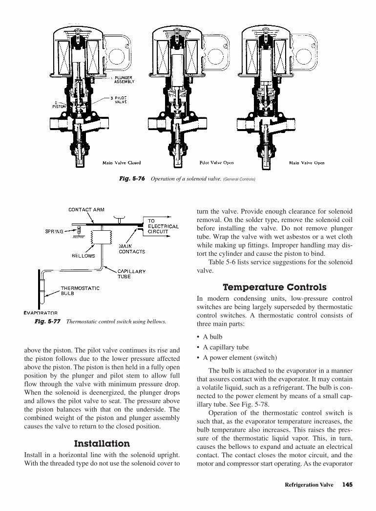
turn the valve. Provide enough clearance for solenoidremoval. On the solder type, remove the solenoid coilbefore installing the valve. Do not remove plungertube. Wrap the valve with wet asbestos or a wet clothwhile making up fittings. Improper handling may dis-tort the cylinder and cause the piston to bind.
Table 5-6 lists service suggestions for the solenoidvalve.
Temperature Controls In modern condensing units, low-pressure controlswitches are being largely superseded by thermostaticcontrol switches. A thermostatic control consists ofthree main parts:
• A bulb
• A capillary tube
• A power element (switch)
The bulb is attached to the evaporator in a mannerthat assures contact with the evaporator. It may containa volatile liquid, such as a refrigerant. The bulb is con-nected to the power element by means of a small cap-illary tube. See Fig. 5-78.
Operation of the thermostatic control switch issuch that, as the evaporator temperature increases, thebulb temperature also increases. This raises the pres-sure of the thermostatic liquid vapor. This, in turn,causes the bellows to expand and actuate an electricalcontact. The contact closes the motor circuit, and themotor and compressor start operating. As the evaporator
above the piston. The pilot valve continues its rise andthe piston follows due to the lower pressure affectedabove the piston. The piston is then held in a fully openposition by the plunger and pilot stem to allow fullflow through the valve with minimum pressure drop.When the solenoid is deenergized, the plunger dropsand allows the pilot valve to seat. The pressure abovethe piston balances with that on the underside. Thecombined weight of the piston and plunger assemblycauses the valve to return to the closed position.
InstallationInstall in a horizontal line with the solenoid upright.With the threaded type do not use the solenoid cover to
Refrigeration Valve 145
Fig. 5-76 Operation of a solenoid valve. (General Controls)
Fig. 5-77 Thermostatic control switch using bellows.
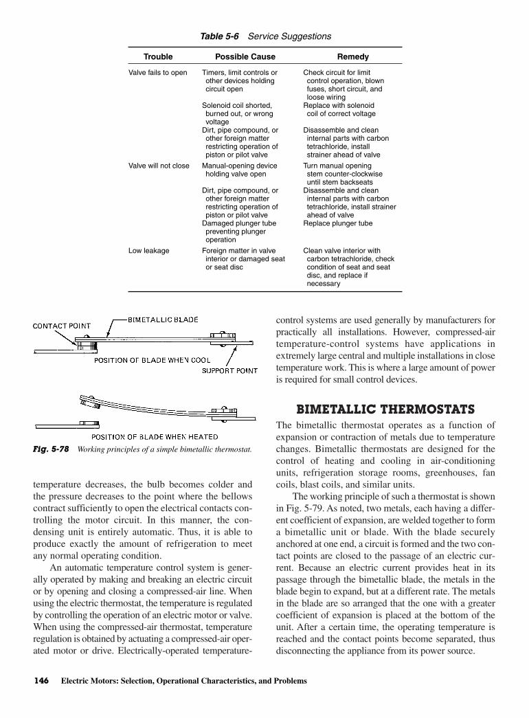
temperature decreases, the bulb becomes colder andthe pressure decreases to the point where the bellowscontract sufficiently to open the electrical contacts con-trolling the motor circuit. In this manner, the con-densing unit is entirely automatic. Thus, it is able toproduce exactly the amount of refrigeration to meetany normal operating condition.
An automatic temperature control system is gener-ally operated by making and breaking an electric circuitor by opening and closing a compressed-air line. Whenusing the electric thermostat, the temperature is regulatedby controlling the operation of an electric motor or valve.When using the compressed-air thermostat, temperatureregulation is obtained by actuating a compressed-air oper-ated motor or drive. Electrically-operated temperature-
control systems are used generally by manufacturers forpractically all installations. However, compressed-airtemperature-control systems have applications inextremely large central and multiple installations in closetemperature work. This is where a large amount of poweris required for small control devices.
BIMETALLIC THERMOSTATSThe bimetallic thermostat operates as a function ofexpansion or contraction of metals due to temperaturechanges. Bimetallic thermostats are designed for thecontrol of heating and cooling in air-conditioningunits, refrigeration storage rooms, greenhouses, fancoils, blast coils, and similar units.
The working principle of such a thermostat is shownin Fig. 5-79. As noted, two metals, each having a differ-ent coefficient of expansion, are welded together to forma bimetallic unit or blade. With the blade securelyanchored at one end, a circuit is formed and the two con-tact points are closed to the passage of an electric cur-rent. Because an electric current provides heat in itspassage through the bimetallic blade, the metals in theblade begin to expand, but at a different rate. The metalsin the blade are so arranged that the one with a greatercoefficient of expansion is placed at the bottom of theunit. After a certain time, the operating temperature isreached and the contact points become separated, thusdisconnecting the appliance from its power source.
146 Electric Motors: Selection, Operational Characteristics, and Problems
Table 5-6 Service Suggestions
Trouble Possible Cause Remedy
Valve fails to open Timers, limit controls or Check circuit for limitother devices holding control operation, blowncircuit open fuses, short circuit, and
loose wiringSolenoid coil shorted, Replace with solenoidburned out, or wrong coil of correct voltagevoltage
Dirt, pipe compound, or Disassemble and cleanother foreign matter internal parts with carbonrestricting operation of tetrachloride, installpiston or pilot valve strainer ahead of valve
Valve will not close Manual-opening device Turn manual openingholding valve open stem counter-clockwise
until stem backseatsDirt, pipe compound, or Disassemble and cleanother foreign matter internal parts with carbonrestricting operation of tetrachloride, install strainerpiston or pilot valve ahead of valve
Damaged plunger tube Replace plunger tubepreventing plunger operation
Low leakage Foreign matter in valve Clean valve interior with interior or damaged seat carbon tetrachloride, checkor seat disc condition of seat and seat
disc, and replace if necessary
Fig. 5-78 Working principles of a simple bimetallic thermostat.

The defrosting is usually accomplished by providingone or more electric heaters. They are energized by theaction of the electric clock and provide the heatingaction necessary for complete defrosting.
The defrost controls, as usually employed, areessentially SPDT switching devices in which theswitch arm is moved to the defrost position by an elec-tric clock. The switch arm is returned to the normalposition by a power element that is responsive tochanges in temperature. As the evaporator is warmedduring a defrost period, the feeler tube of the defrostcontrol is also warmed until it reaches the defrost cut-out point of approximately 45°F [7°C]. The defrost-control bellows then force the switch arm to snap fromthe defrost position to the normal position. SeeFig. 5-81. This starts the motor compressor.
After a short period, the contact blade will againbecome sufficiently cooled to cause the contact points tojoin, thus reestablishing the circuit and permitting thecurrent again to actuate the circuit leading to the appli-ance. The foregoing cycle is repeated over and overagain. In this way, the bimetallic thermostat prevents thetemperature from rising too high or dropping too low.
Thermostat Constructionand Wiring
Some thermostats are designed for use on both heatingand cooling equipment. The thermostat shown inFig. 5-80 is such a device. The basic thermostat ele-ment has a permanently sealed, magnetic single-poledouble-throw (SPDT) switch. The thermostat elementplugs into the subbase and contains the heat anticipa-tion, the magnetic switching, and a room temperaturethermometer. The subbase unit contains fixed coldanticipation and circuitry. This thermostat is for usewith 24-V equipment. In this case, the thermostaticelement (bimetal) does not make direct contact withthe electrical circuit. The expansion of the bimetalcauses a magnet to move. This, in turn, causes a switchto close or open. Figure 5-80 illustrates the fact that thebimetal is not in the electrical circuit at all.
DEFROST CONTROLS Automatic defrost is common in domestic refrigeration,it is accomplished in several ways. The control methodused depends on the type of refrigeration system, the sizeand number of condensing units, and other factors.
Defrost Timer OperationIn small and medium-size domestic refrigerators, anautomatic defrost-control clock may be set for a defrostcycle once every 24 h, or as often as deemed necessary.
Defrost Controls 147
Fig. 5-79 Modern thermostat for both cooling and heating using a metallic strip’s expansion ability to move a magnet close toa magnetic switch. (A) Typical thermostat. (B) Interior of thermostat element. (C) Typical subbase showing switching and wiringterminal locations. (General Controls)
Fig. 5-80 Wiring diagram showing how the thermostat iswired and hooked into a circuit.

Another common method of automatic defrosting isthe so-called defrost cycle method. In this, the defrostcycle occurs during each compressor off-cycle. In adefrost system of this type, the defrost heaters are con-nected across the thermostat-switch terminals. When thethermostat switch is closed, the heaters are shunted out ofthe circuit. When the thermostat opens, the heaters areenergized, completing the circuit through the overloadrelay and compressor. Figure 5-83 illustrates this type ofdefrosting. Note that the serpentine resistor is shorted outby the temperature control. This occurs when the temper-ature control is closed and the compressor motor is run-ning normally.
Hot-Gas DefrostingIn any low-temperature room, where the air is to bemaintained below freezing, some adequate means forremoving accumulated frost from the cooling sur-face should be provided. An improved hot-gasmethod of quick defrosting for direct-expansionlow-temperature evaporators is now available. Toapply this method, two or more evaporators areneeded in the system. This is because the hot gasrequired to defrost part of the system must be pro-vided by the heat absorbed from the other coolingsurface in a given system. Defrosting a plate bank
with hot gas can be accomplished automatically byinstalling the proper controls.
MOTOR BURNOUT CLEANUP The following cleanup methods are simple, rapid,and economical. They represent a drastic reductionin labor requirements over the obsolete flushingmethods.
Procedure for SmallTonnage Systems
In systems up to 40 tons, the refrigerant charge is rela-tively small. Motor burnout contaminants are not dilutedto the extent that they are in large tonnage systems. As aresult, there is a greater need to isolate the motor com-pressor from all harmful soluble and insoluble materialsthat might cause another burnout.
Driers should be installed in both the liquid andsuction lines. See Fig. 5-82. The desiccant in the dri-ers removes all harmful soluble chemicals thatcause corrosion and attack motor-winding insulation.Suction-line filtration should be employed to preventharmful solids above 5 µm (0.0002 in.) from return-ing to the compressor. Through abrasion, foreign par-ticles such as casting dust, copper and aluminum dust,
148 Electric Motors: Selection, Operational Characteristics, and Problems
Fig. 5-81 Twenty–four hour clock used to activate the defrost cycle.

Since oil breakdown materials dissolve readily in oil,higher concentrations of contaminants are in contactwith the desiccant. This results in conditions morefavorable to maximum pickup.
Liquid refrigerant does not compete with the desiccant toaccept soluble contaminants. In the liquid line itdoes by greatly diluting soluble materials. This greatlyreduces contact time and, consequently, reduces therate of pickup.
The low-side filter drier has an access valve on the inletside for checking pressure drop and charge adjustment.
There is no method of cleanup after a burnout thatdoes not carry some risk. No cleanup procedure willguarantee 100 percent success. The procedures thatfollow have been generally successful. They are practi-cal at the field level and economical enough to be usedby the equipment owner.
1. Discharge oil refrigerant mixture in liquid phase. Ifwater cooled, drain all water containing areas first.
2. Remove burned-out compressor, taking care not totouch oil or sludge with bare hands.
3. Blow out coils and condenser with clean, dry-liquidrefrigerant.
4. Install new motor compressor.
5. Install a moisture indicator and an oversize high-side filter-drier in the liquid line.
6. Install a low-side filter-drier in the suction line asclose to the compressor as possible. If the system islarger than 20 actual tons, install two low-side filter-driers in parallel.
7. Triple evacuate to 500 µm, or as low as practical,and charge.
Optional Check back in two weeks and performan acid test on the oil. Use the acid-test kit. If the oilis acidic or discolored, chance the oil, both driers,
and flux contribute to motor burnouts and compressordamage.
The type of drier used in the suction line is of greatimportance. Throwaway-type liquid-line driers, whenused in the suction line, are usually too small. Theymay create a dangerously high pressure drop. This maycause overheating of the motor compressor and a repeatburnout.
Until recently, it has been necessary to use largereplaceable cartridge-type driers for this purpose. Eventhese have a limited range. They are costly, heavy, and dif-ficult to mount. Their filtering ability is very questionable.In addition, since the system must be opened to removethem, replacement of the liquid-line drier and reevacua-tion of the system are needed. These operations add to thecost.
New low-side filter-driers eliminate these difficul-ties. Two essential components are combined into one.Thus, the filter-drier is both a suction-line filter and asuction-line drier. It is designed for permanent installa-tion. The blended mixture of activated alumina andmolecular sieves provides an enormous capacity foradsorbing moisture and other harmful soluble con-taminants. It can adsorb inorganic and organic acidsand oil breakdown materials.
Evidence indicates that these soluble contaminantsare most easily removed in the suction line for the fol-lowing reasons:
Field experience shows success with soluble contami-nants removal when properly-sized driers have beenused in the suction line following hermetic motorburnouts.
Modern drying materials have a substantially highercapacity for moisture and acids at lower temperatures.Suction-line temperatures are normally from 20 to60°F (11 to 33°C) lower than liquid-line tempera-tures, depending upon the application and ambientconditions.
Motor Burnout Cleanup 149
Fig. 5-82 Low-side filter-drier. (Virginia Chemicals)

and again evacuate. Another twoweek checkup isdesirable.
This method, due to line sizing and refrigerantcost, is applicable up to 40 tons. Consideration mayalso be given to saving the refrigerant if the charge isabove 100 lb.
Procedure for LargeTonnage Systems
In systems above 40 tons, the large refrigerant charge sodilutes the motor burnout contaminants that discardingthe refrigerant is unnecessary. It cannot be justifiedfrom cost considerations. Oil breakdown materials andorganic acids are more soluble in the oil than the refrig-erant. They tend to concentrate in the oil. By repeatedoil changes and drier changes, with the oil and drierextracting the contaminants, such systems can becleaned up. The following procedure has been usedover an extended period of time by many large contrac-tors with successful cleanups from 40 to over 500 tons.
Due to design variations, the mechanics of carry-ing out the following procedures must be adapted tothe system involved. The basic procedure is as follows:
1. If possible, wash out coil and condenser with cleanrefrigerant. In some designs, this is possible, butwith others, completely impractical.
2. Reinstall the rebuilt compressor with a fresh, cleancharge of oil.
3. Install the largest possible drier in the liquid phaseof the system.
4. Operate 24 hours.
5. Change oil and drier or drier cores.
6. Operate 24 hours.
7. Change oil and drier or drier cores.
8. Operate 24 hours.
9. Change oil and drier or drier cores.
10. Triple evacuate to 500 µm or as low as practical,and charge.
11. Operate two weeks and check oil color. Perform anacid test on the oil. If it is neutral and the color nor-mal, consider the job done. If the oil is acidic ordiscolored, repeat the above steps until neutrality issecure and the oil color is normal.
READING A SCHEMATICIt is often difficult to read a schematic at first glance.Figure 5-83 shows the schematic for a home appliance.The voltage being used is 115 V. Follow the brown
wires and see how they control the freezer light, cabi-net light, and mullion heater. The brown wire on theright is spliced to an orange wire. This orange wireconnects to one side of the freezer door switch, oneside of the refrigerator door switch, and one side ofthe mullion heater. The brown wire from the left side ofthe schematic connects to two orange wires that attachto one side of the freezer light and one side of the cab-inet light. The brown wire on the left connects to theother side of the mullion heater. There is a wireconnecting the freezer light and the freezer doorswitch. Likewise, there is a wire connecting the cabinetlight and the cabinet door switch.
Now, trace the schematic. Start at the top of theschematic at the 115 V lead. Trace the left side first.The brown wire on the left side goes down to theorange wires that connect to the freezer light and cabi-net light. The brown wire also connects to the mullionheater. Now, take the brown wire leading from the rightside of the 115 V plug. It is spliced to the orange wirethat connects to the door switch and the mullion heater.This means that the mullion heater is on when the plugis inserted into a power source. It also means that thefreezer light does not come on until the door is openand the refrigerator door switch is closed. Likewise,the cabinet light does not come on until the door isopen and the door switch is closed.
Referring again to Fig. 5-81, note the way in whichthe defrost controls are wired. Note in this case that thebrown wire on the left side of the schematic—comingfrom the 115 V plug—has the temperature control insertedin series with the rest of the wiring and devices. Tracingfrom the left to right you will find that a black wire runsfrom the temperature control to the door switch. An ivorywire runs from the door switch to the freezer fan. Anotherivory wire runs from the freezer fan to the defrost control(point 4). If the defrost control switch is up, it completesthe path from point 3 to the brown wire that leads back tothe 115-V plug. Thus, if the temperature control (refriger-ator thermostat) and the freezer door switch are closedand the defrost control switch is up, the circuit is completefor the freezer fan to operate.
Note that the defrost control is operated by a timermotor. The timer motor is in the circuit at all timeswhen the temperature control switch is closed. Thismeans the defrost control timer will operate and com-plete its cycle faster if the thermostat is closed. There-fore, the more the refrigerator compressor runs, thefaster the defrost control advances to its predeterminedpoint of operation.
To trace the defrost control’s source of power, startat the 115-V plug. Trace from the left side through thetemperature control and down the black wire to the
150 Electric Motors: Selection, Operational Characteristics, and Problems
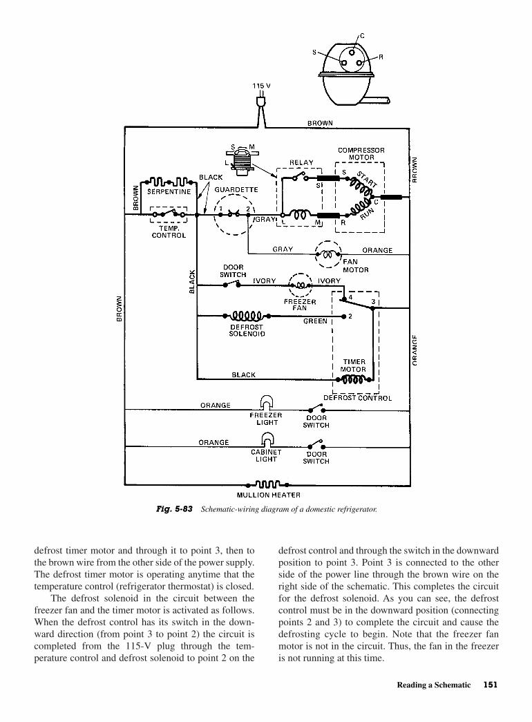
defrost control and through the switch in the downwardposition to point 3. Point 3 is connected to the otherside of the power line through the brown wire on theright side of the schematic. This completes the circuitfor the defrost solenoid. As you can see, the defrostcontrol must be in the downward position (connectingpoints 2 and 3) to complete the circuit and cause thedefrosting cycle to begin. Note that the freezer fanmotor is not in the circuit. Thus, the fan in the freezeris not running at this time.
defrost timer motor and through it to point 3, then tothe brown wire from the other side of the power supply.The defrost timer motor is operating anytime that thetemperature control (refrigerator thermostat) is closed.
The defrost solenoid in the circuit between thefreezer fan and the timer motor is activated as follows.When the defrost control has its switch in the down-ward direction (from point 3 to point 2) the circuit iscompleted from the 115-V plug through the tem-perature control and defrost solenoid to point 2 on the
Reading a Schematic 151
Fig. 5-83 Schematic-wiring diagram of a domestic refrigerator.
The refrigerator motor is controlled as follows. Start-ing at the left side of the 115-V plug, trace the brown wireto the junction of the serpentine and temperature control.This temperature control switch shorts out the serpentinewhen the switch is closed. Thus, the serpentine is not inthe circuit when the refrigerator is running. A black wireruns from the temperature control switch to the guardette(circuit breaker). A gray wire leads from the guardette topoint L of the relay. From point L to point M on the relayis the relay’s coil. This coil (point M to point R on thecompressor motor) is in series with the run-winding ofthe compressor motor. Point R to point C of the com-pressor motor represents the run-winding of the com-pressor motor. Point C is common to start andrun-winding. Note the drawing of the compressor abovethe schematic. Here, the S, C, and R points are shown rel-ative to their true location within the refrigerator. It canbe seen that the temperature control and guardette mustbe closed for the run-winding to have a complete circuitto the power source lines.
The relay is in series with the run-winding. Whenthe motor starts, the relay contacts are closed. Currentthrough the contacts also completes its path to the com-mon side of the power line (point C). Once the motorcomes up to speed, the run-winding draws more cur-rent and causes the relay to be energized.
Once energized, the relay opens the contact pointsand takes the start-winding out of the circuit. When themotor stops again (when the thermostat opens), the relaydeenergizes and the contacts close. This means the relayis ready for the next starting sequence. If the relay con-tacts stick, the start-winding stays in the circuit anddraws current. The guardette is brought into action andopens the circuit to protect the motor windings fromoverheating.
For the refrigerator fan motor to operate, it musthave power. It runs when the temperature control andthe guardette are closed. To trace the circuit for the fanmotor, start at the left side of the 115-V plug. Trace thebrown wire through the temperature control, the closedswitch, and the guardette. From the number 2 positionon the guardette, a gray wire is connected to one side ofthe fan motor. The other side of the fan motor is con-nected by an orange wire to the brown wire leading tothe other side of the 115-V plug. Thus, the temperaturecontrol switch and the guardette must be closed beforethe fan switch can run. Also, the fan motor runs when-ever the compressor motor runs.
The serpentine heater is in the circuit whenever thetemperature control is off or the refrigerator is notoperating. It is a heating element wrapped around theevaporator coil. It prevents frost build-up betweendefrosting cycles.
Look again at Fig. 5-83. See if you can more easilyread the schematic.
REVIEW QUESTIONS1. State the left-hand rule for current in a conductor.
2. State the right-hand rule for motors.
3. What is the main advantage of a DC series motor?
4. What is the difference between a single-phasemotor and a three-phase motor?
5. How does the capacitor-start motor differ from asplit-phase motor?
6. What is the advantage of a three-phase motor overa single-phase motor?
7. What is a squirrel-cage rotor?
8. What is a megger?
9. What is synchronous speed?
10. What is meant by the service factor of a motor?
11. What does NEMA stand for?
12. Describe the operation of a bimetallic thermostat.
13. How is automatic defrost accomplished in today’srefrigerators?
14. Where are driers located in a refrigeration system?
15. What is a schematic?
16. What is a serpentine heater?
17. What is voltage spread?
18. What is the purpose of a centrifugal switch on asingle-phase motor?
19. How can direction of rotation be reversed on asplit-phase motor?
20. What type of motor uses pushrods and a woundarmature?
21. Where are capacitor-start motors used?
22. How are capacitor-start motors reversed when stand-ing still?
23. What advantage does the permanent split-capacitormotor have?
24. What are shaded-pole motors most likely to beused for?
25. What is needed to get a split-phase motor to run?
26. How much current does an across-the-line motordraw when it starts?
27. What is another name for primary resistor starters?
28. What is the major disadvantage of the autotrans-former starter?
29. What type of starting does part-winding startersprovide?
152 Electric Motors: Selection, Operational Characteristics, and Problems
34. What happens to motor speed when more poles areadded?
35. How do consequence pole motors obtain two speeds?
36. What is the advantage of reduced-voltage motorstarting?
30. What is the least expensive method of motor starting?
31. Where are wye-delta starters typically used?
32. Why are wye-delta starters used with delta-woundsquirrel-cage motors?
33. Why are compelling relays needed?
Review Questions 153

This page intentionally left blank

6CHAPTER
Refrigerants:New and Old
Copyright © 2006 by The McGraw-Hill Companies, Inc. Click here for terms of use.

156 Refrigerants: New and Old
PERFORMANCE OBJECTIVESAfter studying this chapter, you should:
1. Know the classifications of refrigerants.
2. Know some of the physical properties of Freon.
3. Know the potential hazards of fluorocarbons.
4. Know operating pressures of refrigerants.
5. Know about moisture and refrigerants.
6. Know some of the problems with older refrigerants.
7. Know why new refrigerants are needed.
Refrigerants are used in the process of refrigeration.Refrigeration is a process whereby heat is removed froma substance or a space.
A refrigerant is a substance that picks up latentheat when the substance evaporates from a liquid to agas. This is done at a low temperature and pressure. Arefrigerant expels latent heat when it condenses from agas to a liquid at a high pressure and temperature. Therefrigerant cools by absorbing heat in one place anddischarging it in another area.
The desirable properties of a good refrigerant forcommercial use are:
• Low boiling point
• Safe nontoxic
• Easy to liquefy and moderate pressure and temperature
• High latent-heat value
• Operation on a positive pressure
• Not affected by moisture
• Mixes well with oil
• Noncorrosive to metal.
There are other qualities that all refrigerants have.These qualities are molecular weight, density, com-pression ratio, heat value, and temperature of compres-sion. These qualities will vary with the refrigerants.The compressor displacement and compressor type ordesign will also influence the choice of refrigerant.
CLASSIFICATION OFREFRIGERANTS
Refrigerants are classified according to their manner ofabsorption or extraction of heat from substances to berefrigerated. The classifications can be broken downinto class 1, class 2, and class 3.
Class 1 refrigerants are used in the standard com-pression type of refrigeration systems. Class 2 refriger-ants are used as immediate cooling agents between class1 and the substance to be refrigerated. They do the same
work for class 3. Class 3 refrigerants are used in the stan-dard absorption-type systems of refrigerating systems.
Class 1. This class includes those refrigerants that coolby absorption or extraction of heat from the sub-stances to be refrigerated by the absorption of theirlatent heats. Table 6-1 lists the characteristics of typ-ical refrigerants.
Class 2. The refrigerants in this class are those that coolsubstances by absorbing their sensible heats. They areair, calcium-chloride brine, sodium-chloride (salt)brine, alcohol, and similar nonfreezing solutions.
Class 3. This group consists of solutions that containabsorbed vapors of liquefiable agents or refrigeratingmedia. These solutions function through their abilityto carry the liquefiable vapors. The vapors produce acooling effect by the absorption of their latent heat.An example is aqua ammonia, which is a solutioncomposed of distilled water and pure ammonia.
Common Refrigerants Following are some of the more common refrigerants.Table 6-1 summarizes the characteristics to a selectedfew of the many refrigerants available for home, com-mercial, and industrial use.
Sulfur Dioxide Sulfur dioxide (SO2) is a colorlessgas or liquid. It is toxic, with a very pungent odor. Whensulfur is burned in air, sulfur dioxide is formed. Whensulfur dioxide combines with water it produces sulfuricand sulfurous acids. These acids are very corrosive tometal. They have an adverse effect on most materials.Sulfur dioxide is not considered a safe refrigerant.
Table 6-1 Characteristics of Typical Refrigerants
Heat of Vaporization Boiling Point at Boiling Point
Name (°F) Btu/lb. 1 At.
Sulfur dioxide 14.0 172.3Methyl chloride −10.6 177.8Ethyl chloride 55.6 177.0Ammonia −28.0 554.7Carbon dioxide −110.5 116.0Freezol (isobutane) 10.0 173.5Freon 11 74.8 78.31Freon 12 −21.7 71.04Freon 13 −114.6 63.85Freon 21 48.0 104.15Freon 22 −41.4 100.45Freon 113 117.6 63.12Freon 114 38.4 58.53Freon 115 −37.7 54.20Freon 502 −50.1 76.46
Classification of Refrigerants 157
Sulfur dioxide is not considered safe when used in largequantities. As a refrigerant, sulfur dioxide operates on avacuum to give the temperatures required. Moisture inthe air will be drawn into the system when a leak occurs.This means the metal parts will eventually corrode,causing the compressor to seize.
Sulfur dioxide (SO2) boils at 14°F (−10°C) and hasa heat of vaporization at boiling point (1 atmosphere) of172.3 Btu/1b. It has a latent-heat value of 166 Btu/lb.
To produce the same amount of refrigeration, sul-fur dioxide requires about one-third more vapor thanFreon and methyl chloride. This means the condensingunit has to operate at a higher speed or the compressorcylinders must be larger. Since sulfur dioxide does notmix well with oil, the suction line must be on a steadyslant to the machine. Otherwise, the oil will trap out,constricting the suction line. This refrigerant is not fea-sible for use in some locations.
Methyl Chloride Methyl chloride (CH3Cl) has a boil-ing point of −10.6° F (−23.3°C). It also has heat of va-porization at boiling point (at l atmosphere) of 177.8Btu/lb. It is a good refrigerant. However, because it willburn under some conditions, some cities will not allowit to be used. It is easy to liquefy and has a compara-tively high latent-heat value. It does not corrode metalwhen in its dry state.
However, in the presence of moisture it damagesthe compressor. A sticky black sludge is formed whenexcess moisture combines with the chemical. Methylchloride mixes well with oil. It will operate on a posi-tive pressure as low as −10°F (−23°C). The amount ofvapor needed to cause discomfort in a person is in pro-portion to the following numbers:
Carbon dioxide 100Methyl chloride 70Ammonia 2Sulfur dioxide 1
That means methyl chloride is 35 times safer thanammonia and 70 times safer than sulfur dioxide.
Methyl chloride is hard to detect with the nose oreyes. It does not produce irritating effects. Therefore,some manufacturers add a 1 percent amount of acrolein,a colorless liquid with a pungent odor, as a warningagent. It is produced by destructive distillation of fats.
Ammonia Ammonia (NH3) is used most frequentlyin large industrial plants. Freezers for packing housesusually employ ammonia as a refrigerant. It is a gaswith a very noticeable odor. Even a small leak can bedetected with the nose. Its boiling point at normalatmospheric pressure is −28°F (−33°C). Its freezingpoint is −107.86°F (−77.7°C). It is very soluble in
water. Large refrigeration capacity is possible withsmall machines. It has high latent heat [555 Btu at 18°F(−7.7°C)]. It can be used with steel fittings. Water-cooledunits are commonly used to cool down the refrigerant.High pressures are used in the lines (125 to 200 lb/in.2).Anyone inside the refrigeration unit when it springs aleak is rapidly overcome by the fumes. Fresh air is nec-essary to reduce the toxic effects of ammonia fumes.Ammonia is combustible when combined with certainamounts of air (about one volume of ammonia to twovolumes of air). It is even more combustible whencombined with oxygen. It is very toxic. Heavy steel fit-tings are required since pressures of 125 to 200 lb/in.2
are common. The units must be water cooled.
Carbon Dioxide Carbon dioxide (CO2) is a colorlessgas at ordinary temperatures. It has a slight odor and anacid taste. Carbon dioxide is nonexplosive and nonflam-mable. It has a boiling point of 5°F (−15°C). A pressureof over 300 lb/in.2 is required to keep it from evapora-tion. To liquefy the gas, a condenser temperature of 80°F(26.6°C) and a pressure of approximately 1000 lb/in.2
are needed. Its critical temperature is 87.8°F (31°C). It isharmless to breathe except in extremely large concentra-tions. The lack of oxygen can cause suffocation undercertain conditions of carbon dioxide concentration.
Carbon dioxide is used aboard ships and in indus-trial installations. It is not used in household applica-tions. The main advantage of using carbon dioxide fora refrigerant is that a small compressor can be used.The compressor is very small since a high pressure isrequired for the refrigerant. Carbon dioxide is, how-ever, very inefficient, compared to other refrigerants.Thus, it is not used in household units.
Calcium Chloride Calcium chloride (CaC12) is usedonly in commercial refrigeration plants. Calciumchloride is used as a simple carrying medium forrefrigeration.
Brine systems are used in large installations wherethere is danger of leakage. They are used also wherethe temperature fluctuates in the space to be refriger-ated. Brine is cooled down by the direct expansion ofthe refrigerant. It is then pumped through the materialor space to be cooled. Here, it absorbs sensible heat.
Most modern plants operate with the brine at lowtemperature. This permits the use of less brine, less pipingor smaller diameter pipe, and smaller pumps. It also low-ers pumping costs. Instead of cooling a large volume ofbrine to a given temperature, the same number of refriger-ation units are used to cool a smaller volume of brine to alower temperature. This results in greater economy. Theuse of extremely low-freezing brine, such as calciumchloride, is desirable in the case of the shell-type cooler.
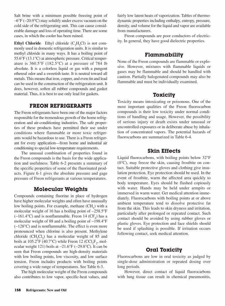
Salt brine with a minimum possible freezing point of–6°F (−20.9°C) may solidify under excess vacuum on thecold side of the refrigerating unit. This can cause consid-erable damage and loss of operating time. There are somecases, in which the cooler has been ruined.
Ethyl Chloride Ethyl chloride (C2H5Cl) is not com-monly used in domestic refrigeration units. It is similar tomethyl chloride in many ways. It has a boiling point of55.6°F (13.1°C) at atmospheric pressure. Critical temper-ature is 360.5°F (182.5°C) at a pressure of 784 lbabsolute. It is a colorless liquid or gas with a pungentethereal odor and a sweetish taste. It is neutral toward allmetals. This means that iron, copper, and even tin and leadcan be used in the construction of the refrigeration unit. Itdoes, however, soften all rubber compounds and gasketmaterial. Thus, it is best to use only lead for gaskets.
FREON REFRIGERANTSThe Freon refrigerants have been one of the major factorsresponsible for the tremendous growth of the home refrig-eration and air-conditioning industries. The safe proper-ties of these products have permitted their use underconditions where flammable or more toxic refriger-ants would be hazardous to use. There is a Freon refriger-ant for every application—from home and industrial airconditioning to special low-temperature requirements.
The unusual combination of properties found inthe Freon compounds is the basis for the wide applica-tion and usefulness. Table 6-2 presents a summary ofthe specific properties of some of the fluorinated prod-ucts. Figure 6-1 gives the absolute pressure and gagepressure of Freon refrigerants at various temperatures.
Molecular Weights Compounds containing fluorine in place of hydrogenhave higher molecular weights and often have unusuallylow boiling points. For example, methane (CH4) with amolecular weight of 16 has a boiling point of −258.5°F(−161.4°C) and is nonflammable. Freon 14 (CF4) has amolecular weight of 88 and a boiling point of −198.4°F(−128°C) and is nonflammable. The effect is even morepronounced when chlorine is also present. Methylenechloride (CH2Cl2) has a molecular weight of 85 andboils at 105.2°F (40.7°C) while Freon 12 (CCl2F2, mol-ecular weight 121) boils at −21.6°F (−29.8°C). It can beseen that Freon compounds are high-density materialswith low boiling points, low viscosity, and low surfacetension. Freon includes products with boiling pointscovering a wide range of temperatures. See Table 6-3.
The high molecular weight of the Freon compoundsalso contributes to low vapor, specific-heat values, and
fairly low latent heats of vaporization. Tables of thermo-dynamic properties including enthalpy, entropy, pressure,density, and volume for the liquid and vapor are availablefrom manufacturers.
Freon compounds are poor conductors of electric-ity. In general, they have good dielectric properties.
FlammabilityNone of the Freon compounds are flammable or explo-sive. However, mixtures with flammable liquids orgases may be flammable and should be handled withcaution. Partially halogenated compounds may also beflammable and must be individually examined.
ToxicityToxicity means intoxicating or poisonous. One of themost important qualities of the Freon fluorocarboncompounds is their low toxicity under normal condi-tions of handling and usage. However, the possibilityof serious injury or death exists under unusual oruncontrolled exposures or in deliberate abuse by inhala-tion of concentrated vapors. The potential hazards offluorocarbons are summarized in Table 6-4.
Skin EffectsLiquid fluorocarbons, with boiling points below 32°F(0°C), may freeze the skin, causing frostbite on con-tact. Suitable protective gloves and clothing give insu-lation protection. Eye protection should be used. In theevent of frostbite, warm the affected area quickly tobody temperature. Eyes should be flushed copiouslywith water. Hands may be held under armpits orimmersed in warm water. Get medical attention imme-diately. Fluorocarbons with boiling points at or aboveambient temperature tend to dissolve protective fatfrom the skin. This leads to skin dryness and irritation,particularly after prolonged or repeated contact. Suchcontact should be avoided by using rubber gloves orplastic gloves. Eye protection and face shields shouldbe used if splashing is possible. If irritation occursfollowing contact, seek medical attention.
Oral ToxicityFluorocarbons are low in oral toxicity as judged bysingle-dose administration or repeated dosing overlong periods.
However, direct contact of liquid fluorocarbonswith lung tissue can result in chemical pneumonitis,
158 Refrigerants: New and Old
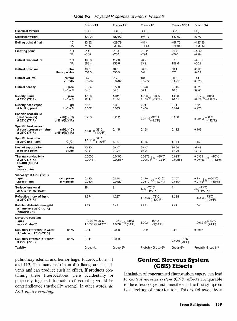
Freon Refrigerants 159
pulmonary edema, and hemorrhage. Fluorocarbons 11and 113, like many petroleum distillates, are fat sol-vents and can produce such an effect. If products con-taining these fluorocarbons were accidentally orpurposely ingested, induction of vomiting would becontraindicated (medically wrong). In other words, doNOT induce vomiting.
Central Nervous System(CNS) Effects
Inhalation of concentrated fluorocarbon vapors can leadto central nervous system (CNS) effects comparableto the effects of general anesthesia. The first symptomis a feeling of intoxication. This is followed by a
Table 6-2 Physical Properties of Freon* Products
Freon 11 Freon 12 Freon 13 Freon 13B1 Freon 14
Chemical formula CCI3F CCI2F2 CCIF3 CBrF3 CF4
Molecular weight 137.37 120.92 104.46 148.92 88.00
Boiling point at 1 atm °C 23.82 –29.79 –81.4 –57.75 –127.96°F. 74.87 –21.62 –114.6 –71.95 –198.32
Freezing point °C –111 –158 –1811 –168 –1842
°F. –168 –252 –294 –270 –299
Critical temperature °C 198.0 112.0 28.9 67.0 –45.67°F. 388.4 233.6 83.9 152.6 –50.2
Critical pressure atm 43.5 40.6 38.2 39.1 36.96lbs/sq in abs 639.5 596.9 561 575 543.2
Critical volume cc/mol 247 217 181 200 141cu ft/lb 0.0289 0.0287 0.0277 0.0215 0.0256
Critical density g/cc 0.554 0.588 0.578 0.745 0.626lbs/cu ft 34.6 34.8 36.1 46.5 39.06
Density, liquid g/cc 1.476 1.311 1.298 −30°C 1.538 1.317 −80°Cat 25°C (77°F.) lbs/cu ft 92.14 81.84 81.05@(−22°F.) 96.01 82.21@(−112°F.)
Density, sat’d vapor g/l 5.86 6.33 7.01 8.71 7.62at boiling point lbs/cu ft 0.367 0.395 0.438 0.544 0.476
Specific heat, liquid(Heat capacity) cal/(g)(°C) 0.208 0.232 0.247@−30°C 0.208
0.294@−80°C
at 25°C (77°F.) or Btu/(lb)(°F.) (−22°F.) (−112°F.)
Specific heat, vapor,at const pressure (1 atm) cal/(g)(°C)
0.142 @38°C 0.145 0.158 0.112 0.169
at 25°C (77°F.) or Btu/(lb)(°F.) (100°F.)
Specific heat ratio1.137 @
38°Cat 25°C and 1 atm Cp/Cv (100°F.) 1.137 1.145 1.144 1.159
Heat of vaporization cal/g 43.10 39.47 35.47 28.38 32.49at boiling point Btu/lb 77.51 71.04 63.85 51.08 58.48
Thermal conductivity 0.0506 0.0405 0.0378 −30°C 0.0234 0.0361 −80°Cat 25°C (77°F.) 0.00451 0.00557 0.00501 @ (−22°F.) 0.00534 0.00463 @ (−112°F.)Btu/(hr) (ft) (°F.)liquidvapor (1 atm)
Viscosity7 at 25°C (77°F.)liquid centipoise 0.415 0.214 0.170 (−30°C) 0.157 0.23 (−80°C)vapor (1 atm) centipoise 0.0107 0.0123 0.0119 @ (−22°F.) 0.0154 0.0116 @ (−112°F.)
Surface tension at 18 914@
−73°C 44@
−73°C25°C (77°F.) dynes/cm −100°F. (−100°F.)
Refractive index of liquid 1.374 1.2871.199@
−73°C 1.238 1.151@ −73°Cat 25°C (77°F.) (−100°F.) (−100°F.)
Relative dielectric strength8 3.71 2.46 1.65 1.83 1.06at 1 atm and 25°C (77°F.) (nitrogen = 1)
Dielectric constantliquid 2.28 @ 29°C 2.13 29°C
1.002429°C
1.0012 @24.5°C
vapor (1 atm)9a 1.0036 @ 24°C9b 1.0032 @ (84°F.) @(84°F.) (76°F.)
Solubility of “Freon” in water wt % 0.11 0.028 0.009 0.03 0.0015at 1 atm and 25°C (77°F.)
Solubility of water in “Freon” wt % 0.011 0.0090.0095
21°Cat 25°C (77°F.) (70°F.)
Toxicity Group 5a12 Group 612 Probably Group 613 Group 612 Probably Group 613
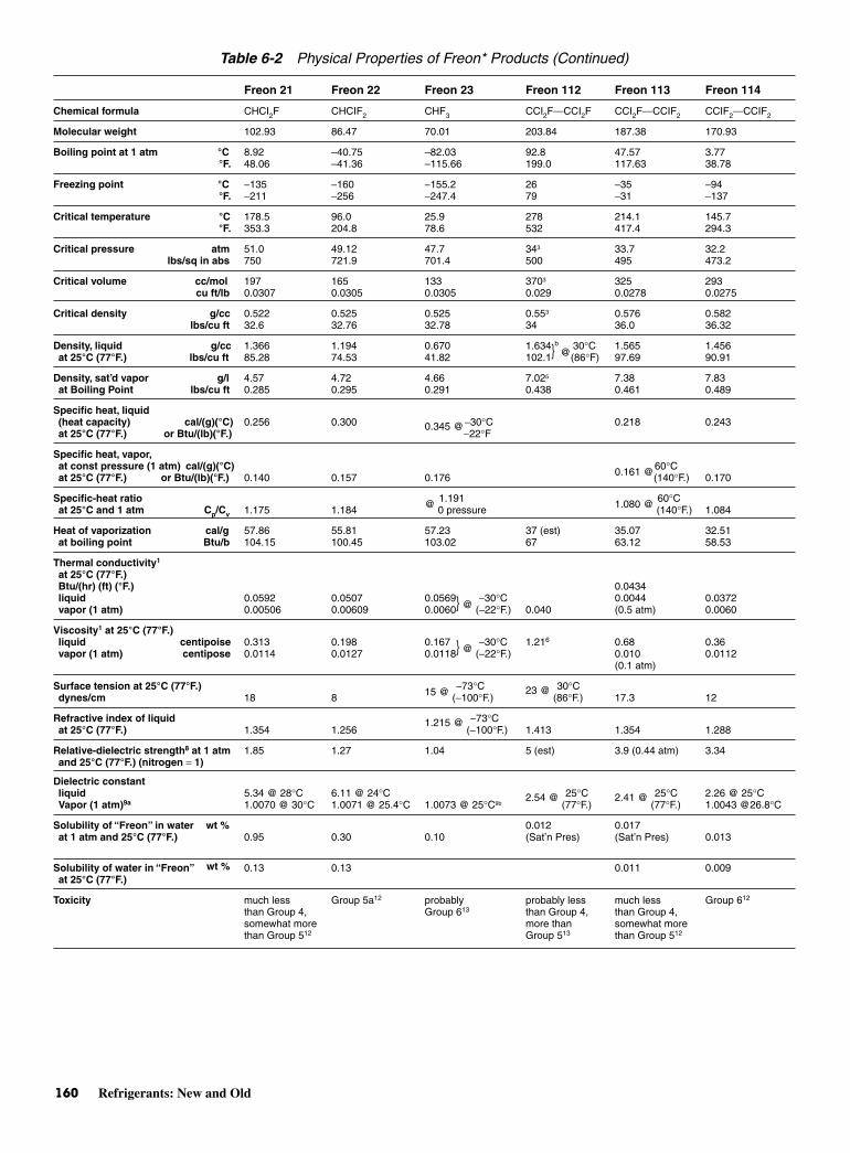
160 Refrigerants: New and Old
Table 6-2 Physical Properties of Freon* Products (Continued)
Freon 21 Freon 22 Freon 23 Freon 112 Freon 113 Freon 114
Chemical formula CHCI2F CHCIF2 CHF3 CCI2F´CCI2F CCI2F´CCIF2 CCIF2´CCIF2
Molecular weight 102.93 86.47 70.01 203.84 187.38 170.93
Boiling point at 1 atm °C 8.92 –40.75 –82.03 92.8 47.57 3.77°F. 48.06 –41.36 –115.66 199.0 117.63 38.78
Freezing point °C −135 −160 −155.2 26 −35 −94°F. −211 −256 −247.4 79 −31 −137
Critical temperature °C 178.5 96.0 25.9 278 214.1 145.7°F. 353.3 204.8 78.6 532 417.4 294.3
Critical pressure atm 51.0 49.12 47.7 343 33.7 32.2lbs/sq in abs 750 721.9 701.4 500 495 473.2
Critical volume cc/mol 197 165 133 3703 325 293cu ft/lb 0.0307 0.0305 0.0305 0.029 0.0278 0.0275
Critical density g/cc 0.522 0.525 0.525 0.553 0.576 0.582lbs/cu ft 32.6 32.76 32.78 34 36.0 36.32
Density, liquid g/cc 1.366 1.194 0.670 1.634 30°C 1.565 1.456at 25°C (77°F.) lbs/cu ft 85.28 74.53 41.82 102.1
b
@(86°F) 97.69 90.91
Density, sat’d vapor g/l 4.57 4.72 4.66 7.025 7.38 7.83at Boiling Point lbs/cu ft 0.285 0.295 0.291 0.438 0.461 0.489
Specific heat, liquid (heat capacity) cal/(g)(°C) 0.256 0.300 −30°C 0.218 0.243at 25°C (77°F.) or Btu/(lb)(°F.)
0.345 @−22°F
Specific heat, vapor,at const pressure (1 atm) cal/(g)(°C) 60°Cat 25°C (77°F.) or Btu/(lb)(°F.) 0.140 0.157 0.176 0.161 @(140°F.) 0.170
Specific-heat ratio 1.191 60°Cat 25°C and 1 atm Cp/Cv 1.175 1.184 @ 0 pressure 1.080 @ (140°F.) 1.084
Heat of vaporization cal/g 57.86 55.81 57.23 37 (est) 35.07 32.51at boiling point Btu/b 104.15 100.45 103.02 67 63.12 58.53
Thermal conductivity1
at 25°C (77°F.)Btu/(hr) (ft) (°F.) 0.0434liquid 0.0592 0.0507 0.0569 −30°C 0.0044 0.0372vapor (1 atm) 0.00506 0.00609 0.0060 @ (−22°F.) 0.040 (0.5 atm) 0.0060
Viscosity1 at 25°C (77°F.)liquid centipoise 0.313 0.198 0.167 −30°C 1.216 0.68 0.36vapor (1 atm) centipose 0.0114 0.0127 0.0118 @ (−22°F.) 0.010 0.0112
(0.1 atm)
Surface tension at 25°C (77°F.) −73°C 30°Cdynes/cm 18 8 15 @ (−100°F.)
23 @(86°F.) 17.3 12
Refractive index of liquid −73°Cat 25°C (77°F.) 1.354 1.256
1.215 @(−100°F.) 1.413 1.354 1.288
Relative-dielectric strength8 at 1 atm 1.85 1.27 1.04 5 (est) 3.9 (0.44 atm) 3.34and 25°C (77°F.) (nitrogen = 1)
Dielectric constantliquid 5.34 @ 28°C 6.11 @ 24°C 25°C 25°C 2.26 @ 25°CVapor (1 atm)9a 1.0070 @ 30°C 1.0071 @ 25.4°C 1.0073 @ 25°C9b
2.54 @(77°F.)
2.41 @(77°F.) 1.0043 @26.8°C
Solubility of “Freon” in water 0.012 0.017at 1 atm and 25°C (77°F.)
wt %0.95 0.30 0.10 (Sat’n Pres) (Sat’n Pres) 0.013
Solubility of water in “Freon” 0.13 0.13 0.011 0.009at 25°C (77°F.)
wt %
Toxicity much less Group 5a12 probably probably less much less Group 612
than Group 4, Group 613 than Group 4, than Group 4,somewhat more more than somewhat morethan Group 512 Group 513 than Group 512

Freon Refrigerants 161
loss of coordination and unconsciousness. Under severeconditions, death can result. If these symptoms are felt,the exposed individual should immediately go or bemoved to fresh air. Medical attention should be soughtpromptly. Individuals exposed to fluorocarbons shouldNOT be treated with adrenalin (epinephrine).
Cardiac SensitizationFluorocarbons can, in sufficient vapor concentration,produce cardiac sensitization. This is a sensitization of
the heart to adrenaline brought about by exposure to highconcentrations of organic vapors. Under severe exposure,cardiac arrhythmias may result from sensitization of theheart to the body’s own levels of adrenaline. This is par-ticularly so under conditions of emotional or physicalstress, fright, panic, and so forth. Such cardiac arrhyth-mias may result in ventricular fibrillation and death.Exposed individuals should immediately go or be removedto fresh air. There, the hazard of cardiac effects willrapidly decrease. Prompt medical attention and observation
Table 6-2 Physical Properties of Freon* Products
FC 114B2 Freon 115 Freon 116 Freon 500 Freon 502 Freon 503
CBrF2´CBrF2 CCIF2–CF3 CF3´CF3 a b c
259.85 154.47 138.01 99.31 111.64 87.28
47.26 −39.1 −78.2 −33.5 −45.42 −87.9
117.06 −38.4 −108.8 −28.3 −49.76 −126.2
−110.5 −10610 −100.6 −159
−166.8 −159 −149.1 −254
214.5 80.0 19.74 105.5 82.2 19.5
418.1 175.9 67.5 221.9 179.9 67.1
34.4 30.8 29.44 43.67 40.2 43.0
506.1 453 432 641.9 591.0 632.2
329 259 225 200.0 199 155
0.0203 0.0269 0.0262 0.03226 0.02857 0.0284
0.790 0.596 0.612 0.4966 0.561 0.564
49.32 37.2 38.21 31.0 35.0 35.21
2.163 1.291 1.587 −73°C 1.156 1.217 1.233 −30°C135.0 80.60 99.084
@(−100°F.) 72.16 75.95 76.95 @ (−22°F.)7
8.37 9.014 5.278 6.22 6.020.522 0.562 0.3295 0.388 0.374
−73°C −30°C0.166 0.285
0.232 @(−100°F.)4 0.258 0.293
0.287 @(−22°F.)
0.18211
0.164 @ 0 pressure 0.175 0.164 0.161.085 (est) −34°C
1.091@
0 pressure 1.143 1.1321.21 @
(−30°F.)25 (est) 30.11 27.97 48.04 41.21 42.8645 (est) 54.20 50.35 86.47 74.18 77.15
0.0302 0.045 −73°C 0.0373 −30°C0.027 0.00724 0.0098 @ (−100°F.) 0.0432 0.00670 0.0430 @ (−22°F.)7
0.72 0.193 0.30 0.192 0.180 −30°C0.0125 0.0148 0.0120 0.0126
0.144@(−22°F.)
−73°C −30°C18 5
16 @(−100°F.) 8.4 5.9 6.1 @ (−22°F.)
−73°C −30°C1.367 1.214
1.206 @(−100°F.) 1.273 1.234
1.209 @(−22°F.)
4.02 (0.44 atm) 2.54 2.02 1.3
25°C 23°C6.11 @ 25°C 1.00352.34 @
(77°F.) 1.0035 @ 27.4°C1.0021 @
(73°F.) (0.5 atm)
0.006 0.042
0.056 0.056Group 5a12 Group 612 probably Group 5a probably
Group 613 Group 5a12 Group 613
*FREON is Du pont’s registered trademark for its fluorocarbon products a. CCI2F2/CH3CHF2 (73.8/26.2% by wt.)b. CHCIF2/CCIF2CF3 (48.8/51.2% by wt.)c. CHF3/CCIF3 (40/60% by wt.)

should be provided following accidental exposures. Aworker adversely affected by fluorocarbon vapors shouldNOT be treated with adrenalin (epinephrine) or similarheart stimulants since these would increase the risk ofcardiac arrhythmias.
Thermal Decomposition Fluorocarbons decompose when exposed directly to hightemperatures. Flames and electrical-resistance heaters,for example, will chemically decompose fluorocarbonvapors. Products of this decomposition in air includehalogens and halogen acids (hydrochloric, hydrofluoric,and hydrobromic), as well as other irritating compounds.Although much more toxic than the parent fluorocarbon,these decomposition products tend to irritate the nose,eyes, and upper respiratory system. This provides a warn-ing of their presence. The practical hazard is relativelyslight. It is difficult for a person to remain voluntarily inthe presence of’ decomposition products at concentra-tions where physiological damage occurs.
When such irritating decomposition products aredetected, the area should be evacuated and ventilated.The source of the problem should be corrected.
APPLICATIONS OF FREONREFRIGERANTS
There is a Freon refrigerant for every application fromhome and industrial air conditioning to special low-temperature requirements. Following are a few of theFreon refrigerants.
Freon 11 (CC13F) has a boiling point of 74.9°F (23.8°C)and is widely used in centrifugal compressors forindustrial and commercial air-conditioning systems,it is also used for industrial process water and brinecooling. Its low viscosity and freezing point have alsoled to its use as a low-temperature brine.
Freon 12 (CCl2F2) has a boiling point of −21.6°F(−29.8°C) and is the most widely known andused of the Freon refrigerants. It is used principallyin household and commercial refrigeration and airconditioning. It is used for refrigerators, frozen foodlocker plants, water coolers, room and window air-conditioning units and similar equipment. It is gener-ally used in reciprocating compressors ranging in sizefrom fractional to 800 horsepower. It is also used inthe smaller–rotary type compressors, Fig. 6-2.
162 Refrigerants: New and Old
Fig. 6-1 The absolute and gage pressures of Freon refrigerants.
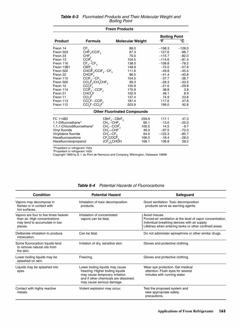
Applications of Freon Refrigerants 163
Table 6-4 Potential Hazards of Fluorocarbons
Condition Potential Hazard Safeguard
Vapors may decompose in Inhalation of toxic decomposition Good ventilation. Toxic decompositionflames or in contact with products. products serve as warning agents.hot surfaces.
Vapors are four to five times heavier Inhalation of concentrated Avoid misuse.than air. High concentrations vapors can be fatal. Forced-air ventilation at the level of vapor concentration.may tend to accumulate in low Individual breathing devices with air supply.places. Lifelines when entering tanks or other confined areas.
Deliberate inhalation to produce Can be fatal. Do not administer epinephrine or other similar drugs.intoxication.
Some fluorocarbon liquids tend Irritation of dry, sensitive skin. Gloves and protective clothing.to remove natural oils from the skin.
Lower boiling liquids may be Freezing. Gloves and protective clothing.splashed on skin.
Liquids may be splashed into Lower boiling liquids may cause Wear eye protection. Get medical eyes. freezing. Higher boiling liquids attention. Flush eyes for several
may cause temporary irritation minutes with running water.and if other chemicals are dissolved, may cause serious damage.
Contact with highly reactive Violent explosion may occur. Test the proposed system and metals. take appropriate safety
precautions.
Table 6-3 Fluorinated Products and Their Molecular Weight and Boiling Point
Freon Products
Boiling PointProduct Formula Molecular Weight °F °C
Freon 14 CF4 88.0 −198.3 −128.0Freon 503 CHF3/CCIF3 87.3 −127.6 −88.7Freon 23 CHF3 70.0 −115.7 −82.0Freon 13 CClF3 104.5 −114.6 −81.4Freon 116 CF3´CF3 138.0 −108.8 −78.2Freon 13B1 CBrF3 148.9 −72.0 −57.8Freon 502 CHClF2/CClF2´CF3 111.6 −49.8 −45.4Freon 22 CHClF2 86.5 −41.4 −40.8Freon 115 CClF2´CF3 154.5 −37.7 −38.7Freon 500 CCl2F2/CH3CHF2 99.3 −28.3 −33.5Freon 12 CCl2F2 120.9 −21.6 −29.8Freon 114 CClF2´CClF2 170.9 38.8 3.8Freon 21 CHCl2F 102.9 48.1 8.9Freon 11 CCl3F 137.4 74.9 23.8Freon 113 CCl2F´CClF2 187.4 117.6 47.6Freon 112 CCl2F−CCl2F 203.9 199.0 92.8
Other Fluorinated Compounds
FC 114B2 CBrF2´CBrF2 259.9 117.1 47.31,1-Difluoroethane* CH3´CHF2 66.1 −13.0 −25.01,1,1-Chlorodifluoroethane† CH3´CClF2 100.5 14.5 −9.7Vinyl fluoride CH2˙CHF 46.0 −97.5 −72.0Vinylidene fluoride CH2˙CF2 64.0 −122.3 −85.7Hexafluoroacetone CF3COCF3 166.0 −18.4 −28.0Hexafluoroisopropanol (CF3)2CHOH 168.1 136.8 58.2
*Propellant or refrigerant 152a†Propellant or refrigerant 142bCopyright 1969 by E. I. du Pont de Nemours and Company, Wilmington, Delaware 19898
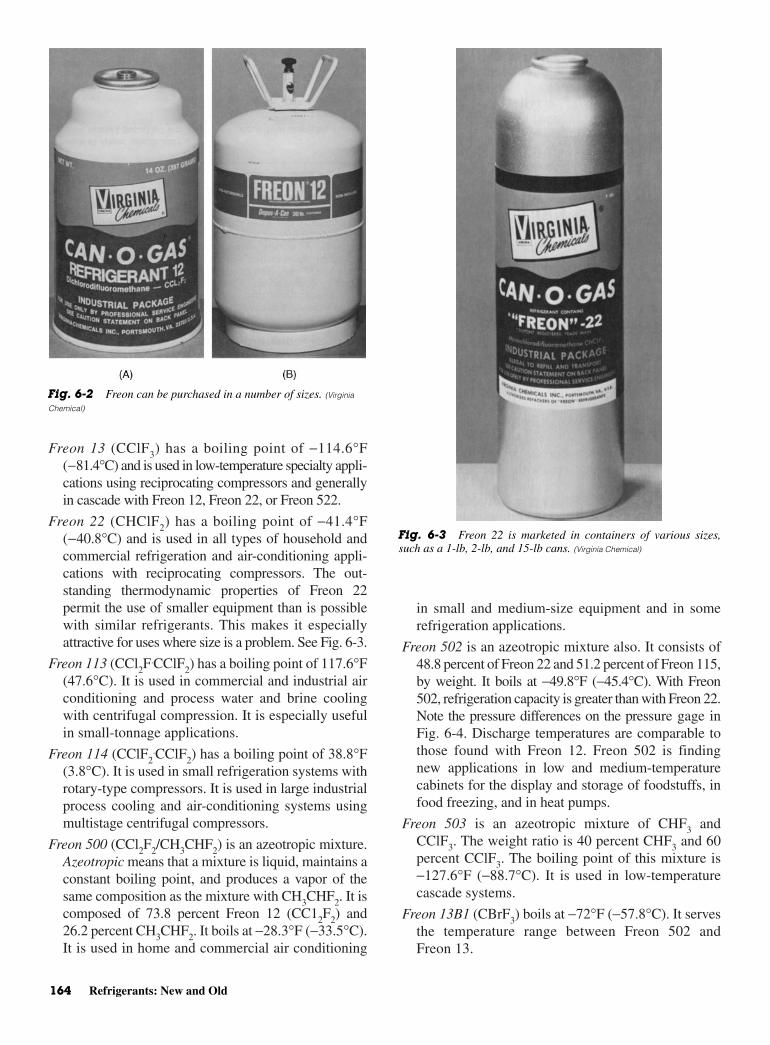
Freon 13 (CClF3) has a boiling point of −114.6°F(−81.4°C) and is used in low-temperature specialty appli-cations using reciprocating compressors and generallyin cascade with Freon 12, Freon 22, or Freon 522.
Freon 22 (CHClF2) has a boiling point of −41.4°F(−40.8°C) and is used in all types of household andcommercial refrigeration and air-conditioning appli-cations with reciprocating compressors. The out-standing thermodynamic properties of Freon 22permit the use of smaller equipment than is possiblewith similar refrigerants. This makes it especiallyattractive for uses where size is a problem. See Fig. 6-3.
Freon 113 (CCl2F.CClF2) has a boiling point of 117.6°F
(47.6°C). It is used in commercial and industrial airconditioning and process water and brine coolingwith centrifugal compression. It is especially usefulin small-tonnage applications.
Freon 114 (CClF2.CClF2) has a boiling point of 38.8°F
(3.8°C). It is used in small refrigeration systems withrotary-type compressors. It is used in large industrialprocess cooling and air-conditioning systems usingmultistage centrifugal compressors.
Freon 500 (CCl2F2/CH3CHF2) is an azeotropic mixture.Azeotropic means that a mixture is liquid, maintains aconstant boiling point, and produces a vapor of thesame composition as the mixture with CH3CHF2. It iscomposed of 73.8 percent Freon 12 (CC12F2) and26.2 percent CH3CHF2. It boils at −28.3°F (−33.5°C).It is used in home and commercial air conditioning
in small and medium-size equipment and in somerefrigeration applications.
Freon 502 is an azeotropic mixture also. It consists of48.8 percent of Freon 22 and 51.2 percent of Freon 115,by weight. It boils at −49.8°F (−45.4°C). With Freon502, refrigeration capacity is greater than with Freon 22.Note the pressure differences on the pressure gage inFig. 6-4. Discharge temperatures are comparable tothose found with Freon 12. Freon 502 is findingnew applications in low and medium-temperaturecabinets for the display and storage of foodstuffs, infood freezing, and in heat pumps.
Freon 503 is an azeotropic mixture of CHF3 andCClF3. The weight ratio is 40 percent CHF3 and 60percent CClF3. The boiling point of this mixture is−127.6°F (−88.7°C). It is used in low-temperaturecascade systems.
Freon 13B1 (CBrF3) boils at −72°F (−57.8°C). It servesthe temperature range between Freon 502 andFreon 13.
164 Refrigerants: New and Old
Fig. 6-2 Freon can be purchased in a number of sizes. (Virginia
Chemical)
Fig. 6-3 Freon 22 is marketed in containers of various sizes,such as a 1-lb, 2-lb, and 15-lb cans. (Virginia Chemical)

Reaction of Freon to Various Materials Found in Refrigeration Systems 165
These are some of the refrigerants that are now underclose scrutiny because of their chlorine content and theireffect on the environment. Some have been banned andcannot be manufactured anywhere in the world. Othersare being phased out gradually and replaced by a newcombination of chemicals.
REACTION OF FREON TOVARIOUS MATERIALS FOUND IN
REFRIGERATION SYSTEMSMetals
Most of the commonly used construction metals—suchas steel, cast iron, brass, copper, tin, lead, and alu-minum—can be used satisfactorily with the Freon com-pounds under normal conditions of use. At hightemperatures some of the metals may act as catalysts forthe breakdown of the compound. The tendency of met-als to promote thermal decomposition of the Freon com-pounds is in the following general order. Those metalsthat least promote thermal decomposition are listed first.
• Inconel®
• Stainless steel
• Nickel
• 1340 steel
• Aluminum
• Copper
• Bronze
• Brass
• Silver
The above order is only approximate. Exceptionsmay be found for individual Freon compounds or forspecial conditions of use.
Magnesium alloys and aluminum containing morethan 2 percent magnesium are not recommended foruse in systems containing Freon compounds wherewater may be present. Zinc is not recommended for usewith Freon 113. Experience with zinc and other Freoncompounds has been limited and no unusual reactivity hasbeen observed. However, it is more chemically reactivethan other common construction metals. Thus, it wouldseem wise to avoid its use with the Freon compoundsunless adequate testing is carried out.
Some metals may be questionable for use in appli-cations requiring contact with Freon compounds forlong periods of time or unusual conditions of exposure.These metals, however, can be cleaned safely withFreon solvents. Cleaning applications are usually forshort exposures at moderate temperatures.
Most halocarbons may react violently with highlyreactive materials, such as sodium, potassium, and bar-ium in their free metallic form. Materials become morereactive when finely ground or powdered. In this state,magnesium and aluminum may react with fluorocar-bons, especially at higher temperatures. Highly reac-tive materials should not be brought into contact withfluorocarbons until a careful study is made and appro-priate safety precautions are taken.
PlasticsA brief summary of the effect of Freon compounds onvarious plastic materials follows. However, compati-bility should be tested for specific applications. Differ-ences in polymer structure and molecular weight,plasticizers, temperature, and pressure may alter theresistance of the plastic toward the Freon compound.
Teflon - TFE - fluorocarbon resin. No swelling observedwhen submerged in Freon liquids, but some diffusionfound with Freon 12 and Freon 22.
Polychluorotrifluoroethylene. Slight swelling, but gen-erally suitable for use with Freon compounds.
Polyvinyl alcohol. Not affected by the Freon com-pounds, but very sensitive to water. Used especiallyin tubing with an outer protective coating.
Vinyl. Resistance to the Freon compounds depends onvinyl type and plasticizer. Considerable variation isfound. Samples should be tested before use.
Orlon-acrylic fiber. Generally suitable for use with theFreon compounds.
Nylon. Generally suitable for use with Freon com-pounds, but may tend to become brittle at high tem-peratures in the presence of air or water. Tests at250°F (121°C) with Freon 12 and Freon 22 showed
Fig. 6-4 Pressure gage for R-12, R-22, and R-502. (Marsh)

the presence of water or alcohol to be undesirable.Adequate testing should be carried out.
Polyethylene. May be suitable for some applications atroom temperatures. However, it should be thor-oughly tested since greatly different results havebeen found with different samples.
Lucite-acrylic resin (methacrylate polymers). Dissolvedby Freon 22. However, it is generally suitable for usewith Freon 12 and Freon 114 for short exposure. Onlong exposure, it tends to crack, craze, and becomecloudy. Use with Freon 113 may be questionable. Itprobably should not be used with Freon 11.
Cast Lucite acrylic resin. Much more resistant to theeffect of solvents than extruded resin. It can proba-bly be used with most of the Freon compounds.
Polystyrene. Considerable variation found in individualsamples. However, it is generally not suited for usewith Freon compounds. Some applications might beall right with Freon 114.
Phenolic resins. Usually not affected by the Freoncompounds. However, composition of resins of thistype may be quite different. Samples should betested before use.
Epoxy resins. Resistant to most solvents and entirelysuitable for use with the Freon compounds.
Cellulose acetate or nitrate. Suitable for use withFreon compounds.
Delrin-acetal resin. Suitable for use with Freon com-pounds under most conditions.
Elastomers. Considerable variation is found in the effect ofthe Freon compounds on elastomers. The effect dependson the particular compound and elastomer type. Innearly all cases a satisfactory combination can be found.In some instances the presence of other materials, suchas oils, may give unexpected results. Thus, preliminarytesting of the system involved is recommended.
REFRIGERANT PROPERTIESRefrigerants can be characterized by a number of prop-erties. These properties are pressure, temperature, vol-ume, density, and enthalpy. Also, flammability, abilityto mix with oil, moisture reaction, odor, toxicity, leak-age tendency, and leakage detection are importantproperties that characterize refrigerants.
Freon refrigerants R-11, R-12, R-22, plus ammo-nia and water will be used to show their properties inrelationship to the mentioned categories. Freon R-11,R-12, and R-22 are common Freon refrigerants. Thenumber assigned to ammonia is R-717, while water hasthe number R-718.
PressureThe pressure of a refrigeration system is important. Itdetermines how sturdy the equipment must be tohold the refrigerant. The refrigerant must be com-pressed and sent to various parts of the system underpressure. The main concern is keeping the pressureas low as possible. The ideal low-side pressure orevaporating pressure should be as near atmosphericpressure (14.7 lb/in.2) as possible. This keeps downthe price of the equipment. It also puts positive pres-sure on the system at all points. By having a smallpressure, it is possible to prevent air and moisturefrom entering the system. In the case of a vacuum ora low pressure, it is possible for a leak to suck in airand moisture. Note the five refrigerants and theirpressures in Table 6-5.
Freon R-11 is used in very large systems because itrequires more refrigerant than others, even though it hasthe best pressure characteristics of the group. Several fac-tors must be considered before a suitable refrigerant isfound. There is no ideal refrigerant for all applications.
TemperatureTemperature is important in selecting a refrigerant for aparticular job. The boiling temperature is that point atwhich a liquid is vaporized upon the addition of heat. This,of course, depends upon the refrigerant and the absolutepressure at the surface of the liquid and vapor. Note thatin Table 6-6, R-22 has the lowest boiling temperature.Water (R-718) has the highest boiling temperature.Atmospheric pressure is 14.7 lb/in.2.
Once again, there is no ideal atmospheric boilingtemperature for a refrigerant. However, temperature-pressure relationships are important in choosing a re-frigerant for a particular job.
VolumeSpecific volume is defined as the definite weight of amaterial. Usually expressed in terms of cubic feet per
166 Refrigerants: New and Old
Table 6-5 Operating Pressures
Evaporating Condensing Pressure Pressure
Refrigerant (PSIG) at 5°F (PSIG) at 86°F
R-11 24.0 in. Hg 3.6R-12 11.8 93.2R-22 28.3 159.8R-717 19.6 154.5R-718 29.7 28.6
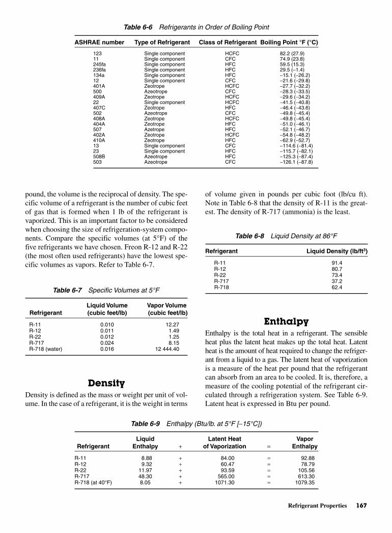
Refrigerant Properties 167
pound, the volume is the reciprocal of density. The spe-cific volume of a refrigerant is the number of cubic feetof gas that is formed when 1 lb of the refrigerant isvaporized. This is an important factor to be consideredwhen choosing the size of refrigeration-system compo-nents. Compare the specific volumes (at 5°F) of thefive refrigerants we have chosen. Freon R-12 and R-22(the most often used refrigerants) have the lowest spe-cific volumes as vapors. Refer to Table 6-7.
DensityDensity is defined as the mass or weight per unit of vol-ume. In the case of a refrigerant, it is the weight in terms
of volume given in pounds per cubic foot (lb/cu ft).Note in Table 6-8 that the density of R-11 is the great-est. The density of R-717 (ammonia) is the least.
EnthalpyEnthalpy is the total heat in a refrigerant. The sensibleheat plus the latent heat makes up the total heat. Latentheat is the amount of heat required to change the refriger-ant from a liquid to a gas. The latent heat of vaporizationis a measure of the heat per pound that the refrigerantcan absorb from an area to be cooled. It is, therefore, ameasure of the cooling potential of the refrigerant cir-culated through a refrigeration system. See Table 6-9.Latent heat is expressed in Btu per pound.
Table 6-6 Refrigerants in Order of Boiling Point
ASHRAE number Type of Refrigerant Class of Refrigerant Boiling Point °F (°C)
123 Single component HCFC 82.2 (27.9)11 Single component CFC 74.9 (23.8)245fa Single component HFC 59.5 (15.3)236fa Single component HFC 29.5 (−1.4)134a Single component HFC −15.1 (−26.2)12 Single component CFC −21.6 (−29.8)401A Zeotrope HCFC −27.7 (−32.2)500 Azeotrope CFC −28.3 (−33.5)409A Zeotrope HCFC −29.6 (−34.2)22 Single component HCFC −41.5 (−40.8)407C Zeotrope HFC −46.4 (−43.6)502 Azeotrope CFC −49.8 (−45.4)408A Zeotrope HCFC −49.8 (−45.4)404A Zeotrope HFC −51.0 (−46.1)507 Azetrope HFC −52.1 (−46.7)402A Zeotrope HCFC −54.8 (−48.2)410A Zeotrope HFC −62.9 (−52.7)13 Single component CFC −114.6 (−81.4)23 Single component HFC −115.7 (−82.1)508B Azeotrope HFC −125.3 (−87.4)503 Azeotrope CFC −126.1 (−87.8)
Table 6-7 Specific Volumes at 5°F
Liquid Volume Vapor VolumeRefrigerant (cubic feet/lb) (cubic feet/lb)
R-11 0.010 12.27R-12 0.011 1.49R-22 0.012 1.25R-717 0.024 8.15R-718 (water) 0.016 12 444.40
Table 6-9 Enthalpy (Btu/lb. at 5°F [−15°C])
Liquid Latent Heat VaporRefrigerant Enthalpy + of Vaporization = Enthalpy
R-11 8.88 + 84.00 = 92.88R-12 9.32 + 60.47 = 78.79R-22 11.97 + 93.59 = 105.56R-717 48.30 + 565.00 = 613.30R-718 (at 40°F) 8.05 + 1071.30 = 1079.35
Table 6-8 Liquid Density at 86°F
Refrigerant Liquid Density (lb/ft3)
R-11 91.4R-12 80.7R-22 73.4R-717 37.2R-718 62.4
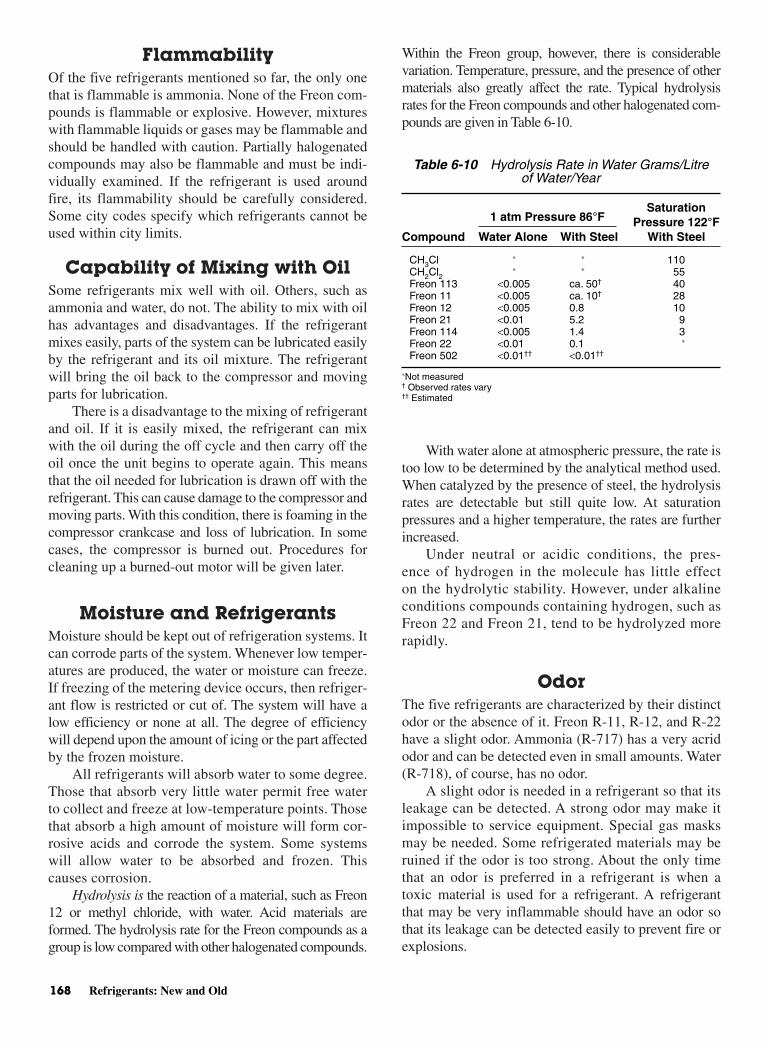
FlammabilityOf the five refrigerants mentioned so far, the only onethat is flammable is ammonia. None of the Freon com-pounds is flammable or explosive. However, mixtureswith flammable liquids or gases may be flammable andshould be handled with caution. Partially halogenatedcompounds may also be flammable and must be indi-vidually examined. If the refrigerant is used aroundfire, its flammability should be carefully considered.Some city codes specify which refrigerants cannot beused within city limits.
Capability of Mixing with OilSome refrigerants mix well with oil. Others, such asammonia and water, do not. The ability to mix with oilhas advantages and disadvantages. If the refrigerantmixes easily, parts of the system can be lubricated easilyby the refrigerant and its oil mixture. The refrigerantwill bring the oil back to the compressor and movingparts for lubrication.
There is a disadvantage to the mixing of refrigerantand oil. If it is easily mixed, the refrigerant can mixwith the oil during the off cycle and then carry off theoil once the unit begins to operate again. This meansthat the oil needed for lubrication is drawn off with therefrigerant. This can cause damage to the compressor andmoving parts. With this condition, there is foaming in thecompressor crankcase and loss of lubrication. In somecases, the compressor is burned out. Procedures forcleaning up a burned-out motor will be given later.
Moisture and Refrigerants Moisture should be kept out of refrigeration systems. Itcan corrode parts of the system. Whenever low temper-atures are produced, the water or moisture can freeze.If freezing of the metering device occurs, then refriger-ant flow is restricted or cut of. The system will have alow efficiency or none at all. The degree of efficiencywill depend upon the amount of icing or the part affectedby the frozen moisture.
All refrigerants will absorb water to some degree.Those that absorb very little water permit free waterto collect and freeze at low-temperature points. Thosethat absorb a high amount of moisture will form cor-rosive acids and corrode the system. Some systemswill allow water to be absorbed and frozen. Thiscauses corrosion.
Hydrolysis is the reaction of a material, such as Freon12 or methyl chloride, with water. Acid materials areformed. The hydrolysis rate for the Freon compounds as agroup is low compared with other halogenated compounds.
Within the Freon group, however, there is considerablevariation. Temperature, pressure, and the presence of othermaterials also greatly affect the rate. Typical hydrolysisrates for the Freon compounds and other halogenated com-pounds are given in Table 6-10.
With water alone at atmospheric pressure, the rate istoo low to be determined by the analytical method used.When catalyzed by the presence of steel, the hydrolysisrates are detectable but still quite low. At saturationpressures and a higher temperature, the rates are furtherincreased.
Under neutral or acidic conditions, the pres-ence of hydrogen in the molecule has little effecton the hydrolytic stability. However, under alkalineconditions compounds containing hydrogen, such asFreon 22 and Freon 21, tend to be hydrolyzed morerapidly.
OdorThe five refrigerants are characterized by their distinctodor or the absence of it. Freon R-11, R-12, and R-22have a slight odor. Ammonia (R-717) has a very acridodor and can be detected even in small amounts. Water(R-718), of course, has no odor.
A slight odor is needed in a refrigerant so that itsleakage can be detected. A strong odor may make itimpossible to service equipment. Special gas masksmay be needed. Some refrigerated materials may beruined if the odor is too strong. About the only timethat an odor is preferred in a refrigerant is when atoxic material is used for a refrigerant. A refrigerantthat may be very inflammable should have an odor sothat its leakage can be detected easily to prevent fire orexplosions.
168 Refrigerants: New and Old
Table 6-10 Hydrolysis Rate in Water Grams/Litreof Water/Year
SaturationPressure 122°F
Compound Water Alone With Steel With Steel
CH3Cl ∗ ∗ 110CH2Cl2
∗ ∗ 55Freon 113 <0.005 ca. 50† 40Freon 11 <0.005 ca. 10† 28Freon 12 <0.005 0.8 10Freon 21 <0.01 5.2 9Freon 114 <0.005 1.4 3Freon 22 <0.01 0.1 ∗
Freon 502 <0.01†† <0.01††
∗Not measured† Observed rates vary†† Estimated
1 atm Pressure 86°F

Detecting Leaks 169
ToxicityToxicity is the characteristic of a material that makes itintoxicating or poisonous. Some refrigerants can be verytoxic to humans, Others may not be toxic at all, Thehalogen refrigerants (R11, R-12, and R-22) are harmlessin their normal condition or state. However, they form ahighly toxic gas when an open name is used around them.
Water, of course, is not toxic. However, ammoniacan be toxic if present in sufficient quantities. Make surethe manufacturer’s recommended procedures for han-dling are followed when working with refrigerants.
Tendency to LeakThe size of the molecule makes a difference in the ten-dency of a refrigerant to leak. The greater the molecu-lar weight, the larger the hole must be for therefrigerant to escape. A check of the molecular weightof a refrigerant will indicate the problem it may presentto a sealed refrigeration system. Table 6-11 shows thatR-11 has the least tendency to leak, whereas ammoniais more likely to leak.
DETECTING LEAKS There are several tests used to check for leaks in aclosed refrigeration system. Most of them are simple.Following are some useful procedures:
• Hold the joint or suspected leakage point underwater and watch for bubbles.
• Coat the area suspected of leakage with a strongsolution of soap. If a leak is present, soap bubbleswill be produced.
Sulfur DioxideTo detect sulfur dioxide leaks, an ammonia swab maybe used. The swab is made by soaking a sponge orcloth—tied onto a stick or piece of wire—in aquaammonia. Household ammonia may also be used. Adense white smoke forms when the ammonia comes in
contact with the sulfur dioxide. The usual soap bubbleor oil test may be used when no ammonia is available.
If ammonia is used, check for leakage in the fol-lowing ways:
• Burn a sulfur stick in the area of the leak. If there isa leak, a dense white smoke will be produced. Thestronger the leak, the denser the white smoke.
• Hold a wet litmus paper close to the suspected leakarea. If there is a leak, the ammonia will cause the lit-mus paper to change color.
Refrigerants that are halogenated hydrocarbons(Freon compounds) can be checked for leakage with ahalide leak test. This involves holding a torch or flameclose to the leak area. If there is a refrigerant leak, theflame will turn green. In every instance, the roomshould be well ventilated when the torch test is made.
An electronic detector for such refrigerant leaks ispresently available. The detector gives off a series ofrapid clicks if the refrigerant is present. The higher theconcentration of the refrigerant, the more rapid theclicks. See Fig. 6-5.
Carbon DioxideLeaks can be detected with a soap solution if there isinternal pressure on the part to be tested. When carbondioxide is present in the condenser water, the water willturn yellow with the addition of bromthymol blue.
Table 6-11 Molecular Weight of Selected Refrigerants
Refrigerant Molecular Weight
R-11 137.4R-12 120.9R-22 86.5R-717 (ammonia) 17.0R-718 (water) 18.0
Fig. 6-5 A hand-held electronic leak detector. (Thermal Engineering)
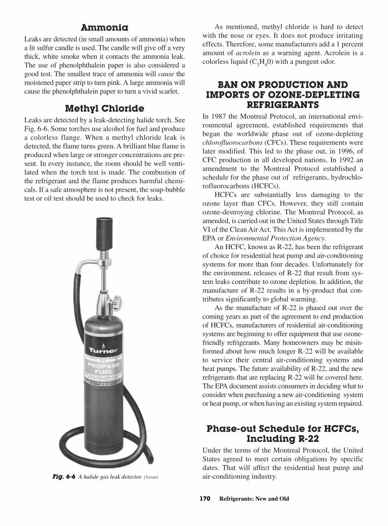
AmmoniaLeaks are detected (in small amounts of ammonia) whena lit sulfur candle is used. The candle will give off a verythick, white smoke when it contacts the ammonia leak.The use of phenolphthalein paper is also considered agood test. The smallest trace of ammonia will cause themoistened paper strip to turn pink. A large ammonia willcause the phenolphthalein paper to turn a vivid scarlet.
Methyl ChlorideLeaks are detected by a leak-detecting halide torch. SeeFig. 6-6. Some torches use alcohol for fuel and producea colorless flange. When a methyl chloride leak isdetected, the flame turns green. A brilliant blue flame isproduced when large or stronger concentrations are pre-sent. In every instance, the room should be well venti-lated when the torch test is made. The combustion ofthe refrigerant and the flame produces harmful chemi-cals. If a safe atmosphere is not present, the soap-bubbletest or oil test should be used to check for leaks.
As mentioned, methyl chloride is hard to detectwith the nose or eyes. It does not produce irritatingeffects. Therefore, some manufacturers add a 1 percentamount of acrolein as a warning agent. Acrolein is acolorless liquid (C3H40) with a pungent odor.
BAN ON PRODUCTION ANDIMPORTS OF OZONE-DEPLETING
REFRIGERANTSIn 1987 the Montreal Protocol, an international envi-ronmental agreement, established requirements thatbegan the worldwide phase out of ozone-depletingchlorofluorocarbons (CFCs). These requirements werelater modified. This led to the phase out, in 1996, ofCFC production in all developed nations. In 1992 anamendment to the Montreal Protocol established aschedule for the phase out of refrigerants, hydrochlo-rofluorocarbons (HCFCs).
HCFCs are substantially less damaging to theozone layer than CFCs. However, they still containozone-destroying chlorine. The Montreal Protocol, asamended, is carried out in the United States through TitleVI of the Clean Air Act. This Act is implemented by theEPA or Environmental Protection Agency.
An HCFC, known as R-22, has been the refrigerantof choice for residential heat pump and air-conditioningsystems for more than four decades. Unfortunately forthe environment, releases of R-22 that result from sys-tem leaks contribute to ozone depletion. In addition, themanufacture of R-22 results in a by-product that con-tributes significantly to global warming.
As the manufacture of R-22 is phased out over thecoming years as part of the agreement to end productionof HCFCs, manufacturers of residential air-conditioningsystems are beginning to offer equipment that use ozone-friendly refrigerants. Many homeowners may be misin-formed about how much longer R-22 will be availableto service their central air-conditioning systems andheat pumps. The future availability of R-22, and the newrefrigerants that are replacing R-22 will be covered here.The EPA document assists consumers in deciding what toconsider when purchasing a new air-conditioning systemor heat pump, or when having an existing system repaired.
Phase-out Schedule for HCFCs,Including R-22
Under the terms of the Montreal Protocol, the UnitedStates agreed to meet certain obligations by specificdates. That will affect the residential heat pump andair-conditioning industry.
170 Refrigerants: New and Old
Fig. 6-6 A halide gas leak detector. (Turner)
Alternatives to R-22 171
January 1, 2004 In accordance with the terms of theProtocol, the amount of all the HCFCs that can be pro-duced nationwide must be reduced by 35 percent by2004. In order to achieve this goal, the United States hasceased production of HCFC-141b, the most ozone dam-aging of this class of chemicals, on January 1, 2003.This production ban should greatly reduce nationwideuse of HCFCs as a group and make it likely that the 2004deadline will have a minimal effect on R-22 supplies.
January 1, 2010 After 2010, chemical manufactur-ers may still produce R-22. But this is to service exist-ing equipment and not for use in new equipment. As aresult, heating, ventilation and air-conditioning(HVAC) system manufacturers will only be able to usepreexisting supplies of R-22 in the production of newair conditioners and heat pumps. These existing sup-plies will include R-22 recovered from existing equip-ment and recycled by licensed reclaimers.
January 1, 2020 Use of existing refrigerant, includ-ing refrigerant that has been recovered and recycled,will be allowed beyond 2020 to service existing sys-tems. However, chemical manufacturers will no longerbe able to produce R-22 to service existing air condi-tioners and heat pumps.
What does the R-22 phase out mean for con-sumers? The following paragraphs are an attempt toanswer this question.
Availability of R-22 The Clean Air Act does not allow any refrigerant tobe vented into the atmosphere during installation,service, or retirement of equipment. Therefore, R-22must be:
• Recovered and recycled (for reuse in the same system)
• Reclaimed (reprocessed to the same purity levels asnew R-22)
• Destroyed
After 2020, the servicing of R-22-based systemswill rely on recycled refrigerants. It is expected thatreclamation and recycling will ensure that existing sup-plies of R-22 will last longer and be available to servicea greater number of systems. As noted earlier, chemicalmanufacturers will be able to produce R-22 for use innew air-conditioning equipment until 2010, and they cancontinue production of R-22 until 2020 for use in servicingthat equipment. Given this schedule, the transition awayfrom R-22 to the use of ozone-friendly refrigerants shouldbe smooth. For the next 20 years or more, R-22 shouldcontinue to be available for all systems that require R-22for servicing.
Cost of R-22 While consumers should be aware that prices of R-22may increase as supplies dwindle over the next 20 or30 years, EPA believes that consumers are not likely tobe subjected to major price increases within a shorttime period. Although there is no guarantee that servicecosts of R-22 will not increase, the lengthy phase-outperiod for R-22 means that market conditions shouldnot be greatly affected by the volatility and resultingrefrigerant price hikes that have characterized thephase out of R-12, the refrigerant used in automotiveair-conditioning systems and replaced by R-134a.
ALTERNATIVES TO R-22Alternatives for residential air conditioning will beneeded as R-22 is gradually phased out. Nonozone-depleting alternative refrigerants are being introduced.Under the Clean Air Act, EPA reviews alternatives toozone-depleting substances like R-22 in order to eval-uate their effects on human health and the environment.The EPA has reviewed several of these alternatives toR-22 and has compiled a list of substitutes that the EPAhas determined are acceptable. One of these substitutesis R-410A, a blend of HFCs, substances that do notcontribute to depletion of the ozone layer, but, likeR-22, contribute to global warming. R-410A is manu-factured and sold under various trade names, includingGenetron AZ 20, SUVA 410A, and Puron. Additionalrefrigerants on the list of acceptable substitutes includeR-134a and R-407C. These two refrigerants are notyet available for residential applications in the UnitedStates, but are commonly found in residential air-conditioning systems and heat pumps in Europe. EPAwill continue to review new nonozone-depleting refrig-erants as they are developed.
Servicing existing unitsExisting units using R-22 can continue to be servicedwith R-22. There is no EPA requirement to change orconvert R-22 units for use with a nonozone-depletingsubstitute refrigerant. In addition, the new substituterefrigerants cannot be used without making some changesto system components. As a result, service technicianswho repair leaks to the system will continue to chargeR-22 into the system as part of that repair.
Installing new units The transition away from ozone-depleting R-22 to sys-tems that rely on replacement refrigerants, like R-410A,has required redesign of heat pump and air-conditioning
systems. New systems incorporate compressors andother components specifically designed for use withspecific replacement refrigerants. With these significantproduct and production process changes, testing andtraining must also change. Consumers should be awarethat dealers of systems that use substitute refrigerantsshould be schooled in installation and service techniquesrequired for use of that substitute refrigerant.
Servicing Your SystemAlong with prohibiting the production of ozone-depletingrefrigerants, the Clean Air Act also mandates the use ofcommon sense in handling refrigerants. By containingand using refrigerants responsibly, that is, by recovering,recycling, and reclaiming, and by reducing leaks, theirozone depletion and global-warming consequences areminimized. The Clean Air Act outlines specific refriger-ant containment and management practices for HVACmanufacturers, distributors, dealers, and technicians.Properly installed home comfort systems rarely developrefrigerant leaks, and with proper servicing, a system us-ing R-22, R-410A, or another refrigerant will minimizeits impact on the environment. While EPA does not man-date repairing or replacing small systems because ofleaks, system leaks can not only harm the environment,but also result in increased maintenance costs.
One important thing a homeowner can do for theenvironment, regardless of the refrigerant used, is toselect a reputable dealer that employs service techni-cians who are EPA-certified to handle refrigerants.Technicians often call this certification “Section 608certification,” referring to the part of the Clean Air Actthat requires minimizing releases of ozone-depletingchemicals from HVAC equipment.
Purchasing New SystemsAnother important thing a homeowner can do for theenvironment is to purchase a highly energy-efficientsystem. Energy-efficient systems result in cost savingsfor the homeowner. Today’s best air conditioners usemuch less energy to produce the same amount of cool-ing as air conditioners made in the mid-1970s. Even ifyour air conditioner is only 10 years old, you may savesignificantly on your cooling energy costs by replacingit with a newer, more efficient model. Products withEPA’s Energy Star label can save homeowners 10 to40 percent on their heating and cooling bills every year.These products are made by most major manufacturersand have the same features as standard products, butalso incorporate energy-saving technology. Both R-22and R-410A systems may have the Energy Star label.Equipment that displays the Energy Star label must
have a minimum seasonal energy efficiency ratio(SEER). The higher the SEER specification, the moreefficient the equipment.
Energy efficiency, along with performance, relia-bility, and cost, should be considered in making a deci-sion. And do not forget that when purchasing a newsystem, you can also speed the transition away fromozone-depleting R-22 by choosing a system that usesozone-friendly refrigerants.
AIR CONDITIONING ANDWORKING WITH HALON
Several regulations have been issued under Section 608of the Clean Air Act to govern the recycling of refrig-erants in stationary systems and to end the practice ofventing refrigerants to the air. These regulations alsogovern the handling of halon fire-extinguishing agents.A Web site and both the regulations themselves andfact sheets are available from the EPA StratosphericOzone Hotline at 1-800-296-1996.
NOTE: The handling and recycling ofrefrigerants used in motor vehicle air-conditioning systems are governed undersection 609 of the Clean Air Act.
General InformationApril 13, 2005 EPA is finalizing a rulemakingamending the definition of refrigerant to make certainthat it only includes substitutes that consist of a class Ior class II ozone-depleting substance (ODS). Thisrulemaking also amends the venting prohibition tomake certain that it remains illegal to knowingly ventnonexempt substitutes that do not consist of a class I orclass II ODS, such as R-134a and R-410A.
January 11, 2005 EPA has published a final ruleextending the leak repair required practices and the associ-ated reporting and record-keeping requirements to ownersand/or operators of comfort cooling, commercial refriger-ation, or industrial process refrigeration appliances con-taining more than 50 pounds of a substitute refrigerant, ifthe substitute contains a class I or class II ozone-depletingsubstance (ODS). In addition, EPA has defined leak ratein terms of the percentage of the appliance’s full chargethat would be lost over a consecutive 12-month period, ifthe current rate of loss were to continue over that period.EPA now requires calculation of the leak rate every timethat refrigerant is added to an appliance.
March 12, 2004 EPA finalizes rulemaking sustain-ing the Clean Air Act prohibition against venting
172 Refrigerants: New and Old
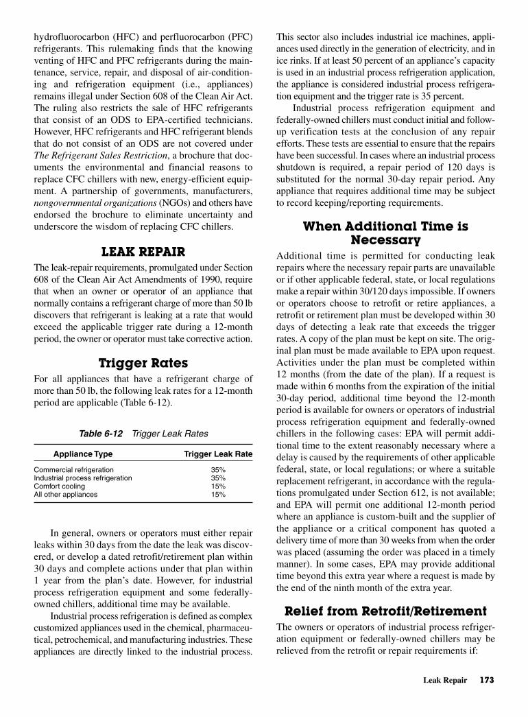
Leak Repair 173
hydrofluorocarbon (HFC) and perfluorocarbon (PFC)refrigerants. This rulemaking finds that the knowingventing of HFC and PFC refrigerants during the main-tenance, service, repair, and disposal of air-condition-ing and refrigeration equipment (i.e., appliances)remains illegal under Section 608 of the Clean Air Act.The ruling also restricts the sale of HFC refrigerantsthat consist of an ODS to EPA-certified technicians.However, HFC refrigerants and HFC refrigerant blendsthat do not consist of an ODS are not covered underThe Refrigerant Sales Restriction, a brochure that doc-uments the environmental and financial reasons toreplace CFC chillers with new, energy-efficient equip-ment. A partnership of governments, manufacturers,nongovernmental organizations (NGOs) and others haveendorsed the brochure to eliminate uncertainty andunderscore the wisdom of replacing CFC chillers.
LEAK REPAIRThe leak-repair requirements, promulgated under Section608 of the Clean Air Act Amendments of 1990, requirethat when an owner or operator of an appliance thatnormally contains a refrigerant charge of more than 50 lbdiscovers that refrigerant is leaking at a rate that wouldexceed the applicable trigger rate during a 12-monthperiod, the owner or operator must take corrective action.
Trigger RatesFor all appliances that have a refrigerant charge ofmore than 50 lb, the following leak rates for a 12-monthperiod are applicable (Table 6-12).
In general, owners or operators must either repairleaks within 30 days from the date the leak was discov-ered, or develop a dated retrofit/retirement plan within30 days and complete actions under that plan within1 year from the plan’s date. However, for industrialprocess refrigeration equipment and some federally-owned chillers, additional time may be available.
Industrial process refrigeration is defined as complexcustomized appliances used in the chemical, pharmaceu-tical, petrochemical, and manufacturing industries. Theseappliances are directly linked to the industrial process.
This sector also includes industrial ice machines, appli-ances used directly in the generation of electricity, and inice rinks. If at least 50 percent of an appliance’s capacityis used in an industrial process refrigeration application,the appliance is considered industrial process refrigera-tion equipment and the trigger rate is 35 percent.
Industrial process refrigeration equipment andfederally-owned chillers must conduct initial and follow-up verification tests at the conclusion of any repairefforts. These tests are essential to ensure that the repairshave been successful. In cases where an industrial processshutdown is required, a repair period of 120 days issubstituted for the normal 30-day repair period. Anyappliance that requires additional time may be subjectto record keeping/reporting requirements.
When Additional Time isNecessary
Additional time is permitted for conducting leakrepairs where the necessary repair parts are unavailableor if other applicable federal, state, or local regulationsmake a repair within 30/120 days impossible. If ownersor operators choose to retrofit or retire appliances, aretrofit or retirement plan must be developed within 30days of detecting a leak rate that exceeds the triggerrates. A copy of the plan must be kept on site. The orig-inal plan must be made available to EPA upon request.Activities under the plan must be completed within12 months (from the date of the plan). If a request ismade within 6 months from the expiration of the initial30-day period, additional time beyond the 12-monthperiod is available for owners or operators of industrialprocess refrigeration equipment and federally-ownedchillers in the following cases: EPA will permit addi-tional time to the extent reasonably necessary where adelay is caused by the requirements of other applicablefederal, state, or local regulations; or where a suitablereplacement refrigerant, in accordance with the regula-tions promulgated under Section 612, is not available;and EPA will permit one additional 12-month periodwhere an appliance is custom-built and the supplier ofthe appliance or a critical component has quoted adelivery time of more than 30 weeks from when the orderwas placed (assuming the order was placed in a timelymanner). In some cases, EPA may provide additionaltime beyond this extra year where a request is made bythe end of the ninth month of the extra year.
Relief from Retrofit/RetirementThe owners or operators of industrial process refriger-ation equipment or federally-owned chillers may berelieved from the retrofit or repair requirements if:
Table 6-12 Trigger Leak Rates
Appliance Type Trigger Leak Rate
Commercial refrigeration 35%Industrial process refrigeration 35%Comfort cooling 15%All other appliances 15%
• Second efforts to repair the same leaks that were sub-ject to the first repair efforts are successful
• Within 180 days of the failed follow-up verificationtest, the owners or operators determine the leak rateis below 35 percent. In this case, the owners or oper-ators must notify EPA as to how this determinationwill be made, and must submit the informationwithin 30 days of the failed verification test.
System MothballingFor all appliances subject to the leak-repair require-ments, the timelines may be suspended if the appliancehas undergone system mothballing. System moth-balling means the intentional shutting down of a refrig-eration appliance undertaken for an extended period oftime where the refrigerant has been evacuated from theappliance or the affected isolated section of the appli-ance to at least atmospheric pressure. However, thetimelines pick up again as soon as the system is broughtback on line.
EPA-CERTIFIED REFRIGERANTRECLAIMERS
The EPA listing of reclaimers is updated when addi-tional refrigerant reclaimers are approved. Reclaimersappearing on this list are approved to reprocess usedrefrigerant to at least the purity specified in appendix Ato 40 CFR part 82, subpart F (based on ARI Standard700, “Specifications for Fluorocarbon and OtherRefrigerants”). Reclamation of used refrigerant by anEPA-certified reclaimer is required in order to sell usedrefrigerant not originating from and intended for usewith motor vehicle air conditioners.
The EPA encourages reclaimers to participate in avoluntary third-party reclaimer certification programoperated by the Air-Conditioning and RefrigerationInstitute (ARI). The volunteer program offered by theARI involves quarterly testing of random samples ofreclaimed refrigerant. Third-party certification canenhance the attractiveness of a reclaimer’s program byproviding an objective assessment of its purity.
NEWER REFRIGERANTSSince the world has become aware of the damage theFreon refrigerants can do to the ozone layer, there hasbeen a mad scramble to obtain new refrigerants thatcan replace all those now in use. There are some prob-lems with adjusting the new and especially existingequipment to the properties of new refrigerant blends.
It is difficult to directly replace R-12 for instance.It has been the mainstay in refrigeration equipment foryears. However, the automobile air-conditioning indus-try has been able to reformulate R-12 to produce anacceptable substitute, R-134a. There are others nowavailable to substitute in the more sophisticated equip-ment with large amounts of refrigerants. Some of thesewill be covered here.
FREON REFRIGERANTSThe Freon family of refrigerants has been one of themajor factors responsible for the impressive growth ofnot only the home refrigeration and air-conditioningindustry, but also of the commercial refrigerationindustry. The safe properties of these products havepermitted their use under conditions where flammableor more toxic refrigerants would be hazardous.
ClassificationsFollowing were commonly used Freon refrigerants:
• Freon-11. Freon-11 has a boiling point of 74.87°Fand has wide usage as a refrigerant in indirect industrialand commercial air-conditioning systems employingsingle or multistage centrifugal compressors withcapacities of 100 tons and above. Freon-11 is alsoemployed as brine for low-temperature applications.It provides relatively low operating pressures withmoderate displacement requirements.
• Freon-12. The boiling point of Freon-12 is −21.7°F. Itis the most widely known and used of the Freonrefrigerants. It is used principally in household andcommercial refrigeration and air-conditioning units,for refrigerators, frozen-food cabinets, ice-cream cabi-nets, food-locker plants, water coolers, room and win-dow air-conditioning units, and similar equipment. It isgenerally used in reciprocating compressors, rangingin size from fractional to 800 hp. Rotary compressorsare useful in small units. The use of centrifugal com-pressors with Freon-12 for large air-conditioning andprocess-cooling applications is increasing.
• Freon-13. The boiling point of Freon-13 is −144.6°F.It is used in low-temperature specialty applicationsemploying reciprocating compressors and generallyin cascade with Freon-12 or Freon-22.
• Freon-21. Freon-21 has a boiling point of 48°F. It isused in fractional-horsepower household refrigerat-ing systems and drinking-water coolers employingrotary vane-type compressors. Freon-21 is also usedin comfort-cooling air-conditioning systems of the
174 Refrigerants: New and Old

Freon Refrigerants 175
absorption type where dimethyl ether or tetraethyl-ene glycol is used as the absorbent.
• Freon-22. The boiling point of Freon-22 is −41.4°F.It is used in all types of household and commercialrefrigeration and air-conditioning applications withreciprocating compressors. The outstanding thermo-dynamic properties of Freon-22 permit the use ofsmaller equipment than is possible with similarrefrigerants, making it especially suitable where sizeis a problem.
• Freon-113. The boiling point of Freon-113 is 117.6°F.It is used in commercial and industrial air conditioningand process water and brine cooling with centrifugalcompression. It is especially useful in small-tonnageapplications.
• Freon-114. The boiling point of Freon-114 is 38.78°F.It is used as a refrigerant in fractional-horsepowerhousehold refrigerating systems and drinking-watercoolers employing rotary vane-type compressors. It isalso used in indirect industrial and commercial air-conditioning systems and in industrial process waterand brine cooling to −70°F employing multistagecentrifugal-type compressors in cascade of 100-tonsrefrigerating capacity and larger.
• Freon-115. The boiling point of Freon-115 is −37.7°F.It is especially stable, offering a particularly low dis-charge temperature in reciprocating compressors. Itscapacity exceeds that of Freon-12 by as much as50 percent in low-temperature systems. Its potentialapplications include household refrigerators and auto-mobile air conditioning.
• Freon-502. Freon-502 is an azeotropic mixture com-posed of 48.8 percent Freon-22 and 51.2 percentFreon-115 by weight. It boils at −50.1°F. Because itpermits achieving the capacity of Freon-22 with dis-charge temperatures comparable to Freon-12, it isfinding new reciprocating compressor applicationsin low-temperature display cabinets and in storingand freezing of food.
Properties of FreonsThe Freon refrigerants are colorless and almost odorless,and their boiling points vary over a wide range of tem-peratures. Those Freon refrigerants that are produced arenontoxic, non-corrosive, nonirritating, and nonflamma-ble under all conditions of usage. They are generallyprepared by replacing chlorine or hydrogen with fluo-rine. Chemically, Freon refrigerants are inert and ther-mally stable up to temperatures far beyond conditionsfound in actual operation. However, Freon is harmfulwhen allowed to escape into the atmosphere. It can
deplete the ozone layer around earth and cause moreharmful ultraviolet rays to reach the surface of the earth.
Physical PropertiesThe pressures required in liquefying the refrigerantvapor affect the design of the system. The refrigerat-ing effect and specific volume of the refrigerant vapordetermine the compressor displacement. The heat ofvaporization and specific volume of the liquid refrigerantaffect the quantity of refrigerant to be circulated throughthe pressure-regulating valve or other system device.
Flammability Freon is nonflammable and noncom-bustible under conditions where appreciable quantitiescontact flame or hot metal surfaces. It requires an openflame at 1382°F to decompose the vapor. Even at thistemperature, only the vapor decomposes to formhydrogen chloride and hydrogen fluoride, which areirritating but are readily dissolved in water. Air mixturesare not capable of burning and contain no elementsthat will support combustion. For this reason, Freon isconsidered nonflammable.
Amount of Liquid Refrigerant Circulated It shouldbe noted that the Freon refrigerants have relativelylow-heat values, but this must not be considered a dis-advantage. It simply means that a greater volume of liq-uid must be circulated per unit of time to produce thedesired amount of refrigeration. It does not concern theamount of refrigerant in the system. Actually, it is adecided advantage (especially in the smaller- or low-tonnage systems) to have a refrigerant with low-heatvalues. This is because the larger quantity of liquidrefrigerant to be metered through the liquid-regulatingdevice will permit the use of more accurate and morepositive operating and regulating mechanisms of lesssensitive and less critical adjustments. Table 6-13 liststhe quantities of liquid refrigerant metered or circulatedper minute under standard ton conditions.
Volume (Piston) Displacement For reason of com-pactness, cost of equipment, reduction of friction, andcompressor speed, the volume of gas that must be com-pressed per unit of time for a given refrigerating effect, ingeneral, should be as low as possible. Freon-12 has a rel-atively low-volume displacement, which makes it suitablefor use in reciprocating compressors, ranging from thesmallest size to those of up to 800-ton capacity, includingcompressors for household and commercial refrigeration.Freon-12 also permits the construction of compact rotarycompressors in the commercial sizes. Generally, low-volume displacement (high-pressure) refrigerants are usedin reciprocating compressors; high-volume displacement(low-pressure) refrigerants are used in large-tonnage
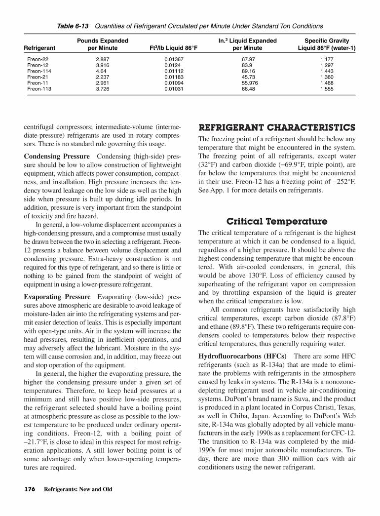
centrifugal compressors; intermediate-volume (interme-diate-pressure) refrigerants are used in rotary compres-sors. There is no standard rule governing this usage.
Condensing Pressure Condensing (high-side) pres-sure should be low to allow construction of lightweightequipment, which affects power consumption, compact-ness, and installation. High pressure increases the ten-dency toward leakage on the low side as well as the highside when pressure is built up during idle periods. Inaddition, pressure is very important from the standpointof toxicity and fire hazard.
In general, a low-volume displacement accompanies ahigh-condensing pressure, and a compromise must usuallybe drawn between the two in selecting a refrigerant. Freon-12 presents a balance between volume displacement andcondensing pressure. Extra-heavy construction is notrequired for this type of refrigerant, and so there is little ornothing to be gained from the standpoint of weight ofequipment in using a lower-pressure refrigerant.
Evaporating Pressure Evaporating (low-side) pres-sures above atmospheric are desirable to avoid leakage ofmoisture-laden air into the refrigerating systems and per-mit easier detection of leaks. This is especially importantwith open-type units. Air in the system will increase thehead pressures, resulting in inefficient operations, andmay adversely affect the lubricant. Moisture in the sys-tem will cause corrosion and, in addition, may freeze outand stop operation of the equipment.
In general, the higher the evaporating pressure, thehigher the condensing pressure under a given set oftemperatures. Therefore, to keep head pressures at aminimum and still have positive low-side pressures,the refrigerant selected should have a boiling pointat atmospheric pressure as close as possible to the low-est temperature to be produced under ordinary operat-ing conditions. Freon-12, with a boiling point of–21.7°F, is close to ideal in this respect for most refrig-eration applications. A still lower boiling point is ofsome advantage only when lower-operating tempera-tures are required.
REFRIGERANT CHARACTERISTICSThe freezing point of a refrigerant should be below anytemperature that might be encountered in the system.The freezing point of all refrigerants, except water(32°F) and carbon dioxide (−69.9°F, triple point), arefar below the temperatures that might be encounteredin their use. Freon-12 has a freezing point of −252°F.See App. 1 for more details on refrigerants.
Critical TemperatureThe critical temperature of a refrigerant is the highesttemperature at which it can be condensed to a liquid,regardless of a higher pressure. It should be above thehighest condensing temperature that might be encoun-tered. With air-cooled condensers, in general, thiswould be above 130°F. Loss of efficiency caused bysuperheating of the refrigerant vapor on compressionand by throttling expansion of the liquid is greaterwhen the critical temperature is low.
All common refrigerants have satisfactorily highcritical temperatures, except carbon dioxide (87.8°F)and ethane (89.8°F). These two refrigerants require con-densers cooled to temperatures below their respectivecritical temperatures, thus generally requiring water.
Hydrofluorocarbons (HFCs) There are some HFCrefrigerants (such as R-134a) that are made to elimi-nate the problems with refrigerants in the atmospherecaused by leaks in systems. The R-134a is a nonozone-depleting refrigerant used in vehicle air-conditioningsystems. DuPont’s brand name is Suva, and the productis produced in a plant located in Corpus Christi, Texas,as well in Chiba, Japan. According to DuPont’s Website, R-134a was globally adopted by all vehicle manu-facturers in the early 1990s as a replacement for CFC-12.The transition to R-134a was completed by the mid-1990s for most major automobile manufacturers. To-day, there are more than 300 million cars with airconditioners using the newer refrigerant.
176 Refrigerants: New and Old
Table 6-13 Quantities of Refrigerant Circulated per Minute Under Standard Ton Conditions
Pounds Expanded ln.3 Liquid Expanded Specific GravityRefrigerant per Minute Ft3/lb Liquid 86°F per Minute Liquid 86°F (water-1)
Freon-22 2.887 0.01367 67.97 1.177Freon-12 3.916 0.0124 83.9 1.297Freon-114 4.64 0.01112 89.16 1.443Freon-21 2.237 0.01183 45.73 1.360Freon-11 2.961 0.01094 55.976 1.468Freon-113 3.726 0.01031 66.48 1.555

Refrigerant Characteristics 177
Latent Heat of EvaporationA refrigerant should have a high latent heat of evapora-tion per unit of weight so that the amount of refrigerantcirculated to produce a given refrigeration effect maybe small. Latent heat is important when considering itsrelationship to the volume of liquid required to be cir-culated. The net result is the refrigerating effect. Sinceother factors enter into the determination of these, theyare discussed separately.
The refrigerant effect per pound of refrigerant understandard ton conditions determines the amount of refrig-erant to be evaporated per minute. The refrigeratingeffect per pound is the difference in Btu content of the sat-urated vapor leaving the evaporator (5°F) and the liquidrefrigerant just before passing through the regulatingvalve (86°F). While the Btu refrigerating effect per pounddirectly determines the number of pounds of refriger-ant to be evaporated in a given length of time to producethe required results, it is much more important to considerthe volume of the refrigerant vapor required rather thanthe weight of the liquid refrigerant. By considering thevolume of refrigerant necessary to produce standard tonconditions, it is possible to make a comparison betweenFreon-12 and other refrigerants so as to provide for thereproportioning of the liquid orifice sizes in the regulatingvalves, sizes of liquid refrigerant lines, and so on.
A refrigerant must not be judged only by its refrig-erating effect per pound, but the volume per pound of theliquid refrigerant must also be taken into account toarrive at the volume of refrigerant to be vaporized.Although Freon-12 has relatively low refrigerating effect,this is not a disadvantage, because it merely indicatesthat more liquid refrigerant must be circulated to pro-duce the desired amount of refrigeration. Actually, it is adecided advantage to circulate large quantities of liquidrefrigerant because the greater volumes required willpermit the use of less sensitive operating and regulatingmechanisms with less critical adjustment.
Refrigerants with high Btu refrigerating effects arenot always desirable, especially for household and smallcommercial installations, because of the small amountof liquid refrigerant in the system and the difficultyencountered in accurately controlling its flow throughthe regulating valve. For household and small commer-cial systems, the adjustment of the regulating-valve ori-fice is most critical for refrigerants with high Btu values.
Specific HeatA low specific heat of the liquid is desirable in a refrig-erant. If the ratio of the latent heat to the specific heat ofa liquid is low, a relatively high proportion of the latentheat may be used in lowering the temperature of the liq-
uid from the condenser temperature to the evaporatortemperature. This results in a small net-refrigeratingeffect per pound of refrigerant circulated and, assumingother factors remain the same, reduces the capacity andlowers the efficiency. When the ratio is low, it is advan-tageous to precool the liquid before evaporation by heatinterchange with the cool gases leaving the evaporator.
In the common type of refrigerating systems,expansion of the high-pressure liquid to a lower-pressure,lower-temperature vapor and liquid take place througha throttling device such as an expansion valve. In thisprocess, energy available from the expansion is notrecovered as useful work. Since it performs no externalwork, it reduces the net-refrigerating effect.
Power ConsumptionIn a perfect system operating between 5 and –86°Fconditions, 5.74 Btu is the maximum refrigerationobtainable per Btu of energy used to operate the refrig-erating system. This is the theoretical maximum coeffi-cient of performance on cycles of maximum efficiency(for example, the Carnet cycle). The minimum horse-power would be 0.821 hp/ton of refrigeration. Thetheoretical coefficient of performance would be thesame for all refrigerants if they could be used on cyclesof maximum efficiency.
However, because of engineering limitations, refrig-erants are used on cycles with a theoretical maximumcoefficient of performance of less than 5.74. The cycle mostcommonly used differs in its basic form from (1) the Car-net cycle, as already explained in employing expansionwithout loss or gain of heat from an outside source, and(2) in compressing adiabatically (compression withoutgaining or losing heat to an outside source) until the gas issuperheated above the condensing medium temperature.These two factors, both of which increase the powerrequirement, vary in importance with different refriger-ants. But, it so happens that when expansion loss is high,compression loss is generally low, and vice versa. Allcommon refrigerants (except carbon dioxide and water)show about the same overall theoretical power require-ment on a 5 to −86°F cycle. At least the theoretical differ-ences are so small that other factors are more important indetermining the actual differences in efficiency.
The amount of work required to produce a givenrefrigerating effect increases as the temperature level towhich the heat is pumped from the cold body is increased.Therefore, on a 5 to −86°F cycle, when gas is superheatedabove 86°F temperature on compression, efficiency isdecreased and the power requirement increased unless therefrigerating effect caused by superheating is salvagedthrough the proper use of a heat interchanger.
Volume of Liquid CirculatedVolumes of liquid required to circulate for a givenrefrigerant effect should be low. This is to avoid fluid-flow (pressure-drop) problems and to keep down thesize of the required refrigerant change. In small-capacitymachines, the volume of liquid circulated should notbe so low as to present difficult problems in accuratelycontrolling its flow through expansion valves or othertypes of liquid-metering devices.
With a given net-refrigerating effect per pound, ahigh density of liquid is preferable to a low volume.However, a high density tends to increase the volumecirculated by lowering the net-refrigerating effect.
HANDLING REFRIGERANTSOne of the requirements of an ideal refrigerant is that itmust be nontoxic. In reality, however, all gases (withthe exception of pure air) are more or less toxic orasphyxiating. It is therefore important that wherevergases or highly volatile liquids are used, adequate ven-tilation be provided, because even nontoxic gases in airproduce a suffocating effect.
Vaporized refrigerants (especially ammonia and sulfurdioxide) bring about irritation and congestion of the lungsand bronchial organs, accompanied by violent coughing,vomiting, and, when breathed in sufficient quantity, suffo-cation. It is of the utmost importance, therefore, that the ser-viceman subjected to a refrigerant gas find access to freshair at frequent intervals to clear his lungs. When engaged inthe repair of ammonia and sulfur dioxide machines,approved gas masks and goggles should be used. Carrene,Freon (R-12), and carbon dioxide fumes are not irritatingand can be inhaled in considerable concentrations for shortperiods without serious consequences.
It should be remembered that liquid refrigerantwould refrigerate or remove heat from anything it meetswhen released from a container. In the case of contactwith refrigerant, the affected or injured area should betreated as if it has been frozen or frostbitten.
Storing and HandlingRefrigerant Cylinders
Refrigerant cylinders should be stored in a dry, shel-tered, and well-ventilated area. The cylinders should beplaced in a horizontal position, if possible, and held byblocks or saddles to prevent rolling. It is of utmostimportance to handle refrigerant cylinders with careand to observe the following precautions:
• Never drop the cylinders, or permit them to strikeeach other violently.
• Never use a lifting magnet or a sling (rope or chain)when handling cylinders. A crane may be used whena safe cradle or platform is provided to hold thecylinders.
• Caps provided for valve protection should be kept onthe cylinders at all times except when the cylindersare actually in use.
• Never overfill the cylinders. Whenever refrigerant isdischarged from or into a cylinder, weigh the cylinderand record the weight of the refrigerant remaining in it.
• Never mix gases in a cylinder.
• Never use cylinders for rollers, supports, or for anypurpose other than to carry gas.
• Never tamper with the safety devices in valves or onthe cylinders.
• Open the cylinder valves slowly. Never use wrenchesor tools except those provided or approved by the gasmanufacturer.
• Make sure that the threads on regulators or otherunions are the same as those on the cylinder-valveoutlets. Never force a connection that does not fit.
• Regulators and gages provided for use with one gasmust not be used on cylinders containing a differentgas.
• Never attempt to repair or alter the cylinders or valves.
• Never store the cylinders near highly flammable sub-stances (such as oil, gasoline, or waste).
• Cylinders should not be exposed to continuous damp-ness, salt water, or salt spray.
• Store full and empty cylinders apart to avoid confusion.
• Protect the cylinders from any object that will producea cut or other abrasion on the surface of the metal.
LUBRICANTS*
Lubricant properties can be evaluated. It can be deter-mined if the product is right for the job. Three basic prop-erties are:
• Viscosity
• Lubricity
• Chemical stability
They must be satisfactory to protect the compressor.The correct viscosity is needed to fill the gaps betweenparts and flow correctly where it is supposed to go.Generally speaking, smaller equipment with smaller
178 Refrigerants: New and Old
*Courtesy of National Refrigerants.

R-134a Refrigerant 179
gaps between moving parts requires a lighter viscosity,and larger equipment with bigger parts needs heavierviscosity oils.
Lubricity refers to the lubricant’s ability to protectthe metal surfaces from wear. Good chemical stabilitymeans the lubricant will not react to form harmfulchemicals such as acids, sludges, and so forth that mayblock tubing or there may be carbon deposits. Theinteraction of lubricant and refrigerant can cause potentialproblems as well.
Miscibility defines the temperature region where refrig-erant and oil will mix or separate. If there is separation ofthe oil from the refrigerant in the compressor it is possiblethat the oil is not getting to metal parts that need it. If thereis separation in the evaporator or other parts of the systemit is possible that the oil does not return to the compressorand eventually there is not enough oil to protect it.
Solubility determines if the refrigerant will thin theoil too much. That would cause it to lose its ability to pro-tect the compressor. The thinning effect also influencesoil return.
Once you mix a blend at a given composition, thepressure-temperature relationships follow the same gen-eral rules as for pure components. For example, the pres-sure goes up when the temperature goes up. For threeblends containing different amounts of A and B, the pres-sure curve is similarly shaped, but the resulting pressurewill be higher for the blend which contains more of the Aor higher pressure component.
Some refrigerant blends that are intended to matchsome other product. R-12 is a good example. It willrarely match the pressure at all points in the desired tem-perature range. What is more common is the blend willmatch in one region and the pressures will be differentelsewhere.
In the example, the blend with concentration C1matches the CFC at cold-evaporator temperatures,but the pressures run higher at condenser conditions.The blend with composition C2 matches closer toroom temperature. And, it may show the same pres-sure in a cylinder being stored, for example. Theoperation pressures at evaporator and condensertemperatures, however, will be somewhat different.Finally, the blend at C3 will generate the same pres-sures at hot condenser conditions, but the evaporatormust run at lower pressures to get the same tempera-ture. See Fig. 6-7.
It can be seen later that the choice of where theblend matches the pressure relationship can solve, orcause, certain retrofit-related problems.
Generally speaking, the R-12 retrofit blends havehigher temperature glide. They do not match the pressure/
temperature/capacity of R-12 across the wide temper-ature application range which R-12 once did. In otherwords, one blend does not fit all. Blends which matchR-12 at colder evaporator temperatures may generatehigher pressures and discharge temperatures when usedin warmer applications or in high-ambient temperatures.These are called refrigeration blends.
In refrigeration it is often an easier, and cheaper,retrofit job if you can match evaporator pressures to R-12and split the glide. That is because you can get similarbox temperatures in similar run times. And, you wouldprobably not need to change controls or the TXVs, whichare sensitive to pressure.
Blends, which match R-12 properties in hot condi-tions, such as in automotive AC condensers, may losecapacity or require lower suction pressures when appliedat colder evaporator temperatures. These are called Auto-motive Blends.
For automotive air conditioning many of the con-trols and safety switches are related to the high-sidepressure. If the blend generates higher discharge pres-sures you could short cycle more often and lose capac-ity in general. It is better to pick the high side to matchR-12 and let the low side run a little lower pressure.
R-134a REFRIGERANTThe blended refrigerant R-134a is a long-term, HFCalternative with similar properties to R-12. It has becomethe new industry-standard refrigerant for automotive air-conditioning and refrigerator/freezer appliances.
R-134a refrigerating performance will suffer atlower temperatures (below −10°F). Some traditionalR-12 applications have used alternatives other thanR-134a for lower temperatures.
Fig. 6-7 New refrigerants variable: composition. (National Refrigerants)
R-134a requires polyolester (POE) lubricants. Tra-ditional mineral oils and alkyl benzenes do not mix withHFC refrigerants and their use with R-134a may causeoperation problems or compressor failures. In addition,automotive AC systems may use poly alkaline glycols(PAGs), which are typically not seen in stationaryequipment.
Both POEs and PAGs will absorb moisture, andhold onto it, to a much greater extent than traditionallubricants. The moisture will promote reactions in thelubricant as well as the usual problems associated withwater corrosion and acid formation. The best way todry a wet HFC system is to rely on the filter drier. Deepvacuum will remove “free” water, but not the water thathas been absorbed into the lubricant.
R-134a ApplicationsAppliances, refrigeration both commercial and self-contained equipment, centrifugal chillers, and automotiveair conditioning utilize R-134a. Retrofitting equipmentwith a substitute for R-12 is sometimes difficult as thereare a number of considerations to be examined beforeundertaking the task.
R-12 SYSTEMS—GENERALCONSIDERATIONS
1. For centrifugal compressors it is recommended thatthe manufacturer’s engineering staff become involvedin the project; special parts or procedures may berequired. This will ensure proper capacity and reliableoperation after the retrofit.
2. Most older, direct expansion systems can be retrofitto R-401A, R-409A, R-414B or R-416A (R-500 toR-401 B or R-409A), so long as there are no com-ponents that will cause fractionation within the sys-tem to occur.
3. Filter driers should be changed at the time of con-version.
4. System should be properly labeled with refrigerantand lubricant type.
R-12 Medium/High TemperatureRefrigeration (>0°F evap)
1. See “Recommendation Table” (this can be found onNational Refrigerants Web site—click on “Techni-cal Manual”) for blends that work better in high-ambient heat conditions.
2. Review the properties of the new refrigerant youwill use, and compare them to R-12. Prepare for any
adjustments to system components based on pres-sure difference or temperature glide.
3. Filter driers should be changed at the time of con-version.
4. System should be properly labeled with refrigerantand lubricant type.
R-12 Low TemperatureRefrigeration (<20°F evap)
1. See “Recommendation Table” for blends that havebetter low-temperature capacity.
2. Review the properties of the new refrigerant youwill use, and compare them to R-12. Prepare for anyadjustments to system components based on pres-sure difference or temperature glide.
3. Filter driers should be changed at the time of con-version.
4. System should be properly labeled with refrigerantand lubricant type.
Another blended refrigerant that can be used tosubstitute for R-12 is 401A . It is a blend of R-22, 152a,and 124. The pressure and system capacity matchR-12 when the blend is running an average evaporatortemperature of 10 to 20°F.
Applications for this refrigerant is a direct expan-sion refrigerate for R-12 in air-conditioning systemsand in R-500 systems.
R-401BThis blend refrigerant is similar to R-401A except, it ishigher in R-22 content. This blend has higher capacityat lower temperatures and matches R-12 at –20°F. Italso provides a closer match to R-500 at air-conditioningtemperatures.
Applications for R-401B are in normally lowertemperature R-12 refrigeration locations and in trans-port refrigeration, and in R-500 as a direct expansionrefrigerant in air-conditioning systems.
R-402AThis is a blend of R-22 and R-125 with hydrocarbonR-290 (propane) added to improve mineral oil circula-tion. This blend is formulated to match R-502 evaporatorpressures, yet it has higher discharge pressure than 502.Although the propane helps with oil return, it is stillrecommended that some mineral oil be replaced withalkyl benzene.
180 Refrigerants: New and Old
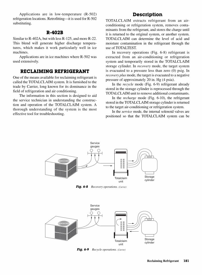
Reclaiming Refrigerant 181
Applications are in low-temperature (R-502)refrigeration locations. Retrofitting—it is used for R-502substituting.
R-402BSimilar to R-402A, but with less R-125, and more R-22.This blend will generate higher discharge tempera-tures, which makes it work particularly well in icemachines.
Applications are in ice machines where R-502 wasused extensively.
RECLAIMING REFRIGERANTOne of the means available for reclaiming refrigerant iscalled the TOTALCLAIM system. It is furnished to thetrade by Carrier, long known for its dominance in thefield of refrigeration and air conditioning.
The information in this section is designed to aidthe service technician in understanding the construc-tion and operation of the TOTALCLAIM system. Athorough understanding of the system is the mosteffective tool for troubleshooting.
DescriptionTOTALCLAIM extracts refrigerant from an air-conditioning or refrigeration system, removes conta-minants from the refrigerant, and stores the charge untilit is returned to the original system, or another system.TOTALCLAIM can determine the level of acid andmoisture contamination in the refrigerant through theuse of TOTALTEST.
In recovery operations (Fig. 6-8) refrigerant isextracted from an air-conditioning or refrigerationsystem and temporarily stored in the TOTALCLAIMstorage cylinder. In recovery mode, the target systemis evacuated to a pressure less than zero (0) psig. Inrecovery plus mode, the target is evacuated to a negativepressure of approximately 20 in. Hg (4 psia).
In the recycle mode (Fig. 6-9) refrigerant alreadystored in the storage cylinder is reprocessed through theTOTALCLAIM unit to remove additional contaminants.
In the recharge mode (Fig. 6-10), the refrigerantstored in the TOTALCLAIM storage cylinder is returnedto the target air-conditioning or refrigeration system.
In the service mode, the internal solenoid valves arepositioned so that the TOTALCLAIM system can be
Totalclaim unit
Storage cylinder
Service gauges
Fig. 6-9 Recycle operations. (Carrier)
Totalclaim unit
Storage cylinder
Service gauges
Fig. 6-8 Recovery operations. (Carrier)
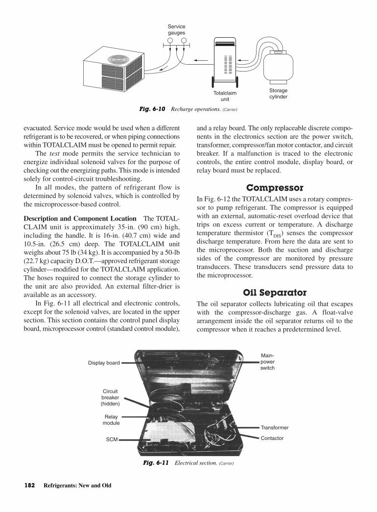
evacuated. Service mode would be used when a differentrefrigerant is to be recovered, or when piping connectionswithin TOTALCLAIM must be opened to permit repair.
The test mode permits the service technician toenergize individual solenoid valves for the purpose ofchecking out the energizing paths. This mode is intendedsolely for control-circuit troubleshooting.
In all modes, the pattern of refrigerant flow isdetermined by solenoid valves, which is controlled bythe microprocessor-based control.
Description and Component Location The TOTAL-CLAIM unit is approximately 35-in. (90 cm) high,including the handle. It is 16-in. (40.7 cm) wide and10.5-in. (26.5 cm) deep. The TOTALCLAIM unitweighs about 75 lb (34 kg). It is accompanied by a 50-lb(22.7 kg) capacity D.O.T.—approved refrigerant storagecylinder—modified for the TOTALCLAIM application.The hoses required to connect the storage cylinder tothe unit are also provided. An external filter-drier isavailable as an accessory.
In Fig. 6-11 all electrical and electronic controls,except for the solenoid valves, are located in the uppersection. This section contains the control panel displayboard, microprocessor control (standard control module),
and a relay board. The only replaceable discrete compo-nents in the electronics section are the power switch,transformer, compressor/fan motor contactor, and circuitbreaker. If a malfunction is traced to the electroniccontrols, the entire control module, display board, orrelay board must be replaced.
CompressorIn Fig. 6-12 the TOTALCLAIM uses a rotary compres-sor to pump refrigerant. The compressor is equippedwith an external, automatic-reset overload device thattrips on excess current or temperature. A dischargetemperature thermistor (TDIS) senses the compressordischarge temperature. From here the data are sent tothe microprocessor. Both the suction and dischargesides of the compressor are monitored by pressuretransducers. These transducers send pressure data tothe microprocessor.
Oil SeparatorThe oil separator collects lubricating oil that escapeswith the compressor-discharge gas. A float-valvearrangement inside the oil separator returns oil to thecompressor when it reaches a predetermined level.
182 Refrigerants: New and Old
Display board
Relay module
SCM
Circuitbreaker (hidden)
Main-power switch
Transformer
Contactor
Fig. 6-11 Electrical section. (Carrier)
Totalclaim unit
Storage cylinder
Service gauges
Fig. 6-10 Recharge operations. (Carrier)
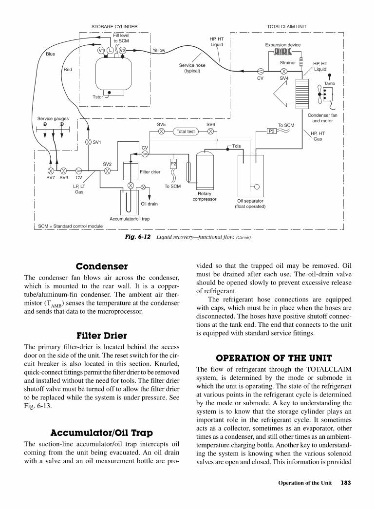
Operation of the Unit 183
CondenserThe condenser fan blows air across the condenser,which is mounted to the rear wall. It is a copper-tube/aluminum-fin condenser. The ambient air ther-mistor (TAMB) senses the temperature at the condenserand sends that data to the microprocessor.
Filter DrierThe primary filter-drier is located behind the accessdoor on the side of the unit. The reset switch for the cir-cuit breaker is also located in this section. Knurled,quick-connect fittings permit the filter drier to be removedand installed without the need for tools. The filter driershutoff valve must be turned off to allow the filter drierto be replaced while the system is under pressure. SeeFig. 6-13.
Accumulator/Oil TrapThe suction-line accumulator/oil trap intercepts oilcoming from the unit being evacuated. An oil drainwith a valve and an oil measurement bottle are pro-
vided so that the trapped oil may be removed. Oilmust be drained after each use. The oil-drain valveshould be opened slowly to prevent excessive releaseof refrigerant.
The refrigerant hose connections are equippedwith caps, which must be in place when the hoses aredisconnected. The hoses have positive shutoff connec-tions at the tank end. The end that connects to the unitis equipped with standard service fittings.
OPERATION OF THE UNITThe flow of refrigerant through the TOTALCLAIMsystem, is determined by the mode or submode inwhich the unit is operating. The state of the refrigerantat various points in the refrigerant cycle is determinedby the mode or submode. A key to understanding thesystem is to know that the storage cylinder plays animportant role in the refrigerant cycle. It sometimesacts as a collector, sometimes as an evaporator, othertimes as a condenser, and still other times as an ambient-temperature charging bottle. Another key to understand-ing the system is knowing when the various solenoidvalves are open and closed. This information is provided
Condenser fan and motor
HP, HT Gas
HP, HT Liquid
HP, HT Liquid
Tamb
Strainer
CV SV4
P3To SCM
Expansion device
TOTALCLAIM UNITSTORAGE CYLINDER
Service hose (typical)
Yellow
Fill level to SCM
V1 V2LBlue
Red
Tstor
Service gauges
SV1
SV2
SV7 SV3 CV
CV
LP, LT Gas
To SCM
Filter drier
P2
Oil drain
Accumulator/oil trap
Rotary compressor Oil separator
(float operated)
SV5 SV6
Total test
Tdis
SCM = Standard control module
Fig. 6-12 Liquid recovery—functional flow. (Carrier)
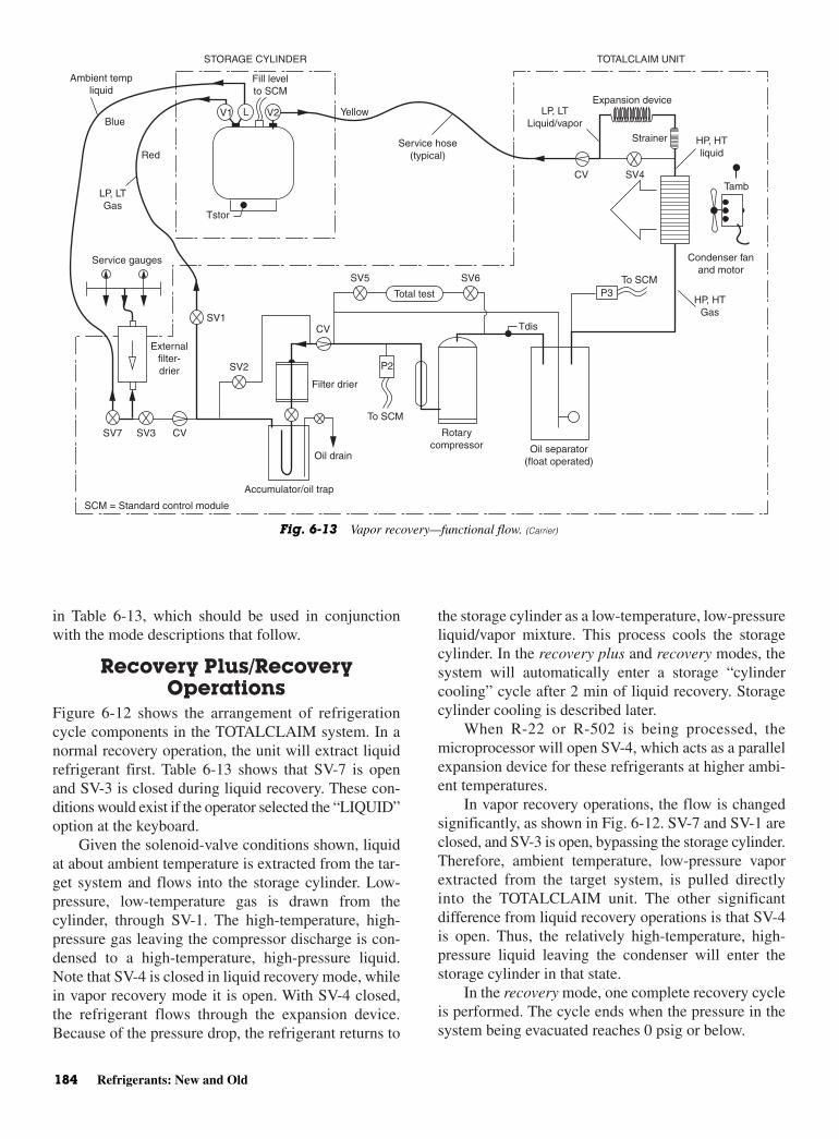
in Table 6-13, which should be used in conjunctionwith the mode descriptions that follow.
Recovery Plus/RecoveryOperations
Figure 6-12 shows the arrangement of refrigerationcycle components in the TOTALCLAIM system. In anormal recovery operation, the unit will extract liquidrefrigerant first. Table 6-13 shows that SV-7 is openand SV-3 is closed during liquid recovery. These con-ditions would exist if the operator selected the “LIQUID”option at the keyboard.
Given the solenoid-valve conditions shown, liquidat about ambient temperature is extracted from the tar-get system and flows into the storage cylinder. Low-pressure, low-temperature gas is drawn from thecylinder, through SV-1. The high-temperature, high-pressure gas leaving the compressor discharge is con-densed to a high-temperature, high-pressure liquid.Note that SV-4 is closed in liquid recovery mode, whilein vapor recovery mode it is open. With SV-4 closed,the refrigerant flows through the expansion device.Because of the pressure drop, the refrigerant returns to
the storage cylinder as a low-temperature, low-pressureliquid/vapor mixture. This process cools the storagecylinder. In the recovery plus and recovery modes, thesystem will automatically enter a storage “cylindercooling” cycle after 2 min of liquid recovery. Storagecylinder cooling is described later.
When R-22 or R-502 is being processed, themicroprocessor will open SV-4, which acts as a parallelexpansion device for these refrigerants at higher ambi-ent temperatures.
In vapor recovery operations, the flow is changedsignificantly, as shown in Fig. 6-12. SV-7 and SV-1 areclosed, and SV-3 is open, bypassing the storage cylinder.Therefore, ambient temperature, low-pressure vaporextracted from the target system, is pulled directlyinto the TOTALCLAIM unit. The other significantdifference from liquid recovery operations is that SV-4is open. Thus, the relatively high-temperature, high-pressure liquid leaving the condenser will enter thestorage cylinder in that state.
In the recovery mode, one complete recovery cycleis performed. The cycle ends when the pressure in thesystem being evacuated reaches 0 psig or below.
184 Refrigerants: New and Old
Condenser fan and motor
HP, HT Gas
HP, HT liquid
Tamb
Strainer
CV SV4
P3To SCM
Expansion device
TOTALCLAIM UNITSTORAGE CYLINDER
Yellow
Fill level to SCM
V1 V2LBlue
Red
Tstor
Service gauges
SV1
SV2
SV7 SV3 CV
CV
To SCM
Filter drier
P2
Oil drain
Accumulator/oil trap
Rotary compressor Oil separator
(float operated)
SV5 SV6
Total test
Tdis
SCM = Standard control module
LP, LT Liquid/vapor
Service hose (typical)
External filter-drier
LP, LT Gas
Ambient temp liquid
Fig. 6-13 Vapor recovery—functional flow. (Carrier)
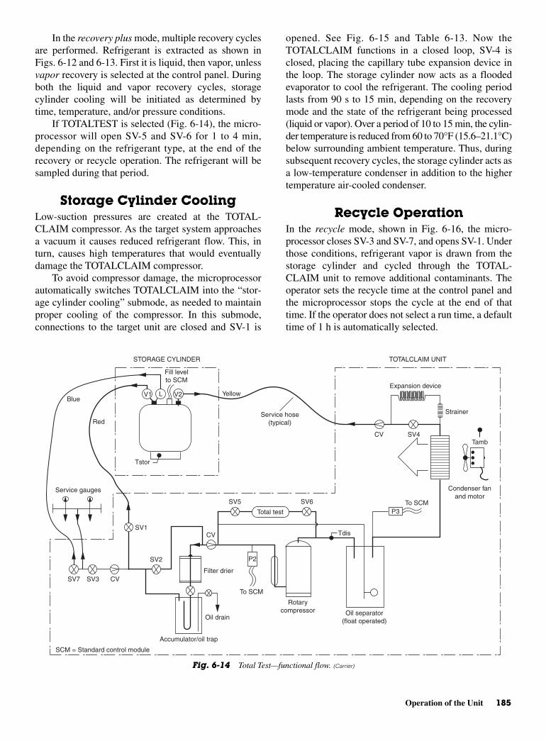
Operation of the Unit 185
In the recovery plus mode, multiple recovery cyclesare performed. Refrigerant is extracted as shown inFigs. 6-12 and 6-13. First it is liquid, then vapor, unlessvapor recovery is selected at the control panel. Duringboth the liquid and vapor recovery cycles, storagecylinder cooling will be initiated as determined bytime, temperature, and/or pressure conditions.
If TOTALTEST is selected (Fig. 6-14), the micro-processor will open SV-5 and SV-6 for 1 to 4 min,depending on the refrigerant type, at the end of therecovery or recycle operation. The refrigerant will besampled during that period.
Storage Cylinder CoolingLow-suction pressures are created at the TOTAL-CLAIM compressor. As the target system approachesa vacuum it causes reduced refrigerant flow. This, inturn, causes high temperatures that would eventuallydamage the TOTALCLAIM compressor.
To avoid compressor damage, the microprocessorautomatically switches TOTALCLAIM into the “stor-age cylinder cooling” submode, as needed to maintainproper cooling of the compressor. In this submode,connections to the target unit are closed and SV-1 is
opened. See Fig. 6-15 and Table 6-13. Now theTOTALCLAIM functions in a closed loop, SV-4 isclosed, placing the capillary tube expansion device inthe loop. The storage cylinder now acts as a floodedevaporator to cool the refrigerant. The cooling periodlasts from 90 s to 15 min, depending on the recoverymode and the state of the refrigerant being processed(liquid or vapor). Over a period of 10 to 15 min, the cylin-der temperature is reduced from 60 to 70°F (15.6–21.1°C)below surrounding ambient temperature. Thus, duringsubsequent recovery cycles, the storage cylinder acts asa low-temperature condenser in addition to the highertemperature air-cooled condenser.
Recycle OperationIn the recycle mode, shown in Fig. 6-16, the micro-processor closes SV-3 and SV-7, and opens SV-1. Underthose conditions, refrigerant vapor is drawn from thestorage cylinder and cycled through the TOTAL-CLAIM unit to remove additional contaminants. Theoperator sets the recycle time at the control panel andthe microprocessor stops the cycle at the end of thattime. If the operator does not select a run time, a defaulttime of 1 h is automatically selected.
Condenser fan and motor
Tamb
Strainer
CV SV4
P3To SCM
Expansion device
TOTALCLAIM UNITSTORAGE CYLINDER
Service hose (typical)
Yellow
Fill level to SCM
V1 V2LBlue
Red
Tstor
Service gauges
SV1
SV2
SV7 SV3 CV
CV
To SCM
Filter drier
P2
Oil drain
Accumulator/oil trap
Rotary compressor Oil separator
(float operated)
SV5 SV6
Total test
Tdis
SCM = Standard control module
Fig. 6-14 Total Test—functional flow. (Carrier)

186 Refrigerants: New and Old
Condenser fan and motor
HP, HT Gas
HP, HT Liquid
Tamb
Strainer
CV SV4
P3To SCM
Expansion device
TOTALCLAIM UNITSTORAGE CYLINDER
Service hose (typical)
Yellow
Fill level to SCM
V1 V2LBlue
Red
Tstor
Service gauges
SV1
SV2
SV7 SV3 CV
CV
LP, LT Gas
To SCM
Filter drier
P2
Oil drain
Accumulator/oil trap
Rotary compressor Oil separator
(float operated)
SV5 SV6
Total test
Tdis
SCM = Standard control module
HP, HT Liquid relative to storage cylinder
Fig. 6-15 Storage cylinder cooling—functional flow. (Carrier)
Condenser fan and motor
HP, HT Gas
HP, HT Liquid
Tamb
Strainer
CV SV4
P3To SCM
Expansion device
TOTALCLAIM UNITSTORAGE CYLINDER
Service hose (typical)
Yellow
Fill level to SCM
V1 V2LBlue
Red
Tstor
Service gauges
SV1
SV2
SV7 SV3 CV
CV
LP, LT Gas
To SCM
Filter drier
P2
Oil drain
Accumulator/oil trap
Rotary compressor Oil separator
(float operated)
SV5 SV6
Total test
Tdis
SCM = Standard control module
Fig. 6-16 Recycle—functional flow. (Carrier)
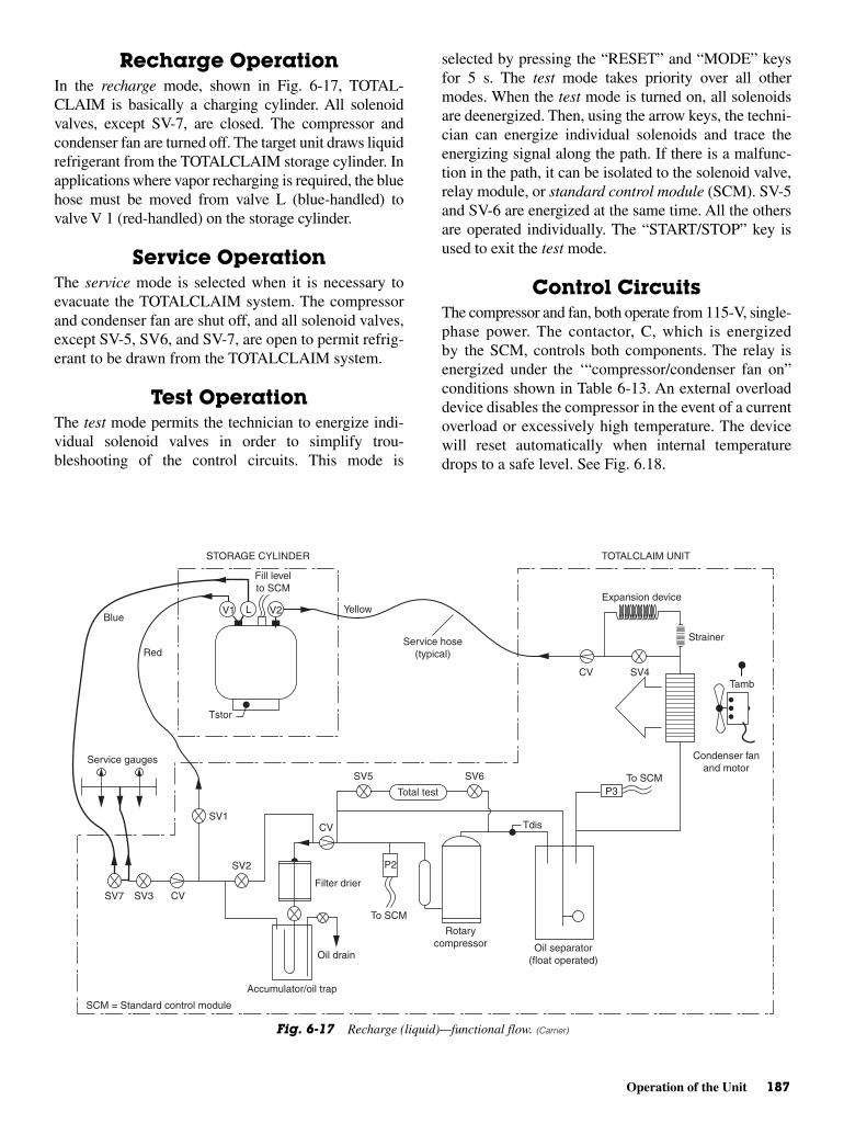
Operation of the Unit 187
Recharge OperationIn the recharge mode, shown in Fig. 6-17, TOTAL-CLAIM is basically a charging cylinder. All solenoidvalves, except SV-7, are closed. The compressor andcondenser fan are turned off. The target unit draws liquidrefrigerant from the TOTALCLAIM storage cylinder. Inapplications where vapor recharging is required, the bluehose must be moved from valve L (blue-handled) tovalve V 1 (red-handled) on the storage cylinder.
Service OperationThe service mode is selected when it is necessary toevacuate the TOTALCLAIM system. The compressorand condenser fan are shut off, and all solenoid valves,except SV-5, SV6, and SV-7, are open to permit refrig-erant to be drawn from the TOTALCLAIM system.
Test OperationThe test mode permits the technician to energize indi-vidual solenoid valves in order to simplify trou-bleshooting of the control circuits. This mode is
selected by pressing the “RESET” and “MODE” keysfor 5 s. The test mode takes priority over all othermodes. When the test mode is turned on, all solenoidsare deenergized. Then, using the arrow keys, the techni-cian can energize individual solenoids and trace theenergizing signal along the path. If there is a malfunc-tion in the path, it can be isolated to the solenoid valve,relay module, or standard control module (SCM). SV-5and SV-6 are energized at the same time. All the othersare operated individually. The “START/STOP” key isused to exit the test mode.
Control Circuits The compressor and fan, both operate from 115-V, single-phase power. The contactor, C, which is energizedby the SCM, controls both components. The relay isenergized under the ‘“compressor/condenser fan on”conditions shown in Table 6-13. An external overloaddevice disables the compressor in the event of a currentoverload or excessively high temperature. The devicewill reset automatically when internal temperaturedrops to a safe level. See Fig. 6.18.
Condenser fan and motor
Tamb
Strainer
CV SV4
P3To SCM
Expansion device
TOTALCLAIM UNITSTORAGE CYLINDER
Service hose (typical)
Yellow
Fill level to SCM
V1 V2LBlue
Red
Tstor
Service gauges
SV1
SV2
SV7 SV3 CV
CV
To SCM
Filter drier
P2
Oil drain
Accumulator/oil trap
Rotary compressor Oil separator
(float operated)
SV5 SV6
Total test
Tdis
SCM = Standard control module
Fig. 6-17 Recharge (liquid)—functional flow. (Carrier)

188 Refrigerants: New and Old
WHT WHT
WHT
WHTWHT
WHT
WHT
WHT
BLK BLK
BLK YEL
BLU WHT
WHT
YEL
BLK
BLK
BLKBLK
BLK
BLK
BLK
BLK
BLK
WHT
WHT
BLK
BLK
BLK
BLK
ORN BLK
BLK
BLK
GRY
PNK
GRN
BRN
BRN
RED
ORN
RED
BLK
BRN
BLK
BLU
PNK
PNK
YEL GRY
DPT
SPT
REDRED
GRNGRN GRN BRNORN
GRN
BRNBLK
BLK
BLK BLU
BLUBLU
BLKBLK
REDRED
BLUBRN
GRY
GRY
GRY
GRY
VIO VIO
RED BLU BLU YEL
YEL
RED
BLK
BLK R C
YEL
GRY WHT
WHT
WHT
WHT/BLK
ORN
GRY GRYORN
ORN BRNBLK BLKWHT WHTVIO
VIO
BLK GRY
RED
RED ORN
GRN
SW
PSC
CC
OL
CAP
SV-7
SV-5
SV-6
SV-4
SV-3
SV-2
SV-1VIO
COMPR
SYSTEM SCHEMATIC
FM
S
R
1 2 1 2 3 4 5 6 7 8
1 21 2 3 4 5 6 7 8
1 2 3 4 5 6 7 8 9
1 2 3 4 5 6 7 8 91 2 3 4 5 6 7 8 9
9 8 7 6 5 4 3 2 1
1 8 2 3 4 5 6 7
910111213 8 7 6 5 4 3 2 1 5 4 3 2 1 3 2 1 2 1
101112
1 2 3 4 5 6 7 8 9 101112
CP14
P6
P4 P2 P1
P7
P3 P5
P8
P12 P13
P15 P16 TRAN
RELAY BOARD
CIRCUITBREAKER
STANDARD-CONTROL MODULE
FACTORY- TESTPLUG
1234567891011
P9
P10
GRN
REFRIG TANK
DISPLAY BOARD
LCD
STATIC LOOP
DISCH.
TANK
AIR
T1
T2
T3
(RIB
BO
N C
AB
LE)
STATIC LOOP
ESD GRID
1
8
CONTROL KEYPAD
RefrigLiquid
VaporMode Total test
StartStop
Reset
Fig. 6-18 TOTALCLAIM wiring diagram. (Carrier)
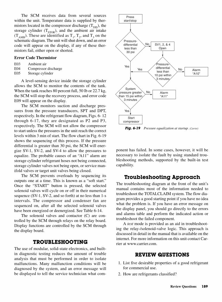
Review Questions 189
The SCM receives data from several sourceswithin the unit. Temperature data is supplied by ther-mistors located in the compressor discharge (TDIS), thestorage cylinder (TSTOR), and the ambient air intake(TAMB). These are identified as T1, T2, and T3 on theschematic diagram. The unit will shut down, and an errorcode will appear on the display, if any of these ther-mistors fail, either open or shorted.
Error Code Thermistor
E03 Ambient airE04 Compressor dischargeE05 Storage cylinder
A level-sensing device inside the storage cylinderallows the SCM to monitor the contents of the tank.When the tank reaches 80 percent full, 50 lb or 22.7 kg,the SCM will stop the recovery process, and error codeE09 will appear on the display.
The SCM monitors suction and discharge pres-sures from the pressure transducers, SPT and DPT,respectively. In the refrigerant flow diagram, Figs. 6- 12through 6-17, they are designated as P2 and P3,respectively. The SCM will not allow the compressorto start unless the pressures in the unit reach the correctlevels within 3 min of start. The flow chart in Fig. 6-19shows the sequencing of this process. If the pressuredifferential is greater than 30 psi, the SCM will ener-gize SV-1, SV-2, and SV-4 to allow the pressures toequalize. The probable causes of an “A11” alarm arestorage cylinder refrigerant hoses not being connected,storage cylinder valves not being open, or service man-ifold valves or target unit valves being closed.
The SCM prevents overloads by sequencing itsoutputs one at a time. This is known as a “soft start.”Once the “START” button is pressed, the selectedsolenoid valves will cycle on or off in their numericalsequence (SV-1, SV-2, and so forth) at no less than 1-sintervals. The compressor and condenser fan aresequenced on, after all the selected solenoid valveshave been energized or deenergized. See Table 6-14.
The solenoid valves and contactor (C) are con-trolled by the SCM through relays on the relay board.Display functions are controlled by the SCM throughthe display board.
TROUBLESHOOTINGThe use of modular, solid-state electronics, and built-in diagnostic testing reduces the amount of troubleanalysis that must be performed in order to isolatemalfunctions. Many malfunction conditions will bediagnosed by the system, and an error message willbe displayed to tell the service technician what com-
ponent has failed. In some cases, however, it will benecessary to isolate the fault by using standard trou-bleshooting methods, supported by the built-in testcapability.
Troubleshooting ApproachThe troubleshooting diagram at the front of the unit’smanual contains most of the information needed totroubleshoot the TOTALCLAIM system. The flow dia-gram provides a good starting point if you have no ideawhat the problem is. If you have an error message onthe display panel, you should go directly to the errorsand alarms table and perform the indicated action ortroubleshoot the failed component.
A test mode is provided as an aid in troubleshoot-ing the relay-/solenoid-valve logic. This approach isdiscussed in detail in the manual that is available on theinternet. For more information on this unit contact Car-rier at www.carrier.com.
REVIEW QUESTIONS1. List five desirable properties of a good refrigerant
for commercial use.
2. How are refrigerants classified?
Pressure-differential less than
30 psi
Pressure-differential less than
10 psi within 3 minutes
Systempressure greater than 15 psi within
3 minutes
Pressstart/stop
SV1, 2, & 4 Open
Alarm “A10”
Alarm “A11”
Start compressor
Yes
Yes
No
Yes No
No
Fig. 6-19 Pressure equalization at startup. (Carrier)

3. Where is calcium chloride used in refrigerationsystems?
4. What type of refrigerant is used in home refrigerators?
5. Are Freon compounds flammable?
6. What does toxicity mean?
7. What is a fluorocarbon?
8. What is a halocarbon?
9. Why is the pressure of a refrigeration systemimportant?
10. Define specific volume.
11. How are refrigerant leaks detected?
12. What is the Montreal Protocol?
13. What is R-134a used for?
14. Why are R-22 and R-12 so harmful?
15. Where will technicians get their Freon after 2020?
16. What is a trigger leak rate?
190 Refrigerants: New and Old

7CHAPTER
RefrigerationCompressors
Copyright © 2006 by The McGraw-Hill Companies, Inc. Click here for terms of use.

PERFORMANCE OBJECTIVES1. Know how to identify refrigeration compressors.
2. Know types of condensers.
3. Be able to explain how evaporative condenserswork.
4. Know the types of compressors.
5. Know how to read serial-plate information on ahermetic compressor.
6. Know how the internal line-break motor protectorworks.
7. Know how hermetic compressors work.
8. Know how PSC motor hook-ups are made.
9. Know different types of hermetic compressors.
10. Know how relays operate and malfunction.
11. Know how and why crankcase heaters are neededin certain compressors.
12. Know how CSIR or high-starting torque motorsoperate.
13. Know how rotary compressors operate.
Refrigeration compressors can be classified accord-ing to the following:
• Number of cylinders
• Method of compression
• Type of drive
• Location of the driving force or motor
The method of compression may be reciprocating,centrifugal, or rotary. The location of the power sourcealso classifies compressors. Independent compressorsare belt driven. Semihermetic compressors have directdrive, with the motor and compressor in separate hous-ings. The hermetic compressor has direct drive, withthe motor and compressor in the same housing.
Reciprocating units have a piston in a cylinder. Thepiston acts as a pump to increase the pressure of therefrigerant from the low side to the high side of the sys-tem. A reciprocating compressor can have twelve ormore cylinders. See Fig. 7-1.
The most commonly used reciprocating compres-sor is made for refrigerants R-22 and R-134a. Theseare for heating, ventilating and air conditioning, andprocess cooling. The most practical refrigerants usedtoday are R-134a and R-22. However, R-134a, is gain-ing acceptance, in view of the CFC regulations world-wide. As a matter of fact, some countries only acceptR-134a today. Other environmentally acceptablerefrigerants are R-404A and R-507. They are for low-and medium-temperature applications. R-470C is for
medium temperatures and air-conditioning applica-tions. Recently, R-410A has gained acceptance as anenvironmentally acceptable substitute for R-22, butonly for residential and small equipment. R-410A isnot a drop-in refrigerant for R-22.
There are three types of reciprocating compres-sors: open drive, hermetic, and semihermetic.
Two methods of capacity control are generallyapplied to the reciprocating refrigeration compressorused on commercial air-conditioning systems. Bothmethods involve mechanical means of unloading cylin-ders by holding open the suction valve.
The most common method of capacity control usesan internal multiple-step valve. This applies compressor-oil pressure or high–side refrigerant pressure to a bel-low or piston that actuates the unloader.
The second method of capacity control uses anexternal solenoid valve for each cylinder. The solenoidvalve allows compressor oil or high-side refrigerant topass to the unloader.
A centrifugal compressor is basically a fan or blowerthat builds refrigerant pressure by forcing the gas througha funnel-shaped opening at high speed. See Fig. 7-2.
Compressor capacity is controlled when the vanesare opened and closed. These vanes regulate theamount of refrigerant gas allowed to enter the fan orturbine. See Fig. 7-3. When the vanes restrict the flowof refrigerant, the turbine cannot do its full amount ofwork on the refrigerant. Thus, its capacity is limited.Most centrifugal machines can be limited to 10 to 25percent of full capacity by this method. Some willoperate at almost zero capacity. However, another,though less common, method is to control the speed ofthe motor that is turning the turbine.
CONDENSERSA condenser must take the superheated vapor from thecompressor, cool it to its condensing temperature, and
192 Refrigeration Compressors
Fig. 7-1 Reciprocating compressor. (Trane)
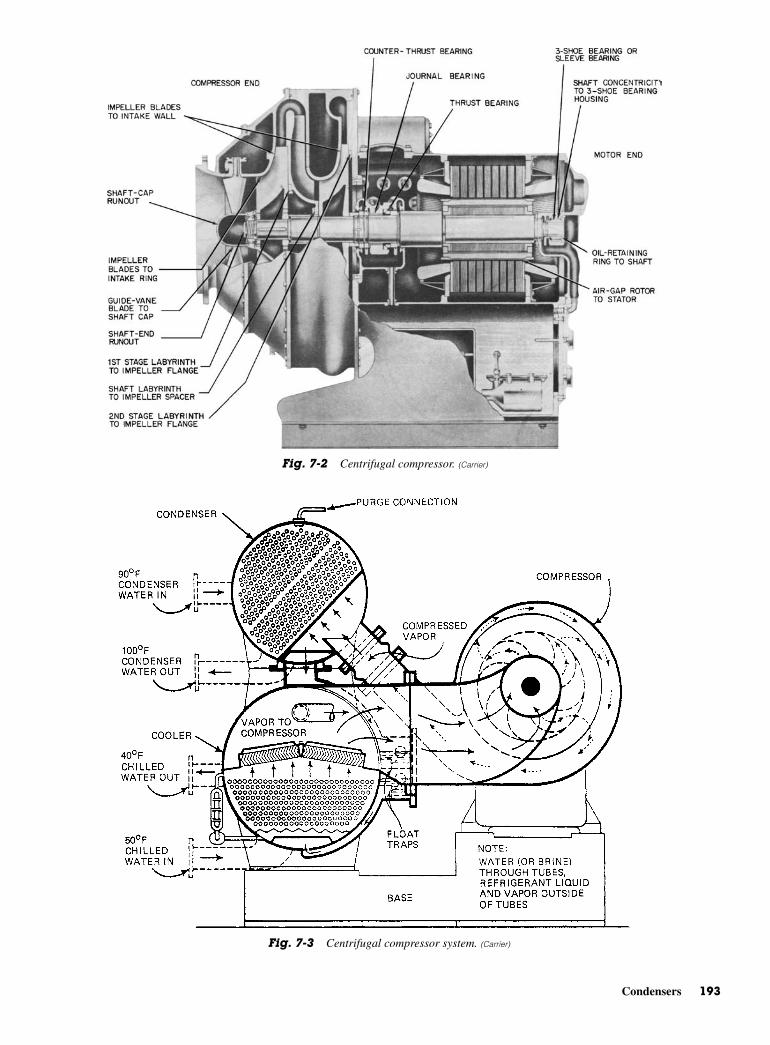
Condensers 193
Fig. 7-2 Centrifugal compressor. (Carrier)
Fig. 7-3 Centrifugal compressor system. (Carrier)
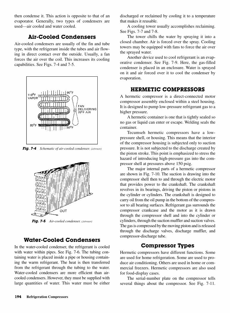
194 Refrigeration Compressors
then condense it. This action is opposite to that of anevaporator. Generally, two types of condensers areused—air cooled and water cooled.
Air-Cooled Condensers Air-cooled condensers are usually of the fin and tubetype, with the refrigerant inside the tubes and air flow-ing in direct contact over the outside. Usually, a fanforces the air over the coil. This increases its coolingcapabilities. See Figs. 7-4 and 7-5.
Water-Cooled CondensersIn the water-cooled condenser, the refrigerant is cooledwith water within pipes. See Fig. 7-6. The tubing con-taining water is placed inside a pipe or housing contain-ing the warm refrigerant. The heat is then transferredfrom the refrigerant through the tubing to the water.Water-cooled condensers are more efficient than air-cooled condensers. However, they must be supplied withlarge quantities of water. This water must be either
discharged or reclaimed by cooling it to a temperaturethat makes it reusable.
A cooling tower usually accomplishes reclaiming.See Figs. 7-7 and 7-8.
The tower chills the water by spraying it into aclosed chamber. Air is forced over the spray. Coolingtowers may be equipped with fans to force the air overthe sprayed water.
Another device used to cool refrigerant is an evap-orative condenser. See Fig. 7-9. Here, the gas-filledcondenser is placed in an enclosure. Water is sprayedon it and air forced over it to cool the condenser byevaporation.
HERMETIC COMPRESSORSA hermetic compressor is a direct-connected motorcompressor assembly enclosed within a steel housing.It is designed to pump low-pressure refrigerant gas to ahigher pressure.
A hermetic container is one that is tightly sealed sono gas or liquid can enter or escape. Welding seals thecontainer.
Tecumseh hermetic compressors have a low-pressure shell, or housing. This means that the interiorof the compressor housing is subjected only to suctionpressure. It is not subjected to the discharge created bythe piston stroke. This point is emphasized to stress thehazard of introducing high-pressure gas into the com-pressor shell at pressures above 150 psig.
The major internal parts of a hermetic compressorare shown in Fig. 7-10. The suction is drawing into thecompressor shell then to and through the electric motorthat provides power to the crankshaft. The crankshaftrevolves in its bearings, driving the piston or pistons inthe cylinder or cylinders. The crankshaft is designed tocarry oil from the oil pump in the bottom of the compres-sor to all bearing surfaces. Refrigerant gas surrounds thecompressor crankcase and the motor as it is drawnthrough the compressor shell and into the cylinder orcylinders, through the suction muffler and suction valves.The gas is compressed by the moving piston and is releasedthrough the discharge valves, discharge muffler, andcompressor-discharge tube.
Compressor TypesHermetic compressors have different functions. Someare used for home refrigeration. Some are used to pro-duce air conditioning. Others are used in home or com-mercial freezers. Hermetic compressors are also usedfor food-display cases.
The serial-number plate on the compressor tellsseveral things about the compressor. See Fig. 7-11.
Fig. 7-4 Schematic of air-cooled condenser. (Johnson)
Fig. 7-5 Air-cooled condenser. (Johnson)
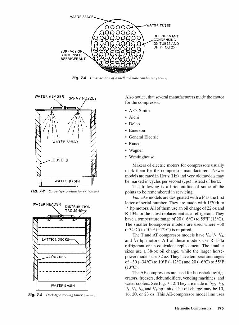
Hermetic Compressors 195
Also notice, that several manufacturers made the motorfor the compressor:
• A.O. Smith
• Aichi
• Delco
• Emerson
• General Electric
• Ranco
• Wagner
• Westinghouse
Makers of electric motors for compressors usuallymark them for the compressor manufacturers. Newermodels are rated in Hertz (Hz) and very old models maybe marked in cycles per second (cps) instead of hertz.
The following is a brief outline of some of thepoints to be remembered in servicing.
Pancake models are designated with a P as the firstletter of serial number. They are made with 1/20th to1/3 hp motors. All of them use an oil charge of 22 oz andR-134a or the latest replacement as a refrigerant. Theyhave a temperature range of 20 (−6°C) to 55°F (13°C).The smaller horsepower models are used where −30(−34°C) to 10°F (−12°C) is required.
The T and AT compressor models have 1/6, 1/5, 1/4,and 1/3 hp motors. All of these models use R-134arefrigerant or its equivalent replacement. The smallersizes use a 38-oz oil charge, while the larger horse-power models use 32 oz. They have temperature rangesof −30 (−34°C) to 10°F (−12°C) and 20 (−6°C) to 55°F(13°C).
The AE compressors are used for household refrig-erators, freezers, dehumidifiers, vending machines, andwater coolers. See Fig. 7-12. They are made in 1/20, 1/12,1/8, 1/6, 1/5, and 1/4-hp units. The oil charge may be 10,16, 20, or 23 oz. This AE-compressor model line uses
Fig. 7-6 Cross-section of a shell and tube condenser. (Johnson)
Fig. 7-7 Spray-type cooling tower. (Johnson)
Fig. 7-8 Deck-type cooling tower. (Johnson)

196 Refrigeration Compressors
Fig. 7-9 Evaporative condenser. (Johnson)
Fig. 7-10 Cutaway view of a compressor. Note the motor is on the bottom of the compressor and the piston is on the top. (Tecumseh)

Hermetic Compressors 197
Fig. 7-11 (A) Serial plate information on Tecumseh’s hermetic compressors. (B) Model numbers. (C) Nomenclature explained.(D) Compressor application categories. (Tecumseh)
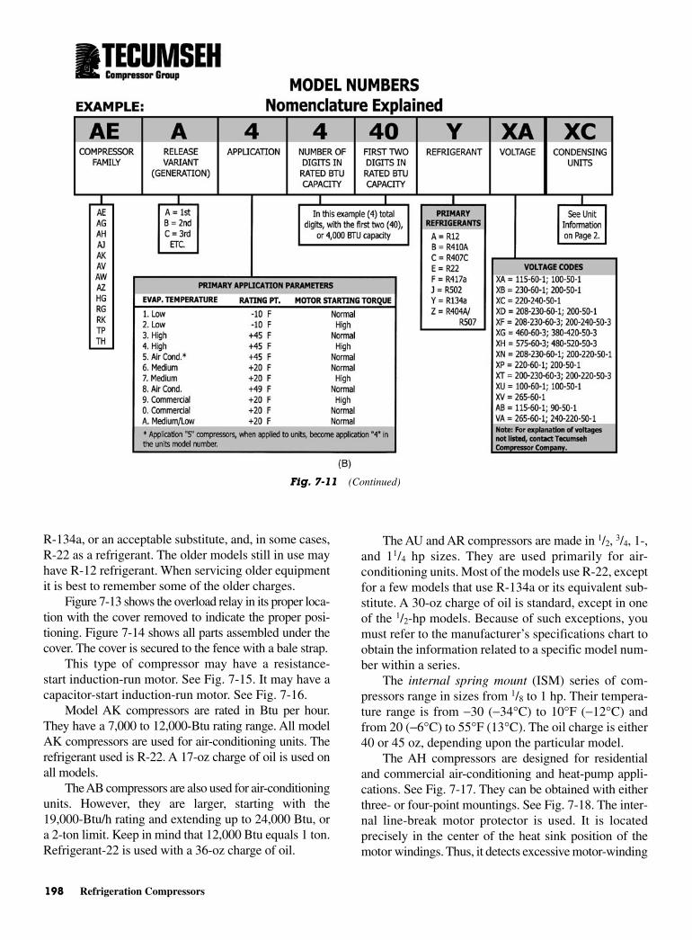
198 Refrigeration Compressors
R-134a, or an acceptable substitute, and, in some cases,R-22 as a refrigerant. The older models still in use mayhave R-12 refrigerant. When servicing older equipmentit is best to remember some of the older charges.
Figure 7-13 shows the overload relay in its proper loca-tion with the cover removed to indicate the proper posi-tioning. Figure 7-14 shows all parts assembled under thecover. The cover is secured to the fence with a bale strap.
This type of compressor may have a resistance-start induction-run motor. See Fig. 7-15. It may have acapacitor-start induction-run motor. See Fig. 7-16.
Model AK compressors are rated in Btu per hour.They have a 7,000 to 12,000-Btu rating range. All modelAK compressors are used for air-conditioning units. Therefrigerant used is R-22. A 17-oz charge of oil is used onall models.
The AB compressors are also used for air-conditioningunits. However, they are larger, starting with the19,000-Btu/h rating and extending up to 24,000 Btu, ora 2-ton limit. Keep in mind that 12,000 Btu equals 1 ton.Refrigerant-22 is used with a 36-oz charge of oil.
The AU and AR compressors are made in 1/2, 3/4, 1-,and 11/4 hp sizes. They are used primarily for air-conditioning units. Most of the models use R-22, exceptfor a few models that use R-134a or its equivalent sub-stitute. A 30-oz charge of oil is standard, except in oneof the 1/2-hp models. Because of such exceptions, youmust refer to the manufacturer’s specifications chart toobtain the information related to a specific model num-ber within a series.
The internal spring mount (ISM) series of com-pressors range in sizes from 1/8 to 1 hp. Their tempera-ture range is from −30 (−34°C) to 10°F (−12°C) andfrom 20 (−6°C) to 55°F (13°C). The oil charge is either40 or 45 oz, depending upon the particular model.
The AH compressors are designed for residentialand commercial air-conditioning and heat-pump appli-cations. See Fig. 7-17. They can be obtained with eitherthree- or four-point mountings. See Fig. 7-18. The inter-nal line-break motor protector is used. It is locatedprecisely in the center of the heat sink position of themotor windings. Thus, it detects excessive motor-winding
Fig. 7-11 (Continued)
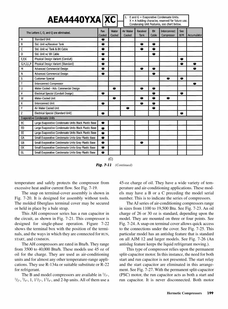
Hermetic Compressors 199
temperature and safely protects the compressor fromexcessive heat and/or current flow. See Fig. 7-19.
The snap on terminal-cover assembly is shown inFig. 7-20. It is designed for assembly without tools.The molded fiberglass terminal cover may be securedor held in place by a bale strap.
This AH compressor series has a run capacitor inthe circuit, as shown in Fig. 7-21. This compressor isdesigned for single-phase operation. Figure 7-22shows the terminal box with the position of the termi-nals, and the ways in which they are connected for RUN,START, and COMMON.
The AH compressors are rated in Btu/h. They rangefrom 3500 to 40,000 Btu/h. These models use 45 oz ofoil for the charge. They are used as air-conditioningunits and for almost any other temperature-range appli-cations. They use R-134a or suitable substitute or R-22for refrigerant.
The B and model compressors are available in 1/3-,1/2-, 3/4-, 1, 11/2-, 13/4-, and 2-hp units. All of them use a
45-oz charge of oil. They have a wide variety of tem-perature and air-conditioning applications. These mod-els may have a B or a C preceding the model serialnumber. This is to indicate the series of compressors.
The AJ series of air-conditioning compressors rangein sizes from 1100 to 19,500 Btu. See Fig. 7-23. An oilcharge of 26 or 30 oz is standard, depending upon themodel. They are mounted on three or four points. SeeFig. 7-24. A snap-on terminal cover allows quick accessto the connections under the cover. See Fig. 7-25. Thisparticular model has an antislug feature that is standardon all AJM 12 and larger models. See Fig. 7-26 (Anantislug feature keeps the liquid refrigerant moving.).
This type of compressor relies upon the permanentsplit-capacitor motor. In this instance, the need for bothstart and run capacitor is not presented. The start relayand the start capacitor are eliminated in this arrange-ment. See Fig. 7-27. With the permanent split-capacitor(PSC) motor, the run capacitor acts as both a start andrun capacitor. It is never disconnected. Both motor
Fig. 7-11 (Continued)
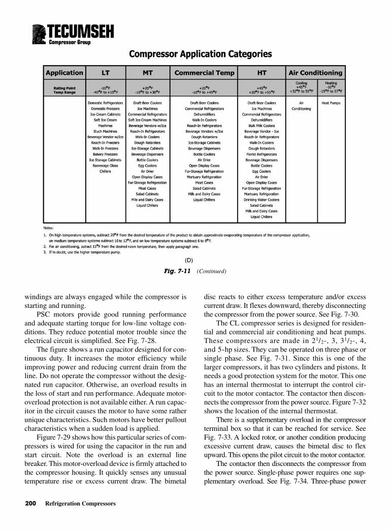
200 Refrigeration Compressors
windings are always engaged while the compressor isstarting and running.
PSC motors provide good running performanceand adequate starting torque for low-line voltage con-ditions. They reduce potential motor trouble since theelectrical circuit is simplified. See Fig. 7-28.
The figure shows a run capacitor designed for con-tinuous duty. It increases the motor efficiency whileimproving power and reducing current drain from theline. Do not operate the compressor without the desig-nated run capacitor. Otherwise, an overload results inthe loss of start and run performance. Adequate motor-overload protection is not available either. A run capac-itor in the circuit causes the motor to have some ratherunique characteristics. Such motors have better pulloutcharacteristics when a sudden load is applied.
Figure 7-29 shows how this particular series of com-pressors is wired for using the capacitor in the run andstart circuit. Note the overload is an external linebreaker. This motor-overload device is firmly attached tothe compressor housing. It quickly senses any unusualtemperature rise or excess current draw. The bimetal
disc reacts to either excess temperature and/or excesscurrent draw. It flexes downward, thereby disconnectingthe compressor from the power source. See Fig. 7-30.
The CL compressor series is designed for residen-tial and commercial air conditioning and heat pumps.These compressors are made in 21/2-, 3, 31/2-, 4,and 5-hp sizes. They can be operated on three phase orsingle phase. See Fig. 7-31. Since this is one of thelarger compressors, it has two cylinders and pistons. Itneeds a good protection system for the motor. This onehas an internal thermostat to interrupt the control cir-cuit to the motor contactor. The contactor then discon-nects the compressor from the power source. Figure 7-32shows the location of the internal thermostat.
There is a supplementary overload in the compressorterminal box so that it can be reached for service. SeeFig. 7-33. A locked rotor, or another condition producingexcessive current draw, causes the bimetal disc to flexupward. This opens the pilot circuit to the motor contactor.
The contactor then disconnects the compressor fromthe power source. Single-phase power requires one sup-plementary overload. See Fig. 7-34. Three-phase power
Fig. 7-11 (Continued)
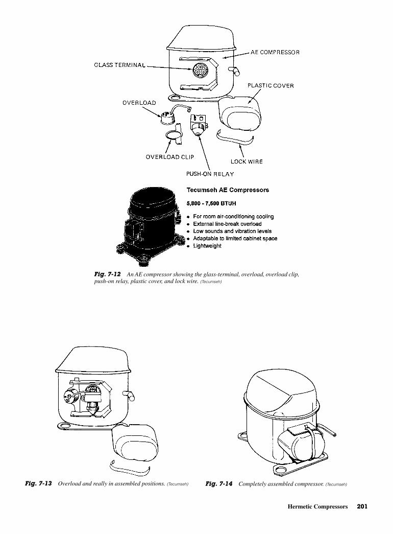
Hermetic Compressors 201
Fig. 7-12 An AE compressor showing the glass-terminal, overload, overload clip,push-on relay, plastic cover, and lock wire. (Tecumseh)
Fig. 7-13 Overload and really in assembled positions. (Tecumseh) Fig. 7-14 Completely assembled compressor. (Tecumseh)
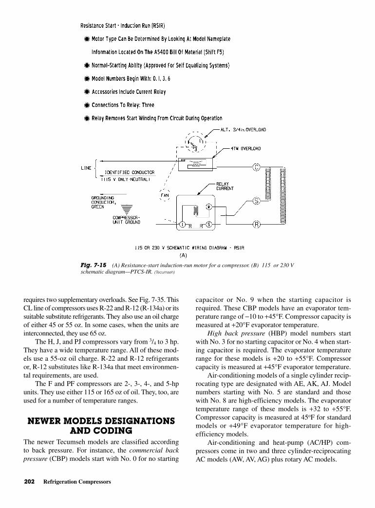
202 Refrigeration Compressors
requires two supplementary overloads. See Fig. 7-35. ThisCL line of compressors uses R-22 and R-12 (R-134a) or itssuitable substitute refrigerants. They also use an oil chargeof either 45 or 55 oz. In some cases, when the units areinterconnected, they use 65 oz.
The H, J, and PJ compressors vary from 3/4 to 3 hp.They have a wide temperature range. All of these mod-els use a 55-oz oil charge. R-22 and R-12 refrigerantsor, R-12 substitutes like R-134a that meet environmen-tal requirements, are used.
The F and PF compressors are 2-, 3-, 4-, and 5-hpunits. They use either 115 or 165 oz of oil. They, too, areused for a number of temperature ranges.
NEWER MODELS DESIGNATIONSAND CODING
The newer Tecumseh models are classified accordingto back pressure. For instance, the commercial backpressure (CBP) models start with No. 0 for no starting
capacitor or No. 9 when the starting capacitor isrequired. These CBP models have an evaporator tem-perature range of −10 to +45°F. Compressor capacity ismeasured at +20°F evaporator temperature.
High back pressure (HBP) model numbers startwith No. 3 for no starting capacitor or No. 4 when start-ing capacitor is required. The evaporator temperaturerange for these models is +20 to +55°F. Compressorcapacity is measured at +45°F evaporator temperature.
Air-conditioning models of a single cylinder recip-rocating type are designated with AE, AK, AJ. Modelnumbers starting with No. 5 are standard and thosewith No. 8 are high-efficiency models. The evaporatortemperature range of these models is +32 to +55°F.Compressor capacity is measured at 45oF for standardmodels or +49°F evaporator temperature for high-efficiency models.
Air-conditioning and heat-pump (AC/HP) com-pressors come in two and three cylinder-reciprocatingAC models (AW, AV, AG) plus rotary AC models.
Fig. 7-15 (A) Resistance-start induction-run motor for a compressor. (B) 115 or 230 Vschematic diagram—PTCS-IR. (Tecumseh)

Newer Models Designations and Coding 203
The AC/HP model number starts with No. 5. Theevaporator temperature range is −15 to +55°F. Com-pressor capacity evaporator temperature is measured at+45°F (AC) and −10°F for heat-pump models.
Low back pressure models start with No. 1 for nostarting capacitor or No. 2 with starting capacitorrequired models. The evaporator temperature range is
−40 to +10°F. Compressor capacity is measured at −10°Fevaporator temperature.
Medium back pressure (MBP) model numbers startwith No. 6 for no starting capacitor and No. 7 withstarting capacitor required. The evaporator temperaturerange is −10 to +30°F. Compressor capacity is mea-sured at +20°F evaporator temperature.
Fig. 7-15 (Continued)
Fig. 7-16 (A) Capacitor-start induction-run motor for a compressor. (B) PTC/capacitor run (PTCS/CR). (C) PTC relay. (Tecumseh)

204 Refrigeration Compressors
Fig. 7-16 (Continued)

Hermetic Compressor Motor Types 205
HERMETIC COMPRESSORMOTOR TYPES
There are four general types of single-phase motors.Each has distinctly different characteristics. Compres-sor motors are designed for specific requirementsregarding starting torque and running efficiency. These
are two of the reasons why different types of motorsare required to meet the various demands.
Resistance Start-Induction RunThe resistance start-induction run (RSIR) motor isused on many small hermetic compressors through
Fig. 7-17 Construction details of the Tecumseh AH air-conditioning and heat-pump compressors. (Tecumseh)
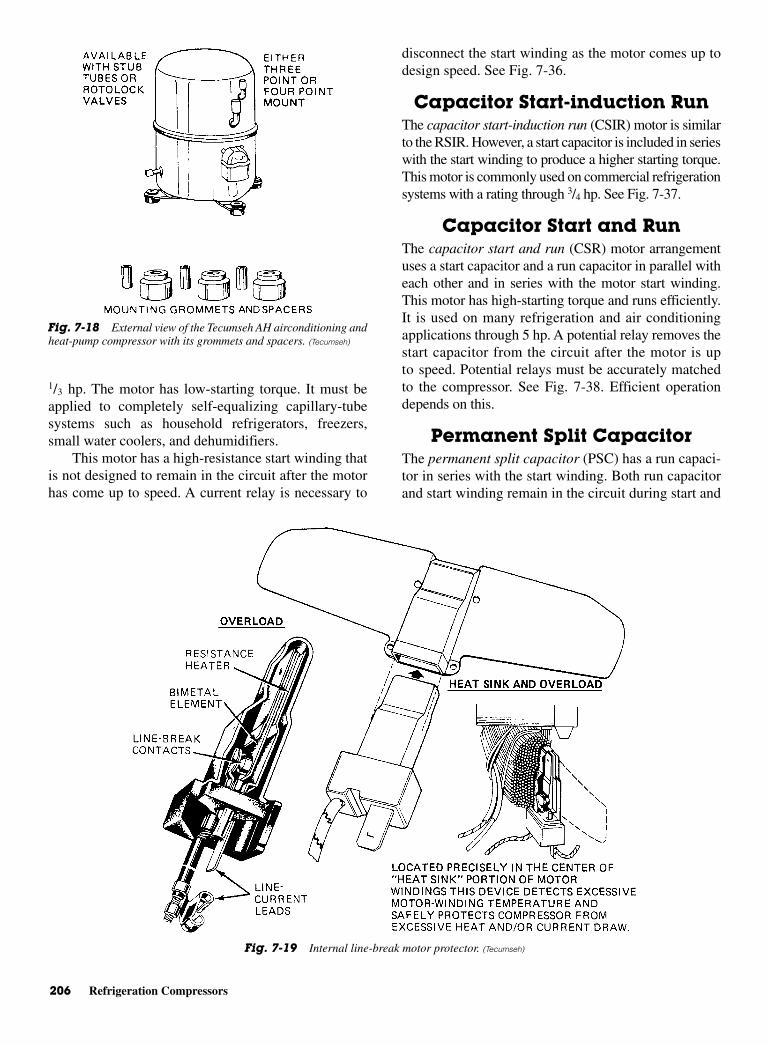
206 Refrigeration Compressors
1/3 hp. The motor has low-starting torque. It must beapplied to completely self-equalizing capillary-tubesystems such as household refrigerators, freezers,small water coolers, and dehumidifiers.
This motor has a high-resistance start winding thatis not designed to remain in the circuit after the motorhas come up to speed. A current relay is necessary to
disconnect the start winding as the motor comes up todesign speed. See Fig. 7-36.
Capacitor Start-induction Run The capacitor start-induction run (CSIR) motor is similarto the RSIR. However, a start capacitor is included in serieswith the start winding to produce a higher starting torque.This motor is commonly used on commercial refrigerationsystems with a rating through 3/4 hp. See Fig. 7-37.
Capacitor Start and Run The capacitor start and run (CSR) motor arrangementuses a start capacitor and a run capacitor in parallel witheach other and in series with the motor start winding.This motor has high-starting torque and runs efficiently.It is used on many refrigeration and air conditioningapplications through 5 hp. A potential relay removes thestart capacitor from the circuit after the motor is upto speed. Potential relays must be accurately matchedto the compressor. See Fig. 7-38. Efficient operationdepends on this.
Permanent Split Capacitor The permanent split capacitor (PSC) has a run capaci-tor in series with the start winding. Both run capacitorand start winding remain in the circuit during start and
Fig. 7-18 External view of the Tecumseh AH airconditioning andheat-pump compressor with its grommets and spacers. (Tecumseh)
Fig. 7-19 Internal line-break motor protector. (Tecumseh)
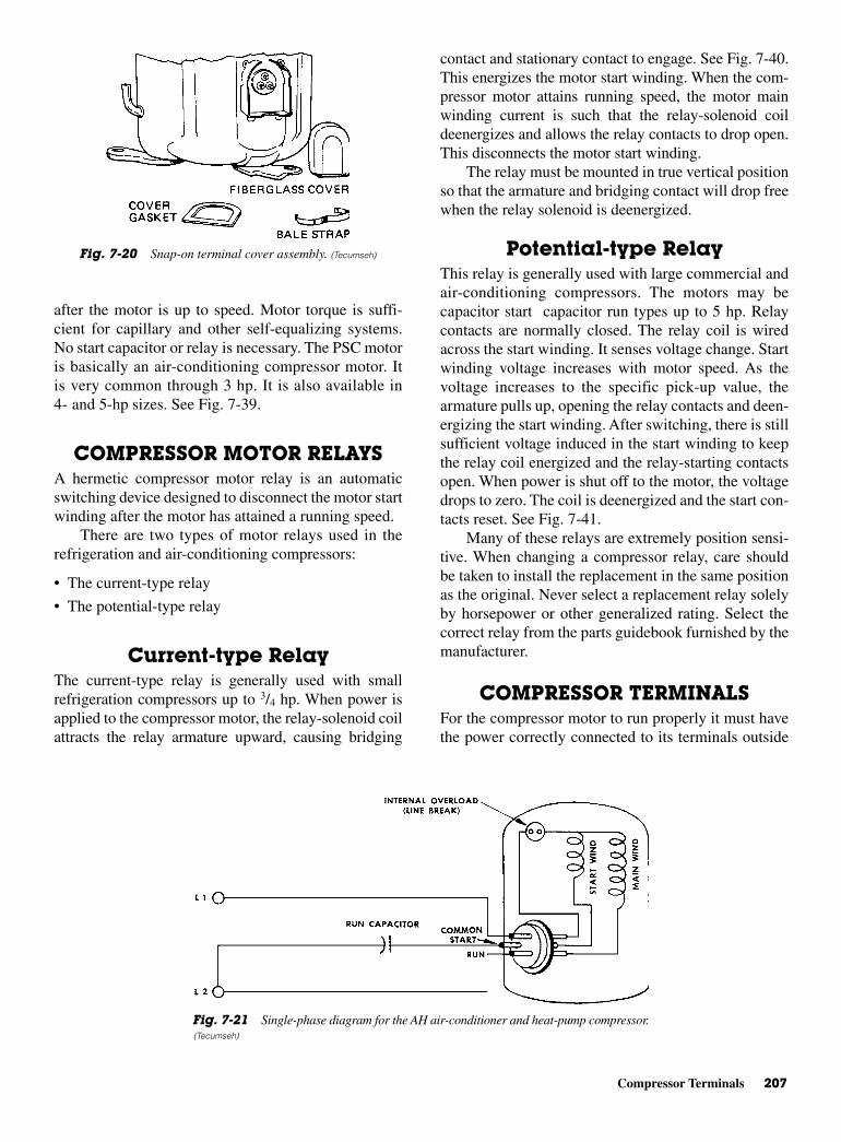
Compressor Terminals 207
after the motor is up to speed. Motor torque is suffi-cient for capillary and other self-equalizing systems.No start capacitor or relay is necessary. The PSC motoris basically an air-conditioning compressor motor. Itis very common through 3 hp. It is also available in4- and 5-hp sizes. See Fig. 7-39.
COMPRESSOR MOTOR RELAYSA hermetic compressor motor relay is an automaticswitching device designed to disconnect the motor startwinding after the motor has attained a running speed.
There are two types of motor relays used in therefrigeration and air-conditioning compressors:
• The current-type relay
• The potential-type relay
Current-type RelayThe current-type relay is generally used with smallrefrigeration compressors up to 3/4 hp. When power isapplied to the compressor motor, the relay-solenoid coilattracts the relay armature upward, causing bridging
contact and stationary contact to engage. See Fig. 7-40.This energizes the motor start winding. When the com-pressor motor attains running speed, the motor mainwinding current is such that the relay-solenoid coildeenergizes and allows the relay contacts to drop open.This disconnects the motor start winding.
The relay must be mounted in true vertical positionso that the armature and bridging contact will drop freewhen the relay solenoid is deenergized.
Potential-type Relay This relay is generally used with large commercial andair-conditioning compressors. The motors may becapacitor start capacitor run types up to 5 hp. Relaycontacts are normally closed. The relay coil is wiredacross the start winding. It senses voltage change. Startwinding voltage increases with motor speed. As thevoltage increases to the specific pick-up value, thearmature pulls up, opening the relay contacts and deen-ergizing the start winding. After switching, there is stillsufficient voltage induced in the start winding to keepthe relay coil energized and the relay-starting contactsopen. When power is shut off to the motor, the voltagedrops to zero. The coil is deenergized and the start con-tacts reset. See Fig. 7-41.
Many of these relays are extremely position sensi-tive. When changing a compressor relay, care shouldbe taken to install the replacement in the same positionas the original. Never select a replacement relay solelyby horsepower or other generalized rating. Select thecorrect relay from the parts guidebook furnished by themanufacturer.
COMPRESSOR TERMINALS For the compressor motor to run properly it must havethe power correctly connected to its terminals outside
Fig. 7-20 Snap-on terminal cover assembly. (Tecumseh)
Fig. 7-21 Single-phase diagram for the AH air-conditioner and heat-pump compressor.(Tecumseh)
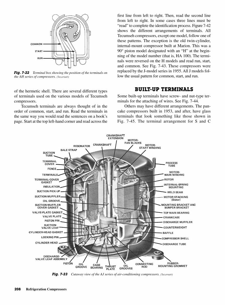
208 Refrigeration Compressors
of the hermetic shell. There are several different typesof terminals used on the various models of Tecumsehcompressors.
Tecumseh terminals are always thought of in theorder of common, start, and run. Read the terminals inthe same way you would read the sentences on a book’spage. Start at the top left-hand corner and read across the
first line from left to right. Then, read the second linefrom left to right. In some cases three lines must be“read” to complete the identification process. Figure 7-42shows the different arrangements of terminals. AllTecumseh compressors, except one model, follow one ofthese patterns. The exception is the old twin-cylinder,internal-mount compressor built at Marion. This was a90° piston model designated with an “H” at the begin-ning of the model number (that is, HA 100). The termi-nals were reversed on the H models and read run, start,and common. See Fig. 7-43. These compressors werereplaced by the J-model series in 1955. All J models fol-low the usual pattern for common, start, and run.
BUILT-UP TERMINALSSome built-up terminals have screw- and nut-type ter-minals for the attaching of wires. See Fig. 7-44.
Others may have different arrangements. The pan-cake compressors built in 1953, and after, have glassterminals that look something like those shown inFig. 7-45. The terminal arrangement for S and C
Fig. 7-22 Terminal box showing the position of the terminals onthe AH series of compressors. (Tecumseh)
Fig. 7-23 Cutaway view of the AJ series of air-conditioning compressors. (Tecumseh)

Crankcase Heaters 209
single-cylinder ISM models resembles that shown inFig. 7-46. Models J and PJ with twin-cylinder internalmount have a different terminal arrangement. It lookslike that shown in Fig. 7-47.
GLASS QUICK-CONNECTTERMINALS
Figure 7-48 shows the quick-connect terminals used onS and C single-cylinder ISM models. The AK and CLmodels also use this type of arrangement. Many of theCL models have the internal thermostat terminalslocated close by.
Quick-connect glass terminals are also used on AUand AR air-conditioning models. The AE air-conditioningmodels also use glass quick connects. Models AB, AJ,and AH also use glass quick connects, but notice howtheir arrangement of common, start, and run vary fromthat shown in Fig. 7-48. Figure 7-49 shows how the AU,AR, AE, AB, AJ, and AH models terminate.
Glass terminals are also used on pancake-typecompressors with P, R, AP, and AR designations. SeeFig. 7-50. The T and AT models, as well as the AE-refrigeration models, also use the glass terminals, butwithout the quick connect.
Keep in mind that you should never solder any wireor wire termination to a compressor terminal. Heatapplied to a terminal is liable to crack the glass-terminalbase or loosen the built-up terminals. This will, in turn,cause a refrigerant leak at the compressor.
MOTOR MOUNTS To dampen vibration, hold the compressor while in ship-ment, and cushion horizontal thrust when the compressorstarts or stops, some type of mounting is necessary. Severaldifferent arrangements are used. However, each of themuses a base plate. Also, some space is allowed between therubber grommet and the washer on the nut. The rubbergrommet absorbs most of the vibration. See Fig. 7-51.
In Fig. 7-52, you can see the use of a spring to pre-vent damage to the rubber grommet. This is used forthe heavier compressors. There are usually three, butsometimes four of these rubber motor mounts on eachcompressor model. One of the greatest uses of this typeof mount is to make sure that vibrations are not trans-ferred to other parts of the refrigeration system orpassed on to the pipes. There, they would weaken thesoldered joints.
CRANKCASE HEATERS Most compressors have crankcase heaters. This isbecause most air-conditioning and commercial systemsare started up with a large part of the system refrigerantcharge in the compressor. This is especially when theunit has been idle for some time or when the compres-sor is being started for the first time. On start-up, therefrigerant boils off, taking the oil charge with it. This
Fig. 7-24 External view of the AJ compressor. (Tecumseh)
Fig. 7-25 Snap-on terminal cover assembly. (Tecumseh)
Fig. 7-26 An antislug feature is standard on all AJ1M12 modelsand on larger models of the AJ series. (Tecumseh)
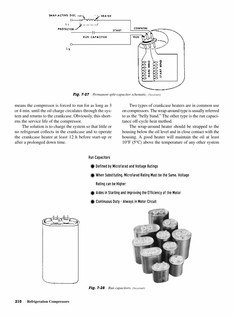
210 Refrigeration Compressors
means the compressor is forced to run for as long as 3or 4 min. until the oil charge circulates through the sys-tem and returns to the crankcase. Obviously, this short-ens the service life of the compressor.
The solution is to charge the system so that little orno refrigerant collects in the crankcase and to operatethe crankcase heater at least 12 h before start-up orafter a prolonged down time.
Two types of crankcase heaters are in common useon compressors. The wrap-around type is usually referredto as the “belly band.” The other type is the run capaci-tance off-cycle heat method.
The wrap-around heater should be strapped to thehousing below the oil level and in close contact with thehousing. A good heater will maintain the oil at least10°F (5°C) above the temperature of any other system
Fig. 7-27 Permanent split-capacitor schematic. (Tecumseh)
Fig. 7-28 Run capacitors. (Tecumseh)
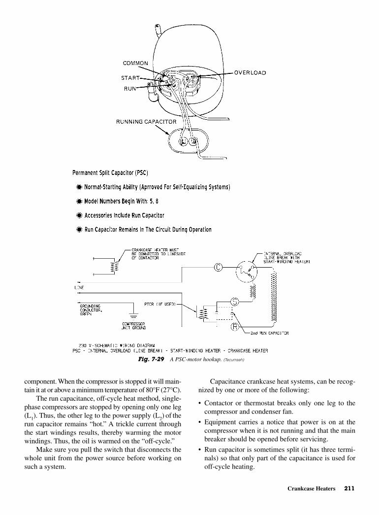
Crankcase Heaters 211
component. When the compressor is stopped it will main-tain it at or above a minimum temperature of 80°F (27°C).
The run capacitance, off-cycle heat method, single-phase compressors are stopped by opening only one leg(L1). Thus, the other leg to the power supply (L2) of therun capacitor remains “hot.” A trickle current throughthe start windings results, thereby warming the motorwindings. Thus, the oil is warmed on the “off-cycle.”
Make sure you pull the switch that disconnects thewhole unit from the power source before working onsuch a system.
Capacitance crankcase heat systems, can be recog-nized by one or more of the following:
• Contactor or thermostat breaks only one leg to thecompressor and condenser fan.
• Equipment carries a notice that power is on at thecompressor when it is not running and that the mainbreaker should be opened before servicing.
• Run capacitor is sometimes split (it has three termi-nals) so that only part of the capacitance is used foroff-cycle heating.
Fig. 7-29 A PSC-motor hookup. (Tecumseh)
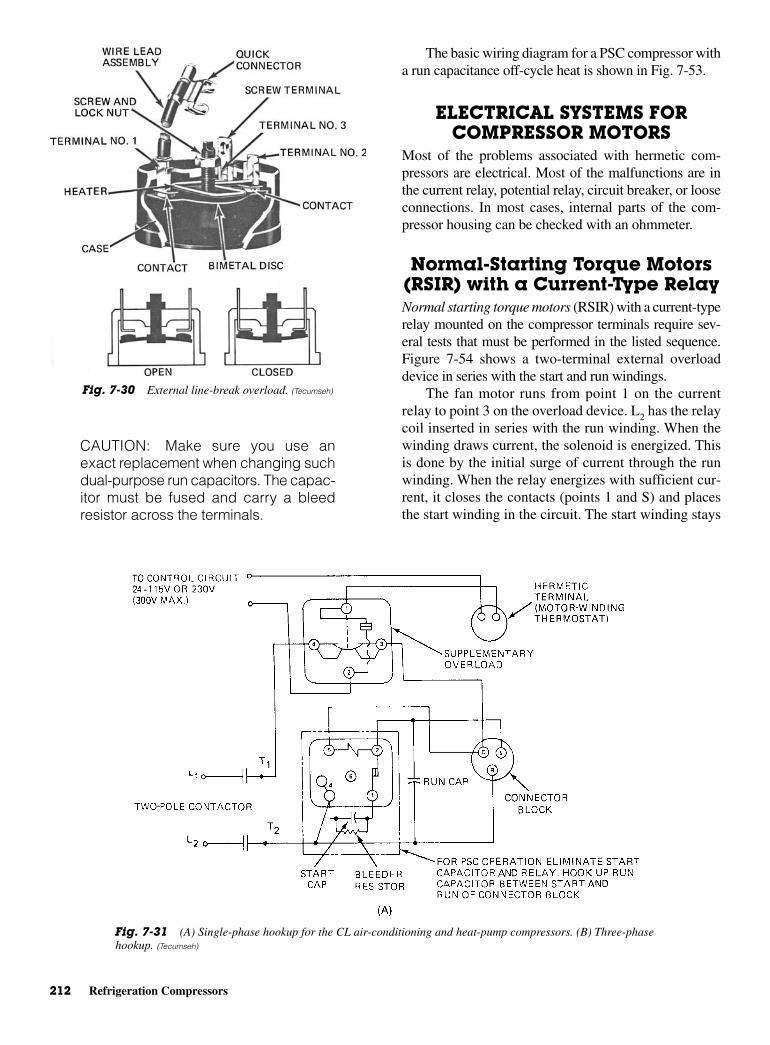
212 Refrigeration Compressors
CAUTION: Make sure you use anexact replacement when changing suchdual-purpose run capacitors. The capac-itor must be fused and carry a bleedresistor across the terminals.
The basic wiring diagram for a PSC compressor witha run capacitance off-cycle heat is shown in Fig. 7-53.
ELECTRICAL SYSTEMS FORCOMPRESSOR MOTORS
Most of the problems associated with hermetic com-pressors are electrical. Most of the malfunctions are inthe current relay, potential relay, circuit breaker, or looseconnections. In most cases, internal parts of the com-pressor housing can be checked with an ohmmeter.
Normal-Starting Torque Motors(RSIR) with a Current-Type RelayNormal starting torque motors (RSIR) with a current-typerelay mounted on the compressor terminals require sev-eral tests that must be performed in the listed sequence.Figure 7-54 shows a two-terminal external overloaddevice in series with the start and run windings.
The fan motor runs from point 1 on the currentrelay to point 3 on the overload device. L2 has the relaycoil inserted in series with the run winding. When thewinding draws current, the solenoid is energized. Thisis done by the initial surge of current through the runwinding. When the relay energizes with sufficient cur-rent, it closes the contacts (points 1 and S) and placesthe start winding in the circuit. The start winding stays
Fig. 7-30 External line-break overload. (Tecumseh)
Fig. 7-31 (A) Single-phase hookup for the CL air-conditioning and heat-pump compressors. (B) Three-phasehookup. (Tecumseh)
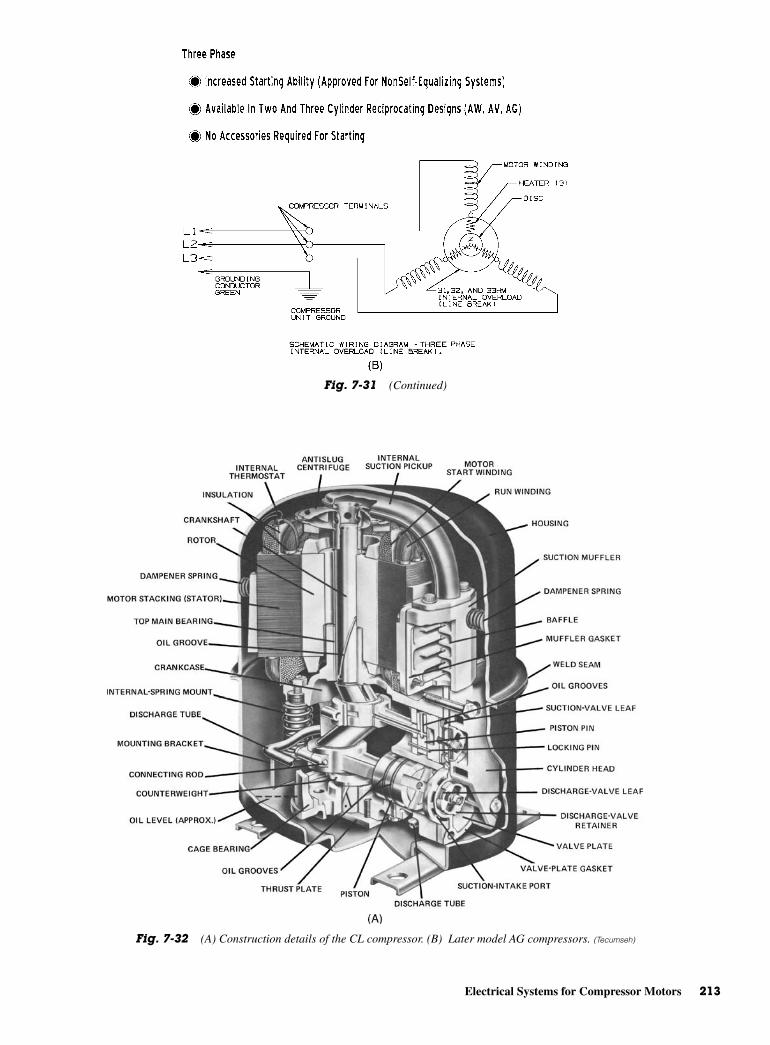
Electrical Systems for Compressor Motors 213
Fig. 7-31 (Continued)
Fig. 7-32 (A) Construction details of the CL compressor. (B) Later model AG compressors. (Tecumseh)

214 Refrigeration Compressors
in the circuit until the relay deenergizes. When themotor comes up to about 75 percent of its run speed,the relay deenergizes since the current through the run
winding drops off. This change in current makes it avery sensitive circuit. The sensing relay must be ingood operating condition. Otherwise, it will not ener-gize or deenergize at the proper times.
The start contacts on the current-type relay are nor-mally open. See Fig. 7-54. Check the electrical system onthis type of compressor system by using a voltmeter forobtaining line-voltage reading. Then, use an ohmmeter
Fig. 7-32 (Continued)
Fig. 7-33 Cutaway view of the supplementary overload. (Tecumseh)
Fig. 7-34 Location of the supplementary overload on the CL-compressor series. (Tecumseh)
Fig. 7-35 Location of two supplementary overloads in the ter-minal box makes it applicable for three-phase power connections.(Tecumseh)
Fig. 7-36 Resistance-start induction-run motor schematic.(Tecumseh)

Electrical Systems for Compressor Motors 215
to check continuity. That means the power must be off.Make sure the circuit breaker is off at the main power sup-ply for this unit. If a fan is used (as shown in the dottedlines of Fig. 7-54) make sure lead is disconnected fromthe line. Next, check continuity across the following:
1. Check continuity across L1and point 3 of the overload.There is no continuity. Close control contacts by hand.If there is still no continuity, replace the control.
2. Check continuity across No. 3 and No. 1 on theoverload. If there is no continuity, the protector maybe tripped. Wait 10 min and check again. If thereis still no continuity, the protector is defective.Replace it.
3. Pull the relay off the compressor terminals. Be sureto keep it in an upright position.
4. Check continuity across relay-terminal 1 (or L) andS. If there is continuity, relay contacts are closed,when they should be open. Replace the relay.
5. Check continuity across No. 1 and M. If there is nocontinuity, replace the relay. The solenoid is open.
6. Check continuity across compressor terminals Cand R. If there is no continuity, there is an open runwinding. Replace the compressor.
7. Check continuity across compressor terminals Cand S. If there is no continuity there is an open startwinding. Replace the compressor.
8. Check continuity across compressor terminal C andthe shell of the compressor. There is no continuity.This means the motor is grounded. Replace thecompressor.
9. Check the winding resistance values against those pub-lished by the manufacturer of the particular model.
If all the tests prove satisfactory, and there is nocapillary restriction, plus, the unit continues to fail tooperate properly, change the relay. The new relay willeliminate any electrical problems, such as improperpickup or dropout, that cannot be determined by the testslisted. If a good relay fails to correct the difficulty, thecompressor is inoperative due to internal defects. It mustbe replaced.
High-Starting Torque Motors(CSIR) with a Current-Type Relay High-starting torque motors (CSIR) with a current-type relay mounted on the compressor terminals can beeasily checked for proper operation. Remember from
Fig. 7-36 (Continued)

216 Refrigeration Compressors
Fig. 7-37 (A) Capacitor-start induction-run motor schematic. (B) Startcapacitors—PTC-start device. (Tecumseh)
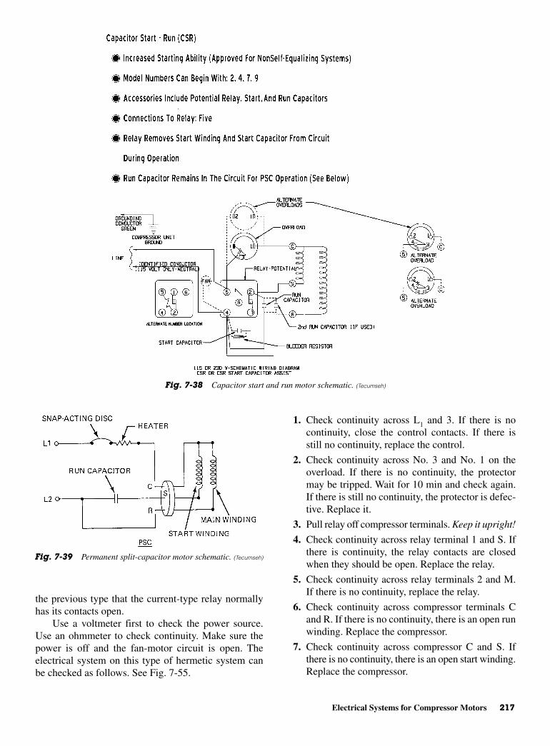
Electrical Systems for Compressor Motors 217
the previous type that the current-type relay normallyhas its contacts open.
Use a voltmeter first to check the power source.Use an ohmmeter to check continuity. Make sure thepower is off and the fan-motor circuit is open. Theelectrical system on this type of hermetic system canbe checked as follows. See Fig. 7-55.
1. Check continuity across L1 and 3. If there is nocontinuity, close the control contacts. If there isstill no continuity, replace the control.
2. Check continuity across No. 3 and No. 1 on theoverload. If there is no continuity, the protectormay be tripped. Wait for 10 min and check again.If there is still no continuity, the protector is defec-tive. Replace it.
3. Pull relay off compressor terminals. Keep it upright!
4. Check continuity across relay terminal 1 and S. Ifthere is continuity, the relay contacts are closedwhen they should be open. Replace the relay.
5. Check continuity across relay terminals 2 and M.If there is no continuity, replace the relay.
6. Check continuity across compressor terminals Cand R. If there is no continuity, there is an open runwinding. Replace the compressor.
7. Check continuity across compressor C and S. Ifthere is no continuity, there is an open start winding.Replace the compressor.
Fig. 7-38 Capacitor start and run motor schematic. (Tecumseh)
Fig. 7-39 Permanent split-capacitor motor schematic. (Tecumseh)
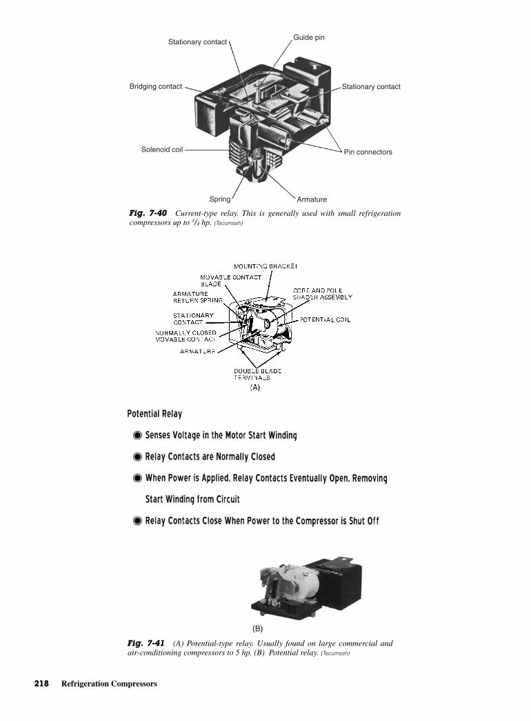
218 Refrigeration Compressors
Stationary contactGuide pin
Stationary contact
Pin connectors
ArmatureSpring
Solenoid coil
Bridging contact
Fig. 7-40 Current-type relay. This is generally used with small refrigerationcompressors up to 3/4 hp. (Tecumseh)
Fig. 7-41 (A) Potential-type relay. Usually found on large commercial andair-conditioning compressors to 5 hp. (B) Potential relay. (Tecumseh)
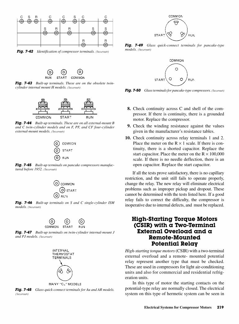
Electrical Systems for Compressor Motors 219
8. Check continuity across C and shell of the com-pressor. If there is continuity, there is a groundedmotor. Replace the compressor.
9. Check the winding resistance against the valuesgiven in the manufacturer’s resistance tables.
10. Check continuity across relay terminals 1 and 2.Place the meter on the R × 1 scale. If there is con-tinuity, there is a shorted capacitor. Replace thestart capacitor. Place the meter on the R × 100,000scale. If there is no needle deflection, there is anopen capacitor. Replace the start capacitor.
If all the tests prove satisfactory, there is no capillaryrestriction, and the unit still fails to operate properly,change the relay. The new relay will eliminate electricalproblems such as improper pickup and dropout. Thesecannot be determined with the tests listed here. If a goodrelay fails to correct the difficulty, the compressor isinoperative due to internal defects, and must be replaced.
High-Starting Torque Motors(CSIR) with a Two-TerminalExternal Overload and a
Remote-MountedPotential Relay
High-starting torque motors (CSIR) with a two-terminalexternal overload and a remote- mounted potentialrelay represent another type that must be checked.These are used in compressors for light air-conditioningunits and also for commercial and residential refrig-eration units.
In this type of motor the starting contacts on thepotential-type relay are normally closed. The electricalsystem on this type of hermetic system can be seen in
C C C CS CS
SSR
R R
S R
R
Fig. 7-42 Identification of compressor terminals. (Tecumseh)
Fig. 7-43 Built-up terminals. These are on the obsolete twin-cylinder internal mount H models. (Tecumseh)
Fig. 7-44 Built-up terminals. These are on all external-mount Band C twin-cylinder models and on F, PF, and CF four-cylinderexternal-mount models. (Tecumseh)
Fig. 7-45 Built-up terminals on pancake compressors manufac-tured before 1952. (Tecumseh)
Fig. 7-46 Built-up terminals on S and C single-cylinder ISMmodels. (Tecumseh)
Fig. 7-47 Built-up terminals on twin-cylinder internal-mount Jand PJ models. (Tecumseh)
Fig. 7-48 Glass quick-connect terminals for Au and AR models.(Tecumseh)
Fig. 7-49 Glass quick-connect terminals for pancake-typemodels. (Tecumseh)
Fig. 7-50 Glass terminals for pancake-type compressors. (Tecumseh)
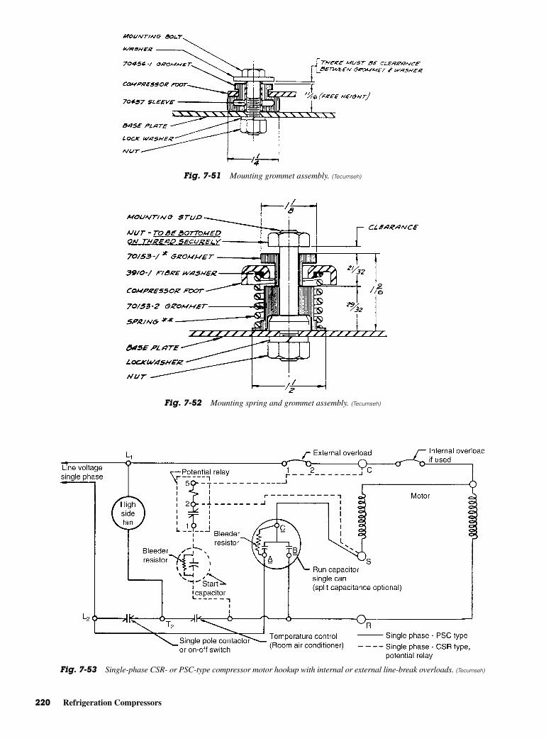
220 Refrigeration Compressors
Fig. 7-51 Mounting grommet assembly. (Tecumseh)
Fig. 7-52 Mounting spring and grommet assembly. (Tecumseh)
Fig. 7-53 Single-phase CSR- or PSC-type compressor motor hookup with internal or external line-break overloads. (Tecumseh)
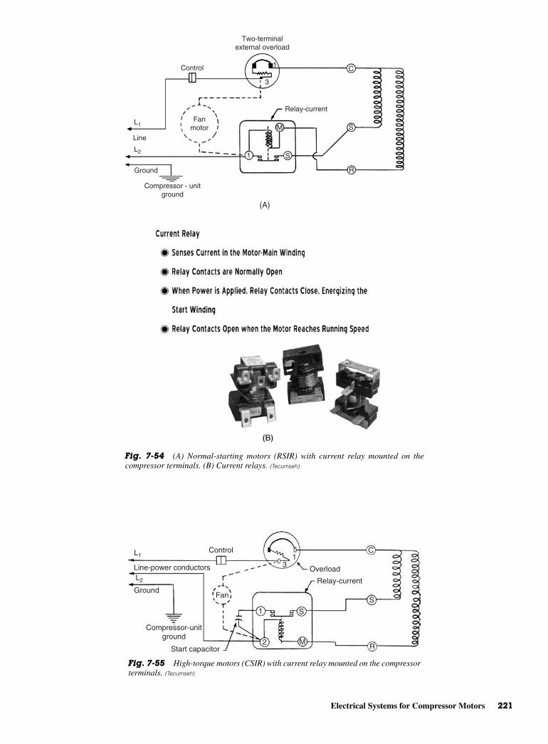
Electrical Systems for Compressor Motors 221
Control
Two-terminalexternal overload
1
3
C
S
R
S
M
1
Compressor - unitground
Ground
L2
L1
Line
Fanmotor
Relay-current
(A)
Fig. 7-54 (A) Normal-starting motors (RSIR) with current relay mounted on thecompressor terminals. (B) Current relays. (Tecumseh)
ControlL1
L2
Line-power conductors
Ground
Compressor-unitground
Start capacitor
Fan
31
1
2 M
S
S
C
R
Relay-current
Overload
Fig. 7-55 High-torque motors (CSIR) with current relay mounted on the compressorterminals. (Tecumseh)
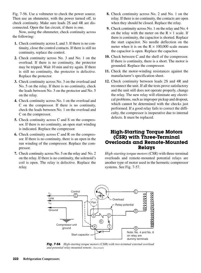
222 Refrigeration Compressors
Fig. 7-56. Use a voltmeter to check the power source.Then use an ohmmeter, with the power turned off, tocheck continuity. Make sure leads 2S and 4R are dis-connected. Open the fan circuit, if there is one.
Now, using the ohmmeter, check continuity acrossthe following:
1. Check continuity across L and 3. If there is no con-tinuity, close the control contacts. If there is still nocontinuity, replace the control.
2. Check continuity across No. 3 and No. 1 on theoverload. If there is no continuity, the protectormay be tripped. Wait 10 min and try again. If thereis still no continuity, the protector is defective.Replace the protector.
3. Check continuity across No. 3 on the overload andNo. 5 on the relay. If there is no continuity, checkthe leads between No. 3 on the protector and No. 5on the relay.
4. Check continuity across No. 1 on the overload andC on the compressor. If there is no continuity,check the leads between No. 1 on the overload andC on the compressor.
5. Check continuity across C and S on the compres-sor. If there is no continuity, an open start windingis indicated. Replace the compressor.
6. Check continuity across C and R on the compres-sor. If there is no continuity, there is an open in therun winding of the compressor. Replace the com-pressor.
7. Check continuity across No. 5 on the relay and No. 2on the relay. If there is no continuity, the solenoid’scoil is open. The relay is defective. Replace therelay.
8. Check continuity across No. 2 and No. 1 on therelay. If there is no continuity, the contacts are openwhen they should be closed. Replace the relay.
9. Check continuity across No. 1 on the relay and No. 4on the relay with the meter on the R × 1 scale. Ifthere is continuity, the capacitor is shorted. Replacethe start capacitor. No needle deflection on themeter when it is on the R × 100,000 scale meansthe capacitor is open. Replace the capacitor.
10. Check between C and the shell of the compressor.If there is continuity, there is a short. The motor isgrounded. Replace the compressor.
11. Check the motor-winding resistances against themanufacturer’s specification sheet.
12. Check continuity between leads 2S and 4R andreconnect the unit. If all the tests prove satisfactoryand the unit still does not operate properly, changethe relay. The new relay will eliminate any electri-cal problems, such as improper pickup and dropout,which cannot be determined with the checks justperformed. If a good relay fails to correct the diffi-culty, the compressor is inoperative due to internaldefects. It must be replaced.
High-Starting Torque Motors(CSR) with Three-Terminal
Overloads and Remote-MountedRelays
High-starting torque motors (CSR) with three-terminaloverloads and remote-mounted potential relays areanother type of motor used in the hermetic compressorsystems. See Fig. 7-57.
L1
L2
Line
Ground
Control
Fan
Compressor-unitground
Start capacitor
5
4
6
1
2
Relay-potential
Overload
C
S
RNote: No. 4 and No. 6on relay aredummy terminals
13
Fig. 7-56 High-starting torque motors (CSIR) with two-terminal external overloadand potential relay mounted remote. (Tecumseh)
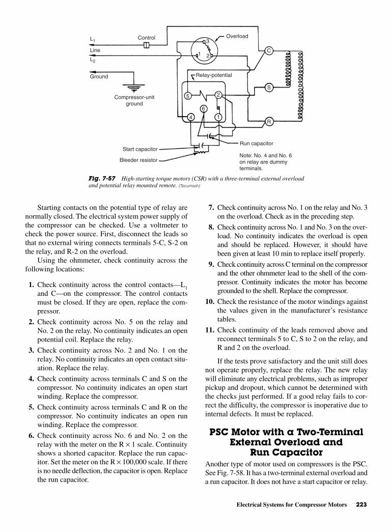
Electrical Systems for Compressor Motors 223
Starting contacts on the potential type of relay arenormally closed. The electrical system power supply ofthe compressor can be checked. Use a voltmeter tocheck the power source. First, disconnect the leads sothat no external wiring connects terminals 5-C, S-2 onthe relay, and R-2 on the overload.
Using the ohmmeter, check continuity across thefollowing locations:
1. Check continuity across the control contacts—L1and C—on the compressor. The control contactsmust be closed. If they are open, replace the com-pressor.
2. Check continuity across No. 5 on the relay andNo. 2 on the relay. No continuity indicates an openpotential coil. Replace the relay.
3. Check continuity across No. 2 and No. 1 on therelay. No continuity indicates an open contact situ-ation. Replace the relay.
4. Check continuity across terminals C and S on thecompressor. No continuity indicates an open startwinding. Replace the compressor.
5. Check continuity across terminals C and R on thecompressor. No continuity indicates an open runwinding. Replace the compressor.
6. Check continuity across No. 6 and No. 2 on therelay with the meter on the R × 1 scale. Continuityshows a shorted capacitor. Replace the run capac-itor. Set the meter on the R × 100,000 scale. If thereis no needle deflection, the capacitor is open. Replacethe run capacitor.
7. Check continuity across No. 1 on the relay and No. 3on the overload. Check as in the preceding step.
8. Check continuity across No. 1 and No. 3 on the over-load. No continuity indicates the overload is openand should be replaced. However, it should havebeen given at least 10 min to replace itself properly.
9. Check continuity across C terminal on the compressorand the other ohmmeter lead to the shell of the com-pressor. Continuity indicates the motor has becomegrounded to the shell. Replace the compressor.
10. Check the resistance of the motor windings againstthe values given in the manufacturer’s resistancetables.
11. Check continuity of the leads removed above andreconnect terminals 5 to C, S to 2 on the relay, andR and 2 on the overload.
If the tests prove satisfactory and the unit still doesnot operate properly, replace the relay. The new relaywill eliminate any electrical problems, such as improperpickup and dropout, which cannot be determined withthe checks just performed. If a good relay fails to cor-rect the difficulty, the compressor is inoperative due tointernal defects. It must be replaced.
PSC Motor with a Two-TerminalExternal Overload and
Run Capacitor Another type of motor used on compressors is the PSC.See Fig. 7-58. It has a two-terminal external overload anda run capacitor. It does not have a start capacitor or relay.
OverloadControlL1
L2
Line
Ground
Compressor-unitground
Start capacitor
Bleeder resistor
5
4
6
2
1
Run capacitor
Note: No. 4 and No. 6on relay are dummyterminals.
Relay-potential
1 2
3
C
S
R
Fig. 7-57 High-starting torque motors (CSR) with a three-terminal external overloadand potential relay mounted remote. (Tecumseh)
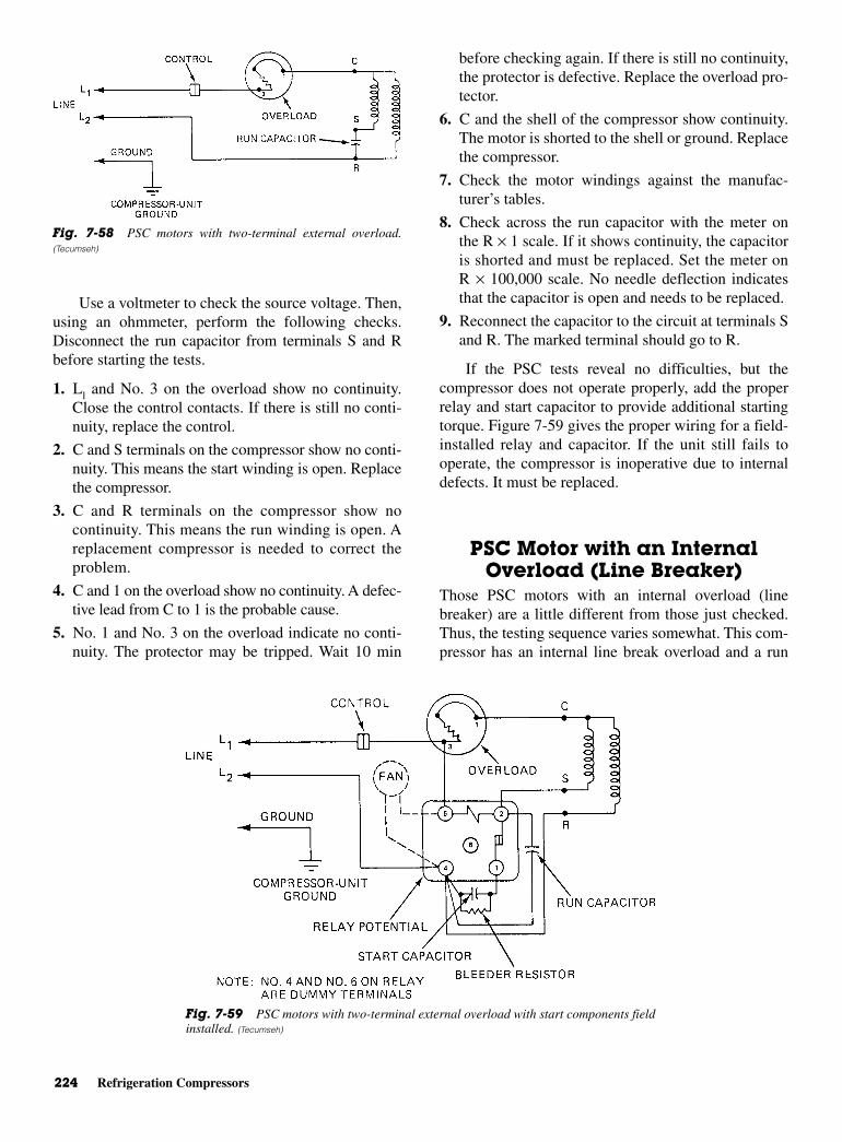
224 Refrigeration Compressors
Use a voltmeter to check the source voltage. Then,using an ohmmeter, perform the following checks.Disconnect the run capacitor from terminals S and Rbefore starting the tests.
1. Ll and No. 3 on the overload show no continuity.Close the control contacts. If there is still no conti-nuity, replace the control.
2. C and S terminals on the compressor show no conti-nuity. This means the start winding is open. Replacethe compressor.
3. C and R terminals on the compressor show nocontinuity. This means the run winding is open. Areplacement compressor is needed to correct theproblem.
4. C and 1 on the overload show no continuity. A defec-tive lead from C to 1 is the probable cause.
5. No. 1 and No. 3 on the overload indicate no conti-nuity. The protector may be tripped. Wait 10 min
before checking again. If there is still no continuity,the protector is defective. Replace the overload pro-tector.
6. C and the shell of the compressor show continuity.The motor is shorted to the shell or ground. Replacethe compressor.
7. Check the motor windings against the manufac-turer’s tables.
8. Check across the run capacitor with the meter onthe R × 1 scale. If it shows continuity, the capacitoris shorted and must be replaced. Set the meter onR × 100,000 scale. No needle deflection indicatesthat the capacitor is open and needs to be replaced.
9. Reconnect the capacitor to the circuit at terminals Sand R. The marked terminal should go to R.
If the PSC tests reveal no difficulties, but thecompressor does not operate properly, add the properrelay and start capacitor to provide additional startingtorque. Figure 7-59 gives the proper wiring for a field-installed relay and capacitor. If the unit still fails tooperate, the compressor is inoperative due to internaldefects. It must be replaced.
PSC Motor with an InternalOverload (Line Breaker)
Those PSC motors with an internal overload (linebreaker) are a little different from those just checked.Thus, the testing sequence varies somewhat. This com-pressor has an internal line break overload and a run
Fig. 7-58 PSC motors with two-terminal external overload.(Tecumseh)
Fig. 7-59 PSC motors with two-terminal external overload with start components fieldinstalled. (Tecumseh)
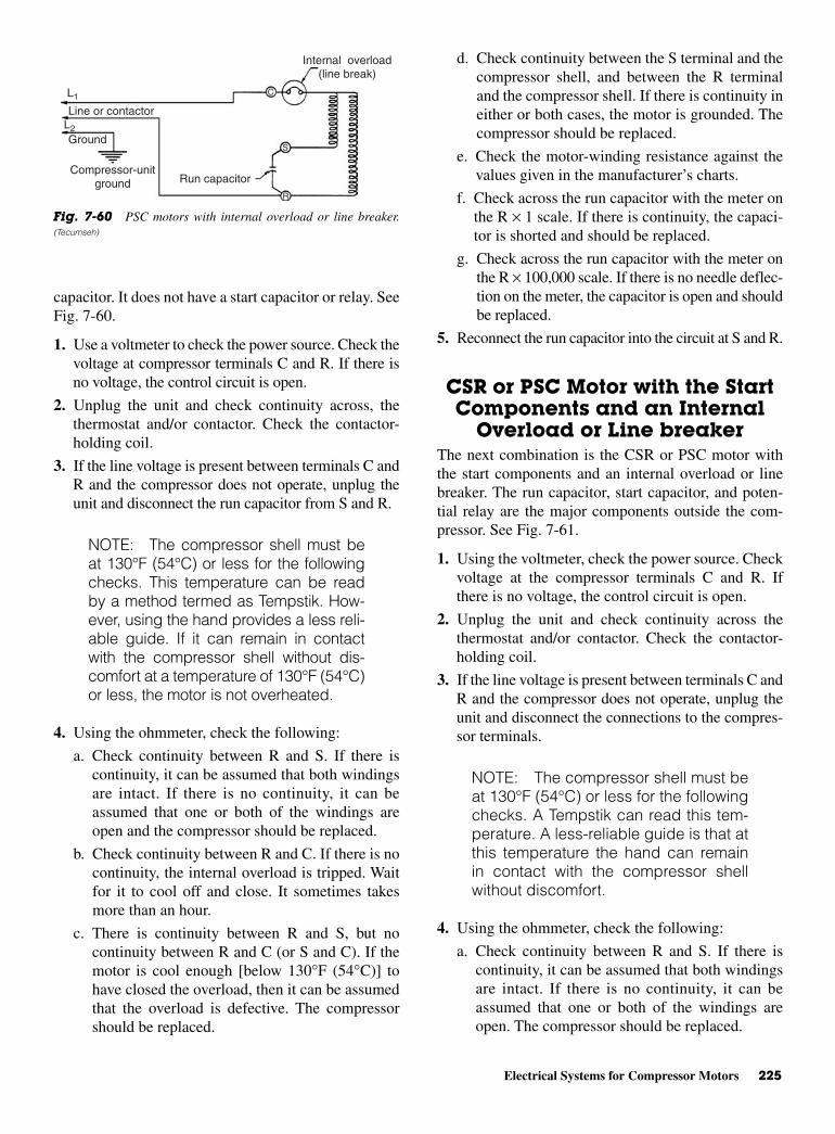
Electrical Systems for Compressor Motors 225
capacitor. It does not have a start capacitor or relay. SeeFig. 7-60.
1. Use a voltmeter to check the power source. Check thevoltage at compressor terminals C and R. If there isno voltage, the control circuit is open.
2. Unplug the unit and check continuity across, thethermostat and/or contactor. Check the contactor-holding coil.
3. If the line voltage is present between terminals C andR and the compressor does not operate, unplug theunit and disconnect the run capacitor from S and R.
NOTE: The compressor shell must beat 130°F (54°C) or less for the followingchecks. This temperature can be readby a method termed as Tempstik. How-ever, using the hand provides a less reli-able guide. If it can remain in contactwith the compressor shell without dis-comfort at a temperature of 130°F (54°C)or less, the motor is not overheated.
4. Using the ohmmeter, check the following:
a. Check continuity between R and S. If there iscontinuity, it can be assumed that both windingsare intact. If there is no continuity, it can beassumed that one or both of the windings areopen and the compressor should be replaced.
b. Check continuity between R and C. If there is nocontinuity, the internal overload is tripped. Waitfor it to cool off and close. It sometimes takesmore than an hour.
c. There is continuity between R and S, but nocontinuity between R and C (or S and C). If themotor is cool enough [below 130°F (54°C)] tohave closed the overload, then it can be assumedthat the overload is defective. The compressorshould be replaced.
d. Check continuity between the S terminal and thecompressor shell, and between the R terminaland the compressor shell. If there is continuity ineither or both cases, the motor is grounded. Thecompressor should be replaced.
e. Check the motor-winding resistance against thevalues given in the manufacturer’s charts.
f. Check across the run capacitor with the meter onthe R × 1 scale. If there is continuity, the capaci-tor is shorted and should be replaced.
g. Check across the run capacitor with the meter onthe R × 100,000 scale. If there is no needle deflec-tion on the meter, the capacitor is open and shouldbe replaced.
5. Reconnect the run capacitor into the circuit at S and R.
CSR or PSC Motor with the StartComponents and an Internal
Overload or Line breakerThe next combination is the CSR or PSC motor withthe start components and an internal overload or linebreaker. The run capacitor, start capacitor, and poten-tial relay are the major components outside the com-pressor. See Fig. 7-61.
1. Using the voltmeter, check the power source. Checkvoltage at the compressor terminals C and R. Ifthere is no voltage, the control circuit is open.
2. Unplug the unit and check continuity across thethermostat and/or contactor. Check the contactor-holding coil.
3. If the line voltage is present between terminals C andR and the compressor does not operate, unplug theunit and disconnect the connections to the compres-sor terminals.
NOTE: The compressor shell must beat 130°F (54°C) or less for the followingchecks. A Tempstik can read this tem-perature. A less-reliable guide is that atthis temperature the hand can remainin contact with the compressor shellwithout discomfort.
4. Using the ohmmeter, check the following:
a. Check continuity between R and S. If there iscontinuity, it can be assumed that both windingsare intact. If there is no continuity, it can beassumed that one or both of the windings areopen. The compressor should be replaced.
Internal overload(line break)
C
S
R
L1
L2
Line or contactor
Ground
Compressor-unitground Run capacitor
Fig. 7-60 PSC motors with internal overload or line breaker.(Tecumseh)
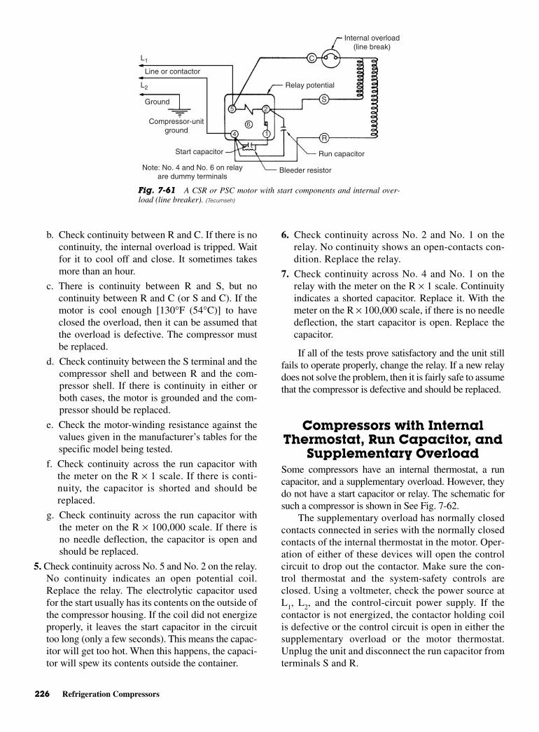
226 Refrigeration Compressors
b. Check continuity between R and C. If there is nocontinuity, the internal overload is tripped. Waitfor it to cool off and close. It sometimes takesmore than an hour.
c. There is continuity between R and S, but nocontinuity between R and C (or S and C). If themotor is cool enough [130°F (54°C)] to haveclosed the overload, then it can be assumed thatthe overload is defective. The compressor mustbe replaced.
d. Check continuity between the S terminal and thecompressor shell and between R and the com-pressor shell. If there is continuity in either orboth cases, the motor is grounded and the com-pressor should be replaced.
e. Check the motor-winding resistance against thevalues given in the manufacturer’s tables for thespecific model being tested.
f. Check continuity across the run capacitor withthe meter on the R × 1 scale. If there is conti-nuity, the capacitor is shorted and should bereplaced.
g. Check continuity across the run capacitor withthe meter on the R × 100,000 scale. If there isno needle deflection, the capacitor is open andshould be replaced.
5. Check continuity across No. 5 and No. 2 on the relay.No continuity indicates an open potential coil.Replace the relay. The electrolytic capacitor usedfor the start usually has its contents on the outside ofthe compressor housing. If the coil did not energizeproperly, it leaves the start capacitor in the circuittoo long (only a few seconds). This means the capac-itor will get too hot. When this happens, the capaci-tor will spew its contents outside the container.
6. Check continuity across No. 2 and No. 1 on therelay. No continuity shows an open-contacts con-dition. Replace the relay.
7. Check continuity across No. 4 and No. 1 on therelay with the meter on the R × 1 scale. Continuityindicates a shorted capacitor. Replace it. With themeter on the R × 100,000 scale, if there is no needledeflection, the start capacitor is open. Replace thecapacitor.
If all of the tests prove satisfactory and the unit stillfails to operate properly, change the relay. If a new relaydoes not solve the problem, then it is fairly safe to assumethat the compressor is defective and should be replaced.
Compressors with InternalThermostat, Run Capacitor, and
Supplementary OverloadSome compressors have an internal thermostat, a runcapacitor, and a supplementary overload. However, theydo not have a start capacitor or relay. The schematic forsuch a compressor is shown in See Fig. 7-62.
The supplementary overload has normally closedcontacts connected in series with the normally closedcontacts of the internal thermostat in the motor. Oper-ation of either of these devices will open the controlcircuit to drop out the contactor. Make sure the con-trol thermostat and the system-safety controls areclosed. Using a voltmeter, check the power source atL1, L2, and the control-circuit power supply. If thecontactor is not energized, the contactor holding coilis defective or the control circuit is open in either thesupplementary overload or the motor thermostat.Unplug the unit and disconnect the run capacitor fromterminals S and R.
L1
L2
Line or contactor
Ground
Compressor-unitground
Start capacitor
Bleeder resistor
Run capacitor
Note: No. 4 and No. 6 on relayare dummy terminals
5
4
6
2
1
S
R
C
Internal overload(line break)
Relay potential
Fig. 7-61 A CSR or PSC motor with start components and internal over-load (line breaker). (Tecumseh)
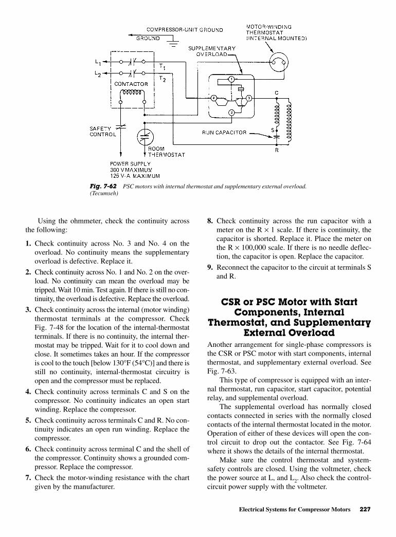
Electrical Systems for Compressor Motors 227
Using the ohmmeter, check the continuity acrossthe following:
1. Check continuity across No. 3 and No. 4 on theoverload. No continuity means the supplementaryoverload is defective. Replace it.
2. Check continuity across No. 1 and No. 2 on the over-load. No continuity can mean the overload may betripped. Wait 10 min. Test again. If there is still no con-tinuity, the overload is defective. Replace the overload.
3. Check continuity across the internal (motor winding)thermostat terminals at the compressor. CheckFig. 7-48 for the location of the internal-thermostatterminals. If there is no continuity, the internal ther-mostat may be tripped. Wait for it to cool down andclose. It sometimes takes an hour. If the compressoris cool to the touch [below 130°F (54°C)] and there isstill no continuity, internal-thermostat circuitry isopen and the compressor must be replaced.
4. Check continuity across terminals C and S on thecompressor. No continuity indicates an open startwinding. Replace the compressor.
5. Check continuity across terminals C and R. No con-tinuity indicates an open run winding. Replace thecompressor.
6. Check continuity across terminal C and the shell ofthe compressor. Continuity shows a grounded com-pressor. Replace the compressor.
7. Check the motor-winding resistance with the chartgiven by the manufacturer.
8. Check continuity across the run capacitor with ameter on the R × 1 scale. If there is continuity, thecapacitor is shorted. Replace it. Place the meter onthe R × 100,000 scale. If there is no needle deflec-tion, the capacitor is open. Replace the capacitor.
9. Reconnect the capacitor to the circuit at terminals Sand R.
CSR or PSC Motor with StartComponents, Internal
Thermostat, and SupplementaryExternal Overload
Another arrangement for single-phase compressors isthe CSR or PSC motor with start components, internalthermostat, and supplementary external overload. SeeFig. 7-63.
This type of compressor is equipped with an inter-nal thermostat, run capacitor, start capacitor, potentialrelay, and supplemental overload.
The supplemental overload has normally closedcontacts connected in series with the normally closedcontacts of the internal thermostat located in the motor.Operation of either of these devices will open the con-trol circuit to drop out the contactor. See Fig. 7-64where it shows the details of the internal thermostat.
Make sure the control thermostat and system-safety controls are closed. Using the voltmeter, checkthe power source at L, and L2. Also check the control-circuit power supply with the voltmeter.
Fig. 7-62 PSC motors with internal thermostat and supplementary external overload.(Tecumseh)
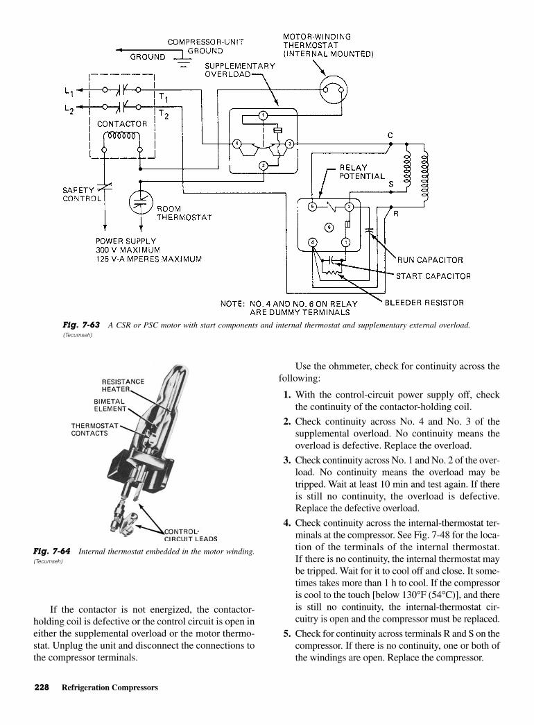
228 Refrigeration Compressors
If the contactor is not energized, the contactor-holding coil is defective or the control circuit is open ineither the supplemental overload or the motor thermo-stat. Unplug the unit and disconnect the connections tothe compressor terminals.
Use the ohmmeter, check for continuity across thefollowing:
1. With the control-circuit power supply off, checkthe continuity of the contactor-holding coil.
2. Check continuity across No. 4 and No. 3 of thesupplemental overload. No continuity means theoverload is defective. Replace the overload.
3. Check continuity across No. 1 and No. 2 of the over-load. No continuity means the overload may betripped. Wait at least 10 min and test again. If thereis still no continuity, the overload is defective.Replace the defective overload.
4. Check continuity across the internal-thermostat ter-minals at the compressor. See Fig. 7-48 for the loca-tion of the terminals of the internal thermostat.If there is no continuity, the internal thermostat maybe tripped. Wait for it to cool off and close. It some-times takes more than 1 h to cool. If the compressoris cool to the touch [below 130°F (54°C)], and thereis still no continuity, the internal-thermostat cir-cuitry is open and the compressor must be replaced.
5. Check for continuity across terminals R and S on thecompressor. If there is no continuity, one or both ofthe windings are open. Replace the compressor.
Fig. 7-63 A CSR or PSC motor with start components and internal thermostat and supplementary external overload.(Tecumseh)
Fig. 7-64 Internal thermostat embedded in the motor winding.(Tecumseh)

Electrical Systems for Compressor Motors 229
6. Check for continuity across terminal S and thecompressor shell. Check for continuity across ter-minal R and the compressor shell. If there is conti-nuity in either or both cases, the motor is groundedand the compressor should be replaced.
7. Check the motor-winding resistances with thechart furnished by the compressor manufacturer.
8. Check for continuity across terminals 5 and 2 onthe relay. No continuity indicates an open potentialcoil. Replace the relay.
9. Check for continuity across terminals 2 and 1 onthe relay. No continuity indicates open contacts.Replace the relay.
10. Check for continuity across terminals 4 and 1 on therelay with the meter on the R × 1 scale. If continu-ity is read, it indicates a shorted capacitor. Replacethe capacitor. Repeat with the meter on the R ×100,000 scale. No needle deflection indicates thestart capacitor is open. Replace the start capacitor.
11. Discharge the run capacitor by placing a screw-driver across the terminals. Remove the leads from
the run capacitor. With the meter set on the R × 1scale, continuity across the capacitor terminals in-dicates a shorted capacitor. Replace the capacitor.Repeat the same test with the meter set on the R ×100,000 scale. No needle deflection indicates anopen capacitor. Replace the run capacitor. If all thetests prove satisfactory and the unit still fails tooperate properly, change the relay. The new relaywill eliminate electrical problems such as improperpickup or dropout, which cannot be determined bythe given tests. If a good relay fails to correct thedifficulty, the compressor is inoperative due tointernal defects. It must be replaced.
One other arrangement for a compressor usingsingle-phase current is a CSR or PSC motor with startcomponents, internal thermostat, supplemental externaloverload, and start-winding overload. See Fig. 7-65.
The diagnosis is identical to that described for the pre-vious type of motor circuit. However, there is an additionalstart-winding overload in the control circuit in series withthe internal thermostat and supplemental overload.
Fig. 7-65 A CSR or PSC motor with start components and internal thermostat plus supplemental external overload andstart-winding overload. Note No. 4 and No. 6 on the relay are dummy terminals. (Tecumseh)

230 Refrigeration Compressors
Check the start-winding overload in the same waythe supplemental overload is checked.
COMPRESSOR CONNECTIONSAND TUBES
Tecumseh, like other compressor manufacturers, madecompressors for many manufacturers of refrigerators,air-conditioning systems, and coolers. Because of this,the same compressor model may be found in the fieldin many suction and discharge variations. Each varia-tion depends upon the specific application for whichthe compressor was designed.
Suction connections can usually be identified asthe stub tube with the largest diameter in the housing.If two stubs have the same outside diameter, then theone with the heavier wall will be the suction connec-tion. If both of the largest stub tubes have the same out-side diameter and wall thickness, then either can beused as the suction connection. However, the one far-thest from the terminals is preferred.
The stub tube not chosen for the suction connectionmay be used for processing the system. Compressorconnections can usually be easily identified. However,occasionally some question arises concerning oil-coolertubes and process tubes.
Oil-cooler tubes are found only in low-temperaturerefrigeration models. These tubes connect to a coil orhairpin bend within the compressor oil sump. SeeFig. 7-66. This coil or hairpin bend is not open insidethe compressor. Its only function is to cool the com-pressor sump oil. The oil-cooler tubes are generallyconnected to an individually separated tubing circuitin the air-cooled condenser.
Process TubesProcess tubes are installed in compressor housings atthe factory as an aid in factory dehydration and charg-ing. These can be used in place of the suction tube ifthey are of the same diameter and wall thickness as thesuction tube.
Standard discharge tubing arrangements for Tecumsehhermetic compressors are shown in Fig. 7-67. Dischargetubes are generally in the same position within any modelfamily. Suction and process tube positions may vary.
Other Manufacturersof Compressors
Besides Tecumseh, there are other manufacturers ofcompressors for the air-conditioning and refrigerationtrade. One is Americold Compressor Corporation. Twoof the models made by Americold are the M series andthe A series. See Fig. 7-68. Both use the same overloadrelay and current relay connections. See Fig. 7-69. Allof these models use R-12, or suitable substitute, as therefrigerant. They are made in sizes ranging from 1/10
(0.10) through 1/4 hp. They weigh 21 to 25 lb. Figure 7-70shows the location of the suction and discharge stubs aswell as the process tube.
ROTARY COMPRESSORSThe rotary compressor is made in two differentconfigurations—the stationary blade rotary compres-sor and the rotating blade rotary compressor. The sta-tionary blade rotary compressor is the type that has justbeen described. Both of these compressors have prob-lems regarding lubrication. This problem has beenpartly solved.
Stationary Blade RotaryCompressors
The only moving parts in a stationary blade rotarycompressor are a steel ring, an eccentric or cam, and asliding barrier. See Fig. 7-71. Figure 7-72 shows howthe rotation of the off-center cam compresses the gasrefrigerant in the cylinder of the rotary compressor.The cam is rotated by an electric motor. As the camspins it carries the ring with it. The ring rolls on itsouter rim around the wall of the cylinder.
To be brought into the chamber, the gas must havea pathway. Note that in Fig. 7-73 the vapor comes infrom the freezer and goes out to the condenser throughholes that have been drilled in the compressor frame.Note that an offset rotating ring compresses the gas.Figure 7-74 shows how the refrigerant vapor in the
Fig. 7-66 Location of the oil-cooling tubes inside the compres-sor shell. (Tecumseh)
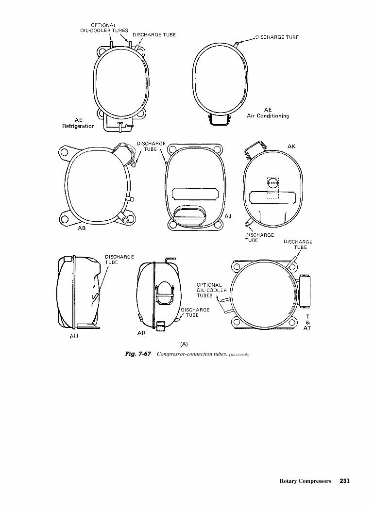
Rotary Compressors 231
Fig. 7-67 Compressor-connection tubes. (Tecumseh)

232 Refrigeration Compressors
Fig. 7-67 (Continued)

Screw Compressors 233
compressor is brought from the freezer. Then, the exitport is opening. When the compressor starts to draw inthe vapor from the freezer the barrier is held against thering by a spring.
This barrier separates the intake and exhaust ports.As the ring rolls around the cylinder it compresses thegas and passes it on to the condenser. See Fig. 7-75.The finish of the compression portion of the stroke oroperation is shown in Fig. 7-76. The ring rotatesaround the cylinder wall. The spring tension of the bar-rier’s spring and the pressure of the cam being drivenby the electric motor hold it in place. This type of com-pressor is not used as much as the reciprocating her-metic type of compressor.
Rotating Blade RotaryCompressors
The rotating blade rotary compressor has its roller cen-tered on a shaft that is eccentric to the center of thecylinder. Two spring-loaded roller blades are mounted180° apart. They sweep the sides of the cylinder. Theroller is mounted so that it touches the cylinder at apoint between the intake and the discharge ports. Theroller rotates. In rotating, it pulls the vapor into the
cylinder through the intake port. Here, the vapor istrapped in the space between the cylinder wall, theblade, and the point of contact between the roller andthe cylinder. As the next blade passes the contact point,the vapor is compressed. The space or the vapor becomessmaller and smaller as the blade rotates.
Once the vapor has reached the pressure deter-mined by the compressor manufacturer, it exits throughthe discharge port to the condenser.
On this type of rotating blade rotary compressorthe seals on the blades present a particular problem.There also are lubrication problems. However, a num-ber of rotary compressors are still in operation in homerefrigerators.
Some manufacturers make rotary blade compressorsfor commercial applications. They are used primarilywith ammonia. Thus, there is no copper or copper-alloytubing or parts. Most of the ammonia tubing and workingmetal is stainless steel.
SCREW COMPRESSORSScrew compressors operate more or less like pumps, andhave continuous flow refrigerant compared to recipro-cals. Reciprocal have pulsations. This results in smooth
Fig. 7-67 (Continued)
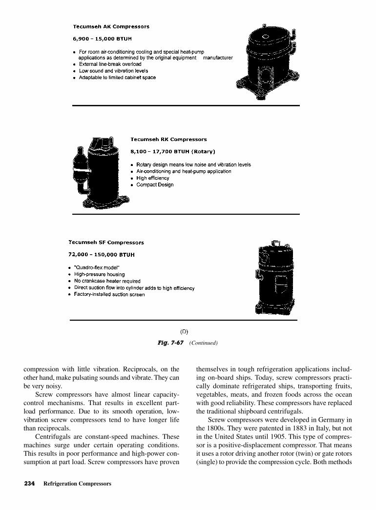
234 Refrigeration Compressors
compression with little vibration. Reciprocals, on theother hand, make pulsating sounds and vibrate. They canbe very noisy.
Screw compressors have almost linear capacity-control mechanisms. That results in excellent part-load performance. Due to its smooth operation, low-vibration screw compressors tend to have longer lifethan reciprocals.
Centrifugals are constant-speed machines. Thesemachines surge under certain operating conditions.This results in poor performance and high-power con-sumption at part load. Screw compressors have proven
themselves in tough refrigeration applications includ-ing on-board ships. Today, screw compressors practi-cally dominate refrigerated ships, transporting fruits,vegetables, meats, and frozen foods across the oceanwith good reliability. These compressors have replacedthe traditional shipboard centrifugals.
Screw compressors were developed in Germany inthe 1800s. They were patented in 1883 in Italy, but notin the United States until 1905. This type of compres-sor is a positive-displacement compressor. That meansit uses a rotor driving another rotor (twin) or gate rotors(single) to provide the compression cycle. Both methods
Fig. 7-67 (Continued)
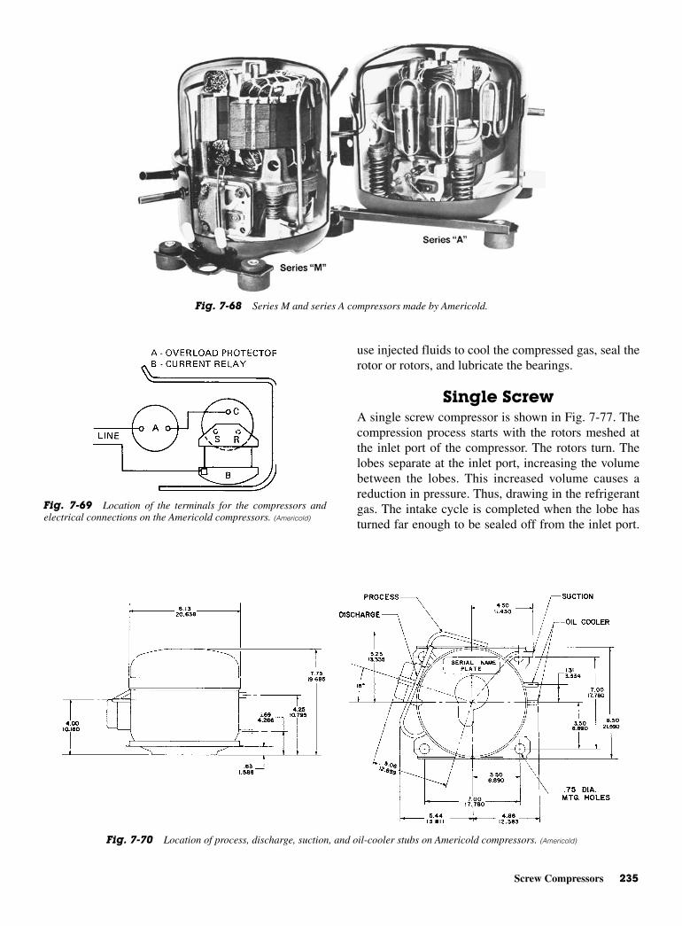
Screw Compressors 235
use injected fluids to cool the compressed gas, seal therotor or rotors, and lubricate the bearings.
Single ScrewA single screw compressor is shown in Fig. 7-77. Thecompression process starts with the rotors meshed atthe inlet port of the compressor. The rotors turn. Thelobes separate at the inlet port, increasing the volumebetween the lobes. This increased volume causes areduction in pressure. Thus, drawing in the refrigerantgas. The intake cycle is completed when the lobe hasturned far enough to be sealed off from the inlet port.
Fig. 7-68 Series M and series A compressors made by Americold.
Fig. 7-69 Location of the terminals for the compressors andelectrical connections on the Americold compressors. (Americold)
Fig. 7-70 Location of process, discharge, suction, and oil-cooler stubs on Americold compressors. (Americold)

236 Refrigeration Compressors
As the lobe continues to turn, the volume trapped in thelobe between the meshing point of the rotors, the dis-charge housing, and the stator and rotors, is continu-ously decreased. When the rotor turns far enough, thelobe opens to the discharge port, allowing the gas toleave the compressor. See Fig. 7-78.
Fig. 7-71 Parts of a rotary compressor. (General Motors)
Fig. 7-75 Compression and intake phases half completed in arotary compressor. (General Motors)
Fig. 7-76 Finish of the compression phase of the rotary com-pressor. (General Motors)
Fig. 7-72 Operation of a rotary compressor. (General Motors)
Fig. 7-73 Beginning of the compression phase of a rotary com-pressor. (General Motors)
Fig. 7-74 Beginning of the intake phase in a rotary compressor.(General Motors)

Screw Compressors 237
DISCHARGE DISCHARGE
SUCTION
(A)
Fig. 7-77 (A) Single-screw compressor. (B) Mono-screw compression cycle (a) Suction (b) Compression (c) Discharge orexhaust (Single Screw Compressor, Inc.)
SUCTION GAS
COMPRESSORINLET
TRAPPED GAS COMPRESSORDISCHARGE
COMPRESSEDGAS DISCHARGING
GAS
(A) (B) (C) (D)
Fig. 7-78 Twin-screw compression cycle. (A) Intake of gas. (B) Gas trapped in compres-sor housing and rotor cavities. (C) Compression cycle. (D) Compressed gas is dischargedthrough the discharge port. (Sullair Refrigeration)
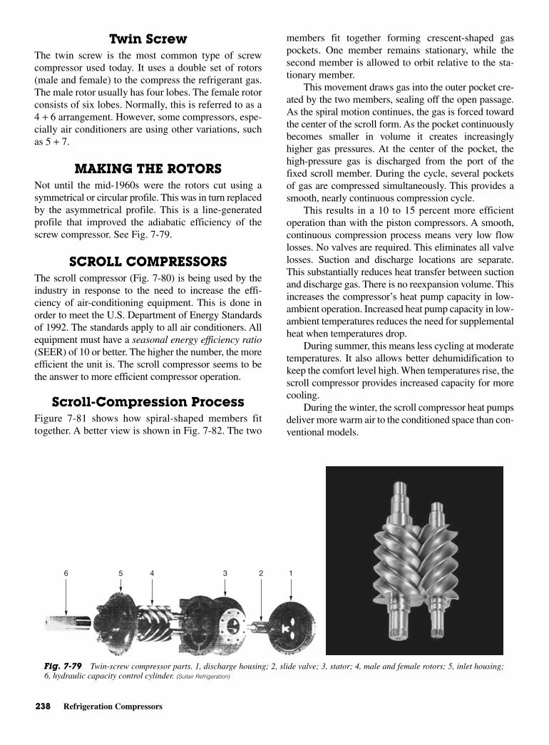
238 Refrigeration Compressors
Twin ScrewThe twin screw is the most common type of screwcompressor used today. It uses a double set of rotors(male and female) to the compress the refrigerant gas.The male rotor usually has four lobes. The female rotorconsists of six lobes. Normally, this is referred to as a4 + 6 arrangement. However, some compressors, espe-cially air conditioners are using other variations, suchas 5 + 7.
MAKING THE ROTORSNot until the mid-1960s were the rotors cut using asymmetrical or circular profile. This was in turn replacedby the asymmetrical profile. This is a line-generatedprofile that improved the adiabatic efficiency of thescrew compressor. See Fig. 7-79.
SCROLL COMPRESSORSThe scroll compressor (Fig. 7-80) is being used by theindustry in response to the need to increase the effi-ciency of air-conditioning equipment. This is done inorder to meet the U.S. Department of Energy Standardsof 1992. The standards apply to all air conditioners. Allequipment must have a seasonal energy efficiency ratio(SEER) of 10 or better. The higher the number, the moreefficient the unit is. The scroll compressor seems to bethe answer to more efficient compressor operation.
Scroll-Compression ProcessFigure 7-81 shows how spiral-shaped members fittogether. A better view is shown in Fig. 7-82. The two
members fit together forming crescent-shaped gaspockets. One member remains stationary, while thesecond member is allowed to orbit relative to the sta-tionary member.
This movement draws gas into the outer pocket cre-ated by the two members, sealing off the open passage.As the spiral motion continues, the gas is forced towardthe center of the scroll form. As the pocket continuouslybecomes smaller in volume it creates increasinglyhigher gas pressures. At the center of the pocket, thehigh-pressure gas is discharged from the port of thefixed scroll member. During the cycle, several pocketsof gas are compressed simultaneously. This provides asmooth, nearly continuous compression cycle.
This results in a 10 to 15 percent more efficientoperation than with the piston compressors. A smooth,continuous compression process means very low flowlosses. No valves are required. This eliminates all valvelosses. Suction and discharge locations are separate.This substantially reduces heat transfer between suctionand discharge gas. There is no reexpansion volume. Thisincreases the compressor’s heat pump capacity in low-ambient operation. Increased heat pump capacity in low-ambient temperatures reduces the need for supplementalheat when temperatures drop.
During summer, this means less cycling at moderatetemperatures. It also allows better dehumidification tokeep the comfort level high. When temperatures rise, thescroll compressor provides increased capacity for morecooling.
During the winter, the scroll compressor heat pumpsdeliver more warm air to the conditioned space than con-ventional models.
123456
Fig. 7-79 Twin-screw compressor parts. 1, discharge housing; 2, slide valve; 3, stator; 4, male and female rotors; 5, inlet housing;6, hydraulic capacity control cylinder. (Sullair Refrigeration)
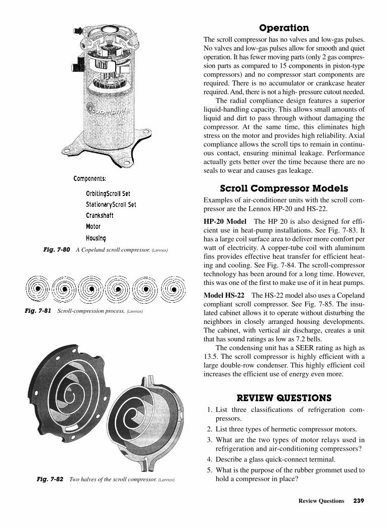
Review Questions 239
OperationThe scroll compressor has no valves and low-gas pulses.No valves and low-gas pulses allow for smooth and quietoperation. It has fewer moving parts (only 2 gas compres-sion parts as compared to 15 components in piston-typecompressors) and no compressor start components arerequired. There is no accumulator or crankcase heaterrequired. And, there is not a high- pressure cutout needed.
The radial compliance design features a superiorliquid-handling capacity. This allows small amounts ofliquid and dirt to pass through without damaging thecompressor. At the same time, this eliminates highstress on the motor and provides high reliability. Axialcompliance allows the scroll tips to remain in continu-ous contact, ensuring minimal leakage. Performanceactually gets better over the time because there are noseals to wear and causes gas leakage.
Scroll Compressor ModelsExamples of air-conditioner units with the scroll com-pressor are the Lennox HP-20 and HS-22.
HP-20 Model The HP 20 is also designed for effi-cient use in heat-pump installations. See Fig. 7-83. Ithas a large coil surface area to deliver more comfort perwatt of electricity. A copper-tube coil with aluminumfins provides effective heat transfer for efficient heat-ing and cooling. See Fig. 7-84. The scroll-compressortechnology has been around for a long time. However,this was one of the first to make use of it in heat pumps.
Model HS-22 The HS-22 model also uses a Copelandcompliant scroll compressor. See Fig. 7-85. The insu-lated cabinet allows it to operate without disturbing theneighbors in closely arranged housing developments.The cabinet, with vertical air discharge, creates a unitthat has sound ratings as low as 7.2 bells.
The condensing unit has a SEER rating as high as13.5. The scroll compressor is highly efficient with alarge double-row condenser. This highly efficient coilincreases the efficient use of energy even more.
REVIEW QUESTIONS1. List three classifications of refrigeration com-
pressors.
2. List three types of hermetic compressor motors.
3. What are the two types of motor relays used inrefrigeration and air-conditioning compressors?
4. Describe a glass quick-connect terminal.
5. What is the purpose of the rubber grommet used tohold a compressor in place?
Fig. 7-80 A Copeland scroll compressor. (Lennox)
Fig. 7-81 Scroll-compression process. (Lennox)
Fig. 7-82 Two halves of the scroll compressor. (Lennox)
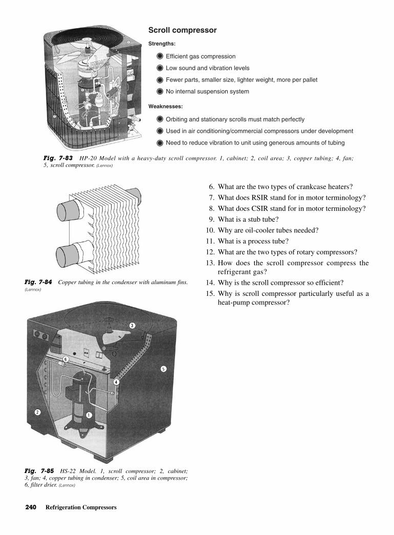
240 Refrigeration Compressors
6. What are the two types of crankcase heaters?
7. What does RSIR stand for in motor terminology?
8. What does CSIR stand for in motor terminology?
9. What is a stub tube?
10. Why are oil-cooler tubes needed?
11. What is a process tube?
12. What are the two types of rotary compressors?
13. How does the scroll compressor compress therefrigerant gas?
14. Why is the scroll compressor so efficient?
15. Why is scroll compressor particularly useful as aheat-pump compressor?
Scroll compressor
Strengths:
Weaknesses:
Efficient gas compression
Low sound and vibration levels
Fewer parts, smaller size, lighter weight, more per pallet
No internal suspension system
Orbiting and stationary scrolls must match perfectly
Used in air conditioning/commercial compressors under development
Need to reduce vibration to unit using generous amounts of tubing
Fig. 7-83 HP-20 Model with a heavy-duty scroll compressor. 1, cabinet; 2, coil area; 3, copper tubing; 4, fan;5, scroll compressor. (Lennox)
Fig. 7-84 Copper tubing in the condenser with aluminum fins.(Lennox)
Fig. 7-85 HS-22 Model. 1, scroll compressor; 2, cabinet;3, fan; 4, copper tubing in condenser; 5, coil area in compressor;6, filter drier. (Lennox)
8CHAPTER
Condensers,Chillers, and
CoolingTowers
Copyright © 2006 by The McGraw-Hill Companies, Inc. Click here for terms of use.
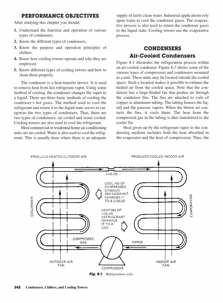
PERFORMANCE OBJECTIVESAfter studying this chapter you should:
1. Understand the function and operation of varioustypes of condensers.
2. Know the different types of condensers.
3. Know the purpose and operation principles ofchillers.
4. Know how cooling towers operate and why they areemployed.
5. Know different types of cooling towers and how toclean them properly.
The condenser is a heat-transfer device. It is usedto remove heat from hot refrigerant vapor. Using somemethod of cooling, the condenser changes the vapor toa liquid. There are three basic methods of cooling thecondenser’s hot gases. The method used to cool therefrigerant and return it to the liquid state serves to cat-egorize the two types of condensers. Thus, there aretwo types of condensers: air cooled and water cooled.Cooling towers are also used to cool the refrigerant.
Most commercial or residential home air-conditioningunits are air cooled. Water is also used to cool the refrig-erant. This is usually done where there is an adequate
supply of fairly clean water. Industrial applications relyupon water to cool the condenser gases. The evapora-tive process is also used to return the condenser gasesto the liquid state. Cooling towers use the evaporativeprocess.
CONDENSERSAir-Cooled Condensers
Figure 8-1 illustrates the refrigeration process withinan air-cooled condenser. Figure 8-2 shows some of thevarious types of compressors and condensers mountedas a unit. These units may be located outside the cooledspace. Such a location makes it possible to exhaust theheated air from the cooled space. Note that the con-denser has a large-bladed fan that pushes air throughthe condenser fins. The fins are attached to coils ofcopper or aluminum tubing. The tubing houses the liq-uid and the gaseous vapors. When the blown air con-tacts the fins, it cools them. The heat from thecompressed gas in the tubing is thus transferred to thecooler fin.
Heat given up by the refrigerant vapor to the con-densing medium includes both the heat absorbed inthe evaporator and the heat of compression. Thus, the
242 Condensers, Chillers, and Cooling Towers
Fig. 8-1 Refrigeration cycle.
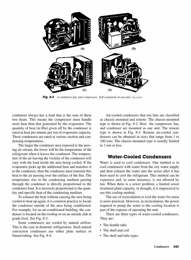
Condensers 243
condenser always has a load that is the sum of thesetwo heats. This means the compressor must handlemore heat than that generated by the evaporator. Thequantity of heat (in Btu) given off by the condenser israted in heat per minute per ton of evaporator capacity.These condensers are rated at various suction and con-densing temperatures.
The larger the condenser area exposed to the mov-ing air stream, the lower will be the temperature of therefrigerant when it leaves the condenser. The tempera-ture of the air leaving the vicinity of the condenser willvary with the load inside the area being cooled. If theevaporator picks up the additional heat and transfers itto the condenser, then the condenser must transmit thisheat to the air passing over the surface of the fins. Thetemperature rise in the condensing medium passingthrough the condenser is directly proportional to thecondenser load. It is inversely proportional to the quan-tity and specific heat of the condensing medium.
To exhaust the heat without causing the area beingcooled to heat up again, it is common practice to locatethe condenser outside of the area being conditioned.For example, for an air-conditioned building, the con-denser is located on the rooftop or on an outside slab atgrade level. See Fig. 8-3.
Some condensers are cooled by natural airflow.This is the case in domestic refrigerators. Such naturalconvection condensers use either plate surface orfinned tubing. See Fig. 8-4.
Air-cooled condensers that use fans are classifiedas chassis mounted and remote. The chassis-mountedtype is shown in Fig. 8-2. Here the compressor, fan,and condenser are mounted as one unit. The remotetype is shown in Fig. 8-3. Remote air-cooled con-densers can be obtained in sizes that range from 1 to100 tons. The chassis-mounted type is usually limitedto 1 ton or less.
Water-Cooled CondensersWater is used to cool condensers. One method is tocool condensers with water from the city water supplyand then exhaust the water into the sewer after it hasbeen used to cool the refrigerant. This method can beexpensive and, in some instances, is not allowed bylaw. When there is a sewer problem, a limited sewertreatment plant capacity, or drought, it is impractical touse this cooling method.
The use of recirculation to cool the water for reuseis more practical. However, in recirculation, the powerrequired to pump the water to the cooling location ispart of the expense of operating the unit.
There are three types of water-cooled condensers.They are:
• The double tube
• The shell and coil
• The shell and tube types
Fig. 8-2 A condenser, fan, and compressor. Self-contained, in one unit. (Tecumseh)

244 Condensers, Chillers, and Cooling Towers
Unit on slab at grade level Multiple units on rooftop
Fig. 8-3 Condensers mounted on rooftops and at grade level. (Lennox)
Fig. 8-4 Flat, coil-type condenser, with natural air circulation. Used inrefrigeration in the home. (Sears)
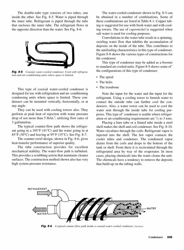
Condensers 245
The double-tube type consists of two tubes, oneinside the other. See Fig. 8-5. Water is piped throughthe inner tube. Refrigerant is piped through the tubethat encloses the inner tube. The refrigerant flows inthe opposite direction than the water. See Fig. 8-6.
This type of coaxial water-cooled condenser isdesigned for use with refrigeration and air–conditioningcondensing units where space is limited. These con-densers can be mounted vertically, horizontally, or atany angle.
They can be used with cooling towers also. Theyperform at peak heat of rejection with water pressuredrop of not more than 5 lb/in.2, utilizing flow rates of3 gal/min/ton.
The typical counter-flow path shows the refriger-ant going in a 105°F (41°C) and the water going in at85°F (30°C) and leaving at 95°F (35°C). See Fig. 8-7.
The counter-swirl design, shown in Fig. 8-6, givesheat-transfer performance of superior quality.
The tube construction provides for excellentmechanical stability. The water-flow path is turbulent.This provides a scrubbing action that maintains cleanersurfaces. The construction method shown also has veryhigh system pressure resistance.
The water-cooled condenser shown in Fig. 8-5 canbe obtained in a number of combinations. Some ofthese combinations are listed in Table 8-1. Copper tub-ing is suggested for use with fresh water and with cool-ing towers. The use of cupronickel is suggested whensalt water is used for cooling purposes.
Convolutions to the water tube result in a spinning,swirling water flow that inhibits the accumulation ofdeposits on the inside of the tube. This contributes tothe antifouling characteristics in this type of condenser.Figure 8-8 shows the various types of constructions forthe condenser.
This type of condenser may be added as a boosterto standard air-cooled units. Figure 8-9 shows some of’the configurations of this type of condenser:
• The spiral
• The helix
• The trombone
Note the input for the water and the input for therefrigerant. Using a cooling tower to furnish water tocontact the outside tube can further cool the con-densers. Also, a water tower can be used to cool thewater sent through the inside tube for cooling pur-poses. This type of’ condenser is usable where refriger-ation or air-conditioning requirements are 1/3 to 3 tons.
Placing a bare tube or a finned tube inside a steelshell makes the shell and coil condenser. See Fig. 8-10.Water circulates through the coils. Refrigerant vapor isinjected into the shell. The hot vapor contacts thecooler tubes and condenses. The condensed vapordrains from the coils and drops to the bottom of thetank or shell. From there it is recirculated through therefrigerated area by way of the evaporator. In mostcases, placing chemicals into the water cleans the unit.The chemicals have a tendency to remove the depositsthat build up on the tubing walls.
Fig. 8-5 Coaxial, water-cooled condenser. Used with refrigera-tion and air-conditioning units where space is limited.
Fig. 8-6 A typical counter-flow path inside a coaxial water-cooled condenser. (Packless)

246 Condensers, Chillers, and Cooling Towers
CHILLERSA chiller is part of a condenser. Chillers are used tocool water or brine solutions. The cooled (chilled)water or brine is then fed through pipes to evaporators.This cools the area in which the evaporators are located.This type of cooling, using chilled water or brine, canbe used in large air-conditioning units. It can also beused for industrial processes where cooling is requiredfor a particular operation.
Figure 8-11 illustrates such an operation. Note howthe compressor sits atop the condenser. Chillers are theanswer to requirements of 200 to 1600 tons of refriger-ation. They are used for process cooling, comfort airconditioning, and nuclear power plant cooling. In somecases, they are used to provide ice for ice-skating rinks.The arrows in Fig. 8-11 indicate the refrigerant flow
and the water or brine flow through the large pipes.Figure 8-12 shows the machine in a cutaway view. Thefollowing explanation of the various cycles will pro-vide a better understanding of the operation of this typeof equipment.
Refrigeration CycleThe machine compressor continuously draws largequantities of refrigerant vapor from the cooler, at a ratedetermined by the size of the guide-vane opening. Thiscompressor suction reduces the pressure within thecooler, allowing the liquid refrigerant to boil vigor-ously at a fairly low temperature [typically 30 to 35°F(−1 to 2°C)].
Liquid refrigerant obtains the energy needed, forthe change to vapor, by removing heat from the waterin the cooler tubes. The cold water can then be used inthe air-conditioning process.
After removing heat from the water, the refrigerantvapor enters the first stage of the compressor. There, itis compressed and flows into the second stage of thecompressor. Here it is mixed with flash-economizergas and further compressed.
Compression raises the refrigerant temperatureabove that of the water flowing through the condensertubes. When the warm [typically 100 to 105°F (38 to41°C)] refrigerant vapor contacts the condenser tubes,the relatively cool condensing water [typically 85 to95°F (29 to 35°C)] removes some of the heat and thevapor condenses into a liquid.
Further heat removal occurs in the group of con-denser tubes that form the thermal economizer. Here,the condensed liquid refrigerant is subcooled by con-tact with the coolest condenser tubes. These are thetubes that contain the entering water.
The subcooled liquid refrigerant drains into a high-side valve chamber. This chamber maintains the properfluid level in the thermal economizer and meters therefrigerant liquid into a flash economizer chamber.Pressure in this chamber is intermediate between con-denser and cooler pressures. At this lower pressure,
Fig. 8-7 Water and refrigerant temperatures in a counter-flow,water-cooled condenser. (Packless)
Fig. 8-8 Different types of tubing fabrication, located inside the coaxialtype water-cooled condenser. (Packless)
Table 8-1 Some Possible Metal Combinationsin Water-Cooled Condensers
Shell Metal Tubing Metal
Steel CopperCopper CopperSteel CupronickelCopper CupronickelSteel Stainless steelStainless steel Stainless steel
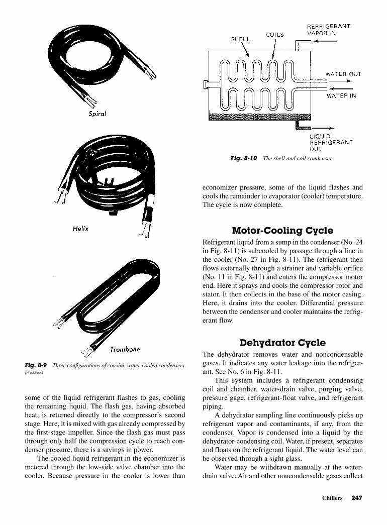
Chillers 247
some of the liquid refrigerant flashes to gas, coolingthe remaining liquid. The flash gas, having absorbedheat, is returned directly to the compressor’s secondstage. Here, it is mixed with gas already compressed bythe first-stage impeller. Since the flash gas must passthrough only half the compression cycle to reach con-denser pressure, there is a savings in power.
The cooled liquid refrigerant in the economizer ismetered through the low-side valve chamber into thecooler. Because pressure in the cooler is lower than
economizer pressure, some of the liquid flashes andcools the remainder to evaporator (cooler) temperature.The cycle is now complete.
Motor-Cooling Cycle Refrigerant liquid from a sump in the condenser (No. 24in Fig. 8-11) is subcooled by passage through a line inthe cooler (No. 27 in Fig. 8-11). The refrigerant thenflows externally through a strainer and variable orifice(No. 11 in Fig. 8-11) and enters the compressor motorend. Here it sprays and cools the compressor rotor andstator. It then collects in the base of the motor casing.Here, it drains into the cooler. Differential pressurebetween the condenser and cooler maintains the refrig-erant flow.
Dehydrator CycleThe dehydrator removes water and noncondensablegases. It indicates any water leakage into the refriger-ant. See No. 6 in Fig. 8-11.
This system includes a refrigerant condensingcoil and chamber, water-drain valve, purging valve,pressure gage, refrigerant-float valve, and refrigerantpiping.
A dehydrator sampling line continuously picks uprefrigerant vapor and contaminants, if any, from thecondenser. Vapor is condensed into a liquid by thedehydrator-condensing coil. Water, if present, separatesand floats on the refrigerant liquid. The water level canbe observed through a sight glass.
Water may be withdrawn manually at the water-drain valve. Air and other noncondensable gases collect
Fig. 8-10 The shell and coil condenser.
Fig. 8-9 Three configurations of coaxial, water-cooled condensers.(Packless)

248 Condensers, Chillers, and Cooling Towers
Fig. 8-11 The chiller, compressor, condenser, and cooler are combined in one unit. (Carrier)
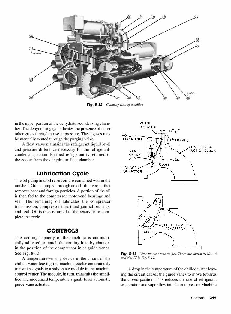
Controls 249
in the upper portion of the dehydrator-condensing cham-ber. The dehydrator gage indicates the presence of air orother gases through a rise in pressure. These gases maybe manually vented through the purging valve.
A float valve maintains the refrigerant liquid leveland pressure difference necessary for the refrigerant-condensing action. Purified refrigerant is returned tothe cooler from the dehydrator-float chamber.
Lubrication CycleThe oil pump and oil reservoir are contained within theunishell. Oil is pumped through an oil-filter cooler thatremoves heat and foreign particles. A portion of the oilis then fed to the compressor motor-end bearings andseal. The remaining oil lubricates the compressortransmission, compressor thrust and journal bearings,and seal. Oil is then returned to the reservoir to com-plete the cycle.
CONTROLSThe cooling capacity of the machine is automati-cally adjusted to match the cooling load by changesin the position of the compressor inlet guide vanes.See Fig. 8-13.
A temperature-sensing device in the circuit of thechilled water leaving the machine cooler continuouslytransmits signals to a solid-state module in the machinecontrol center. The module, in turn, transmits the ampli-fied and modulated temperature signals to an automaticguide-vane actuator.
A drop in the temperature of the chilled water leav-ing the circuit causes the guide vanes to move towardsthe closed position. This reduces the rate of refrigerantevaporation and vapor flow into the compressor. Machine
Fig. 8-12 Cutaway view of a chiller.
Fig. 8-13 Vane motor-crank angles. These are shown as No. 16and No. 17 in Fig. 8-11.
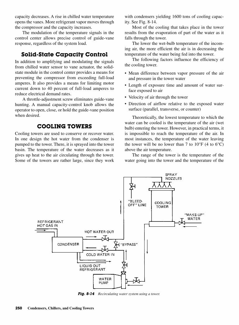
250 Condensers, Chillers, and Cooling Towers
capacity decreases. A rise in chilled water temperatureopens the vanes. More refrigerant vapor moves throughthe compressor and the capacity increases.
The modulation of the temperature signals in thecontrol center allows precise control of guide-vaneresponse, regardless of the system load.
Solid-State Capacity ControlIn addition to amplifying and modulating the signalsfrom chilled water sensor to vane actuator, the solid-state module in the control center provides a means forpreventing the compressor from exceeding full-loadamperes. It also provides a means for limiting motorcurrent down to 40 percent of full-load amperes toreduce electrical demand rates.
A throttle-adjustment screw eliminates guide-vanehunting. A manual capacity-control knob allows theoperator to open, close, or hold the guide-vane positionwhen desired.
COOLING TOWERS Cooling towers are used to conserve or recover water.In one design the hot water from the condenser ispumped to the tower. There, it is sprayed into the towerbasin. The temperature of the water decreases as itgives up heat to the air circulating through the tower.Some of the towers are rather large, since they work
with condensers yielding 1600 tons of cooling capac-ity. See Fig. 8-14.
Most of the cooling that takes place in the towerresults from the evaporation of part of the water as itfalls through the tower.
The lower the wet-bulb temperature of the incom-ing air, the more efficient the air is in decreasing thetemperature of the water being fed into the tower.
The following factors influence the efficiency ofthe cooling tower.
• Mean difference between vapor pressure of the airand pressure in the tower water
• Length of exposure time and amount of water sur-face exposed to air
• Velocity of air through the tower
• Direction of airflow relative to the exposed watersurface (parallel, transverse, or counter)
Theoretically, the lowest temperature to which thewater can be cooled is the temperature of the air (wetbulb) entering the tower. However, in practical terms, itis impossible to reach the temperature of the air. Inmost instances, the temperature of the water leavingthe tower will be no lower than 7 to 10°F (4 to 6°C)above the air temperature.
The range of the tower is the temperature of thewater going into the tower and the temperature of the
Fig. 8-14 Recirculating water system using a tower.
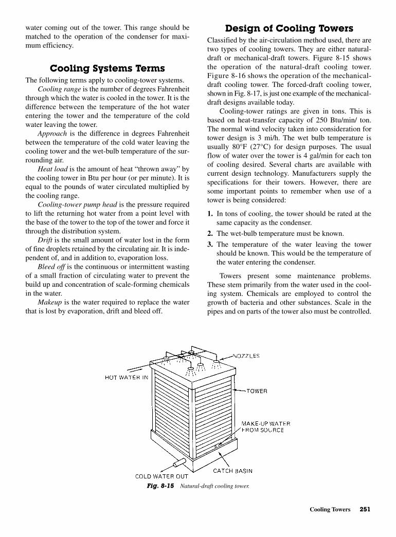
Cooling Towers 251
water coming out of the tower. This range should bematched to the operation of the condenser for maxi-mum efficiency.
Cooling Systems Terms The following terms apply to cooling-tower systems.
Cooling range is the number of degrees Fahrenheitthrough which the water is cooled in the tower. It is thedifference between the temperature of the hot waterentering the tower and the temperature of the coldwater leaving the tower.
Approach is the difference in degrees Fahrenheitbetween the temperature of the cold water leaving thecooling tower and the wet-bulb temperature of the sur-rounding air.
Heat load is the amount of heat “thrown away” bythe cooling tower in Btu per hour (or per minute). It isequal to the pounds of water circulated multiplied bythe cooling range.
Cooling-tower pump head is the pressure requiredto lift the returning hot water from a point level withthe base of the tower to the top of the tower and force itthrough the distribution system.
Drift is the small amount of water lost in the formof fine droplets retained by the circulating air. It is inde-pendent of, and in addition to, evaporation loss.
Bleed off is the continuous or intermittent wastingof a small fraction of circulating water to prevent thebuild up and concentration of scale-forming chemicalsin the water.
Makeup is the water required to replace the waterthat is lost by evaporation, drift and bleed off.
Design of Cooling Towers Classified by the air-circulation method used, there aretwo types of cooling towers. They are either natural-draft or mechanical-draft towers. Figure 8-15 showsthe operation of the natural-draft cooling tower.Figure 8-16 shows the operation of the mechanical-draft cooling tower. The forced-draft cooling tower,shown in Fig. 8-17, is just one example of the mechanical-draft designs available today.
Cooling-tower ratings are given in tons. This isbased on heat-transfer capacity of 250 Btu/min/ ton.The normal wind velocity taken into consideration fortower design is 3 mi/h. The wet bulb temperature isusually 80°F (27°C) for design purposes. The usualflow of water over the tower is 4 gal/min for each tonof cooling desired. Several charts are available withcurrent design technology. Manufacturers supply thespecifications for their towers. However, there aresome important points to remember when use of atower is being considered:
1. In tons of cooling, the tower should be rated at thesame capacity as the condenser.
2. The wet-bulb temperature must be known.
3. The temperature of the water leaving the towershould be known. This would be the temperature ofthe water entering the condenser.
Towers present some maintenance problems.These stem primarily from the water used in the cool-ing system. Chemicals are employed to control thegrowth of bacteria and other substances. Scale in thepipes and on parts of the tower also must be controlled.
Fig. 8-15 Natural-draft cooling tower.
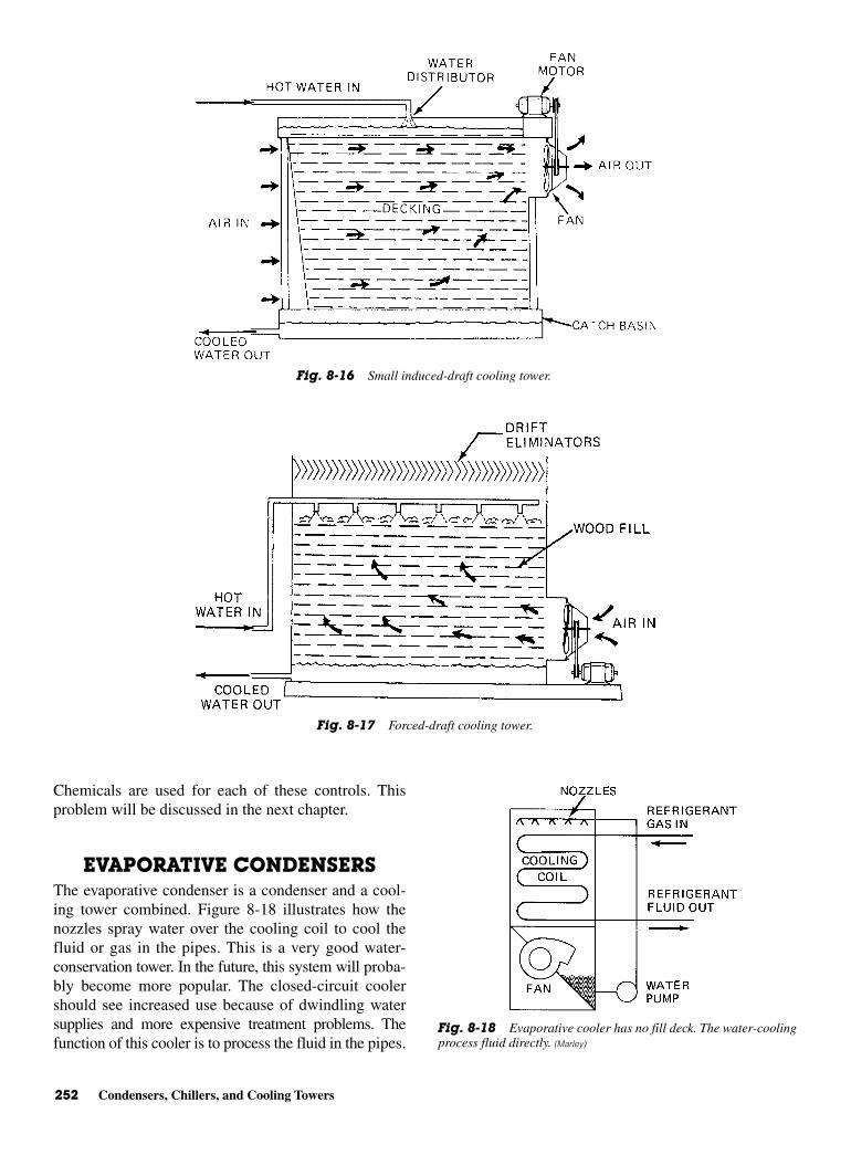
252 Condensers, Chillers, and Cooling Towers
Chemicals are used for each of these controls. Thisproblem will be discussed in the next chapter.
EVAPORATIVE CONDENSERS The evaporative condenser is a condenser and a cool-ing tower combined. Figure 8-18 illustrates how thenozzles spray water over the cooling coil to cool thefluid or gas in the pipes. This is a very good water-conservation tower. In the future, this system will proba-bly become more popular. The closed-circuit coolershould see increased use because of dwindling watersupplies and more expensive treatment problems. Thefunction of this cooler is to process the fluid in the pipes.
Fig. 8-16 Small induced-draft cooling tower.
Fig. 8-17 Forced-draft cooling tower.
Fig. 8-18 Evaporative cooler has no fill deck. The water-coolingprocess fluid directly. (Marley)

Temperature Conversion 253
This is a sealed contamination-free system. Instead ofallowing the water to drop onto slats or other deflectors,this unit sprays the water directly onto the cooling coil.
NEW DEVELOPMENTS All-metal towers with housing, fans, fill, piping, andstructural members made of galvanized or stainlesssteel are now being built. Some local building codesare becoming more restrictive with respect to firesafety. Low maintenance is another factor in the use ofall-metal towers.
Engineers are beginning to specify towers less sub-ject to deterioration due to environmental conditions.Thus, all-steel or all-metal towers are called for. Already,galvanized-steel towers have made inroads into the air-conditioning and refrigeration market. Stainless-steeltowers are being specified in New York City, northernNew Jersey, and Los Angeles. This is primarily due toa polluted atmosphere, which can lead to early deterio-ration of nonmetallic towers and, in some cases,metals.
Figure 8-19 shows a no-fans design for a coolingtower. Large quantities of air are drawn into the towerby cooling water as it is injected through spray nozzlesat one end of a venturi plenum. No fans are needed.Effective mixing of air and water in the plenum permitsevaporative heat transfer to take place without the fillrequired in conventional towers.
The cooled water falls into the sump and ispumped through a cooling-water circuit to return foranother cycle. The name applied to this design is Bal-timore Aircoil. In 1981, towers rated at 10 to 640 tonswith 30 to 1920 gal/min were standard. Using pre-strainers in the high-pressure flow has minimized the
nozzle-clogging problem. There are no moving parts inthe tower. This results in very low maintenance costs.
Air-cooled condensers are reaching 1000 tons incapacity. Air coolers and air condensers are quite attrac-tive for use in refineries and natural gas compressorstations. They are also used for cooling in industry, aswell as for commercial air-conditioning purposes.Figure 8-19 shows how the air-cooled condensers areused in a circuit system that is completely closed. Theseare very popular where there is little or no water supply.
TEMPERATURE CONVERSIONA cooling tower is a device for cooling a stream ofwater. Evaporating a portion of the circulating streamdoes this. Such cooled water may be used for many pur-poses, but the main concern here is its utilization as aheat sink for a refrigeration-system condenser. A num-ber of types of cooling towers are used for industrialand commercial purposes. They are usually regarded asa necessity for large buildings or manufacturingprocesses. Some of these types have already been men-tioned, but the following will bring you more details onthe workings of cooling towers and their differences.
Cooling water concerns must be addressed for thehealth of those who operate and maintain the systems.There is the potential for harboring and for the growthof pathogens in the water basin or related surface. Thismay occur during many the summer and also duringidle periods. When the temperature falls in the 70 to120°F range, there are periods when the unit will not beoperational and will sit idle. Dust from the air will set-tle in the water and create an organic medium for theculture of bacteria and pathogens. Algae will grow inthe water—some need sunlight, others grow without.
Fig. 8-19 Cooling tower with natural-draft properties. There are no moving parts inthe cooling tower. (Marley)
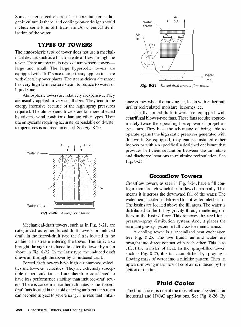
254 Condensers, Chillers, and Cooling Towers
Some bacteria feed on iron. The potential for patho-genic culture is there, and cooling-tower design shouldinclude some kind of filtration and/or chemical steril-ization of the water.
TYPES OF TOWERSThe atmospheric type of tower does not use a mechal-nical device, such as a fan, to create airflow through thetower. There are two main types of atmospherictowers—large and small. The large hyperbolic towers areequipped with “fill” since their primary applications arewith electric-power plants. The steam-driven alternatorhas very high temperature steam to reduce to water orliquid state.
Atmospheric towers are relatively inexpensive. Theyare usually applied in very small sizes. They tend to beenergy intensive because of the high spray pressuresrequired. The atmospheric towers are far more affectedby adverse wind conditions than are other types. Theiruse on systems requiring accurate, dependable cold-watertemperatures is not reocmmended. See Fig. 8-20.
Mechanical-draft towers, such as in Fig. 8-21, arecategorized as either forced-draft towers or induceddraft. In the forced-draft type the fan is located in theambient air stream entering the tower. The air is alsobrought through or induced to enter the tower by a fanabove in Fig. 8-22. In the later type the induced draftdraws air through the tower by an induced draft.
Forced-draft towers have high air-entrance veloci-ties and low-exit velocities. They are extremely suscep-tible to recirculation and are therefore considered tohave less performance stability than induced-draft tow-ers. There is concern in northern climates as the forced-draft fans located in the cold entering ambient air streamcan become subject to severe icing. The resultant imbal-
ance comes when the moving air, laden with either nat-ural or recirculated moisture, becomes ice.
Usually forced-draft towers are equipped withcentrifugal blower-type fans. These fans require approx-imately twice the operating horsepower of propeller-type fans. They have the advantage of being able tooperate against the high static pressures generated withductwork. So equipped, they can be installed eitherindoors or within a specifically designed enclosure thatprovides sufficient separation between the air intakeand discharge locations to minimize recirculation. SeeFig. 8-23.
Crossflow TowersCrossflow towers, as seen in Fig. 8-24, have a fill con-figuration through which the air flows horizontally. Thatmeans it is across the downward fall of the water. Thewater being cooled is delivered to hot-water inlet basins.The basins are located above the fill areas. The water isdistributed to the fill by gravity through metering ori-fices in the basins’ floor. This removes the need for apressure-spray distribution system. And, it places theresultant gravity system in full view for maintenance.
A cooling tower is a specialized heat exchanger.See Fig. 8-25. The two fluids, air and water, arebrought into direct contact with each other. This is toeffect the transfer of heat. In the spray-filled tower,such as Fig. 8-25, this is accomplished by spraying aflowing mass of water into a rainlike pattern. Then anupward-moving mass flow of cool air is induced by theaction of the fan.
Fluid CoolerThe fluid cooler is one of the most efficient systems forindustrial and HVAC applications. See Fig. 8-26. By
Air Flow
Water in
Water out
Fig. 8-20 Atmospheric tower.
Water out
Water sprays
Airout
Airin
Fig. 8-21 Forced-draft counter flow tower.
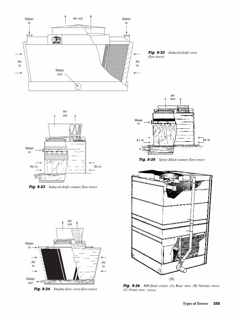
Types of Towers 255
Airin
Airin
Air out
Water out
Water in
Water in
Fig. 8-22 Induced-draft crossflow tower.
Air inAir in
Water in
Airout
Fig. 8-23 Induced-draft counter flow tower.
Waterin
Airin
Airin
Waterout
Airout
Fig. 8-24 Double-flow cross flow tower.
Fig. 8-25 Spray-filled counter flow tower.
Fig. 8-26 MH-fluid cooler. (A) Rear view. (B) Various views.(C) Front view. (Marley)
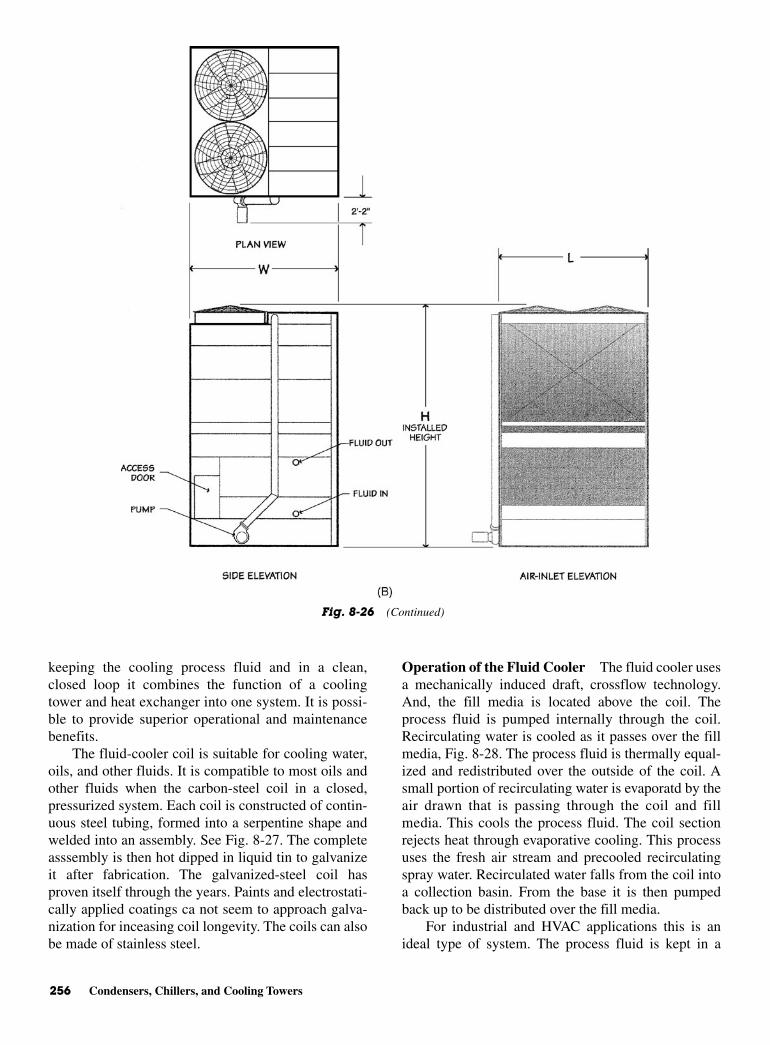
256 Condensers, Chillers, and Cooling Towers
keeping the cooling process fluid and in a clean,closed loop it combines the function of a coolingtower and heat exchanger into one system. It is possi-ble to provide superior operational and maintenancebenefits.
The fluid-cooler coil is suitable for cooling water,oils, and other fluids. It is compatible to most oils andother fluids when the carbon-steel coil in a closed,pressurized system. Each coil is constructed of contin-uous steel tubing, formed into a serpentine shape andwelded into an assembly. See Fig. 8-27. The completeasssembly is then hot dipped in liquid tin to galvanizeit after fabrication. The galvanized-steel coil hasproven itself through the years. Paints and electrostati-cally applied coatings ca not seem to approach galva-nization for inceasing coil longevity. The coils can alsobe made of stainless steel.
Operation of the Fluid Cooler The fluid cooler usesa mechanically induced draft, crossflow technology.And, the fill media is located above the coil. Theprocess fluid is pumped internally through the coil.Recirculating water is cooled as it passes over the fillmedia, Fig. 8-28. The process fluid is thermally equal-ized and redistributed over the outside of the coil. Asmall portion of recirculating water is evaporatd by theair drawn that is passing through the coil and fillmedia. This cools the process fluid. The coil sectionrejects heat through evaporative cooling. This processuses the fresh air stream and precooled recirculatingspray water. Recirculated water falls from the coil intoa collection basin. From the base it is then pumpedback up to be distributed over the fill media.
For industrial and HVAC applications this is anideal type of system. The process fluid is kept in a
Fig. 8-26 (Continued)
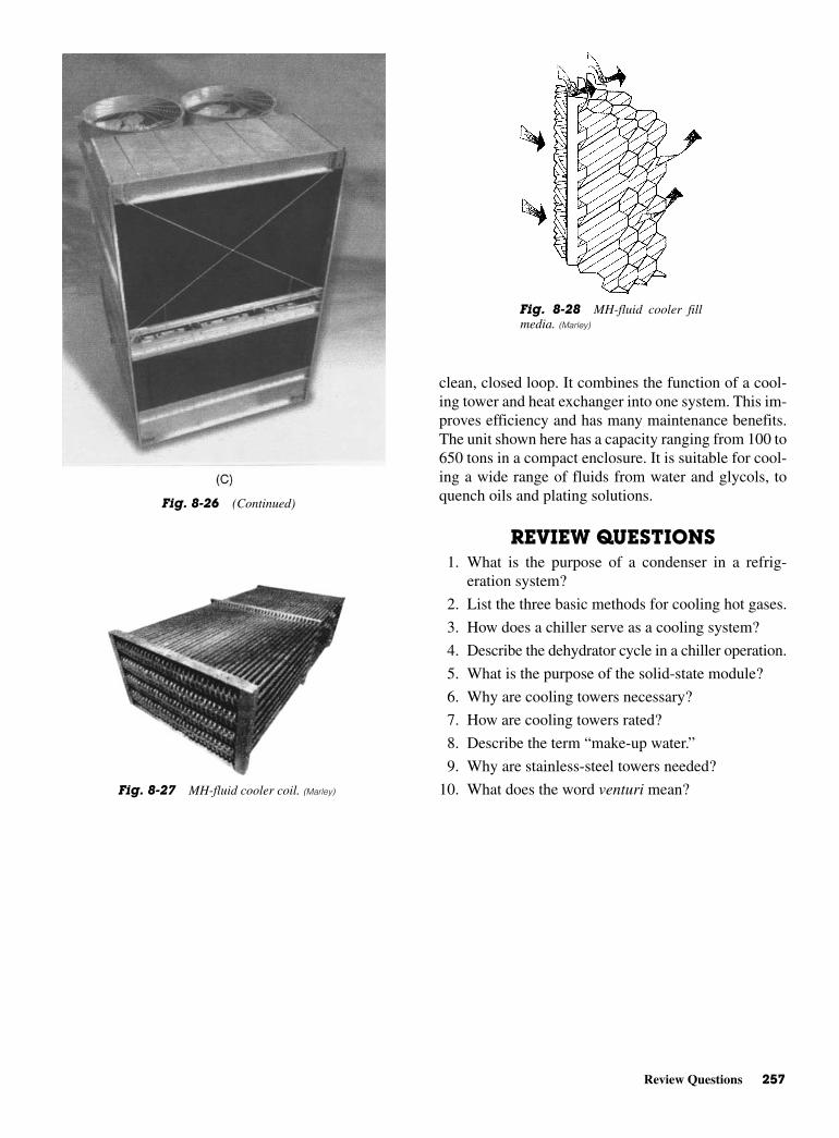
Review Questions 257
clean, closed loop. It combines the function of a cool-ing tower and heat exchanger into one system. This im-proves efficiency and has many maintenance benefits.The unit shown here has a capacity ranging from 100 to650 tons in a compact enclosure. It is suitable for cool-ing a wide range of fluids from water and glycols, toquench oils and plating solutions.
REVIEW QUESTIONS1. What is the purpose of a condenser in a refrig-
eration system?
2. List the three basic methods for cooling hot gases.
3. How does a chiller serve as a cooling system?
4. Describe the dehydrator cycle in a chiller operation.
5. What is the purpose of the solid-state module?
6. Why are cooling towers necessary?
7. How are cooling towers rated?
8. Describe the term “make-up water.”
9. Why are stainless-steel towers needed?
10. What does the word venturi mean?
Fig. 8-26 (Continued)
Fig. 8-27 MH-fluid cooler coil. (Marley)
Fig. 8-28 MH-fluid cooler fillmedia. (Marley)

This page intentionally left blank

9CHAPTER
Working withWater-Cooling
Problems
Copyright © 2006 by The McGraw-Hill Companies, Inc. Click here for terms of use.

PERFORMANCE OBJECTIVESAfter studying this chapter, you should:
1. Be able to understand why water fit for human con-sumption is not necessarily acceptable for use inboilers and cooling equipment.
2. Know how to treat cooling water for corrosion,algae, slime, and fungi.
3. Know how to clean cooling towers and evaporativecondensers.
4. Know how to use cleaning chemicals safely.
5. Know how to use solvents and detergents.
Three-fourths of the earth’s surface is covered withwater. The earth is blanketed with water vapor, whichis an indispensable part of the atmosphere. Heat fromthe sun shining on oceans, rivers, and lakes evaporatesome water into the atmosphere. Warm, moisture-ladenair rises and cools. The cooling vapor condenses toform clouds. Wind currents carry clouds over land-masses where the precipitation may occur in the formof rain, snow, or sleet. Because of the sun and upper aircurrents, this process is repeated again and again. Purewater has no taste and no odor. Pure water, however, isactually a rarity.
All water found in oceans, rivers, lakes, streams, andwells contains various amounts of minerals picked upfrom the earth. Even rainwater is not completely pure.As rain falls to earth, it washes from the air various gasesand solids such as oxygen, carbon dioxide, industrialgases, dust, and even bacteria. Some of this water sinksinto the earth and collects in wells or forms undergroundstreams. The remainder runs over the ground and findsits way back into various surface-water supplies.
Water is often referred to as the universal solvent.Water runs over and through the earth mixes with manyminerals. Some of these mineral solids are dissolved ordisintegrated by water.
PURE WATERPure water and sanitary water are the same as far asmunicipalities are concerned. Pure in this case meansthat the water is free from excessive quantities ofgerms and will not cause disease. Mineral salts or othersubstances in water do not have to be removed bywater-treatment plants unless they affect sanitary con-ditions. Mineral salts are objectionable in water usedfor many other purposes. These uses include generat-ing power, heating buildings, processing materials, andmanufacturing. Water fit for human consumption is notnecessarily acceptable for use in boilers or coolingequipment.
Water is used in many types of cooling systems.Heat removal is the main use of water in air-conditioningor refrigeration equipment. Typical uses include once-through condensers, open recirculating cooling sys-tems employing cooling towers, evaporative condensers,chilled-water systems, and air washers. In evaporativecondensers, once-through systems, and cooling towers,water removes heat from refrigerant and then is eitherwasted or cooled by partial evaporation in air. Knowl-edge of impurities in water used in any of these sys-tems aids in predicting possible problems and methodsof preventing them.
Cooling towers are usually remotely located; itbecomes necessary to regularly inspect and clean thetower according to the manufacturer’s recommenda-tion. The few hours, each month, spent on inspectingthe cooling tower and maintaining it will pay divi-dends. The life of a tower varies according to:
• Materials of construction
• Location within the system
• The location of the city or country
Generally, the premium materials of constructionare:
• Wood
• Concrete
• Stainless steel
• Fiberglass
These units are expected to last from 20 to 30 yearsif properly cared for. The less-expensive units, made ofgalvanized steel, will operate for 8 to 20 years. Of course,tower life will vary due to the extremes of weather,number of hours used each year, and type of watertreatment. It is sufficient to say that in order to get themost of the tower, cooling-tower manufacturers wantto make that tower last as long as possible.
FOULING, SCALING,AND CORROSION
Fouling reduces water flow and heat transfer. Foulingcan be caused by the collection of loose debris overpump-suction screens in sumps, growth of algae insunlit areas, and slime in shade or dark sections ofwater systems. Material can clog pipes, or other partsof a system, after it has broken loose and been carriedinto the system by the water stream. Scaling also reduceswater flow and heat transfer. The depositing of dis-solved minerals on equipment surfaces causes scaling.This is particularly so in hot areas, where heat transferis most important.
260 Working with Water-Cooling Problems
Fouling, Scaling, and Corrosion 261
Corrosion is caused by impurities in the water. Inaddition to reducing water flow and heat transfer it alsodamages equipment. Eventually, corrosion will reduceoperational efficiency. It may lead to expensive repairsor even equipment replacement.
Impurities have at least five confirmed sources. Oneis the earth’s atmosphere. Water falling through the air,whether it be natural precipitation or water showeringthrough a cooling tower, picks up dust, as well as oxygenand carbon dioxide. Similarly, synthetic atmosphericgases and dust affect the purity of water. Heavily indus-trialized areas are susceptible to such impurities beingintroduced into their water systems.
Decaying plant life is a source of water impurity.Decaying plants produce carbon dioxide. Other prod-ucts of vegetable decay cause bad odor and taste. Theby-products of plant decay provide a nutrient for slimegrowth.
These three sources of impurities contaminatewater with material that makes it possible for water topick up more impurities from a fourth source, miner-als. Minerals found in the soil beneath the earth’s sur-face are probably the major source of impurities inwater. Many minerals are present in subsurface soil.They are more soluble in the presence of the impuritiesfrom the first three sources, mentioned earlier.
Industrial and municipal wastes are a fifth majorsource of water impurities. Municipal waste affectsbacterial count. Therefore, it is of interest to healthofficials, but is not of primary concern from a scale orcorrosion standpoint. Industrial waste, however, canadd greatly to the corrosive nature of water. It can indi-rectly cause a higher than normal mineral content.
The correction or generation of finely dividedmaterial that has the appearance of mud or silt causesfouling. This sludge is normally composed of dirt andtrash from the air. Silt is introduced with make-up water.Leaves and dust are blown in by wind and washed fromthe air by rain. This debris settles in sumps or otherparts of cooling systems. Plant growth also causesfouling. Bacteria or algae in water will result in the for-mation of large masses of algae and slime. These mayclog system water pipes and filters. Paper, bottles, andother trash also cause fouling.
Prevention of Scaling There are two ways to prevent scaling.
• Eliminate or reduce the hardness minerals from thefeed water. Control of factors that cause hardnesssalts to become less soluble is important. Hardnessminerals are defined as water-soluble compounds ofcalcium and magnesium. Most calcium and magnesium
compounds are much less soluble than are correspond-ing sodium compounds. By replacing the calciumand magnesium portion of these minerals with sodium,solubility of the sulfates and carbonates is improvedto such a degree that scaling no longer is a problem.This is the function of the water softener.
• The second method of preventing scale is by control-ling water conditions that affect the solubility ofscale-forming minerals. The five factors that affectthe rate of scale formation are:
• Temperature• Total dissolved solids (TDS)• Hardness• Alkalinity• pHThese factors can, to some extent, be regulated byproper design and operation of water-cooled equip-ment. Proper temperature levels are maintained byensuring a good water flow rate and adequate coolingin the tower. Water flow in recirculating systemsshould be approximately 3 gal/min/ton. Lower flowlevels allow the water to remain in contact with hotsurfaces of the condenser for a longer time and pickup more heat. Temperature drop across the towershould be 8 to 10°F (4.5 to 5.5°C) for a compression-refrigeration system, and 18 to 20°F (10 to 11°C) inmost absorption systems. This cooling effect, due toevaporation, is dependent on tower characteristicsand uncontrollable atmospheric conditions.
Airflow through the tower and the degree of waterbreakup are two factors that determine the amount ofevaporation that will occur. Since heat energy is requiredfor evaporation, the amount of water that is changed intovapor and lost from the system determines the amount ofheat. That is, the number of Btu to be dissipated is theheat factor. One pound of water, at cooling-tower tem-peratures, requires 1050 Btu to be converted from liquidto vapor. Therefore, the greater the weight of water evap-orated from the system, the greater the cooling effect ortemperature drop across the tower.
Total dissolved solids, hardness, and alkalinity areaffected by three interrelated factors. These are evapo-ration, makeup, and bleed or blow-down rates. Water,when it evaporates, leaves the system in a pure state,leaving behind all dissolved matter. Water volume ofevaporative cooling systems is held at a relatively con-stant figure through the use of float valves.
Fresh make-up water brings with it dissolved mate-rial. This is added to that already left behind by theevaporated water. Theoretically, assuming that all thewater leaves the system by evaporation and the systemvolume stays constant, the concentration of dissolved
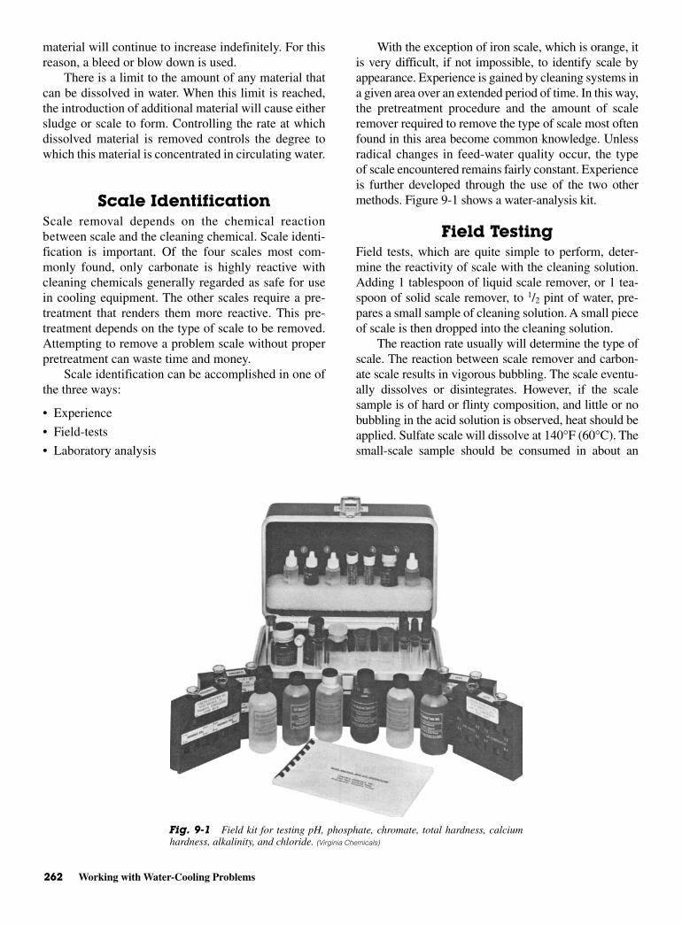
262 Working with Water-Cooling Problems
material will continue to increase indefinitely. For thisreason, a bleed or blow down is used.
There is a limit to the amount of any material thatcan be dissolved in water. When this limit is reached,the introduction of additional material will cause eithersludge or scale to form. Controlling the rate at whichdissolved material is removed controls the degree towhich this material is concentrated in circulating water.
Scale IdentificationScale removal depends on the chemical reactionbetween scale and the cleaning chemical. Scale identi-fication is important. Of the four scales most com-monly found, only carbonate is highly reactive withcleaning chemicals generally regarded as safe for usein cooling equipment. The other scales require a pre-treatment that renders them more reactive. This pre-treatment depends on the type of scale to be removed.Attempting to remove a problem scale without properpretreatment can waste time and money.
Scale identification can be accomplished in one ofthe three ways:
• Experience
• Field-tests
• Laboratory analysis
With the exception of iron scale, which is orange, itis very difficult, if not impossible, to identify scale byappearance. Experience is gained by cleaning systems ina given area over an extended period of time. In this way,the pretreatment procedure and the amount of scaleremover required to remove the type of scale most oftenfound in this area become common knowledge. Unlessradical changes in feed-water quality occur, the typeof scale encountered remains fairly constant. Experienceis further developed through the use of the two othermethods. Figure 9-1 shows a water-analysis kit.
Field TestingField tests, which are quite simple to perform, deter-mine the reactivity of scale with the cleaning solution.Adding 1 tablespoon of liquid scale remover, or 1 tea-spoon of solid scale remover, to 1/2 pint of water, pre-pares a small sample of cleaning solution. A small pieceof scale is then dropped into the cleaning solution.
The reaction rate usually will determine the type ofscale. The reaction between scale remover and carbon-ate scale results in vigorous bubbling. The scale eventu-ally dissolves or disintegrates. However, if the scalesample is of hard or flinty composition, and little or nobubbling in the acid solution is observed, heat should beapplied. Sulfate scale will dissolve at 140°F (60°C). Thesmall-scale sample should be consumed in about an
Fig. 9-1 Field kit for testing pH, phosphate, chromate, total hardness, calciumhardness, alkalinity, and chloride. (Virginia Chemicals)
Fouling, Scaling, and Corrosion 263
hour. If the scale sample contains a high percentage ofsilica, little or no reaction will be observed. Iron scale iseasily identified by appearance. Testing with a cleansolution usually is not required.
Since this identification procedure is quite elemen-tary, and combinations of all types of scale are oftenencountered, it is obvious that more precise methodsmay be required. Such methods are most easily carriedout in a laboratory. Many chemical manufacturers pro-vide this service. Scale samples that cannot be identi-fied in the field may be mailed to these laboratories.Here a complete breakdown and analysis of the prob-lem scale will be performed. Detailed cleaning recom-mendations will be given to the sender.
Most scales are predominately carbonate, but theymay also contain varying amounts of sulfate, iron, orsilica. Thus, the quantities of scale remover requiredfor cleaning should be calculated specifically for thetype of scale present. The presence of sulfate, iron, orsilica also affects other cleaning procedures.
CorrosionThere are four basic causes of corrosion:
• Corrosive acids
• Oxygen
• Galvanic action
• Biological organisms
Corrosive Acids Aggressive or strong acids, such assulfurous, sulfuric, hydrochloric, and nitric, are found inmost industrial areas. These acids are formed when cer-tain industrial waste gases are washed out of the atmos-phere by water showering through a cooling tower. Thepresence of any of these acids will cause a drop in circu-lating water pH. Water and carbon dioxide are foundeverywhere. When carbon dioxide is dissolved in water,carbonic acid is formed. This acid is less aggressive thanthe acids already mentioned. Because it is always pre-sent, however, serious damage to equipment can resultfrom the corrosive effects of this acid.
Corrosion by Oxygen Corrosion by oxygen is anotherproblem. Water that is sprayed into the air picks upoxygen. This oxygen then is carried into the system.Oxygen reacts with any iron in equipment. It formsiron oxide, which is a porous material. Flaking orblistering of oxidized metal allows corrosion of thefreshly exposed metal. Blistering also restricts waterflow and reduces heat transfer. Reaction rates betweenoxygen and iron increase rapidly as temperaturesincrease. Thus, the most severe corrosion takes place inhot areas of equipment with iron parts.
Oxygen also affects copper and zinc. Zinc is theouter coating of galvanized material. Here, damage ismuch less severe because oxidation of zinc and copperforms an inert metal oxide. This sets up a protectivefilm between the metal and the attacking oxygen.
Galvanic Action Galvanic corrosion is the thirdcause of corrosion. Galvanic corrosion is basically a re-action between two different metals in electrical con-tact. This reaction is both electrical and chemical innature. The following three conditions are necessary toproduce galvanic action.
1. Two dissimilar metals possessing different electro-chemical properties must be present.
2. An electrolyte, a solution through which an electri-cal current can flow, must be present.
3. An electron path to connect these two metals is alsorequired.
Many different metals are used to fabricate air-conditioning and refrigeration systems. Copper andiron are two dissimilar metals. Add a solution contain-ing ions, and an electrolyte is produced. Unless the twometals are placed in contact, no galvanic action willtake place. A coupling is made when two dissimilarmetals, such as iron and copper, are brought into con-tact with one another. This sets up an electrical path ora path for electron movement. This allows electrons topass from the copper to the iron. As current leaves theiron and reenters the solution to return to the copper,corrosion of the iron takes place. Copper-iron connec-tions are common in cooling systems.
Greater separation of metals in the galvanic seriesresults in their increased tendency to corrode. Forexample, if platinum is joined with magnesium, with aproper electrolyte, then platinum would be protectedand magnesium would corrode. Since they are so farapart on the scale, the corrosion would be rapid. SeeTable 9-1. If iron and copper are joined, we can tell bytheir relative positions in the series that iron would cor-rode, but to a lesser degree than the magnesium men-tioned in the previous example. Nevertheless, corrosionwould be extensive enough to be very damaging. How-ever, if copper and silver were joined together, then thecopper would corrode. Consequently, the degree ofcorrosion is determined by the relative positions of thetwo metals in the galvanic series.
Improperly grounded electrical equipment or poorinsulation can also initiate or accelerate galvanicaction. Stray electrical currents cause a similar type ofcorrosion, usually referred to as electrolytic corrosion.This generally results in the formation of deep pits inmetal surfaces.
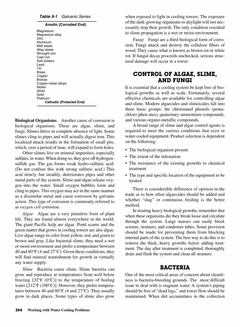
264 Working with Water-Cooling Problems
Biological Organisms Another cause of corrosion isbiological organisms. These are algae, slime, andfungi. Slimes thrive in complete absence of light. Someslimes cling to pipes and will actually digest iron. Thislocalized attack results in the formation of small pits,which, over a period of time, will expand to form holes.
Other slimes live on mineral impurities, especiallysulfates, in water. When doing so, they give off hydrogen-sulfide gas. The gas forms weak hydro-sulfuric acid.(Do not confuse this with strong sulfuric acid.) Thisacid slowly, but steadily, deteriorates pipes and othermetal parts of the system. Slime and algae release oxy-gen into the water. Small oxygen bubbles form andcling to pipes. This oxygen may act in the same manneras a dissimilar metal and cause corrosion by galvanicaction. This type of corrosion is commonly referred toas oxygen cell corrosion.
Algae Algae are a very primitive form of plantlife. They are found almost everywhere in the world.The giant Pacific kelp are algae. Pond scums and thegreen matter that grows in cooling towers are also algae.Live algae range in color from yellow, red, and green tobrown and gray. Like bacterial slime, they need a wetor moist environment and prefer a temperature between40 and 80°F (4 and 27°C). Given these conditions, theywill find mineral nourishment for growth in virtuallyany water supply.
Slime Bacteria cause slime. Slime bacteria cangrow and reproduce at temperatures from well belowfreezing [32°F (0°C)] to the temperature of boilingwater [212°F (100°C)]. However, they prefer tempera-tures between 40 and 80°F (4 and 27°C). They usuallygrow in dark places. Some types of slime also grow
when exposed to light in cooling towers. The exposureof the dark-growing organisms to daylight will not nec-essarily stop their growth. The only condition essentialto slime propagation is a wet or moist environment.
Fungi Fungi are a third biological form of corro-sion. Fungi attack and destroy the cellulose fibers ofwood. They cause what is known as brown rot or whiterot. If fungal decay proceeds unchecked, serious struc-tural damage will occur in a tower.
CONTROL OF ALGAE, SLIME,AND FUNGI
It is essential that a cooling system be kept free of bio-logical growths as well as scale. Fortunately, severaleffective chemicals are available for controlling algaeand slime. Modern algaecides and slimeicides fall intothree basic groups: the chlorinated phenols (penta-chloro-phen-ates), quaternary-ammonium compounds,and various organo-metallic compounds.
A broad range of slime and algae control agents isrequired to meet the various conditions that exist inwater-cooled equipment. Product selection is dependenton the following:
• The biological organism present
• The extent of the infestation
• The resistance of the existing growths to chemicaltreatment
• The type and specific location of the equipment to betreated
There is considerable difference of opinion in thetrade as to how often algaecides should be added andwhether “slug” or continuous feeding is the bettermethod.
In treating heavy biological growths, remember thatwhen these organisms die they break loose and circulatethrough the system. Large masses can easily blockscreens, strainers, and condenser tubes. Some provisionshould be made for preventing them from blockinginternal parts of the system. The best way to do this is toremove the thick, heavy growths before adding treat-ment. The day after treatment is completed, thoroughlydrain and flush the system and clean all strainers.
BACTERIAOne of the most critical areas of concern about cleanli-ness is bacteria-breeding grounds. The most difficultissue to deal with is stagnant water. A system’s pipingshould be free of “dead legs,” and tower flow should bemaintained. When dirt accumulates in the collection
Table 9-1 Galvanic Series
Anodic (Corroded End)
MagnesiumMagnesium alloyZincAluminumMild steelsAlloy steelsWrought ironCast ironSoft soldersLeadTinBrassCopperBronzeCopper-nickel alloysNickelSilverGoldPlatinum
Cathodic (Protected End)

The Problem of Scale 265
basin of a tower, it provides the right combination ofsupplies for the creation of Legionella bacteria:
• Moisture
• Oxygen
• Warm water
• Food supply
These bacteria can be found in water supplies aswell as around rivers and/or streams. They are con-tained in water droplets and can become airborne. Thisbacteria makes humans susceptible to it by breathing inthe contaminated air. No chemicals can positivelyeliminate all bacteria from the water supply in a cool-ing tower. However, evidence exists to suggest thatgood maintenance along with comprehensive treat-ment can dramatically minimize the risk.
THE PROBLEM OF SCALE Air conditioning or refrigeration is basically the con-trolled removal of heat from a specific area. The refrig-erant that carries heat from the cooled space must becooled before it can be reused. Cooling and condensa-tion of refrigerant require the use of a cooling mediumthat, in many systems, is water.
There are two types of water-cooled systems. Thefirst type uses once-through operation. The water picksup heat and is then discarded or wasted. In effect, thisis 100 percent, or total, bleed. Little, if any, mineralconcentration occurs. The scale that forms is due to thebreak down of bicarbonates by heat. These form car-bonates, which are less soluble at high temperaturesthan at low. Such scale can be prevented through use ofa treatment chemical.
The other type of water-cooled system is the typein which heat is removed from water by partial evapo-
ration. The water is then recirculated. Water volumelost by evaporation is replaced. This type of system ismore economical from the standpoint of water use.However, the concentration of dissolved minerals leadsto conditions which, if not controlled and chemicallytreated, may result in heavy scale formation.
Evaporative SystemsOne method of operating evaporative recirculatingsystems involves 100 percent evaporation of the waterwith no bleed. This, of course, causes excessivemineral concentration. Without a bleed on the sys-tem, water conditions will soon exceed the capabilityof any treatment chemical. A second method of oper-ation employs a high bleed rate without chemicaltreatment. Scale will form and water is wasted. Thethird method is the reuse of water, with a bleed tocontrol concentration of scale-forming minerals.Thus, by the addition of minimum amounts of chemi-cal treatment, good water economy can be realized.This last approach is the most logical and leastexpensive. Figure 9-2 shows how connections forbleed lines are made on evaporative condensers andcooling towers.
Scale FormationScale is formed as a direct result of mineral insolubil-ity. This in turn, is a direct function of temperature,hardness, alkalinity, pH, and total-dissolved solids.Generally speaking, as these factors increase, solubil-ity or stability of scale-forming minerals decreases.Unlike most minerals, scale-forming salts are less solu-ble at high temperatures. For this reason, scale formsmost rapidly on heat-exchanger surfaces.
Fig. 9-2 Connections for bleed lines for evaporative condensers and cooling towers. (Virginia Chemical)

266 Working with Water-Cooling Problems
HOW TO CLEAN COOLINGTOWERS AND EVAPORATIVE
CONDENSERSTo clean cooling towers and evaporative condensers,first determine the amount of water in the system. Thisis done by the following procedures.
Determining the Amountof Water in the Sump
Measure the length, width, and water depth in feet. SeeFig. 9-3.
Use the following formula—length × width × waterdepth × 7.5 = gallons of water in the sump.
Example: A sump is 5 ft long and 4 ft wide, with awater depth of 6 in.
Solution:
5 × 4 × 0.5 × 7.5 = 75 gal of water in the sump
Determining the Amountof Water In the Tank
1. Measure the diameter of the tank and the depth ofthe water in feet. See Fig. 9-4.
2. Use the following formula: diameter 2 × water depth ×6 = gallons of water in tank.
Example: A tank has a diameter of 3 ft and the wateris 3 ft deep.
Solution:
32 × 3 × 6, or 9 × 3 × 6 = 162 gal of water in the tank
Total Water VolumeThe preceding two formulas will give you the water vol-ume in either the tank or sump. Each is figured sepa-rately since they are both part of the system’s circulatingwater supply. There is also water in the connecting lines.These lines must be measured for total footage. Onceyou find the pipe footage connecting the system you canfigure its volume of water too. Simply take 10 percent ofthe water volume in the sump for each 50 ft of pipe run.This is added to the water in the sump and the water inthe tank to find the total system water volume.
For example, a system has 75 gal of water in thesump and 162 gal of water in the tank. The system has160 ft of pipe.
75 gal + 162 gal = 237 gal
160 ft ÷ 50 ft = 3.2 ft
75 gal in sump ÷ 10 = 7.5 gal for every 50 ft in thepipes
7.5 gal × 3.2 = 24 gal in the total-pipe system
237 gal (in tank and sump) + 24 gal (in pipes) =261 gal in the total system. This is the amount ofwater that must be treated to keep the system operatingproperly.
Now that you have determined the volume of waterin the system, you can calculate the amount of chemi-cals needed.
1. Drain the sump. Flush out, or remove manually, allloose sludge and dirt. This is important because theywaste the chemicals.
2. Close the bleed line and refill the sump with freshwater to the lowest level at which the circulatingpump will operate. See Fig. 9-5.
3. Calculate the total gallons of water in the system.Next, while the water is circulating, add startingamounts of either chemical slowly, as follows.
NOTE: These amounts are for hotwater systems.
For cold water systems, see the section “ChilledWater Systems.”
Fig. 9-3 Method of calculating the amount of water in a rectan-gular tank or sump.
Fig. 9-4 Calculating the amount of water in a round tank. (Virginia
Chemicals)
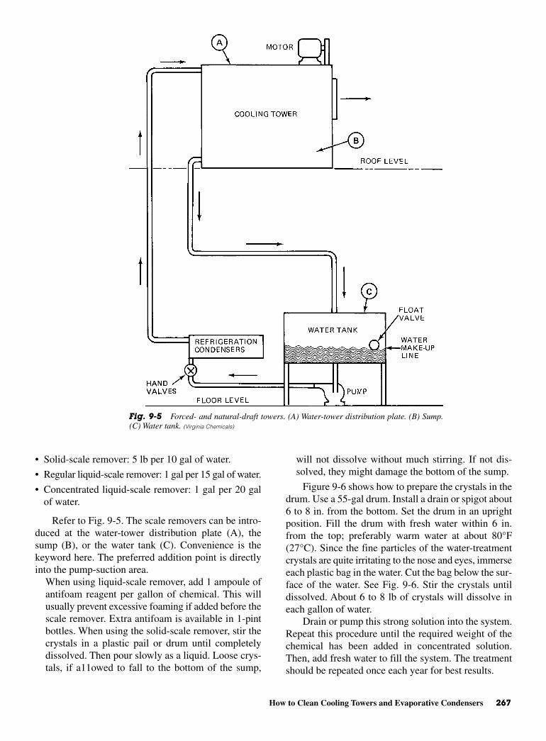
How to Clean Cooling Towers and Evaporative Condensers 267
• Solid-scale remover: 5 lb per 10 gal of water.
• Regular liquid-scale remover: 1 gal per 15 gal of water.
• Concentrated liquid-scale remover: 1 gal per 20 galof water.
Refer to Fig. 9-5. The scale removers can be intro-duced at the water-tower distribution plate (A), thesump (B), or the water tank (C). Convenience is thekeyword here. The preferred addition point is directlyinto the pump-suction area.
When using liquid-scale remover, add 1 ampoule ofantifoam reagent per gallon of chemical. This willusually prevent excessive foaming if added before thescale remover. Extra antifoam is available in 1-pintbottles. When using the solid-scale remover, stir thecrystals in a plastic pail or drum until completelydissolved. Then pour slowly as a liquid. Loose crys-tals, if a11owed to fall to the bottom of the sump,
will not dissolve without much stirring. If not dis-solved, they might damage the bottom of the sump.
Figure 9-6 shows how to prepare the crystals in thedrum. Use a 55-gal drum. Install a drain or spigot about6 to 8 in. from the bottom. Set the drum in an uprightposition. Fill the drum with fresh water within 6 in.from the top; preferably warm water at about 80°F(27°C). Since the fine particles of the water-treatmentcrystals are quite irritating to the nose and eyes, immerseeach plastic bag in the water. Cut the bag below the sur-face of the water. See Fig. 9-6. Stir the crystals untildissolved. About 6 to 8 lb of crystals will dissolve ineach gallon of water.
Drain or pump this strong solution into the system.Repeat this procedure until the required weight of thechemical has been added in concentrated solution.Then, add fresh water to fill the system. The treatmentshould be repeated once each year for best results.
Fig. 9-5 Forced- and natural-draft towers. (A) Water-tower distribution plate. (B) Sump.(C) Water tank. (Virginia Chemicals)
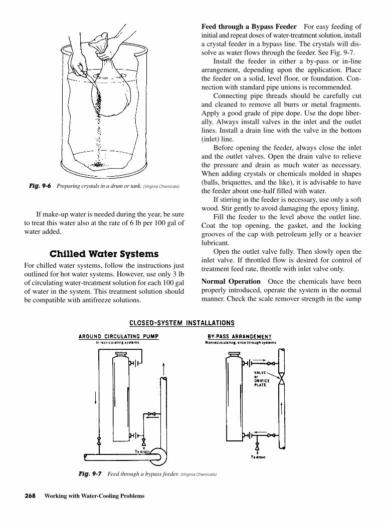
268 Working with Water-Cooling Problems
If make-up water is needed during the year, be sureto treat this water also at the rate of 6 lb per 100 gal ofwater added.
Chilled Water SystemsFor chilled water systems, follow the instructions justoutlined for hot water systems. However, use only 3 lbof circulating water-treatment solution for each 100 galof water in the system. This treatment solution shouldbe compatible with antifreeze solutions.
Feed through a Bypass Feeder For easy feeding ofinitial and repeat doses of water-treatment solution, installa crystal feeder in a bypass line. The crystals will dis-solve as water flows through the feeder. See Fig. 9-7.
Install the feeder in either a by-pass or in-linearrangement, depending upon the application. Placethe feeder on a solid, level floor, or foundation. Con-nection with standard pipe unions is recommended.
Connecting pipe threads should be carefully cutand cleaned to remove all burrs or metal fragments.Apply a good grade of pipe dope. Use the dope liber-ally. Always install valves in the inlet and the outletlines. Install a drain line with the valve in the bottom(inlet) line.
Before opening the feeder, always close the inletand the outlet valves. Open the drain valve to relievethe pressure and drain as much water as necessary.When adding crystals or chemicals molded in shapes(balls, briquettes, and the like), it is advisable to havethe feeder about one-half filled with water.
If stirring in the feeder is necessary, use only a softwood. Stir gently to avoid damaging the epoxy lining.
Fill the feeder to the level above the outlet line.Coat the top opening, the gasket, and the lockinggrooves of the cap with petroleum jelly or a heavierlubricant.
Open the outlet valve fully. Then slowly open theinlet valve. If throttled flow is desired for control oftreatment feed rate, throttle with inlet valve only.
Normal Operation Once the chemicals have beenproperly introduced, operate the system in the normalmanner. Check the scale remover strength in the sump
Fig. 9-6 Preparing crystals in a drum or tank. (Virginia Chemicals)
Fig. 9-7 Feed through a bypass feeder. (Virginia Chemicals)
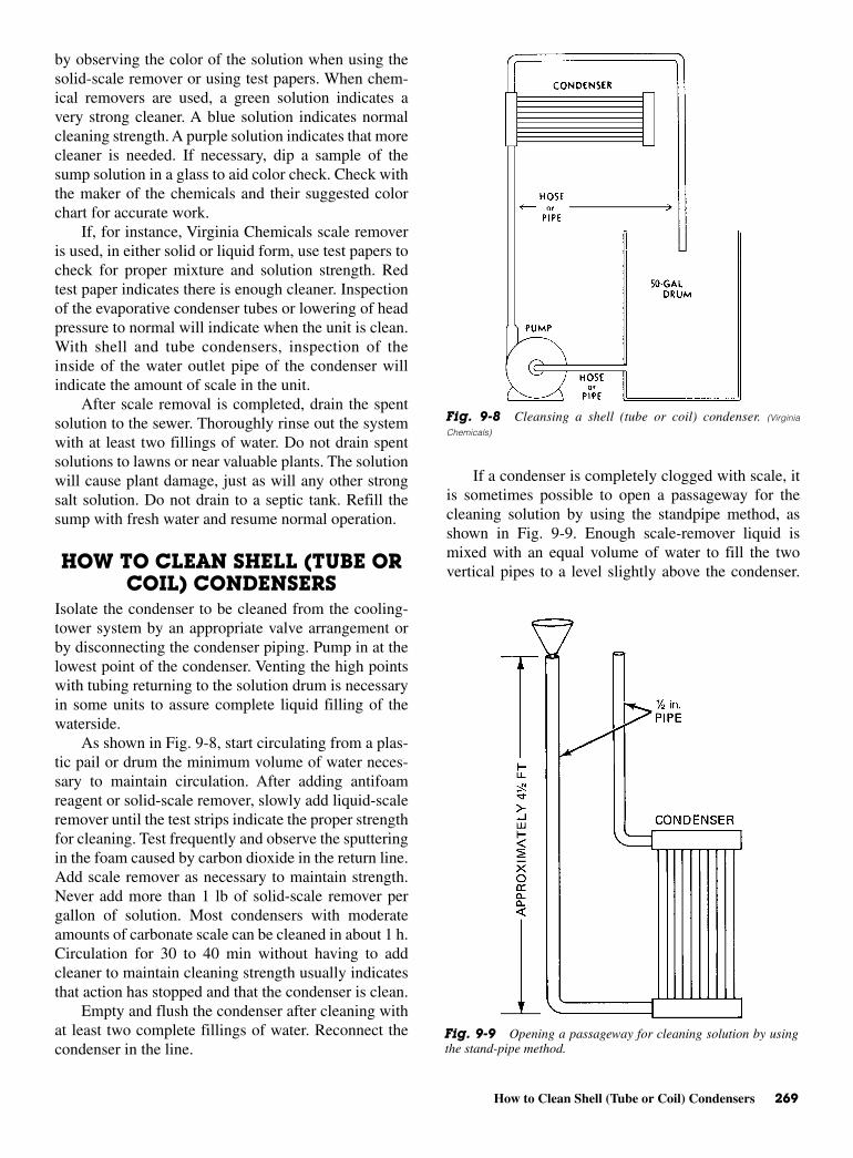
How to Clean Shell (Tube or Coil) Condensers 269
by observing the color of the solution when using thesolid-scale remover or using test papers. When chem-ical removers are used, a green solution indicates avery strong cleaner. A blue solution indicates normalcleaning strength. A purple solution indicates that morecleaner is needed. If necessary, dip a sample of thesump solution in a glass to aid color check. Check withthe maker of the chemicals and their suggested colorchart for accurate work.
If, for instance, Virginia Chemicals scale removeris used, in either solid or liquid form, use test papers tocheck for proper mixture and solution strength. Redtest paper indicates there is enough cleaner. Inspectionof the evaporative condenser tubes or lowering of headpressure to normal will indicate when the unit is clean.With shell and tube condensers, inspection of theinside of the water outlet pipe of the condenser willindicate the amount of scale in the unit.
After scale removal is completed, drain the spentsolution to the sewer. Thoroughly rinse out the systemwith at least two fillings of water. Do not drain spentsolutions to lawns or near valuable plants. The solutionwill cause plant damage, just as will any other strongsalt solution. Do not drain to a septic tank. Refill thesump with fresh water and resume normal operation.
HOW TO CLEAN SHELL (TUBE ORCOIL) CONDENSERS
Isolate the condenser to be cleaned from the cooling-tower system by an appropriate valve arrangement orby disconnecting the condenser piping. Pump in at thelowest point of the condenser. Venting the high pointswith tubing returning to the solution drum is necessaryin some units to assure complete liquid filling of thewaterside.
As shown in Fig. 9-8, start circulating from a plas-tic pail or drum the minimum volume of water neces-sary to maintain circulation. After adding antifoamreagent or solid-scale remover, slowly add liquid-scaleremover until the test strips indicate the proper strengthfor cleaning. Test frequently and observe the sputteringin the foam caused by carbon dioxide in the return line.Add scale remover as necessary to maintain strength.Never add more than 1 lb of solid-scale remover pergallon of solution. Most condensers with moderateamounts of carbonate scale can be cleaned in about 1 h.Circulation for 30 to 40 min without having to addcleaner to maintain cleaning strength usually indicatesthat action has stopped and that the condenser is clean.
Empty and flush the condenser after cleaning withat least two complete fillings of water. Reconnect thecondenser in the line.
If a condenser is completely clogged with scale, itis sometimes possible to open a passageway for thecleaning solution by using the standpipe method, asshown in Fig. 9-9. Enough scale-remover liquid ismixed with an equal volume of water to fill the twovertical pipes to a level slightly above the condenser.
Fig. 9-8 Cleansing a shell (tube or coil) condenser. (Virginia
Chemicals)
Fig. 9-9 Opening a passageway for cleaning solution by usingthe stand-pipe method.
270 Working with Water-Cooling Problems
Some foaming will result from the action of the cleanersolution on the scale. Thus, some protective measuresshould be taken to prevent foam from injuring sur-rounding objects. The antifoam reagent supplied witheach package will help control this nuisance. When thecleaning operation has been completed drain the spentsolution to the sewer. Rinse the condenser with at leasttwo fillings of fresh water.
SAFETYMost areas of the tower must be inspected for safeworking and operating conditions. A number of itemsshould be inspected yearly and repaired immediately inorder to guarantee the safety of maintenance personnel.
• Scale remover contains acid and can cause skin irri-tation. Avoid contact with your eyes, skin, and cloth-ing. In case of contact, flush the skin or eyes withplenty of water for at least 15 min. If the eyes areaffected, get medical attention.
• Keep scale remover and other chemicals out of thereach of children.
• Do not drain the spent solution to the roof or to a sep-tic tank. Always drain the spent solution in an envi-ronmentally safe way, not to the storm sewer.
• Safety is all-important. All chemicals, especiallyacids, should be treated with great respect and han-dled with care. Rubber gloves, acid-proof coveralls,and safety goggles should be worn when workingwith chemicals. Cleaning a system through the tower,although easier and faster than some of the othermethods, presents one unique hazard—wind drift.
Wind drift, even with the tower fan off, is a definitepossibility. Wind drift will carry tiny droplets of acidthat can burn eyes and skin. These acid droplets willalso damage automobile finishes and buildings. Shouldcleaning solution contact any part of the person, itshould be washed off immediately with soap and water.
Using forethought and reasonable precaution canprevent grief and expense.
SOLVENTS AND DETERGENTSThere are several uses for solvents and detergents inthe ordinary maintenance schedule of air-cooled fincoil condensers, evaporator coils, permanent-type airfilters, and fan blades. In most instances, a high-pressure spray washer is used to clean the equipmentwith detergent. Then a high-pressure spray rinse isused to clean the unit being scrubbed. The pump is usu-ally rated at 2 gal/min at 500 lb/in.2 of pressure. The
main function is to remove dirt and grease from fansand cooling surfaces. It takes about 10 to 15 min for thecleaning solution to do its job. It is then rinsed withclean water.
Using the dipping method cleans permanent-typefilters. Prepare a cleaning solution-one part detergent toone part water. Use this solution as a bath in which thefilters may be immersed briefly. After dipping, set thefilter aside for 10 to 15 min. Flush with a stream of water.If water is not available, good results may be obtained bybrisk agitation in a tank filled with fresh water.
When draining the solution used for cleaning pur-poses, be sure to follow the local codes on the use ofthe storm sewers for disposal purposes. Proper disposalof the spent solution is critical for legal operation ofthis type of air-conditioning unit.
Another more recent requirement is the use ofasbestos in the construction of the tower fill. If discov-ered when inspections are conducted, make sure it isreplaced with the latest materials. The older towers canbecome more efficient with newer fill of more moderndesign.
Cooling tower manufacturers design their unitsfor:
• A given performance standard
• Conditions such as: • The type of chiller used • Ambient temperatures • Location • Specifications
As a system ages, it may lose efficiency. The clean-liness of the tower and its components are crucial to thesuccess of the system. An unattended cold-water tem-perature will rise. This will send warmer water to thechiller. When the chiller kicks out on high head pres-sure, the system may shut down. Certain precautionsshould be taken to prevent shutdown from occurring.
REVIEW QUESTIONS1. Why is rainwater not pure?
2. Why is water that is fit for human consumption notusable in boilers and cooling equipment?
3. How can scaling be prevented?
4. List some aggressive or strong acids.
5. In what way does oxygen cause corrosion?
6. What is meant by galvanic action?
7. What are algae?
8. What is slime?
Review Questions 271
9. What damage does fungi cause?
10. How are shell condensers cleaned?
11. What safety precautions should be taken whenusing scale remover?
12. How does wind drift affect tower operation?
13. How is detergent used to clean condensers andevaporator coils?
14. How are permanent-type filters cleaned?
15. How do you dispose off spent chemicals?

This page intentionally left blank

10CHAPTER
Evaporators
Copyright © 2006 by The McGraw-Hill Companies, Inc. Click here for terms of use.

PERFORMANCE OBJECTIVESAfter studying this chapter you should:
1. Be able to identify various types of evaporators.
2. Know how a shell-and-tube chiller operates.
3. Know how hot-gas defrost of ammonia evaporatorscontrols operate.
4. Know how various types of evaporators operate.
5. Know the value of control valves in the proper oper-ation of evaporators.
6. Know how to troubleshoot a differential pressure-relief regulator.
7. Know how the differential pressure-relief regulatorworks.
The evaporator removes heat from the space beingcooled. As the air is cooled, it condenses water vapor.This must be drained. If the water condensing on theevaporator coil freezes when the temperature is below32°F (0°C), the refrigerator or freezer must workharder. Frozen water or ice acts as an insulator. It reducesthe efficiency of the evaporator. When evaporators areoperated below 32°F, they must be defrosted periodic-ally. This eliminates frost buildup on the coils or theevaporator plates.
There are several types of evaporators. The coiledevaporator is used in warehouses for refrigerating largeareas. The fin evaporator is used in the air-conditioningsystem that is part of the furnace in a house. See Fig. 10-1.The finned evaporator has a fan that blows air over itsthin metal surfaces. Plate evaporators use flat surfacesfor their cooling surface. See Fig. 10-2. They are com-monly used in freezers. If the object to be cooled orfrozen is placed directly in contact with the evaporatorplate, the cold is transferred more efficiently.
Figure 10-3 shows a home refrigerator cooling sys-tem. Note the evaporator.
COILED EVAPORATOR Evaporator coils on air-conditioning units fall into twocategories:
• Finned-tube coil. The finned-tube coil is placed in theair stream of the unit. Refrigerant vaporizes in it. Therefrigerant in the tubes and the air flowing aroundthe fins attached to the tubes draw heat from the air.This is commonly referred to as a direct expansioncooling system. See Fig. 10-4.
• Shell-and-tube chiller. Shell-and-tube units are used tochill water for air-cooling purposes. Usually, the refrig-erant is to tubes mounted inside a tank or shell contain-
ing the water or liquid to be cooled. The refrigerant inthe tubes draws the heat through the tube wall and fromthe liquid as it flows around the tubes in the shell. Thissystem can be reversed. Thus, the water would be in thetubes and the refrigerant would be in the tank. As thegas passes through the tank over the tubes, it woulddraw the heat from the water in the tubes. See Fig. 10-5.
Figure l0-5 shows how K-12 is used in a standardvapor-compression refrigeration cycle. System waterfor air conditioning and other uses is cooled as it flowsthrough the evaporator tubes. Heat is transferred fromthe water to the low-temperature, low-pressure refrig-erant. The heat removed from the water causes the refrig-erant to evaporate. The refrigerant vapor is drawn into
274 Evaporators
Fig. 10-1 Evaporators. (A) Evaporator used in home air-conditioning systems where the unit is placed in the bonnet of thehot-air furnace. (B) Slanted evaporator used in home air condi-tioning. (Lennex)
Fig. 10-2 Plate evaporator.

Application of Controls for Hot-Gas Defrost of Ammonia Evaporators 275
the first stage of the compressor at a rate controlled bythe size of the guide-vane opening. The first stage of thecompressor raises the temperature and pressure of thevapor. This vapor, plus vapor from the flash econo-mizer, flows into the second stage of the compressor.There, the saturation temperature of the refrigerant israised above that of the condenser water.
This vapor mixture is discharged directly into thecondenser. There, relatively cool condenser water removesheat from the vapor, causing it to condense again to liq-uid. The heated water leaves the system, returning to acooling tower or other heat-rejection device.
A thermal economizer in the bottom section of thecondenser brings warm condensed refrigerant into con-tact with the inlet water tubes. These are the coldestwater tubes. They may hold water with a temperatureas low as 55°F (13°C). This subcools the refrigerant sothat when it moves on in the cycle, it has greater cool-ing potential. This improves cycle efficiency and reducespower per ton requirements. The liquefied refrigerantleaves the condenser through a plate-type control. Itflows into the flash economizer or utility vessel. Here,the normal flashing of part of the refrigerant into vaporcools the remaining refrigerant. This flash vapor isdiverted directly to the second stage of the compressor.Thus, it does not need to be pumped through the fullcompression cycle. The net effect of the flash econo-mizer is energy savings and lower operating costs. Asecond plate-type control meters the flow of liquidrefrigerant from the utility vessel back to the cooler,where the cycle begins again. See Fig. 10-6.
APPLICATION OF CONTROLS FORHOT-GAS DEFROST OF AMMONIA
EVAPORATORS To defrost ammonia evaporators, it is sometimes neces-sary to check the plumbing arrangement and the valvesused to accomplish the task. To enable hot-gas defrostsystems to operate successfully, several factors must beconsidered. There must be an adequate supply of hot gas.The gas should be at a minimum of 100 psig. The defrostcycle should be accurately timed. Condensate removalor storage must be provided. An automatic suction
Fig. 10-3 A home refrigerator’s cooling system.
Fig. 10-4 Finned-coil evaporator. (Johnson Controls)

276E
vaporators
Fig. 10-5 Complete operation of a shell-and-tube chiller. (Carrier Corporation)
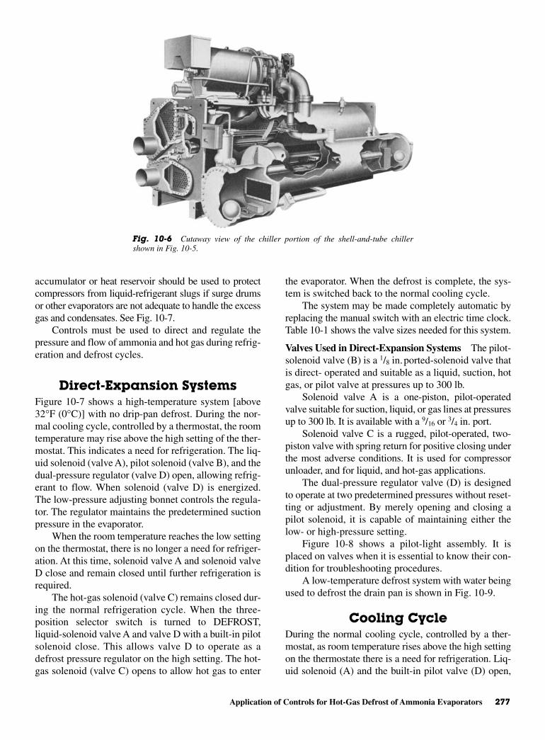
Application of Controls for Hot-Gas Defrost of Ammonia Evaporators 277
accumulator or heat reservoir should be used to protectcompressors from liquid-refrigerant slugs if surge drumsor other evaporators are not adequate to handle the excessgas and condensates. See Fig. 10-7.
Controls must be used to direct and regulate thepressure and flow of ammonia and hot gas during refrig-eration and defrost cycles.
Direct-Expansion Systems Figure 10-7 shows a high-temperature system [above32°F (0°C)] with no drip-pan defrost. During the nor-mal cooling cycle, controlled by a thermostat, the roomtemperature may rise above the high setting of the ther-mostat. This indicates a need for refrigeration. The liq-uid solenoid (valve A), pilot solenoid (valve B), and thedual-pressure regulator (valve D) open, allowing refrig-erant to flow. When solenoid (valve D) is energized.The low-pressure adjusting bonnet controls the regula-tor. The regulator maintains the predetermined suctionpressure in the evaporator.
When the room temperature reaches the low settingon the thermostat, there is no longer a need for refriger-ation. At this time, solenoid valve A and solenoid valveD close and remain closed until further refrigeration isrequired.
The hot-gas solenoid (valve C) remains closed dur-ing the normal refrigeration cycle. When the three-position selector switch is turned to DEFROST,liquid-solenoid valve A and valve D with a built-in pilotsolenoid close. This allows valve D to operate as adefrost pressure regulator on the high setting. The hot-gas solenoid (valve C) opens to allow hot gas to enter
the evaporator. When the defrost is complete, the sys-tem is switched back to the normal cooling cycle.
The system may be made completely automatic byreplacing the manual switch with an electric time clock.Table 10-1 shows the valve sizes needed for this system.
Valves Used in Direct-Expansion Systems The pilot-solenoid valve (B) is a 1/8 in.ported-solenoid valve thatis direct- operated and suitable as a liquid, suction, hotgas, or pilot valve at pressures up to 300 lb.
Solenoid valve A is a one-piston, pilot-operatedvalve suitable for suction, liquid, or gas lines at pressuresup to 300 lb. It is available with a 9/16 or 3/4 in. port.
Solenoid valve C is a rugged, pilot-operated, two-piston valve with spring return for positive closing underthe most adverse conditions. It is used for compressorunloader, and for liquid, and hot-gas applications.
The dual-pressure regulator valve (D) is designedto operate at two predetermined pressures without reset-ting or adjustment. By merely opening and closing apilot solenoid, it is capable of maintaining either thelow- or high-pressure setting.
Figure 10-8 shows a pilot-light assembly. It isplaced on valves when it is essential to know their con-dition for troubleshooting procedures.
A low-temperature defrost system with water beingused to defrost the drain pan is shown in Fig. 10-9.
Cooling CycleDuring the normal cooling cycle, controlled by a ther-mostat, as room temperature rises above the high settingon the thermostate there is a need for refrigeration. Liq-uid solenoid (A) and the built-in pilot valve (D) open,
Fig. 10-6 Cutaway view of the chiller portion of the shell-and-tube chillershown in Fig. 10-5.

278 Evaporators
Fig. 10-7 High-temperature defrost system. (Hubbell)
Table 10-1 Valve Sizing for High-Temperature System
Tons Liquid Hot-Gas Pilot Dual-PressureRefrigerant Solenoid (in.) Solenoid (in.) Solenoid (in.) Regulator (in.)
3 1/2 1/2 1/4 3/45 1/2 1/2 1/4 3/47 1/2 1/2 1/4 1
10 1/2 1/2 1/4 11/412 1/2 1/2 1/4 11/415 1/2 1/2 1/4 11/220 1/2 1/2 1/4 11/225 1/2 1/2 1/4 230 1/2 1/2 1/4 235 1/2 1/2 1/4 240 3/4 3/4 1/4 245 3/4 3/4 1/4 21/250 3/4 3/4 1/4 21/2
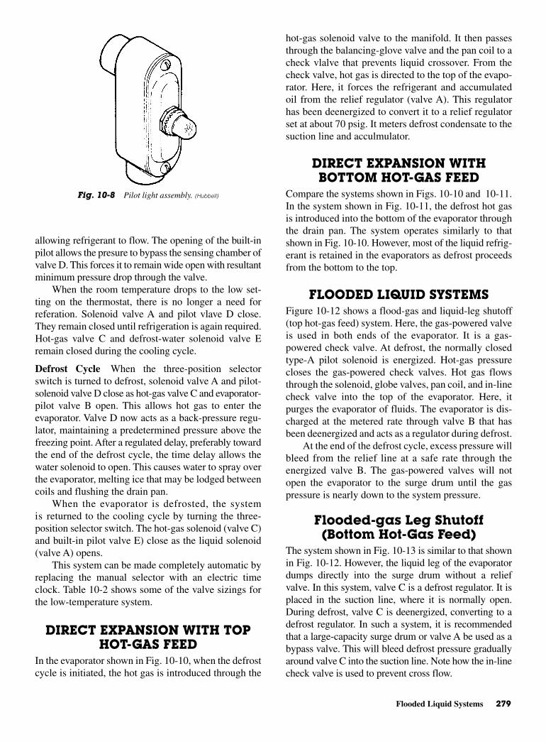
Flooded Liquid Systems 279
allowing refrigerant to flow. The opening of the built-inpilot allows the presure to bypass the sensing chamber ofvalve D. This forces it to remain wide open with resultantminimum pressure drop through the valve.
When the room temperature drops to the low set-ting on the thermostat, there is no longer a need forreferation. Solenoid valve A and pilot vlave D close.They remain closed until refrigeration is again required.Hot-gas valve C and defrost-water solenoid valve Eremain closed during the cooling cycle.
Defrost Cycle When the three-position selectorswitch is turned to defrost, solenoid valve A and pilot-solenoid valve D close as hot-gas valve C and evaporator-pilot valve B open. This allows hot gas to enter theevaporator. Valve D now acts as a back-pressure regu-lator, maintaining a predetermined pressure above thefreezing point. After a regulated delay, preferably towardthe end of the defrost cycle, the time delay allows thewater solenoid to open. This causes water to spray overthe evaporator, melting ice that may be lodged betweencoils and flushing the drain pan.
When the evaporator is defrosted, the systemis returned to the cooling cycle by turning the three-position selector switch. The hot-gas solenoid (valve C)and built-in pilot valve E) close as the liquid solenoid(valve A) opens.
This system can be made completely automatic byreplacing the manual selector with an electric timeclock. Table 10-2 shows some of the valve sizings forthe low-temperature system.
DIRECT EXPANSION WITH TOPHOT-GAS FEED
In the evaporator shown in Fig. 10-10, when the defrostcycle is initiated, the hot gas is introduced through the
hot-gas solenoid valve to the manifold. It then passesthrough the balancing-glove valve and the pan coil to acheck vlalve that prevents liquid crossover. From thecheck valve, hot gas is directed to the top of the evapo-rator. Here, it forces the refrigerant and accumulatedoil from the relief regulator (valve A). This regulatorhas been deenergized to convert it to a relief regulatorset at about 70 psig. It meters defrost condensate to thesuction line and acculmulator.
DIRECT EXPANSION WITHBOTTOM HOT-GAS FEED
Compare the systems shown in Figs. 10-10 and 10-11.In the system shown in Fig. 10-11, the defrost hot gasis introduced into the bottom of the evaporator throughthe drain pan. The system operates similarly to thatshown in Fig. 10-10. However, most of the liquid refrig-erant is retained in the evaporators as defrost proceedsfrom the bottom to the top.
FLOODED LIQUID SYSTEMS Figure 10-12 shows a flood-gas and liquid-leg shutoff(top hot-gas feed) system. Here, the gas-powered valveis used in both ends of the evaporator. It is a gas-powered check valve. At defrost, the normally closedtype-A pilot solenoid is energized. Hot-gas pressurecloses the gas-powered check valves. Hot gas flowsthrough the solenoid, globe valves, pan coil, and in-linecheck valve into the top of the evaporator. Here, itpurges the evaporator of fluids. The evaporator is dis-charged at the metered rate through valve B that hasbeen deenergized and acts as a regulator during defrost.
At the end of the defrost cycle, excess pressure willbleed from the relief line at a safe rate through theenergized valve B. The gas-powered valves will notopen the evaporator to the surge drum until the gaspressure is nearly down to the system pressure.
Flooded-gas Leg Shutoff(Bottom Hot-Gas Feed)
The system shown in Fig. 10-13 is similar to that shownin Fig. 10-12. However, the liquid leg of the evaporatordumps directly into the surge drum without a reliefvalve. In this system, valve C is a defrost regulator. It isplaced in the suction line, where it is normally open.During defrost, valve C is deenergized, converting to adefrost regulator. In such a system, it is recommendedthat a large-capacity surge drum or valve A be used as abypass valve. This will bleed defrost pressure graduallyaround valve C into the suction line. Note how the in-linecheck valve is used to prevent cross flow.
Fig. 10-8 Pilot light assembly. (Hubbell)

280 Evaporators
Flooded-CeilingEvaporator—Liquid-Leg Shutoff
(Bottom Hot-Gas Feed)Figure 10-14 illustrates a flooded-ceiling evaporator.Upon initiation of the defrost sequence, the hot-gassolenoid (Number 1) is opened. Gas flows to gas-powered check valve, isolating the bottom of the surgetank from the evaporator. The hot gas flows through thepan coil and the in-line check valve into the evaporator.Excess gas pressure is dumped into the surge tank. It
will bleed through valve A. During defrost, this valvehas been deenergized to perform as a relief regulatorset at approximately 70 psig.
Flooded-CeilingEvaporator—Liquid-Leg Shutoff
(Top Hot-Gas Feed)Figure 10-15 shows a multiple flooded-evaporator sys-tem using input and output headers to connect the variousevaporators and the surge drum. Note that, upon defrost,
Fig. 10-9 Low-temperature defrost system. (Hubbell)
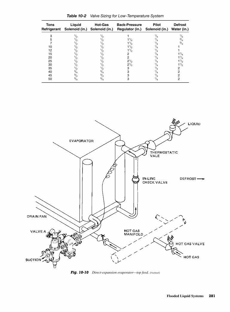
Flooded Liquid Systems 281
Fig. 10-10 Direct-expansion evaporator—top feed. (Hubbell)
Table 10-2 Valve Sizing for Low-Temperature System
Tons Liquid Hot-Gas Back-Pressure Pilot DefrostRefrigerant Solenoid (in.) Solenoid (in.) Regulator (in.) Solenoid (in.) Water (in.)
3 1/2 1/2 1 1/4 1/25 1/2 1/2 11/4 1/4 3/47 1/2 1/2 11/4 1/4 3/4
10 1/2 1/2 11/2 1/4 112 1/2 1/2 11/2 1/4 115 1/2 1/2 2 1/4 11/420 1/2 1/2 2 1/4 11/425 1/2 1/2 21/2 1/4 11/230 1/2 1/2 21/2 1/4 11/235 1/2 1/2 3 1/4 240 3/4 3/4 3 1/4 245 3/4 3/4 3 1/4 250 3/4 3/4 3 1/4 2
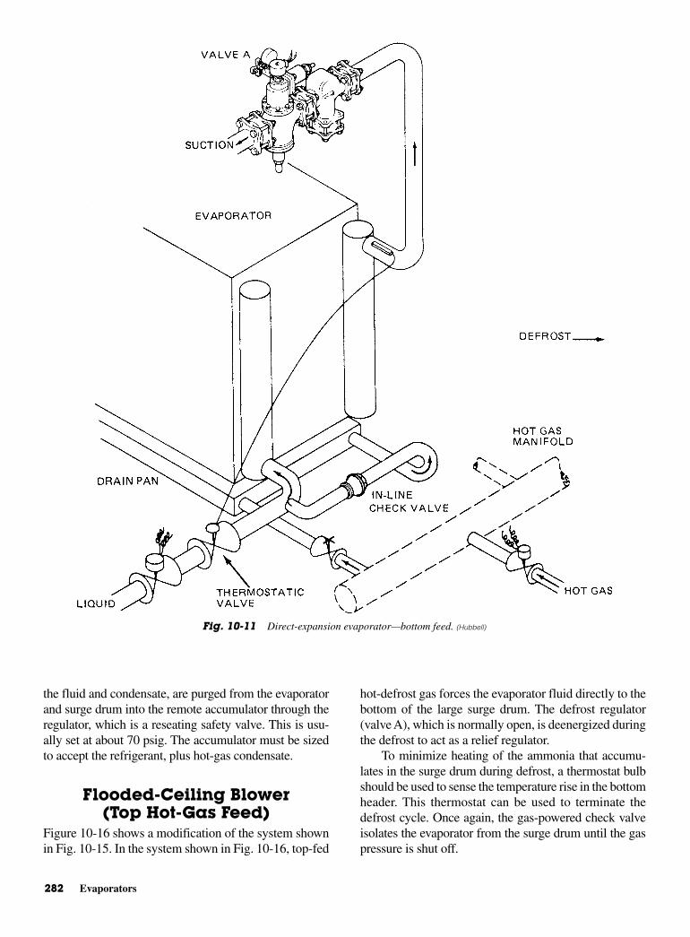
282 Evaporators
the fluid and condensate, are purged from the evaporatorand surge drum into the remote accumulator through theregulator, which is a reseating safety valve. This is usu-ally set at about 70 psig. The accumulator must be sizedto accept the refrigerant, plus hot-gas condensate.
Flooded-Ceiling Blower(Top Hot-Gas Feed)
Figure 10-16 shows a modification of the system shownin Fig. 10-15. In the system shown in Fig. 10-16, top-fed
hot-defrost gas forces the evaporator fluid directly to thebottom of the large surge drum. The defrost regulator(valve A), which is normally open, is deenergized duringthe defrost to act as a relief regulator.
To minimize heating of the ammonia that accumu-lates in the surge drum during defrost, a thermostat bulbshould be used to sense the temperature rise in the bottomheader. This thermostat can be used to terminate thedefrost cycle. Once again, the gas-powered check valveisolates the evaporator from the surge drum until the gaspressure is shut off.
Fig. 10-11 Direct-expansion evaporator—bottom feed. (Hubbell)
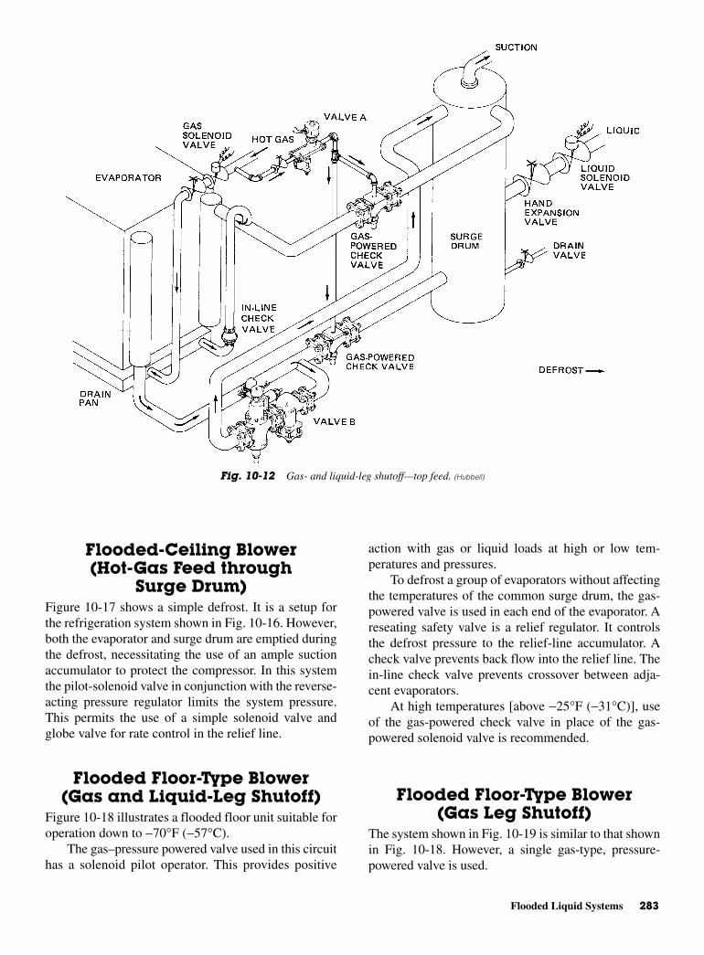
Flooded Liquid Systems 283
Flooded-Ceiling Blower(Hot-Gas Feed through
Surge Drum)Figure 10-17 shows a simple defrost. It is a setup forthe refrigeration system shown in Fig. 10-16. However,both the evaporator and surge drum are emptied duringthe defrost, necessitating the use of an ample suctionaccumulator to protect the compressor. In this systemthe pilot-solenoid valve in conjunction with the reverse-acting pressure regulator limits the system pressure.This permits the use of a simple solenoid valve andglobe valve for rate control in the relief line.
Flooded Floor-Type Blower(Gas and Liquid-Leg Shutoff)
Figure 10-18 illustrates a flooded floor unit suitable foroperation down to −70°F (−57°C).
The gas–pressure powered valve used in this circuithas a solenoid pilot operator. This provides positive
action with gas or liquid loads at high or low tem-peratures and pressures.
To defrost a group of evaporators without affectingthe temperatures of the common surge drum, the gas-powered valve is used in each end of the evaporator. Areseating safety valve is a relief regulator. It controlsthe defrost pressure to the relief-line accumulator. Acheck valve prevents back flow into the relief line. Thein-line check valve prevents crossover between adja-cent evaporators.
At high temperatures [above −25°F (−31°C)], useof the gas-powered check valve in place of the gas-powered solenoid valve is recommended.
Flooded Floor-Type Blower(Gas Leg Shutoff)
The system shown in Fig. 10-19 is similar to that shownin Fig. 10-18. However, a single gas-type, pressure-powered valve is used.
Fig. 10-12 Gas- and liquid-leg shutoff—top feed. (Hubbell)
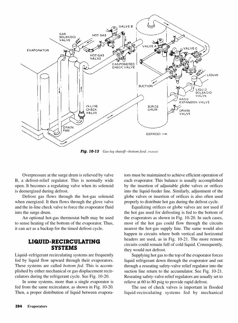
284 Evaporators
Overpressure at the surge drum is relieved by valveB, a defrost-relief regulator. This is normally wideopen. It becomes a regulating valve when its solenoidis deenergized during defrost.
Defrost gas flows through the hot-gas solenoidwhen energized. It then flows through the glove valveand the in-line check valve to force the evaporator fluidinto the surge drum.
An optional hot-gas thermostat bulb may be usedto sense heating of the bottom of the evaporator. Thus,it can act as a backup for the timed defrost cycle.
LIQUID-RECIRCULATINGSYSTEMS
Liquid–refrigerant recirculating systems are frequentlyfed by liquid flow upward through their evaporators.These systems are called bottom fed. This is accom-plished by either mechanical or gas displacement recir-culators during the refrigerant cycle. See Fig. 10-20.
In some systems, more than a single evaporator isfed from the same recirculator, as shown in Fig. 10-20.Then, a proper distribution of liquid between evapora-
tors must be maintained to achieve efficient operation ofeach evaporator. This balance is usually accomplishedby the insertion of adjustable globe valves or orificesinto the liquid-feeder line. Similarly, adjustment of theglobe valves or insertion of orifices is also often usedproperly to distribute hot gas during the defrost cycle.
Equalizing orifices or globe valves are not used ifthe hot gas used for defrosting is fed to the bottom ofthe evaporators as shown in Fig. 10-20. In such cases,most of the hot gas could flow through the circuitsnearest the hot-gas supply line. The same would alsohappen in circuits where both vertical and horizontalheaders are used, as in Fig. 10-21. The more remotecircuits could remain full of cold liquid. Consequently,they would not defrost.
Supplying hot gas to the top of the evaporator forcesliquid refrigerant down through the evaporator and outthrough a reseating safety-valve relief regulator into thesuction line return to the accumulator. See Fig. 10-21.Reseating safety-valve relief regulators are usually set torelieve at 60 to 80 psig to provide rapid defrost.
The use of check valves is important in floodedliquid-recirculating systems fed by mechanical
Fig. 10-13 Gas-leg shutoff—bottom feed. (Hubbell)
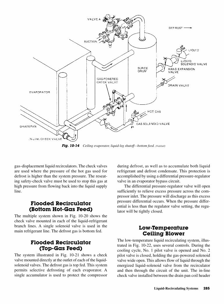
Liquid-Recirculating Systems 285
gas-displacement liquid recirculators. The check valvesare used where the pressure of the hot gas used fordefrost is higher than the system pressure. The reseat-ing safety-check valve must be used to stop this gas athigh pressure from flowing back into the liquid supplyline.
Flooded Recirculator(Bottom Hot-Gas Feed)
The multiple system shown in Fig. 10-20 shows thecheck valve mounted in each of the liquid-refrigerantbranch lines. A single solenoid valve is used in themain refrigerant line. The defrost gas is bottom fed.
Flooded Recirculator(Top-Gas Feed)
The system illustrated in Fig. 10-21 shows a checkvalve mounted directly at the outlet of each of the liquid-solenoid valves. The defrost gas is top fed. This systempermits selective defrosting of each evaporator. Asingle accumulator is used to protect the compressor
during defrost, as well as to accumulate both liquidrefrigerant and defrost condensate. This protection isaccomplished by using a differential pressure-regulatorvalve in an evaporator bypass circuit.
The differential pressure-regulator valve will opensufficiently to relieve excess pressure across the com-pressor inlet. The pressure will discharge as this excesspressure differential occurs. When the pressure differ-ential is less than the regulator valve setting, the regu-lator will be tightly closed.
Low-TemperatureCeiling Blower
The low-temperature liquid recirculating system, illus-trated in Fig. 10-22, uses several controls. During thecooling cycle, No. 1 pilot valve is opened and No. 2pilot valve is closed, holding the gas-powered solenoidvalve wide open. This allows flow of liquid through theenergized liquid-solenoid valve from the recirculatorand then through the circuit of the unit. The in-linecheck valve installed between the drain pan coil header
Fig. 10-14 Ceiling evaporator, liquid-leg shutoff—bottom feed. (Hubbell)
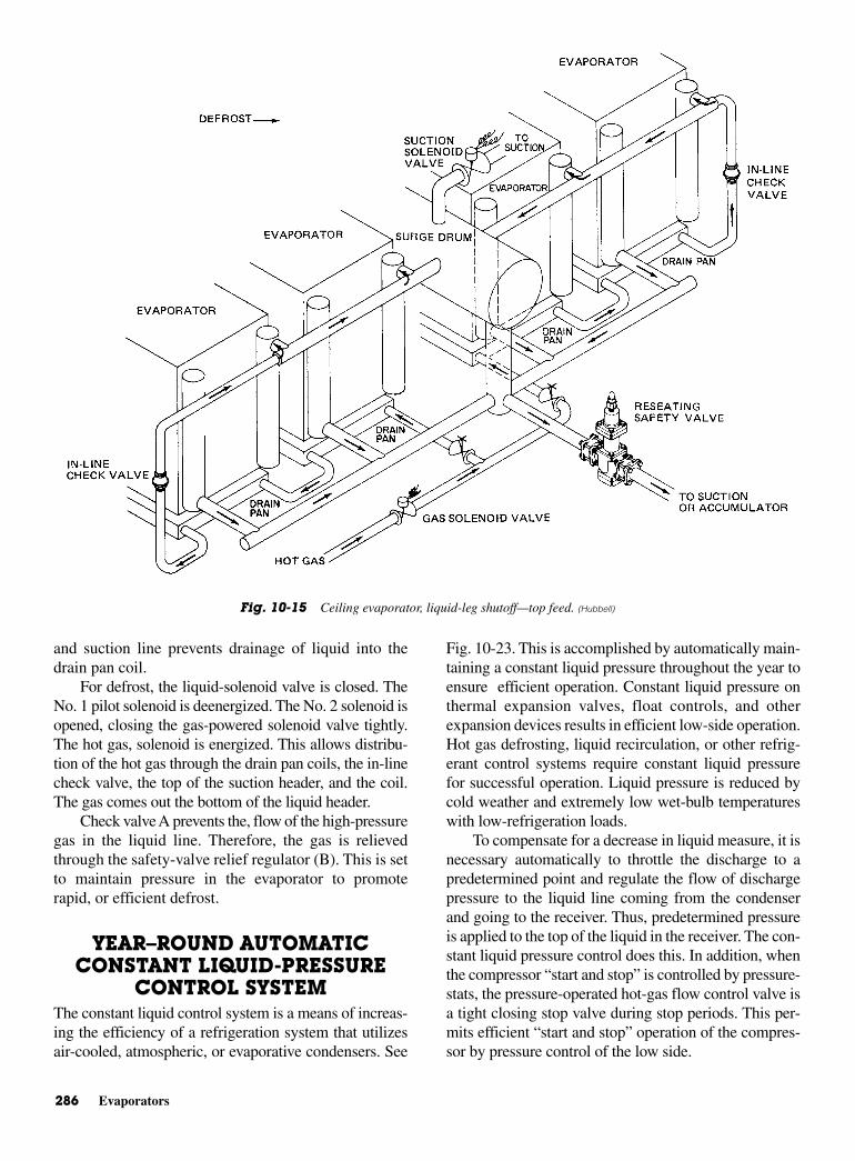
286 Evaporators
and suction line prevents drainage of liquid into thedrain pan coil.
For defrost, the liquid-solenoid valve is closed. TheNo. 1 pilot solenoid is deenergized. The No. 2 solenoid isopened, closing the gas-powered solenoid valve tightly.The hot gas, solenoid is energized. This allows distribu-tion of the hot gas through the drain pan coils, the in-linecheck valve, the top of the suction header, and the coil.The gas comes out the bottom of the liquid header.
Check valve A prevents the, flow of the high-pressuregas in the liquid line. Therefore, the gas is relievedthrough the safety-valve relief regulator (B). This is setto maintain pressure in the evaporator to promoterapid, or efficient defrost.
YEAR–ROUND AUTOMATICCONSTANT LIQUID-PRESSURE
CONTROL SYSTEMThe constant liquid control system is a means of increas-ing the efficiency of a refrigeration system that utilizesair-cooled, atmospheric, or evaporative condensers. See
Fig. 10-23. This is accomplished by automatically main-taining a constant liquid pressure throughout the year toensure efficient operation. Constant liquid pressure onthermal expansion valves, float controls, and otherexpansion devices results in efficient low-side operation.Hot gas defrosting, liquid recirculation, or other refrig-erant control systems require constant liquid pressurefor successful operation. Liquid pressure is reduced bycold weather and extremely low wet-bulb temperatureswith low-refrigeration loads.
To compensate for a decrease in liquid measure, it isnecessary automatically to throttle the discharge to apredetermined point and regulate the flow of dischargepressure to the liquid line coming from the condenserand going to the receiver. Thus, predetermined pressureis applied to the top of the liquid in the receiver. The con-stant liquid pressure control does this. In addition, whenthe compressor “start and stop” is controlled by pressure-stats, the pressure-operated hot-gas flow control valve isa tight closing stop valve during stop periods. This per-mits efficient “start and stop” operation of the compres-sor by pressure control of the low side.
Fig. 10-15 Ceiling evaporator, liquid-leg shutoff—top feed. (Hubbell)
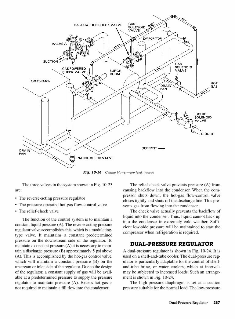
Dual-Pressure Regulator 287
The three valves in the system shown in Fig. 10-23are:
• The reverse-acting pressure regulator
• The pressure-operated hot-gas flow-control valve
• The relief-check valve
The function of the control system is to maintain aconstant liquid pressure (A). The reverse acting pressureregulator valve accomplishes this, which is a modulating-type valve. It maintains a constant predeterminedpressure on the downstream side of the regulator. Tomaintain a constant pressure (A) it is necessary to main-tain a discharge pressure (B) approximately 5 psi above(A). This is accomplished by the hot-gas control valve,which will maintain a constant pressure (B) on theupstream or inlet side of the regulator. Due to the designof the regulator, a constant supply of gas will be avail-able at a predetermined pressure to supply the pressureregulator to maintain pressure (A). Excess hot gas isnot required to maintain a fill flow into the condenser.
The relief-check valve prevents pressure (A) fromcausing backflow into the condenser. When the com-pressor shuts down, the hot-gas flow-control valvecloses tightly and shuts off the discharge line. This pre-vents gas from flowing into the condenser.
The check valve actually prevents the backflow ofliquid into the condenser. Thus, liquid cannot back upinto the condenser in extremely cold weather. Suffi-cient low-side pressure will be maintained to start thecompressor when refrigeration is required.
DUAL-PRESSURE REGULATOR A dual-pressure regulator is shown in Fig. 10-24. It isused on a shell-and-tube cooler. The dual-pressure reg-ulator is particularly adaptable for the control of shell-and-tube brine, or water coolers, which at intervalsmay be subjected to increased loads. Such an arrange-ment is shown in Fig. 10-24.
The high-pressure diaphragm is set at a suctionpressure suitable for the normal load. The low-pressure
Fig. 10-16 Ceiling blower—top feed. (Hubbell)
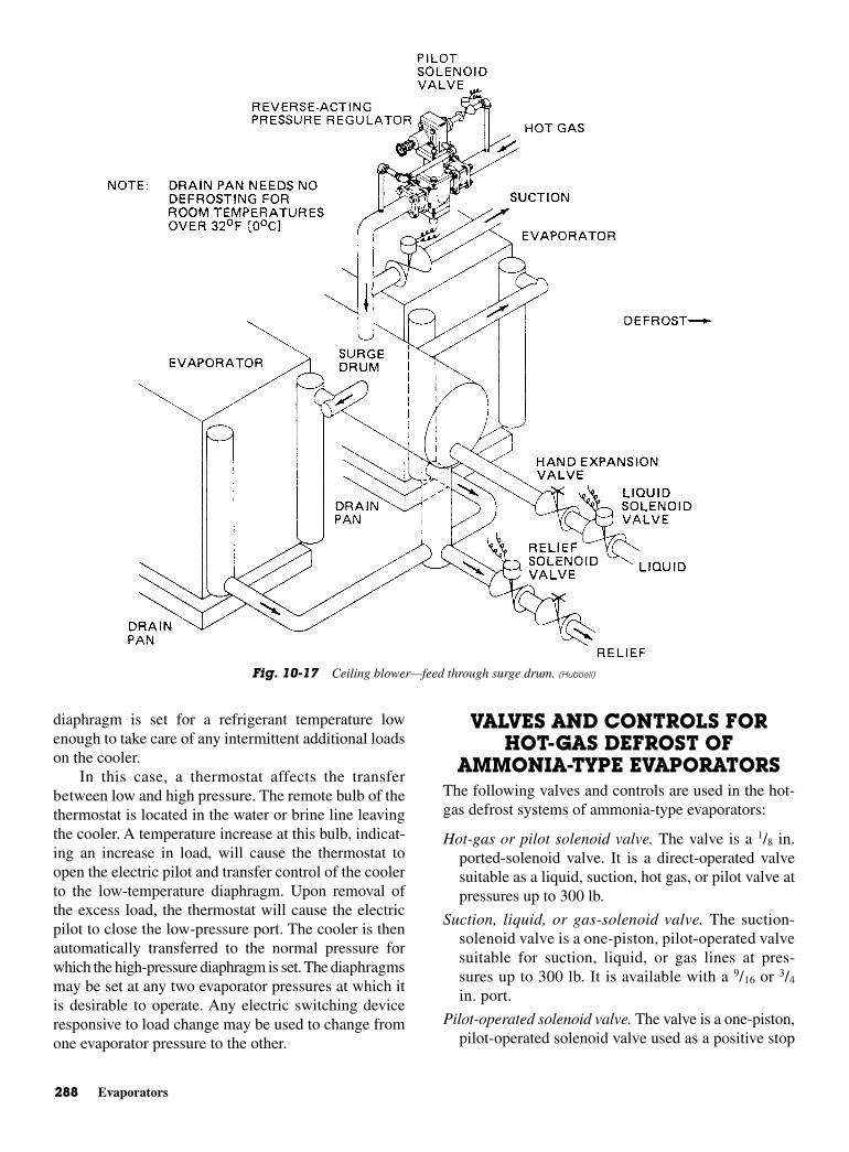
288 Evaporators
diaphragm is set for a refrigerant temperature lowenough to take care of any intermittent additional loadson the cooler.
In this case, a thermostat affects the transferbetween low and high pressure. The remote bulb of thethermostat is located in the water or brine line leavingthe cooler. A temperature increase at this bulb, indicat-ing an increase in load, will cause the thermostat toopen the electric pilot and transfer control of the coolerto the low-temperature diaphragm. Upon removal ofthe excess load, the thermostat will cause the electricpilot to close the low-pressure port. The cooler is thenautomatically transferred to the normal pressure forwhich the high-pressure diaphragm is set. The diaphragmsmay be set at any two evaporator pressures at which itis desirable to operate. Any electric switching deviceresponsive to load change may be used to change fromone evaporator pressure to the other.
VALVES AND CONTROLS FORHOT-GAS DEFROST OF
AMMONIA-TYPE EVAPORATORSThe following valves and controls are used in the hot-gas defrost systems of ammonia-type evaporators:
Hot-gas or pilot solenoid valve. The valve is a 1/8 in.ported-solenoid valve. It is a direct-operated valvesuitable as a liquid, suction, hot gas, or pilot valve atpressures up to 300 lb.
Suction, liquid, or gas-solenoid valve. The suction-solenoid valve is a one-piston, pilot-operated valvesuitable for suction, liquid, or gas lines at pres-sures up to 300 lb. It is available with a 9/16 or 3/4
in. port.
Pilot-operated solenoid valve. The valve is a one-piston,pilot-operated solenoid valve used as a positive stop
Fig. 10-17 Ceiling blower—feed through surge drum. (Hubbell)

Valves and Controls for Hot-Gas Defrost of Ammonia-Type Evaporators 289
valve for applications above −30°F (−34°C) on gasor liquid.
Pilot-operated two-piston valve. The solenoid valve isa rugged, pilot-operated, two-piston valve with springreturn for positive closing under the most adverseconditions. It is used for compressor unloader, suction,liquid, and hot-gas applications.
Gas-powered solenoid valve. The gas-powered sole-noid valve is a power-piston type of valve that useshigh pressure to force the valve open through thecontrol of pilot valves. Because of the high poweravailable to open these valves, heavy springs may beused to close the valves positively at temperaturesdown to −90°F (−68°C).
Dual-pressure regulator valve. The dual-pressure regu-lator valve is designed to operate at two predeter-mined pressures without resetting or adjustment. Bymerely opening and closing a pilot solenoid, eitherthe low- or high-pressure setting is maintained.
Reseating safety valve. The reseating safety valve isgenerally used as a relief regulator to maintain a pre-determined system pressure. The pressure main-tained by the valve is adjustable manually.
Back-pressure regulator arranged for full capacity.The back-pressure regulator is normally used wherepressure control of the evaporator is not required, asin a direct expansion system. A pilot solenoid isenergized, allowing pressure to bypass the sensingchamber of the regulator holding the valve wideopen. Deenergizing the pilot valve allows the valveto revert to its function as a back-pressure regulatormaintaining a preset pressure upstream of the valve.The valve performs both as a suction solenoid andas a relief regulator.
Differential relief valve. The differential relief valve is amodulating regulator for liquid or gas use. It will main-tain a constant preset pressure differential between theupstream and downstream side of a regulator.
Reverse-acting pressure regulator. The reverse-actingpressure regulator is used to maintain a constant pre-determined pressure downstream of the valve. Whencomplete shutoff of the regulator is required, a pilotvalve is installed in the upstream feeder line. Whenthe solenoid valve is closed, the regulator closestightly. When the solenoid valve is open, the regula-tor is free to operate as the pressure demands. With
Fig. 10-18 Floor blower—gas and liquid shutoff. (Hubbell)
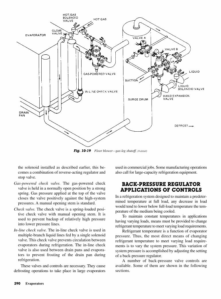
290 Evaporators
the solenoid installed as described earlier, this be-comes a combination of reverse-acting regulator andstop valve.
Gas-powered check valve. The gas-powered checkvalve is held in a normally open position by a strongspring. Gas pressure applied at the top of the valvecloses the valve positively against the high-systempressures. A manual opening stem is standard.
Check valve. The check valve is a spring-loaded posi-tive check valve with manual opening stem. It isused to prevent backup of relatively high pressureinto lower pressure lines.
In-line check valve. The in-line check valve is used inmultiple-branch liquid lines fed by a single solenoidvalve. This check valve prevents circulation betweenevaporators during refrigeration. The in-line checkvalve is also used between drain pans and evapora-tors to prevent frosting of the drain pan duringrefrigeration.
These valves and controls are necessary. They causedefrosting operations to take place in large evaporators
used in commercial jobs. Some manufacturing operationsalso call for large-capacity refrigeration equipment.
BACK-PRESSURE REGULATORAPPLICATIONS OF CONTROLS
In a refrigeration system designed to maintain a predeter-mined temperature at full load, any decrease in loadwould tend to lower below full-load temperature the tem-perature of the medium being cooled.
To maintain constant temperatures in applicationshaving varying loads, means must be provided to changerefrigerant temperature to meet varying load requirements.
Refrigerant temperature is a function of evaporatorpressure. Thus, the most direct means of changingrefrigerant temperature to meet varying load require-ments is to vary the system pressure. This variation ofsystem pressure is accomplished by adjusting the settingof a back-pressure regulator.
A number of back-pressure valve controls areavailable. Some of them are shown in the followingsections.
Fig. 10-19 Floor blower—gas-leg shutoff. (Hubbell)
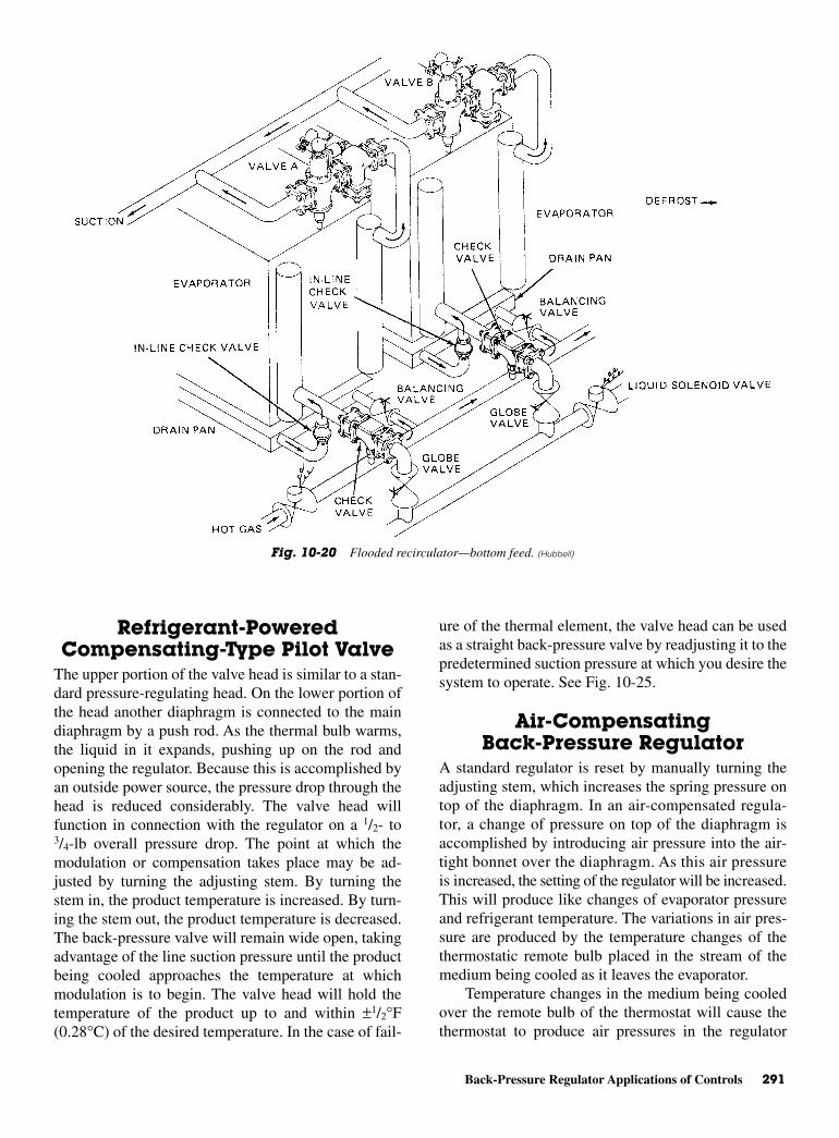
Back-Pressure Regulator Applications of Controls 291
Refrigerant-PoweredCompensating-Type Pilot Valve
The upper portion of the valve head is similar to a stan-dard pressure-regulating head. On the lower portion ofthe head another diaphragm is connected to the maindiaphragm by a push rod. As the thermal bulb warms,the liquid in it expands, pushing up on the rod andopening the regulator. Because this is accomplished byan outside power source, the pressure drop through thehead is reduced considerably. The valve head willfunction in connection with the regulator on a 1/2- to3/4-lb overall pressure drop. The point at which themodulation or compensation takes place may be ad-justed by turning the adjusting stem. By turning thestem in, the product temperature is increased. By turn-ing the stem out, the product temperature is decreased.The back-pressure valve will remain wide open, takingadvantage of the line suction pressure until the productbeing cooled approaches the temperature at whichmodulation is to begin. The valve head will hold thetemperature of the product up to and within ±1/2°F(0.28°C) of the desired temperature. In the case of fail-
ure of the thermal element, the valve head can be usedas a straight back-pressure valve by readjusting it to thepredetermined suction pressure at which you desire thesystem to operate. See Fig. 10-25.
Air-CompensatingBack-Pressure Regulator
A standard regulator is reset by manually turning theadjusting stem, which increases the spring pressure ontop of the diaphragm. In an air-compensated regula-tor, a change of pressure on top of the diaphragm isaccomplished by introducing air pressure into the air-tight bonnet over the diaphragm. As this air pressureis increased, the setting of the regulator will be increased.This will produce like changes of evaporator pressureand refrigerant temperature. The variations in air pres-sure are produced by the temperature changes of thethermostatic remote bulb placed in the stream of themedium being cooled as it leaves the evaporator.
Temperature changes in the medium being cooledover the remote bulb of the thermostat will cause thethermostat to produce air pressures in the regulator
Fig. 10-20 Flooded recirculator—bottom feed. (Hubbell)
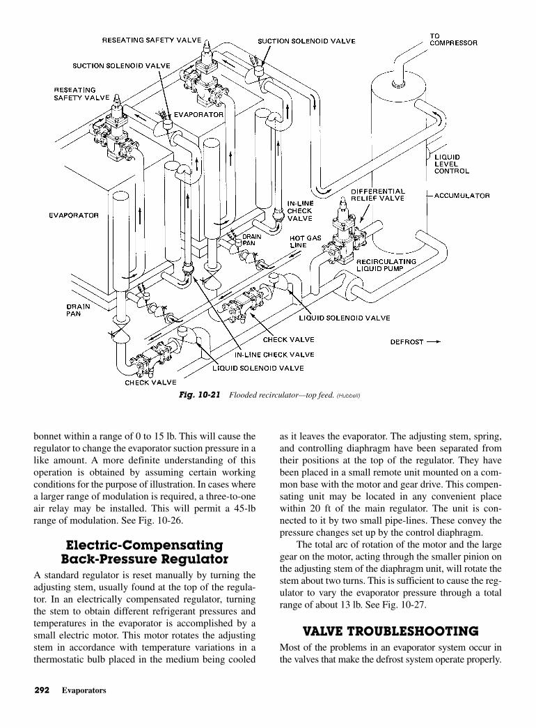
292 Evaporators
bonnet within a range of 0 to 15 lb. This will cause theregulator to change the evaporator suction pressure in alike amount. A more definite understanding of thisoperation is obtained by assuming certain workingconditions for the purpose of illustration. In cases wherea larger range of modulation is required, a three-to-oneair relay may be installed. This will permit a 45-lbrange of modulation. See Fig. 10-26.
Electric-CompensatingBack-Pressure Regulator
A standard regulator is reset manually by turning theadjusting stem, usually found at the top of the regula-tor. In an electrically compensated regulator, turningthe stem to obtain different refrigerant pressures andtemperatures in the evaporator is accomplished by asmall electric motor. This motor rotates the adjustingstem in accordance with temperature variations in athermostatic bulb placed in the medium being cooled
as it leaves the evaporator. The adjusting stem, spring,and controlling diaphragm have been separated fromtheir positions at the top of the regulator. They havebeen placed in a small remote unit mounted on a com-mon base with the motor and gear drive. This compen-sating unit may be located in any convenient placewithin 20 ft of the main regulator. The unit is con-nected to it by two small pipe-lines. These convey thepressure changes set up by the control diaphragm.
The total arc of rotation of the motor and the largegear on the motor, acting through the smaller pinion onthe adjusting stem of the diaphragm unit, will rotate thestem about two turns. This is sufficient to cause the reg-ulator to vary the evaporator pressure through a totalrange of about 13 lb. See Fig. 10-27.
VALVE TROUBLESHOOTINGMost of the problems in an evaporator system occur inthe valves that make the defrost system operate properly.
Fig. 10-21 Flooded recirculator—top feed. (Hubbell)
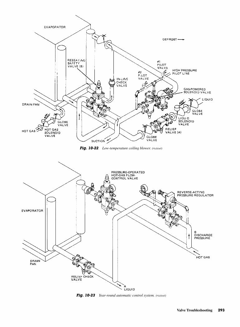
Valve Troubleshooting 293
Fig. 10-22 Low-temperature ceiling blower. (Hubbell)
Fig. 10-23 Year-round automatic control system. (Hubbell)
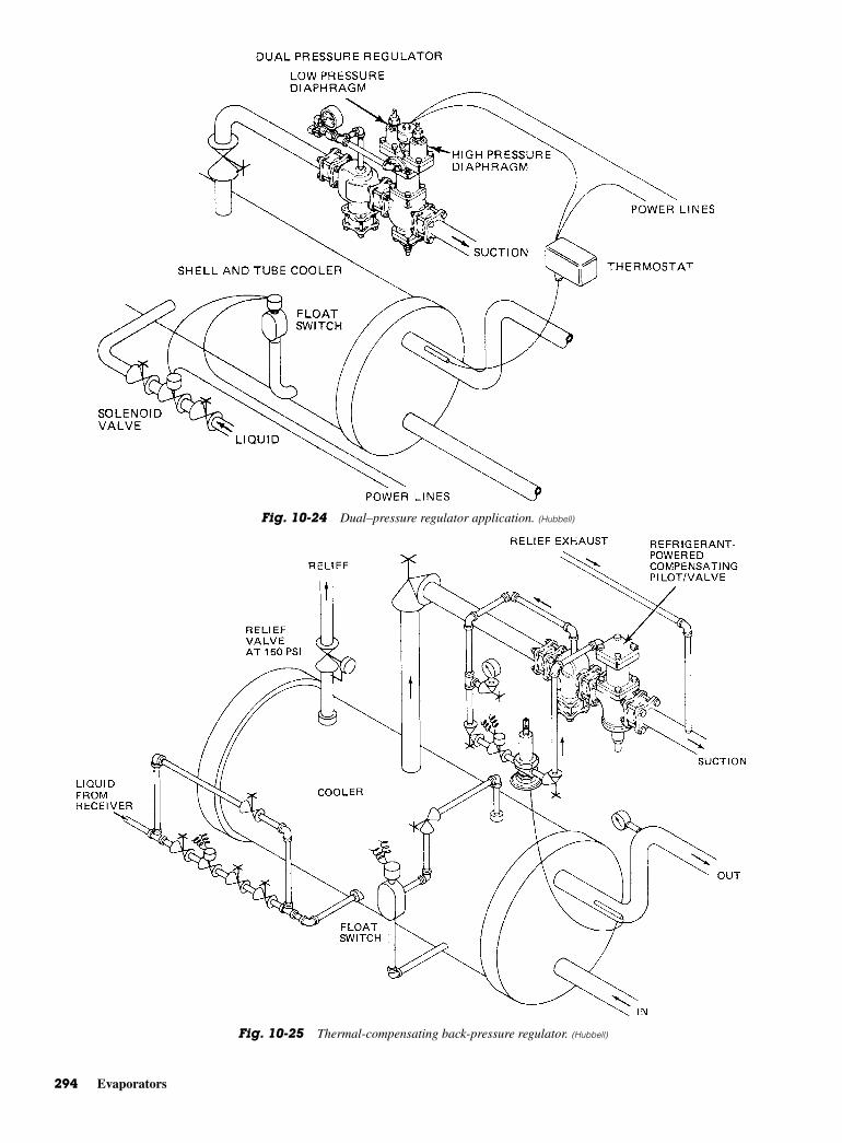
294 Evaporators
Fig. 10-24 Dual–pressure regulator application. (Hubbell)
Fig. 10-25 Thermal-compensating back-pressure regulator. (Hubbell)

Valve Troubleshooting 295
Fig. 10-26 Air-compensating back-pressure regulator. (Hubbell)
Fig. 10-27 Electric-compensating back-pressure regulator. (Hubbell)
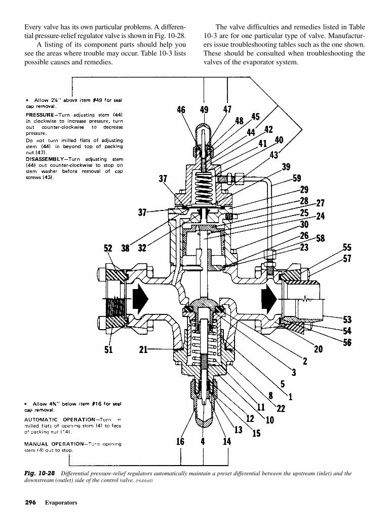
296 Evaporators
Every valve has its own particular problems. A differen-tial pressure-relief regulator valve is shown in Fig. 10-28.
A listing of its component parts should help yousee the areas where trouble may occur. Table 10-3 listspossible causes and remedies.
The valve difficulties and remedies listed in Table10-3 are for one particular type of valve. Manufactur-ers issue troubleshooting tables such as the one shown.These should be consulted when troubleshooting thevalves of the evaporator system.
Fig. 10-28 Differential pressure-relief regulators automatically maintain a preset differential between the upstream (inlet) and thedownstream (outlet) side of the control valve. (Hubbell)

Valve Troubleshooting 297
Noise in Hot-Gas LinesNoise in hot-gas lines between interconnected compres-sors and evaporator condensers may be eliminated by theinstallation of mufflers. This noise may be particularlynoticeable in large installations and is usually caused bythe pulsations in gas flow caused by the reciprocatingaction of the compressors and velocity of the gas throughthe hot-gas line from the compressor. The proper locationof a muffler is in a horizontal or down portion of the hot-
gas line, immediately after leaving the compressor. Itshould never be installed in a riser. The problem ofdecreased system capacity due to excessive vertical liftsin the liquid line is usually solved by the installation ofsubcoolers. Check valves are used in the suction line oflow-temperature fixtures when they are multiplied withhigh-temperature fixtures. Their use is most importantwhen the condensing unit is regulated by low-pressurecontrol.
Fig. 10-28 (Continued)
Table 10-3 Troubleshooting a Differential Pressure-Relief Regulator
Symptom Probable Cause *Remedy
Erratic Operation. Damaged pilot seat bead and/or Replace.No adjustment. diaphragms.Regulator remains Dirt-binding power or disc pistons. Clean, repair, and/oropen. Dirt lodged in seat disc or replace damaged items.
pilot seat bead area.Tubing sensing downstream Remove obstruction.pressure blocked.
Manual opening stem holding Turn opening stem to disc piston open. automatic position.
Short cycling, Regulator too large for Install properlyhunting, or load conditions. sized meteredchattering. orifice control.
Power piston bleed hole Replace or contactenlarged. factory for sizing.
O.D. of power piston worn, Replace piston.creating excessive clearance.
Excessive Regulator too small for load. Replace with correctlypressure drop. sized regulator.
Passage to sensing chamber Remove obstructions.blocked.
Strainer blocked. Clean strainer—replace screenif damaged.
No adjustment over Range spring rated at Order range kit rated at90 psig. 2 to 90 psig. 75 to 300 psig.
No adjustment under Range spring rated at Order range kit rated2 psig. 2 to 90 psig. at 25 in. vacuum to 50 psig.
*If repair requires metal removal—replace part.
298 Evaporators
REVIEW QUESTIONS1. What is the purpose of an evaporator?
2. What is the purpose of a shell-and-tube chiller?
3. Describe the cooling cycle.
4. Describe the defrost cycle.
5. What is meant by direct expansion with top hot-gas feed?
6. What is a flooded-ceiling evaporator?
7. How are liquid refrigerant recirculating systemsfed?
8. Where are equalizing orifices or globe valvesused?
9. Why is the constant liquid control system used inrefrigeration systems?
10. What is a dual-pressure regulator?
11CHAPTER
Refrigerant:Flow Control
Copyright © 2006 by The McGraw-Hill Companies, Inc. Click here for terms of use.
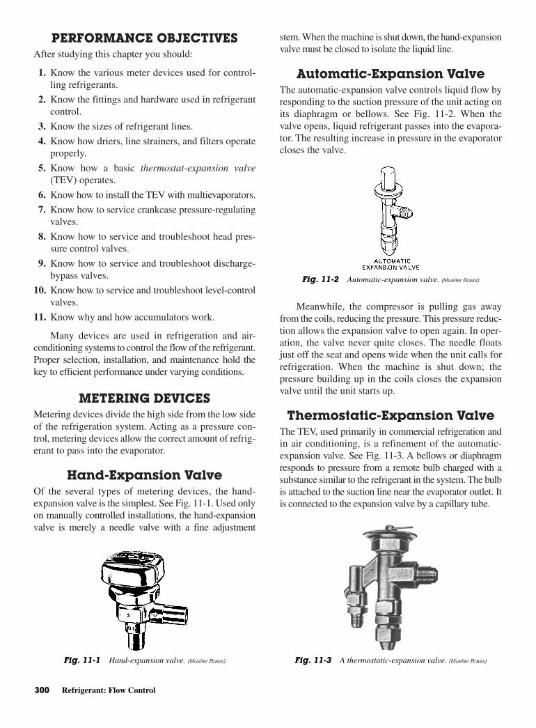
PERFORMANCE OBJECTIVESAfter studying this chapter you should:
1. Know the various meter devices used for control-ling refrigerants.
2. Know the fittings and hardware used in refrigerantcontrol.
3. Know the sizes of refrigerant lines.
4. Know how driers, line strainers, and filters operateproperly.
5. Know how a basic thermostat-expansion valve(TEV) operates.
6. Know how to install the TEV with multievaporators.
7. Know how to service crankcase pressure-regulatingvalves.
8. Know how to service and troubleshoot head pres-sure control valves.
9. Know how to service and troubleshoot discharge-bypass valves.
10. Know how to service and troubleshoot level-controlvalves.
11. Know why and how accumulators work.
Many devices are used in refrigeration and air-conditioning systems to control the flow of the refrigerant.Proper selection, installation, and maintenance hold thekey to efficient performance under varying conditions.
METERING DEVICESMetering devices divide the high side from the low sideof the refrigeration system. Acting as a pressure con-trol, metering devices allow the correct amount of refrig-erant to pass into the evaporator.
Hand-Expansion ValveOf the several types of metering devices, the hand-expansion valve is the simplest. See Fig. 11-1. Used onlyon manually controlled installations, the hand-expansionvalve is merely a needle valve with a fine adjustment
stem. When the machine is shut down, the hand-expansionvalve must be closed to isolate the liquid line.
Automatic-Expansion Valve The automatic-expansion valve controls liquid flow byresponding to the suction pressure of the unit acting onits diaphragm or bellows. See Fig. 11-2. When thevalve opens, liquid refrigerant passes into the evapora-tor. The resulting increase in pressure in the evaporatorcloses the valve.
Meanwhile, the compressor is pulling gas awayfrom the coils, reducing the pressure. This pressure reduc-tion allows the expansion valve to open again. In oper-ation, the valve never quite closes. The needle floatsjust off the seat and opens wide when the unit calls forrefrigeration. When the machine is shut down; thepressure building up in the coils closes the expansionvalve until the unit starts up.
Thermostatic-Expansion ValveThe TEV, used primarily in commercial refrigeration andin air conditioning, is a refinement of the automatic-expansion valve. See Fig. 11-3. A bellows or diaphragmresponds to pressure from a remote bulb charged with asubstance similar to the refrigerant in the system. The bulbis attached to the suction line near the evaporator outlet. Itis connected to the expansion valve by a capillary tube.
300 Refrigerant: Flow Control
Fig. 11-1 Hand-expansion valve. (Mueller Brass)
Fig. 11-2 Automatic-expansion valve. (Mueller Brass)
Fig. 11-3 A thermostatic-expansion valve. (Mueller Brass)
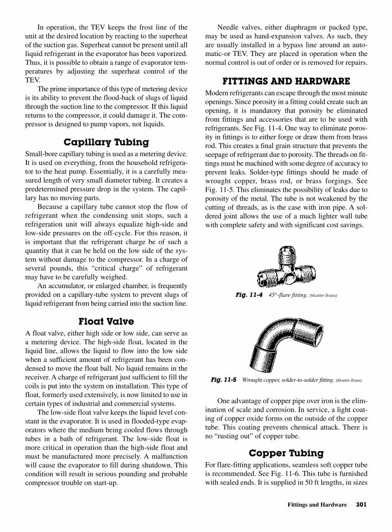
Fittings and Hardware 301
In operation, the TEV keeps the frost line of theunit at the desired location by reacting to the superheatof the suction gas. Superheat cannot be present until allliquid refrigerant in the evaporator has been vaporized.Thus, it is possible to obtain a range of evaporator tem-peratures by adjusting the superheat control of theTEV.
The prime importance of this type of metering deviceis its ability to prevent the flood-back of slugs of liquidthrough the suction line to the compressor. If this liquidreturns to the compressor, it could damage it. The com-pressor is designed to pump vapors, not liquids.
Capillary Tubing Small-bore capillary tubing is used as a metering device.It is used on everything, from the household refrigera-tor to the heat pump. Essentially, it is a carefully mea-sured length of very small diameter tubing. It creates apredetermined pressure drop in the system. The capil-lary has no moving parts.
Because a capillary tube cannot stop the flow ofrefrigerant when the condensing unit stops, such arefrigeration unit will always equalize high-side andlow-side pressures on the off-cycle. For this reason, itis important that the refrigerant charge be of such aquantity that it can be held on the low side of the sys-tem without damage to the compressor. In a charge ofseveral pounds, this “critical charge” of refrigerantmay have to be carefully weighed.
An accumulator, or enlarged chamber, is frequentlyprovided on a capillary-tube system to prevent slugs ofliquid refrigerant from being carried into the suction line.
Float ValveA float valve, either high side or low side, can serve asa metering device. The high-side float, located in theliquid line, allows the liquid to flow into the low sidewhen a sufficient amount of refrigerant has been con-densed to move the float ball. No liquid remains in thereceiver. A charge of refrigerant just sufficient to fill thecoils is put into the system on installation. This type offloat, formerly used extensively, is now limited to use incertain types of industrial and commercial systems.
The low-side float valve keeps the liquid level con-stant in the evaporator. It is used in flooded-type evap-orators where the medium being cooled flows throughtubes in a bath of refrigerant. The low-side float ismore critical in operation than the high-side float andmust be manufactured more precisely. A malfunctionwill cause the evaporator to fill during shutdown. Thiscondition will result in serious pounding and probablecompressor trouble on start-up.
Needle valves, either diaphragm or packed type,may be used as hand-expansion valves. As such, theyare usually installed in a bypass line around an auto-matic-or TEV. They are placed in operation when thenormal control is out of order or is removed for repairs.
FITTINGS AND HARDWARE Modern refrigerants can escape through the most minuteopenings. Since porosity in a fitting could create such anopening, it is mandatory that porosity be eliminatedfrom fittings and accessories that are to be used withrefrigerants. See Fig. 11-4. One way to eliminate poros-ity in fittings is to either forge or draw them from brassrod. This creates a final grain structure that prevents theseepage of refrigerant due to porosity. The threads on fit-tings must be machined with some degree of accuracy toprevent leaks. Solder-type fittings should be made ofwrought copper, brass rod, or brass forgings. SeeFig. 11-5. This eliminates the possibility of leaks due toporosity of the metal. The tube is not weakened by thecutting of threads, as is the case with iron pipe. A sol-dered joint allows the use of a much lighter wall tubewith complete safety and with significant cost savings.
One advantage of copper pipe over iron is the elim-ination of scale and corrosion. In service, a light coat-ing of copper oxide forms on the outside of the coppertube. This coating prevents chemical attack. There isno “rusting out” of copper tube.
Copper TubingFor flare-fitting applications, seamless soft copper tubeis recommended. See Fig. 11-6. This tube is furnishedwith sealed ends. It is supplied in 50 ft lengths, in sizes
Fig. 11-4 45°-flare fitting. (Mueller Brass)
Fig. 11-5 Wrought copper, solder-to-solder fitting. (Mueller Brass)

302 Refrigerant: Flow Control
from 1/8 through 3/4 in. outside diameter (OD) for flar-ing and through OD for soldering.
The chief demand for this tube is in sizes from 1/4
through 5/8 in. OD. Sizes smaller than 1/4 in. are seldomused in commercial refrigeration. To uncoil the tubewithout kinks, hold one free end against the floor, or ona bench, and uncoil along the floor or bench. The tubemay be cut to length with a hacksaw or tube cutter. Ineither case, deburr the end before flaring. Bending isreadily accomplished with either external or internalbending springs or lever-type bending tools.
ACR (air-conditioning, refrigeration) tube is fre-quently used. It is cleaned, degreased, dried, and end-sealed at the factory. This assures the user that he or sheis installing a clean, trouble-free tube. Some tubing isavailable with an inert gas (nitrogen). See Fig. 11-7.The nitrogenized-ACR tube is purged, charged withclean, dry nitrogen, and then sealed with reusableplugs. After cutting the tube, the remaining length caneasily be replugged. The remaining nitrogen limitsexcess oxides during succeeding brazing operations. Itcomes in 20 ft lengths. Type-L hard tube has from 3/8
through 31/8 in.OD. Type-K tube is also available.Where tubing will be exposed inside food compart-
ments, tinned copper is recommended. Type-L, hard-temper copper tube is recommended for field installationsusing solder-type fittings. Type M is sufficiently strongfor any pressures of the commonly used refrigerants.However, it is used chiefly in manufactured assemblies
where external damage to the tube is not as likely as infield installations. For maximum protection against pos-sible external damage to refrigerant lines, a few citiesrequire the use of type-K copper tube.
LineCorrect line sizes are essential to obtain maximum effi-ciency from refrigeration equipment. In supermarkets,for example, the long lines running under the floorfrom the display cases to the machine room at the rearof the store must be fully engineered. Otherwise, prob-lems of oil return, slugging, or erratic refrigeration arequite likely. Table 11-1 lists refrigerant-line sizes.When available, the manufacturer’s recommendationsmust be followed regarding step-sizing, risers, traps, andthe like. Available information on Refrigerant 502claims performance at temperatures below 5°F (−15°C)when compared with Refrigerant 22. The newer refrig-erants like 502a are said to be equivalent in performanceto the older designated refrigerant.
SolderEach solder is designed for a certain job. For instance,50-50 solder, which consists of 50 percent tin and 50percent lead, will not function well in some instances.In fact, 50-50 solder will deteriorate in some refriger-ated food-storage compartments where normally wet-refrigerant lines and high carbon dioxide content arepresent. For this reason, No. 95 solder is recommended.It has 95 percent tin and 5 percent antimony. Number122 solder (45 percent silver brazing alloy) is usedfor joints in refrigerant lines where 50-50 solder maydeteriorate.
Suction Line P-TrapsFor years, the P-trap was made by forming two or morefittings. It has now become available in one piece. SeeFig. 11-8. The newer one-piece P-trap promotes effi-cient oil migration in refrigeration systems. This isincreasingly important today. Many large food marketsplace their compressors and condensers on balconiesor mezzanines. Such remote condensing units are
Fig. 11-6 Refrigeration service tube in a 50-ft coil. (Mueller Brass)
Fig. 11-7 Nitrogenized ACR-copper tube. (Mueller Brass)
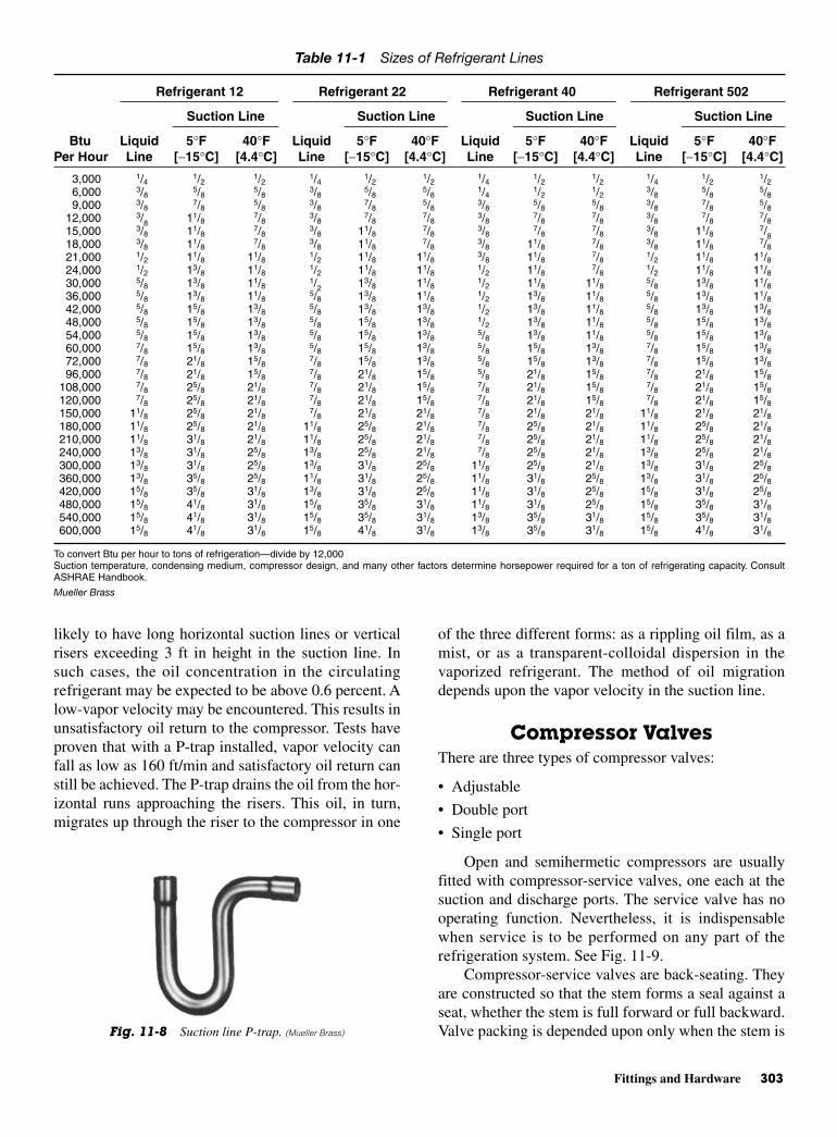
Fittings and Hardware 303
likely to have long horizontal suction lines or verticalrisers exceeding 3 ft in height in the suction line. Insuch cases, the oil concentration in the circulatingrefrigerant may be expected to be above 0.6 percent. Alow-vapor velocity may be encountered. This results inunsatisfactory oil return to the compressor. Tests haveproven that with a P-trap installed, vapor velocity canfall as low as 160 ft/min and satisfactory oil return canstill be achieved. The P-trap drains the oil from the hor-izontal runs approaching the risers. This oil, in turn,migrates up through the riser to the compressor in one
of the three different forms: as a rippling oil film, as amist, or as a transparent-colloidal dispersion in thevaporized refrigerant. The method of oil migrationdepends upon the vapor velocity in the suction line.
Compressor Valves There are three types of compressor valves:
• Adjustable
• Double port
• Single port
Open and semihermetic compressors are usuallyfitted with compressor-service valves, one each at thesuction and discharge ports. The service valve has nooperating function. Nevertheless, it is indispensablewhen service is to be performed on any part of therefrigeration system. See Fig. 11-9.
Compressor-service valves are back-seating. Theyare constructed so that the stem forms a seal against aseat, whether the stem is full forward or full backward.Valve packing is depended upon only when the stem isFig. 11-8 Suction line P-trap. (Mueller Brass)
Table 11-1 Sizes of Refrigerant Lines
Refrigerant 12 Refrigerant 22 Refrigerant 40 Refrigerant 502
Suction Line Suction Line Suction Line Suction Line
Btu Liquid 5°F 40°F Liquid 5°F 40°F Liquid 5°F 40°F Liquid 5°F 40°FPer Hour Line [−15°C] [4.4°C] Line [−15°C] [4.4°C] Line [−15°C] [4.4°C] Line [−15°C] [4.4°C]
3,000 1/4 1/2 1/2 1/4 1/2 1/2 1/4 1/2 1/2 1/4 1/2 1/26,000 3/8 5/8 5/8 3/8 5/8 5/8 1/4 1/2 1/2 3/8 5/8 5/89,000 3/8 7/8 5/8 3/8 7/8 5/8 3/8 5/8 5/8 3/8 7/8 5/8
12,000 3/8 11/8 7/8 3/8 7/8 7/8 3/8 7/8 7/8 3/8 7/8 7/815,000 3/8 11/8 7/8 3/8 11/8 7/8 3/8 7/8 7/8 3/8 11/8 7/818,000 3/8 11/8 7/8 3/8 11/8 7/8 3/8 11/8 7/8 3/8 11/8 7/821,000 1/2 11/8 11/8 1/2 11/8 11/8 3/8 11/8 7/8 1/2 11/8 11/824,000 1/2 13/8 11/8 1/2 11/8 11/8 1/2 11/8 7/8 1/2 11/8 11/830,000 5/8 13/8 11/8 1/2 13/8 11/8 1/2 11/8 11/8 5/8 13/8 11/836,000 5/8 13/8 11/8 5/8 13/8 11/8 1/2 13/8 11/8 5/8 13/8 11/842,000 5/8 15/8 13/8 5/8 13/8 13/8 1/2 13/8 11/8 5/8 13/8 13/848,000 5/8 15/8 13/8 5/8 15/8 13/8 1/2 13/8 11/8 5/8 15/8 13/854,000 5/8 15/8 13/8 5/8 15/8 13/8 5/8 13/8 11/8 5/8 15/8 13/860,000 7/8 15/8 13/8 5/8 15/8 13/8 5/8 15/8 13/8 7/8 15/8 13/872,000 7/8 21/8 15/8 7/8 15/8 13/8 5/8 15/8 13/8 7/8 15/8 13/896,000 7/8 21/8 15/8 7/8 21/8 15/8 5/8 21/8 15/8 7/8 21/8 15/8
108,000 7/8 25/8 21/8 7/8 21/8 15/8 7/8 21/8 15/8 7/8 21/8 15/8120,000 7/8 25/8 21/8 7/8 21/8 15/8 7/8 21/8 15/8 7/8 21/8 15/8150,000 11/8 25/8 21/8 7/8 21/8 21/8 7/8 21/8 21/8 11/8 21/8 21/8180,000 11/8 25/8 21/8 11/8 25/8 21/8 7/8 25/8 21/8 11/8 25/8 21/8210,000 11/8 31/8 21/8 11/8 25/8 21/8 7/8 25/8 21/8 11/8 25/8 21/8240,000 13/8 31/8 25/8 13/8 25/8 21/8 7/8 25/8 21/8 13/8 25/8 21/8300,000 13/8 31/8 25/8 13/8 31/8 25/8 11/8 25/8 21/8 13/8 31/8 25/8360,000 13/8 35/8 25/8 11/8 31/8 25/8 11/8 31/8 25/8 13/8 31/8 25/8420,000 15/8 35/8 31/8 13/8 31/8 25/8 11/8 31/8 25/8 15/8 31/8 25/8480,000 15/8 41/8 31/8 15/8 35/8 31/8 11/8 31/8 25/8 15/8 35/8 31/8540,000 15/8 41/8 31/8 15/8 35/8 31/8 13/8 35/8 31/8 15/8 35/8 31/8600,000 15/8 41/8 31/8 15/8 41/8 31/8 13/8 35/8 31/8 15/8 41/8 31/8
To convert Btu per hour to tons of refrigeration—divide by 12,000Suction temperature, condensing medium, compressor design, and many other factors determine horsepower required for a ton of refrigerating capacity. ConsultASHRAE Handbook.
Mueller Brass
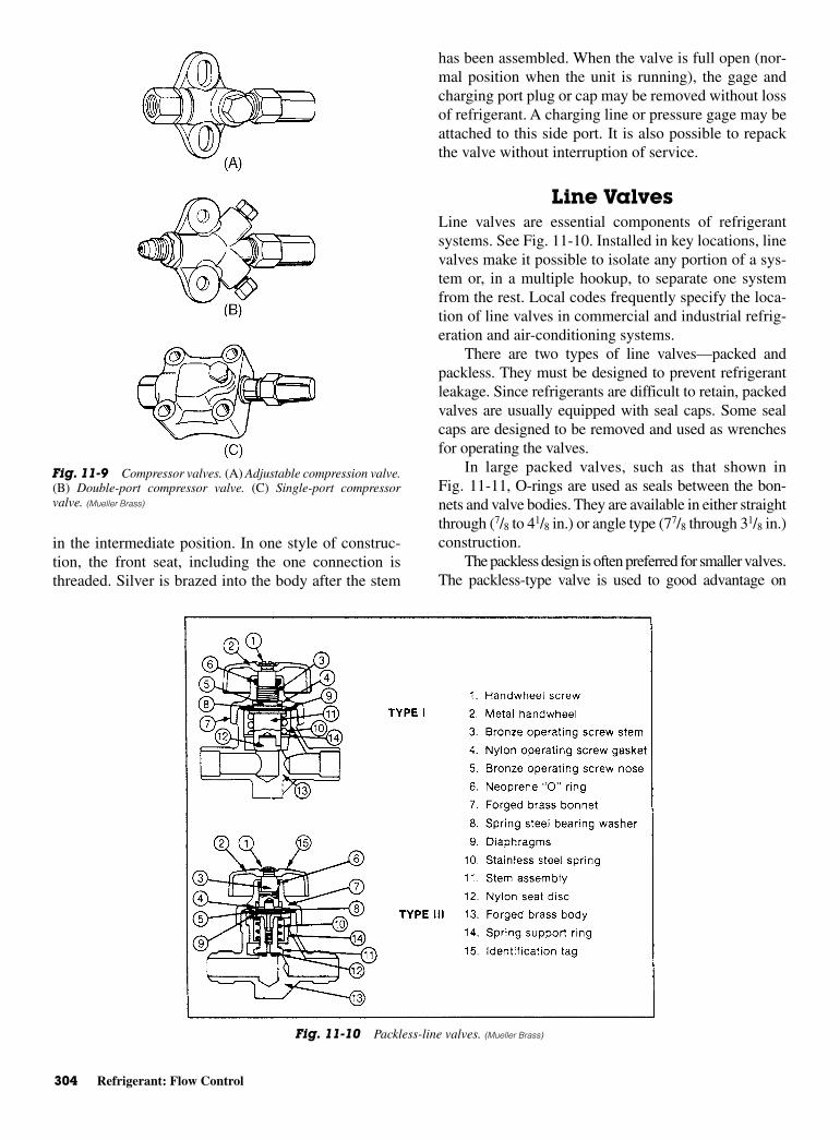
304 Refrigerant: Flow Control
in the intermediate position. In one style of construc-tion, the front seat, including the one connection isthreaded. Silver is brazed into the body after the stem
has been assembled. When the valve is full open (nor-mal position when the unit is running), the gage andcharging port plug or cap may be removed without lossof refrigerant. A charging line or pressure gage may beattached to this side port. It is also possible to repackthe valve without interruption of service.
Line ValvesLine valves are essential components of refrigerantsystems. See Fig. 11-10. Installed in key locations, linevalves make it possible to isolate any portion of a sys-tem or, in a multiple hookup, to separate one systemfrom the rest. Local codes frequently specify the loca-tion of line valves in commercial and industrial refrig-eration and air-conditioning systems.
There are two types of line valves—packed andpackless. They must be designed to prevent refrigerantleakage. Since refrigerants are difficult to retain, packedvalves are usually equipped with seal caps. Some sealcaps are designed to be removed and used as wrenchesfor operating the valves.
In large packed valves, such as that shown inFig. 11-11, O-rings are used as seals between the bon-nets and valve bodies. They are available in either straightthrough (7/8 to 41/8 in.) or angle type (77/8 through 31/8 in.)construction.
The packless design is often preferred for smaller valves.The packless-type valve is used to good advantage on
Fig. 11-9 Compressor valves. (A) Adjustable compression valve.(B) Double-port compressor valve. (C) Single-port compressorvalve. (Mueller Brass)
Fig. 11-10 Packless-line valves. (Mueller Brass)
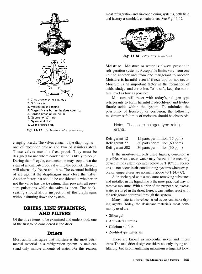
Driers, Line Strainers, and Filters 305
charging boards. The valves contain triple diaphragms—one of phosphor bronze and two of stainless steel.These valves must be frost-proof. They must bedesigned for use where condensation is likely to occur.During the off-cycle, condensation may seep down thestem of a nonfrost-proof valve into the bonnet. There, itwill alternately freeze and thaw. The eventual buildupof ice against the diaphragms may close the valve.Another factor that should be considered is whether ornot the valve has back-seating. This prevents all pres-sure pulsations while the valve is open. The back-seating should allow inspection of the diaphragmswithout shutting down the system.
DRIERS, LINE STRAINERS,AND FILTERS
Of the three items to be examined and understood, oneof the first to be considered is the drier.
DriersMost authorities agree that moisture is the most detri-mental material in a refrigeration system. A unit canstand only minute amounts of water. For this reason,
most refrigeration and air-conditioning systems, both fieldand factory-assembled, contain driers. See Fig. 11-12.
Moisture Moisture or water is always present inrefrigeration systems. Acceptable limits vary from oneunit to another and from one refrigerant to another.Moisture is harmful even if freeze-ups do not occur.Moisture is an important factor in the formation ofacids, sludge, and corrosion. To be safe, keep the mois-ture level as low as possible.
Moisture will react with today’s halogen-typerefrigerants to form harmful hydrochloric and hydro-fluoric acids within the system. To minimize thepossibility of freeze-up or corrosion, the followingmaximum safe limits of moisture should be observed:
Note: These are halogen-type refrig-erants.
Refrigerant 12 15 parts per million (15 ppm) Refrigerant 22 60 parts per million (60 ppm) Refrigerant 502 30 parts per million (30 ppm)
If the moisture exceeds these figures, corrosion ispossible. Also, excess water may freeze at the meteringdevice if the system operates below 32°F (0°C). Freeze-ups do not occur in air-conditioning systems where evap-orator temperatures are normally above 40°F (4.4°C).
A drier charged with a moisture-removing substanceand installed in the liquid line is the most practical way toremove moisture. With a drier of the proper size, excesswater is stored in the drier. Here, it can neither react withthe refrigerant nor travel through the system.
Many materials have been tried as desiccants, or dry-ing agents. Today, the desiccant materials most com-monly used are:
• Silica gel
• Activated alumina
• Calcium sulfate
• Zeolite-type materials
These are known as molecular sieves and microtraps. The total drier design considers not only drying andfiltering, but also maintaining maximum refrigerant flow.
Fig. 11-11 Packed-line valve. (Mueller Brass)
Fig. 11-12 Filter drier. (Mueller Brass)
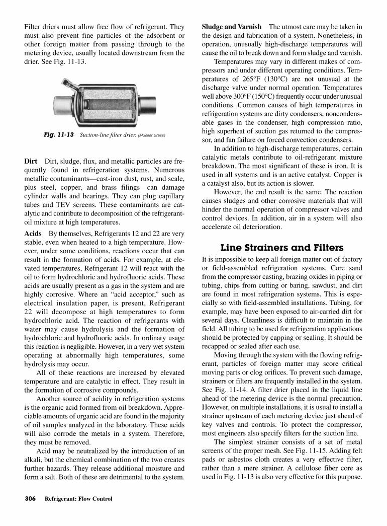
306 Refrigerant: Flow Control
Filter driers must allow free flow of refrigerant. Theymust also prevent fine particles of the adsorbent orother foreign matter from passing through to themetering device, usually located downstream from thedrier. See Fig. 11-13.
Dirt Dirt, sludge, flux, and metallic particles are fre-quently found in refrigeration systems. Numerousmetallic contaminants—cast-iron dust, rust, and scale,plus steel, copper, and brass filings—can damagecylinder walls and bearings. They can plug capillarytubes and TEV screens. These contaminants are cat-alytic and contribute to decomposition of the refrigerant-oil mixture at high temperatures.
Acids By themselves, Refrigerants 12 and 22 are verystable, even when heated to a high temperature. How-ever, under some conditions, reactions occur that canresult in the formation of acids. For example, at ele-vated temperatures, Refrigerant 12 will react with theoil to form hydrochloric and hydrofluoric acids. Theseacids are usually present as a gas in the system and arehighly corrosive. Where an “acid acceptor,” such aselectrical insulation paper, is present, Refrigerant22 will decompose at high temperatures to formhydrochloric acid. The reaction of refrigerants withwater may cause hydrolysis and the formation ofhydrochloric and hydrofluoric acids. In ordinary usagethis reaction is negligible. However, in a very wet systemoperating at abnormally high temperatures, somehydrolysis may occur.
All of these reactions are increased by elevatedtemperature and are catalytic in effect. They result inthe formation of corrosive compounds.
Another source of acidity in refrigeration systemsis the organic acid formed from oil breakdown. Appre-ciable amounts of organic acid are found in the majorityof oil samples analyzed in the laboratory. These acidswill also corrode the metals in a system. Therefore,they must be removed.
Acid may be neutralized by the introduction of analkali, but the chemical combination of the two createsfurther hazards. They release additional moisture andform a salt. Both of these are detrimental to the system.
Sludge and Varnish The utmost care may be taken inthe design and fabrication of a system. Nonetheless, inoperation, unusually high-discharge temperatures willcause the oil to break down and form sludge and varnish.
Temperatures may vary in different makes of com-pressors and under different operating conditions. Tem-peratures of 265°F (130°C) are not unusual at thedischarge valve under normal operation. Temperatureswell above 300°F (150°C) frequently occur under unusualconditions. Common causes of high temperatures inrefrigeration systems are dirty condensers, noncondens-able gases in the condenser, high compression ratio,high superheat of suction gas returned to the compres-sor, and fan failure on forced convection condensers.
In addition to high-discharge temperatures, certaincatalytic metals contribute to oil-refrigerant mixturebreakdown. The most significant of these is iron. It isused in all systems and is an active catalyst. Copper isa catalyst also, but its action is slower.
However, the end result is the same. The reactioncauses sludges and other corrosive materials that willhinder the normal operation of compressor valves andcontrol devices. In addition, air in a system will alsoaccelerate oil deterioration.
Line Strainers and FiltersIt is impossible to keep all foreign matter out of factoryor field-assembled refrigeration systems. Core sandfrom the compressor casting, brazing oxides in piping ortubing, chips from cutting or baring, sawdust, and dirtare found in most refrigeration systems. This is espe-cially so with field-assembled installations. Tubing, forexample, may have been exposed to air-carried dirt forseveral days. Cleanliness is difficult to maintain in thefield. All tubing to be used for refrigeration applicationsshould be protected by capping or sealing. It should berecapped or sealed after each use.
Moving through the system with the flowing refrig-erant, particles of foreign matter may score criticalmoving parts or clog orifices. To prevent such damage,strainers or filters are frequently installed in the system.See Fig. 11-14. A filter drier placed in the liquid lineahead of the metering device is the normal precaution.However, on multiple installations, it is usual to install astrainer upstream of each metering device just ahead ofkey valves and controls. To protect the compressor,most engineers also specify filters for the suction line.
The simplest strainer consists of a set of metalscreens of the proper mesh. See Fig. 11-15. Adding feltpads or asbestos cloth creates a very effective filter,rather than a mere strainer. A cellulose fiber core asused in Fig. 11-13 is also very effective for this purpose.
Fig. 11-13 Suction-line filter drier. (Mueller Brass)

Liquid Indicators 307
Suction-line strainers and filters are designed withsufficient flow capacity to prevent excessive pressuredrop. Since determining the need for cleaning or replace-ment of a suction-line filter is related to pressure drop,some designs are offered with pressure taps. These per-mit pressure gage installation to determine the degree ofpressure drop.
Strainers are made in several designs. They are alsosupplied in a wide range of sizes. Screen areas are large.In cartridge-type strainers, provision is made for removalof the screens or filters. See Fig. 11-16.
LIQUID INDICATORS Liquid indicators are inserted in a refrigerant line to indi-cate the amount of refrigerant in a system. See Fig. 11-17.Proper operation of a refrigeration system dependsupon there being the correct amount of refrigerant inthe unit. Looking through the window of a liquid indi-cator is the simplest way to determine whether there isa refrigerant shortage. A shortage of refrigerant may bedue to a leak in the system or due to failure to chargeenough refrigerant into a unit after field service.
Liquid indicators normally disclose a shortage ofrefrigerant by the appearance of bubbles. Some use aspecial assembly that shows by the appearance of theword “FULL” that there is sufficient refrigerant at thatpoint in the system.
Liquid indicators are manufactured in single-port,double-port, and straight-through types. In the single-and double-port indicators, an internal compressionbushing seals the glass firmly against the body. Assem-blies are furnished with a protective dust cap or seal cap.
Fig. 11-16 A strainer and its replacement-type filter. (Sporlan Valve)
Fig. 11-17 Liquid-line indicator installation. (Sporlan Valve)
Fig. 11-14 Strainers. (A) Non-cleanable strainer. (B) Y-type linestrainer. (Sporlan Valve)
Fig. 11-15 Strainer-filter, removable metal screen. (Mueller Brass)

308 Refrigerant: Flow Control
To observe the liquid stream, it is necessary to removethe cap. See Fig. 11-18.
A relatively new addition to the function of the liquidindicator is that of moisture detection. Special materials
used in the ports of liquid-moisture indicators changecolor to indicate excessive moisture in the system.
Indicators with solder-type ends, but withoutextended ends, are normally furnished disassembled sothe heating required for soldering will not damageglass or gaskets. In addition, single- and double-porttypes are supplied assembled with extended ends.These make it possible to solder without damaging theindicator, as long as normal precautions are observed.
ConstructionThe indicator is a porous filter paper impregnated witha chemical salt that is sensitive to moisture. The saltchanges color according to the moisture content (rela-tive saturation) of the refrigerant. The indicator changescolor below moisture levels generally accepted as a safeoperation range. This device is not suitable for use withammonia or sulfur dioxide. However, it does have a fullapplication with Refrigerants 11, 12, 22, 113, 114, 500,and 502. See Table 11-2. The indicator should be installedafter the filter drier and ahead of the expansion device.Prior to installation, the indicator will be yellow, indi-cating a wet condition. This is a normal situation, sincethe air in contact with the element is above 0.5 percentrelative humidity. This does not affect the operation orcalibration of the indicator. As soon as it is installed ina system, the indicator element will begin to changeaccording to the moisture content in the refrigerant. Theaction of the indicator element is completely reversible.
Fig. 11-18 Liquid indicators. (A) and (B) Double port. (C) Singleport. (Mueller Brass)
Table 11-2 Moisture Content (In Parts Per Million)
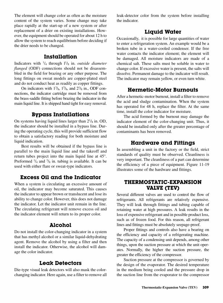
Thermostatic-Expansion Valve (TEV) 309
The element will change color as often as the moisturecontent of the system varies. Some change may takeplace rapidly at the start-up of a new system or afterreplacement of a drier on existing installations. How-ever, the equipment should be operated for about 12 h toallow the system to reach equilibrium before deciding ifthe drier needs to be changed.
InstallationIndicators with 1/4 through l1/8 in. outside diameterflanged (ODF) connections should not be disassem-bled in the field for brazing or any other purpose. Thelong fittings on sweat models are copper-plated steeland do not conduct heat as readily as copper fittings.
On indicators with 13/8, 15/8, and 21/8 in., ODF con-nections, the indicator cartridge must be removed fromthe brass-saddle fitting before brazing the indicator in themain liquid line. It is shipped hand tight for easy removal.
Bypass InstallationsOn systems having liquid lines larger than 21/8 in. OD,the indicator should be installed in a bypass line. Dur-ing the operating cycle, this will provide sufficient flowto obtain a satisfactory reading for both moisture andliquid indication.
Best results will be obtained if the bypass line isparallel to the main liquid line and the takeoff andreturn tubes project into the main liquid line at 45°.Preformed 1/4 and 3/8 in. tubing is available. It can beused with either flare or sweat-type indicators.
Excess Oil and the IndicatorWhen a system is circulating an excessive amount ofoil, the indicator may become saturated. This causesthe indicator to appear brown or translucent and lose itsability to change color. However, this does not damagethe indicator. Let the indicator unit remain in the line.The circulating refrigerant will remove excess oil andthe indicator element will return to its proper color.
AlcoholDo not install the color-changing indicator in a systemthat has methyl alcohol or a similar liquid-dehydratingagent. Remove the alcohol by using a filter and theninstall the indicator. Otherwise, the alcohol will dam-age the color indicator.
Leak DetectorsDie-type visual leak detectors will also mask the color-changing indicator. Here again, use a filter to remove all
leak-detector color from the system before installingthe indicator.
Liquid WaterOccasionally, it is possible for large quantities of waterto enter a refrigeration system. An example would be abroken tube in a water-cooled condenser. If the freewater contacts the indicator element; the element willbe damaged. All moisture indicators are made of achemical salt. These salts must be soluble in water tochange color. If excessive water is present, the salts willdissolve. Permanent damage to the indicator will result.The indicator may remain yellow, or even turn white.
Hermetic-Motor BurnoutsAfter a hermetic-motor burnout, install a filter to removethe acid and sludge contamination. When the systemhas operated for 48 h, replace the filter. At the sametime, install the color indicator for moisture.
The acid formed by the burnout may damage theindicator element of the color-changing unit. Thus, itshould be installed only after the greater percentage ofcontaminants has been removed.
Hardware and FittingsIn assembling a unit in the factory or the field, strictstandards of quality must be observed. Cleanliness isvery important. The cleanliness of a part can determinethe efficiency of a piece of equipment. Figure 11-19illustrates some of the hardware and fittings.
THERMOSTATIC-EXPANSIONVALVE (TEV)
Several different valves are used to control the flow ofrefrigerants. All refrigerants are relatively expensive.They will leak through fittings and tubing capable ofretaining water at high pressures. A leak results in theloss of expensive refrigerant and in possible product loss,such as of frozen food. For this reason, all refrigerantlines and fittings must be absolutely seepage-proof.
Proper fittings and controls also have a bearing onthe efficiency and capacity of a refrigerating machine.The capacity of a condensing unit depends, among otherthings, upon the suction pressure at which the unit oper-ates. Normally, the higher the suction pressure, thegreater the efficiency of the compressor.
Suction pressure at the compressor is governed bythe design of the evaporator. The desired temperaturein the medium being cooled and the pressure drop inthe suction line from the evaporator to the compressor
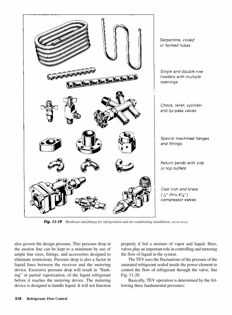
310 Refrigerant: Flow Control
also govern the design pressure. This pressure drop inthe suction line can be kept to a minimum by use ofample line sizes, fittings, and accessories designed toeliminate restrictions. Pressure drop is also a factor inliquid lines between the receiver and the meteringdevice. Excessive pressure drop will result in “flash-ing” or partial vaporization, of the liquid refrigerantbefore it reaches the metering device. The meteringdevice is designed to handle liquid. It will not function
properly if fed a mixture of vapor and liquid. Here,valves play an important role in controlling and meteringthe flow of liquid in the system.
The TEV uses the fluctuations of the pressure of thesaturated refrigerant sealed inside the power element tocontrol the flow of refrigerant through the valve. SeeFig. 11-20.
Basically, TEV operation is determined by the fol-lowing three fundamental pressures:
Fig. 11-19 Hardware and fittings for refrigeration and air-conditioning installation. (Mueller Brass)
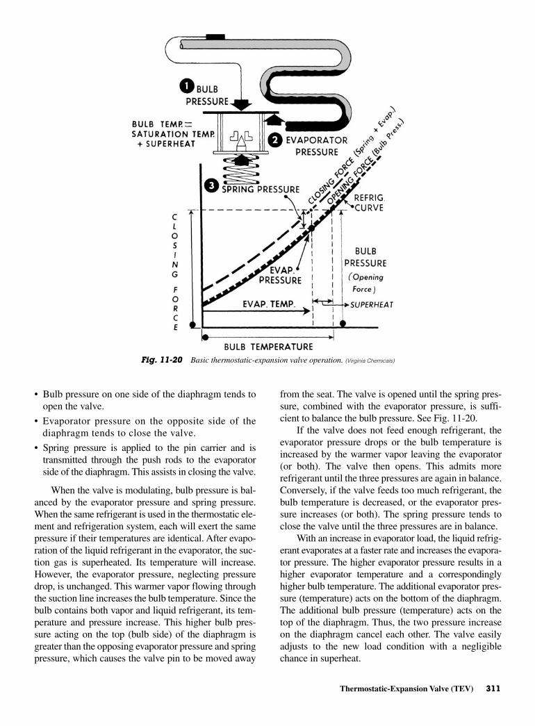
Thermostatic-Expansion Valve (TEV) 311
• Bulb pressure on one side of the diaphragm tends toopen the valve.
• Evaporator pressure on the opposite side of thediaphragm tends to close the valve.
• Spring pressure is applied to the pin carrier and istransmitted through the push rods to the evaporatorside of the diaphragm. This assists in closing the valve.
When the valve is modulating, bulb pressure is bal-anced by the evaporator pressure and spring pressure.When the same refrigerant is used in the thermostatic ele-ment and refrigeration system, each will exert the samepressure if their temperatures are identical. After evapo-ration of the liquid refrigerant in the evaporator, the suc-tion gas is superheated. Its temperature will increase.However, the evaporator pressure, neglecting pressuredrop, is unchanged. This warmer vapor flowing throughthe suction line increases the bulb temperature. Since thebulb contains both vapor and liquid refrigerant, its tem-perature and pressure increase. This higher bulb pres-sure acting on the top (bulb side) of the diaphragm isgreater than the opposing evaporator pressure and springpressure, which causes the valve pin to be moved away
from the seat. The valve is opened until the spring pres-sure, combined with the evaporator pressure, is suffi-cient to balance the bulb pressure. See Fig. 11-20.
If the valve does not feed enough refrigerant, theevaporator pressure drops or the bulb temperature isincreased by the warmer vapor leaving the evaporator(or both). The valve then opens. This admits morerefrigerant until the three pressures are again in balance.Conversely, if the valve feeds too much refrigerant, thebulb temperature is decreased, or the evaporator pres-sure increases (or both). The spring pressure tends toclose the valve until the three pressures are in balance.
With an increase in evaporator load, the liquid refrig-erant evaporates at a faster rate and increases the evapora-tor pressure. The higher evaporator pressure results in ahigher evaporator temperature and a correspondinglyhigher bulb temperature. The additional evaporator pres-sure (temperature) acts on the bottom of the diaphragm.The additional bulb pressure (temperature) acts on thetop of the diaphragm. Thus, the two pressure increaseon the diaphragm cancel each other. The valve easilyadjusts to the new load condition with a negligiblechance in superheat.
Fig. 11-20 Basic thermostatic-expansion valve operation. (Virginia Chemicals)

312 Refrigerant: Flow Control
Valve Location TEVs may be mounted in any position. However, theyshould be installed as close as possible to the evapora-tor inlet. If a refrigerant distributor is used, mount thedistributor directly to the valve outlet for best perfor-mance. If a hand valve is located on the outlet side ofthe TEV, it should have a full-sized port. No restric-tions should appear between the TEV and the evapora-tor, except a refrigerant distributor if one is used.
When the evaporator and TEV valve are locatedabove the receiver, there is a static-pressure loss in theliquid line. This is due to the weight of the column ofliquid refrigerant. This weight may be interpreted interms of pressure loss in pounds per square inch, seeTable 11-3. If the vertical lift is great enough, vapor, orflash gas, will form in the liquid line. This greatlyreduces the capacity of the TEV. When an appreciablevertical lift is unavoidable, precautions should be takento prevent the accompanying pressure loss from pro-ducing liquid-line vapor. This can be accomplished byproviding enough subcooling, to the liquid refrigerant,
either in the condenser or after the liquid leaves thereceiver. Subcooling is found by subtracting the actualliquid temperature from the condensing temperature(corresponding to the condensing pressure). Theamount of subcooling necessary to prevent vapor for-mation in the liquid line is usually available in a table.See Table 11-4.
CAUTION: Ammonia valves shouldnever be permitted to operate with vaporin the liquid line. This causes severe pinand seat erosion. It also will drasticallyreduce the life of the valve.
Bulb LocationThe location of the bulb is extremely important. Insome cases, it determines the success or failure of therefrigerating plant. For satisfactory expansion-valvecontrol, good thermal contact between the bulb andsuction line is essential. The bulb should be securely
Table 11-4 Pressure Loss and Required Subcooling for 100 and 130∞FCondensing of Refrigerants
100°F [37.8°C] Condensing 130°F [54.4°C] Condensing
Pressure Loss (psi) Pressure Loss (psi)Refrigerant
5 10 20 30 40 50 5 10 20 30 40 50
Required Subcooling (°F) Required Subcooling (°F)
12 3 6 12 18 25 33 3 5 9 14 18 2322 2 4 8 11 15 19 2 4 6 9 12 14
500 3 5 10 15 21 27 2 4 8 11 15 19502 2 3 7 10 14 18 1 3 5 8 11 13717 2 4 7 10 14 17 2 3 5 7 10 12
(Ammonia)
Sporlan Valve
Table 11-3 Vertical Lift and Pressure Drop
Vertical Lift (F)
20 40 60 80 100
Refrigerant Static Pressure Loss (psi)
12 11 22 33 44 55 25 psi22 10 20 30 40 50 35 psi500 10 19 29 39 49 25 psi502 10 21 31 41 52 35 psi717 5 10 15 20 25 40 psi
(Ammonia)
Sporlan Valve
AveragePressure
Drop AcrossDistributor

Thermostatic-Expansion Valve (TEV) 313
fastened with two bulb straps to a clean, straight sec-tion of the suction line.
Application of the bulb to a horizontal run of suc-tion line is preferred. If a vertical installation cannot beavoided, the bulb should be mounted so that the capil-lary tubing comes out at the top. On suction lines, ODand larger, the surface temperature may vary slightlyaround the circumference of the line. On these lines, itis generally recommended that the bulb be installed at apoint midway on the side of the horizontal line and par-allel to the direction of flow. On smaller lines the bulbmay be mounted at any point around the circumference.However, locating the bulb on the bottom of the line isnot recommended, since an oil-refrigerant mixture isgenerally present at that point. Certain conditions pecu-liar to a particular system may require a different bulblocation than that normally recommended. In thesecases, the proper bulb location may be determined bytrial. Accepted principles of good suction-line pipingshould be followed to provide a bulb location that willgive the best possible valve control. Never locate thebulb in a trap or pocket in the suction line. Liquid re-frigerant or a mixture of liquid refrigerant and oil boil-ing out of the trap will falsely influence the temperatureof the bulb and result in poor valve control.
Recommended suction-line piping includes a hori-zontal line leaving the evaporator to which the TEV bulbis attached. This line is pitched slightly downward. Whena vertical riser follows, a short trap is placed immediately
ahead of the vertical line. See Fig. 11-21. The trap willcollect any liquid refrigerant or oil passing through thesuction line and prevent it from influencing the bulbtemperature.
On multiple evaporator installations the pipingshould be arranged so that the flow from any valve can-not affect the bulb of another. Approved piping prac-tices, including the proper use of traps, ensure individualcontrol for each valve without the influence of refriger-ant and oil flow from other evaporators. See Fig. 11-22.
For recommended suction-line piping when the evap-orator is located above the compressor see Fig. 11-23. Thevertical riser extending to the height of the evaporator
Fig. 11-21 Installation of TEV with the compressor above theevaporator. (Virginia Chemicals)
Flow from upper
valve cannot a
ffect
bulb...line-fre
e draining
Inverted trap to avoid oil draining into idle evap.
Free draining
Fig. 11-22 Installation of the TEV with multiple evaporators, above and belowmain suction line. (Virginia Chemical)
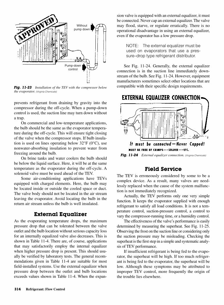
314 Refrigerant: Flow Control
prevents refrigerant from draining by gravity into thecompressor during the off-cycle. When a pump-downcontrol is used, the suction line may turn down withouta trap.
On commercial and low-temperature applications,the bulb should be the same as the evaporator tempera-ture during the off-cycle. This will ensure tight closingof the valve when the compressor stops. If bulb insula-tion is used on lines operating below 32°F (0°C), usenonwater-absorbing insulation to prevent water fromfreezing around the bulb.
On brine tanks and water coolers the bulb shouldbe below the liquid surface. Here, it will be at the sametemperature as the evaporator during the off-cycle. Asolenoid valve must be used ahead of the TEV.
Some air-conditioning applications have TEVsequipped with charged elements. Here, the bulb maybe located inside or outside the cooled space or duct.The valve body should not be located in the air streamleaving the evaporator. Avoid locating the bulb in thereturn air stream unless the bulb is well insulated.
External EqualizerAs the evaporating temperature drops, the maximumpressure drop that can be tolerated between the valveoutlet and the bulb location without serious capacity lossfor an internally equalized valve also decreases. This isshown in Table 11-4. There are, of course, applicationsthat may satisfactorily employ the internal equalizerwhen higher pressure drop is present. This should usu-ally be verified by laboratory tests. The general recom-mendations given in Table 11-4 are suitable for mostfield-installed systems. Use the external equalizer whenpressure drop between the outlet and bulb locationsexceeds values shown in Table 11-4. When the expan-
sion valve is equipped with an external equalizer, it mustbe connected. Never cap an external equalizer. The valvemay flood, starve, or regulate erratically. There is nooperational disadvantage in using an external equalizer,even if the evaporator has a low pressure drop.
NOTE: The external equalizer must beused on evaporators that use a pres-sure–drop type refrigerant distributor.
See Fig. 11-24. Generally, the external equalizerconnection is in the suction line immediately down-stream of the bulb. See Fig. 11-24. However, equipmentmanufacturers sometimes select other locations that arecompatible with their specific design requirements.
Field ServiceThe TEV is erroneously considered by some to be acomplex device. As a result, many valves are need-lessly replaced when the cause of the system malfunc-tion is not immediately recognized.
Actually, the TEV performs only one very simplefunction. It keeps the evaporator supplied with enoughrefrigerant to satisfy all load conditions. It is not a tem-perature control, suction-pressure control, a control tovary the compressor-running time, or a humidity control.
The effectiveness of the valve’s performance is easilydetermined by measuring the superheat. See Fig. 11-25.Observing the frost on the suction line or considering onlythe suction pressure may be misleading. Checking thesuperheat is the first step in a simple and systematic analy-sis of TEV performance.
If insufficient refrigerant is being fed to the evapo-rator, the superheat will be high. If too much refriger-ant is being fed to the evaporator, the superheat will below. Although these symptoms may be attributed toimproper TEV control, more frequently the origin ofthe trouble lies elsewhere.
Withoutpump down
Pump-down control
Fig. 11-23 Installation of the TEV with the compressor belowthe evaporator. (Virginia Chemicals)
Fig. 11-24 External equalizer connection. (Virginia Chemicals)

Crankcase Pressure-Regulating Valves 315
CRANKCASEPRESSURE-REGULATING VALVES
Crankcase pressure-regulating valves are designed toprevent overloading of the compressor motor. Theylimit the crankcase pressure during and after a defrostcycle or after a normal shutdown period. When prop-erly installed in the suction line, these valves automat-ically throttle the vapor flow from the evaporator untilthe compressor can handle the load. They are availablein the range of 0 to 60 psig.
Operation of the ValveCrankcase pressure-regulating valves (CROS) are some-times called suction pressure-regulating valves. They aresensitive only to their outlet pressure. This would be thecompressor crankcase or suction pressure. To indicate thistrait, the designation describes the operation: close on riseof outlet pressure, or CRO. As shown in Fig. 11-26, theinlet pressure is exerted on the underside of the bellowsand on top of the seat disc. Since the effective area of thebellows is equal to the area of the port, the inlet pressurecancels out and does not affect valve operation. Thevalve-outlet pressure acting on the bottom of the discexerts a force in the closing direction. This force isopposed by the adjustable spring force. These are theoperating forces of the CRO. The CRO’s pressure settingis determined by the spring force. Thus, by increasing thespring force, the valve setting or the pressure at which thevalve will close is increased.
As long as the valve-outlet pressure is greater thanthe valve-pressure setting, the valve will remain closed.As the outlet pressure is reduced, the valve will openand pass refrigerant vapor into the compressor. Furtherreduction of the outlet pressure will allow the valve toopen to its rated position, where the rated pressure dropwill exist across the valve port. An increase in the out-
let pressure will cause the valve to throttle until thepressure setting is reached.
The operation of a valve of this type is improvedby an antichatter device built into the valve. Withoutthis device, the CRO would be susceptible to compres-sor pulsations that greatly reduce the life of a bellows.This feature allows the CRO to function at low-loadconditions without any chattering or other operationdifficulties.
Valve LocationAs Fig. 11-27 indicates, the CRO valve is applied in thesuction line between the evaporator and the compressor.Normally, the CRO is installed downstream of any othercontrols or accessories. However, on some applicationsit may be advisable or necessary to locate other systemcomponents, such as an accumulator, downstream of theCRO. This is satisfactory as long as the CRO valve isapplied only as a crankcase pressure-regulating valve.CRO valves are designed for application in the suctionline only. They should not be applied in hot–gas bypasslines or any other refrigerant line of a system.
Fig. 11-25 How to figure superheat? (Virginia Chemicals)
Fig. 11-26 Crankcase pressure-regulating valve. (Sporlan Valve)
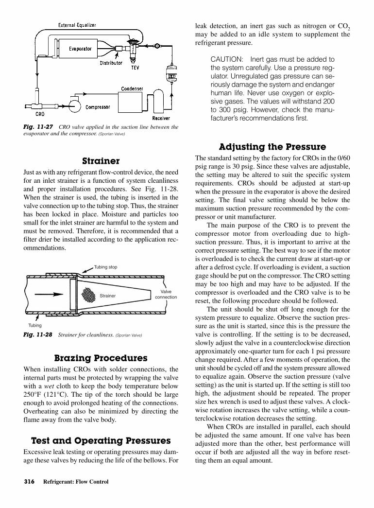
316 Refrigerant: Flow Control
StrainerJust as with any refrigerant flow-control device, the needfor an inlet strainer is a function of system cleanlinessand proper installation procedures. See Fig. 11-28.When the strainer is used, the tubing is inserted in thevalve connection up to the tubing stop. Thus, the strainerhas been locked in place. Moisture and particles toosmall for the inlet strainer are harmful to the system andmust be removed. Therefore, it is recommended that afilter drier be installed according to the application rec-ommendations.
Brazing Procedures When installing CROs with solder connections, theinternal parts must be protected by wrapping the valvewith a wet cloth to keep the body temperature below250°F (121°C). The tip of the torch should be largeenough to avoid prolonged heating of the connections.Overheating can also be minimized by directing theflame away from the valve body.
Test and Operating PressuresExcessive leak testing or operating pressures may dam-age these valves by reducing the life of the bellows. For
leak detection, an inert gas such as nitrogen or CO2may be added to an idle system to supplement therefrigerant pressure.
CAUTION: Inert gas must be added tothe system carefully. Use a pressure reg-ulator. Unregulated gas pressure can se-riously damage the system and endangerhuman life. Never use oxygen or explo-sive gases. The values will withstand 200to 300 psig. However, check the manu-facturer’s recommendations first.
Adjusting the PressureThe standard setting by the factory for CROs in the 0/60psig range is 30 psig. Since these valves are adjustable,the setting may be altered to suit the specific systemrequirements. CROs should be adjusted at start-upwhen the pressure in the evaporator is above the desiredsetting. The final valve setting should be below themaximum suction pressure recommended by the com-pressor or unit manufacturer.
The main purpose of the CRO is to prevent thecompressor motor from overloading due to high-suction pressure. Thus, it is important to arrive at thecorrect pressure setting. The best way to see if the motoris overloaded is to check the current draw at start-up orafter a defrost cycle. If overloading is evident, a suctiongage should be put on the compressor. The CRO settingmay be too high and may have to be adjusted. If thecompressor is overloaded and the CRO valve is to bereset, the following procedure should be followed.
The unit should be shut off long enough for thesystem pressure to equalize. Observe the suction pres-sure as the unit is started, since this is the pressure thevalve is controlling. If the setting is to be decreased,slowly adjust the valve in a counterclockwise directionapproximately one-quarter turn for each 1 psi pressurechange required. After a few moments of operation, theunit should be cycled off and the system pressure allowedto equalize again. Observe the suction pressure (valvesetting) as the unit is started up. If the setting is still toohigh, the adjustment should be repeated. The propersize hex wrench is used to adjust these valves. A clock-wise rotation increases the valve setting, while a coun-terclockwise rotation decreases the setting.
When CROs are installed in parallel, each shouldbe adjusted the same amount. If one valve has beenadjusted more than the other, best performance willoccur if both are adjusted all the way in before reset-ting them an equal amount.
Fig. 11-27 CRO valve applied in the suction line between theevaporator and the compressor. (Sporlan Valve)
Fig. 11-28 Strainer for cleanliness. (Sporlan Valve)
Tubing stop
Valve connectionStrainer
Tubing
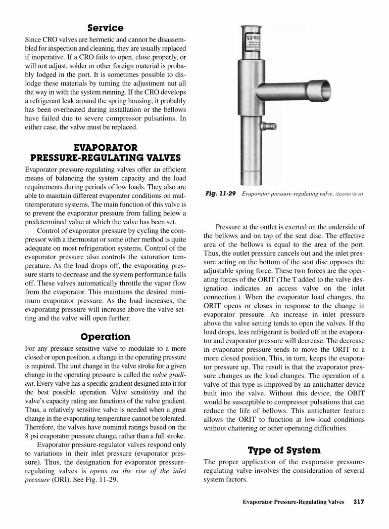
Evaporator Pressure-Regulating Valves 317
ServiceSince CRO valves are hermetic and cannot be disassem-bled for inspection and cleaning, they are usually replacedif inoperative. If a CRO fails to open, close properly, orwill not adjust, solder or other foreign material is proba-bly lodged in the port. It is sometimes possible to dis-lodge these materials by turning the adjustment nut allthe way in with the system running. If the CRO developsa refrigerant leak around the spring housing, it probablyhas been overheated during installation or the bellowshave failed due to severe compressor pulsations. Ineither case, the valve must be replaced.
EVAPORATORPRESSURE-REGULATING VALVES
Evaporator pressure-regulating valves offer an efficientmeans of balancing the system capacity and the loadrequirements during periods of low loads. They also areable to maintain different evaporator conditions on mul-titemperature systems. The main function of this valve isto prevent the evaporator pressure from falling below apredetermined value at which the valve has been set.
Control of evaporator pressure by cycling the com-pressor with a thermostat or some other method is quiteadequate on most refrigeration systems. Control of theevaporator pressure also controls the saturation tem-perature. As the load drops off, the evaporating pres-sure starts to decrease and the system performance fallsoff. These valves automatically throttle the vapor flowfrom the evaporator. This maintains the desired mini-mum evaporator pressure. As the load increases, theevaporating pressure will increase above the valve set-ting and the valve will open further.
OperationFor any pressure-sensitive valve to modulate to a moreclosed or open position, a change in the operating pressureis required. The unit change in the valve stroke for a givenchange in the operating pressure is called the valve gradi-ent. Every valve has a specific gradient designed into it forthe best possible operation. Valve sensitivity and thevalve’s capacity rating are functions of the valve gradient.Thus, a relatively sensitive valve is needed when a greatchange in the evaporating temperature cannot be tolerated.Therefore, the valves have nominal ratings based on the8 psi evaporator pressure change, rather than a full stroke.
Evaporator pressure-regulator valves respond onlyto variations in their inlet pressure (evaporator pres-sure). Thus, the designation for evaporator pressure-regulating valves is opens on the rise of the inletpressure (ORI). See Fig. 11-29.
Pressure at the outlet is exerted on the underside ofthe bellows and on top of the seat disc. The effectivearea of the bellows is equal to the area of the port.Thus, the outlet pressure cancels out and the inlet pres-sure acting on the bottom of the seat disc opposes theadjustable spring force. These two forces are the oper-ating forces of the ORIT (The T added to the valve des-ignation indicates an access valve on the inletconnection.). When the evaporator load changes, theORIT opens or closes in response to the change inevaporator pressure. An increase in inlet pressureabove the valve setting tends to open the valves. If theload drops, less refrigerant is boiled off in the evapora-tor and evaporator pressure will decrease. The decreasein evaporator pressure tends to move the ORIT to amore closed position. This, in turn, keeps the evapora-tor pressure up. The result is that the evaporator pres-sure changes as the load changes. The operation of avalve of this type is improved by an antichatter devicebuilt into the valve. Without this device, the OBITwould be susceptible to compressor pulsations that canreduce the life of bellows. This antichatter featureallows the ORIT to function at low-load conditionswithout chattering or other operating difficulties.
Type of SystemThe proper application of the evaporator pressure-regulating valve involves the consideration of severalsystem factors.
Fig. 11-29 Evaporator pressure-regulating valve. (Sporlan Valve)

318 Refrigerant: Flow Control
One type of system is a single evaporator type,such as a water chiller. Here, the valve is used to pre-vent freeze-up at light loads. See Fig. 11-30.
Another type of system is a multitemperature refrig-eration system with evaporators operating at differenttemperatures. See Fig. 11-31. A valve may be requiredon one or more of the evaporators to maintain pressureshigher than that of the common suction line. For exam-ple, if evaporator A in Fig. 11-31 is designed for 35°F(1.7°C) (72.6 psig on Refrigerant 502), evaporator B for32°F (0°C) on the same refrigerant (68.2 psig), andother evaporators for 25°F (−3.9°C) (58.7 psig), thevalves (ORIT) are used to maintain a pressure of 72.6psig in evaporator A and 68.2 psig in evaporator B. How-ever, some multitemperature systems may require anOBIT on each evaporator, depending on the type ofproduct being refrigerated.
Valve LocationORITs must be installed upstream of any other suction-line controls or accessories. These valves may be installed
in the position most suited to the application. However,these valves should be located so that they do not act asan oil trap or so that solder cannot run into the internalparts during brazing in the suction line. Since thesevalves are hermetic, they cannot be disassembled toremove solder trapped in the internal parts. Installationof a filter drier and a strainer may be worth the expenseto keep the system clean and operational. Brazing pro-cedures are the same as for other valves of this type.The valve core of the access valve is shipped in anenvelope attached to the access valve. If the access-valve connection is to be used as a reusable pressuretap to check the valve setting, the OBIT must be brazedin before the core is installed. This protects the syn-thetic material of the core. If the access valve is to beused as a permanent pressure tap, the core and accessvalve cap may be discarded.
Test and Operating PressuresAs with other pressure valves, it is possible to intro-duce nitrogen or CO2 in an idle system to check forcorrect pressure settings.
The usual precautions for working with gases applyhere. The standard factory setting for the 0/50 psigrange is 30 psi. For the 30/100 psig range, it is 60 psig.Since these valves are adjustable, the setting may bealtered to suit the system.
The main purpose of an OBIT valve is to keep theevaporator pressure above some given point at mini-mum load conditions. The valves are selected on thebasis of the pressure drop at full-load conditions. Nev-ertheless, they should be adjusted to maintain the min-imum allowable evaporator pressure under the actualminimum load conditions.
These valves can be adjusted by removing the capand turning the adjustment screw with a hex wrench ofthe proper size. A clockwise rotation increases the valve
Fig. 11-31 Multitemperature refrigeration system. (Sporlan Valve)
Fig. 11-30 Valve location in a single-evaporator system. (Sporlan Valve)
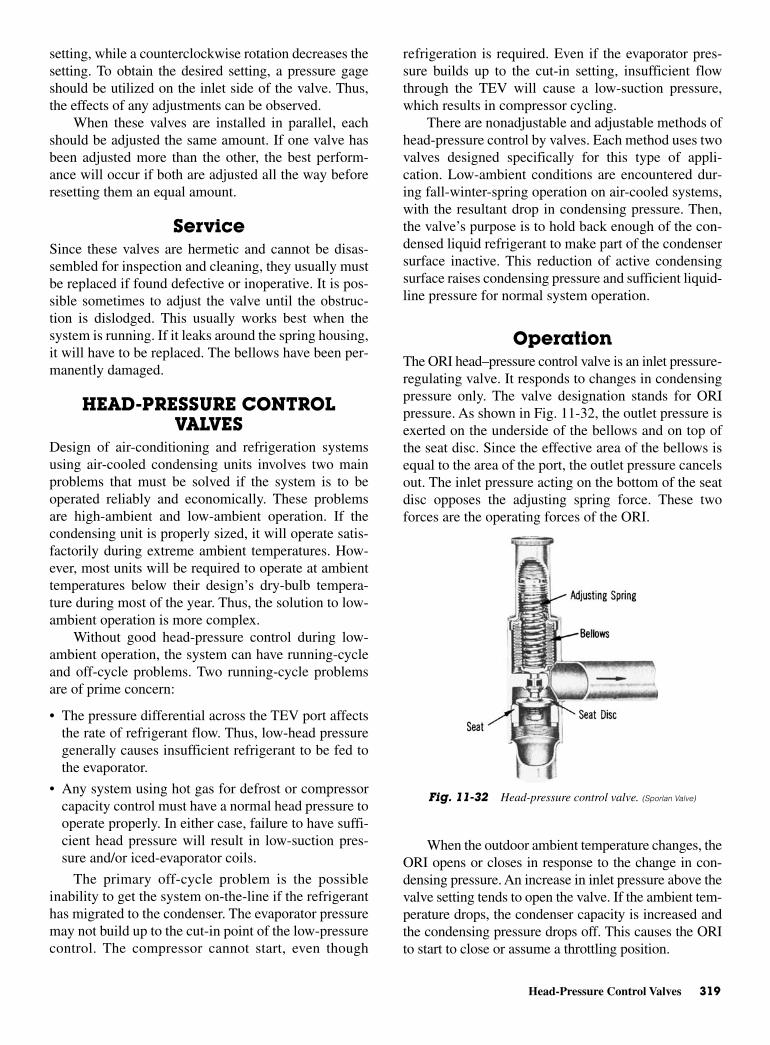
Head-Pressure Control Valves 319
setting, while a counterclockwise rotation decreases thesetting. To obtain the desired setting, a pressure gageshould be utilized on the inlet side of the valve. Thus,the effects of any adjustments can be observed.
When these valves are installed in parallel, eachshould be adjusted the same amount. If one valve hasbeen adjusted more than the other, the best perform-ance will occur if both are adjusted all the way beforeresetting them an equal amount.
ServiceSince these valves are hermetic and cannot be disas-sembled for inspection and cleaning, they usually mustbe replaced if found defective or inoperative. It is pos-sible sometimes to adjust the valve until the obstruc-tion is dislodged. This usually works best when thesystem is running. If it leaks around the spring housing,it will have to be replaced. The bellows have been per-manently damaged.
HEAD-PRESSURE CONTROLVALVES
Design of air-conditioning and refrigeration systemsusing air-cooled condensing units involves two mainproblems that must be solved if the system is to beoperated reliably and economically. These problemsare high-ambient and low-ambient operation. If thecondensing unit is properly sized, it will operate satis-factorily during extreme ambient temperatures. How-ever, most units will be required to operate at ambienttemperatures below their design’s dry-bulb tempera-ture during most of the year. Thus, the solution to low-ambient operation is more complex.
Without good head-pressure control during low-ambient operation, the system can have running-cycleand off-cycle problems. Two running-cycle problemsare of prime concern:
• The pressure differential across the TEV port affectsthe rate of refrigerant flow. Thus, low-head pressuregenerally causes insufficient refrigerant to be fed tothe evaporator.
• Any system using hot gas for defrost or compressorcapacity control must have a normal head pressure tooperate properly. In either case, failure to have suffi-cient head pressure will result in low-suction pres-sure and/or iced-evaporator coils.
The primary off-cycle problem is the possibleinability to get the system on-the-line if the refrigeranthas migrated to the condenser. The evaporator pressuremay not build up to the cut-in point of the low-pressurecontrol. The compressor cannot start, even though
refrigeration is required. Even if the evaporator pres-sure builds up to the cut-in setting, insufficient flowthrough the TEV will cause a low-suction pressure,which results in compressor cycling.
There are nonadjustable and adjustable methods ofhead-pressure control by valves. Each method uses twovalves designed specifically for this type of appli-cation. Low-ambient conditions are encountered dur-ing fall-winter-spring operation on air-cooled systems,with the resultant drop in condensing pressure. Then,the valve’s purpose is to hold back enough of the con-densed liquid refrigerant to make part of the condensersurface inactive. This reduction of active condensingsurface raises condensing pressure and sufficient liquid-line pressure for normal system operation.
OperationThe ORI head–pressure control valve is an inlet pressure-regulating valve. It responds to changes in condensingpressure only. The valve designation stands for ORIpressure. As shown in Fig. 11-32, the outlet pressure isexerted on the underside of the bellows and on top ofthe seat disc. Since the effective area of the bellows isequal to the area of the port, the outlet pressure cancelsout. The inlet pressure acting on the bottom of the seatdisc opposes the adjusting spring force. These twoforces are the operating forces of the ORI.
When the outdoor ambient temperature changes, theORI opens or closes in response to the change in con-densing pressure. An increase in inlet pressure above thevalve setting tends to open the valve. If the ambient tem-perature drops, the condenser capacity is increased andthe condensing pressure drops off. This causes the ORIto start to close or assume a throttling position.
Fig. 11-32 Head-pressure control valve. (Sporlan Valve)

320 Refrigerant: Flow Control
ORO-Valve OperationThe ORO head-pressure control valve is an outlet pressure-regulating valve that responds to changes in receiverpressure. The valve designation stands for “opens on riseof outlet” pressure. See Fig. 11-33. The inlet and outletpressures are exerted on the underside of the seat disc inan opening direction. Since the area of the port is smallin relationship to the diaphragm area, the inlet pressurehas little direct effect on the operation of the valve. Theoutlet or receiver pressure is the control pressure. Theforce on top of the diaphragm that opposes the controlpressure is due to the air charge in the element. Thesetwo forces are the operating forces of the ORO.
When the outdoor ambient temperature changes,the condensing pressure changes. This causes thereceiver pressure to fluctuate accordingly. As the receiverpressure decreases, the ORO throttles the flow of liquidfrom the condenser. As the receiver pressure increases,the valve modulates in an opening direction to main-tain a nearly constant pressure in the receiver. Since theambient temperature of the element affects the valve-pressure setting, the control pressure may changeslightly when the ambient temperature changes. How-ever, the valve and element temperature remain fairlyconstant.
ORD Valve OperationThe ORD valve is a pressure-differential valve. It respondsto changes in the pressure difference across the valve.See Fig. 11-34. The valve designation stands for“opens on rise of differential” pressure. Therefore, theORD is dependent on some other control valve oraction for its operation. In this respect, it is used witheither the ORI or ORO for head-pressure control.
As either the ORI or ORO valve starts to throttlethe flow of liquid refrigerant from the condenser, apressure differential is created across the ORD. Whenthe differential reaches 20 psi, the ORD starts to openand bypasses hot gas to the liquid drain line. As the dif-ferential increases, the ORD opens further until its fullstroke is reached at a differential of 30 psi. Due to itsfunction in the control of head pressure, the full strokecan be utilized in selecting the ORD. While the capac-ity of the ORD increases, as the pressure differentialincreases, the rating point at 30 psi is considered asatisfactory maximum value.
The standard pressure setting for the ORD is 20 psig.For systems where the condenser pressure drop ishigher than 10 or 12 psi, an ORD with a higher settingcan be ordered.
Head-pressure control can be improved with anarrangement, such as that shown in Fig. 11-35. In thisoperation, a constant receiver pressure is maintainedfor normal system operation. The ORI is adjustableover a nominal range of 100 to 225 psig. Thus, thedesired pressure can be maintained for all of the com-monly used refrigerants—12, 22, and 502, as a well asthe latest alternatives.
The ORI is located in the liquid drain line betweenthe condenser and the receiver. The ORD is located in
Fig. 11-33 Head-pressure control valve that opens on rise of outletpressure (ORO). (Sporlan Valve)
Fig. 11-34 Head-pressure control valve that opens on rise ofdifferential across the valve (ORD). (Sporlan Valve)
Fig. 11-35 Adjustable ORI/ORD system. (Sporlan Valve)
Head-Pressure Control Valves 321
a hot-gas line bypassing the condenser. During periodsof low-ambient temperature, the condensing pressurefalls until it approaches the setting of the ORI valve.The ORI then throttles, restricting the flow of liquidfrom the condenser. This causes refrigerant to back upin the condenser, thus reducing the active condensersurface. This raises the condensing pressure. Since it isreally receiver pressure that needs to be maintained, thebypass line with the ORD is required.
The ORD opens after the ORI has offered enoughrestriction to cause the differential between condensingpressure and receiver pressure to exceed 20 psi. The hotgas flowing through the ORD heats up the cold liquidbeing passed through the ORI. Thus, the liquid reachesthe receiver warm and with sufficient pressure to assureproper expansion-valve operation. As long as sufficientrefrigerant charge is in the system, the two valves mod-ulate the flow automatically to maintain proper receiverpressure regardless of outside ambient temperature.
InstallationTo insure proper performance, head-pressure controlvalves must be selected and applied correctly. Thesevalves can be installed in either horizontal or verticallines, if possible, the valves should be oriented so sol-der cannot run into the internal parts during brazing.Care should be taken to install the valves with the flowin the proper direction. The ORI and ORO valves can-not be installed in the discharge line for any reason.
In most cases the valves are located at the con-densing unit. When the condenser is remote from thecompressor, the usual location is near the compressor.In all cases it is important that some precautions betaken in mounting the valves. While the heaviest valveis approximately 2.5 lb (1.14 kg) in weight, it is sug-gested that they be adequately supported to preventexcessive stress on the connections. Since dischargelines are a possible source of vibrations that result fromdischarge gas pulses and inertia forces associated withthe moving parts, fatigue in tubing, fittings, and connec-tions may result. Pulsations are best handled by placinga good muffler as close to the compressor as possible.
Vibrations from moving parts of the compressor arebest isolated by flexible loops or coils (discharge lines orsmaller) or flexible metal hoses for larger lines. For bestresults, the hoses should be installed as close to the com-pressor shut-off valves as possible. The hoses should bemounted horizontally, and parallel to the crankshaft, orvertically. The hoses should never be mounted horizon-tally and 90° from the crankshaft. A rigid brace shouldbe placed on the outlet end of the hose. This brace willprevent vibrations beyond the hose.
Brazing ProceduresAny of the commonly used brazing alloys for high-sideusage are satisfactory. It is very important that the inter-nal parts be protected by wrapping the valve with a wetcloth to keep the body temperature below 250°F(121°C). Also, when using high-temperature solders,the torch tip should be large enough to avoid prolongedheating of the copper connections. Always direct theflame away from the valve body.
Test and Operating PressuresExcessive leak testing or operating pressures may dam-age these valves and reduce the life of the operatingmembers. For leak detection, an inert dry gas, such asnitrogen or CO2, can be added to an idle system to sup-plement the refrigerant pressure.
Remove the cap and adjust the adjustment screwwith the proper wrench. Check the manufacturer’s rec-ommended pressures before making adjustments.
Refrigerant and charging procedures require thatenough refrigerant be available for flooding the condenserat the lowest expected ambient temperature. There muststill be enough charge in the system for proper operation.
A shortage of refrigerant will cause hot gas toenter the liquid line and the expansion valve. Refriger-ation will cease.
The receiver must have sufficient capacity to holdat least all of the excess liquid refrigerant in the system.This is because such refrigerant will be returned to thereceiver when high-ambient conditions prevail. If thereceiver is too small, liquid refrigerant will be held backin the condenser during high-ambient condition. Exces-sively high-discharge pressures will be experienced.
CAUTION: All receivers must utilize apressure-relief valve or device accordingto the applicable standards or codes.
Follow the manufacturer’s recommendations forcharging the system. Procedures may vary with differ-ent valve manufacturers.
ServiceThere are several possible causes for system malfunc-tion with “refrigerant side” head-pressure control.These may be difficult to isolate from each other. Aswith any form of system troubleshooting, it is necessaryto know the existing operating temperatures and pres-sures before system problems can be determined. Oncethe malfunction is established, it is easier to pinpointthe cause and then take suitable action. Table 11-5 lists
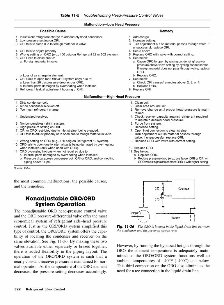
322 Refrigerant: Flow Control
the most common malfunctions, the possible causes,and the remedies.
Nonadjustable ORO/ORDSystem Operation
The nonadjustable ORO head-pressure control valveand the ORD pressure-differential valve offer the mosteconomical system of refrigerant side–head pressurecontrol. Just as the ORI/ORD system simplified thistype of control, the ORO/ORD system offers the capa-bility of locating the condenser and receiver on thesame elevation. See Fig. 11-36. By making these twovalves available either separately or brazed together,there is added flexibility in the piping layout. Theoperation of the ORO/ORD system is such that anearly constant receiver pressure is maintained for nor-mal operation. As the temperature of the ORO elementdecreases, the pressure setting decreases accordingly.
However, by running the bypassed hot gas through theORO the element temperature is adequately main-tained so the ORO/ORD system functions well toambient temperatures of −40°F (−40°C) and below.This third connection on the ORO also eliminates theneed for a tee connection in the liquid drain line.
Table 11-5 Troubleshooting Head-Pressure Control Valves
Malfunction—Low Head Pressure
Possible Cause Remedy
1. Insufficient refrigerant charge to adequately flood condenser. 1. Add charge.2. Low-pressure setting on ORI. 2. Increase setting.3. ORI fails to close due to foreign material in valve. 3. Turn adjustment out so material passes through valve. If
unsuccessful, replace ORI.4. ORI fails to adjust properly. 4. See 3 above.5. Wrong setting on ORO (e.g., 100 psig on Refrigerant 22 or 502 system). 5. Replace ORO with valve with correct setting.6. ORO fails to close due to: 6. See below:
a. Foreign material in valve. a. Cause ORO to open by raising condensing/receiverpressure above valve setting by cycling condenser fan.If foreign material does not pass through valve, replaceORO.
b. Loss of air charge in element. b. Replace ORO.7. ORD fails to open (on ORI/ORD system only) due to: 7. See below:
a. Less than 20 psi pressure drop across ORD. a. Check ORI causes/remedies above: 2, 3, or 4.b. Internal parts damaged by overheating when installed. b. Replace ORD.
8. Refrigerant leak at adjustment housing of ORI. 8. Replace ORI.
Malfunction—High Head Pressure
1. Dirty condenser coil. 1. Clean coil.2. Air on condenser blocked off. 2. Clear area around unit.3. Too much refrigerant charge. 3. Remove change until proper head pressure is main-
tained.4. Undersized receiver. 4. Check receiver capacity against refrigerant required
to maintain desired head pressure.5. Noncondensibles (air) in system. 5. Purge from system.6. High-pressure setting on ORI. 6. Decrease setting.7. ORI or ORO restricted due to inlet strainer being plugged. 7. Open inlet connection to clean strainer.8. ORI fails to adjust properly or to open due to foreign material in valve. 8. Turn adjustment out so material passes through
valve. If unsuccessful, replace ORI.9. Wrong setting on ORO (e.g., 180 psig on Refrigerant 12 system). 9. Replace ORO with valve with correct setting.
10. ORD fails to open due to internal parts being damaged by overheatingwhen installed (only when used with ORO). 10. Replace ORD.
11. ORD bypassing hot gas when not required due to: 11. See below:a. Internal parts damaged by overheating when installed. a. Replace ORD.b. Pressure drop across condenser coil, ORI or ORO, and connecting b. Reduce pressure drop (e.g., use larger ORI or ORI or
piping above 14 psi. ORO valves in parallel) or order ORD-4 with higher setting.
Sporlan Valve
Fig. 11-36 The ORO is located in the liquid drain line betweenthe condenser and the receiver. (Sporlan Valve)
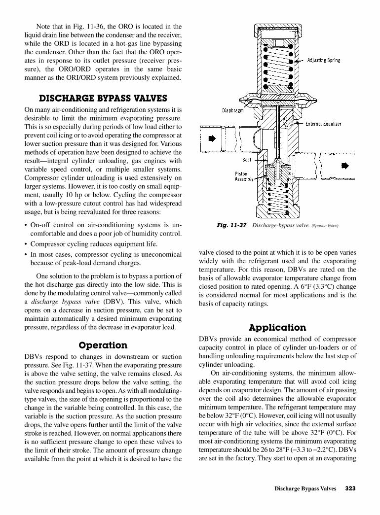
Discharge Bypass Valves 323
Note that in Fig. 11-36, the ORO is located in theliquid drain line between the condenser and the receiver,while the ORD is located in a hot-gas line bypassingthe condenser. Other than the fact that the ORO oper-ates in response to its outlet pressure (receiver pres-sure), the ORO/ORD operates in the same basicmanner as the ORI/ORD system previously explained.
DISCHARGE BYPASS VALVESOn many air-conditioning and refrigeration systems it isdesirable to limit the minimum evaporating pressure.This is so especially during periods of low load either toprevent coil icing or to avoid operating the compressor atlower suction pressure than it was designed for. Variousmethods of operation have been designed to achieve theresult—integral cylinder unloading, gas engines withvariable speed control, or multiple smaller systems.Compressor cylinder unloading is used extensively onlarger systems. However, it is too costly on small equip-ment, usually 10 hp or below. Cycling the compressorwith a low-pressure cutout control has had widespreadusage, but is being reevaluated for three reasons:
• On-off control on air-conditioning systems is un-comfortable and does a poor job of humidity control.
• Compressor cycling reduces equipment life.
• In most cases, compressor cycling is uneconomicalbecause of peak-load demand charges.
One solution to the problem is to bypass a portion ofthe hot discharge gas directly into the low side. This isdone by the modulating control valve—commonly calleda discharge bypass valve (DBV). This valve, whichopens on a decrease in suction pressure, can be set tomaintain automatically a desired minimum evaporatingpressure, regardless of the decrease in evaporator load.
OperationDBVs respond to changes in downstream or suctionpressure. See Fig. 11-37. When the evaporating pressureis above the valve setting, the valve remains closed. Asthe suction pressure drops below the valve setting, thevalve responds and begins to open. As with all modulating-type valves, the size of the opening is proportional to thechange in the variable being controlled. In this case, thevariable is the suction pressure. As the suction pressuredrops, the valve opens further until the limit of the valvestroke is reached. However, on normal applications thereis no sufficient pressure change to open these valves tothe limit of their stroke. The amount of pressure changeavailable from the point at which it is desired to have the
valve closed to the point at which it is to be open varieswidely with the refrigerant used and the evaporatingtemperature. For this reason, DBVs are rated on thebasis of allowable evaporator temperature change fromclosed position to rated opening. A 6°F (3.3°C) changeis considered normal for most applications and is thebasis of capacity ratings.
ApplicationDBVs provide an economical method of compressorcapacity control in place of cylinder un-loaders or ofhandling unloading requirements below the last step ofcylinder unloading.
On air-conditioning systems, the minimum allow-able evaporating temperature that will avoid coil icingdepends on evaporator design. The amount of air passingover the coil also determines the allowable evaporatorminimum temperature. The refrigerant temperature maybe below 32°F (0°C). However, coil icing will not usuallyoccur with high air velocities, since the external surfacetemperature of the tube will be above 32°F (0°C). Formost air-conditioning systems the minimum evaporatingtemperature should be 26 to 28°F (−3.3 to −2.2°C). DBVsare set in the factory. They start to open at an evaporating
Fig. 11-37 Discharge-bypass valve. (Sporlan Valve)

324 Refrigerant: Flow Control
pressure equivalent to 32°F (0°C) saturation temperature.Therefore, evaporating temperature of 26°F (−3.3°C) istheir rated capacity. However, since they are adjustable,these valves can be set to open at a higher evaporatingtemperature.
On refrigeration systems, DBV are used to preventthe suction pressure from going below the minimumvalue recommended by the compressor manufacturer. Atypical application would be a low-temperature compres-sor designed for operation at a minimum evaporatingtemperature on Refrigerant 22 of −40°F (−40°C). Therequired evaporating temperature at normal load conditionsis −30°F (−34°C). A DBV would be selected that wouldstart to open at the pressure equivalent to −34°F (−36°C)and bypass enough hot gas at −40°F (−40°C) to prevent afurther decrease in suction pressure. Valve settings areaccording to manufacturer’s recommendations.
The DBV is applied in a branch line off the dis-charge line as close to the compressor as possible. Thebypassed vapor can enter the low side at one of the fol-lowing locations:
• To evaporator inlet with distributor
• To evaporator inlet without distributor
• To suction line
Figure 11-38 shows the bypass to evaporator inletwith a distributor. The primary advantage of thismethod is that the system TEV will respond to theincreased superheat of the vapor, leaving the evapora-tor, and will provide the liquid required fordesuperheating. The evaporator also serves as an excel-lent mixing chamber for the bypassed hot gas and theliquid-vapor mixture from the expansion valve. This en-sures that dry vapor reaches the compressor suction. Oilreturn from the evaporator is also improved, since thevelocity in the evaporator is kept high by the hot gas.
Externally Equalized BypassValves
The primary function of the DBV is to maintain suc-tion pressure. Thus, the compressor suction pressure isthe control pressure. It must be exerted on the under-side of the valve diaphragm. When the DBV is applied,as shown in Fig. 11-38, where there is an appreciablepressure drop between the valve outlet and the com-pressor suction, the externally equalized valve must beused. This is true because when the valve opens, a sud-den rise in pressure occurs at the valve outlet. This cre-ates a false control pressure, which would cause theinternally equalized valve to close.
Many refrigeration systems and water chillers donot use refrigerant distributors but may require somemethod of compressor capacity control. This type ofapplication provides the advantages discussed earlier.
Bypass to Evaporator Inletwithout Distributor
On many applications, it may be necessary to bypassdirectly into the suction line. This is generally true ofsystems with multievaporators or remote-condensingunits. It may also be true for existing systems where it iseasier to connect to the suction line than the evaporatorinlet. The latter situation involves systems fed by TEVsor capillary tubes. When hot gas is bypassed, tempera-ture starts to increase. This can cause breakdown of theoil and refrigerant, possibly resulting in a compressorburnout. On close-coupled systems, this can be elimi-nated by locating the main expansion-valve bulb down-stream of the bypass connection, as shown in Fig. 11-39.
InstallationBypass valves can be installed in horizontal or verticallines, whichever best suits the application and permits
Fig. 11-38 Connection arrangement for a discharge-bypass valve.(Sporlan Valve)
Fig. 11-39 Application of a hot-gas bypass to an existing systemwith only minor piping changes. (Sporlan Valve)

Discharge Bypass Valves 325
easy accessibility to the valves. However, considerationshould be given to locating these valves so that they donot act as oil traps. Also solder must not run into theinternal parts during brazing.
The DBV should always be installed at the condens-ing unit rather than at the evaporator section. This willensure the rated bypass capacity of the DBV. It will alsoeliminate the possibility of hot gas condensing in thebypass line. This is especially true on remote systems.
When externally equalized lines are used, theequalizer connection must be connected to the suctionline where it will sense the desired operating pressure.See Fig. 11-40.
Since the DBV is applied in a bypass line betweenthe discharge line and the low side of a system, the valveis subjected to compressor vibrations. Unless the valve,connecting fittings, and tubing are properly isolatedfrom the vibrations, fatigue failures may occur. Whilethe heaviest valve weighs only 3.5 lb (1.6 kg), it shouldbe adequately supported to prevent excessive stress onthe connections.
If the remote-bulb type bypass valve is used, the bulbmust be located in a fairly constant ambient temperaturebecause the element-bulb assembly is air charged. Thesevalves are set at the factory in an 80°F (27°C) ambienttemperature. Thus, any appreciable variation from thistemperature will cause the pressure setting to vary fromthe factory setting. For a nonadjustable valve, the remotebulb may be located in an ambient of 80°F ±10°F (27°C±5.5°C). The adjustable remote bulb model can be ad-justed to operate in a temperature of 80°F ±30°F (27°C±16.7°C). On many units the manufacturer will have al-tered the pressure setting to compensate for an ambienttemperature appreciably different than 80°F (27°C).Therefore, on some units it may be necessary to consultwith the equipment manufacturer for the proper openingpressure setting of the bypass valve.
There are numerous places on a system where theremote bulb can be located. Two possible locations arethe return air stream and a structural member of the unit,if it is located in a conditioned space. Other locations,where the temperature is fairly constant but differentthan 80°F (27°C) are also available. These include thereturn water line on a chiller, the compressor suctionline, or the main liquid line. As previously mentioned,the setting may have been altered.
A bulb strap with bolts and nuts is usually suppliedwith each remote-bulb type DBV. This strap is for usein fastening the bulb in place.
Special ConsiderationsIf a DBV is applied on a system with an evaporatorpressure regulating valve (ORIT or other type), theDBV may bypass into either the evaporator inlet or thesuction line. The bypass will depend on the specific sys-tem. Valve function and the best piping method to pro-tect the compressor should be the deciding factors. Ifthe DBV is required on a system with a crankcase pressure-regulating valve (CRO or other type), the bypass valvecan bypass to the low side of the evaporator inlet or thesuction line without difficulties. The only decision nec-essary is whether an internally or externally equalizedvalve is required. This depends on where the hot gasenters the low side. The pressure setting of the DBVmust be lower than the CRO setting for each valve tofunction properly.
The hot-gas solenoid valve is to be located upstreamof the bypass valve. If the solenoid valve is installeddownstream of the DBV, the oil and/or liquid refrigerantmay be trapped between the two valves. Depending on theambient temperature surrounding the valves and piping,this could be dangerous.
If the hot-gas solenoid valve is required for pump-down control, it should be wired in parallel with theliquid-solenoid valve so that it can be deenergized by athermostat.
The hot-gas solenoid is sometimes used for protec-tion against high superheat conditions because thecompressor does not have an integral temperature-protection device. If this is done, the solenoid valve iswired in series with a bimetal thermostat fastened tothe discharge line close to the compressor.
Testing and OperatingPressures
Excessive leak testing or operating pressures may damagethese valves and reduce the life of the operating members.Since a high-side test pressure differential of approximately
Fig. 11-40 Externally equalized discharge-bypass valve. (Sporlan Valve)
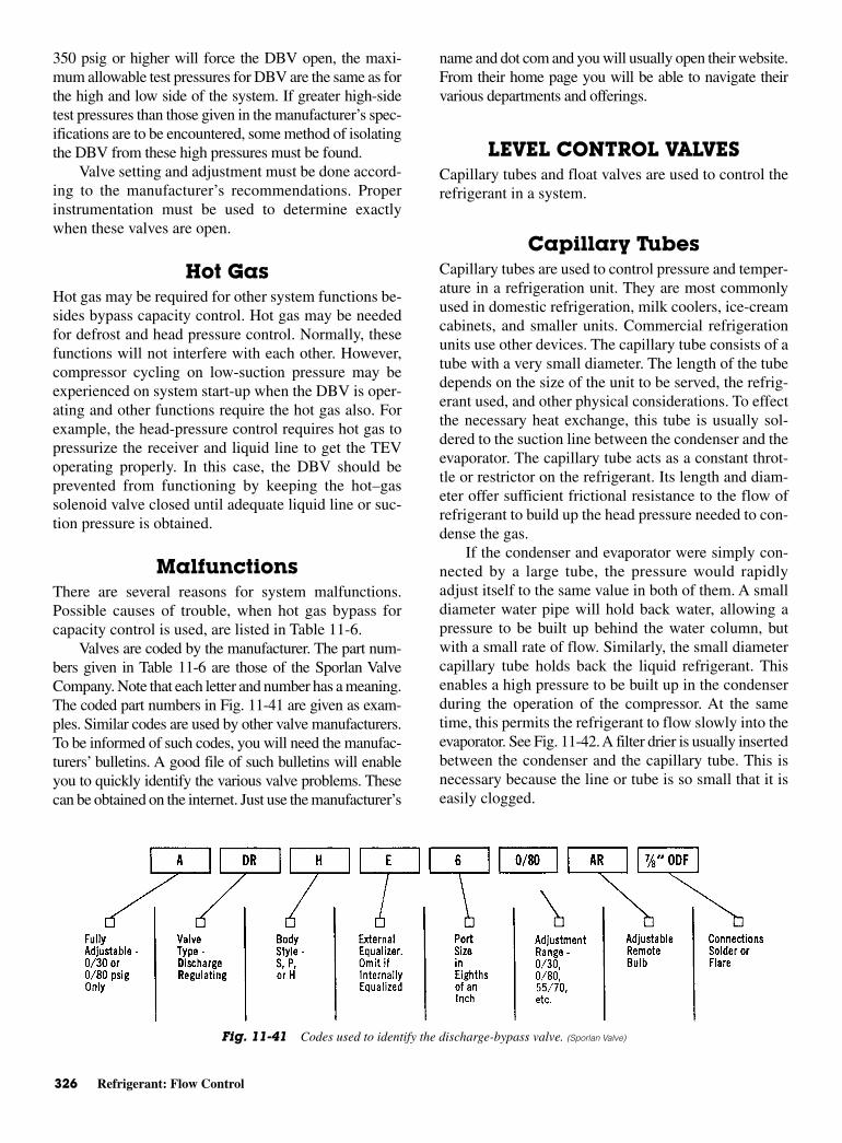
326 Refrigerant: Flow Control
350 psig or higher will force the DBV open, the maxi-mum allowable test pressures for DBV are the same as forthe high and low side of the system. If greater high-sidetest pressures than those given in the manufacturer’s spec-ifications are to be encountered, some method of isolatingthe DBV from these high pressures must be found.
Valve setting and adjustment must be done accord-ing to the manufacturer’s recommendations. Properinstrumentation must be used to determine exactlywhen these valves are open.
Hot GasHot gas may be required for other system functions be-sides bypass capacity control. Hot gas may be neededfor defrost and head pressure control. Normally, thesefunctions will not interfere with each other. However,compressor cycling on low-suction pressure may beexperienced on system start-up when the DBV is oper-ating and other functions require the hot gas also. Forexample, the head-pressure control requires hot gas topressurize the receiver and liquid line to get the TEVoperating properly. In this case, the DBV should beprevented from functioning by keeping the hot–gassolenoid valve closed until adequate liquid line or suc-tion pressure is obtained.
MalfunctionsThere are several reasons for system malfunctions.Possible causes of trouble, when hot gas bypass forcapacity control is used, are listed in Table 11-6.
Valves are coded by the manufacturer. The part num-bers given in Table 11-6 are those of the Sporlan ValveCompany. Note that each letter and number has a meaning.The coded part numbers in Fig. 11-41 are given as exam-ples. Similar codes are used by other valve manufacturers.To be informed of such codes, you will need the manufac-turers’ bulletins. A good file of such bulletins will enableyou to quickly identify the various valve problems. Thesecan be obtained on the internet. Just use the manufacturer’s
name and dot com and you will usually open their website.From their home page you will be able to navigate theirvarious departments and offerings.
LEVEL CONTROL VALVESCapillary tubes and float valves are used to control therefrigerant in a system.
Capillary TubesCapillary tubes are used to control pressure and temper-ature in a refrigeration unit. They are most commonlyused in domestic refrigeration, milk coolers, ice-creamcabinets, and smaller units. Commercial refrigerationunits use other devices. The capillary tube consists of atube with a very small diameter. The length of the tubedepends on the size of the unit to be served, the refrig-erant used, and other physical considerations. To effectthe necessary heat exchange, this tube is usually sol-dered to the suction line between the condenser and theevaporator. The capillary tube acts as a constant throt-tle or restrictor on the refrigerant. Its length and diam-eter offer sufficient frictional resistance to the flow ofrefrigerant to build up the head pressure needed to con-dense the gas.
If the condenser and evaporator were simply con-nected by a large tube, the pressure would rapidlyadjust itself to the same value in both of them. A smalldiameter water pipe will hold back water, allowing apressure to be built up behind the water column, butwith a small rate of flow. Similarly, the small diametercapillary tube holds back the liquid refrigerant. Thisenables a high pressure to be built up in the condenserduring the operation of the compressor. At the sametime, this permits the refrigerant to flow slowly into theevaporator. See Fig. 11-42. A filter drier is usually insertedbetween the condenser and the capillary tube. This isnecessary because the line or tube is so small that it iseasily clogged.
Fig. 11-41 Codes used to identify the discharge-bypass valve. (Sporlan Valve)
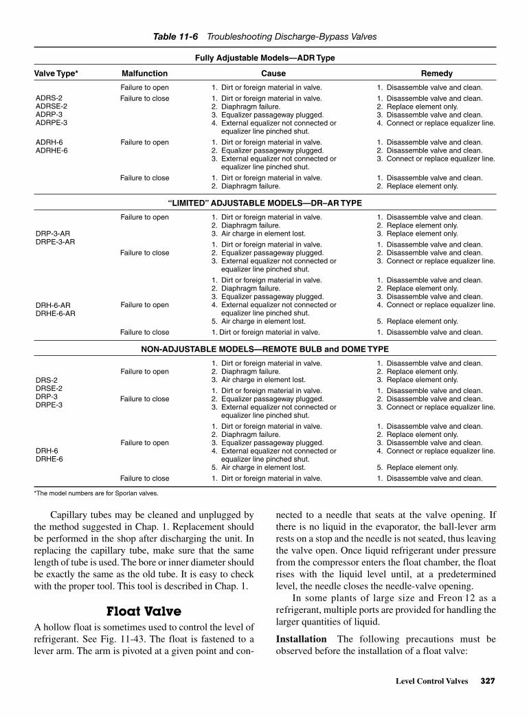
Level Control Valves 327
Table 11-6 Troubleshooting Discharge-Bypass Valves
Fully Adjustable Models—ADR Type
Valve Type* Malfunction Cause Remedy
Failure to open 1. Dirt or foreign material in valve. 1. Disassemble valve and clean.
Failure to close 1. Dirt or foreign material in valve. 1. Disassemble valve and clean.2. Diaphragm failure. 2. Replace element only.3. Equalizer passageway plugged. 3. Disassemble valve and clean.4. External equalizer not connected or 4. Connect or replace equalizer line.
equalizer line pinched shut.
Failure to open 1. Dirt or foreign material in valve. 1. Disassemble valve and clean.2. Equalizer passageway plugged. 2. Disassemble valve and clean.3. External equalizer not connected or 3. Connect or replace equalizer line.
equalizer line pinched shut.
Failure to close 1. Dirt or foreign material in valve. 1. Disassemble valve and clean.2. Diaphragm failure. 2. Replace element only.
“LIMITED” ADJUSTABLE MODELS—DR–AR TYPE
Failure to open 1. Dirt or foreign material in valve. 1. Disassemble valve and clean.2. Diaphragm failure. 2. Replace element only.3. Air charge in element lost. 3. Replace element only.
1. Dirt or foreign material in valve. 1. Disassemble valve and clean.Failure to close 2. Equalizer passageway plugged. 2. Disassemble valve and clean.
3. External equalizer not connected or 3. Connect or replace equalizer line.equalizer line pinched shut.
1. Dirt or foreign material in valve. 1. Disassemble valve and clean.2. Diaphragm failure. 2. Replace element only.3. Equalizer passageway plugged. 3. Disassemble valve and clean.
Failure to open 4. External equalizer not connected or 4. Connect or replace equalizer line.equalizer line pinched shut.
5. Air charge in element lost. 5. Replace element only.
Failure to close 1. Dirt or foreign material in valve. 1. Disassemble valve and clean.
NON-ADJUSTABLE MODELS—REMOTE BULB and DOME TYPE
1. Dirt or foreign material in valve. 1. Disassemble valve and clean.Failure to open 2. Diaphragm failure. 2. Replace element only.
3. Air charge in element lost. 3. Replace element only.
1. Dirt or foreign material in valve. 1. Disassemble valve and clean.Failure to close 2. Equalizer passageway plugged. 2. Disassemble valve and clean.
3. External equalizer not connected or 3. Connect or replace equalizer line.equalizer line pinched shut.
1. Dirt or foreign material in valve. 1. Disassemble valve and clean.2. Diaphragm failure. 2. Replace element only.
Failure to open 3. Equalizer passageway plugged. 3. Disassemble valve and clean.4. External equalizer not connected or 4. Connect or replace equalizer line.
equalizer line pinched shut.5. Air charge in element lost. 5. Replace element only.
Failure to close 1. Dirt or foreign material in valve. 1. Disassemble valve and clean.
*The model numbers are for Sporlan valves.
ADRS-2ADRSE-2ADRP-3ADRPE-3
DRH-6DRHE-6
ADRH-6ADRHE-6
DRP-3-ARDRPE-3-AR
DRH-6-ARDRHE-6-AR
DRS-2DRSE-2DRP-3DRPE-3
Capillary tubes may be cleaned and unplugged bythe method suggested in Chap. 1. Replacement shouldbe performed in the shop after discharging the unit. Inreplacing the capillary tube, make sure that the samelength of tube is used. The bore or inner diameter shouldbe exactly the same as the old tube. It is easy to checkwith the proper tool. This tool is described in Chap. 1.
Float ValveA hollow float is sometimes used to control the level ofrefrigerant. See Fig. 11-43. The float is fastened to alever arm. The arm is pivoted at a given point and con-
nected to a needle that seats at the valve opening. Ifthere is no liquid in the evaporator, the ball-lever armrests on a stop and the needle is not seated, thus leavingthe valve open. Once liquid refrigerant under pressurefrom the compressor enters the float chamber, the floatrises with the liquid level until, at a predeterminedlevel, the needle closes the needle-valve opening.
In some plants of large size and Freon-12 as arefrigerant, multiple ports are provided for handling thelarger quantities of liquid.
Installation The following precautions must beobserved before the installation of a float valve:

328 Refrigerant: Flow Control
Fig. 11-42 Refrigerant flow with a capillary tube in the line.
Fig. 11-43 Interior construction of a typical float valve. (Frick)

Level-Master Control 329
• Most float controls are designed for a maximumdifferential pressure of 200 lb.
• If the pressure will exceed 190 psi, there arestems and orifices of special size available forlow-temperature use.
• In any application, keep the bottom equalizing lineabove the bottom of the evaporator to avoid oil logging.
• Make sure there are no traps in the equalizing line.
• The stems of a globe valve must be in a horizontal plane.
• Refrigerant flow must be kept to less than 100 ft/minwhere a bottom float equalizing connection is madeto the header or accumulator return. That means theheader and accumulator pipe must be properly sized.
• Accumulators of a small diameter with a velocity ofover 50 ft/min are not suitable for accurate floatapplication. However, the float may control withinwider limits with higher velocities. The top equalizing
connection must be connected to a point of practi-cally zero gas velocity.
• In automatic plants, always provide a solenoid valvein the liquid line ahead of the float control. Thissolenoid valve is to close either when the tempera-tures are satisfactory or when the compressor stops.
Figure 11-44 illustrates the connections for a high-pressure float control. There have been new develop-ments in the control of liquid level since the early daysof refrigeration.
LEVEL-MASTER CONTROLThe level-master control is a positive liquid-level con-trol device suitable for application to all flooded evap-orators. See Fig. 11-45. The level-master control is astandard TEV with a level-master element. The combina-tion provides a simple, economical, and highly effective
Fig. 11-45 Level-master control. (Sporlan Valve)
Fig. 11-44 High-pressure float-control system.
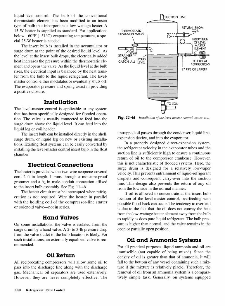
330 Refrigerant: Flow Control
liquid-level control. The bulb of the conventionalthermostatic element has been modified to an inserttype of bulb that incorporates a low-wattage heater. A15-W heater is supplied as standard. For applicationsbelow −60°F (−51°C) evaporating temperature, a spe-cial 25-W heater is needed.
The insert bulb is installed in the accumulator orsurge drum at the point of the desired liquid level. Asthe level at the insert bulb drops, the electrically addedheat increases the pressure within the thermostatic ele-ment and opens the valve. As the liquid level at the bulbrises, the electrical input is balanced by the heat trans-fer from the bulb to the liquid refrigerant. The level-master control either modulates or eventually shuts off.The evaporator pressure and spring assist in providinga positive closure.
InstallationThe level-master control is applicable to any systemthat has been specifically designed for flooded opera-tion. The valve is usually connected to feed into thesurge drum above the liquid level. It can feed into theliquid leg or coil header.
The insert bulb can be installed directly in the shell,surge drum, or liquid leg on new or existing installa-tions. Existing float systems can be easily converted byinstalling the level-master control insert bulb in the floatchamber.
Electrical Connections The heater is provided with a two-wire neoprene-coveredcord 2 ft in length. It runs through a moisture-proofgrommet and a 1/2 in. male-conduit connection affixedto the insert bulb assembly. See Fig. 11-46.
The heater circuit must be interrupted when refrig-eration is not required. Wire the heater in parallelwith the holding coil of the compressor-line starteror solenoid valve—not in series.
Hand ValvesOn some installations, the valve is isolated from thesurge drum by a hand valve. A 2- to 3-lb pressure dropfrom the valve outlet to the bulb location is likely. Forsuch installations, an externally equalized valve is rec-ommended.
Oil ReturnAll reciprocating compressors will allow some oil topass into the discharge line along with the dischargegas. Mechanical oil separators are used extensively.However, they are never completely effective. The
untrapped oil passes through the condenser, liquid line,expansion device, and into the evaporator.
In a properly designed direct-expansion system,the refrigerant velocity in the evaporator tubes and thesuction line is sufficiently high to ensure a continuousreturn of oil to the compressor crankcase. However,this is not characteristic of flooded systems. Here, thesurge drum is designed for a relatively low-vaporvelocity. This prevents entrainment of liquid-refrigerantdroplets and consequent carry-over into the suctionline. This design also prevents the return of any oilfrom the low side in the normal manner.
If oil is allowed to concentrate at the insert bulblocation of the level-master control, overfeeding withpossible flood-back can occur. The tendency to overfeedis due to the fact that the oil does not convey the heatfrom the low-wattage heater element away from the bulbas rapidly as does pure liquid refrigerant. The bulb pres-sure is higher than normal, and the valve remains in theopen or partially open position.
Oil and Ammonia Systems For all practical purposes, liquid ammonia and oil areimmiscible (not capable of being mixed). Since thedensity of oil is greater than that of ammonia, it willfall to the bottom of any vessel containing such a mix-ture if the mixture is relatively placid. Therefore, theremoval of oil from an ammonia system is a compara-tively simple task. Generally, on systems equipped
Fig. 11-46 Installation of the level-master control. (Sporlan Valve)
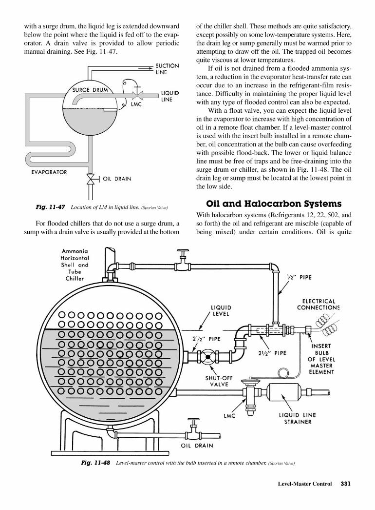
Level-Master Control 331
with a surge drum, the liquid leg is extended downwardbelow the point where the liquid is fed off to the evap-orator. A drain valve is provided to allow periodicmanual draining. See Fig. 11-47.
For flooded chillers that do not use a surge drum, asump with a drain valve is usually provided at the bottom
of the chiller shell. These methods are quite satisfactory,except possibly on some low-temperature systems. Here,the drain leg or sump generally must be warmed prior toattempting to draw off the oil. The trapped oil becomesquite viscous at lower temperatures.
If oil is not drained from a flooded ammonia sys-tem, a reduction in the evaporator heat-transfer rate canoccur due to an increase in the refrigerant-film resis-tance. Difficulty in maintaining the proper liquid levelwith any type of flooded control can also be expected.
With a float valve, you can expect the liquid levelin the evaporator to increase with high concentration ofoil in a remote float chamber. If a level-master controlis used with the insert bulb installed in a remote cham-ber, oil concentration at the bulb can cause overfeedingwith possible flood-back. The lower or liquid balanceline must be free of traps and be free-draining into thesurge drum or chiller, as shown in Fig. 11-48. The oildrain leg or sump must be located at the lowest point inthe low side.
Oil and Halocarbon SystemsWith halocarbon systems (Refrigerants 12, 22, 502, andso forth) the oil and refrigerant are miscible (capable ofbeing mixed) under certain conditions. Oil is quite
Fig. 11-48 Level-master control with the bulb inserted in a remote chamber. (Sporlan Valve)
Fig. 11-47 Location of LM in liquid line. (Sporlan Valve)
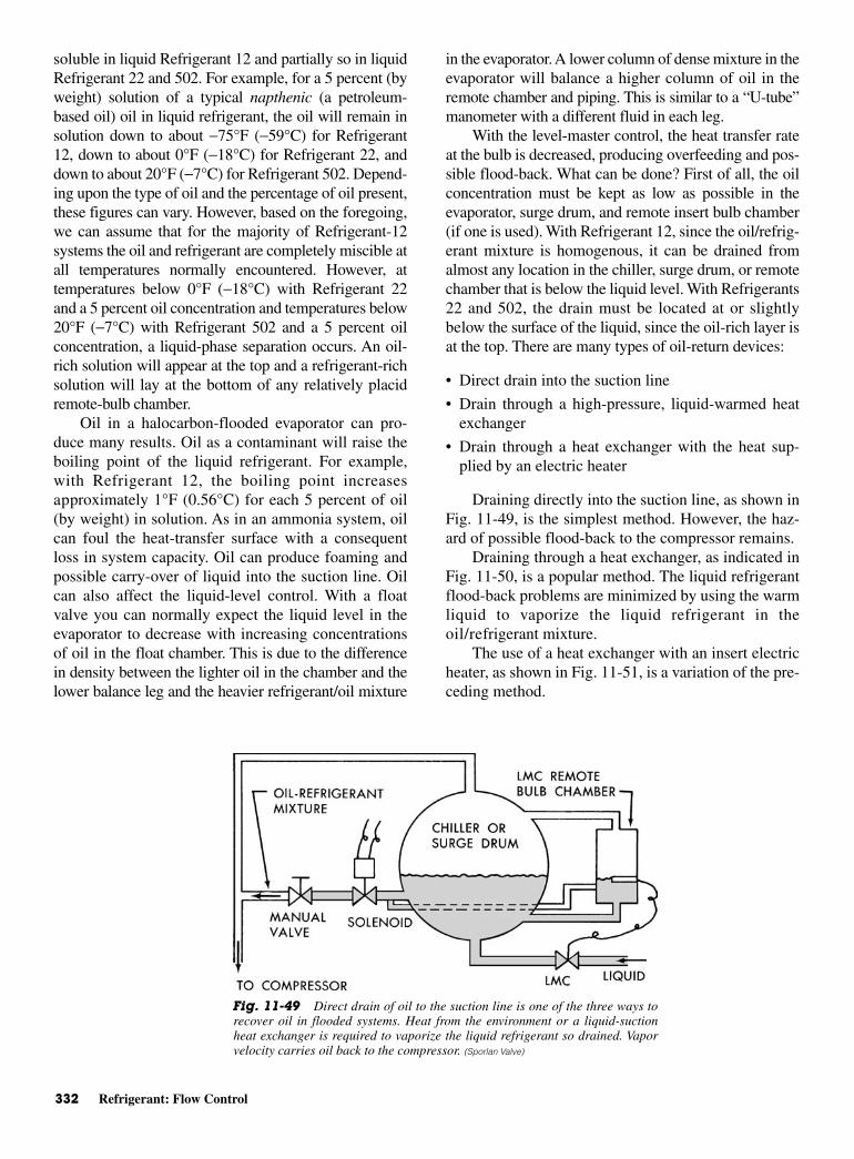
332 Refrigerant: Flow Control
soluble in liquid Refrigerant 12 and partially so in liquidRefrigerant 22 and 502. For example, for a 5 percent (byweight) solution of a typical napthenic (a petroleum-based oil) oil in liquid refrigerant, the oil will remain insolution down to about −75°F (−59°C) for Refrigerant12, down to about 0°F (−18°C) for Refrigerant 22, anddown to about 20°F (−7°C) for Refrigerant 502. Depend-ing upon the type of oil and the percentage of oil present,these figures can vary. However, based on the foregoing,we can assume that for the majority of Refrigerant-12systems the oil and refrigerant are completely miscible atall temperatures normally encountered. However, attemperatures below 0°F (−18°C) with Refrigerant 22and a 5 percent oil concentration and temperatures below20°F (−7°C) with Refrigerant 502 and a 5 percent oilconcentration, a liquid-phase separation occurs. An oil-rich solution will appear at the top and a refrigerant-richsolution will lay at the bottom of any relatively placidremote-bulb chamber.
Oil in a halocarbon-flooded evaporator can pro-duce many results. Oil as a contaminant will raise theboiling point of the liquid refrigerant. For example,with Refrigerant 12, the boiling point increasesapproximately 1°F (0.56°C) for each 5 percent of oil(by weight) in solution. As in an ammonia system, oilcan foul the heat-transfer surface with a consequentloss in system capacity. Oil can produce foaming andpossible carry-over of liquid into the suction line. Oilcan also affect the liquid-level control. With a floatvalve you can normally expect the liquid level in theevaporator to decrease with increasing concentrationsof oil in the float chamber. This is due to the differencein density between the lighter oil in the chamber and thelower balance leg and the heavier refrigerant/oil mixture
in the evaporator. A lower column of dense mixture in theevaporator will balance a higher column of oil in theremote chamber and piping. This is similar to a “U-tube”manometer with a different fluid in each leg.
With the level-master control, the heat transfer rateat the bulb is decreased, producing overfeeding and pos-sible flood-back. What can be done? First of all, the oilconcentration must be kept as low as possible in theevaporator, surge drum, and remote insert bulb chamber(if one is used). With Refrigerant 12, since the oil/refrig-erant mixture is homogenous, it can be drained fromalmost any location in the chiller, surge drum, or remotechamber that is below the liquid level. With Refrigerants22 and 502, the drain must be located at or slightlybelow the surface of the liquid, since the oil-rich layer isat the top. There are many types of oil-return devices:
• Direct drain into the suction line
• Drain through a high-pressure, liquid-warmed heatexchanger
• Drain through a heat exchanger with the heat sup-plied by an electric heater
Draining directly into the suction line, as shown inFig. 11-49, is the simplest method. However, the haz-ard of possible flood-back to the compressor remains.
Draining through a heat exchanger, as indicated inFig. 11-50, is a popular method. The liquid refrigerantflood-back problems are minimized by using the warmliquid to vaporize the liquid refrigerant in theoil/refrigerant mixture.
The use of a heat exchanger with an insert electricheater, as shown in Fig. 11-51, is a variation of the pre-ceding method.
Fig. 11-49 Direct drain of oil to the suction line is one of the three ways torecover oil in flooded systems. Heat from the environment or a liquid-suctionheat exchanger is required to vaporize the liquid refrigerant so drained. Vaporvelocity carries oil back to the compressor. (Sporlan Valve)
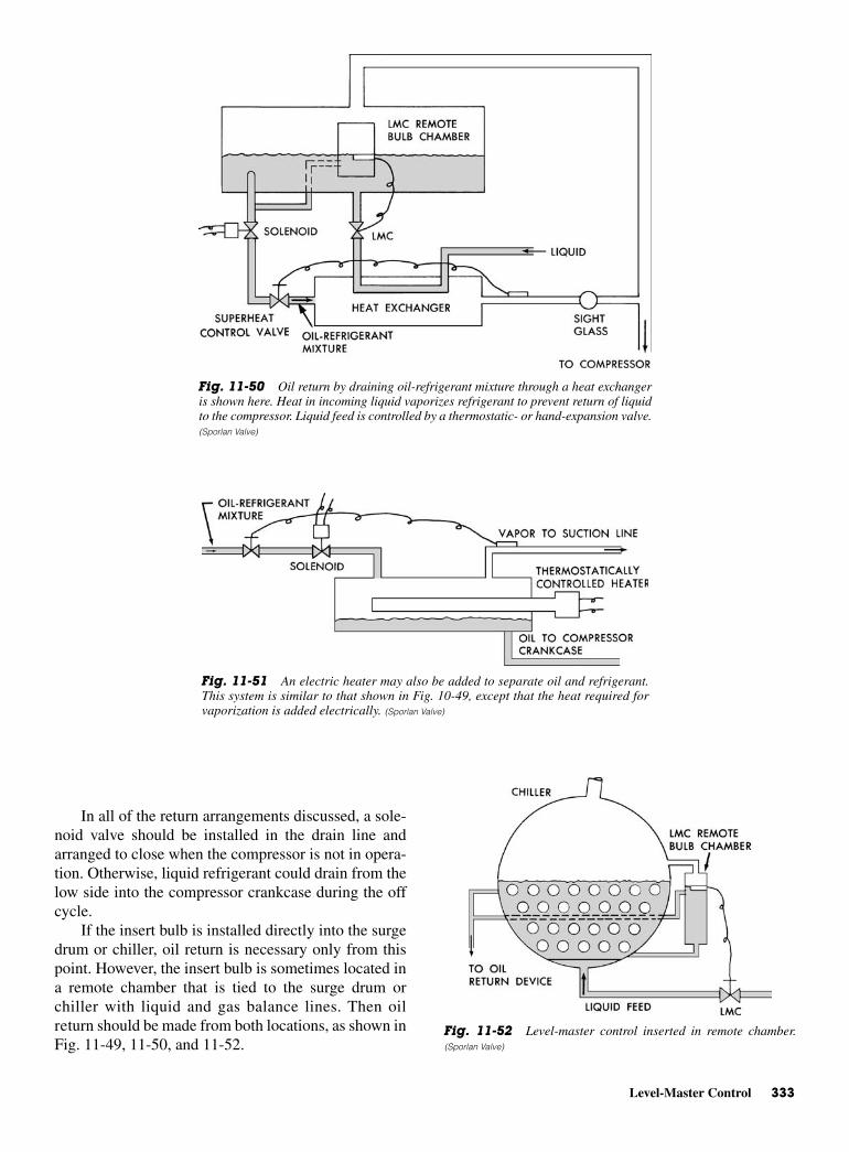
Level-Master Control 333
In all of the return arrangements discussed, a sole-noid valve should be installed in the drain line andarranged to close when the compressor is not in opera-tion. Otherwise, liquid refrigerant could drain from thelow side into the compressor crankcase during the offcycle.
If the insert bulb is installed directly into the surgedrum or chiller, oil return is necessary only from thispoint. However, the insert bulb is sometimes located ina remote chamber that is tied to the surge drum orchiller with liquid and gas balance lines. Then oilreturn should be made from both locations, as shown inFig. 11-49, 11-50, and 11-52.
Fig. 11-50 Oil return by draining oil-refrigerant mixture through a heat exchangeris shown here. Heat in incoming liquid vaporizes refrigerant to prevent return of liquidto the compressor. Liquid feed is controlled by a thermostatic- or hand-expansion valve.(Sporlan Valve)
Fig. 11-51 An electric heater may also be added to separate oil and refrigerant.This system is similar to that shown in Fig. 10-49, except that the heat required forvaporization is added electrically. (Sporlan Valve)
Fig. 11-52 Level-master control inserted in remote chamber.(Sporlan Valve)
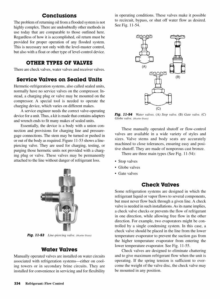
334 Refrigerant: Flow Control
ConclusionsThe problem of returning oil from a flooded system is nothighly complex. There are undoubtedly other methods inuse today that are comparable to those outlined here.Regardless of how it is accomplished, oil return must beprovided for proper operation of any flooded system.This is necessary not only with the level-master control,but also with a float or other type of level-control device.
OTHER TYPES OF VALVESThere are check valves, water valves and receiver valves.
Service Valves on Sealed UnitsHermetic-refrigeration systems, also called sealed units,normally have no service valves on the compressor. In-stead, a charging plug or valve may be mounted on thecompressor. A special tool is needed to operate thecharging device, which varies on different makes.
A service engineer needs the correct valve-operatingdevice for a unit. Thus, a kit is made that contains adaptersand wrench ends to fit many makes of sealed units.
Essentially, the device is a body with a union con-nection and provisions for charging line and pressure-gage connections. The stem may be turned or pushed inor out of the body as required. Figure 11-53 shows a line-piercing valve. They are used for charging, testing, orpurging those hermetic units not provided with a charg-ing plug or valve. These valves may be permanentlyattached to the line without danger of refrigerant loss.
Water ValvesManually operated valves are installed on water circuitsassociated with refrigeration systems—either on cool-ing towers or in secondary brine circuits. They areinstalled for convenience in servicing and for flexibility
in operating conditions. These valves make it possibleto recircuit, bypass, or shut off water flow as desired.See Fig. 11-54.
These manually operated shutoff or flow-controlvalves are available in a wide variety of styles andsizes. Valve stems and body seats are accuratelymachined to close tolerances, ensuring easy and posi-tive shutoff. They are made of nonporous cast bronze.
There are three main types (See Fig. 11-54):
• Stop valves
• Globe valves
• Gate valves
Check ValvesSome refrigeration systems are designed in which therefrigerant liquid or vapor flows to several components,but must never flow back through a given line. A checkvalve is needed in such installations. As its name implies,a check valve checks or prevents the flow of refrigerantin one direction, while allowing free flow in the otherdirection. For example, two evaporators might be con-trolled by a single condensing system. In this case, acheck valve should be placed in the line from the lowertemperature evaporator to prevent the suction gas fromthe higher temperature evaporator from entering thelower temperature evaporator. See Fig. 11-55.
Check valves are designed to eliminate chatteringand to give maximum refrigerant flow when the unit isoperating. If the spring tension is sufficient to over-come the weight of the valve disc, the check valve maybe mounted in any position.
Fig. 11-53 Line-piercing valve. (Mueller Brass)
Fig. 11-54 Water valves. (A) Stop valve. (B) Gate valve. (C)Globe valve. (Mueller Brass)
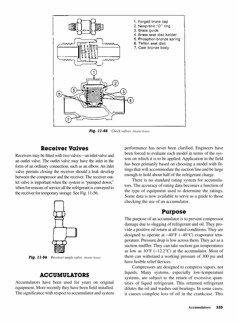
Accumulators 335
Receiver Valves Receivers may be fitted with two valves—an inlet valve andan outlet valve. The outlet valve may have the inlet in theform of an ordinary connection, such as an elbow. An inletvalve permits closing the receiver should a leak developbetween the compressor and the receiver. The receiver out-let valve is important when the system is “pumped down,”when for reasons of service all the refrigerant is conveyed tothe receiver for temporary storage. See Fig. 11-56.
ACCUMULATORSAccumulators have been used for years on originalequipment. More recently they have been field installed.The significance with respect to accumulator and system
performance has never been clarified. Engineers havebeen forced to evaluate each model in terms of the sys-tem on which it is to be applied. Application in the fieldhas been primarily based on choosing a model with fit-tings that will accommodate the suction line and be largeenough to hold about half of the refrigerant charge.
There is no standard rating system for accumula-tors. The accuracy of rating data becomes a function ofthe type of equipment used to determine the ratings.Some data is now available to serve as a guide to thosechecking the use of an accumulator.
PurposeThe purpose of an accumulator is to prevent compressordamage due to slugging of refrigerant and oil. They pro-vide a positive oil return at all rated conditions. They aredesigned to operate at −40°F (−40°C) evaporator tem-perature. Pressure drop is low across them. They act as asuction muffler. They can take suction-gas temperaturesas low as 10°F (−12.2°C) at the accumulator. Most ofthem can withstand a working pressure of 300 psi andhave fusible relief devices.
Compressors are designed to compress vapors, notliquids. Many systems, especially low-temperaturesystems, are subject to the return of excessive quan-tities of liquid refrigerant. This returned refrigerantdilutes the oil and washes out bearings. In some cases,it causes complete loss of oil in the crankcase. This
Fig. 11-55 Check valves. (Mueller Brass)
Fig. 11-56 Receiver-angle valve. (Mueller Brass)
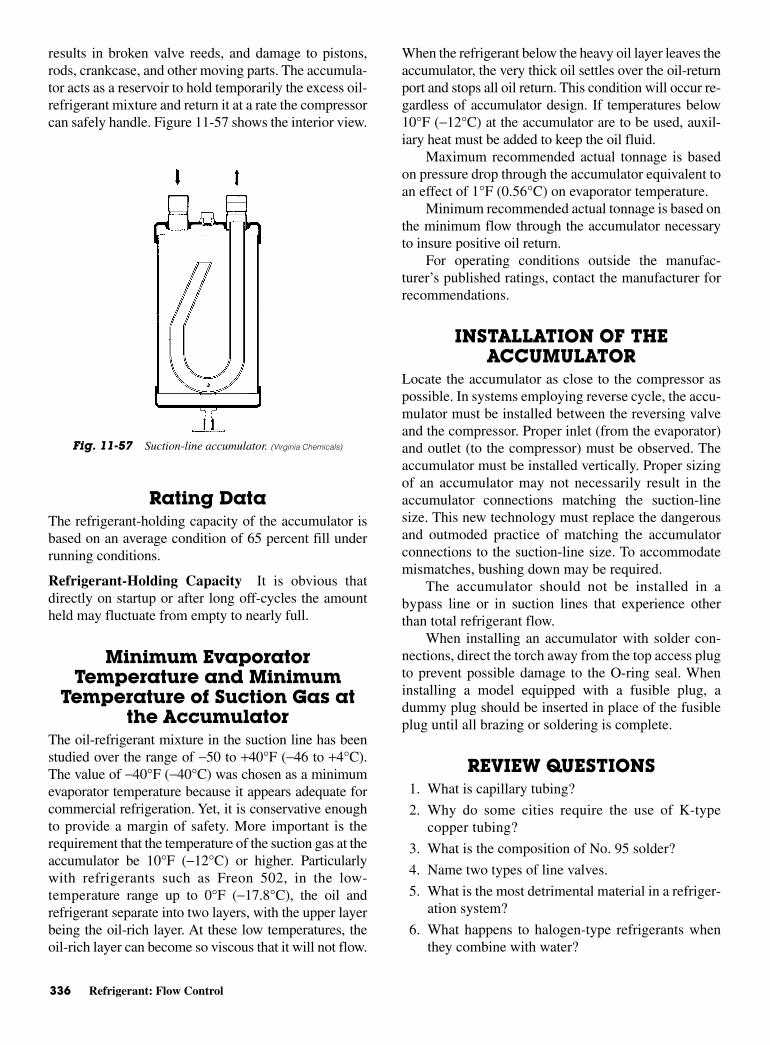
336 Refrigerant: Flow Control
results in broken valve reeds, and damage to pistons,rods, crankcase, and other moving parts. The accumula-tor acts as a reservoir to hold temporarily the excess oil-refrigerant mixture and return it at a rate the compressorcan safely handle. Figure 11-57 shows the interior view.
Rating DataThe refrigerant-holding capacity of the accumulator isbased on an average condition of 65 percent fill underrunning conditions.
Refrigerant-Holding Capacity It is obvious thatdirectly on startup or after long off-cycles the amountheld may fluctuate from empty to nearly full.
Minimum EvaporatorTemperature and Minimum
Temperature of Suction Gas atthe Accumulator
The oil-refrigerant mixture in the suction line has beenstudied over the range of −50 to +40°F (−46 to +4°C).The value of −40°F (−40°C) was chosen as a minimumevaporator temperature because it appears adequate forcommercial refrigeration. Yet, it is conservative enoughto provide a margin of safety. More important is therequirement that the temperature of the suction gas at theaccumulator be 10°F (−12°C) or higher. Particularlywith refrigerants such as Freon 502, in the low-temperature range up to 0°F (−17.8°C), the oil andrefrigerant separate into two layers, with the upper layerbeing the oil-rich layer. At these low temperatures, theoil-rich layer can become so viscous that it will not flow.
When the refrigerant below the heavy oil layer leaves theaccumulator, the very thick oil settles over the oil-returnport and stops all oil return. This condition will occur re-gardless of accumulator design. If temperatures below10°F (−12°C) at the accumulator are to be used, auxil-iary heat must be added to keep the oil fluid.
Maximum recommended actual tonnage is basedon pressure drop through the accumulator equivalent toan effect of 1°F (0.56°C) on evaporator temperature.
Minimum recommended actual tonnage is based onthe minimum flow through the accumulator necessaryto insure positive oil return.
For operating conditions outside the manufac-turer’s published ratings, contact the manufacturer forrecommendations.
INSTALLATION OF THEACCUMULATOR
Locate the accumulator as close to the compressor aspossible. In systems employing reverse cycle, the accu-mulator must be installed between the reversing valveand the compressor. Proper inlet (from the evaporator)and outlet (to the compressor) must be observed. Theaccumulator must be installed vertically. Proper sizingof an accumulator may not necessarily result in theaccumulator connections matching the suction-linesize. This new technology must replace the dangerousand outmoded practice of matching the accumulatorconnections to the suction-line size. To accommodatemismatches, bushing down may be required.
The accumulator should not be installed in abypass line or in suction lines that experience otherthan total refrigerant flow.
When installing an accumulator with solder con-nections, direct the torch away from the top access plugto prevent possible damage to the O-ring seal. Wheninstalling a model equipped with a fusible plug, adummy plug should be inserted in place of the fusibleplug until all brazing or soldering is complete.
REVIEW QUESTIONS1. What is capillary tubing?
2. Why do some cities require the use of K-typecopper tubing?
3. What is the composition of No. 95 solder?
4. Name two types of line valves.
5. What is the most detrimental material in a refriger-ation system?
6. What happens to halogen-type refrigerants whenthey combine with water?
Fig. 11-57 Suction-line accumulator. (Virginia Chemicals)
Review Questions 337
7. What happens to Refrigerants 12 and 22 whenheated to a high temperature?
8. How are sludge and varnish formed in a refrigerationsystem?
9. What happens to a liquid indicator if the systemhas too much oil?
10. What does TEV stand for?
11. What is flash gas?
12. What is the purpose of the crankcase pressure-regulating valve?
13. What does CRO stand for?
14. Where are ORITs installed?
15. What is the purpose of an ORO head-pressurevalve?
16. What is the function of a discharge-bypass valve?
17. How is a remote bulb used in a bypass valve?
18. List two possible locations for the mounting of theremote bulb.
19. How are capillary tubes used in a refrigeration unit?
20. What is an accumulator?
21. What is the refrigerant-holding capacity of theaccumulator?

This page intentionally left blank

12CHAPTER
Servicing andSafety
Copyright © 2006 by The McGraw-Hill Companies, Inc. Click here for terms of use.
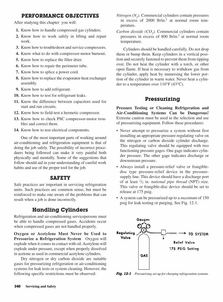
PERFORMANCE OBJECTIVESAfter studying this chapter you will:
1. Know how to handle compressed gas cylinders.
2. Know how to work safely in lifting and repairwork.
3. Know how to troubleshoot and service compressors.
4. Know what to do with compressor-motor burnout.
5. Know how to replace the filter drier.
6. Know how to repair the perimeter tube.
7. Know how to splice a power cord.
8. Know how to replace the evaporator-heat exchangerassembly.
9. Know how to add refrigerant.
10. Know how to test for refrigerant leaks.
11. Know the difference between capacitors used forstart and run circuits.
12. Know how to field-test a hermetic compressor.
13. Know how to check PSC compressor-motor trou-bles and correct them.
14. Know how to test electrical components.
One of the most important parts of working aroundair-conditioning and refrigeration equipment is that ofdoing the job safely. The possibility of incorrect proce-dures being followed can make it very painful bothphysically and mentally. Some of the suggestions thatfollow should aid in your understanding of careful workhabits and use of the proper tool for the job.
SAFETYSafe practices are important in servicing refrigerationunits. Such practices are common sense, but must bereinforced to make one aware of the problems that canresult when a job is done incorrectly.
Handling Cylinders Refrigeration and air-conditioning servicepersons mustbe able to handle compressed gases. Accidents occurwhen compressed gases are not handled properly.
Oxygen or Acetylene Must Never be Used toPressurize a Refrigeration System Oxygen willexplode when it comes in contact with oil. Acetylene willexplode under pressure, except when properly dissolvedin acetone as used in commercial acetylene cylinders.
Dry nitrogen or dry carbon dioxide are suitablegases for pressurizing refrigeration or air-conditioningsystems for leak tests or system cleaning. However, thefollowing specific restrictions must be observed:
Nitrogen (N2). Commercial cylinders contain pressuresin excess of 2000 lb/in.2 at normal room tem-perature.
Carbon dioxide (CO2). Commercial cylinders containpressures in excess of 800 lb/in.2 at normal roomtemperature.
Cylinders should be handled carefully. Do not dropthem or bump them. Keep cylinders in a vertical posi-tion and securely fastened to prevent them from tippingover. Do not heat the cylinder with a torch, or otheropen flame. If heat is necessary to withdraw gas fromthe cylinder, apply heat by immersing the lower por-tion of the cylinder in warm water. Never heat a cylin-der to a temperature over 110°F (43°C).
Pressurizing
Pressure Testing or Cleaning Refrigeration andAir-Conditioning Systems Can be Dangerous!Extreme caution must be used in the selection and useof pressurizing equipment. Follow these procedures:
• Never attempt to pressurize a system without firstinstalling an appropriate pressure-regulating valve onthe nitrogen or carbon dioxide cylinder discharge.This regulating valve should be equipped with twofunctioning pressure gages. One gage indicates cylin-der pressure. The other gage indicates discharge ordownstream pressure.
• Always install a pressure-relief valve or frangible-disc type pressure-relief device in the pressure-supply line. This device should have a discharge portof at least 1/2 in. national pipe thread (NPT) size.This valve or frangible-disc device should be set torelease at 175 psig.
• A system can be pressurized up to a maximum of 150psig for leak testing or purging. See Fig. 12-1.
340 Servicing and Safety
Fig. 12-1 Pressurizing set-up for charging refrigeration systems.
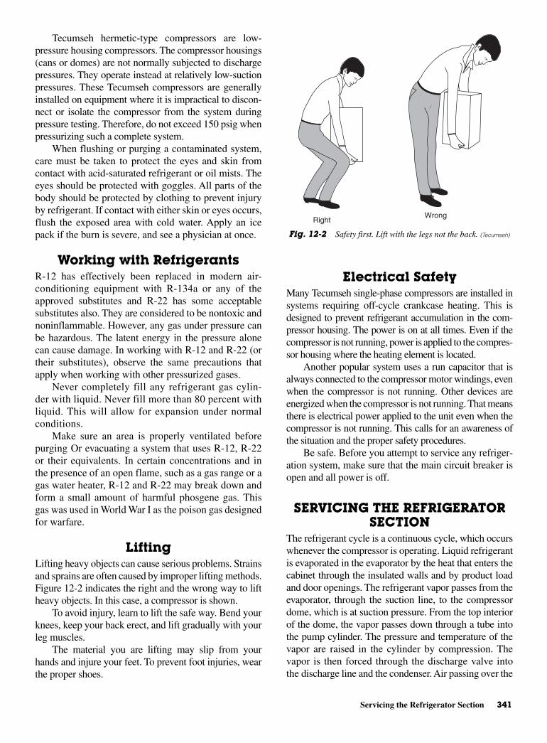
Servicing the Refrigerator Section 341
Tecumseh hermetic-type compressors are low-pressure housing compressors. The compressor housings(cans or domes) are not normally subjected to dischargepressures. They operate instead at relatively low-suctionpressures. These Tecumseh compressors are generallyinstalled on equipment where it is impractical to discon-nect or isolate the compressor from the system duringpressure testing. Therefore, do not exceed 150 psig whenpressurizing such a complete system.
When flushing or purging a contaminated system,care must be taken to protect the eyes and skin fromcontact with acid-saturated refrigerant or oil mists. Theeyes should be protected with goggles. All parts of thebody should be protected by clothing to prevent injuryby refrigerant. If contact with either skin or eyes occurs,flush the exposed area with cold water. Apply an icepack if the burn is severe, and see a physician at once.
Working with Refrigerants R-12 has effectively been replaced in modern air-conditioning equipment with R-134a or any of theapproved substitutes and R-22 has some acceptablesubstitutes also. They are considered to be nontoxic andnoninflammable. However, any gas under pressure canbe hazardous. The latent energy in the pressure alonecan cause damage. In working with R-12 and R-22 (ortheir substitutes), observe the same precautions thatapply when working with other pressurized gases.
Never completely fill any refrigerant gas cylin-der with liquid. Never fill more than 80 percent withliquid. This will allow for expansion under normalconditions.
Make sure an area is properly ventilated beforepurging Or evacuating a system that uses R-12, R-22or their equivalents. In certain concentrations and inthe presence of an open flame, such as a gas range or agas water heater, R-12 and R-22 may break down andform a small amount of harmful phosgene gas. Thisgas was used in World War I as the poison gas designedfor warfare.
LiftingLifting heavy objects can cause serious problems. Strainsand sprains are often caused by improper lifting methods.Figure 12-2 indicates the right and the wrong way to liftheavy objects. In this case, a compressor is shown.
To avoid injury, learn to lift the safe way. Bend yourknees, keep your back erect, and lift gradually with yourleg muscles.
The material you are lifting may slip from yourhands and injure your feet. To prevent foot injuries, wearthe proper shoes.
Electrical SafetyMany Tecumseh single-phase compressors are installed insystems requiring off-cycle crankcase heating. This isdesigned to prevent refrigerant accumulation in the com-pressor housing. The power is on at all times. Even if thecompressor is not running, power is applied to the compres-sor housing where the heating element is located.
Another popular system uses a run capacitor that isalways connected to the compressor motor windings, evenwhen the compressor is not running. Other devices areenergized when the compressor is not running. That meansthere is electrical power applied to the unit even when thecompressor is not running. This calls for an awareness ofthe situation and the proper safety procedures.
Be safe. Before you attempt to service any refriger-ation system, make sure that the main circuit breaker isopen and all power is off.
SERVICING THE REFRIGERATORSECTION
The refrigerant cycle is a continuous cycle, which occurswhenever the compressor is operating. Liquid refrigerantis evaporated in the evaporator by the heat that enters thecabinet through the insulated walls and by product loadand door openings. The refrigerant vapor passes from theevaporator, through the suction line, to the compressordome, which is at suction pressure. From the top interiorof the dome, the vapor passes down through a tube intothe pump cylinder. The pressure and temperature of thevapor are raised in the cylinder by compression. Thevapor is then forced through the discharge valve intothe discharge line and the condenser. Air passing over the
RightWrong
Fig. 12-2 Safety first. Lift with the legs not the back. (Tecumseh)
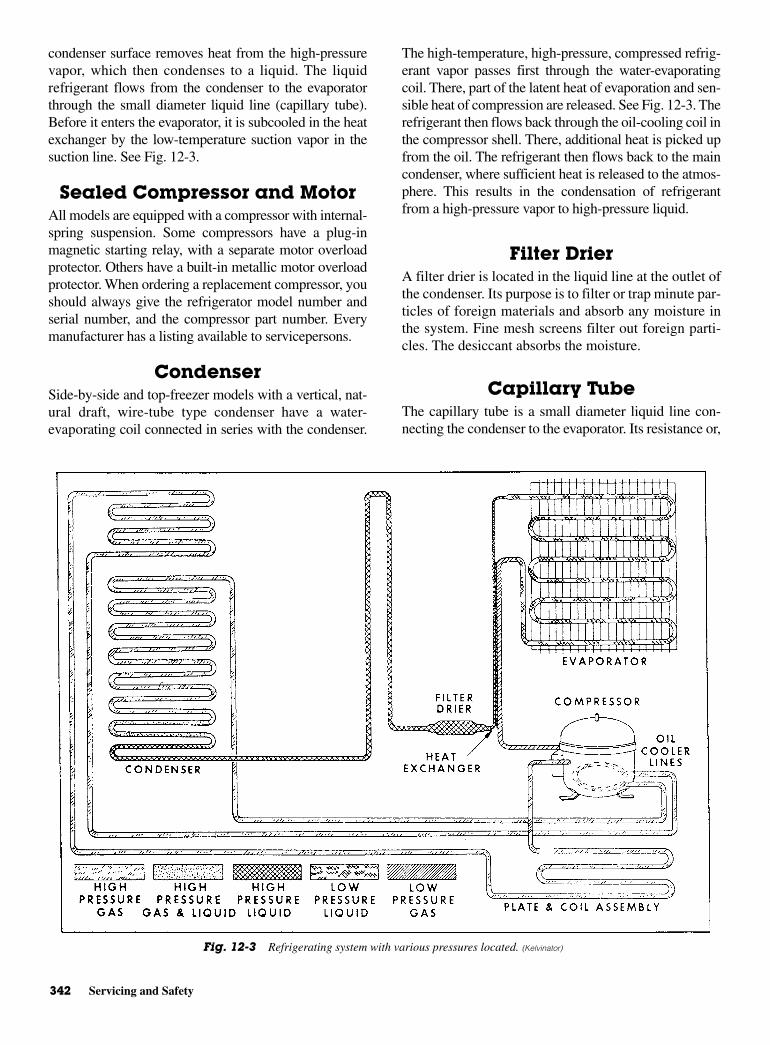
342 Servicing and Safety
condenser surface removes heat from the high-pressurevapor, which then condenses to a liquid. The liquidrefrigerant flows from the condenser to the evaporatorthrough the small diameter liquid line (capillary tube).Before it enters the evaporator, it is subcooled in the heatexchanger by the low-temperature suction vapor in thesuction line. See Fig. 12-3.
Sealed Compressor and MotorAll models are equipped with a compressor with internal-spring suspension. Some compressors have a plug-inmagnetic starting relay, with a separate motor overloadprotector. Others have a built-in metallic motor overloadprotector. When ordering a replacement compressor, youshould always give the refrigerator model number andserial number, and the compressor part number. Everymanufacturer has a listing available to servicepersons.
CondenserSide-by-side and top-freezer models with a vertical, nat-ural draft, wire-tube type condenser have a water-evaporating coil connected in series with the condenser.
The high-temperature, high-pressure, compressed refrig-erant vapor passes first through the water-evaporatingcoil. There, part of the latent heat of evaporation and sen-sible heat of compression are released. See Fig. 12-3. Therefrigerant then flows back through the oil-cooling coil inthe compressor shell. There, additional heat is picked upfrom the oil. The refrigerant then flows back to the maincondenser, where sufficient heat is released to the atmos-phere. This results in the condensation of refrigerantfrom a high-pressure vapor to high-pressure liquid.
Filter DrierA filter drier is located in the liquid line at the outlet ofthe condenser. Its purpose is to filter or trap minute par-ticles of foreign materials and absorb any moisture inthe system. Fine mesh screens filter out foreign parti-cles. The desiccant absorbs the moisture.
Capillary TubeThe capillary tube is a small diameter liquid line con-necting the condenser to the evaporator. Its resistance or,
Fig. 12-3 Refrigerating system with various pressures located. (Kelvinator)
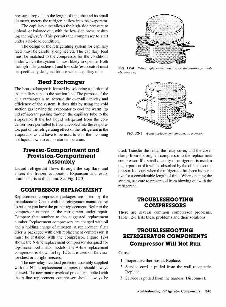
Troubleshooting Refrigerator Components 343
pressure drop due to the length of the tube and its smalldiameter, meters the refrigerant flow into the evaporator.
The capillary tube allows the high-side pressure tounload, or balance out, with the low-side pressure dur-ing the off-cycle. This permits the compressor to startunder a no-load condition.
The design of the refrigerating system for capillaryfeed must be carefully engineered. The capillary feedmust be matched to the compressor for the conditionsunder which the system is most likely to operate. Boththe high side (condenser) and low side (evaporator) mustbe specifically designed for use with a capillary tube.
Heat ExchangerThe heat exchanger is formed by soldering a portion ofthe capillary tube to the suction line. The purpose of theheat exchanger is to increase the over-all capacity andefficiency of the system. It does this by using the coldsuction gas leaving the evaporator to cool the warm liq-uid refrigerant passing through the capillary tube to theevaporator. If the hot liquid refrigerant from the con-denser were permitted to flow uncooled into the evapora-tor, part of the refrigerating effect of the refrigerant in theevaporator would have to be used to cool the incominghot liquid down to evaporator temperature.
Freezer-Compartment andProvision-Compartment
AssemblyLiquid refrigerant flows through the capillary andenters the freezer evaporator. Expansion and evap-oration starts at this point. See Fig. 12-3.
COMPRESSOR REPLACEMENTReplacement compressor packages are listed by themanufacturer. Check with the refrigerator manufacturerto be sure you have the proper replacement. Refer to thecompressor number in the refrigerator under repair.Compare that number to the suggested replacementnumber. Replacement compressors are charged with oiland a holding charge of nitrogen. A replacement filterdrier is packaged with each replacement compressor. Itmust be installed with the compressor. Figure 12-4shows the N-line replacement compressor designed fortop-freezer Kelvinator models. The A-line replacementcompressor is shown in Fig. 12-5. It is used on Kelvina-tor chest or upright freezers.
The new relay-overload protector assembly suppliedwith the N-line replacement compressor should alwaysbe used. The new motor-overload protector supplied withthe A-line replacement compressor should always be
used. Transfer the relay, the relay cover, and the coverclamp from the original compressor to the replacementcompressor. If a small quantity of refrigerant is used, amajor portion of it will be absorbed by the oil in the com-pressor. It occurs when the refrigerator has been inopera-tive for a considerable length of time. When opening thesystem, use care to prevent oil from blowing out with therefrigerant.
TROUBLESHOOTINGCOMPRESSORS
There are several common compressor problems.Table 12-1 lists these problems and their solutions.
TROUBLESHOOTINGREFRIGERATOR COMPONENTS
Compressor Will Not Run
Cause
1. Inoperative thermostat. Replace.
2. Service cord is pulled from the wall receptacle.Replace.
3. Service is pulled from the harness. Disconnect.
Fig. 12-4 N-line replacement compressor for top-freezer mod-els. (Kelvinator)
Fig. 12-5 A-line replacement compressor. (Kelvinator)
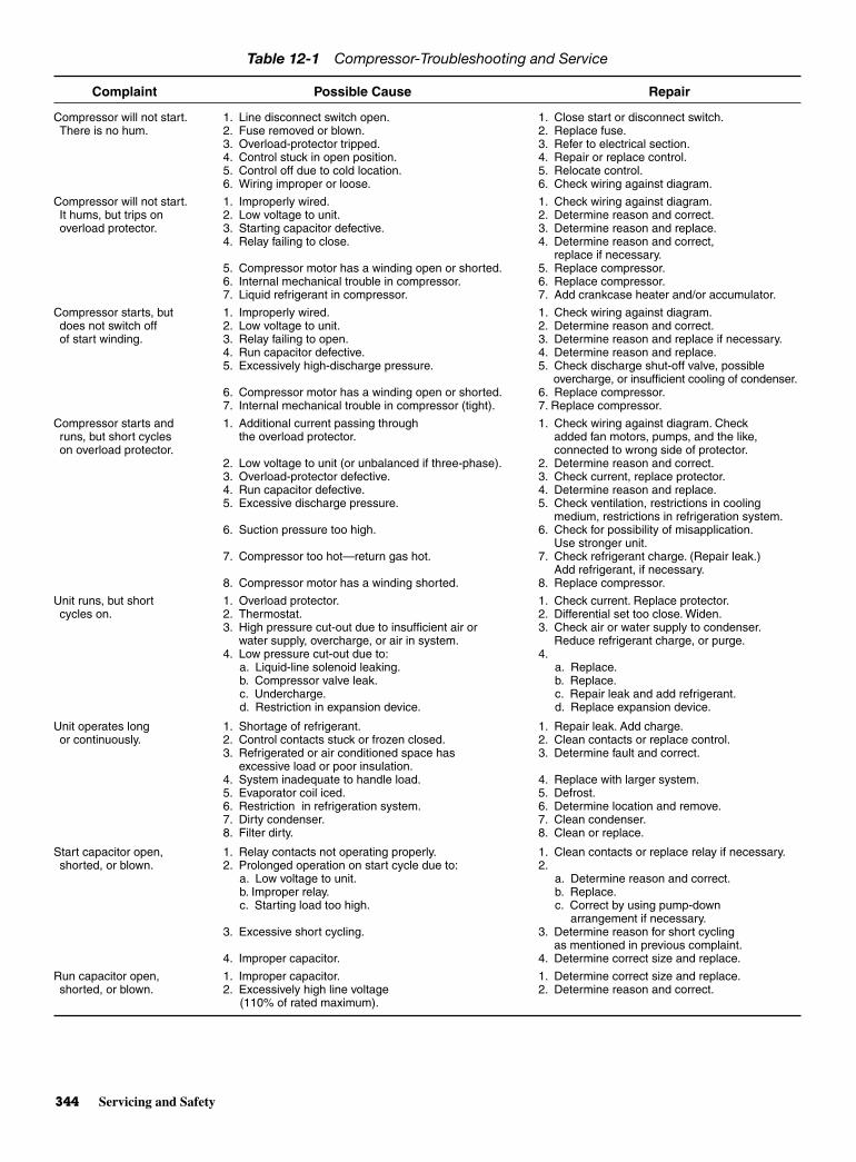
344 Servicing and Safety
Table 12-1 Compressor-Troubleshooting and Service
Complaint Possible Cause Repair
Compressor will not start. 1. Line disconnect switch open. 1. Close start or disconnect switch.There is no hum. 2. Fuse removed or blown. 2. Replace fuse.
3. Overload-protector tripped. 3. Refer to electrical section.4. Control stuck in open position. 4. Repair or replace control.5. Control off due to cold location. 5. Relocate control.6. Wiring improper or loose. 6. Check wiring against diagram.
Compressor will not start. 1. Improperly wired. 1. Check wiring against diagram.It hums, but trips on 2. Low voltage to unit. 2. Determine reason and correct.overload protector. 3. Starting capacitor defective. 3. Determine reason and replace.
4. Relay failing to close. 4. Determine reason and correct, replace if necessary.
5. Compressor motor has a winding open or shorted. 5. Replace compressor.6. Internal mechanical trouble in compressor. 6. Replace compressor.7. Liquid refrigerant in compressor. 7. Add crankcase heater and/or accumulator.
Compressor starts, but 1. Improperly wired. 1. Check wiring against diagram.does not switch off 2. Low voltage to unit. 2. Determine reason and correct.of start winding. 3. Relay failing to open. 3. Determine reason and replace if necessary.
4. Run capacitor defective. 4. Determine reason and replace.5. Excessively high-discharge pressure. 5. Check discharge shut-off valve, possible
overcharge, or insufficient cooling of condenser.6. Compressor motor has a winding open or shorted. 6. Replace compressor.7. Internal mechanical trouble in compressor (tight). 7. Replace compressor.
Compressor starts and 1. Additional current passing through 1. Check wiring against diagram. Check runs, but short cycles the overload protector. added fan motors, pumps, and the like,on overload protector. connected to wrong side of protector.
2. Low voltage to unit (or unbalanced if three-phase). 2. Determine reason and correct.3. Overload-protector defective. 3. Check current, replace protector.4. Run capacitor defective. 4. Determine reason and replace.5. Excessive discharge pressure. 5. Check ventilation, restrictions in cooling
medium, restrictions in refrigeration system.6. Suction pressure too high. 6. Check for possibility of misapplication.
Use stronger unit.7. Compressor too hot—return gas hot. 7. Check refrigerant charge. (Repair leak.)
Add refrigerant, if necessary.8. Compressor motor has a winding shorted. 8. Replace compressor.
Unit runs, but short 1. Overload protector. 1. Check current. Replace protector.cycles on. 2. Thermostat. 2. Differential set too close. Widen.
3. High pressure cut-out due to insufficient air or 3. Check air or water supply to condenser.water supply, overcharge, or air in system. Reduce refrigerant charge, or purge.
4. Low pressure cut-out due to: 4.a. Liquid-line solenoid leaking. a. Replace.b. Compressor valve leak. b. Replace.c. Undercharge. c. Repair leak and add refrigerant.d. Restriction in expansion device. d. Replace expansion device.
Unit operates long 1. Shortage of refrigerant. 1. Repair leak. Add charge.or continuously. 2. Control contacts stuck or frozen closed. 2. Clean contacts or replace control.
3. Refrigerated or air conditioned space has 3. Determine fault and correct.excessive load or poor insulation.
4. System inadequate to handle load. 4. Replace with larger system.5. Evaporator coil iced. 5. Defrost.6. Restriction in refrigeration system. 6. Determine location and remove.7. Dirty condenser. 7. Clean condenser.8. Filter dirty. 8. Clean or replace.
Start capacitor open, 1. Relay contacts not operating properly. 1. Clean contacts or replace relay if necessary.shorted, or blown. 2. Prolonged operation on start cycle due to: 2.
a. Low voltage to unit. a. Determine reason and correct.b. Improper relay. b. Replace.c. Starting load too high. c. Correct by using pump-down
arrangement if necessary.3. Excessive short cycling. 3. Determine reason for short cycling
as mentioned in previous complaint.4. Improper capacitor. 4. Determine correct size and replace.
Run capacitor open, 1. Improper capacitor. 1. Determine correct size and replace.shorted, or blown. 2. Excessively high line voltage 2. Determine reason and correct.
(110% of rated maximum).

Troubleshooting Refrigerator Components 345
4. No voltage at the wall receptacle. House fuse blown.
5. Faulty cabinet wiring. Repair or replace.
6. Relay leads. Disconnect.
7. Relay loose or inoperative. Tighten or replace.
8. Compressor windings open. Replace compressor.
9. Compressor stuck. Replace.
10. Low voltage, causing compressor to cycle on over-load. Voltage fluctuation should not exceed 10 per-cent, plus or minus, from the nominal rating of 115 V.
Compressor Runs, but There IsNo Refrigeration
Cause
1. System is out of refrigerant. Check for leaks.
2. Compressor is not pumping. Replace.
3. Restricted filter drier. Replace.
4. Restricted capillary tube. Replace.
5. Moisture in the system. Pump down and recharge.
Compressor Short Cycles
Cause
1. Erratic thermostat operation. Replace.
2. Faulty relay. Replace.
3. Restricted airflow over the condenser. Removerestrictions.
4. Low voltage. Fluctuation exceeds 10 percent.
5. Inoperative condenser fan. Repair or replace.
6. Compressor draws excessive wattage. Replace.
Compressor Runs Too Muchor 100 Percent
Cause
1. Erratic thermostat or thermostat is set too cold.Replace or reset to normal position.
2. Refrigerator exposed to unusual heat. Relocate.
3. Abnormally high room temperature. If outsidetemperature is cooler, open windows to lower tem-perature. Turn on fans to move the air.
4. Low pumping capacity compressor. Replace.
5. Door gaskets not sealing. Check with 100-W lamp.
6. System is undercharged or overcharged. Correctthe charge.
7. Interior light stays on. Check door switch.
8. Noncondensable are in the system. Evacuate andrecharge.
9. Capillary-tube kinked or partially restricted.
10. Filter drier or strainer partially restricted. Replace.
11. Excessive service load. Remove part of the load.
12. Restricted airflow over the condenser. Removerestriction.
Table 12-1 (Continued)
Complaint Possible Cause Repair
Relay defective or burned out. 1. Incorrect relay. 1. Check and replace.2. Incorrect mounting angle. 2. Remount relay in correct position.3. Line voltage too high or too low. 3. Determine reason and correct.4. Excessive short cycling. 4. Determine reason and correct.5. Relay being influenced by loose 5. Remount rigidly.
vibrating mounting.6. Incorrect run capacitor. 6. Replace with proper capacitor.
Space temperature too high. 1. Control setting too high. 1. Reset control.2. Expansion valve too small. 2. Use larger valve.3. Cooling coils too small. 3. Add surface or replace.4. Inadequate air circulation. 4. Improve air movement.
Suction-line frosted 1. Expansion-valve oversized 1. Readjust valve or replace with smaller or sweating. or passing excess refrigerant. valve.
2. Expansion valve stuck open. 2. Clean valve of foreign particles.Replace if necessary.
3. Evaporator fan not running. 3. Determine reason and correct.4. Overcharge of refrigerant. 4. Correct charge.
Liquid-line frosted or sweating. 1. Restriction in dehydrator or strainer. 1. Replace part.2. Liquid shutoff (king valve) partially closed. 2. Open valve fully.
Unit noisy. 1. Loose parts or mountings. 1. Tighten.2. Tubing rattle. 2. Reform to be free of contact.3. Bent fan blade causing vibration. 3. Replace blade.4. Fan motor bearings worn. 4. Replace motor.
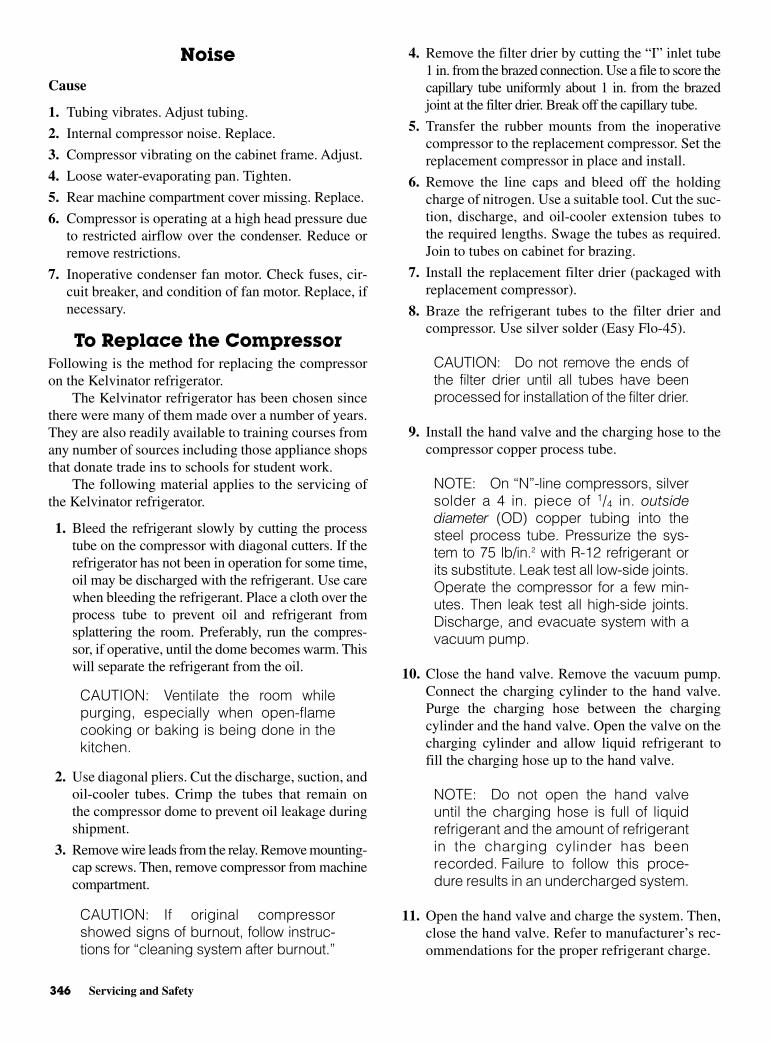
346 Servicing and Safety
Noise
Cause
1. Tubing vibrates. Adjust tubing.
2. Internal compressor noise. Replace.
3. Compressor vibrating on the cabinet frame. Adjust.
4. Loose water-evaporating pan. Tighten.
5. Rear machine compartment cover missing. Replace.
6. Compressor is operating at a high head pressure dueto restricted airflow over the condenser. Reduce orremove restrictions.
7. Inoperative condenser fan motor. Check fuses, cir-cuit breaker, and condition of fan motor. Replace, ifnecessary.
To Replace the Compressor Following is the method for replacing the compressoron the Kelvinator refrigerator.
The Kelvinator refrigerator has been chosen sincethere were many of them made over a number of years.They are also readily available to training courses fromany number of sources including those appliance shopsthat donate trade ins to schools for student work.
The following material applies to the servicing ofthe Kelvinator refrigerator.
1. Bleed the refrigerant slowly by cutting the processtube on the compressor with diagonal cutters. If therefrigerator has not been in operation for some time,oil may be discharged with the refrigerant. Use carewhen bleeding the refrigerant. Place a cloth over theprocess tube to prevent oil and refrigerant fromsplattering the room. Preferably, run the compres-sor, if operative, until the dome becomes warm. Thiswill separate the refrigerant from the oil.
CAUTION: Ventilate the room whilepurging, especially when open-flamecooking or baking is being done in thekitchen.
2. Use diagonal pliers. Cut the discharge, suction, andoil-cooler tubes. Crimp the tubes that remain onthe compressor dome to prevent oil leakage duringshipment.
3. Remove wire leads from the relay. Remove mounting-cap screws. Then, remove compressor from machinecompartment.
CAUTION: If original compressorshowed signs of burnout, follow instruc-tions for “cleaning system after burnout.”
4. Remove the filter drier by cutting the “I” inlet tube1 in. from the brazed connection. Use a file to score thecapillary tube uniformly about 1 in. from the brazedjoint at the filter drier. Break off the capillary tube.
5. Transfer the rubber mounts from the inoperativecompressor to the replacement compressor. Set thereplacement compressor in place and install.
6. Remove the line caps and bleed off the holdingcharge of nitrogen. Use a suitable tool. Cut the suc-tion, discharge, and oil-cooler extension tubes tothe required lengths. Swage the tubes as required.Join to tubes on cabinet for brazing.
7. Install the replacement filter drier (packaged withreplacement compressor).
8. Braze the refrigerant tubes to the filter drier andcompressor. Use silver solder (Easy Flo-45).
CAUTION: Do not remove the ends ofthe filter drier until all tubes have beenprocessed for installation of the filter drier.
9. Install the hand valve and the charging hose to thecompressor copper process tube.
NOTE: On “N”-line compressors, silversolder a 4 in. piece of 1/4 in. outsidediameter (OD) copper tubing into thesteel process tube. Pressurize the sys-tem to 75 lb/in.2 with R-12 refrigerant orits substitute. Leak test all low-side joints.Operate the compressor for a few min-utes. Then leak test all high-side joints.Discharge, and evacuate system with avacuum pump.
10. Close the hand valve. Remove the vacuum pump.Connect the charging cylinder to the hand valve.Purge the charging hose between the chargingcylinder and the hand valve. Open the valve on thecharging cylinder and allow liquid refrigerant tofill the charging hose up to the hand valve.
NOTE: Do not open the hand valveuntil the charging hose is full of liquidrefrigerant and the amount of refrigerantin the charging cylinder has beenrecorded. Failure to follow this proce-dure results in an undercharged system.
11. Open the hand valve and charge the system. Then,close the hand valve. Refer to manufacturer’s rec-ommendations for the proper refrigerant charge.
Replacing the Filter Drier 347
12. Pinch off the copper process tube after the charge hasbeen established. With the pinch-off tool on theprocess tube, remove the charging hand valve and thecharging hose. Flatten the end of the tube and seal itwith phos-copper. Then, remove pinch-off tool.
COMPRESSOR MOTOR BURNOUTThere are four major causes of motor burnout: low linevoltage, loss of refrigerant, high head pressure, andmoisture.
Low line voltage. When the motor winding in a motorgets too hot, the insulation melts and the windingshort circuits. A blackened burned-out run windingis the result. Low line voltage causes the winding toget very hot because it is forced to carry more cur-rent at the same compressor load. When this currentgets too high, or is carried for too many hours, themotor run winding fails. A burnout caused by lowvoltage is generally a slow burnout. This contami-nates the system.
Loss of refrigerant. A second cause of motor burnout isloss of refrigerant. In a hermetically sealed motorcompressor, the refrigerant vapor passes down aroundthe motor windings. The cool refrigerant vapor keepsthe motor operating at proper temperature. If there isa refrigerant leak, and there is no refrigerant to coolthe motor, the windings become too hot. A burnoutresults. The overload protector may not always pro-tect against this type of burnout since it requires thetransfer of high heat from the motor through therefrigerant vapor to the compressor dome.
High head pressure. High head pressure is a third causeof motor burnout. With high head pressure, the motorload is increased. The increased current causes thewinding to overheat and eventually fail. Poor circu-lation of air over the high-side condenser can causemotor failure for this reason.
Moisture. The fourth major cause of motor burnout ismoisture. It takes very little moisture to cause prob-lems. In the compressor dome, refrigerant is mixedwith lubricating oil, and heat from the motor windingsand compressor operation. If there is any air present,the oxygen can combine chemically with hydrogen inthe refrigerant and oil to form water. Just one drop ofwater can cause problems. When water contacts therefrigerant and oil in the presence of heat, hydrochlo-ric or hydrofluoric acid is formed. These acids destroythe insulation on the motor winding. When the wind-ing short circuits, a momentary temperature of over3000°F (1648°C) is created. Acids combine chemi-
cally with the insulation and oil in the compressordome to create sludge. This quickly contaminates therefrigerating system. Sludge collects in various placesthroughout the system. It is very hard to dislodge.Purging the refrigerant charge or blowing refrigerantvapor through the system will not clean the system.
CLEANING SYSTEM AFTERBURNOUT
Remove the inoperative compressor and filter drier.Flush the high side and low side of the system with R-12(or R-134a) liquid refrigerant. (Invert the refrigerantdrum.)
Connect the high side and low side of the system.Also, connect the oil-cooler tubes. Then, evacuatethe system using a vacuum pump. Never use the newreplacement compressor for this purpose. It will quicklybecome contaminated. Break the vacuum with refriger-ant. Repeat the process. Then, and this is extremelyimportant, repeat the process a third time. Thus, thereare three purges and three evacuations.
Remove the vacuum pump and install a new replace-ment compressor and filter drier. Follow the procedurespreviously outlined. Use silver solder (Easy Flo-45) orphos-copper to make brazed connections.
REPLACING THE FILTER DRIERIf the compressor is not to be changed, follow theseprocedures to replace the filter drier.
1. To replace the filter drier, move the refrigerator toa location where the rear of the machine compart-ment is accessible.
2. Remove the machine compartment sound dead-ener baffle.
3. Cut the copper process tube on the compressor andbleed the refrigerant. Retain as much length as pos-sible. Remove the filter drier by cutting 1/4 in. inlettube 1 in. from the brazed connection. Use a file toscore the capillary tube uniformly approximately1 in. from the brazed joint at the filter drier. Then,break off the capillary tube.
4. Install the replacement filter drier with its inlet atthe top. (Arrow indicates direction of flow.) SeeFig. 12-6. Braze the refrigerant tubes to the filterdrier. Use silver solder (Easy Flo-45).
CAUTION: Do not remove caps fromthe replacement filter drier until all therefrigerant tubes have been processedfor installation of the filter drier.
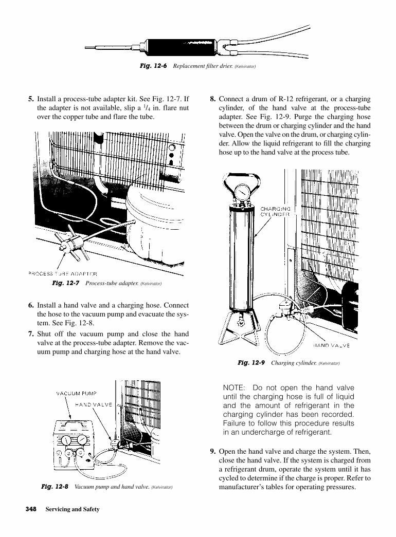
348 Servicing and Safety
5. Install a process-tube adapter kit. See Fig. 12-7. Ifthe adapter is not available, slip a 1/4 in. flare nutover the copper tube and flare the tube.
6. Install a hand valve and a charging hose. Connectthe hose to the vacuum pump and evacuate the sys-tem. See Fig. 12-8.
7. Shut off the vacuum pump and close the handvalve at the process-tube adapter. Remove the vac-uum pump and charging hose at the hand valve.
8. Connect a drum of R-12 refrigerant, or a chargingcylinder, of the hand valve at the process-tubeadapter. See Fig. 12-9. Purge the charging hosebetween the drum or charging cylinder and the handvalve. Open the valve on the drum, or charging cylin-der. Allow the liquid refrigerant to fill the charginghose up to the hand valve at the process tube.
NOTE: Do not open the hand valveuntil the charging hose is full of liquidand the amount of refrigerant in thecharging cylinder has been recorded.Failure to follow this procedure resultsin an undercharge of refrigerant.
9. Open the hand valve and charge the system. Then,close the hand valve. If the system is charged froma refrigerant drum, operate the system until it hascycled to determine if the charge is proper. Refer tomanufacturer’s tables for operating pressures.
Fig. 12-6 Replacement filter drier. (Kelvinator)
Fig. 12-7 Process-tube adapter. (Kelvinator)
Fig. 12-8 Vacuum pump and hand valve. (Kelvinator)
Fig. 12-9 Charging cylinder. (Kelvinator)
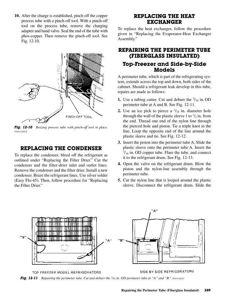
Repairing the Perimeter Tube (Fiberglass Insulated) 349
10. After the charge is established, pinch off the copperprocess tube with a pinch-off tool. With a pinch-offtool on the process tube, remove the chargingadapter and hand valve. Seal the end of the tube withphos-copper. Then remove the pinch-off tool. SeeFig. 12-10.
REPLACING THE CONDENSERTo replace the condenser, bleed off the refrigerant asoutlined under “Replacing the Filter Drier.” Cut thecondenser and the filter-drier inlet and outlet lines.Remove the condenser and the filter drier. Install a newcondenser. Braze the refrigerant lines. Use silver solder(Easy Flo-45). Then, follow procedure for “Replacingthe Filter Drier.”
REPLACING THE HEATEXCHANGER
To replace the heat exchanger, follow the proceduregiven in “Replacing the Evaporator-Heat ExchangerAssembly.”
REPAIRING THE PERIMETER TUBE(FIBERGLASS INSULATED)
Top-Freezer and Side-by-SideModels
A perimeter tube, which is part of the refrigerating sys-tem, extends across the top and down, both sides of thecabinet. Should a refrigerant leak develop in this tube,repairs are made as follows:
1. Use a tubing cutter. Cut and deburr the 3/16 in. ODperimeter tube at A and B. See Fig. 12-11.
2. Use an ice pick to pierce a 1/32 in. diameter holethrough the wall of the plastic sleeve 1 to 1/2 in. fromthe end. Thread one end of the nylon line throughthe pierced hole and piston. Tie a triple knot in theline. Loop the opposite end of the line around theplastic sleeve and tie. See Fig. 12-12.
3. Insert the piston into the perimeter tube A. Slide theplastic sleeve onto the perimeter tube A. Insert the3/16 in. OD copper tube. Flare the tube, and connectit to the refrigerant drum. See Fig. 12-13.
4. Open the valve on the refrigerant drum. Blow thepiston and the nylon-line assembly through theperimeter tube.
5. Cut the nylon line that is looped around the plasticsleeve. Disconnect the refrigerant drum. Slide the
Fig. 12-10 Brazing process tube with pinch-off tool in place.(Kelvinator)
Fig. 12-11 Repairing the perimeter tube. Cut and deburr the 3/16 in. OD perimeter tube at “A” and “B.” (Kelvinator)
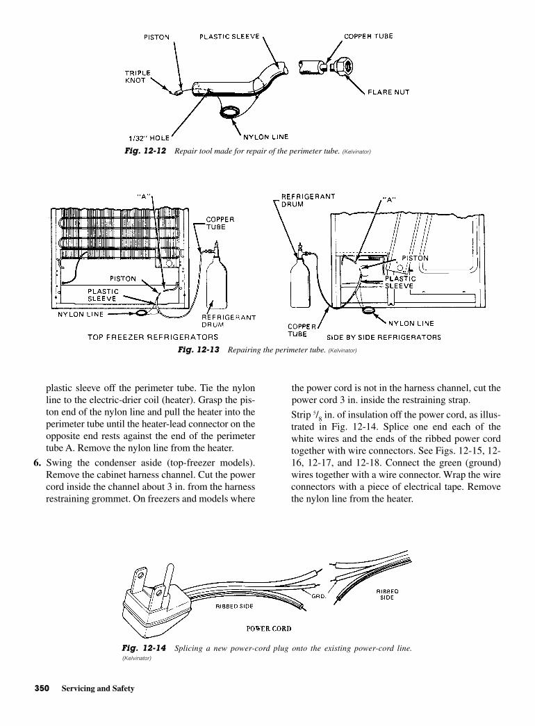
350 Servicing and Safety
plastic sleeve off the perimeter tube. Tie the nylonline to the electric-drier coil (heater). Grasp the pis-ton end of the nylon line and pull the heater into theperimeter tube until the heater-lead connector on theopposite end rests against the end of the perimetertube A. Remove the nylon line from the heater.
6. Swing the condenser aside (top-freezer models).Remove the cabinet harness channel. Cut the powercord inside the channel about 3 in. from the harnessrestraining grommet. On freezers and models where
the power cord is not in the harness channel, cut thepower cord 3 in. inside the restraining strap.
Strip 5/8 in. of insulation off the power cord, as illus-trated in Fig. 12-14. Splice one end each of thewhite wires and the ends of the ribbed power cordtogether with wire connectors. See Figs. 12-15, 12-16, 12-17, and 12-18. Connect the green (ground)wires together with a wire connector. Wrap the wireconnectors with a piece of electrical tape. Removethe nylon line from the heater.
Fig. 12-12 Repair tool made for repair of the perimeter tube. (Kelvinator)
Fig. 12-13 Repairing the perimeter tube. (Kelvinator)
Fig. 12-14 Splicing a new power-cord plug onto the existing power-cord line.(Kelvinator)

Repairing the Perimeter Tube (Fiberglass Insulated) 351
CAUTION: Recheck your work to besure the ribbed ends of power cord arespliced together to maintain polarity.Shape the perimeter tubes A and B asrequired for routing the heater leadsalong the flange of the cabinet to theharness channel.
7. Cut off the excess heater approximately 2 in. fromthe end of perimeter tube B.
NOTE: Exercise extreme care whenstripping insulation to prevent damag-ing the heater-resistance wire.
Cut the black and white wires to their proper length.Splice the white wire to the heater lead C and theblack wire to heater lead D with wire connectors.Secure the leads to the cabinet flange with clips.Reinstall the harness channel.
8. Score the capillary tube and remove the filter drier.Use a copper tube and the filter drier to connect thecondenser to the capillary tube. See Fig. 12-19.
Foam-Insulated 12 and 14 ft3,Top-Freezer Models
1. Disconnect the service cord from the powersupply.
2. Use a tubing cutter to cut and deburr the 3/16 in. ODhot tube at A and B. See Fig. 12-11.
3. Mount the auxiliary condenser on the bottom of theexisting condenser, using bolts, nuts, and spacers.
Fig. 12-15 Power-cord location and splices, side-by-sidemodels. (Kelvinator)
Fig. 12-16 Power-cord splicing on top-freezer models. (Kelvinator)
Fig. 12-17 Another top-freezer refrigerator power-cord splice. (Kelvinator)

352 Servicing and Safety
4. Use silver solder to connect the refrigerant linesthat were removed from the hot tube, to the auxiliary-condenser lines.
NOTE: Refrigerant must enter the topof the auxiliary condenser.
5. Install a replacement drier. Evacuate and rechargethe system using the nameplate charge.
6. Use an ice pick to pierce a 1/32 in. diameter holethrough the wall of the plastic sleeve 11/2 in. fromthe end. Thread one end of the nylon line throughthe pierced hole and piston. Tie a triple knot in theline. Loop the opposite end of the line around theplastic sleeve and tie. See Fig. 12-12.
7. Insert the piston into the hot tube A. Slide the plas-tic sleeve onto the hot tube A. Insert the 3/8 in. ODcopper tube into the opposite end of the plasticsleeve. Install a flare nut on the copper tube andflare the tube. Connect to the refrigerant drum. SeeFig. 12-20.
8. Open the valve on the refrigerant drum. Blow thepiston and nylon-line assembly through the hottube. (Use vapor pressure.)
9. Cut the nylon line that is looped around the plasticsleeve. Disconnect the refrigerant drum. Slide theplastic sleeve off the hot tube. Tie the nylon line to
Fig. 12-18 Top-freezer refrigerator-cord splice location. (Kelvinator)
Fig. 12-19 Side-by side and top-freezer model refrigerator filter-drier location. (Kelvinator)
Fig. 12-20 An older technique using vapor pressure fromrefrigerant drum to blow the piston and nylon assembly through thehot tube. (Kelvinator)
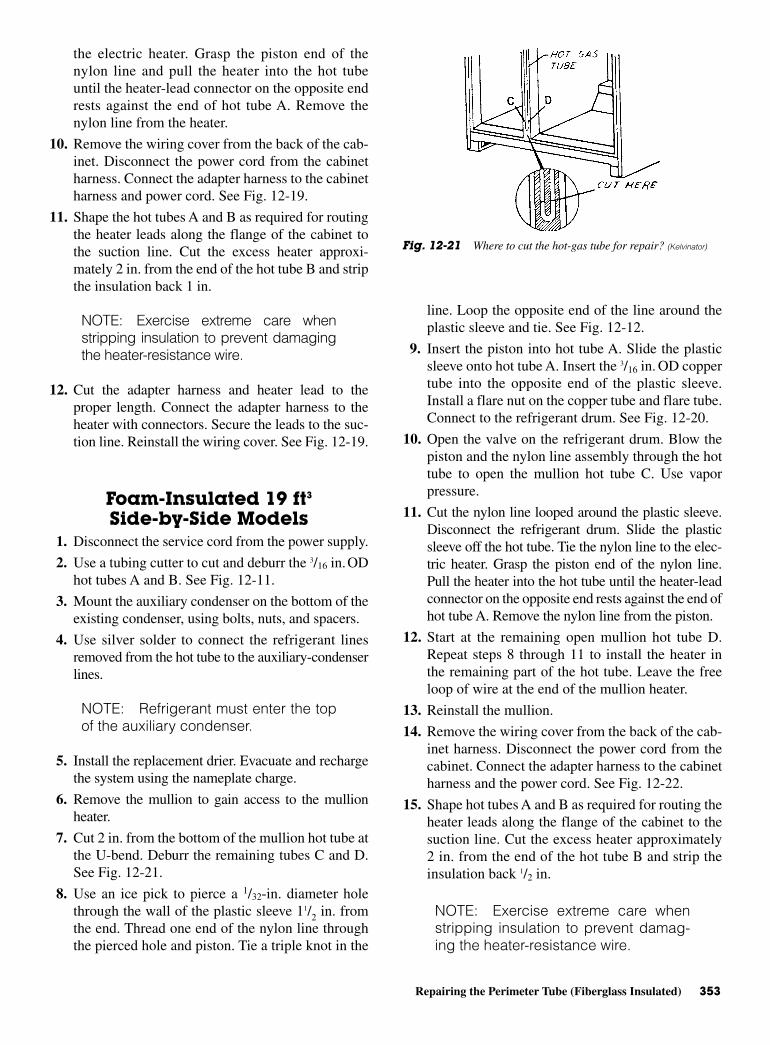
Repairing the Perimeter Tube (Fiberglass Insulated) 353
the electric heater. Grasp the piston end of thenylon line and pull the heater into the hot tubeuntil the heater-lead connector on the opposite endrests against the end of hot tube A. Remove thenylon line from the heater.
10. Remove the wiring cover from the back of the cab-inet. Disconnect the power cord from the cabinetharness. Connect the adapter harness to the cabinetharness and power cord. See Fig. 12-19.
11. Shape the hot tubes A and B as required for routingthe heater leads along the flange of the cabinet tothe suction line. Cut the excess heater approxi-mately 2 in. from the end of the hot tube B and stripthe insulation back 1 in.
NOTE: Exercise extreme care whenstripping insulation to prevent damagingthe heater-resistance wire.
12. Cut the adapter harness and heater lead to theproper length. Connect the adapter harness to theheater with connectors. Secure the leads to the suc-tion line. Reinstall the wiring cover. See Fig. 12-19.
Foam-Insulated 19 ft3
Side-by-Side Models1. Disconnect the service cord from the power supply.
2. Use a tubing cutter to cut and deburr the 3/16 in.ODhot tubes A and B. See Fig. 12-11.
3. Mount the auxiliary condenser on the bottom of theexisting condenser, using bolts, nuts, and spacers.
4. Use silver solder to connect the refrigerant linesremoved from the hot tube to the auxiliary-condenserlines.
NOTE: Refrigerant must enter the topof the auxiliary condenser.
5. Install the replacement drier. Evacuate and rechargethe system using the nameplate charge.
6. Remove the mullion to gain access to the mullionheater.
7. Cut 2 in. from the bottom of the mullion hot tube atthe U-bend. Deburr the remaining tubes C and D.See Fig. 12-21.
8. Use an ice pick to pierce a 1/32-in. diameter holethrough the wall of the plastic sleeve 11/2 in. fromthe end. Thread one end of the nylon line throughthe pierced hole and piston. Tie a triple knot in the
line. Loop the opposite end of the line around theplastic sleeve and tie. See Fig. 12-12.
9. Insert the piston into hot tube A. Slide the plasticsleeve onto hot tube A. Insert the 3/16 in. OD coppertube into the opposite end of the plastic sleeve.Install a flare nut on the copper tube and flare tube.Connect to the refrigerant drum. See Fig. 12-20.
10. Open the valve on the refrigerant drum. Blow thepiston and the nylon line assembly through the hottube to open the mullion hot tube C. Use vaporpressure.
11. Cut the nylon line looped around the plastic sleeve.Disconnect the refrigerant drum. Slide the plasticsleeve off the hot tube. Tie the nylon line to the elec-tric heater. Grasp the piston end of the nylon line.Pull the heater into the hot tube until the heater-leadconnector on the opposite end rests against the end ofhot tube A. Remove the nylon line from the piston.
12. Start at the remaining open mullion hot tube D.Repeat steps 8 through 11 to install the heater inthe remaining part of the hot tube. Leave the freeloop of wire at the end of the mullion heater.
13. Reinstall the mullion.
14. Remove the wiring cover from the back of the cab-inet harness. Disconnect the power cord from thecabinet. Connect the adapter harness to the cabinetharness and the power cord. See Fig. 12-22.
15. Shape hot tubes A and B as required for routing theheater leads along the flange of the cabinet to thesuction line. Cut the excess heater approximately2 in. from the end of the hot tube B and strip theinsulation back 1/2 in.
NOTE: Exercise extreme care whenstripping insulation to prevent damag-ing the heater-resistance wire.
Fig. 12-21 Where to cut the hot-gas tube for repair? (Kelvinator)

354 Servicing and Safety
16. Cut the adapter harness and the heater lead to theirproper lengths. Connect the adapter harness to theheater with connectors. Secure the leads to the suc-tion line. Reinstall the wiring cover. See Fig. 12-22.
REPLACING THEEVAPORATOR-HEAT
EXCHANGER ASSEMBLYTop-Freezer, No-Frost Models
When an evaporator-heat exchanger assembly devel-ops a refrigerant leak and the compressor has operatedafter the refrigerant escaped, air and moisture haveentered the system. To protect the system, it must beflushed with liquid refrigerant and evacuated. A replace-ment filter drier must be installed in conjunction withthe evaporator-heat exchanger assembly.
To replace the evaporator-heat exchanger assembly,move the refrigerator to a location where the front andrear are accessible. Remove the machine compartmentcover on models so equipped. Then, follow steps (1) and(4) in the discussion of “To Replace the Compressor.”Use a tubing cutter to cut suction tube at the compressor.Swing the condenser aside. Disconnect the defrostheater and defrost termination thermostat leads from thecabinet harness. Bend the heat exchanger upward.Remove the sealer from the tubing-harness entrancehole. Remove the evaporator cover mounting screws andlay the cover on the bottom of the freezer compartment.Remove the evaporator mounting screws and RH andLH air barriers. Pull the evaporator-heat exchangerassembly forward out of the freezer compartment. Trans-fer the defrost heater and defrost termination thermostatto the replacement evaporator. Install the replacementevaporator-heat exchanger assembly. Install the evapora-
tor RH and LH air barriers and evaporator cover. Pressthe sealer firmly into the tubing-harness entrance hole.Connect the defrost heater and termination thermostatleads to the harness. Swing the condenser into place andsecure. Braze the suction tube to the compressor. Use sil-ver solder (Easy Flo-45). Then, follow steps (4) through(10) discussed in “Replacing the Filter Drier.” Install themachine compartment cover on models so equipped.
Side-by-Side Models When an evaporator-heat exchanger assembly devel-ops a refrigerant leak and the compressor has operatedafter the refrigerant escaped, air and moisture haveentered the system. To protect the system, it must beflushed with liquid refrigerant and evacuated.
Proper procedure must be followed to make sure theflushing refrigerant does not escape into the atmosphere.Use the proper recovery techniques for reclaiming refrig-erant. A replacement filter drier must be installed in con-junction with the evaporator-heat exchanger assembly.
To replace the evaporator-heat exchanger assem-bly, move the refrigerator to a location where the frontand rear are accessible.
Remove the machine compartment cover. Then,follow steps (1) and (4) discussed in “To Replace theCompressor.” Use a tubing cutter to cut the suction tubeat the compressor. Disconnect the defrost terminationthermostat leads from the cabinet harness. Bend theheat exchanger upward. Remove the sealer from thetubing-harness entrance hole. Remove the shelves,shelf supports, evaporator cover, and evaporator mount-ing screws. Pull the evaporator-heat exchanger assem-bly forward from the freezer compartment. Transfer thedefrost heater and defrost termination thermostat tothe replacement evaporator. Install the replacementevaporator-heat exchanger assembly. Connect the defrostheater and defrost termination thermostat leads to thecabinet harness. Install the sealer firmly into the tubing-harness entrance hole from the front and rear. Install theevaporator cover, shelf supports, and shelves. Braze thesuction tube to the compressor. Use silver solder (EasyFlo-45). Then, follow steps (4) through (10) discussedin “Replacing the Filter Drier.” Install the machinecompartment cover.
ADDING REFRIGERANT
CAUTION: Always introduce refriger-ant into the system in a vapor state.When the operation of a system indi-cates that it is short of refrigerant, it mustbe assumed that there is a leak in the
Fig. 12-22 Location of the leads and power cord. (Kelvinator)
Testing for Refrigerant Leaks 355
system. Proceed to test the system witha leak detector. When the leak is located,it should be repaired. First, however, youmust determine if the leak is repairable.
Unless the system has lost most of its refrigerant, theleak test can be made without the addition of extrarefrigerant. If the system is completely out, sufficientrefrigerant must be added to make a leak test. A new fil-ter drier must be installed.
Low-Side Leak or SlightUndercharge
If a slight undercharge of refrigerant is indicated, with-out a leak being found, the charge can be correctedwithout changing the compressor.
In the case of a low-side refrigerant leak, resulting incomplete loss of refrigerant, the compressor will run.However, there will be no refrigeration. Suction pressurewill drop below atmospheric pressure. Air and moistureare drawn into the system, saturating the filter drier.
It is not necessary to replace the compressor. The leakshould be repaired. The system should be flushed withliquid refrigerant. A replacement filter drier should beinstalled. The system should be excavated and recharged.
The system may have operated for a considerablelength of time with no refrigerant and the leak mayhave occurred in the evaporator. In this case, excessiveamounts of moisture may have entered the system. Insuch cases the compressor may need to be replaced toprevent repetitive service.
High-Side Leak or SlightUndercharge
It is not necessary to change a compressor when a leak isfound in the system. If a slight undercharge of refriger-ant is indicated, without a leak being found, the chargecan be corrected without changing the compressor.
It is recommended that the system be flushed withliquid refrigerant and evacuated. A replacement filterdrier should be installed to protect the system againstmoisture. Make sure the flushing refrigerate is capturedand reprocessed.
Overcharge of RefrigerantWhen the cabinet is pulled down to temperature, anindication of an overcharge is that the suction line willbe colder than normal. The normal temperature of thesuction line will be a few degrees cooler than roomtemperature. If its temperature is much lower than roomtemperature, the unit will run longer because the liquid
is pulled into the heat exchanger. When the overcharge isexcessive, the suction line will sweat or frost.
TESTING FOR REFRIGERANTLEAKS
If the system is diagnosed as short of refrigerant andhas not been recently opened, there is probably a leakin the system. Adding refrigerant without first locatingand repairing the leak will not permanently correct thedifficulty. The leak must be found. Sufficient refriger-ant may have escaped to make it impossible to leak testeffectively. In such cases, add a 1/4 in. line-piercingvalve to the compressor process tube. Add sufficientrefrigerant to increase the pressure to 75 lb/in.2.Through this procedure, minute leaks are more easilydetected before discharging the system and contam-inating the surrounding air.
NOTE: The line-piercing valve (clamp-on type) should be used only for addingrefrigerant and for test purposes. It mustbe removed from the system after it hasserved its purpose. Braze-on type line-piercing valves may be left on theprocess tube to evacuate the system andrecharge after repairs are completed.
Various types of leak detectors are available. Liq-uid detectors (bubbles), halide torches, halogen-sensingelectronic detectors, and electronic transistor pressure-sensing detectors are used.
You can sometimes spot a leak by the presence of oilaround it. To be conclusive, however, use a leak detector.
Liquid detectors (bubbles) can be used to detectsmall leaks in the following manner. Brush liquid detec-tor over the suspected area and watch for the formationof bubbles as the gas escapes. If the leak is slight, youmay have to wait several minutes for a bubble to appear.
CAUTION: Use the bubble methodonly when you are sure that the systemhas positive pressure. Using it where avacuum is present could pull liquiddetector into the system.
When testing with the halide torch, be sure theroom is free from refrigerant vapors. Watch the flamefor the slightest change in color. A very faint greenindicates a small leak. The flame will be unmistakablygreen to purple when large leaks are encountered. Tosimplify leak detection, keep the system pressurized toa minimum of 75 lb/in.2.
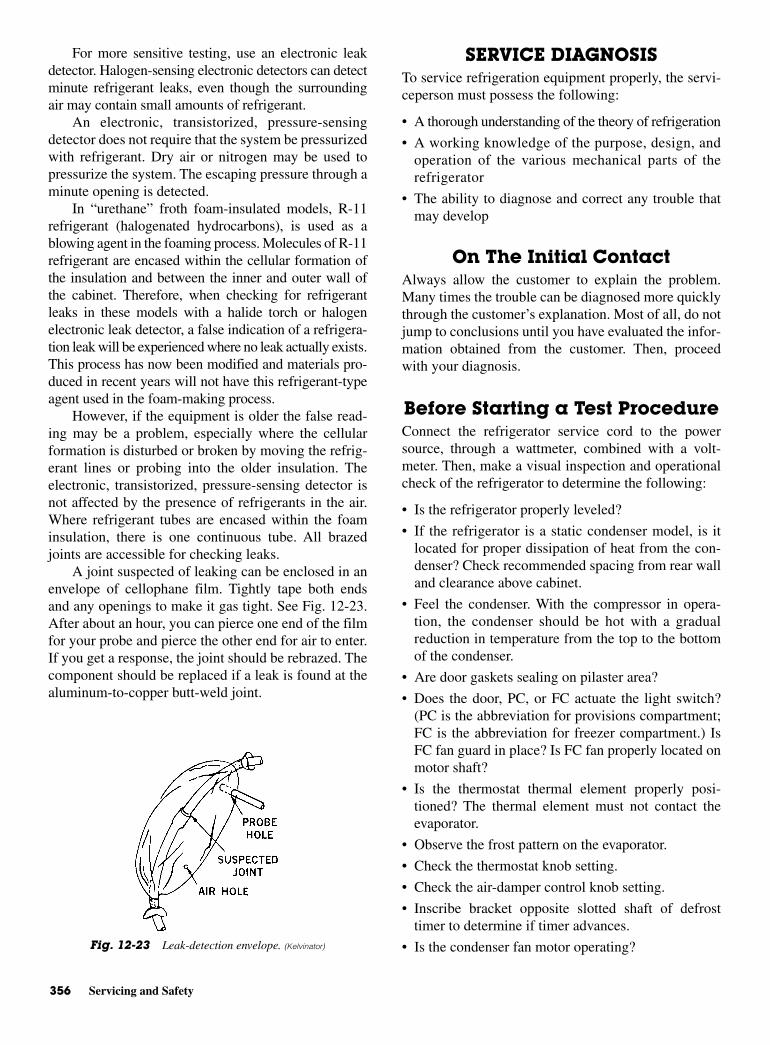
356 Servicing and Safety
For more sensitive testing, use an electronic leakdetector. Halogen-sensing electronic detectors can detectminute refrigerant leaks, even though the surroundingair may contain small amounts of refrigerant.
An electronic, transistorized, pressure-sensingdetector does not require that the system be pressurizedwith refrigerant. Dry air or nitrogen may be used topressurize the system. The escaping pressure through aminute opening is detected.
In “urethane” froth foam-insulated models, R-11refrigerant (halogenated hydrocarbons), is used as ablowing agent in the foaming process. Molecules of R-11refrigerant are encased within the cellular formation ofthe insulation and between the inner and outer wall ofthe cabinet. Therefore, when checking for refrigerantleaks in these models with a halide torch or halogenelectronic leak detector, a false indication of a refrigera-tion leak will be experienced where no leak actually exists.This process has now been modified and materials pro-duced in recent years will not have this refrigerant-typeagent used in the foam-making process.
However, if the equipment is older the false read-ing may be a problem, especially where the cellularformation is disturbed or broken by moving the refrig-erant lines or probing into the older insulation. Theelectronic, transistorized, pressure-sensing detector isnot affected by the presence of refrigerants in the air.Where refrigerant tubes are encased within the foaminsulation, there is one continuous tube. All brazedjoints are accessible for checking leaks.
A joint suspected of leaking can be enclosed in anenvelope of cellophane film. Tightly tape both endsand any openings to make it gas tight. See Fig. 12-23.After about an hour, you can pierce one end of the filmfor your probe and pierce the other end for air to enter.If you get a response, the joint should be rebrazed. Thecomponent should be replaced if a leak is found at thealuminum-to-copper butt-weld joint.
SERVICE DIAGNOSISTo service refrigeration equipment properly, the servi-ceperson must possess the following:
• A thorough understanding of the theory of refrigeration
• A working knowledge of the purpose, design, andoperation of the various mechanical parts of therefrigerator
• The ability to diagnose and correct any trouble thatmay develop
On The Initial Contact Always allow the customer to explain the problem.Many times the trouble can be diagnosed more quicklythrough the customer’s explanation. Most of all, do notjump to conclusions until you have evaluated the infor-mation obtained from the customer. Then, proceedwith your diagnosis.
Before Starting a Test Procedure Connect the refrigerator service cord to the powersource, through a wattmeter, combined with a volt-meter. Then, make a visual inspection and operationalcheck of the refrigerator to determine the following:
• Is the refrigerator properly leveled?
• If the refrigerator is a static condenser model, is itlocated for proper dissipation of heat from the con-denser? Check recommended spacing from rear walland clearance above cabinet.
• Feel the condenser. With the compressor in opera-tion, the condenser should be hot with a gradualreduction in temperature from the top to the bottomof the condenser.
• Are door gaskets sealing on pilaster area?
• Does the door, PC, or FC actuate the light switch?(PC is the abbreviation for provisions compartment;FC is the abbreviation for freezer compartment.) IsFC fan guard in place? Is FC fan properly located onmotor shaft?
• Is the thermostat thermal element properly posi-tioned? The thermal element must not contact theevaporator.
• Observe the frost pattern on the evaporator.
• Check the thermostat knob setting.
• Check the air-damper control knob setting.
• Inscribe bracket opposite slotted shaft of defrosttimer to determine if timer advances.
• Is the condenser fan motor operating? Fig. 12-23 Leak-detection envelope. (Kelvinator)
Service Diagnosis 357
NOTE: Condenser fan motor operatesonly when compressor operates.
• Are air ducts free of obstructions?
The service technician should inquire regarding thenumber of people in the family. This will help determinethe service load and daily door openings. In addition, theservice technician should know the room temperature.
After this phase of diagnosis is completed, a thor-ough operational check should be made of the refriger-ation system. Any components not previously checkedshould be checked in the following order.
Thermostat Cut-Out and Cut-InTemperatures
To check the cut-out and cut-in temperatures of thethermostat, use a refrigeration tester or a recording meter.Attach a test bulb to the thermal element on the top-freezer and side-by-side models. Replace the evaporatorcover before starting the test.
When using a refrigeration tester equipped withseveral bulbs, place a No. 2 bulb in FC air (center) anda No. 3 bulb in PC air (center).
Allow the system to operate through a completecut-out and cut-in cycle, with the thermostat set on mid-dle position.
For accurate reading or recording, the temperatureof the thermostat thermal element must not be reducedmore than 1°F (0.5°C) per minute through the final 5°F(2.7°C) prior to cut out.
Erratic operation of the thermostat will affect boththe FC and PC air temperature.
Freezer- andProvision-Compartment
Air TemperaturesFreezer- and provision-compartment temperatures areaffected by the following:
• Improper door seal
• Frost accumulation on the PC and the FC evaporators
• Service load
• Ambient temperature
• Percentage of relative humidity
• Thermostat calibration (cut in and cut out)
• Location of the FC fan blade on motor shaft
• Compressor efficiency
From this, it is evident that temperatures are notalways the same in every refrigerator, even under identi-
cal conditions. However, an average FC air temperatureof 0 ±6°F (−17.8 ± 3.3°C) with a PC air temperature of36 (2.2°C) to 42°F (5.6°C), should be obtained.
Freezer Compartment Too Warm Cause:
1. Inoperative fan motor
2. Improperly position fan
3. Evaporator iced up
4. Defrost heater burned out
5. Inoperative defrost timer
6. Inoperative defrost temperature terminationthermostat
7. Wire loose at defrost timer
8. Fan guard missing
9. Excessive service load
10. Abnormally low room temperatures
11. FC or PC door left open
12. Thermostat out of calibration
13. PC or FC door gasket not sealing; check with 100-Wlamp
14. Thermostat thermal element touching the evaporator
15. Inoperative condenser fan motor
16. Shortage of refrigerant (side-by-side models only)
17. Restricted filter drier or capillary tube
Provision Compartment Too WarmCause
1. Inoperative fan motor
2. Improperly positioned fan
3. Fan guard missing
4. PC air inlet air duct restricted
5. PC to FC return air duct restricted
6. Air-flow control on warmer position
7. Thermostat out of calibration.
8. Thermostat knob set at warm setting
9. Thermostat thermal element touching the evaporator
10. Evaporator iced up
11. Inoperative defrost timer
12. Inoperative defrost heater
13. Inoperative defrost temperature termination ther-mostat
14. Loose wire at defrost timer
15. Excessive service load, resulting from too much foodin compartment
358 Servicing and Safety
16. Inoperative capacitor in the fan motor
17. PC or FC door left open
18. Inoperative or erratically opening FC and/or FCdoor switch
19. Shelves covered with foil wrap or paper, retardingair circulation
20. Restricted capillary tube or filter drier
Evaporator Blocked with Ice Cause
1. Inoperative defrost timer
2. Defrost timer terminates too early
3. Defrost timer incorrectly wired; check wiring
4. Inoperative fan motor
5. Inoperative termination thermostat
6. Inoperative defrost heater
7. PC or FC door left open
8. FC drain plugged; clean
9. FC drain sump or drain-trough heater burned out;replace.
Line VoltageIt is essential to know the line voltage at the appliance.A voltage reading should be taken the instant the com-pressor starts and while the compressor is running.Line-voltage fluctuation should not exceed 10 percent,plus or minus, from nominal rating. Low voltage willcause overheating of the compressor motor windings.This will result in compressor cycling on thermal over-load, or the compressor may fail to start.
Inadequate line-wire size and overloaded lines are themost common reasons for low voltage at the appliance.
WattageWattage is a true measure of power. It is the measure ofthe rate at which electrical energy is consumed. There-fore, wattage readings are useful in determining com-pressor efficiency, proper refrigerant charge, and thepresence of a restriction. They also help detect the mal-function of an electrical component.
Amperes, measured with an Amprobe, multipliedby the voltage is not a true measurement of power in analternating current (AC) circuit. It gives only “volt-amperes” or “apparent power.” This value must be mul-tiplied by the power factor (phase angle), to obtain thetrue or actual (AC) power. The actual power is indi-cated by a wattmeter.
Or
Thus, the power factor may be expressed as theratio of the actual watts to the apparent watts. The appar-ent watts value is the product of the amperes and voltsas indicated by an ammeter and a voltmeter. The powerfactor varies from 0 to 1.00 (or 100 percent). On resis-tance heaters, such as the drier coil and drain heater,the actual watts are equal to the amperes multiplied bythe volts. Thus, the power factor is 100 percent or 1.00.On electric motors, because of their magnetic reaction,the actual watts are not equal to amperes multiplied byvolts. This means the power factor is less than 1.00. Forthis reason, a wattmeter should be used.
Compressor EfficiencyA low-capacity pumping compressor causes excessiveor continuous compressor operation, depending on theambient temperature and service load. Recovery ofcabinet temperature will be slow. If cycling does occur,wattage will generally be below normal. Condensertemperature will be near normal.
Refrigerant ShortageA loss of refrigerant results in the following:
• Excessive or continuous compressor operation.
• Above-normal PC temperature.
• A partially frosted evaporator (depending on amountof refrigerant lost).
• Below-normal FC temperature.
• Low-suction pressure (vacuum).
• Low wattage. The condenser will be “warm to cool”again, depending on the amount of refrigerant lost.
When refrigerant is added, the frost pattern willimprove. The suction and discharge pressures will rise.The condenser will become hot. The wattage willincrease. The refrigerator should then be turned off andthoroughly leak tested.
It is not always necessary to change a compressorwhen a leak is found in the system. If a slight underchargeof refrigerant is indicated, without a leak being found, thecharge can be corrected without changing the compressor.
Power factorwatts
volts amperes (VA)
actual powerapparent power
= ×
=
Watts volts amperes power factor= × ×
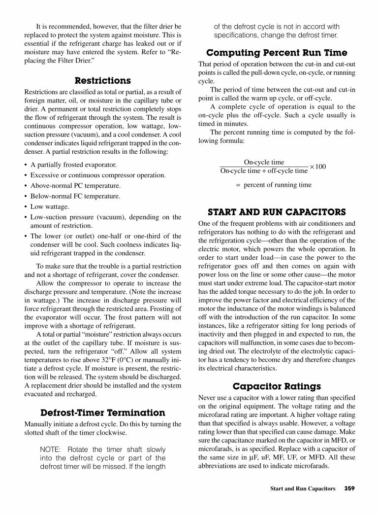
Start and Run Capacitors 359
It is recommended, however, that the filter drier bereplaced to protect the system against moisture. This isessential if the refrigerant charge has leaked out or ifmoisture may have entered the system. Refer to “Re-placing the Filter Drier.”
RestrictionsRestrictions are classified as total or partial, as a result offoreign matter, oil, or moisture in the capillary tube ordrier. A permanent or total restriction completely stopsthe flow of refrigerant through the system. The result iscontinuous compressor operation, low wattage, low-suction pressure (vacuum), and a cool condenser. A coolcondenser indicates liquid refrigerant trapped in the con-denser. A partial restriction results in the following:
• A partially frosted evaporator.
• Excessive or continuous compressor operation.
• Above-normal PC temperature.
• Below-normal FC temperature.
• Low wattage.
• Low-suction pressure (vacuum), depending on theamount of restriction.
• The lower (or outlet) one-half or one-third of thecondenser will be cool. Such coolness indicates liq-uid refrigerant trapped in the condenser.
To make sure that the trouble is a partial restrictionand not a shortage of refrigerant, cover the condenser.
Allow the compressor to operate to increase thedischarge pressure and temperature. (Note the increasein wattage.) The increase in discharge pressure willforce refrigerant through the restricted area. Frosting ofthe evaporator will occur. The frost pattern will notimprove with a shortage of refrigerant.
A total or partial “moisture” restriction always occursat the outlet of the capillary tube. If moisture is sus-pected, turn the refrigerator “off.” Allow all systemtemperatures to rise above 32°F (0°C) or manually ini-tiate a defrost cycle. If moisture is present, the restric-tion will be released. The system should be discharged.A replacement drier should be installed and the systemevacuated and recharged.
Defrost-Timer Termination Manually initiate a defrost cycle. Do this by turning theslotted shaft of the timer clockwise.
NOTE: Rotate the timer shaft slowlyinto the defrost cycle or part of thedefrost timer will be missed. If the length
of the defrost cycle is not in accord withspecifications, change the defrost timer.
Computing Percent Run Time That period of operation between the cut-in and cut-outpoints is called the pull-down cycle, on-cycle, or runningcycle.
The period of time between the cut-out and cut-inpoint is called the warm up cycle, or off-cycle.
A complete cycle of operation is equal to theon-cycle plus the off-cycle. Such a cycle usually istimed in minutes.
The percent running time is computed by the fol-lowing formula:
START AND RUN CAPACITORSOne of the frequent problems with air conditioners andrefrigerators has nothing to do with the refrigerant andthe refrigeration cycle—other than the operation of theelectric motor, which powers the whole operation. Inorder to start under load—in case the power to therefrigerator goes off and then comes on again withpower loss on the line or some other cause—the motormust start under extreme load. The capacitor-start motorhas the added torque necessary to do the job. In order toimprove the power factor and electrical efficiency of themotor the inductance of the motor windings is balancedoff with the introduction of the run capacitor. In someinstances, like a refrigerator sitting for long periods ofinactivity and then plugged in and expected to run, thecapacitors will malfunction, in some cases due to becom-ing dried out. The electrolyte of the electrolytic capaci-tor has a tendency to become dry and therefore changesits electrical characteristics.
Capacitor Ratings Never use a capacitor with a lower rating than specifiedon the original equipment. The voltage rating and themicrofarad rating are important. A higher voltage ratingthan that specified is always usable. However, a voltagerating lower than that specified can cause damage. Makesure the capacitance marked on the capacitor in MFD, ormicrofarads, is as specified. Replace with a capacitor ofthe same size in µF, uF, MF, UF, or MFD. All theseabbreviations are used to indicate microfarads.
On-cycle timeOn-cycle time off-cycle time
100
percent of running time
+ ×
=
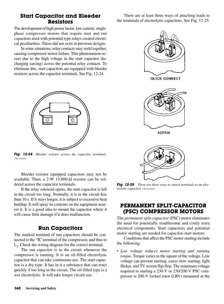
360 Servicing and Safety
Start Capacitor and BleederResistors
The development of high power factor, low-current, single-phase compressor motors that require start and runcapacitors used with potential type relays created electri-cal peculiarities. These did not exist in previous designs.
In some situations, relay contacts may weld together,causing compressor motor failure. This phenomenon oc-curs due to the high voltage in the start capacitor dis-charging (arcing) across the potential relay contacts. Toeliminate this, start capacitors are equipped with bleederresistors across the capacitor terminals. See Fig. 12-24.
Bleeder resistor equipped capacitors may not beavailable. Then, a 2-W 15,000-Ω resistor can be sol-dered across the capacitor terminals.
If the relay solenoid opens, the start capacitor is leftin the circuit too long. Normally, it is in the circuit lessthan 10 s. If it stays longer, it is subject to excessive heatbuildup. It will spray its contents on the equipment near-est it. It is a good idea to mount the capacitor where itwill cause little damage if it does malfunction.
Run CapacitorsThe marked terminal of run capacitors should be con-nected to the “R” terminal of the compressor, and thus toL2. Check the wiring diagram for the correct terminal.
The run capacitor is in the circuit whenever thecompressor is running. It is an oil-filled electrolyticcapacitor that can take continuous use. The start capac-itor is a dry type. It has in it a substance that can reactquickly if too long in the circuit. The oil-filled type is awet electrolytic. It will take longer circuit use.
There are at least three ways of attaching leads tothe terminals of electrolytic capacitors. See Fig. 12-25.
PERMANENT SPLIT-CAPACITOR(PSC) COMPRESSOR MOTORS
The permanent split-capacitor (PSC) motor eliminatesthe need for potentially troublesome and costly extraelectrical components. Start capacitors and potentialmotor starting are needed for capacitor-start motors.
Conditions that affect the PSC motor starting includethe following:
• Low voltage reduces motor starting and runningtorque. Torque varies as the square of the voltage. Lowvoltage can prevent starting, cause slow starting, lightflicker, and TV screen flip-flop. The minimum voltagerequired in starting a 230-V or 230/208-V PSC com-pressor is 200-V locked rotor (LRV) measured at the
Fig. 12-24 Bleeder resistor across the capacitor terminals.(Tecumseh)
Fig. 12-25 There are three ways to attach terminals to an elec-trolytic capacitor. (Tecumseh)
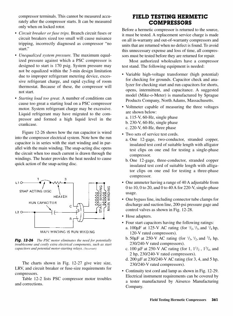
Field Testing Hermetic Compressors 361
compressor terminals. This cannot be measured accu-rately after the compressor starts. It can be measuredonly when on locked rotor.
• Circuit breaker or fuse trips. Branch circuit fuses orcircuit breakers sized too small will cause nuisancetripping, incorrectly diagnosed as compressor “nostart.”
• Unequalized system pressure. The maximum equal-ized pressure against which a PSC compressor isdesigned to start is 170 psig. System pressure maynot be equalized within the 3-min design limitationdue to improper refrigerant metering device, exces-sive refrigerant charge, and rapid cycling of roomthermostat. Because of these, the compressor willnot start.
• Starting load too great. A number of conditions cancause too great a starting load on a PSC compressormotor. System refrigerant charge may be excessive.Liquid refrigerant may have migrated to the com-pressor and formed a high liquid level in thecrankcase.
Figure 12-26 shows how the run capacitor is wiredinto the compressor electrical system. Note how the runcapacitor is in series with the start winding and in par-allel with the main winding. The snap-acting disc opensthe circuit when too much current is drawn through thewindings. The heater provides the heat needed to causequick action of the snap-acting disc.
The charts shown in Fig. 12-27 give wire size,LRV, and circuit breaker or fuse-size requirements forcompressors.
Table 12-2 lists PSC compressor motor troublesand corrections.
FIELD TESTING HERMETICCOMPRESSORS
Before a hermetic compressor is returned to the source,it must be tested. A replacement service charge is madeon all in-warranty and out-of-warranty compressors andunits that are returned when no defect is found. To avoidthis unnecessary expense and loss of time, all compres-sors must be tested before they are returned for repair.
Most authorized wholesalers have a compressortest stand. The following equipment is needed:
• Variable high-voltage transformer (high potential)for checking for grounds. Capacitor check and ana-lyzer for checking start and run capacitors for shorts,opens, intermittent, and capacitance. A suggestedmodel (Mike-o-Meter) is manufactured by SpragueProducts Company, North Adams, Massachusetts.
• Voltmeter capable of measuring the three voltagesare shown below:a. 115-V, 60-Hz, single phaseb. 230-V, 60-Hz, single phasec. 220-V, 60-Hz, three phase
• Two sets of service test cords.a. One 12-gage, two-conductor, stranded copper,
insulated test cord of suitable length with alligatortest clips on one end for testing a single-phasecompressor.
b. One 12-gage, three-conductor, stranded copperinsulated test cord of suitable length with alliga-tor clips on one end for testing a three-phasecompressor.
• One ammeter having a range of 40 A adjustable from0 to 10, 0 to 20, and 0 to 40 A for 220-V, single-phaseusage.
• One bypass line, including connector tube clamps fordischarge and suction line, 200-psi pressure gage andcontrol valves as shown in Fig. 12-28.
• Hose adapters.
• Four start capacitors having the following ratings:a. 100µF at 125-V AC rating (for 1/2, 1/3, and 3/4 hp,
120-V rated compressors). b. 50µF at 250-V AC rating (for 1/3, 1/2, and 3/4 hp,
230/240-V rated compressors). c. 100 µF at 250-V AC rating (for 1, 11/2 , 13/4, and
2 hp, 230/240-V rated compressors).d. 200 µF at 230/240-V AC rating (for 3, 4, and 5 hp,
230/240-V rated compressors).
• Continuity test cord and lamp as shown in Fig. 12-29.Electrical instrument requirements can be covered bya tester manufactured by Airserco ManufacturingCompany.
Fig. 12-26 The PSC motor eliminates the need for potentiallytroublesome and costly extra electrical components, such as startcapacitors and potential motor-starting relays. (Tecumseh)
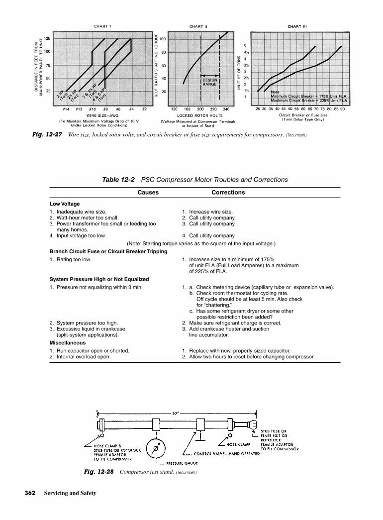
362 Servicing and Safety
Fig. 12-27 Wire size, locked rotor volts, and circuit breaker or fuse size requirements for compressors. (Tecumseh)
Fig. 12-28 Compressor test stand. (Tecumseh)
Table 12-2 PSC Compressor Motor Troubles and Corrections
Causes Corrections
Low Voltage
1. Inadequate wire size. 1. Increase wire size.2. Watt-hour meter too small. 2. Call utility company.3. Power transformer too small or feeding too 3. Call utility company.
many homes.4. Input voltage too low. 4. Call utility company.
(Note: Starting torque varies as the square of the input voltage.)
Branch Circuit Fuse or Circuit Breaker Tripping
1. Rating too low. 1. Increase size to a minimum of 175%of unit FLA (Full Load Amperes) to a maximumof 225% of FLA.
System Pressure High or Not Equalized
1. Pressure not equalizing within 3 min. 1. a. Check metering device (capillary tube or expansion valve).b. Check room thermostat for cycling rate.
Off cycle should be at least 5 min. Also checkfor “chattering.”
c. Has some refrigerant dryer or some otherpossible restriction been added?
2. System pressure too high. 2. Make sure refrigerant charge is correct.3. Excessive liquid in crankcase 3. Add crankcase heater and suction
(split-system applications). line accumulator.
Miscellaneous
1. Run capacitor open or shorted. 1. Replace with new, properly-sized capacitor.2. Internal overload open. 2. Allow two hours to reset before changing compressor.
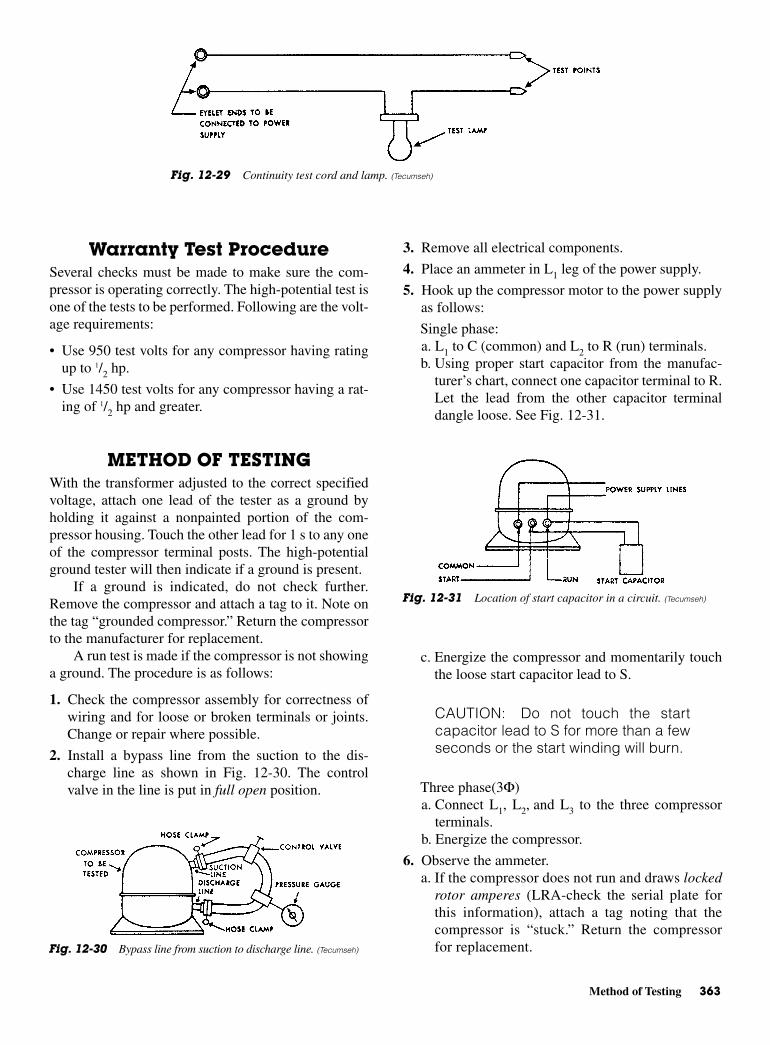
Method of Testing 363
Warranty Test Procedure Several checks must be made to make sure the com-pressor is operating correctly. The high-potential test isone of the tests to be performed. Following are the volt-age requirements:
• Use 950 test volts for any compressor having ratingup to 1/2 hp.
• Use 1450 test volts for any compressor having a rat-ing of 1/2 hp and greater.
METHOD OF TESTINGWith the transformer adjusted to the correct specifiedvoltage, attach one lead of the tester as a ground byholding it against a nonpainted portion of the com-pressor housing. Touch the other lead for 1 s to any oneof the compressor terminal posts. The high-potentialground tester will then indicate if a ground is present.
If a ground is indicated, do not check further.Remove the compressor and attach a tag to it. Note onthe tag “grounded compressor.” Return the compressorto the manufacturer for replacement.
A run test is made if the compressor is not showinga ground. The procedure is as follows:
1. Check the compressor assembly for correctness ofwiring and for loose or broken terminals or joints.Change or repair where possible.
2. Install a bypass line from the suction to the dis-charge line as shown in Fig. 12-30. The controlvalve in the line is put in full open position.
3. Remove all electrical components.
4. Place an ammeter in L1 leg of the power supply.
5. Hook up the compressor motor to the power supplyas follows:
Single phase:a. L1 to C (common) and L2 to R (run) terminals.b. Using proper start capacitor from the manufac-
turer’s chart, connect one capacitor terminal to R.Let the lead from the other capacitor terminaldangle loose. See Fig. 12-31.
c. Energize the compressor and momentarily touchthe loose start capacitor lead to S.
CAUTION: Do not touch the startcapacitor lead to S for more than a fewseconds or the start winding will burn.
Three phase(3Φ)a. Connect L1, L2, and L3 to the three compressor
terminals.b. Energize the compressor.
6. Observe the ammeter.a. If the compressor does not run and draws locked
rotor amperes (LRA-check the serial plate forthis information), attach a tag noting that thecompressor is “stuck.” Return the compressorfor replacement.
Fig. 12-29 Continuity test cord and lamp. (Tecumseh)
Fig. 12-31 Location of start capacitor in a circuit. (Tecumseh)
Fig. 12-30 Bypass line from suction to discharge line. (Tecumseh)

364 Servicing and Safety
b. If the compressor runs, but is abnormally noisy,attach a tag noting that the compressor is “noisy.”Return the compressor for replacement.
c. If the compressor does not run and draws no amperes,attach a tag noting that the compressor has “openwinding.” Return the compressor for replacement.
7. If the compressor runs normally, close the controlvalve in the bypass line until the gage reads approx-imately 175 psig. Read the amperes. If the current ismore than the rated FLA, attach a tag noting that“high amperes” are the problem. Return the com-pressor for replacement.
8. If the current and sound are normal, close the con-trol valve. Stop the compressor and clock the rate ofpressure fall on the bypass line gage. The followingpressures are for Tecumseh compressors. For othercompressors, the manufacturer’s recommendationmust be checked.
Twenty-five psig per minute initial rate of dis-charge pressure drop should not be exceeded onmodels AE, T, AT, AK, AJ, AR, AU, and ISM.
Forty psig per minute initial rate of dischargepressure drop should not be exceeded on modelsAB, AH, B, C, P, and AP.
Eighty psig per minute initial rate discharge pres-sure drop should not be exceeded on models F and PF.
If pressure changes occur in excess of those indicated,tag the compressor and mark it “internal leak.” Returnthe compressor to the manufacturer for replacement.
9. If the compressor tests normal, open the controlvalve in the bypass line. Remove the bypass, andimmediately seal the discharge and suction tubes.
10. Check the resistance of the motor windings againstthe values furnished by the manufacturer.
11. If the compressor checks out normal, return it tothe customer.
Resistance ChecksThe run (main) windings of a single-phase hermeticcompressor motor consist of large-diameter wire hav-ing very low resistance. The accurate measurement ofrun-windings resistance requires a digital ohmmeter.Less accurate meters are not sensitive enough to givecorrect readings.
Motors are sometimes diagnosed as groundedwhen the problem actually lies with the ohmmeter. It maynot be sensitive to the normal 1- or 2-Ω run-windingresistance.
There is a test procedure that can circumvent thismeasurement problem. This technique also enables the
serviceperson to determine the operating position of aninternal line break overload if one is installed in themotor.
The procedure is as follows:
1. Remove all electrical connections from the com-pressor terminals.
2. Measure the resistance across the run and start ter-minals of the motor. This measures the combinedresistance of the run and start windings. If the meas-ured resistance approaches the value given in themanufacturer’s specifications, the windings can beconsidered normal. If no resistance is read, thewindings are open. The motor should be rejected.
3. If step 2 indicates no problems, measure the resis-tance of the start winding only by checking acrossthe terminal S (start) and C (common). The ohmsshould approach the range given by the manufac-turer. If no resistance is read, the internal commonlead to the motor is open.
If the motor has an external overload, then an opencommon lead means the motor is defective. If themotor has an internal line break overload, then theoverload may be open because the motor is overly hot.It is not uncommon for the overload to remain
open for more than an hour if tripped by a hot motor.Motors cool slowly. The internal overload will notclose until the compressor dome (and thus the motoriron) is cool to the touch—below 130°F (54°C).
4. If steps 2 and 3 indicate no problems, check eachterminal in turn for a ground to the compressorhousing. First, file a shiny spot to ensure a goodelectrical connection.
5. If steps 2, 3 and 4 indicate no problems, the problemmay not be with the single-phase motor. Three-phase motors are more difficult to diagnose, sinceall three windings are run windings with low resis-tance. The internal overload, if present, is across allthree windings. Here, the suggested procedure is asfollows:
a. Check for continuity between each of the threeterminal pairs.
b. If the circuit is open and an internal overload ispresent, be sure the motor is cool before rejectingthe motor.
c. If step a, indicates no problems, check for groundbetween each terminal and the housing.
Testing Electrical ComponentsThe individual electrical components in a compressormay be tested as follows:
Installing an Air-Cooled Condensing Unit 365
1. Check the rating and part number of each compo-nent to ensure that the component is correct for thecompressor model. If the wrong component is beingused, replace with the correct one.
2. Using an ohmmeter, check the external overload (atroom temperature) for continuity across the termi-nals. If defective, replace with the proper component.
3. The start and run capacitor should be checked onthe recommended capacitor tester according to themanufacturer’s instructions. An alternate, but lessprecise method, uses a good ohmmeter. With themeter on the R × 1 range, continuity indicates ashorted capacitor. Replace. With the meter on theR × 100,000 scale, no needle deflection indicates anopen capacitor. Replace.
4. It is difficult to check the starting relay without spe-cial equipment.
Use the ohmmeter to make continuity checks.While being checked, current relays must be held
upright in their normal operating position.Contacts should be open between terminals 1 (or
L) and S. Therefore there should be no continuity.Terminals 2 (or L) and M should indicate conti-
nuity through the operating coil. (If there is no ter-minal 2, use terminal 1.)
Test the potential relay as follows:Contacts should be closed between terminals 1
and 2. Therefore, there should be continuity.There should be continuity through the operating
coil between terminals 2 and 5.
5. If all the above tests prove satisfactory, change therelay. The new relay will eliminate any faulty elec-trical characteristics, such as improper pickup anddropout. These cannot be determined in the previ-ous tests.
6. As a final check, connect the new relay to the com-pressor and the capacitors previously checked. If thecompressor fails to start at serial plate voltage, thecompressor should be considered inoperative becauseof internal defects. It must be replaced. If a capacitorchecker other than that recommended was used, trynew capacitors before rejecting the compressor.
INSTALLING AN AIR-COOLEDCONDENSING UNIT
There are some important steps to be taken in unpack-ing and installing a unit for the first time. General ship-ping and receiving instructions should be followed andthe unit be checked out before attempting to put it intooperation. A service manual is provided with each new
unit package. Be sure to follow it completely in orderthat the warranty will cover any future problems. Thefollowing is a typical unit installation instructionalguide. The following information and illustrations areprovided by Rheem Manufacturing Company.
General InformationThe information contained in this manual has been pre-pared to assist in the proper installation, operation, andmaintenance of the air-conditioning system. Improperinstallation, or installation not made in accordancewith these instructions, can result in unsatisfactoryoperation and/or dangerous conditions, and can causethe related warranty not to apply.
Read this manual and any instructions packagedwith separate equipment required to make up the sys-tem prior to installation. Retain this manual for futurereference.
To achieve unit design operating efficiency andcapacity, the indoor cooling coils listed in the condens-ing unit specification sheet should be used.
Check the outside sheet metal for signs of damageor rough handling. See Fig. 12-32.
Checking Product ReceivedUpon receiving unit, inspect it for any shipping damage.Claims for damage, either apparent or concealed, shouldbe filed immediately with the shipping company. Checkcondensing unit model number, electrical characteristicsand accessories to determine if they are correct. Checksystem components (evaporator coil, condensing unit,evaporator, and blower) to make sure they are properlymatched. Figure 12-33 shows the way to make sure theright model was delivered. The dimensions will be givenin a sheet similar to that in Table 12-3.
Remove shipping bracket under compressor ifsupplied.
Corrosive EnvironmentThe metal parts of this unit may be subject to rust ordeterioration if exposed to a corrosive environment.This oxidation could shorten the equipment’s usefullife. Corrosive elements include salt spray, fog or mistin seacoast areas, sulfur or chlorine from lawn-wateringsystems, and various chemical contaminants fromindustries such as paper mills and petroleum refineries.
If the unit is to be installed in an area where conta-minants are likely to be a problem, special attentionshould be given to the equipment location and exposure.
• Avoid having lawn sprinkler heads spray directly onthe unit cabinet.
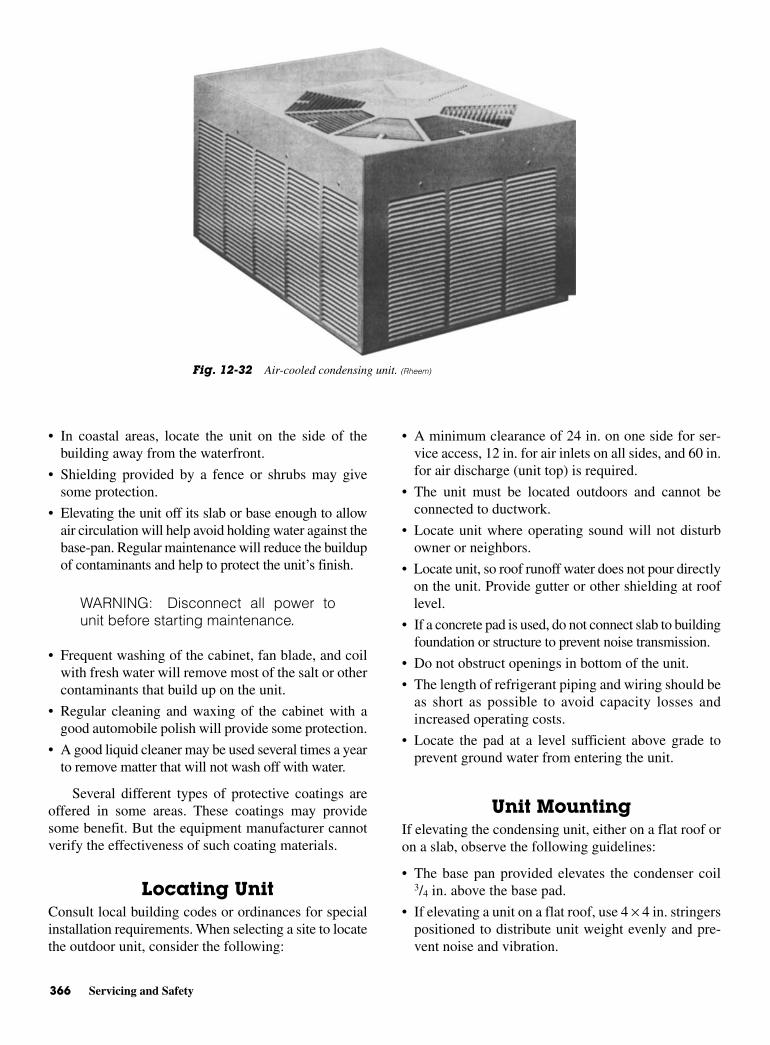
366 Servicing and Safety
• In coastal areas, locate the unit on the side of thebuilding away from the waterfront.
• Shielding provided by a fence or shrubs may givesome protection.
• Elevating the unit off its slab or base enough to allowair circulation will help avoid holding water against thebase-pan. Regular maintenance will reduce the buildupof contaminants and help to protect the unit’s finish.
WARNING: Disconnect all power tounit before starting maintenance.
• Frequent washing of the cabinet, fan blade, and coilwith fresh water will remove most of the salt or othercontaminants that build up on the unit.
• Regular cleaning and waxing of the cabinet with agood automobile polish will provide some protection.
• A good liquid cleaner may be used several times a yearto remove matter that will not wash off with water.
Several different types of protective coatings areoffered in some areas. These coatings may providesome benefit. But the equipment manufacturer cannotverify the effectiveness of such coating materials.
Locating UnitConsult local building codes or ordinances for specialinstallation requirements. When selecting a site to locatethe outdoor unit, consider the following:
• A minimum clearance of 24 in. on one side for ser-vice access, 12 in. for air inlets on all sides, and 60 in.for air discharge (unit top) is required.
• The unit must be located outdoors and cannot beconnected to ductwork.
• Locate unit where operating sound will not disturbowner or neighbors.
• Locate unit, so roof runoff water does not pour directlyon the unit. Provide gutter or other shielding at rooflevel.
• If a concrete pad is used, do not connect slab to buildingfoundation or structure to prevent noise transmission.
• Do not obstruct openings in bottom of the unit.
• The length of refrigerant piping and wiring should beas short as possible to avoid capacity losses andincreased operating costs.
• Locate the pad at a level sufficient above grade toprevent ground water from entering the unit.
Unit MountingIf elevating the condensing unit, either on a flat roof oron a slab, observe the following guidelines:
• The base pan provided elevates the condenser coil3/4 in. above the base pad.
• If elevating a unit on a flat roof, use 4 × 4 in. stringerspositioned to distribute unit weight evenly and pre-vent noise and vibration.
Fig. 12-32 Air-cooled condensing unit. (Rheem)
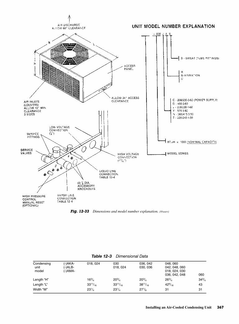
Installing an Air-Cooled Condensing Unit 367
Fig. 12-33 Dimensions and model number explanation. (Rheem)
Table 12-3 Dimensional Data
Condensing (-)AKA- 018, 024 030 036, 042 048, 060unit (-)ALB- 018, 024 030, 036 042, 048, 060model (-)AMA- 018, 024, 030
036, 042, 048 060
Length “H” 163/4 203/4 203/4 263/4 343/4Length “L” 3311/16 3311/16 3811/16 429/18 43
Width “W” 231/4 231/4 271/8 31 31
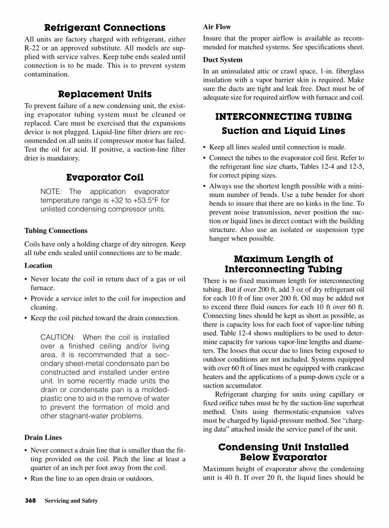
368 Servicing and Safety
Refrigerant ConnectionsAll units are factory charged with refrigerant, eitherR-22 or an approved substitute. All models are sup-plied with service valves. Keep tube ends sealed untilconnection is to be made. This is to prevent systemcontamination.
Replacement UnitsTo prevent failure of a new condensing unit, the exist-ing evaporator tubing system must be cleaned orreplaced. Care must be exercised that the expansionsdevice is not plugged. Liquid-line filter driers are rec-ommended on all units if compressor motor has failed.Test the oil for acid. If positive, a suction-line filterdrier is mandatory.
Evaporator CoilNOTE: The application evaporatortemperature range is +32 to +53.5°F forunlisted condensing compressor units.
Tubing Connections
Coils have only a holding charge of dry nitrogen. Keepall tube ends sealed until connections are to be made.
Location
• Never locate the coil in return duct of a gas or oilfurnace.
• Provide a service inlet to the coil for inspection andcleaning.
• Keep the coil pitched toward the drain connection.
CAUTION: When the coil is installedover a finished ceiling and/or livingarea, it is recommended that a sec-ondary sheet-metal condensate pan beconstructed and installed under entireunit. In some recently made units thedrain or condensate pan is a molded-plastic one to aid in the remove of waterto prevent the formation of mold andother stagnant-water problems.
Drain Lines
• Never connect a drain line that is smaller than the fit-ting provided on the coil. Pitch the line at least aquarter of an inch per foot away from the coil.
• Run the line to an open drain or outdoors.
Air Flow
Insure that the proper airflow is available as recom-mended for matched systems. See specifications sheet.
Duct System
In an uninsulated attic or crawl space, 1-in. fiberglassinsulation with a vapor barrier skin is required. Makesure the ducts are tight and leak free. Duct must be ofadequate size for required airflow with furnace and coil.
INTERCONNECTING TUBING
Suction and Liquid Lines
• Keep all lines sealed until connection is made.
• Connect the tubes to the evaporator coil first. Refer tothe refrigerant line size charts, Tables 12-4 and 12-5,for correct piping sizes.
• Always use the shortest length possible with a mini-mum number of bends. Use a tube bender for shortbends to insure that there are no kinks in the line. Toprevent noise transmission, never position the suc-tion or liquid lines in direct contact with the buildingstructure. Also use an isolated or suspension typehanger when possible.
Maximum Length ofInterconnecting Tubing
There is no fixed maximum length for interconnectingtubing. But if over 200 ft, add 3 oz of dry refrigerant oilfor each 10 ft of line over 200 ft. Oil may be added notto exceed three fluid ounces for each 10 ft over 60 ft.Connecting lines should be kept as short as possible, asthere is capacity loss for each foot of vapor-line tubingused. Table 12-4 shows multipliers to be used to deter-mine capacity for various vapor-line lengths and diame-ters. The losses that occur due to lines being exposed tooutdoor conditions are not included. Systems equippedwith over 60 ft of lines must be equipped with crankcaseheaters and the applications of a pump-down cycle or asuction accumulator.
Refrigerant charging for units using capillary orfixed orifice tubes must be by the suction-line superheatmethod. Units using thermostatic-expansion valvesmust be charged by liquid-pressure method. See “charg-ing data” attached inside the service panel of the unit.
Condensing Unit InstalledBelow Evaporator
Maximum height of evaporator above the condensingunit is 40 ft. If over 20 ft, the liquid lines should be
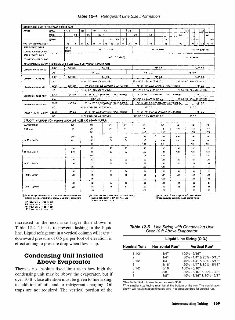
Interconnecting Tubing 369
increased to the next size larger than shown inTable 12-4. This is to prevent flashing in the liquidline. Liquid refrigerant in a vertical column will exert adownward pressure of 0.5 psi per foot of elevation, ineffect adding to pressure drop when flow is up.
Condensing Unit InstalledAbove Evaporator
There is no absolute fixed limit as to how high thecondensing unit may be above the evaporator, but ifover 10 ft, close attention must be given to line sizing,to addition of oil, and to refrigerant charging. Oiltraps are not required. The vertical portion of the
Table 12-4 Refrigerant Line Size Information
Table 12-5 Line Sizing with Condensing UnitOver 10 ft Above Evaporator
Liquid Line Sizing (O.D.)
Nominal Tons Horizontal Run* Vertical Run†
1·1/2 1/4′′ 100% · 3/16′′2 1/4′′ 80% · 1/4′′ & 20% · 5/16′′2.1/2 1/4′′ 40% · 1/4′′ & 60% · 5/16′′3 5/16′′ 20% · 1/4′′ & 80% · 5/16′′3.1/2 5/16′′ 100% · 5/16′′4 3/8′′ 80% · 5/16′′ & 20% · 3/8′′5 3/8′′ 40% · 5/16′′ & 60% · 3/8′′
*See Table 12-4 if horizontal run exceeds 30 ft.†The smaller size tubing must be at the bottom of the run. The combinationshown will result in approximately zero net pressure drop for vertical run.
370 Servicing and Safety
liquid line must be sized, as shown in Table 12-5, foruse with flow checks and expansion-valve coils.Erratic operating pressure can result if piping is notproperly sized.
TUBING INSTALLATIONObserve the following when installing refrigerant tub-ing between the condensing unit and evaporator coil:
• Use clean, dehydrated, sealed refrigeration grade tub-ing.
• Always keep tubing sealed until tubing is in placeand connections are to be made.
• If there is any question as to how clean the liquid andvapor lines are, blow out with dry nitrogen beforeconnecting to the outdoor unit and indoor coil. Anydebris in the line set will end up plugging the expan-sion device.
• As an added precaution, you may install a good filterdrier in the liquid line.
• Vapor line and liquid line must not be in contact witheach other. The vapor line must be insulated.
• If tubing has been cut, make sure ends are deburredwhile holding in a position to prevent chips fromfalling into tubing. Burrs such as those caused bytubing cutters can affect performance dramatically,particularly on small liquid-line sizes.
• For best operation, keep tubing run as short as possi-ble with a minimum number of elbows or bends.
• Locations where the tubing will be exposed tomechanical damage should be avoided. If it is neces-sary to use such locations, copper tubing should behoused to prevent damage.
• If tubing is to be run underground, it must be run in asealed watertight chase.
• Use care in routing tubing and do not kink or twist.Use a good tubing bender on the vapor line to preventkinking.
• Route the tubing using temporary hangers, thenstraighten the tubing and install permanent hangers.Line must be adequately supported.
• The vapor line must be insulated to prevent drip-ping, sweating, and prevent performance losses.Rubatex and Armaflex are satisfactory insulationsfor this purpose. Use minimum 1/2 in. insulationthickness, additional insulation may be required forlong runs.
• Check Table 12-4 for correct liquid and vapor-linesizing for condensing unit size and length of run.
TUBING CONNECTIONS
• Be certain both refrigerant service valves at the con-densing unit are closed (turn fully clockwise).
• All lines should be assembled with type “L” refriger-ant tubing and not with copper water pipe. Theyshould be brazed with the following alloys:
• Copper to copper—5 percent silver alloy (no flux)
• Copper to steel or brass—35 percent silver alloy(no flux)
• Clean the inside of fittings and the outside of the tub-ing with steel wool or sand cloth before soldering.Always keep chips, steel wool, dirt, and the like, out ofthe inside when cleaning. Assemble tubing part wayinto fitting. Apply flux all around the outside of thetubing and push tubing into the stop. This procedurewill keep the flux from getting inside the system.
• Remove cap and Schrader core from service port toprotect seals from heat damage.
• Wrap service valves with a wet rag. Before applyingheat, to braze the tubing between outdoor unit andindoor coil. Flow dry nitrogen into a service port andthrough the tubing while brazing.
LEAK TESTING
• Pressurize line set and coil through service fittingswith dry nitrogen to 150 psig maximum. Leak test alljoints using liquid detergent. If a leak is found, recoverpressure and repair.
WARNING: Do not use oxygen topurge lines of pressure system for leaktest. Oxygen reacts violently with oil,which can cause an explosion resultingin severe personal injury or death.
• The indoor coil and tubing of sweat-type units mustbe evacuated before operating unit. See evacuationprocedure.
• The brass valve is not a back-seating valve. Openingor closing valve does not close service port.
NOTE: 3/16 and 5/16 in. Allen wrenchesare required for brass-service valves.Extreme caution must be exercised notto force valve stem against the retain-ing ring when opening the valves. Sys-tem pressure could force the valvestem out of the valve body and possibly

Flow-Check Piston 371
cause personal injury. In the event thatthe retaining ring is missing, do notattempt to open the valve.
FLOW-CHECK PISTONThe flow-check piston is a multipurpose device. Withflow into the compression nut end from the liquid line,the piston acts as the expansion device with flowthrough the metering orifice in the center of the piston.The “O” ring on the end of the piston prevents refriger-ant from bypassing the metering orifice. Flow from themetering orifice is centered into a distributor thatserves to evenly distribute refrigerant to the evaporatorcircuits. See Fig. 12-34.
It is essential that the evaporator and condensingunit be properly matched. Use only matched compo-nents as shown in sales specification sheets. SeeTable 12-6 for the appropriate piston size for the evap-orator and condensing-unit combination.
A piston size that is too small will cause starvingand one that is too large will cause flooding. In anycase, system performance and reliability will be unac-ceptable.
If a combination is used that requires a piston-sizechange (see Table 12-7), the combination cannot beused without changing to the correct size piston.
Change the piston in the distributor on the evapo-rator before installing the coil and charging the systemfollowing the procedure shown:
• Using a back-up wrench on the distributor body, loosenthe compression nut to gain access to the piston.
• Using the wire provided with replacement pistons,run (hooked end) through hole in piston.
• Hook nose of piston and lift gently from distributorbody.
• Replace piston with one of proper size (see Table 12-6).Install piston with gasket end of piston in distributor.Do not force piston into distributor.
NOTE: With piston in distributor, sealend should be down and should not beseen looking in end of distributor. Pis-tons must be free to rotate and move upand down. Make sure piston is free tomove in distributor body.
• Insure that distributor gasket is located properly inthe distributor body.
• Replace compression nut using back-up wrench ondistributor body. Torque compression nut with 8 to10 lb/ft.
• Original piston size is stamped on outside of distrib-utor body. Remove the new piston-size label from itspoly bag. The new piston comes in the plastic bag.Install the new size label on the outside of the dis-tributor tube.
• Check fittings for leaks after installation, evacuation,and charging are complete.
CAUTION: Do not attempt to drill pis-tons to size in the field. Metering holeshave a special champhered inlet and
Fig. 12-34 Base pan. (Rheem)
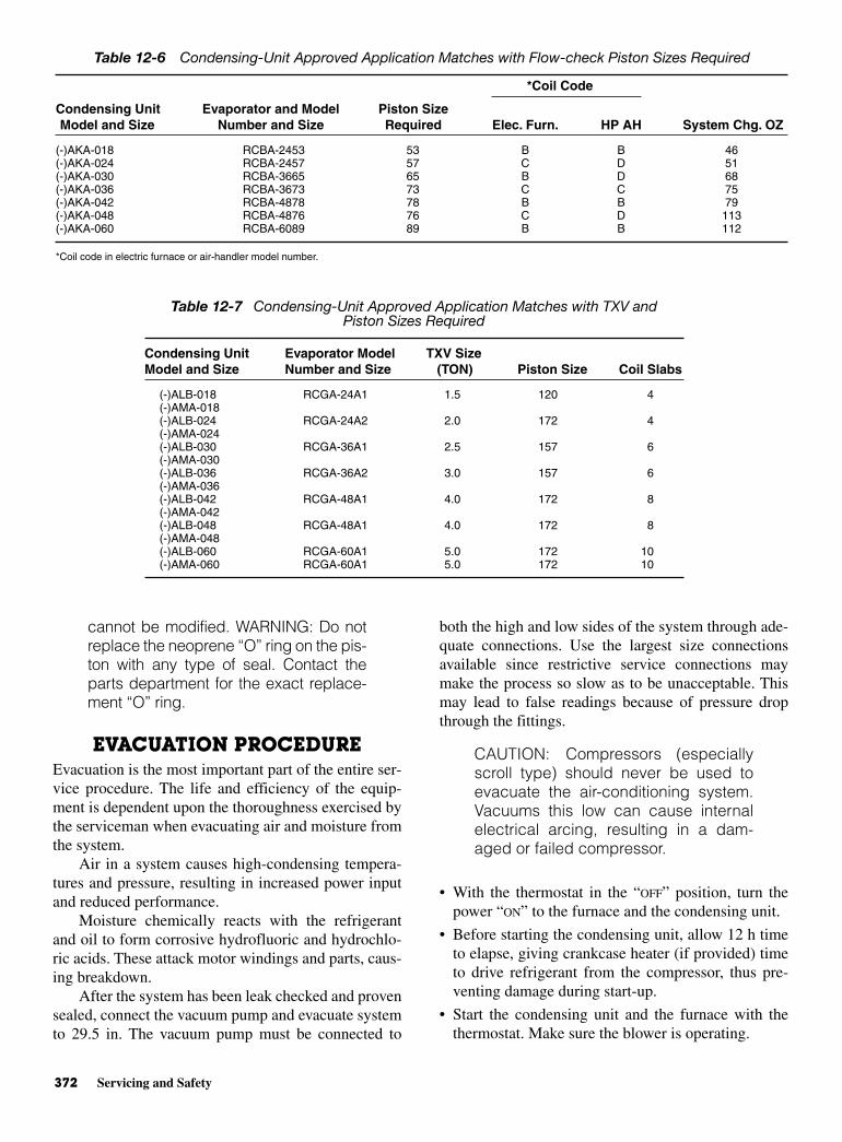
372 Servicing and Safety
cannot be modified. WARNING: Do notreplace the neoprene “O” ring on the pis-ton with any type of seal. Contact theparts department for the exact replace-ment “O” ring.
EVACUATION PROCEDUREEvacuation is the most important part of the entire ser-vice procedure. The life and efficiency of the equip-ment is dependent upon the thoroughness exercised bythe serviceman when evacuating air and moisture fromthe system.
Air in a system causes high-condensing tempera-tures and pressure, resulting in increased power inputand reduced performance.
Moisture chemically reacts with the refrigerantand oil to form corrosive hydrofluoric and hydrochlo-ric acids. These attack motor windings and parts, caus-ing breakdown.
After the system has been leak checked and provensealed, connect the vacuum pump and evacuate systemto 29.5 in. The vacuum pump must be connected to
both the high and low sides of the system through ade-quate connections. Use the largest size connectionsavailable since restrictive service connections maymake the process so slow as to be unacceptable. Thismay lead to false readings because of pressure dropthrough the fittings.
CAUTION: Compressors (especiallyscroll type) should never be used toevacuate the air-conditioning system.Vacuums this low can cause internalelectrical arcing, resulting in a dam-aged or failed compressor.
• With the thermostat in the “OFF” position, turn thepower “ON” to the furnace and the condensing unit.
• Before starting the condensing unit, allow 12 h timeto elapse, giving crankcase heater (if provided) timeto drive refrigerant from the compressor, thus pre-venting damage during start-up.
• Start the condensing unit and the furnace with thethermostat. Make sure the blower is operating.
Table 12-6 Condensing-Unit Approved Application Matches with Flow-check Piston Sizes Required
*Coil Code
Condensing Unit Evaporator and Model Piston SizeModel and Size Number and Size Required Elec. Furn. HP AH System Chg. OZ
(-)AKA-018 RCBA-2453 53 B B 46(-)AKA-024 RCBA-2457 57 C D 51(-)AKA-030 RCBA-3665 65 B D 68(-)AKA-036 RCBA-3673 73 C C 75(-)AKA-042 RCBA-4878 78 B B 79(-)AKA-048 RCBA-4876 76 C D 113(-)AKA-060 RCBA-6089 89 B B 112
*Coil code in electric furnace or air-handler model number.
Table 12-7 Condensing-Unit Approved Application Matches with TXV andPiston Sizes Required
Condensing Unit Evaporator Model TXV SizeModel and Size Number and Size (TON) Piston Size Coil Slabs
(-)ALB-018 RCGA-24A1 1.5 120 4(-)AMA-018(-)ALB-024 RCGA-24A2 2.0 172 4(-)AMA-024(-)ALB-030 RCGA-36A1 2.5 157 6(-)AMA-030(-)ALB-036 RCGA-36A2 3.0 157 6(-)AMA-036(-)ALB-042 RCGA-48A1 4.0 172 8(-)AMA-042(-)ALB-048 RCGA-48A1 4.0 172 8(-)AMA-048(-)ALB-060 RCGA-60A1 5.0 172 10(-)AMA-060 RCGA-60A1 5.0 172 10
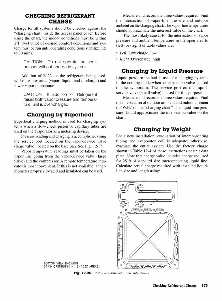
Checking Refrigerant Charge 373
CHECKING REFRIGERANTCHARGE
Charge for all systems should be checked against the“charging chart” inside the access panel cover. Beforeusing the chart, the indoor conditions must be within2°F (wet bulb) of desired comfort conditions and sys-tem must be run until operating conditions stabilize (15to 30 min).
CAUTION: Do not operate the com-pressor without charge in system.
Addition of R-22, or the refrigerant being used,will raise pressures (vapor, liquid, and discharge) andlower vapor temperature.
CAUTION: If addition of Refrigerantraises both vapor pressure and tempera-ture, unit is over-charged.
Charging by SuperheatSuperheat charging method is used for charging sys-tems when a flow-check piston or capillary tubes areused on the evaporator as a metering device.
Pressure reading and charging is accomplished usingthe service port located on the vapor-service valve(large valve) located on the base pan. See Fig. 12-35.
Vapor temperature readings must be taken on thevapor line going from the vapor-service valve (largevalve) and the compressor. A remote temperature indi-cator is most convenient. If this is not available, a ther-mometer properly located and insulated can be used.
Measure and record the three values required. Findthe intersection of vapor-line pressure and outdoorambient on the charging chart. The vapor-line temperatureshould approximate the intersect value on the chart.
The most likely causes for the intersection of vaporpressure and ambient temperature in the open area to(left) or (right) of table values are:
• Left. Low charge, low
• Right. Overcharge, high
Charging by Liquid PressureLiquid-pressure method is used for charging systemsin the cooling mode when an expansion valve is usedon the evaporator. The service port on the liquid-service valve (small valve) is used for this purpose.
Measure and record the three values required. Findthe intersection of outdoor ambient and indoor ambient(°F W.B.) on the “charging chart.” The liquid-line pres-sure should approximate the intersection value on thechart.
Charging by WeightFor a new installation, evacuation of interconnectingtubing and evaporator coil is adequate; otherwise,evacuate the entire system. Use the factory chargeshown in Table 12-4 of these instructions or unit dataplate. Note that charge value includes charge requiredfor 25 ft of standard size interconnecting liquid line.Calculate actual charge required with installed liquid-line size and length using:
Fig. 12-35 Piston and distributor assembly. (Rheem)
374 Servicing and Safety
• 1/4 in. OD = 0.6 oz/ft
• 5/16 in. OD = 0.4 oz/ft
• 3/8 in. OD = 0.6 oz/ft
• 1/2 in. OD = 1.2 oz/ft
With an accurate scale (±1 oz) or volumetric charg-ing device, adjust charge difference between thatshown on the unit data plate and that calculated for thenew installation. If the entire system has been evacu-ated, add the total calculated charge.
FINAL LEAK TESTINGAfter the unit has been properly evacuated and charged,a halogen leak detector should be used to detect leaks inthe system. All piping within the condensing unit, evap-orator, and interconnecting tubing should be checked forleaks. If a leak is detected, the refrigerant should berecovered before repairing the leak. The Clean Air Actprohibits releasing refrigerant into the atmosphere.
SERVICEOperation
Most single-phase units are operated PSC (no startingcomponents). It is important that such systems be off fora minimum of 5 min before restarting to allow equaliza-tion of pressure. The thermostat should not be moved tocycle unit without waiting 5 min. To do so may cause thecompressor to go off on an automatic overload device orblow a fuse. Poor electrical service can also cause nui-sance tripping on overloads or blow fuses. This gener-ally can be corrected by adding start components. Checkwith factory for recommended start components, ifrequired. For PSC type operation, refrigerant meteringmust be done with fixed orifice, cap tubes, or bleed typeexpansion valves because of low-starting torque. If non-bleed expansion valve coils (supplied by factory) areused, start components are required.
Single-Pole CompressorContactor (CC)
Single-pole contactors are used on all standard single-phase units through 5 tons. Caution must be exercisedwhen servicing, as only one leg of the power supply isbroken with the contactor. Two pole contactors areused on some three-phase units.
Compressor CrankcaseHeat (CCH)
All heaters are located on the lower half of the com-pressor shell. Its purpose is to drive refrigerant from
the compressor shell during long off-cycles, thus pre-venting damage to the compressor during starting.
At initial start-up or after extended shutdown peri-ods, make sure the heater is energized for at least 12 hbefore the compressor is started. (Disconnect switch isON and wall thermostat is OFF.)
NOTE: Crankcase heaters are notrequired for scroll compressors.
Hard Start Components(SC and SR)
They are available through parts department only. Thestart component kit includes start capacitor (SC) andstart relay (SR). Start components are required with allnonbleed expansion-valve coils.
NOTE: Start components are notrequired for scroll compressors.
Time Delay Control (TDC)The time delay control (TDC) is in the low-voltagecontrol circuit. When the compressor shuts off due to apower failure or thermostat operation, this controlkeeps it off at least 5 min which allows the system pres-sure to equalize, thus not damaging the compressor orblowing fuses on start-up.
Low Ambient Control (LAC)This component senses compressor head pressure andshuts the condenser fan off when the head pressuredrops to approximately 175 psig. This allows the unitto build a sufficient head pressure at lower ambient inorder to maintain system balance and obtain improvedcapacity. Low ambient control should be used on allequipment operated below 65°F ambient.
High- and Low-PressureControls (HPC or LPC)
These controls keep the compressor from operating inpressure ranges that can damage it. Both controls are inthe low-voltage control circuit. High-pressure control(HPC) is a manual reset that operates near 450 psig. Donot reset arbitrarily without first determining whatcaused it to function. The low-pressure control (LPC)is an automatic reset that operates near 15 psig and resetsnear 40 psig.
NOTE: High- and low-pressure con-trols may be standard on some models.
Electrical Wiring 375
ELECTRICAL WIRINGField wiring must comply with the National Electric Code(C.E.C. in Canada) and any applicable local ordinance.
Power WiringIt is important that proper electrical power is available atthe condensing-unit contactor. Voltage should not varymore than 10 percent of that stamped on the rating platewhen the unit tries to start. Interphase variation on thethree-phase units must not be more than 3 percent.
Install a branch circuit disconnect within sight ofthe unit and of adequate size to handle the starting cur-rent. See Table 12-8.
For branch circuit wiring (main power supply tounit disconnect), the minimum wire size for the lengthof run can be determined from Table 12-9 using the cir-cuit ampacity found on the unit rating plate. From theunit disconnect to unit, the smallest wire size allowablein Table12-9 should be used.
Power wiring must be run in grounded, rain-tightconduit. Conduit must be run through the connectorpanel below the access cover and attached to the bot-tom of the control box. (See Fig. 12-33.)
Connect power wiring to contactor located in out-door heat pump electrical box. (See wiring diagramattached to unit access panel.)
Check all electrical connections, including factorywiring within the unit and make sure all connectionsare tight.
Do not connect aluminum field wire to the contac-tor terminals.
Special Instruction for Power Wiring with Aluminumconductors
• Select the equivalent aluminum wire size from thefollowing tabulation:
• Attach a length (6 in. or more) of recommended sizecopper wire to the unit contactor terminals L1 and L3for single phase, L2 and L3 for three phase.
• Splice copper wire pigtails to aluminum wire withUnderwriters’ Laboratories (UL) recognized con-nectors for copper-aluminum splices. Follow theseinstructions very carefully to make a positive andlasting connection.
• Strip insulation from the aluminum conductor.
• Coat the stripped end of the aluminum wire with therecommended inhibitor, and wire brush aluminumsurface through inhibitor. Inhibitors: Brundy-Pentex“A,” Alcoa No. 2EJC; T & B-KPOR Shield.
• Clean and recoat aluminum conductor with inhibitor.
• Make the splice using the earlier- listed wire nuts orsplit-bolt connectors.
• Coat the entire connection with inhibitor and wrapwith electrical-insulating tape.
GROUNDING WARNING: The unit mustbe permanently grounded.
A grounding lug is provided near contactor for aground wire. Grounding may be accomplished bygrounding the power wire conduit to the condensing unit.Make sure the conduit nut locking teeth have pierced theinsulating paint film.
Control WiringIf the low-voltage control wiring is run in conduit withthe power supply, Class-I insulation is required. Class-IIinsulation is required if run separate. Low-voltagewiring may be run through the insulated bushing pro-vided in the 7/8-in. hole in the base panel, up to andattached to the pigtails from the bottom of the controlbox. Conduit can be run to the base panel if desired byremoving the insulated bushing.
A thermostat and a 24-V, 20-VA minimum trans-former are required for the control circuit of the condens-ing unit. The furnace or the air-handler transformer may
Table 12-8 Electrical and Physical Data
ConnectorAWG Copper AWG Aluminum Type & SizeWire Size Wire Size (or equivalent)
12 10 T & B Wire Nut PT210 8 T & B Wire Nut PT38 8 Sherman Split Bolt TSP66 4 Sherman Split Bolt TSP44 2 Sherman Split Bolt TSP2
Table 12-9 Copper wire size-AWG
(1% Voltage Drop)
200 6 4 4 4 3 3 2 2150 8 6 6 4 4 4 3 3100 10 8 8 6 6 6 4 450 14 12 10 10 8 8 6 6
15 20 25 30 35 40 45 50Supply-circuit ampacity
Sup
ply
wire
leng
th (
feet
)
376 Servicing and Safety
be used if it has the proper voltage and current available.See the wiring diagram and Table 12-10 for reference.
START-UP AND PERFORMANCEEven though the unit is factory charged with refriger-ant, the charge must be checked. This is done using thecharge table attached to the service panel and adjusted,if required. Allow a minimum of 30 min running. Seethe instructions on the unit service panel for markingthe total charge on the unit rating plate.
TROUBLESHOOTINGA troubleshooting chart is provided in Table 12-11 forchecking the unit before and after it has been installed.Keep in mind that you should disconnect all power tothe unit before servicing.
Table 12-10 Field Wire Sizes for 24-VThermostat Circuits
Solid Copper Wire-Awg.
3.0 16 14 12 10 10 10
2.5 16 14 12 12 10 10
2.0 18 16 14 12 12 10
50 100 150 200 250 300Length of Run-Feet*
*Wire length equals twice the run distance.NOTE: Do not use control wiring smaller than No. 18 AWGbetween thermostat and outdoor unit.
The
rmos
tat L
oad-
Am
ps
Table 12-11 Troubleshooting Chart
Symptom Possible Cause Remedy
High head-low suction a. Restriction in liquid line or a. Remove or replace defective component
capillary tube or filter drier
High head-high a. Dirty condenser coil a. Clean coilor normal suction b. Overcharged b. Correct system charge
c. Condenser fan not running c. Repair or replace
Low head-high suction a. Incorrect capillary tube a. Replace evaporator assemblyb. Defective compressor valves b. Replace compressor
Unit will not run a. Power off or loose electrical connection a. Check for unit voltage at contactor in condensing unit
b. Thermostat out of calibration-set too high b. Resetc. Defective contactor c. Check for 24 volts at contactor coil
replace if contacts are opend. Blown fuses d. Replace fusese. Transformer defective e. Check wiring-replace transformerf. High-pressure control open f. Reset-also see high head pressure remedy.
The high-pressure control opens at 430 PSIg. Compressor overload contacts open g. If external overload-replace OL. If internal
replace compressorNOTE: Wait at least 2 h for overload to reset
Condenser fan runs. a. Run or start capacitor defective a. Replacecompressor does not b. Start relay defective b. Replace
c. Loose connectionc. Check for unit voltage at compressor-check
and tighten all connectionsd. Compressor stuck, grounded or open d. Wait at least 2 h for overload to reset
motor winding, open internal overload. If still open, replace the compressor.e. Low-voltage condition e. Add start kit components
Low suction-cool compressor a. Low-indoor airflow a. Increase speed of blower or reduceIced Evaporator Coil restriction-replace air filter
b. Operating unit at temperatures below 65° b. Add low ambient kitoutdoor temperature.
Compressor short cycles a. Defective overload protector a. Replace-check for correct voltage
Registers sweat a. Low airflow a. Increase speed of furnace blower orreduce restriction replace air filter.
High-suction pressure a. Excessive load a. Recheck load calculation
b. Defective compressor b. Replace
Insufficient cooling a. Improperly sized unit a. Recalculate loadb. Improper airflow b. Check-should be approximately 400 CFM per ton
c. Incorrect refrigerant charge c. Charge per procedure attached to unit service paneld. Incorrect voltage d. At compressor terminals, voltage must be within
10% of nameplate volts when unit is operating
WARNING: Disconnect all power to unit before servicing. Contactor may break only one side of line.

Review Questions 377
REVIEW QUESTIONS1. Why is oxygen not used to pressurize a refrig-
eration system?
2. Why can pressure testing of a refrigeration systembe dangerous?
3. Why should you wear goggles when purging acontaminated system?
4. Why do you not fill a gas cylinder completely full?
5. What is meant by off-cycle crankcase heating?
6. Where is the filter drier located in the liquid line?
7. What is a heat exchanger?
8. What are the four major causes of motor burnouton a compressor?
9. How do you repair the perimeter tube if it developsa break?
10. What is the mullion on a refrigerator cabinet?
11. Why do you not use the bubble method for findinga leak when a vacuum is present?
12. What color of flame indicates a leak with a halidetorch?
13. Why can you get a false reading of a refrigerant leakin a refrigerator when the insulation is urethanefoam?
14. How do you test the potential relay?

This page intentionally left blank

13CHAPTER
Freezers
Copyright © 2006 by The McGraw-Hill Companies, Inc. Click here for terms of use.

PERFORMANCE OBJECTIVESAfter studying this chapter you will:
1. Know how to install a chest type or an uprightfreezer.
2. Know how to identify and assemble freezer parts.
3. Know how to select the proper thermostat for arepair job.
4. Know how to troubleshoot freezers: upright models.
5. Know how to troubleshoot freezers: chest models.
6. Know how to work on a portable ice-cream freezer.
Freezers come in a variety of styles and shapes.Much depends on the use to which the freezer is to beput—whether it be for commercial purposes or forhome use. Many homes now have upright and chest-type freezers for convenience in storing meat and fishas well as other foodstuffs. This chapter is concernedwith the operation, maintenance, and repair of bothtypes of freezes, commercial and noncommercial.
TYPES OF FREEZERS There are two types of domestic freezers—the uprightfreezer and the chest-type freezer. The essential partsof the upright freezer are shown in Fig. 13-1.
Notice that the evaporator coils are built into theshelves as part of that unit. This means the shelves arenot adjustable. Notice that the condenser coils (17) inFig. 13-1 are welded to the outside of the cabinet. Thisprevents sweating and aids the dissipation of heat overa large surface. The primary convenience of this type offreezer is that the frozen food is visible, easily arranged,and easily removed.
The chest-type freezer provides a different storagearrangement. See Fig. 13-2. In some instances, the con-denser coils are mounted on the back of the chest-typefreezer.
The electrical diagram for a chest-type freezer isshown in Fig. 13-3. Note that the thermostat controlsthe on-off operation of the compressor. The lightswitch completes the circuit from one side of the power
380 Freezers
Fig. 13-1 The parts of an upright home freezer: 1—polyurethane foam-insulationcabinets, 2—wrap-around steel cabinet, 3—baked-on enamel finish, 4—magnetic-doorseal, 5—key-ejecting lock, 6—bookshelf door storage, 7—slide-out basket, 8—juice-canshelf, 9—steel shelves, 10—fast two-way freezing level, 11—temperature-control knob,12—door stops, 13—interior light, 13— power-on light, 15—defrost water drain, 16—adjustable leveling legs, 17—coils welded to outer walls, 18—sealed compressor, and19. RED.
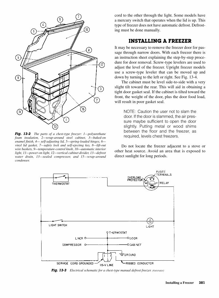
Installing a Freezer 381
cord to the other through the light. Some models havea mercury switch that operates when the lid is up. Thistype of freezer does not have automatic defrost. Defrost-ing must be done manually.
INSTALLING A FREEZER It may be necessary to remove the freezer door for pas-sage through narrow doors. With each freezer there isan instruction sheet explaining the step-by-step proce-dure for door removal. Screw-type levelers are used toadjust the level of the freezer. Upright freezer modelsuse a screw-type leveler that can be moved up anddown by turning to the left or right. See Fig. 13-4.
The cabinet must be level side-to-side with a veryslight tilt toward the rear. This will aid in obtaining atight door gasket seal. If the cabinet is tilted toward thefront, the weight of the door, plus the door food load,will result in poor gasket seal.
NOTE: Caution the user not to slam thedoor. If the door is slammed, the air pres-sure maybe sufficient to open the doorslightly. Putting metal or wood shimsbetween the floor and the freezer, asrequired, levels chest freezers.
Do not locate the freezer adjacent to a stove orother heat source. Avoid an area that is exposed todirect sunlight for long periods.
Fig. 13-2 The parts of a chest-type freezer: 1—polyurethanefoam insulation, 2—wrap-around steel cabinet, 3—baked-onenamel finish, 4— self-adjusting lid, 5—spring-loaded hinges, 6—vinyl lid gasket, 7—safety lock and self-ejecting key, 8—lift-outwire baskets, 9—temperature-control knob, 10—automatic interiorlight, 11—power-on light, 12—vertical cabinet divider, 13—defrostwater drain, 13—sealed compressor, and 15—wrap-aroundcondenser.
Fig. 13-3 Electrical schematic for a chest-type manual defrost freezer. (Kelvinator)
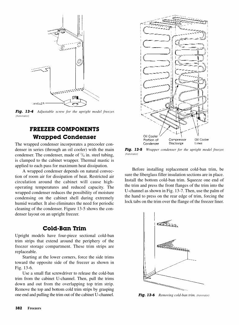
382 Freezers
FREEZER COMPONENTSWrapped Condenser
The wrapped condenser incorporates a precooler con-denser in series (through an oil cooler) with the maincondenser. The condenser, made of 1/4 in. steel tubing,is clamped to the cabinet wrapper. Thermal mastic isapplied to each pass for maximum heat dissipation.
A wrapped condenser depends on natural convec-tion of room air for dissipation of heat. Restricted aircirculation around the cabinet will cause high-operating temperatures and reduced capacity. Thewrapped condenser reduces the possibility of moisturecondensing on the cabinet shell during extremelyhumid weather. It also eliminates the need for periodiccleaning of the condenser. Figure 13-5 shows the con-denser layout on an upright freezer.
Cold-Ban Trim Upright models have four-piece sectional cold-bantrim strips that extend around the periphery of thefreezer storage compartment. These trim strips arereplaceable.
Starting at the lower corners, force the side trimstoward the opposite side of the freezer as shown inFig. 13-6.
Use a small flat screwdriver to release the cold-bantrim from the cabinet U-channel. Then, pull the trimsdown and out from the overlapping top trim strip.Remove the top and bottom cold trim strips by graspingone end and pulling the trim out of the cabinet U-channel.
Before installing replacement cold-ban trim, besure the fiberglass filler insulation sections are in place.Install the bottom cold-ban trim. Squeeze one end ofthe trim and press the front flanges of the trim into theU-channel as shown in Fig. 13-7. Then, use the palm ofthe hand to press on the rear edge of trim, forcing thelock tabs on the trim over the flange of the freezer liner.
Fig. 13-5 Wrapper condenser for the upright model freezer.(Kelvinator)
Fig. 13-4 Adjustable screw for the upright model freezer.(Kelvinator)
Fig. 13-6 Removing cold-ban trim. (Kelvinator)
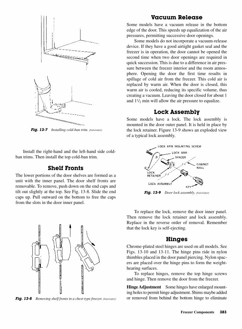
Freezer Components 383
Install the right-hand and the left-hand side cold-ban trims. Then install the top cold-ban trim.
Shelf FrontsThe lower portions of the door shelves are formed as aunit with the inner panel. The door shelf fronts areremovable. To remove, push down on the end caps andtilt out slightly at the top. See Fig. 13-8. Slide the endcaps up. Pull outward on the bottom to free the capsfrom the slots in the door inner panel.
Vacuum ReleaseSome models have a vacuum release in the bottomedge of the door. This speeds up equalization of the airpressures, permitting successive door openings.
Some models do not incorporate a vacuum-releasedevice. If they have a good airtight gasket seal and thefreezer is in operation, the door cannot be opened thesecond time when two door openings are required inquick succession. This is due to a difference in air pres-sure between the freezer interior and the room atmos-phere. Opening the door the first time results inspillage of cold air from the freezer. This cold air isreplaced by warm air. When the door is closed, thiswarm air is cooled, reducing its specific volume, thuscreating a vacuum. Leaving the door closed for about 1and 11/2 min will allow the air pressure to equalize.
Lock AssemblySome models have a lock. The lock assembly ismounted in the door outer panel. It is held in place bythe lock retainer. Figure 13-9 shows an exploded viewof a typical lock assembly.
To replace the lock, remove the door inner panel.Then remove the lock retainer and lock assembly.Replace in the reverse order of removal. Rememberthat the lock key is self-ejecting.
HingesChrome-plated steel hinges are used on all models. SeeFigs. 13-10 and 13-11. The hinge pins ride in nylonthimbles placed in the door panel piercing. Nylon spac-ers are placed over the hinge pins to form the weight-hearing surfaces.
To replace hinges, remove the top hinge screwsand hinge. Then remove the door from the freezer.
Hinge Adjustment Some hinges have enlarged mount-ing holes to permit hinge adjustment. Shims maybe addedor removed from behind the bottom hinge to eliminate
Fig. 13-7 Installing cold-ban trim. (Kelvinator)
Fig. 13-8 Removing shelf fronts in a chest-type freezer. (Kelvinator)
Fig. 13-9 Door lock assembly. (Kelvinator)
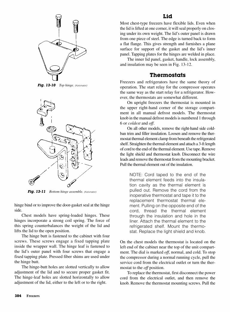
384 Freezers
hinge bind or to improve the door-gasket seal at the hingeside.
Chest models have spring-loaded hinges. Thesehinges incorporate a strong coil spring. The force ofthis spring counterbalances the weight of the lid andlifts the lid to the open position.
The hinge butt is fastened to the cabinet with fourscrews. These screws engage a fixed tapping plateinside the wrapper wall. The hinge leaf is fastened tothe lid’s outer panel with four screws that engage afixed tapping plate. Pressed fiber shims are used underthe hinge butt.
The hinge-butt holes are slotted vertically to allowadjustment of the lid and to secure proper gasket fit.The hinge-leaf holes are slotted horizontally to allowadjustment of the lid, either to the left or to the right.
LidMost chest-type freezers have flexible lids. Even whenthe lid is lifted at one corner, it will seal properly on clos-ing under its own weight. The lid’s outer panel is drawnfrom one piece of steel. The edge is turned back to forma flat flange. This gives strength and furnishes a planesurface for support of the gasket and the lid’s innerpanel. Tapping plates for the hinges are welded in place.
The inner lid panel, gasket, handle, lock assembly,and insulation may be seen in Fig. 13-12.
ThermostatsFreezers and refrigerators have the same theory ofoperation. The start relay for the compressor operatesthe same way as the start relay for a refrigerator. How-ever, the thermostats are somewhat different.
On upright freezers the thermostat is mounted inthe upper right-hand corner of the storage compart-ment in all manual defrost models. The thermostatknob in the manual defrost models is numbered 1 through6 or coldest and off.
On all other models, remove the right-hand side cold-ban trim and filler insulation. Loosen and remove the ther-mostat thermal element clamp from beneath the refrigeratedshelf. Straighten the thermal element and attach a 3-ft lengthof cord to the end of the thermal element. Use tape. Removethe light shield and thermostat knob. Disconnect the wireleads and remove the thermostat from the mounting bracket.Pull the thermal element out of the insulation.
NOTE: Cord taped to the end of thethermal element feeds into the insula-tion cavity as the thermal element ispulled out. Remove the cord from theinoperative thermostat and tape it to thereplacement thermostat thermal ele-ment. Pulling on the opposite end of thecord, thread the thermal elementthrough the insulation and hole in theliner. Attach the thermal element to therefrigerated shelf. Mount the thermo-stat. Replace the light shield and knob.
On the chest models the thermostat is located on theleft end of the cabinet near the top of the unit compart-ment. The dial is marked off, normal, and cold. To stopthe compressor during a normal running cycle, pull theservice cord from the electrical outlet or turn the ther-mostat to the off position.
To replace the thermostat, first disconnect the powercord from the electrical outlet, and then remove theknob. Remove the thermostat mounting screws. Pull the
Fig. 13-10 Top hinge. (Kelvinator)
Fig. 13-11 Bottom hinge assemble. (Kelvinator)
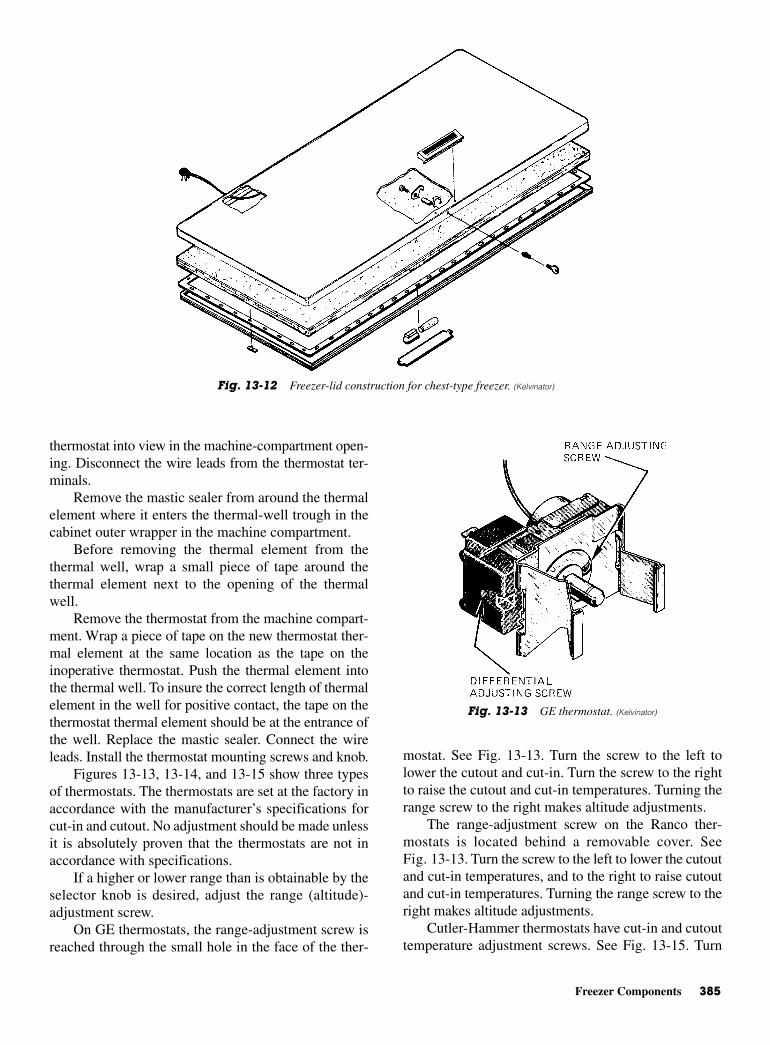
Freezer Components 385
thermostat into view in the machine-compartment open-ing. Disconnect the wire leads from the thermostat ter-minals.
Remove the mastic sealer from around the thermalelement where it enters the thermal-well trough in thecabinet outer wrapper in the machine compartment.
Before removing the thermal element from thethermal well, wrap a small piece of tape around thethermal element next to the opening of the thermalwell.
Remove the thermostat from the machine compart-ment. Wrap a piece of tape on the new thermostat ther-mal element at the same location as the tape on theinoperative thermostat. Push the thermal element intothe thermal well. To insure the correct length of thermalelement in the well for positive contact, the tape on thethermostat thermal element should be at the entrance ofthe well. Replace the mastic sealer. Connect the wireleads. Install the thermostat mounting screws and knob.
Figures 13-13, 13-14, and 13-15 show three typesof thermostats. The thermostats are set at the factory inaccordance with the manufacturer’s specifications forcut-in and cutout. No adjustment should be made unlessit is absolutely proven that the thermostats are not inaccordance with specifications.
If a higher or lower range than is obtainable by theselector knob is desired, adjust the range (altitude)-adjustment screw.
On GE thermostats, the range-adjustment screw isreached through the small hole in the face of the ther-
mostat. See Fig. 13-13. Turn the screw to the left tolower the cutout and cut-in. Turn the screw to the rightto raise the cutout and cut-in temperatures. Turning therange screw to the right makes altitude adjustments.
The range-adjustment screw on the Ranco ther-mostats is located behind a removable cover. SeeFig. 13-13. Turn the screw to the left to lower the cutoutand cut-in temperatures, and to the right to raise cutoutand cut-in temperatures. Turning the range screw to theright makes altitude adjustments.
Cutler-Hammer thermostats have cut-in and cutouttemperature adjustment screws. See Fig. 13-15. Turn
Fig. 13-12 Freezer-lid construction for chest-type freezer. (Kelvinator)
Fig. 13-13 GE thermostat. (Kelvinator)

386 Freezers
the screws to the left to raise the cutout and cut-in tem-peratures and to the right to lower the cut-in and cutouttemperatures.
Both cutout and cut-in screws must be adjustedcounterclockwise to compensate for altitudes above1000 ft.
Drain System Manual defrost models have a defrost water drain andtube assembly for draining defrost water into a shallowpan. The drain tube is located behind the removablefront grille. See Fig. 13-16.
Chest models must be defrosted manually. A drainand tube assembly is located in the bottom left-handcorner of the storage compartment. See Fig. 13-17.
Remove the drain plug from the inside bottom ofthe compartment. Place a shallow pan under the draintube in front of the freezer and remove the cap. Analternate method is to insert a male garden hoseadapter into the drain tube and attach a garden hose.Remove the hose and adapter when defrosting is com-pleted. Replace the drain plug and cap.
Wrapper CondenserAll compressors have internal spring suspension withfour point external mounting. The compressors haveplug-in magnetic starting relays. These mount directlyover the compressor Fusite terminal assembly and aseparate motor overload protector.
The wrapper condenser incorporates a precoolercondenser in series with the main condenser. A wrap-per condenser depends on the natural convection of theroom air for dissipation of heat.
The high-temperature, high-pressure dischargerefrigerant vapor is pumped into the precooler con-denser. This is located on the back wall of the freezerwhere it releases part of its latent heat of vaporizationand sensible heat of compression. From the precoolercondenser, the refrigerant passes back to the machinecompartment and through the cooler coil in the com-pressor dome (where additional heat is picked up fromthe oil). It then passes back to the main condenser,where additional heat is released to the atmosphere.This results in condensation of the refrigerant from thehigh-pressure vapor to the high-pressure liquid.
Ample condenser area is provided to keep the sur-face temperature of the cabinet only 10 to 15°F (5.5 to8.3°C) above room temperatures. Heat released by thecondenser helps reduce the possibility of moisturecondensation on the cabinet surface in humid areas. Thewrapper-type condenser eliminates service calls causedby plugged or dirty condensers. For the life of the
Fig. 13-14 Ranco thermostat. (Kelvinator)
Fig. 13-15 Cutler-Hammer thermostat. (Kelvinator)
Fig. 13-16 Drain system for manual-defrost model uprightfreezer. (Kelvinator)
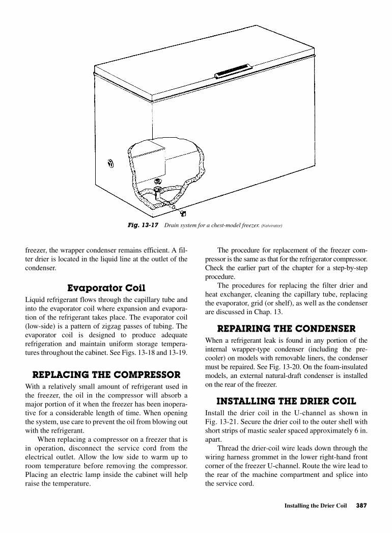
Installing the Drier Coil 387
freezer, the wrapper condenser remains efficient. A fil-ter drier is located in the liquid line at the outlet of thecondenser.
Evaporator CoilLiquid refrigerant flows through the capillary tube andinto the evaporator coil where expansion and evapora-tion of the refrigerant takes place. The evaporator coil(low-side) is a pattern of zigzag passes of tubing. Theevaporator coil is designed to produce adequaterefrigeration and maintain uniform storage tempera-tures throughout the cabinet. See Figs. 13-18 and 13-19.
REPLACING THE COMPRESSOR With a relatively small amount of refrigerant used inthe freezer, the oil in the compressor will absorb amajor portion of it when the freezer has been inopera-tive for a considerable length of time. When openingthe system, use care to prevent the oil from blowing outwith the refrigerant.
When replacing a compressor on a freezer that isin operation, disconnect the service cord from theelectrical outlet. Allow the low side to warm up toroom temperature before removing the compressor.Placing an electric lamp inside the cabinet will helpraise the temperature.
The procedure for replacement of the freezer com-pressor is the same as that for the refrigerator compressor.Check the earlier part of the chapter for a step-by-stepprocedure.
The procedures for replacing the filter drier andheat exchanger, cleaning the capillary tube, replacingthe evaporator, grid (or shelf), as well as the condenserare discussed in Chap. 13.
REPAIRING THE CONDENSER When a refrigerant leak is found in any portion of theinternal wrapper-type condenser (including the pre-cooler) on models with removable liners, the condensermust be repaired. See Fig. 13-20. On the foam-insulatedmodels, an external natural-draft condenser is installedon the rear of the freezer.
INSTALLING THE DRIER COIL Install the drier coil in the U-channel as shown inFig. 13-21. Secure the drier coil to the outer shell withshort strips of mastic sealer spaced approximately 6 in.apart.
Thread the drier-coil wire leads down through thewiring harness grommet in the lower right-hand frontcorner of the freezer U-channel. Route the wire lead tothe rear of the machine compartment and splice intothe service cord.
Fig. 13-17 Drain system for a chest-model freezer. (Kelvinator)
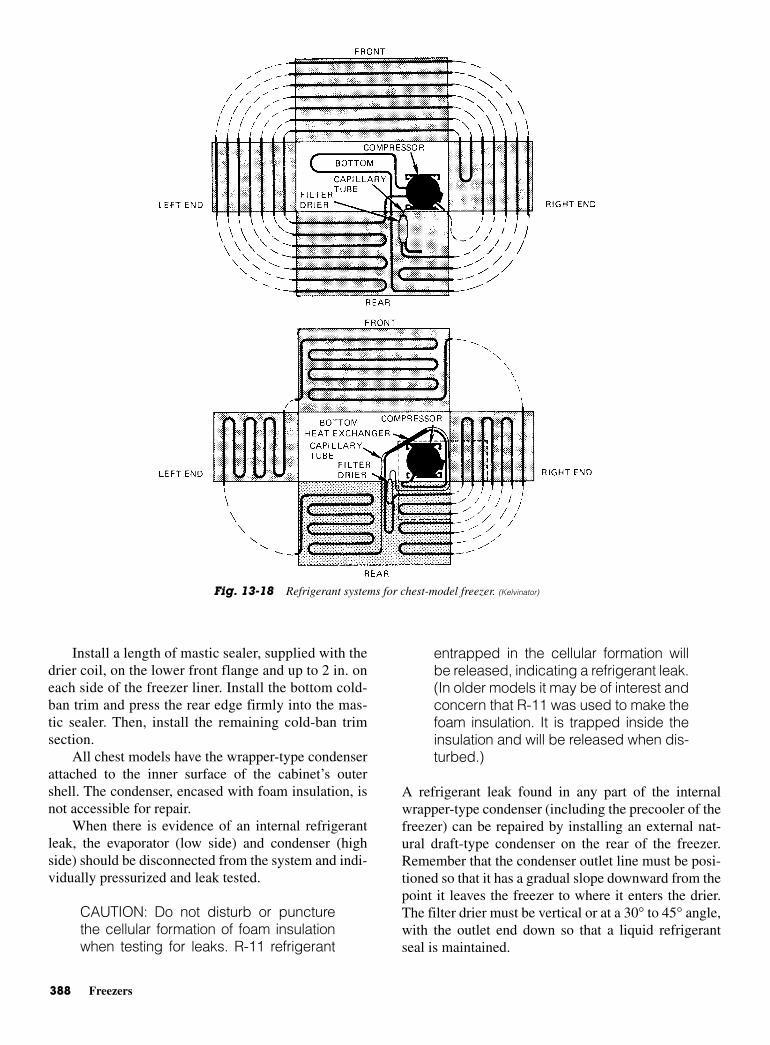
388 Freezers
Install a length of mastic sealer, supplied with thedrier coil, on the lower front flange and up to 2 in. oneach side of the freezer liner. Install the bottom cold-ban trim and press the rear edge firmly into the mas-tic sealer. Then, install the remaining cold-ban trimsection.
All chest models have the wrapper-type condenserattached to the inner surface of the cabinet’s outershell. The condenser, encased with foam insulation, isnot accessible for repair.
When there is evidence of an internal refrigerantleak, the evaporator (low side) and condenser (highside) should be disconnected from the system and indi-vidually pressurized and leak tested.
CAUTION: Do not disturb or puncturethe cellular formation of foam insulationwhen testing for leaks. R-11 refrigerant
entrapped in the cellular formation willbe released, indicating a refrigerant leak.(In older models it may be of interest andconcern that R-11 was used to make thefoam insulation. It is trapped inside theinsulation and will be released when dis-turbed.)
A refrigerant leak found in any part of the internalwrapper-type condenser (including the precooler of thefreezer) can be repaired by installing an external nat-ural draft-type condenser on the rear of the freezer.Remember that the condenser outlet line must be posi-tioned so that it has a gradual slope downward from thepoint it leaves the freezer to where it enters the drier.The filter drier must be vertical or at a 30° to 45° angle,with the outlet end down so that a liquid refrigerantseal is maintained.
Fig. 13-18 Refrigerant systems for chest-model freezer. (Kelvinator)
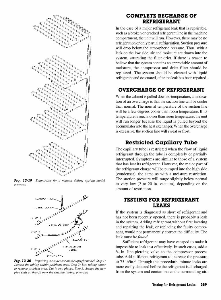
Testing for Refrigerant Leaks 389
COMPLETE RECHARGE OFREFRIGERANT
In the case of a major refrigerant leak that is repairable,such as a broken or cracked refrigerant line in the machinecompartment, the unit will run. However, there may be norefrigeration or only partial refrigeration. Suction pressurewill drop below the atmospheric pressure. Thus, with aleak on the low side, air and moisture are drawn into thesystem, saturating the filter drier. If there is reason tobelieve that the system contains an appreciable amount ofmoisture, the compressor and drier filter should bereplaced. The system should be cleaned with liquidrefrigerant and evacuated, after the leak has been repaired.
OVERCHARGE OF REFRIGERANTWhen the cabinet is pulled down to temperature, an indica-tion of an overcharge is that the suction line will be coolerthan normal. The normal temperature of the suction linewill be a few degrees cooler than room temperature. If itstemperature is much lower than room temperature, the unitwill run longer because the liquid is pulled beyond theaccumulator into the heat exchanger. When the overchargeis excessive, the suction line will sweat or frost.
Restricted Capillary TubeThe capillary tube is restricted when the flow of liquidrefrigerant through the tube is completely or partiallyinterrupted. Symptoms are similar to those of a systemthat has lost its refrigerant. However, the major part ofthe refrigerant charge will be pumped into the high side(condenser), the same as with a moisture restriction.The suction pressure will range slightly below normalto very low (2 to 20 in. vacuum), depending on theamount of restriction.
TESTING FOR REFRIGERANTLEAKS
If the system is diagnosed as short of refrigerant andhas not been recently opened, there is probably a leakin the system. Adding refrigerant without first locatingand repairing the leak, or replacing the faulty compo-nent, would not permanently correct the difficulty. Theleak must be found.
Sufficient refrigerant may have escaped to make itimpossible to leak test effectively. In such cases, add a1/4-in. line-piercing valve to the compressor processtube. Add sufficient refrigerant to increase the pressureto 75 lb/in.2. Through this procedure, minute leaks aremore easily detected before the refrigerant is dischargedfrom the system and contaminates the surrounding air.
Fig. 13-19 Evaporator for a manual defrost upright model.(Kelvinator)
Fig. 13-20 Repairing a condenser on the upright model. Step 1:Loosen the tubing within problems area. Step 2: Use tubing cutterto remove problem area. Cut in two places. Step 3: Swage the newpipe ends so they fit over the existing tubing. (Kelvinator)
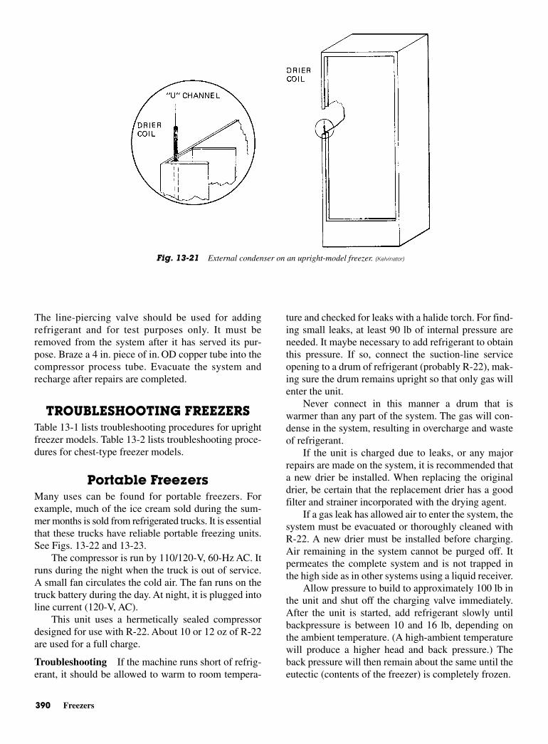
390 Freezers
The line-piercing valve should be used for addingrefrigerant and for test purposes only. It must beremoved from the system after it has served its pur-pose. Braze a 4 in. piece of in. OD copper tube into thecompressor process tube. Evacuate the system andrecharge after repairs are completed.
TROUBLESHOOTING FREEZERS Table 13-1 lists troubleshooting procedures for uprightfreezer models. Table 13-2 lists troubleshooting proce-dures for chest-type freezer models.
Portable FreezersMany uses can be found for portable freezers. Forexample, much of the ice cream sold during the sum-mer months is sold from refrigerated trucks. It is essentialthat these trucks have reliable portable freezing units.See Figs. 13-22 and 13-23.
The compressor is run by 110/120-V, 60-Hz AC. Itruns during the night when the truck is out of service.A small fan circulates the cold air. The fan runs on thetruck battery during the day. At night, it is plugged intoline current (120-V, AC).
This unit uses a hermetically sealed compressordesigned for use with R-22. About 10 or 12 oz of R-22are used for a full charge.
Troubleshooting If the machine runs short of refrig-erant, it should be allowed to warm to room tempera-
ture and checked for leaks with a halide torch. For find-ing small leaks, at least 90 lb of internal pressure areneeded. It maybe necessary to add refrigerant to obtainthis pressure. If so, connect the suction-line serviceopening to a drum of refrigerant (probably R-22), mak-ing sure the drum remains upright so that only gas willenter the unit.
Never connect in this manner a drum that iswarmer than any part of the system. The gas will con-dense in the system, resulting in overcharge and wasteof refrigerant.
If the unit is charged due to leaks, or any majorrepairs are made on the system, it is recommended thata new drier be installed. When replacing the originaldrier, be certain that the replacement drier has a goodfilter and strainer incorporated with the drying agent.
If a gas leak has allowed air to enter the system, thesystem must be evacuated or thoroughly cleaned withR-22. A new drier must be installed before charging.Air remaining in the system cannot be purged off. Itpermeates the complete system and is not trapped inthe high side as in other systems using a liquid receiver.
Allow pressure to build to approximately 100 lb inthe unit and shut off the charging valve immediately.After the unit is started, add refrigerant slowly untilbackpressure is between 10 and 16 lb, depending onthe ambient temperature. (A high-ambient temperaturewill produce a higher head and back pressure.) Theback pressure will then remain about the same until theeutectic (contents of the freezer) is completely frozen.
Fig. 13-21 External condenser on an upright-model freezer. (Kelvinator)
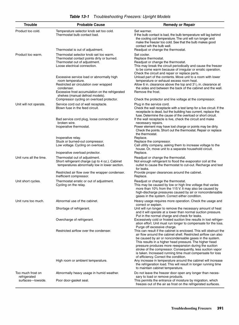
Troubleshooting Freezers 391
Temperature selector knob set too cold.Thermostat bulb contact bad.
Thermostat is out of adjustment.
Thermostat selector knob set too warm.Thermostat contact points dirty or burned.Thermostat out of adjustment.Loose electrical connection.
Excessive service load or abnormally highroom temperature.
Restricted air circulation over wrappedcondenser.
Excessive frost accumulation on the refrigeratedshelves (manual defrost models).
Compressor cycling on overload protector.
Service cord out of wall receptacle.Blown fuse in the feed circuit.
Bad service cord plug, loose connection orbroken wire.
Inoperative thermostat.
Inoperative relay.Stuck or burned-out compressor.Low voltage. Cycling on overload.
Inoperative overload protector.
Thermostat out of adjustment.Short refrigerant charge (up to 4 oz.). Cabinettemperatures abnormally low in lower section.
Restricted air flow over the wrapper condenser.Inefficient compressor.
Thermostat erratic or out of adjustment.Cycling on the relay.
Abnormal use of the cabinet.
Shortage of refrigerant.
Overcharge of refrigerant.
Restricted airflow over the condenser.
High room or ambient temperature.
Abnormally heavy usage in humid weather.
Poor door-gasket seal.
Product too cold.
Product too warm.
Unit will not operate.
Unit runs all the time.
Unit short cycles.
Unit runs too much.
Too much frost onrefrigeratedsurfaces—lowside.
Set warmer.If the bulb contact is bad, the bulb temperature will lag behindthe cooling coil temperature.The unit will run longer and make the freezer too cold. See that the bulb makes goodcontact wih the bulb well.
Readjust or change the thermostat.
Set cooler.Replace thermostat.Readjust or change the thermostat.This may break the circuit periodically and cause the freezerto be come warm because of irregular or erratic operation.
Check the circuit and repair or replace parts.Unload part of the contents. Move unit to a room with lowertemperature or exhaust excess room heat.
Allow 6 in. clearance above the top and 31/2 in. clearance atthe sides and between the back of the cabinet and the wall.
Remove the frost.
Check the protector and line voltage at the compressor.
Plug in the service cord.Check the wall receptacle with a test lamp for a live circuit. If thereceptacle is dead, but the building has current, replace thefuse. Determine the cause of the overload or short circuit.
If the wall receptacle is live, check the circuit and makenecessary repairs.
Power element may have lost charge or points may be dirty.Check the points. Short out the thermostat. Repair or replacethe thermostat.
Replace.Replace the compressor.Call utility company, asking them to increase voltage to thehouse. Or, move unit to a separate household circuit.
Replace.
Readjust or change the thermostat.Not enough refrigerant to flood the evaporator coil at theoutlet to cause the thermostat to cut-out. Recharge and testfor leaks.
Provide proper clearances around the cabinet.Replace.
Readjust or change the thermostat.This may be caused by low or high line voltage that variesmore than 10% from the 115 V. It may also be caused byhigh-discharge pressures caused by air or noncondensablegases in the system. Correct either condition.
Heavy usage requires more operation. Check the usage andcorrect or explain.
Unit will run longer to remove the necessary amount of heatand it will operate at a lower than normal suction pressure.Put in the normal charge and check for leaks.
Excessively cold or frosted suction line results in lost refriger-ation effort. Unit must run longer to compensate for the loss.Purge off excessive charge.
This can result if the cabinet is enclosed. This will obstruct theair flow around the cabinet shell. Restricted airflow can alsobe caused by air or noncondensable gases in the system.This results in a higher head pressure. The higher headpressure produces more reexpansion during the suctionstroke of the compressor. Consequently, less suction vaporis taken. Increased running time must compensate for lossof efficiency. Correct the condition.
Any increase in temperature around the cabinet will increasethe refrigeration load. This will result in longer running timeto maintain cabinet temperature.
Do not leave the freezer door open any longer than neces-sary to load or remove products.
This permits the entrance of moisture by migration, whichfreezes out of the air as frost on the refrigerated surfaces.
Table 13-1 Troubleshooting Freezers: Upright Models
Trouble Probable Cause Remedy or Repair
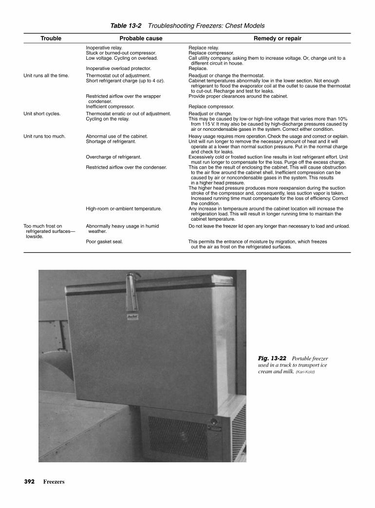
392 Freezers
Table 13-2 Troubleshooting Freezers: Chest Models
Trouble Probable cause Remedy or repair
Inoperative relay. Replace relay.Stuck or burned-out compressor. Replace compressor.Low voltage. Cycling on overlead. Call utility company, asking them to increase voltage. Or, change unit to a
different circuit in house.Inoperative overload protector. Replace.
Unit runs all the time. Thermostat out of adjustment. Readjust or change the thermostat.Short refrigerant charge (up to 4 oz). Cabinet temperatures abnormally low in the lower section. Not enough
refrigerant to flood the evaporator coil at the outlet to cause the thermostatto cut-out. Recharge and test for leaks.
Restricted airflow over the wrapper Provide proper clearances around the cabinet.condenser.
Inefficient compressor. Replace compressor.
Unit short cycles. Thermostat erratic or out of adjustment. Readjust or change.Cycling on the relay. This may be caused by low-or high-line voltage that varies more than 10%
from 115 V. It may also be caused by high-discharge pressures caused byair or noncondensable gases in the system. Correct either condition.
Unit runs too much. Abnormal use of the cabinet. Heavy usage requires more operation. Check the usage and correct or explain.Shortage of refrigerant. Unit will run longer to remove the necessary amount of heat and it will
operate at a lower than normal suction pressure. Put in the normal chargeand check for leaks.
Overcharge of refrigerant. Excessively cold or frosted suction line results in lost refrigerant effort. Unitmust run longer to compensate for the loss. Purge off the excess charge.
Restricted airflow over the condenser. This can be the result of enclosing the cabinet. This will cause obstructionto the air flow around the cabinet shell. Inefficient compression can becaused by air or noncondensable gases in the system. This results in a higher head pressure.
The higher head pressure produces more reexpansion during the suctionstroke of the compressor and, consequently, less suction vapor is taken.Increased running time must compensate for the loss of efficiency. Correctthe condition.
High-room or-ambient temperature. Any increase in temperaure around the cabinet location will increase therefrigeration load. This will result in longer running time to maintain thecabinet temperature.
Too much frost on Abnormally heavy usage in humid Do not leave the freezer lid open any longer than necessary to load and unload.refrigerated surfaces— weather.lowside.
Poor gasket seal. This permits the entrance of moisture by migration, which freezesout the air as frost on the refrigerated surfaces.
Fig. 13-22 Portable freezerused in a truck to transport icecream and milk. (Kari-Kold)
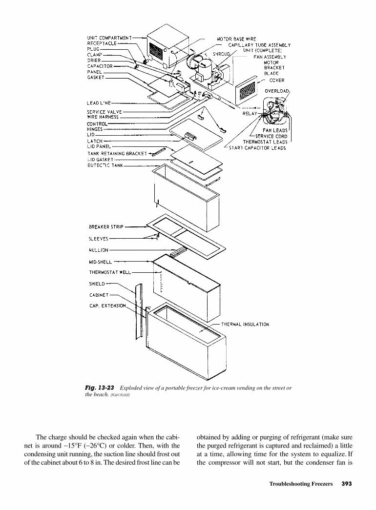
Troubleshooting Freezers 393
The charge should be checked again when the cabi-net is around −15°F (−26°C) or colder. Then, with thecondensing unit running, the suction line should frost outof the cabinet about 6 to 8 in. The desired frost line can be
obtained by adding or purging of refrigerant (make surethe purged refrigerant is captured and reclaimed) a littleat a time, allowing time for the system to equalize. Ifthe compressor will not start, but the condenser fan is
Fig. 13-23 Exploded view of a portable freezer for ice-cream vending on the street orthe beach. (Kari-Kold)
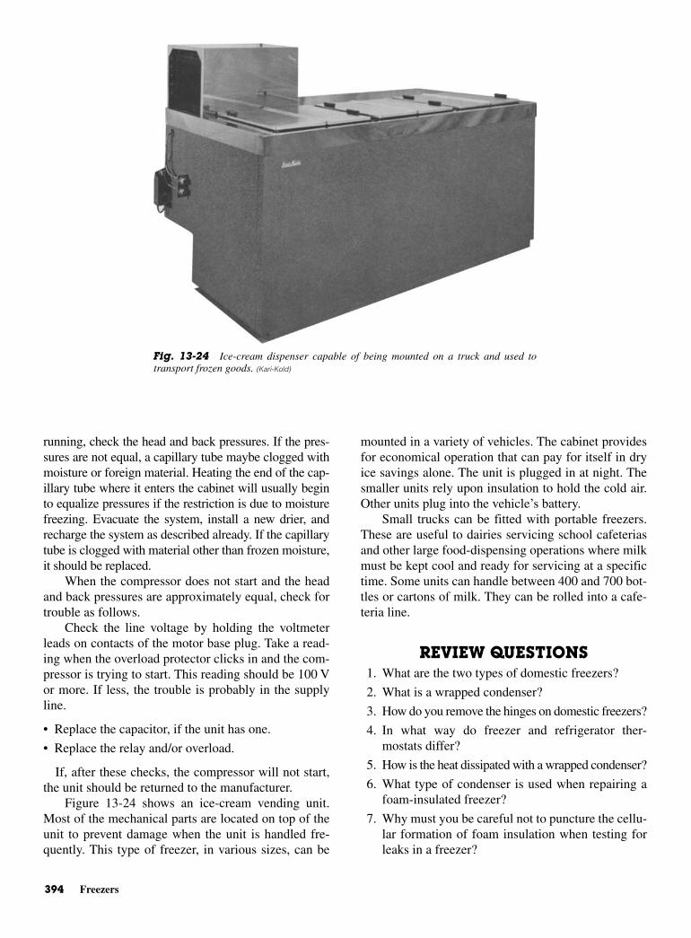
394 Freezers
running, check the head and back pressures. If the pres-sures are not equal, a capillary tube maybe clogged withmoisture or foreign material. Heating the end of the cap-illary tube where it enters the cabinet will usually beginto equalize pressures if the restriction is due to moisturefreezing. Evacuate the system, install a new drier, andrecharge the system as described already. If the capillarytube is clogged with material other than frozen moisture,it should be replaced.
When the compressor does not start and the headand back pressures are approximately equal, check fortrouble as follows.
Check the line voltage by holding the voltmeterleads on contacts of the motor base plug. Take a read-ing when the overload protector clicks in and the com-pressor is trying to start. This reading should be 100 Vor more. If less, the trouble is probably in the supplyline.
• Replace the capacitor, if the unit has one.
• Replace the relay and/or overload.
If, after these checks, the compressor will not start,the unit should be returned to the manufacturer.
Figure 13-24 shows an ice-cream vending unit.Most of the mechanical parts are located on top of theunit to prevent damage when the unit is handled fre-quently. This type of freezer, in various sizes, can be
mounted in a variety of vehicles. The cabinet providesfor economical operation that can pay for itself in dryice savings alone. The unit is plugged in at night. Thesmaller units rely upon insulation to hold the cold air.Other units plug into the vehicle’s battery.
Small trucks can be fitted with portable freezers.These are useful to dairies servicing school cafeteriasand other large food-dispensing operations where milkmust be kept cool and ready for servicing at a specifictime. Some units can handle between 400 and 700 bot-tles or cartons of milk. They can be rolled into a cafe-teria line.
REVIEW QUESTIONS1. What are the two types of domestic freezers?
2. What is a wrapped condenser?
3. How do you remove the hinges on domestic freezers?
4. In what way do freezer and refrigerator ther-mostats differ?
5. How is the heat dissipated with a wrapped condenser?
6. What type of condenser is used when repairing afoam-insulated freezer?
7. Why must you be careful not to puncture the cellu-lar formation of foam insulation when testing forleaks in a freezer?
Fig. 13-24 Ice-cream dispenser capable of being mounted on a truck and used totransport frozen goods. (Kari-Kold)
Review Questions 395
8. When does the suction pressure drop below theatmospheric pressure in a defective freezer?
9. What indicates an overcharge of refrigerant in afreezer?
10. What symptoms are observed when the capillarytube is restricted and partially interrupts the flow ofrefrigerant?
11. How much internal pressure is needed in a freezersystem to aid in locating small leaks?
12. When the compressor does not start and the headand back pressures are approximately equal, whatshould be checked first?

This page intentionally left blank

14CHAPTER
Temperature,Psychrometrics,and Air Control
Copyright © 2006 by The McGraw-Hill Companies, Inc. Click here for terms of use.
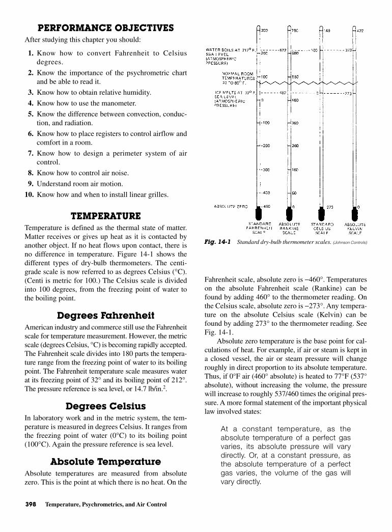
398 Temperature, Psychrometrics, and Air Control
PERFORMANCE OBJECTIVESAfter studying this chapter you should:
1. Know how to convert Fahrenheit to Celsiusdegrees.
2. Know the importance of the psychrometric chartand be able to read it.
3. Know how to obtain relative humidity.
4. Know how to use the manometer.
5. Know the difference between convection, conduc-tion, and radiation.
6. Know how to place registers to control airflow andcomfort in a room.
7. Know how to design a perimeter system of aircontrol.
8. Know how to control air noise.
9. Understand room air motion.
10. Know how and when to install linear grilles.
TEMPERATURETemperature is defined as the thermal state of matter.Matter receives or gives up heat as it is contacted byanother object. If no heat flows upon contact, there isno difference in temperature. Figure 14-1 shows thedifferent types of dry-bulb thermometers. The centi-grade scale is now referred to as degrees Celsius (°C).(Centi is metric for 100.) The Celsius scale is dividedinto 100 degrees, from the freezing point of water tothe boiling point.
Degrees Fahrenheit American industry and commerce still use the Fahrenheitscale for temperature measurement. However, the metricscale (degrees Celsius, °C) is becoming rapidly accepted.The Fahrenheit scale divides into 180 parts the tempera-ture range from the freezing point of water to its boilingpoint. The Fahrenheit temperature scale measures waterat its freezing point of 32° and its boiling point of 212°.The pressure reference is sea level, or 14.7 lb/in.2.
Degrees CelsiusIn laboratory work and in the metric system, the tem-perature is measured in degrees Celsius. It ranges fromthe freezing point of water (0°C) to its boiling point(100°C). Again the pressure reference is sea level.
Absolute Temperature Absolute temperatures are measured from absolutezero. This is the point at which there is no heat. On the
Fahrenheit scale, absolute zero is −460°. Temperatureson the absolute Fahrenheit scale (Rankine) can befound by adding 460° to the thermometer reading. Onthe Celsius scale, absolute zero is −273°. Any tempera-ture on the absolute Celsius scale (Kelvin) can befound by adding 273° to the thermometer reading. SeeFig. 14-1.
Absolute zero temperature is the base point for cal-culations of heat. For example, if air or steam is kept ina closed vessel, the air or steam pressure will changeroughly in direct proportion to its absolute temperature.Thus, if 0°F air (460° absolute) is heated to 77°F (537°absolute), without increasing the volume, the pressurewill increase to roughly 537/460 times the original pres-sure. A more formal statement of the important physicallaw involved states:
At a constant temperature, as theabsolute temperature of a perfect gasvaries, its absolute pressure will varydirectly. Or, at a constant pressure, asthe absolute temperature of a perfectgas varies, the volume of the gas willvary directly.
Fig. 14-1 Standard dry-bulb thermometer scales. (Johnson Controls)
Pressure Measuring Devices 399
This statement is known as the perfect gas law. It canbe expressed mathematically by the following equation.
PV = TR
where P = absolute pressure V = volumeT = absolute temperatureR = a constant, depending on the units selected
CONVERTING TEMPERATURESIt is sometimes necessary to convert from one temperaturescale to another. In converting from the Fahrenheit to theCelsius scale, 5/9°F is equal to 1°C. Or, 1°C is equal to1°F. Equations facilitate converting from one scale to theother.
EXAMPLE:Convert 77°F to °C. Use the following formula:°C = 5/9 (°F−32)
EXAMPLE:Convert 25°C to °F. Use the following formula:°F = 9/5 (°C) + 32
Temperature conversion tables are available. Usingthem, it is easy to convert temperatures from one tem-perature scale to another.
A calculator can be used for the above temperatureconversions. If a calculator is used, the number0.55555555 can be substituted for 5/9. The number 1.8can be substituted for 9/5.
PSYCHROMETRICSPsychrometry is the science and practice of air mix-tures and their control. The science deals mainly with
dry air, water vapor mixtures, with the specific heat ofdry air and its volume. It also deals with the heat ofwater, heat of vaporization or condensation, and thespecific heat of steam in reference to moisture mixedwith dry air. Psychrometry is a specialized area of ther-modynamics.
PRESSURESAll devices that measure pressure must be exposed totwo pressures. The measurement is always the differ-ence between two pressures, such as gage pressure andatmospheric pressure.
Gage PressureOn an ordinary pressure gage, one side of the measur-ing element is exposed to the medium under pressure.The other side of the measuring element is exposed tothe atmosphere. Atmospheric pressure varies with alti-tude and climatic conditions.
Thus, it is obvious that gage pressure readings willnot represent a precise, definite value unless the atmos-pheric pressure is known. Gage pressures are usuallydesignated as psig (pounds per square inch gage). Pres-sure values that include atmospheric pressure are des-ignated psia (pounds per square inch absolute).
Atmospheric PressureA barometer is used to measure atmospheric pressure.A simple mercury barometer may be made with a glasstube slightly more than 30 in. in length. It should besealed at one end and filled with mercury. The openend should be inverted in a container of mercury. SeeFig. 14-2. The mercury will drop in the tube until theweight of the atmosphere on the surface of the mercuryin the pan just supports the weight of the mercury col-umn in the tube. At sea level and under certain averageclimatic conditions, the height of mercury in the tubewill be 29.92 in. The space above the mercury in thetube will be an almost perfect vacuum, except for aslight amount of mercury vapor.
A mercury manometer is an accurate instrumentfor measuring pressure. The mercury is placed in aglass U-tube. With both ends open to the atmosphere,the mercury will stand at the same level in both sides ofthe tube. See Fig. 14-3. A scale is usually mounted onone of the tubes with its zero point at the mercury level.
PRESSURE MEASURING DEVICES Low pressures, such as in an air-distribution duct, aremeasured with a manometer using water instead ofmercury in the U-tube. See Fig. 14-3. The unit of
95
25 32
9 255
32
2255
45 32 77
25 77
( )
( )
+
+
= + =
° = °C F
59
77 32
59
45
5 459
2259
25
77 25
( )
( )
( )
−
=
° = °F C
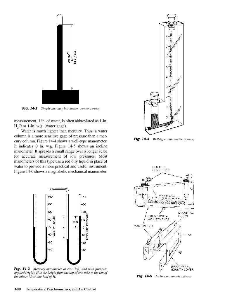
measurement, 1 in. of water, is often abbreviated as 1-in.H2O or 1-in. w.g. (water gage).
Water is much lighter than mercury. Thus, a watercolumn is a more sensitive gage of pressure than a mer-cury column. Figure 14-4 shows a well-type manometer.It indicates 0 in. w.g. Figure 14-5 shows an inclinemanometer. It spreads a small range over a longer scalefor accurate measurement of low pressures. Mostmanometers of this type use a red oily liquid in place ofwater to provide a more practical and useful instrument.Figure 14-6 shows a magnahelic mechanical manometer.
400 Temperature, Psychrometrics, and Air Control
Fig. 14-2 Simple mercury barometer. (Johnson Controls)
Fig. 14-3 Mercury manometer at rest (left) and with pressureapplied (right). H is the height from the top of one tube to the top ofthe other; H/2 is one-half of H.
Fig. 14-4 Well-type manometer. (Johnson)
Fig. 14-5 Incline manometer. (Dwyer)

Hygrometer 401
It is designed to eliminate the liquid in the water gage. Itis calibrated in hundredths of an inch water gage for verysensitive measurement.
Figure 14-7 shows a standard air-pressure gageused for adjusting control instruments. It is calibratedin inches of water and psig. It is apparent from thescale that 1 psig is equal to 27.6-in. w.g.
Bourdon (spring) tube gages and metal diaphragmgages are also used for measuring pressure. Thesegages are satisfactory for most commercial uses. Theyare not as accurate as the manometer or barometerbecause of the mechanical methods involved. TheBourdon tube gage is discussed in Chap. 2.
Another unit of pressure measurement is the“atmosphere.” Zero gage pressure is one atmosphere(14.7 lb/in.2) at sea level. For rough calculations, oneatmosphere can be considered 15 psig. A gage pressure ofl5 psia is approximately two atmospheres. The volumeof a perfect gas varies inversely with its pressure as longas the temperature remains constant. Thus, measuringpressures in atmospheres is convenient in some cases,as may be observed from the following example:
A 30-gal tank, open to the atmosphere, contains30 gal of free air at a pressure of one atmosphere. If thetank is closed and air pumped in until the pressureequals two atmospheres, the tank will contain 60 gal offree air. The original 30 gal now occupies only one-halfof the volume it originally occupied.
Conversion charts for pressures (psi to inches of Hg)may be found in various publications. The reference sec-tion of an engineering data book is a good source.
HYGROMETERA hygrometer is described as an instrument (bywww.wikipedia.org) used to measure the amount ofmoisture in the air. If a moist wick is placed over a ther-mometer bulb the evaporation of moisture from the wickwill lower the thermometer reading (temperature). If theair surrounding a wet-bulb thermometer is dry, evapora-tion from the moist wick will be more rapid than if thebulb thermometer is wet. When the air is saturated nowater will evaporate from the cloth wick and the tem-perature of the wet-bulb thermometer will be the sameas the reading on the dry-bulb thermometer. However, ifthe air is not saturated, the water will evaporate from thewick, causing the tempeature reading to be lower. Theaccuracy of the wet-bulb thermometer depends on howfast air passes over the bulb. Speeds of 5000 ft/min(60 mph) are best, but it is dangerous to move a ther-mometer at that speed. Errors up to 15 percent can occurif the air movement is too slow or if there is too muchradiant heat (sunlight for example) present. A wet-bulbtemperature taken with air moving at about 1 to 2 m/secis referred to as a screen temperature, whereas a temper-ature taken with air moving about 3.5 m/s or more isreferred to as the sling temperature.
Properties of AirAir is composed of nitrogen, oxygen, and small amountsof water vapor. Nitrogen makes up 77 percent, while oxy-gen accounts for 23 percent. Water vapor can account for0 to 3 percent under certain conditions. Water vapor ismeasured in grains or, in some cases, pounds per poundof dry air. Seven thousand grains of water equal 1 lb.
Temperature determines the amount of water vaporthat air can hold. Hotter temperatures mean that air hasa greater capacity to hold water suspended. Water iscondensed out of air as it is cooled. Outside, water con-densation becomes rain. Inside, it becomes condensa-tion on the window glass.
Thus, dry air acts somewhat like a sponge. It absorbsmoisture. There are four properties of air that accountfor its behavior under varying conditions. These
Fig. 14-6 Magnahelic manometer.
Fig. 14-7 Inches of water gage. (Johnson)
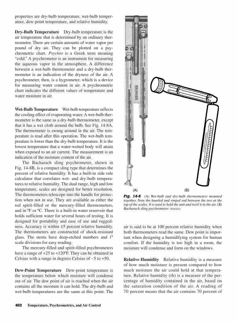
properties are dry-bulb temperature, wet-bulb temper-ature, dew-point temperature, and relative humidity.
Dry-Bulb Temperature Dry-bulb temperature is theair temperature that is determined by an ordinary ther-mometer. There are certain amounts of water vapor perpound of dry air. They can be plotted on a psy-chrometric chart. Psychro is a Greek term meaning“cold.” A psychrometer is an instrument for measuringthe aqueous vapor in the atmosphere. A differencebetween a wet-bulb thermometer and a dry-bulb ther-mometer is an indication of the dryness of the air. Apsychrometer, then, is a hygrometer, which is a devicefor measuring water content in air. A psychrometricchart indicates the different values of temperature andwater moisture in air.
Wet-Bulb Temperature Wet-bulb temperature reflectsthe cooling effect of evaporating water. A wet-bulb ther-mometer is the same as a dry-bulb thermometer, exceptthat it has a wet cloth around the bulb. See Fig. 14-8A.The thermometer is swung around in the air. The tem-perature is read after this operation. The wet-bulb tem-perature is lower than the dry-bulb temperature. It is thelowest temperature that a water-wetted body will attainwhen exposed to an air current. The measurement is anindication of the moisture content of the air.
The Bacharach sling psychrometer, shown inFig. 14-8B, is a compact sling type that determines thepercent of relative humidity. It has a built-in side rulecalculator that correlates wet- and dry-bulb tempera-tures to relative humidity. The dual range, high and lowtemperature, scales are designed for better resolution.The thermometers telescope into the handle for protec-tion when not in use. They are available as either thered spirit-filled or the mercury-filled thermometers,and in ºF or ºC. There is a built-in water reservoir thatholds sufficient water for several hours of testing. It isdesigned for portability and ease of use and rugged-ness. Accuracy is within ±5 percent relative humidity.The thermometers are constructed of shock-resistantglass. The stems have deep-etched numbers and 1ºscale divisions for easy reading.
The mercury-filled and spirit-filled psychrometershave a range of +25 to +120ºF. They can be obtained inCelsius with a range in degrees Celsius of −5 to +50.
Dew-Point Temperature Dew-point temperature isthe temperature below which moisture will condenseout of air. The dew point of air is reached when the aircontains all the moisture it can hold. The dry-bulb andwet-bulb temperatures are the same at this point. The
air is said to be at 100 percent relative humidity whenboth thermometers read the same. Dew point is impor-tant when designing a humidifying system for humancomfort. If the humidity is too high in a room, themoisture will condense and form on the windows.
Relative Humidity Relative humidity is a measureof how much moisture is present compared to howmuch moisture the air could hold at that tempera-ture. Relative humidity (rh) is a measure of the per-centage of humidity contained in the air, based onthe saturation condition of the air. A reading of70 percent means that the air contains 70 percent of
402 Temperature, Psychrometrics, and Air Control
Fig. 14-8 (A) Wet-bulb and dry-bulb thermometers mountedtogether. Note the knurled and ringed rod between the two at thetop of the scales. It is used to hold the unit and twirl it in the air. (B)Bacharach sling psychrometer. (Weksler)
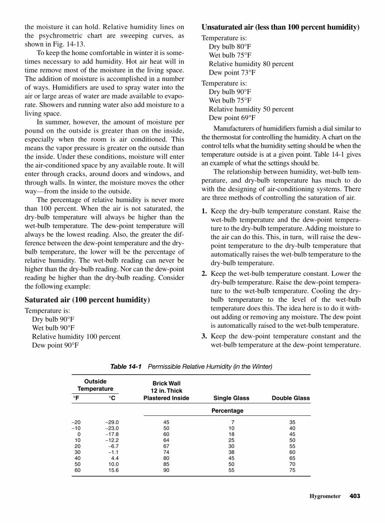
Hygrometer 403
the moisture it can hold. Relative humidity lines onthe psychrometric chart are sweeping curves, asshown in Fig. 14-13.
To keep the home comfortable in winter it is some-times necessary to add humidity. Hot air heat will intime remove most of the moisture in the living space.The addition of moisture is accomplished in a numberof ways. Humidifiers are used to spray water into theair or large areas of water are made available to evapo-rate. Showers and running water also add moisture to aliving space.
In summer, however, the amount of moisture perpound on the outside is greater than on the inside,especially when the room is air conditioned. Thismeans the vapor pressure is greater on the outside thanthe inside. Under these conditions, moisture will enterthe air-conditioned space by any available route. It willenter through cracks, around doors and windows, andthrough walls. In winter, the moisture moves the otherway—from the inside to the outside.
The percentage of relative humidity is never morethan 100 percent. When the air is not saturated, thedry-bulb temperature will always be higher than thewet-bulb temperature. The dew-point temperature willalways be the lowest reading. Also, the greater the dif-ference between the dew-point temperature and the dry-bulb temperature, the lower will be the percentage ofrelative humidity. The wet-bulb reading can never behigher than the dry-bulb reading. Nor can the dew-pointreading be higher than the dry-bulb reading. Considerthe following example:
Saturated air (100 percent humidity) Temperature is:
Dry bulb 90°FWet bulb 90°FRelative humidity 100 percent Dew point 90°F
Unsaturated air (less than 100 percent humidity) Temperature is:
Dry bulb 80°FWet bulb 75°FRelative humidity 80 percent Dew point 73°F
Temperature is: Dry bulb 90°FWet bulb 75°FRelative humidity 50 percent Dew point 69°F
Manufacturers of humidifiers furnish a dial similar tothe thermostat for controlling the humidity. A chart on thecontrol tells what the humidity setting should be when thetemperature outside is at a given point. Table 14-1 givesan example of what the settings should be.
The relationship between humidity, wet-bulb tem-perature, and dry-bulb temperature has much to dowith the designing of air-conditioning systems. Thereare three methods of controlling the saturation of air.
1. Keep the dry-bulb temperature constant. Raise thewet-bulb temperature and the dew-point tempera-ture to the dry-bulb temperature. Adding moisture tothe air can do this. This, in turn, will raise the dew-point temperature to the dry-bulb temperature thatautomatically raises the wet-bulb temperature to thedry-bulb temperature.
2. Keep the wet-bulb temperature constant. Lower thedry-bulb temperature. Raise the dew-point tempera-ture to the wet-bulb temperature. Cooling the dry-bulb temperature to the level of the wet-bulbtemperature does this. The idea here is to do it with-out adding or removing any moisture. The dew pointis automatically raised to the wet-bulb temperature.
3. Keep the dew-point temperature constant and thewet-bulb temperature at the dew-point temperature.
Table 14-1 Permissible Relative Humidity (in the Winter)
Outside Brick WallTemperature 12 in.Thick
°F °C Plastered Inside Single Glass Double Glass
Percentage
−20 −29.0 45 7 35−10 −23.0 50 10 40
0 −17.8 60 18 4510 −12.2 64 25 5020 −6.7 67 30 5530 −1.1 74 38 6040 4.4 80 45 6550 10.0 85 50 7060 15.6 90 55 75
Cooling the dry-bulb and wet-bulb temperatures tothe dew-point temperature can do this.
People and Moisture People working inside a building or occupied spacegive off moisture as they work. They also give off heat.Such moisture and heat must be considered in deter-mining air-conditioning requirements. Table 14-2 indi-cates some of the heat given off by the human bodywhen working.
PSYCHROMETRIC CHART The psychrometric chart holds much information. SeeFig. 14-9. However, it is hard to read. It must be stud-ied for some time. The dry-bulb temperature is locatedin one place and the wet bulb in another. If the two areknown, it is easy to find the relative humidity and otherfactors relating to air being checked. Both customaryand metric psychrometric charts are available.
Air contains different amounts of moisture at dif-ferent temperatures. Table 14-3 shows the amounts ofmoisture that air can hold at various temperatures.
An explanation of the various quantities shown ona psychrometric chart will enable you to understand thechart. The different quantities on the chart are shownseparately on the following charts. These charts willhelp you see how the psychrometric chart is con-structed. See Fig. 14-10.
Across the bottom, the vertical lines are labeledfrom 25 to 110°F in increments of 5°F. These tem-peratures indicate the dry-bulb temperature. SeeFig. 14-11.
The horizontal lines are labeled from 0 to 180°F.This span of numbers represents the grains of moistureper pound of dry air (when saturated). See Fig. 14-11.
The outside curving line on the left side of thegraph indicates the wet-bulb, dew-point, or saturationtemperature. See Fig. 14-12.
At 100 percent saturation the wet-bulb temperaturesare the same as the dry-bulb and the dew-point tempera-
tures. This means the wet-bulb lines start from the100 percent saturation curve. Diagonal lines representthe wet-bulb temperatures. The point where the diagonalline of the wet bulb crosses the dry bulb’s vertical line isthe dew point. The temperature of the dew point will befound by running the horizontal line to the left and read-ing the temperature on the curve since the wet-bulb anddew-point temperatures are on the curve.
The curving lines within the graph indicate the per-centage of relative humidity. These lines are labeled10, 20 percent, and so on. See Fig. 14-13.
The pounds of water per pound of dry air areshown in the middle column of numbers on the right.See Fig. 14-14.
The grains of moisture per pound of dry air areshown in the left-hand column of the three columns ofnumbers on the right. See Fig. 14-14.
Table 14-3 shows that 1 lb of dry air will hold 19.1grains of water at 25°F (−3.9°C). One pound of dry airwill hold 415 grains of water at 110°F. It can be seen thatthe higher the temperature, the more moisture the air canhold. This is one point that should be remembered. Tofind the weight per grain, divide 1 by 7000 to get0.00014 lb per grain. Therefore, on the chart 0.01 lb cor-responds with about 70 grains. The volume of dry air(ft3/lb) is represented by diagonal lines. See Fig. 14-15.The values are marked along the lines. They representthe cubic feet of the mixture of vapor and air per poundof dry air. The chart indicates that volume is affected bytemperature relationships of the wet and dry-bulb read-ings. The lines are usually at intervals of 1/2 ft3/lb.
Enthalpy is the total amount of heat contained inthe air above 0°F (−17.8°C). See Fig. 14-16. The lineson the chart that represent enthalpy are extensions ofthe wet-bulb lines. They are extended and labeled inBtu per pound. This value can be used to help deter-mine the load on an air-conditioning unit.
AIR MOVEMENTConvection, Conduction, and
RadiationHeat always passes from a warmer to a colder object orspace. The action of refrigeration depends upon thisnatural law. The three methods by which heat can betransferred are convection, conduction, and radiation.
• Convection is heat transfer that takes place in liquidsand gases. In convection, the molecules carry theheat from one point to another.
• Conduction is heat transfer that takes place chieflyin solids. In conduction, the heat passes from one
404 Temperature, Psychrometrics, and Air Control
Table 14-2 Activity-Heat Relationships
Activity Total Heat in Btu Per Hour
Person at rest 385Person standing 430Tailor 480Clerk 600Dancing 760Waiter 1000Walking 1400Bowling 1500Fast walking 2300Severe exercise 2600
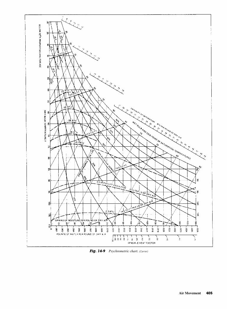
Air Movement 405
Fig. 14-9 Psychrometric chart. (Carrier)
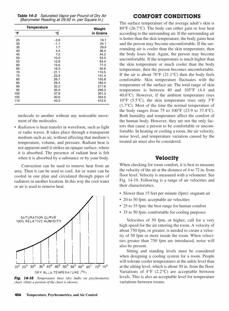
molecule to another without any noticeable move-ment of the molecules.
• Radiation is heat transfer in waveform, such as lightor radio waves. It takes place through a transparentmedium such as air, without affecting that medium’stemperature, volume, and pressure. Radiant heat isnot apparent until it strikes an opaque surface, whereit is absorbed. The presence of radiant heat is feltwhen it is absorbed by a substance or by your body.
Convection can be used to remove heat from anarea. Then it can be used to cool. Air or water can becooled in one plan and circulated through pipes ofradiators in another location. In this way the cool wateror air is used to remove heat.
COMFORT CONDITIONSThe surface temperature of the average adult’s skin is80°F (26.7°C). The body can either gain or lose heataccording to the surrounding air. If the surrounding airis hotter than the skin temperature, the body gains heatand the person may become uncomfortable. If the sur-rounding air is cooler than the skin temperature, thenthe body loses heat. Again, the person may becomeuncomfortable. If the temperature is much higher thanthe skin temperature or much cooler than the bodytemperature, then the person becomes uncomfortable.If the air is about 70°F (21.1°C) then the body feelscomfortable. Skin temperature fluctuates with thetemperature of the surface air. The total range of skintemperature is between 40 and 105°F (4.4 and40.6°C). However, if the ambient temperature rises10°F (5.5°C), the skin temperature rises only 3°F(1.7°C). Most of the time the normal temperature ofthe body ranges from 75 to 100°F (23.9 to 37.8°C).Both humidity and temperature affect the comfort ofthe human body. However, they are not the only fac-tors that cause a person to be comfortable or uncom-fortable. In heating or cooling a room, the air velocity,noise level, and temperature variation caused by thetreated air must also be considered.
VelocityWhen checking for room comfort, it is best to measurethe velocity of the air at the distance of 4 to 72 in. fromfloor level. Velocity is measured with a velometer. SeeFig. 14-19. Following is a range of air velocities andtheir characteristics.
• Slower than 15 feet per minute (fpm): stagnant air
• 20 to 50 fpm: acceptable air velocities
• 25 to 35 fpm: the best range for human comfort
• 35 to 50 fpm: comfortable for cooling purposes
Velocities of 50 fpm, or higher, call for a veryhigh speed for the air entering the room. A velocity ofabout 750 fpm, or greater, is needed to create a veloc-ity of 50 fpm or more inside the room. When veloci-ties greater than 750 fpm are introduced, noise willalso be present.
Sitting and standing levels must be consideredwhen designing a cooling system for a room. Peoplewill tolerate cooler temperatures at the ankle level thanat the sitting level, which is about 30 in. from the floor.Variations of 4°F (2.2°C) are acceptable betweenlevels. This is also an acceptable level for temperaturevariations between rooms.
406 Temperature, Psychrometrics, and Air Control
Fig. 14-10 Temperature lines (dry bulb) on psychrometricchart. (Only a portion of the chart is shown).
Table 14-3 Saturated Vapor per Pound of Dry Air(Barometer Reading at 29.92 in. per Square in.)
Temperature Weight°F °C in Grains
25 −3.9 19.130 −1.1 24.135 1.7 29.940 4.4 36.445 7.2 44.250 10.0 53.555 12.8 64.460 15.6 77.365 18.3 92.670 21.1 110.575 23.9 131.480 26.7 155.885 29.4 184.490 32.2 217.695 35.0 256.3
100 37.8 301.3105 40.6 354.0110 43.3 415.0
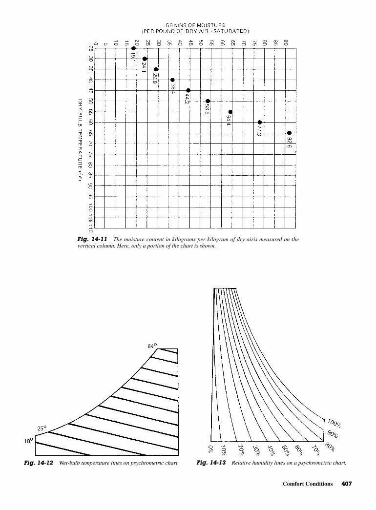
Comfort Conditions 407
Fig. 14-11 The moisture content in kilograms per kilogram of dry airis measured on thevertical column. Here, only a portion of the chart is shown.
Fig. 14-12 Wet-bulb temperature lines on psychrometric chart. Fig. 14-13 Relative humidity lines on a psychrometric chart.

To make sure that the air is properly distributed forcomfort, it is necessary to look at the methods used toaccomplish the job.
TERMINOLOGYThe following terms apply to the movement of air. Theyare frequently used in referring to air-conditioningsystems.
• Aspiration is the induction of room air into the primaryair stream. Aspiration helps eliminate stratification of
air within the room. When outlets are properlylocated along exposed walls, aspiration also aids inabsorbing undesirable currents from these walls andwindows. See Fig. 14-17.
• Cubic feet per minute (cfm) is the measure of a vol-ume of air. Air now in cubic feet per minute of a reg-ister or grille is computed by multiplying the facevelocity times the free area in square feet.
EXAMPLE:A resister with 144 in.2 (1 ft2) of free area and a measuredface velocity of 500 fpm would be delivering 500 cfm.
• Decibels (db) are units of measure of sound level. Itis important to keep this noise at a minimum. In mostcatalogs for outlets, there is a line dividing the noiselevel of the registers or diffusers. Lower total pres-sure loss provides a quieter system.
• Drop is generally associated with cooling where airis discharged horizontally from high sidewall outlets.Since cool air has a natural tendency to drop, it will
408 Temperature, Psychrometrics, and Air Control
Fig. 14-14 The sensible heat factor on a psychrometeric chart.
Fig. 14-15 Air-volume lines on a psychrometric chart.
Fig. 14-16 Enthalpy lines on a psychrometric chart.
Fig. 14-17 Aspiration, throw, and spread. (Lima)

Terminology 409
fall progressively as the velocity decreases. Mea-sured at the point of terminal velocity, drop is the dis-tance in feet that the air has fallen below the level ofthe outlet. See Fig. 14-18.
• Diffusers are outlets that have a widespread, fan-shaped pattern of air,
• Effective area is the smallest net area of an outlet uti-lized by the air stream in passing through the outletpassages. It determines the maximum, or jet, velocityof the air in the outlet. In many outlets, the effectivearea occurs at the velocity measuring point and isequal to the outlet area. See Fig. 14-19.
• Face velocity is the average velocity of air passingthrough the face of an outlet or a return.
• Feet per minute (fpm) is the measure of the velocityof an air stream. This velocity can be measured witha velocity meter that is calibrated in fpm.
• Free area is the total area of the openings in the out-let or inlet through which air can pass. With gravitysystems, free area is of prime importance. With
forced air systems, free area is secondary to totalpressure loss, except in sizing return air grilles.
• Noise criteria (NC) is an outlet sound rating in pres-sure level at a given condition of operation, based onestablished criteria and a specific room acousticabsorption value.
• Occupied zone is that interior area of a conditionedspace that extends to within 6 in. of all room wallsand to a height of 6 ft above the floor.
• Outlet area is the area of an outlet utilized by the airstream at the point of the outlet velocity as measuredwith an appropriate meter. The point of measurementand type of meter must be defined to determine cfmaccurately.
• Outlet velocity (Vk) is the measured velocity at thestarted point with a specific meter.
• Perimeter systems are heating and cooling installa-tions in which the diffusers are installed to blanketthe outside walls. Returns are usually located at oneor more centrally located places. High sidewall orceiling returns are preferred, especially for cooling.Low returns are acceptable for heating. High side-wall or ceiling returns are highly recommended forcombination heating and cooling installations.
• Registers are outlets that deliver air in a concentratedstream into the occupied zone.
• Residual velocity (VR) is the average sustainedvelocity within the confines of the occupied zone,generally ranging from 20 to 70 fpm.
• Sound power level (Lw ) is the total sound created byan outlet under a specified condition of operation.
• Spread is the measurement (in feet) of the maximumwidth of the air pattern at the point of terminal veloc-ity. See Fig. 14-20.
• Static pressure (sp) is the outward force of air within aduct. This pressure is measured in inches of water. Thestatic pressure within a duct is comparable to the airpressure within an automobile tire. A manometer mea-sures static pressure. See Figs. 14-3 through 14-6.
• Temperature differential (∆T) is the differencebetween primary supply and room air temperatures.
Fig. 14-18 Drop. (ARI)
Fig. 14-19 Air measurement at the grille. (Lima)
Fig. 14-20 Typical air-stream pattern. (Tuttle & Bailey)
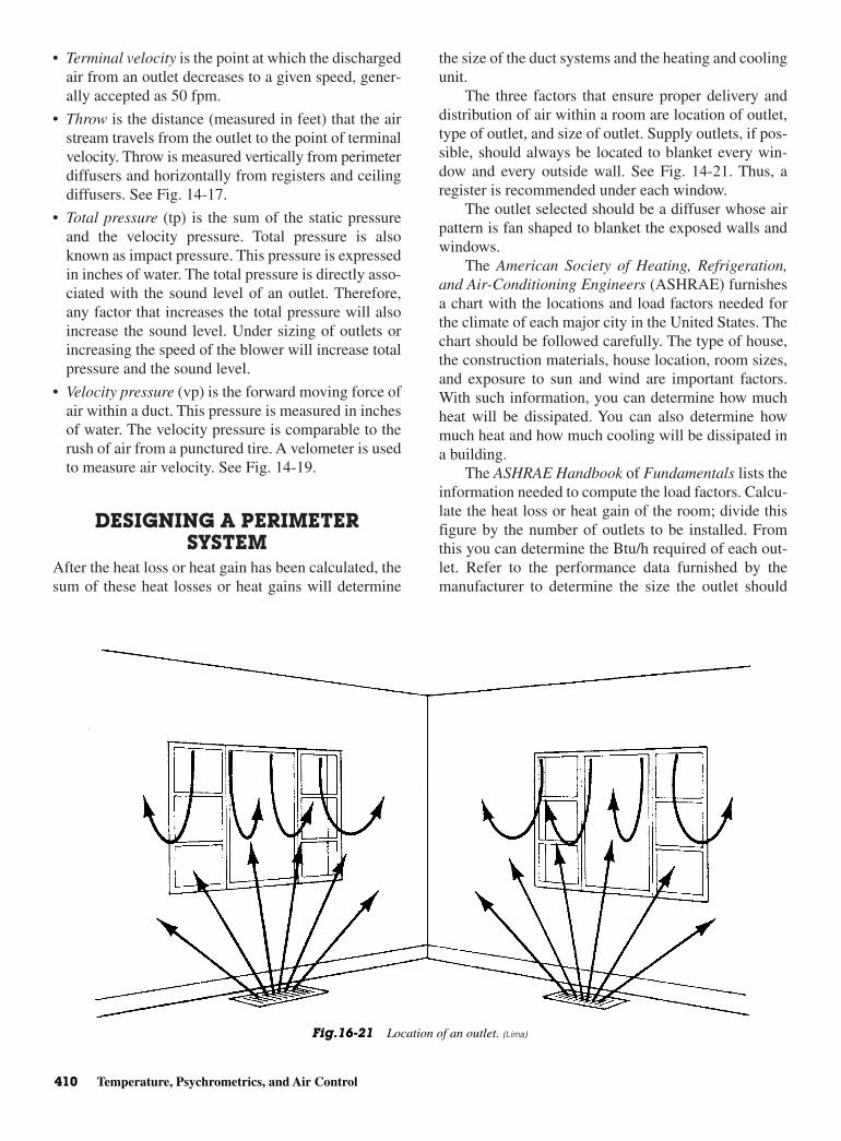
• Terminal velocity is the point at which the dischargedair from an outlet decreases to a given speed, gener-ally accepted as 50 fpm.
• Throw is the distance (measured in feet) that the airstream travels from the outlet to the point of terminalvelocity. Throw is measured vertically from perimeterdiffusers and horizontally from registers and ceilingdiffusers. See Fig. 14-17.
• Total pressure (tp) is the sum of the static pressureand the velocity pressure. Total pressure is alsoknown as impact pressure. This pressure is expressedin inches of water. The total pressure is directly asso-ciated with the sound level of an outlet. Therefore,any factor that increases the total pressure will alsoincrease the sound level. Under sizing of outlets orincreasing the speed of the blower will increase totalpressure and the sound level.
• Velocity pressure (vp) is the forward moving force ofair within a duct. This pressure is measured in inchesof water. The velocity pressure is comparable to therush of air from a punctured tire. A velometer is usedto measure air velocity. See Fig. 14-19.
DESIGNING A PERIMETERSYSTEM
After the heat loss or heat gain has been calculated, thesum of these heat losses or heat gains will determine
the size of the duct systems and the heating and coolingunit.
The three factors that ensure proper delivery anddistribution of air within a room are location of outlet,type of outlet, and size of outlet. Supply outlets, if pos-sible, should always be located to blanket every win-dow and every outside wall. See Fig. 14-21. Thus, aregister is recommended under each window.
The outlet selected should be a diffuser whose airpattern is fan shaped to blanket the exposed walls andwindows.
The American Society of Heating, Refrigeration,and Air-Conditioning Engineers (ASHRAE) furnishesa chart with the locations and load factors needed forthe climate of each major city in the United States. Thechart should be followed carefully. The type of house,the construction materials, house location, room sizes,and exposure to sun and wind are important factors.With such information, you can determine how muchheat will be dissipated. You can also determine howmuch heat and how much cooling will be dissipated ina building.
The ASHRAE Handbook of Fundamentals lists theinformation needed to compute the load factors. Calcu-late the heat loss or heat gain of the room; divide thisfigure by the number of outlets to be installed. Fromthis you can determine the Btu/h required of each out-let. Refer to the performance data furnished by themanufacturer to determine the size the outlet should
410 Temperature, Psychrometrics, and Air Control
Fig.16-21 Location of an outlet. (Lima)
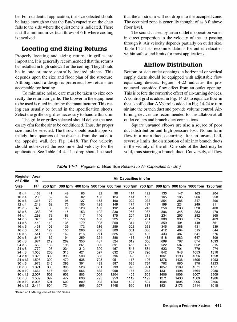
Designing a Perimeter System 411
be. For residential application, the size selected shouldbe large enough so that the Btu/h capacity on the chartfalls to the side where the quiet zone is indicated. Thereis still a minimum vertical throw of 6 ft where coolingis involved.
Locating and Sizing ReturnsProperly locating and sizing return air grilles areimportant. It is generally recommended that the returnsbe installed in high sidewall or the ceiling. They shouldbe in one or more centrally located places. Thisdepends upon the size and floor plan of the structure.Although such a design is preferred, low returns areacceptable for heating.
To minimize noise, care must be taken to size cor-rectly the return air grille. The blower in the equipmentto be used is rated in cfm by the manufacturer. This rat-ing can usually be found in the specification sheets.Select the grille or grilles necessary to handle this cfm.
The grille or grilles selected should deliver the nec-essary cfm for the air to be conditioned. Thus, the propersize must be selected. The throw should reach approxi-mately three-quarters of the distance from the outlet tothe opposite wall. See Fig. 14-18. The face velocityshould not exceed the recommended velocity for theapplication. See Table 14-4. The drop should be such
that the air stream will not drop into the occupied zone.The occupied zone is generally thought of as 6 ft abovefloor level.
The sound caused by an air outlet in operation variesin direct proportion to the velocity of the air passingthrough it. Air velocity depends partially on outlet size.Table 14-5 lists recommendations for outlet velocitieswithin safe sound limits for most applications.
Airflow Distribution Bottom or side outlet openings in horizontal or verticalsupply ducts should be equipped with adjustable flowequalizing devices. Figure 14-22 indicates the pro-nounced one-sided flow effect from an outlet opening.This is before the corrective effect of air-turning devices.A control grid is added in Fig. 14-23 to equalize flow inthe takeoff collar. A Vectrol is added in Fig. 14-24 to turnair into the branch duct and provide volume control. Air-turning devices are recommended for installation at alloutlet collars and branch duct connections.
Square unvaned elbows are also a source of poorduct distribution and high-pressure loss. Nonuniformflow in a main duct, occurring after an unvaned ell,severely limits the distribution of air into branch ductsin the vicinity of the ell. One side of the duct may bevoid, thus starving a branch duct. Conversely, all flow
Table 14-4 Register or Grille Size Related to Air Capacities (in cfm)
Register Areaof Grille in
Air Capacities in cfm
Size Ft2 250 fpm 300 fpm 400 fpm 500 fpm 600 fpm 700 fpm 750 fpm 800 fpm 900 fpm 1000 fpm 1250 fpm
8 × 4 .163 41 49 65 82 98 114 122 130 147 163 20410 × 4 .206 52 62 82 103 124 144 155 165 185 206 25810 × 6 .317 79 95 127 158 190 222 238 254 285 317 39612 × 4 .249 62 75 100 125 149 174 187 199 224 249 31112 × 5 .320 80 96 128 160 192 224 240 256 288 320 40012 × 6 .383 96 115 153 192 230 268 287 306 345 383 47914 × 4 .292 73 88 117 146 175 204 219 234 263 292 36514 × 5 .375 94 113 150 188 225 263 281 300 338 375 46914 × 6 .449 112 135 179 225 269 314 337 359 404 449 56116 × 5 .431 108 129 172 216 259 302 323 345 388 431 53916 × 6 .515 129 155 206 258 309 361 386 412 464 515 64420 × 5 .541 135 162 216 271 325 379 406 433 487 541 67620 × 6 .647 162 194 259 324 388 453 485 518 582 647 80920 × 8 .874 219 262 350 437 524 612 656 699 787 874 109324 × 5 .652 162 195 261 326 391 456 489 522 587 652 81524 × 6 .779 195 234 312 390 467 545 584 623 701 779 97424 × 8 1.053 263 316 421 527 632 737 790 842 948 1053 131624 × 10 1.326 332 398 530 663 796 928 995 1061 1193 1326 165824 × 12 1.595 399 479 638 798 951 1117 1196 1276 1436 1595 199330 × 6 .978 245 293 391 489 587 685 734 782 880 978 122330 × 8 1.321 330 396 528 661 793 925 991 1057 1189 1371 165130 × 10 1.664 416 499 666 832 998 1165 1248 1331 1498 1664 208030 × 12 2.007 502 602 803 1004 1204 1405 1505 1606 1806 2007 250936 × 8 1.589 397 477 636 795 953 1112 1192 1271 1430 1589 198636 × 10 2.005 501 602 802 1003 1203 1404 1504 1604 1805 2005 250636 × 12 2.414 604 724 966 1207 1448 1690 1811 1931 2173 2414 3018
∗Based on LIMA registers of the 100 Series.
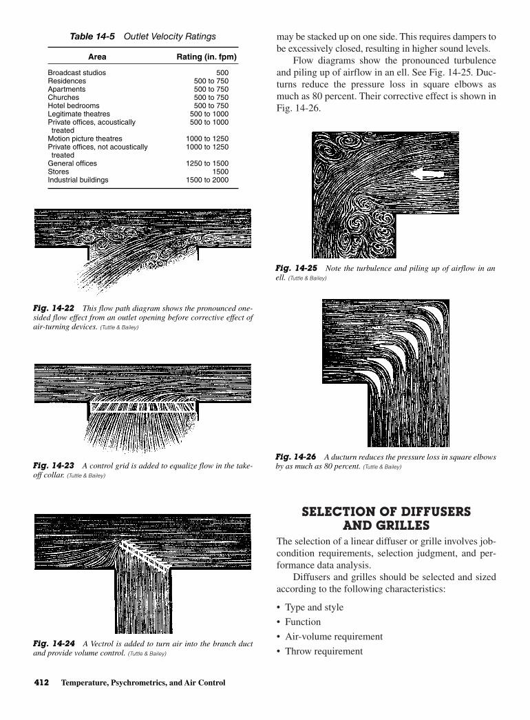
may be stacked up on one side. This requires dampers tobe excessively closed, resulting in higher sound levels.
Flow diagrams show the pronounced turbulenceand piling up of airflow in an ell. See Fig. 14-25. Duc-turns reduce the pressure loss in square elbows asmuch as 80 percent. Their corrective effect is shown inFig. 14-26.
SELECTION OF DIFFUSERSAND GRILLES
The selection of a linear diffuser or grille involves job-condition requirements, selection judgment, and per-formance data analysis.
Diffusers and grilles should be selected and sizedaccording to the following characteristics:
• Type and style
• Function
• Air-volume requirement
• Throw requirement
412 Temperature, Psychrometrics, and Air Control
Table 14-5 Outlet Velocity Ratings
Area Rating (in. fpm)
Broadcast studios 500Residences 500 to 750Apartments 500 to 750Churches 500 to 750Hotel bedrooms 500 to 750Legitimate theatres 500 to 1000Private offices, acoustically 500 to 1000treated
Motion picture theatres 1000 to 1250Private offices, not acoustically 1000 to 1250treated
General offices 1250 to 1500Stores 1500Industrial buildings 1500 to 2000
Fig. 14-22 This flow path diagram shows the pronounced one-sided flow effect from an outlet opening before corrective effect ofair-turning devices. (Tuttle & Bailey)
Fig. 14-23 A control grid is added to equalize flow in the take-off collar. (Tuttle & Bailey)
Fig. 14-24 A Vectrol is added to turn air into the branch ductand provide volume control. (Tuttle & Bailey)
Fig. 14-25 Note the turbulence and piling up of airflow in anell. (Tuttle & Bailey)
Fig. 14-26 A ducturn reduces the pressure loss in square elbowsby as much as 80 percent. (Tuttle & Bailey)
Selection of Diffusers and Grilles 413
• Pressure requirement
• Sound requirement
Air-Volume Requirement The air volume per diffuser or grille is that which is nec-essary for the cooling, heating, or ventilation require-ments of the area served by the unit. The air volumerequired, when related to throw, sound, or pressure-designlimitations, determines the proper diffuser or grille size.
Generally, air volumes for internal zones of buildingspaces vary from 1 to 3 cfm/ft2 of floor area. Exteriorzones will require higher air volumes of 2.5 to 4 cfm/ft2.In some cases, only the heating or cooling load of theexterior wall panel or glass surface is to be carried by thedistribution center. Then, the air volume per linear footof diffuser or grille will vary from 20 to 200 cfm,depending on heat-transfer coefficient, wall height, andinfiltration rate.
Throw RequirementThrow and occupied area air location are closely related.Both could be considered in the analysis of specific arearequirements. The minimum-maximum throw for a givencondition of aeration is based upon a terminal velocity atthat distance from the diffuser. The residual room velocityis a function of throw to terminal velocity. Throw valuesare based on terminal velocities ranging from 75 to150 fpm with corresponding residual room velocities of75 to 150 fpm. The diffuser or grille location together withthe air pattern selected, should generally direct the air pathabove the occupied zone. The air path then induces roomair along its throw as it expands in cross section. Thisequalizes temperature and velocity within the stream.With the throw terminating in a partition or wall surface,the mixed air path further dissipates energy.
Ceiling mounted grilles and diffusers are recom-mended for vertical down pattern. Some locations in theroom may need to be cooler than others. Also, someroom locations may be harder to condition because ofairflow problems. They are used in areas adjacent toperimeter wall locations that require localized spot con-ditioning. Ceiling heights of 12 ft or greater are needed.The throw for vertical projection is greatly affected bysupply air temperature and proximity of wall surfaces.
Sidewall mounted diffusers and grilles have hori-zontal values based on a ceiling height of 8 to l0 ft. Thediffuser or grille is mounted approximately 1 ft belowthe ceiling. For a given listed throw, the room airmotion will increase or decrease inversely with theceiling height. For a given air pattern setting and roomair motion, the listed minimum-maximum throw value
can be decreased by l ft for each 1 ft increase in ceilingheight above 10 ft. Throw values are furnished by themanufacturer.
When sidewall grilles are installed remote fromthe ceiling (more than 3 ft away), reduce rated throwvalues by 20 percent.
Sill-mounted diffusers or grilles have throw valuesbased on an 8- to 10-ft ceiling height. This is with theoutlet installed in the top of a 30 in. high sill. For agiven listed throw, the room air motion will changewith the ceiling height. For a given air pattern settingand room air motion, the listed minimum-maximumthrow value can be decreased by 2 ft for each 1 ftincrease in ceiling height above 10 ft. Decrease 1 ft foreach 1 ft decrease in sill height.
The minimum throw results in a room air motionhigher than that obtained when utilizing the maximumthrow. Thus, 50 fpm, rather than 35 fpm, is the airmotion. The listed minimum throw indicates the mini-mum distance recommended. The minimum distance isfrom the diffuser to a wall or major obstruction such asa structural beam. The listed maximum throw is therecommended maximum distance to a wall or majorobstruction. Throw values for sidewall grilles and ceil-ing diffusers and the occupied area velocity are basedon flush ceiling construction providing an unob-structed air-stream path. The listed maximum throwtimes 1.3 is the complete throw of the air stream. Thisis where the terminal velocity equals the room air veloc-ity. Rated occupied area velocities range from 25 to35 fpm for maximum listed throws, and 35 to 50 fpmfor minimum listed throw values.
Cooled-air drop or heated-air rise are of practicalsignificance when supplying heated or cooled air froma sidewall grille. If the throw is such that the air streamprematurely enters the occupied zone, considerabledraft may be experienced. This is due to incompletemixing. The total airdrop must be considered when thewall grille is located at a distance from the ceiling.Cooled airdrop is controlled by spacing the wall grillefrom the ceiling and adjusting the grilles upward 15 in.Heated-air rise contributes significantly to temperaturestratification in the upper part of the room.
The minimum separation between grille and ceil-ing must be 2 ft or more. The minimum mounting sep-aration must be 2 ft or more. The minimum mountingheight should be 7 ft.
Pressure Requirement The diffuser or grille minimum pressure for a given airvolume reflects itself in ultimate system fan horse-power requirements.
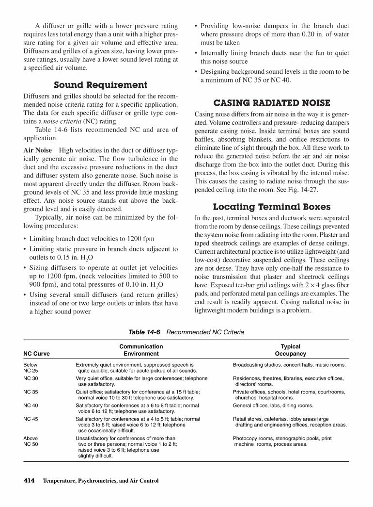
A diffuser or grille with a lower pressure ratingrequires less total energy than a unit with a higher pres-sure rating for a given air volume and effective area.Diffusers and grilles of a given size, having lower pres-sure ratings, usually have a lower sound level rating ata specified air volume.
Sound RequirementDiffusers and grilles should be selected for the recom-mended noise criteria rating for a specific application.The data for each specific diffuser or grille type con-tains a noise criteria (NC) rating.
Table 14-6 lists recommended NC and area ofapplication.
Air Noise High velocities in the duct or diffuser typ-ically generate air noise. The flow turbulence in theduct and the excessive pressure reductions in the ductand diffuser system also generate noise. Such noise ismost apparent directly under the diffuser. Room back-ground levels of NC 35 and less provide little maskingeffect. Any noise source stands out above the back-ground level and is easily detected.
Typically, air noise can be minimized by the fol-lowing procedures:
• Limiting branch duct velocities to 1200 fpm
• Limiting static pressure in branch ducts adjacent tooutlets to 0.15 in. H2O
• Sizing diffusers to operate at outlet jet velocitiesup to 1200 fpm, (neck velocities limited to 500 to900 fpm), and total pressures of 0.10 in. H2O
• Using several small diffusers (and return grilles)instead of one or two large outlets or inlets that havea higher sound power
• Providing low-noise dampers in the branch ductwhere pressure drops of more than 0.20 in. of watermust be taken
• Internally lining branch ducts near the fan to quietthis noise source
• Designing background sound levels in the room to bea minimum of NC 35 or NC 40.
CASING RADIATED NOISE Casing noise differs from air noise in the way it is gener-ated. Volume controllers and pressure- reducing dampersgenerate casing noise. Inside terminal boxes are soundbaffles, absorbing blankets, and orifice restrictions toeliminate line of sight through the box. All these work toreduce the generated noise before the air and air noisedischarge from the box into the outlet duct. During thisprocess, the box casing is vibrated by the internal noise.This causes the casing to radiate noise through the sus-pended ceiling into the room. See Fig. 14-27.
Locating Terminal BoxesIn the past, terminal boxes and ductwork were separatedfrom the room by dense ceilings. These ceilings preventedthe system noise from radiating into the room. Plaster andtaped sheetrock ceilings are examples of dense ceilings.Current architectural practice is to utilize lightweight (andlow-cost) decorative suspended ceilings. These ceilingsare not dense. They have only one-half the resistance tonoise transmission that plaster and sheetrock ceilingshave. Exposed tee-bar grid ceilings with 2 × 4 glass fiberpads, and perforated metal pan ceilings are examples. Theend result is readily apparent. Casing radiated noise inlightweight modern buildings is a problem.
414 Temperature, Psychrometrics, and Air Control
Table 14-6 Recommended NC Criteria
Communication Typical NC Curve Environment Occupancy
Below Extremely quiet environment, suppressed speech is Broadcasting studios, concert halls, music rooms.NC 25 quite audible, suitable for acute pickup of all sounds.
NC 30 Very quiet office, suitable for large conferences; telephone Residences, theatres, libraries, executive offices, use satisfactory. directors’ rooms.
NC 35 Quiet office; satisfactory for conference at a 15 ft table; Private offices, schools, hotel rooms, courtrooms,normal voice 10 to 30 ft telephone use satisfactory. churches, hospital rooms.
NC 40 Satisfactory for conferences at a 6 to 8 ft table; normal General offices, labs, dining rooms.voice 6 to 12 ft; telephone use satisfactory.
NC 45 Satisfactory for conferences at a 4 to 5 ft; table; normal Retail stores, cafeterias, lobby areas largevoice 3 to 6 ft; raised voice 6 to 12 ft; telephone drafting and engineering offices, reception areas.use occasionally difficult.
Above Unsatisfactory for conferences of more than Photocopy rooms, stenographic pools, print NC 50 two or three persons; normal voice 1 to 2 ft; machine rooms, process areas.
raised voice 3 to 6 ft; telephone use slightly difficult.

Return Grilles 415
Controlling Casing NoiseTerminal boxes can sometimes be located over noisyareas (corridors, toilet areas, machine equipment rooms),rather than over quiet areas. In quiet areas casing noisecan penetrate the suspended ceiling and become objec-tionable. Enclosures built around the terminal box (suchas sheetrock or sheet lead over a glass fiber blanketwrapped around the box) can reduce the radiated noiseto an acceptable level.
However, this method is cumbersome and limitsaccess to the motor and volume controllers in the box.It depends upon field conditions for satisfactory per-formance, and is expensive. Limiting static pressure inthe branch ducts minimizes casing noise. This tech-nique, however, limits the flexibility of terminal boxsystems. It hardly classifies as a control.
Vortex Shedding Product research in controlling casing noise has devel-oped a new method of reducing radiated noise. Thetechnique is known as vortex shedding. When appliedto terminal boxes, casing radiated noise is dramaticallylowered. Casing radiation attenuation (CRA) vortexshedders can be installed in all single- or dual-ductboxes up to 7000 cfm, both constant volume or variablevolume, with or without reheat coils. CRA devices pro-vide unique features and the following benefits:
• No change in terminal box size. Box is easier to installin tight ceiling plenums to insure minimum casingnoise under all conditions.
• Factory-fabricated box and casing-noise eliminator, aone-piece assembly, reduces cost of installation. Onlyone box is hung. Only one duct connection is made.
• Quick-opening access door is provided in box. Thisassures easy and convenient access to all operating
parts without having to cut and patch field-fabricatedenclosures.
• Equipment is laboratory tested and performancerated. Engineering measurements are made in accor-dance with industry standards. Thus, on-job per-formance is insured. Quiet rooms result and ownersatisfaction is assured.
RETURN GRILLESPerformance
Return air grilles are usually selected for the requiredair volume at a given sound level or pressure value. Theintake air velocity at the face of the grille dependsmainly on the grille size and the air volume.
The grille style and damper setting have a smalleffect on this intake velocity. The grille style, however,has a very great effect on the pressure drop. This, inturn, directly influences the sound level.
The intake velocity is evident only in the immedi-ate vicinity of the return grille. It cannot influenceroom air distribution. Recent ASHRAE research pro-jects have developed a scientific computerized methodof relating intake grille velocities, measured 1 in. outfrom the grille face, to air volume. Grille measuringfactors for straight, deflected bar, open, and partiallyclosed dampers are in the engineering data furnishedwith the grille.
It still remains the function of the supply outlets toestablish proper coverage, air motion, and thermalequilibrium. Because of this, the location of returngrilles is not critical and their placement can be largelya matter of convenience. Specific locations in the ceilingmay be desirable for local heat loads, or smoke exhaust,or a location in the perimeter sill or floor may be desir-able for an exterior zone intake under a window wall
Fig. 14-27 Casing noises. (Tuttle & Bailey)
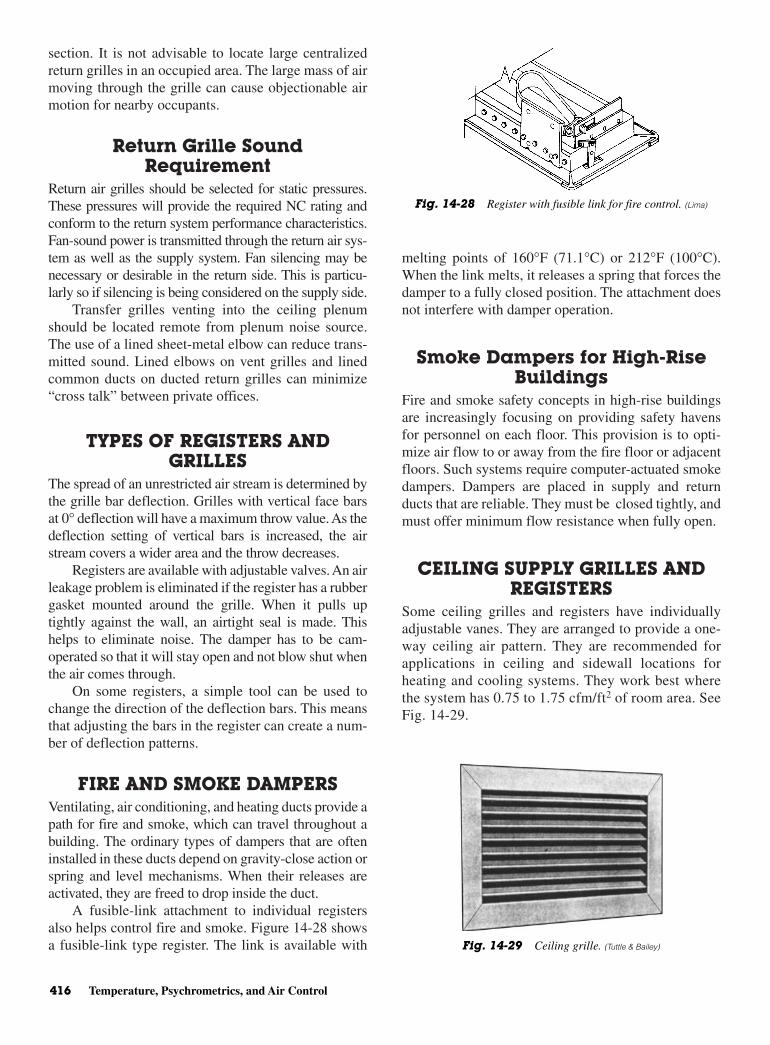
section. It is not advisable to locate large centralizedreturn grilles in an occupied area. The large mass of airmoving through the grille can cause objectionable airmotion for nearby occupants.
Return Grille SoundRequirement
Return air grilles should be selected for static pressures.These pressures will provide the required NC rating andconform to the return system performance characteristics.Fan-sound power is transmitted through the return air sys-tem as well as the supply system. Fan silencing may benecessary or desirable in the return side. This is particu-larly so if silencing is being considered on the supply side.
Transfer grilles venting into the ceiling plenumshould be located remote from plenum noise source.The use of a lined sheet-metal elbow can reduce trans-mitted sound. Lined elbows on vent grilles and linedcommon ducts on ducted return grilles can minimize“cross talk” between private offices.
TYPES OF REGISTERS ANDGRILLES
The spread of an unrestricted air stream is determined bythe grille bar deflection. Grilles with vertical face barsat 0° deflection will have a maximum throw value. As thedeflection setting of vertical bars is increased, the airstream covers a wider area and the throw decreases.
Registers are available with adjustable valves. An airleakage problem is eliminated if the register has a rubbergasket mounted around the grille. When it pulls uptightly against the wall, an airtight seal is made. Thishelps to eliminate noise. The damper has to be cam-operated so that it will stay open and not blow shut whenthe air comes through.
On some registers, a simple tool can be used tochange the direction of the deflection bars. This meansthat adjusting the bars in the register can create a num-ber of deflection patterns.
FIRE AND SMOKE DAMPERS Ventilating, air conditioning, and heating ducts provide apath for fire and smoke, which can travel throughout abuilding. The ordinary types of dampers that are ofteninstalled in these ducts depend on gravity-close action orspring and level mechanisms. When their releases areactivated, they are freed to drop inside the duct.
A fusible-link attachment to individual registersalso helps control fire and smoke. Figure 14-28 showsa fusible-link type register. The link is available with
melting points of 160°F (71.1°C) or 212°F (100°C).When the link melts, it releases a spring that forces thedamper to a fully closed position. The attachment doesnot interfere with damper operation.
Smoke Dampers for High-RiseBuildings
Fire and smoke safety concepts in high-rise buildingsare increasingly focusing on providing safety havensfor personnel on each floor. This provision is to opti-mize air flow to or away from the fire floor or adjacentfloors. Such systems require computer-actuated smokedampers. Dampers are placed in supply and returnducts that are reliable. They must be closed tightly, andmust offer minimum flow resistance when fully open.
CEILING SUPPLY GRILLES ANDREGISTERS
Some ceiling grilles and registers have individuallyadjustable vanes. They are arranged to provide a one-way ceiling air pattern. They are recommended forapplications in ceiling and sidewall locations forheating and cooling systems. They work best wherethe system has 0.75 to 1.75 cfm/ft2 of room area. SeeFig. 14-29.
416 Temperature, Psychrometrics, and Air Control
Fig. 14-28 Register with fusible link for fire control. (Lima)
Fig. 14-29 Ceiling grille. (Tuttle & Bailey)

Ceiling Diffusers 417
Some supply ceiling grilles and registers have indi-vidually adjustable curved vanes. They are arranged toprovide a three-way ceiling air pattern. The verticalface vanes are a three-way diversion for air. A horizon-tal pattern with the face vanes also produces a three-way dispersion of air. These grilles and registers arerecommended for applications in ceiling locations forheating and cooling systems handling 1.0 to 2.0 cfm/ft2
of room area.Figure 14-30 shows a grille with four-way vertical
face vanes. Horizontal face vanes are also available.They, too, are adjustable individually for focusing an airstream in any direction. Both the three-way and four-waypattern grilles can be adjusted to a full or partial downblow position. The curved streamlined vanes are adjustedto a uniform partially closed position. This deflects theair path while retaining an effective area capacity of35 percent of the neck area. In the full down blow posi-tion, grille effective area is increased by 75 percent.
Perforated adjustable diffusers for ceiling installa-tion are recommended for heating and cooling. SeeFig. 14-31. They are also recommended for jobs requir-ing on-the-job adjustment of air diffusion patterns.
Full-flow square or round necks have expandedmetal air-pattern deflectors. They are adjustable for four-,
three-, two-, or one-way horizontal diffusion patterns.This can be done without change in the air volume, pres-sure, or sound levels. This deflector and diffuser havehigh-diffusion rates. The result is rapid temperature andvelocity equalization of the mixed air mass well abovethe zone of occupancy.
They diffuse efficiently with 6 to 18 air changesper hour.
CEILING DIFFUSERSThere are other designs in ceiling diffusers. The typeshown in Fig. 14-32 is often used in a supermarket orother large store. Here, it is difficult to mount othermeans of air distribution. These round diffusers with aflush face and fixed pattern are for ceiling installation.They are used for heating, ventilating, and cooling.They are compact and simple flush diffusers. Highinduction rates result in rapid temperature and velocityequalization of the mixed air mass. Mixing is doneabove the zone of occupancy.
Grids are used and sold as an accessory to thesediffusers. The grid, see Fig. 14-33, is a multibladedevice designed to insure uniform airflow in a diffusercollar. It is individually adjustable. The blades can bemoved to control the air stream precisely.
For maximum effect, the control grid should beinstalled with the blades perpendicular to the directionof approaching airflow. Where short collars are encoun-tered, a double bank of control grids is recommended.The upper grid is placed perpendicular to the branchduct flow. The lower grid is placed parallel to thebranch duct flow. The control grid is attached to theduct collar by means of mounting straps. It is com-monly used with volume dampers.
Fig. 14-30 Vertical face vanes in a four-way ceiling supplygrille. (Tuttle & Bailey)
Fig. 14-31 Perforated face adjustable diffuser for full flow anda deflector for ceiling installation. (Tuttle & Bailey)
Fig. 14-32 Round diffusers with flush face, fixed pattern forceiling installation. (Tuttle & Bailey)
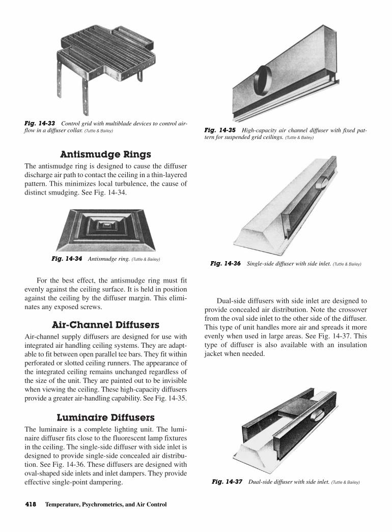
Antismudge RingsThe antismudge ring is designed to cause the diffuserdischarge air path to contact the ceiling in a thin-layeredpattern. This minimizes local turbulence, the cause ofdistinct smudging. See Fig. 14-34.
For the best effect, the antismudge ring must fitevenly against the ceiling surface. It is held in positionagainst the ceiling by the diffuser margin. This elimi-nates any exposed screws.
Air-Channel DiffusersAir-channel supply diffusers are designed for use withintegrated air handling ceiling systems. They are adapt-able to fit between open parallel tee bars. They fit withinperforated or slotted ceiling runners. The appearance ofthe integrated ceiling remains unchanged regardless ofthe size of the unit. They are painted out to be invisiblewhen viewing the ceiling. These high-capacity diffusersprovide a greater air-handling capability. See Fig. 14-35.
Luminaire DiffusersThe luminaire is a complete lighting unit. The lumi-naire diffuser fits close to the fluorescent lamp fixturesin the ceiling. The single-side diffuser with side inlet isdesigned to provide single-side concealed air distribu-tion. See Fig. 14-36. These diffusers are designed withoval-shaped side inlets and inlet dampers. They provideeffective single-point dampering.
Dual-side diffusers with side inlet are designed toprovide concealed air distribution. Note the crossoverfrom the oval side inlet to the other side of the diffuser.This type of unit handles more air and spreads it moreevenly when used in large areas. See Fig. 14-37. Thistype of diffuser is also available with an insulationjacket when needed.
418 Temperature, Psychrometrics, and Air Control
Fig. 14-33 Control grid with multiblade devices to control air-flow in a diffuser collar. (Tuttle & Bailey)
Fig. 14-34 Antismudge ring. (Tuttle & Bailey)
Fig. 14-35 High-capacity air channel diffuser with fixed pat-tern for suspended grid ceilings. (Tuttle & Bailey)
Fig. 14-36 Single-side diffuser with side inlet. (Tuttle & Bailey)
Fig. 14-37 Dual-side diffuser with side inlet. (Tuttle & Bailey)
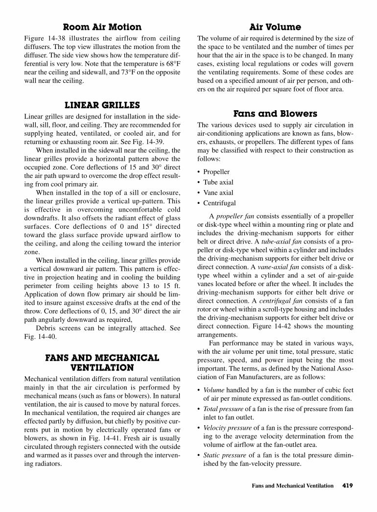
Fans and Mechanical Ventilation 419
Room Air Motion Figure 14-38 illustrates the airflow from ceilingdiffusers. The top view illustrates the motion from thediffuser. The side view shows how the temperature dif-ferential is very low. Note that the temperature is 68°Fnear the ceiling and sidewall, and 73°F on the oppositewall near the ceiling.
LINEAR GRILLES Linear grilles are designed for installation in the side-wall, sill, floor, and ceiling. They are recommended forsupplying heated, ventilated, or cooled air, and forreturning or exhausting room air. See Fig. 14-39.
When installed in the sidewall near the ceiling, thelinear grilles provide a horizontal pattern above theoccupied zone. Core deflections of 15 and 30° directthe air path upward to overcome the drop effect result-ing from cool primary air.
When installed in the top of a sill or enclosure,the linear grilles provide a vertical up-pattern. Thisis effective in overcoming uncomfortable colddowndrafts. It also offsets the radiant effect of glasssurfaces. Core deflections of 0 and 15° directedtoward the glass surface provide upward airflow tothe ceiling, and along the ceiling toward the interiorzone.
When installed in the ceiling, linear grilles providea vertical downward air pattern. This pattern is effec-tive in projection heating and in cooling the buildingperimeter from ceiling heights above 13 to 15 ft.Application of down flow primary air should be lim-ited to insure against excessive drafts at the end of thethrow. Core deflections of 0, 15, and 30° direct the airpath angularly downward as required,
Debris screens can be integrally attached. SeeFig. 14-40.
FANS AND MECHANICALVENTILATION
Mechanical ventilation differs from natural ventilationmainly in that the air circulation is performed bymechanical means (such as fans or blowers). In naturalventilation, the air is caused to move by natural forces.In mechanical ventilation, the required air changes areeffected partly by diffusion, but chiefly by positive cur-rents put in motion by electrically operated fans orblowers, as shown in Fig. 14-41. Fresh air is usuallycirculated through registers connected with the outsideand warmed as it passes over and through the interven-ing radiators.
Air VolumeThe volume of air required is determined by the size ofthe space to be ventilated and the number of times perhour that the air in the space is to be changed. In manycases, existing local regulations or codes will governthe ventilating requirements. Some of these codes arebased on a specified amount of air per person, and oth-ers on the air required per square foot of floor area.
Fans and BlowersThe various devices used to supply air circulation inair-conditioning applications are known as fans, blow-ers, exhausts, or propellers. The different types of fansmay be classified with respect to their construction asfollows:
• Propeller
• Tube axial
• Vane axial
• Centrifugal
A propeller fan consists essentially of a propelleror disk-type wheel within a mounting ring or plate andincludes the driving-mechanism supports for eitherbelt or direct drive. A tube-axial fan consists of a pro-peller or disk-type wheel within a cylinder and includesthe driving-mechanism supports for either belt drive ordirect connection. A vane-axial fan consists of a disk-type wheel within a cylinder and a set of air-guidevanes located before or after the wheel. It includes thedriving-mechanism supports for either belt drive ordirect connection. A centrifugal fan consists of a fanrotor or wheel within a scroll-type housing and includesthe driving-mechanism supports for either belt drive ordirect connection. Figure 14-42 shows the mountingarrangements.
Fan performance may be stated in various ways,with the air volume per unit time, total pressure, staticpressure, speed, and power input being the mostimportant. The terms, as defined by the National Asso-ciation of Fan Manufacturers, are as follows:
• Volume handled by a fan is the number of cubic feetof air per minute expressed as fan-outlet conditions.
• Total pressure of a fan is the rise of pressure from faninlet to fan outlet.
• Velocity pressure of a fan is the pressure correspond-ing to the average velocity determination from thevolume of airflow at the fan-outlet area.
• Static pressure of a fan is the total pressure dimin-ished by the fan-velocity pressure.
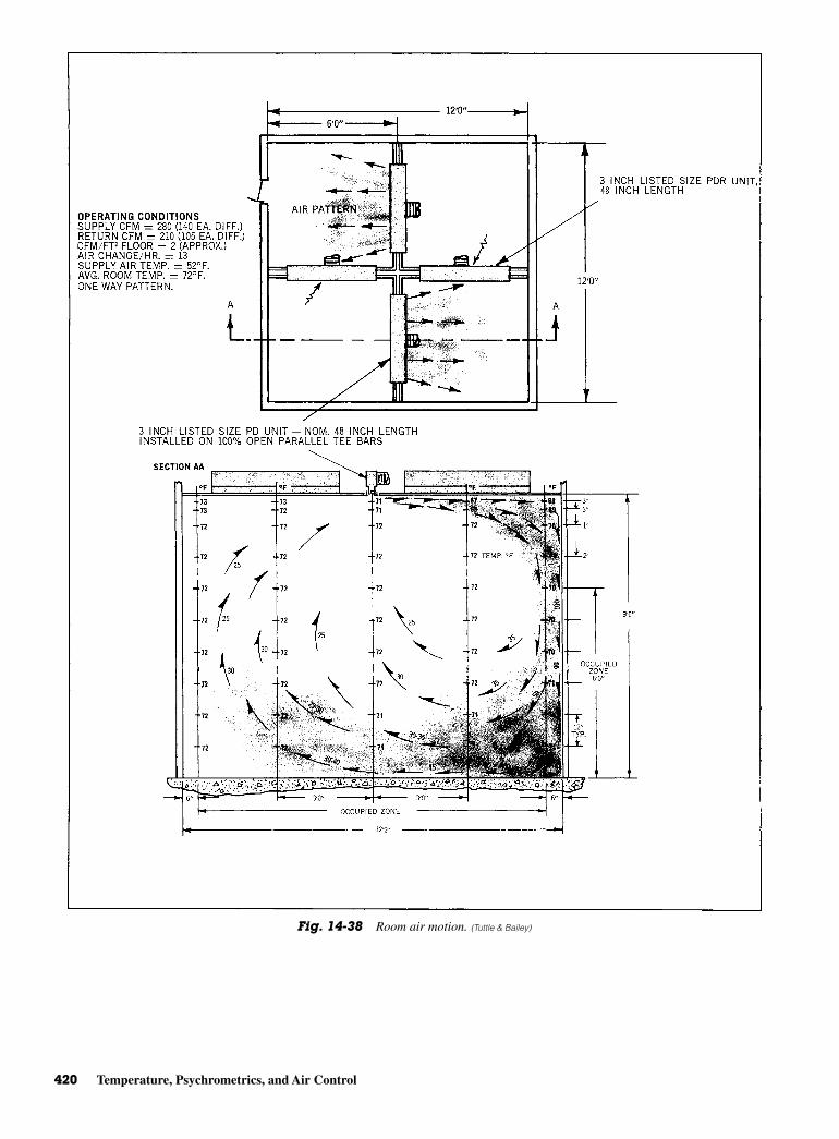
420 Temperature, Psychrometrics, and Air Control
Fig. 14-38 Room air motion. (Tuttle & Bailey)
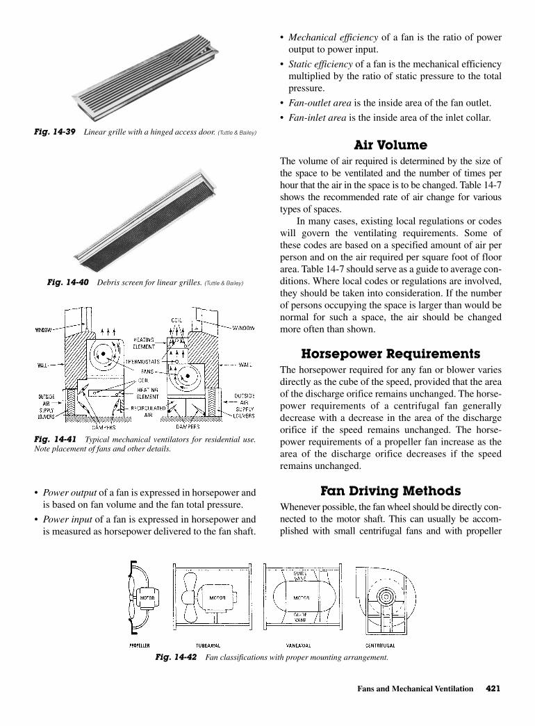
Fans and Mechanical Ventilation 421
• Power output of a fan is expressed in horsepower andis based on fan volume and the fan total pressure.
• Power input of a fan is expressed in horsepower andis measured as horsepower delivered to the fan shaft.
• Mechanical efficiency of a fan is the ratio of poweroutput to power input.
• Static efficiency of a fan is the mechanical efficiencymultiplied by the ratio of static pressure to the totalpressure.
• Fan-outlet area is the inside area of the fan outlet.
• Fan-inlet area is the inside area of the inlet collar.
Air VolumeThe volume of air required is determined by the size ofthe space to be ventilated and the number of times perhour that the air in the space is to be changed. Table 14-7shows the recommended rate of air change for varioustypes of spaces.
In many cases, existing local regulations or codeswill govern the ventilating requirements. Some ofthese codes are based on a specified amount of air perperson and on the air required per square foot of floorarea. Table 14-7 should serve as a guide to average con-ditions. Where local codes or regulations are involved,they should be taken into consideration. If the numberof persons occupying the space is larger than would benormal for such a space, the air should be changedmore often than shown.
Horsepower RequirementsThe horsepower required for any fan or blower variesdirectly as the cube of the speed, provided that the areaof the discharge orifice remains unchanged. The horse-power requirements of a centrifugal fan generallydecrease with a decrease in the area of the dischargeorifice if the speed remains unchanged. The horse-power requirements of a propeller fan increase as thearea of the discharge orifice decreases if the speedremains unchanged.
Fan Driving MethodsWhenever possible, the fan wheel should be directly con-nected to the motor shaft. This can usually be accom-plished with small centrifugal fans and with propeller
Fig. 14-39 Linear grille with a hinged access door. (Tuttle & Bailey)
Fig. 14-40 Debris screen for linear grilles. (Tuttle & Bailey)
Fig. 14-41 Typical mechanical ventilators for residential use.Note placement of fans and other details.
Fig. 14-42 Fan classifications with proper mounting arrangement.
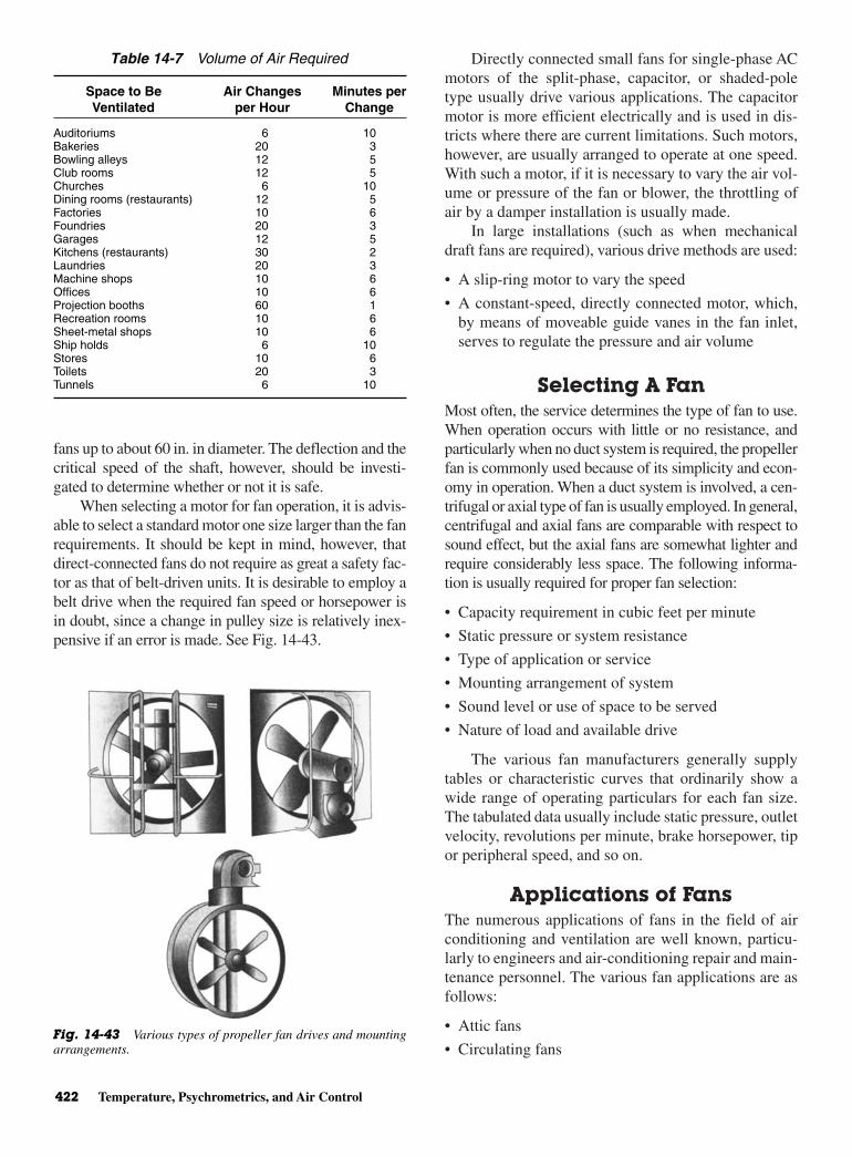
fans up to about 60 in. in diameter. The deflection and thecritical speed of the shaft, however, should be investi-gated to determine whether or not it is safe.
When selecting a motor for fan operation, it is advis-able to select a standard motor one size larger than the fanrequirements. It should be kept in mind, however, thatdirect-connected fans do not require as great a safety fac-tor as that of belt-driven units. It is desirable to employ abelt drive when the required fan speed or horsepower isin doubt, since a change in pulley size is relatively inex-pensive if an error is made. See Fig. 14-43.
Directly connected small fans for single-phase ACmotors of the split-phase, capacitor, or shaded-poletype usually drive various applications. The capacitormotor is more efficient electrically and is used in dis-tricts where there are current limitations. Such motors,however, are usually arranged to operate at one speed.With such a motor, if it is necessary to vary the air vol-ume or pressure of the fan or blower, the throttling ofair by a damper installation is usually made.
In large installations (such as when mechanicaldraft fans are required), various drive methods are used:
• A slip-ring motor to vary the speed
• A constant-speed, directly connected motor, which,by means of moveable guide vanes in the fan inlet,serves to regulate the pressure and air volume
Selecting A FanMost often, the service determines the type of fan to use.When operation occurs with little or no resistance, andparticularly when no duct system is required, the propellerfan is commonly used because of its simplicity and econ-omy in operation. When a duct system is involved, a cen-trifugal or axial type of fan is usually employed. In general,centrifugal and axial fans are comparable with respect tosound effect, but the axial fans are somewhat lighter andrequire considerably less space. The following informa-tion is usually required for proper fan selection:
• Capacity requirement in cubic feet per minute
• Static pressure or system resistance
• Type of application or service
• Mounting arrangement of system
• Sound level or use of space to be served
• Nature of load and available drive
The various fan manufacturers generally supplytables or characteristic curves that ordinarily show awide range of operating particulars for each fan size.The tabulated data usually include static pressure, outletvelocity, revolutions per minute, brake horsepower, tipor peripheral speed, and so on.
Applications of Fans The numerous applications of fans in the field of airconditioning and ventilation are well known, particu-larly to engineers and air-conditioning repair and main-tenance personnel. The various fan applications are asfollows:
• Attic fans
• Circulating fans
422 Temperature, Psychrometrics, and Air Control
Table 14-7 Volume of Air Required
Space to Be Air Changes Minutes perVentilated per Hour Change
Auditoriums 6 10Bakeries 20 3Bowling alleys 12 5Club rooms 12 5Churches 6 10Dining rooms (restaurants) 12 5Factories 10 6Foundries 20 3Garages 12 5Kitchens (restaurants) 30 2Laundries 20 3Machine shops 10 6Offices 10 6Projection booths 60 1Recreation rooms 10 6Sheet-metal shops 10 6Ship holds 6 10Stores 10 6Toilets 20 3Tunnels 6 10
Fig. 14-43 Various types of propeller fan drives and mountingarrangements.
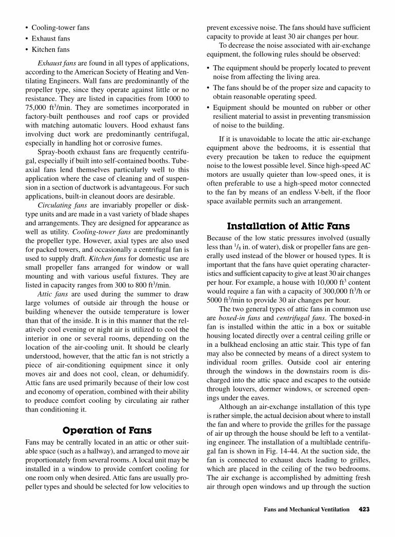
Fans and Mechanical Ventilation 423
• Cooling-tower fans
• Exhaust fans
• Kitchen fans
Exhaust fans are found in all types of applications,according to the American Society of Heating and Ven-tilating Engineers. Wall fans are predominantly of thepropeller type, since they operate against little or noresistance. They are listed in capacities from 1000 to75,000 ft3/min. They are sometimes incorporated infactory-built penthouses and roof caps or providedwith matching automatic louvers. Hood exhaust fansinvolving duct work are predominantly centrifugal,especially in handling hot or corrosive fumes.
Spray-booth exhaust fans are frequently centrifu-gal, especially if built into self-contained booths. Tube-axial fans lend themselves particularly well to thisapplication where the case of cleaning and of suspen-sion in a section of ductwork is advantageous. For suchapplications, built-in cleanout doors are desirable.
Circulating fans are invariably propeller or disk-type units and are made in a vast variety of blade shapesand arrangements. They are designed for appearance aswell as utility. Cooling-tower fans are predominantlythe propeller type. However, axial types are also usedfor packed towers, and occasionally a centrifugal fan isused to supply draft. Kitchen fans for domestic use aresmall propeller fans arranged for window or wallmounting and with various useful fixtures. They arelisted in capacity ranges from 300 to 800 ft3/min.
Attic fans are used during the summer to drawlarge volumes of outside air through the house orbuilding whenever the outside temperature is lowerthan that of the inside. It is in this manner that the rel-atively cool evening or night air is utilized to cool theinterior in one or several rooms, depending on thelocation of the air-cooling unit. It should be clearlyunderstood, however, that the attic fan is not strictly apiece of air-conditioning equipment since it onlymoves air and does not cool, clean, or dehumidify.Attic fans are used primarily because of their low costand economy of operation, combined with their abilityto produce comfort cooling by circulating air ratherthan conditioning it.
Operation of FansFans may be centrally located in an attic or other suit-able space (such as a hallway), and arranged to move airproportionately from several rooms. A local unit may beinstalled in a window to provide comfort cooling forone room only when desired. Attic fans are usually pro-peller types and should be selected for low velocities to
prevent excessive noise. The fans should have sufficientcapacity to provide at least 30 air changes per hour.
To decrease the noise associated with air-exchangeequipment, the following rules should be observed:
• The equipment should be properly located to preventnoise from affecting the living area.
• The fans should be of the proper size and capacity toobtain reasonable operating speed.
• Equipment should be mounted on rubber or otherresilient material to assist in preventing transmissionof noise to the building.
If it is unavoidable to locate the attic air-exchangeequipment above the bedrooms, it is essential thatevery precaution be taken to reduce the equipmentnoise to the lowest possible level. Since high-speed ACmotors are usually quieter than low-speed ones, it isoften preferable to use a high-speed motor connectedto the fan by means of an endless V-belt, if the floorspace available permits such an arrangement.
Installation of Attic FansBecause of the low static pressures involved (usuallyless than 1/8 in. of water), disk or propeller fans are gen-erally used instead of the blower or housed types. It isimportant that the fans have quiet operating character-istics and sufficient capacity to give at least 30 air changesper hour. For example, a house with 10,000 ft3 contentwould require a fan with a capacity of 300,000 ft3/h or5000 ft3/min to provide 30 air changes per hour.
The two general types of attic fans in common useare boxed-in fans and centrifugal fans. The boxed-infan is installed within the attic in a box or suitablehousing located directly over a central ceiling grille orin a bulkhead enclosing an attic stair. This type of fanmay also be connected by means of a direct system toindividual room grilles. Outside cool air enteringthrough the windows in the downstairs room is dis-charged into the attic space and escapes to the outsidethrough louvers, dormer windows, or screened open-ings under the eaves.
Although an air-exchange installation of this typeis rather simple, the actual decision about where to installthe fan and where to provide the grilles for the passageof air up through the house should be left to a ventilat-ing engineer. The installation of a multiblade centrifu-gal fan is shown in Fig. 14-44. At the suction side, thefan is connected to exhaust ducts leading to grilles,which are placed in the ceiling of the two bedrooms.The air exchange is accomplished by admitting freshair through open windows and up through the suction

side of the fan; the air is finally discharged through lou-vers as shown in Fig. 14-44.
Another installation is shown in Fig. 14-45. Thisfan is a centrifugal curved-blade type, mounted on alight angle-iron frame, which supports the fan wheel,shaft, and bearings. The air inlet in this installation isplaced close to a circular opening, which is cut in anairtight board partition that serves to divide the atticspace into a suction and discharge chamber. The air isadmitted through open windows and doors and is then
drawn up the attic stairway through the fan into the dis-charge chamber.
Routine Fan OperationThe routine of operation to secure the best and most effi-cient results with an attic fan is important. A typicaloperating routine might require that, in the late afternoonwhen the outdoor temperature begins to fall, the windowson the first floor and the grilles in the ceiling or the attic
424 Temperature, Psychrometrics, and Air Control
Fig. 14-44 Installing a centrifugal fan in a one-family dwelling.
Fig. 14-45 Typical attic installation of a belt-driven fan.

Review Questions 425
floor be opened and the second-floor windows keptclosed. This will place the principal cooling effect in theliving rooms. Shortly before bedtime, the first-floor win-dows may be closed and those on the second flooropened to transfer the cooling effect to the bedrooms.A suitable time clock may be used to shut the motor offbefore arising time.
VENTILATION METHODSVentilation is produced by two basic methods: naturaland mechanical. Open windows, vents, or drafts obtainnatural ventilation, whereas mechanical ventilation isproduced by the use of fans.
Thermal effect is possibly better known as flueeffect. Flue effect is the draft in a stack or chimney thatis produced within a building when the outdoor tem-perature is lower than the indoor temperature. This iscaused by the difference in weight of the warm columnof air within the building and the cooler air outside.
Air may be filtered two ways: dry filtering and wetfiltering. Various air-cleaning equipment (such as fil-tering, washing, or combined filtering and washingdevices) is used to purify the air. When designing theduct network, ample filter area must be included so thatthe air velocity passing through the filters is sufficient.Accuracy in estimating the resistance to the flow of airthrough the duct system is important in the selection ofblower motors. Resistance should be kept as low aspossible in the interest of economy. Ducts should beinstalled as short as possible.
Competent medical authorities have properlyemphasized the effect of dust on health. Air-conditioningapparatus removes these contaminants from the air.The apparatus also provides the correct amount of
moisture so that the respiratory tracts are not dehy-drated, but are kept properly moist. Dust is more thanjust dry dirt. It is a complex, variable mixture of mate-rials and, as a whole, is rather uninviting, especially thetype found in and around human habitation. Dustcontains fine particles of sand, soot, earth, rust, fiber,animal and vegetable refuse, hair, and chemicals.
REVIEW QUESTIONS1. Define temperature.2. What is the difference between absolute zero and
zero on the Fahrenheit scale?3. What is the formula for converting degrees
Fahrenheit to degrees Celsius?4. What is a manometer?5. What does psig stand for?6. What is the meaning of psia?7. What is the difference between a wet-bulb ther-
mometer and a dry-bulb thermometer?8. Define dew point.9. What is relative humidity?
10. What is a psychrometric chart?11. How is a psychrometeric chart used in designing
cooling systems?12. What is enthalpy?13. What is the purpose of ducturns?14. Name at least three factors to be considered when
selecting and sizing diffusers and grilles.15. Name two ways to minimize air noise. 16. What is vortex shedding?17. How do you minimize or eliminate cross talk
between private offices due to the air-distributionsystem?
18. What is a fusible link?

This page intentionally left blank

15CHAPTER
Comfort AirConditioning
Copyright © 2006 by The McGraw-Hill Companies, Inc. Click here for terms of use.

PERFORMANCE OBJECTIVESAfter studying this chapter you will:
1. Know how to mount window units properly.
2. Know how to select the proper plug for operationof a window unit.
3. Know how to install a basement located furnacewith air-conditioning ability.
4. Know how to install single-package rooftop units.
5. Understand the refrigerant piping for the rooftopunit.
6. Know how to select the proper copper tubing suc-tion line for a unit.
7. Know how to select the proper copper tubing liq-uid line and size the installation.
8. Know how to troubleshoot mobile home units.
9. Know how to troubleshoot hermetic compressortype air-conditioning equipment.
10. Understand the newer types of ductless air condi-tioners and their controls.
Most of us think of window air conditioners whenwe think of motels and homes in areas where central airconditioning throughout the house is not affordable.These units require a lot of attention from the mainte-nance person inasmuch as they are operated by a numberof different people, and children can reach the controls.
WINDOW UNITSRoom air conditioners are appliances that cool, dehumid-ify, filter, and circulate air. See Fig. 15-1. There are several
manufacturers of window-mounted air-conditioningunits. No attempt is being made here to represent all ofthem. Some general information is needed to help therepairperson make recommendations to those whorequest information on various units.
Today, energy conservation is important. Thus, mostmanufacturers specify the energy savings their unit willproduce. The best way to determine the amount ofenergy consumed is to check the electrical requirementsof the unit. Check this figure with the Btu generated bythat power. Room air conditioners are usually ratedaccording to the number of Btu they will produce incooling. The smallest unit is about 5000 Btu. Thus, it ispossible to determine which unit can produce a greateramount of cooling in terms of Btu per kilowatt hour.
Figure 15-2 shows a room air conditioner with thecover removed. The compressor, fan, evaporator, andcondenser are visible. The three main parts of an airconditioner are the fan, filter, and cooling element. Thefan pulls warm moist air into the unit. The air is movedthrough the filter, where dust particles are removed.Next, the air is passed over the cooling element, whereit is cooled and dehumidified. The fan then returns theconditioned air to the room. This conditioned air hasbeen cooled, dehumidified, and filtered.
MountingWindow units are mounted in several different ways.Some are mounted in windows and some are mountedin a hole in the wall. The hole-in-the-wall mount is usu-ally designed into the building at the time it is con-structed. Different window types require that adapters
428 Comfort Air Conditioning
Fig. 15-1 Window-mounted air-conditioning unit. (Admiral)
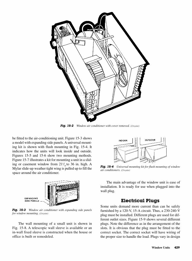
Window Units 429
be fitted to the air-conditioning unit. Figure 15-3 showsa model with expanding side panels. A universal mount-ing kit is shown with flush mounting in Fig. 15-4. Itindicates how the units will look inside and outside.Figures 15-5 and 15-6 show two mounting methods.Figure 15-7 illustrates a kit for mounting a unit in a slid-ing or casement window from 211/4 to 36 in. high. AMylar slide-up weather tight wing is pulled up to fill thespace around the air conditioner.
The wall mounting of a small unit is shown inFig. 15-8. A telescopic wall sleeve is available or anin-wall fixed sleeve is constructed when the house oroffice is built or remodeled.
The main advantage of the window unit is ease ofinstallation. It is ready for use when plugged into thewall plug.
Electrical PlugsSome units demand more current than can be safelyfurnished by a 120-V, 15-A circuit. Thus, a 230-240-Vplug must be installed. Different plugs are used for dif-ferent outlet sizes. Figure 15-9 shows several differentplugs. Note the difference as in the arrangement of theslots. It is obvious that the plug must be fitted to thecorrect socket. The correct socket will have wiring ofthe proper size to handle the load. Plugs vary in design
Fig. 15-2 Window air conditioner with cover removed. (Chrysler)
Fig. 15-3 Window air conditioner with expanding side panelsfor window mounting. (Chrysler)
Fig. 15-4 Universal mounting kit for flush mounting of windowair conditioners. (Chrysler)
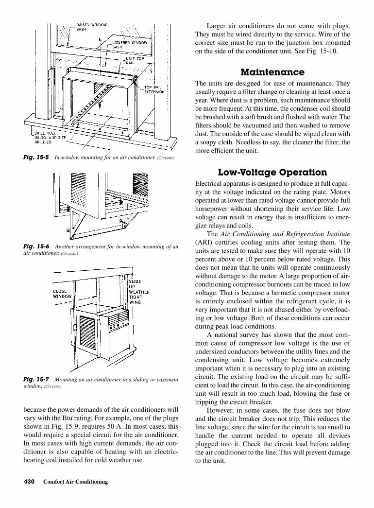
430 Comfort Air Conditioning
because the power demands of the air conditioners willvary with the Btu rating. For example, one of the plugsshown in Fig. 15-9, requires 50 A. In most cases, thiswould require a special circuit for the air conditioner.In most cases with high current demands, the air con-ditioner is also capable of heating with an electric-heating coil installed for cold weather use.
Larger air conditioners do not come with plugs.They must be wired directly to the service. Wire of thecorrect size must be run to the junction box mountedon the side of the conditioner unit. See Fig. 15-10.
MaintenanceThe units are designed for ease of maintenance. Theyusually require a filter change or cleaning at least once ayear. Where dust is a problem, such maintenance shouldbe more frequent. At this time, the condenser coil shouldbe brushed with a soft brush and flushed with water. Thefilters should be vacuumed and then washed to removedust. The outside of the case should be wiped clean witha soapy cloth. Needless to say, the cleaner the filter, themore efficient the unit.
Low-Voltage OperationElectrical apparatus is designed to produce at full capac-ity at the voltage indicated on the rating plate. Motorsoperated at lower than rated voltage cannot provide fullhorsepower without shortening their service life. Lowvoltage can result in energy that is insufficient to ener-gize relays and coils.
The Air Conditioning and Refrigeration Institute(ARI) certifies cooling units after testing them. Theunits are tested to make sure they will operate with 10percent above or 10 percent below rated voltage. Thisdoes not mean that he units will operate continuouslywithout damage to the motor. A large proportion of air-conditioning compressor burnouts can be traced to lowvoltage. That is because a hermetic compressor motoris entirely enclosed within the refrigerant cycle, it isvery important that it is not abused either by overload-ing or low voltage. Both of these conditions can occurduring peak load conditions.
A national survey has shown that the most com-mon cause of compressor low voltage is the use ofundersized conductors between the utility lines and thecondensing unit. Low voltage becomes extremelyimportant when it is necessary to plug into an existingcircuit. The existing load on the circuit may be suffi-cient to load the circuit. In this case, the air-conditioningunit will result in too much load, blowing the fuse ortripping the circuit breaker.
However, in some cases, the fuse does not blowand the circuit breaker does not trip. This reduces theline voltage, since the wire for the circuit is too small tohandle the current needed to operate all devicesplugged into it. Check the circuit load before addingthe air conditioner to the line. This will prevent damageto the unit.
Fig. 15-5 In-window mounting for an air conditioner. (Chrysler)
Fig. 15-6 Another arrangement for in-window mounting of anair conditioner. (Chrysler)
Fig. 15-7 Mounting an air conditioner in a sliding or casementwindow. (Chrysler)
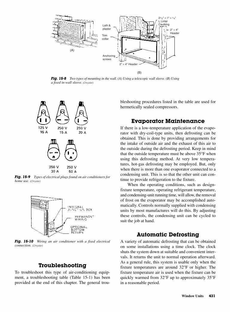
Window Units 431
TroubleshootingTo troubleshoot this type of air-conditioning equip-ment, a troubleshooting table (Table 15-1) has beenprovided at the end of this chapter. The general trou-
bleshooting procedures listed in the table are used forhermetically sealed compressors.
Evaporator MaintenanceIf there is a low-temperature application of the evapo-rator with dry-coil-type units, then defrosting can beobtained. This is done by providing arrangements forthe intake of outside air and the exhaust of this air tothe outside during the defrosting period. Keep in mindthat the outside temperature must be above 35°F whenusing this defrosting method. At very low tempera-tures, hot-gas defrosting may be employed. But, onlywhen there is more than one evaporator connected to acondensing unit. This is so that the other unit can con-tinue to provide refrigeration to the fixture.
When the operating conditions, such as design-fixture temperature, operating refrigerant temperature,and condensing-unit running time, will allow, the removalof frost on the evaporator may be accomplished auto-matically. Controls normally supplied with condensingunits by most manufactures will do this. By adjustingthese controls, the condensing unit can be cycled tosuit the job at hand.
Automatic DefrostingA variety of automatic defrosting that can be obtainedon some installations using a time clock. The clockshuts the system down at suitable and convenient inter-vals. It returns the unit to normal operation afterward.As a general rule, this system is usable only when thefixture temperatures are around 32°F or higher. Thefixture temperature air is used when the fixture can bequickly warmed from 32°F up to approximately 35°Fin a reasonable period.
Lath & plaster
Trim collar
Anchoring screws
2" × 4" Header
21/2" × 3" × 1/4"L LintelCaulking
2" × 4" Header
(B)
(A)
Fig. 15-8 Two types of mounting in the wall. (A) Using a telescopic wall sleeve. (B) Usinga fixed in-wall sleeve. (Chrysler)
Fig. 15-9 Types of electrical plugs found on air conditioners forhome use. (Chrysler)
Fig. 15-10 Wiring an air conditioner with a fixed electricalconnection. (Chrysler)
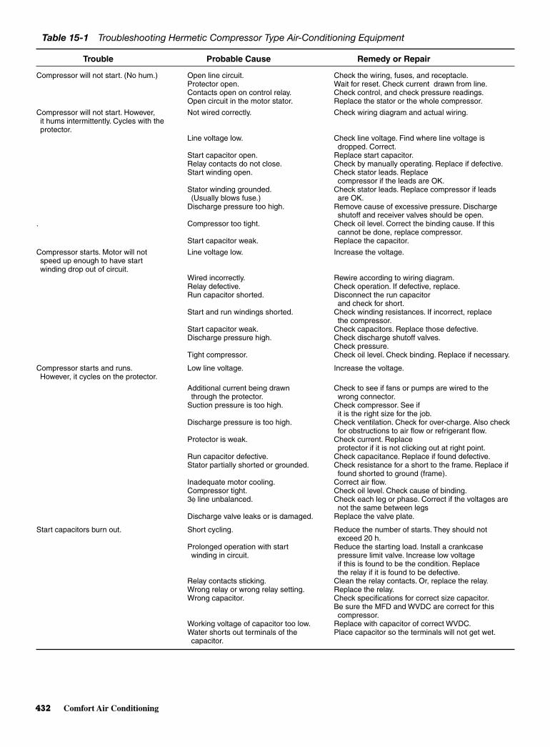
432 Comfort Air Conditioning
Table 15-1 Troubleshooting Hermetic Compressor Type Air-Conditioning Equipment
Trouble Probable Cause Remedy or Repair
Compressor will not start. (No hum.) Open line circuit. Check the wiring, fuses, and receptacle.Protector open. Wait for reset. Check current drawn from line.Contacts open on control relay. Check control, and check pressure readings.Open circuit in the motor stator. Replace the stator or the whole compressor.
Compressor will not start. However, Not wired correctly. Check wiring diagram and actual wiring.it hums intermittently. Cycles with theprotector.
Line voltage low. Check line voltage. Find where line voltage isdropped. Correct.
Start capacitor open. Replace start capacitor.Relay contacts do not close. Check by manually operating. Replace if defective.Start winding open. Check stator leads. Replace
compressor if the leads are OK.Stator winding grounded. Check stator leads. Replace compressor if leads(Usually blows fuse.) are OK.
Discharge pressure too high. Remove cause of excessive pressure. Dischargeshutoff and receiver valves should be open.
. Compressor too tight. Check oil level. Correct the binding cause. If thiscannot be done, replace compressor.
Start capacitor weak. Replace the capacitor.
Compressor starts. Motor will not Line voltage low. Increase the voltage.speed up enough to have startwinding drop out of circuit.
Wired incorrectly. Rewire according to wiring diagram.Relay defective. Check operation. If defective, replace.Run capacitor shorted. Disconnect the run capacitor
and check for short.Start and run windings shorted. Check winding resistances. If incorrect, replace
the compressor.Start capacitor weak. Check capacitors. Replace those defective.Discharge pressure high. Check discharge shutoff valves.
Check pressure.Tight compressor. Check oil level. Check binding. Replace if necessary.
Compressor starts and runs. Low line voltage. Increase the voltage.However, it cycles on the protector.
Additional current being drawn Check to see if fans or pumps are wired to the through the protector. wrong connector.
Suction pressure is too high. Check compressor. See ifit is the right size for the job.
Discharge pressure is too high. Check ventilation. Check for over-charge. Also checkfor obstructions to air flow or refrigerant flow.
Protector is weak. Check current. Replace protector if it is not clicking out at right point.
Run capacitor defective. Check capacitance. Replace if found defective.Stator partially shorted or grounded. Check resistance for a short to the frame. Replace if
found shorted to ground (frame).Inadequate motor cooling. Correct air flow.Compressor tight. Check oil level. Check cause of binding.3φ line unbalanced. Check each leg or phase. Correct if the voltages are
not the same between legsDischarge valve leaks or is damaged. Replace the valve plate.
Start capacitors burn out. Short cycling. Reduce the number of starts. They should notexceed 20 h.
Prolonged operation with start Reduce the starting load. Install a crankcasewinding in circuit. pressure limit valve. Increase low voltage
if this is found to be the condition. Replacethe relay if it is found to be defective.
Relay contacts sticking. Clean the relay contacts. Or, replace the relay.Wrong relay or wrong relay setting. Replace the relay.Wrong capacitor. Check specifications for correct size capacitor.
Be sure the MFD and WVDC are correct for thiscompressor.
Working voltage of capacitor too low. Replace with capacitor of correct WVDC.Water shorts out terminals of the Place capacitor so the terminals will not get wet.capacitor.
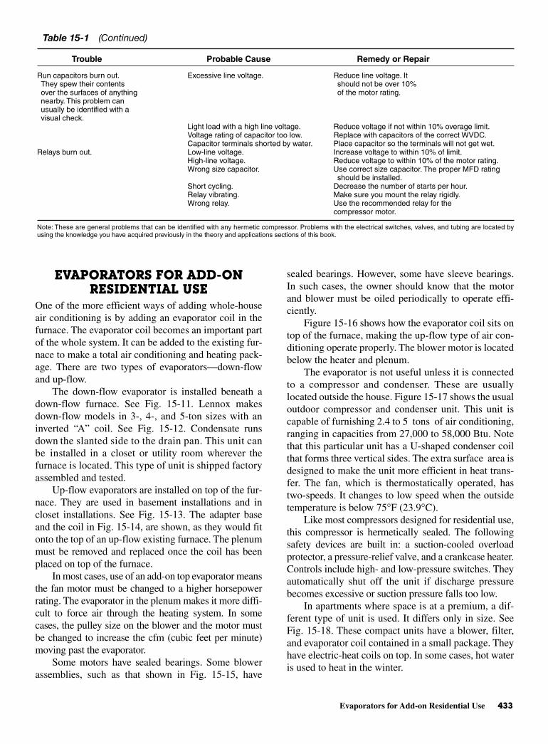
Evaporators for Add-on Residential Use 433
EVAPORATORS FOR ADD-ONRESIDENTIAL USE
One of the more efficient ways of adding whole-houseair conditioning is by adding an evaporator coil in thefurnace. The evaporator coil becomes an important partof the whole system. It can be added to the existing fur-nace to make a total air conditioning and heating pack-age. There are two types of evaporators—down-flowand up-flow.
The down-flow evaporator is installed beneath adown-flow furnace. See Fig. 15-11. Lennox makesdown-flow models in 3-, 4-, and 5-ton sizes with aninverted “A” coil. See Fig. 15-12. Condensate runsdown the slanted side to the drain pan. This unit canbe installed in a closet or utility room wherever thefurnace is located. This type of unit is shipped factoryassembled and tested.
Up-flow evaporators are installed on top of the fur-nace. They are used in basement installations and incloset installations. See Fig. 15-13. The adapter baseand the coil in Fig. 15-14, are shown, as they would fitonto the top of an up-flow existing furnace. The plenummust be removed and replaced once the coil has beenplaced on top of the furnace.
In most cases, use of an add-on top evaporator meansthe fan motor must be changed to a higher horsepowerrating. The evaporator in the plenum makes it more diffi-cult to force air through the heating system. In somecases, the pulley size on the blower and the motor mustbe changed to increase the cfm (cubic feet per minute)moving past the evaporator.
Some motors have sealed bearings. Some blowerassemblies, such as that shown in Fig. 15-15, have
sealed bearings. However, some have sleeve bearings.In such cases, the owner should know that the motorand blower must be oiled periodically to operate effi-ciently.
Figure 15-16 shows how the evaporator coil sits ontop of the furnace, making the up-flow type of air con-ditioning operate properly. The blower motor is locatedbelow the heater and plenum.
The evaporator is not useful unless it is connectedto a compressor and condenser. These are usuallylocated outside the house. Figure 15-17 shows the usualoutdoor compressor and condenser unit. This unit iscapable of furnishing 2.4 to 5 tons of air conditioning,ranging in capacities from 27,000 to 58,000 Btu. Notethat this particular unit has a U-shaped condenser coilthat forms three vertical sides. The extra surface area isdesigned to make the unit more efficient in heat trans-fer. The fan, which is thermostatically operated, hastwo-speeds. It changes to low speed when the outsidetemperature is below 75°F (23.9°C).
Like most compressors designed for residential use,this compressor is hermetically sealed. The followingsafety devices are built in: a suction-cooled overloadprotector, a pressure-relief valve, and a crankcase heater.Controls include high- and low-pressure switches. Theyautomatically shut off the unit if discharge pressurebecomes excessive or suction pressure falls too low.
In apartments where space is at a premium, a dif-ferent type of unit is used. It differs only in size. SeeFig. 15-18. These compact units have a blower, filter,and evaporator coil contained in a small package. Theyhave electric-heat coils on top. In some cases, hot wateris used to heat in the winter.
Table 15-1 (Continued)
Trouble Probable Cause Remedy or Repair
Run capacitors burn out. Excessive line voltage. Reduce line voltage. It They spew their contents should not be over 10%over the surfaces of anything of the motor rating.nearby. This problem canusually be identified with avisual check.
Light load with a high line voltage. Reduce voltage if not within 10% overage limit.Voltage rating of capacitor too low. Replace with capacitors of the correct WVDC.Capacitor terminals shorted by water. Place capacitor so the terminals will not get wet.
Relays burn out. Low-line voltage. Increase voltage to within 10% of limit.High-line voltage. Reduce voltage to within 10% of the motor rating.Wrong size capacitor. Use correct size capacitor. The proper MFD rating
should be installed.Short cycling. Decrease the number of starts per hour.Relay vibrating. Make sure you mount the relay rigidly.Wrong relay. Use the recommended relay for the
compressor motor.
Note: These are general problems that can be identified with any hermetic compressor. Problems with the electrical switches, valves, and tubing are located byusing the knowledge you have acquired previously in the theory and applications sections of this book.

434 Comfort Air Conditioning
Fig. 15-11 Utility room installation of a down-flow evaporator on an existingfurnace. (Lennox)
Fig. 15-12 Evaporator units for add-on cooling for up-flow and down-flow furnaces. (Lennox)
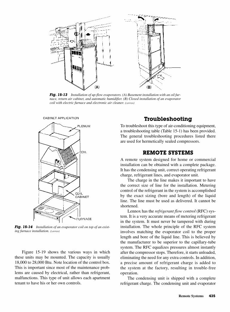
Remote Systems 435
Figure 15-19 shows the various ways in whichthese units may be mounted. The capacity is usually18,000 to 28,000 Btu. Note location of the control box.This is important since most of the maintenance prob-lems are caused by electrical, rather than refrigerant,malfunctions. This type of unit allows each apartmenttenant to have his or her own controls.
TroubleshootingTo troubleshoot this type of air-conditioning equipment,a troubleshooting table (Table 15-1) has been provided.The general troubleshooting procedures listed thereare used for hermetically sealed compressors.
REMOTE SYSTEMSA remote system designed for home or commercialinstallation can be obtained with a complete package.It has the condensing unit, correct operating refrigerantcharge, refrigerant lines, and evaporator unit.
The charge in the line makes it important to havethe correct size of line for the installation. Meteringcontrol of the refrigerant in the system is accomplishedby the exact sizing (bore and length) of the liquidline. The line must be used as delivered. It cannot beshortened.
Lennox has the refrigerant flow control (RFC) sys-tem. It is a very accurate means of metering refrigerantin the system. It must never be tampered with duringinstallation. The whole principle of the RFC systeminvolves matching the evaporator coil to the properlength and bore of the liquid line. This is believed bythe manufacturer to be superior to the capillary-tubesystem. The RFC equalizes pressures almost instantlyafter the compressor stops. Therefore, it starts unloaded,eliminating the need for any extra controls. In addition,a precise amount of refrigerant charge is added tothe system at the factory, resulting in trouble-freeoperation.
The condensing unit is shipped with a completerefrigerant charge. The condensing unit and evaporator
Fig. 15-13 Installation of up-flow evaporators. (A) Basement installation with an oil fur-nace, return air cabinet, and automatic humidifier. (B) Closed installation of an evaporatorcoil with electric furnace and electronic air cleaner. (Lennox)
Fig. 15-14 Installation of an evaporator coil on top of an exist-ing furnace installation. (Lennox)
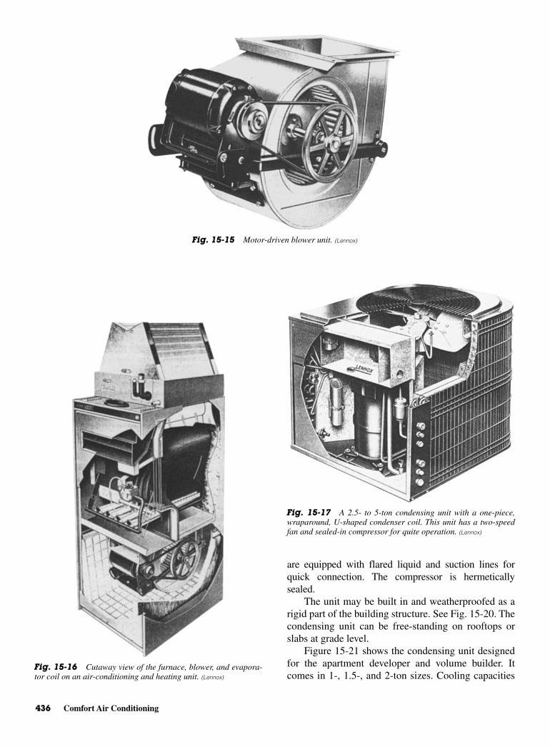
436 Comfort Air Conditioning
are equipped with flared liquid and suction lines forquick connection. The compressor is hermeticallysealed.
The unit may be built in and weatherproofed as arigid part of the building structure. See Fig. 15-20. Thecondensing unit can be free-standing on rooftops orslabs at grade level.
Figure 15-21 shows the condensing unit designedfor the apartment developer and volume builder. Itcomes in 1-, 1.5-, and 2-ton sizes. Cooling capacities
Fig. 15-15 Motor-driven blower unit. (Lennox)
Fig. 15-16 Cutaway view of the furnace, blower, and evapora-tor coil on an air-conditioning and heating unit. (Lennox)
Fig. 15-17 A 2.5- to 5-ton condensing unit with a one-piece,wraparound, U-shaped condenser coil. This unit has a two-speedfan and sealed-in compressor for quite operation. (Lennox)
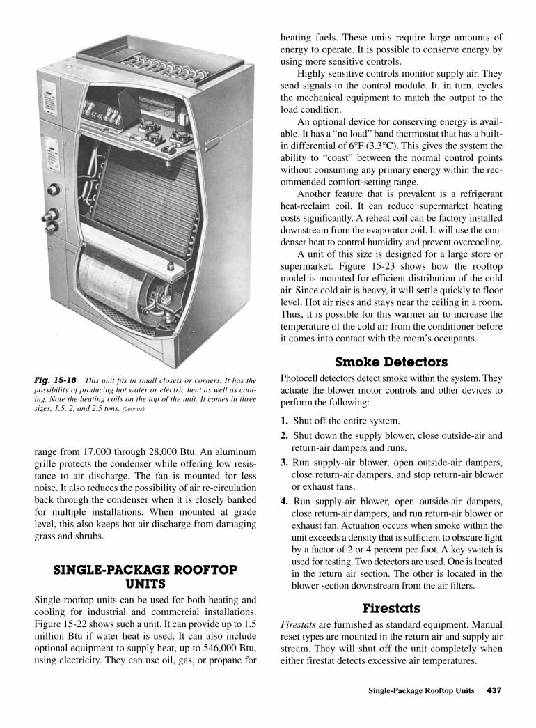
Single-Package Rooftop Units 437
range from 17,000 through 28,000 Btu. An aluminumgrille protects the condenser while offering low resis-tance to air discharge. The fan is mounted for lessnoise. It also reduces the possibility of air re-circulationback through the condenser when it is closely bankedfor multiple installations. When mounted at gradelevel, this also keeps hot air discharge from damaginggrass and shrubs.
SINGLE-PACKAGE ROOFTOPUNITS
Single-rooftop units can be used for both heating andcooling for industrial and commercial installations.Figure 15-22 shows such a unit. It can provide up to 1.5million Btu if water heat is used. It can also includeoptional equipment to supply heat, up to 546,000 Btu,using electricity. They can use oil, gas, or propane for
heating fuels. These units require large amounts ofenergy to operate. It is possible to conserve energy byusing more sensitive controls.
Highly sensitive controls monitor supply air. Theysend signals to the control module. It, in turn, cyclesthe mechanical equipment to match the output to theload condition.
An optional device for conserving energy is avail-able. It has a “no load” band thermostat that has a built-in differential of 6°F (3.3°C). This gives the system theability to “coast” between the normal control pointswithout consuming any primary energy within the rec-ommended comfort-setting range.
Another feature that is prevalent is a refrigerantheat-reclaim coil. It can reduce supermarket heatingcosts significantly. A reheat coil can be factory installeddownstream from the evaporator coil. It will use the con-denser heat to control humidity and prevent overcooling.
A unit of this size is designed for a large store orsupermarket. Figure 15-23 shows how the rooftopmodel is mounted for efficient distribution of the coldair. Since cold air is heavy, it will settle quickly to floorlevel. Hot air rises and stays near the ceiling in a room.Thus, it is possible for this warmer air to increase thetemperature of the cold air from the conditioner beforeit comes into contact with the room’s occupants.
Smoke DetectorsPhotocell detectors detect smoke within the system. Theyactuate the blower motor controls and other devices toperform the following:
1. Shut off the entire system.
2. Shut down the supply blower, close outside-air andreturn-air dampers and runs.
3. Run supply-air blower, open outside-air dampers,close return-air dampers, and stop return-air bloweror exhaust fans.
4. Run supply-air blower, open outside-air dampers,close return-air dampers, and run return-air blower orexhaust fan. Actuation occurs when smoke within theunit exceeds a density that is sufficient to obscure lightby a factor of 2 or 4 percent per foot. A key switch isused for testing. Two detectors are used. One is locatedin the return air section. The other is located in theblower section downstream from the air filters.
FirestatsFirestats are furnished as standard equipment. Manualreset types are mounted in the return air and supply airstream. They will shut off the unit completely wheneither firestat detects excessive air temperatures.
Fig. 15-18 This unit fits in small closets or corners. It has thepossibility of producing hot water or electric heat as well as cool-ing. Note the heating coils on the top of the unit. It comes in threesizes, 1.5, 2, and 2.5 tons. (Lennox)

438 Comfort Air Conditioning
On this type of unit, the blowers are turned by onemotor with a shaft connecting the two fans. There arethree small fan motors and blades mounted to exhaustair from the unit. There are four condenser fans. Theevaporator coil is slanted. There are two condenser coilsmounted at angles. There are two compressors. Thepath for the return air is through the filters and evapora-tor coil back to the supply-air ductwork.
Return-Air SystemsReturn-air systems are generally one of two types: theducted return-air system or the open plenum return-airsystem (“sandwich space”). See Fig. 15-24. The ductedreturn-air system duct is lined with insulation, whichgreatly reduces noise.
The open-plenum system eliminates the cost ofreturn-air returns or ducts and is extremely flexible. Ina building with relocatable interior walls, it is much
easier to change the location of a ceiling grille thanreroute a ducted return system.
Acoustical Treatment Insulating the supply duct reduces duct loss or gain andprevents condensation. Use 11/2-lb density on ductsthat deliver air velocities up to 1500 fpm.
Three-pound density or neoprene-coated insula-tion is recommended for ducts that handle air at veloc-ities greater than 1500 fpm. Insulation can be 1/2 or 1 in.thick on the inside of the duct.
Where rooftop equipment uses the sandwich spacefor the return air system, a return air chamber should beconnected to the air-inlet opening. Such an air chamberis shown in Fig. 15-24. This reduces air handling soundtransmission through the thin ceiling panels. It shouldbe sized not to exceed 1500-fpm return-air velocity.The duct can be fiberglass or a fiberglass-lined metal
Fig. 15-19 Typical installations of the blower, coil, and filter units. (A) A closet installation with electric-heat section. (B) A utility-room installation. (C) A wall-mounted installation with hot-water section. (Lennox)
Fig. 15-20 Three typical condensing applications. (Lennox)
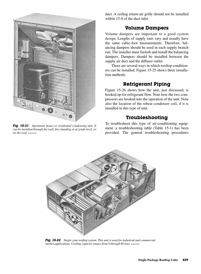
Single-Package Rooftop Units 439
duct. A ceiling return-air grille should not be installedwithin 15 ft of the duct inlet.
Volume Dampers Volume dampers are important to a good systemdesign. Lengths of supply runs vary and usually havethe same cubic-foot measurements. Therefore, bal-ancing dampers should be used in each supply branchrun. The installer must furnish and install the balancingdampers. Dampers should be installed between thesupply air duct and the diffuser outlet.
There are several ways in which rooftop condition-ers can be installed. Figure 15-25 shows three installa-tion methods.
Refrigerant PipingFigure 15-26 shows how the unit, just discussed, ishooked up for refrigerant flow. Note how the two com-pressors are hooked into the operation of the unit. Notealso the location of the reheat condenser coil, if it isinstalled in this type of unit.
TroubleshootingTo troubleshoot this type of air-conditioning equip-ment, a troubleshooting table (Table 15-1) has beenprovided. The general troubleshooting procedures
Fig. 15-21 Apartment house or residential condensing unit. Itcan be installed through the wall, free standing or at grade level, oron the roof. (Lennox)
Fig. 15-22 Single-zone rooftop system. This unit is used for industrial and commercial-market applications. Cooling capacity ranges from 8 through 60 tons. (Lennox)
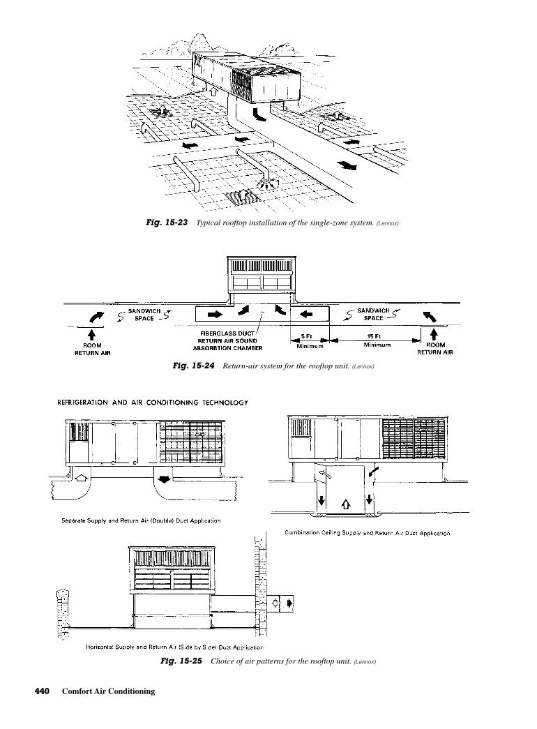
440 Comfort Air Conditioning
Fig. 15-23 Typical rooftop installation of the single-zone system. (Lennox)
Fig. 15-24 Return-air system for the rooftop unit. (Lennox)
Fig. 15-25 Choice of air patterns for the rooftop unit. (Lennox)
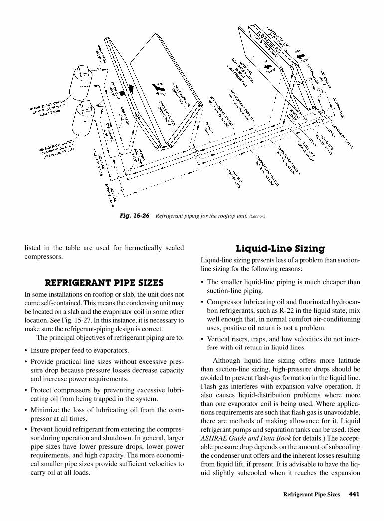
Refrigerant Pipe Sizes 441
listed in the table are used for hermetically sealedcompressors.
REFRIGERANT PIPE SIZESIn some installations on rooftop or slab, the unit does notcome self-contained. This means the condensing unit maybe located on a slab and the evaporator coil in some otherlocation. See Fig. 15-27. In this instance, it is necessary tomake sure the refrigerant-piping design is correct.
The principal objectives of refrigerant piping are to:
• Insure proper feed to evaporators.
• Provide practical line sizes without excessive pres-sure drop because pressure losses decrease capacityand increase power requirements.
• Protect compressors by preventing excessive lubri-cating oil from being trapped in the system.
• Minimize the loss of lubricating oil from the com-pressor at all times.
• Prevent liquid refrigerant from entering the compres-sor during operation and shutdown. In general, largerpipe sizes have lower pressure drops, lower powerrequirements, and high capacity. The more economi-cal smaller pipe sizes provide sufficient velocities tocarry oil at all loads.
Liquid-Line SizingLiquid-line sizing presents less of a problem than suction-line sizing for the following reasons:
• The smaller liquid-line piping is much cheaper thansuction-line piping.
• Compressor lubricating oil and fluorinated hydrocar-bon refrigerants, such as R-22 in the liquid state, mixwell enough that, in normal comfort air-conditioninguses, positive oil return is not a problem.
• Vertical risers, traps, and low velocities do not inter-fere with oil return in liquid lines.
Although liquid-line sizing offers more latitudethan suction-line sizing, high-pressure drops should beavoided to prevent flash-gas formation in the liquid line.Flash gas interferes with expansion-valve operation. Italso causes liquid-distribution problems where morethan one evaporator coil is being used. Where applica-tions requirements are such that flash gas is unavoidable,there are methods of making allowance for it. Liquidrefrigerant pumps and separation tanks can be used. (SeeASHRAE Guide and Data Book for details.) The accept-able pressure drop depends on the amount of subcoolingthe condenser unit offers and the inherent losses resultingfrom liquid lift, if present. It is advisable to have the liq-uid slightly subcooled when it reaches the expansion
Fig. 15-26 Refrigerant piping for the rooftop unit. (Lennox)
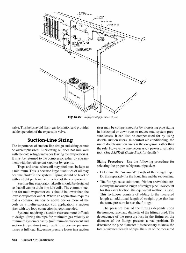
442 Comfort Air Conditioning
valve. This helps avoid flash-gas formation and providesstable operation of the expansion valve.
Suction-Line SizingThe importance of suction-line design and sizing cannotbe overemphasized. Lubricating oil does not mix wellwith the cold refrigerant vapor leaving the evaporator(s).It must be returned to the compressor either by entrain-ment with the refrigerant vapor or by gravity.
Traps and areas where oil may pool must be kept toa minimum. This is because large quantities of oil maybecome “lost” in the system. Piping should be level orwith a slight pitch in the direction of the compressor.
Suction-line evaporator takeoffs should be designedso that oil cannot drain into idle coils. The common suc-tion for multievaporator coils should be lower than thelowest evaporator outlet. Where an application requiresthat a common suction be above one or more of thecoils on a multievaporator coil application, a suctionriser with top loop connection is recommended.
Systems requiring a suction riser are more difficultto design. Sizing the pipe for minimum gas velocity atminimum system capacity (minimum displacement andsuction temperature) may result in excessive pressurelosses at full load. Excessive pressure losses in a suction
riser may be compensated for by increasing pipe sizingin horizontal or down runs to reduce total system pres-sure losses. It can also be compensated for by usingdouble suction risers. In comfort air conditioning, theuse of double-suction risers is the exception, rather thanthe rule. However, where necessary, it proves a valuabletool. (See ASHRAE Guide Book for details.)
Sizing Procedure Use the following procedure forselecting the proper refrigerant pipe size:
• Determine the “measured” length of the straight pipe.Do this separately for the liquid line and the suction line.
• The fittings cause additional friction above that cre-ated by the measured length of straight pipe. To accountfor this extra friction, the equivalent method is used.This technique consists of adding to the measuredlength an additional length of straight pipe that hasthe same pressure loss as the fittings.
The pressure loss of the fittings depends uponthe number, type, and diameter of the fittings used. Thedependence of the pressure loss in the fitting on thediameter of the fittings presents a real problem. Todetermine the pipe diameter, it is necessary to know thetotal equivalent length of pipe, the sum of the measured
Fig.15-27 Refrigerant pipe sizes. (Bryant)

Refrigerant Pipe Sizes 443
straight pipe length, and the fitting losses in equivalentpipe length. On the other hand, since the fitting pres-sure losses do depend upon diameter, it is necessary toknow the diameter of the pipe to determine the fittinglosses in equivalent pipe length.
The result is a situation in which it seems that thesolution is needed to solve the problem. Fortunately, ifthe pipe diameter can be estimated with reasonableaccuracy, the fitting losses can be determined. In turn,the correct pipe diameter can be determined.
A pipe diameter selection based upon 1.5 times themeasured straight pipe length can be used to obtain anestimate of the pipe diameter.
• In the majority of applications, the design conditionsare a pressure loss equal to 2°F (1.1°C), a suctiontemperature of 40°F (4.4°C), and a condensing tem-perature of 105°F (40.6°C).
• Once the estimated pipe diameter is determined, theactual equivalent length (corrected if necessary) canbe determined. Then the final pipe diameter can bedetermined.
For example, the following demonstrates theprocedure that was just outlined. A Bryant unit—566B360RCU—is used for the example. This 360-sizeunit has two separate 180,000 Btu/h (15-ton) condensingsections. Each section is piped individually. The liquidand suction lines for each condensing section should besized for 15 tons. This example covers only suction-linesizing. However, the same procedure is used for theliquid lines.
In the majority of comfort air-conditioning appli-cations, the design conditions closely approximate105°/40°/2°. The following design conditions are usedto demonstrate the use of the correction factors:
Condensing temperature 110°FSuction temperature 35°FMaximum friction drop 2.5°F
The measured straight pipe length in suction or liq-uid line equals 100 ft. Number and type of fitting ineach line:
Ten standard 45° elbows
Four gate valves
Four standard 90° elbows
The measured straight pipe length of the suctionline is equal to 100 ft. Therefore, use 150 ft as a firstapproximation of the total equivalent length for acombination of 150 ft and 15 tons. Table 15-2 gives anestimated pipe diameter of 15/8 in.
Once the estimated pipe diameter is obtained,obtain the following fitting losses in equivalent lengthsfrom Tables 15-3 and 15-4. Use the 2 in. pipe size for15/8 in. pipe.
Ten standard 45° e1bows:
10 × 2.6 = 26 ft
Four gate valves:
4 × 2.3 = 9.2 ft
Four standard 90° elbows:
Actual total equivalent pipe length:
100 ft measured pipe length + 55.2 ft fitting losses = 155.2 ft
Correct the nominal tonnage for the 35°F suctionand 110°F condensing temperatures. The factor is 1.13.
4 5.0 =20
55.2ft×
Table 15-2 Copper Tubing Suction Line Sizes (in Inches) for Pressure Drop Corresponding to 2∞F
EquivalentPipe
R-22 Refrigerant Systems (tons)
Length (ft) 2 3 3.5 4 5 7.5 10 15 20 25 30 40 50 60 80 100
500 11/8 13/8 13/8 13/8 15/8 21/8 21/8 25/8 25/8 25/8 31/8 31/8 35/8 35/8 41/8 51/8400 11/8 13/8 13/8 13/8 13/8 15/8 21/8 21/8 25/8 25/8 31/8 31/8 35/8 35/8 41/8 51/8300 11/8 11/8 13/8 13/8 13/8 15/8 21/8 21/8 25/8 25/8 25/8 31/8 31/8 35/8 35/8 41/8200 7/8` 11/8 11/8 11/8 13/8 15/8 15/8 21/8 21/8 25/8 25/8 25/8 31/8 31/8 35/8 35/8150 7/8 11/8 11/8 11/8 13/8 13/8 15/8 15/8 21/8 21/8 25/8 25/8 25/8 31/8 31/8 35/8100 7/8 7/8 11/8 11/8 11/8 13/8 13/8 15/8 21/88 21/8 21/8 25/8 25/8 25/8 31/8 35/880 7/8 7/8 11/8 11/8 11/8 13/8 13/8 15/8 21/8 21/8 21/8 21/8 25/8 25/8 31/8 31/860 7/8 7/8 7/8 7/8 11/8 11/8 13/8 15/8 15/8 21/8 21/8 21/8 25/8 25/8 25/8 31/850 7/8 7/8 7/8 7/8 11/8 11/8 13/8 13/8 15/8 21/8 21/8 21/8 21/8 25/8 25/8 31/840 7/8 7/8 7/8 7/8 7/8 11/8 11/8 13/8 15/8 15/8 21/8 21/8 21/8 25/8 25/8 25/830 5/8 7/8 7/8 7/8 7/8 11/8 11/8 13/8 13/8 15/8 15/8 21/8 21/8 21/8 25/8 25/820 5/8 7/8 7/8 7/8 7/8 11/8 11/8 13/8 13/8 15/8 15/8 21/8 21/8 21/8 21/8 25/8
Bryant
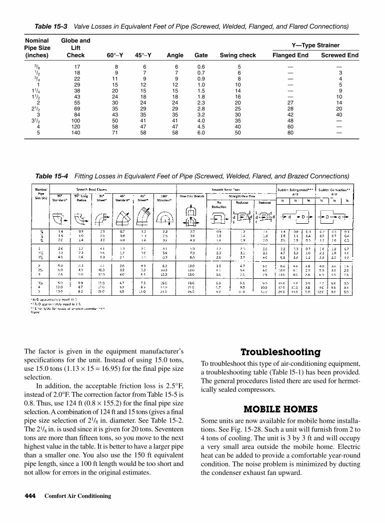
444 Comfort Air Conditioning
The factor is given in the equipment manufacturer’sspecifications for the unit. Instead of using 15.0 tons,use 15.0 tons (1.13 × 15 = 16.95) for the final pipe sizeselection.
In addition, the acceptable friction loss is 2.5°F,instead of 2.0°F. The correction factor from Table 15-5 is0.8. Thus, use 124 ft (0.8 × 155.2) for the final pipe sizeselection. A combination of 124 ft and 15 tons (gives a finalpipe size selection of 21/8 in. diameter. See Table 15-2.The 21/8 in. is used since it is given for 20 tons. Seventeentons are more than fifteen tons, so you move to the nexthighest value in the table. It is better to have a larger pipethan a smaller one. You also use the 150 ft equivalentpipe length, since a 100 ft length would be too short andnot allow for errors in the original estimates.
TroubleshootingTo troubleshoot this type of air-conditioning equipment,a troubleshooting table (Table l5-1) has been provided.The general procedures listed there are used for hermet-ically sealed compressors.
MOBILE HOMESSome units are now available for mobile home installa-tions. See Fig. 15-28. Such a unit will furnish from 2 to4 tons of cooling. The unit is 3 by 3 ft and will occupya very small area outside the mobile home. Electricheat can be added to provide a comfortable year-roundcondition. The noise problem is minimized by ductingthe condenser exhaust fan upward.
Table 15-4 Fitting Losses in Equivalent Feet of Pipe (Screwed, Welded, Flared, and Brazed Connections)
Table 15-3 Valve Losses in Equivalent Feet of Pipe (Screwed, Welded, Flanged, and Flared Connections)
Nominal Globe andPipe Size Lift Y—Type Strainer
(inches) Check 60°−Y 45°−Y Angle Gate Swing check Flanged End Screwed End
3/8 17 8 6 6 0.6 5 — —1/2 18 9 7 7 0.7 6 — 33/4 22 11 9 9 0.9 8 — 41 29 15 12 12 1.0 10 — 5
11/4 38 20 15 15 1.5 14 — 911/2 43 24 18 18 1.8 16 — 10
2 55 30 24 24 2.3 20 27 1421/2 69 35 29 29 2.8 25 28 20
3 84 43 35 35 3.2 30 42 4031/2 100 50 41 41 4.0 35 48 —
4 120 58 47 47 4.5 40 60 —5 140 71 58 58 6.0 50 80 —
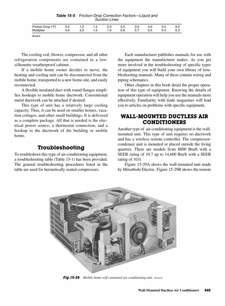
Wall-Mounted Ductless Air Conditioners 445
The cooling coil, blower, compressor, and all otherrefrigeration components are contained in a low-silhouette weatherproof cabinet.
If a mobile home owner decides to move, theheating and cooling unit can be disconnected from themobile home, transported to a new home-site, and easilyreconnected.
A flexible insulated duct with round flanges simpli-fies hookups to mobile home ductwork. Conventionalmetal ductwork can be attached if desired.
This type of unit has a relatively large coolingcapacity. Thus, it can be used on smaller homes, vaca-tion cottages, and other small buildings. It is deliveredas a complete package. All that is needed is the elec-trical power source, a thermostat connection, and ahookup to the ductwork of the building or mobilehome.
TroubleshootingTo troubleshoot this type of air-conditioning equipment,a troubleshooting table (Table 15-1) has been provided.The general troubleshooting procedures listed in thetable are used for hermetically sealed compressors.
Each manufacturer publishes manuals for use withthe equipment the manufacturer makes. As you getmore involved in the troubleshooting of specific typesof equipment you will build your own library of trou-bleshooting manuals. Many of these contain wiring andpiping schematics.
Other chapters in this book detail the proper opera-tion of this type of equipment. Knowing the details ofequipment operation will help you use the manuals moreeffectively. Familiarity with trade magazines will leadyou to articles on problems with specific equipment.
WALL-MOUNTED DUCTLESS AIRCONDITIONERS
Another type of air-conditioning equipment is the wall-mounted unit. This type of unit requires no ductworkand has a wireless remote controller. The compressor-condenser unit is mounted or placed outside the livingquarters. There are models from 8800 Btu/h with aSEER rating of 10.7 up to 14,600 Btu/h with a SEERrating of 10.0.
Figure 15-29A shows the wall-mounted unit madeby Mitsubishi Electric. Figure 15-29B shows the remote
Table 15-5 Friction-Drop Correction Factors—Liquid andSuction Lines
Friction Drop (°F) 0.5 1.0 1.5 2.0 2.5 3.0 4.0 5.0 6.0Multiplier 4.0 2.0 1.3 1.0 0.8 0.7 0.5 0.4 0.3
Bryant
Fig.15-28 Mobile home self-contained air-conditioning unit. (Bryant)
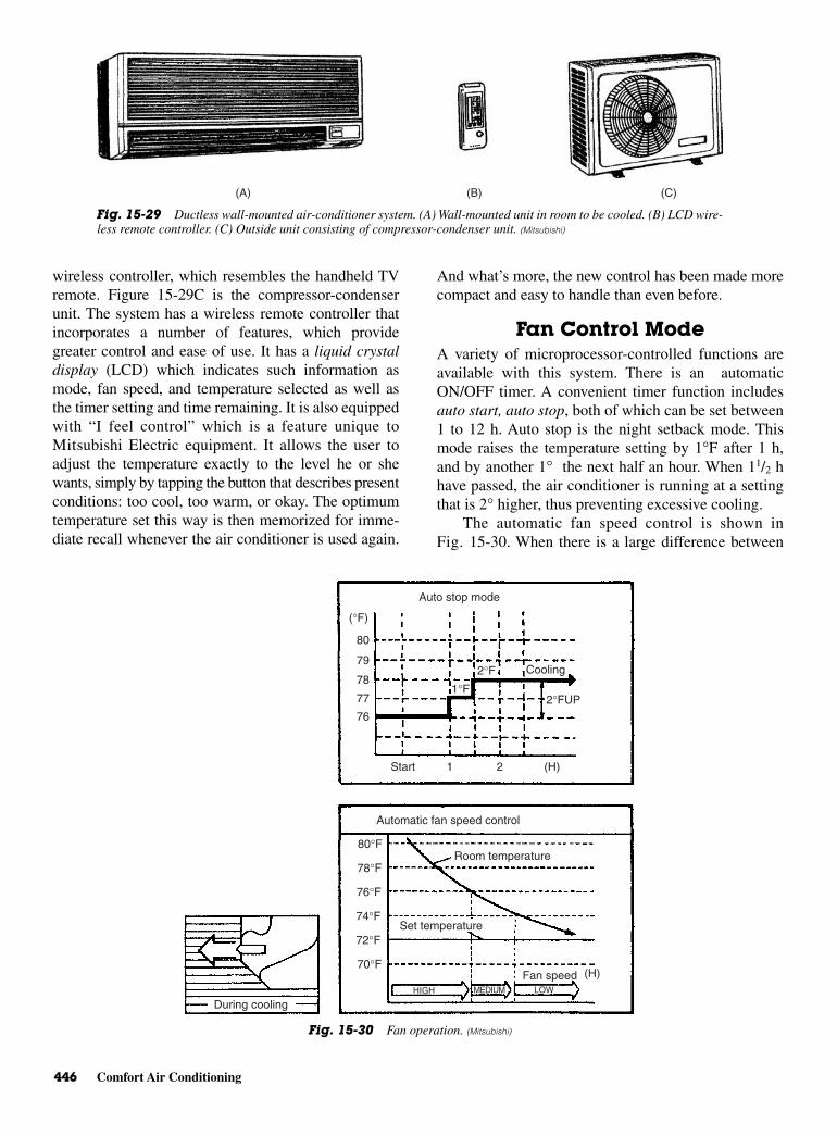
446 Comfort Air Conditioning
wireless controller, which resembles the handheld TVremote. Figure 15-29C is the compressor-condenserunit. The system has a wireless remote controller thatincorporates a number of features, which providegreater control and ease of use. It has a liquid crystaldisplay (LCD) which indicates such information asmode, fan speed, and temperature selected as well asthe timer setting and time remaining. It is also equippedwith “I feel control” which is a feature unique toMitsubishi Electric equipment. It allows the user toadjust the temperature exactly to the level he or shewants, simply by tapping the button that describes presentconditions: too cool, too warm, or okay. The optimumtemperature set this way is then memorized for imme-diate recall whenever the air conditioner is used again.
And what’s more, the new control has been made morecompact and easy to handle than even before.
Fan Control ModeA variety of microprocessor-controlled functions areavailable with this system. There is an automaticON/OFF timer. A convenient timer function includesauto start, auto stop, both of which can be set between1 to 12 h. Auto stop is the night setback mode. Thismode raises the temperature setting by 1°F after 1 h,and by another 1° the next half an hour. When 11/2 hhave passed, the air conditioner is running at a settingthat is 2° higher, thus preventing excessive cooling.
The automatic fan speed control is shown inFig. 15-30. When there is a large difference between
(B) (C)(A)
Fig. 15-29 Ductless wall-mounted air-conditioner system. (A) Wall-mounted unit in room to be cooled. (B) LCD wire-less remote controller. (C) Outside unit consisting of compressor-condenser unit. (Mitsubishi)
(°F)
80
79
78
77
76
Start 1 2 (H)
(H)
Auto stop mode
1°F2°F Cooling
2°FUP
Automatic fan speed control
Room temperature
Set temperature
HIGH MEDIUM LOW
Fan speed
80°F
78°F
76°F
74°F
72°F
70°F
During cooling
Fig. 15-30 Fan operation. (Mitsubishi)
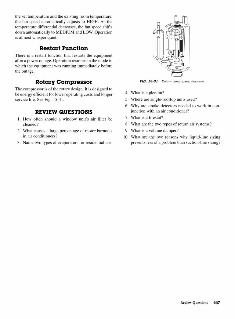
Review Questions 447
the set temperature and the existing room temperature,the fan speed automatically adjusts to HIGH. As thetemperature differential decreases, the fan speed shiftsdown automatically to MEDIUM and LOW. Operationis almost whisper quiet.
Restart FunctionThere is a restart function that restarts the equipmentafter a power outage. Operation resumes in the mode inwhich the equipment was running immediately beforethe outage.
Rotary CompressorThe compressor is of the rotary design. It is designed tobe energy efficient for lower operating costs and longerservice life. See Fig. 15-31.
REVIEW QUESTIONS1. How often should a window unit’s air filter be
cleaned?
2. What causes a large percentage of motor burnoutsin air conditioners?
3. Name two types of evaporators for residential use.
4. What is a plenum?
5. Where are single-rooftop units used?
6. Why are smoke detectors needed to work in con-junction with an air conditioner?
7. What is a firestat?
8. What are the two types of return air systems?
9. What is a volume damper?
10. What are the two reasons why liquid-line sizingpresents less of a problem than suction-line sizing?
Fig. 15-31 Rotary compressor. (Mitsubishi)

This page intentionally left blank

16CHAPTER
CommercialAir-Conditioning
Systems
Copyright © 2006 by The McGraw-Hill Companies, Inc. Click here for terms of use.

PERFORMANCE OBJECTIVESAfter studying this chapter you will:
1. Know how to troubleshoot commercial air-conditioning systems.
2. Know how to read the wiring diagram for a208/230 V 60 Hz unit.
3. Know how to troubleshoot the direct multizonesystem.
4. Know how to troubleshoot the evaporative coolingsystem.
5. Know how to troubleshoot the absorption-type air-conditioning system.
6. Know how to troubleshoot the chilled water air-conditioning system.
7. Understand the operation of the chilled watersystem.
8. Understand the refrigeration cycle of a hermetic-type centrifugal chiller.
9. Be able to troubleshoot a console model (self-contained) air conditioner.
10. Know how to keep a service log used with an open-drive centrifugal refrigeration machine (chiller).
There are several types of commercial air-conditioning systems. This chapter discusses the follow-ing systems: expansion-valve air-conditioning systems,packaged cooling units, rooftop heating and coolingunits, direct multizone systems, evaporative cooling sys-tems, absorption-type air-conditioning systems, chilledwater air conditioning, chillers, and console-type air-conditioning systems.
EXPANSION-VALVEAIR-CONDITIONING SYSTEM
This type of condensing unit can be installed in singlesor multiples. Such units are used in residential, apart-ment, motel, and commercial applications. These unitsare applicable only to expansion-valve systems. Thelow height and upward discharge of air make it easy toconceal the unit among shrubs on a slab at ground levelor out of sight on a roof.
CompressorThe compressor is hermetically sealed. Built-in protec-tion devices protect from excessive current and temper-ature. It is suction cooled. Overload protection is by aninternal pressure relief. A crankcase heater is the stan-dard equipment on all of these units. It ensures propercompressor lubrication at all times. The crankcase
heater is thermostatically controlled and temperatureactuated to operate only when required. Rubber mountshelp to reduce the noise associated with compressors.
CondenserThe condenser coil is U-shaped to provide a large surfacearea for heat exchange. The joints in the compressor aresilver soldered. The compressor is tested for leaks at 450to 500 psi. Refrigerant lines come precharged. This unitcomes with a drier. Solid-state controls prevent compres-sor short-cycling and also allow time for suction and dis-charge pressure to equalize. This permits the compressorto start in an unloaded condition. An automatic reset con-trol will shut off the compressor for 5 min.
EXPANSION-VALVE KITAn expansion-valve kit has been developed to match theevaporator unit. The expansion valve is equipped with ableed port. This permits pressures to equalize after thecompressor stops. This means the compressor can restartin an unloaded condition. Flare fittings permit con-nections on the valve in a simple field installation.
Since single-phase models require large amountsof current, they can cause lights to blink when theystart up. A positive temperature coefficient (PTC) kitcan eliminate some of the start-up problems. It consistsof a solid-state circuit with a ceramic thermistor. Thethermistor provides extra starting torque to solve mostcompressor hard starting problems such as low voltageor light dimming. It switches itself out of the circuitafter start-up.
A start kit consisting of a start capacitor and poten-tial relay must be installed in some models when usedwith certain evaporator units and expansion-valve kits.The added capacitance is taken from the circuit whenthe coil energizes almost instantly.
However, it does help with the starting load. Sincethe coil is energized whenever the air-conditioner sys-tem is operating, it is possible for the coil to becomeopen. This causes the start capacitor to “blow-up” andspread its contents inside the control housing. Replace-ment of the capacitor and the coil of the relay is neces-sary in order to repair the equipment for properoperation. Usually the entire relay must be replaced,since the coil is not always available separately.
TroubleshootingTo troubleshoot this type of air-conditioning equip-ment, refer to Table 16-1. The general troubleshootingprocedures listed in the table are used for hermeticallysealed compressors.
450 Commercial Air-Conditioning Systems
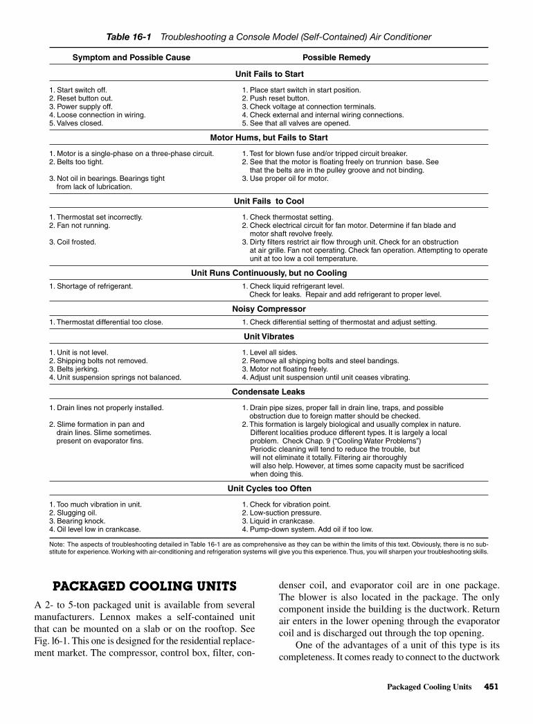
Packaged Cooling Units 451
PACKAGED COOLING UNITS A 2- to 5-ton packaged unit is available from severalmanufacturers. Lennox makes a self-contained unitthat can be mounted on a slab or on the rooftop. SeeFig. l6-1. This one is designed for the residential replace-ment market. The compressor, control box, filter, con-
denser coil, and evaporator coil are in one package.The blower is also located in the package. The onlycomponent inside the building is the ductwork. Returnair enters in the lower opening through the evaporatorcoil and is discharged out through the top opening.
One of the advantages of a unit of this type is itscompleteness. It comes ready to connect to the ductwork
Table 16-1 Troubleshooting a Console Model (Self-Contained) Air Conditioner
Symptom and Possible Cause Possible Remedy
Unit Fails to Start
1. Start switch off. 1. Place start switch in start position.2. Reset button out. 2. Push reset button.3. Power supply off. 3. Check voltage at connection terminals.4. Loose connection in wiring. 4. Check external and internal wiring connections.5. Valves closed. 5. See that all valves are opened.
Motor Hums, but Fails to Start
1. Motor is a single-phase on a three-phase circuit. 1. Test for blown fuse and/or tripped circuit breaker.2. Belts too tight. 2. See that the motor is floating freely on trunnion base. See
that the belts are in the pulley groove and not binding.3. Not oil in bearings. Bearings tight 3. Use proper oil for motor.
from lack of lubrication.
Unit Fails to Cool
1. Thermostat set incorrectly. 1. Check thermostat setting.2. Fan not running. 2. Check electrical circuit for fan motor. Determine if fan blade and
motor shaft revolve freely.3. Coil frosted. 3. Dirty filters restrict air flow through unit. Check for an obstruction
at air grille. Fan not operating. Check fan operation. Attempting to operateunit at too low a coil temperature.
Unit Runs Continuously, but no Cooling
1. Shortage of refrigerant. 1. Check liquid refrigerant level.Check for leaks. Repair and add refrigerant to proper level.
Noisy Compressor
1. Thermostat differential too close. 1. Check differential setting of thermostat and adjust setting.
Unit Vibrates
1. Unit is not level. 1. Level all sides.2. Shipping bolts not removed. 2. Remove all shipping bolts and steel bandings.3. Belts jerking. 3. Motor not floating freely.4. Unit suspension springs not balanced. 4. Adjust unit suspension until unit ceases vibrating.
Condensate Leaks
1. Drain lines not properly installed. 1. Drain pipe sizes, proper fall in drain line, traps, and possibleobstruction due to foreign matter should be checked.
2. Slime formation in pan and 2. This formation is largely biological and usually complex in nature.drain lines. Slime sometimes. Different localities produce different types. It is largely a localpresent on evaporator fins. problem. Check Chap. 9 (“Cooling Water Problems”)
Periodic cleaning will tend to reduce the trouble, butwill not eliminate it totally. Filtering air thoroughlywill also help. However, at times some capacity must be sacrificedwhen doing this.
Unit Cycles too Often
1. Too much vibration in unit. 1. Check for vibration point.2. Slugging oil. 2. Low-suction pressure.3. Bearing knock. 3. Liquid in crankcase.4. Oil level low in crankcase. 4. Pump-down system. Add oil if too low.
Note: The aspects of troubleshooting detailed in Table 16-1 are as comprehensive as they can be within the limits of this text. Obviously, there is no sub-stitute for experience.Working with air-conditioning and refrigeration systems will give you this experience.Thus, you will sharpen your troubleshooting skills.
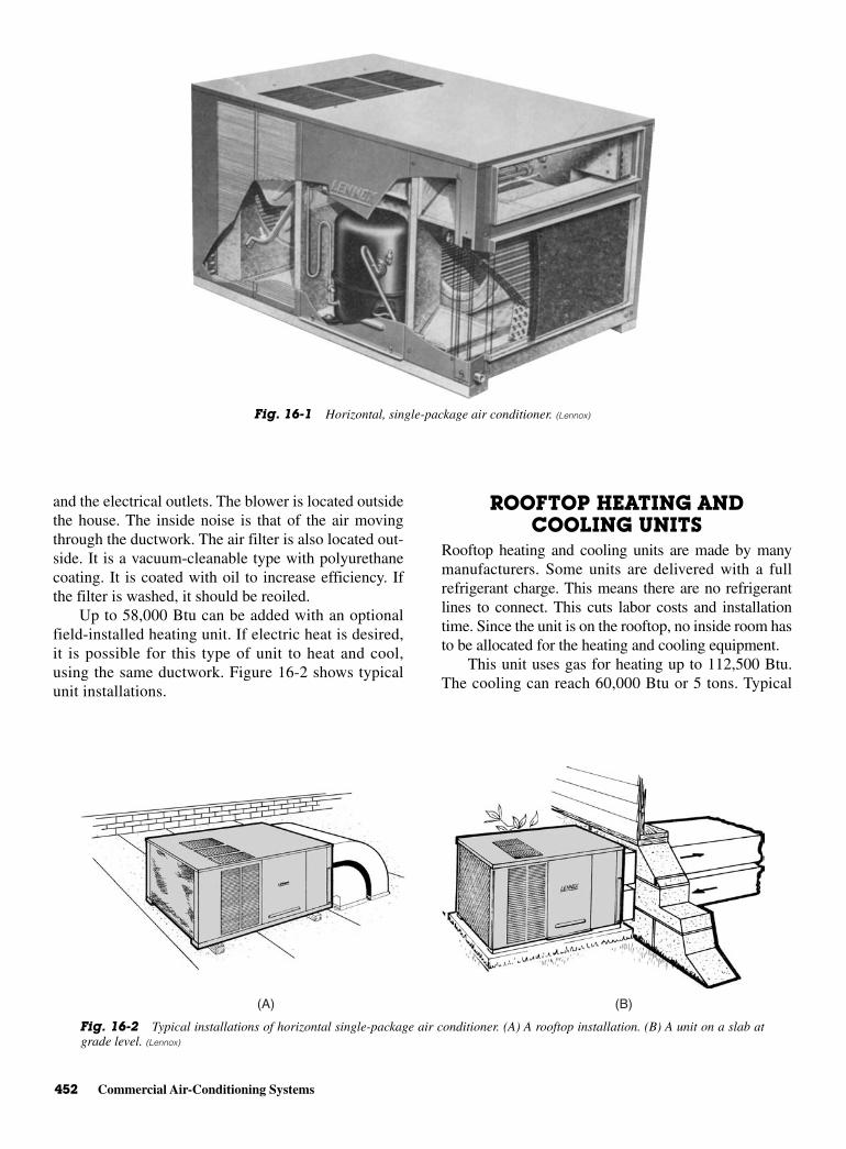
452 Commercial Air-Conditioning Systems
and the electrical outlets. The blower is located outsidethe house. The inside noise is that of the air movingthrough the ductwork. The air filter is also located out-side. It is a vacuum-cleanable type with polyurethanecoating. It is coated with oil to increase efficiency. Ifthe filter is washed, it should be reoiled.
Up to 58,000 Btu can be added with an optionalfield-installed heating unit. If electric heat is desired,it is possible for this type of unit to heat and cool,using the same ductwork. Figure 16-2 shows typicalunit installations.
ROOFTOP HEATING ANDCOOLING UNITS
Rooftop heating and cooling units are made by manymanufacturers. Some units are delivered with a fullrefrigerant charge. This means there are no refrigerantlines to connect. This cuts labor costs and installationtime. Since the unit is on the rooftop, no inside room hasto be allocated for the heating and cooling equipment.
This unit uses gas for heating up to 112,500 Btu.The cooling can reach 60,000 Btu or 5 tons. Typical
Fig. 16-1 Horizontal, single-package air conditioner. (Lennox)
(A) (B)
Fig. 16-2 Typical installations of horizontal single-package air conditioner. (A) A rooftop installation. (B) A unit on a slab atgrade level. (Lennox)
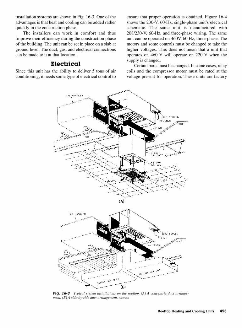
Rooftop Heating and Cooling Units 453
installation systems are shown in Fig. 16-3. One of theadvantages is that heat and cooling can be added ratherquickly in the construction phase.
The installers can work in comfort and thusimprove their efficiency during the construction phaseof the building. The unit can be set in place on a slab atground level. The duct, gas, and electrical connectionscan be made to it at that location.
ElectricalSince this unit has the ability to deliver 5 tons of airconditioning, it needs some type of electrical control to
ensure that proper operation is obtained. Figure 16-4shows the 230-V, 60-Hz, single-phase unit’s electricalschematic. The same unit is manufactured with208/230-V, 60-Hz, and three-phase wiring. The sameunit can be operated on 460V, 60 Hz, three-phase. Themotors and some controls must be changed to take thehigher voltages. This does not mean that a unit thatoperates on 460 V will operate on 220 V when thesupply is changed.
Certain parts must be changed. In some cases, relaycoils and the compressor motor must be rated at thevoltage present for operation. These units are factory
Fig. 16-3 Typical system installations on the rooftop. (A) A concentric duct arrange-ment. (B) A side-by-side duct arrangement. (Lennox)
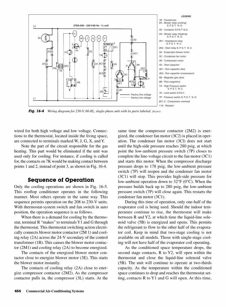
454 Commercial Air-Conditioning Systems
wired for both high voltage and low voltage. Connec-tions to the thermostat, located inside the living space,are connected to terminals marked W, J, G, X, and Y.
Note the part of the circuit responsible for the gasheating. This part would be eliminated if the unit wasused only for cooling. For instance, if cooling is calledfor, the contacts on 7K would be making contact betweenpoints 1 and 2, instead of point 3, as shown in Fig. 16-4.
Sequence of Operation Only the cooling operations are shown in Fig. 16-5.This rooftop conditioner operates in the followingmanner. Most others operate in the same way. Thissequence permits operation on the 208 to 230-V units.With thermostat-system switch and fan switch in autoposition, the operation sequence is as follows.
When there is a demand for cooling by the thermo-stat, terminal R “makes” to terminals Y1 and G throughthe thermostat. This thermostat switching action electri-cally connects blower motor contactor (2M 1) and cool-ing relay (2A) across the 24-V secondary of the controltransformer (1B). This causes the blower motor contac-tor (2M1) and cooling relay (2A) to become energized.
The contacts of the energized blower motor con-tactor close to energize blower motor (3E). This startsthe blower motor instantly.
The contacts of cooling relay (2A) close to ener-gize compressor contactor (2M2). As the compressorcontactor pulls in, the compressor (3L) starts. At the
same time the compressor contactor (2M2) is ener-gized, the condenser fan motor (3C2) is placed in oper-ation. The condenser fan motor (3Cl) does not startuntil the high-side pressure reaches 280 psig, at whichpoint the low-ambient pressure switch (7P) closes tocomplete the line-voltage circuit to the fan motor (3C1)and starts this motor. When the compressor dischargepressure drops to 178 psig, the low-ambient pressureswitch (7P) will reopen and the condenser fan motor(3C1) will stop. This provides high-side pressure forlow-ambient operation down to 32°F (0°C). When thepressure builds back up to 280 psig, the low-ambientpressure switch (7P) will close again. This restarts thecondenser fan motor (3C1).
During this time of operation, only one-half of theevaporator coil is being used. Should the indoor tem-perature continue to rise, the thermostat will makebetween R and Y2, at which time the liquid-line sole-noid valve (5B) is energized and opens. This permitsthe refrigerant to flow to the other half of the evapora-tor coil. Keep in mind that two-stage cooling is notavailable on all models. Those with single-stage cool-ing will not have half of the evaporator coil operating.
As the conditioned space temperature drops, thesecond stage contacts, R to Y2, will open within thethermostat and close the liquid-line solenoid valve(5B). The unit will continue to operate at two-thirdscapacity. As the temperature within the conditionedspace continues to drop and reaches the thermostat set-ting, contacts R to Y1 and G will open. At this time,
3A
2A
1B
2G 2G
2A 2D
3C
2D
2D
4D
7A7P
7K
PRLSEC
1
2
3
4
345
W J G X Y
6B
8C1
4E1
2K2
4E2
2K1
8C2
8C1
3N
3NR
C
2
5
Factory line voltageFactory low voltage
579A-048 – 230 V-60 Hz - 1φ unit
L1
L2
LEGEND
1B - Transformer 2A - Blower relay (cooling) S. P. S. T. N. O.
2D - Contactor D.P.S.T. N.O.
3A - Evaporator blower motor
3C - Condenser fan motor
3N - Compressor motor
4D - Start capacitor
4E1 - Run capacitor (fan)
4E2 - Run capacitor (compressor)
5B - Magnetic gas valve
7K - Limit switch S.P.D.T.
7P - Pressure switch S. P. S. T. N. O.
8C1-2 - Compressor overload
11A - Resistor
6B - Pilot (reignition)
7A - High-Pressure switch S. P. S. T. N. C.
2G - Blower relay (Heating) S. P. S. T. N. O.
2K1 - Impedance relay S. P. S. T. N. C.
2K2 - Start relay S. P. S. T. N. C.
Fig. 16-4 Wiring diagram for 230-V, 60-Hz, single-phase unit with its parts labeled. (Bryant)
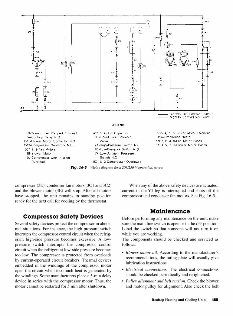
Rooftop Heating and Cooling Units 455
compressor (3L), condenser fan motors (3C1 and 3C2)and the blower motor (3E) will stop. After all motorshave stopped, the unit remains in standby positionready for the next call for cooling by the thermostat.
Compressor Safety Devices Several safety devices protect the compressor in abnor-mal situations. For instance, the high pressure switchinterrupts the compressor control circuit when the refrig-erant high-side pressure becomes excessive. A low-pressure switch interrupts the compressor controlcircuit when the refrigerant low-side pressure becomestoo low. The compressor is protected from overloadsby current-operated circuit breakers. Thermal devicesembedded in the windings of the compressor motoropen the circuit when too much heat is generated bythe windings. Some manufacturers place a 5-min delaydevice in series with the compressor motor. Thus, themotor cannot be restarted for 5 min after shutdown.
When any of the above safety devices are actuated,current in the Y1 leg is interrupted and shuts off thecompressor and condenser fan motors. See Fig. 16-5.
MaintenanceBefore performing any maintenance on the unit, makesure the main line switch is open or in the OFF position.Label the switch so that someone will not turn it onwhile you are working.The components should be checked and serviced asfollows:
• Blower motor oil. According to the manufacturer’srecommendations, the rating plate will usually givelubrication instructions.
• Electrical connections. The electrical connectionsshould be checked periodically and retightened.
• Pulley alignment and belt tension. Check the blowerand motor pulley for alignment. Also check the belt
Fig. 16-5 Wiring diagram for a 208/230-V operation. (Bryant)

456 Commercial Air-Conditioning Systems
for proper tension. It should have approximately 1 in.of sag under normal finger pressure.
• Blower bearings. Blowers are equipped with prelubri-cated bearings and need no lubrication. If, however,there are a blower unit and blower motor withoutsealed bearings, a few drops of oil must be addedoccasionally.
• Condenser and evaporator coils. Coils should beinspected occasionally and cleaned as necessary. Becareful not to bend the soft aluminum fins.
WARNING: Make sure the main linedisconnect switch is in the off positionbefore cleaning the coils.
• Filters. System air filters should be inspected everytwo months for clogging because of dirt. When nec-essary, replace disposable-type filters.
Special Instructions
• Do not rapid-cycle the unit. Allow at least 5 minbefore turning on the unit after it has shut oil.
• If a general power failure occurs, the electrical powersupply should be turned off at the unit disconnectswitch until the electrical power supply has beenrestored.
• Air filters should be cleaned or replaced at regularintervals to ensure against restricted airflow acrossthe cooling coil.
• During the off season, the main power supply may beleft on or turned off. Leaving the power turned on willkeep the compressor crankcase heaters energized.
• If power has been off during the winter, it must beturned on for at least 12 h before spring start-up ofthe unit. This allows the crankcase heaters to vapor-ize any liquid refrigerant that may be condensed inthe compressor.
TroubleshootingTo troubleshoot this type of air-conditioning equip-ment, refer to Table 16-1. The general troubleshootingprocedures listed in the table are used for hermeticallysealed compressors.
DIRECT MULTIZONE SYSTEMThe direct multizone system unit is roof mounted andcan be used for cooling and heating. See Fig. 16-6. Itcan use chilled water for cooling up to 550,000 Btu/h.
Air distribution is 12- or 16-zone multizone con-trol at the unit or double duct with independent mixingdampers at each zone. Figure 16-7 shows the typicalapplications of such a unit with a zone distribution sys-tem using mixing dampers located at the unit. A double-duct distribution system with zone damper boxes canbe used. Mixing dampers are remote from the unit. Thenet weight of the unit is 2525 lb or 11/4 tons.
Figure 16-8 shows the location of the parts insidethe unit. Figure 16-9 shows how the refrigerant piping
Fig. 16-6 Direct multizone system for rooftop mounting. (Lennox)
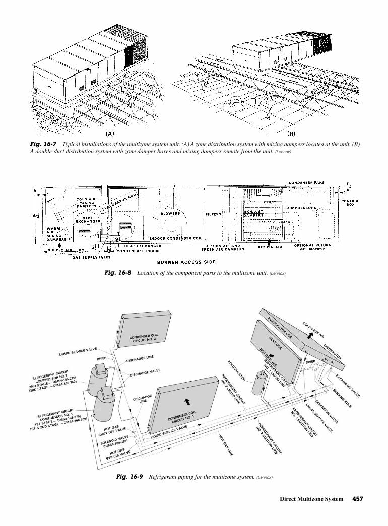
Direct Multizone System 457
Fig. 16-7 Typical installations of the multizone system unit. (A) A zone distribution system with mixing dampers located at the unit. (B)A double-duct distribution system with zone damper boxes and mixing dampers remote from the unit. (Lennox)
Fig. 16-8 Location of the component parts to the multizone unit. (Lennox)
Fig. 16-9 Refrigerant piping for the multizone system. (Lennox)

458 Commercial Air-Conditioning Systems
is laid out for the unit when two compressors are usedfor cooling purposes. Note that this unit uses an accu-mulator. There are certain conditions under which thecapacity of such a unit must be rated. These conditionsare the temperature of the evaporator air, the condensercoil air temperature, the speed of the blower motor, andits volume of air delivered.
TroubleshootingTo troubleshoot this type of air-conditioning equip-ment, refer to Table 16-1. The general troubleshootingprocedures listed in the table are used for hermeticallysealed compressors.
EVAPORATIVE COOLING SYSTEMIn some locations, it is possible to use the coolingtower principles to condense the refrigerant. Thismethod has the usual problems with water and towerfungi. Those problems are discussed in Chap. 10.
The condensing coil is cooled by air drawn in fromoutside the tower and forced upward over the coil.
Water is pumped continuously to a distribution systemand sprayed so that it drops in small droplets over thecondensing coil. See Fig. 16-10. The water is reusedsince it cools as it drops through the moving air stream.In some systems the water is pumped up and into atrough. The water drips down over the condenser coilsand cools them.
In some cases, the water moves through the tubesthat surround the refrigerant-carrying tubes. The airstream then removes the heat and discharges it into thesurrounding air. This means the cooling tower shouldbe mounted outside a building. In some instances it ispossible to mount the tower inside. However, a duct isthen needed to carry the discharged air outside. Asshown in Fig. 16-10B, the water is carried off and mustbe replaced as it, too, evaporates. The pan is filled tolevel when the float moves down and allows the watermakeup valve to open. If the condenser temperaturereaches or exceeds 100°F (37.8°C), the thermostatturns on the water and the fan.
Problems with this system center in the electricalcontrol system and the water system. The controls, fan
Fig. 16-10 An evaporative cooling system. (A) Outside view. (B) Operation of the evaporative cooling system.
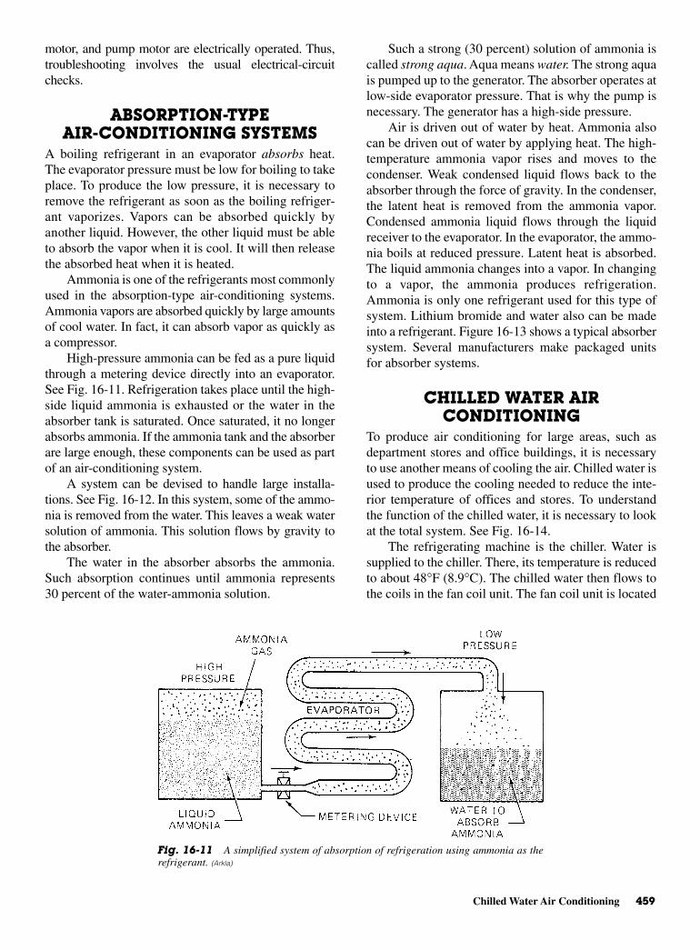
Chilled Water Air Conditioning 459
motor, and pump motor are electrically operated. Thus,troubleshooting involves the usual electrical-circuitchecks.
ABSORPTION-TYPEAIR-CONDITIONING SYSTEMS
A boiling refrigerant in an evaporator absorbs heat.The evaporator pressure must be low for boiling to takeplace. To produce the low pressure, it is necessary toremove the refrigerant as soon as the boiling refriger-ant vaporizes. Vapors can be absorbed quickly byanother liquid. However, the other liquid must be ableto absorb the vapor when it is cool. It will then releasethe absorbed heat when it is heated.
Ammonia is one of the refrigerants most commonlyused in the absorption-type air-conditioning systems.Ammonia vapors are absorbed quickly by large amountsof cool water. In fact, it can absorb vapor as quickly asa compressor.
High-pressure ammonia can be fed as a pure liquidthrough a metering device directly into an evaporator.See Fig. 16-11. Refrigeration takes place until the high-side liquid ammonia is exhausted or the water in theabsorber tank is saturated. Once saturated, it no longerabsorbs ammonia. If the ammonia tank and the absorberare large enough, these components can be used as partof an air-conditioning system.
A system can be devised to handle large installa-tions. See Fig. 16-12. In this system, some of the ammo-nia is removed from the water. This leaves a weak watersolution of ammonia. This solution flows by gravity tothe absorber.
The water in the absorber absorbs the ammonia.Such absorption continues until ammonia represents30 percent of the water-ammonia solution.
Such a strong (30 percent) solution of ammonia iscalled strong aqua. Aqua means water. The strong aquais pumped up to the generator. The absorber operates atlow-side evaporator pressure. That is why the pump isnecessary. The generator has a high-side pressure.
Air is driven out of water by heat. Ammonia alsocan be driven out of water by applying heat. The high-temperature ammonia vapor rises and moves to thecondenser. Weak condensed liquid flows back to theabsorber through the force of gravity. In the condenser,the latent heat is removed from the ammonia vapor.Condensed ammonia liquid flows through the liquidreceiver to the evaporator. In the evaporator, the ammo-nia boils at reduced pressure. Latent heat is absorbed.The liquid ammonia changes into a vapor. In changingto a vapor, the ammonia produces refrigeration.Ammonia is only one refrigerant used for this type ofsystem. Lithium bromide and water also can be madeinto a refrigerant. Figure 16-13 shows a typical absorbersystem. Several manufacturers make packaged unitsfor absorber systems.
CHILLED WATER AIRCONDITIONING
To produce air conditioning for large areas, such asdepartment stores and office buildings, it is necessaryto use another means of cooling the air. Chilled water isused to produce the cooling needed to reduce the inte-rior temperature of offices and stores. To understandthe function of the chilled water, it is necessary to lookat the total system. See Fig. 16-14.
The refrigerating machine is the chiller. Water issupplied to the chiller. There, its temperature is reducedto about 48°F (8.9°C). The chilled water then flows tothe coils in the fan coil unit. The fan coil unit is located
Fig. 16-11 A simplified system of absorption of refrigeration using ammonia as therefrigerant. (Arkla)
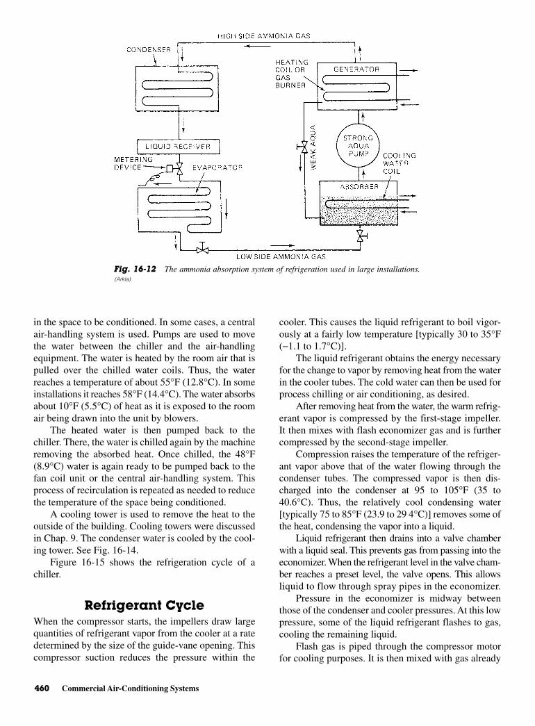
460 Commercial Air-Conditioning Systems
in the space to be conditioned. In some cases, a centralair-handling system is used. Pumps are used to movethe water between the chiller and the air-handlingequipment. The water is heated by the room air that ispulled over the chilled water coils. Thus, the waterreaches a temperature of about 55°F (12.8°C). In someinstallations it reaches 58°F (14.4°C). The water absorbsabout 10°F (5.5°C) of heat as it is exposed to the roomair being drawn into the unit by blowers.
The heated water is then pumped back to thechiller. There, the water is chilled again by the machineremoving the absorbed heat. Once chilled, the 48°F(8.9°C) water is again ready to be pumped back to thefan coil unit or the central air-handling system. Thisprocess of recirculation is repeated as needed to reducethe temperature of the space being conditioned.
A cooling tower is used to remove the heat to theoutside of the building. Cooling towers were discussedin Chap. 9. The condenser water is cooled by the cool-ing tower. See Fig. 16-14.
Figure 16-15 shows the refrigeration cycle of achiller.
Refrigerant Cycle When the compressor starts, the impellers draw largequantities of refrigerant vapor from the cooler at a ratedetermined by the size of the guide-vane opening. Thiscompressor suction reduces the pressure within the
cooler. This causes the liquid refrigerant to boil vigor-ously at a fairly low temperature [typically 30 to 35°F(−1.1 to 1.7°C)].
The liquid refrigerant obtains the energy necessaryfor the change to vapor by removing heat from the waterin the cooler tubes. The cold water can then be used forprocess chilling or air conditioning, as desired.
After removing heat from the water, the warm refrig-erant vapor is compressed by the first-stage impeller.It then mixes with flash economizer gas and is furthercompressed by the second-stage impeller.
Compression raises the temperature of the refriger-ant vapor above that of the water flowing through thecondenser tubes. The compressed vapor is then dis-charged into the condenser at 95 to 105°F (35 to40.6°C). Thus, the relatively cool condensing water[typically 75 to 85°F (23.9 to 29 4°C)] removes some ofthe heat, condensing the vapor into a liquid.
Liquid refrigerant then drains into a valve chamberwith a liquid seal. This prevents gas from passing into theeconomizer. When the refrigerant level in the valve cham-ber reaches a preset level, the valve opens. This allowsliquid to flow through spray pipes in the economizer.
Pressure in the economizer is midway betweenthose of the condenser and cooler pressures. At this lowpressure, some of the liquid refrigerant flashes to gas,cooling the remaining liquid.
Flash gas is piped through the compressor motorfor cooling purposes. It is then mixed with gas already
Fig. 16-12 The ammonia absorption system of refrigeration used in large installations.(Arkla)
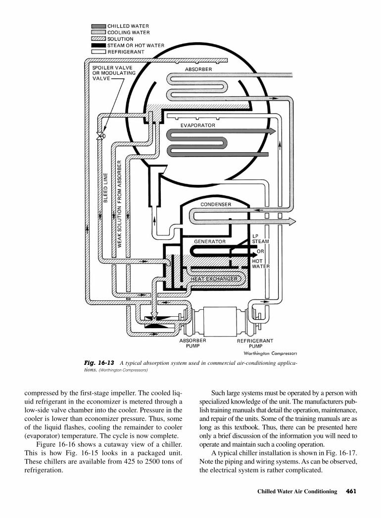
Chilled Water Air Conditioning 461
compressed by the first-stage impeller. The cooled liq-uid refrigerant in the economizer is metered through alow-side valve chamber into the cooler. Pressure in thecooler is lower than economizer pressure. Thus, someof the liquid flashes, cooling the remainder to cooler(evaporator) temperature. The cycle is now complete.
Figure 16-16 shows a cutaway view of a chiller.This is how Fig. 16-15 looks in a packaged unit.These chillers are available from 425 to 2500 tons ofrefrigeration.
Such large systems must be operated by a person withspecialized knowledge of the unit. The manufacturers pub-lish training manuals that detail the operation, maintenance,and repair of the units. Some of the training manuals are aslong as this textbook. Thus, there can be presented hereonly a brief discussion of the information you will need tooperate and maintain such a cooling operation.
A typical chiller installation is shown in Fig. 16-17.Note the piping and wiring systems. As can be observed,the electrical system is rather complicated.
Fig. 16-13 A typical absorption system used in commercial air-conditioning applica-tions. (Worthington Compressors)
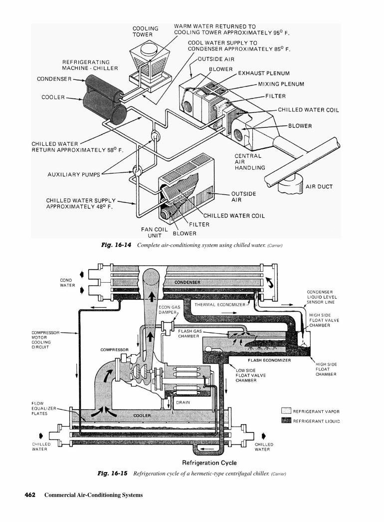
462 Commercial Air-Conditioning Systems
Fig. 16-14 Complete air-conditioning system using chilled water. (Carrier)
Fig. 16-15 Refrigeration cycle of a hermetic-type centrifugal chiller. (Carrier)
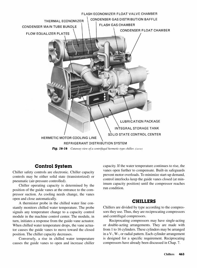
Chillers 463
Control SystemChiller safety controls are electronic. Chiller capacitycontrols may be either solid state (transistorized) orpneumatic (air-pressure controlled).
Chiller operating capacity is determined by theposition of the guide vanes at the entrance to the com-pressor suction. As cooling needs change, the vanesopen and close automatically.
A thermistor probe in the chilled water line con-stantly monitors chilled water temperature. The probesignals any temperature change to a capacity controlmodule in the machine control center. The module, inturn, initiates a response from the guide-vane actuator.When chilled water temperature drops, the vane actua-tor causes the guide vanes to move toward the closedposition. The chiller capacity decreases.
Conversely, a rise in chilled water temperaturecauses the guide vanes to open and increase chiller
capacity. If the water temperature continues to rise, thevanes open further to compensate. Built-in safeguardsprevent motor overloads. To minimize start-up demand,control interlocks keep the guide vanes closed (at min-imum capacity position) until the compressor reachesrun condition.
CHILLERSChillers are divided by type according to the compres-sors they use. Thus, they are reciprocating compressorsand centrifugal compressors.
Reciprocating compressors may have single-actingor double-acting arrangements. They are made withfrom 1 to 16 cylinders. These cylinders may be arrangedin a V-, W-, or radial pattern. Each cylinder arrangementis designed for a specific requirement. Reciprocatingcompressors have already been discussed in Chap. 7.
Fig. 16-16 Cutaway view of a centrifugal hermetic-type chiller. (Carrier)
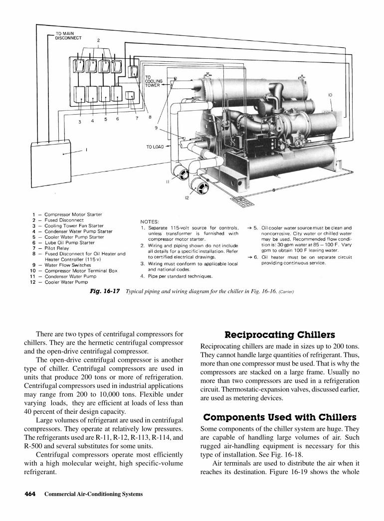
464 Commercial Air-Conditioning Systems
There are two types of centrifugal compressors forchillers. They are the hermetic centrifugal compressorand the open-drive centrifugal compressor.
The open-drive centrifugal compressor is anothertype of chiller. Centrifugal compressors are used inunits that produce 200 tons or more of refrigeration.Centrifugal compressors used in industrial applicationsmay range from 200 to 10,000 tons. Flexible undervarying loads, they are efficient at loads of less than40 percent of their design capacity.
Large volumes of refrigerant are used in centrifugalcompressors. They operate at relatively low pressures.The refrigerants used are R-11, R-12, R-113, R-114, andR-500 and several substitutes for some units.
Centrifugal compressors operate most efficientlywith a high molecular weight, high specific-volumerefrigerant.
Reciprocating Chillers Reciprocating chillers are made in sizes up to 200 tons.They cannot handle large quantities of refrigerant. Thus,more than one compressor must be used. That is why thecompressors are stacked on a large frame. Usually nomore than two compressors are used in a refrigerationcircuit. Thermostatic-expansion valves, discussed earlier,are used as metering devices.
Components Used with ChillersSome components of the chiller system are huge. Theyare capable of handling large volumes of air. Suchrugged air-handling equipment is necessary for thistype of installation. See Fig. 16-18.
Air terminals are used to distribute the air when itreaches its destination. Figure 16-19 shows the whole
Fig. 16-17 Typical piping and wiring diagram for the chiller in Fig. 16-16. (Carrier)
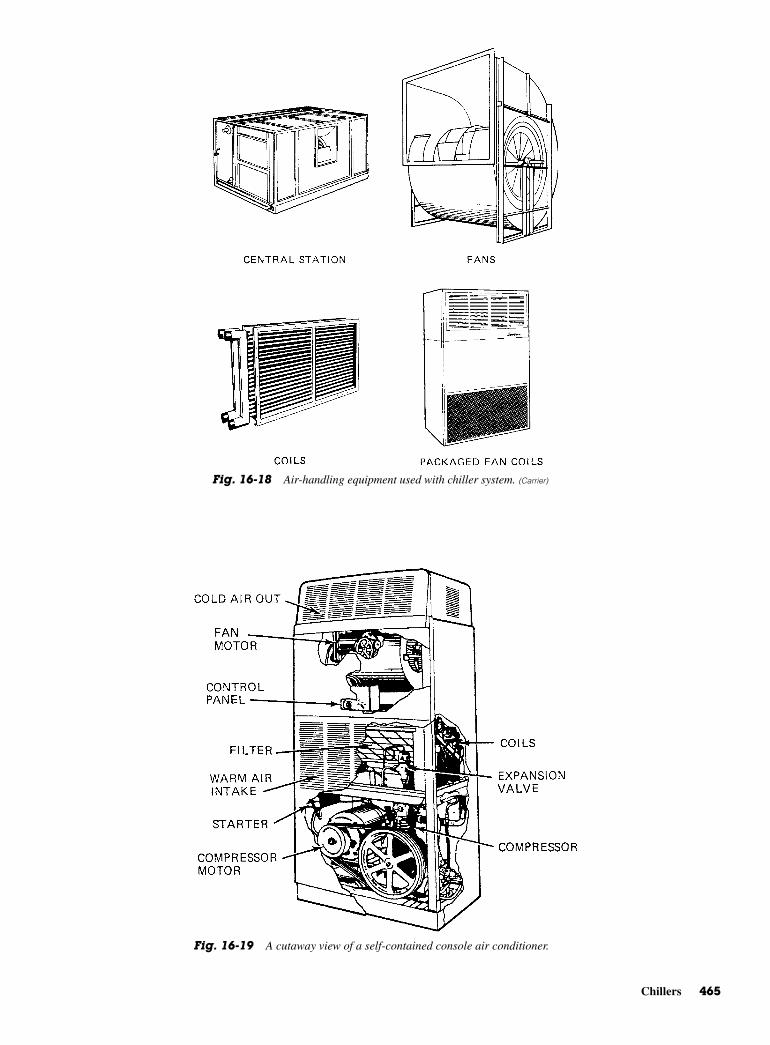
Chillers 465
Fig. 16-19 A cutaway view of a self-contained console air conditioner.
Fig. 16-18 Air-handling equipment used with chiller system. (Carrier)
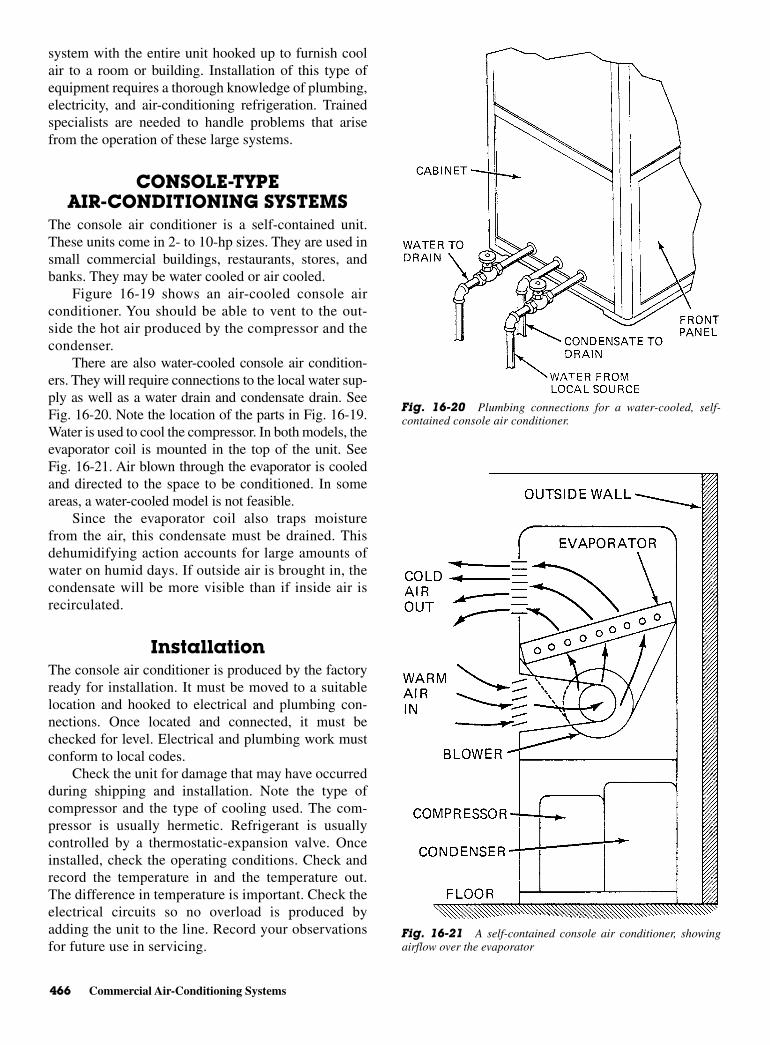
466 Commercial Air-Conditioning Systems
system with the entire unit hooked up to furnish coolair to a room or building. Installation of this type ofequipment requires a thorough knowledge of plumbing,electricity, and air-conditioning refrigeration. Trainedspecialists are needed to handle problems that arisefrom the operation of these large systems.
CONSOLE-TYPEAIR-CONDITIONING SYSTEMS
The console air conditioner is a self-contained unit.These units come in 2- to 10-hp sizes. They are used insmall commercial buildings, restaurants, stores, andbanks. They may be water cooled or air cooled.
Figure 16-19 shows an air-cooled console airconditioner. You should be able to vent to the out-side the hot air produced by the compressor and thecondenser.
There are also water-cooled console air condition-ers. They will require connections to the local water sup-ply as well as a water drain and condensate drain. SeeFig. 16-20. Note the location of the parts in Fig. 16-19.Water is used to cool the compressor. In both models, theevaporator coil is mounted in the top of the unit. SeeFig. 16-21. Air blown through the evaporator is cooledand directed to the space to be conditioned. In someareas, a water-cooled model is not feasible.
Since the evaporator coil also traps moisturefrom the air, this condensate must be drained. Thisdehumidifying action accounts for large amounts ofwater on humid days. If outside air is brought in, thecondensate will be more visible than if inside air isrecirculated.
InstallationThe console air conditioner is produced by the factoryready for installation. It must be moved to a suitablelocation and hooked to electrical and plumbing con-nections. Once located and connected, it must bechecked for level. Electrical and plumbing work mustconform to local codes.
Check the unit for damage that may have occurredduring shipping and installation. Note the type ofcompressor and the type of cooling used. The com-pressor is usually hermetic. Refrigerant is usuallycontrolled by a thermostatic-expansion valve. Onceinstalled, check the operating conditions. Check andrecord the temperature in and the temperature out.The difference in temperature is important. Check theelectrical circuits so no overload is produced byadding the unit to the line. Record your observationsfor future use in servicing.
Fig. 16-20 Plumbing connections for a water-cooled, self-contained console air conditioner.
Fig. 16-21 A self-contained console air conditioner, showingairflow over the evaporator
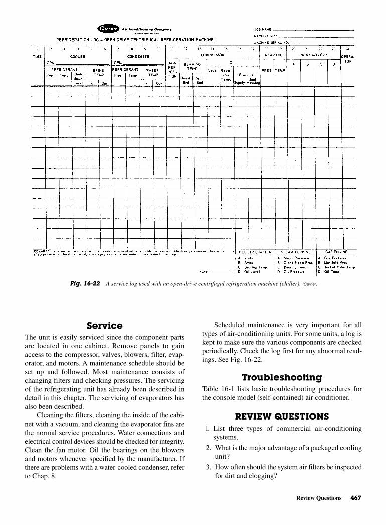
Review Questions 467
ServiceThe unit is easily serviced since the component partsare located in one cabinet. Remove panels to gainaccess to the compressor, valves, blowers, filter, evap-orator, and motors. A maintenance schedule should beset up and followed. Most maintenance consists ofchanging filters and checking pressures. The servicingof the refrigerating unit has already been described indetail in this chapter. The servicing of evaporators hasalso been described.
Cleaning the filters, cleaning the inside of the cabi-net with a vacuum, and cleaning the evaporator fins arethe normal service procedures. Water connections andelectrical control devices should be checked for integrity.Clean the fan motor. Oil the bearings on the blowersand motors whenever specified by the manufacturer. Ifthere are problems with a water-cooled condenser, referto Chap. 8.
Scheduled maintenance is very important for alltypes of air-conditioning units. For some units, a log iskept to make sure the various components are checkedperiodically. Check the log first for any abnormal read-ings. See Fig. 16-22.
TroubleshootingTable 16-1 lists basic troubleshooting procedures forthe console model (self-contained) air conditioner.
REVIEW QUESTIONSl. List three types of commercial air-conditioning
systems.
2. What is the major advantage of a packaged coolingunit?
3. How often should the system air filters be inspectedfor dirt and clogging?
Fig. 16-22 A service log used with an open-drive centrifugal refrigeration machine (chiller). (Carrier)

468 Commercial Air-Conditioning Systems
4. How long must power be on before starting theunit in the spring?
5. Where is the direct multizone system mounted?
6. What refrigerant is most commonly used in anabsorption-type air-conditioning system?
7. What is the meaning of the term strong aqua?
8. What is a chiller?
9. How are cooling towers used to remove heat froma building?
10. How do you determine the operating capacity of achiller?
11. Where is the hot air produced by the consolemodel’s compressor and condenser, vented?
12. What maintenance procedures are necessary for aconsole air-conditioning unit?

17CHAPTER
Various Typesof Air
Conditionersand Heat
Pumps
Copyright © 2006 by The McGraw-Hill Companies, Inc. Click here for terms of use.
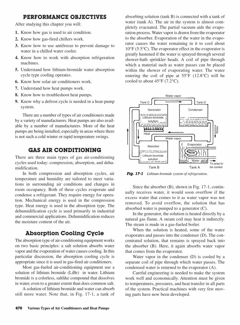
PERFORMANCE OBJECTIVESAfter studying this chapter you will:
1. Know how gas is used to air condition.
2. Know how gas-fired chillers work.
3. Know how to use antifreeze to prevent damage towater in a chilled water cooler.
4. Know how to work with absorption refrigerationmachines.
5. Understand how lithium-bromide water absorptioncycle type cooling operates.
6. Know how solar air conditioners work.
7. Understand how heat pumps work.
8. Know how to troubleshoot heat pumps.
9. Know why a defrost cycle is needed in a heat-pumpsystem.
There are a number of types of air conditioners madeby a variety of manufacturers. Heat pumps are also avail-able by a number of manufacturers. More of the heatpumps are being installed, especially in areas where thereis not such a cold winter or rapid temperature swings.
GAS AIR CONDITIONING There are three main types of gas air-conditioningcycles used today: compression, absorption, and dehu-midification.
In both compression and absorption cycles, airtemperature and humidity are tailored to meet varia-tions in surrounding air conditions and changes inroom occupancy. Both of these cycles evaporate andcondense a refrigerant. They require energy for opera-tion. Mechanical energy is used in the compressiontype. Heat energy is used in the absorption type. Thedehumidification cycle is used primarily in industrialand commercial applications. Dehumidification reducesthe moisture content of the air.
Absorption Cooling Cycle The absorption type of air-conditioning equipment workson two basic principles: a salt solution absorbs watervapor and the evaporation of water causes cooling. In thisparticular discussion, the absorption cooling cycle isappropriate since it is used in gas-fired air conditioners.
Most gas-fueled air-conditioning equipment use asolution of lithium bromide (LiBr) in water. Lithiumbromide is a colorless, saltlike compound that dissolvesin water, even to a greater extent than does common salt.
A solution of lithium bromide and water can absorbstill more water. Note that, in Fig. 17-1, a tank of
absorbing solution (tank B) is connected with a tank ofwater (tank A). The air in the system is almost com-pletely evacuated. The partial vacuum aids the evapo-ration process. Water vapor is drawn from the evaporatorto the absorber. Evaporation of the water in the evapo-rator causes the water remaining in it to cool about10°F (5.5°C). The evaporator effect in the evaporator isgreatly hastened if the water is sprayed through severalshower-bath sprinkler heads. A coil of pipe throughwhich a material such as water passes can be placedwithin the shower of evaporating water. The waterentering the coil of pipe at 55°F (12.8°C) will becooled to about 45°F (7.2°C).
Since the absorber (B), shown in Fig. 17-1, contin-ually receives water, it would soon overflow if theexcess water that comes to it as water vapor was notremoved. To avoid overflow, the solution that hasabsorbed water is pumped to a generator (C).
In the generator, the solution is heated directly by anatural gas flame. A steam coil may heat it indirectly.The steam is made in a gas-fueled boiler.
When the solution is heated, some of the waterevaporates and passes into the condenser (D). The con-centrated solution, that remains is sprayed back intothe absorber (B). Here, it again absorbs water vaporthat comes from the evaporator.
Water vapor in the condenser (D) is cooled by aseparate coil of pipe through which water passes. Thecondensed water is returned to the evaporator (A).
Careful engineering is needed to make the systemwork well and economically. Attention must be givento temperatures, pressures, and heat transfer in all partsof the system. Practical machines with very few mov-ing parts have now been developed.
470 Various Types of Air Conditioners and Heat Pumps
Water
Water vapor
Water vapor
Tank C
Tank B Tank A
Tank D
Generator Condenser
Lithium-bromidesolution
Lithium-bromidesolution
Heat
AbsorberEvaporator
Wat
er
To area to be cooled
Fig. 17-1 Lithium-bromide system of refrigeration.
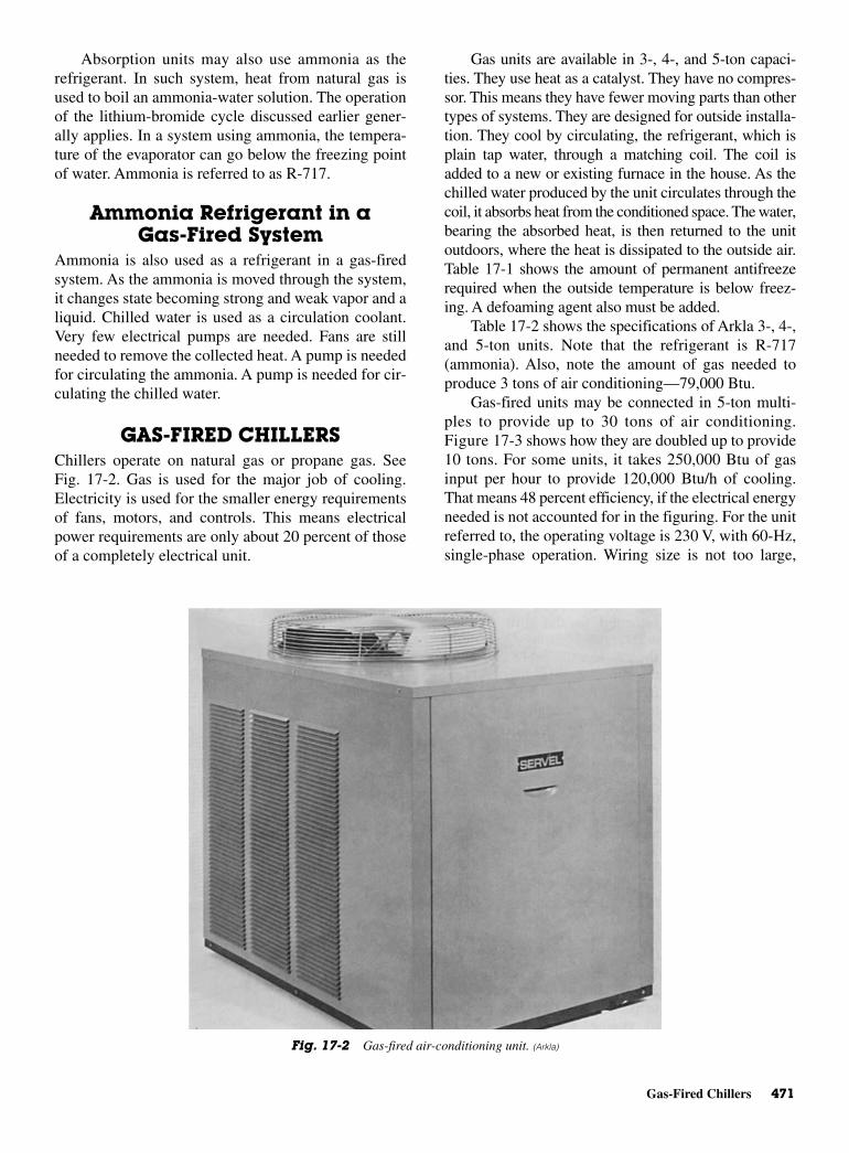
Gas-Fired Chillers 471
Absorption units may also use ammonia as therefrigerant. In such system, heat from natural gas isused to boil an ammonia-water solution. The operationof the lithium-bromide cycle discussed earlier gener-ally applies. In a system using ammonia, the tempera-ture of the evaporator can go below the freezing pointof water. Ammonia is referred to as R-717.
Ammonia Refrigerant in aGas-Fired System
Ammonia is also used as a refrigerant in a gas-firedsystem. As the ammonia is moved through the system,it changes state becoming strong and weak vapor and aliquid. Chilled water is used as a circulation coolant.Very few electrical pumps are needed. Fans are stillneeded to remove the collected heat. A pump is neededfor circulating the ammonia. A pump is needed for cir-culating the chilled water.
GAS-FIRED CHILLERSChillers operate on natural gas or propane gas. SeeFig. 17-2. Gas is used for the major job of cooling.Electricity is used for the smaller energy requirementsof fans, motors, and controls. This means electricalpower requirements are only about 20 percent of thoseof a completely electrical unit.
Gas units are available in 3-, 4-, and 5-ton capaci-ties. They use heat as a catalyst. They have no compres-sor. This means they have fewer moving parts than othertypes of systems. They are designed for outside installa-tion. They cool by circulating, the refrigerant, which isplain tap water, through a matching coil. The coil isadded to a new or existing furnace in the house. As thechilled water produced by the unit circulates through thecoil, it absorbs heat from the conditioned space. The water,bearing the absorbed heat, is then returned to the unitoutdoors, where the heat is dissipated to the outside air.Table 17-1 shows the amount of permanent antifreezerequired when the outside temperature is below freez-ing. A defoaming agent also must be added.
Table 17-2 shows the specifications of Arkla 3-, 4-,and 5-ton units. Note that the refrigerant is R-717(ammonia). Also, note the amount of gas needed toproduce 3 tons of air conditioning—79,000 Btu.
Gas-fired units may be connected in 5-ton multi-ples to provide up to 30 tons of air conditioning.Figure 17-3 shows how they are doubled up to provide10 tons. For some units, it takes 250,000 Btu of gasinput per hour to provide 120,000 Btu/h of cooling.That means 48 percent efficiency, if the electrical energyneeded is not accounted for in the figuring. For the unitreferred to, the operating voltage is 230 V, with 60-Hz,single-phase operation. Wiring size is not too large,
Fig. 17-2 Gas-fired air-conditioning unit. (Arkla)

472 Various Types of Air Conditioners and Heat Pumps
since there is a maximum of 8 A drawn for the con-denser fan motors and 33 A for the solution pumps.Normal running current for the solution pump motorsis only 5 A. Locked rotor current of 33 A occurs only ifthe motor is stuck or jammed so it cannot start. Thestart currents may also reach this 33-A level undersome load conditions.
The chilled water system uses stainless steel toprevent problems with rust and other ferrous metal pip-ing problems. There is only one electrical, one gas, andone chilled water supply and return connection foreach unit.
CHILLER-HEATER Some gas-fired units furnish cooling for the summerand heat for the winter. The user changes the functionssimply by changing the settings of a room thermostat.The “all-year” units are designed for outdoor installa-tion. They operate on either natural or propane gas.
Changeover Sequence forChilled Water Operation
When the thermostat calls for cooling, the hot waterpump is off. The chilled water pump moves water fromthe chiller tank and pumps it up a “candy cane” shapedloop and out to the air handler. See Fig. 17-4. As thewater returns to the chiller tank to be cooled again, itpasses through the water reservoir.
The water does not flow through the tubes of thehot water generator as it returns to the chiller tank. Thewater in the generator is dormant because it is pluggedby a check ball. This is held in place by the pressurefrom the discharge side of the chilled water pump.
Changeover Sequence for HotWater Operation
When the thermostat is set for heating, the chilledwater pump is off. The pressure from the hot water
pump moves the check ball to seal off the water in thechiller tank. See Fig. 17-5. Now the water in the chillersystem is dormant. The hot water pump circulates thewater from the hot water generator through the airhandler and back to the generator through the waterreservoir. During the heating cycle the reservoir alsoserves as a place to relieve air from the system. Thetube from the top of the reservoir passes through thechiller tank and runs up to the distribution pan, whichis open to atmospheric pressure.
Self-Leveling Feature Self-leveling of water between the chiller tank and thewater reservoir during the heating cycle is anotherunique feature of this system.
Should the water level in the reservoir drop belownormal, a vacuum is created in the top of the reservoir.The vacuum causes a negative pressure that acts as asuction to draw water up the air release tube, refillingthe reservoir. See Fig. 17-6. As the water level in thedistribution tube falls below the level of the water inthe chiller tank, the second check ball is forced awayfrom the seat to allow the water level to return to nor-mal. See Fig. 17-7. It should be remembered thatantifreeze and a defoaming agent are necessary for thiswater system.
ABSORPTION REFRIGERATIONMACHINE
The absorption refrigeration machine is used primarilyin air-conditioning applications. Chilled water is theoutput of the machine. The chilled water is then used tocool. This particular machine is available for capacitiesof 100 through 600 tons. These units are small, rela-tively lightweight, and vibration free. They can belocated wherever a source of steam or very hot water isavailable. Lithium bromide, a salt solution, is used asthe absorbent.
Absorption Operation Cycle Figure 17-8 is a schematic diagram of an absorptioncold generator. Note that the evaporator, absorber, con-centrator, and condenser are enclosed in a single cas-ing. The heat exchanger is located externally below themain shell.
• Evaporator. The evaporator pump circulates therefrigerant (water) from the refrigerant pump intothe spray trees. To utilize the maximum surface forevaporation, the refrigerant is sprayed over the evap-orator tubes. As the spray contacts the relatively
Table 17-1 Antifreeze Needed to Prevent Damageto Water in a Chilled Water Cooler
Lowest Expected Outdoor Permanent AntifreezeTemp. °F (Freezing Point Percentage by
of Mixture) Volume (%)
25 1015 205 300 33
−5 35−10 40−20 45
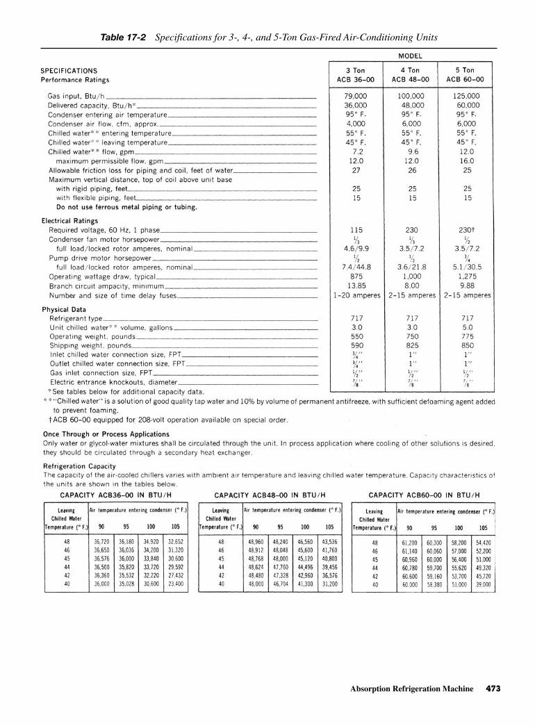
Absorption Refrigeration Machine 473
Table 17-2 Specifications for 3-, 4-, and 5-Ton Gas-Fired Air-Conditioning Units

474 Various Types of Air Conditioners and Heat Pumps
warm surface of the tubes carrying the water to bechilled, a vapor is created. In this manner heat isextracted from the tube surface, chilling the fluid inthe tubes. The vapor created in this process passesthrough eliminators to the absorber.
• Absorber. The lithium-bromide solution (underproper conditions) keeps the pressure in the absorbersection low enough to pull the refrigerant vapor from
the high-pressure evaporator. As the vapor flows intothe absorber, it mixes with the absorbent solutionbeing sprayed over the tube bundle.
• Heat exchanger. The heat exchanger is used only asan economizer. The cool diluted solution from theconcentrator pump is heated by the hotter concen-trated solution moving from the concentrator to theabsorber steam or hot water (heating medium) is
Fig. 17-3 Ten-ton gas-fired air-conditioning unit. (Arkla)
Fig. 17-4 The cooling cycle in a chiller heater. (Arkla)
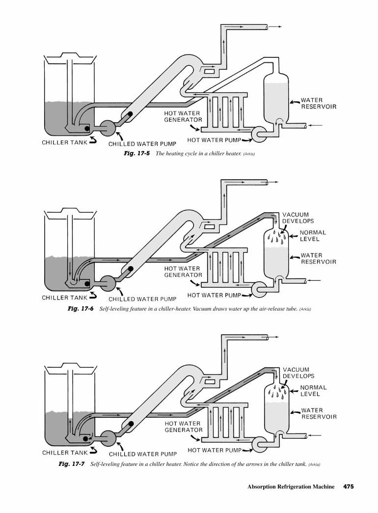
Absorption Refrigeration Machine 475
Fig. 17-5 The heating cycle in a chiller heater. (Arkla)
Fig. 17-6 Self-leveling feature in a chiller-heater. Vacuum draws water up the air-release tube. (Arkla)
Fig. 17-7 Self-leveling feature in a chiller heater. Notice the direction of the arrows in the chiller tank. (Arkla)

476 Various Types of Air Conditioners and Heat Pumps
conserved. The heat transfer in the heat exchangerbrings the temperature of the diluted solution closer tothe boiling point. It also brings the concentrated solu-tion temperature closer to the absorber temperature.
• Concentrator. Steam or high-temperature waterentering the concentrator is controlled to boil off thesame quantity of refrigerant picked up by the absorber.The refrigerant vapor is given up by boiling the solu-tion in the concentrator. The vapor passes througheliminators to the tube surface of the condenser.
• Condenser. The refrigerant vapor from the concen-trator is condensed on the tube surface of the con-denser and falls into the pan below the tube bundle.
SOLAR AIR CONDITIONERS Harnessing the sun’s energy is nothing new. As farback as 1878, the sun was used to power a printingplant. In Egypt, in 1913, solar energy was used to pro-duce steam to operate an engine that drove an irrigationpump.
In the United States, solar energy powered thephone of a Georgia cotton grower in 1955. Even then,the costs involved in harnessing solar energy were
astronomical in comparison to the costs for the abun-dantly available fossil fuels—coal, oil, and natural gas.Thus, the research programs languished until theenergy crisis of the early 1970s. Then, fossil-fuel short-ages, environmental concerns, and the rising costs ofenergy, reawakened interest in solar energy. It wasknown that solar-heated water could provide the powerfor space heating and water heating. However, couldit effectively cool a home? Could the costs of usingsolar energy be brought within the reach of the averageperson?
History of Solar Cooling Prior to 1972, little, if any, research had been doneregarding the use of solar energy for cooling. There-fore, no air-conditioning equipment specially designedfor use with solar energy was available. Currently,however, there are cooling systems that lend them-selves to easy modification for use with solar energy.One is the absorption-type system manufactured byArkla Industries. The other is the Rankine cycle.
The Rankine cycle needs an intermediate step.This involves replacing the electric motor in the con-ventional vapor compression refrigeration cycle with a
Fig. 17-8 Schematic of an absorption cold generator. (Johnson)

Solar Air Conditioners 477
turbine or using solar cells to produce electricity. Ineither case, making modifications for the Rankinecycle is more costly than making modifications of theabsorption system.
The National Science Foundation has worked on acooling system specially designed for use with solarenergy by giving grant money to researchers. Work isbeing done on improving both the residential andmedium-tonnage range.
Systems of Solar Cooling There are two systems used in solar cooling: the directsystem and the indirect system. The direct system ofapplication uses the absorption cooling system. It pro-vides higher firing water temperatures directly fromthe storage tanks to the unit’s generator. See Fig. 17-9.
The indirect system is a closed system in which aheat exchanger transfers the heat from the solar-heatedwater storage tanks. This allows the use of an antifreezefluid. See Fig. 17-10.
Lithium-Bromide WaterAbsorption Cycle
The Arkla-Solaire unit operates on the absorption prin-ciple. See Fig. 17-11. It uses solar-heated water as theenergy source. Lithium bromide and water are used asthe absorbent/refrigerant solution. The refrigerationtonnage is delivered through a chilled water circuit thatflows between the unit’s evaporator and a standard
fan-coil assembly located inside the conditioned space.The heat from the conditioned space is dissipatedexternally at the cooling tower.
The four main components of the Solaire cool-ing unit are the generator, condenser, evaporator,and absorber.
When the solar-heated water enters the tubesinside the generator, the heat from the hot water vapor-izes the refrigerant (water), separating it from theabsorbent (lithium bromide).
The vaporized refrigerant vapor then flows to theabsorber. There, it again liquefies and combines withthe circulating solution. The reunited lithium bromideand water solution then passes to the liquid heat exchanger.There, it is reheated before being returned to thegenerator.
Figure 17-12 shows a medium-tonnage air-conditioning unit specially designed for use with solarenergy. This is a nominally rated 25-ton unit that canoperate with a firing water temperature as low as 190°F(87.8°C).
There is also a 3-ton absorption unit that operateswith solar-heated water. It provides full capacity with afiring water temperature of 210°F (98.9°C).
Solar Cooling Research CentersFigure 17-13 pictures a Solar House, which was conceivedby the Copper Development Association. Inc. a number ofyears ago. Almost everything in this innovative (for
Fig. 17-9 Solar-energy air-conditioning unit—direct system. (Arkla)
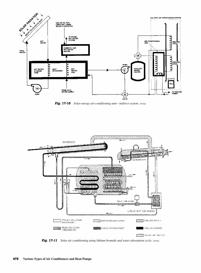
478 Various Types of Air Conditioners and Heat Pumps
Fig. 17-10 Solar-energy air-conditioning unit—indirect system. (Arkla)
Fig. 17-11 Solar air conditioning using lithium bromide and water absorption cycle. (Arkla)

Solar Air Conditioners 479
Fig. 17-12 A medium-tonnage air-conditioning unit specially designed for use withsolar energy. This is a 25-ton unit that operates with a firing temperature as low as190°F. (Arkla)
Fig. 17-13 Artist’s rendering of a solar house in Tucson, Arizona. The four-bedroom home is cooled by two units fired by solar-heatedwater. (Arkla)

480 Various Types of Air Conditioners and Heat Pumps
its time) four-bedroom house from the heating, cool-ing, and sound systems to the door chimes and kitchenclock can be run on stored solar energy. Coupled withthe solar energy collector system, the heating/coolingsystem is probably the most challenging technologicalinnovation in the house.
The climate control system consists of two 3-tonSolaire units for cooling and two duct coils for heating.As designed, it was anticipated so that the solar-heatedwater would be able to operate the cooling cycle nearly75 percent of the time. It should supply 100 percent ofthe heating requirements. A back-up water heater wasinstalled near the 3000-gal hot water thermal energystorage. The backup unit functioned automatically.That is, if the water temperature dropped too low tooperate the climate control system. The house, fullycomputerized, can analyze hard data on solar energy ina normal home environment.
Solar heating and cooling for homes are still underdevelopment and engineering study in a number oflocations. For instance, one of those was a ColoradoState University solar research project that studied aresidential-type structure. It was designed as a labora-tory for testing and evaluating the performance of solarequipment designed for heating and cooling. The solarcooling system was a 3-ton system which used lithium-bromide absorption, modified for using hot water asthe heat source.
The Marshall Space Flight Center Solar House wasa simulated residence that used three surplus office trail-ers with a freestanding roof. See Fig. 17-14. It had theeffective areas and the heating/cooling load equivalent
of an average three-bedroom house. A 3500-gal watertank was used as a heat storage reservoir. A lithium-bromide type of air-conditioning system was used.
One of the first schools heated and cooled by solarenergy is shown in Fig. 17-15. It used a lithium-bromide system for cooling. The control system’scomponents included 10,000 ft2 of collector area and45,000 gal of fluid for thermal storage. This experi-mental project was designed to provide solar heatingand cooling, and domestic hot water for the 32,000 ft2,one-story school.
Take a closer look at the solar energy collectorsshown in Fig. 17-16. This is an absorption air condi-tioner. It is used for both cooling and heating a portionof a training facility.
HEAT PUMPSA heat pump is a mechanical refrigeration system. It isarranged and controlled to utilize the condenser heat.The condenser heat is wasted or dissipated into the airwhen a condenser-compressor are mounted outside abuilding being air conditioned. By utilizing the heatgenerated by the condenser can be used for some use-ful purpose. This useful purpose is in most instances,space heating. Heat-pump systems may be classifiedas:
• Package, or built-up
• Air-to-air
• Water-to-air
• Water-to-water
Fig. 17-14 This research solar-energy house is cooled by a lithium-bromide air conditioner. It uses solar-heated water. (Arkla)
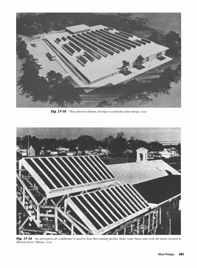
Heat Pumps 481
Fig. 17-15 This school in Atlanta, Georgia is cooled by solar energy. (Arkla)
Fig. 17-16 An absorption air conditioner is used to heat this training facility. Solar water heats and cools the house located inMorton Grove, Illinois. (Arkla)
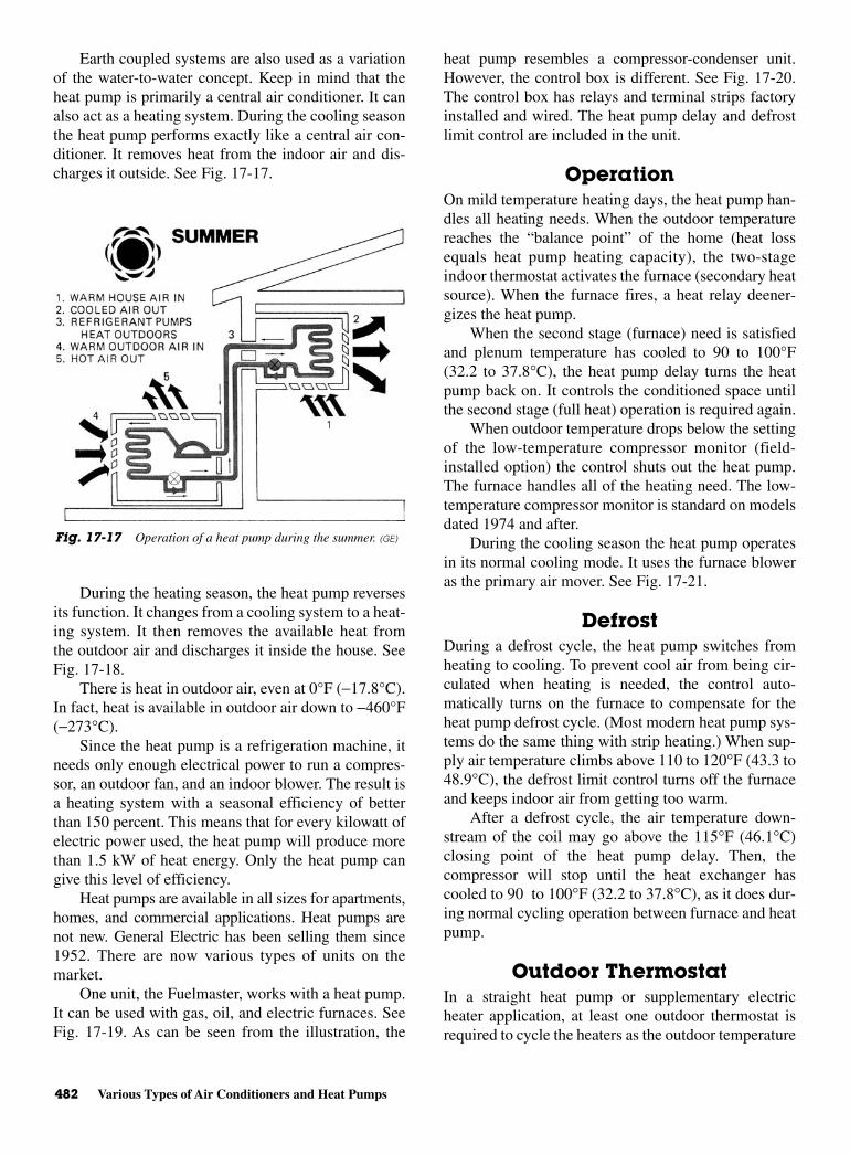
482 Various Types of Air Conditioners and Heat Pumps
Earth coupled systems are also used as a variationof the water-to-water concept. Keep in mind that theheat pump is primarily a central air conditioner. It canalso act as a heating system. During the cooling seasonthe heat pump performs exactly like a central air con-ditioner. It removes heat from the indoor air and dis-charges it outside. See Fig. 17-17.
During the heating season, the heat pump reversesits function. It changes from a cooling system to a heat-ing system. It then removes the available heat fromthe outdoor air and discharges it inside the house. SeeFig. 17-18.
There is heat in outdoor air, even at 0°F (−17.8°C).In fact, heat is available in outdoor air down to −460°F(−273°C).
Since the heat pump is a refrigeration machine, itneeds only enough electrical power to run a compres-sor, an outdoor fan, and an indoor blower. The result isa heating system with a seasonal efficiency of betterthan 150 percent. This means that for every kilowatt ofelectric power used, the heat pump will produce morethan 1.5 kW of heat energy. Only the heat pump cangive this level of efficiency.
Heat pumps are available in all sizes for apartments,homes, and commercial applications. Heat pumps arenot new. General Electric has been selling them since1952. There are now various types of units on themarket.
One unit, the Fuelmaster, works with a heat pump.It can be used with gas, oil, and electric furnaces. SeeFig. 17-19. As can be seen from the illustration, the
heat pump resembles a compressor-condenser unit.However, the control box is different. See Fig. 17-20.The control box has relays and terminal strips factoryinstalled and wired. The heat pump delay and defrostlimit control are included in the unit.
OperationOn mild temperature heating days, the heat pump han-dles all heating needs. When the outdoor temperaturereaches the “balance point” of the home (heat lossequals heat pump heating capacity), the two-stageindoor thermostat activates the furnace (secondary heatsource). When the furnace fires, a heat relay deener-gizes the heat pump.
When the second stage (furnace) need is satisfiedand plenum temperature has cooled to 90 to 100°F(32.2 to 37.8°C), the heat pump delay turns the heatpump back on. It controls the conditioned space untilthe second stage (full heat) operation is required again.
When outdoor temperature drops below the settingof the low-temperature compressor monitor (field-installed option) the control shuts out the heat pump.The furnace handles all of the heating need. The low-temperature compressor monitor is standard on modelsdated 1974 and after.
During the cooling season the heat pump operatesin its normal cooling mode. It uses the furnace bloweras the primary air mover. See Fig. 17-21.
DefrostDuring a defrost cycle, the heat pump switches fromheating to cooling. To prevent cool air from being cir-culated when heating is needed, the control auto-matically turns on the furnace to compensate for theheat pump defrost cycle. (Most modern heat pump sys-tems do the same thing with strip heating.) When sup-ply air temperature climbs above 110 to 120°F (43.3 to48.9°C), the defrost limit control turns off the furnaceand keeps indoor air from getting too warm.
After a defrost cycle, the air temperature down-stream of the coil may go above the 115°F (46.1°C)closing point of the heat pump delay. Then, thecompressor will stop until the heat exchanger hascooled to 90 to 100°F (32.2 to 37.8°C), as it does dur-ing normal cycling operation between furnace and heatpump.
Outdoor ThermostatIn a straight heat pump or supplementary electricheater application, at least one outdoor thermostat isrequired to cycle the heaters as the outdoor temperature
Fig. 17-17 Operation of a heat pump during the summer. (GE)

Heat Pumps 483
drops. In the Fuelmaster system, the indoor thermostatcontrols the supplemental heat source (furnace). Theoutdoor thermostat is not required. Since the furnace isserving as the secondary heat source, the Fuelmastersystem does not require the home rewiring usuallyassociated with supplemental electric strip heating.
Special Requirements of HeatPump Systems
The installation, maintenance, and operating efficiencyof the heat pump system are like those of no other com-fort system. A heat pump system requires the same air
Fig. 17-18 Operation of a heat pump during the winter. (GE)
Fig. 17-19 Outside unit for a heat pump made by Lennox. (Lennox)

484 Various Types of Air Conditioners and Heat Pumps
quantity for heating and cooling. Because of this, the airmoving capability of an existing furnace is extremelyimportant. It should be carefully checked before a heatpump is added. Heating and load calculations must beaccurate. System design and installation must be precise.
The air-distribution system and diffuser locationare equally important. Supply ducts must be properlysized and insulated. Adequate return air is also a must.
Heating supply air is cooler than with other sys-tems. This is quite noticeable to homeowners accus-tomed to gas or oil heat. This makes diffuser locationand system balancing critical. Typical installations ofheat pumps are shown in Fig. 17-22.
Sizing Equipment Home insulation, exposure, design and construction,climate, and living habits determine the efficiency of aheat pump system. Each heat pump installation isunique. Each job must be calculated carefully. Remem-ber, there are no rules of thumb for heat pump sizing.
To determine the most economical operating cost,size the system for its cooling load. Use supplementalheating (second stage) to make up the difference betweenheat pump heating capacity and building heat loss. Siz-ing the heat pump to handle the entire heat loss willresult in oversized cooling capacity that will adverselyaffect dehumidification during cooling.
Defrost CycleDuring a heat pump heating cycle, the outdoor coilabsorbs heat from outdoor air. To do this the coil mustbe cooler than the air.
When air temperature falls below 40°F (4.4°C),coil surface temperature is below freezing. Moisture inthe air freezes on the coil. Frost or ice builds up, reducingthe air passage through the coil and cutting heat pumpoutput.
The heat pump defrost cycle removes this buildup.The system is reversed to a cooling cycle, which heatsthe coil and melts the ice. Supplemental heat is used tocounteract the cooling effect of the cycle change.
Balance PointThe outdoor temperature at which heat loss of a build-ing and heating output of a heat pump are equal iscalled the balance point. It is the lowest temperature atwhich the heat pump alone can handle the heating load.
Using the Heat PumpIn the last fifty years, several large office buildings andsmall college campuses have been constructed usingwater-to-water heat pumps. Their capacities were up toseveral hundred tons. These systems usually use wellwater. That means two wells are used. One is used forsupply and one for disposal. A possible arrangement isshown in Fig. 17-23.
The supply and disposal wells are manually selected.Well water and return water are mixed, for both evapo-rator and condenser. This is done on a temperaturebasis. Under some conditions, this system can becomean internal source heat pump. That is, when the exte-rior-zone heating and interior-zone cooling loads arein balance, or nearly so, little or no well water is needed.
Internal source heat pumps without wells are usedwhere there is sufficient internal cooling load to supplythe net heating requirements under all conditions.Excess heat can be disposed of through cooling towers.
A problem with these systems is related to a highelectrical load for the pumping system. A variety ofvariable-flow piping schemes have been devised toovercome this problem.
Fig. 17-20 Control box for a heat pump add-on unit made byLennox. (Lennox)
Fig. 17-21 Typical heat pump components. (Lennox)
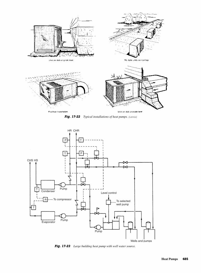
Heat Pumps 485
Fig. 17-22 Typical installations of heat pumps. (Lennox)
HR CHR
P
P
T
T
T
T
R
CondenserPump
CHS HS
Pump
Pump
To compressor
Evaporator
Level control
To selected well pump
Wells and pumps
Fig. 17-23 Large building heat pump with well water source.

486 Various Types of Air Conditioners and Heat Pumps
REVIEW QUESTIONS1. What are the three main types of gas air-conditioning
cycles used today?
2. What are the two basic principles of operation of theabsorption-type airconditioner?
3. What type of refrigerant does an absorption-typeunit use?
4. What type of refrigerant is used in a gas-fired system?
5. How can problems from rust and other ferrousmetals be prevented in a chilled water system?
6. What is a concentrator?
7. What two types of systems are used in solar cooling?
8. What determines the efficiency of a heat pumpsystem?
18CHAPTER
EstimatingLoad andInsulating
Pipes
Copyright © 2006 by The McGraw-Hill Companies, Inc. Click here for terms of use.

PERFORMANCE OBJECTIVESAfter studying this chapter you will:
1. Know how to figure refrigeration and air-conditioningload.
2. Know how air doors are used and installed.
3. Know how insulation is properly used to aid in theload factor.
4. Know how insulated pipes can improve efficiencyof a system.
REFRIGERATION ANDAIR-CONDITIONING LOAD
The load for a refrigeration unit comes from manysources. This load comes from several heat sources, themore common being the following:
• Heat from the outside leaks through doors and win-dows or conducted through the insulated walls.
• Transparent materials allow heat to penetrate them.This occurs when windows are used in a refrigeratedspace.
• Open doors and windows may allow heat to enter arefrigerated place. Cracks around the doors and win-dows also allow heat to enter the refrigerated space.
• The materials (products) stored in the refrigeratedspace give off heat. To lower the product tempera-ture, it is necessary to lower the heat content of thematerials.
• People who occupy a cooled space give off heat. Thismust be considered when figuring any load for agiven refrigeration unit.
• Equipment inside the refrigerated space may give offheat. For example, motors, electric lights, electronicequipment, steam tables, urns, hair dryers, and simi-lar items give off heat. To obtain an accurate figure,it is necessary to consider all of the heat sources.This will, in turn, determine how long the equipmentmust run to maintain a given temperature in the spacebeing cooled.
RUNNING TIMEThe time necessary for the cooling equipment to main-tain or come down to a certain temperature is called therunning time. The time used for calculations is 24 h.Equipment capacity is rated in Btu per hour. Therefore,24 h times the Btu per hour will produce the normalcapacity of refrigeration equipment. A quick way todetermine this is to use the following formula:
Most equipment cannot run for 24 h, since defrost-ing consumes some of the time. That is why the totalcooling load for 24 h is divided by the desired runningtime.
Moisture taken from the stored product causes frostto form on the evaporator coils or surface. This frostmust be removed to maintain the efficiency of the unit.The defrost cycle must be determined by the amount offrost that will form on the coils. The refrigerationprocess stops while defrosting is being accomplished.
A system may be stopped long enough for the frostto melt. This is not the desired method in most cases. Itmay allow the product’s temperature to rise, thus spoil-ing the product. To speed up the defrosting process, aheating element is usually introduced into the system.The heating element melts the frost rapidly. The wateris drained to the outside of the unit. The off-cycle typeof defrost is time consuming. It usually takes 8 h. Thismeans the loss of 8 h of refrigeration or a total runningtime of 16 h for the equipment. (It takes 8 h for defrost-ing and about 8 h to bring the temperature back to theprevious point.) Where heated defrost methods areused, it usually takes about 6 h on the average. Thatproduces an equipment running time of 18 h. This isusually taken as average for calculations. Several heat-ing methods are used. Electric heating elements havebeen mounted near the evaporator surfaces, or hot gasmay be recirculated to produce the same effect. Thismethod is explored in detail in Chap. 10.
In air-conditioning equipment, the temperature ofthe coil rarely gets below 40°F (4.4°C). Thus, no frostaccumulates. This means that in most cases a defrostmethod is not necessary in air-conditioning equipment.Air-conditioning equipment is designed for continuousrunning. The running time is determined by the Btuactually needed to cool a room.
CALCULATING COOLING LOADThe individual loads should be figured first. These arethen totaled. This produces the load to be used for figur-ing running time and equipment design characteristics.
The four sources of load are:
• Wall gain load
• Air change load
• Product load
• Miscellaneous load
Required Btu/h equipment capacity
Total cooling load in Btu for 24 hDesired running time
=
488 Estimating Load and Insulating Pipes
Calculating Heat Leakage 489
Wall Gain LoadHeat that leaks through the wall is the wall gain load.This heat comes from outside the refrigerated area.There is no perfect insulation. Thus, there is alwayssome heat leakage through the walls. Heat alwaysmoves toward a less-heated (cooled) area. So, if theinside of a space is cooler than the outside, there isalways movement of heat from the warmer to thecooler area. Insulation is used to slow down this heatmovement. Air conditioners and commercial refrigera-tion systems are always subject to wall gain or heatgain from outside the cooled area.
Air Change LoadThe air change load originates when the door is openedto a refrigerated space. The warm moist air that entersthe area must be cooled to the inside temperature. Thiscooling presents a load to the equipment.
In some cases, this is not a factor. In the case ofchillers, there is no opening through which air canpass. Thus, this type of load does not exist. However,this is not the case with air-conditioning equipment.The cracks around doors and windows also add to theload in an air-conditioned space. In some cases air isintroduced from outside to improve ventilation. This isespecially true in air-conditioning systems. The outsideair must be cooled. Therefore, it presents a load to theair conditioner.
The introduction of air for ventilation is the ventila-tion load. The air that leaks around doors and windowsis the infiltration load. Every air-conditioning systemmust deal with this type of load.
Most commercial refrigerators have well-fitted doorgaskets. Thus, they have little infiltration load. Here airchanges are the result of opening and closing the door(s).
Product LoadAny material stored in a refrigerated space must bebrought down to the temperature of the inside space ifit is not already to that temperature. In some cases, thetemperature of the product is lower than the insidetemperature. This means it can also add to the coolingprocess. However, in most cases the temperature ofsuch a product is not taken into consideration. The refrig-eration process it contributes to is gradual and, usually,is slowly diminishing.
Once the product is cooled to the temperature ofthe refrigerated space it is no longer a part of the load.
Fruits and vegetables give off respiration heat theentire time they are in storage. They give off heat even
though they reach the temperature of the storage area.There is no further decrease in their temperature, however.
In sonic instances a product will give off heat allthe time it is stored. In this case it is best to place it in achiller first, then transfer it to cold storage.
Air conditioning has no product load as such. How-ever, there is often a pull-down load. This is thought ofas a product load.
Miscellaneous LoadsHeat from electrical equipment, electric lights, andpeople working in a refrigerated place is thought of asa miscellaneous load.
In an air-conditioned space there is no miscella-neous load. It has been taken care of previously. Thepeople in the air-conditioned space make up the majorpart of the load. In fact, human occupancy is the pri-mary load on most air-conditioned spaces. There areexceptions in which electrical equipment, or other typesof equipment, is the entire load. This would occur whenthe air-conditioning system was designed solely forcooling some type of equipment for better operation.
CALCULATING HEAT LEAKAGEIt is difficult to estimate some loads with accuracy.Heat leakage can be estimated with some degree ofaccuracy. Heat leakage through walls, floors, and ceil-ings depends on the insulating material and its thick-ness. The formula for determining heat leakage is:
H = kA (t1 − t2)
where H = heat leakagek = heat transfer coefficient in Btu per square
foot per degree FahrenheitA = area in square feet
t1 − t2 = temperature gradient through the wall, whichis expressed in degrees Fahrenheit.
In this example, the wall is made of 6 in. of con-crete and 4 in. of cork. What is the heat transfer coeffi-cient of the wall?
Assume that the concrete wall is an outside wall. Itis exposed to air circulation from the environment. Thetransfer of heat through the air film next to a concreteand cork wall is about 4.2 Btu/ft2/h for each degree dif-ference in temperature between the inside and outside.This information can be found in handbooks for engi-neers. The resistance is the reciprocal of this, or
14.2
0.24 (0.238095 rounded to 0.24)=
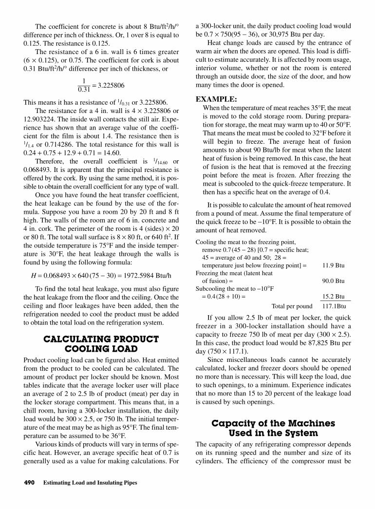
490 Estimating Load and Insulating Pipes
The coefficient for concrete is about 8 Btu/ft2/h/°difference per inch of thickness. Or, 1 over 8 is equal to0.125. The resistance is 0.125.
The resistance of a 6 in. wall is 6 times greater(6 × 0.125), or 0.75. The coefficient for cork is about0.31 Btu/ft2/h/° difference per inch of thickness, or
This means it has a resistance of 1/0.31 or 3.225806.The resistance for a 4 in. wall is 4 × 3.225806 or
12.903224. The inside wall contacts the still air. Expe-rience has shown that an average value of the coeffi-cient for the film is about 1.4. The resistance then is1/1.4 or 0.714286. The total resistance for this wall is0.24 + 0.75 + 12.9 + 0.71 = 14.60.
Therefore, the overall coefficient is 1/14.60 or0.068493. It is apparent that the principal resistance isoffered by the cork. By using the same method, it is pos-sible to obtain the overall coefficient for any type of wall.
Once you have found the heat transfer coefficient,the heat leakage can be found by the use of the for-mula. Suppose you have a room 20 by 20 ft and 8 fthigh. The walls of the room are of 6 in. concrete and4 in. cork. The perimeter of the room is 4 (sides) × 20or 80 ft. The total wall surface is 8 × 80 ft, or 640 ft2. Ifthe outside temperature is 75°F and the inside temper-ature is 30°F, the heat leakage through the walls isfound by using the following formula:
H = 0.068493 × 640 (75 − 30) = 1972.5984 Btu/h
To find the total heat leakage, you must also figurethe heat leakage from the floor and the ceiling. Once theceiling and floor leakages have been added, then therefrigeration needed to cool the product must be addedto obtain the total load on the refrigeration system.
CALCULATING PRODUCTCOOLING LOAD
Product cooling load can be figured also. Heat emittedfrom the product to be cooled can be calculated. Theamount of product per locker should be known. Mosttables indicate that the average locker user will placean average of 2 to 2.5 lb of product (meat) per day inthe locker storage compartment. This means that, in achill room, having a 300-locker installation, the dailyload would be 300 × 2.5, or 750 lb. The initial temper-ature of the meat may be as high as 95°F. The final tem-perature can be assumed to be 36°F.
Various kinds of products will vary in terms of spe-cific heat. However, an average specific heat of 0.7 isgenerally used as a value for making calculations. For
a 300-locker unit, the daily product cooling load wouldbe 0.7 × 750(95 − 36), or 30,975 Btu per day.
Heat change loads are caused by the entrance ofwarm air when the doors are opened. This load is diffi-cult to estimate accurately. It is affected by room usage,interior volume, whether or not the room is enteredthrough an outside door, the size of the door, and howmany times the door is opened.
EXAMPLE:When the temperature of meat reaches 35°F, the meatis moved to the cold storage room. During prepara-tion for storage, the meat may warm up to 40 or 50°F.That means the meat must be cooled to 32°F before itwill begin to freeze. The average heat of fusionamounts to about 90 Btu/lb for meat when the latentheat of fusion is being removed. In this case, the heatof fusion is the heat that is removed at the freezingpoint before the meat is frozen. After freezing themeat is subcooled to the quick-freeze temperature. Itthen has a specific heat on the average of 0.4.
It is possible to calculate the amount of heat removedfrom a pound of meat. Assume the final temperature ofthe quick freeze to be −10°F. It is possible to obtain theamount of heat removed.
Cooling the meat to the freezing point,remove 0.7(45 − 28) [0.7 = specific heat;45 = average of 40 and 50; 28 =temperature just below freezing point] = 11.9 Btu
Freezing the meat (latent heatof fusion) = 90.0 Btu
Subcooling the meat to −10°F= 0.4(28 + 10) = 15.2 Btu
Total per pound 117.1Btu
If you allow 2.5 lb of meat per locker, the quickfreezer in a 300-locker installation should have acapacity to freeze 750 lb of meat per day (300 × 2.5).In this case, the product load would be 87,825 Btu perday (750 × 117.1).
Since miscellaneous loads cannot be accuratelycalculated, locker and freezer doors should be openedno more than is necessary. This will keep the load, dueto such openings, to a minimum. Experience indicatesthat no more than 15 to 20 percent of the leakage loadis caused by such openings.
Capacity of the MachinesUsed in the System
The capacity of any refrigerating compressor dependson its running speed and the number and size of itscylinders. The efficiency of the compressor must be
10.31
3.225806=
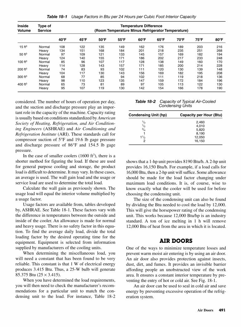
Air Doors 491
considered. The number of hours of operation per day,and the suction and discharge pressure play an impor-tant role in the capacity of the machine. Capacity ratingis usually based on conditions standardized by AmericanSociety of Heating, Refrigeration, and Air Condition-ing Engineers (ASHRAE) and Air Conditioning andRefrigeration Institute (ARI). These standards call forcompressor suction of 5°F and 19.6 lb gage pressureand discharge pressure of 86°F and 154.5 lb gagepressure.
In the case of smaller coolers (1600 ft3), there is ashorter method for figuring the load. If these are usedfor general purpose cooling and storage, the productload is difficult to determine. It may vary. In these cases,an average is used. The wall gain load and the usage orservice load are used to determine the total load.
Calculate the wall gain as previously shown. Theusage load will equal the interior volume multiplied bya usage factor.
Usage factors are available from, tables developedby, ASHRAE. See Table 18-1. These factors vary withthe difference in temperatures between the outside andinside of the cooler. An allowance is made for normaland heavy usage. There is no safety factor in this equa-tion. To find the average daily load, divide the totalloading factor by the desired operating time for theequipment. Equipment is selected from informationsupplied by manufacturers of the cooling units.
When determining the miscellaneous load, youwill need a constant that has been found to be veryreliable. This constant is that 1 W of electrical energyproduces 3.415 Btu. Thus, a 25-W bulb will generate85.375 Btu (25 × 3.415).
When you have determined the load requirements,you will then need to check the manufacturer’s recom-mendations for a particular unit to match the con-densing unit to the load. For instance, Table 18-2
shows that a 1-hp unit provides 8190 Btu/h. A 2-hp unitprovides 16,150 Btu/h. For example, if a load calls for16,000 Btu, then a 2-hp unit will suffice. Some allowanceshould be made for the load factor changing undermaximum load conditions. It is, of course, wise toknow exactly what the cooler will be used for beforechoosing the condensing unit.
The size of the condensing unit can also be foundby dividing the Btu needed to cool the load by 12,000.This will give the horsepower rating of the condensingunit. This works because 12,000 Btu/hp is an industrystandard. A ton of ice melting in 1 h will remove12,000 Btu of heat from the area in which it is located.
AIR DOORSOne of the ways to minimize temperature losses andprevent warm moist air entering is by using an air door.An air door also provides protection against insects,dust, dirt, and fumes. It provides an invisible barrieraffording people an unobstructed view of the workarea. It ensures a constant interior temperature by pre-venting the entry of hot or cold air. See Fig. 18-1.
An air door can be used to seal in cold air and saveenergy by preventing excessive operation of the refrig-eration system.
Table 18-1 Usage Factors in Btu per 24 Hours per Cubic Foot Interior Capacity
Inside Type of Temperature Difference Volume Service (Room Temperature Minus Refrigerator Temperature)
40F 45F 50F 55F 60F 65F 70F 75F 80F
15 ft3 Normal 108 122 135 149 162 176 189 203 216Heavy 134 151 168 184 201 218 235 251 268
50 ft3 Normal 97 109 121 133 145 157 169 182 194Heavy 124 140 155 171 186 202 217 233 248
100 ft3 Normal 85 96 107 117 128 138 149 160 170Heavy 114 128 143 157 171 185 200 214 228
200 ft3 Normal 74 83 93 102 111 120 130 139 148Heavy 104 117 130 143 156 169 182 195 208
300 ft3 Normal 68 77 85 94 102 111 119 218 136Heavy 98 110 123 135 147 159 172 184 196
400 ft3 Normal 65 73 81 89 97 105 113 122 130Heavy 95 107 119 130 142 154 166 178 190
Table 18-2 Capacity of Typical Air-CooledCondensing Units
Condensing Unit (hp) Capacity per Hour (Btu)
1/3 2,4601/2 4,0103/4 5,8201 8,190
11/2 12,0502 16,150
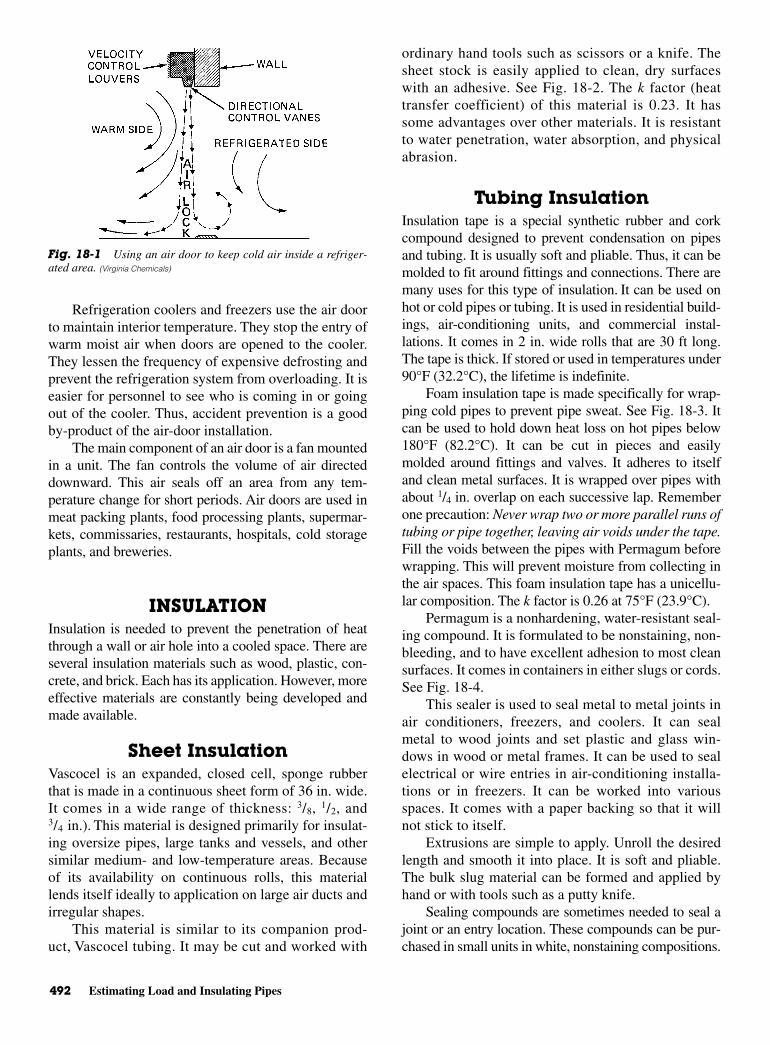
492 Estimating Load and Insulating Pipes
Refrigeration coolers and freezers use the air doorto maintain interior temperature. They stop the entry ofwarm moist air when doors are opened to the cooler.They lessen the frequency of expensive defrosting andprevent the refrigeration system from overloading. It iseasier for personnel to see who is coming in or goingout of the cooler. Thus, accident prevention is a goodby-product of the air-door installation.
The main component of an air door is a fan mountedin a unit. The fan controls the volume of air directeddownward. This air seals off an area from any tem-perature change for short periods. Air doors are used inmeat packing plants, food processing plants, supermar-kets, commissaries, restaurants, hospitals, cold storageplants, and breweries.
INSULATION Insulation is needed to prevent the penetration of heatthrough a wall or air hole into a cooled space. There areseveral insulation materials such as wood, plastic, con-crete, and brick. Each has its application. However, moreeffective materials are constantly being developed andmade available.
Sheet Insulation Vascocel is an expanded, closed cell, sponge rubberthat is made in a continuous sheet form of 36 in. wide.It comes in a wide range of thickness: 3/8, 1/2, and3/4 in.). This material is designed primarily for insulat-ing oversize pipes, large tanks and vessels, and othersimilar medium- and low-temperature areas. Becauseof its availability on continuous rolls, this materiallends itself ideally to application on large air ducts andirregular shapes.
This material is similar to its companion prod-uct, Vascocel tubing. It may be cut and worked with
ordinary hand tools such as scissors or a knife. Thesheet stock is easily applied to clean, dry surfaceswith an adhesive. See Fig. 18-2. The k factor (heattransfer coefficient) of this material is 0.23. It hassome advantages over other materials. It is resistantto water penetration, water absorption, and physicalabrasion.
Tubing InsulationInsulation tape is a special synthetic rubber and corkcompound designed to prevent condensation on pipesand tubing. It is usually soft and pliable. Thus, it can bemolded to fit around fittings and connections. There aremany uses for this type of insulation. It can be used onhot or cold pipes or tubing. It is used in residential build-ings, air-conditioning units, and commercial instal-lations. It comes in 2 in. wide rolls that are 30 ft long.The tape is thick. If stored or used in temperatures under90°F (32.2°C), the lifetime is indefinite.
Foam insulation tape is made specifically for wrap-ping cold pipes to prevent pipe sweat. See Fig. 18-3. Itcan be used to hold down heat loss on hot pipes below180°F (82.2°C). It can be cut in pieces and easilymolded around fittings and valves. It adheres to itselfand clean metal surfaces. It is wrapped over pipes withabout 1/4 in. overlap on each successive lap. Rememberone precaution: Never wrap two or more parallel runs oftubing or pipe together, leaving air voids under the tape.Fill the voids between the pipes with Permagum beforewrapping. This will prevent moisture from collecting inthe air spaces. This foam insulation tape has a unicellu-lar composition. The k factor is 0.26 at 75°F (23.9°C).
Permagum is a nonhardening, water-resistant seal-ing compound. It is formulated to be nonstaining, non-bleeding, and to have excellent adhesion to most cleansurfaces. It comes in containers in either slugs or cords.See Fig. 18-4.
This sealer is used to seal metal to metal joints inair conditioners, freezers, and coolers. It can sealmetal to wood joints and set plastic and glass win-dows in wood or metal frames. It can be used to sealelectrical or wire entries in air-conditioning installa-tions or in freezers. It can be worked into variousspaces. It comes with a paper backing so that it willnot stick to itself.
Extrusions are simple to apply. Unroll the desiredlength and smooth it into place. It is soft and pliable.The bulk slug material can be formed and applied byhand or with tools such as a putty knife.
Sealing compounds are sometimes needed to seal ajoint or an entry location. These compounds can be pur-chased in small units in white, nonstaining compositions.
Fig. 18-1 Using an air door to keep cold air inside a refriger-ated area. (Virginia Chemicals)
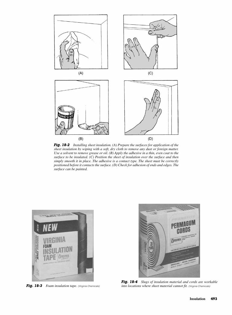
Insulation 493
Fig. 18-2 Installing sheet insulation. (A) Prepare the surfaces for application of thesheet insulation by wiping with a soft, dry cloth to remove any dust or foreign matter.Use a solvent to remove grease or oil. (B) Apply the adhesive in a thin, even coat to thesurface to be insulated. (C) Position the sheet of insulation over the surface and thensimply smooth it in place. The adhesive is a contact type. The sheet must be correctlypositioned before it contacts the surface. (D) Check for adhesion of ends and edges. Thesurface can be painted.
Fig. 18-3 Foam insulation tape. (Virginia Chemicals)
Fig. 18-4 Slugs of insulation material and cords are workableinto locations where sheet material cannot fit. (Virginia Chemicals)
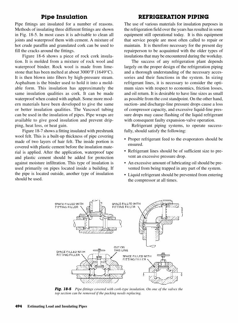
494 Estimating Load and Insulating Pipes
Pipe InsulationPipe fittings are insulated for a number of reasons.Methods of insulating three different fittings are shownin Fig. 18-5. In most cases it is advisable to clean alljoints and waterproof them with cement. A mixture ofhot crude paraffin and granulated cork can be used tofill the cracks around the fittings.
Figure 18-6 shows a piece of rock cork insula-tion. It is molded from a mixture of rock wool andwaterproof binder. Rock wool is made from lime-stone that has been melted at about 3000°F (1649°C).It is then blown into fibers by high-pressure steam.Asphaltum is the binder used to hold it into a mold-able form. This insulation has approximately thesame insulation qualities as cork. It can be madewaterproof when coated with asphalt. Some more mod-ern materials have been developed to give the sameor better insulation qualities. The Vascocel tubingcan be used in the insulation of pipes. Pipe wraps areavailable to give good insulation and prevent drip-ping, heat loss, or heat gain.
Figure 18-7 shows a fitting insulated with preshrunkwool felt. This is a built-up thickness of pipe coveringmade of two layers of hair felt. The inside portion iscovered with plastic cement before the insulation mate-rial is applied. After the application, waterproof tapeand plastic cement should be added for protectionagainst moisture infiltration. This type of insulation isused primarily on pipes located inside a building. Ifthe pipe is located outside, another type of insulationshould be used.
REFRIGERATION PIPINGThe use of various materials for insulation purposes inthe refrigeration field over the years has resulted in someequipment still operational today. It is this equipmentthat service people are most often called to repair ormaintain. It is therefore necessary for the present dayrepairperson to be acquainted with the older types ofinsulations that may be encountered during the workday.
The success of any refrigeration plant dependslargely on the proper design of the refrigeration pipingand a thorough understanding of the necessary acces-sories and their functions in the system. In sizingrefrigerant lines, it is necessary to consider the opti-mum sizes with respect to economics, friction losses,and oil return. It is desirable to have line sizes as smallas possible from the cost standpoint. On the other hand,suction- and discharge-line pressure drops cause a lossof compressor capacity, and excessive liquid-line pres-sure drops may cause flashing of the liquid refrigerantwith consequent faulty expansion-valve operation.
Refrigerant piping systems, to operate success-fully, should satisfy the following:
• Proper refrigerant feed to the evaporators should beensured.
• Refrigerant lines should be of sufficient size to pre-vent an excessive pressure drop.
• An excessive amount of lubricating oil should be pre-vented from being trapped in any part of the system.
• Liquid refrigerant should be prevented from enteringthe compressor at all times.
Fig. 18-5 Pipe-fittings covered with cork-type insulation. On one of the valves thetop section can be removed if the packing needs replacing.

Liquid Refrigerant Lines 495
PRESSURE-DROPCONSIDERATIONS
Pressure drop in liquid lines is not as critical as it is inthe suction and discharge lines. The important thing toremember is that the pressure drop should not be sogreat as to cause gas formation in the liquid line and/orinsufficient liquid pressure at the liquid-feed device. Asystem should normally be designed so that the pres-sure drop, due to friction in the liquid line, is notgreater than that corresponding to 1 to 2° change in sat-uration temperature. Friction pressure drops in the liq-uid line include the drop in accessories, such as thesolenoid valve, strainer-drier, and hand valves, as wellas in the actual pipe and fittings from the receiver out-let to the refrigerant feed device at the evaporator.
Friction pressure drop in the suction line means aloss in system capacity because it forces the compressorto operate at a lower suction pressure to maintain thedesired evaporating temperature in the coil. It is usuallystandard practice to size the suction line to have a pres-
sure drop due to friction not any greater than the equiv-alent of a 1 to 2° change in saturation temperature.
LIQUID REFRIGERANT LINESThe liquid lines do not generally present any design prob-lems. Refrigeration oil is sufficiently miscible with com-monly used refrigerants in the liquid form to assureadequate mixture and positive oil return. The followingfactors should be considered when designating liquidlines.
The liquid lines, including the interconnected valvesand accessories, must be of sufficient size to preventexcessive pressure drops.
When interconnecting condensing units with con-denser receivers or evaporative condensers, the liquidlines from each unit should be brought into a commonliquid line.
Each unit should join the common liquid line as farbelow the receivers as possible, with a minimum of 2 ftpreferred. The common liquid line should rise to theceiling of the machine room. The added heat of liquid isprovided to prevent, as far as possible, hot gas blowingback from the receivers.
All liquid lines from the receivers to the commonline should have equal pressure drops in order to pro-vide, as nearly as possible, equal liquid flow and pre-vent the blowing of gas.
Remove all liquid-line filters from the condensingunits, and install them in parallel in the common liquidline at the ceiling level.
Fig. 18-6 Pipe insulation.
Fig. 18-7 Insulated pipe fittings.
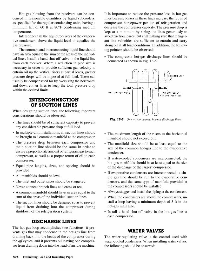
496 Estimating Load and Insulating Pipes
Hot gas blowing from the receivers can be con-densed in reasonable quantities by liquid subcoolers,as specified for the regular condensing units, having aminimum lift of 60 ft at 80°F condensing mediumtemperature.
Interconnect all the liquid receivers of the evapora-tive condensers above the liquid level to equalize thegas pressure.
The common and interconnecting liquid line shouldhave an area equal to the sum of the areas of the individ-ual lines. Install a hand shut-off valve in the liquid linefrom each receiver. Where a reduction in pipe size isnecessary in order to provide sufficient gas velocity toentrain oil up the vertical risers at partial loads, greaterpressure drops will be imposed at full load. These canusually be compensated for by oversizing the horizontaland down comer lines to keep the total pressure dropwithin the desired limits.
INTERCONNECTIONOF SUCTION LINES
When designing suction lines, the following importantconsiderations should be observed:
• The lines should be of sufficient capacity to preventany considerable pressure drop at full load.
• In multiple-unit installations, all suction lines shouldbe brought to a common manifold at the compressor.
• The pressure drop between each compressor andmain suction line should be the same in order toensure a proportionate amount of refrigerant gas to eachcompressor, as well as a proper return of oil to eachcompressor.
• Equal pipe lengths, sizes, and spacing should beprovided.
• All manifolds should be level.
• The inlet and outlet pipes should be staggered.
• Never connect branch lines at a cross or tee.
• A common manifold should have an area equal to thesum of the areas of the individual suction lines.
• The suction lines should be designed so as to preventliquid from draining into the compressor duringshutdown of the refrigeration system.
DISCHARGE LINESThe hot-gas loop accomplishes two functions: it pre-vents gas that may condense in the hot-gas line fromdraining back into the heads of the compressor duringthe off cycles, and it prevents oil leaving one compres-sor from draining down into the head of an idle machine.
It is important to reduce the pressure loss in hot-gaslines because losses in these lines increase the requiredcompressor horsepower per ton of refrigeration anddecrease the compressor capacity. The pressure drop iskept at a minimum by sizing the lines generously toavoid friction losses, but still making sure that refriger-ant line velocities are sufficient to entrain and carryalong oil at all load conditions. In addition, the follow-ing pointers should be observed:
• The compressor hot-gas discharge lines should beconnected as shown in Fig. 18-8.
• The maximum length of the risers to the horizontalmanifold should not exceed 6 ft.
• The manifold size should be at least equal to thesize of the common hot-gas line to the evaporativecondenser.
• If water-cooled condensers are interconnected, thehot-gas manifolds should be at least equal to the sizeof the discharge of the largest compressor.
• If evaporative condensers are interconnected, a sin-gle gas line should be run to the evaporative con-densers, and the same type of manifold provided atthe compressors should be installed.
• Always stagger and install the piping at the condensers.
• When the condensers are above the compressors, in-stall a loop having a minimum depth of 3 ft in thehot-gas main line.
• Install a hand shut-off valve in the hot-gas line ateach compressor.
WATER VALVESThe water-regulating valve is the control used withwater-cooled condensers. When installing water valves,the following should be observed:
Fig. 18-8 One way to connect hot-gas discharge lines.

Multiple-Unit Installation 497
• The condenser water for interconnected compressorcondensers should be applied from a common waterline.
• Single automatic water valves or multiple valves inparallel (Fig. 18-9) should be installed in the com-mon water line.
• Pressure-control tubing from the water valves shouldbe connected to a common line, which, in turn,should be connected to one of the receivers or to thecommon liquid line.
MULTIPLE-UNIT INSTALLATIONMultiple compressors operating in parallel must becarefully piped to ensure proper operation. The suctionpiping at parallel compressors should be designed sothat all compressors run at the same suction pressureand oil is returned in equal proportions to the runningcompressors. All suction lines should be brought into acommon suction header in order to return the oil toeach crankcase as uniformly as possible.
The suction header should be run above the level ofthe compressor suction inlets so that oil can drain intothe compressors by gravity. The header should not bebelow the compressor suction inlets because it canbecome an oil trap. Branch suction lines to the com-pressors should be taken off from the side of the header.Care should be taken to make sure that the return mainsfrom the evaporators are not connected into the suctionheader so as to form crosses with the branch suctionlines to the compressors. The suction header should berun full size along its entire length. The horizontaltakeoffs to the various compressors should be the samesize as the suction header. No reduction should bemade in the branch suction lines to the compressorsuntil the vertical drop is reached.
Figure 18-10 shows the suction and hot-gas headerarrangements for two compressors operating in parallel.
Fig. 18-9 A method of interconnecting water valves.
Fig. 18-10 Connections for the suction and hot-gas headers in a multiplecompressor installation.

498 Estimating Load and Insulating Pipes
Takeoffs to each compressor from the common suctionheader should be horizontal and from the side, toensure equal distribution of oil and prevent accumu-lating liquid refrigerant in an idle compressor in caseof slop-over.
Piping InsulationInsulation is required for refrigeration piping to preventmoisture condensation and prevent heat gain from thesurrounding air. The desirable properties of insulation arethat it should have a low coefficient of heat transmission,be easy to apply, have a high degree of permanency, andprovide protection against air and moisture infiltration.Finally, it should have a reasonable installation cost.
The type and thickness of insulation used dependson the temperature difference between the surface of thepipe and the surrounding air, and also on the relativehumidity of the air. It should be clearly understood thatalthough a system is designed to operate at a high-suction temperature, it is quite difficult to prevent coldertemperatures occurring from time to time. This may bedue to a carrying over of some liquid from the evapora-tor or the operation of an evaporator pressure valve.Interchangers are preferable to insulation, in this case.
One of the safest pipe insulations available ismolded cork or rock cork of the proper thickness. Hair-felt insulation may be used, but great care must betaken to have it properly sealed. For temperaturesabove 40°F, wool felt or a similar insulation may beused, but here again success depends on the proper sealagainst air and moisture infiltration.
Liquid refrigerant lines carry much higher temper-ature refrigerant than suction lines; and if this temper-ature is above the temperature of the space throughwhich they pass, no insulation is usually necessary.However, if there is danger of the liquid lines goingbelow the surrounding air temperatures and causingcondensation, they should be insulated when conden-sation will be objectionable. If they must unavoidablypass through highly heated spaces, such as those adja-cent to steam pipes, through boiler rooms, then the liq-uid lines should also be insulated to ensure a solidcolumn of liquid to the expansion valve.
There were four types of insulation in use beforethe discovery of modern insulation materials. Thoseyou may encounter were in general use for refrigeratorpiping. They are namely:
• Cork
• Rock cork
• Wool felt with waterproof jacket
• Hair felt with waterproof jacket
Cork InsulationCork pipe covering is prepared by pressing dried andgranulated cork in metal molds. The natural resins inthe cork bind the entire mass into its new shape. In thecase of the cheaper cork, an artificial binder is used.The cork may be molded to fit pipe and fittings, or itmay be made into flat boards of varying sizes andthickness. Cork has a low thermal conductivity. Thenatural binder in the material itself makes cork highlywater-resistant, and its structure ensures a low capillar-ity. It can be made practically impervious to water bysurfacing with odorless asphalt.
All fittings in the piping, as well as the pipe itself,should be thoroughly insulated to prevent heat gain toprotect the pipe insulation from moisture infiltrationand deterioration, and eliminate condensation prob-lems. Molded cork covering, made especially for thispurpose, is available for all common types of fittings.Each covering should be the same in every respect asthe pipe insulation, with the exception of the shape, andshould be formed so that it joins to the pipe insulationwith a break. Typical cork fitting covers are furnished inthree standard thicknesses for ice water, brine, and spe-cial brine.
To secure maximum efficiency and long life fromcork covering, it must be correctly applied and serviced,as well as properly selected. Hence, it is essential thatthe manufacturer’s recommendations and instructionsbe followed in detail. The following general informationis a summary of the data that are of general interest.
All pipelines should be thoroughly cleaned, dried,and free from all leaks. It is also advisable to paint thepiping with waterproof paint before applying the insu-lation, although this is not recommended by all manu-facturers. All joints should be sealed with waterproofcement when applied. Fitting insulation should beapplied in substantially the same manner, with theaddition of a mixture of hot crude paraffin and granu-lated cork used to fill the space between the fittingsshown in Fig. 18-5.
Rock-Cork InsulationRock-cork insulation is manufactured commercially bymolding a mixture of rock wool and a waterproof binderinto any shape or thickness desired. The rock wool ismade from limestone melted at about 3000°F and thenblown into fibers by high-pressure steam. It is mixedwith an asphalt binder and molded into the various com-mercial forms. The heat conductivity is about the sameas cork, and the installed price may be less. Because ofits mineral composition, it is odorless, vermin-proof, andfree from decay. Like cork, it can be made completely
Multiple-Unit Installation 499
waterproof by surfacing with odorless asphaltum. Thepipe covering fabricated from rock wool and a binder ispremolded in single-layer sections, 36-in. long, to fit allstandard pipe sizes and is usually furnished with afactory-applied waterproof jacket.
When pipelines are insulated with rock-cork cov-ering, the fittings are generally insulated with built-uprock wool impregnated with asphalt. This material isgenerally supplied in felted form, having a nominalthickness of about 1 in. and a width of about 18 in. Itcan be readily adapted to any type of fitting and is effi-cient as an insulator when properly applied.
Before applying the formed rock-cork insulation, itis first necessary to thoroughly clean and dry the pipingand then paint it with waterproof asphalt paint. Thestraight lengths of piping are next covered with the insu-lation, which has the two longitudinal joints and one endjoint of each section coated with plastic cement. Thesections are butted tightly together with the longitudinaljoints at the top and bottom and temporarily held inplace by staples. The plastic cement should coat that partof the exterior area of each section to be covered by thewaterproof lap and the lap pressed smoothly into it. Theend joints should be sealed with a waterproof fabricembedded in a coat of the plastic cement. Each sectionshould then be secured permanently in place with threeto six loops of copper-plated annealed steel wire.
Wool-Felt InsulationWool felt is a relatively inexpensive type of pipe insula-tion and is made up of successive layers of waterproofwool felt that are indented in the manufacturing processto form air spaces. The inner layer is a waterproofasphalt-saturated felt, while the outside layer is an inte-gral waterproof jacket. This insulating material is satis-factory when it can be kept airtight and moisture free. Ifair is allowed to penetrate, condensation will take placein the wool felt, and it will quickly deteriorate. Thus, it isadvisable to use it only where temperatures above 40°Fare encountered and when it is perfectly sealed. Underall conditions, it should carry the manufacturer’s guaran-tee for the duty that it is to perform.
After all the piping is thoroughly cleaned and dried,the sectional covering is usually applied directly to thepipe with the outer layer slipped back and turned so thatall joints are staggered. The joints should be sealed withplastic cement, and the flap of the waterproof jacketshould be sealed in place with the same material. Staplesand copper-clad steel wire should be provided to perma-nently hold the insulation in place, and then the circularjoints should be covered with at least two layers ofwaterproof tape to which plastic cement is applied.
Pipe fittings should be insulated with at least twolayers of hair felt (Fig. 18-7) built up to the thickness ofthe pipe covering; but before the felt is placed aroundthe fittings, the exposed ends of the pipe insulationshould be coated with plastic cement.
After the felt is in place, two layers of waterprooftape and plastic cement should be applied for protec-tion from moisture infiltration.
Insulation of this type is designed for installation inbuildings where it is normally protected against outsideweather conditions. When outside pipes are to be insu-lated, one of the better types of pipe covering should beused. In all cases, the manufacturer’s recommendationsshould be followed during the application.
Hair-Felt InsulationHair-felt insulation is usually made from pure cattlehair that has been especially prepared and cleaned. It isa very good insulator against heat, having a low thermalconductivity. Its installed cost is somewhat lower thancork; but it is more difficult to install and seal properly,and hence its use must be considered a hazard with theaverage type of workmanship. Prior to installation, thepiping should be cleaned and dried and then preparedby applying a thickness of waterproof paper or tapewound spirally, over which the hair felt of approxi-mately 1-in. thickness is spirally wound for the desiredlength of pipe. It is then tightly bound with jute twine,wrapped with a sealing tape to make it entirely airtight,and finally painted with waterproof paint. If more thanone thickness of hair felt is desired, it should be built upin layers with tarpaper between. When it is necessary tomake joints around fittings, the termination of the hairfelt should be tapered down with sealing tape and theinsulation applied to the fittings should overlap thistaper, thus ensuring a permanently tight fit.
The important point to remember is that this typeof insulation must be carefully sealed against any air ormoisture infiltration, and even then difficulty mayoccur after it has been installed. At any point where airinfiltration (or “breathing,” as it is called) is permittedto occur, condensation will start and travel great dis-tances along the pipe, even undermining the insulationthat is properly sealed.
There are several other types of pipe insulation avail-able, but they are not used extensively. These include var-ious types of wrapped and felt insulation, but they areseldom applied with success. Whatever insulation isused, it should be critically examined to see whether itwill provide the protection and permanency required ofit; otherwise it should never be considered. Although allrefrigerant piping, joints, and fittings should be covered,

500 Estimating Load and Insulating Pipes
it is not advisable to do so until the system has been thor-oughly leak tested and operated for a time.
Pressure drop in the various parts of commercialrefrigeration systems, due to pipe friction, and the properdimensioning to obtain the best operating results areimportant items when installation of equipment is made.
By careful observation of the foregoing detaileddescription of refrigeration piping and methods of instal-lation, the piping problem will be greatly simplified andresult in proper system operation.
REVIEW QUESTIONS1. Why is off-cycle defrost not used in commercial
units?
2. Why does frost not form on an air-conditioningunit?
3. Explain wall gain load, air change load, and productload.
4. How do you calculate heat leakage?
5. What are miscellaneous loads?
6. What does the capacity of a refrigerating compres-sor depend on?
7. What is the purpose of an air door?
8. What is the main component of an air door?
9. What is the basic purpose of Vascocel?
10. Why is tubing insulation needed in a refrigeratingsystem?

19CHAPTER
Installingand ControllingElectrical Power
forAir-Conditioning
Units
Copyright © 2006 by The McGraw-Hill Companies, Inc. Click here for terms of use.
502 Installing and Controlling Electrical Power for Air-Conditioning Units
PERFORMANCE OBJECTIVESAfter studying this chapter you will:
1. Understand how to find the correct wire size for arefrigeration unit.
2. Know the permissible maximum voltage drops in aservice line.
3. Know the effects of voltage variations on AC motors.
4. Know how to calculate starting current values andinrush voltage drops.
5. Know the code limitations on amperes per conductor.
6. Know how to select the correct circuit protection.
7. Know the different types of fuses and circuit breakers.
In order to operate properly, the correct voltage,amperage, and wattage must be furnished to the air-conditioning unit. A number of devices have to be uti-lized to keep the voltage source clean and available forefficient operation of the unit. It all starts with the choos-ing of the correct wire from the power pole to the houseor store or school where the air-conditioning unit is used.
CHOOSING WIRE SIZEThere are two criteria for choosing wire size for instal-lation of air-conditioning or refrigeration equipment.The size of the electrical conductor wire recommendedfor a given appliance circuit depends upon two things:limitation on voltage loss and minimum wire size.
Limiting Voltage LossProper operation of an electrical device must be underthe conditions for which it was designed. The wire sizeselected must be low in resistance per foot of length.This will assure that the full load “line loss” of the totallength of the circuit does not cause low voltage of theappliance terminals. Since the length of electrical feed-ers varies with each installation, wire sizing to avoidexcessive voltage loss becomes the responsibility ofthe installing contractor. The National Electrical Code(NEC) or local code should be followed.
Minimum Wire SizeTo avoid field wiring being damaged by tensile stress oroverheating, national and local codes establish mini-mum wire sizes. The maximum amperage permitted fora given conductor limits internal heat generation so thattemperature will not damage its insulation. This assumesproper fusing that will limit the maximum current flowso that the conductor will always be protected.
Wire size and voltage loss go hand in hand, so tospeak. The larger the wire, the more current it can han-dle without voltage loss along the lines. Each conduc-tor or wire has resistance. This resistance, measured inohms per unit of wire length, increases as the cross-sectional area of the wire decreases. The size of thewire is indicated by gage number. The higher the gagenumber, the smaller the wire. American Wire Gage (AWG)is the standard used for wire size. Each gage numberhas a resistance value in ohms per foot of wire length.The resistance of aluminum wire is 64 percent greaterthan that for copper of the same gage number.
Wire SelectionThe wire size recommended for actual use should bethe heavier of the two indicated by the procedures thatfollow.
Local approval is usually necessary for any instal-lation that has large current draws. The data presentedhere are based on the NEC. Much of the detail has beenomitted in the interest of simplification. Thus, theremay be areas of incompleteness not covered by a foot-note or reference. In all cases it is recognized that finalapproval must come from the authority having localjurisdiction. The NEC sets forth minimum standards.It is an effort to establish some standard for safe opera-tion of equipment.
WIRE SIZE AND LOW VOLTAGEThe voltage at which a motor or device should operateis stamped on the nameplate. This voltage indicatesthat the full capacity of the device is being utilizedwhen that particular voltage is available. Motors oper-ated at lower than rated voltage are unable to providefull horsepower without jeopardizing their service life.Electric heating units lose capacity even more rapidlyat reduced voltages.
Low voltage can result in insufficient spark for oilburner ignition, reluctant starting of motors, and over-heating of motors handling normal loads. Thus, it is notuncommon to protect electrical devices by selectingrelays that will not close load circuits if the voltage ismore than 15 percent below rating.
Air Conditioning and Refrigeration Institute (ARI)certified that cooling units are tested to assure they willstart and run at 10 percent above and 10 percent belowtheir rating plate voltage. However, this does not implythat continuous operation at these voltages will notaffect their capacity, performance, and anticipated ser-vice life. A large proportion of air-conditioning com-pressor burnouts can be traced to low voltage. Because

The Effects of Voltage Variations on Ac Motors 503
the motor of a hermetic compressor is entirely enclosedwithin the refrigerant cycle, it is important that it not beabused either by overloading or undervoltage. Both ofthese can occur during peak load conditions. A nationalsurvey has shown that the most common cause of com-pressor low voltage is the use of undersized conductorsbetween the utility lines and the condensing unit.
The size of the wire selected must be one that, underfull-load conditions, will deliver acceptable voltages tothe appliance terminals. The NEC requires that theconductors be sized to limit voltage drop between theoutdoor-pole service tap and the appliance terminals;not in excess of 5 percent of rated voltage underfull-load conditions. This loss may be subdivided, with3 percent permissible in service drops, feeders, meters,and overcurrent protectors at the distribution panel andthe appliance. See Fig. 19-1.
In a 240-V service, the wire size selected for anindividual appliance circuit should cause no more than4.8-V drop under full-load conditions. Even with this5 percent limitation on voltage drop, the voltage at theequipment terminals is still very apt to be below therating plate values. See Table 19-1.
Voltage Drop Calculations Just as friction creates pressure loss in water flowthrough pipes, so does electrical resistance create volt-age drop as current flows through a conductor. The dropincreases with the length of the conductor (in feet), thecurrent flow (in amperes), and the ohms of resistance
per foot of wire. This relationship may be expressed asfollows:
Voltage drop = amperes × ohms/foot× length of conductor
Figure 19-2 illustrates how voltage drop per 100 ftof copper conductor will increase with the amount ofcurrent drawn through the conductor. The wire size isindicated on the straight line. Match the amperes withthe wire size. Then follow over to the left column todetermine the voltage drop. For instance, Fig. 19-2shows that there will be a 2.04-V drop per 100 ft of cop-per conductor for 20 A of current through a No. 10 wire.
THE EFFECTS OF VOLTAGEVARIATIONS ON AC MOTORS
Motors will run at the voltage variations already men-tioned. This does not imply such operation will comply
Fig. 19-1 Voltage drops from post to air conditioner. (Bryant)
Table 19-1 Permissible Maximum Voltage Drops
For a line voltage of: 120 208 240 480
Feeders to distribution panel (3%) 3.6 6.24 7.2 14.4Branch circuit to appliance (2%) 2.4 4.16 4.8 9.6Total voltage drop fully loaded 6 10.4 12 24Resultant∗ voltage at appliance 114 197.6 228 456
∗Assumes full-rated voltage where feeders connect to utility lines. If utility volt-age runs low, the overall voltage drop should be further reduced so as to makeavailable at the appliance terminals a voltage as close as practical to that spec-ified on the appliance rating plate.
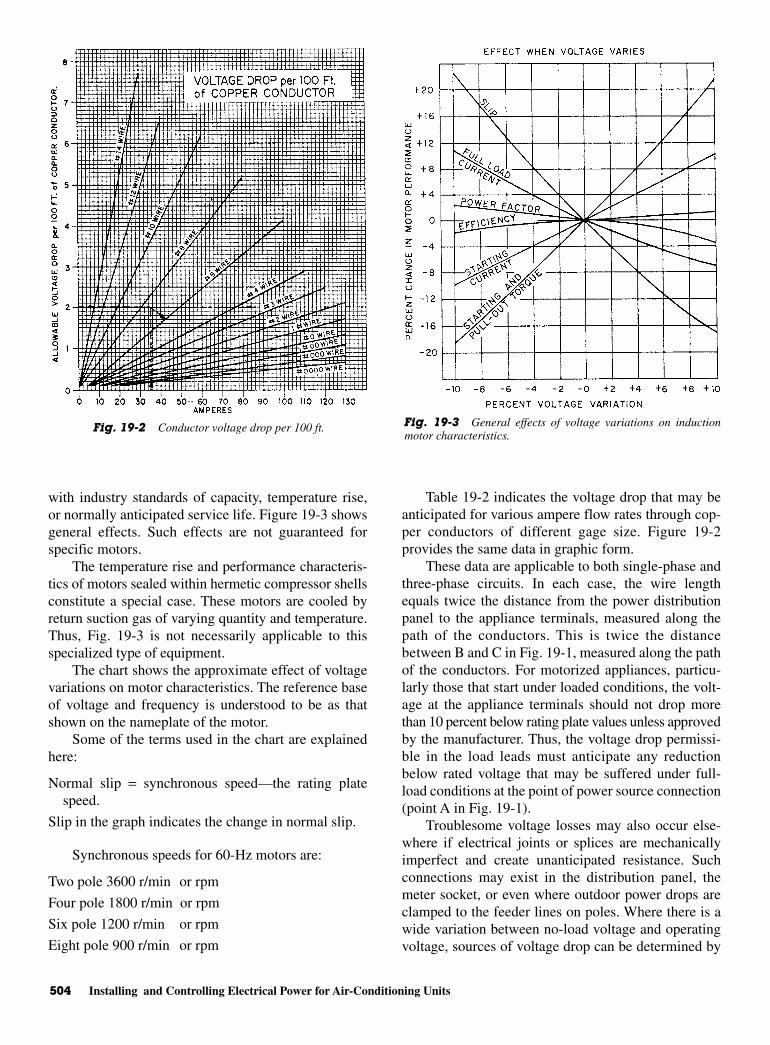
504 Installing and Controlling Electrical Power for Air-Conditioning Units
with industry standards of capacity, temperature rise,or normally anticipated service life. Figure 19-3 showsgeneral effects. Such effects are not guaranteed forspecific motors.
The temperature rise and performance characteris-tics of motors sealed within hermetic compressor shellsconstitute a special case. These motors are cooled byreturn suction gas of varying quantity and temperature.Thus, Fig. 19-3 is not necessarily applicable to thisspecialized type of equipment.
The chart shows the approximate effect of voltagevariations on motor characteristics. The reference baseof voltage and frequency is understood to be as thatshown on the nameplate of the motor.
Some of the terms used in the chart are explainedhere:
Normal slip = synchronous speed—the rating platespeed.
Slip in the graph indicates the change in normal slip.
Synchronous speeds for 60-Hz motors are:
Two pole 3600 r/min or rpm
Four pole 1800 r/min or rpm
Six pole 1200 r/min or rpm
Eight pole 900 r/min or rpm
Table 19-2 indicates the voltage drop that may beanticipated for various ampere flow rates through cop-per conductors of different gage size. Figure 19-2provides the same data in graphic form.
These data are applicable to both single-phase andthree-phase circuits. In each case, the wire lengthequals twice the distance from the power distributionpanel to the appliance terminals, measured along thepath of the conductors. This is twice the distancebetween B and C in Fig. 19-1, measured along the pathof the conductors. For motorized appliances, particu-larly those that start under loaded conditions, the volt-age at the appliance terminals should not drop morethan 10 percent below rating plate values unless approvedby the manufacturer. Thus, the voltage drop permissi-ble in the load leads must anticipate any reductionbelow rated voltage that may be suffered under full-load conditions at the point of power source connection(point A in Fig. 19-1).
Troublesome voltage losses may also occur else-where if electrical joints or splices are mechanicallyimperfect and create unanticipated resistance. Suchconnections may exist in the distribution panel, themeter socket, or even where outdoor power drops areclamped to the feeder lines on poles. Where there is awide variation between no-load voltage and operatingvoltage, sources of voltage drop can be determined by
Fig. 19-2 Conductor voltage drop per 100 ft. Fig. 19-3 General effects of voltage variations on inductionmotor characteristics.
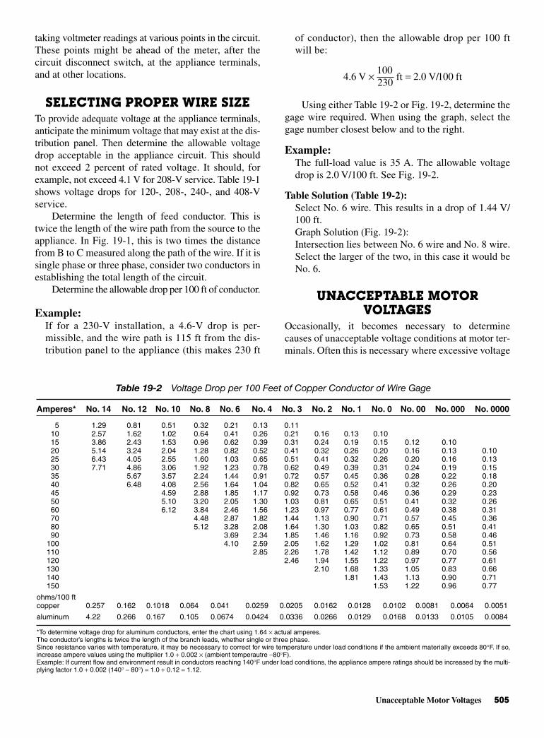
Unacceptable Motor Voltages 505
taking voltmeter readings at various points in the circuit.These points might be ahead of the meter, after thecircuit disconnect switch, at the appliance terminals,and at other locations.
SELECTING PROPER WIRE SIZETo provide adequate voltage at the appliance terminals,anticipate the minimum voltage that may exist at the dis-tribution panel. Then determine the allowable voltagedrop acceptable in the appliance circuit. This shouldnot exceed 2 percent of rated voltage. It should, forexample, not exceed 4.1 V for 208-V service. Table 19-1shows voltage drops for 120-, 208-, 240-, and 408-Vservice.
Determine the length of feed conductor. This istwice the length of the wire path from the source to theappliance. In Fig. 19-1, this is two times the distancefrom B to C measured along the path of the wire. If it issingle phase or three phase, consider two conductors inestablishing the total length of the circuit.
Determine the allowable drop per 100 ft of conductor.
Example:If for a 230-V installation, a 4.6-V drop is per-missible, and the wire path is 115 ft from the dis-tribution panel to the appliance (this makes 230 ft
of conductor), then the allowable drop per 100 ftwill be:
Using either Table 19-2 or Fig. 19-2, determine thegage wire required. When using the graph, select thegage number closest below and to the right.
Example:The full-load value is 35 A. The allowable voltagedrop is 2.0 V/100 ft. See Fig. 19-2.
Table Solution (Table 19-2): Select No. 6 wire. This results in a drop of 1.44 V/100 ft.Graph Solution (Fig. 19-2): Intersection lies between No. 6 wire and No. 8 wire.Select the larger of the two, in this case it would beNo. 6.
UNACCEPTABLE MOTORVOLTAGES
Occasionally, it becomes necessary to determinecauses of unacceptable voltage conditions at motor ter-minals. Often this is necessary where excessive voltage
4.6 V100230
ft 2.0 V/100 ft× =
Table 19-2 Voltage Drop per 100 Feet of Copper Conductor of Wire Gage
Amperes* No. 14 No. 12 No. 10 No. 8 No. 6 No. 4 No. 3 No. 2 No. 1 No. 0 No. 00 No. 000 No. 0000
5 1.29 0.81 0.51 0.32 0.21 0.13 0.1110 2.57 1.62 1.02 0.64 0.41 0.26 0.21 0.16 0.13 0.1015 3.86 2.43 1.53 0.96 0.62 0.39 0.31 0.24 0.19 0.15 0.12 0.1020 5.14 3.24 2.04 1.28 0.82 0.52 0.41 0.32 0.26 0.20 0.16 0.13 0.1025 6.43 4.05 2.55 1.60 1.03 0.65 0.51 0.41 0.32 0.26 0.20 0.16 0.1330 7.71 4.86 3.06 1.92 1.23 0.78 0.62 0.49 0.39 0.31 0.24 0.19 0.1535 5.67 3.57 2.24 1.44 0.91 0.72 0.57 0.45 0.36 0.28 0.22 0.1840 6.48 4.08 2.56 1.64 1.04 0.82 0.65 0.52 0.41 0.32 0.26 0.2045 4.59 2.88 1.85 1.17 0.92 0.73 0.58 0.46 0.36 0.29 0.2350 5.10 3.20 2.05 1.30 1.03 0.81 0.65 0.51 0.41 0.32 0.2660 6.12 3.84 2.46 1.56 1.23 0.97 0.77 0.61 0.49 0.38 0.3170 4.48 2.87 1.82 1.44 1.13 0.90 0.71 0.57 0.45 0.3680 5.12 3.28 2.08 1.64 1.30 1.03 0.82 0.65 0.51 0.4190 3.69 2.34 1.85 1.46 1.16 0.92 0.73 0.58 0.46
100 4.10 2.59 2.05 1.62 1.29 1.02 0.81 0.64 0.51110 2.85 2.26 1.78 1.42 1.12 0.89 0.70 0.56120 2.46 1.94 1.55 1.22 0.97 0.77 0.61130 2.10 1.68 1.33 1.05 0.83 0.66140 1.81 1.43 1.13 0.90 0.71150 1.53 1.22 0.96 0.77
ohms/100 ftcopper 0.257 0.162 0.1018 0.064 0.041 0.0259 0.0205 0.0162 0.0128 0.0102 0.0081 0.0064 0.0051
aluminum 4.22 0.266 0.167 0.105 0.0674 0.0424 0.0336 0.0266 0.0129 0.0168 0.0133 0.0105 0.0084
*To determine voltage drop for aluminum conductors, enter the chart using 1.64 × actual amperes.The conductor’s lengths is twice the length of the branch leads, whether single or three phase.Since resistance varies with temperature, it may be necessary to correct for wire temperature under load conditions if the ambient materially exceeds 80°F. If so,increase ampere values using the multiplier 1.0 + 0.002 × (ambient temperautre −80°F).Example: If current flow and environment result in conductors reaching 140°F under load conditions, the appliance ampere ratings should be increased by the multi-plying factor 1.0 + 0.002 (140° − 80°) = 1.0 + 0.12 = 1.12.

506 Installing and Controlling Electrical Power for Air-Conditioning Units
drops are encountered as motors start. During this briefinterval, the starting inrush current may approximate amotor’s locked-rotor amperage rating.
Table 19-3 shows the range of locked-rotor amperes(LRA) per motor horsepower. LRA appear on the ratingplates of hermetic compressors. Depending on the typeof motor, its locked-rotor amperage may be two to sixtimes its rated full-load current. Motor-starting torque
varies as the square of the voltage. Thus, only 81 percentof the anticipated torque is available if the voltagedrops to 90 percent of the rating during the startingperiod.
The full-load amperage value must be consideredin choosing the proper wire size and making sure themotor has acceptable voltages. These are shown inTable 19-4.
Table 19-3 Range of Locked Rotor Amperes per Motor Horsepower
NEMA115 208 230 460
Code Letter 1 1 3 1 3 1 3
A 0–27.4 0–15.1 0–9.1 0–13.7 0–7.9 0–6.9 0–4.0B 27.5–30.9 15.2–17.0 9.2–9.8 13.8–15.5 8.0–9.0 7.0–7.7 4.1–4.5C 31.0–34.8 17.1–19.4 9.9–11.2 15.6–17.4 9.1–10.1 7.8–8.7 4.6–5.0D 34.9–39.2 19.5–21.6 11.3–12.5 17.5–19.6 10.2–11.3 8.8–9.8 5.1–5.7E 39.3–43.5 21.7–24.0 12.6–13.9 19.7–21.7 11.4–12.5 9.9–10.9 5.8–6.3F 43.6–48.7 24.1–26.9 14.0–15.5 21.8–24.4 12.6–14.1 11.0–12.2 6.4–7.0G 48.8–54.8 27.0–30.3 15.6–17.5 24.5–27.4 14.2–15.8 12.3–13.7 7.1–7.9H 54.9–61.7 30.4–33.7 17.6–19.5 27.5–30.6 15.9–17.7 13.8–15.3 8.0–8.8J 61.8–69.6 33.8–38.4 19.6–22.2 30.7–34.8 17.8–20.1 15.4–17.4 8.9–10.1K 69.7–78.4 38.5–43.3 22.3–25.0 34.9–39.2 20.2–22.6 17.5–19.6 10.2–11.3L 78.5–87.1 43.4–48.0 25.1–27.7 39.3–43.2 22.7–25.2 19.7–21.8 11.4–12.6M 87.2–97.4 48.1–53.8 27.8–31.1 43.3–48.7 25.3–28.7 21.9–24.4 12.7–14.1N 97.5–109 53.9–60.0 31.2–34.6 48.7–54.5 28.3–31.5 24.5–27.3 14.2–15.8P 110–122 60.1–67.2 34.7–38.8 54.6–61.0 31.6–35.2 27.4–30.5 15.9–17.6R 123–139 67.3–76.8 38.9–44.4 61.1–69.6 35.3–40.2 30.6–34.8 17.7–20.1S 140–157 76.9–86.5 44.5–50.0 69.7–78.4 40.3–45.3 34.9–39.2 20.2–22.6T 158–174 86.6–96.0 50.1–55.5 78.5–87.0 45.4–50.2 39.3–43.5 22.7–25.1U 175–195 96.1–108 55.6–56.4 87.1–97.5 50.3–56.3 44.5–48.8 25.2–28.2V 196 and up 109 and up 56.5 and up 97.6 and up 56.4 and up 48.9 and up 28.3 and up
Note: Locked rotor amperes appear on rating plates of hermetic compressors.The NEMA code letter appears on the motor rating plate.Multiply above values by motor horsepower.
Table 19-4 Approximate Full-Load Amperage Values for AC Motors
Motor Single Phase* Three-Phase, Squirrel Cage Induction
HP 115 V 230 V 230 V 460 V 575 V
1/6 4.4 2.21/4 5.8 2.91/3 7.2 3.61/2 9.8 4.9 2 1.0 0.83/4 13.8 6.9 2.8 1.4 1.11 16 8 3.6 1.8 1.4
11/2 20 10 5.2 2.6 2.12 24 12 6.8 3.4 2.73 34 17 9.6 4.8 3.95 56 28 15.2 7.6 6.1
71/2 22 11.0 9.010 28 14.0 11.015 42 21.0 17.020 54 27.0 22.025 68 34.0 27.0
∗Does not include shaded pole.
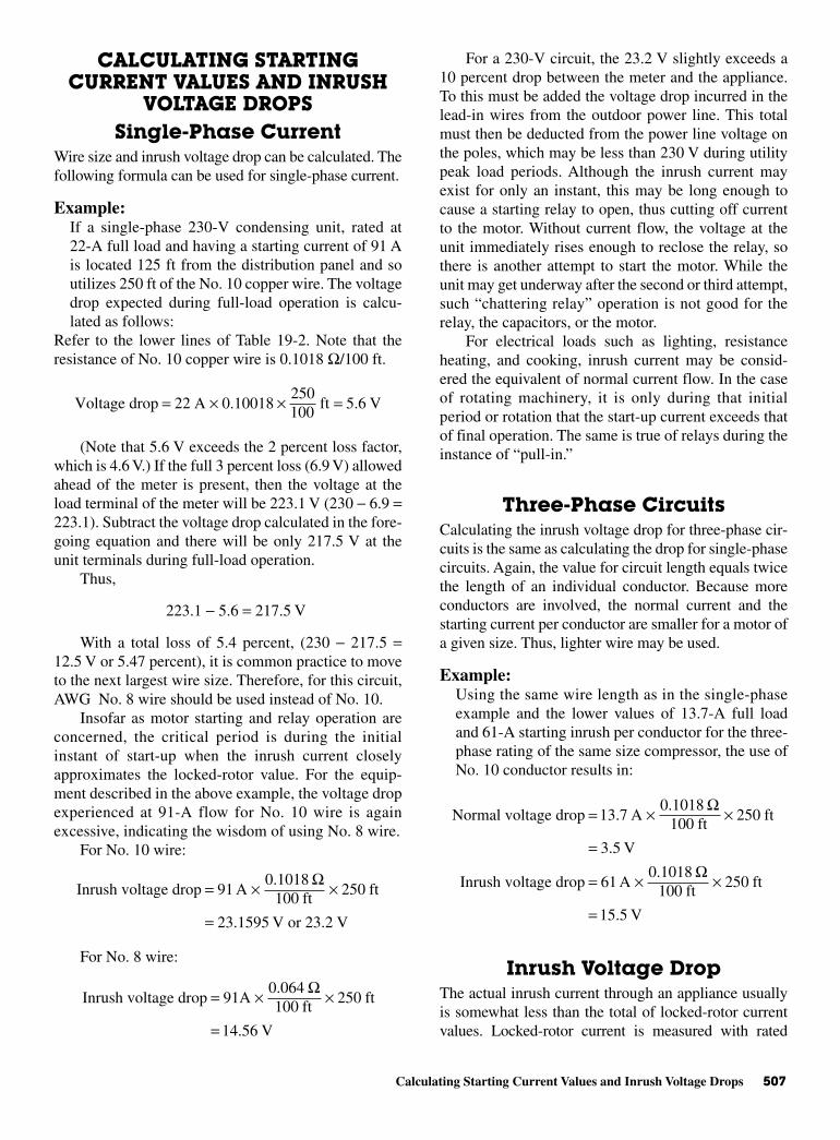
Calculating Starting Current Values and Inrush Voltage Drops 507
CALCULATING STARTINGCURRENT VALUES AND INRUSH
VOLTAGE DROPSSingle-Phase Current
Wire size and inrush voltage drop can be calculated. Thefollowing formula can be used for single-phase current.
Example:If a single-phase 230-V condensing unit, rated at22-A full load and having a starting current of 91 Ais located 125 ft from the distribution panel and soutilizes 250 ft of the No. 10 copper wire. The voltagedrop expected during full-load operation is calcu-lated as follows:
Refer to the lower lines of Table 19-2. Note that theresistance of No. 10 copper wire is 0.1018 Ω/100 ft.
(Note that 5.6 V exceeds the 2 percent loss factor,which is 4.6 V.) If the full 3 percent loss (6.9 V) allowedahead of the meter is present, then the voltage at theload terminal of the meter will be 223.1 V (230 − 6.9 =223.1). Subtract the voltage drop calculated in the fore-going equation and there will be only 217.5 V at theunit terminals during full-load operation.
Thus,
223.1 − 5.6 = 217.5 V
With a total loss of 5.4 percent, (230 − 217.5 =12.5 V or 5.47 percent), it is common practice to moveto the next largest wire size. Therefore, for this circuit,AWG No. 8 wire should be used instead of No. 10.
Insofar as motor starting and relay operation areconcerned, the critical period is during the initialinstant of start-up when the inrush current closelyapproximates the locked-rotor value. For the equip-ment described in the above example, the voltage dropexperienced at 91-A flow for No. 10 wire is againexcessive, indicating the wisdom of using No. 8 wire.
For No. 10 wire:
For No. 8 wire:
For a 230-V circuit, the 23.2 V slightly exceeds a10 percent drop between the meter and the appliance.To this must be added the voltage drop incurred in thelead-in wires from the outdoor power line. This totalmust then be deducted from the power line voltage onthe poles, which may be less than 230 V during utilitypeak load periods. Although the inrush current mayexist for only an instant, this may be long enough tocause a starting relay to open, thus cutting off currentto the motor. Without current flow, the voltage at theunit immediately rises enough to reclose the relay, sothere is another attempt to start the motor. While theunit may get underway after the second or third attempt,such “chattering relay” operation is not good for therelay, the capacitors, or the motor.
For electrical loads such as lighting, resistanceheating, and cooking, inrush current may be consid-ered the equivalent of normal current flow. In the caseof rotating machinery, it is only during that initialperiod or rotation that the start-up current exceeds thatof final operation. The same is true of relays during theinstance of “pull-in.”
Three-Phase Circuits Calculating the inrush voltage drop for three-phase cir-cuits is the same as calculating the drop for single-phasecircuits. Again, the value for circuit length equals twicethe length of an individual conductor. Because moreconductors are involved, the normal current and thestarting current per conductor are smaller for a motor ofa given size. Thus, lighter wire may be used.
Example:Using the same wire length as in the single-phaseexample and the lower values of 13.7-A full loadand 61-A starting inrush per conductor for the three-phase rating of the same size compressor, the use ofNo. 10 conductor results in:
Inrush Voltage DropThe actual inrush current through an appliance usuallyis somewhat less than the total of locked-rotor currentvalues. Locked-rotor current is measured with rated
Normal voltage drop 13.7 A0.1018
100 ft250 ft
3.5 V
Inrush voltage drop 61 A0.1018
100 ft250 ft
15.5 V
= × ×
=
= × ×
=
Ω
Ω
Inrush voltage drop 91A0.064100 ft
250 ft
14.56 V
= × ×
=
Ω
Inrush voltage drop 91 A0.1018
100 ft250 ft
23.1595 V or 23.2 V
= × ×
=
Ω
Voltage drop 22 A 0.10018 ft 5.6 V= × × =250100
508 Installing and Controlling Electrical Power for Air-Conditioning Units
voltage at the appliance terminals. Because voltage dropin the feed lines reduces the voltage available at the ter-minals, less than rated voltage can be anticipated acrossthe electrical components. Consequently, inrush currentsand voltage drops are somewhat less. This fact is illus-trated in the following, which is based on the sameinstallation as that in the previous single-phase exam-ples. However, here the actual locked-rotor current of101 A is used. The formula can be found in the columnon the right.
CODE LIMITATIONS ON AMPERESPER CONDUCTOR
Varied mechanical conditions are encountered in fieldwiring. Thus, the NEC places certain limitations on thesmallness of conductors installed in the field. Suchlimitations apply regardless of conductor length. Theyassure the following:
• That the wire itself has ample strength to withstandthe stress of pulling it through long conduits andchases. With specific exceptions, no wire lighter thanNo. 14 copper is permitted for field wiring of line-voltage power circuits.
• By stipulating the maximum amperage permissiblefor each wire gage, self-generated heat can be limitedto avoid temperature damage to wire insulation. Ifwiring is installed in areas of high-ambient temper-ature, the amperage rating may need to be reduced.
• By stipulating the maximum amperage of overload pro-tectors for circuits, current flow is limited to safe valuesfor the conductor used. Some equipment has momen-tary starting currents that trip-out overload protectorssized on the basis of full-load current. Here heavierfusing is permissible, but only under specific circum-stances. Current flow limitations for each gage protectwire insulation from damage due to overheating.
HEAT GENERATED WITHINCONDUCTORS
Heat generation due to current flow through the wire isimportant for the following two reasons:
• Temperature rise increases the resistance of the wireand, therefore, the voltage drop in the circuit. Undermost conditions of circuit usage, this added resist-ance generates additional heat in the wires. Finally,a temperature is reached where heat dissipationfrom the conductors equals the heat that theygenerate. It is desirable to keep this equilibriumtemperature low. The number of Btu generated can
be found by both of the following formulas [Eqs. (19.3)and (19.4)].
• Temperature also damages wire insulation. The degreeof damage is dependent upon the insulation’s ability towithstand temperature under varying degrees of expo-sure, age, moisture, corrosive environment, mechanicalabuse, and thickness.
Estimating the probable operating temperature of aconductor and its insulation is difficult. The rate of heatdissipation from the wiring surfaces varies with theambient temperature, the proximity of other heat-generating conductors, the heat conductivity of the insu-lation and jacket material, the availability of cooling air,and other factors. Freestanding individual conductorsdissipate heat more effectively. However, the typical sit-uation of two or three conductors, each carrying equal
Btu generated amperes resistance in ohms
3.4313*
Btu generated amperes voltage drop 3.4313*
2= ××
= × ×
Locked-rotor voltage drop
1010.1018
100 ft250 ft 25.7 V= × × =Ω
Calculated inrush voltage drop
91.00.1018
100 ft250 ft 23.2 V= × × =Ω
Inrush currentDistribution panel voltagetotal indicated impedance
Inrush current230 V2.53
91 A
=
= =Ω
Total indicated load and conductor impedance
(2.28 0.25) 2.53= + = Ω
Resistance of No. 10 leads
ohms/100 ft length of wire (in ft)
0.1018 /100 ft 250 ft 0.25
= ×= × =Ω Ω
Indicated locked-rotor impedance
rated voltagelocked-rotor amperes
230 V/101 A 2.28
=
= = Ω
*Conversion factor
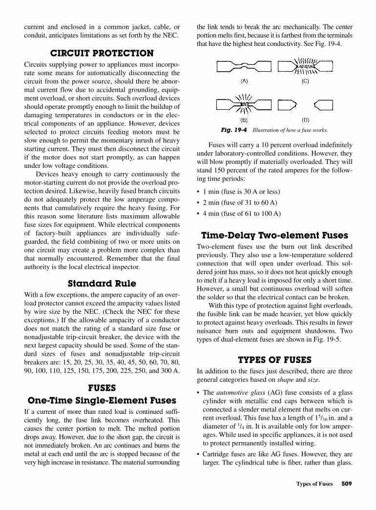
Types of Fuses 509
current and enclosed in a common jacket, cable, orconduit, anticipates limitations as set forth by the NEC.
CIRCUIT PROTECTION Circuits supplying power to appliances must incorpo-rate some means for automatically disconnecting thecircuit from the power source, should there be abnor-mal current flow due to accidental grounding, equip-ment overload, or short circuits. Such overload devicesshould operate promptly enough to limit the buildup ofdamaging temperatures in conductors or in the elec-trical components of an appliance. However, devicesselected to protect circuits feeding motors must beslow enough to permit the momentary inrush of heavystarting current. They must then disconnect the circuitif the motor does not start promptly, as can happenunder low voltage conditions.
Devices heavy enough to carry continuously themotor-starting current do not provide the overload pro-tection desired. Likewise, heavily fused branch circuitsdo not adequately protect the low amperage compo-nents that cumulatively require the heavy fusing. Forthis reason some literature lists maximum allowablefuse sizes for equipment. While electrical componentsof factory-built appliances are individually safe-guarded, the field combining of two or more units onone circuit may create a problem more complex thanthat normally encountered. Remember that the finalauthority is the local electrical inspector.
Standard RuleWith a few exceptions, the ampere capacity of an over-load protector cannot exceed the ampacity values listedby wire size by the NEC. (Check the NEC for theseexceptions.) If the allowable ampacity of a conductordoes not match the rating of a standard size fuse ornonadjustable trip-circuit breaker, the device with thenext largest capacity should be used. Some of the stan-dard sizes of fuses and nonadjustable trip-circuitbreakers are: 15, 20, 25, 30, 35, 40, 45, 50, 60, 70, 80,90, 100, 110, 125, 150, 175, 200, 225, 250, and 300 A.
FUSESOne-Time Single-Element Fuses
If a current of more than rated load is continued suffi-ciently long, the fuse link becomes overheated. Thiscauses the center portion to melt. The melted portiondrops away. However, due to the short gap, the circuit isnot immediately broken. An arc continues and burns themetal at each end until the arc is stopped because of thevery high increase in resistance. The material surrounding
the link tends to break the arc mechanically. The centerportion melts first, because it is farthest from the terminalsthat have the highest heat conductivity. See Fig. 19-4.
Fuses will carry a 10 percent overload indefinitelyunder laboratory-controlled conditions. However, theywill blow promptly if materially overloaded. They willstand 150 percent of the rated amperes for the follow-ing time periods:
• 1 min (fuse is 30 A or less)
• 2 min (fuse of 31 to 60 A)
• 4 min (fuse of 61 to 100 A)
Time-Delay Two-element FusesTwo-element fuses use the burn out link describedpreviously. They also use a low-temperature solderedconnection that will open under overload. This sol-dered joint has mass, so it does not heat quickly enoughto melt if a heavy load is imposed for only a short time.However, a small but continuous overload will softenthe solder so that the electrical contact can be broken.
With this type of protection against light overloads,the fusible link can be made heavier, yet blow quicklyto protect against heavy overloads. This results in fewernuisance burn outs and equipment shutdowns. Twotypes of dual-element fuses are shown in Fig. 19-5.
TYPES OF FUSESIn addition to the fuses just described, there are threegeneral categories based on shape and size.
• The automotive glass (AG) fuse consists of a glasscylinder with metallic end caps between which isconnected a slender metal element that melts on cur-rent overload. This fuse has a length of 15/16 in. and adiameter of 1/4 in. It is available only for low amper-ages. While used in specific appliances, it is not usedto protect permanently installed wiring.
• Cartridge fuses are like AG fuses. However, they arelarger. The cylindrical tube is fiber, rather than glass.
Fig. 19-4 Illustration of how a fuse works.

510 Installing and Controlling Electrical Power for Air-Conditioning Units
The metallic end pieces may be formed as lugs, blades,or cylinders to meet a variety of fuse box socketrequirements. The internal metal fusible link may beenclosed in sand or powder to quench the burnout arc.
Cartridge fuses are made in a variety of dimen-sions, based on amperage and voltage. Blade-typeterminals are common above 60 A. Fuses used tobreak 600-V arcs are longer than those for lowervoltages. Fuses are available in many capacitiesother than the listed standard capacities, particu-larly in the two-element, time-delay types. Often,they are so dimensioned as to not be interchangeablewith fuses of other capacities.
• Plug fuses are limited in maximum capacity to 30 A.They are designed for use in circuits of not more than150 V above ground. Two-element time-delay typesare available to fit standard screw lamp sockets. Theyare also available with nonstandard threads madeespecially for various amperage ratings.
THERMOSTATSThe thermostat (or temperature control) stops andstarts the compressor in response to room temperaturerequirements. Each thermostat has a charged powerelement containing either a volatile liquid or an activevapor charge. The temperature-sensitive part of thiselement (thermostat feeler bulb) is located in the returnair stream. As the return air temperature rises, the pressure
of the liquid or vapor inside the bulb increases Thiscloses the electrical contacts and starts the compressor.As the return air temperature drops, the reduced tem-perature of the feeler bulb causes the contacts to openand stops the compressor.
The advent of transistors and the semiconductorchips or integrated circuits produced a more accuratemethod of monitoring and adjusting temperatureswithin a system. The microprocessor makes use of thesemiconductor and chip’s abilities to compare temper-atures. It can also program on and off cycles, as well asmonitor the duration of each cycle. This leads to moreaccurate temperature control.
Figure 19-6 shows a microprocessor-based thermo-stat. As you can see from the front of the control panel,you can adjust the program to do many things. It canalso save energy, whether it is operating the furnace forheat or the air-conditioning unit for cooling. These unitsusually come with a battery so that the memory canretain whatever is programmed into it. The battery isalso a backup for the clock so that the program is retainedeven if the line power is interrupted.
Thermostat As a Control SwitchThe control switch (thermostat) may be located in theroom to be cooled or heated, depending upon the par-ticular switch selection point. The control switch (heat,off, cool, and auto) is of the sliding type and normally
Fig. 19-5 Types of fuses.

Thermostats 511
has four positions, marked HEAT, OFF, COOL, andAUTO. The thermostat is taken from its socket and pro-grammed according to the manufacturer’s directions.Then it is activated by plugging it into the wall socketand replacing a couple of screws to hold it in place.
To operate the unit as a ventilator, the switch on theleft is marked “Fan” with an “On” and “Auto” choiceto select the FAN operation. When a thermostat isinstalled for automatic cooling, the compressor andfans will cycle according to the dial requirements.
Figure 19-7 shows the electrical circuitry for ahome heat-cool thermostat. Keep in mind that the ther-mostat should always be on an inside partition, never
on an outside wall. Do not mount the instrument on apart of the wall that has steam or hot water pipes orwarm air ducts behind it. The location should be suchthat direct sunshine or fireplace radiation cannot strikethe thermostat. Be careful that the spot selected is notlikely to have a floor lamp near it or a table lamp underit. Do not locate the thermostat where heat fromkitchen appliances can affect it. Do not locate it on awall that has cold unused room on the other side.
After a thermostat has been mounted, it is wise tofill the stud space behind the instrument with insulatingmaterial. This is to prevent any circulation of cold air.Furthermore, the hole behind the thermostat for thewires should be sealed so that air cannot emerge fromthe stud space and blow across the thermostat element. Itis quite common to find considerable air motion throughthis hole caused by a chimney effect in the stud space.
ServiceServicemen who have a good knowledge of refrigera-tion and air conditioning will be able to competentlyservice air conditioners. Most air-conditioning units ofpresent design contain compressors of the hermetic orsealed type. The only parts that can be serviced in thefield are the relay, control switch, fan, fan motor, startand run capacitors, air filters, and cabinet parts. Therefrigerating system (consisting of the cooling unit, con-densers, compressors, and connecting lines) generally
Fig. 19-6 Microprocessor thermostat used for residential tem-perature and cooling control.
Auto On
Switch action on temperature rise
Adjustable heat anticipation
Thermostat element
Sub-base unit
Fan switch
On Auto
Cold
Anticipation
Fan Cool 24-V Supply HeatExactterminal location
G Y RY
WW
GR
Fan
Fig. 19-7 Electrical circuitry of a home heat-cool thermostat.
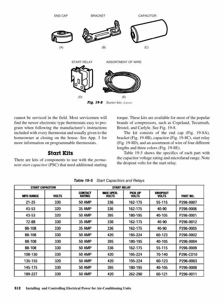
512 Installing and Controlling Electrical Power for Air-Conditioning Units
cannot be serviced in the field. Most servicemen willfind the newer electronic type thermostats easy to pro-gram when following the manufacturer’s instructionsincluded with every thermostat and usually given to thehomeowner at closing on the house. See App. 3 formore information on programmable thermostats.
Start KitsThere are kits of components to use with the perma-nent start capacitor (PSC) that need additional starting
torque. These kits are available for most of the popularbrands of compressors, such as Copeland, Tecumseh,Bristol, and Carlyle. See Fig. 19-8.
The kit consists of the end cap (Fig. 19-8A),bracket (Fig. 19-8B), capacitor (Fig. 19-8C), start relay(Fig. 19-8D), and an assortment of wire of four differentlengths and three colors (Fig. 19-8E).
Table 19-5 shows the specifics of each part withthe capacitor voltage rating and microfarad range. Notethe dropout volts for the start relay.
(A) (B)
(D) (E)
(C)
END CAP BRACKET
START RELAY ASSORTMENT OF WIRE
CAPACITOR
Fig. 19-8 Starter kits. (Carrier)
Table 19-5 Start Capacitors and Relays
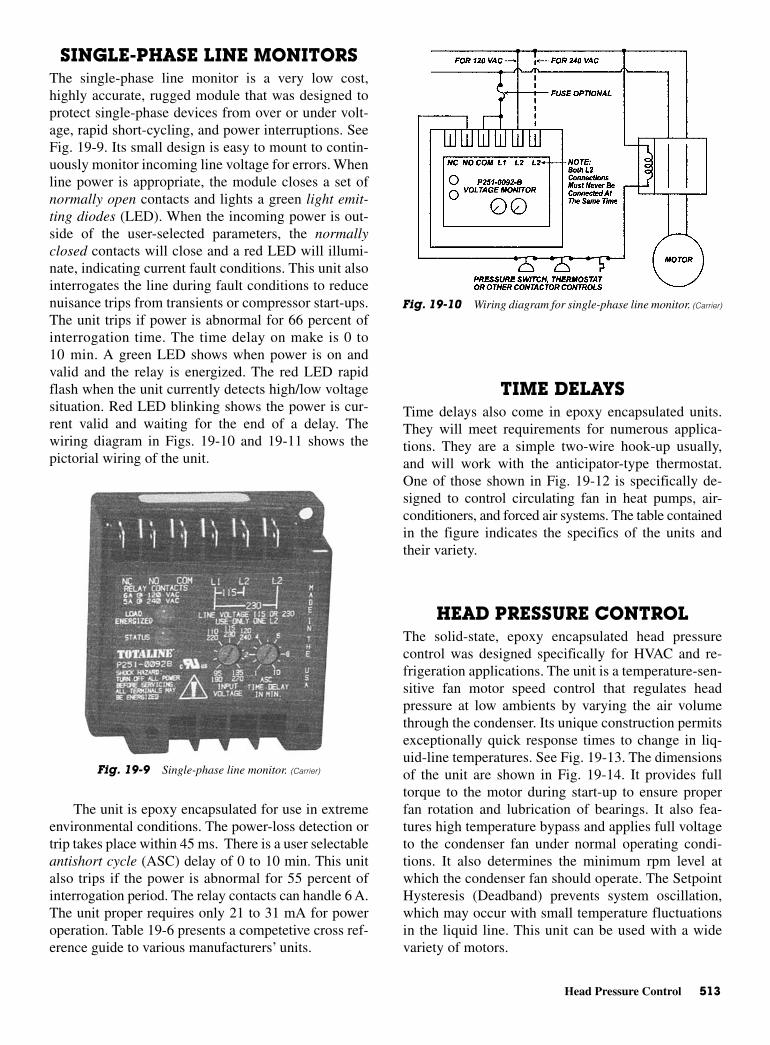
Head Pressure Control 513
SINGLE-PHASE LINE MONITORSThe single-phase line monitor is a very low cost,highly accurate, rugged module that was designed toprotect single-phase devices from over or under volt-age, rapid short-cycling, and power interruptions. SeeFig. 19-9. Its small design is easy to mount to contin-uously monitor incoming line voltage for errors. Whenline power is appropriate, the module closes a set ofnormally open contacts and lights a green light emit-ting diodes (LED). When the incoming power is out-side of the user-selected parameters, the normallyclosed contacts will close and a red LED will illumi-nate, indicating current fault conditions. This unit alsointerrogates the line during fault conditions to reducenuisance trips from transients or compressor start-ups.The unit trips if power is abnormal for 66 percent ofinterrogation time. The time delay on make is 0 to10 min. A green LED shows when power is on andvalid and the relay is energized. The red LED rapidflash when the unit currently detects high/low voltagesituation. Red LED blinking shows the power is cur-rent valid and waiting for the end of a delay. Thewiring diagram in Figs. 19-10 and 19-11 shows thepictorial wiring of the unit.
The unit is epoxy encapsulated for use in extremeenvironmental conditions. The power-loss detection ortrip takes place within 45 ms. There is a user selectableantishort cycle (ASC) delay of 0 to 10 min. This unitalso trips if the power is abnormal for 55 percent ofinterrogation period. The relay contacts can handle 6 A.The unit proper requires only 21 to 31 mA for poweroperation. Table 19-6 presents a competetive cross ref-erence guide to various manufacturers’ units.
TIME DELAYSTime delays also come in epoxy encapsulated units.They will meet requirements for numerous applica-tions. They are a simple two-wire hook-up usually,and will work with the anticipator-type thermostat.One of those shown in Fig. 19-12 is specifically de-signed to control circulating fan in heat pumps, air-conditioners, and forced air systems. The table containedin the figure indicates the specifics of the units andtheir variety.
HEAD PRESSURE CONTROLThe solid-state, epoxy encapsulated head pressurecontrol was designed specifically for HVAC and re-frigeration applications. The unit is a temperature-sen-sitive fan motor speed control that regulates headpressure at low ambients by varying the air volumethrough the condenser. Its unique construction permitsexceptionally quick response times to change in liq-uid-line temperatures. See Fig. 19-13. The dimensionsof the unit are shown in Fig. 19-14. It provides fulltorque to the motor during start-up to ensure properfan rotation and lubrication of bearings. It also fea-tures high temperature bypass and applies full voltageto the condenser fan under normal operating condi-tions. It also determines the minimum rpm level atwhich the condenser fan should operate. The SetpointHysteresis (Deadband) prevents system oscillation,which may occur with small temperature fluctuationsin the liquid line. This unit can be used with a widevariety of motors.
Fig. 19-10 Wiring diagram for single-phase line monitor. (Carrier)
Fig. 19-9 Single-phase line monitor. (Carrier)
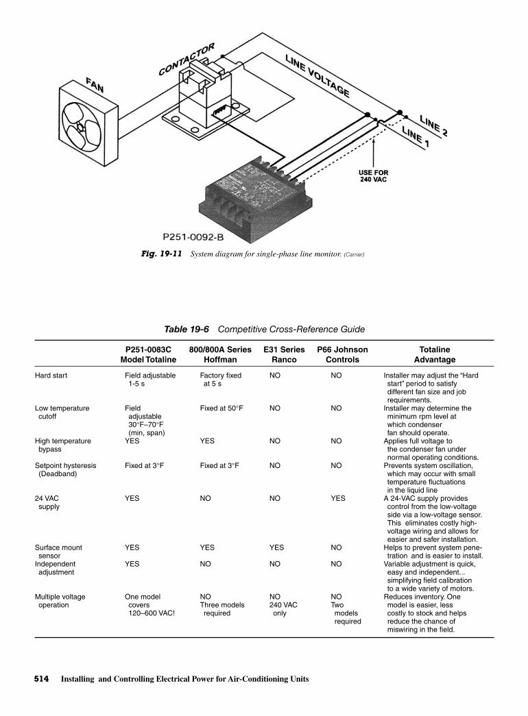
514 Installing and Controlling Electrical Power for Air-Conditioning Units
Fig. 19-11 System diagram for single-phase line monitor. (Carrier)
Table 19-6 Competitive Cross-Reference Guide
P251-0083C 800/800A Series E31 Series P66 Johnson TotalineModel Totaline Hoffman Ranco Controls Advantage
Hard start Field adjustable Factory fixed NO NO Installer may adjust the “Hard1-5 s at 5 s start” period to satisfy
different fan size and jobrequirements.
Low temperature Field Fixed at 50°F NO NO Installer may determine the cutoff adjustable minimum rpm level at
30°F–70°F which condenser(min, span) fan should operate.
High temperature YES YES NO NO Applies full voltage to bypass the condenser fan under
normal operating conditions.Setpoint hysteresis Fixed at 3°F Fixed at 3°F NO NO Prevents system oscillation, (Deadband) which may occur with small
temperature fluctuations in the liquid line
24 VAC YES NO NO YES A 24-VAC supply provides supply control from the low-voltage
side via a low-voltage sensor.This eliminates costly high-voltage wiring and allows foreasier and safer installation.
Surface mount YES YES YES NO Helps to prevent system pene-sensor tration and is easier to install.
Independent YES NO NO NO Variable adjustment is quick,adjustment easy and independent...
simplifying field calibrationto a wide variety of motors.
Multiple voltage One model NO NO NO Reduces inventory. Oneoperation covers Three models 240 VAC Two model is easier, less
120–600 VAC! required only models costly to stock and helpsrequired reduce the chance of
miswiring in the field.
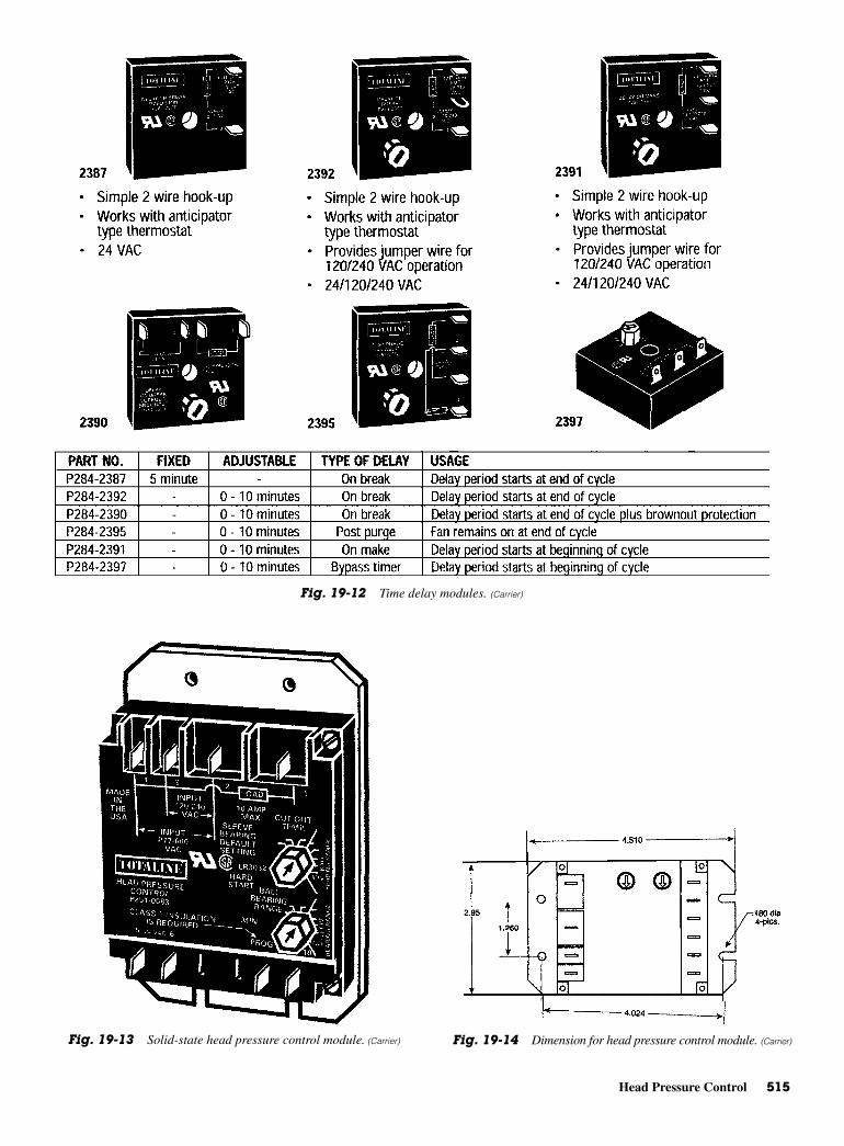
Head Pressure Control 515
Fig. 19-12 Time delay modules. (Carrier)
Fig. 19-13 Solid-state head pressure control module. (Carrier) Fig. 19-14 Dimension for head pressure control module. (Carrier)
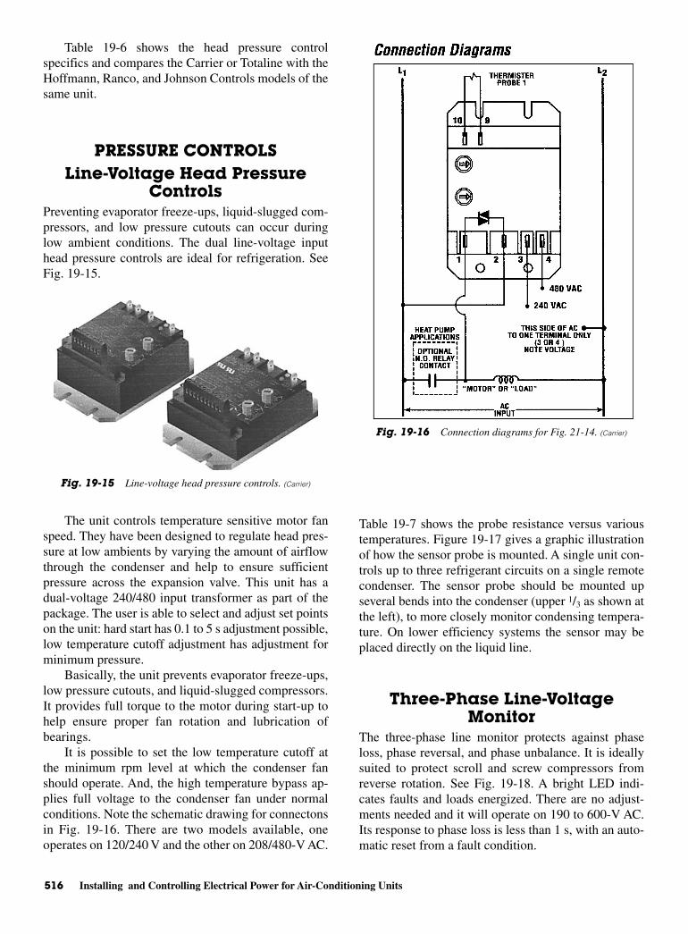
516 Installing and Controlling Electrical Power for Air-Conditioning Units
Table 19-6 shows the head pressure controlspecifics and compares the Carrier or Totaline with theHoffmann, Ranco, and Johnson Controls models of thesame unit.
PRESSURE CONTROLSLine-Voltage Head Pressure
ControlsPreventing evaporator freeze-ups, liquid-slugged com-pressors, and low pressure cutouts can occur duringlow ambient conditions. The dual line-voltage inputhead pressure controls are ideal for refrigeration. SeeFig. 19-15.
The unit controls temperature sensitive motor fanspeed. They have been designed to regulate head pres-sure at low ambients by varying the amount of airflowthrough the condenser and help to ensure sufficientpressure across the expansion valve. This unit has adual-voltage 240/480 input transformer as part of thepackage. The user is able to select and adjust set pointson the unit: hard start has 0.1 to 5 s adjustment possible,low temperature cutoff adjustment has adjustment forminimum pressure.
Basically, the unit prevents evaporator freeze-ups,low pressure cutouts, and liquid-slugged compressors.It provides full torque to the motor during start-up tohelp ensure proper fan rotation and lubrication ofbearings.
It is possible to set the low temperature cutoff atthe minimum rpm level at which the condenser fanshould operate. And, the high temperature bypass ap-plies full voltage to the condenser fan under normalconditions. Note the schematic drawing for connectonsin Fig. 19-16. There are two models available, oneoperates on 120/240 V and the other on 208/480-V AC.
Table 19-7 shows the probe resistance versus varioustemperatures. Figure 19-17 gives a graphic illustrationof how the sensor probe is mounted. A single unit con-trols up to three refrigerant circuits on a single remotecondenser. The sensor probe should be mounted upseveral bends into the condenser (upper 1/3 as shown atthe left), to more closely monitor condensing tempera-ture. On lower efficiency systems the sensor may beplaced directly on the liquid line.
Three-Phase Line-VoltageMonitor
The three-phase line monitor protects against phaseloss, phase reversal, and phase unbalance. It is ideallysuited to protect scroll and screw compressors fromreverse rotation. See Fig. 19-18. A bright LED indi-cates faults and loads energized. There are no adjust-ments needed and it will operate on 190 to 600-V AC.Its response to phase loss is less than 1 s, with an auto-matic reset from a fault condition.
Fig. 19-15 Line-voltage head pressure controls. (Carrier)
Fig. 19-16 Connection diagrams for Fig. 21-14. (Carrier)

Head Pressure Control 517
If all the three phases are relattively equal and inproper sequence, the normally open contacts (Y-Y-OUT) will close when 24 V is applied betweeen Cand Y. If the phases are out of sequence or one ismissing, the contacts will never close. If a phase islost while the unit is energized, the contacts willopen immediately, and remain open until the error iscorrected.
An illuminated green LED indicates that the outputis energized and a red LED indicates that there is afault and the output is deenergized. See Fig. 19-19.
Figure 19-20 shows a graphic presentation of atypical wiring diagram, while Fig. 19-21 shows typicalpart-winding start wiring.
Table 19-7 Probe Resistance vs. Temperature
P251-0084 P251-0085 P251-0086
Resistance Resistance ResistanceF C K Ohms F C K Ohms F C K Ohms
32 0 22.8 59 15 28.3 59 15 42.450 10 15.9 68 20 22.5 68 20 33.768 20 11.4 77 25 18.0 77 25 27.077 25 9.7 86 30 14.5 86 30 21.886 30 7.6 95 35 11.8 95 35 17.6
104 40 4.6 11 40 9.6 104 40 14.422 50 2.8 113 45 7.9 113 45 11.840 60 1.8 22 50 6.5 122 50 9.758 70 1.2 131 55 5.4 131 55 81
Fig. 19-17 Typical system diagram for pressure controls. (Carrier)
Fig. 19-18 Three-phase line-voltage monitor. (Carrier)
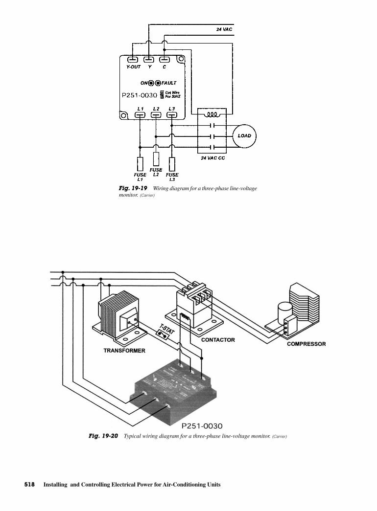
518 Installing and Controlling Electrical Power for Air-Conditioning Units
Fig. 19-19 Wiring diagram for a three-phase line-voltagemonitor. (Carrier)
Fig. 19-20 Typical wiring diagram for a three-phase line-voltage monitor. (Carrier)
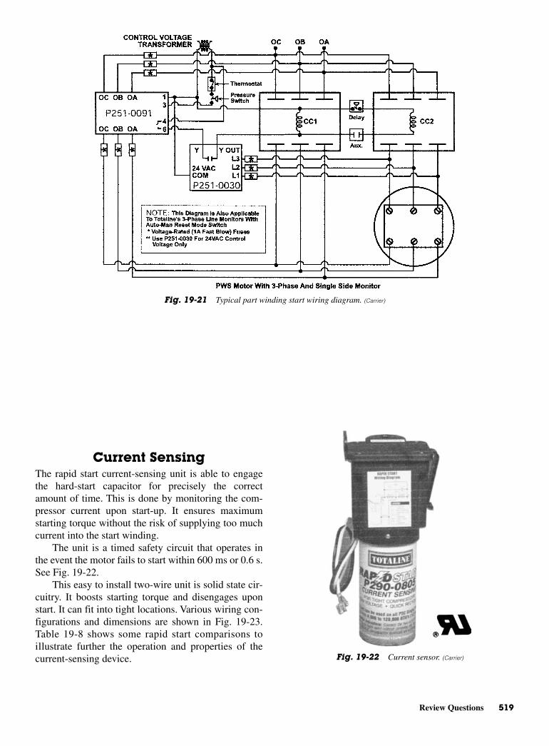
Review Questions 519
Current SensingThe rapid start current-sensing unit is able to engagethe hard-start capacitor for precisely the correctamount of time. This is done by monitoring the com-pressor current upon start-up. It ensures maximumstarting torque without the risk of supplying too muchcurrent into the start winding.
The unit is a timed safety circuit that operates inthe event the motor fails to start within 600 ms or 0.6 s.See Fig. 19-22.
This easy to install two-wire unit is solid state cir-cuitry. It boosts starting torque and disengages uponstart. It can fit into tight locations. Various wiring con-figurations and dimensions are shown in Fig. 19-23.Table 19-8 shows some rapid start comparisons toillustrate further the operation and properties of thecurrent-sensing device.
Fig. 19-21 Typical part winding start wiring diagram. (Carrier)
Fig. 19-22 Current sensor. (Carrier)
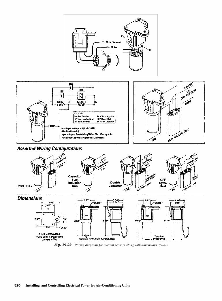
520 Installing and Controlling Electrical Power for Air-Conditioning Units
Fig. 19-23 Wiring diagrams for current sensors along with dimensions. (Carrier)
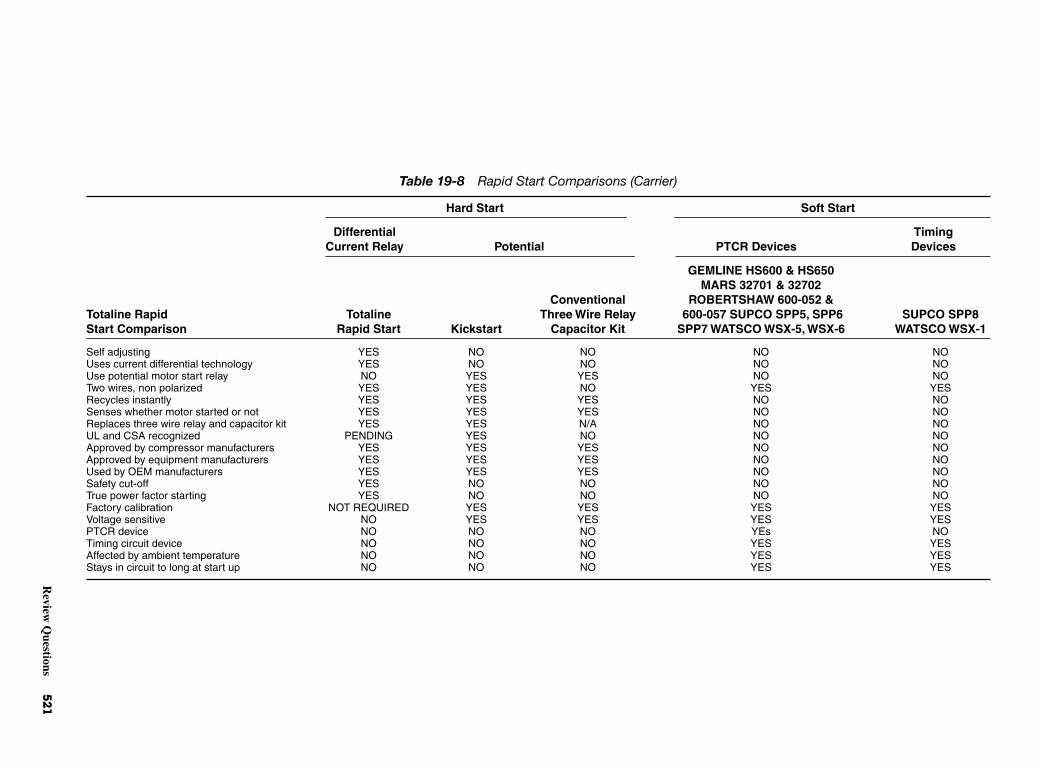
Review
Questions
521
Table 19-8 Rapid Start Comparisons (Carrier)
Hard Start Soft Start
Differential TimingCurrent Relay Potential PTCR Devices Devices
GEMLINE HS600 & HS650MARS 32701 & 32702
Conventional ROBERTSHAW 600-052 &Totaline Rapid Totaline Three Wire Relay 600-057 SUPCO SPP5, SPP6 SUPCO SPP8Start Comparison Rapid Start Kickstart Capacitor Kit SPP7 WATSCO WSX-5, WSX-6 WATSCO WSX-1
Self adjusting YES NO NO NO NOUses current differential technology YES NO NO NO NOUse potential motor start relay NO YES YES NO NOTwo wires, non polarized YES YES NO YES YESRecycles instantly YES YES YES NO NOSenses whether motor started or not YES YES YES NO NOReplaces three wire relay and capacitor kit YES YES N/A NO NOUL and CSA recognized PENDING YES NO NO NOApproved by compressor manufacturers YES YES YES NO NOApproved by equipment manufacturers YES YES YES NO NOUsed by OEM manufacturers YES YES YES NO NOSafety cut-off YES NO NO NO NOTrue power factor starting YES NO NO NO NOFactory calibration NOT REQUIRED YES YES YES YESVoltage sensitive NO YES YES YES YESPTCR device NO NO NO YEs NOTiming circuit device NO NO NO YES YESAffected by ambient temperature NO NO NO YES YESStays in circuit to long at start up NO NO NO YES YES

522 Installing and Controlling Electrical Power for Air-Conditioning Units
REVIEW QUESTIONS1. What are the two criteria for choosing wire size for
installation in air-conditioning and refrigerationequipment?
2. What are some of the results of low voltage to arefrigerating system?
3. What is the most common cause of compressorlow voltage?
4. What is synchronous speed?
5. How do you choose the proper size of wire for a job?
6. What does the abbreviation LRA mean in refer-ence to motors?
7. How much torque is available from a motor if thevoltage drops to 90 percent of its rated value?
8. What is the minimum number of wires needed towire a three-phase compressor?
9. What causes heat generation in wire conductors?
10. What is the purpose of a fuse in a circuit?
11. What is the difference between a cartridge fuse anda plug fuse?

20CHAPTER
Air-Conditioningand
RefrigerationCareers
Copyright © 2006 by The McGraw-Hill Companies, Inc. Click here for terms of use.
PERFORMANCE OBJECTIVESAfter studying this chapter you will:
1. Know the industries that employ air-conditioningand refrigeration mechanics.
2. Know what job qualifications are needed for workin the air-conditioning/refrigeration field.
3. Know the various sources of information for thosein the field.
4. Know the opportunities for teaching in the field.
The field of air conditioning and refrigerationoffers a variety of career opportunities. Air-conditioningand refrigeration mechanics install and service air-conditioning and refrigeration equipment. There are anumber of different types of equipment that require ser-vice. Some systems are complex, but are easily brokendown into smaller units for repair purposes. Somemechanics specialize in a particular part of a system.
INDUSTRIES THAT EMPLOYAIR-CONDITIONING AND
REFRIGERATION MECHANICS Approximately 259,000 persons work as air-conditioningand refrigeration mechanics. Cooling contractorsemploy most of these mechanics. Food chains, schoolsystems, manufacturers, and other organizations usethe services of air-conditioning and refrigeration mechan-ics. Large air-conditioning systems use many mechanicsto keep the equipment operational. However, not allmechanics work for other people. About one in everyseven mechanics is self-employed.
Manufacturers use refrigeration equipment for avariety of processes. Meat packers and chemical makersuse refrigeration in some form. Temperature control isvery important for many manufacturing processes.
Mechanics work in homes, office buildings, andfactories. They work anywhere there is air conditioningor refrigeration to be installed or serviced. They bringto the job sites the tools and parts they need. During therepair season, mechanics may do considerable driving.Radio communications and cell phones may be used todispatch them to the jobs. If major repairs are needed,mechanics will transport parts or inoperative machineryto a repair shop.
Mechanics work in buildings that are often uncom-fortable. This is because the air-conditioning or refrig-eration system has failed. The mechanic may have towork in a cramped position in an attic, a basement, or acrawl space.
Rooftop units are a common practice in keepingsmaller installations cool. Many of the systems have at
least one unit on the roof of the building. Cooling towersare usually mounted on top of a building. Thus, themechanic may be called upon to work in high places. Insummer, the rooftop may be very hot. This trade doesrequire some hazardous work. For instance, there are thedangers of electrical shock, torch burns, muscle strains,and other injuries from handling heavy equipment.
System installation calls for work with motors,compressors, condensing units, evaporators, and othercomponents. These devices must be installed properly.This calls for the mechanic to be able to follow thedesigner’s specification. In most instances, blueprintsare used to indicate where and how the equipment is tobe installed. The ability to read blueprints is essentialfor the air-conditioning and refrigeration mechanic.Such ability will help ensure that the ductwork, refrig-erant lines, and electrical service are properly con-nected. See Fig. 20-1.
After making the connections, it is then necessaryto charge the system with the proper refrigerant. Properoperation must be assured before the mechanic isthrough with the job.
Equipment installation is but one of the jobs themechanic must perform. If the equipment fails, thenthe mechanic must diagnose the cause of the troubleand make the proper repairs. The mechanic must:
• Find defects
• Inspect parts
• Be able to know if thermostats and relays are workingcorrectly
During the winter, air-conditioning mechanics inspectparts such as relays and thermostats. They also performrequired maintenance. Overhauling may be included ifcompressors need attention or recharging. They may alsoadjust the airflow ducts for the change of seasons.
Air-conditioning and refrigeration mechanics use anumber of special tools. They also use more commontools such as hammers, wrenches, metal snips, electricdrills, pipe cutters and benders, and acetylene torches.Air ducts and refrigeration lines require more special-ized tools. Voltammeters are also part of the mechanic’stoolbox. Electrical circuits and refrigeration lines mustbe tested and checked. Testing of electrical componentsis also required. A good background in electricity isnecessary for any mechanic. See Fig. 20-2.
Cooling systems sometimes are installed or repairedby other craft workers. For example, on a large air-conditioning installation job, especially where peopleare covered by union contracts, sheet-metal specialistsmight do ductwork. Electricians will do electricalwork. The installation of piping will be done by pipe
524 Air-Conditioning and Refrigeration Careers
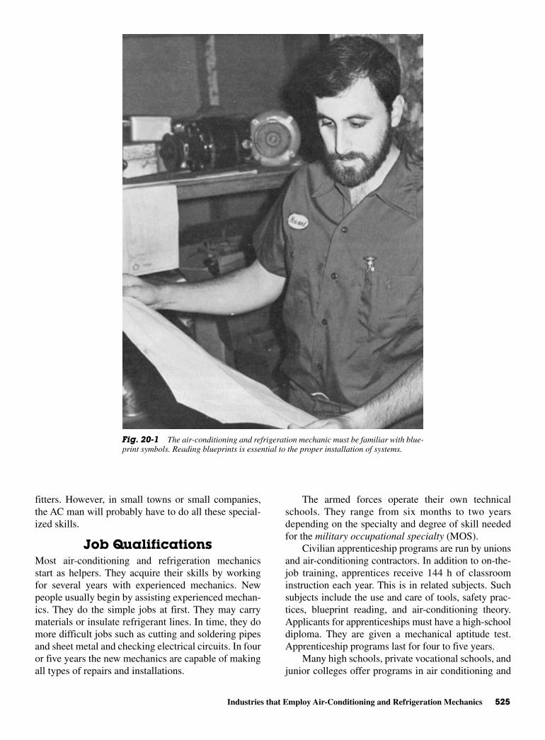
Industries that Employ Air-Conditioning and Refrigeration Mechanics 525
fitters. However, in small towns or small companies,the AC man will probably have to do all these special-ized skills.
Job Qualifications Most air-conditioning and refrigeration mechanicsstart as helpers. They acquire their skills by workingfor several years with experienced mechanics. Newpeople usually begin by assisting experienced mechan-ics. They do the simple jobs at first. They may carrymaterials or insulate refrigerant lines. In time, they domore difficult jobs such as cutting and soldering pipesand sheet metal and checking electrical circuits. In fouror five years the new mechanics are capable of makingall types of repairs and installations.
The armed forces operate their own technicalschools. They range from six months to two yearsdepending on the specialty and degree of skill neededfor the military occupational specialty (MOS).
Civilian apprenticeship programs are run by unionsand air-conditioning contractors. In addition to on-the-job training, apprentices receive 144 h of classroominstruction each year. This is in related subjects. Suchsubjects include the use and care of tools, safety prac-tices, blueprint reading, and air-conditioning theory.Applicants for apprenticeships must have a high-schooldiploma. They are given a mechanical aptitude test.Apprenticeship programs last for four to five years.
Many high schools, private vocational schools, andjunior colleges offer programs in air conditioning and
Fig. 20-1 The air-conditioning and refrigeration mechanic must be familiar with blue-print symbols. Reading blueprints is essential to the proper installation of systems.

526 Air-Conditioning and Refrigeration Careers
refrigeration. Students study air-conditioning andrefrigeration theory and equipment design and con-struction. They also learn the basics of installation,maintenance, and repair. Employers, may prefer to hiregraduates of these programs because they require lesson-the-job training.
High-school graduates are preferred as helpers. Ifthey have mechanical aptitude and have had courses inmathematics, mechanical drawing, electricity, physics,and blueprint reading, they have a better opportunity tobe hired. Good physical condition is also necessary.Mechanics sometimes have to lift and move heavyequipment.
To keep up with technological change and to expandtheir skill, experienced mechanics may take courses,offered by a number of sources. The Refrigeration ServiceEngineers Society (RSES) and the Air-ConditioningContractors of America (ACCA) offer updating coursesfor mechanics. There are a number of trade magazines,that help keep the mechanic up-to-gate in the latestequipment and troubleshooting procedures.
Mechanics can advance. They can become super-visors. Some open their own contracting businesses.
However, it is becoming difficult for single-personoperations to operate successfully.
The Future Employment of air-conditioning and refrigerationmechanics is expected to increase. The increase isexpected to be about as fast as the average of alloccupations during the past 10 years. Many openingswill occur as experienced mechanics transfer to otherfields of work. As experienced mechanics retire or diethey have to be replaced. The numbers will vary fromyear to year. However, in the United States, as peoplemove toward the sunbelt there will be more jobs for air-conditioning mechanics. See Fig. 20-3.
Opportunities for air-conditioning and refrigerationmechanics are expected to follow trends in residentialand commercial construction. Even during periods ofslow growth, many mechanics will be needed to serviceexisting systems. Installations of new energy-savingair-conditioning systems will also create new jobs. Inaddition, more refrigeration equipment will be neededin the production, storage, and marketing of food and
Fig. 20-2 The air-conditioning and refrigeration mechanic must be able to test effectiveness of acomponent. This demands skill in using a variety of instruments.
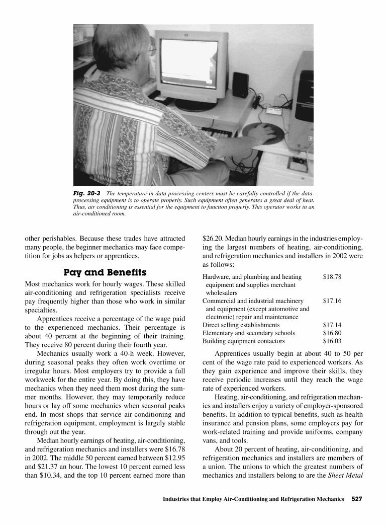
Industries that Employ Air-Conditioning and Refrigeration Mechanics 527
other perishables. Because these trades have attractedmany people, the beginner mechanics may face compe-tition for jobs as helpers or apprentices.
Pay and Benefits Most mechanics work for hourly wages. These skilledair-conditioning and refrigeration specialists receivepay frequently higher than those who work in similarspecialties.
Apprentices receive a percentage of the wage paidto the experienced mechanics. Their percentage isabout 40 percent at the beginning of their training.They receive 80 percent during their fourth year.
Mechanics usually work a 40-h week. However,during seasonal peaks they often work overtime orirregular hours. Most employers try to provide a fullworkweek for the entire year. By doing this, they havemechanics when they need them most during the sum-mer months. However, they may temporarily reducehours or lay off some mechanics when seasonal peaksend. In most shops that service air-conditioning andrefrigeration equipment, employment is largely stablethrough out the year.
Median hourly earnings of heating, air-conditioning,and refrigeration mechanics and installers were $16.78in 2002. The middle 50 percent earned between $12.95and $21.37 an hour. The lowest 10 percent earned lessthan $10.34, and the top 10 percent earned more than
$26.20. Median hourly earnings in the industries employ-ing the largest numbers of heating, air-conditioning,and refrigeration mechanics and installers in 2002 wereas follows:
Hardware, and plumbing and heating $18.78 equipment and supplies merchant wholesalers
Commercial and industrial machinery $17.16 and equipment (except automotive andelectronic) repair and maintenance
Direct selling establishments $17.14Elementary and secondary schools $16.80Building equipment contactors $16.03
Apprentices usually begin at about 40 to 50 percent of the wage rate paid to experienced workers. Asthey gain experience and improve their skills, theyreceive periodic increases until they reach the wagerate of experienced workers.
Heating, air-conditioning, and refrigeration mechan-ics and installers enjoy a variety of employer-sponsoredbenefits. In addition to typical benefits, such as healthinsurance and pension plans, some employers pay forwork-related training and provide uniforms, companyvans, and tools.
About 20 percent of heating, air-conditioning, andrefrigeration mechanics and installers are members ofa union. The unions to which the greatest numbers ofmechanics and installers belong to are the Sheet Metal
Fig. 20-3 The temperature in data processing centers must be carefully controlled if the data-processing equipment is to operate properly. Such equipment often generates a great deal of heat.Thus, air conditioning is essential for the equipment to function properly. This operator works in anair-conditioned room.

528 Air-Conditioning and Refrigeration Careers
Workers’ International Association (SMWIA) and theUnited Association of Journeymen and Apprentices ofthe Plumbing and Pipe-fitting Industry of the UnitedStates and Canada.
TEACHING AS A CAREER A person interested in passing on to others his or herknowledge of air conditioning might be to teach invocational schools. The public schools also offerclasses in air conditioning and refrigeration. Teachersof such courses (vocational education) often comefrom the trade itself. Once they have secured a positionin the school, they may have to take certain college-level courses. These courses will deal with teachingmethods and other subjects related to education.
Private trade schools are usually in need of goodpeople with experience in the trade. They are needed toorganize and teach apprentices. These schools may besponsored by air-conditioning and refrigeration con-tractors or by unions. See Fig. 20-4.
Pay and benefits, are the same as for any otherteacher in the public or the private schools. Workingconditionings are similar throughout the country. Thedemand varies with the temperature. Therefore, theclimate has much to do with the demand for air-conditioning and refrigeration specialists.
SOURCES OF ADDITIONALINFORMATION
For more information about opportunities for training,certification, and employment in this trade, contactlocal vocational and technical schools; local heating,air-conditioning, and refrigeration contractors; a localof the unions or organizations previously mentioned; alocal joint union-management apprenticeship commit-tee; or the nearest office of the state employment ser-vice or apprenticeship agency.
For information on career opportunities, training,and technician certification, contact:
Fig. 20-4 The field of air-conditioning and refrigeration offers many opportunities to qualifiedteachers. Such teachers can work in private trade schools, as well as public schools.
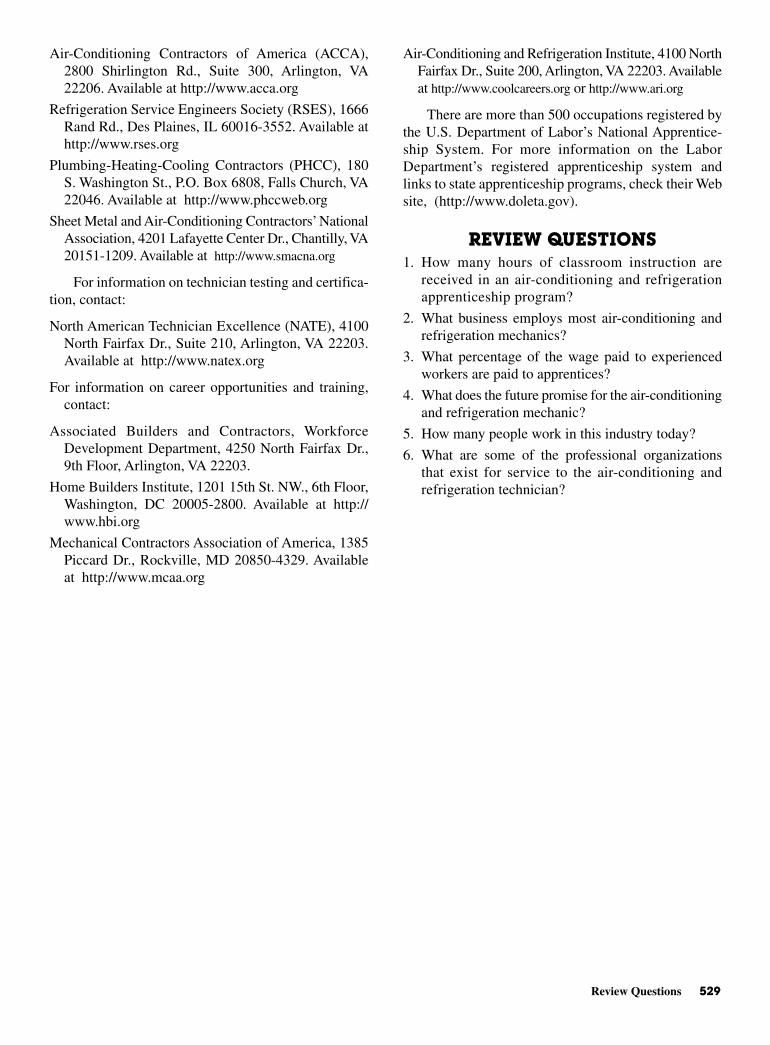
Review Questions 529
Air-Conditioning Contractors of America (ACCA),2800 Shirlington Rd., Suite 300, Arlington, VA22206. Available at http://www.acca.org
Refrigeration Service Engineers Society (RSES), 1666Rand Rd., Des Plaines, IL 60016-3552. Available athttp://www.rses.org
Plumbing-Heating-Cooling Contractors (PHCC), 180S. Washington St., P.O. Box 6808, Falls Church, VA22046. Available at http://www.phccweb.org
Sheet Metal and Air-Conditioning Contractors’ NationalAssociation, 4201 Lafayette Center Dr., Chantilly, VA20151-1209. Available at http://www.smacna.org
For information on technician testing and certifica-tion, contact:
North American Technician Excellence (NATE), 4100North Fairfax Dr., Suite 210, Arlington, VA 22203.Available at http://www.natex.org
For information on career opportunities and training,contact:
Associated Builders and Contractors, WorkforceDevelopment Department, 4250 North Fairfax Dr.,9th Floor, Arlington, VA 22203.
Home Builders Institute, 1201 15th St. NW., 6th Floor,Washington, DC 20005-2800. Available at http://www.hbi.org
Mechanical Contractors Association of America, 1385Piccard Dr., Rockville, MD 20850-4329. Availableat http://www.mcaa.org
Air-Conditioning and Refrigeration Institute, 4100 NorthFairfax Dr., Suite 200, Arlington, VA 22203. Availableat http://www.coolcareers.org or http://www.ari.org
There are more than 500 occupations registered bythe U.S. Department of Labor’s National Apprentice-ship System. For more information on the LaborDepartment’s registered apprenticeship system andlinks to state apprenticeship programs, check their Website, (http://www.doleta.gov).
REVIEW QUESTIONS1. How many hours of classroom instruction are
received in an air-conditioning and refrigerationapprenticeship program?
2. What business employs most air-conditioning andrefrigeration mechanics?
3. What percentage of the wage paid to experiencedworkers are paid to apprentices?
4. What does the future promise for the air-conditioningand refrigeration mechanic?
5. How many people work in this industry today?
6. What are some of the professional organizationsthat exist for service to the air-conditioning andrefrigeration technician?

This page intentionally left blank

AAPPENDIX
Some NewRefrigerants
Copyright © 2006 by The McGraw-Hill Companies, Inc. Click here for terms of use.
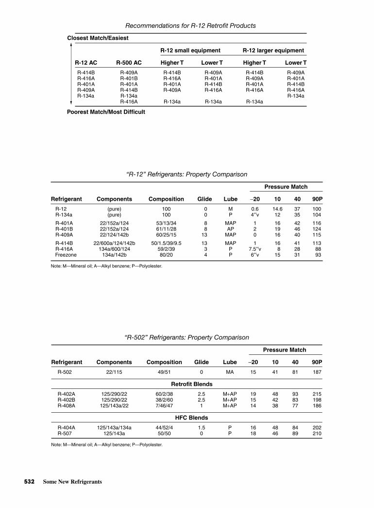
532 Some New Refrigerants
“R-502” Refrigerants: Property Comparison
Pressure Match
Refrigerant Components Composition Glide Lube −20 10 40 90P
R-502 22/115 49/51 0 MA 15 41 81 187
Retrofit Blends
R-402A 125/290/22 60/2/38 2.5 M+AP 19 48 93 215R-402B 125/290/22 38/2/60 2.5 M+AP 15 42 83 198R-408A 125/143a/22 7/46/47 1 M+AP 14 38 77 186
HFC Blends
R-404A 125/143a/134a 44/52/4 1.5 P 16 48 84 202R-507 125/143a 50/50 0 P 18 46 89 210
Note: M—Mineral oil; A—Alkyl benzene; P—Polyolester.
“R-12” Refrigerants: Property Comparison
Pressure Match
Refrigerant Components Composition Glide Lube −20 10 40 90P
R-12 (pure) 100 0 M 0.6 14.6 37 100R-134a (pure) 100 0 P 4′′v 12 35 104
R-401A 22/152a/124 53/13/34 8 MAP 1 16 42 116R-401B 22/152a/124 61/11/28 8 AP 2 19 46 124R-409A 22/124/142b 60/25/15 13 MAP 0 16 40 115
R-414B 22/600a/124/142b 50/1.5/39/9.5 13 MAP 1 16 41 113R-416A 134a/600/124 59/2/39 3 P 7.5′′v 8 28 88Freezone 134a/142b 80/20 4 P 6′′v 15 31 93
Note: M—Mineral oil; A—Alkyl benzene; P—Polyolester.
Recommendations for R-12 Retrofit Products
R-12 small equipment R-12 larger equipment
R-12 AC R-500 AC Higher T Lower T Higher T Lower T
R-414B R-409A R-414B R-409A R-414B R-409AR-416A R-401B R-416A R-401A R-409A R-401AR-401A R-401A R-401A R-414B R-401A R-414BR-409A R-414B R-409A R-416A R-416A R-416AR-134a R-134a R-134a
R-416A R-134a R-134a R-134a
Poorest Match/Most Difficult
Closest Match/Easiest

Some New Refrigerants 533
Thermodynamic Properties of R-401A
Pressure Pressure Density Density Enthalpy Enthalpy Entropy EntropyTemp Liquid Vapor Liquid Vapor Liquid Vapor Liquid Vapor
[F] [psia] [psia] [lb/ft3] [lb/ft3] [Btu/lb] [Btu/lb] [Btu/R-lb] [Btu/R-lb]
−60 6.5 4.7 88.18 0.1049 −5.371 94.93 −0.01309 0.2418−55 7.5 5.5 87.71 0.1215 −4.035 95.60 −0.00977 0.2402−50 8.7 6.4 87.24 0.1401 −2.694 96.26 −0.00648 0.2386−45 9.9 7.4 86.77 0.1610 −1.350 96.93 −0.00323 0.2372−40 11.4 8.6 86.29 0.1842 0.000 97.59 0.00000 0.2358−35 12.9 9.9 85.82 0.2101 1.354 98.25 0.00320 0.2345−30 14.7 11.3 85.33 0.2386 2.714 98.91 0.00637 0.2333−25 16.6 12.9 84.85 0.2701 4.078 99.56 0.00952 0.2321−20 18.7 14.7 84.36 0.3048 5.449 100.2 0.01265 0.2310−15 21.0 16.6 83.86 0.3429 6.825 100.9 0.01575 0.2299−10 23.6 18.8 83.37 0.3846 8.207 101.5 0.01882 0.2289
−5 26.4 21.2 82.86 0.4302 9.595 102.1 0.02188 0.22790 29.4 23.8 82.36 0.4799 10.99 102.8 0.02492 0.22695 32.7 26.6 81.84 0.5340 12.39 103.4 0.02793 0.2261
10 36.2 29.7 81.33 0.5927 13.80 104.0 0.03093 0.225215 40.1 33.1 80.80 0.6563 15.21 104.6 0.03391 0.224420 44.2 36.7 80.27 0.7251 16.64 105.2 0.03687 0.223625 48.7 40.7 79.74 0.7995 18.07 105.8 0.03982 0.222930 53.5 45.0 79.20 0.8798 19.51 106.4 0.04275 0.222135 58.6 49.6 78.65 0.9662 20.95 107.0 0.04566 0.221440 64.2 54.6 78.10 1.059 22.41 107.6 0.04857 0.220845 70.1 59.9 77.54 1.159 23.88 108.2 0.05145 0.220150 76.4 65.6 76.97 1.267 25.35 108.7 0.05433 0.219555 83.1 71.8 76.39 1.382 26.83 109.3 0.05720 0.218960 90.2 78.3 75.81 1.505 28.33 109.8 0.06005 0.218365 97.8 85.3 75.21 1.637 29.83 110.4 0.06290 0.217870 105.9 92.8 74.61 1.779 31.35 110.9 0.06573 0.217275 114.5 100.7 74.00 1.930 32.87 111.4 0.06856 0.216780 123.5 109.2 73.37 2.092 34.41 111.9 0.07138 0.216285 133.1 118.1 72.74 2.265 35.96 112.4 0.07420 0.215690 143.2 127.6 72.09 2.449 37.52 112.8 0.07701 0.215195 153.9 137.7 71.43 2.647 39.10 113.3 0.07981 0.2146
100 165.2 148.3 70.76 2.858 40.69 113.7 0.08261 0.2141105 177.0 159.6 70.08 3.083 42.30 114.1 0.08541 0.2136110 189.5 171.4 69.38 3.324 43.92 114.5 0.08822 0.2131115 202.6 183.9 68.66 3.581 45.56 114.9 0.09102 0.2126120 216.3 197.1 67.93 3.857 47.21 115.2 0.09382 0.2120125 230.7 211.0 67.17 4.152 48.89 115.6 0.09663 0.2115130 245.8 225.6 66.40 4.468 50.58 115.9 0.09945 0.2110135 261.7 240.9 65.60 4.807 52.30 116.2 0.1023 0.2104140 278.2 257.1 64.77 5.171 54.04 116.4 0.1051 0.2098145 295.5 274.0 63.92 5.564 55.81 116.6 0.1080 0.2092150 313.6 291.7 63.04 5.987 57.61 116.8 0.1108 0.2085155 332.6 310.3 62.12 6.444 59.43 116.9 0.1137 0.2078
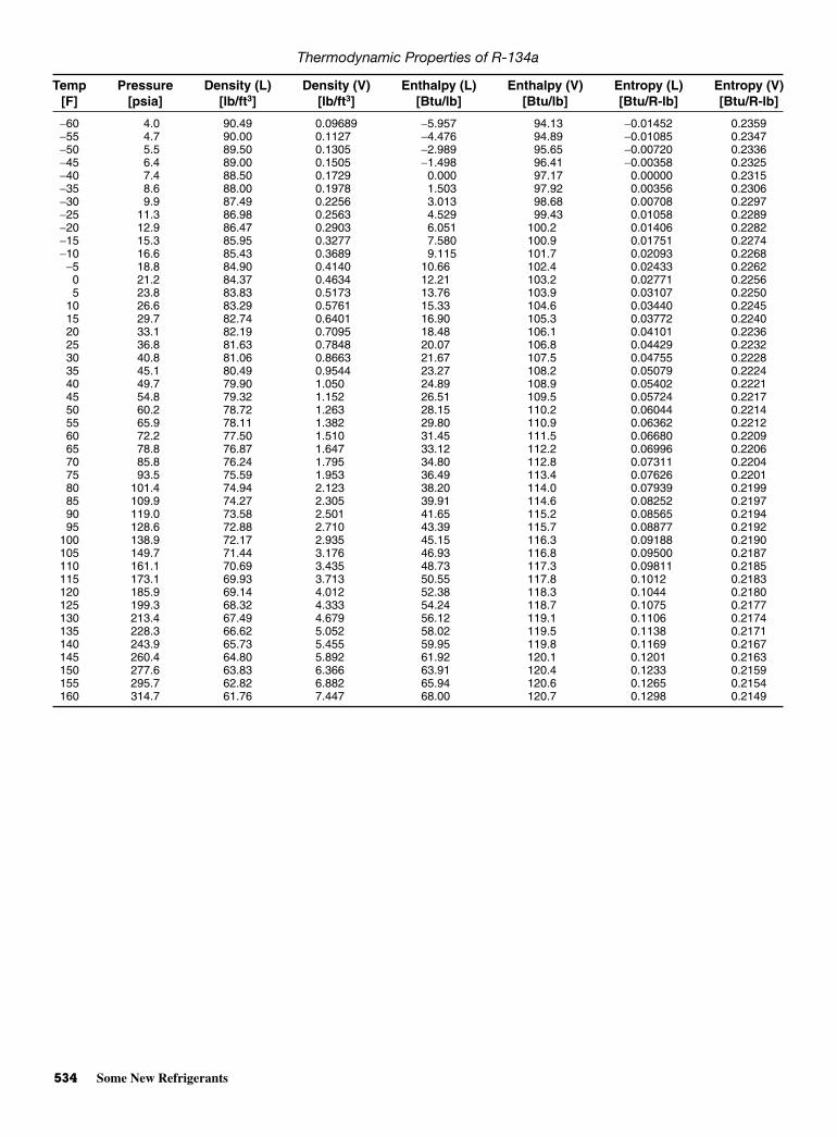
534 Some New Refrigerants
Thermodynamic Properties of R-134a
Temp Pressure Density (L) Density (V) Enthalpy (L) Enthalpy (V) Entropy (L) Entropy (V)[F] [psia] [lb/ft3] [lb/ft3] [Btu/lb] [Btu/lb] [Btu/R-lb] [Btu/R-lb]
−60 4.0 90.49 0.09689 −5.957 94.13 −0.01452 0.2359−55 4.7 90.00 0.1127 −4.476 94.89 −0.01085 0.2347−50 5.5 89.50 0.1305 −2.989 95.65 −0.00720 0.2336−45 6.4 89.00 0.1505 −1.498 96.41 −0.00358 0.2325−40 7.4 88.50 0.1729 0.000 97.17 0.00000 0.2315−35 8.6 88.00 0.1978 1.503 97.92 0.00356 0.2306−30 9.9 87.49 0.2256 3.013 98.68 0.00708 0.2297−25 11.3 86.98 0.2563 4.529 99.43 0.01058 0.2289−20 12.9 86.47 0.2903 6.051 100.2 0.01406 0.2282−15 15.3 85.95 0.3277 7.580 100.9 0.01751 0.2274−10 16.6 85.43 0.3689 9.115 101.7 0.02093 0.2268
−5 18.8 84.90 0.4140 10.66 102.4 0.02433 0.22620 21.2 84.37 0.4634 12.21 103.2 0.02771 0.22565 23.8 83.83 0.5173 13.76 103.9 0.03107 0.2250
10 26.6 83.29 0.5761 15.33 104.6 0.03440 0.224515 29.7 82.74 0.6401 16.90 105.3 0.03772 0.224020 33.1 82.19 0.7095 18.48 106.1 0.04101 0.223625 36.8 81.63 0.7848 20.07 106.8 0.04429 0.223230 40.8 81.06 0.8663 21.67 107.5 0.04755 0.222835 45.1 80.49 0.9544 23.27 108.2 0.05079 0.222440 49.7 79.90 1.050 24.89 108.9 0.05402 0.222145 54.8 79.32 1.152 26.51 109.5 0.05724 0.221750 60.2 78.72 1.263 28.15 110.2 0.06044 0.221455 65.9 78.11 1.382 29.80 110.9 0.06362 0.221260 72.2 77.50 1.510 31.45 111.5 0.06680 0.220965 78.8 76.87 1.647 33.12 112.2 0.06996 0.220670 85.8 76.24 1.795 34.80 112.8 0.07311 0.220475 93.5 75.59 1.953 36.49 113.4 0.07626 0.220180 101.4 74.94 2.123 38.20 114.0 0.07939 0.219985 109.9 74.27 2.305 39.91 114.6 0.08252 0.219790 119.0 73.58 2.501 41.65 115.2 0.08565 0.219495 128.6 72.88 2.710 43.39 115.7 0.08877 0.2192
100 138.9 72.17 2.935 45.15 116.3 0.09188 0.2190105 149.7 71.44 3.176 46.93 116.8 0.09500 0.2187110 161.1 70.69 3.435 48.73 117.3 0.09811 0.2185115 173.1 69.93 3.713 50.55 117.8 0.1012 0.2183120 185.9 69.14 4.012 52.38 118.3 0.1044 0.2180125 199.3 68.32 4.333 54.24 118.7 0.1075 0.2177130 213.4 67.49 4.679 56.12 119.1 0.1106 0.2174135 228.3 66.62 5.052 58.02 119.5 0.1138 0.2171140 243.9 65.73 5.455 59.95 119.8 0.1169 0.2167145 260.4 64.80 5.892 61.92 120.1 0.1201 0.2163150 277.6 63.83 6.366 63.91 120.4 0.1233 0.2159155 295.7 62.82 6.882 65.94 120.6 0.1265 0.2154160 314.7 61.76 7.447 68.00 120.7 0.1298 0.2149
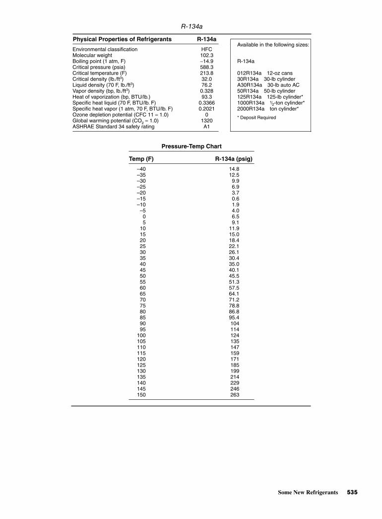
Some New Refrigerants 535
R-134a
Physical Properties of Refrigerants R-134a
Environmental classification HFCAvailable in the following sizes:
Molecular weight 102.3Boiling point (1 atm, F) −14.9 R-134aCritical pressure (psia) 588.3Critical temperature (F) 213.8 012R134a 12-oz cansCritical density (lb./ft3) 32.0 30R134a 30-lb cylinderLiquid density (70 F, lb./ft3) 76.2 A30R134a 30-lb auto ACVapor density (bp, lb./ft3) 0.328 50R134a 50-lb cylinderHeat of vaporization (bp, BTU/lb.) 93.3 125R134a 125-lb cylinder*Specific heat liquid (70 F, BTU/lb. F) 0.3366 1000R134a 1/2-ton cylinder*Specific heat vapor (1 atm, 70 F, BTU/lb. F) 0.2021 2000R134a ton cylinder*Ozone depletion potential (CFC 11 = 1.0) 0Global warming potential (CO2 = 1.0) 1320
* Deposit Required
ASHRAE Standard 34 safety rating A1
Pressure-Temp Chart
Temp (F) R-134a (psig)
–40 14.8–35 12.5–30 9.9–25 6.9–20 3.7–15 0.6–10 1.9–5 4.00 6.55 9.1
10 11.915 15.020 18.425 22.130 26.135 30.440 35.045 40.150 45.555 51.360 57.565 64.170 71.275 78.880 86.885 95.490 10495 114
100 124105 135110 147115 159120 171125 185130 199135 214140 229145 246150 263
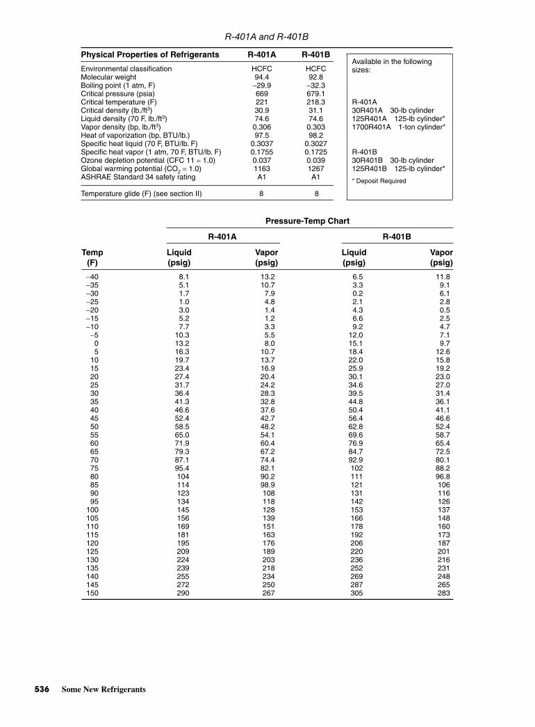
536 Some New Refrigerants
R-401A and R-401B
Physical Properties of Refrigerants R-401A R-401B
Environmental classification HCFC HCFCAvailable in the following
Molecular weight 94.4 92.8sizes:
Boiling point (1 atm, F) −29.9 −32.3Critical pressure (psia) 669 679.1Critical temperature (F) 221 218.3 R-401ACritical density (lb./ft3) 30.9 31.1 30R401A 30-lb cylinderLiquid density (70 F, lb./ft3) 74.6 74.6 125R401A 125-lb cylinder*Vapor density (bp, lb./ft3) 0.306 0.303 1700R401A 1-ton cylinder*Heat of vaporization (bp, BTU/lb.) 97.5 98.2Specific heat liquid (70 F, BTU/lb. F) 0.3037 0.3027Specific heat vapor (1 atm, 70 F, BTU/lb. F) 0.1755 0.1725 R-401BOzone depletion potential (CFC 11 = 1.0) 0.037 0.039 30R401B 30-lb cylinderGlobal warming potential (CO2 = 1.0) 1163 1267 125R401B 125-lb cylinder*ASHRAE Standard 34 safety rating A1 A1 * Deposit Required
Temperature glide (F) (see section II) 8 8
Pressure-Temp Chart
R-401A R-401B
Temp Liquid Vapor Liquid Vapor(F) (psig) (psig) (psig) (psig)
−40 8.1 13.2 6.5 11.8−35 5.1 10.7 3.3 9.1−30 1.7 7.9 0.2 6.1−25 1.0 4.8 2.1 2.8−20 3.0 1.4 4.3 0.5−15 5.2 1.2 6.6 2.5−10 7.7 3.3 9.2 4.7
−5 10.3 5.5 12.0 7.10 13.2 8.0 15.1 9.75 16.3 10.7 18.4 12.6
10 19.7 13.7 22.0 15.815 23.4 16.9 25.9 19.220 27.4 20.4 30.1 23.025 31.7 24.2 34.6 27.030 36.4 28.3 39.5 31.435 41.3 32.8 44.8 36.140 46.6 37.6 50.4 41.145 52.4 42.7 56.4 46.650 58.5 48.2 62.8 52.455 65.0 54.1 69.6 58.760 71.9 60.4 76.9 65.465 79.3 67.2 84.7 72.570 87.1 74.4 92.9 80.175 95.4 82.1 102 88.280 104 90.2 111 96.885 114 98.9 121 10690 123 108 131 11695 134 118 142 126
100 145 128 153 137105 156 139 166 148110 169 151 178 160115 181 163 192 173120 195 176 206 187125 209 189 220 201130 224 203 236 216135 239 218 252 231140 255 234 269 248145 272 250 287 265150 290 267 305 283

Some New Refrigerants 537
R-402A and R-402B
Physical Properties of Refrigerants R-402A R-402B
Environmental classification HCFC HCFCAvailable in the following
Molecular weight 101.6 94.7sizes:
Boiling point (1 atm, F) −56.5 −52.9Critical pressure (psia) 600 645Critical temperature (F) 168 180.7 R-402ACritical density (lb./ft3) 33.8 33.1 27R402A 27-lb cylinderLiquid density (70 F, lb./ft3) 72.61 72.81 110R402A 110-lb cylinder*Vapor density (bp, lb./ft3) 0.356 0.328Heat of vaporization (bp, BTU/lb.) 83.58 90.42Specific heat liquid (70 F, BTU/lb. F) 0.3254 0.317Specific heat vapor (1 atm, 70 F, BTU/lb. F) 0.1811 0.1741 R-402BOzone depletion potential (CFC 11 = 1.0) 0.019 0.03 13R402B 13-lb cylinderGlobal warming potential (CO2 = 1.0) 2746 2379 * Deposit RequiredASHRAE Standard 34 safety rating A1 A1
Temperature Glide (see section II) 2.5 2.5
Pressure-Temp Chart
Temp (F) R402A (psig) R402B (psig)
−40 6.3 3.6−35 9.1 6.0−30 12.1 9.0−25 15.4 12.0−20 18.9 15.4−15 22.9 18.6−10 27.1 22.6
−5 31.7 27.00 36.7 31.05 42.1 36.0
10 48.0 42.015 54.2 47.020 60.9 54.025 68.1 60.030 75.8 67.035 84.0 75.040 92.8 83.445 102 91.650 112 10055 123 11060 134 12065 146 13370 158 14375 171 15580 185 17085 200 18390 215 19895 232 213
100 249 230105 267 247110 286 262115 305 283120 326 303125 347 323130 370 345135 393 —140 418 —145 443 —150 470 —

This page intentionally left blank

BAPPENDIX
Electrical andElectronic
Symbols Usedin Schematics
Copyright © 2006 by The McGraw-Hill Companies, Inc. Click here for terms of use.
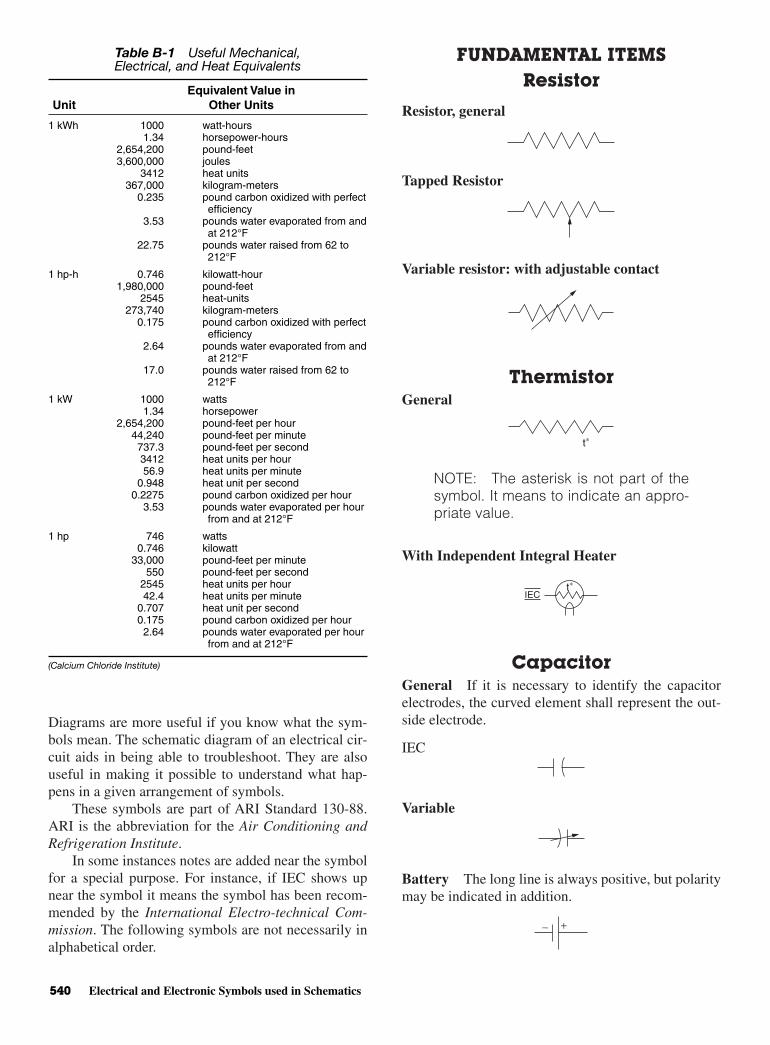
Diagrams are more useful if you know what the sym-bols mean. The schematic diagram of an electrical cir-cuit aids in being able to troubleshoot. They are alsouseful in making it possible to understand what hap-pens in a given arrangement of symbols.
These symbols are part of ARI Standard 130-88.ARI is the abbreviation for the Air Conditioning andRefrigeration Institute.
In some instances notes are added near the symbolfor a special purpose. For instance, if IEC shows upnear the symbol it means the symbol has been recom-mended by the International Electro-technical Com-mission. The following symbols are not necessarily inalphabetical order.
FUNDAMENTAL ITEMSResistor
Resistor, general
Tapped Resistor
Variable resistor: with adjustable contact
ThermistorGeneral
NOTE: The asterisk is not part of thesymbol. It means to indicate an appro-priate value.
With Independent Integral Heater
CapacitorGeneral If it is necessary to identify the capacitorelectrodes, the curved element shall represent the out-side electrode.
IEC
Variable
Battery The long line is always positive, but polaritymay be indicated in addition.
+−
t∗IEC
t∗
540 Electrical and Electronic Symbols used in Schematics
Table B-1 Useful Mechanical,Electrical, and Heat Equivalents
Equivalent Value inUnit Other Units
1 kWh 1000 watt-hours1.34 horsepower-hours
2,654,200 pound-feet3,600,000 joules
3412 heat units367,000 kilogram-meters
0.235 pound carbon oxidized with perfectefficiency
3.53 pounds water evaporated from andat 212°F
22.75 pounds water raised from 62 to212°F
1 hp-h 0.746 kilowatt-hour1,980,000 pound-feet
2545 heat-units273,740 kilogram-meters
0.175 pound carbon oxidized with perfectefficiency
2.64 pounds water evaporated from andat 212°F
17.0 pounds water raised from 62 to212°F
1 kW 1000 watts1.34 horsepower
2,654,200 pound-feet per hour44,240 pound-feet per minute737.3 pound-feet per second3412 heat units per hour56.9 heat units per minute
0.948 heat unit per second0.2275 pound carbon oxidized per hour
3.53 pounds water evaporated per hourfrom and at 212°F
1 hp 746 watts0.746 kilowatt
33,000 pound-feet per minute550 pound-feet per second
2545 heat units per hour42.4 heat units per minute
0.707 heat unit per second0.175 pound carbon oxidized per hour2.64 pounds water evaporated per hour
from and at 212°F
(Calcium Chloride Institute)

Fundamental Items 541
Multicell
Temperature-Measuring Thermocouple
IEC
Thermopile for pumping heat
Spark Gap, Igniter Gap
Transmission PathTransmission Path: Conductors, Cables, Wiring ⋅⋅⋅Factory Wired
Field Installed or Sales Option, if specified
Crossing of Paths or Conductors Not ConnectedThe crossing is not necessarily at a 90° angle.
IEC
Junction of Paths or Conductors Junction(Connection)
IEC
Application: Junction of Connected Paths, Conduc-tors, or Wires
IEC
Terminal block
*Terminal number
Assembled Conductors: Cable. Shielded SingleConductor
Shielded Cable (5-Conductor Shown)
Shielded Cable With Shield Grounded (2-ConductorShown)
Cable (2-Conductor Shown)
IEC
Ribbon Cable
Twisted Cable (pair, triple, and the like)
Circuit Return
Ground (1) A direct conducting connection tothe earth or body of water that is a part thereof. (2) Aconducting connection to a structure (chassis) thatserves a function similar to that of an earth ground (thatis, a structure such as a frame of an air, space, or, landvehicle that is not conductively connected to earth).
Normally Closed Contact (break)
Normally Open Contact (make)
IEC
Earth ground Chassis ground
or
IEC
COLD
HOT

542 Electrical and Electronic Symbols used in Schematics
Operating Coil (Relay coil)
Solenoid Coil
Switch Fundamental symbols for contacts, mechan-ical connections, and so forth, may be used for switchsymbols.
The standard method of showing switches is in a posi-tion with no operating force applied. For switches that maybe in any one of two or more positions with no operatingforce applied and for switches actuated by some mechani-cal device (as in air-pressure, liquid-level, rate-of flow, andso forth, switches), a clarifying note may be necessary toexplain the point at which the switch functions.
Pushbutton, Momentary or Spring-Return
Normally Open, Circuit Closing (make)
Normally closed, Circuit Opening (break)
Two-Circuit (dual)
Two Circuit, Maintained or Not Spring-Return
Maintained (Locking) Switch
Toggle Switch Single Throw
Application: 3 Disconnect Switch
Transfer, 2-Position––Double Throw
Transfer 3-Position
Transfer, 2-Position
IEC
Transfer 3-Position
Selector or Multiposition Switch The position inwhich the switch is shown may be indicated by a noteor designation of switch position.
General (for Power or Control Diagrams) Anynumber of transmission paths may be shown.
Segmental Contact
Slide
Master or Control
Limit Switch, Directly Actuated, Spring Returned
Normally Open
Normally Open––Held Closed
Detached contactsshown elsewhere
on diagram
Contact
1–23–45–67–8
Indicatorposition
A B C XX XX
X-indicatescontacts closed
Rotary Linear
off IEC
IEC
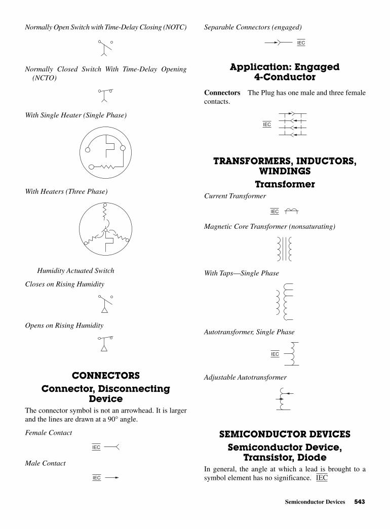
Semiconductor Devices 543
Normally Open Switch with Time-Delay Closing (NOTC)
Normally Closed Switch With Time-Delay Opening(NCTO)
With Single Heater (Single Phase)
With Heaters (Three Phase)
Humidity Actuated Switch
Closes on Rising Humidity
Opens on Rising Humidity
CONNECTORSConnector, Disconnecting
DeviceThe connector symbol is not an arrowhead. It is largerand the lines are drawn at a 90° angle.
Female Contact
Male Contact
Separable Connectors (engaged)
Application: Engaged4-Conductor
Connectors The Plug has one male and three femalecontacts.
TRANSFORMERS, INDUCTORS,WINDINGS
TransformerCurrent Transformer
Magnetic Core Transformer (nonsaturating)
With Taps––Single Phase
Autotransformer, Single Phase
Adjustable Autotransformer
SEMICONDUCTOR DEVICESSemiconductor Device,
Transistor, DiodeIn general, the angle at which a lead is brought to asymbol element has no significance. IEC
IEC
IEC
IEC
IEC
IEC
IEC
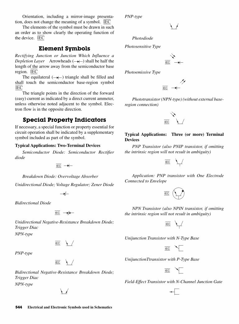
544 Electrical and Electronic Symbols used in Schematics
Orientation, including a mirror-image presenta-tion, does not change the meaning of a symbol.
The elements of the symbol must be drawn in suchan order as to show clearly the operating function ofthe device.
Element SymbolsRectifying Junction or Junction Which Influence aDepletion Layer Arrowheads ( ) shall be half thelength of the arrow away from the semiconductor baseregion.
The equilateral ( ) triangle shall be filled andshall touch the semiconductor base-region symbol
The triangle points in the direction of the forward(easy) current as indicated by a direct current ammeter,unless otherwise noted adjacent to the symbol. Elec-tron flow is in the opposite direction.
Special Property IndicatorsIf necessary, a special function or property essential forcircuit operation shall be indicated by a supplementarysymbol included as part of the symbol.
Typical Applications: Two-Terminal Devices
Semiconductor Diode: Semiconductor Rectifierdiode
Breakdown Diode: Overvoltage Absorber
Unidirectional Diode; Voltage Regulator; Zener Diode
Bidirectional Diode
Unidirectional Negative-Resistance Breakdown Diode;Trigger Diac
NPN-type
PNP-type
Bidirectional Negative-Resistance Breakdown Diode;Trigger Diac
NPN-type
PNP-type
Photodiode
Photosensitive Type
Photoemissive Type
Phototransistor (NPN-type) (without external base-region connection)
Typical Applications: Three (or more) TerminalDevices
PNP Transistor (also PNIP transistor, if omittingthe intrinsic region will not result in ambiguity)
Application: PNP transistor with One ElectrodeConnected to Envelope
NPN Transistor (also NPIN transistor, if omittingthe intrinsic region will not result in ambiguity)
Unijunction Transistor with N-Type Base
UnijunctionTtransistor with P-Type Base
Field-Effect Transistor with N-Channel Junction Gate
IEC
IEC
IEC
IEC
IEC
IEC
IEC
IEC
IEC
IEC
IEC
IEC
IEC
IEC
IEC
IEC
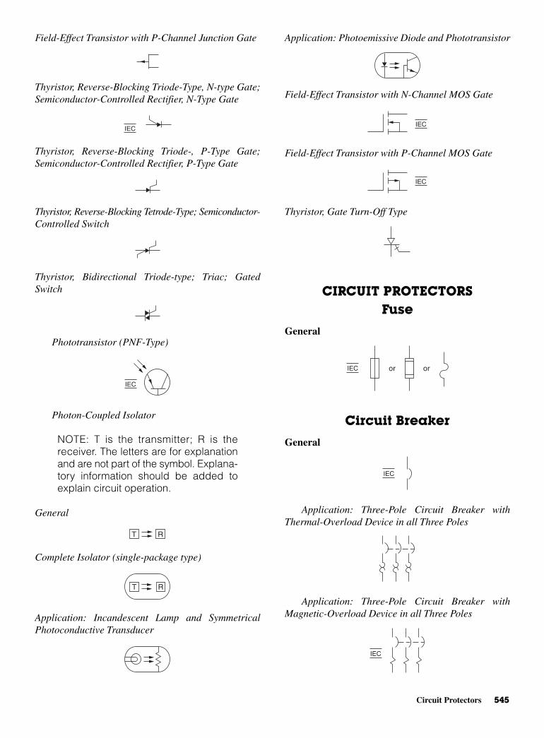
Circuit Protectors 545
Field-Effect Transistor with P-Channel Junction Gate
Thyristor, Reverse-Blocking Triode-Type, N-type Gate;Semiconductor-Controlled Rectifier, N-Type Gate
Thyristor, Reverse-Blocking Triode-, P-Type Gate;Semiconductor-Controlled Rectifier, P-Type Gate
Thyristor, Reverse-Blocking Tetrode-Type; Semiconductor-Controlled Switch
Thyristor, Bidirectional Triode-type; Triac; GatedSwitch
Phototransistor (PNF-Type)
Photon-Coupled Isolator
NOTE: T is the transmitter; R is thereceiver. The letters are for explanationand are not part of the symbol. Explana-tory information should be added toexplain circuit operation.
General
Complete Isolator (single-package type)
Application: Incandescent Lamp and SymmetricalPhotoconductive Transducer
Application: Photoemissive Diode and Phototransistor
Field-Effect Transistor with N-Channel MOS Gate
Field-Effect Transistor with P-Channel MOS Gate
Thyristor, Gate Turn-Off Type
CIRCUIT PROTECTORSFuse
General
Circuit Breaker
General
Application: Three-Pole Circuit Breaker withThermal-Overload Device in all Three Poles
Application: Three-Pole Circuit Breaker withMagnetic-Overload Device in all Three Poles
IEC
IEC
IEC or or
IEC
IEC
T R
T R
IEC
IEC
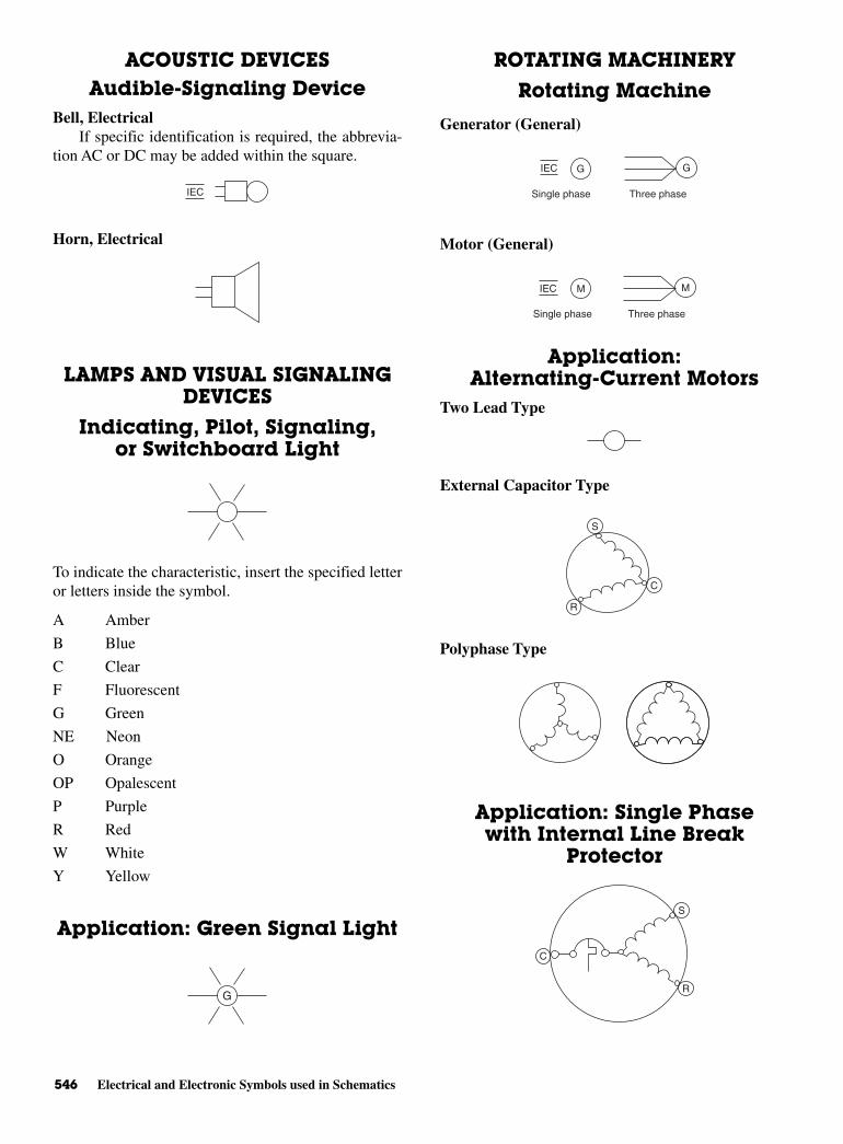
546 Electrical and Electronic Symbols used in Schematics
ACOUSTIC DEVICESAudible-Signaling Device
Bell, ElectricalIf specific identification is required, the abbrevia-
tion AC or DC may be added within the square.
Horn, Electrical
LAMPS AND VISUAL SIGNALINGDEVICES
Indicating, Pilot, Signaling,or Switchboard Light
To indicate the characteristic, insert the specified letteror letters inside the symbol.
A Amber
B Blue
C Clear
F Fluorescent
G Green
NE Neon
O Orange
OP Opalescent
P Purple
R Red
W White
Y Yellow
Application: Green Signal Light
ROTATING MACHINERY
Rotating Machine
Generator (General)
Motor (General)
Application:Alternating-Current Motors
Two Lead Type
External Capacitor Type
Polyphase Type
Application: Single Phasewith Internal Line Break
Protector
R
C
S
R
C
S
IEC M
Single phase Three phase
M
IEC G G
Single phase Three phase
G
IEC
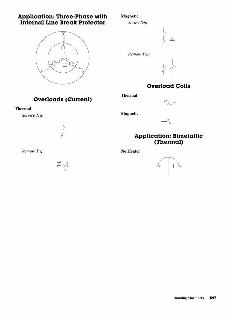
Rotating Machinery 547
Application: Three-Phase withInternal Line Break Protector
Overloads (Current)
Thermal
Service Trip
Remote Trip
Magnetic
Series Trip
Remote Trip
Overload Coils
Thermal
Magnetic
Application: Bimetallic(Thermal)
No Heater
IEC

This page intentionally left blank

CAPPENDIX
ProgrammingThermostats*
NOTE: A variety of thermostats are available; those shown here are fromone manufacturer only. See Internet for more complete coverage andhomeowner’s guides.
*All the figures are taken from http://www.totaline.com.
Copyright © 2006 by The McGraw-Hill Companies, Inc. Click here for terms of use.
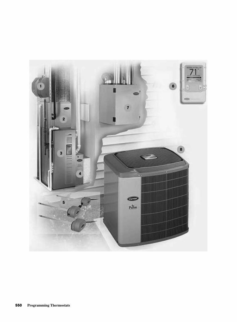
550 Programming Thermostats

Programming Thermostats 551
OUTDOORTEMPERATUREDISPLAY is an optional feature that shows theoutdoortemperature.
SET TEMP is displayed while setting your desired temperatures.
COOL ON INDICATOR is displayed when the cooling equipment is operating.
HEAT ON INDICATOR is displayed when the heating equipment is operating.
RESET FILTER button restarts thetimer thatcalculates thenext air filterchange orcleaning.
FAN button chooses between ON or AUTO fan operation.
MODE button selects between OFF, HEAT, COOL and AUTO operation. Heat pump thermostat models also include an EMERGENCY HEAT mode.
AUXILIARY HEAT INDICATOR isdisplayed when a heat pumpsystem’s auxiliary heat is on.
CLEAN FILTER INDICATOR lets you know it is time to clean or replace your system’s air filter.
UP AND DOWN buttons increaseor decrease the desiredtemperaturesettings.
ROOMTEMPERATUREDISPLAYshows current room temperature.
Comfort At Your Command. This is no ordinary thermostat. Bryant listened to the needs of homeowners nationwide and delivered a product to meet those needs. The result is athermostat that interacts with people as effectively as it does with your heatingand cooling system. It’s a simple, yet powerful control that puts comfort atyour command.
Making Life Easier. Take a few minutes to review the features and functions listed above.Bryant gives you control over your comfort with simple instructions,responsive push buttons and an easy-to-read backlit display. Once set, thisthermostat reliably monitors indoor temperatures and responsively meets yourcomfort demands.
NOTE: Not all messages displayed in above illustration will appear at once in any situation.

552 Programming Thermostats
Fan Setting
Fan Button chooses “high,” “medium,” “low,” or “auto” fan mode.
Outside Temperature
Desired Heating/Cooling Temperature
Right Button providessystem status.
Heat Button selects heating operation.
Cool Button selects cooling operation.
Heat/Cool LEDs indicateheating or cooling operation.
Temp (+\-) Button
Off Button turns the system on and off.
Advanced Setup Button provides access tocustomizable features.
Basic Setup Button providesaccess to current day, time and desired humidity level.
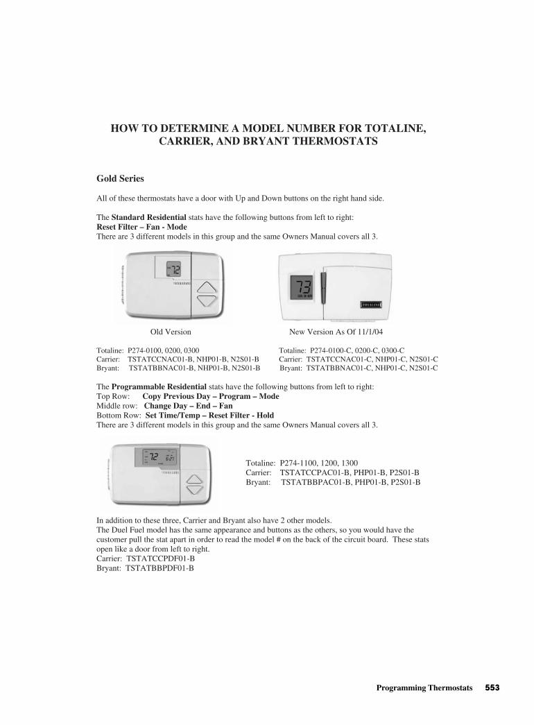
Programming Thermostats 553
HOW TO DETERMINE A MODEL NUMBER FOR TOTALINE, CARRIER, AND BRYANT THERMOSTATS
Gold Series
All of these thermostats have a door with Up and Down buttons on the right hand side.
The Standard Residential stats have the following buttons from left to right:Reset Filter – Fan - Mode There are 3 different models in this group and the same Owners Manual covers all 3.
Old Version New Version As Of 11/1/04
Totaline: P274-0100, 0200, 0300 Totaline: P274-0100-C, 0200-C, 0300-CCarrier: TSTATCCNAC01-B, NHP01-B, N2S01-B Carrier: TSTATCCNAC01-C, NHP01-C, N2S01-CBryant: TSTATBBNAC01-B, NHP01-B, N2S01-B Bryant: TSTATBBNAC01-C, NHP01-C, N2S01-C
The Programmable Residential stats have the following buttons from left to right:Top Row: Copy Previous Day – Program – ModeMiddle row: Change Day – End – FanBottom Row: Set Time/Temp – Reset Filter - HoldThere are 3 different models in this group and the same Owners Manual covers all 3.
Totaline: P274-1100, 1200, 1300 TSTATCCPAC01-B, PHP01-B, P2S01-B
Bryant: TSTATBBPAC01-B, PHP01-B, P2S01-B
In addition to these three, Carrier and Bryant also have 2 other models. The Duel Fuel model has the same appearance and buttons as the others, so you would have the customer pull the stat apart in order to read the model # on the back of the circuit board. These stats open like a door from left to right. Carrier: TSTATCCPDF01-B Bryant: TSTATBBPDF01-B
Carrier:
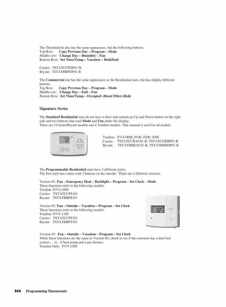
554 Programming Thermostats
The Thermidistat also has the same appearance, but the following buttons: Top Row: Copy Previous Day – Program – ModeMiddle row: Change Day – Humidity – FanBottom Row: Set Time/Temp – Vacation – Hold/End
Carrier: TSTATCCPDF01-B Bryant: TSTATBBPDF01-B
The Commercial stat has the same appearance as the Residential stats, but has slightly different buttons.Top Row: Copy Previous Day – Program – ModeMiddle row: Change Day – End – FanBottom Row: Set Time/Temp – Occupied <Reset Filter>Hold
Signature Series
The Standard Residential stats do not have a door and contain an Up and Down button on the right side and two buttons that read Mode and Fan under the display. There are 2 Carrier/Bryant models and 4 Totaline models. One manual is used for all models.
Totaline: P374-0000, 0100, 0200, 0300 Carrier: TSTATCCBAC01-B, TSTATCCBHP01-B Bryant: TSTATBBBAC01-B, TSTATBBBHP01-B
The Programmable Residential stats have 3 different styles. The first style has a door with 3 buttons on the outside. There are 4 different versions.
Version #1: Fan – Emergency Heat – Backlight – Program – Set Clock – Mode These functions refer to the following models: Totaline: P374-1000 Carrier: TSTATCCPS101 Bryant: TSTATBBPS101
Version #2: Fan – Outside – Vacation – Program – Set Clock These functions refer to the following models: Totaline: P374-1100 Carrier: TSTATCCPS701 Bryant: TSTATBBPS701
Version #3: Fan – Outside – Vacation – Program – Set Clock While these functions are the same as Version #2, check to see if the customer has a duel fuel system … ie. A heat pump and a gas furnace. Totaline Only: P374-1500

Programming Thermostats 555
Version #4: “INTELLISTAT” Fan – Outside – Humidity – Program – Set Clock - ModeTotaline Only: P374-1600
The second style is a flushmount or “flatstat”. It has 4 buttons under the display, plus a raised round bubble where the sensor is enclosed. There are 2 different versions that both have the same buttons. Mode – Fan – Up - Down
1-Day or Non-Programmable: 7-Day Programmable:Totaline: P374-1000FM Carrier: TSTATCCPF101 Bryant: TSTATBBPF101 Bryant: TSTATBBPF701
The third style has the Up/Down buttons on the right and 6 buttons under the display. There are two versions but the manual is the same for both. These are not available in Totaline branding.Top Row: Mode – FanBottom Row: Program – Time/Temp – Day – Hold/End
Carrier: TSTATCCSAC01 and TSTATCCSHP01 Bryant: TSTATBBSAC01 and TSTATBBSHP01
The Commercial stats have 2 different styles and several different versions. The first style has a door with 3 buttons on the outside. There are 4 different versions.
Version #1: Mode – Fan – Emerg. Heat – Backlight – Reset Filter Totaline: P374-2100 Carrier: 33CS071-01 Bryant: TSTATBB071-01
Version #2: Mode – Fan – Holiday – Program – Set Clock Totaline: P374-2200 or P374-2200LA (Light Activated) Carrier: 33CS220-01 or 33CS220-LA Bryant: TSTATBB220-01 or TSTATBB220-LA
Version #3: Mode – Fan – Holiday – Program – Set Clock While these buttons are the same as Version #2, there is a difference, please call. Totaline: P374-2300 or P374-2300LA (Light Activated) Carrier: 33CS250-01 or 33CS250-LA Bryant: TSTATBB250-01 or TSTATBB250-LA
Totaline: P374-1100FMCarrier: TSTATCCPF701

556 Programming Thermostats
The second style is a flushmount or “flatstat”. It has 4 buttons under the display, plus a raised round bubble where the sensor is enclosed. There are 2 different versions that both have the same buttons. This is not available in the Bryant branding. Mode – Override – Up - Down
Standard: Delux:Totaline: P374-2200FM Totaline: P374-2300FMCarrier: 33CS220-FS Carrier: 33CS250-FS
Star Series
The Standard Residential stats have 2 different styles. The first style is a battery operated stat that has the Up/Down buttons plus slide switches on the bottom– and the side if a Heat Pump model (P474-0140).
Totaline: P474-0130 Totaline Only: P474-0140Carrier: TSTATCCNQ001 Bryant: TSTATBBNQ001
The second style has two buttons on each side of the display. There are two different versions, but they both have the same buttons. Have the consumer pull the stat off of the backplate. The part # is located on the circuit board. Left side: Mode – Fan Right side: Up - Down
Totaline: P474-0100 or P474-0220 Carrier: TSTATCCNB001 or TSTATCCN2W01
Bryant: T STATBBNB001 or TSTATBBN2W01

Programming Thermostats 557
The Programmable Residential stats have 4 different styles. The first style has two buttons on each side of the display. It looks exactly like the above picture, but is 1-day programmable. Have the customer pull the body of the stat off of the back plate. The part # is located on the circuit board.
Totaline: P474-1010 Carrier: TSTATCCBP101 Bryant: TSTATBBPB101
The second style is a battery operated stat that has the Up/Down buttons plus slide switches on the bottom and the side.
Totaline: P474-1035 Carrier: TSTATCCPQ501 Bryant: TSTATBBPQ501
The third style has 4 buttons all located under the display. There are two different versions so the customer needs to pull the body of the stat off of the back plate. The part # is printed on the circuit board. Mode – Fan – Down - Up
Totaline: P474-1020 or P474-1050 Carrier: TSTATCCP2W01 or TSTATCCPB501
Bryant:
There are also 2 Commercial versions of this stat. One version has the same buttons as the Residential model. Again, the customer needs to pull the body of the stat off to determine the model #. The second version has one different button: Mode – Override – Down- Up
Totaline: P474-2050 and P474-2150 Carrier: 33CSN2-WC and 33CSSP2-WC Bryant: Not Available
TSTATBBP2W01 or TSTATBBPB501
The fourth style is the wireless stat. It consists of two parts, the transmitter and the receiver. The transmitter has 4 buttons located vertically under the display: Up – Down – Mode – Fan
Totaline: P474-1100RF and P474-1100REC Carrier: TSTATCCPRF01 and TSTATCCREC01 Bryant: TSTATBBPRF01 and TSTATBBREC01
The Commercial version of the wireless stat looks exactly the same, but one button changes: Up – Down – Mode – Override
Totaline: P474-2300RF and P474-2300REC Carrier: 33CS250-RC and 33CS250-RE Bryant: Not Available
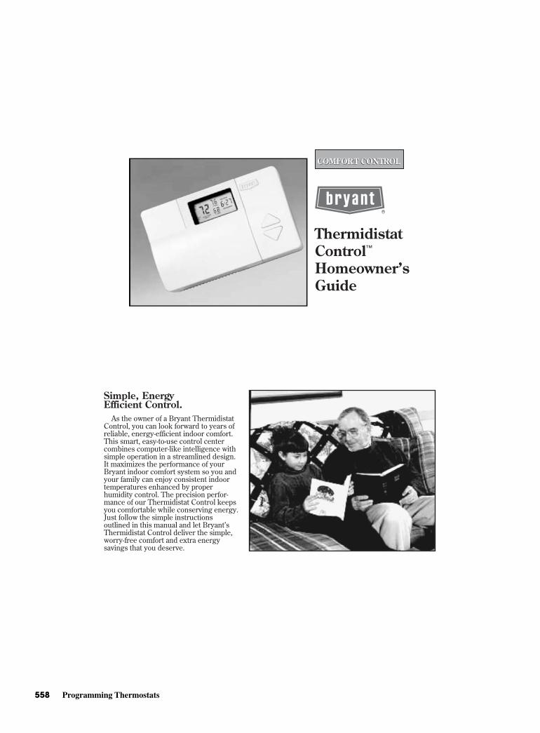
558 Programming Thermostats
ThermidistatControl™
Homeowner’sGuide
COMFORT CONTROLCOMFORT CONTROL
As the owner of a Bryant Thermidistat Control, you can look forward to years of reliable, energy-efficient indoor comfort. This smart, easy-to-use control centercombines computer-like intelligence with simple operation in a streamlined design. It maximizes the performance of your Bryant indoor comfort system so you and your family can enjoy consistent indoor temperatures enhanced by properhumidity control. The precision perfor- mance of our Thermidistat Control keeps you comfortable while conserving energy. Just follow the simple instructionsoutlined in this manual and let Bryant’sThermidistat Control deliver the simple,worry-free comfort and extra energysavings that you deserve.
Simple, Energy Efficient Control.
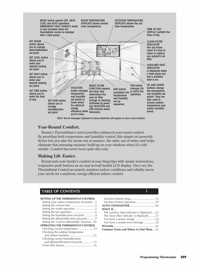
Programming Thermostats 559
OUTDOOR TEMPERATURE DISPLAYS shows the out- door temperature.
ROOM TEMPERATUREDISPLAYS shows current room temperature.
TIME OF DAYDISPLAY exhibits the time of day.
MODE button selects OFF, HEAT, COOL and AUTO operation.EMERGENCY HEAT (EHEAT) mode is also included when thethermidistat control is installedwith a heat pump.
FAN button chooses ON or AUTO fanoperation.
END button completes thetemperatureand humidity set-upsequence.
SET HUM button allows you to changehumidificationset point.
SET TIME button allows you to enter the time of day.
SET DHUMbutton allows you to change dehumidificationset point.
SET HEAT button allows you to enter your desired heating set point.
SET COOL button allows you to enter your desired cooling set point.
VACATIONbutton changes temperatureand humidityset points to lower levelsfor optimumenergyefficiency while you’re away.
RESET FILTER FUNCTION restarts the timer thatdetermines thenext air filter change or cleaning. Activated by press- ing VACATION and END buttons simul- taneously.
UP AND DOWN buttons changethe temperature and humidity set points. They are also used to access outdoor temperature and indoor humidity levels.
AUXILIARY HEAT INDICATORis displayed when a heat pump sys- tem’s auxiliary heat is on.
CLEAN FILTER INDICATORlets you know when it’s time to clean or replace you system’s air filter
Year-Round Comfort. Bryant’s Thermidistat Control provides enhanced year-round comfort. By providing both temperature and humidity control, this simple yet powerful device lets you take the steam out of summer, the static out of winter and helps eliminate that annoying moisture build-up on your windows when it’s cold outside. Comfort has never been quite this easy.
Making Life Easier. Bryant puts your family’s comfort at your fingertips with simple instructions, responsive push buttons an an easy-to-read backlit LCD display. Once set, the Thermidistat Control accurately monitors indoor conditions and reliably meets your needs for consistent, energy-efficient indoor comfort.
NOTE: Not all messages displayed in above illustration will appear at once in any situation.
TABLE OF CONTENTS
SETTING UP THE THERMIDISTAT CONTROLSetting your indoor temperature set points ...1Setting the current time ................................2Setting the mode operation ..........................3Setting the fan operation ..............................5Setting the humidification set point ..............6Setting the dehumidification set point ..........9Setting the “cool to dehumidify” function ..10
OPERATING THE THERMIDISTAT CONTROLChecking current temperature ....................12Checking the outdoor temperature
and indoor humidity ...............................12Checking current humidification
and dehumidification set points ..............13Clean filter feature .....................................14
Vacation feature setup ................................15Vacation feature operation .........................19
AUTO CHANGEOVER .................................20WHAT IF…
The auxiliary heat indicator is displayed .....21The clean filter indicator is displayed .........21You have a power outage ...........................22You have a system error message ...............22
Warranty.......................................................24Common Terms and Where to Find Them ...25
i
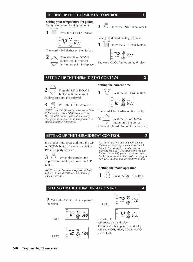
560 Programming Thermostats
SETTING UP THE THERMIDISTAT CONTROL
Setting your temperature set pointsSetting the desired heating set point
1 Press the SET HEAT button.
The word HEAT flashes on the display.
2 Press the UP or DOWNbutton until the correct heating set point is displayed.
3 Press the END button to exit.
Setting the desired cooling set point
1 Press the SET COOL button.
The word COOL flashes on the display.
1
SETTING UP THE THERMIDISTAT CONTROL
2 Press the UP or DOWNbutton until the correct
cooling set point is displayed.
3 Press the END button to exit.
NOTE: Your COOL setting must be at least2° higher than your HEAT setting. YourThermidistat Control will automaticallychange your previously set temperature tomaintain that 2° difference.
Setting the current time
1 Press the SET TIME button.
The word TIME flashes on the display.
2 Press the UP or DOWNbutton until the correct
time is displayed. To quickly advance to
2
SETTING UP THE THERMIDISTAT CONTROL
the proper time, press and hold the UPor DOWN button. Be sure that AM orPM is properly selected.
3 When the correct timeappears on the display, press the ENDbutton.
NOTE: If you choose not to press the ENDbutton, the word TIME will stop flashingafter 15 seconds.
NOTE: If you live in a Daylight SavingsTime area, you may advance the time 1hour in the spring by simultaneously pressing the SET TIME button and the UPbutton. In the fall, you may set the timeback 1 hour by simultaneously pressing theSET TIME button and the DOWN button.
Setting the mode operation
1 Press the MODE button.
3
SETTING UP THE THERMIDISTAT CONTROL
2 When the MODE button is pressed,the words
OFF,
HEAT,
COOL,
and AUTO will rotate on the display.If you have a heat pump, the displaywill show OFF, HEAT, COOL, AUTO, and EHEAT.
4
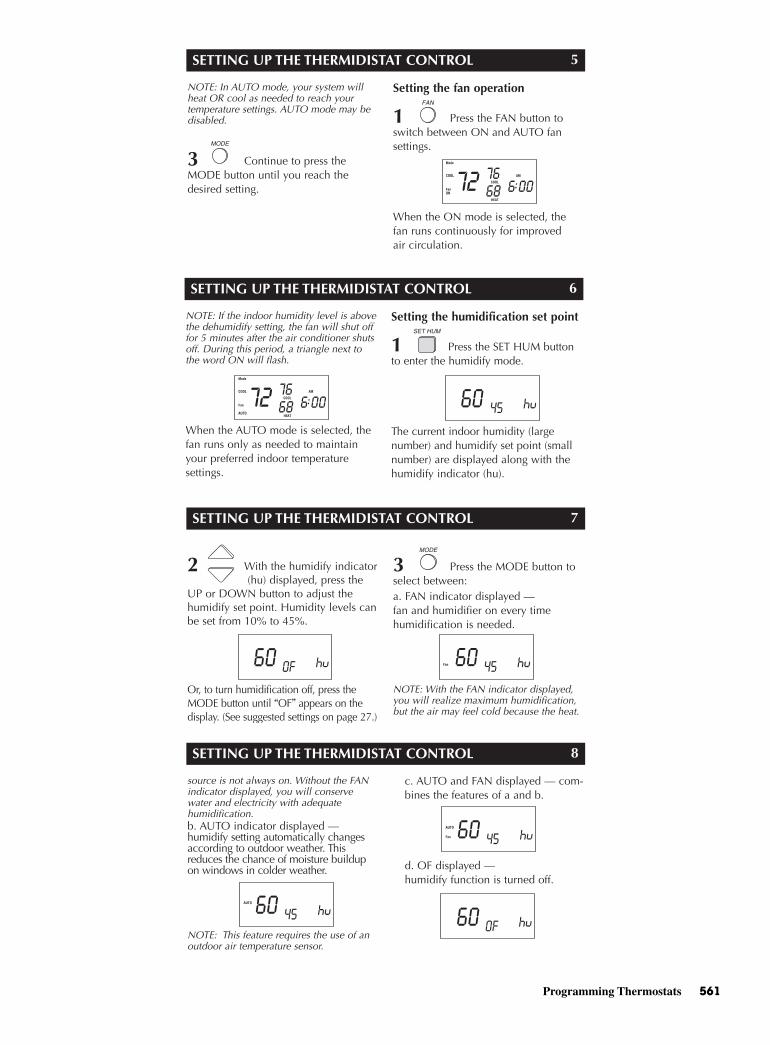
Programming Thermostats 561
SETTING UP THE THERMIDISTAT CONTROL
NOTE: In AUTO mode, your system willheat OR cool as needed to reach your temperature settings. AUTO mode may bedisabled.
3 Continue to press theMODE button until you reach thedesired setting.
Setting the fan operation
1 Press the FAN button toswitch between ON and AUTO fan settings.
When the ON mode is selected, the fan runs continuously for improved air circulation.
5
SETTING UP THE THERMIDISTAT CONTROL
NOTE: If the indoor humidity level is abovethe dehumidify setting, the fan will shut offfor 5 minutes after the air conditioner shutsoff. During this period, a triangle next tothe word ON will flash.
When the AUTO mode is selected, thefan runs only as needed to maintainyour preferred indoor temperature settings.
Setting the humidification set point
1 Press the SET HUM buttonto enter the humidify mode.
The current indoor humidity (largenumber) and humidify set point (smallnumber) are displayed along with thehumidify indicator (hu).
6
SETTING UP THE THERMIDISTAT CONTROL
2 With the humidify indicator(hu) displayed, press the
UP or DOWN button to adjust thehumidify set point. Humidity levels canbe set from 10% to 45%.
Or, to turn humidification off, press theMODE button until “OF” appears on thedisplay. (See suggested settings on page 27.)
3 Press the MODE button toselect between:a. FAN indicator displayed — fan and humidifier on every time humidification is needed.
NOTE: With the FAN indicator displayed,you will realize maximum humidification,but the air may feel cold because the heat.
7
SETTING UP THE THERMIDISTAT CONTROL
source is not always on. Without the FANindicator displayed, you will conservewater and electricity with adequate humidification.b. AUTO indicator displayed —humidify setting automatically changesaccording to outdoor weather. Thisreduces the chance of moisture buildupon windows in colder weather.
NOTE: This feature requires the use of anoutdoor air temperature sensor.
c. AUTO and FAN displayed — com-bines the features of a and b.
d. OF displayed —humidify function is turned off.
8
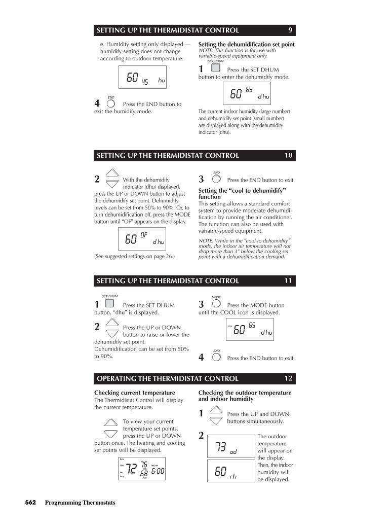
562 Programming Thermostats
SETTING UP THE THERMIDISTAT CONTROL
e. Humidify setting only displayed —humidify setting does not change according to outdoor temperature.
4 Press the END button toexit the humidify mode.
Setting the dehumidification set pointNOTE: This function is for use with variable-speed equipment only.
1 Press the SET DHUM button to enter the dehumidify mode.
The current indoor humidity (large number)and dehumidify set point (small number) are displayed along with the dehumidify indicator (dhu).
9
SETTING UP THE THERMIDISTAT CONTROL
2 With the dehumidify indicator (dhu) displayed,
press the UP or DOWN button to adjustthe dehumidify set point. Dehumidify levels can be set from 50% to 90%. Or, toturn dehumidification off, press the MODEbutton until “OF” appears on the display.
(See suggested settings on page 26.)
3 Press the END button to exit.
Setting the “cool to dehumidify”functionThis setting allows a standard comfortsystem to provide moderate dehumidi-fication by running the air conditioner.The function can also be used withvariable-speed equipment.
NOTE: While in the “cool to dehumidify”mode, the indoor air temperature will notdrop more than 3° below the cooling setpoint with a dehumidification demand.
10
SETTING UP THE THERMIDISTAT CONTROL
1 Press the SET DHUM button. “dhu” is displayed.
2 Press the UP or DOWN button to raise or lower the
dehumidify set point.Dehumidification can be set from 50%to 90%.
3 Press the MODE buttonuntil the COOL icon is displayed.
4 Press the END button to exit.
11
OPERATING THE THERMIDISTAT CONTROL
Checking current temperatureThe Thermidistat Control will displaythe current temperature.
To view your current temperature set points, press the UP or DOWN
button once. The heating and coolingset points will be displayed.
Checking the outdoor temperatureand indoor humidity
1 Press the UP and DOWN buttons simultaneously.
2 The outdoor temperature will appear on the display. Then, the indoor humidity will be displayed.
12
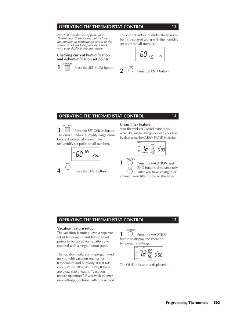
Programming Thermostats 563
OPERATING THE THERMIDISTAT CONTROL
NOTE: If 2 dashes (--) appear, yourThermidistat Control does not include the outdoor air temperature sensor or thesensor is not working properly. Check with your dealer if you are unsure.
Checking current humidificationand dehumidification set points
1 Press the SET HUM button.
The current indoor humidity (large num-ber) is displayed along with the humidifyset point (small number).
2 Press the END button.
13
OPERATING THE THERMIDISTAT CONTROL
3 Press the SET DHUM button.The current indoor humidity (large num-ber) is displayed along with the dehumidify set point (small number).
4 Press the END button.
Clean filter featureYour Thermidistat Control reminds youwhen it’s time to change or clean your filterby displaying the CLEAN FILTER indicator.
1 Press the VACATION and END buttons simultaneouslyafter you have changed or
cleaned your filter to restart the timer.
14
OPERATING THE THERMIDISTAT CONTROL
Vacation feature setupThe vacation feature allows a separateset of temperature and humidity setpoints to be stored for vacation andrecalled with a single button press.
The vacation feature is preprogrammedfor you with vacation settings for temperature and humidity. (Heat 60°,cool 85°, hu 10%, dhu 75%) If theseare okay, skip ahead to “vacation feature operation.” If you wish to enternew settings, continue with this section.
1 Press the VACATION button to display the vacation temperature settings.
The OUT indicator is displayed.
15
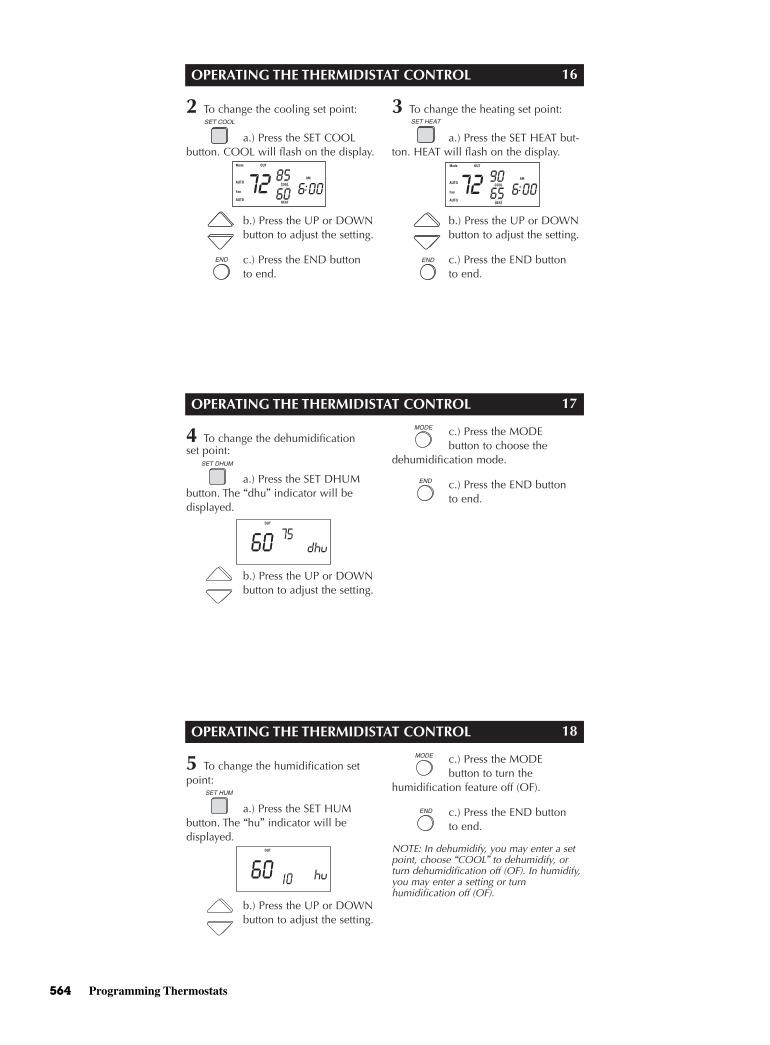
564 Programming Thermostats
OPERATING THE THERMIDISTAT CONTROL
2 To change the cooling set point:
a.) Press the SET COOLbutton. COOL will flash on the display.
b.) Press the UP or DOWNbutton to adjust the setting.
c.) Press the END buttonto end.
3 To change the heating set point:
a.) Press the SET HEAT but-ton. HEAT will flash on the display.
b.) Press the UP or DOWN button to adjust the setting.
c.) Press the END button to end.
16
OPERATING THE THERMIDISTAT CONTROL
4 To change the dehumidification set point:
a.) Press the SET DHUMbutton. The “dhu” indicator will be displayed.
b.) Press the UP or DOWNbutton to adjust the setting.
c.) Press the MODE button to choose the
dehumidification mode.
c.) Press the END buttonto end.
17
OPERATING THE THERMIDISTAT CONTROL
5 To change the humidification setpoint:
a.) Press the SET HUM button. The “hu” indicator will be displayed.
b.) Press the UP or DOWNbutton to adjust the setting.
c.) Press the MODE button to turn the
humidification feature off (OF).
c.) Press the END buttonto end.
NOTE: In dehumidify, you may enter a setpoint, choose “COOL” to dehumidify, orturn dehumidification off (OF). In humidify,you may enter a setting or turn humidification off (OF).
18
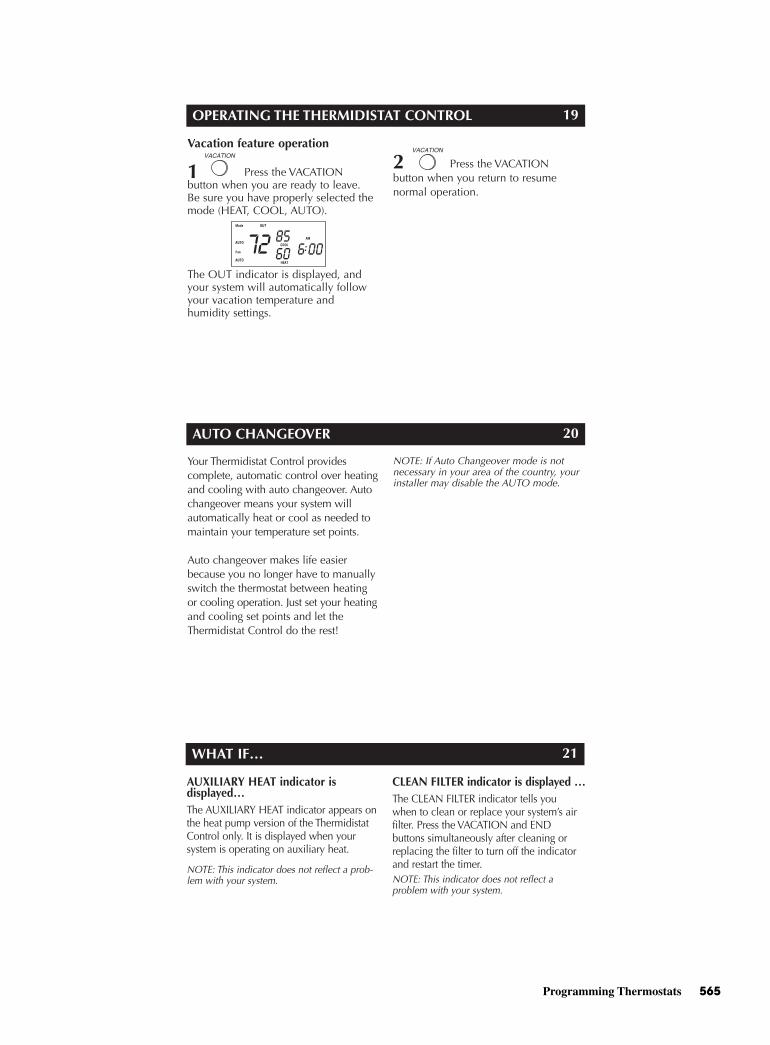
Programming Thermostats 565
OPERATING THE THERMIDISTAT CONTROL
Vacation feature operation
1 Press the VACATION button when you are ready to leave. Be sure you have properly selected themode (HEAT, COOL, AUTO).
The OUT indicator is displayed, andyour system will automatically followyour vacation temperature and humidity settings.
2 Press the VACATION button when you return to resume normal operation.
19
AUTO CHANGEOVER
Your Thermidistat Control provides complete, automatic control over heatingand cooling with auto changeover. Autochangeover means your system willautomatically heat or cool as needed tomaintain your temperature set points.
Auto changeover makes life easierbecause you no longer have to manuallyswitch the thermostat between heatingor cooling operation. Just set your heatingand cooling set points and let theThermidistat Control do the rest!
NOTE: If Auto Changeover mode is notnecessary in your area of the country, yourinstaller may disable the AUTO mode.
20
WHAT IF…
AUXILIARY HEAT indicator is displayed…The AUXILIARY HEAT indicator appears onthe heat pump version of the ThermidistatControl only. It is displayed when your system is operating on auxiliary heat.
NOTE: This indicator does not reflect a prob-lem with your system.
CLEAN FILTER indicator is displayed …The CLEAN FILTER indicator tells youwhen to clean or replace your system’s airfilter. Press the VACATION and END buttons simultaneously after cleaning orreplacing the filter to turn off the indicatorand restart the timer.NOTE: This indicator does not reflect a problem with your system.
21
566 Programming Thermostats
WHAT IF…
OUT Indicator is displayed …The OUT indicator reminds you that yoursystem is in vacation mode. This functionautomatically adjusts the temperatureand humidity settings to levels appropriate for when you’re away. Press the VACATION button to resumenormal system operation.
NOTE: This indicator does not reflect aproblem with your system.
EQUIPMENT ON Indicator is displayed …When the cooling equipment is operating,the word COOL preceded by a small triangle is displayed below the cooling setpoint. When the heating equipment isoperating, the word HEAT preceded by asmall triangle is displayed below the heating set point. If the equipment turn onis being delayed, the triangle and the wordwill flash.
NOTE: This indicator does not reflect aproblem with your system.
22
WHAT IF …
You have a power outage …An internal power source eliminatesthe need to re-enter your settings intothe Thermidistat Control after poweroutages. The comfort settings you haveentered will be maintained indefinitely.The clock will run for 8 hours.
You have a system error message …The display may appear as follows:
--, E3, E4, E5, or E6
-- indicates a problem with the indoorair temperature sensor
E3 indicates a problem with the outdoor air temperature sensor
E4, E5, or E6 indicates an internal failure.
23
WARRANTY
This Thermidistat Control includes a 1-year limited warranty. For detailedwarranty information, please refer tothe All Product Limited Warranty Cardincluded in your information packet.This Thermidistat Control is also eligible for manufacturer’s extendedsystem warranties. Ask your dealer for details on extended warranties forlonger-term protection.
24
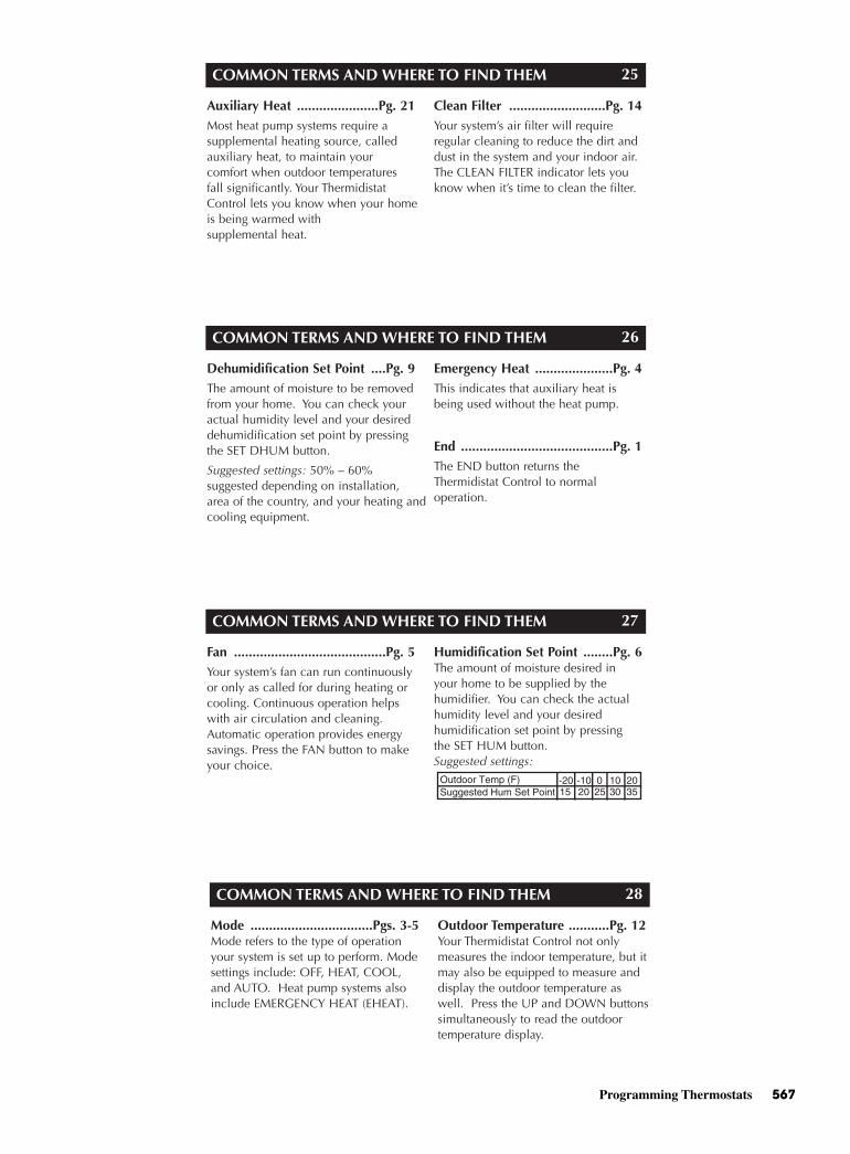
Programming Thermostats 567
COMMON TERMS AND WHERE TO FIND THEM
Auxiliary Heat ......................Pg. 21Most heat pump systems require a supplemental heating source, calledauxiliary heat, to maintain your comfort when outdoor temperatures fall significantly. Your ThermidistatControl lets you know when your homeis being warmed with supplemental heat.
Clean Filter ..........................Pg. 14Your system’s air filter will require regular cleaning to reduce the dirt anddust in the system and your indoor air.The CLEAN FILTER indicator lets youknow when it’s time to clean the filter.
25
COMMON TERMS AND WHERE TO FIND THEM
Dehumidification Set Point ....Pg. 9The amount of moisture to be removedfrom your home. You can check youractual humidity level and your desireddehumidification set point by pressingthe SET DHUM button.
Suggested settings: 50% – 60% suggested depending on installation,area of the country, and your heating andcooling equipment.
Emergency Heat .....................Pg. 4This indicates that auxiliary heat isbeing used without the heat pump.
End .........................................Pg. 1The END button returns theThermidistat Control to normal operation.
26
COMMON TERMS AND WHERE TO FIND THEM
Fan .........................................Pg. 5Your system’s fan can run continuouslyor only as called for during heating orcooling. Continuous operation helpswith air circulation and cleaning.Automatic operation provides energysavings. Press the FAN button to makeyour choice.
Humidification Set Point ........Pg. 6The amount of moisture desired in your home to be supplied by thehumidifier. You can check the actualhumidity level and your desired humidification set point by pressing the SET HUM button.Suggested settings:
27
COMMON TERMS AND WHERE TO FIND THEM
Mode .................................Pgs. 3-5Mode refers to the type of operationyour system is set up to perform. Modesettings include: OFF, HEAT, COOL,and AUTO. Heat pump systems alsoinclude EMERGENCY HEAT (EHEAT).
Outdoor Temperature ...........Pg. 12Your Thermidistat Control not onlymeasures the indoor temperature, but itmay also be equipped to measure anddisplay the outdoor temperature aswell. Press the UP and DOWN buttonssimultaneously to read the outdoortemperature display.
28
568 Programming Thermostats
COMMON TERMS AND WHERE TO FIND THEM
Power Outage ........................Pg. 22Complete loss of electricity. YourThermidistat Control has an internalpower source that allows the clock tocontinue to run for 8 hours or morewithout electricity. Settings are storedindefinitely without the aid of batteries.
Reset Filter ..............................Pg. 14The reset filter function turns off theCLEAN FILTER indicator and restartsthe timer. Press the VACATION andEND buttons simultaneously afteryou’ve cleaned and replaced the sys-tem’s air filter.
29
COMMON TERMS AND WHERE TO FIND THEM
Set Time .....................................Pg. 2This function allows you to set theproper time. Press the SET TIME buttonto activate.
Temperature Sensor .............Pg. 12Temperature sensors measure the cur-rent indoor or outdoor temperatureswhich are displayed on the ThermidistatControl.
Temperature Set Points ...........Pg. 1These are the desired heating and cooling set points entered into theThermidistat Control. The actual roomtemperature will automatically be displayed, but you can check thedesired temperature for the currentmode by pressing either the UP orDOWN button.
30
Copyright 1997 Bryant Heating and Cooling SystemsForm: OM17-25 Replaces: OM17-22 Printed in the U.S.A. 9-98 Catalog No. 13TS-TA11
Manufacturer reserves the right to discontinue, or change at any time,specifications or designs without notice and without incurring obligations.
7310 West Morris Street, Indianapolis, IN 46231
COMMON TERMS AND WHERE TO FIND THEM
Time .......................................Pg. 2The current time is displayed continuously on the display.
Up and Down Buttons ...........Pg. 1These buttons are used to set the clockand enter temperature and humidityinformation.
31

DAPPENDIX
Tools of the Trade(Plus FrequentlyAsked Questions
with Answers)
Copyright © 2006 by The McGraw-Hill Companies, Inc. Click here for terms of use.
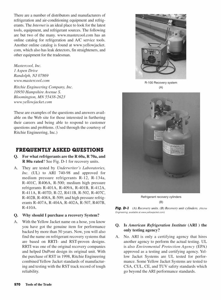
There are a number of distributors and manufacturers ofrefrigeration and air-conditioning equipment and refrig-erants. The Internet is an ideal place to look for the latesttools, equipment, and refrigerant sources. The followingare but two of the many. www.mastercool.com has anonline catalog for refrigeration and A/C service tools.Another online catalog is found at www.yellowjacket.com, which also has leak detectors, fin straighteners, andother equipment for the tradesman.
Mastercool, Inc.1 Aspen DriveRandolph, NJ 07869www.mastercool.com
Ritchie Engineering Company, Inc.10950 Hampshire Avenue S.Bloomington, MN 55438-2623www.yellowjacket.com
These are examples of the questions and answers avail-able on the Web site for those interested in furtheringtheir careers and being able to respond to customerquestions and problems. (Used through the courtesy ofRitchie Engineering, Inc.)
FREQUENTLY ASKED QUESTIONSQ. For what refrigerants are the R 60a, R 70a, and
R 80a rated? See Fig. D-1 for recovery units.
A. They are tested by Underwriter’s Laboratories,Inc. (UL) to ARI 740-98 and approved formedium pressure refrigerants R-12, R-134a,R-401C, R406A, R-500; medium high pressurerefrigerants R-401A, R-409A, R-401B, R-412A,R-411A, R-407D, R-22, R411B, R-502, R-407C,R-402B, R-408A, R-509; and high pressure refrig-erants R-407A, R-404A, R-402A, R-507, R407B,R-410A.
Q. Why should I purchase a recovery System?
A. With the Yellow Jacket name on a hose, you knowyou have got the genuine item for performancebacked by more than 50 years. Now, you will alsofind the name on refrigerant recovery systems thatare based on RRTI- and RST-proven designs.RRTI was one of the original recovery companiesand helped DuPont design its original unit. Withthe purchase of RST in 1998, Ritchie Engineeringcombined Yellow Jacket standards of manufactur-ing and testing with the RST track record of toughreliability.
Q. Is American Refrigeration Institute (ARI ) theonly testing agency?
A. No. ARI is only a certifying agency that hiresanother agency to perform the actual testing. ULis also Enviromental Protection Agency (EPA)approved as a testing and certifying agency. Yel-low Jacket Systems are UL tested for perfor-mance. Some Yellow Jacket Systems are tested toCSA, CUL, CE, and TUV safety standards whichgo beyond the ARI performance standards.
570 Tools of the Trade
R-100 Recovery system
(A)
Refrigerant recovery cylinders
(B)
Fig. D-1 (A) Recovery units. (B) Recovery unit cylinders. (Ritchie
Engineering, available at www.yellowjacket.com)
Frequently Asked Questions 571
Q. Can I compare systems by comparing theirARI or UL ratings?
A. Yes. ARI and UL test standards should be thesame. And remember that manufacturers canchange the conditions under which they test theirown machines to give the appearance of enhancedperformance. Only ARI and UL test results pro-vide consistent benchmarks and controls onwhich to make objective comparisons.
Q. How dependable are Yellow Jacket refrigerantrecovery systems?
A. Yellow Jacket recovery systems get pushed to thelimits: day in and day out in dirty conditions, onroof tops, and sometimes in freezing or highambient temperatures. Yellow Jacket equipmenthas been tested at thousands of cycles, and arebacked with the experience of units in the fieldsince 1992.
Q. Is pumping liquid the fastest way to moverefrigerant?
A. Yes, and the R 50a, R 60a, R 70a, R 80a, and R100 monitor liquid flow at a rate safe for the com-pressor. In Yellow Jacket lab testing, over 80,000lb of virgin liquid R-22 were continuously andsuccessfully pumped. That is over 2,500 standard30-lb tanks, or the equivalent of refrigerant in over25,000 typical central AC systems.
Q. What is the push/pull recovery method?
A. Many technicians use this recovery method, par-ticularly on large jobs. By switching the R 50a, R60a, R 70a, R 80a, or R 100 discharge valve to“recover” during push/pull recovery, the con-denser is bypassed, increasing the “push” pressureand speeding the recovery.
Q. Why do the R 50a through 100 feature a built-in filter?
A. Every recovery machine requires an in-line filterto protect the machine against the particles and“gunk” that can be found in failed refrigerationsystems. For your convenience, the R 50a, R 60a,R 70a, R 80a, and R 100 series incorporate a built-in 200-mesh filter that you can clean, and if nec-essary, replace. The filter traps 150-micronparticles and protects against the dirtiest systemsto maximize service life. In case of a burn-out, anacid-core filter/drier is mandatory. The YellowJacket filter is built-in to prevent breaking off likesome competitive units with external filters.
Q. What is auto purge and how does it work?
A. At the end of each cycle, several ounces of refrig-erant can be left in the recovery machine to possi-bly contaminate the next job, or be illegallyvented. Many competitive recovery machinesrequire switching hoses, tuning the unit off and on,or other time-consuming procedures. The R 50a,R 60a, R 70a, R 80a, and R 100 can be quicklypurged “on the fly” by simply closing the inletvalve, and switching the discharge valve to purge.In a few seconds, all residual refrigerant is purgedand you are finished. Purging is completed with-out switching off the recovery unit.
Q. Can increased airflow benefit recovery cylin-der pressure?
A. Yes. For reliable performance in the high ambienttemperatures, Yellow Jacket units are engineeredwith a larger condenser and more aggressive fanblade with a greater pitch. This allows the unit torun cooler and keeps the refrigerant cooler in therecovery cylinder.
Q. Can I service a Yellow Jacket System in the field?
A. Although Yellow Jacket Systems feature either afull one or optional two year warranty, there aretimes when a unit will need a tune-up. The servicemanual with every unit includes a wide variety ofinformation such as tips to speed recovery, trou-bleshooting guides, and parts listings. On the sideof every unit, you will find hook-up instructions, aquick start guide, and simple tips for trou-bleshooting. And if ever in doubt, just call 1-800-769-8370 and ask for customer service.
All service and repair parts are readily availablethrough your nearest Yellow Jacket wholesaler.
Q. Are there any recovery systems certified forR-410A?
A. ARI 740-98 has been written but not yet enactedby the EPA. The Yellow Jacket R 60a, R 70a, andR 80a series have also been UL tested and certi-fied for high-pressure gases such as R-410A thatare covered under ARI 740-98.
Q. What features should I demand in a system tobe used for R-410A?
A. Look for the following three features as a minimum:
• High-volume airflow through an oversized con-denser to keep the unit running cooler and helpeliminate cut-outs in high ambient temperatures
• Single automatic internal high-pressure switchfor simple operation

572 Tools of the Trade
• Constant pressure regulator (CPR) valve ratedto 600 psi for safety and it eliminates the need tomonitor and regulate the unit during recovery
Q. What is a CPR valve?
A. The CPR valve is the feature that makes the Yel-low Jacket R 70a and R 80a the first truly auto-matic recovery systems for every refrigerant. Thesingle 600 psi rated high-pressure switch coversall refrigerants and eliminates the need for a con-trol panel with two selector switches for R-410A.
The CPR valve automatically reduces the pres-sure of the refrigerant being recovered. Regardlessof which refrigerant, input is automatically regu-lated through a small orifice that allows refrigerantto flash into vapor for compression without slug-ging the compressor. Throttling is not required.
Under normal conditions, you could turn themachine to the “liquid” and “recover” settings.The machine will complete the job while youwork elsewhere.
Q. With the Yellow Jacket R 70a design, do I haveto manually reset a pressure switch betweenmedium and high-pressure gasses?
A. No. Some competitive machines require you tochoose between medium and high-pressure gassettings before recovery. You will see the switchon their control panels. With the Yellow Jacket R70a, the single internal automatic high-pressureswitch makes the choice for you. That is why onlyR 70a is truly automatic.
Frequently Asked QuestionsAbout Pumps
l. How can I select the right pump cfm?
A. See Fig. D-2 for a sampling of pumps. The fol-lowing guidelines are for domestic through com-mercial applications.
System(tons) Pump (cfm)10–15 2.015–30 4.030–45 6.045–60 8.060–90 12.090–130 18.0Over 130 24.0
2. Can I use a vacuum pump for recovery?
A. A vacuum pump removes water vapor and is not forrefrigerant recovery. Connecting a vacuum pump toa pressurized line will damage the pump and ventrefrigerant to the atmosphere, which is a crime.
3. How much of a vacuum should I pull?
A. A properly evacuated system is at 2500 microns orless. This is 1/10 of 1 in. and impossible to detectwithout an electronic vacuum gauge. For mostrefrigeration systems, American Society of Heating,Refrigerating, and Air-Conditioning Engineers(ASHRAE) recommends pulling vacuum to 1000microns or less. Most system manufacturers recom-mend pulling to an even lower number of microns.
4. Do I connect an electronic vacuum gauge to thesystem or pump?
A. To monitor evacuation progress, connect it to thesystem with a vacuum/charge valve.
5. Why does the gauge micron reading rise afterthe system is isolated from the vacuum pump?
A. This indicates that water molecules are stilldetaching from the system’s interior surfaces. Therate of rise indicates the level of system contami-nation and if evacuation should continue.
6. Why does frost form on the system exteriorduring evacuation?
A. Because ice has formed inside. Use a heat gun tothaw all spots. This helps molecules move off sys-tem walls more quickly toward the pump.
7. How can I speed evacuation?
A.
• Use clean vacuum pump oil. Milky oil is watersaturated and limits pump efficiency.
Large capacity supervacTM pumps 12, 18, 24 cfm
Fig. D-2 Vacuum pumps. (Ritchie Engineering, available at
www.yellowjacket.com)

Frequently Asked Questions 573
• Remove valve cores from both high and low fit-tings with a vacuum/charge valve tool to reducetime through this orifice by at least 20 percent.
• Evacuate both high and low sides at the sametime. Use short, 3/8-in. diameter and larger hoses.
SuperEvac Systems can reduce evacuation time byover 50 to 60 percent. SuperEvac pumps are ratedat 15 microns (or less) to pull a vacuum quickly.Large inlet allows you to connect a large diameterhose. With large oil capacity, SuperEvac pumpscan remove more moisture from systems betweenoil changes.
8. What hose construction is best for evacuation?
A. Stainless steel. There is no permeation and out-gassing.
Frequently Asked QuestionsAbout Fluorescent Leak
ScannersQ. Does the ultra violet (UV) scanner light work
better than an electronic leak detector? SeeFig. A4-3.
A. No one detection system is better for all situa-tions. But, with a UV lamp you can scan a systemmore quickly and moving air is never a problem.Solutions also leave a telltale mark at every leaksite. Multiple leaks are found more quickly.
Q. How effective are new light emitting diode(LED) type UV lights? See Fig. A4-4.
A. LEDs are small, compact lights for use in closerange. Most effective at 6-in. range. The modelwith two blue UV and three UV bulbs has a slightlygreater range. Higher power Yellow Jacket lightsare available.
Q. Can LED bulbs be replaced?
A. No. The average life is 110,000 h.
Q. Are RediBeam lamps as effective as the SystemII lamps?
A. The RediBeam lamp has slightly less power toprovide lightweight portability. But with thepatented reflector and filter technologies, the Red-iBeam 100-W bulb produces sufficient UV lightfor pinpointing leaks.
Q. Does the solution mix completely in the system?
A. Solutions are combinations of compatible refrig-eration oil and fluorescent material designed tomix completely with the oil type in the system.
Fig. A4-3 Leak scanners (Flourescent type). (Mastercool, available at
www.yellowjacket.com)
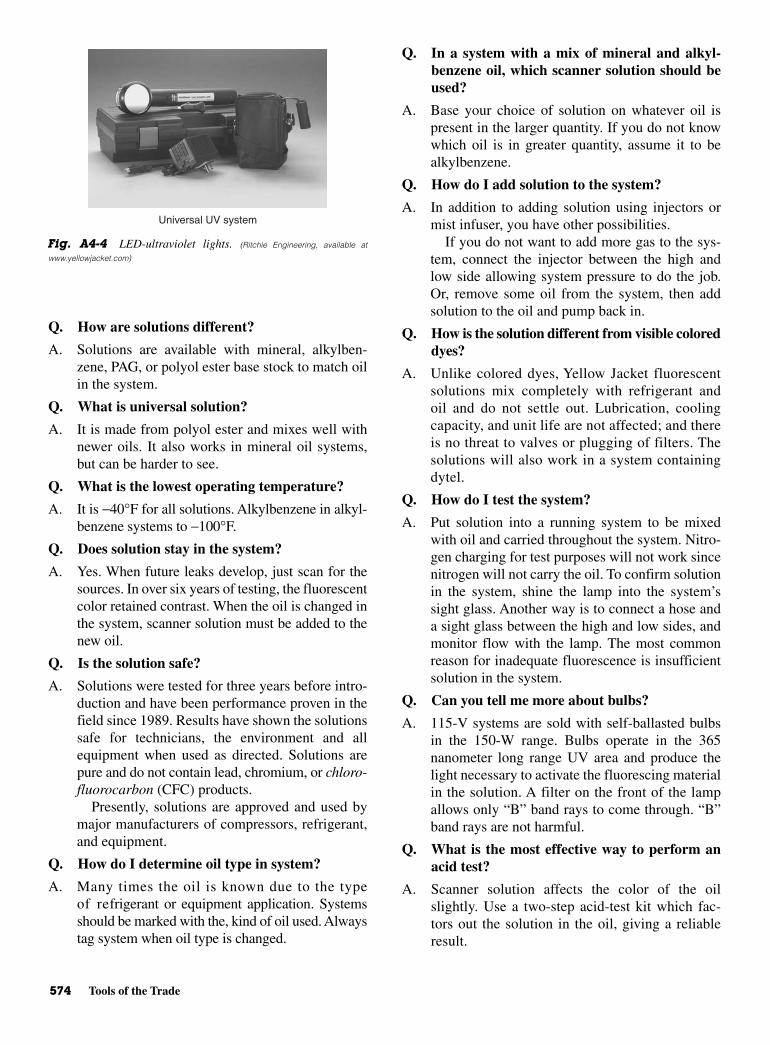
574 Tools of the Trade
Q. How are solutions different?
A. Solutions are available with mineral, alkylben-zene, PAG, or polyol ester base stock to match oilin the system.
Q. What is universal solution?
A. It is made from polyol ester and mixes well withnewer oils. It also works in mineral oil systems,but can be harder to see.
Q. What is the lowest operating temperature?
A. It is −40°F for all solutions. Alkylbenzene in alkyl-benzene systems to −100°F.
Q. Does solution stay in the system?
A. Yes. When future leaks develop, just scan for thesources. In over six years of testing, the fluorescentcolor retained contrast. When the oil is changed inthe system, scanner solution must be added to thenew oil.
Q. Is the solution safe?
A. Solutions were tested for three years before intro-duction and have been performance proven in thefield since 1989. Results have shown the solutionssafe for technicians, the environment and allequipment when used as directed. Solutions arepure and do not contain lead, chromium, or chloro-fluorocarbon (CFC) products.
Presently, solutions are approved and used bymajor manufacturers of compressors, refrigerant,and equipment.
Q. How do I determine oil type in system?
A. Many times the oil is known due to the typeof refrigerant or equipment application. Systemsshould be marked with the, kind of oil used. Alwaystag system when oil type is changed.
Q. In a system with a mix of mineral and alkyl-benzene oil, which scanner solution should beused?
A. Base your choice of solution on whatever oil ispresent in the larger quantity. If you do not knowwhich oil is in greater quantity, assume it to bealkylbenzene.
Q. How do I add solution to the system?
A. In addition to adding solution using injectors ormist infuser, you have other possibilities.
If you do not want to add more gas to the sys-tem, connect the injector between the high andlow side allowing system pressure to do the job.Or, remove some oil from the system, then addsolution to the oil and pump back in.
Q. How is the solution different from visible coloreddyes?
A. Unlike colored dyes, Yellow Jacket fluorescentsolutions mix completely with refrigerant andoil and do not settle out. Lubrication, coolingcapacity, and unit life are not affected; and thereis no threat to valves or plugging of filters. Thesolutions will also work in a system containingdytel.
Q. How do I test the system?
A. Put solution into a running system to be mixedwith oil and carried throughout the system. Nitro-gen charging for test purposes will not work sincenitrogen will not carry the oil. To confirm solutionin the system, shine the lamp into the system’ssight glass. Another way is to connect a hose anda sight glass between the high and low sides, andmonitor flow with the lamp. The most commonreason for inadequate fluorescence is insufficientsolution in the system.
Q. Can you tell me more about bulbs?
A. 115-V systems are sold with self-ballasted bulbsin the 150-W range. Bulbs operate in the 365nanometer long range UV area and produce thelight necessary to activate the fluorescing materialin the solution. A filter on the front of the lampallows only “B” band rays to come through. “B”band rays are not harmful.
Q. What is the most effective way to perform anacid test?
A. Scanner solution affects the color of the oilslightly. Use a two-step acid-test kit which fac-tors out the solution in the oil, giving a reliableresult.
Universal UV system
Fig. A4-4 LED-ultraviolet lights. (Ritchie Engineering, available at
www.yellowjacket.com)
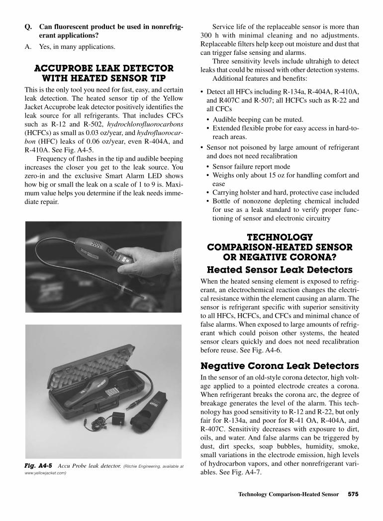
Technology Comparison-Heated Sensor 575
Q. Can fluorescent product be used in nonrefrig-erant applications?
A. Yes, in many applications.
ACCUPROBE LEAK DETECTORWITH HEATED SENSOR TIP
This is the only tool you need for fast, easy, and certainleak detection. The heated sensor tip of the YellowJacket Accuprobe leak detector positively identifies theleak source for all refrigerants. That includes CFCssuch as R-12 and R-502, hydrochlorofluorocarbons(HCFCs) as small as 0.03 oz/year, and hydrofluorocar-bon (HFC) leaks of 0.06 oz/year, even R-404A, andR-410A. See Fig. A4-5.
Frequency of flashes in the tip and audible beepingincreases the closer you get to the leak source. Youzero-in and the exclusive Smart Alarm LED showshow big or small the leak on a scale of 1 to 9 is. Maxi-mum value helps you determine if the leak needs imme-diate repair.
Service life of the replaceable sensor is more than300 h with minimal cleaning and no adjustments.Replaceable filters help keep out moisture and dust thatcan trigger false sensing and alarms.
Three sensitivity levels include ultrahigh to detectleaks that could be missed with other detection systems.
Additional features and benefits:
• Detect all HFCs including R-134a, R-404A, R-410A,and R407C and R-507; all HCFCs such as R-22 andall CFCs
• Audible beeping can be muted.• Extended flexible probe for easy access in hard-to-
reach areas.
• Sensor not poisoned by large amount of refrigerantand does not need recalibration
• Sensor failure report mode• Weighs only about 15 oz for handling comfort and
ease• Carrying holster and hard, protective case included• Bottle of nonozone depleting chemical included
for use as a leak standard to verify proper func-tioning of sensor and electronic circuitry
TECHNOLOGYCOMPARISON-HEATED SENSOR
OR NEGATIVE CORONA?Heated Sensor Leak Detectors
When the heated sensing element is exposed to refrig-erant, an electrochemical reaction changes the electri-cal resistance within the element causing an alarm. Thesensor is refrigerant specific with superior sensitivityto all HFCs, HCFCs, and CFCs and minimal chance offalse alarms. When exposed to large amounts of refrig-erant which could poison other systems, the heatedsensor clears quickly and does not need recalibrationbefore reuse. See Fig. A4-6.
Negative Corona Leak Detectors In the sensor of an old-style corona detector, high volt-age applied to a pointed electrode creates a corona.When refrigerant breaks the corona arc, the degree ofbreakage generates the level of the alarm. This tech-nology has good sensitivity to R-12 and R-22, but onlyfair for R-134a, and poor for R-41 OA, R-404A, andR-407C. Sensitivity decreases with exposure to dirt,oils, and water. And false alarms can be triggered bydust, dirt specks, soap bubbles, humidity, smoke,small variations in the electrode emission, high levelsof hydrocarbon vapors, and other nonrefrigerant vari-ables. See Fig. A4-7.
Fig. A4-5 Accu Probe leak detector. (Ritchie Engineering, available at
www.yellowjacket.com)

576 Tools of the Trade
TIPS FOR DETECTING SYSTEMLEAKS
1. Inspect entire A/C system for signs of oil leakage,corrosion cracks, or other damage. Follow the sys-tem in a continuous path so no potential leaks aremissed.
2. Make sure there is enough refrigerant in a system(about 15 percent of system capacity or 50 psi/min)to generate pressure to detect leaks.
3. Check all service access port fittings. Check seals incaps.
4. Move detector probe at 1 in/s within 1/4 in. of sus-pected leak area.
5. Refrigerant is heavier than air, so position probebelow test point.
6. Minimize air movement in area to make it easier topinpoint the leak.
7. Verify an apparent leak by blowing air into the sus-pected leak.
8. When checking for evaporator leaks, check for gasin condensate drain tube.
9. Use heated sensor type detector for difficult-to-detect R-134a, R-410A, R-407C, and R-404A.
NEW COMBUSTIBLE GASDETECTOR––WITH
ULTRASENSITIVE, LONG-LIFESENSOR
Hand-held precision equipment detects all hydrocarbonand other combustible gases including propane, methane,butane, industrial solvents, and more. See Fig. A4-8.
• Sensitivity, bar graph, and beeping to signal howmuch and how close.
• Unit is preset at normal sensitivity, but you canswitch to high or low. After warm-up you will hear aslow beeping. Frequency increases when a leak isdetected until an alarm sounds when moving intohigh gas concentration. The illuminated bar graphindicates leak size.
• If no leak is detected in an area you suspect, selecthigh sensitivity. This will detect even low levels inthe area to confirm your suspicions. Use low sensi-tivity as you move the tip over more defined areas,and you will be alerted when the tip encounters theconcentration at the leak source.
• Ultrasensitive sensor detects less than 5 ppmmethane and better than 2 ppm for propane. Theyperform equally well on a complete list of detectablegases including acetylene, butane, and isobutane.
• Automatic calibration and zeroing.
• Long-life sensor easily replaced after full service life.
Heater
Electronicspackage
Fig. A4-6 Heated sensor leak detector. (Ritchie Engineering, available at
www.yellowjacket.com)
Electronicspackage
Fig. A4-7 Negative corona leak detector. (Ritchie Engineering, available
at www.yellowjacket.com)
Combustible gas detector
Fig. A4-8 Gas detectors. (Ritchie Engineering, available at www.yellowjacket.com)
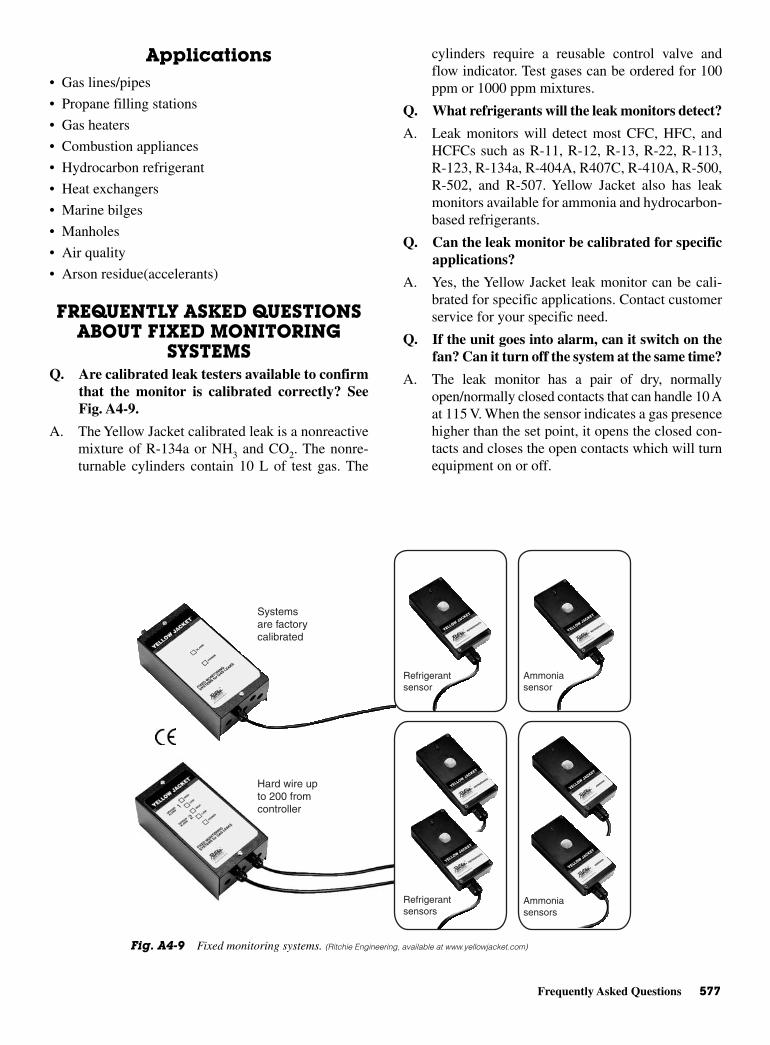
Frequently Asked Questions 577
Applications• Gas lines/pipes
• Propane filling stations
• Gas heaters
• Combustion appliances
• Hydrocarbon refrigerant
• Heat exchangers
• Marine bilges
• Manholes
• Air quality
• Arson residue(accelerants)
FREQUENTLY ASKED QUESTIONSABOUT FIXED MONITORING
SYSTEMSQ. Are calibrated leak testers available to confirm
that the monitor is calibrated correctly? SeeFig. A4-9.
A. The Yellow Jacket calibrated leak is a nonreactivemixture of R-134a or NH3 and CO2. The nonre-turnable cylinders contain 10 L of test gas. The
cylinders require a reusable control valve andflow indicator. Test gases can be ordered for 100ppm or 1000 ppm mixtures.
Q. What refrigerants will the leak monitors detect?
A. Leak monitors will detect most CFC, HFC, andHCFCs such as R-11, R-12, R-13, R-22, R-113,R-123, R-134a, R-404A, R407C, R-410A, R-500,R-502, and R-507. Yellow Jacket also has leakmonitors available for ammonia and hydrocarbon-based refrigerants.
Q. Can the leak monitor be calibrated for specificapplications?
A. Yes, the Yellow Jacket leak monitor can be cali-brated for specific applications. Contact customerservice for your specific need.
Q. If the unit goes into alarm, can it switch on thefan? Can it turn off the system at the same time?
A. The leak monitor has a pair of dry, normallyopen/normally closed contacts that can handle 10 Aat 115 V. When the sensor indicates a gas presencehigher than the set point, it opens the closed con-tacts and closes the open contacts which will turnequipment on or off.
Systemsare factorycalibrated
Hard wire upto 200 fromcontroller
Refrigerantsensor
Ammoniasensor
Ammoniasensors
Refrigerantsensors
Fig. A4-9 Fixed monitoring systems. (Ritchie Engineering, available at www.yellowjacket.com)
578 Tools of the Trade
Q. After a unit goes into alarm and the contactsclose, what can it be connected to?
A. The open contacts can shut the system down, calla phone number, turn on a fan, or emergency light.
Q. How does the sensor work?
A. When the sintered metal oxide surface within thesensor absorbs gas molecules, electrical resistanceis reduced in the surface allowing electrons toflow more easily. The system controller reads thisincrease in conductivity and signals an alarm.Metal oxide technology is proven for stability andperformance.
Q. What is the detection sensitivity level of YellowJacket fixed monitors?
A. The dual sensitivity system has a low alarm level ofabout 100 ppm and a high level of about 1000 ppmfor most CFC, HFC, and HCFC products. The highlevel for R-123 is an exception at about 300 ppm.Ammonia detection levels are about 100 ppm lowand about 150 ppm high. The alarm level of all Yel-low Jacket single-level systems is about 100 ppm.
Detection levels are preset at the factory to covermost situations. If necessary, however, you can ordera custom level, or adjust the set point on site.
Q. What gas concentration must be detected?
A. Depends on the refrigerant. For a more thoroughanswer, terms established by U.S. agencies mustfirst be understood:
• IDLH––immediately dangerous to life andhealth
• TWA––time weighted average concentrationvalue over an 8-h work day or a 40-h work week(OSHA or NIOSH levels)
• STEL––short term exposure level measuredover 15 min (NIOSH)
• Ceiling concentration––should not be exceededin a working day (OSHA)
Obviously, the first consideration is IDLH. Formost refrigerants, the IDLH is relatively high(e.g., R-12 is 15,000 ppm), and such a concen-tration would be unusual in a typical refrigerantleak situation. Leak detection, however, is still animmediate condition, so the STEL should be thenext consideration, followed then by the 8-h TWAor ceiling concentration. R-22, for example, has aSTEL of 1250 ppm and a TWA of 1000 ppm. (TheTWA for most refrigerants is 1000 ppm.)
The draft UL standard for leak monitors requiresgas detection at 50 percent of the IDLH. In other
words, R-12 with a IDLH value of 15,000 ppmmust be detected at 7500 ppm. As with mostrefrigerants, the TWA is 1000 ppm.
All of the foregoing suggests that for most CFC,HFC and HCFCs, detection at 1000 ppm providesa necessary safety margin for repair personnel.Ammonia with a significantly lower IDLH of 300ppm and a TWA of 25 ppm requires detection at150 ppm to comply with 50 percent IDLH require-ments. R-123 has a TWA of 50 ppm and an IDLHof 1000 ppm, therefore detection at 100 ppm pro-vides a good margin of safety. A monitor with adetection threshold of about 100 ppm for any gasprovides an early warning so that repairs can bemade quickly. This can save refrigerant, money,and the environment.
Q. How frequently should the system be calibrated?
A. Factory calibration should be adequate for 5 to8 years. Routine calibration is unnecessary whenused with intended refrigerants. Yellow Jacket sen-sors can not be poisoned, show negligible drift, andare stable long term. You should, however, routinelycheck performance.
Q. Can there be a false alarm?
A. For monitoring mixtures, the semiconductor mustbe able to respond to molecularly similar gases.With such sensitivity, false alarms can be possi-ble. Engineered features in Yellow Jacket moni-tors help minimize false alarms:
• The two-level system waits about 30 s until it is“certain” that gas is present before signalling.
• At about 100 to 1000-ppm calibration level,false alarms are unlikely.
To prevent an unnecessary alarm, turn off the unitor disable the siren during maintenance involvingrefrigerants or solvents. Temperature, humidity, ortransient gases may occasionally cause an alarm.If in doubt, check with the manufacturer.
Q. What are alternative technologies for monitor-ing and detecting refrigeration gas leaks?
A. Infrared technology is sensitive down to 1 ppm.This level is not normally required for refrigera-tion gases and is also very expensive compared tosemiconductor technology. As an infrared beampasses through an air sample, each substance inthe air absorbs the beam differently. Variations inthe beam indicate the presence of a particular sub-stance. The technique is very gas specific and in aroom of mixed refrigerants, more than one systemwould be required. To get over this problem,

New and Old Tools 579
newer models work on a broad band principle sothey can see a range of gases. As a result they donot generally operate below 50 ppm and can expe-rience false alarms.
Electrochemical cells can be used for ammonia.These cells are very accurate, but are expensive, and arenormally used to detect low levels (less than 500 ppm),and perform for about two years.
With air sampling transport systems, tubing extendsfrom the area(s) to be monitored back to a centralcontroller/ sensor.
Micropumps move air through the system elimi-nating a number of on-site sensors, but there may beproblems:
• Air in the area of concern is sampled at intervalsrather than monitored continuously. This can slowthe response to changing conditions.
• Dirt can be sucked into the tubes, blocking filters.
• Gases can be absorbed by the tube or leak out of thetube providing a concentration at the sensor lowerthan in the monitored area.
• Gases can leak into the tube in transit rather than thearea monitored. The reading would be misleading.
NEW AND OLD TOOLS, ORCATALOG SHOPPING AND
UPDATINGRefer to Fig. A4-10 for the following tools and supplies.
The Mastercool Company is indicative of the sup-ply house supplies provided for those working in therefrigeration and air-conditioning field.
Some of the equipment you should be aware of asyou continue to work in the field are shown in their cat-alog. A few of them are shown here as an example ofsome of the latest devices available to make your workday more efficient.
A convenient way to categorize the tools you workwith are shown in the following example of a listing ofavailable tools. This listing may change in time as therequirements for handling new refrigerants are broughtabout by accrediting agencies and standards writers.
• Leak detection relies on electronic detectors as wellas the older types that have been around for years.Ultraviolet rays have now been utilized to moreaccurately identify and locate leaks. There are vari-ous dyes and injectors that need examining for keep-ing up. The combustible gas leak detector shouldalso be examined as gases other than refrigerants areencountered on the job.
(A)
(B)
(C)
(D)
(E)
(F)
(G)
(H)
Fig. A4-10 (A) Electronic leak detector. (B) Manifold andgauges. (C) Recovery unit. (D) Vacuum pumps. (E) Refrigerantscales. (F) Laser thermometer. (G) Hydraulic tools. (H) Tube cut-ters. (Mastercool, available at www.yellowjacket.com)

580 Tools of the Trade
• Manifold/gages and hoses are another of the cate-gories most often recognized as essential to the tech-nician working in the field and in-house. Hoses canstand some examination since they have been con-stantly improving through the years. And, there isalways the chance a hose will/or has ruptured orleaked or deteriorated. Newer hoses are usuallydesigned for a longer life than previously.
• Another category for classifying devices, tools, andother equipment is the recovery equipment, now sonecessary to keep within the letter of the law and pro-tect the environment.
• Vacuum pumps now have the rotary vane to producedeep vacuums. There are a number of pumps, oils, andaccessories that fall into this classification process.
• Refrigerant scales have certified scales and program-mable scales. The charging program allows the userto program desired quantities, and before the chargeis complete, an alarm will sound allowing ample timeto turn off the refrigerant supply. There are now fea-tures such as pause/charge: empty/full tank allows theuser to know the amount of refrigerant left in the tankat any time. There is a repeat function that allows theuser to charge to the previously stored amount. Thescales are multilingual and have memory that allowsprogramming for any number of vehicles or refriger-ant applications.
• Specialty hydraulic tools, such as the tube expandingtool kit and the hydraulic flaring and swaging tool,are updated also. The new features are a hand-heldhydraulic press that accurately flares and swagescopper tubing. Once the die and adapter are securedin the fixture, a few pumps of the handle and you aredone. This tool really takes the work out of swagingand flaring, especially on larger tube sizes. The kitincludes dies and adapters for flaring and swagingcopper tubing sizes from 1/4 to 7/8 in.
• Tube cutters have carbide steel cutting wheels forcutting hard and soft copper, aluminum, brass, andthin wall steel as well as stainless steel.
• Charging station, a lightweight durable steel framecart, contains all the necessary tools to quickly andconveniently charge the A/C system. No need for dif-ferent charging cylinders with units that have arugged die cast electronic scale. Simply place therefrigerant cylinder on the scale and charge.
• Electronic tank heater blanket speeds up rechargetime. It also assures total discharge of refrigerantfrom 30 lb and 50-lb tanks of 125°/55°C and maxi-mum pressure of 185 psi (R134a) and 170 psifor R-12. They are available for use with 120 or240 V.
• Air content analyzer: when an A/C system leaks,refrigerant is lost and air enters the system. Yourrefrigerant recycler cannot tell the differencebetween refrigerant and air––it cycles both frompartially filled systems. You end up with an unknownquantity of efficiency robbing air in your supplytank. Excess actual pressure in your supply tankindicates the pressure of air, also called “noncon-densable gases” or NCGs. When you release theexcess pressure, you are also releasing air. Theresult is purer refrigerant which will work moreefficiently. This one can be left on the supply tankfor regular monitoring or it can be removed to checkall your tanks.
• Thermometers, valve core tools, and accessories:valve core remover/installer controls refrigerant flow1/4 turn of the valve lever. Lever position also givesvisual indication of whether valve is opened orclosed. The infrared thermometer with laser has aback-kit LCD display and an expanded temperaturerange of −20 to 500°C or −4 to 932°F. An alkalinebattery furnishes power for up to 15 h.

Glossaryabsolute humidity The weight of water vapor per unit
volume; grains per cubic foot; or grams per cubic meter.
absolute pressure The sum of gage pressure and atmos-pheric pressure. Thus, for example, if the gage pressureis 154 psi, the absolute pressure will be 154 + 14.7, or168.7 psi.
absolute zero A temperature equal to –459.6°F or –273°C.At this temperature the volume of an ideal gas maintainedat a constant pressure becomes zero.
absorption The action of a material in extracting one ormore substances present in the atmosphere or a mixture ofgases or liquids accompanied by physical change, chemi-cal change, or both.
acceleration The time rate of change of velocity. It is thederivative of velocity with respect to time.
accumulator A shell placed in a suction line for separat-ing the liquid entrained in the suction gas. A storage tankat the evaporator exit or suction line used to prevent flood-backs to the compressor.
acrolein A warning agent often used with methyl chloride tocall attention to the escape of refrigerant. The material has acompelling, pungent odor and causes irritation of the throatand eyes. Acrolein reacts with sulfur dioxide to form asludge.
ACR tube A copper tube usually hard drawn and sold tothe trade cleaned and sealed with nitrogen inside to pre-vent oxidation. Identified by its actual outside diameter(OD).
activated alumina A form of aluminum oxide (Al2O3)that absorbs moisture readily and is used as a dryingagent.
adiabatic Referring to a change in gas conditions whereno heat is added or removed except in the form of work.
adiabatic process Any thermodynamic process taking placein a closed system without the addition or removal of heat.
adsorbent A sorbent that changes physically, chemically,or both during the sorption process.
aeration Exposing a substance or area to air circulation.
agitation A condition in which a device causes circulationin a tank containing fluid.
air, ambient Generally speaking, the air surrounding anobject.
air changes A method of expressing the amount of airleakage into or out of a building or room in terms of thenumber of building volumes or room volumes exchangedper unit of time.
air circulation Natural or imparted motion of air.
air cleaner A device designed for the purpose of remov-ing airborne impurities such as dust, gases, vapors, fumes,and smoke. An air cleaner includes air washers, air filters,electrostatic precipitors, and charcoal filters.
air conditioner An assembly of equipment for the controlof at least the first three items enumerated in the definitionof air conditioning.
air conditioner, room A factory-made assembly designedas a unit for mounting in a window, through a wall, or asa console. It is designed for free delivery of conditionedair to an enclosed space without ducts.
air conditioning The simultaneous control of all, or atleast the first three, of the following factors affecting thephysical and chemical conditions of the atmosphere withina structure—temperature, humidity, motion, distribution,dust, bacteria, odors, toxic gases, and ionization—most ofwhich affect human health or comfort.
air-conditioning system, central fan A mechanical indi-rect system of heating, ventilating, or air conditioning inwhich the air is treated or handled by equipment locatedoutside the rooms served, usually at a central location andconveyed to and from the rooms by means of a fan and asystem of distributing ducts.
air-conditioning system, year round An air-conditioningsystem that ventilates, heats, and humidifies in winter, andcools and dehumidifies in summer to provide the desireddegree of air motion and cleanliness.
Copyright © 2006 by The McGraw-Hill Companies, Inc. Click here for terms of use.

air-conditioning unit A piece of equipment designed as aspecific air-treating combination, consisting of a meansfor ventilation, air circulation, air cleaning, and heat trans-fer with a control means for maintaining temperature andhumidity within prescribed limits.
air cooler A factory-assembled unit including elements,whereby the temperature of air passing through the unit isreduced.
air cooler, spray type A forced-circulation air cooler,wherein the coil surface capacity is augmented by a liquidspray during the period of operation.
air cooling A reduction in air temperature due to theremoval of heat as a result of contact with a medium heldat a temperature lower than that of the air.
air diffuser A circular, square, or rectangular air-distribution outlet, generally located in the ceiling, andcomprised of deflecting members discharging supply airin various directions and planes, arranged to promote mix-ing of primary air with secondary room air.
air, dry In psychrometry, air unmixed with or containingno water vapor.
air infiltration The in-leakage of air through cracks,crevices, doors, windows, or other openings caused by windpressure or temperature difference.
air, recirculated Return air passed through the conditionerbefore being again supplied to the conditioned space.
air, return Air returned from conditioned or refrigeratedspace.
air, saturated Moist air in which the partial pressure of thewater vapor is equal to the vapor pressure of water at theexisting temperature. This occurs when dry air and satu-rated water vapor coexist at the same dry-bulb temperature.
air, standard Air with a density of 0.075 lb/ft3 and anabsolute viscosity of 1.22 × 10 lb mass/ft-s. This is sub-stantially equivalent to dry air at 70°F and 29.92 in. Hgbarometer.
air washer An enclosure in which air is forced through aspray of water in order to cleanse, humidify, or precool theair.
ambient temperature The temperature of the mediumsurrounding an object. In a domestic system having an air-cooled condenser, it is the temperature of the air enteringthe condenser.
ammonia machine An abbreviation for a compression-refrigerating machine using ammonia as a refrigerant.Similarly, Freon machine, sulfur dioxide machine, and soforth.
ampere Unit used to measure electrical current. It is equalto 1 C of electrons flowing past a point in 1 s. A coulombis 6.28 × 10¹⁸ electrons.
analyzer A device used in the high side of an absorptionsystem for increasing the concentration of vapor enteringthe rectifier or condenser.
anemometer An instrument for measuring the velocity ofair in motion.
antifreeze, liquid A substance added to the refrigerant toprevent formation of ice crystals at the expansion valve.Antifreeze agents in general do not prevent corrosion dueto moisture. The use of a liquid should be a temporarymeasure where large quantities of water are involved,unless a drier is used to reduce the moisture content. Icecrystals may form when moisture is present below the cor-rosion limits, and in such instances, a suitable noncorro-sive antifreeze liquid is often of value. Materials such asalcohol are corrosive and, if used, should be allowed toremain in the machine for a limited time only.
atmospheric condenser A condenser operated with waterthat is exposed to the atmosphere.
atmospheric pressure The pressure exerted by the atmos-phere in all directions as indicated by a barometer. Stan-dard atmospheric pressure is considered to be 14.695 psi(pounds per square inch), which is equivalent to 29.92 in.Hg (inches of mercury).
atomize To reduce to a fine spray.
automatic air conditioning An air-conditioning systemthat regulates itself to maintain a definite set of conditionsby means of automatic controls and valves usually respon-sive to temperature or pressure.
automatic expansion valve A pressure-actuated devicethat regulates the flow of refrigerant from the liquid lineinto the evaporator to maintain a constant evaporatorpressure.
baffle A partition used to divert the flow of air or a fluid.
balanced pressure The same pressure in a system or con-tainer that exists outside the system or container.
barometer An instrument for measuring atmosphericpressure.
blast heater A set of heat-transfer coils or sections used toheat air that is drawn or forced through it by a fan.
bleeder A pipe sometimes attached to a condenser tobleed off liquid refrigerant parallel to the main flow.
boiler A closed vessel in which liquid is heated or vaporized.
boiler horsepower The equivalent evaporation of 34.5 lbof water per hour from and at 212°F, which is equal to aheat output of 970.3 × 34.5 = 33,475 Btu.
boiling point The temperature at which a liquid is vapor-ized upon the addition of heat, dependent on the refriger-ant and the absolute pressure at the surface of the liquidand vapor.
bore The inside diameter of a cylinder.
Bourdon tube Tube of elastic metal bent into circularshape that is found inside a pressure gage.
brine Any liquid cooled by a refrigerant and used fortransmission of heat without a change in its state.
582 Glossary
Glossary 583
brine system A system whereby brine cooled by a refrig-erating system is circulated through pipes to the pointwhere the refrigeration is needed.
British thermal unit (Btu) The amount of heat requiredto raise the temperature of 1 lb of water 1°F. It is also themeasure of the amount of heat removed in cooling 1 lb ofwater 1°F and is so used as a measure of refrigeratingeffect.
butane A hydrocarbon, flammable refrigerant used to alimited extent in small units.
calcium chloride A chemical having the formula CaCl2,which, in granular form, is used as a drier. This material issoluble in water, and in the presence of large quantities ofmoisture may dissolve and plug up the drier unit or evenpass into the system beyond the drier.
calcium sulfate A solid chemical of the formula CaSO4,which may be used as a drying agent.
calibration The process of dividing and numbering thescale of an instrument; also of correcting and determiningthe error of an existing scale.
calorie Heat required to raise the temperature of 1 g ofwater 1°C (actually, from 4 to 5°C). Mean calorie is equalto one-hundredth part of the heat required to raise 1 g ofwater from 0 to 100°C.
capacitor An electrical device that has the ability to storean electrical charge. It is used to start motors, among otherpurposes.
capacity, refrigerating The ability of a refrigeratingsystem, or part thereof, to remove heat. Expressed as arate of heat removal, it is usually measured in Btu/h ortons/24 h.
capacity reducer In a compressor, a device, such as aclearance pocket, movable cylinder head, or suction bypass,by which compressor capacity can be adjusted withoutotherwise changing the operating conditions.
capillarity The action by which the surface of a liquid incontact with a solid (as in a slender tube) is raised orlowered.
capillary tube In refrigeration practice, a tube of smallinternal diameter used as a liquid refrigerant-flow controlor expansion device between high and low sides; alsoused to transmit pressure from the sensitive bulb of sometemperature controls to the operating element.
carbon dioxide ice Compressed solid CO2; dry ice.
Celsius A thermometric system in which the freezingpoint of water is called 0°C and its boiling point 100°C atnormal pressure. This system is used in the scientific com-munity for research work and also by most Europeancountries and Canada. This book has the Celsius value ofeach Fahrenheit temperature in parenthesis.
centrifugal compressor A compressor employing cen-trifugal force for compression.
centrifuge A device for separating liquids of differentdensities by centrifugal action.
change of air Introduction of new, cleansed, or recircu-lated air to a conditioned space, measured by the numberof complete changes per unit time.
change of state Change from one state to another, as froma liquid to a solid, from a liquid to a gas, and so forth.
charge The amount of refrigerant in a system.
chimney effect The tendency of air or gas in a duct orother vertical passage to rise when heated due to its lowerdensity compared with that of the surrounding air or gas.In buildings, the tendency toward displacement, caused bythe difference in temperature, of internal heated air byunheated outside air due to the difference in density ofoutside and inside air.
clearance Space in a cylinder not occupied by a piston atthe end of the compression stroke or volume of gas remain-ing in a cylinder at the same point, measured in percent-age of piston displacement.
coefficient of expansion The fractional increase in lengthor volume of a material per degree rise in temperature.
coefficient of performance (heat pump) Ratio of heatingeffect produced to the energy supplied, each expressed inthe same thermal units.
coil Any heating or cooling element made of pipe or tub-ing connected in series.
cold storage A trade or process of preserving perishableson a large scale by refrigeration.
comfort chart A chart showing effective temperatureswith dry-bulb temperatures and humidities (and some-times air motion) by which the effects of various air con-ditions on human comfort maybe compared.
compression system A refrigerating system in which thepressure-imposing element is mechanically operated.
compressor That part of a mechanical refrigerating sys-tem, which receives the refrigerant vapor at low pressureand compresses it into a smaller volume at higher pressure.
compressor, centrifugal A nonpositive displacementcompressor that depends on centrifugal effect, at least inpart, for pressure rise.
compressor displacement Compressor volume in cubicinches found by multiplying piston area by stroke by thenumber of cylinders.
compressor, open-type A compressor with a shaft or othermoving part, extending through a casing, to be driven byan outside source of power, thus requiring a stuffing box,shaft seals, or equivalent rubbing contact between a fixedand moving part.
Displacement in cubic feet per minute
rpm 1728
2
= × × × ×p r L n

584 Glossary
compressor, reciprocating A positive-displacement com-pressor with a piston or pistons moving in a straight linebut alternately in opposite directions.
compressor, rotary One in which compression is attained ina cylinder by rotation of a positive-displacement member.
compressor booster A compressor for very low pressures,usually discharging into the suction line of anothercompressor.
condenser A heat-transfer device that receives high-pressurevapor at temperatures above that of the cooling medium,such as air or water, to which the condenser passes latent heatfrom the refrigerant, causing the refrigerant vapor to liquefy.
condensing The process of giving up latent heat of vapor-ization in order to liquefy a vapor.
condensing unit A specific refrigerating machine combi-nation, for a given refrigerant, consisting of one or morepower-driven compressors, condensers, liquid receivers(when required), and the regularly furnished accessories.
condensing unit, sealed A mechanical condensing unit, inwhich the compressor and compressor motor are enclosedin the same housing, with no external shaft or shaft seal, thecompressor motor operating in the refrigerant atmosphere.
conduction, thermal Passage of heat from one point toanother by transmission of molecular energy from particleto particle through a conductor.
conductivity, thermal The ability of a material to passheat from one point to another, generally expressed interms of Btu per hour per square foot of material per inchof thickness per degree temperature difference.
conductor, electrical A material that will pass an electriccurrent as part of an electrical system.
connecting rod A device connecting the piston to a crankand used to change rotating motion into reciprocatingmotion, or vice versa, as from a rotating crankshaft to areciprocating piston.
constant-pressure valve A valve of the throttling type,responsive to pressure, located in the suction line of anevaporator to maintain a desired constant pressure in theevaporator higher than the main suction-line pressure.
constant-temperature valve A valve of the throttlingtype, responsive to the temperature of a thermostatic bulb.This valve is located in the suction line of an evaporator toreduce the refrigerating effect on the coil to just maintaina desired minimum temperature.
control Any device for regulation of a system or componentin normal operation either manual or automatic. If auto-matic, the implication is that it is responsive to changes oftemperature, pressure, or any other property whose magni-tude is to be regulated.
control, high-pressure A pressure-responsive device(usually an electric switch) actuated directly by therefrigerant-vapor pressure on the high side of a refrigerat-ing system (usually compressor-head pressure).
control, low-pressure An electric switch, responsive topressure, connected into the low-pressure part of a refrig-erating system (usually closes at high pressure and opensat low pressure).
control, temperature An electric switch or relay that isresponsive to the temperature change of a thermostaticbulb or element.
convection The circulatory motion that occurs in a fluid ata nonuniform temperature, owing to the variation of itsdensity and the action of gravity.
convection, forced Convection resulting from forced cir-culation of a fluid as by a fan, jet, or pump.
cooling tower, water An enclosed device for evaporativecooling water by contact with air.
cooling unit A specific air-treating combination consist-ing of a means for air circulation and cooling within pre-scribed temperature limits.
cooling water Water used for condensation of refrigerant.Condenser water.
copper plating Formation of a film of copper, usually oncompressor walls, pistons, or discharge valves caused bymoisture in a methyl chloride system.
corrosive Having a chemically destructive effect on met-als (occasionally on other materials).
counter-flow In the heat exchange between two fluids, theopposite direction of flow, the coldest portion of onemeeting the coldest portion of the other.
critical pressure The vapor pressure corresponding to thecritical temperature.
critical temperature The temperature above which a vaporcannot be liquefied, regardless of pressure.
critical velocity The velocity above which fluid flow isturbulent.
Crohydrate An eutectic brine mixture of water and any saltmixed in proportions to give the lowest freezing temperature.
cycle A complete course of operation of working fluid backto a starting point measured in thermodynamic terms. Alsoused in general for any repeated process in a system.
cycle, defrosting That portion of a refrigeration operation,which permits the cooling unit to defrost.
cycle, refrigeration A complete course of operation of arefrigerant back to the starting point measured in thermo-dynamic terms. Also used in general for any repeatedprocess for any system.
Dalton’s law of partial pressure Each constituent of amixture of gases behaves thermodynamically as if italone occupied the space. The sum of the individual pres-sures of the constituents equals the total pressure of themixture.
defrosting The removal of accumulated ice from a coolingunit.
Glossary 585
degree day A unit based on temperature difference andtime used to specify the nominal heating load in winter.For one day there exist as many degree-days as there aredegrees Fahrenheit difference in temperature between theaverage outside air temperature, taken over a 24-h period,and a temperature of 65°F.
dehumidifier An air cooler used for lowering the moisturecontent of the air passing through it. An absorption oradsorption device for removing moisture from the air.
dehumidify To remove water vapor from the atmosphereor to remove water or liquid from stored goods.
dehydrator A device used to remove moisture from therefrigerant.
density The mass or weight per unit of volume.
dew point, air The temperature at which a specified sam-ple of air, with no moisture added or removed, is com-pletely saturated. The temperature at which the air, onbeing cooled, gives up moisture or dew.
differential (of a control) The difference between the cut-in and cutout temperature. A valve that opens at one pres-sure and closes at another. This allows a system to adjustitself with a minimum of overcorrection.
direct connected Driver and driven, as motor and compres-sor, positively connected in line to operate at the samespeed.
direct expansion A system in which the evaporator islocated in the material or space refrigerated or in the air-circulating passages communicating with such space.
discharge gas Hot, high-pressure vapor refrigerant, whichhas just left the compressor.
displacement, actual The volume of gas at the compres-sor inlet actually moved in a given time.
displacement, theoretical The total volume displaced byall the pistons of a compressor for every stroke during adefinite interval (usually measured in cubic feet perminute).
drier Synonymous with dehydrator.
dry-type evaporator An evaporator of the continuous-tube type where the refrigerant from a pressure-reducingdevice is fed into one end and the suction line connectedto the outlet end.
duct A passageway made of sheet metal or other suitablematerial, not necessarily leaktight, used for conveying airor other gas at low pressure.
dust An air suspension (aerosol) of solid particles ofearthy material, as differentiated from smoke.
economizer A reservoir or chamber wherein energy ormaterial from a process is reclaimed for further usefulpurpose.
efficiency, mechanical The ratio of the output of a machineto the input in equivalent units.
efficiency, volumetric The ratio of the volume of gas actu-ally pumped by a compressor or pump to the theoreticaldisplacement of the compressor.
ejector A device that utilizes static pressure to build up ahigh fluid velocity in a restricted area to obtain a lowerstatic pressure at that point so that fluid from anothersource maybe drawn in.
element, bimetallic An element formed of two metalshaving different coefficients of thermal expansion, such asused in temperature-indicating and controlling devices.
emulsion A relatively stable suspension of small, but notcolloidal, particles of a substance in a liquid.
engine Prime mover; device for transforming fuel or heatenergy into mechanical energy.
enthalpy The total heat content of a substance, comparedto a standard value 32°F or 0°C for water vapor. A mea-sure of the energy content of a system per unit mass.
entropy The ratio of the heat added to a substance to theabsolute temperature at which it is added.
equalizer A piping arrangement to maintain a commonliquid level or pressure between two or more chambers.
eutectic solution A solution of such concentration as tohave a constant freezing point at the lowest freezing tem-perature for the solution.
evaporative condenser A refrigerant condenser utilizingthe evaporation of water by air at the condenser surface asa means of dissipating heat.
evaporative cooling The process of cooling by means ofthe evaporation of water in air.
evaporator A device in which the refrigerant evaporateswhile absorbing heat.
expansion valve, automatic A device that regulates theflow of refrigerant from the liquid line into the evaporatorto maintain a constant evaporator pressure.
expansion valve, thermostatic A device that regulates theflow of refrigerant into an evaporator so as to maintain anevaporation temperature in a definite relationship to thetemperature of a thermostatic bulb.
extended surface The evaporator or condenser surfacethat is not a primary surface. Fins or other surfaces thattransmit heat from or to a primary surface, which is part ofthe refrigerant container.
external equalizer In a thermostatic expansion valve, atube connection from the chamber containing the pressure-actuated element of the valve to the outlet of the evapora-tor coil. A device to compensate for excessive pressuredrop through the coil.
Fahrenheit A thermometric system in which 32°F denotesthe freezing point of water and 212°F the boiling pointunder normal pressure.
fan An air-moving device comprising a wheel, or blade,and housing or orifice plate.
586 Glossary
fan, centrifugal A fan rotor or wheel within a scroll-typehousing and including driving-mechanism supports foreither belt-drive or direct connection.
fan, propeller A propeller or disk-type wheel within amounting ring or plate and including driving-mechanismsupports for either belt-drive or direct connection.
fan, tube-axial A disk-type wheel within a cylinder, a setof air-guide vanes located either before or after the wheel,and driving-mechanism supports for either belt-drive ordirect connection.
filter A device to remove solid material from a fluid by astraining action.
flammability The ability of a material to burn.
flare fitting A type of connector for soft tubing that involvesthe flaring of the tube to provide a mechanical seal.
flash gas The gas resulting from the instantaneous evapo-ration of the refrigerant in a pressure-reducing deviceto cool the refrigerant to the evaporation temperatureobtained at the reduced pressure.
float valve Valve actuated by a float immersed in a liquidcontainer.
flooded system A system in which the refrigerant entersinto a header from a pressure-reducing valve and the evap-orator maintains a liquid level. Opposed to dry evaporator.
fluid A gas or liquid.
foaming Formation of a foam or froth of oil refrigerant dueto rapid boiling out of the refrigerant dissolved in the oilwhen the pressure is suddenly reduced. This occurs whenthe compressor operates; and if large quantities of refriger-ant have been dissolved, large quantities of oil may “boil”out and be carried through the refrigerant lines.
freezeup Failure of a refrigeration unit to operate nor-mally due to formation of ice at the expansion valve. Thevalve maybe frozen closed or open, causing improperrefrigeration in either case.
freezing point The temperature at which a liquid willsolidify upon the removal of heat.
Freon-12 The common name for dichlorodifluoromethane(CCl2F2).
frostback The flooding of liquid from an evaporator intothe suction line, accompanied by frost formation on thesuction line in most cases.
furnace That part of a boiler or warm-up heating plant inwhich combustion takes place. Also a complete heatingunit for transferring heat from fuel being burned to the airsupplied to a heating system.
fusible plug A safety plug used in vessels containingrefrigerant. The plug is designed to melt at high tempera-tures (usually about 165°F) to prevent excessive pressurefrom bursting the vessel.
gage An instrument used for measuring various pressuresor liquid levels. (Sometimes spelled gauge).
gas The vapor state of a material.
generator A basic component of any absorption-refrigerationsystem.
gravity, specific The density of a standard material usu-ally compared to that of water or air.
grille A perforated or louvered covering for an air passage,usually installed in a sidewall, ceiling, or floor.
halide torch A leak tester generally using alcohol and burn-ing with a blue flame; when the sampling tube draws in halo-carbon refrigerant vapor, the color of the flame changes tobright green. Gas given off by the burning halocarbon isphosgene, a deadly gas used in World War I in Europe againstAllied troops (can be deadly if breathed in a closed or con-fined area).
halogen An element from the halogen group that consistsof chlorine, fluorine, bromine, and iodine. Two halogensmay be present in chlorofluorocarbon refrigerants.
heat Basic form of energy that may be partially convertedinto other forms and into which all other forms may beentirely converted.
heat of fusion Latent heat involved in changing betweenthe solid and the liquid states.
heat, sensible Heat that is associated with a change intemperature; specific heat exchange of temperature, incontrast to a heat interchange in which a change of state(latent heat) occurs.
heat, specific The ratio of the quantity of heat required toraise the temperature of a given mass of any substance 1°to the quantity required to raise the temperature of an equalmass of a standard substance (usually water at 59°) 1°.
heat of vaporization Latent heat involved in the changebetween liquid and vapor states.
heat pump A refrigerating system employed to transferheat into a space or substance. The condenser provides theheat, while the evaporator is arranged to pick up heat fromair, water, and so forth. By shifting the flow of the refrig-erant, a heat-pump system may also be used to cool thespace.
heating system Any of the several heating methods usuallytermed according to the method used in its generation,such as steam heating, warm-air heating, and the like.
heating system, electric Heating produced by the riseof temperature caused by the passage of an electric cur-rent through a conductor having a high resistance to thecurrent flow. Residence electric-heating systems gener-ally consist of one or several resistance units installed ina frame or casing, the degree of heating being thermo-statically controlled.
heating system, steam A heating system in which heatis transferred from a boiler or other source to the heat-ing units by steam at, above, or below atmosphericpressure.

Glossary 587
heating system, vacuum A two-pipe steam heating sys-tem equipped with the necessary accessory apparatusto permit operating the system below atmosphericpressure.
heating system, warm-air A warm-air heating plant con-sisting of a heating unit (fuel burning furnace) enclosed ina casing from which the heated air is distributed to variousrooms of the building through ducts.
hermetically sealed unit A refrigerating unit containingthe motor and compressor in a sealed container.
high-pressure cutout A control device connected into thehigh-pressure part of a refrigerating system to stop themachine when the pressure becomes excessive.
high side That part of the refrigerating system contain-ing the high-pressure refrigerant. Also the term used torefer to the condensing unit consisting of the motor,compressor, condenser, and receiver mounted on a sin-gle base.
high-side float valve A float valve that floats in high-pressure liquid. Opens on an increase in liquid level.
hold over In an evaporator, the ability to stay cold afterheat removal from the evaporator stops.
horsepower A unit of power. Work done at the rate of33,000 lb-ft/min, or 550 lb-ft/s.
humidifier A device to add moisture to the air.
humidify To add water vapor to the atmosphere; to addwater vapor or moisture to any material.
humidistat A control device actuated by changes in humid-ity and used for automatic control of relative humidity.
humidity, absolute The definite amount of water con-tained in a definite quantity of air (usually measured ingrains of water per pound or per cubic foot of air).
humidity, relative The ratio of the water-vapor pressureof air compared to the vapor pressure it would have if sat-urated at its dry-bulb temperature. Very near to the ratio ofthe amount of moisture contained in air compared to whatit could hold at the existing temperature.
humidity, specific The weight of vapor associated with 1 lbof dry air; also termed humidity ratio.
hydrocarbons A series of chemicals of similar chemicalnature, ranging from methane (the main constituent of nat-ural gas) through butane, octane, and so forth, to heavy lubri-cating oils. All are more or less flammable. Butane andisobutane have been used to a limited extent as refrigerants.
hydrolysis Reaction of a material, such as Freon-12 ormethyl chloride, with water. Acid materials in general areformed.
hydrostatic pressure The pressure due to liquid in a con-tainer that contains no gas space.
hygrometer An instrument used to measure moisture inthe air.
hygroscope See humidistat.
ice-melting equivalent The amount of heat (144 Btu)absorbed by 1 lb of ice at 32°F in liquefying to water at 32°F.
indirect cooling system See brine system.infiltration The leakage of air into a building or space.
insulation A material of low heat conductivity.
irritant refrigerant Any refrigerant that has an irritatingeffect on the eyes, nose, throat, or lungs.
isobutane A hydrocarbon refrigerant used to a limitedextent. It is flammable.
kilowatt Unit of electrical power equal to 1000 W, or 1.34 hp,approximately.
lag of temperature control The delay in action of atemperature-responsive element due to the time requiredfor the temperature of the element to reach the surround-ing temperature.
latent heat The quantity of heat that may be added to asubstance during a change of state without causing a tem-perature change.
latent heat of evaporation The quantity of heat requiredchanging 1 lb of liquid into a vapor with no change in tem-perature. Reversible.
leak detector A device used to detect refrigerant leaks in arefrigerating system.
liquid The state of a material in which its top surface in avessel will become horizontal. Distinguished from solidor vapor forms.
liquid line The tube or pipe that carries the refrigerantliquid from the condenser or receiver of a refrigeratingsystem to a pressure-reducing device.
liquid receiver That part of the condensing unit that storesthe liquid refrigerant.
load The required rate of heat removal.
low-pressure control An electric switch and pressure-responsive element connected into the suction side of arefrigerating unit to control the operation of the system.
low side That part of a refrigerating system, which nor-mally operates under low pressure, as opposed to the highside. Also used to refer to the evaporator.
low-side float A valve operated by the low-pressure liq-uid, which opens at a low level and closes at a high level.
main A pipe or duct for distributing to or collecting condi-tioned air from various branches.
manometer A U-shaped liquid-filled tube for measuringpressure differences.
mechanical efficiency The ratio of work done by a machineto the work done on it or energy used by it.
mechanical equivalent of heat An energy-conversion ratioof 778.18 lb-ft = 1 Btu.
588 Glossary
methyl chloride A refrigerant having the chemical for-mula CH3Cl.
micron (µ) A unit of length; the thousandth part of 1 mmor the millionth part of a meter.
Mollier chart A graphical representation of thermal prop-erties of fluids, with total heat and entropy as coordinates.
motor A device for transforming electrical energy intomechanical energy.
motor capacitor A device designed to improve the start-ing ability of single-phase induction motors.
noncondensables Foreign gases mixed with a refrigerant,which cannot be condensed into liquid form at the temper-atures and pressures at which the refrigerant condenses.
oil trap A device to separate oil from the high-pressurevapor from the compressor. Usually contains a float valveto return the oil to the compressor crankcase.
output Net refrigeration produced by the system.
ozone The O3 form of oxygen, sometimes used in air con-ditioning or cold-storage rooms to eliminate odors, can betoxic in concentrations of 0.5 ppm and over.
packing The stuffing around a shaft to prevent fluid leak-age between the shaft and parts around the shaft.
packless valve A valve that does not use packing to pre-vent leaks around the valve stem. Flexible material is usu-ally used to seal against leaks and still permit valvemovement.
performance factor The ratio of the heat moved by a refrig-erating system to heat equivalent of the energy used.Varies with conditions.
phosphorous pentoxide An efficient drier material thatbecomes gummy reacting with moisture and hence is notused alone as a drying agent.
pour point, oil The temperature below, which the oil sur-face will not change when the oil container is tilted.
power The rate of doing work measured in horsepower,watts, kilowatts, and so forth.
power factor, electrical devices The ratio of watts to volt-amperes in an alternating current circuit.
pressure The force exerted per unit of area.
pressure drop Loss in pressure, as from one end of arefrigerant line to the other, due to friction, static head,and the like.
pressure gage See Gage.
pressure-relief valve A valve or rupture member designedto relieve excessive pressure automatically.
psychrometric chart A chart used to determine the specificvolume, heat content, dew point, relative humidity, absolutehumidity, and wet- and dry-bulb temperatures, knowingany two independent items of those mentioned.
purging The act of blowing out refrigerant gas from arefrigerant containing vessel usually for the purpose ofremoving noncondensables.
pyrometer An instrument for the measurement of hightemperatures.
radiation The passage of heat from one object to anotherwithout warming the space between. The heat is passed bywave motion similar to light.
refrigerant The medium of heat transfer in a refrigeratingsystem that picks up heat by evaporating at a low temper-ature and gives up heat by condensing at a highertemperature.
refrigerating system A combination of parts in which arefrigerant is circulated for the purpose of extractingheat.
relative humidity The ratio of the water-vapor pressure ofair compared to the vapor pressure it would have if satu-rated at its dry-bulb temperature. Very nearly the ratio ofthe amount of moisture contained in air compared to whatit could hold at the existing temperature.
relief valve A valve designed to open at excessively highpressures to allow the refrigerant to escape.
resistance, electrical The opposition to electric-currentflow, measured in ohms.
resistance, thermal The reciprocal of thermal conductivity.
room cooler A cooling element for a room. In air condi-tioning, a device for conditioning small volumes of air forcomfort.
rotary compressor A compressor in which compression isattained in a cylinder by rotation of a semiradial member.
running time Usually indicates percent of time a refriger-ant compressor operates.
saturated vapor Vapor not superheated but of 100 percentquality, that is, containing no unvaporized liquid.
seal, shaft A mechanical system of parts for preventing gasleakage between a rotating shaft and a stationary crankcase.
sealed unit See hermetically sealed nit.
shell and tube Pertaining to heat exchangers in which acoil of tubing or pipe is contained in a shell or container.The pipe is provided with openings to allow the passageof a fluid through it, while the shell is also provided withan inlet and outlet for a fluid flow.
silica gel A drier material having the formula SiO2.
sludge A decomposition product formed in a refrigerantdue to impurities in the oil or due to moisture. Sludgesmay be gummy or hard.
soda lime A material used for removing moisture. Not rec-ommended for refrigeration use.
solenoid valve A valve opened by a magnetic effect of anelectric current through a solenoid coil.
Glossary 589
solid The state of matter in which a force can be exerted ina downward direction only when not confined. As distin-guished from fluids.
solubility The ability of one material to enter into solutionwith another.
solution The homogeneous mixture of two or more materials.
specific gravity The weight of a volume of a material com-pared to the weight of the same volume of water.
specific heat The quantity of heat required to raise thetemperature of a definite mass of a material to a definiteamount compared to that required to raise the tempera-ture of the same mass of water the same amount. May beexpressed as Btu/ pound/ degrees Fahrenheit.
specific volume The volume of a definite weight of amaterial. Usually expressed in cubic feet per pound. Thereciprocal of density.
spray pond An arrangement for lowering the temperatureof water by evaporative cooling of the water in contactwith outside air. The water to be cooled is sprayed by noz-zles into the space above a body of previously cooled waterand allowed to fall by gravity into it.
steam Water in the vapor phase.
steam trap A device for allowing the passage of condensate,or air and condensate, and preventing the passage of steam.
subcooled Cooled below the condensing temperature cor-responding to the existing pressure.
sublimation The change from a solid to a vapor state with-out an intermediate liquid state.
suction line The tube or pipe that carries refrigerant vaporfrom the evaporator to the compressor inlet.
suction pressure Pressure on the suction side of thecompressor.
superheater A heat exchanger used on flooded evapora-tors, wherein hot liquid on its way to enter the evaporatoris cooled by supplying heat to dry and superheat the wetvapor leaving the evaporator.
sweating Condensation of moisture from the air on sur-faces below the dew-point temperature.
system A heating or refrigerating scheme or machine,usually confined to those parts in contact with the heatingor refrigerating medium.
temperature Heat level or pressure. The thermal state of abody with respect to its ability to pick up heat from or passheat to another body.
thermal conductivity The ability of a material to conductheat from one point to another. Indicated in terms ofBtu/per hour per square foot per inches of thickness perdegrees Fahrenheit.
thermocouple A device consisting of two electrical con-ductors having two junctions—one at a point whose tem-perature is to be measured, and the other at a knowntemperature. The temperature between the two junctions
is determined by the material characteristics and the elec-trical potential setup.
thermodynamics The science of the mechanics of heat.
thermometer A device for indicating temperature.
thermostat A temperature-actuated switch.
ton of refrigeration Refrigeration equivalent to the melt-ing of 1 ton of ice per 24 h. 288,000 Btu/day, 12,000 Btu/h,or 200 Btu/min.
total heat The total heat added to a refrigerant above anarbitrary starting point to bring it to a given set of condi-tions (usually expressed in Btu/pound). For instance, in asuper-heated gas, the combined heat added to the liquidnecessary to raise its temperature from an arbitrary start-ing point to the evaporation temperature to complete evap-oration, and to raise the temperature to the finaltemperature where the gas is superheated.
total pressure In fluid flow, the sum of static pressure andvelocity pressure.
turbulent flow Fluid flow in which the fluid moves trans-versely as well as in the direction of the tube or pipe axis,as opposed to streamline or viscous flow.
unit heater A direct-heating, factory-made, encased assem-bly including a heating element, fan, motor, and directionaloutlet.
unit system A system that can be removed from the user’spremises without disconnecting refrigerant-containingparts, water connection, or fixed electrical connections.
unloader A device in a compressor for equalizing high-and low-side pressures when the compressor stops and fora brief period after it starts so as to decrease the startingload on the motor.
vacuum A pressure below atmospheric, usually measuredin inches of mercury below atmospheric pressure.
valve In refrigeration, a device for regulation of a liquid,air, or gas.
vapor A gas, particularly one near to equilibrium with theliquid phase of the substance, which does not followthe gas laws. Frequently used instead of gas for a refrig-erant and, in general, for any gas below the criticaltemperature.
viscosity The property of a fluid to resist flow or change ofshape.
water cooler Evaporator for cooling water in an indirectrefrigerating system.
wax A material that may separate when oil/refrigerantmixtures are cooled. Wax may plug the expansion valveand reduce heat transfer of the coil.
wet-bulb depression Different between dry- and wet-bulbtemperatures.
wet compression A system of refrigeration, in whichsome liquid refrigerant is mixed with vapor entering thecompressor so as to cause discharge vapors from the com-pressor to tend to be saturated rather than superheated.
xylene A flammable solvent, similar to kerosene, used fordissolving or loosening sludges, and for cleaning com-pressors and lines.
zero, absolute, of pressure The pressure existing in a ves-sel that is entirely empty. The lowest possible pressure.Perfect vacuum.
zero, absolute, of temperature The temperature at whicha body has no heat in it (–459.6°F or –273.1°C).
zone, comfort (average) The range of effective tempera-ture during which the majority of adults feel comfortable.
590 Glossary

IndexA
Absolutetemperature, 398zero, 55
Absorptionair-conditioning systems, 459, 461cold generator, 476coling cycle, 470refrigeration, 472
AC circuit, 73
and the capacitor, 73motor control, 140, 141power, 65waveforms, 66
Accumulator, 183, 335installation, 336purpose, 335
Acids, 306Acoustical treatment, 438Actuator, 86
hydraulic, 87operation of, 87thermal, 87
Adding refrigerant, 354Additional information, 529Add-on
cooling evaporators, 434, 435, 436evaporators, 433
Adrenalin, 161Air
capacitors, 70change load, 491channel diffusers, 418conditioning and refrigeration institute, 542conditioning load, 490conditioning mechanics, 526cooled condensing unit, 366doors, 492, 493filter, 28measurement, 409
gages, 28motion, 419movement, 404noise, 414properties, 401systems, high velocity, 29unsaturated, 403volume, 413, 419, 421
lines, 408Airflow distribution, 411
Air-stream pattern, 409Alcohol, 309Algae, slime, fungus, 264Alternating current, 7Ambient temperature, 84American National Standards Institute (ANSI), 10Ammeter, 23, 25Ammonia, 58, 157, 170
absorption system, 460evaporators, controls, 275refrigerant, gas-fired unit, 471type evaporators, 288
Antifreeze, 472Anti-smudge rings, 418Appliances, small, 139ASHRAE, 410Aspiration, 408Atmospheric pressure, 399Atom, 51Attic fans, 423
installation, 424Automatic
defrosting, 431sequence accelerating relay, 124sequence decelerating relay, 124
Automotive blends, 179Autotransformer starting, 119, 120Autotransformer type of
magnetic starter, 121starter, 122
advantages and disadvantages, 121, 122operation of, 121, 122
Average value, 66
B
Back-pressure regulator, 291, 292thermal-compensating, 294, 295
Bacteria, 260, 264Balanced diaphragm valve, 99Bandwidths, 86Barometer, 400Basic refrigeration cycle, 56Bellows, pressure sensing element, 53Bender, tubing, 44Bending tools, 43Bimetallic thermostat, 146Biological organisms, 264Bleeder resistors, 360Blower unit, 436Blowers, 419
591
Copyright © 2006 by The McGraw-Hill Companies, Inc. Click here for terms of use.
592 Index
Bourdon tube, 11 spring tube type gage, 53tube gages, 401
Brazing, 46 procedures, 321
Breakdown voltage, 79Bridge circuits, 80, 81British thermal unit, 28Btu, 28, 55Burnout, compressor motor, 347Burnouts, 309Bypass feeder, 268Bypass installations, 309
C
CAB-resistive element, 82Calcium chloride, 157Calculating product cooling load, 492Can capacitor, 72Capacitance, basic units of, 69Capacitive reactance, 73, 74Capacitive value conversions, 70Capacitive values, working with, 69Capacitor, 67
AC current in a, 74capacity of a, 69charge, 68how it works, 68parallel, 72ratings, 359start and run, 104, 206, 359start motor, disassembled, 104start-induction run, 206, 216, 217, 229symbols, 69test for, 135types, 70uses of, 75
Capacitycapacitor, 137control, 250refrigeration machines, 57of system machines, 490
Cap-check, 30, 31Capillary tube, 389Carbon composition resistors, 67Carbon dioxide, 157, 169Cardiac sensitization, 161Casing radiated noise, 414, 415Ceiling blower, 287, 288Ceiling
diffusers, 417evaporator, 286supply grilles, 416
Celsius, 398Central nervous system, 159
Centrifugalfan, 424switch, 136
Ceramic capacitors, 71CFC, 179Changeover, 472Changing oil, 37Characteristics of controllers, 125Charge, checking refrigerant, 373Charging by weight, 373Charging
cylinder, 35, 348oil, 36
pump, 36, 37station, 37
Check valves, 335Checks, resistance, 364Chest model freezer, 388Chilled water systems, 268, 459, 462Chiller, 246, 463, 465
components, 464compressor, and cooler, 248cutaway view, 249heater, 472reciprocating, 464
Chisels, 5Circuit
breakers, 140connections, 85protection, 509
Circulated liquid, volume of, 178Clamp-on volt-ammeter, 134Cleaning and degreasing, 47Cleaning system, 347Cleanup, motor burnout, 148Closed-system installations, 268CNS effects, 159Code limitations, wire size, 508Coiled evaporator, 274Coils, 140
servicing, 97Cold-ban trim, 382Comfort conditions, 406Compression ratio, 54Compressor, 182, 450, 192
applications, 200centrifugal, 192connected tubes, 231, 232connections, 230construction details, 213crankcase, 374cut-away view, 196efficiency, 358heat pump, 111, 207hermetic, 194, 205with internal thermostat, 226, 228
Index 593
and motor, sealed, 342motors, electrical systems, 212reciprocating, 192to replace, 346replacing, 387resistance start, 205with run capacitor, 226safety devices, 455schematic, 202–204scroll, 238single-screw, 235, 237with supplementary overload, 226Tecumseh AE, 201Tecumseh, 233, 234terminals, 207test stand, 362troubleshooting, 343, 344, 345and tubes, 230twin screw, 237, 238types, 194
Condenser, 183, 192, 342, 450air cooled, 194, 242configurations, 245, 247evaporator, 196flat, coil-type, 244repairing, 387replacing, 349water cooled, 194, 243, 245, 246
Condensing unit, 368, 371 capacity, 491installation, 365pressure, 176
Conductors, heat generated by, 510Connections
external equalizer, 314refrigerant, 368star-delta, 123various sequences, 128wye-delta, 123
Consequent-pole motor controller, 124Console air conditioner, 465, 466Console, service, 467Constant horsepower motors, 128Constant liquid pressure control system, 286Construction, 308Contactors, 142Control circuits, 187Control modules, solid state, 90Control system, 463
valves, 320installation, 321
year-round automatic, 293Control, 290
head pressure, 516troubleshooting the, 89 wiring, 375
Controllers, 83dual-element, 86single element, 84
Controls, chiller, 249Converting temperatures, 399Cooling cycle, 277
chiller-heater, 475, 476Cooling
load, calculating, 490tower, 195, 250
cleaning, 266design of, 251natural draft, 251, 253new developments, 253
Copper losses, 78Copper
ACR tubing, 301tubing, 38
fitting, 43hard-drawn, 38
Copper wire size, 375current carrying, 63
Cork insulation, 498Corrosion, 263Corrosive environment, 365Crankcase heaters, 209Crankcase, 315CRO valve, 316Crystals in drum or tank, 268CSIR, 219, 222CSR or PSC-type compressor motor, 220Current in parallel circuit, 64Current sensor, 519, 520 Cutters, tubing, 40Cylinder
handling, 340storage, 185
D
Data, rating, 336DBV operation, 323DC power, 65Defrost
controls, 147cycle, 279
clock, 148heat pump, 482high temperature, 278 timer, 147
Defrosting, hot gas, 148Defrost-timer termination, 359Dehydrator cycle, 247Designations and coding, 202Detecting leaks, 22

594 Index
Detector, setting up, 21Detectors, 21
halide leak, 21Devices
auxiliary, 88metering, 300pressure indicating, 52test, 6
Dew-point temperature, 402Diagram, piping, chiller, 464Dielectric failure, 69Differential amplifiers, DC, 84Diffusers, 409Dimensional data, 367Diode, 78
circuit, 79symbol, 78
Direct drain, oil, 332Direct expansion with top hot gas feed, 279Direct multizone system, 456Dirt, 306Discharge lines, 496Discharge-bypass valves, 327Domestic refrigerator
circuit, 143schematic wiring diagram, 151
Drain system, 386Drier coil, installing, 387Driers, 304Drilling equipment, 4Drills, masonry, 5Drop, 408, 409DRV special considerations, 325Dry-bulb temperature, 402, 406Dual bridge, 86Dual-pressure regulator, 287DVD application, 323
E
Eddy currents, 78Effective, 66Elbow, half-union, 42Electric motors
characteristics, 132operation, 132uses, 132
Electricalconnections, 330plugs, 429safety, 341
Electrolytic capacitor, 71, 105making an, 72
Electrolytics and AC, 72Elementary diagrams, connections, 130Elements, 51Enclosures, 142
Enthalpy lines, 408Enthalpy, 167EPA, 172Equipment, power rating of, 67Error code for thermistors, 189Ethyl chloride, 158Evacuating a system, 35Evacuation procedure, 371Evaporating pressure, 176Evaporation, latent heat of, 177Evaporative
condensers, 252cooling system, 265, 458
Evaporator coil, 387condenser, 196direct expansion, 281, 282finned-coil, 275maintenance, 431pressure-regulating valves, 317temperatures, 336
Excess oil and the indicator, 309Exhaust fans, 423Expansion-valve
kit, 450system, 450
Extension cord, 6
F
Fahrenheit, 398Fans, 419, 422
classifications, 421, 422control mode, 446operation, 423
Field service, 314Field testing
hermetic compressors, 361water, 262
Filter drier, 149, 305, 342replacement, 348replacing, 347suction-line, 306
Filters, 305line, 306
Fire and smoke dampers, 416Firestats, 437Fitting
flare, 301and hardware, 301losses, 444
Flammability, 158, 168, 175Flares, double, 41Float control system, 329Float valve, interior construction, 328Flooded ceiling
blower, 283evaporator, 280

Index 595
Flooded floor-type blower, 283gas leg shutoff, 283, 284
Flooded liquid systems, 279Flooded re-circulator, 285, 291, 292Floor blower, 289Flow-check piston, 372Flue effect, 425Fluid cooler, 254, 257
operation of, 256Fluorinated products, 163Fluorocarbons, 161
potential hazards, 163Foam insulation tape, 493Forced and natural draft towers, 267Fouling, scaling, and corrosion, 260Frame solenoids, 94Freezer
compartment, 343components, 382installing, 381portable, exploded view, 393schematic, 381troubleshooting, 390, 391, 392types, 380
Freon-11, 162, 174Freon-113, 164, 175Freon-114, 164, 175Freon-115, 175Freon-12, 162, 174Freon-13, 164, 174Freon-13B1, 164Freon-21, 174Freon-22, 164, 175Freon-500, 164Freon-502, 164, 175Freon-503, 164Freon® products,
applications of, 162classifications, 174properties of, 175
physical, 159–161, 175 refrigerants, 174reaction of and to various materials, 165
Full load amperes, 506Full voltage starters, 127Furnace, blower, evaporator coil, 436Fuse puller, 2Fuses, 509, 510
types of, 509Future of a/c and refrigeration, 526
G
Gageaccuracy, 10air filter efficiency, 28ammonia, 11
classification, 10effects of temperature, 12electronic high-vacuum, 36and instruments, 9liquid-filled, 11performance, 12pressure, 53, 399recalibration, 12, 13selection, 10vacuum check, 35
Galvanic action, 263Gas air conditioning, 470Gases, pressure of, 53Gas-fired
air conditioning, 471, 474chillers, 471
Glassquick-connect terminals, 219terminals, 209
Glossary, 581–590Grains of moisture, 407, 408Graphs, 29Grilles, 416
size, 416Guide, cross reference, 514Grommet, 206, 209
assembly, 220Grounds, testing for, 135
H
Hair-felt insulation, 499Halon, 172
general information, 172working with, 172
Hammers, 5Hand valves, 330Hard start components, 374Hardware and fittings, 309, 310Harmonic distortions, 133HCFCs, 171
phase out, 170Head-pressure control valves, 322, 513Heat content, 55Heat exchanger, 343
balance point, 484calculating, 489defrost cycle, 484installations, 484, 485operation, 482replacing, 349, 354special requirements, 480, 485
Heat pumps, 480Heat, other sources, 56Heater, serpentine, 152Henry, 75Hermetic compressors, field testing, 361Hermetic type centrifugal chiller, 462, 463
596 Index
HFCs, 176High starting torque motors, 215High torque motors, 221, 222, 223High-pressure controls, 374Hinges, 383Home refrigerator, 50Horsepower requirements, 421Hot gas, 326
lines, 297Humidity
elements, 82measurement instruments, 29measuring, 28
Hydrofluorocarbons, 176Hydrolysis rate, 168Hydrolyzed humidity element, 83Hygrometer, 401Hysteresis, 78
I
Ice-cream dispenser, 394Impedance, 74Indicator, installation, 309Inductance, 74
changing, 75Induction motor, construction of, 102Inductive reactance, 77
uses of, 77Industrial solenoids, 94Inrush voltage drops, 507Installation, console type, 466Instantaneous value, 66Instruments, electrical, 23Insulation resistance
measuring, 139testing, 138
J
Job qualifications, 525
K
Kilopascal, 52Knives, 5
L
Lamp continuity tester, 363Large tonnage systems, 150Latent heat, 55Leak detection, envelope method, 356Leak detector, 23, 309, 575, 576Leak
testing, 22, 370, 374Leaks
detecting, 169refrigerators, 355repair, 173
tendency to, 169testing for, 47
Level-master control, 329, 333installation, 330
Lid, freezer, 384, 385Lifting, 341Lighting, 22Line, 302
monitors, single-phase, 513, 514pressure, 11strainers, 305voltage, 358
head pressure controls, 514Linear grilles, 419, 421Line-break motor protector, 206Liquid
indicators, 307, 308line sizing, 441line, 331pressure of, 53pressure, charging by, 373recovery, 183refrigerant lines, 495water, 309
Lithium-bromide system, 470, 478Locating unit, 366Location, valve, 312, 315, 318Lock assembly, 383Locked-rotor amperes, 506Low temperature defrost cycle, 280Low voltage operation, 430
protection against, 129Low-pressure controls, 374Low-temperature ceiling blower, 285Lubricants, 178Lubrication cycle, 249Luminaire diffusers, 418
M
Magnahelic manometer, 401Magnetic starter, 118Main element, 86Maintenance, 22, 455
window units, 430Malfunctions, 326Manometer, 400Manufacturers of compressors, 230Markers, wire code, 6Maatter
properties of, 51structure, 50
Maximum value, 66Mechanical ventilation, 419Megohmmeter, 138
cable testing, 140Meter movements, 24

Index 597
Meters, 6sound, 29vibration, 29
Methyl chloride, 157, 170Mica capacitors, 70Microfarad, 69Milliampere, 23Minimum wire size, 502Miscellaneous loads, 491Mixing with oil, 168Mobile homes units, 444Model numbers, 198Modern thermostats, 147Modules, solid-state, 89, 90Moisture
analyzers, 28, 29content, 308in hermetic compressor systems, 140 and refrigerants, 168
Molecular structure, 52Molecular weight, 158, 169Monitor, three-phase, wiring
diagram, 520Monitoring system, 577Motor, 109
capacitor start, 111, 113capacitor start, reversibility, 111circuits, 117, 128cooling cycle, 247cooling, 105direction of rotation, 106manufacturers, 195mounting, 105mounts, 209open, drip-proof, 132permanent split-capacitor, 112protection, 142
electronic compressor, 88repulsion start, 110reversibility, 110rotation, 133shaded pole, 103, 112starting a, 109theory of operation, 107time delay protection, 129totally enclosed fan cooled, 132uses, 110winding relays, 143
Motors, electric, 109sizes of, 104testing, 139voltage variations, 109
Mounting, window units, 428–431Multimeter, 26, 27Multiple compressor unit installation, 497Multispeed starter, 126Multizone system,
installation, 457refrigerant piping, 457
Mutual inductance, 76
N
National Electrical Code, 2, 142National Electrical Manufacturer’s Association, 119Natural ice, 50Needle valves, 12NEMA, 119, 128New refrigerants, 179, 531–538New systems, purchasing, 172Newer models, 202Noise, 346Nomenclature explained, compressors, 198–200Normal starting motors, 221
torque motors, 212Nylon, 165
O
Odor, 168Ohm, 26Ohm’s law, 62Ohmmeter, 26Oil
and ammonia systems, 330filled capacitors, 71and halocarbon systems, 331return draining, 333return, 330separator, 182
Open sensor, 91Opens, testing for, 135Operating pressure, 166Operation, 317
of electronic motor protection, 88Oral toxicity, 158ORD, valve operation, 320ORI operation, 319Orlon-acrylic fiber, 165ORO, valve operation, 320ORO/ORD, system operation, 322OSHA, 29Outdoor thermostat, 482Outlet velocity ratings, 412
location of, 410Output circuit connections, 85Overcharge, 389
refrigerant, 355Overload protector, motor, 142
supplementary, location of, 214Oxygen, corrosion by, 263Ozone depleting, 170
P
Packaged cooling units, 451Paper capacitors, 70
598 Index
Parallel circuit, 64, 65current in, 64resistance in a, 65
Part-winding starter wiring diagram, 120, 123, 519Pay and benefits, 527People and moisture, 404Percent run time, computing, 359Performance, 376Performance objectives, 2, 50, 62, 94, 102, 156, 192, 242,
260, 274, 300, 340, 380, 398, 428, 450, 470, 488,502, 524
Perimeter system, 410Perimeter tube, repairing, 350Permanent split capacitor motor, 114, 206, 360
schematic, 210, 217, 224Permissible relative humidity, 403Phase, 66Pilot light, 279Pilot valve, 291Pipe insulation, 494, 495, 498Piston volume displacement, 175Plastics, 165Plate evaporator, 274Pliers and clippers, 2Plugs, electrical, 431Pointer, flutter, 11Polychluorotrifluomethylene, 165Poly-phase motor, 107
starters, 115Portable freezers, 390Potential type relay, 218Power
consumption, 177in DC circuits, 66tools, 139wiring, 375
Pressure, 52, 166 absolute, 53adjusting, 316controls, 516drop consideration, 495drop, 312equalization, 189gage, 165loss, 312relief regulators, 296requirement, 413
Pressures, 318test and operating, 316
Pressurizing, 340Primary resistor
type of magnetic starter, 119, 120starting, 116
Procedures, soldering, 45Process tubes, 230Product load, 489
Properties of matter, 50Provision compartment, 357PSC
compressor motor, troubles, 362motor diagram, 361motor hookup, 211, 223, 225, 227, 228, 229
Psychrometers, stationary, 29Psychrometric chart, 404, 405Psychrometrics, 399PTC start device, 215P-traps, suction line, 302Pulsating DC, 79Pure water, 260
R
R-11, 58R-12, 180R-123, 58R-134a, 179, 180, 192R-22, 170, 332
alternatives, 171availability, 171cost, 171installing new units, 171servicing existing units, 171
R-401B, 180R-402A, 180R-402B, 181R-502, 332Rapid start comparisons, 521Recharge operations, 182, 187, 389Recorder, voltage and current, 9Recovery, 184
mode, 184system, 570
Rectifier circuit, 79Recycle
functional flow, 186operations, 181, 185
Reduced-voltage starting methods, 116Refrigerant and the atmosphere, 58Refrigerant cycle, 460Refrigerant cylinders
handling, 178storing, 178
Refrigerantcharacteristics, 176circulated, 176flow, 328line size, 303, 369pipe sizes, 441piping, 439properties, 166R-12, 58R-22, 58
Index 599
R-40, 58reclaiming, 181replacement, 58shortage, 358
Refrigerants, 57, 156characteristics, 156classification of, 156common, 156Freon, 158, 174handling, 178in order of boiling point, 167new, 531–537newer, 174properties, physical, 535–537property comparison, 532recommendations, 532thermodynamic properties, 533, 534working with, 341
Refrigerationbasic step, 57blends, 179cycle, 242, 246installation, 100load, 488mechanics, 524piping, 494, 495process, 50system, 342
multitemperature, 318systems, 56,58valve, 99
application, 144installation of, 146leads identification, 144operation, 144
from vaporization, 56Refrigerator cooling system, 278Refrigerators, side-by-side, 349Registers, 416Relative humidity, 402
lines, 407Relay, 140, 142
compressor motor, 207current type, 207, 218potential type, 207
Remote systems, 435Replacement units, 368
compressor, 343Repulsion-start motor, 110Resistance
checks, 364in a parallel circuit, 65
Resistor ranges and properties, 119Resistors, wire wound, 68Restart function, 447Restrictions, 359
Retrofit, relief from, 173Return air systems, 438Return grill
grilles, 415sound, 416
Returns, locating and sizing, 411Rigid base mountings, 108Rock-cork insulation, 498Rooftop units, 437
heating and cooling, 452installation, 453
Room air motion, 420Rotary compressors, 230, 236, 447Rotating blade rotary compressors, 233Rotors, 238RSIR compressor, 212Ruler, 6Run capacitors, 210, 211, 360
S
Safety, 270, 340Saturated
air, 403vapor, 406
Scale formation, 265Scale
identification, 262problem of, 265
Scaling, preventing, 261Schematic, reading a, 150SCR, 80Screw compressors, 233, 234Screwdriver, 2, 3
Phillips head, 3Scroll compressors, 238, 240
models, 239operation of, 238, 239
Sealed units, 334Selecting a fan, 422Selection of diffusers, 412Self-inductance, 75Self-leveling, 472Semiconductors, 78Sensible heat, 55Sensors, 81Sequence of operation, rooftop
unit, 454Serial plate information, 197Series circuit, 62, 63Serpentine heater, 152Service, 317
operation, 187, 374restoring, 91tools, 30valves, 319

600 Index
Servicing, 172refrigerator, 341
Shade pole motor, shading, 103, 114, 115Sheet insulation, 492
installing, 493Shelf fronts, 383Shell and tube chiller, 276, 277Shell condensers, cleaning, 269Short circuit, motor windings, 136Short, testing for, 136, 137Side diffusers, 418Side-by-side models, refrigerators, 352–354Silver soldering, 46Single screw compressors, 235, 237Single-phase
current, 507hookup for CL AC & Heat Pump, 212induction motor, 109line monitor, 514motors, 103, 105, 116
Single-transistor amplifier stage, 85Single-zone rooftop system, 439, 440, 441Sizing procedure, 442Skin effects, 158Slide rules, 29Sludge, 306Slugs of insulation, 493Small appliances, 139Smoke
dampers, 416detectors, 437
Soft copper tubing, 37Solar air conditioners, 476–481Solar cooling, 477–480Solder, soft, 44, 302Soldering, 43
equipment, 3paste, 3procedures, 45silver, 46
Solenoid, 94applications, 97, 98as electromagnets, 97classes of, 98coils, 97, 98valves, 98, 99, 143
Solvents and detergents, 47, 270Sound
meters, 29requirement, 414
Specific heat, 55, 177Specific volumes, refrigerants, 167Splicing power cord, 350, 351Split-phase motor, 103, 113, 114
windings, 109Spread, 409
Squirrel-cage motor, 141Squirrel-cage rotors, 136Standard rule, NEC, 509Star-delta
connections, 125starters, 121
Start and run capacitors, 359Start capacitor, location in compressor
circuit, 113Start capacitors, 216Start kits, 512Starter, 142
magnetic motor, 116multispeed, 123polyphase-motor, 115wiring diagram, 126
Startinga motor, 109method characteristics, 118sequence, full voltage, 129
Start-up, 376Stationary blade rotary compressors, 230Storage cylinder cooling, 186Strainer, 307, 316
line, 306replacements, 307
Structure of matter, 50Suction line sizes, 443
interconnection, 496sizing, 442
Sulfur dioxide, 58, 156, 169Sump, water in, 266Superheat, 373
how it works, 20measurement, 17where and how to check, 20
Swaging tool, 43Switches, 140Symbol
diode, 78electrical, 540–547electronic, 540–547
Synchronous motor, 107advantages of, 108properties, 108
System, 317direct expansion, 277liquid-recirculating, 284mothballing, 174small tonnage, 148
T
Tape, 5Teaching as a career, 528Teflon, 165

Index 601
Temperature, 166, 398 controls, 145conversion, 253elements, 82 and heat, 54
Terminal box, 208locating, 414
Terminals, built-up, 208Terminology, 408Terms, cooling tower systems, 251Test
operation, 187pressures, 318prods, 6
Testing electrical components, 364for leaks, 389method, 363 and operating pressures, 325
TEV, 310installation, 313, 314
Thermal actuator, operation of a, 87Thermal decomposition, 162Thermometer, 13, 14
analog, 14bimetallic, 13, 15care and repair, 18dial-type, 16electronic, 19mercury, 15pocket, 13and pressure gage, 55resistance, 13, 16shielding, 13split, 15superheat, 14, 17thermocouple, 13, 16
Thermostat, 510construction 147cut-out and cut-in, 357freezer, 384, 385, 386microprocessor, 511modern, 147, Appendix IVprogramming, 550–568service, 511wiring diagram, 147
Three-phasecompressors, 213current, 507line voltage monitor, 516motor, cutaway, 106
Throw, 409 requirement, 413
Time delay, 513control, 374modules, 515
Time lag, 76Tolerances, capacitor, 73Tool kits, 7
air-conditioning and refrigeration, 8swaging, 43
Toolsbending, 43and equipment, 2flaring, 40, 41insulation stripping, 5masonry, 4metalworking, 4new, 579, 580refrigeration and appliance, 8service, 30special, 31of the trade, 570–580woodworking, 4
Torque, 141Totalclaim, 181, 182, 184, 187
operation of the unit, 183Totaltest, 185Towers
cross flow, 254types of, 254–256
Toxicity, 158, 169oral, 158
Transformers, 77 applications, 78construction, 77
Transistor amplifier, 80Transistors, 79Trigger rates, 173Troubleshooting, 189, 376, 444–446, 450,
458, 467add on units, 435, 436approach, 189console model, 451hermetic compressor, 432, 433a regulator, 297with volt-ammeter, 133voltage drop, 504window units, 431
Tube adapter, 348capillary, 342capillary connection, 44refrigeration service, 301
Tubes, capillary, 326Tubing connections, 370
installation, 370insulation, 492
Tubing, 37capillary, 38, 301constricting, 41copper, 301cutter, 42
602 Index
Tubing (Cont.):cutting, 39diameters, 39flaring copper, 40forming refrigerant, 42interconnecting, 368soft copper, 37swaging, copper, 41
Tubular ceramic capacitors, 71Tubular solenoids, 94–96Turns ratio, 78Two-value capacitor motor, 106Types of freezers, 380
U
Undercharge of refrigerant, 355Unit mounting, 366Up flow evaporators, 435Upright freezer, 389Using the heat pump, 484Utility room installation, 434
V
Vacuum levels, 32, 33Vacuum pump, 348, 572
maintenance, 34oil problems, 34operating instructions, 34two stage, 34
Valve, 100, 289, 290 automatic expansion, 300bypass, installation, 324check, 334compressor, 303, 304and controls, 288discharge bypass, 323externally equalized bypass, 324float, 301, 326
installation, 327hand-expansion, 300head pressure control, 319level control, 326line, 304losses, 444modulating, 311operation, 311, 315other types, 334packless-line, 304pressure-regulating, 315receiver, 335refrigeration, 144
service suggestions, 145service, 321sizing, 278, 281thermostatic expansion, 300, 309
troubleshooting, 292used in direct expansion system, 277water, 334
Vane motor-crank angles, 249Vapor recovery, 184Variable
resistor, 81speed drives, 133
Various motor connections, 131Varnish, 306Vectrol, 412Velocity, 406
pressure, 410Ventilation methods, 425Vertical lift, 312VFDs, 133Vibration meters, 29Vinyl, 165Voltage
drop, calculations, 503conductor, 504unacceptable, 505
loss, limiting, 502variations, 503
Volt-ammeter, clamp-on, 134split core, 134
Voltmeter, 25, 26Volume, 166
of air, 422dampers, 439
Vortex shedding, 415
W
Wall gain load, 489mounted ductless air conditioners, 445
Warranty test procedure, 363Water
lines, 497in tank, 266valves, 496volume, 266
Wattage, 358 rating, resistors, 67
Wattmeter, 27Wet bulb temperature, 402, 407Wheatstone bridges, 80Window units, 428Wire
selection, 502Wire
size, 63, 361choosing, 502, 505
wound resistors, 118Wiring diagram, 455
for current sensors, 520
Index 603
Totalclaim™, 188two-speed motors, 129
constant horsepower motor, 127Woodworking tools, 4Wool-felt insulation, 499Working voltage, DC, 72Wrapper condenser, 386Wrenches, 3
crescent, 3monkey, 3pipe, 3
WVDC, 72Wye-Delta, 121
starters, circuits, 123
X
Xc, 74
Z
Z (impedance), 74Zener diode, 79

Browse list of topics, search, preview and purchase individual articles!Contact Us: call 888-307-5984 (outside the U.S.: 1-614-759-3663)
www.digitalengineeringlibrary.com
A Dynamic Online Source of WORLD-RENOWNED ENGINEERING TITLESCombined with Innovative Technology
Digital Engineering Library Features:
• A powerful online resource ofengineering content from the field’spremier publisher
• 12 major areas of engineering withmore than 500 major subtopics
The 12 major areas ofengineering include:
— Aerospace Engineering
— Bio Engineering
— Chemical Engineering
— Civil Engineering
— Communications Engineering
— Construction & ArchitecturalEngineering
— Electrical Engineering
— Engineering Math & Science
— Environmental Engineering
— Industrial Engineering
— Materials Science &Engineering
— Mechanical Engineering
• 5,000+ Chapters derived from 170+outstanding McGraw-Hill Titlesincluding:
— Marks’ Standard Handbook forMechanical Engineers
— Perry’s Chemical Engineers’ Handbook
— Roark’s Formulas for Stress and Strain
• Pay-Per-View Access
• Chapters available in PDFs
• Ultra-efficient search or topical browse
• Late-breaking industry news fromEngineering News Record
• Search the McGraw-Hill Dictionaryof Engineering with more than18,000+ entries
• Bookmark, highlight, e-mail articles,and annotate to add your ownpersonal notes and comments tothe text
www.digitalengineeringlibrary.com
Related Documents