PRELIMINARY DRAFT Document Dispatch Advice Ref. Date MED 03/T-10, 13 & 33 03-01-2017 Refrigeration and Air Conditioning Sectional Committee, MED 03 To, All members of Refrigeration and Air Conditioning Sectional Committee MED 03 Dear Sir(s), Please find enclosed the following documents: Doc. No. Title Prepared by MED 3 (1423) Specification for Bottle coolers (Second revision of IS 2167) Shri Ritesh Singh of M/s Voltas Ltd, Mumbai MED 3 (11160) Evaporative air coolers (desert coolers) – Specification (Third revision of IS 3315) Shri Ritesh Singh of M/s Voltas Ltd, Mumbai MED 3 (11161) Code of practice for testing of water cooling towers (First revision of IS 11561) Shri J.K. Agrawal, In Personal capacity Last date for comments: 03 Feb 2017 Comments if any; may please be made in the format attached and mailed to the undersigned at the above address. Thanking you, Yours Faithfully (Khashboo Kumari ) Sc ‘C’ (MED) Member Secretary, MED 03 Encl.: As above.

Welcome message from author
This document is posted to help you gain knowledge. Please leave a comment to let me know what you think about it! Share it to your friends and learn new things together.
Transcript

PRELIMINARY DRAFT
Document Dispatch Advice
Ref. Date
MED 03/T-10, 13 & 33
03-01-2017
Refrigeration and Air Conditioning Sectional Committee, MED 03
To,
All members of Refrigeration and Air Conditioning Sectional Committee MED 03
Dear Sir(s),
Please find enclosed the following documents:
Doc. No. Title
Prepared by
MED 3 (1423) Specification for Bottle coolers (Second revision of
IS 2167)
Shri Ritesh Singh of M/s
Voltas Ltd, Mumbai
MED 3 (11160) Evaporative air coolers (desert coolers) –
Specification (Third revision of IS 3315)
Shri Ritesh Singh of M/s
Voltas Ltd, Mumbai
MED 3 (11161) Code of practice for testing of water cooling towers
(First revision of IS 11561)
Shri J.K. Agrawal, In
Personal capacity
Last date for comments: 03 Feb 2017
Comments if any; may please be made in the format attached and mailed to the undersigned at
the above address.
Thanking you,
Yours Faithfully
(Khashboo Kumari )
Sc ‘C’ (MED) Member Secretary, MED 03
Encl.: As above.
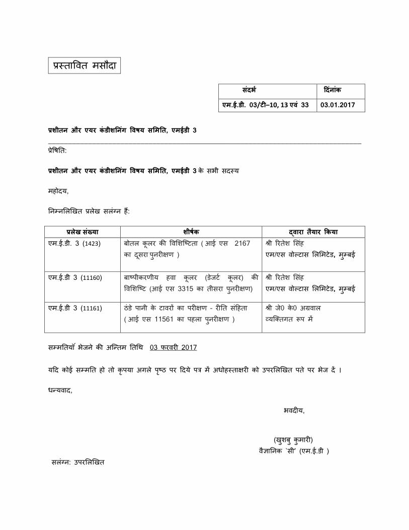
प्रस् तावित मस दा
प्रशीतन और एयर कंडीशननगं विषय समिनत, एिईडी 3
______________________________________________________________________________
प्रवितत:
प्रशीतन और एयर कंडीशननगं विषय समिनत, एिईडी 3 क सभी सदस् य
मह दय,
तिम् िलिखित प्रिि सिंग् ि हैं:
प्रलख संख् या शीषषक द्िारा तयार ककया एम.ई.डी. 3 (1423) ब ति कूिर की विलिष्टिता ( आई एस 2167
का दसूरा पुिरीक्षण )
श्री ररति लसहं
एम/एस ि ल् िास लिलमिड, मुम् बई
एम.ई.डी 3 (11160) बाटपीकरणीय हिा कूिर (डजिट कूिर) की विलिष्टि (आई एस 3315 का तीसरा पुिरीक्षण)
श्री ररति लसहं
एम/एस ि ल् िास लिलमिड, मुम् बई
एम.ई.डी 3 (11161) ठंड पािी क िािरों का परीक्षण – रीतत संहहता
( आई एस 11561 का पहिा पुिरीक्षण )
श्री ज0 क0 अग्रिाि
व्यष्ततगत रूप में
सम् मततय ंभजि की अष्तितम तति 03 फरिरी 2017
यहद क ई सम् मतत ह त कृपया अगि पटृ ठ पर हदय पत्र में अध हस् ताक्षरी क उपरलिखित पत पर भज दें ।
धतियिाद,
भिदीय,
(िुिबु कुमारी)
िज्ञातिक `सी’ (एम.ई.डी ) सिंग् ि: उपरलिखित
संदर्ष ददनंांक
एि.ई.डी. 03/टी–10, 13 एिं 33 03.01.2017
Doc: MED 03 (1423)p
Jan 2017
1
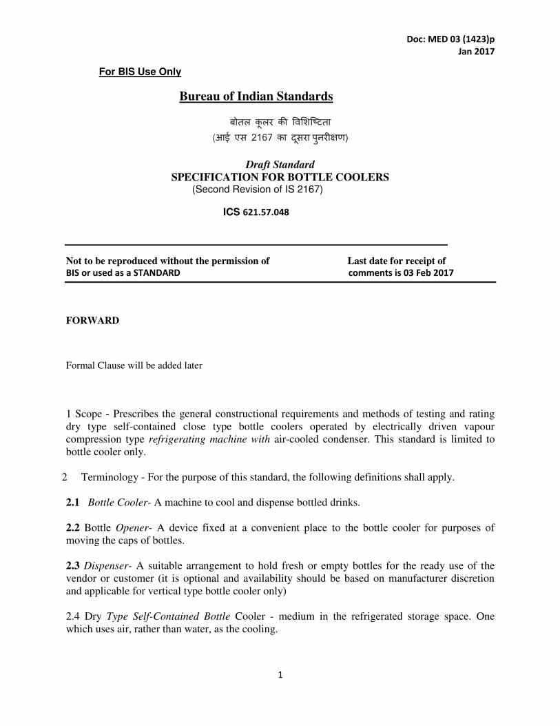
For BIS Use Only
Bureau of Indian Standards
बोतल कूलर की विशिष्टिता (आई एस 2167 का दसूरा पुनरीक्षण)
Draft Standard
SPECIFICATION FOR BOTTLE COOLERS (Second Revision of IS 2167)
ICS 621.57.048
Not to be reproduced without the permission of Last date for receipt of
BIS or used as a STANDARD comments is 03 Feb 2017
FORWARD
Formal Clause will be added later
1 Scope - Prescribes the general constructional requirements and methods of testing and rating
dry type self-contained close type bottle coolers operated by electrically driven vapour
compression type refrigerating machine with air-cooled condenser. This standard is limited to
bottle cooler only.
2 Terminology - For the purpose of this standard, the following definitions shall apply.
2.1 Bottle Cooler- A machine to cool and dispense bottled drinks.
2.2 Bottle Opener- A device fixed at a convenient place to the bottle cooler for purposes of
moving the caps of bottles.
2.3 Dispenser- A suitable arrangement to hold fresh or empty bottles for the ready use of the
vendor or customer (it is optional and availability should be based on manufacturer discretion
and applicable for vertical type bottle cooler only)
2.4 Dry Type Self-Contained Bottle Cooler - medium in the refrigerated storage space. One
which uses air, rather than water, as the cooling.
Doc: MED 03 (1423)p
Jan 2017
2
2.5 Vapour Compression cycle- A refrigeration cycle in which a volatile liquid absorbs heat,
evaporates and is compressed to a higher pressure and temperature to return to its liquid state
again, by surrendering heat at a higher temperature and Pressure.
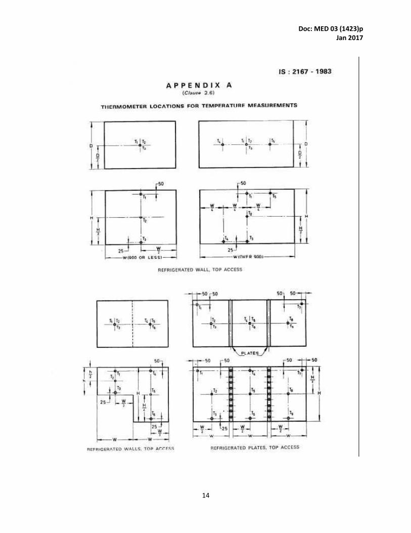
2.6 The Average Cabinet Air Temperatures- The average air temperature taken by means of the
thermocouples or thermometers located at Places in the cabinet as shown in Appendix A at any,
point
of the thermostatic cycle.
2.7 Cycles per 24 Hours - A Cycle in the Operation Of a bottle cooler is the period during which
a compressor goes through the steps of starting, running, Stopping and Starting again. Cycles per
day can be
determined by dividing the number of Complete Cycles by the elapsed time in hours and
multiplying
the result by 24.
2.8 Percentage Running Time - The Percentage running time, under given conditions of ambient
ternperatures and of mean internal temperature, is the ratio:
R = dD x 100
where
d = duration of compressor operation during a full number of cycles, and
D = total duration of the Cycles.
2.9 Overall Dimensions - Measurement of the outside rectangular dimensions over the
horizontal
base within which the bottle cooler including the accessories other than bottle opener and
handle arc inscribed.
2.10 Gross Volume - Total volume contained within interior walls of the cabinet with the door
closed
and determined by the method given in 4.3.
2.11 Storage Volume-The total volume contained inside the cabinet for storage of bottles. This
will
be equal to the gross volume minus volume of internal fittings as described in 4.4.
2.12 Bottle Storage Capacity - The total number of standard 650ml beverage bottles that can be
loaded inside the cabinet. Bottle make should be specified.
3. Construction
3.1 General Design --The cabinet and their parts shall be constructed with strength and rigidity
adequate to withstand normal conditions of handling, transport and usage. Where an internal
light is fitted, the lamp shall be effectively protected from mechanical damage but shall be

Doc: MED 03 (1423)p
Jan 2017
3
accessible without excessive dismantling. There shall be no sharp edges or corners liable to
cause injury to the user in the normal conditions of use. The door of the cooler should be
constructed based on the temperatures required for the specific market in which the cooler will
be placed. For example, (2) two panes of glass may be necessary for use in normal and high
ambient environmental conditions and (3) three panes of glass may be necessary in very high
ambient and extra high ambient environmental conditions. Tempered glass should be used when
required by local safety regulations. To prevent condensation and minimize heat gain,
consideration should be given to energy saving features such as glass panes with low E coatings,
gaps between panes filled with argon gas, or panes hermetically sealed and thermally insulated
from metal frame surfaces. High altitude should not affect the hermetic seal. If an anti-sweat
device is being used, consideration should be given to use of hot air instead of an electric heating
element. Considerations should be given for making the weight of doors as light as possible to
allow easy opening and to including self-closing features for closing after use. Built-in door
blocks should be incorporated especially on double-door and triple-door units with sliding doors
to prevent the door closing during cooler loading. Hinges and breaker plates on all coolers must
be designed to handle rough treatment without becoming damaged. The door material should
also be able to withstand temperatures up to 150°F (65.6°C). Swing doors should be fitted with
safe and sturdy door handles preferably installed by the manufacturer; recessed door handles are
recommended. In some markets, integrated door locks and interchangeable right and left hinges
may be requested as standard items. Coolers should not be unstable due to top heaviness and
must remain stable when placed on uneven surfaces. Leveling legs should be included to ensure
stability. Reference can be taken from UL specification, entitled Stability Test.
3.2 Materials- Materials used in the construction of the cabinet shall comply with Indian
Standards wherever applicable, except where such requirements are modified by this standard.
They shall be free from defects which are liable to cause undue deterioration or failure. Under
normal conditions of use, the materials used shall not shrink, warp or cause odour and shall be
resistant to attach by local vermins and destructive pests. Sealing materials used shall not
become lose in service any of their essential properties, such as adhesiveness, plasticity and
moisture resistance, due to ageing, temperature and humidity variations.
3.3 Finish - The interior and exterior finish shall be durable and capable of being cleared
effectively and hygienically without undue deterioration. All metal parts used inside or outside
the cooler which are exposed to moisture or ambient conditions shall be corrosion resistant or
adequately protected against corrosion under normal condition and usage.
3.4 Thermal insulation - The quality, thickness and application of the insulating material shall be
such as to maintain the required temperature inside the cabinet. There shall be proper seals
against moisture penetration by diffusion or condensation. Detachable plates and covers in the
cabinet shall be provided with suitable seals to prevent ingress of moisture into the insulation.
External surfaces of the cabinet shall be free from moisture condensation under normal
conditions of service.
3.5 Fittings-. Linings and facing shall have sufficient mechanical strength to resist distortion and
give reasonable protection to the insulation. When the lids of the refrigerated space are closed,
Doc: MED 03 (1423)p
Jan 2017
4
there shall be no leakage of external air into the cabinet either past the lid gaskets or by any other
means.
3.7 Power Characteristics- Coolers shall be designed with power characteristics suitable for the
country in which they will be used. Because of wide voltage fluctuations in some international
markets, it that electrical equipment be able to operate within ±10% of the minimum rated
voltage without component failure or producing a hazardous situation. Coolers must have
overload protection to avoid damage caused by voltage fluctuations.
3.8 Hardware-- Lid fasteners and hinges shall be smooth and positive in action and designed to
maintain their proper function without undue wear under normal conditions of service. Screws
and all other hardware shall be of corrosion resisting material.
3.9 Refrigeration System
3.9.1 Construction -The pipes and connections to moving or resiliently mounted parts shall be
arranged so as not to foul with or transmit vibration to other parts. The pipes and connections
shall be securely fixed and should be of sufficient length to minimize the risk of failure due to
vibration. The refrigerating system shall not have distinct nuisance noise in the normal running
operation and should not transmit vibration to adjoining portions of the surroundings. Where
necessary pipes and valves shall be properly insulated.
3.9.2 Safety features in design - The refrigerating system shall be assembled in accordance with
good engineering practice. The refrigerating system shall be so designed that it will suffer no
damage if the lid of the cabinet is left open accidently for a short duration in ambient air of the
specified temperature. During this period motor overload protective device may come into
operation.
3.9.3 Control of operations - Refrigerant flow and compressor motors shall be automatically
controlled to reduce the cabinet temperature to the temperature specified and to maintain it
within the limits of applications. Suitable strainer shall always be provided in the liquid line.
3.9.4 Location of components - The evaporator, screen and shelves shall not obstruct access to
the stored bottles. All control devices and service valves shall be readily accessible.
3.9.5 Strength of pressure parts - The parts of the refrigerating circuit subjected to internal
pressure shall be perfectly tight. They should be designed to withstand without permanent
deformation and leakage the pressure given in Table I.
3.9.6 Cabinet Insulation- The insulating materials and refrigerant must be free of CFC free. All
foams and refrigerants must be safe, technically and economically viable, and in compliance
with all local guidelines and regulations governing the use of refrigerants and insulation.
3.10 Electrical Components
Doc: MED 03 (1423)p
Jan 2017
5
3.10.1 All ratings shall be based on either 230 volts in the case of single phase supply and 415
volts in the case of 3 phase supply. The unit, however, shall be capable of working at any voltage
within ±10 percent of the rated voltage.
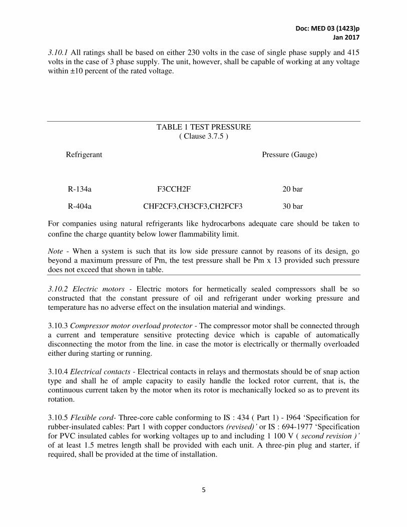
TABLE 1 TEST PRESSURE
( Clause 3.7.5 )
Refrigerant Pressure (Gauge)
R-134a F3CCH2F 20 bar
R-404a CHF2CF3,CH3CF3,CH2FCF3 30 bar
For companies using natural refrigerants like hydrocarbons adequate care should be taken to
confine the charge quantity below lower flammability limit.
Note - When a system is such that its low side pressure cannot by reasons of its design, go
beyond a maximum pressure of Pm, the test pressure shall be Pm x 13 provided such pressure
does not exceed that shown in table.
3.10.2 Electric motors - Electric motors for hermetically sealed compressors shall be so
constructed that the constant pressure of oil and refrigerant under working pressure and
temperature has no adverse effect on the insulation material and windings.
3.10.3 Compressor motor overload protector - The compressor motor shall be connected through
a current and temperature sensitive protecting device which is capable of automatically
disconnecting the motor from the line. in case the motor is electrically or thermally overloaded
either during starting or running.
3.10.4 Electrical contacts - Electrical contacts in relays and thermostats should be of snap action
type and shall he of ample capacity to easily handle the locked rotor current, that is, the
continuous current taken by the motor when its rotor is mechanically locked so as to prevent its
rotation.
3.10.5 Flexible cord- Three-core cable conforming to IS : 434 ( Part 1) - I964 ‘Specification for rubber-insulated cables: Part 1 with copper conductors (revised)’ or IS : 694-1977 ‘Specification for PVC insulated cables for working voltages up to and including 1 100 V ( second revision )’ of at least 1.5 metres length shall be provided with each unit. A three-pin plug and starter, if
required, shall be provided at the time of installation.
Doc: MED 03 (1423)p
Jan 2017
6
3.10.6 Wiring- Electrical wiring and connections shall conform to the requirement of IS : 732-
1963 ‘Code of practice for electrical wire installations ( system voltage not exceeding 650 V )
(revised)’ and also to the Indian Electricity Act, 1910 and Indian Electricity Rules 1956. All
electrical joints shall be electrically and mechanically secure.
3.10.7 Accidental contact- Live parts shall be protected by suitable guards, shields or screens of
adequate strength and durability to avoid the possibility of making inadvertent contact therewith
during normal service conditions.
3.10.8 Electrical accessories - All internal electrical fittings, such as lamps, and switches, shall
be provided with guards for protection against mechanical damage and shall be suitable for
operation at the lowest air temperature likely to occur. Electrical accessories should be able to
operate safely with in operating power and environment class mentioned on product. Care should
be taken such that Product should not have to be removed from the cooler to change lights
3.10.9 Terminals- The materials, design and proportions of all terminals shall be such that
connections made shall not slacken or overheat under the normal conditions of use. Terminals
shall be such that conductors connected thereto are rigidly and effectively clamped between
metal surfaces. Terminal screws and nuts shall engage for at least two full turns.
3.10.10 Thermostat- The thermostat should conform to IS: 11338.
3.10.11 Provision for Earthing- The cabinet shall be provided with a suitable terminal for
attaching the earth conductor and this terminal shall be in effective electrical contact with
accessible metal parts during normal use or when any cover or casing, removable without the use
of tools, has been removed and which is liable to become live in the case of breakdown of
electrical insulation.
The earth terminal shall be so designed that the pressure necessary to clamp the conductor shall
not serve to secure any other component. The terminal shall be clearly and indelibly indicated by
the letter ‘E’ and the symbol L or by green or green/yellow colour and the symbol.
3.10.12 Fan and motor- Condenser and evaporator fans and motor should be quiet when running
and designed for long life, high efficiency, and low power consumption. Materials of
construction should be durable and resistant to rust and moisture. Some markets may request a
fan switch operated by the opening of the cooler door as a standard item
4. Measurement of Bottle Cooler Storage Capacity
4.1 Accuracy of Measurement and Units- Linear dimensions shall be measured to the nearest
millimeter.
Areas estimated shall be expressed in square decimeters. Volumes estimated shall be expressed
in cubic decimeters or litres.
4.2 Inside Dimensions of the Cabinet
Doc: MED 03 (1423)p
Jan 2017
7
4.2.1 Front access type
4.2.1.I Inside depth -This shall be the mean horizontal distance between the front door in close
condition and the rear inside surface of the enclosed space of the cabinet.
4.2.1.2 inside width - This shall be the mean horizontal distance between the inner surfaces of the
side walls of the enclosed space.
4.2.1.3 Inside height - This shall be mean vertical distance between the inner surfaces of the floor
and the ceiling of the enclosed space.
4.2.2 Top access type
4.2.2.1 Inside depth-This shall be the mean horizontal distance between the front and rear inner
surfaces of the front and back walls of the enclosed space of the cabinet.
4.2.2.2 inside width - This shall be the mean horizontal distance between the inner surface of the
side walls of the enclosed space.
4.2.2.3 Inside height - This shall be the mean vertical distance between the inner surface of the
floor and the lids.
4.3 Gross Volume - The gross volume of the bottle cooler shall be the product of inside depth,
inside width and inside height as defined in 4.2.1 and 4.2.2.
4.4 Storage Volume ( Net Volume) - The storage volume shall be the gross volume or sum of the
gross volumes of individual compartments less the volumes of internal fittings fixed in the
cabinet and the volumes of the shelves and partitions essential for the proper operation of the
cabinet, provided each part is more than 0.25 litre.
4.5 Volume of Shelves, Partitions and Internal Fittings - The volume of a shelf, partition or
internal fitting shall be the product of its area and thickness. The area of a shelf shall be the
product of its width and depth. Where part of the shelf is cut away, the area of the cut-out shelf
shall be deducted. Where the edge of the shelf is not more than 25 mm from the cabinet lining,
the shell shall be considered as extending to the lining for the purpose of calculating shelf area.
Where there is an access door in a wall of the cabinet the inner surface of the door shall be
considered as being the inner surface of the lining.
4.5.1 The thickness of the shelves and partitions shall be the distance between the outer surface
excluding the edges, where those are reinforced (see Fig. 1). Where surfaces are corrugated or
fitted with pipe grids, the plane through the apices of the corrugations or pipes shall be used for
calculating volumes except that where the door distance between adjacent corrugations or pipes
is greater than 100 mm the surface itself shall be used and a volume shall be deducted for each
corrugation or pipe equal to the product of the width, the distance from the surface to the outside
of the corrugation or pipe and the length of the corrugation of pipe.

Doc: MED 03 (1423)p
Jan 2017
8
4.6 Full Partitions - The volume of a full partition is the product of its thickness, depth and width
or height. This depth, width and height are those dimensions of the cabinet applicable in the
Place of partition.
4.7 Fractional Partitions - The volume of a permanently fixed fractional partition is the /product
of it thickness, depth and width or height whichever of these two is applicable. The depth, width
or height are the distances normal to the lining from adjacent surfaces to the further edges of, the
partitions or to the evaporator in case the fractional partition touches it. A horizontal partition the
edges of which are more than 70 mm from the lining of the cabinet is regarded as fractional
partition. A vertical partition, the edges of which are more than 100 mm from the lining of the
cabinet, is regarded as a fractional partition.
4.8 Rated Gross Volume - This shall be the gross volume as declared by the manufacturer in
cubic decimeters or litres. The measured gross volume as described in 4.3 shall not be less than
the rated gross volume by more than 5 percent.
4.9 Rated Storage Volume - This shall be the storage volume as declared by the manufacturer in
cubic decimeters or litres. The measure storage (net) volume as described in 4.4 shall not be less
than the rated storage volume by more than 5 percent.
4.10 Rated Bottle Storage Capacity- This shall be the storage capacity as declared by the
manufacturer in terms of number of standard 650 ml beverage’ bottles.The actual bottle storage
capacity shall not be less than rated bottle storage capacity by more than 5 percent.
5. Tests
5.1 Type Tests -The following shall constitute the type test:
a) Thermal insulation test,
b) Insulation resistance test,
c) High voltage test,
d) No load performance test,
e) Percentage running time test,
f) Capacity rating test, and
9) Maximum operating condition test.
5.1.7 Once a bottle cooler has undergone type test any major .alterations affecting the
performance which the manufacturer intends to make in the bottle cooler shall be reported to the
Doc: MED 03 (1423)p
Jan 2017
9
testing authority recommended by ISI or as per manufacture discretion and further type test shall
be carried out in the modified bottle cooler in ‘accordance with the procedure laid down in this
standard (see 5.7).
5.2 Production Routine Tests- Every bottle coolers, after completion shall be subjected to the
following
routine tests:
a) Insulation resistance test.
b) Performance test, and
c) High voltage test
5.2.1 The manufacturer shall furnish with bottle cooler a certificate based on customer demand
that the production routine tests specified in 5.2 have been conducted in accordance with the
prescribed procedure (see 5.8) and that the unit conforms to the requirement of this standard.
5.3 Acceptance Tests - If the purchaser desires any of the production routine tests to be repeated
at the time of purchase then, where agreed to between the purchaser and the manufacturer, the
tests shall be carried out at the manufacturer’s works, alternatively, the test may be repeated at a place specified by the purchaser provided all the arrangements for tests are made by the
purchaser at the specified place.
5.4 Sample for Tests
5.4.1 Type tests- Two bottle coolers of each type and size shall be sent along with manufacturer’s
detailed specifications to the appropriate testing authority for purposes of type tests. Type tests
can be performed by the manufacturer himself if approved by the purchaser.
5.4.2 Acceptance tests - The number of samples shall-be as agreed to between the purchaser and
the manufacturer.
5.5 Preparation and Test Conditions for Type Tests
5.5.1 Each specimen tested shall be selected from stock or routine factory production, and shall
be representative of construction and adjustments.
5.5.2 The bottle cooler with all panels and lids in place, shall be tested in a room in which the
temperature can be controlled. Panels and lids should remain in place throughout the entire test.
5.5.3 Bottle coolers shall be operated until stable operating conditions are reached. The stable
conditions
are deemed to have reached when during a time of 2 hours the average cabinet air temperature
does not vary by more than 0.5°C.
5.5.4 The bottle cooler being tested shall be located in a room so that its temperature is not
affected by direct radiation to or from external cooling or heating equipment. The air circulation

Doc: MED 03 (1423)p
Jan 2017
10
in the room shall be such that the specified uniformity of ambient temperature is obtained
without direct draft upon the bottle cooler under test.
5.5.5 The fan motor and compressor shall be SO connected as to facilitate measurement of the
power input. When tested under actual working conditions the fan motor should conform to the
requirements specified in IS 996.
5.5.6 For the test during which the bottle cooler will be in operation, electric power supply shall
not vary by more than 2% of the rated voltage.
5.5.7 Bottles shall be filled with either beverage liquid or water. Alternatively suitable brine
solution may be used if there is any likelihood of temperature falling to 0°C or less.
5.5.8 Bottle temperature shall be measured by thermocouple located approximately at the centre
of the mass of the liquid in the bottle. Bottles shall be corked with provision for bringing the
thermocouple leads out through the cork.
5.5.9 For determination of average bottle temperature, liquid temperature should be measured in
bottles located at uniformly distributed points inside the cabinet, including measurement in top
layers and .one measurement in the bottom layer of bottles. Apart from these two locations,
additional bottles should be based on approximately one bottle per 100 to 150 litres of storage
volume,
5.6 Instruments
5.6.1 Temperature measurements shall be made with one or more of the following instruments:
a) Mercury-in-glass thermometer,
b) Alcohol-in-glass thermometer,
c) Thermocouples,
d) Electric resistance thermometers, or
e) Electric resistance measurements instruments having accuracy 0’2 percent of the scale.
5.6.1.I Accuracy of measurement shall be within ± 0.5ºC.
5.6.2 Electrical measurements shall be made with indicating instruments.
5.6.2.1 The accuracy of indicating instruments shall be within 1.5 Percent of the full scale
reading.
5.6.3 The Smallest division on the scale of any instrument shall not exceed twice the specified
accuracy for it.
5.7 Procedure for Type Tests
Doc: MED 03 (1423)p
Jan 2017
11
5.7.1 Thermal insulation test (external condensation test) - The bottle cooler cabinet shall be
held with an average internal temperature between 4°C to 8°C under ambient temperature of 32
± 2°C. it Shall be considered satisfactory if. when the relative humidity of the ambient air is held
between 70 to 75 percent condensed moisture is not visible on the Outer surface of the bottle
cooler to the unaided eye of a trained observer during a period of time lasting for 12 hours after
the test conditions have become stable.
5.7.2 Insulation resistance test - The insulation resistance between all electric circuits included in
the bottle coolers, and earthed metal parts, when measured at normal room temperatures with a
voltage of 500 V dc, shall not be less than 1 MQ at the end Of the maximum operating condition
test. This test Should be repeated after high voltage test.
5.7.3 High voltage test --- The electrical insulation of all electric circuits included in the bottle
cooler shall be such as to withstand a high voltage test of 1 000 V rms applied for 2 seconds
between aft electric circuits and all accessible metal parts ( electrically connected together for
this test) at normal room temperature. The test voltage shall be alternating, of approximately
sine-wave form, and of any convenient frequency between 25 to 100 Hz.
5.7.4 No-load performance test - With the bottle cooler working under no-load and with the
thermostat terminals short-circuited, at ambient temperature of 35 ± 2°C, the time required to
pull down the average cabinet air temperature from 35 ± 2°C to 4°C shall not exceed 3 hours.
5.7.5 Power consumption test and Percentage running test- For this test, the cabinet shall be
tested on no-load, with lids closed and the thermostat set for maximum cooling. The duration of
the test will be 12 hours at an ambient temperature of 35 ± 2 °C. Power Consumption and
Percentage running time will be taken as average of three successive runs in the later half of this
period. It should not exceed the value stated by the manufacturer by more than 5 percent.
5.7.6 Capacity rating test -This test should immediately follow percentage running time without
switching off the unit. In case, this is not possible then the unit should run on no-load for a
minimum period of 3 hours under prevailing ambient conditions before the start of this test.
During the entire test period, the ambient temperature should be maintained at 35 ± 2°C and
thermostat should be set for maximum cooling. Unit should be loaded with specified number of
standard 650 ml bottles at an initial temperature of 35 ± 2°C. Rate of loading of bottles should
not be less than 10 bottles per minute. Once the loading is over, lids should be properly closed.
The test duration starts from the moment the lids are closed. Bottle temperatures should be
recorded every 30 minutes for specified pull down period which shall not exceed 12 hours.
Average temperature of bottles at the end of specified pull down period shall not be greater than
5°C, and the maximum bottle temperature shall not exceed 8°C.
5.7.7 Maximum operating conditions test- This test should immediately follow capacity rating
test without switching off the unit. In case this is not possible the unit should run on no-load for a
minimum of3 hours under prevailing ambient conditions before the start of this test. During the
entire test period the ambient temperature should be maintained at 43 ± 2°C and the thermostat
should be set for maximum cooling. Unit should be loaded with specified number of standard
Doc: MED 03 (1423)p
Jan 2017
12
650 ml bottles at an initial temperature of 35 ± 2 ºC. Rate of loading of bottles should not be less
than 10 bottles per minute. Once the loading is over, lids should be properly closed. The test
duration starts from the moment the lids are closed. Bottle temperatures should be recorded
every 30 minutes for specified pull down period which shall not exceed 18 hours.
Note - Unit may trip on overload protector during initial stage of the test. This should be
considered as permissible.
5.7.8 The type test report shall also contain the following identification data:
a) Name-plate data of bottle cooler,
b) Name-plate data of compressor, and
c) Name-plate data of fan motor.
5.8 Procedure for Production Routine Tests
5.8.1 Insulation resistance test - Electrical insulation test shall be carried out at 500 V dc, given
in 5.7.2 at the end of performance test.
5.8.2 Performance test-This test should be carried out with thermostat short-circuited externally
(or thermostat bulb pulled out from its housing) under prevailing ambient condition provided
ambient temperature is not less than 25°C. In case ambient is less than 25°C the provision of
suitable heating arrangement should be incorporated in the test area to create higher ambient
temperature. Measurement shall be made of the following and the performance figure shall be
compared with the unit which has already passed the type test:
a) Ambient temperature,
b) Initial average cabinet temperature on no-load,
c) Average cabinet temperature at the and of specified pull-down period,
d) Current, and
e) Voltage.
Duration of the test should not exceed 3 hours. During this test a single thermometer may be
used to measure cabinet temperature, with its bulb at least 150 mm from any walls or bottom
.After pull down, the machine should be continued to run with thermostat adjusted for minimum
specified temperature for a period of at least 3 hours. During this period operation of the unit
should be satisfactory and thermostat should operate correctly.
Note - Minimum specified cabinet temperature should not be greater than 4°C when operating at
an ambient temperature of 35 ± 2°C.
5.8.3 High voltage test - The electrical insulation of all electric circuits included in the bottle
cooler shall be such as to withstand a high voltage test of 1 000 V rms applied for 2 seconds
between the electric circuits and all accessible metal parts (electrically connected together for
this test) at normal room temperature. The test voltage shall be alternating of approximately sine-
wave form, and of any convenient frequency between 25 and 100 Hz.
Doc: MED 03 (1423)p
Jan 2017
13
5.8.4 Earthing Test - A current of 1.5 times the rated current, but not less than 25 amperes
derived from ac source with a no-load voltage not exceeding 12 V is passed between the earthing
terminal or earthing contact and each of the accessible metal parts in turn. The voltage drop
between the earthing teminal or earthing contact of the cabinet and the accessible metal parts is
measured and the resistance calculated from the current and voltage drop. The resistance of the
flexible cord is not included in the resistance measurement. In no case shall the resistance exceed
0.1 ohm when tested as per IS 302 (Part 1).
6. Manufacturer’s Certificate - The manufacturer shall furnish with each bottle cooler a copy of
the type test certificate, if required by the customer, and shall also certify that the bottle cooler
has-been manufactured according to the type tested by the testing authority and that it conforms
to the requirements of this standard.
7. Marking and Information
7.1 Each bottle cooler shall have the following information marked in a permanent and legible
manner in a location where it is easily accessible and easily visible after installation:
a) Name-plate data of bottle cooler including make, model and serial number of the unit and
the name and quantity of refrigerant,
b) Supply characteristics,
c) Capacity in terms of litres of storage volume;
d) Wiring diagram, and
e) Full load current.
f) Input Power supply requirement (Voltage/ Freq/ Phase)
g) Operating environment (Ambient class, RH% and Temp.)
7.2 The bottle cooler may also be marked with the standard mark
7.2.1 The use of the Standard Mark is governed by the provisions of Bureau of Indian
Standards Act, 1986 and the Rules and Regulations made thereunder. The details of
conditions under which the license for the use of Standard Mark may be granted to
a ufa turers or produ ers ay e o tai ed fro the Bureau of I dia Sta dards.’
8.0 User Manual - Each cooler should have an operation manual that clearly list operating
instructions, directions for installation, the recommended maintenance schedule, cleaning
instructions, a troubleshooting guide, a wiring diagram, and a complete parts list with an
exploded view or assembly drawings of all major subassemblies. The manual and especially the
installation and repair instructions should be written as simply and clearly as possible; inclusion
of pictures and diagrams is highly encouraged. The manual should be provided in electronic
format when possible.
Doc: MED 03 (1423)p
Jan 2017
14

Doc: MED 03 (1423)p
Jan 2017
15
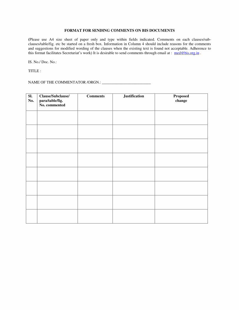
FORMAT FOR SENDING COMMENTS ON BIS DOCUMENTS
(Please use A4 size sheet of paper only and type within fields indicated. Comments on each clauses/sub-
clauses/table/fig. etc be started on a fresh box. Information in Column 4 should include reasons for the comments
and suggestions for modified wording of the clauses when the existing text is found not acceptable. Adherence to
this format facilitates Secretariat’s work) It is desirable to send comments through email at : [email protected] .
IS. No./ Doc. No.:
TITLE :
NAME OF THE COMMENTATOR /ORGN.: _________________________
Sl.
No.
Clause/Subclause/
para/table/fig.
No. commented
Comments
Justification
Proposed
change
Related Documents