AGILENT 1100/1200 Clarity Control Module ENG Code/Rev.: M060/70D Date: 10/5/2017 Phone: +420 251 013 400 DataApex Ltd. Fax: +420 251 013 401 Petrzilkova 2583/13 [email protected] 158 00 Prague 5 www.dataapex.com The Czech Republic

Welcome message from author
This document is posted to help you gain knowledge. Please leave a comment to let me know what you think about it! Share it to your friends and learn new things together.
Transcript

AGILENT 1100/1200
Clarity Control Module ENG
Code/Rev.: M060/70DDate: 10/5/2017
Phone: +420251013400 DataApex Ltd.
Fax: +420251013401 Petrzilkova 2583/13
[email protected] 15800Prague 5
www.dataapex.com TheCzech Republic

Clarity® , DataApex® and ® are trademarks of DataApex Ltd. Microsoft ® and WindowsTM aretrademarks of Microsoft Corporation.DataApex reserves the right to make changes to manuals without prior notice. Updated manuals can bedownloaded fromwww.dataapex.com.
Author: MP

Agilent 1100/1200 Table of Contents
Contents1 Agilent 1100/1200 Control Module 12 Requirements 32.1 Compatible Agilent 1100/1200 Devices 4
3 Installation procedure 53.1 Installing 1100 control modules 53.1.1 Installing the GPIB interface in the PC 53.1.2 LAN card setting 83.1.3 Connections 113.1.3.1 Wiring 113.1.3.2 Description of connectors 113.1.3.3 Recommended GPIB addresses 123.1.3.4 Single PC & network connection 13
3.1.4 Clarity Configuration 143.1.5 First start of Clarity after configuration 19
3.2 Installing 1200 control modules 203.2.1 LAN card setting 203.2.2 Connections 233.2.2.1 Description of connectors 233.2.2.2 Single PC & network connection 24
3.2.3 Clarity Configuration 254 Using the control modules 284.1 Using the 1100 control modules 284.1.1 Agilent 1100 Configuration - Common 284.1.2 Add Module 294.1.3 Autosampler AS (G1313) and TAS (G1329) 304.1.3.1 Agilent 1100 Configuration 304.1.3.2 Method Setup - AS - Injection 304.1.3.3 Method Setup - AS - Program 324.1.3.4 Hardware Configuration 334.1.3.5 Device Monitor 34
4.1.4 DAD (G1315) 344.1.4.1 Agilent 1100 Configuration 344.1.4.2 Method Setup - Acquisition - Signal 354.1.4.3 Method Setup - Acquisition 374.1.4.4 Method Setup - Acquisition - Outputs 384.1.4.5 Method Setup - Acquisition - Time Table 394.1.4.6 Hardware Configuration - Main 404.1.4.7 Hardware Configuration - Info 404.1.4.8 Data Acquisition 414.1.4.9 Device Monitor 42
4.1.5 FLD (G1321) 424.1.5.1 Agilent 1100 Configuration 424.1.5.2 Method Setup - Acquisition - FLD Parameters 444.1.5.3 Method Setup - Acquisition - Flashlamp 46
- i -

Table of Contents ClarityControlModule
4.1.5.4 Method Setup - Acquisition - Outputs 474.1.5.5 Method Setup - Acquisition - Time Table 484.1.5.6 Hardware Configuration - Main 494.1.5.7 Hardware Configuration - Info 494.1.5.8 Data Acquisition 504.1.5.9 Device Monitor 51
4.1.6 MWD (G1365) 514.1.6.1 Agilent 1100 Configuration 514.1.6.2 Method Setup - Acquisition - Signal 534.1.6.3 Method Setup - Acquisition - MWD 544.1.6.4 Method Setup - Acquisition - Outputs 554.1.6.5 Method Setup - Acquisition - Time Table 564.1.6.6 Data Acquisition 574.1.6.7 Device Monitor 58
4.1.7 VWD (G1314) 584.1.7.1 Agilent 1100 Configuration 584.1.7.2 Method Setup - Acquisition - Signal 594.1.7.3 Method Setup - Acquisition - VWD 604.1.7.4 Method Setup - Acquisition - Outputs 614.1.7.5 Method Setup - Acquisition - Time Table 624.1.7.6 Data Acquisition 634.1.7.7 Device Monitor 64
4.1.8 LC Gradient (G1310, G1311, G1312) 654.1.8.1 Options 674.1.8.2 Method Setup - LC 684.1.8.3 Device Monitor 694.1.8.4 Agilent 1100 Setup 71
4.1.9 Column Compartment (G1316) 734.1.9.1 Agilent 1100 Configuration 734.1.9.2 Method Setup - Thermostat - Temperature 744.1.9.3 Method Setup - Thermostat - Time Events 754.1.9.4 Device Monitor 76
4.2 Using the 1200 control modules 774.2.1 Agilent 1200 Configuration - Common 774.2.2 Add Module 784.2.3 DAD-1200 794.2.3.1 Agilent 1200 Setup 794.2.3.2 Method Setup - Acquisition - DAD Parameters 804.2.3.3 Method Setup - Acquisition - Lamps 814.2.3.4 Method Setup - Acquisition - Outputs 824.2.3.5 Method Setup - Acquisition - Time Table 834.2.3.6 Data Acquisition 844.2.3.7 Device Monitor 854.2.3.8 Hardware Configuration 85
4.2.4 FLD-1200 874.2.4.1 Agilent 1200 Setup 874.2.4.2 Method Setup - Acquisition - Flashlamp 88
- ii -

Agilent 1100/1200 Table of Contents
4.2.4.3 Method Setup - Acquisition - FLD Parameters 894.2.4.4 Method Setup - Acquisition - Outputs 914.2.4.5 Method Setup - Acquisition - Time Table 924.2.4.6 Data Acquisition 934.2.4.7 Device Monitor 944.2.4.8 Hardware Configuration 94
5 Troubleshooting 96
- iii -

Table of Contents ClarityControlModule
To facilitate the orientation in the Agilent 1100/1200 manual and Clarity chromatographystation, different fonts are used throughout themanual. Meanings of these fonts are:
Instrument (blue text) marks the nameof thewindow to which the text refers.Open File (italics) describes the commands and names of fields in Clarity, parameters that canbe entered into themor a window or dialog name (when you already are in the topic describingthewindow).WORK1 (capitals) indicates the nameof the file and/or directory.ACTIVE (capital italics) marks the state of the station or its part.
The bold text is sometimes also used for important parts of the text and the name of the Claritystation. Moreover, some sections are written in format other than normal text. These sections areformatted as follows:
Note: Notifies the reader of relevant information.
Caution: Warns the user of possibly dangerous or very importantinformation.
▌ Marks the problem statement or trouble question.Description: Presents more detailed information on the problem, describes its causes,
etc.Solution: Marks the response to the question, presents a procedure how to remove it.
- iv -

Agilent 1100/1200 1 Agilent 1100/1200 ControlModule
1 Agilent 1100/1200 Control ModuleThe Agilent 1100 driver can control Agilent 1100 series and 1200 series(in 1100 emulation mode) HPLC systems with:
DAD*, MWD*, VWD, FLD and RID detectorsQuarternary, Binary and Isocratic PumpsColumn compartmentsAutosamplers (standard and thermostated)
Note: For the 1200 series compatibility, please refer the Agilent 1100/1200SeriesFirmware UpgradeGuide.
We recommend to use Agilent ICF control module which supportscomplete list of Agilent LC instruments and is regularly updated tosupport latest firmwares of instruments. Refer to www.dataapex.com/icf.
Fig 1: Agilent 1100
The direct control can be performed via
82357A USB/GPIB Interface82350A PCI/GPIB InterfaceLAN
Note: The 82355 and 82431 ISA/GPIB Interfaces are not supported.* From the G1315 (DAD) and G1365 (MWD) modules, only the -A and -Bsubtypes can be controlled using the Clarity 1100 driver. The -C and -Dtypes use different protocol and cannot be downgraded to the 1100operation mode.
- 1 -

1 Agilent 1100/1200 ControlModule ClarityControlModule
Data Acquisition can be performed via
GPIB - Clarity Digital Data AcquisitionLAN - Clarity Digital Data AcquisitionANALOG - analog signal to A/D converter (e.g. INT7 or U-PAD).
Note: GPIB communication is not supported sinceWindows7.
- 2 -

Agilent 1100/1200 2 Requirements
2 RequirementsClarity Installation CD ROM with LC Control module (p/n A24).AS control module (p/n A26) when the autosampler is used.PDA Extension (p/n A29) when the DAD or FLD detector is used.Cross LAN cable (p/n SK08) and the LAN card in the PC for the newerAgilent 1100 and all Agilent 1200 systems. For older Agilent 1100systems, GPIB interface may be necessary. This consists of:
either 82357A PCI/GPIB interface card, GPIB cable and free PCI slot inthe PC.or 82350A USB/GPIB interface card and free USB port in the PC.
Note: The interface cards and GPIB cable are available from Agilent or 3rdparties only.
Caution: If you want to use the GPIB interface, install the IOLib Suite first. It can befound on the Clarity Installation CD in the directory HW_DRIVERS\AGILENT or download the newest version from the Agilentwebsite.
Caution: GPIB communication interface is not supported sinceWindows7.
Caution: It is only possible to control one Agilent 1100 system via a single GPIBinterface, for more systemsmore GPIB interface cards are necessary. Nosuch restrictionsapply for LAN communication.
Note: Cables are not part of Clarity Control Module. It is stronglyrecommended to order required cables together with the ControlModule.
Caution: Check your Agilent 1100 for available communication options. In oldersystems, the LAN communication interface was optional and HP- IBstandard. In recent new systems and in the 1200 series modules the HP-IB port is nomore present.
Caution: Before you start Clarity, ensure there is not any other application or theAgilent Handheld Controller active and controlling the Agilent 1100instruments.
- 3 -

2 Requirements ClarityControlModule
2.1 Compatible Agilent 1100/1200 DevicesClarity is able to control Agilent 1200 devices only if their firmware iscompatible with 1100 series (firmware version series A.XX). Firmwareversions A.06.0X used in currently delivered (as for 2008/2009) Agilent1200 devices were tested with Clarity successfully. The minimumrecommended firmware version will be the A.05.06-10 set.Firmware change can be performed by Agilent service at delivery, thenecessary tools and files are also available on the ChemstationInstallation CD or can be downloaded from Agilent web pages. More infocan be found in Agilent 1100/1200 Series Firmware Updates Manual PartNumber 01100-90110 available on their web pages.
Tab 1: The following Agilent 1100/1200moduleswith the respective 1100 compatible firmwarerevision are supported byClarityAgilent 1100 LC system driver:
Agilent Device TypeG1310A Isocratic PumpG1311A Quaternary PumpG1312A Binary PumpG1313A AutosamplerG1329A, G1330A, G1330B Thermostatted AutosamplerG1314A, G1314B Variable Wavelength DetectorG1365A, G1365B Multiple Wavelength DetectorG1315A, G1315B Diode Array DetectorG1321A Fluorescence DetectorG1362A Refractive Index DetectorG1316A, G1316B Thermostatted Column Compartment
The DAD and MWD detector models G1315C DAD SL,G1365C MWD SL,G1315D DAD , G1365D MWD cannot go below firmware versionB.01.01/B.01.04 and will not work in 1100 emulation mode and are notsupported by the Clarity Agilent 1100 HPLC System driver.New Agilent 1200 LC System driver is in development stage. Currently itallows control of the G1315D Diode Array Detector . In future the1100 /1200 modules supported by the 1100 LC System driver andadditional 1200 LC System modules will be added to allowdiscontinuation of the Agilent 1100 LC System control module.At current stage, the G1315D Diode Array Detector has to be controlledby one separate LAN communication line using the 1200 control moduleand the rest of the 1100 / 1200 System by other LAN or GP- IBcommunication line using the 1100 control module on the same ClarityInstrument.
- 4 -

Agilent 1100/1200 3 Installation procedure
3 Installation procedureThe installation procedures of the Agilent 1100 and 1200 modules aredescribed in the separate sections below.
3.1 Installing 1100 control modules3.1.1 Installing the GPIB interface in the PC
Caution: If you are using the 82357A USB/GPIB Interface, then leave out the firststep and plug in the GPIB device after you have installed the drivers.
Insert the 82350A PCI/GPIB Interface in the PCI slot.Install the corresponding drivers (SICL and VISA) provided by theinterface manufacturer.
Caution: InWindows Vista and 7, run the installation as administrator (right-clickon the installation executable file and selectRun asadministrator).
Note: The communication was tested on theGPIB driver library versionM01.01.The IO libraries are also available on www.agilent.com/find/iolib.
(Plug in the 82357A USB/GPIB Interface).In the right part of the Windows taskbar click the IO icon.
Fig 2: Popupmenu of the IQ icon
- 5 -

3 Installation procedure ClarityControlModule
In the Agilent IO Libraries Configuration dialog select your GPIB card.
Fig 3: Agilent IOLibrariesConfiguration - IOConfig
Press Edit to invoke the Card Configuration dialog.
Fig 4: 87350 PCI GPIBCard Configuration
Set the SICL Interface Name.
The BUS Address must be different from the address of any of the othercomponents in the Agilent 1100 configuration - recommended values are21 or 30 (21 is offered as default).
Note: Should the setting be compatible with the Chemstation the SICLInterface Namemust be "HP82341").
Write down the SICL Interface Name and BUS Address fields it will benecessary to set these values later also to the Agilent 1100 Configurationdialog.
- 6 -

Agilent 1100/1200 3 Installation procedure
Connect the Agilent 1100 to the PC by GPIB interface.
Caution: It is recommended to connect the GPIB cable between the PC and theAgilent 1100 component with the largest amount of communication. Thisis usually the DAD detector. If it is not present in the set then any otherdetector (MVD,WVD, FLD, etc.)
Turn the power on (both PC and Agilent 1100).Review the GPIB settings.
- 7 -

3 Installation procedure ClarityControlModule
3.1.2 LAN card settingTo operate properly in a network environment, the LAN Interface must beconfigured with valid TCP/IP network parameters. These parameters are:
IP addressSubnet MaskDefault Gateway
There are several different Init modes for setting the IP address of theAgilent 1100 system selectable by dip switch settings on the LANcommunication board.
Fig 5: LAN card DIPSwitches
Default settings
The factory set “Using Default” option (SW5 ON and SW6 ON) uses fixedIP address 192.168.254.11. In case the 1100 is connected directly to PC,it is the recommended setting, please see the chapter "Single PC& network connection" on pg 13.For the LAN card in the PC use TCP/IP settings with a fixed IP address, forexample:
IP address: 192.168.254.12Subnet mask: 255.255.255.0
Note: The last IP address section should be different from the 1100 IP address.
When connected to a network, the address above should be assigned tothe 1100 system (contact your LAN administrator).
- 8 -

Agilent 1100/1200 3 Installation procedure
Stored Settings
When this address could not be used due to network constraints, it can bechanged from the default settings by following procedure:Use the Run command from the Windows Start menu. Run the CMD.EXEwith following commands:
Note: It is necessary to have Telnet client enabled. The status of Telnet clientcan be modified in theWindows 7 andWindows 10 settings. The Telnet isoperational onWindows XP by default. If not, contact PC's administratorin order to checkand/or modify statusof Telnet service.
Fig 6:Windows7 - Telnet client
Fig 7:Windows10 - Telnet client
- 9 -

3 Installation procedure ClarityControlModule
telnet 192.168.254.11 (default or stored address)
IP 192.168.254.12 (desired IP address)
Quit
After this switch off the Agilent 1100 and change the dip switch settings onthe LAN card to “Using Stored” (SW5 ON and SW6 OFF).
Note: The stored address can be also changed using the HandheldController (G1323A/B).
Bootp SettingsThe Chemstation usually uses the bootp server to assign an IP addressto the Agilent 1100 instruments. The DIP switches on the LAN card areSW5 OFF and SW6 ON or OFF in such case. Set the appropriate IPaddress according to the bootp manager settings in Agilent 1100configuration too.
Note: Detailed description of the possible LAN interface card settings can befound in theAgilent G1369A LAN Interface User Manual (Agilent P/NG1369-90000).
Caution: In case you want to use J4100A JetDirect card (alternative to HP JetDirectPrint Servers 600N/400N/500X/300X) we don't support it and don'tguarantee the functionality.
- 10 -

Agilent 1100/1200 3 Installation procedure
3.1.3 Connections3.1.3.1 Wiring
In case of complete system with autosampler, pump and detector only theHP-IB communication line is needed.When using a system without autosampler or single modules (detectors,pumps) only, they need to be started using the Remote external eventcontact connector.The connector is 9 pin Sub D Receptacle (Canon female) on the backsideof the module, marked Remote. Use the Pin 1 to Pin 3 (Start) contacts toconnect the injector. The pins 1 to 8 may be used to Stop the runalternatively.
Caution: Next to it is another connector of the same typemarked RS232.
3.1.3.2 Description of connectorsLAN interfaceThe LAN interface board is installed usually in only one component of theAgilent 1100 system. On others a cover plate is in its place.
Fig 8: Back side of the Agilent 1100 and the LAN connector
Caution: Be careful that you connect the LAN cable to the LAN Interface and NOTto one of the CAN connections. The CAN bus uses 12-Volt signals, and amisconnection to the CAN bus may destroy network equipment on theother end of the cable.
GP-IB communicationThe HP-IB connector is a standard on the Agilent 1100 series modules.
Fig 9: Back side of the Agilent 1100 and theGP-IB
- 11 -

3 Installation procedure ClarityControlModule
Tab 2: General-purpose remote cable pin layout and colours:
PIN HP 1100 Signal Name Active (TTL)1 White Digital Ground2 Brown Prepare run Low3 Gray Start Low4 Blue Shut donw Low5 Pink Not Connected6 Yellow Power on High7 Red Ready High8 Green Stop Low9 Black Start request Low
3.1.3.3 Recommended GPIB addressesTab 3: Default GP-IB Addresses:
Device Adress Device AdressAutosampler 28 Autosampler 28Pump 22 RID 29FLD 23VWD 24 Autosampler (HP 1050) 18Agilent 8453 25 Pump (HP 1050) 16DAD/MWD 26 VWD (HP 1050) 10Column Compartment 27 DAD (HP 1050) 17
For GP-IB board is recommended to use the Address 21 (default) or 30.
- 12 -

Agilent 1100/1200 3 Installation procedure
3.1.3.4 Single PC & network connectionA single PC equipped with LAN card can be used together with Agilent1100 . When using a switch or a hub , multiple Agilent 1100 can beconnected to one PC.SettingsPC: LAN card, TCP/IP protocol.Both PC and Agilent 1100 should be configured on the same IP range.
Caution: Crossed LAN cable is required (in case the Agilent 1100 is connected toLAN card directly, without using the switch).
Tab 4: Recommended IP settings:
Agilent 1100 LAN cardIP 192.168.0.200 192.168.0.1Port 80 - - -Subnet Mask 255.255.255.0 255.255.255.0Default Gateway 192.168.0.1 192.168.0.1Accept From IP 0.0.0.0 - - -Accept From SubnetMask 0.0.0.0 - - -
FirewallEnsure that the firewall does not block communication from the Agilent1100.Internet connectionBe aware that many Internet connections are provided using the LANcard. If this is the case a separate LAN card must be configured for eachInternet and Agilent 1100.
- 13 -

3 Installation procedure ClarityControlModule
3.1.4 Clarity ConfigurationCaution: Before you start configuring the Agilent 1100 in Clarity, ensure there is
not any other application or the Agilent Handheld Controller activeand controlling the instruments.
Fig 10: How to add Agilent 1100
Start the Clarity station by clicking on the icon on the desktop.Invoke the System Configuration dialog accessible from the Claritywindow using the System - Configuration... command.Press the Add button ① (see Fig 10 on pg 14 .) to invoke the AvailableControl Modules dialog.
- 14 -

Agilent 1100/1200 3 Installation procedure
You can specify the searching filter② to simplify the finding of the driver.Select the 1100 Detectors and press the Add ③ button.
The Agilent 1100 Setup dialog will appear.
Fig 11: Agilent 1100 Setup
If you have LAN skip to LAN communication section.
- 15 -

3 Installation procedure ClarityControlModule
GPIB communication
Set the GPIB Board name.
Note: (Use the SICL Name set for the board in the Agilent IO Librariesconfiguration - IOConfig window).
Set the Address according to the BUS Address of the Agilent 1100component that is physically connected with the PC.
It is recommended to connect the component with largest amount ofcommunication, which is usually DAD detector.
Fig 12: GP-IBConfiguration in the Agilent 1100
Note: Default factory settings are listed in the chapter "Recommended GPIBaddresses" on pg 12..
Caution: The interface address set for the GPIB interface in Agilent IO Librariesconfiguration - IO Config window should be different from those used forthe connectedAgilent 1100 components.
Skip to the Common procedures section.
- 16 -

Agilent 1100/1200 3 Installation procedure
LAN communication
Fig 13: LAN configuration in the Agilent 1100
Set the IP Address of the Agilent 1100 system.Set the Port address used (9100 by default).
Note: The Port address in the Agilent 1100 system can be changed using theHandheld Controller (G1323A/B).
Common proceduresAutomatic Configuration
Use the Auto Detect button.
Clarity will determine the Agilent 1100 configuration automatically. Tabsof individual components of the Agilent 1100 configuration will appear.
Go to the individual tabs and set the desired parameters for eachcomponent (e.g. names of detectors, etc.)
Manual Configuration
Note: Manual configuration can be performed if the automatic configuration didnot detect all components correctly or if you want to customize theconfiguration settings.
Use the Add button to invoke the Add Module dialog and add the modulesmanually.
- 17 -

3 Installation procedure ClarityControlModule
Fig 14: Adding a controlledmodule of the Agilent 1100
Select the desired module from the Module Type listbox and set the SerialNumber.Click OK . A corresponding tab will appear in the Agilent 1100 Setupdialog.
Note: Repeat the above three steps to add all desired components.
Go to the individual tabs and set the desired parameters for eachcomponent (e.g. names of detectors, etc.)Press the OK button.
Note: The Agilent 1100 Setup dialog is more closely described in the chapter"Agilent 1100 Configuration - Common" on pg 28.
The Agilent 1100 item will appear in the Setup Control Modules list of theSystem Configuration dialogDrag and drop the desired Agilent 1100modules from the Setup ControlModules ④ list on the left side of the System Configuration dialog to thedesired Instrument ⑤ tab on the right side ⑥ (or use the button ⑦ todo so).
Caution: The spectral detector can be configured only if there is at least onedetector signal from the same device configured on the ClarityInstrument.
- 18 -

Agilent 1100/1200 3 Installation procedure
3.1.5 First start of Clarity after configurationAt the first start Clarity may display a warning message that the storedAgilent 1100 instrument method stored in Clarity does not match with themethod in the device.
Fig 15: Cannot readmethodmessage box
This message is normal, when the method is first time used with new ormodified configuration of the controlled instruments.The message requesting confirmation of sending changed method toAgilent 1100 instrument will appear (under default settings).
Fig 16: Changedmethod dialog
Click the No button.
If you have some methods already stored in the Agilent 1100 device, it ispossible to download them to Clarity.
Open the respective tabs of the Method Setup dialog: AS, Acquisition ,Thermostat and download the methods using the From ..(device name)..button.
Note: It is currently not possible to download the LC method from the device toClarity.
- 19 -

3 Installation procedure ClarityControlModule
3.2 Installing 1200 control modules3.2.1 LAN card setting
To operate properly in a network environment, the LAN Interface must beconfigured with valid TCP/IP network parameters. These parameters are:
IP addressSubnet MaskDefault Gateway
There are several different Init modes for setting the IP address of theAgilent 1200 system selectable by dip switch settings on the LANcommunication board.
Fig 17: LAN card DIPSwitches
Default settings
The factory set “Using Default” option (SW5 ON and SW6 ON) uses fixedIP address 192.168.254.11. In case the 1200 is connected directly to PC,it is the recommended setting, please see the chapter "Single PC& network connection" on pg 24.For the LAN card in the PC use TCP/IP settings with a fixed IP address, forexample:
IP address: 192.168.254.12Subnet mask: 255.255.255.0
Note: The last IP address section should be different from the 1200 IP address.
When connected to a network, the address above should be assigned tothe 1200 system (contact your LAN administrator).
- 20 -

Agilent 1100/1200 3 Installation procedure
Stored Settings
When this address could not be used due to network constraints, it can bechanged from the default settings by following procedure:Use the Run command from the Windows Start menu. Run the CMD.EXEwith following commands:
Note: It is necessary to have Telnet client enabled. The status of Telnet clientcan be modified in theWindows 7 andWindows 10 settings. The Telnet isoperational onWindowsXP by default, if not contact PC's administrator inorder to checkand/or modify statusof Telnet service.
Fig 18:Windows7 - Telnet client
Fig 19:Windows10 - Telnet client
- 21 -

3 Installation procedure ClarityControlModule
telnet 192.168.254.11 (default or stored address)
IP 192.168.254.12 (desired IP address)
Quit
After this switch off the Agilent 1200 and change the dip switch settings onthe LAN card to “Using Stored” (SW5 ON and SW6 OFF).
Note: The stored address can be also changed using the HandheldController (G1323A/B).
Bootp SettingsThe Chemstation usually uses the bootp server to assign an IP addressto the Agilent 1200 instruments. The DIP switches on the LAN card areSW5 OFF and SW6 ON or OFF in such case. Set the appropriate IPaddress according to the bootp manager settings in Clarity Agilent 1200configuration too.
Caution: In case you want to use J4100A JetDirect card (alternative to HP JetDirectPrint Servers 600N/400N/500X/300X) we don't support it and don'tguarantee the functionality.
Note: Detailed description of the possible LAN interface card settings can befound in theAgilent G1369A LAN Interface User Manual (Agilent P/NG1369-90000).
- 22 -

Agilent 1100/1200 3 Installation procedure
3.2.2 Connections3.2.2.1 Description of connectors
LAN interfaceThe LAN interface board is installed usually in only one component of theAgilent 1200 system. On others a cover plate is in its place.
Fig 20: Back side of the Agilent 1200 and the LAN connector
Caution: Be careful that you connect the LAN cable to the LAN Interface and NOTto one of the CAN connections. The CAN bus uses 12-Volt signals, and amisconnection to the CAN bus may destroy network equipment on theother end of the cable.
- 23 -

3 Installation procedure ClarityControlModule
3.2.2.2 Single PC & network connectionA single PC equipped with LAN card can be used together with Agilent1200 . When using a switch or a hub , multiple Agilent 1200 can beconnected to one PC.SettingsPC: LAN card, TCP/IP protocol.Both PC and Agilent 1200 should be configured on the same IP range.
Caution: Crossed LAN cable is required (in case the Agilent 1200 is connected toLAN card directly, without using the switch).
Tab 5: Recommended IP settings:
Agilent 1200 LAN cardIP 192.168.0.200 192.168.0.1Port 80 - - -Subnet Mask 255.255.255.0 255.255.255.0Default Gateway 192.168.0.1 192.168.0.1Accept From IP 0.0.0.0 - - -Accept From SubnetMask 0.0.0.0 - - -
FirewallEnsure that the firewall does not block communication from the Agilent1200.Internet connectionBe aware that many Internet connections are provided using the LANcard. If this is the case a separate LAN card must be configured for eachInternet and Agilent 1200.
- 24 -

Agilent 1100/1200 3 Installation procedure
3.2.3 Clarity ConfigurationCaution: Before you start configuring the Agilent 1200 in Clarity, ensure there is
not any other application or the Agilent Handheld Controller activeand controlling the instruments.
Fig 21: How to add Agilent 1200
Start the Clarity station by clicking on the icon on the desktop.Invoke the System Configuration dialog accessible from the Claritywindow using the System - Configuration... command.Press the Add button ① (see Fig 21 on pg 25 .) to invoke the AvailableControl Modules dialog.
- 25 -

3 Installation procedure ClarityControlModule
You can specify the searching filter② to simplify the finding of the driver.Select the 1200 Detectors and press the Add ③ button.
The Agilent 1200 Setup dialog will appear.
Fig 22: Agilent 1200 Setup
Set the IP Address of the Agilent 1200 system and the Port address used(9100 by default).
Note: The Port address in the Agilent 1200 system can be changed using theHandheld Controller (G1323A/B).
Automatic Configuration
Use the Auto Detect button.
Clarity will determine the Agilent 1200 configuration automatically. Tabsof individual components of the Agilent 1200 configuration will appear.
Go to the individual tabs and set the desired parameters for eachcomponent (e.g. names of detectors, etc.)
Manual Configuration
Note: Manual configuration can be performed if the automatic configuration didnot detect all components correctly or if you want to customize theconfiguration settings.
Use the Add button to invoke the Add Module dialog and add the modulesmanually.
- 26 -

Agilent 1100/1200 3 Installation procedure
Fig 23: Adding a controlledmodule of the Agilent 1200
Select the desired module from the Module Type listbox, select theVersion and set the Serial Number.Click OK . A corresponding tab will appear in the Agilent 1200 Setupdialog.
Note: Repeat the above steps to add all desired components.
Go to the individual tabs and set the desired parameters for eachcomponent (e.g. names of detectors, etc.)Press the OK button.
Note: The Agilent 1200 Setup dialog is more closely described in the chapter"Agilent 1200 Configuration - Common" on pg 77.
The 1200 Detectors item will appear in the Setup Control Modules list ofthe System Configuration dialogDrag and drop the 1200 Detectors icon from the Setup Control Modules④ list on the left side of the System Configuration dialog to the desiredInstrument⑤ tab on the right side ⑥ (or use the button ⑦ to do so).
Caution: The spectral detector can be configured only if there is at least onedetector signal from the same device configured on the ClarityInstrument.
- 27 -

Agilent 1100/1200 4 Using the controlmodules
4 Using the control modulesUsing the Agilent 1100 and 1200 control modules is described in theseparate sections below.
4.1 Using the 1100 control modulesDepending on the selected component appropriate new tabs will appearin the Method Setup dialog. These are used for setting the correspondingparts of the Agilent 1100 instrument (device) method.
The Method Setup tabs contain:The From … button (e.g. From AS, From DAD, etc.) that loads theinstrument method from the corresponding device to the template methodthat is currently opened in the Instrument window.The To … button (e.g. To AS, To DAD, etc.) that sends the sampler part ofthe template method opened in the Instrument window (and displayed inthe individual tabs of Method Setup dialog) from Clarity to thecorresponding device.The … Status opens the Hardware Configuration dialog listing theavailable hardware features of current configuration and enabling manualcontrol of selected functions.
Caution: If the module does not get the method file, for example after theInstrument window opening or method file change, the Single Runmeasurement will run with the old method loaded to the Agilent 1100controlmodule.
4.1.1 Agilent 1100 Configuration - CommonThis dialog sets the basic communication parameters of the GPIBinterface. After the communication with the interface is properlyestablished the Auto Detect button will automatically detect and connectall Agilent 1100 components.
- 28 -

4 Using the controlmodules ClarityControlModule
Fig 24: Agilent 1100 Configuration - Common
It is also possible to add or remove components manually. However this isrecommended only in specific cases and for advanced users.BoardSets the GPIB interface name. Use the SICL Name set for the board in theAgilent IO Libraries configuration - IO Config window."LAN card setting" on page 8 to learn how to correctly set this field.Address
Sets the BUS Address for the Agilent 1100 component that is connectedto the GPIB cable.
Note: Default factory settings are listed in the chapter "Recommended GPIBaddresses" on pg 12.
.The interface address set for the GPIB interface in Agilent IO Librariesconfiguration - IO Config window should be different from those used forthe connected Agilent 1100 components."LAN card setting" on page 8 to learn how to correctly set this field.Auto DetectAutomatically detects current configuration of the Agilent 1100 set.Add / RemoveInvokes the Add Module / Remove Module dialog described in followingchapter.
4.1.2 Add ModuleAdds tabs corresponding to the specific configuration of the Agilent 1100set to the Agilent 1100 Configuration dialog.
- 29 -

Agilent 1100/1200 4 Using the controlmodules
Fig 25: AddModule
Module TypeSelect the desired module type to add a corresponding tab to the Agilent1100 Configuration dialog.Serial NumberStates the serial number that can be found on a label on the device.
4.1.3 Autosampler AS (G1313) and TAS (G1329)4.1.3.1 Agilent 1100 Configuration
Fig 26: Agilent 1100 Configuration - TAS
TypeType of Agilent 1100 component indicated by name and code number.Serial NumberSerial number must correspond to the serial number imprinted on a labelon the device.
4.1.3.2 Method Setup - AS - InjectionThe Injection tab specifies the basic autosampler settings.Standard InjectionInjection will be performed without wash or program.Injection with Needle WashBefore each injection the needle will be washed in the vial specified in theWash Vial field.
- 30 -

4 Using the controlmodules ClarityControlModule
Wash VialSets the number of the vial to be used for needle washing in the Injectionwith Needle Wash mode.Injection ProgramApplies injection program specified in the Program tab.
Fig 27: Method Setup - ASControl - Injection
Click Edit to switch to the Program tab.From AS will load injection program with the specified Prog.ID from theautosampler.Run Time [min]Run time of the analysis. Data acquisition will be finished after thespecified time unless a shorter time is specified in another module.Post Time [min]The system will stay in running state for the specified time after theanalysis is finishedDraw Speed [µl/min]Sets speed for drawing sample in micro litres per second. This parameterdetermines how fast the metering device moves to draw up sample.Eject Speed [µl/min]Sets speed for ejecting sample in micro litres per second. This parameterdetermines how fast the metering device moves to eject sample.Draw Position Offset [mm]Needle draw/eject position offset.Defines the offset of the needle from the default draw position in a vial.0 means default draw position, negative values move needle closer to thebottom of the vial.
- 31 -

Agilent 1100/1200 4 Using the controlmodules
4.1.3.3 Method Setup - AS - ProgramThe Program tab is used to display and modify injection program of theautosampler.
Fig 28: Method Setup - ASControl - Program
Working with the Injection program is simple:Compose the command in the line above the table. Use the Insert buttonto add it to the table and the Change and Delete buttons to modify theprogram tableInstructionDisplays a list of available operations.See the Agilent 1100 User manual for detailed description.Amount [µl]Specifies the volume used in operationSpeed [µl/min]Sets speed for drawing/ejecting in micro litres per second. This parameterdetermines how fast the metering device moves during the selectedoperation.SourceDisplays a list of optionsVialSpecifies used vial number (where appropriate)Offset [mm]Defines the offset of the needle from the default draw position in a vial.0 means default draw position, negative values move needle closer to thebottom of the vial.
- 32 -

4 Using the controlmodules ClarityControlModule
ViewCopies the content of the selected line to the fields above the table.InsertInserts a line bellow the active line containing the instruction defined inthe fields above the table.
Caution: The button is active only when the Injection Program is selected on theInjection tab.
ChangeReplaces current line with the instruction specified in the fields above thetable.
Caution: The button is active only when the Injection Program is selected on theInjection tab.
DeleteDeletes selected line.
Caution: The button is active only when the Injection Program is selected on theInjection tab.
4.1.3.4 Hardware ConfigurationThis dialog is invoked by pressing the AS Status button in the MethodSetup - AS dialog.
Fig 29: Hardware Configuration
In the top section the Type of Sampler, Connection and Tray Configurationare displayed.Syringe VolumeSelects the volume of the syringe in µl.Seat CapillarySelects the volume of the seat capillary in µl.Following items are displayed only for the thermostated sampler (TAS)ThermostatDisplays the actual status, the button allows for manual switching itON/OFF
- 33 -

Agilent 1100/1200 4 Using the controlmodules
Switch thermostat on at StartupThe thermostat will be setON during the initialization.Not Ready until Temperature ReachedThe autosampler will be "Not Ready" until the set temperature +/-2 C isreached.TemperatureSetting of the desired temperature.
4.1.3.5 Device MonitorThe Device Monitor window can be invoked by the Monitor - DeviceMonitor command from the Instrument window or using the DeviceMonitor icon.
Fig 30: DeviceMonitor of Agilent 1100 AS
4.1.4 DAD (G1315)4.1.4.1 Agilent 1100 Configuration
Fig 31: Agilent 1100 Configuration - DAD
TypeType of Agilent 1100 component indicated by name and code number.Serial NumberSerial number must correspond to the serial number imprinted on a labelon the device.ChannelsNumber of independent data channels.
- 34 -

4 Using the controlmodules ClarityControlModule
Signal nSets the names of individual signals (detectors).Inversion of SignalInverts the polarity of the respective signal.This Device Starts the Run in Clarity / Clarity Starts This DeviceThis radiobutton enables to start the analysis run from the Clarity . WithThis Device Starts the Run in Clarity checked, the device is started prior toClarity by its front button or autosampler connected to this device andpasses the start to Clarity . When Clarity Starts This Device is checked,Clarity is started prior to this device by separately wired autosampler,Start button in Single Run or different device and then starts this device.
Note: The ThisDevice Starts the Run in Clarityoption is checked bydefault.
4.1.4.2 Method Setup - Acquisition - Signal
Fig 32: Method Setup - Acquisition - Signal
Detector (X)External Start/StopEnables control through the use of an external event.
Note: The digital detectors distinguish Start and Stop events so it is notnecessary to specify the (Start-Start, Start-Restart, etc. options like withthe A/D converters.
Range [mV]Sets the signal range of the detector.Sample [nm]Sets the centre of the wavelength of the detector.
- 35 -

Agilent 1100/1200 4 Using the controlmodules
Bw [nm]Sets the bandwidth for the (sample) wavelength in nm.Valid Values: 2 .. 400 nmUse reference (unlabeled checkbox)Use the reference wavelength (to compensate for lamp fluctuations)Ref. [nm]Sets the center of the reference wavelength in nm.Valid Values: 0, 190 .. 950 nmBw [nm]Sets the bandwidth for the reference wavelength in nm; must be 0, ifreference is switched off(190 <= Ref. - Bw / 2 <= 950 )Valid Values: 0.2 .. 400 nm
CommonRate [Hz]Selects the data acquisition rate for the stored signals.Autozero Before RunResets the detector to zero at the beginning of the analysisAutozero After RunResets the detector to zero after finishing the analysis.Slit [nm]Defines the width of the built-in microslit in its open-position.The instrument performs a zero automatically, whenever the Slitparameter has been changed.Margin for neg. absorb [mAU]Maximal negative value of absorbance that will be still taken into account.Run Time [min]Run time of the analysis. Data acquisition will be finished after thespecified time unless a shorter time is specified in another module.Post Time [min]The system will stay in running state for the specified time after theanalysis is finished
- 36 -

4 Using the controlmodules ClarityControlModule
4.1.4.3 Method Setup - Acquisition
Fig 33: Method Setup - Acquisition - DAD
SpectrumStoreSpectral data will be acquired and stored in the chromatogram.Every 2nd SpectrumLeaves out every second spectrum to reduce the data throughput.Range [mV]Sets the signal range for spectra.From (x) To (xx) Step (xxx)Sets the wavelength range and stepwidth for spectra. The stepwidthdefines the distance [in nm] between two adjacent data points.Valid Values:From - 190 .. 950: lower wavelength limit [nm]To - 190 .. 950: upper wavelength limit [nm]Step - 1 .. 100: stepwidth [nm]
LampsSet state after send methodCheckboxes UV Lamp - Vis Lamp will switch the respective lamp ON aftersending the method in case it is OFF.Check state before runConfigure, if UV light source (UV Lamp) or visible light source (Vis Lamp)is required. Determines whether a method requires the selected lamp or
- 37 -

Agilent 1100/1200 4 Using the controlmodules
not. The module becomes NOT READY state if the respective lamp isswitched off.
4.1.4.4 Method Setup - Acquisition - Outputs
Fig 34: Method Setup - Acquisition - Outputs
Analog Output (x.)Zero Offset [%]Sets the zero offset voltage for Analog Output 1 (2) to a percentage of thefull scale voltage.Attenuation [mAU]Selects analog output attenuationThe DAD offers two analog outputs: Signal A at Analog Output 1 andSignal B at Analog Output 2.The attenuation can be changed in power of 2 steps between 2000 mAUand 0.98 mAU.Range [V]Sets the output signal Range to 1 V or 0.1 V.
TableThe Output relays on detector are optional feature of certain Agilent 1100configuration.If it is present in your configuration, then the table will enable to set thetimetable of events to trigger these outputs.
- 38 -

4 Using the controlmodules ClarityControlModule
4.1.4.5 Method Setup - Acquisition - Time Table
Fig 35: Method Setup - Acquisition - Time Table
Time [min.]Sets a time for the desired change. Zero time is not a permitted value.Prep.Autozero will be performed when checkedSignal ChangeSelect the signal (1-4) to set a new wavelengthSample [nm]Set the sample wavelengthBw [nm]Set the Sample bandwidthUse ref.Reference wavelength will be used when checkedRef. [nm]Set the reference wavelengthBw [nm]Set the Reference bandwidth
- 39 -

Agilent 1100/1200 4 Using the controlmodules
4.1.4.6 Hardware Configuration - Main
Fig 36: Hardware Configuration - Main
UV - Deuterium lampDeuterium lamp configuration determines whether the Deuterium lampwill be switched on during Agilent 1100 startup or not. The button enablesto turn the lamp ON or OFF manually.VIS - Tungsten lampTungsten lamp configuration determines whether the Tungsten lamp willbe switched on during Agilent 1100 startup or not. The button enables toturn the lamp ON or OFF manually.
4.1.4.7 Hardware Configuration - InfoDisplays the configuration of the DAD detector.
Fig 37: Hardware Configuration - Info
- 40 -

4 Using the controlmodules ClarityControlModule
4.1.4.8 Data AcquisitionThe Data Acquisiton window displays online signal from the detectors. Italso provides access to analysis controlling commands such as Start ,Stop etc. For detailed description of the Data Acquisition window see theClarity Reference Guide.
Fig 38: Data Acquisiton
The graph can also display acquired spectra using the View - ShowSpectrum command (active only during running acquisition).
Fig 39: Customize
It is also possible to add Show Spectrum icon to the toolbar for fast
setting of the spectral mode (as well as Set Zero and Reset Zero).To do this use the View - Toolbars - Customize command. The ShowSpectrum icon can be found on the Customize - Commands dialog in theAnalysis set of commands.
- 41 -

Agilent 1100/1200 4 Using the controlmodules
4.1.4.9 Device MonitorThe Device Monitor window can be invoked by the Monitor - DeviceMonitor command from the Instrument window or using the DeviceMonitor icon. It allows to perform the Zero Detector action and switchthe lamps on/off.
Fig 40: DeviceMonitor of Agilent 1100 DAD
It is possible to control the detector operation during the analysis in theDevice Monitor window.Zero DetectorSets the response of the detector to 0.Switch On (Off)Turns the UV - Deuterium lamp or Vis - Tungsten lamp on/off.
4.1.5 FLD (G1321)4.1.5.1 Agilent 1100 Configuration
Fig 41: Agilent 1100 Configuration - FLD
TypeType of Agilent 1100 component indicated by name and code number.Serial NumberSerial number must correspond to the serial number imprinted on a labelon the device.ChannelsNumber of independent data channels.
- 42 -

4 Using the controlmodules ClarityControlModule
Signal nSets the names of individual signals (detectors).Inversion of SignalInverts the polarity of the respective signal.This Device Starts the Run in Clarity / Clarity Starts This DeviceThis radiobutton enables to start the analysis run from the Clarity . WithThis Device Starts the Run in Clarity checked, the device is started prior toClarity by its front button or autosampler connected to this device andpasses the start to Clarity . When Clarity Starts This Device is checked,Clarity is started prior to this device by separately wired autosampler,Start button in Single Run or different device and then starts this device.
Note: The ThisDevice Starts the Run in Clarityoption is checked bydefault.
- 43 -

Agilent 1100/1200 4 Using the controlmodules
4.1.5.2 Method Setup - Acquisition - FLD ParametersSets the basic parameters of the FLD detector.
Fig 42: Method Setup - Acquisition - FLD Parameters
Acquisition ModeSelects among Fluorescence , Phosphorescens or Chemoluminiscenceacquisition modes.PhosphorescenceSets the parameters of the Phosphorescence acquisition mode.Delay [µs]Determines the time between flash and Start_of_Integration.Gate [µs]Determines the time between Start of Integration and End ofIntegration.
Caution: If flash frequency is 370 Hz (the Economy Mode on the Flashlamp tab ischecked) and Delay + Gate fields sum is greater than 4.5 msec then theflash frequencywill automatically be reduced to 74 Hz!
External Start/StopEnables control through the use of an external event.
Note: The digital detectors distinguish Start and Stop events so it is notnecessary to specify the (Start-Start, Start-Restart, etc. options like withthe A/D converters.
Base WaveLengthSets the base wavelength of the Excitation and Emission for the selecteddetector.
- 44 -

4 Using the controlmodules ClarityControlModule
Excitation (Detector1)Sets excitation base wavelength for detector (channel) - 1, 2, 3 or 4.Possible options are Zero Order or specifying a wavelength value (defaultis 460 nm)EmissionSets Emission base wavelength of the selected detector (channel) - 1, 2, 3or 4.Possible options are Zero Order or specifying a wavelength value (defaultis 460 nm)PMT-GainSets the sensitiveness (PMT-gain) of the photomultiplier.Rate [Hz]Sets the data output rate of the detector to the workstation.The data rate cannot be changed during RUN mode of the detector.Multi-wavelength ModeDefines the Multi-Wavelength-Mode of the detector.
Note: Clarity Control module does not enable to switch the Multi-wavelengthModeOFF.
Switching between different multi-wavelength modes lasts from 20 up to50 seconds, the module becomes NOT READY in-between.ExcitationMulti excitation wavelength and excitation spectrum. Emission will beconstant - EX1-4/EM1.EmissionMulti emission wavelength and emission spectrum. Excitation will beconstant - EX1/EM1-4.
Spectra AcquisitionSet parameters for acquisition of excitation/emission spectra (dependingon the setting of the Multi-wavelength Mode).If the On checkbox is not checked the spectra will not be acquired.If it is On , the From , To and Step fields can be filled in to specify thespectrum to be acquired.
Note: A Spectral Detector must be configured on the Clarity Instrument ."ClarityConfiguration" on page 14 example④), otherwise this section willbe disabled.
- 45 -

Agilent 1100/1200 4 Using the controlmodules
4.1.5.3 Method Setup - Acquisition - Flashlamp
Fig 43: Method Setup - Acquisition - Flashlamp
Check Flash LampDetermines whether a method requires the flashlamp or not.The module will get in NOT READY state if the flashlamp is switched offwhile this parameter is checked.Lamp OnSets the flashlamp off or on in different modes.Always - Lamp will be always on.Only During Analysis - Lamp will be ON only during analysis
Caution: The Lamp must be switched ON after the detector is switched on if theOnlyDuring Analysis option is active.
Economy ModeSets the Flashlamp Economy mode.
Tab 6: Flash frequencyaccording tomode:
Multi wavelength modestandard mode flash frequency: 74.074 Hz flash energy: higheconomy mode flash frequency: 74.074 Hz flash energy: low
Lamp Energy ReferenceDefines whether the lamp energy signal is used as reference for thefluorescence signal or not. The lamp energy signal is measured with thereference diode.
- 46 -

4 Using the controlmodules ClarityControlModule
4.1.5.4 Method Setup - Acquisition - Outputs
Fig 44: Method Setup - Acquisition - Outputs
Analog Output (X.)Zero Offset [%]Sets the zero offset voltage for Analog Output 1 (2) to a percentage of thefull scale voltage.Attenuation [mAU]Selects analog output attenuationThe :Agilent 1100 - FLD offers two analog outputs: signal A at analogoutput 1 and signal B at analog output 2.The attenuation can be changed in power of 2 between 1600 LU and 0.2LU.Range [V]Sets the output signal Range to 1 V or to 0,1V
TableThe Output relays on detector are optional feature of certain Agilent 1100configuration.If it is present in your configuration, then the table will enable to set thetimetable of events to trigger these outputs.
- 47 -

Agilent 1100/1200 4 Using the controlmodules
4.1.5.5 Method Setup - Acquisition - Time Table
Fig 45: Method Setup - Acquisition - Time Table
TimeSets a time for the desired change. Zero time is not a permitted value.Emission/ExcitationSets the Emission/Excitation wavelength (according to themultiwavelength mode selectedEx. n/Em. nSets the respective wavelengths according to the multiwavelength modeselected.PMT GainSets the PMT Gain
- 48 -

4 Using the controlmodules ClarityControlModule
4.1.5.6 Hardware Configuration - Main
Fig 46: Hardware Configuration - Main
Flash lampDetermines whether the flash lamp will be automatically switched onduring Agilent 1100 startup or not. The button enables to set the lamp ONor OFF manually.
4.1.5.7 Hardware Configuration - InfoDisplays the configuration of the FLD detector.
Fig 47: Hardware Configuration - Info
- 49 -

Agilent 1100/1200 4 Using the controlmodules
4.1.5.8 Data AcquisitionThe Data Acquisiton window displays online signal from the detectors. Italso provides access to analysis controlling commands such as Start ,Stop etc. For detailed description of the Data Acquisition window see theClarity Reference Guide.
Fig 48: Data Acquisiton
The graph can also display acquired spectra using the View - ShowSpectrum command (active only during running acquisition).
Fig 49: Customize
It is also possible to add Show Spectrum icon to the toolbar for fast
setting of the spectral mode (as well as Set Zero and Reset Zero).To do this use the View - Toolbars - Customize command. The ShowSpectrum icon can be found on the Customize - Commands dialog in theAnalysis set of commands.
- 50 -

4 Using the controlmodules ClarityControlModule
4.1.5.9 Device MonitorThe Device Monitor window can be invoked by the Monitor - DeviceMonitor command from the Instrument window or using the DeviceMonitor icon. It allows to perform the Zero Detector action and switchthe lamp on/off.
Fig 50: DeviceMonitor of Agilent 1100 FLD
It is possible to control the detector operation during the analysis in theDevice Monitor window.Zero DetectorSets the response of the detector to 0.Switch On (Off)Turns the Flash lamp on/off.
4.1.6 MWD (G1365)4.1.6.1 Agilent 1100 Configuration
Fig 51: Agilent 1100 Configuration - MWD
TypeType of Agilent 1100 component indicated by name and code number.Serial NumberSerial number must correspond to the serial number imprinted on a labelon the device.ChannelsNumber of independent data channels.
- 51 -

Agilent 1100/1200 4 Using the controlmodules
Signal nSets the names of individual signals (detectors).Inversion of SignalInverts the polarity of the respective signal.This Device Starts the Run in Clarity / Clarity Starts This DeviceThis radiobutton enables to start the analysis run from the Clarity . WithThis Device Starts the Run in Clarity checked, the device is started prior toClarity by its front button or autosampler connected to this device andpasses the start to Clarity . When Clarity Starts This Device is checked,Clarity is started prior to this device by separately wired autosampler,Start button in Single Run or different device and then starts this device.
Note: The ThisDevice Starts the Run in Clarityoption is checked bydefault.
- 52 -

4 Using the controlmodules ClarityControlModule
4.1.6.2 Method Setup - Acquisition - Signal
Fig 52: Method Setup - Acquisition - Signal
Detector (X)External Start/StopEnables control through the use of an external event.
Note: The digital detectors distinguish Start and Stop events so it is notnecessary to specify the (Start-Start, Start-Restart, etc. options like withthe A/D converters.
Range [mV]Sets the signal range of the detector.Sample [nm]Sets the centre of the wavelength of the detector.Bw [nm]Sets the bandwidth for the (sample) wavelength in nm.Valid Values: 2 .. 400Use reference (unlabeled checkbox)Use the reference wavelength (to compensate for lamp fluctuations)Ref. [nm]Sets the center of the reference wavelength in nm.Valid Values: 0, 190 .. 950Bw [nm]Sets the bandwidth for the reference wavelength in nm; must be 0, ifreference is switched off(190 <= Ref. - Bw / 2 <= 950)
- 53 -

Agilent 1100/1200 4 Using the controlmodules
Valid Values: 0.2 .. 400
CommonRate [Hz]Selects the data acquisition rate for the stored signals.Autozero Before RunResets the detector to zero at the beginning of the analysis.Autozero After RunResets the detector to zero after finishing the analysis.Slit [nm]Defines the width of the built-in microslit in its open-position.The instrument performs a zero automatically, whenever the Slitparameter has been changed.Margin for neg. absorb [mAU]Maximal negative value of absorbance that will be still taken into account.Run Time [min]Run time of the analysis. Data acquisition will be finished after thespecified time unless a shorter time is specified in another module.Post Time [min]The system will stay in running state for the specified time after theanalysis is finished
4.1.6.3 Method Setup - Acquisition - MWD
Fig 53: Method Setup - Acquisition - MWD
- 54 -

4 Using the controlmodules ClarityControlModule
LampsSet state after send methodCheckboxes UV Lamp - Vis Lamp will set the respective lamp ON aftersending the method in case it is OFF.Check state before runConfigure, if UV light source (UV Lamp ) or visible light source (VisLamp)is requiredDetermines whether a method requires the selected lamp or not. Themodule becomes NOT READY state if the respective lamp is switched off
4.1.6.4 Method Setup - Acquisition - Outputs
Fig 54: Method Setup - Acquisition - Outputs
Analog Output (X.)Zero Offset [%]Sets the zero offset voltage for Analog Output 1 (2) to a percentage of thefull-scale voltage.Attenuation [mAU]Selects analog output attenuationThe DAD offers two analog outputs: signal A at analog output 1 and signalB at analog output 2.The attenuation can be changed in power of 2 steps between 2000 mAUand 0.98 mAU.Range [V]Sets the output signal Range to 1 V or 0.1 V.
- 55 -

Agilent 1100/1200 4 Using the controlmodules
TableThe Output relays on detector are optional feature of certain Agilent 1100configuration.If it is present in your configuration, then the table will enable to set thetimetable of events to trigger these outputs.
4.1.6.5 Method Setup - Acquisition - Time Table
Fig 55: Method Setup - Acquisition - Time Table
Time [min.]Sets a time for the desired change. Zero time is not a permitted value.Prep.Autozero will be performed when checkedSignal ChangeSelect the signal (1-4) to set a new wavelengthSample [nm]Set the sample wavelengthBw [nm]Set the Sample bandwidthUse ref.Reference wavelength will be used when checkedRef. [nm]Set the reference wavelengthBw [nm]Set the Reference bandwidth
- 56 -

4 Using the controlmodules ClarityControlModule
4.1.6.6 Data AcquisitionThe Data Acquisiton window displays online signal from the detectors. Italso provides access to analysis controlling commands such as Start ,Stop etc. For detailed description of the Data Acquisition window see theClarity Reference Guide.
Fig 56: Data Acquisiton
The graph can also display acquired spectra using the View - ShowSpectrum command (active only during running acquisition).
Fig 57: Customize
It is also possible to add Show Spectrum icon to the toolbar for fast
setting of the spectral mode (as well as Set Zero and Reset Zero).To do this use the View - Toolbars - Customize command. The ShowSpectrum icon can be found on the Customize - Commands dialog in theAnalysis set of commands.
- 57 -

Agilent 1100/1200 4 Using the controlmodules
4.1.6.7 Device MonitorThe Device Monitor window can be invoked by the Monitor - DeviceMonitor command from the Instrument window or using the DeviceMonitor icon. It allows to perform the Zero Detector action and switchthe lamps on/off.
Fig 58: DeviceMonitor of Agilent 1100MWD
It is possible to control the detector operation during the analysis in theDevice Monitor window.Zero DetectorSets the response of the detector to 0.Switch On (Off)Turns the UV - Deuterium lamp or Vis - Tungsten lamp on/off.
4.1.7 VWD (G1314)4.1.7.1 Agilent 1100 Configuration
Fig 59: Agilent 1100 Configuration - VWD
TypeType of Agilent 1100 component indicated by name and code number.Serial NumberSerial number must correspond to the serial number imprinted on a labelon the device.ChannelsNumber of independent data channels.
- 58 -

4 Using the controlmodules ClarityControlModule
Signal (n)Sets the names of individual signals (detectors).Inversion of SignalInverts the polarity of the respective signal.This Device Starts the Run in Clarity / Clarity Starts This DeviceThis radiobutton enables to start the analysis run from the Clarity . WithThis Device Starts the Run in Clarity checked, the device is started prior toClarity by its front button or autosampler connected to this device andpasses the start to Clarity . When Clarity Starts This Device is checked,Clarity is started prior to this device by separately wired autosampler,Start button in Single Run or different device and then starts this device.
Note: The ThisDevice Starts the Run in Clarityoption is checked bydefault.
4.1.7.2 Method Setup - Acquisition - Signal
Fig 60: Method Setup - Acquisition - Signal
Detector 1External Start/StopEnables control through the use of an external event.
Note: The digital detectors distinguish Start and Stop events so it is notnecessary to specify the (Start-Start, Start-Restart, etc. options like withthe A/D converters.
Range [mV]Sets the signal range of the detector.Sample [nm]Sets the signal wavelength of the detector.
- 59 -

Agilent 1100/1200 4 Using the controlmodules
PolaritySets the polarity of data handling for the detector. For positive polarity (+)the detector output positive data if detecting higher absorbance comparedto the value during balance. With negative polarity (-) the detector outputpositive data if detecting lower absorbance compared to the value duringbalance.
CommonRate [Hz]Selects the data acquisition rate for the stored signals.Autozero Before RunResets the detector to zero at the beginning of the analysisAutozero After RunResets the detector to zero after finishing the analysis.Margin for neg. absorb. [mAU]Maximal negative value of absorbance that will be still taken into account.Run Time [min]Run time of the analysis. Data acquisition will be finished after thespecified time unless a shorter time is specified in another module.Post Time [min]The system will stay in running state for the specified time after theanalysis is finished
4.1.7.3 Method Setup - Acquisition - VWD
Fig 61: Method Setup - Acquisition - VWD
- 60 -

4 Using the controlmodules ClarityControlModule
LampsSet state after send methodCheckboxes UV Lamp - Vis Lamp will set the respective lamp ON aftersending the method in case it is OFF.Check state before runConfigure, if UV light source (UV Lamp ) or visible light source (VisLamp)is required.Determines whether a method requires the selected lamp or not. Themodule becomes NOT READY state if the respective lamp is switched off.
4.1.7.4 Method Setup - Acquisition - Outputs
Fig 62: Method Setup - Acquisition - Outputs
Time [min.]Sets a time for the desired change. Zero time is not a permitted value.Cont. no. 1 - 4Sets the desired state of the Output to be set at the specified time.
- 61 -

Agilent 1100/1200 4 Using the controlmodules
4.1.7.5 Method Setup - Acquisition - Time Table
Fig 63: Method Setup - Acquisition - Time Table
Time [min.]Sets a time for the desired change. Zero time is not a permitted value.Prep.Autozero will be performed when checkedSignal ChangeSelect the signal (1-4) to set a new wavelengthSample [nm]Set the sample wavelength
- 62 -

4 Using the controlmodules ClarityControlModule
4.1.7.6 Data AcquisitionThe Data Acquisiton window displays online signal from the detectors. Italso provides access to analysis controlling commands such as Start ,Stop etc. For detailed description of the Data Acquisition window see theClarity Reference Guide.
Fig 64: Data Acquisiton
The graph can also display acquired spectra using the View - ShowSpectrum command (active only during running acquisition).
Fig 65: Customize
It is also possible to add Show Spectrum icon to the toolbar for fast
setting of the spectral mode (as well as Set Zero and Reset Zero).To do this use the View - Toolbars - Customize command. The ShowSpectrum icon can be found on the Customize - Commands dialog in theAnalysis set of commands.
- 63 -

Agilent 1100/1200 4 Using the controlmodules
4.1.7.7 Device MonitorThe Device Monitor window can be invoked by the Monitor - DeviceMonitor command from the Instrument window or using the DeviceMonitor icon. It allows to perform the Zero Detector action and switchthe lamp on/off.
Fig 66: DeviceMonitor of Agilent 1100 VWD
It is possible to control the detector operation during the analysis in theDevice Monitor window.Zero DetectorSets the response of the detector to 0.Switch On (Off)Turns the UV - Deuterium lamp on/off.
- 64 -

4 Using the controlmodules ClarityControlModule
4.1.8 LC Gradient (G1310, G1311, G1312)Setting of the LC pumps. Following pumps are available: Isocratic(G1310) Binary (G1311) Quaternary (G1312).The Method Setup - LC Gradient dialog sets the parameters of the LCpumps method (gradient).
Fig 67: Method Setup - LC Gradient
Caution: Pump is working properly when flow is set 0-10 ml for pressure max. 200bar and 0- 5 ml for pressure max 400 bar. Other values are ignoredwithout anywarning.
Caution: When pump is configured on the system, the data acquisition time isgoverned by the last entry in the Gradient Table . Even when runningisocraticaly, you must define at least two lines, the last with the desiredanalysis time.
Caution: When stopping pump from the LC Monitor , the pump may go to Errorstate (StatusLED on the pump is in red). The sending of method using theSendMethod button from the Single Analysis dialog or OK or Applybuttonfrom theMethod Setup dialog will clear this state.
GraphThe graph depicts the percentage of components as a function of timetogether with the overall flowrate. Data are taken over from the GradientTable . Changes effected in this table are immediately reflected in thegraph. Assignment of colors to individual components is shown in theheader. The assignment is fixed and individual components are displayedin the graph from bottom to top.The flowrate is displayed in black.
- 65 -

Agilent 1100/1200 4 Using the controlmodules
The graph has two vertical axes: the axis on the left refers to the mixingratio, that on the right to the overall flowrate.Gradient TableA table for setting the composition of the mobile phase and the overallflowrate as a function of time. Operation is analogous to that ofspreadsheets (Excel, Quatro Pro, …). Upon clicking a cell by the leftmouse button that cell is highlighted by dots and ready to receive values.A cell that fails to highlight is not available for editing.Time [min.]The entered value represents the time at which the ratio of flowrates andthe overall flowrate correspond to the values entered in the correspondingrow. (These values vary continuously from one time to the next in amanner ensuring that the conditions specified in the next row aresatisfied).XXX1 (..4) [%]Represents the percentage of a component. The designation XXX1-4 is infact replaced by the name of the component (items Solvent 1 - 4 in theGradient Options Dialog box). Should you enter a component value suchthat the sum of all values exceeds 100 %, the percentage in the lastcolumn is automatically adjusted; if the percentage of the last compoundis already zero, the value of the currently entered component is adjustedinstead. The flowrate of a compound is calculated by multiplying theoverall flowrate (indicated in the Flow column) by the correspondingpercentage divided by 100.Flow [ml/min]Indicates the overall flowrate through the column. The entered valueapplies to the time specified in the corresponding row.
Caution: If the flowrate set for the given pump in the Gradient Table (calculatedfrom percentage and total flow) will exceed the maximum flowrate for theset pump head, the change will not be accepted and may invoke acommunication error.
ParametersStandby FlowIndicates the overall flowrate through the column in the STANDBY statereached after the last row of the table has been performed and the Time toStandby has passed. The time period during which the flowrate is somaintained is defined by item Standby Time. (The ratio of individualcomponents in the respective STANDBY and IDLE states is given by thefirst row of the Table (the Initial row).Time to Standby [min]Indicates the time during which the flowrate varies continuously betweenthe last values entered in the table and the value defined by StandbyFlow. This time is included in the analysis time (the CONTROL state).
- 66 -

4 Using the controlmodules ClarityControlModule
Standby Time [min]The time during which the flowrate is maintained at Standby Flow. Thistime is included in the analysis time ( CONTROL state).Idle StateAn item specifying the overall flowrate through the column outside theinstrument method. The following states are possible:Pump OffThe flowrates of all components are zero.InitialThe flowrate is defined by the first row of the gradient table (the Initialrow).StandbyThe flowrate is the same as in the STANDBY mode and, accordingly,corresponds to the value entered in Standby Flow.The IDLE state enters into effect each time an instrument is opened, atthe end or after abortion of an analysis by the Abort command, and ismaintained also when the Clarity program is shut down.The mixing ratio of individual components in both the IDLE andSTANDBY states is given by the first row of the Gradient Table (theInitial row).Initial - StandbyThis function is not supported by the Agilent 1100.
4.1.8.1 OptionsBy invoking the Options button in the Method Setup - LC dialog, theGradient Options dialog will appear.
Fig 68: Gradient Options
In this dialog, the Flow Rate and Pressure units can be selected, thepressure limits set and Solvents can be enabled and named.
Caution: Do not disable the solvents for binary or quaternary pumps and alwaysuse all of them, even if you are running isocratically. Only the data forenabled solvents are sent to the pump and if the pump remembers nonzero percentage for not used solvent from previous method, it will notaccept the new values since the totalwould exceed 100%.
- 67 -

Agilent 1100/1200 4 Using the controlmodules
4.1.8.2 Method Setup - LCA tab serving for setting of the program for Seal Wash Pump (if there isone installed).
Fig 69: Method Setup - LC
Seal Wash PumpSets the behavior of the Seal Wash Pump. The pump may be either Off,perform a Single Wash on each run with the Duration specified in minutes,or perform Periodic washes which last for amount of time set in ON fieldand have the amount of time between the washes as specified in Periodfield.
- 68 -

4 Using the controlmodules ClarityControlModule
4.1.8.3 Device MonitorThe pump status dialog can be invoked by the Monitor - Device Monitorcommand from the Instrument window or using the Device Monitoricon. It displays the actual flows of particular solvents, as well as the totalflow, the total pressure and the analysis time.
Fig 70: LCmonitor
Stop FlowThe pumps can be stopped from this window using the Stop Flow button.This action will stop the pump only, the analysis run will continue andmust be stopped or aborted from the Data Acquisition window or SingleAnalysis dialog.PurgeThe pumps may be purged by pressing this button. Set the desired totalflow and solvent ratios in the opened Set Flow dialog.
Fig 71: Set Flow
The number of solvents and their names displayed in the Set Flow dialogcorrespond to the solvent number and names set in the Gradient Optionsdialog. The last available solvent field is always grayed and isautomatically counted as a rest of the percentage of the other solvents.Resume IdleReturns the pumps to IDLE state as defined in the appropriate field on theLC Gradient tab of the Method Setup dialog.
- 69 -

Agilent 1100/1200 4 Using the controlmodules
Hold / ResumePauses / resumes the execution of the Gradient Table at the actual flowand mobile phase composition. The same flow and composition will bemaintained until the Resume button is pressed, which returns the methodto the original Gradient Table again. The command is only availableduring the analysis run.Manual Flow…Opens the LC Control Manual Flow dialog allowing to set custom flow andmobile phase composition, disregarding the Gradient Table set in themethod. The command is only available during the analysis run.
- 70 -

4 Using the controlmodules ClarityControlModule
4.1.8.3.1 LC Control Manual FlowThe LC Control Manual Flow dialog accessible through using the ManualFlow… button from Device Monitor window allows the user to set a custommobile phase composition and flow while the analysis is running. Itresembles the Method Setup - LC Gradient tab in functionality.
Fig 72: LC ControlManual Flow dialog
The LC Control Manual Flow dialog is only available during the analysisrun. When it is invoked and the OK button is pressed, the originalGradient Table from the acquisition method is discarded and replaced bythe Gradient Table from the LC Control Manual Flow dialog. Any suchoperation is recorded in the audit trail of the measured chromatogram.
Caution: After the analysis run which used manual flow changes ends, the originalmethod is automatically sent to all controlled devices to make sure Claritystation returns to the originalmethod.
4.1.8.4 Agilent 1100 Setup
Fig 73: Agilent 1100 Setup - Pump
- 71 -

Agilent 1100/1200 4 Using the controlmodules
TypeType of Agilent 1100 component indicated by name and code number.Serial NumberSerial number must correspond to the serial number imprinted on a labelon the device.Sealwash PumpSets the presence of the Seal Wash Pump.
- 72 -

4 Using the controlmodules ClarityControlModule
4.1.9 Column Compartment (G1316)4.1.9.1 Agilent 1100 Configuration
Fig 74: Agilent 1100 Configuration - COLCOMP
TypeType of Agilent 1100 component indicated by name and code number.Serial NumberSerial number must correspond to the serial number imprinted on a labelon the device.Column switching valveSelect if the column switching valve is present in the configuration
- 73 -

Agilent 1100/1200 4 Using the controlmodules
4.1.9.2 Method Setup - Thermostat - Temperature
Fig 75: Method Setup - Thermostat - Temperature
The Temperature tab specifies the left and right temperature settings.
Temperature (left)Not Controlled x specific temperatureEnable AnalysisWith Any Temp, Temp. is in Range, +/-Sets the temperature control mode. When a temperature range is set, themodule will be READY only after the temperature reaches the presetlimits.Flow CompensationAuto x Off x specific flowColumn switching valveSets the column to be used in the current method.
Note: The column can be switched during the analysis using the timed event("Method Setup - Thermostat - Time Events" on the next page).
Caution: Note names of columns in Clarity (Column 1, Column 2) differ fromnames of columns displayed on thermostat controller display. Column 1 inClarity actually stands for column located on position 2 in the thermostatand vice- versa for column 2 in Clarity and column in position 1 in thethermostat.
Run Time [min]Run time of the analysis. Data acquisition will be finished after thespecified time unless a shorter time is specified in another module.
- 74 -

4 Using the controlmodules ClarityControlModule
Post Time [min]The system will stay in running state for the specified time after theanalysis is finished
4.1.9.3 Method Setup - Thermostat - Time EventsThe Time Events tab is used to display and modify a table with timeprogram of temperatures.
Fig 76: Method Setup - Thermostat - Time Events
Time [min.]Sets time when at least one of the temperatures in the table should bechanged.Left Temp.Switches the Left temperature control Off or On.Temp. [°C]Sets the right temperature value.Right Temp.Switches the Right temperature control Off or On.Temp. [°C]Sets the left temperature value.ColumnSwitches the column selection valve position.
- 75 -

Agilent 1100/1200 4 Using the controlmodules
Caution: Note names of columns in Clarity (Column 1, Column 2) differ fromnames of columns displayed on thermostat controller display. Column 1 inClarity actually stands for column located on position 2 in the thermostatand vice- versa for column 2 in Clarity and column in position 1 in thethermostat.
4.1.9.4 Device MonitorThe Device Monitor window can be invoked by the Monitor - DeviceMonitor command from the Instrument window or using the DeviceMonitor icon. Thermostat Device Monitor serves for monitoring theactual thermostat temperature and allows to switch the thermostat on andoff.
Fig 77: DeviceMonitor of Agilent 1100 COLCOMP
Switch On (Off)Turns the thermostat on and off.TemperatureCurrent temperature retrieved from the thermostat.
- 76 -

4 Using the controlmodules ClarityControlModule
4.2 Using the 1200 control modulesDepending on the selected component appropriate new tabs will appearin the Method Setup dialog. These are used for setting the correspondingparts of the Agilent 1200 instrument (device) method.
The Method Setup tabs contain:The From PDA button that loads the instrument method from thecorresponding device to the template method that is currently opened inthe Instrument window.The PDA Status opens the Hardware Configuration dialog listing theavailable hardware features of current configuration and enabling manualcontrol of selected functions.
Caution: If the module does not get the method file, for example after theInstrument window opening or method file change, the Single Runmeasurement will run with the old method loaded to the Agilent 1200controlmodule.
4.2.1 Agilent 1200 Configuration - CommonThis dialog sets the basic communication parameters of the LAN interface.After the communication with the interface is properly established the AutoDetect button will automatically detect and connect all Agilent 1200components.
Fig 78: Agilent 1200 Setup - Common
Set the IP Address of the Agilent 1200 system and the Port address used(9100 by default).
Note: The Port address in the Agilent 1200 system can be changed using theHandheld Controller (G1323A/B).
- 77 -

Agilent 1100/1200 4 Using the controlmodules
Auto DetectAutomatically detects the current configuration of the Agilent 1200 set.Tabs of individual components of the Agilent 1200 configuration willappear.Go to the individual tabs and set the desired parameters for eachcomponent (e.g. names of detectors, etc.)It is also possible to add or remove components manually. However this isrecommended only in specific cases and for advanced users.Add / RemoveInvokes the Add Module / Remove Module dialog described in thefollowing chapter.
4.2.2 Add ModuleAdds tabs corresponding to the specific configuration of the Agilent 1200set to the Agilent 1200 Setup dialog.
Fig 79: AddModule
Module TypeSelect the desired module type to add a corresponding tab to the Agilent1200 Setup dialog.VersionSelect the version of your instrument.Serial NumberStates the serial number that can be found on a label on the device.
- 78 -

4 Using the controlmodules ClarityControlModule
4.2.3 DAD-12004.2.3.1 Agilent 1200 Setup
Fig 80: Agilent 1200 Setup - DAD
Module TypeType of Agilent 1200 component indicated by name and code number.Serial NumberSerial number must correspond to the serial number imprinted on a labelon the device.Signal nSets the names of individual signals (detectors).This Device Starts the Run in Clarity / Clarity Starts This DeviceThis radiobutton enables to start the analysis run from the Clarity . WithThis Device Starts the Run in Clarity checked, the device is started prior toClarity by its front button or autosampler connected to this device andpasses the start to Clarity . When Clarity Starts This Device is checked,Clarity is started prior to this device by separately wired autosampler,Start button in Single Run or different device and then starts this device.
Note: The ThisDevice Starts the Run in Clarityoption is checked bydefault.
- 79 -

Agilent 1100/1200 4 Using the controlmodules
4.2.3.2 Method Setup - Acquisition - DAD Parameters
Fig 81: Method Setup - Acquisition - DAD Parameters
Signal WavelengthWL [nm], Bw [nm]Sets the wavelength and its bandwidth in nm for the selected detector.Valid wavelength values: 191 .. 950 nmRef. WL [nm], Ref. Bw [nm]Sets the reference wavelength and its reference bandwidth in nm; must be0, if reference is switched off(190 <= Ref. - Bw / 2 <= 950 )Valid wavelength values: 191 .. 950 nm
CommonRate [Hz]Sets the data output rate of the detector to the workstation.The data rate cannot be changed during RUN mode of the detector.Autozero before/after runSets the response of the detector to 0 before/after run.Slit [nm]Defines the width of the built-in microslit in its open-position.The instrument performs a zero automatically, whenever the Slitparameter has been changed.Run time [min]Run time of the analysis. Data acquisition will be finished after thespecified time unless a shorter time is specified in another module.
- 80 -

4 Using the controlmodules ClarityControlModule
Post time [min]The system will stay in running state for the specified time after theanalysis is finished
Prepare ModeDetector BehaviourSets if the detector will automatically change the gain. Part of this setting isHeadroom and Smp Gain.
4.2.3.3 Method Setup - Acquisition - Lamps
Fig 82: Method Setup - Acquisition - Lamps
LampsSet state after send methodChoose one of the given options for UV - Deuterium lamp and Vis -Tungsten lamp.Check state before runConfigure, if UV light source (UV lamp) or visible light source (Vis lamp) isrequired. Determines whether a method requires the selected lamp or not.The module becomes NOT READY state if the respective lamp is switchedoff.
- 81 -

Agilent 1100/1200 4 Using the controlmodules
4.2.3.4 Method Setup - Acquisition - Outputs
Fig 83: Method Setup - Acquisition - Outputs
Analog Output (x.)Zero Offset [%]Sets the zero offset voltage for Analog output 1 (2) to a percentage of thefull scale voltage.Attenuation [mAU]Selects analog output attenuation.The DAD offers two analog outputs: Signal A at Analog output 1 andSignal B at Analog output 2.The attenuation can be changed in power of 2 steps between 2000 mAUand 0.98 mAU.
TableThe Output relays on detector are optional feature of certain Agilent 1200configuration.If it is present in your configuration, then the table will enable to set thetimetable of events to trigger these outputs.
- 82 -

4 Using the controlmodules ClarityControlModule
4.2.3.5 Method Setup - Acquisition - Time Table
Fig 84: Method Setup - Acquisition - Time Table
Time [min.]Sets a time for the desired change. Zero time is not a permitted value.ZeroAutozero will be performed when checked.Signal ChangeSelect the signal (1-4) to set a new wavelength.Sample [nm]Set the sample wavelength.Bw [nm]Set the Sample bandwidth.Use ref.Reference wavelength will be used when checked.Ref. [nm]Set the reference wavelength.Bw [nm]Set the Reference bandwidth.
- 83 -

Agilent 1100/1200 4 Using the controlmodules
4.2.3.6 Data AcquisitionThe Data Acquisiton window displays online signal from the detectors. Italso provides access to analysis controlling commands such as Start ,Stop etc. For detailed description of the Data Acquisition window see theClarity Reference Guide.
Fig 85: Data Acquisiton
The graph can also display acquired spectra using the View - ShowSpectrum command (active only during running acquisition).
Fig 86: Customize
It is also possible to add Show Spectrum icon to the toolbar for fast
setting of the spectral mode (as well as Set Zero and Reset Zero).To do this use the View - Toolbars - Customize... command. The ShowSpectrum icon can be found on the Customize - Commands dialog in theView set of commands.
- 84 -

4 Using the controlmodules ClarityControlModule
4.2.3.7 Device MonitorThe Device Monitor window can be invoked by the Monitor - DeviceMonitor command from the Instrument window or using the DeviceMonitor icon. It allows to perform the Autozero action and switch thelamps on/off.
Fig 87: DeviceMonitor of Agilent 1200 DAD
It is possible to control the detector operation during the analysis in theDevice Monitor window.AutozeroSets the response of the detector to 0.Switch On (Off)Turns the UV - Deuterium lamp or Vis - Tungsten lamp on/off.Det Status...Invokes the Agilent 1200 Hardware Configuration.
4.2.3.8 Hardware ConfigurationCommon tab
Displays the configuration of the DAD detector.
Fig 88: Agilent 1200 Hardware Configuration - Common
- 85 -

Agilent 1100/1200 4 Using the controlmodules
DAD tab
Fig 89: Agilent 1200 Hardware Configuration - DAD
Deuterium lampDeuterium lamp configuration determines whether the Deuterium lampwill be switched on during Agilent 1200 startup or not. The button enablesto turn the lamp ON or OFF manually.Tungsten lampTungsten lamp configuration determines whether the Tungsten lamp willbe switched on during Agilent 1200 startup or not. The button enables toturn the lamp ON or OFF manually.Analog Output 1(2) Range [V]Sets the output signal range to 1 V or to 0,1V.
- 86 -

4 Using the controlmodules ClarityControlModule
4.2.4 FLD-12004.2.4.1 Agilent 1200 Setup
Fig 90: Agilent 1200 Setup - FLD
Module TypeType of Agilent 1200 component indicated by name and code number.Serial NumberSerial number must correspond to the serial number imprinted on a labelon the device.Signal nSets the names of individual signals (detectors).This Device Starts the Run in Clarity / Clarity Starts This DeviceThis radiobutton enables to start the analysis run from the Clarity . WithThis Device Starts the Run in Clarity checked, the device is started prior toClarity by its front button or autosampler connected to this device andpasses the start to Clarity . When Clarity Starts This Device is checked,Clarity is started prior to this device by separately wired autosampler,Start button in Single Run or different device and then starts this device.
Note: The ThisDevice Starts the Run in Clarityoption is checked bydefault.
- 87 -
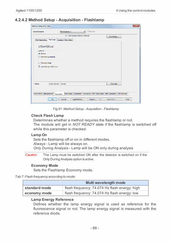
Agilent 1100/1200 4 Using the controlmodules
4.2.4.2 Method Setup - Acquisition - Flashlamp
Fig 91: Method Setup - Acquisition - Flashlamp
Check Flash LampDetermines whether a method requires the flashlamp or not.The module will get in NOT READY state if the flashlamp is switched offwhile this parameter is checked.Lamp OnSets the flashlamp off or on in different modes.Always - Lamp will be always on.Only During Analysis - Lamp will be ON only during analysis
Caution: The Lamp must be switched ON after the detector is switched on if theOnlyDuring Analysis option is active.
Economy ModeSets the Flashlamp Economy mode.
Tab 7: Flash frequencyaccording tomode:
Multi wavelength modestandard mode flash frequency: 74.074 Hz flash energy: higheconomy mode flash frequency: 74.074 Hz flash energy: low
Lamp Energy ReferenceDefines whether the lamp energy signal is used as reference for thefluorescence signal or not. The lamp energy signal is measured with thereference diode.
- 88 -

4 Using the controlmodules ClarityControlModule
4.2.4.3 Method Setup - Acquisition - FLD ParametersSets the basic parameters of the FLD detector.
Fig 92: Method Setup - Acquisition - FLD Parameters
Acquisition ModeSelects among Fluorescence , Phosphorescens or Chemoluminiscenceacquisition modes.PhosphorescenceSets the parameters of the Phosphorescence acquisition mode.Delay [µs]Determines the time between flash and Start_of_Integration.Gate [µs]Determines the time between Start of Integration and End ofIntegration.
Caution: If flash frequency is 370 Hz (the Economy Mode on the Flashlamp tab ischecked) and Delay + Gate fields sum is greater than 4.5 msec then theflash frequencywill automatically be reduced to 74 Hz!
Base WaveLengthSets the base wavelength of the Excitation and Emission for the selecteddetector.Excitation (measured)Sets excitation base wavelength for the selected detector.Possible options are Zero Order or specifying a wavelength value(default is 460 nm).
- 89 -

Agilent 1100/1200 4 Using the controlmodules
Emission (common)Sets Emission base wavelength of the selected detector.Possible options are Zero Order or specifying a wavelength value(default is 460 nm).
Multi-wavelength ModeDefines the Multi-wavelength-Mode of the detector.
Note: Clarity Control module does not enable to switch the Multi-wavelengthModeOFF.
Switching between different multi-wavelength modes lasts from 20 up to50 seconds, the module becomes NOT READY in-between.ExcitationMulti excitation wavelength and excitation spectrum. Emission will beconstant - EX1-4/EM1.EmissionMulti emission wavelength and emission spectrum. Excitation will beconstant - EX1/EM1-4.
PMT-GainSets the sensitivity (PMT-gain) of the photomultiplier.Rate [Hz]Sets the data output rate of the detector to the workstation.The data rate cannot be changed during RUN mode of the detector.Disable ADC Overflow DetectionIf set, the detection of ADC overflow is disabled and the user will not bewarned that the peaks may be cut off.
- 90 -

4 Using the controlmodules ClarityControlModule
4.2.4.4 Method Setup - Acquisition - Outputs
Fig 93: Method Setup - Acquisition - Outputs
Analog Output (X.)Zero Offset [%]Sets the zero offset voltage for Analog output 1 (2) to a percentage of thefull scale voltage.Attenuation [mAU]Selects analog output attenuation.The Agilent 1200 - FLD offers two analog outputs: Signal A at Analogoutput 1 and Signal B at Analog output 2.The attenuation can be changed in power of 2 between 1600 LU and 0.2LU.
TableThe Output relays on detector are optional feature of certain Agilent 1200configuration.If it is present in your configuration, then the table will enable to set thetimetable of events to trigger these outputs.
- 91 -
Agilent 1100/1200 4 Using the controlmodules
4.2.4.5 Method Setup - Acquisition - Time Table
Fig 94: Method Setup - Acquisition - Time Table
Time [min.]Sets a time for the desired change. Zero time is not a permitted value.Emission/ExcitationSets the Emission/Excitation wavelength (according to themultiwavelength mode selected.Ex. n/Em. nSets the respective wavelengths according to the multiwavelength modeselected.PMT GainSets the PMT Gain.
- 92 -

4 Using the controlmodules ClarityControlModule
4.2.4.6 Data AcquisitionThe Data Acquisiton window displays online signal from the detectors. Italso provides access to analysis controlling commands such as Start ,Stop etc. For detailed description of the Data Acquisition window see theClarity Reference Guide.
Fig 95: Data Acquisiton
The graph can also display acquired spectra using the View - ShowSpectrum command (active only during running acquisition).
Fig 96: Customize
It is also possible to add Show Spectrum icon to the toolbar for fast
setting of the spectral mode (as well as Set Zero and Reset Zero).To do this use the View - Toolbars - Customize... command. The ShowSpectrum icon can be found on the Customize - Commands dialog in theView set of commands.
- 93 -

Agilent 1100/1200 4 Using the controlmodules
4.2.4.7 Device MonitorThe Device Monitor window can be invoked by the Monitor - DeviceMonitor command from the Instrument window or using the DeviceMonitor icon. It allows to perform the Zero Detector action and switchthe lamp on/off.
Fig 97: DeviceMonitor of Agilent 1200 FLD
It is possible to control the detector operation during the analysis in theDevice Monitor window.AutozeroSets the response of the detector to 0.Switch On (Off)Turns the Flash lamp on/off.Det Status...Invokes the Agilent 1200 Hardware Configuration.
4.2.4.8 Hardware Configuration
Common tabDisplays the configuration of the FLD detector.
Fig 98: Hardware Configuration - Common
- 94 -

4 Using the controlmodules ClarityControlModule
FLD tab
Fig 99: Hardware Configuration - FLD
Flash lampDetermines whether the flash lamp will be automatically switched onduring Agilent 1200 startup or not. The button enables to set the lamp ONor OFF manually.Analog Output 1(2) Range [V]Sets the output signal Range to 1 V or to 0,1V.
- 95 -

Agilent 1100/1200 5 Troubleshooting
5 TroubleshootingProblem 1 - Communication problemThe communication cable must be connected to the module with mostextensive communication. When DAD detector is present, it should beused for communication. Otherwise first other detectors and only last theother modules should be used.Problem 2 - Error dialog or communication problem with GPIBEnsure you have corrected installed the IOLib Suite. If found, remove theSICL32.DLL file from the Clarity installation directory which is no longerused in Clarity from version 2.8 (C:\CLARITY by default). Then reinstall theIOLIb Suite which it can be found on the Clarity Installation CD in thedirectory HW_DRIVERS\AGILENT or download the newest version fromthe Agilent website.Communication problems may be caused by GP-IB Address conflict onthe GP-IB bus. Each Module including the GP-IB board must have uniqueaddress. The Addressees can be changed for the individual modules bythe DIPswitch settings on their backside.Default settings are listed in the chapter "Recommended GPIBaddresses" on pg 12.Also notice that GPIB communication interface is not supported sinceWindows 7.Problem 3 - Error in communication with the HP-IB cardThis may be caused by the running IOLib drivers. Remove automatic startof IOLib drivers by deleting the corresponding item from the Start - AllPrograms - Startup menu (example from English Windows XP).Problem 4 - Aborting ActivityOccasionally some Agilent 1100 module may get to the "ABORTINGACTIVITY" state (referred in the status line of the Method Setup - controltabs). The red diode is indicating Error status on the module. Usually it isnecessary to:
Close Clarity SoftwareSwitch off all the Agilent 1100 modulesWait for few secondsSwitch on the Agilent 1100 modulesStart Clarity after the modules have been initialized.
Problem 5 - Not ConnectedOccasionally some or all Agilent 1100 modules may get to the "NOTCONNECTED " state (referred in the status line of the Method Setup -xxControl tabs). This may be caused by some error in the communication.Usually it is necessary to:
- 96 -

5 Troubleshooting ClarityControlModule
Close the Clarity SoftwareSwitch off all the Agilent 1100 modulesWait for few secondsSwitch on the Agilent 1100 modulesStart Clarity after the modules have been initialized.
Problem 6 - Not ready problemWhen autosampler is not injecting, some module may be "NOT READY".(Yellow diode is lighted on this module).Check that the required lamps in detectors and the thermostat has beenturned ON.When the autosampler detects even temporary NOT READY state of somemodule, it will wait for 1 minute and then it will retry the injection.Problem 7 - Analysis stop problemWhen LC pump is configured on the system, the Analysis time is governedby the length of the gradient defined by the last line in the gradient table.The table should always contain at least two lines, even when runningisocratically.When only one line is set and the Run time is not specified in othermodules, the Agilent 1100 may be in RUNNIG STATE (green diodes on)even after the analysis time in Clarity has elapsed. The system can be insuch case stopped by the Stop command/icon from the LC Monitorwindow. The initial conditions will be resumed after using the ResumeInitial conditions command or sending the method.Problem 8 - Agilent 1100 Module ErrorOccasionally some Agilent 1100 module may get to the "ERROR" state(referred in the status line of the Method Setup - xxControl tabs). The reddiode is indicating Error status on the module. A message box describingthe error may appear in Clarity.Most common causes will be missing vial in the autosampler, exceededpressure limits on the pump, or leak detected by the solvent sensors onsome module.First it is necessary to remedy the cause, after sending the method fromClarity the operation can be usually resumed.Otherwise it may be necessary to restart the system.Problem 9 - Clarity stays in the Waiting state after Agilent 1100 stoppedthe analysisWhen the analysis is stopped from the device equipped with autosampler(unknown reason of the stop) Clarity waits two minutes and then tries tore-run the sequence, this is repeated five times and then the analysis isstopped in Clarity.Problem 10 - AS unknown error while encountering thermostat leakIn this situation, the state of the thermostat and detectors cannot be resetby sending the method nor by shutdown.
- 97 -

Agilent 1100/1200 5 Troubleshooting
It is necessary to switch the thermostat and/or detector off using the buttonon the device and then turn it on again.Problem 11 - Buffer OverflowmessageWhen the Buffer Overflow dialog appears, the communication speed withthe 1100 DAD is probably very slow. Try to change the data acquisitionRate [Hz] in Method Setup - Acquisition - Signal tab or the signal andwave length range in the Method Setup - Acquisition - DAD tab to lowervalues.Commdrv.log utilityWhen the cause of problems could not be discovered easily, the recordingof communication between Clarity and the 1100 modules cansignificantly help the DataApex support to discover the cause.It is possible to record the communication between Clarity and theAgilent 1100 system. The recording can be enabled by amending the fileCOMMDRV.INI in the Clarity installation directory (located inC:\CLARITY\CFG by default). The file can be edited in any text editor (e.g.Notepad).Find an area of the COMMDRV.INI file appropriate to the 1100 connectionyou use (GPIB or LAN) and change the paragraph so it looks as follows:for GP-IB[GPIB0,26]echo=ontextmode=onfilename=CommDrvGPIB.txtreset=on
or for LAN communication[TCP_IP 192.168.254.11:9100]echo=ontextmode=onfilename=CommDrvTCP.txtreset=onFirst rows of each paragraph should correspond to the settings of yourAgilent 1100 system and appropriate values can be found in the SystemConfiguration dialog.
Note: The communication from several COM ports /other sources may berecorded at once. It is only necessary to set each paragraph so.
The particular parametres in each paragraph mean:EchoOn - communication will be recorded.Off (default) - communication will not be recorded.TextmodeWhile set to On ensures that the communication will be recorded in thetext format. If set to Off, the output may be in binary format (if the device
- 98 -

5 Troubleshooting ClarityControlModule
supports it).FilenameThe name of the file where the communication should be stored. If thepath is not specified, the file will be stored in the same folder as theCOMMDRV.INI file.The created log file can be viewed in any text editor.ResetOn - will erase the log each time the station is restarted. In case the recordis needed, it must be renamed, copied or moved before the Clarity isstarted again.Off - the log will not be reset, it can increase substantially after some time)
Note: This record is very helpful for troubleshooting the communicationbetweenClarity and anydevice.
- 99 -
Related Documents