AFRL-VA-WP-TR-2004-3048 STRUCTURAL TESTING AND ANALYSIS OF A JOINED WING TECHNOLOGY DEMONSTRATOR Jason Robinson Design and Analysis Methods Branch (AFRL/VASD) Structures Division Air Vehicles Directorate Air Force Research Laboratory, Air Force Materiel Command Wright-Patterson Air Force Base, OH 45433-7542 APRIL 2004 Final Report for 01 October 2003 – 31 March 2004 Approved for public release; distribution is unlimited. STINFO FINAL REPORT AIR VEHICLES DIRECTORATE AIR FORCE MATERIEL COMMAND AIR FORCE RESEARCH LABORATORY WRIGHT-PATTERSON AIR FORCE BASE, OH 45433-7542

Welcome message from author
This document is posted to help you gain knowledge. Please leave a comment to let me know what you think about it! Share it to your friends and learn new things together.
Transcript

AFRL-VA-WP-TR-2004-3048
STRUCTURAL TESTING AND ANALYSIS OF A JOINED WING TECHNOLOGY DEMONSTRATOR Jason Robinson Design and Analysis Methods Branch (AFRL/VASD) Structures Division Air Vehicles Directorate Air Force Research Laboratory, Air Force Materiel Command Wright-Patterson Air Force Base, OH 45433-7542 APRIL 2004 Final Report for 01 October 2003 – 31 March 2004
Approved for public release; distribution is unlimited.
STINFO FINAL REPORT
AIR VEHICLES DIRECTORATE AIR FORCE MATERIEL COMMAND AIR FORCE RESEARCH LABORATORY WRIGHT-PATTERSON AIR FORCE BASE, OH 45433-7542
NOTICE USING GOVERNMENT DRAWINGS, SPECIFICATIONS, OR OTHER DATA INCLUDED IN THIS DOCUMENT FOR ANY PURPOSE OTHER THAN GOVERNMENT PROCUREMENT DOES NOT IN ANY WAY OBLIGATE THE US GOVERNMENT. THE FACT THAT THE GOVERNMENT FORMULATED OR SUPPLIED THE DRAWINGS, SPECIFICATIONS, OR OTHER DATA DOES NOT LICENSE THE HOLDER OR ANY OTHER PERSON OR CORPORATION; OR CONVEY ANY RIGHTS OR PERMISSION TO MANUFACTURE, USE, OR SELL ANY PATENTED INVENTION THAT MAY RELATE TO THEM. THIS REPORT IS RELEASABLE TO THE NATIONAL TECHNICAL INFORMATION SERVICE (NTIS). AT NTIS, IT WILL BE AVAILABLE TO THE GENERAL PUBLIC, INCLUDING FOREIGN NATIONALS. THIS TECHNICAL REPORT HAS BEEN REVIEWED AND IS APPROVED FOR PUBLICATION. /s/ /s/ JASON R. ROBINSON MIKE L ZEIGLER Engineering Trainee Chief Design and Analysis Methods Branch Design and Analysis Methods Branch Structures Division Structures Division /s/ JOHN A. BOWLUS Chief, Structures Division Air Vehicles Directorate Do not return copies of this report unless contractual obligations or notice on a specific document requires its return.

i
REPORT DOCUMENTATION PAGE Form Approved OMB No. 0704-0188
The public reporting burden for this collection of information is estimated to average 1 hour per response, including the time for reviewing instructions, searching existing data sources, searching existing data sources, gathering and maintaining the data needed, and completing and reviewing the collection of information. Send comments regarding this burden estimate or any other aspect of this collection of information, including suggestions for reducing this burden, to Department of Defense, Washington Headquarters Services, Directorate for Information Operations and Reports (0704-0188), 1215 Jefferson Davis Highway, Suite 1204, Arlington, VA 22202-4302. Respondents should be aware that notwithstanding any other provision of law, no person shall be subject to any penalty for failing to comply with a collection of information if it does not display a currently valid OMB control number. PLEASE DO NOT RETURN YOUR FORM TO THE ABOVE ADDRESS.
1. REPORT DATE (DD-MM-YY) 2. REPORT TYPE 3. DATES COVERED (From - To)
April 2004 Final 10/01/2003 – 03/31/2004 5a. CONTRACT NUMBER
In-house 5b. GRANT NUMBER
4. TITLE AND SUBTITLE
STRUCTURAL TESTING AND ANALYSIS OF A JOINED WING TECHNOLOGY DEMONSTRATOR
5c. PROGRAM ELEMENT NUMBER 60221F
5d. PROJECT NUMBER
A03H 5e. TASK NUMBER
0A
6. AUTHOR(S)
Jason Robinson
5f. WORK UNIT NUMBER
7. PERFORMING ORGANIZATION NAME(S) AND ADDRESS(ES) 8. PERFORMING ORGANIZATION
REPORT NUMBER
Design and Analysis Methods Branch (AFRL/VASD) Structures Division Air Vehicles Directorate Air Force Research Laboratory, Air Force Materiel Command Wright-Patterson Air Force Base, OH 45433-7542
AFRL-VA-WP-TR-2004-3048
9. SPONSORING/MONITORING AGENCY NAME(S) AND ADDRESS(ES) 10. SPONSORING/MONITORING AGENCY ACRONYM(S)
AFRL/VASD Air Vehicles Directorate Air Force Research Laboratory Air Force Materiel Command Wright-Patterson Air Force Base, OH 45433-7542
11. SPONSORING/MONITORING AGENCY REPORT NUMBER(S)
AFRL-VA-WP-TR-2004-3048 12. DISTRIBUTION/AVAILABILITY STATEMENT
Approved for public release; distribution is unlimited. 13. SUPPLEMENTARY NOTES
Report contains color. 14. ABSTRACT
This report covers the load testing, subsequent structural failure, redesign, and structural analysis of said redesign of the Air Vehicles Joined Wing Technology Demonstrator.
15. SUBJECT TERMS
16. SECURITY CLASSIFICATION OF: 19a. NAME OF RESPONSIBLE PERSON (Monitor) a. REPORT Unclassified
b. ABSTRACT Unclassified
c. THIS PAGE Unclassified
17. LIMITATION OF ABSTRACT:
SAR
18. NUMBER OF PAGES
50 Jason Robinson 19b. TELEPHONE NUMBER (Include Area Code)
(937) 255-7229
Standard Form 298 (Rev. 8-98) Prescribed by ANSI Std. Z39-18

iii
Table of Contents Section Page I Introduction 1
II Configuration 4
III Joined Wing Static Load Testing 7
Requirements and Design of Test 7
Test Results 11
IV Redesigned Concept 14
V Finite Element Analysis of Baseline the Wing 16
Geometric Modeling 16
Meshing 17
Verification of Solid Elements 18
FEM Loads 19
Material Properties and Model Tuning 21
Validation 23
VI Finite Element Analysis of the Redesigned Wing 27
VII Conclusion 31
VIII References 32

iv
LIST OF FIGURES AND TABLES
Figure 1: Front View of the Joined Wing Technology Demonstrator Figure 2: The Joined Wing Technology Demonstrator as Delivered Under
Contract with AeroComposites, Inc. Figure 3: Double Lap Joint in Wing-Fuselage Connection Figure 4: Carry-Through Spar and Bulkhead System Figure 5: Free Body Diagram of Aircraft in Radial Flight Pattern Figure 6: Free-body Diagram of JWTD Under 2G Loading Figure 7: Free-body Diagram of JWTD under Testing Conditions Figure 8: Successive Loadings of JWTD Static Load Test Figure 9: Top-view of JWTD Finite Element Mesh Figure 10: Final Aspect Ratio of Solid Elements Beam Used in the Solid to
Shell Element Comparison Study Figure 11: CosmosWorks Load Visualization for the JWTD Finite Element
Model Figure 12: Twisting of the Wing Root Modeled with CosmosWorks Figure 13: Deflection of Wing Modeled with CosmosWorks Figure 14: Von-Mises Stress Concentrations at Wing-Fuselage Connection Figure 15: Top and Bottom Views of Stress Patterns in JWTD Model Figure 16: Top View of Stress Pattern under Modified Boundary Conditions Figure 17: Positioning of Mounting Bolts under Modified Mounting
Conditions Figure 18: Layout of Fiberglass Reinforcement

v
Figure 19: Top View of Stress Patterns in Fully Modified JWTD Model Table 1: JWTD Delivery Specifications Table 2: Static Load Test Displacement Results Table 3: Material Propertie Ranges of Balsa Wood Table 4: Balsa Material Properties Used in JWTD Finite Element Model Table 5: Material Properties of Foam Table 6: Material Properties of Graphite Table 7: Boundary Conditions and Corresponding Tip Deflections

vi
FOREWORD
This report covers the load testing, subsequent structural failure, redesign, and structural analysis of said redesign of the Air Vehicles Joined Wing Technology Demonstrator. This work started on October 1, 2003 and the finite element analysis was completed by March 31, 2004. As this is being written, structural modifications to the aircraft are being made in response to the work compiled in this report. The author would like to extend his most sincere gratitude to Dr. Maxwell Blair for assistance in all stages of this project, including the finite element analysis and the writing of this report. The author would also like to thank Mr. Amarshi Bhungalia for his contributions to the finite element analysis comparisons of solid and shell elements. Jason Bowman is credited with creating the design modification procedure as outlined in Appendix A of this document. His contributions are greatly appreciated.

1
SECTION I
INTRODUCTION As an initiative into affordable, fast-response scaled aircraft prototype production, a team led by Dr. Maxwell Blair of Air Vehicles Division of the Air Force Research Laboratory began design of the Air Vehicles Joined Wing Technology Demonstrator (VA JWTD). The JWTD is a scaled version of the joined wing SensorCraft candidate in development by Dr. Blair and Lt. Col. Robert Canfield of the Air Force Institute of Technology. (Reference 1.) The SensorCraft program is an ambitious design challenge set forth by the Air Force Research Laboratory to create an aircraft with 360 degrees of sensor coverage. Along with the sensor criterion are mission critical needs: long range (50 to 60 hour missions) and high altitude (65,000 feet) flight capabilities. (Reference 3.)
Figure 1: Front View of the Joined Wing Technology Demonstrator Dr. Julian Wolkovitch, the original patent holder of the joined wing configuration, created the first proof of concept joined wing vehicles in 1983 through a contract between ACA Industries and Unmanned Systems of East Texas, Inc. In 1986, Dr. Wolkovitch published in the March edition of the Journal of Aircraft, an article entitled “The Joined Wing: An Overview.” In this article, he defined the joined wing aircraft configuration as “an airplane that incorporates tandem wings arranged to form diamond shapes in both plan and front views.” (Reference 2.) An example of this diamond shape in the front view can be seen in the picture above. Through mere geometric considerations alone, this configuration lends itself to the SensorCraft application inasmuch as the diamond shaped wing from the plan view gives 360° coverage for possible radar applications. As well as the unique geometry of the configuration, the naturally self-bracing design allows for unique structural designs. Connecting the wings

2
makes possible a thinner airfoil design than traditional wing configurations. By creating a simple truss-like structure in both plan and front views, the integrity of a wing with a thin airfoil is increased from that of a cantilever beam to that of a truss. In other words, the fore wing is reinforced by the axial load carrying capability of the aft wing. The shape creates a distributed wing load that not only passes into a transverse load, as in the case of a cantilever, but also an axial load, as in the case of a truss - leading to a stronger wing. This added wing strength is very important to the notion of decreased airfoil thickness, because it allows for smaller structural members to be used. Thin airfoil design also lends itself to the mission of the SensorCraft in that the airplane will see decreased transonic drag and an increased allowable speed before the occurrence of drag divergence. There is also an implied increase of rigidity with a decrease of vehicle weight. All this makes the joined wing configuration very attractive for the SensorCraft application. Using this knowledge of the possibility of a thin airfoil, the JWTD was designed during the summer of 2002 as a 7% scale design of the full-scale SensorCraft candidate from Blair and Canfield. This resulted in an aircraft with a 14-foot span and fore and aft wings swept at ± 30°, respectively. The fore wings are placed at a 9° dihedral, and the aft wings are placed at a 7.8° anhedral. Using inexpensive materials to facilitate a build-up approach with some trial-and-error, the vehicle consists of construction materials found in nearly all remotely controlled aircrafts on the commercial market. The JWTD also contains many off-the-shelf items, such as its motor, servos, and other pieces of R/C equipment.
Figure 2: The Joined Wing Technology Demonstrator as Delivered Under
Contract with AeroComposites, Inc.

3
During the time of construction, computer based structural analysis of the full-scale joined wing configuration was near completion, but since analysis was not yet finished, it was left to conventional knowledge and common R/C construction practices to complete the design and building of the JWTD. This will be discussed in further detail as it directly lead to the failure of the JWTD under static load testing.

4
SECTION II
CONFIGURATION A key design consideration of the JWTD was modularity of its wings, due to the cumbersome nature of a 14-foot aircraft. The design called for three removable wing sections: right fore wing, left fore wing, and aft wing. The fore wings were to be attached to the fuselage by means of a male carry-through spar (made of a carbon fiber composite) running spanwise across the fuselage and a female double-sided lap joint section on each wing. The lap joints were to receive the male portion of the carry-through spar and two bolts were to connect them. This lap joint is shown below in Figure 3.
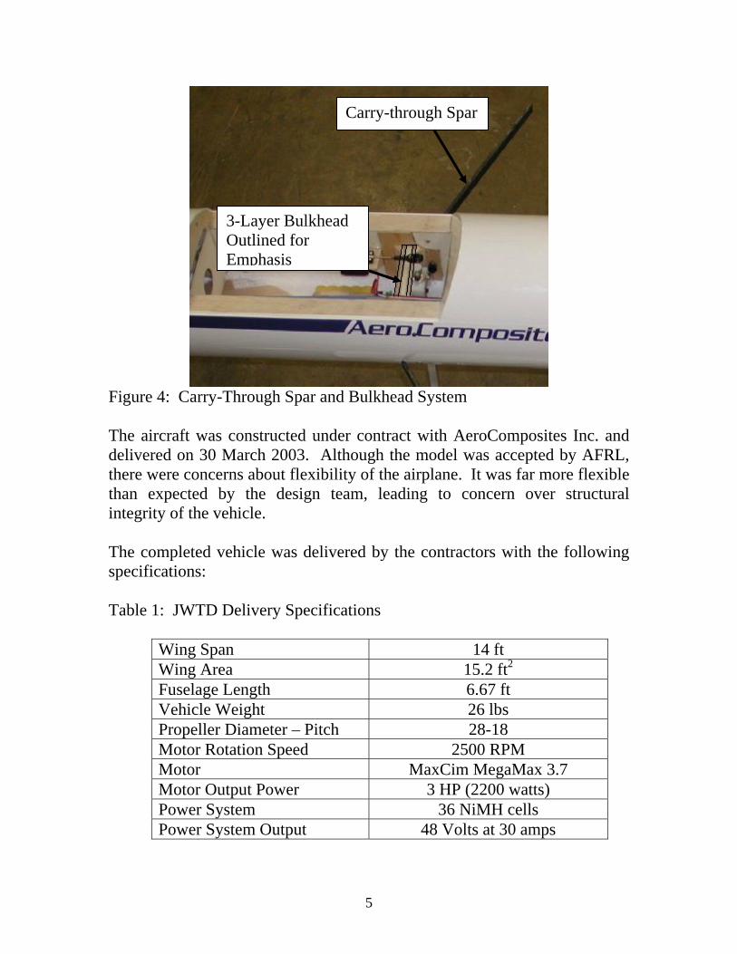
Figure 3: Double Lap Joint in Wing-Fuselage Connection The carry-through spar was inserted into the fuselage by imbedding it in a structural bulkhead. The bulkhead consisted of three layers of plywood. The middle layer had a section removed that was the height of the carry-through spar. The spar was bonded in that removed section within bulkhead with an epoxy adhesive. The spar and bulkhead system are shown in Figure 4.
Double Lap Joint
5
Figure 4: Carry-Through Spar and Bulkhead System The aircraft was constructed under contract with AeroComposites Inc. and delivered on 30 March 2003. Although the model was accepted by AFRL, there were concerns about flexibility of the airplane. It was far more flexible than expected by the design team, leading to concern over structural integrity of the vehicle. The completed vehicle was delivered by the contractors with the following specifications: Table 1: JWTD Delivery Specifications
Wing Span 14 ft Wing Area 15.2 ft2
Fuselage Length 6.67 ft Vehicle Weight 26 lbs Propeller Diameter – Pitch 28-18 Motor Rotation Speed 2500 RPM Motor MaxCim MegaMax 3.7 Motor Output Power 3 HP (2200 watts) Power System 36 NiMH cells Power System Output 48 Volts at 30 amps
Carry-through Spar
3-Layer Bulkhead Outlined for Emphasis

6
The motor and propeller of the JWTD were tested in a wind tunnel at speeds from 0 mph to 45 mph, where thrust was the key output data. From this testing, it was found that at zero velocity, the motor and propeller are able to create 11.5 pounds of thrust. At 45 mph, the motor and propeller are able to produce 4 pounds of thrust. If a linear decrease in thrust with respect to velocity and a lift to drag ratio of 10 are assumed (see Appendix B), the maximum flight speed of the vehicle can be calculated. In order to maintain a static velocity, thrust must equal drag and lift must equal the weight of the vehicle. D is the drag force and L is the lift force.
10
26 lbs26 lbs 2.6 lbs
10
LD
L
D
=
=
= =
Since drag has been calculated, it must equal the thrust. Therefore, the motor and propeller must create 2.6 pounds of thrust. Knowing the value of thrust, the velocity and thrust curve can be linearized in order to find the maximum velocity of the aircraft.
( ) ( ) ( )
( )
mi45 hrmi0 11.5 lbshr 4 11.5 lbs
6 69
V T
V mph T
− = −−
= − +
Now, the maximum velocity is simply found by calculating a value for velocity when thrust is equal to the drag found above (2.6 pounds).
( )max 6 2.6 69 53.4 V MPH= − + =
Unfortunately, the wind tunnel data may be slightly skewed by the absence of airflow interference around the wings and fuselage of the JWTD. The maximum airspeed of the JWTD is estimated to be approximately 50 miles per hour.

7
SECTION III
JOINED WING STATIC LOAD TESTING
Requirements and Design of Test The JWTD test plan calls for a series of pre-flight ground tests. These tests are more than one normally associates with RC airplane development, but less than required for certified aircraft. The ground tests are intended to balance the requirement for safety with practicality. The first of the series of tests is a 2G-maneuver load test. The rationale behind a 2G load testing is based on the calculation of flight loads at the minimum radius and maximum speed predicted for the flight-testing. The aircraft flying around a radius, r, at a speed, V, must create the proper amount lift, L, that will maintain its flight pattern. Calculating this needed lift will allow us to find the amount of Gs the aircraft must withstand. FC is the inertial load of the vehicle, and θ is its bank angle. Figure 5: Free Body Diagram of Aircraft in Radial Flight Pattern To calculate lift, we must also calculate bank angle. We make this calculation by balancing forces shown in the free body diagram of Figure 5.
0 sin sinX C cF L F L maθ θ= = − = −∑
L θ
FC
W
x
y

8
The aircraft is making a coordinated turn with a radius, r. The inertial acceleration must be centripetal acceleration.
2
2
2
sin 0
sin
Cvma mr
vL mrvL mr
θ
θ
=
− =
=
0 cos cos
cosyF L W L mg
L mg
θ θ
θ
= = − = −
=∑
With two equations and two unknowns, our aerodynamic load can be obtained.
2
sin
cos
mvLrmgL
θ
θ
=
=
2 222 2
2 22 22 22
sin cos 1 1
1 1
mv mgLr L
mv mg m v gLr L L r
θ θ⎛ ⎞ ⎛ ⎞+ = ⇒ + =⎜ ⎟ ⎜ ⎟
⎝ ⎠⎝ ⎠
⎛ ⎞ ⎛ ⎞⎛ ⎞ ⎛ ⎞⇒ + = ⇒ + =⎜ ⎟ ⎜ ⎟⎜ ⎟ ⎜ ⎟⎝ ⎠ ⎝ ⎠⎝ ⎠ ⎝ ⎠
22
2 1m v gL r
⎛ ⎞+ =⎜ ⎟
⎝ ⎠
22
2vL m gr
⎛ ⎞= +⎜ ⎟
⎝ ⎠
This value is the lift that must be created by the aircraft to maintain velocity, v, around a turn of radius, r. The maximum lift is caused when the radius is
Equation 1
9
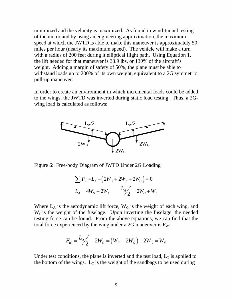
minimized and the velocity is maximized. As found in wind-tunnel testing of the motor and by using an engineering approximation, the maximum speed at which the JWTD is able to make this maneuver is approximately 50 miles per hour (nearly its maximum speed). The vehicle will make a turn with a radius of 200 feet during it elliptical flight path. Using Equation 1, the lift needed for that maneuver is 33.9 lbs, or 130% of the aircraft’s weight. Adding a margin of safety of 50%, the plane must be able to withstand loads up to 200% of its own weight, equivalent to a 2G symmetric pull-up maneuver. In order to create an environment in which incremental loads could be added to the wings, the JWTD was inverted during static load testing. Thus, a 2G-wing load is calculated as follows: Figure 6: Free-body Diagram of JWTD Under 2G Loading
( )2 2 2 0
4 2 22
Z A G f G
AA G f G f
F L W W W
LL W W W W
= − + + =
= + = +
∑
Where LA is the aerodynamic lift force, WG is the weight of each wing, and Wf is the weight of the fuselage. Upon inverting the fuselage, the needed testing force can be found. From the above equations, we can find that the total force experienced by the wing under a 2G maneuver is FW:
( )2 2 22A
W G F G G FLF W W W W W= − = + − =
Under test conditions, the plane is inverted and the test load, LT is applied to the bottom of the wings. LT is the weight of the sandbags to be used during
2WG 2WG
2Wf
LA/2 LA/2
10
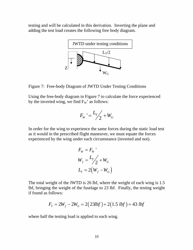
testing and will be calculated in this derivation. Inverting the plane and adding the test load creates the following free body diagram. Figure 7: Free-body Diagram of JWTD Under Testing Conditions Using the free-body diagram in Figure 7 to calculate the force experienced by the inverted wing, we find FW’ as follows:
' 2T
W GLF W= +
In order for the wing to experience the same forces during the static load test as it would in the prescribed flight maneuver, we must equate the forces experienced by the wing under each circumstance (inverted and not).
( )
'
22
W W
Tf G
T f G
F FLW W
L W W
=
= +
= −
The total weight of the JWTD is 26 lbf, where the weight of each wing is 1.5 lbf, bringing the weight of the fuselage to 23 lbf. Finally, the testing weight if found as follows:
( ) ( )2 2 2 23 2 1.5 43 T f GF W W lbf lbf lbf= − = + = where half the testing load is applied to each wing.
WG
LT/2
JWTD under testing conditions
Z

11
Due to the research nature of the load tests, it was imperative that the loads be applied at small increments so the results of progressively increased loads could be documented. Also, in the case of test failure, a single application of the testing load could cause catastrophic failure without any forewarning. On the other hand, an incremental application of the load may show lesser signs of failure before the aircraft would break beyond repair. A set of one-pound sandbags was created that would be placed along the wing at even intervals as the loads were applied. During testing, these one-pound sandbags were placed symmetrically along the wings, two at a time – one on the right wing and one on the left wing, at the same distance from the fuselage. Starting at the root of the wing, leading outward, the load was placed at even intervals until reaching the wing tip. This loading was placed on both the fore and aft wings.
Test Results The first loading at which measurements were recorded is 20 pounds, 10 pounds on each the right and left wing. This resulted in a wing tip displacement of 8 inches at either tip. The second set of measurements was taken at a loading of 40 pounds. This resulted in a tip displacement of 21 inches on both sides. Upon nearing the target test weight, considerable creaking sounds pointed to possible failure. The test was aborted at 46 pounds when the deflection was far too great and signs of structural failure were evident. The weights were removed and the wings were inspected. As shown in the following pictures in Figure 8, the displacement of the tip was far from linear with respect to the wing loading. Table 2: Static Load Test Displacement Results
Increment Applied Load (lbs)
Tip Displacement - Left (in)
Tip Displacement - Right (in)
0 0 0.00 0.00 1 20 8.00 8.00 2 40 21.00 21.00 3 46 NM NM

12
Figure 8: Successive Loadings of JWTD Static Load Test Through inspection, it was found that parts of the wing construction had become delaminated and structural integrity of the joint between the wing and fuselage had been severely compromised. Prior to testing, the lap joints connecting the wing to the fuselage carry-through spar had been reinforced with epoxy adhesive. During the test, much of the epoxy connecting the spars was damaged and cracked. Also, the bulkhead in which the carry-through spar was mounted was delaminated. As discussed before, the bulkhead was constructed of three layers. The outer two layers were no longer glued to the inner layer in the area surrounding the carry-through spar, and the carry-through spar was free to twist within the bulkhead. This freedom led to the excessive deflection of the wing upon substantial loading. It was determined that the wing, upon loading - with its attachment to the fuselage via a single carry-through spar, attempted to twist at the wing root until the carry through spar acted as a prying member. The spar was able to pry apart the three sections of the plywood bulkhead as well as the glue that reinforced the lap joints within the wing. After becoming free to twist within the bulkhead, the wing was more free to flatten out into a plane (consisting of three points: the fore root, the aft root, and the wing merge), causing the moment of inertia of the wing sections with respect to that plane, as a bending plane, to be reduced. This effectively erased the truss-like characteristics of the joined-wing design and allowed the wing to transition into a simple cantilever, slightly skewed from simple vertical deflection.
Load 1: Increment 0 Load 2: Increment 1 Load 3: Increment 2
13
The static load test revealed obvious failure in the structural design of the JWTD. This failure is focused in the region of the fore wing root. The original design shows a need for structural improvement in the connection of the fuselage and the fore wing sections. As the bulkhead within the fuselage was delaminated, along with the spar lap joints, it would be impractical to clear the vehicle for further testing. These two malfunctions severely inhibit the ability of the wings to support the loads needed for even the simplest of flight maneuvers.

14
SECTION IV
REDESIGNED CONCEPT In conceiving a redesign plan for the JWTD, the design team’s main focus was to reduce the likelihood of failures similar to those found in the static load test. The fore wing root quickly became the center of attention. As the wing was simply fastened to a single spar (of relatively low thickness), all the loads were passed through that spar into the fuselage. Because it was not thick, the carry-through spar presented very low resistance to twisting in the wing. These are the two main problems accounted for in the redesign of the wing-fuselage attachment. See Appendix A for a detailed description of the repair process. In order to create a more evenly distributed load path, the redesign called for a broader base of attachment of the wings to the fuselage. More specifically, a new section created from foam and balsa would be placed spanwise around the current carry-through spar. This addition, upon subsequent reinforcement, would then serve as mounting point connecting the wing to the fuselage. The advantage of this connection over the single carry-through spar configuration is two-fold. First, by adding cross-sectional area to the connection point, the stress is more evenly distributed. This decreases the chance of static failure due to shear and axial stresses within the wing, but it does not account for the twisting problems exhibited in the static load testing. The second advantage, however, takes care of the twisting problem. After adding the new foam and balsa addition, four hard-points would be added within the addition. A hard-point is a section of significant structural integrity (i.e. a hard wood) adhered to the foam and balsa in order to act as a structural connection. The hard-point is a way to distribute the load of the connection throughout the balsa and foam structure whereas it would be impossible to mount directly to foam and balsa, due to their relatively low abilities to resist failure due to high stress concentrations. Four hard points in total would be added to the wings – two on either side of the center axis of the plane. Each set of hard points would have one directly in front of the other. These hard-points would in turn be bolted directly onto a horizontal bulkhead within the fuselage. This bulkhead would replace the vertical bulkhead damaged in the static load test. By setting these hard points away from each other (one near the leading edge and one near the trailing edge of

15
the wing), they would act to reinforce the wing root against the torque that led to the delamination of the lap joint within the wing. Unlike the single carry-through spar design, the new design would not allow all load paths to channel themselves through a small area. This is done by the addition of the large connection base to the fuselage. In creating that large base, the issue of torque has been circumvented as well. To create an extra bit of assurance against stress failure, and to reduce unwanted flexibility within the wing, several degrees of fiberglass reinforcement would be added. These fiberglass layers would be added incrementally, and to different sections of the wing, according to necessity. The first layer of fiberglass to be added is reinforcement tape. Two strips of thick fiberglass tape would run near the leading and trailing edges of the wing on both the top and bottom of the wing. This layer would be added only from the wing root section out to midway between the root and the wing merge section. This section would aid in the reinforcement of the joint at the wing root. The second layer of fiberglass would both reinforce the root joint and act as a stiffener for the entire wing. This layer would be composed of a single sheet of 2 oz. fiberglass that covers the entire surface of the wing from the wing root to the wing merge. Up to three additional layers of 2 oz. fiberglass sheets would be added to the wing root. They would run spanwise to half the distance between the root and the wing merge section. These layers would also both reinforce the joint at the wing root and add needed stiffness to the wing. Between the fiberglass reinforcement and the updated mounting section of the wing, it would appear that all problems exhibited by the JWTD during static load testing had been addressed by the redesigned mounting configuration.

16
SECTION V
FINITE ELEMENT ANALYSIS OF THE BASELINE WING Upon seeing that the first static load test of the JWTD would end in failure, it was believed to be a lapse in structural analysis that led the design to its demise. In order to ensure a successful redesign, the JWTD was to be subjected to a series of finite elements studies. This finite elements work focused on the point of the structural failure – the root of the fore wing – and integrated the structural redesign concepts into the model. With new knowledge of structural loading and a reassurance of the aircraft’s structural integrity after modifications, the finite element studies should help create an aircraft with improved structural performance under prescribed flight conditions. A finite element study would be performed to match baseline model behavior with the behavior of the JWTD under static load testing. From here, the baseline finite element model would be modified to reflect the redesign concepts mentioned above. It is thought that having properly matched the behavior of the baseline model, any advantages seen by the modifications in the finite elements analysis would also be seen in the real model upon modification. In order to subject an aircraft to such a study, one must create a finite elements model of that aircraft. This model consists of a 3-Dimensional geometric model, which gets meshed into the finite elements. A model is created via a pre-processor within the finite elements software package or within a separate modeling program that can export the model to the software package. The model of the JWTD was created using a 3D computer aided design package, named SolidWorks. SolidWorks creates solid geometries that can be exported to the software module COSMOSWorks to be studied as finite element models. The benefit of SolidWorks over other preprocessor driven model generation packages is its relative ease of use. Someone with only a small amount of training can accurately capture geometries of quite complex objects.
Geometric Model Within SolidWorks, all three structural components of the JWTD wing are created as separate part files. The foam core, balsa sheeting, and carbon-

17
fiber spar system are then merged into one assembly of parts with perfect precision. The model is created so that it is an idealized version of the JWTD, whereas any imperfections in construction are neglected. In order to reduce computation time, the airfoil was reduced in complexity (only one out of ten data points of the fully smoothed airfoil cross-section were used to create its cross-sectional geometry), but still maintained the shape of the actual airfoil. This cross-sectional geometry was extruded to the proper angles and lengths in order to create the foam core entity. The balsa sheeting was created by means of an outward shelling process. Knowing that the balsa sheeting is 1/16 of an inch thick, and it covers the foam, the foam core entity was used to create the balsa skin. The foam core was expanded by the thickness of the balsa and left hollow. This created an accurate representation of the balsa skin used on the JWTD. In creating the spars, an entity was created that modeled the geometry of the spars. This exact shape was removed from the foam and balsa entities, allowing for the recess in which the spar sits. These three entities were brought together in one assembly to create the 3-Dimensional model of the JWTD wing. This assembly of the three basic wing sections will now be referred to as the baseline geometric model. In order to perform any series of finite element analyses, the baseline geometric model must be converted to a finite elements model by means of creating a mesh and assigning material properties to the different wing components. From the point of completing baseline geometric model, the assembly is loaded into the COSMOSWorks software module. This module is a piece of add-on software that allows a user to analyze a model within the SolidWorks graphical interface using the COSMOS finite elements solver algorithms.
Meshing The mesh of the JWTD finite elements model makes it a departure from standard thin-wall aerospace analysis. Due to the expansive geometry of the foam wing core, it would be quite a task to create a proper representation of the solid foam using plate or shell elements. This led to the using solid elements to represent all components of the JWTD. The solid elements used are a standard tetrahedral element, with a standard edge length of 0.75 inches, allowing for a highly refined mesh. The edge length, however, was

18
allowed to vary in the planar axis when the element needed to be thinner than the standard length, as was the case in the thin layer of balsa.
Figure 9: Top-view of JWTD Finite Element Mesh
Verification of Solid Elements
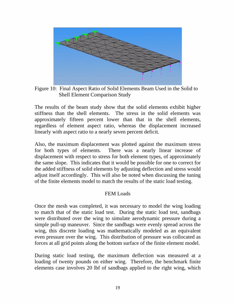
In an attempt to verify the use of solid elements with such extreme aspect ratios, a study was conducted on a simple beam structure, as shown in Figure 10. The beam study compares solid elements and shell elements – the latter being more commonly used in aerospace analysis. Both maximum stress and displacement were recorded as the thickness was decreased and the aspect ratio of the solid elements reached that of the solid elements used in the balsa skin of the JWTD model. In the beam study, the final result compares solid and shell elements at the aspect ratio used in the thin balsa layer of the JWTD finite element model. The beam was made incrementally thinner until it the ratio of the standard top edge length of the solid elements to the thickness of the beam matched the same ratio as seen on the balsa elements of the JWTD model. In the case of the JWTD model, the average planar edge length of each element is approximately 0.75 inches. The balsa sheeting is one sixteenth of an inch thick. The average planar edge length used in the beam study is equal to that used in the JWTD model; therefore, the final thickness – which was incrementally decreased from 1 inch – was also one sixteenth of an inch. The final element aspect ratio can be observed in Figure 10.
19
Figure 10: Final Aspect Ratio of Solid Elements Beam Used in the Solid to
Shell Element Comparison Study The results of the beam study show that the solid elements exhibit higher stiffness than the shell elements. The stress in the solid elements was approximately fifteen percent lower than that in the shell elements, regardless of element aspect ratio, whereas the displacement increased linearly with aspect ratio to a nearly seven percent deficit. Also, the maximum displacement was plotted against the maximum stress for both types of elements. There was a nearly linear increase of displacement with respect to stress for both element types, of approximately the same slope. This indicates that it would be possible for one to correct for the added stiffness of solid elements by adjusting deflection and stress would adjust itself accordingly. This will also be noted when discussing the tuning of the finite elements model to match the results of the static load testing.
FEM Loads Once the mesh was completed, it was necessary to model the wing loading to match that of the static load test. During the static load test, sandbags were distributed over the wing to simulate aerodynamic pressure during a simple pull-up maneuver. Since the sandbags were evenly spread across the wing, this discrete loading was mathematically modeled as an equivalent even pressure over the wing. This distribution of pressure was collocated as forces at all grid points along the bottom surface of the finite element model. During static load testing, the maximum deflection was measured at a loading of twenty pounds on either wing. Therefore, the benchmark finite elements case involves 20 lbf of sandbags applied to the right wing, which

20
computes to an equivalent 0.0143 psi pressure over the bottom skin. The load was applied in a vertical direction, the direction that gravity acted on the sand bags. Although the graphic below makes it appear as though the pressure is unevenly distributed along the merge section, this is simply due to the nature of the load visualization used. The pressure is added to several separated surfaces in that section, which is shown as a cluster of vectors. Each vector cluster only accounts for pressure on a section, and not the magnitude of the total applied force. This is why along the larger sections – e.g. the fore and aft wings – the load looks very sparse. This means that the smaller each section is, the more vectors will be shown.
Figure 11: CosmosWorks Load Visualization for the JWTD Finite Element
Model Because only half the spar is modeled, and the loads are added symmetrically to each side, symmetry boundary conditions could be applied. Another complication of the boundary conditions is the notion of spar twisting. When discussing the results of the static load testing, it was mentioned that the spar was found to have twisted within the plywood bulkhead. This is motion that must be accounted for within the finite elements model. In order to do so, a point on the top of the spar was constrained in the x-, y-, and z-directions. This allows for twisting about that point in any direction, but removes the possibility for translation. To model the symmetry of the spar, a constraint at the bottom of the spar root is placed to keep it from moving from the model’s plane of symmetry. While this constrains the model from moving away from the plane of symmetry, it does nothing to stop the twisting of the wing, which is a desired effect in the model. Because the connection of the aft wing was found to be far more

21
rigid during static testing, every node of the aft wing is constrained from translation at its root.
Material Properties And Model Tuning One peculiarity of this analysis is the fact that the materials used are not common engineering materials. Whereas the material properties of steels and other metals are easily found in materials handbooks, the same cannot be said about any material used in this analysis. Using sheets of expanded bead insulating foam for structural purposes is not the original intent for the product; therefore its structural properties have not been thoroughly tested nor published. To further compound the issue, once the published material properties were actually found, both balsa and carbon fiber composites were shown to have a range of material properties. This is because balsa is an organic material; each section of wood has different properties. The difficulty with the carbon composite is that it is produced in a variety of methods, rendering different material properties for each, depending on the density of carbon fibers with respect to resin content. Balsa wood has desirable strength-to-weight properties for use with small-scale airplane structures. Balsa wood material properties also come with significant variability. The specific gravity of balsa varies between [0.06 < d < 0.22]. The Young's modulus (EL) is parametrically related to density as EL = [(5.5e6)ρ - 2.0e5]psi. Balsa is orthotropic and requires a transverse Young's modulus, which we take to be [ET = 0.015EL]. Also the shear modulus for balsa is GLT = 0.037EL. The strength of balsa is also variable. Table 3: Material Propertie Ranges of Balsa Wood
Range (psi) Tensile longitudinal strength (SLt) [1375 < SLt < 4525] Compressive longitudinal strength (SLc) [ 500 < SLc < 2310] Tensile transverse strength is (STt) [ 72 < STt < 223] Compressive transverse strength is (STc) [ 50 < STc < 198] Shear strength (SLT) [ 158 < SLT < 522]

22
References: (http://www.cstsales.com/balsa_wood_properties.htm) and US Dept of Agriculture Wood Handbook Handbook No. 72 produced by the Forest Products Laboratory of the Forest Service. Table 4: Balsa Material Properties Used in JWTD Finite Element Model
(psi) Young’s Modulus (EL) 768000 Transverse Young’s Modulus (ET) 11520 Poisson’s Ratio (ηxy) 0.3 (no units) Shear Modulus (GLT) 28416 Tensile longitudinal strength (SLt) 2500 Compressive longitudinal strength (SLc) 1750 Tensile transverse strength is (STt) 125 Compressive transverse strength is (STc) 100 Shear strength (SLT) 350
The material properties for low-density foam (1 lbm/ft3 white expanded bead - source unknown) are also not well specified. Engineering data is not commonly published for this kind of lightweight packing foam. Klegecell is an engineering foam with published isotropic properties indicated below. Table 5: Material Properties of Foam
Young's Modulus (psi) 3630 Shear Modulus (psi) 1450 Poisson Ratio 0.25 Density (lbm/ft3) 2.5 Tensile strength (psi) 100 Compressive strength (psi) 60 Shear strength (psi) 68
The properties for unidirectional graphite epoxy are also not calibrated, primarily due to undocumented resin content. These are the assumed properties. Table 6: Material Properties of Graphite

23
Graphite Properties Longitudinal Modulus (psi) 2.63e+7 Transverse Modulus (psi) 1.49e+6 Shear Modulus (psi) 1.04e+6 Poisson Ratio 0.28 Density (lbm/in3) 0.042 Longitudinal strength (psi) 5.0e+5 Transverse strength (psi) 5.0e+4 Shear strength (psi) 1.0e+5
Preliminary results indicated that the balsa skin properties strongly dominated the overall stiffness of the wing. With this in mind and the wide variability in balsa material properties (factor of two), we chose to tune the baseline model by adjusting the stiffness of the balsa within a reasonable range. In the end, the FEM produced a wingtip deflection of 20.6 in. This matches very well with the experimental test deflection of 21” deflection. As discussed, we assume the non-linear shift in the tabulated test results were the result of the bulkhead failure with delamination. In this FEM, we assumed the spar was totally free to twist in the bulkhead following the bulkhead failure. Also, we feel that it is possible to obtain accurate stress information in the simple case of a cantilever beam by changing the deflection. If that statement is generalized, then the same principle can be applied to a model such as the JWTD.
Validation
Lower Balsa Skin
Upper Balsa Skin
Graphite Spar at Symmetry Plane
Figure 12: Twisting of the Wing Root Modeled with CosmosWorks

24
The wing deforms with both bending and twisting as the wing loading increases. Twisting is evident in the graphic above, Figure 12, where the structure twists away from the superimposed vertical red line. Again, we have assumed that this twisting caused the delamination of the multi-ply bulkhead in the fuselage and debonding between the wing spar and the interior foam.
Figure 13: Deflection of Wing Modeled with CosmosWorks As shown below, in Figure 13, the interface between the root of the wing and the carbon fiber spar has a very high stress concentration (as indicated by the color red) due to the twisting of the spar at the wing’s root. There is no load carried along the forward wing leading or trailing edges. This is expected, with no corresponding support and all loads transmitted through the spar.
Figure 14: Von-Mises Stress Concentrations at Wing-Fuselage Connection
As shown in Figure 14, the maximum von-Mises stresses in the aft wing root occurs on the top of the wing along the leading edge and on the bottom of the wing along the trailing edge. The red sections of this chart are in the realm of 2000 psi. This is approaching the lower limit of the weakest balsa wood (see material properties table).

25
Top View
Bottom View
Figure 15: Top and Bottom Views of Stress Patterns in JWTD Model After taking note of all the results, the baseline finite elements model was found to be an acceptable model of the JWTD under a static load test. This assumption is made based on two results: stress and displacement. After tuning the material properties of the balsa, the tip displacement of the model matched within two percent error of the measured value. Also, the rotational displacement of the wing’s spar about a vertical axis is representative of the twisting spar within the fuselage of the JWTD. The stress analysis is thought to be accurate because of its placement and magnitude. There are

26
high stress levels shown at the root of the forewing, where the spar enters the wing. This is consistent with the spar splaying the connections within the wing and the bulkhead. Also, the stress levels are not above the allowable stress levels of balsa wood – which did not fracture during testing. Finally, the stress patterns in the aft wing are consistent with those published for the full-scale joined wing aircraft.

27
SECTION VI
FINITE ELEMENT ANALYSIS OF THE REDESIGNED WING After it was found that the baseline finite elements model properly captured the behavior of the JWTD under static testing, modifications in step with the redesign plans were made. Both the left and right fore wings were extended to the centerline and connected with foam core covered with balsa. This is the first step in the redesign process. The finite element analysis was repeated with the wing root cantilevered.
Figure 16: Top View of Stress Pattern Under Modified Boundary
Conditions The largest change in displacement results found in the finite elements analysis, due to changing only one variable, is in changing the boundary conditions to reflect a case where the newly added center section is constrained. Both the fore and aft wings are constrained as cantilevers to the plane of symmetry in this case. In Figure 16, a stress contour (using the same color scale as the stress contour in the baseline study for continuity) is shown to have peaks in the stress contours along the leading and trailing edges of both the fore and aft wings. The stress concentrations shown are consistent with the location of the stress concentrations in the aft wing of the baseline study. Due to the new constraints on the fore wing (similar to those on the aft wing), it has stress concentrations in similar locations. These results are quite similar to the results of the full-scale finite elements analysis published at the time of completion of the JWTD.

28
Figure 17: Positioning of Mounting Bolts Under Modified Mounting
Conditions Eventually this is modified to model a possible wing fastening design by adding four fasteners to clamp the wing to the fuselage. These bolts are fasteners that would be added at the approximate location of the red circles shown above, in Figure 17. This models the method of joining the wing to the fuselage called for in the redesign plan. This is modeled by fixing the wing at the positions indicated and applying a symmetry boundary condition to the root of the wing. The effects of changing this boundary condition are negligible in terms of stress concentrations. Although there is a slightly higher concentration at the position of the bolts, the rest of the wing experienced approximately the same stresses. This modification also did very little to affect the overall tip deflection, when compared to the totally cantilevered model. The following table shows the effects of the different boundary conditions on deflection: Table 7: Boundary Conditions and Corresponding Tip Deflections
Constraint Tip deflection Graphite spar (Baseline) 20.61” Entire Wing Root 9.00” Bolts 9.01”
As a possible solution to the problem of excessive tip deflection and as reinforcement against torsion, it is suggested that fiberglass be applied to the inboard section of the fore wing of the JWTD. Adding fiberglass as shown, and allowing the boundary conditions to remain the same (a cantilevered center section) produce a decrease in tip deflection of the model. The fiberglass is added in two thicknesses. From the root to slightly inboard of the wing merge, a base layer is applied. Two additional layers are added

29
from the root up to one quarter the distance to the wing merge. This results in thicknesses of 0.012 inches and 0.004 inches, respectively. Applying this modification to the baseline finite element model produces desirable results of decreasing tip deflection even further than before. This reduction in tip deflection indicates the absence of structural failure due to excessive twisting within the wing. The fiberglass layout plan is shown in Figure 18.
Figure 18: Layout of Fiberglass Reinforcement
Another, more important, favorable effect of adding fiberglass is the stress reduction seen in the wing. As shown in the graphic in Figure 19, adding fiberglass to the wing structure allows for a great decrease in the stress concentrations. Whereas the highest stress levels in the all the cases before adding fiberglass, the maximum stress levels were on the order of 2000 pounds per square inch. After adding fiberglass, and using the cantilevered boundary conditions, it’s shown that the maximum stress concentration has a value of less than 700 pounds per square inch. This shows that adding fiberglass reduces stress by about 66%. While it was noted that solid elements are stiffer than shell elements, simply by their nature, this reduction in stress is a great sign for the confidence of the redesign plan. The maximum stress as indicated here is well within the design parameters of the materials used. This means that an even greater maximum stress is acceptable.

30
Figure 19: Top View of Stress Patterns in Fully Modified JWTD Model

31
SECTION VII
CONCLUSION
As clearly demonstrated above, the success of the JWTD finite elements model is based on its successful capture of the physical behaviors of the JWTD when subject to static load test with a 40-pound load. This success is marked by the model showing such characteristics as increased stress concentrations at the point of failure on the model, the non-failure of the balsa structure, the twisting exhibited in the fore wing root, and proper displacement values of the model’s wing tip when compared to the loaded JWTD. These points of success validate the finite elements model to a point at which confidence in the model was sufficient to continue with model modifications. These modifications were simply the institution of redesign concepts into the finite elements model. As the first change, the mounting procedure of the wing was altered to allow a broader base of support for the wing root – reflected in the model as a change in boundary conditions along the fore wing root. The second change was the addition of a fiberglass structure along the inboard half of the fore wing. This change was made possible in the model by adding a fiberglass part to the wing model and applying it to the baseline geometric model. After making these changes, the finite elements model was again analyzed with a 40-pound static loading scheme and the results were highly encouraging. Modifying the boundary conditions caused unwanted deflection to be reduced and detrimental stress concentrations to be decreased with regard to both size and magnitude. Adding the fiberglass reinforcement layers caused an even further decreased tip deflection, but more importantly, a maximum stress concentration value that was incredibly low compared to the baseline model. This decreased stress concentration is what allowed the design team to initiate fabrication of the modifications on the actual JWTD. We are confident that the failure experienced in the original static load test will not be experienced under the modified structural conditions.

32
SECTION VIII
REFERENCES 1.) Maxwell Blair, Robert A. Canfield, Ronald W. Roberts. “Joined Wing
Aeroelastic Design with Geometric Non-Linearity”, Presented at International Forum on Aeroelasticity and Structural Dynamics in Amsterdam Netherlands 04-06 June 2003. (To be published in AIAA Journal of Aircraft).
2.) Julian Wolkovitch. “The Joined Wing: An Overview”, Journal of
Aircraft, p. 161-178, March 1986. 3.) Michael Sirak. “USAF’s Sensorcraft Takes Shape”, Jane’s Defense
Weekly, < http://www.janes.com/defence/air_forces/news/ jdw/jdw030509_1_n.shtml>, 09 May 2003.

33
APPENDIX A
Proposed Repair and Modification The proposed modification is to place the carry-through structure inside the wing rather than in the fuselage. This procedure will result in a one-piece removable forward wing of 14 ft. span and a one-piece aft wing. Graphical representations will aid the interpretation of the following proposed repair and modification sequence.
1. Restore the damaged bond between the wing and the carry-through spar
2. Mark curve where wing and fuselage intersect (see fuselage modification)
3. Remove the carry-through spar and wing assembly from the fuselage 4. Cut foam core (airfoil shape minus skin) for carry-through 5. Bond foam core to the wing and carry-through spar 6. Bond 1/16 in balsa skin to carry-through foam core. 7. Mill out balsa to receive 10 oz/yd fiberglass strips top and bottom 8. Bond 10 oz fiberglass strips into balsa top and bottom 9. Bond 2 oz/yd fiberglass on top and bottom of forward and rear wings
(orient ±45°) 10. Bond 2nd layer of 2 oz/yd fiberglass on top and bottom of forward
and rear wings (orient ±45°) 11. Finish wing surface to a smooth surface without ripples or bumps. 12. Use a hole saw to cut 3/4 holes (quantity four) through wing and
through 10 oz cloth as indicated 13. Bond dowel rod segments in 3/4 holes. 14. Drill 1/8 in centered holes in dowel segments to receive mounting
bolts. 15. Refer to fuselage modifications contained in the Statement of Work. 16. Fasten modified wing to modified fuselage
A sketch of this repair technique is shown in the following sequence of schematics. A test article was constructed and is shown in Figure A-1.

34
Existing carry- through spar
[Step 3]
[Step 1]

35
Existing carry- through spar
New Foam [Step 5]
2 oz woven fiberglass
cloth
[Step 8]
[Step 9]
10 oz tape top & bottom

36
2 oz woven fiberglass
cloth
dowel
2 oz woven fiberglass
cloth
dowel
[Step 10]
[Step 16]
2 oz woven fiberglass
cloth
[Step 13]

37
Figure A-1: Bottom Side of Repair Test Article
Rear reinforcing tape
Forward reinforcing tapes constructed from 2” and 1” tapes
Wing mount hard points

38
APPENDIX B
Cruise Velocity Analysis Reference: "Aircraft Performance Stability and Control" by Perkins and Hage The component for each vehicle component Table B-1: Component Specifications for Drag and Area
CD0 Sref (ft2) D/q (ft2) wing 0.007 15.2 0.106 fuselage 0.12 0.35 0.042 vertical tail 0.008 0.75 0.006 3 wheels (3" spheres)
0.9 0.15 0.135
Total 0.289 The dynamic pressure q is 25.0 Vq ρ= The drag on a sphere comes from Kuethe and Chow, "Foundations of Aerodynamics" The formula for total vehicle drag (form and induced components):
R
LDD A
CCCΠ
+=2
0
From the table, we calculate the vehicle CD0 (using the wing planform area as the vehicle reference area, S0 = 15.2 ft2):
( ) ( ) 222
00 1090.12.15289.0/ −×=== ftftS
qDCD
The lift coefficient for level flight :
qqqSWCL
71.1)2.15(
26
0
===

39
The aspect ratio is AR = b2/S0. We can arrive at a formula for CD:
2
22
2
01022.71090.1
qACCC
R
LDD
−− ×+×=
Π+=
The total drag is
⎟⎠⎞
⎜⎝⎛
+⎟⎠⎞
⎜⎝⎛=+==
2
20
21
10.121289.010.1289.0
VV
qqqSCD D
ρρ
Linear extrapolation of the thrust test results generates the following formula for T(V):
5.11)106.0( +−= VT Using standard density (ρ = 0.002378 slug/ft2) Equilibrating thrust and drag allows the calculation of cruise velocity at max thrust:
5.11)106.0(
21
10.121289.0
2
2 +−=⎟⎠⎞
⎜⎝⎛
+⎟⎠⎞
⎜⎝⎛ V
VV
ρρ
V = 84 f/s or 57 mph.
The drag can now be calculated:
56.2
21
10.121289.0
2
2 =⎟⎠⎞
⎜⎝⎛
+⎟⎠⎞
⎜⎝⎛=
VVD
ρρ
With airplane weight of 26 lbs and calculated drag of 2.56 lbs (@ max cruise V = 84 f/s), the L/D is 10.16.
Related Documents


