AFRL-RQ-WP-TR-2019-0107 UNITED TECHNOLOGIES RESEARCH CENTER (UTRC) WORKSHOP ON COMBUSTOR-TURBINE WALL HEAT TRANSFER MODELING AND PREDICTION John P. Clark Turbomachinery Branch Turbine Engine Division Jeffrey P. Moder NASA John H. Glenn Research Center MAY 2019 Interim Report DISTRIBUTION STATEMENT A. Approved for public release. Distribution is unlimited. STINFO COPY AIR FORCE RESEARCH LABORATORY AEROSPACE SYSTEMS DIRECTORATE WRIGHT-PATTERSON AIR FORCE BASE, OH 45433-7542 AIR FORCE MATERIEL COMMAND UNITED STATES AIR FORCE

Welcome message from author
This document is posted to help you gain knowledge. Please leave a comment to let me know what you think about it! Share it to your friends and learn new things together.
Transcript

AFRL-RQ-WP-TR-2019-0107
UNITED TECHNOLOGIES RESEARCH CENTER (UTRC) WORKSHOP ON COMBUSTOR-TURBINE WALL HEAT TRANSFER MODELING AND PREDICTION John P. Clark Turbomachinery Branch Turbine Engine Division Jeffrey P. Moder NASA John H. Glenn Research Center MAY 2019 Interim Report
DISTRIBUTION STATEMENT A. Approved for public release.
Distribution is unlimited.
STINFO COPY
AIR FORCE RESEARCH LABORATORY AEROSPACE SYSTEMS DIRECTORATE
WRIGHT-PATTERSON AIR FORCE BASE, OH 45433-7542 AIR FORCE MATERIEL COMMAND
UNITED STATES AIR FORCE

NOTICE AND SIGNATURE PAGE
Using Government drawings, specifications, or other data included in this document for any purpose other than Government procurement does not in any way obligate the U.S. Government. The fact that the Government formulated or supplied the drawings, specifications, or other data does not license the holder or any other person or corporation; or convey any rights or permission to manufacture, use, or sell any patented invention that may relate to them.
This report was cleared for public release by the USAF 88th Air Base Wing (88 ABW) Public Affairs Office (PAO) and is available to the general public, including foreign nationals.
Copies may be obtained from the Defense Technical Information Center (DTIC) (http://www.dtic.mil).
AFRL-RQ-WP-TR-2019-0107 HAS BEEN REVIEWED AND IS APPROVED FOR PUBLICATION IN ACCORDANCE WITH ASSIGNED DISTRIBUTION STATEMENT.
This report is published in the interest of scientific and technical information exchange and its publication does not constitute the Government’s approval or disapproval of its ideas or findings.

REPORT DOCUMENTATION PAGE Form Approved OMB No. 0704-0188
The public reporting burden for this collection of information is estimated to average 1 hour per response, including the time for reviewing instructions, searching existing data sources, gathering and maintaining the data needed, and completing and reviewing the collection of information. Send comments regarding this burden estimate or any other aspect of this collection of information, including suggestions for reducing this burden, to Department of Defense, Washington Headquarters Services, Directorate for Information Operations and Reports (0704-0188), 1215 Jefferson Davis Highway, Suite 1204, Arlington, VA 22202-4302. Respondents should be aware that notwithstanding any other provision of law, no person shall be subject to any penalty for failing to comply with a collection of information if it does not display a currently valid OMB control number. PLEASE DO NOT RETURN YOUR FORM TO THE ABOVE ADDRESS.
1. REPORT DATE (DD-MM-YY) 2. REPORT TYPE 3. DATES COVERED (From - To)May 2019 Interim 11 March 2019 – 31 May 2019
4. TITLE AND SUBTITLEUNITED TECHNOLOGIES RESEARCH CENTER (UTRC) WORKSHOP ONCOMBUSTOR-TURBINE WALL HEAT TRANSFER MODELING AND PREDICTION
5a. CONTRACT NUMBER In-house
5b. GRANT NUMBER
5c. PROGRAM ELEMENT NUMBER 62203F
6. AUTHOR(S)John P. Clark (AFRL/RQTT)Jeffrey P. Moder (NASA John H. Glenn Research Center)
5d. PROJECT NUMBER 3066
5e. TASK NUMBER 5f. WORK UNIT NUMBER
Q28J 7. PERFORMING ORGANIZATION NAME(S) AND ADDRESS(ES) 8. PERFORMING ORGANIZATION
REPORT NUMBERAFRL-RQ-WP-TR-2019-0107 Turbomachinery Branch (AFRL/RQTT)
Turbine Engine Division Air Force Research Laboratory, Aerospace Systems Directorate Wright-Patterson Air Force Base, OH 45433-7542 Air Force Materiel Command, United States Air Force
NASA John H. Glenn Research Center 21000 Brookpark Rd. Cleveland, OH 44135
9. SPONSORING/MONITORING AGENCY NAME(S) AND ADDRESS(ES) 10. SPONSORING/MONITORINGAir Force Research LaboratoryAerospace Systems Directorate Wright-Patterson Air Force Base, OH 45433-7542 Air Force Materiel Command United States Air Force
AGENCY ACRONYM(S)AFRL/RQTT
11. SPONSORING/MONITORINGAGENCY REPORT NUMBER(S)
AFRL-RQ-WP-TR-2019-0107
12. DISTRIBUTION/AVAILABILITY STATEMENTDISTRIBUTION STATEMENT A. Approved for public release. Distribution is unlimited.
13. SUPPLEMENTARY NOTESPA Clearance Number: 88ABW-2019-2677; Clearance Date: 31 May 2019.The U.S. Government is joint author of the work and has the right to use, modify, reproduce, release, perform, display,or disclose the work.
14. ABSTRACTThis document summarizes the findings from a workshop on combustor and turbine durability design and analysissystems that was held at the United Technologies Research Center on March 11th and 12th of 2019. Researchers fromindustry, government, and academia presented state-of-the-art results, and there were subsequent group discussions onmeans to improve component durability design and analysis methods toward the development of future gas turbineengines.
15. SUBJECT TERMSheat transfer, turbine, combustor, durability, conjugate heat transfer
16. SECURITY CLASSIFICATION OF: 17. LIMITATIONOF ABSTRACT:
SAR
18. NUMBER OFPAGES 24
19a. NAME OF RESPONSIBLE PERSON (Monitor) a. REPORTUnclassified
b. ABSTRACTUnclassified
c. THIS PAGEUnclassified
John P. Clark 19b. TELEPHONE NUMBER (Include Area Code)
N/A Standard Form 298 (Rev. 8-98) Prescribed by ANSI Std. Z39-18

i DISTRIBUTION STATEMENT A. Approved for public release. Distribution is unlimited.
TABLE OF CONTENTS
Section Page 1 SUMMARY ............................................................................................................................ 1 2 BACKGROUND AND OBJECTIVES OF THE WORKSHOP ............................................ 2 3 TOWARD AN UPDATED TURBINE DURABILITY DESIGN SYSTEM ........................ 3 4 IMPROVING COMBUSTOR DURABILITY DESIGN ....................................................... 6 5 SUMMARY OF FINDINGS FROM OPEN DISCUSSIONS ................................................ 8
5.1 Near-Wall Modeling ........................................................................................................ 8 5.2 Conjugate Heat Transfer (CHT) ...................................................................................... 8 5.3 Environmental Effects ..................................................................................................... 9 5.4 Radiation and Soot ......................................................................................................... 10
6 SUGGESTIONS FOR A RESEARCH PROGRAM ............................................................ 11 7 ACKNOWLEDGEMENTS .................................................................................................. 14 8 REFERENCES ..................................................................................................................... 15 LIST OF SYMBOLS, ABBREVIATIONS, AND ACRONYMS ............................................... 17 APPENDIX A : LIST OF PARTICIPANTS ................................................................................ 18 APPENDIX B : WORKSHOP AGENDA .................................................................................... 19

1 DISTRIBUTION STATEMENT A. Approved for public release. Distribution is unlimited.
1 SUMMARY Over two days in March 2019, invited members of industry, government, and academia assembled at the United Technologies Research Center (UTRC) for a Workshop on Combustor-Turbine Wall Heat Transfer. This meeting was predicated on emergent industrial needs in heat transfer modeling and durability design for the hot section of advanced gas turbines. A series of talks was given by those assembled, and these focused on canonical problems, studies specific to either the combustor or the turbine, and investigations which looked into the coupled physics involved with the interfacing of combustors with turbines. These presentations served both to give the audience a glimpse of the state-of-the-art with respect to computational and experimental capabilities in these areas and to provide a point of departure for discussions on what is needed to move the subject forward. Subsequent discussions focused on four topics: near-wall flow physics, Conjugate Heat Transfer (CHT), environmental effects, and radiation/soot/combustion. This report gives a summary of the presentations and discussions and tentatively suggests research programs to improve durability design capabilities for combustors and turbines. In what follows, the most important points raised in discussion on each of the four topics are summarized. These talking points are used in conjunction with information presented in the workshop briefings as well as some additional references to suggest research programs in the area of combustor and turbine durability.

2 DISTRIBUTION STATEMENT A. Approved for public release. Distribution is unlimited.
2 BACKGROUND AND OBJECTIVES OF THE WORKSHOP The need for further attention on heat transfer predictive capabilities in the hot section was stated quite clearly by engineers from both UTRC and Pratt & Whitney at the beginning of the workshop [1, 2]. However, it was noted that while the workshop was sponsored by United Technologies, the point of view presented was consistent with the technical direction of the overall gas turbine industry. Namely, the drive toward higher Overall Pressure Ratio (OPR) cycles has led to smaller cores with much larger levels of heat release per unit volume of the combustor. Likewise, higher OPR leads to increased levels of T3 and therefore higher temperature cooling flows. At the same time, the very point of increasing OPR is to achieve reduced Specific Fuel Consumption. So, there is a concomitant drive to decrease the amount of high-value cooling air required to cool components, and this in turn exacerbates durability problems.
The use of a common core to develop a product family is now standard practice in the gas turbine industry both for military and commercial engines. However, many aspects of durability design are themselves not scalable with the rest of the core. The scaling of internal and external cooling features is typically limited by manufacturing capabilities, and this is true whether traditional casting or additive manufacturing techniques are used to develop components. It was estimated by Brogan [2] that no more than approximately a 5% scaling of a given geometry was possible before heat transfer designs become non-optimal. Combustor fuel nozzles designed for stable operation and low emissions present significant scaling challenges [2]. So, there is a need for rapid turnaround, high fidelity analytics in combustor and turbine durability design to enable adjustments to the design with the scaling of the engine cores. Such analytics of course require grounding and benchmarking against relevant physical experiments.
Further to the above, the environmental operating conditions of engines in the developing world are severe and lead to substantial production of soot and contamination [2]. Since much of the future growth in the commercial aviation industry is expected to come from the developing world, these difficulties require immediate and sustained attention from researchers. This is because operation of turbine engines in dirtier environments leads directly to fouling and build-up of contaminants in cooling features as well as chemical attack to surfaces. This is of course true for military as well as commercial turbines, and there has been much recent concern with respect to sand ingestion in naval aviation. Additionally, the consequences of volcanic ash ingestion have been of concern to the USAF, FAA, and NASA [3].
Taken together, the development of high heat release cores, the drive to improve SFC, and the operation of engines in more austere environments leads to exceptional durability design challenges. Whereas in previous designs it was usually possible to rely on more simplistic, correlation-based analysis procedures coupled with built-in design margins and allowances for some “build-and-bust” in component development to attain product life, such an approach is becoming untenable. Accordingly, it is pertinent to assess the state-of-the-art in combustor and turbine durability analysis and verification, to identify desired data, and to suggest a way forward.

3 DISTRIBUTION STATEMENT A. Approved for public release. Distribution is unlimited.
3 TOWARD AN UPDATED TURBINE DURABILITY DESIGN SYSTEM
State-of-the-art turbine durability design systems, which have matured considerably over very many years, are still largely based on published and/or proprietary correlations [4, 5]. These correlations often are not tied to the physics of the flowfield in any way, and there is therefore substantial uncertainty regarding the results obtained from such methods. Accordingly, there is a durability margin built into the design of turbine components. When the method works, this leads in many cases to parts that are over-cooled, and the efficiency of the engine is reduced. When the method fails, substantial development costs are incurred in redesign efforts. Still, it is tempting to see a reduction in the turbine durability margin as a potential source of increased combustor cooling for high heat-release combustors. However, in many engine designs, turbine components are found already to be locally under-cooled, so at present any reduction in the durability margin will likely lead to component distress and very costly redesigns. Over the same time interval when turbine durability design systems were maturing, substantial increases in the fidelity of flowfield simulations has occurred, as evidenced by a number of presentations at the workshop [6-13]. Unfortunately, many of these more physics-based analyses have not been applied to develop cooled turbine components, although some exceptions are starting to appear [14, 15]. Clearly, it is desirous to close the gap between state-of-the-art durability design and modern flowfield analysis. One reason this has not occurred already is the high cost of advanced CFD methods. Several presentations at the workshop discussed attempts to reduce the cost and/or wall-clock time involved with more rigorous simulations. These included improved parallelization of codes and the use of advanced computer architectures [6, 7], the application of immersed boundary methods to facilitate grid generation for complex geometries [8], and the use of entropy stable numerical methods with adaptive meshing [7] and two-level simulations [9] to improve fidelity at lower computational cost. At the same time, it was clear from much of the information presented that the higher fidelity viscous modeling afforded by Large Eddy Simulations (LES) is critical to improve the quality of predictions [7-13]. Usage of LES in combustor analysis is now widespread in industry, but application to turbine simulations is not so commonplace. The performance of simulations that include both the combustor and downstream turbine components is an obvious way to spur adoption of such techniques in industry. Several presentations at the workshop demonstrated the advantages of employing coupled analyses [10-13]. Another reason that advanced simulation techniques have not been adopted for use in durability design is the lack of sufficient benchmark data that is relevant for comparison against such simulations. Several presentations at the workshop were aimed at producing such data. It is critical to perform experiments over a range of fidelity from fundamental studies that assess assumptions regarding the turbulence closure for the energy equation [16] to flat plate efforts with relevant cooling arrays [17] to cascade experiments targeting flow physics that are known to affect turbine durability [7, 18] and on to CHT assessments against data from modern, fully cooled turbine hardware [6]. Turbine flows are subject to significant unsteadiness that can have consequences for turbine durability [19]. This can occur due to interactions that arise from the relative motion of airfoil rows including potential field effects, wakes, and shocks (both upstream and downstream
4 DISTRIBUTION STATEMENT A. Approved for public release. Distribution is unlimited.
propagating), as well as inherent sources of unsteadiness due to trailing-edge vortex shedding, for example. In the high pressure turbine, where a large fraction of the compressor through-flow is used for hot section cooling, the wakes emanating from airfoil trailing edges can lead to phantom cooling effects on downstream blades. Additionally, combustor hot streak effects can persist through the stationary nozzle guide-vane row and lead to time-varying incidence angles at the rotating blade row owing to the Munk and Prim substitution principle. Buoyancy and centrifugal effects also act on internal cooling flows in rotating blades, and leakage and purge flows can also have a significant impact on airfoil cooling flows. Further, engine transients can have significant impacts on component durability, and consideration of these at an early phase in the durability design cycle is likely to have substantial benefits. At the same time, it is becoming apparent that it is inappropriate to consider the durability of turbine airfoils in isolation, and several presentations at the workshop made that clear [10-13]. Traditionally, combustor design maturity lags that of turbine design, and this leads to uncertainties in the turbine inlet temperature profiles used for airfoil design. Consequently, turbine durability problems often occur. Additionally, the mismatch between combustor and turbine endwall geometries can lead to backward-facing steps in the flow that produce vorticity that can act to bring hot gases from further out in the mainstream toward the turbine endwalls. Further, combustor hot streaks are known to persist for a substantial distance into the turbine. If one were to include turbine durability design into combustor design, then how much of the turbine downstream of the combustor must be modeled? The coupled combustor/turbine simulations underway at NASA Glenn [10] can perhaps begin to answer this question. However, there is a lack of available E3 rig data for integrated combustor/turbine experiments with which to compare the results of those simulations. Again, hot streak and phantom cooling have substantial effects on blade heat transfer due to the preferential segregation of hot and cold gases as they proceed downstream of the vanes onto rotating airfoils. Radiation from the combustor certainly affects the net heat load to the vanes [13], particularly in the presence of soot formation. One notes that much of the vane pressure side has direct line-of-sight to the upstream combustor. There is also likely secondary radiation from the vane pressure sides onto the suction sides and from there onto the rotating airfoils. Finally, there are reports of incidents where burning has occurred in the turbine as unburned reactants come into contact with oxygen rich flows exiting turbine cooling holes. It is quite clear that an improved durability design system is one that eliminates (or at least decreases) the reliance on correlation-based design methods in favor of unsteady analysis, including conjugate heat transfer with appropriate viscous modeling. This ultimately requires a multi-physics solver that is appropriate for both steady and unsteady flows with conjugate heat transfer (including radiation) perhaps including fluid-structures interaction. This analysis must allow for rapid turnaround of grid generation with complex internal and external cooling features as well as solution convergence on a time-scale consistent with design. Only this approach has the potential to produce cooling schemes that are optimized for specific flowfields versus empirically-based cooling designs. That said, a pragmatic approach to the development of an improved durability design system would consider a range of fidelity in both numerical and experimental methods. It is certainly true that the greatest learning comes from research programs that have both numerical and

5 DISTRIBUTION STATEMENT A. Approved for public release. Distribution is unlimited.
experimental aspects. However, such programs are more likely to produce useful results when each side is given the benefit of the doubt and results of the numerical techniques are used to improve the experiment and vice versa. The use of experimental data to assess the applicability of and then tune the turbulent Prandtl number for certain flowfield prediction applications is one such example [16, 20]. Durability analyses can range in fidelity from boundary-layer methods with correlations to steady RANS, to URANS, to hybrid RANS/LES, to true LES. Conjugate Heat Transfer techniques are applicable for any of the techniques from RANS to LES. There are time-scale differences between solid conduction, convection, and radiation, but these are surmountable [6]. At the same time, experiments can range in fidelity from simple flat plates with rudimentary cooling features to more complex cooled cascades to rotating turbine experiments with relevant internal and external cooling schemes at laboratory conditions all the way to measurements in operating engines.
6 DISTRIBUTION STATEMENT A. Approved for public release. Distribution is unlimited.
4 IMPROVING COMBUSTOR DURABILITY DESIGN
Large Eddy Simulation (LES) of combustors with chemical reactions and spray is common and is capable of predicting stable flame conditions with consistent accuracy, including combustion efficiency and temperature profile into the turbine, as well as reasonable predictions of NOx and CO emissions. LES tools for combustion dynamics, ignition and blowout are currently under development, and successful simulations of such highly unsteady processes have been published. However, CFD analysis of combustors does not typically focus on predicting liner temperatures or heat fluxes. Combustor CFD simulations often use adiabatic or imposed wall temperature boundary conditions, and provide thermal boundary conditions to other tools used for analysis and optimization of liner cooling designs. Results of combustor CFD simulations may also provide temperature, pressure and concentration fields for separate radiation simulations.
Several challenges exist for accurate predictions of combustor liner temperatures. In addition to including chemical reactions and liquid spray in combustor LES simulations, accurate wall temperature predictions require inclusion of radiation heat transfer and liner heat conduction, and an accurate representation of liner cooling holes. For combustor concepts with fuel rich regions, the inception and evolution of soot (including soot precursor chemistry) must also be included. Several workshop presentations addressed one or more of these simulations challenges: liner heat conduction with thickened cooling holes [12]; swirl flow/effusion cooling flow interactions [21]; non-adiabatic flamelet model [26]; coupled flow/soot/radiation [13, 27]; coupled flow/soot/radiation/solid-conduction [13]. As noted in the Turbine Durability Design section, there are fluid and solid time scale differences for CHT applications, but several techniques were presented enabling efficient time-accurate CHT simulations [8, 12, 13].
Performing coupled flow/soot/radiation/solid-conduction LES simulations on practical combustor sectors is not common, and requires large computational resources and optimized coupling strategies. A number of approaches were presented the enable reductions in computation cost without significant loss of accuracy. These included GPU-like accelerator technologies for up to 100X reduction in cost of large runs [6], entropy-stable low-dissipation operators allowing coarser grids with reasonable accuracy [7], immersed Boundary Methods for efficient solvers on GPUs [8], a two-level simulation near-wall model [9], and backward Monte Carlo radiation solvers with quasi-random sampling [13, 27].
LES tools for performing fully-coupled flow/soot/radiation/solid-conduction do exist and methods for significant reduction in computational cost are available, but a well-defined set of benchmark experiments over range of conditions and fidelity (compared to actual application) is required to advance combustor durability design tools and assess tradeoffs in accuracy versus computational cost. A number of such experiments were presented at the workshop, including non-reacting flow interactions with cooling hole flow [12, 16,17, 21] and sooting flames (premixed and non-premixed) with radiation [13]. DNS datasets can also provide benchmark results for model development and validation, such as the development of non-adiabatic flamelet models [26] and wall models including radiation effects on turbulent boundary layers [13]. Two presentations at the workshop [6, 16] illustrated the benefit of performing simulations and in-depth analysis of experimental setup while experiments are occurring in order to resolve differences in simulations compared to experiments.

7 DISTRIBUTION STATEMENT A. Approved for public release. Distribution is unlimited.
In developing improved combustor durability tools and benchmark experiments, collaboration opportunities beyond subsonic aircraft engines should be considered. Two examples are future commercial supersonic aircraft and internal combustion engines. Commercial supersonic aircraft experience their most severe thermal conditions during cruise, which is likely to last several hours each flight. NASA is setting very low NOx emissions goals for cruise, which drives less air for liner cooling and more air for combustion. The combination of reduced cooling air and high inlet combustor temperatures requires advances in liner materials and/or cooling approaches. Internal combustion engines experience high pressure and temperature conditions on a repeated basis. Coupled approaches and benchmark data sets for flow/soot/radiation/solid-conduction are likely to have significant overlap with gas-turbine combustors.
8 DISTRIBUTION STATEMENT A. Approved for public release. Distribution is unlimited.
5 SUMMARY OF FINDINGS FROM OPEN DISCUSSIONS The four groups participating in the brainstorming session were asked to compile lists of suggested studies and/or unanswered questions in each of four areas. These included near-wall modeling, conjugate heat transfer, environmental effects, and radiation and soot. There was often a consensus among the groups as to the most important topics for further investigation in each of the four areas. These are summarized below in an initial attempt to organize the comments. 5.1 Near-Wall Modeling In the area of near-wall modeling, several participants stressed the need for combined computational and experimental studies. In particular, one group suggested the development of a roadmap for code development/validation experiments of incremental complexity culminating in a fully cooled combustor and turbine experiment. This would begin with simple experiments for highly turbulent flow both with and without reacting conditions, with and without swirl flow interaction with cooling holes, and ultimately provide comprehensive physical insights on film burning under fuel rich conditions, including radiation effects on the thermal boundary layer. It was suggested that several predictive tools be brought to bear on these experiments and benchmarked together. There was also much preoccupation with the idea of fidelity and relevance of measurements. For example, participants stressed the need to verify the relevance of heat transfer experiments in the absence of reacting flows to the turbine situation. Also, participants questioned the relevance of using time-averaged experimental results for the validation of predicted flowfields given the known unsteady effects present in the turbine as well as the prevalence of local burning and the response of parts to engine transients. Additionally, there was interest in improved measurements of gas temperature in the thermal boundary layer as well wall heat flux and local surface temperature measurements, as well as experimental data sets that include all three such measurements. Again, the discussion participants emphasized the need for time-resolved measurements of these quantities. On the modeling side, one group stated boldly that RANS-based techniques were no longer appropriate for simulations of combustors and turbines, and that only higher fidelity simulations are of interest. This contrasted with statements from other groups that acknowledged a continuing need for modeling in situations with hundreds or even thousands of film- or effusion-cooling holes. Still others stressed the continuing need for modeling that enables prediction of heat transfer coefficients on coarse grids that are amenable to completing calculations on a time-scale consistent with the design cycle. It was also stated that there was a need for more physics-based wall-treatment approaches for heat transfer predictions. Finally, it was noted that time-averaged experimental data leads researchers to employ steady state boundary conditions for flowfield simulations, and that these in turn are not physically realistic relative to the true situation in a coupled combustor and turbine. 5.2 Conjugate Heat Transfer (CHT) The discussion on Conjugate Heat Transfer (CHT) perhaps resulted in the clearest consensus among the workshop participants as well as the largest number of suggestions to chart the way forward. The need to build the complexity of validation test cases from fundamental test cases to a fully cooled, coupled combustor and turbine geometry was stressed. Ultimately, such an experimental program would culminate in a rotating turbine rig with fully cooled hardware as well
9 DISTRIBUTION STATEMENT A. Approved for public release. Distribution is unlimited.
as full surface temperature and heat flux measurement capabilities. Participants clearly argued for the need to keep the investigated geometry both open to all participants in the community as well as relevant to modern engines. At the same time, it was suggested that the complexity of the experimental test cases would be built as a set of unit problems. For turbine CHT, a proposed set of increasingly complex unit problems are: (1) solid airfoils, (2) airfoils with internal cooling, (3) airfoils with full coverage film cooling, (3) airfoils with internal and film-cooling, (4) airfoils with full cooling and reactive films, and (5) airfoils with full cooling, reactive films, and radiation. For combustor liner CHT, a possible set of unit problems are: (1) non-reacting flow with and without swirl interacting with liner cooling, (2) non-reacting flow with and without dilution jet interacting with liner cooling (3) reacting flow with swirl interacting with liner cooling, (4) reacting with swirl and dilution jets interacting with liner cooling, and (5) reacting with swirl, dilution jets and soot interacting with liner cooling. Especially important for such combustor liner experiments is including fuel rich conditions (to assess potential for near-wall burning) and pressure ranges over which soot production changes significantly (such as 1-10 atm). Combustor liner unit problems (1) and (2) were partially addressed in [22] and [17], respectively. There was also emphasis on the treatment and assessment of boundary conditions in any future studies, particularly for turbine unit problems. These included surface roughness and material properties as well as inlet turbulence conditions and spatial and temporal variations in inlet temperature, pressure, and gas properties. In terms of numerical techniques, the importance of rapid turnaround CHT predictions was stressed. This implied both an ability to define computational meshes rapidly as well as a fast parallel set of solvers for flow, solid conduction and radiation. It was noted that it is now possible to predict convective heat loads to hot-section surfaces using existing methods. However, it was also stressed that further development is necessary to solve accurately the coupled combustor/turbine problem with radiation. Accordingly, a numerical assessment of conductive, convective, and radiative timescales was suggested to determine prerequisites for accurate prediction of average heat loads. The question was asked whether there were in fact situations where direct fluid-solid coupling was needed for accurate predictions. Uncertainty quantification was stressed, and this was predicated on an assessment of the level of accuracy desired by durability designers. Finally, there was a consensus that the European teams in attendance at the workshop had made great strides in this area, and it was suggested that the American teams emulate their approach. 5.3 Environmental Effects The effect of gas turbine operating environments on component life is well known, and the increasing prevalence of severe conditions for future engines was stated succinctly by engineers from both UTRC and P&W. While none of the presentations at the workshop centered on environmental effects, there was substantial discussion on that topic among the working groups. The groups noted that both the impact of sand on the US Navy’s turbine engines and the effect of volcanic ash ingestion [3] were both areas of recent study. However, there was also a consensus among the groups that more fundamental research was required in the modeling of particulate transport, deposition, and accumulation. The necessity of modeling particulate deposition in an unsteady manner was also stressed. On the experimental side, the overall deposition and ultimate effects of CMAS expected over a typical lifetime of a nozzle guide vane was of interest as were the effects of particulate chemical composition on deposition. Additionally, the impact of particulate deposition on effusion and film-cooling designs as well as the erosion and increase in surface roughness expected on hot-section surfaces were items of interest. At the same time, there

10 DISTRIBUTION STATEMENT A. Approved for public release. Distribution is unlimited.
was recognition that the effects of particulates are systemic. Accordingly, it was stressed that the tracking of particulates through compression systems as well as the deposition in turbine secondary air systems and the development of potential mitigation techniques like dirt-purge holes require additional research attention. 5.4 Radiation and Soot As stated previously, radiation has a substantial effect on combustor liner and turbine nozzle guide vane heat transfer, especially in the presence of soot. Additionally, there are secondary radiation effects from the vane to other turbine components that are also likely finite. One of the groups made the very important point that it is important at the outset to define the intended level of accuracy for predicting wall temperatures. It is well known that tens of degrees in accuracy can make substantial differences in hot-section component life. That agreed-upon level of accuracy quite naturally suggests the physics to model as well as the right numerical schemes, mesh quality, and boundary conditions necessary to achieve the goal. This is an important point that is relevant to any research program designed to improve combustor or turbine durability design methods. Several discussion groups stressed the need for canonical experiments to determine the importance of radiation on the overall heat transfer to convectively cooled parts. The need for spectral property measurements and models for turbine specific coatings was also stressed. In combustors, including radiation in simulations can change the predicted maximum temperature up to 100 to 200 C, and impact predicted flame holding and emissions. Radiation heat transfer may also smooth near-wall temperature distributions (relative to results without radiation included), leading to changes in convective wall heat flux magnitude and spatial distribution. It was suggested to develop radiation test cases for premixed, lean, and rich combustion at both low and high pressure conditions. Measurements that allow convective and radiative wall heat flux contributions to be calculated were also recommended. Errors in predictions of soot volume fraction are often the leading cause of errors in radiative heat flux predictions. While the International Sooting Flames (ISF) workshop provides valuable validation data sets for soot modeling, two groups recommended that the workshop begin including larger hydrocarbon species that are more representative of jet fuel components. Conducting tests contributing to the ISF workshop at increased pressures with measurements of radiative heat flux would also greatly improve the value of these data sets.
11 DISTRIBUTION STATEMENT A. Approved for public release. Distribution is unlimited.
6 SUGGESTIONS FOR A RESEARCH PROGRAM
Taking the above narrative into consideration allows one to suggest a research program to improve the fidelity of turbine durability design systems. The following is not intended to be in any way complete: instead, it is meant to suggest a framework for a research program that is to serve as a starting point of discussion in future meetings.
It is recommended that a team of researchers that is interested in the furtherance of combustor-turbine design systems is assembled to address the durability challenges of small core, high OPR hot-sections. Ideally, this team would consist of members from industry, government, and academia. It would be comprised of combustor and turbine durability designers and analysts as well as experts in both experimental and computational methods. To increase participation across industry, it is recommended that an open source hot section is designed, such that the data and geometry produced in the program is freely distributable. The open source hot section should be designed to meet the requirements of an advanced engine study cycle, perhaps with guidance from government demonstrator engine programs. Once the hot section is designed, a series of relevant physical and numerical experiments could be derived from the overall geometry. These would ideally target specific aspects of the physics at various levels of fidelity from flat plate studies to airfoil linear and annular cascades to rotating rigs and finally to an operating engine. At each of the levels of fidelity, experiments with and without cooling, burning, and particulates would be necessary. A team approach would be employed for each experiment with a designer/analyst, an experimentalist, and a computational expert involved in each investigation. The data and geometry from each experiment would then be distributed to the rest of the team such that additional experimental and computational techniques could be applied to improve understanding of the relevant physics, as warranted. This implies a need for careful characterization and documentation of inlet boundary conditions in terms of total pressures and temperature profiles (1D/2D), as well as turbulence quantities (e.g., intensity, scale, and spectra), and surface boundary conditions. It is noted that this approach to investigations at various levels of fidelity with both experimental and numerical tools was used to great effect in the combustor program at the University of Florence [21, 22] as well as the development of multi-physics combustor simulations by Vicquelin [13].
While the intended focus of this workshop was modeling of heat transfer phenomena in combustors and turbines, progress in this area will require companion experiments. These experiments necessarily take on two embodiments:
• Experiments to diagnose the phenomena more completely
• Experiments to acquire data that can be used both to validate models and to provide guidance in setting accurate boundary conditions
Diagnostic experiments are critical in that they define the requirements for future modeling efforts and increase our understanding of the most critical phenomena. It will be necessary to design these experiments so as to isolate effects. With such an approach, it will be possible to proceed in a building-block fashion from very simple canonical configurations to those with more realistic features. This progression also allows for more tractable experimental and

12 DISTRIBUTION STATEMENT A. Approved for public release. Distribution is unlimited.
modeling configurations early on, progressing to more complex, difficult configurations as capabilities and understanding improve.
Of critical importance in these experiments is building an understanding of hot-side heat transfer physics. Examples include effusion cooling performance in impinging flow regions, the relative contributions of radiative, convective, and conductive heat transfer, unsteady effects and the potential reaction of cooling flows with rich free-stream mixtures. These experiments would have relevance to both combustor and turbine components.
A reasonable progression of experimental configurations would start with backside-cooled flat plate exposed to a parallel flow and an imposed heat flux. This would provide a means for developing and validating measurement techniques for film effectiveness, near-wall gas temperature and surface temperature. Progression of this experiment to an effusion-cooled flat plate would provide an additional level of information and realism.
Subsequent combustor experiments could expand this into reacting flows, first with gas-fueled, lean, premixed combustion and then proceeding to rich mixtures to capture soot and soot radiation effects. Soot measurement and radiation measurement in realistic sooting environments will likely require some development of diagnostic methods.
Experiments in a realistic combustor configuration with swirling, non-premixed reactants (gaseous, then liquid fuel) at high pressures and temperatures would enable diagnosis in a relevant environment. Corresponding cascade experiments for turbine application would provide equivalent information. Coupling of a combustor experiment with a turbine guide vane would provide realistic boundary conditions, including unsteadiness and spatial variations in both temperature and velocity that would enable a more realistic diagnosis of combustor/turbine interaction and its impact on turbine vane heat transfer.
These diagnostic experiments should be effective at identifying the most important physics at play in realistic combustor/turbine heat transfer. Subsequent validation experiments should be performed with the needs of the models in mind. Key boundary conditions must be measured with the appropriate level of fidelity. It will be necessary to focus validation measurements on those elements of the models which are most in need of development. Again, those largely relate to hot-side heat transfer physics. Detailed measurements of near-wall flow field, near-wall gas temperature, hot-side surface temperature and local heat flux are of principal importance. Soot and soot radiation modeling is a key weakness, so benchmark data sets that assist in the validation of those models will be important to the application of models to rich combustors. The same progression of experiments from simple canonical configurations to more realistic configurations will enable faster and better validation of specific physical models through the process.
It is also necessary to develop advanced diagnostic methods. The challenge of developing the diagnostics for relevant environments (high pressure, high temperature, sooty flow-fields in confined flow-paths) is key for getting useful hot section data. There is a lot of research required in this area before quality data can be measured beyond very simple canonical problem.

13 DISTRIBUTION STATEMENT A. Approved for public release. Distribution is unlimited.
Several facilities and capabilities are available in government to aid in execution of this program. For example, AFRL has both low and high pressure combustor facilities and a full scale rotating turbine facility that is capable of testing components from large military engines at appropriate non-dimensional conditions [6]. As another example, the flat-plate facility (SW-6) at NASA GRC has produced very detailed film cooling data over a number of years [16]. This set of facilities, taken together with the basic science facilities available within academia [e.g., 17, 18, 20, and 23] would allow for a broad spectrum of experimental capability, and it would allow for design system validation studies at Technology Readiness Levels up to 5. Additionally, government cycle, combustor, and turbine experts can be enlisted to aid in the development of the open-source hot section. It is noted that the development of the turbine components in [6] and [24] followed this model of cooperation between industry, government, and academia, albeit with the more modest goal of improving the understanding of unsteady interactions in high work, high pressure turbines. However, the program of [6] and [24] was successful in producing geometries and datasets that were distributed widely to OEMs as well as academic partners. A very similar program is now getting underway at Penn State [17], so perhaps that effort can be used as a catalyst to furtherance of these research goals. Additionally, the US Navy is in the early stages of developing a test facility that would allow for cooled component experiments at full turbine operating temperatures and pressures [25]. If completed, such a capability would allow for assessment of new cooling designs up to a Technology Readiness Levels of 6.
Finally, it is important to keep future trends in mind as this research program develops. For example, the industry is actively working toward the use of cooled CMCs that can have non-isotropic thermal properties. Also, the adoption of components created with additive manufacturing techniques suggests a need to design for robustness with respect to cooling-hole variations.
14 DISTRIBUTION STATEMENT A. Approved for public release. Distribution is unlimited.
7 ACKNOWLEDGEMENTS The authors would like to acknowledge the contributions of Dr. Jeffrey M. Cohen of the United Technologies Research Center and Dr. Won-Wook Kim of Pratt and Whitney Engines toward the completion of this document.
Please note that several of the references below concern materials presented at the workshop. Interested readers can obtain the complete slides from the workshop by contacting Dr. Vaidya Sankaran at the United Technologies Research Center ([email protected]).
15 DISTRIBUTION STATEMENT A. Approved for public release. Distribution is unlimited.
8 REFERENCES 1. Van Slooten, P. and Fotache, C., 2019, “Workshop Introduction: UTRC Perspective,”
UTRC Combustor-Turbine Wall Heat Transfer Workshop. 2. Brogan, T., 2019, “Workshop Introduction: P&W Perspective,” UTRC Combustor-
Turbine Wall Heat Transfer Workshop. 3. Boyle, D. K., 2017, “Acoustic Detection of Faults and Degradation in a High Bypass
Turbofan Engine in Vehicle Integrated Propulsion Research (VIPR) Phase III Testing,” AIAA Paper No. 2017-0933.
4. Downs, J. P. and Landis, K. K., 2009, “Turbine Cooling Systems Design – Past, Present, and Future,” ASME Paper No. GT2009-59991.
5. Bunker, R. S., 2014,"Turbine Cooling Design", in Turbine Aerodynamics, Heat Transfer, Materials, and Mechanics, ed. Shih, T. I-P. and Yang, V., Progress in Astronautics and Aeronautics, Vol. 243, AIAA, Reston, VA, pp. 39-60.
6. Ni, R. H., 2019, “Conjugate Heat Transfer Analysis of AFRL’s HIT-RT Cooled Turbine 1st Vane,” UTRC Combustor-Turbine Wall Heat Transfer Workshop.
7. Ham, F, 2019, “LES of Effusion Cooling: from Canonical to Complex,” UTRC Combustor-Turbine Wall Heat Transfer Workshop.
8. Tafti, D., 2019, “Advantages & Challenges of Using Immersed Boundary Methods for Conjugate Analysis in Complex Internal Cooling Geometries,” UTRC Combustor-Turbine Wall Heat Transfer Workshop.
9. Menon, S., 2019, “LES, Combustors, Heat Transfer,” UTRC Combustor-Turbine Wall Heat Transfer Workshop.
10. Miki, K., 2019, “Progress on Fully-Coupled Combustor-High-Pressure Turbine Simulations Using OpenNCC,” UTRC Combustor-Turbine Wall Heat Transfer Workshop.
11. Odier, N., and Gicquel, L., 2019, “Integrated Combustion Chamber / High Pressure Turbine Large-Eddy Simulations,” UTRC UTRC Combustor-Turbine Wall Heat Transfer Workshop.
12. Duchaine, F., 2019, “Prediction of Combustor & Turbine Thermal Environment by Large-Eddy Simulations,” UTRC Combustor-Turbine Wall Heat Transfer Workshop.
13. Vicquelin, R., 2019, “Conjugate Heat Transfer & Detailed Radiation Modeling in Multi-Physics High-Fidelity Simulations of Combustors,” UTRC Combustor-Turbine Wall Heat Transfer Workshop.
14. Winchler, L., Andreini, A., Facchini, B., Andrei, L., Bonini, A., and Innocenti, L., 2018, “Conjugate Heat Transfer Methodology for Thermal Design and Verification of Gas Turbine Cooled Components,” ASME J. Turbomach., 140(12), pp. 121001-121001-8.
15. Andreoli., V., Braun, J., Paniagua, G., De Maesschalck. C., Bloxham, M., Cummings, W., and Langford, L., 2019, “Aerothermal Optimization of Fully Cooled Turbine Blade Tips,” ASME J. Turbomach., 141(6), pp. 061007-061007-10.

16 DISTRIBUTION STATEMENT A. Approved for public release. Distribution is unlimited.
16. Borghi, M., 2019, “A Numerical and Experimental Evaluation of the Turbulent Heat Flux in A Heated Jet in Crossflow,” UTRC Combustor-Turbine Wall Heat Transfer Workshop.
17. Thole, K. A., 2019, “Effect of Effusion Cooling Pattern Near the Dilution Hole for a Double-Walled Combustor Liner,” UTRC Combustor-Turbine Wall Heat Transfer Workshop.
18. Lynch, S., 2019, “Three-Dimensional Boundary Layers in Gas Turbine End-wall Flows,” UTRC Combustor-Turbine Wall Heat Transfer Workshop.
19. Sharma, O. P., Pickett, G. F., and Ni. R. H., 1992, “Assessment of Unsteady Flows in Turbines,” ASME J. Turbomach., Vol. 114, No. 1, pp. 79-90.
20. Milani, P. M., Ling, J., Saez-Mischlich, G., Bodart, J., and Eaton, J. K., 2017, “A Machine Learning Approach for Determining the Turbulent Diffusivity in Film Cooling Flows,” ASME J. Turbomach., Vol. 140, No. 2, pp. 021006-021006-8.
21. Mazzei, L. and Andreini, A., 2019, “Effusion Cooled Lean Burn Aero-Engine Combustors: In-depth Investigations From Lab Experiments to FANN Tests,” UTRC Combustor-Turbine Wall Heat Transfer Workshop.
22. Mazzei, L. and Picchi, A., 2019, “Effects of Representative Lean Burn Combustor Outflow on Flowfield and Film Effectiveness through HP Cooled Vanes,” UTRC Combustor-Turbine Wall Heat Transfer Workshop.
23. Benson, M. J., Van Poppel, B. P., Elkins, C. J., and Owkes, M., 2019 “Three Dimensional Velocity and Temperature Field Measurements of Internal and External Turbine Blade Features Using Magnetic Resonance Thermometry,” ASME J. Turbomach., Vol. 141, pp. 1-15.
24. Clark, J. P., Anthony, R. J., Ooten, M. K., Finnegan, J. M., Johnson, P. D., and Ni, R. H., 2018, “Effects of Vane Bowing and Asymmetry on Unsteadiness in a Transonic Turbine,” ASME J. Turbomach., Vol. 140, No. 9, pp. 101006-101006-9.
25. Schmidt, L., 2019, Personal Communication. 26. Ihme, M., 2019, “Experimental Analysis & Modeling of Non-Equilibrium Wall Models
& Flame-Wall Interaction in Turbulent Combustion,” UTRC Combustor-Turbine Wall Heat Transfer Workshop.
27. Zhao, X., 2019, “Coupled Radiation Simulation under Engine Relevant Conditions: Needs and Problems,” UTRC Combustor-Turbine Wall Heat Transfer Workshop.
17 DISTRIBUTION STATEMENT A. Approved for public release. Distribution is unlimited.
LIST OF SYMBOLS, ABBREVIATIONS, AND ACRONYMS
ACRONYMS DESCRIPTION AFRL Air Force Research Laboratory CHT Conjugate Heat Transfer CO Carbon Monoxide GRC Glenn Research Center HIT-RT High Impact Technologies Research Turbine LES Large Eddy Simulaition NASA National Aeronautics and Space Administration NOx Nitrous Oxide P&W Pratt & Whitney RANS Reynolds Averaged Navier-Stokes TRF Turbine Research Facility UTRC United Technologies Research Center
18 DISTRIBUTION STATEMENT A. Approved for public release. Distribution is unlimited.
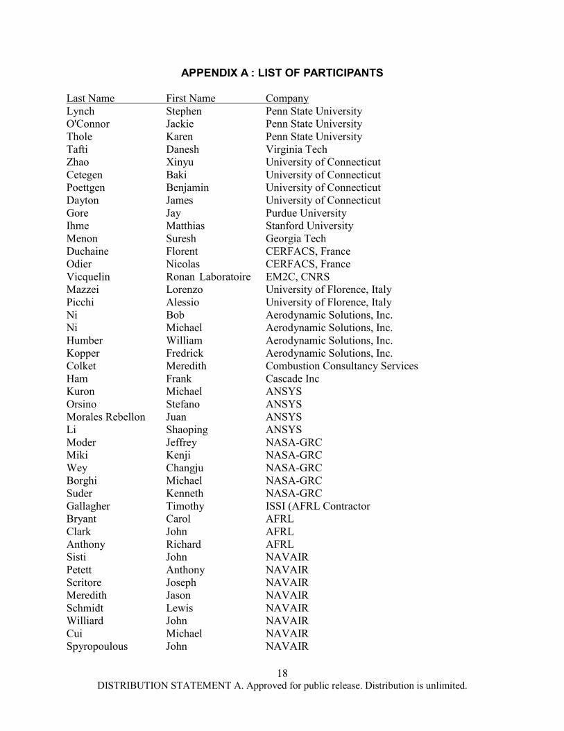
APPENDIX A : LIST OF PARTICIPANTS Last Name First Name Company Lynch Stephen Penn State University O'Connor Jackie Penn State University Thole Karen Penn State University Tafti Danesh Virginia Tech Zhao Xinyu University of Connecticut Cetegen Baki University of Connecticut Poettgen Benjamin University of Connecticut Dayton James University of Connecticut Gore Jay Purdue University Ihme Matthias Stanford University Menon Suresh Georgia Tech Duchaine Florent CERFACS, France Odier Nicolas CERFACS, France Vicquelin Ronan Laboratoire EM2C, CNRS Mazzei Lorenzo University of Florence, Italy Picchi Alessio University of Florence, Italy Ni Bob Aerodynamic Solutions, Inc. Ni Michael Aerodynamic Solutions, Inc. Humber William Aerodynamic Solutions, Inc. Kopper Fredrick Aerodynamic Solutions, Inc. Colket Meredith Combustion Consultancy Services Ham Frank Cascade Inc Kuron Michael ANSYS Orsino Stefano ANSYS Morales Rebellon Juan ANSYS Li Shaoping ANSYS Moder Jeffrey NASA-GRC Miki Kenji NASA-GRC Wey Changju NASA-GRC Borghi Michael NASA-GRC Suder Kenneth NASA-GRC Gallagher Timothy ISSI (AFRL Contractor Bryant Carol AFRL Clark John AFRL Anthony Richard AFRL Sisti John NAVAIR Petett Anthony NAVAIR Scritore Joseph NAVAIR Meredith Jason NAVAIR Schmidt Lewis NAVAIR Williard John NAVAIR Cui Michael NAVAIR Spyropoulous John NAVAIR
19 DISTRIBUTION STATEMENT A. Approved for public release. Distribution is unlimited.
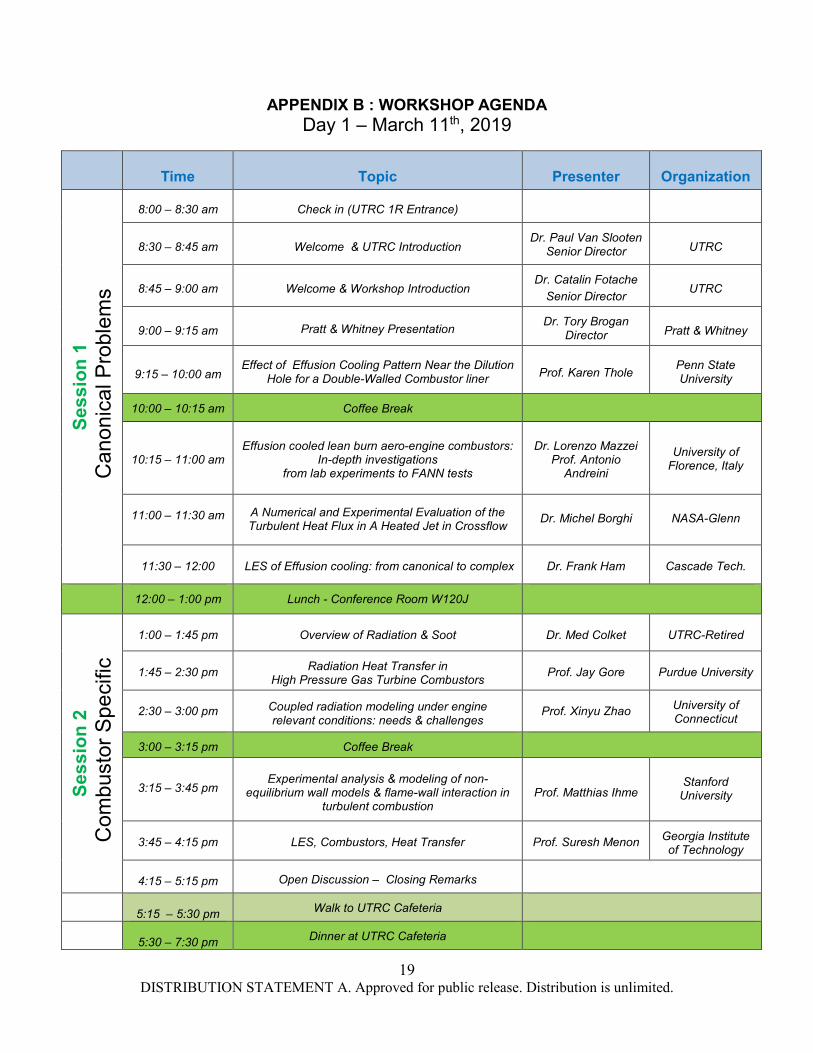
APPENDIX B : WORKSHOP AGENDA Day 1 – March 11th, 2019
Time
Topic
Presenter
Organization
Sess
ion
1 C
anon
ical
Pro
blem
s
8:00 – 8:30 am
Check in (UTRC 1R Entrance)
8:30 – 8:45 am
Welcome & UTRC Introduction
Dr. Paul Van Slooten Senior Director
UTRC
8:45 – 9:00 am
Welcome & Workshop Introduction
Dr. Catalin Fotache
Senior Director
UTRC
9:00 – 9:15 am
Pratt & Whitney Presentation
Dr. Tory Brogan Director
Pratt & Whitney
9:15 – 10:00 am
Effect of Effusion Cooling Pattern Near the Dilution
Hole for a Double-Walled Combustor liner
Prof. Karen Thole
Penn State University
10:00 – 10:15 am
Coffee Break
10:15 – 11:00 am
Effusion cooled lean burn aero-engine combustors:
In-depth investigations from lab experiments to FANN tests
Dr. Lorenzo Mazzei
Prof. Antonio Andreini
University of
Florence, Italy
11:00 – 11:30 am
A Numerical and Experimental Evaluation of the Turbulent Heat Flux in A Heated Jet in Crossflow
Dr. Michel Borghi
NASA-Glenn
11:30 – 12:00
LES of Effusion cooling: from canonical to complex
Dr. Frank Ham
Cascade Tech.
12:00 – 1:00 pm
Lunch - Conference Room W120J
Sess
ion
2 C
ombu
stor
Spe
cific
1:00 – 1:45 pm
Overview of Radiation & Soot
Dr. Med Colket
UTRC-Retired
1:45 – 2:30 pm
Radiation Heat Transfer in High Pressure Gas Turbine Combustors
Prof. Jay Gore
Purdue University
2:30 – 3:00 pm
Coupled radiation modeling under engine relevant conditions: needs & challenges
Prof. Xinyu Zhao
University of Connecticut
3:00 – 3:15 pm
Coffee Break
3:15 – 3:45 pm
Experimental analysis & modeling of non-
equilibrium wall models & flame-wall interaction in turbulent combustion
Prof. Matthias Ihme
Stanford
University
3:45 – 4:15 pm
LES, Combustors, Heat Transfer
Prof. Suresh Menon
Georgia Institute of Technology
4:15 – 5:15 pm
Open Discussion – Closing Remarks
5:15 – 5:30 pm
Walk to UTRC Cafeteria
5:30 – 7:30 pm
Dinner at UTRC Cafeteria

20 DISTRIBUTION STATEMENT A. Approved for public release. Distribution is unlimited.
Combustor-Turbine Wall Heat Transfer Workshop
Day 2 – March 12th, 2019
Time
Topic
Presenter
Organization
Sess
ion
3 T
urbi
ne S
peci
fic
8:00 – 8:30 am
Check in (UTRC 1R Entrance)
8:30 – 8:45 am
Welcome and Agenda
Dr. Paul Van Slooten Senior Director
UTRC
8:45 – 9:30 am
Conjugate Heat Transfer Analysis of
AFRL’s HIT-RT Cooled Turbine 1st Vane
Dr. Ron Ho Ni
ADS-CFD
9:30 – 10:15 am
Three-Dimensional Boundary Layers in
Gas Turbine End-wall Flows
Prof. Steve Lynch
Penn State University
10:15 – 10:30 am
Coffee Break
10:30 – 11:15 am
Advantages & Challenges of Using Immersed Boundary Methods for Conjugate Analysis in
Complex Internal Cooling Geometries
Prof. Danesh Tafti
Virginia Tech
11:15 – noon
Effects of representative lean burn combustor
outflow on flow field and film effectiveness through HP cooled vanes
Prof. Alessio Picchi
Prof. Antonio Andreini
University of
Florence, Italy
12:00 – 1:00 pm
Lunch - Conference Room W120J
Sess
ion
4 C
oupl
ing
Phys
ics
– So
lver
1:00 – 1:40 pm
Progress on fully-coupled combustor-high-
pressure turbine simulations using OpenNCC
Dr. Kenji-Miki
NASA-Glenn
1:40 – 2:20 pm
Integrated combustion chamber / high pressure
turbine Large-Eddy Simulations
Dr. Nicolas Odier
Dr. Laurent Gicquel
CERFACS
2:20 – 3:00 pm
Prediction of combustor & turbine thermal environment by Large-Eddy Simulations
Dr. Florent Duchaine
CERFACS
3:00 – 3:20 pm
Coffee Break
3:20 – 4:00 pm
Conjugate heat transfer & detailed radiation
modelling in multi-physics high-fidelity simulations of combustors
Dr. Ronan Vicquelin
Laboratoire
EM2C, CNRS, France
4:00 – 5:00 PM
Discussion - Closing Remarks
Related Documents