Advanced Topic in Operating Systems Lecture Notes Dr. Warren Toomey School of Information Technology Bond University Queensland, Australia With quotes from ‘The New Hacker’s Dictionary’ Third Session, 2003 c 1992-2003, Warren Toomey

Welcome message from author
This document is posted to help you gain knowledge. Please leave a comment to let me know what you think about it! Share it to your friends and learn new things together.
Transcript
Advanced Topic in Operating SystemsLecture Notes
Dr. Warren Toomey
School of Information TechnologyBond University
Queensland, Australia
With quotes from ‘The New Hacker’s Dictionary’
Third Session, 2003
c©1992-2003, Warren Toomey
Contents
1 Introduction to Operating Systems 1
1.1 What is an Operating System? . . . . . . . . . . . . . . . . . . . . . . . . . . . . . . . . . . . . 1
1.2 Kernel Mode and User Mode . . . . . . . . . . . . . . . . . . . . . . . . . . . . . . . . . . . . 2
1.3 Other System Software . . . . . . . . . . . . . . . . . . . . . . . . . . . . . . . . . . . . . . . . 2
1.4 Types of Operating Systems . . . . . . . . . . . . . . . . . . . . . . . . . . . . . . . . . . . . . 3
2 Design Principles & Concepts 3
2.1 The Process . . . . . . . . . . . . . . . . . . . . . . . . . . . . . . . . . . . . . . . . . . . . . . 4
2.2 Memory . . . . . . . . . . . . . . . . . . . . . . . . . . . . . . . . . . . . . . . . . . . . . . . . 4
2.3 Files . . . . . . . . . . . . . . . . . . . . . . . . . . . . . . . . . . . . . . . . . . . . . . . . . . . 4
2.4 Windows . . . . . . . . . . . . . . . . . . . . . . . . . . . . . . . . . . . . . . . . . . . . . . . . 5
2.5 Operating System Services . . . . . . . . . . . . . . . . . . . . . . . . . . . . . . . . . . . . . . 5
2.6 Unix and Laboratory Work . . . . . . . . . . . . . . . . . . . . . . . . . . . . . . . . . . . . . . 5
2.7 Operating System Structure . . . . . . . . . . . . . . . . . . . . . . . . . . . . . . . . . . . . . 6
2.8 The Monolithic Model . . . . . . . . . . . . . . . . . . . . . . . . . . . . . . . . . . . . . . . . 6
2.9 Client-Server Model . . . . . . . . . . . . . . . . . . . . . . . . . . . . . . . . . . . . . . . . . 8
3 The OS/Machine Interface 10
3.1 The CPU . . . . . . . . . . . . . . . . . . . . . . . . . . . . . . . . . . . . . . . . . . . . . . . . 10
3.2 Main Memory . . . . . . . . . . . . . . . . . . . . . . . . . . . . . . . . . . . . . . . . . . . . . 11
3.3 Buses . . . . . . . . . . . . . . . . . . . . . . . . . . . . . . . . . . . . . . . . . . . . . . . . . . 11
3.4 Peripheral Devices . . . . . . . . . . . . . . . . . . . . . . . . . . . . . . . . . . . . . . . . . . 13
3.5 Interrupts . . . . . . . . . . . . . . . . . . . . . . . . . . . . . . . . . . . . . . . . . . . . . . . 14
3.6 Interrupt Vectors . . . . . . . . . . . . . . . . . . . . . . . . . . . . . . . . . . . . . . . . . . . 14
3.7 The OS vs The User . . . . . . . . . . . . . . . . . . . . . . . . . . . . . . . . . . . . . . . . . . 15
3.8 Traps and System Calls . . . . . . . . . . . . . . . . . . . . . . . . . . . . . . . . . . . . . . . . 15
4 Operating System History and Evolution 16
4.1 1st Generation: 1945 – 1955 . . . . . . . . . . . . . . . . . . . . . . . . . . . . . . . . . . . . . 16
4.2 2nd Generation: 1955 – 1965 . . . . . . . . . . . . . . . . . . . . . . . . . . . . . . . . . . . . . 17
4.3 3rd Generation: 1965 – 1980 . . . . . . . . . . . . . . . . . . . . . . . . . . . . . . . . . . . . . 18
4.4 Timesharing . . . . . . . . . . . . . . . . . . . . . . . . . . . . . . . . . . . . . . . . . . . . . . 18
4.5 3rd Generation – Part 2 . . . . . . . . . . . . . . . . . . . . . . . . . . . . . . . . . . . . . . . . 19
4.6 4th Generation: 1980 onwards . . . . . . . . . . . . . . . . . . . . . . . . . . . . . . . . . . . . 19
5 Processes 20
5.1 What is a Process? . . . . . . . . . . . . . . . . . . . . . . . . . . . . . . . . . . . . . . . . . . . 20
5.2 The Process Environment . . . . . . . . . . . . . . . . . . . . . . . . . . . . . . . . . . . . . . 20
i
5.3 System Calls . . . . . . . . . . . . . . . . . . . . . . . . . . . . . . . . . . . . . . . . . . . . . . 20
5.4 Layout of a Process . . . . . . . . . . . . . . . . . . . . . . . . . . . . . . . . . . . . . . . . . . 20
5.5 Process Models . . . . . . . . . . . . . . . . . . . . . . . . . . . . . . . . . . . . . . . . . . . . 21
5.6 How the Operating System Deals with System Calls . . . . . . . . . . . . . . . . . . . . . . . 22
5.7 Process Control Blocks . . . . . . . . . . . . . . . . . . . . . . . . . . . . . . . . . . . . . . . . 23
5.8 Context Switching . . . . . . . . . . . . . . . . . . . . . . . . . . . . . . . . . . . . . . . . . . . 24
6 Process Scheduling 25
6.1 Introduction . . . . . . . . . . . . . . . . . . . . . . . . . . . . . . . . . . . . . . . . . . . . . . 25
6.2 Scheduling Algorithms – Interactive (Pre-emption) . . . . . . . . . . . . . . . . . . . . . . . . 26
6.3 First Come First Served/ Round Robin . . . . . . . . . . . . . . . . . . . . . . . . . . . . . . . 26
6.4 Timeslice Priority . . . . . . . . . . . . . . . . . . . . . . . . . . . . . . . . . . . . . . . . . . . 26
6.5 Multiple Priority Queues . . . . . . . . . . . . . . . . . . . . . . . . . . . . . . . . . . . . . . . 27
6.6 Long-Term Schedulers . . . . . . . . . . . . . . . . . . . . . . . . . . . . . . . . . . . . . . . . 27
6.7 The Unix Long-Term Scheduler . . . . . . . . . . . . . . . . . . . . . . . . . . . . . . . . . . . 27
6.8 Which is the Right Scheduling Algorithm to Use? . . . . . . . . . . . . . . . . . . . . . . . . 28
6.9 The Idle Process . . . . . . . . . . . . . . . . . . . . . . . . . . . . . . . . . . . . . . . . . . . . 28
7 Introduction to Input/Output 29
7.1 Why does the Operating System do I/O? . . . . . . . . . . . . . . . . . . . . . . . . . . . . . 29
7.2 Devices and the Machine Architecture . . . . . . . . . . . . . . . . . . . . . . . . . . . . . . . 29
7.3 Direct Memory Access . . . . . . . . . . . . . . . . . . . . . . . . . . . . . . . . . . . . . . . . 30
8 Principles of Input/Output 31
8.1 Introduction . . . . . . . . . . . . . . . . . . . . . . . . . . . . . . . . . . . . . . . . . . . . . . 31
8.2 Goals of I/O Handling . . . . . . . . . . . . . . . . . . . . . . . . . . . . . . . . . . . . . . . . 31
8.3 Interrupt Handlers . . . . . . . . . . . . . . . . . . . . . . . . . . . . . . . . . . . . . . . . . . 32
8.4 Device Drivers . . . . . . . . . . . . . . . . . . . . . . . . . . . . . . . . . . . . . . . . . . . . . 33
8.5 The Device-Independent Layer . . . . . . . . . . . . . . . . . . . . . . . . . . . . . . . . . . . 33
8.6 Clocks – Hardware . . . . . . . . . . . . . . . . . . . . . . . . . . . . . . . . . . . . . . . . . . 34
8.7 Clocks – Software . . . . . . . . . . . . . . . . . . . . . . . . . . . . . . . . . . . . . . . . . . . 35
9 Device Drivers and Interrupt Handlers 35
10 The Disk Device 36
10.1 Disk Hardware . . . . . . . . . . . . . . . . . . . . . . . . . . . . . . . . . . . . . . . . . . . . 37
10.2 Disk Software . . . . . . . . . . . . . . . . . . . . . . . . . . . . . . . . . . . . . . . . . . . . . 37
10.3 Arm Scheduling – FCFS . . . . . . . . . . . . . . . . . . . . . . . . . . . . . . . . . . . . . . . 38
10.4 Shortest Seek Time First . . . . . . . . . . . . . . . . . . . . . . . . . . . . . . . . . . . . . . . 38
10.5 SCAN Algorithm . . . . . . . . . . . . . . . . . . . . . . . . . . . . . . . . . . . . . . . . . . . 38
ii
10.6 C-SCAN Algorithm . . . . . . . . . . . . . . . . . . . . . . . . . . . . . . . . . . . . . . . . . . 39
10.7 Sector Queueing . . . . . . . . . . . . . . . . . . . . . . . . . . . . . . . . . . . . . . . . . . . . 40
10.8 Interleaving . . . . . . . . . . . . . . . . . . . . . . . . . . . . . . . . . . . . . . . . . . . . . . 40
10.9 Error Handling . . . . . . . . . . . . . . . . . . . . . . . . . . . . . . . . . . . . . . . . . . . . 40
10.10Recent Disk Advances . . . . . . . . . . . . . . . . . . . . . . . . . . . . . . . . . . . . . . . . 41
11 Terminals 41
11.1 Terminal Hardware . . . . . . . . . . . . . . . . . . . . . . . . . . . . . . . . . . . . . . . . . . 41
11.2 Serial Terminal Types . . . . . . . . . . . . . . . . . . . . . . . . . . . . . . . . . . . . . . . . . 42
11.3 Memory-Mapped Terminals . . . . . . . . . . . . . . . . . . . . . . . . . . . . . . . . . . . . . 43
11.4 Terminal Software . . . . . . . . . . . . . . . . . . . . . . . . . . . . . . . . . . . . . . . . . . . 43
11.5 Output . . . . . . . . . . . . . . . . . . . . . . . . . . . . . . . . . . . . . . . . . . . . . . . . . 44
12 Introduction to Memory Management 45
12.1 What is Memory & Why Manage It? . . . . . . . . . . . . . . . . . . . . . . . . . . . . . . . . 45
12.2 Process Compilation & Memory Locations . . . . . . . . . . . . . . . . . . . . . . . . . . . . 45
12.3 Bare Machine . . . . . . . . . . . . . . . . . . . . . . . . . . . . . . . . . . . . . . . . . . . . . 46
12.4 Operating System in ROM – Resident Monitor . . . . . . . . . . . . . . . . . . . . . . . . . . 46
12.5 Partitions . . . . . . . . . . . . . . . . . . . . . . . . . . . . . . . . . . . . . . . . . . . . . . . . 46
12.6 Allocating & Placing Partitions in Memory . . . . . . . . . . . . . . . . . . . . . . . . . . . . 47
13 Pages 48
13.1 Problems with Partitions . . . . . . . . . . . . . . . . . . . . . . . . . . . . . . . . . . . . . . . 48
13.2 Pages . . . . . . . . . . . . . . . . . . . . . . . . . . . . . . . . . . . . . . . . . . . . . . . . . . 49
13.3 An Example Page Entry . . . . . . . . . . . . . . . . . . . . . . . . . . . . . . . . . . . . . . . 50
13.4 Pages vs. Paging . . . . . . . . . . . . . . . . . . . . . . . . . . . . . . . . . . . . . . . . . . . 51
13.5 Huge Logical Memory Maps . . . . . . . . . . . . . . . . . . . . . . . . . . . . . . . . . . . . 51
13.6 Problems of Paged Memory Management . . . . . . . . . . . . . . . . . . . . . . . . . . . . . 51
13.7 Sharing Pages . . . . . . . . . . . . . . . . . . . . . . . . . . . . . . . . . . . . . . . . . . . . . 52
13.8 Copy-on-Write . . . . . . . . . . . . . . . . . . . . . . . . . . . . . . . . . . . . . . . . . . . . . 52
13.9 Operating System Use of Page Entry Protections . . . . . . . . . . . . . . . . . . . . . . . . . 53
14 Virtual Memory 53
14.1 Why Use Virtual Memory? . . . . . . . . . . . . . . . . . . . . . . . . . . . . . . . . . . . . . . 54
14.2 Paging . . . . . . . . . . . . . . . . . . . . . . . . . . . . . . . . . . . . . . . . . . . . . . . . . 54
14.3 Paging – How It Works . . . . . . . . . . . . . . . . . . . . . . . . . . . . . . . . . . . . . . . . 54
14.4 Hardware Requirements . . . . . . . . . . . . . . . . . . . . . . . . . . . . . . . . . . . . . . . 55
14.5 Optimal Page Replacement . . . . . . . . . . . . . . . . . . . . . . . . . . . . . . . . . . . . . 55
14.6 Not Recently Used Algorithm . . . . . . . . . . . . . . . . . . . . . . . . . . . . . . . . . . . . 56
iii
14.7 FIFO Algorithm – First In, First Out . . . . . . . . . . . . . . . . . . . . . . . . . . . . . . . . 56
14.8 Second Chance . . . . . . . . . . . . . . . . . . . . . . . . . . . . . . . . . . . . . . . . . . . . 56
14.9 Least Recently Used (LRU) . . . . . . . . . . . . . . . . . . . . . . . . . . . . . . . . . . . . . . 56
14.10VM Problems . . . . . . . . . . . . . . . . . . . . . . . . . . . . . . . . . . . . . . . . . . . . . 57
14.11Initial Process Memory Allocation . . . . . . . . . . . . . . . . . . . . . . . . . . . . . . . . . 58
15 Introduction to File Systems 58
15.1 Introduction . . . . . . . . . . . . . . . . . . . . . . . . . . . . . . . . . . . . . . . . . . . . . . 58
15.2 What’s a File? . . . . . . . . . . . . . . . . . . . . . . . . . . . . . . . . . . . . . . . . . . . . . 58
15.3 File Types . . . . . . . . . . . . . . . . . . . . . . . . . . . . . . . . . . . . . . . . . . . . . . . 59
15.4 File Operations . . . . . . . . . . . . . . . . . . . . . . . . . . . . . . . . . . . . . . . . . . . . 59
15.5 Directories . . . . . . . . . . . . . . . . . . . . . . . . . . . . . . . . . . . . . . . . . . . . . . . 60
15.6 Filesystem Metadata . . . . . . . . . . . . . . . . . . . . . . . . . . . . . . . . . . . . . . . . . 61
15.7 Directory Information . . . . . . . . . . . . . . . . . . . . . . . . . . . . . . . . . . . . . . . . 61
15.8 File System Design . . . . . . . . . . . . . . . . . . . . . . . . . . . . . . . . . . . . . . . . . . 62
16 File System Layout 65
16.1 Introduction . . . . . . . . . . . . . . . . . . . . . . . . . . . . . . . . . . . . . . . . . . . . . . 65
16.2 The MS-DOS Filesystem . . . . . . . . . . . . . . . . . . . . . . . . . . . . . . . . . . . . . . . 65
16.3 The System V Unix Filesystem . . . . . . . . . . . . . . . . . . . . . . . . . . . . . . . . . . . 66
16.4 The Berkeley Fast Filesystem . . . . . . . . . . . . . . . . . . . . . . . . . . . . . . . . . . . . 68
17 File System Reliability & Performance 69
17.1 File System Reliability . . . . . . . . . . . . . . . . . . . . . . . . . . . . . . . . . . . . . . . . 69
17.2 Bad Blocks . . . . . . . . . . . . . . . . . . . . . . . . . . . . . . . . . . . . . . . . . . . . . . . 70
17.3 Backups . . . . . . . . . . . . . . . . . . . . . . . . . . . . . . . . . . . . . . . . . . . . . . . . 70
17.4 File System Consistency . . . . . . . . . . . . . . . . . . . . . . . . . . . . . . . . . . . . . . . 70
17.5 File System Performance – Caching . . . . . . . . . . . . . . . . . . . . . . . . . . . . . . . . . 71
17.6 File Block Allocation . . . . . . . . . . . . . . . . . . . . . . . . . . . . . . . . . . . . . . . . . 72
17.7 Holey Files . . . . . . . . . . . . . . . . . . . . . . . . . . . . . . . . . . . . . . . . . . . . . . . 72
18 Interprocess Communication (IPC) 72
18.1 Why Do Processes Intercommunicate? . . . . . . . . . . . . . . . . . . . . . . . . . . . . . . . 72
18.2 Files . . . . . . . . . . . . . . . . . . . . . . . . . . . . . . . . . . . . . . . . . . . . . . . . . . . 73
18.3 Pipes – Unidirectional Streams . . . . . . . . . . . . . . . . . . . . . . . . . . . . . . . . . . . 73
18.4 Bidirectional Streams . . . . . . . . . . . . . . . . . . . . . . . . . . . . . . . . . . . . . . . . . 73
18.5 Messages . . . . . . . . . . . . . . . . . . . . . . . . . . . . . . . . . . . . . . . . . . . . . . . . 74
18.6 Remote Procedure Call – RPC . . . . . . . . . . . . . . . . . . . . . . . . . . . . . . . . . . . . 74
18.7 Shared Memory . . . . . . . . . . . . . . . . . . . . . . . . . . . . . . . . . . . . . . . . . . . . 76
iv
19 Synchronisation 76
19.1 Race Conditions and Critical Sections . . . . . . . . . . . . . . . . . . . . . . . . . . . . . . . 76
19.2 Avoiding a Critical Section . . . . . . . . . . . . . . . . . . . . . . . . . . . . . . . . . . . . . . 77
19.3 Infinite Timeslices . . . . . . . . . . . . . . . . . . . . . . . . . . . . . . . . . . . . . . . . . . . 77
19.4 Strict Alternation/Rotation . . . . . . . . . . . . . . . . . . . . . . . . . . . . . . . . . . . . . 77
19.5 Test and Set Lock Instruction . . . . . . . . . . . . . . . . . . . . . . . . . . . . . . . . . . . . 78
19.6 Semaphores . . . . . . . . . . . . . . . . . . . . . . . . . . . . . . . . . . . . . . . . . . . . . . 78
19.7 Monitors . . . . . . . . . . . . . . . . . . . . . . . . . . . . . . . . . . . . . . . . . . . . . . . . 79
19.8 Message Passing . . . . . . . . . . . . . . . . . . . . . . . . . . . . . . . . . . . . . . . . . . . . 79
19.9 Synchronisation Within the Operating System . . . . . . . . . . . . . . . . . . . . . . . . . . 80
20 Threads 81
20.1 Introduction . . . . . . . . . . . . . . . . . . . . . . . . . . . . . . . . . . . . . . . . . . . . . . 81
20.2 Kernel Threads . . . . . . . . . . . . . . . . . . . . . . . . . . . . . . . . . . . . . . . . . . . . 83
20.3 Lightweight Processes . . . . . . . . . . . . . . . . . . . . . . . . . . . . . . . . . . . . . . . . 83
20.4 Mediumweight Processes . . . . . . . . . . . . . . . . . . . . . . . . . . . . . . . . . . . . . . 84
20.5 User Threads . . . . . . . . . . . . . . . . . . . . . . . . . . . . . . . . . . . . . . . . . . . . . . 84
20.6 Performance Figures . . . . . . . . . . . . . . . . . . . . . . . . . . . . . . . . . . . . . . . . . 84
21 Windows NT 85
21.1 Overall Design . . . . . . . . . . . . . . . . . . . . . . . . . . . . . . . . . . . . . . . . . . . . . 86
21.2 Environment Subsystems . . . . . . . . . . . . . . . . . . . . . . . . . . . . . . . . . . . . . . 87
21.3 Processes and Threads . . . . . . . . . . . . . . . . . . . . . . . . . . . . . . . . . . . . . . . . 87
21.4 Memory Management . . . . . . . . . . . . . . . . . . . . . . . . . . . . . . . . . . . . . . . . 89
21.5 Input/Output . . . . . . . . . . . . . . . . . . . . . . . . . . . . . . . . . . . . . . . . . . . . . 90
21.6 The NT Filesystem . . . . . . . . . . . . . . . . . . . . . . . . . . . . . . . . . . . . . . . . . . 90
v
1 Introduction to Operating Systems
1.1 What is an Operating System?
Textbook reference: Stallings ppg 53 – 100; Tanenbaum & Woodhull ppg 1 – 5
Without software, a computer is effectively useless. Computer software controls the use of the hardware(CPU, memory, disks etc.), and makes the computer into a useful tool for its users.
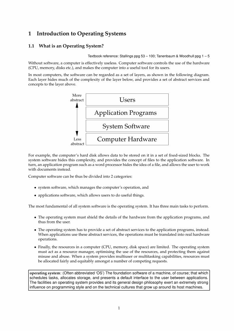
In most computers, the software can be regarded as a set of layers, as shown in the following diagram.Each layer hides much of the complexity of the layer below, and provides a set of abstract services andconcepts to the layer above.
System Software
More
Lessabstract
Computer Hardware
Application Programs
Usersabstract
For example, the computer’s hard disk allows data to be stored on it in a set of fixed-sized blocks. Thesystem software hides this complexity, and provides the concept of files to the application software. Inturn, an application program such as a word processor hides the idea of a file, and allows the user to workwith documents instead.
Computer software can be thus be divided into 2 categories:
• system software, which manages the computer’s operation, and
• applications software, which allows users to do useful things.
The most fundamental of all system software is the operating system. It has three main tasks to perform.
• The operating system must shield the details of the hardware from the application programs, andthus from the user.
• The operating system has to provide a set of abstract services to the application programs, instead.When applications use these abstract services, the operations must be translated into real hardwareoperations.
• Finally, the resources in a computer (CPU, memory, disk space) are limited. The operating systemmust act as a resource manager, optimising the use of the resources, and protecting them againstmisuse and abuse. When a system provides multiuser or multitasking capabilities, resources mustbe allocated fairly and equitably amongst a number of competing requests.
operating system: (Often abbreviated ‘OS’) The foundation software of a machine, of course; that whichschedules tasks, allocates storage, and presents a default interface to the user between applications.The facilities an operating system provides and its general design philosophy exert an extremely stronginfluence on programming style and on the technical cultures that grow up around its host machines.
1
1.2 Kernel Mode and User Mode
Textbook reference: Tanenbaum & Woodhull pg 3
Because an operating system must hide the computer’s hardware, and manage the hardware resources,it needs to prevent the application software from accessing the hardware directly. Without this sort ofprotection, the operating system would not be able to do its job.
The computer’s CPU provides two modes of operation which enforce this protection. The operatingsystem runs in kernel mode, also known as supervisor mode or privileged mode. In kernel mode, thesoftware has complete access to all of the computer’s hardware, and can control the switching betweenthe CPU modes.
The rest of the software runs in user mode. In this mode, direct access to the hardware is prohibited, andso is any arbitrary switching to kernel mode. Any attempts to violate these restrictions are reported to thekernel mode software: in other words, to the operating system itself.
By having two modes of operation which are enforced by the computer’s own hardware, the operatingsystem can force application programs to use the operating system’s abstract services, instead of circum-venting any resource allocations by direct hardware access.
1.3 Other System Software
Textbook reference: Tanenbaum & Woodhull pg 2
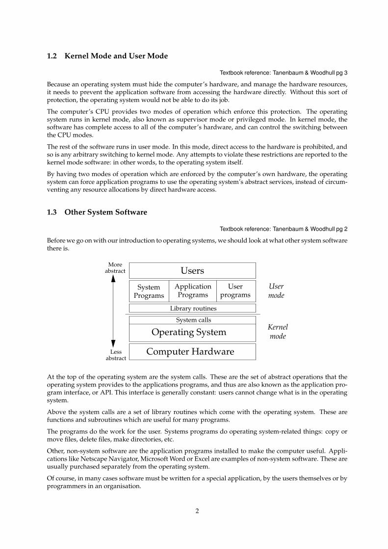
Before we go on with our introduction to operating systems, we should look at what other system softwarethere is.
System calls
Computer Hardware
ApplicationPrograms
UserprogramsPrograms
System
UsersabstractMore
Lessabstract
Usermode
KernelmodeOperating System
Library routines
At the top of the operating system are the system calls. These are the set of abstract operations that theoperating system provides to the applications programs, and thus are also known as the application pro-gram interface, or API. This interface is generally constant: users cannot change what is in the operatingsystem.
Above the system calls are a set of library routines which come with the operating system. These arefunctions and subroutines which are useful for many programs.
The programs do the work for the user. Systems programs do operating system-related things: copy ormove files, delete files, make directories, etc.
Other, non-system software are the application programs installed to make the computer useful. Appli-cations like Netscape Navigator, Microsoft Word or Excel are examples of non-system software. These areusually purchased separately from the operating system.
Of course, in many cases software must be written for a special application, by the users themselves or byprogrammers in an organisation.
2
Regardless of type, all programs can use the library routines and the system calls that come with anoperating system.
1.4 Types of Operating Systems
Every operating system is different, and each is designed to meet a set of goals. However, we can generallyclassify operating systems into the following categories.
• A simple monitor provides few services to the user, and leaves much the control of the hardware tothe user’s own programs. A good example here is MS-DOS.
• A batch system takes user’s jobs, and segregates them into batches, with similar requirements. Eachbatch is given to the computer to run. When jobs with similar system requirements are batchedtogether, this helps to streamline their processing. User interaction is generally lacking in batchsystems: jobs are entered, are processed, and the output from each job comes out at a later time. Theemphasis here is on the computer’s utilisation. An example batch system is IBM’s VM.
• An embedded system usually has the operating system built into the computer, and is used tocontrol external hardware. There is little or no application software in an embedded system. Exam-ples here are the Palm Pilot, the electronic diaries that everybody seems to have, and of course thecomputers built into VCRs, microwaves, and into most cars.
• A real-time system is designed to respond to input within certain time constraints. This inputusually comes from external sensors, and not from humans. Thus, there is usually little or no userinteraction. Many embedded systems are also real-time systems. An example real-time system isthe QNX operating system.
• Finally, a multiprogramming system appears to be running many jobs at the same time, each withuser interaction. The emphasis here is on user response time as well as computer utilisation. Multi-programming systems are usually more general-purpose than the other types of operating systems.Example multiprogramming systems are Unix and Windows NT.
In this course, we will concentrate on multiprogramming systems: these are much more sophisticatedand complex then the other operating system types, and will give us a lot more to look at. We will alsoconcentrate on multi-user systems: these are systems which support multiple users at the same time.
2 Design Principles & Concepts
Textbook reference: Stallings ppg 53 – 100; Tanenbaum & Woodhull ppg 15 – 20
The services provided by an operating system depends on the concepts around which the operating sys-tem was created; this gives each operating system a certain ‘feel’ to the programmers who write programsfor it.
We are talking here not about the ‘look & feel’ of the user interface, but the ‘look & feel’ of the programmer’sinterface, i.e the services provided by the API.
Although each operating system provides its own unique set of services, most operating systems share afew common concepts. Let’s briefly take at look at each now. We will examine most of these concepts indetail in later topics.
3
2.1 The Process
Most operating systems provide the concept of a process. Here, we need to distinguish between a programand a process.
• A program is a collection of computer instructions plus some data that resides on a storage medium,waiting to be called into action.
• A process is a program during execution. It has been loaded into the computer’s main memory, andis taking input, manipulating the input, and producing output.
Specifically, a process is an enviroment for a program to run in. This environment protects the runningprogram against other processes, and also provides the running program with access to the operatingsystem’s services via the system calls.
2.2 Memory
Part of every computer’s hardware is its main memory. This is a set of temporary storage locations whichcan hold machine code instructions and data. Memory is volatile: when the power is turned off, thecontents of main memory are lost.
In current computers, there are usually several megabytes of memory (i.e millions of 8-bit storage areas).Memory contents can be accessed by reading or writing a memory location, which has an integer address,just like the numbers on the letter boxes in a street.
Memory locations often have a hardware protection, allowing or preventing read and writes. Usually, aprocess can only read or write to a specific set of locations that have been given to it by the operatingsystem.
The operating system allocates memory to processes as they are created, and reclaims the memory oncethey finish. As well, processes can usually request more memory, and also relinquish this extra memoryif they no longer require it.
2.3 Files
Files are storage areas for programs, source code, data, documents etc. They can be accessed by processes,but don’t disappear when processes die, or when the machine is turned off. They are thus persistentobjects.
Operating systems provide mechanisms for file manipulation, such as open, close, create, read and write.
As part of the job of hiding the hardware and providing abstract services, the operating system must mapfiles onto areas on disks and tapes. The operating system must also deal with files that grow or shrink insize.
Some operating systems don’t enforce any structure to files, or enforce particular file types types. Othersdistinguish between file types and structures, e.g Pascal source files, text documents, machine code files,data files etc.
Most operating systems allow files to have permissions, allowing certain types of file access to authorisedusers only.
Directories may exist to allow related files to be collected. The main reason for the existence of directoriesis to make file organisation easier and more flexible for the user.
4
2.4 Windows
Nearly all operating systems these days provide some form of graphical user interface, although in manycases a command-line interface is also available.
In these operating systems, there are services available to allow processes to do graphical work. Althoughthere are primitive services such as line and rectangle drawing, most GUI interfaces provide a abstractconcept known as the window.
The window is a logical, rectangular, drawing area. Processes can create one or more windows, of anysize. The operating system may decorate each window with borders, and these may include icons whichallow the window to be destroyed, resized, or hidden.
The operating system must map these logical windows onto the physical display area provided by thevideo card and computer monitor. As well, the operating system must direct the input from the user (inthe form of keyboard input, and mouse operations) to the appropriate window: this is known as changingthe input focus.
2.5 Operating System Services
Textbook reference: Tanenbaum & Woodhull ppg 21 – 26
From a programmer’s point of view, an operating system is defined mainly by the Application ProgramInterface that it provides, and to a lesser extent what library routines are available.
It follows, therefore, that a number of different operating system products may provide exactly the sameApplication Program Interface, and thus appear to be the same operating system to the programmer. Themost obvious example of this is Unix.
Unix is really not a single operating system, but rather a collection of operating systems that share acommon Application Program Interface. This API has now been standardised, and is known as the POSIXstandard. Solaris, HP-UX, SCO Unix, Digital Unix, System V, Linux, Minix and FreeBSD are all examplesof Unix operating systems.
What this means is that a program written to run on one Unix platform can be recompiled and will runon another Unix system. As long as the set of systems calls are the same on both systems, the programwill run on both systems.
Another group of operating systems which share a common API are the Windows systems from Microsoft:Windows CE, Windows 95 or 98 and Windows NT. Although structurally different, a program can bewritten to run on all three.
2.6 Unix and Laboratory Work
The aim of this course is not to examine the implementation of a particular operating system. Instead, wewill be looking at the abstractions provided by operating systems, and the design tradeoffs that must bemade when constructing an operating system.
In the laboratory work in this course, we will be using the Unix operating system to look at some of itsabstract concepts, and to see some of their implementation details. It is in your best interests to learn a bitabout Unix and what it provides to the programmer and the user.
Section 1.3 of Tanenbaum’s textbook gives a good overview of the main Unix concepts. For the program-mers who are interested in Unix’s system calls, an overview of these are given in Section 1.4.
Note that Sections 1.3 and 1.4 cover the Minix system. As noted above, Minix is a particular implemen-tation of Unix. Sections 1.3 and 1.4 cover the core concepts and system calls that are available in all Unixsystems.
5

2.7 Operating System Structure
Textbook reference: Tanenbaum & Woodhull ppg 37 – 44
The implementation of an operating system is completely up to its designers, and throughout the coursewe will look at some of the design decisions that must be made when creating an operating system.
In general, none of the implementation details of an operating system are visible to the programmer oruser: these details are hidden behind the operating system’s Application Program Interface. The API fixesthe “look” of the operating system, as seen by the programmer.
This API, however, can be implemented by very different operating system designs. For example, So-laris, Linux and Minix all provide a POSIX API: all three systems have a very different operating systemarchitecture.
We will examine the two most common operating system designs, the monolithic model and the client-server model.
2.8 The Monolithic Model
In the monolithic model, the operating system is written as a collection of routines, each of which can callany of the other routines as required. At build-time, each routine is compiled, and then they are all linkedtogether to create a single program called the operating system kernel.
When the operating system is started, this kernel is loaded into the computer’s memory, and runs in kernelmode. Most versions of Unix, including Linux, use the monolithic design model.
The monolithic design model suffers from the fact that every part of the operating system can see all theother parts; thus, a bug in one part may destroy the data that another part is using. Recompilation of theoperating system can also be slow and painful.
To reduce this shortcoming, most designers place some overriding structure on their operating systemdesign. Many of the routines and data structures are ‘hidden’ in some way, and are visible only to theother routines that need them.
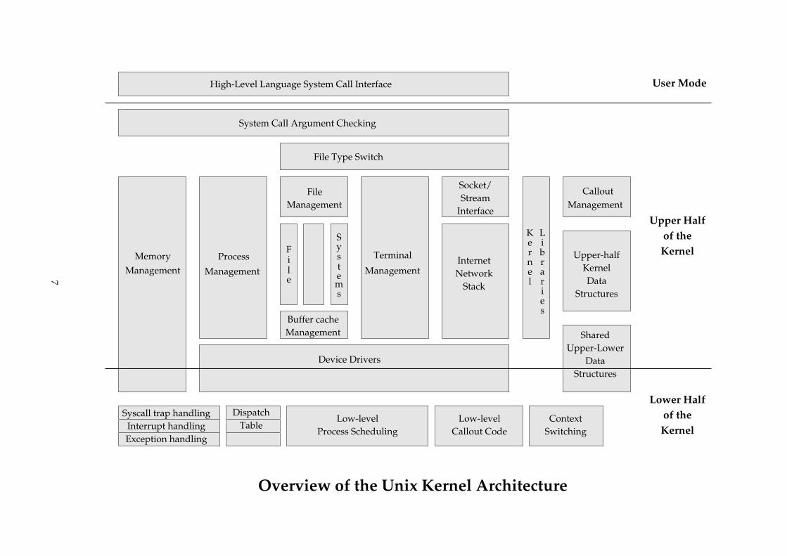
An abstract map of Unix’s architecture is shown in the diagram on the following page. As you can see,the functionality provided by the kernel is broken up into a number of sections. Each section provides asmall number of interface routines, and it is these routines which can be used by the other sections.
Because Unix is monolithic, nothing stops one section of the operating system from calling another withfunction calls, or using another section’s data. Each box is a set of C source files.
6
Low-levelProcess Scheduling
Libraries
Upper Halfof theKernel
Lower Halfof theKernel
File
Systems
ManagementBuffer cache
System Call Argument Checking
Management
Management
ProcessManagement
Terminal
Device Drivers
User ModeHigh-Level Language System Call Interface
Overview of the Unix Kernel Architecture
ManagementMemory
ManagementCallout
Kern
le
File Type Switch
Internet
File
NetworkStack
Socket/Stream
Interface
Upper-halfKernelData
Structures
SharedUpper-Lower
DataStructures
Syscall trap handlingInterrupt handlingException handling
DispatchTable
Low-levelCallout Code
ContextSwitching
7
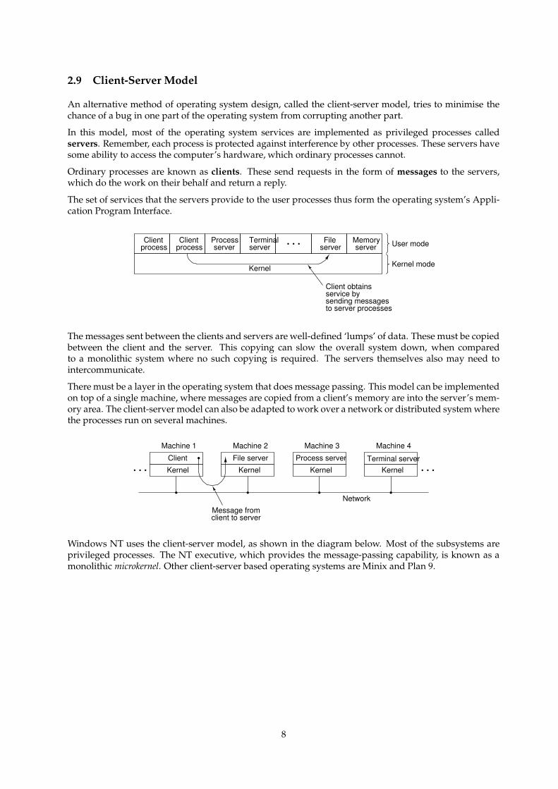
2.9 Client-Server Model
An alternative method of operating system design, called the client-server model, tries to minimise thechance of a bug in one part of the operating system from corrupting another part.
In this model, most of the operating system services are implemented as privileged processes calledservers. Remember, each process is protected against interference by other processes. These servers havesome ability to access the computer’s hardware, which ordinary processes cannot.
Ordinary processes are known as clients. These send requests in the form of messages to the servers,which do the work on their behalf and return a reply.
The set of services that the servers provide to the user processes thus form the operating system’s Appli-cation Program Interface.
Clientprocess
Clientprocess
Processserver
Terminalserver
Fileserver
Memoryserver
Kernel
User mode
Kernel mode
Client obtainsservice bysending messagesto server processes
The messages sent between the clients and servers are well-defined ‘lumps’ of data. These must be copiedbetween the client and the server. This copying can slow the overall system down, when comparedto a monolithic system where no such copying is required. The servers themselves also may need tointercommunicate.
There must be a layer in the operating system that does message passing. This model can be implementedon top of a single machine, where messages are copied from a client’s memory are into the server’s mem-ory area. The client-server model can also be adapted to work over a network or distributed system wherethe processes run on several machines.
Machine 1 Machine 2 Machine 3 Machine 4
Client
Kernel
File server
Kernel
Process server
KernelTerminal server
Kernel
Message fromclient to server
Network
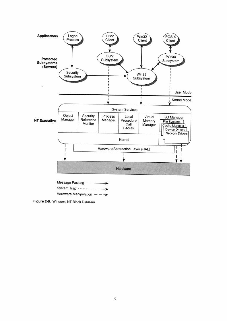
Windows NT uses the client-server model, as shown in the diagram below. Most of the subsystems areprivileged processes. The NT executive, which provides the message-passing capability, is known as amonolithic microkernel. Other client-server based operating systems are Minix and Plan 9.
8
9
3 The OS/Machine Interface
Textbook reference: Stallings ppg 9 – 38
The operating system must hide the physical resources of the computer from the user’s programs, andfairly allocate these resources. In order to explore how this is achieved, we must first consider how themain components of a computer work.
There are several viewpoints on how a computer works: how its electronic gates operate, how it executesmachine code etc. We will examine the main functional components of a computer and their abstractinterconnection. We will ignore complications such as caches, pipelines etc.
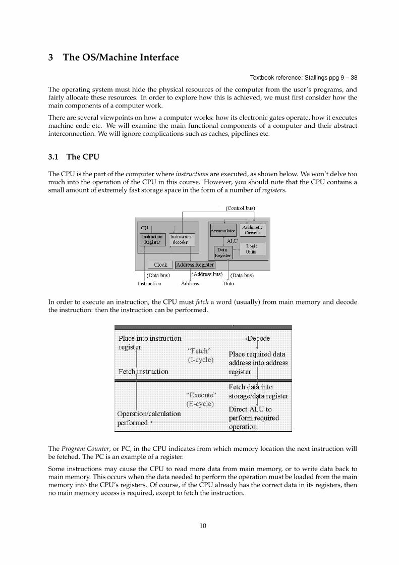
3.1 The CPU
The CPU is the part of the computer where instructions are executed, as shown below. We won’t delve toomuch into the operation of the CPU in this course. However, you should note that the CPU contains asmall amount of extremely fast storage space in the form of a number of registers.
In order to execute an instruction, the CPU must fetch a word (usually) from main memory and decodethe instruction: then the instruction can be performed.
The Program Counter, or PC, in the CPU indicates from which memory location the next instruction willbe fetched. The PC is an example of a register.
Some instructions may cause the CPU to read more data from main memory, or to write data back tomain memory. This occurs when the data needed to perform the operation must be loaded from the mainmemory into the CPU’s registers. Of course, if the CPU already has the correct data in its registers, thenno main memory access is required, except to fetch the instruction.
10
As the number of internal registers is limited, data currently in a registers often has to be discarded sothat it can be replaced by new data that is required to perform an instruction. Such a discard is known asa register spill.
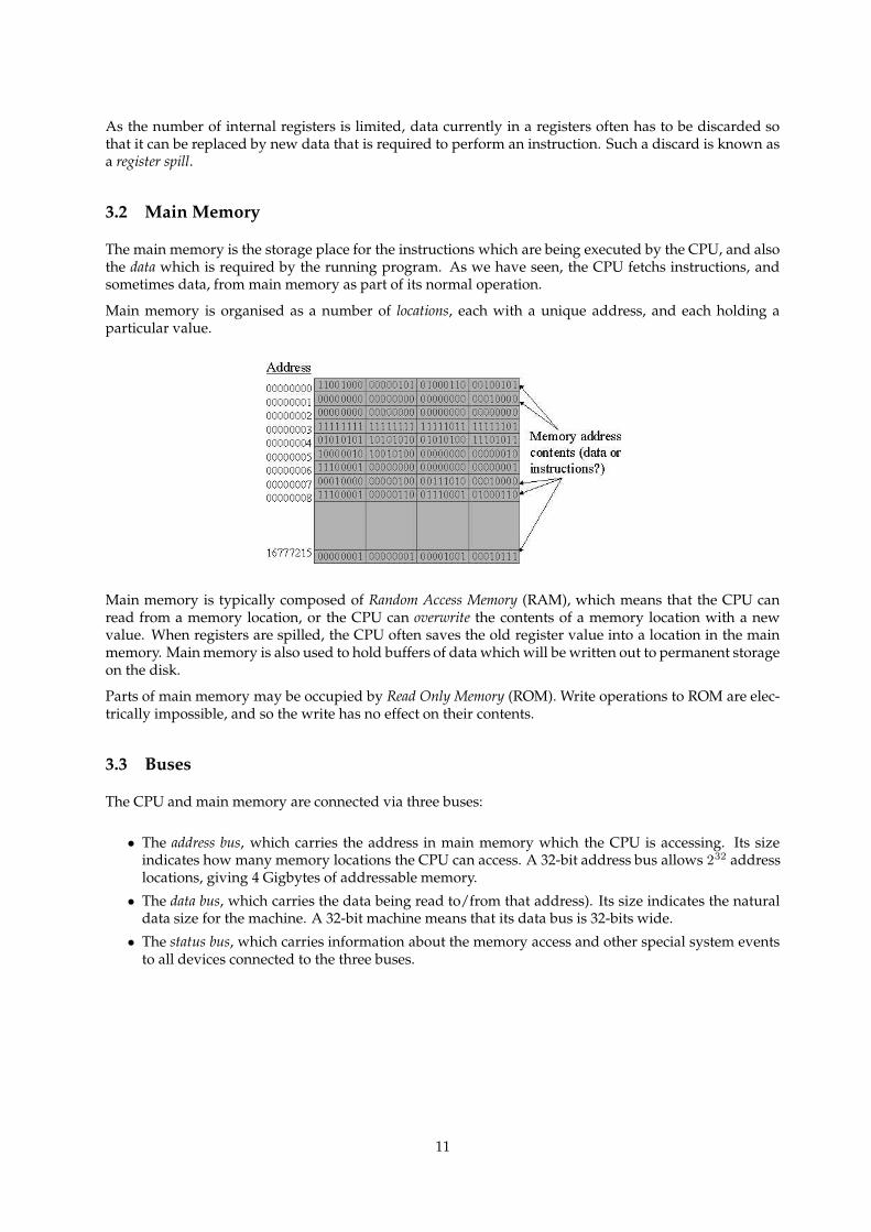
3.2 Main Memory
The main memory is the storage place for the instructions which are being executed by the CPU, and alsothe data which is required by the running program. As we have seen, the CPU fetchs instructions, andsometimes data, from main memory as part of its normal operation.
Main memory is organised as a number of locations, each with a unique address, and each holding aparticular value.
Main memory is typically composed of Random Access Memory (RAM), which means that the CPU canread from a memory location, or the CPU can overwrite the contents of a memory location with a newvalue. When registers are spilled, the CPU often saves the old register value into a location in the mainmemory. Main memory is also used to hold buffers of data which will be written out to permanent storageon the disk.
Parts of main memory may be occupied by Read Only Memory (ROM). Write operations to ROM are elec-trically impossible, and so the write has no effect on their contents.
3.3 Buses
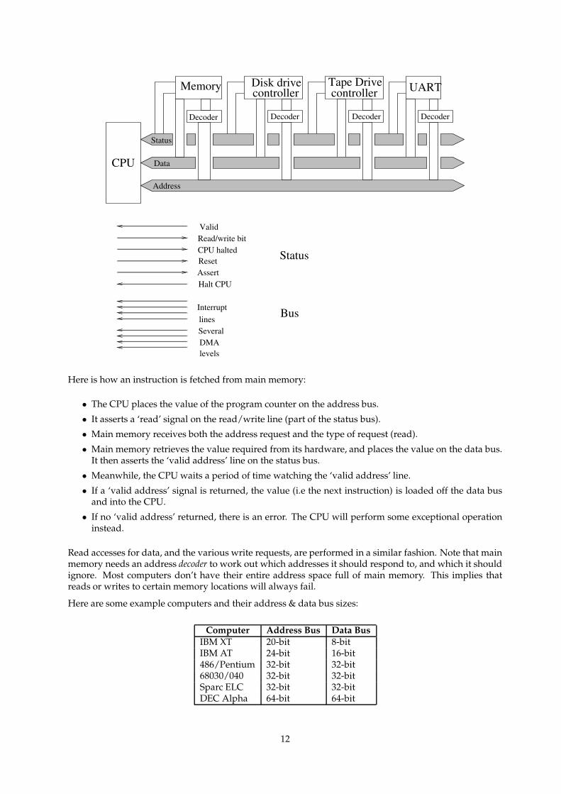
The CPU and main memory are connected via three buses:
• The address bus, which carries the address in main memory which the CPU is accessing. Its sizeindicates how many memory locations the CPU can access. A 32-bit address bus allows 232 addresslocations, giving 4 Gigbytes of addressable memory.
• The data bus, which carries the data being read to/from that address). Its size indicates the naturaldata size for the machine. A 32-bit machine means that its data bus is 32-bits wide.
• The status bus, which carries information about the memory access and other special system eventsto all devices connected to the three buses.
11
Disk drivecontroller
Tape Drivecontroller UARTMemory
Decoder Decoder Decoder Decoder
Address
Data
Status
ValidRead/write bitCPU haltedResetAssertHalt CPU
InterruptlinesSeveralDMAlevels
Status
Bus
CPU
Here is how an instruction is fetched from main memory:
• The CPU places the value of the program counter on the address bus.
• It asserts a ‘read’ signal on the read/write line (part of the status bus).
• Main memory receives both the address request and the type of request (read).
• Main memory retrieves the value required from its hardware, and places the value on the data bus.It then asserts the ‘valid address’ line on the status bus.
• Meanwhile, the CPU waits a period of time watching the ‘valid address’ line.
• If a ‘valid address’ signal is returned, the value (i.e the next instruction) is loaded off the data busand into the CPU.
• If no ‘valid address’ returned, there is an error. The CPU will perform some exceptional operationinstead.
Read accesses for data, and the various write requests, are performed in a similar fashion. Note that mainmemory needs an address decoder to work out which addresses it should respond to, and which it shouldignore. Most computers don’t have their entire address space full of main memory. This implies thatreads or writes to certain memory locations will always fail.
Here are some example computers and their address & data bus sizes:
Computer Address Bus Data BusIBM XT 20-bit 8-bitIBM AT 24-bit 16-bit486/Pentium 32-bit 32-bit68030/040 32-bit 32-bitSparc ELC 32-bit 32-bitDEC Alpha 64-bit 64-bit
12
3.4 Peripheral Devices
Textbook reference: Tanenbaum & Woodhull ppg 154 – 157
The computer must be able to do I/O, so as to store data on long-term storage devices, and to commu-nicate with the outside world. However, we don’t want the CPU to be burdened with the whole taskof doing I/O, i.e controlling every electrical & mechanical aspect of every peripheral. Therefore, mostdevices have a device controller which takes device commands from the CPU, performs them on the actualdevice, and reports the results (and any data) back to the CPU.
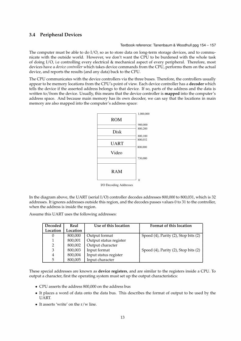
The CPU communicates with the device controllers via the three buses. Therefore, the controllers usuallyappear to be memory locations from the CPU’s point of view. Each device controller has a decoder whichtells the device if the asserted address belongs to that device. If so, parts of the address and the data iswritten to/from the device. Usually, this means that the device controller is mapped into the computer’saddress space. And because main memory has its own decoder, we can say that the locations in mainmemory are also mapped into the computer’s address space:
1,000,000
I/O Decoding Addresses
UART
RAM
Video
Disk
ROM
0
730,000
800,000
800,032800,100
800,200900,000
In the diagram above, the UART (serial I/O) controller decodes addresses 800,000 to 800,031, which is 32addresses. It ignores addresses outside this region, and the decodes passes values 0 to 31 to the controller,when the address is inside the region.
Assume this UART uses the following addresses:
Decoded Real Use of this location Format of this locationLocation Location
0 800,000 Output format Speed (4), Parity (2), Stop bits (2)1 800,001 Output status register2 800,002 Output character3 800,003 Input format Speed (4), Parity (2), Stop bits (2)4 800,004 Input status register5 800,005 Input character
These special addresses are known as device registers, and are similar to the registers inside a CPU. Tooutput a character, first the operating system must set up the output characteristics:
• CPU asserts the address 800,000 on the address bus
• It places a word of data onto the data bus. This describes the format of output to be used by theUART.
• It asserts ‘write’ on the r/w line.
13
• It waits a period of time.
• If no ‘valid address’ returned, error.
Then, to output a character, the character is sent to 800,002 as above. The UART latches the character, andit is transmitted over the serial line at the bit rate set in the output format.
Input from a device is more complicated. There are three types: polling, interrupts, and direct memoryaccess (DMA). We will leave DMA until later.
With polling, the UART leaves the input character at the address 800,005 and an indicator that a characterhas arrived at the address 800,004. The CPU must periodically scan (i.e read) this address to determineif a character has arrived. Because of this periodic checking, polling makes multitasking difficult if notimpossible: the frequent reading cannot be performed by the operating system if a running program hassole use of the CPU.
poll: v.,n. 1. [techspeak] The action of checking the status of an input line, sensor, or memory locationto see if a particular external event has been registered. 2. To repeatedly call or check with someone: “Ikeep polling him, but he’s not answering his phone; he must be swapped out.”
3.5 Interrupts
An alternative way for the operating system to find out when input has arrived, or when output has beencompleted, is to use interrupts. If a computer uses interrupts for I/O operations, a device will assertan interrupt line on the status bus when an I/O operation has been completed. Each device has its owninterrupt line.
For example, when a character arrives, the UART described above asserts its interrupt line. This sendsa signal in to the CPU along the status bus. If the interrupt has priority greater than any other assertedinterrupt line, the CPU will stop what it is doing, and jump to an interrupt handler for that line. Thisinterrupt handler is a section of machine code places at a fixed location in main memory.
Here, the interrupt handler will collect the character, do something with it and then return the CPU towhat it was doing before the handler started i.e the program running before the interrupt came in. Gen-erally speaking, interrupt handlers are a part of the operating system.
Interrupts are prioritised. The CPU is either running the current program, or dealing with the highestinterrupt sent in from devices along the status bus. If an interrupt’s priority is too low, then the interruptwill remain asserted until the other interrupts finish, and the CPU can handle it. Alternatively, if a newinterrupt has a priority higher than the one currently being handled by the CPU, then the CPU diverts tothe new interrupt’s handler, just as it did when it left the running program.
The CPU has an internal status register which holds the value of the current interrupt being handed.Normal programs run at a level below the lowest interrupt priority.
3.6 Interrupt Vectors
To ensure that the CPU goes back to what it was doing, old values of the program counter are stacked ininterrupt-level order somewhere. Each time an interrupt handler is called, the program counter’s valueis stacked, and the PC is set to the address of the first instruction in the interrupt handler.
The last instruction in an interrupt handler must unstack an old PC value, and put it back into the programcounter. All CPUs have a special instruction (often known as ReTurn from Interrupt or RTI) which doesthe unstacking.
Each interrupt level has its own interrupt handler. How does the CPU know where each handler is storedin main memory? A table of vectors is kept in main memory for each interrupt level. It holds the addressof the first instruction in the appropriate interrupt handler.
14
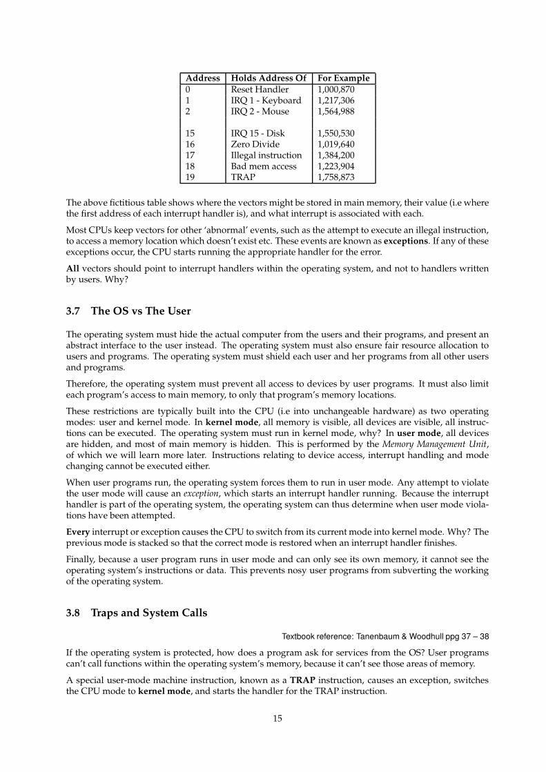
Address Holds Address Of For Example0 Reset Handler 1,000,8701 IRQ 1 - Keyboard 1,217,3062 IRQ 2 - Mouse 1,564,988
15 IRQ 15 - Disk 1,550,53016 Zero Divide 1,019,64017 Illegal instruction 1,384,20018 Bad mem access 1,223,90419 TRAP 1,758,873
The above fictitious table shows where the vectors might be stored in main memory, their value (i.e wherethe first address of each interrupt handler is), and what interrupt is associated with each.
Most CPUs keep vectors for other ‘abnormal’ events, such as the attempt to execute an illegal instruction,to access a memory location which doesn’t exist etc. These events are known as exceptions. If any of theseexceptions occur, the CPU starts running the appropriate handler for the error.
All vectors should point to interrupt handlers within the operating system, and not to handlers writtenby users. Why?
3.7 The OS vs The User
The operating system must hide the actual computer from the users and their programs, and present anabstract interface to the user instead. The operating system must also ensure fair resource allocation tousers and programs. The operating system must shield each user and her programs from all other usersand programs.
Therefore, the operating system must prevent all access to devices by user programs. It must also limiteach program’s access to main memory, to only that program’s memory locations.
These restrictions are typically built into the CPU (i.e into unchangeable hardware) as two operatingmodes: user and kernel mode. In kernel mode, all memory is visible, all devices are visible, all instruc-tions can be executed. The operating system must run in kernel mode, why? In user mode, all devicesare hidden, and most of main memory is hidden. This is performed by the Memory Management Unit,of which we will learn more later. Instructions relating to device access, interrupt handling and modechanging cannot be executed either.
When user programs run, the operating system forces them to run in user mode. Any attempt to violatethe user mode will cause an exception, which starts an interrupt handler running. Because the interrupthandler is part of the operating system, the operating system can thus determine when user mode viola-tions have been attempted.
Every interrupt or exception causes the CPU to switch from its current mode into kernel mode. Why? Theprevious mode is stacked so that the correct mode is restored when an interrupt handler finishes.
Finally, because a user program runs in user mode and can only see its own memory, it cannot see theoperating system’s instructions or data. This prevents nosy user programs from subverting the workingof the operating system.
3.8 Traps and System Calls
Textbook reference: Tanenbaum & Woodhull ppg 37 – 38
If the operating system is protected, how does a program ask for services from the OS? User programscan’t call functions within the operating system’s memory, because it can’t see those areas of memory.
A special user-mode machine instruction, known as a TRAP instruction, causes an exception, switchesthe CPU mode to kernel mode, and starts the handler for the TRAP instruction.
15
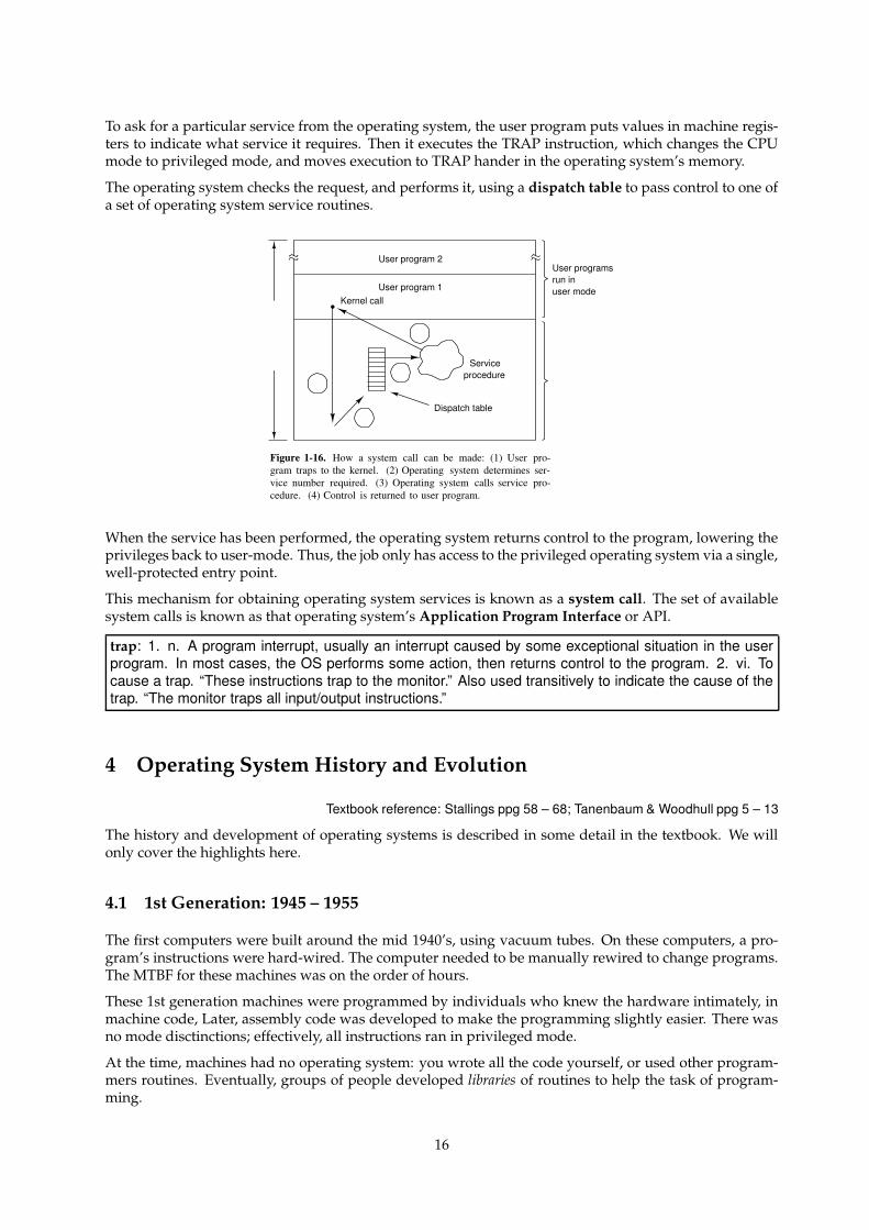
To ask for a particular service from the operating system, the user program puts values in machine regis-ters to indicate what service it requires. Then it executes the TRAP instruction, which changes the CPUmode to privileged mode, and moves execution to TRAP hander in the operating system’s memory.
The operating system checks the request, and performs it, using a dispatch table to pass control to one ofa set of operating system service routines.
User program 2
User program 1Kernel call
Serviceprocedure
Dispatch table
User programsrun inuser mode
Figure 1-16. How a system call can be made: (1) User pro-gram traps to the kernel. (2) Operating system determines ser-vice number required. (3) Operating system calls service pro-cedure. (4) Control is returned to user program.
When the service has been performed, the operating system returns control to the program, lowering theprivileges back to user-mode. Thus, the job only has access to the privileged operating system via a single,well-protected entry point.
This mechanism for obtaining operating system services is known as a system call. The set of availablesystem calls is known as that operating system’s Application Program Interface or API.
trap: 1. n. A program interrupt, usually an interrupt caused by some exceptional situation in the userprogram. In most cases, the OS performs some action, then returns control to the program. 2. vi. Tocause a trap. “These instructions trap to the monitor.” Also used transitively to indicate the cause of thetrap. “The monitor traps all input/output instructions.”
4 Operating System History and Evolution
Textbook reference: Stallings ppg 58 – 68; Tanenbaum & Woodhull ppg 5 – 13
The history and development of operating systems is described in some detail in the textbook. We willonly cover the highlights here.
4.1 1st Generation: 1945 – 1955
The first computers were built around the mid 1940’s, using vacuum tubes. On these computers, a pro-gram’s instructions were hard-wired. The computer needed to be manually rewired to change programs.The MTBF for these machines was on the order of hours.
These 1st generation machines were programmed by individuals who knew the hardware intimately, inmachine code, Later, assembly code was developed to make the programming slightly easier. There wasno mode disctinctions; effectively, all instructions ran in privileged mode.
At the time, machines had no operating system: you wrote all the code yourself, or used other program-mers routines. Eventually, groups of people developed libraries of routines to help the task of program-ming.
16
You usually had to book time slots to use the computer. Often the slot was too short. Sometimes (if yourprogram worked), the slot was too long. This of course led to CPU wastage.
Most early programs were numerical calculations, and very CPU-intensive. The early 1950s saw theintroduction of punched cards to speed programming.
bare metal: n. 1. New computer hardware, unadorned with such snares and delusions as an operatingsystem, a high-level language, or even an assembler. Commonly used in the phrase ‘programming onthe bare metal’, which refers to the arduous work needed to create these basic tools for a new machine.Real bare-metal programming involves things like building boot proms and BIOS chips, implementingbasic monitors used to test device drivers, and writing the assemblers that will be used to write thecompiler back ends that will give the new machine a real development environment.
Stone Age: n., adj. 1. In computer folklore, an ill-defined period from ENIAC (ca. 1943) to the mid-1950s; the great age of electromechanical dinosaurs, characterised by hardware such as mercury delaylines and/or relays.
4.2 2nd Generation: 1955 – 1965
The introduction of the transistor made computers more reliable. It was now possible for companies tosell/lease the computers they built to 3rd parties. Computers were used more efficiently by employ-ing people to run the machines for the customer. High-level languages such as FORTRAN and COBOLinvented, which made programming much easier and somewhat more portable.
To run a program, a user would punch their code/data onto cards, give the deck of cards to operators,who would feed them to the computer, and return printout/new cards to user. Each program run wasknown as a job. Doing this this way made programs hard to debug due to the slow turnaround, but meantthat the CPU was utilised more. However, the CPU still sat idle between jobs.
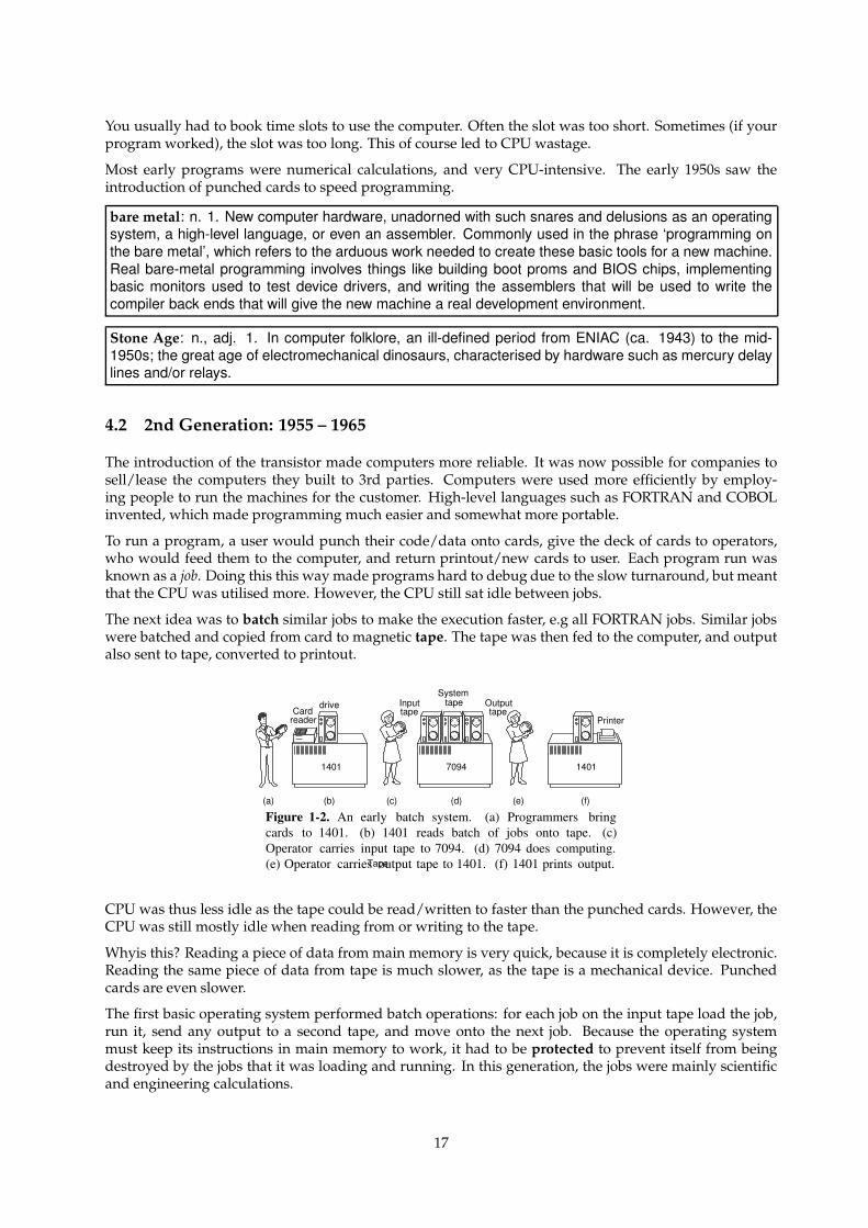
The next idea was to batch similar jobs to make the execution faster, e.g all FORTRAN jobs. Similar jobswere batched and copied from card to magnetic tape. The tape was then fed to the computer, and outputalso sent to tape, converted to printout.
1401 7094 1401
(a) (b) (c) (d) (e) (f)
Cardreader
Tape
drive Inputtape
Outputtape
Systemtape
Printer
Figure 1-2. An early batch system. (a) Programmers bringcards to 1401. (b) 1401 reads batch of jobs onto tape. (c)Operator carries input tape to 7094. (d) 7094 does computing.(e) Operator carries output tape to 1401. (f) 1401 prints output.
CPU was thus less idle as the tape could be read/written to faster than the punched cards. However, theCPU was still mostly idle when reading from or writing to the tape.
Whyis this? Reading a piece of data from main memory is very quick, because it is completely electronic.Reading the same piece of data from tape is much slower, as the tape is a mechanical device. Punchedcards are even slower.
The first basic operating system performed batch operations: for each job on the input tape load the job,run it, send any output to a second tape, and move onto the next job. Because the operating systemmust keep its instructions in main memory to work, it had to be protected to prevent itself from beingdestroyed by the jobs that it was loading and running. In this generation, the jobs were mainly scientificand engineering calculations.
17
Bronze Age: n. 1. Era of transistor-logic, pre-ferrite-core machines with drum or CRT mass storage.
4.3 3rd Generation: 1965 – 1980
In the 3rd Generation, integrated circuits (ICs) make machines smaller and more reliable, although theywere initially more expensive. Companies found they outgrew their machines, but each model had dif-ferent batch systems. This meant that each change of computer system involved a recoding of jobs andretraining of operators.
To alleviate these problems, IBM decided to create a whole family of machines, each with a similar hard-ware architecture, with a single operating system that ran on every family member. This was the Sys-tem/360 family, and OS/360. OS/360 ran to millions of lines of code, with a constant number of bugs,even in new system releases.
Computer usage moved away from purely scientific work to business work e.g inventories. These typeof jobs were more I/O intensive (lots of reading/writing on tape). The CPU became idle waiting for thetape while processing these I/O intensive jobs, and so CPU utilisation dropped again.
The solution to the problem of CPU utilisation on I/O jobs was multiprogramming:
• Have >1 jobs in memory, each protected from the others.
• As one job goes idle waiting for I/O, the operating system can switch to another job which is waitingfor the CPU. Alternatively, the operating system could start up another job if no current jobs arewaiting for the CPU.
This could give over 90% CPU utilisation, but with some overhead caushed by the switching betweenjobs. To improve performance further, disks were used to cache/spool jobs (i.e both the programs toexecute and their associated data). Disks were faster to access than tape, especially for random accesswhere the data is accessed in no particular order from the disk.
These system still suffered from slow job turnaround: the users had to wait for a job to run to termination(or crash) before they could do any reprogramming.
Iron Age: n. In the history of computing, 1961–1971 — the formative era of commercial mainframetechnology, when big iron dinosaurs ruled the earth. These began with the delivery of the first PDP-1,coincided with the dominance of ferrite core, and ended with the introduction of the first commercialmicroprocessor (the Intel 4004) in 1971.
4.4 Timesharing
A method of overcoming the slow job turnaround was introduced at this point timesharing. on a time-sharing system, the operating system swapped very quickly between jobs (even if the current job was stillusing the CPU), allowing input/output to come from users on terminals instead of tape or punched cards.
This switching away from a job using the CPU is known as pre-emption, and is the hallmark of an interac-tive operating multiprogramming operating system. The Multics operating system was designed at thistime, to support hundreds of users simultaneously. Its design was good, and introduced many new ideas,but was very expensive hardware-wise, and fizzled out with the introduction of minicomputers.
Multics: n. [from “MULTiplexed Information and Computing Service”] A late 1960s timesharing operatingsystem co-designed by a consortium including MIT, GE, and Bell Laboratories. Very innovative for itstime — among other things, it introduced the idea of treating all devices uniformly as special files. All themembers but GE eventually pulled out after determining that second-system effect had bloated Multicsto the point of practical unusability. One of the developers left in the lurch by the project’s breakup wasKen Thompson, a circumstance which led directly to the birth of UNIX.
18
4.5 3rd Generation – Part 2
Minicomputers arrived, introduced with the PDP-1 in 1961. These machines were only 5% the cost ofmainframes, but gave about 10% – 20% of their performance. These made minicomputers affordable toindividual departments, not just to large companies.
Although Multics died, many of its ideas were passed on to Unix. Unix was mostly written in a high-levellanguage called ‘C’, thus aiding ports to new hardware. In fact, it was one of the first portable operatingsystems.
Both minicomuters and mainframes got faster/cheaper and minis picked up more mainframe operatingsystem ideas as time went on.
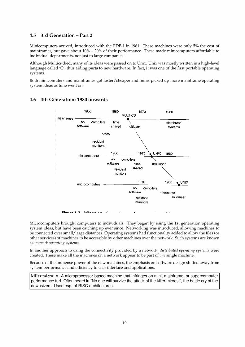
4.6 4th Generation: 1980 onwards
Microcomputers brought computers to individuals. They began by using the 1st generation operatingsystem ideas, but have been catching up ever since. Networking was introduced, allowing machines tobe connected over small/large distances. Operating systems had functionality added to allow the files (orother services) of machines to be accessible by other machines over the network. Such systems are knownas network operating systems.
In another approach to using the connectivity provided by a network, distributed operating systems werecreated. These make all the machines on a network appear to be part of one single machine.
Because of the immense power of the new machines, the emphasis on software design shifted away fromsystem performance and efficiency to user interface and applications.
killer micro: n. A microprocessor-based machine that infringes on mini, mainframe, or supercomputerperformance turf. Often heard in “No one will survive the attack of the killer micros!”, the battle cry of thedownsizers. Used esp. of RISC architectures.
19
5 Processes
Textbook reference: Stallings ppg 107 – 147; Tanenbaum & Woodhull ppg 47 – 52
5.1 What is a Process?
The primary function of an operating system is to provide an environment where user programs can run.The operating system must provide a framework for program execution, a set of services (file manage-ment etc.) and an interface to these services. On a multiprogramming system, the operating system mustalso ensure that the many programs loaded into memory do not interfere with each other.
This restricted form of program execution, with access to the services of the operating system, is knownas a process. Specifically, a process is a sequence of computer instructions executing in an address space,with access to the operating system services. An address space is an area of main memory to which theprocess has exclusive access.
The process consists of: the machine code instructions in main memory, a data area and a stack in mainmemory, and the CPU’s registers which the process uses while it is using the CPU.
The data area holds the process’ global data, e.g the internal memory representation of a word processordocument. The stack usually holds the process’ local data e.g local variables in functions and subroutines,plus program counters for subroutine returns.
5.2 The Process Environment
As noted before, the operating system ensures that a process lives in a protected environment: it is pro-tected against any interference from other processes currently in main memory. The operating systemalso prevents a process from seeing or altering other processes, and of course the operating system itself.
This is achieved by running all of the machine code instructions of all processes in user mode. In thismode, certain privileged machine instructions are ‘disabled’, areas of memory not owned by a process aremade invalid, and access to all hardware is prevented by the CPU.
5.3 System Calls
If the process can execute its instructions and read/write its data, but nothing else, how does it actuallydo anything useful, like read from a file, get mouse movements etc.? There needs to be a mechanism toallow a process to ask for specific services from the operating system, without compromising the protectedenvironment that constrains the process.
This is achieved by a special instruction built into the CPU: the TRAP instruction. A process accessesthe services of the operating system by using the TRAP instruction, which passes execution directly fromthe process to the operating system. Information placed in the CPU’s registers by the process tells theoperating system what service the process wants. This mechanism of obtaining services via a TRAPinstruction is known as a system call.
Each operating system has its own set of available system calls. The set of available system calls is knownas that operating system’s Application Program Interface or API.
5.4 Layout of a Process
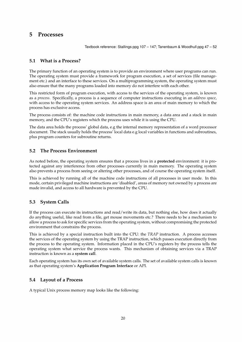
A typical Unix process memory map looks like the following:
20
Machine code
Data
Stack
C D
S
Non-segmentedArchitecture
ArchitectureSegmented
low
high
Memory map is another term for ‘address space’. The memory map allows the stack to grow down andthe data area to grow up: in other words, the process is able to use more main memory that the operatingsystem initially allocates. Areas above or below the process’ memory are invalid because of protectionsset by the operating system; they usually contain other processes. On some machine architectures, suchas segmented architectures, the three sections are separated.
5.5 Process Models
Although I’ve said a process is in memory and doing something, often a process can’t do anything, eitherbecause another process is running or it is waiting for I/O. A state diagram shows what states a processcan be in, and how it moves to new states.
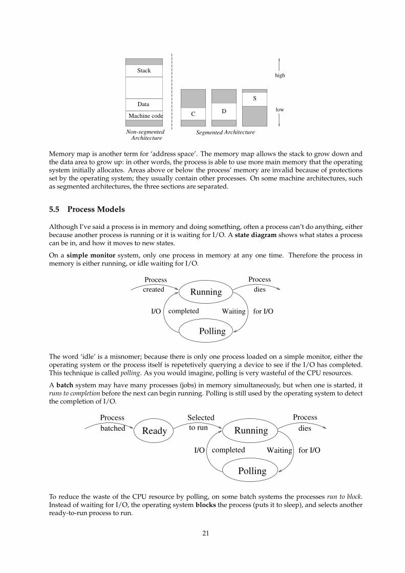
On a simple monitor system, only one process in memory at any one time. Therefore the process inmemory is either running, or idle waiting for I/O.
Polling
WaitingcompletedI/O
Running
for I/O
createdProcess
diesProcess
The word ‘idle’ is a misnomer; because there is only one process loaded on a simple monitor, either theoperating system or the process itself is repetetively querying a device to see if the I/O has completed.This technique is called polling. As you would imagine, polling is very wasteful of the CPU resources.
A batch system may have many processes (jobs) in memory simultaneously, but when one is started, itruns to completion before the next can begin running. Polling is still used by the operating system to detectthe completion of I/O.
Polling
WaitingcompletedI/O
Running
for I/O
ReadyProcessbatched
Selectedto run dies
Process
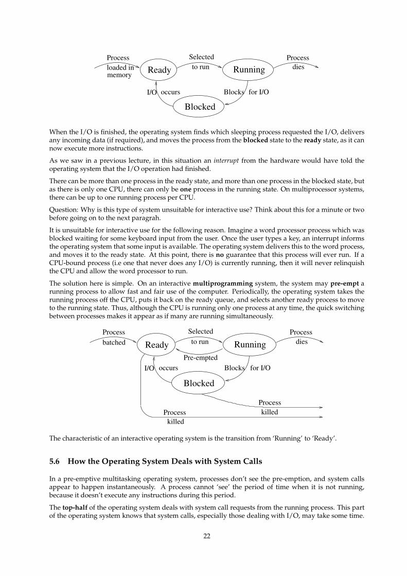
To reduce the waste of the CPU resource by polling, on some batch systems the processes run to block.Instead of waiting for I/O, the operating system blocks the process (puts it to sleep), and selects anotherready-to-run process to run.
21
memoryRunningReady
Blocked
I/O occurs Blocks for I/O
Selectedto run
Process Processdiesloaded in
When the I/O is finished, the operating system finds which sleeping process requested the I/O, deliversany incoming data (if required), and moves the process from the blocked state to the ready state, as it cannow execute more instructions.
As we saw in a previous lecture, in this situation an interrupt from the hardware would have told theoperating system that the I/O operation had finished.
There can be more than one process in the ready state, and more than one process in the blocked state, butas there is only one CPU, there can only be one process in the running state. On multiprocessor systems,there can be up to one running process per CPU.
Question: Why is this type of system unsuitable for interactive use? Think about this for a minute or twobefore going on to the next paragrah.
It is unsuitable for interactive use for the following reason. Imagine a word processor process which wasblocked waiting for some keyboard input from the user. Once the user types a key, an interrupt informsthe operating system that some input is available. The operating system delivers this to the word process,and moves it to the ready state. At this point, there is no guarantee that this process will ever run. If aCPU-bound process (i.e one that never does any I/O) is currently running, then it will never relinquishthe CPU and allow the word processor to run.
The solution here is simple. On an interactive multiprogramming system, the system may pre-empt arunning process to allow fast and fair use of the computer. Periodically, the operating system takes therunning process off the CPU, puts it back on the ready queue, and selects another ready process to moveto the running state. Thus, although the CPU is running only one process at any time, the quick switchingbetween processes makes it appear as if many are running simultaneously.
Process
RunningReady
Blocked
I/O occurs Blocks for I/O
Selectedto run
Pre-empted
killedProcesskilled
Processbatched
Processdies
The characteristic of an interactive operating system is the transition from ‘Running’ to ‘Ready’.
5.6 How the Operating System Deals with System Calls
In a pre-emptive multitasking operating system, processes don’t see the pre-emption, and system callsappear to happen instantaneously. A process cannot ‘see’ the period of time when it is not running,because it doesn’t execute any instructions during this period.
The top-half of the operating system deals with system call requests from the running process. This partof the operating system knows that system calls, especially those dealing with I/O, may take some time.
22
Therefore, instead of busy-waiting or polling, the top-half blocks the process until the operation completes.In other words, the state of the running process is changed to blocked, and the operating systems choosesanother running process from the ready queue.
The bottom-half of the operating system reacts to all of the interrupts sent by the various devices. Thesetell the operating system that I/O is done. The bottom half finds the blocked process that asked for theI/O operation, changes its state from blocked to ready, and returns back to the currently running process.
To summarise, the process:
• lives in a transparently pre-emptive scheduling environment,
• cannot block itself, and
• can be scheduled by the operating system.
The top-half of the operating system:
• is only used when a system call is performed by a process,
• is never scheduled (it isn’t a process), and
• runs until the system call is done, or blocks the calling process.
The bottom-half of the operating system:
• reacts to hardware interrupts,
• is never scheduled (it isn’t a process),
• can never be blocked or stopped, and
• wakes up the blocked process, making it ready to run.
5.7 Process Control Blocks
Textbook reference: Tanenbaum & Woodhull ppg 52 – 53
When the operating system moves a process from the running state, it must ensure that the process’ bitsand pieces are kept so it can be restarted. This means that the operating system must:
• Preserve the process’ areas of memory,
• Protect these from other processes,
• Save copies of the CPU registers used by the process,
• Save information about any other resources used,
• Mark the process’ new state, and
• If blocked, record which I/O operation the process is blocked on. so when I/O completes, theprocess can be moved back to ‘Ready’.
All of this information is stored in the Process Control Block in the operating system. There is one ProcessControl Block per process, and it usually contains several sections:
• Machine dependent section:
– Register copies– Information about the process’ memory areas
• Machine independent section:
– The process’ state
23
– The process’ priority, other scheduling information– Open files and their state– The process id– The user id of the user running the process– On what the process is blocked
• Statistics section:
– Total time the process has been running, etc.
The above is an example only of the possible types of information that must be recorded. Each operatingsystem stores different things in its PCBs. The statistics section is used to aid the operating system indeciding how/when to allocate resources to the process, as will be seen in future lectures.
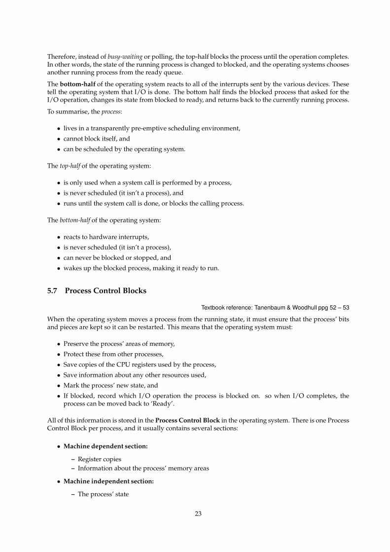
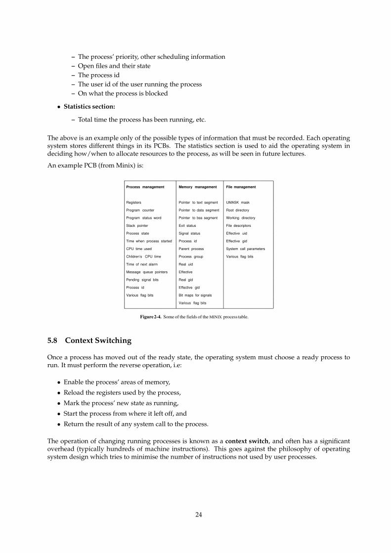
An example PCB (from Minix) is:
Process management Memory management File management
Registers Pointer to text segment UMASK mask
Program counter Pointer to data segment Root directory
Program status word Pointer to bss segment Working directory
Stack pointer Exit status File descriptors
Process state Signal status Effective uid
Time when process started Process id Effective gid
CPU time used Parent process System call parameters
Children’s CPU time Process group Various flag bits
Time of next alarm Real uid
Message queue pointers Effective
Pending signal bits Real gid
Process id Effective gid
Various flag bits Bit maps for signals
Various flag bits
Figure2-4. Some of the fields of the MINIX process table.
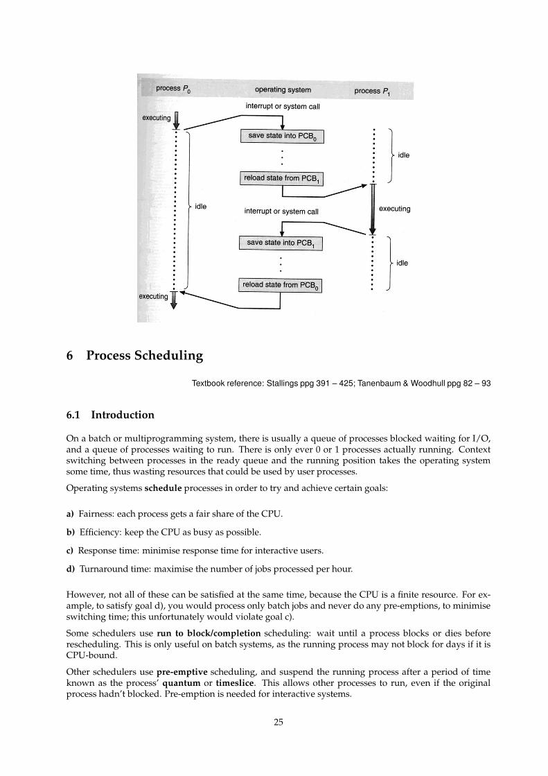
5.8 Context Switching
Once a process has moved out of the ready state, the operating system must choose a ready process torun. It must perform the reverse operation, i.e:
• Enable the process’ areas of memory,
• Reload the registers used by the process,
• Mark the process’ new state as running,
• Start the process from where it left off, and
• Return the result of any system call to the process.
The operation of changing running processes is known as a context switch, and often has a significantoverhead (typically hundreds of machine instructions). This goes against the philosophy of operatingsystem design which tries to minimise the number of instructions not used by user processes.
24
6 Process Scheduling
Textbook reference: Stallings ppg 391 – 425; Tanenbaum & Woodhull ppg 82 – 93
6.1 Introduction
On a batch or multiprogramming system, there is usually a queue of processes blocked waiting for I/O,and a queue of processes waiting to run. There is only ever 0 or 1 processes actually running. Contextswitching between processes in the ready queue and the running position takes the operating systemsome time, thus wasting resources that could be used by user processes.
Operating systems schedule processes in order to try and achieve certain goals:
a) Fairness: each process gets a fair share of the CPU.
b) Efficiency: keep the CPU as busy as possible.
c) Response time: minimise response time for interactive users.
d) Turnaround time: maximise the number of jobs processed per hour.
However, not all of these can be satisfied at the same time, because the CPU is a finite resource. For ex-ample, to satisfy goal d), you would process only batch jobs and never do any pre-emptions, to minimiseswitching time; this unfortunately would violate goal c).
Some schedulers use run to block/completion scheduling: wait until a process blocks or dies beforerescheduling. This is only useful on batch systems, as the running process may not block for days if it isCPU-bound.
Other schedulers use pre-emptive scheduling, and suspend the running process after a period of timeknown as the process’ quantum or timeslice. This allows other processes to run, even if the originalprocess hadn’t blocked. Pre-emption is needed for interactive systems.
25
6.2 Scheduling Algorithms – Interactive (Pre-emption)
There are several algorithms available to choose a process from the list of ready-to-run processes whenthe running state has been vacated. Each one reflects a certain system policy for process scheduling. Eachalgorithm has its advantages and disadvantages. Wee will look at:
• First Come First Served/Round Robin
• Timeslice Priority
• Multiple Priority Queues
• Long Term Schedulers
6.3 First Come First Served/ Round Robin
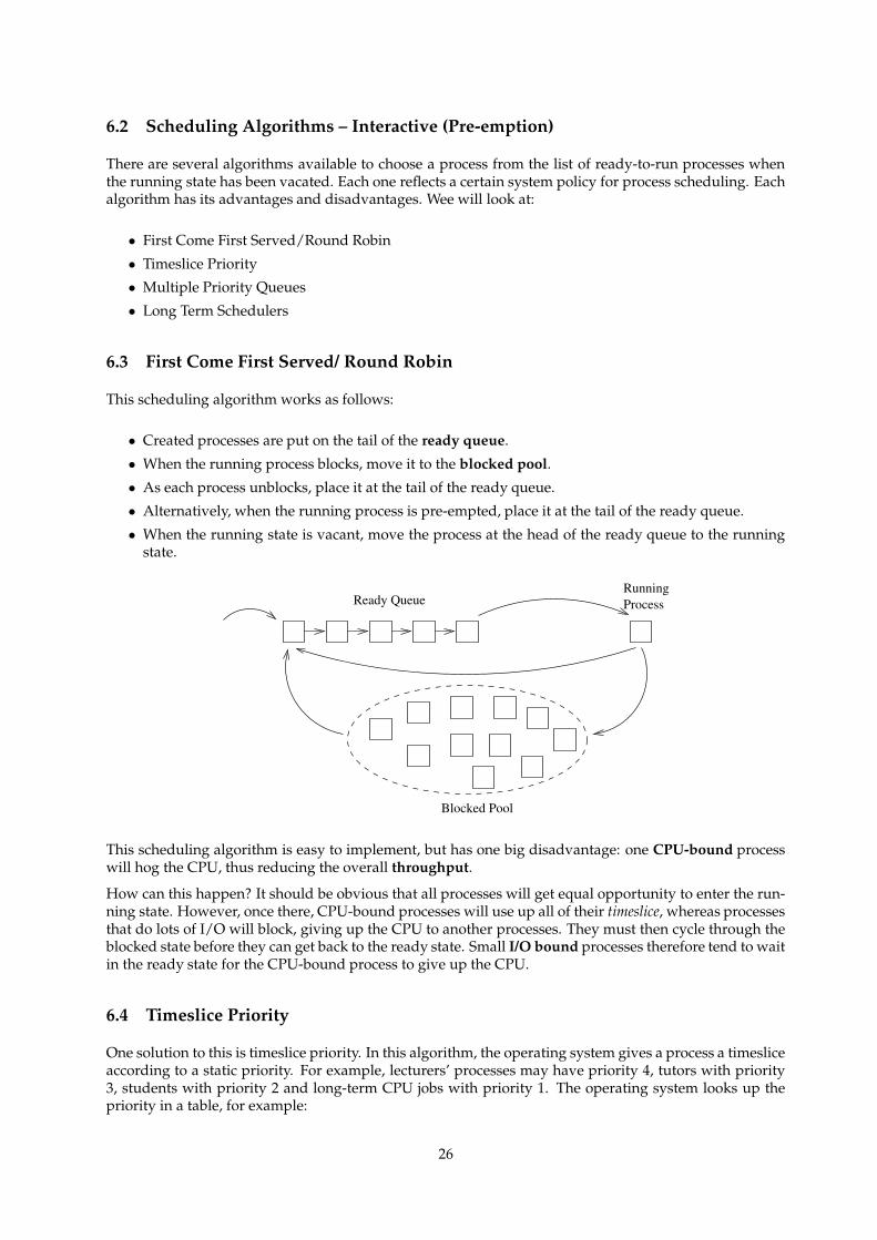
This scheduling algorithm works as follows:
• Created processes are put on the tail of the ready queue.
• When the running process blocks, move it to the blocked pool.
• As each process unblocks, place it at the tail of the ready queue.
• Alternatively, when the running process is pre-empted, place it at the tail of the ready queue.
• When the running state is vacant, move the process at the head of the ready queue to the runningstate.
Process
Blocked Pool
Ready QueueRunning
This scheduling algorithm is easy to implement, but has one big disadvantage: one CPU-bound processwill hog the CPU, thus reducing the overall throughput.
How can this happen? It should be obvious that all processes will get equal opportunity to enter the run-ning state. However, once there, CPU-bound processes will use up all of their timeslice, whereas processesthat do lots of I/O will block, giving up the CPU to another processes. They must then cycle through theblocked state before they can get back to the ready state. Small I/O bound processes therefore tend to waitin the ready state for the CPU-bound process to give up the CPU.
6.4 Timeslice Priority
One solution to this is timeslice priority. In this algorithm, the operating system gives a process a timesliceaccording to a static priority. For example, lecturers’ processes may have priority 4, tutors with priority3, students with priority 2 and long-term CPU jobs with priority 1. The operating system looks up thepriority in a table, for example:
26
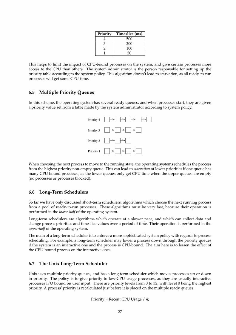
Priority Timeslice (ms)4 5003 2002 1001 50
This helps to limit the impact of CPU-bound processes on the system, and give certain processes moreaccess to the CPU than others. The system administrator is the person responsible for setting up thepriority table according to the system policy. This algorithm doesn’t lead to starvation, as all ready-to-runprocesses will get some CPU-time.
6.5 Multiple Priority Queues
In this scheme, the operating system has several ready queues, and when processes start, they are givena priority value set from a table made by the system administrator according to system policy.
Priority 1
Priority 4
Priority 3
Priority 2
When choosing the next process to move to the running state, the operating systems schedules the processfrom the highest priority non-empty queue. This can lead to starvation of lower priorities if one queue hasmany CPU bound processes, as the lower queues only get CPU time when the upper queues are empty(no processes or processes blocked).
6.6 Long-Term Schedulers
So far we have only discussed short-term schedulers: algorithms which choose the next running processfrom a pool of ready-to-run processes. These algorithms must be very fast, because their operation isperformed in the lower-half of the operating system.
Long-term schedulers are algorithms which operate at a slower pace, and which can collect data andchange process priorities and timeslice values over a period of time. Their operation is performed in theupper-half of the operating system.
The main of a long-term scheduler is to enforce a more sophisticated system policy with regards to processscheduling. For example, a long-term scheduler may lower a process down through the priority queuesif the system is an interactive one and the process is CPU-bound. The aim here is to lessen the effect ofthe CPU-bound process on the interactive ones.
6.7 The Unix Long-Term Scheduler
Unix uses multiple priority queues, and has a long-term scheduler which moves processes up or downin priority. The policy is to give priority to low-CPU usage processes, as they are usually interactiveprocesses I/O bound on user input. There are priority levels from 0 to 32, with level 0 being the highestpriority. A process’ priority is recalculated just before it is placed on the multiple ready queues:
Priority = Recent CPU Usage / 4;
27
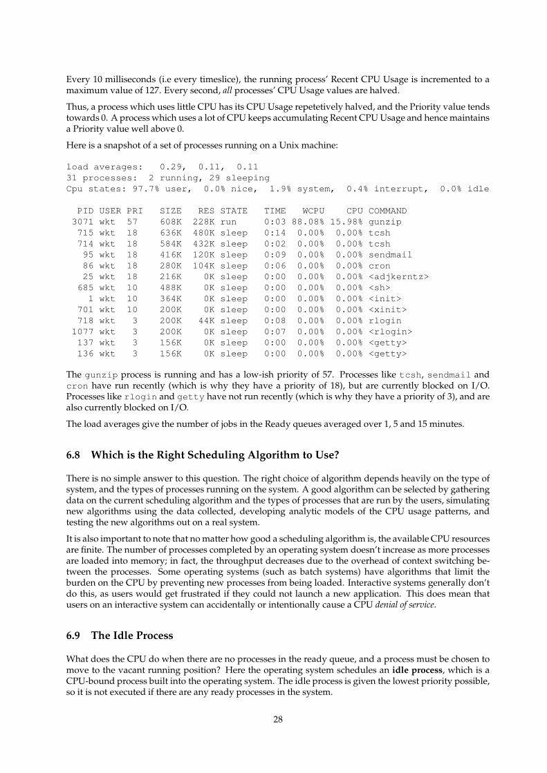
Every 10 milliseconds (i.e every timeslice), the running process’ Recent CPU Usage is incremented to amaximum value of 127. Every second, all processes’ CPU Usage values are halved.
Thus, a process which uses little CPU has its CPU Usage repetetively halved, and the Priority value tendstowards 0. A process which uses a lot of CPU keeps accumulating Recent CPU Usage and hence maintainsa Priority value well above 0.
Here is a snapshot of a set of processes running on a Unix machine:
load averages: 0.29, 0.11, 0.1131 processes: 2 running, 29 sleepingCpu states: 97.7% user, 0.0% nice, 1.9% system, 0.4% interrupt, 0.0% idle
PID USER PRI SIZE RES STATE TIME WCPU CPU COMMAND3071 wkt 57 608K 228K run 0:03 88.08% 15.98% gunzip715 wkt 18 636K 480K sleep 0:14 0.00% 0.00% tcsh714 wkt 18 584K 432K sleep 0:02 0.00% 0.00% tcsh95 wkt 18 416K 120K sleep 0:09 0.00% 0.00% sendmail86 wkt 18 280K 104K sleep 0:06 0.00% 0.00% cron25 wkt 18 216K 0K sleep 0:00 0.00% 0.00% <adjkerntz>685 wkt 10 488K 0K sleep 0:00 0.00% 0.00% <sh>1 wkt 10 364K 0K sleep 0:00 0.00% 0.00% <init>
701 wkt 10 200K 0K sleep 0:00 0.00% 0.00% <xinit>718 wkt 3 200K 44K sleep 0:08 0.00% 0.00% rlogin
1077 wkt 3 200K 0K sleep 0:07 0.00% 0.00% <rlogin>137 wkt 3 156K 0K sleep 0:00 0.00% 0.00% <getty>136 wkt 3 156K 0K sleep 0:00 0.00% 0.00% <getty>
The gunzip process is running and has a low-ish priority of 57. Processes like tcsh, sendmail andcron have run recently (which is why they have a priority of 18), but are currently blocked on I/O.Processes like rlogin and getty have not run recently (which is why they have a priority of 3), and arealso currently blocked on I/O.
The load averages give the number of jobs in the Ready queues averaged over 1, 5 and 15 minutes.
6.8 Which is the Right Scheduling Algorithm to Use?
There is no simple answer to this question. The right choice of algorithm depends heavily on the type ofsystem, and the types of processes running on the system. A good algorithm can be selected by gatheringdata on the current scheduling algorithm and the types of processes that are run by the users, simulatingnew algorithms using the data collected, developing analytic models of the CPU usage patterns, andtesting the new algorithms out on a real system.
It is also important to note that no matter how good a scheduling algorithm is, the available CPU resourcesare finite. The number of processes completed by an operating system doesn’t increase as more processesare loaded into memory; in fact, the throughput decreases due to the overhead of context switching be-tween the processes. Some operating systems (such as batch systems) have algorithms that limit theburden on the CPU by preventing new processes from being loaded. Interactive systems generally don’tdo this, as users would get frustrated if they could not launch a new application. This does mean thatusers on an interactive system can accidentally or intentionally cause a CPU denial of service.
6.9 The Idle Process
What does the CPU do when there are no processes in the ready queue, and a process must be chosen tomove to the vacant running position? Here the operating system schedules an idle process, which is aCPU-bound process built into the operating system. The idle process is given the lowest priority possible,so it is not executed if there are any ready processes in the system.
28
7 Introduction to Input/Output
Textbook reference: Stallings ppg 471 – 511; Tanenbaum & Woodhull ppg 153 – 165
7.1 Why does the Operating System do I/O?
One of the main functions of an operating system is to control all the I/O devices: disks, tapes clocks,terminals, network devices etc. This harks back to the idea that the operating system provides an abstractinterface to the system. Thus the operating system must control the hardware for the user. Because ofthis, it can also manage the system resources fairly and efficiently.
To control all the I/O devices, the operating system must issue commands to the devices, catch interruptsreturned by the device controllers, and handle andy device errors. The operating system must then pro-vide an interface between the devices and the processes that is simple and easy to use by programmers.If possible, the operating system should also make this interface device-independent.
The reasons for this all: the user doesn’t want to worry about physical attributes of devices, their program-ming quirks, and how to handle errors. They just want to deal with abstract I/O such as mouse events,files and documents, windows on the screen, and data sent across the network. Leaving the managementof I/O to the operating system makes the programmers’ and users’ lives easier, and allows schedulingalgorithms to be created for the devices.
interrupt: 1. [techspeak] n. On a computer, an event that interrupts normal processing and temporarilydiverts flow-of-control through an “interrupt handler” routine. See also trap. 2. interj. A request forattention from a hacker. Often explicitly spoken. “Interrupt — have you seen Joe recently?”
interrupts locked out: When someone is ignoring you. In a restaurant, after several fruitless attemptsto get the waitress’s attention, a hacker might well observe “She must have interrupts locked out”. Thesynonym ‘interrupts disabled’ is also common.
7.2 Devices and the Machine Architecture
We have seen how devices are accessed via the CPU. Here is a reiteration. Devices are seen by the CPUthrough device registers, which are often mapped to specific physical memory addresses. Each registercontrols, or shows, an aspect of the device’s operation. You might like to review the example UART thatwe described previously. I/O is performed by examining/modifying the values in the device’s registers.The device controller, in turn, observes these changes and performs the requested I/O.
The CPU can poll the device registers to see when any I/O has been completed by the device. This isusually undesirable, as it wastes CPU time when no I/O has been done. Alternatively, the device maysend the CPU an interrupt to inform it when I/O has completed, or when some error has occurred. Eachdevice has its own interrupt line.
Interrupts typically have a set of priority levels: interrupt handling at a low priority is delayed until ahigher priority interrupt has been handled. Alternatively, handling of a low priority interrupt will itselfbe interrupted when a higher priority interrupt arrives.
Interrupts allow multitasking, because any running process is automatically interrupted when input ar-rives, and resumes when the I/O operation has been completed by the interrupt handler.
poll: v.,n. 1. [techspeak] The action of checking the status of an input line, sensor, or memory locationto see if a particular external event has been registered. 2. To repeatedly call or check with someone: “Ikeep polling him, but he’s not answering his phone; he must be swapped out.”
29

7.3 Direct Memory Access
Textbook reference: Tanenbaum & Woodhull ppg 157 – 158
Using polling or interrupts to transfer data can be quite CPU intensive. Consider a UART that interruptseach time a character arrives from a serial port. Now imagine that the serial port is connected to a 56Kbpsmodem downloading a large JPEG image from the Internet. 56Kbps is roughly 5,600 characters per sec-ond. Therefore, while the image is being downloaded, the UART is interrupting the current runningprocess 5,600 times a second.
On each interrupt, the CPU is diverted to the UART interrupt handler. The handler must read the incom-ing character, find the process waiting for it, copy the character to the process, change its state to readybefore returning to the running process. You can imagine that this takes a lot of the CPU away from therunning process.
A better method is to use direct memory access (DMA). Here, the device controller delivers the data tothe appropriate process location in main memory, and sends an interrupt when the transfer is complete.And if the device can buffer and deliver a bundle of data (e.g 16 characters with the 16550AN UART),then this can again reduce the interrupt handling load on the CPU.
DMA requires some intelligence to be built into the device controller. For example, consider a disk drivecontroller which has the following registers:
Location Meaning of Register10,000 Disk address: cylinder, head, sector10,004 Operation to perform: read or write10,008 Start of DMA buffer in main memory
Imagine the operating system wants to write one disk block (say 1,000 bytes) from address 34,500 tocylinder 159, head 7, sector 5. The operating system also knows that the disk device can perform DMA.To make the write to disk occur, the operating system writes the value 34,500 into address 10,008, the diskaddress ‘cyl 159, hd 7, sc 5’ into address 10,000, and finally the command ‘write’ into address 10,004.
The disk device controller reads these values, and understands that it must write the buffer starting atlocation 34,500 to disk location ‘cyl 159, hd 7, sc 5’. It then uses the address/data/status buses to readthe 1,000 bytes from main memory into a buffer on the controller. The device asserts each address in turn(just like the CPU does), and can thus temporarily stop the CPU (or any other device) from accessing thebus.
Once the data is copied into the disk controller, it can command the disk hardware to write the data atthe requested disk location. Once the operation is complete, the disk controller sends an interrupt intothe CPU to indicate completion. Only now is the operating system’s disk interrupt handler brought intoaction, and it has much less work to do now.
CPU Memory Diskcontroller
System bus
Count
Drive
Buffer
DMA registers
Figure 3-3. A DMA transfer is done entirely by the controller.
Usually DMA is slower than the CPU, as the I/O devices don’t operate as fast as the CPU. Thus, DMAmay prevent the CPU from using the bus on average about 1 access out of every N machine cycles; this isknown as “stealing a cycle” from the CPU.
30
If the CPU needs to read/write data from its internal registers and main memory, this denial of memoryaccess can slow it down. But with modern computers, this is often a rare situation. Modern CPUs havelarge numbers of registers, and a lot of memory cache. CPUs can continue to run the current program byusing the data in registers and cache, and minimise the use of the main memory. The CPU can usuallycontinue to work temporarily without requiring main memory access.
As with the DMA write operation described above, reads from the disk can be performed without su-pervision from the operating system/CPU. Many peripheral device controllers (disks, UARTs, networkcards, printer ports etc.) support DMA data transfers. Good operating systems make use of this supportto improve their performance.
8 Principles of Input/Output
Textbook reference: Stallings ppg 471 – 511; Tanenbaum & Woodhull ppg 159 – 165
8.1 Introduction
As we have noted previously, devices are usually memory-mapped: the operating system sees the devicecontroller and its registers but not the actual device itself. Devices usually interrupt when input arrives,or when an error as occurred. The operating system must have an interrupt handler to perform the taskswhen interrupts occur. On most machines, interrupts are prioritised.
There are usually two types of devices:
• Character-based: keyboards, screens, serial connections, printers, mice, network cards. These devicedo I/O operations one byte at a time, or sometimes a variable number of bytes at a time.
• Block-based: disks, tapes, scanners. These device do I/O operations one block at a time. The size ofthe blocks depend on the device, and can range from 128 bytes to over 4,096 bytes.
Some devices in a computer, like clocks (which only send interrupts at fixed intervals), or ROM/RAM,don’t fit the above category.
8.2 Goals of I/O Handling
As potential operating system designers, we would like to construct our operating system so that it iseasy to debug, easy to extend as new features and devices become available; we also want to handle thecomplexities of the devices, but hide this from the users, while providing them with an abstract view ofthese devices.
Generally, this is achieved by having the I/O part of an operating system organised as a series of layers.The lower layers worry about hiding a device’s peculiarities from the upper ones. The upper layerspresent a simple, clean interface for I/O to the users.
A major goal is Device Independence: users should be able to perform I/O on devices regardless ofthe actual devices themselves. This allows the operating system itself to be ported to another hardwareplatform, and allow the existing applications to continue to run. This also allows hardware to be upgraded(e.g a new video card, sound card or hard disk) without modification of the applications.
Another goal is the method of Error Handling: errors should be handled as close to the hardware aspossible. For example:
• If the controller finds an error, it should try to fix it.
• If not, the device driver may retry the operation.
• If lower layers cannot handle it, only then report to upper layers, and maybe the user.
31
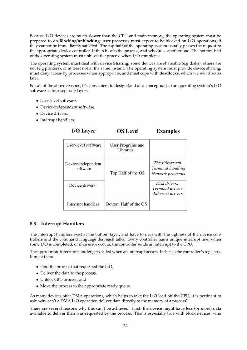
Because I/O devices are much slower than the CPU and main memory, the operating system must beprepared to do Blocking/unblocking: user processes must expect to be blocked on I/O operations, ifthey cannot be immediately satisfied. The top-half of the operating system usually passes the request tothe appropriate device controller. It then blocks the process, and schedules another one. The bottom-halfof the operating system must unblock the process when I/O completes.
The operating system must deal with device Sharing: some devices are shareable (e.g disks); others arenot (e.g printers), or at least not at the same instant. The operating system must provide device sharing,must deny access by processes when appropriate, and must cope with deadlocks, which we will discusslater.
For all of the above reasons, it’s convenient to design (and also conceptualise) an operating system’s I/Osoftware as four separate layers:
• User-level software.
• Device-independent software.
• Device drivers.
• Interrupt handlers.
Examples
Bottom Half of the OS
I/O Layer
User-level software User Programs andLibraries
Device-independentsoftware
Top Half of the OS
Interrupt handlers
Device drivers
Network protocolsTerminal handlingThe Filesystem
Ethernet driversTerminal drivers
Disk drivers
OS Level
8.3 Interrupt Handlers
The interrupt handlers exist at the bottom layer, and have to deal with the ugliness of the device con-trollers and the command language that each talks. Every controller has a unique interrupt line; whensome I/O is completed, or if an error occurs, the controller sends an interrupt to the CPU.
The appropriate interrupt handler gets called when an interrupt occurs. It checks the controller’s registers.It must then:
• Find the process that requested the I/O,
• Deliver the data to the process,
• Unblock the process, and
• Move the process to the appropriate ready queue.
As many devices offer DMA operations, which helps to take the I/O load off the CPU, it is pertinent toask: why can’t a DMA I/O operation deliver data directly to the memory of a process?
There are several reasons why this can’t be achieved. First, the device might have less (or more) dataavailable to deliver than was requested by the process. This is especially true with block devices, who
32
can only do I/O in block-sized units. The process may have crashed or terminated since the request wasmade. Another reason is that the operating system may prefer to cache the data from the I/O operation.More on that later.
Interrupt handlers cannot be put to sleep, as they are in the lower-half of the kernel. However, a low-priority interrupt handler will be interrupted by a high-priority interrupt.
Interrupt handlers should be as fast as possible, as while running, the CPU is taken away from the taskof running users’ processes. Thus, large or complicated interrupt handlers can degrade the processingperformance of a computer. Similarly, a large high-priority handler slows down the system’s response tolow-priority interrupts.
8.4 Device Drivers
Device drivers hold the device-dependent software for one device, or sometimes for a class of devices, e.g allterminals. A driver knows about the registers of the controller, and the characteristics of the device (e.gnumber of tracks/heads on each disk).
If the interrupt handler passes the data from an I/O to the operating system and not directly to the process,then it delivers it to the device driver, and notifies the driver of success/error. The driver takes the dataand converts it to an abstract format, with corresponding abstract success/error events for the device-independent layer.
Similarly, the device driver takes abstract requests for I/O from the device-independent layer and con-verts them to requests that the device controller can perform.
For example, the device-independent layer may know that a particular disk has 1,700,000 512-byte blocks.A read request from the device-independent layer for disk block X must be converted to the correct cylin-der/head/sector number. The device driver can then load this information into the controller, ask it toread the block, and place the incoming data into a certain location using DMA. On some drives, thecontroller must be asked to seek to the track first before data can be read.
driver: n. 1. The main loop of an event-processing program; the code that gets commands and dis-patches them for execution. 2. [techspeak] In ‘device driver’, code designed to handle a particularperipheral device such as a magnetic disk or tape unit.
8.5 The Device-Independent Layer
A large fraction of the I/O software in an operating system is device-independent. The boundary betweenthis layer and the drivers varies, and depends upon the design of the particular system.
Typically, this layer does:
• Uniform interfacing for the device drivers;
• Device naming;
• Device protection;
• Providing a device-independent block size;
• Buffering;
• Storage allocation;
• Allocating and releasing dedicated devices; and
• Reporting of abstract I/O errors.
The basic function of this layer is to perform I/O functions that are common to all devices in a particulargrouping, and to provide a uniform interface to the user-level software.
33
For example, a terminal-layer performs terminal operations, even when the devices used are keyboards& screens, remote serial terminals or network-linked terminals. Similarly, a filesystem provides files,directories, file permissions and read/write operations, even when the devices used are floppies, harddisks, CD-ROMs, network drives and RAM disks.
A uniform interface makes writing user software easier. Similarly, a uniform naming method makes iteasier to use devices or the abstract objects available on those devices (e.g files). Protection of devices ortheir services is also important, and it is best to do it here, so that all devices get protection in the samemanner, and the user sees consistency in the protection.
Different block devices have different block sizes. This layer must provide a standard block size. To doso it may need to buffer incoming blocks, or to read/write multiple real blocks. Buffering must be doneas a user may only want to read/write half a block, or to read one character from a device where 20 areavailable to be read. Allocating device blocks to store data is also done at a device-independent level in adevice-independent fashion. We will cover this in the filesystem lectures.
The operating system must ensure that only one user is accessing particular devices, e.g a printer. Thus,new opens on opened devices must fail. User access may lead to starvation and the operating systemshould attempt to prevent starvation. To avoid this, the operating system may use spooling, and operat-ing system services to regulate device access, for example:
• Output to printer is spooled in a file on a disk.• When the printer becomes ready, the file is queued for printing.• The queue is FIFO, and the operating system opens/closes the printer.
Without spooling, one user could open the device indefinitely.
Error reporting must be done at the device-independent level, and is done only if the lower levels cannotrectify the error.
buffer overflow: n. What happens when you try to stuff more data into a buffer (holding area) than itcan handle. This may be due to a mismatch in the processing rates of the producing and consumingprocesses, or because the buffer is simply too small to hold all the data that must accumulate before apiece of it can be processed. The term is used of and by humans in a metaphorical sense. “What timedid I agree to meet you? My buffer must have overflowed.”
spool: [from early IBM ‘Simultaneous Peripheral Operation Off-Line’, but this acronym is widely thoughtto have been contrived for effect] vt. To send files to some device or program (a ‘spooler’) that queuesthem up and does something useful with them later. The spooler usually understood is the ‘print spooler’controlling output of jobs to a printer, but the term has been used in connection with other peripherals(especially plotters and graphics devices).
8.6 Clocks – Hardware
Textbook reference: Tanenbaum & Woodhull ppg 222 – 227
As mentioned above, clocks don’t really ‘do’ I/O. As they are hardware devices, they are included here.Clocks usually do two things:
• Send interrupts to the CPU at regular intervals (clock ticks). These can be used to prompt processrescheduling and allow the operating system to calculate time-specific statistics.
• Send an interrupt after a requested time (alarm clock).• A few clock devices provide the time of day values in registers. The time of day is often battery-
backed.
Most clocks have settable clock tick periods. The usual speeds are 50Hz, 60Hz or 100Hz. Alarm clocks areachieved by writing a value into a clock register. This is decremented each clock tick, and an interrupt issent when the value reaches zero.
34
8.7 Clocks – Software
The clock interrupt handler receives the clock tick interrupt. The software must:
• Maintain the time of day clock when the clock hardware doesn’t have one.
• Pre-empt processes when their timeslice has been exhausted.
• Handle any ‘alarm calls’ that have been requested, e.g by processes like cron.
• Provide ‘alarm calls’ for the operating system itself, e.g for network retransmissions.
• Perform time-based statistics gathering for the operating system.
Maintaining the time of day is hard because, at 60Hz, a 32-bit value overflows in 2 years. It is most oftenachieved by keeping two counters, a tick counter, and a seconds counter. Under Unix, the seconds counterhas its epoch at 1st January 1970. For MS-DOS and Windows, the epoch is 1980.
Each process has a timeslice. When scheduled, this is copied into an operating system variable as anumber of clock ticks, and is decremented on each tick. At value zero, the process can be pre-empted bythe operating system.
Some operating systems allow processes to set up ‘alarm calls’. When the alarm goes off, exceptionalthings happen to the process e.g under Unix, a signal can be sent to the process. The clock driver sim-ulates alarm calls by keeping a linked list of calls and their differences. The head node’s difference isdecremented until zero, at which time the alarm ‘goes off’. The node is removed, and the next nodebecomes the head.
Because of the overhead of context switching, there is no guarantee of accuracy for the alarm call. Gen-erally processes are only guaranteed that the alarm will not go off earlier than requested. The operatingsystem uses alarm calls to timeout on I/O operations, e.g a disk read which never occurs, a networktransmission.
Most operating systems gather time-based statistics to aid adaptive scheduling algorithms. The statisticsare used by high level process schedulers, user information, system administration.
jiffy: n. 1. The duration of one tick of the system clock on the computer. Often one AC cycle time(1/60 second in the U.S. and Canada, 1/50 most other places), but more recently 1/100 sec has becomecommon. “The swapper runs every 6 jiffies” means that the virtual memory management routine isexecuted once for every 6 ticks of the clock, or about ten times a second. 2. Indeterminate time froma few seconds to forever. “I’ll do it in a jiffy” means certainly not now and possibly never. This is a bitcontrary to the more widespread use of the word.
9 Device Drivers and Interrupt Handlers
Device drivers and interrupt handlers live at the bottom of the Input/Output stack. They perform device-dependent I/O operations at the request of the device-independent I/O layer.
A device driver and associated interrupt handler need to communicate with each other. This is usuallyperformed through memory shared by the various parts of the operating system, or via messages in amicrokernel system.
There may be several instantiations of a single device driver in progress, because several processes havemade I/O requests. The device driver must:
• Convert the DIL command into the matching device command.
• Send command to the device through its controller’s registers.
• Move the current process to the blocked list.
35
All of the above is done by the top-half of the operating system at the behest of the calling process. Allof this is done at interrupt priority level zero. This implies that the operating system could pre-emptthe process (and the I/O operation in progress) anywhere in the above three lines. This is how severalinstantiations of the driver at any one time.
The device driver may also be interrupted by its interrupt handler. Therefore, both the device driverand the interrupt handler must be re-entrant: the code can be in use by several threads of execution,and all non-private data structures are properly shared. Note that on a single CPU machine, only onedevice driver instantiation or the interrupt handler is actually in execution; the others are temporarilysuspended.
Because of the multiple driver instantiations, any access to shared memory by the driver or the interrupthandler must by synchronised, to prevent the corruption of shared data structures. Under most systems,this is achieved by masking out the interrupts that may pre-empt the device driver or start the interrupthandler. This may disable all interrupts below a certain level, and is known as raising the interrupt level.Here is an example from the FreeBSD IDE disk device driver:
/* queue transfer on drive, activate drive and controller if idle */s = splbio(); /* Raise int. level to stop block I/O */
disksort(dp, bp);if (dp->b_active == 0) wdustart(du); /* start drive */
splx(s); /* Return int. level to previous level */
Device drivers provide a set of operations to the device-independent I/O layer. Here are some of thedevice driver operations provided by Unix device drivers. In Unix, a ‘character’ device is a ‘non-block’device.
Function Device Type Descriptiond open Block and character Initialise device when first usedd close Block and character Used when device is released. May
shutdown device or take it off-line.d strategy Block Read/write interface, allows event re-ordering.d read Character Reads data from device.d write Character Writes data to device.d ioctl Block and character Generic control operations on device.
Writing and debugging devices drivers and interrupt handlers is a real pain. There is no protected processenvironment, and many device drivers or interrupt handlers cannot be single-stepped or stopped at abreakpoint. We will look at two example devices: disks and terminals/keyboards.
10 The Disk Device
Textbook reference: Tanenbaum & Woodhull ppg 200 – 208
36
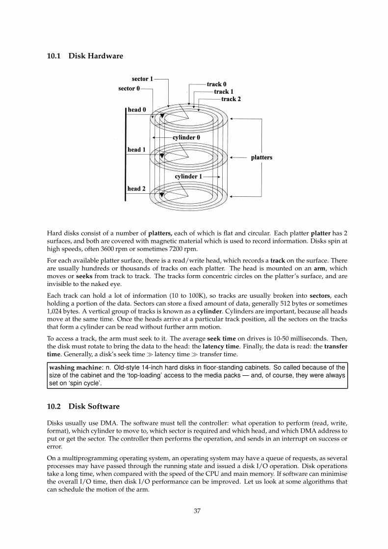
10.1 Disk Hardware
Hard disks consist of a number of platters, each of which is flat and circular. Each platter platter has 2surfaces, and both are covered with magnetic material which is used to record information. Disks spin athigh speeds, often 3600 rpm or sometimes 7200 rpm.
For each available platter surface, there is a read/write head, which records a track on the surface. Thereare usually hundreds or thousands of tracks on each platter. The head is mounted on an arm, whichmoves or seeks from track to track. The tracks form concentric circles on the platter’s surface, and areinvisible to the naked eye.
Each track can hold a lot of information (10 to 100K), so tracks are usually broken into sectors, eachholding a portion of the data. Sectors can store a fixed amount of data, generally 512 bytes or sometimes1,024 bytes. A vertical group of tracks is known as a cylinder. Cylinders are important, because all headsmove at the same time. Once the heads arrive at a particular track position, all the sectors on the tracksthat form a cylinder can be read without further arm motion.
To access a track, the arm must seek to it. The average seek time on drives is 10-50 milliseconds. Then,the disk must rotate to bring the data to the head: the latency time. Finally, the data is read: the transfertime. Generally, a disk’s seek time � latency time � transfer time.
washing machine: n. Old-style 14-inch hard disks in floor-standing cabinets. So called because of thesize of the cabinet and the ‘top-loading’ access to the media packs — and, of course, they were alwaysset on ‘spin cycle’.
10.2 Disk Software
Disks usually use DMA. The software must tell the controller: what operation to perform (read, write,format), which cylinder to move to, which sector is required and which head, and which DMA address toput or get the sector. The controller then performs the operation, and sends in an interrupt on success orerror.
On a multiprogramming operating system, an operating system may have a queue of requests, as severalprocesses may have passed through the running state and issued a disk I/O operation. Disk operationstake a long time, when compared with the speed of the CPU and main memory. If software can minimisethe overall I/O time, then disk I/O performance can be improved. Let us look at some algorithms thatcan schedule the motion of the arm.
37
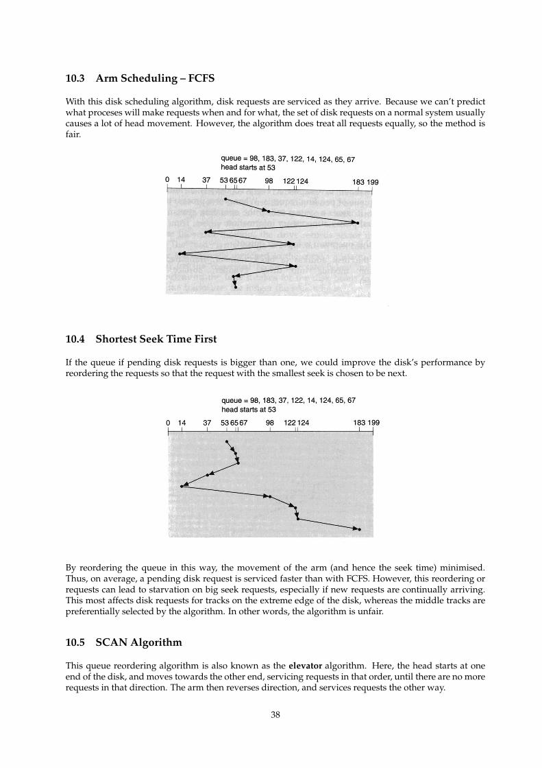
10.3 Arm Scheduling – FCFS
With this disk scheduling algorithm, disk requests are serviced as they arrive. Because we can’t predictwhat proceses will make requests when and for what, the set of disk requests on a normal system usuallycauses a lot of head movement. However, the algorithm does treat all requests equally, so the method isfair.
10.4 Shortest Seek Time First
If the queue if pending disk requests is bigger than one, we could improve the disk’s performance byreordering the requests so that the request with the smallest seek is chosen to be next.
By reordering the queue in this way, the movement of the arm (and hence the seek time) minimised.Thus, on average, a pending disk request is serviced faster than with FCFS. However, this reordering orrequests can lead to starvation on big seek requests, especially if new requests are continually arriving.This most affects disk requests for tracks on the extreme edge of the disk, whereas the middle tracks arepreferentially selected by the algorithm. In other words, the algorithm is unfair.
10.5 SCAN Algorithm
This queue reordering algorithm is also known as the elevator algorithm. Here, the head starts at oneend of the disk, and moves towards the other end, servicing requests in that order, until there are no morerequests in that direction. The arm then reverses direction, and services requests the other way.
38
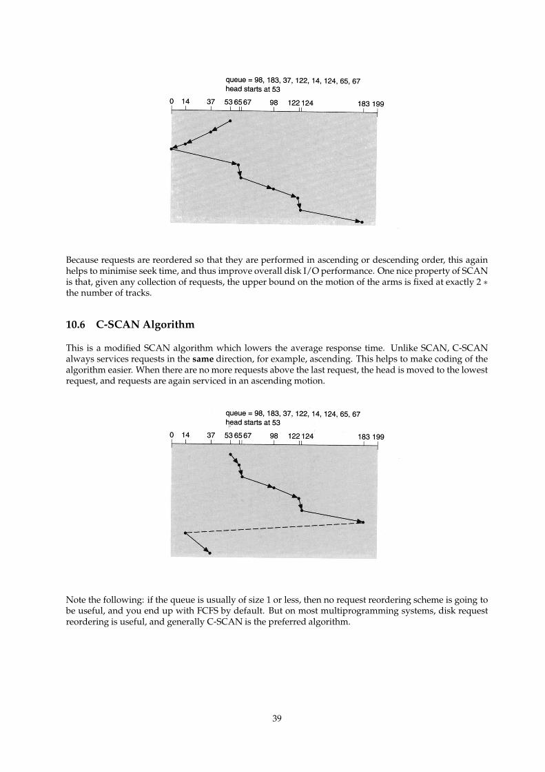
Because requests are reordered so that they are performed in ascending or descending order, this againhelps to minimise seek time, and thus improve overall disk I/O performance. One nice property of SCANis that, given any collection of requests, the upper bound on the motion of the arms is fixed at exactly 2 ∗
the number of tracks.
10.6 C-SCAN Algorithm
This is a modified SCAN algorithm which lowers the average response time. Unlike SCAN, C-SCANalways services requests in the same direction, for example, ascending. This helps to make coding of thealgorithm easier. When there are no more requests above the last request, the head is moved to the lowestrequest, and requests are again serviced in an ascending motion.
Note the following: if the queue is usually of size 1 or less, then no request reordering scheme is going tobe useful, and you end up with FCFS by default. But on most multiprogramming systems, disk requestreordering is useful, and generally C-SCAN is the preferred algorithm.
39

walking drives: n. An occasional failure mode of magnetic-disk drives back in the days when theywere huge, clunky washing machines. Those old dinosaur parts carried terrific angular momentum;the combination of a misaligned spindle or worn bearings and stick-slip interactions with the floor couldcause them to ‘walk’ across a room, lurching alternate corners forward a couple of millimeters at a time.There is a legend about a drive that walked over to the only door to the computer room and jammed itshut; the staff had to cut a hole in the wall in order to get at it! Walking could also be induced by certainpatterns of drive access (a fast seek across the whole width of the disk, followed by a slow seek in theother direction). Some bands of old-time hackers figured out how to induce disk-accessing patterns thatwould do this to particular drive models and held disk-drive races.
10.7 Sector Queueing
If the hardware is clever enough to determine which sector is passing under the head, the operatingsystem can order requests on that cylinder to minimise latency. For example, if we have requests for sector3, 8 and 11, and the head is passing over sector 5, we can schedule 8 and 11 first. The disk hardware thatsupports this is generally very expensive, and is only found on mainframe or high-end server computers.
10.8 Interleaving
Textbook reference: Tanenbaum & Woodhull ppg 158 – 159
In many cases where the operating system is slow, it must spend time processing a block read in fromthe disk before it can read in another one. For example, the number of DMA buffers may be limited, andthe operating system must move out a block to free up a DMA buffer for another transfer. Thus, if theoperating system wants to read sectors 0, 1 and 2 from a particular track, it may miss sector 1 after reading0, and have to wait an entire revolution before it can read sector 1.
If the sectors are interleaved, then there will be a gap to give the operating system time to process beforeits next read.
(a)
07
34
1
2
6
5
(b)
07
52
4
1
3
6
(c)
05
14
3
6
2
7
Figure 3-4. (a) No interleaving. (b) Single interleaving. (c)Double interleaving.
Note that interleaving can either be done in hardware (i.e within the disk controller logic) or in the soft-ware: for example, on a disk with eight sectors per track, the operating system can treat physical sectors0,1,2,3,4,5,6,7 as 0,2,4,6,1,3,5,7; in other words, the operating system can itself perform a logical to physicalmapping.
10.9 Error Handling
Textbook reference: Tanenbaum & Woodhull ppg 205 – 206
Disks are subject to a wide variety of errors:
a) programming error: e.g request for non-existent sector. Hopefully the operating system is written toensure this does not happen. If it does, halt the system?
b) transient error: e.g dust on the head. The best option is to retry the operation; if errors persist, tell theupper layers the sector is bad.
40
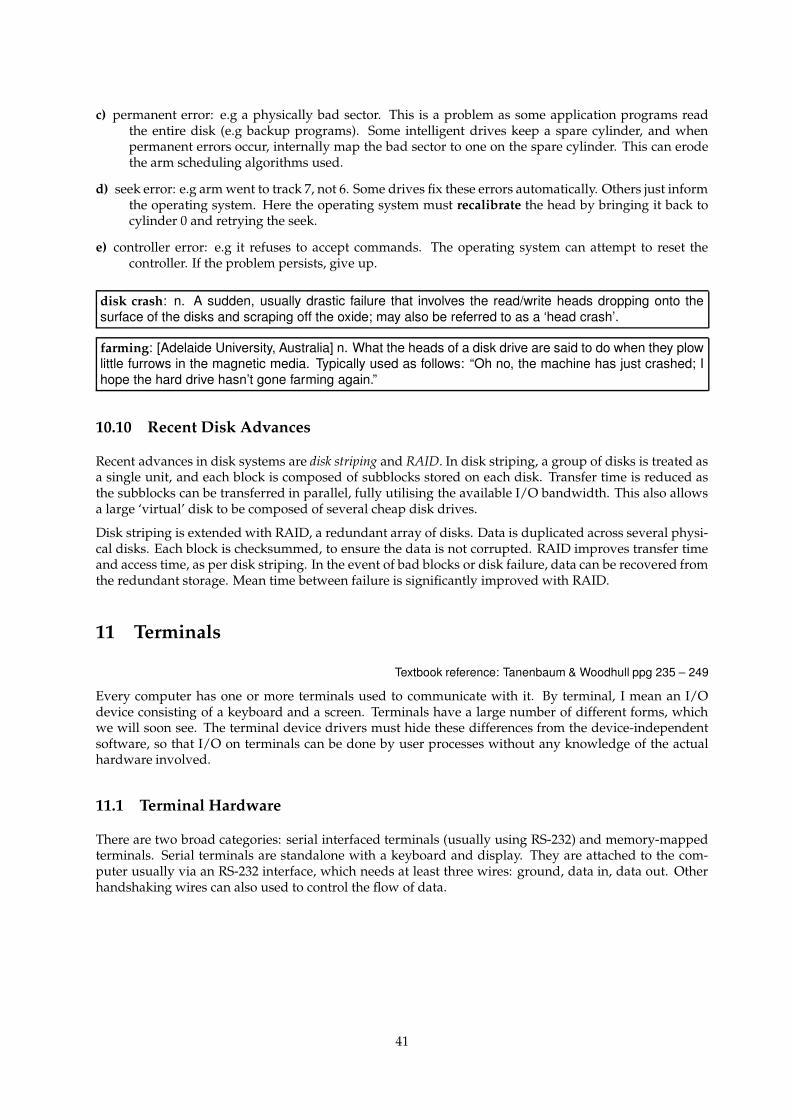
c) permanent error: e.g a physically bad sector. This is a problem as some application programs readthe entire disk (e.g backup programs). Some intelligent drives keep a spare cylinder, and whenpermanent errors occur, internally map the bad sector to one on the spare cylinder. This can erodethe arm scheduling algorithms used.
d) seek error: e.g arm went to track 7, not 6. Some drives fix these errors automatically. Others just informthe operating system. Here the operating system must recalibrate the head by bringing it back tocylinder 0 and retrying the seek.
e) controller error: e.g it refuses to accept commands. The operating system can attempt to reset thecontroller. If the problem persists, give up.
disk crash: n. A sudden, usually drastic failure that involves the read/write heads dropping onto thesurface of the disks and scraping off the oxide; may also be referred to as a ‘head crash’.
farming: [Adelaide University, Australia] n. What the heads of a disk drive are said to do when they plowlittle furrows in the magnetic media. Typically used as follows: “Oh no, the machine has just crashed; Ihope the hard drive hasn’t gone farming again.”
10.10 Recent Disk Advances
Recent advances in disk systems are disk striping and RAID. In disk striping, a group of disks is treated asa single unit, and each block is composed of subblocks stored on each disk. Transfer time is reduced asthe subblocks can be transferred in parallel, fully utilising the available I/O bandwidth. This also allowsa large ‘virtual’ disk to be composed of several cheap disk drives.
Disk striping is extended with RAID, a redundant array of disks. Data is duplicated across several physi-cal disks. Each block is checksummed, to ensure the data is not corrupted. RAID improves transfer timeand access time, as per disk striping. In the event of bad blocks or disk failure, data can be recovered fromthe redundant storage. Mean time between failure is significantly improved with RAID.
11 Terminals
Textbook reference: Tanenbaum & Woodhull ppg 235 – 249
Every computer has one or more terminals used to communicate with it. By terminal, I mean an I/Odevice consisting of a keyboard and a screen. Terminals have a large number of different forms, whichwe will soon see. The terminal device drivers must hide these differences from the device-independentsoftware, so that I/O on terminals can be done by user processes without any knowledge of the actualhardware involved.
11.1 Terminal Hardware
There are two broad categories: serial interfaced terminals (usually using RS-232) and memory-mappedterminals. Serial terminals are standalone with a keyboard and display. They are attached to the com-puter usually via an RS-232 interface, which needs at least three wires: ground, data in, data out. Otherhandshaking wires can also used to control the flow of data.
41
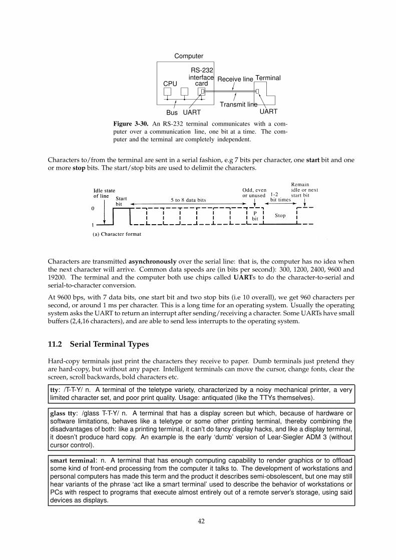
RS-232interface
card
Computer
TerminalCPU
Receive line
Bus UART UARTTransmit line
Figure 3-30. An RS-232 terminal communicates with a com-puter over a communication line, one bit at a time. The com-puter and the terminal are completely independent.
Characters to/from the terminal are sent in a serial fashion, e.g 7 bits per character, one start bit and oneor more stop bits. The start/stop bits are used to delimit the characters.
Characters are transmitted asynchronously over the serial line: that is, the computer has no idea whenthe next character will arrive. Common data speeds are (in bits per second): 300, 1200, 2400, 9600 and19200. The terminal and the computer both use chips called UARTs to do the character-to-serial andserial-to-character conversion.
At 9600 bps, with 7 data bits, one start bit and two stop bits (i.e 10 overall), we get 960 characters persecond, or around 1 ms per character. This is a long time for an operating system. Usually the operatingsystem asks the UART to return an interrupt after sending/receiving a character. Some UARTs have smallbuffers (2,4,16 characters), and are able to send less interrupts to the operating system.
11.2 Serial Terminal Types
Hard-copy terminals just print the characters they receive to paper. Dumb terminals just pretend theyare hard-copy, but without any paper. Intelligent terminals can move the cursor, change fonts, clear thescreen, scroll backwards, bold characters etc.
tty: /T-T-Y/ n. A terminal of the teletype variety, characterized by a noisy mechanical printer, a verylimited character set, and poor print quality. Usage: antiquated (like the TTYs themselves).
glass tty: /glass T-T-Y/ n. A terminal that has a display screen but which, because of hardware orsoftware limitations, behaves like a teletype or some other printing terminal, thereby combining thedisadvantages of both: like a printing terminal, it can’t do fancy display hacks, and like a display terminal,it doesn’t produce hard copy. An example is the early ‘dumb’ version of Lear-Siegler ADM 3 (withoutcursor control).
smart terminal: n. A terminal that has enough computing capability to render graphics or to offloadsome kind of front-end processing from the computer it talks to. The development of workstations andpersonal computers has made this term and the product it describes semi-obsolescent, but one may stillhear variants of the phrase ‘act like a smart terminal’ used to describe the behavior of workstations orPCs with respect to programs that execute almost entirely out of a remote server’s storage, using saiddevices as displays.
42
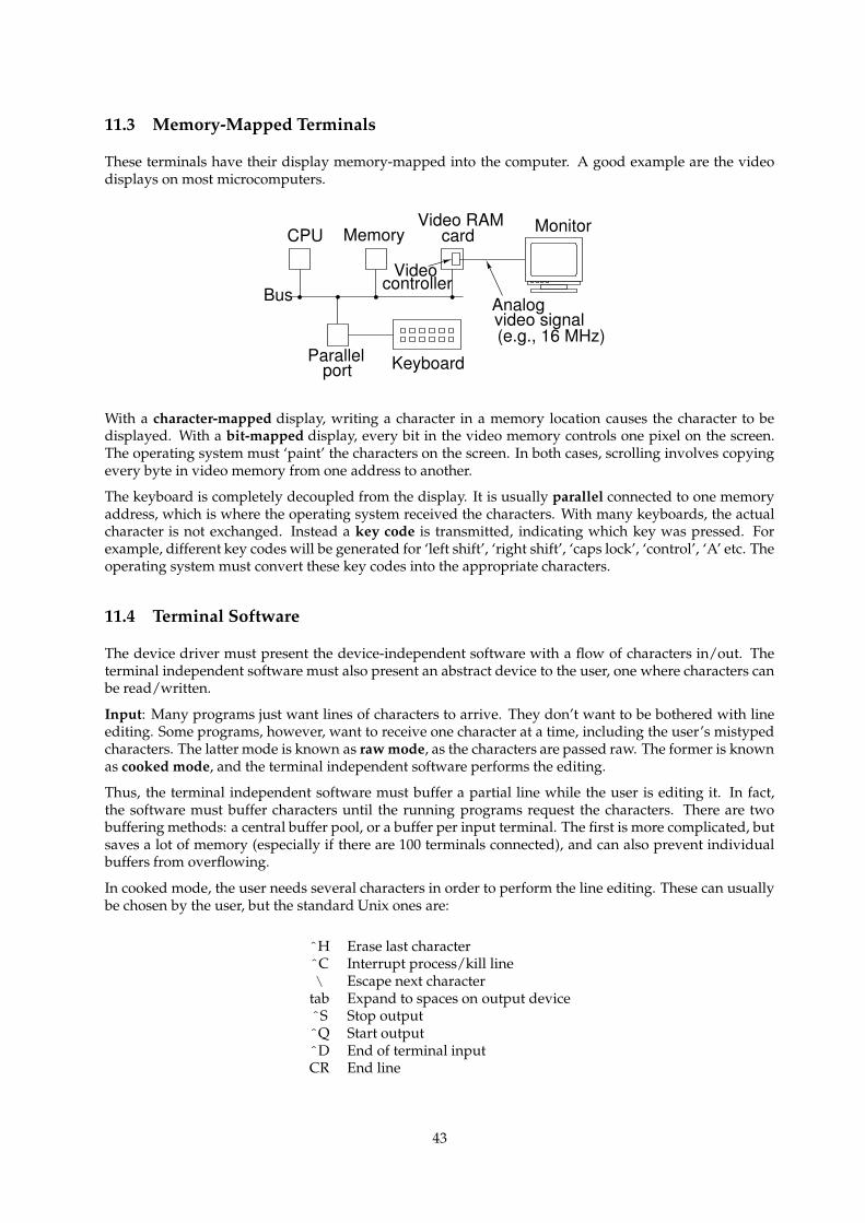
11.3 Memory-Mapped Terminals
These terminals have their display memory-mapped into the computer. A good example are the videodisplays on most microcomputers.
CPU Memory
Bus
Video RAMcard
Videocontroller
Monitor
Analogvideo signal(e.g., 16 MHz)
Parallelport Keyboard
With a character-mapped display, writing a character in a memory location causes the character to bedisplayed. With a bit-mapped display, every bit in the video memory controls one pixel on the screen.The operating system must ‘paint’ the characters on the screen. In both cases, scrolling involves copyingevery byte in video memory from one address to another.
The keyboard is completely decoupled from the display. It is usually parallel connected to one memoryaddress, which is where the operating system received the characters. With many keyboards, the actualcharacter is not exchanged. Instead a key code is transmitted, indicating which key was pressed. Forexample, different key codes will be generated for ‘left shift’, ‘right shift’, ‘caps lock’, ‘control’, ‘A’ etc. Theoperating system must convert these key codes into the appropriate characters.
11.4 Terminal Software
The device driver must present the device-independent software with a flow of characters in/out. Theterminal independent software must also present an abstract device to the user, one where characters canbe read/written.
Input: Many programs just want lines of characters to arrive. They don’t want to be bothered with lineediting. Some programs, however, want to receive one character at a time, including the user’s mistypedcharacters. The latter mode is known as raw mode, as the characters are passed raw. The former is knownas cooked mode, and the terminal independent software performs the editing.
Thus, the terminal independent software must buffer a partial line while the user is editing it. In fact,the software must buffer characters until the running programs request the characters. There are twobuffering methods: a central buffer pool, or a buffer per input terminal. The first is more complicated, butsaves a lot of memory (especially if there are 100 terminals connected), and can also prevent individualbuffers from overflowing.
In cooked mode, the user needs several characters in order to perform the line editing. These can usuallybe chosen by the user, but the standard Unix ones are:
ˆH Erase last characterˆC Interrupt process/kill line\ Escape next character
tab Expand to spaces on output deviceˆS Stop outputˆQ Start outputˆD End of terminal inputCR End line
43
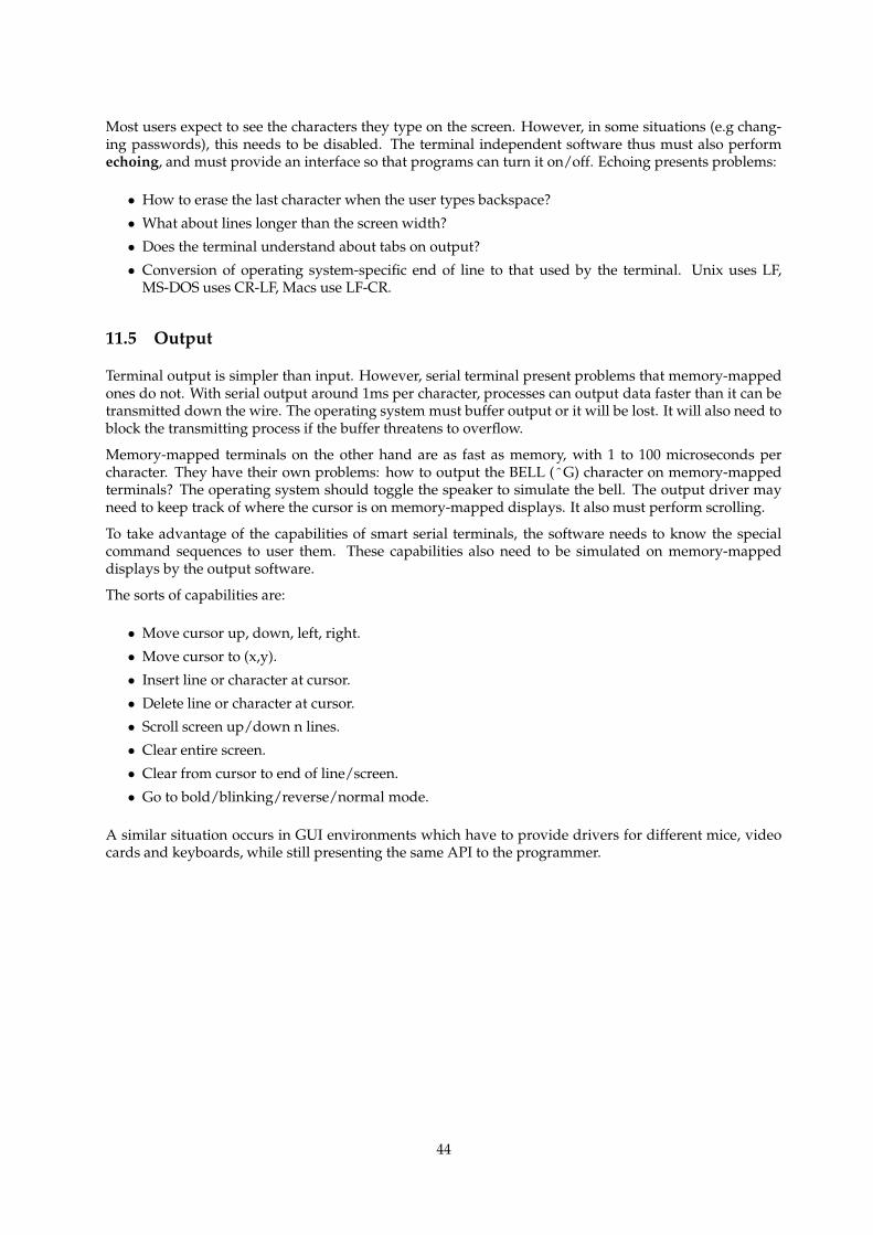
Most users expect to see the characters they type on the screen. However, in some situations (e.g chang-ing passwords), this needs to be disabled. The terminal independent software thus must also performechoing, and must provide an interface so that programs can turn it on/off. Echoing presents problems:
• How to erase the last character when the user types backspace?
• What about lines longer than the screen width?
• Does the terminal understand about tabs on output?
• Conversion of operating system-specific end of line to that used by the terminal. Unix uses LF,MS-DOS uses CR-LF, Macs use LF-CR.
11.5 Output
Terminal output is simpler than input. However, serial terminal present problems that memory-mappedones do not. With serial output around 1ms per character, processes can output data faster than it can betransmitted down the wire. The operating system must buffer output or it will be lost. It will also need toblock the transmitting process if the buffer threatens to overflow.
Memory-mapped terminals on the other hand are as fast as memory, with 1 to 100 microseconds percharacter. They have their own problems: how to output the BELL (ˆG) character on memory-mappedterminals? The operating system should toggle the speaker to simulate the bell. The output driver mayneed to keep track of where the cursor is on memory-mapped displays. It also must perform scrolling.
To take advantage of the capabilities of smart serial terminals, the software needs to know the specialcommand sequences to user them. These capabilities also need to be simulated on memory-mappeddisplays by the output software.
The sorts of capabilities are:
• Move cursor up, down, left, right.
• Move cursor to (x,y).
• Insert line or character at cursor.
• Delete line or character at cursor.
• Scroll screen up/down n lines.
• Clear entire screen.
• Clear from cursor to end of line/screen.
• Go to bold/blinking/reverse/normal mode.
A similar situation occurs in GUI environments which have to provide drivers for different mice, videocards and keyboards, while still presenting the same API to the programmer.
44
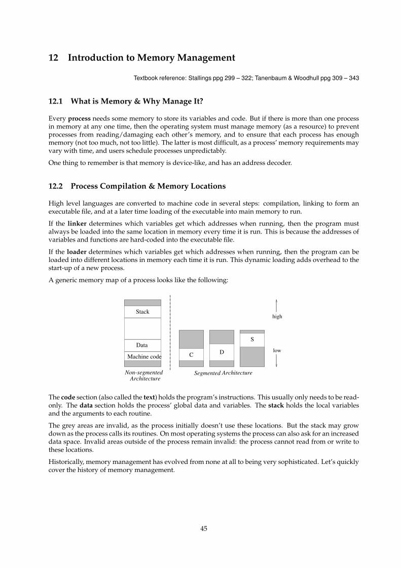
12 Introduction to Memory Management
Textbook reference: Stallings ppg 299 – 322; Tanenbaum & Woodhull ppg 309 – 343
12.1 What is Memory & Why Manage It?
Every process needs some memory to store its variables and code. But if there is more than one processin memory at any one time, then the operating system must manage memory (as a resource) to preventprocesses from reading/damaging each other’s memory, and to ensure that each process has enoughmemory (not too much, not too little). The latter is most difficult, as a process’ memory requirements mayvary with time, and users schedule processes unpredictably.
One thing to remember is that memory is device-like, and has an address decoder.
12.2 Process Compilation & Memory Locations
High level languages are converted to machine code in several steps: compilation, linking to form anexecutable file, and at a later time loading of the executable into main memory to run.
If the linker determines which variables get which addresses when running, then the program mustalways be loaded into the same location in memory every time it is run. This is because the addresses ofvariables and functions are hard-coded into the executable file.
If the loader determines which variables get which addresses when running, then the program can beloaded into different locations in memory each time it is run. This dynamic loading adds overhead to thestart-up of a new process.
A generic memory map of a process looks like the following:
Machine code
Data
Stack
C D
S
Non-segmentedArchitecture
ArchitectureSegmented
low
high
The code section (also called the text) holds the program’s instructions. This usually only needs to be read-only. The data section holds the process’ global data and variables. The stack holds the local variablesand the arguments to each routine.
The grey areas are invalid, as the process initially doesn’t use these locations. But the stack may growdown as the process calls its routines. On most operating systems the process can also ask for an increaseddata space. Invalid areas outside of the process remain invalid: the process cannot read from or write tothese locations.
Historically, memory management has evolved from none at all to being very sophisticated. Let’s quicklycover the history of memory management.
45
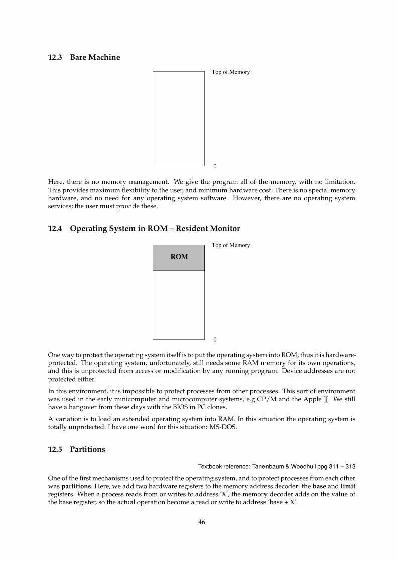
12.3 Bare Machine
0
Top of Memory
Here, there is no memory management. We give the program all of the memory, with no limitation.This provides maximum flexibility to the user, and minimum hardware cost. There is no special memoryhardware, and no need for any operating system software. However, there are no operating systemservices; the user must provide these.
12.4 Operating System in ROM – Resident Monitor
ROM
0
Top of Memory
One way to protect the operating system itself is to put the operating system into ROM, thus it is hardware-protected. The operating system, unfortunately, still needs some RAM memory for its own operations,and this is unprotected from access or modification by any running program. Device addresses are notprotected either.
In this environment, it is impossible to protect processes from other processes. This sort of environmentwas used in the early minicomputer and microcomputer systems, e.g CP/M and the Apple ][. We stillhave a hangover from these days with the BIOS in PC clones.
A variation is to load an extended operating system into RAM. In this situation the operating system istotally unprotected. I have one word for this situation: MS-DOS.
12.5 Partitions
Textbook reference: Tanenbaum & Woodhull ppg 311 – 313
One of the first mechanisms used to protect the operating system, and to protect processes from each otherwas partitions. Here, we add two hardware registers to the memory address decoder: the base and limitregisters. When a process reads from or writes to address ‘X’, the memory decoder adds on the value ofthe base register, so the actual operation become a read or write to address ‘base + X’.
46
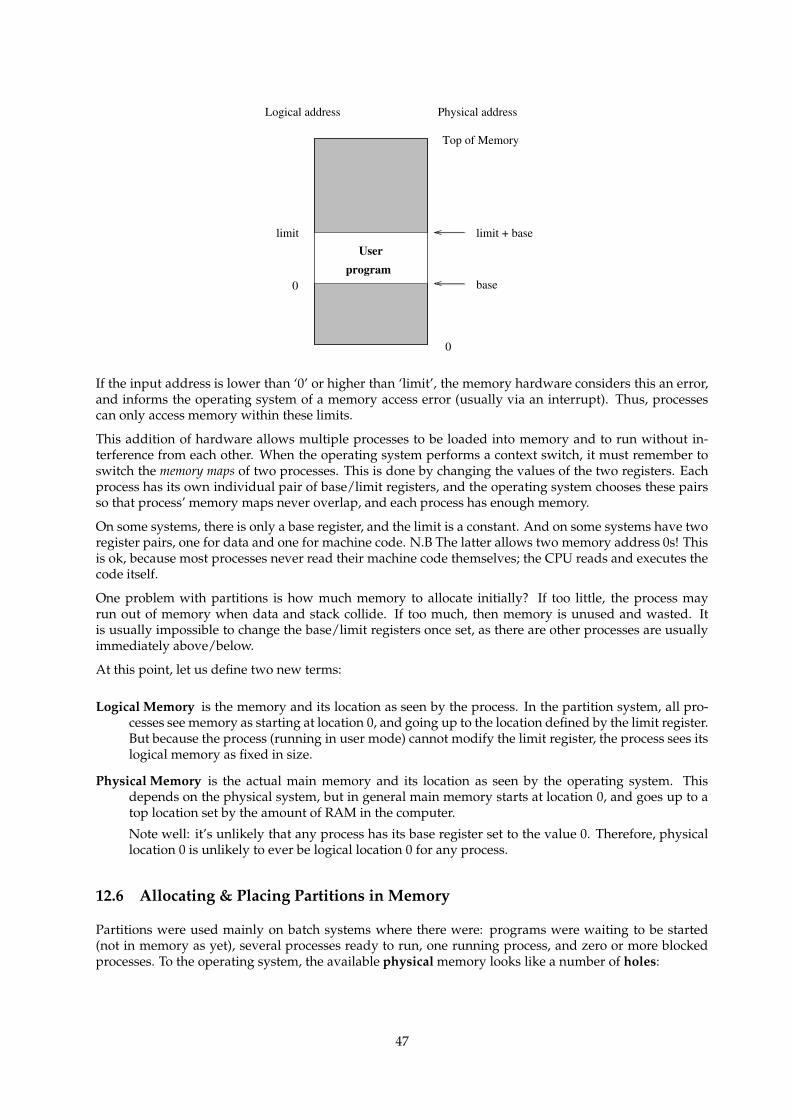
0 base
limit + baselimit
Physical addressLogical address
programUser
0
Top of Memory
If the input address is lower than ‘0’ or higher than ‘limit’, the memory hardware considers this an error,and informs the operating system of a memory access error (usually via an interrupt). Thus, processescan only access memory within these limits.
This addition of hardware allows multiple processes to be loaded into memory and to run without in-terference from each other. When the operating system performs a context switch, it must remember toswitch the memory maps of two processes. This is done by changing the values of the two registers. Eachprocess has its own individual pair of base/limit registers, and the operating system chooses these pairsso that process’ memory maps never overlap, and each process has enough memory.
On some systems, there is only a base register, and the limit is a constant. And on some systems have tworegister pairs, one for data and one for machine code. N.B The latter allows two memory address 0s! Thisis ok, because most processes never read their machine code themselves; the CPU reads and executes thecode itself.
One problem with partitions is how much memory to allocate initially? If too little, the process mayrun out of memory when data and stack collide. If too much, then memory is unused and wasted. Itis usually impossible to change the base/limit registers once set, as there are other processes are usuallyimmediately above/below.
At this point, let us define two new terms:
Logical Memory is the memory and its location as seen by the process. In the partition system, all pro-cesses see memory as starting at location 0, and going up to the location defined by the limit register.But because the process (running in user mode) cannot modify the limit register, the process sees itslogical memory as fixed in size.
Physical Memory is the actual main memory and its location as seen by the operating system. Thisdepends on the physical system, but in general main memory starts at location 0, and goes up to atop location set by the amount of RAM in the computer.
Note well: it’s unlikely that any process has its base register set to the value 0. Therefore, physicallocation 0 is unlikely to ever be logical location 0 for any process.
12.6 Allocating & Placing Partitions in Memory
Partitions were used mainly on batch systems where there were: programs were waiting to be started(not in memory as yet), several processes ready to run, one running process, and zero or more blockedprocesses. To the operating system, the available physical memory looks like a number of holes:
47

0
Top of Memory
P5
P4
P3
P2
P1
As new processes are chosen from the pool of programs waiting to be started, the operating system has tochoose a partition size and physical location for this partition. We need a partition allocation algorithm.Here are some possible algorithms:
First fit: Find the first hole where the waiting program will fit. This is fast algorithm, but usually leaves asmaller hole, except where the fit is exact.
Best fit: Find the hole that best fits the job. i.e with the least left over. Surprisingly this is not a goodalgorithm, as it leaves a lot of tiny, useless holes all over the physical memory.
Worst fit: Find the biggest hole, leaving the biggest remainder. This is usually the partition allocationalgorithm chosen by system designers.
When a process exits, merging can be done if there is an existing hole above and/or below it.
Fragmentation describes when we have a lot of useless little holes. The system may get to a point whenthe available memory is enough to start a process, but it is in the form of holes too small to load theprocess. As the useless holes are outside of any process’ memory, this situation is known as externalfragmentation. This can be solved by compaction, by moving existing processes (and their partitionregisters) to consolidate the holes. The operating system should use an algorithm to minimise the amountof copying to make the compaction as fast as possible.
13 Pages
Textbook reference: Stallings ppg 299 – 323; Tanenbaum & Woodhull ppg 319 – 343
13.1 Problems with Partitions
There are several problems with using paritions for memory management. First is the allocation of parti-tion size: if the operating sets the partition to be too big, then the process doesn’t use all of the memoryand it is wasted memory; on the other hand, if the partition is too small, then there is not enough memoryfor the process to run. Once a partition size is chosen, it is essentially impossible to change.
The second major problem is fragmentation of physical memory as the number of small holes builds up.
The cause of both problems is the fact that the logical memory map is contiguous, i.e for each process, allthe machine code is in one lump, all the data is in one lump etc. The process sees a single region of logicalmemory, and this is mapped to a single region of physical memory. If we could make these lumps appearto be contiguous to the process (i.e contiguous logical memory), but actually break the lumps into smallphysical memory units, then we could fill the unused phsyical holes with these small units.
48
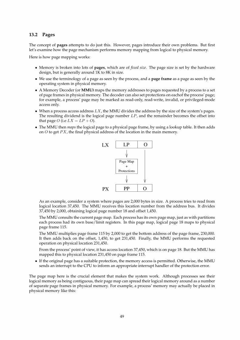
13.2 Pages
The concept of pages attempts to do just this. However, pages introduce their own problems. But firstlet’s examine how the page mechanism performs memory mapping from logical to physical memory.
Here is how page mapping works:
• Memory is broken into lots of pages, which are of fixed size. The page size is set by the hardwaredesign, but is generally around 1K to 8K in size.
• We use the terminology of a page as seen by the process, and a page frame as a page as seen by theoperating system in physical memory.
• A Memory Decoder (or MMU) maps the memory addresses to pages requested by a process to a setof page frames in physical memory. The decoder can also set protections on eachof the process’ page;for example, a process’ page may be marked as read-only, read-write, invalid, or privileged-modeaccess only.
• When a process access address LX , the MMU divides the address by the size of the system’s pages.The resulting dividend is the logical page number LP , and the remainder becomes the offset intothat page O (i.e LX = LP + O).
• The MMU then maps the logical page to a physical page frame, by using a lookup table. It then addson O to get PX , the final physical address of the location in the main memory.
O
PX PP O
Page Map+
Protections
LX LP
As an example, consider a system where pages are 2,000 bytes in size. A process tries to read fromlogical location 37,450. The MMU receives this location number from the address bus. It divides37,450 by 2,000, obtaining logical page number 18 and offset 1,450.
The MMU consults the current page map. Each process has its own page map, just as with partitionseach process had its own base/limit registers. In this page map, logical page 18 maps to physicalpage frame 115.
The MMU multiplies page frame 115 by 2,000 to get the bottom address of the page frame, 230,000.It then adds back on the offset, 1,450, to get 231,450. Finally, the MMU performs the requestedoperation on physical location 231,450.
From the process’ point of view, it has access location 37,450, which is on page 18. But the MMU hasmapped this to physical location 231,450 on page frame 115.
• If the original page has a suitable protection, the memory access is permitted. Otherwise, the MMUsends an interrupt to the CPU to inform an appropriate interrupt handler of the protection error.
The page map here is the crucial element that makes the system work. Although processes see theirlogical memory as being contiguous, their page map can spread their logical memory around as a numberof separate page frames in physical memory. For example, a process’ memory may actually be placed inphysical memory like this:
49
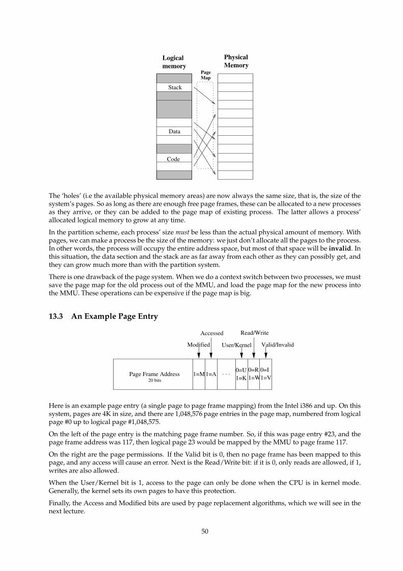
PhysicalMemorymemory
PageMap
Logical
Code
Data
Stack
The ‘holes’ (i.e the available physical memory areas) are now always the same size, that is, the size of thesystem’s pages. So as long as there are enough free page frames, these can be allocated to a new processesas they arrive, or they can be added to the page map of existing process. The latter allows a process’allocated logical memory to grow at any time.
In the partition scheme, each process’ size must be less than the actual physical amount of memory. Withpages, we can make a process be the size of the memory: we just don’t allocate all the pages to the process.In other words, the process will occupy the entire address space, but most of that space will be invalid. Inthis situation, the data section and the stack are as far away from each other as they can possibly get, andthey can grow much more than with the partition system.
There is one drawback of the page system. When we do a context switch between two processes, we mustsave the page map for the old process out of the MMU, and load the page map for the new process intothe MMU. These operations can be expensive if the page map is big.
13.3 An Example Page Entry
0=I1=W
0=U1=K
. . .Page Frame Address 1=A1=M
Accessed
Modified
Read/Write
Valid/InvalidUser/Kernel
20 bits 1=V0=R
Here is an example page entry (a single page to page frame mapping) from the Intel i386 and up. On thissystem, pages are 4K in size, and there are 1,048,576 page entries in the page map, numbered from logicalpage #0 up to logical page #1,048,575.
On the left of the page entry is the matching page frame number. So, if this was page entry #23, and thepage frame address was 117, then logical page 23 would be mapped by the MMU to page frame 117.
On the right are the page permissions. If the Valid bit is 0, then no page frame has been mapped to thispage, and any access will cause an error. Next is the Read/Write bit: if it is 0, only reads are allowed, if 1,writes are also allowed.
When the User/Kernel bit is 1, access to the page can only be done when the CPU is in kernel mode.Generally, the kernel sets its own pages to have this protection.
Finally, the Access and Modified bits are used by page replacement algorithms, which we will see in thenext lecture.
50
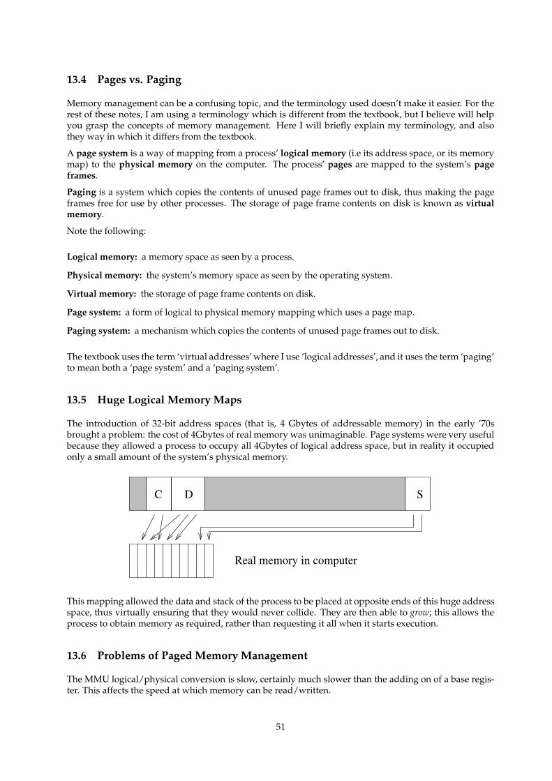
13.4 Pages vs. Paging
Memory management can be a confusing topic, and the terminology used doesn’t make it easier. For therest of these notes, I am using a terminology which is different from the textbook, but I believe will helpyou grasp the concepts of memory management. Here I will briefly explain my terminology, and alsothey way in which it differs from the textbook.
A page system is a way of mapping from a process’ logical memory (i.e its address space, or its memorymap) to the physical memory on the computer. The process’ pages are mapped to the system’s pageframes.
Paging is a system which copies the contents of unused page frames out to disk, thus making the pageframes free for use by other processes. The storage of page frame contents on disk is known as virtualmemory.
Note the following:
Logical memory: a memory space as seen by a process.
Physical memory: the system’s memory space as seen by the operating system.
Virtual memory: the storage of page frame contents on disk.
Page system: a form of logical to physical memory mapping which uses a page map.
Paging system: a mechanism which copies the contents of unused page frames out to disk.
The textbook uses the term ‘virtual addresses’ where I use ‘logical addresses’, and it uses the term ‘paging’to mean both a ‘page system’ and a ‘paging system’.
13.5 Huge Logical Memory Maps
The introduction of 32-bit address spaces (that is, 4 Gbytes of addressable memory) in the early ’70sbrought a problem: the cost of 4Gbytes of real memory was unimaginable. Page systems were very usefulbecause they allowed a process to occupy all 4Gbytes of logical address space, but in reality it occupiedonly a small amount of the system’s physical memory.
C D S
Real memory in computer
This mapping allowed the data and stack of the process to be placed at opposite ends of this huge addressspace, thus virtually ensuring that they would never collide. They are then able to grow; this allows theprocess to obtain memory as required, rather than requesting it all when it starts execution.
13.6 Problems of Paged Memory Management
The MMU logical/physical conversion is slow, certainly much slower than the adding on of a base regis-ter. This affects the speed at which memory can be read/written.
51
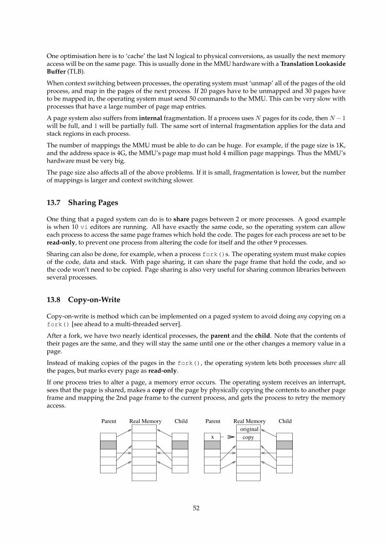
One optimisation here is to ‘cache’ the last N logical to physical conversions, as usually the next memoryaccess will be on the same page. This is usually done in the MMU hardware with a Translation LookasideBuffer (TLB).
When context switching between processes, the operating system must ‘unmap’ all of the pages of the oldprocess, and map in the pages of the next process. If 20 pages have to be unmapped and 30 pages haveto be mapped in, the operating system must send 50 commands to the MMU. This can be very slow withprocesses that have a large number of page map entries.
A page system also suffers from internal fragmentation. If a process uses N pages for its code, then N − 1
will be full, and 1 will be partially full. The same sort of internal fragmentation applies for the data andstack regions in each process.
The number of mappings the MMU must be able to do can be huge. For example, if the page size is 1K,and the address space is 4G, the MMU’s page map must hold 4 million page mappings. Thus the MMU’shardware must be very big.
The page size also affects all of the above problems. If it is small, fragmentation is lower, but the numberof mappings is larger and context switching slower.
13.7 Sharing Pages
One thing that a paged system can do is to share pages between 2 or more processes. A good exampleis when 10 vi editors are running. All have exactly the same code, so the operating system can alloweach process to access the same page frames which hold the code. The pages for each process are set to beread-only, to prevent one process from altering the code for itself and the other 9 processes.
Sharing can also be done, for example, when a process fork()s. The operating system must make copiesof the code, data and stack. With page sharing, it can share the page frame that hold the code, and sothe code won’t need to be copied. Page sharing is also very useful for sharing common libraries betweenseveral processes.
13.8 Copy-on-Write
Copy-on-write is method which can be implemented on a paged system to avoid doing any copying on afork() [see ahead to a multi-threaded server].
After a fork, we have two nearly identical processes, the parent and the child. Note that the contents oftheir pages are the same, and they will stay the same until one or the other changes a memory value in apage.
Instead of making copies of the pages in the fork(), the operating system lets both processes share allthe pages, but marks every page as read-only.
If one process tries to alter a page, a memory error occurs. The operating system receives an interrupt,sees that the page is shared, makes a copy of the page by physically copying the contents to another pageframe and mapping the 2nd page frame to the current process, and gets the process to retry the memoryaccess.
copy
Parent Real Memory Child Parent Real Memory Child
xoriginal
52
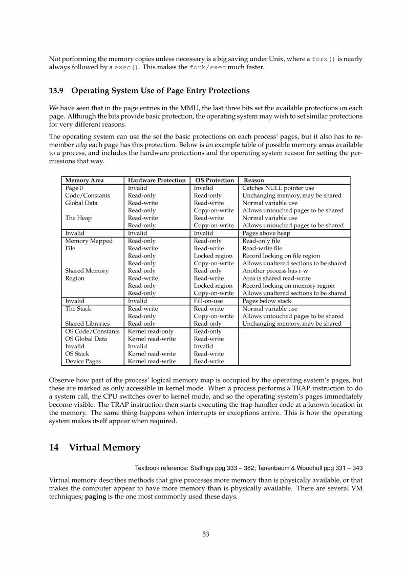
Not performing the memory copies unless necessary is a big saving under Unix, where a fork() is nearlyalways followed by a exec(). This makes the fork/exec much faster.
13.9 Operating System Use of Page Entry Protections
We have seen that in the page entries in the MMU, the last three bits set the available protections on eachpage. Although the bits provide basic protection, the operating system may wish to set similar protectionsfor very different reasons.
The operating system can use the set the basic protections on each process’ pages, but it also has to re-member why each page has this protection. Below is an example table of possible memory areas availableto a process, and includes the hardware protections and the operating system reason for setting the per-missions that way.
Memory Area Hardware Protection OS Protection ReasonPage 0 Invalid Invalid Catches NULL pointer useCode/Constants Read-only Read-only Unchanging memory, may be sharedGlobal Data Read-write Read-write Normal variable use
Read-only Copy-on-write Allows untouched pages to be sharedThe Heap Read-write Read-write Normal variable use
Read-only Copy-on-write Allows untouched pages to be sharedInvalid Invalid Invalid Pages above heapMemory Mapped Read-only Read-only Read-only fileFile Read-write Read-write Read-write file
Read-only Locked region Record locking on file regionRead-only Copy-on-write Allows unaltered sections to be shared
Shared Memory Read-only Read-only Another process has r-wRegion Read-write Read-write Area is shared read-write
Read-only Locked region Record locking on memory regionRead-only Copy-on-write Allows unaltered sections to be shared
Invalid Invalid Fill-on-use Pages below stackThe Stack Read-write Read-write Normal variable use
Read-only Copy-on-write Allows untouched pages to be sharedShared Libraries Read-only Read-only Unchanging memory, may be sharedOS Code/Constants Kernel read-only Read-onlyOS Global Data Kernel read-write Read-writeInvalid Invalid InvalidOS Stack Kernel read-write Read-writeDevice Pages Kernel read-write Read-write
Observe how part of the process’ logical memory map is occupied by the operating system’s pages, butthese are marked as only accessible in kernel mode. When a process performs a TRAP instruction to doa system call, the CPU switches over to kernel mode, and so the operating system’s pages immediatelybecome visible. The TRAP instruction then starts executing the trap handler code at a known location inthe memory. The same thing happens when interrupts or exceptions arrive. This is how the operatingsystem makes itself appear when required.
14 Virtual Memory
Textbook reference: Stallings ppg 333 – 382; Tanenbaum & Woodhull ppg 331 – 343
Virtual memory describes methods that give processes more memory than is physically available, or thatmakes the computer appear to have more memory than is physically available. There are several VMtechniques; paging is the one most commonly used these days.
53
14.1 Why Use Virtual Memory?
The memory management methods shown in the last two lectures arise because of one basic requirement:the entire logical address space of a process must be in physical memory before the process can executeand while it is executing. In many cases, the entire process need not be in memory:
• Parts of the process (e.g error handling) get used rarely.
• Often statically declared objects (e.g arrays) are only partially used (e.g a list of records in an array).
If we could get the operating system to have in memory only the needed bits of a process:
• Users could write programs bigger than the size of available memory.
• As each process would use less physical memory while running, the operating system could fit moreprocesses into physical memory.
• Less I/O would be needed to load a process into memory.
The sections of memory currently in use by a process are known as its working set, or as its locality ofreference. The whole point here is to keep the working set in memory (which is fast), and to leave the restof a process’s memory out on disk (which is slow).
14.2 Paging
A paged architecture has a memory granularity less than the process size. Thus, if we can determine whatpages are not needed immediately, we can write them out to disk, and release these pages for other pagesto use. In other words, we copy to disk the contents of pages which are not part of any process’ workingset.
14.3 Paging – How It Works
The operating system either has an abundancy of free pages, or is running short of free pages. As newprocesses start, or existing processes grow, they request pages from the operating system. If the operatingsystem has spare pages, it allocates them to the requesting process.
However, when the operating system is running short of free pages, the operating system looks throughthe list of used pages and selects pages that it believes won’t be used for a while. It writes these pages tothe disk, scrubs the pages, and gives them to the process that requested them. If the selection mechanismis good, then eventually only the working set of all processes is left in memory.
What happens when a process tries to access a page of memory that has been written to disk? The missingpage is marked as invalid (it’s no longer in main memory), and so a page fault occurs when the processtries to access it. The operating system realises that the page is on disk, so it finds a free page frame, andreads the disk copy back into the new page frame.
Note that the operating system must know why a page is invalid, and if invalid because it is on the disk,exactly where it is on the disk.
54
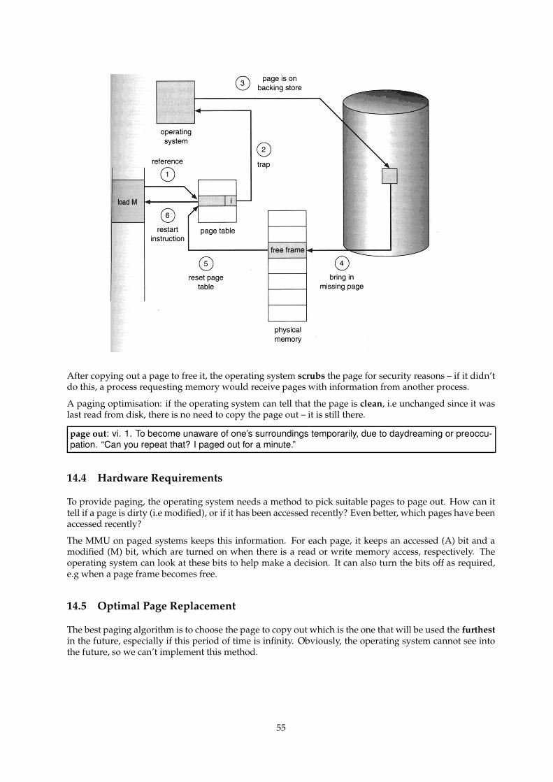
After copying out a page to free it, the operating system scrubs the page for security reasons – if it didn’tdo this, a process requesting memory would receive pages with information from another process.
A paging optimisation: if the operating system can tell that the page is clean, i.e unchanged since it waslast read from disk, there is no need to copy the page out – it is still there.
page out: vi. 1. To become unaware of one’s surroundings temporarily, due to daydreaming or preoccu-pation. “Can you repeat that? I paged out for a minute.”
14.4 Hardware Requirements
To provide paging, the operating system needs a method to pick suitable pages to page out. How can ittell if a page is dirty (i.e modified), or if it has been accessed recently? Even better, which pages have beenaccessed recently?
The MMU on paged systems keeps this information. For each page, it keeps an accessed (A) bit and amodified (M) bit, which are turned on when there is a read or write memory access, respectively. Theoperating system can look at these bits to help make a decision. It can also turn the bits off as required,e.g when a page frame becomes free.
14.5 Optimal Page Replacement
The best paging algorithm is to choose the page to copy out which is the one that will be used the furthestin the future, especially if this period of time is infinity. Obviously, the operating system cannot see intothe future, so we can’t implement this method.
55
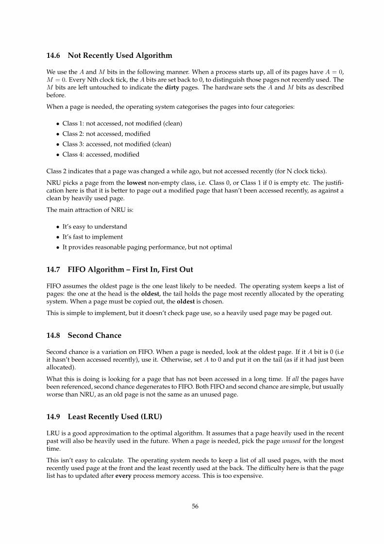
14.6 Not Recently Used Algorithm
We use the A and M bits in the following manner. When a process starts up, all of its pages have A = 0,M = 0. Every Nth clock tick, the A bits are set back to 0, to distinguish those pages not recently used. TheM bits are left untouched to indicate the dirty pages. The hardware sets the A and M bits as describedbefore.
When a page is needed, the operating system categorises the pages into four categories:
• Class 1: not accessed, not modified (clean)
• Class 2: not accessed, modified
• Class 3: accessed, not modified (clean)
• Class 4: accessed, modified
Class 2 indicates that a page was changed a while ago, but not accessed recently (for N clock ticks).
NRU picks a page from the lowest non-empty class, i.e. Class 0, or Class 1 if 0 is empty etc. The justifi-cation here is that it is better to page out a modified page that hasn’t been accessed recently, as against aclean by heavily used page.
The main attraction of NRU is:
• It’s easy to understand
• It’s fast to implement
• It provides reasonable paging performance, but not optimal
14.7 FIFO Algorithm – First In, First Out
FIFO assumes the oldest page is the one least likely to be needed. The operating system keeps a list ofpages: the one at the head is the oldest, the tail holds the page most recently allocated by the operatingsystem. When a page must be copied out, the oldest is chosen.
This is simple to implement, but it doesn’t check page use, so a heavily used page may be paged out.
14.8 Second Chance
Second chance is a variation on FIFO. When a page is needed, look at the oldest page. If it A bit is 0 (i.eit hasn’t been accessed recently), use it. Otherwise, set A to 0 and put it on the tail (as if it had just beenallocated).
What this is doing is looking for a page that has not been accessed in a long time. If all the pages havebeen referenced, second chance degenerates to FIFO. Both FIFO and second chance are simple, but usuallyworse than NRU, as an old page is not the same as an unused page.
14.9 Least Recently Used (LRU)
LRU is a good approximation to the optimal algorithm. It assumes that a page heavily used in the recentpast will also be heavily used in the future. When a page is needed, pick the page unused for the longesttime.
This isn’t easy to calculate. The operating system needs to keep a list of all used pages, with the mostrecently used page at the front and the least recently used at the back. The difficulty here is that the pagelist has to updated after every process memory access. This is too expensive.
56
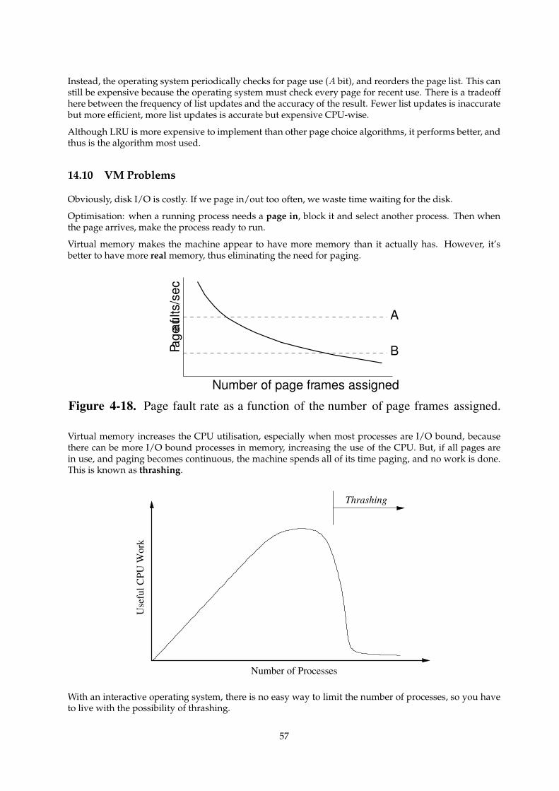
Instead, the operating system periodically checks for page use (A bit), and reorders the page list. This canstill be expensive because the operating system must check every page for recent use. There is a tradeoffhere between the frequency of list updates and the accuracy of the result. Fewer list updates is inaccuratebut more efficient, more list updates is accurate but expensive CPU-wise.
Although LRU is more expensive to implement than other page choice algorithms, it performs better, andthus is the algorithm most used.
14.10 VM Problems
Obviously, disk I/O is costly. If we page in/out too often, we waste time waiting for the disk.
Optimisation: when a running process needs a page in, block it and select another process. Then whenthe page arrives, make the process ready to run.
Virtual memory makes the machine appear to have more memory than it actually has. However, it’sbetter to have more real memory, thus eliminating the need for paging.
Page
faults
/sec
Number of page frames assigned
A
B
Figure 4-18. Page fault rate as a function of the number of page frames assigned.
Virtual memory increases the CPU utilisation, especially when most processes are I/O bound, becausethere can be more I/O bound processes in memory, increasing the use of the CPU. But, if all pages arein use, and paging becomes continuous, the machine spends all of its time paging, and no work is done.This is known as thrashing.
Use
ful C
PU W
ork
Number of Processes
Thrashing
With an interactive operating system, there is no easy way to limit the number of processes, so you haveto live with the possibility of thrashing.
57
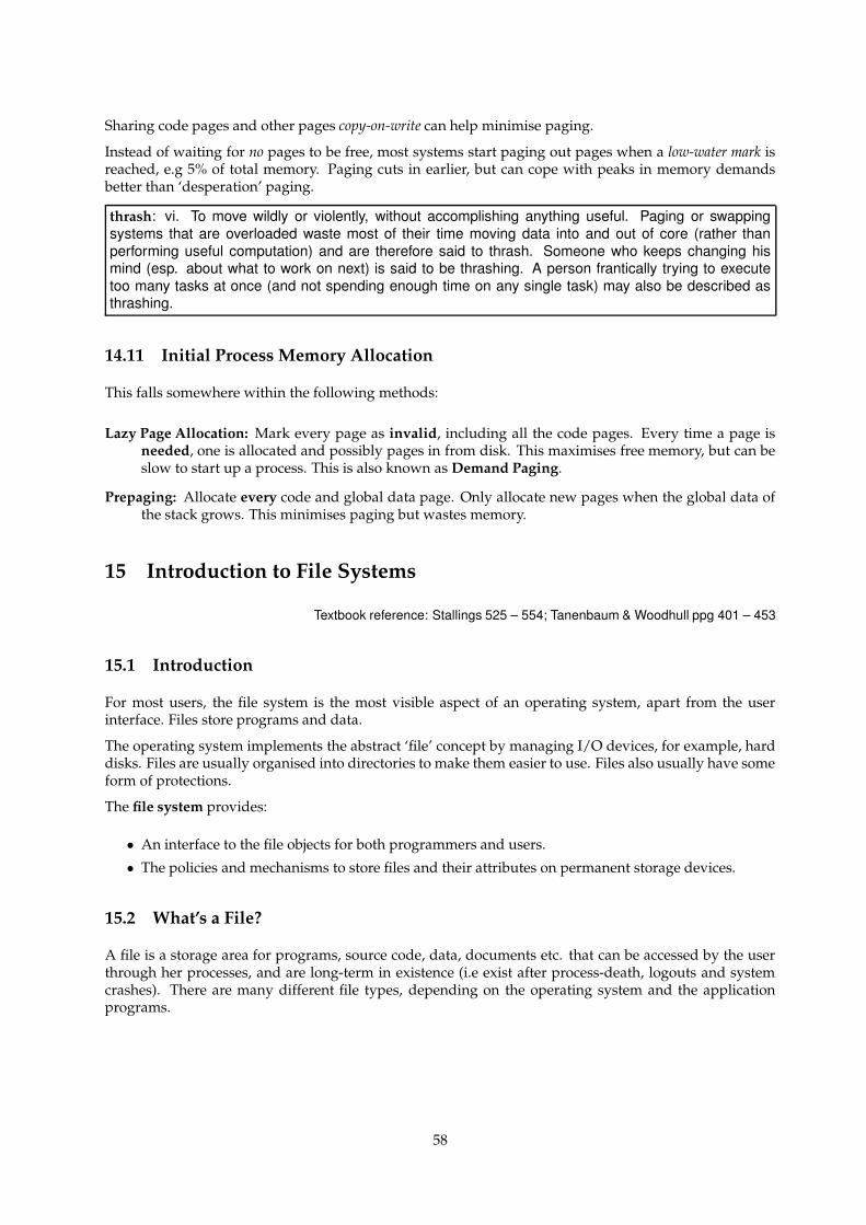
Sharing code pages and other pages copy-on-write can help minimise paging.
Instead of waiting for no pages to be free, most systems start paging out pages when a low-water mark isreached, e.g 5% of total memory. Paging cuts in earlier, but can cope with peaks in memory demandsbetter than ‘desperation’ paging.
thrash: vi. To move wildly or violently, without accomplishing anything useful. Paging or swappingsystems that are overloaded waste most of their time moving data into and out of core (rather thanperforming useful computation) and are therefore said to thrash. Someone who keeps changing hismind (esp. about what to work on next) is said to be thrashing. A person frantically trying to executetoo many tasks at once (and not spending enough time on any single task) may also be described asthrashing.
14.11 Initial Process Memory Allocation
This falls somewhere within the following methods:
Lazy Page Allocation: Mark every page as invalid, including all the code pages. Every time a page isneeded, one is allocated and possibly pages in from disk. This maximises free memory, but can beslow to start up a process. This is also known as Demand Paging.
Prepaging: Allocate every code and global data page. Only allocate new pages when the global data ofthe stack grows. This minimises paging but wastes memory.
15 Introduction to File Systems
Textbook reference: Stallings 525 – 554; Tanenbaum & Woodhull ppg 401 – 453
15.1 Introduction
For most users, the file system is the most visible aspect of an operating system, apart from the userinterface. Files store programs and data.
The operating system implements the abstract ‘file’ concept by managing I/O devices, for example, harddisks. Files are usually organised into directories to make them easier to use. Files also usually have someform of protections.
The file system provides:
• An interface to the file objects for both programmers and users.
• The policies and mechanisms to store files and their attributes on permanent storage devices.
15.2 What’s a File?
A file is a storage area for programs, source code, data, documents etc. that can be accessed by the userthrough her processes, and are long-term in existence (i.e exist after process-death, logouts and systemcrashes). There are many different file types, depending on the operating system and the applicationprograms.
58
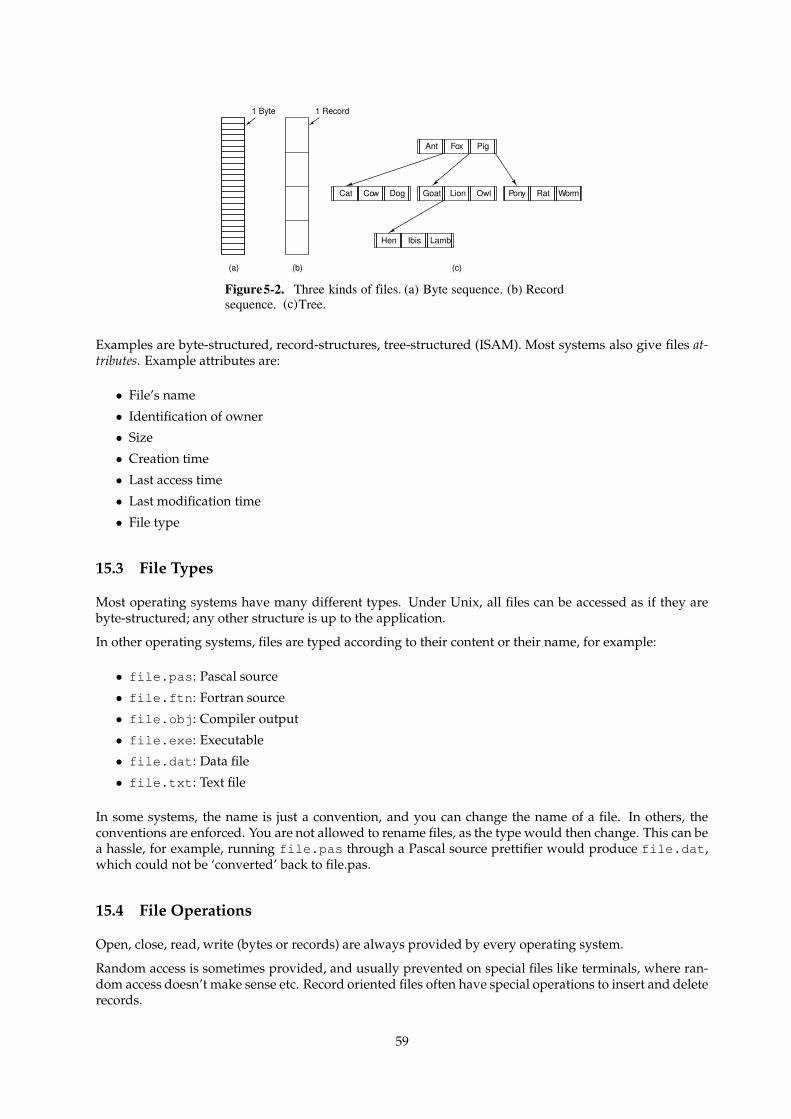
(a) (b) (c)
1 Record
Ant Fox Pig
Cat Cow Dog Goat Lion Owl Pony Rat Worm
Hen Ibis Lamb
1 Byte
Figure5-2. Three kinds of files. (a) Byte sequence. (b) Recordsequence. (c)Tree.
Examples are byte-structured, record-structures, tree-structured (ISAM). Most systems also give files at-tributes. Example attributes are:
• File’s name
• Identification of owner
• Size
• Creation time
• Last access time
• Last modification time
• File type
15.3 File Types
Most operating systems have many different types. Under Unix, all files can be accessed as if they arebyte-structured; any other structure is up to the application.
In other operating systems, files are typed according to their content or their name, for example:
• file.pas: Pascal source
• file.ftn: Fortran source
• file.obj: Compiler output
• file.exe: Executable
• file.dat: Data file
• file.txt: Text file
In some systems, the name is just a convention, and you can change the name of a file. In others, theconventions are enforced. You are not allowed to rename files, as the type would then change. This can bea hassle, for example, running file.pas through a Pascal source prettifier would produce file.dat,which could not be ‘converted’ back to file.pas.
15.4 File Operations
Open, close, read, write (bytes or records) are always provided by every operating system.
Random access is sometimes provided, and usually prevented on special files like terminals, where ran-dom access doesn’t make sense etc. Record oriented files often have special operations to insert and deleterecords.
59
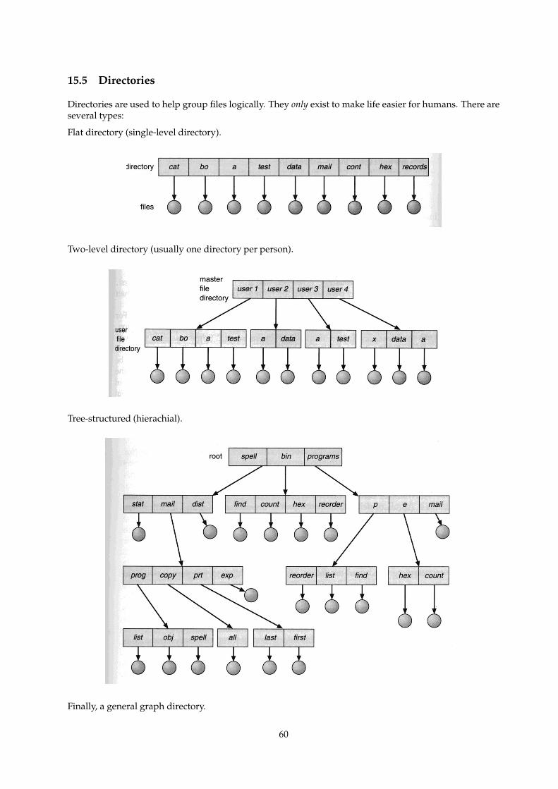
15.5 Directories
Directories are used to help group files logically. They only exist to make life easier for humans. There areseveral types:
Flat directory (single-level directory).
Two-level directory (usually one directory per person).
Tree-structured (hierachial).
Finally, a general graph directory.
60
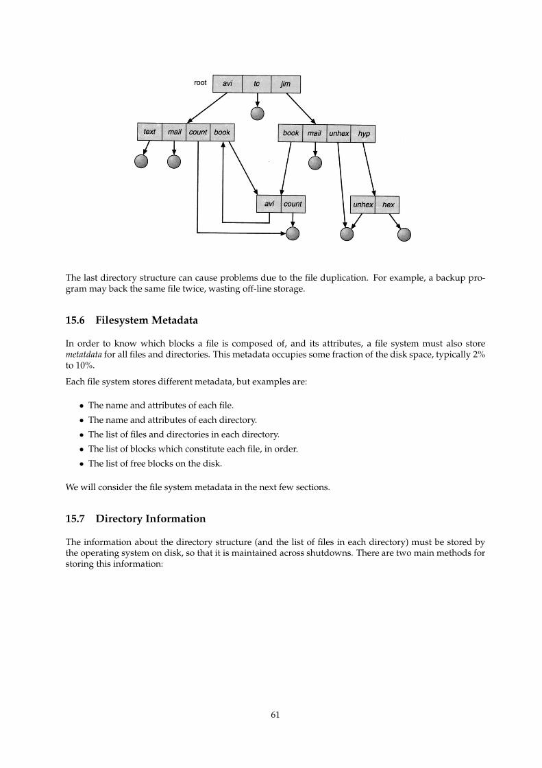
The last directory structure can cause problems due to the file duplication. For example, a backup pro-gram may back the same file twice, wasting off-line storage.
15.6 Filesystem Metadata
In order to know which blocks a file is composed of, and its attributes, a file system must also storemetatdata for all files and directories. This metadata occupies some fraction of the disk space, typically 2%to 10%.
Each file system stores different metadata, but examples are:
• The name and attributes of each file.
• The name and attributes of each directory.
• The list of files and directories in each directory.
• The list of blocks which constitute each file, in order.
• The list of free blocks on the disk.
We will consider the file system metadata in the next few sections.
15.7 Directory Information
The information about the directory structure (and the list of files in each directory) must be stored bythe operating system on disk, so that it is maintained across shutdowns. There are two main methods forstoring this information:
61
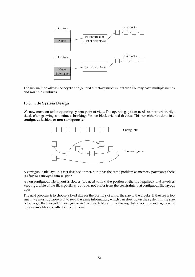
Directory
Name
Disk blocks
Directory
Name List of disk blocksFile information
Disk blocks
Information
List of disk blocks
The first method allows the acyclic and general directory structure, where a file may have multiple namesand multiple attributes.
15.8 File System Design
We now move on to the operating system point of view. The operating system needs to store arbitrarily-sized, often growing, sometimes shrinking, files on block-oriented devices. This can either be done in acontiguous fashion, or non-contiguously.
Non-contiguous
Contiguous
A contiguous file layout is fast (less seek time), but it has the same problem as memory partitions: thereis often not enough room to grow.
A non-contiguous file layout is slower (we need to find the portion of the file required), and involveskeeping a table of the file’s portions, but does not suffer from the constraints that contiguous file layoutdoes.
The next problem is to choose a fixed size for the portions of a file: the size of the blocks. If the size is toosmall, we must do more I/O to read the same information, which can slow down the system. If the sizeis too large, then we get internal fragmentation in each block, thus wasting disk space. The average size ofthe system’s files also affects this problem.
62
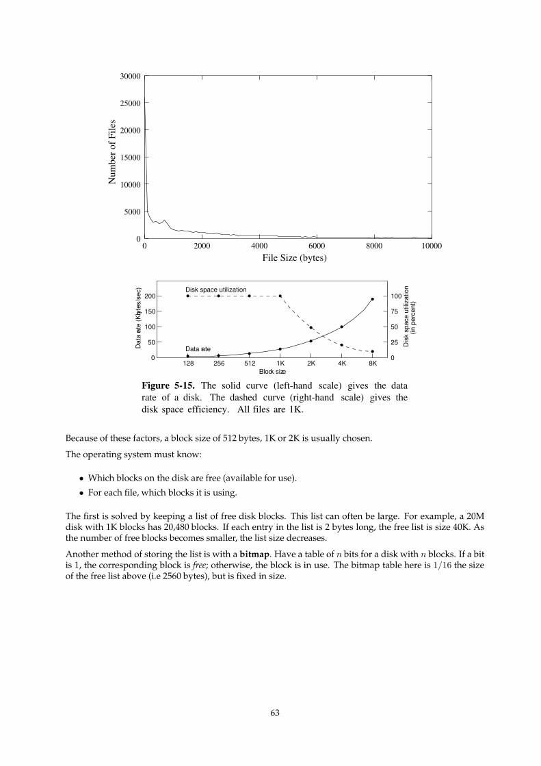
File Size (bytes)
Num
ber o
f File
s
0
15000
20000
25000
30000
0 2000 4000 6000 8000 10000
5000
10000
Dat
a rat
e (K
byte
s/se
c)
Dis
k sp
ace
utili
zatio
n(in
per
cent
)
Block size
Disk space utilization
Data rate
200
150
100
50
0
100
75
50
25
0128 256 512 1K 2K 4K 8K
Figure 5-15. The solid curve (left-hand scale) gives the datarate of a disk. The dashed curve (right-hand scale) gives thedisk space efficiency. All files are 1K.
Because of these factors, a block size of 512 bytes, 1K or 2K is usually chosen.
The operating system must know:
• Which blocks on the disk are free (available for use).
• For each file, which blocks it is using.
The first is solved by keeping a list of free disk blocks. This list can often be large. For example, a 20Mdisk with 1K blocks has 20,480 blocks. If each entry in the list is 2 bytes long, the free list is size 40K. Asthe number of free blocks becomes smaller, the list size decreases.
Another method of storing the list is with a bitmap. Have a table of n bits for a disk with n blocks. If a bitis 1, the corresponding block is free; otherwise, the block is in use. The bitmap table here is 1/16 the sizeof the free list above (i.e 2560 bytes), but is fixed in size.
63
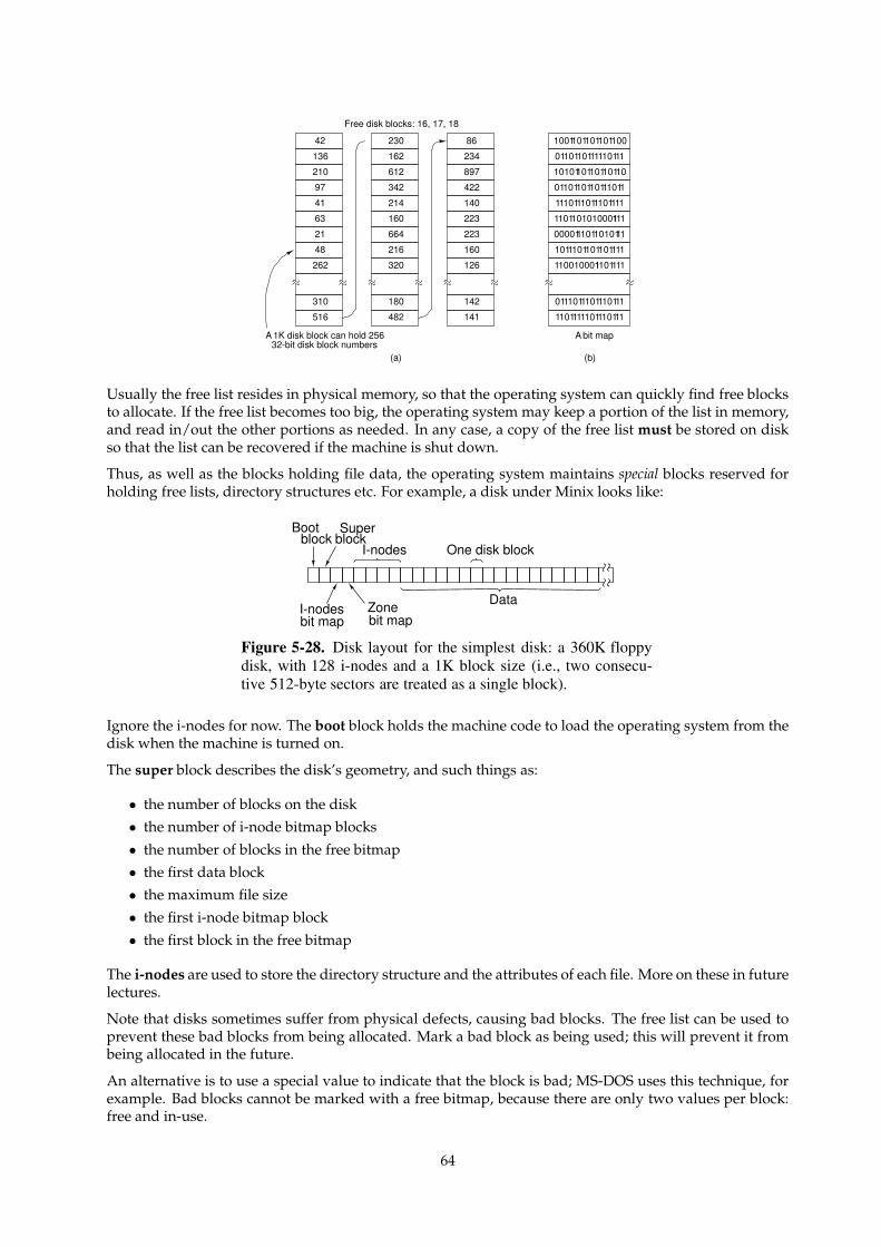
(a) (b)
Free disk blocks: 16, 17, 18
A bit mapA 1K disk block can hold 25632-bit disk block numbers
86
234
897
422
140
223
223
160
126
142
141
1001101101101100
0110110111110111
1010110110110110
0110110110111011
1110111011101111
1101101010001111
0000111011010111
1011101101101111
1100100011101111
0111011101110111
1101111101110111
230
162
612
342
214
160
664
216
320
180
482
42
136
210
97
41
63
21
48
262
310
516
Usually the free list resides in physical memory, so that the operating system can quickly find free blocksto allocate. If the free list becomes too big, the operating system may keep a portion of the list in memory,and read in/out the other portions as needed. In any case, a copy of the free list must be stored on diskso that the list can be recovered if the machine is shut down.
Thus, as well as the blocks holding file data, the operating system maintains special blocks reserved forholding free lists, directory structures etc. For example, a disk under Minix looks like:
Bootblock
Superblock
I-nodes
I-nodesbit map
Zonebit map
One disk block
Data
Figure 5-28. Disk layout for the simplest disk: a 360K floppydisk, with 128 i-nodes and a 1K block size (i.e., two consecu-tive 512-byte sectors are treated as a single block).
Ignore the i-nodes for now. The boot block holds the machine code to load the operating system from thedisk when the machine is turned on.
The super block describes the disk’s geometry, and such things as:
• the number of blocks on the disk• the number of i-node bitmap blocks
• the number of blocks in the free bitmap• the first data block• the maximum file size• the first i-node bitmap block
• the first block in the free bitmap
The i-nodes are used to store the directory structure and the attributes of each file. More on these in futurelectures.
Note that disks sometimes suffer from physical defects, causing bad blocks. The free list can be used toprevent these bad blocks from being allocated. Mark a bad block as being used; this will prevent it frombeing allocated in the future.
An alternative is to use a special value to indicate that the block is bad; MS-DOS uses this technique, forexample. Bad blocks cannot be marked with a free bitmap, because there are only two values per block:free and in-use.
64
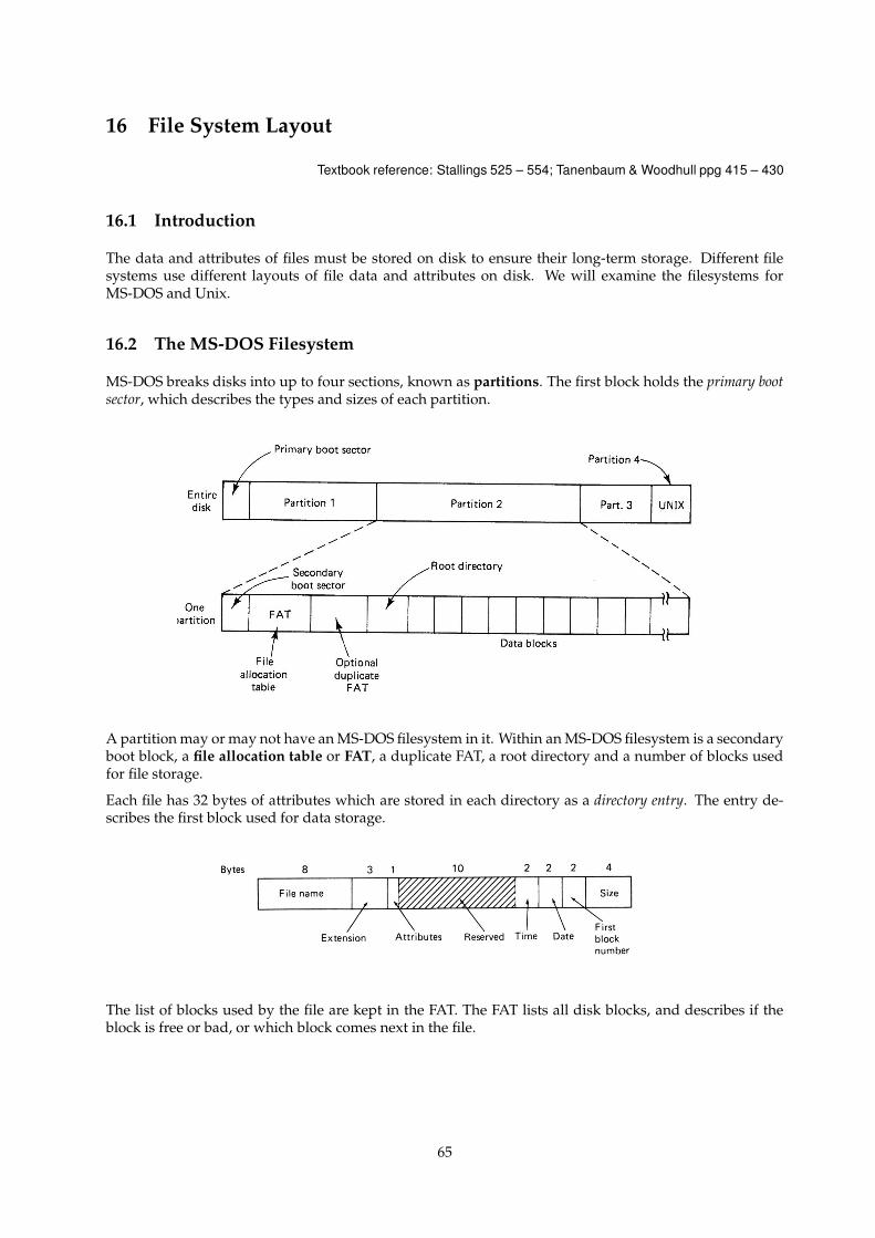
16 File System Layout
Textbook reference: Stallings 525 – 554; Tanenbaum & Woodhull ppg 415 – 430
16.1 Introduction
The data and attributes of files must be stored on disk to ensure their long-term storage. Different filesystems use different layouts of file data and attributes on disk. We will examine the filesystems forMS-DOS and Unix.
16.2 The MS-DOS Filesystem
MS-DOS breaks disks into up to four sections, known as partitions. The first block holds the primary bootsector, which describes the types and sizes of each partition.
A partition may or may not have an MS-DOS filesystem in it. Within an MS-DOS filesystem is a secondaryboot block, a file allocation table or FAT, a duplicate FAT, a root directory and a number of blocks usedfor file storage.
Each file has 32 bytes of attributes which are stored in each directory as a directory entry. The entry de-scribes the first block used for data storage.
The list of blocks used by the file are kept in the FAT. The FAT lists all disk blocks, and describes if theblock is free or bad, or which block comes next in the file.
65
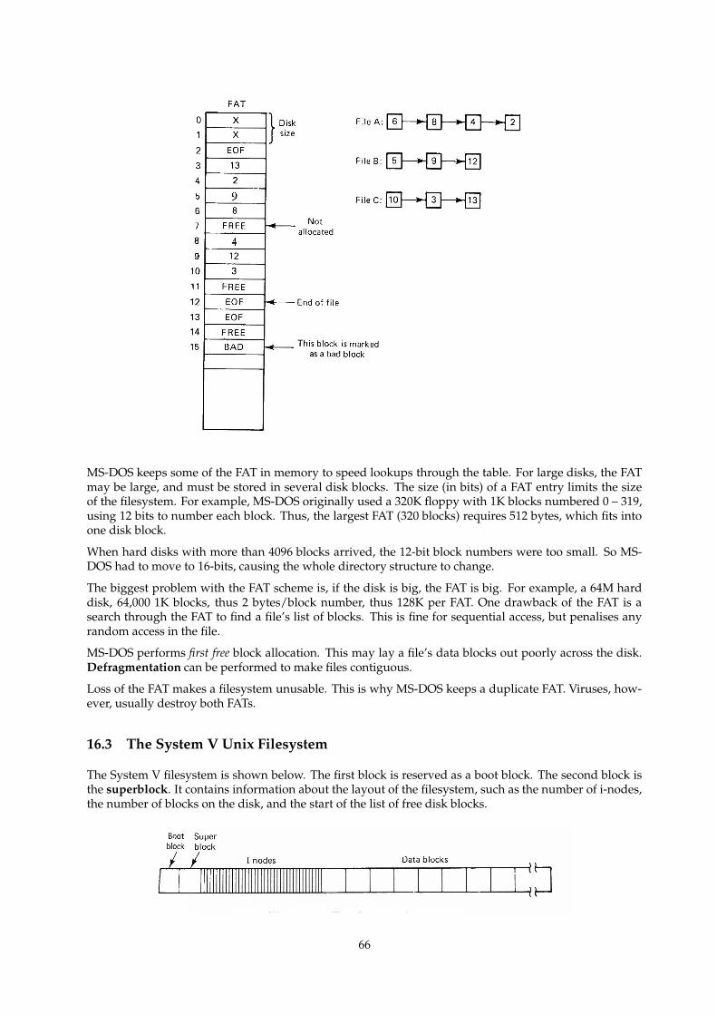
MS-DOS keeps some of the FAT in memory to speed lookups through the table. For large disks, the FATmay be large, and must be stored in several disk blocks. The size (in bits) of a FAT entry limits the sizeof the filesystem. For example, MS-DOS originally used a 320K floppy with 1K blocks numbered 0 – 319,using 12 bits to number each block. Thus, the largest FAT (320 blocks) requires 512 bytes, which fits intoone disk block.
When hard disks with more than 4096 blocks arrived, the 12-bit block numbers were too small. So MS-DOS had to move to 16-bits, causing the whole directory structure to change.
The biggest problem with the FAT scheme is, if the disk is big, the FAT is big. For example, a 64M harddisk, 64,000 1K blocks, thus 2 bytes/block number, thus 128K per FAT. One drawback of the FAT is asearch through the FAT to find a file’s list of blocks. This is fine for sequential access, but penalises anyrandom access in the file.
MS-DOS performs first free block allocation. This may lay a file’s data blocks out poorly across the disk.Defragmentation can be performed to make files contiguous.
Loss of the FAT makes a filesystem unusable. This is why MS-DOS keeps a duplicate FAT. Viruses, how-ever, usually destroy both FATs.
16.3 The System V Unix Filesystem
The System V filesystem is shown below. The first block is reserved as a boot block. The second block isthe superblock. It contains information about the layout of the filesystem, such as the number of i-nodes,the number of blocks on the disk, and the start of the list of free disk blocks.
66

After the superblock are the i-nodes. These contain the attributes of files, but not the filenames. Note thatthe attributes are quite different to MS-DOS. As Unix is a multiuser system, files have ownership and athree-level set of protections (read, write, execute for user, a group of users, and all other users),
Triple indirect ptr
Last inode access time
File mode
Link count
Owner’s id
Group id
File size
Last access time
Last mod time
Addresses offirst 10 blocks
Single indirect ptr
Double indirect ptr
Instead of a linear structure for keeping the list of blocks, Unix uses a tree structure which is faster totraverse.
The i-node holds the first 10 block numbers used by the file. If the file grows larger, a disk block is usedto store further block numbers; this is a single indirect block. Assume the single indirect block can hold256 block numbers: this allows the file to grow to 10 + 256 = 266 blocks.
If the single indirect block becomes full, another two blocks are used. One becomes the next single indirectblock, and the second points to the new single indirect block; this is a double indirect block, which canpoint at 256 single indirect blocks, allowing the file to grow to 10 + 256 + 256 ∗ 256 = 65, 802 blocks.
Sometimes, a file will exceed 65,802 blocks. In this situation, a triple indirect block is allocated whichpoints at up to 256 double indirect blocks. There can only be one triple indirect block, but when used, afile can grow to be 10 + 256 + 2562 + 2563 = 16, 843, 018 blocks, or around 16 gigabytes in size.
One strength of the i-node system is that the indirect blocks are used only as required, and for files lessthan 10 blocks, none are required. The main advantage is that a tree search can be used to find the blocknumber for any block, and as the tree is never more than three levels deep, it never takes more than threedisk accesses to find a block. This also speeds random file accesses.
A System V Unix directory entry looks like:
Bytes 2 14File name
I-nodenumber
Figure 5-13. A UNIX directory entry.
Note here that Unix only stores the file name and i-node number in each directory entry. The rest ofthe information about each file is kept in the i-node. This allows files to be linked, allowing acyclic andgeneral graph directory structures. This cannot be done with MS-DOS.
592 shared.c in /usr/fred
592 temp shared.c in /tmp
67
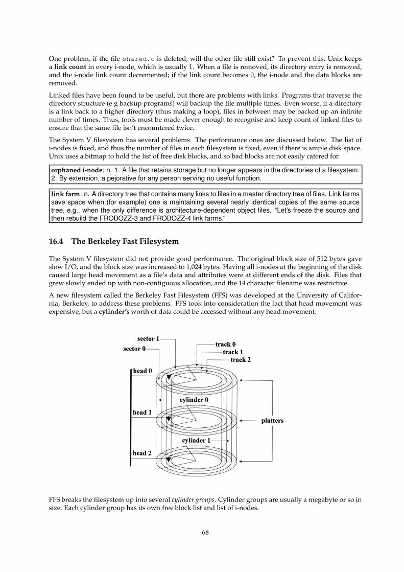
One problem, if the file shared.c is deleted, will the other file still exist? To prevent this, Unix keepsa link count in every i-node, which is usually 1. When a file is removed, its directory entry is removed,and the i-node link count decremented; if the link count becomes 0, the i-node and the data blocks areremoved.
Linked files have been found to be useful, but there are problems with links. Programs that traverse thedirectory structure (e.g backup programs) will backup the file multiple times. Even worse, if a directoryis a link back to a higher directory (thus making a loop), files in between may be backed up an infinitenumber of times. Thus, tools must be made clever enough to recognise and keep count of linked files toensure that the same file isn’t encountered twice.
The System V filesystem has several problems. The performance ones are discussed below. The list ofi-nodes is fixed, and thus the number of files in each filesystem is fixed, even if there is ample disk space.Unix uses a bitmap to hold the list of free disk blocks, and so bad blocks are not easily catered for.
orphaned i-node: n. 1. A file that retains storage but no longer appears in the directories of a filesystem.2. By extension, a pejorative for any person serving no useful function.
link farm: n. A directory tree that contains many links to files in a master directory tree of files. Link farmssave space when (for example) one is maintaining several nearly identical copies of the same sourcetree, e.g., when the only difference is architecture-dependent object files. “Let’s freeze the source andthen rebuild the FROBOZZ-3 and FROBOZZ-4 link farms.”
16.4 The Berkeley Fast Filesystem
The System V filesystem did not provide good performance. The original block size of 512 bytes gaveslow I/O, and the block size was increased to 1,024 bytes. Having all i-nodes at the beginning of the diskcaused large head movement as a file’s data and attributes were at different ends of the disk. Files thatgrew slowly ended up with non-contiguous allocation, and the 14 character filename was restrictive.
A new filesystem called the Berkeley Fast Filesystem (FFS) was developed at the University of Califor-nia, Berkeley, to address these problems. FFS took into consideration the fact that head movement wasexpensive, but a cylinder’s worth of data could be accessed without any head movement.
FFS breaks the filesystem up into several cylinder groups. Cylinder groups are usually a megabyte or so insize. Each cylinder group has its own free block list and list of i-nodes.
68
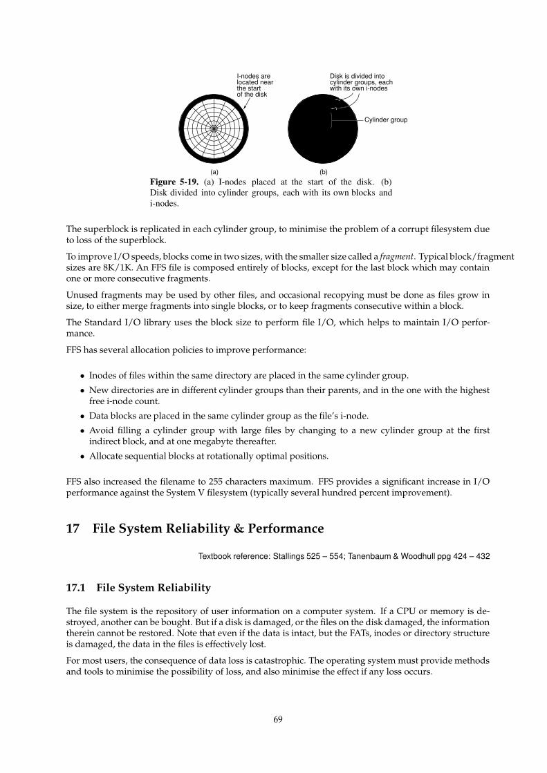
I-nodes arelocated nearthe startof the disk
Disk is divided intocylinder groups, eachwith its own i-nodes
(a) (b)
Cylinder group
Figure 5-19. (a) I-nodes placed at the start of the disk. (b)Disk divided into cylinder groups, each with its own blocks andi-nodes.
The superblock is replicated in each cylinder group, to minimise the problem of a corrupt filesystem dueto loss of the superblock.
To improve I/O speeds, blocks come in two sizes, with the smaller size called a fragment. Typical block/fragmentsizes are 8K/1K. An FFS file is composed entirely of blocks, except for the last block which may containone or more consecutive fragments.
Unused fragments may be used by other files, and occasional recopying must be done as files grow insize, to either merge fragments into single blocks, or to keep fragments consecutive within a block.
The Standard I/O library uses the block size to perform file I/O, which helps to maintain I/O perfor-mance.
FFS has several allocation policies to improve performance:
• Inodes of files within the same directory are placed in the same cylinder group.
• New directories are in different cylinder groups than their parents, and in the one with the highestfree i-node count.
• Data blocks are placed in the same cylinder group as the file’s i-node.
• Avoid filling a cylinder group with large files by changing to a new cylinder group at the firstindirect block, and at one megabyte thereafter.
• Allocate sequential blocks at rotationally optimal positions.
FFS also increased the filename to 255 characters maximum. FFS provides a significant increase in I/Operformance against the System V filesystem (typically several hundred percent improvement).
17 File System Reliability & Performance
Textbook reference: Stallings 525 – 554; Tanenbaum & Woodhull ppg 424 – 432
17.1 File System Reliability
The file system is the repository of user information on a computer system. If a CPU or memory is de-stroyed, another can be bought. But if a disk is damaged, or the files on the disk damaged, the informationtherein cannot be restored. Note that even if the data is intact, but the FATs, inodes or directory structureis damaged, the data in the files is effectively lost.
For most users, the consequence of data loss is catastrophic. The operating system must provide methodsand tools to minimise the possibility of loss, and also minimise the effect if any loss occurs.
69
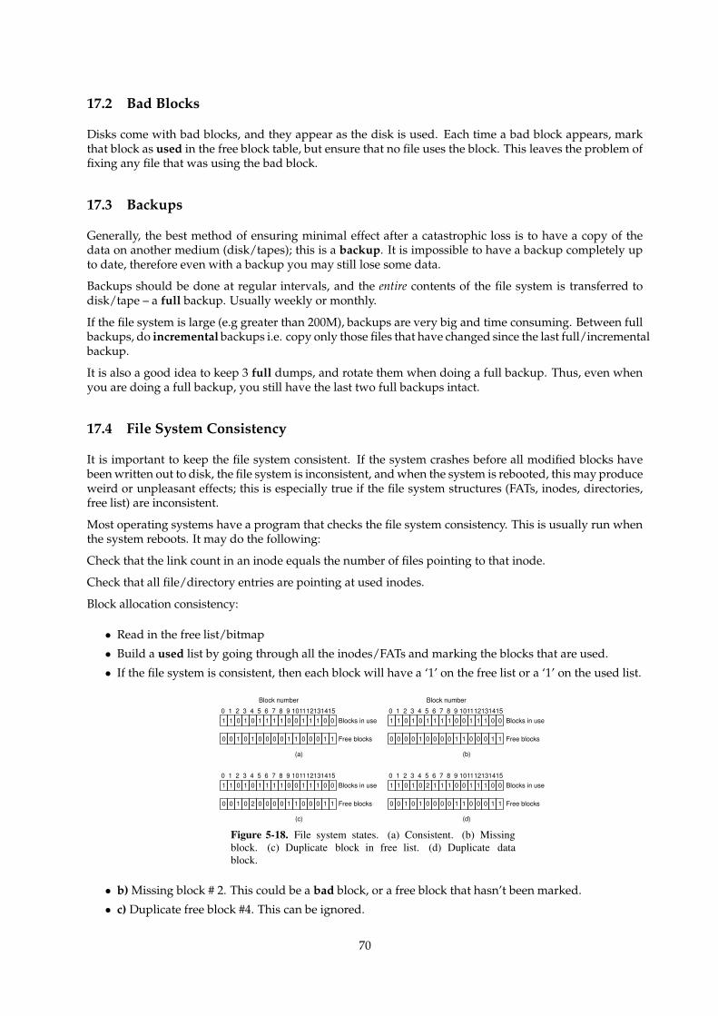
17.2 Bad Blocks
Disks come with bad blocks, and they appear as the disk is used. Each time a bad block appears, markthat block as used in the free block table, but ensure that no file uses the block. This leaves the problem offixing any file that was using the bad block.
17.3 Backups
Generally, the best method of ensuring minimal effect after a catastrophic loss is to have a copy of thedata on another medium (disk/tapes); this is a backup. It is impossible to have a backup completely upto date, therefore even with a backup you may still lose some data.
Backups should be done at regular intervals, and the entire contents of the file system is transferred todisk/tape – a full backup. Usually weekly or monthly.
If the file system is large (e.g greater than 200M), backups are very big and time consuming. Between fullbackups, do incremental backups i.e. copy only those files that have changed since the last full/incrementalbackup.
It is also a good idea to keep 3 full dumps, and rotate them when doing a full backup. Thus, even whenyou are doing a full backup, you still have the last two full backups intact.
17.4 File System Consistency
It is important to keep the file system consistent. If the system crashes before all modified blocks havebeen written out to disk, the file system is inconsistent, and when the system is rebooted, this may produceweird or unpleasant effects; this is especially true if the file system structures (FATs, inodes, directories,free list) are inconsistent.
Most operating systems have a program that checks the file system consistency. This is usually run whenthe system reboots. It may do the following:
Check that the link count in an inode equals the number of files pointing to that inode.
Check that all file/directory entries are pointing at used inodes.
Block allocation consistency:
• Read in the free list/bitmap
• Build a used list by going through all the inodes/FATs and marking the blocks that are used.
• If the file system is consistent, then each block will have a ‘1’ on the free list or a ‘1’ on the used list.
1 1 0 1 0 1 1 1 1 0 0 1 1 1 0 00 1 2 3 4 5 6 7 8 9 101112131415
Block number
Blocks in use
0 0 1 0 1 0 0 0 0 1 1 0 0 0 1 1 Free blocks
(a)
1 1 0 1 0 1 1 1 1 0 0 1 1 1 0 00 1 2 3 4 5 6 7 8 9 101112131415
Blocks in use
0 0 1 0 2 0 0 0 0 1 1 0 0 0 1 1 Free blocks
(c)
1 1 0 1 0 1 1 1 1 0 0 1 1 1 0 00 1 2 3 4 5 6 7 8 9 101112131415
Block number
Blocks in use
0 0 0 0 1 0 0 0 0 1 1 0 0 0 1 1 Free blocks
(b)
1 1 0 1 0 2 1 1 1 0 0 1 1 1 0 00 1 2 3 4 5 6 7 8 9 101112131415
Blocks in use
0 0 1 0 1 0 0 0 0 1 1 0 0 0 1 1 Free blocks
(d)
Figure 5-18. File system states. (a) Consistent. (b) Missingblock. (c) Duplicate block in free list. (d) Duplicate datablock.
• b) Missing block # 2. This could be a bad block, or a free block that hasn’t been marked.
• c) Duplicate free block #4. This can be ignored.
70
• d) Duplicate used block #5, i.e 2 or more files use this block. This should never happen! If one file isfreed, the block is on both the used and the free list! One solution is to make ‘n’ copies of the blockand give each file its own block. Also signal an error to the owners of each file.
• e) Block on both free and used lists. We must fix this immediately, as the free block may be allocatedand overwritten. Remove the block from the free list.
Some operating systems can protect against user errors. For example, under MS-DOS, you can usuallyundelete a file that was accidentally deleted, because the directory entry is marked unused, but the re-maining information is still intact (i.e attributes, FAT tables). This is technically possible under Unix,but usually not possible because Unix allows multiple processes and users, thus the freed blocks may bereused at any time.
scribble: n. To modify a data structure in a random and unintentionally destructive way. “Somebody’sdisk-compactor program went berserk and scribbled on the i-node table.” Synonymous with trash; com-pare mung, which conveys a bit more intention, and mangle, which is more violent and final.
17.5 File System Performance – Caching
Disk accesses are much slower than memory, usually at least 10,000 times slower. We therefore needto optimise the file system performance. We have seen that arm and sector scheduling can help in thisregard.
Another common technique is a cache: a collection of disk blocks that logically belong on disk, but arekept in memory to improve performance.
Obviously, we should keep the most recently used or most frequently used disk blocks in memory so thatread/writes to these blocks will occur at memory speeds.
Note that we can use the cache to cache reads from the disk and writes to disk. This is known as a write-through cache, as writes go through the cache before eventually being written to the disk.
Some operating systems only cache reads, and all writes go directly to disk. This is known as a write-backcache. The problem arises as to which block to discard/write back to disk if the cache is full? This is verymuch like out paging problem, and algorithms like FIFO, second chance and LRU can be used here. Notethat because block accesses occur much less frequently than page accesses, it is feasible to keep cachedblocked in strict LRU order.
Any algorithm that is used should take into account the fact that blocks containing inodes, directoriesand free lists are special because they are essential to the file system consistency, and are likely to be usedfrequently. For this reason, some operating systems will write metadata to disk immediately, but writesfile data through the cache.
One problem with writes through the cache is that, if the machine crashes, dirty blocks will not be writtento the disk, and so data will be lost. This means recent disk writes are not written to disk.
The solution under Unix is to flush all dirty blocks to disk every 30 seconds. Caches that write direct todisk do not suffer from this problem, but are usually slower because of the I/O delay in writing.
The larger the cache, the more blocks in memory, and thus the better the hit-rate and the performance.Disk caches usually range from 512K to 8M of memory.
Finally, it’s a bit quirky that disks are used to hold pages from virtual memory, and memory is used tohold recently used disk blocks. It makes sense when you realise that VM is providing more memory witha performance penalty, whereas disk caching is providing some disk with a performance increase.
In fact, newer operating systems (Solaris, FreeBSD) have merged the disk cache into the virtual mem-ory subsystem. Disk blocks and memory pages are kept on the same LRU list, and so the whole of acomputer’s memory can be used for both working set storage and disk caching.
71
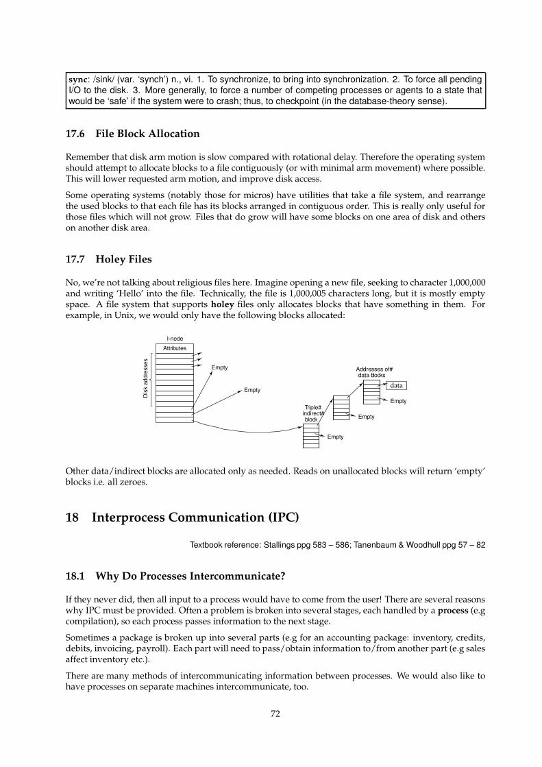
sync: /sink/ (var. ‘synch’) n., vi. 1. To synchronize, to bring into synchronization. 2. To force all pendingI/O to the disk. 3. More generally, to force a number of competing processes or agents to a state thatwould be ‘safe’ if the system were to crash; thus, to checkpoint (in the database-theory sense).
17.6 File Block Allocation
Remember that disk arm motion is slow compared with rotational delay. Therefore the operating systemshould attempt to allocate blocks to a file contiguously (or with minimal arm movement) where possible.This will lower requested arm motion, and improve disk access.
Some operating systems (notably those for micros) have utilities that take a file system, and rearrangethe used blocks to that each file has its blocks arranged in contiguous order. This is really only useful forthose files which will not grow. Files that do grow will have some blocks on one area of disk and otherson another disk area.
17.7 Holey Files
No, we’re not talking about religious files here. Imagine opening a new file, seeking to character 1,000,000and writing ‘Hello’ into the file. Technically, the file is 1,000,005 characters long, but it is mostly emptyspace. A file system that supports holey files only allocates blocks that have something in them. Forexample, in Unix, we would only have the following blocks allocated:
I-node
Empty
Empty
Empty
Attr
Empty
Empty
ibutes
Dis
k ad
dres
ses
Triple#indirect#block
Addresses of#data blocks
data
Other data/indirect blocks are allocated only as needed. Reads on unallocated blocks will return ‘empty’blocks i.e. all zeroes.
18 Interprocess Communication (IPC)
Textbook reference: Stallings ppg 583 – 586; Tanenbaum & Woodhull ppg 57 – 82
18.1 Why Do Processes Intercommunicate?
If they never did, then all input to a process would have to come from the user! There are several reasonswhy IPC must be provided. Often a problem is broken into several stages, each handled by a process (e.gcompilation), so each process passes information to the next stage.
Sometimes a package is broken up into several parts (e.g for an accounting package: inventory, credits,debits, invoicing, payroll). Each part will need to pass/obtain information to/from another part (e.g salesaffect inventory etc.).
There are many methods of intercommunicating information between processes. We would also like tohave processes on separate machines intercommunicate, too.
72
18.2 Files
Files are the most obvious way of passing information around. One process writes a file, and anotherreads it later. This works, but isn’t very interactive – you can’t use a file to query a database. It can also bevery slow, due to disk speeds. However, it is often used for IPC, especially for time-separated files.
Question: what problems do files have as an IPC mechanism for concurrent processes?
18.3 Pipes – Unidirectional Streams
We often need to pass output from one process directly to another process. We could write the output toa file and invoke the next process, but this wastes disk space, especially if the file is discarded after thesecond process exits.
A classic example is program compilation. In C, the source code is passed through a preprocessor beforebeing compiled down to intermediate code by the compiler front-end. This is then optimised by the opti-mizer, producing position-independent code. This, finally, has to be linked with any required libraries bythe linker/loader.
In this situation, there are several intermediate files which will be deleted once the final binary is pro-duced. Many operating systems provide a method of connecting the output stream of data from oneprocess to the input of another; this is known as a pipe under Unix. A pipe avoids the use of a temporaryfile. It is unidirectional, so the second process can’t talk back to the first.
One pipe problem is the size of the pipe, which is usually limited, e.g. 7K under Unix. If the secondprocess isn’t reading as fast as the first is writing, the pipe fills. What should be done?
Unix blocks the first process until the second has read some data from the pipe. Similarly, if there isnothing in the pipe, the second process will block reading from the pipe.
Under some systems, the two ends of a pipe are shared between processes that are related (e.g childprocesses in Unix). In other systems, the pipe ends can be owned by non-related processes. In this lattercase, each pipe end needs a ‘name’ so that processes can find the pipe and connect to it asynchronously.
The naming scheme is usually dependent on the operating system. Pipe ends may be given dummy filenames, and can be opened and used just like files. Alternatively, pipe ends may just be given uniquenumbers.
In any case, how does a process know which pipe to attach itself to? Solutions here are to use a well-knownname for certain services, or to have a name lookup service to find the service you want. Obviously, thename service must have a well-known name!
By including the computer’s networking address in the pipe’s name, IPC via pipes/streams can be per-formed over networks. This is essentially how most of the Internet’s communications works.
18.4 Bidirectional Streams
In this situation, two pipes connect the processes, one in each direction.
This allows replies, so the processes can ‘chat’. Two-way IPC is needed for client/server interaction. Thisis the situation when one process is a client, and the other is providing a service. The first asks forsomething to be done, and the second performs it and replies with a success/failure message and anyassociated results.
Bidirectional streams have an inherent deadlock problem: Imagine if both pipes fill up and both processesare blocked writing to their pipe. Neither can read any information from their own pipe because they haveyet to finish writing into the other pipe. Unidirectional pipes don’t suffer from this problem, as there isalways one process which isn’t writing to a pipe.
Streams are ok if the data really is a stream. But if it is a number of different requests, how does the server
73
determine where each request begins/ends? Placing markers in the stream is one solution, but then theprocesses at the end must know how to deal with the markers. We need another approach.
deadlock: n. 1. [techspeak] A situation wherein two or more processes are unable to proceed becauseeach is waiting for one of the others to do something. A common example is a program communicating toa server, which may find itself waiting for output from the server before sending anything more to it, whilethe server is similarly waiting for more input from the controlling program before outputting anything. (Itis reported that this particular flavor of deadlock is sometimes called a ‘starvation deadlock’, though theterm ‘starvation’ is more properly used for situations where a program can never run simply because itnever gets high enough priority. Another common flavor is ‘constipation’, where each process is trying tosend stuff to the other but all buffers are full because nobody is reading anything.) See deadly embrace.2. Also used of deadlock-like interactions between humans, as when two people meet in a narrowcorridor, and each tries to be polite by moving aside to let the other pass, but they end up swaying fromside to side without making any progress because they always both move the same way at the sametime.
deadly embrace: n. Same as deadlock, though usually used only when exactly 2 processes are in-volved. This is the more popular term in Europe, while deadlock predominates in the United States.
18.5 Messages
An alternative IPC is to use messages. Each process can send/receive short lumps of data called messages.Each message is independent of all others, and thus is useful for separate requests. A process sends themessage to some named destination, either a process or an endpoint. These may be on the same machineor on remote machines.
• Send(to destination, from source, message)
• Receive(&destination, &source, &message)
Each message also holds the addresses for the source and destination process, in a manner similar toe-mail.
Rendezvous Method: The two processes must rendezvous. The sender blocks until the receiver is receiv-ing, and vice versa. Once both are ready, the message is exchanged, and both unblock. This is likepassing a letter by hand. Delivery is guaranteed.
Queue Method: The receiver has a mailbox (sometimes known as a port or a socket) where sent mes-sages are delivered. A FIFO queue of messages builds up there. Each receive() receives a mes-sage. The process blocks if there are no messages to receive. The sender never blocks. This is likesending a letter through Australia Post. There are no guarantees of delivery and, even worse, thereceiver’s buffer may overflow.
18.6 Remote Procedure Call – RPC
A call operation is basically a send and receive all rolled into one.
call(destination, request, &reply){send (destination, our_name, request);if (error) return(error);
receive(&our_name, &dummy_buffer, &reply);if (error) return(error);else return(ok);
}
74
This can make message passing look like a regular program procedure call, and it is usually known as aremote procedure call. For example, a request to read a disk block usually goes directly to the operatingsystem:
/* Read block b from the file f, and store it in buf */err= block_read(block b, file f, buffer *buf)
The operating system performs the operation, or returns an error if there is a failure.
The call operation could be used to send the read request to a remote file server and get the buffer back fromthe server. For this to work, we must create the right messages to send the request and receive the reply.
Here’s an example subprogram to replace block read with a call to a remote server:
block_read(block b, file f, buffer *buf){error err;
struct send_message{operation o;block b;file f;
} out;
struct recv_message{error e;block b;file f;char buf[1024];
} in;
out.o = READ;out.b = b;out.f = f;
err = call(FILE_SERVER, out, &in);if (err) return (err);
err = in.e;if (in.b != out.b || in.f != out.f) return(WRONG_ANSWER);copy (in.buf, buf);return(err);
}
A programmer can use the subprogram given above, and s/he will not be able to tell if the block readis going to the local operating system or to a server.
Actually this is sometimes untrue: the operating system will often timeout on a network send or read,and inform the process of the problem.
Many operating systems provide already-written RPCs to perform operations to remote servers. Notethat with uni/bidirectional streams, message and RPCs, the two processes involved do not need to be onthe same machine, as the flow of data can travel across network wires.
75
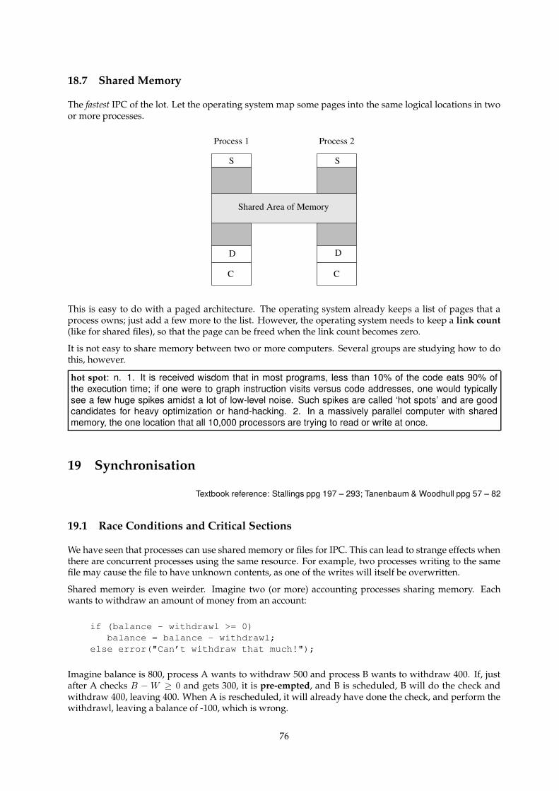
18.7 Shared Memory
The fastest IPC of the lot. Let the operating system map some pages into the same logical locations in twoor more processes.
Shared Area of Memory
Process 1 Process 2
S S
D D
C C
This is easy to do with a paged architecture. The operating system already keeps a list of pages that aprocess owns; just add a few more to the list. However, the operating system needs to keep a link count(like for shared files), so that the page can be freed when the link count becomes zero.
It is not easy to share memory between two or more computers. Several groups are studying how to dothis, however.
hot spot: n. 1. It is received wisdom that in most programs, less than 10% of the code eats 90% ofthe execution time; if one were to graph instruction visits versus code addresses, one would typicallysee a few huge spikes amidst a lot of low-level noise. Such spikes are called ‘hot spots’ and are goodcandidates for heavy optimization or hand-hacking. 2. In a massively parallel computer with sharedmemory, the one location that all 10,000 processors are trying to read or write at once.
19 Synchronisation
Textbook reference: Stallings ppg 197 – 293; Tanenbaum & Woodhull ppg 57 – 82
19.1 Race Conditions and Critical Sections
We have seen that processes can use shared memory or files for IPC. This can lead to strange effects whenthere are concurrent processes using the same resource. For example, two processes writing to the samefile may cause the file to have unknown contents, as one of the writes will itself be overwritten.
Shared memory is even weirder. Imagine two (or more) accounting processes sharing memory. Eachwants to withdraw an amount of money from an account:
if (balance - withdrawl >= 0)balance = balance - withdrawl;
else error("Can’t withdraw that much!");
Imagine balance is 800, process A wants to withdraw 500 and process B wants to withdraw 400. If, justafter A checks B − W ≥ 0 and gets 300, it is pre-empted, and B is scheduled, B will do the check andwithdraw 400, leaving 400. When A is rescheduled, it will already have done the check, and perform thewithdrawl, leaving a balance of -100, which is wrong.
76
This is a race condition, where two or more processes are reading or writing some shared data, and thefinal result depends on who runs precisely when.
The section of code where the race condition occurs is a critical section; here it is
if (balance - withdrawl >= 0) balance = balance - withdrawl;
A critical section happens because it is composed of several steps, and a process can be scheduled outafter any of the steps. If there was only one atomic step, there would be no critical section, as a processcould only be scheduled out after the entire operation.
An operation is atomic if it is guaranteed to be performed all at once, with no interruptions.
19.2 Avoiding a Critical Section
To avoid a critical section, we need the following conditions:
1. No two processes can be inside the critical section simultaneously. As we will see, this isn’t enough, sowe add three more conditions.
2. No assumptions are made about the relative speeds of each process or the number of CPUs. Thisdisallows solutions based on exact timing.
3. No process stopped outside its critical section should block another process.
4. No process should wait arbitrarily long to enter the critical section. In other words, starvation is notallowed.
Consider a general situation where there is a shared object, e.g the number of stock left for a particularitem in a wharehouse, with multiple requests for that stock coming in from various parts of the country.Timing of the requests are unpredictable, and so is the duration of the operations to ship items and updatethe wharehouse records.
Let us look at some possible solutions for avoiding critical sections.
19.3 Infinite Timeslices
Remember, a process is scheduled out when running if its timeslice expires. If the process could obtain aninfinite timeslice, there would be no pre-emption. Therefore, it would complete the critical section, andsatisfy condition 1.
However, this is not a good solution, as there is no guarantee that the process will either die, or relinquishthe CPU. Thus, this solution violates condition 4.
19.4 Strict Alternation/Rotation
One solution is, for each process:
for (ever){loop while (turn != 0); /* Wait */ /* != 1, != 2, != 3 etc */critical_section();turn= 1; /* =2, =3, =0 etc */other stuff;
}
77
Thus, the access to the critical section rotates through each process.
This is a bad solution, as each process loops continuously waiting for the value of turn to change andthus wasting the CPU. This is known as busy-waiting.
Also, the solution relies on rotation through the set of processes. Even if a process doesn’t want thecritical section, it is given it, and others must wait for it to go through the section, thus violating condition3. Finally, a slow process slows down the rotation, thus violating condition 2.
busy-wait: vi. Used of human behavior, conveys that the subject is busy waiting for someone or some-thing, intends to move instantly as soon as it shows up, and thus cannot do anything else at the moment.“Can’t talk now, I’m busy-waiting till Bill gets off the phone.”Technically, ‘busy-wait’ means to wait on an event by spinning through a tight or timed-delay loop thatpolls for the event on each pass, as opposed to setting up an interrupt handler and continuing executionon another part of the task. This is a wasteful technique, best avoided on time-sharing systems where abusy-waiting program may hog the processor.
19.5 Test and Set Lock Instruction
If the CPU provides an atomic way of reading and overwriting an address with a ‘1’ (a test and set lockinstruction), we can create the following:
enter_region:tsl register, flag /* Copy the flag to the register, and set flag to 1 */cmp register, 0 /* Was flag zero? */jnz enter_region /* No, loop until it is */
leave_region:mov flag, 0; /* Set the flag to zero */ret /* and return */
Now we can protect the critical section with:
enter_section();
/* Critical section stuff */
leave_region();
A process can only enter the critical section if the flag is zero, and in checking the flag, it is set to one,thus preventing anybody else from entering the critical section. This satisfies condition 1.
This also avoids infinite timeslices and the rotation problem. However, we still have busy-waiting, as weloop until we have the flag, which wastes the CPU. At the same time, all four conditions are satisfied.
To prevent busywaiting, we need a way of blocking/unblocking a process if it wants to obtain access toa critical section, but can’t get it yet. Hint: What normally performs process blocking?
block: 1. vi. To delay or sit idle while waiting for something. “We’re blocking until everyone gets here.”Compare busy-wait. 2. ‘block on’ vt. To block, waiting for (something). “Lunch is blocked on Phil’sarrival.”
19.6 Semaphores
Semaphores were invented by Edgar Dijkstra in 1965. The operating system provides new objects calledsemaphores, each with integer values. The operating system also provides two system call operations on
78
semaphores:
acquire(sem){if (sem.count == 0) block process;sem.count=0; /* When reawakened, lower count back to 0 */
}
release(sem){sem.count=1; /* Raise semaphore’s value to 1 */if (any process blocked waiting for sem) unblock one;
}
The operating system performs both operations in kernel mode, and guarantees that both operations areatomic. Now, with the semaphore count initialised by the operating system to 1, we can do:
acquire(sem);
/* Critical section stuff */
release(sem);
The first process to acquire the semaphore sets the count to zero. All other processes that try to accessthe semaphore are blocked. When the process with the semaphore releases it, it sets the count to one,andanother process is unblocked. As soon as it is unblocked, it lowers the count to zero, and thus acquiresthe semaphore.
This solution satisfies all four conditions, and also avoid busy waiting. Usually, the operating systemkeeps a queue for the set of processes blocked on a semaphore, but this is not strictly necessary.
19.7 Monitors
Of course, if a process goes ahead and enters a critical section without using any synchronisation method,problems will occur. We have to trust that all programmers will do the right thing, and also that the codethey produce is correct.
Hoare and Hansen in 1975 suggested building synchronisation into the language so that it is invokedwithout conscious work by the programmers. The monitor is a collection of code and condition vari-ables which describe the critical section. The compiler wraps the synchronisation code around the criticalsection transparently. The synchronisation code can be semaphores, or whatever.
Not many languages provide monitors. The only one that I can think of off-hand is Java.
19.8 Message Passing
Another method of avoiding critical section relies on the fact that in message passing the receiver blocksif there are no message available. This allows processes to exchange a token (in the form of a message).Possession of the token allows the process to enter the critical section.
79
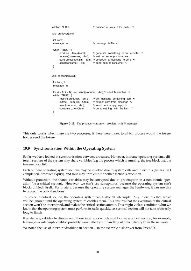
#define N 100 /* number of slots in the buffer */
void producer(void){
int item;message m; /* message buffer */
while (TRUE) {produce item(&item); /* generate something to put in buffer */receive(consumer, &m); /* wait for an empty to arrive */build message(&m, item); /* construct a message to send */send(consumer, &m); /* send item to consumer */
}}
void consumer(void){
int item, i;message m;
for (i = 0; i < N; i++) send(producer, &m);/ * send N empties * /while (TRUE) {
receive(producer, &m); /* get message containing item */extract item(&m, &item); /* extract item from message */send(producer, &m); /* send back empty reply */consume item(item); /* do something with the item */
}}
Figure 2-15. The producer-consumer problem with N messages.
This only works when there are two processes; if there were more, to which process would the token-holder send the token?
19.9 Synchronisation Within the Operating System
So far we have looked at synchronisation between processes. However, in many operating systems, dif-ferent sections of the system may share variables (e.g the process which is running, the free block list, thefree memory list).
Each of these operating system sections may be invoked due to system calls and interrupts (timers, I/Ocompletion, timeslice expiry), and thus may “pre-empt” another section’s execution.
Without protection, the shared variables may be corrupted due to pre-emption in a non-atomic oper-ation (i.e a critical section). However, we can’t use semaphores, because the operating system can’tblock/unblock itself. Fortunately, because the operating system manages the hardware, it can use thisto protect the critical sections.
To protect a critical section, the operating system can disable all interrupts. Any interrupts that arrivewill be ignored until the operating system re-enables them. This ensures that the execution of the criticalsection won’t be interrupted, and makes the critical section atomic. This might violate condition 4, but weknow that the operating system must perform its tasks quickly, so a critical section will not take arbitrarilylong to finish.
It is also a good idea to disable only those interrupts which might cause a critical section; for example,leaving disk interrupts enabled probably won’t affect your handling of data delivery from the network.
We noted the use of interrupt disabling in Section 9, in the example disk driver from FreeBSD.
80
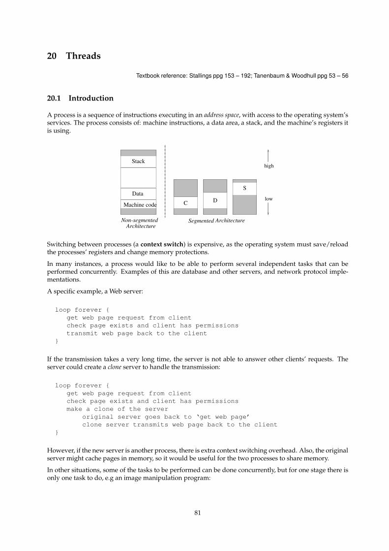
20 Threads
Textbook reference: Stallings ppg 153 – 192; Tanenbaum & Woodhull ppg 53 – 56
20.1 Introduction
A process is a sequence of instructions executing in an address space, with access to the operating system’sservices. The process consists of: machine instructions, a data area, a stack, and the machine’s registers itis using.
Machine code
Data
Stack
C D
S
Non-segmentedArchitecture
ArchitectureSegmented
low
high
Switching between processes (a context switch) is expensive, as the operating system must save/reloadthe processes’ registers and change memory protections.
In many instances, a process would like to be able to perform several independent tasks that can beperformed concurrently. Examples of this are database and other servers, and network protocol imple-mentations.
A specific example, a Web server:
loop forever {get web page request from clientcheck page exists and client has permissionstransmit web page back to the client
}
If the transmission takes a very long time, the server is not able to answer other clients’ requests. Theserver could create a clone server to handle the transmission:
loop forever {get web page request from clientcheck page exists and client has permissionsmake a clone of the server
original server goes back to ‘get web page’clone server transmits web page back to the client
}
However, if the new server is another process, there is extra context switching overhead. Also, the originalserver might cache pages in memory, so it would be useful for the two processes to share memory.
In other situations, some of the tasks to be performed can be done concurrently, but for one stage there isonly one task to do, e.g an image manipulation program:
81
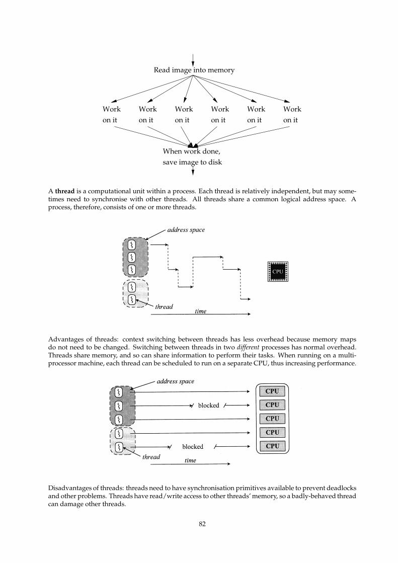
Read image into memory
on itWorkon it
Workon it
Workon it
Workon it
Workon it
When work done,save image to disk
Work
A thread is a computational unit within a process. Each thread is relatively independent, but may some-times need to synchronise with other threads. All threads share a common logical address space. Aprocess, therefore, consists of one or more threads.
Advantages of threads: context switching between threads has less overhead because memory mapsdo not need to be changed. Switching between threads in two different processes has normal overhead.Threads share memory, and so can share information to perform their tasks. When running on a multi-processor machine, each thread can be scheduled to run on a separate CPU, thus increasing performance.
Disadvantages of threads: threads need to have synchronisation primitives available to prevent deadlocksand other problems. Threads have read/write access to other threads’ memory, so a badly-behaved threadcan damage other threads.
82
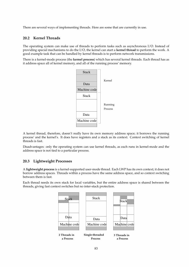
There are several ways of implementing threads. Here are some that are currently in use.
20.2 Kernel Threads
The operating system can make use of threads to perform tasks such as asynchronous I/O. Instead ofproviding special mechanisms to do the I/O, the kernel can start a kernel thread to perform the work. Agood example task that can be handled by kernel threads is to perform network transmissions.
There is a kernel-mode process (the kernel process) which has several kernel threads. Each thread has asit address space all of kernel memory, and all of the running process’ memory.
Data
Stack
Machine code
Data
Stack
Machine code
Kernel
Process
Running
A kernel thread, therefore, doesn’t really have its own memory address space; it borrows the runningprocess’ and the kernel’s. It does have registers and a stack as its context. Context switching of kernelthreads is fast.
Disadvantages: only the operating system can use kernel threads, as each runs in kernel-mode and theaddress space is not tied to a particular process.
20.3 Lightweight Processes
A lightweight process is a kernel-supported user-mode thread. Each LWP has its own context; it does notborrow address spaces. Threads within a process have the same address space, and so context switchingbetween them is fast.
Each thread needs its own stack for local variables, but the entire address space is shared between thethreads, giving fast context switches but no inter-stack protection.
a Process
Machine code
Stack
Machine codeMachine code
Data Data Data
StackStack
2 Threads in Single-threaded 3 Threads ina Process Process
83
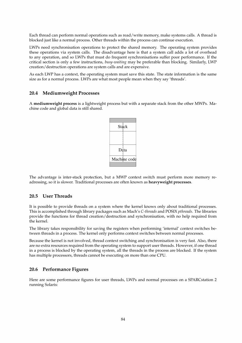
Each thread can perform normal operations such as read/write memory, make systems calls. A thread isblocked just like a normal process. Other threads within the process can continue execution.
LWPs need synchronisation operations to protect the shared memory. The operating system providesthese operations via system calls. The disadvantage here is that a system call adds a lot of overheadto any operation, and so LWPs that must do frequent synchronisations suffer poor performance. If thecritical section is only a few instructions, busy-waiting may be preferable than blocking. Similarly, LWPcreation/destruction operations are system calls and are expensive.
As each LWP has a context, the operating system must save this state. The state information is the samesize as for a normal process. LWPs are what most people mean when they say ‘threads’.
20.4 Mediumweight Processes
A mediumweight process is a lightweight process but with a separate stack from the other MWPs. Ma-chine code and global data is still shared.
Data
Machine code
Stack
The advantage is inter-stack protection, but a MWP context switch must perform more memory re-adressing, so it is slower. Traditional processes are often known as heavyweight processes.
20.5 User Threads
It is possible to provide threads on a system where the kernel knows only about traditional processes.This is accomplished through library packages such as Mach’s C-threads and POSIX pthreads. The librariesprovide the functions for thread creation/destruction and synchronisation, with no help required fromthe kernel.
The library takes responsibility for saving the registers when performing ‘internal’ context switches be-tween threads in a process. The kernel only performs context switches between normal processes.
Because the kernel is not involved, thread context switching and synchronisation is very fast. Also, thereare no extra resources required from the operating system to support user threads. However, if one threadin a process is blocked by the operating system, all the threads in the process are blocked. If the systemhas multiple processors, threads cannot be executing on more than one CPU.
20.6 Performance Figures
Here are some performance figures for user threads, LWPs and normal processes on a SPARCstation 2running Solaris:
84
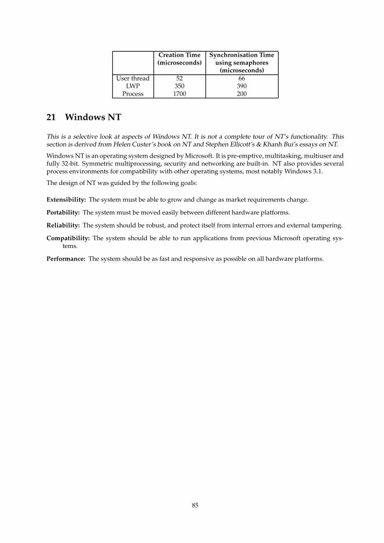
Creation Time Synchronisation Time(microseconds) using semaphores
(microseconds)User thread 52 66
LWP 350 390Process 1700 200
21 Windows NT
This is a selective look at aspects of Windows NT. It is not a complete tour of NT’s functionality. Thissection is derived from Helen Custer’s book on NT and Stephen Ellicott’s & Khanh Bui’s essays on NT.
Windows NT is an operating system designed by Microsoft. It is pre-emptive, multitasking, multiuser andfully 32-bit. Symmetric multiprocessing, security and networking are built-in. NT also provides severalprocess environments for compatibility with other operating systems, most notably Windows 3.1.
The design of NT was guided by the following goals:
Extensibility: The system must be able to grow and change as market requirements change.
Portability: The system must be moved easily between different hardware platforms.
Reliability: The system should be robust, and protect itself from internal errors and external tampering.
Compatibility: The system should be able to run applications from previous Microsoft operating sys-tems.
Performance: The system should be as fast and responsive as possible on all hardware platforms.
85
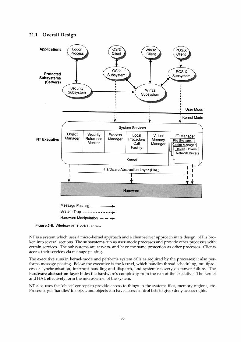
21.1 Overall Design
NT is a system which uses a micro-kernel approach and a client-server approach in its design. NT is bro-ken into several sections. The subsystems run as user-mode processes and provide other processes withcertain services. The subsystems are servers, and have the same protection as other processes. Clientsaccess their services via message passing.
The executive runs in kernel-mode and performs system calls as required by the processes; it also per-forms message-passing. Below the executive is the kernel, which handles thread scheduling, multipro-cessor synchronisation, interrupt handling and dispatch, and system recovery on power failure. Thehardware abstraction layer hides the hardware’s complexity from the rest of the executive. The kerneland HAL effectively form the micro-kernel of the system.
NT also uses the ‘object’ concept to provide access to things in the system: files, memory regions, etc.Processes get ‘handles’ to object, and objects can have access control lists to give/deny access rights.
86
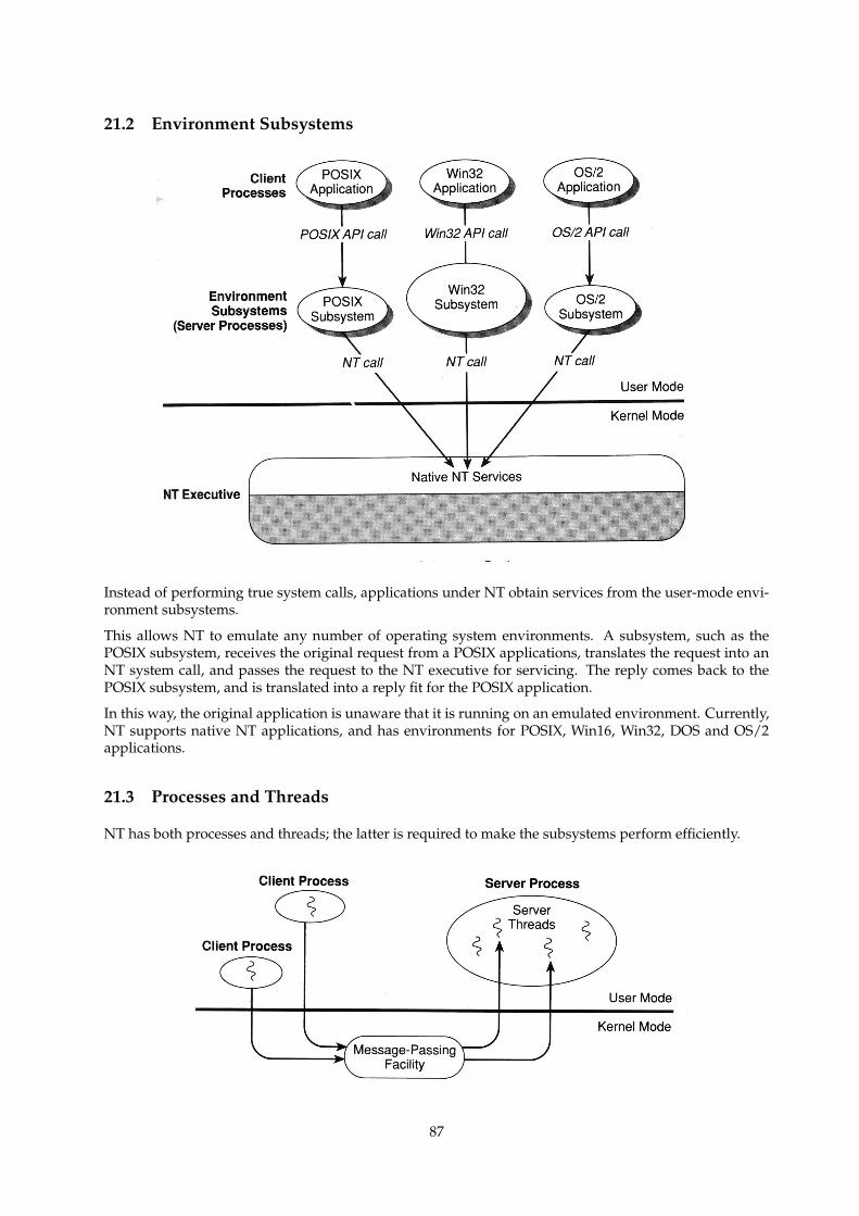
21.2 Environment Subsystems
Instead of performing true system calls, applications under NT obtain services from the user-mode envi-ronment subsystems.
This allows NT to emulate any number of operating system environments. A subsystem, such as thePOSIX subsystem, receives the original request from a POSIX applications, translates the request into anNT system call, and passes the request to the NT executive for servicing. The reply comes back to thePOSIX subsystem, and is translated into a reply fit for the POSIX application.
In this way, the original application is unaware that it is running on an emulated environment. Currently,NT supports native NT applications, and has environments for POSIX, Win16, Win32, DOS and OS/2applications.
21.3 Processes and Threads
NT has both processes and threads; the latter is required to make the subsystems perform efficiently.
87

Processes are protected and have their own logical address space. In a 32-bit address space, a process has2G of the address space, and the remaining 2G is reserved for the protected-mode kernel. When a TRAPis done, the upper 2G becomes valid and the CPU jumps to the kernel’s code.
NT uses pre-emtive thread scheduling, with a priority scheme having 32 priority levels. The upper 16levels are reserved for real-time threads, which have fixed priorities. The lower levels are for normalthreads, which start with a particular priority, but move up/down in priority according to their amountof CPU usage.
Threads can be in the following states:
As well as syscalls to create and destroy threads, NT has operations to synchronise threads; these can beused to protect critical sections, or for threads to wait until other threads have performed certain tasks.
88
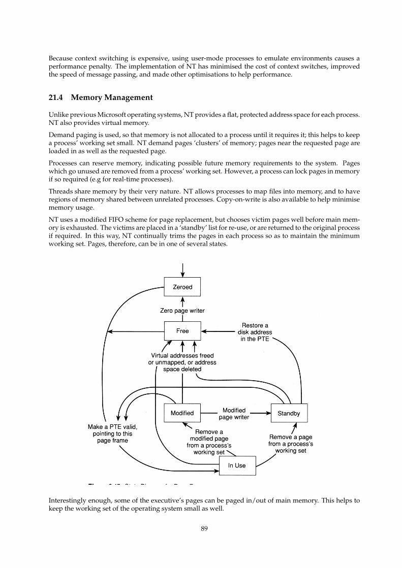
Because context switching is expensive, using user-mode processes to emulate environments causes aperformance penalty. The implementation of NT has minimised the cost of context switches, improvedthe speed of message passing, and made other optimisations to help performance.
21.4 Memory Management
Unlike previous Microsoft operating systems, NT provides a flat, protected address space for each process.NT also provides virtual memory.
Demand paging is used, so that memory is not allocated to a process until it requires it; this helps to keepa process’ working set small. NT demand pages ‘clusters’ of memory; pages near the requested page areloaded in as well as the requested page.
Processes can reserve memory, indicating possible future memory requirements to the system. Pageswhich go unused are removed from a process’ working set. However, a process can lock pages in memoryif so required (e.g for real-time processes).
Threads share memory by their very nature. NT allows processes to map files into memory, and to haveregions of memory shared between unrelated processes. Copy-on-write is also available to help minimisememory usage.
NT uses a modified FIFO scheme for page replacement, but chooses victim pages well before main mem-ory is exhausted. The victims are placed in a ‘standby’ list for re-use, or are returned to the original processif required. In this way, NT continually trims the pages in each process so as to maintain the minimumworking set. Pages, therefore, can be in one of several states.
Interestingly enough, some of the executive’s pages can be paged in/out of main memory. This helps tokeep the working set of the operating system small as well.
89
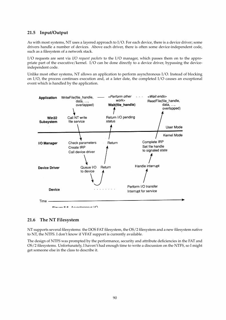
21.5 Input/Output
As with most systems, NT uses a layered approach to I/O. For each device, there is a device driver; somedrivers handle a number of devices. Above each driver, there is often some device-independent code,such as a filesystem of a network stack.
I/O requests are sent via I/O request packets to the I/O manager, which passes them on to the appro-priate part of the executive/kernel. I/O can be done directly to a device driver, bypassing the device-independent code.
Unlike most other systems, NT allows an application to perform asynchronous I/O. Instead of blockingon I/O, the process continues execution and, at a later date, the completed I/O causes an exceptionalevent which is handled by the application.
21.6 The NT Filesystem
NT supports several filesystems: the DOS FAT filesystem, the OS/2 filesystem and a new filesystem nativeto NT, the NTFS. I don’t know if VFAT support is currently available.
The design of NTFS was prompted by the performance, security and attribute deficiencies in the FAT andOS/2 filesystems. Unfortunately, I haven’t had enough time to write a discussion on the NTFS, so I mightget someone else in the class to describe it.
90
Related Documents