ADVANCED AFTERTREATMENT SYSTEM DEVELOPMENT FOR A LOCOMOTIVE APPLICATION Dr. Paul W. Park Caterpillar Inc. Mossville IL, USA Markus Downey Emitec Inc. Rochester Hills MI, USA David Youngren BASF Union NJ, USA Claus Bruestle Emitec Inc. Rochester Hills MI, USA ABSTRACT For the first time in the locomotive industry, an advanced exhaust aftertreatment system for a locomotive application was successfully demonstrated to reduce nitrogen oxides from 6.46 g/kW·hr to 1.21g/kWhr to meet the needs of local NOx reduction requirements for non-attainment areas. Five 2,240 kW (3,005 horsepower) PR30C line-haul repowered Progress Rail locomotives were equipped with diesel oxidation catalyst and selective catalytic reduction technologies to accumulate more than 27,000 hours in total in revenue service. Full emissions performance including carbon monoxide, hydrocarbons, nitrogen oxides and particulate matter was conducted at Southwest Research Institute on a regular basis to measure the change of emissions performance for two selected locomotives. The emissions performance of the aftertreatment system did not show any degradation during 3,000 hours operation. After 3,000 hours operation, 0.13 g/kW·hr carbon monoxide (89-91% reduction), 0.027 g/ kW·hr hydrocarbons (91% reduction), 1.08-1.21 g/ kW·hr nitrogen oxides (81-83% reduction) and 0.05-0.08 g/ kW·hr particulate matter (38-58% reduction) were measured on the line-haul cycle. The baseline emissions levels of the engine are within Tier 2 EPA locomotive limits. The newly developed close loop control software successfully controlled targeted nitrogen oxides reduction with minimum ammonia slip during the locomotive emission cycle tests. INTRODUCTION In 2008 the U.S. Environmental Protection Agency (EPA) adopted more stringent emissions standards for diesel locomotives . The new standards are applied to existing and newly built locomotives depending on the date remanufactured or built. For newly built locomotives Tier 3 (2012) and Tier4 (2015) standards will be applied. The Tier 4 standards require 80% and 90% nitrogen oxides (NO x ) and particulate matter (PM) reduction, respectively compared to engines meeting the current Tier 2 standards. [1] The finalized standards resulted in bringing earlier emissions reductions of NO x from the locomotive with Tier 4 NO x requirements for line-haul locomotives two years earlier (from 2017 to 2015) than initially proposed. The motivation of tightening and early adoption of the emissions regulations for locomotives is based on locomotive diesel engines becoming significant air pollution contributors over the next few decades according to EPA estimation. This is because conventional major emissions sources including cars, trucks and nonroad vehicles have been successfully regulated with stringent emissions regulations. Aftertreatment technologies for these applications have been developed successfully to meet the challenging regulations. Prior to US EPA Tier4 emission regulation was finalized, Caterpillar Inc. began to develop a locomotive emission solution for customers in non-attainment areas. In 1998 a Memorandum of Mutual Understandings and Agreements (MOU) between ARB (Air Resource Board) and BNSF and UP Railroads was signed, requiring fleet owners to meet fleet average NO x emissions to Tier 2 line-haul level (7.38 g/kW·hr) by 2010 [2]. In order to meet this customer’s demand Caterpillar Inc. developed PR30C line-haul locomotives designed for 1.74 g/kW·hr NOx emissions and placed them into Proceedings of the ASME 2012 Internal Combustion Engine Division Fall Technical Conference ICEF2012 September 23-26, 2012, Vancouver, BC, Canada ICEF2012-92198 1 Copyright © 2012 by ASME and Caterpillar Inc.

Welcome message from author
This document is posted to help you gain knowledge. Please leave a comment to let me know what you think about it! Share it to your friends and learn new things together.
Transcript
ADVANCED AFTERTREATMENT SYSTEM DEVELOPMENT FOR A LOCOMOTIVE
APPLICATION
Dr. Paul W. Park Caterpillar Inc.
Mossville IL, USA
Markus Downey Emitec Inc.
Rochester Hills MI, USA
David Youngren BASF
Union NJ, USA
Claus Bruestle Emitec Inc.
Rochester Hills MI, USA
ABSTRACT
For the first time in the locomotive industry, an advanced
exhaust aftertreatment system for a locomotive application was
successfully demonstrated to reduce nitrogen oxides from 6.46
g/kW·hr to 1.21g/kWhr to meet the needs of local NOx
reduction requirements for non-attainment areas.
Five 2,240 kW (3,005 horsepower) PR30C line-haul
repowered Progress Rail locomotives were equipped with diesel
oxidation catalyst and selective catalytic reduction technologies
to accumulate more than 27,000 hours in total in revenue
service.
Full emissions performance including carbon monoxide,
hydrocarbons, nitrogen oxides and particulate matter was
conducted at Southwest Research Institute on a regular basis to
measure the change of emissions performance for two selected
locomotives.
The emissions performance of the aftertreatment system did not
show any degradation during 3,000 hours operation. After 3,000
hours operation, 0.13 g/kW·hr carbon monoxide (89-91%
reduction), 0.027 g/ kW·hr hydrocarbons (91% reduction),
1.08-1.21 g/ kW·hr nitrogen oxides (81-83% reduction) and
0.05-0.08 g/ kW·hr particulate matter (38-58% reduction) were
measured on the line-haul cycle. The baseline emissions levels
of the engine are within Tier 2 EPA locomotive limits. The
newly developed close loop control software successfully
controlled targeted nitrogen oxides reduction with minimum
ammonia slip during the locomotive emission cycle tests.
INTRODUCTION
In 2008 the U.S. Environmental Protection Agency (EPA)
adopted more stringent emissions standards for diesel
locomotives. The new standards are applied to existing and
newly built locomotives depending on the date remanufactured
or built. For newly built locomotives Tier 3 (2012) and Tier4
(2015) standards will be applied. The Tier 4 standards require
80% and 90% nitrogen oxides (NOx) and particulate matter
(PM) reduction, respectively compared to engines meeting the
current Tier 2 standards. [1] The finalized standards resulted in
bringing earlier emissions reductions of NOx from the
locomotive with Tier 4 NOx requirements for line-haul
locomotives two years earlier (from 2017 to 2015) than initially
proposed. The motivation of tightening and early adoption of
the emissions regulations for locomotives is based on
locomotive diesel engines becoming significant air pollution
contributors over the next few decades according to EPA
estimation. This is because conventional major emissions
sources including cars, trucks and nonroad vehicles have been
successfully regulated with stringent emissions regulations.
Aftertreatment technologies for these applications have been
developed successfully to meet the challenging regulations.
Prior to US EPA Tier4 emission regulation was finalized,
Caterpillar Inc. began to develop a locomotive emission
solution for customers in non-attainment areas. In 1998 a
Memorandum of Mutual Understandings and Agreements
(MOU) between ARB (Air Resource Board) and BNSF and UP
Railroads was signed, requiring fleet owners to meet fleet
average NOx emissions to Tier 2 line-haul level (7.38 g/kW·hr)
by 2010 [2]. In order to meet this customer’s demand
Caterpillar Inc. developed PR30C line-haul locomotives
designed for 1.74 g/kW·hr NOx emissions and placed them into
Proceedings of the ASME 2012 Internal Combustion Engine Division Fall Technical Conference ICEF2012
September 23-26, 2012, Vancouver, BC, Canada
ICEF2012-92198
1 Copyright © 2012 by ASME and Caterpillar Inc.
demonstration service in 2009. The PR30C was equipped with a
Tier 2 Caterpillar 2,240 kW 3516C-HD diesel engine and an
advanced aftertreatment system.
Although Selective Catalytic Reduction (SCR) technology is
considered as a new and unproven technology for the
locomotive industry, the NOx abatement technologies using urea
as a reductant have been well developed and widely used for
various diesel engine applications including stationary gen-sets,
and both on-road and non-road mobile applications. Numerous
diesel engine manufacturers developed urea-SCR technologies
to meet Euro IV (2005), Euro V (2008) and US On-highway
truck (2010) emissions standards for their engines.
This paper covers the description of key aftertreatment
technologies (substrates and washcoat) and the introduction of
the first advanced aftertreatment system for a locomotive
application, which successfully demonstrated meeting all
functional expectations as well as significant reliability and
durability for a locomotive application.
METAL SUBSTRATE TECHNOLOGY
A large portion of the operating expense of a large-bore diesel
engine is fuel cost and the flow restriction of the aftertreatment
system is one of the influences on fuel consumption. The
additional work that the engine has to perform in order to
exhaust the combustion products from the engine translates into
additional fuel used.
In an effort to keep this additional flow restriction to a
minimum the maximum frontal area of the catalyst within the
aftertreatment system is needed. A catalyst is made up of the
substrate or honeycomb and the washcoat where the chemical
reactions take place. The substrate will influence the flow of the
exhaust gas and provide surface area for washcoat. For the
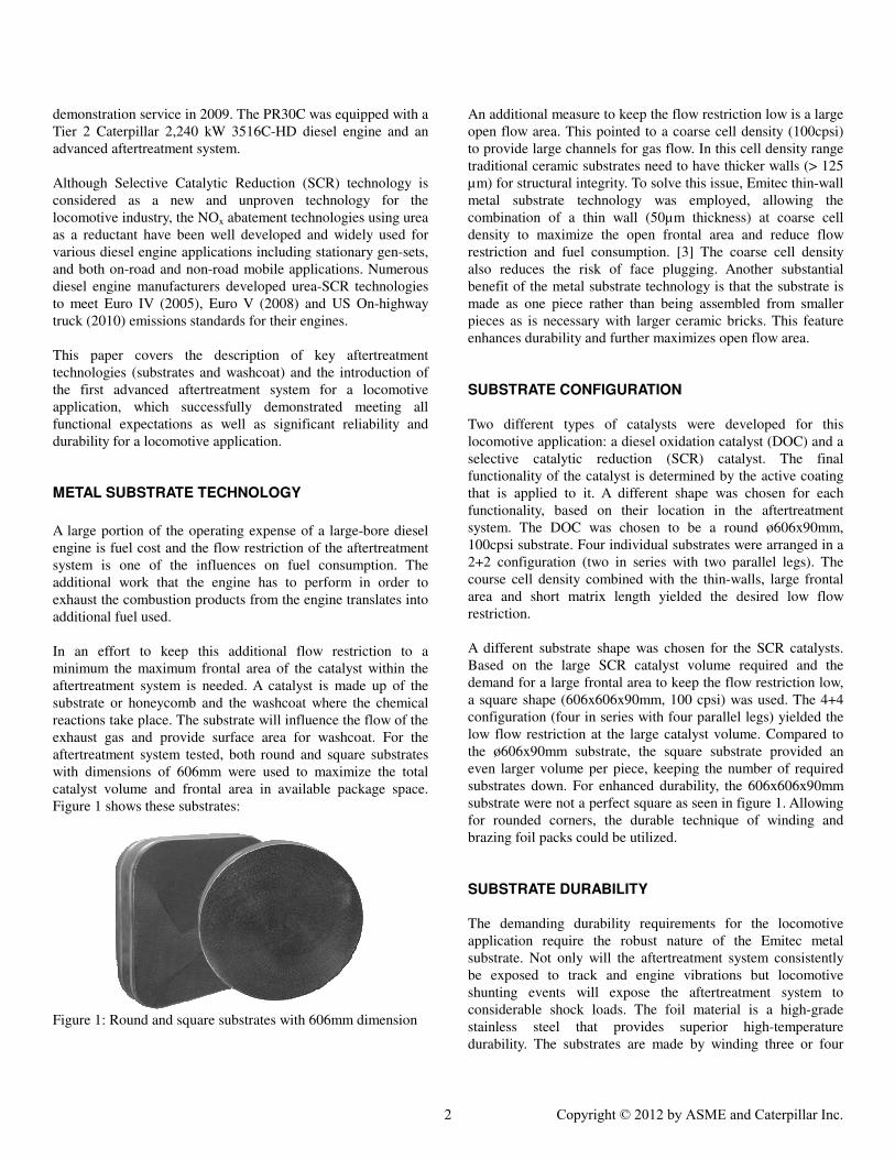
aftertreatment system tested, both round and square substrates
with dimensions of 606mm were used to maximize the total
catalyst volume and frontal area in available package space.
Figure 1 shows these substrates:
Figure 1: Round and square substrates with 606mm dimension
An additional measure to keep the flow restriction low is a large
open flow area. This pointed to a coarse cell density (100cpsi)
to provide large channels for gas flow. In this cell density range
traditional ceramic substrates need to have thicker walls (> 125
µm) for structural integrity. To solve this issue, Emitec thin-wall
metal substrate technology was employed, allowing the
combination of a thin wall (50µm thickness) at coarse cell
density to maximize the open frontal area and reduce flow
restriction and fuel consumption. [3] The coarse cell density
also reduces the risk of face plugging. Another substantial
benefit of the metal substrate technology is that the substrate is
made as one piece rather than being assembled from smaller
pieces as is necessary with larger ceramic bricks. This feature
enhances durability and further maximizes open flow area.
SUBSTRATE CONFIGURATION
Two different types of catalysts were developed for this
locomotive application: a diesel oxidation catalyst (DOC) and a
selective catalytic reduction (SCR) catalyst. The final
functionality of the catalyst is determined by the active coating
that is applied to it. A different shape was chosen for each
functionality, based on their location in the aftertreatment
system. The DOC was chosen to be a round ø606x90mm,
100cpsi substrate. Four individual substrates were arranged in a
2+2 configuration (two in series with two parallel legs). The
course cell density combined with the thin-walls, large frontal
area and short matrix length yielded the desired low flow
restriction.
A different substrate shape was chosen for the SCR catalysts.
Based on the large SCR catalyst volume required and the
demand for a large frontal area to keep the flow restriction low,
a square shape (606x606x90mm, 100 cpsi) was used. The 4+4
configuration (four in series with four parallel legs) yielded the
low flow restriction at the large catalyst volume. Compared to
the ø606x90mm substrate, the square substrate provided an
even larger volume per piece, keeping the number of required
substrates down. For enhanced durability, the 606x606x90mm
substrate were not a perfect square as seen in figure 1. Allowing
for rounded corners, the durable technique of winding and
brazing foil packs could be utilized.
SUBSTRATE DURABILITY
The demanding durability requirements for the locomotive
application require the robust nature of the Emitec metal
substrate. Not only will the aftertreatment system consistently
be exposed to track and engine vibrations but locomotive
shunting events will expose the aftertreatment system to
considerable shock loads. The foil material is a high-grade
stainless steel that provides superior high-temperature
durability. The substrates are made by winding three or four
2 Copyright © 2012 by ASME and Caterpillar Inc.

packets of foil around a common center and then brazing this
honeycomb (matrix) into a mantel (tube).
This arrangement allows for each foil layer to not only be
attached to the neighboring layer but also to the mantel in two
places. This foil configuration eliminates telescoping, which is
known to happen with spiral-wound substrates. For the square
substrates, the corners were rounded off to enable the use of the
same winding technique and enhancing the robustness.
To provide superior durability the substrates are brazed in two
areas: the matrix within itself at inlet and outlet and the matrix
to the mantel. [4] This provides structural robustness within the
matrix itself and secures the matrix inside the mantel. The
Emitec winding and brazing technology has been in production
since 1986. Figure 2 shows the areas of brazing:
Figure 2: Example of the Areas of Brazing in an Emitec
Substrate [4]
An additional benefit of the metal substrate is that the substrate
can be integrated into the aftertreatment system without need
for a retention mat and further canning effort. The substrate
mantel can be welded directly into the aftertreatment system.
This reduces the overall integration effort and further increases
system durability. The lack of required matting also increased
the total available flow area, since a portion of the outer radius
is not taken up by the retention mat and this has a positive
impact on the flow restriction.
RESONANCE FREQUENCY ANALYSIS
During operation, vibrations are transmitted into all components
of the locomotive. These vibration come from the rails and
engine. The effect that these vibrations have on all the
components of the system is not only determined by the
amplitude of the vibration but also its frequency. Every system
has a frequency at which it will start to amplify any vibrations
that it is exposed to, known as the resonance frequency. If a
component of the system is repeatedly exposed to its resonance
frequency, the component has the potential to fail more quickly.
In the case of the metal substrate, the foil material has the
potential of vibrating when the part reaches its resonance
frequency. This can also lead to challenges in terms of washcoat
adhesion. These frequencies need to be shifted out of the
frequency range during operation or to as high of a frequency as
possible.
Various excitation frequencies were measured at different
operation conditions including various speeds, accelerations,
decelerations and couplings. Excitation frequencies at a high-
speed operation (97 km/hour) on the locomotive are shown in
appendix 1, figures 1 & 2. These data were generated by
instrumenting a locomotive with accelerometers in different
locations, including the mantels of the DOC and SCR
substrates. The accelerations experienced at the mantel are
important as the vibrational loads are transferred into the matrix
via the mantel. The main excitation peak of the DOC substrate
is observed at 121Hz in the spectrum of axial substrate
direction, which is the most critical direction based on aspect
ratio (ratio of diameter to length). For the SCR substrate
excitation peaks are observed in the range of 116 to 135 Hz.
This potential excitation frequency range of substrates is
identified for further investigation to ensure the long-term
durability of the aftertreatment system.
In order to have a basis of comparison, the substrates were
measured using a laser scanning vibrometer (LSV). The
substrate were suspended using wires to achieve a free-free
boundary condition and were subsequently excited with a small
shaker (stinger) in the radial direction with a frequency sweep.
Figure 3 shows the test setup:
Figure 3: Experimental setup for resonance frequency analysis.
Substrate are suspended with wires and attached to stinger.
Measurement points of the scanning laser is show for reference
Left: ø606x90mm round; Right: 606x606x90mm square
During the frequency sweep of the stinger, the substrate can be
excited in several different modes, including the ovalization
3 Copyright © 2012 by ASME and Caterpillar Inc.
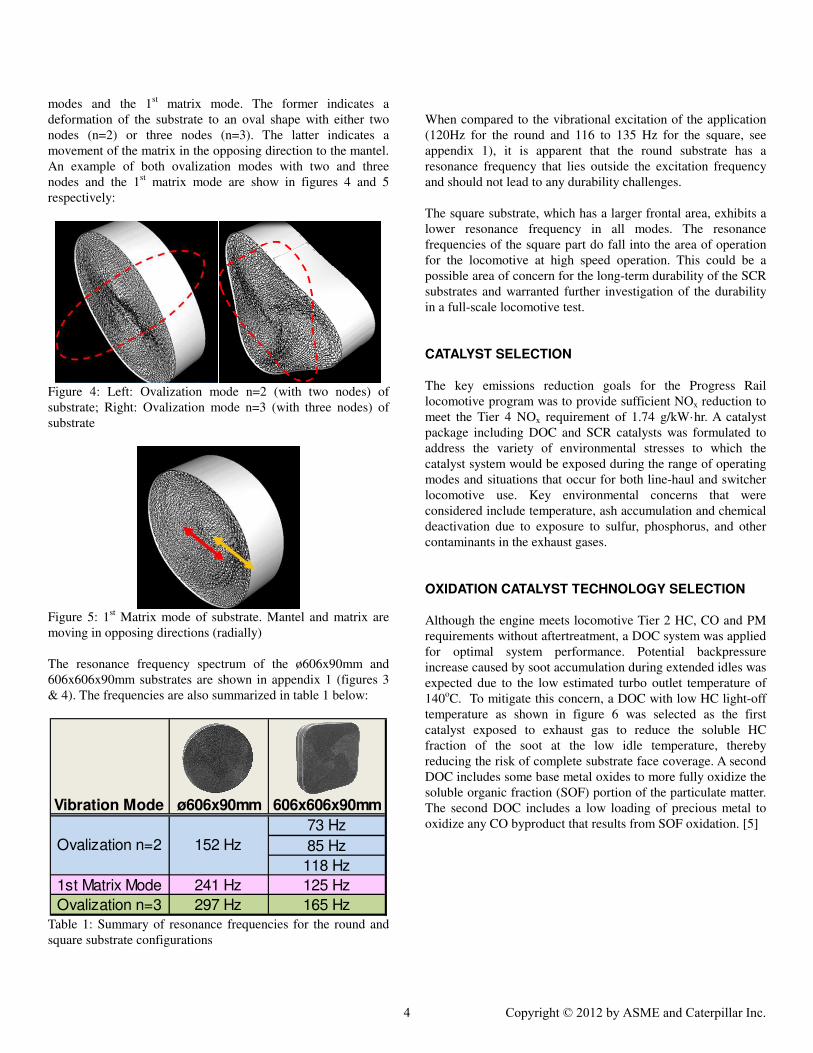
modes and the 1st matrix mode. The former indicates a
deformation of the substrate to an oval shape with either two
nodes (n=2) or three nodes (n=3). The latter indicates a
movement of the matrix in the opposing direction to the mantel.
An example of both ovalization modes with two and three
nodes and the 1st matrix mode are show in figures 4 and 5
respectively:
Figure 4: Left: Ovalization mode n=2 (with two nodes) of
substrate; Right: Ovalization mode n=3 (with three nodes) of
substrate
Figure 5: 1
st Matrix mode of substrate. Mantel and matrix are
moving in opposing directions (radially)
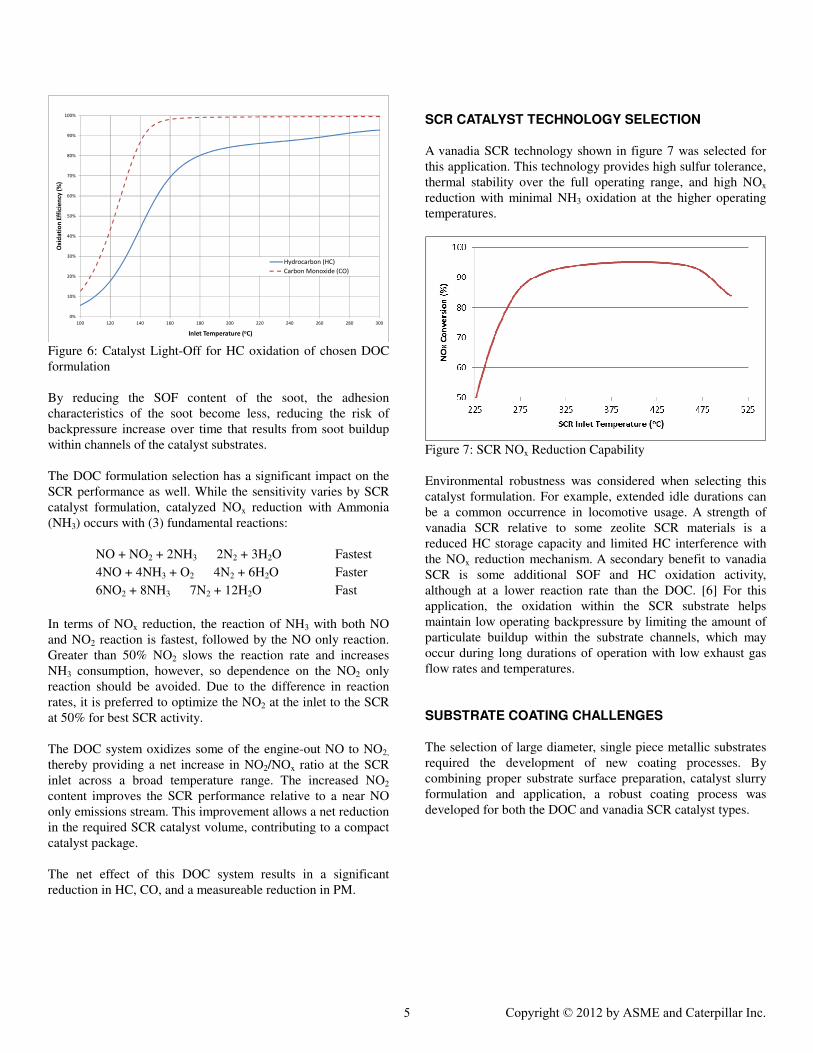
The resonance frequency spectrum of the ø606x90mm and
606x606x90mm substrates are shown in appendix 1 (figures 3
& 4). The frequencies are also summarized in table 1 below:
73 Hz
85 Hz
118 Hz
1st Matrix Mode 241 Hz 125 Hz
Ovalization n=3 297 Hz 165 Hz
152 HzOvalization n=2
Vibration Mode ø606x90mm 606x606x90mm
Table 1: Summary of resonance frequencies for the round and
square substrate configurations
When compared to the vibrational excitation of the application
(120Hz for the round and 116 to 135 Hz for the square, see
appendix 1), it is apparent that the round substrate has a
resonance frequency that lies outside the excitation frequency
and should not lead to any durability challenges.
The square substrate, which has a larger frontal area, exhibits a
lower resonance frequency in all modes. The resonance
frequencies of the square part do fall into the area of operation
for the locomotive at high speed operation. This could be a
possible area of concern for the long-term durability of the SCR
substrates and warranted further investigation of the durability
in a full-scale locomotive test.
CATALYST SELECTION The key emissions reduction goals for the Progress Rail
locomotive program was to provide sufficient NOx reduction to
meet the Tier 4 NOx requirement of 1.74 g/kW·hr. A catalyst
package including DOC and SCR catalysts was formulated to
address the variety of environmental stresses to which the
catalyst system would be exposed during the range of operating
modes and situations that occur for both line-haul and switcher
locomotive use. Key environmental concerns that were
considered include temperature, ash accumulation and chemical
deactivation due to exposure to sulfur, phosphorus, and other
contaminants in the exhaust gases.
OXIDATION CATALYST TECHNOLOGY SELECTION
Although the engine meets locomotive Tier 2 HC, CO and PM
requirements without aftertreatment, a DOC system was applied
for optimal system performance. Potential backpressure
increase caused by soot accumulation during extended idles was
expected due to the low estimated turbo outlet temperature of
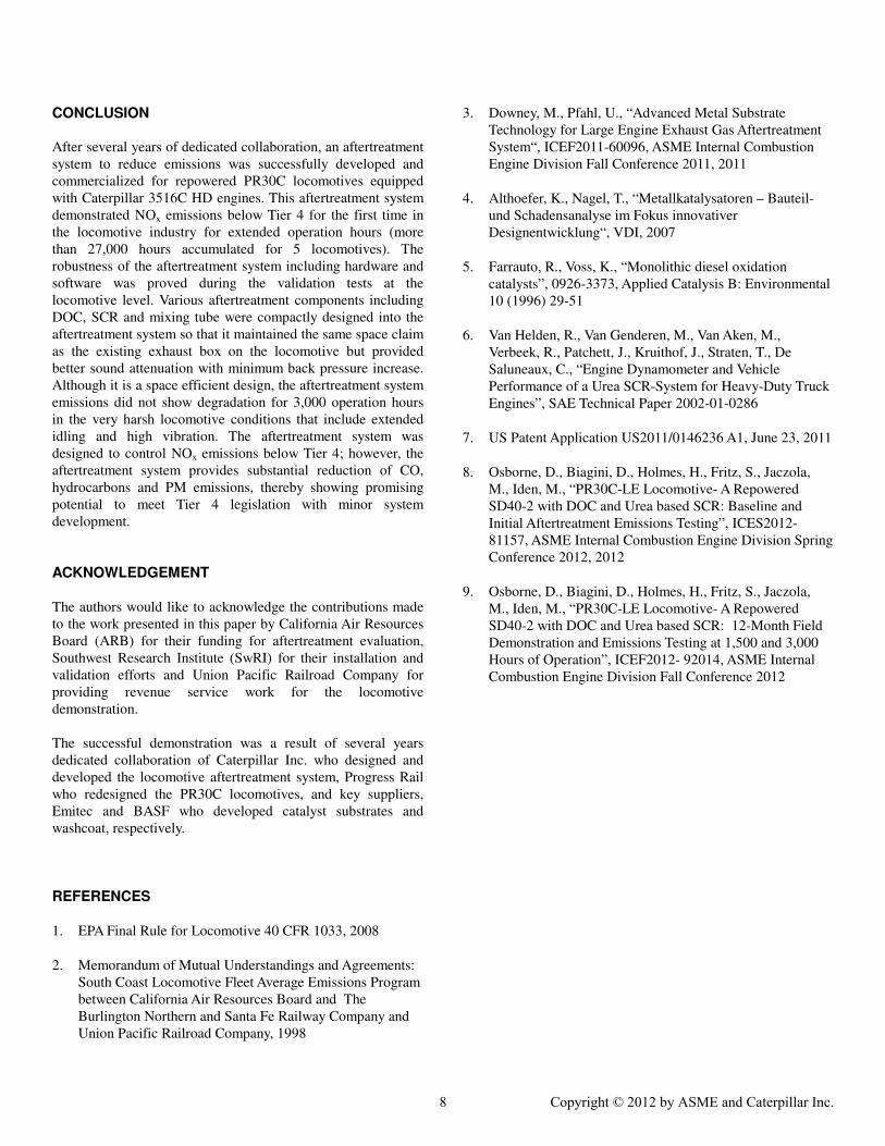
140oC. To mitigate this concern, a DOC with low HC light-off
temperature as shown in figure 6 was selected as the first
catalyst exposed to exhaust gas to reduce the soluble HC
fraction of the soot at the low idle temperature, thereby
reducing the risk of complete substrate face coverage. A second
DOC includes some base metal oxides to more fully oxidize the
soluble organic fraction (SOF) portion of the particulate matter.
The second DOC includes a low loading of precious metal to
oxidize any CO byproduct that results from SOF oxidation. [5]
4 Copyright © 2012 by ASME and Caterpillar Inc.
0%
10%
20%
30%
40%
50%
60%
70%
80%
90%
100%
100 120 140 160 180 200 220 240 260 280 300
Ox
ida
tio
n E
ffic
ien
cy (
%)
Inlet Temperature (oC)
Hydrocarbon (HC)
Carbon Monoxide (CO)
Figure 6: Catalyst Light-Off for HC oxidation of chosen DOC
formulation
By reducing the SOF content of the soot, the adhesion
characteristics of the soot become less, reducing the risk of
backpressure increase over time that results from soot buildup
within channels of the catalyst substrates.
The DOC formulation selection has a significant impact on the
SCR performance as well. While the sensitivity varies by SCR
catalyst formulation, catalyzed NOx reduction with Ammonia
(NH3) occurs with (3) fundamental reactions:
NO + NO2 + 2NH3 à 2N2 + 3H2O Fastest
4NO + 4NH3 + O2 à 4N2 + 6H2O Faster
6NO2 + 8NH3 à 7N2 + 12H2O Fast
In terms of NOx reduction, the reaction of NH3 with both NO
and NO2 reaction is fastest, followed by the NO only reaction.
Greater than 50% NO2 slows the reaction rate and increases
NH3 consumption, however, so dependence on the NO2 only
reaction should be avoided. Due to the difference in reaction
rates, it is preferred to optimize the NO2 at the inlet to the SCR
at 50% for best SCR activity.
The DOC system oxidizes some of the engine-out NO to NO2,
thereby providing a net increase in NO2/NOx ratio at the SCR
inlet across a broad temperature range. The increased NO2
content improves the SCR performance relative to a near NO
only emissions stream. This improvement allows a net reduction
in the required SCR catalyst volume, contributing to a compact
catalyst package.
The net effect of this DOC system results in a significant
reduction in HC, CO, and a measureable reduction in PM.
SCR CATALYST TECHNOLOGY SELECTION
A vanadia SCR technology shown in figure 7 was selected for
this application. This technology provides high sulfur tolerance,
thermal stability over the full operating range, and high NOx
reduction with minimal NH3 oxidation at the higher operating
temperatures.
Figure 7: SCR NOx Reduction Capability
Environmental robustness was considered when selecting this
catalyst formulation. For example, extended idle durations can
be a common occurrence in locomotive usage. A strength of
vanadia SCR relative to some zeolite SCR materials is a
reduced HC storage capacity and limited HC interference with
the NOx reduction mechanism. A secondary benefit to vanadia
SCR is some additional SOF and HC oxidation activity,
although at a lower reaction rate than the DOC. [6] For this
application, the oxidation within the SCR substrate helps
maintain low operating backpressure by limiting the amount of
particulate buildup within the substrate channels, which may
occur during long durations of operation with low exhaust gas
flow rates and temperatures.
SUBSTRATE COATING CHALLENGES The selection of large diameter, single piece metallic substrates
required the development of new coating processes. By
combining proper substrate surface preparation, catalyst slurry
formulation and application, a robust coating process was
developed for both the DOC and vanadia SCR catalyst types.
5 Copyright © 2012 by ASME and Caterpillar Inc.

AFTERTREATMENT SYSTEM DESIGN CHALLENGES
Aftertreatment Functional Requirements
NOx emissions <1.74 g/kW·hr
System backpressure <6.7 kPa
Vibration 5 G
Ambient temperature: continuous -40 to 50 oC
Ambient temperature: intermittent 100 oC
Noise limit <93 dBA at 100 ft
Altitude emissions compliance up to 4,000 ft
Skin temperature 250 oC
Table 2: The list of aftertreatment specifications
Functional requirements of the aftertreatment system are listed
in Table 2. There are many technical challenges to design an
aftertreatment system meeting all those requirements as well as
fit into the very limited space in the locomotive body. The
radiator, dynamic brake and car body have been redesigned to
provide space for the aftertreatment system. A 950 L (250
gallon) urea (diesel exhaust fluid or DEF) tank was added under
the body to provide DEF. This tank has to be filled
approximately every 4 fuel tank fillings, based on the EPA line-
haul cycle. In order to accommodate the DEF tank the fuel tank
was resized from 15,000 to 12,000 L (4,000 to 3,200 gallon).
Figure 8 shows the fully re-powered locomotive:
Figure 8: Locomotive equipped with the aftertreatment system
and DEF tank
DEF INJECTION PUMP The injection of DEF is a critical aspect of the system
functionality. The DEF dosing rate dynamically varies
according to operating conditions by close loop control.
Insufficient or excess DEF will result in un-optimized NOx
performance or ammonia slip. An Emitec DME60 dosing pump
was selected to supply DEF to the system. This pump has been
used for pumping chemicals for many other applications. From
rigorous testing including bench and vehicle the pump proved
its applicability for accurate urea dosing (±2%) and durability
for locomotive application.
CATERPILLAR EMISSIONS MODULE DESIGN
The configuration of the aftertreatment system is shown in
Figure 9:
Figure 9: Configuration of aftertreatment system (cross-section
pictured to show exhaust flow path)
The aftertreatment system, patented by Caterpillar Inc.[7], is
mounted directly above the engine to achieve a compact
installation. The two engine exhaust turbo outlets are coupled
to the two separate inlets of DOC housing. The DOC housing is
designed with easily accessible doors for necessary service.
While they are not expected to be replaced throughout the
emissions useful life, the DOC substrates can be removed to be
cleaned if necessary. After passing through DOC substrates the
exhaust gets combined and then flows through a mixing tube. A
specially designed mixer and an injector lance are located in the
mixing tube to enhance mixing urea with exhaust gas stream.
An air assisted injector system is utilized to maximize urea
spray quality and minimize urea deposit and clogging issue. The
air is provided by the locomotive which has an existing air
compressor. The exhaust gas stream mixed with DEF runs down
to the end of the mixing tube, is divided in two and passes
through each SCR housing placed in parallel to the mixing tube.
Perforated plates placed in front of the first SCR substrate
layers with different hole sizes and several layers of SCR
substrates provide the function of diffusers to achieve even flow
distribution. The exhaust manifolds are installed each side of
SCR outlet to protect SCR catalysts and NOx sensors from
environmental influences. Two NOx sensor signals were
averaged to serve as a complete closed loop feedback control
system combined with a NOx sensor located upstream in the
mixing tube which is set for feed forward control. This
complete feed back and feed forward control strategy is a key
enabler to achieve targeted NOx reduction with minimum DEF
injection and tight control NH3 slip. This aftertreatment unit
demonstrated compliance with 40CFR201 noise requirement
without addition of further noise abatement devices.
DOC SCR
SCR
Aftertreatment system
DEF Tank
6 Copyright © 2012 by ASME and Caterpillar Inc.

LOCOMOTIVE DURABILITY TESTING 1) Emissions Performance
As with any aftertreatment system, the final durability check has
to be done on the vehicle. For the presented case a fleet of five
locomotives were equipped with working aftertreatment
systems and operated in line-haul service in California and
Arizona. A total of more than 27,000 hours have been
accumulated on those 5 aftertreatment systems for long term
durability assessment. For those hours no major issue have been
reported.
Two of the locomotives (PRLX 3002 and 3004) were inspected
in detail at defined intervals as well as the emissions
performance of the system evaluated. Table 3 summaries the
emissions data from both locomotives.
g/kW·hr Engine-
out 0hr 3,000hr
% Conv.
at 3,000hr
NOx 6.4 1.1 1.1 83
PM 0.13 0.09 0.08 38
HC 0.34 0.03 0.03 91
PRLX
3002
CO 1.1 0.1 0.1 91
NOx 6.4 1.2 1.2 81
PM 0.12 0.07 0.05 58
HC 0.35 0.03 0.03 91
PRLX
3004
CO 0.9 0.3 0.1 89
Table 3: The summary of aftertreatment EPA line-haul cycle
emissions performance
For both locomotives the NOx emissions was maintained below
1.74 g/kW·hr with plenty of margin for extended emissions
useful life. Other gas constituents including CO, HC, and PM
do not show any degradation during 3000 hours operation.
Except PM, all the emissions levels are below US Tier 4
standards. Although PM reduction was not in scope for this
development, high PM conversion, 40-56%, was observed.
When considering the Tier 2 engine calibration, this level of
PM reduction is very promising. The results may warrant Tier 4
level capability for all emissions constituents with minor engine
calibrations without using a diesel particulate filter (DPF)
technology.
More details of the emissions results from PRLX locomotive
are being presented in other bodies of work. [8&9]
2) Substrates
A detailed visual inspection of the aftertreatment system was
also performed at the given intervals. The DOC substrates were
removed from the aftertreatment system and visually inspected
for any damage (cracked foils, mantel/matrix retention) that
could be attributed to in-service conditions. All DOC substrates
inspected were in good condition. No damage was found that
could be attributed to the in-service conditions. Figure 10 shows
the inlet and outlet sides of a DOC substrates after 3,000h of
operation. A fine layer of soot is seen on the inlet of the DOC
substrate. The soot is dry and loosely bonded to the surface, so
it rubs off easily when the substrate surface is touched. The soot
does not agglomerate into larger particles, so there is no
indication of face plugging. The large channel diameter and
total open frontal area of the coarse cell density also mitigated
the risk of face and channel plugging.
Figure 10: Inlet (left) and outlet (right) of DOC substrate after
more than 3,000h of operation
The durability of the SCR substrates was also found to be good.
No mechanical defects or indications of in-service fatigue of the
substrates was found. The lack of mechanical damage to the
substrates reduced the concerns about the mechanical
robustness of the substrates that were raised from the resonance
frequency analysis.
Based on these test results, the mechanical durability of the
DOC and SCR substrates for the emissions useful life is
expected.
3) Aftertreatment System Body
Complete inspection was conducted on welding workmanship,
bolted joints, fittings, connectors, gasket etc. There was no sign
of damage or deformation. All parts were very good condition
and structurally intact. Bolts were in good shape and torque met
to manufacturing standards. Welds did not show any sign of
cracks. Insulation was intact at all areas and did not show any
wear or tear.
4) Injection System
DEF Pump, valves, and manifold showed no leakage. Wiring
harness, urea tank and strainer maintained their original
condition. No sign of corrosion or damage were observed. DEF
injector also showed good condition. No urea deposit or
clogging was observed in the injector nozzle as well as the
mixing tube.
7 Copyright © 2012 by ASME and Caterpillar Inc.
CONCLUSION
After several years of dedicated collaboration, an aftertreatment
system to reduce emissions was successfully developed and
commercialized for repowered PR30C locomotives equipped
with Caterpillar 3516C HD engines. This aftertreatment system
demonstrated NOx emissions below Tier 4 for the first time in
the locomotive industry for extended operation hours (more
than 27,000 hours accumulated for 5 locomotives). The
robustness of the aftertreatment system including hardware and
software was proved during the validation tests at the
locomotive level. Various aftertreatment components including
DOC, SCR and mixing tube were compactly designed into the
aftertreatment system so that it maintained the same space claim
as the existing exhaust box on the locomotive but provided
better sound attenuation with minimum back pressure increase.
Although it is a space efficient design, the aftertreatment system
emissions did not show degradation for 3,000 operation hours
in the very harsh locomotive conditions that include extended
idling and high vibration. The aftertreatment system was
designed to control NOx emissions below Tier 4; however, the
aftertreatment system provides substantial reduction of CO,
hydrocarbons and PM emissions, thereby showing promising
potential to meet Tier 4 legislation with minor system
development.
ACKNOWLEDGEMENT The authors would like to acknowledge the contributions made
to the work presented in this paper by California Air Resources
Board (ARB) for their funding for aftertreatment evaluation,
Southwest Research Institute (SwRI) for their installation and
validation efforts and Union Pacific Railroad Company for
providing revenue service work for the locomotive
demonstration.
The successful demonstration was a result of several years
dedicated collaboration of Caterpillar Inc. who designed and
developed the locomotive aftertreatment system, Progress Rail
who redesigned the PR30C locomotives, and key suppliers,
Emitec and BASF who developed catalyst substrates and
washcoat, respectively.
REFERENCES
1. EPA Final Rule for Locomotive 40 CFR 1033, 2008
2. Memorandum of Mutual Understandings and Agreements:
South Coast Locomotive Fleet Average Emissions Program
between California Air Resources Board and The
Burlington Northern and Santa Fe Railway Company and
Union Pacific Railroad Company, 1998
3. Downey, M., Pfahl, U., “Advanced Metal Substrate
Technology for Large Engine Exhaust Gas Aftertreatment
System“, ICEF2011-60096, ASME Internal Combustion
Engine Division Fall Conference 2011, 2011
4. Althoefer, K., Nagel, T., “Metallkatalysatoren – Bauteil-
und Schadensanalyse im Fokus innovativer
Designentwicklung“, VDI, 2007
5. Farrauto, R., Voss, K., “Monolithic diesel oxidation
catalysts”, 0926-3373, Applied Catalysis B: Environmental
10 (1996) 29-51
6. Van Helden, R., Van Genderen, M., Van Aken, M.,
Verbeek, R., Patchett, J., Kruithof, J., Straten, T., De
Saluneaux, C., “Engine Dynamometer and Vehicle
Performance of a Urea SCR-System for Heavy-Duty Truck
Engines”, SAE Technical Paper 2002-01-0286
7. US Patent Application US2011/0146236 A1, June 23, 2011
8. Osborne, D., Biagini, D., Holmes, H., Fritz, S., Jaczola,
M., Iden, M., “PR30C-LE Locomotive- A Repowered
SD40-2 with DOC and Urea based SCR: Baseline and
Initial Aftertreatment Emissions Testing”, ICES2012-
81157, ASME Internal Combustion Engine Division Spring
Conference 2012, 2012
9. Osborne, D., Biagini, D., Holmes, H., Fritz, S., Jaczola,
M., Iden, M., “PR30C-LE Locomotive- A Repowered
SD40-2 with DOC and Urea based SCR: 12-Month Field
Demonstration and Emissions Testing at 1,500 and 3,000
Hours of Operation”, ICEF2012- 92014, ASME Internal
Combustion Engine Division Fall Conference 2012
8 Copyright © 2012 by ASME and Caterpillar Inc.

APPENDIX 1
Figure 1: Acceleration data recorded on locomotive during 60 mph operation (axial substrate direction). For clarity the data has been
truncated at 600Hz. Orange band shows the resonance frequency band of the DOC substrate as determined in the LSV measurement
Figure 2: Acceleration data recorded on locomotive during 60 mph operation (FA & V: radial substrate direction; SS: axial substrate
direction). For clarity the data has been truncated at 600Hz. Orange band shows the resonance frequency band of the SCR substrate as
determined in the LSV measurement
9 Copyright © 2012 by ASME and Caterpillar Inc.
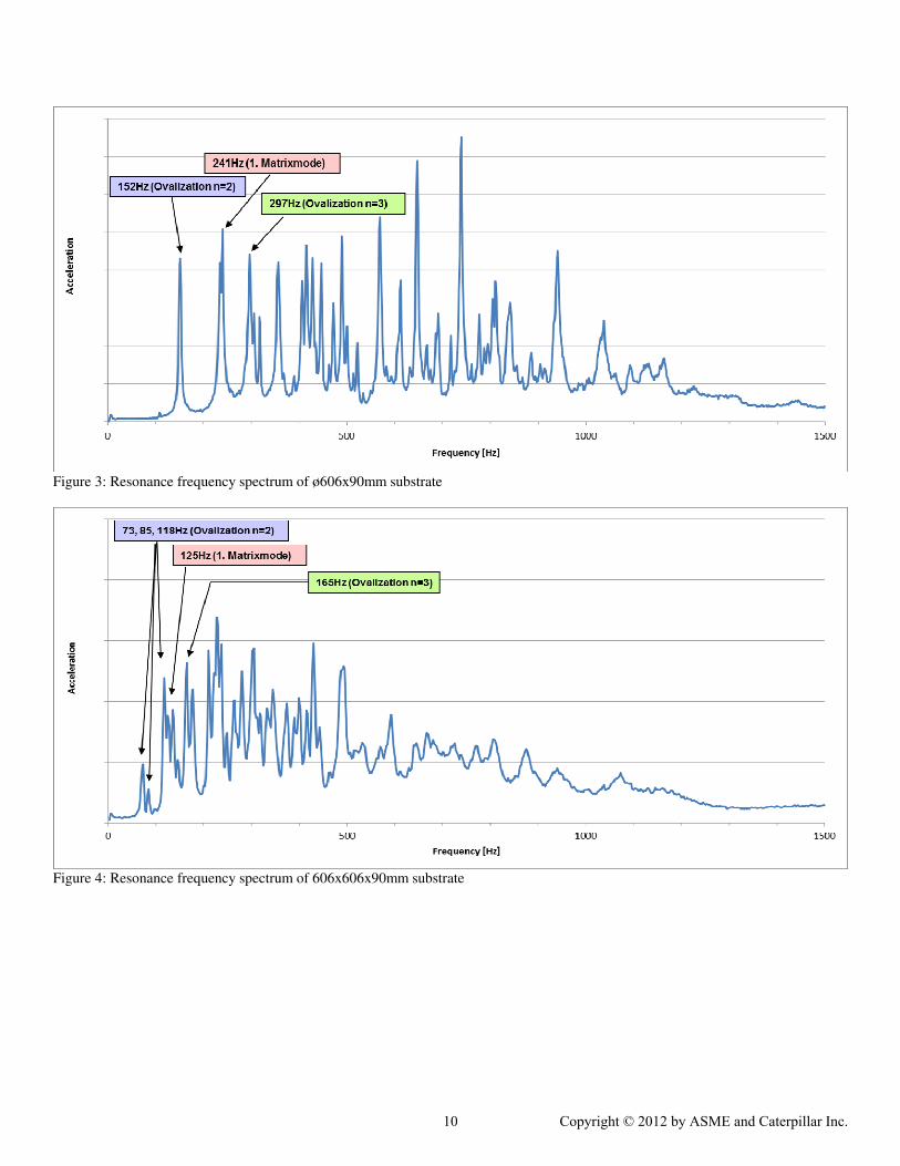
Figure 3: Resonance frequency spectrum of ø606x90mm substrate
Figure 4: Resonance frequency spectrum of 606x606x90mm substrate
10 Copyright © 2012 by ASME and Caterpillar Inc.
Related Documents