Oracle® Fusion Middleware Administering Oracle Coherence 14c (14.1.1.0.0) F23523-12 July 2022

Welcome message from author
This document is posted to help you gain knowledge. Please leave a comment to let me know what you think about it! Share it to your friends and learn new things together.
Transcript
Oracle® Fusion MiddlewareAdministering Oracle Coherence
14c (14.1.1.0.0)F23523-12July 2022

Oracle Fusion Middleware Administering Oracle Coherence, 14c (14.1.1.0.0)
F23523-12
Copyright © 2008, 2022, Oracle and/or its affiliates.
Primary Author: Oracle Corporation
This software and related documentation are provided under a license agreement containing restrictions onuse and disclosure and are protected by intellectual property laws. Except as expressly permitted in yourlicense agreement or allowed by law, you may not use, copy, reproduce, translate, broadcast, modify, license,transmit, distribute, exhibit, perform, publish, or display any part, in any form, or by any means. Reverseengineering, disassembly, or decompilation of this software, unless required by law for interoperability, isprohibited.
The information contained herein is subject to change without notice and is not warranted to be error-free. Ifyou find any errors, please report them to us in writing.
If this is software or related documentation that is delivered to the U.S. Government or anyone licensing it onbehalf of the U.S. Government, then the following notice is applicable:
U.S. GOVERNMENT END USERS: Oracle programs (including any operating system, integrated software,any programs embedded, installed or activated on delivered hardware, and modifications of such programs)and Oracle computer documentation or other Oracle data delivered to or accessed by U.S. Government endusers are "commercial computer software" or "commercial computer software documentation" pursuant to theapplicable Federal Acquisition Regulation and agency-specific supplemental regulations. As such, the use,reproduction, duplication, release, display, disclosure, modification, preparation of derivative works, and/oradaptation of i) Oracle programs (including any operating system, integrated software, any programsembedded, installed or activated on delivered hardware, and modifications of such programs), ii) Oraclecomputer documentation and/or iii) other Oracle data, is subject to the rights and limitations specified in thelicense contained in the applicable contract. The terms governing the U.S. Government’s use of Oracle cloudservices are defined by the applicable contract for such services. No other rights are granted to the U.S.Government.
This software or hardware is developed for general use in a variety of information management applications.It is not developed or intended for use in any inherently dangerous applications, including applications thatmay create a risk of personal injury. If you use this software or hardware in dangerous applications, then youshall be responsible to take all appropriate fail-safe, backup, redundancy, and other measures to ensure itssafe use. Oracle Corporation and its affiliates disclaim any liability for any damages caused by use of thissoftware or hardware in dangerous applications.
Oracle, Java, and MySQL are registered trademarks of Oracle and/or its affiliates. Other names may betrademarks of their respective owners.
Intel and Intel Inside are trademarks or registered trademarks of Intel Corporation. All SPARC trademarks areused under license and are trademarks or registered trademarks of SPARC International, Inc. AMD, Epyc,and the AMD logo are trademarks or registered trademarks of Advanced Micro Devices. UNIX is a registeredtrademark of The Open Group.
This software or hardware and documentation may provide access to or information about content, products,and services from third parties. Oracle Corporation and its affiliates are not responsible for and expresslydisclaim all warranties of any kind with respect to third-party content, products, and services unless otherwiseset forth in an applicable agreement between you and Oracle. Oracle Corporation and its affiliates will not beresponsible for any loss, costs, or damages incurred due to your access to or use of third-party content,products, or services, except as set forth in an applicable agreement between you and Oracle.
Contents
Preface
Audience x
Documentation Accessibility x
Related Documents x
Conventions xi
Diversity and Inclusion xi
Part I Basic Administration
1 Deploying Coherence Applications
Deploying Standalone Coherence Applications 1-1
Deploying a Data Tier 1-1
Deploying an Application Tier 1-2
Deploying a Proxy Tier for Extend Clients 1-3
Deploying Extend Clients 1-4
Deploying Coherence Applications on Docker and Kubernetes 1-5
Deploying Coherence Applications to WebLogic Server 1-5
Overview of the WebLogic Server Coherence Integration 1-5
Packaging Coherence Applications for WebLogic Server 1-6
Building a Coherence GAR Module 1-6
Packaging a GAR Module in an EAR Module 1-7
Setting Up a WebLogic Server Domain Topology for Coherence 1-8
Guidelines for Setting Up a Domain Topology 1-8
Create a Coherence Cluster 1-8
Create Coherence Deployment Tiers 1-9
Create Managed Coherence Servers For a Coherence Deployment Tier 1-10
Deploying Coherence Applications To a WebLogic Server Domain 1-11
Overview of WebLogic Server Domain Deployment 1-11
Deploy the Data Tier GAR 1-12
Deploy the Application Tier EAR 1-12
Deploy the Proxy Tier GAR 1-13
iii
Performing Basic Coherence Administration Tasks 1-13
Deploying Coherence Applications to an Application Server (Generic) 1-14
Deploying Coherence as an Application Server Library 1-14
Deploying Coherence in a Java EE Module 1-15
Deploying Coherence Within an EAR 1-15
Deploying Coherence Within a WAR 1-15
Running Multiple Applications in a Single Cluster 1-16
Specifying a Scope Name 1-16
Scoping Applications in WebLogic Server 1-17
Scoping Applications in a Java EE Environment (Generic) 1-17
Isolating Applications in a JavaEE Environment 1-17
Sharing Application Data in a JavaEE Environment 1-18
Scoping Applications in a Standalone Environment 1-19
Providing a Custom Scope Resolver 1-20
2 Performing a Network Performance Test
Using the Datagram Test Utility 2-1
Running the Datagram Test Utility 2-1
How to Test Datagram Network Performance 2-3
Performing a Point-to-Point Datagram Test 2-3
Performing a Bidirectional Datagram Test 2-4
Performing a Distributed Datagram Test 2-4
Understanding Datagram Report Statistics 2-5
Using the Message Bus Test Utility 2-6
Running the Message Bus Test Utility 2-6
How to Test Message Bus Performance 2-8
Performing a Point-to-Point Message Bus Test 2-8
Performing a Bidirectional Message Bus Test 2-9
Performing a Distributed Message Bus Test 2-9
Understanding Message Bus Report Statistics 2-10
3 Performing a Multicast Connectivity Test
Running the Multicast Test Utility 3-1
How to Test Multicast 3-2
Troubleshooting Multicast Communications 3-4
4 Performance Tuning
Operating System Tuning 4-1
Socket Buffer Sizes 4-1
iv
High Resolution timesource (Linux) 4-2
Datagram size (Microsoft Windows) 4-3
TCP Retransmission Timeout (Microsoft Windows) 4-3
Thread Scheduling (Microsoft Windows) 4-4
Swapping 4-4
Load Balancing Network Interrupts (Linux) 4-5
Network Tuning 4-6
Network Interface Settings 4-7
Network Infrastructure Settings 4-8
Switch and Subnet Considerations 4-8
Ethernet Flow-Control 4-8
Path MTU 4-8
10GbE Considerations 4-9
TCP Considerations 4-9
JVM Tuning 4-10
Basic Sizing Recommendation 4-10
Heap Size Considerations 4-11
General Guidelines 4-12
Moving the Cache Out of the Application Heap 4-14
Garbage Collection Monitoring 4-15
Data Access Patterns 4-16
Data Access Distribution (hot spots) 4-16
Cluster-node Affinity 4-16
Read/Write Ratio and Data Sizes 4-17
Interleaving Cache Reads and Writes 4-17
Concurrent Near Cache Misses on a Specific Hot Key 4-17
Distributed Tracing 4-17
5 Production Checklist
Network Performance Test and Multicast Recommendations 5-1
Network Recommendations 5-3
Cache Size Calculation Recommendations 5-5
Hardware Recommendations 5-7
Operating System Recommendations 5-9
JVM Recommendations 5-10
Oracle Exalogic Elastic Cloud Recommendations 5-12
Security Recommendations 5-16
Persistence Recommendations 5-16
Application Instrumentation Recommendations 5-17
Coherence Modes and Editions 5-17
v
Coherence Operational Configuration Recommendations 5-18
Coherence Cache Configuration Recommendations 5-19
Large Cluster Configuration Recommendations 5-20
Death Detection Recommendations 5-21
Part II Advanced Administration
6 Persisting Caches
Overview of Persistence 6-1
Persistence Modes 6-2
Disk-Based Persistence Storage 6-2
Persistence Configuration 6-3
Management and Monitoring 6-3
Persistence Dependencies 6-3
Persisting Caches on Demand 6-3
Actively Persisting Caches 6-4
Using Snapshots to Persist a Cache Service 6-4
Create a Snapshot 6-4
Recover a Snapshot 6-5
Remove a Snapshot 6-6
Archiving Snapshots 6-6
Defining a Snapshot Archive Directory 6-7
Specifying a Directory Snapshot Archiver 6-7
Performing Snapshot Archiving Operations 6-7
Archiving a Snapshot 6-8
Retrieving Archived Snapshots 6-8
Removing Archived Snapshots 6-8
Listing Archived Snapshots 6-8
Listing Archived Snapshot Stores 6-9
Creating a Custom Snapshot Archiver 6-9
Create a Custom Snapshot Archiver Implementation 6-9
Create a Custom Snapshot Archiver Definition 6-9
Specifying a Custom Snapshot Archiver 6-10
Using Active Persistence Mode 6-10
Enabling Active Persistence Mode 6-11
Changing the Active Persistence Failure Response 6-11
Changing the Partition Count When Using Active Persistence 6-12
Workarounds to Migrate a Persistent Service to a Different Partition Count 6-12
Using Asynchronous Persistence Mode 6-17
Modifying the Pre-Defined Persistence Environments 6-17
vi
Overview of the Pre-Defined Persistence Environment 6-17
Changing the Pre-Defined Persistence Directory 6-18
Creating Persistence Environments 6-19
Define a Persistence Environment 6-19
Configure a Persistence Mode 6-20
Configure Persistence Directories 6-20
Configure a Cache Service to Use a Persistence Environment 6-21
Using Quorum for Persistence Recovery 6-21
Overview of Persistence Recovery Quorum 6-21
Using the Dynamic Recovery Quorum Policy 6-22
Explicit Persistence Quorum Configuration 6-23
Subscribing to Persistence JMX Notifications 6-24
Managing Persistence 6-25
Plan for Persistence Storage 6-25
Plan for Persistence Memory Overhead 6-26
Monitor Persistence Storage Usage 6-26
Monitoring Persistence Latencies 6-26
Configuring Caches as Transient 6-27
7 Federating Caches Across Clusters
Overview of Federated Caching 7-1
Multiple Federation Topologies 7-1
Conflict Resolution 7-2
Federation Configuration 7-2
Management and Monitoring 7-2
General Steps for Setting Up Federated Caching 7-2
Defining Federation Participants 7-3
Changing the Default Settings of Federation Participants 7-4
Understanding Federation Topologies 7-4
Defining Federation Topologies 7-7
Defining Active-Passive Topologies 7-8
Defining Active-Active Topologies 7-8
Defining Hub and Spoke Topologies 7-8
Defining Central Federation Topologies 7-9
Defining Custom Topologies 7-9
Defining Federated Cache Schemes 7-10
Associating a Federated Cache with a Federation Topology 7-10
Overriding the Destination Cache 7-11
Excluding Caches from Being Federated 7-12
Limiting Federation Service Resource Usage 7-12
vii
Resolving Federation Conflicts 7-13
Processing Federated Connection Events 7-13
Processing Federated Change Events 7-14
Federating Events to Custom Participants 7-16
Using a Specific Network Interface for Federation Communication 7-18
Load Balancing Federated Connections 7-19
Using Federation-Based Load Balancing 7-19
Implementing a Custom Federation-Based Load Balancing Strategy 7-20
Using Client-Based Load Balancing 7-20
Managing Federated Caching 7-21
Monitor Cluster Participant Status 7-21
Monitor Federation Performance and Throughput 7-22
A Platform-Specific Deployment Considerations
Deploying to Oracle HotSpot JVMs A-1
Heap Sizes A-1
AtomicLong A-2
OutOfMemoryError A-2
Deploying to IBM JVMs A-2
OutOfMemoryError A-2
Heap Sizing A-3
Deploying to Linux A-3
TSC High Resolution Timesource A-3
Deploying to Solaris A-3
Solaris 10 (x86 and SPARC) A-4
Solaris 10 Networking A-4
Solaris Network Interface Cards A-4
Solaris Link Aggregation A-4
Deploying to Windows A-4
Performance Tuning A-5
Personal Firewalls A-5
Disconnected Network Interface A-5
Deploying to OS X A-5
Multicast and IPv6 A-6
Socket Buffer Sizing A-6
Deploying to z/OS A-6
EBCDIC A-6
Multicast A-6
Deploying to AIX A-6
Multicast and IPv6 A-7
viii
Deploying to Virtual Machines A-7
Multicast Connectivity A-7
Performance A-7
Fault Tolerance A-7
Deploying to Cisco Switches A-7
Buffer Space and Packet Pauses A-8
Multicast Connectivity on Large Networks A-8
Multicast Outages A-8
Multicast Time-to-Live A-10
Deploying to Foundry Switches A-10
Multicast Connectivity A-10
Deploying to IBM BladeCenters A-11
MAC Address Uniformity and Load Balancing A-11
B Log Message Glossary
TCMP Log Messages B-1
Configuration Log Messages B-8
Partitioned Cache Service Log Messages B-10
Service Thread Pool Log Messages B-17
TMB Log Messages B-17
ix
Preface
Welcome to Administering Oracle Coherence. This document provides keyadministration concepts and detailed instructions for administering Coherence clustersand caches.
This preface includes the following sections:
• Audience
• Documentation Accessibility
• Related Documents
• Conventions
• Diversity and Inclusion
AudienceThis guide is intended for the following audiences:
• Primary Audience – Administrators and Operators who want to administerCoherence clusters in their network environment.
• Secondary Audience – System Architects and developers who want to understandthe options for administering Coherence.
The audience should be familiar with Java and JavaEE. In addition, the examples inthis guide require the installation and use of the Oracle Coherence product. Usersshould be familiar with running command line scripts.
Documentation AccessibilityFor information about Oracle's commitment to accessibility, visit the OracleAccessibility Program website at http://www.oracle.com/pls/topic/lookup?ctx=acc&id=docacc.
Access to Oracle Support
Oracle customers that have purchased support have access to electronic supportthrough My Oracle Support. For information, visit http://www.oracle.com/pls/topic/lookup?ctx=acc&id=info or visit http://www.oracle.com/pls/topic/lookup?ctx=acc&id=trsif you are hearing impaired.
Related DocumentsFor more information, see the following documents in the Oracle Coherencedocumentation set:
Preface
x
• Administering HTTP Session Management with Oracle Coherence*Web
• Developing Applications with Oracle Coherence
• Developing Remote Clients for Oracle Coherence
• Installing Oracle Coherence
• Integrating Oracle Coherence
• Managing Oracle Coherence
• Securing Oracle Coherence
• Java API Reference for Oracle Coherence
• C++ API Reference for Oracle Coherence
• .NET API Reference for Oracle Coherence
• Release Notes for Oracle Coherence
ConventionsThe following text conventions are used in this document:
Convention Meaning
boldface Boldface type indicates graphical user interface elements associated with anaction, or terms defined in text or the glossary.
italic Italic type indicates book titles, emphasis, or placeholder variables for whichyou supply particular values.
monospace Monospace type indicates commands within a paragraph, URLs, code inexamples, text that appears on the screen, or text that you enter.
Diversity and InclusionOracle is fully committed to diversity and inclusion. Oracle respects and values having adiverse workforce that increases thought leadership and innovation. As part of our initiative tobuild a more inclusive culture that positively impacts our employees, customers, andpartners, we are working to remove insensitive terms from our products and documentation.We are also mindful of the necessity to maintain compatibility with our customers' existingtechnologies and the need to ensure continuity of service as Oracle's offerings and industrystandards evolve. Because of these technical constraints, our effort to remove insensitiveterms is ongoing and will take time and external cooperation.
Preface
xi
Part IBasic Administration
There are many administrative tasks to consider when moving Coherence applications to aproduction environment. Tasks such as testing the network environment and tuningproduction systems are essential for a successful deployment.
Part I contains the following chapters:
• Deploying Coherence Applications
• Performing a Network Performance Test
• Performing a Multicast Connectivity Test
• Performance Tuning
• Production Checklist
1Deploying Coherence Applications
Coherence can be deployed as a standalone application or as a Java EE application to anapplication server. Specific instructions are provided for WebLogic Server deployment inaddition to instructions for generic application server deployment.This chapter includes the following topics:
• Deploying Standalone Coherence Applications
• Deploying Coherence Applications on Docker and Kubernetes
• Deploying Coherence Applications to WebLogic Server
• Deploying Coherence Applications to an Application Server (Generic)
• Running Multiple Applications in a Single Cluster
Deploying Standalone Coherence ApplicationsStandalone Coherence applications are deployed as a set of distributed processes. Fordeployment, it is often beneficial to logically group these processes into tiers based on theirrole; however, it is not a requirement for deployment. The most common tiers are a data tier,application tier, proxy tier, and extend client tier. Tiers facilitate deployment by allowingcommon artifacts, packaging, and scripts to be defined and targeted specifically for each tier.This section includes the following topics:
• Deploying a Data Tier
• Deploying an Application Tier
• Deploying a Proxy Tier for Extend Clients
• Deploying Extend Clients
Deploying a Data TierA data tier is comprised of cache servers that are responsible for storing cached objects. ACoherence application may require any number of cache servers in the data tier. The numberof cache servers depends on the amount of data that is expected in the cache and whetherthe data must be backed up and survive a server failure. Each cache server is a Coherencecluster member and runs in its own JVM process and multiple cache server processes can becollocated on a physical server. See Cache Size Calculation Recommendations and Hardware Recommendations.
Cache servers are typically started using the com.tangosol.net.DefaultCacheServer class.The class contains a main method and is started from the command line. See Starting CacheServers in Developing Applications with Oracle Coherence.
The following application artifacts are often deployed with a cache server:
• Configuration files such as the operational override configuration file, the cacheconfiguration file and the POF user type configuration file
• POF serializers and domain objects
1-1
• Data grid processing implementations such as queries, entry processor, entryaggregators, and so on
• Event processing implementations
• Cache store and loader implementations when caching objects from data sources
There are no restrictions on how the application artifacts must be packaged on a datatier. However, the artifacts must be found on the server classpath and all configurationfiles must be found before the coherence.jar library if the default names are used;otherwise, the default configuration files that are located in the coherence.jar libraryare loaded. The following example starts a single cache server using the configurationfiles in the APPLICATION_HOME\config directory and uses the implementations classesin the APPLICATION_HOME\lib\myClasses library:
java -server -Xms4g -Xmx4g -cp APPLICATION_HOME\config;APPLICATION_HOME\lib\myClasses.jar;COHERENCE_HOME\lib\coherence.jar com.tangosol.net.DefaultCacheServer
If you choose to include any configuration overrides as system properties (rather thanmodifying an operational override file), then they can be included as -D arguments tothe java command. As a convenience, you can reuse theCOHERENCE_HOME\bin\cache-server script and modify it as required.
GAR Deployment
Coherence application artifacts can be packaged as a Grid ARchive (GAR) anddeployed with the DefaultCacheServer class. A GAR adheres to a specific directorystructure and includes an application descriptor. See Building a Coherence GARModule. The instructions are included as part of WebLogic server deployment, but arealso applicable to a GAR being deployed with the DefaultCacheServer class.
The following example starts a cache server and uses the application artifacts that arepackaged in the MyGar.gar file. The default name (MyGAR) is used as the applicationname, which provides a scope for the application on the cluster.
java -server -Xms4g -Xmx4g -cp APPLICATION_HOME\config;COHERENCE_HOME\lib\coherence.jar com.tangosol.net.DefaultCacheServer D:\example\MyGAR.gar
You can override the default name by providing a different name as an argument. See Overview of the DefaultCacheServer Class in Developing Applications with OracleCoherence. For details about application scope, see Running Multiple Applications in aSingle Cluster.
Deploying an Application TierAn application tier is comprised of any number of clients that perform cacheoperations. Cache operations include loading objects in the cache, using cachedobjects, processing cached data, and performing cache maintenance. The clients areCoherence cluster members, but are not responsible for storing data.
The following application artifacts are often deployed with a client:
• Configuration files such as the operational override configuration file, the cacheconfiguration file and the POF user type configuration file
• POF serializers and domain objects
Chapter 1Deploying Standalone Coherence Applications
1-2
• Data grid processing implementations such as queries, entry processor, entryaggregators, and so on
• Event processing implementations
• Cache store and loader implementations when caching objects from data sources
There are no restrictions on how the application artifacts must be packaged on an applicationtier. Clients must include the COHERENCE_HOME/lib/coherence.jar library on the applicationclasspath. Coherence configuration files must be included in the classpath and must be foundbefore the coherence.jar library if the default names are used; otherwise, the defaultconfiguration files that are located in the coherence.jar library are loaded. The followingexample starts a client using the configuration files in the APPLICATION_HOME\config directoryand uses the implementations classes in the APPLICATION_HOME\lib\myClasses.jar library.
java -cp APPLICATION_HOME\config;APPLICATION_HOME\lib\myClasses.jar;COHERENCE_HOME\lib\coherence.jar com.MyApp
If you choose to include any system property configuration overrides (rather than modifyingan operational override file), then they can be included as -D arguments to the javacommand. For example, to disable storage on the client, thetangosol.coherence.distributed.localstorage system property can be used as follows:
java -Dcoherence.distributed.localstorage=false -cp APPLICATION_HOME\config;APPLICATION_HOME\lib\myClasses.jar;COHERENCE_HOME\lib\coherence.jar com.MyApp
Note:
If a GAR is used for deployment on a cache server, then cache services arerestricted by an application scope name. Clients must use the same applicationscope name; otherwise, the clients can not access the cache services. See Running Multiple Applications in a Single Cluster.
Deploying a Proxy Tier for Extend ClientsA proxy tier is comprised of proxy servers that are responsible for handling extend clientrequests. Any number of proxy servers may be required in the proxy tier. The number ofproxy servers depends on the expected number of extend clients and the expected requestload of the clients. Each proxy server is a cluster member and runs in its own JVM processand multiple proxy server processes can be collocated on a physical server. See DefiningExtend Proxy Services in Developing Remote Clients for Oracle Coherence.
A proxy server is typically started using the com.tangosol.net.DefaultCacheServer class.The class contains a main method and is started from the command line. See Starting CacheServers in Developing Applications with Oracle Coherence. There is no difference between aproxy server and a cache server.
The following application artifacts are often deployed with a proxy:
• Configuration files such as the operational override configuration file, the cacheconfiguration file and the POF user type configuration file
• POF serializers and domain objects. If an extend client is implemented using C++or .NET, then a Java version of the objects must also be deployed for certain use cases.
Chapter 1Deploying Standalone Coherence Applications
1-3
• Data grid processing implementations such as queries, entry processor, entryaggregators, and so on
• Event processing implementations
• Cache store and loader implementations when caching objects from data sources
There are no restrictions on how the application artifacts must be packaged on a proxytier. However, the artifacts must be found on the server classpath and all configurationfiles must be found before the coherence.jar library; otherwise, the defaultconfiguration files that are located in the coherence.jar library are loaded. Thefollowing example starts a single proxy server using the configuration files in theAPPLICATION_HOME\config directory and uses the implementations classes in theAPPLICATION_HOME\lib\myClasses library:
java -server -Xms512m -Xmx512m -Dcoherence.distributed.localstorage=false -cp APPLICATION_HOME\config;APPLICATION_HOME\lib\myClasses.jar;COHERENCE_HOME\lib\coherence.jar com.tangosol.net.DefaultCacheServer
GAR Deployment
Coherence application artifacts can be packaged as a Grid ARchive (GAR) anddeployed with the DefaultCacheServer class. A GAR adheres to a specific directorystructure and includes an application descriptor. See Building a Coherence GARModule. The instructions are included as part of WebLogic server deployment, but arealso applicable to a GAR being deployed with the DefaultCacheServer class.
The following example starts a proxy server and uses the application artifacts that arepackaged in the MyGar.gar file. The default name (MyGAR) is used as the applicationname, which provides a scope for the application on the cluster.
java -server -Xms512m -Xmx512m -Dcoherence.distributed.localstorage=false -cp APPLICATION_HOME\config;APPLICATION_HOME\lib\myClasses.jar;COHERENCE_HOME\lib\coherence.jar com.tangosol.net.DefaultCacheServer D:\example\MyGAR.gar
You can override the default name by providing a different name as an argument. See Starting Cache Servers in Developing Applications with Oracle Coherence. For detailsabout application scope, see Running Multiple Applications in a Single Cluster.
Deploying Extend ClientsExtend clients are implemented as Java, C++, or .NET applications. In addition, anyclient technology that provides a REST client API can use the caching services in aCoherence cluster. Extend clients are applications that use Coherence caches, but arenot members of a Coherence cluster. See Configuring Extend Clients in DevelopingRemote Clients for Oracle Coherence.
The following Coherence artifacts are often deployed with an extend client:
• Configuration files such as the operational override configuration file, the cacheconfiguration file and the POF user type configuration file
• POF serializers and domain objects
• Data grid processing implementations such as queries, entry processor, entryaggregators, and so on
• Event processing implementations
Chapter 1Deploying Standalone Coherence Applications
1-4
Deploying Coherence Applications on Docker and KubernetesOracle Coherence applications can be deployed as Docker containers and orchestratedusing Kubernetes. These industry-leading standards offer a modern, cloud-neutraldeployment solution that is highly scalable and easy to manage.Oracle has released Docker files for Coherence and supporting scripts to GitHub. The postedfiles are examples to help you get started and include documentation and samples. TheCoherence images are available for Java 8 and support both the Coherence full installationand the Coherence quick installation. See docker-images/OracleCoherence on GitHub.
In addition, Oracle has released the Coherence Kubernetes Operator to GitHub. The operatoris a Coherence-specific Kubernetes controller that facilitates running and managingcontainerized Coherence applications on Kubernetes. The operator is installed using Helmand provides integrations with ELK (Elasticsearch, Logstash, and Kibana) for logging, andPrometheus and Grafana for monitoring. The operator includes documentation and samplesto help you get started. See the coherence-kubernetes-operator project on GitHub.
To build custom Coherence Docker images, see the coherence-docker readme document onthe Coherence CE GitHub repository - coherence-docker.
Deploying Coherence Applications to WebLogic ServerWebLogic Server includes a Coherence integration that standardizes the way Coherenceapplications can be deployed and managed within a WebLogic Server domain. Theintegration allows administrators to set up distributed Coherence environments using familiarWebLogic Server components and infrastructure, such as Java EE-styled packaging anddeployment, remote server management, server clusters, WebLogic Scripting Tool (WLST)automation, and configuration through the Administration Console.This section includes the following topics:
• Overview of the WebLogic Server Coherence Integration
• Packaging Coherence Applications for WebLogic Server
• Setting Up a WebLogic Server Domain Topology for Coherence
• Deploying Coherence Applications To a WebLogic Server Domain
• Performing Basic Coherence Administration Tasks
Overview of the WebLogic Server Coherence IntegrationCoherence is integrated with WebLogic Server. The integration aligns the lifecycle of aCoherence cluster member with the lifecycle of a managed server: starting or stopping aserver JVM starts and stops a Coherence cluster member. The first member of the clusterstarts the cluster service and is the senior member. The integration is detailed in Configuringand Managing Coherence Clusters in Administering Clusters for Oracle WebLogic Server.
Like other Java EE modules, Coherence supports its own application module, which is calleda Grid ARchive (GAR). The GAR contains the artifacts of a Coherence application andincludes a deployment descriptor. A GAR is deployed and undeployed in the same way asother Java EE modules and is decoupled from the cluster service lifetime. Coherenceapplications are isolated by a service namespace and by class loader.
Coherence is typically setup in tiers that provide functional isolation within a WebLogic Serverdomain. The most common tiers are: a data tier for caching data and an application tier for
Chapter 1Deploying Coherence Applications on Docker and Kubernetes
1-5
consuming cached data. A proxy server tier and an extend client tier should be setupwhen using Coherence*Extend. An HTTP session tier should be setup when usingCoherence*Web. See Using Coherence*Web with WebLogic Server in AdministeringHTTP Session Management with Oracle Coherence*Web.
WebLogic managed servers that are associated with a Coherence cluster are referredto as managed Coherence servers. Managed Coherence servers in each tier can beindividually managed but are typically associated with respective WebLogic Serverclusters. A GAR must be deployed to each data and proxy tier server. The same GARis then packaged within an EAR and deployed to each application and extend clienttier server. The use of dedicated storage tiers that are separate from client tiers is abest practice that ensures optimal performance.
Packaging Coherence Applications for WebLogic ServerCoherence applications must be packaged as a GAR module for deployment. A GARmodule includes the artifacts that comprise a Coherence application and adheres to aspecific directory structure. A GAR can be left as an unarchived directory or can bearchived with a .gar extension. A GAR is deployed as both a standalone module andwithin an EAR. An EAR cannot contain multiple GAR modules.
This section includes the following topics:
• Building a Coherence GAR Module
• Packaging a GAR Module in an EAR Module
Building a Coherence GAR ModuleTo build a Coherence GAR module:
1. Create the following GAR directory structure:
//lib//META-INF/
2. Add the Coherence cache configuration file and the POF configuration file (ifrequired) to a directory within the GAR. For example:
//lib//META-INF/coherence-cache-config.xml/META-INF/pof-config.xml
Note:
The configuration files should not be placed in the root directory of theGAR. If the configuration files are placed in the root, do not use thedefault names as shown; otherwise, the configuration files are loadedfrom the coherence.jar file which is located in the system classpath.
3. Create a coherence-application.xml deployment descriptor file and save it tothe /META-INF directory. A Coherence GAR must contain a coherence-application.xml deployment descriptor that is located within the META-INFdirectory. The presence of the deployment descriptor indicates a valid GAR.
Chapter 1Deploying Coherence Applications to WebLogic Server
1-6
//lib//META-INF/coherence-application.xml/META-INF/coherence-cache-config.xml/META-INF/pof-config.xml
4. Edit the coherence-application.xml file and specify the location of the configurationfiles from step 2. For example:
<?xml version="1.0"?><coherence-application> xmlns="http://xmnls.oracle.com/coherence/coherence-application"> <cache-configuration-ref>META-INF/coherence-cache-config.xml </cache-configuration-ref> <pof-configuration-ref>META-INF/pof-config.xml</pof-configuration-ref></coherence-application>
Note:
• Configuration files can be placed on a network and referenced using a URLinstead of copying the files locally to the GAR.
• The cache configuration file can be overridden at runtime with a clustercache configuration file. See Overriding a Cache Configuration File inAdministering Clusters for Oracle WebLogic Server.
• The cache configuration file can also be overridden at runtime using a JNDIproperty. See Using JNDI to Override Configuration in Developing OracleCoherence Applications for Oracle WebLogic Server.
5. Place all Coherence application Java classes (entry processors, aggregators, filters, andso on) in the root directory within the appropriate package structure.
6. Place any library dependencies in the /lib directory.
7. Use the Java jar command from the root directory to compress the archive with a .garextension. For example:
jar cvf MyApp.gar *
Packaging a GAR Module in an EAR ModuleA GAR module must be packaged in an EAR module to be referenced by other modules. See Enterprise Applications in Developing Applications for Oracle WebLogic Server.
To include a GAR module within an EAR module:
1. Copy a GAR to the root directory of an EAR together with any application modules (WAR,EJB, and so on) that use Coherence.
2. Edit the META-INF/weblogic-application.xml descriptor and include a reference to theGAR using the <module> element. The reference is required so that the GAR is deployedwhen the EAR is deployed. For example:
<?xml version = '1.0'><weblogic-application xmlns:xsi="http://www.w3.org/2001/XMLSchema-instance" xsi:schemaLocation="http://www.bea.com/ns/weblogic/weblogic-application http://www.bea.com/ns/weblogic/weblogic-application/1.0/ weblogic-application.xsd"
Chapter 1Deploying Coherence Applications to WebLogic Server
1-7
xmlns="http://www.bea.com/ns/weblogic/weblogic-application"> <module> <name>MyAppGAR</name> <type>GAR</type> <path>MyApp.gar</path> </module></weblogic-application>
Setting Up a WebLogic Server Domain Topology for CoherenceThis section includes the following topics:
• Guidelines for Setting Up a Domain Topology
• Create a Coherence Cluster
• Create Coherence Deployment Tiers
• Create Managed Coherence Servers For a Coherence Deployment Tier
Guidelines for Setting Up a Domain TopologyCoherence supports different domain topologies within a WebLogic Server domain toprovide varying levels of performance, scalability, and ease of use. For example,during development, a single managed Coherence server instance may be used asboth a cache server and a cache client. The single-server topology is easy to setupand use, but does not provide optimal performance or scalability. For production,Coherence is typically setup using WebLogic Server clusters. A WebLogic Servercluster is used as a Coherence data tier and hosts one or more cache servers; adifferent WebLogic Server cluster is used as a Coherence application tier and hostsone or more cache clients; and (if required) different WebLogic Server clusters areused for the Coherence proxy tier that hosts one or more managed Coherence proxyservers and the Coherence extend client tier that hosts extend clients. The tieredtopology approach provides optimal scalability and performance. A domain topologyshould always be based on the requirements of an application.
Use the following guidelines when creating a domain topology for Coherence:
• A domain typically contains a single Coherence cluster.
• Multiple WebLogic Server clusters can be associated with a Coherence cluster.
• A managed server that is associated with a Coherence cluster is referred to as amanaged Coherence server and is the same as a Coherence cluster member.
• Use different managed Coherence server instances (and preferably differentWebLogic Server clusters) to separate Coherence cache servers and clients.
• Coherence members managed within a WebLogic Server domain should not joinan external Coherence cluster comprised of standalone JVM cluster members.Standalone JVM cluster members cannot be managed within a WebLogic Serverdomain.
Create a Coherence ClusterTo create a Coherence cluster using the WebLogic Server console:
1. From the console home page's Environment section, click Coherence Clusters.
2. From the Summary of Coherence Clusters page, click New.
Chapter 1Deploying Coherence Applications to WebLogic Server
1-8
3. From the Create a Coherence Cluster Configuration page, enter a name for the clusterusing the Name field.
4. Click Next and skip to step 6.
Or,
Click to select the Use a Custom Cluster Configuration File check-box. WebLogic ServerMBeans expose a subset of the operational settings that are sufficient for most usecases. However, for advanced use cases that require full control over operationalsettings, a cluster configuration file (such as the tangosol-coherence-override.xml file)can be used. Click Next. See Setting Up a Cluster in Developing Applications with OracleCoherence.
Note:
The use of an external cluster configuration file is only recommended foroperational settings that are not available through the provided MBeans. Thatis, avoid configuring the same operational settings in both an external clusterconfiguration file and through the MBeans.
5. From the Create a Coherence Cluster Configuration File screen, use the File Path field toenter the path and name of a cluster configuration file that is located on theadministration server. Click Next and skip to step 7.
6. From the Coherence Cluster Addressing section, leave the default clustering mode(Unicast) and change the port if required. To use multicast, use the drop-down list andselect Multicast and provide a unique multicast address and port for the cluster. ClickNext.
If Unicast is used, the cluster automatically creates a Well Known Addresses (WKA) listbased on the managed Coherence server instances in the Coherence cluster (one permachine). You can edit the cluster definition using the Administration Console and defineyour own WKA list if you wish to change the number of members. Addresses must beentered using the actual IP address on the host and not localhost; otherwise, themanaged Coherence servers will not be able to join with other cluster members. See Using Well Known Addresses in Developing Applications with Oracle Coherence.
7. From the Coherence Cluster Members section, click to select the managed Coherenceservers or WebLogic Server clusters to be part of the Coherence cluster or skip thissection if managed Coherence servers and WebLogic Clusters are yet to be defined.
8. Click Finish. The Summary of Coherence Clusters screen displays and the CoherenceClusters table lists the cluster.
Create Coherence Deployment TiersThe preferred approach for setting up Coherence in a WLS domain is to separate Coherencecache servers, clients, and proxies into different tiers that are associated with the sameCoherence cluster. Typically, each tier is associated with its own WebLogic Server cluster ofmanaged Coherence servers. However, a tier may also be comprised of standalonemanaged Coherence servers. The former approach provides the easiest way to manage andscale Coherence because the managed Coherence servers can inherit the WebLogic Servercluster's Coherence settings and deployments. Use the instructions in this section to createdifferent WebLogic Server clusters for the data, application, and proxy tiers. See Configuringand Managing Coherence Clusters in Administering Clusters for Oracle WebLogic Server.
Chapter 1Deploying Coherence Applications to WebLogic Server
1-9
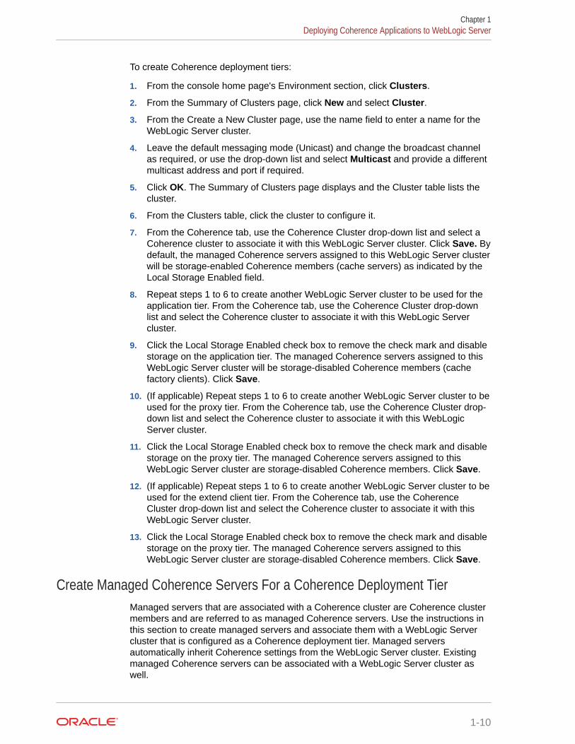
To create Coherence deployment tiers:
1. From the console home page's Environment section, click Clusters.
2. From the Summary of Clusters page, click New and select Cluster.
3. From the Create a New Cluster page, use the name field to enter a name for theWebLogic Server cluster.
4. Leave the default messaging mode (Unicast) and change the broadcast channelas required, or use the drop-down list and select Multicast and provide a differentmulticast address and port if required.
5. Click OK. The Summary of Clusters page displays and the Cluster table lists thecluster.
6. From the Clusters table, click the cluster to configure it.
7. From the Coherence tab, use the Coherence Cluster drop-down list and select aCoherence cluster to associate it with this WebLogic Server cluster. Click Save. Bydefault, the managed Coherence servers assigned to this WebLogic Server clusterwill be storage-enabled Coherence members (cache servers) as indicated by theLocal Storage Enabled field.
8. Repeat steps 1 to 6 to create another WebLogic Server cluster to be used for theapplication tier. From the Coherence tab, use the Coherence Cluster drop-downlist and select the Coherence cluster to associate it with this WebLogic Servercluster.
9. Click the Local Storage Enabled check box to remove the check mark and disablestorage on the application tier. The managed Coherence servers assigned to thisWebLogic Server cluster will be storage-disabled Coherence members (cachefactory clients). Click Save.
10. (If applicable) Repeat steps 1 to 6 to create another WebLogic Server cluster to beused for the proxy tier. From the Coherence tab, use the Coherence Cluster drop-down list and select the Coherence cluster to associate it with this WebLogicServer cluster.
11. Click the Local Storage Enabled check box to remove the check mark and disablestorage on the proxy tier. The managed Coherence servers assigned to thisWebLogic Server cluster are storage-disabled Coherence members. Click Save.
12. (If applicable) Repeat steps 1 to 6 to create another WebLogic Server cluster to beused for the extend client tier. From the Coherence tab, use the CoherenceCluster drop-down list and select the Coherence cluster to associate it with thisWebLogic Server cluster.
13. Click the Local Storage Enabled check box to remove the check mark and disablestorage on the proxy tier. The managed Coherence servers assigned to thisWebLogic Server cluster are storage-disabled Coherence members. Click Save.
Create Managed Coherence Servers For a Coherence Deployment TierManaged servers that are associated with a Coherence cluster are Coherence clustermembers and are referred to as managed Coherence servers. Use the instructions inthis section to create managed servers and associate them with a WebLogic Servercluster that is configured as a Coherence deployment tier. Managed serversautomatically inherit Coherence settings from the WebLogic Server cluster. Existingmanaged Coherence servers can be associated with a WebLogic Server cluster aswell.
Chapter 1Deploying Coherence Applications to WebLogic Server
1-10
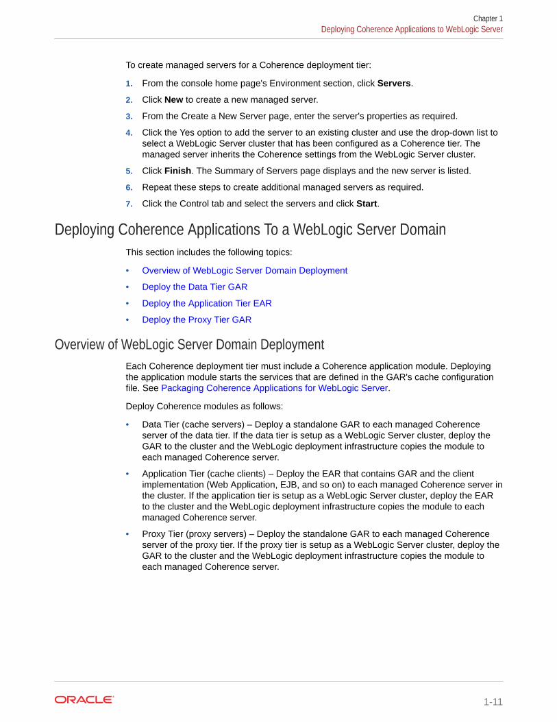
To create managed servers for a Coherence deployment tier:
1. From the console home page's Environment section, click Servers.
2. Click New to create a new managed server.
3. From the Create a New Server page, enter the server's properties as required.
4. Click the Yes option to add the server to an existing cluster and use the drop-down list toselect a WebLogic Server cluster that has been configured as a Coherence tier. Themanaged server inherits the Coherence settings from the WebLogic Server cluster.
5. Click Finish. The Summary of Servers page displays and the new server is listed.
6. Repeat these steps to create additional managed servers as required.
7. Click the Control tab and select the servers and click Start.
Deploying Coherence Applications To a WebLogic Server DomainThis section includes the following topics:
• Overview of WebLogic Server Domain Deployment
• Deploy the Data Tier GAR
• Deploy the Application Tier EAR
• Deploy the Proxy Tier GAR
Overview of WebLogic Server Domain DeploymentEach Coherence deployment tier must include a Coherence application module. Deployingthe application module starts the services that are defined in the GAR's cache configurationfile. See Packaging Coherence Applications for WebLogic Server.
Deploy Coherence modules as follows:
• Data Tier (cache servers) – Deploy a standalone GAR to each managed Coherenceserver of the data tier. If the data tier is setup as a WebLogic Server cluster, deploy theGAR to the cluster and the WebLogic deployment infrastructure copies the module toeach managed Coherence server.
• Application Tier (cache clients) – Deploy the EAR that contains GAR and the clientimplementation (Web Application, EJB, and so on) to each managed Coherence server inthe cluster. If the application tier is setup as a WebLogic Server cluster, deploy the EARto the cluster and the WebLogic deployment infrastructure copies the module to eachmanaged Coherence server.
• Proxy Tier (proxy servers) – Deploy the standalone GAR to each managed Coherenceserver of the proxy tier. If the proxy tier is setup as a WebLogic Server cluster, deploy theGAR to the cluster and the WebLogic deployment infrastructure copies the module toeach managed Coherence server.
Chapter 1Deploying Coherence Applications to WebLogic Server
1-11
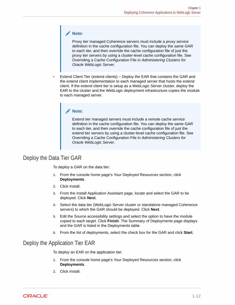
Note:
Proxy tier managed Coherence servers must include a proxy servicedefinition in the cache configuration file. You can deploy the same GARto each tier, and then override the cache configuration file of just theproxy tier servers by using a cluster-level cache configuration file. See Overriding a Cache Configuration File in Administering Clusters forOracle WebLogic Server.
• Extend Client Tier (extend clients) – Deploy the EAR that contains the GAR andthe extend client implementation to each managed server that hosts the extendclient. If the extend client tier is setup as a WebLogic Server cluster, deploy theEAR to the cluster and the WebLogic deployment infrastructure copies the moduleto each managed server.
Note:
Extend tier managed servers must include a remote cache servicedefinition in the cache configuration file. You can deploy the same GARto each tier, and then override the cache configuration file of just theextend tier servers by using a cluster-level cache configuration file. See Overriding a Cache Configuration File in Administering Clusters forOracle WebLogic Server.
Deploy the Data Tier GARTo deploy a GAR on the data tier:
1. From the console home page's Your Deployed Resources section, clickDeployments.
2. Click Install.
3. From the Install Application Assistant page, locate and select the GAR to bedeployed. Click Next.
4. Select the data tier (WebLogic Server cluster or standalone managed Coherenceservers) to which the GAR should be deployed. Click Next.
5. Edit the Source accessibility settings and select the option to have the modulecopied to each target. Click Finish. The Summary of Deployments page displaysand the GAR is listed in the Deployments table.
6. From the list of deployments, select the check box for the GAR and click Start.
Deploy the Application Tier EARTo deploy an EAR on the application tier:
1. From the console home page's Your Deployed Resources section, clickDeployments.
2. Click Install.
Chapter 1Deploying Coherence Applications to WebLogic Server
1-12
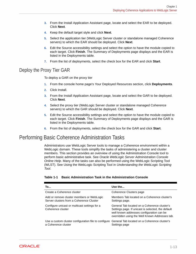
3. From the Install Application Assistant page, locate and select the EAR to be deployed.Click Next.
4. Keep the default target style and click Next.
5. Select the application tier (WebLogic Server cluster or standalone managed Coherenceservers) to which the EAR should be deployed. Click Next.
6. Edit the Source accessibility settings and select the option to have the module copied toeach target. Click Finish. The Summary of Deployments page displays and the EAR islisted in the Deployments table.
7. From the list of deployments, select the check box for the EAR and click Start.
Deploy the Proxy Tier GARTo deploy a GAR on the proxy tier
1. From the console home page's Your Deployed Resources section, click Deployments.
2. Click Install.
3. From the Install Application Assistant page, locate and select the GAR to be deployed.Click Next.
4. Select the proxy tier (WebLogic Server cluster or standalone managed Coherenceservers) to which the GAR should be deployed. Click Next.
5. Edit the Source accessibility settings and select the option to have the module copied toeach target. Click Finish. The Summary of Deployments page displays and the GAR islisted in the Deployments table.
6. From the list of deployments, select the check box for the GAR and click Start.
Performing Basic Coherence Administration TasksAdministrators use WebLogic Server tools to manage a Coherence environment within aWebLogic domain. These tools simplify the tasks of administering a cluster and clustermembers. This section provides an overview of using the Administration Console tool toperform basic administrative task. See Oracle WebLogic Server Administration ConsoleOnline Help. Many of the tasks can also be performed using the WebLogic Scripting Tool(WLST). See Using the WebLogic Scripting Tool in Understanding the WebLogic ScriptingTool.
Table 1-1 Basic Administration Task in the Administration Console
To... Use the...
Create a Coherence cluster Coherence Clusters page
Add or remove cluster members or WebLogicServer clusters from a Coherence Cluster
Members Tab located on a Coherence cluster'sSettings page.
Configure unicast or multicast settings for aCoherence cluster
General Tab located on a Coherence cluster'sSettings page. If unicast is selected, the defaultwell known addresses configuration can beoverridden using the Well Known Addresses tab.
Use a custom cluster configuration file to configurea Coherence cluster
General Tab located on a Coherence cluster'sSettings page
Chapter 1Deploying Coherence Applications to WebLogic Server
1-13
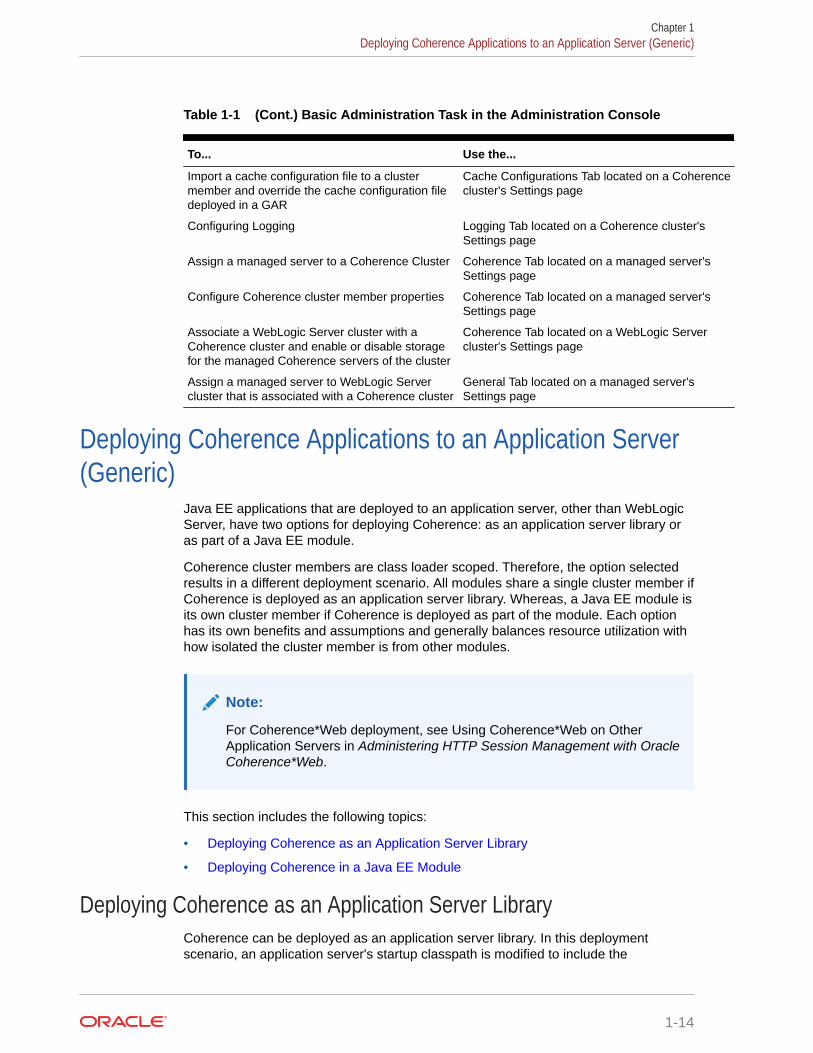
Table 1-1 (Cont.) Basic Administration Task in the Administration Console
To... Use the...
Import a cache configuration file to a clustermember and override the cache configuration filedeployed in a GAR
Cache Configurations Tab located on a Coherencecluster's Settings page
Configuring Logging Logging Tab located on a Coherence cluster'sSettings page
Assign a managed server to a Coherence Cluster Coherence Tab located on a managed server'sSettings page
Configure Coherence cluster member properties Coherence Tab located on a managed server'sSettings page
Associate a WebLogic Server cluster with aCoherence cluster and enable or disable storagefor the managed Coherence servers of the cluster
Coherence Tab located on a WebLogic Servercluster's Settings page
Assign a managed server to WebLogic Servercluster that is associated with a Coherence cluster
General Tab located on a managed server'sSettings page
Deploying Coherence Applications to an Application Server(Generic)
Java EE applications that are deployed to an application server, other than WebLogicServer, have two options for deploying Coherence: as an application server library oras part of a Java EE module.
Coherence cluster members are class loader scoped. Therefore, the option selectedresults in a different deployment scenario. All modules share a single cluster member ifCoherence is deployed as an application server library. Whereas, a Java EE module isits own cluster member if Coherence is deployed as part of the module. Each optionhas its own benefits and assumptions and generally balances resource utilization withhow isolated the cluster member is from other modules.
Note:
For Coherence*Web deployment, see Using Coherence*Web on OtherApplication Servers in Administering HTTP Session Management with OracleCoherence*Web.
This section includes the following topics:
• Deploying Coherence as an Application Server Library
• Deploying Coherence in a Java EE Module
Deploying Coherence as an Application Server LibraryCoherence can be deployed as an application server library. In this deploymentscenario, an application server's startup classpath is modified to include the
Chapter 1Deploying Coherence Applications to an Application Server (Generic)
1-14
COHERENCE_HOME/lib/coherence.jar library. In addition, any objects that are being placedinto the cache must also be available in the server's classpath. Consult your applicationserver vendor's documentation for instructions on adding libraries to the server's classpath.
This scenario results in a single cluster member that is shared by all applications that aredeployed in the server's containers. This scenario minimizes resource utilization becauseonly one copy of the Coherence classes are loaded into the JVM. See Running MultipleApplications in a Single Cluster.
Deploying Coherence in a Java EE ModuleCoherence can be deployed within an EAR file or a WAR file. This style of deployment isgenerally preferred because modification to the application server run-time environment is notrequired and because cluster members are isolated to either the EAR or WAR.
This section includes the following topics:
• Deploying Coherence Within an EAR
• Deploying Coherence Within a WAR
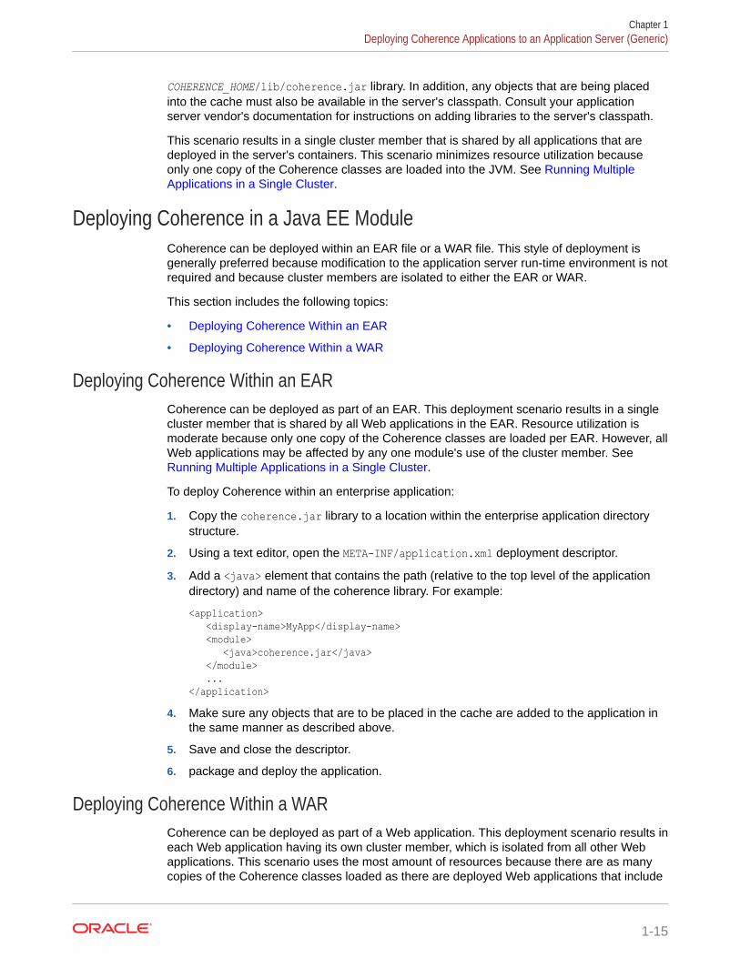
Deploying Coherence Within an EARCoherence can be deployed as part of an EAR. This deployment scenario results in a singlecluster member that is shared by all Web applications in the EAR. Resource utilization ismoderate because only one copy of the Coherence classes are loaded per EAR. However, allWeb applications may be affected by any one module's use of the cluster member. See Running Multiple Applications in a Single Cluster.
To deploy Coherence within an enterprise application:
1. Copy the coherence.jar library to a location within the enterprise application directorystructure.
2. Using a text editor, open the META-INF/application.xml deployment descriptor.
3. Add a <java> element that contains the path (relative to the top level of the applicationdirectory) and name of the coherence library. For example:
<application> <display-name>MyApp</display-name> <module> <java>coherence.jar</java> </module> ...</application>
4. Make sure any objects that are to be placed in the cache are added to the application inthe same manner as described above.
5. Save and close the descriptor.
6. package and deploy the application.
Deploying Coherence Within a WARCoherence can be deployed as part of a Web application. This deployment scenario results ineach Web application having its own cluster member, which is isolated from all other Webapplications. This scenario uses the most amount of resources because there are as manycopies of the Coherence classes loaded as there are deployed Web applications that include
Chapter 1Deploying Coherence Applications to an Application Server (Generic)
1-15
Coherence. This scenario is ideal when deploying only a few Web applications to anapplication server.
To deploy Coherence within a Web application:
1. Copy the coherence.jar library to the Web Application's WEB-INF/lib directory.
2. Make sure any objects that are to be placed in the cache are located in either theWEB-INF/lib or WEB-INF/classes directory.
3. Package and deploy the application.
Running Multiple Applications in a Single ClusterCoherence can be deployed in shared environments where multiple applications usethe same cluster but define their own set of Coherence caches and services. For suchscenarios, each application uses its own cache configuration file that includes a scopename that controls whether the caches and services are allowed to be shared amongapplications.This section includes the following topics:
• Specifying a Scope Name
• Scoping Applications in WebLogic Server
• Scoping Applications in a Java EE Environment (Generic)
• Scoping Applications in a Standalone Environment
• Providing a Custom Scope Resolver
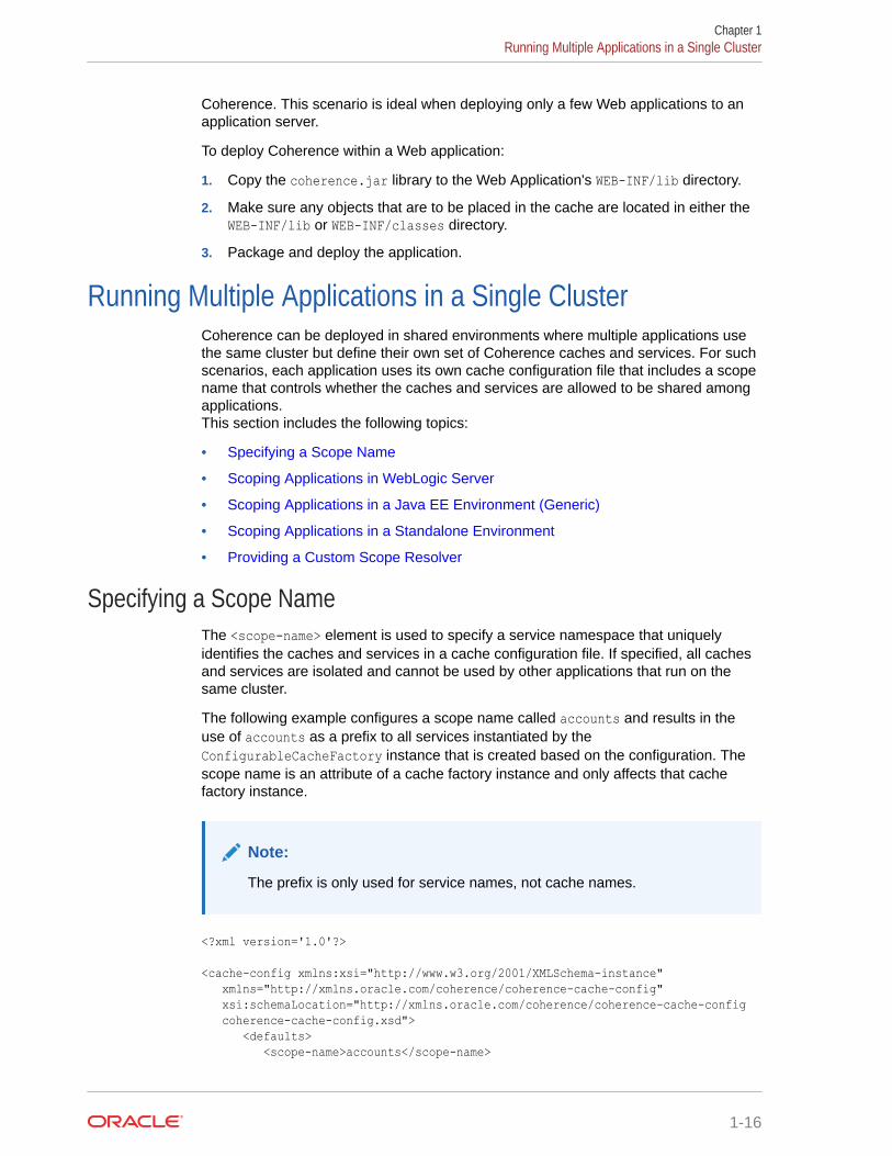
Specifying a Scope NameThe <scope-name> element is used to specify a service namespace that uniquelyidentifies the caches and services in a cache configuration file. If specified, all cachesand services are isolated and cannot be used by other applications that run on thesame cluster.
The following example configures a scope name called accounts and results in theuse of accounts as a prefix to all services instantiated by theConfigurableCacheFactory instance that is created based on the configuration. Thescope name is an attribute of a cache factory instance and only affects that cachefactory instance.
Note:
The prefix is only used for service names, not cache names.
<?xml version='1.0'?>
<cache-config xmlns:xsi="http://www.w3.org/2001/XMLSchema-instance" xmlns="http://xmlns.oracle.com/coherence/coherence-cache-config" xsi:schemaLocation="http://xmlns.oracle.com/coherence/coherence-cache-config coherence-cache-config.xsd"> <defaults> <scope-name>accounts</scope-name>
Chapter 1Running Multiple Applications in a Single Cluster
1-16
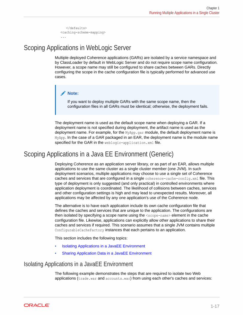
</defaults> <caching-scheme-mapping> ...
Scoping Applications in WebLogic ServerMultiple deployed Coherence applications (GARs) are isolated by a service namespace andby ClassLoader by default in WebLogic Server and do not require scope name configuration.However, a scope name may still be configured to share caches between GARs. Directlyconfiguring the scope in the cache configuration file is typically performed for advanced usecases.
Note:
If you want to deploy multiple GARs with the same scope name, then theconfiguration files in all GARs must be identical; otherwise, the deployment fails.
The deployment name is used as the default scope name when deploying a GAR. If adeployment name is not specified during deployment, the artifact name is used as thedeployment name. For example, for the MyApp.gar module, the default deployment name isMyApp. In the case of a GAR packaged in an EAR, the deployment name is the module namespecified for the GAR in the weblogic-application.xml file.
Scoping Applications in a Java EE Environment (Generic)Deploying Coherence as an application server library, or as part of an EAR, allows multipleapplications to use the same cluster as a single cluster member (one JVM). In suchdeployment scenarios, multiple applications may choose to use a single set of Coherencecaches and services that are configured in a single coherence-cache-config.xml file. Thistype of deployment is only suggested (and only practical) in controlled environments whereapplication deployment is coordinated. The likelihood of collisions between caches, servicesand other configuration settings is high and may lead to unexpected results. Moreover, allapplications may be affected by any one application's use of the Coherence node.
The alternative is to have each application include its own cache configuration file thatdefines the caches and services that are unique to the application. The configurations arethen isolated by specifying a scope name using the <scope-name> element in the cacheconfiguration file. Likewise, applications can explicitly allow other applications to share theircaches and services if required. This scenario assumes that a single JVM contains multipleConfigurableCacheFactory instances that each pertains to an application.
This section includes the following topics:
• Isolating Applications in a JavaEE Environment
• Sharing Application Data in a JavaEE Environment
Isolating Applications in a JavaEE EnvironmentThe following example demonstrates the steps that are required to isolate two Webapplications (trade.war and accounts.war) from using each other's caches and services:
Chapter 1Running Multiple Applications in a Single Cluster
1-17
1. Create a cache configuration file for the trade application (for example, trade-cache-config.xml) that defines a scope name called trade and include any cachescheme definitions for the application:
<?xml version='1.0'?>
<cache-config xmlns:xsi="http://www.w3.org/2001/XMLSchema-instance" xmlns="http://xmlns.oracle.com/coherence/coherence-cache-config" xsi:schemaLocation="http://xmlns.oracle.com/coherence/coherence-cache-config coherence-cache-config.xsd"> <defaults> <scope-name>trade</scope-name> </defaults> ...
2. Create a cache configuration file for the accounts application (for example,accounts-cache-config.xml) that defines a scope name called accounts andinclude any cache scheme definitions for the application:
<?xml version='1.0'?>
<cache-config xmlns:xsi="http://www.w3.org/2001/XMLSchema-instance" xmlns="http://xmlns.oracle.com/coherence/coherence-cache-config" xsi:schemaLocation="http://xmlns.oracle.com/coherence/coherence-cache-config coherence-cache-config.xsd"> <defaults> <scope-name>accounts</scope-name> </defaults> ...
3. Ensure the cache configurations files are included in their respective WAR files(typically in the WEB-INF/classes directory) so that they can be loaded at run timeand used by the application.
Sharing Application Data in a JavaEE EnvironmentApplications can share data by allowing access to their caches and services. Thefollowing example demonstrates allowing a Web application (trade.war) to access thecaches and services of another Web application (accounts.war):
1. Create a cache configuration file for the trade application (for example, trade-cache-config.xml) that defines a scope name called trade and include any cachescheme definitions for the application:
<?xml version='1.0'?>
<cache-config xmlns:xsi="http://www.w3.org/2001/XMLSchema-instance" xmlns="http://xmlns.oracle.com/coherence/coherence-cache-config" xsi:schemaLocation="http://xmlns.oracle.com/coherence/coherence-cache-config coherence-cache-config.xsd"> <defaults> <scope-name>trade</scope-name> </defaults> ...
Chapter 1Running Multiple Applications in a Single Cluster
1-18
2. Create a cache configuration file (for example, accounts-cache-config.xml) for theaccounts application that defines a scope name called accounts and include any cachescheme definitions for the application:
<?xml version='1.0'?>
<cache-config xmlns:xsi="http://www.w3.org/2001/XMLSchema-instance" xmlns="http://xmlns.oracle.com/coherence/coherence-cache-config" xsi:schemaLocation="http://xmlns.oracle.com/coherence/coherence-cache-config coherence-cache-config.xsd"> <defaults> <scope-name>accounts</scope-name> </defaults> ...
3. Ensure the cache configurations files are included in their respective WAR files (typicallyin the WEB-INF/classes directory) so that they can be loaded at run time and used by theapplication.
4. The trade application must also include the accounts-cache-config.xml file to accessthe caches and services of the accounts application.
5. The trade application can then use the following pattern to create cache factories for theaccounts application:
ClassLoader loader = ...CacheFactoryBuilder builder = CacheFactory.getCacheFactoryBuilder();ConfigurableCacheFactory tradesCcf = builder.getConfigurableCacheFactory(tradesUri, loader);ConfigurableCacheFactory accountsCcf = builder.getConfigurableCacheFactory(accountsUri, loader);
Scoping Applications in a Standalone EnvironmentStandalone applications that use a single Coherence cluster can each include their owncache configuration files; however, these configurations are coalesced into a singleConfigurableCacheFactory. Since there is a 1 to 1 relationship betweenConfigurableCacheFactory and DefaultCacheServer, application scoping is not feasiblewithin a single cluster node. Instead, one or more instances of DefaultCacheServer must bestarted for each cache configuration, and each cache configuration must include a scopename.
The following example isolates two applications (trade and accounts) from using each other'scaches and services:
1. Create a cache configuration file for the trade application (for example, trade-cache-config.xml) that defines a scope name called trade and include any cache schemedefinitions for the application:
<?xml version='1.0'?>
<cache-config xmlns:xsi="http://www.w3.org/2001/XMLSchema-instance" xmlns="http://xmlns.oracle.com/coherence/coherence-cache-config" xsi:schemaLocation="http://xmlns.oracle.com/coherence/coherence-cache-config coherence-cache-config.xsd"> <defaults> <scope-name>trade</scope-name> </defaults> ...
Chapter 1Running Multiple Applications in a Single Cluster
1-19
2. Start a DefaultCacheServer instance that loads the trade-cache-config.xmlcache configuration file.
3. Create a cache configuration file for the accounts application (for example,accounts-cache-config.xml) that defines a scope name called accounts andinclude any cache scheme definitions for the application:
<?xml version='1.0'?>
<cache-config xmlns:xsi="http://www.w3.org/2001/XMLSchema-instance" xmlns="http://xmlns.oracle.com/coherence/coherence-cache-config" xsi:schemaLocation="http://xmlns.oracle.com/coherence/coherence-cache-config coherence-cache-config.xsd"> <defaults> <scope-name>accounts</scope-name> </defaults> ...
4. Start a DefaultCacheServer instance that loads the accounts-cache-config.xmlcache configuration file.
Note:
To share data between applications, the applications must use the samecache configuration file. Coherence does not support using multiple cacheconfigurations which specify the same scope name.
Providing a Custom Scope ResolverThe com.tangosol.net.ScopeResolver interface allows containers and applications tomodify the scope name for a given ConfigurableCacheFactory at run time to enforce(or disable) isolation between applications. Implement the ScopeResolver interfaceand add any custom functionality as required.
To enable a custom scope resolver, the fully qualified name of the implementationclass must be defined in the operational override file using the <scope-resolver>element within the <cache-factory-builder-config> node. For example:
<?xml version='1.0'?>
<coherence xmlns:xsi="http://www.w3.org/2001/XMLSchema-instance" xmlns="http://xmlns.oracle.com/coherence/coherence-operational-config" xsi:schemaLocation="http://xmlns.oracle.com/coherence/coherence-operational-config coherence-operational-config.xsd"> <cache-factory-builder-config> <scope-resolver> <class-name>package.MyScopeResolver</class-name> </scope-resolver> </cache-factory-builder-config><coherence>
As an alternative, the <instance> element supports the use of a <class-factory-name> element to specify a factory class that is responsible for creating ScopeResolverinstances, and a <method-name> element to specify the static factory method on the
Chapter 1Running Multiple Applications in a Single Cluster
1-20
factory class that performs object instantiation. The following example gets a custom scoperesolver instance using the getResolver method on the MyScopeResolverFactory class.
<?xml version='1.0'?>
<coherence xmlns:xsi="http://www.w3.org/2001/XMLSchema-instance" xmlns="http://xmlns.oracle.com/coherence/coherence-operational-config" xsi:schemaLocation="http://xmlns.oracle.com/coherence/coherence-operational-config coherence-operational-config.xsd"> <cache-factory-builder-config> <scope-resolver> <class-factory-name>package.MyScopeReolverFactory</class-factory-name> <method-name>getResolver</method-name> </scope-resolver> </cache-factory-builder-config><coherence>
Any initialization parameters that are required for an implementation can be specified usingthe <init-params> element. The following example sets an isDeployed parameter to true.
<?xml version='1.0'?>
<coherence xmlns:xsi="http://www.w3.org/2001/XMLSchema-instance" xmlns="http://xmlns.oracle.com/coherence/coherence-operational-config" xsi:schemaLocation="http://xmlns.oracle.com/coherence/coherence-operational-config coherence-operational-config.xsd"> <cache-factory-builder-config> <scope-resolver> <class-name>package.MyScopeResolver</class-name> <init-params> <init-param> <param-name>isDeployed</param-name> <param-value>true</param-value> </init-param> </init-params> </scope-resolver> </cache-factory-builder-config><coherence>
Chapter 1Running Multiple Applications in a Single Cluster
1-21
2Performing a Network Performance Test
Coherence provides a datagram utility and a message bus utility for testing networkperformance between two or more computers. Any production deployment should bepreceded by a successful run of both tests.This chapter includes the following sections:
• Using the Datagram Test Utility
• Using the Message Bus Test Utility
Using the Datagram Test UtilityThe Coherence datagram test utility is used to test and tune network performance betweentwo or more computers. The utility ensures that a network is optimally configured to supportCoherence cluster management communication. There are two types of tests: a point-to-pointtest that tests the performance of a pair of servers to ensure they are properly configured,and a distributed datagram test to ensure the network itself is functioning properly. Both testsneed to be run successfully.The datagram test operates in one of three modes: either as a packet publisher, a packetlistener, or both. When the utility is run, a publisher transmits packets to the listener who thenmeasures the throughput, success rate, and other statistics. Tune an environment based onthe results of these tests to achieve maximum performance. See Performance Tuning.
This section includes the following topics:
• Running the Datagram Test Utility
• How to Test Datagram Network Performance
• Understanding Datagram Report Statistics
Running the Datagram Test UtilityThe datagram test utility is run from the command line using either thecom.tangosol.net.DatagramTest class or by running the datagram-test script that isprovided in the COHERENCE_HOME/bin directory. A script is provided for both Windows andUNIX-based platforms.
The following example demonstrates using the DatagramTest class:
java -server -cp coherence.jar com.tangosol.net.DatagramTest <command value> <command value> ...
The following example demonstrates using the script:
datagram-test <command value> <command value> ...
Table 2-1 describes the available command line options for the datagram test utility.
2-1
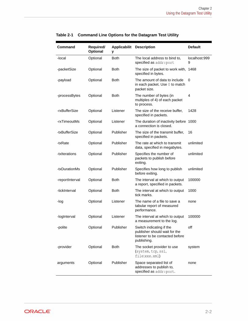
Table 2-1 Command Line Options for the Datagram Test Utility
Command Required/Optional
Applicability
Description Default
-local Optional Both The local address to bind to,specified as addr:port
localhost:9999
-packetSize Optional Both The size of packet to work with,specified in bytes.
1468
-payload Optional Both The amount of data to includein each packet. Use 0 to matchpacket size.
0
-processBytes Optional Both The number of bytes (inmultiples of 4) of each packetto process.
4
-rxBufferSize Optional Listener The size of the receive buffer,specified in packets.
1428
-rxTimeoutMs Optional Listener The duration of inactivity beforea connection is closed.
1000
-txBufferSize Optional Publisher The size of the transmit buffer,specified in packets.
16
-txRate Optional Publisher The rate at which to transmitdata, specified in megabytes.
unlimited
-txIterations Optional Publisher Specifies the number ofpackets to publish beforeexiting.
unlimited
-txDurationMs Optional Publisher Specifies how long to publishbefore exiting.
unlimited
-reportInterval Optional Both The interval at which to outputa report, specified in packets.
100000
-tickInterval Optional Both The interval at which to outputtick marks.
1000
-log Optional Listener The name of a file to save atabular report of measuredperformance.
none
-logInterval Optional Listener The interval at which to outputa measurement to the log.
100000
-polite Optional Publisher Switch indicating if thepublisher should wait for thelistener to be contacted beforepublishing.
off
-provider Optional Both The socket provider to use(system, tcp, ssl,file:xxx.xml)
system
arguments Optional Publisher Space separated list ofaddresses to publish to,specified as addr:port.
none
Chapter 2Using the Datagram Test Utility
2-2
How to Test Datagram Network PerformanceThis section includes instructions for running a point-to-point datagram test and a distributeddatagram test. Both tests must be run successfully and show no significant performanceissues or packet loss. See Understanding Datagram Report Statistics.
This section includes the following topics:
• Performing a Point-to-Point Datagram Test
• Performing a Bidirectional Datagram Test
• Performing a Distributed Datagram Test
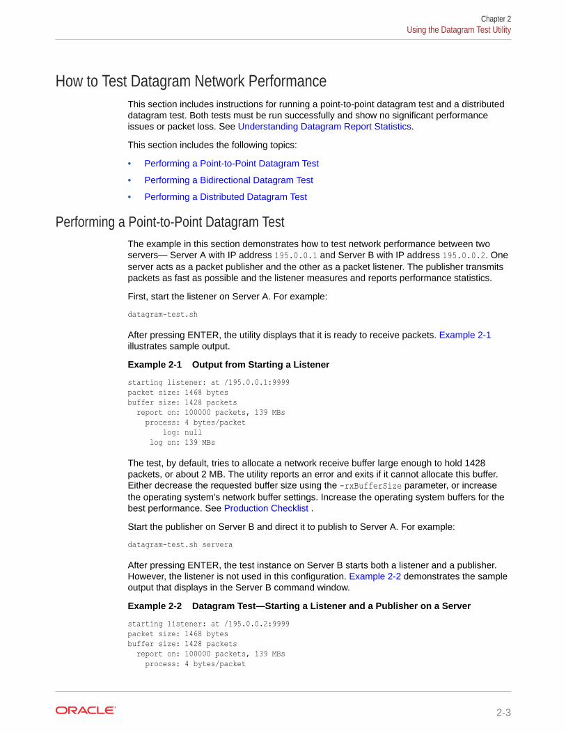
Performing a Point-to-Point Datagram TestThe example in this section demonstrates how to test network performance between twoservers— Server A with IP address 195.0.0.1 and Server B with IP address 195.0.0.2. Oneserver acts as a packet publisher and the other as a packet listener. The publisher transmitspackets as fast as possible and the listener measures and reports performance statistics.
First, start the listener on Server A. For example:
datagram-test.sh
After pressing ENTER, the utility displays that it is ready to receive packets. Example 2-1illustrates sample output.
Example 2-1 Output from Starting a Listener
starting listener: at /195.0.0.1:9999packet size: 1468 bytesbuffer size: 1428 packets report on: 100000 packets, 139 MBs process: 4 bytes/packet log: null log on: 139 MBs
The test, by default, tries to allocate a network receive buffer large enough to hold 1428packets, or about 2 MB. The utility reports an error and exits if it cannot allocate this buffer.Either decrease the requested buffer size using the -rxBufferSize parameter, or increasethe operating system's network buffer settings. Increase the operating system buffers for thebest performance. See Production Checklist .
Start the publisher on Server B and direct it to publish to Server A. For example:
datagram-test.sh servera
After pressing ENTER, the test instance on Server B starts both a listener and a publisher.However, the listener is not used in this configuration. Example 2-2 demonstrates the sampleoutput that displays in the Server B command window.
Example 2-2 Datagram Test—Starting a Listener and a Publisher on a Server
starting listener: at /195.0.0.2:9999packet size: 1468 bytesbuffer size: 1428 packets report on: 100000 packets, 139 MBs process: 4 bytes/packet
Chapter 2Using the Datagram Test Utility
2-3
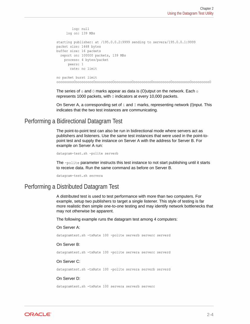
log: null log on: 139 MBs
starting publisher: at /195.0.0.2:9999 sending to servera/195.0.0.1:9999packet size: 1468 bytesbuffer size: 16 packets report on: 100000 packets, 139 MBs process: 4 bytes/packet peers: 1 rate: no limit
no packet burst limitoooooooooOoooooooooOoooooooooOoooooooooOoooooooooOoooooooooOoooooooooOoooooooooO
The series of o and O marks appear as data is (O)utput on the network. Each orepresents 1000 packets, with O indicators at every 10,000 packets.
On Server A, a corresponding set of i and I marks, representing network (I)nput. Thisindicates that the two test instances are communicating.
Performing a Bidirectional Datagram TestThe point-to-point test can also be run in bidirectional mode where servers act aspublishers and listeners. Use the same test instances that were used in the point-to-point test and supply the instance on Server A with the address for Server B. Forexample on Server A run:
datagram-test.sh -polite serverb
The -polite parameter instructs this test instance to not start publishing until it startsto receive data. Run the same command as before on Server B.
datagram-test.sh servera
Performing a Distributed Datagram TestA distributed test is used to test performance with more than two computers. Forexample, setup two publishers to target a single listener. This style of testing is farmore realistic then simple one-to-one testing and may identify network bottlenecks thatmay not otherwise be apparent.
The following example runs the datagram test among 4 computers:
On Server A:
datagramtest.sh -txRate 100 -polite serverb serverc serverd
On Server B:
datagramtest.sh -txRate 100 -polite servera serverc serverd
On Server C:
datagramtest.sh -txRate 100 -polite servera serverb serverd
On Server D:
datagramtest.sh -txRate 100 servera serverb serverc
Chapter 2Using the Datagram Test Utility
2-4
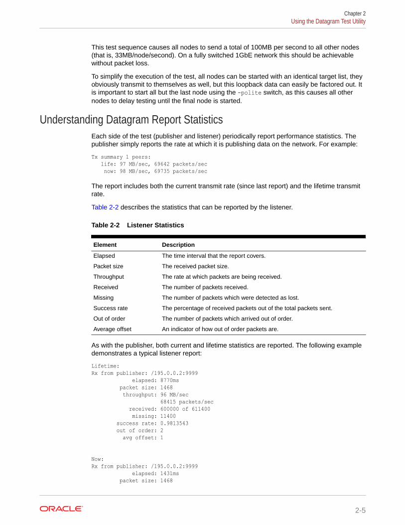
This test sequence causes all nodes to send a total of 100MB per second to all other nodes(that is, 33MB/node/second). On a fully switched 1GbE network this should be achievablewithout packet loss.
To simplify the execution of the test, all nodes can be started with an identical target list, theyobviously transmit to themselves as well, but this loopback data can easily be factored out. Itis important to start all but the last node using the -polite switch, as this causes all othernodes to delay testing until the final node is started.
Understanding Datagram Report StatisticsEach side of the test (publisher and listener) periodically report performance statistics. Thepublisher simply reports the rate at which it is publishing data on the network. For example:
Tx summary 1 peers: life: 97 MB/sec, 69642 packets/sec now: 98 MB/sec, 69735 packets/sec
The report includes both the current transmit rate (since last report) and the lifetime transmitrate.
Table 2-2 describes the statistics that can be reported by the listener.
Table 2-2 Listener Statistics
Element Description
Elapsed The time interval that the report covers.
Packet size The received packet size.
Throughput The rate at which packets are being received.
Received The number of packets received.
Missing The number of packets which were detected as lost.
Success rate The percentage of received packets out of the total packets sent.
Out of order The number of packets which arrived out of order.
Average offset An indicator of how out of order packets are.
As with the publisher, both current and lifetime statistics are reported. The following exampledemonstrates a typical listener report:
Lifetime:Rx from publisher: /195.0.0.2:9999 elapsed: 8770ms packet size: 1468 throughput: 96 MB/sec 68415 packets/sec received: 600000 of 611400 missing: 11400 success rate: 0.9813543 out of order: 2 avg offset: 1
Now:Rx from publisher: /195.0.0.2:9999 elapsed: 1431ms packet size: 1468
Chapter 2Using the Datagram Test Utility
2-5
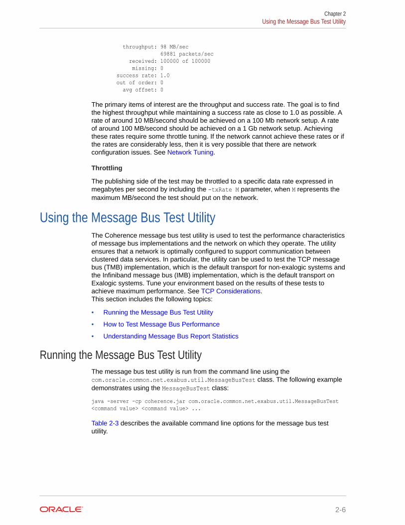
throughput: 98 MB/sec 69881 packets/sec received: 100000 of 100000 missing: 0 success rate: 1.0 out of order: 0 avg offset: 0
The primary items of interest are the throughput and success rate. The goal is to findthe highest throughput while maintaining a success rate as close to 1.0 as possible. Arate of around 10 MB/second should be achieved on a 100 Mb network setup. A rateof around 100 MB/second should be achieved on a 1 Gb network setup. Achievingthese rates require some throttle tuning. If the network cannot achieve these rates or ifthe rates are considerably less, then it is very possible that there are networkconfiguration issues. See Network Tuning.
Throttling
The publishing side of the test may be throttled to a specific data rate expressed inmegabytes per second by including the -txRate M parameter, when M represents themaximum MB/second the test should put on the network.
Using the Message Bus Test UtilityThe Coherence message bus test utility is used to test the performance characteristicsof message bus implementations and the network on which they operate. The utilityensures that a network is optimally configured to support communication betweenclustered data services. In particular, the utility can be used to test the TCP messagebus (TMB) implementation, which is the default transport for non-exalogic systems andthe Infiniband message bus (IMB) implementation, which is the default transport onExalogic systems. Tune your environment based on the results of these tests toachieve maximum performance. See TCP Considerations.This section includes the following topics:
• Running the Message Bus Test Utility
• How to Test Message Bus Performance
• Understanding Message Bus Report Statistics
Running the Message Bus Test UtilityThe message bus test utility is run from the command line using thecom.oracle.common.net.exabus.util.MessageBusTest class. The following exampledemonstrates using the MessageBusTest class:
java -server -cp coherence.jar com.oracle.common.net.exabus.util.MessageBusTest <command value> <command value> ...
Table 2-3 describes the available command line options for the message bus testutility.
Chapter 2Using the Message Bus Test Utility
2-6
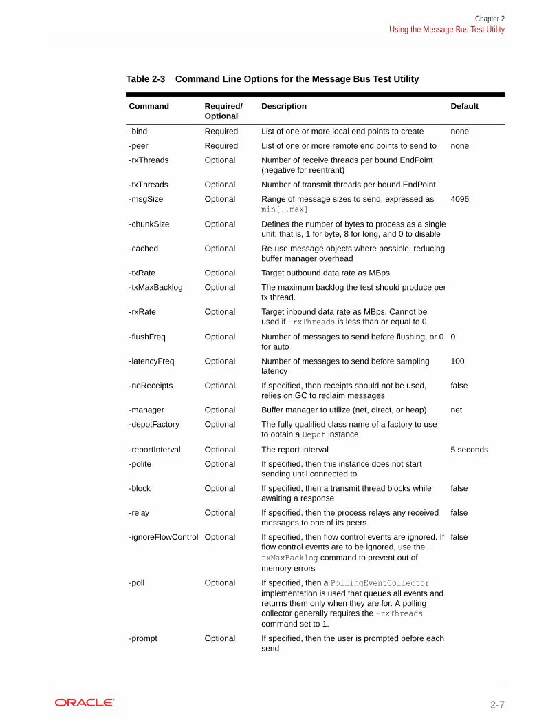
Table 2-3 Command Line Options for the Message Bus Test Utility
Command Required/Optional
Description Default
-bind Required List of one or more local end points to create none
-peer Required List of one or more remote end points to send to none
-rxThreads Optional Number of receive threads per bound EndPoint(negative for reentrant)
-txThreads Optional Number of transmit threads per bound EndPoint
-msgSize Optional Range of message sizes to send, expressed asmin[..max]
4096
-chunkSize Optional Defines the number of bytes to process as a singleunit; that is, 1 for byte, 8 for long, and 0 to disable
-cached Optional Re-use message objects where possible, reducingbuffer manager overhead
-txRate Optional Target outbound data rate as MBps
-txMaxBacklog Optional The maximum backlog the test should produce pertx thread.
-rxRate Optional Target inbound data rate as MBps. Cannot beused if -rxThreads is less than or equal to 0.
-flushFreq Optional Number of messages to send before flushing, or 0for auto
0
-latencyFreq Optional Number of messages to send before samplinglatency
100
-noReceipts Optional If specified, then receipts should not be used,relies on GC to reclaim messages
false
-manager Optional Buffer manager to utilize (net, direct, or heap) net
-depotFactory Optional The fully qualified class name of a factory to useto obtain a Depot instance
-reportInterval Optional The report interval 5 seconds
-polite Optional If specified, then this instance does not startsending until connected to
-block Optional If specified, then a transmit thread blocks whileawaiting a response
false
-relay Optional If specified, then the process relays any receivedmessages to one of its peers
false
-ignoreFlowControl Optional If specified, then flow control events are ignored. Ifflow control events are to be ignored, use the -txMaxBacklog command to prevent out ofmemory errors
false
-poll Optional If specified, then a PollingEventCollectorimplementation is used that queues all events andreturns them only when they are for. A pollingcollector generally requires the -rxThreadscommand set to 1.
-prompt Optional If specified, then the user is prompted before eachsend
Chapter 2Using the Message Bus Test Utility
2-7
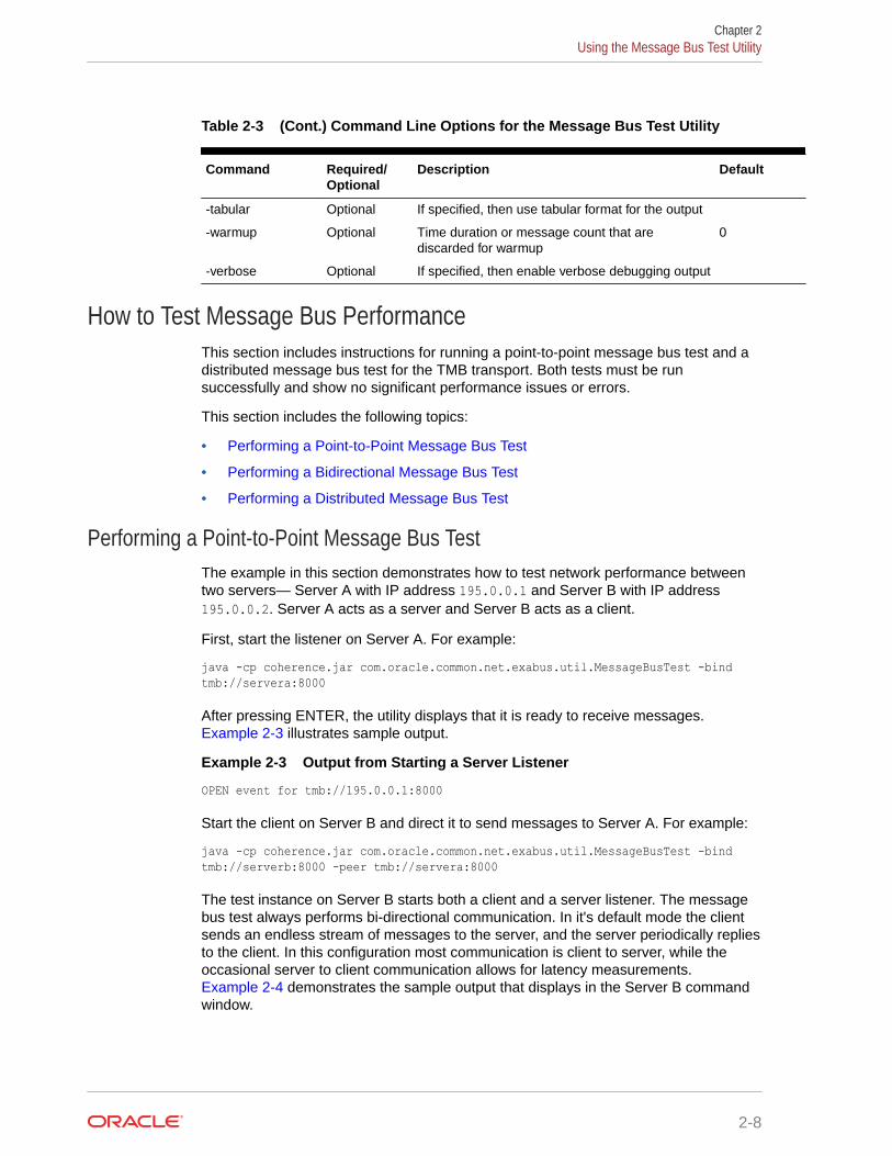
Table 2-3 (Cont.) Command Line Options for the Message Bus Test Utility
Command Required/Optional
Description Default
-tabular Optional If specified, then use tabular format for the output
-warmup Optional Time duration or message count that arediscarded for warmup
0
-verbose Optional If specified, then enable verbose debugging output
How to Test Message Bus PerformanceThis section includes instructions for running a point-to-point message bus test and adistributed message bus test for the TMB transport. Both tests must be runsuccessfully and show no significant performance issues or errors.
This section includes the following topics:
• Performing a Point-to-Point Message Bus Test
• Performing a Bidirectional Message Bus Test
• Performing a Distributed Message Bus Test
Performing a Point-to-Point Message Bus TestThe example in this section demonstrates how to test network performance betweentwo servers— Server A with IP address 195.0.0.1 and Server B with IP address195.0.0.2. Server A acts as a server and Server B acts as a client.
First, start the listener on Server A. For example:
java -cp coherence.jar com.oracle.common.net.exabus.util.MessageBusTest -bind tmb://servera:8000
After pressing ENTER, the utility displays that it is ready to receive messages. Example 2-3 illustrates sample output.
Example 2-3 Output from Starting a Server Listener
OPEN event for tmb://195.0.0.1:8000
Start the client on Server B and direct it to send messages to Server A. For example:
java -cp coherence.jar com.oracle.common.net.exabus.util.MessageBusTest -bind tmb://serverb:8000 -peer tmb://servera:8000
The test instance on Server B starts both a client and a server listener. The messagebus test always performs bi-directional communication. In it's default mode the clientsends an endless stream of messages to the server, and the server periodically repliesto the client. In this configuration most communication is client to server, while theoccasional server to client communication allows for latency measurements. Example 2-4 demonstrates the sample output that displays in the Server B commandwindow.
Chapter 2Using the Message Bus Test Utility
2-8
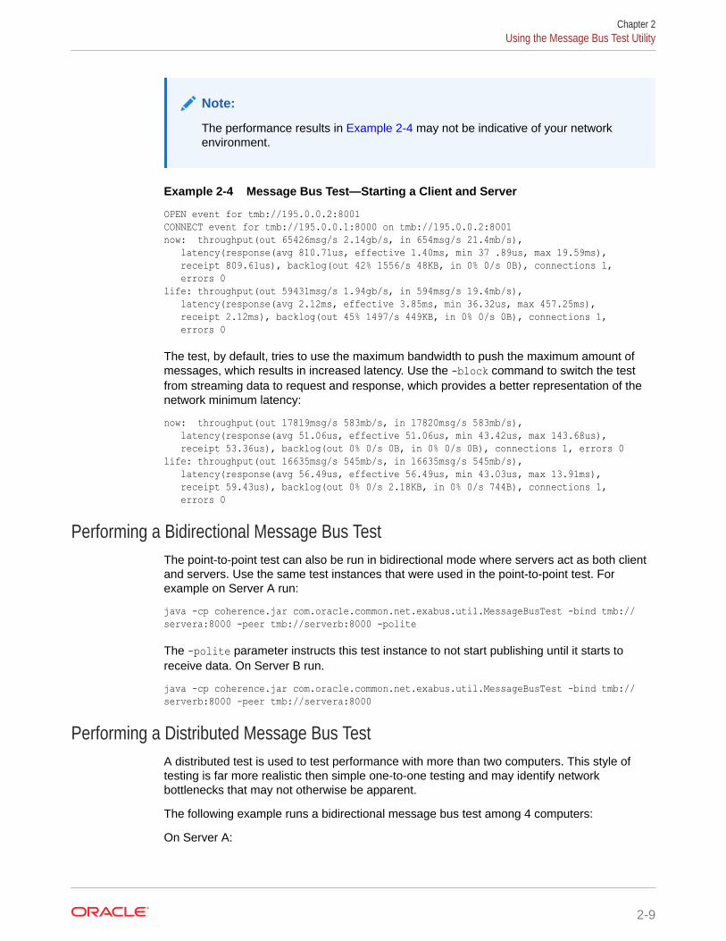
Note:
The performance results in Example 2-4 may not be indicative of your networkenvironment.
Example 2-4 Message Bus Test—Starting a Client and Server
OPEN event for tmb://195.0.0.2:8001CONNECT event for tmb://195.0.0.1:8000 on tmb://195.0.0.2:8001now: throughput(out 65426msg/s 2.14gb/s, in 654msg/s 21.4mb/s), latency(response(avg 810.71us, effective 1.40ms, min 37 .89us, max 19.59ms), receipt 809.61us), backlog(out 42% 1556/s 48KB, in 0% 0/s 0B), connections 1, errors 0life: throughput(out 59431msg/s 1.94gb/s, in 594msg/s 19.4mb/s), latency(response(avg 2.12ms, effective 3.85ms, min 36.32us, max 457.25ms), receipt 2.12ms), backlog(out 45% 1497/s 449KB, in 0% 0/s 0B), connections 1, errors 0
The test, by default, tries to use the maximum bandwidth to push the maximum amount ofmessages, which results in increased latency. Use the -block command to switch the testfrom streaming data to request and response, which provides a better representation of thenetwork minimum latency:
now: throughput(out 17819msg/s 583mb/s, in 17820msg/s 583mb/s), latency(response(avg 51.06us, effective 51.06us, min 43.42us, max 143.68us), receipt 53.36us), backlog(out 0% 0/s 0B, in 0% 0/s 0B), connections 1, errors 0life: throughput(out 16635msg/s 545mb/s, in 16635msg/s 545mb/s), latency(response(avg 56.49us, effective 56.49us, min 43.03us, max 13.91ms), receipt 59.43us), backlog(out 0% 0/s 2.18KB, in 0% 0/s 744B), connections 1, errors 0
Performing a Bidirectional Message Bus TestThe point-to-point test can also be run in bidirectional mode where servers act as both clientand servers. Use the same test instances that were used in the point-to-point test. Forexample on Server A run:
java -cp coherence.jar com.oracle.common.net.exabus.util.MessageBusTest -bind tmb://servera:8000 -peer tmb://serverb:8000 -polite
The -polite parameter instructs this test instance to not start publishing until it starts toreceive data. On Server B run.
java -cp coherence.jar com.oracle.common.net.exabus.util.MessageBusTest -bind tmb://serverb:8000 -peer tmb://servera:8000
Performing a Distributed Message Bus TestA distributed test is used to test performance with more than two computers. This style oftesting is far more realistic then simple one-to-one testing and may identify networkbottlenecks that may not otherwise be apparent.
The following example runs a bidirectional message bus test among 4 computers:
On Server A:
Chapter 2Using the Message Bus Test Utility
2-9
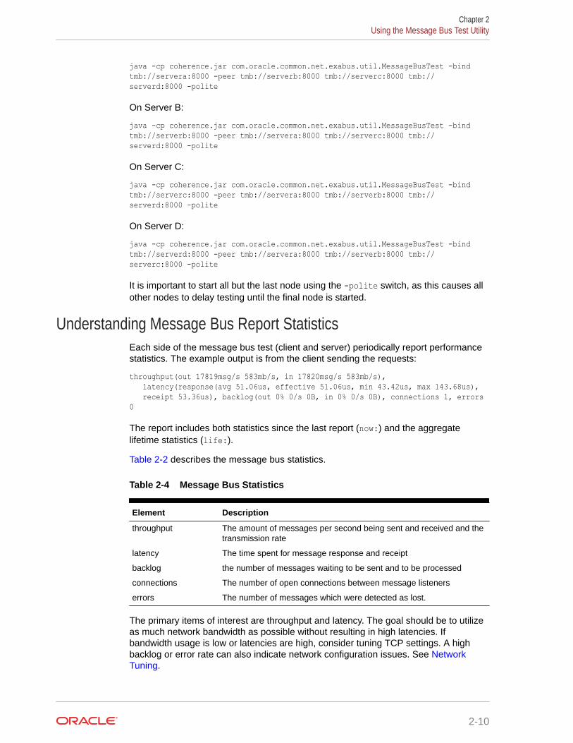
java -cp coherence.jar com.oracle.common.net.exabus.util.MessageBusTest -bind tmb://servera:8000 -peer tmb://serverb:8000 tmb://serverc:8000 tmb://serverd:8000 -polite
On Server B:
java -cp coherence.jar com.oracle.common.net.exabus.util.MessageBusTest -bind tmb://serverb:8000 -peer tmb://servera:8000 tmb://serverc:8000 tmb://serverd:8000 -polite
On Server C:
java -cp coherence.jar com.oracle.common.net.exabus.util.MessageBusTest -bind tmb://serverc:8000 -peer tmb://servera:8000 tmb://serverb:8000 tmb://serverd:8000 -polite
On Server D:
java -cp coherence.jar com.oracle.common.net.exabus.util.MessageBusTest -bind tmb://serverd:8000 -peer tmb://servera:8000 tmb://serverb:8000 tmb://serverc:8000 -polite
It is important to start all but the last node using the -polite switch, as this causes allother nodes to delay testing until the final node is started.
Understanding Message Bus Report StatisticsEach side of the message bus test (client and server) periodically report performancestatistics. The example output is from the client sending the requests:
throughput(out 17819msg/s 583mb/s, in 17820msg/s 583mb/s), latency(response(avg 51.06us, effective 51.06us, min 43.42us, max 143.68us), receipt 53.36us), backlog(out 0% 0/s 0B, in 0% 0/s 0B), connections 1, errors 0
The report includes both statistics since the last report (now:) and the aggregatelifetime statistics (life:).
Table 2-2 describes the message bus statistics.
Table 2-4 Message Bus Statistics
Element Description
throughput The amount of messages per second being sent and received and thetransmission rate
latency The time spent for message response and receipt
backlog the number of messages waiting to be sent and to be processed
connections The number of open connections between message listeners
errors The number of messages which were detected as lost.
The primary items of interest are throughput and latency. The goal should be to utilizeas much network bandwidth as possible without resulting in high latencies. Ifbandwidth usage is low or latencies are high, consider tuning TCP settings. A highbacklog or error rate can also indicate network configuration issues. See NetworkTuning.
Chapter 2Using the Message Bus Test Utility
2-10
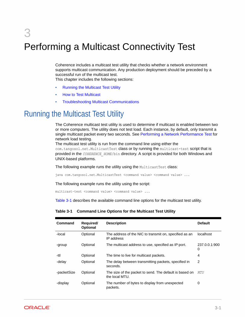
3Performing a Multicast Connectivity Test
Coherence includes a multicast test utility that checks whether a network environmentsupports multicast communication. Any production deployment should be preceded by asuccessful run of the multicast test.This chapter includes the following sections:
• Running the Multicast Test Utility
• How to Test Multicast
• Troubleshooting Multicast Communications
Running the Multicast Test UtilityThe Coherence multicast test utility is used to determine if multicast is enabled between twoor more computers. The utility does not test load. Each instance, by default, only transmit asingle multicast packet every two seconds. See Performing a Network Performance Test fornetwork load testing.The multicast test utility is run from the command line using either thecom.tangosol.net.MulticastTest class or by running the multicast-test script that isprovided in the COHERENCE_HOME/bin directory. A script is provided for both Windows andUNIX-based platforms.
The following example runs the utility using the MulticastTest class:
java com.tangosol.net.MulticastTest <command value> <command value> ...
The following example runs the utility using the script:
multicast-test <command value> <command value> ...
Table 3-1 describes the available command line options for the multicast test utility.
Table 3-1 Command Line Options for the Multicast Test Utility
Command Required/Optional
Description Default
-local Optional The address of the NIC to transmit on, specified as anIP address
localhost
-group Optional The multicast address to use, specified as IP:port. 237.0.0.1:9000
-ttl Optional The time to live for multicast packets. 4
-delay Optional The delay between transmitting packets, specified inseconds.
2
-packetSize Optional The size of the packet to send. The default is based onthe local MTU.
MTU
-display Optional The number of bytes to display from unexpectedpackets.
0
3-1
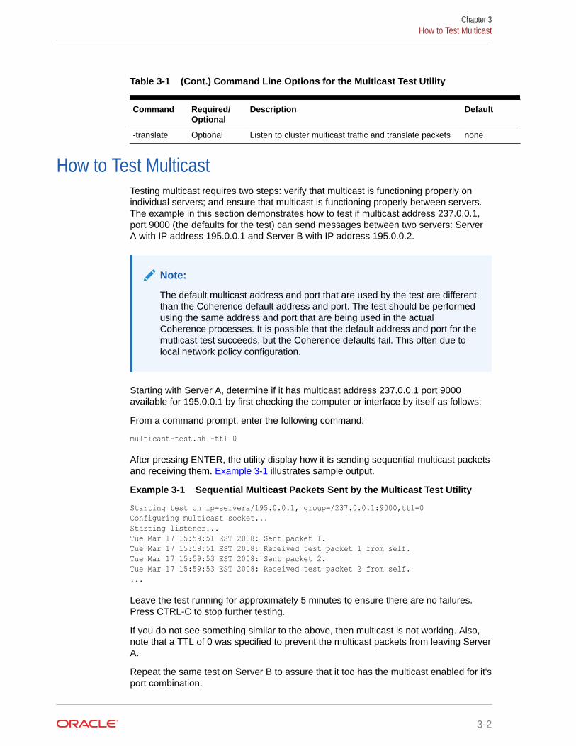
Table 3-1 (Cont.) Command Line Options for the Multicast Test Utility
Command Required/Optional
Description Default
-translate Optional Listen to cluster multicast traffic and translate packets none
How to Test MulticastTesting multicast requires two steps: verify that multicast is functioning properly onindividual servers; and ensure that multicast is functioning properly between servers.The example in this section demonstrates how to test if multicast address 237.0.0.1,port 9000 (the defaults for the test) can send messages between two servers: ServerA with IP address 195.0.0.1 and Server B with IP address 195.0.0.2.
Note:
The default multicast address and port that are used by the test are differentthan the Coherence default address and port. The test should be performedusing the same address and port that are being used in the actualCoherence processes. It is possible that the default address and port for themutlicast test succeeds, but the Coherence defaults fail. This often due tolocal network policy configuration.
Starting with Server A, determine if it has multicast address 237.0.0.1 port 9000available for 195.0.0.1 by first checking the computer or interface by itself as follows:
From a command prompt, enter the following command:
multicast-test.sh -ttl 0
After pressing ENTER, the utility display how it is sending sequential multicast packetsand receiving them. Example 3-1 illustrates sample output.
Example 3-1 Sequential Multicast Packets Sent by the Multicast Test Utility
Starting test on ip=servera/195.0.0.1, group=/237.0.0.1:9000,ttl=0Configuring multicast socket...Starting listener...Tue Mar 17 15:59:51 EST 2008: Sent packet 1.Tue Mar 17 15:59:51 EST 2008: Received test packet 1 from self.Tue Mar 17 15:59:53 EST 2008: Sent packet 2.Tue Mar 17 15:59:53 EST 2008: Received test packet 2 from self....
Leave the test running for approximately 5 minutes to ensure there are no failures.Press CTRL-C to stop further testing.
If you do not see something similar to the above, then multicast is not working. Also,note that a TTL of 0 was specified to prevent the multicast packets from leaving ServerA.
Repeat the same test on Server B to assure that it too has the multicast enabled for it'sport combination.
Chapter 3How to Test Multicast
3-2
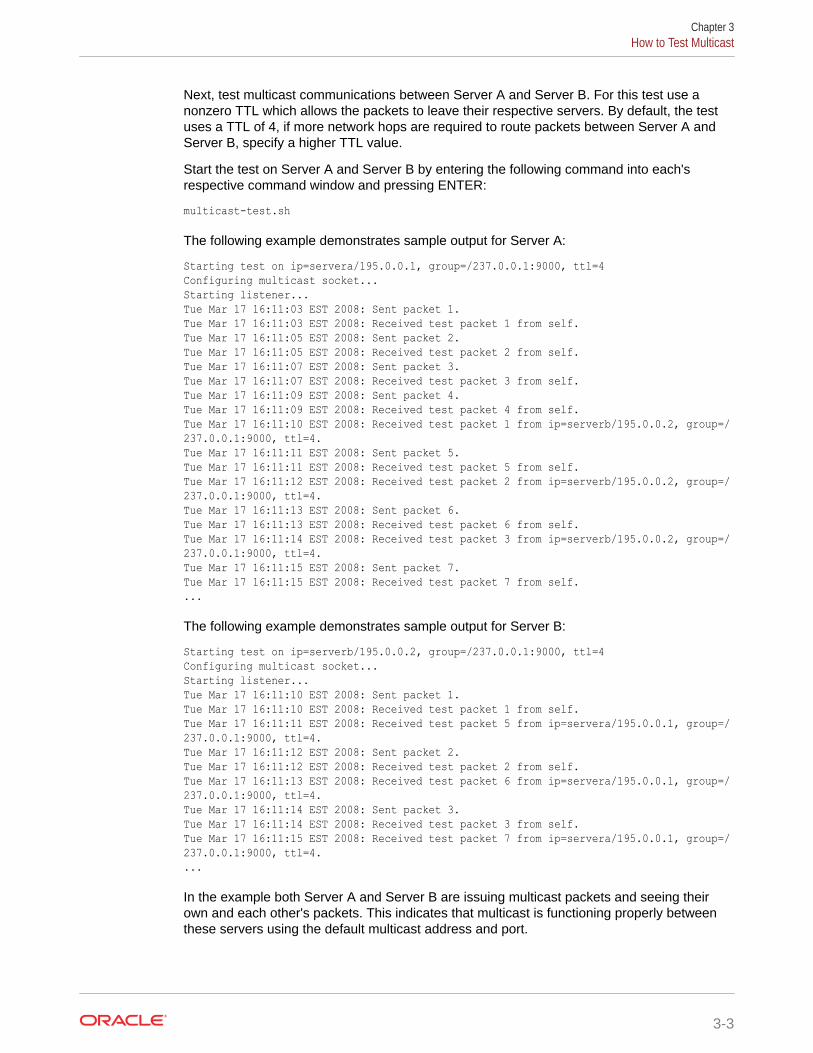
Next, test multicast communications between Server A and Server B. For this test use anonzero TTL which allows the packets to leave their respective servers. By default, the testuses a TTL of 4, if more network hops are required to route packets between Server A andServer B, specify a higher TTL value.
Start the test on Server A and Server B by entering the following command into each'srespective command window and pressing ENTER:
multicast-test.sh
The following example demonstrates sample output for Server A:
Starting test on ip=servera/195.0.0.1, group=/237.0.0.1:9000, ttl=4Configuring multicast socket...Starting listener...Tue Mar 17 16:11:03 EST 2008: Sent packet 1.Tue Mar 17 16:11:03 EST 2008: Received test packet 1 from self.Tue Mar 17 16:11:05 EST 2008: Sent packet 2.Tue Mar 17 16:11:05 EST 2008: Received test packet 2 from self.Tue Mar 17 16:11:07 EST 2008: Sent packet 3.Tue Mar 17 16:11:07 EST 2008: Received test packet 3 from self.Tue Mar 17 16:11:09 EST 2008: Sent packet 4.Tue Mar 17 16:11:09 EST 2008: Received test packet 4 from self.Tue Mar 17 16:11:10 EST 2008: Received test packet 1 from ip=serverb/195.0.0.2, group=/237.0.0.1:9000, ttl=4.Tue Mar 17 16:11:11 EST 2008: Sent packet 5.Tue Mar 17 16:11:11 EST 2008: Received test packet 5 from self.Tue Mar 17 16:11:12 EST 2008: Received test packet 2 from ip=serverb/195.0.0.2, group=/237.0.0.1:9000, ttl=4.Tue Mar 17 16:11:13 EST 2008: Sent packet 6.Tue Mar 17 16:11:13 EST 2008: Received test packet 6 from self.Tue Mar 17 16:11:14 EST 2008: Received test packet 3 from ip=serverb/195.0.0.2, group=/237.0.0.1:9000, ttl=4.Tue Mar 17 16:11:15 EST 2008: Sent packet 7.Tue Mar 17 16:11:15 EST 2008: Received test packet 7 from self....
The following example demonstrates sample output for Server B:
Starting test on ip=serverb/195.0.0.2, group=/237.0.0.1:9000, ttl=4Configuring multicast socket...Starting listener...Tue Mar 17 16:11:10 EST 2008: Sent packet 1.Tue Mar 17 16:11:10 EST 2008: Received test packet 1 from self.Tue Mar 17 16:11:11 EST 2008: Received test packet 5 from ip=servera/195.0.0.1, group=/237.0.0.1:9000, ttl=4.Tue Mar 17 16:11:12 EST 2008: Sent packet 2.Tue Mar 17 16:11:12 EST 2008: Received test packet 2 from self.Tue Mar 17 16:11:13 EST 2008: Received test packet 6 from ip=servera/195.0.0.1, group=/237.0.0.1:9000, ttl=4.Tue Mar 17 16:11:14 EST 2008: Sent packet 3.Tue Mar 17 16:11:14 EST 2008: Received test packet 3 from self.Tue Mar 17 16:11:15 EST 2008: Received test packet 7 from ip=servera/195.0.0.1, group=/237.0.0.1:9000, ttl=4....
In the example both Server A and Server B are issuing multicast packets and seeing theirown and each other's packets. This indicates that multicast is functioning properly betweenthese servers using the default multicast address and port.
Chapter 3How to Test Multicast
3-3
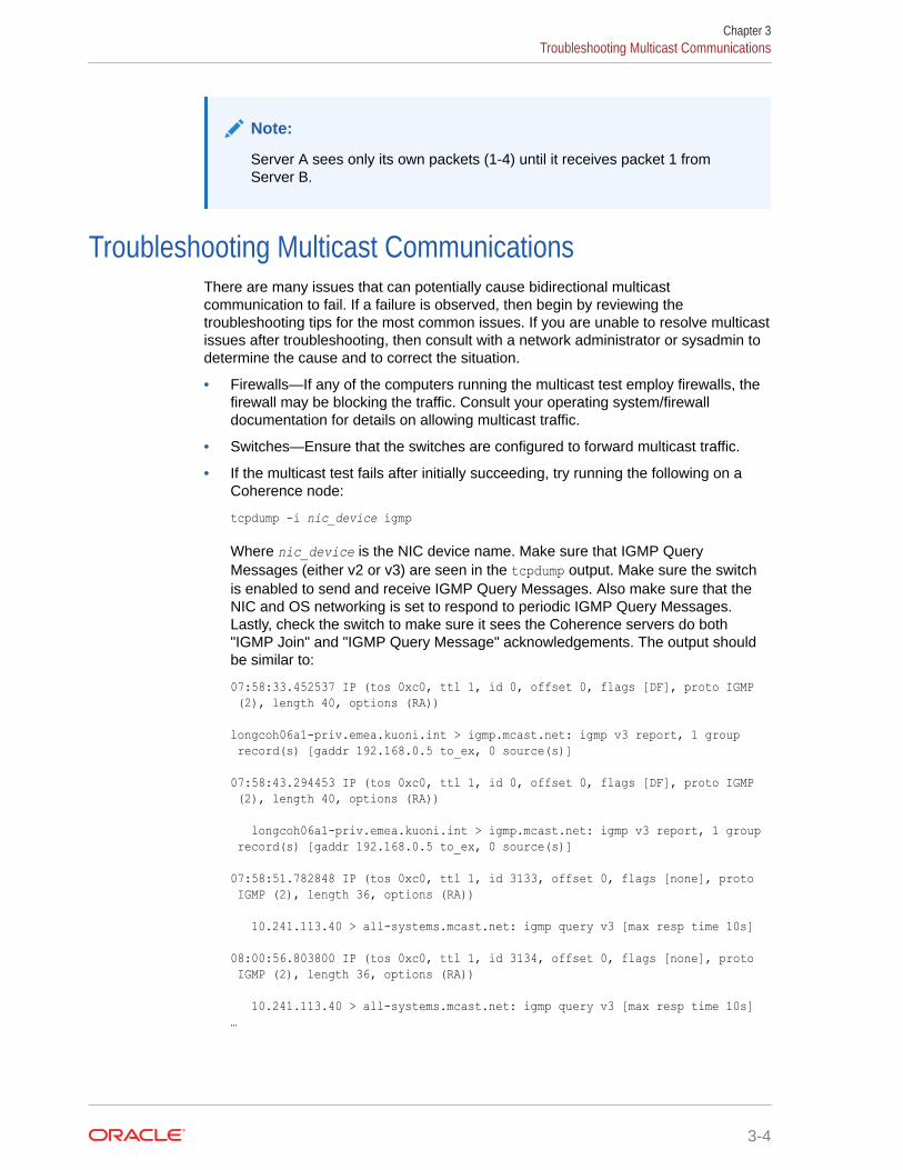
Note:
Server A sees only its own packets (1-4) until it receives packet 1 fromServer B.
Troubleshooting Multicast CommunicationsThere are many issues that can potentially cause bidirectional multicastcommunication to fail. If a failure is observed, then begin by reviewing thetroubleshooting tips for the most common issues. If you are unable to resolve multicastissues after troubleshooting, then consult with a network administrator or sysadmin todetermine the cause and to correct the situation.
• Firewalls—If any of the computers running the multicast test employ firewalls, thefirewall may be blocking the traffic. Consult your operating system/firewalldocumentation for details on allowing multicast traffic.
• Switches—Ensure that the switches are configured to forward multicast traffic.
• If the multicast test fails after initially succeeding, try running the following on aCoherence node:
tcpdump -i nic_device igmp
Where nic_device is the NIC device name. Make sure that IGMP QueryMessages (either v2 or v3) are seen in the tcpdump output. Make sure the switchis enabled to send and receive IGMP Query Messages. Also make sure that theNIC and OS networking is set to respond to periodic IGMP Query Messages.Lastly, check the switch to make sure it sees the Coherence servers do both"IGMP Join" and "IGMP Query Message" acknowledgements. The output shouldbe similar to:
07:58:33.452537 IP (tos 0xc0, ttl 1, id 0, offset 0, flags [DF], proto IGMP (2), length 40, options (RA)) longcoh06a1-priv.emea.kuoni.int > igmp.mcast.net: igmp v3 report, 1 group record(s) [gaddr 192.168.0.5 to_ex, 0 source(s)] 07:58:43.294453 IP (tos 0xc0, ttl 1, id 0, offset 0, flags [DF], proto IGMP (2), length 40, options (RA)) longcoh06a1-priv.emea.kuoni.int > igmp.mcast.net: igmp v3 report, 1 group record(s) [gaddr 192.168.0.5 to_ex, 0 source(s)] 07:58:51.782848 IP (tos 0xc0, ttl 1, id 3133, offset 0, flags [none], proto IGMP (2), length 36, options (RA)) 10.241.113.40 > all-systems.mcast.net: igmp query v3 [max resp time 10s] 08:00:56.803800 IP (tos 0xc0, ttl 1, id 3134, offset 0, flags [none], proto IGMP (2), length 36, options (RA)) 10.241.113.40 > all-systems.mcast.net: igmp query v3 [max resp time 10s]…
Chapter 3Troubleshooting Multicast Communications
3-4
The first two lines are servers "joining" the multicast group. The remaining output are theIGMP Query Messages originating at the switch, these are continuous, every few minutes- if the switch is configured to send them, and the NIC is configured to respond.
• IPv6—On operating systems which support IPv6, Java may be attempting to route theMulticast traffic over IPv6 rather than IPv4. Try specifying the following Java systemproperty to force IPv4 networking java.net.preferIPv4Stack=true. Coherence clustermembers must all use either IPv4 or IPv6 and cannot use a mix of both.
• Received ???—If the test reports receiving "???" this is an indication that it is receivingmulticast packets which did not originate from an instance of the Multicast test. Thisoccurs if the test is run with the same multicast address as an existing Coherence cluster,or any other multicast application.
• Multiple NICs—If the computers have multiple network interfaces, try specifying anexplicit interface by using the -local test parameter. For instance if Server A has twointerfaces with IP addresses 195.0.0.1 and 195.0.100.1, including -local 195.0.0.1 onthe test command line would ensure that the multicast packets used the first interface. Inaddition, the computer's routing table may require explicit configuration to forwardmulticast traffic through the desired network interface. This can be done by issuing thefollowing command:
route add -net 224.0.0.0 netmask 240.0.0.0 dev eth1
Where eth1 is the device that is designated to transmit multicast traffic.
• AIX—On AIX systems, the following multicast issues may be encountered:
– IPv6—In addition to specifying java.net.preferIPv4Stack=true, the operatingsystem may require additional configuration to perform IPv4 name resolution. Addhosts=local,bind4 to the /etc/netsvc.conf file.
– Virtual IP (VIPA)—AIX does not support multicast with VIPA. If using VIPA either bindmulticast to a non-VIPA device, or run Coherence with multicast disabled. See UsingWell Known Addresses in Developing Applications with Oracle Coherence.
– MTU—Configure the MTU for the multicast device to 1500 bytes.
• Cisco Switches—See Deploying to Cisco Switches.
• Foundry Switches—See Deploying to Foundry Switches.
Chapter 3Troubleshooting Multicast Communications
3-5
4Performance Tuning
A critical part of successfully deploying Coherence solutions is to tune the application andproduction environment to achieve maximum performance.This chapter includes manyguidelines and considerations that can be used to tune performance and possibly identifyperformance issues. However, as with any production deployment, always run performanceand stress tests to validate how a particular application and production environmentperforms.This chapter includes the following sections:
• Operating System Tuning
• Network Tuning
• JVM Tuning
• Data Access Patterns
• Distributed Tracing
Operating System TuningOperating system settings, such as socket buffers, thread scheduling, and disk swapping canbe configured to minimize latency.This section includes the following topics:
• Socket Buffer Sizes
• High Resolution timesource (Linux)
• Datagram size (Microsoft Windows)
• TCP Retransmission Timeout (Microsoft Windows)
• Thread Scheduling (Microsoft Windows)
• Swapping
• Load Balancing Network Interrupts (Linux)
Socket Buffer SizesLarge operating system socket buffers can help minimize packet loss during garbagecollection. Each Coherence socket implementation attempts to allocate a default socketbuffer size. A warning message is logged for each socket implementation if the default sizecannot be allocated. The following example is a message for the inbound UDP socket buffer:
UnicastUdpSocket failed to set receive buffer size to 16 packets (1023KB); actualsize is 12%, 2 packets (127KB). Consult your OS documentation regarding increasingthe maximum socket buffer size. Proceeding with the actual value may causesub-optimal performance.
It is recommended that you configure the operating system to allow for larger buffers.However, alternate buffer sizes for Coherence packet publishers and unicast listeners can be
4-1
configured using the <packet-buffer> element. See Configuring the Size of thePacket Buffers in Developing Applications with Oracle Coherence.
Note:
Most versions of UNIX have a very low default buffer limit, which should beincreased to at least 2MB. Also, note that UDP recommendations are onlyapplicable for configurations which explicitly configure UDP in favor of TCPas TCP is the default for performance sensitive tasks.
On Linux, execute (as root):
sysctl -w net.core.rmem_max=2097152sysctl -w net.core.wmem_max=2097152
On Solaris, execute (as root):
ndd -set /dev/udp udp_max_buf 2097152
On AIX, execute (as root):
no -o rfc1323=1no -o sb_max=4194304
Note:
Note that AIX only supports specifying buffer sizes of 1MB, 4MB, and 8MB.
On Windows:
Windows does not impose a buffer size restriction by default.
Other:
For information on increasing the buffer sizes for other operating systems, refer to youroperating system's documentation.
High Resolution timesource (Linux)Linux has several high resolution timesources to choose from, the fastest TSC (TimeStamp Counter) unfortunately is not always reliable. Linux chooses TSC by defaultand during startup checks for inconsistencies, if found it switches to a slower safetimesource. The slower time sources can be 10 to 30 times more expensive to querythen the TSC timesource, and may have a measurable impact on Coherenceperformance. For more details on TSC, see
https://lwn.net/Articles/209101/Note that Coherence and the underlying JVM are not aware of the timesource whichthe operating system is using. It is suggested that you check your system logs(/var/log/dmesg) to verify that the following is not present.
Chapter 4Operating System Tuning
4-2
kernel: Losing too many ticks!kernel: TSC cannot be used as a timesource.kernel: Possible reasons for this are:kernel: You're running with Speedstep,kernel: You don't have DMA enabled for your hard disk (see hdparm),kernel: Incorrect TSC synchronization on an SMP system (see dmesg).kernel: Falling back to a sane timesource now.
As the log messages suggest, this can be caused by a variable rate CPU (SpeedStep),having DMA disabled, or incorrect TSC synchronization on multi CPU computers. If present,work with your system administrator to identify and correct the cause allowing the TSCtimesource to be used.
Datagram size (Microsoft Windows)Microsoft Windows supports a fast I/O path which is used when sending "small" datagrams.The default setting for what is considered a small datagram is 1024 bytes; increasing thisvalue to match your network maximum transmission unit (MTU), normally 1500, cansignificantly improve network performance.
To adjust this parameter:
1. Run Registry Editor (regedit)
2. Locate the following registry keyHKLM\System\CurrentControlSet\Services\AFD\Parameters
3. Add the following new DWORD value Name: FastSendDatagramThreshold Value: 1500(decimal)
4. Restart.
Note:
The COHERENCE_HOME/bin/optimize.reg script can also perform this change. Afterrunning the script, restart the computer for the changes to take effect.
TCP Retransmission Timeout (Microsoft Windows)Microsoft Windows includes a TCP retransmission timeout that is used for existing and newconnections. The default retransmission timeout can abandon connections in a matter ofseconds based on the Windows automatic tuning for TCP data transmission on the network.The short timeout can result in the false positive detection of cluster member death by theTcpRing process and can result in data loss. The default retransmission timeout can beconfigured to be more tolerant of short outages that may occur on the production network.
To increase the TCP retransmission timeout:
1. Run Registry Editor (regedit)
2. Locate the following registry keyHKLM\SYSTEM\CurrentControlSet\Services\Tcpip\Parameters
3. Add the following new DWORD value Name: TcpMaxConnectRetransmissions Value:00000015 (Hex)
Chapter 4Operating System Tuning
4-3
4. Add the following new DWORD value Name: TcpMaxDataRetransmissions Value:00000015 (Hex)
5. Restart.
Note:
The COHERENCE_HOME/bin/optimize.reg script can also perform this change.After running the script, restart the computer for the changes to take effect.
Thread Scheduling (Microsoft Windows)Windows is optimized for desktop application usage. If you run two console ("DOSbox") windows, the one that has the focus can use almost 100% of the CPU, even ifother processes have high-priority threads in a running state. To correct thisimbalance, you must configure the Windows thread scheduling to less-heavily favorforeground applications.
1. Open the Control Panel.
2. Open System.
3. Select the Advanced tab.
4. Under Performance select Settings.
5. Select the Advanced tab.
6. Under Processor scheduling, choose Background services.
Note:
The COHERENCE_HOME/bin/optimize.reg script performs this change. Afterrunning the script, restart the computer for the changes to take effect.
SwappingSwapping, also known as paging, is the use of secondary storage to store and retrieveapplication data for use in RAM memory. Swapping is automatically performed by theoperating system and typically occurs when the available RAM memory is depleted.Swapping can have a significant impact on Coherence's performance and should beavoided. Often, swapping manifests itself as Coherence nodes being removed fromthe cluster due to long periods of unresponsiveness caused by them having beenswapped out of RAM. See Avoid using virtual memory (paging to disk).
To avoid swapping, ensure that sufficient RAM memory is available on the computer orthat the number of running processes is accounted for and do not consume all theavailable RAM. Tools such as vmstat and top (on Unix and Linux) and taskmgr (onWindows) should be used to monitor swap rates.
Chapter 4Operating System Tuning
4-4
Swappiness in Linux
Linux, by default, may choose to swap out a process or some of its heap due to low usageeven if it is not running low on RAM. Swappiness is performed to be ready to handle eventualmemory requests. Swappiness should be avoided for Coherence JVMs. The swappinesssetting on Linux is a value between 0 and 100, where higher values encourage moreoptimistic swapping. The default value is 60. For Coherence, a lower value (0 if possible)should always be set.
To see the current swappiness value that is set, enter the following at the command prompt:
cat /proc/sys/vm/swappiness
To temporarily set the swappiness, as the root user echo a value onto /proc/sys/vm/swappiness. The following example sets the value to 0.
echo 0 > /proc/sys/vm/swappiness
To set the value permanently, modify the /etc/sysctl.conf file as follows:
vm.swappiness = 0
Load Balancing Network Interrupts (Linux)Linux kernels have the ability to balance hardware interrupt requests across multiple CPUs orCPU cores. The feature is referred to as SMP IRQ Affinity and results in better systemperformance as well as better CPU utilization. For Coherence, significant performance can begained by balancing ethernet card interrupts for all servers that host cluster members. MostLinux distributions also support irqbalance, which is aware of the cache topologies and powermanagement features of modern multi-core and multi-socket systems.
Most Linux installations are not configured to balance network interrupts. The default networkinterrupt behavior uses a single processor (typically CPU0) to handle all network interruptsand can become a serious performance bottleneck with high volumes of network traffic.Balancing network interrupts among multiple CPUs increases the performance of network-based operations.
For detailed instructions on how to configure SMP IRQ Affinity, see the following documentwhich is only summarized below:
http://www.mjmwired.net/kernel/Documentation/IRQ-affinity.txtTo view a list of the system's IRQs that includes which device they are assigned to and thenumber of interrupts each processor has handled for the device, run the following command:
# cat /proc/interrupts
The following example output snippet shows a single network interface card where allinterrupts have been handled by the same processor (CPU0). This particular network cardhas multiple transmit and receive queues which have their own assigned IRQ. Systems thatuse multiple network cards will have additional IRQs assigned for each card.
CPU0 CPU1 CPU2 CPU365: 20041 0 0 0 IR-PCI-MSI-edge eth0-tx-066: 20232 0 0 0 IR-PCI-MSI-edge eth0-tx-167: 20105 0 0 0 IR-PCI-MSI-edge eth0-tx-268: 20423 0 0 0 IR-PCI-MSI-edge eth0-tx-369: 21036 0 0 0 IR-PCI-MSI-edge eth0-rx-0
Chapter 4Operating System Tuning
4-5
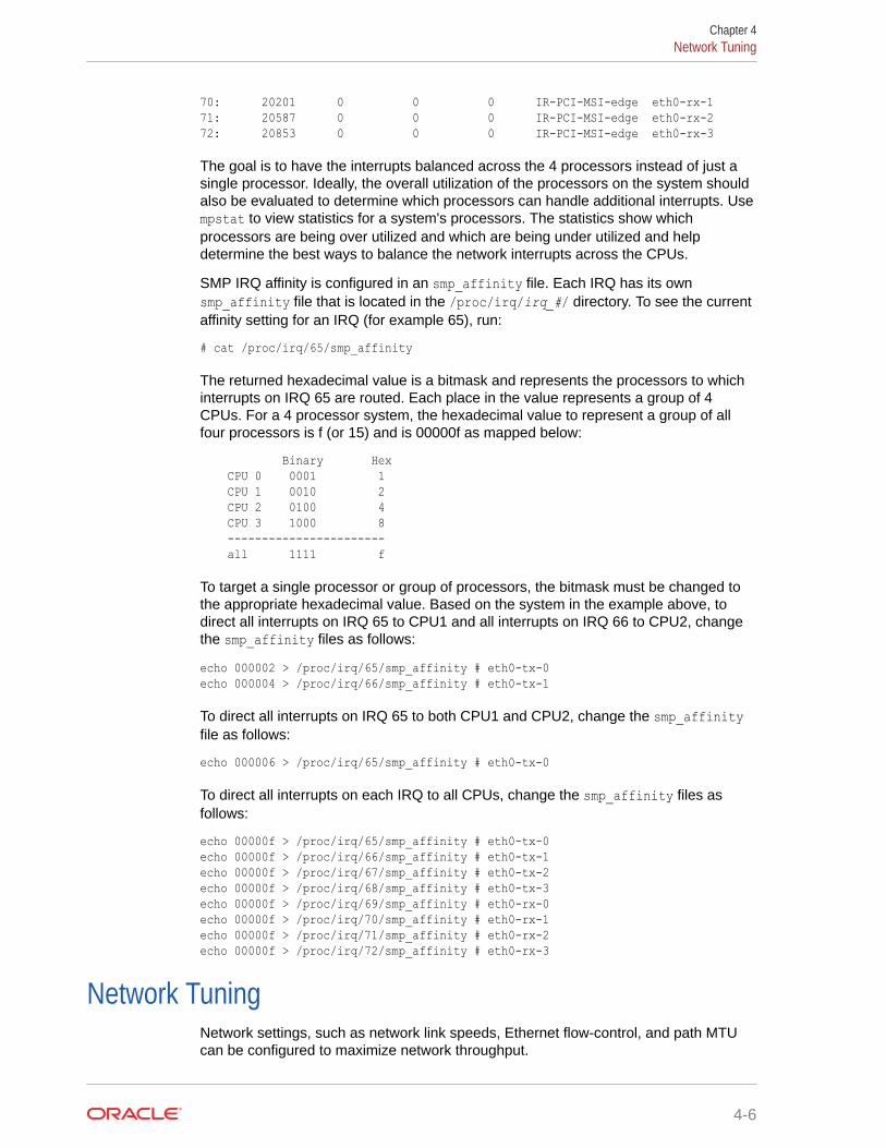
70: 20201 0 0 0 IR-PCI-MSI-edge eth0-rx-171: 20587 0 0 0 IR-PCI-MSI-edge eth0-rx-272: 20853 0 0 0 IR-PCI-MSI-edge eth0-rx-3
The goal is to have the interrupts balanced across the 4 processors instead of just asingle processor. Ideally, the overall utilization of the processors on the system shouldalso be evaluated to determine which processors can handle additional interrupts. Usempstat to view statistics for a system's processors. The statistics show whichprocessors are being over utilized and which are being under utilized and helpdetermine the best ways to balance the network interrupts across the CPUs.
SMP IRQ affinity is configured in an smp_affinity file. Each IRQ has its ownsmp_affinity file that is located in the /proc/irq/irq_#/ directory. To see the currentaffinity setting for an IRQ (for example 65), run:
# cat /proc/irq/65/smp_affinity
The returned hexadecimal value is a bitmask and represents the processors to whichinterrupts on IRQ 65 are routed. Each place in the value represents a group of 4CPUs. For a 4 processor system, the hexadecimal value to represent a group of allfour processors is f (or 15) and is 00000f as mapped below:
Binary Hex CPU 0 0001 1 CPU 1 0010 2 CPU 2 0100 4 CPU 3 1000 8 ----------------------- all 1111 f
To target a single processor or group of processors, the bitmask must be changed tothe appropriate hexadecimal value. Based on the system in the example above, todirect all interrupts on IRQ 65 to CPU1 and all interrupts on IRQ 66 to CPU2, changethe smp_affinity files as follows:
echo 000002 > /proc/irq/65/smp_affinity # eth0-tx-0echo 000004 > /proc/irq/66/smp_affinity # eth0-tx-1
To direct all interrupts on IRQ 65 to both CPU1 and CPU2, change the smp_affinityfile as follows:
echo 000006 > /proc/irq/65/smp_affinity # eth0-tx-0
To direct all interrupts on each IRQ to all CPUs, change the smp_affinity files asfollows:
echo 00000f > /proc/irq/65/smp_affinity # eth0-tx-0echo 00000f > /proc/irq/66/smp_affinity # eth0-tx-1echo 00000f > /proc/irq/67/smp_affinity # eth0-tx-2echo 00000f > /proc/irq/68/smp_affinity # eth0-tx-3echo 00000f > /proc/irq/69/smp_affinity # eth0-rx-0echo 00000f > /proc/irq/70/smp_affinity # eth0-rx-1echo 00000f > /proc/irq/71/smp_affinity # eth0-rx-2echo 00000f > /proc/irq/72/smp_affinity # eth0-rx-3
Network TuningNetwork settings, such as network link speeds, Ethernet flow-control, and path MTUcan be configured to maximize network throughput.
Chapter 4Network Tuning
4-6
This section includes the following topics:
• Network Interface Settings
• Network Infrastructure Settings
• Switch and Subnet Considerations
• Ethernet Flow-Control
• Path MTU
• 10GbE Considerations
• TCP Considerations
Network Interface SettingsVerify that your Network card (NIC) is configured to operate at it's maximum link speed and atfull duplex. The process for doing this varies between operating systems.
On Linux execute (as root):
ethtool eth0
See the man page on ethtool for further details and for information on adjust the interfacesettings.
On Solaris execute (as root):
kstat ce:0 | grep link_
This displays the link settings for interface 0. Items of interest are link_duplex (2 = full), andlink_speed which is reported in Mbps.
Note:
If running on Solaris 10, review issues 1000972.1 and 1000940.1 which relate topacket corruption and multicast disconnections. These often manifest as eitherEOFExceptions, "Large gap" warnings while reading packet data, or frequent packettimeouts. It is highly recommend that the patches for both issues be applied whenusing Coherence on Solaris 10 systems.
On Windows:
1. Open the Control Panel.
2. Open Network Connections.
3. Open the Properties dialog for desired network adapter.
4. Select Configure.
5. Select the Advanced tab.
6. Locate the driver specific property for Speed & Duplex.
7. Set it to either auto or to a specific speed and duplex setting.
Chapter 4Network Tuning
4-7
Network Infrastructure SettingsIf you experience frequent multi-second communication pauses across multiple clusternodes, try increasing your switch's buffer space. These communication pauses can beidentified by a series of Coherence log messages identifying communication delayswith multiple nodes which are not attributable to local or remote GCs.
Example 4-1 Message Indicating a Communication Delay
Experienced a 4172 ms communication delay (probable remote GC) with Member(Id=7, Timestamp=2006-10-20 12:15:47.511, Address=192.168.0.10:8089, MachineId=13838); 320 packets rescheduled, PauseRate=0.31, Threshold=512
Some switches such as the Cisco 6500 series support configuring the amount of bufferspace available to each Ethernet port or ASIC. In high load applications it may benecessary to increase the default buffer space. On Cisco, this can be accomplished byexecuting:
fabric buffer-reserve high
See Cisco's documentation for additional details on this setting.
Switch and Subnet ConsiderationsCluster members may be split across multiple switches and may be part of multiplesubnets. However, such topologies can overwhelm inter-switch links and increase thechances of a split cluster if the links fail.Typically, the impact materializes ascommunication delays that affect cluster and application performance. If possible,consider always locating all cluster members on the same switch and subnet tominimize the impact. See Evaluate the Production Network's Speed for both UDP andTCP.
Ethernet Flow-ControlFull duplex Ethernet includes a flow-control feature which allows the receiving end of apoint to point link to slow down the transmitting end. This is implemented by thereceiving end sending an Ethernet PAUSE frame to the transmitting end, thetransmitting end then halts transmissions for the interval specified by the PAUSEframe. Note that this pause blocks all traffic from the transmitting side, even trafficdestined for computers which are not overloaded. This can induce a head of lineblocking condition, where one overloaded computer on a switch effectively slows downall other computers. Most switch vendors recommend that Ethernet flow-control bedisabled for inter switch links, and at most be used on ports which are directlyconnected to computers. Even in this setup head of line blocking can still occur, andthus it is advisable to disable Ethernet flow-control. Higher level protocols such asTCP/IP and Coherence TCMP include their own flow-control mechanisms which arenot subject to head of line blocking, and also negate the need for the lower level flow-control.
Path MTUBy default Coherence assumes a 1500 byte network MTU, and uses a default packetsize of 1468 based on this assumption. Having a packet size which does not fill theMTU results in an under used network. If your equipment uses a different MTU, then
Chapter 4Network Tuning
4-8
configure Coherence by specifying the <packet-size> setting, which is 32 bytes smaller thenthe network path's minimal MTU.
If you are unsure of your equipment's MTU along the full path between nodes, you can useeither the standard ping or traceroute utilities to determine the MTU. For example, executea series of ping or traceroute operations between the two computers. With each attempt,specify a different packet size, starting from a high value and progressively moving downwarduntil the packets start to make it through without fragmentation.
On Linux execute:
ping -c 3 -M do -s 1468 serverb
On Solaris execute:
traceroute -F serverb 1468
On Windows execute:
ping -n 3 -f -l 1468 serverb
On other operating systems: Consult the documentation for the ping or traceroutecommand to see how to disable fragmentation, and specify the packet size.
If you receive a message stating that packets must be fragmented then the specified size islarger then the path's MTU. Decrease the packet size until you find the point at which packetscan be transmitted without fragmentation. If you find that you must use packets smaller then1468, you may want to contact your network administrator to get the MTU increased to atleast 1500.
10GbE ConsiderationsMany 10 Gigabit Ethernet (10GbE) switches and network interface cards support frame sizesthat are larger than the 1500 byte ethernet frame standard. When using 10GbE, make surethat the MTU is set to the maximum allowed by the technology (approximately 16KB forethernet) to take full advantage of the greater bandwidth. Coherence automatically detectsthe MTU of the network and selects a UDP socket buffer size accordingly. UDP socket buffersizes of 2MB, 4MB, or 8MB are selected for MTU sizes of 1500 bytes (standard), 9000 bytes(jumbo), and over 9000 (super jumbo), respectively. Also, make sure to increase theoperating system socket buffers to 8MB to accommodate the larger sizes. A warning isissued in the Coherence logs if a significantly small operating system buffer is detected.Lastly, always run the datagram test to validate the performance and throughput of thenetwork. See Performing a Network Performance Test.
TCP ConsiderationsCoherence utilizes a TCP message bus (TMB) to transmit messages between clustered dataservices. Therefore, a network must be optimally tuned for TCP. Coherence inherits TCPsettings, including buffer settings, from the operating system. Most servers already have TCPtuned for the network and should not require additional configuration. The recommendation isto tune the TCP stack for the network instead of tuning Coherence for the network.
Coherence includes a message bus test utility that can be used to test throughput andlatency between network nodes. See Running the Message Bus Test Utility. If a networkshows poor performance, then it may not be properly configured, use the following
Chapter 4Network Tuning
4-9
recommendations (note that these settings are demonstrated on Linux but can betranslated to other operating systems):
#!/bin/bash## aggregate size limitations for all connections, measured in pages; these values# are for 4KB pages (getconf PAGESIZE)
/sbin/sysctl -w net.ipv4.tcp_mem=' 65536 131072 262144'
# limit on receive space bytes per-connection; overridable by SO_RCVBUF; still# goverened by core.rmem_max
/sbin/sysctl -w net.ipv4.tcp_rmem=' 262144 4194304 8388608'
# limit on send space bytes per-connection; overridable by SO_SNDBUF; still# goverered by core.wmem_max
/sbin/sysctl -w net.ipv4.tcp_wmem=' 65536 1048576 2097152'
# absolute limit on socket receive space bytes per-connection; cannot be# overriden programatically
/sbin/sysctl -w net.core.rmem_max=16777216
# absolute limit on socket send space bytes per-connection; cannot be overriden;# cannot be overriden programatically
/sbin/sysctl -w net.core.wmem_max=16777216
Each connection consumes a minimum of 320KB, but under normal memory pressure,consumes 5MB per connection and ultimately the operating system tries to keep theentire system buffering for TCP under 1GB. These are recommended defaults basedon tuning for fast (>= 10gbe) networks and should be acceptable on 1gbe.
JVM TuningJVM runtime settings, such as heap size and garbage collection can be configured toensure the right balance of resource utilization and performance.This section includes the following topics:
• Basic Sizing Recommendation
• Heap Size Considerations
• Garbage Collection Monitoring
Basic Sizing RecommendationThe recommendations in this section are sufficient for general use cases and requireminimal setup effort. The primary issue to consider when sizing your JVMs is abalance of available RAM versus garbage collection (GC) pause times.
Cache Servers
The standard, safe recommendation for Coherence cache servers is to run a fixed sizeheap of up to 8GB. In addition, use an incremental garbage collector to minimize GCpause durations. Lastly, run all Coherence JVMs in server mode, by specifying the -
Chapter 4JVM Tuning
4-10
server on the JVM command line. This allows for several performance optimizations for longrunning applications.
For example:
java -server -Xms8g -Xmx8g -Xloggc: -jar coherence.jar
This sizing allows for good performance without the need for more elaborate JVM tuning. See Garbage Collection Monitoring.
Larger heap sizes are possible and have been implemented in production environments;however, it becomes more important to monitor and tune the JVMs to minimize the GCpauses. It may also be necessary to alter the storage ratios such that the amount of scratchspace is increased to facilitate faster GC compactions. Additionally, it is recommended thatyou make use of an up-to-date JVM version to ensure the latest improvements for managinglarge heaps. See Heap Size Considerations.
TCMP Clients
Coherence TCMP clients should be configured similarly to cache servers as long GCs couldcause them to be misidentified as being terminated.
Extends Clients
Coherence Extend clients are not technically speaking cluster members and, as such, theeffect of long GCs is less detrimental. For extend clients it is recommended that you followthe existing guidelines as set forth by the application in which you are embedding coherence.
Heap Size ConsiderationsUse this section to decide:
• How many CPUs are need for your system
• How much memory is need for each system
• How many JVMs to run per system
• How much heap to configure with each JVM
Since all applications are different, this section should be read as guidelines. You mustanswer the following questions to choose the configuration that is right for you:
• How much data is to be stored in Coherence caches?
• What are the application requirements in terms of latency and throughput?
• How CPU or Network intensive is the application?
Sizing is an imprecise science. There is no substitute for frequent performance and stresstesting.
This section includes the following topics:
• General Guidelines
• Moving the Cache Out of the Application Heap
Chapter 4JVM Tuning
4-11
General GuidelinesRunning with a fixed sized heap saves the JVM from having to grow the heap ondemand and results in improved performance. To specify a fixed size heap use the -Xms and -Xmx JVM options, setting them to the same value. For example:
java -server -Xms4G -Xmx4G ...
A JVM process consumes more system memory then the specified heap size. Theheap size settings specify the amount of heap which the JVM makes available to theapplication, but the JVM itself also consumes additional memory. The amountconsumed differs depending on the operating system and JVM settings. For instance,a HotSpot JVM running on Linux configured with a 1GB JVM consumes roughly 1.2GBof RAM. It is important to externally measure the JVMs memory utilization to ensurethat RAM is not over committed. Tools such as top, vmstat, and Task Manager areuseful in identifying how much RAM is actually being used.
Storage Ratios
The basic starting point for how much data can be stored within a cache server of agiven size is to use a 1/3rd of the heap for primary cache storage. This leaves another1/3rd for backup storage and the final 1/3rd for scratch space. Scratch space is thenused for things such as holding classes, temporary objects, network transfer buffers,and GC compaction. However, this recommendation is considered a basic startingpoint and should not be considered a rule. A more precise, but still conservativestarting point, is to assume your cache data can occupy no more than the total heapminus two times the young generation size of a JVM heap (for example, 32GB – (2 *4GB) = 24GB). In this case, cache data can occupy 75% of the heap. Note that theresulting percentage depends on the configured young generation size. In addition,you may instruct Coherence to limit primary storage on a per-cache basis byconfiguring the <high-units> element and specifying a BINARY value for the <unit-calculator> element. These settings are automatically applied to backup storage aswell.
Ideally, both the primary and backup storage also fits within the JVMs tenured space(for HotSpot-based JVMs). See Sizing the Generations in Java Platform, StandardEdition HotSpot Virtual Machine Garbage Collection Tuning.
Cache Topologies and Heap Size
For large data sets, partitioned or near caches are recommended. Varying the numberof Coherence JVMs does not significantly affect cache performance because thescalability of the partitioned cache is linear for both reading and writing. Using areplicated cache puts significant pressure on GC.
Planning Capacity for Data Grid Operations
Data grid operations (such as queries and aggregations) have additional heap spacerequirements and their use must be planned for accordingly. During data gridoperations, binary representations of the cache entries that are part of the result setare held in-memory. Depending on the operation, the entries may also be held indeserialized form for the duration of the operation. Typically, this doubles the amountof memory for each entry in the result set. In addition, a second binary copy ismaintained when using RAM or flash journaling as the backing map implementationdue to differences in how the objects are stored. The second binary copy is also held
Chapter 4JVM Tuning
4-12
for the duration of the operation and increases the total memory for each entry in the resultset by 3x.
Heap memory usage depends on the size of the result set on which the operations areperformed and the number of concurrent requests being handled. The result set size isaffected by both the total number of entries as well as the size of each entry. Moderatelysized result sets that are maintained on a storage cache server would not likely exhaust theheap's memory. However, if the result set is sufficiently large, the additional memoryrequirements can cause the heap to run out of memory. Data grid aggregate operationstypically involve larger data sets and are more likely to exhaust the available memory thanother operations.
The JVMs heap size should be increased on storage enabled cache servers whenever largeresult sets are expected. For example, if a third of the heap has been reserved for scratchspace, then the scratch space must also support the projected result set sizes. Alternatively,data grid operations can use the PartitionedFilter API. The API reduces memoryconsumption by executing grid operations against individual partition sets.
Deciding How Many JVMs to Run Per System
The number of JVMs (nodes) to run per system depends on the system's number ofprocessors/cores and amount of memory. As a starting point, plan to run one JVM for everyfour cores. This recommendation balances the following factors:
• Multiple JVMs per server allow Coherence to make more efficient use of high-bandwidth(>1gb) network resources.
• Too many JVMs increases contention and context switching on processors.
• Too few JVMs may not be able to handle available memory and may not fully use theNIC.
• Especially for larger heap sizes, JVMs must have available processing capacity to avoidlong GC pauses.
Depending on your application, you can add JVMs up toward one per core. Therecommended number of JVMs and amount of configured heap may also vary based on thenumber of processors/cores per socket and on the computer architecture.
Note:
Applications that use Coherence as a basic cache (get, put and remove operations)and have no application classes (entry processors, aggregators, queries,cachestore modules, and so on) on the cache server can sometimes go beyond 1JVM per core. They should be tested for both health and failover scenarios.
Sizing Your Heap
When considering heap size, it is important to find the right balance. The lower bound isdetermined by per-JVM overhead (and also, manageability of a potentially large number ofJVMs). For example, if there is a fixed overhead of 100MB for infrastructure software (forexample, JMX agents, connection pools, internal JVM structures), then the use of JVMs with256MB heap sizes results in close to 40% overhead for non-cache data. The upper bound onJVM heap size is governed by memory management overhead, specifically the maximumduration of GC pauses and the percentage of CPU allocated to GC (and other memorymanagement tasks).
Chapter 4JVM Tuning
4-13
GC can affect the following:
• The latency of operations against Coherence. Larger heaps cause longer and lesspredictable latency than smaller heaps.
• The stability of the cluster. With very large heaps, lengthy long garbage collectionpauses can trick TCMP into believing a cluster member is terminated since theJVM is unresponsive during GC pauses. Although TCMP takes GC pauses intoaccount when deciding on member health, at some point it may decide themember is terminated.
The following guideline is provided:
• For Java, a conservative heap size of 8GB is recommended for most applicationsand is based on throughput, latency, and stability. However, larger heap sizes, aresuitable for some applications where the simplified management of fewer, largerJVMs outweighs the performance benefits of many smaller JVMs. A core-to-heapratio of roughly 4 cores: 8GB is ideal, with some leeway to manage more GBs percore. Every application is different and GC must be monitored accordingly.
The length of a GC pause scales worse than linearly to the size of the heap. That is, ifyou double the size of the heap, pause times due to GC more than double (in general).GC pauses are also impacted by application usage:
• Pause times increase as the amount of live data in the heap increases. Do notexceed 70% live data in your heap. This includes primary data, backup data,indexes, and application data.
• High object allocation rates increase pause times. Even "simple" Coherenceapplications can cause high object allocation rates since every network packetgenerates many objects.
• CPU-intensive computations increase contention and may also contribute tohigher pause times.
Depending on your latency requirements, you can increase allocated heap spacebeyond the above recommendations, but be sure to stress test your system.
Moving the Cache Out of the Application HeapUsing dedicated Coherence cache server instances for Partitioned cache storageminimizes the heap size of application JVMs because the data is no longer storedlocally. As most Partitioned cache access is remote (with only 1/N of data being heldlocally), using dedicated cache servers does not generally impose much additionaloverhead. Near cache technology may still be used, and it generally has a minimalimpact on heap size (as it is caching an even smaller subset of the Partitioned cache).Many applications are able to dramatically reduce heap sizes, resulting in betterresponsiveness.
Local partition storage may be enabled (for cache servers) or disabled (for applicationserver clients) with the coherence.distributed.localstorage Java property (forexample, -Dcoherence.distributed.localstorage=false).
It may also be disabled by modifying the <local-storage> setting in the tangosol-coherence.xml (or tangosol-coherence-override.xml) file as follows:
Example 4-2 Disabling Partition Storage
<?xml version='1.0'?>
Chapter 4JVM Tuning
4-14
<coherence xmlns:xsi="http://www.w3.org/2001/XMLSchema-instance" xmlns="http://xmlns.oracle.com/coherence/coherence-operational-config" xsi:schemaLocation="http://xmlns.oracle.com/coherence/coherence-operational-config coherence-operational-config.xsd"> <cluster-config> <services> <!-- id value must match what's in tangosol-coherence.xml for DistributedCache service --> <service id="3"> <init-params> <init-param id="4"> <param-name>local-storage</param-name> <param-value system-property="coherence.distributed. localstorage">false</param-value> </init-param> </init-params> </service> </services> </cluster-config></coherence>
At least one storage-enabled JVM must be started before any storage-disabled clientsaccess the cache.
Garbage Collection MonitoringLengthy GC pause times can negatively impact the Coherence cluster and are typicallyindistinguishable from node termination. A Java application cannot send or receive packetsduring these pauses. As for receiving the operating system buffered packets, the packetsmay be discarded and must be retransmitted. For these reasons, it is very important thatcluster nodes are sized and tuned to ensure that their GC times remain minimal. As a generalrule, a node should spend less than 10% of its time paused in GC, normal GC times shouldbe under 100ms, and maximum GC times should be around 1 second. See Introduction inJava Platform, Standard Edition HotSpot Virtual Machine Garbage Collection Tuning.
Log messages are generated when one cluster node detects that another cluster node hasbeen unresponsive for a period of time, generally indicating that a target cluster node was ina GC cycle.
Example 4-3 Message Indicating Target Cluster Node is in Garbage Collection Mode
Experienced a 4172 ms communication delay (probable remote GC) with Member(Id=7, Timestamp=2006-10-20 12:15:47.511, Address=192.168.0.10:8089, MachineId=13838); 320 packets rescheduled, PauseRate=0.31, Threshold=512
PauseRate indicates the percentage of time for which the node has been consideredunresponsive since the statistics were last reset. Nodes reported as unresponsive for morethen a few percent of their lifetime may be worth investigating for GC tuning.
GC activity can be monitored in many ways; some Oracle HotSpot mechanisms include:
• -verbose:gc (writes GC log to standard out; use -Xloggc to direct it to some customlocation)
• -XX:+PrintGCDetails, -XX:+PrintGCTimeStamps, -XX:+PrintHeapAtGC, -XX:+PrintTenuringDistribution, -XX:+PrintGCApplicationStoppedTime -XX:+PrintGCApplicationConcurrentTime
Chapter 4JVM Tuning
4-15
• -Xprof: enables profiling. Profiling activities should be distinguished betweentesting and production deployments and its effects on resources and performanceshould always be monitored
• JConsole and VisualVM (including VisualGC plug-in) that are included with theJDK.
Data Access PatternsUnderstanding how an application uses a cache can help you determine how toconfigure the cache for maximum performance.This section includes the following topics:
• Data Access Distribution (hot spots)
• Cluster-node Affinity
• Read/Write Ratio and Data Sizes
• Interleaving Cache Reads and Writes
• Concurrent Near Cache Misses on a Specific Hot Key
Data Access Distribution (hot spots)When caching a large data set, typically a small portion of that data set is responsiblefor most data accesses. For example, in a 1000 object datasets, 80% of operationsmay be against a 100 object subset. The remaining 20% of operations may be againstthe other 900 objects. Obviously the most effective return on investment is gained bycaching the 100 most active objects; caching the remaining 900 objects provides 25%more effective caching while requiring a 900% increase in resources.
However, if every object is accessed equally often (for example in sequential scans ofthe datasets), then caching requires more resources for the same level ofeffectiveness. In this case, achieving more than 0% effectiveness requires caching100% of the data. (Note that sequential scans of partially cached data sets generallydefeat MRU, LFU and MRU-LFU eviction policies). In practice, most non-synthetic(benchmark) data access patterns are uneven, and respond well to caching subsets ofdata.
In cases where a subset of data is active, and a smaller subset is particularly active,Near caching can be very beneficial when used with the all invalidation strategy (thisis effectively a two-tier extension of the above rules).
Cluster-node AffinityCoherence's Near cache technology transparently takes advantage of cluster-nodeaffinity, especially when used with the present invalidation strategy. This topology isparticularly useful when used with a sticky load-balancer. Note that the presentinvalidation strategy results in higher overhead (as opposed to all) when the frontportion of the cache is "thrashed" (very short lifespan of cache entries); this is due tothe higher overhead of adding/removing key-level event listeners. In general, a cacheshould be tuned to avoid thrashing and so this is usually not an issue.
Chapter 4Data Access Patterns
4-16
Read/Write Ratio and Data SizesGenerally speaking, the following cache topologies are best for the following use cases:
• Replicated cache—small amounts of read-heavy data (for example, metadata)
• Partitioned cache—large amounts of read/write data (for example, large data caches)
• Near cache—similar to Partitioned, but has further benefits from read-heavy tieredaccess patterns (for example, large data caches with hotspots) and "sticky" data access(for example, sticky HTTP session data). Depending on the synchronization method(expiry, asynchronous, synchronous), the worst case performance may range fromsimilar to a Partitioned cache to considerably worse.
Interleaving Cache Reads and WritesInterleaving refers to the number of cache reads between each cache write. The Partitionedcache is not affected by interleaving (as it is designed for 1:1 interleaving). The Replicatedand Near caches by contrast are optimized for read-heavy caching, and prefer a read-heavyinterleave (for example, 10 reads between every write). This is because they both locallycache data for subsequent read access. Writes to the cache forces these locally cacheditems to be refreshed, a comparatively expensive process (relative to the near-zero cost offetching an object off the local memory heap). Note that with the Near cache technology,worst-case performance is still similar to the Partitioned cache; the loss of performance isrelative to best-case scenarios.
Note that interleaving is related to read/write ratios, but only indirectly. For example, a Nearcache with a 1:1 read/write ratio may be extremely fast (all writes followed by all reads) ormuch slower (1:1 interleave, write-read-write-read...).
Concurrent Near Cache Misses on a Specific Hot KeyFrequent cache misses by multiple clients, concurrently on a specific hot key that will neverhave a value in a near cache, result in all the misses being serialized across the cluster. Thebacklog of multiple cache lookups on the same hot key results in cluster slowdown aroundregistering/unregistering of the message listener for the hot key in question. The moreconcurrent clients request the same key, the longer the delay will be for the clients.
To avoid this issue, Oracle recommends you to completely avoid requesting a value for a keythat will never have a value from a near cache.
If that is not possible, use negative caching to resolve performance slow down. Negativecaching turns the expensive misses that cannot be satisfied, into a cheap miss that returns avalue, which by application convention, indicates no value for the key. However, it is a valuethat is kept in the near cache to avoid the overhead of frequent misses on the same key.
Distributed TracingDuring development, there may be unexpected latencies involved in request processing.OpenTracing is the ideal tool to help diagnose such issues. See Using Distributed Tracing.
Chapter 4Distributed Tracing
4-17
5Production Checklist
There are many production related issues to consider when moving a Coherence solutionfrom a development or test environment to a production environment. The productionchecklist provides a comprehensive set of best practices that can be implemented asrequired to ensure a smooth transition to a production environment. Always test yourCoherence solution in the production environment to identify potential resource andperformance issues.This chapter includes the following sections:
• Network Performance Test and Multicast Recommendations
• Network Recommendations
• Cache Size Calculation Recommendations
• Hardware Recommendations
• Operating System Recommendations
• JVM Recommendations
• Oracle Exalogic Elastic Cloud Recommendations
• Security Recommendations
• Persistence Recommendations
• Application Instrumentation Recommendations
• Coherence Modes and Editions
• Coherence Operational Configuration Recommendations
• Coherence Cache Configuration Recommendations
• Large Cluster Configuration Recommendations
• Death Detection Recommendations
Network Performance Test and Multicast RecommendationsConfigured and test network communication.
Test TCP Network Performance
Run the message bus test utility to test the actual network speed and determine its capabilityfor pushing large amounts TCP messages. Any production deployment should be precededby a successful run of the message bus test. See Running the Message Bus Test Utility. ATCP stack is typically already configured for a network and requires no additionalconfiguration for Coherence. If TCP performance is unsatisfactory, consider changing TCPsettings. See TCP Considerations.
Test Datagram Network Performance
Run the datagram test utility to test the actual network speed and determine its capability forpushing datagram messages. Any production deployment should be preceded by a
5-1
successful run of both tests. See Performing a Network Performance Test.Furthermore, the datagram test utility must be run with an increasing ratio ofpublishers to consumers, since a network that appears fine with a single publisher anda single consumer may completely fall apart as the number of publishers increases.
Consider the Use of Multicast
The term multicast refers to the ability to send a packet of information from one serverand to have that packet delivered in parallel by the network to many servers.Coherence supports both multicast and multicast-free clustering. The use of multicastcan be used to ease cluster configuration. However, the use of multicast may notalways be possible for several reasons:
• Some organizations disallow the use of multicast.
• Multicast cannot operate over certain types of network equipment; for example,many WAN routers disallow or do not support multicast traffic.
• Multicast is occasionally unavailable for technical reasons; for example, someswitches do not support multicast traffic.
Run the multicast test to verify that multicast is working and to determine the correct(the minimum) TTL value for the production environment. Any production deploymentshould be preceded by a successful run of the multicast test. See Performing aMulticast Connectivity Test.
Applications that cannot use multicast for deployment must use unicast and the wellknown addresses feature. See Using Well Known Addresses in DevelopingApplications with Oracle Coherence.
Configure Network Devices
Network devices may require configuration even if all network performance tests andthe multicast test pass without incident and the results are perfect. See NetworkTuning.
Changing the Default Cluster Port
The default cluster port is 7574 and for most use cases does not need to be changed.This port number, or any other selected port number, must not be within the operatingsystem ephemeral port range. Ephemeral ports can be randomly assigned to otherprocesses and can result in Coherence not being able to bind to the port duringstartup. On most operating systems, the ephemeral port range typically starts at32,768 or higher. Some versions of Linux, such as Red Hat, have a much lowerephemeral port range and additional precautions must be taken to avoid random bindfailures.
On Linux the ephemeral port range can be queried as follows:
sysctl net.ipv4.ip_local_port_range
sysctl net.ipv4.ip_local_reserved_ports
The first command shows the range as two space separated values indicating the startand end of the range. The second command shows exclusions from the range as acomma separated list of reserved ports, or reserved port ranges (for example,(1,2,10-20,40-50, and so on).
Chapter 5Network Performance Test and Multicast Recommendations
5-2
If the desired port is in the ephemeral range and not reserved, you can modify the reservedset and optionally narrow the ephemeral port range. This can be done as root beediting /etc/sysctl.conf. For example:
net.ipv4.ip_local_port_range = 9000 65000net.ipv4.ip_local_reserved_ports = 7574
After editing the file you can then trigger a reload of the settings by running:
sysctl -p
Network RecommendationsTest the production network.
Ensure a Consistent IP Protocol
It is suggested that cluster members share the same setting for thejava.net.preferIPv4Stack property. In general, this property does not need to be set. Ifthere are multiple clusters running on the same machine and they share a cluster port, thenthe clusters must also share the same value for this setting. In rare circumstances, such asrunning multicast over the loopback address, this setting may be required.
Test in a Clustered Environment
After the POC or prototype stage is complete, and until load testing begins, it is not out of theordinary for an application to be developed and tested by engineers in a non-clustered form.Testing primarily in the non-clustered configuration can hide problems with the applicationarchitecture and implementation that appear later in staging or even production.
Make sure that the application has been tested in a clustered configuration before moving toproduction. There are several ways for clustered testing to be a natural part of thedevelopment process; for example:
• Developers can test with a locally clustered configuration (at least two instances runningon their own computer). This works well with the TTL=0 setting, since clustering on asingle computer works with the TTL=0 setting.
• Unit and regression tests can be introduced that run in a test environment that isclustered. This may help automate certain types of clustered testing that an individualdeveloper would not always remember (or have the time) to do.
Evaluate the Production Network's Speed for both UDP and TCP
Most production networks are based on 10 Gigabit Ethernet (10GbE), with some still built onGigabit Ethernet (GbE) and 100Mb Ethernet. For Coherence, GbE and 10GbE are suggestedand 10GbE is recommended. Most servers support 10GbE, and switches are economical,highly available, and widely deployed.
It is important to understand the topology of the production network, and what the devices areused to connect all of the servers that run Coherence. For example, if there are ten differentswitches being used to connect the servers, are they all the same type (make and model) ofswitch? Are they all the same speed? Do the servers support the network speeds that areavailable?
In general, all servers should share a reliable, fully switched network. This generally impliessharing a single switch (ideally, two parallel switches and two network cards per server foravailability). There are two primary reasons for this. The first is that using multiple switches
Chapter 5Network Recommendations
5-3
almost always results in a reduction in effective network capacity. The second is thatmulti-switch environments are more likely to have network partitioning events where apartial network failure results in two or more disconnected sets of servers. Whilepartitioning events are rare, Coherence cache servers ideally should share a commonswitch.
To demonstrate the impact of multiple switches on bandwidth, consider several serversplugged into a single switch. As additional servers are added, each server receivesdedicated bandwidth from the switch backplane. For example, on a fully switchedgigabit backplane, each server receives a gigabit of inbound bandwidth and a gigabitof outbound bandwidth for a total of 2Gbps full duplex bandwidth. Four servers wouldhave an aggregate of 8Gbps bandwidth. Eight servers would have an aggregate of16Gbps. And so on up to the limit of the switch (in practice, usually in the range of160-192Gbps for a gigabit switch). However, consider the case of two switchesconnected by a 4Gbps (8Gbps full duplex) link. In this case, as servers are added toeach switch, they have full mesh bandwidth up to a limit of four servers on each switch(that is, all four servers on one switch can communicate at full speed with the fourservers on the other switch). However, adding additional servers potentially create abottleneck on the inter-switch link. For example, if five servers on one switch send datato five servers on the other switch at 1Gbps per server, then the combined 5Gbps isrestricted by the 4Gbps link. Note that the actual limit may be much higher dependingon the traffic-per-server and also the portion of traffic that must actually move acrossthe link. Also note that other factors such as network protocol overhead and uneventraffic patterns may make the usable limit much lower from an application perspective.
Avoid mixing and matching network speeds: make sure that all servers connect to thenetwork at the same speed and that all of the switches and routers between thoseservers run at that same speed or faster.
Plan for Sustained Network Outages
The Coherence cluster protocol can detect and handle a wide variety of connectivityfailures. The clustered services are able to identify the connectivity issue and force theoffending cluster node to leave and re-join the cluster. In this way the cluster ensures aconsistent shared state among its members. See Death Detection Recommendationsand Deploying to Cisco Switches.
Plan for Firewall Port Configuration
Coherence clusters members that are located outside of a firewall must be able tocommunicate with cluster members that are located within the firewall. Configure thefirewall to allow Coherence communication as required. The following list showscommon default ports and additional areas where ports are configured.
Note:
In general, using a firewall within a cluster (even between TCMP clients andTCMP servers) is an anti-pattern as it is very easy to mis-configure andprone to reliability issues that can be hard to troubleshoot in a productionenvironment. By definition, any member within a cluster should beconsidered trusted. Untrusted members should not be allowed into thecluster and should connect as Coherence extend clients or using a serviceslayer (HTTP, SOA, and so on).
Chapter 5Network Recommendations
5-4
• cluster port: The default cluster port is 7574. The cluster port should be open in thefirewall for both UDP and TCP traffic.
• unicast ports: Unicast uses TMB (default) and UDP. Each cluster member listens on oneUDP and one TCP port and both ports need to be opened in the firewall. The defaultunicast ports are automatically assigned from the operating system's available ephemeralport range. For clusters that need to communicate across a firewall, a range of ports canbe specified for coherence to operate within. Using a range rather then a specific portallows multiple cluster members to reside on the same machine and use a commonconfiguration. See Specifying a Cluster Member's Unicast Address in DevelopingApplications with Oracle Coherence.
• port 7: The default TCP port of the IpMonitor component that is used for detectinghardware failure of cluster members. Coherence doesn't bind to this port, it only tries toconnect to it as a means of pinging remote machines. The port needs to be open in orderfor Coherence to do health monitoring checks.
• Proxy service ports: The proxy listens by default on the same TCP port as the unicastport. For firewall-based configurations, this can be restricted to a range of ports whichcan then be opened in the firewall. Using a range of ports allows multiple clustermembers to be run on the same machine and share a single common configuration. See Defining a Single Proxy Service Instance in Developing Remote Clients for OracleCoherence.
• Coherence REST ports: Any number of TCP ports that are used to allow remoteconnections from Coherence REST clients. See Deploying Coherence REST inDeveloping Remote Clients for Oracle Coherence.
Ensure that IP Masquerading (IPMASQ) is Not Enabled
IP masquerading rules block some types of traffic that Coherence requires to form clusters. Ifyou are not able to form clusters, check for the issue using the following command:
# iptables -t nat -v -L POST_public_allow -nChain POST_public_allow (1 references)pkts bytes target prot opt in out source destination164K 11M MASQUERADE all -- * !lo 0.0.0.0/0 0.0.0.0/0 0 0 MASQUERADE all -- * !lo 0.0.0.0/0 0.0.0.0/0
If you see an output similar to the above example, you need to remove them. You canremove the entries using this command:
# iptables -t nat -v -D POST_public_allow 1
You will need to run the command for each line. So in the example above, you will need torun it twice. After you are done, run the previous command again to verify that the output isan empty list. After you make this change, restart the cluster. You can now form theCoherence cluster correctly.
Cache Size Calculation RecommendationsCalculate the approximate size of a cache. Understanding what size cache is required canhelp determine how many JVMs, how much physical memory, and how many CPUs andservers are required. Hardware and JVM recommendations are provided later in this chapter.
Chapter 5Cache Size Calculation Recommendations
5-5
The recommendations in this section are only guidelines: an accurate view of size canonly be validated through specific tests that take into account an application's load anduse cases that simulate expected users volumes, transactions profiles, processingoperations, and so on.
As a starting point, allocate at least 3x the physical heap size as the data set size,assuming that you are going to keep 1 backup copy of primary data. To make a moreaccurate calculation, the size of a cache can be calculated as follows and alsoassumes 1 backup copy of primary data:
Cache Capacity = Number of entries * 2 * Entry Size
Where:
Entry Size = Serialized form of the key + Serialized form of the Value + 150 bytes
For example, consider a cache that contains 5 million objects, where the value andkey serialized are 100 bytes and 2kb, respectively.
Calculate the entry size:
100 bytes + 2048 bytes + 150 bytes = 2298 bytesThen, calculate the cache capacity:
5000000 * 2 * 2298 bytes = 21,915 MBIf indexing is used, the index size must also be taken into account. Un-ordered cacheindexes consist of the serialized attribute value and the key. Ordered indexes includeadditional forward and backward navigation information.
Indexes are stored in memory. Each node will require 2 additional maps (instances ofjava.util.HashMap) for an index: one for a reverse index and one for a forward index.The reverse index size is a cardinal number for the value (size of the value domain,that is, the number of distinct values). The forward index size is of the key set size.The extra memory cost for the HashMap is about 30 bytes. Extra cost for each extractedindexed value is 12 bytes (the object reference size) plus the size for the value itself.
For example, the extra size for a Long value is 20 bytes (12 bytes + 8 bytes) and for aString is 12 bytes + the string length. There is also an additional reference (12 bytes)cost for indexes with a large cardinal number and a small additional cost (about 4bytes) for sorted indexes. Therefore, calculate an approximate index cost as:
Index size = forward index map + backward index map + reference + value size
For an indexed Long value of large cardinal, it's going to be approximately:
30 bytes + 30 bytes + 12 bytes + 8 bytes = 80 bytesFor an indexed String of an average length of 20 chars it's going to be approximately:
30 bytes + 30 bytes + 12 bytes + (20 bytes * 2) = 112 bytesThe index cost is relatively high for small objects, but it's constant and becomes lessand less expensive for larger objects.
Sizing a cache is not an exact science. Assumptions on the size and maximumnumber of objects have to be made. A complete example follows:
• Estimated average entry size = 1k• Estimated maximum number of cache objects = 100k
Chapter 5Cache Size Calculation Recommendations
5-6
• String indexes of 20 chars = 5Calculate the index size:
5 * 112 bytes * 100k = 56MBThen, calculate the cache capacity:
100k * 2 * 1k + 56MB = ~312MBEach JVM stores on-heap data itself and requires some free space to process data. With a1GB heap this will be approximately 300MB or more. The JVM process address space for theJVM – outside of the heap is also approximately 200MB. Therefore, to store 312MB of datarequires the following memory for each node in a 2 node JVM cluster:
312MB (for data) + 300MB (working JVM heap) + 200MB (JVM executable) = 812MB (of physicalmemory)
Note that this is the minimum heap space that is required. It is prudent to add additionalspace, to take account of any inaccuracies in your estimates, about 10%, and for growth (ifthis is anticipated). Also, adjust for M+N redundancy. For example, with a 12 member clusterthat needs to be able to tolerate a loss of two servers, the aggregate cache capacity shouldbe based on 10 servers and not 12.
With the addition of JVM memory requirements, the complete formula for calculating memoryrequirements for a cache can be written as follows:
Cache Memory Requirement = (Size of cache entries * 2 (for primary and backup)) + Size ofindexes + JVM working memory (~30% of 1GB JVM)
Hardware RecommendationsUnderstand the hardware requirements and test the hardware accordingly.
Plan Realistic Load Tests
Development typically occurs on relatively fast workstations. Moreover, test cases are usuallynon-clustered and tend to represent single-user access (that is, only the developer). In suchenvironments the application may seem extraordinarily responsive.
Before moving to production, ensure that realistic load tests have been routinely run in acluster configuration with simulated concurrent user load.
Develop on Adequate Hardware Before Production
Coherence is compatible with all common workstation hardware. Most developers use PC orApple hardware, including notebooks, desktops and workstations.
Developer systems should have a significant amount of RAM to run a modern IDE, debugger,application server, database and at least two cluster instances. Memory utilization varieswidely, but to ensure productivity, the suggested minimum memory configuration fordeveloper systems is 2GB.
Select a Server Hardware Platform
Oracle works to support the hardware that the customer has standardized on or otherwiseselected for production deployment.
Chapter 5Hardware Recommendations
5-7

• Oracle has customers running on virtually all major server hardware platforms.The majority of customers use "commodity x86" servers, with a significant numberdeploying Oracle SPARC and IBM Power servers.
• Oracle continually tests Coherence on "commodity x86" servers, both Intel andAMD.
• Intel, Apple and IBM provide hardware, tuning assistance and testing support toOracle.
If the server hardware purchase is still in the future, the following are suggested forCoherence:
It is strongly recommended that servers be configured with a minimum of 32GB ofRAM. For applications that plan to store massive amounts of data in memory (tens orhundreds of gigabytes, or more), evaluate the cost-effectiveness of 128GB or even256GB of RAM per server. Also, note that a server with a very large amount of RAMlikely must run more Coherence nodes (JVMs) per server to use that much memory,so having a larger number of CPU cores helps. Applications that are data-heavyrequire a higher ratio of RAM to CPU, while applications that are processing-heavyrequire a lower ratio.
A minimum of 1000Mbps for networking (for example, Gigabit Ethernet or better) isstrongly recommended. NICs should be on a high bandwidth bus such as PCI-X orPCIe, and not on standard PCI.
Plan the Number of Servers
Coherence is primarily a scale-out technology. The natural mode of operation is tospan many servers (for example, 2-socket or 4-socket commodity servers). However,Coherence can also effectively scale-up on a small number of large servers by usingmultiple JVMs per server. Failover and failback are more efficient the more servers thatare present in the cluster and the impact of a server failure is lessened. A clustershould contain a minimum of four physical servers to minimize the possibility of dataloss during a failure. In most WAN configurations, each data center has independentclusters (usually interconnected by Extend-TCP). This increases the total number ofdiscrete servers (four servers per data center, multiplied by the number of datacenters).
Coherence is often deployed on smaller clusters (one, two or three physical servers)but this practice has increased risk if a server failure occurs under heavy load. Inaddition, Coherence clusters are ideally confined to a single switch (for example, fewerthan 96 physical servers). In some use cases, applications that are compute-bound ormemory-bound applications (as opposed to network-bound) may run acceptably onlarger clusters. See Evaluate the Production Network's Speed for both UDP and TCP.
Also, given the choice between a few large JVMs and a lot of small JVMs, the lattermay be the better option. There are several production environments of Coherencethat span hundreds of JVMs. Some care is required to properly prepare for clusters ofthis size, but smaller clusters of dozens of JVMs are readily achieved.
Decide How Many Servers are Required Based on JVMs Used
The following rules should be followed in determining how many servers are requiredfor reliable high availability configuration and how to configure the number of storage-enabled JVMs.
• There must be more than two servers. A grid with only two servers stops beingmachine-safe as soon as several JVMs on one server are different than the
Chapter 5Hardware Recommendations
5-8
number of JVMs on the other server; so, even when starting with two servers with equalnumber of JVMs, losing one JVM forces the grid out of machine-safe state. If the numberof JVMs becomes unequal it may be difficult for Coherence to assign partitions in a waythat ensures both equal per-member utilization as well as the placement of primary andbackup copies on different machines. As a result, the recommended best practice is touse more than two physical servers.
• For a server that has the largest number of JVMs in the cluster, that number of JVMsmust not exceed the total number of JVMs on all the other servers in the cluster.
• A server with the smallest number of JVMs should run at least half the number of JVMsas a server with the largest number of JVMs; this rule is particularly important for smallerclusters.
• The margin of safety improves as the number of JVMs tends toward equality on allcomputers in the cluster; this is more of a general practice than the preceding rules.
Operating System RecommendationsSelect and configure an operating system.
Selecting an Operating System
Oracle tests on and supports the following operating systems:
• Various Linux distributions
• Sun Solaris
• IBM AIX
• Windows
• Mac
• OS/400
• z/OS
• HP-UX
• Various BSD UNIX distributions
For commodity x86 servers, Linux distributions (Linux 2.6 kernel or higher) arerecommended. While it is expected that most Linux distributions provide a good environmentfor running Coherence, the following are recommended by Oracle: Oracle Linux (includingOracle Linux with the Unbreakable Enterprise Kernel), Red Hat Enterprise Linux (version 4 orlater), and Suse Linux Enterprise (version 10 or later).
Review and follow the instructions in Platform-Specific Deployment Considerations for theoperating system on which Coherence is deployed.
Note:
The development and production operating systems may be different. Make sure toregularly test the target production operating system.
Chapter 5Operating System Recommendations
5-9
Avoid using virtual memory (paging to disk)
In a Coherence-based application, primary data management responsibilities (forexample, Dedicated Cache Servers) are hosted by Java-based processes. ModernJava distributions do not work well with virtual memory. In particular, garbage collection(GC) operations may slow down by several orders of magnitude if memory is paged todisk. A properly tuned JVM can perform full GCs in less than a second. However, thismay grow to many minutes if the JVM is partially resident on disk. During garbagecollection, the node appears unresponsive for an extended period and the choice forthe rest of the cluster is to either wait for the node (blocking a portion of applicationactivity for a corresponding amount of time) or to consider the unresponsive node asfailed and perform failover processing. Neither of these outcomes are a good option,and it is important to avoid excessive pauses due to garbage collection. JVMs shouldbe configured with a set heap size to ensure that the heap does not deplete theavailable RAM memory. Also, periodic processes (such as daily backup programs)should be monitored to ensure that memory usage spikes do not cause CoherenceJVMs to be paged to disk.
See also: Swapping.
Increase Socket Buffer Sizes
The operating system socket buffers must be large enough to handle the incomingnetwork traffic while your Java application is paused during garbage collection. Mostversions of UNIX have a very low default buffer limit, which should be increased to2MB.
See also: Socket Buffer Sizes.
JVM RecommendationsSelect and configure a JVM. During development, developers typically use the latestOracle HotSpot JVM or a direct derivative such as the Mac OS X JVM. The mainissues related to using a different JVM in production are:
• Command line differences, which may expose problems in shell scripts and batchfiles;
• Logging and monitoring differences, which may mean that tools used to analyzelogs and monitor live JVMs during development testing may not be available inproduction;
• Significant differences in optimal garbage collection configuration and approachesto tuning;
• Differing behaviors in thread scheduling, garbage collection behavior andperformance, and the performance of running code.
Make sure that regular testing has occurred on the JVM that is used in production.
Selecting a JVM
For the minimum supported JVM version, refer to System Requirements in InstallingOracle Coherence.
Often the choice of JVM is also dictated by other software. For example:
Chapter 5JVM Recommendations
5-10
• IBM only supports IBM WebSphere running on IBM JVMs. Most of the time, this is theIBM "Sovereign" or "J9" JVM, but when WebSphere runs on Oracle Solaris/Sparc, IBMbuilds a JVM using the Oracle JVM source code instead of its own.
• Oracle WebLogic and Oracle Exalogic include specific JVM versions.
• Apple Mac OS X, HP-UX, IBM AIX and other operating systems only have one JVMvendor (Apple, HP, and IBM respectively).
• Certain software libraries and frameworks have minimum Java version requirementsbecause they take advantage of relatively new Java features.
On commodity x86 servers running Linux or Windows, use the Oracle HotSpot JVM.Generally speaking, the recent update versions should be used.
Note:
Test and deploy using the latest supported Oracle HotSpot JVM based on yourplatform and Coherence version.
Before going to production, a JVM vendor and version should be selected and well tested,and absent any flaws appearing during testing and staging with that JVM, that should be theJVM that is used when going to production. For applications requiring continuous availability,a long-duration application load test (for example, at least two weeks) should be run with thatJVM before signing off on it.
Review and follow the instructions in Platform-Specific Deployment Considerations for theJVM on which Coherence is deployed.
Setting the JVM Options
JVM configuration options vary over versions and between vendors, but the following aregenerally suggested.
• Using the -server option results in substantially better performance.
• Using identical heap size values for both -Xms and -Xmx yields substantially betterperformance on Oracle HotSpot JVM and "fail fast" memory allocation.
• Using Garbage First Garbage Collector (G1GC) results in better garbage collectionperformance: -XX:+UseG1GC.
• Monitor garbage collection– especially when using large heaps: -verbose:gc, -XX:+PrintGCDetails, -XX:+PrintGCTimeStamps, -XX:+PrintHeapAtGC, -XX:+PrintTenuringDistribution, -XX:+PrintGCApplicationStoppedTime -XX:+PrintGCApplicationConcurrentTime
• JVMs that experience an OutOfMemoryError can be left in an indeterministic state whichcan have adverse effects on a cluster. Configure JVMs to exit upon encountering anOutOfMemoryError instead of allowing the JVM to attempt recovery: On Linux, -XX:OnOutOfMemoryError="kill -9 %p"; on Windows, -XX:OnOutOfMemoryError="taskkill /F /PID %p".
• Capture a heap dump if the JVM experiences an out of memory error: -XX:+HeapDumpOnOutOfMemoryError.
Chapter 5JVM Recommendations
5-11
Plan to Test Mixed JVM Environments
Coherence is pure Java software and can run in clusters composed of anycombination of JVM vendors and versions and Oracle tests such configurations.
Note that it is possible for different JVMs to have slightly different serialization formatsfor Java objects, meaning that it is possible for an incompatibility to exist when objectsare serialized by one JVM, passed over the wire, and a different JVM (vendor, version,or both) attempts to deserialize it. Fortunately, the Java serialization format has beenvery stable for several years, so this type of issue is extremely unlikely. However, it ishighly recommended to test mixed configurations for consistent serialization beforedeploying in a production environment.
See also:
• Deploying to Oracle HotSpot JVMs
• Deploying to IBM JVMs
Oracle Exalogic Elastic Cloud RecommendationsConfigure Coherence accordingly when using Oracle Exalogic Elastic Cloud software.Oracle Exalogic and the Oracle Exalogic Elastic Cloud software provide a foundationfor extreme performance, reliability, and scalability. Coherence has been optimized totake advantage of this foundation especially in its use of Oracle Exabus technology.Exabus consists of unique hardware, software, firmware, device drivers, andmanagement tools and is built on Oracle's Quad Data Rate (QDR) InfiniBandtechnology. Exabus forms the high-speed communication (I/O) fabric that ties allOracle Exalogic system components together.Oracle Coherence includes the following optimizations:
• Transport optimizations
Oracle Coherence uses the Oracle Exabus messaging API for message transport.The API is optimized on Exalogic to take advantage of InfiniBand. The API is partof the Oracle Exalogic Elastic Cloud software and is only available on OracleExalogic systems.
In particular, Oracle Coherence uses the InfiniBand Message Bus (IMB) provider.IMB uses a native InfiniBand protocol that supports zero message copy, kernelbypass, predictive notifications, and custom off-heap buffers. The result isdecreased host processor load, increased message throughput, decreasedinterrupts, and decreased garbage collection pauses.
The default Coherence setup on Oracle Exalogic uses IMB for servicecommunication (transferring data) and for cluster communication. Both defaultscan be changed and additional protocols are supported. See Changing theReliable Transport Protocol.
• Elastic data optimizations
The Elastic Data feature is used to store backing map and backup dataseamlessly across RAM memory and devices such as Solid State Disks (SSD).The feature enables near memory speed while storing and reading data fromSSDs. The feature includes dynamic tuning to ensure the most efficient use ofSSD memory on Exalogic systems. See Using the Elastic Data Feature to StoreData in Developing Applications with Oracle Coherence.
Chapter 5Oracle Exalogic Elastic Cloud Recommendations
5-12
• Coherence*Web optimizations
Coherence*Web naturally benefits on Exalogic systems because of the increasedperformance of the network between WebLogic Servers and Coherence servers.Enhancements also include less network usage and better performance by enablingoptimized session state management when locking is disabled(coherence.session.optimizeModifiedSessions=true). See Coherence*Web ContextParameters in Administering HTTP Session Management with Oracle Coherence*Web.
Consider Using Fewer JVMs with Larger Heaps
The IMB protocol requires more CPU usage (especially at lower loads) to achieve lowerlatencies. If you are using many JVMs, JVMs with smaller heaps (under 12GB), or manyJVMs and smaller heaps, then consider consolidating the JVMs as much as possible. Largeheap sizes up to 20GB are common and larger heaps can be used depending on theapplication and its tolerance to garbage collection. See JVM Tuning.
Disable Application Support for Huge (Large) Pages
Support for huge pages (also called large pages) is enabled in the Linux OS on Exalogicnodes by default. However, due to JVM stability issues, Java applications should not enablelarge pages. For example, do not use the -XX:+UseLargePages option when starting the JVM.Depending on the specific version of the JVM in use, large pages may be enabled with theJVM by default and thus the safest configuration is to explicitly disable them using -XX:-UseLargePages.
Note:
Updates to large page support is scheduled for a future release of Exalogic.
Changing the Reliable Transport Protocol
On Oracle Exalogic, Coherence automatically selects the best reliable transport available forthe environment. The default Coherence setup uses the InfiniBand Message Bus (IMB) forservice communication (transferring data) and for cluster communication unless SSL isenabled, in which case SDMBS is used. You can use a different transport protocol and checkfor improved performance. However, you should only consider changing the protocol afterfollowing the previous recommendations in this section.
Note:
The only time the default transport protocol may need to be explicitly set is in aSolaris Super Cluster environment. The recommended transport protocol is SDMBor (if supported by the environment) IMB.
The following transport protocols are available on Exalogic:
• datagram – Specifies the use of UDP.
• tmb – Specifies the TCP Message Bus (TMB) protocol. TMB provides support for TCP/IP.
Chapter 5Oracle Exalogic Elastic Cloud Recommendations
5-13
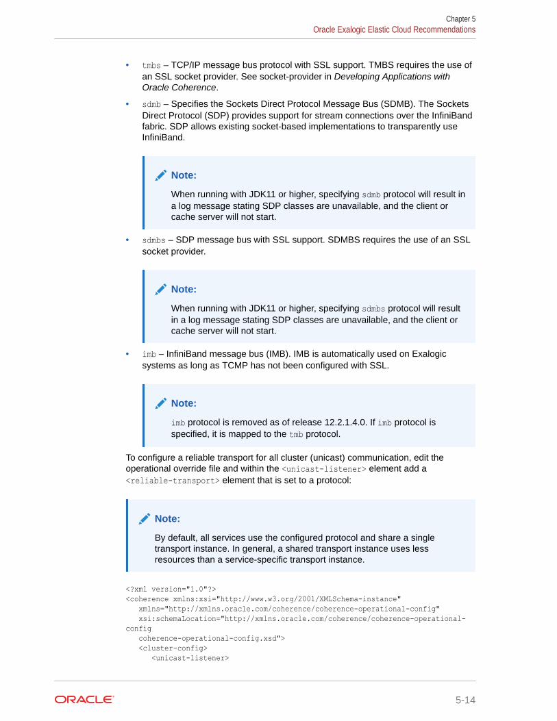
• tmbs – TCP/IP message bus protocol with SSL support. TMBS requires the use ofan SSL socket provider. See socket-provider in Developing Applications withOracle Coherence.
• sdmb – Specifies the Sockets Direct Protocol Message Bus (SDMB). The SocketsDirect Protocol (SDP) provides support for stream connections over the InfiniBandfabric. SDP allows existing socket-based implementations to transparently useInfiniBand.
Note:
When running with JDK11 or higher, specifying sdmb protocol will result ina log message stating SDP classes are unavailable, and the client orcache server will not start.
• sdmbs – SDP message bus with SSL support. SDMBS requires the use of an SSLsocket provider.
Note:
When running with JDK11 or higher, specifying sdmbs protocol will resultin a log message stating SDP classes are unavailable, and the client orcache server will not start.
• imb – InfiniBand message bus (IMB). IMB is automatically used on Exalogicsystems as long as TCMP has not been configured with SSL.
Note:
imb protocol is removed as of release 12.2.1.4.0. If imb protocol isspecified, it is mapped to the tmb protocol.
To configure a reliable transport for all cluster (unicast) communication, edit theoperational override file and within the <unicast-listener> element add a<reliable-transport> element that is set to a protocol:
Note:
By default, all services use the configured protocol and share a singletransport instance. In general, a shared transport instance uses lessresources than a service-specific transport instance.
<?xml version="1.0"?><coherence xmlns:xsi="http://www.w3.org/2001/XMLSchema-instance" xmlns="http://xmlns.oracle.com/coherence/coherence-operational-config" xsi:schemaLocation="http://xmlns.oracle.com/coherence/coherence-operational-config coherence-operational-config.xsd"> <cluster-config> <unicast-listener>
Chapter 5Oracle Exalogic Elastic Cloud Recommendations
5-14
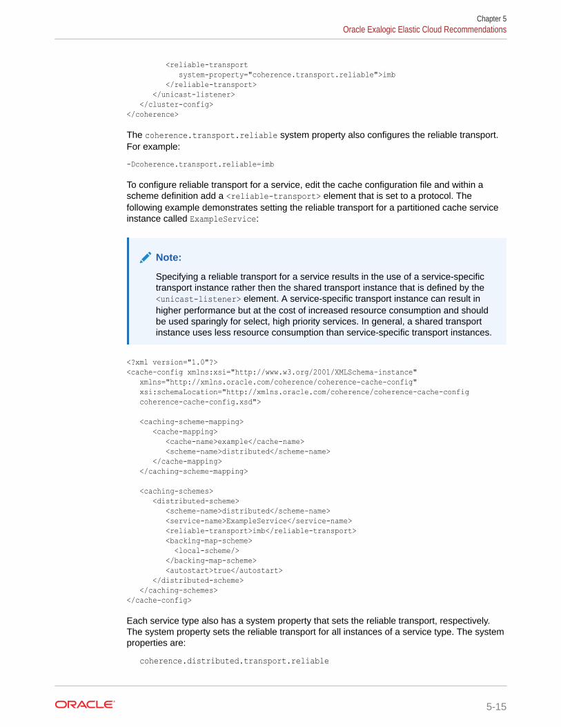
<reliable-transport system-property="coherence.transport.reliable">imb </reliable-transport> </unicast-listener> </cluster-config></coherence>
The coherence.transport.reliable system property also configures the reliable transport.For example:
-Dcoherence.transport.reliable=imb
To configure reliable transport for a service, edit the cache configuration file and within ascheme definition add a <reliable-transport> element that is set to a protocol. Thefollowing example demonstrates setting the reliable transport for a partitioned cache serviceinstance called ExampleService:
Note:
Specifying a reliable transport for a service results in the use of a service-specifictransport instance rather then the shared transport instance that is defined by the<unicast-listener> element. A service-specific transport instance can result inhigher performance but at the cost of increased resource consumption and shouldbe used sparingly for select, high priority services. In general, a shared transportinstance uses less resource consumption than service-specific transport instances.
<?xml version="1.0"?><cache-config xmlns:xsi="http://www.w3.org/2001/XMLSchema-instance" xmlns="http://xmlns.oracle.com/coherence/coherence-cache-config" xsi:schemaLocation="http://xmlns.oracle.com/coherence/coherence-cache-config coherence-cache-config.xsd">
<caching-scheme-mapping> <cache-mapping> <cache-name>example</cache-name> <scheme-name>distributed</scheme-name> </cache-mapping> </caching-scheme-mapping> <caching-schemes> <distributed-scheme> <scheme-name>distributed</scheme-name> <service-name>ExampleService</service-name> <reliable-transport>imb</reliable-transport> <backing-map-scheme> <local-scheme/> </backing-map-scheme> <autostart>true</autostart> </distributed-scheme> </caching-schemes></cache-config>
Each service type also has a system property that sets the reliable transport, respectively.The system property sets the reliable transport for all instances of a service type. The systemproperties are:
coherence.distributed.transport.reliable
Chapter 5Oracle Exalogic Elastic Cloud Recommendations
5-15
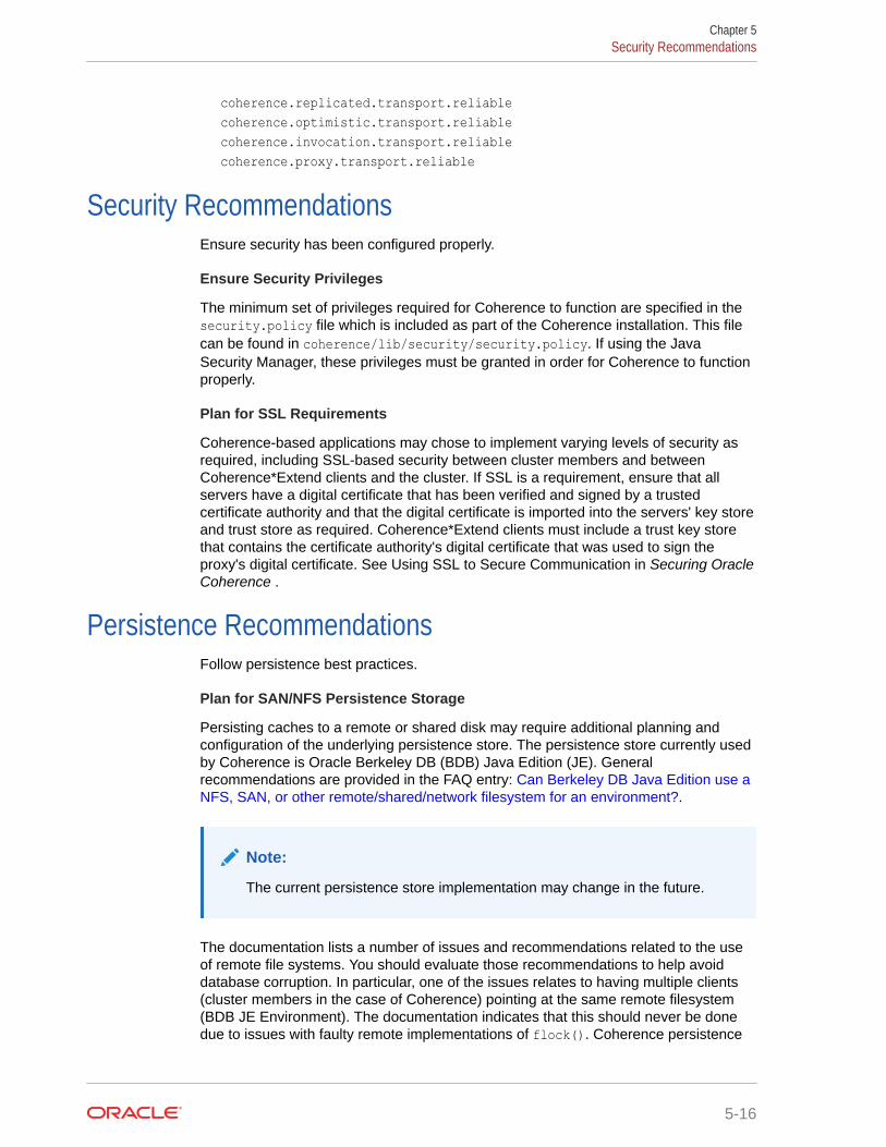
coherence.replicated.transport.reliablecoherence.optimistic.transport.reliablecoherence.invocation.transport.reliablecoherence.proxy.transport.reliable
Security RecommendationsEnsure security has been configured properly.
Ensure Security Privileges
The minimum set of privileges required for Coherence to function are specified in thesecurity.policy file which is included as part of the Coherence installation. This filecan be found in coherence/lib/security/security.policy. If using the JavaSecurity Manager, these privileges must be granted in order for Coherence to functionproperly.
Plan for SSL Requirements
Coherence-based applications may chose to implement varying levels of security asrequired, including SSL-based security between cluster members and betweenCoherence*Extend clients and the cluster. If SSL is a requirement, ensure that allservers have a digital certificate that has been verified and signed by a trustedcertificate authority and that the digital certificate is imported into the servers' key storeand trust store as required. Coherence*Extend clients must include a trust key storethat contains the certificate authority's digital certificate that was used to sign theproxy's digital certificate. See Using SSL to Secure Communication in Securing OracleCoherence .
Persistence RecommendationsFollow persistence best practices.
Plan for SAN/NFS Persistence Storage
Persisting caches to a remote or shared disk may require additional planning andconfiguration of the underlying persistence store. The persistence store currently usedby Coherence is Oracle Berkeley DB (BDB) Java Edition (JE). Generalrecommendations are provided in the FAQ entry: Can Berkeley DB Java Edition use aNFS, SAN, or other remote/shared/network filesystem for an environment?.
Note:
The current persistence store implementation may change in the future.
The documentation lists a number of issues and recommendations related to the useof remote file systems. You should evaluate those recommendations to help avoiddatabase corruption. In particular, one of the issues relates to having multiple clients(cluster members in the case of Coherence) pointing at the same remote filesystem(BDB JE Environment). The documentation indicates that this should never be donedue to issues with faulty remote implementations of flock(). Coherence persistence
Chapter 5Security Recommendations
5-16
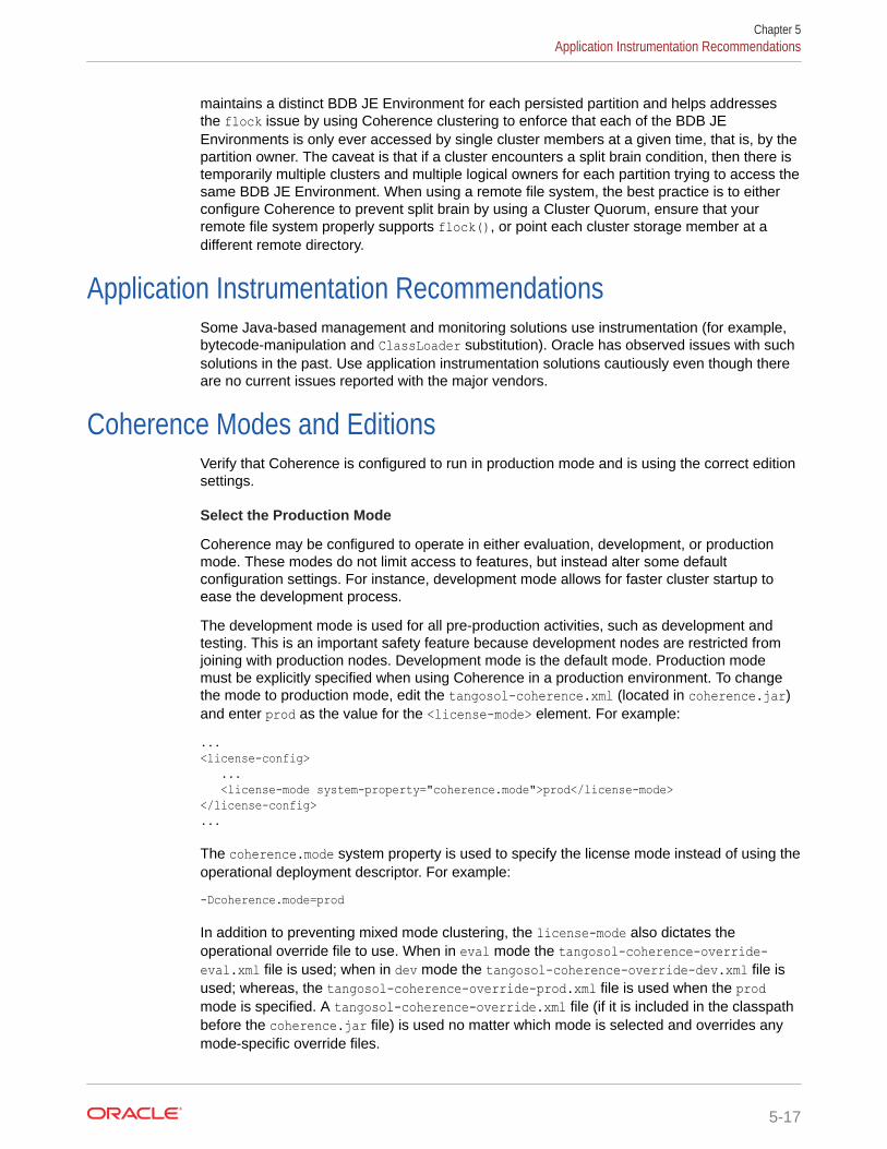
maintains a distinct BDB JE Environment for each persisted partition and helps addressesthe flock issue by using Coherence clustering to enforce that each of the BDB JEEnvironments is only ever accessed by single cluster members at a given time, that is, by thepartition owner. The caveat is that if a cluster encounters a split brain condition, then there istemporarily multiple clusters and multiple logical owners for each partition trying to access thesame BDB JE Environment. When using a remote file system, the best practice is to eitherconfigure Coherence to prevent split brain by using a Cluster Quorum, ensure that yourremote file system properly supports flock(), or point each cluster storage member at adifferent remote directory.
Application Instrumentation RecommendationsSome Java-based management and monitoring solutions use instrumentation (for example,bytecode-manipulation and ClassLoader substitution). Oracle has observed issues with suchsolutions in the past. Use application instrumentation solutions cautiously even though thereare no current issues reported with the major vendors.
Coherence Modes and EditionsVerify that Coherence is configured to run in production mode and is using the correct editionsettings.
Select the Production Mode
Coherence may be configured to operate in either evaluation, development, or productionmode. These modes do not limit access to features, but instead alter some defaultconfiguration settings. For instance, development mode allows for faster cluster startup toease the development process.
The development mode is used for all pre-production activities, such as development andtesting. This is an important safety feature because development nodes are restricted fromjoining with production nodes. Development mode is the default mode. Production modemust be explicitly specified when using Coherence in a production environment. To changethe mode to production mode, edit the tangosol-coherence.xml (located in coherence.jar)and enter prod as the value for the <license-mode> element. For example:
...<license-config> ... <license-mode system-property="coherence.mode">prod</license-mode></license-config>...
The coherence.mode system property is used to specify the license mode instead of using theoperational deployment descriptor. For example:
-Dcoherence.mode=prod
In addition to preventing mixed mode clustering, the license-mode also dictates theoperational override file to use. When in eval mode the tangosol-coherence-override-eval.xml file is used; when in dev mode the tangosol-coherence-override-dev.xml file isused; whereas, the tangosol-coherence-override-prod.xml file is used when the prodmode is specified. A tangosol-coherence-override.xml file (if it is included in the classpathbefore the coherence.jar file) is used no matter which mode is selected and overrides anymode-specific override files.
Chapter 5Application Instrumentation Recommendations
5-17
Select the Edition
Note:
The edition switches no longer enforce license restrictions. Do not changethe default setting (GE).
All nodes within a cluster must use the same license edition and mode. The defaultedition is grid edition (GE). Be sure to obtain enough licenses for the all the clustermembers in the production environment. The servers hardware configuration (numberor type of processor sockets, processor packages, or CPU cores) may be verifiedusing ProcessorInfo utility included with Coherence. For example:
java -cp coherence.jar com.tangosol.license.ProcessorInfo
If the result of the ProcessorInfo program differs from the licensed configuration, sendthe program's output and the actual configuration as a support issue.
Note:
Clusters that run different editions may connect by using Coherence*Extendas a Data Client.
Ensuring that RTC Nodes do Not Use Coherence TCMP
Real-Time client nodes can connect to clusters using either Coherence TCMP orCoherence*Extend. If the intention is to use extend clients, disable TCMP on the clientto ensure that it only connects to a cluster using Coherence*Extend. Otherwise, Theclient may become a member of the cluster. See Disabling TCMP Communication inDeveloping Remote Clients for Oracle Coherence.
Coherence Operational Configuration RecommendationsVerify that the operational configuration file is setup correctly.
Operational configuration relates to cluster-level configuration that is defined in thetangosol-coherence.xml file and includes such items as:
• Cluster and cluster member settings
• Network settings
• Management settings
• Security settings
Coherence Operational aspects are typically configured by using a tangosol-coherence-override.xml file. See Specifying an Operational Configuration File inDeveloping Applications with Oracle Coherence.
The contents of this file often differs between development and production. It isrecommended that these variants be maintained independently due to the significant
Chapter 5Coherence Operational Configuration Recommendations
5-18
differences between these environments. The production operational configuration file shouldbe maintained by systems administrators who are far more familiar with the workings of theproduction systems.
All cluster nodes should use the same operational configuration override file and any node-specific values should be specified by using system properties. See System PropertyOverrides in Developing Applications with Oracle Coherence. A centralized configuration filemay be maintained and accessed by specifying a URL as the value of thecoherence.override system property on each cluster node. For example:
-Dcoherence.override=/net/mylocation/tangosol-coherence-override.xml
The override file need only contain the operational elements that are being changed. Inaddition, always include the id and system-property attributes if they are defined for anelement.
Coherence Cache Configuration RecommendationsVerify that the cache configuration file is setup correctly.
Cache configuration relates to cache-level configuration and includes such things as:
• Cache topology (<distributed-scheme>, <near-scheme>, and so on)
• Cache capacities (<high-units>)
• Cache redundancy level (<backup-count>)
Coherence cache configuration aspects are typically configured by using a coherence-cache-config.xml file. See Specifying a Cache Configuration File in Developing Applicationswith Oracle Coherence.
The default coherence-cache-config.xml file included within coherence.jar is intended onlyas an example and is not suitable for production use. Always use a cache configuration filewith definitions that are specific to the application.
All cluster nodes should use the same cache configuration descriptor if possible. Acentralized configuration file may be maintained and accessed by specifying a URL as thevalue the coherence.cacheconfig system property on each cluster node. For example:
-Dcoherence.cacheconfig=/net/mylocation/coherence-cache-config.xml
Caches can be categorized as either partial or complete. In the former case, the applicationdoes not rely on having the entire data set in memory (even if it expects that to be the case).Most caches that use cache loaders or that use a side cache pattern are partial caches.Complete caches require the entire data set to be in cache for the application to workcorrectly (most commonly because the application is issuing non-primary-key queries againstthe cache). Caches that are partial should always have a size limit based on the allocatedJVM heap size. The limits protect an application from OutOfMemoryExceptions errors. Set thelimits even if the cache is not expected to be fully loaded to protect against changingexpectations. See JVM Tuning. Conversely, if a size limit is set for a complete cache, it maycause incorrect results.
It is important to note that when multiple cache schemes are defined for the same cacheservice name, the first to be loaded dictates the service level parameters. Specifically the<partition-count>, <backup-count>, and <thread-count> subelements of <distributed-scheme> are shared by all caches of the same service. It is recommended that a single
Chapter 5Coherence Cache Configuration Recommendations
5-19
service be defined and inherited by the various cache-schemes. If you want differentvalues for these items on a cache by cache basis then multiple services may beconfigured.
For partitioned caches, Coherence evenly distributes the storage responsibilities to allcache servers, regardless of their cache configuration or heap size. For this reason, itis recommended that all cache server processes be configured with the same heapsize. For computers with additional resources multiple cache servers may be used toeffectively make use of the computer's resources.
To ensure even storage responsibility across a partitioned cache the <partition-count> subelement of the <distributed-scheme> element, should be set to a primenumber which is at least the square of the number of expected cache servers.
A clustered service can perform all tasks on the service thread, a caller's thread ifpossible, and any number of daemon (worker) threads managed by a dynamic threadpool. The dynamic thread pool is automatically enabled for these services. You canuse <thread-count-min> and <thread-count-max> to control the minimum andmaximum number of threads in a dynamic thread pool. By default, the value of<thread-count-min> is 1 and <thead-count-max> is Integer.MAX_VALUE. Thedynamic thread pool is started with the number of threads specified by <thread-count-min>.
For caches which are backed by a cache store, Oracle recommends configuring theparent service with a thread pool of <thread-count-min> greater than 1 as requests tothe cache store may block on I/O. Such thread pools are also recommended forcaches that perform CPU-intensive operations on the cache server (queries,aggregations, some entry processors, and so on). For non-CacheStore-based caches,more threads are unlikely to improve performance. Therefore, you may leave the<thread-count-min> at its default value of 1.
Unless explicitly specified, all cluster nodes are storage enabled, that is, they act ascache servers. It is important to control which nodes in your production environmentare storage enabled and storage disabled. Thecoherence.distributed.localstorage system property may be used to controlstorage, setting it to either true or false. Generally, only dedicated cache servers(including proxy servers) should have storage enabled. All other cluster nodes shouldbe configured as storage disabled. This is especially important for short livedprocesses which may join the cluster to perform some work and then exit the cluster.Having these nodes as storage enabled introduces unneeded re-partitioning.
Large Cluster Configuration RecommendationsConfigure Coherence accordingly when deploying a large cluster.
• Distributed caches on large clusters of more than 16 cache servers require morepartitions to ensure optimal performance. The default partition count is 257 andshould be increased relative to the number of cache servers in the cluster and theamount of data being stored in each partition. See Changing the Number ofPartitions in Developing Applications with Oracle Coherence.
• The maximum packet size on large clusters of more than 400 cluster membersmust be increased to ensure better performance. The default of 1468 should beincreased relative to the size of the cluster, that is, a 600 node cluster would needthe maximum packet size increased by 50%. A simple formula is to allow fourbytes per node, that is, maximum_packet_size >= maximum_cluster_size * 4B.
Chapter 5Large Cluster Configuration Recommendations
5-20
The maximum packet size is configured as part of the coherence operationalconfiguration file. See Adjusting the Maximum Size of a Packet in DevelopingApplications with Oracle Coherence.
• Multicast communication, if supported by the network, can be used instead of point-to-point communication for cluster discovery. This is an ease-of-use recommendation and isnot a requirement for large clusters. Multicast is enabled in an operational configurationfile. See Configuring Multicast Communication in Developing Applications with OracleCoherence.
Death Detection RecommendationsTest scenarios that include node failure and configure Coherence accordingly. TheCoherence death detection algorithms are based on sustained loss of connectivity betweentwo or more cluster nodes.When a node identifies that it has lost connectivity with any other node, it consults with othercluster nodes to determine what action should be taken. In attempting to consult with others,the node may find that it cannot communicate with any other nodes and assumes that it hasbeen disconnected from the cluster. Such a condition could be triggered by physicallyunplugging a node's network adapter. In such an event, the isolated node restarts itsclustered services and attempts to rejoin the cluster.
If connectivity with other cluster nodes remains unavailable, the node may (depending on wellknown address configuration) form a new isolated cluster, or continue searching for the largercluster. In either case, the previously isolated cluster nodes rejoins the running cluster whenconnectivity is restored. As part of rejoining the cluster, the nodes former cluster state isdiscarded, including any cache data it may have held, as the remainder of the cluster hastaken on ownership of that data (restoring from backups).
It is obviously not possible for a node to identify the state of other nodes without connectivity.To a single node, local network adapter failure and network wide switch failure looks identicaland are handled in the same way, as described above. The important difference is that for aswitch failure all nodes are attempting to re-join the cluster, which is the equivalent of a fullcluster restart, and all prior state and data is dropped.
Dropping all data is not desirable and, to avoid this as part of a sustained switch failure, youmust take additional precautions. Options include:
• Increase detection intervals: The cluster relies on a deterministic process-level deathdetection using the TcpRing component and hardware death detection using theIpMonitor component. Process-level detection is performed within milliseconds andnetwork or machine failures are detected within 15 seconds by default. Increasing thesevalue allows the cluster to wait longer for connectivity to return. Death detection isenabled by default and is configured within the <tcp-ring-listener> element. See Configuring Death Detection in Developing Applications with Oracle Coherence.
• Persist data to external storage: By using a Read Write Backing Map, the cluster persistsdata to external storage, and can retrieve it after a cluster restart. So long as write-behindis disabled (the <write-delay> subelement of <read-write-backing-map-scheme>) nodata would be lost if a switch fails. The downside here is that synchronously writingthrough to external storage increases the latency of cache update operations, and theexternal storage may become a bottleneck.
• Decide on a cluster quorum: The cluster quorum policy mandates the minimum numberof cluster members that must remain in the cluster when the cluster service is terminatingsuspect members. During intermittent network outages, a high number of clustermembers may be removed from the cluster. Using a cluster quorum, a certain number of
Chapter 5Death Detection Recommendations
5-21
members are maintained during the outage and are available when the networkrecovers. See Using the Cluster Quorum in Developing Applications with OracleCoherence.
Note:
To ensure that Windows does not disable a network adapter when it isdisconnected, add the following Windows registry DWORD and set it to1:HKEY_LOCAL_MACHINE\SYSTEM\CurrentControlSet\Services\Tcpip\Parameters\DisableDHCPMediaSense. See How to disable the MediaSensing feature for TCP/IP in Windows. This setting also affects staticIPs despite the name.
• Add network level fault tolerance: Adding a redundant layer to the cluster'snetwork infrastructure allows for individual pieces of networking equipment to failwithout disrupting connectivity. This is commonly achieved by using at least twonetwork adapters per computer, and having each adapter connected to a separateswitch. This is not a feature of Coherence but rather of the underlying operatingsystem or network driver. The only change to Coherence is that it should beconfigured to bind to the virtual rather then physical network adapter. This form ofnetwork redundancy goes by different names depending on the operating system: Linux bonding, Solaris trunking and Windows teaming.
Chapter 5Death Detection Recommendations
5-22
Part IIAdvanced Administration
Persistence and federation are advanced features that are used for solutions that requirecontinuous availability and redundancy. In many cases, these features can be enabledwithout any changes to an application.
Part II contains the following chapters:
• Persisting Caches
• Federating Caches Across Clusters
6Persisting Caches
The Coherence persistence feature is used to save a cache to disk and ensures that cachedata can always be recovered.This chapter includes the following sections:
• Overview of Persistence
• Persistence Dependencies
• Persisting Caches on Demand
• Actively Persisting Caches
• Using Snapshots to Persist a Cache Service
• Archiving Snapshots
• Using Active Persistence Mode
• Using Asynchronous Persistence Mode
• Modifying the Pre-Defined Persistence EnvironmentsPersistence uses a set of directories for storage. You can choose to use the defaultstorage directories or change the directories as required.
• Creating Persistence Environments
• Using Quorum for Persistence RecoveryCoherence includes a quorum policy that enables Coherence to defer recovery until asuitable point. Suitability is based on availability of all partitions and sufficient capacity toinitiate recovery across storage members.
• Subscribing to Persistence JMX Notifications
• Managing Persistence
• Configuring Caches as Transient
Overview of PersistenceCoherence persistence is a set of tools and technologies that manage the persistence andrecovery of Coherence distributed caches. Cached data is persisted so that it can be quicklyrecovered after a catastrophic failure or after a cluster restart due to planned maintenance.Persistence and federated caching can be used together as required. See FederatingCaches Across Clusters .This section includes the following topics:
• Persistence Modes
• Disk-Based Persistence Storage
• Persistence Configuration
• Management and Monitoring
6-1
Persistence ModesPersistence can operate in two modes:
• On-Demand persistence mode – a cache service is manually persisted andrecovered upon request using the persistence coordinator. The persistencecoordinator is exposed as an MBean interface that provides operations forcreating, archiving, and recovering snapshots of a cache service.
• Active persistence mode – In this mode, cache contents are automaticallypersisted on all mutations and are automatically recovered on cluster/servicestartup. The persistence coordinator can still be used in active persistence modeto perform on-demand snapshots.
Disk-Based Persistence StoragePersistence uses a database for the persistence store. The database is used to storethe backing map partitions of a partitioned service. The locations of the database filescan be stored on the local disk of each cache server or on a shared disk: Storage AreaNetwork (SAN) or Network File System (NFS). See Plan for SAN/NFS PersistenceStorage.
Note:
Database files should never be manually edited. Editing the database filescan lead to persistence errors.
The local disk option allows each cluster member to access persisted data for theservice partitions that it owns. Persistence is coordinated across all storage memberusing a list of cache server host addresses. The address list ensures that all persistedpartitions are discovered during recovery. Local disk storage provides a highthroughput and low latency storage mechanism; however, a partition service must stillrely on in-memory backup (backup-count value greater than zero) to remain machinesafe.
The shared disk option, together with active persistence mode, allows each clustermember to access persisted data for all service partitions. An advantage to using ashared disk is that partitioned services do not require in-memory backup (backup-count value can be equal to zero) to remain machine-safe; because, all storage-enabled members can recover partitions from the shared storage. Disabling in-memory backup increases the cache capacity of the cluster at the cost of higherlatency recovery during node failure. In general, the use of a shared disk canpotentially affect throughput and latencies and should be tested and monitoredaccordingly.
Chapter 6Overview of Persistence
6-2
Note:
The service statusHA statistic shows an ENDAGERED status when the backup count isset to zero even if persistence is being used to replace in-memory backup.
Both the local disk and shared disk approach can rely on a quorum policy that controls howmany cluster members must be present to perform persistence operations and beforerecovery can begin. Quorum policies allow time for a cluster to start before data recoverybegins.
Persistence ConfigurationPersistence is declaratively configured using Coherence configuration files and requires nochanges to application code. An operational override file is used to configure the underlyingpersistence implementation if the default settings are not acceptable. A cache configurationfile is used to set persistence properties on a distributed cache.
Management and MonitoringPersistence can be monitored and managed using MBean attributes and operations.Persistence operations such as creating and archiving snapshots are performed using thePersistenceManagerMBean MBean. Persistence attributes are included as part of theattributes of a service and can be viewed using the ServiceMBean MBean.
Persistence attributes and statistics are aggregated in the persistence and persistence-details reports. Persistence statistics are also aggregated in the VisualVM plug-in. Bothtools can help troubleshoot possible resource and performance issues.
Persistence DependenciesPersistence is only available for distributed caches and requires the use of a centralizedpartition assignment strategy.
Note:
Transactional caches do not support persistence.
Distributed caches use a centralized partitioned assignment strategy by default. Althoughuncommon, it is possible that an autonomous or a custom partition assignment strategy isbeing used. Check the StrategyName attribute on the PartitionAssignment MBean to verifythe strategy that is currently configured for a distributed cache. See Changing the PartitionDistribution Strategy in Developing Applications with Oracle Coherence.
Persisting Caches on DemandCaches can be persisted to disk at any point in time and recovered as required.To persist caches on demand:
Chapter 6Persistence Dependencies
6-3
1. Use the persistence coordinator to create, recover, and remove snapshots. See Using Snapshots to Persist a Cache Service.
2. Optionally, change the location where persistence files are written to disk. See Changing the Pre-Defined Persistence Directory.
3. Optionally, configure the number of storage members that are required to performrecovery. See Using Quorum for Persistence Recovery.
Actively Persisting CachesCaches can be automatically persisted to disk and automatically recovered when acluster is restarted.To actively persist caches:
1. Enable active persistence. See Enabling Active Persistence Mode.
2. Optionally, change the location where persistence files are written to disk. See Changing the Pre-Defined Persistence Directory.
3. Optionally, change how a service responds to possible failures during activepersistence. See Changing the Active Persistence Failure Response.
4. Optionally, configure the number of storage members that are required to performrecovery. See Using Quorum for Persistence Recovery.
Using Snapshots to Persist a Cache ServiceSnapshots are a backup of the contents of a cache service that must be manuallymanaged using the PersistenceManagerMBean MBean.
The MBean includes asynchronous operations to create, recover, and removesnapshots. When a snapshot is recovered, the entire service is automatically restoredto the state of the snapshot. To use the MBean, JMX must be enabled on the cluster.See Using JMX to Manage Oracle Coherence in Managing Oracle Coherence.
Note:
The instructions in this section were created using the VisualVM-MBeansplug-in for the Coherence VisualVM tool. The Coherence VisualVM Plug-incan also be used to perform snapshot operations.
This section includes the following topics:
• Create a Snapshot
• Recover a Snapshot
• Remove a Snapshot
Create a SnapshotCreating snapshots writes the contents of a cache service to the snapshot directorythat is specified within the persistence environment definition in the operationaloverride configuration file. A snapshot can be created either on a running service (a
Chapter 6Actively Persisting Caches
6-4
service that is accepting and processing requests) or on a suspended service. The formerprovides consistency at a partition level while the latter provides global consistency.
By default, the snapshot operation assumes partition level consistency. To achieve globalconsistency, the service must be explicitly suspended which causes any requests into theservice to be blocked.
Snapshot with Partition Consistency
To create a snapshot with partition consistency:
1. From the list of MBeans, select and expand the Persistence node.
2. Expand a service for which you want to create a snapshot and selectPersistenceCoordinator.
3. From the Operations tab, enter a name for the snapshot in the field for thecreateSnapshot operation.
4. Click createSnapshot.
Snapshot with Global Consistency
To create a snapshot with global consistency:
1. From the list of MBeans, select the ClusterMBean node.
2. From the Operations tab, enter the name of the service that you want to suspend in thefield for the suspendService operation.
3. Click suspendService.
4. From the list of MBeans, select and expand the Persistence node.
5. Expand the service (now suspended) for which you want to create a snapshot and selectPersistenceCoordinator.
6. From the Operations tab, enter a name for the snapshot in the field for thecreateSnapshot operation.
7. Click createSnapshot.
Note:
Applications can be notified when the operation completes by subscribing to thesnapshot JMX notifications. See Subscribing to Persistence JMX Notifications.
8. From the list of MBeans, select the ClusterMBean node.
9. From the Operations tab, enter the name of the service that you want to resume in thefield for the resumeService operation.
10. Click resumeService.
Recover a SnapshotRecovering snapshots restores the contents of a cache service from a snapshot.
Chapter 6Using Snapshots to Persist a Cache Service
6-5
Note:
A Coherence service recovered from a persistent snapshot is not propagatedto federated clusters. The data on the originating cluster is recovered but thecache data on the destination cluster remains unaffected and may stillcontain the data that was present prior to the recovery. To propagate thesnapshot data, a federation ReplicateAll operation is required after thesnapshot recovery is completed. The ReplicateAll operation is available onthe FederationManagerMBean MBean. See FederationManagerMBeanOperations in Managing Oracle Coherence.
To recover a snapshot:
1. From the list of MBeans, select and expand the Persistence node.
2. Expand a service for which you want to recover a snapshot and selectPersistenceCoordinator.
3. From the Operations tab, enter the name of a snapshot in the field for therecoverSnapshot operation.
4. Click recoverSnapshot.
After the operation has returned, check the OperationStatus or Idle attributes onthe persistence coordinator to determine when the operation has completed.Applications can be notified when the operation completes by subscribing to thesnapshot JMX notifications.
Remove a SnapshotRemoving a snapshot deletes the snapshot from the snapshot directory. The cacheservice remains unchanged.
To remove a snapshot:
1. From the list of MBeans, select and expand the Persistence node.
2. Expand a service for which you want to remove a snapshot and selectPersistenceCoordinator.
3. From the Operations tab, enter the name of a snapshot in the field for theremoveSnapshot operation.
4. Click removeSnapshot.
Archiving SnapshotsSnapshots can be archived to a central location and then later retrieved and restored.Archiving snapshots requires defining the directory where archives are stored andconfiguring cache services to use an archive directory. Archiving operations areperformed using the PersistenceManagerMBean MBean. An archive is slower to createthan snapshots but, unlike snapshots, the archive is portable.This section includes the following topics:
• Defining a Snapshot Archive Directory
Chapter 6Archiving Snapshots
6-6
• Specifying a Directory Snapshot Archiver
• Performing Snapshot Archiving Operations
• Creating a Custom Snapshot Archiver
Defining a Snapshot Archive DirectoryThe directory where snapshots are archived is defined in the operational override file using adirectory snapshot archiver definition. Multiple definitions can be created as required.
Note:
The archive directory location and name must be the same across all members.The archive directory location must be a shared directory and must be accessible toall members.
To define a snapshot archiver directory, include the <directory-archiver> element withinthe <snapshot-archivers> element. Use the <archiver-directory> element to enter thedirectory where snapshot archives are stored. Use the id attribute to provide a unique namefor the definition. For example:
<snapshot-archivers> <directory-archiver id="archiver1"> <archive-directory>/mydirectory</archive-directory> </directory-archiver></snapshot-archivers>
Specifying a Directory Snapshot ArchiverTo specify a directory snapshot archiver, edit the persistence definition within a distributedscheme and include the name of a directory snapshot archiver that is defined in theoperational override configuration file. For example:
<distributed-scheme> <scheme-name>distributed</scheme-name> <service-name>Service1</service-name> <backing-map-scheme> <local-scheme/> </backing-map-scheme> <persistence> <archiver>archiver1</archiver> </persistence> <autostart>true</autostart></distributed-scheme>
Performing Snapshot Archiving OperationsSnapshot archiving is manually managed using the PersistenceManagerMBean MBean. TheMBean includes asynchronous operations to archive and retrieve snapshot archives and alsoincludes operations to list and remove archives.
This section includes the following topics:
• Archiving a Snapshot
Chapter 6Archiving Snapshots
6-7
• Retrieving Archived Snapshots
• Removing Archived Snapshots
• Listing Archived Snapshots
• Listing Archived Snapshot Stores
Archiving a SnapshotTo archive a snapshot:
1. From the list of MBeans, select and expand the Persistence node.
2. Expand a service for which you want to archive a snapshot and selectPersistenceCoordinator.
3. From the Operations tab, enter a name for the archive in the field for thearchiveSnapshot operation.
4. Click archiveSnapshot. The snapshot is archived to the location that is specifiedin the directory archiver definition defined in the operational override configurationfile.
Check the OperationStatus on the persistence coordinator to determine when theoperation has completed.
Retrieving Archived SnapshotsTo retrieve an archived snapshot:
1. From the list of MBeans, select and expand the Persistence node.
2. Expand a service for which you want to retrieve an archived snapshot and selectPersistenceCoordinator.
3. From the Operations tab, enter the name of an archived snapshot in the field forthe retrieveArchivedSnapshot operation.
4. Click retrieveArchivedSnapshot. The archived snapshot is copied from thedirectory archiver location to the snapshot directory and is available to berecovered to the service backing map. See Recover a Snapshot.
Removing Archived SnapshotsTo remove an archived snapshot:
1. From the list of MBeans, select and expand the Persistence node.
2. Expand a service for which you want to purge an archived snapshot and selectPersistenceCoordinator.
3. From the Operations tab, enter the name of an archived snapshot in the field forthe removeArchivedSnapshot operation.
4. Click removeArchivedSnapshot. The archived snapshot is removed from thearchive directory.
Listing Archived SnapshotsTo get a list of the current archived snapshots:
Chapter 6Archiving Snapshots
6-8
1. From the list of MBeans, select and expand the Persistence node.
2. Expand a service for which you want to list archived snapshots and selectPersistenceCoordinator.
3. From the Operations tab, click the listArchivedSnapshots operation. A list of archivedsnapshots is returned.
Listing Archived Snapshot StoresTo list the individual stores, or parts of and archived snapshot:
1. From the list of MBeans, select and expand the Persistence node.
2. Expand a service for which you want to list archived snapshot stores and selectPersistenceCoordinator.
3. From the Operations tab, enter the name of an archived snapshot in the field for thelistArchivedSnapshotStores operation.
4. Click listArchivedSnapshotStores. A list of stores for the archived snapshots isreturned.
Creating a Custom Snapshot ArchiverCustom snapshot archiver implementations can be created as required to store archivesusing an alternative technique than the default directory snapshot archiver implementation.For example, you may want to persist archives to an external database, use a web service tostore archives to a storage area network, or store archives in a content repository.
This section includes the following topics:
• Create a Custom Snapshot Archiver Implementation
• Create a Custom Snapshot Archiver Definition
• Specifying a Custom Snapshot Archiver
Create a Custom Snapshot Archiver ImplementationTo create a custom snapshot archiver implementation, create a class that extends theAbstractSnapshotArchiver class.
Create a Custom Snapshot Archiver DefinitionTo create a custom snapshot archiver definition, include the <custom-archiver> elementwithin the <snapshot-archivers> element and use the id attribute to provide a unique namefor the definition. Add the <class-name> element within the <custom-archiver> element thatcontains the fully qualified name of the implementation class. The following example createsa definition for a custom implementation called MyCustomArchiver:
<snapshot-archivers> <custom-archiver id="custom1"> <class-name>package.MyCustomArchiver</class-name> </custom-archiver></snapshot-archivers>
Use the <class-factory-name> element if your implementation uses a factory class that isresponsible for creating archiver instances. Use the <method-name> element to specify the
Chapter 6Archiving Snapshots
6-9
static factory method on the factory class that performs object instantiation. Thefollowing example gets a snapshot archiver instance using the getArchiver methodon the MyArchiverFactory class.
<snapshot-archivers> <custom-archiver id="custom1"> <class-factory-name>package.MyArchiverFactory</class-factory-name> <method-name>getArchiver</method-name> </custom-archiver></snapshot-archivers>
Any initialization parameters that are required for an implementation can be specifiedusing the <init-params> element. The following example sets the UserNameparameter to Admin.
<snapshot-archivers> <custom-archiver id="custom1"> <class-name>package.MyCustomArchiver</class-name> <init-params> <init-param> <param-name>UserName</param-name> <param-value>Admin</param-value> </init-param> </init-params> </custom-archiver></snapshot-archivers>
Specifying a Custom Snapshot ArchiverTo specify a custom snapshot archiver, edit the persistence definition within adistributed scheme and include the name of a custom snapshot archiver that is definedin the operational override configuration file. For example:
<distributed-scheme> <scheme-name>distributed</scheme-name> <service-name>Service1</service-name> <backing-map-scheme> <local-scheme/> </backing-map-scheme> <persistence> <archiver>custom1</archiver> </persistence> <autostart>true</autostart></distributed-scheme>
Using Active Persistence ModeYou can enable and configure active persistence mode to have the contents of acache automatically persisted and recovered.This section includes the following topics:
• Enabling Active Persistence Mode
• Changing the Active Persistence Failure Response
• Changing the Partition Count When Using Active Persistence
Chapter 6Using Active Persistence Mode
6-10
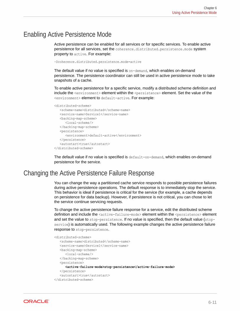
Enabling Active Persistence ModeActive persistence can be enabled for all services or for specific services. To enable activepersistence for all services, set the coherence.distributed.persistence.mode systemproperty to active. For example:
-Dcoherence.distributed.persistence.mode=active
The default value if no value is specified is on-demand, which enables on-demandpersistence. The persistence coordinator can still be used in active persistence mode to takesnapshots of a cache.
To enable active persistence for a specific service, modify a distributed scheme definition andinclude the <environment> element within the <persistence> element. Set the value of the<environment> element to default-active. For example:
<distributed-scheme> <scheme-name>distributed</scheme-name> <service-name>Service1</service-name> <backing-map-scheme> <local-scheme/> </backing-map-scheme> <persistence> <environment>default-active</environment> </persistence> <autostart>true</autostart></distributed-scheme>
The default value if no value is specified is default-on-demand, which enables on-demandpersistence for the service.
Changing the Active Persistence Failure ResponseYou can change the way a partitioned cache service responds to possible persistence failuresduring active persistence operations. The default response is to immediately stop the service.This behavior is ideal if persistence is critical for the service (for example, a cache dependson persistence for data backup). However, if persistence is not critical, you can chose to letthe service continue servicing requests.
To change the active persistence failure response for a service, edit the distributed schemedefinition and include the <active-failure-mode> element within the <persistence> elementand set the value to stop-persistence. If no value is specified, then the default value (stop-service) is automatically used. The following example changes the active persistence failureresponse to stop-persistence.
<distributed-scheme> <scheme-name>distributed</scheme-name> <service-name>Service1</service-name> <backing-map-scheme> <local-scheme/> </backing-map-scheme> <persistence> <active-failure-mode>stop-persistence</active-failure-mode> </persistence> <autostart>true</autostart></distributed-scheme>
Chapter 6Using Active Persistence Mode
6-11
Changing the Partition Count When Using Active PersistenceThe partition count cannot be changed when using active persistence. If you change aservices partition count, then on restart of the services all active data is moved to thepersistence trash and must be recovered after the original partition count is restored.Data that is persisted can only be recovered only to services that are running with thesame partition count, or you can select one of the available workarounds. See Workarounds to Migrate a Persistent Service to a Different Partition Count.
Ensure that the partition count is not modified if active persistence is being used. If thepartition count is changed, then a message similar to the following is displayed whenthe services are started:
<Warning> (thread=DistributedCache:DistributedCachePersistence, member=1):Failed to recover partition 0 from SafeBerkeleyDBStore(...); partition-countmismatch 501(persisted) != 277(service); reinstate persistent store fromtrash once validation errors have been resolved
The message indicates that the change in the partition-count is not supported and thecurrent active data has been copied to the trash directory. To recover the data:
1. Shutdown the entire cluster.
2. Remove the current active directory contents for the cluster and service affectedon each cluster member.
3. Copy (recursively) the contents of the trash directory for each service to the activedirectory.
4. Restore the partition count to the original value.
5. Restart the cluster.
• Workarounds to Migrate a Persistent Service to a Different Partition Count
Workarounds to Migrate a Persistent Service to a Different Partition CountThere are two possible workarounds when changing the partition count with persistentservices:
• Using Coherence Federation as a means to replicate data to a service with adifferent partition count.
• Defining a new persistent service and transferring the data manually.
For instructions to use the two options, see Using Federation and Using a NewService. Oracle recommends using federation because it ensures that data is migratedand available as quickly as possible.
If the existing persistent cache service is federated, migration is trivial, as illustrated inthe following steps:
1. Stop one of the destination clusters in the federation.
2. Move the persistence directory to a backup storage.
3. Create a new cache config that differs only in the partition count for the relatedservice.
4. Invoke the Mean operation replicateAll from the newly started cluster with thedifferent partition count.
Chapter 6Using Active Persistence Mode
6-12
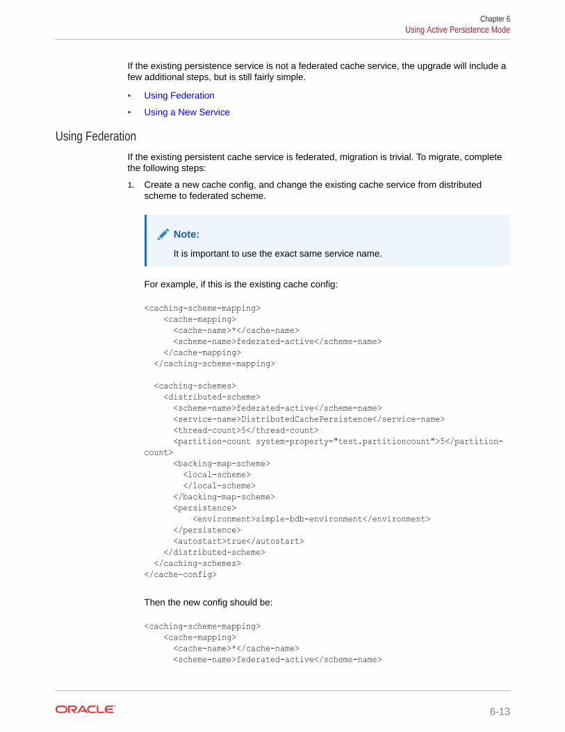
If the existing persistence service is not a federated cache service, the upgrade will include afew additional steps, but is still fairly simple.
• Using Federation
• Using a New Service
Using FederationIf the existing persistent cache service is federated, migration is trivial. To migrate, completethe following steps:
1. Create a new cache config, and change the existing cache service from distributedscheme to federated scheme.
Note:
It is important to use the exact same service name.
For example, if this is the existing cache config:
<caching-scheme-mapping> <cache-mapping> <cache-name>*</cache-name> <scheme-name>federated-active</scheme-name> </cache-mapping> </caching-scheme-mapping>
<caching-schemes> <distributed-scheme> <scheme-name>federated-active</scheme-name> <service-name>DistributedCachePersistence</service-name> <thread-count>5</thread-count> <partition-count system-property="test.partitioncount">5</partition-count> <backing-map-scheme> <local-scheme> </local-scheme> </backing-map-scheme> <persistence> <environment>simple-bdb-environment</environment> </persistence> <autostart>true</autostart> </distributed-scheme> </caching-schemes></cache-config>
Then the new config should be:
<caching-scheme-mapping> <cache-mapping> <cache-name>*</cache-name> <scheme-name>federated-active</scheme-name>
Chapter 6Using Active Persistence Mode
6-13
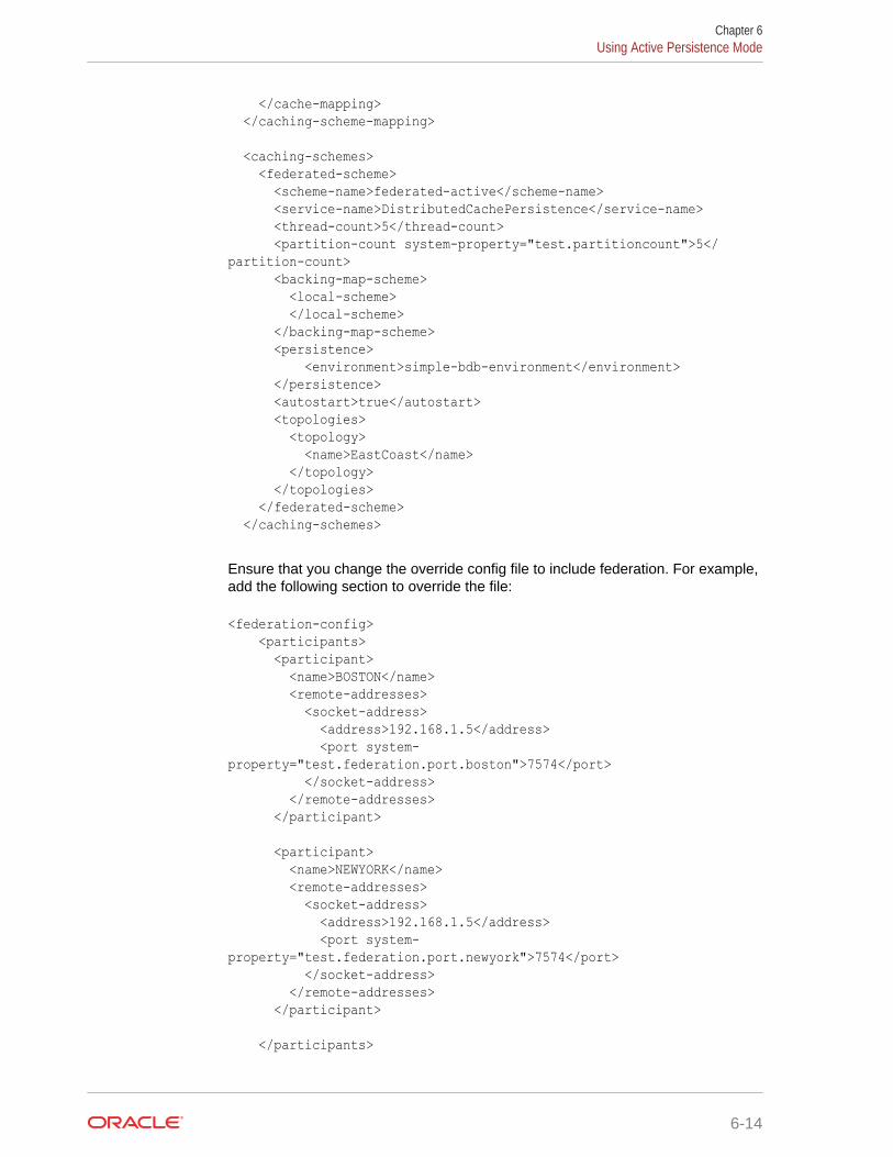
</cache-mapping> </caching-scheme-mapping>
<caching-schemes> <federated-scheme> <scheme-name>federated-active</scheme-name> <service-name>DistributedCachePersistence</service-name> <thread-count>5</thread-count> <partition-count system-property="test.partitioncount">5</partition-count> <backing-map-scheme> <local-scheme> </local-scheme> </backing-map-scheme> <persistence> <environment>simple-bdb-environment</environment> </persistence> <autostart>true</autostart> <topologies> <topology> <name>EastCoast</name> </topology> </topologies> </federated-scheme> </caching-schemes>
Ensure that you change the override config file to include federation. For example,add the following section to override the file:
<federation-config> <participants> <participant> <name>BOSTON</name> <remote-addresses> <socket-address> <address>192.168.1.5</address> <port system-property="test.federation.port.boston">7574</port> </socket-address> </remote-addresses> </participant>
<participant> <name>NEWYORK</name> <remote-addresses> <socket-address> <address>192.168.1.5</address> <port system-property="test.federation.port.newyork">7574</port> </socket-address> </remote-addresses> </participant>
</participants>
Chapter 6Using Active Persistence Mode
6-14
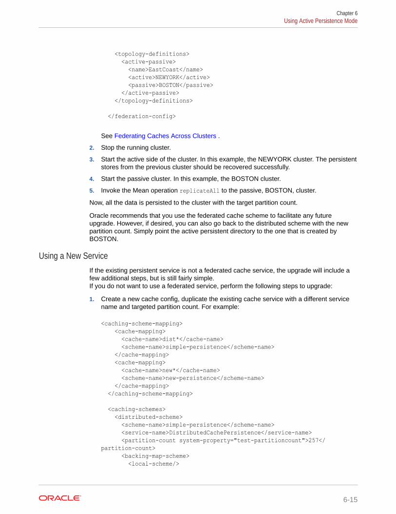
<topology-definitions> <active-passive> <name>EastCoast</name> <active>NEWYORK</active> <passive>BOSTON</passive> </active-passive> </topology-definitions>
</federation-config>
See Federating Caches Across Clusters .
2. Stop the running cluster.
3. Start the active side of the cluster. In this example, the NEWYORK cluster. The persistentstores from the previous cluster should be recovered successfully.
4. Start the passive cluster. In this example, the BOSTON cluster.
5. Invoke the Mean operation replicateAll to the passive, BOSTON, cluster.
Now, all the data is persisted to the cluster with the target partition count.
Oracle recommends that you use the federated cache scheme to facilitate any futureupgrade. However, if desired, you can also go back to the distributed scheme with the newpartition count. Simply point the active persistent directory to the one that is created byBOSTON.
Using a New ServiceIf the existing persistent service is not a federated cache service, the upgrade will include afew additional steps, but is still fairly simple.If you do not want to use a federated service, perform the following steps to upgrade:
1. Create a new cache config, duplicate the existing cache service with a different servicename and targeted partition count. For example:
<caching-scheme-mapping> <cache-mapping> <cache-name>dist*</cache-name> <scheme-name>simple-persistence</scheme-name> </cache-mapping> <cache-mapping> <cache-name>new*</cache-name> <scheme-name>new-persistence</scheme-name> </cache-mapping> </caching-scheme-mapping>
<caching-schemes> <distributed-scheme> <scheme-name>simple-persistence</scheme-name> <service-name>DistributedCachePersistence</service-name> <partition-count system-property="test-partitioncount">257</partition-count> <backing-map-scheme> <local-scheme/>
Chapter 6Using Active Persistence Mode
6-15
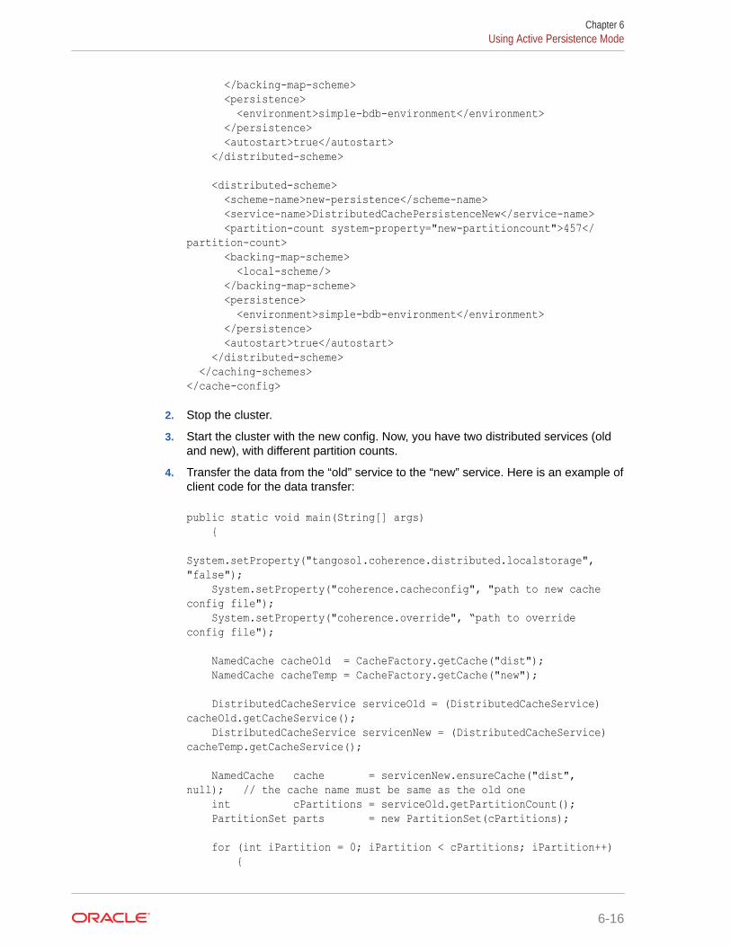
</backing-map-scheme> <persistence> <environment>simple-bdb-environment</environment> </persistence> <autostart>true</autostart> </distributed-scheme>
<distributed-scheme> <scheme-name>new-persistence</scheme-name> <service-name>DistributedCachePersistenceNew</service-name> <partition-count system-property="new-partitioncount">457</partition-count> <backing-map-scheme> <local-scheme/> </backing-map-scheme> <persistence> <environment>simple-bdb-environment</environment> </persistence> <autostart>true</autostart> </distributed-scheme> </caching-schemes></cache-config>
2. Stop the cluster.
3. Start the cluster with the new config. Now, you have two distributed services (oldand new), with different partition counts.
4. Transfer the data from the “old” service to the “new” service. Here is an example ofclient code for the data transfer:
public static void main(String[] args) { System.setProperty("tangosol.coherence.distributed.localstorage", "false"); System.setProperty("coherence.cacheconfig", "path to new cache config file"); System.setProperty("coherence.override", “path to override config file");
NamedCache cacheOld = CacheFactory.getCache("dist"); NamedCache cacheTemp = CacheFactory.getCache("new");
DistributedCacheService serviceOld = (DistributedCacheService) cacheOld.getCacheService(); DistributedCacheService servicenNew = (DistributedCacheService) cacheTemp.getCacheService();
NamedCache cache = servicenNew.ensureCache("dist", null); // the cache name must be same as the old one int cPartitions = serviceOld.getPartitionCount(); PartitionSet parts = new PartitionSet(cPartitions);
for (int iPartition = 0; iPartition < cPartitions; iPartition++) {
Chapter 6Using Active Persistence Mode
6-16
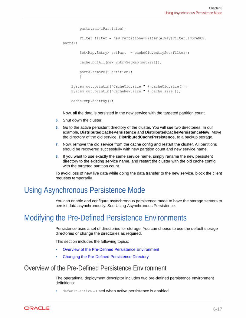
parts.add(iPartition);
Filter filter = new PartitionedFilter(AlwaysFilter.INSTANCE, parts);
Set<Map.Entry> setPart = cacheOld.entrySet(filter);
cache.putAll(new EntrySetMap(setPart));
parts.remove(iPartition); } System.out.println("CacheOld.size " + cacheOld.size()); System.out.println("CacheNew.size " + cache.size());
cacheTemp.destroy();
Now, all the data is persisted in the new service with the targeted partition count.
5. Shut down the cluster.
6. Go to the active persistent directory of the cluster. You will see two directories. In ourexample, DistributedCachePersistence and DistributedCachePersistenceNew. Movethe directory of the old service, DistributedCachePersistence, to a backup storage.
7. Now, remove the old service from the cache config and restart the cluster. All partitionsshould be recovered successfully with new partition count and new service name.
8. If you want to use exactly the same service name, simply rename the new persistentdirectory to the existing service name, and restart the cluster with the old cache configwith the targeted partition count.
To avoid loss of new live data while doing the data transfer to the new service, block the clientrequests temporarily.
Using Asynchronous Persistence ModeYou can enable and configure asynchronous persistence mode to have the storage servers topersist data asynchronously. See Using Asynchronous Persistence.
Modifying the Pre-Defined Persistence EnvironmentsPersistence uses a set of directories for storage. You can choose to use the default storagedirectories or change the directories as required.
This section includes the following topics:
• Overview of the Pre-Defined Persistence Environment
• Changing the Pre-Defined Persistence Directory
Overview of the Pre-Defined Persistence EnvironmentThe operational deployment descriptor includes two pre-defined persistence environmentdefinitions:
• default-active – used when active persistence is enabled.
Chapter 6Using Asynchronous Persistence Mode
6-17
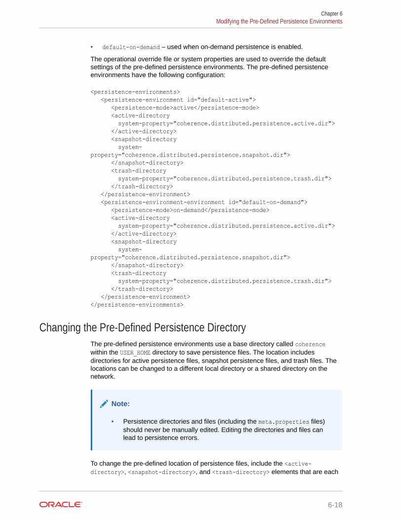
• default-on-demand – used when on-demand persistence is enabled.
The operational override file or system properties are used to override the defaultsettings of the pre-defined persistence environments. The pre-defined persistenceenvironments have the following configuration:
<persistence-environments> <persistence-environment id="default-active"> <persistence-mode>active</persistence-mode> <active-directory system-property="coherence.distributed.persistence.active.dir"> </active-directory> <snapshot-directory system-property="coherence.distributed.persistence.snapshot.dir"> </snapshot-directory> <trash-directory system-property="coherence.distributed.persistence.trash.dir"> </trash-directory> </persistence-environment> <persistence-environment-environment id="default-on-demand"> <persistence-mode>on-demand</persistence-mode> <active-directory system-property="coherence.distributed.persistence.active.dir"> </active-directory> <snapshot-directory system-property="coherence.distributed.persistence.snapshot.dir"> </snapshot-directory> <trash-directory system-property="coherence.distributed.persistence.trash.dir"> </trash-directory> </persistence-environment></persistence-environments>
Changing the Pre-Defined Persistence DirectoryThe pre-defined persistence environments use a base directory called coherencewithin the USER_HOME directory to save persistence files. The location includesdirectories for active persistence files, snapshot persistence files, and trash files. Thelocations can be changed to a different local directory or a shared directory on thenetwork.
Note:
• Persistence directories and files (including the meta.properties files)should never be manually edited. Editing the directories and files canlead to persistence errors.
To change the pre-defined location of persistence files, include the <active-directory>, <snapshot-directory>, and <trash-directory> elements that are each
Chapter 6Modifying the Pre-Defined Persistence Environments
6-18
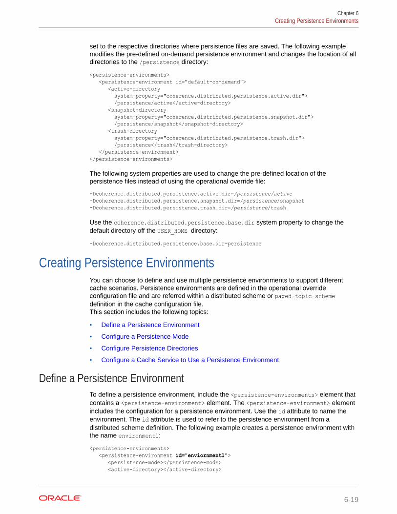
set to the respective directories where persistence files are saved. The following examplemodifies the pre-defined on-demand persistence environment and changes the location of alldirectories to the /persistence directory:
<persistence-environments> <persistence-environment id="default-on-demand"> <active-directory system-property="coherence.distributed.persistence.active.dir"> /persistence/active</active-directory> <snapshot-directory system-property="coherence.distributed.persistence.snapshot.dir"> /persistence/snapshot</snapshot-directory> <trash-directory system-property="coherence.distributed.persistence.trash.dir"> /persistence</trash</trash-directory> </persistence-environment></persistence-environments>
The following system properties are used to change the pre-defined location of thepersistence files instead of using the operational override file:
-Dcoherence.distributed.persistence.active.dir=/persistence/active-Dcoherence.distributed.persistence.snapshot.dir=/persistence/snapshot-Dcoherence.distributed.persistence.trash.dir=/persistence/trash
Use the coherence.distributed.persistence.base.dir system property to change thedefault directory off the USER_HOME directory:
-Dcoherence.distributed.persistence.base.dir=persistence
Creating Persistence EnvironmentsYou can choose to define and use multiple persistence environments to support differentcache scenarios. Persistence environments are defined in the operational overrideconfiguration file and are referred within a distributed scheme or paged-topic-schemedefinition in the cache configuration file.This section includes the following topics:
• Define a Persistence Environment
• Configure a Persistence Mode
• Configure Persistence Directories
• Configure a Cache Service to Use a Persistence Environment
Define a Persistence EnvironmentTo define a persistence environment, include the <persistence-environments> element thatcontains a <persistence-environment> element. The <persistence-environment> elementincludes the configuration for a persistence environment. Use the id attribute to name theenvironment. The id attribute is used to refer to the persistence environment from adistributed scheme definition. The following example creates a persistence environment withthe name environment1:
<persistence-environments> <persistence-environment id="enviornment1"> <persistence-mode></persistence-mode> <active-directory></active-directory>
Chapter 6Creating Persistence Environments
6-19
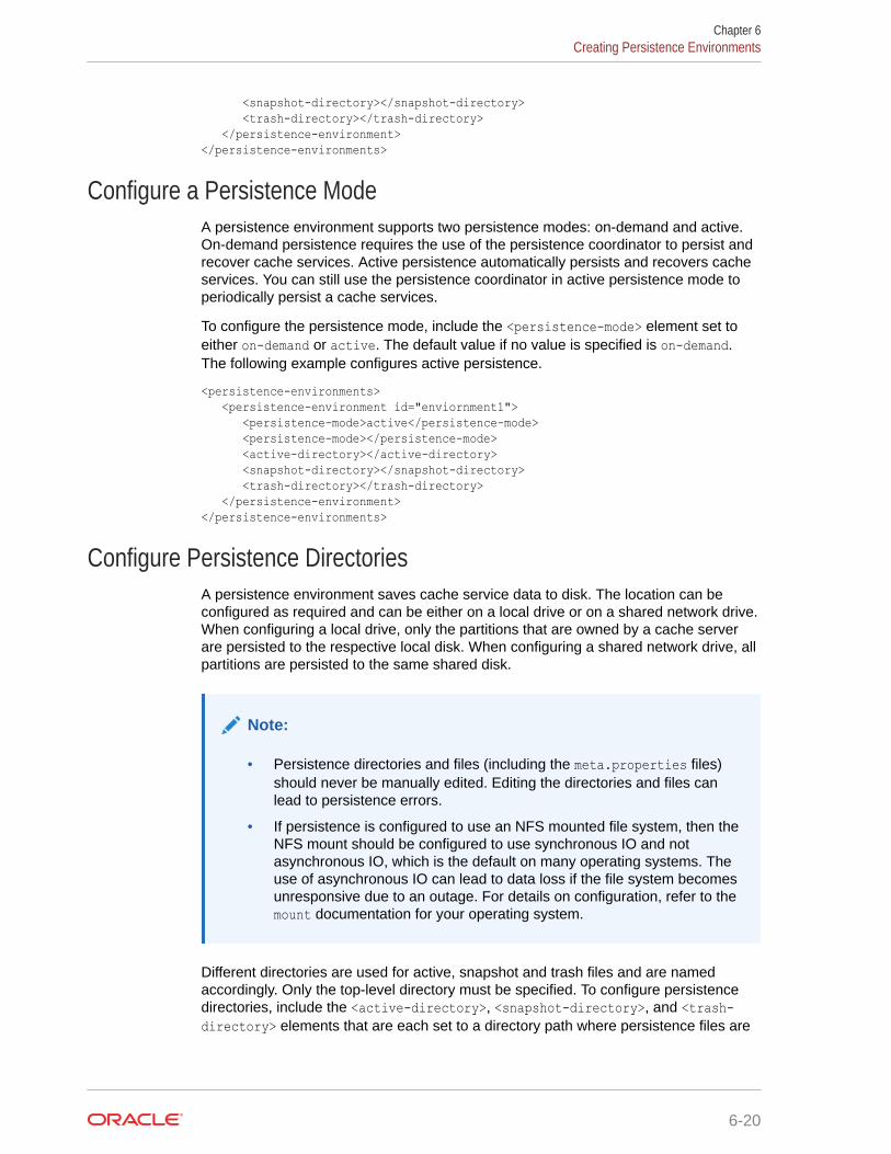
<snapshot-directory></snapshot-directory> <trash-directory></trash-directory> </persistence-environment></persistence-environments>
Configure a Persistence ModeA persistence environment supports two persistence modes: on-demand and active.On-demand persistence requires the use of the persistence coordinator to persist andrecover cache services. Active persistence automatically persists and recovers cacheservices. You can still use the persistence coordinator in active persistence mode toperiodically persist a cache services.
To configure the persistence mode, include the <persistence-mode> element set toeither on-demand or active. The default value if no value is specified is on-demand.The following example configures active persistence.
<persistence-environments> <persistence-environment id="enviornment1"> <persistence-mode>active</persistence-mode> <persistence-mode></persistence-mode> <active-directory></active-directory> <snapshot-directory></snapshot-directory> <trash-directory></trash-directory> </persistence-environment></persistence-environments>
Configure Persistence DirectoriesA persistence environment saves cache service data to disk. The location can beconfigured as required and can be either on a local drive or on a shared network drive.When configuring a local drive, only the partitions that are owned by a cache serverare persisted to the respective local disk. When configuring a shared network drive, allpartitions are persisted to the same shared disk.
Note:
• Persistence directories and files (including the meta.properties files)should never be manually edited. Editing the directories and files canlead to persistence errors.
• If persistence is configured to use an NFS mounted file system, then theNFS mount should be configured to use synchronous IO and notasynchronous IO, which is the default on many operating systems. Theuse of asynchronous IO can lead to data loss if the file system becomesunresponsive due to an outage. For details on configuration, refer to themount documentation for your operating system.
Different directories are used for active, snapshot and trash files and are namedaccordingly. Only the top-level directory must be specified. To configure persistencedirectories, include the <active-directory>, <snapshot-directory>, and <trash-directory> elements that are each set to a directory path where persistence files are
Chapter 6Creating Persistence Environments
6-20
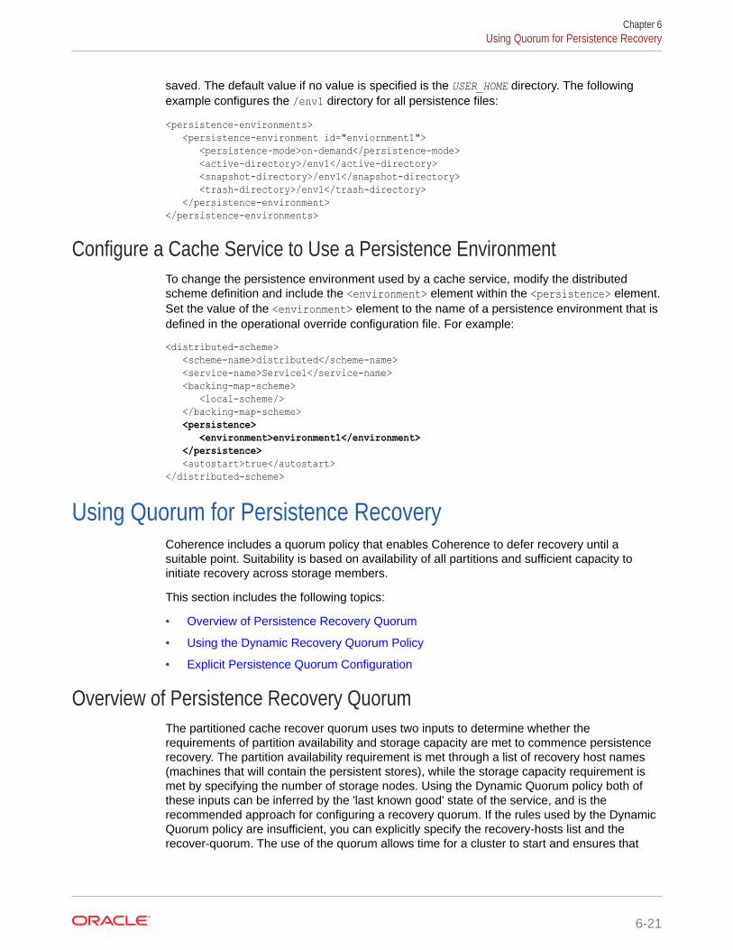
saved. The default value if no value is specified is the USER_HOME directory. The followingexample configures the /env1 directory for all persistence files:
<persistence-environments> <persistence-environment id="enviornment1"> <persistence-mode>on-demand</persistence-mode> <active-directory>/env1</active-directory> <snapshot-directory>/env1</snapshot-directory> <trash-directory>/env1</trash-directory> </persistence-environment></persistence-environments>
Configure a Cache Service to Use a Persistence EnvironmentTo change the persistence environment used by a cache service, modify the distributedscheme definition and include the <environment> element within the <persistence> element.Set the value of the <environment> element to the name of a persistence environment that isdefined in the operational override configuration file. For example:
<distributed-scheme> <scheme-name>distributed</scheme-name> <service-name>Service1</service-name> <backing-map-scheme> <local-scheme/> </backing-map-scheme> <persistence> <environment>environment1</environment> </persistence> <autostart>true</autostart></distributed-scheme>
Using Quorum for Persistence RecoveryCoherence includes a quorum policy that enables Coherence to defer recovery until asuitable point. Suitability is based on availability of all partitions and sufficient capacity toinitiate recovery across storage members.
This section includes the following topics:
• Overview of Persistence Recovery Quorum
• Using the Dynamic Recovery Quorum Policy
• Explicit Persistence Quorum Configuration
Overview of Persistence Recovery QuorumThe partitioned cache recover quorum uses two inputs to determine whether therequirements of partition availability and storage capacity are met to commence persistencerecovery. The partition availability requirement is met through a list of recovery host names(machines that will contain the persistent stores), while the storage capacity requirement ismet by specifying the number of storage nodes. Using the Dynamic Quorum policy both ofthese inputs can be inferred by the 'last known good' state of the service, and is therecommended approach for configuring a recovery quorum. If the rules used by the DynamicQuorum policy are insufficient, you can explicitly specify the recovery-hosts list and therecover-quorum. The use of the quorum allows time for a cluster to start and ensures that
Chapter 6Using Quorum for Persistence Recovery
6-21
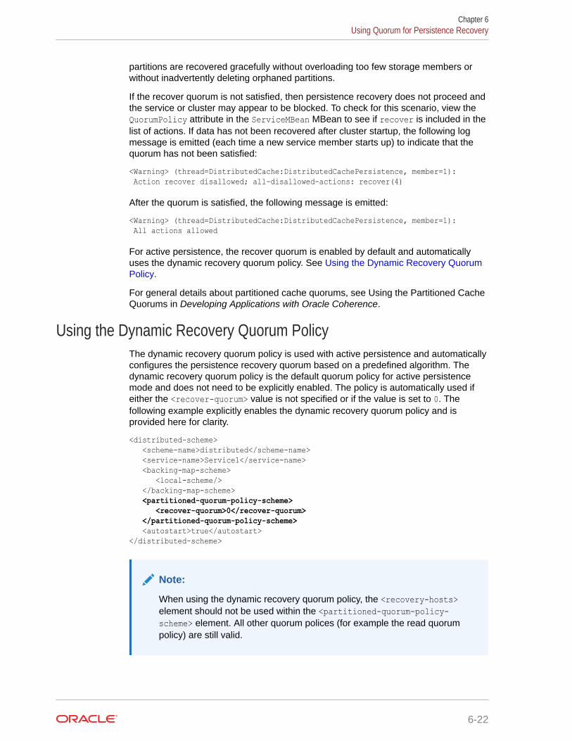
partitions are recovered gracefully without overloading too few storage members orwithout inadvertently deleting orphaned partitions.
If the recover quorum is not satisfied, then persistence recovery does not proceed andthe service or cluster may appear to be blocked. To check for this scenario, view theQuorumPolicy attribute in the ServiceMBean MBean to see if recover is included in thelist of actions. If data has not been recovered after cluster startup, the following logmessage is emitted (each time a new service member starts up) to indicate that thequorum has not been satisfied:
<Warning> (thread=DistributedCache:DistributedCachePersistence, member=1): Action recover disallowed; all-disallowed-actions: recover(4)
After the quorum is satisfied, the following message is emitted:
<Warning> (thread=DistributedCache:DistributedCachePersistence, member=1): All actions allowed
For active persistence, the recover quorum is enabled by default and automaticallyuses the dynamic recovery quorum policy. See Using the Dynamic Recovery QuorumPolicy.
For general details about partitioned cache quorums, see Using the Partitioned CacheQuorums in Developing Applications with Oracle Coherence.
Using the Dynamic Recovery Quorum PolicyThe dynamic recovery quorum policy is used with active persistence and automaticallyconfigures the persistence recovery quorum based on a predefined algorithm. Thedynamic recovery quorum policy is the default quorum policy for active persistencemode and does not need to be explicitly enabled. The policy is automatically used ifeither the <recover-quorum> value is not specified or if the value is set to 0. Thefollowing example explicitly enables the dynamic recovery quorum policy and isprovided here for clarity.
<distributed-scheme> <scheme-name>distributed</scheme-name> <service-name>Service1</service-name> <backing-map-scheme> <local-scheme/> </backing-map-scheme> <partitioned-quorum-policy-scheme> <recover-quorum>0</recover-quorum> </partitioned-quorum-policy-scheme> <autostart>true</autostart></distributed-scheme>
Note:
When using the dynamic recovery quorum policy, the <recovery-hosts>element should not be used within the <partitioned-quorum-policy-scheme> element. All other quorum polices (for example the read quorumpolicy) are still valid.
Chapter 6Using Quorum for Persistence Recovery
6-22
Understanding the Dynamic Recovery Algorithm
The dynamic recovery quorum policy works by recording cluster membership informationeach time a member joins the cluster and partition distribution stabilizes. Membership is onlyrecorded if the service is not suspended and all other partitioned cache actions (such asread, write, restore, and distribute) are allowed by the policy. JMX notifications are sent tosubscribers of the PersistenceManagerMBean MBean every time the cluster membershipchanges.
During recovery scenarios, a service only recovers data if the following conditions aresatisfied:
• the persistent image of all partitions is accessible by the cluster members
• the number of storage-enabled nodes is at least 2/3 of the last recorded membership
• if the persistent data is being stored to a local disk (not shared and visible by all hosts),then there should be at least 2/3 of the number of members for each host as there waswhen the last membership was recorded
The partitioned cache service blocks any client side requests if any of the conditions are notsatisfied. However, if an administrator determines that the full recovery is impossible due tomissing partitions or that starting the number of servers that is expected by the quorum isunnecessary, then the recovery can be forced by invoking the forceRecovery operation onthe PersistenceManagerMBean MBean.
The recovery algorithm can be overridden by using a custom quorum policy class thatextends thecom.tangosol.net.ConfigurableQuorumPolicy.PartitionedCacheQuorumPolicy class. Tochange the hard-coded 2/3 ratio, override thePartitionedCacheQuorumPolicy.calculateMinThreshold method. See Using Custom ActionPolicies in Developing Applications with Oracle Coherence.
Explicit Persistence Quorum ConfigurationTo configure the recover quorum for persistence, modify a distributed scheme definition andinclude the <recover-quorum> element within the <partitioned-quorum-policy-scheme>element. Set the <recover-quorum> element value to the number of storage members thatmust be available before recovery starts. For example:
<distributed-scheme> <scheme-name>distributed</scheme-name> <service-name>Service1</service-name> <backing-map-scheme> <local-scheme/> </backing-map-scheme> <partitioned-quorum-policy-scheme> <recover-quorum>2</recover-quorum> </partitioned-quorum-policy-scheme> <autostart>true</autostart></distributed-scheme>
Note:
In active persistence mode, setting the <recover-quorum> element to 0, enables thedynamic recovery quorum policy. See Using the Dynamic Recovery Quorum Policy.
Chapter 6Using Quorum for Persistence Recovery
6-23
In shared disk scenarios, all partitions are persisted and recovered from a singlelocation. For local-disk scenarios, each storage member recovers its partitions from alocal disk. However, if you use a non-dynamic recovery quorum with local-disk basedstorage, you must define a list of storage-enabled hosts in the cluster that are requiredto recover orphaned partition from the persistent storage, otherwise empty partitionswill be assigned.
Note:
Recovery hosts must be specified to ensure that recovery does notcommence prior to all persisted state being available.
To define a list of addresses, edit the operational override configuration file and includethe <address-provider> element that contains a list of addresses each defined usingan <address> element. Use the id attribute to name the address provider list. The idattribute is used to refer to the list from a distributed scheme definition. The followingexample creates an address provider list that contains two member addresses and isnamed persistence_hosts:
<address-providers> <address-provider id="persistence_hosts"> <address>HOST_NAME1</address> <address>HOST_NAME2</address> </address-provider></address-providers>
To refer to the address provider list, modify a distributed scheme definition and includethe <recovery-hosts> element within the <partitioned-quorum-policy-scheme>element and set the value to the name of an address provider list. For example:
<distributed-scheme> <scheme-name>distributed</scheme-name> <service-name>Service1</service-name> <backing-map-scheme> <local-scheme/> </backing-map-scheme> <partitioned-quorum-policy-scheme> <recover-quorum>2</recover-quorum> <recovery-hosts>persistence_hosts</recovery-hosts> </partitioned-quorum-policy-scheme> <autostart>true</autostart></distributed-scheme>
Subscribing to Persistence JMX NotificationsThe PersistenceManagerMBean MBean includes a set of notification types thatapplications can use to monitor persistence operations. See PersistenceManagerMBean in Managing Oracle Coherence.To subscribe to persistence JMX notifications, implement the JMXNotificationListener interface and register the listener. The following code snippetdemonstrates registering a notification listener. Refer to the Coherence examples forthe complete example, which includes a sample listener implementation.
...MBeanServer server = MBeanHelper.findMBeanServer();
Chapter 6Subscribing to Persistence JMX Notifications
6-24
Registry registry = cluster.getManagement();try { for (String sServiceName : setServices) { logHeader("Registering listener for " + sServiceName); String sMBeanName = getMBeanName(sServiceName); ObjectName oBeanName = new ObjectName(sMBeanName); NotificationListener listener = new PersistenceNotificationListener(sServiceName); server.addNotificationListener(oBeanName, listener, null, null); } ...
Managing PersistencePersistence should be managed to ensure there is enough disk space and to ensurepersistence operations do not add significant latency to cache operations. Latency is specificto active persistence mode and can affect cache performance because persistenceoperations are being performed in parallel with cache operations.This section includes the following topics:
• Plan for Persistence Storage
• Plan for Persistence Memory Overhead
• Monitor Persistence Storage Usage
• Monitoring Persistence Latencies
Plan for Persistence StorageAn adequate amount of disk space is required to persist data. Ensure enough space isprovisioned to persist the expected amount of cached data. The following guidelines shouldbe used when sizing disks for persistence:
• The approximate overhead for active persistence data storage is an extra 10-30% perpartition. The actual overhead may vary depending upon data access patterns, the sizeof keys and values, and other factors such as block sizes and heavy system load.
• Use the Coherence VisualVM plug-in and persistence reports to monitor spaceavailability and usage. See Monitor Persistence Storage Usage. Specifically, use thePersistenceActiveSpaceUsed attribute on the ServiceMBean MBean to monitor theactual persistence space used for each service and node.
• Persistence configurations that use a shared disk for storage should plan for the potentialmaximum size of the cache because all partitions are persisted to the same location. Forexample, if the maximum capacity of a cache is 8GB, then the shared disk must be ableto accommodate at least 8GB of persisted data plus overhead.
• Persistence configurations that use a local disk for storage should plan for the potentialmaximum cache capacity of the cache server because only the partitions owned by acache server are persisted to the local disk. For example, if the maximum cache capacityof a cache server is 2GB, then the local disk must be able to accommodate at least 2GBof persisted data plus overhead.
• Plan additional space when creating snapshots in either active or on-demand mode.Each snapshot of a cache duplicates the size of the persistence files on disk.
Chapter 6Managing Persistence
6-25
• Plan additional space for snapshot archives. Each archive of a snapshot is slightlyless than the size of the snapshot files on disk.
Plan for Persistence Memory OverheadIn addition to affecting disk usage, active persistence requires additional datastructures and memory within each JVM's heap for managing persistence. The amountof memory required varies based on the partition-count and data usage patterns but asa guide, you should allocate an additional 20-35% of memory to each JVM that isrunning active persistence.
Monitor Persistence Storage UsageMonitor persistence storage to ensure that there is enough space available on the filesystem to persist cached data.
Coherence VisualVM Plug-in
Use the Persistence tab in the Coherence VisualVM plug-in to view the amount ofspace being used by a service for active persistence. The space is reported in bothBytes and Megabytes. The tab also reports the current number of snapshots availablefor a service. The snapshot number can be used to estimate the additional spaceusage and to determine whether snapshots should be deleted to free up space.
Coherence Reports
Use the persistence detail report (persistence-detail.txt) to view the amount ofspace being used by a service for both active persistence and for persistencesnapshots. The amount of available disk space is also reported and allows you tomonitor if a disk is reaching capacity.
Coherence MBeans
Use the persistence attributes on the ServiceMBean MBean to view all the persistencestorage statistics for a service. The MBean includes statistics for both activepersistence and persistence snapshots.
Monitoring Persistence LatenciesMonitor persistence latencies when using active persistence to ensure that persistenceoperations are not adversely affecting cache operations. High latencies can be a signthat network issues are delaying writing persistence files to a shared disk or delayingcoordination between local disks.
Coherence VisualVM Plug-In
Use the Persistence tab in the Coherence VisualVM plug-in to view the amount oflatency that persistence operations are adding to cache operations. The time isreported in milliseconds. Statistics are reported for each service and provide theaverage latency of all persistence operations and for the highest recorded latency.
Coherence Reports
Use the persistence detail report (persistence-detail.txt) to view the amount oflatency that persistence operations are adding to cache operations. The time is
Chapter 6Managing Persistence
6-26
reported in milliseconds. Statistics are provided for the average latency of all persistenceoperations and for the highest recorded latency on each cluster node of a service. Thestatistics can be used to determine if some nodes are experiencing higher latencies thanother nodes.
Coherence MBeans
Use the persistence attributes on the ServiceMBean MBean to view the amount of latency thatpersistence operations are adding to cache operations. The time is reported in milliseconds.Statistics are provided for the average latency of all persistence operations and for thehighest recorded latency on each cluster nodes of a service. The statistics can be used todetermine if some nodes are experiencing higher latencies than other nodes.
Configuring Caches as TransientCaches that do not require persistence can be configured as transient. Caches that aretransient are not recovered during persistence recovery operations.
Note:
During persistence recovery operations, the entire cache service is recovered fromthe persisted state and any caches that are configured as transient are reset.
Caches are configured as transient using the <transient> element within the <backing-map-scheme> element of a distributed scheme definition. However, because persistence is alwaysenabled on a service, a parameter macro is used to configure the transient setting for eachcache. For example:
<caching-scheme-mapping> <cache-mapping> <cache-name>nonPersistedCache</cache-name> <scheme-name>distributed</scheme-name> <init-params> <init-param> <param-name>transient</param-name> <param-value>true</param-value> </init-param> </init-params> </cache-mapping> <cache-mapping> <cache-name>persistedCache</cache-name> <scheme-name>distributed</scheme-name> </cache-mapping></caching-scheme-mapping>
<distributed-scheme> <scheme-name>distributed</scheme-name> <service-name>DistributedService</service-name> <backing-map-scheme> <transient>{transient false}</transient> <local-scheme/> </backing-map-scheme> <autostart>true</autostart></distributed-scheme>
Chapter 6Configuring Caches as Transient
6-27
Note:
The default value of the <transient> element is false and indicates thatcache data is persisted.
Chapter 6Configuring Caches as Transient
6-28
7Federating Caches Across Clusters
The Coherence federated caching feature is used to link multiple clusters so that cache datais automatically synchronized between clusters.This chapter includes the following sections:
• Overview of Federated Caching
• General Steps for Setting Up Federated Caching
• Defining Federation Participants
• Changing the Default Settings of Federation Participants
• Understanding Federation Topologies
• Defining Federation Topologies
• Defining Federated Cache Schemes
• Associating a Federated Cache with a Federation Topology
• Overriding the Destination Cache
• Excluding Caches from Being Federated
• Limiting Federation Service Resource Usage
• Resolving Federation Conflicts
• Using a Specific Network Interface for Federation Communication
• Load Balancing Federated Connections
• Managing Federated Caching
Overview of Federated CachingFederated caching federates cache data asynchronously across multiple geographicallydispersed clusters. Cached data is federated across clusters to provide redundancy, off-sitebackup, and multiple points of access for application users in different geographical locations.This section includes the following topics:
• Multiple Federation Topologies
• Conflict Resolution
• Federation Configuration
• Management and Monitoring
Multiple Federation TopologiesFederated caching supports multiple federation topologies. These include:
• active-active
• active-passive
7-1
• hub-spoke
• central-federation
The topologies define common federation strategies between clusters and support awide variety of use cases. Custom federation topologies can also be created asrequired.
Conflict ResolutionFederated caching provides applications with the ability to accept, reject, or modifycache entries being stored locally or remotely. Conflict resolution is application specificto allow the greatest amount of flexibility when defining federation rules.
Federation ConfigurationFederated caching is configured using Coherence configuration files and requires nochanges to application code. An operational override file is used to configurefederation participants and the federation topology. A cache configuration file is usedto create federated caches schemes. A federated cache is a type of partitioned cacheservice and is managed by a federated cache service instance.
Management and MonitoringFederated caching is managed using attributes and operations from theFederationManagerMBean, DestinationMBean, OriginMBean and TopologyMBeanMBeans. These MBeans make it easy to perform administrative operations, such asstarting and stopping federation and to monitor federation configuration andperformance statistics. Many of these statistics and operations are also available fromthe Coherence VisualVM plug-in.
Federation attributes and statistics are aggregated in the federation-status,federation-origin, and federation-destination reports. Federation statistics arealso aggregated in the Coherence VisualVM plug-in. Both tools can help troubleshootpossible resource and performance issues.
In addition, as with any distributed cache, federated services and caches can bemanaged and monitored using the attributes operations of the ServiceMBean MBeanand CacheMBean MBean and related reports and the VisualVM plug-in tabs.
General Steps for Setting Up Federated CachingFederated caching is configuration based and in most cases requires no applicationchanges. Setup includes configuring federation participants, topologies, and caches.To set up federated caching:
1. Ensure that all clusters that are participating in the federation are operational andthat you know the address (host and cluster port) of at least one cache server ineach cluster.
2. Configure each cluster with a list of the cluster participants that are in thefederation. See Defining Federation Participants.
3. Configure each cluster with a topology definition that specifies how data isfederated among cluster participants. See Defining Federation Topologies.
Chapter 7General Steps for Setting Up Federated Caching
7-2
4. Configure each cluster with a federated cache scheme that is used to store cached data.See Defining Federated Cache Schemes.
5. Configure the federated cache on each cluster to use a defined federation topology. See Associating a Federated Cache with a Federation Topology.
Defining Federation ParticipantsEach Coherence cluster in a federation must be defined as a federation participant.Federation participants are defined in an operational override file. The operational overridefile for each cluster in the federation must include the list of participants to be federated. Thelist of participants must include the local cluster participant and remote cluster participants.To define federation participants, include any number of <participant> elements within the<participants> element. Use the <name> element to define a name for the participant andthe <remote-addresses> element to define the address and port of at least one cache serveror proxy that is located in the participant cluster. Enter the cluster port if you are using theNameService service to look up ephemeral ports. Entering an exact port is typically only usedfor environments which cannot use the NameService service for address lookups. Thefollowing example defines multiple participants and demonstrates both methods for specifyinga remote address:
<federation-config> <participants> <participant> <name>LocalClusterA</name> <remote-addresses> <socket-address> <address>192.168.1.7</address> <port>7574</port> </socket-address> </remote-addresses> </participant> <participant> <name>RemoteClusterB</name> <remote-addresses> <socket-address> <address>192.168.10.16</address> <port>9001</port> </socket-address> </remote-addresses> </participant> <participant> <name>RemoteClusterC</name> <remote-addresses> <socket-address> <address>192.168.19.25</address> <port>9001</port> </socket-address> </remote-addresses> </participant> </participants></federation-config>
The <address> element also supports external NAT addresses that route to local addresses;however the external and local addresses must use the same port number.
Chapter 7Defining Federation Participants
7-3
Changing the Default Settings of Federation ParticipantsFederation participants can be explicitly configured to override their default settings.The default settings include:
• The federation state that a cluster participant is in when the cluster is started.
• The connect time-out to a destination cluster.
• The send time-out for acknowledgement messages from a destination cluster.
• The maximum bandwidth, per member, for sending federated data to a destinationparticipant. This value is loaded from the source member's configuration of thedestination participant.
Note:
The value of maximum bandwidth can be specified as a combination of adecimal factor and a unit descriptor such as Mbps, KBps, and so on. Ifno unit is specified, a unit of bps (bits per second) is assumed.
• The location meta-data for the participant
See participant in Developing Applications with Oracle Coherence, for moreinformation.To change the default settings of federation participants, edit the operational overridefile for the cluster and modify the <participant> definition. Update the value of eachsetting as required. For example:
<participant> <name>ClusterA</name> <initial-action>start</initial-action> <connect-timeout>1m</connect-timeout> <send-timeout>5m</send-timeout> <max-bandwidth>100Mbps</max-bandwidth> <geo-ip>Philadelphia</geo-ip> <remote-addresses> <socket-address> <address>192.168.1.7</address> <port>7574</port> </socket-address> </remote-addresses></participant>
Understanding Federation TopologiesFederation topologies determine how data is federated and synchronized betweencluster participants in a federation. The federation topology defines which clusters cansend cached data, which clusters can receive cached data, and which clusters can re-send cached data. These roles are well-defined and ensure that data is not missed orsent multiples times.The supported federation topologies are:
• Active-Passive Topologies
• Active-Active Topologies
Chapter 7Changing the Default Settings of Federation Participants
7-4
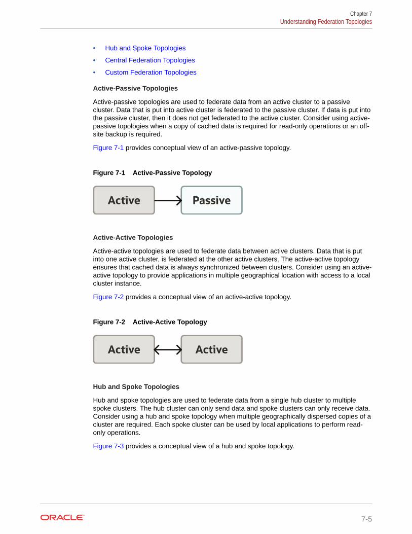
• Hub and Spoke Topologies
• Central Federation Topologies
• Custom Federation Topologies
Active-Passive Topologies
Active-passive topologies are used to federate data from an active cluster to a passivecluster. Data that is put into active cluster is federated to the passive cluster. If data is put intothe passive cluster, then it does not get federated to the active cluster. Consider using active-passive topologies when a copy of cached data is required for read-only operations or an off-site backup is required.
Figure 7-1 provides conceptual view of an active-passive topology.
Figure 7-1 Active-Passive Topology
Active Passive
Active-Active Topologies
Active-active topologies are used to federate data between active clusters. Data that is putinto one active cluster, is federated at the other active clusters. The active-active topologyensures that cached data is always synchronized between clusters. Consider using an active-active topology to provide applications in multiple geographical location with access to a localcluster instance.
Figure 7-2 provides a conceptual view of an active-active topology.
Figure 7-2 Active-Active Topology
Active Active
Hub and Spoke Topologies
Hub and spoke topologies are used to federate data from a single hub cluster to multiplespoke clusters. The hub cluster can only send data and spoke clusters can only receive data.Consider using a hub and spoke topology when multiple geographically dispersed copies of acluster are required. Each spoke cluster can be used by local applications to perform read-only operations.
Figure 7-3 provides a conceptual view of a hub and spoke topology.
Chapter 7Understanding Federation Topologies
7-5
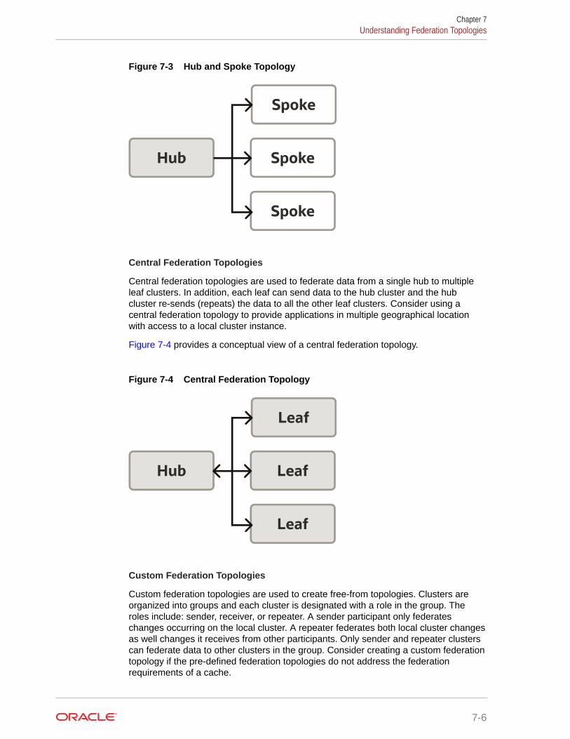
Figure 7-3 Hub and Spoke Topology
Hub Spoke
Spoke
Spoke
Central Federation Topologies
Central federation topologies are used to federate data from a single hub to multipleleaf clusters. In addition, each leaf can send data to the hub cluster and the hubcluster re-sends (repeats) the data to all the other leaf clusters. Consider using acentral federation topology to provide applications in multiple geographical locationwith access to a local cluster instance.
Figure 7-4 provides a conceptual view of a central federation topology.
Figure 7-4 Central Federation Topology
Hub Leaf
Leaf
Leaf
Custom Federation Topologies
Custom federation topologies are used to create free-from topologies. Clusters areorganized into groups and each cluster is designated with a role in the group. Theroles include: sender, receiver, or repeater. A sender participant only federateschanges occurring on the local cluster. A repeater federates both local cluster changesas well changes it receives from other participants. Only sender and repeater clusterscan federate data to other clusters in the group. Consider creating a custom federationtopology if the pre-defined federation topologies do not address the federationrequirements of a cache.
Chapter 7Understanding Federation Topologies
7-6
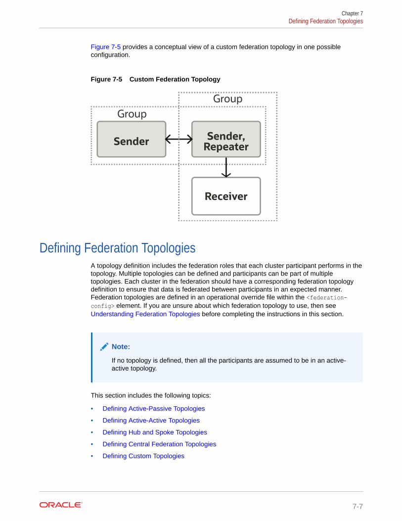
Figure 7-5 provides a conceptual view of a custom federation topology in one possibleconfiguration.
Figure 7-5 Custom Federation Topology
Group
SenderSender,
Repeater
Receiver
Group
Defining Federation TopologiesA topology definition includes the federation roles that each cluster participant performs in thetopology. Multiple topologies can be defined and participants can be part of multipletopologies. Each cluster in the federation should have a corresponding federation topologydefinition to ensure that data is federated between participants in an expected manner.Federation topologies are defined in an operational override file within the <federation-config> element. If you are unsure about which federation topology to use, then see Understanding Federation Topologies before completing the instructions in this section.
Note:
If no topology is defined, then all the participants are assumed to be in an active-active topology.
This section includes the following topics:
• Defining Active-Passive Topologies
• Defining Active-Active Topologies
• Defining Hub and Spoke Topologies
• Defining Central Federation Topologies
• Defining Custom Topologies
Chapter 7Defining Federation Topologies
7-7
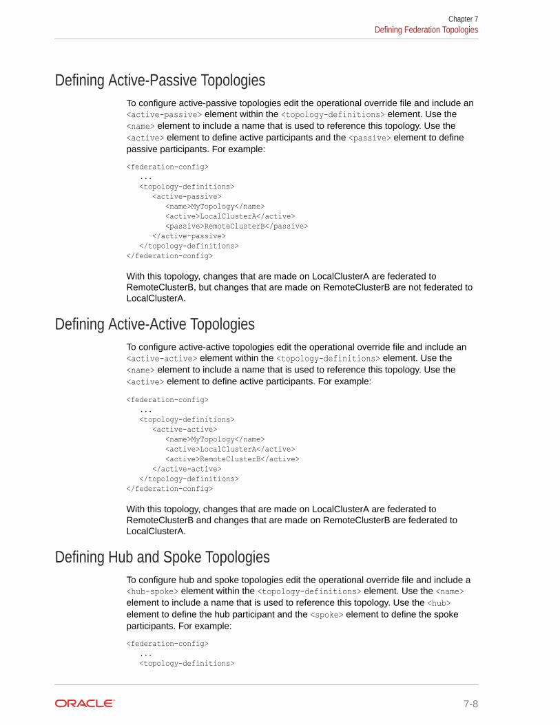
Defining Active-Passive TopologiesTo configure active-passive topologies edit the operational override file and include an<active-passive> element within the <topology-definitions> element. Use the<name> element to include a name that is used to reference this topology. Use the<active> element to define active participants and the <passive> element to definepassive participants. For example:
<federation-config> ... <topology-definitions> <active-passive> <name>MyTopology</name> <active>LocalClusterA</active> <passive>RemoteClusterB</passive> </active-passive> </topology-definitions></federation-config>
With this topology, changes that are made on LocalClusterA are federated toRemoteClusterB, but changes that are made on RemoteClusterB are not federated toLocalClusterA.
Defining Active-Active TopologiesTo configure active-active topologies edit the operational override file and include an<active-active> element within the <topology-definitions> element. Use the<name> element to include a name that is used to reference this topology. Use the<active> element to define active participants. For example:
<federation-config> ... <topology-definitions> <active-active> <name>MyTopology</name> <active>LocalClusterA</active> <active>RemoteClusterB</active> </active-active> </topology-definitions></federation-config>
With this topology, changes that are made on LocalClusterA are federated toRemoteClusterB and changes that are made on RemoteClusterB are federated toLocalClusterA.
Defining Hub and Spoke TopologiesTo configure hub and spoke topologies edit the operational override file and include a<hub-spoke> element within the <topology-definitions> element. Use the <name>element to include a name that is used to reference this topology. Use the <hub>element to define the hub participant and the <spoke> element to define the spokeparticipants. For example:
<federation-config> ... <topology-definitions>
Chapter 7Defining Federation Topologies
7-8
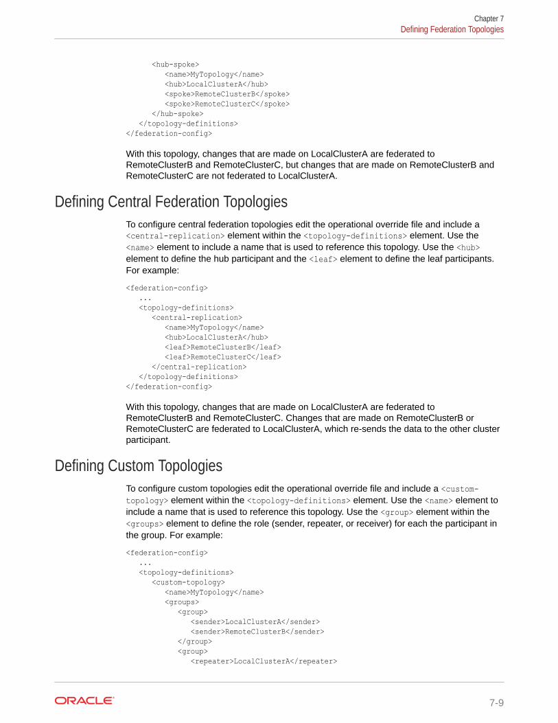
<hub-spoke> <name>MyTopology</name> <hub>LocalClusterA</hub> <spoke>RemoteClusterB</spoke> <spoke>RemoteClusterC</spoke> </hub-spoke> </topology-definitions></federation-config>
With this topology, changes that are made on LocalClusterA are federated toRemoteClusterB and RemoteClusterC, but changes that are made on RemoteClusterB andRemoteClusterC are not federated to LocalClusterA.
Defining Central Federation TopologiesTo configure central federation topologies edit the operational override file and include a<central-replication> element within the <topology-definitions> element. Use the<name> element to include a name that is used to reference this topology. Use the <hub>element to define the hub participant and the <leaf> element to define the leaf participants.For example:
<federation-config> ... <topology-definitions> <central-replication> <name>MyTopology</name> <hub>LocalClusterA</hub> <leaf>RemoteClusterB</leaf> <leaf>RemoteClusterC</leaf> </central-replication> </topology-definitions></federation-config>
With this topology, changes that are made on LocalClusterA are federated toRemoteClusterB and RemoteClusterC. Changes that are made on RemoteClusterB orRemoteClusterC are federated to LocalClusterA, which re-sends the data to the other clusterparticipant.
Defining Custom TopologiesTo configure custom topologies edit the operational override file and include a <custom-topology> element within the <topology-definitions> element. Use the <name> element toinclude a name that is used to reference this topology. Use the <group> element within the<groups> element to define the role (sender, repeater, or receiver) for each the participant inthe group. For example:
<federation-config> ... <topology-definitions> <custom-topology> <name>MyTopology</name> <groups> <group> <sender>LocalClusterA</sender> <sender>RemoteClusterB</sender> </group> <group> <repeater>LocalClusterA</repeater>
Chapter 7Defining Federation Topologies
7-9
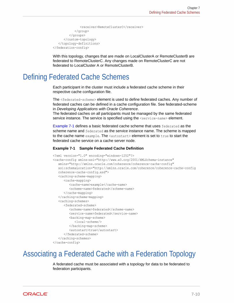
<receiver>RemoteClusterC</receiver> </group> </groups> </custom-topology> </topology-definitions></federation-config>
With this topology, changes that are made on LocalClusterA or RemoteClusterB arefederated to RemoteClusterC. Any changes made on RemoteClusterC are notfederated to LocalCluster A or RemoteClusterB.
Defining Federated Cache SchemesEach participant in the cluster must include a federated cache scheme in theirrespective cache configuration file.
The <federated-scheme> element is used to define federated caches. Any number offederated caches can be defined in a cache configuration file. See federated-schemein Developing Applications with Oracle Coherence.The federated caches on all participants must be managed by the same federatedservice instance. The service is specified using the <service-name> element.
Example 7-1 defines a basic federated cache scheme that uses federated as thescheme name and federated as the service instance name. The scheme is mappedto the cache name example. The <autostart> element is set to true to start thefederated cache service on a cache server node.
Example 7-1 Sample Federated Cache Definition
<?xml version="1.0" encoding="windows-1252"?><cache-config xmlns:xsi="http://www.w3.org/2001/XMLSchema-instance" xmlns="http://xmlns.oracle.com/coherence/coherence-cache-config" xsi:schemaLocation="http://xmlns.oracle.com/coherence/coherence-cache-config coherence-cache-config.xsd"> <caching-scheme-mapping> <cache-mapping> <cache-name>example</cache-name> <scheme-name>federated</scheme-name> </cache-mapping> </caching-scheme-mapping> <caching-schemes> <federated-scheme> <scheme-name>federated</scheme-name> <service-name>federated</service-name> <backing-map-scheme> <local-scheme/> </backing-map-scheme> <autostart>true</autostart> </federated-scheme> </caching-schemes></cache-config>
Associating a Federated Cache with a Federation TopologyA federated cache must be associated with a topology for data to be federated tofederation participants.
Chapter 7Defining Federated Cache Schemes
7-10
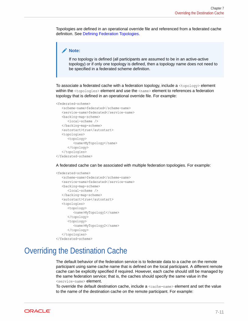
Topologies are defined in an operational override file and referenced from a federated cachedefinition. See Defining Federation Topologies.
Note:
If no topology is defined (all participants are assumed to be in an active-activetopology) or if only one topology is defined, then a topology name does not need tobe specified in a federated scheme definition.
To associate a federated cache with a federation topology, include a <topology> elementwithin the <topologies> element and use the <name> element to references a federationtopology that is defined in an operational override file. For example:
<federated-scheme> <scheme-name>federated</scheme-name> <service-name>federated</service-name> <backing-map-scheme> <local-scheme /> </backing-map-scheme> <autostart>true</autostart> <topologies> <topology> <name>MyTopology</name> </topology> </topologies></federated-scheme>
A federated cache can be associated with multiple federation topologies. For example:
<federated-scheme> <scheme-name>federated</scheme-name> <service-name>federated</service-name> <backing-map-scheme> <local-scheme /> </backing-map-scheme> <autostart>true</autostart> <topologies> <topology> <name>MyTopology1</name> </topology> <topology> <name>MyTopology2</name> </topology> </topologies></federated-scheme>
Overriding the Destination CacheThe default behavior of the federation service is to federate data to a cache on the remoteparticipant using same cache name that is defined on the local participant. A different remotecache can be explicitly specified if required. However, each cache should still be managed bythe same federation service; that is, the caches should specify the same value in the<service-name> element.To override the default destination cache, include a <cache-name> element and set the valueto the name of the destination cache on the remote participant. For example:
Chapter 7Overriding the Destination Cache
7-11
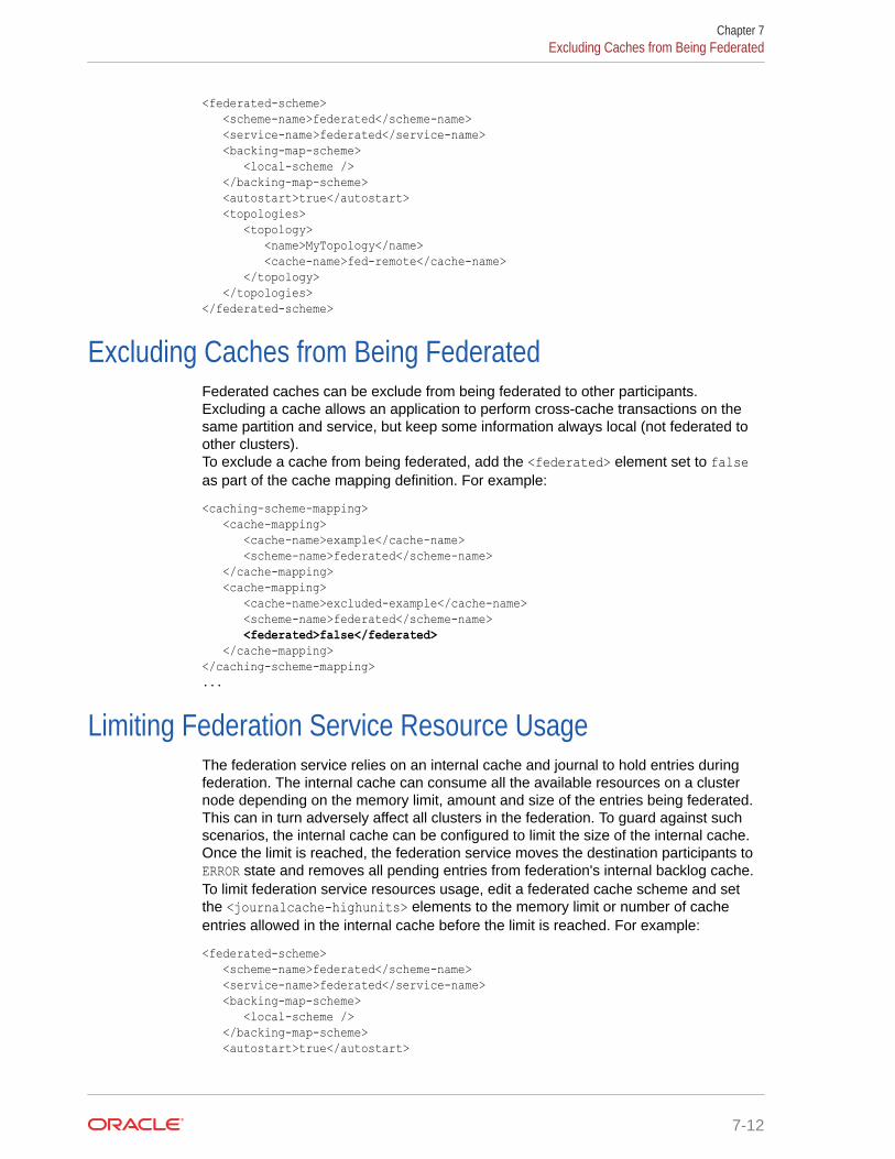
<federated-scheme> <scheme-name>federated</scheme-name> <service-name>federated</service-name> <backing-map-scheme> <local-scheme /> </backing-map-scheme> <autostart>true</autostart> <topologies> <topology> <name>MyTopology</name> <cache-name>fed-remote</cache-name> </topology> </topologies></federated-scheme>
Excluding Caches from Being FederatedFederated caches can be exclude from being federated to other participants.Excluding a cache allows an application to perform cross-cache transactions on thesame partition and service, but keep some information always local (not federated toother clusters).To exclude a cache from being federated, add the <federated> element set to falseas part of the cache mapping definition. For example:
<caching-scheme-mapping> <cache-mapping> <cache-name>example</cache-name> <scheme-name>federated</scheme-name> </cache-mapping> <cache-mapping> <cache-name>excluded-example</cache-name> <scheme-name>federated</scheme-name> <federated>false</federated> </cache-mapping></caching-scheme-mapping>...
Limiting Federation Service Resource UsageThe federation service relies on an internal cache and journal to hold entries duringfederation. The internal cache can consume all the available resources on a clusternode depending on the memory limit, amount and size of the entries being federated.This can in turn adversely affect all clusters in the federation. To guard against suchscenarios, the internal cache can be configured to limit the size of the internal cache.Once the limit is reached, the federation service moves the destination participants toERROR state and removes all pending entries from federation's internal backlog cache.To limit federation service resources usage, edit a federated cache scheme and setthe <journalcache-highunits> elements to the memory limit or number of cacheentries allowed in the internal cache before the limit is reached. For example:
<federated-scheme> <scheme-name>federated</scheme-name> <service-name>federated</service-name> <backing-map-scheme> <local-scheme /> </backing-map-scheme> <autostart>true</autostart>
Chapter 7Excluding Caches from Being Federated
7-12
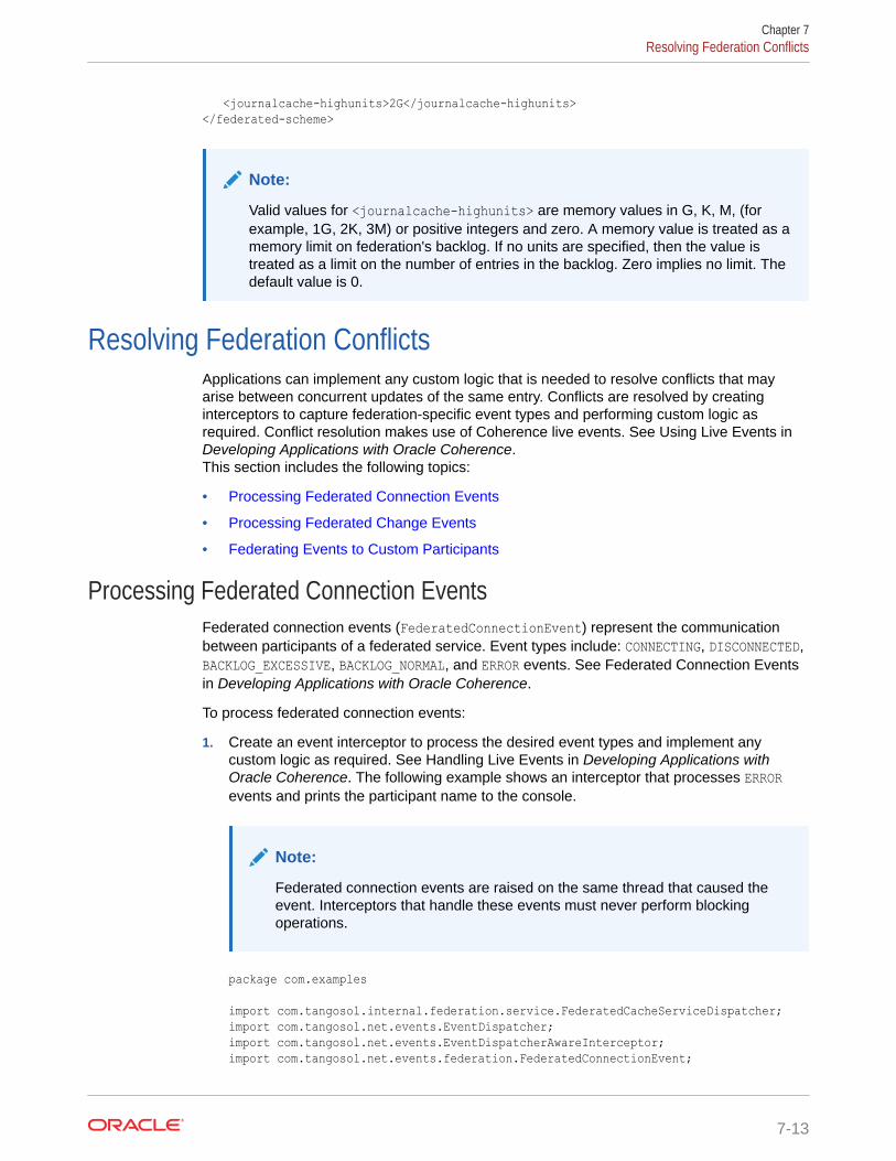
<journalcache-highunits>2G</journalcache-highunits></federated-scheme>
Note:
Valid values for <journalcache-highunits> are memory values in G, K, M, (forexample, 1G, 2K, 3M) or positive integers and zero. A memory value is treated as amemory limit on federation's backlog. If no units are specified, then the value istreated as a limit on the number of entries in the backlog. Zero implies no limit. Thedefault value is 0.
Resolving Federation ConflictsApplications can implement any custom logic that is needed to resolve conflicts that mayarise between concurrent updates of the same entry. Conflicts are resolved by creatinginterceptors to capture federation-specific event types and performing custom logic asrequired. Conflict resolution makes use of Coherence live events. See Using Live Events inDeveloping Applications with Oracle Coherence.This section includes the following topics:
• Processing Federated Connection Events
• Processing Federated Change Events
• Federating Events to Custom Participants
Processing Federated Connection EventsFederated connection events (FederatedConnectionEvent) represent the communicationbetween participants of a federated service. Event types include: CONNECTING, DISCONNECTED,BACKLOG_EXCESSIVE, BACKLOG_NORMAL, and ERROR events. See Federated Connection Eventsin Developing Applications with Oracle Coherence.
To process federated connection events:
1. Create an event interceptor to process the desired event types and implement anycustom logic as required. See Handling Live Events in Developing Applications withOracle Coherence. The following example shows an interceptor that processes ERRORevents and prints the participant name to the console.
Note:
Federated connection events are raised on the same thread that caused theevent. Interceptors that handle these events must never perform blockingoperations.
package com.examples
import com.tangosol.internal.federation.service.FederatedCacheServiceDispatcher;import com.tangosol.net.events.EventDispatcher;import com.tangosol.net.events.EventDispatcherAwareInterceptor;import com.tangosol.net.events.federation.FederatedConnectionEvent;
Chapter 7Resolving Federation Conflicts
7-13
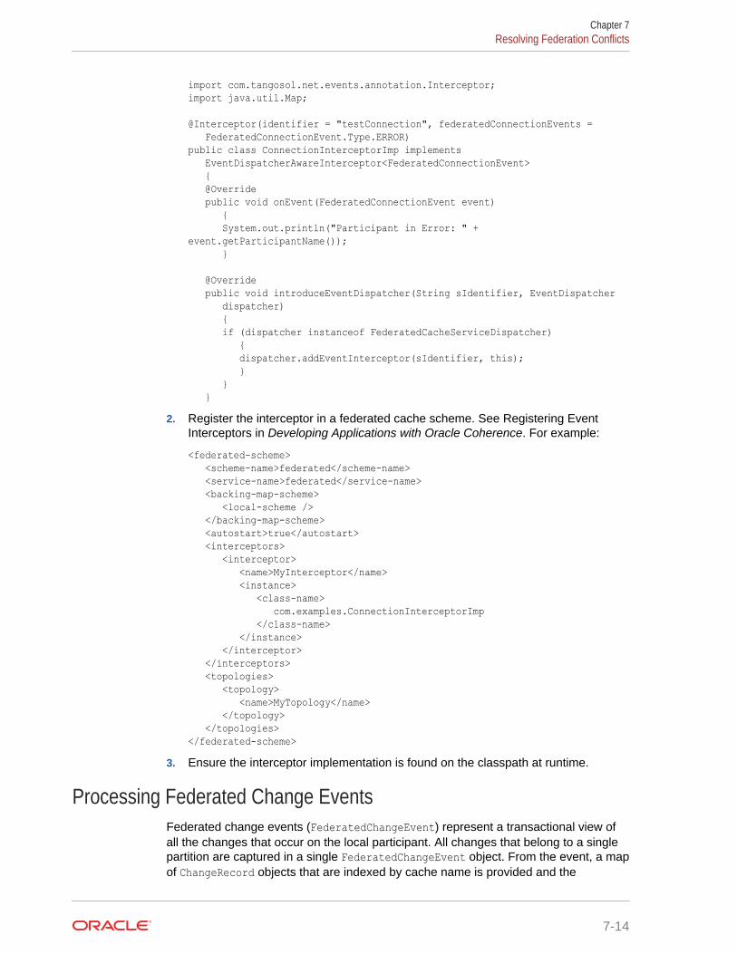
import com.tangosol.net.events.annotation.Interceptor;import java.util.Map;
@Interceptor(identifier = "testConnection", federatedConnectionEvents = FederatedConnectionEvent.Type.ERROR)public class ConnectionInterceptorImp implements EventDispatcherAwareInterceptor<FederatedConnectionEvent> { @Override public void onEvent(FederatedConnectionEvent event) { System.out.println("Participant in Error: " + event.getParticipantName()); }
@Override public void introduceEventDispatcher(String sIdentifier, EventDispatcher dispatcher) { if (dispatcher instanceof FederatedCacheServiceDispatcher) { dispatcher.addEventInterceptor(sIdentifier, this); } } }
2. Register the interceptor in a federated cache scheme. See Registering EventInterceptors in Developing Applications with Oracle Coherence. For example:
<federated-scheme> <scheme-name>federated</scheme-name> <service-name>federated</service-name> <backing-map-scheme> <local-scheme /> </backing-map-scheme> <autostart>true</autostart> <interceptors> <interceptor> <name>MyInterceptor</name> <instance> <class-name> com.examples.ConnectionInterceptorImp </class-name> </instance> </interceptor> </interceptors> <topologies> <topology> <name>MyTopology</name> </topology> </topologies></federated-scheme>
3. Ensure the interceptor implementation is found on the classpath at runtime.
Processing Federated Change EventsFederated change events (FederatedChangeEvent) represent a transactional view ofall the changes that occur on the local participant. All changes that belong to a singlepartition are captured in a single FederatedChangeEvent object. From the event, a mapof ChangeRecord objects that are indexed by cache name is provided and the
Chapter 7Resolving Federation Conflicts
7-14
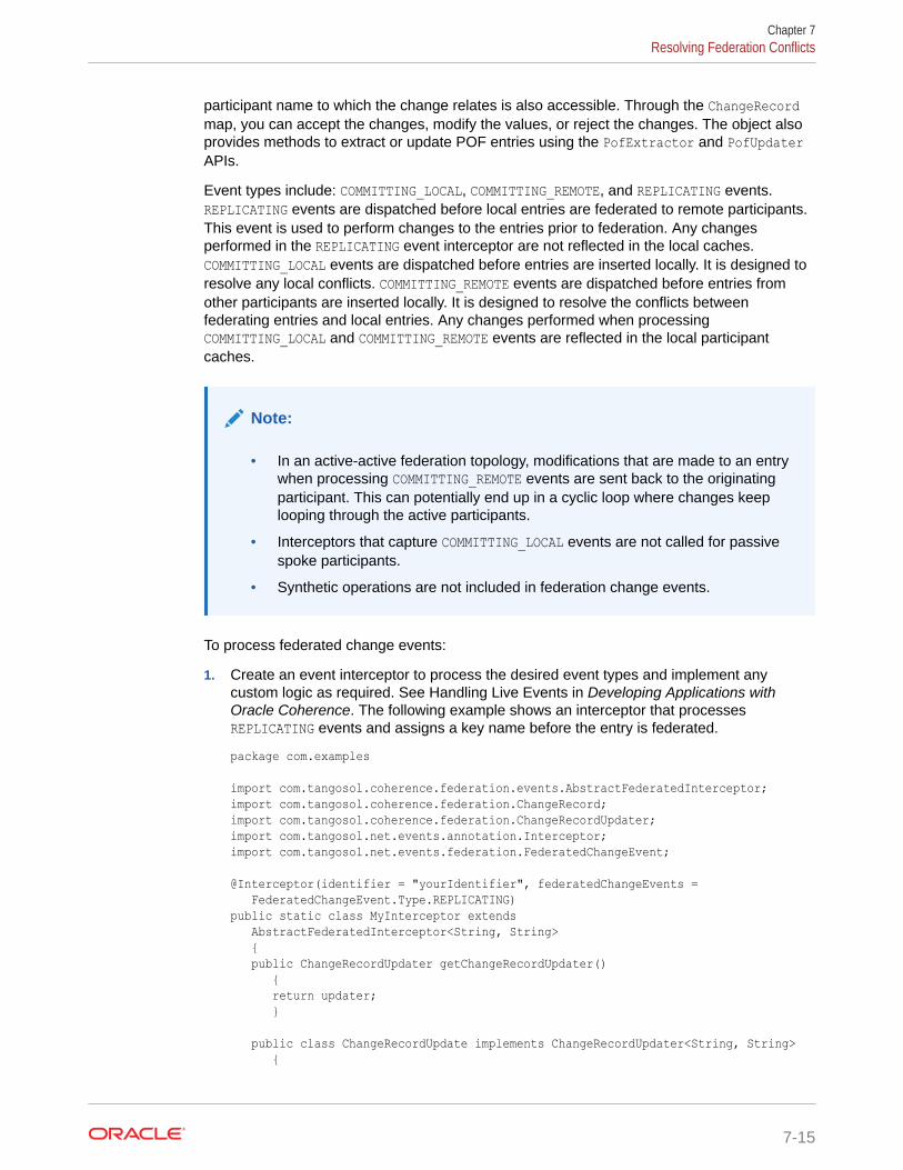
participant name to which the change relates is also accessible. Through the ChangeRecordmap, you can accept the changes, modify the values, or reject the changes. The object alsoprovides methods to extract or update POF entries using the PofExtractor and PofUpdaterAPIs.
Event types include: COMMITTING_LOCAL, COMMITTING_REMOTE, and REPLICATING events.REPLICATING events are dispatched before local entries are federated to remote participants.This event is used to perform changes to the entries prior to federation. Any changesperformed in the REPLICATING event interceptor are not reflected in the local caches.COMMITTING_LOCAL events are dispatched before entries are inserted locally. It is designed toresolve any local conflicts. COMMITTING_REMOTE events are dispatched before entries fromother participants are inserted locally. It is designed to resolve the conflicts betweenfederating entries and local entries. Any changes performed when processingCOMMITTING_LOCAL and COMMITTING_REMOTE events are reflected in the local participantcaches.
Note:
• In an active-active federation topology, modifications that are made to an entrywhen processing COMMITTING_REMOTE events are sent back to the originatingparticipant. This can potentially end up in a cyclic loop where changes keeplooping through the active participants.
• Interceptors that capture COMMITTING_LOCAL events are not called for passivespoke participants.
• Synthetic operations are not included in federation change events.
To process federated change events:
1. Create an event interceptor to process the desired event types and implement anycustom logic as required. See Handling Live Events in Developing Applications withOracle Coherence. The following example shows an interceptor that processesREPLICATING events and assigns a key name before the entry is federated.
package com.examples
import com.tangosol.coherence.federation.events.AbstractFederatedInterceptor;import com.tangosol.coherence.federation.ChangeRecord;import com.tangosol.coherence.federation.ChangeRecordUpdater;import com.tangosol.net.events.annotation.Interceptor;import com.tangosol.net.events.federation.FederatedChangeEvent; @Interceptor(identifier = "yourIdentifier", federatedChangeEvents = FederatedChangeEvent.Type.REPLICATING)public static class MyInterceptor extends AbstractFederatedInterceptor<String, String> { public ChangeRecordUpdater getChangeRecordUpdater() { return updater; } public class ChangeRecordUpdate implements ChangeRecordUpdater<String, String> {
Chapter 7Resolving Federation Conflicts
7-15
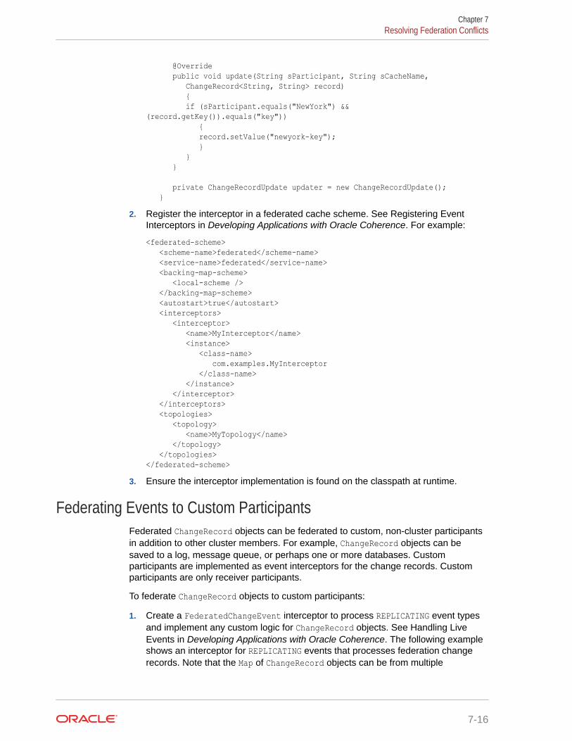
@Override public void update(String sParticipant, String sCacheName, ChangeRecord<String, String> record) { if (sParticipant.equals("NewYork") && (record.getKey()).equals("key")) { record.setValue("newyork-key"); } } }
private ChangeRecordUpdate updater = new ChangeRecordUpdate(); }
2. Register the interceptor in a federated cache scheme. See Registering EventInterceptors in Developing Applications with Oracle Coherence. For example:
<federated-scheme> <scheme-name>federated</scheme-name> <service-name>federated</service-name> <backing-map-scheme> <local-scheme /> </backing-map-scheme> <autostart>true</autostart> <interceptors> <interceptor> <name>MyInterceptor</name> <instance> <class-name> com.examples.MyInterceptor </class-name> </instance> </interceptor> </interceptors> <topologies> <topology> <name>MyTopology</name> </topology> </topologies></federated-scheme>
3. Ensure the interceptor implementation is found on the classpath at runtime.
Federating Events to Custom ParticipantsFederated ChangeRecord objects can be federated to custom, non-cluster participantsin addition to other cluster members. For example, ChangeRecord objects can besaved to a log, message queue, or perhaps one or more databases. Customparticipants are implemented as event interceptors for the change records. Customparticipants are only receiver participants.
To federate ChangeRecord objects to custom participants:
1. Create a FederatedChangeEvent interceptor to process REPLICATING event typesand implement any custom logic for ChangeRecord objects. See Handling LiveEvents in Developing Applications with Oracle Coherence. The following exampleshows an interceptor for REPLICATING events that processes federation changerecords. Note that the Map of ChangeRecord objects can be from multiple
Chapter 7Resolving Federation Conflicts
7-16
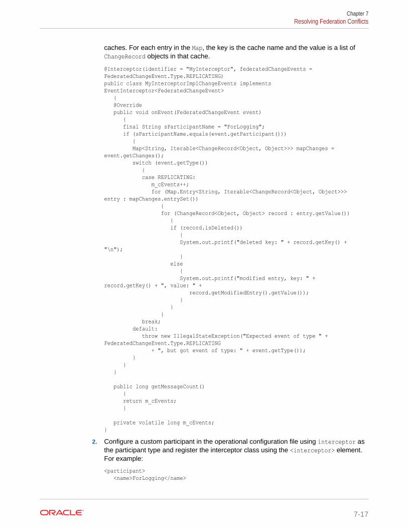
caches. For each entry in the Map, the key is the cache name and the value is a list ofChangeRecord objects in that cache.
@Interceptor(identifier = "MyInterceptor", federatedChangeEvents = FederatedChangeEvent.Type.REPLICATING)public class MyInterceptorImplChangeEvents implements EventInterceptor<FederatedChangeEvent> { @Override public void onEvent(FederatedChangeEvent event) { final String sParticipantName = "ForLogging"; if (sParticipantName.equals(event.getParticipant())) { Map<String, Iterable<ChangeRecord<Object, Object>>> mapChanges = event.getChanges(); switch (event.getType()) { case REPLICATING: m_cEvents++; for (Map.Entry<String, Iterable<ChangeRecord<Object, Object>>> entry : mapChanges.entrySet()) { for (ChangeRecord<Object, Object> record : entry.getValue()) { if (record.isDeleted()) { System.out.printf("deleted key: " + record.getKey() + "\n"); } else { System.out.printf("modified entry, key: " + record.getKey() + ", value: " + record.getModifiedEntry().getValue()); } } } break; default: throw new IllegalStateException("Expected event of type " + FederatedChangeEvent.Type.REPLICATING + ", but got event of type: " + event.getType()); } } }
public long getMessageCount() { return m_cEvents; }
private volatile long m_cEvents;}
2. Configure a custom participant in the operational configuration file using interceptor asthe participant type and register the interceptor class using the <interceptor> element.For example:
<participant> <name>ForLogging</name>
Chapter 7Resolving Federation Conflicts
7-17
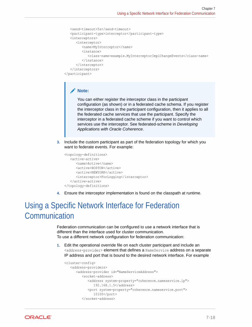
<send-timeout>5s</send-timeout> <participant-type>interceptor</participant-type> <interceptors> <interceptor> <name>MyInterceptor</name> <instance> <class-name>example.MyInterceptorImplChangeEvents</class-name> </instance> </interceptor> </interceptors></participant>
Note:
You can either register the interceptor class in the participantconfiguration (as shown) or in a federated cache schema. If you registerthe interceptor class in the participant configuration, then it applies to allthe federated cache services that use the participant. Specify theinterceptor in a federated cache scheme if you want to control whichservices use the interceptor. See federated-scheme in DevelopingApplications with Oracle Coherence.
3. Include the custom participant as part of the federation topology for which youwant to federate events. For example:
<topology-definitions> <active-active> <name>Active</name> <active>BOSTON</active> <active>NEWYORK</active> <interceptor>ForLogging</interceptor> </active-active></topology-definitions>
4. Ensure the interceptor implementation is found on the classpath at runtime.
Using a Specific Network Interface for FederationCommunication
Federation communication can be configured to use a network interface that isdifferent than the interface used for cluster communication.To use a different network configuration for federation communication:
1. Edit the operational override file on each cluster participant and include an<address-provider> element that defines a NameService address on a separateIP address and port that is bound to the desired network interface. For example
<cluster-config> <address-providers> <address-provider id="NameServiceAddress"> <socket-address> <address system-property="coherence.nameservice.ip"> 192.168.1.5</address> <port system-property="coherence.nameservice.port"> 10100</port> </socket-address>
Chapter 7Using a Specific Network Interface for Federation Communication
7-18
</address-provider> </address-providers></cluster-config>
2. Modify the participant definition to use the remote address. For example:
<federation-config> <participants> <participant> <name>LocalClusterA</name> <remote-addresses> <address-provider>NameServiceAddress</address-provider> </remote-addresses> </participant> ...
3. When starting cluster members (for the LocalClusterA participant in the above example),use the coherence.nameservice.addressprovider system property and reference theaddress provider definition for the name service. For example:
-Dcoherence.nameservice.addressprovider=NameServiceAddress
Load Balancing Federated ConnectionsConnections between federated service members are load balanced. By default, afederation-based strategy is used that distributes connections to federated service membersthat are being utilized the least. Custom strategies can be created or the default strategy canbe modified as required. As an alternative, a client-based load balance strategy can beimplemented by creating an address provider implementation or by relying on randomizedconnections to federated service members. The random approach provides minimalbalancing as compared to federated-based load balancing.Connections between federated service members are distributed equally across federatedservice members based upon existing connection count and incoming message backlog.Typically, this algorithm provides the best load balancing strategy. However, you can chooseto implement a different load balancing strategy as required.
This section includes the following topics:
• Using Federation-Based Load Balancing
• Implementing a Custom Federation-Based Load Balancing Strategy
• Using Client-Based Load Balancing
Using Federation-Based Load Balancingfederation-based load balancing is the default strategy that is used to balance connectionsbetween two or more members of the same federation service. The strategy distributeconnections equally across federated service members based upon existing connectioncount and incoming message backlog.
The federation-based load balancing strategy is configured within a <federated-scheme>definition using a <load-balancer> element that is set to federation. For clarity, thefollowing example explicitly specifies the strategy. However, the strategy is used by default ifno strategy is specified and is not required in a federated scheme definition.
<federated-scheme> <scheme-name>federated</scheme-name> <service-name>federated</service-name>
Chapter 7Load Balancing Federated Connections
7-19
<backing-map-scheme> <local-scheme /> </backing-map-scheme> <autostart>true</autostart> <load-balancer>federation</load-balancer> <topologies> <topology> <name>MyTopology</name> </topology> </topologies></federated-scheme>
Implementing a Custom Federation-Based Load Balancing StrategyThe com.tangosol.coherence.net.federation package includes the APIs that areused to balance client load across federated service members.
A custom strategy must implement the FederatedServiceLoadBalancer interface.New strategies can be created or the default strategy(DefaultFederatedServiceLoadBalancer) can be extended and modified as required.
To enable a custom federation-based load balancing strategy, edit a federated schemeand include an <instance> subelement within the <load-balancer> element andprovide the fully qualified name of a class that implements theFederatedServiceLoadBalancer interface. The following example enables a customfederation-based load balancing strategy that is implemented in theMyFederationServiceLoadBalancer class:
...<load-balancer> <instance> <class-name>package.MyFederationServiceLoadBalancer</class-name> </instance></load-balancer>...
In addition, the <instance> element also supports the use of a <class-factory-name>element to use a factory class that is responsible for creatingFederatedServiceLoadBalancer instances, and a <method-name> element to specifythe static factory method on the factory class that performs object instantiation. See instance in Developing Applications with Oracle Coherence.
Using Client-Based Load BalancingThe client-based load balancing strategy relies upon acom.tangosol.net.AddressProvider implementation to dictate the distribution ofconnections across federated service members. If no address provider implementationis provided, each configured cluster participant member is tried in a random order untila connection is successful. See address-provider in Developing Applications withOracle Coherence.
The client-based load balancing strategy is configured within a <federated-scheme>definition using a <load-balancer> element that is set to client. For example:
<federated-scheme> <scheme-name>federated</scheme-name> <service-name>federated</service-name>
Chapter 7Load Balancing Federated Connections
7-20
<backing-map-scheme> <local-scheme /> </backing-map-scheme> <autostart>true</autostart> <load-balancer>client</load-balancer> <topologies> <topology> <name>MyTopology</name> </topology> </topologies></federated-scheme>
Managing Federated CachingFederated caching should be managed on each cluster participant in the same manner asany non-federated cluster and distributed cache to ensure optimal performance and resourceusage. A poorly performing cluster is likely to cause performance issues when it is includedas part of a federation. In addition, federated caching should also be managed to ensureefficient federation performance and throughput among cluster participants in the federation.Monitoring federation performance is especially important due to the possible issues that areinherent in wide area network topologies.This section includes the following topics:
• Monitor Cluster Participant Status
• Monitor Federation Performance and Throughput
Monitor Cluster Participant StatusMonitor the status of each cluster participant in the federation to ensure that there are noissues.
Coherence VisualVM Plug-in
Use the Federation tab in the Coherence VisualVM plug-in to view the status of each clusterparticipant from the context of the local cluster participant. That is, each destination clusterparticipant is listed and its status is shown. In addition, the federation state of each node inthe local cluster participant is reported in the Outbound tab. Check the Error Description fieldto view an error message, if the status of cluster participant is Error.
Coherence Reports
Use the federation destination report (federation-destination.txt) to view the status ofeach destination cluster participant and the federation state of each node over time.
Coherence MBeans
Use the federation attributes on the DestinationMBean MBean to view the status of eachdestination cluster participants and the federation state of each node of the local clusterparticipant.
Coherence Command Line Interface
Use the Coherence Command Line Interface (CLI) to monitor and manage Coherencefederation clusters from a terminal based interface. For more information on federationcommands, see Federation. For more information about CLI, see coherence-cli.
Chapter 7Managing Federated Caching
7-21
Monitor Federation Performance and ThroughputMonitor federation performance and throughput to ensure that the local clusterparticipant is federating data to each participant without any substantial delays or lostdata. Issues with performance and throughput can be a sign that there is a problemwith the network connect between cluster participants or that there is a problem on thelocal cluster participant.
Coherence VisualVM Plug-in
Use the Federation tab in the Coherence VisualVM plug-in to view the currentfederation performance statistics and throughput from the local participant to eachdestination cluster participant. Select a destination cluster participant and view itsfederation performance statistics, then view the Current Throughput column on theOutbound tab to see the throughput to the selected participant from each node in thelocal cluster. Select an individual node in the Outbound tab to see its bandwidthutilization and federation performance in the graph tabs, respectively. Lastly, select theInbound tab to view how efficiently the local cluster participant is receiving data fromdestination cluster participants.
Coherence Reports
Use the federation destination report (federation-destination.txt) and thefederation origin report (federation-origin.txt) to view federation performancestatistics. The destination report shows how efficiently each node in the local clusterparticipant is sending data to each destination cluster participant. The federation originreports shows how efficiently each node in the local cluster participant is receiving datafrom destination cluster participants.
Coherence MBeans
Use the persistence attributes on the DestinationMBean MBean and the OriginMBeanMBean to view federation performance statistics. The DestinationMBean MBeanattribute shows how efficiently each node in the local cluster participant is sending datato each destination cluster participant. The OriginMBean MBean shows how efficientlythe local cluster participant is receiving data from destination cluster participants.
Chapter 7Managing Federated Caching
7-22
APlatform-Specific Deployment Considerations
Coherence can be deployed to many different platforms, each of which may require specificdeployment considerations. This appendix identifies issues that should be considered whendeploying Coherence to various platforms and offers solutions if available.This appendix includes the following sections:
• Deploying to Oracle HotSpot JVMs
• Deploying to IBM JVMs
• Deploying to Linux
• Deploying to Solaris
• Deploying to Windows
• Deploying to OS X
• Deploying to z/OS
• Deploying to AIX
• Deploying to Virtual Machines
• Deploying to Cisco Switches
• Deploying to Foundry Switches
• Deploying to IBM BladeCenters
Deploying to Oracle HotSpot JVMsIssues to be aware of when deploying Coherence on Oracle HotSpot JVMs
• Heap Sizes
• AtomicLong
• OutOfMemoryError
Heap SizesCoherence recommends keeping heap sizes at 1-8GB per JVM. However, larger heap sizes,up to 20GB, are suitable for some applications where the simplified management of fewer,larger JVMs outweighs the performance benefits of many smaller JVMs. Using multiple cacheservers allows a single computer to achieve higher capacities. With Oracle's JVMs, heapsizes beyond 8GB are reasonable, though GC tuning is still advisable to minimize long GCpauses. See Introduction in Java Platform, Standard Edition HotSpot Virtual MachineGarbage Collection Tuning Guide. It is also advisable to run with fixed sized heaps as thisgenerally lowers GC times. See JVM Tuning.
A-1
AtomicLongWhen available Coherence uses the highly concurrent AtomicLong class, which allowsconcurrent atomic updates to long values without requiring synchronization.
It is suggested to run in server mode to ensure that the stable and highly concurrentversion can be used. To run the JVM in server mode include the -server option on theJava command line.
OutOfMemoryErrorJVMs that experience an OutOfMemoryError can be left in an indeterministic statewhich can have adverse effects on a cluster. We recommend configuring JVMs to exitupon encountering an OutOfMemoryError instead of allowing the JVM to attemptrecovery. Here is the parameter to configure this setting on Sun JVMs:
UNIX:
-XX:OnOutOfMemoryError="kill -9 %p"
Windows:
-XX:OnOutOfMemoryError="taskkill /F /PID %p"
Additionally, it is recommended to configure the JVM to generate a heap dump if anOutOfMemoryError is thrown to assist the investigation into the root cause for the error.Use the following flag to enable this feature on the Sun JVM:
-XX:+HeapDumpOnOutOfMemoryError
Deploying to IBM JVMsIssues to be aware of when deploying Coherence on IBM JVMs
• OutOfMemoryError
• Heap Sizing
OutOfMemoryErrorJVMs that experience an OutOfMemoryError can be left in an indeterministic statewhich can have adverse effects on a cluster. We recommend configuring JVMs to exitupon encountering an OutOfMemoryError instead of allowing the JVM to attemptrecovery. Here is the parameter to configure this setting on IBM JVMs:
UNIX:
-Xdump:tool:events=throw,filter=java/lang/OutOfMemoryError,exec="kill -9 %pid"
Windows:
-Xdump:tool:events=throw,filter=java/lang/OutOfMemoryError,exec="taskkill /F /PID %pid"
Appendix ADeploying to IBM JVMs
A-2
Heap SizingIBM does not recommend fixed size heaps for JVMs. In many cases, it is recommended touse the default for -Xms (in other words, omit this setting and only set -Xmx). See this link formore details:
http://www.ibm.com/developerworks/java/jdk/diagnosis/It is recommended to configure the JVM to generate a heap dump if an OutOfMemoryError isthrown to assist the investigation into the root cause for the error. IBM JVMs generate a heapdump on OutOfMemoryError by default; no further configuration is required.
Deploying to LinuxIssues to be aware of when deploying Coherence on Linux
• TSC High Resolution Timesource
TSC High Resolution TimesourceLinux has several high resolution timesources to choose from, the fastest TSC (Time StampCounter) unfortunately is not always reliable. Linux chooses TSC by default, and duringstartup checks for inconsistencies, if found it switches to a slower safe timesource. Theslower time sources can be 10 to 30 times more expensive to query then the TSCtimesource, and may have a measurable impact on Coherence performance. For moredetails on TSC, see
https://lwn.net/Articles/209101/Coherence and the underlying JVM are not aware of the timesource which the operatingsystem is using. It is suggested that you check your system logs (/var/log/dmesg) to verifythat the following is not present.
kernel: Losing too many ticks!kernel: TSC cannot be used as a timesource.kernel: Possible reasons for this are:kernel: You're running with Speedstep,kernel: You don't have DMA enabled for your hard disk (see hdparm),kernel: Incorrect TSC synchronization on an SMP system (see dmesg).kernel: Falling back to a sane timesource now.
As the log messages suggest, this can be caused by a variable rate CPU (SpeedStep),having DMA disabled, or incorrect TSC synchronization on multi CPU computers. If present,it is suggested that you work with your system administrator to identify the cause and allowthe TSC timesource to be used.
Deploying to SolarisIssues to be aware of when deploying Coherence on Solaris
• Solaris 10 (x86 and SPARC)
• Solaris 10 Networking
• Solaris Network Interface Cards
Appendix ADeploying to Linux
A-3
• Solaris Link Aggregation
Solaris 10 (x86 and SPARC)When running on Solaris 10, there are known issues relate to packet corruption andmulticast disconnections. These most often manifest as either EOFExceptions, "Largegap" warnings while reading packet data, or frequent packet timeouts. It is highlyrecommend that the patches for both issues below be applied when using Coherenceon Solaris 10 systems.
Possible Data Integrity Issues on Solaris 10 Systems Using the e1000g Driver for theIntel Gigabit Network Interface Card (NIC)
https://support.oracle.com/CSP/main/article?cmd=show&type=NOT&doctype=ALERT&id=1000972.1IGMP(1) Packets do not Contain IP Router Alert Option When Sent From Solaris 10Systems With Patch 118822-21 (SPARC) or 118844-21 (x86/x64) or Later Installed
https://support.oracle.com/CSP/main/article?cmd=show&type=NOT&doctype=ALERT&id=1000940.1
Solaris 10 NetworkingIf running on Solaris 10, review the above Solaris 10 (x86 and SPARC) issues whichrelate to packet corruption and multicast disconnections. These most often manifest aseither EOFExceptions, "Large gap" warnings while reading packet data, or frequentpacket timeouts. It is highly recommend that the patches for both issues be appliedwhen using Coherence on Solaris 10 systems.
Solaris Network Interface CardsSolaris M series systems include an on-board NIC (bge) and PCI connected NIC(nxge). The on-board gigabit ethernet ports are used for low-bandwidth administrativenetworking connectivity for the domain and are not intended for high-performancecluster interconnect workloads with high traffic demands. Coherence cluster membersmust always use the dedicated PCIe NICs for high bandwidth cluster interconnects.
Solaris Link AggregationSolaris 11 supports two types of NIC link aggregation: trunk aggregation and Datalinkmultipathing (DLMP) aggregations. Trunk aggregation requires the use of a networkswitch, which must support the Link Aggregation Control Protocol (LCAP). DLMPaggregation requires the use of at least one network switch. However, when usingDLMP aggregations, make sure any switches are not configured to use trunkaggregation with LCAP. If you change from a trunk aggregation to a DLMPaggregation, you must remove the switch configuration that was previously created forthe trunk aggregation. Failure to do so, can result in packet loss and under utilizationof the network bandwidth.
Deploying to WindowsIssues to be aware of when deploying Coherence on Windows
Appendix ADeploying to Windows
A-4
• Performance Tuning
• Personal Firewalls
• Disconnected Network Interface
Performance TuningThe default Windows configuration is not optimized for background processes, heavy networkloads, and network interruptions. This may be addressed by running the optimize.reg scriptincluded in the Coherence installation's bin directory. See Operating System Tuning.
Personal FirewallsIf running a firewall on a computer you may have difficulties in forming a cluster consisting ofmultiple computers. This can be resolved by either:
• Disabling the firewall, though this is generally not recommended.
• Granting full network access to the Java executable which runs Coherence.
• Opening up individual address and ports for Coherence. See Configuring Firewalls forCluster Members in Developing Applications with Oracle Coherence.
Disconnected Network InterfaceOn Microsoft Windows, if the Network Interface Card (NIC) is unplugged from the network,the operating system invalidates the associated IP address. The effect of this is that anysocket which is bound to that IP address enters an error state. This results in the Coherencenodes exiting the cluster and residing in an error state until the NIC is reattached to thenetwork. In cases where it is desirable to allow multiple collocated JVMs to remain clusteredduring a physical outage Windows must be configured to not invalidate the IP address.
To adjust this parameter:
1. Run Registry Editor (regedit)
2. Locate the following registry key
HKLM\System\CurrentControlSet\Services\Tcpip\Parameters3. Add or reset the following new DWORD value
Name: DisableDHCPMediaSenseValue: 1 (boolean)
4. Reboot
While the name of the keyword includes DHCP, the setting effects both static and dynamic IPaddresses. See Microsoft Windows TCP/IP Implementation Details for additional information:
http://technet.microsoft.com/en-us/library/bb726981.aspx#EDAA
Deploying to OS XIssues to be aware of when deploying Coherence on OS X
• Multicast and IPv6
• Socket Buffer Sizing
Appendix ADeploying to OS X
A-5
Multicast and IPv6OS X defaults to running multicast over IPv6 rather than IPv4. If you run in a mixedIPv6/IPv4 environment, configure your JVMs to explicitly use IPv4. This can be doneby setting the java.net.preferIPv4Stack system property to true on the Javacommand line.
Socket Buffer SizingGenerally, Coherence prefers 2MB or higher buffers, but for OS X this may result inunexpectedly high kernel CPU time, which in turn reduces throughput. For OS X, thesuggested buffers size is 768KB, though your own tuning may find a better size. See Configuring the Size of the Packet Buffers in Developing Applications with OracleCoherence.
Deploying to z/OSIssues to be aware of when deploying Coherence on z/OS
• EBCDIC
• Multicast
EBCDICWhen deploying Coherence into environments where the default character set isEBCDIC rather than ASCII, ensure that Coherence configuration files which areloaded from JAR files or off of the classpath are in ASCII format. Configuration filesloaded directly from the file system should be stored in the systems native format ofEBCDIC.
MulticastUnder some circumstances, Coherence cluster nodes that run within the same logicalpartition (LPAR) on z/OS on IBM zSeries cannot communicate with each other. (Thisproblem does not occur on the zSeries when running on Linux.)
The root cause is that z/OS may bind the MulticastSocket that Coherence uses to anautomatically-assigned port, but Coherence requires the use of a specific port in orderfor cluster discovery to operate correctly. (Coherence does explicitly initialize thejava.net.MulitcastSocket to use the necessary port, but that information appears tobe ignored on z/OS when there is an instance of Coherence running within that sameLPAR.)
The solution is to run only one instance of Coherence within a z/OS LPAR; if multipleinstances are required, each instance of Coherence should be run in a separate z/OSLPAR. Alternatively, well known addresses may be used. See Using Well KnownAddresses in Developing Applications with Oracle Coherence.
Deploying to AIXIssues to be aware of when deploying Coherence on AIX
Appendix ADeploying to z/OS
A-6
• Multicast and IPv6
Multicast and IPv6AIX 5.2 and above default to running multicast over IPv6 rather than IPv4. If you run in amixed IPv6/IPv4 environment, configure your JVMs to explicitly use IPv4. This can be doneby setting the java.net.preferIPv4Stack system property to true on the Java commandline. See the IBM 32-bit SDK for AIX User Guide for details.
Deploying to Virtual MachinesIssues to be aware of when deploying Coherence on virtual machinesOracle Coherence follows the support policies of Oracle Fusion Middleware. See SupportedVirtualization and Partitioning Technologies for Oracle Fusion Middleware.
• Multicast Connectivity
• Performance
• Fault Tolerance
Multicast ConnectivityVirtualization adds another layer to your network topology and it must be properly configuredto support multicast networking. See Configuring Multicast Communication in DevelopingApplications with Oracle Coherence.
PerformanceIt is less likely that a process running in a virtualized operating system can fully use gigabitEthernet. This is not specific to Coherence and is visible on most network intensivevirtualized applications.
Fault ToleranceAdditional configuration is required to ensure that cache entry backups reside on physicallyseparate hardware. See Specifying a Cluster Member's Identity in Developing Applicationswith Oracle Coherence.
Deploying to Cisco SwitchesIssues to be aware of when deploying Coherence with Cisco switches
• Buffer Space and Packet Pauses
• Multicast Connectivity on Large Networks
• Multicast Outages
• Multicast Time-to-Live
Appendix ADeploying to Virtual Machines
A-7
Buffer Space and Packet PausesSome Cisco switches may run out of buffer space and exhibit frequent multi-secondcommunication pauses under heavy packet load some. These communication pausescan be identified by a series of Coherence log messages referencing communicationdelays with multiple nodes which cannot be attributed to local or remote GCs.
Experienced a 4172 ms communication delay (probable remote GC) with Member(Id=7, Timestamp=2008-09-15 12:15:47.511, Address=xxx.xxx.x.xx:8089, MachineId=13838); 320 packets rescheduled, PauseRate=0.31, Threshold=512
The Cisco 6500 series support configuring the amount of buffer space available toeach Ethernet port or ASIC. In high load applications it may be necessary to increasethe default buffer space. This can be accomplished by executing:
fabric buffer-reserve high
See Cisco's documentation for additional details on this setting.
Multicast Connectivity on Large NetworksCisco's default switch configuration does not support proper routing of multicastpackets between switches due to the use of IGMP snooping. See the Cisco'sdocumentation regarding the issue and solutions.
Multicast OutagesSome Cisco switches have shown difficulty in maintaining multicast group membershipresulting in existing multicast group members being silently removed from themulticast group. This cause a partial communication disconnect for the associatedCoherence node(s) and they are forced to leave and rejoin the cluster. This type ofoutage can most often be identified by the following Coherence log messagesindicating that a partial communication problem has been detected.
A potential network configuration problem has been detected. A packet has failed to be delivered (or acknowledged) after 60 seconds, although other packets were acknowledged by the same cluster member (Member(Id=3, Timestamp=Sat Sept 13 12:02:54 EST 2008, Address=192.168.1.101, Port=8088, MachineId=48991)) to this member (Member(Id=1, Timestamp=Sat Sept 13 11:51:11 EST 2008, Address=192.168.1.101, Port=8088, MachineId=49002)) as recently as 5 seconds ago.
To confirm the issue, use the same multicast address and port as the running cluster. Ifthe issue affects a multicast test node, its logs show that it suddenly stopped receivingmulticast test messages. See Performing a Multicast Connectivity Test.
The following test logs show the issue:
Example A-1 Log for a Multicast Outage
Test Node 192.168.1.100:
Sun Sept 14 16:44:22 GMT 2008: Received 83 bytes from a Coherence cluster node at 182.168.1.100: ??? Sun Sept 14 16:44:23 GMT 2008: Received test packet 76 from ip=/192.168.1.101, group=/224.3.2.0:32367, ttl=4. Sun Sept 14 16:44:23 GMT 2008: Received 83 bytes from a Coherence cluster node at 182.168.1.100: ???
Appendix ADeploying to Cisco Switches
A-8
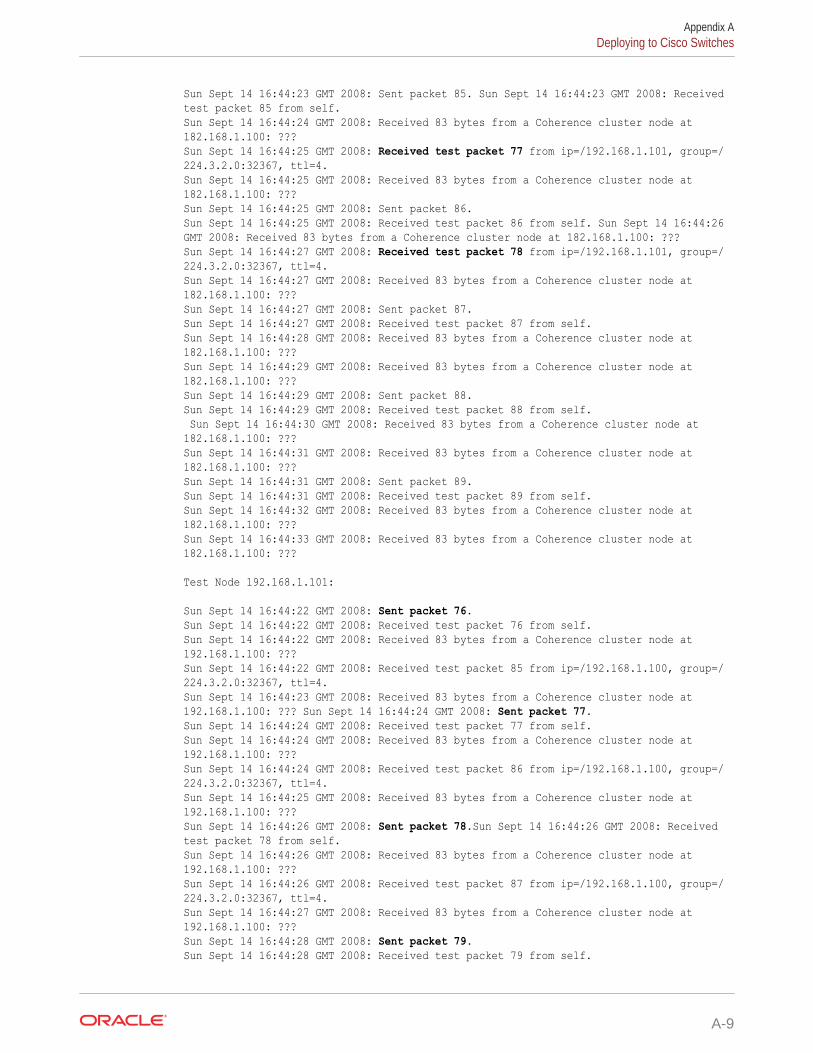
Sun Sept 14 16:44:23 GMT 2008: Sent packet 85. Sun Sept 14 16:44:23 GMT 2008: Received test packet 85 from self. Sun Sept 14 16:44:24 GMT 2008: Received 83 bytes from a Coherence cluster node at 182.168.1.100: ??? Sun Sept 14 16:44:25 GMT 2008: Received test packet 77 from ip=/192.168.1.101, group=/224.3.2.0:32367, ttl=4. Sun Sept 14 16:44:25 GMT 2008: Received 83 bytes from a Coherence cluster node at 182.168.1.100: ??? Sun Sept 14 16:44:25 GMT 2008: Sent packet 86. Sun Sept 14 16:44:25 GMT 2008: Received test packet 86 from self. Sun Sept 14 16:44:26 GMT 2008: Received 83 bytes from a Coherence cluster node at 182.168.1.100: ??? Sun Sept 14 16:44:27 GMT 2008: Received test packet 78 from ip=/192.168.1.101, group=/224.3.2.0:32367, ttl=4. Sun Sept 14 16:44:27 GMT 2008: Received 83 bytes from a Coherence cluster node at 182.168.1.100: ??? Sun Sept 14 16:44:27 GMT 2008: Sent packet 87. Sun Sept 14 16:44:27 GMT 2008: Received test packet 87 from self. Sun Sept 14 16:44:28 GMT 2008: Received 83 bytes from a Coherence cluster node at 182.168.1.100: ??? Sun Sept 14 16:44:29 GMT 2008: Received 83 bytes from a Coherence cluster node at 182.168.1.100: ??? Sun Sept 14 16:44:29 GMT 2008: Sent packet 88. Sun Sept 14 16:44:29 GMT 2008: Received test packet 88 from self. Sun Sept 14 16:44:30 GMT 2008: Received 83 bytes from a Coherence cluster node at 182.168.1.100: ??? Sun Sept 14 16:44:31 GMT 2008: Received 83 bytes from a Coherence cluster node at 182.168.1.100: ??? Sun Sept 14 16:44:31 GMT 2008: Sent packet 89. Sun Sept 14 16:44:31 GMT 2008: Received test packet 89 from self. Sun Sept 14 16:44:32 GMT 2008: Received 83 bytes from a Coherence cluster node at 182.168.1.100: ??? Sun Sept 14 16:44:33 GMT 2008: Received 83 bytes from a Coherence cluster node at 182.168.1.100: ???
Test Node 192.168.1.101:
Sun Sept 14 16:44:22 GMT 2008: Sent packet 76.Sun Sept 14 16:44:22 GMT 2008: Received test packet 76 from self. Sun Sept 14 16:44:22 GMT 2008: Received 83 bytes from a Coherence cluster node at 192.168.1.100: ??? Sun Sept 14 16:44:22 GMT 2008: Received test packet 85 from ip=/192.168.1.100, group=/224.3.2.0:32367, ttl=4. Sun Sept 14 16:44:23 GMT 2008: Received 83 bytes from a Coherence cluster node at 192.168.1.100: ??? Sun Sept 14 16:44:24 GMT 2008: Sent packet 77.Sun Sept 14 16:44:24 GMT 2008: Received test packet 77 from self. Sun Sept 14 16:44:24 GMT 2008: Received 83 bytes from a Coherence cluster node at 192.168.1.100: ??? Sun Sept 14 16:44:24 GMT 2008: Received test packet 86 from ip=/192.168.1.100, group=/224.3.2.0:32367, ttl=4. Sun Sept 14 16:44:25 GMT 2008: Received 83 bytes from a Coherence cluster node at 192.168.1.100: ??? Sun Sept 14 16:44:26 GMT 2008: Sent packet 78.Sun Sept 14 16:44:26 GMT 2008: Received test packet 78 from self. Sun Sept 14 16:44:26 GMT 2008: Received 83 bytes from a Coherence cluster node at 192.168.1.100: ??? Sun Sept 14 16:44:26 GMT 2008: Received test packet 87 from ip=/192.168.1.100, group=/224.3.2.0:32367, ttl=4. Sun Sept 14 16:44:27 GMT 2008: Received 83 bytes from a Coherence cluster node at 192.168.1.100: ??? Sun Sept 14 16:44:28 GMT 2008: Sent packet 79.Sun Sept 14 16:44:28 GMT 2008: Received test packet 79 from self.
Appendix ADeploying to Cisco Switches
A-9
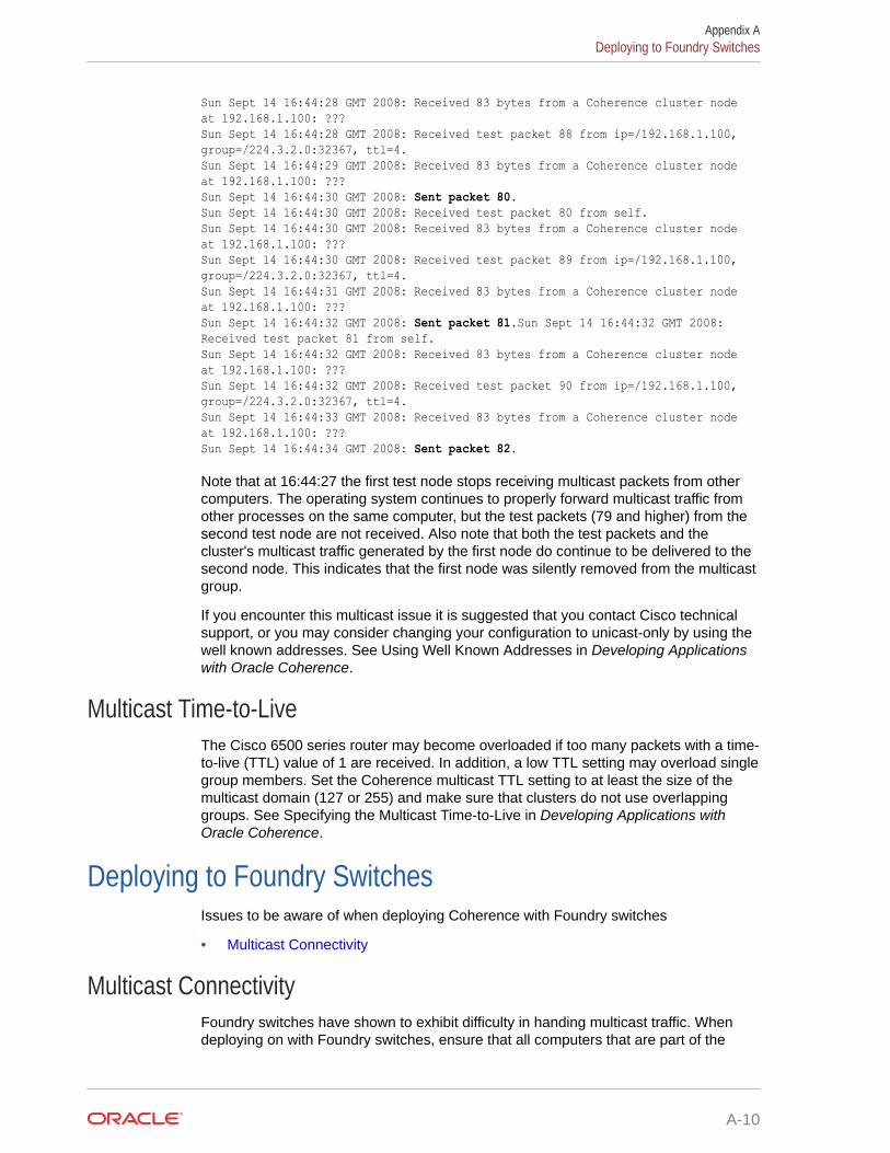
Sun Sept 14 16:44:28 GMT 2008: Received 83 bytes from a Coherence cluster node at 192.168.1.100: ??? Sun Sept 14 16:44:28 GMT 2008: Received test packet 88 from ip=/192.168.1.100, group=/224.3.2.0:32367, ttl=4. Sun Sept 14 16:44:29 GMT 2008: Received 83 bytes from a Coherence cluster node at 192.168.1.100: ??? Sun Sept 14 16:44:30 GMT 2008: Sent packet 80.Sun Sept 14 16:44:30 GMT 2008: Received test packet 80 from self. Sun Sept 14 16:44:30 GMT 2008: Received 83 bytes from a Coherence cluster node at 192.168.1.100: ??? Sun Sept 14 16:44:30 GMT 2008: Received test packet 89 from ip=/192.168.1.100, group=/224.3.2.0:32367, ttl=4. Sun Sept 14 16:44:31 GMT 2008: Received 83 bytes from a Coherence cluster node at 192.168.1.100: ??? Sun Sept 14 16:44:32 GMT 2008: Sent packet 81.Sun Sept 14 16:44:32 GMT 2008: Received test packet 81 from self. Sun Sept 14 16:44:32 GMT 2008: Received 83 bytes from a Coherence cluster node at 192.168.1.100: ??? Sun Sept 14 16:44:32 GMT 2008: Received test packet 90 from ip=/192.168.1.100, group=/224.3.2.0:32367, ttl=4. Sun Sept 14 16:44:33 GMT 2008: Received 83 bytes from a Coherence cluster node at 192.168.1.100: ??? Sun Sept 14 16:44:34 GMT 2008: Sent packet 82.
Note that at 16:44:27 the first test node stops receiving multicast packets from othercomputers. The operating system continues to properly forward multicast traffic fromother processes on the same computer, but the test packets (79 and higher) from thesecond test node are not received. Also note that both the test packets and thecluster's multicast traffic generated by the first node do continue to be delivered to thesecond node. This indicates that the first node was silently removed from the multicastgroup.
If you encounter this multicast issue it is suggested that you contact Cisco technicalsupport, or you may consider changing your configuration to unicast-only by using thewell known addresses. See Using Well Known Addresses in Developing Applicationswith Oracle Coherence.
Multicast Time-to-LiveThe Cisco 6500 series router may become overloaded if too many packets with a time-to-live (TTL) value of 1 are received. In addition, a low TTL setting may overload singlegroup members. Set the Coherence multicast TTL setting to at least the size of themulticast domain (127 or 255) and make sure that clusters do not use overlappinggroups. See Specifying the Multicast Time-to-Live in Developing Applications withOracle Coherence.
Deploying to Foundry SwitchesIssues to be aware of when deploying Coherence with Foundry switches
• Multicast Connectivity
Multicast ConnectivityFoundry switches have shown to exhibit difficulty in handing multicast traffic. Whendeploying on with Foundry switches, ensure that all computers that are part of the
Appendix ADeploying to Foundry Switches
A-10
Coherence cluster can communicate over multicast. See Performing a Multicast ConnectivityTest.
If you encounter issues with multicast you may consider changing your configuration tounicast-only by using the well-known-addresses feature. See Using Well Known Addresses inDeveloping Applications with Oracle Coherence.
Deploying to IBM BladeCentersIssues to be aware of when deploying Coherence on IBM BladeCenters
• MAC Address Uniformity and Load Balancing
MAC Address Uniformity and Load BalancingA typical deployment on a BladeCenter may include blades with two NICs where one is usedfor administration purposes and the other for cluster traffic. By default, the MAC addressesassigned to the blades of a BladeCenter are uniform enough that the first NIC generally hasan even MAC address and the second has an odd MAC address. If the BladeCenter's uplinkto a central switch also has an even number of channels, then layer 2 (MAC based) loadbalancing may prevent one set of NICs from making full use of the available uplink bandwidthas they are all bound to either even or odd channels. This issue arises due to the assumptionin the switch that MAC addresses are essentially random, which in BladeCenter's is untrue.Remedies to this situation include:
• Use layer 3 (IP based) load balancing (if the IP addresses do not follow the sameeven/odd pattern).
– This setting must be applied across all switches carrying cluster traffic.
• Randomize the MAC address assignments by swapping them between the first andsecond NIC on alternating computers.
– Linux enables you to change a NIC's MAC address using the ifconfig command.
– For other operating systems custom tools may be available to perform the same task.
Appendix ADeploying to IBM BladeCenters
A-11
BLog Message Glossary
Coherence emits many log messages that identify important information, which includespotential issues. This appendix provides a reference to common Coherence log messagesand includes the cause of the message and possible actions to take.This appendix includes the following sections:
• TCMP Log Messages
• Configuration Log Messages
• Partitioned Cache Service Log Messages
• Service Thread Pool Log MessagesLog messages that pertain to the service thread pool
• TMB Log MessagesLog messages that pertain to TMB.
TCMP Log MessagesLog messages that pertain to TCMP
Experienced a %n1 ms communication delay (probable remote GC) with Member %s%n1 - the latency in milliseconds of the communication delay; %s - the full Memberinformation. Severity: 2-Warning or 5-Debug Level 5 or 6-Debug Level 6 depending on thelength of the delay.
Cause: This node detected a delay in receiving acknowledgment packets from the specifiednode, and has determined that is it likely due to a remote GC (rather than a local GC). Thismessage indicates that the overdue acknowledgment has been received from the specifiednode, and that it has likely emerged from its GC. Any slowdown in the network or the remoteserver can trigger this, but the most common cause is GC, which should be investigated first.
Action: Prolonged and frequent garbage collection can adversely affect cluster performanceand availability. If these warnings are seen frequently, review your JVM heap and GCconfiguration and tuning. See Performance Tuning.
Failed to satisfy the variance: allowed=%n1 actual=%n2%n1 - the maximum allowed latency in milliseconds; %n2 - the actual latency in milliseconds.Severity: 3-Informational or 5-Debug Level 5 depending on the message frequency.
Cause: One of the first steps in the Coherence cluster discovery protocol is the calculation ofthe clock difference between the new and the senior nodes. This step assumes a relativelysmall latency for peer-to-peer round trip communication between the nodes. By default, theconfigured maximum allowed latency (the value of the <maximum-time-variance>configuration element) is 16 milliseconds. See incoming-message-handler in DevelopingApplications with Oracle Coherence. Failure to satisfy that latency causes this message tobe logged and increases the latency threshold, which is reflected in a follow up message.
B-1
Action: If the latency consistently stays very high (over 100 milliseconds), consult yournetwork administrator and see Performing a Network Performance Test.
Created a new cluster "%s1" with Member(%s2)%s1 - the cluster name; %s2 - the full Member information. Severity: 3-Informational.
Cause: This Coherence node attempted to join an existing cluster in the configuredamount of time (specified by the <join-timeout-milliseconds> element), but did notreceive any responses from any other node. As a result, it created a new cluster withthe specified name (either configured by the <cluster-name> element or calculatedbased on the multicast listener address and port, or the well known addresses list).The Member information includes the node id, creation timestamp, unicast addressand port, location, process id, role, and so on.
Action: None, if this node is expected to be the first node in the cluster. Otherwise, theoperational configuration has to be reviewed to determine the reason that this nodedoes not join the existing cluster.
This Member(%s1) joined cluster "%s2" with senior Member(%s3)%s1 - the full Member information for this node; %s2 - the cluster name; %s3 - the fullMember information for the cluster senior node. Severity: 3-Informational.
Cause: This Coherence node has joined an existing cluster.
Action: None, if this node is expected to join an existing cluster. Otherwise, identify therunning cluster and consider corrective actions.
Member(%s) joined Cluster with senior member %n%s - the full Member information for a new node that joined the cluster this nodebelongs to; %n - the node id of the cluster senior node. Severity: 5-Debug Level 5.
Cause: A new node has joined an existing Coherence cluster.
Action: None.
there appears to be other members of the cluster "%s" already running with anincompatible network configuration, aborting join with "%n"%s - the cluster name to which a join attempt was made; %n - information for thecluster. Severity: 5-Debug Level 5.
Cause:The joining member has a network configuration that conflicts with existingmembers of the cluster.
Action:The operational configuration has to be reviewed to determine the reason thatthis node does not join the existing cluster.
Member(%s) left Cluster with senior member %n%s - the full Member information for a node that left the cluster; %n - the node id ofthe cluster senior node. Severity: 5-Debug Level 5.
Cause: A node has left the cluster. This departure could be caused by theprogrammatic shutdown, process termination (normal or abnormal), or any othercommunication failure (for example, a network disconnect or a very long GC pause).This message reports the node's departure.
Appendix BTCMP Log Messages
B-2
Action: None, if the node departure was intentional. Otherwise, the departed node logsshould be analyzed.
MemberLeft notification for Member %n received from Member(%s)%n - the node id of the departed node; %s - the full Member information for a node that leftthe cluster. Severity: 5-Debug Level 5.
Cause: When a Coherence node terminates, this departure is detected by some nodesearlier than others. Most commonly, a node connected through the TCP ring connection("TCP ring buddy") would be the first to detect it. This message provides the informationabout the node that detected the departure first.
Action: None, if the node departure was intentional. Otherwise, the logs for both the departedand the detecting nodes should be analyzed.
Received cluster heartbeat from the senior %n that does not contain this %s ;stopping cluster service.%n - the senior service member id; %s - a cluster service member's id. Severity: 1-Error.
Cause: A heartbeat is broadcast from the senior cluster service member that contains acluster member set. If this cluster service member is not part of the broadcast set, then it isassumed that the senior member believes this service member to be dead and the clusterservice is stopped on the member. This typically occurs if a member lost communication withthe cluster for an extended period of time (possibly due to network issues or extendedgarbage collection) and was ejected from the cluster.
Action: Corrective action is not necessarily required, since the rest of the cluster presumablyis continuing its operation. However, it may warrant an investigation into root causes of theproblem (especially if it is recurring with some frequency).
Service %s joined the cluster with senior service member %n%s - the service name; %n - the senior service member id. Severity: 5-Debug Level 5.
Cause: When a clustered service starts on a given node, Coherence initiates a handshakeprotocol between all cluster nodes running the specified service. This message serves as anindication that this protocol has been initiated. If the senior node is not currently known, it isshown as "n/a".
Action: None.
This node appears to have partially lost the connectivity: it receives responses fromMemberSet(%s1) which communicate with Member(%s2), but is not respondingdirectly to this member; that could mean that either requests are not coming out orresponses are not coming in; stopping cluster service.%s1 - set of members that can communicate with the member indicated in %s2; %s2 -member that can communicate with set of members indicated in %s1. Severity: 1-Error.
Cause: The communication link between this member and the member indicated by %s2 hasbeen broken. However, the set of witnesses indicated by %s1 report no communicationissues with %s2. It is therefore assumed that this node is in a state of partial failure, thusresulting in the shutdown of its cluster threads.
Action: Corrective action is not necessarily required, since the rest of the cluster presumablyis continuing its operation and this node may recover and rejoin the cluster. On the otherhand, it may warrant an investigation into root causes of the problem (especially if it isrecurring with some frequency).
Appendix BTCMP Log Messages
B-3
validatePolls: This senior encountered an overdue poll, indicating a deadmember, a significant network issue or an Operating System threading librarybug (e.g. Linux NPTL): PollSeverity: 2-Warning
Cause: When a node joins a cluster, it performs a handshake with each cluster node.A missing handshake response prevents this node from joining the service. The logmessage following this one indicates the corrective action taken by this node.
Action: If this message reoccurs, further investigation into the root cause may bewarranted.
Received panic from junior member %s1 caused by %s2%s1 - the cluster member that sent the panic; %s2 - a member claiming to be thesenior member. Severity 2-Warning
Cause: This occurs after a cluster is split into multiple cluster islands (usually due to anetwork link failure). This message indicates that this senior member has noinformation about the other member that is claiming to be the senior member and willignore the panic from the junior member until it can communicate with the other seniormember.
Action: If this issue occurs frequently, the root cause of the cluster split should beinvestigated.
Received panic from senior Member(%s1) caused by Member(%s2)%s1 - the cluster senior member as known by this node; %s2 - a member claiming tobe the senior member. Severity: 1-Error.
Cause: This occurs after a cluster is split into multiple cluster islands (usually due to anetwork link failure). When a link is restored and the corresponding island seniors seeeach other, the panic protocol is initiated to resolve the conflict.
Action: If this issue occurs frequently, the root cause of the cluster split should beinvestigated.
Member %n1 joined Service %s with senior member %n2%n1 - an id of the Coherence node that joins the service; %s - the service name; %n2- the senior node for the service. Severity: 5-Debug Level 5.
Cause: When a clustered service starts on any cluster node, Coherence initiates ahandshake protocol between all cluster nodes running the specified service. Thismessage serves as an indication that the specified node has successfully completedthe handshake and joined the service.
Action: None.
Member %n1 left Service %s with senior member %n2%n1 - an id of the Coherence node that joins the service; %s - the service name; %n2- the senior node for the service. Severity: 5-Debug Level 5.
Cause: When a clustered service terminates on some cluster node, all other nodesthat run this service are notified about this event. This message serves as anindication that the specified clustered service at the specified node has terminated.
Action: None.
Appendix BTCMP Log Messages
B-4
Service %s: received ServiceConfigSync containing %n entries%s - the service name; %n - the number of entries in the service configuration map. Severity:5-Debug Level 5.
Cause: As a part of the service handshake protocol between all cluster nodes running thespecified service, the service senior member updates every new node with the full content ofthe service configuration map. For the partitioned cache services that map includes the fullpartition ownership catalog and internal ids for all existing caches. The message is also sentfor an abnormal service termination at the senior node when a new node assumes theservice seniority. This message serves as an indication that the specified node has receivedthat configuration update.
Action: None.
TcpRing: connecting to member %n using TcpSocket{%s}%s - the full information for the TcpSocket that serves as a TcpRing connector to anothernode; %n - the node id to which this node has connected. Severity: 5-Debug Level 5.
Cause: For quick process termination detection Coherence utilizes a feature called TcpRing,which is a sparse collection of TCP/IP-based connection between different nodes in thecluster. Each node in the cluster is connected to at least one other node, which (if at allpossible) is running on a different physical box. This connection is not used for any datatransfer; only trivial "heartbeat" communications are sent once a second per each link. Thismessage indicates that the connection between this and specified node is initialized.
Action: None.
Rejecting connection to member %n using TcpSocket{%s}%n - the node id that tries to connect to this node; %s - the full information for the TcpSocketthat serves as a TcpRing connector to another node. Severity: 4-Debug Level 4.
Cause: Sometimes the TCP Ring daemons running on different nodes could attempt to joineach other or the same node at the same time. In this case, the receiving node maydetermine that such a connection would be redundant and reject the incoming connectionrequest. This message is logged by the rejecting node when this happens.
Action: None.
Timeout while delivering a packet; requesting the departure confirmation forMember(%s1) by MemberSet(%s2)%s1 - the full Member information for a node that this node failed to communicate with; %s2- the full information about the "witness" nodes that are asked to confirm the suspectedmember departure. Severity: 2-Warning.
Cause: Coherence uses TMB for all data communications (mostly peer-to-peer unicast),which by itself does not have any delivery guarantees. Those guarantees are built into thecluster management protocol used by Coherence (TCMP). The TCMP daemons areresponsible for acknowledgment (ACK or NACK) of all incoming communications. If one ormore packets are not acknowledged within the ACK interval ("ack-delay-milliseconds"), theyare resent. This repeats until the packets are finally acknowledged or the timeout intervalelapses ("timeout-milliseconds"). At this time, this message is logged and the "witness"protocol is engaged, asking other cluster nodes whether they experience similarcommunication delays with the non-responding node. The witness nodes are chosen basedon their roles and location.
Appendix BTCMP Log Messages
B-5
Action: Corrective action is not necessarily required, since the rest of the clusterpresumably is continuing its operation and this node may recover and rejoin thecluster. On the other hand, it may warrant an investigation into root causes of theproblem (especially if it is recurring with some frequency).
This node appears to have become disconnected from the rest of the clustercontaining %n nodes. All departure confirmation requests went unanswered.Stopping cluster service.%n - the number of other nodes in the cluster this node was a member of. Severity: 1-Error.
Cause: Sometime a node that lives within a valid Java process, stops communicatingto other cluster nodes. (Possible reasons include: a network failure; extremely longGC pause; swapped out process.) In that case, other cluster nodes may choose torevoke the cluster membership for the paused node and completely shun any furthercommunication attempts by that node, causing this message be logged when theprocess attempts to resume cluster communications.
Action: Corrective action is not necessarily required, since the rest of the clusterpresumably is continuing its operation and this node may recover and rejoin thecluster. On the other hand, it may warrant an investigation into root causes of theproblem (especially if it is recurring with some frequency).
A potential communication problem has been detected. A packet has failed tobe delivered (or acknowledged) after %n1 seconds, although other packetswere acknowledged by the same cluster member (Member(%s1)) to thismember (Member(%s2)) as recently as %n2 seconds ago. Possible causesinclude network failure, poor thread scheduling (see FAQ if running onWindows), an extremely overloaded server, a server that is attempting to run itsprocesses using swap space, and unreasonably lengthy GC times.%n1 - The number of seconds a packet has failed to be delivered or acknowledged;%s1 - the recipient of the packets indicated in the message; %s2 - the sender of thepackets indicated in the message; %n2 - the number of seconds since a packet wasdelivered successfully between the two members indicated above. Severity: 2-Warning.
Cause: Possible causes are indicated in the text of the message.
Action: If this issue occurs frequently, the root cause should be investigated.
Node %s1 is not allowed to create a new cluster; WKA list: [%s2]%s1 - Address of node attempting to join cluster; %s2 - List of WKA addresses.Severity: 1-Error.
Cause: The cluster is configured to use WKA, and there are no nodes present in thecluster that are in the WKA list.
Action: Ensure that at least one node in the WKA list exists in the cluster, or add thisnode's address to the WKA list.
This member is configured with a compatible but different WKA list then thesenior Member(%s). It is strongly recommended to use the same WKA list for allcluster members.%s - the senior node of the cluster. Severity: 2-Warning.
Appendix BTCMP Log Messages
B-6
Cause: The WKA list on this node is different than the WKA list on the senior node. Usingdifferent WKA lists can cause different cluster members to operate independently from therest of the cluster.
Action: Verify that the two lists are intentionally different or set them to the same values.
<socket implementation> failed to set receive buffer size to %n1 packets (%n2 bytes);actual size is %n3 packets (%n4 bytes). Consult your OS documentation regardingincreasing the maximum socket buffer size. Proceeding with the actual value maycause sub-optimal performance.%n1 - the number of packets that fits in the buffer that Coherence attempted to allocate; %n2- the size of the buffer Coherence attempted to allocate; %n3 - the number of packets thatfits in the actual allocated buffer size; %n4 - the actual size of the allocated buffer. Severity:2-Warning.
Cause: See Operating System Tuning.
Action: See Operating System Tuning.
The timeout value configured for IpMonitor pings is shorter than the value of 5seconds. Short ping timeouts may cause an IP address to be wrongly reported asunreachable on some platforms.Severity: 2-Warning
Cause: The ping timeout value is less than 5 seconds.
Action: Ensure that the ping timeout that is configured within the <tcp-ring-listener>element is greater than 5 seconds.
Network failure encountered during InetAddress.isReachable(): %s%n - a stack trace. Severity: 5-Debug Level 5.
Cause: The IpMonitor component is unable to ping a member and has reached theconfigured timeout interval.
Action: Ensure that the member is operational or verify a network outage. The ping timeoutthat is configured within the <tcp-ring-listener> element can be increased to allow for alonger timeout as required by the network.
TcpRing has been explicitly disabled, this is not a recommended practice and willresult in a minimum death detection time of %n seconds for failed processes.%n - the number of seconds that is specified by the packet publisher's resend timeout whichis 5 minutes by default. Severity: 2-Warning.
Cause: The TcpRing Listener component has been disabled.
Action: Enable the TcpRing listener within the <tcp-ring-listener> element.
IpMonitor has been explicitly disabled, this is not a recommended practice and willresult in a minimum death detection time of %n seconds for failed machines ornetworks.%n - the number of seconds that is specified by the packet publisher's resend timeout whichis 5 minutes by default. Severity: 2-Warning.
Cause: The IpMonitor component has been disabled.
Appendix BTCMP Log Messages
B-7
Action: The IpMonitor component is enabled when the TcpRing listener is enabledwithin the <tcp-ring-listener> element.
TcpRing connecting to %s%s - the cluster member to which this member has joined to form a TCP-Ring.Severity: 6-Debug Level 6.
Cause: This message indicates that the connection between this and the specifiedmember is initialized. The TCP-Ring is used for quick process termination detectionand is a sparse collection of TCP/IP-based connection between different nodes in thecluster.
Action: none.
TcpRing disconnected from %s to maintain ring%s - the cluster member from which this member has disconnected. Severity: 6-Debug Level 6.
Cause: This message indicates that this member has disconnected from the specifiedmember and that the specified member is no longer a member of the TCP-Ring. TheTCP-Ring is used for quick process termination detection and is a sparse collection ofTCP/IP-based connection between different nodes in the cluster.
Action: If the member was intentionally stopped, no further action is required.Otherwise, the member may have been released from the cluster due to a failure ornetwork outage. Restart the member.
TcpRing disconnected from %s due to a peer departure; removing the member.%s - the cluster member from which this member has disconnected. Severity: 5-Debug Level 5.
Cause: This message indicates that this member has disconnected from the specifiedmember and that the specified member is no longer a member of the TCP-Ring. TheTCP-Ring is used for quick process termination detection and is a sparse collection ofTCP/IP-based connection between different nodes in the cluster.
Action: If the member was intentionally stopped, no further action is required.Otherwise, the member may have been released from the cluster due to a failure ornetwork outage. Restart the member.
TcpRing connection to "%s" refused ("%s1"); removing the member.%s - the cluster member to which this member was refused a connection; %s1- therefusal message. Severity: 5-Debug Level 5.
Cause: The specified member has refused a TCP connection from this member andhas subsequently been removed from the TCP-Ring.
Action: If the member was intentionally stopped, no further action is required.Otherwise, the member may have been released from the cluster due to a failure ornetwork outage. Restart the member.
Configuration Log MessagesLog messages that pertain to configuration
Appendix BConfiguration Log Messages
B-8
java.io.IOException: Configuration file is missing: "tangosol-coherence.xml"Severity: 1-Error.
Cause: The operational configuration descriptor cannot be loaded.
Action: Make sure that the tangosol-coherence.xml resource can be loaded from the classpath specified in the Java command line.
Loaded operational configuration from resource "%s"%s - the full resource path (URI) of the operational configuration descriptor. Severity: 3-Informational.
Cause: The operational configuration descriptor is loaded by Coherence from the specifiedlocation.
Action: If the location of the operational configuration descriptor was explicitly specified usingsystem properties or programmatically, verify that the reported URI matches the expectedlocation.
Loaded operational overrides from "%s"%s - the URI (file or resource) of the operational configuration descriptor override. Severity:3-Informational.
Cause: The operational configuration descriptor points to an override location, from whichthe descriptor override has been loaded.
Action: If the location of the operational configuration descriptor was explicitly specified usingsystem properties, descriptor override or programmatically, verify that the reported URImatches the expected location.
Optional configuration override "%s" is not specified%s - the URI of the operational configuration descriptor override. Severity: 3-Informational.
Cause: The operational configuration descriptor points to an override location which does notcontain any resource.
Action: Verify that the operational configuration descriptor override is not supposed to exist.
java.io.IOException: Document "%s1" is cyclically referenced by the 'xml-override'attribute of element %s2%s1 - the URI of the operational configuration descriptor or override; %s2 - the name of theXML element that contains an incorrect reference URI. Severity: 1-Error.
Cause: The operational configuration override points to itself or another override that point toit, creating an infinite recursion.
Action: Correct the invalid xml-override attribute's value.
java.io.IOException: Exception occurred during parsing: %s%s - the XML parser error. Severity: 1-Error.
Cause: The specified XML is invalid and cannot be parsed.
Action: Correct the XML document.
Appendix BConfiguration Log Messages
B-9
Loaded cache configuration from "%s"%s - the URI (file or resource) of the cache configuration descriptor. Severity: 3-Informational.
Cause: The operational configuration descriptor or a programmatically createdConfigurableCacheFactory instance points to a cache configuration descriptor thathas been loaded.
Action: Verify that the reported URI matches the expected cache configurationdescriptor location.
Partitioned Cache Service Log MessagesLog messages that pertain to the partitioned cache service
Asking member %n1 for %n2 primary partitions%n1 - the node id this node asks to transfer partitions from; %n2 - the number ofpartitions this node is willing to take. Severity: 4-Debug Level 4.
Cause: When a storage-enabled partitioned service starts on a Coherence node, itfirst receives the configuration update that informs it about other storage-enabledservice nodes and the current partition ownership information. That information allowsit to calculate the "fair share" of partitions that each node is supposed to own after there-distribution process. This message demarcates the beginning of the transferrequest to a specified node for its "fair" ownership distribution.
Action: None.
Transferring %n1 out of %n2 primary partitions to member %n3 requesting %n4%n1 - the number of primary partitions this node transferring to a requesting node;%n2 - the total number of primary partitions this node currently owns; %n3 - the nodeid that this transfer is for; %n4 - the number of partitions that the requesting nodeasked for. Severity: 4-Debug Level 4.
Cause: During the partition distribution protocol, a node that owns less than a "fairshare" of primary partitions requests any of the nodes that own more than the fairshare to transfer a portion of owned partitions. The owner may choose to send anynumber of partitions less or equal to the requested amount. This messagedemarcates the beginning of the corresponding primary data transfer.
Action: None.
Transferring %n1 out of %n2 partitions to a machine-safe backup 1 at member%n3 (under %n4)%n1 - the number of backup partitions this node transferring to a different node; %n2 -the total number of partitions this node currently owns that are "endangered" (do nothave a backup); %n3 - the node id that this transfer is for; %n4 - the number ofpartitions that the transferee can take before reaching the "fair share" amount.Severity: 4-Debug Level 4.
Cause: After the primary partition ownership is completed, nodes start distributing thebackups, ensuring the "strong backup" policy, that places backup ownership to nodesrunning on computers that are different from the primary owners' computers. Thismessage demarcates the beginning of the corresponding backup data transfer.
Appendix BPartitioned Cache Service Log Messages
B-10
Action: None.
Transferring backup%n1 for partition %n2 from member %n3 to member %n4%n1 - the index of the backup partition that this node transferring to a different node; %n2 -the partition number that is being transferred; %n3 the node id of the previous owner of thisbackup partition; %n4 the node id that the backup partition is being transferred to. Severity:5-Debug Level 5.
Cause: During the partition distribution protocol, a node that determines that a backup ownerfor one of its primary partitions is overloaded may choose to transfer the backup ownershipto another, underloaded node. This message demarcates the beginning of the correspondingbackup data transfer.
Action: None.
Failed backup transfer for partition %n1 to member %n2; restoring owner from: %n2to: %n3%n1 the partition number for which a backup transfer was in-progress; %n2 the node id thatthe backup partition was being transferred to; %n3 the node id of the previous backup ownerof the partition. Severity: 4-Debug Level 4.
Cause: This node was in the process of transferring a backup partition to a new backupowner when that node left the service. This node is restoring the backup ownership to theprevious backup owner.
Action: None.
Deferring the distribution due to %n1 pending configuration updates%n1- the number of configuration updates. Severity: 5-Debug Level 5.
Cause: This node is in the process of updating the global ownership map (notifying othernodes about ownership changes) when the periodic scheduled distribution check takesplace. Before the previous ownership changes (most likely due to a previously completedtransfer) are finalized and acknowledged by the other service members, this node postponessubsequent scheduled distribution checks.
Action: None.
Limiting primary transfer to %n1 KB (%n2 partitions)%n1 - the size in KB of the transfer that was limited; %n2 the number of partitions that weretransferred. Severity: 4-Debug Level 4.
Cause: When a node receives a request for some number of primary partitions from anunderloaded node, it may transfer any number of partitions (up to the requested amount) tothe requester. The size of the transfer is limited by the <transfer-threshold> element. Thismessage indicates that the distribution algorithm limited the transfer to the specified numberof partitions due to the transfer-threshold.
Action: None.
DistributionRequest was rejected because the receiver was busy. Next retry in %n1ms%n1 - the time in milliseconds before the next distribution check is scheduled. Severity: 6-Debug Level 6.
Appendix BPartitioned Cache Service Log Messages
B-11
Cause: This (underloaded) node issued a distribution request to another node askingfor one or more partitions to be transferred. However, the other node declined toinitiate the transfer as it was in the process of completing a previous transfer with adifferent node. This node waits at least the specified amount of time (to allow time forthe previous transfer to complete) before the next distribution check.
Action: None.
Restored from backup %n1 partitions%n1 - the number of partitions being restored. Severity: 3-Informational.
Cause: The primary owner for some backup partitions owned by this node has left theservice. This node is restoring those partitions from backup storage (assumingprimary ownership). This message is followed by a list of the partitions that are beingrestored.
Action: None.
Re-publishing the ownership for partition %n1 (%n2)%n1 the partition number whose ownership is being re-published; %n2 the node id ofthe primary partition owner, or 0 if the partition is orphaned. Severity: 4-Debug Level4.
Cause: This node is in the process of transferring a partition to another node when aservice membership change occurred, necessitating redistribution. This messageindicates this node re-publishing the ownership information for the partition whosetransfer is in-progress.
Action: None.
%n1> Ownership conflict for partition %n2 with member %n3 (%n4!=%n5)%n1 - the number of attempts made to resolve the ownership conflict; %n2 - thepartition whose ownership is in dispute; %n3 - the node id of the service member indisagreement about the partition ownership; %n4 - the node id of the partition'sprimary owner in this node's ownership map; %n5 - the node id of the partition'sprimary owner in the other node's ownership map. Severity: 4-Debug Level 4.
Cause: If a service membership change occurs while the partition ownership is in-flux,it is possible for the ownership to become transiently out-of-sync and requirereconciliation. This message indicates that such a conflict was detected, and denotesthe attempts to resolve it.
Action: None.
Unreconcilable ownership conflict; conceding the ownershipSeverity: 1-Error
Cause: If a service membership change occurs while the partition ownership is in-flux,it is possible for the ownership to become transiently out-of-sync and requirereconciliation. This message indicates that an ownership conflict for a partition couldnot be resolved between two service members. To resolve the conflict, one member isforced to release its ownership of the partition and the other member republishesownership of the partition to the senior member.
Action: None
Appendix BPartitioned Cache Service Log Messages
B-12
Multi-way ownership conflict; requesting a republish of the ownershipSeverity: 1-Error
Cause: If a service membership change occurs while the partition ownership is in-flux, it ispossible for the ownership to become transiently out-of-sync and require reconciliation. Thismessage indicates that a service member and the most senior storage-enabled memberhave conflicting views about the owner of a partition. To resolve the conflict, the partitioned isdeclared an orphan until the owner of the partition republishes its ownership of the partition.
Action: None
Assigned %n1 orphaned primary partitions%n1 - the number of orphaned primary partitions that were re-assigned. Severity: 2-Warning.
Cause: This service member (the most senior storage-enabled) has detected that one ormore partitions have no primary owner (orphaned), most likely due to several nodes leavingthe service simultaneously. The remaining service members agree on the partitionownership, after which the storage-senior assigns the orphaned partitions to itself. Thismessage is followed by a list of the assigned orphan partitions. This message indicates thatdata in the corresponding partitions may have been lost.
Action: None.
validatePolls: This service timed-out due to unanswered handshake request. Manualintervention is required to stop the members that have not responded to this PollSeverity: 1-Error.
Cause: When a node joins a clustered service, it performs a handshake with each clusterednode running the service. A missing handshake response prevents this node from joining theservice. Most commonly, it is caused by an unresponsive (for example, deadlocked) servicethread.
Action: Corrective action may require locating and shutting down the JVM running theunresponsive service. See Note 845363.1 at My Oracle Support for more details.
com.tangosol.net.RequestPolicyException: No storage-enabled nodes exist forservice service_nameSeverity: 1-Error.
Cause: A cache request was made on a service that has no storage-enabled servicemembers. Only storage-enabled service members may process cache requests, so theremust be at least one storage-enabled member.
Action: Check the configuration/deployment to ensure that members that are intended tostore cache data are configured to be storage-enabled. Storage is enabled on a memberusing the <local-storage> element or by using the -Dcoherence.distributed.localstorage command-line override.
An entry was inserted into the backing map for the partitioned cache "%s" that is notowned by this member; the entry will be removed."%s - the name of the cache into which insert was attempted. Severity: 1-Error.
Cause: The backing map for a partitioned cache may only contain keys that are owned bythat member. Cache requests are routed to the service member owning the requested keys,ensuring that service members only process requests for keys which they own. Thismessage indicates that the backing map for a cache detected an insertion for a key which is
Appendix BPartitioned Cache Service Log Messages
B-13
not owned by the member. This is most likely caused by a direct use of the backing-map as opposed to the exposed cache APIs (for example, NamedCache) in user coderunning on the cache server. This message is followed by a Java exception stacktrace showing where the insertion was made.
Action: Examine the user-code implicated by the stack-trace to ensure that anybacking-map operations are safe. This error can be indicative of an incorrectimplementation of KeyAssociation.
Exception occurred during filter evaluation: %s; removing the filter...%s - the description of the filter that failed during evaluation. Severity: 1-Error.
Cause: An exception was thrown while evaluating a filter for a MapListenerimplementation that is registered on this cache. As a result, some map events maynot have been issued. Additionally, to prevent further failures, the filter (andassociated MapListener implementation) are removed. This message is followed by aJava exception stack trace showing where the failure occurred.
Action: Review filter implementation and the associated stack trace for errors.
Exception occurred during event transformation: %s; removing the filter...%s - the description of the filter that failed during event transformation. Severity: 1-Error.
Cause: An Exception was thrown while the specified filter was transforming aMapEvent for a MapListener implementation that is registered on this cache. As aresult, some map events may not have been issued. Additionally, to prevent furtherfailures, the Filter implementation (and associated MapListener implementation) areremoved. This message is followed by a Java exception stack trace showing wherethe failure occurred.
Action: Review the filter implementation and the associated stack trace for errors.
Exception occurred during index rebuild: %s%s - the stack trace for the exception that occurred during index rebuild. Severity: 1-Error.
Cause: An Exception was thrown while adding or rebuilding an index. A likely causeof this is a faulty ValueExtractor implementation. As a result of the failure, theassociated index is removed. This message is followed by a Java exception stacktrace showing where the failure occurred.
Action: Review the ValueExtractor implementation and associated stack trace forerrors.
Exception occurred during index update: %s%s - the stack trace for the exception that occurred during index update. Severity: 1-Error.
Cause: An Exception was thrown while updating an index. A likely cause of this is afaulty ValueExtractor implementation. As a result of the failure, the associated indexis removed. This message is followed by a Java exception stack trace showing wherethe failure occurred.
Appendix BPartitioned Cache Service Log Messages
B-14
Action: Review the ValueExtractor implementation and associated stack trace for errors.
Exception occurred during query processing: %s%s - the stack trace for the exception that occurred while processing a query. Severity: 1-Error.
Cause: An Exception was thrown while processing a query. A likely cause of this is an errorin the filter implementation used by the query. This message is followed by a Java exceptionstack trace showing where the failure occurred.
Action: Review the filter implementation and associated stack trace for errors.
BackingMapManager %s1: returned "null" for a cache: %s2%s1 - the classname of the BackingMapManager implementation that returned a nullbacking-map; %s2 - the name of the cache for which the BackingMapManager returned null.Severity: 1-Error.
Cause: A BackingMapManager returned null for a backing-map for the specified cache.
Action: Review the specified BackingMapManager implementation for errors and to ensurethat it properly instantiates a backing map for the specified cache.
BackingMapManager %s1: failed to instantiate a cache: %s2%s1 - the classname of the BackingMapManager implementation that failed to create abacking-map; %s2 - the name of the cache for which the BackingMapManager failed.Severity: 1-Error.
Cause: A BackingMapManager unexpectedly threw an Exception while attempting toinstantiate a backing-map for the specified cache.
Action: Review the specified BackingMapManager implementation for errors and to ensurethat it properly instantiates a backing map for the specified cache.
BackingMapManager %s1: failed to release a cache: %s2%s1 - the classname of the BackingMapManager implementation that failed to release abacking-map; %s2 - the name of the cache for which the BackingMapManager failed.Severity: 1-Error.
Cause: A BackingMapManager unexpectedly threw an Exception while attempting to releasea backing-map for the specified cache.
Action: Review the specified BackingMapManager implementation for errors and to ensurethat it properly releases a backing map for the specified cache.
Unexpected event during backing map operation: key=%s1; expected=%s2;actual=%s3%s1 - the key being modified by the cache; %s2 - the expected backing-map event from thecache operation in progress; %s3 - the actual MapEvent received. Severity: 6-Debug Level6.
Cause: While performing a cache operation, an unexpected MapEvent was received on thebacking-map. This indicates that a concurrent operation was performed directly on thebacking-map and is most likely caused by direct manipulation of the backing-map asopposed to the exposed cache APIs (for example, NamedCache) in user code running on thecache server.
Appendix BPartitioned Cache Service Log Messages
B-15
Action: Examine any user-code that may directly modify the backing map to ensurethat any backing-map operations are safe.
Application code running on "%s1" service thread(s) should not call %s2 asthis may result in deadlock. The most common case is a CacheFactory call froma custom CacheStore implementation.%s1 - the name of the service which has made a re-entrant call; %s2 - the name ofthe method on which a re-entrant call was made. Severity: 2-Warning.
Cause: While executing application code on the specified service, a re-entrant call (arequest to the same service) was made. Coherence does not support re-entrantservice calls, so any application code (CacheStore, EntryProcessor, and so on...)running on the service thread(s) should avoid making cache requests.
Action: Remove re-entrant calls from application code running on the servicethread(s) and consider using alternative design strategy. See Constraints on Re-entrant Calls in Developing Applications with Oracle Coherence.
Repeating %s1 for %n1 out of %n2 items due to re-distribution of %s2%s1 - the description of the request that must be repeated; %n1 - the number of itemsthat are outstanding due to re-distribution; %n2 - the total number of items requested;%s2 - the list of partitions that are in the process of re-distribution and for which therequest must be repeated. Severity: 5-Debug Level 5.
Cause: When a cache request is made, the request is sent to the service membersowning the partitions to which the request refers. If one or more of the partitions that arequest refers to is in the process of being transferred (for example, due to re-distribution), the request is rejected by the (former) partition owner and isautomatically resent to the new partition owner.
Action: None.
Error while starting cluster: com.tangosol.net.RequestTimeoutException:Timeout during service start: ServiceInfo(%s)%s - information on the service that could not be started. Severity: 1-Error.
Cause: When joining a service, every service in the cluster must respond to the joinrequest. If one or more nodes have a service that does not respond within the timeoutperiod, the join times out.
Action: See 845363.1 at My Oracle Support for more details.
Failed to restart services: com.tangosol.net.RequestTimeoutException: Timeoutduring service start: ServiceInfo(%s)%s - information on the service that could not be started. Severity: 1-Error.
Cause: When joining a service, every service in the cluster must respond to the joinrequest. If one or more nodes have a service that does not respond within the timeoutperiod, the join times out.
Action: See My Oracle Support NoteSee 845363.1 at My Oracle Support for more details.
Appendix BPartitioned Cache Service Log Messages
B-16
Failed to recover partition 0 from SafeBerkeleyDBStore(...); partition-countmismatch501(persisted) != 277(service); reinstate persistent store fromtrash once validationerrors have been resolvedCause: The partition-count is changed while active persistence is enabled. The currentactive data is copied to the trash directory.
Action: Complete the following steps to recover the data:
1. Shutdown the entire cluster.
2. Remove the current active directory contents for the cluster and service affected on eachcluster member.
3. Copy (recursively) the contents of the trash directory for each service to the activedirectory.
4. Restore the partition count to the original value.
5. Restart the cluster.
Service Thread Pool Log MessagesLog messages that pertain to the service thread pool
DaemonPool "%s" increasing the pool size from %n1 to %n2 thread(s) due to the poolbeing shaken%s - the service name; %n1 - the current thread pool count; %n2 - the new thread poolcount. Severity: 3 - Informational.Cause: The thread pool count will be increased intermittently and the thread pool throughputwill be measured to determine if the increase is effective. The thread count will be increasedonly if dynamic thread pooling is enabled and the new thread count does not exceed themaximum configured value.Action: None. This is part of the process for determining the most effective thread pool count.
DaemonPool "%s" increasing the pool size from %n1 to %n2 thread(s) due to adecrease in throughput of %n3op/sec%s - the service name; %n1 - the current thread pool count; %n2 - the new thread poolcount; %n3 - the change in operations per second. Severity: 3 - Informational.Cause: The thread pool task throughput was reduced with a lower thread count. The threadcount is being increased to improve throughput. The thread count will be increased only ifdynamic thread pooling is enabled and the new thread count does not exceed the maximumconfigured value.Action: None. This is part of the process for determining the most effective thread pool count.
DaemonPool "%s" decreasing the pool size from %n1 to %n2 thread(s) due to adecrease in throughput of %n3op/sec%s - the service name; %n1 - the current thread pool count; %n2 - the new thread poolcount; %n3 - the change in operations per second. Severity: 3 - Informational.Cause: The thread pool task throughput was reduced with a higher thread count. The threadcount is being decreased to improve throughput. The thread count will be decreased only ifdynamic thread pooling is enabled and the new thread count does not drop below theconfigured minimum value.Action: None. This is part of the process for determining the most effective thread pool count.
TMB Log MessagesLog messages that pertain to TMB.
Appendix BService Thread Pool Log Messages
B-17
%s1 rejecting connection from %s2 using incompatible protocol id %s3,required %s4%s1 - the local endpoint; %s2 - the socket address; %s3 - the connection protocol id;%s4 - the required protocol Id. Severity: 2 -Warning.Cause: A Coherence node with incompatible protocol identifier has attempted toestablish a connection with this node. This should not happen unless the request isfrom a malicious connect attempt or the message header is corrupted.Action: Restart remote node. If problem persists, send all related information to OracleSupport for investigation.
%s1 rejecting connection from %s2, bus is closing%s1 – the local endpoint; %s2 – the socket address. Severity: 5-Debug.Cause: The local message bus connection received a connection request while it isbeing closed. This is likely to occur during the local node shutdown.Action: None.
%s1 deferring reconnect attempt from %s2 on %s3, pending release%s1 – the local endpoint; %s2 – the peer’s endpoint; %s3 – the associated channelsocket. Severity: 5-Debug.Cause: The local message bus connection received a reconnect request from thesame remote endpoint while the current connection is waiting for an application tofully release.Action: None.
%s1 replacing deferred reconnect attempt from %s2 on %s3, pending release%s1 – the local endpoint; %s2 – the peer’s endpoint; %s3 – the associated channelsocket. Severity: 5-Debug.Cause: The local TCP socket received a subsequent reconnect request, thusreplacing a previous reconnect attempt, while waiting for the application to fullyrelease. This is expected due to the possibility of concurrent connect initiation fromboth the remote and local endpoint, which is part of the connection handshakeprotocol.Action: None.
%s1 initiating connection migration with %s2 after %n ack timeout %s3%s1 – the local endpoint; %s2 - the peer’s endpoint; %n – the ack timeout value; %s3– debug info. Severity: 2-Warning.Cause: A message was sent, but a logical ack for that message was not received formore than the configured ack timeout. The default value of this timeout is 15s which,from a Coherence perspective, is an eternity to not deliver a message. This is ameans to detect a stalled connection and initiate the remedial actions to resolve thesituation.Action: If a stalled connection was correctly inferred, then the remedial action ofmigrating the connection to a new TCP connection should resolve the issue. Toresolve the stalled connections, ensure that you have the latest version of the OS asstalls have been observed in certain Linux Kernel versions. The connection may nothave been installed and may be due to process unresponsiveness. Therefore, alsoensure that network connectivity to the machine mentioned in %s2 looks reasonableand the process seems responsive (not in a GC loop). Frequent migration willseverely impact performance and availability. If the message perpetually repeats,collect a heap dump from both the local and peer, any network reports available, andall coherence logs. Send the information to Oracle Support for investigation.
Appendix BTMB Log Messages
B-18
%s1 accepting connection migration with %s2, replacing %s3 with %s4:%s5%s1 – the local endpoint; %s2 – the peer endpoint; %s3 – the old SocketChannel; %s4 – thenew SocketChannel; %s5 – the old message bus connection. Severity: 2-Warning.Cause: The peer initiated a connection migration while local was not aware of the connectionissue. The local message bus accepted the request and replaced the old socket channelwith the new one. The migration can be caused by TCP connection stalls, GC, or a networkissue.Action: If the problem persists, collect heap dumps from local and remote server, anyavailable network reports, and all coherence logs. Send the information to Oracle Support forinvestigation. Also, enabling TCP captures provides significant insight into whether themessages are being received by the peer and the sender.
%s1 migrating connection with %s2 off %s3 on %s4%s1 – the local endpoint; %s2 – the peer endpoint; %s3 – the socket channel; %s4 – thestring representation of the message bus connection. Severity: 6-Debug.Cause: The local message bus initiated a connection migration due to ack timeout or anothererror. If the message is seen frequently while the application is still functioning, it indicatesprocess unresponsiveness (often due to GC) or a network issue, which is likely to impactcluster performance.Action: Investigate the remote GC or network issue. If the problem persists, send heapdumps of both the local and peer as well as all Coherence logs to Oracle Support forinvestigation. Also, enabling TCP captures provides significant insight into whether themessages are being received by the peer and by the sender.
%s1 synchronizing migrated connection with %s2 will result in %n1 skips and %n2 re-deliveries: %s3%s1 – the local endpoint; %s2 – the peer’s endpoint %n1 – number of messages to skip;%n2 – number of messages to re-deliver; %s3 – the string representation of the local busconnection. Severity: 5-Debug.Cause: This is informational only. The migrated connection needs to skip or redeliver thequeued messages, depending on whether acks for the messages are received.Action: None.
%s1 rejecting connection migration from %s2 on %s3, no existing connection%s4/%s5%s1 – the local endpoint; %s2 – the peer endpoint; %s3 – the local socket address; %s4 –the current connection identifier; %s5 – the old connection identifier or 0 if old connectiondoes not exist. Severity: 5-Debug.Cause: The local message bus received a migration request on a connection that does notexist. Hence, reject the request. Most probably, the connection has been released.Action: None.
%s1, %s2 accepted connection migration with %s3:%s4%s1 – the local endpoint; %s2 – the peer endpoint; %s3 – the socket channel; %s4 – thestring representation of message bus connection. Severity: 2-Warning.Cause: This is informational message. The connection migration has successfully finishedthe handshake protocol.Action: None.
%s1 resuming migrated connection with %s2%s1 – the local endpoint; %s2 – the string representation of bus connection. Severity: 5-Debug.Cause: This is informational message. The connection was successfully migrated; nowresuming normal processing with the new migrated socket channel.Action: None.
Appendix BTMB Log Messages
B-19
%s1 ServerSocket failure; no new connection will be accepted.%s2 – the local endpoint. Severity: 1-Error.Cause: This message indicates that the server socket channel, on which the messagebus accepts new connections, has failed to register with a selection service.Action: This is an unexpected state and may require a node restart if the processcontinues to appear unhealthy.
%s1 disconnected connection with %s2%s1 – local endpoint; %s2 – remote endpoint. Severity: 3-Info.Cause: The connection with the mentioned remote endpoint was disconnected.Action: None.
%s1 close due to exception during handshake phase %s2 on %s3%s1 – the local endpoint; %s2 – the phase of handshake; %s3 – socket associatedwith the connection channel. Severity: 2-Warning.Cause: The connection request was rejected during the mentioned handshake phasedue to SSLException; the associated socket channel was closed.Action: The error message should indicate why the handshake failed and shouldprovide sufficient information to resolve (for example, an expired cert). If the issuepersists, contact Oracle Support.
%s1 dropping connection with %s2 after %s3 fatal ack timeout %s4%s1 – the local endpoint; %s2 – the remote endpoint; %s3 – the fatal ack timeoutvalue in ms; %s4 – info for debugging purpose. Severity: 2-Warning.Cause: The local bus connection has failed to hear from the peer for the configurefatal ack timeout; the connection will be dropped as it is unrecoverable. It is likelycaused by extended process unresponsiveness (potential GC issues) or a networkissue.Action: Investigate remote GC logs or network logs (TCP captures / networkmonitoring). If the problem persists, send heap dumps from both the local and peer,as well as all Coherence logs to Oracle Support for investigation.
%s unexpected exception during Bus accept, ignoring%s – the local endpoint. Severity: 3-Info.Cause: An exception has occurred during server socket accepting a connectionrequest. It is safe to ignore the exception and continue to accept the request as theserver socket channel is still open.Action: None.
%s ServerSocket failure; no new connection will be accepted%s – the local endpoint. Severity: 1-Error.Cause: An exception has occurred during server socket accepting a connectionrequest and the server socket was closed unexpectedly.Action: Restart the node. If the problem persists, contact Oracle Support.
Unhandled exception in %s, attempting to continue%s – the selection service. Severity: 1-Error.Cause: Unexpected error while running the selector thread. The thread will continueto select and process messages.Action: None.
%s1 disconnected connection with %s2%s1 – the local endpoint; %s2 – the string representation of bus connection. Severity:2-Warning if the reason for disconnect is SSLException, otherwise 6-Debug.
Appendix BTMB Log Messages
B-20

Cause: The mentioned connection was closed. This could be due to various reasons,including an encountered exception/error or an expected release.Action: None.
Appendix BTMB Log Messages
B-21
Related Documents


![[1]Oracle® Fusion Middleware Administering HTTP Session ...Administering HTTP Session Management with Oracle Coherence*Web 12c (12.1.3) E47888-02 May 2015 Documentation for developers](https://static.cupdf.com/doc/110x72/60bebbf924ff6572207c343f/1oracle-fusion-middleware-administering-http-session-administering-http.jpg)


