Oracle ® Fusion Middleware Administering Oracle Coherence 12c (12.2.1) E55624-08 October 2016 Documentation for System Administrators and Operators that describes how to deploy Coherence applications and how to tune production environments for Coherence.

Welcome message from author
This document is posted to help you gain knowledge. Please leave a comment to let me know what you think about it! Share it to your friends and learn new things together.
Transcript
Oracle® Fusion MiddlewareAdministering Oracle Coherence
12c (12.2.1)
E55624-08
October 2016
Documentation for System Administrators and Operators thatdescribes how to deploy Coherence applications and how totune production environments for Coherence.

Oracle Fusion Middleware Administering Oracle Coherence, 12c (12.2.1)
E55624-08
Copyright © 2008, 2016, Oracle and/or its affiliates. All rights reserved.
Primary Author: Joseph Ruzzi
This software and related documentation are provided under a license agreement containing restrictions onuse and disclosure and are protected by intellectual property laws. Except as expressly permitted in yourlicense agreement or allowed by law, you may not use, copy, reproduce, translate, broadcast, modify, license,transmit, distribute, exhibit, perform, publish, or display any part, in any form, or by any means. Reverseengineering, disassembly, or decompilation of this software, unless required by law for interoperability, isprohibited.
The information contained herein is subject to change without notice and is not warranted to be error-free. Ifyou find any errors, please report them to us in writing.
If this is software or related documentation that is delivered to the U.S. Government or anyone licensing it onbehalf of the U.S. Government, then the following notice is applicable:
U.S. GOVERNMENT END USERS: Oracle programs, including any operating system, integrated software,any programs installed on the hardware, and/or documentation, delivered to U.S. Government end users are"commercial computer software" pursuant to the applicable Federal Acquisition Regulation and agency-specific supplemental regulations. As such, use, duplication, disclosure, modification, and adaptation of theprograms, including any operating system, integrated software, any programs installed on the hardware,and/or documentation, shall be subject to license terms and license restrictions applicable to the programs.No other rights are granted to the U.S. Government.
This software or hardware is developed for general use in a variety of information management applications.It is not developed or intended for use in any inherently dangerous applications, including applications thatmay create a risk of personal injury. If you use this software or hardware in dangerous applications, then youshall be responsible to take all appropriate fail-safe, backup, redundancy, and other measures to ensure itssafe use. Oracle Corporation and its affiliates disclaim any liability for any damages caused by use of thissoftware or hardware in dangerous applications.
Oracle and Java are registered trademarks of Oracle and/or its affiliates. Other names may be trademarks oftheir respective owners.
Intel and Intel Xeon are trademarks or registered trademarks of Intel Corporation. All SPARC trademarks areused under license and are trademarks or registered trademarks of SPARC International, Inc. AMD, Opteron,the AMD logo, and the AMD Opteron logo are trademarks or registered trademarks of Advanced MicroDevices. UNIX is a registered trademark of The Open Group.
This software or hardware and documentation may provide access to or information about content, products,and services from third parties. Oracle Corporation and its affiliates are not responsible for and expresslydisclaim all warranties of any kind with respect to third-party content, products, and services unlessotherwise set forth in an applicable agreement between you and Oracle. Oracle Corporation and its affiliateswill not be responsible for any loss, costs, or damages incurred due to your access to or use of third-partycontent, products, or services, except as set forth in an applicable agreement between you and Oracle.
Contents
Preface ................................................................................................................................................................ ix
Audience ....................................................................................................................................................... ix
Documentation Accessibility ..................................................................................................................... ix
Related Documents...................................................................................................................................... ix
Conventions................................................................................................................................................... x
What's New in This Guide.......................................................................................................................... xi
New and Changed Features for 12c (12.2.1) ............................................................................................ xi
Other Significant Changes in This Document for 12c (12.2.1)............................................................... xi
Part I Basic Administration
1 Deploying Coherence Applications
1.1 Deploying Standalone Coherence Applications ......................................................................... 1-1
1.1.1 Deploying a Data Tier.......................................................................................................... 1-1
1.1.2 Deploying an Application Tier........................................................................................... 1-2
1.1.3 Deploying a Proxy Tier for Extend Clients....................................................................... 1-3
1.1.4 Deploying Extend Clients ................................................................................................... 1-4
1.2 Deploying Coherence Applications to WebLogic Server .......................................................... 1-5
1.2.1 Overview of the WebLogic Server Coherence Integration............................................. 1-5
1.2.2 Packaging Coherence Applications for WebLogic Server.............................................. 1-6
1.2.3 Setting Up a WebLogic Server Domain Topology for Coherence................................. 1-8
1.2.4 Deploying Coherence Applications To a WebLogic Server Domain.......................... 1-11
1.2.5 Performing Basic Coherence Administration Tasks ..................................................... 1-13
1.3 Deploying Coherence Applications to an Application Server (Generic)............................... 1-14
1.3.1 Deploying Coherence as an Application Server Library.............................................. 1-14
1.3.2 Deploying Coherence in a Java EE Module.................................................................... 1-14
1.4 Running Multiple Applications in a Single Cluster.................................................................. 1-15
1.4.1 Specifying a Scope Name .................................................................................................. 1-16
1.4.2 Scoping Applications in WebLogic Server ..................................................................... 1-16
1.4.3 Scoping Applications in a Java EE Environment (Generic) ......................................... 1-16
iii

1.4.4 Scoping Applications in a Standalone Environment .................................................... 1-18
1.4.5 Providing a Custom Scope Resolver ............................................................................... 1-19
2 Performing a Network Performance Test
2.1 Running the Datagram Test Utility............................................................................................... 2-1
2.1.1 How to Test Datagram Network Performance ................................................................ 2-3
2.1.2 Understanding Datagram Report Statistics...................................................................... 2-5
2.2 Running the Message Bus Test Utility.......................................................................................... 2-6
2.2.1 How to Test Message Bus Performance............................................................................ 2-8
2.2.2 Understanding Message Bus Report Statistics............................................................... 2-10
3 Performing a Multicast Connectivity Test
3.1 Running the Multicast Test Utility................................................................................................ 3-1
3.2 How to Test Multicast ..................................................................................................................... 3-2
3.3 Troubleshooting Multicast Communications.............................................................................. 3-4
4 Performance Tuning
4.1 Operating System Tuning............................................................................................................... 4-1
4.1.1 Socket Buffer Sizes................................................................................................................ 4-1
4.1.2 High Resolution timesource (Linux) ................................................................................. 4-2
4.1.3 Datagram size (Microsoft Windows)................................................................................. 4-3
4.1.4 TCP Retransmission Timeout (Microsoft Windows) ...................................................... 4-3
4.1.5 Thread Scheduling (Microsoft Windows)......................................................................... 4-4
4.1.6 Swapping............................................................................................................................... 4-4
4.1.7 Load Balancing Network Interrupts (Linux).................................................................... 4-5
4.2 Network Tuning............................................................................................................................... 4-6
4.2.1 Network Interface Settings ................................................................................................. 4-7
4.2.2 Network Infrastructure Settings ........................................................................................ 4-7
4.2.3 Switch and Subnet Considerations .................................................................................... 4-8
4.2.4 Ethernet Flow-Control ......................................................................................................... 4-8
4.2.5 Path MTU............................................................................................................................... 4-8
4.2.6 10GbE Considerations ......................................................................................................... 4-9
4.2.7 TCP Considerations ............................................................................................................. 4-9
4.3 JVM Tuning .................................................................................................................................... 4-10
4.3.1 Basic Sizing Recommendation.......................................................................................... 4-10
4.3.2 Heap Size Considerations ................................................................................................. 4-11
4.3.3 Garbage Collection Monitoring........................................................................................ 4-15
4.4 Data Access Patterns ..................................................................................................................... 4-16
4.4.1 Data Access Distribution (hot spots) ............................................................................... 4-16
4.4.2 Cluster-node Affinity......................................................................................................... 4-16
4.4.3 Read/Write Ratio and Data Sizes .................................................................................... 4-16
4.4.4 Interleaving Cache Reads and Writes ............................................................................. 4-17
iv

5 Production Checklist
5.1 Network Performance Test and Multicast Recommendations ................................................. 5-1
5.2 Network Recommendations .......................................................................................................... 5-3
5.3 Cache Size Calculation Recommendations .................................................................................. 5-5
5.4 Hardware Recommendations ........................................................................................................ 5-7
5.5 Operating System Recommendations .......................................................................................... 5-8
5.6 JVM Recommendations .................................................................................................................. 5-9
5.7 Oracle Exalogic Elastic Cloud Recommendations .................................................................... 5-11
5.8 Security Recommendations.......................................................................................................... 5-15
5.9 Application Instrumentation Recommendations...................................................................... 5-15
5.10 Coherence Modes and Editions ................................................................................................. 5-15
5.11 Coherence Operational Configuration Recommendations ................................................... 5-18
5.12 Coherence Cache Configuration Recommendations.............................................................. 5-18
5.13 Large Cluster Configuration Recommendations .................................................................... 5-20
5.14 Death Detection Recommendations.......................................................................................... 5-20
Part II Advanced Administration
6 Persisting Caches
6.1 Overview of Persistence.................................................................................................................. 6-1
6.2 Persistence Dependencies............................................................................................................... 6-3
6.3 Persisting Caches on Demand ....................................................................................................... 6-3
6.4 Actively Persisting Caches ............................................................................................................. 6-3
6.5 Using Snapshots to Persist a Cache Service................................................................................. 6-3
6.5.1 Create a Snapshot ................................................................................................................. 6-4
6.5.2 Recover a Snapshot .............................................................................................................. 6-4
6.5.3 Remove a Snapshot .............................................................................................................. 6-4
6.6 Archiving Snapshots ....................................................................................................................... 6-5
6.6.1 Defining a Snapshot Archive Directory ............................................................................ 6-5
6.6.2 Specifying a Directory Snapshot Archiver ....................................................................... 6-5
6.6.3 Performing Snapshot Archiving Operations.................................................................... 6-5
6.6.4 Creating a Custom Snapshot Archiver.............................................................................. 6-7
6.7 Enabling Active Persistence Mode................................................................................................ 6-8
6.7.1 Changing the Partition Count When Using Active Persistence .................................... 6-9
6.8 Modifying the Pre-Defined Persistence Environments.............................................................. 6-9
6.8.1 Changing the Pre-Defined Persistence Directory .......................................................... 6-10
6.9 Creating Persistence Environments ............................................................................................ 6-11
6.9.1 Define a Persistence Environment ................................................................................... 6-11
6.9.2 Configure a Persistence Mode.......................................................................................... 6-11
6.9.3 Configure Persistence Directories.................................................................................... 6-12
6.9.4 Configure a Cache Service to Use a Persistence Environment .................................... 6-12
6.10 Changing the Active Persistence Failure Response................................................................ 6-13
v

6.11 Configuring the Quorum for Persistence Recovery .............................................................. 6-13
6.12 Subscribing to Persistence JMX Notifications.......................................................................... 6-15
6.13 Managing Persistence.................................................................................................................. 6-15
6.13.1 Plan for Persistence Storage............................................................................................ 6-15
6.13.2 Monitor Persistence Storage Usage ............................................................................... 6-16
6.13.3 Monitoring Persistence Latencies .................................................................................. 6-16
6.14 Configuring Caches as Transient............................................................................................... 6-17
7 Federating Caches Across Clusters
7.1 Overview of Federated Caching.................................................................................................... 7-1
7.2 General Steps for Setting Up Federated Caching........................................................................ 7-2
7.3 Defining Federation Participants................................................................................................... 7-2
7.4 Changing the Default Settings of Federation Participants ........................................................ 7-3
7.5 Understanding Federation Topologies......................................................................................... 7-4
7.6 Defining Federation Topologies .................................................................................................... 7-7
7.6.1 Defining Active-Passive Topologies.................................................................................. 7-8
7.6.2 Defining Active-Active Topologies ................................................................................... 7-8
7.6.3 Defining Hub and Spoke Topologies ................................................................................ 7-8
7.6.4 Defining Central Federation Topologies........................................................................... 7-9
7.6.5 Defining Custom Topologies.............................................................................................. 7-9
7.7 Defining Federated Cache Schemes............................................................................................ 7-10
7.8 Associating a Federated Cache with a Federation Topology.................................................. 7-10
7.9 Overriding the Destination Cache............................................................................................... 7-11
7.10 Limiting Federation Service Resource Usage .......................................................................... 7-12
7.11 Resolving Federation Conflicts.................................................................................................. 7-12
7.11.1 Processing Federated Connection Events..................................................................... 7-12
7.11.2 Processing Federated Change Events............................................................................ 7-14
7.11.3 Federating Events to Custom Participants ................................................................... 7-15
7.12 Using a Specific Network Interface for Federation Communication................................... 7-17
7.13 Load Balancing Federated Connections .................................................................................. 7-18
7.13.1 Using Federation-Based Load Balancing ...................................................................... 7-18
7.13.2 Implementing a Custom Federation-Based Load Balancing Strategy...................... 7-19
7.13.3 Using Client-Based Load Balancing .............................................................................. 7-19
7.14 Managing Federated Caching.................................................................................................... 7-20
7.14.1 Monitor Cluster Participant Status ................................................................................ 7-20
7.14.2 Monitor Federation Performance and Throughput .................................................... 7-21
A Platform-Specific Deployment Considerations
A.1 Deploying to Oracle HotSpot JVMs ..................................................................................................... A-1
A.1.1 Heap Sizes..................................................................................................................................... A-1
A.1.2 AtomicLong.................................................................................................................................. A-2
A.1.3 OutOfMemoryError .................................................................................................................... A-2
A.2 Deploying to IBM JVMs ......................................................................................................................... A-2
vi

A.2.1 OutOfMemoryError .................................................................................................................... A-2
A.2.2 Heap Sizing................................................................................................................................... A-2
A.3 Deploying to Linux ................................................................................................................................. A-3
A.3.1 TSC High Resolution Timesource ............................................................................................ A-3
A.4 Deploying to Solaris................................................................................................................................ A-3
A.4.1 Solaris 10 (x86 and SPARC)........................................................................................................ A-3
A.4.2 Solaris 10 Networking................................................................................................................. A-4
A.4.3 Solaris Network Interface Cards ............................................................................................... A-4
A.4.4 Solaris Link Aggregation............................................................................................................ A-4
A.5 Deploying to Windows .......................................................................................................................... A-4
A.5.1 Performance Tuning.................................................................................................................... A-4
A.5.2 Personal Firewalls........................................................................................................................ A-4
A.5.3 Disconnected Network Interface............................................................................................... A-5
A.6 Deploying to OS X .................................................................................................................................. A-5
A.6.1 Multicast and IPv6....................................................................................................................... A-5
A.6.2 Socket Buffer Sizing..................................................................................................................... A-5
A.7 Deploying to z/OS.................................................................................................................................. A-5
A.7.1 EBCDIC ......................................................................................................................................... A-5
A.7.2 Multicast........................................................................................................................................ A-6
A.8 Deploying to AIX .................................................................................................................................... A-6
A.8.1 Multicast and IPv6....................................................................................................................... A-6
A.9 Deploying to Virtual Machines............................................................................................................. A-6
A.9.1 Multicast Connectivity................................................................................................................ A-6
A.9.2 Performance.................................................................................................................................. A-6
A.9.3 Fault Tolerance............................................................................................................................. A-7
A.10 Deploying to Cisco Switches ............................................................................................................... A-7
A.10.1 Buffer Space and Packet Pauses ............................................................................................. A-7
A.10.2 Multicast Connectivity on Large Networks........................................................................... A-7
A.10.3 Multicast Outages...................................................................................................................... A-7
A.10.4 Multicast Time-to-Live.............................................................................................................. A-9
A.11 Deploying to Foundry Switches ......................................................................................................... A-9
A.11.1 Multicast Connectivity............................................................................................................ A-10
A.12 Deploying to IBM BladeCenters ....................................................................................................... A-10
A.12.1 MAC Address Uniformity and Load Balancing ................................................................. A-10
B Log Message Glossary
B.1 TCMP Log Messages ............................................................................................................................... B-1
B.2 Configuration Log Messages ................................................................................................................. B-8
B.3 Partitioned Cache Service Log Messages ............................................................................................. B-9
Index
vii

viii
Preface
Welcome to Administering Oracle Coherence. This document provides keyadministration concepts and detailed instructions for administering Coherenceclusters and caches.
AudienceThis guide is intended for the following audiences:
• Primary Audience – Administrators and Operators who want to administerCoherence clusters in their network environment.
• Secondary Audience – System Architects and developers who want to understandthe options for administering Coherence.
The audience should be familiar with Java and JavaEE. In addition, the examples inthis guide require the installation and use of the Oracle Coherence product. Usersshould be familiar with running command line scripts.
Documentation AccessibilityFor information about Oracle's commitment to accessibility, visit the OracleAccessibility Program website at http://www.oracle.com/pls/topic/lookup?ctx=acc&id=docacc.
Access to Oracle Support
Oracle customers that have purchased support have access to electronic supportthrough My Oracle Support. For information, visit http://www.oracle.com/pls/topic/lookup?ctx=acc&id=info or visit http://www.oracle.com/pls/topic/lookup?ctx=acc&id=trs if you are hearing impaired.
Related DocumentsFor more information, see the following documents in the Oracle Coherencedocumentation set:
• Administering HTTP Session Management with Oracle Coherence*Web
• Developing Applications with Oracle Coherence
• Developing Remote Clients for Oracle Coherence
• Installing Oracle Coherence
ix
• Integrating Oracle Coherence
• Managing Oracle Coherence
• Securing Oracle Coherence
• Java API Reference for Oracle Coherence
• C++ API Reference for Oracle Coherence
• .NET API Reference for Oracle Coherence
•
ConventionsThe following text conventions are used in this document:
Convention Meaning
boldface Boldface type indicates graphical user interface elements associatedwith an action, or terms defined in text or the glossary.
italic Italic type indicates book titles, emphasis, or placeholder variables forwhich you supply particular values.
monospace Monospace type indicates commands within a paragraph, URLs, codein examples, text that appears on the screen, or text that you enter.
x

What's New in This Guide
The following topics introduce the new and changed features of Oracle Coherence andother significant changes that are described in this guide, and provides pointers toadditional information.
New and Changed Features for 12c (12.2.1)Oracle Coherence 12c (12.2.1) includes the following new and changed features for thisdocument.
• Persistence, which manages the backup and recovery of Coherence distributedcaches. See Persisting Caches.
• Federated Caching, which replicates and synchronizes cache data across multiplegeographically dispersed clusters. See Federating Caches Across Clusters .
Other Significant Changes in This Document for 12c (12.2.1)For 12c (12.2.1), this guide has been updated in several ways. Following are thesections that have been added or changed.
• Revised instructions for running a multicast connectivity test. See Performing aMulticast Connectivity Test.
• Revised instructions for changing the default cluster port. See “Changing theDefault Cluster Port.”
• Revised IPv4 and IPv6 recommendations. “Ensure a Consistent IP Protocol.”
• Added a section about firewall port configuration. See “Plan for Firewall PortConfiguration.”
• Revised recommendations for Oracle Exalogic Elastic Cloud. See “Oracle ExalogicElastic Cloud Recommendations”.
• Added new log messages to the log message reference. See Log Message Glossary.
xi


Part IBasic Administration
Part I contains the following chapters:
• Deploying Coherence Applications
• Performing a Network Performance Test
• Performing a Multicast Connectivity Test
• Performance Tuning
• Production Checklist

1Deploying Coherence Applications
This chapter provides instructions for deploying Coherence as a standaloneapplication and as a Java EE application. Specific instructions are provided forWebLogic Server.
The following sections are included in this chapter:
• Deploying Standalone Coherence Applications
• Deploying Coherence Applications to WebLogic Server
• Deploying Coherence Applications to an Application Server (Generic)
• Running Multiple Applications in a Single Cluster
1.1 Deploying Standalone Coherence ApplicationsStandalone Coherence applications are comprised of distributed processes thatperform different roles. For deployment, it is often beneficial to logically group theseprocesses into tiers based on their role; however, it is not a requirement fordeployment. The most common tiers are a data tier, application tier, proxy tier, andextend client tier. Tiers facilitate deployment by allowing common artifacts,packaging, and scripts to be defined and targeted specifically for each tier.
This section includes the following topics:
• Deploying a Data Tier
• Deploying an Application Tier
• Deploying a Proxy Tier for Extend Clients
• Deploying Extend Clients
1.1.1 Deploying a Data TierA data tier is comprised of cache servers that are responsible for storing cachedobjects. A Coherence application may require any number of cache servers in the datatier. The number of cache servers depends on the amount of data that is expected inthe cache and whether the data must be backed up and survive a server failure. Eachcache server is a Coherence cluster member and runs in its own JVM process andmultiple cache server processes can be collocated on a physical server. For details onplanning the number of cache servers for an application, see “Cache Size CalculationRecommendations” and “Hardware Recommendations”.
Cache servers are typically started using thecom.tangosol.net.DefaultCacheServer class. The class contains a mainmethod and is started from the command line. For details about starting a cacheserver, see Developing Applications with Oracle Coherence.
Deploying Coherence Applications 1-1
The following application artifacts are often deployed with a cache server:
• Configuration files such as the operational override configuration file, the cacheconfiguration file and the POF user type configuration file.
• POF serializers and domain objects
• Data grid processing implementations such as queries, entry processor, entryaggregators, and so on.
• Event processing implementations.
• Cache store and loader implementations when caching objects from data sources.
There are no restrictions on how the application artifacts must be packaged on a datatier. However, the artifacts must be found on the server classpath and all configurationfiles must be found before the coherence.jar library if the default names are used;otherwise, the default configuration files that are located in the coherence.jarlibrary are loaded. The following example starts a single cache server using theconfiguration files in the APPLICATION_HOME\config directory and uses theimplementations classes in the APPLICATION_HOME\lib\myClasses library:
java -server -Xms4g -Xmx4g -cp APPLICATION_HOME\config;APPLICATION_HOME\lib\myClasses.jar;COHERENCE_HOME\lib\coherence.jar com.tangosol.net.DefaultCacheServer
If you choose to include any configuration overrides as system properties (rather thanmodifying an operational override file), then they can be included as -D arguments tothe java command. As a convenience, you can reuse the COHERENCE_HOME\bin\cache-server script and modify it as required.
GAR Deployment
Coherence application artifacts can be packaged as a Grid ARchive (GAR) anddeployed with the DefaultCacheServer class. A GAR adheres to a specificdirectory structure and includes an application descriptor. For details about GARpackaging, see “Building a Coherence GAR Module”. The instructions are included aspart of WebLogic server deployment, but are also applicable to a GAR being deployedwith the DefaultCacheServer class.
The following example starts a cache server and uses the application artifacts that arepackaged in the MyGar.gar file. The default name (MyGAR) is used as the applicationname, which provides a scope for the application on the cluster.
java -server -Xms4g -Xmx4g -cp APPLICATION_HOME\config;COHERENCE_HOME\lib\coherence.jar com.tangosol.net.DefaultCacheServer D:\example\MyGAR.gar
You can override the default name by providing a different name as an argument. Fordetails about valid DefaultCacheServer arguments, see Developing Applicationswith Oracle Coherence. For details about application scope, see “Running MultipleApplications in a Single Cluster”.
1.1.2 Deploying an Application TierAn application tier is comprised of any number of clients that perform cacheoperations. Cache operations include loading objects in the cache, using cachedobjects, processing cached data, and performing cache maintenance. The clients areCoherence cluster members, but are not responsible for storing data.
The following application artifacts are often deployed with a client:
Deploying Standalone Coherence Applications
1-2 Administering Oracle Coherence
• Configuration files such as the operational override configuration file, the cacheconfiguration file and the POF user type configuration file.
• POF serializers and domain objects
• Data grid processing implementations such as queries, entry processor, entryaggregators, and so on.
• Event processing implementations.
• Cache store and loader implementations when caching objects from data sources.
There are no restrictions on how the application artifacts must be packaged on anapplication tier. Clients must include the COHERENCE_HOME/lib/coherence.jarlibrary on the application classpath. Coherence configuration files must be included inthe classpath and must be found before the coherence.jar library if the defaultnames are used; otherwise, the default configuration files that are located in thecoherence.jar library are loaded. The following example starts a client using theconfiguration files in the APPLICATION_HOME\config directory and uses theimplementations classes in the APPLICATION_HOME\lib\myClasses.jar library.
java -cp APPLICATION_HOME\config;APPLICATION_HOME\lib\myClasses.jar;COHERENCE_HOME\lib\coherence.jar com.MyApp
If you choose to include any system property configuration overrides (rather thanmodifying an operational override file), then they can be included as -D arguments tothe java command. For example, to disable storage on the client, thetangosol.coherence.distributed.localstorage system property can beused as follows:
java -Dcoherence.distributed.localstorage=false -cp APPLICATION_HOME\config;APPLICATION_HOME\lib\myClasses.jar;COHERENCE_HOME\lib\coherence.jar com.MyApp
Note:
If a GAR is used for deployment on a cache server, then cache services arerestricted by an application scope name. Clients must use the same applicationscope name; otherwise, the clients can not access the cache services. For detailsabout specifying an application scope name, see “Running MultipleApplications in a Single Cluster”.
1.1.3 Deploying a Proxy Tier for Extend ClientsA proxy tier is comprised of proxy servers that are responsible for handling extendclient requests. Any number of proxy servers may be required in the proxy tier. Thenumber of proxy servers depends on the expected number of extend clients and theexpected request load of the clients. Each proxy server is a cluster member and runs inits own JVM process and multiple proxy server processes can be collocated on aphysical server. For details on extend clients and setting up proxies, see DevelopingRemote Clients for Oracle Coherence.
A proxy server is typically started using thecom.tangosol.net.DefaultCacheServer class. The class contains a mainmethod and is started from the command line. For details about starting a cacheserver, see Developing Applications with Oracle Coherence. There is no difference betweena proxy server and a cache server.
The following application artifacts are often deployed with a proxy:
Deploying Standalone Coherence Applications
Deploying Coherence Applications 1-3
• Configuration files such as the operational override configuration file, the cacheconfiguration file and the POF user type configuration file.
• POF serializers and domain objects. If an extend client is implemented using C++or .NET, then a Java version of the objects must also be deployed for certain usecases.
• Data grid processing implementations such as queries, entry processor, entryaggregators, and so on.
• Event processing implementations.
• Cache store and loader implementations when caching objects from data sources.
There are no restrictions on how the application artifacts must be packaged on a proxytier. However, the artifacts must be found on the server classpath and all configurationfiles must be found before the coherence.jar library; otherwise, the defaultconfiguration files that are located in the coherence.jar library are loaded. Thefollowing example starts a single proxy server using the configuration files in theAPPLICATION_HOME\config directory and uses the implementations classes in theAPPLICATION_HOME\lib\myClasses library:
java -server -Xms512m -Xmx512m -Dcoherence.distributed.localstorage=false -cp APPLICATION_HOME\config;APPLICATION_HOME\lib\myClasses.jar;COHERENCE_HOME\lib\coherence.jar com.tangosol.net.DefaultCacheServer
GAR Deployment
Coherence application artifacts can be packaged as a Grid ARchive (GAR) anddeployed with the DefaultCacheServer class. A GAR adheres to a specificdirectory structure and includes an application descriptor. For details about GARpackaging, see “Building a Coherence GAR Module”. The instructions are included aspart of WebLogic server deployment, but are also applicable to a GAR being deployedwith the DefaultCacheServer class.
The following example starts a proxy server and uses the application artifacts that arepackaged in the MyGar.gar file. The default name (MyGAR) is used as the applicationname, which provides a scope for the application on the cluster.
java -server -Xms512m -Xmx512m -Dcoherence.distributed.localstorage=false -cp APPLICATION_HOME\config;APPLICATION_HOME\lib\myClasses.jar;COHERENCE_HOME\lib\coherence.jar com.tangosol.net.DefaultCacheServer D:\example\MyGAR.gar
You can override the default name by providing a different name as an argument. Fordetails about valid DefaultCacheServer arguments, see Developing Applicationswith Oracle Coherence. For details about application scope, see “Running MultipleApplications in a Single Cluster”.
1.1.4 Deploying Extend ClientsExtend clients are implemented as Java, C++, or .NET applications. In addition, anyclient technology that provides a REST client API can use the caching services in aCoherence cluster. Extend clients are applications that use Coherence caches, but arenot members of a Coherence cluster. For deployment details specific to these clients,see Developing Remote Clients for Oracle Coherence.
The following Coherence artifacts are often deployed with an extend client:
• Configuration files such as the operational override configuration file, the cacheconfiguration file and the POF user type configuration file.
Deploying Standalone Coherence Applications
1-4 Administering Oracle Coherence
• POF serializers and domain objects.
• Data grid processing implementations such as queries, entry processor, entryaggregators, and so on.
• Event processing implementations.
1.2 Deploying Coherence Applications to WebLogic ServerWebLogic Server includes a Coherence integration that standardizes the wayCoherence applications can be deployed and managed within a WebLogic Serverdomain. The integration allows administrators to set up distributed Coherenceenvironments using familiar WebLogic Server components and infrastructure, such asJava EE-styled packaging and deployment, remote server management, serverclusters, WebLogic Scripting Tool (WLST) automation, and configuration through theAdministration Console.
The instructions in this section assume some familiarity with WebLogic Server andassume that a WebLogic Server domain has already been created. All instructions areprovided using the WebLogic Server Administration Console. For details on using theWebLogic Server Administration Console, see Oracle WebLogic Server AdministrationConsole Online Help. For additional details on configuring and managing Coherenceclusters, see Administering Clusters for Oracle WebLogic Server.
This section includes the following topics:
• Overview of the WebLogic Server Coherence Integration
• Packaging Coherence Applications for WebLogic Server
• Setting Up a WebLogic Server Domain Topology for Coherence
• Deploying Coherence Applications To a WebLogic Server Domain
• Performing Basic Coherence Administration Tasks
1.2.1 Overview of the WebLogic Server Coherence IntegrationCoherence is integrated with WebLogic Server. The integration aligns the lifecycle of aCoherence cluster member with the lifecycle of a managed server: starting or stoppinga server JVM starts and stops a Coherence cluster member. The first member of thecluster starts the cluster service and is the senior member.
Like other Java EE modules, Coherence supports its own application module, which iscalled a Grid ARchive (GAR). The GAR contains the artifacts of a Coherenceapplication and includes a deployment descriptor. A GAR is deployed andundeployed in the same way as other Java EE modules and is decoupled from thecluster service lifetime. Coherence applications are isolated by a service namespaceand by class loader.
Coherence is typically setup in tiers that provide functional isolation within aWebLogic Server domain. The most common tiers are: a data tier for caching data andan application tier for consuming cached data. A proxy server tier and an extend clienttier should be setup when using Coherence*Extend. An HTTP session tier should besetup when using Coherence*Web. See the Administering HTTP Session Managementwith Oracle Coherence*Web for instructions on deploying Coherence*Web andmanaging HTTP session data.
Deploying Coherence Applications to WebLogic Server
Deploying Coherence Applications 1-5
WebLogic managed servers that are associated with a Coherence cluster are referredto as managed Coherence servers. Managed Coherence servers in each tier can beindividually managed but are typically associated with respective WebLogic Serverclusters. A GAR must be deployed to each data and proxy tier server. The same GARis then packaged within an EAR and deployed to each application and extend clienttier server. The use of dedicated storage tiers that are separate from client tiers is a bestpractice that ensures optimal performance.
1.2.2 Packaging Coherence Applications for WebLogic ServerCoherence applications must be packaged as a GAR module for deployment. A GARmodule includes the artifacts that comprise a Coherence application and adheres to aspecific directory structure. A GAR can be left as an unarchived directory or can bearchived with a .gar extension. A GAR is deployed as both a standalone module andwithin an EAR. An EAR cannot contain multiple GAR modules.
1.2.2.1 Building a Coherence GAR Module
To build a Coherence GAR module:
1. Create the following GAR directory structure:
//lib//META-INF/
2. Add the Coherence cache configuration file and the POF configuration file (ifrequired) to a directory within the GAR. For example:
//lib//META-INF/coherence-cache-config.xml/META-INF/pof-config.xml
Note:
The configuration files should not be placed in the root directory of the GAR.If the configuration files are placed in the root, do not use the default names asshown; otherwise, the configuration files are loaded from thecoherence.jar file which is located in the system classpath.
3. Create a coherence-application.xml deployment descriptor file and save itto the /META-INF directory. A Coherence GAR must contain a coherence-application.xml deployment descriptor that is located within the META-INFdirectory. The presence of the deployment descriptor indicates a valid GAR.
//lib//META-INF/coherence-application.xml/META-INF/coherence-cache-config.xml/META-INF/pof-config.xml
4. Edit the coherence-application.xml file and specify the location of theconfiguration files from step 2. For example:
<?xml version="1.0"?><coherence-application> xmlns="http://xmnls.oracle.com/coherence/coherence-application">
Deploying Coherence Applications to WebLogic Server
1-6 Administering Oracle Coherence

<cache-configuration-ref>META-INF/coherence-cache-config.xml </cache-configuration-ref> <pof-configuration-ref>META-INF/pof-config.xml</pof-configuration-ref></coherence-application>
Note:
• Configuration files can be placed on a network and referenced using a URLinstead of copying the files locally to the GAR.
• The cache configuration file can be overridden at runtime with a clustercache configuration file. For details, see Administering Clusters for OracleWebLogic Server.
• The cache configuration file can also be overridden at runtime using aJNDI property. See Developing Oracle Coherence Applications for OracleWebLogic Server and Administering Clusters for Oracle WebLogic Server.
5. Place all Coherence application Java classes (entry processors, aggregators, filters,and so on) in the root directory within the appropriate package structure.
6. Place any library dependencies in the /lib directory.
7. Use the Java jar command from the root directory to compress the archive witha .gar extension. For example:
jar cvf MyApp.gar *
1.2.2.2 Packaging a GAR Module in an EAR Module
A GAR module must be packaged in an EAR module to be referenced by othermodules. For details on creating an EAR module, see Developing Applications for OracleWebLogic Server.
To include a GAR module within an EAR module:
1. Copy a GAR to the root directory of an EAR together with any application modules(WAR, EJB, and so on) that use Coherence.
2. Edit the META-INF/weblogic-application.xml descriptor and include areference to the GAR using the <module> element. The reference is required sothat the GAR is deployed when the EAR is deployed. For example:
<?xml version = '1.0'><weblogic-application xmlns:xsi="http://www.w3.org/2001/XMLSchema-instance" xsi:schemaLocation="http://www.bea.com/ns/weblogic/weblogic-application http://www.bea.com/ns/weblogic/weblogic-application/1.0/ weblogic-application.xsd" xmlns="http://www.bea.com/ns/weblogic/weblogic-application"> <module> <name>MyAppGAR</name> <type>GAR</type> <path>MyApp.gar</path> </module></weblogic-application>
Deploying Coherence Applications to WebLogic Server
Deploying Coherence Applications 1-7

1.2.3 Setting Up a WebLogic Server Domain Topology for CoherenceCoherence supports different domain topologies within a WebLogic Server domain toprovide varying levels of performance, scalability, and ease of use. For example,during development, a single managed Coherence server instance may be used asboth a cache server and a cache client. The single-server topology is easy to setup anduse, but does not provide optimal performance or scalability. For production,Coherence is typically setup using WebLogic Server clusters. A WebLogic Servercluster is used as a Coherence data tier and hosts one or more cache servers; a differentWebLogic Server cluster is used as a Coherence application tier and hosts one or morecache clients; and (if required) different WebLogic Server clusters are used for theCoherence proxy tier that hosts one or more managed Coherence proxy servers andthe Coherence extend client tier that hosts extend clients. The tiered topologyapproach provides optimal scalability and performance. A domain topology shouldalways be based on the requirements of an application.
Use the following guidelines when creating a domain topology for Coherence:
• A domain typically contains a single Coherence cluster.
• Multiple WebLogic Server clusters can be associated with a Coherence cluster.
• A managed server that is associated with a Coherence cluster is referred to as amanaged Coherence server and is the same as a Coherence cluster member.
• Use different managed Coherence server instances (and preferably differentWebLogic Server clusters) to separate Coherence cache servers and clients.
• Coherence members managed within a WebLogic Server domain should not joinan external Coherence cluster comprised of standalone JVM cluster members.Standalone JVM cluster members cannot be managed within a WebLogic Serverdomain.
1.2.3.1 Create a Coherence Cluster
To create a Coherence cluster using the WebLogic Server console:
1. From the console home page's Environment section, click Coherence Clusters.
2. From the Summary of Coherence Clusters page, click New.
3. From the Create a Coherence Cluster Configuration page, enter a name for thecluster using the Name field.
4. Click Next and skip to step 6.
Or,
Click to select the Use a Custom Cluster Configuration File check-box. WebLogicServer MBeans expose a subset of the operational settings that are sufficient formost use cases. However, for advanced use cases that require full control overoperational settings, a cluster configuration file (such as the tangosol-coherence-override.xml file) can be used. Click Next. For details on usingcluster operational settings, see Developing Applications with Oracle Coherence.
Note:
Deploying Coherence Applications to WebLogic Server
1-8 Administering Oracle Coherence
The use of an external cluster configuration file is only recommended foroperational settings that are not available through the provided MBeans. Thatis, avoid configuring the same operational settings in both an external clusterconfiguration file and through the MBeans.
5. From the Create a Coherence Cluster Configuration File screen, use the File Pathfield to enter the path and name of a cluster configuration file that is located on theadministration server. Click Next and skip to step 7.
6. From the Coherence Cluster Addressing section, leave the default clustering mode(Unicast) and change the port if required. To use multicast, use the drop-down listand select Multicast and provide a unique multicast address and port for thecluster. Click Next.
If Unicast is used, the cluster automatically creates a Well Known Addresses(WKA) list based on the managed Coherence server instances in the Coherencecluster (one per machine). You can edit the cluster definition using theAdministration Console and define your own WKA list if you wish to change thenumber of members. Addresses must be entered using the actual IP address on thehost and not localhost; otherwise, the managed Coherence servers will not beable to join with other cluster members. For details on WKA, see DevelopingApplications with Oracle Coherence.
7. From the Coherence Cluster Members section, click to select the managedCoherence servers or WebLogic Server clusters to be part of the Coherence clusteror skip this section if managed Coherence servers and WebLogic Clusters are yet tobe defined.
8. Click Finish. The Summary of Coherence Clusters screen displays and theCoherence Clusters table lists the cluster.
1.2.3.2 Create Coherence Deployment Tiers
The preferred approach for setting up Coherence in a WLS domain is to separateCoherence cache servers, clients, and proxies into different tiers that are associatedwith the same Coherence cluster. Typically, each tier is associated with its ownWebLogic Server cluster of managed Coherence servers. However, a tier may also becomprised of standalone managed Coherence servers. The former approach providesthe easiest way to manage and scale Coherence because the managed Coherenceservers can inherit the WebLogic Server cluster's Coherence settings and deployments.Use the instructions in this section to create different WebLogic Server clusters for thedata, application, and proxy tiers. For detailed instructions on creating WebLogicServer clusters, see Administering Clusters for Oracle WebLogic Server.
To create Coherence deployment tiers:
1. From the console home page's Environment section, click Clusters.
2. From the Summary of Clusters page, click New and select Cluster.
3. From the Create a New Cluster page, use the name field to enter a name for theWebLogic Server cluster.
4. Leave the default messaging mode (Unicast) and change the broadcast channel asrequired, or use the drop-down list and select Multicast and provide a differentmulticast address and port if required.
Deploying Coherence Applications to WebLogic Server
Deploying Coherence Applications 1-9

5. Click OK. The Summary of Clusters page displays and the Cluster table lists thecluster.
6. From the Clusters table, click the cluster to configure it.
7. From the Coherence tab, use the Coherence Cluster drop-down list and select aCoherence cluster to associate it with this WebLogic Server cluster. Click Save. Bydefault, the managed Coherence servers assigned to this WebLogic Server clusterwill be storage-enabled Coherence members (cache servers) as indicated by theLocal Storage Enabled field.
8. Repeat steps 1 to 6 to create another WebLogic Server cluster to be used for theapplication tier. From the Coherence tab, use the Coherence Cluster drop-down listand select the Coherence cluster to associate it with this WebLogic Server cluster.
9. Click the Local Storage Enabled check box to remove the check mark and disablestorage on the application tier. The managed Coherence servers assigned to thisWebLogic Server cluster will be storage-disabled Coherence members (cachefactory clients). Click Save.
10. (If applicable) Repeat steps 1 to 6 to create another WebLogic Server cluster to beused for the proxy tier. From the Coherence tab, use the Coherence Cluster drop-down list and select the Coherence cluster to associate it with this WebLogic Servercluster.
11. Click the Local Storage Enabled check box to remove the check mark and disablestorage on the proxy tier. The managed Coherence servers assigned to thisWebLogic Server cluster are storage-disabled Coherence members. Click Save.
12. (If applicable) Repeat steps 1 to 6 to create another WebLogic Server cluster to beused for the extend client tier. From the Coherence tab, use the Coherence Clusterdrop-down list and select the Coherence cluster to associate it with this WebLogicServer cluster.
13. Click the Local Storage Enabled check box to remove the check mark and disablestorage on the proxy tier. The managed Coherence servers assigned to thisWebLogic Server cluster are storage-disabled Coherence members. Click Save.
1.2.3.3 Create Managed Coherence Servers For a Coherence Deployment Tier
Managed servers that are associated with a Coherence cluster are Coherence clustermembers and are referred to as managed Coherence servers. Use the instructions inthis section to create managed servers and associate them with a WebLogic Servercluster that is configured as a Coherence deployment tier. Managed serversautomatically inherit Coherence settings from the WebLogic Server cluster. Existingmanaged Coherence servers can be associated with a WebLogic Server cluster as well.For detailed instructions on creating and configuring managed servers, see OracleWebLogic Server Administration Console Online Help.
To create managed servers for a Coherence deployment tier:
1. From the console home page's Environment section, click Servers.
2. Click New to create a new managed server.
3. From the Create a New Server page, enter the server's properties as required.
4. Click the Yes option to add the server to an existing cluster and use the drop-downlist to select a WebLogic Server cluster that has been configured as a Coherence tier.
Deploying Coherence Applications to WebLogic Server
1-10 Administering Oracle Coherence
The managed server inherits the Coherence settings from the WebLogic Servercluster.
5. Click Finish. The Summary of Servers page displays and the new server is listed.
6. Repeat these steps to create additional managed servers as required.
7. Click the Control tab and select the servers and click Start. For details on startingservers, see Oracle Fusion Middleware Administering Server Startup and Shutdown forOracle WebLogic Server.
1.2.4 Deploying Coherence Applications To a WebLogic Server DomainEach Coherence deployment tier must include a Coherence application module.Deploying the application module starts the services that are defined in the GAR'scache configuration file. For details on packaging Coherence applications, see“Packaging Coherence Applications for WebLogic Server”. For details on using theconsole to deploy applications, see the WebLogic Server Administration Console Help.
Deploy Coherence modules as follows:
• Data Tier (cache servers) – Deploy a standalone GAR to each managed Coherenceserver of the data tier. If the data tier is setup as a WebLogic Server cluster, deploythe GAR to the cluster and the WebLogic deployment infrastructure copies themodule to each managed Coherence server.
• Application Tier (cache clients) – Deploy the EAR that contains GAR and the clientimplementation (Web Application, EJB, and so on) to each managed Coherenceserver in the cluster. If the application tier is setup as a WebLogic Server cluster,deploy the EAR to the cluster and the WebLogic deployment infrastructure copiesthe module to each managed Coherence server.
• Proxy Tier (proxy servers) – Deploy the standalone GAR to each managedCoherence server of the proxy tier. If the proxy tier is setup as a WebLogic Servercluster, deploy the GAR to the cluster and the WebLogic deployment infrastructurecopies the module to each managed Coherence server.
Note:
Proxy tier managed Coherence servers must include a proxy service definitionin the cache configuration file. You can deploy the same GAR to each tier, andthen override the cache configuration file of just the proxy tier servers byusing a cluster-level cache configuration file. For details on specifying acluster-level cache, see Administering Clusters for Oracle WebLogic Server.
• Extend Client Tier (extend clients) – Deploy the EAR that contains the GAR and theextend client implementation to each managed server that hosts the extend client. Ifthe extend client tier is setup as a WebLogic Server cluster, deploy the EAR to thecluster and the WebLogic deployment infrastructure copies the module to eachmanaged server.
Note:
Extend tier managed servers must include a remote cache service definition inthe cache configuration file. You can deploy the same GAR to each tier, andthen override the cache configuration file of just the extend tier servers by
Deploying Coherence Applications to WebLogic Server
Deploying Coherence Applications 1-11

using a cluster-level cache configuration file. For details on specifying acluster-level cache, see Administering Clusters for Oracle WebLogic Server.
1.2.4.1 Deploy the Data Tier GAR
To deploy a GAR on the data tier:
1. From the console home page's Your Deployed Resources section, clickDeployments.
2. Click Install.
3. From the Install Application Assistant page, locate and select the GAR to bedeployed. Click Next.
4. Select the data tier (WebLogic Server cluster or standalone managed Coherenceservers) to which the GAR should be deployed. Click Next.
5. Edit the Source accessibility settings and select the option to have the modulecopied to each target. Click Finish. The Summary of Deployments page displaysand the GAR is listed in the Deployments table.
6. From the list of deployments, select the check box for the GAR and click Start.
1.2.4.2 Deploy the Application Tier EAR
To deploy an EAR on the application tier:
1. From the console home page's Your Deployed Resources section, clickDeployments.
2. Click Install.
3. From the Install Application Assistant page, locate and select the EAR to bedeployed. Click Next.
4. Keep the default target style and click Next.
5. Select the application tier (WebLogic Server cluster or standalone managedCoherence servers) to which the EAR should be deployed. Click Next.
6. Edit the Source accessibility settings and select the option to have the modulecopied to each target. Click Finish. The Summary of Deployments page displaysand the EAR is listed in the Deployments table.
7. From the list of deployments, select the check box for the EAR and click Start.
1.2.4.3 Deploy the Proxy Tier GAR
To deploy a GAR on the proxy tier
1. From the console home page's Your Deployed Resources section, clickDeployments.
2. Click Install.
3. From the Install Application Assistant page, locate and select the GAR to bedeployed. Click Next.
Deploying Coherence Applications to WebLogic Server
1-12 Administering Oracle Coherence

4. Select the proxy tier (WebLogic Server cluster or standalone managed Coherenceservers) to which the GAR should be deployed. Click Next.
5. Edit the Source accessibility settings and select the option to have the modulecopied to each target. Click Finish. The Summary of Deployments page displaysand the GAR is listed in the Deployments table.
6. From the list of deployments, select the check box for the GAR and click Start.
1.2.5 Performing Basic Coherence Administration TasksAdministrators use WebLogic Server tools to manage a Coherence environmentwithin a WebLogic domain. These tools simplify the tasks of administering a clusterand cluster members. This section provides an overview of using the AdministrationConsole tool to perform basic administrative task. For details on completing thesetasks, see the Oracle WebLogic Server Administration Console Online Help. For details onusing the WebLogic Scripting Tool (WLST), see Understanding the WebLogic ScriptingTool.
Table 1-1 Basic Administration Task in the Administration Console
To... Use the...
Create a Coherence cluster Coherence Clusters page
Add or remove cluster members or WebLogicServer clusters from a Coherence Cluster
Members Tab located on a Coherencecluster's Settings page.
Configure unicast or multicast settings for aCoherence cluster
General Tab located on a Coherence cluster'sSettings page. If unicast is selected, thedefault well known addresses configurationcan be overridden using the Well KnownAddresses tab.
Use a custom cluster configuration file toconfigure a Coherence cluster
General Tab located on a Coherence cluster'sSettings page
Import a cache configuration file to a clustermember and override the cache configurationfile deployed in a GAR
Cache Configurations Tab located on aCoherence cluster's Settings page
Configuring Logging Logging Tab located on a Coherence cluster'sSettings page
Assign a managed server to a CoherenceCluster
Coherence Tab located on a managed server'sSettings page
Configure Coherence cluster memberproperties
Coherence Tab located on a managed server'sSettings page
Associate a WebLogic Server cluster with aCoherence cluster and enable or disablestorage for the managed Coherence servers ofthe cluster
Coherence Tab located on a WebLogic Servercluster's Settings page
Assign a managed server to WebLogic Servercluster that is associated with a Coherencecluster
General Tab located on a managed server'sSettings page
Deploying Coherence Applications to WebLogic Server
Deploying Coherence Applications 1-13
1.3 Deploying Coherence Applications to an Application Server (Generic)Java EE applications that are deployed to an application server, other than WebLogicServer, have two options for deploying Coherence: as an application server library oras part of a Java EE module. Coherence cluster members are class loader scoped.Therefore, the option selected results in a different deployment scenario. All modulesshare a single cluster member if Coherence is deployed as an application serverlibrary. Whereas, a Java EE module is its own cluster member if Coherence isdeployed as part of the module. Each option has its own benefits and assumptions andgenerally balances resource utilization with how isolated the cluster member is fromother modules.
Note:
See the Administering HTTP Session Management with Oracle Coherence*Web forinstructions on deploying Coherence*Web and clustering HTTP session data.
1.3.1 Deploying Coherence as an Application Server LibraryCoherence can be deployed as an application server library. In this deploymentscenario, an application server's startup classpath is modified to include theCOHERENCE_HOME/lib/coherence.jar library. In addition, any objects that arebeing placed into the cache must also be available in the server's classpath. Consultyour application server vendor's documentation for instructions on adding libraries tothe server's classpath.
This scenario results in a single cluster member that is shared by all applications thatare deployed in the server's containers. This scenario minimizes resource utilizationbecause only one copy of the Coherence classes are loaded into the JVM. See “RunningMultiple Applications in a Single Cluster” for detailed instructions on isolatingCoherence applications from each other when choosing this deployment style.
1.3.2 Deploying Coherence in a Java EE ModuleCoherence can be deployed within an EAR file or a WAR file. This style of deploymentis generally preferred because modification to the application server run-timeenvironment is not required and because cluster members are isolated to either theEAR or WAR.
1.3.2.1 Deploying Coherence Within an EAR
Coherence can be deployed as part of an EAR. This deployment scenario results in asingle cluster member that is shared by all Web applications in the EAR. Resourceutilization is moderate because only one copy of the Coherence classes are loaded perEAR. However, all Web applications may be affected by any one module's use of thecluster member. See “Running Multiple Applications in a Single Cluster” for detailedinstructions for isolating Coherence applications from each other.
To deploy Coherence within an enterprise application:
1. Copy the coherence.jar library to a location within the enterprise applicationdirectory structure.
2. Using a text editor, open the META-INF/application.xml deploymentdescriptor.
Deploying Coherence Applications to an Application Server (Generic)
1-14 Administering Oracle Coherence

3. Add a <java> element that contains the path (relative to the top level of theapplication directory) and name of the coherence library. For example:
<application> <display-name>MyApp</display-name> <module> <java>coherence.jar</java> </module> ...</application>
4. Make sure any objects that are to be placed in the cache are added to theapplication in the same manner as described above.
5. Save and close the descriptor.
6. package and deploy the application.
1.3.2.2 Deploying Coherence Within a WAR
Coherence can be deployed as part of a Web application. This deployment scenarioresults in each Web application having its own cluster member, which is isolated fromall other Web applications. This scenario uses the most amount of resources becausethere are as many copies of the Coherence classes loaded as there are deployed Webapplications that include Coherence. This scenario is ideal when deploying only a fewWeb applications to an application server.
To deploy Coherence within a Web application:
1. Copy the coherence.jar library to the Web Application's WEB-INF/libdirectory.
2. Make sure any objects that are to be placed in the cache are located in either theWEB-INF/lib or WEB-INF/classes directory.
3. Package and deploy the application.
1.4 Running Multiple Applications in a Single ClusterCoherence can be deployed in shared environments where multiple applications usethe same cluster but define their own set of Coherence caches and services. For suchscenarios, each application uses its own cache configuration file that includes a scopename that controls whether the caches and services are allowed to be shared amongapplications.
The following topics are included in this section:
• Specifying a Scope Name
• Scoping Applications in WebLogic Server
• Scoping Applications in a Java EE Environment (Generic)
• Scoping Applications in a Standalone Environment
• Providing a Custom Scope Resolver
Running Multiple Applications in a Single Cluster
Deploying Coherence Applications 1-15
1.4.1 Specifying a Scope NameThe <scope-name> element is used to specify a service namespace that uniquelyidentifies the caches and services in a cache configuration file. If specified, all cachesand services are isolated and cannot be used by other applications that run on thesame cluster.
The following example configures a scope name called accounts and results in theuse of accounts as a prefix to all services instantiated by theConfigurableCacheFactory instance that is created based on the configuration.The scope name is an attribute of a cache factory instance and only affects that cachefactory instance.
Note:
The prefix is only used for service names, not cache names.
<?xml version='1.0'?>
<cache-config xmlns:xsi="http://www.w3.org/2001/XMLSchema-instance" xmlns="http://xmlns.oracle.com/coherence/coherence-cache-config" xsi:schemaLocation="http://xmlns.oracle.com/coherence/coherence-cache-config coherence-cache-config.xsd"> <defaults> <scope-name>accounts</scope-name> </defaults> <caching-scheme-mapping> ...
1.4.2 Scoping Applications in WebLogic ServerMultiple deployed Coherence applications (GARs) are isolated by a service namespaceand by ClassLoader by default in WebLogic Server and do not require scope nameconfiguration. However, a scope name may still be configured to share caches betweenGARs. Directly configuring the scope in the cache configuration file is typicallyperformed for advanced use cases.
The deployment name is used as the default scope name when deploying a GAR. If adeployment name is not specified during deployment, the artifact name is used as thedeployment name. For example, for the MyApp.gar module, the default deploymentname is MyApp. In the case of a GAR packaged in an EAR, the deployment name is themodule name specified for the GAR in the weblogic-application.xml file.
1.4.3 Scoping Applications in a Java EE Environment (Generic)Deploying Coherence as an application server library, or as part of an EAR, allowsmultiple applications to use the same cluster as a single cluster member (one JVM). Insuch deployment scenarios, multiple applications may choose to use a single set ofCoherence caches and services that are configured in a single coherence-cache-config.xml file. This type of deployment is only suggested (and only practical) incontrolled environments where application deployment is coordinated. The likelihoodof collisions between caches, services and other configuration settings is high and maylead to unexpected results. Moreover, all applications may be affected by any oneapplication's use of the Coherence node.
Running Multiple Applications in a Single Cluster
1-16 Administering Oracle Coherence
The alternative is to have each application include its own cache configuration file thatdefines the caches and services that are unique to the application. The configurationsare then isolated by specifying a scope name using the <scope-name> element in thecache configuration file. Likewise, applications can explicitly allow other applicationsto share their caches and services if required. This scenario assumes that a single JVMcontains multiple ConfigurableCacheFactory instances that each pertains to anapplication.
1.4.3.1 Isolating Applications in a JavaEE Environment
The following example demonstrates the steps that are required to isolate two Webapplications (trade.war and accounts.war) from using each other's caches andservices:
1. Create a cache configuration file for the trade application (for example, trade-cache-config.xml) that defines a scope name called trade and include anycache scheme definitions for the application:
<?xml version='1.0'?>
<cache-config xmlns:xsi="http://www.w3.org/2001/XMLSchema-instance" xmlns="http://xmlns.oracle.com/coherence/coherence-cache-config" xsi:schemaLocation="http://xmlns.oracle.com/coherence/coherence-cache-config coherence-cache-config.xsd"> <defaults> <scope-name>trade</scope-name> </defaults> ...
2. Create a cache configuration file for the accounts application (for example,accounts-cache-config.xml) that defines a scope name called accounts andinclude any cache scheme definitions for the application:
<?xml version='1.0'?>
<cache-config xmlns:xsi="http://www.w3.org/2001/XMLSchema-instance" xmlns="http://xmlns.oracle.com/coherence/coherence-cache-config" xsi:schemaLocation="http://xmlns.oracle.com/coherence/coherence-cache-config coherence-cache-config.xsd"> <defaults> <scope-name>accounts</scope-name> </defaults> ...
3. Ensure the cache configurations files are included in their respective WAR files(typically in the WEB-INF/classes directory) so that they can be loaded at runtime and used by the application.
1.4.3.2 Sharing Application Data in a JavaEE Environment
Applications can share data by allowing access to their caches and services. Thefollowing example demonstrates allowing a Web application (trade.war) to accessthe caches and services of another Web application (accounts.war):
1. Create a cache configuration file for the trade application (for example, trade-cache-config.xml) that defines a scope name called trade and include anycache scheme definitions for the application:
<?xml version='1.0'?>
Running Multiple Applications in a Single Cluster
Deploying Coherence Applications 1-17
<cache-config xmlns:xsi="http://www.w3.org/2001/XMLSchema-instance" xmlns="http://xmlns.oracle.com/coherence/coherence-cache-config" xsi:schemaLocation="http://xmlns.oracle.com/coherence/coherence-cache-config coherence-cache-config.xsd"> <defaults> <scope-name>trade</scope-name> </defaults> ...
2. Create a cache configuration file (for example, accounts-cache-config.xml)for the accounts application that defines a scope name called accounts andinclude any cache scheme definitions for the application:
<?xml version='1.0'?>
<cache-config xmlns:xsi="http://www.w3.org/2001/XMLSchema-instance" xmlns="http://xmlns.oracle.com/coherence/coherence-cache-config" xsi:schemaLocation="http://xmlns.oracle.com/coherence/coherence-cache-config coherence-cache-config.xsd"> <defaults> <scope-name>accounts</scope-name> </defaults> ...
3. Ensure the cache configurations files are included in their respective WAR files(typically in the WEB-INF/classes directory) so that they can be loaded at runtime and used by the application.
4. The trade application must also include the accounts-cache-config.xml fileto access the caches and services of the accounts application.
5. The trade application can then use the following pattern to create cache factoriesfor the accounts application:
ClassLoader loader = ...CacheFactoryBuilder builder = CacheFactory.getCacheFactoryBuilder();ConfigurableCacheFactory tradesCcf = builder.getConfigurableCacheFactory(tradesUri, loader);ConfigurableCacheFactory accountsCcf = builder.getConfigurableCacheFactory(accountsUri, loader);
1.4.4 Scoping Applications in a Standalone EnvironmentStandalone applications that use a single Coherence cluster can each include their owncache configuration files; however, these configurations are coalesced into a singleConfigurableCacheFactory. Since there is a 1 to 1 relationship betweenConfigurableCacheFactory and DefaultCacheServer, application scoping isnot feasible within a single cluster node. Instead, one or more instances ofDefaultCacheServer must be started for each cache configuration, and each cacheconfiguration must include a scope name.
The following example isolates two applications (trade and accounts) from using eachother's caches and services:
1. Create a cache configuration file for the trade application (for example, trade-cache-config.xml) that defines a scope name called trade and include anycache scheme definitions for the application:
<?xml version='1.0'?>
<cache-config xmlns:xsi="http://www.w3.org/2001/XMLSchema-instance"
Running Multiple Applications in a Single Cluster
1-18 Administering Oracle Coherence

xmlns="http://xmlns.oracle.com/coherence/coherence-cache-config" xsi:schemaLocation="http://xmlns.oracle.com/coherence/coherence-cache-config coherence-cache-config.xsd"> <defaults> <scope-name>trade</scope-name> </defaults> ...
2. Start a DefaultCacheServer instance that loads the trade-cache-config.xml cache configuration file.
3. Create a cache configuration file for the accounts application (for example,accounts-cache-config.xml) that defines a scope name called accounts andinclude any cache scheme definitions for the application:
<?xml version='1.0'?>
<cache-config xmlns:xsi="http://www.w3.org/2001/XMLSchema-instance" xmlns="http://xmlns.oracle.com/coherence/coherence-cache-config" xsi:schemaLocation="http://xmlns.oracle.com/coherence/coherence-cache-config coherence-cache-config.xsd"> <defaults> <scope-name>accounts</scope-name> </defaults> ...
4. Start a DefaultCacheServer instance that loads the accounts-cache-config.xml cache configuration file.
Note:
To share data between applications, the applications must use the same cacheconfiguration file. Coherence does not support using multiple cacheconfigurations which specify the same scope name.
1.4.5 Providing a Custom Scope ResolverThe com.tangosol.net.ScopeResolver interface allows containers andapplications to modify the scope name for a given ConfigurableCacheFactory atrun time to enforce (or disable) isolation between applications. Implement theScopeResolver interface and add any custom functionality as required.
To enable a custom scope resolver, the fully qualified name of the implementationclass must be defined in the operational override file using the <scope-resolver>element within the <cache-factory-builder-config> node. For example:
<?xml version='1.0'?>
<coherence xmlns:xsi="http://www.w3.org/2001/XMLSchema-instance" xmlns="http://xmlns.oracle.com/coherence/coherence-operational-config" xsi:schemaLocation="http://xmlns.oracle.com/coherence/ coherence-operational-config coherence-operational-config.xsd"> <cache-factory-builder-config> <scope-resolver> <class-name>package.MyScopeResolver</class-name> </scope-resolver> </cache-factory-builder-config><coherence>
Running Multiple Applications in a Single Cluster
Deploying Coherence Applications 1-19
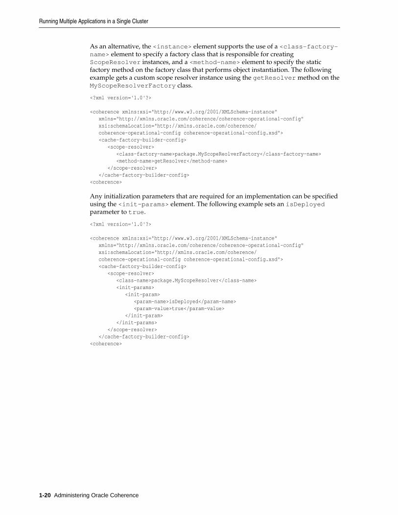
As an alternative, the <instance> element supports the use of a <class-factory-name> element to specify a factory class that is responsible for creatingScopeResolver instances, and a <method-name> element to specify the staticfactory method on the factory class that performs object instantiation. The followingexample gets a custom scope resolver instance using the getResolver method on theMyScopeResolverFactory class.
<?xml version='1.0'?>
<coherence xmlns:xsi="http://www.w3.org/2001/XMLSchema-instance" xmlns="http://xmlns.oracle.com/coherence/coherence-operational-config" xsi:schemaLocation="http://xmlns.oracle.com/coherence/ coherence-operational-config coherence-operational-config.xsd"> <cache-factory-builder-config> <scope-resolver> <class-factory-name>package.MyScopeReolverFactory</class-factory-name> <method-name>getResolver</method-name> </scope-resolver> </cache-factory-builder-config><coherence>
Any initialization parameters that are required for an implementation can be specifiedusing the <init-params> element. The following example sets an isDeployedparameter to true.
<?xml version='1.0'?>
<coherence xmlns:xsi="http://www.w3.org/2001/XMLSchema-instance" xmlns="http://xmlns.oracle.com/coherence/coherence-operational-config" xsi:schemaLocation="http://xmlns.oracle.com/coherence/ coherence-operational-config coherence-operational-config.xsd"> <cache-factory-builder-config> <scope-resolver> <class-name>package.MyScopeResolver</class-name> <init-params> <init-param> <param-name>isDeployed</param-name> <param-value>true</param-value> </init-param> </init-params> </scope-resolver> </cache-factory-builder-config><coherence>
Running Multiple Applications in a Single Cluster
1-20 Administering Oracle Coherence
2Performing a Network Performance Test
This chapter provides instructions for testing network performance between two ormore computers. Two utilities are provided: a datagram utility and a message busutility. Any production deployment should be preceded by a successful run of bothtests.
The following sections are included in this chapter:
• Running the Datagram Test Utility
• Running the Message Bus Test Utility
2.1 Running the Datagram Test UtilityThe Coherence datagram test utility is used to test and tune network performancebetween two or more computers. The utility ensures that a network is optimallyconfigured to support Coherence cluster management communication. There are twotypes of tests: a point-to-point test that tests the performance of a pair of servers toensure they are properly configured, and a distributed datagram test to ensure thenetwork itself is functioning properly. Both tests need to be run successfully.
The datagram test operates in one of three modes: either as a packet publisher, apacket listener, or both. When the utility is run, a publisher transmits packets to thelistener who then measures the throughput, success rate, and other statistics. Tune anenvironment based on the results of these tests to achieve maximum performance. See Performance Tuning for more information.
The datagram test utility is run from the command line using either thecom.tangosol.net.DatagramTest class or by running the datagram-testscript that is provided in the COHERENCE_HOME/bin directory. A script is providedfor both Windows and UNIX-based platforms.
The following example demonstrates using the DatagramTest class:
java -server -cp coherence.jar com.tangosol.net.DatagramTest <command value> <command value> ...
The following example demonstrates using the script:
datagram-test <command value> <command value> ...
Table 2-1 describes the available command line options for the datagram test utility.
Performing a Network Performance Test 2-1
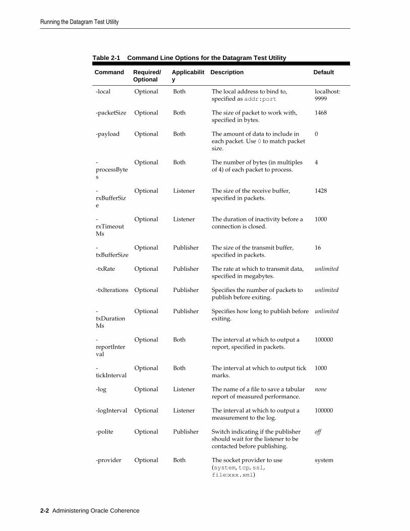
Table 2-1 Command Line Options for the Datagram Test Utility
Command Required/Optional
Applicability
Description Default
-local Optional Both The local address to bind to,specified as addr:port
localhost:9999
-packetSize Optional Both The size of packet to work with,specified in bytes.
1468
-payload Optional Both The amount of data to include ineach packet. Use 0 to match packetsize.
0
-processBytes
Optional Both The number of bytes (in multiplesof 4) of each packet to process.
4
-rxBufferSize
Optional Listener The size of the receive buffer,specified in packets.
1428
-rxTimeoutMs
Optional Listener The duration of inactivity before aconnection is closed.
1000
-txBufferSize
Optional Publisher The size of the transmit buffer,specified in packets.
16
-txRate Optional Publisher The rate at which to transmit data,specified in megabytes.
unlimited
-txIterations Optional Publisher Specifies the number of packets topublish before exiting.
unlimited
-txDurationMs
Optional Publisher Specifies how long to publish beforeexiting.
unlimited
-reportInterval
Optional Both The interval at which to output areport, specified in packets.
100000
-tickInterval
Optional Both The interval at which to output tickmarks.
1000
-log Optional Listener The name of a file to save a tabularreport of measured performance.
none
-logInterval Optional Listener The interval at which to output ameasurement to the log.
100000
-polite Optional Publisher Switch indicating if the publishershould wait for the listener to becontacted before publishing.
off
-provider Optional Both The socket provider to use(system, tcp, ssl,file:xxx.xml)
system
Running the Datagram Test Utility
2-2 Administering Oracle Coherence
Table 2-1 (Cont.) Command Line Options for the Datagram Test Utility
Command Required/Optional
Applicability
Description Default
arguments Optional Publisher Space separated list of addresses topublish to, specified as addr:port.
none
2.1.1 How to Test Datagram Network PerformanceThis section includes instructions for running a point-to-point datagram test and adistributed datagram test. Both tests must be run successfully and show no significantperformance issues or packet loss. For details about interpreting test statistics, see“Understanding Datagram Report Statistics”.
2.1.1.1 Performing a Point-to-Point Datagram Test
The example in this section demonstrates how to test network performance betweentwo servers— Server A with IP address 195.0.0.1 and Server B with IP address195.0.0.2. One server acts as a packet publisher and the other as a packet listener.The publisher transmits packets as fast as possible and the listener measures andreports performance statistics.
First, start the listener on Server A. For example:
datagram-test.sh
After pressing ENTER, the utility displays that it is ready to receive packets. Example2-1 illustrates sample output.
Example 2-1 Output from Starting a Listener
starting listener: at /195.0.0.1:9999packet size: 1468 bytesbuffer size: 1428 packets report on: 100000 packets, 139 MBs process: 4 bytes/packet log: null log on: 139 MBs
The test, by default, tries to allocate a network receive buffer large enough to hold1428 packets, or about 2 MB. The utility reports an error and exits if it cannot allocatethis buffer. Either decrease the requested buffer size using the -rxBufferSizeparameter, or increase the operating system's network buffer settings. Increase theoperating system buffers for the best performance. See Production Checklist for detailson tuning an operating system for Coherence.
Start the publisher on Server B and direct it to publish to Server A. For example:
datagram-test.sh servera
After pressing ENTER, the test instance on Server B starts both a listener and apublisher. However, the listener is not used in this configuration. Example 2-2demonstrates the sample output that displays in the Server B command window.
Example 2-2 Datagram Test—Starting a Listener and a Publisher on a Server
starting listener: at /195.0.0.2:9999packet size: 1468 bytesbuffer size: 1428 packets
Running the Datagram Test Utility
Performing a Network Performance Test 2-3

report on: 100000 packets, 139 MBs process: 4 bytes/packet log: null log on: 139 MBs
starting publisher: at /195.0.0.2:9999 sending to servera/195.0.0.1:9999packet size: 1468 bytesbuffer size: 16 packets report on: 100000 packets, 139 MBs process: 4 bytes/packet peers: 1 rate: no limit
no packet burst limitoooooooooOoooooooooOoooooooooOoooooooooOoooooooooOoooooooooOoooooooooOoooooooooO
The series of o and O marks appear as data is (O)utput on the network. Each orepresents 1000 packets, with O indicators at every 10,000 packets.
On Server A, a corresponding set of i and I marks, representing network (I)nput. Thisindicates that the two test instances are communicating.
2.1.1.1.1 Performing a Bidirectional Datagram Test
The point-to-point test can also be run in bidirectional mode where servers act aspublishers and listeners. Use the same test instances that were used in the point-to-point test and supply the instance on Server A with the address for Server B. Forexample on Server A run:
datagram-test.sh -polite serverb
The -polite parameter instructs this test instance to not start publishing until itstarts to receive data. Run the same command as before on Server B.
datagram-test.sh servera
2.1.1.2 Performing a Distributed Datagram Test
A distributed test is used to test performance with more than two computers. Forexample, setup two publishers to target a single listener. This style of testing is farmore realistic then simple one-to-one testing and may identify network bottlenecksthat may not otherwise be apparent.
The following example runs the datagram test among 4 computers:
On Server A:
datagramtest.sh -txRate 100 -polite serverb serverc serverd
On Server B:
datagramtest.sh -txRate 100 -polite servera serverc serverd
On Server C:
datagramtest.sh -txRate 100 -polite servera serverb serverd
On Server D:
datagramtest.sh -txRate 100 servera serverb serverc
Running the Datagram Test Utility
2-4 Administering Oracle Coherence

This test sequence causes all nodes to send a total of 100MB per second to all othernodes (that is, 33MB/node/second). On a fully switched 1GbE network this should beachievable without packet loss.
To simplify the execution of the test, all nodes can be started with an identical targetlist, they obviously transmit to themselves as well, but this loopback data can easily befactored out. It is important to start all but the last node using the -polite switch, asthis causes all other nodes to delay testing until the final node is started.
2.1.2 Understanding Datagram Report StatisticsEach side of the test (publisher and listener) periodically report performance statistics.The publisher simply reports the rate at which it is publishing data on the network.For example:
Tx summary 1 peers: life: 97 MB/sec, 69642 packets/sec now: 98 MB/sec, 69735 packets/sec
The report includes both the current transmit rate (since last report) and the lifetimetransmit rate.
Table 2-2 describes the statistics that can be reported by the listener.
Table 2-2 Listener Statistics
Element Description
Elapsed The time interval that the report covers.
Packet size The received packet size.
Throughput The rate at which packets are being received.
Received The number of packets received.
Missing The number of packets which were detected as lost.
Success rate The percentage of received packets out of the total packets sent.
Out of order The number of packets which arrived out of order.
Average offset An indicator of how out of order packets are.
As with the publisher, both current and lifetime statistics are reported. The followingexample demonstrates a typical listener report:
Lifetime:Rx from publisher: /195.0.0.2:9999 elapsed: 8770ms packet size: 1468 throughput: 96 MB/sec 68415 packets/sec received: 600000 of 611400 missing: 11400 success rate: 0.9813543 out of order: 2 avg offset: 1
Now:
Running the Datagram Test Utility
Performing a Network Performance Test 2-5
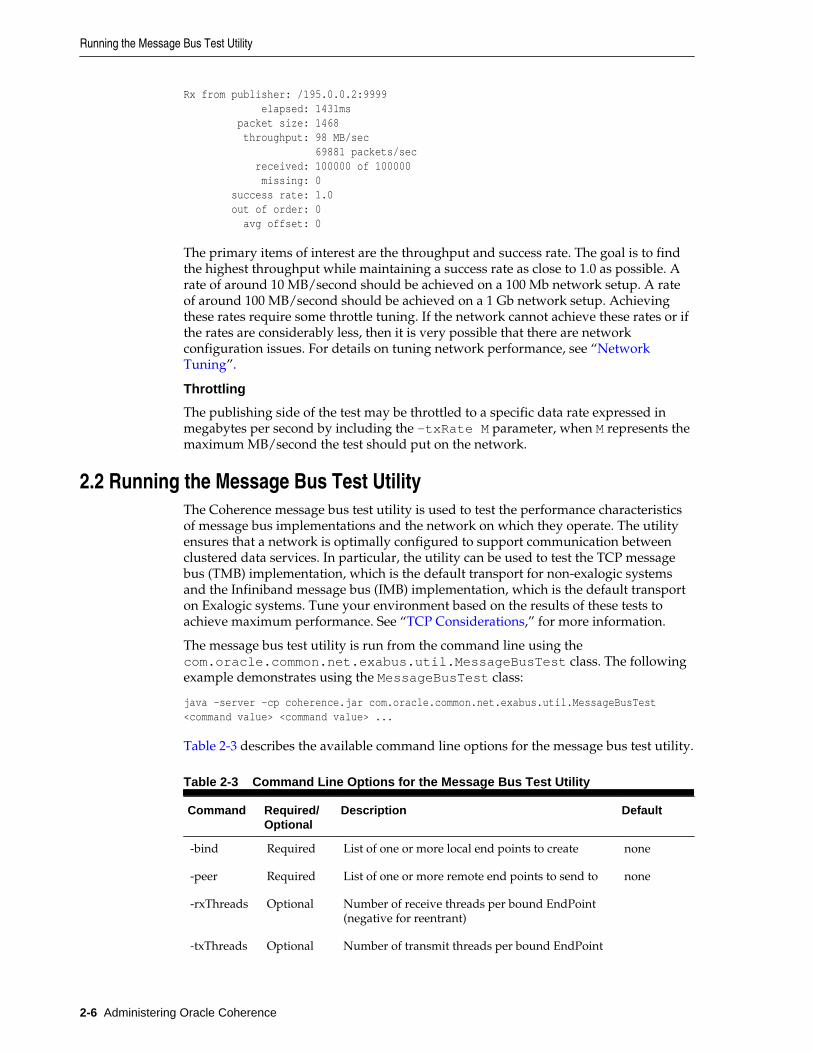
Rx from publisher: /195.0.0.2:9999 elapsed: 1431ms packet size: 1468 throughput: 98 MB/sec 69881 packets/sec received: 100000 of 100000 missing: 0 success rate: 1.0 out of order: 0 avg offset: 0
The primary items of interest are the throughput and success rate. The goal is to findthe highest throughput while maintaining a success rate as close to 1.0 as possible. Arate of around 10 MB/second should be achieved on a 100 Mb network setup. A rateof around 100 MB/second should be achieved on a 1 Gb network setup. Achievingthese rates require some throttle tuning. If the network cannot achieve these rates or ifthe rates are considerably less, then it is very possible that there are networkconfiguration issues. For details on tuning network performance, see “NetworkTuning”.
Throttling
The publishing side of the test may be throttled to a specific data rate expressed inmegabytes per second by including the -txRate M parameter, when M represents themaximum MB/second the test should put on the network.
2.2 Running the Message Bus Test UtilityThe Coherence message bus test utility is used to test the performance characteristicsof message bus implementations and the network on which they operate. The utilityensures that a network is optimally configured to support communication betweenclustered data services. In particular, the utility can be used to test the TCP messagebus (TMB) implementation, which is the default transport for non-exalogic systemsand the Infiniband message bus (IMB) implementation, which is the default transporton Exalogic systems. Tune your environment based on the results of these tests toachieve maximum performance. See “TCP Considerations,” for more information.
The message bus test utility is run from the command line using thecom.oracle.common.net.exabus.util.MessageBusTest class. The followingexample demonstrates using the MessageBusTest class:
java -server -cp coherence.jar com.oracle.common.net.exabus.util.MessageBusTest <command value> <command value> ...
Table 2-3 describes the available command line options for the message bus test utility.
Table 2-3 Command Line Options for the Message Bus Test Utility
Command Required/Optional
Description Default
-bind Required List of one or more local end points to create none
-peer Required List of one or more remote end points to send to none
-rxThreads Optional Number of receive threads per bound EndPoint(negative for reentrant)
-txThreads Optional Number of transmit threads per bound EndPoint
Running the Message Bus Test Utility
2-6 Administering Oracle Coherence
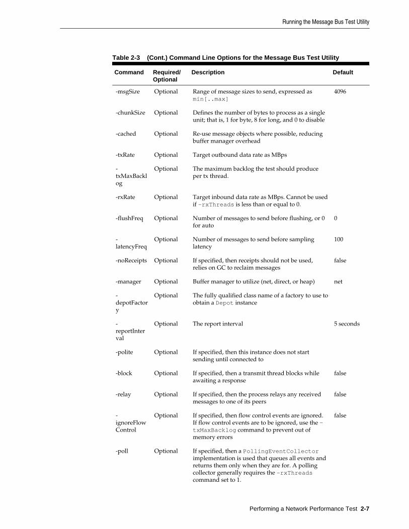
Table 2-3 (Cont.) Command Line Options for the Message Bus Test Utility
Command Required/Optional
Description Default
-msgSize Optional Range of message sizes to send, expressed asmin[..max]
4096
-chunkSize Optional Defines the number of bytes to process as a singleunit; that is, 1 for byte, 8 for long, and 0 to disable
-cached Optional Re-use message objects where possible, reducingbuffer manager overhead
-txRate Optional Target outbound data rate as MBps
-txMaxBacklog
Optional The maximum backlog the test should produceper tx thread.
-rxRate Optional Target inbound data rate as MBps. Cannot be usedif -rxThreads is less than or equal to 0.
-flushFreq Optional Number of messages to send before flushing, or 0for auto
0
-latencyFreq
Optional Number of messages to send before samplinglatency
100
-noReceipts Optional If specified, then receipts should not be used,relies on GC to reclaim messages
false
-manager Optional Buffer manager to utilize (net, direct, or heap) net
-depotFactory
Optional The fully qualified class name of a factory to use toobtain a Depot instance
-reportInterval
Optional The report interval 5 seconds
-polite Optional If specified, then this instance does not startsending until connected to
-block Optional If specified, then a transmit thread blocks whileawaiting a response
false
-relay Optional If specified, then the process relays any receivedmessages to one of its peers
false
-ignoreFlowControl
Optional If specified, then flow control events are ignored.If flow control events are to be ignored, use the -txMaxBacklog command to prevent out ofmemory errors
false
-poll Optional If specified, then a PollingEventCollectorimplementation is used that queues all events andreturns them only when they are for. A pollingcollector generally requires the -rxThreadscommand set to 1.
Running the Message Bus Test Utility
Performing a Network Performance Test 2-7
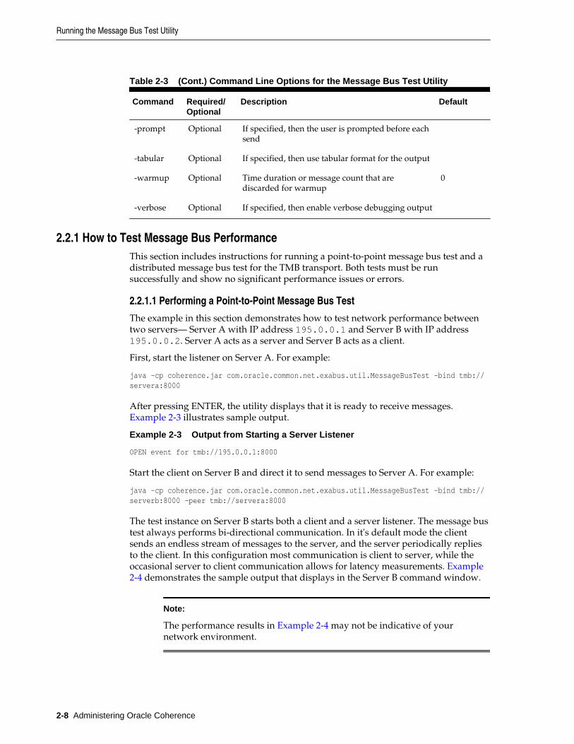
Table 2-3 (Cont.) Command Line Options for the Message Bus Test Utility
Command Required/Optional
Description Default
-prompt Optional If specified, then the user is prompted before eachsend
-tabular Optional If specified, then use tabular format for the output
-warmup Optional Time duration or message count that arediscarded for warmup
0
-verbose Optional If specified, then enable verbose debugging output
2.2.1 How to Test Message Bus PerformanceThis section includes instructions for running a point-to-point message bus test and adistributed message bus test for the TMB transport. Both tests must be runsuccessfully and show no significant performance issues or errors.
2.2.1.1 Performing a Point-to-Point Message Bus Test
The example in this section demonstrates how to test network performance betweentwo servers— Server A with IP address 195.0.0.1 and Server B with IP address195.0.0.2. Server A acts as a server and Server B acts as a client.
First, start the listener on Server A. For example:
java -cp coherence.jar com.oracle.common.net.exabus.util.MessageBusTest -bind tmb://servera:8000
After pressing ENTER, the utility displays that it is ready to receive messages. Example 2-3 illustrates sample output.
Example 2-3 Output from Starting a Server Listener
OPEN event for tmb://195.0.0.1:8000
Start the client on Server B and direct it to send messages to Server A. For example:
java -cp coherence.jar com.oracle.common.net.exabus.util.MessageBusTest -bind tmb://serverb:8000 -peer tmb://servera:8000
The test instance on Server B starts both a client and a server listener. The message bustest always performs bi-directional communication. In it's default mode the clientsends an endless stream of messages to the server, and the server periodically repliesto the client. In this configuration most communication is client to server, while theoccasional server to client communication allows for latency measurements. Example2-4 demonstrates the sample output that displays in the Server B command window.
Note:
The performance results in Example 2-4 may not be indicative of yournetwork environment.
Running the Message Bus Test Utility
2-8 Administering Oracle Coherence

Example 2-4 Message Bus Test—Starting a Client and Server
OPEN event for tmb://195.0.0.2:8001CONNECT event for tmb://195.0.0.1:8000 on tmb://195.0.0.2:8001now: throughput(out 65426msg/s 2.14gb/s, in 654msg/s 21.4mb/s), latency(response(avg 810.71us, effective 1.40ms, min 37 .89us, max 19.59ms), receipt 809.61us), backlog(out 42% 1556/s 48KB, in 0% 0/s 0B), connections 1, errors 0life: throughput(out 59431msg/s 1.94gb/s, in 594msg/s 19.4mb/s), latency(response(avg 2.12ms, effective 3.85ms, min 36.32us, max 457.25ms), receipt 2.12ms), backlog(out 45% 1497/s 449KB, in 0% 0/s 0B), connections 1, errors 0
The test, by default, tries to use the maximum bandwidth to push the maximumamount of messages, which results in increased latency. Use the -block command toswitch the test from streaming data to request and response, which provides a betterrepresentation of the network minimum latency:
now: throughput(out 17819msg/s 583mb/s, in 17820msg/s 583mb/s), latency(response(avg 51.06us, effective 51.06us, min 43.42us, max 143.68us), receipt 53.36us), backlog(out 0% 0/s 0B, in 0% 0/s 0B), connections 1, errors 0life: throughput(out 16635msg/s 545mb/s, in 16635msg/s 545mb/s), latency(response(avg 56.49us, effective 56.49us, min 43.03us, max 13.91ms), receipt 59.43us), backlog(out 0% 0/s 2.18KB, in 0% 0/s 744B), connections 1, errors 0
2.2.1.1.1 Performing a Bidirectional Message Bus Test
The point-to-point test can also be run in bidirectional mode where servers act as bothclient and servers. Use the same test instances that were used in the point-to-point test.For example on Server A run:
java -cp coherence.jar com.oracle.common.net.exabus.util.MessageBusTest -bind tmb://servera:8000 -peer tmb://serverb:8000 -polite
The -polite parameter instructs this test instance to not start publishing until itstarts to receive data. On Server B run.
java -cp coherence.jar com.oracle.common.net.exabus.util.MessageBusTest -bind tmb://serverb:8000 -peer tmb://servera:8000
2.2.1.2 Performing a Distributed Message Bus Test
A distributed test is used to test performance with more than two computers. Thisstyle of testing is far more realistic then simple one-to-one testing and may identifynetwork bottlenecks that may not otherwise be apparent.
The following example runs a bidirectional message bus test among 4 computers:
On Server A:
java -cp coherence.jar com.oracle.common.net.exabus.util.MessageBusTest -bind tmb://servera:8000 -peer tmb://serverb:8000 tmb://serverc:8000 tmb://serverd:8000 -polite
On Server B:
java -cp coherence.jar com.oracle.common.net.exabus.util.MessageBusTest -bind tmb://serverb:8000 -peer tmb://servera:8000 tmb://serverc:8000 tmb://serverd:8000 -polite
On Server C:
java -cp coherence.jar com.oracle.common.net.exabus.util.MessageBusTest -bind tmb://serverc:8000 -peer tmb://servera:8000 tmb://serverb:8000 tmb://serverd:8000 -polite
Running the Message Bus Test Utility
Performing a Network Performance Test 2-9

On Server D:
java -cp coherence.jar com.oracle.common.net.exabus.util.MessageBusTest -bind tmb://serverd:8000 -peer tmb://servera:8000 tmb://serverb:8000 tmb://serverc:8000 -polite
It is important to start all but the last node using the -polite switch, as this causes allother nodes to delay testing until the final node is started.
2.2.2 Understanding Message Bus Report StatisticsEach side of the message bus test (client and server) periodically report performancestatistics. The example output is from the client sending the requests:
throughput(out 17819msg/s 583mb/s, in 17820msg/s 583mb/s), latency(response(avg 51.06us, effective 51.06us, min 43.42us, max 143.68us), receipt 53.36us), backlog(out 0% 0/s 0B, in 0% 0/s 0B), connections 1, errors 0
The report includes both statistics since the last report (now:) and the aggregatelifetime statistics (life:).
Table 2-2 describes the message bus statistics.
Table 2-4 Message Bus Statistics
Element Description
throughput The amount of messages per second being sent and received and thetransmission rate
latency The time spent for message response and receipt
backlog the number of messages waiting to be sent and to be processed
connections The number of open connections between message listeners
errors The number of messages which were detected as lost.
The primary item of interest are throughput and latency. The goal should be to utilizeas much network bandwidth as possible without resulting in high latencies. Ifbandwidth usage is low or latencies are high, consider tuning TCP settings. A highbacklog or error rate can also indicate network configuration issues. For details ontuning network performance, see “Network Tuning”.
Running the Message Bus Test Utility
2-10 Administering Oracle Coherence

3Performing a Multicast Connectivity Test
This chapter provides instructions for using the Coherence multicast test utility tocheck whether a network environment supports multicast communication. Anyproduction deployment should be preceded by a successful run of the multicast test.
The following sections are included in this chapter:
• Running the Multicast Test Utility
• How to Test Multicast
• Troubleshooting Multicast Communications
3.1 Running the Multicast Test UtilityThe Coherence multicast test utility is used to determine if multicast is enabledbetween two or more computers. The utility does not test load. Each instance, bydefault, only transmit a single multicast packet every two seconds. For network loadtesting, see Performing a Network Performance Test.
The multicast test utility is run from the command line using either thecom.tangosol.net.MulticastTest class or by running the multicast-testscript that is provided in the COHERENCE_HOME/bin directory. A script is providedfor both Windows and UNIX-based platforms.
The following example runs the utility using the MulticastTest class:
java com.tangosol.net.MulticastTest <command value> <command value> ...
The following example runs the utility using the script:
multicast-test <command value> <command value> ...
Table 3-1 describes the available command line options for the multicast test utility.
Table 3-1 Command Line Options for the Multicast Test Utility
Command Required/Optional
Description Default
-local Optional The address of the NIC to transmit on, specified asan IP address
localhost
-group Optional The multicast address to use, specified as IP:port. 237.0.0.1:9000
-ttl Optional The time to live for multicast packets. 4
-delay Optional The delay between transmitting packets, specifiedin seconds.
2
Performing a Multicast Connectivity Test 3-1
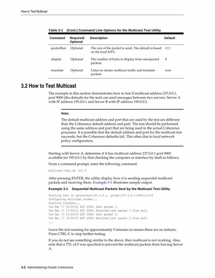
Table 3-1 (Cont.) Command Line Options for the Multicast Test Utility
Command Required/Optional
Description Default
-packetSize Optional The size of the packet to send. The default is basedon the local MTU.
MTU
-display Optional The number of bytes to display from unexpectedpackets.
0
-translate Optional Listen to cluster multicast traffic and translatepackets
none
3.2 How to Test MulticastThe example in this section demonstrates how to test if multicast address 237.0.0.1,port 9000 (the defaults for the test) can send messages between two servers: Server Awith IP address 195.0.0.1 and Server B with IP address 195.0.0.2.
Note:
The default multicast address and port that are used by the test are differentthan the Coherence default address and port. The test should be performedusing the same address and port that are being used in the actual Coherenceprocesses. It is possible that the default address and port for the mutlicast testsucceeds, but the Coherence defaults fail. This often due to local networkpolicy configuration.
Starting with Server A, determine if it has multicast address 237.0.0.1 port 9000available for 195.0.0.1 by first checking the computer or interface by itself as follows:
From a command prompt, enter the following command:
multicast-test.sh -ttl 0
After pressing ENTER, the utility display how it is sending sequential multicastpackets and receiving them. Example 3-1 illustrates sample output.
Example 3-1 Sequential Multicast Packets Sent by the Multicast Test Utility
Starting test on ip=servera/195.0.0.1, group=/237.0.0.1:9000,ttl=0Configuring multicast socket...Starting listener...Tue Mar 17 15:59:51 EST 2008: Sent packet 1.Tue Mar 17 15:59:51 EST 2008: Received test packet 1 from self.Tue Mar 17 15:59:53 EST 2008: Sent packet 2.Tue Mar 17 15:59:53 EST 2008: Received test packet 2 from self....
Leave the test running for approximately 5 minutes to ensure there are no failures.Press CTRL-C to stop further testing.
If you do not see something similar to the above, then multicast is not working. Also,note that a TTL of 0 was specified to prevent the multicast packets from leaving ServerA.
How to Test Multicast
3-2 Administering Oracle Coherence

Repeat the same test on Server B to assure that it too has the multicast enabled for it'sport combination.
Next, test multicast communications between Server A and Server B. For this test use anonzero TTL which allows the packets to leave their respective servers. By default, thetest uses a TTL of 4, if more network hops are required to route packets betweenServer A and Server B, specify a higher TTL value.
Start the test on Server A and Server B by entering the following command into each'srespective command window and pressing ENTER:
multicast-test.sh
The following example demonstrates sample output for Server A:
Starting test on ip=servera/195.0.0.1, group=/237.0.0.1:9000, ttl=4Configuring multicast socket...Starting listener...Tue Mar 17 16:11:03 EST 2008: Sent packet 1.Tue Mar 17 16:11:03 EST 2008: Received test packet 1 from self.Tue Mar 17 16:11:05 EST 2008: Sent packet 2.Tue Mar 17 16:11:05 EST 2008: Received test packet 2 from self.Tue Mar 17 16:11:07 EST 2008: Sent packet 3.Tue Mar 17 16:11:07 EST 2008: Received test packet 3 from self.Tue Mar 17 16:11:09 EST 2008: Sent packet 4.Tue Mar 17 16:11:09 EST 2008: Received test packet 4 from self.Tue Mar 17 16:11:10 EST 2008: Received test packet 1 from ip=serverb/195.0.0.2, group=/237.0.0.1:9000, ttl=4.Tue Mar 17 16:11:11 EST 2008: Sent packet 5.Tue Mar 17 16:11:11 EST 2008: Received test packet 5 from self.Tue Mar 17 16:11:12 EST 2008: Received test packet 2 from ip=serverb/195.0.0.2, group=/237.0.0.1:9000, ttl=4.Tue Mar 17 16:11:13 EST 2008: Sent packet 6.Tue Mar 17 16:11:13 EST 2008: Received test packet 6 from self.Tue Mar 17 16:11:14 EST 2008: Received test packet 3 from ip=serverb/195.0.0.2, group=/237.0.0.1:9000, ttl=4.Tue Mar 17 16:11:15 EST 2008: Sent packet 7.Tue Mar 17 16:11:15 EST 2008: Received test packet 7 from self....
The following example demonstrates sample output for Server B:
Starting test on ip=serverb/195.0.0.2, group=/237.0.0.1:9000, ttl=4Configuring multicast socket...Starting listener...Tue Mar 17 16:11:10 EST 2008: Sent packet 1.Tue Mar 17 16:11:10 EST 2008: Received test packet 1 from self.Tue Mar 17 16:11:11 EST 2008: Received test packet 5 from ip=servera/195.0.0.1, group=/237.0.0.1:9000, ttl=4.Tue Mar 17 16:11:12 EST 2008: Sent packet 2.Tue Mar 17 16:11:12 EST 2008: Received test packet 2 from self.Tue Mar 17 16:11:13 EST 2008: Received test packet 6 from ip=servera/195.0.0.1, group=/237.0.0.1:9000, ttl=4.Tue Mar 17 16:11:14 EST 2008: Sent packet 3.Tue Mar 17 16:11:14 EST 2008: Received test packet 3 from self.Tue Mar 17 16:11:15 EST 2008: Received test packet 7 from ip=servera/195.0.0.1, group=/237.0.0.1:9000, ttl=4....
In the example both Server A and Server B are issuing multicast packets and seeingtheir own and each other's packets. This indicates that multicast is functioningproperly between these servers using the default multicast address and port.
How to Test Multicast
Performing a Multicast Connectivity Test 3-3
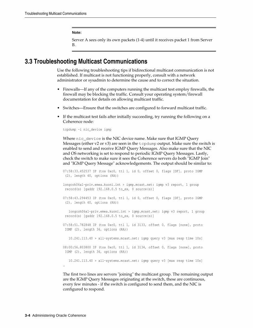
Note:
Server A sees only its own packets (1-4) until it receives packet 1 from ServerB.
3.3 Troubleshooting Multicast CommunicationsUse the following troubleshooting tips if bidirectional multicast communication is notestablished. If multicast is not functioning properly, consult with a networkadministrator or sysadmin to determine the cause and to correct the situation.
• Firewalls—If any of the computers running the multicast test employ firewalls, thefirewall may be blocking the traffic. Consult your operating system/firewalldocumentation for details on allowing multicast traffic.
• Switches—Ensure that the switches are configured to forward multicast traffic.
• If the multicast test fails after initially succeeding, try running the following on aCoherence node:
tcpdump -i nic_device igmp
Where nic_device is the NIC device name. Make sure that IGMP QueryMessages (either v2 or v3) are seen in the tcpdump output. Make sure the switch isenabled to send and receive IGMP Query Messages. Also make sure that the NICand OS networking is set to respond to periodic IGMP Query Messages. Lastly,check the switch to make sure it sees the Coherence servers do both "IGMP Join"and "IGMP Query Message" acknowledgements. The output should be similar to:
07:58:33.452537 IP (tos 0xc0, ttl 1, id 0, offset 0, flags [DF], proto IGMP (2), length 40, options (RA)) longcoh06a1-priv.emea.kuoni.int > igmp.mcast.net: igmp v3 report, 1 group record(s) [gaddr 192.168.0.5 to_ex, 0 source(s)] 07:58:43.294453 IP (tos 0xc0, ttl 1, id 0, offset 0, flags [DF], proto IGMP (2), length 40, options (RA)) longcoh06a1-priv.emea.kuoni.int > igmp.mcast.net: igmp v3 report, 1 group record(s) [gaddr 192.168.0.5 to_ex, 0 source(s)] 07:58:51.782848 IP (tos 0xc0, ttl 1, id 3133, offset 0, flags [none], proto IGMP (2), length 36, options (RA)) 10.241.113.40 > all-systems.mcast.net: igmp query v3 [max resp time 10s] 08:00:56.803800 IP (tos 0xc0, ttl 1, id 3134, offset 0, flags [none], proto IGMP (2), length 36, options (RA)) 10.241.113.40 > all-systems.mcast.net: igmp query v3 [max resp time 10s]…
The first two lines are servers "joining" the multicast group. The remaining outputare the IGMP Query Messages originating at the switch, these are continuous,every few minutes - if the switch is configured to send them, and the NIC isconfigured to respond.
Troubleshooting Multicast Communications
3-4 Administering Oracle Coherence
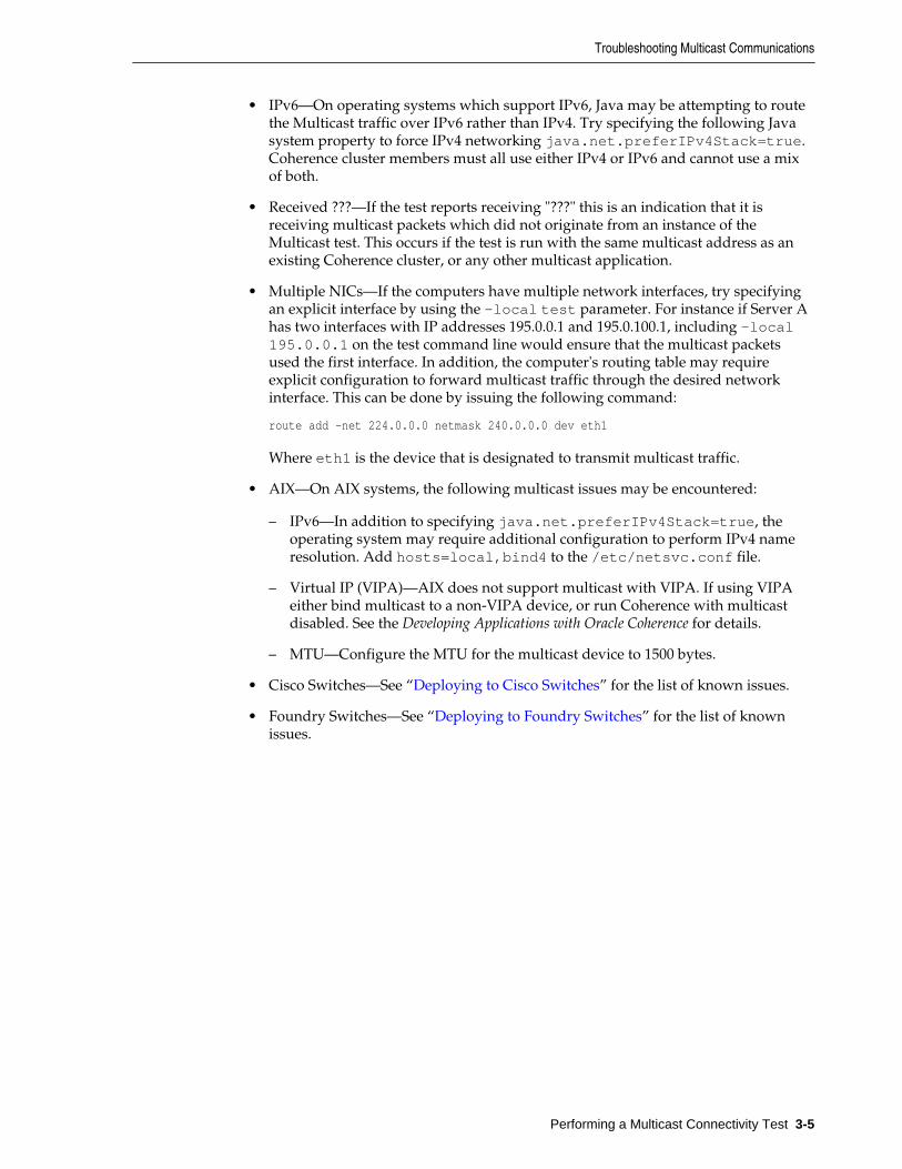
• IPv6—On operating systems which support IPv6, Java may be attempting to routethe Multicast traffic over IPv6 rather than IPv4. Try specifying the following Javasystem property to force IPv4 networking java.net.preferIPv4Stack=true.Coherence cluster members must all use either IPv4 or IPv6 and cannot use a mixof both.
• Received ???—If the test reports receiving "???" this is an indication that it isreceiving multicast packets which did not originate from an instance of theMulticast test. This occurs if the test is run with the same multicast address as anexisting Coherence cluster, or any other multicast application.
• Multiple NICs—If the computers have multiple network interfaces, try specifyingan explicit interface by using the -local test parameter. For instance if Server Ahas two interfaces with IP addresses 195.0.0.1 and 195.0.100.1, including -local195.0.0.1 on the test command line would ensure that the multicast packetsused the first interface. In addition, the computer's routing table may requireexplicit configuration to forward multicast traffic through the desired networkinterface. This can be done by issuing the following command:
route add -net 224.0.0.0 netmask 240.0.0.0 dev eth1
Where eth1 is the device that is designated to transmit multicast traffic.
• AIX—On AIX systems, the following multicast issues may be encountered:
– IPv6—In addition to specifying java.net.preferIPv4Stack=true, theoperating system may require additional configuration to perform IPv4 nameresolution. Add hosts=local,bind4 to the /etc/netsvc.conf file.
– Virtual IP (VIPA)—AIX does not support multicast with VIPA. If using VIPAeither bind multicast to a non-VIPA device, or run Coherence with multicastdisabled. See the Developing Applications with Oracle Coherence for details.
– MTU—Configure the MTU for the multicast device to 1500 bytes.
• Cisco Switches—See “Deploying to Cisco Switches” for the list of known issues.
• Foundry Switches—See “Deploying to Foundry Switches” for the list of knownissues.
Troubleshooting Multicast Communications
Performing a Multicast Connectivity Test 3-5

Troubleshooting Multicast Communications
3-6 Administering Oracle Coherence
4Performance Tuning
This chapter provides instructions for tuning an environment to achieve maximumperformance when deploying Coherence solutions. See also .
The following sections are included in this chapter:
• Operating System Tuning
• Network Tuning
• JVM Tuning
• Data Access Patterns
4.1 Operating System TuningThe following topics are included in this section:
• Socket Buffer Sizes
• High Resolution timesource (Linux)
• Datagram size (Microsoft Windows)
• TCP Retransmission Timeout (Microsoft Windows)
• Thread Scheduling (Microsoft Windows)
• Swapping
• Load Balancing Network Interrupts (Linux)
4.1.1 Socket Buffer SizesLarge operating system socket buffers can help minimize packet loss during garbagecollection. Each Coherence socket implementation attempts to allocate a default socketbuffer size. A warning message is logged for each socket implementation if the defaultsize cannot be allocated. The following example is a message for the inbound UDPsocket buffer:
UnicastUdpSocket failed to set receive buffer size to 16 packets (1023KB); actualsize is 12%, 2 packets (127KB). Consult your OS documentation regarding increasingthe maximum socket buffer size. Proceeding with the actual value may causesub-optimal performance.
It is recommended that you configure the operating system to allow for larger buffers.However, alternate buffer sizes for Coherence packet publishers and unicast listenerscan be configured using the <packet-buffer> element. For details aboutconfiguring packet buffer settings, see Developing Applications with Oracle Coherence.
Performance Tuning 4-1
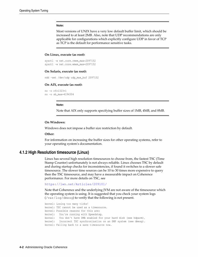
Note:
Most versions of UNIX have a very low default buffer limit, which should beincreased to at least 2MB. Also, note that UDP recommendations are onlyapplicable for configurations which explicitly configure UDP in favor of TCPas TCP is the default for performance sensitive tasks.
On Linux, execute (as root):
sysctl -w net.core.rmem_max=2097152sysctl -w net.core.wmem_max=2097152
On Solaris, execute (as root):
ndd -set /dev/udp udp_max_buf 2097152
On AIX, execute (as root):
no -o rfc1323=1no -o sb_max=4194304
Note:
Note that AIX only supports specifying buffer sizes of 1MB, 4MB, and 8MB.
On Windows:
Windows does not impose a buffer size restriction by default.
Other:
For information on increasing the buffer sizes for other operating systems, refer toyour operating system's documentation.
4.1.2 High Resolution timesource (Linux)Linux has several high resolution timesources to choose from, the fastest TSC (TimeStamp Counter) unfortunately is not always reliable. Linux chooses TSC by defaultand during startup checks for inconsistencies, if found it switches to a slower safetimesource. The slower time sources can be 10 to 30 times more expensive to querythen the TSC timesource, and may have a measurable impact on Coherenceperformance. For more details on TSC, see
https://lwn.net/Articles/209101/
Note that Coherence and the underlying JVM are not aware of the timesource whichthe operating system is using. It is suggested that you check your system logs(/var/log/dmesg) to verify that the following is not present.
kernel: Losing too many ticks!kernel: TSC cannot be used as a timesource.kernel: Possible reasons for this are:kernel: You're running with Speedstep,kernel: You don't have DMA enabled for your hard disk (see hdparm),kernel: Incorrect TSC synchronization on an SMP system (see dmesg).kernel: Falling back to a sane timesource now.
Operating System Tuning
4-2 Administering Oracle Coherence
As the log messages suggest, this can be caused by a variable rate CPU (SpeedStep),having DMA disabled, or incorrect TSC synchronization on multi CPU computers. Ifpresent, work with your system administrator to identify and correct the causeallowing the TSC timesource to be used.
4.1.3 Datagram size (Microsoft Windows)Microsoft Windows supports a fast I/O path which is used when sending "small"datagrams. The default setting for what is considered a small datagram is 1024 bytes;increasing this value to match your network maximum transmission unit (MTU),normally 1500, can significantly improve network performance.
To adjust this parameter:
1. Run Registry Editor (regedit)
2. Locate the following registry key HKLM\System\CurrentControlSet\Services\AFD\Parameters
3. Add the following new DWORD value Name: FastSendDatagramThresholdValue: 1500 (decimal)
4. Restart.
Note:
The COHERENCE_HOME/bin/optimize.reg script can also perform thischange. After running the script, restart the computer for the changes to takeeffect.
4.1.4 TCP Retransmission Timeout (Microsoft Windows)Microsoft Windows includes a TCP retransmission timeout that is used for existingand new connections. The default retransmission timeout can abandon connections ina matter of seconds based on the Windows automatic tuning for TCP datatransmission on the network. The short timeout can result in the false positivedetection of cluster member death by the TcpRing process and can result in data loss.The default retransmission timeout can be configured to be more tolerant of shortoutages that may occur on the production network.
To increase the TCP retransmission timeout:
1. Run Registry Editor (regedit)
2. Locate the following registry key HKLM\SYSTEM\CurrentControlSet\Services\Tcpip\Parameters
3. Add the following new DWORD value Name: TcpMaxConnectRetransmissionsValue: 00000015 (Hex)
4. Add the following new DWORD value Name: TcpMaxDataRetransmissionsValue: 00000015 (Hex)
5. Restart.
Note:
Operating System Tuning
Performance Tuning 4-3
The COHERENCE_HOME/bin/optimize.reg script can also perform thischange. After running the script, restart the computer for the changes to takeeffect.
4.1.5 Thread Scheduling (Microsoft Windows)Windows is optimized for desktop application usage. If you run two console ("DOSbox") windows, the one that has the focus can use almost 100% of the CPU, even ifother processes have high-priority threads in a running state. To correct thisimbalance, you must configure the Windows thread scheduling to less-heavily favorforeground applications.
1. Open the Control Panel.
2. Open System.
3. Select the Advanced tab.
4. Under Performance select Settings.
5. Select the Advanced tab.
6. Under Processor scheduling, choose Background services.
Note:
The COHERENCE_HOME/bin/optimize.reg script performs this change.After running the script, restart the computer for the changes to take effect.
4.1.6 SwappingSwapping, also known as paging, is the use of secondary storage to store and retrieveapplication data for use in RAM memory. Swapping is automatically performed bythe operating system and typically occurs when the available RAM memory isdepleted. Swapping can have a significant impact on Coherence's performance andshould be avoided. Often, swapping manifests itself as Coherence nodes beingremoved from the cluster due to long periods of unresponsiveness caused by themhaving been swapped out of RAM. See “Avoid using virtual memory (paging todisk).” for more information.
To avoid swapping, ensure that sufficient RAM memory is available on the computeror that the number of running processes is accounted for and do not consume all theavailable RAM. Tools such as vmstat and top (on Unix and Linux) and taskmgr (onWindows) should be used to monitor swap rates.
Swappiness in Linux
Linux, by default, may choose to swap out a process or some of its heap due to lowusage even if it is not running low on RAM. Swappiness is performed to be ready tohandle eventual memory requests. Swappiness should be avoided for CoherenceJVMs. The swappiness setting on Linux is a value between 0 and 100, where highervalues encourage more optimistic swapping. The default value is 60. For Coherence, alower value (0 if possible) should always be set.
To see the current swappiness value that is set, enter the following at the commandprompt:
Operating System Tuning
4-4 Administering Oracle Coherence
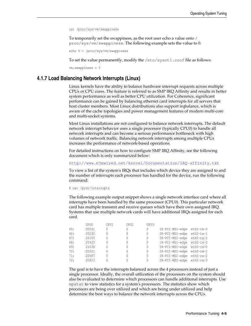
cat /proc/sys/vm/swappiness
To temporarily set the swappiness, as the root user echo a value onto /proc/sys/vm/swappiness. The following example sets the value to 0.
echo 0 > /proc/sys/vm/swappiness
To set the value permanently, modify the /etc/sysctl.conf file as follows:
vm.swappiness = 0
4.1.7 Load Balancing Network Interrupts (Linux)Linux kernels have the ability to balance hardware interrupt requests across multipleCPUs or CPU cores. The feature is referred to as SMP IRQ Affinity and results in bettersystem performance as well as better CPU utilization. For Coherence, significantperformance can be gained by balancing ethernet card interrupts for all servers thathost cluster members. Most Linux distributions also support irqbalance, which isaware of the cache topologies and power management features of modern multi-coreand multi-socket systems.
Most Linux installations are not configured to balance network interrupts. The defaultnetwork interrupt behavior uses a single processor (typically CPU0) to handle allnetwork interrupts and can become a serious performance bottleneck with highvolumes of network traffic. Balancing network interrupts among multiple CPUsincreases the performance of network-based operations.
For detailed instructions on how to configure SMP IRQ Affinity, see the followingdocument which is only summarized below:
http://www.mjmwired.net/kernel/Documentation/IRQ-affinity.txt
To view a list of the system's IRQs that includes which device they are assigned to andthe number of interrupts each processor has handled for the device, run the followingcommand:
# cat /proc/interrupts
The following example output snippet shows a single network interface card where allinterrupts have been handled by the same processor (CPU0). This particular networkcard has multiple transmit and receive queues which have their own assigned IRQ.Systems that use multiple network cards will have additional IRQs assigned for eachcard.
CPU0 CPU1 CPU2 CPU365: 20041 0 0 0 IR-PCI-MSI-edge eth0-tx-066: 20232 0 0 0 IR-PCI-MSI-edge eth0-tx-167: 20105 0 0 0 IR-PCI-MSI-edge eth0-tx-268: 20423 0 0 0 IR-PCI-MSI-edge eth0-tx-369: 21036 0 0 0 IR-PCI-MSI-edge eth0-rx-070: 20201 0 0 0 IR-PCI-MSI-edge eth0-rx-171: 20587 0 0 0 IR-PCI-MSI-edge eth0-rx-272: 20853 0 0 0 IR-PCI-MSI-edge eth0-rx-3
The goal is to have the interrupts balanced across the 4 processors instead of just asingle processor. Ideally, the overall utilization of the processors on the system shouldalso be evaluated to determine which processors can handle additional interrupts. Usempstat to view statistics for a system's processors. The statistics show whichprocessors are being over utilized and which are being under utilized and helpdetermine the best ways to balance the network interrupts across the CPUs.
Operating System Tuning
Performance Tuning 4-5
SMP IRQ affinity is configured in an smp_affinity file. Each IRQ has its ownsmp_affinity file that is located in the /proc/irq/irq_#/ directory. To see thecurrent affinity setting for an IRQ (for example 65), run:
# cat /proc/irq/65/smp_affinity
The returned hexadecimal value is a bitmask and represents the processors to whichinterrupts on IRQ 65 are routed. Each place in the value represents a group of 4 CPUs.For a 4 processor system, the hexadecimal value to represent a group of all fourprocessors is f (or 15) and is 00000f as mapped below:
Binary Hex CPU 0 0001 1 CPU 1 0010 2 CPU 2 0100 4 CPU 3 1000 8 ----------------------- all 1111 f
To target a single processor or group of processors, the bitmask must be changed tothe appropriate hexadecimal value. Based on the system in the example above, todirect all interrupts on IRQ 65 to CPU1 and all interrupts on IRQ 66 to CPU2, changethe smp_affinity files as follows:
echo 000002 > /proc/irq/65/smp_affinity # eth0-tx-0echo 000004 > /proc/irq/66/smp_affinity # eth0-tx-1
To direct all interrupts on IRQ 65 to both CPU1 and CPU2, change the smp_affinityfile as follows:
echo 000006 > /proc/irq/65/smp_affinity # eth0-tx-0
To direct all interrupts on each IRQ to all CPUs, change the smp_affinity files asfollows:
echo 00000f > /proc/irq/65/smp_affinity # eth0-tx-0echo 00000f > /proc/irq/66/smp_affinity # eth0-tx-1echo 00000f > /proc/irq/67/smp_affinity # eth0-tx-2echo 00000f > /proc/irq/68/smp_affinity # eth0-tx-3echo 00000f > /proc/irq/69/smp_affinity # eth0-rx-0echo 00000f > /proc/irq/70/smp_affinity # eth0-rx-1echo 00000f > /proc/irq/71/smp_affinity # eth0-rx-2echo 00000f > /proc/irq/72/smp_affinity # eth0-rx-3
4.2 Network Tuning• Network Interface Settings
• Network Infrastructure Settings
• Switch and Subnet Considerations
• Ethernet Flow-Control
• Path MTU
• 10GbE Considerations
• TCP Considerations
Network Tuning
4-6 Administering Oracle Coherence

4.2.1 Network Interface SettingsVerify that your Network card (NIC) is configured to operate at it's maximum linkspeed and at full duplex. The process for doing this varies between operating systems.
On Linux execute (as root):
ethtool eth0
See the man page on ethtool for further details and for information on adjust theinterface settings.
On Solaris execute (as root):
kstat ce:0 | grep link_
This displays the link settings for interface 0. Items of interest are link_duplex (2 =full), and link_speed which is reported in Mbps.
Note:
If running on Solaris 10, review issues 1000972.1 and 1000940.1 whichrelate to packet corruption and multicast disconnections. These often manifestas either EOFExceptions, "Large gap" warnings while reading packet data,or frequent packet timeouts. It is highly recommend that the patches for bothissues be applied when using Coherence on Solaris 10 systems.
On Windows:
1. Open the Control Panel.
2. Open Network Connections.
3. Open the Properties dialog for desired network adapter.
4. Select Configure.
5. Select the Advanced tab.
6. Locate the driver specific property for Speed & Duplex.
7. Set it to either auto or to a specific speed and duplex setting.
4.2.2 Network Infrastructure SettingsIf you experience frequent multi-second communication pauses across multiple clusternodes, try increasing your switch's buffer space. These communication pauses can beidentified by a series of Coherence log messages identifying communication delayswith multiple nodes which are not attributable to local or remote GCs.
Example 4-1 Message Indicating a Communication Delay
Experienced a 4172 ms communication delay (probable remote GC) with Member(Id=7, Timestamp=2006-10-20 12:15:47.511, Address=192.168.0.10:8089, MachineId=13838); 320 packets rescheduled, PauseRate=0.31, Threshold=512
Some switches such as the Cisco 6500 series support configuring the amount of bufferspace available to each Ethernet port or ASIC. In high load applications it may be
Network Tuning
Performance Tuning 4-7

necessary to increase the default buffer space. On Cisco, this can be accomplished byexecuting:
fabric buffer-reserve high
See Cisco's documentation for additional details on this setting.
4.2.3 Switch and Subnet ConsiderationsCluster members may be split across multiple switches and may be part of multiplesubnets. However, such topologies can overwhelm inter-switch links and increase thechances of a split cluster if the links fail.Typically, the impact materializes ascommunication delays that affect cluster and application performance. If possible,consider always locating all cluster members on the same switch and subnet tominimize the impact.
See also: “Evaluate the Production Network's Speed for both UDP and TCP”.
4.2.4 Ethernet Flow-ControlFull duplex Ethernet includes a flow-control feature which allows the receiving end ofa point to point link to slow down the transmitting end. This is implemented by thereceiving end sending an Ethernet PAUSE frame to the transmitting end, thetransmitting end then halts transmissions for the interval specified by the PAUSEframe. Note that this pause blocks all traffic from the transmitting side, even trafficdestined for computers which are not overloaded. This can induce a head of lineblocking condition, where one overloaded computer on a switch effectively slowsdown all other computers. Most switch vendors recommend that Ethernet flow-control be disabled for inter switch links, and at most be used on ports which aredirectly connected to computers. Even in this setup head of line blocking can stilloccur, and thus it is advisable to disable Ethernet flow-control. Higher level protocolssuch as TCP/IP and Coherence TCMP include their own flow-control mechanismswhich are not subject to head of line blocking, and also negate the need for the lowerlevel flow-control.
See http://www.networkworld.com/netresources/0913flow2.html formore details on this subject
4.2.5 Path MTUBy default Coherence assumes a 1500 byte network MTU, and uses a default packetsize of 1468 based on this assumption. Having a packet size which does not fill theMTU results in an under used network. If your equipment uses a different MTU, thenconfigure Coherence by specifying the <packet-size> setting, which is 32 bytessmaller then the network path's minimal MTU.
If you are unsure of your equipment's MTU along the full path between nodes, youcan use either the standard ping or traceroute utilities to determine the MTU. Forexample, execute a series of ping or traceroute operations between the two computers.With each attempt, specify a different packet size, starting from a high value andprogressively moving downward until the packets start to make it through withoutfragmentation.
On Linux execute:
ping -c 3 -M do -s 1468 serverb
On Solaris execute:
Network Tuning
4-8 Administering Oracle Coherence

traceroute -F serverb 1468
On Windows execute:
ping -n 3 -f -l 1468 serverb
On other operating systems: Consult the documentation for the ping ortraceroute command to see how to disable fragmentation, and specify the packetsize.
If you receive a message stating that packets must be fragmented then the specifiedsize is larger then the path's MTU. Decrease the packet size until you find the point atwhich packets can be transmitted without fragmentation. If you find that you mustuse packets smaller then 1468, you may want to contact your network administrator toget the MTU increased to at least 1500.
4.2.6 10GbE ConsiderationsMany 10 Gigabit Ethernet (10GbE) switches and network interface cards supportframe sizes that are larger than the 1500 byte ethernet frame standard. When using10GbE, make sure that the MTU is set to the maximum allowed by the technology(approximately 16KB for ethernet) to take full advantage of the greater bandwidth.Coherence automatically detects the MTU of the network and selects a UDP socketbuffer size accordingly. UDP socket buffer sizes of 2MB, 4MB, or 8MB are selected forMTU sizes of 1500 bytes (standard), 9000 bytes (jumbo), and over 9000 (super jumbo),respectively. Also, make sure to increase the operating system socket buffers to 8MB toaccommodate the larger sizes. A warning is issued in the Coherence logs if asignificantly small operating system buffer is detected. Lastly, always run thedatagram test to validate the performance and throughput of the network. See Performing a Network Performance Test, for details on performing the test.
4.2.7 TCP ConsiderationsCoherence utilizes a TCP message bus (TMB) to transmit messages between clustereddata services. Therefore, a network must be optimally tuned for TCP. Coherenceinherits TCP settings, including buffer settings, from the operating system. Mostservers already have TCP tuned for the network and should not require additionalconfiguration. The recommendation is to tune the TCP stack for the network instead oftuning Coherence for the network.
Coherence includes a message bus test utility that can be used to test throughput andlatency between network nodes. For details on using the utility, see “Running theMessage Bus Test Utility.” If a network shows poor performance, then it may not beproperly configured, use the following recommendations (note that these settings aredemonstrated on Linux but can be translated to other operating systems):
#!/bin/bash## aggregate size limitations for all connections, measured in pages; these values# are for 4KB pages (getconf PAGESIZE)
/sbin/sysctl -w net.ipv4.tcp_mem=' 65536 131072 262144'
# limit on receive space bytes per-connection; overridable by SO_RCVBUF; still# goverened by core.rmem_max
/sbin/sysctl -w net.ipv4.tcp_rmem=' 262144 4194304 8388608'
Network Tuning
Performance Tuning 4-9
# limit on send space bytes per-connection; overridable by SO_SNDBUF; still# goverered by core.wmem_max
/sbin/sysctl -w net.ipv4.tcp_wmem=' 65536 1048576 2097152'
# absolute limit on socket receive space bytes per-connection; cannot be# overriden programatically
/sbin/sysctl -w net.core.rmem_max=16777216
# absolute limit on socket send space bytes per-connection; cannot be overriden;# cannot be overriden programatically
/sbin/sysctl -w net.core.wmem_max=16777216
Each connection consumes a minimum of 320KB, but under normal memory pressure,consumes 5MB per connection and ultimately the operating system tries to keep theentire system buffering for TCP under 1GB. These are recommended defaults based ontuning for fast (>= 10gbe) networks and should be acceptable on 1gbe.
4.3 JVM Tuning• Basic Sizing Recommendation
• Heap Size Considerations
• Garbage Collection Monitoring
4.3.1 Basic Sizing RecommendationThe recommendations in this section are sufficient for general use cases and requireminimal setup effort. The primary issue to consider when sizing your JVMs is abalance of available RAM versus garbage collection (GC) pause times.
Cache Servers
The standard, safe recommendation for Coherence cache servers is to run a fixed sizeheap of up to 8GB. In addition, use an incremental garbage collector to minimize GCpause durations. Lastly, run all Coherence JVMs in server mode, by specifying the -server on the JVM command line. This allows for several performance optimizationsfor long running applications.
For example:
java -server -Xms8g -Xmx8g -Xloggc: -jar coherence.jar
This sizing allows for good performance without the need for more elaborate JVMtuning. For more information on garbage collection, see “Garbage CollectionMonitoring”.
Larger heap sizes are possible and have been implemented in productionenvironments; however, it becomes more important to monitor and tune the JVMs tominimize the GC pauses. It may also be necessary to alter the storage ratios such thatthe amount of scratch space is increased to facilitate faster GC compactions.Additionally, it is recommended that you make use of an up-to-date JVM version toensure the latest improvements for managing large heaps. See “Heap SizeConsiderations” below for additional details.
JVM Tuning
4-10 Administering Oracle Coherence
TCMP Clients
Coherence TCMP clients should be configured similarly to cache servers as long GCscould cause them to be misidentified as being terminated.
Extends Clients
Coherence Extend clients are not technically speaking cluster members and, as such,the effect of long GCs is less detrimental. For extend clients it is recommended thatyou follow the existing guidelines as set forth by the application in which you areembedding coherence.
4.3.2 Heap Size ConsiderationsUse this section to decide:
• How many CPUs are need for your system
• How much memory is need for each system
• How many JVMs to run per system
• How much heap to configure with each JVM
Since all applications are different, this section should be read as guidelines. You mustanswer the following questions to choose the configuration that is right for you:
• How much data is to be stored in Coherence caches?
• What are the application requirements in terms of latency and throughput?
• How CPU or Network intensive is the application?
Sizing is an imprecise science. There is no substitute for frequent performance andstress testing.
The following topics are included in this section:
• General Guidelines
• Moving the Cache Out of the Application Heap
4.3.2.1 General Guidelines
Running with a fixed sized heap saves the JVM from having to grow the heap ondemand and results in improved performance. To specify a fixed size heap use the -Xms and -Xmx JVM options, setting them to the same value. For example:
java -server -Xms4G -Xmx4G ...
A JVM process consumes more system memory then the specified heap size. The heapsize settings specify the amount of heap which the JVM makes available to theapplication, but the JVM itself also consumes additional memory. The amountconsumed differs depending on the operating system and JVM settings. For instance, aHotSpot JVM running on Linux configured with a 1GB JVM consumes roughly 1.2GBof RAM. It is important to externally measure the JVMs memory utilization to ensurethat RAM is not over committed. Tools such as top, vmstat, and Task Manager areuseful in identifying how much RAM is actually being used.
JVM Tuning
Performance Tuning 4-11
Storage Ratios
The basic starting point for how much data can be stored within a cache server of agiven size is to use a 1/3rd of the heap for primary cache storage. This leaves another1/3rd for backup storage and the final 1/3rd for scratch space. Scratch space is thenused for things such as holding classes, temporary objects, network transfer buffers,and GC compaction. However, this recommendation is considered a basic startingpoint and should not be considered a rule. A more precise, but still conservativestarting point, is to assume your cache data can occupy no more than the total heapminus two times the young generation size of a JVM heap (for example, 32GB – (2 *4GB) = 24GB). In this case, cache data can occupy 75% of the heap. Note that theresulting percentage depends on the configured young generation size. In addition,you may instruct Coherence to limit primary storage on a per-cache basis byconfiguring the <high-units> element and specifying a BINARY value for the<unit-calculator> element. These settings are automatically applied to backupstorage as well.
Ideally, both the primary and backup storage also fits within the JVMs tenured space(for HotSpot-based JVMs). See HotSpot's Tuning Garbage Collection guide for detailson sizing the collectors generations:
http://www.oracle.com/technetwork/java/javase/gc-tuning-6-140523.html
Cache Topologies and Heap Size
For large data sets, partitioned or near caches are recommended. Varying the numberof Coherence JVMs does not significantly affect cache performance because thescalability of the partitioned cache is linear for both reading and writing. Using areplicated cache puts significant pressure on GC.
Planning Capacity for Data Grid Operations
Data grid operations (such as queries and aggregations) have additional heap spacerequirements and their use must be planned for accordingly. During data gridoperations, binary representations of the cache entries that are part of the result set areheld in-memory. Depending on the operation, the entries may also be held indeserialized form for the duration of the operation. Typically, this doubles the amountof memory for each entry in the result set. In addition, a second binary copy ismaintained when using RAM or flash journaling as the backing map implementationdue to differences in how the objects are stored. The second binary copy is also heldfor the duration of the operation and increases the total memory for each entry in theresult set by 3x.
Heap memory usage depends on the size of the result set on which the operations areperformed and the number of concurrent requests being handled. The result set size isaffected by both the total number of entries as well as the size of each entry.Moderately sized result sets that are maintained on a storage cache server would notlikely exhaust the heap's memory. However, if the result set is sufficiently large, theadditional memory requirements can cause the heap to run out of memory. Data gridaggregate operations typically involve larger data sets and are more likely to exhaustthe available memory than other operations.
The JVMs heap size should be increased on storage enabled cache servers wheneverlarge result sets are expected. For example, if a third of the heap has been reserved forscratch space, then the scratch space must also support the projected result set sizes.Alternatively, data grid operations can use the PartitionedFilter API. The APIreduces memory consumption by executing grid operations against individualpartition sets. See Java API Reference for Oracle Coherence for details on using this API.
JVM Tuning
4-12 Administering Oracle Coherence

Deciding How Many JVMs to Run Per System
The number of JVMs (nodes) to run per system depends on the system's number ofprocessors/cores and amount of memory. As a starting point, plan to run one JVM forevery four cores. This recommendation balances the following factors:
• Multiple JVMs per server allow Coherence to make more efficient use of high-bandwidth (>1gb) network resources.
• Too many JVMs increases contention and context switching on processors.
• Too few JVMs may not be able to handle available memory and may not fully usethe NIC.
• Especially for larger heap sizes, JVMs must have available processing capacity toavoid long GC pauses.
Depending on your application, you can add JVMs up toward one per core. Therecommended number of JVMs and amount of configured heap may also vary basedon the number of processors/cores per socket and on the computer architecture.
Note:
Applications that use Coherence as a basic cache (get, put and removeoperations) and have no application classes (entry processors, aggregators,queries, cachestore modules, and so on) on the cache server can sometimes gobeyond 1 JVM per core. They should be tested for both health and failoverscenarios.
Sizing Your Heap
When considering heap size, it is important to find the right balance. The lower boundis determined by per-JVM overhead (and also, manageability of a potentially largenumber of JVMs). For example, if there is a fixed overhead of 100MB for infrastructuresoftware (for example, JMX agents, connection pools, internal JVM structures), thenthe use of JVMs with 256MB heap sizes results in close to 40% overhead for non-cachedata. The upper bound on JVM heap size is governed by memory managementoverhead, specifically the maximum duration of GC pauses and the percentage ofCPU allocated to GC (and other memory management tasks).
GC can affect the following:
• The latency of operations against Coherence. Larger heaps cause longer and lesspredictable latency than smaller heaps.
• The stability of the cluster. With very large heaps, lengthy long garbage collectionpauses can trick TCMP into believing a cluster member is terminated since the JVMis unresponsive during GC pauses. Although TCMP takes GC pauses into accountwhen deciding on member health, at some point it may decide the member isterminated.
The following guideline is provided:
• For Java, a conservative heap size of 8GB is recommended for most applicationsand is based on throughput, latency, and stability. However, larger heap sizes, aresuitable for some applications where the simplified management of fewer, largerJVMs outweighs the performance benefits of many smaller JVMs. A core-to-heap
JVM Tuning
Performance Tuning 4-13

ratio of roughly 4 cores: 8GB is ideal, with some leeway to manage more GBs percore. Every application is different and GC must be monitored accordingly.
The length of a GC pause scales worse than linearly to the size of the heap. That is, ifyou double the size of the heap, pause times due to GC more than double (in general).GC pauses are also impacted by application usage:
• Pause times increase as the amount of live data in the heap increases. Do notexceed 70% live data in your heap. This includes primary data, backup data,indexes, and application data.
• High object allocation rates increase pause times. Even "simple" Coherenceapplications can cause high object allocation rates since every network packetgenerates many objects.
• CPU-intensive computations increase contention and may also contribute to higherpause times.
Depending on your latency requirements, you can increase allocated heap spacebeyond the above recommendations, but be sure to stress test your system.
4.3.2.2 Moving the Cache Out of the Application Heap
Using dedicated Coherence cache server instances for Partitioned cache storageminimizes the heap size of application JVMs because the data is no longer storedlocally. As most Partitioned cache access is remote (with only 1/N of data being heldlocally), using dedicated cache servers does not generally impose much additionaloverhead. Near cache technology may still be used, and it generally has a minimalimpact on heap size (as it is caching an even smaller subset of the Partitioned cache).Many applications are able to dramatically reduce heap sizes, resulting in betterresponsiveness.
Local partition storage may be enabled (for cache servers) or disabled (for applicationserver clients) with the coherence.distributed.localstorage Java property(for example, -Dcoherence.distributed.localstorage=false).
It may also be disabled by modifying the <local-storage> setting in thetangosol-coherence.xml (or tangosol-coherence-override.xml) file asfollows:
Example 4-2 Disabling Partition Storage
<?xml version='1.0'?>
<coherence xmlns:xsi="http://www.w3.org/2001/XMLSchema-instance" xmlns="http://xmlns.oracle.com/coherence/coherence-operational-config" xsi:schemaLocation="http://xmlns.oracle.com/coherence/ coherence-operational-config coherence-operational-config.xsd"> <cluster-config> <services> <!-- id value must match what's in tangosol-coherence.xml for DistributedCache service --> <service id="3"> <init-params> <init-param id="4"> <param-name>local-storage</param-name> <param-value system-property="coherence.distributed. localstorage">false</param-value> </init-param>
JVM Tuning
4-14 Administering Oracle Coherence
</init-params> </service> </services> </cluster-config></coherence>
At least one storage-enabled JVM must be started before any storage-disabled clientsaccess the cache.
4.3.3 Garbage Collection MonitoringLengthy GC pause times can negatively impact the Coherence cluster and are typicallyindistinguishable from node termination. A Java application cannot send or receivepackets during these pauses. As for receiving the operating system buffered packets,the packets may be discarded and must be retransmitted. For these reasons, it is veryimportant that cluster nodes are sized and tuned to ensure that their GC times remainminimal. As a general rule, a node should spend less than 10% of its time paused inGC, normal GC times should be under 100ms, and maximum GC times should bearound 1 second.
For detailed information on GC tuning, refer to the HotSpot garbage collection tuningguide:
http://www.oracle.com/technetwork/java/javase/gc-tuning-6-140523.html
Log messages are generated when one cluster node detects that another cluster nodehas been unresponsive for a period of time, generally indicating that a target clusternode was in a GC cycle.
Example 4-3 Message Indicating Target Cluster Node is in Garbage CollectionMode
Experienced a 4172 ms communication delay (probable remote GC) with Member(Id=7, Timestamp=2006-10-20 12:15:47.511, Address=192.168.0.10:8089, MachineId=13838); 320 packets rescheduled, PauseRate=0.31, Threshold=512
PauseRate indicates the percentage of time for which the node has been consideredunresponsive since the statistics were last reset. Nodes reported as unresponsive formore then a few percent of their lifetime may be worth investigating for GC tuning.
GC activity can be monitored in many ways; some Oracle HotSpot mechanismsinclude:
• -verbose:gc (writes GC log to standard out; use -Xloggc to direct it to somecustom location)
• -XX:+PrintGCDetails, -XX:+PrintGCTimeStamps, -XX:+PrintHeapAtGC,-XX:+PrintTenuringDistribution, -XX:+PrintGCApplicationStoppedTime -XX:+PrintGCApplicationConcurrentTime
• -Xprof: enables profiling. Profiling activities should be distinguished betweentesting and production deployments and its effects on resources and performanceshould always be monitored
• JConsole and VisualVM (including VisualGC plug-in) that are included with theJDK.
JVM Tuning
Performance Tuning 4-15
4.4 Data Access Patterns• Data Access Distribution (hot spots)
• Cluster-node Affinity
• Read/Write Ratio and Data Sizes
• Interleaving Cache Reads and Writes
4.4.1 Data Access Distribution (hot spots)When caching a large data set, typically a small portion of that data set is responsiblefor most data accesses. For example, in a 1000 object datasets, 80% of operations maybe against a 100 object subset. The remaining 20% of operations may be against theother 900 objects. Obviously the most effective return on investment is gained bycaching the 100 most active objects; caching the remaining 900 objects provides 25%more effective caching while requiring a 900% increase in resources.
However, if every object is accessed equally often (for example in sequential scans ofthe datasets), then caching requires more resources for the same level of effectiveness.In this case, achieving more than 0% effectiveness requires caching 100% of the data.(Note that sequential scans of partially cached data sets generally defeat MRU, LFUand MRU-LFU eviction policies). In practice, most non-synthetic (benchmark) dataaccess patterns are uneven, and respond well to caching subsets of data.
In cases where a subset of data is active, and a smaller subset is particularly active,Near caching can be very beneficial when used with the "all" invalidation strategy (thisis effectively a two-tier extension of the above rules).
4.4.2 Cluster-node AffinityCoherence's Near cache technology transparently takes advantage of cluster-nodeaffinity, especially when used with the "present" invalidation strategy. This topology isparticularly useful when used with a sticky load-balancer. Note that the "present"invalidation strategy results in higher overhead (as opposed to "all") when the frontportion of the cache is "thrashed" (very short lifespan of cache entries); this is due tothe higher overhead of adding/removing key-level event listeners. In general, a cacheshould be tuned to avoid thrashing and so this is usually not an issue.
4.4.3 Read/Write Ratio and Data SizesGenerally speaking, the following cache topologies are best for the following usecases:
• Replicated cache—small amounts of read-heavy data (for example, metadata)
• Partitioned cache—large amounts of read/write data (for example, large datacaches)
• Near cache—similar to Partitioned, but has further benefits from read-heavy tieredaccess patterns (for example, large data caches with hotspots) and "sticky" dataaccess (for example, sticky HTTP session data). Depending on the synchronizationmethod (expiry, asynchronous, synchronous), the worst case performance mayrange from similar to a Partitioned cache to considerably worse.
Data Access Patterns
4-16 Administering Oracle Coherence

4.4.4 Interleaving Cache Reads and WritesInterleaving refers to the number of cache reads between each cache write. ThePartitioned cache is not affected by interleaving (as it is designed for 1:1 interleaving).The Replicated and Near caches by contrast are optimized for read-heavy caching, andprefer a read-heavy interleave (for example, 10 reads between every write). This isbecause they both locally cache data for subsequent read access. Writes to the cacheforces these locally cached items to be refreshed, a comparatively expensive process(relative to the near-zero cost of fetching an object off the local memory heap). Notethat with the Near cache technology, worst-case performance is still similar to thePartitioned cache; the loss of performance is relative to best-case scenarios.
Note that interleaving is related to read/write ratios, but only indirectly. For example,a Near cache with a 1:1 read/write ratio may be extremely fast (all writes followed byall reads) or much slower (1:1 interleave, write-read-write-read...).
Data Access Patterns
Performance Tuning 4-17

Data Access Patterns
4-18 Administering Oracle Coherence
5Production Checklist
This chapter provides a checklist of areas that should be planned for and consideredwhen moving from a development or test environment to a production environment.Solutions and best practices are provided and should be implemented as required.Additional recommendations when using Coherence*Extend can be found inDeveloping Remote Clients for Oracle Coherence.
The following sections are included in this chapter:
• Network Performance Test and Multicast Recommendations
• Network Recommendations
• Cache Size Calculation Recommendations
• Hardware Recommendations
• Operating System Recommendations
• JVM Recommendations
• Oracle Exalogic Elastic Cloud Recommendations
• Security Recommendations
• Application Instrumentation Recommendations
• Coherence Modes and Editions
• Coherence Operational Configuration Recommendations
• Coherence Cache Configuration Recommendations
• Large Cluster Configuration Recommendations
• Death Detection Recommendations
5.1 Network Performance Test and Multicast RecommendationsTest TCP Network Performance
Run the message bus test utility to test the actual network speed and determine itscapability for pushing large amounts TCP messages. Any production deploymentshould be preceded by a successful run of the message bus test. See “Running theMessage Bus Test Utility,” for details. A TCP stack is typically already configured for anetwork and requires no additional configuration for Coherence. If TCP performanceis unsatisfactory, consider changing TCP settings. For common TCP settings that canbe tuned, see “TCP Considerations.”
Production Checklist 5-1

Test Datagram Network Performance
Run the datagram test utility to test the actual network speed and determine itscapability for pushing datagram messages. Any production deployment should bepreceded by a successful run of both tests. See Performing a Network PerformanceTest, for details. Furthermore, the datagram test utility must be run with an increasingratio of publishers to consumers, since a network that appears fine with a singlepublisher and a single consumer may completely fall apart as the number ofpublishers increases.
Consider the Use of Multicast
The term multicast refers to the ability to send a packet of information from one serverand to have that packet delivered in parallel by the network to many servers.Coherence supports both multicast and multicast-free clustering. The use of multicastcan be used to ease cluster configuration. However, the use of multicast may notalways be possible for several reasons:
• Some organizations disallow the use of multicast.
• Multicast cannot operate over certain types of network equipment; for example,many WAN routers disallow or do not support multicast traffic.
• Multicast is occasionally unavailable for technical reasons; for example, someswitches do not support multicast traffic.
Run the multicast test to verify that multicast is working and to determine the correct(the minimum) TTL value for the production environment. Any productiondeployment should be preceded by a successful run of the multicast test. See Performing a Multicast Connectivity Test for more information.
Applications that cannot use multicast for deployment must use unicast and the wellknown addresses feature. See Developing Applications with Oracle Coherence for details.
Configure Network Devices
Network devices may require configuration even if all network performance tests andthe multicast test pass without incident and the results are perfect. Review thesuggestions in “Network Tuning”.
Changing the Default Cluster Port
The default cluster port is 7574 and for most use cases does not need to be changed.This port number, or any other selected port number, must not be within the operatingsystem ephemeral port range. Ephemeral ports can be randomly assigned to otherprocesses and can result in Coherence not being able to bind to the port duringstartup. On most operating systems, the ephemeral port range typically starts at 32,768or higher. Some versions of Linux, such as Red Hat, have a much lower ephemeralport range and additional precautions must be taken to avoid random bind failures.
On Linux the ephemeral port range can be queried as follows:
sysctl net.ipv4.ip_local_port_range
sysctl net.ipv4.ip_local_reserved_ports
The first command shows the range as two space separated values indicating the startand end of the range. The second command shows exclusions from the range as acomma separated list of reserved ports, or reserved port ranges (for example,(1,2,10-20,40-50, and so on).
Network Performance Test and Multicast Recommendations
5-2 Administering Oracle Coherence
If the desired port is in the ephemeral range and not reserved, you can modify thereserved set and optionally narrow the ephemeral port range. This can be done as rootbe editing /etc/sysctl.conf. For example:
net.ipv4.ip_local_port_range = 9000 65000net.ipv4.ip_local_reserved_ports = 7574
After editing the file you can then trigger a reload of the settings by running:
sysctl -p
5.2 Network RecommendationsEnsure a Consistent IP Protocol
It is suggested that cluster members share the same setting for thejava.net.preferIPv4Stack property. In general, this property does not need tobe set. If there are multiple clusters running on the same machine and they share acluster port, then the clusters must also share the same value for this setting. In rarecircumstances, such as running multicast over the loopback address, this setting maybe required.
Test in a Clustered Environment
After the POC or prototype stage is complete, and until load testing begins, it is notout of the ordinary for an application to be developed and tested by engineers in anon-clustered form. Testing primarily in the non-clustered configuration can hideproblems with the application architecture and implementation that appear later instaging or even production.
Make sure that the application has been tested in a clustered configuration beforemoving to production. There are several ways for clustered testing to be a natural partof the development process; for example:
• Developers can test with a locally clustered configuration (at least two instancesrunning on their own computer). This works well with the TTL=0 setting, sinceclustering on a single computer works with the TTL=0 setting.
• Unit and regression tests can be introduced that run in a test environment that isclustered. This may help automate certain types of clustered testing that anindividual developer would not always remember (or have the time) to do.
Evaluate the Production Network's Speed for both UDP and TCP
Most production networks are based on 10 Gigabit Ethernet (10GbE), with some stillbuilt on Gigabit Ethernet (GbE) and 100Mb Ethernet. For Coherence, GbE and 10GbEare suggested and 10GbE is recommended. Most servers support 10GbE, and switchesare economical, highly available, and widely deployed.
It is important to understand the topology of the production network, and what thedevices are used to connect all of the servers that run Coherence. For example, if thereare ten different switches being used to connect the servers, are they all the same type(make and model) of switch? Are they all the same speed? Do the servers support thenetwork speeds that are available?
In general, all servers should share a reliable, fully switched network. This generallyimplies sharing a single switch (ideally, two parallel switches and two network cardsper server for availability). There are two primary reasons for this. The first is thatusing multiple switches almost always results in a reduction in effective networkcapacity. The second is that multi-switch environments are more likely to havenetwork partitioning events where a partial network failure results in two or more
Network Recommendations
Production Checklist 5-3
disconnected sets of servers. While partitioning events are rare, Coherence cacheservers ideally should share a common switch.
To demonstrate the impact of multiple switches on bandwidth, consider severalservers plugged into a single switch. As additional servers are added, each serverreceives dedicated bandwidth from the switch backplane. For example, on a fullyswitched gigabit backplane, each server receives a gigabit of inbound bandwidth anda gigabit of outbound bandwidth for a total of 2Gbps full duplex bandwidth. Fourservers would have an aggregate of 8Gbps bandwidth. Eight servers would have anaggregate of 16Gbps. And so on up to the limit of the switch (in practice, usually in therange of 160-192Gbps for a gigabit switch). However, consider the case of twoswitches connected by a 4Gbps (8Gbps full duplex) link. In this case, as servers areadded to each switch, they have full mesh bandwidth up to a limit of four servers oneach switch (that is, all four servers on one switch can communicate at full speed withthe four servers on the other switch). However, adding additional servers potentiallycreate a bottleneck on the inter-switch link. For example, if five servers on one switchsend data to five servers on the other switch at 1Gbps per server, then the combined5Gbps is restricted by the 4Gbps link. Note that the actual limit may be much higherdepending on the traffic-per-server and also the portion of traffic that must actuallymove across the link. Also note that other factors such as network protocol overheadand uneven traffic patterns may make the usable limit much lower from anapplication perspective.
Avoid mixing and matching network speeds: make sure that all servers connect to thenetwork at the same speed and that all of the switches and routers between thoseservers run at that same speed or faster.
Plan for Sustained Network Outages
The Coherence cluster protocol can of detect and handle a wide variety of connectivityfailures. The clustered services are able to identify the connectivity issue, and force theoffending cluster node to leave and re-join the cluster. In this way the cluster ensures aconsistent shared state among its members.
See “Death Detection Recommendations” for more details. See also “Deploying toCisco Switches”
Plan for Firewall Port Configuration
Coherence clusters members that are located outside of a firewall must be able tocommunicate with cluster members that are located within the firewall. Configure thefirewall to allow Coherence communication as required. The following list showscommon default ports and additional areas where ports are configured.
• cluster port: The default multicast port is 7574. For details, see DevelopingApplications with Oracle Coherence.
• unicast ports: UDP requires two ports and TMB uses one port. The default unicastports are automatically assigned from the operating system's available ephemeralport range. For clusters that communicate across a firewall, a range of ports can bespecified for coherence to operate within. Using a range rather then a specific portallows multiple cluster members to reside on the same machine and use a commonconfiguration. For details, see Developing Applications with Oracle Coherence.
Note:
In general, using a firewall within a cluster (even between TCMP clients andTCMP servers) is an anti-pattern as it is very easy to mis-configure and proneto reliability issues that can be hard to troubleshoot in a production
Network Recommendations
5-4 Administering Oracle Coherence
environment. By definition, any member within a cluster should beconsidered trusted. Untrusted members should not be allowed into the clusterand should connect as Coherence extend clients or using a services layer(HTTP, SOA, and so on).
• port 7: The default port of the IpMonitor component that is used for detectinghardware failure of cluster members. Coherence doesn't bind to this port, it onlytries to connect to it as a means of pinging remote machines. The port needs to beopen in order for Coherence to do health monitoring checks.
• Proxy service ports: The proxy by default listens on an ephemeral port. For firewallbased configurations, this can be restricted to a range of ports which can then beopened in the firewall. Using a range of ports allows multiple cluster members tobe run on the same machine and share a single common configuration. For details,see Developing Remote Clients for Oracle Coherence.
• Coherence REST ports: Any number of ports that are used to allow remoteconnections from Coherence REST clients. For details, see Developing Remote Clientsfor Oracle Coherence.
5.3 Cache Size Calculation RecommendationsThe recommendations in this section are used to calculate the approximate size of acache. Understanding what size cache is required can help determine how manyJVMs, how much physical memory, and how many CPUs and servers are required.Hardware and JVM recommendations are provided later in this chapter. Therecommendations are only guidelines: an accurate view of size can only be validatedthrough specific tests that take into account an application's load and use cases thatsimulate expected users volumes, transactions profiles, processing operations, and soon.
As a starting point, allocate at least 3x the physical heap size as the data set size,assuming that you are going to keep 1 backup copy of primary data. To make a moreaccurate calculation, the size of a cache can be calculated as follows and also assumes 1backup copy of primary data:
Cache Capacity = Number of entries * 2 * Entry Size
Where:
Entry Size = Serialized form of the key + Serialized form of the Value + 150 bytes
For example, consider a cache that contains 5 million objects, where the value and keyserialized are 100 bytes and 2kb, respectively.
Calculate the entry size:
100 bytes + 2048 bytes + 150 bytes = 2298 bytes
Then, calculate the cache capacity:
5000000 * 2 * 2298 bytes = 21,915 MB
If indexing is used, the index size must also be taken into account. Un-ordered cacheindexes consist of the serialized attribute value and the key. Ordered indexes includeadditional forward and backward navigation information.
Indexes are stored in memory. Each node will require 2 additional maps (instances ofjava.util.HashMap) for an index: one for a reverse index and one for a forwardindex. The reverse index size is a cardinal number for the value (size of the value
Cache Size Calculation Recommendations
Production Checklist 5-5

domain, that is, the number of distinct values). The forward index size is of the key setsize. The extra memory cost for the HashMap is about 30 bytes. Extra cost for eachextracted indexed value is 12 bytes (the object reference size) plus the size for the valueitself.
For example, the extra size for a Long value is 20 bytes (12 bytes + 8 bytes) and for aString is 12 bytes + the string length. There is also an additional reference (12 bytes)cost for indexes with a large cardinal number and a small additional cost (about 4bytes) for sorted indexes. Therefore, calculate an approximate index cost as:
Index size = forward index map + backward index map + reference + value size
For an indexed Long value of large cardinal, it's going to be approximately:
30 bytes + 30 bytes + 12 bytes + 8 bytes = 80 bytes
For an indexed String of an average length of 20 chars it's going to be approximately:
30 bytes + 30 bytes + 12 bytes + (20 bytes * 2) = 112 bytes
The index cost is relatively high for small objects, but it's constant and becomes lessand less expensive for larger objects.
Sizing a cache is not an exact science. Assumptions on the size and maximum numberof objects have to be made. A complete example follows:
• Estimated average entry size = 1k
• Estimated maximum number of cache objects = 100k
• String indexes of 20 chars = 5
Calculate the index size:
5 * 112 bytes * 100k = 56MB
Then, calculate the cache capacity:
100k * 2 * 1k + 56MB = ~312MB
Each JVM stores on-heap data itself and requires some free space to process data. Witha 1GB heap this will be approximately 300MB or more. The JVM process address spacefor the JVM – outside of the heap is also approximately 200MB. Therefore, to store312MB of data requires the following memory for each node in a 2 node JVM cluster:
312MB (for data) + 300MB (working JVM heap) + 200MB (JVM executable) = 812MB(of physical memory)
Note that this is the minimum heap space that is required. It is prudent to addadditional space, to take account of any inaccuracies in your estimates, about 10%, andfor growth (if this is anticipated). Also, adjust for M+N redundancy. For example, witha 12 member cluster that needs to be able to tolerate a loss of two servers, theaggregate cache capacity should be based on 10 servers and not 12.
With the addition of JVM memory requirements, the complete formula for calculatingmemory requirements for a cache can be written as follows:
Cache Memory Requirement = ((Size of cache entries + Size of indexes) * 2 (for primary andbackup)) + JVM working memory (~30% of 1GB JVM)
Cache Size Calculation Recommendations
5-6 Administering Oracle Coherence
5.4 Hardware RecommendationsPlan Realistic Load Tests
Development typically occurs on relatively fast workstations. Moreover, test cases areusually non-clustered and tend to represent single-user access (that is, only thedeveloper). In such environments the application may seem extraordinarilyresponsive.
Before moving to production, ensure that realistic load tests have been routinely run ina cluster configuration with simulated concurrent user load.
Develop on Adequate Hardware Before Production
Coherence is compatible with all common workstation hardware. Most developers usePC or Apple hardware, including notebooks, desktops and workstations.
Developer systems should have a significant amount of RAM to run a modern IDE,debugger, application server, database and at least two cluster instances. Memoryutilization varies widely, but to ensure productivity, the suggested minimum memoryconfiguration for developer systems is 2GB.
Select a Server Hardware Platform
Oracle works to support the hardware that the customer has standardized on orotherwise selected for production deployment.
• Oracle has customers running on virtually all major server hardware platforms.The majority of customers use "commodity x86" servers, with a significant numberdeploying Oracle SPARC and IBM Power servers.
• Oracle continually tests Coherence on "commodity x86" servers, both Intel andAMD.
• Intel, Apple and IBM provide hardware, tuning assistance and testing support toOracle.
If the server hardware purchase is still in the future, the following are suggested forCoherence:
It is strongly recommended that servers be configured with a minimum of 32GB ofRAM. For applications that plan to store massive amounts of data in memory (tens orhundreds of gigabytes, or more), evaluate the cost-effectiveness of 128GB or even256GB of RAM per server. Also, note that a server with a very large amount of RAMlikely must run more Coherence nodes (JVMs) per server to use that much memory, sohaving a larger number of CPU cores helps. Applications that are data-heavy require ahigher ratio of RAM to CPU, while applications that are processing-heavy require alower ratio.
A minimum of 1000Mbps for networking (for example, Gigabit Ethernet or better) isstrongly recommended. NICs should be on a high bandwidth bus such as PCI-X orPCIe, and not on standard PCI.
Plan the Number of Servers
Coherence is primarily a scale-out technology. The natural mode of operation is tospan many servers (for example, 2-socket or 4-socket commodity servers). However,Coherence can also effectively scale-up on a small number of large servers by usingmultiple JVMs per server. Failover and failback are more efficient the more serversthat are present in the cluster and the impact of a server failure is lessened. A clustershould contain a minimum of four physical servers to minimize the possibility of data
Hardware Recommendations
Production Checklist 5-7
loss during a failure. In most WAN configurations, each data center has independentclusters (usually interconnected by Extend-TCP). This increases the total number ofdiscrete servers (four servers per data center, multiplied by the number of datacenters).
Coherence is often deployed on smaller clusters (one, two or three physical servers)but this practice has increased risk if a server failure occurs under heavy load. Asdiscussed in “Evaluate the Production Network's Speed for both UDP and TCP”,Coherence clusters are ideally confined to a single switch (for example, fewer than 96physical servers). In some use cases, applications that are compute-bound or memory-bound applications (as opposed to network-bound) may run acceptably on largerclusters.
Also, given the choice between a few large JVMs and a lot of small JVMs, the lattermay be the better option. There are several production environments of Coherencethat span hundreds of JVMs. Some care is required to properly prepare for clusters ofthis size, but smaller clusters of dozens of JVMs are readily achieved. Please note thatdisabling multicast (by using WKA) or running on slower networks (for example,100Mbps Ethernet) reduces network efficiency and makes scaling more difficult.
Decide How Many Servers are Required Based on JVMs Used
The following rules should be followed in determining how many servers are requiredfor reliable high availability configuration and how to configure the number of storage-enabled JVMs.
• There must be more than two servers. A grid with only two servers stops beingmachine-safe as soon as several JVMs on one server are different than the numberof JVMs on the other server; so, even when starting with two servers with equalnumber of JVMs, losing one JVM forces the grid out of machine-safe state. If thenumber of JVMs becomes unequal it may be difficult for Coherence to assignpartitions in a way that ensures both equal per-member utilization as well as theplacement of primary and backup copies on different machines. As a result, therecommended best practice is to use more than two physical servers.
• For a server that has the largest number of JVMs in the cluster, that number ofJVMs must not exceed the total number of JVMs on all the other servers in thecluster.
• A server with the smallest number of JVMs should run at least half the number ofJVMs as a server with the largest number of JVMs; this rule is particularlyimportant for smaller clusters.
• The margin of safety improves as the number of JVMs tends toward equality on allcomputers in the cluster; this is more of a general practice than the preceding rules.
5.5 Operating System RecommendationsSelecting an Operating System
Oracle tests on and supports the following operating systems:
• Various Linux distributions
• Sun Solaris
• IBM AIX
• Windows
Operating System Recommendations
5-8 Administering Oracle Coherence

• Mac
• OS/400
• z/OS
• HP-UX
• Various BSD UNIX distributions
For commodity x86 servers, Linux distributions (Linux 2.6 kernel or higher) arerecommended. While it is expected that most Linux distributions provide a goodenvironment for running Coherence, the following are recommended by Oracle:Oracle Linux (including Oracle Linux with the Unbreakable Enterprise Kernel), RedHat Enterprise Linux (version 4 or later), and Suse Linux Enterprise (version 10 orlater).
Review and follow the instructions in Platform-Specific Deployment Considerationsfor the operating system on which Coherence is deployed.
Note:
The development and production operating systems may be different. Makesure to regularly test the target production operating system.
Avoid using virtual memory (paging to disk).
In a Coherence-based application, primary data management responsibilities (forexample, Dedicated Cache Servers) are hosted by Java-based processes. Modern Javadistributions do not work well with virtual memory. In particular, garbage collection(GC) operations may slow down by several orders of magnitude if memory is pagedto disk. A properly tuned JVM can perform full GCs in less than a second. However,this may grow to many minutes if the JVM is partially resident on disk. Duringgarbage collection, the node appears unresponsive for an extended period and thechoice for the rest of the cluster is to either wait for the node (blocking a portion ofapplication activity for a corresponding amount of time) or to consider theunresponsive node as failed and perform failover processing. Neither of theseoutcomes are a good option, and it is important to avoid excessive pauses due togarbage collection. JVMs should be configured with a set heap size to ensure that theheap does not deplete the available RAM memory. Also, periodic processes (such asdaily backup programs) should be monitored to ensure that memory usage spikes donot cause Coherence JVMs to be paged to disk.
See also: “Swapping”.
Increase Socket Buffer Sizes
The operating system socket buffers must be large enough to handle the incomingnetwork traffic while your Java application is paused during garbage collection. Mostversions of UNIX have a very low default buffer limit, which should be increased to2MB.
See also: “Socket Buffer Sizes”.
5.6 JVM RecommendationsDuring development, developers typically use the latest Oracle HotSpot JVM or adirect derivative such as the Mac OS X JVM.
JVM Recommendations
Production Checklist 5-9

The main issues related to using a different JVM in production are:
• Command line differences, which may expose problems in shell scripts and batchfiles;
• Logging and monitoring differences, which may mean that tools used to analyzelogs and monitor live JVMs during development testing may not be available inproduction;
• Significant differences in optimal garbage collection configuration and approachesto tuning;
• Differing behaviors in thread scheduling, garbage collection behavior andperformance, and the performance of running code.
Make sure that regular testing has occurred on the JVM that is used in production.
Select a JVM
Refer to "System Requirements" in Installing Oracle Coherence for the minimumsupported JVM version.
Often the choice of JVM is also dictated by other software. For example:
• IBM only supports IBM WebSphere running on IBM JVMs. Most of the time, this isthe IBM "Sovereign" or "J9" JVM, but when WebSphere runs on Oracle Solaris/Sparc, IBM builds a JVM using the Oracle JVM source code instead of its own.
• Oracle WebLogic and Oracle Exalogic include specific JVM versions.
• Apple Mac OS X, HP-UX, IBM AIX and other operating systems only have oneJVM vendor (Apple, HP, and IBM respectively).
• Certain software libraries and frameworks have minimum Java versionrequirements because they take advantage of relatively new Java features.
On commodity x86 servers running Linux or Windows, use the Oracle HotSpot JVM.Generally speaking, the recent update versions should be used.
Note:
Test and deploy using the latest supported Oracle HotSpot JVM based on yourplatform and Coherence version.
Before going to production, a JVM vendor and version should be selected and welltested, and absent any flaws appearing during testing and staging with that JVM, thatshould be the JVM that is used when going to production. For applications requiringcontinuous availability, a long-duration application load test (for example, at least twoweeks) should be run with that JVM before signing off on it.
Review and follow the instructions in Platform-Specific Deployment Considerationsfor the JVM on which Coherence is deployed.
Set JVM Options
JVM configuration options vary over versions and between vendors, but the followingare generally suggested.
• Using the -server option results in substantially better performance.
JVM Recommendations
5-10 Administering Oracle Coherence

• Using identical heap size values for both -Xms and -Xmx yields substantially betterperformance on Oracle HotSpot JVM and "fail fast" memory allocation.
• Using Concurrent Mark and Sweep (CMS) garbage collection results in bettergarbage collection performance: -XX:+UseConcMarkSweepGC
• Monitor garbage collection– especially when using large heaps: -verbose:gc, -XX:+PrintGCDetails, -XX:+PrintGCTimeStamps, -XX:+PrintHeapAtGC, -XX:+PrintTenuringDistribution, -XX:+PrintGCApplicationStoppedTime -XX:+PrintGCApplicationConcurrentTime
• JVMs that experience an OutOfMemoryError can be left in an indeterministicstate which can have adverse effects on a cluster. Configure JVMs to exit uponencountering an OutOfMemoryError instead of allowing the JVM to attemptrecovery: On Linux, -XX:OnOutOfMemoryError="kill -9 %p"; on Windows,-XX:OnOutOfMemoryError="taskkill /F /PID %p".
• Capture a heap dump if the JVM experiences an out of memory error: -XX:+HeapDumpOnOutOfMemoryError.
Plan to Test Mixed JVM Environments
Coherence is pure Java software and can run in clusters composed of any combinationof JVM vendors and versions and Oracle tests such configurations.
Note that it is possible for different JVMs to have slightly different serialization formatsfor Java objects, meaning that it is possible for an incompatibility to exist when objectsare serialized by one JVM, passed over the wire, and a different JVM (vendor, version,or both) attempts to deserialize it. Fortunately, the Java serialization format has beenvery stable for several years, so this type of issue is extremely unlikely. However, it ishighly recommended to test mixed configurations for consistent serialization beforedeploying in a production environment.
See also:
• “Deploying to Oracle HotSpot JVMs”
• “Deploying to IBM JVMs”
5.7 Oracle Exalogic Elastic Cloud RecommendationsOracle Exalogic and the Oracle Exalogic Elastic Cloud software provide a foundationfor extreme performance, reliability, and scalability. Coherence has been optimized totake advantage of this foundation especially in its use of Oracle Exabus technology.Exabus consists of unique hardware, software, firmware, device drivers, andmanagement tools and is built on Oracle's Quad Data Rate (QDR) InfiniBandtechnology. Exabus forms the high-speed communication (I/O) fabric that ties allOracle Exalogic system components together. For detailed instructions on Exalogic,see Oracle Exalogic Enterprise Deployment Guide.
Oracle Coherence includes the following optimizations:
• Transport optimizations
Oracle Coherence uses the Oracle Exabus messaging API for message transport.The API is optimized on Exalogic to take advantage of InfiniBand. The API is partof the Oracle Exalogic Elastic Cloud software and is only available on OracleExalogic systems.
Oracle Exalogic Elastic Cloud Recommendations
Production Checklist 5-11
In particular, Oracle Coherence uses the InfiniBand Message Bus (IMB) provider.IMB uses a native InfiniBand protocol that supports zero message copy, kernelbypass, predictive notifications, and custom off-heap buffers. The result isdecreased host processor load, increased message throughput, decreasedinterrupts, and decreased garbage collection pauses.
The default Coherence setup on Oracle Exalogic uses IMB for servicecommunication (transferring data) and for cluster communication. Both defaultscan be changed and additional protocols are supported. For details on changing thedefault protocols, see “Changing the Reliable Transport Protocol”.
• Elastic data optimizations
The Elastic Data feature is used to store backing map and backup data seamlesslyacross RAM memory and devices such as Solid State Disks (SSD). The featureenables near memory speed while storing and reading data from SSDs. The featureincludes dynamic tuning to ensure the most efficient use of SSD memory onExalogic systems. For details about enabling and configuring elastic data, see Developing Applications with Oracle Coherence.
• Coherence*Web optimizations
Coherence*Web naturally benefits on Exalogic systems because of the increasedperformance of the network between WebLogic Servers and Coherence servers.Enhancements also include less network usage and better performance by enablingoptimized session state management when locking is disabled(coherence.session.optimizeModifiedSessions=true). For details aboutCoherence*Web context parameters, see Administering HTTP Session Managementwith Oracle Coherence*Web.
Consider Using Fewer JVMs with Larger Heaps
The IMB protocol requires more CPU usage (especially at lower loads) to achievelower latencies. If you are using many JVMs, JVMs with smaller heaps (under 12GB),or many JVMs and smaller heaps, then consider consolidating the JVMs as much aspossible. Large heap sizes up to 20GB are common and larger heaps can be useddepending on the application and its tolerance to garbage collection. For details aboutheap sizing, see “JVM Tuning”.
Disable Application Support for Huge (Large) Pages
Support for huge pages (also called large pages) is enabled in the Linux OS onExalogic nodes by default. However, due to JVM stability issues, Java applicationsshould not enable large pages. For example, do not use the -XX:+UseLargePagesoption when starting the JVM. Depending on the specific version of the JVM in use,large pages may be enabled with the JVM by default and thus the safest configurationis to explicitly disable them using -XX:-UseLargePages.
Note:
Updates to large page support is scheduled for a future release of Exalogic.
Changing the Reliable Transport Protocol
On Oracle Exalogic, Coherence automatically selects the best reliable transportavailable for the environment. The default Coherence setup uses the InfiniBandMessage Bus (IMB) for service communication (transferring data) and for clustercommunication unless SSL is enabled, in which case SDMBS is used. You can use a
Oracle Exalogic Elastic Cloud Recommendations
5-12 Administering Oracle Coherence
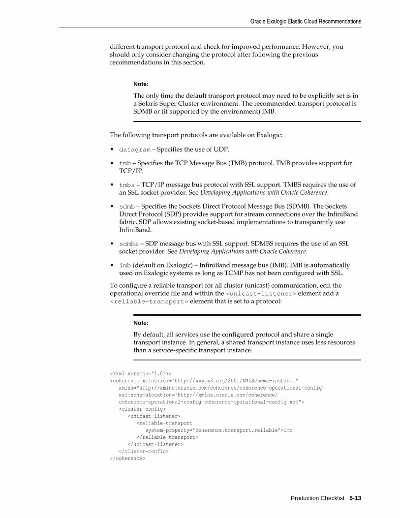
different transport protocol and check for improved performance. However, youshould only consider changing the protocol after following the previousrecommendations in this section.
Note:
The only time the default transport protocol may need to be explicitly set is ina Solaris Super Cluster environment. The recommended transport protocol isSDMB or (if supported by the environment) IMB.
The following transport protocols are available on Exalogic:
• datagram – Specifies the use of UDP.
• tmb – Specifies the TCP Message Bus (TMB) protocol. TMB provides support forTCP/IP.
• tmbs – TCP/IP message bus protocol with SSL support. TMBS requires the use ofan SSL socket provider. See Developing Applications with Oracle Coherence.
• sdmb – Specifies the Sockets Direct Protocol Message Bus (SDMB). The SocketsDirect Protocol (SDP) provides support for stream connections over the InfiniBandfabric. SDP allows existing socket-based implementations to transparently useInfiniBand.
• sdmbs – SDP message bus with SSL support. SDMBS requires the use of an SSLsocket provider. See Developing Applications with Oracle Coherence.
• imb (default on Exalogic) – InfiniBand message bus (IMB). IMB is automaticallyused on Exalogic systems as long as TCMP has not been configured with SSL.
To configure a reliable transport for all cluster (unicast) communication, edit theoperational override file and within the <unicast-listener> element add a<reliable-transport> element that is set to a protocol:
Note:
By default, all services use the configured protocol and share a singletransport instance. In general, a shared transport instance uses less resourcesthan a service-specific transport instance.
<?xml version="1.0"?><coherence xmlns:xsi="http://www.w3.org/2001/XMLSchema-instance" xmlns="http://xmlns.oracle.com/coherence/coherence-operational-config" xsi:schemaLocation="http://xmlns.oracle.com/coherence/ coherence-operational-config coherence-operational-config.xsd"> <cluster-config> <unicast-listener> <reliable-transport system-property="coherence.transport.reliable">imb </reliable-transport> </unicast-listener> </cluster-config></coherence>
Oracle Exalogic Elastic Cloud Recommendations
Production Checklist 5-13

The coherence.transport.reliable system property also configures the reliabletransport. For example:
-Dcoherence.transport.reliable=imb
To configure reliable transport for a service, edit the cache configuration file andwithin a scheme definition add a <reliable-transport> element that is set to aprotocol. The following example demonstrates setting the reliable transport for apartitioned cache service instance called ExampleService:
Note:
Specifying a reliable transport for a service results in the use of a service-specific transport instance rather then the shared transport instance that isdefined by the <unicast-listener> element. A service-specific transportinstance can result in higher performance but at the cost of increased resourceconsumption and should be used sparingly for select, high priority services. Ingeneral, a shared transport instance uses less resource consumption thanservice-specific transport instances.
<?xml version="1.0"?><cache-config xmlns:xsi="http://www.w3.org/2001/XMLSchema-instance" xmlns="http://xmlns.oracle.com/coherence/coherence-cache-config" xsi:schemaLocation="http://xmlns.oracle.com/coherence/coherence-cache-config coherence-cache-config.xsd">
<caching-scheme-mapping> <cache-mapping> <cache-name>example</cache-name> <scheme-name>distributed</scheme-name> </cache-mapping> </caching-scheme-mapping> <caching-schemes> <distributed-scheme> <scheme-name>distributed</scheme-name> <service-name>ExampleService</service-name> <reliable-transport>imb</reliable-transport> <backing-map-scheme> <local-scheme/> </backing-map-scheme> <autostart>true</autostart> </distributed-scheme> </caching-schemes></cache-config>
Each service type also has a system property that sets the reliable transport,respectively. The system property sets the reliable transport for all instances of aservice type. The system properties are:
coherence.distributed.transport.reliable
coherence.replicated.transport.reliable
coherence.optimistic.transport.reliable
coherence.invocation.transport.reliable
coherence.proxy.transport.reliable
Oracle Exalogic Elastic Cloud Recommendations
5-14 Administering Oracle Coherence

5.8 Security RecommendationsEnsure Security Privileges
The minimum set of privileges required for Coherence to function are specified in thesecurity.policy file which is included as part of the Coherence installation. Thisfile can be found in coherence/lib/security/security.policy. If using theJava Security Manager, these privileges must be granted in order for Coherence tofunction properly.
Plan for SSL Requirements
Coherence-based applications may chose to implement varying levels of security asrequired, including SSL-based security between cluster members and betweenCoherence*Extend clients and the cluster. If SSL is a requirement, ensure that allservers have a digital certificate that has been verified and signed by a trustedcertificate authority and that the digital certificate is imported into the servers' keystore and trust store as required. Coherence*Extend clients must include a trust keystore that contains the certificate authority's digital certificate that was used to sign theproxy's digital certificate. See Securing Oracle Coherence for detailed instructions onsetting up SSL.
5.9 Application Instrumentation RecommendationsSome Java-based management and monitoring solutions use instrumentation (forexample, bytecode-manipulation and ClassLoader substitution). Oracle hasobserved issues with such solutions in the past. Use these solutions cautiously eventhough there are no current issues reported with the major vendors.
5.10 Coherence Modes and EditionsSelect the Production Mode
Coherence may be configured to operate in either evaluation, development, orproduction mode. These modes do not limit access to features, but instead alter somedefault configuration settings. For instance, development mode allows for fastercluster startup to ease the development process.
The development mode is used for all pre-production activities, such as developmentand testing. This is an important safety feature because development nodes arerestricted from joining with production nodes. Development mode is the defaultmode. Production mode must be explicitly specified when using Coherence in aproduction environment. To change the mode to production mode, edit thetangosol-coherence.xml (located in coherence.jar) and enter prod as thevalue for the <license-mode> element. For example:
...<license-config> ... <license-mode system-property="coherence.mode">prod</license-mode></license-config>...
The coherence.mode system property is used to specify the license mode instead ofusing the operational deployment descriptor. For example:
-Dcoherence.mode=prod
Security Recommendations
Production Checklist 5-15

In addition to preventing mixed mode clustering, the license-mode also dictates theoperational override file to use. When in eval mode the tangosol-coherence-override-eval.xml file is used; when in dev mode the tangosol-coherence-override-dev.xml file is used; whereas, the tangosol-coherence-override-prod.xml file is used when the prod mode is specified. A tangosol-coherence-override.xml file (if it is included in the classpath before the coherence.jar file)is used no matter which mode is selected and overrides any mode-specific overridefiles.
Select the Edition
Note:
The edition switches no longer enforce license restrictions. Do not change thedefault setting (GE).
All nodes within a cluster must use the same license edition and mode. Be sure toobtain enough licenses for the all the cluster members in the production environment.The servers hardware configuration (number or type of processor sockets, processorpackages or CPU cores) may be verified using ProcessorInfo utility included withCoherence. For example:
java -cp coherence.jar com.tangosol.license.ProcessorInfo
If the result of the ProcessorInfo program differs from the licensed configuration,send the program's output and the actual configuration as a support issue.
The default edition is grid edition. To change the edition, edit the operational overridefile and add an <edition-name> element, within the <license-config> element,that includes an edition name as defined in Table 5-1. For example:
...<license-config> <edition-name system-property="tangosol.coherence.edition">EE</edition-name></license-config>...
The coherence.edition system property is used to specify the license editioninstead of using the operational deployment descriptor. For example:
-Dcoherence.edition=EE
Coherence Modes and Editions
5-16 Administering Oracle Coherence
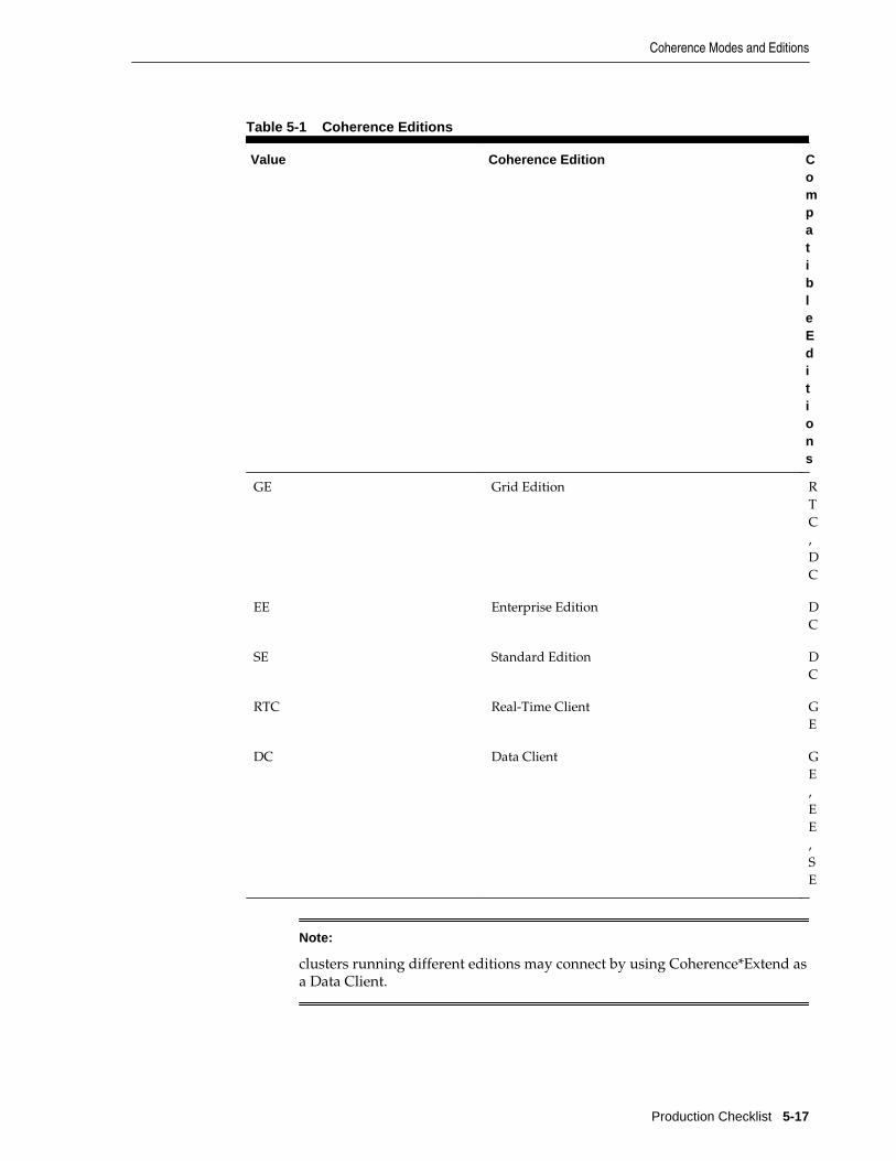
Table 5-1 Coherence Editions
Value Coherence Edition CompatibleEditions
GE Grid Edition RTC,DC
EE Enterprise Edition DC
SE Standard Edition DC
RTC Real-Time Client GE
DC Data Client GE,EE,SE
Note:
clusters running different editions may connect by using Coherence*Extend asa Data Client.
Coherence Modes and Editions
Production Checklist 5-17
Ensuring that RTC Nodes do Not Use Coherence TCMP
Real-Time client nodes can connect to clusters using either Coherence TCMP orCoherence*Extend. If the intention is to use extend clients, disable TCMP on the clientto ensure that it only connects to a cluster using Coherence*Extend. Otherwise, Theclient may become a member of the cluster. See Developing Remote Clients for OracleCoherence for details on disabling TCMP communication.
5.11 Coherence Operational Configuration RecommendationsOperational configuration relates to cluster-level configuration that is defined in thetangosol-coherence.xml file and includes such items as:
• Cluster and cluster member settings
• Network settings
• Management settings
• Security settings
The operational aspects are typically configured by using a tangosol-coherence-override.xml file. See Developing Applications with Oracle Coherence for moreinformation on specifying an operational override file.
The contents of this file often differs between development and production. It isrecommended that these variants be maintained independently due to the significantdifferences between these environments. The production operational configuration fileshould be maintained by systems administrators who are far more familiar with theworkings of the production systems.
All cluster nodes should use the same operational configuration override file and anynode-specific values should be specified by using system properties. See DevelopingApplications with Oracle Coherence for more information on system properties. Acentralized configuration file may be maintained and accessed by specifying a URL asthe value of the coherence.override system property on each cluster node. Forexample:
-Dcoherence.override=/net/mylocation/tangosol-coherence-override.xml
The override file need only contain the operational elements that are being changed. Inaddition, always include the id and system-property attributes if they are definedfor an element.
See Developing Applications with Oracle Coherence for a detailed reference of eachoperational element.
5.12 Coherence Cache Configuration RecommendationsCache configuration relates to cache-level configuration and includes such things as:
• Cache topology (<distributed-scheme>, <near-scheme>, and so on)
• Cache capacities (<high-units>)
• Cache redundancy level (<backup-count>)
The cache configuration aspects are typically configured by using a coherence-cache-config.xml file. See Developing Applications with Oracle Coherence for moreinformation on specifying a cache configuration file.
Coherence Operational Configuration Recommendations
5-18 Administering Oracle Coherence
The default coherence-cache-config.xml file included within coherence.jaris intended only as an example and is not suitable for production use. Always use acache configuration file with definitions that are specific to the application.
All cluster nodes should use the same cache configuration descriptor if possible. Acentralized configuration file may be maintained and accessed by specifying a URL asthe value the coherence.cacheconfig system property on each cluster node. Forexample:
-Dcoherence.cacheconfig=/net/mylocation/coherence-cache-config.xml
Caches can be categorized as either partial or complete. In the former case, theapplication does not rely on having the entire data set in memory (even if it expectsthat to be the case). Most caches that use cache loaders or that use a side cache patternare partial caches. Complete caches require the entire data set to be in cache for theapplication to work correctly (most commonly because the application is issuing non-primary-key queries against the cache). Caches that are partial should always have asize limit based on the allocated JVM heap size. The limits protect an application fromOutOfMemoryExceptions errors. Set the limits even if the cache is not expected tobe fully loaded to protect against changing expectations. See JVM Tuning for sizingrecommendations. Conversely, if a size limit is set for a complete cache, it may causeincorrect results.
It is important to note that when multiple cache schemes are defined for the samecache service name, the first to be loaded dictates the service level parameters.Specifically the <partition-count>, <backup-count>, and <thread-count>subelements of <distributed-scheme> are shared by all caches of the sameservice. It is recommended that a single service be defined and inherited by thevarious cache-schemes. If you want different values for these items on a cache bycache basis then multiple services may be configured.
For partitioned caches, Coherence evenly distributes the storage responsibilities to allcache servers, regardless of their cache configuration or heap size. For this reason, it isrecommended that all cache server processes be configured with the same heap size.For computers with additional resources multiple cache servers may be used toeffectively make use of the computer's resources.
To ensure even storage responsibility across a partitioned cache the <partition-count> subelement of the <distributed-scheme> element, should be set to a prime number which is at least the square of the number of expected cache servers.
For caches which are backed by a cache store, it is recommended that the parentservice be configured with a thread pool as requests to the cache store may block onI/O. Thread pools are also recommended for caches that perform CPU-intensiveoperations on the cache server (queries, aggreations, some entry processors, and soon). The pool is enabled by using the <thread-count> subelement of<distributed-scheme> element. For non-CacheStore-based caches more threadsare unlikely to improve performance and should be left disabled.
Unless explicitly specified, all cluster nodes are storage enabled, that is, they act ascache servers. It is important to control which nodes in your production environmentare storage enabled and storage disabled. Thecoherence.distributed.localstorage system property may be used to controlstorage, setting it to either true or false. Generally, only dedicated cache servers(including proxy servers) should have storage enabled. All other cluster nodes shouldbe configured as storage disabled. This is especially important for short livedprocesses which may join the cluster to perform some work and then exit the cluster.Having these nodes as storage enabled introduces unneeded re-partitioning.
Coherence Cache Configuration Recommendations
Production Checklist 5-19
See Developing Applications with Oracle Coherence for a detailed reference of each cacheconfiguration element.
5.13 Large Cluster Configuration Recommendations• Distributed caches on large clusters of more than 16 cache servers require more
partitions to ensure optimal performance. The default partition count is 257 andshould be increased relative to the number of cache servers in the cluster and theamount of data being stored in each partition. For details on configuring andcalculating the partition count, see Developing Applications with Oracle Coherence.
• The maximum packet size on large clusters of more than 400 cluster members mustbe increased to ensure better performance. The default of 1468 should be increasedrelative to the size of the cluster, that is, a 600 node cluster would need themaximum packet size increased by 50%. A simple formula is to allow four bytesper node, that is, maximum_packet_size >= maximum_cluster_size * 4B.The maximum packet size is configured as part of the coherence operationalconfiguration file, see Developing Applications with Oracle Coherence for details onconfiguring the maximum packet size.
• Multicast cluster communication should be enabled on large clusters that havehundreds of cluster members because it provides more efficient cluster-widetransmissions. These cluster-wide transmissions are rare, but when they do occurmulticast can provide noticeable benefits. Multicast is enabled in an operationalconfiguration file, see Developing Applications with Oracle Coherence for details.
5.14 Death Detection RecommendationsThe Coherence death detection algorithms are based on sustained loss of connectivitybetween two or more cluster nodes. When a node identifies that it has lost connectivitywith any other node, it consults with other cluster nodes to determine what actionshould be taken.
In attempting to consult with others, the node may find that it cannot communicatewith any other nodes and assumes that it has been disconnected from the cluster. Sucha condition could be triggered by physically unplugging a node's network adapter. Insuch an event, the isolated node restarts its clustered services and attempts to rejointhe cluster.
If connectivity with other cluster nodes remains unavailable, the node may(depending on well known address configuration) form a new isolated cluster, orcontinue searching for the larger cluster. In either case, the previously isolated clusternodes rejoins the running cluster when connectivity is restored. As part of rejoiningthe cluster, the nodes former cluster state is discarded, including any cache data it mayhave held, as the remainder of the cluster has taken on ownership of that data(restoring from backups).
It is obviously not possible for a node to identify the state of other nodes withoutconnectivity. To a single node, local network adapter failure and network wide switchfailure looks identical and are handled in the same way, as described above. Theimportant difference is that for a switch failure all nodes are attempting to re-join thecluster, which is the equivalent of a full cluster restart, and all prior state and data isdropped.
Dropping all data is not desirable and, to avoid this as part of a sustained switchfailure, you must take additional precautions. Options include:
Large Cluster Configuration Recommendations
5-20 Administering Oracle Coherence
• Increase detection intervals: The cluster relies on a deterministic process-leveldeath detection using the TcpRing component and hardware death detection usingthe IpMonitor component. Process-level detection is performed within millisecondsand network or machine failures are detected within 15 seconds by default.Increasing these value allows the cluster to wait longer for connectivity to return.Death detection is enabled by default and is configured within the <tcp-ring-listener> element. See Developing Applications with Oracle Coherence for details onconfiguring death detection.
• Persist data to external storage: By using a Read Write Backing Map, the clusterpersists data to external storage, and can retrieve it after a cluster restart. So long aswrite-behind is disabled (the <write-delay> subelement of <read-write-backing-map-scheme>) no data would be lost if a switch fails. The downsidehere is that synchronously writing through to external storage increases the latencyof cache update operations, and the external storage may become a bottleneck.
• Decide on a cluster quorum: The cluster quorum policy mandates the minimumnumber of cluster members that must remain in the cluster when the cluster serviceis terminating suspect members. During intermittent network outages, a highnumber of cluster members may be removed from the cluster. Using a clusterquorum, a certain number of members are maintained during the outage and areavailable when the network recovers. See Developing Applications with OracleCoherence for details on configuring cluster quorum.
Note:
To ensure that Windows does not disable a network adapter when it isdisconnected, add the following Windows registry DWORD, setting it to 1:HKEY_LOCAL_MACHINE\SYSTEM\CurrentControlSet\Services\Tcpip\Parameters\DisableDHCPMediaSense. This setting also affectsstatic IPs despite the name.
• Add network level fault tolerance: Adding a redundant layer to the cluster'snetwork infrastructure allows for individual pieces of networking equipment to failwithout disrupting connectivity. This is commonly achieved by using at least twonetwork adapters per computer, and having each adapter connected to a separateswitch. This is not a feature of Coherence but rather of the underlying operatingsystem or network driver. The only change to Coherence is that it should beconfigured to bind to the virtual rather then physical network adapter. This form ofnetwork redundancy goes by different names depending on the operating system,see Linux bonding, Solaris trunking and Windows teaming for further details.
Death Detection Recommendations
Production Checklist 5-21

Death Detection Recommendations
5-22 Administering Oracle Coherence
Part IIAdvanced Administration
Part II contains the following chapters:
• Persisting Caches
• Federating Caches Across Clusters

6Persisting Caches
This chapter provides instructions for using Coherence persistence to save and recoverthe contents of a cache.
This chapter includes the following sections:
• Overview of Persistence
• Persistence Dependencies
• Persisting Caches on Demand
• Actively Persisting Caches
• Using Snapshots to Persist a Cache Service
• Archiving Snapshots
• Enabling Active Persistence Mode
• Modifying the Pre-Defined Persistence Environments
• Creating Persistence Environments
• Changing the Active Persistence Failure Response
• Configuring the Quorum for Persistence Recovery
• Subscribing to Persistence JMX Notifications
• Managing Persistence
• Configuring Caches as Transient
6.1 Overview of PersistenceCoherence persistence is a set of tools and technologies that manage the persistenceand recovery of Coherence distributed caches. Cached data is persisted so that it canbe quickly recovered after a catastrophic failure or after a cluster restart due toplanned maintenance. Persistence and federated caching can be used together asrequired. For details about using federated caching, see Federating Caches AcrossClusters .
Persistence Modes
Persistence can operate in two modes:
• On-Demand persistence mode – a cache service is manually persisted andrecovered upon request using the persistence coordinator. The persistence
Persisting Caches 6-1
coordinator is exposed as an MBean interface that provides operations for creating,archiving, and recovering snapshots of a cache service.
• Active persistence mode – In this mode, cache contents are automatically persistedon all mutations and are automatically recovered on cluster/service startup. Thepersistence coordinator can still be used in active persistence mode to perform on-demand snapshots.
Disk-Based Persistence Storage
Persistence uses a database for the persistence store. The database is used to store thebacking map partitions of a partitioned service. The locations of the database files canbe stored on the local disk of each cache server or on a shared disk on a storage areanetwork (SAN).
Note:
Database files should never be manually edited. Editing the database files canlead to persistence errors.
The local disk option allows each cluster member to access persisted data for theservice partitions that it owns. Persistence is coordinated across all storage memberusing a list of cache server host addresses. The address list ensures that all persistedpartitions are discovered during recovery. Local disk storage provides a highthroughput and low latency storage mechanism; however, a partition service must stillrely on in-memory backup (backup-count value greater than zero) to remainmachine safe.
The shared disk option, together with active persistence mode, allows each clustermember to access persisted data for all service partitions. An advantage to using ashared disk is that partitioned services do not require in-memory backup (backup-count value can be equal to zero) to remain machine-safe; because, all storage-enabled members can recover partitions from the shared storage. Disabling in-memory backup increases the cache capacity of the cluster at the cost of higher latencyrecovery during node failure. In general, the use of a SAN can potentially affectthroughput and latencies and should be tested and monitored accordingly.
Note:
The service statusHA statistic shows an ENDAGERED status when the backupcount is set to zero even if persistence is being used to replace in-memorybackup.
Both the local disk and shared disk approach can rely on a quorum policy that controlshow many cluster members must be present to perform persistence operations andbefore recovery can begin. Quorum policies allow time for a cluster to start before datarecovery begins.
Persistence Configuration
Persistence is declaratively configured using Coherence configuration files andrequires no changes to application code. An operational override file is used toconfigure the underlying persistence implementation if the default settings are notacceptable. A cache configuration file is used to set persistence properties on adistributed cache.
Overview of Persistence
6-2 Administering Oracle Coherence

Management and Monitoring
Persistence can be monitored and managed using MBean attributes and operations.Persistence operations such as creating and archiving snapshots are performed usingthe PersistenceCoordinatorMBean MBean. Persistence attributes are included aspart of the attributes of a service and can be viewed using the ServiceMBean MBean.
Persistence attributes and statistics are aggregated in the persistence andpersistence-details reports. Persistence statistics are also aggregated in the JavaVisualVM plug-in. Both tools can help troubleshoot possible resource andperformance issues.
6.2 Persistence DependenciesPersistence is only available for distributed caches and requires the use of a centralizedpartition assignment strategy. Distributed caches use a centralized partitionedassignment strategy by default. Although uncommon, it is possible that anautonomous or a custom partition assignment strategy is being used. Check theStrategyName attribute on the PartitionAssignment MBean to verify thestrategy that is currently configured for a distributed cache. For details about partitionassignment strategies, see Developing Applications with Oracle Coherence.
6.3 Persisting Caches on DemandCaches can be persisted to disk at any point in time and recovered as required.
To persist caches on demand:
1. Use the persistence coordinator to create, recover, and remove snapshots asdescribed in “Using Snapshots to Persist a Cache Service”.
2. Optionally, change the location where persistence files are written to disk asdescribed in “Changing the Pre-Defined Persistence Directory”.
3. Optionally, configure the number of storage members that are required to performrecovery as described in “Configuring the Quorum for Persistence Recovery ”.
6.4 Actively Persisting CachesCaches can be automatically persisted to disk and automatically recovered when acluster is restarted.
To actively persist caches:
1. Enable active persistence as described in “Enabling Active Persistence Mode”.
2. Optionally, change the location where persistence files are written to disk asdescribed in “Changing the Pre-Defined Persistence Directory”.
3. Optionally, change how a service responds to possible failures during activepersistence as described in “Changing the Active Persistence Failure Response”.
4. Optionally, configure the number of storage members that are required to performrecovery as described in “Configuring the Quorum for Persistence Recovery ”.
6.5 Using Snapshots to Persist a Cache ServiceSnapshots are a backup of the contents of a cache service that must be manuallymanaged using the PersistenceCoordinatorMBean MBean. The MBean includes
Persistence Dependencies
Persisting Caches 6-3

asynchronous operations to create, recover, and remove snapshots. When a snapshotis recovered, the entire service is automatically restored to the state of the snapshot. Touse the MBean, JMX must be enabled on the cluster. For details about enabling JMXmanagement and accessing Coherence MBeans, see Managing Oracle Coherence.
Note:
The instructions in this section were created using the VisualVM-MBeansplugin for the JDK Java VisualVM tool. The Coherence-Java VisualVM Plug-incan also be used to perform snapshot operations.
6.5.1 Create a SnapshotCreating snapshots writes the contents of a cache service to the snapshot directory thatis specified within the persistence environment definition in the operational overrideconfiguration file.
To create a snapshot:
1. From the list of MBeans, select and expand the Persistence node.
2. Expand a service for which you want to create a snapshot and select thePersistenceCoordinator MBean.
3. From the Operations tab, enter a name for the snapshot in the field for thecreateSnapshot operation.
4. Click createSnapshot.
6.5.2 Recover a SnapshotRecovering snapshots restores the contents of a cache service from a snapshot.
To recover a snapshot:
1. From the list of MBeans, select and expand the Persistence node.
2. Expand a service for which you want to recover a snapshot and select thePersistenceCoordinator MBean.
3. From the Operations tab, enter the name of a snapshot in the field for therecoverSnapshot operation.
4. Click recoverSnapshot.
After the operation has returned, check the OperationStatus or Idle attributeson the persistence coordinator to determine when the operation has completed.Applications can be notified when the operation completes by subscribing to thesnapshot JMX notifications.
6.5.3 Remove a SnapshotRemoving a snapshot deletes the snapshot from the snapshot directory. The cacheservice remains unchanged.
To remove a snapshot:
Using Snapshots to Persist a Cache Service
6-4 Administering Oracle Coherence
1. From the list of MBeans, select and expand the Persistence node.
2. Expand a service for which you want to remove a snapshot and select thePersistenceCoordinator MBean.
3. From the Operations tab, enter the name of a snapshot in the field for theremoveSnapshot operation.
4. Click removeSnapshot.
6.6 Archiving SnapshotsSnapshots can be archived to a central location and then later retrieved and restored.Archiving snapshots requires defining the directory where archives are stored andconfiguring cache services to use an archive directory. Archiving operations areperformed using the PersistenceCoordinatorMBean MBean. An archive isslower to create than snapshots but, unlike snapshots, the archive is portable.
6.6.1 Defining a Snapshot Archive DirectoryThe directory where snapshots are archived is defined in the operational override fileusing a directory snapshot archiver definition. Multiple definitions can be created asrequired.
To define a snapshot archiver directory, include the <directory-archiver>element within the <snapshot-archivers> element. Use the <archiver-directory> element to enter the directory where snapshot archives are stored. Usethe id attribute to provide a unique name for the definition. For example:
<snapshot-archivers> <directory-archiver id="archiver1"> <archive-directory>/mydirectory</archive-directory> </directory-archiver></snapshot-archivers>
6.6.2 Specifying a Directory Snapshot ArchiverTo specify a directory snapshot archiver, edit the persistence definition within adistributed scheme and include the name of a directory snapshot archiver that isdefined in the operational override configuration file. For example:
<distributed-scheme> <scheme-name>distributed</scheme-name> <service-name>Service1</service-name> <backing-map-scheme> <local-scheme/> </backing-map-scheme> <persistence> <archiver>archiver1</archiver> </persistence> <autostart>true</autostart></distributed-scheme>
6.6.3 Performing Snapshot Archiving OperationsSnapshot archiving is manually managed using thePersistenceCoordinatorMBean MBean. The MBean includes asynchronousoperations to archive and retrieve snapshot archives and also includes operations tolist and remove archives.
Archiving Snapshots
Persisting Caches 6-5

6.6.3.1 Archiving a Snapshot
To archive a snapshot:
1. From the list of MBeans, select and expand the Persistence node.
2. Expand a service for which you want to archive a snapshot and select thePersistenceCoordinator MBean.
3. From the Operations tab, enter a name for the archive in the field for thearchiveSnapshot operation.
4. Click archiveSnapshot. The snapshot is archived to the location that is specified inthe directory archiver definition defined in the operational override configurationfile.
Check the OperationStatus on the persistence coordinator to determine whenthe operation has completed.
6.6.3.2 Retrieving Archived Snapshots
To retrieve an archived snapshot:
1. From the list of MBeans, select and expand the Persistence node.
2. Expand a service for which you want to retrieve an archived snapshot and selectthe PersistenceCoordinator MBean.
3. From the Operations tab, enter the name of an archived snapshot in the field for theretrieveArchivedSnapshot operation.
4. Click retrieveArchivedSnapshot. The archived snapshot is copied from thedirectory archiver location to the snapshot directory and is available to berecovered to the service backing map. For details about recovering a snapshot, see“Recover a Snapshot”.
6.6.3.3 Removing Archived Snapshots
To remove an archived snapshot:
1. From the list of MBeans, select and expand the Persistence node.
2. Expand a service for which you want to purge an archived snapshot and select thePersistenceCoordinator MBean.
3. From the Operations tab, enter the name of an archived snapshot in the field for theremoveArchivedSnapshot operation.
4. Click removeArchivedSnapshot. The archived snapshot is removed from thearchive directory.
6.6.3.4 Listing Archived Snapshots
To get a list of the current archived snapshots:
1. From the list of MBeans, select and expand the Persistence node.
2. Expand a service for which you want to list archived snapshots and select thePersistenceCoordinator MBean.
Archiving Snapshots
6-6 Administering Oracle Coherence
3. From the Operations tab, click the listArchivedSnapshots operation. A list ofarchived snapshots is returned.
6.6.3.5 Listing Archived Snapshot Stores
To list the individual stores, or parts of and archived snapshot:
1. From the list of MBeans, select and expand the Persistence node.
2. Expand a service for which you want to list archived snapshot stores and select thePersistenceCoordinator MBean.
3. From the Operations tab, enter the name of an archived snapshot in the field for thelistArchivedSnapshotStores operation.
4. Click listArchivedSnapshotStores. A list of stores for the archived snapshots isreturned.
6.6.4 Creating a Custom Snapshot ArchiverCustom snapshot archiver implementations can be created as required to storearchives using an alternative technique than the default directory snapshot archiverimplementation. For example, you may want to persist archives to an externaldatabase, use a web service to store archives to a storage area network, or storearchives in a content repository.
6.6.4.1 Create a Custom Snapshot Archiver Implementation
To create a custom snapshot archiver implementation, create a class that extends theAbstractSnapshotArchiver class. For details about theAbstractSnapshotArchiver class, see Java API Reference for Oracle Coherence.
6.6.4.2 Create a Custom Snapshot Archiver Definition
To create a custom snapshot archiver definition, include the <custom-archiver>element within the <snapshot-archivers> element and use the id attribute toprovide a unique name for the definition. Add the <class-name> element within the<custom-archiver> element that contains the fully qualified name of theimplementation class. The following example creates a definition for a customimplementation called MyCustomArchiver:
<snapshot-archivers> <custom-archiver id="custom1"> <class-name>package.MyCustomArchiver</class-name> </custom-archiver></snapshot-archivers>
Use the <class-factory-name> element if your implementation uses a factoryclass that is responsible for creating archiver instances. Use the <method-name>element to specify the static factory method on the factory class that performs objectinstantiation. The following example gets a snapshot archiver instance using thegetArchiver method on the MyArchiverFactory class.
<snapshot-archivers> <custom-archiver id="custom1"> <class-factory-name>package.MyArchiverFactory</class-factory-name> <method-name>getArchiver</method-name> </custom-archiver></snapshot-archivers>
Archiving Snapshots
Persisting Caches 6-7
Any initialization parameters that are required for an implementation can be specifiedusing the <init-params> element. The following example sets the UserNameparameter to Admin.
<snapshot-archivers> <custom-archiver id="custom1"> <class-name>package.MyCustomArchiver</class-name> <init-params> <init-param> <param-name>UserName</param-name> <param-value>Admin</param-value> </init-param> </init-params> </custom-archiver></snapshot-archivers>
6.6.4.3 Specifying a Custom Snapshot Archiver
To specify a custom snapshot archiver, edit the persistence definition within adistributed scheme and include the name of a custom snapshot archiver that is definedin the operational override configuration file. For example:
<distributed-scheme> <scheme-name>distributed</scheme-name> <service-name>Service1</service-name> <backing-map-scheme> <local-scheme/> </backing-map-scheme> <persistence> <archiver>custom1</archiver> </persistence> <autostart>true</autostart></distributed-scheme>
6.7 Enabling Active Persistence ModeActive persistence can be enabled for all services or for specific services. To enableactive persistence for all services, set thecoherence.distributed.persistence.mode system property to active. Forexample:
-Dcoherence.distributed.persistence.mode=active
The default value if no value is specified is on-demand, which enables on-demandpersistence. The persistence coordinator can still be used in active persistence mode totake snapshots of a cache.
To enable active persistence for a specific service, modify a distributed schemedefinition and include the <environment> element within the <persistence>element. Set the value of the <environment> element to default-active. Forexample:
<distributed-scheme> <scheme-name>distributed</scheme-name> <service-name>Service1</service-name> <backing-map-scheme> <local-scheme/> </backing-map-scheme> <persistence> <environment>default-active</environment> </persistence>
Enabling Active Persistence Mode
6-8 Administering Oracle Coherence

<autostart>true</autostart></distributed-scheme>
The default value if no value is specified is default-on-demand, which enables on-demand persistence for the service.
6.7.1 Changing the Partition Count When Using Active PersistenceThe partition count cannot be changed when using active persistence. If you change aservices partition count, then on restart of the services all active data is moved to thepersistence trash and must be recovered after the original partition count is restored.Data that is persisted can only be recovered to services running with the samepartition count.
Ensure that the partition count is not modified if active persistence is being used. If thepartition count is changed, then a message similar to the following is displayed whenthe services are started:
<Warning> (thread=DistributedCache:DistributedCachePersistence, member=1):Failed to recover partition 0 from SafeBerkeleyDBStore(...); partition-countmismatch 501(persisted) != 277(service); reinstate persistent store fromtrash once validation errors have been resolved
The message indicates that the change in the partition-count is not supported and thecurrent active data has been copied to the trash directory. To recover the data:
1. Shutdown the entire cluster.
2. Remove the current active directory contents for the cluster and service affected oneach cluster member.
3. Copy (recursively) the contents of the trash directory for each service to the activedirectory.
4. Restore the partition count to the original value.
5. Restart the cluster.
6.8 Modifying the Pre-Defined Persistence EnvironmentsThe operational deployment descriptor includes two pre-defined persistenceenvironment definitions:
• default-active – used when active persistence is enabled.
• default-on-demand – used when on-demand persistence is enabled.
The operational override file or system properties are used to override the defaultsettings of the pre-defined persistence environments. The pre-defined persistenceenvironments have the following configuration:
<persistence-environments> <persistence-environment id="default-active"> <persistence-mode>active</persistence-mode> <active-directory system-property="coherence.distributed.persistence.active.dir"> </active-directory> <snapshot-directory system-property="coherence.distributed.persistence.snapshot.dir"> </snapshot-directory> <trash-directory
Modifying the Pre-Defined Persistence Environments
Persisting Caches 6-9

system-property="coherence.distributed.persistence.trash.dir"> </trash-directory> </persistence-environment> <persistence-environment-environment id="default-on-demand"> <persistence-mode>on-demand</persistence-mode> <active-directory system-property="coherence.distributed.persistence.active.dir"> </active-directory> <snapshot-directory system-property="coherence.distributed.persistence.snapshot.dir"> </snapshot-directory> <trash-directory system-property="coherence.distributed.persistence.trash.dir"> </trash-directory> </persistence-environment></persistence-environments>
6.8.1 Changing the Pre-Defined Persistence DirectoryThe pre-defined persistence environments use a base directory called coherencewithin the USER_HOME directory to save persistence files. The location includesdirectories for active persistence files, snapshot persistence files, and trash files. Thelocations can be changed to a different local directory or a shared directory on thenetwork.
Note:
• Persistence directories and files (including the meta.properties files)should never be manually edited. Editing the directories and files can leadto persistence errors.
• If persistence is configured to use an NFS mounted file system, then theNFS mount should be configured to use synchronous IO and notasynchronous IO, which is the default on many operating systems. The useof asynchronous IO can lead to data loss if the file system becomesunresponsive due to an outage. For details on configuration, refer to themount documentation for your operating system.
To change the pre-defined location of persistence files, include the <active-directory>, <snapshot-directory>, and <trash-directory> elements thatare each set to the respective directories where persistence files are saved. Thefollowing example modifies the pre-defined on-demand persistence environment andchanges the location of all directories to the /persistence directory:
<persistence-environments> <persistence-environment id="default-on-demand"> <active-directory system-property="coherence.distributed.persistence.active.dir"> /persistence/active</active-directory> <snapshot-directory system-property="coherence.distributed.persistence.snapshot.dir"> /persistence/snapshot</snapshot-directory> <trash-directory system-property="coherence.distributed.persistence.trash.dir"> /persistence</trash</trash-directory> </persistence-environment></persistence-environments>
Modifying the Pre-Defined Persistence Environments
6-10 Administering Oracle Coherence

The following system properties are used to change the pre-defined location of thepersistence files instead of using the operational override file:
-Dcoherence.distributed.persistence.active.dir=/persistence/active-Dcoherence.distributed.persistence.snapshot.dir=/persistence/snapshot-Dcoherence.distributed.persistence.trash.dir=/persistence/trash
Use the coherence.distributed.persistence.base.dir system property tochange the default directory off the USER_HOME directory:
-Dcoherence.distributed.persistence.base.dir=persistence
6.9 Creating Persistence EnvironmentsA solution can choose to define and use multiple persistence environments to supportdifferent cache scenarios. Persistence environments are defined in the operationaloverride configuration file and are referred within a distributed scheme definition inthe cache configuration file.
6.9.1 Define a Persistence EnvironmentTo define a persistence environment, include the <persistence-environments>element that contains a <persistence-environment> element. The<persistence-environment> element includes the configuration for a persistenceenvironment. Use the id attribute to name the environment. The id attribute is usedto refer to the persistence environment from a distributed scheme definition. Thefollowing example creates a persistence environment with the name environment1:
<persistence-environments> <persistence-environment id="enviornment1"> <persistence-mode></persistence-mode> <active-directory></active-directory> <snapshot-directory></snapshot-directory> <trash-directory></trash-directory> </persistence-environment></persistence-environments>
6.9.2 Configure a Persistence ModeA persistence environment supports two persistence modes: on-demand and active.On-demand persistence requires the use of the persistence coordinator to persist andrecover cache services. Active persistence automatically persists and recovers cacheservices. You can still use the persistence coordinator in active persistence mode toperiodically persist a cache services.
To configure the persistence mode, include the <persistence-mode> element set toeither on-demand or active. The default value if no value is specified is on-demand. The following example configures active persistence.
<persistence-environments> <persistence-environment id="enviornment1"> <persistence-mode>active</persistence-mode> <persistence-mode></persistence-mode> <active-directory></active-directory> <snapshot-directory></snapshot-directory> <trash-directory></trash-directory> </persistence-environment></persistence-environments>
Creating Persistence Environments
Persisting Caches 6-11
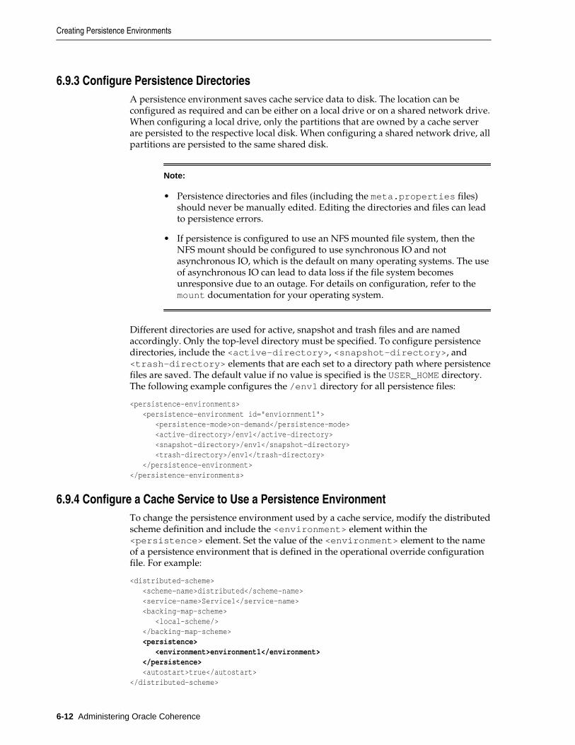
6.9.3 Configure Persistence DirectoriesA persistence environment saves cache service data to disk. The location can beconfigured as required and can be either on a local drive or on a shared network drive.When configuring a local drive, only the partitions that are owned by a cache serverare persisted to the respective local disk. When configuring a shared network drive, allpartitions are persisted to the same shared disk.
Note:
• Persistence directories and files (including the meta.properties files)should never be manually edited. Editing the directories and files can leadto persistence errors.
• If persistence is configured to use an NFS mounted file system, then theNFS mount should be configured to use synchronous IO and notasynchronous IO, which is the default on many operating systems. The useof asynchronous IO can lead to data loss if the file system becomesunresponsive due to an outage. For details on configuration, refer to themount documentation for your operating system.
Different directories are used for active, snapshot and trash files and are namedaccordingly. Only the top-level directory must be specified. To configure persistencedirectories, include the <active-directory>, <snapshot-directory>, and<trash-directory> elements that are each set to a directory path where persistencefiles are saved. The default value if no value is specified is the USER_HOME directory.The following example configures the /env1 directory for all persistence files:
<persistence-environments> <persistence-environment id="enviornment1"> <persistence-mode>on-demand</persistence-mode> <active-directory>/env1</active-directory> <snapshot-directory>/env1</snapshot-directory> <trash-directory>/env1</trash-directory> </persistence-environment></persistence-environments>
6.9.4 Configure a Cache Service to Use a Persistence EnvironmentTo change the persistence environment used by a cache service, modify the distributedscheme definition and include the <environment> element within the<persistence> element. Set the value of the <environment> element to the nameof a persistence environment that is defined in the operational override configurationfile. For example:
<distributed-scheme> <scheme-name>distributed</scheme-name> <service-name>Service1</service-name> <backing-map-scheme> <local-scheme/> </backing-map-scheme> <persistence> <environment>environment1</environment> </persistence> <autostart>true</autostart></distributed-scheme>
Creating Persistence Environments
6-12 Administering Oracle Coherence
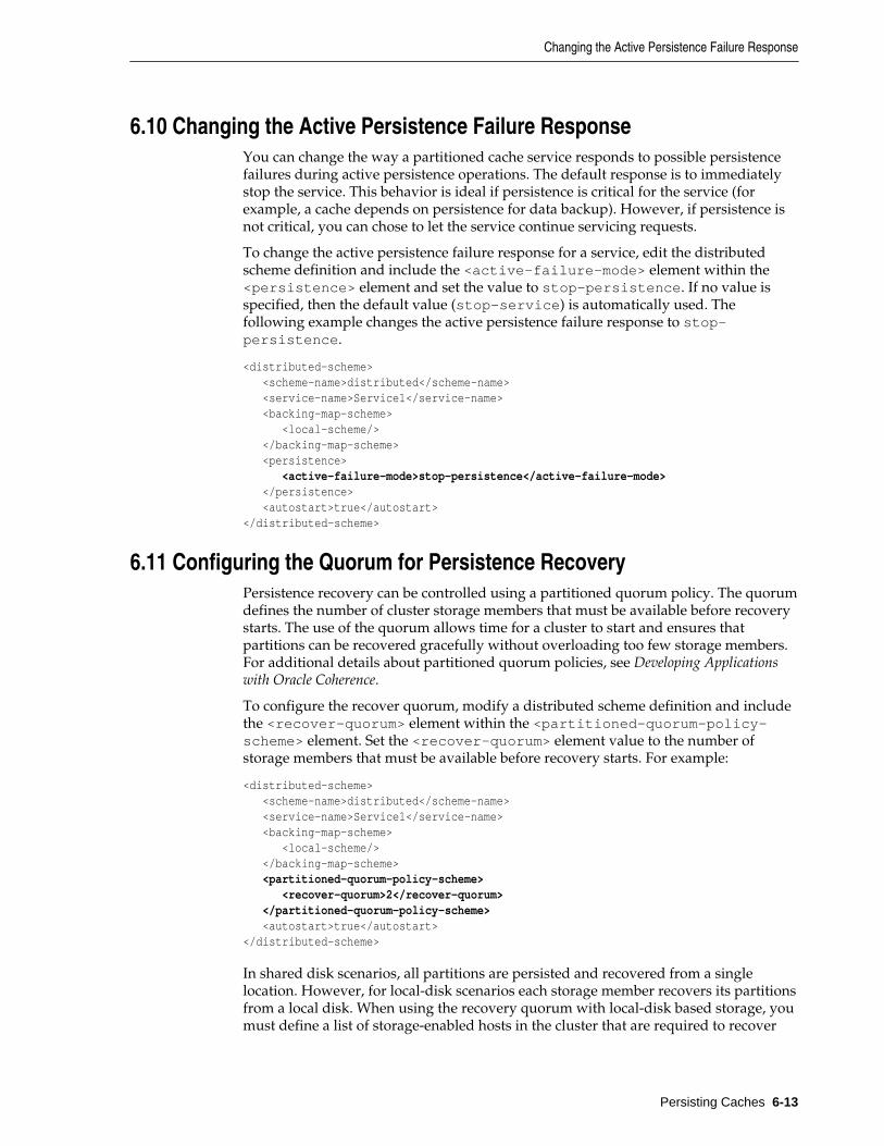
6.10 Changing the Active Persistence Failure ResponseYou can change the way a partitioned cache service responds to possible persistencefailures during active persistence operations. The default response is to immediatelystop the service. This behavior is ideal if persistence is critical for the service (forexample, a cache depends on persistence for data backup). However, if persistence isnot critical, you can chose to let the service continue servicing requests.
To change the active persistence failure response for a service, edit the distributedscheme definition and include the <active-failure-mode> element within the<persistence> element and set the value to stop-persistence. If no value isspecified, then the default value (stop-service) is automatically used. Thefollowing example changes the active persistence failure response to stop-persistence.
<distributed-scheme> <scheme-name>distributed</scheme-name> <service-name>Service1</service-name> <backing-map-scheme> <local-scheme/> </backing-map-scheme> <persistence> <active-failure-mode>stop-persistence</active-failure-mode> </persistence> <autostart>true</autostart></distributed-scheme>
6.11 Configuring the Quorum for Persistence RecoveryPersistence recovery can be controlled using a partitioned quorum policy. The quorumdefines the number of cluster storage members that must be available before recoverystarts. The use of the quorum allows time for a cluster to start and ensures thatpartitions can be recovered gracefully without overloading too few storage members.For additional details about partitioned quorum policies, see Developing Applicationswith Oracle Coherence.
To configure the recover quorum, modify a distributed scheme definition and includethe <recover-quorum> element within the <partitioned-quorum-policy-scheme> element. Set the <recover-quorum> element value to the number ofstorage members that must be available before recovery starts. For example:
<distributed-scheme> <scheme-name>distributed</scheme-name> <service-name>Service1</service-name> <backing-map-scheme> <local-scheme/> </backing-map-scheme> <partitioned-quorum-policy-scheme> <recover-quorum>2</recover-quorum> </partitioned-quorum-policy-scheme> <autostart>true</autostart></distributed-scheme>
In shared disk scenarios, all partitions are persisted and recovered from a singlelocation. However, for local-disk scenarios each storage member recovers its partitionsfrom a local disk. When using the recovery quorum with local-disk based storage, youmust define a list of storage-enabled hosts in the cluster that are required to recover
Changing the Active Persistence Failure Response
Persisting Caches 6-13

orphaned partition from the persistent storage or assign empty partitions if thepersistent storage is unavailable or lost.
Note:
Recovery hosts must be specified to ensure that recovery does not commenceprior to all persisted state being available.
To define a list of addresses, edit the operational override configuration file andinclude the <address-provider> element that contains a list of addresses eachdefined using an <address> element. Use the id attribute to name the addressprovider list. The id attribute is used to refer to the list from a distributed schemedefinition. The following example creates an address provider list that contains twomember addresses and is named persistence_hosts:
<address-providers> <address-provider id="persistence-host-list"> <address>HOST_NAME</address> <address>HOST_NAME</address> </address-provider></address-providers>
To refer to the address provider list, modify a distributed scheme definition andinclude the <recovery-hosts> element within the <partitioned-quorum-policy-scheme> element and set the value to the name of an address provider list.For example:
<distributed-scheme> <scheme-name>distributed</scheme-name> <service-name>Service1</service-name> <backing-map-scheme> <local-scheme/> </backing-map-scheme> <partitioned-quorum-policy-scheme> <recover-quorum>2</recover-quorum> <recovery-hosts>persistence-hosts</recovery-hosts> </partitioned-quorum-policy-scheme> <autostart>true</autostart></distributed-scheme>
If quorum is not satisfied, then the recovery does not proceed. The service or clustermay appear to be hung. To check for this scenario, view the QuorumPolicy attributein the ServiceMBean MBean to see if recover is included in the list of actions.
If data has not been recovered after cluster startup, the following log message isemitted (each time a new service member starts up) to indicate that the quorum hasnot been satisfied:
<Warning> (thread=DistributedCache:DistributedCachePersistence, member=1): Action recover disallowed; all-disallowed-actions: recover(4)
After the quorum is satisfied, the following message is emitted:
<Warning> (thread=DistributedCache:DistributedCachePersistence, member=1): All actions allowed
Configuring the Quorum for Persistence Recovery
6-14 Administering Oracle Coherence
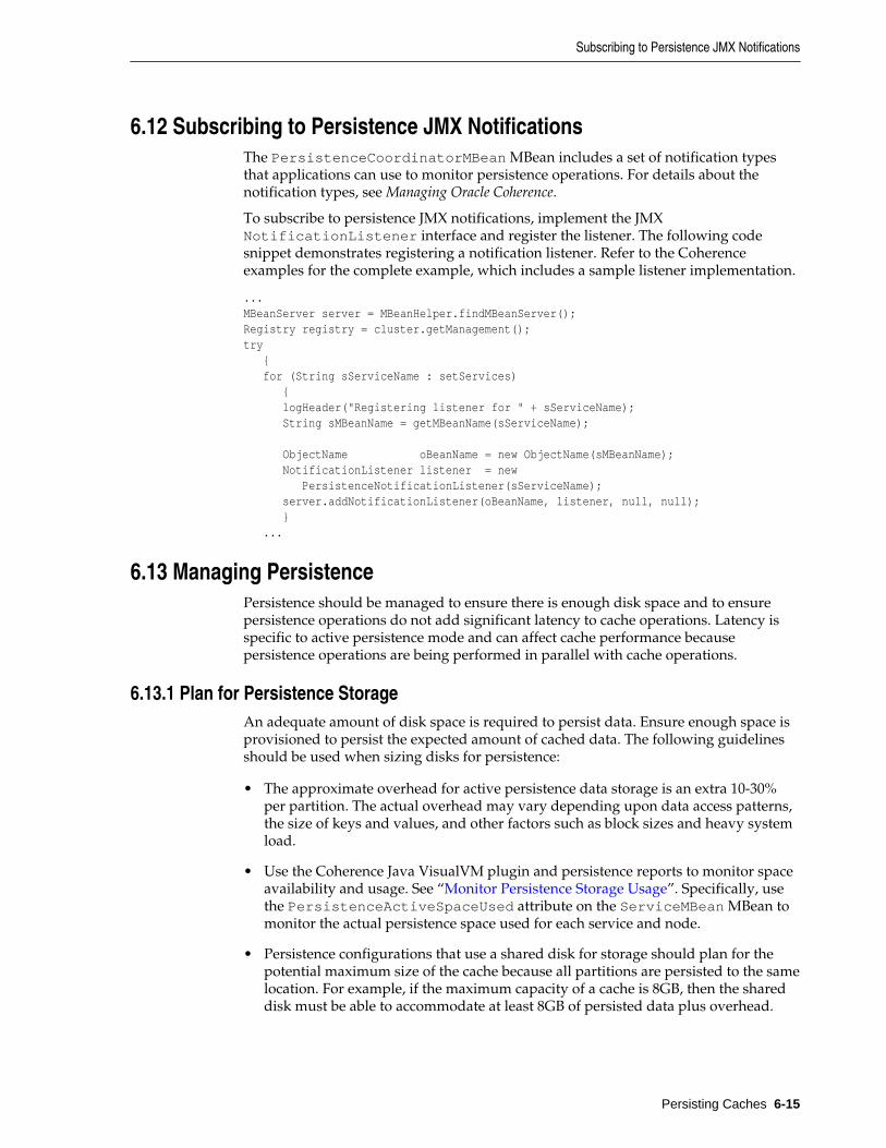
6.12 Subscribing to Persistence JMX NotificationsThe PersistenceCoordinatorMBean MBean includes a set of notification typesthat applications can use to monitor persistence operations. For details about thenotification types, see Managing Oracle Coherence.
To subscribe to persistence JMX notifications, implement the JMXNotificationListener interface and register the listener. The following codesnippet demonstrates registering a notification listener. Refer to the Coherenceexamples for the complete example, which includes a sample listener implementation.
...MBeanServer server = MBeanHelper.findMBeanServer();Registry registry = cluster.getManagement();try { for (String sServiceName : setServices) { logHeader("Registering listener for " + sServiceName); String sMBeanName = getMBeanName(sServiceName); ObjectName oBeanName = new ObjectName(sMBeanName); NotificationListener listener = new PersistenceNotificationListener(sServiceName); server.addNotificationListener(oBeanName, listener, null, null); } ...
6.13 Managing PersistencePersistence should be managed to ensure there is enough disk space and to ensurepersistence operations do not add significant latency to cache operations. Latency isspecific to active persistence mode and can affect cache performance becausepersistence operations are being performed in parallel with cache operations.
6.13.1 Plan for Persistence StorageAn adequate amount of disk space is required to persist data. Ensure enough space isprovisioned to persist the expected amount of cached data. The following guidelinesshould be used when sizing disks for persistence:
• The approximate overhead for active persistence data storage is an extra 10-30%per partition. The actual overhead may vary depending upon data access patterns,the size of keys and values, and other factors such as block sizes and heavy systemload.
• Use the Coherence Java VisualVM plugin and persistence reports to monitor spaceavailability and usage. See “Monitor Persistence Storage Usage”. Specifically, usethe PersistenceActiveSpaceUsed attribute on the ServiceMBean MBean tomonitor the actual persistence space used for each service and node.
• Persistence configurations that use a shared disk for storage should plan for thepotential maximum size of the cache because all partitions are persisted to the samelocation. For example, if the maximum capacity of a cache is 8GB, then the shareddisk must be able to accommodate at least 8GB of persisted data plus overhead.
Subscribing to Persistence JMX Notifications
Persisting Caches 6-15

• Persistence configurations that use a local disk for storage should plan for thepotential maximum cache capacity of the cache server because only the partitionsowned by a cache server are persisted to the local disk. For example, if themaximum cache capacity of a cache server is 2GB, then the local disk must be ableto accommodate at least 2GB of persisted data plus overhead.
• Plan additional space when creating snapshots in either active or on-demandmode. Each snapshot of a cache duplicates the size of the persistence files on disk.
• Plan additional space for snapshot archives. Each archive of a snapshot is slightlyless than the size of the snapshot files on disk.
6.13.2 Monitor Persistence Storage UsageMonitor persistence storage to ensure that there is enough space available on the filesystem to persist cached data.
Coherence-Java VisualVM Plug-in
Use the Persistence tab in the Coherence-Java VisualVM plug-in to view the amount ofspace being used by a service for active persistence. The space is reported in bothBytes and Megabytes. The tab also reports the current number of snapshots availablefor a service. The snapshot number can be used to estimate the additional space usageand to determine whether snapshots should be deleted to free up space.
Coherence Reports
Use the persistence detail report (persistence-detail.txt) to view the amount ofspace being used by a service for both active persistence and for persistence snapshots.The amount of available disk space is also reported and allows you to monitor if a diskis reaching capacity.
Coherence MBeans
Use the persistence attributes on the ServiceMBean MBean to view all thepersistence storage statistics for a service. The MBean includes statistics for both activepersistence and persistence snapshots.
6.13.3 Monitoring Persistence LatenciesMonitor persistence latencies when using active persistence to ensure that persistenceoperations are not adversely affecting cache operations. High latencies can be a signthat network issues are delaying writing persistence files to a shared disk or delayingcoordination between local disks.
Coherence-Java VisualVM Plug-in
Use the Persistence tab in the Coherence-Java VisualVM plug-in to view the amount oflatency that persistence operations are adding to cache operations. The time isreported in milliseconds. Statistics are reported for each service and provide theaverage latency of all persistence operations and for the highest recorded latency.
Coherence Reports
Use the persistence detail report (persistence-detail.txt) to view the amount oflatency that persistence operations are adding to cache operations. The time isreported in milliseconds. Statistics are provided for the average latency of allpersistence operations and for the highest recorded latency on each cluster node of aservice. The statistics can be used to determine if some nodes are experiencing higherlatencies than other nodes.
Managing Persistence
6-16 Administering Oracle Coherence
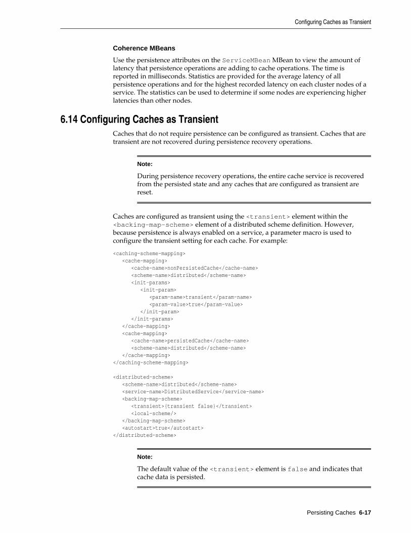
Coherence MBeans
Use the persistence attributes on the ServiceMBean MBean to view the amount oflatency that persistence operations are adding to cache operations. The time isreported in milliseconds. Statistics are provided for the average latency of allpersistence operations and for the highest recorded latency on each cluster nodes of aservice. The statistics can be used to determine if some nodes are experiencing higherlatencies than other nodes.
6.14 Configuring Caches as TransientCaches that do not require persistence can be configured as transient. Caches that aretransient are not recovered during persistence recovery operations.
Note:
During persistence recovery operations, the entire cache service is recoveredfrom the persisted state and any caches that are configured as transient arereset.
Caches are configured as transient using the <transient> element within the<backing-map-scheme> element of a distributed scheme definition. However,because persistence is always enabled on a service, a parameter macro is used toconfigure the transient setting for each cache. For example:
<caching-scheme-mapping> <cache-mapping> <cache-name>nonPersistedCache</cache-name> <scheme-name>distributed</scheme-name> <init-params> <init-param> <param-name>transient</param-name> <param-value>true</param-value> </init-param> </init-params> </cache-mapping> <cache-mapping> <cache-name>persistedCache</cache-name> <scheme-name>distributed</scheme-name> </cache-mapping></caching-scheme-mapping>
<distributed-scheme> <scheme-name>distributed</scheme-name> <service-name>DistributedService</service-name> <backing-map-scheme> <transient>{transient false}</transient> <local-scheme/> </backing-map-scheme> <autostart>true</autostart></distributed-scheme>
Note:
The default value of the <transient> element is false and indicates thatcache data is persisted.
Configuring Caches as Transient
Persisting Caches 6-17

Configuring Caches as Transient
6-18 Administering Oracle Coherence
7Federating Caches Across Clusters
This chapter provides instructions for using the Coherence federated caching featureto federate cache data across clusters.
This chapter includes the following sections:
• Overview of Federated Caching
• General Steps for Setting Up Federated Caching
• Defining Federation Participants
• Changing the Default Settings of Federation Participants
• Understanding Federation Topologies
• Defining Federation Topologies
• Defining Federated Cache Schemes
• Associating a Federated Cache with a Federation Topology
• Overriding the Destination Cache
• Limiting Federation Service Resource Usage
• Resolving Federation Conflicts
• Using a Specific Network Interface for Federation Communication
• Load Balancing Federated Connections
• Managing Federated Caching
7.1 Overview of Federated CachingThe federated caching feature federates cache data asynchronously across multiplegeographically dispersed clusters. Cached data is federated across clusters to provideredundancy, off-site backup, and multiple points of access for application users indifferent geographical locations.
Multiple Federation Topologies
Federated caching supports multiple federation topologies. These include: active-active, active-passive, hub-spoke, and central-federation. The topologies definecommon federation strategies between clusters and support a wide variety of usecases. Custom federation topologies can also be created as required.
Federating Caches Across Clusters 7-1

Conflict Resolution
Federated caching provides applications with the ability to accept, reject, or modifycache entries being stored locally or remotely. Conflict resolution is applicationspecific to allow the greatest amount of flexibility when defining federation rules.
Federation Configuration
Federated caching is configured using Coherence configuration files and requires nochanges to application code. An operational override file is used to configurefederation participants and the federation topology. A cache configuration file is usedto create federated caches schemes. A federated cache is a type of partitioned cacheservice and is managed by a federated cache service instance.
Management and Monitoring
Federated caching is managed using attributes and operations from theFederationManagerMBean, DestinationMBean, OriginMBean andTopologyMBean MBeans. These MBeans make it easy to perform administrativeoperations, such as starting and stopping federation and to monitor federationconfiguration and performance statistics. Many of these statistics and operations arealso available from the Coherence Java VisualVM plugin.
Federation attributes and statistics are aggregated in the federation-status,federation-origin, and federation-destination reports. Federationstatistics are also aggregated in the Coherence Java VisualVM plugin. Both tools canhelp troubleshoot possible resource and performance issues.
In addition, as with any distributed cache, federated services and caches can bemanaged and monitored using the attributes operations of the ServiceMBean MBeanand CacheMBean MBean and related reports and Java VisualVM plugin tabs.
7.2 General Steps for Setting Up Federated CachingTo set up federated caching:
1. Ensure that all clusters that are participating in the federation are operational andthat you know the address (host and cluster port) of at least one cache server ineach cluster.
2. Configure each cluster with a list of the cluster participants that are in thefederation as described in “Defining Federation Participants”.
3. Configure each cluster with a topology definition that specifies how data isfederated among cluster participants as described in “Defining FederationTopologies”.
4. Configure each cluster with a federated cache scheme that is used to store cacheddata as described in “Defining Federated Cache Schemes”.
5. Configure the federated cache on each cluster to use a defined federation topologyas described in “Associating a Federated Cache with a Federation Topology”.
7.3 Defining Federation ParticipantsEach Coherence cluster in a federation must be defined as a federation participant.Federation participants are defined in an operational override file. The operationaloverride file for each cluster in the federation must include the list of participants to befederated. The list of participants must include the local cluster participant and remotecluster participants.
General Steps for Setting Up Federated Caching
7-2 Administering Oracle Coherence
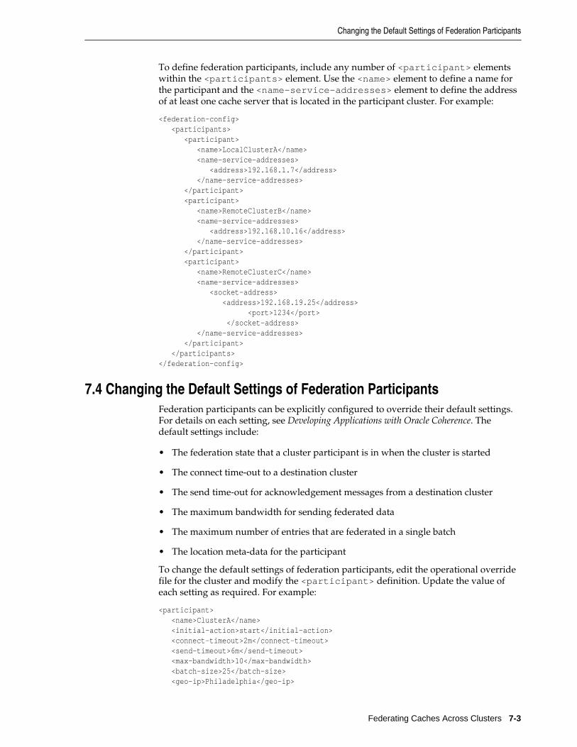
To define federation participants, include any number of <participant> elementswithin the <participants> element. Use the <name> element to define a name forthe participant and the <name—service-addresses> element to define the addressof at least one cache server that is located in the participant cluster. For example:
<federation-config> <participants> <participant> <name>LocalClusterA</name> <name-service-addresses> <address>192.168.1.7</address> </name-service-addresses> </participant> <participant> <name>RemoteClusterB</name> <name-service-addresses> <address>192.168.10.16</address> </name-service-addresses> </participant> <participant> <name>RemoteClusterC</name> <name-service-addresses> <socket-address> <address>192.168.19.25</address> <port>1234</port> </socket-address> </name-service-addresses> </participant> </participants></federation-config>
7.4 Changing the Default Settings of Federation ParticipantsFederation participants can be explicitly configured to override their default settings.For details on each setting, see Developing Applications with Oracle Coherence. Thedefault settings include:
• The federation state that a cluster participant is in when the cluster is started
• The connect time-out to a destination cluster
• The send time-out for acknowledgement messages from a destination cluster
• The maximum bandwidth for sending federated data
• The maximum number of entries that are federated in a single batch
• The location meta-data for the participant
To change the default settings of federation participants, edit the operational overridefile for the cluster and modify the <participant> definition. Update the value ofeach setting as required. For example:
<participant> <name>ClusterA</name> <initial-action>start</initial-action> <connect-timeout>2m</connect-timeout> <send-timeout>6m</send-timeout> <max-bandwidth>10</max-bandwidth> <batch-size>25</batch-size> <geo-ip>Philadelphia</geo-ip>
Changing the Default Settings of Federation Participants
Federating Caches Across Clusters 7-3

<name-service-addresses> <address>192.168.1.7</address> </name-service-addresses></participant>
7.5 Understanding Federation TopologiesFederation topologies determine how data is federated and synchronized betweencluster participants in a federation. The federation topology defines which clusters cansend cached data, which clusters can receive cached data, and which clusters can re-send cached data. These roles are well-defined and ensure that data is not missed orsent multiples times.
The supported federation topologies are:
• Active-Passive Topologies
• Active-Active Topologies
• Hub and Spoke Topologies
• Central Federation Topologies
• Custom Federation Topologies
Active-Passive Topologies
Active-passive topologies are used to federate data from an active cluster to a passivecluster. Data that is put into active cluster is federated to the passive cluster. If data isput into the passive cluster, then it does not get federated to the active cluster.Consider using active-passive topologies when a copy of cached data is required forread-only operations or an off-site backup is required.
Figure 7-1 provides conceptual view of an active-passive topology.
Figure 7-1 Active-Passive Topology
Active-Active Topologies
Active-active topologies are used to federate data between active clusters. Data that isput into one active cluster, is federated at the other active clusters. The active-activetopology ensures that cached data is always synchronized between clusters. Considerusing an active-active topology to provide applications in multiple geographicallocation with access to a local cluster instance.
Figure 7-2 provides a conceptual view of an active-active topology.
Understanding Federation Topologies
7-4 Administering Oracle Coherence
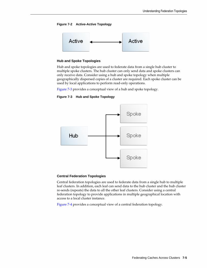
Figure 7-2 Active-Active Topology
Hub and Spoke Topologies
Hub and spoke topologies are used to federate data from a single hub cluster tomultiple spoke clusters. The hub cluster can only send data and spoke clusters canonly receive data. Consider using a hub and spoke topology when multiplegeographically dispersed copies of a cluster are required. Each spoke cluster can beused by local applications to perform read-only operations.
Figure 7-3 provides a conceptual view of a hub and spoke topology.
Figure 7-3 Hub and Spoke Topology
Central Federation Topologies
Central federation topologies are used to federate data from a single hub to multipleleaf clusters. In addition, each leaf can send data to the hub cluster and the hub clusterre-sends (repeats) the data to all the other leaf clusters. Consider using a centralfederation topology to provide applications in multiple geographical location withaccess to a local cluster instance.
Figure 7-4 provides a conceptual view of a central federation topology.
Understanding Federation Topologies
Federating Caches Across Clusters 7-5

Figure 7-4 Central Federation Topology
Custom Federation Topologies
Custom federation topologies are used to create free-from topologies. Clusters areorganized into groups and each cluster is designated with a role in the group. Theroles include: sender, receiver, or repeater. A sender participant only federateschanges occurring on the local cluster. A repeater federates both local cluster changesas well changes it receives from other participants. Only sender and repeater clusterscan federate data to other clusters in the group. Consider creating a custom federationtopology if the pre-defined federation topologies do not address the federationrequirements of a cache.
Figure 7-5 provides a conceptual view of a custom federation topology in one possibleconfiguration.
Understanding Federation Topologies
7-6 Administering Oracle Coherence
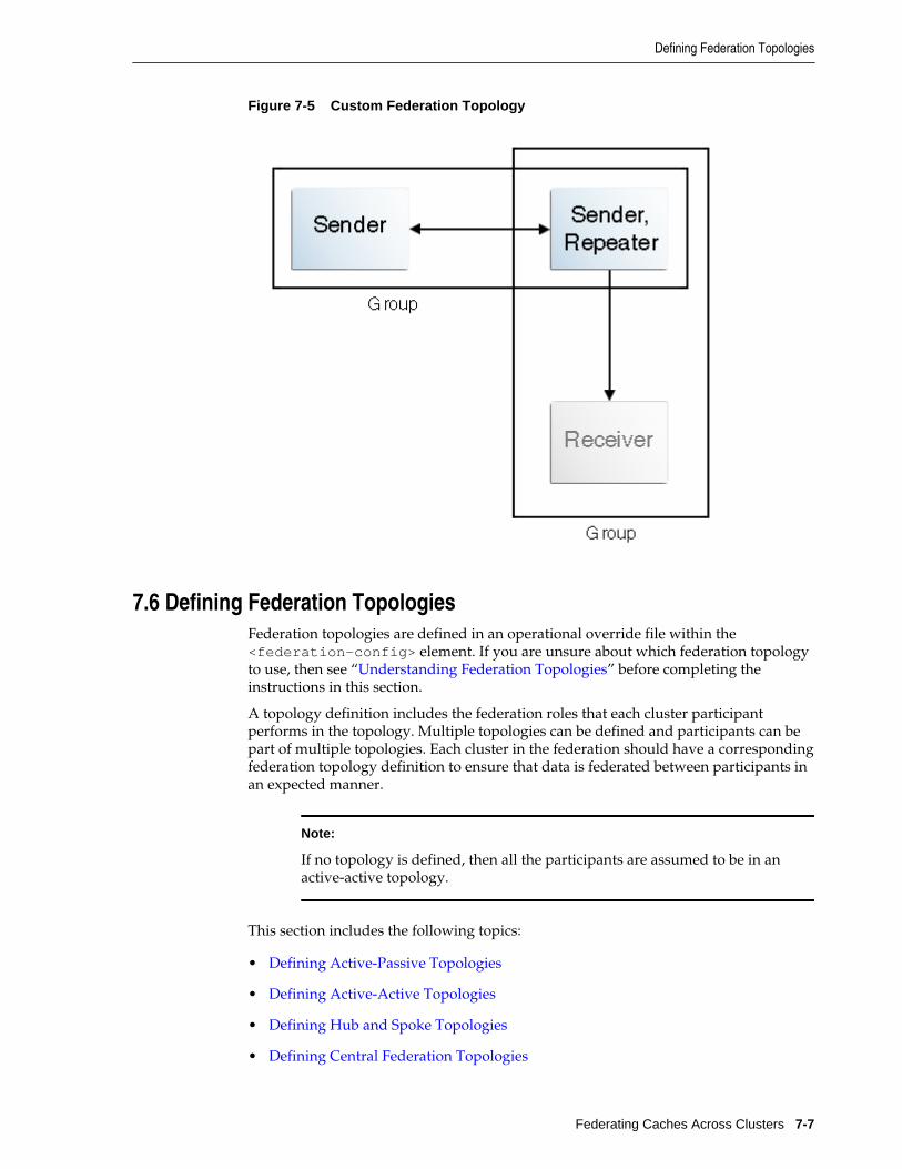
Figure 7-5 Custom Federation Topology
7.6 Defining Federation TopologiesFederation topologies are defined in an operational override file within the<federation-config> element. If you are unsure about which federation topologyto use, then see “Understanding Federation Topologies” before completing theinstructions in this section.
A topology definition includes the federation roles that each cluster participantperforms in the topology. Multiple topologies can be defined and participants can bepart of multiple topologies. Each cluster in the federation should have a correspondingfederation topology definition to ensure that data is federated between participants inan expected manner.
Note:
If no topology is defined, then all the participants are assumed to be in anactive-active topology.
This section includes the following topics:
• Defining Active-Passive Topologies
• Defining Active-Active Topologies
• Defining Hub and Spoke Topologies
• Defining Central Federation Topologies
Defining Federation Topologies
Federating Caches Across Clusters 7-7
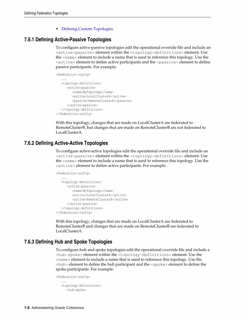
• Defining Custom Topologies
7.6.1 Defining Active-Passive TopologiesTo configure active-passive topologies edit the operational override file and include an<active-passive> element within the <topology-definitions> element. Usethe <name> element to include a name that is used to reference this topology. Use the<active> element to define active participants and the <passive> element to definepassive participants. For example:
<federation-config> ... <topology-definitions> <active-passive> <name>MyTopology</name> <active>LocalClusterA</active> <passive>RemoteClusterB</passive> </active-passive> </topology-definitions></federation-config>
With this topology, changes that are made on LocalClusterA are federated toRemoteClusterB, but changes that are made on RemoteClusterB are not federated toLocalClusterA.
7.6.2 Defining Active-Active TopologiesTo configure active-active topologies edit the operational override file and include an<active-passive> element within the <topology-definitions> element. Usethe <name> element to include a name that is used to reference this topology. Use the<active> element to define active participants. For example:
<federation-config> ... <topology-definitions> <active-passive> <name>MyTopology</name> <active>LocalClusterA</active> <active>RemoteClusterB</active> </active-passive> </topology-definitions></federation-config>
With this topology, changes that are made on LocalClusterA are federated toRemoteClusterB and changes that are made on RemoteClusterB are federated toLocalClusterA.
7.6.3 Defining Hub and Spoke TopologiesTo configure hub and spoke topologies edit the operational override file and include a<hub-spoke> element within the <topology-definitions> element. Use the<name> element to include a name that is used to reference this topology. Use the<hub> element to define the hub participant and the <spoke> element to define thespoke participants. For example:
<federation-config> ... <topology-definitions> <hub-spoke>
Defining Federation Topologies
7-8 Administering Oracle Coherence
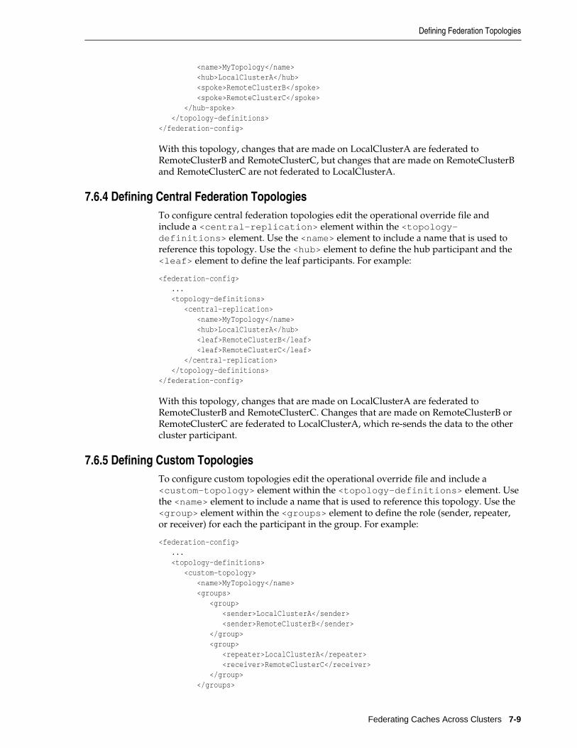
<name>MyTopology</name> <hub>LocalClusterA</hub> <spoke>RemoteClusterB</spoke> <spoke>RemoteClusterC</spoke> </hub-spoke> </topology-definitions></federation-config>
With this topology, changes that are made on LocalClusterA are federated toRemoteClusterB and RemoteClusterC, but changes that are made on RemoteClusterBand RemoteClusterC are not federated to LocalClusterA.
7.6.4 Defining Central Federation TopologiesTo configure central federation topologies edit the operational override file andinclude a <central-replication> element within the <topology-definitions> element. Use the <name> element to include a name that is used toreference this topology. Use the <hub> element to define the hub participant and the<leaf> element to define the leaf participants. For example:
<federation-config> ... <topology-definitions> <central-replication> <name>MyTopology</name> <hub>LocalClusterA</hub> <leaf>RemoteClusterB</leaf> <leaf>RemoteClusterC</leaf> </central-replication> </topology-definitions></federation-config>
With this topology, changes that are made on LocalClusterA are federated toRemoteClusterB and RemoteClusterC. Changes that are made on RemoteClusterB orRemoteClusterC are federated to LocalClusterA, which re-sends the data to the othercluster participant.
7.6.5 Defining Custom TopologiesTo configure custom topologies edit the operational override file and include a<custom-topology> element within the <topology-definitions> element. Usethe <name> element to include a name that is used to reference this topology. Use the<group> element within the <groups> element to define the role (sender, repeater,or receiver) for each the participant in the group. For example:
<federation-config> ... <topology-definitions> <custom-topology> <name>MyTopology</name> <groups> <group> <sender>LocalClusterA</sender> <sender>RemoteClusterB</sender> </group> <group> <repeater>LocalClusterA</repeater> <receiver>RemoteClusterC</receiver> </group> </groups>
Defining Federation Topologies
Federating Caches Across Clusters 7-9
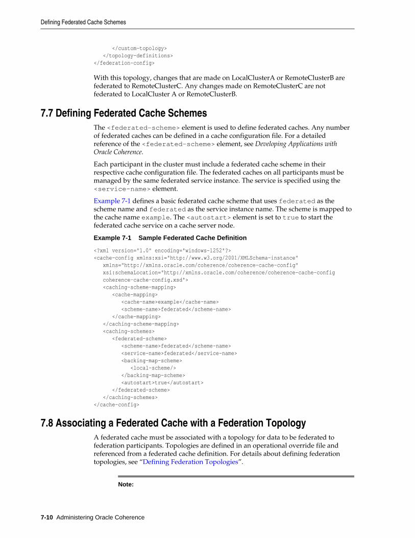
</custom-topology> </topology-definitions></federation-config>
With this topology, changes that are made on LocalClusterA or RemoteClusterB arefederated to RemoteClusterC. Any changes made on RemoteClusterC are notfederated to LocalCluster A or RemoteClusterB.
7.7 Defining Federated Cache SchemesThe <federated-scheme> element is used to define federated caches. Any numberof federated caches can be defined in a cache configuration file. For a detailedreference of the <federated-scheme> element, see Developing Applications withOracle Coherence.
Each participant in the cluster must include a federated cache scheme in theirrespective cache configuration file. The federated caches on all participants must bemanaged by the same federated service instance. The service is specified using the<service-name> element.
Example 7-1 defines a basic federated cache scheme that uses federated as thescheme name and federated as the service instance name. The scheme is mapped tothe cache name example. The <autostart> element is set to true to start thefederated cache service on a cache server node.
Example 7-1 Sample Federated Cache Definition
<?xml version="1.0" encoding="windows-1252"?><cache-config xmlns:xsi="http://www.w3.org/2001/XMLSchema-instance" xmlns="http://xmlns.oracle.com/coherence/coherence-cache-config" xsi:schemaLocation="http://xmlns.oracle.com/coherence/coherence-cache-config coherence-cache-config.xsd"> <caching-scheme-mapping> <cache-mapping> <cache-name>example</cache-name> <scheme-name>federated</scheme-name> </cache-mapping> </caching-scheme-mapping> <caching-schemes> <federated-scheme> <scheme-name>federated</scheme-name> <service-name>federated</service-name> <backing-map-scheme> <local-scheme/> </backing-map-scheme> <autostart>true</autostart> </federated-scheme> </caching-schemes></cache-config>
7.8 Associating a Federated Cache with a Federation TopologyA federated cache must be associated with a topology for data to be federated tofederation participants. Topologies are defined in an operational override file andreferenced from a federated cache definition. For details about defining federationtopologies, see “Defining Federation Topologies”.
Note:
Defining Federated Cache Schemes
7-10 Administering Oracle Coherence
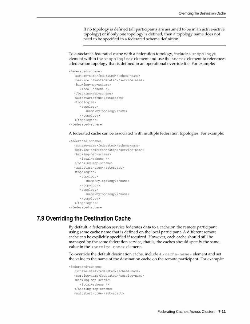
If no topology is defined (all participants are assumed to be in an active-activetopology) or if only one topology is defined, then a topology name does notneed to be specified in a federated scheme definition.
To associate a federated cache with a federation topology, include a <topology>element within the <topologies> element and use the <name> element to referencesa federation topology that is defined in an operational override file. For example:
<federated-scheme> <scheme-name>federated</scheme-name> <service-name>federated</service-name> <backing-map-scheme> <local-scheme /> </backing-map-scheme> <autostart>true</autostart> <topologies> <topology> <name>MyTopology</name> </topology> </topologies></federated-scheme>
A federated cache can be associated with multiple federation topologies. For example:
<federated-scheme> <scheme-name>federated</scheme-name> <service-name>federated</service-name> <backing-map-scheme> <local-scheme /> </backing-map-scheme> <autostart>true</autostart> <topologies> <topology> <name>MyTopology1</name> </topology> <topology> <name>MyTopology2</name> </topology> </topologies></federated-scheme>
7.9 Overriding the Destination CacheBy default, a federation service federates data to a cache on the remote participantusing same cache name that is defined on the local participant. A different remotecache can be explicitly specified if required. However, each cache should still bemanaged by the same federation service; that is, the caches should specify the samevalue in the <service-name> element.
To override the default destination cache, include a <cache-name> element and setthe value to the name of the destination cache on the remote participant. For example:
<federated-scheme> <scheme-name>federated</scheme-name> <service-name>federated</service-name> <backing-map-scheme> <local-scheme /> </backing-map-scheme> <autostart>true</autostart>
Overriding the Destination Cache
Federating Caches Across Clusters 7-11
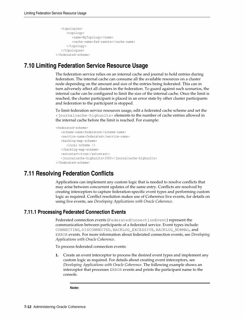
<topologies> <topology> <name>MyTopology</name> <cache-name>fed-remote</cache-name> </topology> </topologies></federated-scheme>
7.10 Limiting Federation Service Resource UsageThe federation service relies on an internal cache and journal to hold entries duringfederation. The internal cache can consume all the available resources on a clusternode depending on the amount and size of the entries being federated. This can inturn adversely affect all clusters in the federation. To guard against such scenarios, theinternal cache can be configured to limit the size of the internal cache. Once the limit isreached, the cluster participant is placed in an error state by other cluster participantsand federation to the participant is stopped.
To limit federation service resources usage, edit a federated cache scheme and set the<journalcache-highunits> elements to the number of cache entries allowed inthe internal cache before the limit is reached. For example:
<federated-scheme> <scheme-name>federated</scheme-name> <service-name>federated</service-name> <backing-map-scheme> <local-scheme /> </backing-map-scheme> <autostart>true</autostart> <journalcache-highunits>1000</journalcache-highunits></federated-scheme>
7.11 Resolving Federation ConflictsApplications can implement any custom logic that is needed to resolve conflicts thatmay arise between concurrent updates of the same entry. Conflicts are resolved bycreating interceptors to capture federation-specific event types and performing customlogic as required. Conflict resolution makes use of Coherence live events, for details onusing live events, see Developing Applications with Oracle Coherence.
7.11.1 Processing Federated Connection EventsFederated connection events (FederatedConnectionEvent) represent thecommunication between participants of a federated service. Event types include:CONNECTING, DISCONNECTED, BACKLOG_EXCESSIVE, BACKLOG_NORMAL, andERROR events. For more information about federated connection events, see DevelopingApplications with Oracle Coherence.
To process federated connection events:
1. Create an event interceptor to process the desired event types and implement anycustom logic as required. For details about creating event interceptors, see Developing Applications with Oracle Coherence. The following example shows aninterceptor that processes ERROR events and prints the participant name to theconsole.
Note:
Limiting Federation Service Resource Usage
7-12 Administering Oracle Coherence
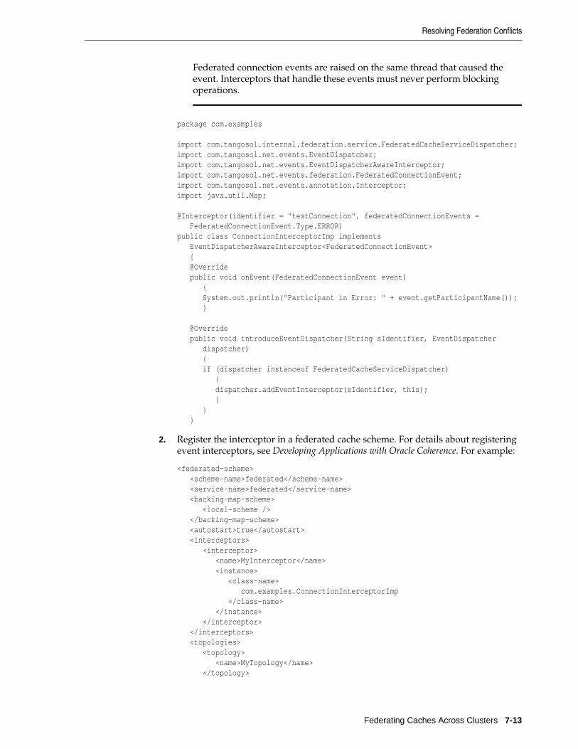
Federated connection events are raised on the same thread that caused theevent. Interceptors that handle these events must never perform blockingoperations.
package com.examples
import com.tangosol.internal.federation.service.FederatedCacheServiceDispatcher;import com.tangosol.net.events.EventDispatcher;import com.tangosol.net.events.EventDispatcherAwareInterceptor;import com.tangosol.net.events.federation.FederatedConnectionEvent;import com.tangosol.net.events.annotation.Interceptor;import java.util.Map;
@Interceptor(identifier = "testConnection", federatedConnectionEvents = FederatedConnectionEvent.Type.ERROR)public class ConnectionInterceptorImp implements EventDispatcherAwareInterceptor<FederatedConnectionEvent> { @Override public void onEvent(FederatedConnectionEvent event) { System.out.println("Participant in Error: " + event.getParticipantName()); }
@Override public void introduceEventDispatcher(String sIdentifier, EventDispatcher dispatcher) { if (dispatcher instanceof FederatedCacheServiceDispatcher) { dispatcher.addEventInterceptor(sIdentifier, this); } } }
2. Register the interceptor in a federated cache scheme. For details about registeringevent interceptors, see Developing Applications with Oracle Coherence. For example:
<federated-scheme> <scheme-name>federated</scheme-name> <service-name>federated</service-name> <backing-map-scheme> <local-scheme /> </backing-map-scheme> <autostart>true</autostart> <interceptors> <interceptor> <name>MyInterceptor</name> <instance> <class-name> com.examples.ConnectionInterceptorImp </class-name> </instance> </interceptor> </interceptors> <topologies> <topology> <name>MyTopology</name> </topology>
Resolving Federation Conflicts
Federating Caches Across Clusters 7-13
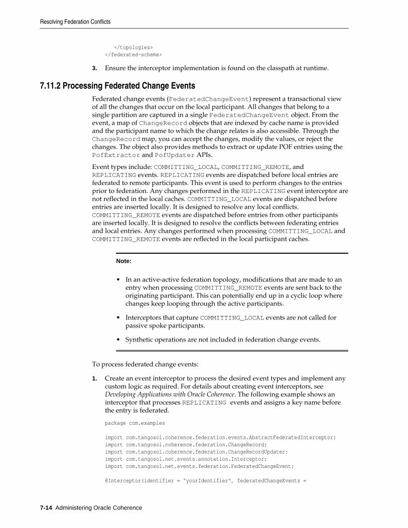
</topologies></federated-scheme>
3. Ensure the interceptor implementation is found on the classpath at runtime.
7.11.2 Processing Federated Change EventsFederated change events (FederatedChangeEvent) represent a transactional viewof all the changes that occur on the local participant. All changes that belong to asingle partition are captured in a single FederatedChangeEvent object. From theevent, a map of ChangeRecord objects that are indexed by cache name is providedand the participant name to which the change relates is also accessible. Through theChangeRecord map, you can accept the changes, modify the values, or reject thechanges. The object also provides methods to extract or update POF entries using thePofExtractor and PofUpdater APIs.
Event types include: COMMITTING_LOCAL, COMMITTING_REMOTE, andREPLICATING events. REPLICATING events are dispatched before local entries arefederated to remote participants. This event is used to perform changes to the entriesprior to federation. Any changes performed in the REPLICATING event interceptor arenot reflected in the local caches. COMMITTING_LOCAL events are dispatched beforeentries are inserted locally. It is designed to resolve any local conflicts.COMMITTING_REMOTE events are dispatched before entries from other participantsare inserted locally. It is designed to resolve the conflicts between federating entriesand local entries. Any changes performed when processing COMMITTING_LOCAL andCOMMITTING_REMOTE events are reflected in the local participant caches.
Note:
• In an active-active federation topology, modifications that are made to anentry when processing COMMITTING_REMOTE events are sent back to theoriginating participant. This can potentially end up in a cyclic loop wherechanges keep looping through the active participants.
• Interceptors that capture COMMITTING_LOCAL events are not called forpassive spoke participants.
• Synthetic operations are not included in federation change events.
To process federated change events:
1. Create an event interceptor to process the desired event types and implement anycustom logic as required. For details about creating event interceptors, see Developing Applications with Oracle Coherence. The following example shows aninterceptor that processes REPLICATING events and assigns a key name beforethe entry is federated.
package com.examples
import com.tangosol.coherence.federation.events.AbstractFederatedInterceptor;import com.tangosol.coherence.federation.ChangeRecord;import com.tangosol.coherence.federation.ChangeRecordUpdater;import com.tangosol.net.events.annotation.Interceptor;import com.tangosol.net.events.federation.FederatedChangeEvent; @Interceptor(identifier = "yourIdentifier", federatedChangeEvents =
Resolving Federation Conflicts
7-14 Administering Oracle Coherence
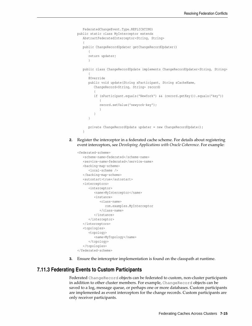
FederatedChangeEvent.Type.REPLICATING)public static class MyInterceptor extends AbstractFederatedInterceptor<String, String> { public ChangeRecordUpdater getChangeRecordUpdater() { return updater; } public class ChangeRecordUpdate implements ChangeRecordUpdater<String, String> { @Override public void update(String sParticipant, String sCacheName, ChangeRecord<String, String> record) { if (sParticipant.equals("NewYork") && (record.getKey()).equals("key")) { record.setValue("newyork-key"); } } }
private ChangeRecordUpdate updater = new ChangeRecordUpdate(); }
2. Register the interceptor in a federated cache scheme. For details about registeringevent interceptors, see Developing Applications with Oracle Coherence. For example:
<federated-scheme> <scheme-name>federated</scheme-name> <service-name>federated</service-name> <backing-map-scheme> <local-scheme /> </backing-map-scheme> <autostart>true</autostart> <interceptors> <interceptor> <name>MyInterceptor</name> <instance> <class-name> com.examples.MyInterceptor </class-name> </instance> </interceptor> </interceptors> <topologies> <topology> <name>MyTopology</name> </topology> </topologies></federated-scheme>
3. Ensure the interceptor implementation is found on the classpath at runtime.
7.11.3 Federating Events to Custom ParticipantsFederated ChangeRecord objects can be federated to custom, non-cluster participantsin addition to other cluster members. For example, ChangeRecord objects can besaved to a log, message queue, or perhaps one or more databases. Custom participantsare implemented as event interceptors for the change records. Custom participants areonly receiver participants.
Resolving Federation Conflicts
Federating Caches Across Clusters 7-15

To federated ChangeRecord objects to custom participants:
1. Create a FederatedChangeEvent interceptor to process REPLICATING eventtypes and implement any custom logic for ChangeRecord objects. For detailsabout creating event interceptors, see Developing Applications with Oracle Coherence.The following example shows an interceptor for REPLICATING events thatprocess federation change records.
@Interceptor(identifier = "MyInterceptor", federatedChangeEvents = FederatedChangeEvent.Type.REPLICATING)public static class MyInterceptorImplChangeEvents implements EventInterceptor<FederatedChangeEvent> { @Override public void onEvent(FederatedChangeEvent event) { final String sParticipantName = "ForLocalCacheStore"; if (sParticipantName.equals(event.getParticipant())) { Map<String, Iterable<ChangeRecord<Object, Object>>> mapChanges = event.getChanges(); switch (event.getType()) { case REPLICATING: m_cEvents++; for (Map.Entry<String, Iterable<ChangeRecord<Object, Object>>> entry : mapChanges.entrySet()) { for (ChangeRecord<Object, Object> record : entry.getValue()) { if (record.isDeleted()) { System.out.printf("deleted key: " + record.getKey()); } else { System.out.printf("added entry, key: " + record.getKey() + ", value: " + record.getModifiedEntry().getValue()); } } } break; default: throw new IllegalStateException("Expected event of type " + FederatedChangeEvent.Type.REPLICATING + ", but got event of type: " + event.getType()); } } }
public long getMessageCount() { return m_cEvents; }
private volatile long m_cEvents;}
2. Configure a custom participant in the operational configuration file and enterinterceptor for the participant type. For example:
Resolving Federation Conflicts
7-16 Administering Oracle Coherence
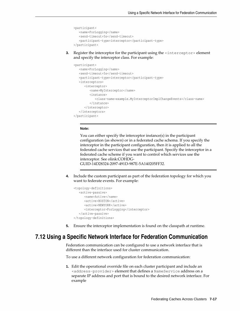
<participant> <name>ForLogging</name> <send-timeout>5s</send-timeout> <participant-type>interceptor</participant-type></participant>
3. Register the interceptor for the participant using the <interceptor> elementand specify the interceptor class. For example:
<participant> <name>ForLogging</name> <send-timeout>5s</send-timeout> <participant-type>interceptor</participant-type> <interceptors> <interceptor> <name>MyInterceptor</name> <instance> <class-name>example.MyInterceptorImplChangeEvents</class-name> </instance> </interceptor> </interceptors></participant>
Note:
You can either specify the interceptor instance(s) in the participantconfiguration (as shown) or in a federated cache schema. If you specify theinterceptor in the participant configuration, then it is applied to all thefederated cache services that use the participant. Specify the interceptor in afederated cache scheme if you want to control which services use theinterceptor. See olink:COHDG-GUID-14D28324-2097-491D-987E-5A140205FF32.
4. Include the custom participant as part of the federation topology for which youwant to federate events. For example:
<topology-definitions> <active-passive> <name>Active</name> <active>BOSTON</active> <active>NEWYORK</active> <interceptor>ForLogging</interceptor> </active-passive></topology-definitions>
5. Ensure the interceptor implementation is found on the classpath at runtime.
7.12 Using a Specific Network Interface for Federation CommunicationFederation communication can be configured to use a network interface that isdifferent than the interface used for cluster communication.
To use a different network configuration for federation communication:
1. Edit the operational override file on each cluster participant and include an<address-provider> element that defines a NameService address on aseparate IP address and port that is bound to the desired network interface. Forexample
Using a Specific Network Interface for Federation Communication
Federating Caches Across Clusters 7-17
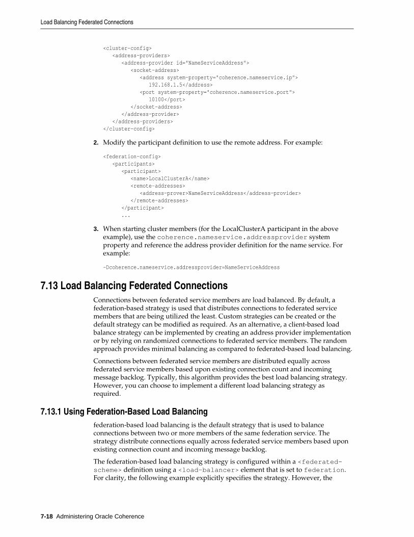
<cluster-config> <address-providers> <address-provider id="NameServiceAddress"> <socket-address> <address system-property="coherence.nameservice.ip"> 192.168.1.5</address> <port system-property="coherence.nameservice.port"> 10100</port> </socket-address> </address-provider> </address-providers></cluster-config>
2. Modify the participant definition to use the remote address. For example:
<federation-config> <participants> <participant> <name>LocalClusterA</name> <remote-addresses> <address-prover>NameServiceAddress</address-provider> </remote-addresses> </participant> ...
3. When starting cluster members (for the LocalClusterA participant in the aboveexample), use the coherence.nameservice.addressprovider systemproperty and reference the address provider definition for the name service. Forexample:
-Dcoherence.nameservice.addressprovider=NameServiceAddress
7.13 Load Balancing Federated ConnectionsConnections between federated service members are load balanced. By default, afederation-based strategy is used that distributes connections to federated servicemembers that are being utilized the least. Custom strategies can be created or thedefault strategy can be modified as required. As an alternative, a client-based loadbalance strategy can be implemented by creating an address provider implementationor by relying on randomized connections to federated service members. The randomapproach provides minimal balancing as compared to federated-based load balancing.
Connections between federated service members are distributed equally acrossfederated service members based upon existing connection count and incomingmessage backlog. Typically, this algorithm provides the best load balancing strategy.However, you can choose to implement a different load balancing strategy asrequired.
7.13.1 Using Federation-Based Load Balancingfederation-based load balancing is the default strategy that is used to balanceconnections between two or more members of the same federation service. Thestrategy distribute connections equally across federated service members based uponexisting connection count and incoming message backlog.
The federation-based load balancing strategy is configured within a <federated-scheme> definition using a <load-balancer> element that is set to federation.For clarity, the following example explicitly specifies the strategy. However, the
Load Balancing Federated Connections
7-18 Administering Oracle Coherence
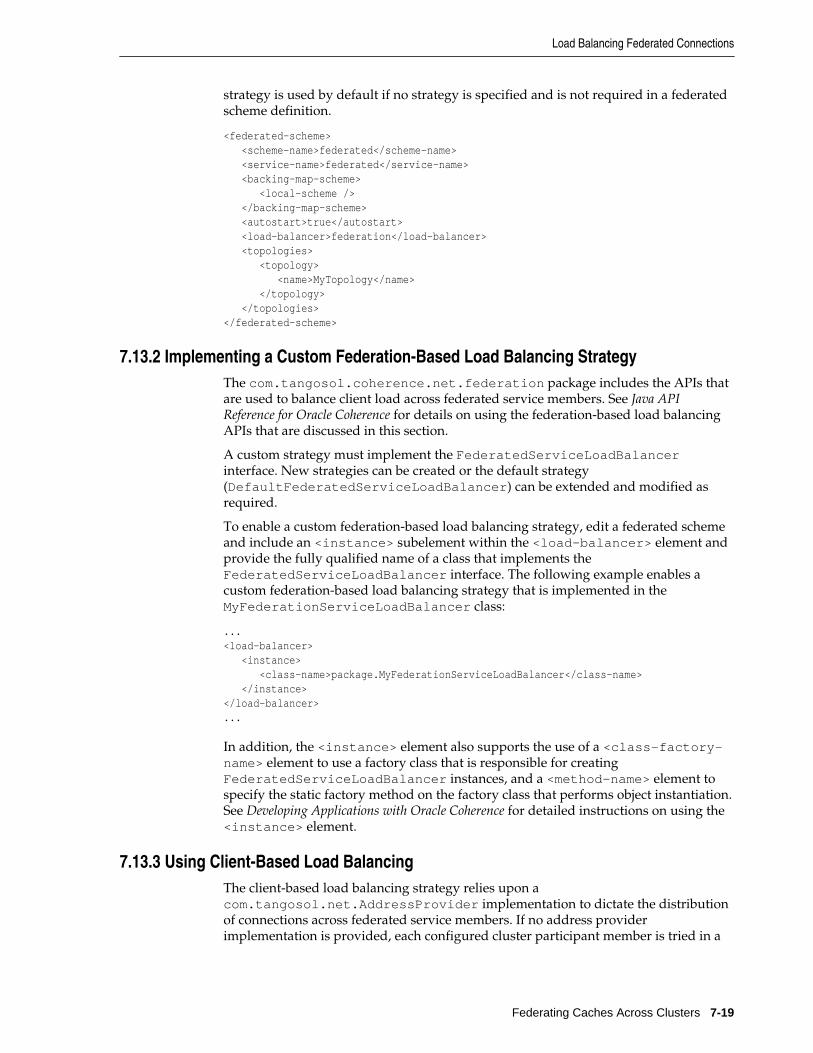
strategy is used by default if no strategy is specified and is not required in a federatedscheme definition.
<federated-scheme> <scheme-name>federated</scheme-name> <service-name>federated</service-name> <backing-map-scheme> <local-scheme /> </backing-map-scheme> <autostart>true</autostart> <load-balancer>federation</load-balancer> <topologies> <topology> <name>MyTopology</name> </topology> </topologies></federated-scheme>
7.13.2 Implementing a Custom Federation-Based Load Balancing StrategyThe com.tangosol.coherence.net.federation package includes the APIs thatare used to balance client load across federated service members. See Java APIReference for Oracle Coherence for details on using the federation-based load balancingAPIs that are discussed in this section.
A custom strategy must implement the FederatedServiceLoadBalancerinterface. New strategies can be created or the default strategy(DefaultFederatedServiceLoadBalancer) can be extended and modified asrequired.
To enable a custom federation-based load balancing strategy, edit a federated schemeand include an <instance> subelement within the <load-balancer> element andprovide the fully qualified name of a class that implements theFederatedServiceLoadBalancer interface. The following example enables acustom federation-based load balancing strategy that is implemented in theMyFederationServiceLoadBalancer class:
...<load-balancer> <instance> <class-name>package.MyFederationServiceLoadBalancer</class-name> </instance></load-balancer>...
In addition, the <instance> element also supports the use of a <class-factory-name> element to use a factory class that is responsible for creatingFederatedServiceLoadBalancer instances, and a <method-name> element tospecify the static factory method on the factory class that performs object instantiation.See Developing Applications with Oracle Coherence for detailed instructions on using the<instance> element.
7.13.3 Using Client-Based Load BalancingThe client-based load balancing strategy relies upon acom.tangosol.net.AddressProvider implementation to dictate the distributionof connections across federated service members. If no address providerimplementation is provided, each configured cluster participant member is tried in a
Load Balancing Federated Connections
Federating Caches Across Clusters 7-19
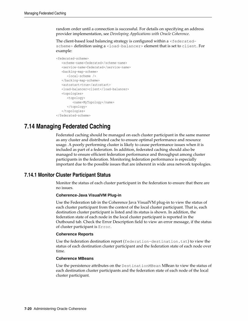
random order until a connection is successful. For details on specifying an addressprovider implementation, see Developing Applications with Oracle Coherence.
The client-based load balancing strategy is configured within a <federated-scheme> definition using a <load-balancer> element that is set to client. Forexample:
<federated-scheme> <scheme-name>federated</scheme-name> <service-name>federated</service-name> <backing-map-scheme> <local-scheme /> </backing-map-scheme> <autostart>true</autostart> <load-balancer>client</load-balancer> <topologies> <topology> <name>MyTopology</name> </topology> </topologies></federated-scheme>
7.14 Managing Federated CachingFederated caching should be managed on each cluster participant in the same manneras any cluster and distributed cache to ensure optimal performance and resourceusage. A poorly performing cluster is likely to cause performance issues when it isincluded as part of a federation. In addition, federated caching should also bemanaged to ensure efficient federation performance and throughput among clusterparticipants in the federation. Monitoring federation performance is especiallyimportant due to the possible issues that are inherent in wide area network topologies.
7.14.1 Monitor Cluster Participant StatusMonitor the status of each cluster participant in the federation to ensure that there areno issues.
Coherence-Java VisualVM Plug-in
Use the Federation tab in the Coherence Java VisualVM plug-in to view the status ofeach cluster participant from the context of the local cluster participant. That is, eachdestination cluster participant is listed and its status is shown. In addition, thefederation state of each node in the local cluster participant is reported in theOutbound tab. Check the Error Description field to view an error message, if the statusof cluster participant is Error.
Coherence Reports
Use the federation destination report (federation-destination.txt) to view thestatus of each destination cluster participant and the federation state of each node overtime.
Coherence MBeans
Use the persistence attributes on the DestinationMBean MBean to view the status ofeach destination cluster participants and the federation state of each node of the localcluster participant.
Managing Federated Caching
7-20 Administering Oracle Coherence
7.14.2 Monitor Federation Performance and ThroughputMonitor federation performance and throughput to ensure that the local clusterparticipant is federating data to each participant without any substantial delays or lostdata. Issues with performance and throughput can be a sign that there is a problemwith the network connect between cluster participants or that there is a problem onthe local cluster participant.
Coherence-Java VisualVM Plug-in
Use the Federation tab in the Coherence-Java VisualVM plug-in to view the currentfederation performance statistics and throughput from the local participant to eachdestination cluster participant. Select a destination cluster participant and view itsfederation performance statistics, then view the Current Throughput column on theOutbound tab to see the throughput to the selected participant from each node in thelocal cluster. Select an individual node in the Outbound tab to see its bandwidthutilization and federation performance in the graph tabs, respectively. Lastly, selectthe Inbound tab to view how efficiently the local cluster participant is receiving datafrom destination cluster participants.
Coherence Reports
Use the federation destination report (federation-destination.txt) and thefederation origin report (federation-origin.txt) to view federation performancestatistics. The destination report shows how efficiently each node in the local clusterparticipant is sending data to each destination cluster participant. The federationorigin reports shows how efficiently each node in the local cluster participant isreceiving data from destination cluster participants.
Coherence MBeans
Use the persistence attributes on the DestinationMBean MBean and theOriginMBean MBean to view federation performance statistics. TheDestinationMBean MBean attribute shows how efficiently each node in the localcluster participant is sending data to each destination cluster participant. TheOriginMBean MBean shows how efficiently the local cluster participant is receivingdata from destination cluster participants.
Managing Federated Caching
Federating Caches Across Clusters 7-21

Managing Federated Caching
7-22 Administering Oracle Coherence
APlatform-Specific Deployment
Considerations
This appendix identifies issues that should be considered when deploying Coherenceto various platforms and offers solutions if available.
This appendix includes the following sections:
• Deploying to Oracle HotSpot JVMs
• Deploying to IBM JVMs
• Deploying to Linux
• Deploying to Solaris
• Deploying to Windows
• Deploying to OS X
• Deploying to z/OS
• Deploying to AIX
• Deploying to Virtual Machines
• Deploying to Cisco Switches
• Deploying to Foundry Switches
• Deploying to IBM BladeCenters
A.1 Deploying to Oracle HotSpot JVMsWhen deploying Coherence on Oracle HotSpot JVMs, be aware of the following:
A.1.1 Heap SizesCoherence recommends keeping heap sizes at 1-8GB per JVM. However, larger heapsizes, up to 20GB, are suitable for some applications where the simplified managementof fewer, larger JVMs outweighs the performance benefits of many smaller JVMs.Using multiple cache servers allows a single computer to achieve higher capacities.With Oracle's JVMs, heap sizes beyond 8GB are reasonable, though GC tuning is stilladvisable to minimize long GC pauses. See Oracle's GC Tuning Guide for tuningdetails. It is also advisable to run with fixed sized heaps as this generally lowers GCtimes. See JVM Tuning for additional information.
Platform-Specific Deployment Considerations A-1
A.1.2 AtomicLongWhen available Coherence uses the highly concurrent AtomicLong class, which allowsconcurrent atomic updates to long values without requiring synchronization.
It is suggested to run in server mode to ensure that the stable and highly concurrentversion can be used. To run the JVM in server mode include the -server option on theJava command line.
A.1.3 OutOfMemoryErrorJVMs that experience an OutOfMemoryError can be left in an indeterministic statewhich can have adverse effects on a cluster. We recommend configuring JVMs to exitupon encountering an OutOfMemoryError instead of allowing the JVM to attemptrecovery. Here is the parameter to configure this setting on Sun JVMs:
UNIX:
-XX:OnOutOfMemoryError="kill -9 %p"
Windows:
-XX:OnOutOfMemoryError="taskkill /F /PID %p"
Additionally, it is recommended to configure the JVM to generate a heap dump if anOutOfMemoryError is thrown to assist the investigation into the root cause for theerror. Use the following flag to enable this feature on the Sun JVM:
-XX:+HeapDumpOnOutOfMemoryError
A.2 Deploying to IBM JVMsWhen deploying Coherence on IBM JVMs, be aware of the following:
A.2.1 OutOfMemoryErrorJVMs that experience an OutOfMemoryError can be left in an indeterministic statewhich can have adverse effects on a cluster. We recommend configuring JVMs to exitupon encountering an OutOfMemoryError instead of allowing the JVM to attemptrecovery. Here is the parameter to configure this setting on IBM JVMs:
UNIX:
-Xdump:tool:events=throw,filter=java/lang/OutOfMemoryError,exec="kill -9 %pid"
Windows:
-Xdump:tool:events=throw,filter=java/lang/OutOfMemoryError,exec="taskkill /F /PID %pid"
A.2.2 Heap SizingIBM does not recommend fixed size heaps for JVMs. In many cases, it is recommendedto use the default for -Xms (in other words, omit this setting and only set -Xmx). Seethis link for more details:
http://www.ibm.com/developerworks/java/jdk/diagnosis/
It is recommended to configure the JVM to generate a heap dump if anOutOfMemoryError is thrown to assist the investigation into the root cause for the
Deploying to IBM JVMs
A-2 Administering Oracle Coherence
error. IBM JVMs generate a heap dump on OutOfMemoryError by default; nofurther configuration is required.
A.3 Deploying to LinuxWhen deploying Coherence on Linux, be aware of the following:
A.3.1 TSC High Resolution TimesourceLinux has several high resolution timesources to choose from, the fastest TSC (TimeStamp Counter) unfortunately is not always reliable. Linux chooses TSC by default,and during startup checks for inconsistencies, if found it switches to a slower safetimesource. The slower time sources can be 10 to 30 times more expensive to querythen the TSC timesource, and may have a measurable impact on Coherenceperformance. For more details on TSC, see
https://lwn.net/Articles/209101/
Coherence and the underlying JVM are not aware of the timesource which theoperating system is using. It is suggested that you check your system logs (/var/log/dmesg) to verify that the following is not present.
kernel: Losing too many ticks!kernel: TSC cannot be used as a timesource.kernel: Possible reasons for this are:kernel: You're running with Speedstep,kernel: You don't have DMA enabled for your hard disk (see hdparm),kernel: Incorrect TSC synchronization on an SMP system (see dmesg).kernel: Falling back to a sane timesource now.
As the log messages suggest, this can be caused by a variable rate CPU (SpeedStep),having DMA disabled, or incorrect TSC synchronization on multi CPU computers. Ifpresent, it is suggested that you work with your system administrator to identify thecause and allow the TSC timesource to be used.
A.4 Deploying to SolarisWhen deploying Coherence on Solaris, be aware of the following:
A.4.1 Solaris 10 (x86 and SPARC)When running on Solaris 10, there are known issues relate to packet corruption andmulticast disconnections. These most often manifest as either EOFExceptions, "Largegap" warnings while reading packet data, or frequent packet timeouts. It is highlyrecommend that the patches for both issues below be applied when using Coherenceon Solaris 10 systems.
Possible Data Integrity Issues on Solaris 10 Systems Using the e1000g Driver for theIntel Gigabit Network Interface Card (NIC)
https://support.oracle.com/CSP/main/article?cmd=show&type=NOT&doctype=ALERT&id=1000972.1
IGMP(1) Packets do not Contain IP Router Alert Option When Sent From Solaris 10Systems With Patch 118822-21 (SPARC) or 118844-21 (x86/x64) or Later Installed
https://support.oracle.com/CSP/main/article?cmd=show&type=NOT&doctype=ALERT&id=1000940.1
Deploying to Linux
Platform-Specific Deployment Considerations A-3
A.4.2 Solaris 10 NetworkingIf running on Solaris 10, review the above Solaris 10 (x86 and SPARC) issues whichrelate to packet corruption and multicast disconnections. These most often manifest aseither EOFExceptions, "Large gap" warnings while reading packet data, or frequentpacket timeouts. It is highly recommend that the patches for both issues be appliedwhen using Coherence on Solaris 10 systems.
A.4.3 Solaris Network Interface CardsSolaris M series systems include an on-board NIC (bge) and PCI connected NIC(nxge). The on-board gigabit ethernet ports are used for low-bandwidthadministrative networking connectivity for the domain and are not intended for high-performance cluster interconnect workloads with high traffic demands. Coherencecluster members must always use the dedicated PCIe NICs for high bandwidth clusterinterconnects.
A.4.4 Solaris Link AggregationSolaris 11 supports two types of NIC link aggregation: trunk aggregation and Datalinkmultipathing (DLMP) aggregations. Trunk aggregation requires the use of a networkswitch, which must support the Link Aggregation Control Protocol (LCAP). DLMPaggregation requires the use of at least one network switch. However, when usingDLMP aggregations, make sure any switches are not configured to use trunkaggregation with LCAP. If you change from a trunk aggregation to a DLMPaggregation, you must remove the switch configuration that was previously createdfor the trunk aggregation. Failure to do so, can result in packet loss and underutilization of the network bandwidth.
A.5 Deploying to WindowsWhen deploying Coherence on Windows, be aware of the following:
A.5.1 Performance TuningThe default Windows configuration is not optimized for background processes, heavynetwork loads, and network interruptions. This may be addressed by running theoptimize.reg script included in the Coherence installation's bin directory. See“Operating System Tuning” for details on the optimizations which are performed.
A.5.2 Personal FirewallsIf running a firewall on a computer you may have difficulties in forming a clusterconsisting of multiple computers. This can be resolved by either:
• Disabling the firewall, though this is generally not recommended.
• Granting full network access to the Java executable which runs Coherence.
• Opening up individual address and ports for Coherence. For details, see DevelopingApplications with Oracle Coherence.
Deploying to Windows
A-4 Administering Oracle Coherence
A.5.3 Disconnected Network InterfaceOn Microsoft Windows, if the Network Interface Card (NIC) is unplugged from thenetwork, the operating system invalidates the associated IP address. The effect of thisis that any socket which is bound to that IP address enters an error state. This resultsin the Coherence nodes exiting the cluster and residing in an error state until the NICis reattached to the network. In cases where it is desirable to allow multiple collocatedJVMs to remain clustered during a physical outage Windows must be configured tonot invalidate the IP address.
To adjust this parameter:
1. Run Registry Editor (regedit)
2. Locate the following registry key
HKLM\System\CurrentControlSet\Services\Tcpip\Parameters
3. Add or reset the following new DWORD value
Name: DisableDHCPMediaSenseValue: 1 (boolean)
4. Reboot
While the name of the keyword includes DHCP, the setting effects both static anddynamic IP addresses. See Microsoft Windows TCP/IP Implementation Details foradditional information:
http://technet.microsoft.com/en-us/library/bb726981.aspx#EDAA
A.6 Deploying to OS XWhen deploying Coherence on OS X, be aware of the following:
A.6.1 Multicast and IPv6OS X defaults to running multicast over IPv6 rather than IPv4. If you run in a mixedIPv6/IPv4 environment, configure your JVMs to explicitly use IPv4. This can be doneby setting the java.net.preferIPv4Stack system property to true on the Javacommand line.
A.6.2 Socket Buffer SizingGenerally, Coherence prefers 2MB or higher buffers, but for OS X this may result inunexpectedly high kernel CPU time, which in turn reduces throughput. For OS X, thesuggested buffers size is 768KB, though your own tuning may find a better size. Seethe Developing Applications with Oracle Coherence for details on configuring socketbuffers.
A.7 Deploying to z/OSWhen deploying Coherence on z/OS, be aware of the following:
A.7.1 EBCDICWhen deploying Coherence into environments where the default character set isEBCDIC rather than ASCII, ensure that Coherence configuration files which are
Deploying to OS X
Platform-Specific Deployment Considerations A-5

loaded from JAR files or off of the classpath are in ASCII format. Configuration filesloaded directly from the file system should be stored in the systems native format ofEBCDIC.
A.7.2 MulticastUnder some circumstances, Coherence cluster nodes that run within the same logicalpartition (LPAR) on z/OS on IBM zSeries cannot communicate with each other. (Thisproblem does not occur on the zSeries when running on Linux.)
The root cause is that z/OS may bind the MulticastSocket that Coherence uses to anautomatically-assigned port, but Coherence requires the use of a specific port in orderfor cluster discovery to operate correctly. (Coherence does explicitly initialize thejava.net.MulitcastSocket to use the necessary port, but that informationappears to be ignored on z/OS when there is an instance of Coherence running withinthat same LPAR.)
The solution is to run only one instance of Coherence within a z/OS LPAR; if multipleinstances are required, each instance of Coherence should be run in a separate z/OSLPAR. Alternatively, well known addresses may be used. See Developing Applicationswith Oracle Coherence for details on using well known addresses.
A.8 Deploying to AIXWhen deploying Coherence on AIX, be aware of the following:
A.8.1 Multicast and IPv6AIX 5.2 and above default to running multicast over IPv6 rather than IPv4. If you runin a mixed IPv6/IPv4 environment, configure your JVMs to explicitly use IPv4. Thiscan be done by setting the java.net.preferIPv4Stack system property to trueon the Java command line. See the IBM 32-bit SDK for AIX User Guide for details.
A.9 Deploying to Virtual MachinesOracle Coherence follows the support policies of Oracle Fusion Middleware. See thefollowing link for Oracle Fusion Middleware supported virtualization andpartitioning technologies:
http://www.oracle.com/technetwork/middleware/ias/oracleas-supported-virtualization-089265.html
When deploying Coherence to virtual machines, be aware of the following:
A.9.1 Multicast ConnectivityVirtualization adds another layer to your network topology and it must be properlyconfigured to support multicast networking. See Developing Applications with OracleCoherence for detailed information on configuring multicast networking.
A.9.2 PerformanceIt is less likely that a process running in a virtualized operating system can fully usegigabit Ethernet. This is not specific to Coherence and is visible on most networkintensive virtualized applications.
Deploying to AIX
A-6 Administering Oracle Coherence
A.9.3 Fault ToleranceAdditional configuration is required to ensure that cache entry backups reside onphysically separate hardware. See Developing Applications with Oracle Coherence fordetailed information on configuring cluster member identity.
A.10 Deploying to Cisco SwitchesWhen deploying Coherence with Cisco switches, be aware of the following:
A.10.1 Buffer Space and Packet PausesSome Cisco switches may run out of buffer space and exhibit frequent multi-secondcommunication pauses under heavy packet load some. These communication pausescan be identified by a series of Coherence log messages referencing communicationdelays with multiple nodes which cannot be attributed to local or remote GCs.
Experienced a 4172 ms communication delay (probable remote GC) with Member(Id=7, Timestamp=2008-09-15 12:15:47.511, Address=xxx.xxx.x.xx:8089, MachineId=13838); 320 packets rescheduled, PauseRate=0.31, Threshold=512
The Cisco 6500 series support configuring the amount of buffer space available to eachEthernet port or ASIC. In high load applications it may be necessary to increase thedefault buffer space. This can be accomplished by executing:
fabric buffer-reserve high
See Cisco's documentation for additional details on this setting.
A.10.2 Multicast Connectivity on Large NetworksCisco's default switch configuration does not support proper routing of multicastpackets between switches due to the use of IGMP snooping. See the Cisco'sdocumentation regarding the issue and solutions.
A.10.3 Multicast OutagesSome Cisco switches have shown difficulty in maintaining multicast groupmembership resulting in existing multicast group members being silently removedfrom the multicast group. This cause a partial communication disconnect for theassociated Coherence node(s) and they are forced to leave and rejoin the cluster. Thistype of outage can most often be identified by the following Coherence log messagesindicating that a partial communication problem has been detected.
A potential network configuration problem has been detected. A packet has failed to be delivered (or acknowledged) after 60 seconds, although other packets were acknowledged by the same cluster member (Member(Id=3, Timestamp=Sat Sept 13 12:02:54 EST 2008, Address=192.168.1.101, Port=8088, MachineId=48991)) to this member (Member(Id=1, Timestamp=Sat Sept 13 11:51:11 EST 2008, Address=192.168.1.101, Port=8088, MachineId=49002)) as recently as 5 seconds ago.
To confirm the issue, use the same multicast address and port as the running cluster. Ifthe issue affects a multicast test node, its logs show that it suddenly stopped receivingmulticast test messages. See Performing a Multicast Connectivity Test.
The following test logs show the issue:
Deploying to Cisco Switches
Platform-Specific Deployment Considerations A-7
Example A-1 Log for a Multicast Outage
Test Node 192.168.1.100:
Sun Sept 14 16:44:22 GMT 2008: Received 83 bytes from a Coherence cluster node at 182.168.1.100: ??? Sun Sept 14 16:44:23 GMT 2008: Received test packet 76 from ip=/192.168.1.101, group=/224.3.2.0:32367, ttl=4. Sun Sept 14 16:44:23 GMT 2008: Received 83 bytes from a Coherence cluster node at 182.168.1.100: ??? Sun Sept 14 16:44:23 GMT 2008: Sent packet 85. Sun Sept 14 16:44:23 GMT 2008: Received test packet 85 from self. Sun Sept 14 16:44:24 GMT 2008: Received 83 bytes from a Coherence cluster node at 182.168.1.100: ??? Sun Sept 14 16:44:25 GMT 2008: Received test packet 77 from ip=/192.168.1.101, group=/224.3.2.0:32367, ttl=4. Sun Sept 14 16:44:25 GMT 2008: Received 83 bytes from a Coherence cluster node at 182.168.1.100: ??? Sun Sept 14 16:44:25 GMT 2008: Sent packet 86. Sun Sept 14 16:44:25 GMT 2008: Received test packet 86 from self. Sun Sept 14 16:44:26 GMT 2008: Received 83 bytes from a Coherence cluster node at 182.168.1.100: ??? Sun Sept 14 16:44:27 GMT 2008: Received test packet 78 from ip=/192.168.1.101, group=/224.3.2.0:32367, ttl=4. Sun Sept 14 16:44:27 GMT 2008: Received 83 bytes from a Coherence cluster node at 182.168.1.100: ??? Sun Sept 14 16:44:27 GMT 2008: Sent packet 87. Sun Sept 14 16:44:27 GMT 2008: Received test packet 87 from self. Sun Sept 14 16:44:28 GMT 2008: Received 83 bytes from a Coherence cluster node at 182.168.1.100: ??? Sun Sept 14 16:44:29 GMT 2008: Received 83 bytes from a Coherence cluster node at 182.168.1.100: ??? Sun Sept 14 16:44:29 GMT 2008: Sent packet 88. Sun Sept 14 16:44:29 GMT 2008: Received test packet 88 from self. Sun Sept 14 16:44:30 GMT 2008: Received 83 bytes from a Coherence cluster node at 182.168.1.100: ??? Sun Sept 14 16:44:31 GMT 2008: Received 83 bytes from a Coherence cluster node at 182.168.1.100: ??? Sun Sept 14 16:44:31 GMT 2008: Sent packet 89. Sun Sept 14 16:44:31 GMT 2008: Received test packet 89 from self. Sun Sept 14 16:44:32 GMT 2008: Received 83 bytes from a Coherence cluster node at 182.168.1.100: ??? Sun Sept 14 16:44:33 GMT 2008: Received 83 bytes from a Coherence cluster node at 182.168.1.100: ???
Test Node 192.168.1.101:
Sun Sept 14 16:44:22 GMT 2008: Sent packet 76.Sun Sept 14 16:44:22 GMT 2008: Received test packet 76 from self. Sun Sept 14 16:44:22 GMT 2008: Received 83 bytes from a Coherence cluster node at 192.168.1.100: ??? Sun Sept 14 16:44:22 GMT 2008: Received test packet 85 from ip=/192.168.1.100, group=/224.3.2.0:32367, ttl=4. Sun Sept 14 16:44:23 GMT 2008: Received 83 bytes from a Coherence cluster node at 192.168.1.100: ??? Sun Sept 14 16:44:24 GMT 2008: Sent packet 77.Sun Sept 14 16:44:24 GMT 2008: Received test packet 77 from self. Sun Sept 14 16:44:24 GMT 2008: Received 83 bytes from a Coherence cluster node at 192.168.1.100: ??? Sun Sept 14 16:44:24 GMT 2008: Received test packet 86 from ip=/192.168.1.100, group=/224.3.2.0:32367, ttl=4. Sun Sept 14 16:44:25 GMT 2008: Received 83 bytes from a Coherence cluster node at
Deploying to Cisco Switches
A-8 Administering Oracle Coherence

192.168.1.100: ??? Sun Sept 14 16:44:26 GMT 2008: Sent packet 78.Sun Sept 14 16:44:26 GMT 2008: Received test packet 78 from self. Sun Sept 14 16:44:26 GMT 2008: Received 83 bytes from a Coherence cluster node at 192.168.1.100: ??? Sun Sept 14 16:44:26 GMT 2008: Received test packet 87 from ip=/192.168.1.100, group=/224.3.2.0:32367, ttl=4. Sun Sept 14 16:44:27 GMT 2008: Received 83 bytes from a Coherence cluster node at 192.168.1.100: ??? Sun Sept 14 16:44:28 GMT 2008: Sent packet 79.Sun Sept 14 16:44:28 GMT 2008: Received test packet 79 from self. Sun Sept 14 16:44:28 GMT 2008: Received 83 bytes from a Coherence cluster node at 192.168.1.100: ??? Sun Sept 14 16:44:28 GMT 2008: Received test packet 88 from ip=/192.168.1.100, group=/224.3.2.0:32367, ttl=4. Sun Sept 14 16:44:29 GMT 2008: Received 83 bytes from a Coherence cluster node at 192.168.1.100: ??? Sun Sept 14 16:44:30 GMT 2008: Sent packet 80.Sun Sept 14 16:44:30 GMT 2008: Received test packet 80 from self. Sun Sept 14 16:44:30 GMT 2008: Received 83 bytes from a Coherence cluster node at 192.168.1.100: ??? Sun Sept 14 16:44:30 GMT 2008: Received test packet 89 from ip=/192.168.1.100, group=/224.3.2.0:32367, ttl=4. Sun Sept 14 16:44:31 GMT 2008: Received 83 bytes from a Coherence cluster node at 192.168.1.100: ??? Sun Sept 14 16:44:32 GMT 2008: Sent packet 81.Sun Sept 14 16:44:32 GMT 2008: Received test packet 81 from self. Sun Sept 14 16:44:32 GMT 2008: Received 83 bytes from a Coherence cluster node at 192.168.1.100: ??? Sun Sept 14 16:44:32 GMT 2008: Received test packet 90 from ip=/192.168.1.100, group=/224.3.2.0:32367, ttl=4. Sun Sept 14 16:44:33 GMT 2008: Received 83 bytes from a Coherence cluster node at 192.168.1.100: ??? Sun Sept 14 16:44:34 GMT 2008: Sent packet 82.
Note that at 16:44:27 the first test node stops receiving multicast packets from othercomputers. The operating system continues to properly forward multicast traffic fromother processes on the same computer, but the test packets (79 and higher) from thesecond test node are not received. Also note that both the test packets and the cluster'smulticast traffic generated by the first node do continue to be delivered to the secondnode. This indicates that the first node was silently removed from the multicast group.
If you encounter this multicast issue it is suggested that you contact Cisco technicalsupport, or you may consider changing your configuration to unicast-only by usingthe well known addresses. See Developing Applications with Oracle Coherence for detailson using well known addresses.
A.10.4 Multicast Time-to-LiveThe Cisco 6500 series router may become overloaded if too many packets with a time-to-live (TTL) value of 1 are received. In addition, a low TTL setting may overloadsingle group members. Set the Coherence multicast TTL setting to at least the size ofthe multicast domain (127 or 255) and make sure that clusters do not use overlappinggroups. See Developing Applications with Oracle Coherence for details on configuringmulticast TTL.
A.11 Deploying to Foundry SwitchesWhen deploying Coherence with Foundry switches, be aware of the following:
Deploying to Foundry Switches
Platform-Specific Deployment Considerations A-9
A.11.1 Multicast ConnectivityFoundry switches have shown to exhibit difficulty in handing multicast traffic. Whendeploying on with Foundry switches, ensure that all computers that are part of theCoherence cluster can communicate over multicast. See Performing a MulticastConnectivity Test.
If you encounter issues with multicast you may consider changing your configurationto unicast-only by using the well-known-addresses feature. See Developing Applicationswith Oracle Coherence for details on using well known addresses.
A.12 Deploying to IBM BladeCentersWhen deploying Coherence on IBM BladeCenters, be aware of the following:
A.12.1 MAC Address Uniformity and Load BalancingA typical deployment on a BladeCenter may include blades with two NICs where oneis used for administration purposes and the other for cluster traffic. By default, theMAC addresses assigned to the blades of a BladeCenter are uniform enough that thefirst NIC generally has an even MAC address and the second has an odd MACaddress. If the BladeCenter's uplink to a central switch also has an even number ofchannels, then layer 2 (MAC based) load balancing may prevent one set of NICs frommaking full use of the available uplink bandwidth as they are all bound to either evenor odd channels. This issue arises due to the assumption in the switch that MACaddresses are essentially random, which in BladeCenter's is untrue. Remedies to thissituation include:
• Use layer 3 (IP based) load balancing (if the IP addresses do not follow the sameeven/odd pattern).
– This setting must be applied across all switches carrying cluster traffic.
• Randomize the MAC address assignments by swapping them between the first andsecond NIC on alternating computers.
– Linux enables you to change a NIC's MAC address using the ifconfigcommand.
– For other operating systems custom tools may be available to perform the sametask.
Deploying to IBM BladeCenters
A-10 Administering Oracle Coherence

BLog Message Glossary
This appendix provides a reference to common Coherence log messages and includesthe cause of the message and possible actions to take.
The following sections are included in this appendix:
• TCMP Log Messages
• Configuration Log Messages
• Partitioned Cache Service Log Messages
B.1 TCMP Log MessagesThe following are TCMP-related log messages:
Experienced a %n1 ms communication delay (probable remote GC) with Member%s%n1 - the latency in milliseconds of the communication delay; %s - the full Memberinformation. Severity: 2-Warning or 5-Debug Level 5 or 6-Debug Level 6 dependingon the length of the delay.
Cause: This node detected a delay in receiving acknowledgment packets from thespecified node, and has determined that is it likely due to a remote GC (rather than alocal GC). This message indicates that the overdue acknowledgment has beenreceived from the specified node, and that it has likely emerged from its GC. Anyslowdown in the network or the remote server can trigger this, but the most commoncause is GC, which should be investigated first.
Action: Prolonged and frequent garbage collection can adversely affect clusterperformance and availability. If these warnings are seen frequently, review your JVMheap and GC configuration and tuning. See Performance Tuning, for more details.
Failed to satisfy the variance: allowed=%n1 actual=%n2%n1 - the maximum allowed latency in milliseconds; %n2 - the actual latency inmilliseconds. Severity: 3-Informational or 5-Debug Level 5 depending on the messagefrequency.
Cause: One of the first steps in the Coherence cluster discovery protocol is thecalculation of the clock difference between the new and the senior nodes. This stepassumes a relatively small latency for peer-to-peer round trip communicationbetween the nodes. By default, the configured maximum allowed latency (the valueof the <maximum-time-variance> configuration element) is 16 milliseconds. Seethe <incoming-message-handler> element in the Developing Applications withOracle Coherence. Failure to satisfy that latency causes this message to be logged andincreases the latency threshold, which is reflected in a follow up message.
Log Message Glossary B-1

Action: If the latency consistently stays very high (over 100 milliseconds), consultyour network administrator and see Performing a Network Performance Test.
Created a new cluster "%s1" with Member(%s2)%s1 - the cluster name; %s2 - the full Member information. Severity: 3-Informational.
Cause: This Coherence node attempted to join an existing cluster in the configuredamount of time (specified by the <join-timeout-milliseconds> element, see the <multicast-listener> element), but did not receive any responses from anyother node. As a result, it created a new cluster with the specified name (eitherconfigured by the <cluster-name> element, see <member-identity> element, orcalculated based on the multicast listener address and port, or the <well-known-addresses> list). The Member information includes the node id, creationtimestamp, unicast address and port, location, process id, role, and so on.
Action: None, if this node is expected to be the first node in the cluster. Otherwise, theoperational configuration has to be reviewed to determine the reason that this nodedoes not join the existing cluster.
This Member(%s1) joined cluster "%s2" with senior Member(%s3)%s1 - the full Member information for this node; %s2 - the cluster name; %s3 - the fullMember information for the cluster senior node. Severity: 3-Informational.
Cause: This Coherence node has joined an existing cluster.
Action: None, if this node is expected to join an existing cluster. Otherwise, identifythe running cluster and consider corrective actions.
Member(%s) joined Cluster with senior member %n%s - the full Member information for a new node that joined the cluster this nodebelongs to; %n - the node id of the cluster senior node. Severity: 5-Debug Level 5.
Cause: A new node has joined an existing Coherence cluster.
Action: None.
Member(%s) left Cluster with senior member %n%s - the full Member information for a node that left the cluster; %n - the node id ofthe cluster senior node. Severity: 5-Debug Level 5.
Cause: A node has left the cluster. This departure could be caused by theprogrammatic shutdown, process termination (normal or abnormal), or any othercommunication failure (for example, a network disconnect or a very long GC pause).This message reports the node's departure.
Action: None, if the node departure was intentional. Otherwise, the departed nodelogs should be analyzed.
MemberLeft notification for Member %n received from Member(%s)%n - the node id of the departed node; %s - the full Member information for a nodethat left the cluster. Severity: 5-Debug Level 5.
Cause: When a Coherence node terminates, this departure is detected by some nodesearlier than others. Most commonly, a node connected through the TCP ringconnection ("TCP ring buddy") would be the first to detect it. This message providesthe information about the node that detected the departure first.
Action: None, if the node departure was intentional. Otherwise, the logs for both thedeparted and the detecting nodes should be analyzed.
TCMP Log Messages
B-2 Administering Oracle Coherence
Received cluster heartbeat from the senior %n that does not contain this %s ;stopping cluster service.%n - the senior service member id; %s - a cluster service member's id. Severity: 1-Error.
Cause: A heartbeat is broadcast from the senior cluster service member that contains acluster member set. If this cluster service member is not part of the broadcast set, thenit is assumed that the senior member believes this service member to be dead and thecluster service is stopped on the member. This typically occurs if a member lostcommunication with the cluster for an extended period of time (possibly due tonetwork issues or extended garbage collection) and was ejected from the cluster.
Action: Corrective action is not necessarily required, since the rest of the clusterpresumably is continuing its operation. However, it may warrant an investigationinto root causes of the problem (especially if it is recurring with some frequency).
Service %s joined the cluster with senior service member %n%s - the service name; %n - the senior service member id. Severity: 5-Debug Level 5.
Cause: When a clustered service starts on a given node, Coherence initiates ahandshake protocol between all cluster nodes running the specified service. Thismessage serves as an indication that this protocol has been initiated. If the senior nodeis not currently known, it is shown as "n/a".
Action: None.
This node appears to have partially lost the connectivity: it receives responses fromMemberSet(%s1) which communicate with Member(%s2), but is not respondingdirectly to this member; that could mean that either requests are not coming out orresponses are not coming in; stopping cluster service.%s1 - set of members that can communicate with the member indicated in %s2; %s2 -member that can communicate with set of members indicated in %s1. Severity: 1-Error.
Cause: The communication link between this member and the member indicated by%s2 has been broken. However, the set of witnesses indicated by %s1 report nocommunication issues with %s2. It is therefore assumed that this node is in a state ofpartial failure, thus resulting in the shutdown of its cluster threads.
Action: Corrective action is not necessarily required, since the rest of the clusterpresumably is continuing its operation and this node may recover and rejoin thecluster. On the other hand, it may warrant an investigation into root causes of theproblem (especially if it is recurring with some frequency).
validatePolls: This senior encountered an overdue poll, indicating a dead member,a significant network issue or an Operating System threading library bug (e.g.Linux NPTL): PollSeverity: 2-Warning
Cause: When a node joins a cluster, it performs a handshake with each cluster node. Amissing handshake response prevents this node from joining the service. The logmessage following this one indicates the corrective action taken by this node.
Action: If this message reoccurs, further investigation into the root cause may bewarranted.
TCMP Log Messages
Log Message Glossary B-3
Received panic from junior member %s1 caused by %s2%s1 - the cluster member that sent the panic; %s2 - a member claiming to be the seniormember. Severity 2-Warning
Cause: This occurs after a cluster is split into multiple cluster islands (usually due to anetwork link failure). This message indicates that this senior member has noinformation about the other member that is claiming to be the senior member and willignore the panic from the junior member until it can communicate with the othersenior member.
Action: If this issue occurs frequently, the root cause of the cluster split should beinvestigated.
Received panic from senior Member(%s1) caused by Member(%s2)%s1 - the cluster senior member as known by this node; %s2 - a member claiming tobe the senior member. Severity: 1-Error.
Cause: This occurs after a cluster is split into multiple cluster islands (usually due to anetwork link failure). When a link is restored and the corresponding island seniorssee each other, the panic protocol is initiated to resolve the conflict.
Action: If this issue occurs frequently, the root cause of the cluster split should beinvestigated.
Member %n1 joined Service %s with senior member %n2%n1 - an id of the Coherence node that joins the service; %s - the service name; %n2 -the senior node for the service. Severity: 5-Debug Level 5.
Cause: When a clustered service starts on any cluster node, Coherence initiates ahandshake protocol between all cluster nodes running the specified service. Thismessage serves as an indication that the specified node has successfully completedthe handshake and joined the service.
Action: None.
Member %n1 left Service %s with senior member %n2%n1 - an id of the Coherence node that joins the service; %s - the service name; %n2 -the senior node for the service. Severity: 5-Debug Level 5.
Cause: When a clustered service terminates on some cluster node, all other nodes thatrun this service are notified about this event. This message serves as an indication thatthe specified clustered service at the specified node has terminated.
Action: None.
Service %s: received ServiceConfigSync containing %n entries%s - the service name; %n - the number of entries in the service configuration map.Severity: 5-Debug Level 5.
Cause: As a part of the service handshake protocol between all cluster nodes runningthe specified service, the service senior member updates every new node with the fullcontent of the service configuration map. For the partitioned cache services that mapincludes the full partition ownership catalog and internal ids for all existing caches.The message is also sent for an abnormal service termination at the senior node whena new node assumes the service seniority. This message serves as an indication thatthe specified node has received that configuration update.
Action: None.
TCMP Log Messages
B-4 Administering Oracle Coherence
TcpRing: connecting to member %n using TcpSocket{%s}%s - the full information for the TcpSocket that serves as a TcpRing connector toanother node; %n - the node id to which this node has connected. Severity: 5-DebugLevel 5.
Cause: For quick process termination detection Coherence utilizes a feature calledTcpRing, which is a sparse collection of TCP/IP-based connection between differentnodes in the cluster. Each node in the cluster is connected to at least one other node,which (if at all possible) is running on a different physical box. This connection is notused for any data transfer; only trivial "heartbeat" communications are sent once asecond per each link. This message indicates that the connection between this andspecified node is initialized.
Action: None.
Rejecting connection to member %n using TcpSocket{%s}%n - the node id that tries to connect to this node; %s - the full information for theTcpSocket that serves as a TcpRing connector to another node. Severity: 4-DebugLevel 4.
Cause: Sometimes the TCP Ring daemons running on different nodes could attemptto join each other or the same node at the same time. In this case, the receiving nodemay determine that such a connection would be redundant and reject the incomingconnection request. This message is logged by the rejecting node when this happens.
Action: None.
Timeout while delivering a packet; requesting the departure confirmation forMember(%s1) by MemberSet(%s2)%s1 - the full Member information for a node that this node failed to communicatewith; %s2 - the full information about the "witness" nodes that are asked to confirmthe suspected member departure. Severity: 2-Warning.
Cause: Coherence uses TMB for all data communications (mostly peer-to-peerunicast), which by itself does not have any delivery guarantees. Those guarantees arebuilt into the cluster management protocol used by Coherence (TCMP). The TCMPdaemons are responsible for acknowledgment (ACK or NACK) of all incomingcommunications. If one or more packets are not acknowledged within the ACKinterval ("ack-delay-milliseconds"), they are resent. This repeats until the packets arefinally acknowledged or the timeout interval elapses ("timeout-milliseconds"). At thistime, this message is logged and the "witness" protocol is engaged, asking othercluster nodes whether they experience similar communication delays with the non-responding node. The witness nodes are chosen based on their roles and location.
Action: Corrective action is not necessarily required, since the rest of the clusterpresumably is continuing its operation and this node may recover and rejoin thecluster. On the other hand, it may warrant an investigation into root causes of theproblem (especially if it is recurring with some frequency).
This node appears to have become disconnected from the rest of the clustercontaining %n nodes. All departure confirmation requests went unanswered.Stopping cluster service.%n - the number of other nodes in the cluster this node was a member of. Severity: 1-Error.
Cause: Sometime a node that lives within a valid Java process, stops communicatingto other cluster nodes. (Possible reasons include: a network failure; extremely long
TCMP Log Messages
Log Message Glossary B-5

GC pause; swapped out process.) In that case, other cluster nodes may choose torevoke the cluster membership for the paused node and completely shun any furthercommunication attempts by that node, causing this message be logged when theprocess attempts to resume cluster communications.
Action: Corrective action is not necessarily required, since the rest of the clusterpresumably is continuing its operation and this node may recover and rejoin thecluster. On the other hand, it may warrant an investigation into root causes of theproblem (especially if it is recurring with some frequency).
A potential communication problem has been detected. A packet has failed to bedelivered (or acknowledged) after %n1 seconds, although other packets wereacknowledged by the same cluster member (Member(%s1)) to this member(Member(%s2)) as recently as %n2 seconds ago. Possible causes include networkfailure, poor thread scheduling (see FAQ if running on Windows), an extremelyoverloaded server, a server that is attempting to run its processes using swap space,and unreasonably lengthy GC times.%n1 - The number of seconds a packet has failed to be delivered or acknowledged;%s1 - the recipient of the packets indicated in the message; %s2 - the sender of thepackets indicated in the message; %n2 - the number of seconds since a packet wasdelivered successfully between the two members indicated above. Severity: 2-Warning.
Cause: Possible causes are indicated in the text of the message.
Action: If this issue occurs frequently, the root cause should be investigated.
Node %s1 is not allowed to create a new cluster; WKA list: [%s2]%s1 - Address of node attempting to join cluster; %s2 - List of WKA addresses.Severity: 1-Error.
Cause: The cluster is configured to use WKA, and there are no nodes present in thecluster that are in the WKA list.
Action: Ensure that at least one node in the WKA list exists in the cluster, or add thisnode's address to the WKA list.
This member is configured with a compatible but different WKA list then thesenior Member(%s). It is strongly recommended to use the same WKA list for allcluster members.%s - the senior node of the cluster. Severity: 2-Warning.
Cause: The WKA list on this node is different than the WKA list on the senior node.Using different WKA lists can cause different cluster members to operateindependently from the rest of the cluster.
Action: Verify that the two lists are intentionally different or set them to the samevalues.
<socket implementation> failed to set receive buffer size to %n1 packets (%n2bytes); actual size is %n3 packets (%n4 bytes). Consult your OS documentationregarding increasing the maximum socket buffer size. Proceeding with the actualvalue may cause sub-optimal performance.%n1 - the number of packets that fits in the buffer that Coherence attempted toallocate; %n2 - the size of the buffer Coherence attempted to allocate; %n3 - thenumber of packets that fits in the actual allocated buffer size; %n4 - the actual size ofthe allocated buffer. Severity: 2-Warning.
TCMP Log Messages
B-6 Administering Oracle Coherence
Cause: See “Operating System Tuning”.
Action: See “Operating System Tuning”.
The timeout value configured for IpMonitor pings is shorter than the value of 5seconds. Short ping timeouts may cause an IP address to be wrongly reported asunreachable on some platforms.Severity: 2-Warning
Cause: The ping timeout value is less than 5 seconds.
Action: Ensure that the ping timeout that is configured within the <tcp-ring-listener> element is greater than 5 seconds.
Network failure encountered during InetAddress.isReachable(): %s%n - a stack trace. Severity: 5-Debug Level 5.
Cause: The IpMonitor component is unable to ping a member and has reached theconfigured timeout interval.
Action: Ensure that the member is operational or verify a network outage. The pingtimeout that is configured within the <tcp-ring-listener> element can beincreased to allow for a longer timeout as required by the network.
TcpRing has been explicitly disabled, this is not a recommended practice and willresult in a minimum death detection time of %n seconds for failed processes.%n - the number of seconds that is specified by the packet publisher's resend timeoutwhich is 5 minutes by default. Severity: 2-Warning.
Cause: The TcpRing Listener component has been disabled.
Action: Enable the TcpRing listener within the <tcp-ring-listener> element.
IpMonitor has been explicitly disabled, this is not a recommended practice andwill result in a minimum death detection time of %n seconds for failed machinesor networks.%n - the number of seconds that is specified by the packet publisher's resend timeoutwhich is 5 minutes by default. Severity: 2-Warning.
Cause: The IpMonitor component has been disabled.
Action: The IpMonitor component is enabled when the TcpRing listener is enabledwithin the <tcp-ring-listener> element.
TcpRing connecting to %s%s - the cluster member to which this member has joined to form a TCP-Ring.Severity: 6-Debug Level 6.
Cause: This message indicates that the connection between this and the specifiedmember is initialized. The TCP-Ring is used for quick process termination detectionand is a sparse collection of TCP/IP-based connection between different nodes in thecluster.
Action: none.
TcpRing disconnected from %s to maintain ring%s - the cluster member from which this member has disconnected. Severity: 6-DebugLevel 6.
TCMP Log Messages
Log Message Glossary B-7
Cause: This message indicates that this member has disconnected from the specifiedmember and that the specified member is no longer a member of the TCP-Ring. TheTCP-Ring is used for quick process termination detection and is a sparse collection ofTCP/IP-based connection between different nodes in the cluster.
Action: If the member was intentionally stopped, no further action is required.Otherwise, the member may have been released from the cluster due to a failure ornetwork outage. Restart the member.
TcpRing disconnected from %s due to a peer departure; removing the member.%s - the cluster member from which this member has disconnected. Severity: 5-DebugLevel 5.
Cause: This message indicates that this member has disconnected from the specifiedmember and that the specified member is no longer a member of the TCP-Ring. TheTCP-Ring is used for quick process termination detection and is a sparse collection ofTCP/IP-based connection between different nodes in the cluster.
Action: If the member was intentionally stopped, no further action is required.Otherwise, the member may have been released from the cluster due to a failure ornetwork outage. Restart the member.
TcpRing connection to "%s" refused ("%s1"); removing the member.%s - the cluster member to which this member was refused a connection; %s1- therefusal message. Severity: 5-Debug Level 5.
Cause: The specified member has refused a TCP connection from this member andhas subsequently been removed from the TCP-Ring.
Action: If the member was intentionally stopped, no further action is required.Otherwise, the member may have been released from the cluster due to a failure ornetwork outage. Restart the member.
B.2 Configuration Log MessagesThe following are configuration-related log messages:
java.io.IOException: Configuration file is missing: "tangosol-coherence.xml"Severity: 1-Error.
Cause: The operational configuration descriptor cannot be loaded.
Action: Make sure that the tangosol-coherence.xml resource can be loaded fromthe class path specified in the Java command line.
Loaded operational configuration from resource "%s"%s - the full resource path (URI) of the operational configuration descriptor. Severity:3-Informational.
Cause: The operational configuration descriptor is loaded by Coherence from thespecified location.
Action: If the location of the operational configuration descriptor was explicitlyspecified using system properties or programmatically, verify that the reported URImatches the expected location.
Configuration Log Messages
B-8 Administering Oracle Coherence
Loaded operational overrides from "%s"%s - the URI (file or resource) of the operational configuration descriptor override.Severity: 3-Informational.
Cause: The operational configuration descriptor points to an override location, fromwhich the descriptor override has been loaded.
Action: If the location of the operational configuration descriptor was explicitlyspecified using system properties, descriptor override or programmatically, verifythat the reported URI matches the expected location.
Optional configuration override "%s" is not specified%s - the URI of the operational configuration descriptor override. Severity: 3-Informational.
Cause: The operational configuration descriptor points to an override location whichdoes not contain any resource.
Action: Verify that the operational configuration descriptor override is not supposedto exist.
java.io.IOException: Document "%s1" is cyclically referenced by the 'xml-override'attribute of element %s2%s1 - the URI of the operational configuration descriptor or override; %s2 - the nameof the XML element that contains an incorrect reference URI. Severity: 1-Error.
Cause: The operational configuration override points to itself or another override thatpoint to it, creating an infinite recursion.
Action: Correct the invalid xml-override attribute's value.
java.io.IOException: Exception occurred during parsing: %s%s - the XML parser error. Severity: 1-Error.
Cause: The specified XML is invalid and cannot be parsed.
Action: Correct the XML document.
Loaded cache configuration from "%s"%s - the URI (file or resource) of the cache configuration descriptor. Severity: 3-Informational.
Cause: The operational configuration descriptor or a programmatically createdConfigurableCacheFactory instance points to a cache configuration descriptorthat has been loaded.
Action: Verify that the reported URI matches the expected cache configurationdescriptor location.
B.3 Partitioned Cache Service Log MessagesThe following are partitioned cache-related log messages:
Asking member %n1 for %n2 primary partitions%n1 - the node id this node asks to transfer partitions from; %n2 - the number ofpartitions this node is willing to take. Severity: 4-Debug Level 4.
Cause: When a storage-enabled partitioned service starts on a Coherence node, it firstreceives the configuration update that informs it about other storage-enabled service
Partitioned Cache Service Log Messages
Log Message Glossary B-9
nodes and the current partition ownership information. That information allows it tocalculate the "fair share" of partitions that each node is supposed to own after the re-distribution process. This message demarcates the beginning of the transfer request toa specified node for its "fair" ownership distribution.
Action: None.
Transferring %n1 out of %n2 primary partitions to member %n3 requesting %n4%n1 - the number of primary partitions this node transferring to a requesting node;%n2 - the total number of primary partitions this node currently owns; %n3 - the nodeid that this transfer is for; %n4 - the number of partitions that the requesting nodeasked for. Severity: 4-Debug Level 4.
Cause: During the partition distribution protocol, a node that owns less than a "fairshare" of primary partitions requests any of the nodes that own more than the fairshare to transfer a portion of owned partitions. The owner may choose to send anynumber of partitions less or equal to the requested amount. This message demarcatesthe beginning of the corresponding primary data transfer.
Action: None.
Transferring %n1 out of %n2 partitions to a machine-safe backup 1 at member %n3(under %n4)%n1 - the number of backup partitions this node transferring to a different node; %n2- the total number of partitions this node currently owns that are "endangered" (donot have a backup); %n3 - the node id that this transfer is for; %n4 - the number ofpartitions that the transferee can take before reaching the "fair share" amount.Severity: 4-Debug Level 4.
Cause: After the primary partition ownership is completed, nodes start distributingthe backups, ensuring the "strong backup" policy, that places backup ownership tonodes running on computers that are different from the primary owners' computers.This message demarcates the beginning of the corresponding backup data transfer.
Action: None.
Transferring backup%n1 for partition %n2 from member %n3 to member %n4%n1 - the index of the backup partition that this node transferring to a different node;%n2 - the partition number that is being transferred; %n3 the node id of the previousowner of this backup partition; %n4 the node id that the backup partition is beingtransferred to. Severity: 5-Debug Level 5.
Cause: During the partition distribution protocol, a node that determines that abackup owner for one of its primary partitions is overloaded may choose to transferthe backup ownership to another, underloaded node. This message demarcates thebeginning of the corresponding backup data transfer.
Action: None.
Failed backup transfer for partition %n1 to member %n2; restoring owner from:%n2 to: %n3%n1 the partition number for which a backup transfer was in-progress; %n2 the nodeid that the backup partition was being transferred to; %n3 the node id of the previousbackup owner of the partition. Severity: 4-Debug Level 4.
Cause: This node was in the process of transferring a backup partition to a newbackup owner when that node left the service. This node is restoring the backupownership to the previous backup owner.
Partitioned Cache Service Log Messages
B-10 Administering Oracle Coherence
Action: None.
Deferring the distribution due to %n1 pending configuration updates%n1- the number of configuration updates. Severity: 5-Debug Level 5.
Cause: This node is in the process of updating the global ownership map (notifyingother nodes about ownership changes) when the periodic scheduled distributioncheck takes place. Before the previous ownership changes (most likely due to apreviously completed transfer) are finalized and acknowledged by the other servicemembers, this node postpones subsequent scheduled distribution checks.
Action: None.
Limiting primary transfer to %n1 KB (%n2 partitions)%n1 - the size in KB of the transfer that was limited; %n2 the number of partitionsthat were transferred. Severity: 4-Debug Level 4.
Cause: When a node receives a request for some number of primary partitions froman underloaded node, it may transfer any number of partitions (up to the requestedamount) to the requester. The size of the transfer is limited by the <transfer-threshold> element located within a <distributed-scheme> element. Thismessage indicates that the distribution algorithm limited the transfer to the specifiednumber of partitions due to the transfer-threshold.
Action: None.
DistributionRequest was rejected because the receiver was busy. Next retry in %n1ms%n1 - the time in milliseconds before the next distribution check is scheduled.Severity: 6-Debug Level 6.
Cause: This (underloaded) node issued a distribution request to another node askingfor one or more partitions to be transferred. However, the other node declined toinitiate the transfer as it was in the process of completing a previous transfer with adifferent node. This node waits at least the specified amount of time (to allow time forthe previous transfer to complete) before the next distribution check.
Action: None.
Restored from backup %n1 partitions%n1 - the number of partitions being restored. Severity: 3-Informational.
Cause: The primary owner for some backup partitions owned by this node has left theservice. This node is restoring those partitions from backup storage (assumingprimary ownership). This message is followed by a list of the partitions that are beingrestored.
Action: None.
Re-publishing the ownership for partition %n1 (%n2)%n1 the partition number whose ownership is being re-published; %n2 the node id ofthe primary partition owner, or 0 if the partition is orphaned. Severity: 4-Debug Level4.
Cause: This node is in the process of transferring a partition to another node when aservice membership change occurred, necessitating redistribution. This messageindicates this node re-publishing the ownership information for the partition whosetransfer is in-progress.
Partitioned Cache Service Log Messages
Log Message Glossary B-11
Action: None.
%n1> Ownership conflict for partition %n2 with member %n3 (%n4!=%n5)%n1 - the number of attempts made to resolve the ownership conflict; %n2 - thepartition whose ownership is in dispute; %n3 - the node id of the service member indisagreement about the partition ownership; %n4 - the node id of the partition'sprimary owner in this node's ownership map; %n5 - the node id of the partition'sprimary owner in the other node's ownership map. Severity: 4-Debug Level 4.
Cause: If a service membership change occurs while the partition ownership is in-flux, it is possible for the ownership to become transiently out-of-sync and requirereconciliation. This message indicates that such a conflict was detected, and denotesthe attempts to resolve it.
Action: None.
Unreconcilable ownership conflict; conceding the ownershipSeverity: 1-Error
Cause: If a service membership change occurs while the partition ownership is in-flux, it is possible for the ownership to become transiently out-of-sync and requirereconciliation. This message indicates that an ownership conflict for a partition couldnot be resolved between two service members. To resolve the conflict, one member isforced to release its ownership of the partition and the other member republishesownership of the partition to the senior member.
Action: None
Multi-way ownership conflict; requesting a republish of the ownershipSeverity: 1-Error
Cause: If a service membership change occurs while the partition ownership is in-flux, it is possible for the ownership to become transiently out-of-sync and requirereconciliation. This message indicates that a service member and the most seniorstorage-enabled member have conflicting views about the owner of a partition. Toresolve the conflict, the partitioned is declared an orphan until the owner of thepartition republishes its ownership of the partition.
Action: None
Assigned %n1 orphaned primary partitions%n1 - the number of orphaned primary partitions that were re-assigned. Severity: 2-Warning.
Cause: This service member (the most senior storage-enabled) has detected that oneor more partitions have no primary owner (orphaned), most likely due to severalnodes leaving the service simultaneously. The remaining service members agree onthe partition ownership, after which the storage-senior assigns the orphanedpartitions to itself. This message is followed by a list of the assigned orphanpartitions. This message indicates that data in the corresponding partitions may havebeen lost.
Action: None.
validatePolls: This service timed-out due to unanswered handshake request.Manual intervention is required to stop the members that have not responded tothis PollSeverity: 1-Error.
Partitioned Cache Service Log Messages
B-12 Administering Oracle Coherence
Cause: When a node joins a clustered service, it performs a handshake with eachclustered node running the service. A missing handshake response prevents this nodefrom joining the service. Most commonly, it is caused by an unresponsive (forexample, deadlocked) service thread.
Action: Corrective action may require locating and shutting down the JVM runningthe unresponsive service. See My Oracle Support Note 845363.1 for more details.
https://support.oracle.com/epmos/faces/DocumentDisplay?_afrLoop=231462233678969&id=845363.1&_afrWindowMode=0&_adf.ctrl-state=lp6w36vgb_4
com.tangosol.net.RequestPolicyException: No storage-enabled nodes exist forservice service_nameSeverity: 1-Error.
Cause: A cache request was made on a service that has no storage-enabled servicemembers. Only storage-enabled service members may process cache requests, sothere must be at least one storage-enabled member.
Action: Check the configuration/deployment to ensure that members that areintended to store cache data are configured to be storage-enabled. Storage is enabledon a member using the <local-storage> element located within a <distributed-scheme> element, or by using the -Dcoherence.distributed.localstorage command-line override.
An entry was inserted into the backing map for the partitioned cache "%s" that isnot owned by this member; the entry will be removed."%s - the name of the cache into which insert was attempted. Severity: 1-Error.
Cause: The backing map for a partitioned cache may only contain keys that areowned by that member. Cache requests are routed to the service member owning therequested keys, ensuring that service members only process requests for keys whichthey own. This message indicates that the backing map for a cache detected aninsertion for a key which is not owned by the member. This is most likely caused by adirect use of the backing-map as opposed to the exposed cache APIs (for example, NamedCache) in user code running on the cache server. This message is followed bya Java exception stack trace showing where the insertion was made.
Action: Examine the user-code implicated by the stack-trace to ensure that anybacking-map operations are safe. This error can be indicative of an incorrectimplementation of KeyAssociation
Exception occurred during filter evaluation: %s; removing the filter...%s - the description of the filter that failed during evaluation. Severity: 1-Error.
Cause: An exception was thrown while evaluating a filter for a MapListenerregistered on this cache. As a result, some map events may not have been issued.Additionally, to prevent further failures, the filter (and associated MapListener) areremoved. This message is followed by a Java exception stack trace showing where thefailure occurred.
Action: Review filter implementation and the associated stack trace for errors.
Exception occurred during event transformation: %s; removing the filter...%s - the description of the filter that failed during event transformation. Severity: 1-Error.
Partitioned Cache Service Log Messages
Log Message Glossary B-13

Cause: An Exception was thrown while the specified filter was transforming a MapEvent for a MapListener registered on this cache. As a result, some map eventsmay not have been issued. Additionally, to prevent further failures, the Filterimplementation (and associated MapListener) are removed. This message isfollowed by a Java exception stack trace showing where the failure occurred.
Action: Review the filter implementation and the associated stack trace for errors.
Exception occurred during index rebuild: %s%s - the stack trace for the exception that occurred during index rebuild. Severity: 1-Error.
Cause: An Exception was thrown while adding or rebuilding an index. A likely causeof this is a faulty ValueExtractor implementation. As a result of the failure, theassociated index is removed. This message is followed by a Java exception stack traceshowing where the failure occurred.
Action: Review the ValueExtractor implementation and associated stack trace forerrors.
Exception occurred during index update: %s%s - the stack trace for the exception that occurred during index update. Severity: 1-Error.
Cause: An Exception was thrown while updating an index. A likely cause of this is afaulty ValueExtractor implementation. As a result of the failure, the associatedindex is removed. This message is followed by a Java exception stack trace showingwhere the failure occurred.
Action: Review the ValueExtractor implementation and associated stack trace forerrors.
Exception occurred during query processing: %s%s - the stack trace for the exception that occurred while processing a query. Severity:1-Error.
Cause: An Exception was thrown while processing a query. A likely cause of this is anerror in the filter implementation used by the query. This message is followed by aJava exception stack trace showing where the failure occurred.
Action: Review the filter implementation and associated stack trace for errors.
BackingMapManager %s1: returned "null" for a cache: %s2%s1 - the classname of the BackingMapManager implementation that returned a nullbacking-map; %s2 - the name of the cache for which the BackingMapManagerreturned null. Severity: 1-Error.
Cause: A BackingMapManager returned null for a backing-map for the specifiedcache.
Action: Review the specified BackingMapManager implementation for errors and toensure that it properly instantiates a backing map for the specified cache.
BackingMapManager %s1: failed to instantiate a cache: %s2%s1 - the classname of the BackingMapManager implementation that failed to createa backing-map; %s2 - the name of the cache for which the BackingMapManagerfailed. Severity: 1-Error.
Partitioned Cache Service Log Messages
B-14 Administering Oracle Coherence

Cause: A BackingMapManager unexpectedly threw an Exception while attemptingto instantiate a backing-map for the specified cache.
Action: Review the specified BackingMapManager implementation for errors and toensure that it properly instantiates a backing map for the specified cache.
BackingMapManager %s1: failed to release a cache: %s2%s1 - the classname of the BackingMapManager implementation that failed to releasea backing-map; %s2 - the name of the cache for which the BackingMapManagerfailed. Severity: 1-Error.
Cause: A BackingMapManager unexpectedly threw an Exception while attemptingto release a backing-map for the specified cache.
Action: Review the specified BackingMapManager implementation for errors and toensure that it properly releases a backing map for the specified cache.
Unexpected event during backing map operation: key=%s1; expected=%s2; actual=%s3%s1 - the key being modified by the cache; %s2 - the expected backing-map eventfrom the cache operation in progress; %s3 - the actual MapEvent received. Severity: 6-Debug Level 6.
Cause: While performing a cache operation, an unexpected MapEvent was receivedon the backing-map. This indicates that a concurrent operation was performeddirectly on the backing-map and is most likely caused by direct manipulation of thebacking-map as opposed to the exposed cache APIs (for example, NamedCache) inuser code running on the cache server.
Action: Examine any user-code that may directly modify the backing map to ensurethat any backing-map operations are safe.
Application code running on "%s1" service thread(s) should not call %s2 as thismay result in deadlock. The most common case is a CacheFactory call from acustom CacheStore implementation.%s1 - the name of the service which has made a re-entrant call; %s2 - the name of themethod on which a re-entrant call was made. Severity: 2-Warning.
Cause: While executing application code on the specified service, a re-entrant call (arequest to the same service) was made. Coherence does not support re-entrant servicecalls, so any application code (CacheStore, EntryProcessor, and so on...) running onthe service thread(s) should avoid making cache requests.
Action: Remove re-entrant calls from application code running on the servicethread(s) and consider using alternative design strategies as outlined in the DevelopingApplications with Oracle Coherence.
Repeating %s1 for %n1 out of %n2 items due to re-distribution of %s2%s1 - the description of the request that must be repeated; %n1 - the number of itemsthat are outstanding due to re-distribution; %n2 - the total number of items requested;%s2 - the list of partitions that are in the process of re-distribution and for which therequest must be repeated. Severity: 5-Debug Level 5.
Cause: When a cache request is made, the request is sent to the service membersowning the partitions to which the request refers. If one or more of the partitions thata request refers to is in the process of being transferred (for example, due to re-distribution), the request is rejected by the (former) partition owner and isautomatically resent to the new partition owner.
Partitioned Cache Service Log Messages
Log Message Glossary B-15
Action: None.
Error while starting cluster: com.tangosol.net.RequestTimeoutException: Timeoutduring service start: ServiceInfo(%s)%s - information on the service that could not be started. Severity: 1-Error.
Cause: When joining a service, every service in the cluster must respond to the joinrequest. If one or more nodes have a service that does not respond within the timeoutperiod, the join times out.
Action: See My Oracle Support Note 845363.1
https://support.oracle.com/epmos/faces/DocumentDisplay?_afrLoop=231462233678969&id=845363.1&_afrWindowMode=0&_adf.ctrl-state=lp6w36vgb_4
Failed to restart services: com.tangosol.net.RequestTimeoutException: Timeoutduring service start: ServiceInfo(%s)%s - information on the service that could not be started. Severity: 1-Error.
Cause: When joining a service, every service in the cluster must respond to the joinrequest. If one or more nodes have a service that does not respond within the timeoutperiod, the join times out.
Action: See My Oracle Support Note 845363.1
https://support.oracle.com/epmos/faces/DocumentDisplay?_afrLoop=231462233678969&id=845363.1&_afrWindowMode=0&_adf.ctrl-state=lp6w36vgb_4
Failed to recover partition 0 from SafeBerkeleyDBStore(...); partition-countmismatch 501(persisted) != 277(service); reinstate persistent store fromtrashonce validation errors have been resolvedCause: The partition-count is changed while active persistence is enabled. The currentactive data is copied to the trash directory.
Action: Complete the following steps to recover the data:
1. Shutdown the entire cluster.
2. Remove the current active directory contents for the cluster and service affectedon each cluster member.
3. Copy (recursively) the contents of the trash directory for each service to the activedirectory.
4. Restore the partition count to the original value.
5. Restart the cluster.
Partitioned Cache Service Log Messages
B-16 Administering Oracle Coherence
Related Documents


![[1]Oracle® Fusion Middleware Administering HTTP Session ...Administering HTTP Session Management with Oracle Coherence*Web 12c (12.1.3) E47888-02 May 2015 Documentation for developers](https://static.cupdf.com/doc/110x72/60bebbf924ff6572207c343f/1oracle-fusion-middleware-administering-http-session-administering-http.jpg)
![Administering Clusters for Oracle WebLogic Server[1]Oracle® Fusion Middleware Administering Clusters for Oracle WebLogic Server 12c (12.1.2) E28074-07 February 2015 This document](https://static.cupdf.com/doc/110x72/5fce323f688ff0318359da61/administering-clusters-for-oracle-weblogic-server-1oracle-fusion-middleware.jpg)
![[1]Oracle® Fusion Middleware Oracle Data Integrator Tools ... · Oracle Data Integrator Tools Reference 12c (12.2.1) E57357-01 ... Oracle Data Integrator 12c Online Help, which is](https://static.cupdf.com/doc/110x72/5c449ef793f3c34c46577b8d/1oracle-fusion-middleware-oracle-data-integrator-tools-oracle-data-integrator.jpg)
![Oracle Fusion Middleware Administering Oracle Data Integrator · [1]Oracle® Fusion Middleware Administering Oracle Data Integrator 12c (12.1.3.0.1) E51086-02 March 2015 This guide](https://static.cupdf.com/doc/110x72/5eccb9c2a0af283cb576ffbb/oracle-fusion-middleware-administering-oracle-data-integrator-1oracle-fusion.jpg)
![Oracle Fusion Middleware Integrator’s Guide for …...[1]Oracle® Fusion Middleware Integrator's Guide for Oracle Business Intelligence Enterprise Edition 12c (12.2.1) E57384-02](https://static.cupdf.com/doc/110x72/5ea80985def444659335030b/oracle-fusion-middleware-integratoras-guide-for-1oracle-fusion-middleware.jpg)
![Oracle® Forms und Reports · Oracle FMW 12c (12.2.1) Version: 1.7 Seite 4 von 73 Installation [5] Oracle® WebLogic Server (WLS) 12cR2 (12.2.1) Installation on Oracle® Linux 6 and](https://static.cupdf.com/doc/110x72/5dd12786d6be591ccb647b57/oracle-forms-und-reports-oracle-fmw-12c-1221-version-17-seite-4-von-73-installation.jpg)

![Oracle Fusion Middleware Administering JDBC Data Sources for … · 2015-12-17 · [1]Oracle® Fusion Middleware Administering JDBC Data Sources for Oracle WebLogic Server 12c (12.2.1)](https://static.cupdf.com/doc/110x72/5fb77a5deae01f334d1febcd/oracle-fusion-middleware-administering-jdbc-data-sources-for-2015-12-17-1oracle.jpg)
