DELHI METRO RAIL CORPORATION LIMITED Contract: OEW-809: Supply, Installation, Testing and Commissioning of 3x100TR Screw Chillers with VFD energy efficient in place of old age 3x80TR reciprocating chillers including associated accessories installed at Shastri Park Metro station over Line-1 and CAMC contract for 15 years after 02 year DLP. Addendum No.1 Summary Sheet S. No Tender Document Page No. Clause No. / Item No. Addendum / Corrigendum Remarks 1 Notice Inviting Tender 2 of 12 1.1.2 (e) date is modified Replace Page 2 of 12 with revised NIT 2 Notice Inviting Tender 3 of 12 1.1.2 (h) date is modified Replace Page 3 of 12 with revised NIT 3 Notice Inviting Tender 3 of 12 1.1.2 (i) (ii) date is modified Replace Page 3 of 12 with revised NIT 4 Notice Inviting Tender 3 of 12 1.1.2 (j) date is modified Replace Page 3 of 12 with revised NIT 5 Notice Inviting Tender 3 of 12 1.1.2 (n) clause is modified Replace Page 3 of 12 with revised NIT 6 Notice Inviting Tender 3 of 12 1.2.1 (ii) clause is added Replace Page 3 of 12 with revised NIT 7 Notice Inviting Tender 7 of 12 1.2.1 (x) clause is added Replace Page 7 of 12 with revised NIT 8 Notice Inviting Tender 8 of 12 1.2.3 clause is added Replace Page 8 of 12 with revised NIT 9 Notice Inviting Tender 8 of 12 1.2.3 clause is added Replace Page 8 of 12 with revised NIT 10 Instruction to Tenderer 6 of 28 C 2.2 (z) clause is added Replace Page 6 of 28 with 6R of 28 11 Instruction to Tenderer 6 of 28 C 2.2 (z)(a) clause is modified Replace Page 6 of 28 with 6R of 28 12 Instruction to Tenderer 7 of 28 C 2.3 clause is modified Replace Page 7 of 28 with 7R of 28 13 Instruction to Tenderer 10 of 28 C 23 clause is modified Replace Page 10 of 28 with 10R of 28 14 Instruction to Tenderer 15 of 28 F 5.1 clause is added Replace Page 15 of 28 with 15R of 28 15 Instruction to Tenderer 18 of 28 Annexure-2 clause is modified Replace Page 18 of 28 with 18R of 28 16 Instruction to Tenderer 19 of 28 Annexure-3 clause is modified Replace Page 19 of 28 with 19R of 28 17 Form of Tender 1 of 31 1 & 5 clause is modified Replace Page 1 of 31 with 1R of 31 18 Form of Tender 3 of 31 Appendix-1 (iii) clause is modified Replace Page 3 of 31 with 3R of 31 19 Form of Tender 22 of 31 Appendix-17 clause is modified Replace Page 22 of 31 with 22R of 31

Welcome message from author
This document is posted to help you gain knowledge. Please leave a comment to let me know what you think about it! Share it to your friends and learn new things together.
Transcript
DELHI METRO RAIL CORPORATION LIMITED
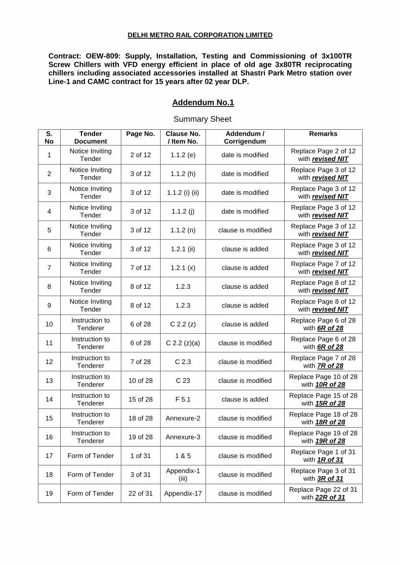
Contract: OEW-809: Supply, Installation, Testing and Commissioning of 3x100TR Screw Chillers with VFD energy efficient in place of old age 3x80TR reciprocating chillers including associated accessories installed at Shastri Park Metro station over Line-1 and CAMC contract for 15 years after 02 year DLP.
Addendum No.1
Summary Sheet
S. No
Tender Document
Page No. Clause No. / Item No.
Addendum / Corrigendum
Remarks
1 Notice Inviting
Tender 2 of 12 1.1.2 (e) date is modified
Replace Page 2 of 12 with revised NIT
2 Notice Inviting
Tender 3 of 12 1.1.2 (h) date is modified
Replace Page 3 of 12 with revised NIT
3 Notice Inviting
Tender 3 of 12 1.1.2 (i) (ii) date is modified
Replace Page 3 of 12 with revised NIT
4 Notice Inviting
Tender 3 of 12 1.1.2 (j) date is modified
Replace Page 3 of 12 with revised NIT
5 Notice Inviting
Tender 3 of 12 1.1.2 (n) clause is modified
Replace Page 3 of 12 with revised NIT
6 Notice Inviting
Tender 3 of 12 1.2.1 (ii) clause is added
Replace Page 3 of 12 with revised NIT
7 Notice Inviting
Tender 7 of 12 1.2.1 (x) clause is added
Replace Page 7 of 12 with revised NIT
8 Notice Inviting
Tender 8 of 12 1.2.3 clause is added
Replace Page 8 of 12 with revised NIT
9 Notice Inviting
Tender 8 of 12 1.2.3 clause is added
Replace Page 8 of 12 with revised NIT
10 Instruction to
Tenderer 6 of 28 C 2.2 (z) clause is added
Replace Page 6 of 28 with 6R of 28
11 Instruction to
Tenderer 6 of 28 C 2.2 (z)(a) clause is modified
Replace Page 6 of 28 with 6R of 28
12 Instruction to
Tenderer 7 of 28 C 2.3 clause is modified
Replace Page 7 of 28 with 7R of 28
13 Instruction to
Tenderer 10 of 28 C 23 clause is modified
Replace Page 10 of 28 with 10R of 28
14 Instruction to
Tenderer 15 of 28 F 5.1 clause is added
Replace Page 15 of 28 with 15R of 28
15 Instruction to
Tenderer 18 of 28 Annexure-2 clause is modified
Replace Page 18 of 28 with 18R of 28
16 Instruction to
Tenderer 19 of 28 Annexure-3 clause is modified
Replace Page 19 of 28 with 19R of 28
17 Form of Tender 1 of 31 1 & 5 clause is modified Replace Page 1 of 31
with 1R of 31
18 Form of Tender 3 of 31 Appendix-1
(iii) clause is modified
Replace Page 3 of 31 with 3R of 31
19 Form of Tender 22 of 31 Appendix-17 clause is modified Replace Page 22 of 31
with 22R of 31
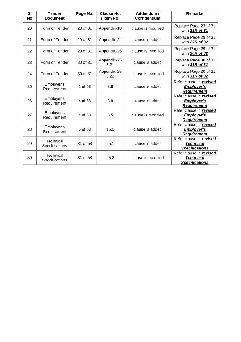
S. No
Tender Document
Page No. Clause No. / Item No.
Addendum / Corrigendum
Remarks
20 Form of Tender 23 of 31 Appendix-18 clause is modified Replace Page 23 of 31
with 23R of 31
21 Form of Tender 29 of 31 Appendix-24 clause is added Replace Page 29 of 31
with 29R of 32
22 Form of Tender 29 of 31 Appendix-25 clause is modified Replace Page 29 of 31
with 30R of 32
23 Form of Tender 30 of 31 Appendix-25
3.21 clause is added
Replace Page 30 of 31 with 31R of 32
24 Form of Tender 30 of 31 Appendix-25
3.22 clause is modified
Replace Page 30 of 31 with 31R of 32
25 Employer’s
Requirement 1 of 58 2.8 clause is added
Refer clause in revised Employer’s
Requirement
26 Employer’s
Requirement 4 of 58 3.9 clause is added
Refer clause in revised Employer’s
Requirement
27 Employer’s
Requirement 4 of 58 5.5 clause is modified
Refer clause in revised Employer’s
Requirement
28 Employer’s
Requirement 6 of 58 15.0 clause is added
Refer clause in revised Employer’s
Requirement
29 Technical
Specifications 31 of 58 25.1 clause is added
Refer clause in revised Technical
Specifications
30 Technical
Specifications 31 of 58 25.2 clause is modified
Refer clause in revised Technical
Specifications
CONTRACT NO: OEW-809
“Supply, Installation, Testing and Commissioning of 3x100TR Screw Chillers with VFD energy efficient in place of old age
3x80TR reciprocating chillers including associated accessories installed at Shastri Park Metro station over Line-1
and CAMC contract for 15 years after 02 year DLP”
Notice Inviting Tender (NIT)
Tender Documents
DELHI METRO RAIL CORPORATION LTD.
5th FLOOR, C-WING, METRO BHAWAN,
FIRE BRIGADE LANE, BARAKHAMBA ROAD,
NEW DELHI 110001
Contract: OEW-809: Supply, Installation, Testing and Commissioning of 3x100TR Screw Chillers with VFD energy efficient in place of old
age 3x80TR reciprocating chillers including associated accessories installed at Shastri Park Metro station over Line-1 and CAMC contract
for 15 years after 02 year DLP.
Notice Inviting Tender Page 1 of 13
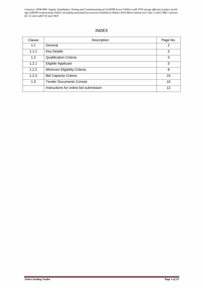
INDEX
Clause Description Page No.
1.1 General 2
1.1.1 Key Details 2
1.2 Qualification Criteria 3
1.2.1 Eligible Applicant 3
1.2.2 Minimum Eligibility Criteria 8
1.2.3 Bid Capacity Criteria 10
1.3 Tender Documents Consist 10
Instructions for online bid submission 12
Contract: OEW-809: Supply, Installation, Testing and Commissioning of 3x100TR Screw Chillers with VFD energy efficient in place of old
age 3x80TR reciprocating chillers including associated accessories installed at Shastri Park Metro station over Line-1 and CAMC contract
for 15 years after 02 year DLP.
Notice Inviting Tender Page 2 of 13
NOTICE INVITING TENDER (NIT)
1.1 GENERAL
DMRC Invites Open tender through e-tendering system (i.e. Technical and Financial bid) from eligible applicants who fulfill qualification criteria as stipulated in clause 1.2 of NIT for Supply, Installation, Testing and Commissioning of 3x100TR Screw Chillers with VFD energy efficient in place of old age 3x80TR reciprocating chillers including associated accessories installed at Shastri Park Metro station over Line-1 and CAMC contract for 15 years after 02 year DLP. The brief scope of the work and site information is provided in ITT clause A2.
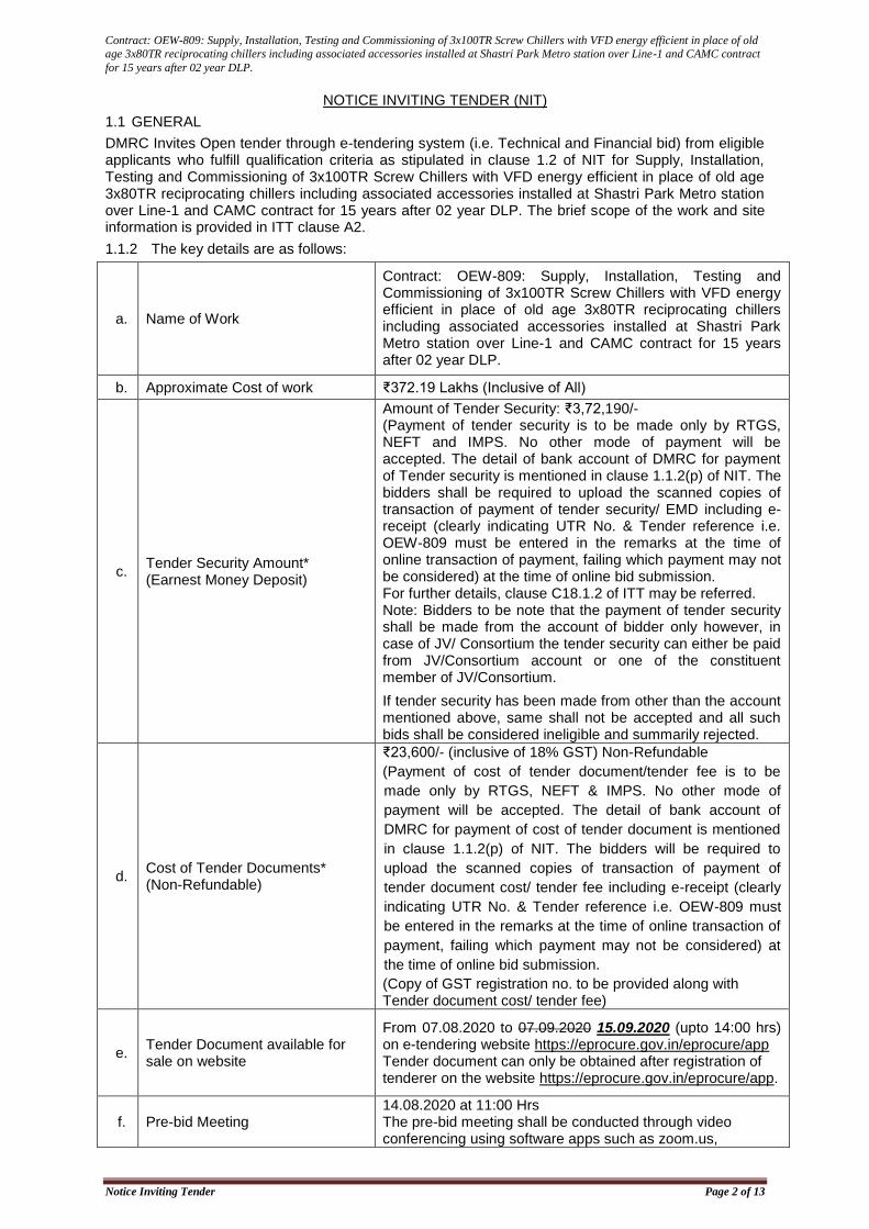
1.1.2 The key details are as follows:
a. Name of Work
Contract: OEW-809: Supply, Installation, Testing and Commissioning of 3x100TR Screw Chillers with VFD energy efficient in place of old age 3x80TR reciprocating chillers including associated accessories installed at Shastri Park Metro station over Line-1 and CAMC contract for 15 years after 02 year DLP.
b. Approximate Cost of work ₹372.19 Lakhs (Inclusive of All)
c. Tender Security Amount* (Earnest Money Deposit)
Amount of Tender Security: ₹3,72,190/- (Payment of tender security is to be made only by RTGS, NEFT and IMPS. No other mode of payment will be accepted. The detail of bank account of DMRC for payment of Tender security is mentioned in clause 1.1.2(p) of NIT. The bidders shall be required to upload the scanned copies of transaction of payment of tender security/ EMD including e-receipt (clearly indicating UTR No. & Tender reference i.e. OEW-809 must be entered in the remarks at the time of online transaction of payment, failing which payment may not be considered) at the time of online bid submission. For further details, clause C18.1.2 of ITT may be referred. Note: Bidders to be note that the payment of tender security shall be made from the account of bidder only however, in case of JV/ Consortium the tender security can either be paid from JV/Consortium account or one of the constituent member of JV/Consortium.
If tender security has been made from other than the account mentioned above, same shall not be accepted and all such bids shall be considered ineligible and summarily rejected.
d. Cost of Tender Documents* (Non-Refundable)
₹23,600/- (inclusive of 18% GST) Non-Refundable
(Payment of cost of tender document/tender fee is to be
made only by RTGS, NEFT & IMPS. No other mode of
payment will be accepted. The detail of bank account of
DMRC for payment of cost of tender document is mentioned
in clause 1.1.2(p) of NIT. The bidders will be required to
upload the scanned copies of transaction of payment of
tender document cost/ tender fee including e-receipt (clearly
indicating UTR No. & Tender reference i.e. OEW-809 must
be entered in the remarks at the time of online transaction of
payment, failing which payment may not be considered) at
the time of online bid submission.
(Copy of GST registration no. to be provided along with Tender document cost/ tender fee)
e. Tender Document available for sale on website
From 07.08.2020 to 07.09.2020 15.09.2020 (upto 14:00 hrs) on e-tendering website https://eprocure.gov.in/eprocure/app Tender document can only be obtained after registration of tenderer on the website https://eprocure.gov.in/eprocure/app.
f. Pre-bid Meeting 14.08.2020 at 11:00 Hrs The pre-bid meeting shall be conducted through video conferencing using software apps such as zoom.us,
Contract: OEW-809: Supply, Installation, Testing and Commissioning of 3x100TR Screw Chillers with VFD energy efficient in place of old
age 3x80TR reciprocating chillers including associated accessories installed at Shastri Park Metro station over Line-1 and CAMC contract
for 15 years after 02 year DLP.
Notice Inviting Tender Page 3 of 13
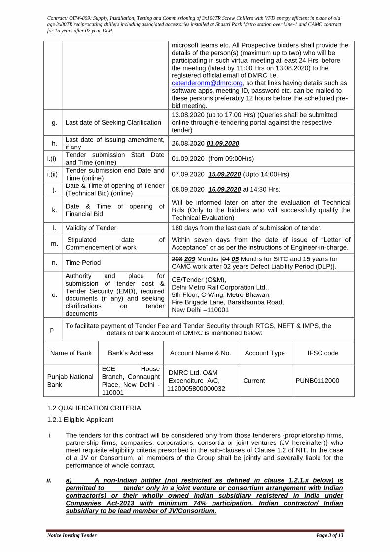
microsoft teams etc. All Prospective bidders shall provide the details of the person(s) (maximum up to two) who will be participating in such virtual meeting at least 24 Hrs. before the meeting (latest by 11:00 Hrs on 13.08.2020) to the registered official email of DMRC i.e. [email protected], so that links having details such as software apps, meeting ID, password etc. can be mailed to these persons preferably 12 hours before the scheduled pre-bid meeting.
g. Last date of Seeking Clarification 13.08.2020 (up to 17:00 Hrs) (Queries shall be submitted online through e-tendering portal against the respective tender)
h. Last date of issuing amendment, if any
26.08.2020 01.09.2020
i.(i) Tender submission Start Date and Time (online)
01.09.2020 (from 09:00Hrs)
i.(ii) Tender submission end Date and Time (online)
07.09.2020 15.09.2020 (Upto 14:00Hrs)
j. Date & Time of opening of Tender (Technical Bid) (online)
08.09.2020 16.09.2020 at 14:30 Hrs.
k. Date & Time of opening of Financial Bid
Will be informed later on after the evaluation of Technical Bids (Only to the bidders who will successfully qualify the Technical Evaluation)
l. Validity of Tender 180 days from the last date of submission of tender.
m. Stipulated date of Commencement of work
Within seven days from the date of issue of “Letter of Acceptance” or as per the instructions of Engineer-in-charge.
n. Time Period 208 209 Months [04 05 Months for SITC and 15 years for CAMC work after 02 years Defect Liability Period (DLP)].
o.
Authority and place for submission of tender cost & Tender Security (EMD), required documents (if any) and seeking clarifications on tender documents
CE/Tender (O&M), Delhi Metro Rail Corporation Ltd., 5th Floor, C-Wing, Metro Bhawan, Fire Brigade Lane, Barakhamba Road, New Delhi –110001
p. To facilitate payment of Tender Fee and Tender Security through RTGS, NEFT & IMPS, the
details of bank account of DMRC is mentioned below:
Name of Bank Bank’s Address Account Name & No. Account Type IFSC code
Punjab National
Bank
ECE House
Branch, Connaught
Place, New Delhi -
110001
DMRC Ltd. O&M
Expenditure A/C,
1120005800000032
Current PUNB0112000
1.2 QUALIFICATION CRITERIA
1.2.1 Eligible Applicant
i. The tenders for this contract will be considered only from those tenderers {proprietorship firms, partnership firms, companies, corporations, consortia or joint ventures (JV hereinafter)} who meet requisite eligibility criteria prescribed in the sub-clauses of Clause 1.2 of NIT. In the case of a JV or Consortium, all members of the Group shall be jointly and severally liable for the performance of whole contract.
ii. a) A non-Indian bidder (not restricted as defined in clause 1.2.1.x below) is permitted to tender only in a joint venture or consortium arrangement with Indian contractor(s) or their wholly owned Indian subsidiary registered in India under Companies Act-2013 with minimum 74% participation. Indian contractor/ Indian subsidiary to be lead member of JV/Consortium.
Contract: OEW-809: Supply, Installation, Testing and Commissioning of 3x100TR Screw Chillers with VFD energy efficient in place of old
age 3x80TR reciprocating chillers including associated accessories installed at Shastri Park Metro station over Line-1 and CAMC contract
for 15 years after 02 year DLP.
Notice Inviting Tender Page 4 of 13
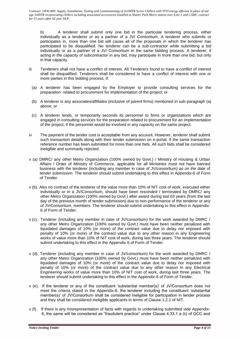
b) A tenderer shall submit only one bid in the particular tendering process, either individually as a tenderer or as a partner of a JV/ Consortium. A tenderer who submits or participates in, more than one bid will cause all of the proposals in which the tenderer has participated to be disqualified. No tenderer can be a sub-contractor while submitting a bid individually or as a partner of a JV/ Consortium in the same bidding process. A tenderer, if acting in the capacity of subcontractor in any bid, may participate in more than one bid, but only in that capacity.
iii Tenderers shall not have a conflict of interest. All Tenderers found to have a conflict of interest
shall be disqualified. Tenderers shall be considered to have a conflict of interest with one or more parties in this bidding process, if:
(a) A tenderer has been engaged by the Employer to provide consulting services for the
preparation related to procurement for implementation of the project; or
(b) A tenderer is any associates/affiliates (inclusive of parent firms) mentioned in sub-paragraph (a) above; or
(c) A tenderer lends, or temporarily seconds its personnel to firms or organizations which are
engaged in consulting services for the preparation related to procurement for an implementation of the project, if the personnel would be involved in any capacity on the same project.
iv The payment of the tender cost is acceptable from any account. However, tenderer shall submit such transaction details along with their tender submission on e-portal. If the same transaction reference number has been submitted for more than one bids. All such bids shall be considered ineligible and summarily rejected.
v (a) DMRC/ any other Metro Organization (100% owned by Govt.) / Ministry of Housing & Urban
Affairs / Order of Ministry of Commerce, applicable for all Ministries must not have banned business with the tenderer (including any member in case of JV/consortium) as on the date of tender submission. The tenderer should submit undertaking to this effect in Appendix-6 of Form of Tender.
v (b). Also no contract of the tenderer of the value more than 10% of NIT cost of work, executed either individually or in a JV/Consortium, should have been rescinded / terminated by DMRC/ any other Metro Organization (100% owned by Govt.) after award during last 03 years (from the last day of the previous month of tender submission) due to non-performance of the tenderer or any of JV/Consortium, members. The tenderer should submit undertaking to this effect in Appendix-6 of Form of Tender.
v (c). Tenderer (including any member in case of JV/consortium) for the work awarded by DMRC /
any other Metro Organization (100% owned by Govt.) must have been neither penalized with liquidated damages of 10% (or more) of the contract value due to delay nor imposed with penalty of 10% (or more) of the contract value due to any other reason in any Engineering works of value more than 10% of NIT cost of work, during last three years. The tenderer should submit undertaking to this effect in the Appendix-6 of Form of Tender.
v (d). Tenderer (including any member in case of JV/consortium) for the work awarded by DMRC / any other Metro Organization (100% owned by Govt.) must have been neither penalized with liquidated damages of 10% (or more) of the contract value due to delay nor imposed with penalty of 10% (or more) of the contract value due to any other reason in any Electrical Engineering works of value more than 10% of NIT cost of work, during last three years. The tenderer should submit undertaking to this effect in the Appendix-6 of Form of Tender.
v (e). If the tenderer or any of the constituent ‘substantial member(s)’ of JV/Consortium does not
meet the criteria stated in the Appendix-6, the tenderer including the constituent ‘substantial member(s)’ of JV/Consortium shall be considered ineligible for participation in tender process and they shall be considered ineligible applicants in terms of Clause 1.2.1 of NIT.
v (f). If there is any misrepresentation of facts with regards to undertaking submitted vide Appendix-
6, the same will be considered as “fraudulent practice” under Clause 4.33.1 a (ii) of GCC and
Contract: OEW-809: Supply, Installation, Testing and Commissioning of 3x100TR Screw Chillers with VFD energy efficient in place of old
age 3x80TR reciprocating chillers including associated accessories installed at Shastri Park Metro station over Line-1 and CAMC contract
for 15 years after 02 year DLP.
Notice Inviting Tender Page 5 of 13
the tender submission of such tenderers will be rejected besides taking further action as per Clause 4.33.1 (b)&13.2.1 of GCC.
vi. Tenderer (any member in case of JV/consortium) must not have suffered bankruptcy/ insolvency
during the last 5 years. The tenderer should submit undertaking to this effect in the Appendix-6 of Form of Tender
vii. LEAD PARTNER/NON SUBSTANTIAL PARTNERS/ CHANGE IN JV/CONSORTIUM
a. Lead partner must be a substantial partner in the JV/Consortium i.e. it should have a minimum of 26% participation in the JV/Consortium. Each substantial partner in case of JV/Consortium shall have experience of executing at least one “similar work” ** of value of ₹148.88 lakhs or more in last 5 years as defined in clause 1.2.2 (a) of NIT.
b. Each non-substantial partner should have a minimum of 20% participation in the JV/Consortium. Partners having less than 26% participation will be termed as non-substantial partner and will not be considered for evaluation which means that their financial soundness and work experience shall not be considered for evaluation of JV/Consortium. In the tender of Electrical work, a Joint Venture/ Consortium to qualify, each of its non-substantial partner must have experience of executing at least one Electrical work of minimum value of ₹74.44 Lakhs in last 05 years.
c. In case of JV/Consortium, change in constitution or percentage participation shall not be permitted at any stage after their submission of application otherwise the applicant shall be treated as non-responsive.
d. The tenderer, in case of JV/Consortium, shall clearly and unambiguously define the role and responsibilities for each substantial/non-substantial partner in the JV/Consortium agreement/ MOU submitted vide foot note (d) of Appendix-5 of Form of Tender, providing clearly that any abrogation /subsequent re-assignment of any responsibility by any substantive/non-substantive partner of JV/Consortium in favour of other JV/Consortium partner or any change in constitution of partners of JV/Consortium (without written approval of Employer) from the one given in JV/Consortium agreement/MOU at tender stage, will be treated, as ‘breach of contract condition’ and/or ‘concealment of facts’ (as the case may be), vide GCC clause 4.33.1 [a (ii) and (iii)] and acted accordingly.
The Employer in such cases, may in its sole discretion take action under clause 4.33.1 (b) of
GCC against any member(s) for failure in tenderer’s obligation and declare that member(s) of
JV/Consortium ineligible for award of any tender in DMRC or take action to terminate the
contract in part or whole under clause 13 of GCC as the situation may demand and recover
the cost/damages as provided in contract.
viii. Participation by Subsidiary Company / Parent Company with credential of other Company
a) Applicant in the capacity of a Subsidiary Company as a single entity is not permitted to use the
credential of its Parent Company and/or its Sister Subsidiary Company/ Companies unless
the Applicant participates in tender as JV/Consortium with its Parent Company and/or its
Sister Subsidiary Company/ Companies as a member(s) in JV/Consortium with minimum 26%
participation each(as substantial member) for such member(s).
b) Applicant in the capacity of a Parent Company as a single entity is not permitted to use
thecredential of its Subsidiary Company/ Companies unless the Applicant participates in
tender asJV/Consortium with its Subsidiary Company/ Companies as a member(s) in
JV/Consortium with minimum26% participation each (as substantial member) for such
member(s).
ix. Purchase Preference to Local Suppliers/Preference to Make in India:
a) Definitions: i. 'Local content' means the amount of value added in India which shall be the total value of the
item procured (excluding net domestic indirect taxes) minus the value of imported content in
the item (including all custom duties) as a proportion of the total value, in percent. Minimum
local content shall be 50% for the subject tender.
iii. 'Local Supplier' means a supplier or service provider whose product or service offered for
procurement meets the minimum local content as prescribed at sr. no. i. above.
Contract: OEW-809: Supply, Installation, Testing and Commissioning of 3x100TR Screw Chillers with VFD energy efficient in place of old
age 3x80TR reciprocating chillers including associated accessories installed at Shastri Park Metro station over Line-1 and CAMC contract
for 15 years after 02 year DLP.
Notice Inviting Tender Page 6 of 13
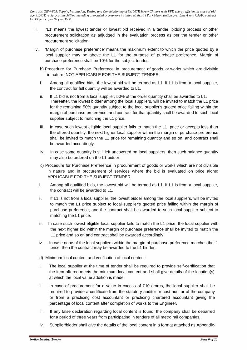
iii. 'L1' means the lowest tender or lowest bid received in a tender, bidding process or other
procurement solicitation as adjudged in the evaluation process as per the tender or other
procurement solicitation.
iv. 'Margin of purchase preference' means the maximum extent to which the price quoted by a
local supplier may be above the L1 for the purpose of purchase preference. Margin of
purchase preference shall be 10% for the subject tender.
b) Procedure for Purchase Preference in procurement of goods or works which are divisible
in nature: NOT APPLICABLE FOR THE SUBJECT TENDER
i. Among all qualified bids, the lowest bid will be termed as L1. If L1 is from a local supplier,
the contract for full quantity will be awarded to L1.
ii. If L1 bid is not from a local supplier, 50% of the order quantity shall be awarded to L1. Thereafter, the lowest bidder among the local suppliers, will be invited to match the L1 price
for the remaining 50% quantity subject to the local supplier's quoted price falling within the
margin of purchase preference, and contract for that quantity shall be awarded to such local
supplier subject to matching the L1 price.
iii. In case such lowest eligible local supplier fails to match the L1 price or accepts less than
the offered quantity, the next higher local supplier within the margin of purchase preference
shall be invited to match the L1 price for remaining quantity and so on, and contract shall
be awarded accordingly.
iv. In case some quantity is still left uncovered on local suppliers, then such balance quantity
may also be ordered on the L1 bidder.
c) Procedure for Purchase Preference in procurement of goods or works which are not divisible
in nature and in procurement of services where the bid is evaluated on price alone:
APPLICABLE FOR THE SUBJECT TENDER
i. Among all qualified bids, the lowest bid will be termed as L1. If L1 is from a local supplier,
the contract will be awarded to L1.
ii. If L1 is not from a local supplier, the lowest bidder among the local suppliers, will be invited
to match the L1 price subject to local supplier's quoted price falling within the margin of
purchase preference, and the contract shall be awarded to such local supplier subject to
matching the L1 price.
iii. In case such lowest eligible local supplier fails to match the L1 price, the local supplier with
the next higher bid within the margin of purchase preference shall be invited to match the
L1 price and so on and contract shall be awarded accordingly.
iv. In case none of the local suppliers within the margin of purchase preference matches theL1 price, then the contract may be awarded to the L1 bidder.
d) Minimum local content and verification of local content:
i. The local supplier at the time of tender shall be required to provide self-certification that
the item offered meets the minimum local content and shall give details of the location(s)
at which the local value addition is made.
ii. In case of procurement for a value in excess of ₹10 crores, the local supplier shall be
required to provide a certificate from the statutory auditor or cost auditor of the company
or from a practicing cost accountant or practicing chartered accountant giving the
percentage of local content after completion of works to the Engineer.
iii. If any false declaration regarding local content is found, the company shall be debarred
for a period of three years from participating in tenders of all metro rail companies.
iv. Supplier/bidder shall give the details of the local content in a format attached as Appendix-
Contract: OEW-809: Supply, Installation, Testing and Commissioning of 3x100TR Screw Chillers with VFD energy efficient in place of old
age 3x80TR reciprocating chillers including associated accessories installed at Shastri Park Metro station over Line-1 and CAMC contract
for 15 years after 02 year DLP.
Notice Inviting Tender Page 7 of 13
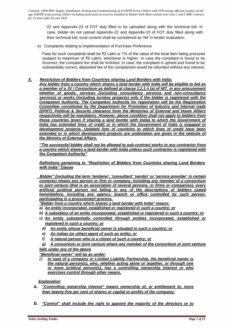
22 and Appendix-23 of FOT duly filled to be uploaded along with the technical bid. In
case, bidder do not upload Appendix-22 and Appendix-23 of FOT duly filled along with
their technical bid, local content shall be considered as 'Nil' in tender evaluation.
e) Complaints relating to implementation of Purchase Preference
Fees for such complaints shall be ₹2 Lakh or 1% of the value of the local item being procured (subject to maximum of ₹5 Lakh), whichever is higher. In case the complaint is found to be incorrect, the complaint fee shall be forfeited. In case, the complaint is upheld and found to be substantially correct, deposited fee of the complainant would be refunded without any interest.
X. Restriction of Bidders from Countries sharing Land Borders with India: Any bidder from a country which shares a land border with India will be eligible to bid as a member of a JV / Consortium as defined at clause 1.2.1 ii (a) of NIT, in any procurement whether of goods, services (including consultancy services and non-consultancy services) or works (including turnkey projects) only if the bidder is registered with the Competent Authority. The Competent Authority for registration will be the Registration Committee constituted by the Department for Promotion of Industry and Internal trade (DPIIT). Political & Security clearance from the Ministries of External and Home Affairs respectively will be mandatory. However, above condition shall not apply to bidders from those countries (even if sharing a land border with India) to which the Government of India has extended lines of credit or in which the Government of India is engaged in development projects. Updated lists of countries to which lines of credit have been extended or in which development projects are undertaken are given in the website of the Ministry of External Affairs.
“The successful bidder shall not be allowed to sub-contract works to any contractor from a country which shares a land border with India unless such contractor is registered with the Competent Authority”
Definitions pertaining to “Restriction of Bidders from Countries sharing Land Borders with India” Clause
Bidder" (including the term 'tenderer', 'consultant' 'vendor' or 'service provider' in certain contexts) means any person or firm or company, including any member of a consortium or joint venture (that is an association of several persons, or firms or companies), every artificial juridical person not falling in any of the descriptions of bidders stated hereinbefore, including any agency, branch or office controlled by such person, participating in a procurement process. "Bidder from a country which shares a land border with India" means: a) An entity incorporated, established or registered in such a country; or
b) A subsidiary of an entity incorporated, established or registered in such a country; or
c) An entity substantially controlled through entities incorporated, established or
registered in such a country; or
d) An entity whose beneficial owner is situated in such a country; or
e) An Indian (or other) agent of such an entity; or
f) A natural person who is a citizen of such a country; or
g) A consortium or joint venture where any member of the consortium or joint venture
falls under any of the above
"Beneficial owner" will be as under: (i) In case of a company or Limited Liability Partnership, the beneficial owner is
the natural person(s), who, whether acting alone or together, or through one or more juridical person(s), has a controlling ownership interest or who exercises control through other means.
Explanation
a. "Controlling ownership interest" means ownership of, or entitlement to, more
than twenty-five per cent of shares or capital or profits of the company;
b. "Control" shall include the right to appoint the majority of the directors or to
Contract: OEW-809: Supply, Installation, Testing and Commissioning of 3x100TR Screw Chillers with VFD energy efficient in place of old
age 3x80TR reciprocating chillers including associated accessories installed at Shastri Park Metro station over Line-1 and CAMC contract
for 15 years after 02 year DLP.
Notice Inviting Tender Page 8 of 13
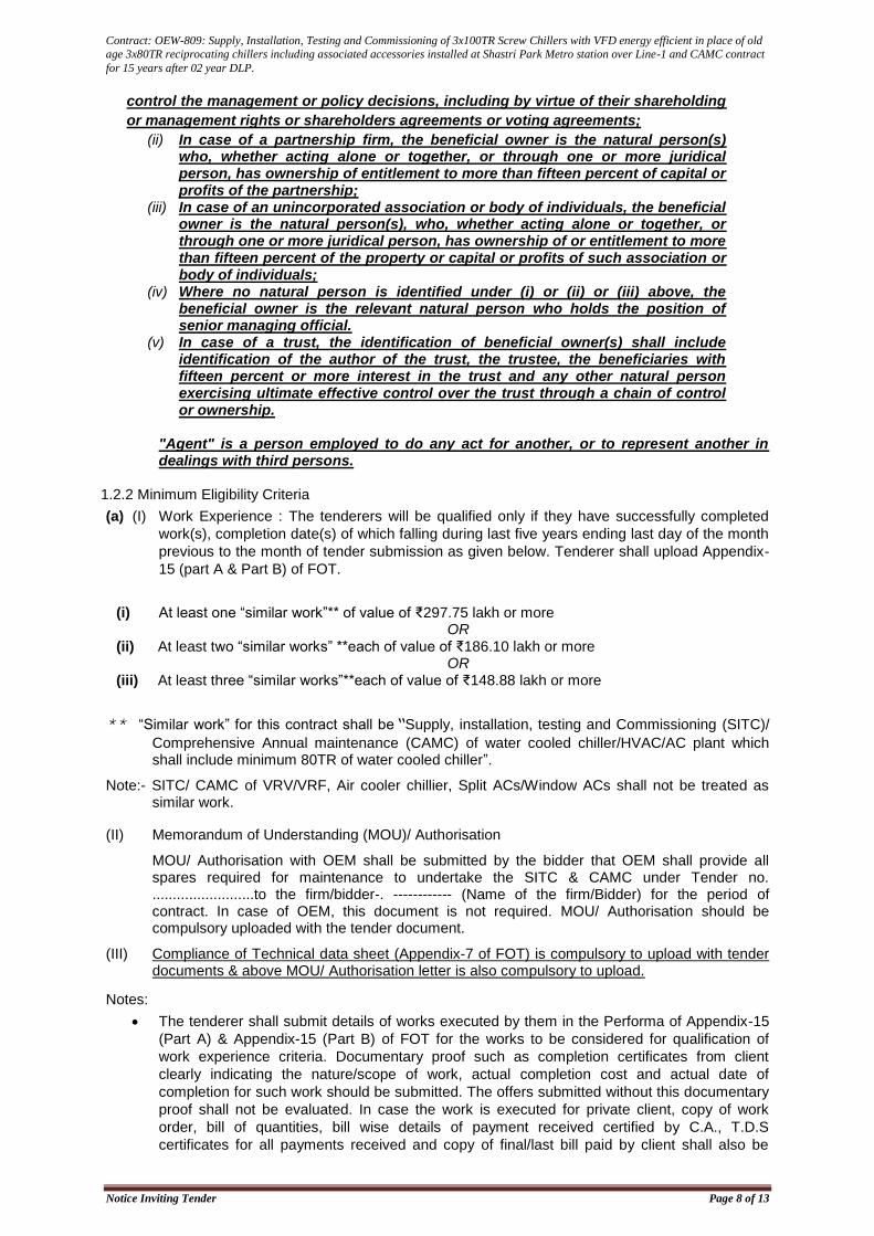
control the management or policy decisions, including by virtue of their shareholding
or management rights or shareholders agreements or voting agreements;
(ii) In case of a partnership firm, the beneficial owner is the natural person(s) who, whether acting alone or together, or through one or more juridical person, has ownership of entitlement to more than fifteen percent of capital or profits of the partnership;
(iii) In case of an unincorporated association or body of individuals, the beneficial owner is the natural person(s), who, whether acting alone or together, or through one or more juridical person, has ownership of or entitlement to more than fifteen percent of the property or capital or profits of such association or body of individuals;
(iv) Where no natural person is identified under (i) or (ii) or (iii) above, the beneficial owner is the relevant natural person who holds the position of senior managing official.
(v) In case of a trust, the identification of beneficial owner(s) shall include identification of the author of the trust, the trustee, the beneficiaries with fifteen percent or more interest in the trust and any other natural person exercising ultimate effective control over the trust through a chain of control or ownership.
"Agent" is a person employed to do any act for another, or to represent another in dealings with third persons.
1.2.2 Minimum Eligibility Criteria
(a) (I) Work Experience : The tenderers will be qualified only if they have successfully completed
work(s), completion date(s) of which falling during last five years ending last day of the month
previous to the month of tender submission as given below. Tenderer shall upload Appendix-
15 (part A & Part B) of FOT.
(i) At least one “similar work”** of value of ₹297.75 lakh or more OR
(ii) At least two “similar works” **each of value of ₹186.10 lakh or more OR
(iii) At least three “similar works”**each of value of ₹148.88 lakh or more
** “Similar work” for this contract shall be“Supply, installation, testing and Commissioning (SITC)/
Comprehensive Annual maintenance (CAMC) of water cooled chiller/HVAC/AC plant which shall include minimum 80TR of water cooled chiller”.
Note:- SITC/ CAMC of VRV/VRF, Air cooler chillier, Split ACs/Window ACs shall not be treated as similar work.
(II) Memorandum of Understanding (MOU)/ Authorisation
MOU/ Authorisation with OEM shall be submitted by the bidder that OEM shall provide all spares required for maintenance to undertake the SITC & CAMC under Tender no. .........................to the firm/bidder-. ------------ (Name of the firm/Bidder) for the period of contract. In case of OEM, this document is not required. MOU/ Authorisation should be compulsory uploaded with the tender document.
(III) Compliance of Technical data sheet (Appendix-7 of FOT) is compulsory to upload with tender documents & above MOU/ Authorisation letter is also compulsory to upload.
Notes:
The tenderer shall submit details of works executed by them in the Performa of Appendix-15
(Part A) & Appendix-15 (Part B) of FOT for the works to be considered for qualification of
work experience criteria. Documentary proof such as completion certificates from client
clearly indicating the nature/scope of work, actual completion cost and actual date of
completion for such work should be submitted. The offers submitted without this documentary
proof shall not be evaluated. In case the work is executed for private client, copy of work
order, bill of quantities, bill wise details of payment received certified by C.A., T.D.S
certificates for all payments received and copy of final/last bill paid by client shall also be
Contract: OEW-809: Supply, Installation, Testing and Commissioning of 3x100TR Screw Chillers with VFD energy efficient in place of old
age 3x80TR reciprocating chillers including associated accessories installed at Shastri Park Metro station over Line-1 and CAMC contract
for 15 years after 02 year DLP.
Notice Inviting Tender Page 9 of 13
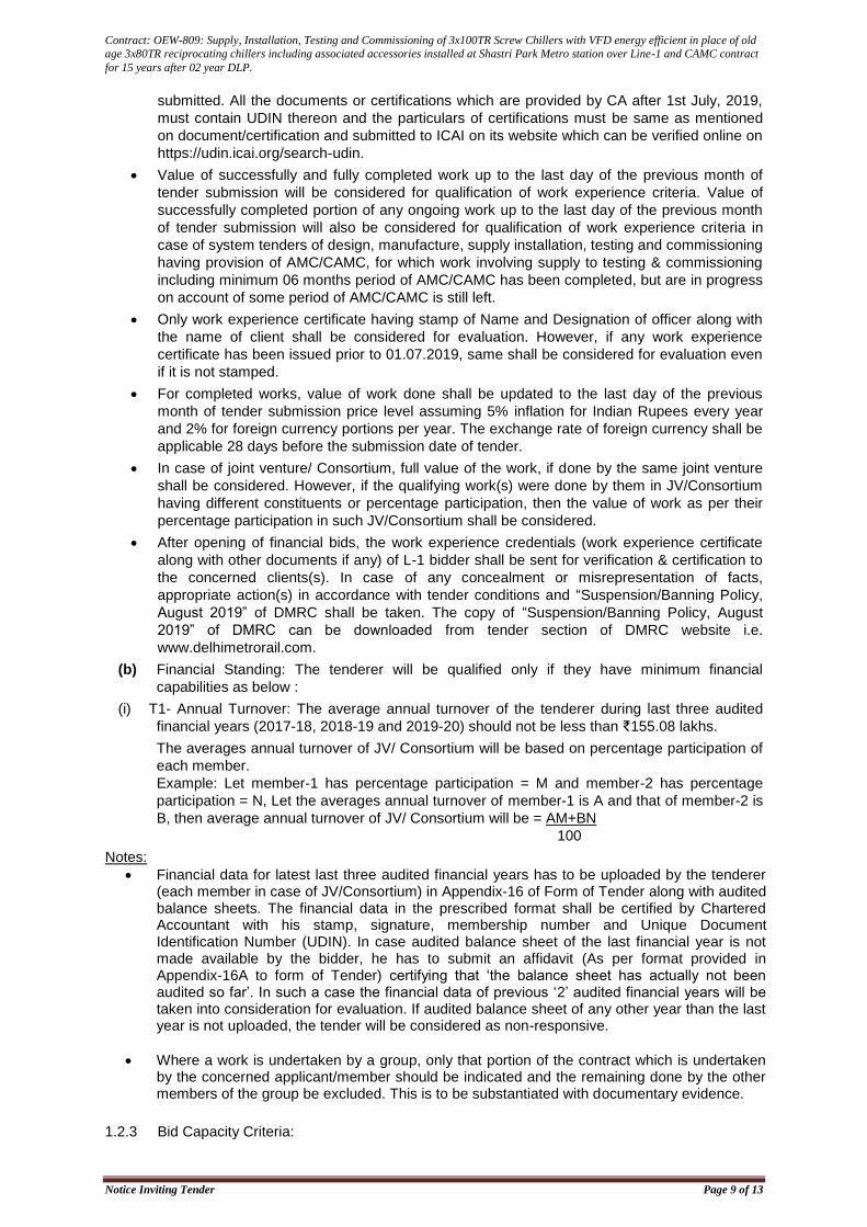
submitted. All the documents or certifications which are provided by CA after 1st July, 2019,
must contain UDIN thereon and the particulars of certifications must be same as mentioned
on document/certification and submitted to ICAI on its website which can be verified online on
https://udin.icai.org/search-udin.
Value of successfully and fully completed work up to the last day of the previous month of
tender submission will be considered for qualification of work experience criteria. Value of
successfully completed portion of any ongoing work up to the last day of the previous month
of tender submission will also be considered for qualification of work experience criteria in
case of system tenders of design, manufacture, supply installation, testing and commissioning
having provision of AMC/CAMC, for which work involving supply to testing & commissioning
including minimum 06 months period of AMC/CAMC has been completed, but are in progress
on account of some period of AMC/CAMC is still left.
Only work experience certificate having stamp of Name and Designation of officer along with
the name of client shall be considered for evaluation. However, if any work experience
certificate has been issued prior to 01.07.2019, same shall be considered for evaluation even
if it is not stamped.
For completed works, value of work done shall be updated to the last day of the previous
month of tender submission price level assuming 5% inflation for Indian Rupees every year
and 2% for foreign currency portions per year. The exchange rate of foreign currency shall be
applicable 28 days before the submission date of tender.
In case of joint venture/ Consortium, full value of the work, if done by the same joint venture
shall be considered. However, if the qualifying work(s) were done by them in JV/Consortium
having different constituents or percentage participation, then the value of work as per their
percentage participation in such JV/Consortium shall be considered.
After opening of financial bids, the work experience credentials (work experience certificate
along with other documents if any) of L-1 bidder shall be sent for verification & certification to
the concerned clients(s). In case of any concealment or misrepresentation of facts,
appropriate action(s) in accordance with tender conditions and “Suspension/Banning Policy,
August 2019” of DMRC shall be taken. The copy of “Suspension/Banning Policy, August
2019” of DMRC can be downloaded from tender section of DMRC website i.e.
www.delhimetrorail.com.
(b) Financial Standing: The tenderer will be qualified only if they have minimum financial
capabilities as below :
(i) T1- Annual Turnover: The average annual turnover of the tenderer during last three audited
financial years (2017-18, 2018-19 and 2019-20) should not be less than ₹155.08 lakhs.
The averages annual turnover of JV/ Consortium will be based on percentage participation of
each member.
Example: Let member-1 has percentage participation = M and member-2 has percentage
participation = N, Let the averages annual turnover of member-1 is A and that of member-2 is
B, then average annual turnover of JV/ Consortium will be = AM+BN
100
Notes:
Financial data for latest last three audited financial years has to be uploaded by the tenderer (each member in case of JV/Consortium) in Appendix-16 of Form of Tender along with audited balance sheets. The financial data in the prescribed format shall be certified by Chartered Accountant with his stamp, signature, membership number and Unique Document Identification Number (UDIN). In case audited balance sheet of the last financial year is not made available by the bidder, he has to submit an affidavit (As per format provided in Appendix-16A to form of Tender) certifying that ‘the balance sheet has actually not been audited so far’. In such a case the financial data of previous ‘2’ audited financial years will be taken into consideration for evaluation. If audited balance sheet of any other year than the last year is not uploaded, the tender will be considered as non-responsive.
Where a work is undertaken by a group, only that portion of the contract which is undertaken by the concerned applicant/member should be indicated and the remaining done by the other members of the group be excluded. This is to be substantiated with documentary evidence.
1.2.3 Bid Capacity Criteria:
Contract: OEW-809: Supply, Installation, Testing and Commissioning of 3x100TR Screw Chillers with VFD energy efficient in place of old
age 3x80TR reciprocating chillers including associated accessories installed at Shastri Park Metro station over Line-1 and CAMC contract
for 15 years after 02 year DLP.
Notice Inviting Tender Page 10 of 13
Bid Capacity: The tenderers will be qualified only if their available bid capacity is more than the approximate cost of work as per NIT. Available bid capacity will be calculated based on the following formula:
Bid capacity will be calculated based on the following formula:
Available Bid Capacity = 2*A*N – B
Where,
A = Maximum of the value of work executed in any one year during the last three financial years (updated to the last day of the previous month of tender submission price level assuming 5% inflation for Indian Rupees every year and 2% for foreign currency portions per year).
N = No. of years prescribed for completion of the work.
B = Value of existing commitments (as on the last day of the previous month of tender submission) for on-going works during period of 208 209 months w.e.f. from the first day of the month of tender submission.
Notes:
Financial data for latest last three financial years has to be uploaded by the tenderer in Appendix-17 of Form of Tender along with audited financial statements. The financial data in the prescribed format shall be certified by the Chartered Accountant with his stamp, signature, membership number and Unique Document Identification Number (UDIN).
Value of existing commitments for on-going works during period of 208 209 months w.e.f. from the first day of the month of tender submission has to be uploaded by the tenderer in Appendix-18 of Form of Tender. These data shall be certified by the Chartered Accountant with his stamp, signature, membership number and Unique Document Identification Number (UDIN).
In the case of a group, the above formula will be applied to each member to the extent of his proposed participation in the execution of the work. If the proposed % is not provided, equal participation will be assumed. Example for calculation of bid capacity in case of JV / Consortium/ Group Suppose there are ‘P’ and ‘Q’ members of the JV / group with their participation in the JV/ group as 70% and 30% respectively and available bid capacity of these members as per above formula individually works out ‘X’ and ‘Y’ respectively, then Bid Capacity of JV / Consortium/ group shall be as under: Bid Capacity of the JV/ group = 0.7X + 0.3Y
The tender submission of tenderers, who do not qualify the minimum eligibility criteria stipulated in the clauses 1.2.2 (a), 1.2.2 (b) and 1.2.3 above, shall not be considered for further evaluation and therefore rejected. The mere fact that the tenderer is qualified as mentioned in sub clause 1.2.2 (a), 1.2.2 (b) and 1.2.3 shall not imply that his bid shall automatically be accepted. The same should contain all technical data as required for consideration of tender prescribed in the ITT.
1.3 Tender document consists of the following: a. Notice Inviting Tender b. Instructions to Tenderers (Including Annexures) c. Form of Tender (Including Appendices) d. General Conditions of Contract (November, 2019) e. Special Conditions of Contract f. Employer’s Requirement &Technical Specifications g. Bill of Quantities h. Conditions of contract on Safety and Health for Electrical works of DMRC(O&M)
Contract: OEW-809: Supply, Installation, Testing and Commissioning of 3x100TR Screw Chillers with VFD energy efficient in place of old
age 3x80TR reciprocating chillers including associated accessories installed at Shastri Park Metro station over Line-1 and CAMC contract
for 15 years after 02 year DLP.
Notice Inviting Tender Page 11 of 13
1.3.1 The Tenderers may obtain further information/ clarification, if any, in respect of these tender documents from the office of CE/Tender (O&M), Delhi Metro Rail Corporation, 5thFloor, C-Wing, Metro Bhawan, Fire Brigade Lane, Barakhamba Road, New Delhi –110001.
1.3.2 All Tenderers are hereby cautioned that tenders containing any material deviation or reservations as described in ClauseE4.4 of “Instructions to Tenderers” and/or minor deviation without quoting the cost of withdrawal shall be considered as non-responsive and is liable to be rejected.
1.3.3 The intending tenderers must be registered on e-tendering portal https://eprocure.gov.in/eprocure/app. Those who are not registered on the e-tendering portal shall be required to get registered beforehand. After registration, the tenderer will get user id and password. On login, tenderer can participate in tendering process and can witness various activities of the process.
1.3.4 The authorized signatory of intending tenderer, as per Power of Attorney (POA), must have valid class-II or class-III digital signature. The tender document can only be downloaded from e-tendering portal using class-II or class-III digital signature. However, the tenderer shall upload their tender on https://eprocure.gov.in/eprocure/app using class-II or class-III digital signature of the authorized signatory only.
1.3.5 Tender submissions shall be done online on https://eprocure.gov.in/eprocure/app after uploading the mandatory scanned copies of transaction of payment of tender document cost/tender fee and Tender Security (in the form of RTGS, NEFT and IMPS.) and other documents as stated in the tender document. Instructions for on-line bid submission are furnished hereinafter.
1.3.6 Submission of Tenders shall be closed on e-tendering website of DMRC at the date & time of submission prescribed in NIT after which no tender shall be accepted.
It shall be the responsibility of the bidder / tenderer to ensure that his tender is uploaded online on e-tendering website https://eprocure.gov.in/eprocure/app before the deadline of submission. DMRC will not be responsible for non-receipt of tender documents due to any delay and/or loss etc.
1.3.7 Tenders shall be valid for a period of 180 days (both days inclusive i.e. the date of submission of tenders and the last date of period of validity of the tender) from the latest Date of Submission of Tender and shall be accompanied with a tender security of the requisite amount as per clause C17 of ITT.
1.3.8 DMRC reserves the right to accept or reject any or all proposals without assigning any reasons. No tenderer shall have any cause of action or claim against the DMRC for rejection of his proposal.
1.3.9 Tenderers are advised to keep in touch with e-tendering portal https://eprocure.gov.in/eprocure/app for updates.
1.3.10 Letter of acceptance to the successful bidder shall be uploaded on procurement portal which can be downloaded by the successful bidder.
1.3.11 For any corruption related complaint, tenderer may contact CVO, DMRC (email- [email protected] Ph.011-23418406. However, no tender related queries shall be enquired from CVO, DMRC. For any queries/clarification related to tender, the bidder may attend pre-bid meeting and/or upload their queries online within the date and time specified at Clause 1.1.1 (f) and 1.1.1 (g) of NIT respectively.
CE/Tender (O&M)
Delhi Metro Rail Corporation Limited
Contract: OEW-809: Supply, Installation, Testing and Commissioning of 3x100TR Screw Chillers with VFD energy efficient in place of old
age 3x80TR reciprocating chillers including associated accessories installed at Shastri Park Metro station over Line-1 and CAMC contract
for 15 years after 02 year DLP.
Notice Inviting Tender Page 12 of 13
Instructions for Online Bid Submission:
1. GENERAL
The bidders are required to submit soft copies of their bids electronically on the CPP Portal, using valid Digital Signature Certificates. The instructions given below are meant to assist the bidders in registering on the CPP Portal, prepare their bids in accordance with the requirements and submitting their bids online on the CPP Portal.
More information useful for submitting online bids on the CPP Portal may be obtained at: https://eprocure.gov.in/eprocure/app.
2. REGISTRATION
a) Bidders are required to enroll on the e-Procurement module of the Central Public Procurement Portal (URL: https://eprocure.gov.in/eprocure/app) by clicking on the link “Online bidder Enrollment” on the CPP Portal which is free of charge.
b) As part of the enrolment process, the bidders will be required to choose a unique username and assign a password for their accounts.
c) Bidders are advised to register their valid email address and mobile numbers as part of the registration process. These would be used for any communication from the CPP Portal.
d) Upon enrolment, the bidders will be required to register their valid Digital Signature Certificate (Class II or Class III Certificates with signing key usage) issued by any Certifying Authority recognized by CCA India (e.g. Sify / nCode / eMudhra etc.), with their profile.
e) Only one valid DSC should be registered by a bidder. Please note that the bidders are responsible to ensure that they do not lend their DSC’s to others which may lead to misuse.
f) Bidder then logs in to the site through the secured log-in by entering their user ID / password and the password of the DSC / e-Token.
3. SEARCHING FOR TENDER DOCUMENTS
a) There are various search options built in the CPP Portal, to facilitate bidders to search active tenders by several parameters. These parameters could include Tender ID, Organization Name, Location, Date, Value, etc. There is also an option of advanced search for tenders, wherein the bidders may combine a number of search parameters such as Organization Name, Form of Contract, Location, Date, Other keywords etc. to search for a tender published on the CPP Portal.
b) Once the bidders have selected the tenders they are interested in, they may download the required documents / tender schedules. These tenders can be moved to the respective ‘My Tenders’ folder. This would enable the CPP Portal to intimate the bidders through SMS / e-mail in case there is any corrigendum issued to the tender document.
c) The bidder should make a note of the unique Tender ID assigned to each tender, in case they want to obtain any clarification / help from the Helpdesk.
4. PREPARATION OF BIDS
a) Bidder should take into account any corrigendum published on the tender document before
submitting their bids.
b) Please go through the tender advertisement and the tender document carefully to
understand the documents required to be submitted as part of the bid. Please note the
number of covers in which the bid documents have to be submitted, the number of
documents - including the names and content of each of the document that need to be
submitted. Any deviations from these may lead to rejection of the bid.
c) Bidder, in advance, should get ready the bid documents to be uploaded as indicated in the
tender document / schedule and generally, they can be in PDF / XLS / RAR / DWF/JPG
formats. Bid documents may be scanned with 100 dpi with black and white option which
helps in reducing size of the scanned document.
d) To avoid the time and effort required in uploading the same set of standard documents which
are required to be uploaded as a part of every bid, a provision of uploading such standard
documents (e.g. PAN card copy, annual reports, auditor certificates etc.) has been provided
to the bidders. Bidders can use “My Space” or ‘’Other Important Documents’’ area available
to them to upload such documents. These documents may be directly submitted from the
Contract: OEW-809: Supply, Installation, Testing and Commissioning of 3x100TR Screw Chillers with VFD energy efficient in place of old
age 3x80TR reciprocating chillers including associated accessories installed at Shastri Park Metro station over Line-1 and CAMC contract
for 15 years after 02 year DLP.
Notice Inviting Tender Page 13 of 13
“My Space” area while submitting a bid, and need not be uploaded again and again. This will
lead to a reduction in the time required for bid submission process.
5. SUBMISSION OF BIDS
a) Bidder should log into the site well in advance for bid submission so that they can upload the bid in time i.e. on or before the bid submission time. Bidder will be responsible for any delay due to other issues.
b) The bidder has to digitally sign and upload the required bid documents one by one as indicated in the tender document.
c) Tender fee / Tender document cost: Bidder has to select the instrument type & enter the details of transaction of payment of tender fee / tender document cost done by RTGS / NEFT / IMPS as applicable and upload scanned copy of transaction receipt as documentary proof for payment. For further details tenderer may refer clause C18of ITT.
d) Tender Security / Earnest Money Deposit (EMD): Bidder should submit the EMD/Tender Security as per the instructions specified in C18 of ITT in the tender document.
e) Bidders are requested to note that they should necessarily submit their financial bids in the format provided and no other format is acceptable. If the price bid has been given as a standard BOQ format with the tender document, then the same is to be downloaded and to be filled by all the bidders. Bidders are required to download the BOQ file, open it and complete the white coloured (unprotected) cells with their respective financial quotes and other details (such as name of the bidder). No other cells should be changed. Once the details have been completed, the bidder should save it and submit it online, without changing the filename. If the BOQ file is found to be modified by the bidder, the bid will be rejected.
f) The server time (which is displayed on the bidders’ dashboard) will be considered as the standard time for referencing the deadlines for submission of the bids by the bidders, opening of bids etc. The bidders should follow this time during bid submission.
g) All the documents being uploaded by the bidders would be encrypted using PKI encryption techniques to ensure the secrecy of the data. The data entered cannot be viewed by unauthorized persons until the time of bid opening. The confidentiality of the bids is maintained using the secured Socket Layer 128 bit encryption technology. Data storage encryption of sensitive fields is done. Any bid document that is uploaded to the server is subjected to symmetric encryption using a system generated symmetric key. Further this key is subjected to asymmetric encryption using buyers/bid openers public keys. Overall, the uploaded tender documents become readable only after the tender opening by the authorized bid openers.
h) The uploaded tender documents become readable only after the tender opening by the
authorized bid openers.
i) Upon the successful and timely submission of bids (i.e. after Clicking “Freeze Bid Submission” in the portal), the portal will give a successful bid submission message & a bid summary will be displayed with the bid no. and the date & time of submission of the bid with all other relevant details.
j) The bid summary has to be printed and kept as an acknowledgement of the submission of the bid. This acknowledgement may be used as an entry pass for any bid opening meetings.
6. ASSISTANCE TO BIDDERS a. Any queries relating to the tender document and the terms and conditions contained
therein should be addressed to the Tender Inviting Authority for a tender or the relevant contact person indicated in the tender.
b. Any queries relating to the process of online bid submission or queries relating to CPP Portal in general may be directed to the 24x7 CPP Portal Helpdesk.
c. For any Technical queries related to Operation of the Central Public Procurement Portal Contact at: Tel: 0120-4001062, 0120-4001002, 0120-4001005, 0120-6277787. E-Mail Support: Technical - support-eproc(at)nic(dot)in Policy Related - cppp-doe(at)nic(dot)in
Contract: OEW-809: Supply, Installation, Testing and Commissioning of 3x100TR Screw Chillers with VFD energy efficient in place of old
age 3x80TR reciprocating chillers including associated accessories installed at Shastri Park Metro station over Line-1 and CAMC contract
for 15 years after 02 year DLP.
Instruction to Tenderer Page 6R of 28
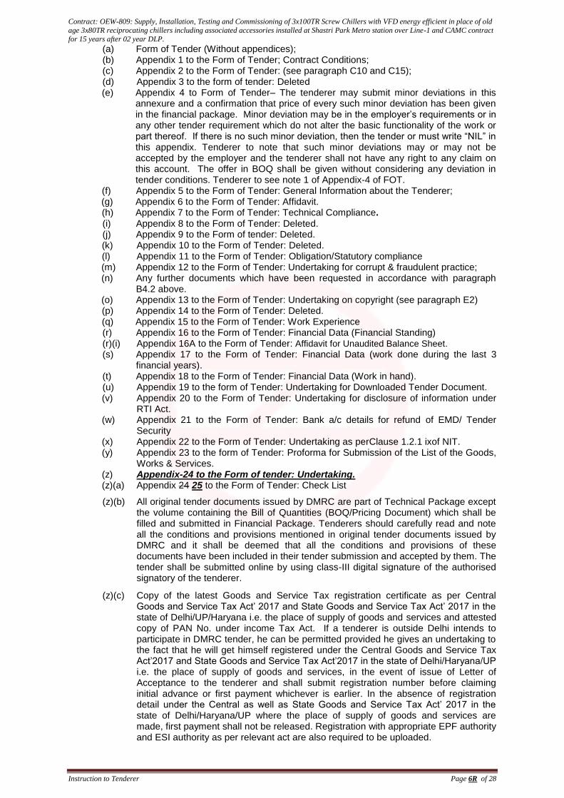
(a) Form of Tender (Without appendices); (b) Appendix 1 to the Form of Tender; Contract Conditions; (c) Appendix 2 to the Form of Tender: (see paragraph C10 and C15); (d) Appendix 3 to the form of tender: Deleted (e) Appendix 4 to Form of Tender– The tenderer may submit minor deviations in this
annexure and a confirmation that price of every such minor deviation has been given in the financial package. Minor deviation may be in the employer’s requirements or in any other tender requirement which do not alter the basic functionality of the work or part thereof. If there is no such minor deviation, then the tender or must write “NIL” in this appendix. Tenderer to note that such minor deviations may or may not be accepted by the employer and the tenderer shall not have any right to any claim on this account. The offer in BOQ shall be given without considering any deviation in tender conditions. Tenderer to see note 1 of Appendix-4 of FOT.
(f) Appendix 5 to the Form of Tender: General Information about the Tenderer; (g) Appendix 6 to the Form of Tender: Affidavit. (h) Appendix 7 to the Form of Tender: Technical Compliance. (i) Appendix 8 to the Form of Tender: Deleted. (j) Appendix 9 to the Form of tender: Deleted. (k) Appendix 10 to the Form of Tender: Deleted. (l) Appendix 11 to the Form of Tender: Obligation/Statutory compliance (m) Appendix 12 to the Form of Tender: Undertaking for corrupt & fraudulent practice; (n) Any further documents which have been requested in accordance with paragraph
B4.2 above. (o) Appendix 13 to the Form of Tender: Undertaking on copyright (see paragraph E2) (p) Appendix 14 to the Form of Tender: Deleted. (q) Appendix 15 to the Form of Tender: Work Experience (r) Appendix 16 to the Form of Tender: Financial Data (Financial Standing)
(r)(i) Appendix 16A to the Form of Tender: Affidavit for Unaudited Balance Sheet. (s) Appendix 17 to the Form of Tender: Financial Data (work done during the last 3
financial years). (t) Appendix 18 to the Form of Tender: Financial Data (Work in hand).
(u) Appendix 19 to the form of Tender: Undertaking for Downloaded Tender Document. (v) Appendix 20 to the Form of Tender: Undertaking for disclosure of information under
RTI Act. (w) Appendix 21 to the Form of Tender: Bank a/c details for refund of EMD/ Tender
Security (x) Appendix 22 to the Form of Tender: Undertaking as perClause 1.2.1 ixof NIT. (y) Appendix 23 to the form of Tender: Proforma for Submission of the List of the Goods,
Works & Services. (z) Appendix-24 to the Form of tender: Undertaking. (z)(a) Appendix 24 25 to the Form of Tender: Check List
(z)(b) All original tender documents issued by DMRC are part of Technical Package except the volume containing the Bill of Quantities (BOQ/Pricing Document) which shall be filled and submitted in Financial Package. Tenderers should carefully read and note all the conditions and provisions mentioned in original tender documents issued by DMRC and it shall be deemed that all the conditions and provisions of these documents have been included in their tender submission and accepted by them. The tender shall be submitted online by using class-III digital signature of the authorised signatory of the tenderer.
(z)(c) Copy of the latest Goods and Service Tax registration certificate as per Central Goods and Service Tax Act’ 2017 and State Goods and Service Tax Act’ 2017 in the state of Delhi/UP/Haryana i.e. the place of supply of goods and services and attested copy of PAN No. under income Tax Act. If a tenderer is outside Delhi intends to participate in DMRC tender, he can be permitted provided he gives an undertaking to the fact that he will get himself registered under the Central Goods and Service Tax Act’2017 and State Goods and Service Tax Act’2017 in the state of Delhi/Haryana/UP i.e. the place of supply of goods and services, in the event of issue of Letter of Acceptance to the tenderer and shall submit registration number before claiming initial advance or first payment whichever is earlier. In the absence of registration detail under the Central as well as State Goods and Service Tax Act’ 2017 in the state of Delhi/Haryana/UP where the place of supply of goods and services are made, first payment shall not be released. Registration with appropriate EPF authority and ESI authority as per relevant act are also required to be uploaded.
Contract: OEW-809: Supply, Installation, Testing and Commissioning of 3x100TR Screw Chillers with VFD energy efficient in place of old
age 3x80TR reciprocating chillers including associated accessories installed at Shastri Park Metro station over Line-1 and CAMC contract
for 15 years after 02 year DLP.
Instruction to Tenderer Page 7R of 28
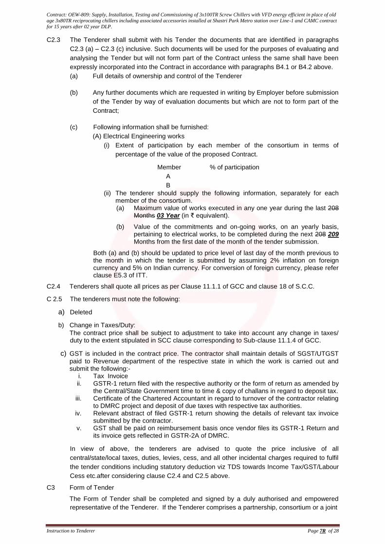
C2.3 The Tenderer shall submit with his Tender the documents that are identified in paragraphs
C2.3 (a) – C2.3 (c) inclusive. Such documents will be used for the purposes of evaluating and
analysing the Tender but will not form part of the Contract unless the same shall have been
expressly incorporated into the Contract in accordance with paragraphs B4.1 or B4.2 above.
(a) Full details of ownership and control of the Tenderer
(b) Any further documents which are requested in writing by Employer before submission
of the Tender by way of evaluation documents but which are not to form part of the
Contract;
(c) Following information shall be furnished:
(A) Electrical Engineering works
(i) Extent of participation by each member of the consortium in terms of
percentage of the value of the proposed Contract.
Member % of participation
A
B
(ii) The tenderer should supply the following information, separately for each member of the consortium. (a) Maximum value of works executed in any one year during the last 208
Months 03 Year (in ₹ equivalent).
(b) Value of the commitments and on-going works, on an yearly basis, pertaining to electrical works, to be completed during the next 208 209 Months from the first date of the month of the tender submission.
Both (a) and (b) should be updated to price level of last day of the month previous to the month in which the tender is submitted by assuming 2% inflation on foreign currency and 5% on Indian currency. For conversion of foreign currency, please refer clause E5.3 of ITT.
C2.4 Tenderers shall quote all prices as per Clause 11.1.1 of GCC and clause 18 of S.C.C.
C 2.5 The tenderers must note the following:
a) Deleted
b) Change in Taxes/Duty:
The contract price shall be subject to adjustment to take into account any change in taxes/ duty to the extent stipulated in SCC clause corresponding to Sub-clause 11.1.4 of GCC.
c) GST is included in the contract price. The contractor shall maintain details of SGST/UTGST
paid to Revenue department of the respective state in which the work is carried out and submit the following:-
i. Tax Invoice ii. GSTR-1 return filed with the respective authority or the form of return as amended by
the Central/State Government time to time & copy of challans in regard to deposit tax. iii. Certificate of the Chartered Accountant in regard to turnover of the contractor relating
to DMRC project and deposit of due taxes with respective tax authorities. iv. Relevant abstract of filed GSTR-1 return showing the details of relevant tax invoice
submitted by the contractor. v. GST shall be paid on reimbursement basis once vendor files its GSTR-1 Return and
its invoice gets reflected in GSTR-2A of DMRC.
In view of above, the tenderers are advised to quote the price inclusive of all
central/state/local taxes, duties, levies, cess, and all other incidental charges required to fulfil
the tender conditions including statutory deduction viz TDS towards Income Tax/GST/Labour
Cess etc.after considering clause C2.4 and C2.5 above.
C3 Form of Tender
The Form of Tender shall be completed and signed by a duly authorised and empowered
representative of the Tenderer. If the Tenderer comprises a partnership, consortium or a joint
Contract: OEW-809: Supply, Installation, Testing and Commissioning of 3x100TR Screw Chillers with VFD energy efficient in place of old
age 3x80TR reciprocating chillers including associated accessories installed at Shastri Park Metro station over Line-1 and CAMC contract
for 15 years after 02 year DLP.
Instruction to Tenderer Page 10R of 28
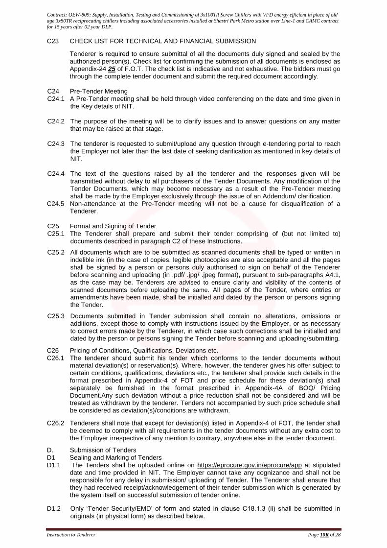
C23 CHECK LIST FOR TECHNICAL AND FINANCIAL SUBMISSION
Tenderer is required to ensure submittal of all the documents duly signed and sealed by the authorized person(s). Check list for confirming the submission of all documents is enclosed as Appendix-24 25 of F.O.T. The check list is indicative and not exhaustive. The bidders must go through the complete tender document and submit the required document accordingly.
C24 Pre-Tender Meeting C24.1 A Pre-Tender meeting shall be held through video conferencing on the date and time given in
the Key details of NIT. C24.2 The purpose of the meeting will be to clarify issues and to answer questions on any matter
that may be raised at that stage. C24.3 The tenderer is requested to submit/upload any question through e-tendering portal to reach
the Employer not later than the last date of seeking clarification as mentioned in key details of NIT.
C24.4 The text of the questions raised by all the tenderer and the responses given will be
transmitted without delay to all purchasers of the Tender Documents. Any modification of the Tender Documents, which may become necessary as a result of the Pre-Tender meeting shall be made by the Employer exclusively through the issue of an Addendum/ clarification.
C24.5 Non-attendance at the Pre-Tender meeting will not be a cause for disqualification of a Tenderer.
C25 Format and Signing of Tender C25.1 The Tenderer shall prepare and submit their tender comprising of (but not limited to)
documents described in paragraph C2 of these Instructions.
C25.2 All documents which are to be submitted as scanned documents shall be typed or written in indelible ink (in the case of copies, legible photocopies are also acceptable and all the pages shall be signed by a person or persons duly authorised to sign on behalf of the Tenderer before scanning and uploading (in .pdf/ .jpg/ .jpeg format), pursuant to sub-paragraphs A4.1, as the case may be. Tenderers are advised to ensure clarity and visibility of the contents of
scanned documents before uploading the same. All pages of the Tender, where entries or amendments have been made, shall be initialled and dated by the person or persons signing the Tender.
C25.3 Documents submitted in Tender submission shall contain no alterations, omissions or additions, except those to comply with instructions issued by the Employer, or as necessary to correct errors made by the Tenderer, in which case such corrections shall be initialled and dated by the person or persons signing the Tender before scanning and uploading/submitting.
C26 Pricing of Conditions, Qualifications, Deviations etc. C26.1 The tenderer should submit his tender which conforms to the tender documents without
material deviation(s) or reservation(s). Where, however, the tenderer gives his offer subject to certain conditions, qualifications, deviations etc., the tenderer shall provide such details in the format prescribed in Appendix-4 of FOT and price schedule for these deviation(s) shall separately be furnished in the format prescribed in Appendix-4A of BOQ/ Pricing Document.Any such deviation without a price reduction shall not be considered and will be treated as withdrawn by the tenderer. Tenders not accompanied by such price schedule shall be considered as deviation(s)/conditions are withdrawn.
C26.2 Tenderers shall note that except for deviation(s) listed in Appendix-4 of FOT, the tender shall be deemed to comply with all requirements in the tender documents without any extra cost to the Employer irrespective of any mention to contrary, anywhere else in the tender document.
D. Submission of Tenders D1 Sealing and Marking of Tenders D1.1 The Tenders shall be uploaded online on https://eprocure.gov.in/eprocure/app at stipulated
date and time provided in NIT. The Employer cannot take any cognizance and shall not be responsible for any delay in submission/ uploading of Tender. The Tenderer shall ensure that they had received receipt/acknowledgement of their tender submission which is generated by the system itself on successful submission of tender online.
D1.2 Only ‘Tender Security/EMD’ of form and stated in clause C18.1.3 (ii) shall be submitted in originals (in physical form) as described below.
Contract: OEW-809: Supply, Installation, Testing and Commissioning of 3x100TR Screw Chillers with VFD energy efficient in place of old
age 3x80TR reciprocating chillers including associated accessories installed at Shastri Park Metro station over Line-1 and CAMC contract
for 15 years after 02 year DLP.
Instruction to Tenderer Page 15R of 28
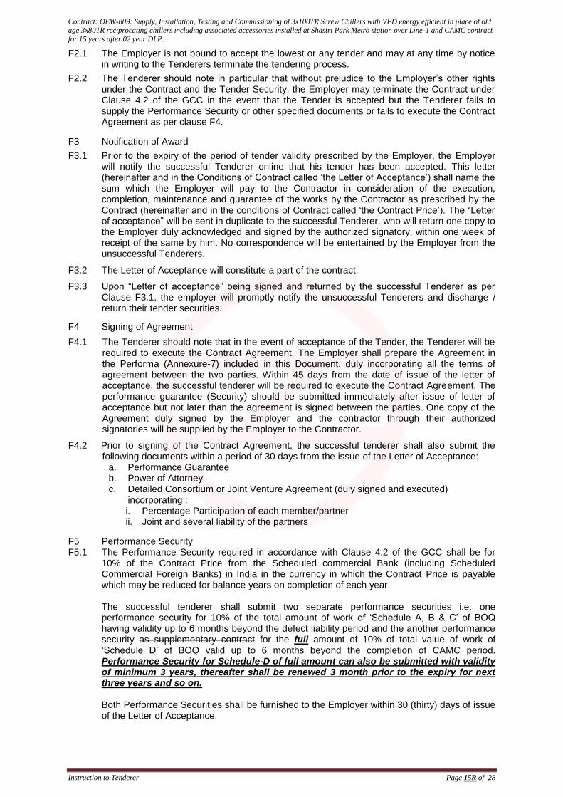
F2.1 The Employer is not bound to accept the lowest or any tender and may at any time by notice in writing to the Tenderers terminate the tendering process.
F2.2 The Tenderer should note in particular that without prejudice to the Employer’s other rights under the Contract and the Tender Security, the Employer may terminate the Contract under Clause 4.2 of the GCC in the event that the Tender is accepted but the Tenderer fails to supply the Performance Security or other specified documents or fails to execute the Contract Agreement as per clause F4.
F3 Notification of Award
F3.1 Prior to the expiry of the period of tender validity prescribed by the Employer, the Employer will notify the successful Tenderer online that his tender has been accepted. This letter (hereinafter and in the Conditions of Contract called ‘the Letter of Acceptance’) shall name the sum which the Employer will pay to the Contractor in consideration of the execution, completion, maintenance and guarantee of the works by the Contractor as prescribed by the Contract (hereinafter and in the conditions of Contract called ‘the Contract Price’). The “Letter of acceptance” will be sent in duplicate to the successful Tenderer, who will return one copy to the Employer duly acknowledged and signed by the authorized signatory, within one week of receipt of the same by him. No correspondence will be entertained by the Employer from the unsuccessful Tenderers.
F3.2 The Letter of Acceptance will constitute a part of the contract.
F3.3 Upon “Letter of acceptance” being signed and returned by the successful Tenderer as per Clause F3.1, the employer will promptly notify the unsuccessful Tenderers and discharge / return their tender securities.
F4 Signing of Agreement
F4.1 The Tenderer should note that in the event of acceptance of the Tender, the Tenderer will be required to execute the Contract Agreement. The Employer shall prepare the Agreement in the Performa (Annexure-7) included in this Document, duly incorporating all the terms of agreement between the two parties. Within 45 days from the date of issue of the letter of acceptance, the successful tenderer will be required to execute the Contract Agreement. The performance guarantee (Security) should be submitted immediately after issue of letter of acceptance but not later than the agreement is signed between the parties. One copy of the Agreement duly signed by the Employer and the contractor through their authorized signatories will be supplied by the Employer to the Contractor.
F4.2 Prior to signing of the Contract Agreement, the successful tenderer shall also submit the following documents within a period of 30 days from the issue of the Letter of Acceptance:
a. Performance Guarantee b. Power of Attorney c. Detailed Consortium or Joint Venture Agreement (duly signed and executed)
incorporating : i. Percentage Participation of each member/partner ii. Joint and several liability of the partners
F5 Performance Security F5.1 The Performance Security required in accordance with Clause 4.2 of the GCC shall be for
10% of the Contract Price from the Scheduled commercial Bank (including Scheduled Commercial Foreign Banks) in India in the currency in which the Contract Price is payable which may be reduced for balance years on completion of each year. The successful tenderer shall submit two separate performance securities i.e. one performance security for 10% of the total amount of work of ‘Schedule A, B & C’ of BOQ having validity up to 6 months beyond the defect liability period and the another performance security as supplementary contract for the full amount of 10% of total value of work of ‘Schedule D’ of BOQ valid up to 6 months beyond the completion of CAMC period. Performance Security for Schedule-D of full amount can also be submitted with validity of minimum 3 years, thereafter shall be renewed 3 month prior to the expiry for next three years and so on. Both Performance Securities shall be furnished to the Employer within 30 (thirty) days of issue of the Letter of Acceptance.
Contract: OEW-809: Supply, Installation, Testing and Commissioning of 3x100TR Screw Chillers with VFD energy efficient in place of old
age 3x80TR reciprocating chillers including associated accessories installed at Shastri Park Metro station over Line-1 and CAMC contract
for 15 years after 02 year DLP.
Instruction to Tenderer Page 18R of 28
Instructions to Tenderers
Annexure-2 [As per clause C12]
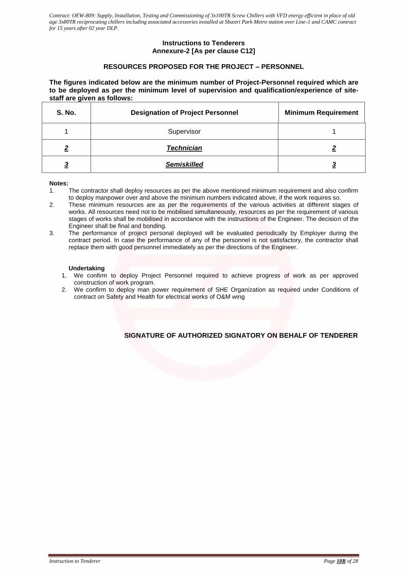
RESOURCES PROPOSED FOR THE PROJECT – PERSONNEL
The figures indicated below are the minimum number of Project-Personnel required which are to be deployed as per the minimum level of supervision and qualification/experience of site-staff are given as follows:
S. No. Designation of Project Personnel Minimum Requirement
1 Supervisor 1
2 Technician 2
3 Semiskilled 3
Notes:
1. The contractor shall deploy resources as per the above mentioned minimum requirement and also confirm to deploy manpower over and above the minimum numbers indicated above, if the work requires so.
2. These minimum resources are as per the requirements of the various activities at different stages of works. All resources need not to be mobilised simultaneously, resources as per the requirement of various stages of works shall be mobilised in accordance with the instructions of the Engineer. The decision of the Engineer shall be final and bonding.
3. The performance of project personal deployed will be evaluated periodically by Employer during the contract period. In case the performance of any of the personnel is not satisfactory, the contractor shall replace them with good personnel immediately as per the directions of the Engineer. Undertaking
1. We confirm to deploy Project Personnel required to achieve progress of work as per approved construction of work program.
2. We confirm to deploy man power requirement of SHE Organization as required under Conditions of contract on Safety and Health for electrical works of O&M wing
SIGNATURE OF AUTHORIZED SIGNATORY ON BEHALF OF TENDERER
Contract: OEW-809: Supply, Installation, Testing and Commissioning of 3x100TR Screw Chillers with VFD energy efficient in place of old
age 3x80TR reciprocating chillers including associated accessories installed at Shastri Park Metro station over Line-1 and CAMC contract
for 15 years after 02 year DLP.
Instruction to Tenderer Page 19R of 28
Instructions to Tenderers
Annexure-3 [As per clause C12]
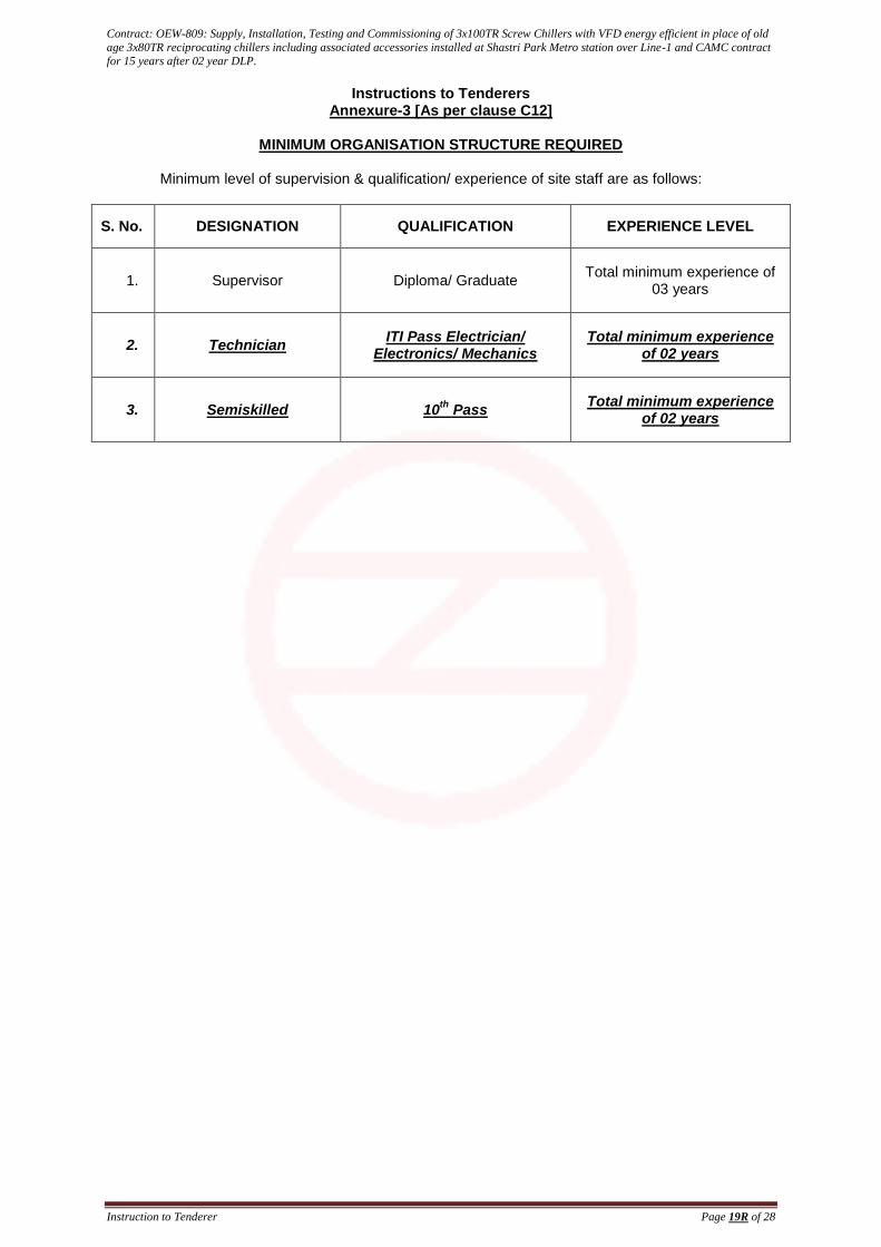
MINIMUM ORGANISATION STRUCTURE REQUIRED
Minimum level of supervision & qualification/ experience of site staff are as follows:
S. No. DESIGNATION QUALIFICATION EXPERIENCE LEVEL
1. Supervisor Diploma/ Graduate Total minimum experience of
03 years
2. Technician ITI Pass Electrician/
Electronics/ Mechanics Total minimum experience
of 02 years
3. Semiskilled 10th
Pass Total minimum experience
of 02 years
Contract: OEW-809: Supply, Installation, Testing and Commissioning of 3x100TR Screw Chillers with VFD energy efficient in place of old
age 3x80TR reciprocating chillers including associated accessories installed at Shastri Park Metro station over Line-1 and CAMC contract
for 15 years after 02 year DLP. age 3x80TR reciprocating chillers including associated accessories installed at Shastri Park Metro station
over Line-1 and CAMC contract for 15 years after 02 year DLP.
Form of tender Page 1R of 31
FORM OF TENDER (FOT)
Note :i. The Appendix forms part of the Tender.
ii. Tenderers are required to fill up all the blank spaces in this Form of Tender and Appendix.
Name of Work: As in the NIT clause No. 1.1.2
To, CE/Tender (O&M), Delhi Metro Rail Corporation, 5
thfloor, C-Wing, Metro Bhawan,
Fire Brigade Lane, Barakhamba Road, New Delhi –110001 1. Having visited the site and examined the General Conditions of Contract as well as Special
Conditions of Contract, Conditions of contract on Safety and Health, Employer’s Requirements, Specifications, Instructions to Tenderers including Bill of Quantity, for the execution of above named works, and the matters set out in Appendix 1 hereto, and having completed and prepared Appendices 2, 3, 4, 5, 6, 7, 8, 9, 10, 11, 12, 13, 14, 15, 16, 17, 18, 19, 20, 21, 22, 23, and 24 and 25 hereto, we the undersigned, offer to execute and complete such works and remedy defects therein in conformity with the said Conditions of Contract, Specifications, and Addenda (if any) for the amount as quoted in BOQ (Financial Bid) or such other sum as may be ascertained in accordance with the said conditions.
2. We undertake (jointly and severally)*
(a) to keep this Tender open for acceptance without unilaterally varying or amending its terms for the period stated in Notice of Invitation to Tender hereto (the withdrawal of any member or any other change in the composition of the partnership/joint venture/consortium on whose behalf this Tender is submitted shall constitute a breach of this undertaking)*; and
(b) If our Tender is accepted, we will furnish at our option a Bank Guarantee/ FDR/ DD for Performance as security for the due performance of the Contract. The amount and form of such guarantee or bond will be in accordance with Clause 4.2 of the General Conditions of the Contract and as indicated in the Appendix-1 hereto; and
(c) to hold in confidence all documents and information whether technical or commercial supplied to us at any time by or on behalf of the DMRC in connection with this Tender or with the above-mentioned Works and, without your written authority or as otherwise required by law, not to publish or otherwise disclose the same.
3. We submit with this Tender a duly executed Tender Guarantee in respect of our obligations under this Tender.
4. Unless and until a formal Agreement is prepared and executed, this Tender, together with your written acceptance thereof, shall constitute a binding contract between us.
5. We undertake, if our Tender is accepted, to commence the works within 7days of issue of the Letter of Acceptance to complete the whole of the Works comprised in the Contract up to 208 209 Months completion period.
6. We understand that you are not bound to accept the lowest or any tender you may receive.
7. We declare that the submission of this Tender confirms that no agent, middleman or any intermediary has been, or will be engaged to provide any services, or any other item of work related to the award and performance of this Contract. We further confirm and declare that no agency commission or any payment, which may be construed as an agency commission has been, or will be, paid and that the tender price does not include any such amount.
8. We acknowledge the right of the Employer, if he finds to the contrary, to declare our Tender to be non-compliant and if the Contract has been awarded to declare the Contract null and void.
9. This Tender shall be governed by and construed in all respects according to the laws for the time being in force in India. The courts at New Delhi will have exclusive jurisdiction in the matter.
10. We agree to abide by this Tender for a minimum period of 180 days from the date fixed for receiving the same and it shall remain binding upon us and may be accepted at any time before the expiry of that period or any extended period mutually agreed to.
11. We acknowledge that the Appendix forms an integral part of the Tender.
Contract: OEW-809: Supply, Installation, Testing and Commissioning of 3x100TR Screw Chillers with VFD energy efficient in place of old
age 3x80TR reciprocating chillers including associated accessories installed at Shastri Park Metro station over Line-1 and CAMC contract
for 15 years after 02 year DLP. age 3x80TR reciprocating chillers including associated accessories installed at Shastri Park Metro station
over Line-1 and CAMC contract for 15 years after 02 year DLP.
Form of tender Page 2R of 31
12. We have independently considered the amount shown Clause 8.5 of the General Conditions of Contract as liquidated damages and agree that they represent a fair estimate of the damages likely to be suffered by you in the event of the work not being completed in time.
13. If our Tender is accepted we understand that we are to be held solely responsible for the due performance of the Contract.
Dated this…………day of…………. 2020.
Signature …………………………………
Name………………..……………… in the capacity of …………………………..
duly authorized to sign Tenders for and on behalf of…………..…………………
Address ……………………………………………………………………..………..
Witness:1 – Signature ………………………
Name ……………………………………………
Address …………………………………………
Occupation ……………………………………
Witness:2 – Signature ………………………
Name ……………………………………………
Address …………………………………………
Occupation ……………………………………
* Note:
If the Tenderer comprises a partnership, joint venture or consortium:
(a) The provisions marked with an asterisk are to be retained subject to deletion of the
brackets and inapplicable descriptions (i.e. partnership, joint venture or consortium).
(b) The liability of each member under the Tender, and under any contract formed upon its
acceptance, will be joint and several.
(c) An authorised representative of each member must sign the Tender.
(d) Signature on the Form of Tender shall be witnessed and dated.
(e) Copies of the relevant power of attorney shall be attached.
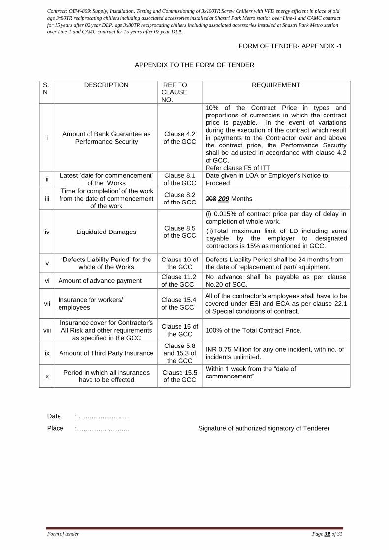
Contract: OEW-809: Supply, Installation, Testing and Commissioning of 3x100TR Screw Chillers with VFD energy efficient in place of old
age 3x80TR reciprocating chillers including associated accessories installed at Shastri Park Metro station over Line-1 and CAMC contract
for 15 years after 02 year DLP. age 3x80TR reciprocating chillers including associated accessories installed at Shastri Park Metro station
over Line-1 and CAMC contract for 15 years after 02 year DLP.
Form of tender Page 3R of 31
FORM OF TENDER- APPENDIX -1
APPENDIX TO THE FORM OF TENDER
S.N
DESCRIPTION REF TO CLAUSE NO.
REQUIREMENT
i Amount of Bank Guarantee as
Performance Security Clause 4.2 of the GCC
10% of the Contract Price in types and proportions of currencies in which the contract price is payable. In the event of variations during the execution of the contract which result in payments to the Contractor over and above the contract price, the Performance Security shall be adjusted in accordance with clause 4.2 of GCC. Refer clause F5 of ITT
ii Latest ‘date for commencement’
of the Works Clause 8.1 of the GCC
Date given in LOA or Employer’s Notice to Proceed
iii ‘Time for completion’ of the work from the date of commencement
of the work
Clause 8.2 of the GCC
208 209 Months
iv Liquidated Damages Clause 8.5 of the GCC
(i) 0.015% of contract price per day of delay in completion of whole work.
(ii)Total maximum limit of LD including sums payable by the employer to designated contractors is 15% as mentioned in GCC.
v ‘Defects Liability Period’ for the
whole of the Works Clause 10 of
the GCC Defects Liability Period shall be 24 months from the date of replacement of part/ equipment.
vi Amount of advance payment Clause 11.2 of the GCC
No advance shall be payable as per clause No.20 of SCC.
vii Insurance for workers/ employees
Clause 15.4 of the GCC
All of the contractor’s employees shall have to be covered under ESI and ECA as per clause 22.1 of Special conditions of contract.
viii Insurance cover for Contractor’s All Risk and other requirements
as specified in the GCC
Clause 15 of the GCC
100% of the Total Contract Price.
ix Amount of Third Party Insurance Clause 5.8 and 15.3 of
the GCC
INR 0.75 Million for any one incident, with no. of incidents unlimited.
x Period in which all insurances
have to be effected Clause 15.5 of the GCC
Within 1 week from the “date of commencement”
Date : …………………..
Place :………….. ……….
Signature of authorized signatory of Tenderer
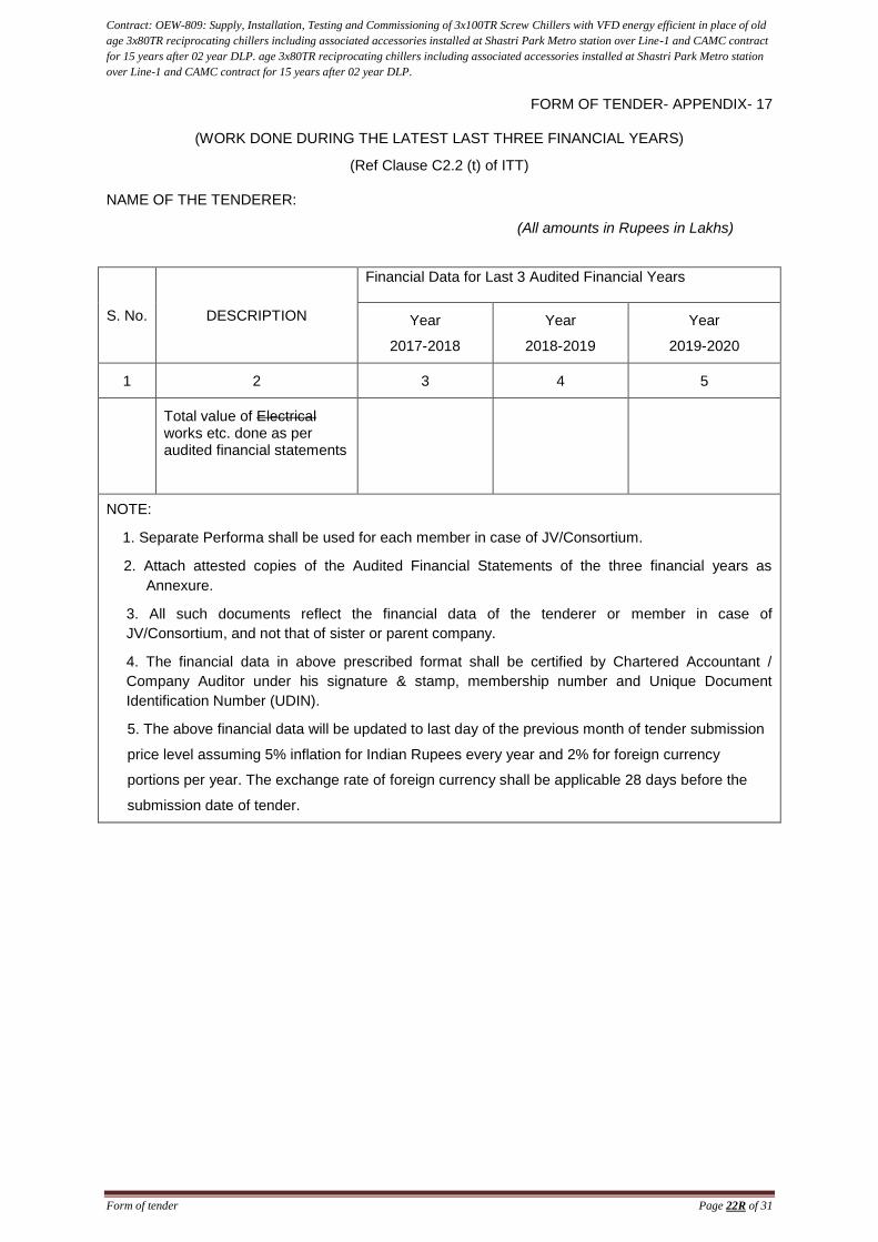
Contract: OEW-809: Supply, Installation, Testing and Commissioning of 3x100TR Screw Chillers with VFD energy efficient in place of old
age 3x80TR reciprocating chillers including associated accessories installed at Shastri Park Metro station over Line-1 and CAMC contract
for 15 years after 02 year DLP. age 3x80TR reciprocating chillers including associated accessories installed at Shastri Park Metro station
over Line-1 and CAMC contract for 15 years after 02 year DLP.
Form of tender Page 22R of 31
FORM OF TENDER- APPENDIX- 17
(WORK DONE DURING THE LATEST LAST THREE FINANCIAL YEARS)
(Ref Clause C2.2 (t) of ITT)
NAME OF THE TENDERER:
(All amounts in Rupees in Lakhs)
S. No. DESCRIPTION
Financial Data for Last 3 Audited Financial Years
Year
2017-2018
Year
2018-2019
Year
2019-2020
1 2 3 4 5
Total value of Electrical works etc. done as per audited financial statements
NOTE:
1. Separate Performa shall be used for each member in case of JV/Consortium.
2. Attach attested copies of the Audited Financial Statements of the three financial years as
Annexure.
3. All such documents reflect the financial data of the tenderer or member in case of
JV/Consortium, and not that of sister or parent company.
4. The financial data in above prescribed format shall be certified by Chartered Accountant /
Company Auditor under his signature & stamp, membership number and Unique Document
Identification Number (UDIN).
5. The above financial data will be updated to last day of the previous month of tender submission
price level assuming 5% inflation for Indian Rupees every year and 2% for foreign currency
portions per year. The exchange rate of foreign currency shall be applicable 28 days before the
submission date of tender.
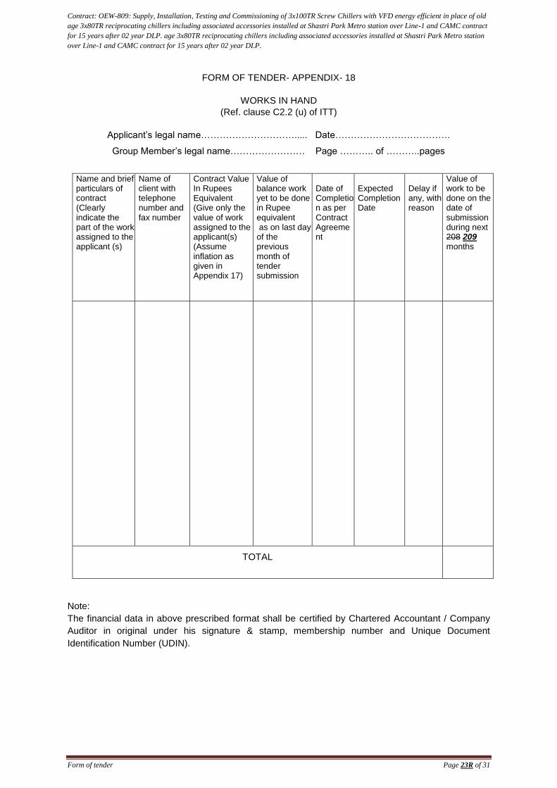
Contract: OEW-809: Supply, Installation, Testing and Commissioning of 3x100TR Screw Chillers with VFD energy efficient in place of old
age 3x80TR reciprocating chillers including associated accessories installed at Shastri Park Metro station over Line-1 and CAMC contract
for 15 years after 02 year DLP. age 3x80TR reciprocating chillers including associated accessories installed at Shastri Park Metro station
over Line-1 and CAMC contract for 15 years after 02 year DLP.
Form of tender Page 23R of 31
FORM OF TENDER- APPENDIX- 18
WORKS IN HAND
(Ref. clause C2.2 (u) of ITT)
Applicant’s legal name…………………………..... Date……………………………….
Group Member’s legal name…………………… Page ……….. of ………..pages
Name and brief particulars of contract (Clearly indicate the part of the work assigned to the applicant (s)
Name of client with telephone number and fax number
Contract Value In Rupees Equivalent (Give only the value of work assigned to the applicant(s) (Assume inflation as given in Appendix 17)
Value of balance work yet to be done in Rupee equivalent as on last day of the previous month of tender submission
Date of Completion as per Contract Agreement
Expected Completion Date
Delay if any, with reason
Value of work to be done on the date of submission during next 208 209 months
TOTAL
TOTAL
Note:
The financial data in above prescribed format shall be certified by Chartered Accountant / Company
Auditor in original under his signature & stamp, membership number and Unique Document
Identification Number (UDIN).
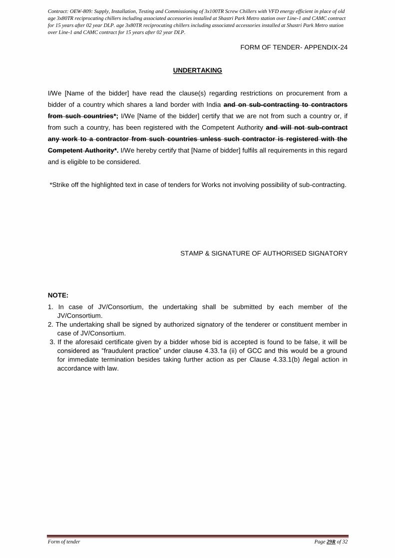
Contract: OEW-809: Supply, Installation, Testing and Commissioning of 3x100TR Screw Chillers with VFD energy efficient in place of old
age 3x80TR reciprocating chillers including associated accessories installed at Shastri Park Metro station over Line-1 and CAMC contract
for 15 years after 02 year DLP. age 3x80TR reciprocating chillers including associated accessories installed at Shastri Park Metro station
over Line-1 and CAMC contract for 15 years after 02 year DLP.
Form of tender Page 29R of 32
FORM OF TENDER- APPENDIX-24
UNDERTAKING
I/We [Name of the bidder] have read the clause(s) regarding restrictions on procurement from a
bidder of a country which shares a land border with India and on sub-contracting to contractors
from such countries*; I/We [Name of the bidder] certify that we are not from such a country or, if
from such a country, has been registered with the Competent Authority and will not sub-contract
any work to a contractor from such countries unless such contractor is registered with the
Competent Authority*. I/We hereby certify that [Name of bidder] fulfils all requirements in this regard
and is eligible to be considered.
*Strike off the highlighted text in case of tenders for Works not involving possibility of sub-contracting.
STAMP & SIGNATURE OF AUTHORISED SIGNATORY
NOTE:
1. In case of JV/Consortium, the undertaking shall be submitted by each member of the
JV/Consortium.
2. The undertaking shall be signed by authorized signatory of the tenderer or constituent member in
case of JV/Consortium.
3. If the aforesaid certificate given by a bidder whose bid is accepted is found to be false, it will be
considered as “fraudulent practice” under clause 4.33.1a (ii) of GCC and this would be a ground
for immediate termination besides taking further action as per Clause 4.33.1(b) /legal action in
accordance with law.
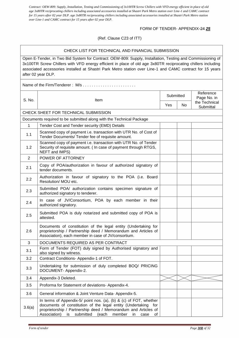
Contract: OEW-809: Supply, Installation, Testing and Commissioning of 3x100TR Screw Chillers with VFD energy efficient in place of old
age 3x80TR reciprocating chillers including associated accessories installed at Shastri Park Metro station over Line-1 and CAMC contract
for 15 years after 02 year DLP. age 3x80TR reciprocating chillers including associated accessories installed at Shastri Park Metro station
over Line-1 and CAMC contract for 15 years after 02 year DLP.
Form of tender Page 30R of 32
FORM OF TENDER- APPENDIX-24 25
(Ref. Clause C23 of ITT)
CHECK LIST FOR TECHNICAL AND FINANCIAL SUBMISSION
Open E-Tender, in Two Bid System for Contract: OEW-809: Supply, Installation, Testing and Commissioning of
3x100TR Screw Chillers with VFD energy efficient in place of old age 3x80TR reciprocating chillers including
associated accessories installed at Shastri Park Metro station over Line-1 and CAMC contract for 15 years
after 02 year DLP.
.
Name of the Firm/Tenderer : M/s . . . . . . . . . . . . . . . . . . . . . . . .
S. No. Item Submitted
Reference Page No. in
the Technical Submittal
Yes No
CHECK SHEET FOR TECHNICAL SUBMISSION
Documents required to be submitted along with the Technical Package
1 Tender Cost and Tender security (EMD) Details
1.1 Scanned copy of payment i.e. transaction with UTR No. of Cost of Tender Documents/ Tender fee of requisite amount.
1.2 Scanned copy of payment i.e. transaction with UTR No. of Tender Security of requisite amount. ( In case of payment through RTGS, NEFT and IMPS)
2 POWER OF ATTORNEY
2.1 Copy of POA/authorization in favour of authorized signatory of tender documents.
2.2 Authorization in favour of signatory to the POA (i.e. Board Resolution/ MOU etc.
2.3 Submitted POA/ authorization contains specimen signature of authorized signatory to tenderer.
2.4 In case of JV/Consortium, POA by each member in their authorized signatory.
2.5 Submitted POA is duly notarized and submitted copy of POA is attested.
2.6 Documents of constitution of the legal entity (Undertaking for proprietorship / Partnership deed / Memorandum and Articles of Association), each member in case of JV/consortium.
3 DOCUMENTS REQUIRED AS PER CONTRACT
3.1 Form of Tender (FOT) duly signed by Authorised signatory and also signed by witness.
3.2 Contract Conditions- Appendix-1 of FOT.
3.3 Undertaking for submission of duly completed BOQ/ PRICING DOCUMENT- Appendix-2.
3.4 Appendix-3 Deleted.
3.5 Proforma for Statement of deviations- Appendix-4.
3.6 General information & Joint Venture Data- Appendix-5.
3.6(a)
In terms of Appendix-5/ point nos. (a), (b) & (c) of FOT, whether documents of constitution of the legal entity (Undertaking for proprietorship / Partnership deed / Memorandum and Articles of Association) is submitted (each member in case of
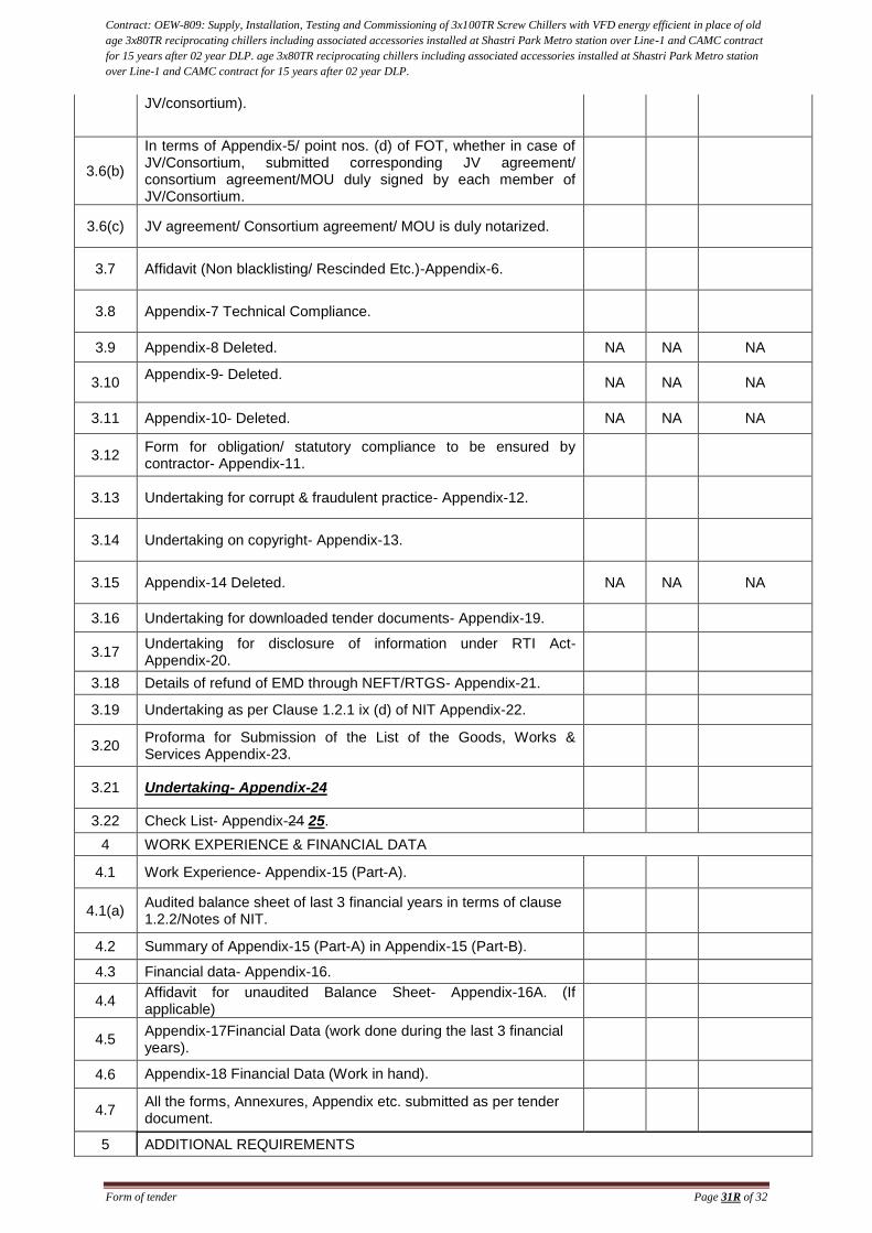
Contract: OEW-809: Supply, Installation, Testing and Commissioning of 3x100TR Screw Chillers with VFD energy efficient in place of old
age 3x80TR reciprocating chillers including associated accessories installed at Shastri Park Metro station over Line-1 and CAMC contract
for 15 years after 02 year DLP. age 3x80TR reciprocating chillers including associated accessories installed at Shastri Park Metro station
over Line-1 and CAMC contract for 15 years after 02 year DLP.
Form of tender Page 31R of 32
JV/consortium).
3.6(b)
In terms of Appendix-5/ point nos. (d) of FOT, whether in case of JV/Consortium, submitted corresponding JV agreement/ consortium agreement/MOU duly signed by each member of JV/Consortium.
3.6(c) JV agreement/ Consortium agreement/ MOU is duly notarized.
3.7 Affidavit (Non blacklisting/ Rescinded Etc.)-Appendix-6.
3.8 Appendix-7 Technical Compliance.
3.9 Appendix-8 Deleted. NA NA NA
3.10 Appendix-9- Deleted.
NA NA NA
3.11 Appendix-10- Deleted. NA NA NA
3.12 Form for obligation/ statutory compliance to be ensured by contractor- Appendix-11.
3.13 Undertaking for corrupt & fraudulent practice- Appendix-12.
3.14 Undertaking on copyright- Appendix-13.
3.15 Appendix-14 Deleted. NA NA NA
3.16 Undertaking for downloaded tender documents- Appendix-19.
3.17 Undertaking for disclosure of information under RTI Act- Appendix-20.
3.18 Details of refund of EMD through NEFT/RTGS- Appendix-21.
3.19 Undertaking as per Clause 1.2.1 ix (d) of NIT Appendix-22.
3.20 Proforma for Submission of the List of the Goods, Works & Services Appendix-23.
3.21 Undertaking- Appendix-24
3.22 Check List- Appendix-24 25.
4 WORK EXPERIENCE & FINANCIAL DATA
4.1 Work Experience- Appendix-15 (Part-A).
4.1(a) Audited balance sheet of last 3 financial years in terms of clause 1.2.2/Notes of NIT.
4.2 Summary of Appendix-15 (Part-A) in Appendix-15 (Part-B).
4.3 Financial data- Appendix-16.
4.4 Affidavit for unaudited Balance Sheet- Appendix-16A. (If applicable)
4.5 Appendix-17Financial Data (work done during the last 3 financial years).
4.6 Appendix-18 Financial Data (Work in hand).
4.7 All the forms, Annexures, Appendix etc. submitted as per tender document.
5 ADDITIONAL REQUIREMENTS
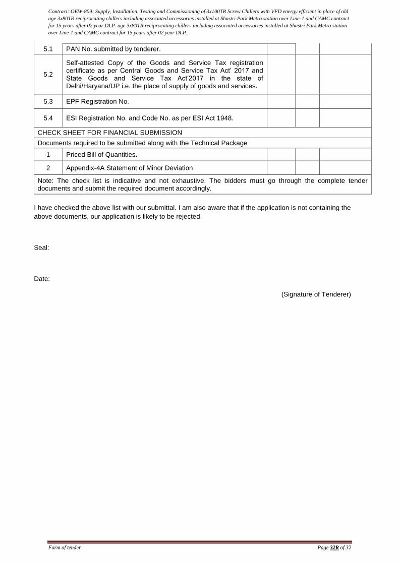
Contract: OEW-809: Supply, Installation, Testing and Commissioning of 3x100TR Screw Chillers with VFD energy efficient in place of old
age 3x80TR reciprocating chillers including associated accessories installed at Shastri Park Metro station over Line-1 and CAMC contract
for 15 years after 02 year DLP. age 3x80TR reciprocating chillers including associated accessories installed at Shastri Park Metro station
over Line-1 and CAMC contract for 15 years after 02 year DLP.
Form of tender Page 32R of 32
5.1 PAN No. submitted by tenderer.
5.2
Self-attested Copy of the Goods and Service Tax registration certificate as per Central Goods and Service Tax Act’ 2017 and State Goods and Service Tax Act’2017 in the state of Delhi/Haryana/UP i.e. the place of supply of goods and services.
5.3 EPF Registration No.
5.4 ESI Registration No. and Code No. as per ESI Act 1948.
CHECK SHEET FOR FINANCIAL SUBMISSION
Documents required to be submitted along with the Technical Package
1 Priced Bill of Quantities.
2 Appendix-4A Statement of Minor Deviation
Note: The check list is indicative and not exhaustive. The bidders must go through the complete tender documents and submit the required document accordingly.
I have checked the above list with our submittal. I am also aware that if the application is not containing the
above documents, our application is likely to be rejected.
Seal:
Date:
(Signature of Tenderer)
CONTRACT NO: OEW-809
“Supply, Installation, Testing and Commissioning of 3x100TR Screw Chillers with VFD energy efficient in place of old age
3x80TR reciprocating chillers including associated accessories installed at Shastri Park Metro station over Line-
1 and CAMC contract for 15 years after 02 year DLP”
Employer’s Requirement and Technical Specifications
(Revised)
DELHI METRO RAIL CORPORATION LTD. 5th Floor, C-Wing, Metro Bhawan, Fire Brigade Lane,
Barakhamba Road, New Delhi –110001
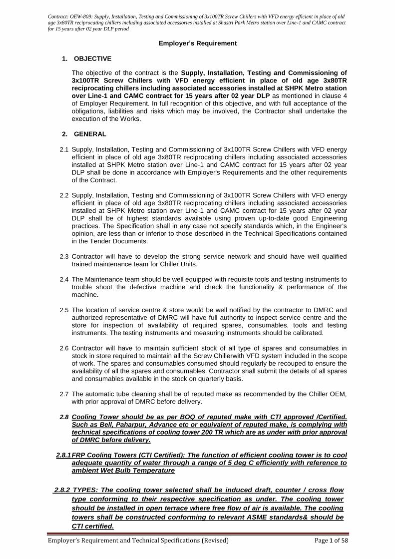
Contract: OEW-809: Supply, Installation, Testing and Commissioning of 3x100TR Screw Chillers with VFD energy efficient in place of old age 3x80TR reciprocating chillers including associated accessories installed at Shastri Park Metro station over Line-1 and CAMC contract
for 15 years after 02 year DLP period
Employer’s Requirement and Technical Specifications (Revised) Page 1 of 58
Employer’s Requirement
1. OBJECTIVE
The objective of the contract is the Supply, Installation, Testing and Commissioning of 3x100TR Screw Chillers with VFD energy efficient in place of old age 3x80TR reciprocating chillers including associated accessories installed at SHPK Metro station over Line-1 and CAMC contract for 15 years after 02 year DLP as mentioned in clause 4 of Employer Requirement. In full recognition of this objective, and with full acceptance of the obligations, liabilities and risks which may be involved, the Contractor shall undertake the execution of the Works.
2. GENERAL
2.1 Supply, Installation, Testing and Commissioning of 3x100TR Screw Chillers with VFD energy efficient in place of old age 3x80TR reciprocating chillers including associated accessories installed at SHPK Metro station over Line-1 and CAMC contract for 15 years after 02 year DLP shall be done in accordance with Employer's Requirements and the other requirements of the Contract.
2.2 Supply, Installation, Testing and Commissioning of 3x100TR Screw Chillers with VFD energy efficient in place of old age 3x80TR reciprocating chillers including associated accessories installed at SHPK Metro station over Line-1 and CAMC contract for 15 years after 02 year DLP shall be of highest standards available using proven up-to-date good Engineering practices. The Specification shall in any case not specify standards which, in the Engineer's opinion, are less than or inferior to those described in the Technical Specifications contained in the Tender Documents.
2.3 Contractor will have to develop the strong service network and should have well qualified trained maintenance team for Chiller Units.
2.4 The Maintenance team should be well equipped with requisite tools and testing instruments to trouble shoot the defective machine and check the functionality & performance of the machine.
2.5 The location of service centre & store would be well notified by the contractor to DMRC and authorized representative of DMRC will have full authority to inspect service centre and the store for inspection of availability of required spares, consumables, tools and testing instruments. The testing instruments and measuring instruments should be calibrated.
2.6 Contractor will have to maintain sufficient stock of all type of spares and consumables in stock in store required to maintain all the Screw Chillerwith VFD system included in the scope of work. The spares and consumables consumed should regularly be recouped to ensure the availability of all the spares and consumables. Contractor shall submit the details of all spares and consumables available in the stock on quarterly basis.
2.7 The automatic tube cleaning shall be of reputed make as recommended by the Chiller OEM, with prior approval of DMRC before delivery.
2.8 Cooling Tower should be as per BOQ of reputed make with CTI approved /Certified. Such as Bell, Paharpur, Advance etc or equivalent of reputed make, is complying with technical specifications of cooling tower 200 TR which are as under with prior approval of DMRC before delivery.
2.8.1 FRP Cooling Towers (CTI Certified): The function of efficient cooling tower is to cool adequate quantity of water through a range of 5 deg C efficiently with reference to ambient Wet Bulb Temperature
2.8.2 TYPES: The cooling tower selected shall be induced draft, counter / cross flow
type conforming to their respective specification as under. The cooling tower
should be installed in open terrace where free flow of air is available. The cooling
towers shall be constructed conforming to relevant ASME standards& should be
CTI certified.
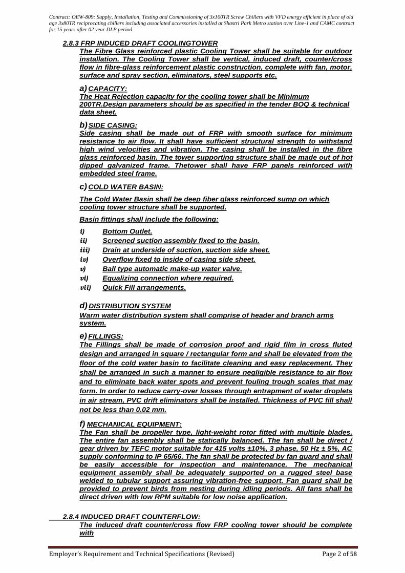
Contract: OEW-809: Supply, Installation, Testing and Commissioning of 3x100TR Screw Chillers with VFD energy efficient in place of old age 3x80TR reciprocating chillers including associated accessories installed at Shastri Park Metro station over Line-1 and CAMC contract
for 15 years after 02 year DLP period
Employer’s Requirement and Technical Specifications (Revised) Page 2 of 58
2.8.3 FRP INDUCED DRAFT COOLINGTOWER The Fibre Glass reinforced plastic Cooling Tower shall be suitable for outdoor
installation. The Cooling Tower shall be vertical, induced draft, counter/cross
flow in fibre-glass reinforcement plastic construction, complete with fan, motor,
surface and spray section, eliminators, steel supports etc.
a) CAPACITY: The Heat Rejection capacity for the cooling tower shall be Minimum 200TR.Design parameters should be as specified in the tender BOQ & technical data sheet.
b) SIDE CASING: Side casing shall be made out of FRP with smooth surface for minimum
resistance to air flow. It shall have sufficient structural strength to withstand
high wind velocities and vibration. The casing shall be installed in the fibre
glass reinforced basin. The tower supporting structure shall be made out of hot
dipped galvanized frame. Thetower shall have FRP panels reinforced with
embedded steel frame.
c) COLD WATER BASIN:
The Cold Water Basin shall be deep fiber glass reinforced sump on which
cooling tower structure shall be supported.
Basin fittings shall include the following:
i) Bottom Outlet.
ii) Screened suction assembly fixed to the basin.
iii) Drain at underside of suction, suction side sheet.
iv) Overflow fixed to inside of casing side sheet.
v) Ball type automatic make-up water valve.
vi) Equalizing connection where required.
vii) Quick Fill arrangements.
d) DISTRIBUTION SYSTEM
Warm water distribution system shall comprise of header and branch arms system.
e) FILLINGS:
The Fillings shall be made of corrosion proof and rigid film in cross fluted
design and arranged in square / rectangular form and shall be elevated from the
floor of the cold water basin to facilitate cleaning and easy replacement. They
shall be arranged in such a manner to ensure negligible resistance to air flow
and to eliminate back water spots and prevent fouling trough scales that may
form. In order to reduce carry-over losses through entrapment of water droplets
in air stream, PVC drift eliminators shall be installed. Thickness of PVC fill shall
not be less than 0.02 mm.
f) MECHANICAL EQUIPMENT:
The Fan shall be propeller type, light-weight rotor fitted with multiple blades.
The entire fan assembly shall be statically balanced. The fan shall be direct /
gear driven by TEFC motor suitable for 415 volts ±10%, 3 phase, 50 Hz ± 5%, AC
supply conforming to IP 65/66. The fan shall be protected by fan guard and shall
be easily accessible for inspection and maintenance. The mechanical
equipment assembly shall be adequately supported on a rugged steel base
welded to tubular support assuring vibration-free support. Fan guard shall be
provided to prevent birds from nesting during idling periods. All fans shall be
direct driven with low RPM suitable for low noise application.
2.8.4 INDUCED DRAFT COUNTERFLOW:
The induced draft counter/cross flow FRP cooling tower should be complete
with
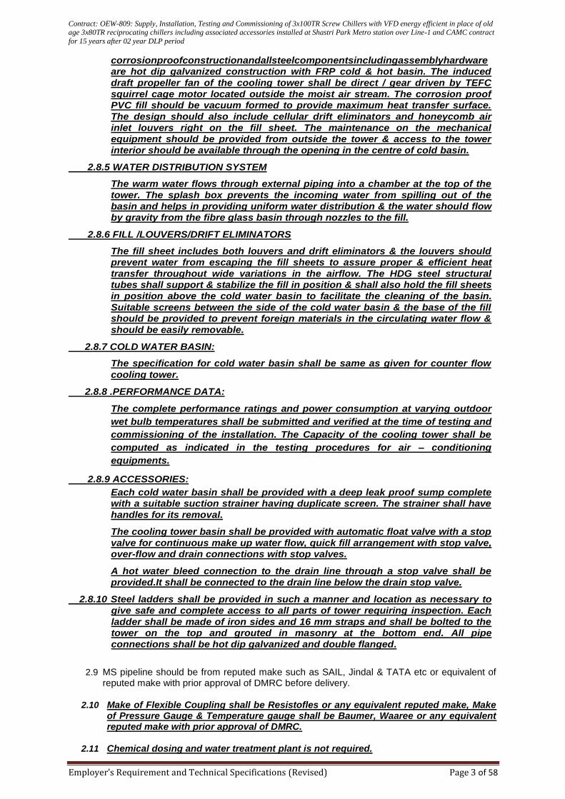
Contract: OEW-809: Supply, Installation, Testing and Commissioning of 3x100TR Screw Chillers with VFD energy efficient in place of old age 3x80TR reciprocating chillers including associated accessories installed at Shastri Park Metro station over Line-1 and CAMC contract
for 15 years after 02 year DLP period
Employer’s Requirement and Technical Specifications (Revised) Page 3 of 58
corrosionproofconstructionandallsteelcomponentsincludingassemblyhardware
are hot dip galvanized construction with FRP cold & hot basin. The induced
draft propeller fan of the cooling tower shall be direct / gear driven by TEFC
squirrel cage motor located outside the moist air stream. The corrosion proof
PVC fill should be vacuum formed to provide maximum heat transfer surface.
The design should also include cellular drift eliminators and honeycomb air
inlet louvers right on the fill sheet. The maintenance on the mechanical
equipment should be provided from outside the tower & access to the tower
interior should be available through the opening in the centre of cold basin.
2.8.5 WATER DISTRIBUTION SYSTEM
The warm water flows through external piping into a chamber at the top of the
tower. The splash box prevents the incoming water from spilling out of the
basin and helps in providing uniform water distribution & the water should flow
by gravity from the fibre glass basin through nozzles to the fill.
2.8.6 FILL /LOUVERS/DRIFT ELIMINATORS
The fill sheet includes both louvers and drift eliminators & the louvers should
prevent water from escaping the fill sheets to assure proper & efficient heat
transfer throughout wide variations in the airflow. The HDG steel structural
tubes shall support & stabilize the fill in position & shall also hold the fill sheets
in position above the cold water basin to facilitate the cleaning of the basin.
Suitable screens between the side of the cold water basin & the base of the fill
should be provided to prevent foreign materials in the circulating water flow &
should be easily removable.
2.8.7 COLD WATER BASIN:
The specification for cold water basin shall be same as given for counter flow
cooling tower.
2.8.8 .PERFORMANCE DATA:
The complete performance ratings and power consumption at varying outdoor
wet bulb temperatures shall be submitted and verified at the time of testing and
commissioning of the installation. The Capacity of the cooling tower shall be
computed as indicated in the testing procedures for air – conditioning
equipments.
2.8.9 ACCESSORIES:
Each cold water basin shall be provided with a deep leak proof sump complete
with a suitable suction strainer having duplicate screen. The strainer shall have
handles for its removal.
The cooling tower basin shall be provided with automatic float valve with a stop
valve for continuous make up water flow, quick fill arrangement with stop valve,
over-flow and drain connections with stop valves.
A hot water bleed connection to the drain line through a stop valve shall be
provided.It shall be connected to the drain line below the drain stop valve.
2.8.10 Steel ladders shall be provided in such a manner and location as necessary to
give safe and complete access to all parts of tower requiring inspection. Each
ladder shall be made of iron sides and 16 mm straps and shall be bolted to the
tower on the top and grouted in masonry at the bottom end. All pipe
connections shall be hot dip galvanized and double flanged.
2.9 MS pipeline should be from reputed make such as SAIL, Jindal & TATA etc or equivalent of
reputed make with prior approval of DMRC before delivery.
2.10 Make of Flexible Coupling shall be Resistofles or any equivalent reputed make, Make of Pressure Gauge & Temperature gauge shall be Baumer, Waaree or any equivalent reputed make with prior approval of DMRC.
2.11 Chemical dosing and water treatment plant is not required.
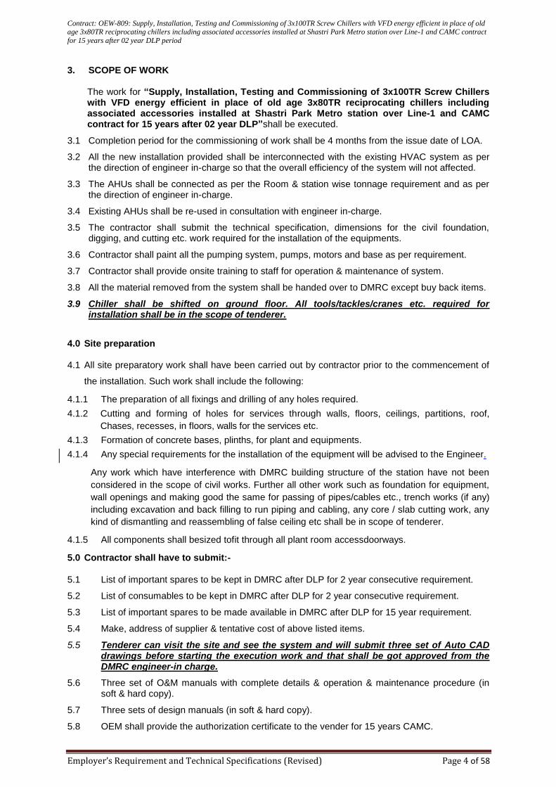
Contract: OEW-809: Supply, Installation, Testing and Commissioning of 3x100TR Screw Chillers with VFD energy efficient in place of old age 3x80TR reciprocating chillers including associated accessories installed at Shastri Park Metro station over Line-1 and CAMC contract
for 15 years after 02 year DLP period
Employer’s Requirement and Technical Specifications (Revised) Page 4 of 58
3. SCOPE OF WORK
The work for “Supply, Installation, Testing and Commissioning of 3x100TR Screw Chillers with VFD energy efficient in place of old age 3x80TR reciprocating chillers including associated accessories installed at Shastri Park Metro station over Line-1 and CAMC contract for 15 years after 02 year DLP”shall be executed.
3.1 Completion period for the commissioning of work shall be 4 months from the issue date of LOA.
3.2 All the new installation provided shall be interconnected with the existing HVAC system as per the direction of engineer in-charge so that the overall efficiency of the system will not affected.
3.3 The AHUs shall be connected as per the Room & station wise tonnage requirement and as per the direction of engineer in-charge.
3.4 Existing AHUs shall be re-used in consultation with engineer in-charge.
3.5 The contractor shall submit the technical specification, dimensions for the civil foundation, digging, and cutting etc. work required for the installation of the equipments.
3.6 Contractor shall paint all the pumping system, pumps, motors and base as per requirement.
3.7 Contractor shall provide onsite training to staff for operation & maintenance of system.
3.8 All the material removed from the system shall be handed over to DMRC except buy back items.
3.9 Chiller shall be shifted on ground floor. All tools/tackles/cranes etc. required for installation shall be in the scope of tenderer.
4.0 Site preparation
4.1 All site preparatory work shall have been carried out by contractor prior to the commencement of
the installation. Such work shall include the following:
4.1.1 The preparation of all fixings and drilling of any holes required.
4.1.2 Cutting and forming of holes for services through walls, floors, ceilings, partitions, roof,
Chases, recesses, in floors, walls for the services etc.
4.1.3 Formation of concrete bases, plinths, for plant and equipments.
4.1.4 Any special requirements for the installation of the equipment will be advised to the Engineer.
Any work which have interference with DMRC building structure of the station have not been
considered in the scope of civil works. Further all other work such as foundation for equipment,
wall openings and making good the same for passing of pipes/cables etc., trench works (if any)
including excavation and back filling to run piping and cabling, any core / slab cutting work, any
kind of dismantling and reassembling of false ceiling etc shall be in scope of tenderer.
4.1.5 All components shall besized tofit through all plant room accessdoorways.
5.0 Contractor shall have to submit:-
5.1 List of important spares to be kept in DMRC after DLP for 2 year consecutive requirement.
5.2 List of consumables to be kept in DMRC after DLP for 2 year consecutive requirement.
5.3 List of important spares to be made available in DMRC after DLP for 15 year requirement.
5.4 Make, address of supplier & tentative cost of above listed items.
5.5 Tenderer can visit the site and see the system and will submit three set of Auto CAD drawings before starting the execution work and that shall be got approved from the DMRC engineer-in charge.
5.6 Three set of O&M manuals with complete details & operation & maintenance procedure (in soft & hard copy).
5.7 Three sets of design manuals (in soft & hard copy).
5.8 OEM shall provide the authorization certificate to the vender for 15 years CAMC.
Contract: OEW-809: Supply, Installation, Testing and Commissioning of 3x100TR Screw Chillers with VFD energy efficient in place of old age 3x80TR reciprocating chillers including associated accessories installed at Shastri Park Metro station over Line-1 and CAMC contract
for 15 years after 02 year DLP period
Employer’s Requirement and Technical Specifications (Revised) Page 5 of 58
6.0 Manpower deployment
6.1 The contractor shall deploy the manpower in consultation with Engineer in-charge and carry
out the activities in hygienic manner. 6.2 The manpower can also be deployed during OFF days/holidays/night hours as per site
requirements for which nothing shall be paid extra.
6.3 All the work associated with finishing complete in all respect shall be carried out by contractor
for which nothing shall be paid extra.
7.0 Key dates
7.1 Contractor shall submit the detailed layout plan & design as per DMRC requirement within 15 days of issue of LOA.
7.2 Contractor shall also submit the schedule for completion of work with key dates for timely completion of work in consultation with DMRC Engineer – in - charge.
8.0 Schedule of Maintenance:
8.1 Preventive Maintenance:
Contractor shall strictly follow the preventive maintenance Schedule along with check lists as
per technical Specification. However, if DMRC feels that any other activity is required to be
additionally done for proper maintenance of the system as per the OEM recommendation, he
shall carry out the same.
Requirement of preventive maintenance indicated in technical specification scheduled
checklists is the bare minimum. The activities to be carried out in Monthly/Quarterly/Half
Yearly/Yearly Scheduled Maintenance as attached as Annexure-A & B in the Employer’s
requirement.
The preventive maintenance is to be carryout for complete Chiller system & its associated
accessories as per BOQ including replacement faulty spares and consumable items.
The preventive maintenance is to be carried out in such a manner that overall functioning of
the system & functional equipment’s are not affected.
8.2 Corrective Maintenance: The corrective/breakdown maintenance is to be carried any time
during 24hrs X 365 days inclusive of all Sundays & Holidays.
8.2.1 Minor Maintenance: Inclusive of Repairing and replacement of all Spares/Components and
all other associated accessories which are covered otherwise and attention of all defects
other than major defects..
i. Response Time (Max.) : 04 hrs (after registration of call)
ii. Attending Time (Max.) : 08 hrs (after response time of 4 hrs)
8.2.2 Major Maintenance: It covers attention of all types of Major failures/Breakdown.
i. Response Time (Max.) : 04 hrs (after registration of call)
ii. Attending Time (Max.) : 48 hrs
Attention time for major breakdown i.e. Gas Charging Compressor replacement: 72 hrs
(i) Call made before 16:00 Hrs shall have to be attended on the same day.
(ii) Call made after 16:00 Hrs shall be attended by 10:00 Hrs on next day.
(iii) Emergency calls shall be attended on necessary priority basis.
8.3 On completion of job (i.e. Preventive Maintenance and Unscheduled breakdown maintenance)
service report, will be made by the contractor’s service engineer and the same should be signed
Contract: OEW-809: Supply, Installation, Testing and Commissioning of 3x100TR Screw Chillers with VFD energy efficient in place of old age 3x80TR reciprocating chillers including associated accessories installed at Shastri Park Metro station over Line-1 and CAMC contract
for 15 years after 02 year DLP period
Employer’s Requirement and Technical Specifications (Revised) Page 6 of 58
by both the service engineer and authorized customer’s representative. One copy of the said
service report will be handed over to the customer for their own records.
8.4 In case the work is additionally required to be carried out at any other location in the DMRC
network in addition to the above mentioned stations, then the same may also be included in the
scope of work at a later stage as per the directions of the DMRC Engineer In-Charge.
8.5 At the end of every quarter the contractor shall submit the details of unscheduled
work/replacement carried out along with list of parts replaced/repaired along with corrective
measures under taken to prevent their re occurrence. The payment against CAMC shall only be
released after submission of duly filled preventive maintenance report.
8.6 Any spare part replaced during carrying out unscheduled breakdown maintenance clearly
recorded in the service report. The format of service report should be approved by DMRC.
9.0 Penalty:
9.1 A penalty will be imposed @ ₹500/- per hour/complaint in case any complaint remains unattended for more than stipulated time on a particular day and a penalty @₹5000/- per day/complaint will be imposed if a complaint remains unattended for more than 24 Hrs.
9.2 Penalty of ₹5,000/- per day will be also imposed if Preventive maintenance is delayed by more than 03 days from the Schedule day, subject to the maximum of 10% of the contract value.
9.3 The penalty shall be imposed against delay in execution of work as specified in GCC of DMRC.
10.0 Transportation: No separate charges will be paid for transport.
11.0 The manpower can also be deployed during OFF days/Holidays/Night hours as per site requirement for which nothing shall be paid extra.
12.0 The tenderer may visit the site before submitting offer.
13.0 The work is to be carried out as per the recommendation of manufacturers.
14.0 Contractor shall deploy multiple teams to work at different sites as per the requirement and nature of job.
15.0 Related electrical work in connection with installation of Chiller shall be done by the tenderer. As far as concerned of BMS, it should be compatible with existing BMS system but control cables related for installation to BMS is not in the scope of Contractor/tenderer.
Contract: OEW-809: Supply, Installation, Testing and Commissioning of 3x100TR Screw Chillers with VFD energy efficient in place of old age 3x80TR reciprocating chillers including associated accessories installed at Shastri Park Metro station over Line-1 and CAMC contract
for 15 years after 02 year DLP period
Employer’s Requirement and Technical Specifications (Revised) Page 7 of 58
Technical Specifications
1.INTRODUCTION:
Specifications for Water cooled (3 x 100 TR) Screw Chiller with VFD energy efficient.
1.0 General
This section specifies the requirements for furnishing, installing and testing of Water cooled (3 x 100
TR) screw chiller chilling units with Screw compressors and appurtenances as specified
herein, including but not limited to:
Screw Chiller package unit with VFD energy efficient.
Charge of refrigerant and oil
Controls and control connections
Chilled water connections.
Condenser water connections
Water cooled chiller packages shall be factory assembled and tested for rated efficiency. Unit shall be
delivered to site fully assembled, and charged oil by the manufacturer and refrigerant charged at
factory/site.
2.0 Quality Control
2.1 Materials and workmanship shall be in accordance with the latest edition of the following
standards and codes to the extent specified herein. The publications listed below form a part
of these specifications to the extent referenced. The publications are referred to in the text by
basic designation only.
2.2 Chiller shall be pressure-tested, evacuated and fully charged with refrigerant and Oil and shall
be factory operational run tested with water flowing through the vessel.
2.3 Within 14 days after successful completion of all factory tests the Contractor shall submit the
following:
i. Certified results for all factory tests conducted. All test data shall be bound in one report. The
test report shall be indexed and cross-referenced in an easily understood manner.
ii. Field test procedures.
2.4 Relevant Codes and Standards
2.4.1 BS 5422: Method for Specifying Thermal Insulating Materials on Pipes, Ductwork and
Equipment (In Temperature Range 40 Degrees Celsius to +700 Degrees Celsius).
2.4.2 BS 5970: Thermal Insulation of Pipe work and Equipment (In the Temperature Range – 100
Degrees Celsius to +870 Degrees Celsius).
2.4.3 NFPA Code 90A: Installation of Air Conditioning
2.4.4 NFPA Code 90B: Installation of Air-Conditioning System
2.4.5 All insulating materials shall comply with the requirement of BS 5422 & BS 5970.
2.4.6 All insulating materials shall be tested to comply with the following: BS 476: Part-4: Non
Combustibility, Combustion rating when tested in accordance with NFPA Standard Nos. 90A
and 90B, shall not exceed 25 for flame spread and 50 for smoke developed, Part 5: Product
shall not ignite when tested by source A for 10s by face ignition, Part 6: Fire propagation I
less than 12, i less than 6, Part 7 Class 1: surface spread of flame.
2.4.7 ANSI/ASHRAE 15-1992, Safety code for mechanical refrigeration.
2.4.8 Material and workmanship shall be in accordance with the latest edition of the following
standards and codes, and the materials shall be certified by the standard organization.
Contract: OEW-809: Supply, Installation, Testing and Commissioning of 3x100TR Screw Chillers with VFD energy efficient in place of old age 3x80TR reciprocating chillers including associated accessories installed at Shastri Park Metro station over Line-1 and CAMC contract
for 15 years after 02 year DLP period
Employer’s Requirement and Technical Specifications (Revised) Page 8 of 58
2.4.9 ASTM A167: Standard Specification for Stainless and Heat-Resisting Chromium – Nickel
Steel Plate, Sheet and Strip
2.4.10 BS 21: Pipe Threads for Tubes and Fittings where Pressure-Tight Joints are made on the
Threads (Metric Dimensions)
2.4.11 BS 759: Valves, Gauges and other Safety Fittings for Application to Boilers and to Piping
Installations for and in Connection with Boiler
2.4.12 BS 1010: Draw off Taps and Stop valves for Water Services (screw down Pattern)
2.4.13 BS 1212: Float Operated Valves (Excluding Floats)
2.4.14 BS 1400: Copper Alloy lngots and Copper alloy and High Conductivity Copper Castings.
2.4.15 BS 1452: Flake Graphite Cast Iron
2.4.16 BS 2456: Floats (Plastics) for Floated Operated Valves for Cold Water Services
2.4.17 BS 2879: Draining Traps (screw– Down Pattern)
2.4.18 BS 3456: Safety of Household and Similar Electrical Appliances
2.4.19 BS 4346: Joints and Fittings for Use with Unplasticized PVC Pressure Pipes
2.4.20 BS 4504: Circular Flanges for Pipes, Valves and Fittings (PN Designated)
2.4.21 BS 4514: Unplasticized PVC Soil and Ventilating Pipes, Fittings and Accessories
2.4.22 BS 4994: Design and Construction of Vessels and Tanks in Reinforced Plastics
2.4.23 BS 5150: Cast Iron Gate Valves
2.4.24 BS 5152: Cast Iron Globe and Globe Stop and Check Valves for General Purposes
2.4.25 BS 5154: Copper Alloy Globe, Globe Stop and Check, Check and Gate Valves
2.4.26 BS 5155: Butterfly Valves
2.4.27 BS 5163: Predominantly Key–Operated Cast Iron Gate Valves for Waterworks Purposes
2.4.28 BS 7350: Double Regulating Globe Valves and Flow Measurement Devices for Heating and
Chilled Water Systems
3.0 Deleted
4.0 Technical and Installation requirements
4.1. Screw Chiller
4.1.1 The water chilling machine shall be self-contained type consisting of Screw compressors,
squirrel cage induction motor, Water cooled condensers, chiller, refrigerant piping, wiring and
automatic controls all mounted on a steel base frame forming a compact assembly. The water
chilling machine shall be complete with full charge of Zero ODP Environmental friendly
refrigerant R134a and oil, vibration rubber isolation pads and accessories as per chilling unit
manufacturer standards, factory assembled and tested for rated capacity.
4.1.2 The IKW/TR for part load conditions of 25% and 50% under operating conditions shall be
indicated.
4.1.3 Structure shall be factory assembled and constructed out of formed & powder coated
galvanized steel panels.
4.1.4 Any special requirements for the installation of the equipment will be advised to the Engineer.
All components shall be sized to fit through all plant room access doorways.
4.1.5 The Water cooled chiller package housing compressor, chiller and condensers shall be
mounted on structural foundation. The Contractor shall supply all necessary foundation bolts,
nuts, washers, levelling screws, mounting frame or base plate, vibration isolation pads etc.
After erection, the unit shall be properly leveled before grouting the foundation bolts and the
levels should be shown to the Engineer’s representative. All the equipment shall be thoroughly
tested and checked for leaks.
Contract: OEW-809: Supply, Installation, Testing and Commissioning of 3x100TR Screw Chillers with VFD energy efficient in place of old age 3x80TR reciprocating chillers including associated accessories installed at Shastri Park Metro station over Line-1 and CAMC contract
for 15 years after 02 year DLP period
Employer’s Requirement and Technical Specifications (Revised) Page 9 of 58
4.1.6 Chillers shall be shell and tube and Brazed type/any improved product as per manufacturer.
The shell shall be of welded steel construction fitted with machined steel tube sheets on either
ends. End water boxes shall be designed to provide adequate space for water movement such
that there is no erosion of the tube ends. End box covers shall be removable, and allow easy
access for cleaning the tubes.
4.1.7 The chillers shall either have internally finned copper tubes or tubes with other means for
increasing heat transfer surface. The tube shall be supported in the shell by adequate, stiff
supports to eliminate vibration and noise. The tube ends shall be mechanically bonded to the
tube sheets to prevent leakage of refrigerant gas.
4.1.8 Tubes shall be as per OEM. The chiller shall be tested against leaks with a pressure as per
OEM recommendation.
4.1.9 Chillers shall be complete with the following accessories:
a. Thermostatic expansion valves, pilot solenoid valves and filter drier. Or as per OEM recommendation
b. Necessary drain valves and vent. c. Anti freeze thermostat. OR OEM recommendation. d. Other standard accessories, necessary for the equipment supplied. e. The chiller shall be insulated with factory-installed insulation.
4.2. Condenser
4.2.1 Condensers shall be Water cooled type of copper and copper fin construction/any improved
product as per manufacturer. Copper tube dia shall be minimum 9.5mm. Condenser shall be
manufactured to ASME codesor comply to equivalent other international standard for unfired
pressure vessels and designed for refrigerant working pressure of 450 psig. Condenser shall
be complete with provisions for refrigerant piping connections, shut off valves and any other
standard accessory necessary with the equipment supplied. In case of twin compressor
system two independent sets of condenser coils shall be incorporated. The condenser coils
shall be arranged in staggered rows and shall be expanded into super slit aluminium fins to
achieve superior efficiency. The fins shall have hydrophilic coating.
4.3. Compressor
Chiller packages shall be provided with single/multiple compressors. The compressor shall be sealed having an integral cast iron frame. The compressor shall be internally lubricated with a highly refined, low foaming, mineral oil. Compressor Motor
4.4.1 The compressor motor should be hermetic, refrigerant gas cooled with inherent all phase protection and shall be suitable for 415 V (+/-10%), 3 phase, 50 cycles AC supply.
4.4.2 Motor shall be screen protected drip proof squirrel cage induction type, designed and guaranteed for continuous operation at name plate rating and motor to be suitable for the refrigerant being used. Temperature sensor shall be provided in motor winding to protect the motor for high temperature rise.
4.4. Starter for compressor motor
4.5.1 The starter for the motor shall be inverter starter/VFD starter recommended by OEM.
4.5.2 Unit mounted pre-wired & pretested with factory settings Starters shall include all necessary
safety devices i.e. Overload relays, under voltage release and single phase preventing
device.
4.5.3 The motor starter shall be factory mounted and fully wired and factory tested during the run
test of the unit.
4.5.4 Starter shall have affixed to the inside of the door complete and unit mounted as built, wiring
scheme showing all accessory items.
4.5. Capacity Controls
The compressors shall have an automatic regulating capacity from 100% to 25%. In case of multiple compressors, sequencing of compressors shall be provided to allow the compressors to start at a time lag of 3-4 minutes.
Contract: OEW-809: Supply, Installation, Testing and Commissioning of 3x100TR Screw Chillers with VFD energy efficient in place of old age 3x80TR reciprocating chillers including associated accessories installed at Shastri Park Metro station over Line-1 and CAMC contract
for 15 years after 02 year DLP period
Employer’s Requirement and Technical Specifications (Revised) Page 10 of 58
4.7 Control Panels
4.8.1 The chiller shall be provided with a factory installed and wired micro processor based rain tight control panel. The control panel shall be provided with necessary MCB/MCCB/isolator for termination of incoming power cable. A contactor shall be included in the control centre for each compressor and a pair of fan motors.
4.8.2 The control system shall automatically control the operation of the unit from the time the unit is started, through the operating period, until the unit is stopped. The internal components shall be arranged for easy access. The panel shall incorporate necessary interlocking between equipment as required. The motor control centre should include safety devices to protect the unit from mal functions. These controls should shut down the unit and signal the operator with their respective lights. The protective controls shall be as listed hereunder: i. High condenser pressure cutout. ii. Low oil pressure cutout. iii. High oil temperature cutout. iv. High discharge temperature cutout. v. VFD motor over current cutout. vi. Solid state low evaporator temperature control.
4.8.3 The chiller shall be to existing station BMS system compatible. The control panel shall incorporate hardware cards/control units for complete integration of chillers to building automation system.
4.8.4 The Software shall be stored in non-volatile memory, with programmed set-points retained in lithium battery backed real time clock (RTC) memory for minimum 5 years or as per standard of OEM.
4.8.5 Liquid crystal display, descriptions in English, numeric data in English (or Metric) units. Sealed keypad with sections for Set points, Display/Print, Entry, Unit Options and clock, and On/Off Switch
4.9 Programmable Set-points: Display language; chilled liquid temperature set point and range,
remote reset temperature range, manual override for servicing, low and high ambient cutouts, number of compressors, low liquid temperature cutout, low suction pressure cutout, high discharge pressure cutout, anti-recycle timer (compressor start cycle time), and anti-coincident timer (delay compressor starts).
4.10 Display Data: Return and leaving liquid temperatures, low leaving liquid temperature cutout
setting, low ambient temperature cutout setting, outdoor air temperature, English or metric data, suction pressure cutout setting, each system suction pressure discharge pressure (optional), liquid temperature reset via a Building Automation System (by others) via PWM input as standard or at a 4-20 milliamp or 0-10VDC input or contact closure with optional BAS interface, anti-coincident system start timer condition, compressor run status, no cooling load condition, day, date and time, daily start/stop times, holiday status, automatic or manual system lead/lag control, lead system definition, compressor starts/operating hours (each), status of hot gas valves, evaporator heater and fan operation, run permissive status, number of compressors running, liquid solenoid valve status, load and unload timer status, water pump status (optional).
4.11 System Safety: Shall cause individual compressor systems to perform auto shut down; for
high discharge pressure, low suction pressure, high pressure switch, and motor protector. Compressor motor protector shall protect against damage due to high input current or thermal overload of windings.
4.12 Unit Safety: Shall be automatic reset and cause compressors to shut down if low ambient,
low leaving chilled liquid temperature, under voltage, and flow switch operation. Contractor shall provide flow switch and wiring per chiller manufacturer requirements.
4.13 Alarm Contacts: Low ambient, low leaving chilled liquid temperature, low voltage, low
battery, and (per compressor circuit): high discharge pressure, and low suction pressure. 4.14 Manufacturer shall provide any controls not listed above, necessary for automatic chiller
operation. Mechanical Contractor shall provide field control wiring necessary to interface sensors to the chiller control system.
Contract: OEW-809: Supply, Installation, Testing and Commissioning of 3x100TR Screw Chillers with VFD energy efficient in place of old age 3x80TR reciprocating chillers including associated accessories installed at Shastri Park Metro station over Line-1 and CAMC contract
for 15 years after 02 year DLP period
Employer’s Requirement and Technical Specifications (Revised) Page 11 of 58
5.00 Globe Valves
5.1.1 The bodies shall be of an even thickness throughout, clean and free from scale and flaws.
Valves up to and including 50 mm nominal bore shall have bronze bodies and valves of 65
mm bore and larger shall have cast iron bodies. No material used shall be susceptible to
dezincification.
5.2.1 Globe valves are used for circuit regulation and shall have characterised plug discs. The
discs shall be free to rotate, readily removable from the valve stem and renewable. Discs
may be manufactured proprietary composition type materials if approved by the Engineer.
5.2.2 Valves may have packed stuffing boxes or be fitted with 'O' rings.
5.2.3 Valves up to and including 50 mm nominal bore shall have taper screw ends, valves of 65
mm nominal bore and larger shall have flanged connections.
5.2.4 Regulating valves shall be fitted with a lockable spindle to limit the proportion open once
regulation is complete.
5.2.5 Bronze globe valves shall be rising stem pattern. Cast iron globe valves shall be
outside screw rising stem type.
5.3 Gate Valves
5.3.1 Generally, gate valves shall be used on service pipelines where isolation of plant, equipment
and system circuits is required and shall be fitted in the locations indicated on the Definitive
Design Drawings.
5.3.2 The bodies shall be of an even thickness throughout, clean and free from scale and flaws.
Valves up to and including 50 mm bore shall be bronze, 65 mm bore and larger shall be cast
iron. No material used shall be susceptible to dezincification.
5.3.3 Valve wedges may be of cast iron, bronze, nickel alloy or stainless steel. Cast iron wedges
shall have bronze trims and seating. Wedges shall be renewable and free to rotate on the
valve spindle.
5.3.4 Valves may have packed stuffing boxes or alternatively may be fitted with 'O' rings.
5.3.5 Bronze gate valves shall have non-rising spindles. Cast iron body gate valves shall be
outside screw rising stem type.
5.4 Balancing Valves
5.4.1 The balancing valves shall be capable of measuring, regulating and isolating the flow.
5.4.2 The balancing valves up to 40 mm dia shall be of gunmetal screw type and 50 mm dia. And
above shall be C.I double-flanged type confirming to B.S. 1452 or equivalent specifications.
5.4.3 The balancing valves shall be made of stainless steel AISI 410. All other internals shall be
non-corrosive material preferably of forged brass.
5.4.4 The port opening shall permit precise regulation of flow rate, by accurately measuring the
pressure drop across the port.
5.4.5 The valve shall be complete with two ports for connections to a mercury manometer, to
measure the pressure drop, as well as drain port.
5.4.6 The spindle shall have a shielded/concealed locking screw to avoid the tempering of the
setting after balancing.
5.4.7 The valves must have easily accessible pressure drop measuring facility.
5.4.8 The balancing valve shall have indication of number of turns on hand wheel preferably digital
type.
5.4.9 The balancing valve shall be used in liew of butterfly / gate / globle / regulating / flow
measurement valves and shall be suitable at 16 kg/sqm working pressure.
5.5 Flow Measurement Valves
5.5.1 Flow measurement valve sets shall comprise a screwed or flanged gate valve close-coupled
to a flow measurement device.
5.5.2 Sets up to DN50 size shall be screw end valves and threaded nipple type carrier with integral
orifice ring. Sets DN65 size and above shall be flanged and include an orifice plate and
carrier with mating flange. Sets shall be used for measurement and isolation in conjunction
with a double regulating valve.
Contract: OEW-809: Supply, Installation, Testing and Commissioning of 3x100TR Screw Chillers with VFD energy efficient in place of old age 3x80TR reciprocating chillers including associated accessories installed at Shastri Park Metro station over Line-1 and CAMC contract
for 15 years after 02 year DLP period
Employer’s Requirement and Technical Specifications (Revised) Page 12 of 58
5.6 Flow Measurement Variable Orifice Double Regulating Valve
5.6.1 Double regulating valves as described shall additionally be provided with 2 No. double seated
pressure test valves for flow measurement in conjunction with a double regulating valve used
in a balancing application.
5.7 Flow Measurement Fixed Orifice Double Regulating Valves (FODR Valves)
5.7.1 FODR valves up to DN50 shall be as for double regulating valves to BS 7350 or other
equivalent standard directly coupled to a flow measurement device comprising male/female
threaded nipple type carrier with integral orifice ring and 2 No. double seal pressure test
valves.
5.7.2 FODR valves DN65 and above shall be cast-iron double regulating valves to BS 7350, or
other equivalent standard with flanged connections.
5.7.3 The flow measurement device shall comprise a single piece stainless steel square edged
orifice plate carrier with 2 No. double seal pressure test valves, integral orifice to fit between
the valve outlet flange and mating flange.
5.7.4 Low flow rate commissioning sets shall comprise bronze double regulating globe valve with
bronze stem, slotted parabolic disc and screw ends, close-coupled to a bronze carrier with
integral fixed orifice and 2 No. double seal pressure test points.
5.7.5 Butterfly valve commissioning sets DN65 to DN300 shall comprise cast-iron wafer semi-
lugged valves with stainless steel shaft, aluminium bronze disc, nitrile liner and gear operated
double regulating properties close-coupled to fixed orifice nickel-plated cast-iron measuring
station, with 2 No. double seal pressure test points.
5.8 Check Valves
5.8.1 Check valves shall be supplied and fitted in the locations indicated on the Definitive Design
Drawings. Care shall be taken to ensure that the valves supplied are suitable for installation
in the plane required as per data sheets. Check valves shall not be installed in vertical pipes
with a downward fluid flow.
5.8.2 Check valves up to DN50 shall be bronze with renewable nitrile rubber faced disc and screw-
in cap with ends screw taper thread.
5.8.3 Check valves DN65 to DN150 shall be cast iron with bronze seat and trim and nitrile rubber
faced disc with flanged connection.
5.8.4 Check valves DN200 and above shall be with metal faced disc, bronze trim with flanged to
connection to PN16.
5.9 Butterfly Valves
5.9.1 Valves of DN40 and larger shall be of cast iron body and arranged to be fixed between pairs
of mating flanges (wafer body) with interconnecting long bolts except for 'end of line' service
or equipment isolation. Valves for the latter applications shall be fully lugged type.
5.9.2 Valve stems shall be of stainless steel with either 'O' ring type seals or non-asbestos material
packed glands.
5.9.3 All isolation valves shown on pipe schematic for all major branches and risers shall be lugged
butterfly valves.
5.9.4 Valve discs shall be either stainless steel or aluminium bronze and shall be machined to give
tight shut off against the valve seat. Valves may contain proprietary latex based materials to
ensure that a good seat is obtained. Where such materials are utilised they shall be well
proven in use and fully bonded.
5.9.5 Valves shall be supplied with graduated indicator plates to show disc position.
5.9.6 Generally valves up to and including DN150 shall be lever operated and valves in excess of
DN150 shall be provided with gear operation.
5.10 Ball Float Valves
5.10.1 Level controllers size 15mm shall be brass bodied float operated valves of the diaphragm
type with discharge component to effectively prevent back-siphoning of water, all in
accordance with BS 1212 Part 2. Copper floats shall be to BS 1968, and plastic floats to BS
2456 or equivalent.
Contract: OEW-809: Supply, Installation, Testing and Commissioning of 3x100TR Screw Chillers with VFD energy efficient in place of old age 3x80TR reciprocating chillers including associated accessories installed at Shastri Park Metro station over Line-1 and CAMC contract
for 15 years after 02 year DLP period
Employer’s Requirement and Technical Specifications (Revised) Page 13 of 58
5.10.2 Valves DN20 to DN30 shall be gunmetal bodies double seat balanced equilibrium type of full
bore pattern with inlet screw end.
5.10.3 A stopcock shall be fitted on the inlet to all ball float valves.
5.10.4 Ball float valves of the delayed action type shall incorporate an equilibrium type ball valve with
the float operating in an auxiliary chamber within the storage tank, cooling tower, etc. A
second float below the base of the chamber shall operate a quick-operating valve, which shall
provide open/shut control. Such ball valves shall be fitted where indicated on the Definitive
Design Drawings.
5.10.5 Ball float valve installations shall be complete with water stilling pipes to minimize the effect of
the water inflow on the operation of the floats and the level controllers.
5.11 Ball Valves
5.11.1 Ball valves up to DN50 shall be copper alloy bodies of DZR to BS 2872.CZ 132 or equivalent,
have an inhibited brass body with chrome coated ball plug and valve stem, and PTFE seat
and seals.
5.11.2 Valves shall be 1/4 turn lever handle operated.
5.11.3 Valves DN65 and above shall be cast iron.
5.12 Foot Valves
5.12.1 Foot valves with inlet bolted strainer shall be fitted on all pump suction dip pipes.
5.12.2 Valves shall be fitted with a leather flap and shall be screwed up to DN50 and flanged DN65
and above.
5.13 Three-way Escape Valves
5.13.1 Three-way escape (diverting) valves as per datasheet shall be provided.
5.13.2 Seat arrangement shall be that closure of one outlet port occurs when the alternate outlet port
is opened. Clockwise hand wheel operation shall open the vent port.
5.14 Strainers
5.14.1 Strainers shall be 'Y' pattern, unless otherwise indicated, suitable for the working pressures
and service of the piping system and of the same nominal bore as the pipeline in which they
are to be installed.
5.14.2 Strainers shall be screw or flanged connected to suit the isolating valves adjacent to, and on
the 'dead' side of which they shall be installed.
5.14.3 Strainers 15-300mm for use up to 120oC shall have upstream and downstream self-sealing
test points incorporated and two blank tapped points.
5.14.4 Baskets/screens shall be readily accessible for removal with adequate clearances for
inspection and clearing.
5.14.5 Baskets/screens shall be of specified sheet material with perforations recommended by the
manufacturer for the service application.
5.14.6 Baskets/screens shall be cleaned with solvent after pipeline pre-operational cleaning and
shall be again thoroughly cleaned before issue of a Completion Certificate.
5.14.7 Strainers for cold service up to 17 bar and size DN15 to DN40 shall be gunmetal body,
screwed ends, with stainless steel screen, non-ferrous cap and non-asbestos cap gasket.
5.14.8 Strainers DN50 to DN200 shall be cast iron flanged body, with stainless steel strainer screen,
cast iron cap, asbestos-free reinforced non-stick cap gasket. The cap shall be complete with
20mm drain valve fitted with hose union.
5.14.9 Strainers DN250 and above shall be cast steel flanged pot-type with scantlings as for DN200.
5.15 Thermoplastic Valves
5.15.1 Thermoplastic valves only shall be installed in ABS and uPVC pipe work systems.
5.15.2 Solvent weld end valves shall be provided for sizes up to DN50. DN80 size valves shall be
flanged.
5.15.3 Pipelines requiring regulation shall be fitted with 'B' grade diaphragm valves.
5.15.4 Pipelines requiring shut-off provision only shall be provided with ball valves with plain ends for
solvent weld jointing in sizes DN15 to DN80 inclusive.
5.15.5 Foot valves and strainers in thermoplastic pipe work systems shall be PVC ball foot valves
and strainers for solvent welding.
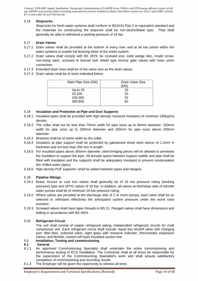
Contract: OEW-809: Supply, Installation, Testing and Commissioning of 3x100TR Screw Chillers with VFD energy efficient in place of old age 3x80TR reciprocating chillers including associated accessories installed at Shastri Park Metro station over Line-1 and CAMC contract
for 15 years after 02 year DLP period
Employer’s Requirement and Technical Specifications (Revised) Page 14 of 58
5.16 Stopcocks
Stopcocks for fresh water systems shall conform to BS1010 Part 2 or equivalent standard and
the materials for constructing the stopcock shall be non-dezincifiable type. They shall
generally be able to withstand a working pressure of 16 bar.
5.17 Drain Valves
5.17.1 Drain valves shall be provided at the bottom of every riser and at all low points within the
water systems to enable full draining down of the entire system.
5.17.2 Drain valves shall comply with BS 2879, be screwed end, solid wedge disc, inside screw,
non-rising stem, screwed in bonnet lock shield type bronze gate valves with hose union
connection.
5.17.3 Extended drain lines shall be of the same size as the drain valves.
5.17.4 Drain valves shall be of sizes indicated below:
Main Pipe Size (DN) Drain Valve Size (DN)
Up to 25 32-100 100-300 300-600
15 20 32 50
5.18 Insulation and Protection at Pipe and Duct Supports
5.18.1 Insulated pipes shall be provided with high-density rockwool insulation of minimum 160kg/m3
density.
5.18.2 The collar shall not be less than 75mm width for pipe sizes up to 80mm diameter, 150mm
width for pipe sizes up to 200mm diameter and 200mm for pipe sizes above 200mm
diameter.
5.18.3 Brackets shall be of same width as the collar.
5.18.4 Insulation at pipe support shall be protected by galvanized sheet steel sleeve of 1.2mm in
thickness and not less than 250 mm in length.
5.18.5 For insulated pipes above 300mm diameter, steel bridging pieces will be allowed to penetrate
the insulation to support the pipe. All annular space between support saddle and pipe shall be
filled with insulation and the supports shall be adequately insulated to prevent condensation
(for chilled water pipes).
5.18.6 High density PUF supports i shall be added between pipes and hangers.
5.19 Pipeline fittings
5.19.1 Brass, bronze or cast iron valves shall generally be of 16 bar pressure rating (working
pressure) type and UPVC valves of 10 bar. In addition, all valves at discharge side of transfer
water pumps shall be of minimum 16 bar pressure rating.
5.19.2 Where valves are provided at the discharge side of 2 or more pumps, each valve shall be so
selected to withstand effectively the anticipated system pressure under the worst case
scenario.
5.19.3 Screwed valves shall have taper threads to BS 21. Flanged valves shall have dimensions and
bolting in accordance with BS 4504.
5.20 Refrigerant Circuit
The unit shall consist of copper refrigerant piping, independent refrigerant circuits for multi compressor unit. Each refrigerant circuit shall include: liquid line shutoff valve with charging port, filter-drier, solenoid valve, sight glass with moisture indicator, thermostatic expansion valves, and flexible, closed-cell foam insulated suction line.
5.0 Installation, Testing and commissioning 6.1 General 6.1.1 An approved Commissioning Specialist shall undertake the entire commissioning and
performance testing of ECS installation. The Contractor shall at all times be responsible for the supervision of the Commissioning Specialist’s work and shall ensure satisfactory completion of commissioning and recording results.
6.1.2 The Employer will be given the opportunity to witness all tests.
Contract: OEW-809: Supply, Installation, Testing and Commissioning of 3x100TR Screw Chillers with VFD energy efficient in place of old age 3x80TR reciprocating chillers including associated accessories installed at Shastri Park Metro station over Line-1 and CAMC contract
for 15 years after 02 year DLP period
Employer’s Requirement and Technical Specifications (Revised) Page 15 of 58
6.1.3 Any defects of Workmanship, materials, performance, maladjustment, non-compliance with
this specification or other irregularities which become apparent during the tests or
commissioning shall be rectified by the Contractor, at its own expense, until the whole Works
is free from defects and in full working order to the complete satisfaction of the Engineer.
6.1.4 The Contractor shall provide all instruments, and sufficient evidence of the accuracy of the
test instruments shall be provided. Test methods shall be demonstrated to the Engineer
where required.
6.1.5 The Contractor shall submit to the Engineer a schedule detailing the equipment, which he
proposes to use in the testing and commissioning of the services and the test methods to be
employed.
6.1.6 Testing and commissioning of major items of proprietary plant or specialist equipment will be
carried out by the suppliers personnel and witnessed by the Commissioning Specialist. The
Engineer will be advised of such advised of such activities
6.1.7 Test results will be recorded on approved Commissioning certificates
6.1.8 All test and commissioning instruments will be provided by the Contractor or its
Commissioning Specialist, and certified evidence of the accuracy of the test instruments will
be provided. The Contractor will submit to the Engineer a schedule detailing the equipment
which he or its Commissioning proposes to use in the testing and commissioning of the
services and the test methods to be employed.
6.1.9 Instruments for testing will include as a minimum the following:
Anemometer (range 1.5m/s to 13 m/s)
Inclined tube anemometer
Pitot tubes of various lengths to suit duct sizes
Mercury in glass thermometers
Weekly recording thermometers
Weekly recording R.H. meters
Specially mounted anemometers fixed in a conical sheet metal sheet box hood for measuring accurately air f
low from diffusers
Ammeter, Tachometer
Vibration and Noise testing instruments
Surface contact dial indicating pyrometer
6.2 Chiller
6.2.1 The refrigeration filling shall be as per manufacture’s recommendation. The system shall be vacuumed to within 7.6mm Hg Absolute and maintained for four hours. At the end of this period the pumps shall be stopped and vacuum maintained for twenty four hours without exceeding a vacuum drop of 2.5mm Hg Absolute. The Contractor shall certify that the vacuum was maintained as specified above. All safety controls, low and high refrigerant pressure controls, starter, overload trips shall be suitably set and record of all the setting shall be furnished to the employer.
6.2.2 The plant will be continuously operated for a minimum period of 24 hours before tests are witnessed. The Contractor will confirm to the Employer, giving a minimum period of 24 hours notice, that the installation is ready for witness of performance testing.
6.2.3 The Contractor will be responsible for the supply, fixing, connection and safe operation of sufficient temporary artificial heat load equipment and any instrumentation necessary to demonstrate system performance and for subsequent disconnection and removal from site when the Employer is satisfied that tests are complete.
6.2.4 The Contract or will subject the entire plant to a total continuous run of the duration agreed with the Engineer to ensure that all apparatus, materials and systems are working properly. During the run tests will be carried out to ensure, that all controls, safety devices, operating services and all units are properly adjusted and operating correctly, that design temperatures in the piping system and throughout the air system are established and that the system
Contract: OEW-809: Supply, Installation, Testing and Commissioning of 3x100TR Screw Chillers with VFD energy efficient in place of old age 3x80TR reciprocating chillers including associated accessories installed at Shastri Park Metro station over Line-1 and CAMC contract
for 15 years after 02 year DLP period
Employer’s Requirement and Technical Specifications (Revised) Page 16 of 58
provide the required internal conditions. The Contract or will assure himself that the design intent is achieved before demonstration to the Engineer. The performance will be evaluated during environmental conditions prevailing at that time.
6.2.5 The Contractor will provide a temporary installation of portable recorders where indicated and simultaneously record temperatures and humidifies for summer and winter design conditions. The location of test instruments shall be approved by the Engineer. The corresponding external conditions will also be recorded whilst tests are in progress. The capacity of refrigeration plant, (including components thereof such as condensers, evaporators will also be demonstrated and recorded.
6.2.6 Individual room temperatures shall be measured by mercury-in-glass thermometers located 1.5m above floor level at points unaffected by the influence or draughts or direct radiation from hot or cold surfaces.
6.2.7 Measurements and records of performance test results will be entered on the Commissioning formats and handed to the Employer within a reasonable time after the tests are completed. Copies of the results will be retained on site by the Contractor and be available to other official representative as required.
6.3 The control panel shall have the following extended capabilities:
6.3.1 Remote indication of:
Chiller operating status
Shutdown codes
Key operating parameters including but not limited to:
Entering and leaving chilled water temperatures
Entering and leaving condenser water temperatures
Oil feed and sump temperatures
Oil pump discharge and oil differential pressure
Motors amps and amps as a percent of rated load amps
Hours of operation and number of starts, time of last start and stop
Fault history for last 8 failures
Self-diagnostics
6.3.2 Programming capabilities of:
- Leaving chilled water temperature
6.3.3 Reset of chilled water temperature from:
Return chilled water temperature (to maintain constant return chilled water temperature)
Reset of supply water temperature between +8°C to +12°C
Load on chiller
Power demand limit
Lead-lag operation and control
6.3.4 The control panel should include but not to be limited to the items listed below:
Start/Stop switch ( for both local/remote operation) and micro-processor module for
capacity control system with overload limit control point adjustment, oil pump and purge
unit controls, etc
Indicating lights
Suction, oil and discharge pressure indications
Necessary motor protection devices
Other time delays, relays, etc as required
6.3.5 As a minimum the following safeties shall be incorporated in the control panel:
High and low discharge pressure
High discharge temperature
Chilled or condenser water pumps failure
High or low oil feed temperature
Low oil differential pressure
High motor temperature, low motor current
Starter fault
Contract: OEW-809: Supply, Installation, Testing and Commissioning of 3x100TR Screw Chillers with VFD energy efficient in place of old age 3x80TR reciprocating chillers including associated accessories installed at Shastri Park Metro station over Line-1 and CAMC contract
for 15 years after 02 year DLP period
Employer’s Requirement and Technical Specifications (Revised) Page 17 of 58
6.3.6 The display shall have a minimum of 160-characters liquid crystal having multi colour display and be backlit with a light emitting diode. Messages shall be in plain English. Coded two or three characters displays are not acceptable.
6.3.7 A time clock shall be incorporated to allow daily time starts and stops
6.3.8 The control system shall have automatic restart after a power failure and not require a battery backup for memory continuity.
6.3.9 The microprocessor shall be capable of communicating to other units or a PC using a twisted pair communication interface RS-232 or RS422/485 or with a 9600-baud modem. The protocol should be BAC-NET/MOD BUS compatible. In case of any translator being required for communication between the chiller panel & BMS the same would be provided by the contractor.
6.4 Chilled water Pump 6.4.1 The pump sets shall be single stage, close-coupled, in-line suction and Discharge ports of
identical diameter with top-pull-out design, directly mounted on TEFC squirrel cage induction motor and suitable Starter as Specified. All external & exposed cast iron parts of pumps have an epoxy-based coating made in Cathodic electro-deposition (CED) process.
6.4.2 The impeller shall be cast bronze enclosed type with smooth surface finish Be for minimum frictional loss. The pump efficiency shall be 70% minimum.
6.4.3 The stuffing box cavity shall be sealed off at the pump by an internal flushed mechanical seal with carbon/silicon carbide face material, suitable for continuous operation up to 140 Deg C without any external cooling arrangement.
6.4.4 Motor and starter shall conform to relevant specifications and of ratings given in “Bill of Quantities”.
6.4.5 The pump set shall be with radial split case, single stage, close-coupled In-line type as per the data sheet/Bill of Quantities.
6.4.6 Pump spiral volute casing shall be of in-line design robust construction with Integral-cast base at bottom in order to transmit load to the base and foundation. Pump casing shall be EN-GJL-250 Grey cast iron withstanding 1.5 times design pressure.
6.4.7 Pump shaft shall be Austenitic stainless steels according to EN 1.4301/AISI 304 stub shaft and the same shall be, ground and polished to final dimension and be adequately sized to withstand all stresses, hydraulic loads, vibration and torques, coming in during operation.
6.4.8 All impellers are dynamically balanced to ISO 1940-1: Grade G6.3. A05.3.9. The shafts seal shall be of mechanical type to withstand leakage at high working pressure of 12 kg/cm².
6.4.9 The pump coupling should be of rigid close-coupled type with stub shaft. 6.4.10 Radial and axial forces should be absorbed by the fixed bearing in the motor driven
end.
6.4.11 The pump shall be installed on a concrete foundation at a suitable height, as per site requirement .
6.4.12 Each pump shall be provided with certified performance curves showing power absorbed and corresponding flow rates by varying the speed. The tests shall be done at factory. Testing report shall be submitted to DMRC.
6.4.13 Split casing pumps, prior to testing shall be aligned with a dial indicator within 0.05mm.
6.4.14 Pump performance curves and power consumption with operating points clearly indicated shall be submitted and verified at the time of testing and commissioning of the installation.
6.4.15 Pump performance shall be computed from the pump curves provided by manufacturer. All pumps shall be tested at factory as per relevant codes.
6.4.16 Head of the Pumps is required as per the BOQ and Pumps required as per the OEM standard meeting requirement as given in FOT. RPM of pumps should be 1500+/ - 10%, as suited for the head and delivery with optimum power consumption. Make of pump should be of Kirloskar, Crompton & Armstrong etc. or equivalent of reputed make with prior approval of DMRC before delivery.
6.5 SENSOR / TRANSMITTERS
Provide field mounted differential pressure sensor transmitter(s) as indicated on the plans. Unit shall transmit an isolated 4-20mA dc signal indicative of process variable to the pump logic controller via standard two wire 24 DC system. Unit shall have stainless steel wetted parts with two 0.25” male NPT process connections. It shall be protected against radio frequency interference and shall have a watertight, NEMA 4 electrical enclosure capable of
Contract: OEW-809: Supply, Installation, Testing and Commissioning of 3x100TR Screw Chillers with VFD energy efficient in place of old age 3x80TR reciprocating chillers including associated accessories installed at Shastri Park Metro station over Line-1 and CAMC contract
for 15 years after 02 year DLP period
Employer’s Requirement and Technical Specifications (Revised) Page 18 of 58
withstanding 2000 PSI static pressure with a 0.5” NPT conduit connection. Accuracy shall be within 0.25% of full span.
6.6 Insulation
6.6.1 Insulation shall not be applied before the relevant plant or service has been satisfactorily inspected and tested.
6.6.2 All insulation shall be applied by skilled workmen.
6.6.3 Apply insulation on clean and dry surface with no foreign materials, such as oil, grease, rust, scale or any other dirt.
6.6.4 Apply clean and dry insulation only.
6.6.5 Install insulation in accordance with the manufacturer’s recommendation as a minimum requirement.
6.6.6 Provide complete moisture and vapour seal wherever insulation terminates against metal hangers, anchors, or other projections through insulation on cold surfaces.
6.6.7 Stagger all joints with respect to the adjacent butt joint. Seal with 50mm wide aluminium foil type for fibre glass insulation.
6.6.8 Apply insulation in a manner to give an acceptable look, smooth and lineable surface of uniform thickness. Steps and undulations in the surfaces will be rejected by the Engineer.
6.7 Insulation on Sheet Metal Ducts
6.7.1 Cut insulation slightly longer than perimeter of duct to insure full thickness at corners.
6.7.2 All insulation shall be applied with edges tightly banded.
6.7.3 Adhesive shall be applied so that insulation conforms to duct surfaces uniformly and firmly.
6.7.4 Provide metal fixing pins and retaining clips in addition to adhesive for securing of insulation.
6.7.5 The protruding ends of the pins shall be cut off flush and the vapour barrier facing shall be thoroughly sealed with a vapour barrier mastic or tape where the pins have pierced through. Pin spacing shall not exceed 300mm on centres.
6.8 Insulation of Pumps
6.8.1 Fit insulation snugly against equipment without voids.
6.8.2 Bevel curved surface edges to provide a tight joint.
6.8.3 Provide metal insulated cover with metal fasteners, supports, frames and membranes.
6.9 Piping
6.9.1 Install same thickness insulation as the adjoining pipe insulation on flanges, valves and other
fittings to obtain the maximum strength and security. Seal joints, protruding metal parts and
valve stems thoroughly.
6.9.2 All valves, traps, flanges and strainers shall be insulated in conformity with the pipework in
which they are incorporated except that 1.2mm thick galvanised steel or aluminium split
boxes shall be provided to ensure easy removal of insulation.
6.9.3 Insulate strainers in such a manner to permit removal of gasket without disturbing the
insulation of the strainer body. Insulate valves up to and including bonnets.
6.10 Pipeline fittings
6.10.1 This Section specifies the manufacture and installation of gate valves, butterfly valves,
motorized valves, automatic air valves, strainers, dirt pockets, stopcocks, pressure reducing
valves, double regulation valves, safety and relief valves, thermostatic mixing valves,
thermometer, pressure gauges, flow measuring elements, expansion joints, pipe anchors,
pipe guides, gaskets for pipe separation, access pipes, traps, water – closet connectors and
fresh air inlets.
6.10.2 All valves, taps and cocks shall be of the types and working pressures suitable for the
systems to which they are connected. Valves shall be rated to withstand the system hydraulic
test pressure.
Contract: OEW-809: Supply, Installation, Testing and Commissioning of 3x100TR Screw Chillers with VFD energy efficient in place of old age 3x80TR reciprocating chillers including associated accessories installed at Shastri Park Metro station over Line-1 and CAMC contract
for 15 years after 02 year DLP period
Employer’s Requirement and Technical Specifications (Revised) Page 19 of 58
6.10.3 All valves shall comply with British Standards in respect of tests and working pressures,
dimensions and materials of construction.
6.10.4 Wheel head valves shall be arranged for clockwise operation of the handle to close the valve.
6.10.5 Connections shall be made between each valve and the adjoining pipe work or equipment
with flanges for 65mm size pipe work and above. Flanges shall be selected to suit working
pressure and temperature.
6.10.6 Screwed connections shall be made between each valve and the adjoining pipe work or
equipment for 50 mm size pipe work and below. A union shall be fitted on each side of all
Screwed valves.
6.10.7 All valves shall be suitably located in accessible positions for operation and maintenance
purposes.
6.10.8 All drain outlets and manual air vents shall have connection pipes leading to the nearest
drain.
6.10.9 Valve packing shall be suitable for the service intended. Valve packing consists of asbestos
or asbestos based materials shall not be used.
6.10.10 Valves of identical make, size, type and duty shall be fully interchangeable.
6.10.11 Inverted mounting of valves shall not be permitted without prior Approval.
6.10.12 All valves provided for manual operation shall have a hand wheel or other suitable device
which shall be fixed to the valve. Hand wheels shall be rotated clock-wise to close the valves
and shall be clearly marked with the words "OPEN" and "CLOSE" and arrows pointing in the
appropriate directions. The rims of hand wheels shall be machined to a smooth finish. All
hand wheels which may be dangerously hot to touch when the system is in use shall be
provided with Approved heat insulation on the rim and spokes.
6.10.13 Chain-operated hand wheels shall be provided including rustproof chain and chain guide for
valves installed two meters or more above finished floor.
6.11 Sound level measurements
6.11.1 Reading will be taken to ensure that the required noise ratings are not exceed. Representative areas will be selected by agreement with the Engineer.
6.11.2 Wherever necessary, when measuring room sound levels, normal continuous background noise from sources other than the installation will be taken into account. Measurements relating to plant and equipment will generally be taken 1.5 m from the item.
6.11.3 Results of octave band analysis will be submitted on noise rating curve charts for each individual space.
6.12 Interlock and Padlocking Facilities
6.12.1 Mechanical key interlocks shall be provided and shall be so designed as to avoid mal-operation at the point of manual application. The scheme shall be such that attempts to remove a captive key shall not result in tripping or opening of the device.
6.12.2 Electrical interlocks on withdraw able equipment shall be so arranged that if the equipments are withdrawn, the complete operation of the withdrawn equipment shall be independent of the remote interlocking contacts. In addition, interlocks shall not be defeated leading to damages or unsafe operations of LVSBs due to the withdrawing of equipment.
6.12.3 Locking facilities shall be provided where appropriate for switches and isolators in order that they may be locked in the open position. Switchgear cubicle access doors shall be equipped with integral type locks, preferably incorporated in the handles of the equipment.
6.12.4 Where locking facilities are of the integral barrel type, the key for each lock shall be unique to the associated lock unless otherwise specified.
6.12.5 Two keys shall be provided for every lock supplied. The keys shall be fitted with rings with identification labels, and wooden cabinets with glazed front- opening doors shall be provided. The cabinets shall be adequate in size and equipped with hooks to house all keys when not in use, and shall be mounted in positions to be decided.
6.14 Insulation and Protection at Pipe and Duct Supports
6 . 1 4 . 1 Pipes insulation shall be provided with high density rock wool insulation of minimum 60kg/m3
density.
Contract: OEW-809: Supply, Installation, Testing and Commissioning of 3x100TR Screw Chillers with VFD energy efficient in place of old age 3x80TR reciprocating chillers including associated accessories installed at Shastri Park Metro station over Line-1 and CAMC contract
for 15 years after 02 year DLP period
Employer’s Requirement and Technical Specifications (Revised) Page 20 of 58
6.14.2 The collar shall not be less than 75mm width for pipe sizes up to 80mm diameter, 150mm
width for pipe sizes up to 200mm dia meter and 200mm for pipe sizes above 200mm
diameter.
6.14.3 Brackets shall be of same width has the collar.
6.14.4 Insulation at pipe support shall be protected by galvanised sheet steel sleeve of1.2mm in thickness and not less than 250mm in length.
6.14.5 For insulated pipes above300mm diameter, steel bridging pieces will be allowed to penetrate
the insulation to support the pipe. All annular space between supports addle and pipe shall
be filled with insulatioan the supports shall be adequately insulated to prevent condensation
(for chilled water pipes).
6.14.6 High density PUF supports shall be added between pipes and hangers.
7.0 Technical and installation requirements
7.1 Pipe material 7.1.1 Chilled water system/Condenser water system
i. Nominal bore 50-150mm:blacksteelto IS 1239heavygrade
ii. Nominal bore 200mm and above: Black carbon steel manufactured by electric resistance
welded using 410Mpagrade steel to IS 3589for 200mmto500mm diameter; manufactured by
submerged arc welded for 600mm diameter and above.
iii. Minimum wall thickness for pipes shall be:
Diameter(mm)
Wall thicknessthickness(mm)
200-300
6.35
350-400
8.0
450-600
9.5
700-800
12.5
7.1.2 Condensate drain and vent piping system: Nominal bore1 5 -150: Galvanised steel to
IS1239 medium grade for fan unit connections: Copper tubestoASTMB88typeL
7.2 Pipe fittings –Materials 7.2.1 Chilled water system/Condenser water system: Black malleable iron screwed fittings to
BS 143 and 1256 or purpose made heavyweight welding fittings to BS1965:Part1 for pipes up to 50mm. Purposemade heavy weight welding fittings to BS 1965:Part2 for pipes 65 mm diameter and above. Thickness and outside diameter of the pipe fittings shall match with the straight pipe.
7.2.2 Condensate drain and vent piping system: Galvanised malleable iron screwed fittings to BS 143 and BS 1256. For FCU connections: wrought copper to ASTMB16.22
7.3 Flanges 7.3.1 Welded piping: Steel, welding neck pattern, 150 (1035 kPa) or 300 (2070 kPa) WSP class,
complying with BS 4504 shall be used.
7.3.2 Screwed piping: Galvanized steel screwed boss flanges complying with
BS4504:Part1Table16/4 or galvanised malleable cast iron screwed boss flanges complying
BS 4504Part1Table16/13.
7.3.3 Copper tubing: Copper slip- on flanges for brazing, complying with BS 4504shall be used.
Galvanised iron bolt sand nuts shall not be used for fixing copper flanges.
7.4. Gaskets 7.4.1 Gasketsshall be suitable for the temperature, service and pressure of the system and
shall be installed in accordance with the Manufacturer’s recommendations. Made-up flanged joints shall be fabricated from one- piece ring gaskets, 3mmthick, neoprene rubber.
7.4.2 For flanged joints between dissimilar metals or insulating flange joints: insulating gaskets,
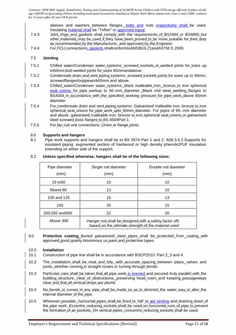
Contract: OEW-809: Supply, Installation, Testing and Commissioning of 3x100TR Screw Chillers with VFD energy efficient in place of old age 3x80TR reciprocating chillers including associated accessories installed at Shastri Park Metro station over Line-1 and CAMC contract
for 15 years after 02 year DLP period
Employer’s Requirement and Technical Specifications (Revised) Page 21 of 58
sleeves and washers between flanges, bolts and nuts respectively shall be used. Insulating material shall be “Teflon” or approved equal.
7.4.3 Joint rings and gaskets shall comply with the requirements of BS2494 or BS4865 but other materials may be used if they have been proved to be more suitable for their duty as recommended by the Manufacturer, and approved by the Engineer.
7.4.4 For FCU connections, gaskets shallconformtoANSIB16.21andASTM D 2000.
7.5 Jointing 7.5.1 Chilled water/Condenser water systems: screwed sockets or welded joints for sizes up
to50mm;butt-welded joints for sizes 65mmandabove.
7.5.2 Condensate drain and vent piping systems: screwed sockets joints for sizes up to 50mm;
screwedflangesforpipework65mm and above.
7.5.3 Chilled water/Condenser water systems: black malleable iron, bronze to iron spherical
seat unions for pipe workup to 50 mm diameter. Black mid steel welding flanges to
BS4504 in accordance with the specified working pressure for pipe work above 65mm
diameter
7.5.4 For condensate drain and vent piping systems: Galvanised malleable iron, bronze to iron spherical seat unions for pipe work upto 50mm diameter. For pipes of 65 mm diameter and above, galvanised malleable iron, bronze to iron spherical seat unions or galvanised steel screwed boss flanges to BS 4504Part 1.
7.5.5 For fan coil unit connections: Union or flange joints.
8.0 Supports and hangers
8.1 Pipe work supports and hangers shall be to BS 3974 Part 1 and 2. A09.3.6.2.Supports for insulated piping: segmented section of hardwood or high density phenolic/PUF insulation extending on either side of the support.
8.2 Unless specified otherwise, hangers shall be of the following sizes:
Pipe diameter
(mm)
Single rod diameter
(mm)
Double rod diameter
(mm)
15 to50
10
10
65and 80
13
10
100 and 125
15
13
150
20
15
200;250 and300
22
20
Above 300
Hanger rod shall be designed with a safety factor of5 ,based on the ultimate strength of the material used
9.0 Protective coating Buried galvanized/ steel pipes shall be protected from rusting with approved good quality bituminous us paint and protective tapes.
10.0 Installation
10.1 Construction of pipe line shall be in accordance with BSCP2010: Part 2, 3 and 4. 10.2 The installation shall be neat and tidy, with accurate spacing between pipes, valves and
joints, whether running in straight routes or turning through bends. 10.3 Particular care shall be taken that all pipe work is erected and secured truly parallel with the
building structure, clear of obstructions, preserving head room and keeping passageways clear and that all vertical drops are plumb
10.4 No bends or curves in any pipe shall be made so as to diminish the water way or alter the
internal diameter of the pipe. 10.5 Wherever possible, horizontal pipes shall be fixed to ’fall’ to aid venting and draining down of
the pipe work. Eccentric reducing sockets shall be used on horizontal runs of pipe to prevent the formation of air pockets. On vertical pipes, concentric reducing sockets shall be used.
Contract: OEW-809: Supply, Installation, Testing and Commissioning of 3x100TR Screw Chillers with VFD energy efficient in place of old age 3x80TR reciprocating chillers including associated accessories installed at Shastri Park Metro station over Line-1 and CAMC contract
for 15 years after 02 year DLP period
Employer’s Requirement and Technical Specifications (Revised) Page 22 of 58
10.6 Drain outlets shall be provided at all low points of the system to enable emptying and to
facilitate maintenance of the pipe work. 10.7 Automatic or manual air vents shall be placed at each high point of each water line and
discharge pipe shall be terminated at 50 mm above floor drain.
10.8 Pipe runs, where exposed, shall be positioned at least 25mm from the finished wall surfaces
to enable subsequent cleaning and painting of all surfaces. Where pipe runs are installed at
anangle, they shall be positioned 40mm from the finished surfaces
10.9 All pipes shall befitted clear of the floor to permit cleaning beneath the pipes. Where
possible, a 125mm clearance shall be provided between the underside of the pipe and the
finished level of the floor and in no case shall the pipe be less than 100mm clear of the floor.
10.10 All pipe runs when not buried underground shall be concealed as far as possible by careful
positioning or shall be chased into walls, or laid in screeds except inside plant rooms. All
pipes which are to be concealed shall be tested and Approved before being covered.
10.18 Where it is not possible to install the pipe work with setting out dimensions as shown on the
Drawings, minor deviations will be allowed, subject to prior Approval.
10.19 Where pipes pass through walls and floors, steel pipe sleeves shall be provided to allow
free axial movement of the pipes. Sleeves passing through walls shall be of sufficient length
to fully enclose the pipe, from one side of the finished wall to the other side. Sleeves
passing through floors shall protrude at least 50mm above and below the finished floor and
soffit to enclose the pipe.
10.20 All pipes passing through the roof shall be provided with at least mm lead flashing
sandwiched between the layers of water proofing roofing membrane, and secured to the
pipe with a galvanized spring clip.
10.21 Where pipes pass through water-containing chambers, puddle flanges of Approved design
shall be provided.
10.22 Accessible pipes shall be flanged or union connected in sections of three nominal lengths
for dismantling. Embedded pipe work shall be in straight lengths as far as possible. Pipes
with screwed joints shall be installed with hexagon unions at suitable positions for easy
removal of equipment.
10.23 All pipe installations shall be provided with removable sections to facilitate pipe-cleaning
operations.
10.24 Pipe work shall rest freely upon supports and be carefully aligned prior to final connection. 10.25 All pipes on straight runs shall be lined up with facilities for pipes to be rotated for the process
of welding joints to avoid welding from the bottom as far as possible.
10.26 Site welding shall be applied with pipe work unrestrained and each joint hydraulically tested at 1.5 times working pressure plus 350k Pa for 60 minutes without loss of pressure followed by application of appropriate protective coating, both internally and externally, prior to final installation.
10.27 During storage, all pipes shall have end covers fitted to prevent the ingress of any unwanted particles or waste
10.28 During installation, all open ends of pipes shall be blanked off with blank flanges or pipe caps. These shall be removed only immediately prior to connecting to adjacent sections. As soon as pipes have been installed, all open ends shall be covered to prevent entrance of materials that would obstruct the pipes. Covers shall be left in place until removal is necessary for completion of the installation.
10.29 Damage to coatings or linings during material transport or handling on Site shall be repaired to the Engineer’s satisfaction before installation of the pipe work and fittings commences.
10.30 The Engineer reserves the right to reject any material deemed to be unsuitable for installation and such material shall be removed from the Site and be replaced with approved material at no extra cost to the Employer.
10.31 Steel welded fittings shall be of the same weight as the piping with which they are to be used complying with AN SIB16.9 and ASTM A234.Long radius welded elbows shall be used at changes in the direction of the pipe work. Welded tees shall be used for branches of the same size as the main pipe. Long radius reducing elbows shall be used at pumps. Reducing outlet tees shall be used for branches of smaller size than main pipe. Where the branch size is three or more pipe sizes smaller than the main pipe, steel gussets to provide full pipe strength shall be used. Where a branch is connected to screwed piping, a steel welded threaded socket shall be used. Eccentric welding reducing fittings shall be used at changes in pipe size for horizontal piping, with top level for water piping.
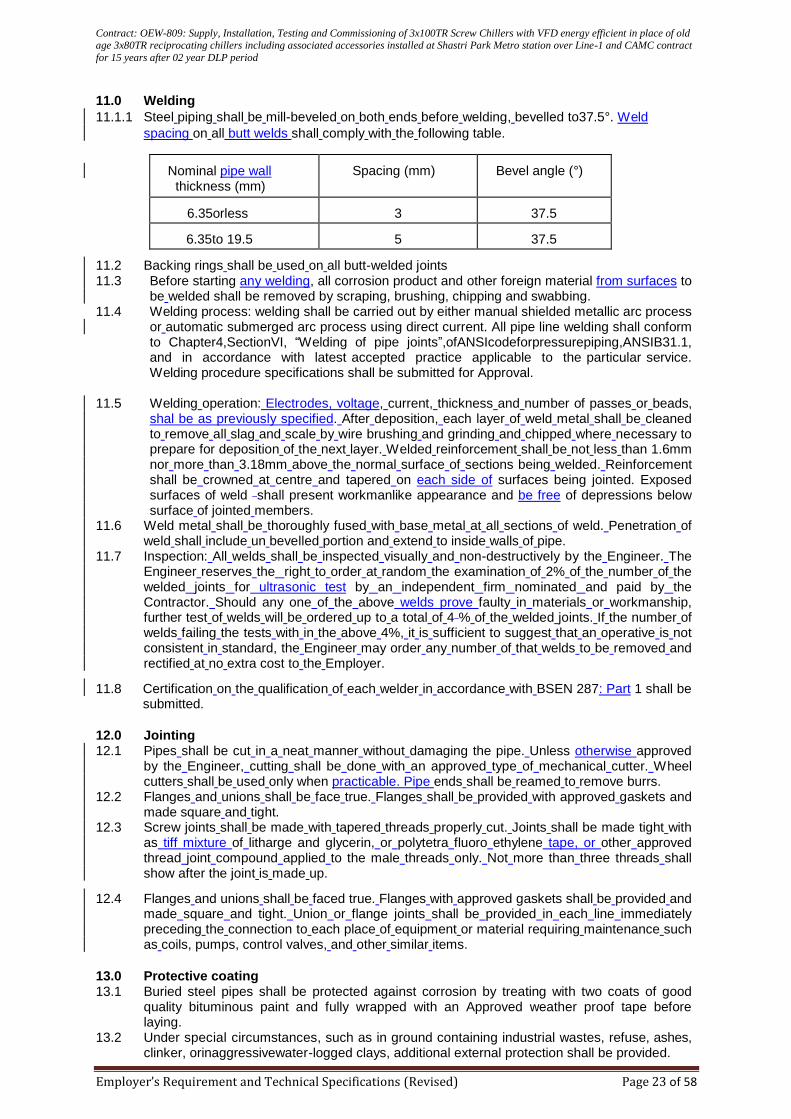
Contract: OEW-809: Supply, Installation, Testing and Commissioning of 3x100TR Screw Chillers with VFD energy efficient in place of old age 3x80TR reciprocating chillers including associated accessories installed at Shastri Park Metro station over Line-1 and CAMC contract
for 15 years after 02 year DLP period
Employer’s Requirement and Technical Specifications (Revised) Page 23 of 58
11.0 Welding
11.1.1 Steel piping shall be mill-beveled on both ends before welding, bevelled to37.5°. Weld
spacing on all butt welds shall comply with the following table.
Nominal pipe wall
thickness (mm)
Spacing (mm)
Bevel angle (°)
6.35orless
3
37.5
6.35to 19.5
5
37.5
11.2 Backing rings shall be used on all butt-welded joints 11.3 Before starting any welding, all corrosion product and other foreign material from surfaces to
be welded shall be removed by scraping, brushing, chipping and swabbing. 11.4 Welding process: welding shall be carried out by either manual shielded metallic arc process
or automatic submerged arc process using direct current. All pipe line welding shall conform to Chapter4,SectionVI, “Welding of pipe joints”,ofANSIcodeforpressurepiping,ANSIB31.1, and in accordance with latest accepted practice applicable to the particular service. Welding procedure specifications shall be submitted for Approval.
11.5 Welding operation: Electrodes, voltage, current, thickness and number of passes or beads, shal be as previously specified. After deposition, each layer of weld metal shall be cleaned to remove all slag and scale by wire brushing and grinding and chipped where necessary to prepare for deposition of the next layer. Welded reinforcement shall be not less than 1.6mm nor more than 3.18mm above the normal surface of sections being welded. Reinforcement shall be crowned at centre and tapered on each side of surfaces being jointed. Exposed surfaces of weld shall present workmanlike appearance and be free of depressions below surface of jointed members.
11.6 Weld metal shall be thoroughly fused with base metal at all sections of weld. Penetration of weld shall include un bevelled portion and extend to inside walls of pipe.
11.7 Inspection: All welds shall be inspected visually and non-destructively by the Engineer. The Engineer reserves the right to order at random the examination of 2% of the number of the welded joints for ultrasonic test by an independent firm nominated and paid by the Contractor. Should any one of the above welds prove faulty in materials or workmanship, further test of welds will be ordered up to a total of 4 % of the welded joints. If the number of welds failing the tests with in the above 4%, it is sufficient to suggest that an operative is not consistent in standard, the Engineer may order any number of that welds to be removed and rectified at no extra cost to the Employer.
11.8 Certification on the qualification of each welder in accordance with BSEN 287: Part 1 shall be submitted.
12.0 Jointing 12.1 Pipes shall be cut in a neat manner without damaging the pipe. Unless otherwise approved
by the Engineer, cutting shall be done with an approved type of mechanical cutter. Wheel cutters shall be used only when practicable. Pipe ends shall be reamed to remove burrs.
12.2 Flanges and unions shall be face true. Flanges shall be provided with approved gaskets and made square and tight.
12.3 Screw joints shall be made with tapered threads properly cut. Joints shall be made tight with as tiff mixture of litharge and glycerin, or polytetra fluoro ethylene tape, or other approved thread joint compound applied to the male threads only. Not more than three threads shall show after the joint is made up.
12.4 Flanges and unions shall be faced true. Flanges with approved gaskets shall be provided and made square and tight. Union or flange joints shall be provided in each line immediately preceding the connection to each place of equipment or material requiring maintenance such as coils, pumps, control valves, and other similar items.
13.0 Protective coating 13.1 Buried steel pipes shall be protected against corrosion by treating with two coats of good
quality bituminous paint and fully wrapped with an Approved weather proof tape before laying.
13.2 Under special circumstances, such as in ground containing industrial wastes, refuse, ashes, clinker, orinaggressivewater-logged clays, additional external protection shall be provided.
Contract: OEW-809: Supply, Installation, Testing and Commissioning of 3x100TR Screw Chillers with VFD energy efficient in place of old age 3x80TR reciprocating chillers including associated accessories installed at Shastri Park Metro station over Line-1 and CAMC contract
for 15 years after 02 year DLP period
Employer’s Requirement and Technical Specifications (Revised) Page 24 of 58
13.3 Where buried metallic pipes cross the route of the railway, the pipe works shallbeelectricallycontinuousanddoublehalf-wrappedwithanapproved electrical insulating tape.
14.0 Cleaning
14.1 For buried ductile iron pipes complying with BSEN 545orBS EN 598, bituminous coating against corrosion shall be provided for the pipes and joints where steel is used for bolts and nuts.
14.2 Where copper pipe work is required to be chromium plated ,such pipe work shall be sent to a specialist for plating after all pulled bends and soldered joints are completed.
15.0 Testing
15.1 At Manufacturer’s factory, samples of pipes and fittings shall be tested and certified to the
relevant IS Test certificates shall be submitted for each type of pipe and fitting to the
Employer.
15.2 All pipe work, except chilled water pipe which is specified below, including valve sand fittings
shall be hydrostatically pressure tested to1.5times the duty head of the system or 1.5times the
closed delivery valve pressure of the pump, whichever is the highest. The pressure shall be
held for a minimum period of 24hours.
15.3 The Contractor shall perform hydrostatic testing of all piping. Preliminary tests shall be carried
out to demonstrate that the work is satisfactory. The Engineer and all authorities having
jurisdiction shall be notified in ample time to be present for final test in go fall piping. Testing
shall be carried out before insulating or concealing any piping takes place. Defects disclosed
by tests shall be repaired and the complete test repeated. Tests shall be carried out in stages
if so ordered by the Engineer to facilitate work of others. Use of wick in tightening leaking
joints is no permitted.
15.4 Un less otherwise specified, chilled water piping shall be tested hydrostatically to 1553 kPa.
Tests shall before two hours duration, during which time piping shall show no leaks and
during which time no sealing of leaks shall be permitted. Equipment not capable of
withstanding test pressures shall be isolated. Blind flanges, by pass valves and piping shall be
used as required during testing.
15.5 Refrigerant pipe work when completed shall be pressure tested by nitrogen gas in two or
more steps up to 28 barand maintained for at least 24hours.Prior to charging any additional
refrigerant as necessary into the system, it shall be vacuum dried. A vacuum test of1mm of
mercury shall be applied to the pipe work and held for 8 hours. The vacuum shall not rise
beyond 2mmof mercury during the8hourtest.
16.0 Pipe line fittings 16.1 This Section specifies the manufacture and installation of globe valves, gate valves, check
valves, butterfly valves, motorized valves, gauge cocks, automatic air valves, strainers, dirt pockets, stopcocks, pressure reducing valves, double regulation valves, safety and relief valves, thermostatic mixing valves, UPVC valves for flushing water, drain cocks, ball float valves, safety and pressure relief valves, escutcheons, thermometer, pressure gauges, flow measuring elements, vortex inhibitors, pipe sleeves, expansion loops, expansion joints, pipe anchors, pipe guides, gaskets for pipe separation, access pipes, traps ,water– closet connectors and fresh air inlets.
16.2 All valves, taps and cocks shall be of the types and working pressures suitable for the systems to which they are connected. Valves shall be rated to withstand the system hydraulic test pressure.
16.3 Brass, bronze or cast iron valves shall generally be of 16bar pressure rating (working pressure) type and UPVC valves of 10bar. In addition, all valves at discharge side of transfer water pumps shall be of minimum 16 bar pressure rating.
16.4 Where valves are provided at the discharge side of 2 or more pumps, each valve shall be so selected to with stand effectively the anticipated system pressure under the worst case scenario.
16.5 All valves shall comply with relevant International Standards or Indian Standards in respect of tests and working pressures, dimensions and materials of construction.
16.6 Wheel head valves shall be arranged for clock wise operation of the handle to close the valve.
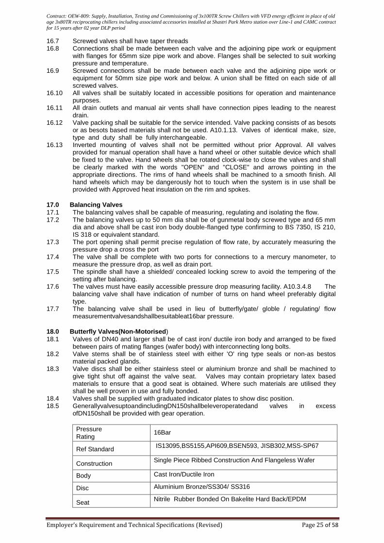
Contract: OEW-809: Supply, Installation, Testing and Commissioning of 3x100TR Screw Chillers with VFD energy efficient in place of old age 3x80TR reciprocating chillers including associated accessories installed at Shastri Park Metro station over Line-1 and CAMC contract
for 15 years after 02 year DLP period
Employer’s Requirement and Technical Specifications (Revised) Page 25 of 58
16.7 Screwed valves shall have taper threads 16.8 Connections shall be made between each valve and the adjoining pipe work or equipment
with flanges for 65mm size pipe work and above. Flanges shall be selected to suit working pressure and temperature.
16.9 Screwed connections shall be made between each valve and the adjoining pipe work or equipment for 50mm size pipe work and below. A union shall be fitted on each side of all screwed valves.
16.10 All valves shall be suitably located in accessible positions for operation and maintenance purposes.
16.11 All drain outlets and manual air vents shall have connection pipes leading to the nearest drain.
16.12 Valve packing shall be suitable for the service intended. Valve packing consists of as besots or as besots based materials shall not be used. A10.1.13. Valves of identical make, size, type and duty shall be fully interchangeable.
16.13 Inverted mounting of valves shall not be permitted without prior Approval. All valves provided for manual operation shall have a hand wheel or other suitable device which shall be fixed to the valve. Hand wheels shall be rotated clock-wise to close the valves and shall be clearly marked with the words "OPEN" and "CLOSE" and arrows pointing in the appropriate directions. The rims of hand wheels shall be machined to a smooth finish. All hand wheels which may be dangerously hot to touch when the system is in use shall be provided with Approved heat insulation on the rim and spokes.
17.0 Balancing Valves
17.1 The balancing valves shall be capable of measuring, regulating and isolating the flow. 17.2 The balancing valves up to 50 mm dia shall be of gunmetal body screwed type and 65 mm
dia and above shall be cast iron body double-flanged type confirming to BS 7350, IS 210, IS 318 or equivalent standard.
17.3 The port opening shall permit precise regulation of flow rate, by accurately measuring the pressure drop a cross the port
17.4 The valve shall be complete with two ports for connections to a mercury manometer, to measure the pressure drop, as well as drain port.
17.5 The spindle shall have a shielded/ concealed locking screw to avoid the tempering of the setting after balancing.
17.6 The valves must have easily accessible pressure drop measuring facility. A10.3.4.8 The balancing valve shall have indication of number of turns on hand wheel preferably digital type.
17.7 The balancing valve shall be used in lieu of butterfly/gate/ globle / regulating/ flow measurementvalvesandshallbesuitableat16bar pressure.
18.0 Butterfly Valves(Non-Motorised)
18.1 Valves of DN40 and larger shall be of cast iron/ ductile iron body and arranged to be fixed between pairs of mating flanges (wafer body) with interconnecting long bolts.
18.2 Valve stems shall be of stainless steel with either 'O' ring type seals or non-as bestos material packed glands.
18.3 Valve discs shall be either stainless steel or aluminium bronze and shall be machined to give tight shut off against the valve seat. Valves may contain proprietary latex based materials to ensure that a good seat is obtained. Where such materials are utilised they shall be well proven in use and fully bonded.
18.4 Valves shall be supplied with graduated indicator plates to show disc position. 18.5 GenerallyvalvesuptoandincludingDN150shallbeleveroperatedand valves in excess
ofDN150shall be provided with gear operation.
Pressure
Rating
16Bar
Ref Standard
IS13095,BS5155,API609,BSEN593, JISB302,MSS-SP67
Construction
Single Piece Ribbed Construction And Flangeless Wafer
Body Cast Iron/Ductile Iron
Disc Aluminium Bronze/SS304/ SS316
Seat
Nitrile Rubber Bonded On Bakelite Hard Back/EPDM
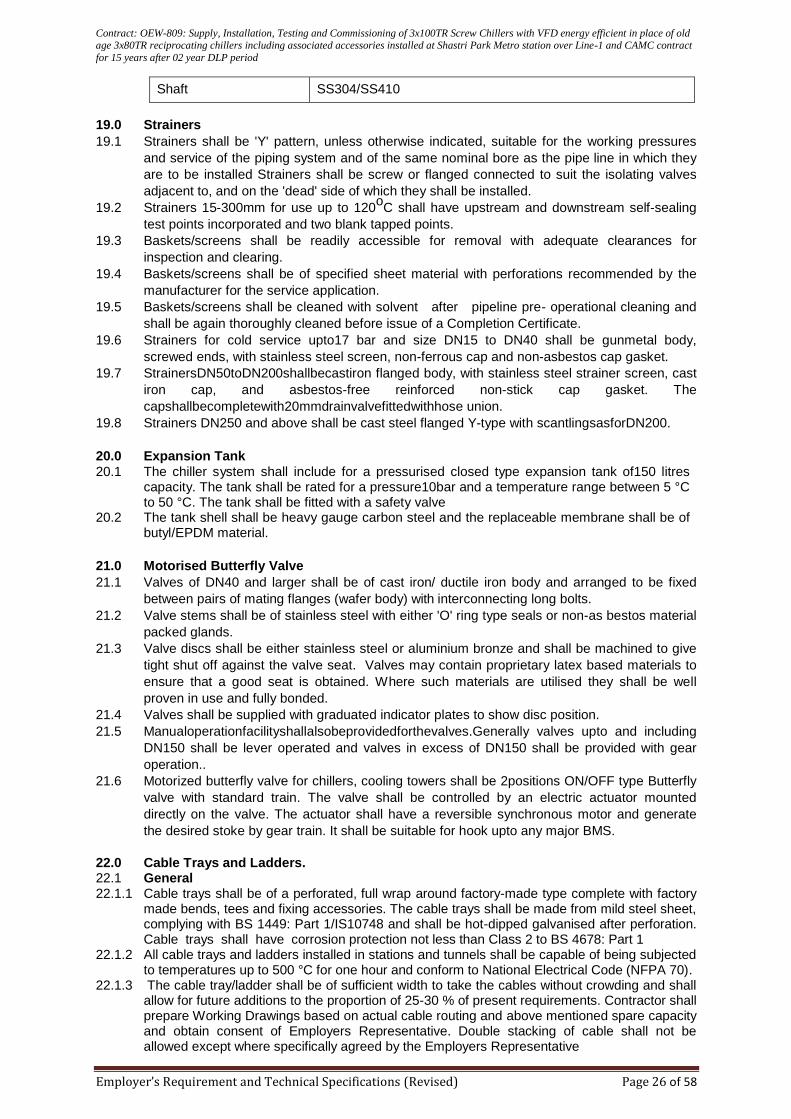
Contract: OEW-809: Supply, Installation, Testing and Commissioning of 3x100TR Screw Chillers with VFD energy efficient in place of old age 3x80TR reciprocating chillers including associated accessories installed at Shastri Park Metro station over Line-1 and CAMC contract
for 15 years after 02 year DLP period
Employer’s Requirement and Technical Specifications (Revised) Page 26 of 58
Shaft SS304/SS410
19.0 Strainers
19.1 Strainers shall be 'Y' pattern, unless otherwise indicated, suitable for the working pressures
and service of the piping system and of the same nominal bore as the pipe line in which they
are to be installed Strainers shall be screw or flanged connected to suit the isolating valves
adjacent to, and on the 'dead' side of which they shall be installed.
19.2 Strainers 15-300mm for use up to 120oC shall have upstream and downstream self-sealing
test points incorporated and two blank tapped points.
19.3 Baskets/screens shall be readily accessible for removal with adequate clearances for
inspection and clearing.
19.4 Baskets/screens shall be of specified sheet material with perforations recommended by the
manufacturer for the service application.
19.5 Baskets/screens shall be cleaned with solvent after pipeline pre- operational cleaning and
shall be again thoroughly cleaned before issue of a Completion Certificate.
19.6 Strainers for cold service upto17 bar and size DN15 to DN40 shall be gunmetal body,
screwed ends, with stainless steel screen, non-ferrous cap and non-asbestos cap gasket.
19.7 StrainersDN50toDN200shallbecastiron flanged body, with stainless steel strainer screen, cast
iron cap, and asbestos-free reinforced non-stick cap gasket. The
capshallbecompletewith20mmdrainvalvefittedwithhose union.
19.8 Strainers DN250 and above shall be cast steel flanged Y-type with scantlingsasforDN200.
20.0 Expansion Tank
20.1 The chiller system shall include for a pressurised closed type expansion tank of150 litres capacity. The tank shall be rated for a pressure10bar and a temperature range between 5 °C to 50 °C. The tank shall be fitted with a safety valve
20.2 The tank shell shall be heavy gauge carbon steel and the replaceable membrane shall be of butyl/EPDM material.
21.0 Motorised Butterfly Valve
21.1 Valves of DN40 and larger shall be of cast iron/ ductile iron body and arranged to be fixed
between pairs of mating flanges (wafer body) with interconnecting long bolts.
21.2 Valve stems shall be of stainless steel with either 'O' ring type seals or non-as bestos material
packed glands.
21.3 Valve discs shall be either stainless steel or aluminium bronze and shall be machined to give
tight shut off against the valve seat. Valves may contain proprietary latex based materials to
ensure that a good seat is obtained. Where such materials are utilised they shall be well
proven in use and fully bonded.
21.4 Valves shall be supplied with graduated indicator plates to show disc position.
21.5 Manualoperationfacilityshallalsobeprovidedforthevalves.Generally valves upto and including
DN150 shall be lever operated and valves in excess of DN150 shall be provided with gear
operation..
21.6 Motorized butterfly valve for chillers, cooling towers shall be 2positions ON/OFF type Butterfly
valve with standard train. The valve shall be controlled by an electric actuator mounted
directly on the valve. The actuator shall have a reversible synchronous motor and generate
the desired stoke by gear train. It shall be suitable for hook upto any major BMS.
22.0 Cable Trays and Ladders. 22.1 General 22.1.1 Cable trays shall be of a perforated, full wrap around factory-made type complete with factory
made bends, tees and fixing accessories. The cable trays shall be made from mild steel sheet, complying with BS 1449: Part 1/IS10748 and shall be hot-dipped galvanised after perforation. Cable trays shall have corrosion protection not less than Class 2 to BS 4678: Part 1
22.1.2 All cable trays and ladders installed in stations and tunnels shall be capable of being subjected to temperatures up to 500 °C for one hour and conform to National Electrical Code (NFPA 70).
22.1.3 The cable tray/ladder shall be of sufficient width to take the cables without crowding and shall allow for future additions to the proportion of 25-30 % of present requirements. Contractor shall prepare Working Drawings based on actual cable routing and above mentioned spare capacity and obtain consent of Employers Representative. Double stacking of cable shall not be allowed except where specifically agreed by the Employers Representative
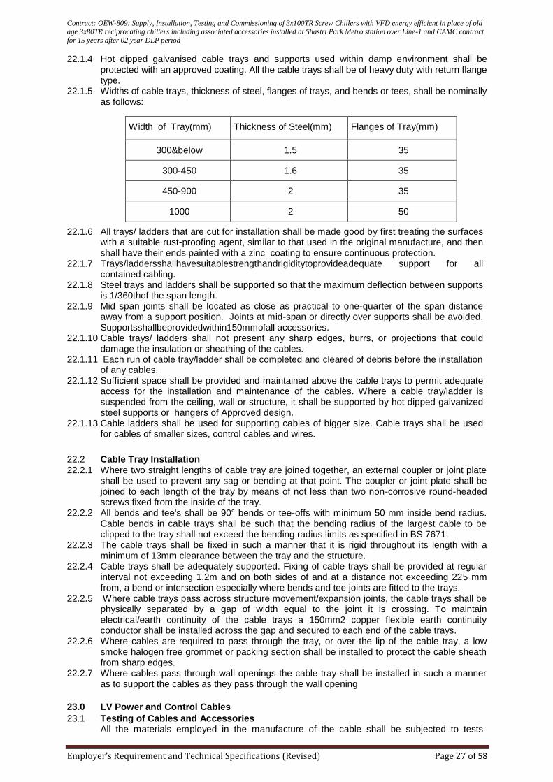
Contract: OEW-809: Supply, Installation, Testing and Commissioning of 3x100TR Screw Chillers with VFD energy efficient in place of old age 3x80TR reciprocating chillers including associated accessories installed at Shastri Park Metro station over Line-1 and CAMC contract
for 15 years after 02 year DLP period
Employer’s Requirement and Technical Specifications (Revised) Page 27 of 58
22.1.4 Hot dipped galvanised cable trays and supports used within damp environment shall be protected with an approved coating. All the cable trays shall be of heavy duty with return flange type.
22.1.5 Widths of cable trays, thickness of steel, flanges of trays, and bends or tees, shall be nominally as follows:
Width of Tray(mm) Thickness of Steel(mm) Flanges of Tray(mm)
300&below 1.5 35
300-450 1.6 35
450-900 2 35
1000 2 50
22.1.6 All trays/ ladders that are cut for installation shall be made good by first treating the surfaces with a suitable rust-proofing agent, similar to that used in the original manufacture, and then shall have their ends painted with a zinc coating to ensure continuous protection.
22.1.7 Trays/laddersshallhavesuitablestrengthandrigiditytoprovideadequate support for all contained cabling.
22.1.8 Steel trays and ladders shall be supported so that the maximum deflection between supports is 1/360thof the span length.
22.1.9 Mid span joints shall be located as close as practical to one-quarter of the span distance away from a support position. Joints at mid-span or directly over supports shall be avoided. Supportsshallbeprovidedwithin150mmofall accessories.
22.1.10 Cable trays/ ladders shall not present any sharp edges, burrs, or projections that could damage the insulation or sheathing of the cables.
22.1.11 Each run of cable tray/ladder shall be completed and cleared of debris before the installation of any cables.
22.1.12 Sufficient space shall be provided and maintained above the cable trays to permit adequate access for the installation and maintenance of the cables. Where a cable tray/ladder is suspended from the ceiling, wall or structure, it shall be supported by hot dipped galvanized steel supports or hangers of Approved design.
22.1.13 Cable ladders shall be used for supporting cables of bigger size. Cable trays shall be used for cables of smaller sizes, control cables and wires.
22.2 Cable Tray Installation 22.2.1 Where two straight lengths of cable tray are joined together, an external coupler or joint plate
shall be used to prevent any sag or bending at that point. The coupler or joint plate shall be joined to each length of the tray by means of not less than two non-corrosive round-headed screws fixed from the inside of the tray.
22.2.2 All bends and tee's shall be 90° bends or tee-offs with minimum 50 mm inside bend radius. Cable bends in cable trays shall be such that the bending radius of the largest cable to be clipped to the tray shall not exceed the bending radius limits as specified in BS 7671.
22.2.3 The cable trays shall be fixed in such a manner that it is rigid throughout its length with a minimum of 13mm clearance between the tray and the structure.
22.2.4 Cable trays shall be adequately supported. Fixing of cable trays shall be provided at regular interval not exceeding 1.2m and on both sides of and at a distance not exceeding 225 mm from, a bend or intersection especially where bends and tee joints are fitted to the trays.
22.2.5 Where cable trays pass across structure movement/expansion joints, the cable trays shall be physically separated by a gap of width equal to the joint it is crossing. To maintain electrical/earth continuity of the cable trays a 150mm2 copper flexible earth continuity conductor shall be installed across the gap and secured to each end of the cable trays.
22.2.6 Where cables are required to pass through the tray, or over the lip of the cable tray, a low smoke halogen free grommet or packing section shall be installed to protect the cable sheath from sharp edges.
22.2.7 Where cables pass through wall openings the cable tray shall be installed in such a manner as to support the cables as they pass through the wall opening
23.0 LV Power and Control Cables
23.1 Testing of Cables and Accessories All the materials employed in the manufacture of the cable shall be subjected to tests
Contract: OEW-809: Supply, Installation, Testing and Commissioning of 3x100TR Screw Chillers with VFD energy efficient in place of old age 3x80TR reciprocating chillers including associated accessories installed at Shastri Park Metro station over Line-1 and CAMC contract
for 15 years after 02 year DLP period
Employer’s Requirement and Technical Specifications (Revised) Page 28 of 58
specified in relevant standards before manufacture of the cable.
The manufacturer must have type test certificates from the third party accredited laboratories certifying compliance to all the type tests mentioned in the relevant clauses of BS6724/ BS7211/ BS7846. In case of non–availability of these test certificates, the manufacturer must get these cables type tested at third party accredited laboratory prior to production of cables. After completion of manufacture and prior to dispatch the cables shall be subjected to routine & acceptance tests as specified in relevant standards.
23.2 Cable Installation
23.2.1 All cables shall be provided with identification labels at each end and at each position where
cables change direction. In the instances where cables are multiple runs, labels shall be
provided at 10m intervals indicating run number also. Identification discs for cables installed
within buildings or tunnels shall be supplied and attached with galvanised wire to each cable
at intervals not greater than12 metres and at all cable terminate
23.2.2 Cables running horizontally at high level shall in general be supported by cable ladder and/or
perforated cable trays or trucking. Where cables are installed in vertical ducts or on vertical
cable ladder/ tray, they shall be clamped at intervals not exceeding1,200mm.
23.2.3 Where cables pass through fire-rated walls and floors, all openings shall be sealed with fire-
resistant material of a fire rating equivalent to that of the fire rating of the wall or floor
approved by Delhi Fire Services. 23.2.4 Where cables are to be laid at ground level these may be laid in concrete duct banks (with or
without conduits) or laidin GI/HDPE /RCC pipes available directly in ground as per the
approval of Employer’s Representative. The cables shall be segregated according to their
duty
23.2.5 Cables shall be installed with a minimum of 300-mm clearance for any equipment or pipe
work including lagging associated with other services. Where this condition is unavoidable or
difficult to maintain, the Employer’s Representative shall be informed prior to the installation
being commenced.
23.2.6 The power cables shall, for interference purposes be separated from the signal
&communication cables in the tunnel, stations & under platform voids. Control and other
cables shall be routed separately from traction or power cables. Cables shall be installed so
that any one cable can be removed without disturbance to cables from other circuits in the
same route.
23.2.7 All cable routes near tracks are to be parallel or perpendicular to the running lines.
23.2.8 In general two cable routes shall be constructed, one each for Up and Down lines, with
minimum changes of directions. Bends shall not be less than the manufacturer’s
recommended minimum bending radius for the cables to be installed
23.2.9 Cables passing under road and railways shall be mechanically protected(i.e. HDPE/
Galvanized iron sleeves/ pipes)and have a minimum cover of 1000mm. Proper care must be
taken for jointing of metallic pipes, so that they do not give way due to weight above and
damage the cables
23.2.10 Track crossings aretobeatrightanglesandatleast2mclearofany rail switches or crossing areas
of leads.
23.2.11 All cable entries into cable pit shall have rounded edges to prevent damage to cables during
installation or during service or as a result of the weight of the cables themselves bearing
against the edges.
23.2.12 Un armoured cables, which are direct buried, shall be mechanically protected throughout their
length such as laid in metallic pipes or by other equivalent methods.
23.2.13 Cable route markers shall be installed for underground cables where cables change direction
and on straight runs of cable at intervals of not more than 50m. Markers shall be of pre-cast
Contract: OEW-809: Supply, Installation, Testing and Commissioning of 3x100TR Screw Chillers with VFD energy efficient in place of old age 3x80TR reciprocating chillers including associated accessories installed at Shastri Park Metro station over Line-1 and CAMC contract
for 15 years after 02 year DLP period
Employer’s Requirement and Technical Specifications (Revised) Page 29 of 58
concrete type and be marked "electrical cable" and have a projection of 200mm above the
finished ground level.
23.2.14 Cables shall be installed without tee joints.
23.2.15 Cable armour shall be earthed at one end or both ends of the cable as required by the
installation and system. Cleats shall be of the moulded rein forced nylon type of low smoke
and halogen free materials.
23.2.16 Where cables are laid in concrete troughs, the trough opening shall be sealed with concrete
slabs.
23.2.17 Bend sin cables shall have an internal radius of not less than six times the overall cable
diameter, or as specified by the cable manufacturer.
23.2.18 Where cables are laid in open ground they shall be bedded in75mm of sieved s and, covered
with a similar material, and protected by concrete slabs or interlocking tiles, and the trench
shall then be back filled. Medium voltage and signalling cables shall have a minimum cover of
750mm
23.3 Termination
23.3.1 The terminating kits shall be suitable for termination of the cables on an indoor switchgear or
equipment. These shall be of proven design and shall be type-tested as per relevant Indian or
International Standards. Type test certificates shall be submitted. The cable and wire
terminations shall avoid any possibility of loose joint and wire snapping. Cable conduct or
termination shall be by means of a heavy-duty solder less cable lug. The lug shall be of high
conductivity copper, electro-tinned and applied to the conductor by means of a hydraulic
crimping tool. All such crimping should meet the requirements of BS4579.
23.3.2 The cables heath shall be clasped by means of a gland of compression type based on
BS6121 or equivalent Indian standard with a compression washer, which will hold the cable
sheath securely. A cable shroud shall be fitted to cover the body of the compression gland.
23.3.3 All wires shall be terminated with an Approved type of connector.
23.4 Cable Glands and Accessories 23.4.1 Non-Armoured Cables
a) All cable glands and accessories shall be to BS6121 or equivalent Indian standard. b) The cable glands shall have a water tight seal when fitted to a cable.
c) Each cable gland shall be supplied with a brass gland locknut and a flame retardant low smoke halogen free outer gland shroud. The shroud shall to tally enclose the gland body and form an effective seal against the cable sheathing.
23.4.2 Armoured Cables
a) All cable glands and accessories shall be approved to BS6121 or equivalent Indian standard.
b) The cable glands shall have a water tight seal when fitted to a cable. c) Cables shall be terminated in a gland fitted with an armour clamp and an earth tag. The
gland body shall be provided with an internal conical seal to receive the armour clamping cone, and a clamp nut, which shall secure the armour-clamping cone, and conical armour seal. The spigot of the gland body shall be threaded to suit standard conduit accessories. A flame retardant low smoke halogen free shroud shall be fitted to cover the gland body.
23.5 Cable Ties Cable ties shall be made from corrosion resistant, flame retardant and ultraviolet stabilised materials. At locations where cables are installed above tracks or in areas subjected to significant and constant vibration, cable ties shall be of metal construction type and coated with a corrosion resistant, low smoke halogen free and flame retardant insulation material.
23.6 Cable Joints 23.6.1 The straight through jointing kits shall be suitable not only for conditions of high humidity
Contract: OEW-809: Supply, Installation, Testing and Commissioning of 3x100TR Screw Chillers with VFD energy efficient in place of old age 3x80TR reciprocating chillers including associated accessories installed at Shastri Park Metro station over Line-1 and CAMC contract
for 15 years after 02 year DLP period
Employer’s Requirement and Technical Specifications (Revised) Page 30 of 58
encountered in Metro sub-way, but also for underground buried installation with uncontrolled back-fill and possibility of flooding by water. These shall be of proven design and shall be type-tested as per relevant Indian or International standards. Type test certificates shall be submitted.
23.6.2 The jointing kits shall match the cable specifications. Joints shall not be permitted in the fire survival cables in case the joint does not meet the fire survival conditions.
23.6.3 Every connection at a cable joint shall be mechanically and electrically sound, be protected against mechanical damage and any vibration, shall not impose mechanical stress on the fixings of the connection and shall not cause any mechanical damage to the cable conductor.
23.6.4 The appropriate tools specified by the joint manufacturer shall be used when jointing cables. 23.6.5 The outer casing/ outer sheath of the cable joint shall be fabricated from a low smoke
halogen free material. 23.6.6 No cable joints shall be allowed without the prior Approval of the Employers
Representative/Engineer. All joints, accessories and cable joint locations shall be submitted to the Engineer for Approval prior to any jointing of cables. All cable jointing shall be performed by a qualified jointer and preferably by the manufacturer of the jointing kits.
23.7 Cable Identification 23.7.1 All cables shall be provided with identification markers, at each end of the cable, at entry and
exit point of cable trays, ducts and trenches and in other such positions as are necessary to identify and trace the route of the cable. Identification discs for cablesinstalled within buildings or tunnels shall be supplied and attached with galvanised wire to each cable at intervals not greater than 12metres and at all cable terminations.
23.7.2 Cable identification shall be assembled from elliptical profiled low smoke halogen free markers, carrier strip and cable ties.
23.7.3 Every single core cable and every core of a multi-core cable shall be provided with identification at its terminations in the form of sleeves or ferrules of appropriate colours or as specified for signalling cables.
24.0 PAINTING All pumping system, pumps, motors and bases shall be supplied with approved finish. Shop
coat of paint that have become marred during shipment or erection shall be cleaned off with
mineral spirits, wire brushed and spot primed over the affected areas, then coated with
enamel paint to match the adjoining areas.
25.0 Chiller System Manager (CSM) Specification 25.1 General
The Chiller System Manager (CSM) supplier shall furnish and install a fully optimized Chiller System Manager, incorporating direct digital control (DDC) for energy management, equipment monitoring and control, suitable for the entire plant usage. The control strategies shall be developed to ensure that the specified environmental conditions are maintained, whilst giving due regard to minimizing of energy consumption.
The system design shall utilise the latest technology in “open” network architecture, distributive intelligence and processing, and direct digital control. The CSM system offered should be from the latest offerings and should be of freely programmable management and automation stations for the full spectrum of today’s building application services.
All peripheral equipment e.g. sensors, pressure switches, control valves and actuators, shall
be of the same manufacture as the direct digital control modules and outstations.
The system offered shall be completely modular in structure and freely expandable at any stage from the smallest system through to large distributed systems. Each level of the system shall operate independently of the next level up.
The system shall fully be consistent with the latest industry standards, operating on Windows 10 professional 64 bit or better, allowing the user to make full use of the features provided with these operating systems.
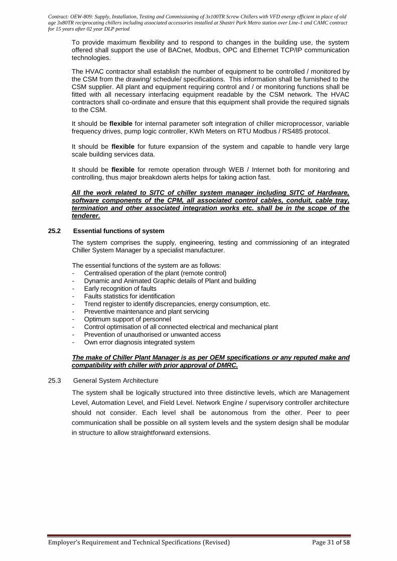
Contract: OEW-809: Supply, Installation, Testing and Commissioning of 3x100TR Screw Chillers with VFD energy efficient in place of old age 3x80TR reciprocating chillers including associated accessories installed at Shastri Park Metro station over Line-1 and CAMC contract
for 15 years after 02 year DLP period
Employer’s Requirement and Technical Specifications (Revised) Page 31 of 58
To provide maximum flexibility and to respond to changes in the building use, the system offered shall support the use of BACnet, Modbus, OPC and Ethernet TCP/IP communication technologies.
The HVAC contractor shall establish the number of equipment to be controlled / monitored by the CSM from the drawing/ schedule/ specifications. This information shall be furnished to the CSM supplier. All plant and equipment requiring control and / or monitoring functions shall be fitted with all necessary interfacing equipment readable by the CSM network. The HVAC contractors shall co-ordinate and ensure that this equipment shall provide the required signals to the CSM.
It should be flexible for internal parameter soft integration of chiller microprocessor, variable frequency drives, pump logic controller, KWh Meters on RTU Modbus / RS485 protocol.
It should be flexible for future expansion of the system and capable to handle very large scale building services data.
It should be flexible for remote operation through WEB / Internet both for monitoring and controlling, thus major breakdown alerts helps for taking action fast. All the work related to SITC of chiller system manager including SITC of Hardware, software components of the CPM, all associated control cables, conduit, cable tray, termination and other associated integration works etc. shall be in the scope of the tenderer.
25.2 Essential functions of system
The system comprises the supply, engineering, testing and commissioning of an integrated Chiller System Manager by a specialist manufacturer.
The essential functions of the system are as follows: - Centralised operation of the plant (remote control) - Dynamic and Animated Graphic details of Plant and building - Early recognition of faults - Faults statistics for identification - Trend register to identify discrepancies, energy consumption, etc. - Preventive maintenance and plant servicing - Optimum support of personnel - Control optimisation of all connected electrical and mechanical plant - Prevention of unauthorised or unwanted access
- Own error diagnosis integrated system The make of Chiller Plant Manager is as per OEM specifications or any reputed make and compatibility with chiller with prior approval of DMRC.
25.3 General System Architecture
The system shall be logically structured into three distinctive levels, which are Management
Level, Automation Level, and Field Level. Network Engine / supervisory controller architecture
should not consider. Each level shall be autonomous from the other. Peer to peer
communication shall be possible on all system levels and the system design shall be modular
in structure to allow straightforward extensions.
Contract: OEW-809: Supply, Installation, Testing and Commissioning of 3x100TR Screw Chillers with VFD energy efficient in place of old age 3x80TR reciprocating chillers including associated accessories installed at Shastri Park Metro station over Line-1 and CAMC contract
for 15 years after 02 year DLP period
Employer’s Requirement and Technical Specifications (Revised) Page 32 of 58
Management
Level
Automation
Level
Field
Level
25.4 Use of communication standards
Only the following standards are appropriate to be used at the three levels.
Management level - BACnet, Ethernet TCP/IP
Automation level - BACnet on LonTalk, BACnet on ETHERNET/IP
Field level - LonTalk with LonMark profiles 25.5 Management Level
The head-end management and operation of the plant shall include process visualization, data analysis, and exchange of data with 3
rd parties. At the management level, it shall be
possible for communication to flow in all directions, across networks and via direct connections.
Personal computer based operator management stations shall be provided for plant
supervision and operation, alarm management, information and database management
function. All real-time control functions shall be resident in the DDC controllers to facilitate
greater fault tolerance and reliability.
The management level of the system shall consist of one, and shall be capable of handling
more management station PCs and the associated software modules.
The management station shall be capable of the following:
Display of graphical representations of the plant overlaid with live data
High quality dynamic graphics with true multitasking of all active pages
Monitor and operate / influence process devices
Receiving of alarm messages from the process level and directing them to the appropriate reporting device e.g. printer, pager, fax, e-mail
Monitor process devices for communication problems and other device faults.
Alarm handling – all the alarms shall be displayed in a graphical tree structure in order located alarms quick and easily.
Adjusting time strategies in the process level.
Long term storage of logged data from the process devices
Multi level user access control for individual access to sites, applications, functions and objects
Display graphically the logged data
Custom application programming
Use of graphical genies to allow manipulation of data.
Contract: OEW-809: Supply, Installation, Testing and Commissioning of 3x100TR Screw Chillers with VFD energy efficient in place of old age 3x80TR reciprocating chillers including associated accessories installed at Shastri Park Metro station over Line-1 and CAMC contract
for 15 years after 02 year DLP period
Employer’s Requirement and Technical Specifications (Revised) Page 33 of 58
The user interface shall be based on a basic taskbar, which is always visible.
History logging for alarms, user actions, system events and messages
Alarm handling – all the alarms shall be displayed in a graphical tree structure in order located alarms quick and easily.
Simultaneous connection of at least of 4 sites via serial connections / 50 sites via LAN/WAN connections for a comprehensive overview on geographically distributed projects
For maximum fault tolerance, the management stations connect to the process level via
point-to-point communications. This shall be via RS232, Ethernet/TCP/IP LAN / WAN or
via AutoDial links.
Operator Touch Panel: The management level should be configured as an optionally by keeping separate operator touch panel in the network. The size of touch panel should be 10.1” minimum. The web server facility should be available in operator touch panel by allowing minimum 3 web client. Graphical viewing through remotely, minimum 2 GB RAM. Multi operator user access.
25.6 Automation Level
General Purpose controllers shall be used for monitoring / controlling equipment which have to perform based on a customized logic, such as AHUs, Chillers, Chilled water pumps, Cooling towers, Lifts, signals from Fire Alarm panels, generators, transformers etc.,.
At the heart of the DDC system shall be the Microprocessor based modules, which can be individually programmed according to the functional requirements.
The automation level DDC controllers shall monitor and control the main plant in the building. The
DDC controller outstations shall be freely programmable and have the ability to perform all the
following routines
Process control & interlock functions.
Generate alarms/events based on comparing measured values against know parameters.
Time control strategies
Runtime totalisation.
Trend logging of specific data-points with transmission of the logged values to the management level
Energy calculations
Backup of the data/program ( >= 5 years) The DDC controllers shall be selected from either a modular or compact type of unit to suit the most economic inclusion of all the data points specified. Each control module shall be capable of operating on a stand-alone basis without control from a central computer.
The input/output connection to Modular controllers shall be via individual plug-in modules suitable for the particular peripheral device. The digital modules shall have visual indication of the status of the input/output. Digital input modules shall be capable of accepting control voltages up to 230vac and will have integral status indication.
It shall be possible to integrate both types of control module onto the same BACnet communication network. Each controller performance shall be to 0.5% control accuracy with sample rates of less than one second.
Main plant DDC controllers shall be 32 bits freely programmable. Controllers meant for VAV controls cannot be used as DDC controllers.
All DDCs must be UL approved, must have an in-built real time clock and be suitable for PID control.
The products used in constructing the CSM management and automation levels shall conform to BACnet protocol for building automation and control networks. All controllers shall have attained a BACnet Testing Laboratories (BTL) listing and display BTL logo.
Contract: OEW-809: Supply, Installation, Testing and Commissioning of 3x100TR Screw Chillers with VFD energy efficient in place of old age 3x80TR reciprocating chillers including associated accessories installed at Shastri Park Metro station over Line-1 and CAMC contract
for 15 years after 02 year DLP period
Employer’s Requirement and Technical Specifications (Revised) Page 34 of 58
Controller should be equipped with direct ASHRAE standard universally open “BACnet/LonMark” protocol with peer to peer communication; Master/Slave topology of BACnet MSTP protocol controllers requiring additional network engines are not acceptable due to Master/slave proprietary nature of the controllers ;
CSM system should able to READ / WRITE any parameters of the chiller plant manager as and when required through direct ‘BACnet/Ethernet IP’ protocol.
The system shall have the facility for a Web server to be added to allow full operation of all
automation station control modules connected to the Lon Talk BACnet network via a standard thin
client/web browser. Functions to include
Display of graphical representations of the plant overlaid with live data
Data point display and operation of all measured values, set points, plant States, operating states and parameters
Alarm monitoring with acknowledgement and visual and audible alarm Indication.
Alarm and event history
Alarm transmission via SMS and e-mail
Operation of all time schedules, exception calendar and heating curves.
Reading of trend data with facility to export data to Microsoft Excel.
Multi user level access protection
Ethernet or Modem connection
DDC Control Module Specification
The DDC controllers shall be selected from either a modular or compact type of unit to suit the most economic inclusion of all the data points specified. The DDC controller shall be strictly UL listed / approved. The DDC controllers shall be provided with minimum 32bit microprocessors to carry our required control and management functions. The DDC controllers being used should confirm to the following specifications as a minimum:
Based on ANSI/ASHRAE standard 135-2001 (BACNet), ENV13321-1
Operation standalone or as part of Lon Talk (clause 11) system network TP/FT-10, 78kBits with Built in BACnet/Lontalk interface or ETHERNET / IP
Optional connection to operator terminal, management station and via Web browser with Web server device.
Freely Programmable
Flash ROM, real time processing and multi tasking
32 bit processor system, 1.5 MB program memory, No 8 bit or multiple of 8 bit
Supply voltage AC 24V +/-20% 50/60 Hz
Event driven data transmission
Automatic mains recovery
PPS2 connection
Digital output to be 250V 2A rated changeover contacts
Historical data memory storage
Software application stored in non volatile memory
Battery back up>= 5 Years
For the generation of the application programs, the following function elements are required as a minimum.
Reset functions
Set point jump
Positioning time
P-controller (reverse or direct acting)
P1-controller (reverse or direct acting)
PI-controller with I-deletion (reverse or direct acting)
PID controller (reverse or direct acting)
2-point controller (reverse or direct acting)
Proportional additional sequences (reverse or direct acting)
Contract: OEW-809: Supply, Installation, Testing and Commissioning of 3x100TR Screw Chillers with VFD energy efficient in place of old age 3x80TR reciprocating chillers including associated accessories installed at Shastri Park Metro station over Line-1 and CAMC contract
for 15 years after 02 year DLP period
Employer’s Requirement and Technical Specifications (Revised) Page 35 of 58
Data transmitter (digital or analogue)
Data converter (analogue-digital or digital-analogue)
Ring Counter
Timer (switch on or switch off)
Logic operations: * logic "AND" (2,3 or 4) * logic "OR" (2,3 or 4) * logic "EXOR" * logic "NOT"
Comparative operations: * Maximum values (2,3 or 4) * Minimum values (2,3 or 4) * Average values (2,3 or 4)
Enthalpy calculation
Optimiser
Mean value calculation
Hysteresis
Output steps (digital or analogue)
Digital outputs shall be potential free outputs. Analog outputs shall be true analog outputs (0-10 V DC, 0-20 ma & 4-20 ma)
Above blocks shall be resident in the DDC Controllers and independent of any high level
interfaces/controllers.
Further, the DDC unit software must have the following additional functions:
Free selection of range and unit (dimension) of all signals (measured values, accumulated values, calculated values, etc.)
Free allocation of access protection in accordance with operating priorities
Free definition of manual override priorities (software) from operator terminal and/or management station.
Wherever control logic is required for equipment such as AHUs, the DDC controller offered shall have a digital display on the fascia. This display shall be capable of displaying 2 categories of 3 parameters each. In the event of an alarm, the display shall switch over to an ‘alarm’ indication. In all, the controller shall have the capacity to indicate 8 different alarms. In case more than one alarm is active at the same time, the controller shall display a coded alphabet, to alert that there is more than one alarm in the controller.
Each DDC Controller shall have a resident real time clock with a battery back up for a minimum of 4 years.
All DDC controllers shall be housed in IP 54 enclosures with proper termination of peripheral
devices at the terminal strip and not directly to the controller.
25.7 Field Level
Individual terminal unit controllers for autonomous room – by – room comfort control, based on application specific logic written on the controllers. All the terminal unit controllers shall fulfil following general requirements:
LONMARK communication
AC230 V power supply
Mountable with screws or DIN rail
Optional terminal cover for local installation without cabinet
Downloadable application software /adjustable parameter set, The type of Use shall be defined by downloadable pre-tested application software.
Contract: OEW-809: Supply, Installation, Testing and Commissioning of 3x100TR Screw Chillers with VFD energy efficient in place of old age 3x80TR reciprocating chillers including associated accessories installed at Shastri Park Metro station over Line-1 and CAMC contract
for 15 years after 02 year DLP period
Employer’s Requirement and Technical Specifications (Revised) Page 36 of 58
Common functions like grouping, scheduling, etc., shall be realised within a master controller on automation level.
All terminal unit controllers supplied on the project shall have the facility for local setpoint
adjustment via a room unit.
Application specific controllers shall be used for terminal devices such as Fan Coil Units and the like. These controllers shall be with Lon Mark compatible bus communication. Any failure problem in communication bus should not affect the working of the FCU controller. A dedicated stand-alone controller shall be provided for each FCU. A common controller for FCUs serving different areas shall not be acceptable. These controllers shall be looped with a bus cable and connected to the CSM.
In general they shall comply with the following specifications
For 2 or 4 pipe FCUs, with or without changeover
PID control
Downloadable application software over the BUS cable
LonMark compatible bus communication
To be integrated to the management station software
Control of AC 24 V PWM valve actuators, 3 point AC 24 V valve and damper actuators, or electric heating coils
Volt-free relays for fan control
Operating Voltage 230 V
Internal fuse, thermal, automatic reset
Connectable to 1 room unit via local bus, 2/4 wire unscreened twisted pair @ 4.8 KBPS
The application specific controllers shall be capable of working in conjunction with the following type of room controllers. The specific type of room controller to be used in specific applications shall be selected from any one of the following types to meet the description written in the sequence of operation.
TYPE 1
Integrated room temperature sensor
TYPE 2
Integrated room temperature sensor
Dial for temperature set point
TYPE 3
Integrated room temperature sensor
Dial for temperature set point
Rocker switch for off/auto1 mode (single speed fan)
TYPE 4
Integrated room temperature sensor
Dial for temperature set point
Rocker switch for off/auto1 mode and fan speeds (3 speed fan)
TYPE 5
Integrated room temperature sensor
Dial for temperature set point
Rocker switch for off/auto1 mode and fan speeds (3 speed fan)
LCD display of measured temperature TYPE 6
Integrated room temperature sensor
Rocker switch for temperature set point (raise/lower)
Rocker switch for off/auto1 mode and fan speeds
LCD display of measured temperature
Communication with controllers via Lon bus
Exchangeable rocker switches for lighting and blinds
Contract: OEW-809: Supply, Installation, Testing and Commissioning of 3x100TR Screw Chillers with VFD energy efficient in place of old age 3x80TR reciprocating chillers including associated accessories installed at Shastri Park Metro station over Line-1 and CAMC contract
for 15 years after 02 year DLP period
Employer’s Requirement and Technical Specifications (Revised) Page 37 of 58
Selection of downloadable software applications for the operation of lighting and blinds
Operating mode ‘auto” –comfort, ‘off’ – standby or economy 25.8 Networks & File Servers
Wherever the building configuration supports in - built network cables, the system shall be able to accommodate several PCs hooked up at locations designated by the user at a later date. The management station software shall support the leading network systems, Windows Server 2012 R2, or 2016 multilingual, 64 bit, Microsoft SQL Server 2012, SQL Server 2014 or SQL Server 2016 (Standard or Enterprise).
The management station(s) shall be set up on the network in two different ways, either operating independently or as client management stations in conjunction with an (optional) file server.
To facilitate central storage of data and programs, the file server is envisaged. Central management of user-specific information such as passwords and protected access to data and programs shall thus be made easily possible. The file server shall also support software updates and changes in the project data. The file server shall also support consistent central archiving of alarms, off-line trend data, log data, graphics, data backup etc.
25.9 Printing
It shall be possible to connect printers either directly to the management station or to the file server.
25.10 Remote Monitoring and Control
It shall be possible, with additional hardware if necessary, to interrogate the system remotely via the following possible methods:
Telephone connection
Building IT network
Web browser technology with password access via IT networks accessing information stored on dedicated embedded web server device installed on automation controller network.
Alarm reporting to mobile pagers/phones/e-mail etc
Energy usage monitoring and control via Chiller System Managers. 25.11 CSM – Records
General
The details of the building automatic system shall include all the manufacturers Technical
Data Sheets and User Manuals. Control valve schedules shall be provided the flow rates;
valve pressure drop and system design basis on which the particular valve type was selected.
DDC Control System Software Strategies
Controller strategies shall be provided, in both hard copy and on CD-ROM, for inclusion in the Operating & Maintenance Manuals.
Copies of all the preliminary strategies, in both hard copy and on CD-ROM, shall be supplied to the Engineer prior to commencement of control systems commissioning.
Copies of all the ‘As Installed’ strategies, in both hard copy and on CD-ROM, shall be supplied to the Engineer within three months of hand over of control systems.
CSM Software and Licences
All Licence rights to the control systems manufacturers’ software packages shall be transferred to the client at the time of hand over. User Registration must be made on behalf of the client, direct to the control system manufacturer by the specialist System House Partner.
Contract: OEW-809: Supply, Installation, Testing and Commissioning of 3x100TR Screw Chillers with VFD energy efficient in place of old age 3x80TR reciprocating chillers including associated accessories installed at Shastri Park Metro station over Line-1 and CAMC contract
for 15 years after 02 year DLP period
Employer’s Requirement and Technical Specifications (Revised) Page 38 of 58
Copies of all of the control system manufacturers Monitoring or CSM software shall be provided on CD-ROM, or other mass storage device, together with copies of any graphics and databases that may be required to re-install the system after a fatal computer failure.
Integration of secondary Pump systems
Secondary Pump System shall be controlled by dedicated Pump Logic Control Panel being
provided by pump supplier along with DP sensor / Sensor technology.
Integrations of Pump Logic Control Panel shall be carried out at the most appropriate level
within a system, depending on the functions and interaction required. The following
integrations must be possible.
RTU Modbus
Lon Mark
BACNet /LonWorks
BACNet/IP
OPC
Integration of standard proprietary buses : Modbus, M Bus, KNX.
As part of the requirements for an open system devices with a Native BACnet protocol shall be connected onto a common field bus backbone network directly without any Gateway/Protocol converter device. If interaction is required between different sub-systems, the integration shall be carried out at either the automation or field level. The integration must not occur at the management level. Link to a third party software package such as a Planned Preventive Maintenance package or a Energy Monitoring package shall be carried out at the management level. When sharing alarm and historical information with Maintenance Management and Energy Management packages, the management system shall provide the information in a standard commercially available format e.g. MS Access and using standard mechanisms e.g. ODBC .Real-time “live” information shall be transferred form the management system to a third party package e.g. MS Excel, either by a standard inter-application mechanism e.g. DDE or OPC or by developing a connection by using a documented API for the management system. Where a physical connection is required between a 3rd party device and the management system, the sub-system supplier shall provide the necessary line drivers and cables, documentation and support to make the connection into the device that will provide the protocol conversion.
25.12 Software Modules
The management station software shall be modular, object oriented, clearly structured and shall be based on Windows 10 professional 64 bit or higher technology.
The main software applications shall, as a minimum, include
Plant Viewer : Graphics based operation of the plant
Trend Viewer : Logging and display of measured values
Alarm Viewer : Display of alarm messages
Alarm Router : Automatic routing of alarms
Log Viewer : Logging of alarms, system events and user activities
The Task Bar
The task bar shall be the 1st and last point of contact for all the interactions between user and
system.
In addition to obtaining quick overview of vital system information, users shall be able to click on various icons in the task bar to switch from one program to another in the multi-tasking operating system. In systems, which include remote sites, the task bar shall be used to switch between sites (subject to user's access privileges).
To make the system easier for new users, the system shall support user-specific start-
sequences with access to selected programs.
Features of The Task Bar
Contract: OEW-809: Supply, Installation, Testing and Commissioning of 3x100TR Screw Chillers with VFD energy efficient in place of old age 3x80TR reciprocating chillers including associated accessories installed at Shastri Park Metro station over Line-1 and CAMC contract
for 15 years after 02 year DLP period
Employer’s Requirement and Technical Specifications (Revised) Page 39 of 58
Control of access privileges and security mechanisms for access to program modules and 3
rd part software at log-in and log-out.
User-and-password dependent access to systems and sub-systems
Automatic user-specific start sequences
Display of alarm and system message status, site connection status, time and date
Facility to connect and terminate connection at various sites
Simultaneous connection to a maximum of 4 sites
Plant Viewer
The plant viewer shall support the following features
Hierarchically linked, animated high-resolution bit-map colour graphics (XGA 1024 x 768 pixels)
Choice of 2D and 3D symbols with animation based on status
Direct access to set points, parameters, operating modes , alarms, time-programs, on-line and off-line trend data features
Dynamic multi-tasking with all active pages
Monitoring and operation of plant at several levels
Flexible operation of multiple pages using plant viewer navigation bar combined with standard handling of windows
Navigation to al other management station software applications
User-definable page size
Jump tags for jumps on the same level or between levels
ToolTips for all dynamic objects, with the option of 'User', 'Technical' or 'System' information
Context-specific information (eg. data sheets) can be attached to any dynamic object
Capable of graphics to be printed in colour or monochrome
All 32 bit graphic file formats supported by Windows can be imported (eg AutoCAD, PCX etc.,)
Dynamic display of the Psychrometric chart, enabling easy simulation of the air - conditioning processes.
Alarms Handling & Alarm Viewer
As a minimum, the system shall support the following features
Operation and manipulation of alarms (based on user privileges)
Alarm message printing
Alarms printed independently of the management station (direct connection at automation level)
Automatic pop-up windows for immediate display and operation of alarms (including pop-ups in 3
rd party programs)
Audible or multi-media alarm indication
Continuous overview of all active alarms from site (updated automatically, displayed in order of priority, option of personalized view)
Graphics based topological view of alarms
Chronological alarm view
Option of displaying detailed information
Direct access to associated plant graphics
Comprehensive filter and search criteria (time, date, priority, discipline, alarm status etc.,)
Colour coding based on alarm priority / alarm status (screen and printer)
Alarms for out of limit values (high, low), change of state, run-time limits exceeded etc.,
Option of repeating unacknowledged alarms at regular intervals
Creation of reports, with facility to print or export alarm data to 3rd
party programs for further analysis
Facility to save user-defined filter criteria
User-specific configuration of the alarm view including on-line configuration
Alarm Routing
In order to monitor alarms round – the – clock, alarm routing is an important feature of the CSM. The CSM shall have the following features
Routing of alarms to alarm printer, fax, pager or mobile phone
Contract: OEW-809: Supply, Installation, Testing and Commissioning of 3x100TR Screw Chillers with VFD energy efficient in place of old age 3x80TR reciprocating chillers including associated accessories installed at Shastri Park Metro station over Line-1 and CAMC contract
for 15 years after 02 year DLP period
Employer’s Requirement and Technical Specifications (Revised) Page 40 of 58
Time schedule for each message recipient
Alarm routing based on priority
Alarm routing based on discipline (HVAC, Security etc.,)
Alarms routing to person responsible at site
Alarm routing based on text
Alarm routing to person(s) responsible for specific equipment or systems
Option of manual transmission of messages from the management system
Time Scheduling
The time-scheduler shall have the following features
7 day time programs
Exception programs (local, building-wise or system-wise)
Direct display of time programs within Plant viewer graphics
Simple graphics programming of switch times
Graphics based overview of all time programs in the system
Graphics based overview of a 7 day programme including all exception programmes
Graphics based overview of all plant points affected by a time programme
Direct entry of various operating modes (comfort, stand-by, energy hold-off)
Easy creation, modification and deletion of all time programmes
Scroll features for fast access to specific weeks or days
Storage and processing independent of management station
Automatic synchronization of all time programmes in a system
Support of different time zones (remote managed sites0
Option of synchronization via radio clock
Printed reports in various display forms
Trend Viewer
The Trend Viewer shall have the following features
On-line or off-line real-time data
Simultaneous display of up to ten signals per window
Absolute or relative time intervals
Zoom, scroll and cursor features for faster data analysis
Flexible, easy-to-use scaling feature with charts displayed in 2D or 3D
Drag-and-drop feature for trend views with automatic scaling and data export
Off-line data logging triggered manually, automatically, or on a time or event basis
Logging and intermediate storage of off-line trend data operates independently of the management
Automatic upload from automation level to local or remote management stations
Management station display and archiving of on-line and off-line trend data
Print-outs of trend data
Easy export of data to 3rd
party software
Facility to export trend data directly to auxiliary programs such as ADP (Advanced Data Processing) or to 3
rd party software such as MS-Excel
Trend Viewer time base can be used directly as a filter creation in Log Viewer
Log Viewer
The Log Viewer shall be categorized into the following sections
ALARM LOG contains all incoming alarms in chronological order
SYSTEM LOG shows at a glance if a printer somewhere in the system has run out of paper, or a hard disk is full. Communication events are also recorded here, showing for example when communication was established or terminated
USER LOG lists al the activities carried out by the user at the management station, unauthorized attempts, modification of parameters, set points etc., STATUS LOG to check the status of all incoming messages
The Log Viewer shall have the following features
Contract: OEW-809: Supply, Installation, Testing and Commissioning of 3x100TR Screw Chillers with VFD energy efficient in place of old age 3x80TR reciprocating chillers including associated accessories installed at Shastri Park Metro station over Line-1 and CAMC contract
for 15 years after 02 year DLP period
Employer’s Requirement and Technical Specifications (Revised) Page 41 of 58
Storage of alarms routed to the management station
Storage of all system messages (from printer, communications, management station, modem etc.,)
Storage of all user activities performed at the management station
Facility to enter and store user comments on events and activities
Facility to display, at a keystroke, detailed information on every entry
Extensive filter options to focus and reduce the volume of information displayed
Comprehensive search features for fast access to information
Facility to display an overview of data for a given day or week
Once defined, filter and search criteria can be saved for future re-use
Compact archiving of virtually un-limited number of entries (depending on hard-disk capacity)
Automatic data management and archiving functions
Facility to create and print log summaries
Export of log entries for further analysis with 3rd
party software (eg –MS access)
User specific configuration of log view can be adapted directly on line
Internet Log Viewer
This is an optional application, which offers users even greater freedom in the management of a site. A browser such as Microsoft Internet Explorer or Netscape Navigator, for example, provides the user with access to the log database from any PC with an Internet connection. Just as with standard log viewer, the user can then obtain an overall view of all the plant and events stored or monitored by the system.
The Internet Log Viewer shall be started without any special management station software on the user’s PC. Access to the Log Viewer can be password protected.
A Web Control
The system shall have the capability to connect to remote sites through a web control module. Individual DDC general purpose communication trunks (described elsewhere) shall have the feature to be connected to this web control module. This should facilitate viewing and controlling the DDC general-purpose controller’s trunk via a remote PC / laptop. All parameters as appearing in the Portable Operator Terminal (described elsewhere) shall be available from this remote PC / laptop. The system offered shall have the facility to control / monitor the plant and equipment connected to these communication trunks via password protection.
Integration of 3
rd Party Software and Exchange Of Data
The system shall support the use of standard interfaces and drivers that make it easy to integrate to 3
rd party software directly at the management station level, or to make common
use of data from the system, eg via ODBC (Open Database Connectivity). DDE (Dynamic Data Exchange) shall enable current data to be loaded continuously into a spreadsheet program such as MS Excel, so that constantly updated graphs can be created for further processing.
Object Viewer
To make operations easier, the software shall have two viewing modes.
System View Provides hierarchical view of the system network. User Designation View Gives a hierarchical breakdown of user addresses based on the system database.
In general, the system shall support the following features
Fast navigation through the system
Fast location of objects and alarms
Detailed information of all objects

Contract: OEW-809: Supply, Installation, Testing and Commissioning of 3x100TR Screw Chillers with VFD energy efficient in place of old age 3x80TR reciprocating chillers including associated accessories installed at Shastri Park Metro station over Line-1 and CAMC contract
for 15 years after 02 year DLP period
Employer’s Requirement and Technical Specifications (Revised) Page 42 of 58
Display of current values from thew process level
Modification of set points and parameters
Users with appropriate access levels can also override outputs manually
Two display modes system view and user designation view
Search features
Jump features and bookmark features as in various internet browsers
Modification of users designation and alarms texts
Customization of users addresses with a maximum of 10 hierarchical levels and up to 40 characters
“Find” function to locate system objects
Reports
Reports shall provide the user with the latest information from the system at specific times or when specific events occur. The following features shall be supported
Reports routed on basis of time and / or priority
Manual or automatic triggering
User-definable or standard reports
Facility to integrate 3rd
party report programs into the management station software
Access Protection
The management station shall grant access to the system only to authorized users. The system administrator shall tailor an environment to match the individual requirements of each user. The access protection facility shall define the buildings (sites) and equipment to which a given user has access, the software modules and functions available to that user within the site. The system shall support the following features
User name / password
Individual access privileges covering access to sites, subsystems, program functions down to individual objects in Plant Viewer
Up to 1000 users grouped into 100 user groups
Automatic log – out (after period of inactivity0
Encrypted passwords
Network security provided by Windows 25.13 Hardware Requirements
DESKTOP COMPUTER
As per BOQ description.
25.14 BACnet Routers
In addition to exchanging data with the management station and the other Controllers in the same
network, a further capability of transferring global data between DDC modules in different groups (i.e.
on different buses).
The CSM offered must be capable of being extended with controllers on the BACnet protocol and the LON bus. The CSM must allow integrating future BACnet controllers on the process level and providing inter-process communication with existing controllers. The CSM must allow to be extended with controllers on the BACnet protocol and the LON Talk technology. The CSM must allow for integration of BACnet devices on the process level via LON bus and on the management level via Ethernet TCP/IP.

Contract: OEW-809: Supply, Installation, Testing and Commissioning of 3x100TR Screw Chillers with VFD energy efficient in place of old age 3x80TR reciprocating chillers including associated accessories installed at Shastri Park Metro station over Line-1 and CAMC contract
for 15 years after 02 year DLP period
Employer’s Requirement and Technical Specifications (Revised) Page 43 of 58
WEB ROUTER :
Dedicated WEB Router from same OEM (Original Equipment Manufacturer) as that of DDC controller
to ensure seamless connectivity should be provided for routing static graphical data to WEB for
remote monitoring as well as controlling through internet (Internet explorer) across the globe
(minimum access to 3 users) ; Client will provide Internet connectivity to Web Router
25.15 DDC LON network This network shall allow the DDC modules to communicate with each other and provides the user with access via the operator terminal to all the connected DDC controllers. The DDC controllers, wherever used, within the same enclosure, should be connected to each other via twisted bus cable and it should have the DATA network cable between distant controllers. Upto 30 DDC modules, and a maximum of 15 operator terminals may be connected to one DDC LON network. Data must be kept even in the event of power failure. Power failures and peak loads must not cause data loss. Permanent self-monitoring of the system must be ensured by integrated test and service functions. Suitable interfaces and appropriate in/outputs must allow the integration of all electrical and mechanical plants. 26.16 Central setting of parameters/structuring and programming It must be possible to enter and/or amend all parameters (setpoints, control algorithms, time, etc.) and the structure diagrams (control and interlock programs) into the lower levels system controllers and DDC units-centrally from the management station and/or the operator terminal from the system controller with a download function. The system manager must be able to read and write all data centrally. It must be possible to set the parameters and structure the application programs by using a graphic and element oriented programming language. 25.17 Portable Operator Terminal (Pot) Each DDC Controller shall have a dedicated service port to plug in the portable operator's terminal (POT). It shall be possible to read, write and change any parameters on a bus by plugging the POT to any one of the Controllers on the communication trunk. The portable operator's terminal shall have a visual and audible alarm with mute facility on its fascia. The POT shall have minimum three password levels. Separate cabling for connecting the POT shall not be acceptable. Changing the parameters locally from any Outstation shall be done by POT which is truly portable and hand held and not via Laptops.
A local operator terminal shall allow full operation of all DDC control modules connected to the
LonTalkBACnet network. Functions to include
Alarm monitoring with acknowledgement and visual and audible alarm indication.
Pop up window with detailed message for alarms and events
Alarm and event history
Data point display and operation of all measured values, setpoints, plant states, operating states and parameters
Graphic based display and operation of all time schedules, exception calendar, online trending and heating curve.
User specific configurable overview of main values in plant
Multi user level access protection The operator terminal shall have a high resolution six line illuminated display for graphics and text, keys for operation and a visual and audible common alarm indication. The textual information
Contract: OEW-809: Supply, Installation, Testing and Commissioning of 3x100TR Screw Chillers with VFD energy efficient in place of old age 3x80TR reciprocating chillers including associated accessories installed at Shastri Park Metro station over Line-1 and CAMC contract
for 15 years after 02 year DLP period
Employer’s Requirement and Technical Specifications (Revised) Page 44 of 58
displayed must reflect the layout of building and plant with clear text English descriptions of up to 40 characters 25.18 Documentation In order to have clear system documentation, the following documents have to be provided:
System diagram
Wiring diagram
Lists of parameters For hand-over all documents must be up to date and provided with the date. 25.19 Services The type and scope of the required services are described below.
The rates for engineering, commissioning and adjustment must contain all services required to ensure optimum operation of the plants.
25.20 Engineering/Planning In addition to the required, complete documentation, the service must include:
analysis of all functions together with the contractor
binding information about conditions of connection of equipment
scheduling and co-ordination with the contractor and design engineer 25.21 Commissioning/Adjustment Function-oriented commissioning includes the following services, which are to be provided by CSM specialist:
verification of the external connections of the equipment
verification of the data transfer channels of the system
loading and testing of all basic and user programs belonging to the equipment
optimisation of the control parameters 25.22 Electric & Electronic Related Equipments Ambient Conditions All controls shall be capable of operating in ambient conditions varying between 0-40
oC and 90% r.h.
non-condensing. Conduit Entry All control devices shall, unless provided with a flying lead, have a 20 mm conduit knockout. Alternatively, they shall be supplied with adapters for 20 mm conduit. Ancillary Items When items of equipment are installed in the situations listed below the CSM/ Control Specialist shall include the following ancillary items: Weather Protection All devices, which are exposed to the atmosphere, are to be weatherproofed. All controls, peripherals and associated accessories serving Chillers, Roof Mounted Air Handling Units and other equipment which are exposed shall be protected from Dust, Rain and Solar Radiation. Adequate protection shades etc., shall be provided by the HVAC contractor Pipe work Immersion
Contract: OEW-809: Supply, Installation, Testing and Commissioning of 3x100TR Screw Chillers with VFD energy efficient in place of old age 3x80TR reciprocating chillers including associated accessories installed at Shastri Park Metro station over Line-1 and CAMC contract
for 15 years after 02 year DLP period
Employer’s Requirement and Technical Specifications (Revised) Page 45 of 58
Corrosion resisting pockets of a length suitable for the complete active length of the device, screwed 1/2" or 3/4" BSPT suitable for the temperature, pressure and medium. Duct Mounting (Metal or Builders Work) Mounting flanges, clamping bushes, couplings, lock nuts, gaskets, brackets, sealing glands and any special fittings necessitated by the device, shall be provided by the HVAC contractor.
Samples
Samples of all types of room mounted equipment (i.e. detectors, thermostats, etc.) shall be provided by the CSM/Controls Specialist for approval by the Consultant/Engineer.
Accuracy
Control and measuring devices shall have the following limits of accuracy: Temperature : +/- 1
oC over the range of 0°C to 50°C
Pressure : +/- 1.5% of measured value Humidity : +/- 5% r.h over the range of 10 to 90% r.h 25.23 Averaging Elements Averaging elements shall be used on supply air ducts having a cross-sectional area exceeding 1.6m
2 and
shall have a minimum capillary length of 8.2 m. The capillary element shall be serpentined across the whole duct. Where the span of the element is less than 1 m then it shall be fixed with purpose-made clips and may be unsupported across the duct. Where the span of the element is above 1 m then it should be supported on Unistrut or similar rigid support. The element shall be clipped every 200m and the supports and hangers shall be adequate to prevent vibration of the element. 25.24 Water flow switches Water flow switches shall be selected for the correct water velocity and pipe size and mounting attitude. 25.25 Room Temperature/Humidity Detectors The temperature sensor shall have sensitivities such that a change at the detector of 0.2
oC from the
stabilised condition is sufficient to start modulating the corrective element. The temperature sensor shall be with silicon sensor having positive temperature coefficient. The sensor shall be field wired using an unscreened cable to a base plate. The sensor housing shall plug into the base so that the same can be easily removed without disturbing the wiring connections. The protection standard shall be IP30 in accordance with IEC 144, DIN 40050. These should be generally mounted 1.5 m above the floor level. These should not be mounted near the heat sources such as windows, electrical appliances, etc. The final location shall be as per the consulting engineers' approval. The sensor shall be linear over 0
oC to 50
oC.
Shall operate on extra-low voltage and be suitable for mounting on British Standard conduit boxes. The humidity sensor shall be in an independent housing or be combined with the room/duct type temperature sensor in he common housing. The sensor should be electronic type with capacitive sensing element. As a minimum it should have a range of 10 to 90% RH. 25.26 Immersion/temperature detector and duct mounted temperature/humidity detectors The temperature sensor shall have sensitivities such that changes at the detector, for 0.3
oC and 0.2
oC
respectively, from the stabilised conditions, are sufficient to start modulating the corrective element.

Contract: OEW-809: Supply, Installation, Testing and Commissioning of 3x100TR Screw Chillers with VFD energy efficient in place of old age 3x80TR reciprocating chillers including associated accessories installed at Shastri Park Metro station over Line-1 and CAMC contract
for 15 years after 02 year DLP period
Employer’s Requirement and Technical Specifications (Revised) Page 46 of 58
The humidity sensor shall be in an independent housing or be combined with the room/duct type temperature sensor in the common housing. The sensor should be electronic type with capacitive sensing element. As a minimum should have a range of 10 to 90% RH. The temperature sensor shall be with silicon sensor having Positive Temperature Coefficient. The sensor shall be field wired using an unscreened cable to a base plate. The sensor housing shall plug into the base so that the same can be easily removed without disturbing the wiring connections. The protection standard shall be IP43 in accordance with IEC 144, DIN 40050. The wiring terminals shall be plug-in type for easy installation and maintenance. The sensor shall be mounted in the duct based on the guidelines given by the specialist control supplier. The sensor shall be linear over 0
oC to 50
oC.
25.27 Pressure Detectors (for liquids and gaseous media) Pressure detectors shall be suitable for the suitable for the medium and the working temperatures and pressures. The pressure detector shall be capable of withstanding a hydraulic test pressure of 2 times the working pressure. Connections shall be suitable for 1/2 to 1/8th in o.d. copper tube. Ductwork versions shall be supplied with the air connections permitting their use as static or differential pressure detectors. The setpoint shall fall within 40%-70% of the sensing range of the detector. The detector shall have a sensitivity such that a change of 1.5% from the stabilised condition shall cause modulation of the corrective element. The static pressure sensor shall be rated for IP65 and the differential pressure sensor shall be as a minimum IP54. The principle of operation should be based on a hall-effect transducer. The diaphragm should be copper benylium type. The sensor must be pressure compensated for a medium temperature of -10 to 80
oC with ambient
ranging between -25 to 60oC.
25.28 Actuators Shall be installed in accordance with the manufacturers' recommendations. Shall have a sufficient torque to open and close valves and dampers against the maximum out of balance pressure across them. Control Damper Actuators Control Damper Actuators shall be of the type where the damper spindle passes through the actuator and is secured by a U clamp. Rotary type damper actuators shall be used on the project. The actuators shall not require any maintenance. The actuators shall have sufficient torque ratings to operate the dampers of various sizes. These should be available in spring return versions as specified elsewhere in the document. Limit switches, if required/specified shall be provided for. The actuators shall be suitable for On/Off and modulating operations.
Actuator Additional features
Actuator Additional features are required when detailed in the Motor Control Panel Equipment Schedules or the Performance Section of the Specification.
Contract: OEW-809: Supply, Installation, Testing and Commissioning of 3x100TR Screw Chillers with VFD energy efficient in place of old age 3x80TR reciprocating chillers including associated accessories installed at Shastri Park Metro station over Line-1 and CAMC contract
for 15 years after 02 year DLP period
Employer’s Requirement and Technical Specifications (Revised) Page 47 of 58
Auxiliary Switches: For On/off applications, the actuators shall have changeover contacts suitable for 220 VAC. 2 amp rating. Auxiliary switch packs containing at least one, if specified two, electrically independent switches one for each end of the motor travel, adjustable for operation over at least half the motor travel.
Feedback signal
0 to 10 V dc.signal should be available from the modulating damper actuator for parallel operation or as feedback. Please refer the data point schedules / sequence of operation/ drawings to incorporate this feature wherever asked for. 25.29 CONTROL VALVES (MODULATING) General All control Valves with Kv lesser than or equal to 4 shall have RG5 gunmetal / red bronze body. Actuators shall be PWM or 0-10v dc modulating motor type or 3 point reversible motor type. PWM actuators shall be used in conjunction with controllers having in-built PID algorithm. Control Valves with Kv = 6.3 shall have RG5 gunmetal / red bronze body. Actuators shall be 3 point reversible motor type or 0 – 10 V dc modulating motor type. Actuators shall have manual override hand-wheel. Control valves with Kv>6.3 shall have RG5 gunmetal / CI. Actuators shall be magnetic / or 0 – 10 V dc modulating motor type. Actuators shall have manual override hand-wheel. Valves up to including 40 mm shall be rated for 16 bar Nominal Pressure. Valves for 50 mm and above shall be rated for nominal pressure of 10 bar, provided the operating pressure of the system is not greater than 6 bar. Valves above 100 mm shall be rated for 16 bar Nominal Pressure and actuators shall for these valves be magnetic / electro–hydraulic / motoric working a 0-10v DC modulating signal. Actuators for valves 100 mm dia and above shall have spring return feature as well as manual override hand-wheel. All valves 15mm and above shall have rangeability> 100.
Authority
All 3 port modulating valves shall be selected to have an authority between 0.4 and 0.68. For systems using 2 port modulating valves, the HVAC contractor shall furnish the controls’ supplier details such as Pressure drop across the index circuit based on which the pump head was calculated, the pump head calculation, the design head of the pump ordered for the project, the available pressure on the system and the nodal pressures on each branch circuit of each AHU / FCU. Based on these data, the controls’ supplier shall submit the working principle for valve selection. Butterfly valves Butterfly valves shall be manufactured by the Controls Manufacturer or alternative, approved by the Consultant / Engineer. 25.30 Flow Meter meters:
The flow meter used in the above meter should be based on the electromagnetic principle with no moving parts. Output of Flow Meter should provide on RTU Modbus protocol with editable setting. 25.31 DDC PANELS
The out-station panel housing the DDC controllers shall be located inside the conditioned area.
Proper care shall be taken to ensure that there is no induction problem between the control and power
cables. These panels shall be IP54 and supplied by the specialist controls supplier.

Contract: OEW-809: Supply, Installation, Testing and Commissioning of 3x100TR Screw Chillers with VFD energy efficient in place of old age 3x80TR reciprocating chillers including associated accessories installed at Shastri Park Metro station over Line-1 and CAMC contract
for 15 years after 02 year DLP period
Employer’s Requirement and Technical Specifications (Revised) Page 48 of 58
The DDC controllers located inside these out-station panels shall provide the required signals to the various equipments connected to these DDC controllers. The DDC controllers shall be capable of accepting digital input signals in the form of volt-free contacts from Motor control centres. The HVAC contractor shall co-ordinate this activity. All these outstations shall be connected with a communication bus cable and terminated to the CSM central station. The CSM supplier shall supply these bus cables. It should be possible to connect the Portable hand held terminal to be connected to any of these panels and talk to any other DDC controllers on the same bus. 25.32 Training All training shall be by the CSM contractor and shall utilise specified manuals and As-Built Documentation Operator training shall include total seven sessions each of six-hour encompassing: - Modifying text and graphics - Sequence of operation review - Selection of all displays and reports - Use of all specified OS functions - Use of portable operators terminals - Trouble shooting of sensors (determining bad sensors) - Password assignment and modification The training shall be under taken in two phases. One training session shall be conducted at system completion, and the other shall be conducted within forty-five days of system completion. 25.33 Warranty All component, system software, parts and assemblies supplied by the CSM contractor shall be guaranteed against defects in materials and workmanship for one year from the acceptance date. Labour to troubleshoot, repair, reprogram, or replace system components shall be furnished by the CSM contractor at no charge to the owner during the warranty period. All corrective software modifications made during warranty service periods shall be updated on all user documentation and on user and manufacturer archived software disks. 25.34 Contractor – Pre Qualification
The Contractor should have a track record of atleast five CSM projects and one Energy (BTU) Meters projects installed and running successfully minimum for the last one year.
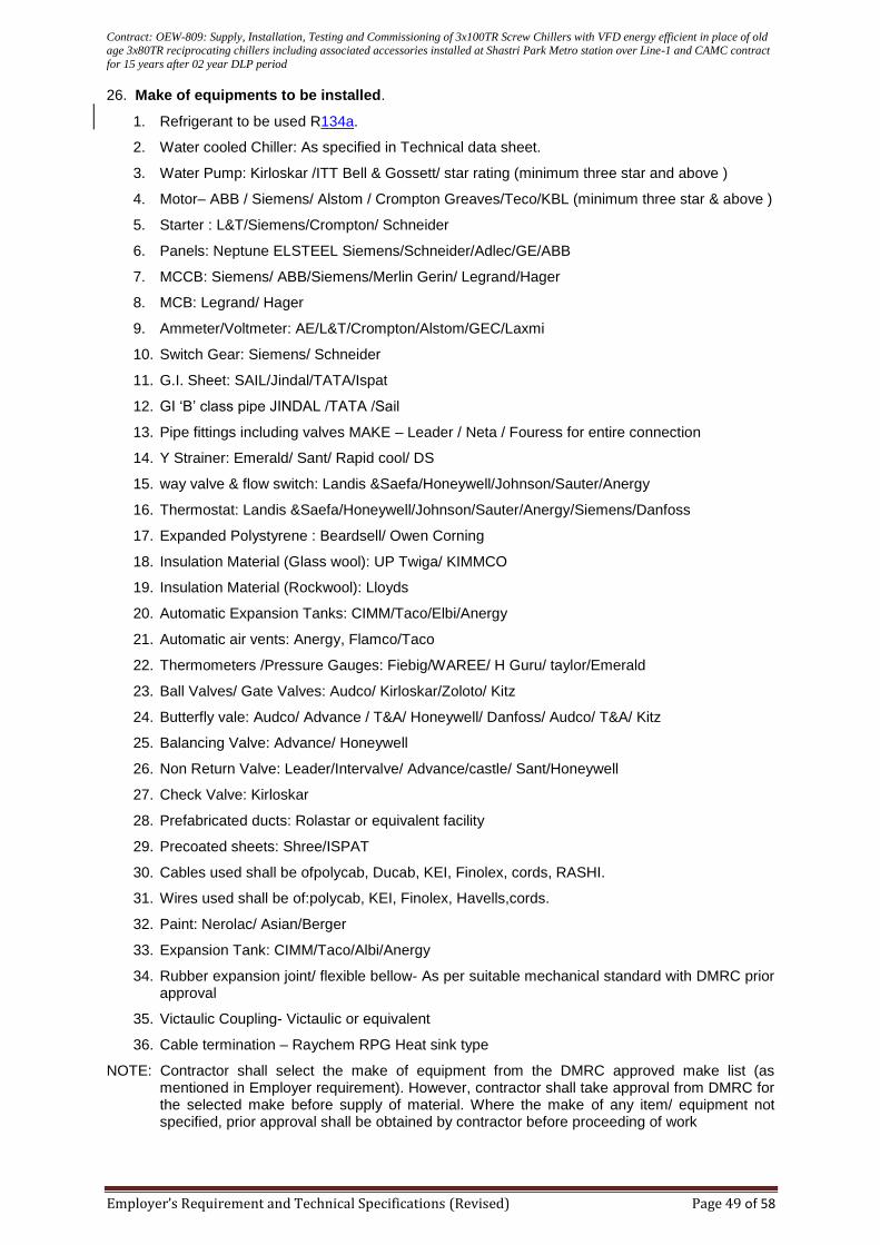
Contract: OEW-809: Supply, Installation, Testing and Commissioning of 3x100TR Screw Chillers with VFD energy efficient in place of old age 3x80TR reciprocating chillers including associated accessories installed at Shastri Park Metro station over Line-1 and CAMC contract
for 15 years after 02 year DLP period
Employer’s Requirement and Technical Specifications (Revised) Page 49 of 58
26. Make of equipments to be installed.
1. Refrigerant to be used R134a.
2. Water cooled Chiller: As specified in Technical data sheet.
3. Water Pump: Kirloskar /ITT Bell & Gossett/ star rating (minimum three star and above )
4. Motor– ABB / Siemens/ Alstom / Crompton Greaves/Teco/KBL (minimum three star & above )
5. Starter : L&T/Siemens/Crompton/ Schneider
6. Panels: Neptune ELSTEEL Siemens/Schneider/Adlec/GE/ABB
7. MCCB: Siemens/ ABB/Siemens/Merlin Gerin/ Legrand/Hager
8. MCB: Legrand/ Hager
9. Ammeter/Voltmeter: AE/L&T/Crompton/Alstom/GEC/Laxmi
10. Switch Gear: Siemens/ Schneider
11. G.I. Sheet: SAIL/Jindal/TATA/Ispat
12. GI ‘B’ class pipe JINDAL /TATA /Sail
13. Pipe fittings including valves MAKE – Leader / Neta / Fouress for entire connection
14. Y Strainer: Emerald/ Sant/ Rapid cool/ DS
15. way valve & flow switch: Landis &Saefa/Honeywell/Johnson/Sauter/Anergy
16. Thermostat: Landis &Saefa/Honeywell/Johnson/Sauter/Anergy/Siemens/Danfoss
17. Expanded Polystyrene : Beardsell/ Owen Corning
18. Insulation Material (Glass wool): UP Twiga/ KIMMCO
19. Insulation Material (Rockwool): Lloyds
20. Automatic Expansion Tanks: CIMM/Taco/Elbi/Anergy
21. Automatic air vents: Anergy, Flamco/Taco
22. Thermometers /Pressure Gauges: Fiebig/WAREE/ H Guru/ taylor/Emerald
23. Ball Valves/ Gate Valves: Audco/ Kirloskar/Zoloto/ Kitz
24. Butterfly vale: Audco/ Advance / T&A/ Honeywell/ Danfoss/ Audco/ T&A/ Kitz
25. Balancing Valve: Advance/ Honeywell
26. Non Return Valve: Leader/Intervalve/ Advance/castle/ Sant/Honeywell
27. Check Valve: Kirloskar
28. Prefabricated ducts: Rolastar or equivalent facility
29. Precoated sheets: Shree/ISPAT
30. Cables used shall be ofpolycab, Ducab, KEI, Finolex, cords, RASHI.
31. Wires used shall be of:polycab, KEI, Finolex, Havells,cords.
32. Paint: Nerolac/ Asian/Berger
33. Expansion Tank: CIMM/Taco/Albi/Anergy
34. Rubber expansion joint/ flexible bellow- As per suitable mechanical standard with DMRC prior approval
35. Victaulic Coupling- Victaulic or equivalent
36. Cable termination – Raychem RPG Heat sink type
NOTE: Contractor shall select the make of equipment from the DMRC approved make list (as mentioned in Employer requirement). However, contractor shall take approval from DMRC for the selected make before supply of material. Where the make of any item/ equipment not specified, prior approval shall be obtained by contractor before proceeding of work
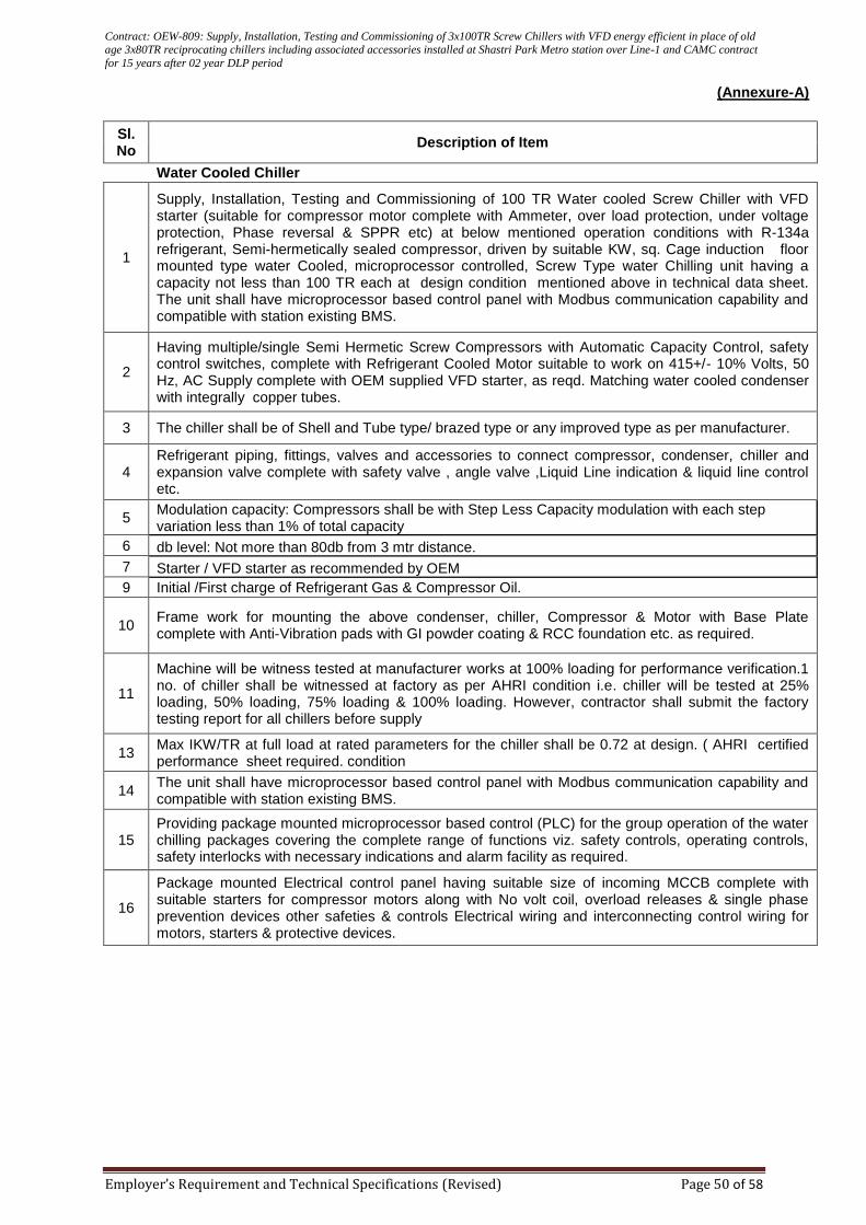
Contract: OEW-809: Supply, Installation, Testing and Commissioning of 3x100TR Screw Chillers with VFD energy efficient in place of old age 3x80TR reciprocating chillers including associated accessories installed at Shastri Park Metro station over Line-1 and CAMC contract
for 15 years after 02 year DLP period
Employer’s Requirement and Technical Specifications (Revised) Page 50 of 58
(Annexure-A)
Sl. No
Description of Item
Water Cooled Chiller
1
Supply, Installation, Testing and Commissioning of 100 TR Water cooled Screw Chiller with VFD starter (suitable for compressor motor complete with Ammeter, over load protection, under voltage protection, Phase reversal & SPPR etc) at below mentioned operation conditions with R-134a refrigerant, Semi-hermetically sealed compressor, driven by suitable KW, sq. Cage induction floor mounted type water Cooled, microprocessor controlled, Screw Type water Chilling unit having a capacity not less than 100 TR each at design condition mentioned above in technical data sheet. The unit shall have microprocessor based control panel with Modbus communication capability and compatible with station existing BMS.
2
Having multiple/single Semi Hermetic Screw Compressors with Automatic Capacity Control, safety control switches, complete with Refrigerant Cooled Motor suitable to work on 415+/- 10% Volts, 50 Hz, AC Supply complete with OEM supplied VFD starter, as reqd. Matching water cooled condenser with integrally copper tubes.
3 The chiller shall be of Shell and Tube type/ brazed type or any improved type as per manufacturer.
4 Refrigerant piping, fittings, valves and accessories to connect compressor, condenser, chiller and expansion valve complete with safety valve , angle valve ,Liquid Line indication & liquid line control etc.
5 Modulation capacity: Compressors shall be with Step Less Capacity modulation with each step variation less than 1% of total capacity
6 db level: Not more than 80db from 3 mtr distance.
7 Starter / VFD starter as recommended by OEM
9 Initial /First charge of Refrigerant Gas & Compressor Oil.
10 Frame work for mounting the above condenser, chiller, Compressor & Motor with Base Plate complete with Anti-Vibration pads with GI powder coating & RCC foundation etc. as required.
11
Machine will be witness tested at manufacturer works at 100% loading for performance verification.1 no. of chiller shall be witnessed at factory as per AHRI condition i.e. chiller will be tested at 25% loading, 50% loading, 75% loading & 100% loading. However, contractor shall submit the factory testing report for all chillers before supply
13 Max IKW/TR at full load at rated parameters for the chiller shall be 0.72 at design. ( AHRI certified performance sheet required. condition
14 The unit shall have microprocessor based control panel with Modbus communication capability and compatible with station existing BMS.
15 Providing package mounted microprocessor based control (PLC) for the group operation of the water chilling packages covering the complete range of functions viz. safety controls, operating controls, safety interlocks with necessary indications and alarm facility as required.
16
Package mounted Electrical control panel having suitable size of incoming MCCB complete with suitable starters for compressor motors along with No volt coil, overload releases & single phase prevention devices other safeties & controls Electrical wiring and interconnecting control wiring for motors, starters & protective devices.
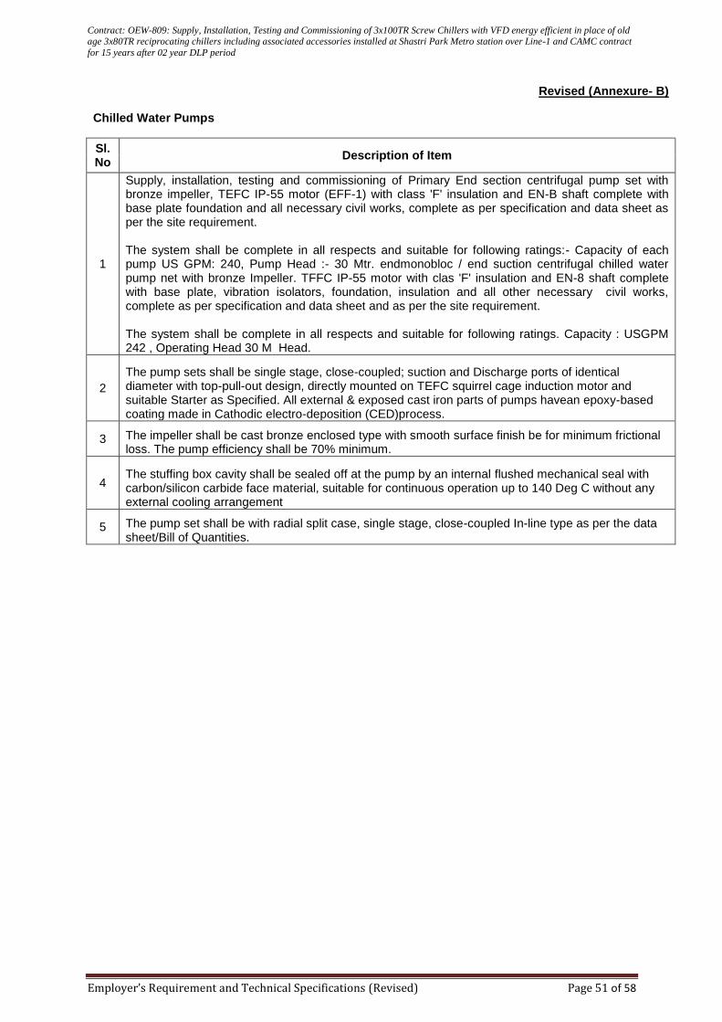
Contract: OEW-809: Supply, Installation, Testing and Commissioning of 3x100TR Screw Chillers with VFD energy efficient in place of old age 3x80TR reciprocating chillers including associated accessories installed at Shastri Park Metro station over Line-1 and CAMC contract
for 15 years after 02 year DLP period
Employer’s Requirement and Technical Specifications (Revised) Page 51 of 58
Revised (Annexure- B)
Chilled Water Pumps
Sl. No
Description of Item
1
Supply, installation, testing and commissioning of Primary End section centrifugal pump set with bronze impeller, TEFC IP-55 motor (EFF-1) with class 'F' insulation and EN-B shaft complete with base plate foundation and all necessary civil works, complete as per specification and data sheet as per the site requirement. The system shall be complete in all respects and suitable for following ratings:- Capacity of each pump US GPM: 240, Pump Head :- 30 Mtr. endmonobloc / end suction centrifugal chilled water pump net with bronze Impeller. TFFC IP-55 motor with clas 'F' insulation and EN-8 shaft complete with base plate, vibration isolators, foundation, insulation and all other necessary civil works, complete as per specification and data sheet and as per the site requirement. The system shall be complete in all respects and suitable for following ratings. Capacity : USGPM 242 , Operating Head 30 M Head.
2
The pump sets shall be single stage, close-coupled; suction and Discharge ports of identical diameter with top-pull-out design, directly mounted on TEFC squirrel cage induction motor and suitable Starter as Specified. All external & exposed cast iron parts of pumps havean epoxy-based coating made in Cathodic electro-deposition (CED)process.
3 The impeller shall be cast bronze enclosed type with smooth surface finish be for minimum frictional loss. The pump efficiency shall be 70% minimum.
4 The stuffing box cavity shall be sealed off at the pump by an internal flushed mechanical seal with carbon/silicon carbide face material, suitable for continuous operation up to 140 Deg C without any external cooling arrangement
5 The pump set shall be with radial split case, single stage, close-coupled In-line type as per the data sheet/Bill of Quantities.
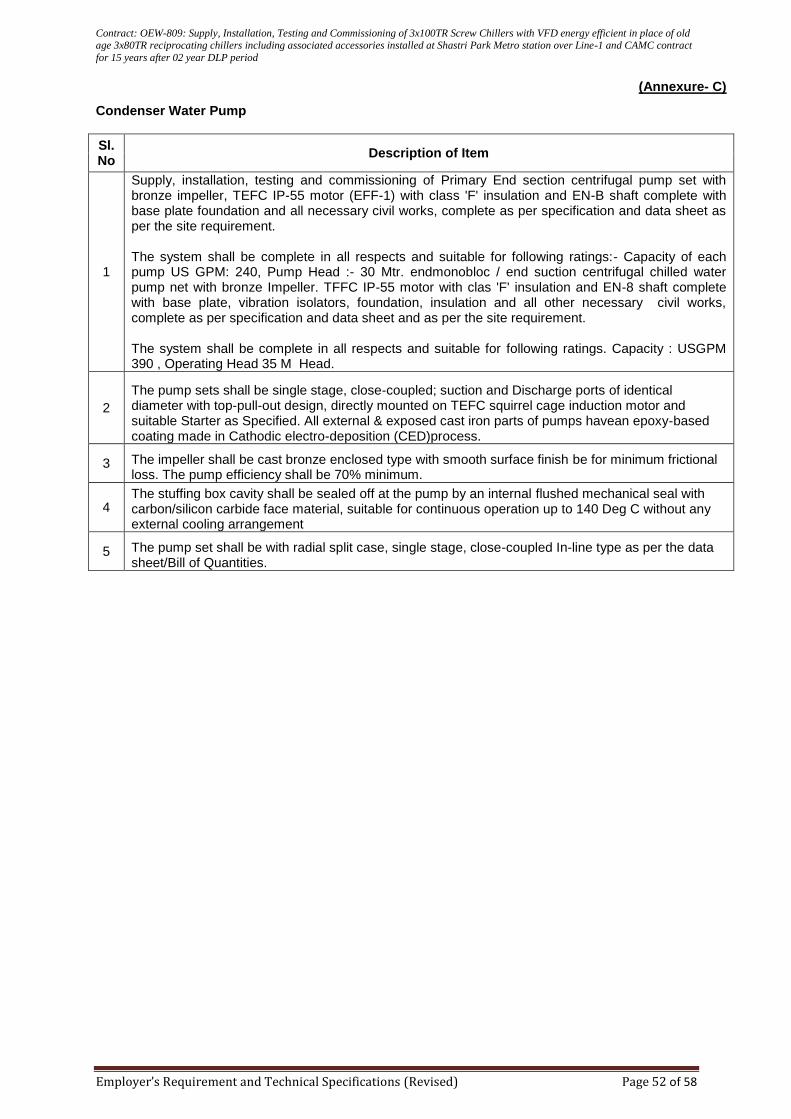
Contract: OEW-809: Supply, Installation, Testing and Commissioning of 3x100TR Screw Chillers with VFD energy efficient in place of old age 3x80TR reciprocating chillers including associated accessories installed at Shastri Park Metro station over Line-1 and CAMC contract
for 15 years after 02 year DLP period
Employer’s Requirement and Technical Specifications (Revised) Page 52 of 58
(Annexure- C)
Condenser Water Pump
Sl. No
Description of Item
1
Supply, installation, testing and commissioning of Primary End section centrifugal pump set with bronze impeller, TEFC IP-55 motor (EFF-1) with class 'F' insulation and EN-B shaft complete with base plate foundation and all necessary civil works, complete as per specification and data sheet as per the site requirement. The system shall be complete in all respects and suitable for following ratings:- Capacity of each pump US GPM: 240, Pump Head :- 30 Mtr. endmonobloc / end suction centrifugal chilled water pump net with bronze Impeller. TFFC IP-55 motor with clas 'F' insulation and EN-8 shaft complete with base plate, vibration isolators, foundation, insulation and all other necessary civil works, complete as per specification and data sheet and as per the site requirement. The system shall be complete in all respects and suitable for following ratings. Capacity : USGPM 390 , Operating Head 35 M Head.
2
The pump sets shall be single stage, close-coupled; suction and Discharge ports of identical diameter with top-pull-out design, directly mounted on TEFC squirrel cage induction motor and suitable Starter as Specified. All external & exposed cast iron parts of pumps havean epoxy-based coating made in Cathodic electro-deposition (CED)process.
3 The impeller shall be cast bronze enclosed type with smooth surface finish be for minimum frictional loss. The pump efficiency shall be 70% minimum.
4 The stuffing box cavity shall be sealed off at the pump by an internal flushed mechanical seal with carbon/silicon carbide face material, suitable for continuous operation up to 140 Deg C without any external cooling arrangement
5 The pump set shall be with radial split case, single stage, close-coupled In-line type as per the data sheet/Bill of Quantities.
Contract: OEW-809: Supply, Installation, Testing and Commissioning of 3x100TR Screw Chillers with VFD energy efficient in place of old age 3x80TR reciprocating chillers including associated accessories installed at Shastri Park Metro station over Line-1 and CAMC contract
for 15 years after 02 year DLP period
Employer’s Requirement and Technical Specifications (Revised) Page 53 of 58
Annexure-D
Auto tube cleaning system OPERATIONAL DETAILS OF WITH BOOSTER PUMP AUTOMATIC TUBES CLEANING SYSTEM The operation of acts is controlled through a plc based control panel. On power up in auto mode the plc checks all the valves are close and no alarm is present. Any one of the 3 or more or all the 3 chillers are ‘on’ feedback is available, system is healthy, the injection cycle is initiated. INJECTION CYCLE Both the 3 way valve along with the 2 way valve of chiller first in the sequence with the ‘on’ status will be opened. After the open feedback of both the 3 way valves along with open feed back of the 2 way valve is received pump is stared and runs for a preset time. by the pressure generated by the booster pump mounted on the skid, balls in the collector are pushed in the inlet water line of chiller. These balls enter the chiller with condenser water flow and pass through the tubes of condenser performing the cleaning action of the inner surface of the tubes. These balls after exiting from the condenser gets trapped in ball trap. After the completion of injection of balls the pump stops, then the injection cycle of next chiller with ‘on’ status available is initiated. at this point the earlier 2 way valve closes and next 2 way valve opens. again the above cycle is repeated till the last chiller with chiller ‘on’ status is available. if any chiller is set on bypass mode that particular 2 way valve will not open and the cycle will jump to the next ‘on’ chiller. AFTER THE INJECTION IN LAST ‘ON’ CHILLER IS COMPLETE BOTH THE 3 WAY VALVE AND THE LAST 2 WAY VALVE WILL CLOSE. COLLECTION CYCLE Collection cycle will be initiate after the preset standby time. Now only the 2 way valves will open and on receiving the open feedback of 2 way valve pump will run for preset time. This time the balls are collected back from ball trap to ball collector on stopping of pump the same sequence of next 2 way valve opening is followed as during the injection cycle. This will continue till the balls of the last chiller are collected back in the collector.
RESTART OF INJECTION CYCLE Once the collection cycle of the last chiller is complete and the last 2 way valve is closed the system will wait for a preset standby time to restart the injection cycle followed by collection cyclce same as above and so the cleaning cycles keep on repeating.
BALL CHANGE ALARM A down counter is provide in the system that generates a reminder alarm when the counter reaches zero. with every completion of one cycle (i.e injection + collection) the down counter will reduce the count by 1 and on reaching zero it will generate the alarm for the particular chiller for which the counter have reached zero.
POWER FAILURE Whenever power resumes the system will reset and will start operation from the first step, i.e. injection cycle of the first on chiller will be initiated irrespective of whatever may be the status of cycle before power failure.
Contract: OEW-809: Supply, Installation, Testing and Commissioning of 3x100TR Screw Chillers with VFD energy efficient in place of old age 3x80TR reciprocating chillers including associated accessories installed at Shastri Park Metro station over Line-1 and CAMC contract
for 15 years after 02 year DLP period
Employer’s Requirement and Technical Specifications (Revised) Page 54 of 58
LIST OF ALARMS
1. SPPR TRIP
2. MPCB TRIP
3. PUMP FAIL TO START
4. PUMP FAIL TO STOP
5. 3WV1 NOT OPEN
6. 3WV1 NOT CLOSE
7. 3WV2 NOT OPEN
8. 3WV2 NOT CLOSE
9. V1 NOT OPEN
10. V1 NOT CLOSE
11. V2 NOT OPEN
12. V2 NOT CLOSE
13. V3 NOT OPEN
14. V3 NOT CLOSE
15. V4 NOT OPEN
16. V4 NOT CLOSE
17. V5 NOT OPEN
18. V5 NOT CLOSE
19. BALL CHANGE CHILLER 1 ALARM
20. BALL CHANGE CHILLER 2 ALARM
21. BALL CHANGE CHILLER 3 ALARM
22. BALL CHANGE CHILLER 4 ALARM
23. BALL CHANGE CHILLER 5 ALARM
Contract: OEW-809: Supply, Installation, Testing and Commissioning of 3x100TR Screw Chillers with VFD energy efficient in place of old age 3x80TR reciprocating chillers including associated accessories installed at Shastri Park Metro station over Line-1 and CAMC contract
for 15 years after 02 year DLP period
Employer’s Requirement and Technical Specifications (Revised) Page 55 of 58
AUTOMATIC TUBES CLEANING SYSTEM LIST OF COMPONENTS AND MAKES
Sr.No. Description Make
1 PLC Schneider/Siemens/Allen Bradley
2 7 inch multi color touch screen hmi. Schneider/Siemens/Allen Bradley
3 Step down transformer Schneider/Siemens/Allen Bradley
4 SMPS Schneider/Siemens/Allen Bradley
5 MPCB Schneider/Siemens/Allen Bradley
6 MCB AC and DC Circuits Schneider/Siemens/Allen Bradley
7 Tower light with green light , red light , buzzer for audio & visual alarm
Schneider/Siemens/Allen Bradley
8 Auxillary relays plug in type Schneider/Siemens/Allen Bradley
9 Power contactors of inductive chattering rating. Schneider/Siemens/Allen Bradley
10 Under voltage protection relay for pump motor protection Schneider/Siemens/Allen Bradley
11 Over voltage protection relay for pump motor protection Schneider/Siemens/Allen Bradley
12 Phase sequence protection relay for pump motor protection
Schneider/Siemens/Allen Bradley
13 Phase loss protection relay for pump motor protection Schneider/Siemens/Allen Bradley
14 Multi color graphics of hmi of complete system for easy monitoring of complete system
Schneider/Siemens/Allen Bradley
15 Single pump for injection and collection of balls Grundfos/ XYLEM
16 motorised ball valves (solonoide valves not to be used) Siemens / Belimo / Denfoss
17 Ball trap, ms carbon steel hot dip galvanised Make as per atcs supplier
18 Ball collector, ms carbon steel hot dip galvanised Make as per atcs supplier
19 Manual ball valves ZOLOTO / L&T
20 Pressure gauge H- GURU
21 Y strainer at the suction of pump ZOLOTO / L&T
22 Swing type nrv Make as per atcs supplier
23 Dual plate nrv is provided at the discharge of pump ZOLOTO / L&T
24 Cleaning sponge balls As per atcs supplier
25 MS steel fabricated frame for skid As per atcs supplier
Contract: OEW-809: Supply, Installation, Testing and Commissioning of 3x100TR Screw Chillers with VFD energy efficient in place of old age 3x80TR reciprocating chillers including associated accessories installed at Shastri Park Metro station over Line-1 and CAMC contract
for 15 years after 02 year DLP period
Employer’s Requirement and Technical Specifications (Revised) Page 56 of 58
FEATURES
• All Spares must available in open market in any part of India.
• 100% Chemical Free System.
• Ball Collector and Ball Trap must be HOT DIP GALVANIZED for much longer life. These
should be cleaned for grease, rust etc by sand blasting before Hot Dip Galvanizing. Epoxy
painting or Hot Dip Epoxy coating will not be accepted.
• The Control Panel shall be mounted on the Skid.
• TOWER LIGHT on control panel is to be provided with Green light glow when system is
healthy, Green light OFF in case of alarm, Red Light glow and blink in case of alarm, Buzzer
sound in case of alarm. This is required for Annunciation from a distance in noisy atmosphere
of Plant Room.
• SEVEN INCH Multi colour Touch Screen HMI.
• COMPLETE SYSTEM GRAPHICS on HMI Screen for easy monitoring of system. Running
Status of all the chillers, control valves and pump must be simultaneously seen on the screen
of HMI.
• MULTIPLE CHILLERS can be cleaned by Only One Skid.
• MAXIMUM SAFETIES for all the Operational Components. Apart from MPCB, MCB, Under/
Over Voltage, Phase sequence and Single Phasing Protection are provided for Pump Motor
Protection.
• ALERT on Balls change period.
• CHILLER BYPASS FACILITY. In case of maintenance of any of the chiller or to change the
balls, the chiller must be bypassed from HMI. The balls will not go in this chiller while for other
running chillers system must operate normally
• UNIVERSAL DESIGN OF BALL TRAP. Can be installed in Horizontal / Vertical pipeline OR at
BEND of pipe.
• Ball Trap comes with Open able Cover for cleaning of mesh and Trap.
• CONTROL VALVES (Solenoid Valves will not be accepted), must be of 24V DC and must be
mounted on the Skid. Control Valves near Ball Collector is not acceptable. Manual Ball Valves
must be used along with each Chiller selection control valves.
• All the control valves must open at least once in every 24 hours, irrespective of chiller is ON
or OFF.
• All the control valves must have over load protection. If the control valve gets struck while
opening or closing the actuator motor must trip and should not get burnt due to mechanical
overload.
• All the control valves will be provided with Open and Close feedback Contacts.
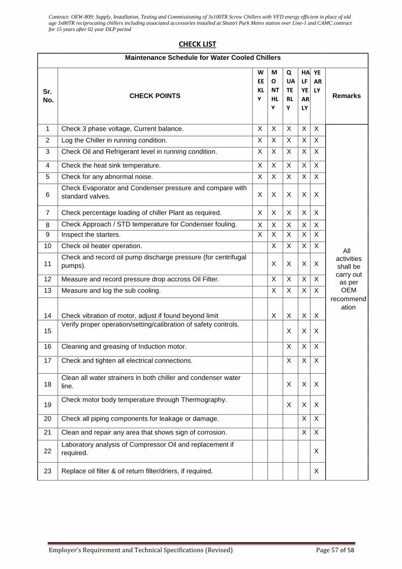
Contract: OEW-809: Supply, Installation, Testing and Commissioning of 3x100TR Screw Chillers with VFD energy efficient in place of old age 3x80TR reciprocating chillers including associated accessories installed at Shastri Park Metro station over Line-1 and CAMC contract
for 15 years after 02 year DLP period
Employer’s Requirement and Technical Specifications (Revised) Page 57 of 58
CHECK LIST
Maintenance Schedule for Water Cooled Chillers
Sr.
No. CHECK POINTS
Remarks
1 Check 3 phase voltage, Current balance. X X X X X
All activities shall be carry out as per OEM
recommend
ation
2 Log the Chiller in running condition. X X X X X
3 Check Oil and Refrigerant level in running condition. X X X X X
4 Check the heat sink temperature. X X X X X
5 Check for any abnormal noise. X X X X X
6 Check Evaporator and Condenser pressure and compare with
standard valves. X X X X X
7 Check percentage loading of chiller Plant as required. X X X X X
8 Check Approach / STD temperature for Condenser fouling. X X X X X
9 Inspect the starters. X X X X X
10 Check oil heater operation. X X X X
11 Check and record oil pump discharge pressure (for centrifugal
pumps). X X X X
12 Measure and record pressure drop accross Oil Filter. X X X X
13 Measure and log the sub cooling. X X X X
14 Check vibration of motor, adjust if found beyond limit X X X X
15 Verify proper operation/setting/calibration of safety controls.
X X X
16 Cleaning and greasing of Induction motor. X X X
17 Check and tighten all electrical connections.
X X X
18 Clean all water strainers in both chiller and condenser water
line. X X X
19 Check motor body temperature through Thermography.
X X X
20 Check all piping components for leakage or damage. X X
21 Clean and repair any area that shows sign of corrosion. X X
22 Laboratory analysis of Compressor Oil and replacement if
required. X
23 Replace oil filter & oil return filter/driers, if required. X
YE
AR
LY
HA
LF
YE
AR
LY
Q
UA
TE
RL
Y
M
O
NT
HL
Y
W
EE
KL
Y
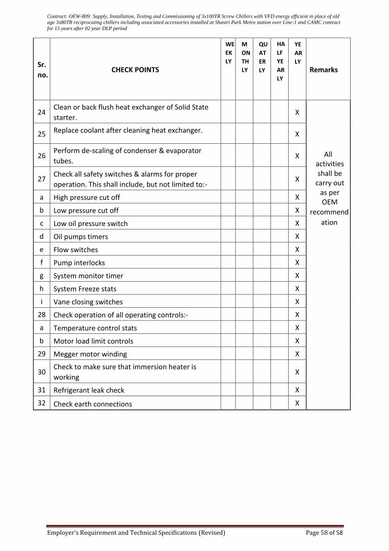
Contract: OEW-809: Supply, Installation, Testing and Commissioning of 3x100TR Screw Chillers with VFD energy efficient in place of old age 3x80TR reciprocating chillers including associated accessories installed at Shastri Park Metro station over Line-1 and CAMC contract
for 15 years after 02 year DLP period
Employer’s Requirement and Technical Specifications (Revised) Page 58 of 58
Sr.
no. CHECK POINTS
Remarks
24 Clean or back flush heat exchanger of Solid State
starter. X
All activities shall be
carry out as per OEM
recommend
ation
25 Replace coolant after cleaning heat exchanger. X
26 Perform de-scaling of condenser & evaporator
tubes. X
27 Check all safety switches & alarms for proper
operation. This shall include, but not limited to:- X
a High pressure cut off X
b Low pressure cut off X
c Low oil pressure switch X
d Oil pumps timers X
e Flow switches X
f Pump interlocks X
g System monitor timer X
h System Freeze stats X
i Vane closing switches X
28 Check operation of all operating controls:- X
a Temperature control stats X
b Motor load limit controls X
29 Megger motor winding X
30 Check to make sure that immersion heater is
working X
31 Refrigerant leak check X
32 Check earth connections X
YE
AR
LY
HA
LF
YE
AR
LY
QU
AT
ER
LY
M
ON
TH
LY
WE
EK
LY
Related Documents


