Architecture • Master Planning • Interior Design • Construction Management • Design Build • Site Acquisition • Property Surveys 100 Dobbs Lane • Suite 204 • Cherry Hill, NJ 08034 (856) 616-2960 • www.mckernanarchitects.com • (856) 616-2963 fax Joseph F. McKernan Jr. Architects and Associates, LLC Joseph F. McKernan Jr.,RA • John J. McQuilkin,AIA • Richard J. Lake,RA •• Francis A. Witt ADDENDUM # 4 OWNER: Rowan University Rutgers Camden Board of Governors 200 Federal Street Camden, NJ PROJECT NAME / NO: #917 Joint Health Sciences Center DATE : August 28, 2017 TRANSMITTED VIA: INFO EXCHANGE • This Addendum is issued to furnish information which is supplemental to the Bid Documents. All work required by this Addendum shall comply with the applicable provisions of the Bid Documents and shall be incorporated in the Base Bid, unless otherwise specified. • Only revised and / or new drawings and specifications have been issued. Drawings and specifications that have not been superseded by the enclosed Addendum documents, are to remain the basis for Bidding. • Modification to Drawings are denoted with a revision cloud and reference “triangle” and boldface for additions and strike-thru for deletions in Specifications. REMARKS: • See narrative for changes for explanation of modifications to drawings and specifications ISSUED BY: John McQuilkin, McKernan Architects

Welcome message from author
This document is posted to help you gain knowledge. Please leave a comment to let me know what you think about it! Share it to your friends and learn new things together.
Transcript
Architecture • Master Planning • Interior Design • Construction Management • Design Build • Site Acquisition • Property Surveys 100 Dobbs Lane • Suite 204 • Cherry Hill, NJ 08034
(856) 616-2960 • www.mckernanarchitects.com • (856) 616-2963 fax
Joseph F. McKernan Jr. Architects and Associates, LLC
Joseph F. McKernan Jr.,RA • John J. McQuilkin,AIA • Richard J. Lake,RA ••
Francis A. Witt
ADDENDUM # 4 OWNER: Rowan University
Rutgers Camden Board of Governors 200 Federal Street Camden, NJ
PROJECT NAME / NO:
#917 Joint Health Sciences Center
DATE : August 28, 2017 TRANSMITTED VIA: INFO EXCHANGE
• This Addendum is issued to furnish information which is supplemental to the Bid Documents. All work required by this Addendum shall comply with the applicable provisions of the Bid Documents and shall be incorporated in the Base Bid, unless otherwise specified.
• Only revised and / or new drawings and specifications have been issued. Drawings and specifications that have not been superseded by the enclosed Addendum documents, are to remain the basis for Bidding.
• Modification to Drawings are denoted with a revision cloud and reference “triangle” and boldface for additions and strike-thru for deletions in Specifications.
REMARKS:
• See narrative for changes for explanation of modifications to drawings and specifications
ISSUED BY: John McQuilkin, McKernan Architects
Architecture • Master Planning • Interior Design • Construction Management • Design Build • Site Acquisition • Property Surveys 100 Dobbs Lane • Suite 204 • Cherry Hill, NJ 08034
(856) 616-2960 • www.mckernanarchitects.com • (856) 616-2963 fax
Joseph F. McKernan Jr. Architects and Associates, LLC
Joseph F. McKernan Jr.,RA • John J. McQuilkin,AIA • Richard J. Lake,RA ••
Francis A. Witt
Rowan University – Rutgers Camden Joint Health Sciences Center
Addendum No. 4
August 28, 2017
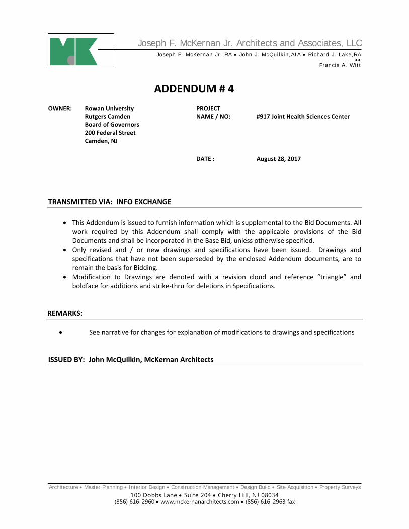
Architect’s Project No. 917 SPECIFICATIONS:
• Form of Proposal: See attached revised form with additional deduct alternates 11-17 added. • Section 088000: See attached revised specification section with revisions to Section 2.4.A.2.a,
changing the color of the seals from ‘gray’ to standard ‘black’ and Section 2.16 for the insulated glass descriptions, with low iron glass noted for all exterior insulated glass types.
• Section 123554: Clarification - Adaptable Lab Casework: Section 1.2 Item A.1 - Delete 'CUSTOMIZED version' in first line. ALPHA SYSTEM Lab Furniture to remain as Basis of Design.
DRAWINGS:
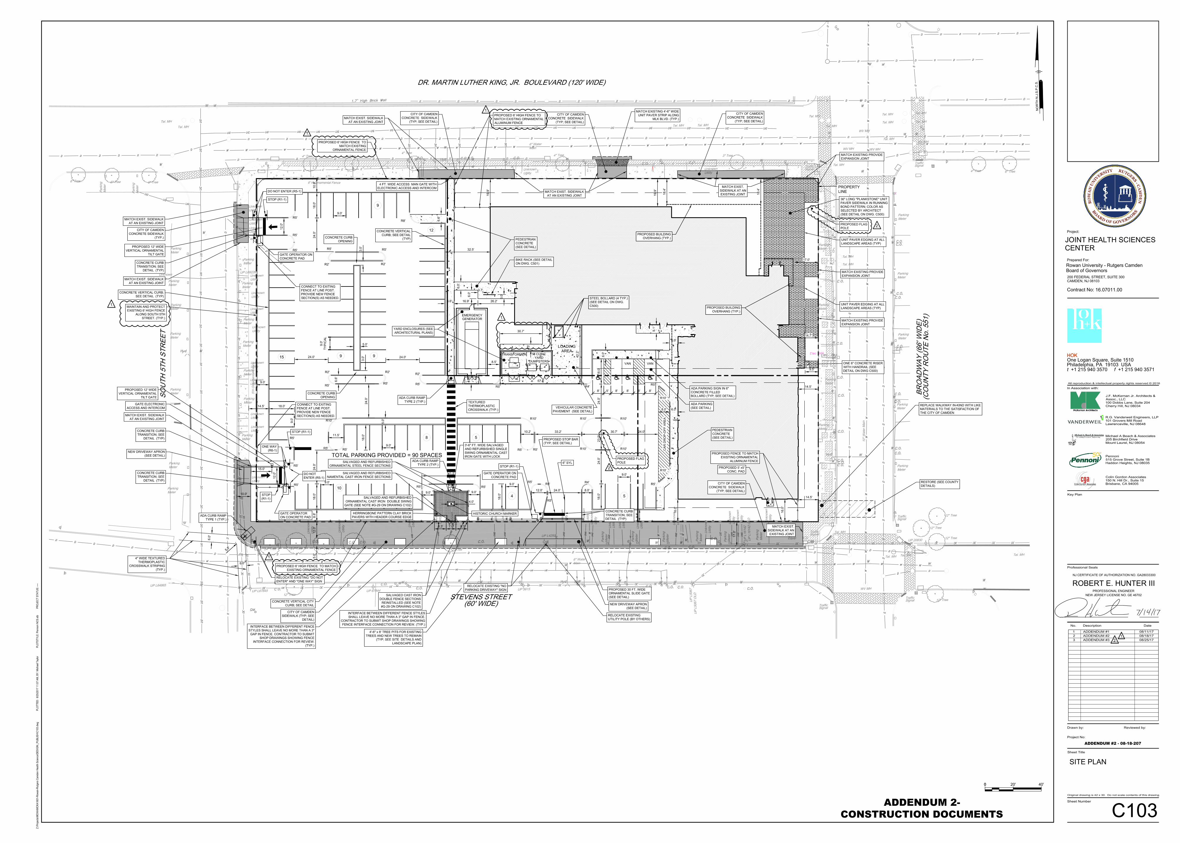
• Drawing C103: See revised Site Plan with the location for the flagpole indicated.
END OF ADDENDUM NO. 4
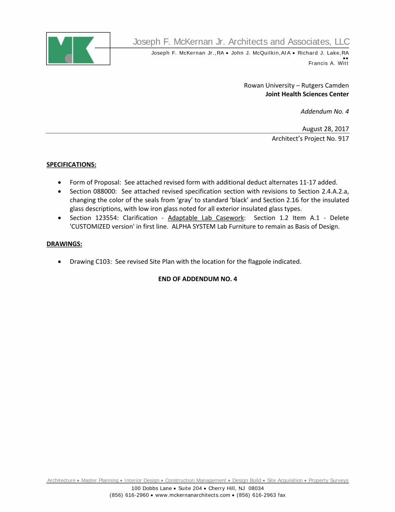
ADDENDUM #4 RFI QUESTIONS:
1. Addendum #2 issued East & West lot contour reference drawings which indicate and show “Anomalies”. Some of these Anomalies being utilities. Without knowing exactly the size or depth of these Anomalies, we cannot accurately quantify the removal and replacement of these Anomalies with suitable soils and recommend that an allowance be carried by all bidders if it is determined that removal and replacement or the relocation of an underground utility is required. We question why these drawings are being issued since our responsibility associated with these drawings is not defined. RESPONSE: These drawings were included in Addendum #2 as background information on the site for the contractor’s use as they see fit and partly due to requests made in questions 21 and 33 of Addendum #1, as well as an attempt to provide the bidders with as much information as is available.
2. Addendum #2 structural drawing S304 adds a note about providing duct/pipe supports for ductwork and piping @ the mechanical equipment platform. Along with giving a detail for the requirements of these supports on drawing S624. The note indicates to review the mechanical “M” series drawings and to coordinate the exact locations and sizes of the supports with the division 23 installing contractors. Since this is a public bid and the steel subcontractors would not know who the installing div 23 contractor is going to be until after the bids are received and awarded, we are requesting that the engineer quantify the amount of supports needed along with the sizes of these supports since they will differ in size so that all bidders are bidding on an apple to apple basis? RESPONSE: The detail on the structural drawings indicates the type of support needed. The quantity of supports will depend on the piping layout by the mechanical subcontractor.
3. Addendum #2 – RFI #53 response indicates “that the pile survey will include numbered piles and may include cut off elevations”. Stating that they may include cut off elevations will require us to carry another surveyor in order to verify the cut off elevations which does not make sense if the pile contractor already has a surveyor preparing these survey drawings. We would think the owner would want to save on the cost of the 2nd survey. Please clarify? RESPONSE: The response in Addendum #2 should have said “will include cut-off elevations”.
4. Addendum #2 – RFI #100 response indicates “Coordinate weight of letters and required support with the sign manufacturer” when asked for an anticipated weight of this signage being supported from the curtain system. We are asking that an approximate weight be given to the curtain wall contractors so that they are able to complete their bids, since the signage contract has not yet been purchased in order for us to be able to obtain this information for them? RESPONSE: The weight of the letters and brackets may vary depending on the manufacturer but one of the specified manufacturer’s has stated each 20” high cast aluminum letter could weigh approximately five pounds. The weight of the support brackets will depend on the sign manufacturer’s bracket design.

5. Addendum #2 – RFI # 51 inquired about the Intrusion Detection and security plans SE201N and SE402 were updated. Please confirm that Duress Button that was added at the Reception Desk in Lobby 101, along with the Burglary Control Panel and Key Pad in Security Office 103 are the only Intrusion Detection devices that are required on this project and all other system hardware noted on SE402 and within the specification is not required? RESPONSE: Confirmed. In addition to that, there needs to be a tie between access control system and the intrusion system as shown on sheet SE402 – Block Diagram detail.
6. Regarding Spec Section 283133 Two-Way Radio PES Communications Enhancement Systems, please confirm which Trade Contractor is responsible to provide this system: Electrical contractor, owner's security contractor, or the General Contractor? RESPONSE: Indicated work is part of the Contract; GC to assign responsible sub-contractor.
7. The Fire Alarm System is listed under Division 28 – Electronic Safety and Security. Is the Electrical Contractor to provide the Fire Alarm System or is the Owner’s Security vendor to provide the Fire Alarm System? RESPONSE: Indicated work is part of the Contract; GC to assign responsible sub-contractor.
8. Please advise if Type MC Cable can be used to wire any “Emergency” lighting or power circuits in concealed walls or ceilings. RESPONSE: No; see Specification Section 260519-3.2F.
9. Please confirm who is responsible to “furnish” motor starters and any VFD’s. Mechanical Contractor or the Electrical Contractor. RESPONSE: Indicated work is part of the Contract; GC to assign responsible sub-contractor.
10. Does all vivarium branch & systems wiring need to be installed RMC & sealed? RESPONSE: Yes; see Vivarium Area General Notes on Drawing E201N.
11. Is RMC required in the Penthouse/ Mechanical area? RESPONSE: Yes; see Specification Section 260533-3.1B2b.
12. Generally, the Mechanical Contractor provides the VFD’s as part of their equipment package. Is the Electrical contractor to provide the VFD’s for this project. RESPONSE: Indicated work is part of the Contract; GC to assign responsible sub-contractor.
13. With vacation schedules and the upcoming holiday weekend, a large number of subcontractors have declined to bid; we feel it is in Rowan University-Rutgers best interest to extend the bid due date to the week of September 11th 2017, to ensure that receive a sufficient amount of competitive subcontractor proposals. Please advise if this is possible/acceptable. RESPONSE: The bid date has been extended to September 7.
14. Regarding the subcontractor ID form and Ironwork, Mechanical, Plumbing, and Electrical certification paperwork, please advise if this may be submitted in a 3-ring binder along with our sealed deliverables. The binder will not be "sealed" with our other deliverables. Please confirm that this is acceptable. RESPONSE: The Subcontractor Identification Form naming the subcontractors for each trade must be submitted with the sealed bid. Failure to do so shall be cause for disqualification of the Bidder and rejection of the Bid. The supporting documentation/paperwork for each subcontractor may be submitted in a separate three ring binder.
15. Regarding the sub ID paperwork, Torcon has noted, "See enclosed," on the page that requires sub information to be listed. It is our intent to only list the named subcontractor, but all other lines for information will be noted, "see enclosed." That information will be within the binder, separated per trade. With sub proposals being submitted up until "last minute," it will be difficult to fill in all information for each subcontractor by hand. Please confirm that this method is acceptable RESPONSE: See response to Question 14.

JOINT HEALTH SCIENCES CENTER PROJECT Form of Proposal
Section 00 41 13 - Page 1 Bid Set
July 14, 2017 ADDENDUM 4 – AUGUST 28, 2017
Rowan University/Rutgers
Camden Board of Governors
SECTION 00 41 13 - FORM OF PROPOSAL To: Rowan University/Rutgers – Camden Board of Governors (Owner) for: Rowan University/Rutgers – Camden Board of Governors Joint Health Sciences Center
Contract #1: General Construction Bid Date: September 7, 2017 BASE BID: 1. We, ________________________________________________, the Undersigned, in accordance
with the published advertisement inviting proposals, will furnish all labor, material, equipment and services necessary for the complete construction, as defined in the advertisement, specimen contract, specifications, drawings, and proposal, for the Contract amount indicated below for the GENERAL CONSTRUCTION CONSTRUCTION CONTRACT for the ROWAN UNIVERSITY/RUTGERS – CAMDEN BOARD OF GOVERNORS in strict accordance with the Contract Documents and Addenda thereto as prepared by Mckernan Architects for the total sum of:
A: TOTAL LUMP SUM BASE BID:
__________________________________________________________ ________________________
Written Figures
B: ALLOWANCE NO. 1: GENERAL ALLOWANCE ($100,000.00)
______________________________________________________ ___________________
Written Figures
C: ALLOWANCE NO. 2: For Light Fixture ($10,000.00)
______________________________________________________ ___________________
Written Figures
D: ALLOWANCE NO. 3: For Aluminum Fencing Repairs ($5,000.00)
______________________________________________________ ___________________
Written Figures
JOINT HEALTH SCIENCES CENTER PROJECT Form of Proposal
Section 00 41 13 - Page 2 Bid Set
July 14, 2017 ADDENDUM 4 – AUGUST 28, 2017
Rowan University/Rutgers
Camden Board of Governors
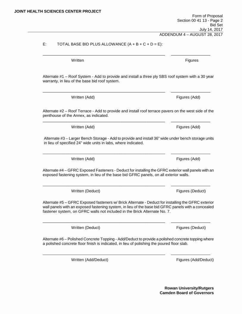
E: TOTAL BASE BID PLUS ALLOWANCE (A + B + C + D = E):
________________________________________________________ __________________
Written Figures
Alternate #1 – Roof System - Add to provide and install a three ply SBS roof system with a 30 year warranty, in lieu of the base bid roof system.
________________________________________________________ __________________
Written (Add) Figures (Add)
Alternate #2 – Roof Terrace - Add to provide and install roof terrace pavers on the west side of the penthouse of the Annex, as indicated. ________________________________________________________ __________________
Written (Add) Figures (Add)
Alternate #3 – Larger Bench Storage - Add to provide and install 36” wide under bench storage units in lieu of specified 24” wide units in labs, where indicated.
________________________________________________________ __________________
Written (Add) Figures (Add)
Alternate #4 – GFRC Exposed Fasteners - Deduct for installing the GFRC exterior wall panels with an exposed fastening system, in lieu of the base bid GFRC panels, on all exterior walls.
________________________________________________________ __________________
Written (Deduct) Figures (Deduct)
Alternate #5 – GFRC Exposed fasteners w/ Brick Alternate - Deduct for installing the GFRC exterior wall panels with an exposed fastening system, in lieu of the base bid GFRC panels with a concealed fastener system, on GFRC walls not included in the Brick Alternate No. 7.
________________________________________________________ __________________
Written (Deduct) Figures (Deduct)
Alternate #6 – Polished Concrete Topping - Add/Deduct to provide a polished concrete topping where a polished concrete floor finish is indicated, in lieu of polishing the poured floor slab.
________________________________________________________ __________________
Written (Add/Deduct) Figures (Add/Deduct)
JOINT HEALTH SCIENCES CENTER PROJECT Form of Proposal
Section 00 41 13 - Page 3 Bid Set
July 14, 2017 ADDENDUM 4 – AUGUST 28, 2017
Rowan University/Rutgers
Camden Board of Governors
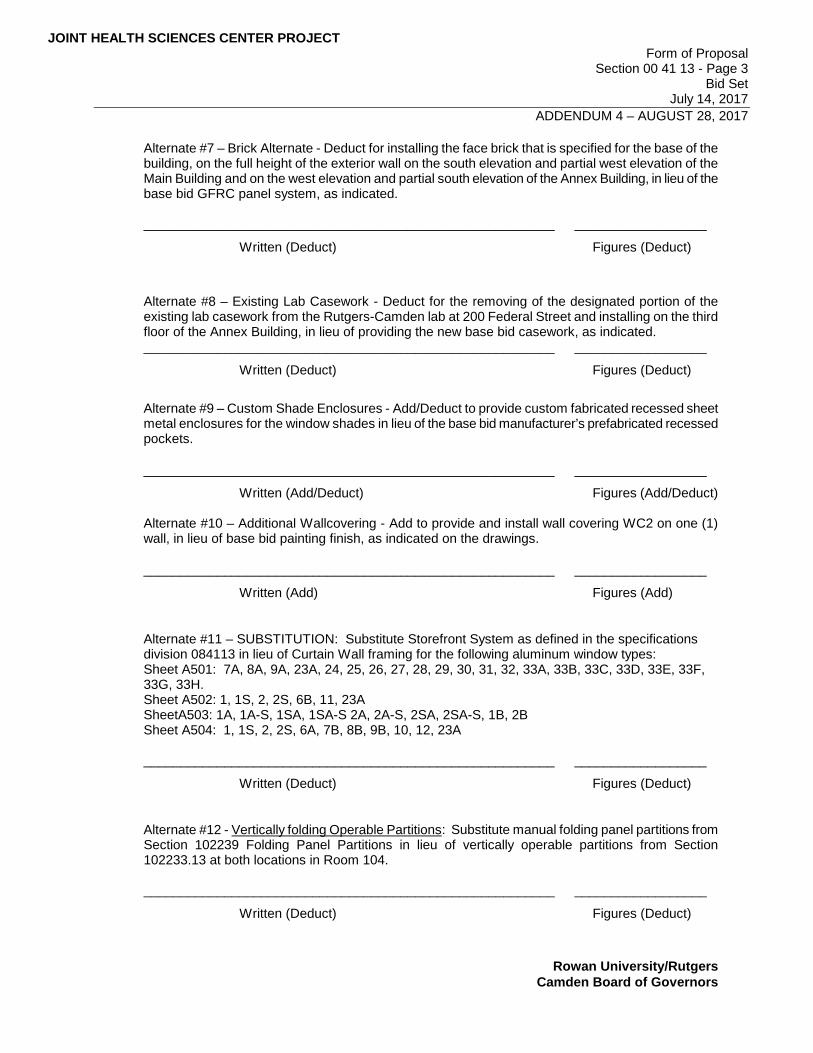
Alternate #7 – Brick Alternate - Deduct for installing the face brick that is specified for the base of the building, on the full height of the exterior wall on the south elevation and partial west elevation of the Main Building and on the west elevation and partial south elevation of the Annex Building, in lieu of the base bid GFRC panel system, as indicated. ________________________________________________________ __________________
Written (Deduct) Figures (Deduct)
Alternate #8 – Existing Lab Casework - Deduct for the removing of the designated portion of the existing lab casework from the Rutgers-Camden lab at 200 Federal Street and installing on the third floor of the Annex Building, in lieu of providing the new base bid casework, as indicated. ________________________________________________________ __________________
Written (Deduct) Figures (Deduct)
Alternate #9 – Custom Shade Enclosures - Add/Deduct to provide custom fabricated recessed sheet metal enclosures for the window shades in lieu of the base bid manufacturer’s prefabricated recessed pockets.
________________________________________________________ __________________
Written (Add/Deduct) Figures (Add/Deduct) Alternate #10 – Additional Wallcovering - Add to provide and install wall covering WC2 on one (1) wall, in lieu of base bid painting finish, as indicated on the drawings.
________________________________________________________ __________________
Written (Add) Figures (Add)
Alternate #11 – SUBSTITUTION: Substitute Storefront System as defined in the specifications division 084113 in lieu of Curtain Wall framing for the following aluminum window types: Sheet A501: 7A, 8A, 9A, 23A, 24, 25, 26, 27, 28, 29, 30, 31, 32, 33A, 33B, 33C, 33D, 33E, 33F, 33G, 33H. Sheet A502: 1, 1S, 2, 2S, 6B, 11, 23A SheetA503: 1A, 1A-S, 1SA, 1SA-S 2A, 2A-S, 2SA, 2SA-S, 1B, 2B Sheet A504: 1, 1S, 2, 2S, 6A, 7B, 8B, 9B, 10, 12, 23A ________________________________________________________ __________________
Written (Deduct) Figures (Deduct)
Alternate #12 - Vertically folding Operable Partitions: Substitute manual folding panel partitions from Section 102239 Folding Panel Partitions in lieu of vertically operable partitions from Section 102233.13 at both locations in Room 104. ________________________________________________________ __________________
Written (Deduct) Figures (Deduct)
JOINT HEALTH SCIENCES CENTER PROJECT Form of Proposal
Section 00 41 13 - Page 4 Bid Set
July 14, 2017 ADDENDUM 4 – AUGUST 28, 2017
Rowan University/Rutgers
Camden Board of Governors
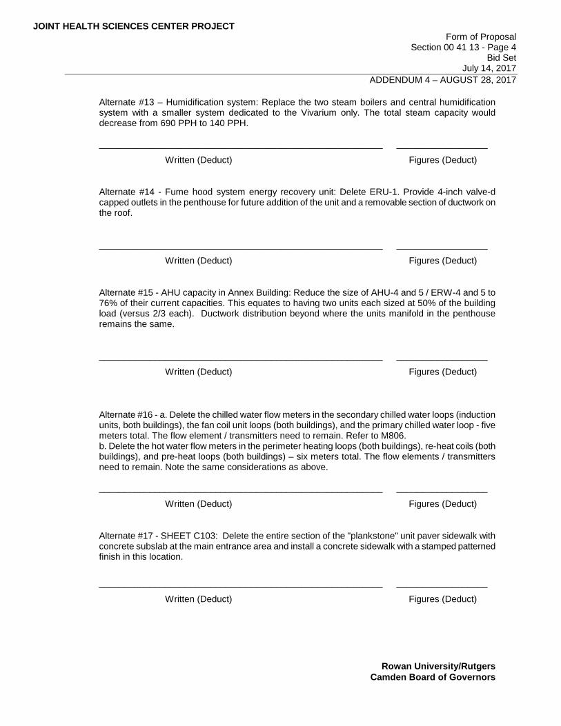
Alternate #13 – Humidification system: Replace the two steam boilers and central humidification system with a smaller system dedicated to the Vivarium only. The total steam capacity would decrease from 690 PPH to 140 PPH. ________________________________________________________ __________________
Written (Deduct) Figures (Deduct)
Alternate #14 - Fume hood system energy recovery unit: Delete ERU-1. Provide 4-inch valve-d capped outlets in the penthouse for future addition of the unit and a removable section of ductwork on the roof.
________________________________________________________ __________________
Written (Deduct) Figures (Deduct)
Alternate #15 - AHU capacity in Annex Building: Reduce the size of AHU-4 and 5 / ERW-4 and 5 to 76% of their current capacities. This equates to having two units each sized at 50% of the building load (versus 2/3 each). Ductwork distribution beyond where the units manifold in the penthouse remains the same.
________________________________________________________ __________________
Written (Deduct) Figures (Deduct)
Alternate #16 - a. Delete the chilled water flow meters in the secondary chilled water loops (induction units, both buildings), the fan coil unit loops (both buildings), and the primary chilled water loop - five meters total. The flow element / transmitters need to remain. Refer to M806. b. Delete the hot water flow meters in the perimeter heating loops (both buildings), re-heat coils (both buildings), and pre-heat loops (both buildings) – six meters total. The flow elements / transmitters need to remain. Note the same considerations as above.
________________________________________________________ __________________
Written (Deduct) Figures (Deduct)
Alternate #17 - SHEET C103: Delete the entire section of the "plankstone" unit paver sidewalk with concrete subslab at the main entrance area and install a concrete sidewalk with a stamped patterned finish in this location.
________________________________________________________ __________________
Written (Deduct) Figures (Deduct)
JOINT HEALTH SCIENCES CENTER PROJECT Form of Proposal
Section 00 41 13 - Page 5 Bid Set
July 14, 2017 ADDENDUM 4 – AUGUST 28, 2017
Rowan University/Rutgers
Camden Board of Governors
The Bid will be awarded and / or Alternates will be selected as follows. 1. Award Total Base Bid Plus Allowances and selected Alternates
2. CHECK LIST FOR BIDDERS:
The following, properly completed, and (where required) signed and sealed, are required to be submitted in quadruplicate with Bid or Bid will be rejected:
See Bidder’s Checklist. A. ALLOWANCES 1. General Allowance: The Allowance amounts herein specified are the net amounts available
for purchase of materials, including taxes (if any), and the installation/labor cost of any Owner approved changes that will be applied against the allowance amount. The approved amount of each allowance change will be the net cost only; insurance, bond, coordination, supervision, project management and overhead/profit are in the contractor's base bid. Changes will be applied to the allowance strictly at the Owner's discretion.
Upon completion of the project, a deduct change order will be issued for all unused allowance
amounts. (Contractor's schedule of values will include line items for the respective allowances.) B. AGREEMENT: We, the Undersigned, agree, if awarded the Contract, to execute an agreement for
the above stated work and compensation on the Standard Form of Agreement Between Owner and Contractor, AIA Document A101/CMa Edition and a Waiver of Liens in such form as the Owner will direct.
C. SURETY: We, the Undersigned, agree, if awarded the Contract, to execute and deliver to the Owner,
prior to the signing of the Contract, the Performance and Payment Bonds as required by Section 00 21 13 - Instructions to Bidders.
D. COMPLETION TIME: We, the Undersigned, agree, if awarded the Contract, to begin work within 10
days after Notice to Proceed and complete the entire work to the satisfaction of the Owner and the Architect within the time stated below, as applicable.
Refer to the schedule at the end of Section 002113 – Instructions to Bidders.
E. LIQUIDATED DAMAGES: We, the Undersigned, agree, if awarded the Contract, that $1,500.00 per
day for Interim Milestones and $2,500 per day for Substantial and Final Completion Milestones. Dates beyond milestone and completion dates as set forth in the schedule provided in Section 002113 will be paid to the Owner for liquidated damages, pursuant to the General Conditions, will be incorporated in the Agreement.
F. BID SECURITY: The attached bid security (10% of bid) is to become the Property of the Owner in the
event that the Contract and bond are not executed within the time set forth, as liquidated damages for the delay and additional expense to the Owner caused thereby.
JOINT HEALTH SCIENCES CENTER PROJECT Form of Proposal
Section 00 41 13 - Page 6 Bid Set
July 14, 2017 ADDENDUM 4 – AUGUST 28, 2017
Rowan University/Rutgers
Camden Board of Governors
G. STATEMENT:
1. We, the Undersigned, acting through its authorized officers and intending to be legally bound, agree that this bid proposal shall constitute an offer by the Undersigned to enter into a Contract with the acts and things therein provided, which offer shall be irrevocable for sixty (60) calendar days from the date of opening hereof and that the Owner may accept this offer at any time during said period by notifying the Undersigned of the acceptance of said offer.
The undersigned further agrees to comply with the requirements as to conditions of
employment, wage rates, and hours of labor set forth in the Contract Documents. Dated
Firm Name
Address
Phone Number
** If a corporation, give the State of Incorporation, using the phrase:
"A corporation organized under the laws of ." If a partnership, give names of the partners, using also the phrase:
"Co-partners trading and doing business under the firm name and style of
If an individual using a trade name, give individual name, also using the phrase:
"An individual doing business under the firm name and style of . Dated: STATE OF SS. COUNTY OF
being duly sworn say that the several matters stated in this proposal are in all respects true, and that no member of the Rowan University/Rutgers – Camden Board of Governors or employee of the OWNER are interested in any way in this proposal. Sworn and subscribed before me Bidder signs above line this day 20 day of

JOINT HEALTH SCIENCES CENTER PROJECT Form of Proposal
Section 00 41 13 - Page 7 Bid Set
July 14, 2017 ADDENDUM 4 – AUGUST 28, 2017
Rowan University/Rutgers
Camden Board of Governors
Print Name and Title
Joint Health Sciences Center HOK Project No. 16.07011.00 July 14, 2017
ADDENDUM 4 – AUGUST 28, 2017
HOK / McKernan Architects GLAZING 088000 - 1
SECTION 088000 - GLAZING
PART 1 - GENERAL
1.1 CONTROLLING DOCUMENTS
A. This specification is controlled by section 084000 “Exterior Enclosure System Requirements”. In addition to the requirements of this document, all requirements of Controlling Documents must also be met. The more onerous conditions of this document or the Controlling Document must be met.
1.2 RELATED DOCUMENTS
A. Drawings and general provisions of the Contract, including General and Supplementary Conditions and Division 01 Specification Sections, apply to this Section.
1.3 SUMMARY
A. Section includes glazing for the following products and applications, including those specified in other Sections where glazing requirements are specified by reference to this Section:
1. Windows. 2. Doors. 3. Structural sealant glazed curtain walls. 4. Storefront framing. 5. Fire protection rated glazing. 6. Decorative glazing film. 7. Decorative glazing film distraction markings. 8. Spectral light control glazing film. 9. One-way vision glass. 10. Interior borrowed lites.
B. Related Sections:
1. Section 057300 "Decorative Metal Railings" for glass panels in railings. 2. Section 079200 "Joint Sealants." 3. Section 081113 "Hollow Metal Doors and Frames." 4. Section 081426 "Flush Wood Doors." 5. Section 084113 "Framed Entrances and Storefronts." 6. Section 084423 "Structural-Sealant-Glazed Curtain Walls" for glazing sealants.
1.4 DEFINITIONS
A. Glass Manufacturers: Firms that produce primary glass, fabricated glass, or both, as defined in referenced glazing publications.
B. Glass Thicknesses: Indicated by thickness designations in millimeters according to ASTM C 1036.
C. Interspace: Space between lites of an insulating-glass unit.
Joint Health Sciences Center HOK Project No. 16.07011.00 July 14, 2017
ADDENDUM 4 – AUGUST 28, 2017
HOK / McKernan Architects GLAZING 088000 - 2
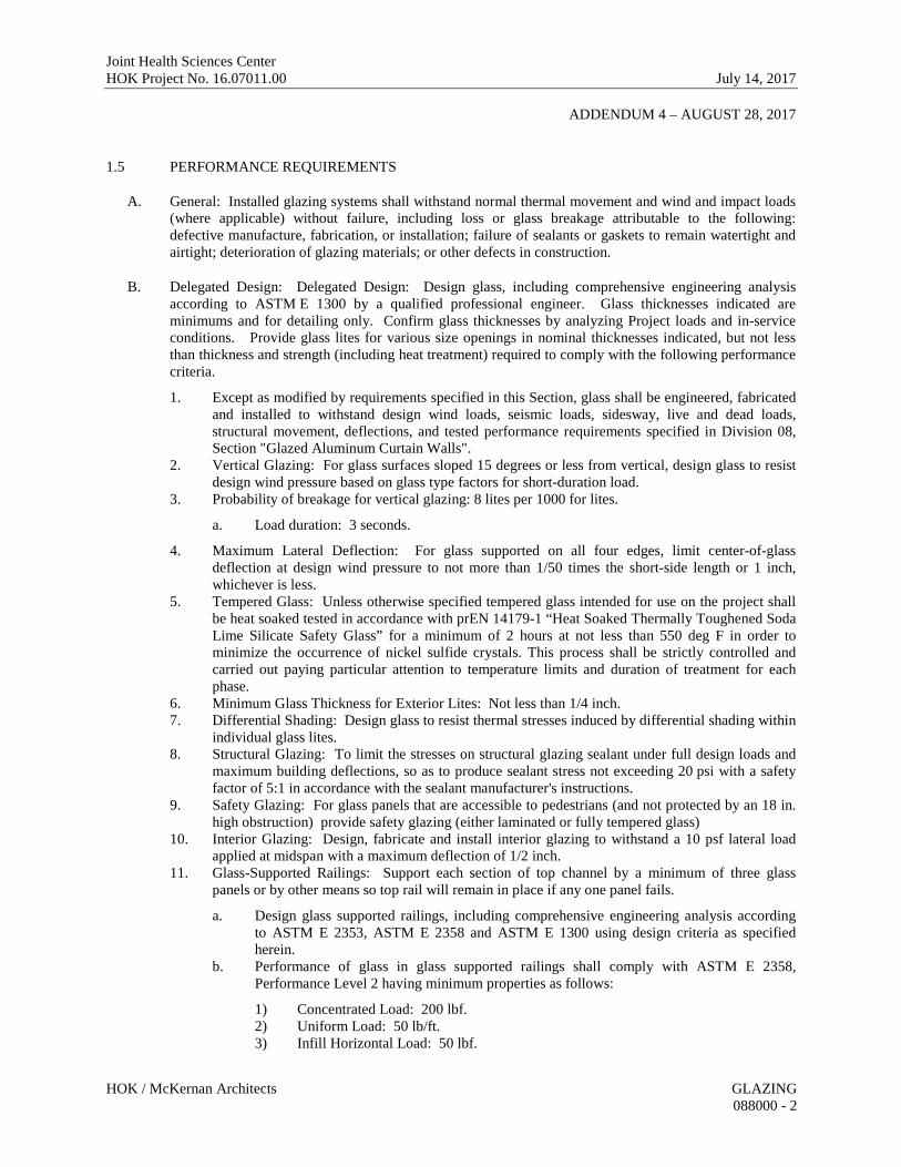
1.5 PERFORMANCE REQUIREMENTS
A. General: Installed glazing systems shall withstand normal thermal movement and wind and impact loads (where applicable) without failure, including loss or glass breakage attributable to the following: defective manufacture, fabrication, or installation; failure of sealants or gaskets to remain watertight and airtight; deterioration of glazing materials; or other defects in construction.
B. Delegated Design: Delegated Design: Design glass, including comprehensive engineering analysis according to ASTM E 1300 by a qualified professional engineer. Glass thicknesses indicated are minimums and for detailing only. Confirm glass thicknesses by analyzing Project loads and in-service conditions. Provide glass lites for various size openings in nominal thicknesses indicated, but not less than thickness and strength (including heat treatment) required to comply with the following performance criteria.
1. Except as modified by requirements specified in this Section, glass shall be engineered, fabricated and installed to withstand design wind loads, seismic loads, sidesway, live and dead loads, structural movement, deflections, and tested performance requirements specified in Division 08, Section "Glazed Aluminum Curtain Walls".
2. Vertical Glazing: For glass surfaces sloped 15 degrees or less from vertical, design glass to resist design wind pressure based on glass type factors for short-duration load.
3. Probability of breakage for vertical glazing: 8 lites per 1000 for lites.
a. Load duration: 3 seconds.
4. Maximum Lateral Deflection: For glass supported on all four edges, limit center-of-glass deflection at design wind pressure to not more than 1/50 times the short-side length or 1 inch, whichever is less.
5. Tempered Glass: Unless otherwise specified tempered glass intended for use on the project shall be heat soaked tested in accordance with prEN 14179-1 “Heat Soaked Thermally Toughened Soda Lime Silicate Safety Glass” for a minimum of 2 hours at not less than 550 deg F in order to minimize the occurrence of nickel sulfide crystals. This process shall be strictly controlled and carried out paying particular attention to temperature limits and duration of treatment for each phase.
6. Minimum Glass Thickness for Exterior Lites: Not less than 1/4 inch. 7. Differential Shading: Design glass to resist thermal stresses induced by differential shading within
individual glass lites. 8. Structural Glazing: To limit the stresses on structural glazing sealant under full design loads and
maximum building deflections, so as to produce sealant stress not exceeding 20 psi with a safety factor of 5:1 in accordance with the sealant manufacturer's instructions.
9. Safety Glazing: For glass panels that are accessible to pedestrians (and not protected by an 18 in. high obstruction) provide safety glazing (either laminated or fully tempered glass)
10. Interior Glazing: Design, fabricate and install interior glazing to withstand a 10 psf lateral load applied at midspan with a maximum deflection of 1/2 inch.
11. Glass-Supported Railings: Support each section of top channel by a minimum of three glass panels or by other means so top rail will remain in place if any one panel fails.
a. Design glass supported railings, including comprehensive engineering analysis according to ASTM E 2353, ASTM E 2358 and ASTM E 1300 using design criteria as specified herein.
b. Performance of glass in glass supported railings shall comply with ASTM E 2358, Performance Level 2 having minimum properties as follows:
1) Concentrated Load: 200 lbf. 2) Uniform Load: 50 lb/ft. 3) Infill Horizontal Load: 50 lbf.
Joint Health Sciences Center HOK Project No. 16.07011.00 July 14, 2017
ADDENDUM 4 – AUGUST 28, 2017
HOK / McKernan Architects GLAZING 088000 - 3
4) Safety Impact: 400 ft-lb. 5) Design Safety Factor: 4.
C. Thermal Movements: Allow for thermal movements from ambient and surface temperature changes acting on glass framing members and glazing components.
1. Temperature Change: 120 deg F, ambient; 180 deg F, material surfaces.
D. Glazing Film Visual Distraction Markings:
1. Visual Distraction Marking Locations: Transparent glass doors and fixed adjacent transparent glass sidelights of all glass entrances and partition systems shall be marked in two areas on the glass surface of the transparent glass doors and sidelites. First area shall be located a minimum of 30 inches, but not more than 36 inches above the ground, floor or equivalent surface below the door or sidelight. Second area shall be a minimum of 60 inches, but not more than 66 inches above the ground, floor or equivalent surface below the door or sidelight.
2. Visual Distraction Marking Dimensions: Distraction marking design shall be designed by the Consultant and shall be minimum of 4 inches in diameter if circular, or 4 inches in its least dimension if elliptical or polygonal, or shall be minimum of 12 inches in horizontal dimension if the distraction marking is less than four inches in its’ least dimension. In no event shall the vertical dimension of any distraction marking including lettering be less than 1-1/2 inches in height.
E. Spectral Light Control Glazing Film: Design spectral light control glazing film to filter the ultra-violet light of the blue-green wavelength spectrum (consisting of 300 nanometers (um) to 580 nanometers (um) of the visible light range) and to have average maximum light transmission of 0.884% as tested by a Filmstar Report Generator for manipulating light transmissions to create controlled light conditions for lab situations of nocturnal animals having night vision required for a Vivarium. Comply with “ORF Biomedical and Animal Research Facilities Design Polices and Guidelines for Vivariums” where manipulating light transmissions to create controlled light conditions for lab situations of nocturnal animals having night vision is required.
1.6 PRECONSTRUCTION TESTING
A. Preconstruction Adhesion and Compatibility Testing: Test each glazing material type, tape sealant, gasket, glazing accessory, and glass-framing member for adhesion to and compatibility with elastomeric glazing sealants.
1. Testing will not be required if data are submitted based on previous testing of current sealant products and glazing materials matching those submitted.
2. Use ASTM C 1087 to determine whether priming and other specific joint-preparation techniques are required to obtain rapid, optimum adhesion of glazing sealants to glass, tape sealants, gaskets, and glazing channel substrates.
3. Test no fewer than eight Samples of each type of material, including joint substrates, shims, sealant backings, secondary seals, and miscellaneous materials.
4. Schedule sufficient time for testing and analyzing results to prevent delaying the Work. 5. For materials failing tests, submit sealant manufacturer's written instructions for corrective
measures including the use of specially formulated primers.
1.7 ACTION SUBMITTALS
A. Product Data: For each glass product and glazing material indicated.
B. Glass Samples: For each type of the following products; 12 inches square.

Joint Health Sciences Center HOK Project No. 16.07011.00 July 14, 2017
ADDENDUM 4 – AUGUST 28, 2017
HOK / McKernan Architects GLAZING 088000 - 4
1. Tinted glass. 2. Patterned glass. 3. Coated glass. 4. Fire-resistive glazing products. 5. Laminated glass with interlayer. 6. Insulating glass.
C. Glazing Accessory Samples: For gaskets and colored spacers, in 12-inches lengths.
D. Glazing Film Samples: For each type of the following products; 12 inches square.
1. Decorative glazing film. 2. Decorative glazing film distraction markings. 3. Spectral light control glazing film.
E. Glazing Schedule: List glass types and thicknesses for each size opening and location. Use same designations indicated on Drawings.
F. Delegated-Design Submittal: For glass indicated to comply with performance requirements and design criteria, including analysis data signed and sealed by the qualified professional engineer responsible for their preparation.
1.8 INFORMATIONAL SUBMITTALS
A. Qualification Data: For installers and manufacturers of insulating-glass units with sputter-coated, low-e coatings, glass testing agency and sealant testing agency.
B. Product Certificates: For glass and glazing products, from manufacturer.
C. Product Test Reports: Based on evaluation of comprehensive tests performed by a qualified testing agency, for tinted glass, coated glass, insulating glass, glazing sealants and glazing gaskets.
1. For glazing sealants, provide test reports based on testing current sealant formulations within previous 36-month period.
D. Preconstruction adhesion and compatibility test report.
E. Warranties: Sample of special warranties.
1.9 QUALITY ASSURANCE
A. Manufacturer Qualifications for Insulating-Glass Units with Sputter-Coated, Low-E Coatings: A qualified insulating-glass manufacturer who is approved by coated-glass manufacturer.
B. Installer Qualifications: A qualified installer who employs glass installers for this Project who are certified under the National Glass Association's Certified Glass Installer Program.
C. Glass Testing Agency Qualifications: A qualified independent testing agency accredited according to the NFRC CAP 1 Certification Agency Program.
D. Sealant Testing Agency Qualifications: An independent testing agency qualified according to ASTM C 1021 to conduct the testing indicated.
Joint Health Sciences Center HOK Project No. 16.07011.00 July 14, 2017
ADDENDUM 4 – AUGUST 28, 2017
HOK / McKernan Architects GLAZING 088000 - 5
E. Source Limitations for Glass: Obtain laminated glass and insulating glass from single source from single manufacturer for each glass type.
F. Source Limitations for Glazing Accessories: Obtain from single source from single manufacturer for each product and installation method.
G. Glazing Publications: Comply with published recommendations of glass product manufacturers and organizations below, unless more stringent requirements are indicated. Refer to these publications for glazing terms not otherwise defined in this Section or in referenced standards.
1. GANA Publications: GANA's "Laminated Glazing Reference Manual" and GANA's "Glazing Manual."
2. IGMA Publication for Insulating Glass: SIGMA TM-3000, "North American Glazing Guidelines for Sealed Insulating Glass Units for Commercial and Residential Use."
H. Safety Glazing Labeling: Where safety glazing labeling is indicated, permanently mark glazing with certification label of the SGCC or another certification agency acceptable to authorities having jurisdiction. Label shall indicate manufacturer's name, type of glass, thickness, and safety glazing standard with which glass complies.
I. Fire-Protection-Rated Glazing Labeling: Permanently mark fire-protection-rated glazing with certification label of a testing agency acceptable to authorities having jurisdiction. Label shall indicate manufacturer's name, test standard, whether glazing is for use in fire doors or other openings, whether or not glazing passes hose-stream test, whether or not glazing has a temperature rise rating of 450 deg F, and the fire-resistance rating in minutes.
J. Insulating-Glass Certification Program: Permanently marked either on spacers or on at least one component lite of units with appropriate certification label of IGCC.
K. Mockups: Build mockups to verify selections made under sample submittals and to demonstrate aesthetic effects and set quality standards for materials and execution.
1. Install glazing in mockups specified in Section 084113 "Framed Entrances and Storefronts" and Section 084423 "Structural Sealant Glazed Curtain Walls" to match glazing systems required for Project, including glazing methods.
2. Approved mockups may become part of the completed Work if undisturbed at time of Substantial Completion.
L. Preinstallation Conference: Conduct conference at Project site.
1. Review and finalize construction schedule and verify availability of materials, Installer's personnel, equipment, and facilities needed to make progress and avoid delays.
2. Review temporary protection requirements for glazing during and after installation.
1.10 DELIVERY, STORAGE, AND HANDLING
A. Protect glazing materials according to manufacturer's written instructions. Prevent damage to glass and glazing materials from condensation, temperature changes, direct exposure to sun, or other causes.
B. Comply with insulating-glass manufacturer's written recommendations for venting and sealing units to avoid hermetic seal ruptures due to altitude change.
Joint Health Sciences Center HOK Project No. 16.07011.00 July 14, 2017
ADDENDUM 4 – AUGUST 28, 2017
HOK / McKernan Architects GLAZING 088000 - 6
1.11 PROJECT CONDITIONS
A. Environmental Limitations: Do not proceed with glazing when ambient and substrate temperature conditions are outside limits permitted by glazing material manufacturers and when glazing channel substrates are wet from rain, frost, condensation, or other causes.
1. Do not install glazing sealants when ambient and substrate temperature conditions are outside limits permitted by sealant manufacturer or below 40 deg F.
1.12 WARRANTY
A. Manufacturer's Special Warranty for Coated-Glass Products: Manufacturer's standard form in which coated-glass manufacturer agrees to replace coated-glass units that deteriorate within specified warranty period. Deterioration of coated glass is defined as defects developed from normal use that are not attributed to glass breakage or to maintaining and cleaning coated glass contrary to manufacturer's written instructions. Defects include peeling, cracking, and other indications of deterioration in coating.
1. Warranty Period: 10 years from date of Substantial Completion.
B. Manufacturer's Special Warranty on Laminated Glass: Manufacturer's standard form in which laminated-glass manufacturer agrees to replace laminated-glass units that deteriorate within specified warranty period. Deterioration of laminated glass is defined as defects developed from normal use that are not attributed to glass breakage or to maintaining and cleaning laminated glass contrary to manufacturer's written instructions. Defects include edge separation, delamination materially obstructing vision through glass, and blemishes exceeding those allowed by referenced laminated-glass standard.
1. Warranty Period: 10 years from date of Substantial Completion.
C. Manufacturer's Special Warranty on Insulating Glass: Manufacturer's standard form in which insulating-glass manufacturer agrees to replace insulating-glass units that deteriorate within specified warranty period. Deterioration of insulating glass is defined as failure of hermetic seal under normal use that is not attributed to glass breakage or to maintaining and cleaning insulating glass contrary to manufacturer's written instructions. Evidence of failure is the obstruction of vision by dust, moisture, or film on interior surfaces of glass.
1. Warranty Period: 10 years from date of Substantial Completion.
D. Special Installer's Warranty: Manufacturer's standard form in which Installer agrees to repair or replace joint sealants that do not comply with performance and other requirements specified in this Section within specified warranty period.
1. Warranty Period: 5 years from date of Substantial Completion.
E. Special Warranty, Sealant: Provide a written warranty, agreeing to repair or replace silicone sealant compounds which have failed to provide airtight and watertight joints for any reason, or which appear to have failed in adhesion, cohesion, abrasion-resistance, migration-resistance, stain-resistance, general durability or other form of apparent deterioration (excluding inherent qualities and limitations clearly specified in the manufacturer's data which was submitted).
1. Period of warranty shall be 20 years, and warranty shall be signed by the Manufacturer. Comply with these Specifications for repair or replacement of work.
Joint Health Sciences Center HOK Project No. 16.07011.00 July 14, 2017
ADDENDUM 4 – AUGUST 28, 2017
HOK / McKernan Architects GLAZING 088000 - 7
PART 2 - PRODUCTS
2.1 GLASS PRODUCTS, GENERAL
A. Thickness: Where glass thickness is indicated, it is a minimum. Provide glass lites in thicknesses as needed to comply with requirements indicated.
1. Minimum Glass Thickness for Exterior Lites: Not less than 1/4 inch.
B. Strength: Where float glass is indicated, provide annealed float glass, Kind HS heat-treated float glass, or Kind FT heat-treated float glass as needed to comply with "Performance Requirements" Article. Where heat-strengthened glass is indicated, provide Kind HS heat-treated float glass or Kind FT heat-treated float glass as needed to comply with "Performance Requirements" Article. Where fully tempered glass is indicated, provide Kind FT heat-treated float glass.
C. Thermal and Optical Performance Properties: Provide glass with performance properties specified, as indicated in manufacturer's published test data, based on procedures indicated below:
1. For monolithic-glass lites, properties are based on units with lites 1/4 inch thick. 2. For laminated-glass lites, properties are based on products of construction indicated. 3. For insulating-glass units, properties are based on units of thickness indicated for overall unit and
for each lite. 4. U-Factors: Center-of-glazing values, according to NFRC 100 and based on LBL's WINDOW 5.2
computer program, expressed as Btu/sq. ft. x h x deg F. 5. Solar Heat-Gain Coefficient and Visible Transmittance: Center-of-glazing values, according to
NFRC 200 and based on LBL's WINDOW 5.2 computer program. 6. Visible Reflectance: Center-of-glazing values, according to NFRC 300.
2.2 GLASS PRODUCTS
A. Float Glass: ASTM C 1036, Type I, Quality-Q3, Class I (clear) unless otherwise indicated.
B. Ultraclear Float Glass: ASTM C 1036, Type I, Quality-Q3, Class I, complying with other requirements specified and with visible light transmission not less than 91 percent and solar heat gain coefficient not less than 0.87.
C. Products: Basis-of-Design Product: Subject to compliance with requirements, provide Viracon Inc., glass products, or comparable product by one of the following:
a. PPG Industries, Inc. b. Or equivalent manufacturer and products acceptable to the Architect.
D. Heat-Treated Float Glass: ASTM C 1048; Type I; Quality-Q3; Class I (clear) unless otherwise indicated; of kind and condition indicated.
1. Fabrication Process: By horizontal (roller-hearth) process with roll-wave distortion parallel to bottom edge of glass as installed unless otherwise indicated.
2. For uncoated glass, comply with requirements for Condition A. 3. For coated vision glass, comply with requirements for Condition C (other coated glass).
E. Pyrolytic-Coated, Self-Cleaning, Low-Maintenance Glass: Clear float glass with a coating on first surface having both photocatalytic and hydrophilic properties that act to loosen dirt and to cause water to sheet evenly over the glass instead of beading.
Joint Health Sciences Center HOK Project No. 16.07011.00 July 14, 2017
ADDENDUM 4 – AUGUST 28, 2017
HOK / McKernan Architects GLAZING 088000 - 8
F. Ceramic-Coated Vision Glass: Heat-treated float glass, Condition C; with ceramic enamel applied by silk-screened process; complying with Specification No. 95-1-31 in GANA's Tempering Division's "Engineering Standards Manual" and with other requirements specified.
1. Glass: Clear float. 2. Ceramic Coating Color and Pattern: As indicated.
G. Ceramic-Coated Spandrel Glass: ASTM C 1048, Condition B, Type I, Quality-Q3, and complying with other requirements specified.
1. Glass: Clear, heat strengthened float. 2. Ceramic Coating Color: As indicated.
2.3 LAMINATED GLASS
A. Laminated Glass: ASTM C 1172, and complying with testing requirements in 16 CFR 1201 for Category II materials, and with other requirements specified. Use materials that have a proven record of no tendency to bubble, discolor, or lose physical and mechanical properties after fabrication and installation.
1. Construction: Laminate glass with polyvinyl butyral interlayer to comply with interlayer manufacturer's written recommendations.
2. Interlayer Thickness: Provide thickness not less than that indicated and as needed to comply with requirements.
3. Interlayer Color: Clear unless otherwise indicated. 4. Basis of Design Product: Subject to compliance with requirements, provide Eastman Chemical
Company; Saflex HP PVB Interlayer, or comparable product by the following:
a. Kuraray America Inc.; Butacite B54 Polyvinyl Butyral PVB Interlayer. b. Or equivalent manufacturer and product acceptable to the Architect.
B. Laminated Glass with Structural Interlayer: ASTM C 1172, and complying with testing requirements in 16 CFR 1201 for Category II materials, and with other requirements specified. Blemishes that may form or grow over time shall not exceed the limits defined in ASTM C 1172. Use materials that have a proven record of no tendency to bubble, discolor, or lose physical and mechanical properties after fabrication and installation.
1. Construction: Laminate glass with structural PVB interlayer or structural ionoplast interlayer to comply with interlayer manufacturer's written instructions.
2. Basis of Design Product: Subject to compliance with requirements, provide Eastman Chemical Company; Saflex DG Structural PVB Interlayer, or comparable product by the following:
a. Kuraray America Inc.; Dupont SentryGlas Ionoplast Interlayer. b. Or equivalent manufacturer and product acceptable to the Architect
C. Laminated Glass with Acoustical Interlayer: ASTM C 1172, and complying with testing requirements in 16 CFR 1201 for Category II materials, achieving minimum STC rating of 40 and OITC of 32 for insulating glass units and achieving minimum STC rating of 35 and OITC of 31 for single glass lites when tested in accordance with ASTM E 90 and calculated in accordance with ASTM E 413 and ASTM E 1332 and with other requirements specified. Blemishes that may form or grow over time shall not exceed the limits defined in ASTM C 1172. Use materials that have a proven record of no tendency to bubble, discolor, or lose physical and mechanical properties after fabrication and installation.
1. Basis of Design Product: Subject to compliance with requirements, provide Eastman Chemical Company; Saflex QS71 Acoustic PVB Interlayer, or comparable product by the following:
a. Kuraray America Inc.; Trosifol SC PVB Interlayer.
Joint Health Sciences Center HOK Project No. 16.07011.00 July 14, 2017
ADDENDUM 4 – AUGUST 28, 2017
HOK / McKernan Architects GLAZING 088000 - 9
b. Or equivalent manufacturer and product acceptable to the Architect.
2.4 INSULATING GLASS
A. Insulating-Glass Units: Factory-assembled units consisting of sealed lites of glass separated by a dehydrated interspace, qualified according to ASTM E 2190, and complying with other requirements specified.
1. Sealing System: Provide dual edge-sealed insulating glass units which are certified for the insulating glass seal classification "CBA" by the Insulating Glass Certification Council (IGCC) or classification "Level A" by the Associated Laboratories, Inc. (ALI) Certification Program when tested in accordance with ASTM E 2188, ASTM E 2189, ASTM E 773 and ASTM E 774 (as sponsored by the Sealed Insulating Glass Manufacturer's Association).
2. Fabrication: Fabricate units at factory with sheets of glass hermetically sealed at edges with a permanent elastomeric sealant. Dehydrate entrapped air. Glass lights with bent, welded or fused corners, splices or joints shall be separated by desiccant filled aluminum spacer marked with the appropriate classification, listed manufacturer and approval marked on the spacer.
a. Sealing System: Dual seal, with preformed black polyisobutylene primary and black silicone secondary seal.
b. Spacer: Mill finished aluminum. c. Desiccant: Molecular sieve or silica gel, or blend of both.
3. Low E Coating Edge Deletion in Insulating Glass Units: Provide accurate and straight edge
deletions of coatings at areas of insulating glass assemblies where Low “E” coatings, metallic coating or other decorative coatings are applied to surfaces scheduled to be in contact with the primary seal of insulating glass units.
2.5 FIRE-PROTECTION-RATED GLAZING
A. Fire-Protection-Rated Glazing, General: Listed and labeled by a testing agency acceptable to authorities having jurisdiction, for fire-protection ratings indicated, based onpositive-pressure testing according to NFPA 257 or UL 9, including the hose stream test, and shall comply with NFPA 80.
B. Monolithic Ceramic Glazing: Clear, ceramic flat glass; 3/16-inch nominal thickness.
1. Products: Subject to compliance with requirements, provide one of the following:
a. Technical Glass Products; FireLite Plus. b. Safti First; SuperLite XL. c. Or equivalent manufacturer and product acceptable to the Architect.
2.6 PYROLYTIC-COATED, TEMPERED ONE-WAY VISION GLASS
A. For use where a one-way vision glass on interior partition locations, where indicated.
B. One Way Vision Glass: “Grey” body color tinted tempered glass complying with ASTM C 1048, Type I, Class 2, Quality Q3 and Kind FT, minimum 1/4 inch thick, with a pyrolytic coating complying with ASTM C 1376 on first surface having pyrolytic properties that provide undetectable surveillance and high quality one way vision to achieve privacy with minimum light level ratio of 8 to 1 from bright (subject) side to (dark) observer side. One way vision glass shall have visible light data based on laboratory spectrophotometric measurement physical properties as follows:
1. Visible Light Transmittance: 11%.
Joint Health Sciences Center HOK Project No. 16.07011.00 July 14, 2017
ADDENDUM 4 – AUGUST 28, 2017
HOK / McKernan Architects GLAZING 088000 - 10
2. Visible Light Reflectance (Coated Side): 68%. 3. Visible Light Reflectance (Glass Side): 16%.
C. Products: Subject to compliance with requirements, provide one of the following:
1. Pilkington North America; Pilkington Mirropane One Way Vision Glass. 2. Or equivalent manufacturer and product acceptable to the Architect.
2.7 DECORATIVE GLAZING FILMS
A. Decorative Translucent Glazing Film Overlay (GF01): Translucent, dimensionally stable, PVC free, 100% polyester window film, 8 ounce/linear yard, with acrylic pressure-sensitive, clear adhesive back for adhering to glass and releasable protective backing.
1. Basis of Design Product: Solyx – SX-C387 Linen, or equivalent manufacturer and product acceptable to the Architect.
B. Decorative Translucent Glazing Film Visual Distraction Markings (GF02): Square milky white squares of decorative translucent film in pattern and spacing complying the visual distraction markings performance requirements specified herein, on clear background , dimensionally stable, PVC free, 100% polyester window film, 8 ounces/linear yard, with acrylic pressure-sensitive, clear adhesive back for adhering to glass and releasable protective backing.
1. Basis of Design Product: Designtex – Bespoke GF12, or equivalent manufacturer and product acceptable to the Architect.
C. Spectral Light Control Glazing Film (GF03):
1. 2.2 mils thick, spectral light control glazing film constructed of laminated dyed colored polyester films designed to filter the ultra-violet light of the blue-green wavelength spectrum (consisting of 300 nanometers (um) to 580 nanometers (um) of the visible light range) and to have average maximum light transmission of 0.884% as tested by a Filmstar Report Generator for manipulating light transmissions to create controlled light conditions for lab situations of nocturnal animals having night vision as required for a Vivarium. Spectral light glazing film shall have minimum properties as follows:
a. Visible Light Transmission: 6.8%. b. Visible Light Reflectance: 4.9%. c. Shading Coefficient: 0.30. d. Emissivity: 0.88. e. Ultra-Violet Light Transmission: >1%. f. Flame Spread Index: Not exceeding 25 when tested in accordance with ASTM E84. g. Smoke Density: Not exceeding 100 when tested in accordance with ASTM E84. h. Haze (Abrasion Differential): 1.94.
2. Spectral light control glazing film shall be optically clear and free of waves, distortions, impurities, and adhesive lines.
3. Spectral light glazing film may be a single layer or laminated. Lamination of film shall only occur at the manufacturer’s factory.
4. Spectral light control glazing film shall be coated with a high performance acrylic based pressure sensitive type adhesive, coupled with a 1.5 mils thick polyester release liner on one side and coated with superior abrasion resistance coating having UV inhibitors. Abrasion resistance shall comply with ASTM D 1044.
5. Spectral light control glazing film shall be resistant to most common cleaning agents, including but not limited to; mild acid and ammonia.
Joint Health Sciences Center HOK Project No. 16.07011.00 July 14, 2017
ADDENDUM 4 – AUGUST 28, 2017
HOK / McKernan Architects GLAZING 088000 - 11
6. Basis of Design Product: Subject to compliance with requirements, provide Light Gard, a subsidiary of Solar Graphics; Light Gard RC-3 (Rose Chocolate) Spectral Control Film or comparable product by the following:
a. Aegis Applied Films; Vivarium Red Spectral Control Film. b. Or equivalent manufacturer and product acceptable to the Architect.
2.8 GLAZING GASKETS
A. Dense Compression Gaskets: Molded or extruded gaskets of profile and hardness required to maintain watertight seal, made from one of the following:
1. Silicone complying with ASTM C 1115. 2. Thermoplastic polyolefin rubber complying with ASTM C 1115.
B. Soft Compression Gaskets: Extruded or molded, closed-cell, silicone or thermoplastic polyolefin rubber gaskets complying with ASTM C 509, Type II, black; of profile and hardness required to maintain watertight seal.
1. Application: Use where soft compression gaskets will be compressed by inserting dense compression gaskets on opposite side of glazing or pressure applied by means of pressure-glazing stops on opposite side of glazing.
2.9 GLAZING SEALANTS
A. General:
1. Compatibility: Provide glazing sealants that are compatible with one another and with other materials they will contact, including glass products, seals of insulating-glass units, and glazing channel substrates, under conditions of service and application, as demonstrated by sealant manufacturer based on testing and field experience.
2. Suitability: Comply with sealant and glass manufacturers' written instructions for selecting glazing sealants suitable for applications indicated and for conditions existing at time of installation.
3. Sealants used inside the weatherproofing system, shall have a VOC content of not more than 250 g/L when calculated according to 40 CFR 59, Subpart D (EPA Method 24).
4. Sealants used inside the weatherproofing system shall comply with the testing and product requirements of the California Department of Health Services' "Standard Practice for the Testing of Volatile Organic Emissions from Various Sources Using Small-Scale Environmental Chambers."
5. Colors of Exposed Glazing Sealants: As indicated by manufacturer's designations.
B. Glazing Sealant for Weather Seal: Neutral-curing silicone glazing sealant complying with ASTM C 920, Type S, Grade NS, Class 100/50, Use NT.
1. Manufacturers and Products: Subject to compliance with requirements, provide one of the following:
a. Dow Corning Corporation; Dow Corning 790 Silicone Building Sealant. b. Momentive Performance Materials Inc.; SilPruf LM SCS2700. c. Or equivalent manufacturer and product acceptable to the Architect.
C. Glazing Sealant for Structural Seal: Neutral-curing silicone glazing sealant complying with ASTM C 920, Type S, Grade NS, Class 25, Use NT.
Joint Health Sciences Center HOK Project No. 16.07011.00 July 14, 2017
ADDENDUM 4 – AUGUST 28, 2017
HOK / McKernan Architects GLAZING 088000 - 12
1. Manufacturers and Products: Subject to compliance with requirements, provide one of the following:
a. Dow Corning Corporation; Dow Corning 799 Glass and Metal Building Sealant for field use and Dow Corning 983 Structural Gazing Sealant for shop application.
b. Momentive Performance Materials Inc.; GE UltraGlaze SSG4000AC Accelerated Cure Silicone Glazing Adhesive for field use and GE UltraGlaze SSG4000 Silicone Structural Glazing Sealant for shop application.
c. Or equivalent manufacturer and product acceptable to the Architect.
D. Glazing Sealants for Fire-Rated Glazing Products: Products that are approved by testing agencies that listed and labeled fire-resistant glazing products with which they are used for applications and fire-protection ratings indicated.
2.10 GLAZING TAPES
A. Expanded Cellular Glazing Tapes: Closed-cell, PVC foam tapes; factory coated with adhesive on both surfaces; and complying with AAMA 800 for the following types:
1. AAMA 810.1, Type 1, for glazing applications in which tape acts as the primary sealant. 2. AAMA 810.1, Type 2, for glazing applications in which tape is used in combination with a full
bead of liquid sealant.
2.11 MISCELLANEOUS GLAZING MATERIALS
A. General: Provide products of material, size, and shape complying with referenced glazing standard, requirements of manufacturers of glass and other glazing materials for application indicated, and with a proven record of compatibility with surfaces contacted in installation.
B. Cleaners, Primers, and Sealers: Types recommended by sealant or gasket manufacturer.
C. Setting Blocks: Elastomeric material with a Shore, Type A durometer hardness of 85, plus or minus 5.
D. Spacers: Elastomeric blocks or continuous extrusions of hardness required by glass manufacturer to maintain glass lites in place for installation indicated.
E. Edge Blocks: Elastomeric material of hardness needed to limit glass lateral movement (side walking).
F. Cylindrical Glazing Sealant Backing: ASTM C 1330, Type O (open-cell material), of size and density to control glazing sealant depth and otherwise produce optimum glazing sealant performance.
G. Perimeter Insulation for Fire-Resistive Glazing: Product that is approved by testing agency that listed and labeled fire-resistant glazing product with which it is used for application and fire-protection rating indicated.
2.12 FABRICATION OF GLAZING UNITS
A. Fabricate glazing units in sizes required to fit openings indicated for Project, with edge and face clearances, edge and surface conditions, and bite complying with written instructions of product manufacturer and referenced glazing publications, to comply with system performance requirements.
Joint Health Sciences Center HOK Project No. 16.07011.00 July 14, 2017
ADDENDUM 4 – AUGUST 28, 2017
HOK / McKernan Architects GLAZING 088000 - 13
B. Clean-cut or flat-grind vertical edges of butt-glazed monolithic lites to produce square edges with slight chamfers at junctions of edges and faces.
C. Grind smooth and polish exposed glass edges and corners.
2.13 MONOLITHIC-GLASS TYPES
A. Glass Type GL21: 1/2 inch thick, fully tempered glass for demountable partitions glass panels and glass doors.
B. Glass Type GL22: 1/4 inch thick, fully tempered, one way vision glass with additional coating or film on reflective side for one-way vision panels in partitions.
C. Glass Type GL23: 1/4 inch thick, fully tempered glass.
2.14 FIRE RATED GLASS SCHEDULE
A. Glass Type GL51: 9/16 inch thick, 45 minutes, 60 minutes and 90 minute fire rated ceramic glazing for vision panels in fire rated hollow metal doors and frames specified in Division 08 Sections “Hollow Metal Doors and Frames” and for vision panels in fire rated flush wood doors specified in Division 08 Section “Flush Wood Doors”.
2.15 LAMINATED-GLASS TYPES
A. Glass Type GL31: 1/2 inch thick laminated glass with clear, structural PVB or ionoplast interlayer, with flat polished edges and slightly eased arises for all glass supported railings specified in Division 05 Section “Glass Rail System”.
B. Glass Type GL32: 5/16 inch thick laminated glass with clear, acoustical PVB interlayer for GL01A and GL05A 1 inch thick insulated glass units (IGUs) specified herein.
2.16 INSULATING-GLASS TYPES
A. Glass Type GL01: 1 inch thick insulated glass units (IGUs) , consisting of two 1/4 inch thick, low iron heat-strengthened float glass lites, with a triple silver high performance low "e" coating on the #2 surface, a 1/2 inch air- filled airspace, a stainless steel spacer and matching color silicone and polyisobutylene sealants.
1. Basis of Design Product: Viracon VNE 24-63, or equivalent.
a. Transmittance: 1) Visible Light 64% 2) Solar Energy 26% 3) U-V* 7%
b. Reflectance: 1) Visible Light-Exterior 12% 2) Visible Light-Interior 12% 3) Solar Energy 51%
Joint Health Sciences Center HOK Project No. 16.07011.00 July 14, 2017
ADDENDUM 4 – AUGUST 28, 2017
HOK / McKernan Architects GLAZING 088000 - 14
c. NFRC U-Value 1) Winter 0.29 Btu/(hr x sq ft x °F) 2) Summer 0.26 Btu/(hr x sq ft x °F)
d. Shading Coefficient (SC) 0.33 e. Solar Heat Gain Coefficient (SHGC) 0.29 f. Relative Heat Gain 70 Btu/(hr x sq ft)
B. Glass Type GL01A: 1 inch thick insulated glass units (IGUs), consisting of one 5/16 inch thick, low iron laminated glass outer lite with acoustical PVB interlayer (GL32), and one 5/16 inch thick, laminated glass inner lite with acoustical PVB interlayer (GL32), low “e” coating on #4 surface and a 3/8” air space.
C. Glass Type GL02: 1 inch thick insulated glass units (IGUs) , consisting of one ¼ inch thick tempered low iron glass inner lite and one ¼ inch heat strengthened laminated glass outer lite with PVB interlayer, low “e” coating on #4 surface and a ½” air space.
D. Glass Type GL05: 1 inch thick insulated glass units (IGUs) , consisting of two ¼ inch thick, low iron heat-strengthened float glass lites, with custom gradient frit type pattern, Viracon Screen #5383, on #3 surface and a ½” air space. Frit color - Viraspan V175 – High Opacity White.
E. Glass Type GL05A: 1 inch thick insulated glass units (IGUs), consisting of one 5/16 inch thick, low iron laminated glass outer lite with acoustical PVB interlayer (GL32), and one 5/16 inch thick, laminated glass inner lite with acoustical PVB interlayer (GL32) low “e” coating on #4 surface, 3/8” air space and a custom gradient frit, Viracon #5383, on #3 surface. Frit color – Viraspan V175-High Opacity White.
F. Glass Type GL06 (Spandrel Panel): 1 inch thick insulated glass units (IGUs) , consisting of two ¼ inch thick, low iron heat-strengthened float glass lites with 100% full coverage frit flood coat on #4 surface. Frit color - Viraspan V175 – High Opacity White.
G. Glass Type GL07 (Spandrel Panel): 1 inch thick insulated glass units (IGUs) , consisting of two ¼ inch thick, low iron heat-strengthened float glass lites with 100% full coverage frit flood coat on #4 surface. Frit color - Viraspan V933 - Warm Grey.
H. Glass Type GL08 (Spandrel Panel): 1 inch thick insulated glass units (IGUs), consisting of two ¼ inch thick, low iron heat-strengthened float glass lites with custom gradient frit type pattern, Viracon #5383, on #3 surface, frit color Viraspan V175 – High Opacity White, and a ½” air space - and 100% full coverage frit flood coat on #4 surface, frit color Viraspan V933 - Warm Grey.
PART 3 - EXECUTION
3.1 EXAMINATION
A. Examine framing, glazing channels, and stops, with Installer present, for compliance with the following:
1. Manufacturing and installation tolerances, including those for size, squareness, and offsets at corners.
2. Presence and functioning of weep systems. 3. Minimum required face and edge clearances. 4. Effective sealing between joints of glass-framing members.
B. Proceed with installation only after unsatisfactory conditions have been corrected.
Joint Health Sciences Center HOK Project No. 16.07011.00 July 14, 2017
ADDENDUM 4 – AUGUST 28, 2017
HOK / McKernan Architects GLAZING 088000 - 15
3.2 PREPARATION
A. Clean glazing channels and other framing members receiving glass immediately before glazing. Remove coatings not firmly bonded to substrates.
B. Examine glazing units to locate exterior and interior surfaces. Label or mark units as needed so that exterior and interior surfaces are readily identifiable. Do not use materials that will leave visible marks in the completed work.
3.3 GLAZING, GENERAL
A. Comply with combined written instructions of manufacturers of glass, sealants, gaskets, and other glazing materials, unless more stringent requirements are indicated, including those in referenced glazing publications.
B. Adjust glazing channel dimensions as required by Project conditions during installation to provide necessary bite on glass, minimum edge and face clearances, and adequate sealant thicknesses, with reasonable tolerances.
C. Protect glass edges from damage during handling and installation. Remove damaged glass from Project site and legally dispose of off Project site. Damaged glass is glass with edge damage or other imperfections that, when installed, could weaken glass and impair performance and appearance.
D. Apply primers to joint surfaces where required for adhesion of sealants, as determined by preconstruction testing.
E. Install setting blocks in sill rabbets, sized and located to comply with referenced glazing publications, unless otherwise required by glass manufacturer. Set blocks in thin course of compatible sealant suitable for heel bead.
F. Do not exceed edge pressures stipulated by glass manufacturers for installing glass lites.
G. Provide spacers for glass lites where length plus width is larger than 50 inches.
1. Locate spacers directly opposite each other on both inside and outside faces of glass. Install correct size and spacing to preserve required face clearances, unless gaskets and glazing tapes are used that have demonstrated ability to maintain required face clearances and to comply with system performance requirements.
2. Provide 1/8-inch minimum bite of spacers on glass and use thickness equal to sealant width. With glazing tape, use thickness slightly less than final compressed thickness of tape.
H. Provide edge blocking where indicated or needed to prevent glass lites from moving sideways in glazing channel, as recommended in writing by glass manufacturer and according to requirements in referenced glazing publications.
I. Set glass lites in each series with uniform pattern, draw, bow, and similar characteristics.
J. Set glass lites with proper orientation so that coatings face exterior or interior as specified.
K. Where wedge-shaped gaskets are driven into one side of channel to pressurize sealant or gasket on opposite side, provide adequate anchorage so gasket cannot walk out when installation is subjected to movement.
Joint Health Sciences Center HOK Project No. 16.07011.00 July 14, 2017
ADDENDUM 4 – AUGUST 28, 2017
HOK / McKernan Architects GLAZING 088000 - 16
L. Square cut wedge-shaped gaskets at corners and install gaskets in a manner recommended by gasket manufacturer to prevent corners from pulling away; seal corner joints and butt joints with sealant recommended by gasket manufacturer.
3.4 TAPE GLAZING
A. Position tapes on fixed stops so that, when compressed by glass, their exposed edges are flush with or protrude slightly above sightline of stops.
B. Install tapes continuously, but not necessarily in one continuous length. Do not stretch tapes to make them fit opening.
C. Cover vertical framing joints by applying tapes to heads and sills first and then to jambs. Cover horizontal framing joints by applying tapes to jambs and then to heads and sills.
D. Place joints in tapes at corners of opening with adjoining lengths butted together, not lapped. Seal joints in tapes with compatible sealant approved by tape manufacturer.
E. Do not remove release paper from tape until right before each glazing unit is installed.
F. Apply heel bead of elastomeric sealant.
G. Center glass lites in openings on setting blocks and press firmly against tape by inserting dense compression gaskets formed and installed to lock in place against faces of removable stops. Start gasket applications at corners and work toward centers of openings.
H. Apply cap bead of elastomeric sealant over exposed edge of tape.
3.5 GASKET GLAZING (DRY)
A. Cut compression gaskets to lengths recommended by gasket manufacturer to fit openings exactly, with allowance for stretch during installation.
B. Insert soft compression gasket between glass and frame or fixed stop so it is securely in place with joints miter cut and bonded together at corners.
C. Installation with Drive-in Wedge Gaskets: Center glass lites in openings on setting blocks and press firmly against soft compression gasket by inserting dense compression gaskets formed and installed to lock in place against faces of removable stops. Start gasket applications at corners and work toward centers of openings. Compress gaskets to produce a weathertight seal without developing bending stresses in glass. Seal gasket joints with sealant recommended by gasket manufacturer.
D. Installation with Pressure-Glazing Stops: Center glass lites in openings on setting blocks and press firmly against soft compression gasket. Install dense compression gaskets and pressure-glazing stops, applying pressure uniformly to compression gaskets. Compress gaskets to produce a weathertight seal without developing bending stresses in glass. Seal gasket joints with sealant recommended by gasket manufacturer.
E. Install gaskets so they protrude past face of glazing stops.
Joint Health Sciences Center HOK Project No. 16.07011.00 July 14, 2017
ADDENDUM 4 – AUGUST 28, 2017
HOK / McKernan Architects GLAZING 088000 - 17
3.6 SEALANT GLAZING (WET)
A. Install continuous spacers, or spacers combined with cylindrical sealant backing, between glass lites and glazing stops to maintain glass face clearances and to prevent sealant from extruding into glass channel and blocking weep systems until sealants cure. Secure spacers or spacers and backings in place and in position to control depth of installed sealant relative to edge clearance for optimum sealant performance.
B. Force sealants into glazing channels to eliminate voids and to ensure complete wetting or bond of sealant to glass and channel surfaces.
C. Tool exposed surfaces of sealants to provide a substantial wash away from glass.
3.7 LOCK-STRIP GASKET GLAZING
A. Comply with ASTM C 716 and gasket manufacturer's written instructions. Provide supplementary wet seal and weep system unless otherwise indicated.
3.8 DECORATIVE GLAZING FILMS AND DECORATIVE GLAZING FILM VISUAL DISTRACTION MARKINGS
A. Decorative glazing films (including spectral light control glazing film) shall be applied to one side of glass by an authorized applicator. Refer to the Drawings for the application side.
B. Prior to application of decorative glazing films, examine glass surfaces to receive film and verify that they are free from defects and imperfections which will affect final appearance.
C. Clean glass thoroughly with a neutral cleaning solution. Remove any foreign contaminants by "blading" with industrial razors.
D. During application ensure film edges are cut neatly and square.
E. Use clear, clean water to remove water soluble overcoat that protects the pressure adhesive.
F. Use poly-plastic bladed squeegees to ensure efficient removal of excess water from the underside of the film and to maximize bonding of the pressure sensitive adhesive.
G. After completion, installed decorative glazing films may have a dimpled appearance from residual mois-ture, which shall dry flat with no moisture dimples within a period of 30 calendar days when viewed un-der normal viewing conditions.
H. Do not wash decorative glazing films for minimum of 30 days after application.
I. Decorative glazing films may be washed using common cleaning solutions, including ammonia solutions, and synthetic sponges or soft cloths. Do not use abrasive type cleaning agents and bristle brushes which could scratch the decorative glazing film.
J. Decorative Glazing Film Visual Distraction Markings: In addition to the above, install decorative glazing film visual distraction markings as follows:
1. Provide decorative glazing film visual distraction markings on glass surfaces, in colors, uniform patterns and spacing as indicated.
Joint Health Sciences Center HOK Project No. 16.07011.00 July 14, 2017
ADDENDUM 4 – AUGUST 28, 2017
HOK / McKernan Architects GLAZING 088000 - 18
2. Apply decorative glazing film visual distraction markings specifically manufactured for application to glass, applied to the glass to provide uniform characters with sharp edges and tightly registered patterns, free from tears, air bubbles, wrinkles, and rough edges, blemishes or other defects which, in the Architect's opinion, will impair the finished work.
3. Apply decorative glazing film visual distraction markings on glass after glass has been installed. 4. Apply decorative glazing film visual distraction markings plumb, level, uniform and in full
alignment across entire elevation. 5. Apply decorative glazing film visual distraction markings in two horizontal bands at 30 inches and
50 inches above finish floor.
3.9 CLEANING AND PROTECTION
A. Protect exterior glass from damage immediately after installation by attaching crossed streamers to framing held away from glass. Do not apply markers to glass surface. Remove nonpermanent labels and clean surfaces.
B. Protect glass from contact with contaminating substances resulting from construction operations. If, despite such protection, contaminating substances do come into contact with glass, remove substances immediately as recommended in writing by glass manufacturer.
C. Examine glass surfaces adjacent to or below exterior concrete and other masonry surfaces at frequent intervals during construction, but not less than once a month, for buildup of dirt, scum, alkaline deposits, or stains; remove as recommended in writing by glass manufacturer.
D. Remove and replace glass that is broken, chipped, cracked, or abraded or that is damaged from natural causes, accidents, and vandalism, during construction period.
E. Wash glass on both exposed surfaces in each area of Project not more than four days before date scheduled for inspections that establish date of Substantial Completion. Wash glass as recommended in writing by glass manufacturer.
END OF SECTION 088000
ParkingMeter
ParkingMeter
UP
L16
142
UP
L16
142
OLD
UP
L50
67U
P L
5067
OLD
UP 5615
UP L4292
UP 67844UP L67845UP L64865
UP L68238
UP L69226
Tel. MH Tel. MH
Tel. MH
Tel. MH
Tel. MH
Tel. MH
Tel. MHTel. MH
Tel. MH Tel. MH Tel. MH
WV MH
Tel. MHTel. MH
WV MH
Tel. MHTel. MH
WV MH
WV MH
WV MH
Tel. MH
Tel. MH
Par
king
Met
er
Par
king
Met
er
Par
king
Met
er
Par
king
Met
er
Par
king
Met
er
Par
king
Met
er
ParkingMeter
UnknownUtility
UnknownUtility
UnknownUtility
UnknownUtility
UnknownUtility
UnknownUtility
UnknownUtility
UnknownUtility
UnknownUtility
UnknownUtility
Unk
now
nU
tility
Unk
now
nU
tility U
nkno
wn
Util
ity Unk
now
nU
tility
Unk
now
nU
tility
Unk
now
nU
tility
Unk
now
nU
tility
Unk
now
nU
tility
Unk
now
nU
tility
Unk
now
nU
tility
Unk
now
nU
tility
Unk
now
nU
tility
Unk
now
nU
tility Unk
now
nU
tility
Unk
now
nU
tility
Unk
now
nU
tility
Unk
now
nU
tility
UnknownUtility
Par
king
Met
er
Par
king
Met
er
UnknownUtility
UnknownUtility
UnknownUtility
UnknownUtility
Unk
now
nU
tility
ParkingMeter
ParkingMeter
ParkingMeter
ParkingMeter
ParkingMeter
ParkingMeter
ParkingMeter
ParkingMeter
ParkingMeter
ParkingMeter
ParkingMeter
ParkingMeter
ParkingMeter
ParkingMeter
ParkingMeter
ParkingMeter
ParkingMeter
ParkingMeter
ParkingMeter
ParkingMeter
ElecEquip
DR. MARTIN LUTHER KING, JR. BOULEVARD (120' WIDE)
STEVENS STREET(60' WIDE)
BR
OA
DW
AY
(66'
WID
E)
(CO
UN
TY R
OU
TE N
o. 5
51)
SO
UTH
5TH
STR
EE
T
TrafficSignal
UP 20830
TrafficSignal
TrafficSignal
TrafficSignal
TrafficSignalTraffic
Signal
24" Tree 24" Tree 24" Tree 24" Tree
12" Tree
12" Tree
4" Tree 6" Tree
3" Tree4" Tree4" Tree4" Tree 3" Tree
6" Tree 6" Tree 6" Tree
12" Tree
12" Tree
12" Tree
12" Tree
Tel. MH
6" WaterMain
6" WaterMain
5'H
Orn
amen
tal F
ence
6' H Ornamental Fence
10" W
ater
Mai
n
LOADINGAREA
PROPERTYLINE
14.5'
24.0'
5.0'
24.0'
8.8'
6.6'
18.0
'24
.0'
24.0
'18
.0'
10.9
'
9.0'
TYP
ICA
L
6.0'
9
15 9
12
4
10
PROPOSED 6' HIGH FENCE TOMATCH EXISTING
ORNAMENTAL FENCE
MATCH EXIST. SIDEWALKAT AN EXISTING JOINT
5.0'
MATCH EXIST.SIDEWALK AT ANEXISTING JOINT
10.0'
12.0
'
MATCH EXIST. SIDEWALKAT AN EXISTING JOINT
MATCH EXIST. SIDEWALKAT AN EXISTING JOINT
MATCH EXIST.SIDEWALK AT ANEXISTING JOINT
MAINTAIN AND PROTECTEXISTING 6' HIGH FENCE
ALONG SOUTH 5THSTREET. (TYP.)
32.5'
MATCH EXIST. SIDEWALKAT AN EXISTING JOINT
CITY OF CAMDENCONCRETE SIDEWALK
(TYP.)
STOP (R1-1)
STOP (R1-1)
STOP (R1-1)
STOP(R1-1)
9.0'
5.0'
18.0
'
9.0'
9.0'
R5'
R5' R5'
R5'R5'R5'
R5'
R8'
R5'
R5'
R5'
R2'R2'
R2'R2'
CONCRETE VERTICAL CURB;SEE DETAIL (TYP)
ADA CURB RAMPTYPE 2 (TYP.)
TOTAL PARKING PROVIDED = 90 SPACES
TEXTUREDTHERMOPLASTICCROSSWALK (TYP.)
CONCRETE VERTICALCURB; SEE DETAIL
(TYP)
CONCRETE CURBTRANSITION; SEEDETAIL (TYP)
CONCRETE CURBTRANSITION; SEE
DETAIL (TYP)
ADA CURB RAMPTYPE 1 (TYP.)
CONCRETE VERTICAL CITYCURB; SEE DETAIL
CITY OF CAMDENCONCRETE SIDEWALK
(TYP; SEE DETAIL)
VEHICULAR CONCRETEPAVEMENT (SEE DETAIL)
36" LONG "PLANKSTONE" UNITPAVER SIDEWALK IN RUNNINGBOND PATTERN; COLOR ASSELECTED BY ARCHITECT(SEE DETAIL ON DWG. C500)
PROPOSED FENCE TO MATCHEXISTING ORNAMENTAL
ALUMINUM FENCE
918
.0'
8
9.0'
PROPOSED 30 FT. WIDEORNAMENTAL SLIDE GATE(SEE DETAIL)
6.6'
PROPOSED 12' WIDEVERTICAL ORNAMENTAL
TILT GATE
5
24.0
'
PROPOSED 6' HIGH FENCE TOMATCH EXISTING ORNAMENTALALUMINUM FENCE
ADA CURB RAMPTYPE 2 (TYP.)
R10'
PROPOSED 12' WIDEVERTICAL ORNAMENTAL
TILT GATE
PROPOSED STOP BAR(TYP; SEE DETAIL)
41.5'
11.5'
4 FT. WIDE ACCESS MAN GATE WITHELECTRONIC ACCESS AND INTERCOM
10 CUBICYARD
DUMPSTERS
CA
R D
RO
P-O
FF A
RE
A
3.0'
CONCRETE CURBOPENING
CONCRETE CURBOPENING
3.0'
ADA PARKING SIGN IN 6"CONCRETE FILLEDBOLLARD (TYP; SEE DETAIL)
ADA PARKING(SEE DETAIL)
4'-6" x 8' TREE PITS FOR EXISTINGTREES AND NEW TREES TO REMAIN
(TYP; SEE SITE DETAILS ANDLANDSCAPE PLAN)
MATCH EXISTING 4'-6" WIDEUNIT PAVER STRIP ALONG
MLK BLVD. (TYP.)
4" WIDE TEXTUREDTHERMOPLASTIC
CROSSWALK STRIPING(TYP.)
6.0'
6.0'
5.3'
5
CONCRETE CURBTRANSITION; SEE
DETAIL (TYP)
MATCH EXIST. SIDEWALKAT AN EXISTING JOINT
CONCRETE CURBTRANSITION; SEE
DETAIL (TYP)
BIKE RACK (SEE DETAILON DWG. C501)
19.9
'
18.4
'
18.4
'
19.9
'
17.0'
9.5'
14.5'
14.5'
16.0
'
PROPOSED 5' x5'CONC. PAD
17.0
'
16.9' 26.2'
R5' R4'
R4'
R5'
18.0
'24
.0'
23.0
'24
.0'
18.0
'6.
0'
8' 5' 8' 8' 8' 8'
R10'
R10'
R5'
9.0'
8.0'
24.0'
6.0'
42.2
'
57.8'
8.5'
6.1'
30.7'
6.6'
R10' R10'
R10' R10'R10'
R5'R5'
R5'
R5'
R5'R5'
R5'
R2'
3.7'
3.0'6.
0'
PROPOSED BUILDINGOVERHANG (TYP.)
PROPOSED BUILDINGOVERHANG (TYP.)
18.4
'
YARD ENCLOSURES (SEEARCHITECTURAL PLANS)
12.0
'
12.0
'
R5'
9.0'
18.0'
R5'
STEEL BOLLARD (4 TYP.)(SEE DETAIL ON DWG.C500)
10.2' 33.2'
UNIT PAVER EDGING AT ALLLANDSCAPE AREAS (TYP)
SALVAGED CAST IRONDOUBLE FENCE SECTIONS
REINSTALLED (SEE NOTE#G-29 ON DRAWING C102)
GATE ELECTRONICACCESS AND INTERCOM
8.0'12.0' 24.0'
30.7'
3'-6" FT. WIDE SALVAGEDAND REFURBISHED SINGLESWING ORNAMENTAL CASTIRON GATE WITH LOCK
9.0'9.0'
8.3'8.3'
R5'
HISTORIC CHURCH MARKERHERRINGBONE PATTERN CLAY BRICKPAVERS WITH HEADER COURSE EDGE
SALVAGED AND REFURBISHEDORNAMENTAL CAST IRON DOUBLE SWING
GATE (SEE NOTE #G-29 ON DRAWING C102)4.0'
7.0'
SALVAGED AND REFURBISHEDORNAMENTAL CAST IRON FENCE SECTIONS
PROPOSED 6' HIGH FENCE TO MATCHEXISTING ORNAMENTAL FENCE
SALVAGED AND REFURBISHEDORNAMENTAL STEEL FENCE SECTIONS
GATE OPERATOR ONCONCRETE PAD
GATE OPERATORON CONCRETE PAD
GATE OPERATOR ONCONCRETE PAD
15.0'
CITY OF CAMDENSIDEWALK (TYP; SEE
DETAIL)
TRANSFORMER
EMERGENCYGENERATOR
ONE 6" CONCRETE RISERWITH HANDRAIL (SEEDETAIL ON DWG C500)
NEW DRIVEWAY APRON(SEE DETAIL)
DO NOT ENTER (R5-1)
DO NOTENTER (R5-1)
CONNECT TO EXITINGFENCE AT LINE POST.PROVIDE NEW FENCESECTION(S) AS NEEDED.
CONNECT TO EXITINGFENCE AT LINE POST.PROVIDE NEW FENCESECTION(S) AS NEEDED.
9.0'
INTERFACE BETWEEN DIFFERENT FENCESTYLES SHALL LEAVE NO MORE THAN A 3"GAP IN FENCE. CONTRACTOR TO SUBMIT
SHOP DRAWINGS SHOWING FENCEINTERFACE CONNECTION FOR REVIEW.
(TYP.)
INTERFACE BETWEEN DIFFERENT FENCE STYLESSHALL LEAVE NO MORE THAN A 3" GAP IN FENCE.
CONTRACTOR TO SUBMIT SHOP DRAWINGS SHOWINGFENCE INTERFACE CONNECTION FOR REVIEW. (TYP.)
NEW DRIVEWAY APRON(SEE DETAIL)
8.8' 16
.0'
PEDESTRIANCONCRETE(SEE DETAIL)
CITY OF CAMDENCONCRETE SIDEWALK
(TYP; SEE DETAIL)
CITY OF CAMDENCONCRETE SIDEWALK
(TYP; SEE DETAIL)
CITY OF CAMDENCONCRETE SIDEWALK
(TYP; SEE DETAIL)
PEDESTRIANCONCRETE(SEE DETAIL)
6.0'
6.1'
VAN VAN
UNIT PAVER EDGING AT ALLLANDSCAPE AREAS (TYP)
MATCH EXISTING PROVIDEEXPANSION JOINT
MATCH EXISTING PROVIDEEXPANSION JOINT
MATCH EXISTING PROVIDEEXPANSION JOINT
RELOCATE EXISTING "NOPARKING DRIVEWAY" SIGN
RELOCATE EXISTINGUTILITY POLE (BY OTHERS)
6" SYL
ONE WAY(R6-1)
14.7'
RESTORE (SEE COUNTYDETAILS)
REPLACE WALKWAY IN-KIND WITH LIKEMATERIALS TO THE SATISFACTION OFTHE CITY OF CAMDEN
RELOCATE EXISTING "DO NOTENTER" AND "ONE WAY" SIGN
4.5'
PROPOSED FLAGPOLE
PROPOSED FLAGPOLE
00 20' 40'
NO
RTH
N.J
.S.P
.C.S
.
Z:\P
rojec
ts\M
CKA\
MCK
A160
1-Ro
wan-
Rutg
ers C
amde
n He
alth
Scien
ce\D
ESIG
N\_P
UBLI
SH\C
103.
dwg
PL
OTTE
D: 8/
25/2
017
11:0
7 AM,
BY:
Mich
ael T
aylor
PL
OTST
YLE:
Penn
oni N
CS.st
b PR
OJEC
T ST
ATUS
: ----
SITE PLAN
C103Sheet Number
Original drawing is 42 x 30. Do not scale contents of this drawing.
Sheet Title
Project No:
Drawn by: Reviewed by:
Professional Seals
Key Plan
In Association with:
Project:
All reproduction & intellectual property rights reserved © 2016
No. Description Date
Philadelphia, PA 19103 USAt +1 215 940 3570 f +1 215 940 3571
Prepared For:
Contract No:
One Logan Square, Suite 1510HOKHOK
200 FEDERAL STREET, SUITE 300CAMDEN, NJ 08103
J.F. McKernan Jr. Architects &Assoc., LLC100 Dobbs Lane, Suite 204Cherry Hill, NJ 08034
R.G. Vanderweil Engineers, LLP101 Grovers Mill RoadLawrenceville, NJ 08648
Michael A Beach & Associates205 Birchfield DriveMount Laurel, NJ 08054
Pennoni515 Grove Street, Suite 1BHaddon Heights, NJ 08035
Colin Gordon Associates150 N. Hill Dr., Suite 15Brisbane, CA 94005
ADDENDUM 2-CONSTRUCTION DOCUMENTS
ADDENDUM #2 - 08-18-207
NEW JERSEY LICENSE NO. GE 46702PROFESSIONAL ENGINEER
ROBERT E. HUNTER IIINJ CERTIFICATE OF AUTHORIZATION NO. GA28033300
JOINT HEALTH SCIENCESCENTER
Rowan University - Rutgers CamdenBoard of Governors
16.07011.00
1 ADDENDUM #1 08/11/172 ADDENDUM #2 08/18/173 ADDENDUM #3 08/25/17
1.
1.
1.
1.
1.
1.
2.
2.
2.
AutoCAD SHX Text
G
AutoCAD SHX Text
G
AutoCAD SHX Text
G
AutoCAD SHX Text
G
AutoCAD SHX Text
G
AutoCAD SHX Text
G
AutoCAD SHX Text
G
AutoCAD SHX Text
G
AutoCAD SHX Text
G
AutoCAD SHX Text
G
AutoCAD SHX Text
G
AutoCAD SHX Text
G
AutoCAD SHX Text
G
AutoCAD SHX Text
G
AutoCAD SHX Text
G
AutoCAD SHX Text
G
AutoCAD SHX Text
GM
AutoCAD SHX Text
GM
AutoCAD SHX Text
G
AutoCAD SHX Text
G
AutoCAD SHX Text
G
AutoCAD SHX Text
G
AutoCAD SHX Text
G
AutoCAD SHX Text
G
AutoCAD SHX Text
G
AutoCAD SHX Text
G
AutoCAD SHX Text
G
AutoCAD SHX Text
G
AutoCAD SHX Text
G
AutoCAD SHX Text
G
AutoCAD SHX Text
G
AutoCAD SHX Text
G
AutoCAD SHX Text
G
AutoCAD SHX Text
C.O.
AutoCAD SHX Text
C.O.
AutoCAD SHX Text
C.O.
AutoCAD SHX Text
C.O.
AutoCAD SHX Text
C.O.
AutoCAD SHX Text
C.O.
AutoCAD SHX Text
C.O.
AutoCAD SHX Text
C.O.
AutoCAD SHX Text
C.O.
AutoCAD SHX Text
C.O.
AutoCAD SHX Text
C.O.
AutoCAD SHX Text
C.O.
AutoCAD SHX Text
C.O.
AutoCAD SHX Text
C.O.
AutoCAD SHX Text
C.O.
AutoCAD SHX Text
C.O.
AutoCAD SHX Text
C.O.
AutoCAD SHX Text
C.O.
AutoCAD SHX Text
C.O.
AutoCAD SHX Text
C.O.
AutoCAD SHX Text
C.O.
AutoCAD SHX Text
W
AutoCAD SHX Text
W
AutoCAD SHX Text
W
AutoCAD SHX Text
W
AutoCAD SHX Text
W
AutoCAD SHX Text
W
AutoCAD SHX Text
W
AutoCAD SHX Text
W
AutoCAD SHX Text
W
AutoCAD SHX Text
W
AutoCAD SHX Text
W
AutoCAD SHX Text
W
AutoCAD SHX Text
W
AutoCAD SHX Text
W
AutoCAD SHX Text
W
AutoCAD SHX Text
W
AutoCAD SHX Text
W
AutoCAD SHX Text
W
AutoCAD SHX Text
W
AutoCAD SHX Text
W
AutoCAD SHX Text
W
AutoCAD SHX Text
W
AutoCAD SHX Text
W
AutoCAD SHX Text
W
AutoCAD SHX Text
W
AutoCAD SHX Text
W
AutoCAD SHX Text
W
AutoCAD SHX Text
W
AutoCAD SHX Text
W
AutoCAD SHX Text
W
AutoCAD SHX Text
W
AutoCAD SHX Text
W
AutoCAD SHX Text
W
AutoCAD SHX Text
W
AutoCAD SHX Text
Hyd
AutoCAD SHX Text
Hyd
AutoCAD SHX Text
Hyd
AutoCAD SHX Text
W
AutoCAD SHX Text
W
AutoCAD SHX Text
W
AutoCAD SHX Text
W
AutoCAD SHX Text
W
AutoCAD SHX Text
C.O.
AutoCAD SHX Text
C.O.
AutoCAD SHX Text
C.O.
AutoCAD SHX Text
C.O.
AutoCAD SHX Text
C.O.
AutoCAD SHX Text
C.O.
AutoCAD SHX Text
C.O.
AutoCAD SHX Text
C.O.
AutoCAD SHX Text
C.O.
AutoCAD SHX Text
C.O.
AutoCAD SHX Text
C.O.
AutoCAD SHX Text
C.O.
AutoCAD SHX Text
C.O.
AutoCAD SHX Text
C.O.
AutoCAD SHX Text
W
AutoCAD SHX Text
W
AutoCAD SHX Text
W
AutoCAD SHX Text
W
AutoCAD SHX Text
W
AutoCAD SHX Text
W
AutoCAD SHX Text
W
AutoCAD SHX Text
W
AutoCAD SHX Text
W
AutoCAD SHX Text
W
AutoCAD SHX Text
W
AutoCAD SHX Text
W
AutoCAD SHX Text
W
AutoCAD SHX Text
W
AutoCAD SHX Text
W
AutoCAD SHX Text
W
AutoCAD SHX Text
W
AutoCAD SHX Text
Elec MH
AutoCAD SHX Text
Hyd
AutoCAD SHX Text
Elec. Box
AutoCAD SHX Text
1.7' High Brick Wall
AutoCAD SHX Text
C.O.
AutoCAD SHX Text
C.O.
AutoCAD SHX Text
C.O.
AutoCAD SHX Text
C.O.
AutoCAD SHX Text
E
AutoCAD SHX Text
C.O.
AutoCAD SHX Text
C.O.
AutoCAD SHX Text
C.O.
AutoCAD SHX Text
C.O.
Related Documents