© 2008 SEAKR Engineering, Inc. All rights reserved Achieving Fault-Tolerant Spaceborne Computing with Commercial Components Ian Troxel, Paul Murray, and Dave Jungkind SEAKR Engineering, Inc. Centennial, CO Workshop on Fault-Tolerant Spaceborne Computing Employing New Technologies Albuquerque, NM May 28-30, 2008

Welcome message from author
This document is posted to help you gain knowledge. Please leave a comment to let me know what you think about it! Share it to your friends and learn new things together.
Transcript
© 2008 SEAKR Engineering, Inc. All rights reserved
Achieving Fault-Tolerant Spaceborne Computing with Commercial Components
Ian Troxel, Paul Murray, and Dave JungkindSEAKR Engineering, Inc.
Centennial, CO
Workshop on Fault-Tolerant Spaceborne Computing Employing New Technologies
Albuquerque, NMMay 28-30, 2008
2/27Fault-Tolerant Spaceborne Computing Workshop, May 28-30, 2008© 2008 SEAKR Engineering, Inc.
Outline
Objectives• Fault tolerance approaches used in previous missions• Radiation testing considerations for commercial
devices• State of the art in technology and planed roadmapTopics• Mass memory data recorders• Command and data handling• COTS-based onboard processors• Commercial device radiation testing considerations• Conclusions
3/27Fault-Tolerant Spaceborne Computing Workshop, May 28-30, 2008© 2008 SEAKR Engineering, Inc.
Motivation
Faster, better, cheaper – moving toward no longer just picking two!
Mission requirements increasing• Higher resolution data acquisition driving processing and storage requirements• Onboard processing and/or downlink often the system bottleneck• Increased need for autonomous functionality affecting system “overhead”
Design challenges also increasing• SWaP limitations on payloads not relaxing quickly• Flexible, multiuse payloads sought to limit NRE• “Radiation-hardened” components often not cost-effective for high-performance
applications• Commercial-Off-The-Shelf (COTS) parts often provide improved performance but
typically require mitigation to achieve the same level of fault tolerance
Achieving required level of fault tolerance often the most limiting factor in meeting mission objectives (after programmatic considerations)
4/27Fault-Tolerant Spaceborne Computing Workshop, May 28-30, 2008© 2008 SEAKR Engineering, Inc.
Recorders on Human Flights
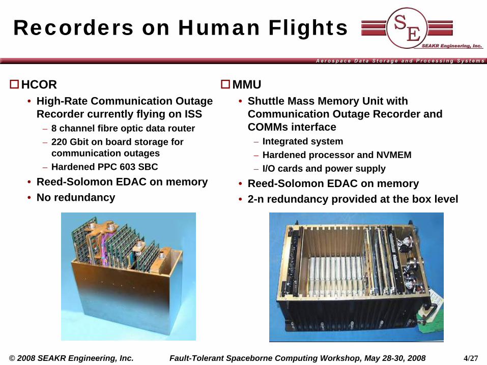
HCOR• High-Rate Communication Outage
Recorder currently flying on ISS– 8 channel fibre optic data router– 220 Gbit on board storage for
communication outages– Hardened PPC 603 SBC
• Reed-Solomon EDAC on memory• No redundancy
MMU• Shuttle Mass Memory Unit with
Communication Outage Recorder and COMMs interface
– Integrated system– Hardened processor and NVMEM– I/O cards and power supply
• Reed-Solomon EDAC on memory• 2-n redundancy provided at the box level
5/27Fault-Tolerant Spaceborne Computing Workshop, May 28-30, 2008© 2008 SEAKR Engineering, Inc.
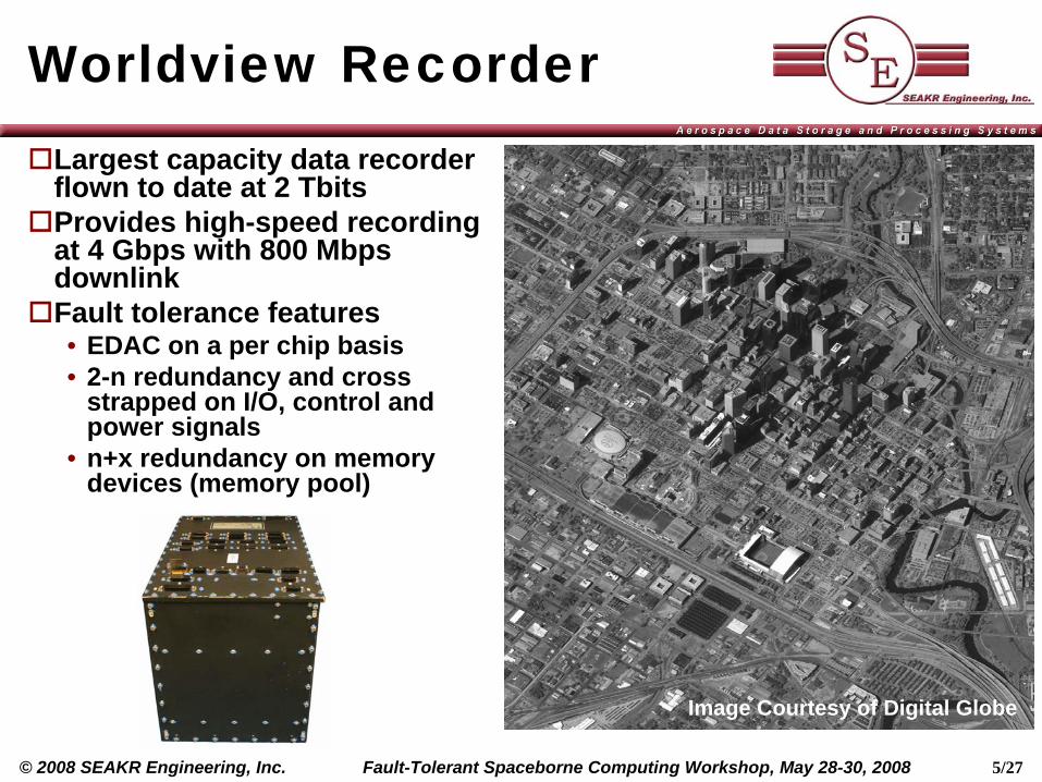
Worldview RecorderLargest capacity data recorder flown to date at 2 TbitsProvides high-speed recording at 4 Gbps with 800 Mbps downlinkFault tolerance features• EDAC on a per chip basis• 2-n redundancy and cross
strapped on I/O, control and power signals
• n+x redundancy on memory devices (memory pool)
Image Courtesy of Digital Globe
6/27Fault-Tolerant Spaceborne Computing Workshop, May 28-30, 2008© 2008 SEAKR Engineering, Inc.
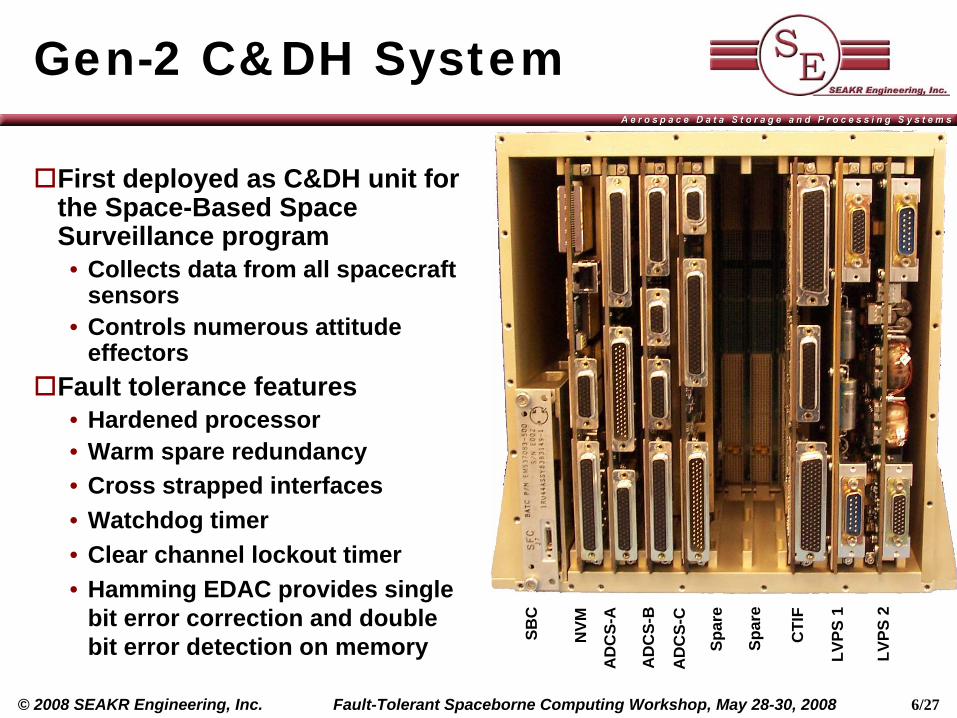
Gen-2 C&DH System
SBC
NVM
AD
CS-
A
AD
CS-
B
AD
CS-
C
Spar
e
Spar
e
CTI
F
LVPS
1
LVPS
2
First deployed as C&DH unit for the Space-Based Space Surveillance program• Collects data from all spacecraft
sensors• Controls numerous attitude
effectorsFault tolerance features• Hardened processor• Warm spare redundancy• Cross strapped interfaces• Watchdog timer• Clear channel lockout timer• Hamming EDAC provides single
bit error correction and double bit error detection on memory
7/27Fault-Tolerant Spaceborne Computing Workshop, May 28-30, 2008© 2008 SEAKR Engineering, Inc.
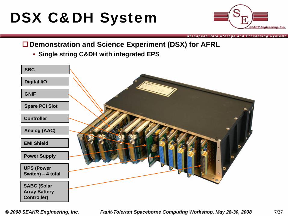
DSX C&DH System
SBC
Digital I/O
GNIF
Spare PCI Slot
Controller
EMI Shield
Power Supply
UPS (Power Switch) – 4 total
SABC (Solar Array Battery Controller)
Analog (AAC)
Demonstration and Science Experiment (DSX) for AFRL• Single string C&DH with integrated EPS
8/27Fault-Tolerant Spaceborne Computing Workshop, May 28-30, 2008© 2008 SEAKR Engineering, Inc.
DSX Fault ToleranceTransceiver interface fault tolerance
• Data downlink engine with CRC generator used to detect link errors• Bose-Chaudhuri-Hocquenghem (BCH) decoder verifies commands and data• Emergency downlink data collection and formatting (CCSDS/CADU format)
– If CPU unable to format downlink messages, critical data is gathered by the control card, formatted and down linked autonomously
Memory fault tolerance• EDAC protection on data• Full chip SDRAM failure detection and avoidance• Autonomous memory scrub routine enabled
System-level fault tolerance• Hardened processor• Read and write transactions return acknowledge bytes• Parity, stop, start, or timeout errors will trigger a retransmission• Up to 16 attempts to transmit before master gives up and notifies user logic• Watchdog timer / heartbeat monitor function on subsystems provides a backup
controller failsafe for the CPU
9/27Fault-Tolerant Spaceborne Computing Workshop, May 28-30, 2008© 2008 SEAKR Engineering, Inc.
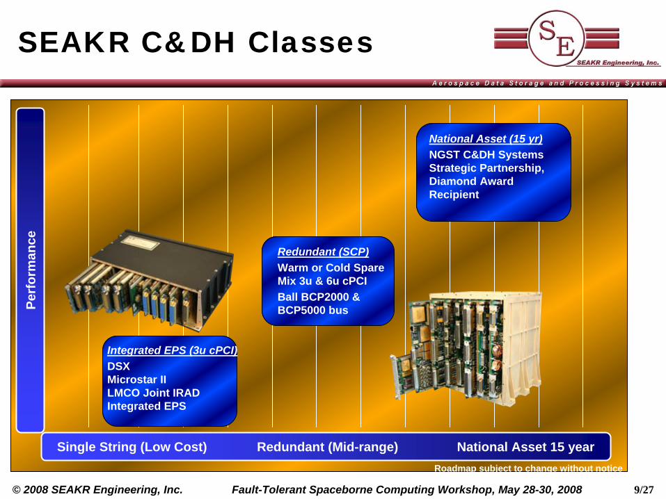
SEAKR C&DH ClassesPe
rfor
man
ce
National Asset (15 yr)NGST C&DH Systems Strategic Partnership, Diamond Award Recipient
Integrated EPS (3u cPCI)DSX Microstar II LMCO Joint IRAD Integrated EPS
Single String (Low Cost) Redundant (Mid-range) National Asset 15 year
Redundant (SCP)Warm or Cold Spare Mix 3u & 6u cPCIBall BCP2000 & BCP5000 bus
Roadmap subject to change without notice
10/27Fault-Tolerant Spaceborne Computing Workshop, May 28-30, 2008© 2008 SEAKR Engineering, Inc.
Application Independent Processor GoalsApplication Independent Processor (AIP) designed for Responsive Space
• Low cost• High Performance• Rapid deployment through adaptability• Designed for multiple missions including image processing, sat. comm., etc.
Key System Development Requirements• Scalable processing from 9 to over 400 GFLOPS• Reconfigurable, on-orbit• Support Terabit Data Storage• Usage of open standards• SEE Tolerant system• Flexible I/O architecture• Provide user interface for rapid development
The AIP first deployed as the processing core for Raytheon’s Advanced Responsive Tactically Effective Military Imaging Spectrometer (ARTEMIS)
11/27Fault-Tolerant Spaceborne Computing Workshop, May 28-30, 2008© 2008 SEAKR Engineering, Inc.
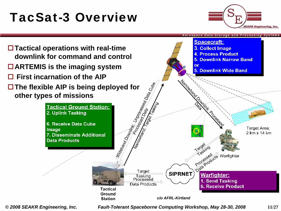
TacSat-3 Overview
Tactical operations with real-time downlink for command and controlARTEMIS is the imaging systemFirst incarnation of the AIPThe flexible AIP is being deployed for other types of missions
c/o AFRL-Kirtland
12/27Fault-Tolerant Spaceborne Computing Workshop, May 28-30, 2008© 2008 SEAKR Engineering, Inc.
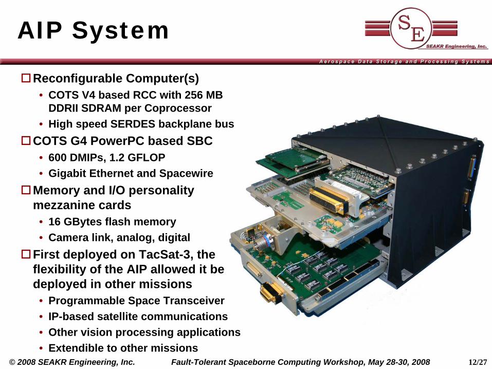
AIP System
Reconfigurable Computer(s)• COTS V4 based RCC with 256 MB
DDRII SDRAM per Coprocessor• High speed SERDES backplane bus
COTS G4 PowerPC based SBC• 600 DMIPs, 1.2 GFLOP• Gigabit Ethernet and Spacewire
Memory and I/O personality mezzanine cards
• 16 GBytes flash memory• Camera link, analog, digital
First deployed on TacSat-3, the flexibility of the AIP allowed it be deployed in other missions
• Programmable Space Transceiver• IP-based satellite communications• Other vision processing applications• Extendible to other missions
13/27Fault-Tolerant Spaceborne Computing Workshop, May 28-30, 2008© 2008 SEAKR Engineering, Inc.
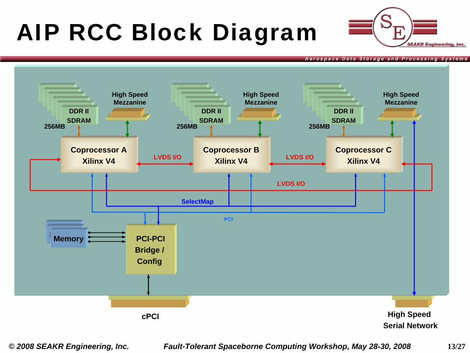
AIP RCC Block Diagram
Coprocessor AXilinx V4
MemoryPCI-PCIBridge / Config
LVDS I/O
PCI
DDR IISDRAMDDR II
SDRAMDDR IISDRAMDDR II
SDRAMDDR IISDRAMDDR IISDRAM
SelectMap
256MB
cPCI High Speed Serial Network
Coprocessor BXilinx V4
DDR IISDRAMDDR II
SDRAMDDR IISDRAMDDR II
SDRAMDDR IISDRAMDDR IISDRAM
256MB
Coprocessor CXilinx V4
DDR IISDRAMDDR II
SDRAMDDR IISDRAMDDR II
SDRAMDDR IISDRAMDDR IISDRAM
256MB
LVDS I/O
LVDS I/O
High Speed Mezzanine
High Speed Mezzanine
High Speed Mezzanine
MemoryMemory
14/27Fault-Tolerant Spaceborne Computing Workshop, May 28-30, 2008© 2008 SEAKR Engineering, Inc.
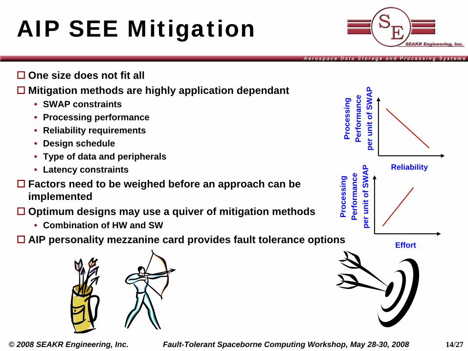
AIP SEE Mitigation
One size does not fit allMitigation methods are highly application dependant
• SWAP constraints• Processing performance• Reliability requirements• Design schedule• Type of data and peripherals• Latency constraints
Factors need to be weighed before an approach can be implementedOptimum designs may use a quiver of mitigation methods
• Combination of HW and SWAIP personality mezzanine card provides fault tolerance options
Proc
essi
ngPe
rfor
man
cepe
r uni
t of S
WA
P
Effort
Proc
essi
ngPe
rfor
man
cepe
r uni
t of S
WA
P
Reliability
15/27Fault-Tolerant Spaceborne Computing Workshop, May 28-30, 2008© 2008 SEAKR Engineering, Inc.
RA-RCC Personality Mezzanine Card
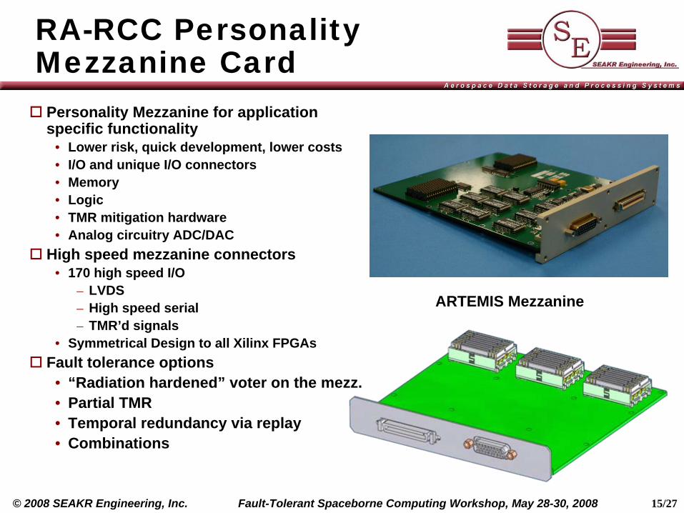
Personality Mezzanine for application specific functionality
• Lower risk, quick development, lower costs• I/O and unique I/O connectors• Memory• Logic• TMR mitigation hardware• Analog circuitry ADC/DAC
High speed mezzanine connectors• 170 high speed I/O
– LVDS– High speed serial– TMR’d signals
• Symmetrical Design to all Xilinx FPGAsFault tolerance options
• “Radiation hardened” voter on the mezz.• Partial TMR• Temporal redundancy via replay• Combinations
ARTEMIS Mezzanine
16/27Fault-Tolerant Spaceborne Computing Workshop, May 28-30, 2008© 2008 SEAKR Engineering, Inc.
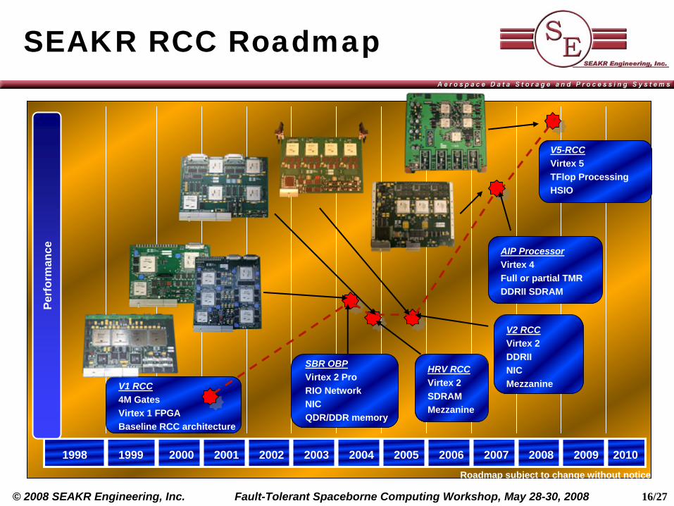
SEAKR RCC Roadmap
1998 1999 2000 2001 2002 2003 2004 2005 2006 2007 2008 2009 2010
V1 RCC4M GatesVirtex 1 FPGABaseline RCC architecture
Perf
orm
ance
V5-RCCVirtex 5TFlop ProcessingHSIO
AIP ProcessorVirtex 4Full or partial TMRDDRII SDRAM
V2 RCCVirtex 2DDRIINICMezzanine
SBR OBPVirtex 2 ProRIO NetworkNICQDR/DDR memory
Roadmap subject to change without notice
HRV RCCVirtex 2SDRAMMezzanine
17/27Fault-Tolerant Spaceborne Computing Workshop, May 28-30, 2008© 2008 SEAKR Engineering, Inc.
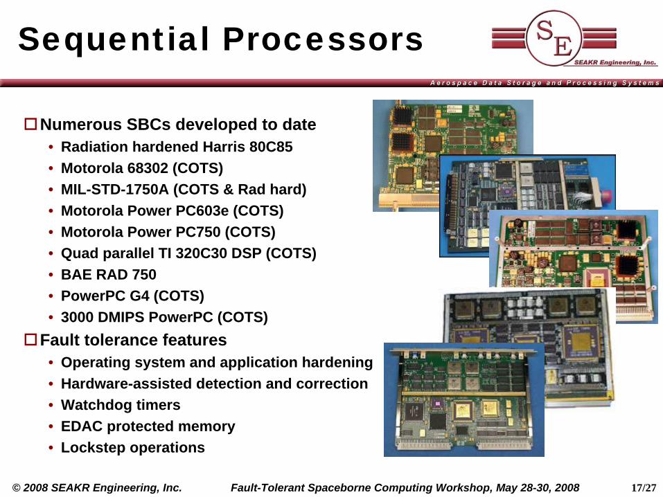
Sequential Processors
Numerous SBCs developed to date• Radiation hardened Harris 80C85• Motorola 68302 (COTS)• MIL-STD-1750A (COTS & Rad hard)• Motorola Power PC603e (COTS)• Motorola Power PC750 (COTS)• Quad parallel TI 320C30 DSP (COTS)• BAE RAD 750• PowerPC G4 (COTS)• 3000 DMIPS PowerPC (COTS)
Fault tolerance features• Operating system and application hardening• Hardware-assisted detection and correction• Watchdog timers• EDAC protected memory• Lockstep operations
18/27Fault-Tolerant Spaceborne Computing Workshop, May 28-30, 2008© 2008 SEAKR Engineering, Inc.
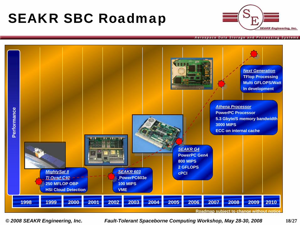
SEAKR SBC Roadmap
1998 1999 2000 2001 2002 2003 2004 2005 2006 2007 2008 2009 2010
MightySat IITI Quad C40250 MFLOP OBPHSI Cloud Detection
Perf
orm
ance
Next GenerationTFlop ProcessingMulti GFLOPS/WattIn development
Athena ProcessorPowerPC Processor5.3 Gbyte/S memory bandwidth3000 MIPSECC on internal cache
SEAKR G4PowerPC Gen4800 MIPS2 GFLOPScPCISEAKR 603
PowerPC603e100 MIPSVME
Roadmap subject to change without notice
19/27Fault-Tolerant Spaceborne Computing Workshop, May 28-30, 2008© 2008 SEAKR Engineering, Inc.
SBC Radiation Testing
Need for performance and SEE fault tolerance• High-end processors, memory, interconnect technology, and other components
required to meet performance targets• Functional upsets directly affect the system’s availability• Therefore, components and mitigation strategies must be correctly and fully
characterized to ensure mission successLessons learned from SEE experiments
• Test methodology must center on application and not be a generic study• Initial tests serve to screen hardware moving toward full capability• When possible use exact system configuration to obtain meaningful results
– All components engaged in test and included in SEFI analysis– Design tests around the mission when possible– Tests performed at speed
• Build in as much visibility into the system as possible to observe SEFIs– Component complexity can make pinpointing the cause of SEFIs difficult– Numerous interacting components can mask SEFIs (latent)– Software is just as, if not more, complex than the underlying hardware
20/27Fault-Tolerant Spaceborne Computing Workshop, May 28-30, 2008© 2008 SEAKR Engineering, Inc.
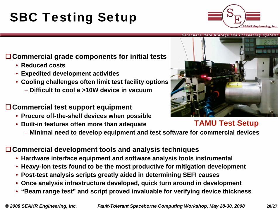
SBC Testing Setup
Commercial grade components for initial tests• Reduced costs• Expedited development activities• Cooling challenges often limit test facility options
– Difficult to cool a >10W device in vacuum
Commercial test support equipment• Procure off-the-shelf devices when possible• Built-in features often more than adequate
– Minimal need to develop equipment and test software for commercial devices
Commercial development tools and analysis techniques• Hardware interface equipment and software analysis tools instrumental• Heavy-ion tests found to be the most productive for mitigation development• Post-test analysis scripts greatly aided in determining SEFI causes• Once analysis infrastructure developed, quick turn around in development• “Beam range test” and script proved invaluable for verifying device thickness
TAMU Test Setup
21/27Fault-Tolerant Spaceborne Computing Workshop, May 28-30, 2008© 2008 SEAKR Engineering, Inc.
SBC Test Methodology
Application-oriented test methodology with three distinct goals1. Determine baseline susceptibility of registers, memory and other components
• Limiting cross section created to aid in bounding development activities2. Determine baseline SEFI cross section for chosen application
• Real stimulus data with tests performed at speed• Focus on gathering data and trace files to help mitigation development
3. Undertake iterative mitigation development process to minimize cross section• For each prominent observed or expected SEFI a range of mitigation
approaches typically developed and retested• Successful approaches retained and additional data helped to guide the next
round of development• Process stops when limiting cross section can not be improved (e.g. below
uncorrectable MBU) or subcomponent geometric cross section sufficiently small
Observed hundreds of individual SEFI mode typically characterized• Some correctable, some understood but not correctable, and some unknown• Focus on reducing the “long poles in the tent”• Uncorrectable and unknown failures typically handled at the system level
22/27Fault-Tolerant Spaceborne Computing Workshop, May 28-30, 2008© 2008 SEAKR Engineering, Inc.
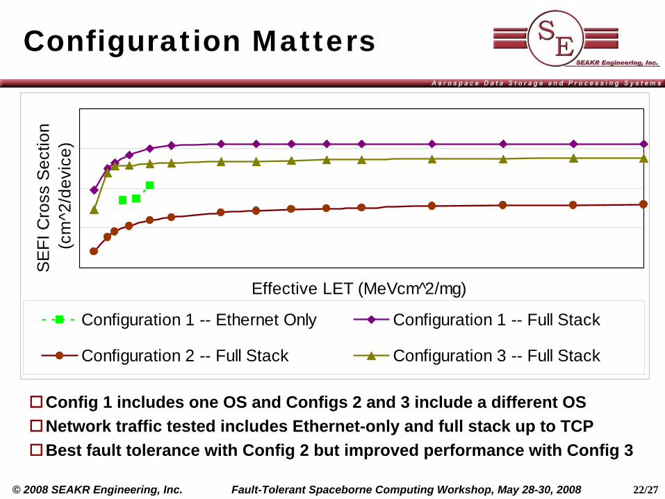
Configuration Matters
Config 1 includes one OS and Configs 2 and 3 include a different OSNetwork traffic tested includes Ethernet-only and full stack up to TCPBest fault tolerance with Config 2 but improved performance with Config 3
Effective LET (MeVcm 2̂/mg)
SEFI
Cro
ss S
ectio
n (c
m^2
/dev
ice)
Configuration 1 -- Ethernet Only Configuration 1 -- Full Stack
Configuration 2 -- Full Stack Configuration 3 -- Full Stack
23/27Fault-Tolerant Spaceborne Computing Workshop, May 28-30, 2008© 2008 SEAKR Engineering, Inc.
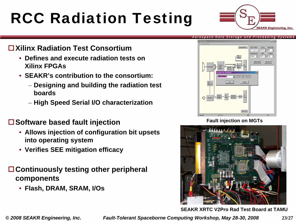
RCC Radiation Testing
Xilinx Radiation Test Consortium• Defines and execute radiation tests on
Xilinx FPGAs• SEAKR’s contribution to the consortium:
– Designing and building the radiation test boards
– High Speed Serial I/O characterization
Software based fault injection• Allows injection of configuration bit upsets
into operating system• Verifies SEE mitigation efficacy
Continuously testing other peripheral components
• Flash, DRAM, SRAM, I/Os
SEAKR XRTC V2Pro Rad Test Board at TAMU
Fault injection on MGTs
24/27Fault-Tolerant Spaceborne Computing Workshop, May 28-30, 2008© 2008 SEAKR Engineering, Inc.
Conclusions
Mission performance requirements driving the use of commercial devices
Fault tolerance often the most limiting factor in meeting mission objectives after programmatic considerations
Rich heritage of deploying fault tolerant systems with commercial devices
Need for performance and fault tolerance compels the need for a selective approach to SEE testing and mitigation development for SBCs
Lessons learned from numerous SEE experiments undertaken have culminated in a mature development and testing approach
Future processing systems under consideration and in development
25/27Fault-Tolerant Spaceborne Computing Workshop, May 28-30, 2008© 2008 SEAKR Engineering, Inc.
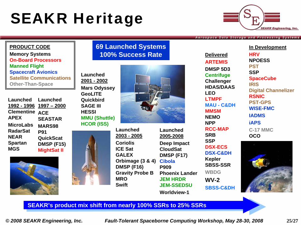
SEAKR Heritage
Launched 1992 - 1996 Clementine APEXMicroLabs RadarSat NEAR Spartan MGS
Launched 1997 – 2000ACE SEASTARMARS98 P91 QuickScat DMSP (F15) MightSat II
Launched 2001 - 2002Mars Odyssey GeoLITE Quickbird SAGE III HESSI MMU (Shuttle) HCOR (ISS)
Launched 2003 - 2005Coriolis ICE Sat GALEX Orbimage (3 & 4) DMSP (F16) Gravity Probe B MRO Swift
Launched 2005-2008Deep Impact CloudSat DMSP (F17) Cibola P909 Phoenix Lander JEM HRDR JEM-SSEDSUWorldview-1
DeliveredARTEMISDMSP 5D3 Centrifuge Challenger HDAS/DAAS LEO LTMPF MAU - C&DH MMSM NEMO NPP RCC-MAP SRB SSP DSX-ECS DSX-C&DH Kepler SBSS-SSRWBDGWV-2SBSS-C&DH
In DevelopmentHRV NPOESS PST SSP SpaceCube IRIS Digital Channelizer RSNIC PST-GPS WISE-FMCIADMSiAPSC-17 MMC OCO
PRODUCT CODEMemory Systems On-Board Processors Manned Flight Spacecraft Avionics Satellite Communications Other-Than-Space
69 Launched Systems 100% Success Rate
SEAKR’s product mix shift from nearly 100% SSRs to 25% SSRs
26/27Fault-Tolerant Spaceborne Computing Workshop, May 28-30, 2008© 2008 SEAKR Engineering, Inc.
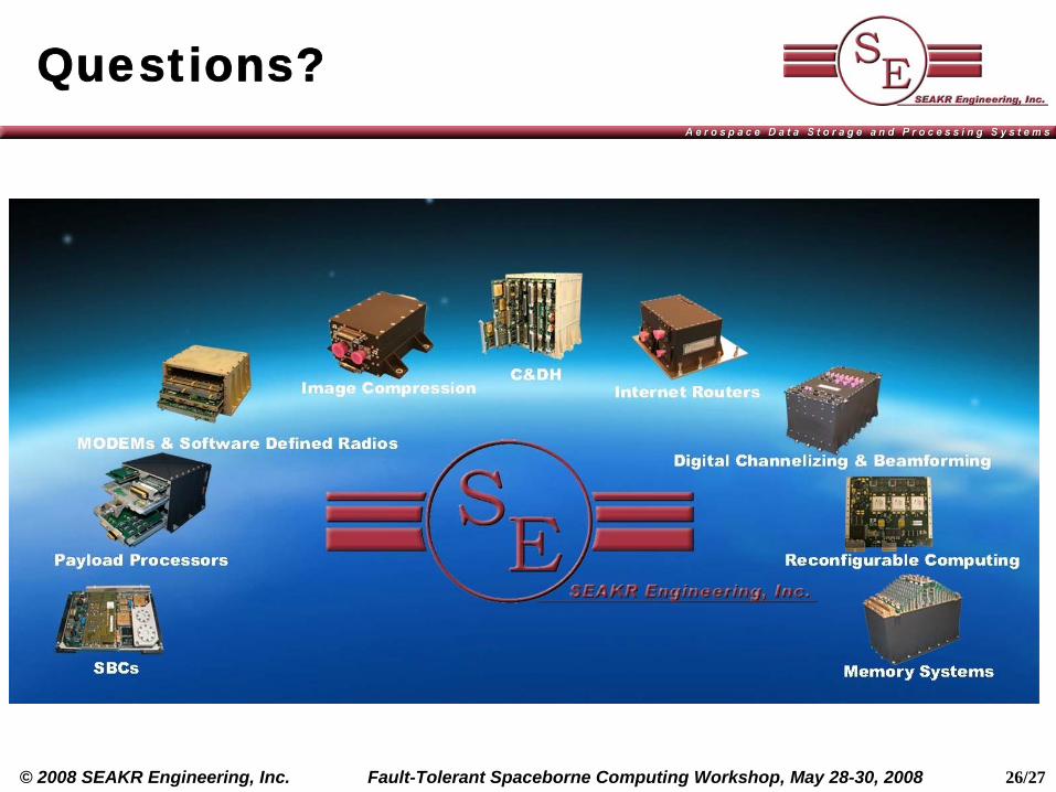
Questions?
27/27Fault-Tolerant Spaceborne Computing Workshop, May 28-30, 2008© 2008 SEAKR Engineering, Inc.
Contact Information
Dave Jungkind Business Development• 303-784-7734 [email protected]
Dr. Ian Troxel Future Systems Architect• 303-784-7673 [email protected]
SEAKR Engineering, Inc. 6221 South Racine Circle Centennial, CO 80111-6427 main: 303 790 8499 fax: 303 790 8720 web: http://www.SEAKR.com
Related Documents