AASHTOWare Bridge Rating and Design Training –STL8 –Single Span 3D Steel Example Last Modified: 7/26/2012 STL8 - 1 AASHTOWare BrR/BrD 6.4 AASHTOWare Bridge Rating/DesignTraining STL8 – Single Span Steel 3D Example (BrR/BrD 6.4)

Welcome message from author
This document is posted to help you gain knowledge. Please leave a comment to let me know what you think about it! Share it to your friends and learn new things together.
Transcript

AASHTOWare Bridge Rating and Design Training –STL8 –Single Span 3D Steel Example
Last Modified: 7/26/2012 STL8 - 1 AASHTOWare BrR/BrD 6.4
AASHTOWare Bridge Rating/DesignTraining
STL8 – Single Span Steel 3D Example (BrR/BrD 6.4)

AASHTOWare Bridge Rating and Design Training –STL8 –Single Span 3D Steel Example
Last Modified: 7/26/2012 STL8 - 2 AASHTOWare BrR/BrD 6.4
AASHTOWare Bridge Rating/DesignTraining
STL8 – Single Span Steel 3D Example (BrR/BrD 6.4) Topics Covered • 3D analysis of a single span steel rolled beam bridge • Diaphragm definitions • 3D analysis settings • 3D model This example describes performing a 3D FEM analysis of a single span steel rolled beam structure. Open the Bridge Workspace for “STL8”. Open the Diaphragm Definition window shown below.

AASHTOWare Bridge Rating and Design Training –STL8 –Single Span 3D Steel Example
Last Modified: 7/26/2012 STL8 - 3 AASHTOWare BrR/BrD 6.4
The following window shows a diaphragm definition that can be assigned to locations in the Framing Plan window.
Steel bridges may contain any of the 4 types of diaphragm definitions. Concrete bridges may only contain Type 4 diaphragm definitions.

AASHTOWare Bridge Rating and Design Training –STL8 –Single Span 3D Steel Example
Last Modified: 7/26/2012 STL8 - 4 AASHTOWare BrR/BrD 6.4
The Superstructure Definition window contains the following settings to control the 3D analysis.
The analysis of all member alternatives in the superstructure definition will use the following engine and specification set on the Specs tab.

AASHTOWare Bridge Rating and Design Training –STL8 –Single Span 3D Steel Example
Last Modified: 7/26/2012 STL8 - 5 AASHTOWare BrR/BrD 6.4
Open the Framing Plan Details: Diaphragms tab to see how diaphragm definitions are assigned to the framing plan. The weight of the diaphragms will be computed by the software and applied to the 3D model.

AASHTOWare Bridge Rating and Design Training –STL8 –Single Span 3D Steel Example
Last Modified: 7/26/2012 STL8 - 6 AASHTOWare BrR/BrD 6.4
For the Bridge Design training, open the Analysis Settings window and make the following selections for an HL93 Design Review:

AASHTOWare Bridge Rating and Design Training –STL8 –Single Span 3D Steel Example
Last Modified: 7/26/2012 STL8 - 7 AASHTOWare BrR/BrD 6.4
For the Bridge Rating training, open the Analysis Settings window and make the following selections for an HS20 rating:

AASHTOWare Bridge Rating and Design Training –STL8 –Single Span 3D Steel Example
Last Modified: 7/26/2012 STL8 - 8 AASHTOWare BrR/BrD 6.4
For both training sessions, select the following output controls:
Sit on the superstructure definition and launch the analysis. The software develops the 3D model using the member alternative marked as Existing for each member. If the member does not have a member alternative marked as Existing and only has 1 member alternative, that member alternative is used for the 3D model. If the member has no member alternative marked as Existing and more than 1 member alternative, the analysis will not be performed. Spec checking and rating is only performed for member alternatives marked as Existing. For this sample bridge, the spec checking will only be performed for the member alternative for member G2.

AASHTOWare Bridge Rating and Design Training –STL8 –Single Span 3D Steel Example
Last Modified: 7/26/2012 STL8 - 9 AASHTOWare BrR/BrD 6.4
The following shows the output files created by the 3D LRFD design review. Similar files are created for a 3D Std rating.
The “3D Model” files list the data for the models including nodes, members, properties and loads. The “3D Model Actions” files list the FE results (reactions, element actions, displacements) for the models. The “Model Graphics” files can be opened to graphically view the FE models. The following shows the graphics for the Stage 1 model which contains the steel beams and diaphragms.
Node and element numbers can be turned on from the Tools menu. The mouse controls manipulation of the view. Zoom by rolling the mouse wheel. Translate by pushing down the mouse wheel. Rotate by pushing down the left mouse button.
AASHTOWare Bridge Rating and Design Training –STL8 –Single Span 3D Steel Example
Last Modified: 7/26/2012 STL8 - 10 AASHTOWare BrR/BrD 6.4
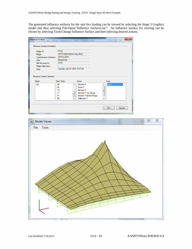
The generated influence surfaces for the unit live loading can be viewed by selecting the Stage 3 Graphics model and then selecting File/Open/”Influence Surfaces.sur”. An influence surface for viewing can be chosen by selecting Tools/Change Influence Surface and then selecting desired actions.

AASHTOWare Bridge Rating and Design Training –STL8 –Single Span 3D Steel Example
Last Modified: 7/26/2012 STL8 - 11 AASHTOWare BrR/BrD 6.4
Tabular results and spec check details can be viewed for the member alternatives that were analyzed.
AASHTOWare Bridge Rating and Design Training –STL8 –Single Span 3D Steel Example
Last Modified: 7/26/2012 STL8 - 12 AASHTOWare BrR/BrD 6.4
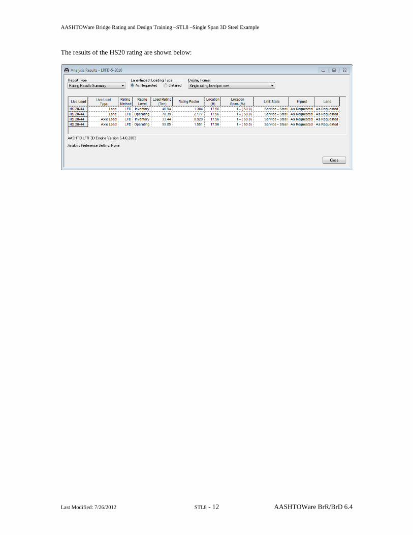
The results of the HS20 rating are shown below:

AASHTOWare Bridge Rating and Design Training –STL8 –Single Span 3D Steel Example
Last Modified: 7/26/2012 STL8 - 13 AASHTOWare BrR/BrD 6.4
3D Model The modeling techniques used are the result of a survey of researchers and practitioners and review of several software packages. Steel beams are modeled with:
• Shell elements for the deck • Beam elements for the top and bottom flanges • Shell elements for the web
Rigid Links
Flange (Beam Elements)
Web (Shell Elements)
Flange (Beam Elements)
Deck (Shell Elements)
SectionPartial Elevation View of
Model
A
Reinforced concrete beams are modeled with:
• Shell elements for the top flange • Beam elements for the girder
Rigid LinksBeam Elements at c.g. of
beam
Deck/Top Flange (Shell Elements)
Reinforced Concrete Section Partial Elevation View of Model
A
AASHTOWare Bridge Rating and Design Training –STL8 –Single Span 3D Steel Example
Last Modified: 7/26/2012 STL8 - 14 AASHTOWare BrR/BrD 6.4
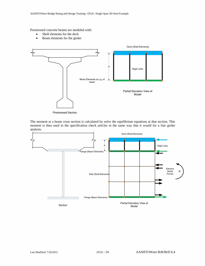
Prestressed concrete beams are modeled with:
• Shell elements for the deck • Beam elements for the girder
Rigid Links
Beam Elements at c.g. of beam
Deck (Shell Elements)
Prestressed Section
Partial Elevation View of Model
A
The moment at a beam cross section is calculated by solve the equilibrium equations at that section. This moment is then used in the specification check articles in the same way that it would for a line girder analysis.
Rigid Links
Flange (Beam Elements)
Web (Shell Elements)
Flange (Beam Elements)
Deck (Shell Elements)
MElementNodalForces
SectionPartial Elevation View of
Model
A

AASHTOWare Bridge Rating and Design Training –STL8 –Single Span 3D Steel Example
Last Modified: 7/26/2012 STL8 - 15 AASHTOWare BrR/BrD 6.4
Mesh Generation The FE model created by BrR/BrD will contain nodes at the following locations:
• Cross section property change points • Span tenth points • Support locations • Diaphragm locations • User defined points of interest
The user controls the mesh generation by the controls previously shown on the Superstructure Definition: Analysis tab. The software creates the mesh following the number of elements selected between beams or within the web of a steel beam and the target aspect ratio entered by the user. The presence of nodes at the locations listed above may result in some elements falling outside the target aspect ratio. The following plan views show how the mesh for this example can be controlled by the user. 3 shells between beams, target aspect ratio = 2 4 shells between beams, target aspect ratio = 1
Loading The program computes all of the dead loads acting on the beam including the self-weight of the beam, user defined appurtenances on the structure typical section, wearing surfaces, diaphragms and user defined member loads. Composite dead loads are applied directly to the deck shells in the 3D model in their actual location. They are not distributed to the girders based on the choices available in the Superstructure Loads window. The Stage 3 FE model is loaded with unit loads at each deck node within the travelway to generate influence surfaces for the beam. Lane positions and combinations are determined based on the travelway and the transverse loading parameters set by the user on the Superstructure Definition: Analysis Settings tab. The influence surfaces are then loaded with the selected vehicles to find the maximum live load effects.
Related Documents