****************************************************************************************** COMPARISON OF SELECTIVE LASER AND ELECTRON BEAM MELTED TITANIUM ALUMINIDES L. Loeber 1 , S. Biamino 2 , U. Ackelid 3 , S. Sabbadini 4 , P. Epicoco 2 , P. Fino 2 , J. Eckert 1 1 Leibniz Institute for Solid State and Materials Research Dresden 2 Politecnico di Torino 3 Arcam AB 4 Avio SpA Abstract In the following paper we present the investigation of microstructure and mechanical properties produced by selective laser melting (SLM) and electron beam melting (EBM). The chosen alloy is a Ti-(46- 48)Al-2Cr-2Nb alloy which has a great potential in replacing heavy weight Ni-base superalloys in turbine blades. Cylindrical specimens were produced and characterized by optical microscopy (OM), scanning electron microscopy (SEM) and chemical analysis to determine the microstructure and composition. In addition compression tests at room and elevated temperatures (700-800 °C) were carried out to identify the mechanical properties of the alloy. Introduction ****************************************************************************************** Titanium Aluminides (TiAl) alloys exhibit a wide range of interesting properties which makes them a good candidate for exchanging heavy weigh Nickel-based superalloys in jet turbine engines. They poses an excellent high temperature behavior in terms of strength, oxidation resistance, creep resistance and high melting point, while their density is only half as the one of Nickel [1-4]. Their poor room temperature ductility and their high reactivity with other materials makes them difficult to process [5,6]. Cost and time intensive methods like isothermal forging or special types of casting have to be used to produce useable parts. The process technology of additive manufacturing is known for polymers like Polyethylene for almost 30 years now. Only recently with the possibilities of high power lasers the technology has been adapted to metallic and ceramic materials [13]. This development lead to the additive manufacturing technologies of selective laser melting (SLM) and electron beam melting (EBM). The high energy source allows it to melt and micro weld metallic or ceramic powder. The principle work process of all additive manufacturing techniques is quite similar. Starting with a thin powder layer an energy source is focused on specific local areas of the powder layer. The energy source can be a laser, electron beam or in case of polymers a simple light source. The energy input has to be high enough to micro weld the powder to a substrate plate and to micro weld the different powder layers together. This three step iterative process can be seen in Figure 1. The contact to the substrate plate is essential as this contact ensures the mechanical stability but mainly to guarantee good heat dissipation. In a second step the building platform is lowered by the layer thickness and finally a coating device applies a new layer of powder and the process starts over again. This three step work principle is iteratively repeated until the desired part is layer wise built. The main benefit of additive manufacturing is the high amount of possible complex geometries. Almost every thinkable complex structure can be built. Examples are back tapers, cooling channels or special lattice structures. Even structures which other processing technologies can not build are possible to build with additive manufacturing. Another advantage is the complete use of the material. Powder which is not melted into the 547

Welcome message from author
This document is posted to help you gain knowledge. Please leave a comment to let me know what you think about it! Share it to your friends and learn new things together.
Transcript
******************************************************************************************
COMPARISON OF SELECTIVE LASER AND ELECTRON BEAM MELTED TITANIUM ALUMINIDES
L. Loeber1, S. Biamino2, U. Ackelid3, S. Sabbadini4, P. Epicoco2, P. Fino2, J. Eckert1
1Leibniz Institute for Solid State and Materials Research Dresden 2Politecnico di Torino 3Arcam AB 4Avio SpA
Abstract
In the following paper we present the investigation of microstructure and mechanical properties
produced by selective laser melting (SLM) and electron beam melting (EBM). The chosen alloy is a Ti-(46-48)Al-2Cr-2Nb alloy which has a great potential in replacing heavy weight Ni-base superalloys in turbine blades. Cylindrical specimens were produced and characterized by optical microscopy (OM), scanning electron microscopy (SEM) and chemical analysis to determine the microstructure and composition. In addition compression tests at room and elevated temperatures (700-800 °C) were carried out to identify the mechanical properties of the alloy.
Introduction ******************************************************************************************
Titanium Aluminides (TiAl) alloys exhibit a wide range of interesting properties which makes them a good candidate for exchanging heavy weigh Nickel-based superalloys in jet turbine engines. They poses an excellent high temperature behavior in terms of strength, oxidation resistance, creep resistance and high melting point, while their density is only half as the one of Nickel [1-4]. Their poor room temperature ductility and their high reactivity with other materials makes them difficult to process [5,6]. Cost and time intensive methods like isothermal forging or special types of casting have to be used to produce useable parts. The process technology of additive manufacturing is known for polymers like Polyethylene for almost 30 years now. Only recently with the possibilities of high power lasers the technology has been adapted to metallic and ceramic materials [13]. This development lead to the additive manufacturing technologies of selective laser melting (SLM) and electron beam melting (EBM). The high energy source allows it to melt and micro weld metallic or ceramic powder. The principle work process of all additive manufacturing techniques is quite similar. Starting with a thin powder layer an energy source is focused on specific local areas of the powder layer. The energy source can be a laser, electron beam or in case of polymers a simple light source. The energy input has to be high enough to micro weld the powder to a substrate plate and to micro weld the different powder layers together. This three step iterative process can be seen in Figure 1. The contact to the substrate plate is essential as this contact ensures the mechanical stability but mainly to guarantee good heat dissipation. In a second step the building platform is lowered by the layer thickness and finally a coating device applies a new layer of powder and the process starts over again. This three step work principle is iteratively repeated until the desired part is layer wise built.
The main benefit of additive manufacturing is the high amount of possible complex geometries. Almost every thinkable complex structure can be built. Examples are back tapers, cooling channels or special lattice structures. Even structures which other processing technologies can not build are possible to build with additive manufacturing. Another advantage is the complete use of the material. Powder which is not melted into the
547

parts can be sieved and used again. In contrast to subtractive manufacturing techniques where usually the process starts with a dense block and during the process material is taken away to create the desired part thus creating a lot of waste material like turnings. Additive manufacturing uses almost only the needed material for the parts and no waste material is created. As the selective laser melting is one of the younger process technologies the methods has only been applied to a clear number of materials like tool steels, stainless steels, aluminum alloys, Inconel, Cobaltchrome or some titanium alloys. In this work the adaption to the material class of titanium aluminides is presented. As there are already some publications about electron beam melting of titanium aluminides and the techniques are quite similar to another this work tries to compare both techniques on this special material.
As there are no existing process parameters for TiAl for SLM, an average between Titanium and
Aluminum with the respect to the different heat conductivities, melting points and heat capacities for an orientation point was chosen for starting parameters. The following formula of the energy impact was used to produce different specimens with different energy impacts:
i
PE
v x h
Where Ei is the energy impact in J/mm³, P is the laser power in W, v is the scanning speed of the laser in mm/s, x is the hatching of the laser tracks in mm and h is the layer thickness in µm. A high energy input mostly leads to a higher density of the parts. But with higher energy input the amount of residual thermal stresses also rises and as the room temperature ductility of TiAl is low a critical value should not be exceeded.
Some additional remarks have to be given to enlighten the main differences between SLM and EBM while processing TiAl. Both names already gives account to the main difference of both processes: while at SLM the energy source to melt and micro weld the powder is a laser the energy source of EBM is a focused electron beam. This main difference in the general set up of the machines lead to additional differences during the actual building. While an electron beam of high quality needs a good vacuum, usually in the range of 10-3 Pa, the whole building space has to be set under vacuum during the building. The laser is much less affected by the atmosphere so SLM only works with an inert gas, normally argon or nitrogen, in special cases also helium. Working with a vacuum has some major benefits like a clean environment, which is especially important while working with reactive elements like titanium. But it also helps to outgas impurities incorporated in the metal powder and gives a good thermal insulation. Another benefit is the possible high scanning rate of the electron beam to preheat the powder. The EBM machine has the capability of heating the powder up to 1100°C. This advantage is quite crucial as the room temperature ductility and the fracture toughness of TiAl is quite low. The material exhibits a brittle-ductile transition between 700-800°C [10,11].
548

Figure 1 Three step iterative process of additive manufacturing Materials and Methods
Simple cylinders with the dimensions of 5 mm diameter and 20 mm in height were created with a CAD program and then built in batches of 10 with a SLM 250 hl (SLM Solutions). The used gas atomized powder can be seen in Figure 2 a. The machine is equipped with a 400 W Yb-YAG fiber laser. The machine is also equipped with two oxygen sensors to ensure a low oxygen content during the building process as titanium is highly reactive with oxygen and titanium aluminides tend to lose their mechanical performance when they reach critical oxygen content [7,8]. Before starting the process itself the building chamber is flooded with 99,999% pure argon until a value below 0,02 % oxygen is reached. During the building of the specimens the building space was constantly flooded with argon ensuring a low oxygen content. With this process an oxygen content of around 100 ppm could be achieved. The specimens were directly built on a substrate plate without any further support structure which is normally used. The substrate plate had the same composition as the powder material: Ti-48Al-2Cr-2Nb and was micro pent before the process to ensure a good adhesion of the powder. The energy inputs of the specimens were chosen to be between 10-21 J/mm³. The laser power lied between 100-175 W, the layer thickness was set constant to 100 µm as the gas atomized powder has a powder size distribution of 45-100 µm and the layer thickness should not undercut the maximum powder size. The hatching was chosen to be between 110 µm and 150 µm. The experimental conditions for building the EBM parts can be found elsewhere [9]. Both types of specimens of EBM and SLM have been characterized via optical microscopy and electron microscopy to determine the microstructure. Additional characterization of the chemical composition and the porosity has been made. Both types of specimens have been analyzed twice by the different institutes. The chemical composition was assessed by means of inductively coupled plasma (ICP), infrared adsorption and/or thermal conductivity (LECO instrument) in both institutes. Specimens for optical microscopy analysis were prepared by polishing and etching in Kroll’s reagent, in order to investigate microstructure and porosity content. The porosity has been quantified according ASTM E 2109-01, while the amount of lamellar phase according ASTM E 562-01. The density of the SLM specimens were conducted via three types of density measurement: by simply measuring and scaling the specimens (geometric method), by the Archimedes method and by an area analysis of the polished samples. Mechanical testing in terms of compression test has been conducted with an Instron 8549. Additional compression tests at elevated temperatures have been carried out on the EBM specimens. For this measurement the cylinders have been electric eroded to smaller cylinders with a diameter of 3 mm and a height of 5-6 mm.
Figure 2. a SEM picture of the used powder for EBM and b SEM picture of the used powder for SLM
b100 µm 100 µm a
549

Results and discussion The chemical composition of the base material of the SLM process, both powder types and both SLM and EBM specimens can be found in Table 1. It can be seen that the amount of impurities of the EBM powder is not changed during the building. It can be assumed that the vacuum helps to keep the amount of pick-up of these elements down. Both the amount of oxygen and the amount of nitrogen lie beneath the critical amount of around 1000 ppm for oxygen and 600 ppm for nitrogen. The composition of the SLM material could already be conducted with the base material. The amount of impurities in the SLM material and powder are in the same range as the EBM powder. The amount of nitrogen and oxygen are a little lower in the starting material. As the gas atomization is conducted in inert atmosphere and with a crucible free method the amount of impurities during this process is kept to minimum. Only the amount of oxygen was determined in the SLM powder, as the oxygen content has the biggest influence on the mechanical properties. It can also clearly be seen, that in contrary to the EBM process were no additional oxygen impurity arises during the process, the SLM process with its inert argon atmosphere leads to higher oxygen content in the SLM specimen. This is quite understandable, as even the purest argon still contains much more oxygen than a good vacuum. On the other hand can the vacuum of the EBM process lead to a higher evaporation of lighter elements such as aluminum. But the variation of the aluminum content of the EBM powder and specimen is around 0.3 wt.% and is thus not considered to have an influence. It is curious that the variation of Aluminum in the SLM specimens is further reduced by 0.1 wt% compared to the one of the EBM. The only explanation for this occurrence is that the energy input of the laser is not yet calibrated well enough thus leading to evaporation effects of the Aluminum. The chemical analyses were conducted on different places of the specimens to determine the homogenous distribution of the elements. The variation in the composition varied below 0.2 wt.% and is also considered to have no effect. The amount of the alloying elements such as Nb and Cr does not change. Table 1. Chemical composition of the powder as received and the specimens Elemental chemical composition in wt.%
Al Cr Nb Fe O N C Ti
EBM powder (as received)
34.1 2.4 4.8 0.03 0.06 0.004 0.005 balance
EBM specimen
33.4 2.2 5.1 0.03 0.06 0.006 0.007 balance
SLM material (as received)
32.9 2.6 4.8 0.056 0.034 0.001 0.004 balance
SLM powder (as received)
32.7 2.6 4.8 ‐ 0.05 ‐ ‐ balance
SLM specimen 32.3 2.6 4.8 ‐ 0.08 ‐ ‐ balance
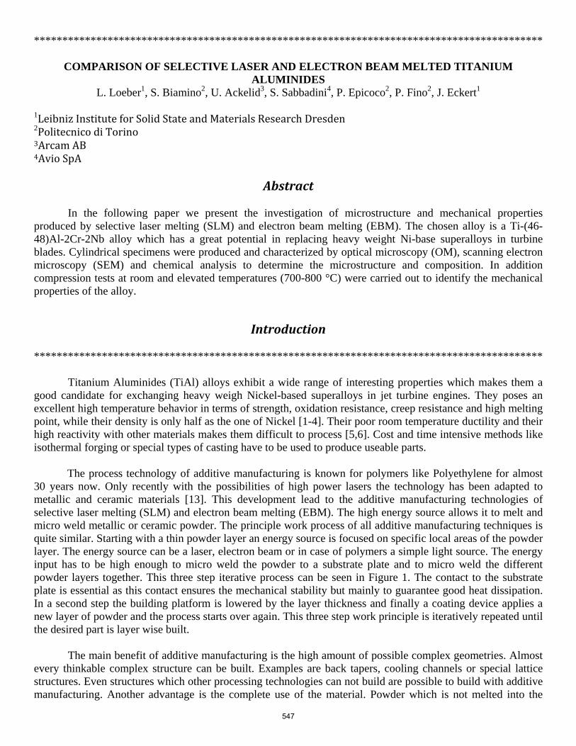
The amount and type of porosity has the biggest influence on the mechanical properties. The EBM process parameters have been adapted to produce a free macrospore material. In the EBM material only one type of small pores still occur caused by entrapped argon gas during the gas atomization. The amount of residual porosity lies below 2.0 % and can further be reduced via hot isostatic pressing to below 1.0 %. The porosity of the SLM specimens looks a lot different. As these are the first specimens build with this technology the process parameters are not fully optimized leading to a much higher residual porosity. Still two types of defects can be determined. Regarding Figure 3.a it can be seen that there are simply some regions where the energy input was not high enough to melt all the powder leading to big porous areas with partially molten or umolten powder around it reflected by the dark areas, especially in the outer region of Figure 3.b. On the other hand a great amount of cracks can be found in the whole specimen. It can be assumed that the contrary to the too low energy input leading to the bigger pores in some regions the energy input seems to be too high leading to thermal tensions which are not tolerated by the material and thus resulting in thermal induced cracks. Figure 4 shows the relative density in dependence of the used energy input of the different specimens. A clear tendency to higher
550
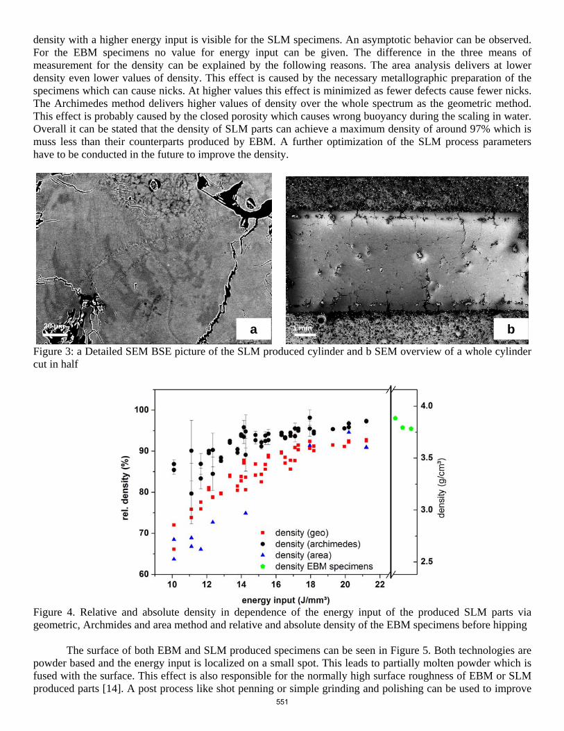
density with a higher energy input is visible for the SLM specimens. An asymptotic behavior can be observed. For the EBM specimens no value for energy input can be given. The difference in the three means of measurement for the density can be explained by the following reasons. The area analysis delivers at lower density even lower values of density. This effect is caused by the necessary metallographic preparation of the specimens which can cause nicks. At higher values this effect is minimized as fewer defects cause fewer nicks. The Archimedes method delivers higher values of density over the whole spectrum as the geometric method. This effect is probably caused by the closed porosity which causes wrong buoyancy during the scaling in water. Overall it can be stated that the density of SLM parts can achieve a maximum density of around 97% which is muss less than their counterparts produced by EBM. A further optimization of the SLM process parameters have to be conducted in the future to improve the density.
Figure 3: a Detailed SEM BSE picture of the SLM produced cylinder and b SEM overview of a whole cylinder cut in half
Figure 4. Relative and absolute density in dependence of the energy input of the produced SLM parts via geometric, Archmides and area method and relative and absolute density of the EBM specimens before hipping
The surface of both EBM and SLM produced specimens can be seen in Figure 5. Both technologies are powder based and the energy input is localized on a small spot. This leads to partially molten powder which is fused with the surface. This effect is also responsible for the normally high surface roughness of EBM or SLM produced parts [14]. A post process like shot penning or simple grinding and polishing can be used to improve
20 µm 1 mm b a
551

the surface roughness. In the picture of the SLM produced specimens horizontal surface cracks can be observed. Compared with Figure 3.b it is notable that at the outer region of the specimens the cracks are horizontal while in the inner volume the cracks are vertical to the building direction. The horizontal outer cracks are probably caused by a wrong parameter choose for the contour. While the inner perpendicular cracks are caused by the effect the work principle of the technology that a hot layer is fused on a cold layer causing thermal and mechanical tensions. Both crack types are thus caused by too high thermal tensions which released in these cracks. The EBM produced surface on the other hand underlines the result from the density measurement that the parts are almost completely dense. No defects like open porosity or cracks can be found. A sort of repeating relief can be observed. This results from the bigger layer thickness in the EBM process.
Figure 5: SEM picutre of the surface of the specimens a) EBM, b) SLM (the arrow indicates the building direction) Figure 6 shows the micorstructure of both EBM and SLM produced specimens. The EBM specimen (Figure 6.a) clearly shows a fine bimodal microstructure alternated to some zone of bigger equiaxed grains generally under the secondary electron (SE) contrast. The zones of bigger (but still below 50 µm) tipically follow the layerwise growing of the sample. In Figure 6 c this zones a mainly parallel to layers. The grain size is small which can be explained through the small size of the focused electron beam which leads to a rapid cooling. The SLM specimen on the other hand shows no clear microstructure under the SE contrast. No clear statement of the as-produced SLM microstructure can be made. However some features of the microstructure can be observed. Figure 3.a shows the micorstructure under back scattered electron contrast (BSE). In the upper part of the figure an extreme fine dentritic structure can be seen. This is the original microstructure of the gas atomized powder which is also a rapid cooling process. This feature reflects the powder particles which are only molten on the surface while the volume keeps its original microstructure. Through the middle of the picture a line of fine small collmular grains can be seen. This structure reflects the connection of different layers which can be described as the melt track. In addition some darker areas can be seen in the picture. These are either caused by minor fluctuation of the element content on the mico level or caused by different oriantations of the grains. In addtion to this Figure 6.d) shows again the horizontal cracks at the outer region of the specimen and some pores with unmolten powder in it which underlines again the theory that the building parameters are yet to be optimized.
500 µm 500 µm ba
552
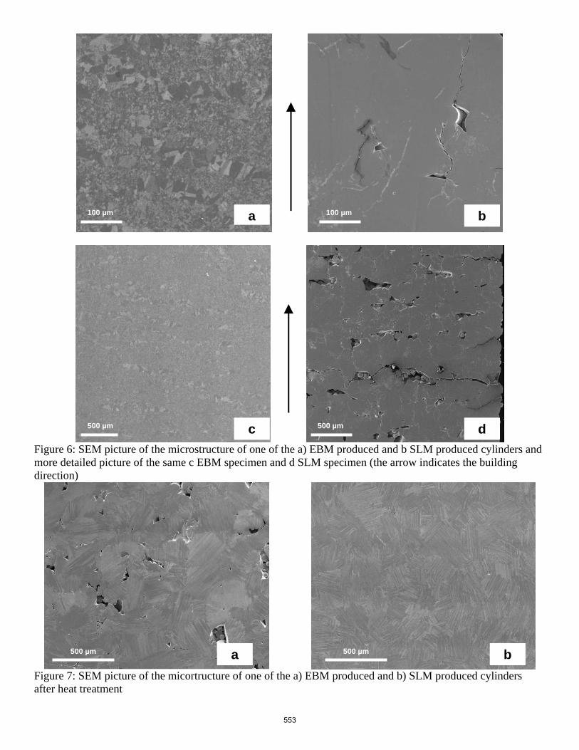
Figure 6: SEM picture of the microstructure of one of the a) EBM produced and b SLM produced cylinders and more detailed picture of the same c EBM specimen and d SLM specimen (the arrow indicates the building direction)
Figure 7: SEM picture of the micortructure of one of the a) EBM produced and b) SLM produced cylinders after heat treatment
100 µm a b 100 µm
c d 500 µm 500 µm
500 µm 500 µm a b
553
As no clear distinction in the microstructure of the SLM specimens could be made and thus no real comparison of SLM and EBM produced microstructure could be made, both types of specimens were treated with a heat treatment. In Figure 7 the microstructure of both EBM and SLM specimens after the heat treatment of 2h at 1400°C (above the alpha transition temperature) can be seen. It can be observed that both samples have changed into the same fine lamellar microstructure. The pores caused by unmolten powder can still be observed in the SLM microstructure. Seven of the as-produced SLM specimens and eleven of the as-produced EBM specimens were mechanically tested under quasi static compression. Compression test were chosen instead of tensile testing because of the simpler testing geometry. For compression simple cylinders are sufficient while using tensile test complex tensile bars have to be produced or eroded out of a cylinder. The SLM specimens were only tested at room temperature as their high porosity already lead to poor results at room temperature. The EBM specimens were tested at room temperature (red curves; 2 specimens), at 700°C (blue curves; three specimens), at 800°C (rose and turquoise curve; three specimens) and at 850°C (green curves, three specimens). The poor results of the SLM specimens are not surprising when regarding the density values of the specimens of around 90%. The Young’s Modulus could be estimated to an arithmetic value of 50 ± 13 GPa which is around a third of the normal value. It is not surprising that the Young’s modulus is much smaller than expected as compression testing delivers normally a much smaller Young’s modulus than tensile testing. Also the ultimate compressive stress lies with a value of 612 ± 56 MPa far beyond normal results of titanium aluminides [12]. The compressive strain of 1.98 ± 0.55% would be a good result for tensile testing but compression testing normally generates values of up to 20-30%. The overall performance of the SLM parts in the mechanical testing can very well be explained through the poor values of density. Further studies of the mechanical properties are not performed until the density can be enhanced to higher values. The results from the EBM specimens then again show some really difference to the SLM specimens. At room temperature they achieve an ultimate compressive stress value of 1800 MPa which is in good agreement with other publications. The compressive strain of the samples however exceed the normal values of 20%. Also at higher temperatures the values of the compressive strain stay this high. The values for the ultimate compressive stress at higher temperatures (see Table 2) lie beneath the typical values from the literature. This effect results probably from the small grain size which makes the material at higher temperature more vulnerable to the effects of creep. The compressive strain values stay mostly at the same high level. It has to be taken in account, that the value of 15% for 850°C is the arithmetic mean of 33%, 8% and 6%. So even at high temperatures some specimens still perform at high levels while others fail much earlier. The Young’s modulus at room temperature delivers the same value as the one of the SLM specimens. With higher temperature the value drops to 32 GPa. Table 2: Results from the compression tests of the EBM specimens at room and at higher temperature Temperature
(°C) Young’s Modulus
(GPa) Ultimate compressive stress
(MPa) Stress at offset yield
(MPa) Compressive strain
(%)
RT 54 1800 544 40 700 42 810 460 31 800 32 540 419 33 850 39 418 339 15
554

Figure 8 Results of the compression test a at room temperature of the as produced SLM specimens and b of the as produced EBM specimens at room temperature and at 700, 800 and 850°C
Summary and Conclusion
In this work we presented the differences between SLM and EBM produced cylindrical specimens of Ti-(46-48)Al-2Cr-2Nb. Although both processes are fairly similar to each other the results from the two techniques vary. With EBM working under a vacuum and with preheated powder the results in density exceeds the one of SLM. EBM produced specimens showed an as produced density of around 98 % density with only small spherical pores. With additional hipping of the specimens the density can be enhanced to a value of >99 %. The microstructure of the EBM specimens exhibits a bimodal microstructure. An altering pattern of bigger (still smaller than 50 µm) and smaller (below 10 µm) grains can be observed. The mechanical properties of the EBM specimens under compression are comparable to those produced by conventional techniques. The SLM produced microstructure is difficult to determine as pores and cracks do lead to a lost in contrast under SE contrast. Under BSE contrast different features such as unmolten areas or melt tracks can be observed. The maximum achievable density up till now lies around 97 %. But as the residual porosity is caused by cracks in the structure the mechanical performance under compression is poor. So fare the EBM process with preheating of the powder and the vacuum surrounding during building seems to fit better for the additive production of TiAl. In the future a main focus has to be set on the optimization of the process parameters of the SLM process and the implementation of a heater to reduce thermal tension during cooling.
References
[1] S. Herter: Spanbildung und Randzonenbeeinflussung beim Drehen intermetallischer Titaniumaluminide. thesis (2010) Technische Universität Berlin [2] Loria EA. Quo vadis gamma titanium aluminide. Intermetallics 2001;9:997-1001. [3] Appel F, Oehring M, Wagner R. Novel design concepts for gamma-base titanium aluminide alloys. Intermetallics 2000;8:1283-312 [4] I. Shishkovsky, Y. Morozov, I.Smurov: Applied Surface Science 2009; 255, 5565 [5] C. Leyens: Titan und Titanlegierungen Wiley-VCH, Weinheim, 2002, 380 [6] Wu X. Review of alloy and process development of TiAl alloys. Intermetallics 2006;14:1114-22.
Compressive strain (%) Compressive strain (%)
RT
700°C
800°C
850°C
555
[7] Lamirand M, Bonnantien JL, Ferrière G, Guérin S, Chevalier JP. Properties of Ti-48Al-2Cr-2Nb with fully lamellar and duplex microstructure. Metallurgical and Materials Transactions A 2006;37:2369-78. [8] Lasalmonie A. Intermetallics: why is it so difficult to introduce them in gas turbine engine. Intermetallics 2006;14:1123-9. [9] S. Biamino, A. Penna, U. Ackelid, S. Sabbadini, O. Tassa, P. Fino, M. Pavese, P. Gennaro,C. Badini Electron beam melting of Tie48Ale2Cre2Nb alloy: Microstructure and mechanical properties investigation [10] Hu D. Effect of composition on grain refinement in TiAl-based alloys. Intermetallics 2001;9:1037-43. [11] Wu X. Review of alloy and process development of TiAl alloys. Intermetallics 2006;14:1114-22. [12] M.Shazly, V. Prakash, S.Draper, Mechanical behavior of Gamma-Met PX under uniaxial loading at elevated temperatures and high strain rates, International Journal of Solids and Structures 2004, 41; 22-23 :6485-6503 [13] Kruth, J.P., Froyen, L., Van Vaerenbergh, J., Mercelis, P., Rombouts, M., & Lauwers, B. 2004. Selective laser melting of iron-based powder. Journal of Materials Processing Technology, 149, (1-3) 616-622 [14] I. Yadroitsev, I. Smurov, Surface Morphology in Selective Laser Melting of Metal Powders, Physics Procedia, Volume 12, Part 1, Lasers in Manufacturing 2011 - Proceedings of the Sixth International WLT Conference on Lasers in Manufacturing, 2011, Pages 264-270, ISSN 1875-3892
556
Related Documents