A synchrotron-based kilowatt-level radiation source for EUV lithography Bocheng Jiang Shanghai Advanced Research Institute Chao Feng ( [email protected] ) Shanghai Advanced Research Institute Changliang Li Shanghai Advanced Research Institute Zhenghe Bai National Synchrotron Radiation Laboratory, USTC Weishi Wan ShanghaiTech University Dao Xiang Shanghai Jiao Tong University Qiang Gu Shanghai Advanced Research Institute Kun Wang University of the Chinese Academy of Sciences Qinglei Zhang Shanghai Advanced Research Institute Dazhang Huang Shanghai Advanced Research Institute senyu Chen Institute of High Energy Physics Research Article Keywords: EUV, laser-produced plasma (LPP), SSMB, ADM, beam energy Posted Date: October 27th, 2021 DOI: https://doi.org/10.21203/rs.3.rs-1001917/v1 License: This work is licensed under a Creative Commons Attribution 4.0 International License. Read Full License

Welcome message from author
This document is posted to help you gain knowledge. Please leave a comment to let me know what you think about it! Share it to your friends and learn new things together.
Transcript
A synchrotron-based kilowatt-level radiation sourcefor EUV lithographyBocheng Jiang
Shanghai Advanced Research InstituteChao Feng ( [email protected] )
Shanghai Advanced Research InstituteChangliang Li
Shanghai Advanced Research InstituteZhenghe Bai
National Synchrotron Radiation Laboratory, USTCWeishi Wan
ShanghaiTech UniversityDao Xiang
Shanghai Jiao Tong UniversityQiang Gu
Shanghai Advanced Research InstituteKun Wang
University of the Chinese Academy of SciencesQinglei Zhang
Shanghai Advanced Research InstituteDazhang Huang
Shanghai Advanced Research Institutesenyu Chen
Institute of High Energy Physics
Research Article
Keywords: EUV, laser-produced plasma (LPP), SSMB, ADM, beam energy
Posted Date: October 27th, 2021
DOI: https://doi.org/10.21203/rs.3.rs-1001917/v1
License: This work is licensed under a Creative Commons Attribution 4.0 International License. Read Full License

Version of Record: A version of this preprint was published at Scienti�c Reports on February 28th, 2022.See the published version at https://doi.org/10.1038/s41598-022-07323-z.
A synchrotron-based kilowatt-level radiation source for EUV
lithography
Bocheng Jiang 1,2,
, Chao Feng 1,2*
, Changliang Li 1, Zhenghe Bai
3, Weishi Wan
4, Dao Xiang
5,
Qiang Gu 1,2
, Kun Wang 1,2,6
, Qinglei Zhang1,Dazhang Huang
1,2,Senyu Chen7
1Shanghai Advanced Research Institute, Chinese Academy of Sciences,
Shanghai 201204, China 2Shanghai Institute of Applied Physics, Chinese Academy of Sciences,
Shanghai 201800, China 3National Synchrotron Radiation Laboratory, USTC,
Hefei 230029, China 4School of Physical Science and Technology, ShanghaiTech University, Shanghai 201210,
China 5Key Laboratory for Laser Plasmas (Ministry of Education),School of Physics and
Astronomy,Shanghai Jiao Tong University, Shanghai 200240, China 6University of the Chinese Academy of Sciences,
Beijing 100049, China 7Institute of High energy physics, Chinese Academy of Sciences,Beijing 100049, China
A compact damping ring with limited circumference of about 160 m is proposed
for producing kilowatt-level coherent EUV radiation. The electron bunch in the ring is
modulated by a 257nm wavelength laser with the help of the angular dispersion
induced micro-bunching method [C. Feng and Z. Zhao, Sci. Rep. 7, 4724 (2017)].
Coherent radiation at 13.5 nm with an average power of about 2.5 kW can be
achieved with the state-of-the-art accelerator and laser technologies.
I. Introduction
Radiation from accelerator based light sources for optical lithography had been
studied for a long time [1, 2]. Accelerator based light sources for lithography gets
several advantages. It is a clean light source without debris contaminating the optics
and it is convenient tuning the wavelength without a major technical change. It has
been confirmed by the semiconductor industry that 13.5nm wavelength extreme
ultraviolet (EUV) lithography will be the route for edge wafer manufacturing. High
power EUV light source is one of the key technologies for EUV lithography. The
EUV source of average power beyond 500W is the cutting edge of the research both
for laser-produced plasma (LPP) light sources and accelerator based light sources.
Yet, the average power of the spontaneous EUV radiation from an electron
storage ring is only several watts even with extremely high beam current and long
undulators. Using micro-bunched electron beams is currently the most effective way
to enhance the average power of accelerator based light source since the output power
is proportional to square of the number of electrons in the micro-bunches [3, 4]. For
storage rings, the leading concept for realizing this kind of light source is the
steady-state micro-bunching (SSMB) [5-7]. Currently, one of the critical issues of
SSMB is how to further compress the micro-bunch to make it shorter than the EUV
wavelength on a turn-by-turn basis.
Micro-bunches with durations at the EUV and soft X-ray wavelength scale can be
achieved by utilizing the angular dispersion induced micro-bunching (ADM)
technique [8], which can precisely tailor the electron beam longitudinal distribution
with the aid of an optical laser. With proper setting of the modulation amplitude and
the dispersion chicane, the bunching factor can be written: 𝑏𝑏𝑛𝑛 = 𝐽𝐽𝑛𝑛(𝑛𝑛𝑘𝑘𝑠𝑠𝜉𝜉 𝛥𝛥𝛥𝛥𝛥𝛥 )𝑒𝑒−12(𝑛𝑛𝑘𝑘𝑠𝑠𝜂𝜂𝜎𝜎𝑦𝑦 ′)2
, (1)
where 𝑏𝑏𝑛𝑛 is the bunching factor of the nth
harmonic, 𝑘𝑘𝑠𝑠 is the wave number of
the seed laser, ξ, η are the momentum compaction and dispersion function of the
dispersive chicane respectively, γ is the relativistic parameter for the mean beam
energy, ∆γ is the energy modulation amplitude induced by the seed laser. 𝜎𝜎𝑦𝑦 ′ is the
vertical angular divergence of the electron beam. When vertical angular divergence of
the electron beam is extraordinary small, unprecedented high harmonic can be
achieved
However, this manipulation processes, or so called the modulation, will increase
the electron beam energy spread and the vertical emittance, resulting a limited
repetition rate [9] even with a demodulation [10] that cancels most parts of the
modulation. For the EUV radiation purpose, the beam energy is optimized to a few
hundreds of MeV, for which the synchrotron radiation damping is very weak, the
damping time is several tens or even hundreds of milliseconds. The residual
perturbation caused by the modulation needs thousands of turns being damped down.
A storage ring with shorter damping time is highly desired to eliminate the
perturbations rapidly and to achieve a higher modulation repetition rate as well as
getting higher average radiation power.
Damping rings have been widely investigated for colliders [11, 12, 13]. Damping
wiggler is an indispensable device in the damping ring that reduces both the damping
time and transverse emittances. Nevertheless, the vertical focusing effect of strong
damping wiggler will significantly distort the linear beam optics, especially when the
beam magnetic rigidity (beam energy) is low (hundreds of MeV), sometimes the
periodic lattice solutions do not exist anymore [14]. In medium energy rings,
superconducting wigglers (SWs) with limited length are used for both colliders and
synchrotron radiation facilities [15, 16, 17]. Long SWs in medium energy storage ring
will create huge radiation power, making great technical challenges for photon
absorbers [18]. Worse still, damping wiggler also contributes remarkable nonlinear
effects that may shrink the dynamic aperture (DA) and the momentum aperture (MA)
[19], resulting in a limited lifetime of the electron beam.
In this paper, a compact EUV light source that combines the dumping ring and
the ADM techniques is proposed. A special design for SWs with quadrupole poles
inside is given and studied. This design splits the focusing equally between horizontal
and vertical planes, making the transfer matrixes in both planes identical ones. As a
result, the beta functions in the wiggler can be very small which minimizes the
nonlinear effects. The MA of the damping ring is optimized to a large value and a
dedicated demodulation bypass line is given to ensure a reasonable beam lifetime for
high current operation. Three-dimensional simulations have been performed and the
results indicate the generation of kilowatt-level EUV radiation at 13.5 nm with current
available technologies.
II. Equally focused wiggler
The wiggler magnet with wide enough poles present a longitudinal field written
as [14], 𝐵𝐵𝑧𝑧 = 𝐵𝐵0 sin�𝑘𝑘𝑝𝑝𝑧𝑧� sinh�𝑘𝑘𝑝𝑝𝑦𝑦� = 𝐵𝐵0 sin�𝑘𝑘𝑝𝑝𝑧𝑧� �𝑘𝑘𝑝𝑝𝑦𝑦 + (𝑘𝑘𝑝𝑝𝑦𝑦)33!
+⋯�, (2)
where z is the longitudinal direction along beam axis. When the beam wiggles in
the horizontal plane, 𝐵𝐵𝑧𝑧 will produce a vertical force. In Eq.(2), 𝐵𝐵𝑧𝑧 is proportional to
y for the first order approximation which acts as a quadrupole field in vertical (V)
plane. While in horizontal (H) plane, the beam acts likely passing through a drift. The
transfer map difference between V/H planes makes it difficult to match in the ring.
This difference can be eliminated by designing the wiggler poles as wedge
magnets [14]. This method is effective when magnetic field is not so strong. For the
strong wigglers such as SWs, the limited wedge angle is insufficient to balance the
focus between V/H planes. Several types of planar wigglers, such as the alternate pole
canting wiggler, had been proposed to produce additional horizontal focusing [20, 21].
However, these field manipulation methods are convenient for the permanent magnet
wiggler. While for SWs, the magnet field is beyond saturation of the yoke, the
quadrupole field quality is difficult to control by introducing gradient of the poles.
Here we propose inserting sets of quadrupoles in the wiggler to balance the
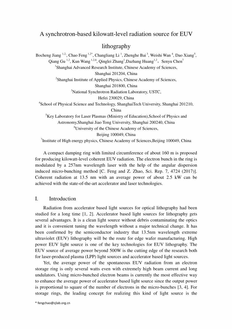
transverse focuses in both planes. The schematic layout of the design is given in Fig.1.
where the poles of orange color are quadrupoles. The equally focused wiggler is
composed by a segment of wiggler followed by a quadupole and in repetition. This
model is simulated by ELEGANT code [22] with canonical integration method. The
structure is compact and effective, identical transfer matrices can be found in both
planes with proper choice of the parameters as shown in Table 1.
Figure 1. Schematic view of equally focused wiggler
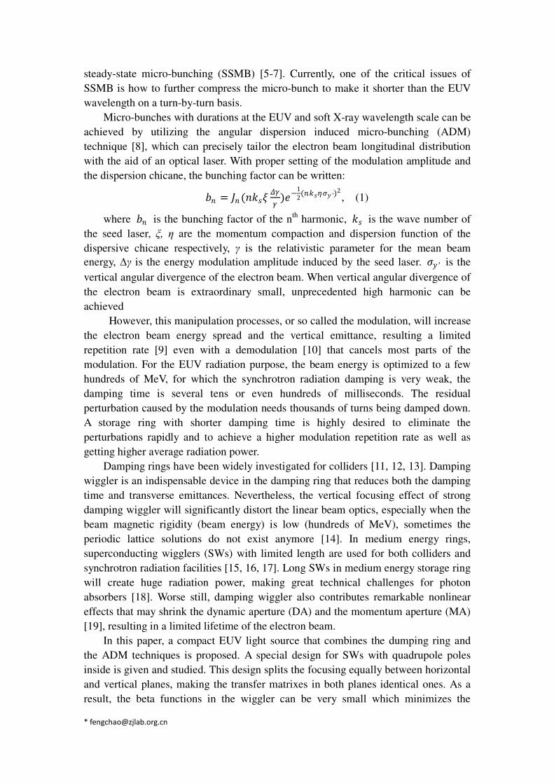
The optimized Twiss parameters are shown in Fig 2, where the beta function is
low and in periodicity. In this setting, the technical challenges had been fully
considered, the wiggler is segmented to 3 sections, each with two segments 0.9m pole
length sandwiched by two 0.1m and one 0.2m long quadrupoles. Two 0.4m drift space
at both ends for cryogenic tank had been reserved, make sure a single wiggler to a
reasonable length of 3.0m. The peak magnetic field is 5.66 Tesla which is achievable
with superconducting techniques.
Table I. Beam parameters for equally focused superconducting wiggler
Parameters Value
Beam energy (MeV) 1000
Period length (mm) 60
Peak magnetic field (Tesla) 5.66
Quad Gradient family 1 (T/m) 13.1
Quad Gradient family 2 (T/m) 10.3
Pole gap (mm) 10
Figure 2. Twiss parameters in the wiggler.
Since the betatron phase advance of the wiggler is 2π, there are many π nodes as
shown in Fig. 2, which cancels most parts of the nonlinear kicks and shapes a good
nonlinear performance, as we will show in the following section.
Unlike the Robinson wiggler [23, 24], for this study the wiggler is place at the
dispersion free straight section, the quadrupole fields combining with wiggler field
will not redistribute the damping partition number.
It is worth to stress here that the helical undulator can also produce both
horizontal and vertical focus naturally. However, by increasing the field of the helical
undualtor, it will excite vertical emittance which is not compatible with the ADM as a
tiny vertical emittance is highly required. This is the reason that helical undulator is
not adopted in our design.
III. Damping ring with large momentum acceptance
For high power EUV radiation from a micro-bunched electron beam, we needs
beam in a storage ring with peak current more than 100A, this may result severe intra
beam scattering (IBS) and Touschek effects. The relative high beam energy of 1GeV
is chosen to mitigate those effects yet the energy is still suitable for EUV radiation.
The Touschek lifetime strongly depends on the MA. For a low energy and high peak
current ring, local momentum aperture (LMA) is the majorly consideration of the
lattice design which is bounded by the nonlinear beam dynamics. LMA is usually
lower in the arc where the dispersion is nonzero. The LMA will be reduced as the
increase of the dispersion. The way to reduce the dispersion without rapidly rising the
sextupole strength is to increase the number of the lattice cells. While considering the
ring needs to be as compact as possible to get cost competitive, the number of cells is
eventually chosen to be 8. There are 8 straight sections, 6 of them are accommodated
by the SWs, the other 2 are for injection, extraction and RF system.
Triple-bend achromat (TBA) lattice was designed for the ring. To have a compact
configuration, all bending magnets are combined-function ones. There are 3 families
of chromatic sextupoles in the lattice. The two defocusing sextupoles of the same
family close to the matching bending magnets have the highest integrated strength,
and the horizontal betatron phase advance between these two sextupoles is about π, which is beneficial for enlarging horizontal dynamic aperture. The fractional parts of
the horizontal and vertical tunes of each lattice cell are near (3/8, 5/8) for nonlinear
dynamics cancellation over 8 cells.
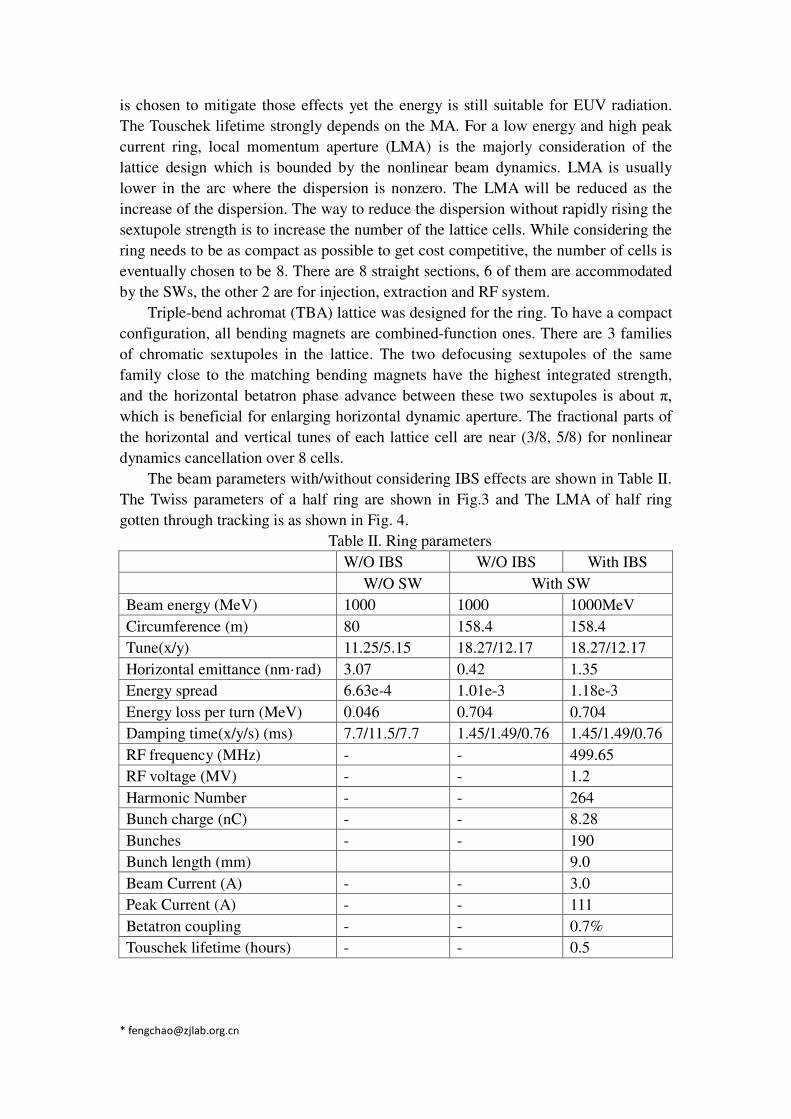
The beam parameters with/without considering IBS effects are shown in Table II.
The Twiss parameters of a half ring are shown in Fig.3 and The LMA of half ring
gotten through tracking is as shown in Fig. 4.
Table II. Ring parameters
W/O IBS W/O IBS With IBS
W/O SW With SW
Beam energy (MeV) 1000 1000 1000MeV
Circumference (m) 80 158.4 158.4
Tune(x/y) 11.25/5.15 18.27/12.17 18.27/12.17
Horizontal emittance (nm·rad) 3.07 0.42 1.35
Energy spread 6.63e-4 1.01e-3 1.18e-3
Energy loss per turn (MeV) 0.046 0.704 0.704
Damping time(x/y/s) (ms) 7.7/11.5/7.7 1.45/1.49/0.76 1.45/1.49/0.76
RF frequency (MHz) - - 499.65
RF voltage (MV) - - 1.2
Harmonic Number - - 264
Bunch charge (nC) - - 8.28
Bunches - - 190
Bunch length (mm) 9.0
Beam Current (A) - - 3.0
Peak Current (A) - - 111
Betatron coupling - - 0.7%
Touschek lifetime (hours) - - 0.5
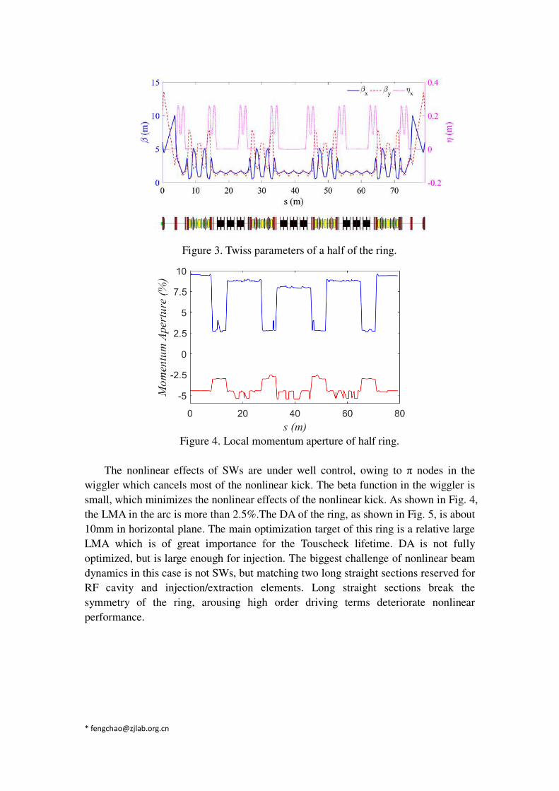
Figure 3. Twiss parameters of a half of the ring.
Figure 4. Local momentum aperture of half ring.
The nonlinear effects of SWs are under well control, owing to π nodes in the
wiggler which cancels most of the nonlinear kick. The beta function in the wiggler is
small, which minimizes the nonlinear effects of the nonlinear kick. As shown in Fig. 4,
the LMA in the arc is more than 2.5%.The DA of the ring, as shown in Fig. 5, is about
10mm in horizontal plane. The main optimization target of this ring is a relative large
LMA which is of great importance for the Touscheck lifetime. DA is not fully
optimized, but is large enough for injection. The biggest challenge of nonlinear beam
dynamics in this case is not SWs, but matching two long straight sections reserved for
RF cavity and injection/extraction elements. Long straight sections break the
symmetry of the ring, arousing high order driving terms deteriorate nonlinear
performance.
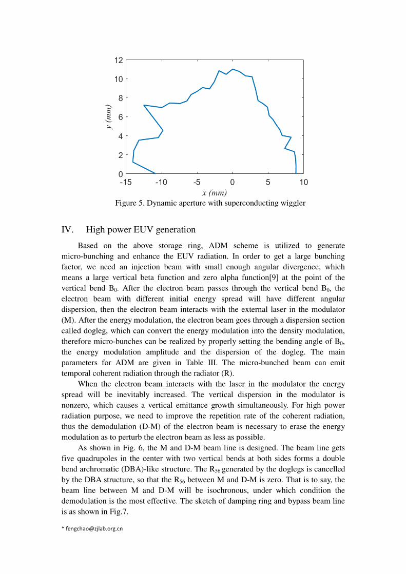
Figure 5. Dynamic aperture with superconducting wiggler
IV. High power EUV generation
Based on the above storage ring, ADM scheme is utilized to generate
micro-bunching and enhance the EUV radiation. In order to get a large bunching
factor, we need an injection beam with small enough angular divergence, which
means a large vertical beta function and zero alpha function[9] at the point of the
vertical bend B0. After the electron beam passes through the vertical bend B0, the
electron beam with different initial energy spread will have different angular
dispersion, then the electron beam interacts with the external laser in the modulator
(M). After the energy modulation, the electron beam goes through a dispersion section
called dogleg, which can convert the energy modulation into the density modulation,
therefore micro-bunches can be realized by properly setting the bending angle of B0,
the energy modulation amplitude and the dispersion of the dogleg. The main
parameters for ADM are given in Table III. The micro-bunched beam can emit
temporal coherent radiation through the radiator (R).
When the electron beam interacts with the laser in the modulator the energy
spread will be inevitably increased. The vertical dispersion in the modulator is
nonzero, which causes a vertical emittance growth simultaneously. For high power
radiation purpose, we need to improve the repetition rate of the coherent radiation,
thus the demodulation (D-M) of the electron beam is necessary to erase the energy
modulation as to perturb the electron beam as less as possible.
As shown in Fig. 6, the M and D-M beam line is designed. The beam line gets
five quadrupoles in the center with two vertical bends at both sides forms a double
bend archromatic (DBA)-like structure. The R56 generated by the doglegs is cancelled
by the DBA structure, so that the R56 between M and D-M is zero. That is to say, the
beam line between M and D-M will be isochronous, under which condition the
demodulation is the most effective. The sketch of damping ring and bypass beam line
is as shown in Fig.7.
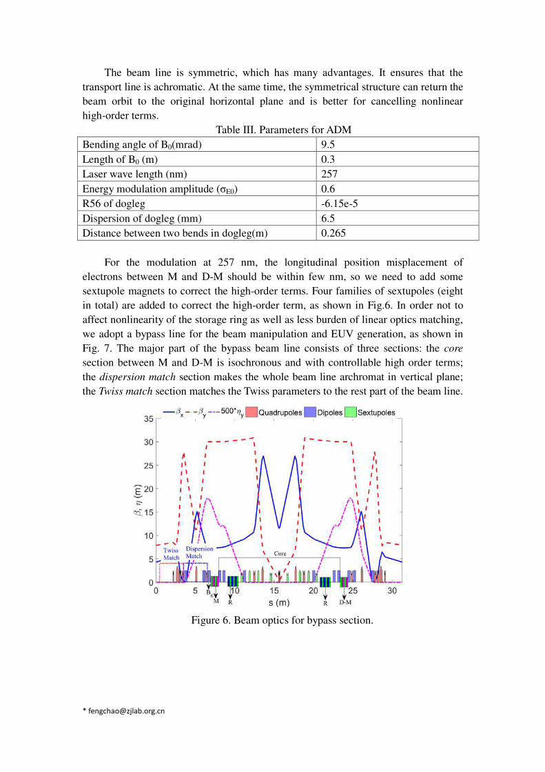
The beam line is symmetric, which has many advantages. It ensures that the
transport line is achromatic. At the same time, the symmetrical structure can return the
beam orbit to the original horizontal plane and is better for cancelling nonlinear
high-order terms.
Table III. Parameters for ADM
Bending angle of B0(mrad) 9.5
Length of B0 (m) 0.3
Laser wave length (nm) 257
Energy modulation amplitude (σE0) 0.6
R56 of dogleg -6.15e-5
Dispersion of dogleg (mm) 6.5
Distance between two bends in dogleg(m) 0.265
For the modulation at 257 nm, the longitudinal position misplacement of
electrons between M and D-M should be within few nm, so we need to add some
sextupole magnets to correct the high-order terms. Four families of sextupoles (eight
in total) are added to correct the high-order term, as shown in Fig.6. In order not to
affect nonlinearity of the storage ring as well as less burden of linear optics matching,
we adopt a bypass line for the beam manipulation and EUV generation, as shown in
Fig. 7. The major part of the bypass beam line consists of three sections: the core
section between M and D-M is isochronous and with controllable high order terms;
the dispersion match section makes the whole beam line archromat in vertical plane;
the Twiss match section matches the Twiss parameters to the rest part of the beam line.
Figure 6. Beam optics for bypass section.
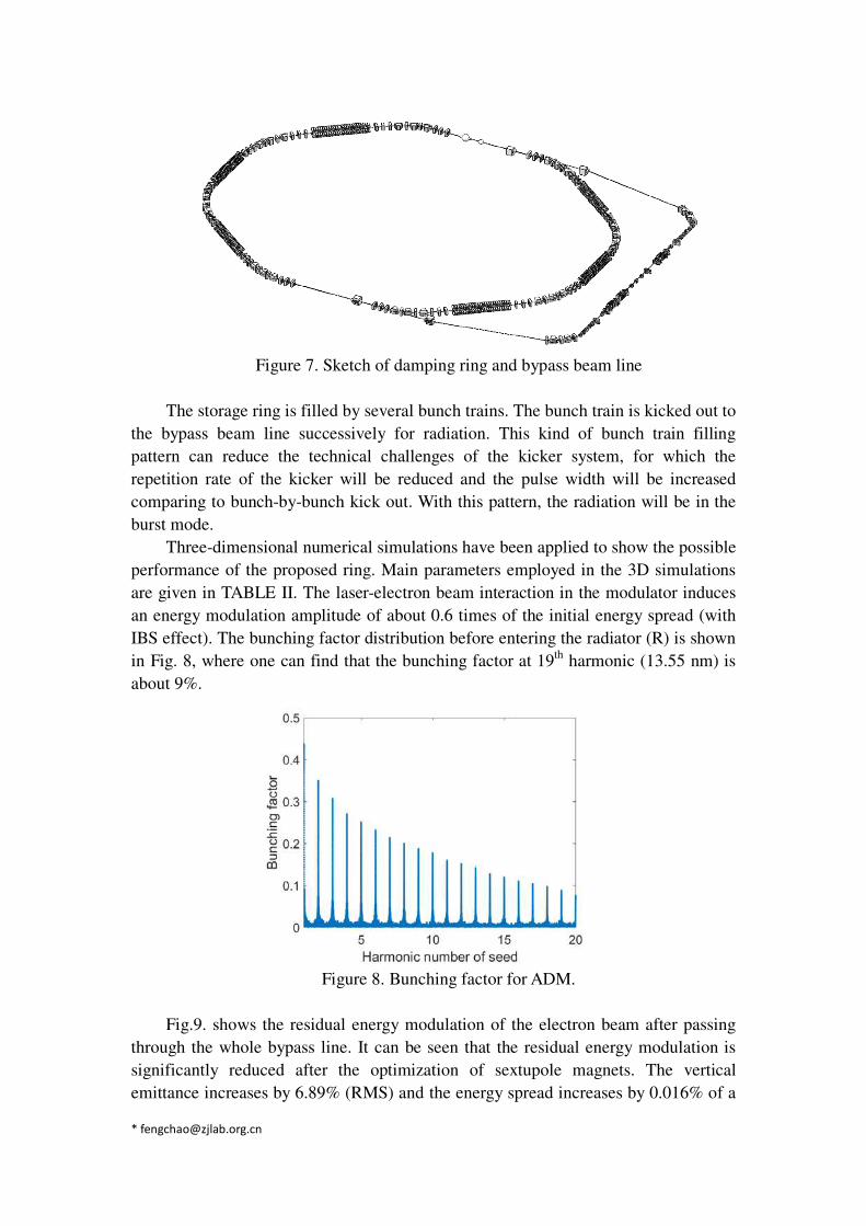
Figure 7. Sketch of damping ring and bypass beam line
The storage ring is filled by several bunch trains. The bunch train is kicked out to
the bypass beam line successively for radiation. This kind of bunch train filling
pattern can reduce the technical challenges of the kicker system, for which the
repetition rate of the kicker will be reduced and the pulse width will be increased
comparing to bunch-by-bunch kick out. With this pattern, the radiation will be in the
burst mode.
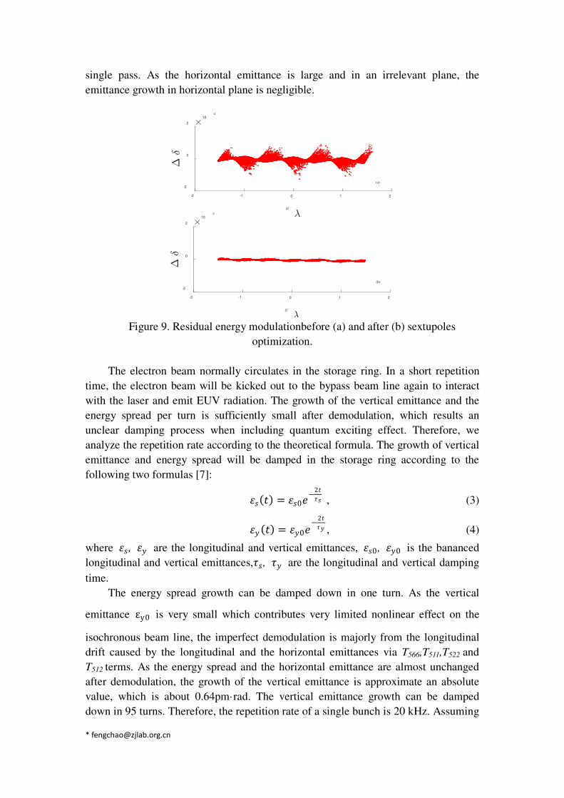
Three-dimensional numerical simulations have been applied to show the possible
performance of the proposed ring. Main parameters employed in the 3D simulations
are given in TABLE II. The laser-electron beam interaction in the modulator induces
an energy modulation amplitude of about 0.6 times of the initial energy spread (with
IBS effect). The bunching factor distribution before entering the radiator (R) is shown
in Fig. 8, where one can find that the bunching factor at 19th
harmonic (13.55 nm) is
about 9%.
Figure 8. Bunching factor for ADM.
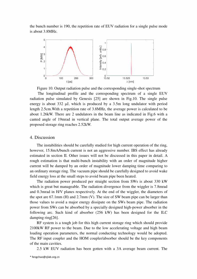
Fig.9. shows the residual energy modulation of the electron beam after passing
through the whole bypass line. It can be seen that the residual energy modulation is
significantly reduced after the optimization of sextupole magnets. The vertical
emittance increases by 6.89% (RMS) and the energy spread increases by 0.016% of a
single pass. As the horizontal emittance is large and in an irrelevant plane, the
emittance growth in horizontal plane is negligible.
Figure 9. Residual energy modulationbefore (a) and after (b) sextupoles
optimization.
The electron beam normally circulates in the storage ring. In a short repetition
time, the electron beam will be kicked out to the bypass beam line again to interact
with the laser and emit EUV radiation. The growth of the vertical emittance and the
energy spread per turn is sufficiently small after demodulation, which results an
unclear damping process when including quantum exciting effect. Therefore, we
analyze the repetition rate according to the theoretical formula. The growth of vertical
emittance and energy spread will be damped in the storage ring according to the
following two formulas [7]: 𝜀𝜀𝑠𝑠(𝑡𝑡) = 𝜀𝜀𝑠𝑠0𝑒𝑒−2𝑡𝑡𝜏𝜏𝑠𝑠 , (3) 𝜀𝜀𝑦𝑦(𝑡𝑡) = 𝜀𝜀𝑦𝑦0𝑒𝑒−2𝑡𝑡𝜏𝜏𝑦𝑦 , (4)
where 𝜀𝜀𝑠𝑠, 𝜀𝜀𝑦𝑦 are the longitudinal and vertical emittances, 𝜀𝜀𝑠𝑠0, 𝜀𝜀𝑦𝑦0 is the bananced
longitudinal and vertical emittances,𝜏𝜏𝑠𝑠, 𝜏𝜏𝑦𝑦 are the longitudinal and vertical damping
time.
The energy spread growth can be damped down in one turn. As the vertical
emittance εy0 is very small which contributes very limited nonlinear effect on the
isochronous beam line, the imperfect demodulation is majorly from the longitudinal
drift caused by the longitudinal and the horizontal emittances via T566,T511,T522 and
T512 terms. As the energy spread and the horizontal emittance are almost unchanged
after demodulation, the growth of the vertical emittance is approximate an absolute
value, which is about 0.64pm·rad. The vertical emittance growth can be damped
down in 95 turns. Therefore, the repetition rate of a single bunch is 20 kHz. Assuming
-2 -1 0 1 2
z/
-2
0
2
10
-3
-2 -1 0 1 2
z/
-2
0
2
10
-3
(a)
(b)
the bunch number is 190, the repetition rate of EUV radiation for a single pulse mode
is about 3.8MHz.
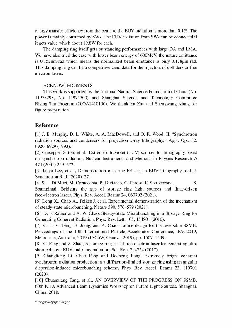
Figure 10. Output radiation pulse and the corresponding single-shot spectrum
The longitudinal profile and the corresponding spectrum of a single EUV
radiation pulse simulated by Genesis [25] are shown in Fig.10. The single pulse
energy is about 332 μJ, which is produced by a 3.5m long undulator with period
length 2.5cm.With a repetition rate of 3.8MHz, the average power is calculated to be
about 1.26kW. There are 2 undulators in the beam line as indicated in Fig.6 with a
canted angle of 19mrad in vertical plane. The total output average power of the
proposed storage ring reaches 2.52kW.
4. Discussion
The instabilities should be carefully studied for high current operation of the ring,
however, 15.8mA/bunch current is not an aggressive number. IBS effect has already
estimated in section II. Other issues will not be discussed in this paper in detail. A
rough estimation is that multi-bunch instability with an order of magnitude higher
current will be damped by an order of magnitude lower damping time comparing to
an ordinary storage ring. The vacuum pipe should be carefully designed to avoid wake
field energy loss at the small steps to avoid beam pipe been heated.
The radiation power produced per straight section from SWs is about 330 kW
which is great but manageable. The radiation divergence from the wiggler is 7.8mrad
and 0.3mrad in H/V planes respectively. At the end of the wiggler, the diameters of
the spot are 67.1mm (H) and 2.7mm (V). The size of SW beam pipe can be larger than
those values to avoid a major energy dissipate on the SWs beam pipe. The radiation
power from SWs can be absorbed by a specially designed high-power absorber in the
following arc. Such kind of absorber (256 kW) has been designed for the ILC
damping ring[26].
RF system is a tough job for this high current storage ring which should provide
2100kW RF power to the beam. Due to the low accelerating voltage and high beam
loading operation parameters, the normal conducting technology would be adopted.
The RF input coupler and the HOM coupler/absorber should be the key components
of the main cavities.
2.5 kW EUV radiation has been gotten with a 3A average beam current. The
energy transfer efficiency from the beam to the EUV radiation is more than 0.1%. The
power is mainly consumed by SWs. The EUV radiation from SWs can be connected if
it gets value which about 19.8W for each.
The damping ring itself gets outstanding performances with large DA and LMA.
We have also tried the case with lower beam energy of 600MeV, the nature emittance
is 0.152nm·rad which means the normalized beam emittance is only 0.178μm·rad.
This damping ring can be a competitive candidate for the injectors of colliders or free
electron lasers.
ACKNOWLEDGMENTS
This work is supported by the National Natural Science Foundation of China (No.
11975298, No. 11975300) and Shanghai Science and Technology Committee
Rising-Star Program (20QA1410100). We thank Ya Zhu and Shengwang Xiang for
figure preparation.
Reference
[1] J. B. Murphy, D. L. White, A. A. MacDowell, and O. R. Wood, II, “Synchrotron
radiation sources and condensers for projection x-ray lithography,” Appl. Opt. 32,
6920–6929 (1993).
[2] Guiseppe Dattoli, et al., Extreme ultraviolet (EUV) sources for lithography based
on synchrotron radiation, Nuclear Instruments and Methods in Physics Research A
474 (2001) 259–272.
[3] Jaeyu Lee, et al., Demonstration of a ring-FEL as an EUV lithography tool, J.
Synchrotron Rad. (2020). 27.
[4] S. Di Mitri, M. Cornacchia, B. Diviacco, G. Perosa, F. Sottocorona, S.
Spampinati, Bridging the gap of storage ring light sources and linac-driven
free-electron lasers, Phys. Rev. Accel. Beams 24, 060702 (2021).
[5] Deng X., Chao A., Feikes J. et al. Experimental demonstration of the mechanism
of steady-state microbunching. Nature 590, 576–579 (2021).
[6] D. F. Ratner and A. W. Chao, Steady-State Microbunching in a Storage Ring for
Generating Coherent Radiation, Phys. Rev. Lett. 105, 154801 (2010).
[7] C. Li, C. Feng, B. Jiang, and A. Chao, Lattice design for the reversible SSMB,
Proceedings of the 10th International Particle Accelerator Conference, IPAC2019,
Melbourne, Australia, 2019 (JACoW, Geneva, 2019), pp. 1507–1509.
[8] C. Feng and Z. Zhao, A storage ring based free-electron laser for generating ultra
short coherent EUV and x-ray radiation, Sci. Rep. 7, 4724 (2017).
[9] Changliang Li, Chao Feng and Bocheng Jiang, Extremely bright coherent
synchrotron radiation production in a diffraction-limited storage ring using an angular
dispersion-induced microbunching scheme, Phys. Rev. Accel. Beams 23, 110701
(2020).
[10] Chuanxiang Tang, et al., AN OVERVIEW OF THE PROGRESS ON SSMB,
60th ICFA Advanced Beam Dynamics Workshop on Future Light Sources, Shanghai,
China, 2018.
[11] D. Schoerling, F. Antoniou, A. Bernhard, et al, Design and system integration of
the superconducting wiggler magnets for the Compact Linear Collider damping rings,
Phys. Rev. Accel. Beams 15, 042401 (2012).
[12] M. Ehrlichman, W. Hartung, B. Heltsley, et al, Intrabeam scattering studies at the
Cornell Electron Storage Ring Test Accelerator, Phys. Rev. Accel. Beams 16, 104401
(2013).
[13] J. Crittenden, J. Conway, G. Dugan, et al, Investigation into electron cloud
effects in the International Linear Collider positron damping ring, Phys. Rev. Accel.
Beams 17, 031002 (2014).
[14] Particle Accelerator Physics II, H. Wiederman, Springer, Berlin, Heidelberg,
1993.
[15] S.V. Khrushchev, V.K. Lev, N.A. Mezentsev, E.G. Miginsky, V.A. Shkaruba, V.M.
Syrovatin, V.M. Tsukanov, 27-Pole 4.2 T wiggler for biomedical imaging and therapy
beam line at the Canadian light source, Nuclear Instruments and Methods in Physics
Research A 603 (2009) 7–9
[16] Z. Patel, E. Rial, A. George, et al, Insertion devices at Diamond Light Source: A
retrospective plus future developments, Proceedings of IPAC2017, Copenhagen,
Denmark, TUPAB116.
[17] M. Fedurin, P. Mortazavi, J. Murphy, et al, Upgrade alternatives for the NSLS
superconducting wiggler, Proceedings of PAC07, Albuquerque, New Mexico, USA,
TUPMS071.
[18] O. Malyshev, J. Lucas, N. Collomb, et al, Mechanical and vacuum design of the
wiggler section of the ILC damping rings, Proceedings of IPAC’10, Kyoto, Japan,
WEPE092.
[19] S. Leemann, A. Andersson, M. Eriksson, et al, Beam dynamics and expected
performance of Sweden’s new storage-ring light source: MAX IV, Phys. Rev. Accel.
Beams 12, 120701 (2009).
[20] G. Travish, and J. Rosenzweig, Strong focusing for planar undulators, AIP
Conference Proceedings 279, 276 (1992).
[21] J. Pfluger, Yu. M. Nikitina, Undulator schemes with the focusing properties for
the VUV-FEL at the TESLA Test Facility, TESLA FEL-Report 1996-2.
[22] Michael Borland, Tim Berenc, User’s Manual for Elegant, Program Version
2020.5.
[23] T. Goetsch, J. Feikes, M. Ries, G. Wüstefeld, Status of the ROBINSON Wiggler
Project at the METROLOGY Light Soruce, IPAC2015, Richmond, VA, USA, 2015.
[24] LI Jing-Yi, LIU Gong-Fa, XU Wei, LI Wei-Min, LI Yong-Jun, A possible
approach to reduce the emittance of HLS-II storagering using a Robinson wiggler,
Chinese Phys. C 37 107006
[25] S. Reiche, Genesis 1.3: a fully 3d time-dependent FEL simulation code, Nucl.
Instrum. Meth. A 429, 243 (1999)
[26] K. Zolotarev, et al., SR POWER DISTRIBUTION ALONG WIGGLER
SECTION OF ILC DR, Proceedings of IPAC’10, Kyoto, Japan, 2010, pp. 3569-3571.
Related Documents