OsecoElfab: Selecting rupture discs using API 520: Part 1, Section 4.3 OsecoElfab | 2021 White Paper Selecting rupture discs: A summary of API Standard 520: Part I, Section 4.3, 10 th edition Rupture discs, their uses, and steps for selecting the right one

Welcome message from author
This document is posted to help you gain knowledge. Please leave a comment to let me know what you think about it! Share it to your friends and learn new things together.
Transcript
OsecoElfab: Selecting rupture discs using API 520: Part 1, Section 4.3
OsecoElfab | 2021 White Paper
Selecting rupture discs: A summary ofAPI Standard 520: Part I, Section 4.3, 10th edition
Rupture discs, their uses, and steps for selecting the right one
OsecoElfab: Selecting rupture discs using API 520: Part 1, Section 4.3 3 2 OsecoElfab: Selecting rupture discs using API 520: Part 1, Section 4.3
ABSTRACT
API 520 Part I is a standard written and published by the American Petroleum Institute. It is the standard of preference in the selection of pressure relief devices in petrochemical applications. For rupture discs, this standard highlights the various types of devices, how to properly select them, and the sizing calculation used for selection. The tenth edition offers no notable changes from the ninth edition as it relates to rupture discs.
This paper summarises the key points from API 520 Part I, Section 4.3 (10th edition). It provides a concise definition of rupture discs, explains how they are used, and lists the various rupture disc designs. Finally, it outlines the process for selecting rupture discs. On many occasions, ASME Sec. VIII Div. I is referenced as this is the enforceable code for rupture discs in much of the United States.
When selecting a rupture disc, we would always recommend working with an engineer from a specialist pressure safety company such as OsecoElfab. This is to verify correct selection, and ensure safety and compliance.
Contributors
David ParnellMegan MillerDaniel Reece
Laura Ball
US office:1701 W. Tacoma, Broken Arrow, OK 74912
+1 (918) 258-5626+1 (800) 395-3475 (toll free)[email protected]
UK office:Alder Road, North Shields, Tyne & Wear NE29 8SD
+44 (0)191 293 [email protected]
OsecoElfab
www.osecoelfab.com
OsecoElfab: Selecting rupture discs using API 520: Part 1, Section 4.3 3
A rupture disc is a non-reclosing, non-mechanical pressure relief device (PRD) used to protect vessels, piping, and other systems from excessive pressure and/or vacuum. An advantage of using rupture discs is their reliability because there are no moving parts. Additionally, they activate faster than other types of PRD, and they can be made from higher alloys than other PRDs due to their lower weight.
Rupture discs can be specified for use in nearly any fluid regime. The type of fluid media will affect the opening characteristics of a rupture disc at the time of bursting. This, in turn, can affect the resistance to flow characteristics of a particular rupture disc during a relief condition. The National Board of Boiler and Pressure Vessel Inspectors publishes a list of these resistance to flow characteristics, which are defined using a Kr value. For applications where the process fluid is compressible, designers should use the published values for Krg or Krgl. For applications where the process fluid is incompressible, the published values for Krl or Krgl should be used.
Rupture discs are temperature sensitive devices. In general, a rupture disc’s burst pressure will decrease as temperatures increase. By the same principle, a rupture disc’s burst pressure will increase as temperatures decrease. Due to this characteristic, a designer must make careful consideration of the relieving temperature when selecting and specifying a rupture disc.
Although rupture discs are known for their reliability, there are a few installation factors that will affect their performance: • Installing a rupture disc that is damaged or oriented in the incorrect direction can decrease or
increase the pressure it will burst. Care should always be taken in handling and installing rupture discs to avoid this concern.
• Some rupture disc designs can be sensitive to uneven torque of companion flanges or forces applied by misaligned piping. This can cause unplanned failure of a rupture disc in service.
How are rupture discs used?
Rupture discs are suitable for use as a single PRD, in systems designed with multiple PRDs, and in fire condition applications. Rupture discs are never to be used on power boilers or other fired vessels as described in ASME section I. Thy are suitable for applications on all other non-fired vessels as described in ASME Section VIII. The maximum burst pressure allowed for the discs in each instance is different: For rupture discs used as the sole or primary source of pressure relief, it is required that the marked burst pressure not exceed the maximum allowable working pressure (MAWP) of the vessel that is protected. For rupture discs installed in parallel to another PRD, the burst pressure must not exceed 105% of the MAWP. In a fire condition with a single rupture disc, the burst pressure shall not exceed 110% of the MAWP. In a fire condition with rupture discs installed in parallel, the burst pressure shall not exceed 116% of the MAWP.
WHAT IS A RUPTURE DISC?
OsecoElfab: Selecting rupture discs using API 520: Part 1, Section 4.3 5 4 OsecoElfab: Selecting rupture discs using API 520: Part 1, Section 4.3
Rupture discs are often installed in series with a Pressure Relief Valve (PRV). In these types of applications, the devices are considered ‘close coupled’, which limits shock loading on the relief valve during activation. Since rupture discs are differential pressure devices, there are some important design considerations to bear in mind when installing rupture discs in series with a PRV:
• First, a means of venting and monitoring pressure build up between the rupture disc and relief valve is required. This is often accomplished using an excess flow valve, trycock and/or a suitable pressure monitoring device such as a pressure gauge, pressure transducer, or pressure switch. In general, we recommend that when using a pressure switch, the alarm pressure of the switch should be set as low as possible.
• Second, it is important that the rupture disc is of a non-fragmenting design. This allows proper re-seating of the PRV and prevents damage to the valve disc. It is also common to find a rupture disc installed at the outlet of a PRV. In this case, it is important to consider any back pressure that may be present between the PRV outlet and rupture disc when selecting which PRV device to use.
In addition to installation under a PRV, it is also common to find two rupture discs installed in series. This is typically accomplished using a double disc holder or as two insert holders installed with a short spool piece placed between them. Since rupture discs are differential pressure devices, it is important that the same guidelines mentioned above for rupture discs in series with a PRV are used when installing two rupture discs in series. This design configuration is commonly used as a means to try and limit the superimposed back pressure on the upstream rupture disc. In this design scenario, the downstream rupture disc is specified at a lower pressure than the upstream disc to account for the superimposed back pressure.
Types of rupture disc
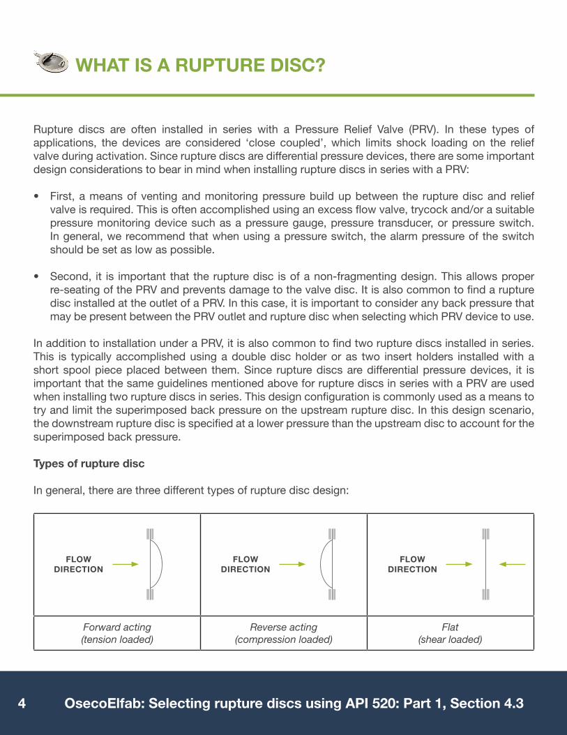
In general, there are three different types of rupture disc design:
WHAT IS A RUPTURE DISC?
Forward acting (tension loaded)
Reverse acting(compression loaded)
Flat (shear loaded)
FLOW DIRECTION
FLOW DIRECTION
FLOW DIRECTION

OsecoElfab: Selecting rupture discs using API 520: Part 1, Section 4.3 5
The table below summarizes the differences between these designs.
TYPES OF RUPTURE DISC
RUPTURE DISC TYPE
RUPTURE DISCMODEL
IMAGE
Forward acting:Solid Metal Rupture
Disc
Standard Rupture Disc (STD) 70%
Forward acting:Scored Rupture
Disc
Forward Acting Scored Disc (FAS)
90%
Forward acting:Composite Rupture
Disc
Composite Disc(F)CO
80%
Reverse acting:Scored Rupture
Disc
Precision Reverse Operating Rupture Disc
(PRO+)95%
Flat:e.g. GraphiteRupture Disc
Graphi-Tech 90%
N.B. API 520 Part I, section 4.3.3.5 highlights the use of reverse-acting rupture discs that use a knife-blade to activate the rupture disc and prevent fragmentation. OsecoElfab does not recommend the use of these types of rupture discs when used with a metal foil sealing membrane. It is common for rupture discs of this type to not activate when blades are not properly sharpened and maintained. Many other reverse-acting designs exist that outperform knife-blade types and are much safer.
OPERATING RATIO

OsecoElfab: Selecting rupture discs using API 520: Part 1, Section 4.3 7 6 OsecoElfab: Selecting rupture discs using API 520: Part 1, Section 4.3
Rupture disc holders consist of an inlet and outlet, and incorporate a seating surface for the rupture disc between. Rupture discs generally seal on a metal-to-metal seal that is often a raised surface at the seat of the inlet. This raised surface creates a stress concentration that results in a leak-tight seal. Typical insert-type holders are held together during installation using a side-lug and cap-screw that installs tangent to the outer diameter of the holder. Pre-torqued type holders allow for pre-installation and pre-loading of the rupture disc with the sealing surface of the holder. This type of holder is torqued using cap-screws installed in countersunk tapped holes along the flange connecting faces of the holder.
Welded cartridges
In addition to the holder types mentioned in API 520 Part I, welded rupture disc assemblies are becoming more prevalent as they provide a more robust PRD solution. For example, OsecoElfab offers the Oseco Safety Cartridge, HPSR and Pure-Gard as welded cartridge alternatives to disc-and-holder style rupture discs.
The Oseco Safety Cartridge is the most advanced, reliable, and safe type of rupture disc assembly available in the market today. The patented weld design and its use as the sealing mechanism for the assembly make it insensitive to uneven loading of the assembly in the companion flanges during installation.
Additionally, the welds are designed in a manner that prevents fugitive emissions and limits exposure of Operations and Maintenance personnel to the process fluids. The simplicity of the design prevents damage when handling, and provides a device that is much easier to install than traditional rupture disc holder assembly types. The Oseco Safety Cartridge is available with several different rupture disc types to meet the requirements of most every process application.
RUPTURE DISC-AND-HOLDER ASSEMBLIES AND WELDED CARTRIDGES
HPSR Pure-Gard
The Oseco Safety Cartridge™
OsecoElfab: Selecting rupture discs using API 520: Part 1, Section 4.3 7
When selecting a rupture disc for an application there are many process and device parameters to consider. As they all affect how a rupture disc will perform during a relief event, it is important to define them accurately.
Process parameters include:
Rupture disc parameters include:
Manufacturing Design Range
One of the more confusing topics for designers is the selection of the manufacturing design range for the rupture disc. This is often confused with burst tolerance, which is a very different quality.
The manufacturing design range (also known as the manufacturing range) defines the maximum and minimum pressure limits within which a rupture disc’s burst pressure can be marked. The more common ranges are 0%, 5%, and 10%, though other standard ranges exist for various rupture disc designs. 5% denotes that the burst pressure will be marked at the average of the test breaks for a lot of rupture disc, which must lie between +0% and -5% of the requested burst pressure. 10% is similar to the 5% range but allows test breaks to fall between +0% and -10%. A 0% range allows the burst pressure to be marked at the requested burst pressure only. A 0% range is preferred as it prevents confusion when reordering or upgrading rupture disc equipment.
Burst tolerance refers to the accuracy of the rupture disc’s performance. It describes the amount of acceptable deviation between the marked burst pressure and the actual burst pressure in practice. ASME requires that the variance be no greater than +/- 5% at the specified disc temperature for pressures above 40 psig. Pressures at 40 psig and lower require a rupture tolerance of +/- 2 psig.
SELECTING A RUPTURE DISC
• MAWP of the vessel• fluid state• operating pressures and temperatures• frequency and magnitude of pressure
fluctuations
• required relief capacity• process fluid corrosiveness• vacuum and back pressure conditions• upstream, downstream and parallel
equipment, including PRDs
• burst pressure and temperature• operating ratio• manufacturing design range• burst tolerance
• disc type• materials of construction• disc/holder line size and class
OsecoElfab: Selecting rupture discs using API 520: Part 1, Section 4.3 8 8 OsecoElfab: Selecting rupture discs using API 520: Part 1, Section 4.3
API 520, Part I, section 4.3.6.2.3 highlights the process for proper selection of a rupture disc. This selection process is summarised below.
OsecoElfab recommends following those guidelines and supplementing the process with support from our technical sales and engineering teams.
Disc Selection Process
THE SELECTION PROCESS
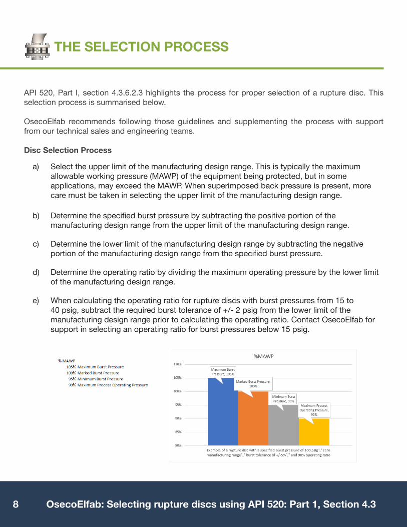
a) Select the upper limit of the manufacturing design range. This is typically the maximum allowable working pressure (MAWP) of the equipment being protected, but in some applications, may exceed the MAWP. When superimposed back pressure is present, more care must be taken in selecting the upper limit of the manufacturing design range.
b) Determine the specified burst pressure by subtracting the positive portion of the manufacturing design range from the upper limit of the manufacturing design range.
c) Determine the lower limit of the manufacturing design range by subtracting the negative portion of the manufacturing design range from the specified burst pressure.
d) Determine the operating ratio by dividing the maximum operating pressure by the lower limit of the manufacturing design range.
e) When calculating the operating ratio for rupture discs with burst pressures from 15 to 40 psig, subtract the required burst tolerance of +/- 2 psig from the lower limit of the manufacturing design range prior to calculating the operating ratio. Contact OsecoElfab for support in selecting an operating ratio for burst pressures below 15 psig.
Related Documents