HAL Id: tel-00780756 https://tel.archives-ouvertes.fr/tel-00780756 Submitted on 24 Jan 2013 HAL is a multi-disciplinary open access archive for the deposit and dissemination of sci- entific research documents, whether they are pub- lished or not. The documents may come from teaching and research institutions in France or abroad, or from public or private research centers. L’archive ouverte pluridisciplinaire HAL, est destinée au dépôt et à la diffusion de documents scientifiques de niveau recherche, publiés ou non, émanant des établissements d’enseignement et de recherche français ou étrangers, des laboratoires publics ou privés. A study of tailoring acoustic porous material properties when designing lightweight multilayered vehicle panels Eleonora Lind Nordgren To cite this version: Eleonora Lind Nordgren. A study of tailoring acoustic porous material properties when designing lightweight multilayered vehicle panels. Other. Conservatoire national des arts et metiers - CNAM, 2012. English. NNT : 2012CNAM0840. tel-00780756

Welcome message from author
This document is posted to help you gain knowledge. Please leave a comment to let me know what you think about it! Share it to your friends and learn new things together.
Transcript
HAL Id: tel-00780756https://tel.archives-ouvertes.fr/tel-00780756
Submitted on 24 Jan 2013
HAL is a multi-disciplinary open accessarchive for the deposit and dissemination of sci-entific research documents, whether they are pub-lished or not. The documents may come fromteaching and research institutions in France orabroad, or from public or private research centers.
L’archive ouverte pluridisciplinaire HAL, estdestinée au dépôt et à la diffusion de documentsscientifiques de niveau recherche, publiés ou non,émanant des établissements d’enseignement et derecherche français ou étrangers, des laboratoirespublics ou privés.
A study of tailoring acoustic porous material propertieswhen designing lightweight multilayered vehicle panels
Eleonora Lind Nordgren
To cite this version:Eleonora Lind Nordgren. A study of tailoring acoustic porous material properties when designinglightweight multilayered vehicle panels. Other. Conservatoire national des arts et metiers - CNAM,2012. English. NNT : 2012CNAM0840. tel-00780756
CONSERVATOIRE NATIONAL
DES ARTS ET METIERS
–
ROYAL INSTITUTE
OF TECHNOLOGY
Ecole Doctorale du Conservatoire National des Arts et Metiers
Laboratoire de Mecanique des Strucutres et des Systemes Couples (LMSSC)
THESE DE DOCTORAT
presentee par : Eleonora LIND NORDGREN
soutenue le : 7 Septembre 2012
pour obtenir le grade de : Docteur du Conservatoire National des Arts
et Metiers
Specialite : Mecanique
A STUDY OF TAILORING ACOUSTIC POROUS MATERIAL
PROPERTIES WHEN DESIGNING LIGHTWEIGHT
MULTILAYERED VEHICLE PANELS
Jury compose de:
M. OLOFSSON U. Royal Institute of Technology (KTH), Suede President du jury
M. GORANSSON P. Royal Institute of Technology (KTH), Suede Directeur de these
M. OHAYON R. Cnam, France Directeur de these
M. DEU J.-F. Cnam, France Co-directeur de these
M. DAZEL O. LAUM, France Rapporteur
M. DESMET W. KU Leuven, Belgique Rapporteur
M. DAVIDSSON P. Creodynamics AB, Suede Examinateur
M. HORLIN N.-E. Royal Institute of Technology (KTH), Suede Examinateur

ii
Contents
I Resume des travaux de these 1
1 Introduction 3
2 Description et conception du milieu poreux 5
2.1 Dissipation de l’energie dans les milieux poreux . . . . . . . . . . . . . . 5
2.2 La theorie de Biot . . . . . . . . . . . . . . . . . . . . . . . . . . . . . . . 7
2.2.1 Principales equations de la theorie de Biot . . . . . . . . . . . . . 9
2.2.2 Representation matricielle des parametres materiau . . . . . . . . 12
2.2.3 Modelisation isotrope versus anisotrope . . . . . . . . . . . . . . . 14
2.3 Modelisation aux Elements Finis (EF) . . . . . . . . . . . . . . . . . . . 15
2.4 Correlations entre les proprietes macroscopiques et microscopiques . . . . 16
2.5 Points notables sur le probleme d’optimisation . . . . . . . . . . . . . . . 19
3 Etude des materiaux poro-elastiques dans des structures multicouches 21
3.1 Adaptation des parametres des materiaux poreux pour une performance
acoustique amelioree . . . . . . . . . . . . . . . . . . . . . . . . . . . . . 23
3.2 Methode combinee d’optimisation structurelle et acoustique – un outil de
conception pluridisciplinaire . . . . . . . . . . . . . . . . . . . . . . . . . 25
4 Conclusions 33
4.1 Perspectives . . . . . . . . . . . . . . . . . . . . . . . . . . . . . . . . . . 34
Bibliography 35
iii

Part I
Resume des travaux de these
1

Chapter 1
Introduction
L’impact de la plupart des activites humaines sur l’environnement est devenu un
probleme de plus en plus important a l’echelle globale. La problematique principale
concerne aujourd’hui le rechauffement climatique, cause, principalement, par l’emission
de dioxyde de carbone et d’autres gaz a effet de serre. En Suede, environ 26% de la
consommation en energie est due a l’industrie du transport et selon Akerman et Hojer
[1] cela est deja trop. Afin de maintenir un environnement durable, l’energie utilisee
dans l’industrie du transport devrait etre reduite de 60% d’ici l’annee 2050. Cela
peut uniquement etre realise en effectuant des changements au niveau des modes de
transport tout en reduisant de maniere significative l’intensite de l’energie du transport.
Plusieurs aspects d’un vehicule doivent etre pris en compte afin d’en ameliorer l’efficacite
energetique. En dehors de la motorisation elle-meme, la resistance au roulement, les
proprietes aerodynamiques et la masse du vehicule sont quelques caracteristiques qui
influencent grandement l’energie consommee durant le cycle de vie total du vehicule.
La reduction de la masse du vehicule est, de ce fait, une des nombreuses strategies
permettant de reduire la consommation en carburant ou en energie, afin d’obtenir
des transports plus efficaces et ayant moins d’impact negatif sur l’environnement. En
parallele, les exigences en matiere de securite et de confort ne peuvent pas etre abaissees,
les modifications apportees a la structure doivent donc permettre de maintenir voire
d’ameliorer ces proprietes. Cela peut etre realise, e.g. en apportant des changements
profonds dans les materiaux selectionnes et dans la conception globale, et la mise en
oeuvre de structures multifonctionnelles et multicouches legeres et rigides (e.g. panneaux
sandwichs et composites) dans la production industrielle a augmente regulierement
depuis un certain temps. Toutefois, l’introduction de nouvelles conceptions legeres induit
souvent une augmentation des problemes de bruit et de vibration, en particulier dans le
domaine des basses frequences. En regle generale, les vibrations de structure indesirables
et le bruit se propagent dans la structure et rayonnent, par exemple, a partir des surfaces
de finition a l’interieur de l’habitacle du vehicule. De ce fait, le comportement dynamique
de ce panneau interieur a un impact majeur sur le bruit rayonne, et sur le niveau de
bruit a l’interieur de l’habitacle.
3
CHAPTER 1. INTRODUCTION
Une methode souvent utilisee pour ameliorer le bruit, les vibrations et la rudesse
(NVH) dans un vehicule, est l’ajout de materiaux poro-elastiques et visco-elastiques
flexibles, lorsqu’il n’est pas possible de realiser des modifications majeures des panneaux
interieurs. Toutefois, l’ajout de materiaux est problematique en vis a vis de l’objectif de
reduction du poids. Cela augmente egalement le cout global (materiaux et assemblage)
et l’espace alloue autrement aux passagers du vehicule. Il serait, de toute evidence,
preferable d’inclure les exigences acoustiques et dynamiques des la conception du
panneau, ou bien, en deuxieme option, d’assurer le meilleur ratio possible performance
par masse ajoutee, en matiere de cout et de volume, pour tout traitement ulterieur
effectue.
Une facon courante d’ameliorer la performance d’un panneau acoustique est de combiner
differents materiaux poro-elastiques et visco-elastiques en plusieurs couches presentant
differentes proprietes physiques et mecaniques, telles que l’amortissement, l’elasticite,
la viscosite et la densite. Determiner quels materiaux combiner et quelles proprietes
rechercher dans chaque couche afin d’obtenir des resultats satisfaisants, est aujourd’hui
une tache longue et couteuse qui necessite la connaissance prealable de combinaisons
fonctionnant avec succes, l’experience d’ingenierie ainsi que des essais pousses. De toute
evidence, il existe un besoin d’outils informatiques capables de prevoir et d’optimiser le
comportement de ces structures multicouches.
Ce travail constitue une premiere tentative visant a demontrer les possibilites d’adaptation
des materiaux poreux a des fins specifiques. Fait correctement, il peut potentiellement
generer des ameliorations notables en matiere de confort NVH, avec un minimum de
volume et masse ajoutee.
4
Chapter 2
Description et conception du milieu
poreux
Les materiaux d’interet dans cette these sont les materiaux poreux, qui sont des
materiaux heterogenes formes d’une structure poreuse elastique saturee en fluide. Le
fluide est suppose etre interconnecte a travers le milieu, formant des pores ouverts ou
cellules ouvertes. Le fluide interstitiel, e.g. l’air, peut se deplacer par rapport a la
structure. De ce fait, quel que soit le fluide enferme dans la structure, celui-ci est
considere comme faisant parti de la structure etant donne qu’il ne peut se deplacer de
maniere relative par rapport a celle-ci. Deux exemples typiques de materiaux poreux
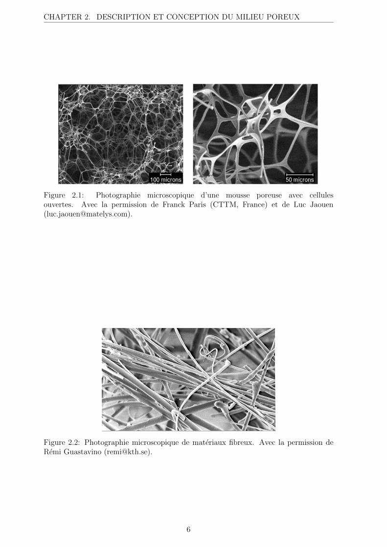
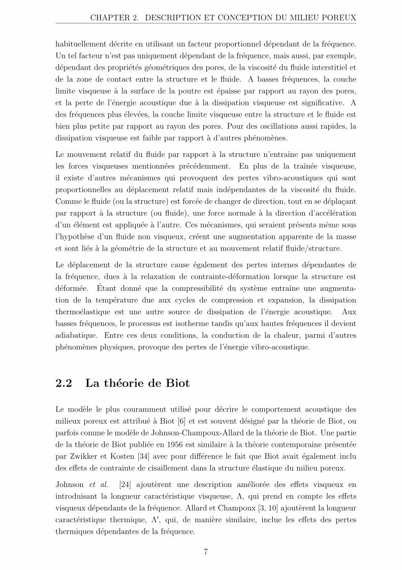
sont les mousses constituees de cellules ouvertes et les matieres fibreuses, voir fig. 2.1 et
2.2. Dans les mousses poreuses, les fibres minces constituant la structure sont souvent
designes par poutres. Les porosites des materiaux utilises comme absorbants acoustiques
sont typiquement elevees, au dessus de 90%, et l’energie acoustique est transportee a
la fois par le fluide dans les pores et par la structure solide. Les ondes sont fortement
couplees et se propagent simultanement dans ces deux milieux mais avec des phases
et amplitudes differentes. La propagation des ondes dans les milieux poreux est, en
d’autres termes, un phenomene d’interaction fluide-structure, se produisant a travers
l’ensemble du volume du materiau.
2.1 Dissipation de l’energie dans les milieux poreux
Lorsque l’energie acoustique traverse un milieu poreux, une partie de l’energie mecanique-
acoustique est dissipee, i.e. convertie en chaleur. Il existe plusieurs mecanismes differents
qui contribuent au comportement acoustique et vibro-acoustique du milieu poreux,
certains de ces mecanismes sont brievement decris ci-apres.
Lorsque la structure et le fluide se deplacent l’un par rapport a l’autre, des interactions
visqueuses apparaissent a l’interface, entraınant des pertes dans le fluide et dans la
structure. La traınee visqueuse est supposee proportionnelle au deplacement relatif et est
5
CHAPTER 2. DESCRIPTION ET CONCEPTION DU MILIEU POREUX
Figure 2.1: Photographie microscopique d’une mousse poreuse avec cellulesouvertes. Avec la permission de Franck Paris (CTTM, France) et de Luc Jaouen([email protected]).
Figure 2.2: Photographie microscopique de materiaux fibreux. Avec la permission deRemi Guastavino ([email protected]).
6
CHAPTER 2. DESCRIPTION ET CONCEPTION DU MILIEU POREUX
habituellement decrite en utilisant un facteur proportionnel dependant de la frequence.
Un tel facteur n’est pas uniquement dependant de la frequence, mais aussi, par exemple,
dependant des proprietes geometriques des pores, de la viscosite du fluide interstitiel et
de la zone de contact entre la structure et le fluide. A basses frequences, la couche
limite visqueuse a la surface de la poutre est epaisse par rapport au rayon des pores,
et la perte de l’energie acoustique due a la dissipation visqueuse est significative. A
des frequences plus elevees, la couche limite visqueuse entre la structure et le fluide est
bien plus petite par rapport au rayon des pores. Pour des oscillations aussi rapides, la
dissipation visqueuse est faible par rapport a d’autres phenomenes.
Le mouvement relatif du fluide par rapport a la structure n’entraıne pas uniquement
les forces visqueuses mentionnees precedemment. En plus de la traınee visqueuse,
il existe d’autres mecanismes qui provoquent des pertes vibro-acoustiques qui sont
proportionnelles au deplacement relatif mais independantes de la viscosite du fluide.
Comme le fluide (ou la structure) est forcee de changer de direction, tout en se deplacant
par rapport a la structure (ou fluide), une force normale a la direction d’acceleration
d’un element est appliquee a l’autre. Ces mecanismes, qui seraient presents meme sous
l’hypothese d’un fluide non visqueux, creent une augmentation apparente de la masse
et sont lies a la geometrie de la structure et au mouvement relatif fluide/structure.
Le deplacement de la structure cause egalement des pertes internes dependantes de
la frequence, dues a la relaxation de contrainte-deformation lorsque la structure est
deformee. Etant donne que la compressibilite du systeme entraıne une augmenta-
tion de la temperature due aux cycles de compression et expansion, la dissipation
thermoelastique est une autre source de dissipation de l’energie acoustique. Aux
basses frequences, le processus est isotherme tandis qu’aux hautes frequences il devient
adiabatique. Entre ces deux conditions, la conduction de la chaleur, parmi d’autres
phenomenes physiques, provoque des pertes de l’energie vibro-acoustique.
2.2 La theorie de Biot
Le modele le plus couramment utilise pour decrire le comportement acoustique des
milieux poreux est attribue a Biot [6] et est souvent designe par la theorie de Biot, ou
parfois comme le modele de Johnson-Champoux-Allard de la theorie de Biot. Une partie
de la theorie de Biot publiee en 1956 est similaire a la theorie contemporaine presentee
par Zwikker et Kosten [34] avec pour difference le fait que Biot avait egalement inclu
des effets de contrainte de cisaillement dans la structure elastique du milieu poreux.
Johnson et al. [24] ajouterent une description amelioree des effets visqueux en
introduisant la longueur caracteristique visqueuse, Λ, qui prend en compte les effets
visqueux dependants de la frequence. Allard et Champoux [3, 10] ajouterent la longueur
caracteristique thermique, Λ′, qui, de maniere similaire, inclue les effets des pertes
thermiques dependantes de la frequence.
7
CHAPTER 2. DESCRIPTION ET CONCEPTION DU MILIEU POREUX
Dans le cadre de la theorie de Biot etendue, la structure solide est modelisee comme
un milieu continu solide elastique equivalent et le fluide interstitiel comme un milieu de
fluide incompressible equivalent, les deux etant decrits par les proprietes mecaniques
macroscopiques homogeneisees standards en mecanique des milieux continus. Les
deux milieux separes mais couples agissent et interagissent donc en occupant le meme
espace. L’interaction entre la phase solide et fluide est decrite par des parametres
de couplage derives de proprietes macroscopiques homogeneisees mesurables. Les
proprietes macroscopiques sont utilisees pour calculer des quantites macroscopiques
homogeneisees e.g. le deplacement du solide et du fluide, la pression acoustique, la
contrainte elastique. Une condition a respecter dans la modelisation des mousses, est que
les dimensions microscopiques caracteristiques des mousses, e.g. taille des pores, soient
petites par rapport aux dimensions caracteristiques du comportement macroscopique.
En acoustique, cette derniere est identifiee comme la longueur d’onde. Pour les modeles
et materiaux etudies ici, cette condition est generalement satisfaite.
Il convient toutefois de noter que la modelisation d’un materiau poro-elastique, en tant
que deux milieux distincts et couples, pose probleme aux interfaces du materiau. Des
etudes montrent que les proprietes homogeneisees peuvent differer pres de la surface
du materiau poro-elastique [18]. Ces types d’effet de frontiere pourrait avoir un effet
non negligeable, en particulier si la profondeur d’une telle couche limite est grande par
rapport a l’epaisseur de la couche de poreux.
Une grande partie des travaux a consiste en l’obtention d’une description des parametres
macroscopiques du materiau ayant un sens physique. De toute importance pour les
milieux poreux, les parametres de couplage peuvent etre definis de differentes facons.
Selon le modele de Johnson-Champoux-Allard, ces parametres sont decrits par:
• Porosite, φ [1], definie comme la fraction volumique de fluide dans le milieu poreux,
0 < φ < 1. Pour des applications en acoustique, la porosite des materiaux est en
general superieure a 0.95.
• Tortuosite, α∞ [1], definie comme le ratio entre le carre de la vitesse moyenne
microscopique du fluide et la vitesse moyenne microscopique au carre du fluide,
dans un volume suppose de viscosite nulle. De maniere pratique, ce parametre
compare la longueur du chemin que le fluide traverse dans un milieu poreux au
niveau microscopique a la longueur du chemin traverse au niveau macroscopique,
impliquant que α∞ ≥ 1. Dans le cas d’un milieu a pores ouverts presentant une
porosite elevee, la tortuosite est souvent proche de un, typiquement egale a 1.05.
• Resistance statique a l’ecoulement, σstatic [Nsm−4], definie comme le rapport entre
la difference de pression et la vitesse d’ecoulement, par unite de longueur.
La resistance a l’ecoulement est dependante de plusieurs proprietes physiques
dans le milieu poreux, comme la viscosite surfacique entre la structure et la
geometrie microscopique du milieu poreux. Ce parametre peut etre mesure ou
8
CHAPTER 2. DESCRIPTION ET CONCEPTION DU MILIEU POREUX
deduit theoriquement a partir e.g. de simulations de Stokes, pour une geometrie
microstructurelle donnee.
• Longueur visqueuse caracteristique, Λ [m], permettant d’ameliorer l’estimation
lorsqu’il est necessaire de tenir compte d’effets dissipatifs causes par des pertes
visqueuses au niveau des parois des pores. Lorsque la taille des pores est
petite par rapport a l’epaisseur de la couche limite, les effets de dissipation
visqueuse ne peuvent pas etre negliges. La longueur visqueuse caracteristique
offre des possibilites de corrections donnant une meilleur representation des pertes
visqueuses, dependantes de la frequence.
• Longueur thermique caracteristique, Λ’ [m], prenant en compte les echanges
thermiques entre la structure et le fluide a la frontiere entre les deux, et,
par analogie avec la longueur visqueuse caracteristique, offre des possibilites de
corrections pour les interactions thermiques fluide-structure dependantes de la
frequence.
Afin de mieux comprendre les materiaux poreux, il est important d’effectuer des essais
experimentaux afin de caracteriser differents materiaux et d’obtenir les parametres
materiaux macroscopiques necessaires. Il existe plusieurs aspects physiques des
materiaux poreux qui ne sont pas encore completement compris, par exemple, l’influence
de la compression statique et de la deformation sur les parametres materiaux [14] ou les
modifications des modules d’elasticite aux elements frontieres d’echantillons de mousses
poreuses [18]. Bien-entendu, le travail pour obtenir des donnees experimentales est lie de
pres au developpement de modeles mathematiques utilises afin de decrire ces materiaux
complexes et leur comportement.
2.2.1 Principales equations de la theorie de Biot
La theorie de Biot correspond a un modele lagrangien ou les relations de contrainte-
deformation sont derivees de l’energie potentielle de deformation. Si la theorie de Biot
est de maniere pratique souvent utilisee sous sa forme isotrope, les principales equations
de cette theorie sont donnees ici sous leur forme anisotrope, de maniere similaire aux
travaux de Biot [8], Biot et Willis [9] et Allard [2]. Cette presentation des principales
equations est en aucune facon complete et doit etre consideree comme un court resume
du travail tres complet qui a deja ete accompli dans le domaine des materiaux poreux.
Pour plus de details, se referer aux travaux en reference.
Les notations utilisees sont expliquees lorsque introduites et egalement resumees dans
le chapitre 6, a l’exception de la notation tensorielle suivante. Le nombre ordinal
du composant dans un systeme de coordonnees cartesiennes, e.g. i = 1, 2, 3 est
note i, j, k. Les derivees partielles par rapport a xi s’ecrivent (.),i = ∂(.)/∂xi. Le
delta de Kronecker s’ecrit δij. La notation tensorielle cartesienne avec la convention
9
CHAPTER 2. DESCRIPTION ET CONCEPTION DU MILIEU POREUX
de sommation de Einstein est aussi utilisee, i.e. des indices repetes impliquent une
sommation de ces termes.
Equations du moment
En supposant un mouvement harmonique a une frequence angulaire ω, les equations du
moment (dans le domaine frequentiel) de la structure solide et du fluide peuvent etre
respectivement ecrites comme ci-apres:
σsij,j = −ω2ρ11
ij usj − ω2ρ12
ij ufj (2.1)
et
σfij,j = −ω2ρ12
ij usj − ω2ρ22
ij ufj (2.2)
ou σsij et σf
ij sont les tenseurs de contrainte de Cauchy, respectivement, pour la structure
et pour le fluide, et usj et uf
j sont les deplacements, respectivement, de la structure et
du fluide. Les tenseurs de densite equivalents, ρ11ij , ρ12
ij et ρ22ij sont les generalisations
anisotropes de celles utilisees par Allard [2] et peuvent etre definies comme:
ρ11ij = ρ1δij + ρa
ij −i
ωbij, (2.3)
ρ12ij = −ρa
ij −i
ωbij, (2.4)
ρ22ij = φρ0δij + ρa
ij −i
ωbij, (2.5)
ou
ρaij = φρ0 (αij − δij) (2.6)
avec ρ0 la masse volumique du fluide ambiant, ρ1 la masse volumique apparente du
materiau poreux et αij le tenseur de tortuosite. ρaij est un coefficient de couplage d’inertie
qui represente l’augmentation apparente de la masse due a la tortuosite. Le tenseur de
traınee visqueuse bij prend en compte les forces visqueuses entre la phase solide et le
fluide, et est ici defini comme precedemment etabli par Johnson et al. [24].
bij = φ2σstaticij Bij (ω) , (2.7)
ou
10
CHAPTER 2. DESCRIPTION ET CONCEPTION DU MILIEU POREUX
Bij =
√1 + iω
4ηρ0α2ij
φ2(σstaticij )2Λ2
ij
(2.8)
avec η la viscosite du fluide ambiant.
Equations constitutives
Les deux equations constitutives peuvent etre definies par:
σsij = Cijklεkl +Qijθ
f (2.9)
et
σfij = Qklεklδij +Rθfδij (2.10)
ou Cijkl est le tenseur de Hooke de la structure solide. La dilatation du fluide est donnee
par la divergence du deplacement du fluide:
θf = ufk,k (2.11)
et la deformation de la structure solide est donnee par le tenseur des deformations de
Cauchy
εkl =1
2
(usk,l + us
l,k
). (2.12)
Les deux tenseurs des materiaux, R et Qij, sont definis par
R =φ2Ks
1− φ−KsCijkldijdkl + φKs/Kf
(2.13)
Qij = [(1− φ)− Cijkldkl]R
φ=
[(1− φ)− Cijkldkl]φKs
1− φ−KsCijkldijdkl + φKs/Kf
(2.14)
ou Ks et Kf sont les modules de compressibilite, respectivement, de la structure et du
fluide et dij est le tenseur de souplesse en compressibilite. Kf est obtenu en utilisant
le modele de Lafarge et al. [26]. Le fluide etant suppose isotrope, R est une grandeur
scalaire. Le couplage de dilatation Qij est, cependant, un tenseur d’ordre deux en raison
de l’anisotropie supposee elastique.
De maniere pratique, souvent et dans le cadre de cette these, le deplacement du fluide
n’est pas utilise comme une variable dependante. Le tenseur des contraintes de Cauchy
du fluide est alors remplace par la pression des pores, laquelle est un scalaire, σfij =
11
CHAPTER 2. DESCRIPTION ET CONCEPTION DU MILIEU POREUX
−φpδij, ce qui permet de reduire le nombre de variables independantes de six a quatre.
2.2.2 Representation matricielle des parametres materiau
Les proprietes elastiques de la structure solide du materiau poreux peuvent etre decrites
en utilisant la matrice de Hooke de la structure solide, equivalente au tenseur de Hooke
Cijkl utilise precedemment. La matrice de Hooke est une matrice 6 × 6 et se compose,
dans le cas de materiaux isotropes, de seulement deux parametres independants:
C =E
(1 + ν)(1− 2ν)
1− ν ν ν 0 0 0
1− ν ν 0 0 0
1− ν 0 0 01−2ν
20 0
symm. 1−2ν2
01−2ν
2
(2.15)
ou E est le module de Young et ν le coefficient de Poisson. Les materiaux anisotropes
presentent differents types d’anisotropie, trois desquels sont decrits succinctement ci-
apres.
1. Les materiaux isotropes transverses presentent les meme proprietes materiaux dans
deux de leur directions principales mais des proprietes differentes dans la troisieme
direction normale au plan d’isotropie. Un exemple de materiaux isotropes
transverses sont les materiaux fibreux. Le nombre de parametres independants
permettant de decrire le comportement de ces materiaux est de cinq au maximum.
C =
C11 C12 C13 0 0 0
C11 C13 0 0 0
C33 0 0 0
C44 0 0
symm. C44 012(C11 − C12)
(2.16)
2. Les materiaux orthotropes presentent trois axes orthogonaux deux a deux et leur
proprietes mecaniques sont, en general, differentes dans chaque direction. De
plus, il existe des directions principales orthogonales pour lesquelles il n’y a pas
de couplage entre la dilatation et le cisaillement. Plusieurs mousses utilisees
dans le domaine de l’acoustique presentent un comportement proche de celui des
materiaux orthotropes. Le nombre de parametres independants permettant de
12
CHAPTER 2. DESCRIPTION ET CONCEPTION DU MILIEU POREUX
decrire le comportement de ces materiaux est de neuf au maximum.
C =
C11 C12 C13 0 0 0
C22 C23 0 0 0
C33 0 0 0
C44 0 0
symm. C55 0
C66
(2.17)
3. Les materiaux completement anisotropes presentent des proprietes materiaux
differentes dans toutes les directions et les directions principales ne sont pas
necessairement orthogonales. Cela implique que e.g. un mouvement de flexion
dans une direction peut induire un mouvement de torsion dans une autre, ou une
contrainte en compression peut induire des contraintes en cisaillement. Il s’agit
de la description la plus generale possible d’un materiau, elle n’est cependant
pas souvent utilisee puisque le nombre de parametres independants permettant de
decrire le comportement de ces materiaux peut aller jusqu’a 21.
C =
C11 C12 C13 C14 C15 C16
C22 C23 C24 C25 C26
C33 C34 C35 C36
C44 C45 C46
symm. C55 C56
C66
(2.18)
D’autres proprietes materiau telles que la tortuosite, la resistance statique a l’ecoulement
et la longueur caracteristique visqueuse peuvent quant a elles etre decrites par une
matrice 3× 3 ou le nombre de parametres independants necessaire peut varier entre un,
pour un materiau isotrope, et six pour un materiau completement anisotrope.
1. Isotrope
S =
S1 0 0
S1 0
symm. S1
(2.19)
2. Isotrope transversal
S =
S1 0 0
S1 0
symm. S3
(2.20)
3. Orthotrope
S =
S1 0 0
S2 0
symm. S3
(2.21)
13
CHAPTER 2. DESCRIPTION ET CONCEPTION DU MILIEU POREUX
4. Completement anisotrope
S =
S11 S12 S13
S22 S23
symm. S33
(2.22)
Pour la plupart des materiaux poreux anisotropes, les matrices de parametres materiaux
sont en grandes parties inconnues et la problematique de mesure/d’obtention de ces
parametres reste toute entiere. La majeure partie des techniques utilisees aujourd’hui
permettent uniquement de mesurer les equivalents isotropes des proprietes anisotropes.
Les travaux en cours sur le developpement de techniques de mesure adequats permettant
de caracteriser completement les milieux poreux anisotropes ne sont pas des plus
simples. L’anisotropie d’un materiau poreux a cependant un impact sur ses proprietes
materiaux macroscopiques homogeneisees et sur son comportement acoustique [25]. Les
recherches en cours se concentrent sur le developpement de nouvelles techniques de
mesure [18] et sur l’etude de geometries de microstructure anisotrope [22, 23, 29]. Il est
important de preciser que les principales directions des differentes proprietes materiaux
macroscopiques ne s’alignent pas forcement entre elles ou avec les directions principales
dans un sens geometrique, necessitant differents systemes de coordonnees locaux afin
d’etre modelisees avec precisions [17, 28, 31].
2.2.3 Modelisation isotrope versus anisotrope
La grande majorite des travaux publies anterieurement sur la theorie de Biot ne
concerne que la modelisation isotrope, les modeles isotropes presentant aujourd’hui des
ameliorations ne sont donc pas directement transferables a une description anisotrope.
Pour exemple, les relations de contrainte-deformation isotropes peuvent etre etendues
afin d’inclure egalement les pertes internes dependantes de la frequence dues aux
mouvements de la structure. Celles-ci peuvent etre modelisees en utilisant la loi de
Hooke generalisee, proposee par Dovstam [13], laquelle est basee sur le travail de e.g.
Biot [7] et Lesieutre [27]. En bref, les pertes internes sont modelisees en ajoutant des
termes complexes dependants de la frequence a la matrice classique de la loi de Hooke
generalisee. Cette loi de Hooke generalisee n’est pas aujourd’hui implementee dans des
modeles de Biot anisotropes etant donne que le comportement de l’amortissement et de
ses directions principales comporte encore des inconnues.
De plus, les parametres materiaux necessaires a la description des materiaux anisotropes
ne sont pas simples a obtenir et de nombreuses questions demeurent quant a leurs
directions principales. Ceci souligne la necessite de developper davantage de techniques
de mesure precises afin d’obtenir des informations concernant le comportement physique
de materiaux anisotropes. Tous sont des sujets de recherche en cours.
De ce fait, le choix entre l’utilisation de modeles isotropes ou anisotropes lors de la
modelisation de materiaux poreux, depend e.g. de la precision necessaire, du type de
14
CHAPTER 2. DESCRIPTION ET CONCEPTION DU MILIEU POREUX
materiaux poreux a modeliser, de la structure dans lequel il est implemente, et de la
disponibilite eventuelle des parametres materiaux anisotropes.
2.3 Modelisation aux Elements Finis (EF)
Les solutions analytiques des equations de Biot existent seulement dans un certain
nombre de cas, ou les equations peuvent etre reduites a un probleme 1D, e.g. un
plan infini, un probleme a symetrie spherique ou cylindrique infini. Dans la plupart
des applications, la complexite du probleme necessite la recherche d’une solution
numerique qui permet de prendre en compte des geometries complexes de taille finie,
une distribution non-uniforme des conditions aux limites et des chargements, ainsi
que le couplage eventuel avec d’autres composants (poreux, solides ou fluides). Ces
questions et plusieurs autres ont ete abordees dans des travaux anterieurs (cas isotropes
et anisotropes) par Horlin et Goransson [20], Horlin [19] et Horlin et al. [21], ou des
solutions tridimensionnelles fondees sur des elements finis hp 1 ont ete developpees et
evaluees. Afin de determiner des solutions aux elements finis pour les equations aux
derivees partielles couplees decrivant le comportement d’un systeme, il est necessaire de
formuler une forme faible des equations aux derivees partielles incluant les conditions aux
limites. Dans ces travaux, Horlin evalue differentes formulations faibles, parmi lesquelles
une formulation mixte deplacement-pression pour des materiaux poreux isotropes a
ete proposee par Atalla et al. [4, 5]. Cette formulation mixte deplacement-pression
a ete plus tard etendue par Horlin et Goransson [20] afin de prendre en compte les
materiaux anisotropes. Elle utilise le deplacement de la structure comme variable
primale decrivant le mouvement de la structure, et la pression du fluide comme variable
primale decrivant le fluide, i.e. formulation (us, p), alors que les formulations faibles
plus repandues utilisent le deplacement de la structure et du fluide comme variables
primales, i.e. formulations (us, uf ). Ces dernieres requierent des ressources de calculs
importantes lorsqu’appliquees a des systemes elements finis de grandes dimensions. La
formulation (us, p) comme proposee par Atalla et al. [5] est consideree aussi precise que
la formulation classique (us, uf ) avec l’avantage qu’elle demande moins de ressources de
calculs pour une meme precision de calcul demandee. Elle decrit le materiaux poreux
avec un minimum de variables de champ independantes, permettant le couplage de
deux composants a pores ouverts et celui d’un composant a pores ouverts avec un
composant solide, sans introduire d’integrales de couplage supplementaires, si les parties
solides sont naturellement couplees. Cependant, il s’avere necessaire d’introduire des
integrales de couplage si il y a couplages entre des composants poreux et des fluides.
Cette formulation mixte deplacement-pression proposee vient etayer les travaux actuels
d’etude des ameliorations possibles d’adaptation des materiaux poreux a des applications
specifiques.
1la convergence est obtenue en raffinant le maillage et / ou en augmentant l’ordre d’approximation.
15
CHAPTER 2. DESCRIPTION ET CONCEPTION DU MILIEU POREUX
2.4 Correlations entre les proprietes macroscopiques
et microscopiques
Comme mentionne precedemment, les materiaux poreux peuvent etre decrits a partir de
leurs proprietes macroscopiques homogeneisees, dont plusieurs ont ete presentees dans
les equations ci-avant. Ces proprietes macroscopiques sont naturellement dependantes
des proprietes geometriques microscopiques et de la nature du materiau de la structure.
Ces proprietes geometriques microscopiques sont, par exemple, la taille et la forme
des pores, et la section transversale et l’epaisseur des poutres, ou fibres, dans le
materiau a pores ouverts. De telles proprietes microscopiques, ainsi que le choix des
materiaux, definissent le comportement thermique, elastique, viscoelastique, mecanique
et acoustique des materiaux poreux. De ce fait, les proprietes macroscopiques
ne peuvent pas etre considerees comme independantes les unes des autres et ne
conviennent donc pas comme variables dans un probleme d’optimisation. L’objectif
de cette these a donc ete d’utiliser des lois d’echelle qui relient les proprietes
macroscopiques aux proprietes microscopiques sous-jacentes. Ces lois d’echelle devraient
de preference decrire les proprietes macroscopiques des materiaux poreux comme etant
continuellement et systematiquement dependantes des proprietes mecaniques micro-
structurelles, permettant de se concentrer directement sur les proprietes microscopiques
lors de l’optimisation. Plusieurs chercheurs ont contribue au developpement de
formulations mathematiques reliant les differentes proprietes materiaux entre elles.
Dans le cas d’une structure de mousse a cellules ouvertes avec une porosite elevee,
ou le materiau des poutres est significativement plus lourd que le fluide interstitiel,
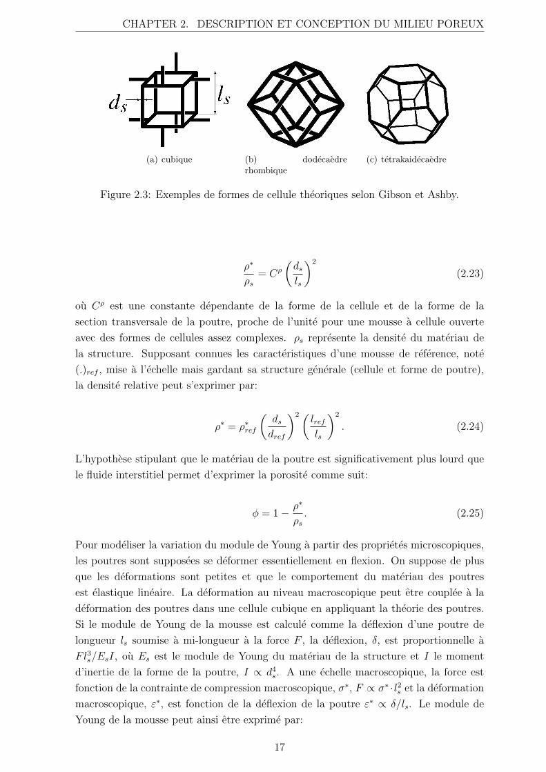
l’approche developpee par Gibson et Ashby [15] peut fournir des indications importantes
pour comprendre le comportement mecanique d’une telle mousse. Gibson et Ashby
definisse la structure cellulaire comme une serie de sommets relies par des aretes.
Une configuration tres simple consiste en une cellule de forme cubique ou les cellules
adjacentes sont echelonnees de telle sorte qu’elles se coupent aux points medians, mais
le raisonnement est tout aussi valable pour des structures cellulaires plus complexes
comme e.g. des dodecaedres rhombiques ou des tetrakaidecaedres, fig. 2.3. La structure
tetrakaidecaedre, egalement appelee cellule de Kelvin, est un choix frequent parce
qu’elle presente un nombre moyen d’aretes par face, et de faces par cellule, qui semble
correspondre de maniere satisfaisante a certaines observations, bien que ces travaux
necessitent des complements [15, 30]. Des etudes recentes [12] montrent que de telles
lois d’echelle fournissent des resultats assez satisfaisants, bien qu’elles se fondent sur des
structures de cellules simplifiees et sur d’autres hypotheses implicites qui ne peuvent pas
etre completement respectees.
En supposant que la cellule geometrique est isotrope, on montre que, pour toutes les
formes de cellules (des mousses) mentionnees ci-avant, la densite relative , ρ∗, pour
des mousses cellulaires, est proportionnelle a la longueur et a l’epaisseur des poutres,
respectivement, ls et ds.
16
CHAPTER 2. DESCRIPTION ET CONCEPTION DU MILIEU POREUX
(a) cubique (b) dodecaedrerhombique
(c) tetrakaidecaedre
Figure 2.3: Exemples de formes de cellule theoriques selon Gibson et Ashby.
ρ∗
ρs= Cρ
(dsls
)2
(2.23)
ou Cρ est une constante dependante de la forme de la cellule et de la forme de la
section transversale de la poutre, proche de l’unite pour une mousse a cellule ouverte
avec des formes de cellules assez complexes. ρs represente la densite du materiau de
la structure. Supposant connues les caracteristiques d’une mousse de reference, note
(.)ref , mise a l’echelle mais gardant sa structure generale (cellule et forme de poutre),
la densite relative peut s’exprimer par:
ρ∗ = ρ∗ref
(dsdref
)2(lrefls
)2
. (2.24)
L’hypothese stipulant que le materiau de la poutre est significativement plus lourd que
le fluide interstitiel permet d’exprimer la porosite comme suit:
φ = 1− ρ∗
ρs. (2.25)
Pour modeliser la variation du module de Young a partir des proprietes microscopiques,
les poutres sont supposees se deformer essentiellement en flexion. On suppose de plus
que les deformations sont petites et que le comportement du materiau des poutres
est elastique lineaire. La deformation au niveau macroscopique peut etre couplee a la
deformation des poutres dans une cellule cubique en appliquant la theorie des poutres.
Si le module de Young de la mousse est calcule comme la deflexion d’une poutre de
longueur ls soumise a mi-longueur a la force F , la deflexion, δ, est proportionnelle a
Fl3s/EsI, ou Es est le module de Young du materiau de la structure et I le moment
d’inertie de la forme de la poutre, I ∝ d4s. A une echelle macroscopique, la force est
fonction de la contrainte de compression macroscopique, σ∗, F ∝ σ∗ ·l2s et la deformation
macroscopique, ε∗, est fonction de la deflexion de la poutre ε∗ ∝ δ/ls. Le module de
Young de la mousse peut ainsi etre exprime par:
17
CHAPTER 2. DESCRIPTION ET CONCEPTION DU MILIEU POREUX
E∗ =σ∗
ε∗=CdlEsI
l4s→ E∗
Es= Cdl
(dsls
)4
= CE
(ρ∗
ρs
)2
(2.26)
ou, lorsque l’on utilise un materiau de reference, par:
E∗ = E∗ref
(ρ∗
ρ∗ref
)2
. (2.27)
De vastes travaux par Allard et Champoux [3] et Allard [2] ont egalement contribue a
etablir des relations entre les proprietes macroscopiques des mousses et les proprietes
structurelles microscopiques. Ces travaux ont ete utilises par Goransson afin de
continuer a developper des lois d’echelle qui mettent en relation la longueur visqueuse
caracteristique, Λ, et la resistance statique a l’ecoulement, σstatic, avec la microstructure
de la mousse [16]. En supposant un ecoulement non visqueux autour d’un cylindre,
Allard et Champoux montrent que si la porosite est proche de un, Λ est donnee par:
Λ =1
2πLr(2.28)
ou L est la longueur totale du cylindre par unite de volume et r est le rayon du cylindre
[3]. En retenant la precedente hypothese de geometrie de cellule, L peut etre definie
en fonction de la porosite par πr2L = ρ∗/ρs, la longueur visqueuse caracteristique
s’exprimant alors par [16]
Λ =ds
4(ρ∗/ρs)=
ds4(1− φ)
. (2.29)
Afin de prendre en compte les effets thermiques, l’hypothese simplificatrice concernant
la longueur caracteristique thermique, Λ′, Λ′ = 2 · Λ est retenue. Etant donne que
la tortuosite des materiaux hautement poreux est tres dependante de la quantite de
pores fermes, et que les materiaux utilises dans cette these sont supposes a pores
ouverts, la variation de tortuosite est tres faible lorsque les proprietes des materiaux
sont modifiees. Toutefois, une loi d’echelle fondee sur le travail de Comiti et Renaud,
[11], a ete implementee dans les Articles II et III,
α∞ = 1− 1− α∞refln(φref )
· ln(φ). (2.30)
De plus, il a ete demontre par Allard que Λ peut s’exprimer en fonction des proprietes
macroscopiques par:
Λ =1
cg
√8α∞η
φσstatic(2.31)
18
CHAPTER 2. DESCRIPTION ET CONCEPTION DU MILIEU POREUX
ou cg est dependant de la forme de la coupe transversale des pores. Pour des geometries
cylindriques on a cg = 1 [2]. Eq. (2.29) et eq. (2.31) donnent:
σstatic =8α∞η
1− (ρ∗/ρs)· 16(ρ∗/ρs)2
d2sc
2g
(2.32)
qui, lorsqu’on utilise un materiau de reference, peut s’exprimer par:
σstatic = σstaticref
(ρ∗
ρref
)2
·(drefds
)2
· α∞α∞ref
·
(1− ρref
ρs
)
(1− ρ∗
ρs
) . (2.33)
2.5 Points notables sur le probleme d’optimisation
Pour resoudre un probleme d’optimisation, il est necessaire d’etablir une fonction
objectif, f(x), qui fournit une valeur numerique representant les qualites recherchees.
La fonction objectif depend d’une ou plusieurs variables de conception, x = [x1
x2 · · ·xn], avec xmin ≤ x ≤ xmax et peut egalement etre soumise a differentes fonctions
de contrainte, gi(x). Le probleme d’optimisation est souvent presente sous la forme
suivante:
min f(x)
subject to g1(x) ≤ 0
g2(x) ≤ 0...
gM(x) ≤ 0
xmin ≤ x ≤ xmax
(2.34)
Le choix de la fonction objectif et des contraintes est souvent une tache plus delicate qu’il
n’en parait, etant donne qu’il y a souvent plusieurs objectifs a atteindre qui dependent
de differentes variables de conception, communes ou non. Les objectifs definis dans
cette these, i.e. reduction de l’inconfort acoustique ou reduction de la masse, sont
souvent utilises dans la pratique. D’autres objectifs peuvent impliquer, par exemple,
de minimiser le cout des materiaux, l’impact environnemental, le temps d’assemblage
ou la consommation de carburant, et le minimum d’un objectif coıncide rarement avec
le minimum d’autres. Le probleme peut etre traite en minimisant un objectif tout en
imposant une contrainte aux autres ou en developpant une fonction objectif qui integre
plusieurs objectifs dans une seule fonction, par exemple sous forme de somme ponderee.
Il existe plusieurs facons d’etablir une fonction objectif, tache non des moindres etant
donne que le resultat de l’optimisation depend inevitablement en grande partie du choix
de la fonction objectif et des contraintes.
Dans la pratique, l’optimisation est souvent mise en oeuvre par une forme d’algorithme.
19
CHAPTER 2. DESCRIPTION ET CONCEPTION DU MILIEU POREUX
Si les fonctions sont differentiables et dependantes de variables de conception continues,
un algorithme du gradient est souvent approprie. Un tel algorithme requiert des
informations sur les valeurs numeriques de la fonction objectif, du vecteur gradient
et de la matrice Hessienne de la fonction objectif par rapport a x, ainsi que la valeur
numerique des fonctions contraintes, des gradients, et les valeurs minimum et maximum
des variables de conception. A partir des donnees d’entree, l’algorithme fournit des
nouveaux parametres de conception pour lesquels la fonction cout est calculee et ainsi
de suite iterativement jusqu’a realisation d’un critere d’arret. Dans des applications
pratiques, la fonction objectif et/ou les fonctions contraintes sont souvent tres complexes
et le resultat d’une simulation par ordinateur. Cela necessite souvent que les valeurs
de gradient et de la matrice Hessienne soient calculees numeriquement, en utilisant
par exemple les differences finies, entraınant une hausse du cout de calcul pour chaque
variable de conception utilisee, et chaque iteration pour trouver un minimum.
Une autre difficulte rencontree lorsqu’une demarche d’optimisation est utilisee est le fait
que les fonctions objectifs ne sont pas convexes, c’est a dire, qu’il peut exister un ou
plusieurs minima locaux au sein du domaine du parametre qui ne correspondent pas a
la meilleur solution. La meilleure solution est plutot appelee le minimum global. Ce
probleme est souvent traite en utilisant plusieurs points d’entree distincts au sein du
domaine du parametre par comparaison du nombre de minima locaux avec la valeur des
fonctions objectifs a ces minima locaux.
20
Chapter 3
Etude des materiaux poro-elastiques
dans des structures multicouches
Ces travaux explorent la possible modification des proprietes microscopiques de
materiaux poro-elastiques specifiques lorsqu’ils sont assembles dans des panneaux
acoustiques multicouches ou multifonctionnels. Bien que la modelisation isotrope
constitue la majeure partie de ce travail , l’influence des proprietes materiaux anisotropes
et de l’orientation angulaire de ces proprietes est egalement aborde. Ces etudes
ont consiste en des simulations numeriques utilisant la theorie de Biot et l’approche
numerique EF decrite dans le chapitre 2. Les modifications des proprietes materiaux
ont ete choisies en utilisant un optimiseur base sur un algorithme du gradient [32, 33].
Alors que l’optimisation des proprietes macroscopiques des materiaux poreux utilisee
dans le modele de Johnson-Champoux-Allard permet de fournir certaines informations
concernant les possibles combinaisons des proprietes materiaux, elle ne permet pas
de determiner quel type de materiau poreux utiliser ou comment atteindre de telles
proprietes dans un materiau poreux. Le materiau resultant serait alors certainement
physiquement impossible a realiser, ce qui rend une telle optimisation peu utile de
maniere pratique. En decrivant le materiau poro-elastique a partir de ses proprietes
microscopiques et en en estimant les parametres macroscopiques correspondants, le
materiau ainsi defini pourra, s’il n’existe pas deja, etre completement decrit et sera
de maniere pratique possible a realiser. D’ou la necessite des lois d’echelle decrites
precedemment qui permettent de fournir des correlations approximatives entre les
parametres microscopiques et macroscopiques.
Afin d’examiner le comportement acoustique et dynamique des materiaux poro-
elastiques assembles dans des panneaux multicouches, un certain nombre de pan-
neaux comprenant des materiaux poreux isotropes ou anisotropes ont ete evalues
numeriquement. Les panneaux ont ete excites par differents types de champs de force
et les proprietes acoustiques et dynamiques ont ete exprimees comme fonction objectif
ou fonction contrainte afin de permettre une optimisation. Une telle fonction peut etre
21
CHAPTER 3. ETUDE DES MATERIAUX PORO-ELASTIQUES DANS DESSTRUCTURES MULTICOUCHES
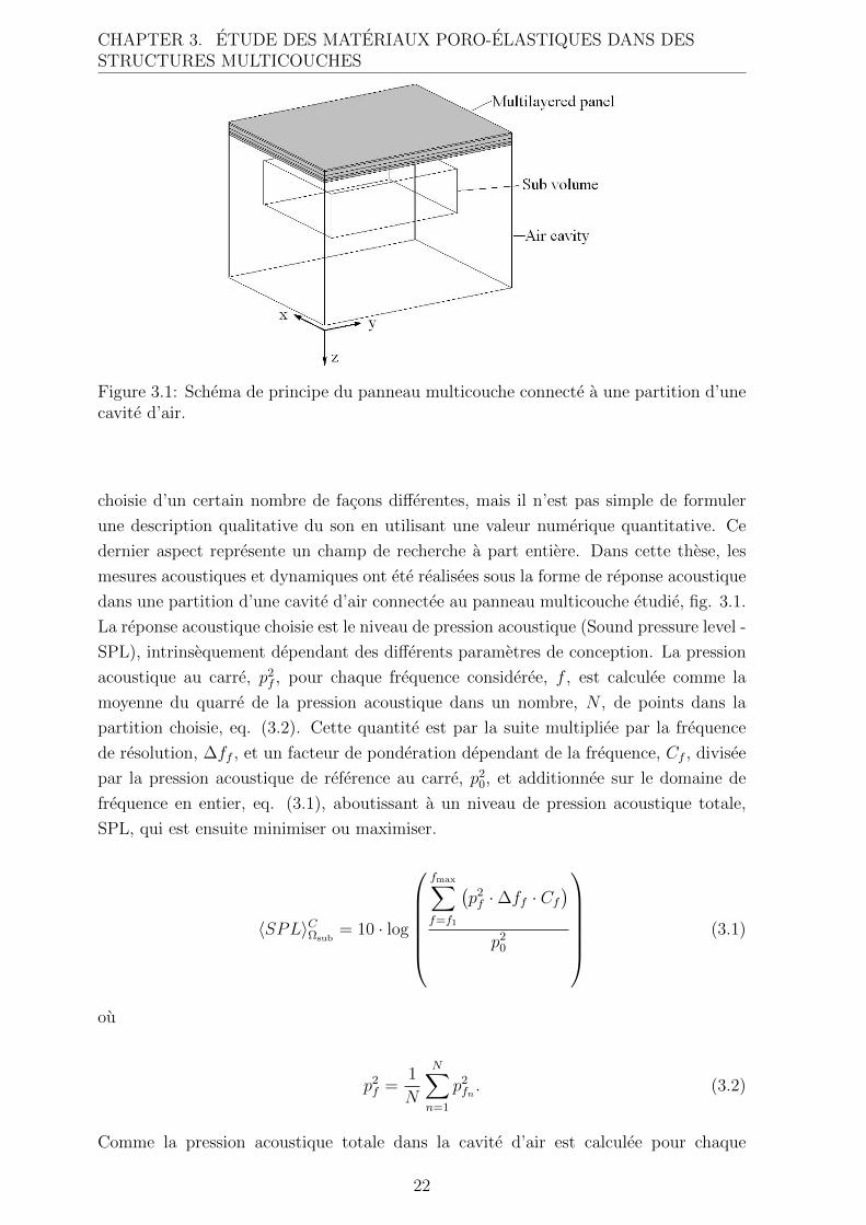
Figure 3.1: Schema de principe du panneau multicouche connecte a une partition d’unecavite d’air.
choisie d’un certain nombre de facons differentes, mais il n’est pas simple de formuler
une description qualitative du son en utilisant une valeur numerique quantitative. Ce
dernier aspect represente un champ de recherche a part entiere. Dans cette these, les
mesures acoustiques et dynamiques ont ete realisees sous la forme de reponse acoustique
dans une partition d’une cavite d’air connectee au panneau multicouche etudie, fig. 3.1.
La reponse acoustique choisie est le niveau de pression acoustique (Sound pressure level -
SPL), intrinsequement dependant des differents parametres de conception. La pression
acoustique au carre, p2f , pour chaque frequence consideree, f , est calculee comme la
moyenne du quarre de la pression acoustique dans un nombre, N , de points dans la
partition choisie, eq. (3.2). Cette quantite est par la suite multipliee par la frequence
de resolution, ∆ff , et un facteur de ponderation dependant de la frequence, Cf , divisee
par la pression acoustique de reference au carre, p20, et additionnee sur le domaine de
frequence en entier, eq. (3.1), aboutissant a un niveau de pression acoustique totale,
SPL, qui est ensuite minimiser ou maximiser.
〈SPL〉CΩsub= 10 · log
fmax∑
f=f1
(p2f ·∆ff · Cf
)
p20
(3.1)
ou
p2f =
1
N
N∑
n=1
p2fn . (3.2)
Comme la pression acoustique totale dans la cavite d’air est calculee pour chaque
22
CHAPTER 3. ETUDE DES MATERIAUX PORO-ELASTIQUES DANS DESSTRUCTURES MULTICOUCHES
frequence dans le domaine de frequence choisi, le cout en terme de ressource et temps
de calcul pour evaluer eq. 3.1 peut etre consequent. De plus, lorsque les gradients
sont calcules en utilisant les differences finies, une autre evaluation de 〈SPL〉CΩsubest
necessaire pour chaque variable de conception. Il est de ce fait tres important, dans
le processus d’optimisation, de trouver le minimum avec un nombre d’iterations aussi
faible que possible. L’optimiseur retenu ici est un optimiseur base sur la methode
des asymptotes mobiles (Method of Moving Asymptotes - MMA), et ulterieurement
sa version globalement convergente [32, 33]. Cet optimiseur fournit de bons resultats en
utilisant moins d’iterations que les autres testes.
3.1 Adaptation des parametres des materiaux poreux
pour une performance acoustique amelioree
Un modele 2D isotrope a d’abord ete utilise pour modeliser un panneau a sept couches,
parmi lesquelles une couche a ete optimisee microstructurellement. Ce modele admet
pour variables de conception la masse volumique apparente, ρ∗, et l’epaisseur de la
poutre, ds. Le facteur de ponderation de l’equation 3.1 est fixe afin de correspondre a
la pression acoustique totale avec filtre decibel A ou C. Deux types de mousse poro-
elastique a cellule ouverte sont utilisees: une mousse a base de polyurethane, mousse-
PU, et une mousse a base de polyimide, mousse-π. Cinq optimisations differentes
ont ete effectuees: minimisation de la pression acoustique totale avec filtre decibel
A et contrainte sur la masse en utilisant la mousse-PU, minimisation de la pression
acoustique totale avec filtre decibel C et contrainte sur la masse en utilisant la mousse-
PU, minimisation de la pression acoustique totale avec filtre decibel C et contrainte
sur la masse en utilisant la mousse-pi, et enfin minimisation de la masse en utilisant,
respectivement, la mousse-PU et la mousse-pi, et des contraintes sur la pression
acoustique totale avec filtre decibel C. La pression acoustique totale a ete evaluee sur
un domaine de frequence 100 – 900 Hz. Des contraintes ont egalement ete mises sur les
variables de conception afin d’exclure tout resultat n’ayant aucun sens physique.
En utilisant differents points de depart, le minimum final reste inchange, indiquant que
les fonctions objectifs utilisees sont relativement convexes pour l’espace des parametres
et le domaine de frequence choisi pour ces simulations. Les parametres de conception
resultants montrent egalement que la fonction filtre a un impact majeur sur le resultat
de l’optimisation. En utilisant un filtre decibel A pour la pression acoustique totale,
le minimum se trouve a ρ∗=32.5 kg m−3 et ds=14.8×10⁻⁶ m alors que le minimum
se trouve a ρ∗=20.1 kg m−3 et ds=15.5×10⁻⁶ m en utilisant filtre decibel C pour
la pression acoustique totale. En comparant les fonctions de reponse en frequence,
FRF, des panneaux optimises avec les FRF des panneaux comprenant une mousse
avec des parametres de conception qui ne sont pas optimaux, on remarque que les
possibilites d’amelioration du comportement acoustique et dynamique sont significatives,
23
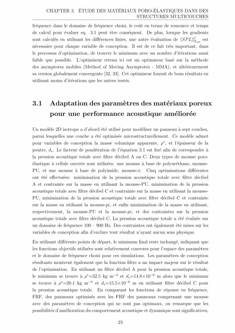
CHAPTER 3. ETUDE DES MATERIAUX PORO-ELASTIQUES DANS DESSTRUCTURES MULTICOUCHES
100 200 300 400 500 600 700 800 90035
40
45
50
55
60
65
70
75
Frequency [Hz]
Wei
ghte
d S
PL
[dB
]
(a) FRF avec filtre decibel A
100 200 300 400 500 600 700 800 90040
45
50
55
60
65
70
75
80
Frequency [Hz]
Wei
ghte
d S
PL
[dB
]
(b) FRF avec filtre decibel C
Figure 3.2: Fonction de reponse en frequence pour la solution optimale de mousse(trais epais) et la solution sous-optimale de mousse (trais fin), avec filtre decibel,respectivement, A (a gauche) et C (a droite).
voir fig. 3.2.
En comparant des panneaux comprenant, respectivement, une mousse-PU et une
mousse-π, pour ceux avec filtre decibel C pour la pression acoustique, on note que
les resultats du panneau comprenant la mousse-PU sont legerement meilleurs. D’autre
part, en minimisant la masse en utilisant des contraintes sur la pression acoustique totale
avec filtre decibel C, c’est la mousse-π qui demontre de meilleurs resultats.
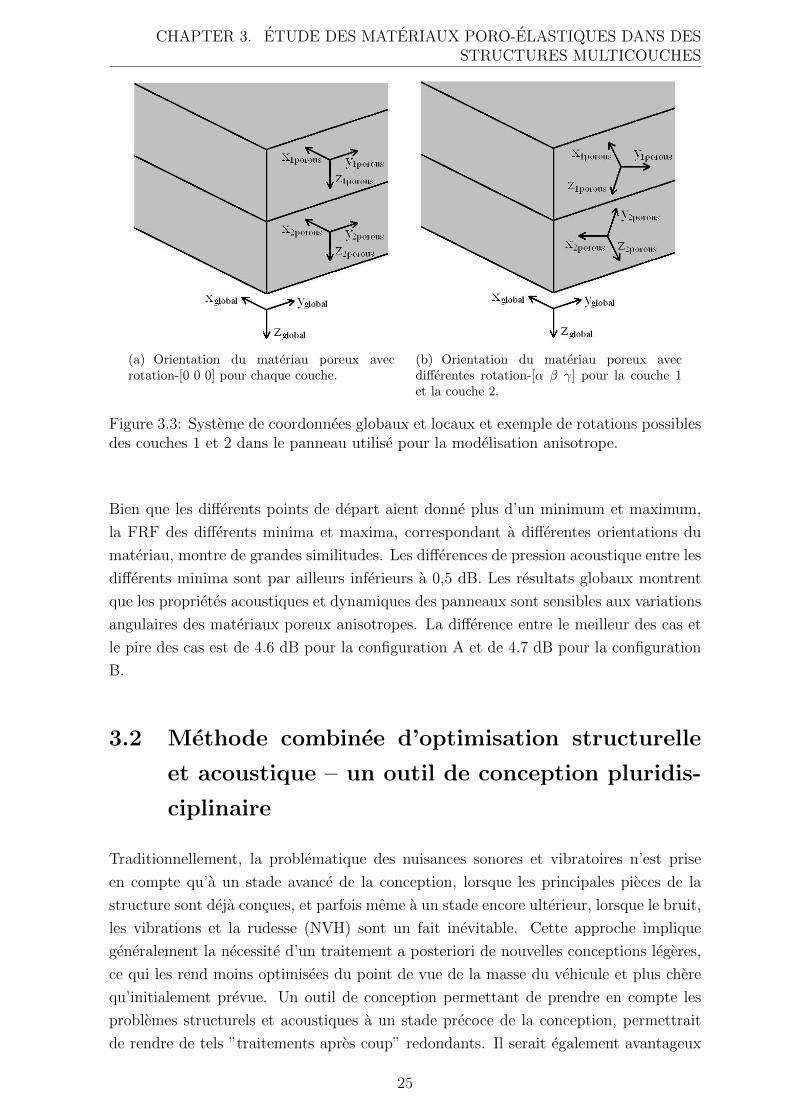
L’influence de l’anisotropie a ete examinee a l’aide d’un modele 3D de panneau
multicouche quadratique constitue de deux feuilles d’aluminium separees par deux
couches de materiaux poro-elastiques, liees elastiquement a la feuille d’aluminium sur
laquelle l’excitation est appliquee, et separees par une mince couche d’air de l’autre feuille
d’aluminium. Deux differents types de panneau ont ete utilises: la configuration A,
comprenant une mousse a cellule ouverte orthotrope, et la configuration B, comprenant
un materiau fibreux isotrope transverse. Pour chaque configuration, les deux couches
sont composees du meme type de materiau. Les seules variations introduites sont
l’orientation relative des proprietes materiaux dans chaque couche, lesquelles peuvent
pivoter independamment dans differentes directions et de ce fait induire des proprietes
dynamiques globales differentes selon la direction d’excitation, voir fig. 3.3.
La description de l’anisotropie des materiaux poreux se limite a celle de la matrice de
Hooke, du tenseur de resistance a l’ecoulement et du tenseur de tortuosite. La fonction
objectif choisie est la pression acoustique totale sans filtre, eq. 3.1, et les variables de
conception sont les angles d’Euler decrivant un axe de rotation fixe Z-Y-X. Les deux
couches de poreux pouvant pivoter independamment l’une de l’autre et la rotation autour
de l’axe z etant redondante pour les materiaux poreux isotropes transverses, le nombre
de variables de conception necessaires est de six pour la configuration A et de quatre
pour la configuration B. Les deux minimisations et maximisations ont ete effectuees
pour un certain nombre de points de depart differents.
24
CHAPTER 3. ETUDE DES MATERIAUX PORO-ELASTIQUES DANS DESSTRUCTURES MULTICOUCHES
(a) Orientation du materiau poreux avecrotation-[0 0 0] pour chaque couche.
(b) Orientation du materiau poreux avecdifferentes rotation-[α β γ] pour la couche 1et la couche 2.
Figure 3.3: Systeme de coordonnees globaux et locaux et exemple de rotations possiblesdes couches 1 et 2 dans le panneau utilise pour la modelisation anisotrope.
Bien que les differents points de depart aient donne plus d’un minimum et maximum,
la FRF des differents minima et maxima, correspondant a differentes orientations du
materiau, montre de grandes similitudes. Les differences de pression acoustique entre les
differents minima sont par ailleurs inferieurs a 0,5 dB. Les resultats globaux montrent
que les proprietes acoustiques et dynamiques des panneaux sont sensibles aux variations
angulaires des materiaux poreux anisotropes. La difference entre le meilleur des cas et
le pire des cas est de 4.6 dB pour la configuration A et de 4.7 dB pour la configuration
B.
3.2 Methode combinee d’optimisation structurelle
et acoustique – un outil de conception pluridis-
ciplinaire
Traditionnellement, la problematique des nuisances sonores et vibratoires n’est prise
en compte qu’a un stade avance de la conception, lorsque les principales pieces de la
structure sont deja concues, et parfois meme a un stade encore ulterieur, lorsque le bruit,
les vibrations et la rudesse (NVH) sont un fait inevitable. Cette approche implique
generalement la necessite d’un traitement a posteriori de nouvelles conceptions legeres,
ce qui les rend moins optimisees du point de vue de la masse du vehicule et plus chere
qu’initialement prevue. Un outil de conception permettant de prendre en compte les
problemes structurels et acoustiques a un stade precoce de la conception, permettrait
de rendre de tels ”traitements apres coup” redondants. Il serait egalement avantageux
25
CHAPTER 3. ETUDE DES MATERIAUX PORO-ELASTIQUES DANS DESSTRUCTURES MULTICOUCHES
qu’un tel outil de conception puisse tenir compte des proprietes mecaniques structurelles
propre aux materiaux poro-elastiques, bien que limitees. Il en est de meme vis a vis
des proprietes d’amortissement acoustique naturelles des structures a sandwich legeres,
tout cela etant idealement integre dans un seul processus de conception. Une partie du
present travail a ete consacree a cette problematique complexe de developpement d’une
methode combinee d’optimisation structurelle et acoustique de panneaux multicouches,
tout en garantissant un temps de calcul raisonnable par rapport aux standards actuels.
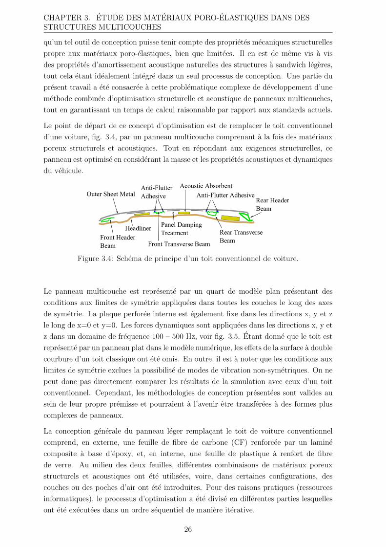
Le point de depart de ce concept d’optimisation est de remplacer le toit conventionnel
d’une voiture, fig. 3.4, par un panneau multicouche comprenant a la fois des materiaux
poreux structurels et acoustiques. Tout en repondant aux exigences structurelles, ce
panneau est optimise en considerant la masse et les proprietes acoustiques et dynamiques
du vehicule.
Figure 3.4: Schema de principe d’un toit conventionnel de voiture.
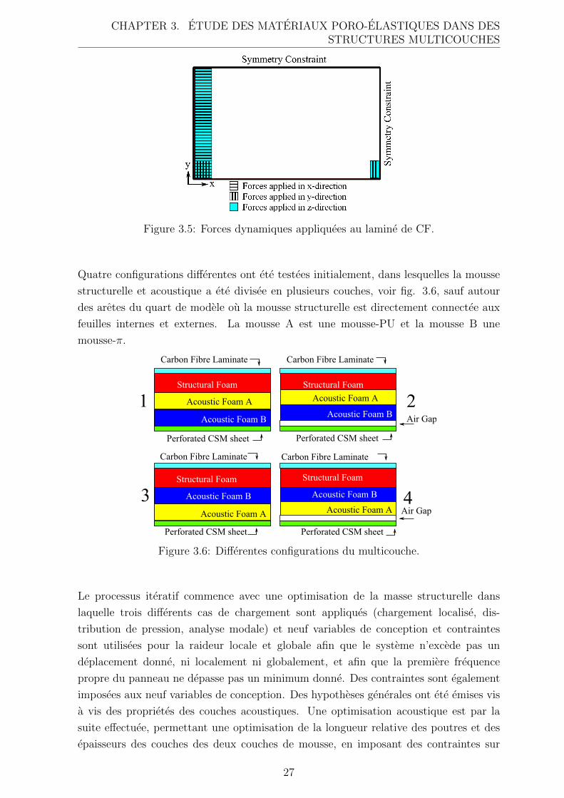
Le panneau multicouche est represente par un quart de modele plan presentant des
conditions aux limites de symetrie appliquees dans toutes les couches le long des axes
de symetrie. La plaque perforee interne est egalement fixe dans les directions x, y et z
le long de x=0 et y=0. Les forces dynamiques sont appliquees dans les directions x, y et
z dans un domaine de frequence 100 – 500 Hz, voir fig. 3.5. Etant donne que le toit est
represente par un panneau plat dans le modele numerique, les effets de la surface a double
courbure d’un toit classique ont ete omis. En outre, il est a noter que les conditions aux
limites de symetrie exclues la possibilite de modes de vibration non-symetriques. On ne
peut donc pas directement comparer les resultats de la simulation avec ceux d’un toit
conventionnel. Cependant, les methodologies de conception presentees sont valides au
sein de leur propre premisse et pourraient a l’avenir etre transferees a des formes plus
complexes de panneaux.
La conception generale du panneau leger remplacant le toit de voiture conventionnel
comprend, en externe, une feuille de fibre de carbone (CF) renforcee par un lamine
composite a base d’epoxy, et, en interne, une feuille de plastique a renfort de fibre
de verre. Au milieu des deux feuilles, differentes combinaisons de materiaux poreux
structurels et acoustiques ont ete utilisees, voire, dans certaines configurations, des
couches ou des poches d’air ont ete introduites. Pour des raisons pratiques (ressources
informatiques), le processus d’optimisation a ete divise en differentes parties lesquelles
ont ete executees dans un ordre sequentiel de maniere iterative.
26
CHAPTER 3. ETUDE DES MATERIAUX PORO-ELASTIQUES DANS DESSTRUCTURES MULTICOUCHES
Figure 3.5: Forces dynamiques appliquees au lamine de CF.
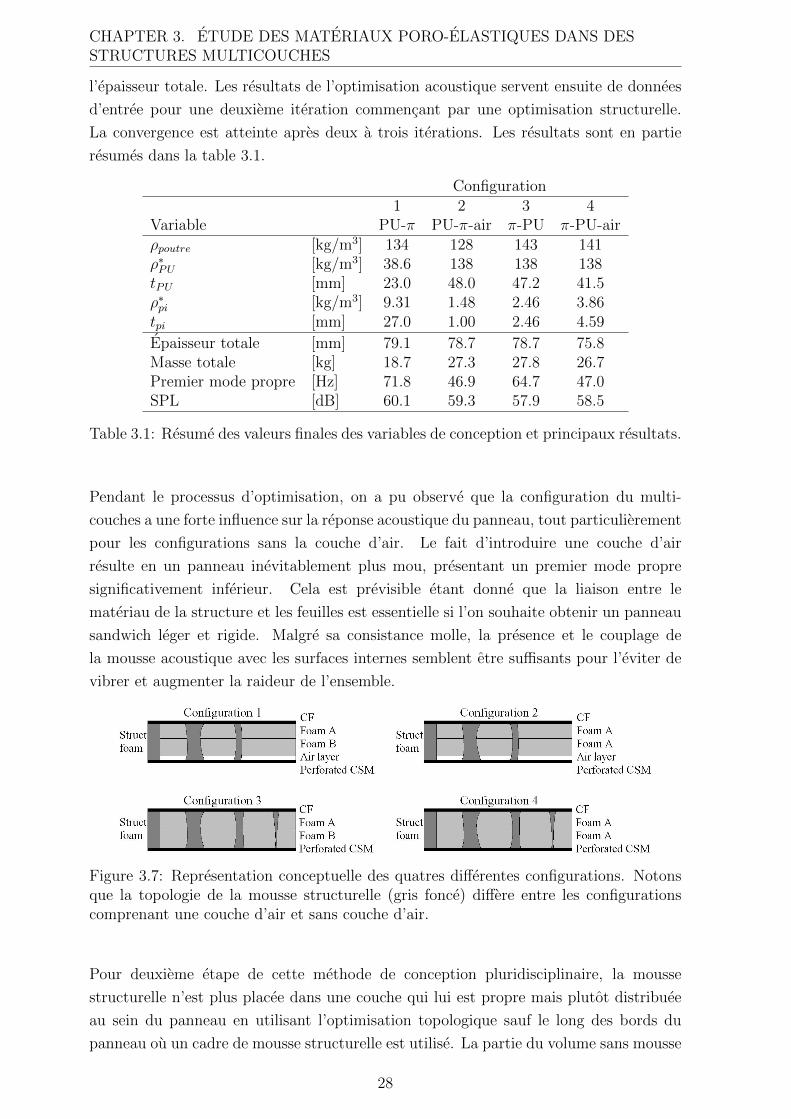
Quatre configurations differentes ont ete testees initialement, dans lesquelles la mousse
structurelle et acoustique a ete divisee en plusieurs couches, voir fig. 3.6, sauf autour
des aretes du quart de modele ou la mousse structurelle est directement connectee aux
feuilles internes et externes. La mousse A est une mousse-PU et la mousse B une
mousse-π.
Figure 3.6: Differentes configurations du multicouche.
Le processus iteratif commence avec une optimisation de la masse structurelle dans
laquelle trois differents cas de chargement sont appliques (chargement localise, dis-
tribution de pression, analyse modale) et neuf variables de conception et contraintes
sont utilisees pour la raideur locale et globale afin que le systeme n’excede pas un
deplacement donne, ni localement ni globalement, et afin que la premiere frequence
propre du panneau ne depasse pas un minimum donne. Des contraintes sont egalement
imposees aux neuf variables de conception. Des hypotheses generales ont ete emises vis
a vis des proprietes des couches acoustiques. Une optimisation acoustique est par la
suite effectuee, permettant une optimisation de la longueur relative des poutres et des
epaisseurs des couches des deux couches de mousse, en imposant des contraintes sur
27
CHAPTER 3. ETUDE DES MATERIAUX PORO-ELASTIQUES DANS DESSTRUCTURES MULTICOUCHES
l’epaisseur totale. Les resultats de l’optimisation acoustique servent ensuite de donnees
d’entree pour une deuxieme iteration commencant par une optimisation structurelle.
La convergence est atteinte apres deux a trois iterations. Les resultats sont en partie
resumes dans la table 3.1.
Configuration1 2 3 4
Variable PU-π PU-π-air π-PU π-PU-airρpoutre [kg/m3] 134 128 143 141ρ∗PU [kg/m3] 38.6 138 138 138tPU [mm] 23.0 48.0 47.2 41.5ρ∗pi [kg/m3] 9.31 1.48 2.46 3.86tpi [mm] 27.0 1.00 2.46 4.59
Epaisseur totale [mm] 79.1 78.7 78.7 75.8Masse totale [kg] 18.7 27.3 27.8 26.7Premier mode propre [Hz] 71.8 46.9 64.7 47.0SPL [dB] 60.1 59.3 57.9 58.5
Table 3.1: Resume des valeurs finales des variables de conception et principaux resultats.
Pendant le processus d’optimisation, on a pu observe que la configuration du multi-
couches a une forte influence sur la reponse acoustique du panneau, tout particulierement
pour les configurations sans la couche d’air. Le fait d’introduire une couche d’air
resulte en un panneau inevitablement plus mou, presentant un premier mode propre
significativement inferieur. Cela est previsible etant donne que la liaison entre le
materiau de la structure et les feuilles est essentielle si l’on souhaite obtenir un panneau
sandwich leger et rigide. Malgre sa consistance molle, la presence et le couplage de
la mousse acoustique avec les surfaces internes semblent etre suffisants pour l’eviter de
vibrer et augmenter la raideur de l’ensemble.
Figure 3.7: Representation conceptuelle des quatres differentes configurations. Notonsque la topologie de la mousse structurelle (gris fonce) differe entre les configurationscomprenant une couche d’air et sans couche d’air.
Pour deuxieme etape de cette methode de conception pluridisciplinaire, la mousse
structurelle n’est plus placee dans une couche qui lui est propre mais plutot distribuee
au sein du panneau en utilisant l’optimisation topologique sauf le long des bords du
panneau ou un cadre de mousse structurelle est utilise. La partie du volume sans mousse
28
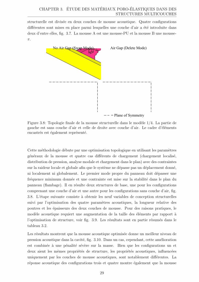
CHAPTER 3. ETUDE DES MATERIAUX PORO-ELASTIQUES DANS DESSTRUCTURES MULTICOUCHES
structurelle est divisee en deux couches de mousse acoustique. Quatre configurations
differentes sont mises en place parmi lesquelles une couche d’air a ete introduite dans
deux d’entre elles, fig. 3.7. La mousse A est une mousse-PU et la mousse B une mousse-
π.
Figure 3.8: Topologie finale de la mousse structurelle dans le modele 1/4. La partie degauche est sans couche d’air et celle de droite avec couche d’air. Le cadre d’elementsencastres est egalement represente.
Cette methodologie debute par une optimisation topologique en utilisant les parametres
generaux de la mousse et quatre cas differents de chargement (chargement localise,
distribution de pression, analyse modale et chargement dans le plan) avec des contraintes
sur la raideur locale et globale afin que le systeme ne depasse pas un deplacement donne,
ni localement ni globalement. Le premier mode propre du panneau doit depasser une
frequence minimum donnee et une contrainte est mise sur la stabilite dans le plan du
panneau (flambage). Il en resulte deux structures de base, une pour les configurations
comprenant une couche d’air et une autre pour les configurations sans couche d’air, fig.
3.8. L’etape suivante consiste a obtenir les neuf variables de conception structurelles
suivi par l’optimisation des quatre parametres acoustiques, la longueur relative des
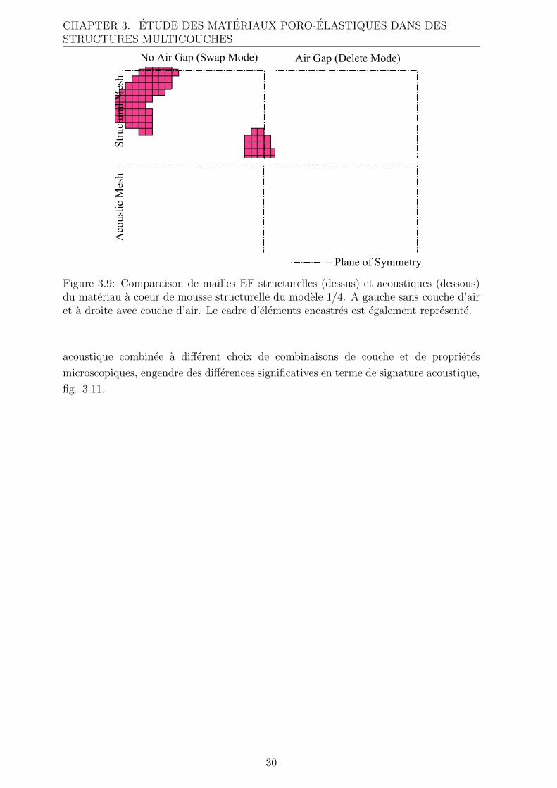
poutres et les epaisseurs des deux couches de mousse. Pour des raisons pratiques, le
modele acoustique requiert une augmentation de la taille des elements par rapport a
l’optimisation de structure, voir fig. 3.9. Les resultats sont en partie resumes dans le
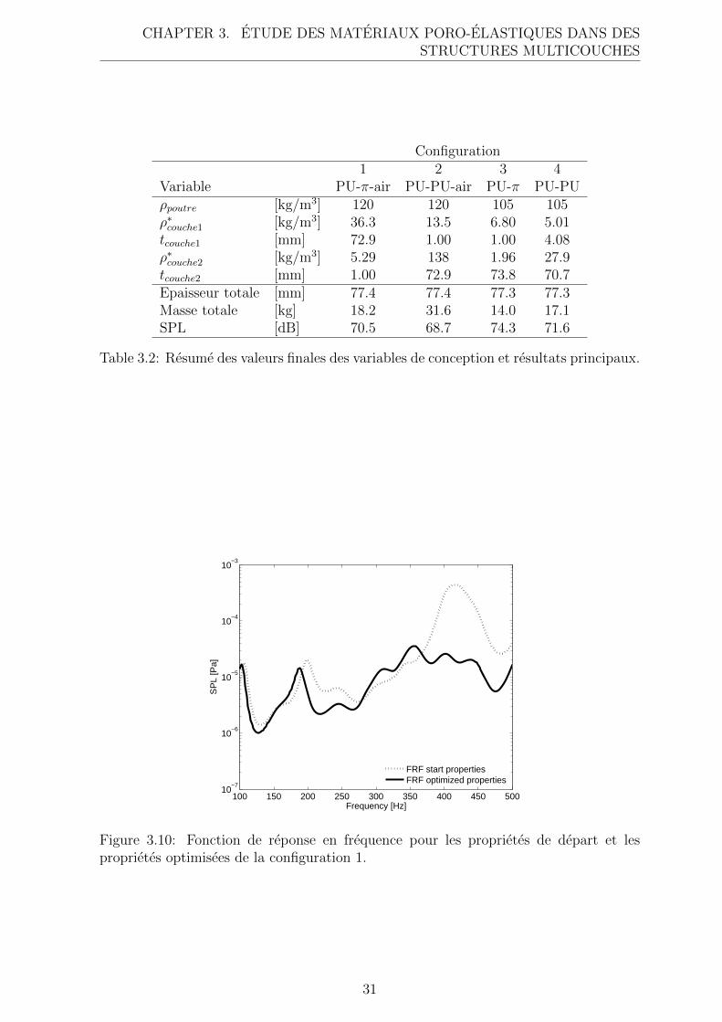
tableau 3.2.
Les resultats montrent que la mousse acoustique optimisee donne un meilleur niveau de
pression acoustique dans la cavite, fig. 3.10. Dans un cas, cependant, cette amelioration
est combinee a une penalite severe sur la masse. Bien que les configurations un et
deux aient les memes proprietes de structure, les proprietes acoustiques, influencees
uniquement par les couches de mousse acoustiques, sont notablement differentes. La
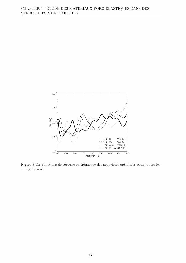
reponse acoustique des configurations trois et quatre montre egalement que la mousse
29
CHAPTER 3. ETUDE DES MATERIAUX PORO-ELASTIQUES DANS DESSTRUCTURES MULTICOUCHES
Figure 3.9: Comparaison de mailles EF structurelles (dessus) et acoustiques (dessous)du materiau a coeur de mousse structurelle du modele 1/4. A gauche sans couche d’airet a droite avec couche d’air. Le cadre d’elements encastres est egalement represente.
acoustique combinee a different choix de combinaisons de couche et de proprietes
microscopiques, engendre des differences significatives en terme de signature acoustique,
fig. 3.11.
30
CHAPTER 3. ETUDE DES MATERIAUX PORO-ELASTIQUES DANS DESSTRUCTURES MULTICOUCHES
Configuration1 2 3 4
Variable PU-π-air PU-PU-air PU-π PU-PUρpoutre [kg/m3] 120 120 105 105ρ∗couche1 [kg/m3] 36.3 13.5 6.80 5.01tcouche1 [mm] 72.9 1.00 1.00 4.08ρ∗couche2 [kg/m3] 5.29 138 1.96 27.9tcouche2 [mm] 1.00 72.9 73.8 70.7Epaisseur totale [mm] 77.4 77.4 77.3 77.3Masse totale [kg] 18.2 31.6 14.0 17.1SPL [dB] 70.5 68.7 74.3 71.6
Table 3.2: Resume des valeurs finales des variables de conception et resultats principaux.
100 150 200 250 300 350 400 450 50010
−7
10−6
10−5
10−4
10−3
Frequency [Hz]
SP
L [P
a]
FRF start propertiesFRF optimized properties
Figure 3.10: Fonction de reponse en frequence pour les proprietes de depart et lesproprietes optimisees de la configuration 1.
31
CHAPTER 3. ETUDE DES MATERIAUX PORO-ELASTIQUES DANS DESSTRUCTURES MULTICOUCHES
100 150 200 250 300 350 400 450 50010
−7
10−6
10−5
10−4
10−3
Frequency [Hz]
SP
L [P
a]
PU−pi 74.3 dBPU−PU 71.6 dBPU−pi−air 70.5 dBPU−PU−air 68.7 dB
Figure 3.11: Fonctions de reponse en frequence des proprietes optmisees pour toutes lesconfigurations.
32
Chapter 4
Conclusions
Le travail presente dans ce manuscrit montre que de petites modifications des proprietes
microscopiques des materiaux poro-elastiques a cellules ouvertes peuvent provoquer
des differences dans le comportement macroscopique suffisamment importantes pour
impacter la reponse acoustique et dynamique du materiau lorsqu’il est assemble dans
des configurations de panneau multicouches. Dans le cas des materiaux poro-elastiques
anisotropes, l’orientation angulaire des proprietes macroscopiques des materiaux dans
chaque couche a un impact significatif sur le comportement acoustique et dynamique
d’un panneau multicouches. Comme demontre dans des travaux precedents et dans
celui-ci, le choix des materiaux poro-elastiques, des combinaisons des couches et des
epaisseurs des couches revet egalement une grande importance dans la conception des
panneaux multicouches. Ces aspects physiques impliquent qu’il existe un fort potentiel
pour adapter des structures multicouches a des besoins specifiques.
Bien que le traitement acoustique ait souvent lieu assez tard dans le processus de
conception, il existe potentiellement de grands avantages a combiner les besoins
acoustiques et structurels dans des structures de type panneaux multifonctionnels,
etant donne que le panneau sandwich presente plusieurs avantages acoustiques deja
integres tels qu’un amortissement assez eleve, et le materiau poro-elastique acoustique,
en comparaison assez souple, peut contribuer a la performance globale de la structure.
Toutefois la combinaison de ces deux disciplines requiert le developpement de nouveaux
outils de conception, lequel represente un travail considerable. Une petite partie de ce
travail a ete realisee dans le cadre de cette these.
Afin de determiner des parametres materiaux optimaux ou du moins significativement
ameliores, une approche d’optimisation a ete implementee dans un outil de modelisation
numerique aux EF existant. L’approche d’optimisation se revele etre un moyen assez
efficace et utile pour trouver de tels parametres materiaux. Cependant, l’optimisation
d’un panneau dans le but d’obtenir un comportement donne presuppose la definition
de ce comportement en termes de valeurs numeriques dependantes des variables de
conception. Il convient de souligner que le choix de la fonction objectif est crucial
puisque ce choix affecte directement le resultat de l’optimisation. Afin d’obtenir un
33
CHAPTER 4. CONCLUSIONS
resultat satisfaisant, il est egalement necessaire de connaitre de maniere tres detaillee
les cas de chargement et les conditions aux limites du systeme.
Enfin, les approches de modelisation presentees ici pourraient constituer une partie d’un
outil de conception assistee par ordinateur, tout particulierement pour le developpement
de panneaux legers multicouches. Un tel outil de conception peut etre de grande
importance dans le developpement de futures concepts de vehicules plus legers et de
meilleur efficacite energetique, puisqu’il permettrait de maintenir voire d’ameliorer les
proprietes NVH lesquelles sont souvent penalisees lorsqu’on diminue la masse d’une
structure.
4.1 Perspectives
Une possible continuation des travaux inities sur les materiaux poro-elastiques anisotropes
serait de developper des lois d’echelles efficaces en terme de calcul, ou d’autres moyens
permettant de lier les proprietes microscopiques et macroscopiques de ces materiaux.
Il pourrait etre egalement interessant d’ameliorer les lois d’echelles des materiaux
isotropes. Il serait aussi necessaire d’accroitre la comprehension du comportement
physique des materiaux poro-elastiques, en particulier lorsqu’ils sont assembles dans
differentes structures (pre-compression des materiaux poreux, difficulte a attribuer des
conditions aux limites appropriees, ...). Cela inclut le developpement de techniques
de mesure des proprietes materiaux macroscopiques, la modelisation de ces proprietes
et leur lien avec les proprietes geometriques microscopiques, la comprehension et la
modelisation de differents phenomenes d’amortissement, ainsi que la comprehension et
la modelisation des variations des proprietes macroscopiques proche des bords d’un
domaine materiau poro-elastique. Pour les materiaux poro-elastiques anisotropes, ce
besoin est d’autant plus grand que la comprehension des phenomenes dynamiques et
acoustiques anisotropes dans de tels materiaux est a ce jour tres limitee.
Une meilleur comprehension de la complexite du comportement vibro-acoustique et une
etendue des possibilites de conception de panneaux multifonctionnels sont egalement
tres recherchees. Cela doit pouvoir etre implemente dans des outils de conception
multidisciplinaires et efficaces en terme de ressources de calcul afin de pouvoir etre
utilise industriellement.
Une meilleur comprehension des phenomenes et le developpement de modeles utilisables
industriellement dans ces domaines peuvent permettre de contribuer a accroıtre la
fonctionnalite et a reduire l’impact environnemental des vehicules dans l’avenir.
34
Bibliography
[1] J. Akerman and M. Hojer. How much transport can the climate stand?-sweden on
a sustainable path in 2050. Energy Policy, 34(14):1944–1957, 2006.
[2] J.-F. Allard. Propagation of sound in porous media: modelling sound absorbing
materials. Elsevier Applied Science, 1993.
[3] J.-F. Allard and Y. Champoux. New empirical equations for sound propagation in
rigid frame fibrous materials. J. Acoust. Soc. Am., 6(91):3346–3353, 1992.
[4] N. Atalla, M. A. Hamdi, and R. Panneton. Enhanced weak integral formulation
for the mixed (u,p) poroelastic equations. J. Acoust. Soc. Am., 109(6):3065–3068,
2001.
[5] N. Atalla, R. Panneton, and P. Debergue. A mixed displacement-pressure
formulation for poroelastic materials. J. Acoust. Soc. Am., 104(3):1444–1452, 1998.
[6] M. A. Biot. Theory of propagation of elastic waves in a fluid saturated porous solid.
I. Low frequency range. J. Acoust. Soc. Am., 28:168–178, 1956:1.
[7] M. A. Biot. Theory of deformation of a porous viscoelastic anisotropic solid. J.
Appl. Phys., 27:459–467, 1956:3.
[8] M. A. Biot. Mechanics of deformation and acoustic propagation in porous media.
J. Appl. Phys., 33(4):1482–1498, 1962.
[9] M. A. Biot and D. G. Willis. The elastic coefficients of the theory of consolidation.
J. Appl. Mech., 24:594–601, 1957.
[10] Y. Champoux and J.-F. Allard. Dynamic tortuosity and bulk modulus in air-
saturated porous media. J. Appl. Phys., 70(4):1975–1979, 1991.
[11] J. Comiti and M. Renaud. New model for determining mean structure parameters
of fixed beds from pressure drop measurements. Application to beds packed with
parallellepipedal particles. Chemical Engineering Science, 44(7):1539–1545, 1989.
[12] O. Doutres, N. Atalla, and K. Dong. Effect of the microstructure closed pore
content on the acoustic behavior of polyurethane foams. J. Appl. Phys., 110(6),
2011.
35
BIBLIOGRAPHY
[13] K. Dovstam. Augmented Hooke’s law in frequency domain. A three dimensional
material damping formulation. Int. J. Solids Structures, 32(19):2835–2852, 1995.
[14] A. Geslain, O. Dazel, J.-P. Groby, S. Sahraoui, and W. Lauriks. Influence of static
compression on mechanical parameters of acoustic foams. J. Acoust. Soc. Am.,
130(2):818–825, 2011.
[15] L. J. Gibson and M. F. Ashby. Cellular solids — Structure and properties.
Cambridge University Press, second edition, 1997. First published by Pergamont
Press Ltd., 1988.
[16] P. Goransson. Acoustic and vibrational damping in porous solids. Phil. Trans. R.
Soc. A, 364:89–108, 2006.
[17] P. Goransson, R. Guastavino, and N.-E. Horlin. Measurement and inverse
estimation of 3d anisotropic flow resistivity for porous materials. J. Sound Vib.,
327(3-5):354–367, 2009.
[18] R. Guastavino and P. Goransson. A 3d displacement measurement methodology for
anisotropic porous cellular foam materials. Polymer Testing, 26(6):711–719, 2007.
[19] N.-E. Horlin. 3-D hierarchical hp-FEM applied to elasto-acoustic modelling of
layered porous media. J. Sound Vib., 285(4):341–363, 2005.
[20] N.-E. Horlin and P. Goransson. Weak, anisotropic symmetric formulations of biot’s
equations for vibro-acoustic modelling of porous elastic materials. Int. J. Numer.
Meth. Engng, 84(12):1519–1540, 2010.
[21] N.-E. Horlin, M. Nordstrom, and P. Goransson. A 3-D hierarchical FE formulation
of Biot’s eguations for elasto-acoustic modelling of porous media. J. Sound Vib.,
254(4):633–652, 2001.
[22] W.-Y. Jang, A. M. Kraynik, and S. Kyriakides. On the microstructure of open-cell
foams and its effect on elastic properties. Int. J. Solids Structures, 45(7-8):1845–
1875, 2008.
[23] W.-Y. Jang, S. Kyriakides, and A. M. Kraynik. On the compressive strength
of open-cell metal foams with kelvin and random cell structures. Int. J. Solids
Structures, 47(21):2872–2883, 2010.
[24] D. L. Johnson, J. Koplik, and R. Dashen. Theory of dynamic permiability and
tortuosity in fluid-saturated porous media. J. Fluid Mech., 176:379–402, 1987.
[25] P. Khurana, L. Boeckx, W. Lauriks, P. Leclaire, O. Dazel, and J.-F. Allard. A
description of transversely isotropic sound absorbing porous materials by transfer
matrices. J. Acoust. Soc. Am., 125(2):915–921, 2009.
36

BIBLIOGRAPHY
[26] D. Lafarge, P. Lemarnier, J.-F. Allard, and V. Tarnow. Dynamic compressibility of
air in porous structures at audible frequencies. J. Acoust. Soc. Am, 102(4):1995–
2006, 1997.
[27] G. A. Lesieutre. Finite elements for dynamic modelling of uniaxial rods with
frequency-dependent material properties. Int. J. Solids Structures, 28:1567–1579,
1992.
[28] M. Melon, E. Mariez, C. Ayrault, and S. Sahraoui. Acoustical and mechanical
characterization of anisotropic open-cell foams. J. Acoust. Soc. Am., 104(5):2622–
2627, 1998.
[29] C. Perrot, F. Chevillotte, M. Tan Hoang, G. Bonnet, F.-X. Becot, L. Gautron,
and A. Duval. Microstructure, transport, and acoustic properties of open-cell foam
samples: Experiments and three-dimensional numerical simulations. J. Appl. Phys.,
111(1), 2012.
[30] C. Perrot, R. Panneton, and X. Olny. From microstructure to acoustic behaviour of
porous materials. Canadian Acoustics - Acoustique Canadienne, 32(3):18–19, 2004.
[31] S. Sahraoui, E. Mariez, and M. Etchessahar. Linear elastic properties of anisotropic
open-cell foams. J. Acoust. Soc. Am., 110(1):635–637, 2001.
[32] K. Svanberg. The method of moving asymptotes — a new method for structural
optimization. Int. J. Numer. Meth. Engng, 24:359–373, 1987.
[33] K. Svanberg. A class of globally convergent optimization methods based on
conservative convex separable approximations. SIAM Journal on Optimization,
12(2):555–573, 2002.
[34] C. Zwikker and C. Kosten. Sound absorbing materials., chapter II and III. Elsevier
Publishing Company, Amsterdam, 1949.
37

CONSERVATOIRE NATIONAL
DES ARTS ET METIERS
–
ROYAL INSTITUTE
OF TECHNOLOGY
Centre for ECO2 Vehicle Design
A study of tailoring acoustic porous materialproperties when designing lightweight multilayered
vehicle panels
Eleonora Lind Nordgren
Doctoral Thesis
Stockholm, Sweden 2012The Marcus Wallenberg Laboratory for Sound and Vibration Research
Department of Aeronautical and Vehicle Engineering
Postal address Visiting address ContactRoyal Institute of Technology Teknikringen 8 Tel: +46 8 790 79 41MWL/AVE Stockholm E-mail: [email protected] 44 StockholmSweden

Akademisk avhandling som med tillstand av Kungliga Tekniska Hogskolan i Stockholm
framlaggs till offentlig granskning for avlaggande av teknologie doktorsexamen fredagen
den 7:e september 2012, 14:00 i sal F3, Lindstedtsvagen 26, Kungliga Tekniska
Hogskolan, Stockholm.
TRITA-AVE-2012:52
ISSN-1651-7660
ISBN-978-91-7501-448-7
c© Eleonora Lind Nordgren, 2012
ii
Abstract
The present work explores the possibilities of adapting poro-elastic lightweight acoustic
materials to specific applications. More explicitly, a design approach is presented where
finite element based numerical simulations are combined with optimization techniques
to improve the dynamic and acoustic properties of lightweight multilayered panels
containing poro-elastic acoustic materials.
The numerical models are based on Biot theory which uses equivalent fluid/solid models
with macroscopic space averaged material properties to describe the physical behaviour
of poro-elastic materials. To systematically identify and compare specific beneficial or
unfavourable material properties, the numerical model is connected to a gradient based
optimizer. As the macroscopic material parameters used in Biot theory are interrelated,
they are not suitable to be used as independent design variables. Instead scaling laws
are applied to connect macroscopic material properties to the underlying microscopic
geometrical properties that may be altered independently.
The design approach is also combined with a structural sandwich panel mass opti-
mization, to examine possible ways to handle the, sometimes contradicting, structural
and acoustic demands. By carefully balancing structural and acoustic components,
synergetic rather than contradictive effects could be achieved, resulting in multifunc-
tional panels; hopefully making additional acoustic treatment, which may otherwise
undo major parts of the weight reduction, redundant.
The results indicate a significant potential to improve the dynamic and acoustic
properties of multilayered panels with a minimum of added weight and volume. The
developed modelling techniques could also be implemented in future computer based
design tools for lightweight vehicle panels. This would possibly enable efficient mass
reduction while limiting or, perhaps, totally avoiding the negative impact on sound and
vibration properties that is, otherwise, a common side effect of reducing weight, thus
helping to achieve lighter and more energy efficient vehicles in the future.

iv
Resume
Le present travail explore la possibilite d’adapter des materiaux poro-elastiques legers
pour des applications specifiques. En particulier, une approche de conception est
presentee, combinant simulations par la methodes des elements finis et techniques
d’optimisation, permettant ainsi d’ameliorer les proprietes dynamiques et acoustiques
de panneaux multicouches comprenant des materiaux poreux.
Les modeles numeriques sont fondes sur la theorie de Biot qui utilise des modeles
equivalents fluide/solide avec des proprietes macroscopiques spatialement homogeneisees,
decrivant le comportement physique des materiaux poro-elastiques. Afin de syste-
matiquement identifier et comparer certaines proprietes specifiques, benefiques ou
defavorables, le modele numerique est connecte a un optimiseur fonde sur les gradients.
Les parametres macroscopiques utilises dans la theorie de Biot etant lies, il ne peuvent
etre utilises comme variables independantes. Par consequent, des lois d’echelle sont
appliquees afin de connecter les proprietes macroscopiques du materiau aux proprietes
geometriques microscopiques, qui elles peuvent etre modifiees independamment.
L’approche de conception est egalement combinee avec l’optimisation de la masse d’un
panneau sandwich structure, afin d’examiner les possibilites de combiner exigences
structurelles et acoustiques, qui peuvent etre en conflit. En prenant le soin d’etablir un
equilibre entre composantes acoustiques et structurelles, des effets de synergie plutot que
destructifs peuvent etre obtenus, donnant lieu a des panneaux multifonctionnels. Cela
pourrait rendre l’ajout de traitements acoustiques redondant, qui par ailleurs annulerait
tout ou partie du gain en masse obtenu par optimisation.
Les resultats indiquent un veritable potentiel d’amelioration des proprietes dynamiques
et acoustiques de panneaux multi-couches, pour un ajout minimum en termes de masse et
volume. La technique de modelisation developpee pourrait egalement etre implementee
au sein d’outils numeriques futures pour la conception de panneaux legers de vehicules.
Cela aurait le potentiel de reduire substantiellement la masse tout en limitant, voire
supprimant l’impact negatif sur les proprietes acoustiques et vibratoires, pourtant
une consequence courante de la reduction de la masse, participant ainsi a l’effort de
developpement de vehicules futures plus legers et efficaces.

vi
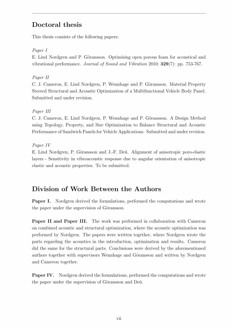
Doctoral thesis
This thesis consists of the following papers:
Paper I
E. Lind Nordgren and P. Goransson. Optimising open porous foam for acoustical and
vibrational performance. Journal of Sound and Vibration 2010; 329(7): pp. 753-767.
Paper II
C. J. Cameron, E. Lind Nordgren, P. Wennhage and P. Goransson. Material Property
Steered Structural and Acoustic Optimization of a Multifunctional Vehicle Body Panel.
Submitted and under revision.
Paper III
C. J. Cameron, E. Lind Nordgren, P. Wennhage and P. Goransson. A Design Method
using Topology, Property, and Size Optimization to Balance Structural and Acoustic
Performance of Sandwich Panels for Vehicle Applications. Submitted and under revision.
Paper IV
E. Lind Nordgren, P. Goransson and J.-F. Deu. Alignment of anisotropic poro-elastic
layers - Sensitivity in vibroacoustic response due to angular orientation of anisotropic
elastic and acoustic properties. To be submitted.
Division of Work Between the Authors
Paper I. Nordgren derived the formulations, performed the computations and wrote
the paper under the supervision of Goransson.
Paper II and Paper III. The work was performed in collaboration with Cameron
on combined acoustic and structural optimization, where the acoustic optimization was
performed by Nordgren. The papers were written together, where Nordgren wrote the
parts regarding the acoustics in the introduction, optimization and results. Cameron
did the same for the structural parts. Conclusions were derived by the aforementioned
authors together with supervisors Wennhage and Goransson and written by Nordgren
and Cameron together.
Paper IV. Nordgren derived the formulations, performed the computations and wrote
the paper under the supervision of Goransson and Deu.
vii

Acknowledgments
The work presented in this thesis has been carried out within in the Centre for ECO2
Vehicle Design at the Marcus Wallenberg Laboratory (MWL) and within the Smart
Structures network at Laboratoire de Mecanique des Structures et des Systemes Couples
(LMSSC) at the Conservatoire National des Arts et Metiers (CNAM). The financial
support is gratefully acknowledged.
First I would like to thank my supervisor, Peter Goransson, for giving me the
opportunity to take on this inspiring, gratifying and frustrating challenge, and for your
support and guidance along the way. Your confidence in me and this project as well as
your great knowledge and devotion to the subject has been invaluable.
Further I would like to thank my other supervisor, Roger Ohayon at LMSSC, and
my assistant supervisors, Nils-Erik Horlin at MWL and Jean-Francois Deu at LMSSC,
for taking the time to answer my many questions varying from theoretical aspects of
numerical simulations and computational issues to practical matters related to this
joint Swedish-French PhD. Also, I would like to thank the administrative staff for their
patience when handling all the different issues of administrative matter.
To Christopher J. Cameron, with whom a substantial part of this work was carried out,
thank you for the interesting discussions and the insights in a different research area.
The collaborative work has definitely helped me become a more versatile researcher.
To my colleges I would like to extend my thanks for creating such a stimulating and
open-minded work environment, especially to Eskil Lindberg for being a great office
mate and for sharing your honest and down-to-earth views in all sorts of questions.
I am also grateful to all of my friends and family for making my life so much more
enjoyable. Special thanks to my beloved Mamma, Pappa, Syster, Bror and Farmor for
their encouragement and genuine love and care throughout my life. And yes, I am now
just about finished with ”school” . . .
Finally, MIKAEL, thank you! Completing this thesis would not have been possible
without your love and support. You are truly wonderful! ♥

Contents
I Overview and Summary 1
1 Introduction 3
2 Describing and designing porous media 5
2.1 Energy dissipation in porous media . . . . . . . . . . . . . . . . . . . . . 6
2.2 Biot theory . . . . . . . . . . . . . . . . . . . . . . . . . . . . . . . . . . 7
2.2.1 Governing equations . . . . . . . . . . . . . . . . . . . . . . . . . 9
2.2.2 Matrix representation of material parameters . . . . . . . . . . . . 11
2.2.3 Isotropic versus anisotropic modelling . . . . . . . . . . . . . . . . 13
2.3 FE-modelling . . . . . . . . . . . . . . . . . . . . . . . . . . . . . . . . . 14
2.4 Correlations between macroscopic and microscopic properties . . . . . . . 15
2.5 Aspects of optimization . . . . . . . . . . . . . . . . . . . . . . . . . . . . 18
3 Studies of poro-elastic acoustic materials in multilayered structures 21
3.1 Adapting porous material parameters for improved acoustic performance 23
3.2 Combined structural and acoustic optimization – a multidisciplinary
design tool . . . . . . . . . . . . . . . . . . . . . . . . . . . . . . . . . . . 25
4 Conclusions 31
4.1 Future work . . . . . . . . . . . . . . . . . . . . . . . . . . . . . . . . . . 32
5 Summary of papers 33
6 Appendix 37
6.1 Notations in latin letters . . . . . . . . . . . . . . . . . . . . . . . . . . . 37
6.2 Notations in greek letters . . . . . . . . . . . . . . . . . . . . . . . . . . . 38
6.3 Material properties of reference materials . . . . . . . . . . . . . . . . . . 38
Bibliography 39
II Appended papers 43
xi

Part I
Overview and Summary
1

Chapter 1
Introduction
The environmental impact caused by human activities in general, has become an
increasingly important issue on a global scale. Major parts of the discussion today regard
global warming, for which emissions of carbon dioxide and other green house gases are
considered responsible. In Sweden approximately 26% of the energy consumption is
due to the transport industry, and according to Akerman and Hojer [1] this is already
too much. In order to achieve a sustainable environmental impact the energy used for
transport would actually need to be decreased by 60% until year 2050. This can only be
done by far reaching changes in transport patterns combined with a significant reduction
of energy intensity of transport. Many aspects of a vehicle have to be considered in order
to improve the energy efficiency. Apart from the drive line itself, rolling resistance,
aerodynamic properties and overall vehicle weight are just a few of many characteristics
that highly influence the total life cycle energy consumed.
Reducing the weight of a vehicle is therefore one of many strategies to reduce the fuel or
energy consumption and hence achieve more effective transportations with less negative
environmental impact. Concurrently, the demands on safety and comfort will not be
lowered and changes made to the structure must hence strive to sustain or even improve
those properties. This may be accomplished by e.g. far-reaching changes in selected
materials as well as overall design, and the implementation of light and stiff multilayered
and multifunctional structures (e.g. sandwich panels and sandwich composites) in
industrial production has steadily increased for some time. Although, along with the
introduction of new lightweight designs, increased problems with noise and vibration
often follows, in particular at low frequencies. Typically, unwanted structural vibrations
and noise are carried through the structure and radiate, for example, from trim surfaces
inside the cabin of a vehicle. Consequently, the dynamic behaviour of such interior trim
panel has a major impact on the radiated noise and hence the interior noise levels.
Adding flexible poro-elastic and visco-elastic materials is an often used method
to improve noise, vibration and harshness (NVH) comfort in vehicles under such
circumstances when major modifications of the interior trim panels are not possible.
However, adding material is problematic in view of the goal of reducing weight. It also
3
CHAPTER 1. INTRODUCTION
adds to the overall cost, material and assembly, and may also take up space that might
otherwise come to the benefit of the user. It would of course be highly sought after to
include acoustic and dynamic requirements in the original design of the panel or, as a
second option, to assure that the best possible performance per added weight, cost and
volume of any latterly added treatment is achieved.
A common way to enhance the performance of an acoustic trim panel is to combine
different poro-elastic and visco-elastic materials into several layers with different
physical and mechanical properties, such as damping, elasticity, viscosity and density.
Determining which materials to combine and what properties to look for in each
individual layer in order to achieve satisfactory result, is today an expensive and
time consuming task that requires knowledge of previously successful combinations,
engineering experience as well as extensive testing. Clearly there is a need for
computational tools that are able to predict and optimize the behaviour of such
multilayered structures.
This work is an initial attempt to demonstrate the possibilities of adapting porous
materials to specific purposes. Done correctly, it can potentially generate considerable
improvements in NVH comfort with a minimum of added volume and weight.
4
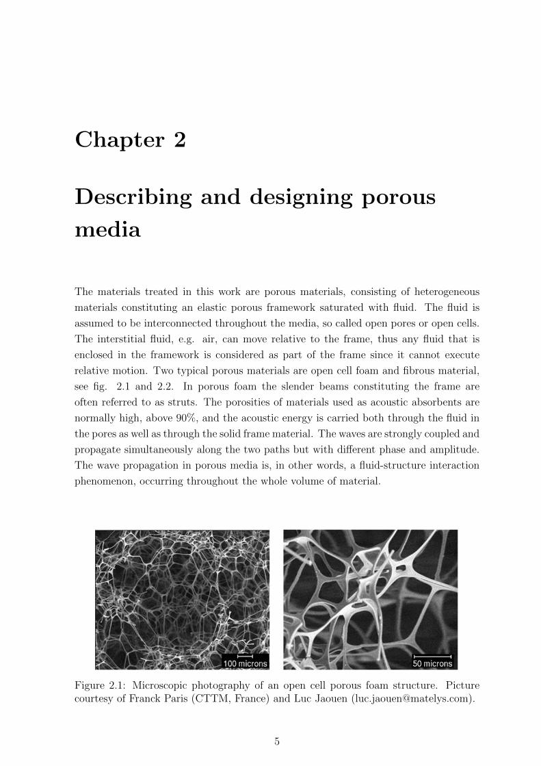
Chapter 2
Describing and designing porous
media
The materials treated in this work are porous materials, consisting of heterogeneous
materials constituting an elastic porous framework saturated with fluid. The fluid is
assumed to be interconnected throughout the media, so called open pores or open cells.
The interstitial fluid, e.g. air, can move relative to the frame, thus any fluid that is
enclosed in the framework is considered as part of the frame since it cannot execute
relative motion. Two typical porous materials are open cell foam and fibrous material,
see fig. 2.1 and 2.2. In porous foam the slender beams constituting the frame are
often referred to as struts. The porosities of materials used as acoustic absorbents are
normally high, above 90%, and the acoustic energy is carried both through the fluid in
the pores as well as through the solid frame material. The waves are strongly coupled and
propagate simultaneously along the two paths but with different phase and amplitude.
The wave propagation in porous media is, in other words, a fluid-structure interaction
phenomenon, occurring throughout the whole volume of material.
Figure 2.1: Microscopic photography of an open cell porous foam structure. Picturecourtesy of Franck Paris (CTTM, France) and Luc Jaouen ([email protected]).
5
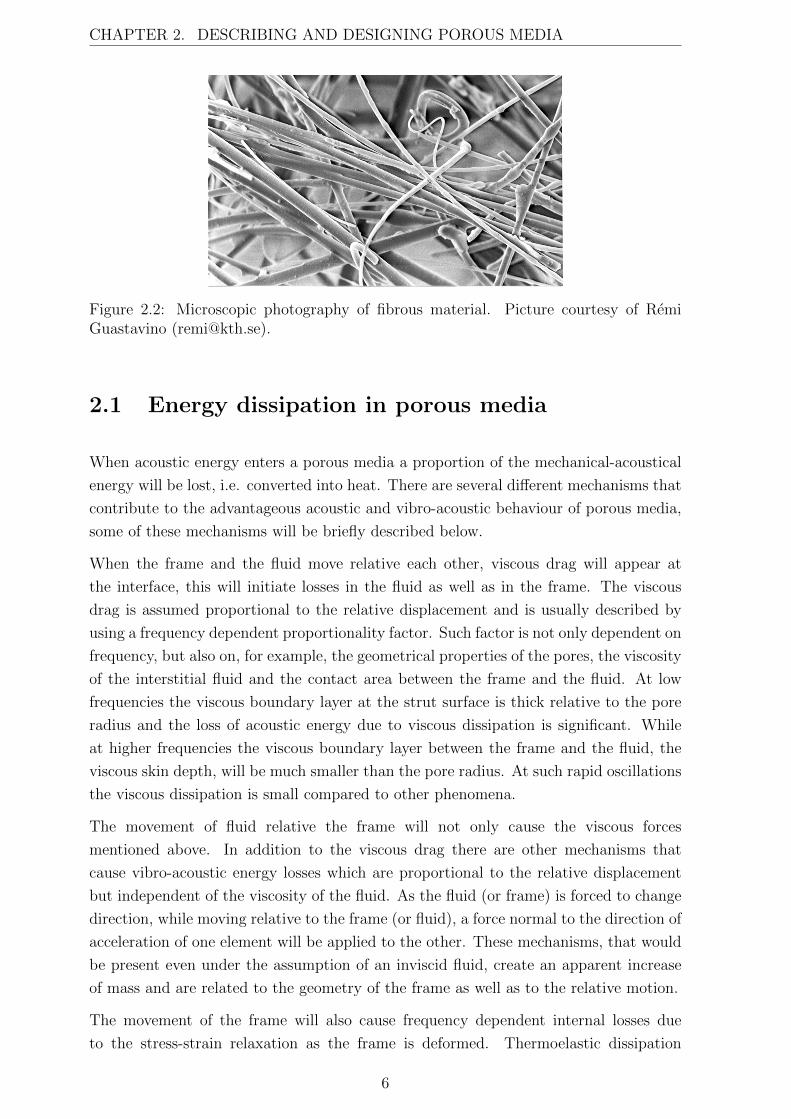
CHAPTER 2. DESCRIBING AND DESIGNING POROUS MEDIA
Figure 2.2: Microscopic photography of fibrous material. Picture courtesy of RemiGuastavino ([email protected]).
2.1 Energy dissipation in porous media
When acoustic energy enters a porous media a proportion of the mechanical-acoustical
energy will be lost, i.e. converted into heat. There are several different mechanisms that
contribute to the advantageous acoustic and vibro-acoustic behaviour of porous media,
some of these mechanisms will be briefly described below.
When the frame and the fluid move relative each other, viscous drag will appear at
the interface, this will initiate losses in the fluid as well as in the frame. The viscous
drag is assumed proportional to the relative displacement and is usually described by
using a frequency dependent proportionality factor. Such factor is not only dependent on
frequency, but also on, for example, the geometrical properties of the pores, the viscosity
of the interstitial fluid and the contact area between the frame and the fluid. At low
frequencies the viscous boundary layer at the strut surface is thick relative to the pore
radius and the loss of acoustic energy due to viscous dissipation is significant. While
at higher frequencies the viscous boundary layer between the frame and the fluid, the
viscous skin depth, will be much smaller than the pore radius. At such rapid oscillations
the viscous dissipation is small compared to other phenomena.
The movement of fluid relative the frame will not only cause the viscous forces
mentioned above. In addition to the viscous drag there are other mechanisms that
cause vibro-acoustic energy losses which are proportional to the relative displacement
but independent of the viscosity of the fluid. As the fluid (or frame) is forced to change
direction, while moving relative to the frame (or fluid), a force normal to the direction of
acceleration of one element will be applied to the other. These mechanisms, that would
be present even under the assumption of an inviscid fluid, create an apparent increase
of mass and are related to the geometry of the frame as well as to the relative motion.
The movement of the frame will also cause frequency dependent internal losses due
to the stress-strain relaxation as the frame is deformed. Thermoelastic dissipation
6
CHAPTER 2. DESCRIBING AND DESIGNING POROUS MEDIA
is yet another source of dissipation of acoustic energy as the compressibility of the
system yields an increase of temperature due to the compression and expansion cycles.
At low frequencies the process is isothermal while as at high frequencies the process
becomes adiabatic. In between these conditions, heat conduction among other physical
phenomena will cause losses in vibro-acoustic energy.
2.2 Biot theory
The most commonly used model to describe the acoustic behaviour of porous media
is attributed to Biot [6] and often referred to as the Biot theory, or sometimes as the
Johnson-Champoux-Allard model of the Biot theory. Part of Biot’s theory published in
1956 is similar to the contemporary one presented by Zwikker and Kosten [34] with the
difference that Biot also included the effects of shear stress in the elastic frame of the
porous medium.
Johnson et al. [24] added an improved description of the viscous effects by introducing
the characteristic viscous length, Λ, which takes frequency dependent viscous effects
into account. Allard and Champoux [3, 10] added the characteristic thermal length, Λ′,
which similarly includes the effects of frequency dependent thermal losses.
Within the extended Biot theory the solid frame is modelled as an equivalent elastic solid
continuum and the interstitial fluid as an equivalent compressible fluid continuum, both
described by space averaged macroscopic mechanical properties common in continuum
mechanics. The two separate but coupled continua are then acting and interacting
while occupying the same space. The interaction between the solid and fluid phase
is described through coupling parameters derived from measurable macroscopic space
averaged properties. The macroscopic properties are used to calculate macroscopic
space averaged quantities e.g. solid and fluid displacement, acoustic pressure, and
elastic stress. One condition for the above modelling of foams is that the characteristic
microscopic dimensions of the foam, e.g. pore size, are small compared to characteristic
dimensions of the macroscopic behaviour. In acoustics the latter is identified as the
wave length. For the models and materials investigated here, this condition is generally
satisfied.
It should however be noted that the modelling of poro-elastic material as two separate,
coupled continua is problematic at the boundary of the material. Studies show the
homogenized properties may be quite different close to the surface of the poro-elastic
material [18]. These types of boundary effect could have a not insignificant impact,
especially if the depth of such boundary layer is large compared to the thickness of the
porous layer.
A substantial amount of work has been done to obtain physically meaningful descriptions
of the macroscopic material parameters. Especially significant for porous media are the
7
CHAPTER 2. DESCRIBING AND DESIGNING POROUS MEDIA
coupling parameters which may be defined in different ways. Within the Johnson-
Champoux-Allard model they are mostly described as:
• Porosity, φ [1], defined as the volume fraction of fluid content in the porous media,
0 < φ < 1. For materials used in acoustic applications the porosity is normally
larger than 0.95.
• Tortuosity, α∞ [1], defined as the fraction between mean microscopic fluid velocity
squared and the mean macroscopic fluid velocity squared averaged over a volume
under the assumption of zero viscosity. In practice it compares the length of the
path the fluid travels in the porous media on microscopic level with the length of
the path on a macroscopic level, implying that α∞ ≥ 1. For open porous media
with high porosity the tortuosity is often close to one, typically 1.05.
• Static flow resistivity, σstatic [Nsm−4], defined as the pressure difference over flow
velocity per unit length. The flow resistivity is dependent of many different
physical properties in the porous media, among them the surface viscosity between
the frame and the microscopic geometry of the porous media. This parameter may
be measured or theoretically deduced from e.g. Stokes simulations given a certain
microstructural geometry.
• Viscous characteristic length, Λ [m], helps to improve the estimation when dissipation
effects due to viscous losses at the pore walls need to be taken into account. When
the pores are small compared to the viscous skin depth the viscous dissipation
effects cannot be neglected. The viscous characteristic length provides possibilities
for modifications that give better frequency dependent representation of the
viscous losses.
• Thermal characteristic length, Λ’ [m], takes into account the thermal exchange
between the frame and the fluid at the boundary, in analogy with the viscous
characteristic length, hence similarly provides adjustments for the frequency
dependent thermal fluid-structure interactions.
An important part for increased understanding of porous materials is the experimental
work carried out to characterize different materials and obtain the macroscopic material
parameters needed. There are also still several not fully understood physical aspects
of porous materials, for example the influence of static compression, strain or other
deformations on the material properties [14] or the changes of elastic moduli at the
boundary region of porous foam samples [18]. Naturally the work to obtain experimental
data are closely connected to the work of developing mathematical models used to
describe these complex materials and their behaviour.
8
CHAPTER 2. DESCRIBING AND DESIGNING POROUS MEDIA
2.2.1 Governing equations
The Biot theory is a Lagrangian model where the stress-strain relations are derived
from potential energy deformation. While Biot theory, in practice, often is used in its
isotropic form, the anisotropic form of the governing equations, similar to what has been
previously stated by Biot [8], Biot and Willis [9] and Allard [2] will be given here. This
overview of the governing equations is in no way complete and should be considered as
a short summary of the very extensive work that has been previously accomplished in
the field of porous materials. The interested reader is referred to the original work for
details.
The notations used is explained when introduced and also summarized in Chapter 6,
except for the following regarding tensor notation. The component ordinal number in
a Cartesian co-ordinate system, e.g. i = 1, 2, 3 is noted i, j, k. Partial derivates with
respect to xi is written (.),i = ∂(.)/∂xi. Kronecker’s delta is δij. Also, Cartesian tensor
notation with Einstein’s summation convention is used, i.e. repeated indices imply a
summation of these terms.
Momentum equations
Assuming time harmonic motion at circular frequency ω, the (frequency domain)
momentum equations for the solid frame and the fluid respectively may be written
as
σsij,j = −ω2ρ11
ij usj − ω2ρ12
ij ufj (2.1)
and
σfij,j = −ω2ρ12
ij usj − ω2ρ22
ij ufj (2.2)
where σsij and σf
ij are the Cauchy stress tensors for the frame and the fluid respectively
while usj and uf
j are the frame and fluid displacements. The equivalent density tensors,
ρ11ij , ρ12
ij and ρ22ij are anisotropic generalizations of those used by Allard [2] and may be
defined as
ρ11ij = ρ1δij + ρa
ij −i
ωbij, (2.3)
ρ12ij = −ρa
ij −i
ωbij, (2.4)
ρ22ij = φρ0δij + ρa
ij −i
ωbij, (2.5)
9
CHAPTER 2. DESCRIBING AND DESIGNING POROUS MEDIA
where
ρaij = φρ0 (αij − δij) (2.6)
with ρ0 as the ambient fluid density and ρ1 as the bulk density of the porous material
and αij is the tortuosity tensor. ρaij is an inertial coupling coefficient that represents
the apparent increase of mass due to tortuosity. The viscous drag tensor bij accounts
for the viscous body forces between the solid and the fluid phase and is here defined as
established by Johnson et al. [24].
bij = φ2σstaticij Bij (ω) , (2.7)
where
Bij =
√1 + iω
4ηρ0α2ij
φ2(σstaticij )2Λ2
ij
(2.8)
with η being the ambient fluid viscosity.
Constitutive equations
The two constitutive equations may be defined as
σsij = Cijklεkl +Qijθ
f (2.9)
and
σfij = Qklεklδij +Rθfδij (2.10)
where Cijkl is the solid frame Hooke’s tensor, the fluid dilatation is given by the
divergence of the fluid displacement
θf = ufk,k (2.11)
and the solid frame strain is given by the Cauchy strain tensor
εkl =1
2
(usk,l + us
l,k
)(2.12)
The two material tensors, R and Qij are defined as
10
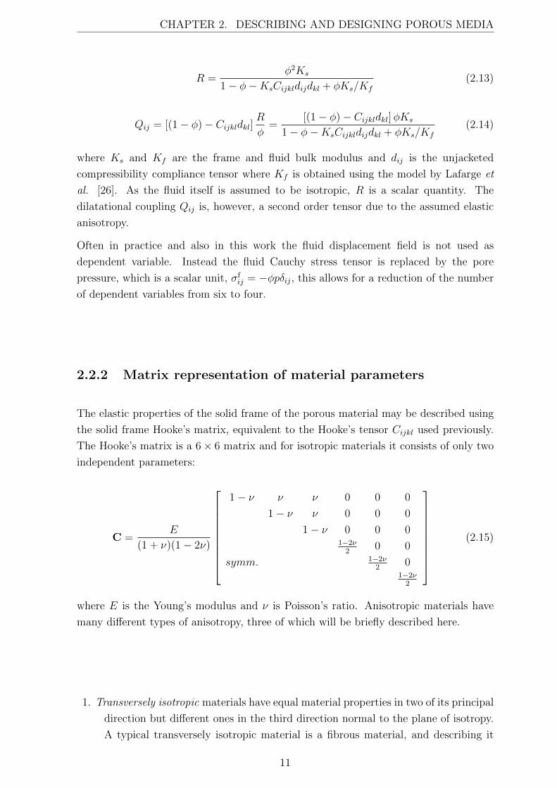
CHAPTER 2. DESCRIBING AND DESIGNING POROUS MEDIA
R =φ2Ks
1− φ−KsCijkldijdkl + φKs/Kf
(2.13)
Qij = [(1− φ)− Cijkldkl]R
φ=
[(1− φ)− Cijkldkl]φKs
1− φ−KsCijkldijdkl + φKs/Kf
(2.14)
where Ks and Kf are the frame and fluid bulk modulus and dij is the unjacketed
compressibility compliance tensor where Kf is obtained using the model by Lafarge et
al. [26]. As the fluid itself is assumed to be isotropic, R is a scalar quantity. The
dilatational coupling Qij is, however, a second order tensor due to the assumed elastic
anisotropy.
Often in practice and also in this work the fluid displacement field is not used as
dependent variable. Instead the fluid Cauchy stress tensor is replaced by the pore
pressure, which is a scalar unit, σfij = −φpδij, this allows for a reduction of the number
of dependent variables from six to four.
2.2.2 Matrix representation of material parameters
The elastic properties of the solid frame of the porous material may be described using
the solid frame Hooke’s matrix, equivalent to the Hooke’s tensor Cijkl used previously.
The Hooke’s matrix is a 6× 6 matrix and for isotropic materials it consists of only two
independent parameters:
C =E
(1 + ν)(1− 2ν)
1− ν ν ν 0 0 0
1− ν ν 0 0 0
1− ν 0 0 01−2ν
20 0
symm. 1−2ν2
01−2ν
2
(2.15)
where E is the Young’s modulus and ν is Poisson’s ratio. Anisotropic materials have
many different types of anisotropy, three of which will be briefly described here.
1. Transversely isotropic materials have equal material properties in two of its principal
direction but different ones in the third direction normal to the plane of isotropy.
A typical transversely isotropic material is a fibrous material, and describing it
11
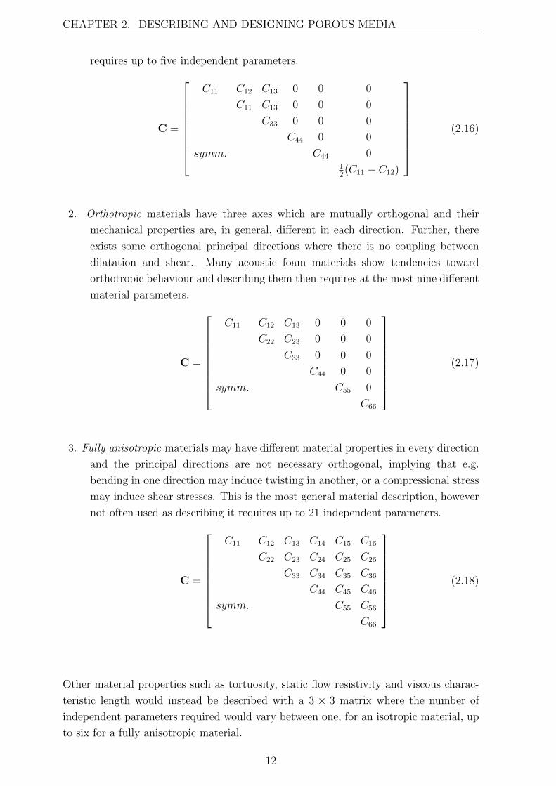
CHAPTER 2. DESCRIBING AND DESIGNING POROUS MEDIA
requires up to five independent parameters.
C =
C11 C12 C13 0 0 0
C11 C13 0 0 0
C33 0 0 0
C44 0 0
symm. C44 012(C11 − C12)
(2.16)
2. Orthotropic materials have three axes which are mutually orthogonal and their
mechanical properties are, in general, different in each direction. Further, there
exists some orthogonal principal directions where there is no coupling between
dilatation and shear. Many acoustic foam materials show tendencies toward
orthotropic behaviour and describing them then requires at the most nine different
material parameters.
C =
C11 C12 C13 0 0 0
C22 C23 0 0 0
C33 0 0 0
C44 0 0
symm. C55 0
C66
(2.17)
3. Fully anisotropic materials may have different material properties in every direction
and the principal directions are not necessary orthogonal, implying that e.g.
bending in one direction may induce twisting in another, or a compressional stress
may induce shear stresses. This is the most general material description, however
not often used as describing it requires up to 21 independent parameters.
C =
C11 C12 C13 C14 C15 C16
C22 C23 C24 C25 C26
C33 C34 C35 C36
C44 C45 C46
symm. C55 C56
C66
(2.18)
Other material properties such as tortuosity, static flow resistivity and viscous charac-
teristic length would instead be described with a 3 × 3 matrix where the number of
independent parameters required would vary between one, for an isotropic material, up
to six for a fully anisotropic material.
12
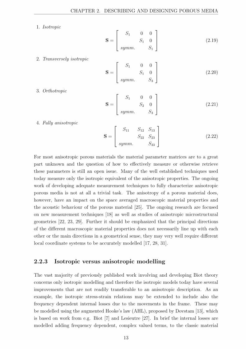
CHAPTER 2. DESCRIBING AND DESIGNING POROUS MEDIA
1. Isotropic
S =
S1 0 0
S1 0
symm. S1
(2.19)
2. Transversely isotropic
S =
S1 0 0
S1 0
symm. S3
(2.20)
3. Orthotropic
S =
S1 0 0
S2 0
symm. S3
(2.21)
4. Fully anisotropic
S =
S11 S12 S13
S22 S23
symm. S33
(2.22)
For most anisotropic porous materials the material parameter matrices are to a great
part unknown and the question of how to effectively measure or otherwise retrieve
these parameters is still an open issue. Many of the well established techniques used
today measure only the isotropic equivalent of the anisotropic properties. The ongoing
work of developing adequate measurement techniques to fully characterize anisotropic
porous media is not at all a trivial task. The anisotropy of a porous material does,
however, have an impact on the space averaged macroscopic material properties and
the acoustic behaviour of the porous material [25]. The ongoing research are focused
on new measurement techniques [18] as well as studies of anisotropic microstructural
geometries [22, 23, 29]. Further it should be emphasized that the principal directions
of the different macroscopic material properties does not necessarily line up with each
other or the main directions in a geometrical sense, they may very well require different
local coordinate systems to be accurately modelled [17, 28, 31].
2.2.3 Isotropic versus anisotropic modelling
The vast majority of previously published work involving and developing Biot theory
concerns only isotropic modelling and therefore the isotropic models today have several
improvements that are not readily transferable to an anisotropic description. As an
example, the isotropic stress-strain relations may be extended to include also the
frequency dependent internal losses due to the movements in the frame. These may
be modelled using the augmented Hooke’s law (AHL), proposed by Dovstam [13], which
is based on work from e.g. Biot [7] and Lesieutre [27]. In brief the internal losses are
modelled adding frequency dependent, complex valued terms, to the classic material
13
CHAPTER 2. DESCRIBING AND DESIGNING POROUS MEDIA
modulus matrix of Hooke’s generalized law. This augmented Hooke’s law is today not
implemented in anisotropic Biot models as several unknowns regarding the damping
behaviour and its principal directions still remain.
In addition the material parameters needed to describe anisotropic materials are not
easy to obtain and many questions remain regarding their principal directions. This
emphasizes the need to further develop accurate measurement techniques in order to
obtain information regarding the physical behaviour of anisotropic materials. These are
all issues for ongoing research.
Therefore, when modelling porous materials, the choice between using isotropic or
anisotropic models is dependent on e.g. the accuracy needed, the type of porous material
to be modelled, the structure in which it is implemented, and also whether or not the
anisotropic material parameters are known or may be obtained.
2.3 FE-modelling
Analytical solutions to Biot’s equations exists only for a few special cases where
the equation set-ups may be reduced to one dimensional problems, e.g. infinite
plane, spherical, and infinite cylinder problems. For most applications of interest the
complexity of the problem requires some kind of numerical solution that can handle
complex geometries, finite sizes, non-uniform distribution of boundary conditions and
loads, as well as the coupling to other porous, solid or fluid components. These issues
and several more have been addressed for both the isotropic as well as the anisotropic
cases in previous works by Horlin and Goransson [20], Horlin [19] and Horlin et al.
[21] where three-dimensional hp-based 1 finite element solutions have been developed
and evaluated. To formulate finite element solutions to the coupled partial differential
equations describing the behaviour of a system, a weak form of the partial differential
equations, including boundary conditions, had to be stated. Horlin evaluated different
weak formulations, among them a mixed displacement-pressure formulation for isotropic
porous materials as it was proposed by Atalla et al. [4, 5]. Later on the mixed
displacement-pressure formulation was extended by Horlin and Goransson [20] to include
also anisotropic materials. This formulation uses the frame displacement as the primary
variable describing the motion of the frame, and the fluid pressure as the primary
variable describing the fluid, i.e. (us, p)-formulation, instead of the more common weak
formulations which use frame and fluid displacement as primary variables, (us, uf )-
formulations. The latter has been shown to require cumbersome calculations when used
in large finite element systems. The (us, p)-formulation as proposed by Atalla et al.
[5] is considered as accurate as the classical (us, uf )-formulation with the advantage
that it is the better choice with respect to the computational effort required to achieve
the wanted accuracy. It describes the porous material with a minimum of dependent
1Convergence is achieved by refining the mesh and/or increasing the approximation order.
14
CHAPTER 2. DESCRIBING AND DESIGNING POROUS MEDIA
field variables and it also couples two open pore components, and also an open pore
component to a solid one, without any additional coupling integrals, as long as the solid
parts are attached to each other. However, couplings between porous components and
fluids require coupling integrals to be used. This proposed mixed displacement pressure
formulation is underpinning the current work of studying the potential improvements of
adapting porous materials to specific applications.
2.4 Correlations between macroscopic and micro-
scopic properties
As stated previously, porous materials are described using the macroscopic space
averaged properties, of which several are presented in the equations above. These
macroscopic properties are naturally dependent on the microscopic geometrical proper-
ties of the frame as well as of the frame material itself. Examples of such geometrical,
microscopic properties are the size and shape of the pores, and the cross section and
thickness of the struts, or fibres, in the open porous material. Microscopic properties like
these will, in combination with material choices, govern the thermal, elastic, viscoelastic,
mechanical and acoustic behaviour of the porous material. Hence, the macroscopic
properties can not be regarded as independent of one another and are therefore
unsuitable as variables in an optimization problem. Instead, the aim in the current work
has been to use scaling laws that relate the macroscopic properties to the underlying
microscopic properties. Such scaling laws should preferably describe the macroscopic
properties of the porous material as being continuously and systematically dependent
on the micro-structural mechanical properties, allowing for the optimization to focus
directly to the microscopic properties. Several researchers have made contributions
in developing mathematical formulations of the relations between different material
properties. Assuming an open cell foam structure with high porosity, where the strut
material is significantly heavier than the interstitial fluid, the approach taken by Gibson
and Ashby [15] may then provide significant guidance in understanding the mechanical
behaviour of such a foam. Gibson and Ashby view the cellular structure as vertices
joined by edges. A very simple configuration would be a cubic cell shape where adjoining
cells are staggered so that their members meet at the mid points, but the reasoning is
just as valid for more complex cell structures such as e.g. rhombic dodecahedra or
tetrakaidecahedra, fig. 2.3. The last cell structure, tetrakaidecahedra, also referred to
as a Kelvin cell, is a common choice because it has an average number of edges per
face, and of faces per cell, which seems to correspond well to some observations, but
the matter would need further investigation [15, 30]. Recent studies [12] show that
such scaling laws, although based on simplified cell structures and possibly different
implicit assumptions that may not be completely fulfilled, still give a fairly satisfactory
prediction.
15
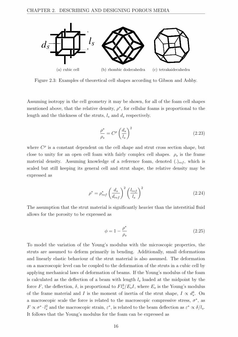
CHAPTER 2. DESCRIBING AND DESIGNING POROUS MEDIA
(a) cubic cell (b) rhombic dodecahedra (c) tetrakaidecahedra
Figure 2.3: Examples of theoretical cell shapes according to Gibson and Ashby.
Assuming isotropy in the cell geometry it may be shown, for all of the foam cell shapes
mentioned above, that the relative density, ρ∗, for cellular foams is proportional to the
length and the thickness of the struts, ls and ds respectively.
ρ∗
ρs= Cρ
(dsls
)2
(2.23)
where Cρ is a constant dependent on the cell shape and strut cross section shape, but
close to unity for an open cell foam with fairly complex cell shapes. ρs is the frame
material density. Assuming knowledge of a reference foam, denoted (.)ref , which is
scaled but still keeping its general cell and strut shape, the relative density may be
expressed as
ρ∗ = ρ∗ref
(dsdref
)2(lrefls
)2
(2.24)
The assumption that the strut material is significantly heavier than the interstitial fluid
allows for the porosity to be expressed as
φ = 1− ρ∗
ρs(2.25)
To model the variation of the Young’s modulus with the microscopic properties, the
struts are assumed to deform primarily in bending. Additionally, small deformations
and linearly elastic behaviour of the strut material is also assumed. The deformation
on a macroscopic level can be coupled to the deformation of the struts in a cubic cell by
applying mechanical laws of deformation of beams. If the Young’s modulus of the foam
is calculated as the deflection of a beam with length ls loaded at the midpoint by the
force F , the deflection, δ, is proportional to Fl3s/EsI, where Es is the Young’s modulus
of the frame material and I is the moment of inertia of the strut shape, I ∝ d4s. On
a macroscopic scale the force is related to the macroscopic compressive stress, σ∗, as
F ∝ σ∗ · l2s and the macroscopic strain, ε∗, is related to the beam deflection as ε∗ ∝ δ/ls.
It follows that the Young’s modulus for the foam can be expressed as
16
CHAPTER 2. DESCRIBING AND DESIGNING POROUS MEDIA
E∗ =σ∗
ε∗=CdlEsI
l4s→ E∗
Es= Cdl
(dsls
)4
= CE
(ρ∗
ρs
)2
(2.26)
or when a reference material is used as
E∗ = E∗ref
(ρ∗
ρ∗ref
)2
(2.27)
Extensive works by Allard and Champoux [3] and Allard [2] have also contributed
to establishing relations between the macroscopic foam properties and the microscopic
structural properties. Their work have been used by Goransson to further develop scaling
laws that relates the viscous characteristic length, Λ, and the static flow resistivity,
σstatic, to the microstructure of the foam [16]. By assuming inviscid flow around a
cylinder Allard and Champoux show that if the porosity is close to one, Λ is given by
Λ =1
2πLr(2.28)
where L is the total cylinder length per unit volume and r is the radius of the cylinder
[3]. With the former assumption of cellular geometry L can be defined in terms of
the porosity as πr2L = ρ∗/ρs which allow for the viscous characteristic length to be
expressed as [16]
Λ =ds
4(ρ∗/ρs)=
ds4(1− φ)
(2.29)
To account for thermal effects the simplified assumption of Λ′ = 2 ·Λ has been made for
the thermal characteristic length, Λ′. As the tortuosity for highly porous materials is
very depend on the closed pore content and the materials used in this work are assumed
to be only open pores, the change in tortuosity when the material properties are altered
is quite small. However, a scaling law based on work by Comiti and Renaud, [11], have
been implemented in Paper II and III,
α∞ = 1− 1− α∞refln(φref )
· ln(φ) (2.30)
Further it has been shown by Allard that Λ may be expressed in terms of macroscopic
properties as:
Λ =1
cg
√8α∞η
φσstatic(2.31)
where cg is dependent on the cross-sectional shape of the pores, for cylindrical geometries
cg = 1 [2]. Eq. (2.29) together with eq. (2.31) give
17
CHAPTER 2. DESCRIBING AND DESIGNING POROUS MEDIA
σstatic =8α∞η
1− (ρ∗/ρs)· 16(ρ∗/ρs)2
d2sc
2g
(2.32)
which when using a reference material may be expressed as
σstatic = σstaticref
(ρ∗
ρref
)2
·(drefds
)2
· α∞α∞ref
·
(1− ρref
ρs
)
(1− ρ∗
ρs
) (2.33)
2.5 Aspects of optimization
Performing an optimization requires some type of objective function, f(x), that provides
a numerical value representing the qualities sought for. This objective function is
dependent on one or more design variables, x = [x1 x2 · · ·xn], limited by xmin ≤ x ≤ xmax
and may also be subjected to different constraint functions, gi(x). The optimization
problem is often seen on the form
min f(x)
subject to g1(x) ≤ 0
g2(x) ≤ 0...
gM(x) ≤ 0
xmin ≤ x ≤ xmax
(2.34)
Choosing a proper objective function and constraints is often more difficult than it may
seem as in reality there are often many different objectives to meet which are dependent
on the same or different design variables. In this work minimizing the acoustic discomfort
or minimizing the mass are often the objectives used in practice. Alternative objectives
may involve for example minimizing material cost, environmental impact, assembly time
or fuel consumption and the minimum of one objective rarely coincide with the minima
of the others. The problem may be handled by minimizing one objective while putting
constraint on the others or by developing an objective function that incorporates several
objectives into one single function, using for example some kind of weighted sum. There
are many ways to construct an objective function and the task should not be taken
lightly as the outcome of the optimization unavoidably will depend greatly on the choice
of objective function and constraints.
In practise the optimization is often performed by some kind of algorithm. If the
functions are differentiable and dependent on continuous design variables a gradient
based algorithm is often suitable. Such algorithm has to be provided with information
of the numerical values of the objective function, the gradient vector and possible
parts of the Hessian matrix of that objective function with regard to x, as well as
18
CHAPTER 2. DESCRIBING AND DESIGNING POROUS MEDIA
the numerical value of the constraint functions and possible the gradients and also
the minimum and maximum values of the design variables. The algorithm will then,
based on the input data, suggest new design parameters for which the cost function is
calculated and so on in an iterative fashion until some kind of stop criterion is met. In
practical applications are the objective function and/or the constraint functions often
very complex and not uncommonly the result of some sort of computer simulation. This
often requires the gradient and Hessian values to be calculated numerically, using for
example finite differences, which increases the computational cost with every design
variable used, and every iteration needed to find a minimum.
Another difficulty when using an optimization approach is that most objective functions
are not convex, meaning that it may exist one or more local minima within the parameter
range that are not the best solution. The best solution is instead referred to as the
global minimum. This issue is most often handled by using several different starting
point within the parameter range and then comparing the number of local minima and
the value of the objective functions at those local minima.
19

CHAPTER 2. DESCRIBING AND DESIGNING POROUS MEDIA
20
Chapter 3
Studies of poro-elastic acoustic
materials in multilayered structures
This work explores the possible effect of altering the microscopic properties of
specific poro-elastic acoustic materials when assembled in multilayered acoustic or
multifunctional panels. While the majority of the work concerns isotropic modelling
the influence of anisotropic material properties and the angular orientation of those
properties is also touched upon. The studies were conducted as numerical simulations
using Biot theory and the, for this purpose, suitable FE-based numerical approach
described in Chapter 2. The alterations of material properties were chosen by a gradient
based optimizer [32, 33].
While optimizing the macroscopic porous material properties used in the Johnson-
Champoux-Allard model may render some information concerning sought for combi-
nations of material properties, it does however not provide any knowledge regarding
what type of porous material to use or how to achieve such properties in any porous
material in reality. Quite possible the resulting material would be physically impossible
to realize, thus making such an optimization less useful in practice. By describing the
poro-elastic acoustic material with its microscopic properties and thereafter estimate
the corresponding macroscopic material parameters the resulting material may be, if
not already existing, at least well described and physically possible to create. Hence the
need for the previously described scaling laws which provide approximative correlations
between microscopic and macroscopic parameters.
To examine the acoustic and dynamic behaviour of poro-elastic materials assembled
in multilayered panels a number of different panels, containing either isotropic or
anisotropic porous materials, have been numerically evaluated. The panels were exited
by different types of force fields and the acoustic and dynamic properties needed to
be expressed as an objective function or a constraint function in order to enable an
optimization. Such a function may be chosen in a number of different ways and
formulating a way to describe good and bad sound quality using a numerical quantitative
21
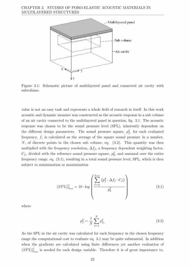
CHAPTER 3. STUDIES OF PORO-ELASTIC ACOUSTIC MATERIALS INMULTILAYERED STRUCTURES
Figure 3.1: Schematic picture of multilayered panel and connected air cavity withsubvolume.
value is not an easy task and represents a whole field of research in itself. In this work
acoustic and dynamic measure was constructed as the acoustic response in a sub volume
of an air cavity connected to the multilayered panel in question, fig. 3.1. The acoustic
response was chosen to be the sound pressure level (SPL), inherently dependent on
the different design parameters. The sound pressure square, p2f , for each evaluated
frequency, f , is calculated as the average of the square sound pressure in a number,
N , of discrete points in the chosen sub volume, eq. (3.2). This quantity was then
multiplied with the frequency resolution, ∆ff , a frequency dependent weighting factor,
Cf , divided with the reference sound pressure square, p20, and summed over the entire
frequency range, eq. (3.1), resulting in a total sound pressure level, SPL, which is then
subject to minimization or maximization
〈SPL〉CΩsub= 10 · log
fmax∑
f=f1
(p2f ·∆ff · Cf
)
p20
(3.1)
where
p2f =
1
N
N∑
n=1
p2fn (3.2)
As the SPL in the air cavity was calculated for each frequency in the chosen frequency
range the computational cost to evaluate eq. 3.1 may be quite substantial. In addition
when the gradients are calculated using finite differences yet another evaluation of
〈SPL〉CΩsubis needed for each design variable. Therefore it is of great importance to,
22
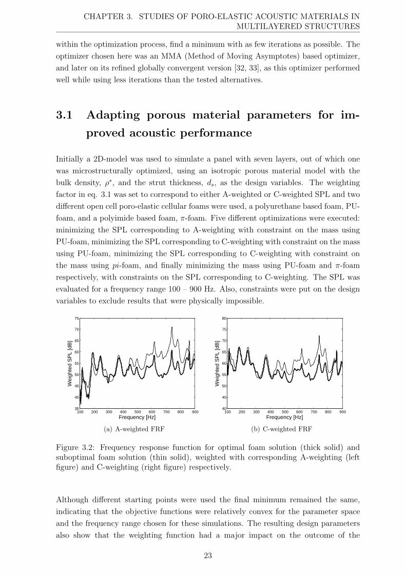
CHAPTER 3. STUDIES OF PORO-ELASTIC ACOUSTIC MATERIALS INMULTILAYERED STRUCTURES
within the optimization process, find a minimum with as few iterations as possible. The
optimizer chosen here was an MMA (Method of Moving Asymptotes) based optimizer,
and later on its refined globally convergent version [32, 33], as this optimizer performed
well while using less iterations than the tested alternatives.
3.1 Adapting porous material parameters for im-
proved acoustic performance
Initially a 2D-model was used to simulate a panel with seven layers, out of which one
was microstructurally optimized, using an isotropic porous material model with the
bulk density, ρ∗, and the strut thickness, ds, as the design variables. The weighting
factor in eq. 3.1 was set to correspond to either A-weighted or C-weighted SPL and two
different open cell poro-elastic cellular foams were used, a polyurethane based foam, PU-
foam, and a polyimide based foam, π-foam. Five different optimizations were executed:
minimizing the SPL corresponding to A-weighting with constraint on the mass using
PU-foam, minimizing the SPL corresponding to C-weighting with constraint on the mass
using PU-foam, minimizing the SPL corresponding to C-weighting with constraint on
the mass using pi-foam, and finally minimizing the mass using PU-foam and π-foam
respectively, with constraints on the SPL corresponding to C-weighting. The SPL was
evaluated for a frequency range 100 – 900 Hz. Also, constraints were put on the design
variables to exclude results that were physically impossible.
100 200 300 400 500 600 700 800 90035
40
45
50
55
60
65
70
75
Frequency [Hz]
Wei
ghte
d S
PL
[dB
]
(a) A-weighted FRF
100 200 300 400 500 600 700 800 90040
45
50
55
60
65
70
75
80
Frequency [Hz]
Wei
ghte
d S
PL
[dB
]
(b) C-weighted FRF
Figure 3.2: Frequency response function for optimal foam solution (thick solid) andsuboptimal foam solution (thin solid), weighted with corresponding A-weighting (leftfigure) and C-weighting (right figure) respectively.
Although different starting points were used the final minimum remained the same,
indicating that the objective functions were relatively convex for the parameter space
and the frequency range chosen for these simulations. The resulting design parameters
also show that the weighting function had a major impact on the outcome of the
23
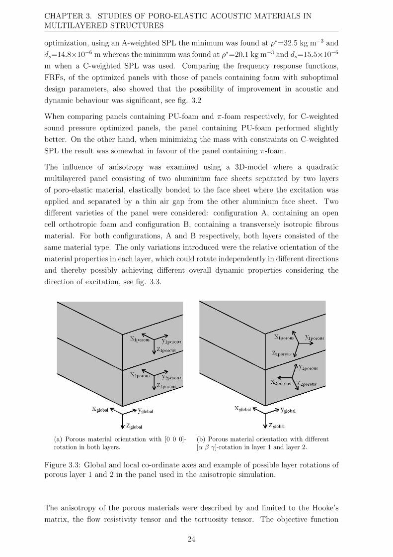
CHAPTER 3. STUDIES OF PORO-ELASTIC ACOUSTIC MATERIALS INMULTILAYERED STRUCTURES
optimization, using an A-weighted SPL the minimum was found at ρ∗=32.5 kg m−3 and
ds=14.8×10⁻⁶ m whereas the minimum was found at ρ∗=20.1 kg m−3 and ds=15.5×10⁻⁶
m when a C-weighted SPL was used. Comparing the frequency response functions,
FRFs, of the optimized panels with those of panels containing foam with suboptimal
design parameters, also showed that the possibility of improvement in acoustic and
dynamic behaviour was significant, see fig. 3.2
When comparing panels containing PU-foam and π-foam respectively, for C-weighted
sound pressure optimized panels, the panel containing PU-foam performed slightly
better. On the other hand, when minimizing the mass with constraints on C-weighted
SPL the result was somewhat in favour of the panel containing π-foam.
The influence of anisotropy was examined using a 3D-model where a quadratic
multilayered panel consisting of two aluminium face sheets separated by two layers
of poro-elastic material, elastically bonded to the face sheet where the excitation was
applied and separated by a thin air gap from the other aluminium face sheet. Two
different varieties of the panel were considered: configuration A, containing an open
cell orthotropic foam and configuration B, containing a transversely isotropic fibrous
material. For both configurations, A and B respectively, both layers consisted of the
same material type. The only variations introduced were the relative orientation of the
material properties in each layer, which could rotate independently in different directions
and thereby possibly achieving different overall dynamic properties considering the
direction of excitation, see fig. 3.3.
(a) Porous material orientation with [0 0 0]-rotation in both layers.
(b) Porous material orientation with different[α β γ]-rotation in layer 1 and layer 2.
Figure 3.3: Global and local co-ordinate axes and example of possible layer rotations ofporous layer 1 and 2 in the panel used in the anisotropic simulation.
The anisotropy of the porous materials were described by and limited to the Hooke’s
matrix, the flow resistivity tensor and the tortuosity tensor. The objective function
24
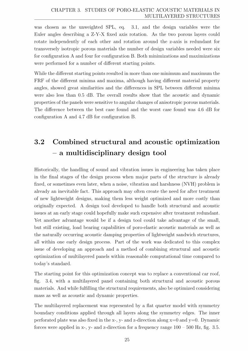
CHAPTER 3. STUDIES OF PORO-ELASTIC ACOUSTIC MATERIALS INMULTILAYERED STRUCTURES
was chosen as the unweighted SPL, eq. 3.1, and the design variables were the
Euler angles describing a Z-Y-X fixed axis rotation. As the two porous layers could
rotate independently of each other and rotation around the z-axis is redundant for
transversely isotropic porous materials the number of design variables needed were six
for configuration A and four for configuration B. Both minimizations and maximizations
were performed for a number of different starting points.
While the different starting points resulted in more than one minimum and maximum the
FRF of the different minima and maxima, although having different material property
angles, showed great similarities and the differences in SPL between different minima
were also less than 0.5 dB. The overall results show that the acoustic and dynamic
properties of the panels were sensitive to angular changes of anisotropic porous materials.
The difference between the best case found and the worst case found was 4.6 dB for
configuration A and 4.7 dB for configuration B.
3.2 Combined structural and acoustic optimization
– a multidisciplinary design tool
Historically, the handling of sound and vibration issues in engineering has taken place
in the final stages of the design process when major parts of the structure is already
fixed, or sometimes even later, when a noise, vibration and harshness (NVH) problem is
already an inevitable fact. This approach may often create the need for after treatment
of new lightweight designs, making them less weight optimized and more costly than
originally expected. A design tool developed to handle both structural and acoustic
issues at an early stage could hopefully make such expensive after treatment redundant.
Yet another advantage would be if a design tool could take advantage of the small,
but still existing, load bearing capabilities of poro-elastic acoustic materials as well as
the naturally occurring acoustic damping properties of lightweight sandwich structures,
all within one early design process. Part of the work was dedicated to this complex
issue of developing an approach and a method of combining structural and acoustic
optimization of multilayered panels within reasonable computational time compared to
today’s standard.
The starting point for this optimization concept was to replace a conventional car roof,
fig. 3.4, with a multilayered panel containing both structural and acoustic porous
materials. And while fulfilling the structural requirements, also be optimized considering
mass as well as acoustic and dynamic properties.
The multilayered replacement was represented by a flat quarter model with symmetry
boundary conditions applied through all layers along the symmetry edges. The inner
perforated plate was also fixed in the x-, y- and z-direction along x=0 and y=0. Dynamic
forces were applied in x-, y- and z-direction for a frequency range 100 – 500 Hz, fig. 3.5.
25
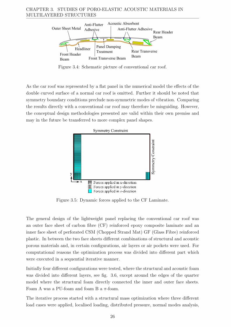
CHAPTER 3. STUDIES OF PORO-ELASTIC ACOUSTIC MATERIALS INMULTILAYERED STRUCTURES
Figure 3.4: Schematic picture of conventional car roof.
As the car roof was represented by a flat panel in the numerical model the effects of the
double curved surface of a normal car roof is omitted. Further it should be noted that
symmetry boundary conditions preclude non-symmetric modes of vibration. Comparing
the results directly with a conventional car roof may therefore be misguiding. However,
the conceptual design methodologies presented are valid within their own premiss and
may in the future be transferred to more complex panel shapes.
Figure 3.5: Dynamic forces applied to the CF Laminate.
The general design of the lightweight panel replacing the conventional car roof was
an outer face sheet of carbon fibre (CF) reinforced epoxy composite laminate and an
inner face sheet of perforated CSM (Chopped Strand Mat) GF (Glass Fibre) reinforced
plastic. In between the two face sheets different combinations of structural and acoustic
porous materials and, in certain configurations, air layers or air pockets were used. For
computational reasons the optimization process was divided into different part which
were executed in a sequential iterative manner.
Initially four different configurations were tested, where the structural and acoustic foam
was divided into different layers, see fig. 3.6, except around the edges of the quarter
model where the structural foam directly connected the inner and outer face sheets.
Foam A was a PU-foam and foam B a π-foam.
The iterative process started with a structural mass optimization where three different
load cases were applied, localised loading, distributed pressure, normal modes analysis,
26
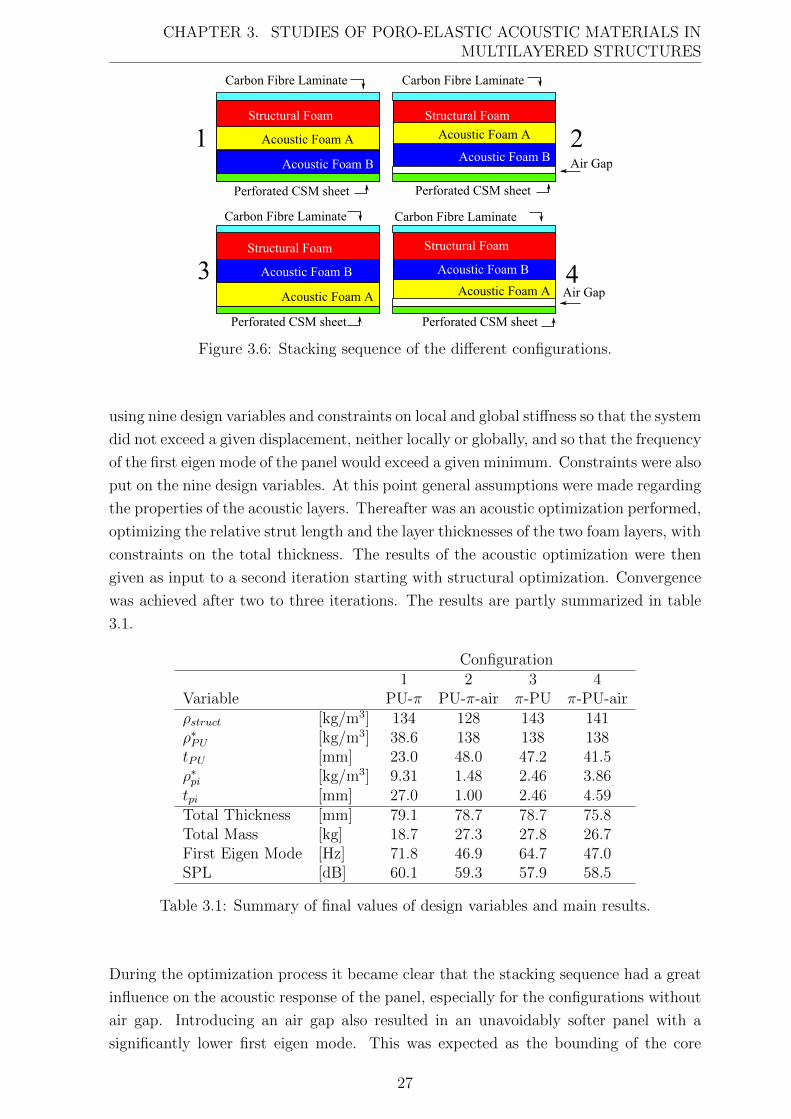
CHAPTER 3. STUDIES OF PORO-ELASTIC ACOUSTIC MATERIALS INMULTILAYERED STRUCTURES
Figure 3.6: Stacking sequence of the different configurations.
using nine design variables and constraints on local and global stiffness so that the system
did not exceed a given displacement, neither locally or globally, and so that the frequency
of the first eigen mode of the panel would exceed a given minimum. Constraints were also
put on the nine design variables. At this point general assumptions were made regarding
the properties of the acoustic layers. Thereafter was an acoustic optimization performed,
optimizing the relative strut length and the layer thicknesses of the two foam layers, with
constraints on the total thickness. The results of the acoustic optimization were then
given as input to a second iteration starting with structural optimization. Convergence
was achieved after two to three iterations. The results are partly summarized in table
3.1.
Configuration1 2 3 4
Variable PU-π PU-π-air π-PU π-PU-airρstruct [kg/m3] 134 128 143 141ρ∗PU [kg/m3] 38.6 138 138 138tPU [mm] 23.0 48.0 47.2 41.5ρ∗pi [kg/m3] 9.31 1.48 2.46 3.86tpi [mm] 27.0 1.00 2.46 4.59Total Thickness [mm] 79.1 78.7 78.7 75.8Total Mass [kg] 18.7 27.3 27.8 26.7First Eigen Mode [Hz] 71.8 46.9 64.7 47.0SPL [dB] 60.1 59.3 57.9 58.5
Table 3.1: Summary of final values of design variables and main results.
During the optimization process it became clear that the stacking sequence had a great
influence on the acoustic response of the panel, especially for the configurations without
air gap. Introducing an air gap also resulted in an unavoidably softer panel with a
significantly lower first eigen mode. This was expected as the bounding of the core
27
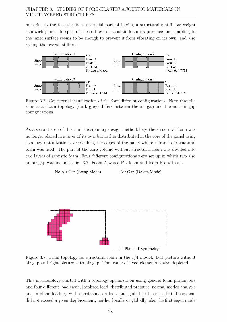
CHAPTER 3. STUDIES OF PORO-ELASTIC ACOUSTIC MATERIALS INMULTILAYERED STRUCTURES
material to the face sheets is a crucial part of having a structurally stiff low weight
sandwich panel. In spite of the softness of acoustic foam its presence and coupling to
the inner surface seems to be enough to prevent it from vibrating on its own, and also
raising the overall stiffness.
Figure 3.7: Conceptual visualization of the four different configurations. Note that thestructural foam topology (dark grey) differs between the air gap and the non air gapconfigurations.
As a second step of this multidisciplinary design methodology the structural foam was
no longer placed in a layer of its own but rather distributed in the core of the panel using
topology optimization except along the edges of the panel where a frame of structural
foam was used. The part of the core volume without structural foam was divided into
two layers of acoustic foam. Four different configurations were set up in which two also
an air gap was included, fig. 3.7. Foam A was a PU-foam and foam B a π-foam.
Figure 3.8: Final topology for structural foam in the 1/4 model. Left picture withoutair gap and right picture with air gap. The frame of fixed elements is also depicted.
This methodology started with a topology optimization using general foam parameters
and four different load cases, localized load, distributed pressure, normal modes analysis
and in-plane loading, with constraints on local and global stiffness so that the system
did not exceed a given displacement, neither locally or globally, also the first eigen mode
28
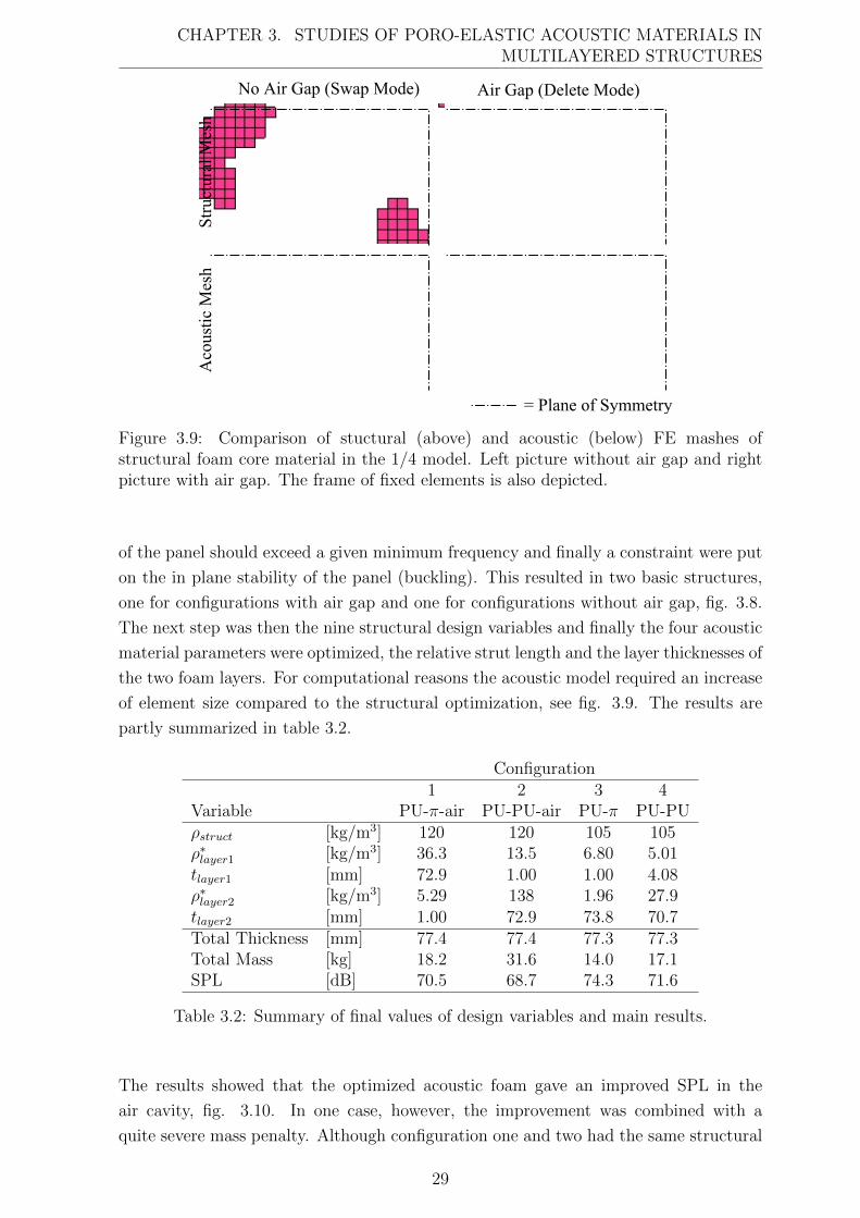
CHAPTER 3. STUDIES OF PORO-ELASTIC ACOUSTIC MATERIALS INMULTILAYERED STRUCTURES
Figure 3.9: Comparison of stuctural (above) and acoustic (below) FE mashes ofstructural foam core material in the 1/4 model. Left picture without air gap and rightpicture with air gap. The frame of fixed elements is also depicted.
of the panel should exceed a given minimum frequency and finally a constraint were put
on the in plane stability of the panel (buckling). This resulted in two basic structures,
one for configurations with air gap and one for configurations without air gap, fig. 3.8.
The next step was then the nine structural design variables and finally the four acoustic
material parameters were optimized, the relative strut length and the layer thicknesses of
the two foam layers. For computational reasons the acoustic model required an increase
of element size compared to the structural optimization, see fig. 3.9. The results are
partly summarized in table 3.2.
Configuration1 2 3 4
Variable PU-π-air PU-PU-air PU-π PU-PUρstruct [kg/m3] 120 120 105 105ρ∗layer1 [kg/m3] 36.3 13.5 6.80 5.01tlayer1 [mm] 72.9 1.00 1.00 4.08ρ∗layer2 [kg/m3] 5.29 138 1.96 27.9tlayer2 [mm] 1.00 72.9 73.8 70.7Total Thickness [mm] 77.4 77.4 77.3 77.3Total Mass [kg] 18.2 31.6 14.0 17.1SPL [dB] 70.5 68.7 74.3 71.6
Table 3.2: Summary of final values of design variables and main results.
The results showed that the optimized acoustic foam gave an improved SPL in the
air cavity, fig. 3.10. In one case, however, the improvement was combined with a
quite severe mass penalty. Although configuration one and two had the same structural
29
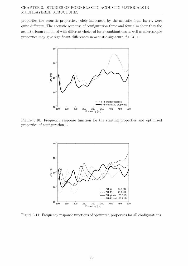
CHAPTER 3. STUDIES OF PORO-ELASTIC ACOUSTIC MATERIALS INMULTILAYERED STRUCTURES
properties the acoustic properties, solely influenced by the acoustic foam layers, were
quite different. The acoustic response of configuration three and four also show that the
acoustic foam combined with different choice of layer combinations as well as microscopic
properties may give significant differences in acoustic signature, fig. 3.11.
100 150 200 250 300 350 400 450 50010
−7
10−6
10−5
10−4
10−3
Frequency [Hz]
SP
L [P
a]
FRF start propertiesFRF optimized properties
Figure 3.10: Frequency response function for the starting properties and optimizedproperties of configuration 1.
100 150 200 250 300 350 400 450 50010
−7
10−6
10−5
10−4
10−3
Frequency [Hz]
SP
L [P
a]
PU−pi 74.3 dBPU−PU 71.6 dBPU−pi−air 70.5 dBPU−PU−air 68.7 dB
Figure 3.11: Frequency response functions of optimized properties for all configurations.
30
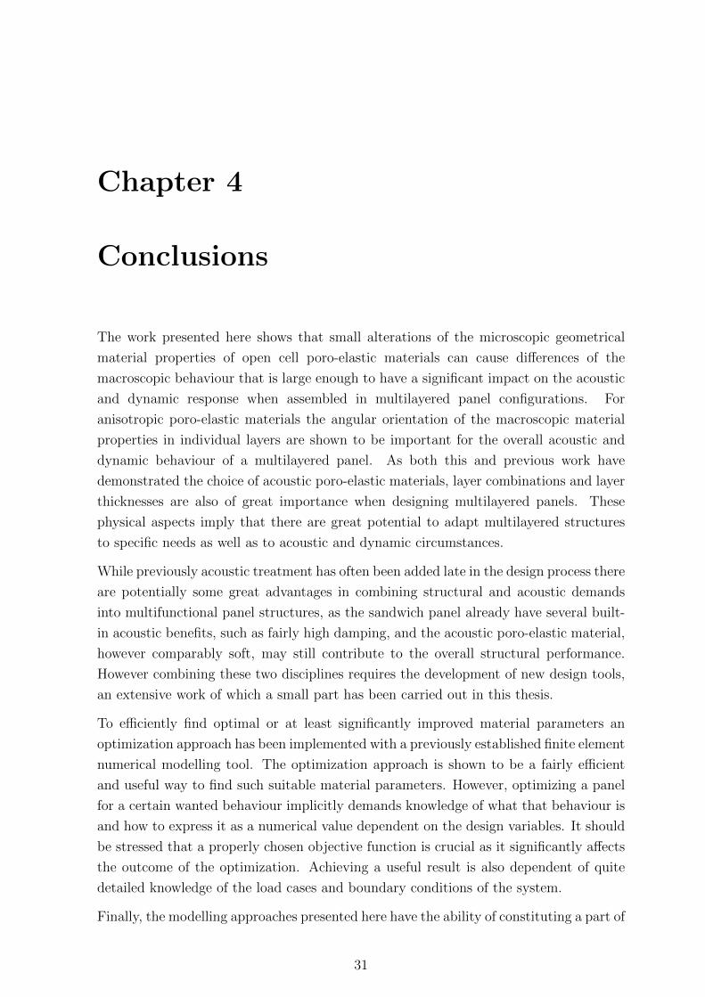
Chapter 4
Conclusions
The work presented here shows that small alterations of the microscopic geometrical
material properties of open cell poro-elastic materials can cause differences of the
macroscopic behaviour that is large enough to have a significant impact on the acoustic
and dynamic response when assembled in multilayered panel configurations. For
anisotropic poro-elastic materials the angular orientation of the macroscopic material
properties in individual layers are shown to be important for the overall acoustic and
dynamic behaviour of a multilayered panel. As both this and previous work have
demonstrated the choice of acoustic poro-elastic materials, layer combinations and layer
thicknesses are also of great importance when designing multilayered panels. These
physical aspects imply that there are great potential to adapt multilayered structures
to specific needs as well as to acoustic and dynamic circumstances.
While previously acoustic treatment has often been added late in the design process there
are potentially some great advantages in combining structural and acoustic demands
into multifunctional panel structures, as the sandwich panel already have several built-
in acoustic benefits, such as fairly high damping, and the acoustic poro-elastic material,
however comparably soft, may still contribute to the overall structural performance.
However combining these two disciplines requires the development of new design tools,
an extensive work of which a small part has been carried out in this thesis.
To efficiently find optimal or at least significantly improved material parameters an
optimization approach has been implemented with a previously established finite element
numerical modelling tool. The optimization approach is shown to be a fairly efficient
and useful way to find such suitable material parameters. However, optimizing a panel
for a certain wanted behaviour implicitly demands knowledge of what that behaviour is
and how to express it as a numerical value dependent on the design variables. It should
be stressed that a properly chosen objective function is crucial as it significantly affects
the outcome of the optimization. Achieving a useful result is also dependent of quite
detailed knowledge of the load cases and boundary conditions of the system.
Finally, the modelling approaches presented here have the ability of constituting a part of
31
CHAPTER 4. CONCLUSIONS
a useful computer aided design tool, especially when developing lightweight multilayered
panels. Such a design tool may be of great importance when striving for lighter and
more energy efficient vehicle concepts in the future as it could help maintaining or even
improving the NVH properties which are otherwise often penalized when reducing the
weight of a structure.
4.1 Future work
A natural continuation of the initialized work on anisotropic poro-elastic material would
be to develop computationally efficient scaling laws or other ways to connect microscopic
and macroscopic properties for such materials. There is also room for improvement
of the suggested scaling laws for isotropic materials. There is a general need for
increased understanding of the physical behaviour of poro-elastic materials, especially
when assembled in different structures as it may involve several different aspects such
as pre-compression of the porous material and difficulties in assigning proper boundary
conditions. Achieving such knowledge includes development of measurement techniques
of the macroscopic material properties, the physical modelling of those properties and
their connection to the geometrical microscopic properties, understanding and modelling
of different damping phenomena as well as understanding and modelling of variations of
the macroscopic material properties close to the boundaries of a poro-elastic material.
For anisotropic poro-elastic materials this need is even greater as the understanding of
anisotropic acoustic and dynamic phenomenas in such materials is today quite limited.
To better understand the complex coupled structural acoustic behaviour and to further
extend the possibilities of designing mass and space efficient multifunctional panels
is also highly sought after. Such knowledge must also be implemented in usable
computationally efficient multidisciplinary design tools in order for it to truly make
a difference in industrial production techniques.
Increasing the understanding and developing usable models in these areas may be a
significant contribution to increase functionality and lower the environmental impact of
vehicles and other structures in the future.
32
Chapter 5
Summary of papers
Paper I
Optimising open porous foam for acoustical and vibrational
performance.
E. Lind Nordgren and P. Goransson
A computational method for optimizing microstructural properties of open cell porous
foam assembled in multilayered acoustic panels is presented. The method uses previously
established scaling techniques to link the microstructural properties to the classical Biot-
Johnson-Champoux-Allard macroscopic parameters. This combined with Biot theory
allows for calculations of an objective function and also its gradients by using finite
differences and thereafter to access a gradient based optimizer. The outer surface of
the panel was excited by three separate force fields and the acoustic properties of the
panel were evaluated by calculating the sound pressure level for a frequency range 100
– 900 Hz in an air cavity attached to the panel. Different cost functions were tested
and the results suggested that if alterations of the microscopic properties of the foam
are made, the foam may be adapted to specific environmental conditions and thereby
achieve improved acoustic behaviour as well as reduced weight. The choice of cost
functions, as well as the chosen frequency range, was however greatly influencing the
outcome of the optimization and must be chosen with care.
33
CHAPTER 5. SUMMARY OF PAPERS
Paper II
Material Property Based Structural and Acoustic Optimization
of a Multifunctional Vehicle Body Panel.
C. J. Cameron, E. Lind Nordgren, P. Wennhage and P. Goransson
A novel design approach involving combined structural and acoustic optimization is
proposed that allows for a multilayered load bearing sandwich panel with integrated
acoustic capabilities. The method is based on an iterative two-step optimization
technique where a mass minimizing structural optimization is followed by an acoustic
optimization. The outcome of the acoustic optimization was then used as a starting
point for the next iteration beginning with structural optimization. Four different
configurations were tested, two of which had an air gap included. Apart from the air gap
the panels consisted of a thin carbon fibre laminate face sheet, one layer of structural
closed cell polymer foam, two layers of lightweight open cell poro-elastic acoustic foam
followed by the optional air gap and finally a thin perforated glass fibre reinforced inner
face sheet. The structural as well as the acoustic optimization allowed for variation of
the microscopic properties as well as variation of the layer thicknesses within certain
boundary conditions. The acoustic response was evaluated for a frequency range 100 –
500 Hz by calculating the sound pressure level in an air cavity connected to the panel.
Evaluating the resulting panels it was obvious that the presence or absence of an air gap,
as well as the stacking sequence of the acoustic foam layers were of great importance for
acoustic and dynamic properties while for the static structural properties the influence
of the stacking sequence of the acoustic foam was small or insignificant. The results also
indicated that there may be potential advantages of introducing acoustic absorbents in
load bearing sandwich panels as the acoustic absorbers, in spite of their low stiffness,
still contribute to the overall stiffness of the panel while also being able to improve
dynamic and acoustic properties.
Paper III
A Design Method using Topology, Property, and Size Opti-
mization to Balance Structural and Acoustic Performance of
Sandwich Panels for Vehicle Applications.
C. J. Cameron, E. Lind Nordgren, P. Wennhage and P. Goransson
A combined structural and acoustic optimization process including topology optimiza-
tion for load bearing panels is presented. Several different optimization stages were
34
CHAPTER 5. SUMMARY OF PAPERS
used starting with a topology optimization to establish the most effective locations
for load bearing material within the core of the panel. As a result the inner and
outer surface of a panel were connected through a finger like framework of stiff, closed
cell, structural foam. Thereafter was a mass optimization process used to tune the
exact properties of the outer and inner face sheet as well as the structural foam. The
remaining sandwich core volume, not occupied by structural foam was then filled with
open cell poro-elastic acoustic materials divided into different layers. Four different
configurations were tested, two of which had an air gap next to the inner surface and
two had not. The acoustic response was evaluated for a frequency range 100 – 500
Hz by calculating the sound pressure level in an air cavity connected to the panel as
the panel was excited by three different dynamic forces. Although the outer and inner
surface of the panel were connected by stiff structural foam the results showed that the
acoustic properties were still quite affected by small changes in the microstructure of the
acoustic porous materials. The design methodology developed also showed a potential
to combine and handle not only the intrinsic coupling but also the conflicts between the
two physical mechanisms addressed, by offering a new approach to systematically deal
with the combined structural and acoustic requirements.
Paper IV
Alignment of anisotropic poro-elastic layers - Sensitivity in
vibroacoustic response due to angular orientation of anisotropic
elastic and acoustic properties.
E. Lind Nordgren, P. Goransson and J.-F. Deu
A numerical experiment was performed to explore the influence of angular changes of
anisotropic poro-elastic layers in multilayered acoustic panels. Two different materials
were tested, one orthotropic open cell lightweight acoustic foam and one transversely
isotropic fibrous material. The simulation set up consisted of two independent layers
of the same porous material connected to an aluminium plate along one surface and
separated from an identical aluminium plate through an air gap along the other surface.
The sensitivity to angular changes of the porous layers was evaluated as an optimization
problem where an objective function was both minimized and maximized in order to
compare possible extremal points. The outer surface of each panel was excited by a unit
force for a frequency range 100 – 700 Hz and the objective function was defined as the
sound pressure level in an air cavity connected to the inner surface. The results showed
that anisotropy of poro-elastic acoustic absorbers as well as their angular orientation
both had significant influence in terms of acoustic properties of multlayered panels.
35

CHAPTER 5. SUMMARY OF PAPERS
36
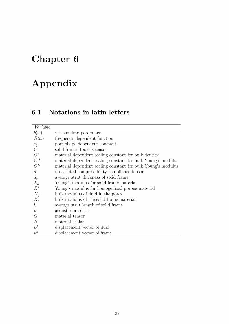
Chapter 6
Appendix
6.1 Notations in latin letters
Variableb(ω) viscous drag parameterB(ω) frequency dependent functioncg pore shape dependent constantC solid frame Hooke’s tensorCρ material dependent scaling constant for bulk densityCdl material dependent scaling constant for bulk Young’s modulusCE material dependent scaling constant for bulk Young’s modulusd unjacketed compressibility compliance tensords average strut thickness of solid frameEs Young’s modulus for solid frame materialE∗ Young’s modulus for homogenized porous materialKf bulk modulus of fluid in the poresKs bulk modulus of the solid frame materialls average strut length of solid framep acoustic pressureQ material tensorR material scalaruf displacement vector of fluidus displacement vector of frame
37
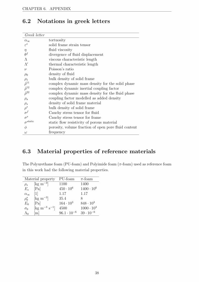
CHAPTER 6. APPENDIX
6.2 Notations in greek letters
Greek letterα∞ tortuosityεs solid frame strain tensorη fluid viscosityθf divergence of fluid displacementΛ viscous characteristic lengthΛ′ thermal characteristic lengthν Poisson’s ratioρ0 density of fluidρ1 bulk density of solid frameρ11 complex dynamic mass density for the solid phaseρ12 complex dynamic inertial coupling factorρ22 complex dynamic mass density for the fluid phaseρa coupling factor modelled as added densityρs density of solid frame materialρ∗ bulk density of solid frameσf Cauchy stress tensor for fluidσs Cauchy stress tensor for frameσstatic static flow resistivity of porous materialφ porosity, volume fraction of open pore fluid contentω frequency
6.3 Material properties of reference materials
The Polyurethane foam (PU-foam) and Polyimide foam (π-foam) used as reference foam
in this work had the following material properties.
Material property PU-foam π-foamρs [kg m−3] 1100 1400Es [Pa] 450 · 106 1400 · 106
α∞ [1] 1.17 1.17ρ∗0 [kg m−3] 35.4 8E0 [Pa] 164 · 103 848 · 103
σ0 [kg m−3 s−1] 4500 1000 · 103
Λ0 [m] 96.1 · 10−6 39 · 10−6
38
Bibliography
[1] J. Akerman and M. Hojer. How much transport can the climate stand?-sweden on
a sustainable path in 2050. Energy Policy, 34(14):1944–1957, 2006.
[2] J.-F. Allard. Propagation of sound in porous media: modelling sound absorbing
materials. Elsevier Applied Science, 1993.
[3] J.-F. Allard and Y. Champoux. New empirical equations for sound propagation in
rigid frame fibrous materials. J. Acoust. Soc. Am., 6(91):3346–3353, 1992.
[4] N. Atalla, M. A. Hamdi, and R. Panneton. Enhanced weak integral formulation
for the mixed (u,p) poroelastic equations. J. Acoust. Soc. Am., 109(6):3065–3068,
2001.
[5] N. Atalla, R. Panneton, and P. Debergue. A mixed displacement-pressure
formulation for poroelastic materials. J. Acoust. Soc. Am., 104(3):1444–1452, 1998.
[6] M. A. Biot. Theory of propagation of elastic waves in a fluid saturated porous solid.
I. Low frequency range. J. Acoust. Soc. Am., 28:168–178, 1956:1.
[7] M. A. Biot. Theory of deformation of a porous viscoelastic anisotropic solid. J.
Appl. Phys., 27:459–467, 1956:3.
[8] M. A. Biot. Mechanics of deformation and acoustic propagation in porous media.
J. Appl. Phys., 33(4):1482–1498, 1962.
[9] M. A. Biot and D. G. Willis. The elastic coefficients of the theory of consolidation.
J. Appl. Mech., 24:594–601, 1957.
[10] Y. Champoux and J.-F. Allard. Dynamic tortuosity and bulk modulus in air-
saturated porous media. J. Appl. Phys., 70(4):1975–1979, 1991.
[11] J. Comiti and M. Renaud. New model for determining mean structure parameters
of fixed beds from pressure drop measurements. Application to beds packed with
parallellepipedal particles. Chemical Engineering Science, 44(7):1539–1545, 1989.
[12] O. Doutres, N. Atalla, and K. Dong. Effect of the microstructure closed pore
content on the acoustic behavior of polyurethane foams. J. Appl. Phys., 110(6),
2011.
39
BIBLIOGRAPHY
[13] K. Dovstam. Augmented Hooke’s law in frequency domain. A three dimensional
material damping formulation. Int. J. Solids Structures, 32(19):2835–2852, 1995.
[14] A. Geslain, O. Dazel, J.-P. Groby, S. Sahraoui, and W. Lauriks. Influence of static
compression on mechanical parameters of acoustic foams. J. Acoust. Soc. Am.,
130(2):818–825, 2011.
[15] L. J. Gibson and M. F. Ashby. Cellular solids — Structure and properties.
Cambridge University Press, second edition, 1997. First published by Pergamont
Press Ltd., 1988.
[16] P. Goransson. Acoustic and vibrational damping in porous solids. Phil. Trans. R.
Soc. A, 364:89–108, 2006.
[17] P. Goransson, R. Guastavino, and N.-E. Horlin. Measurement and inverse
estimation of 3d anisotropic flow resistivity for porous materials. J. Sound Vib.,
327(3-5):354–367, 2009.
[18] R. Guastavino and P. Goransson. A 3d displacement measurement methodology for
anisotropic porous cellular foam materials. Polymer Testing, 26(6):711–719, 2007.
[19] N.-E. Horlin. 3-D hierarchical hp-FEM applied to elasto-acoustic modelling of
layered porous media. J. Sound Vib., 285(4):341–363, 2005.
[20] N.-E. Horlin and P. Goransson. Weak, anisotropic symmetric formulations of biot’s
equations for vibro-acoustic modelling of porous elastic materials. Int. J. Numer.
Meth. Engng, 84(12):1519–1540, 2010.
[21] N.-E. Horlin, M. Nordstrom, and P. Goransson. A 3-D hierarchical FE formulation
of Biot’s eguations for elasto-acoustic modelling of porous media. J. Sound Vib.,
254(4):633–652, 2001.
[22] W.-Y. Jang, A. M. Kraynik, and S. Kyriakides. On the microstructure of open-cell
foams and its effect on elastic properties. Int. J. Solids Structures, 45(7-8):1845–
1875, 2008.
[23] W.-Y. Jang, S. Kyriakides, and A. M. Kraynik. On the compressive strength
of open-cell metal foams with kelvin and random cell structures. Int. J. Solids
Structures, 47(21):2872–2883, 2010.
[24] D. L. Johnson, J. Koplik, and R. Dashen. Theory of dynamic permiability and
tortuosity in fluid-saturated porous media. J. Fluid Mech., 176:379–402, 1987.
[25] P. Khurana, L. Boeckx, W. Lauriks, P. Leclaire, O. Dazel, and J.-F. Allard. A
description of transversely isotropic sound absorbing porous materials by transfer
matrices. J. Acoust. Soc. Am., 125(2):915–921, 2009.
40
BIBLIOGRAPHY
[26] D. Lafarge, P. Lemarnier, J.-F. Allard, and V. Tarnow. Dynamic compressibility of
air in porous structures at audible frequencies. J. Acoust. Soc. Am, 102(4):1995–
2006, 1997.
[27] G. A. Lesieutre. Finite elements for dynamic modelling of uniaxial rods with
frequency-dependent material properties. Int. J. Solids Structures, 28:1567–1579,
1992.
[28] M. Melon, E. Mariez, C. Ayrault, and S. Sahraoui. Acoustical and mechanical
characterization of anisotropic open-cell foams. J. Acoust. Soc. Am., 104(5):2622–
2627, 1998.
[29] C. Perrot, F. Chevillotte, M. Tan Hoang, G. Bonnet, F.-X. Becot, L. Gautron,
and A. Duval. Microstructure, transport, and acoustic properties of open-cell foam
samples: Experiments and three-dimensional numerical simulations. J. Appl. Phys.,
111(1), 2012.
[30] C. Perrot, R. Panneton, and X. Olny. From microstructure to acoustic behaviour of
porous materials. Canadian Acoustics - Acoustique Canadienne, 32(3):18–19, 2004.
[31] S. Sahraoui, E. Mariez, and M. Etchessahar. Linear elastic properties of anisotropic
open-cell foams. J. Acoust. Soc. Am., 110(1):635–637, 2001.
[32] K. Svanberg. The method of moving asymptotes — a new method for structural
optimization. Int. J. Numer. Meth. Engng, 24:359–373, 1987.
[33] K. Svanberg. A class of globally convergent optimization methods based on
conservative convex separable approximations. SIAM Journal on Optimization,
12(2):555–573, 2002.
[34] C. Zwikker and C. Kosten. Sound absorbing materials., chapter II and III. Elsevier
Publishing Company, Amsterdam, 1949.
41

BIBLIOGRAPHY
42

Part II
Appended papers
43

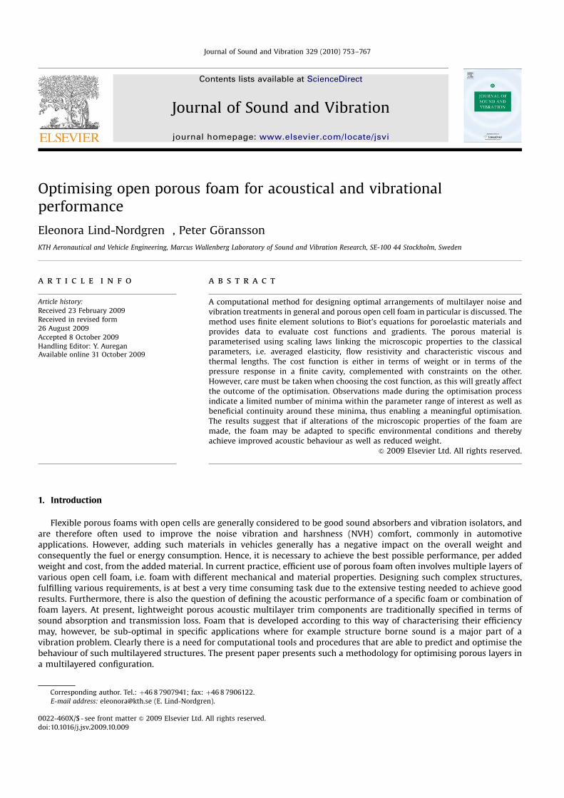
Optimising open porous foam for acoustical and vibrationalperformance
Eleonora Lind-Nordgren , Peter Goransson
KTH Aeronautical and Vehicle Engineering, Marcus Wallenberg Laboratory of Sound and Vibration Research, SE-100 44 Stockholm, Sweden
a r t i c l e i n f o
Article history:
Received 23 February 2009
Received in revised form
26 August 2009
Accepted 8 October 2009
Handling Editor: Y. AureganAvailable online 31 October 2009
a b s t r a c t
A computational method for designing optimal arrangements of multilayer noise and
vibration treatments in general and porous open cell foam in particular is discussed. The
method uses finite element solutions to Biot’s equations for poroelastic materials and
provides data to evaluate cost functions and gradients. The porous material is
parameterised using scaling laws linking the microscopic properties to the classical
parameters, i.e. averaged elasticity, flow resistivity and characteristic viscous and
thermal lengths. The cost function is either in terms of weight or in terms of the
pressure response in a finite cavity, complemented with constraints on the other.
However, care must be taken when choosing the cost function, as this will greatly affect
the outcome of the optimisation. Observations made during the optimisation process
indicate a limited number of minima within the parameter range of interest as well as
beneficial continuity around these minima, thus enabling a meaningful optimisation.
The results suggest that if alterations of the microscopic properties of the foam are
made, the foam may be adapted to specific environmental conditions and thereby
achieve improved acoustic behaviour as well as reduced weight.
& 2009 Elsevier Ltd. All rights reserved.
1. Introduction
Flexible porous foams with open cells are generally considered to be good sound absorbers and vibration isolators, andare therefore often used to improve the noise vibration and harshness (NVH) comfort, commonly in automotiveapplications. However, adding such materials in vehicles generally has a negative impact on the overall weight andconsequently the fuel or energy consumption. Hence, it is necessary to achieve the best possible performance, per addedweight and cost, from the added material. In current practice, efficient use of porous foam often involves multiple layers ofvarious open cell foam, i.e. foam with different mechanical and material properties. Designing such complex structures,fulfilling various requirements, is at best a very time consuming task due to the extensive testing needed to achieve goodresults. Furthermore, there is also the question of defining the acoustic performance of a specific foam or combination offoam layers. At present, lightweight porous acoustic multilayer trim components are traditionally specified in terms ofsound absorption and transmission loss. Foam that is developed according to this way of characterising their efficiencymay, however, be sub-optimal in specific applications where for example structure borne sound is a major part of avibration problem. Clearly there is a need for computational tools and procedures that are able to predict and optimise thebehaviour of such multilayered structures. The present paper presents such a methodology for optimising porous layers ina multilayered configuration.
Contents lists available at ScienceDirect
journal homepage: www.elsevier.com/locate/jsvi
Journal of Sound and Vibration
ARTICLE IN PRESS
0022-460X/$ - see front matter & 2009 Elsevier Ltd. All rights reserved.
doi:10.1016/j.jsv.2009.10.009
Corresponding author. Tel.: þ46 8 7907941; fax: þ46 8 7906122.
E-mail address: [email protected] (E. Lind-Nordgren).
Journal of Sound and Vibration 329 (2010) 753–767
In flexible porous foam, the vibroacoustic energy is carried both through the fluid in the pores (e.g. air) and through thesolid frame material itself. The waves are strongly coupled and propagate simultaneously along the two phases withdifferent amplitude and relative phase angle. Differences in amplitude and phase will transform some of the mechanical-acoustical energy into heat, mainly due to viscoelastic and viscoacoustic phenomena in the solid frame and at the interfacebetween the solid frame and the fluid in the pores.
When modelling wave propagation through a porous medium, the foam is described as a homogenised continuum withco-existing solid and fluid phases with a coupled frame-fluid wave propagation—an approach commonly known as Biot’stheory, see e.g. [1–3]. In Biot’s theory the macroscopic space averaged properties of the foam, such as bulk density, porosity,flow resistivity and Young’s modulus, are required. The dynamic behaviour is then presented as macroscopic spaceaveraged quantities e.g. solid and fluid displacement, acoustic pressure, and elastic stress.
While known macroscopic properties can be used to derive the necessary macroscopic dynamic quantities appearing inBiot’s equations, the former are inherently dependent on microscopic properties of the foam, such as geometry (e.g. poresize, strut length and strut thickness) as well as the actual material used for the solid frame. Thus improving the dynamicbehaviour by optimising the macroscopic properties independently of one another is doubtful as it would most likely resultin a foam that is impossible to realise physically. An alternative approach would be to use scaling laws that relate themacroscopic properties to the microscopic ones, where the latter may be changed independently. This is the approachtaken in the current paper.
The objective of the present work is to establish a methodology to estimate the acoustic behaviour of porous foam aswell as to explore the possibilities to optimise this behaviour. This is carried out by minimising a cost function when thefoam is affected by an oscillating force or other acoustical phenomena. Another purpose of the paper is to show thatalterations in the micromechanical properties of foam may have a significant effect on the acoustical behaviour and that, ifthese micromechanical properties could be controlled, foams could be tailored for specific needs. This may allow for NVHproblems to be treated from another point of view than previously possible, i.e. design for application performance.
This paper will briefly review Biot’s theory and a proposed set of parametric relations between microscopic structureand macroscopic homogenised properties that may be used in the formulation of a 3-D finite element model providing theresponse of a multilayered structure. In the model, a panel is connected to an air filled cavity, in a sub-volume of which thesound pressure level is evaluated for a given load. Results from optimisation of one layer in a multilayered configuration arediscussed, in particular in view of the frequency weighting functions applied to evaluate the response and the influence thedifferent weighting functions have on the optimal configuration found.
1.1. Related work
Optimising the performance of porous foams, modifying the microstructure geometry, has recently been discussed inthe context of structural acoustic performance as well as acoustic absorption, targeting single and multilayerconfigurations.
ARTICLE IN PRESS
Nomenclature
bðoÞ frequency-dependent viscous drag parametercg pore shape dependent constantCr foam dependent scaling constant for bulk
densityCs foam dependent scaling constant for static
flow resistivityCE foam dependent scaling constant for bulk E-
modulusds average strut thickness of solid frameEs Young’s modulus for solid frame materialE Young’s modulus for homogenised foamls average strut length of solid framep acoustic pressureQ dilatational coupling factor between fluid and
solid frameR bulk modulus of fluid phase at zero solid frame
dilatationuf
i Cartesian component of average fluid displace-ment
usi Cartesian component of average solid displa-
cementa1 tortuosityZ dynamic viscosityl bulk Lame’s parameter at constant fluid pres-
surel bulk dynamic Lame’sL viscous characteristic lengthL0 characteristic thermal lengthm bulk Lame’s shear parameterm bulk dynamic Lame’s shear parameterra inertial coupling factor, ra ¼ r12
rf density of fluidrs density of solid frame materialr bulk density of solid framesstatic static flow resistivity of foamf porosity, volume fraction of open pore fluid
contento frequency
E. Lind-Nordgren, P. Goransson / Journal of Sound and Vibration 329 (2010) 753–767754
Simon et al. [4] performed calculations of transmission loss resonance frequencies of a number of multilayered panels inorder to determine the best layer combination. The material database originally consisted of several Nomex honeycomb,fibre glass, Kevlar, carbon and viscoelastic materials. The calculations suggested that due to the high stiffness of theincluded materials the resulting panel basically followed the mass law for the frequency band 500–5000 Hz and that thehigh damping provided by the viscoelastic layer was beneficial only at the coincidence frequency. Instead they proposed asolution using foams that are less stiff than e.g. honeycomb. Based on simulations of the transmission loss, which werepartly validated in laboratory testing, the conclusion was that sandwich panels with open cell foam provide an adequateoption for efficient noise applications.
Focusing on the actual optimisation routine, Tanneau et al. [5] discussed a method using genetic algorithms to optimisethe layer combination, in terms of the number of layers and their respective thicknesses. Their optimisation was performedwith materials chosen from a list of possible candidates. The list contains a limited number of solids, fluids and foam,where each foam is described with a set of material properties, among them: porosity, flow resistivity, tortuosity andYoung’s modulus. Such an optimisation may result in a well performing trim panel by using readily available foam, which isof course very attractive in most practical situations. This approach, however, requires previously known materialparameters for each material that may be included in the multilayered configuration, a quite extensive and possibly costlymeasurement task. It also excludes the possibility of designing a new material for a specific task.
Lee et al. [6] performed a topology optimisation using the transfer matrix derived from Biot’s equations to maximise thetransmission loss. The authors used an MMA optimiser [7] to find the optimal layer sequence consisting of air layers andlayers of a specific poroelastic material with fixed properties. The optimisation was performed at single frequencies as wellas for narrow and wide frequency bands. The frequencies or frequency bands studied were all between 1 and 5 kHz.Results from the single frequency optimisation show that as the target frequency increases the number of layers increases.In addition the thickness of each layer decreases, partly due to constraints on the total thickness but mainly due to theshorter wavelengths that correspond to high frequencies. The results for single frequency optimisations were alsocompared with results of narrow band optimisations. As expected were the foams optimised for narrow band frequenciesoutperformed by the single frequency optimised foam at each individual frequency. The number of layers, however,increased as the upper and lower frequencies of the frequency band were increased, in agreement with the results from thesingle frequency optimisation.
Work that to some extent explored the influence of geometrical properties was performed by Franco et al. [8], whoexamined a sandwich panel with different core and face sheet properties. One configuration was a core made of a lattice oftruss elements; this allowed independent control of the core stiffness along different directions. The truss like core wasmodelled as rod elements with the intent to minimise the mean square average inner surface velocity over a chosenfrequency range. Their model, however, only regarded Young’s modulus in different directions of a truss like unit cell byaltering the cross-sectional area of the rod elements in different directions, whereas neither the coupled wave propagationdue to the frame–fluid interaction, any of the well established energy dissipative mechanisms of foam nor the effects ofdamping levels with respect to different frequency bandwidths were included.
In addition the optimal microstructure properties in the context of sound absorption were discussed by Perrot et al.,see [9–13]. Using numerical solutions of e.g. Stokes equations, appropriate parameters were calculated forgiven microstructures and fed into the proper macroscopic relations. They found interesting effects of throat size onabsorption level, cell size in the peak absorption frequencies and fibre cross-section shape in the weight of the porousmaterial.
The approach of the present paper explores the possible effects of altering the microscopic structure of a specific foamand the resulting acoustical properties to achieve optimal structural acoustic performance in a given application. It isapparent that the result very well may be a foam that is not presently available, but perhaps still possible to produce. Thusit is expected that this methodology may present new possibilities to predict the necessary acoustic properties and to guidein the future creation of foams that fulfil specific needs. To enable such an optimisation tool, a direct link between thefoams microstructural properties and the acoustic performance is a necessity.
2. Modelling aspects
Modelling and optimising the acoustic behaviour of foams in multilayered structures requires the inclusion ofseveral physical mechanisms representing the dynamic frequency-dependent mechanical and acoustical properties ofthe complex arrangement of different layers of solids, fluids and foam materials. To efficiently and accurately solvethe equations governing such behaviour the finite element method is an adequate numerical solution procedure,in particular for intricate structures. However, to ensure a useful result great care has to be taken in the selection of trialsolutions as well as handling the many different boundaries and interfaces within the multilayered structure. Thecomplexity of the problem makes it computationally expensive to solve and as each frequency is solved independently,limiting the frequency range is a necessity. Furthermore, optimising the properties of one or more of the included layersrequires several iterations, consequently, the optimiser’s ability to find a minimum using as few iterations as possible iscrucial for success.
ARTICLE IN PRESS
E. Lind-Nordgren, P. Goransson / Journal of Sound and Vibration 329 (2010) 753–767 755
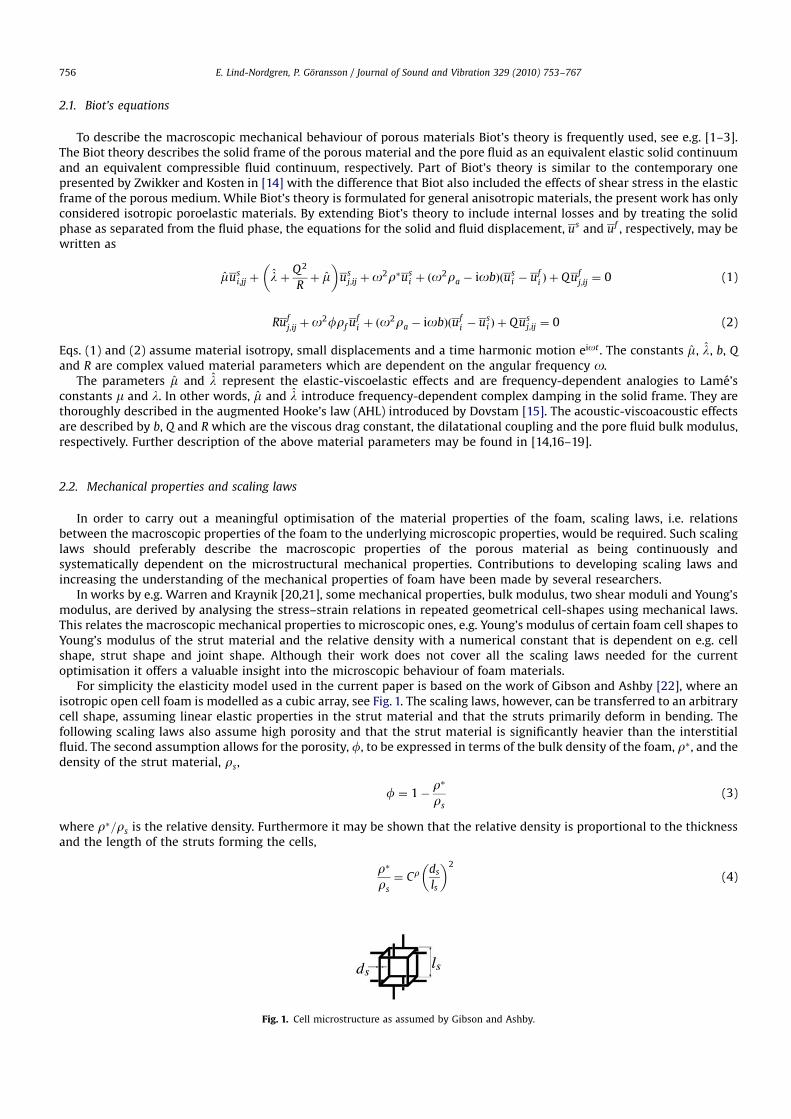
2.1. Biot’s equations
To describe the macroscopic mechanical behaviour of porous materials Biot’s theory is frequently used, see e.g. [1–3].The Biot theory describes the solid frame of the porous material and the pore fluid as an equivalent elastic solid continuumand an equivalent compressible fluid continuum, respectively. Part of Biot’s theory is similar to the contemporary onepresented by Zwikker and Kosten in [14] with the difference that Biot also included the effects of shear stress in the elasticframe of the porous medium. While Biot’s theory is formulated for general anisotropic materials, the present work has onlyconsidered isotropic poroelastic materials. By extending Biot’s theory to include internal losses and by treating the solidphase as separated from the fluid phase, the equations for the solid and fluid displacement, us and uf , respectively, may bewritten as
musi;jj þ l þ
Q2
Rþ m
us
j;ij þo2rus
i þ ðo2ra iobÞðus
i ufi Þ þ Quf
j;ij ¼ 0 (1)
Rufj;ij þo
2frf ufi þ ðo
2ra iobÞðufi us
i Þ þ Qusj;ij ¼ 0 (2)
Eqs. (1) and (2) assume material isotropy, small displacements and a time harmonic motion eiot . The constants m, l, b, Q
and R are complex valued material parameters which are dependent on the angular frequency o.The parameters m and l represent the elastic-viscoelastic effects and are frequency-dependent analogies to Lame’s
constants m and l. In other words, m and l introduce frequency-dependent complex damping in the solid frame. They arethoroughly described in the augmented Hooke’s law (AHL) introduced by Dovstam [15]. The acoustic-viscoacoustic effectsare described by b, Q and R which are the viscous drag constant, the dilatational coupling and the pore fluid bulk modulus,respectively. Further description of the above material parameters may be found in [14,16–19].
2.2. Mechanical properties and scaling laws
In order to carry out a meaningful optimisation of the material properties of the foam, scaling laws, i.e. relationsbetween the macroscopic properties of the foam to the underlying microscopic properties, would be required. Such scalinglaws should preferably describe the macroscopic properties of the porous material as being continuously andsystematically dependent on the microstructural mechanical properties. Contributions to developing scaling laws andincreasing the understanding of the mechanical properties of foam have been made by several researchers.
In works by e.g. Warren and Kraynik [20,21], some mechanical properties, bulk modulus, two shear moduli and Young’smodulus, are derived by analysing the stress–strain relations in repeated geometrical cell-shapes using mechanical laws.This relates the macroscopic mechanical properties to microscopic ones, e.g. Young’s modulus of certain foam cell shapes toYoung’s modulus of the strut material and the relative density with a numerical constant that is dependent on e.g. cellshape, strut shape and joint shape. Although their work does not cover all the scaling laws needed for the currentoptimisation it offers a valuable insight into the microscopic behaviour of foam materials.
For simplicity the elasticity model used in the current paper is based on the work of Gibson and Ashby [22], where anisotropic open cell foam is modelled as a cubic array, see Fig. 1. The scaling laws, however, can be transferred to an arbitrarycell shape, assuming linear elastic properties in the strut material and that the struts primarily deform in bending. Thefollowing scaling laws also assume high porosity and that the strut material is significantly heavier than the interstitialfluid. The second assumption allows for the porosity, f, to be expressed in terms of the bulk density of the foam, r, and thedensity of the strut material, rs,
f ¼ 1r
rs
(3)
where r=rs is the relative density. Furthermore it may be shown that the relative density is proportional to the thicknessand the length of the struts forming the cells,
r
rs
¼ Cr ds
ls
2
(4)
ARTICLE IN PRESS
Fig. 1. Cell microstructure as assumed by Gibson and Ashby.
E. Lind-Nordgren, P. Goransson / Journal of Sound and Vibration 329 (2010) 753–767756
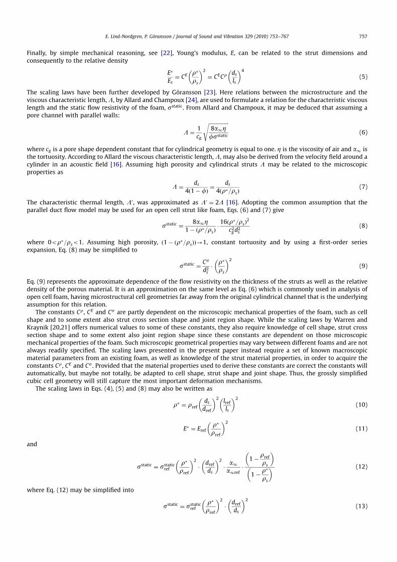
Finally, by simple mechanical reasoning, see [22], Young’s modulus, E, can be related to the strut dimensions andconsequently to the relative density
E
Es¼ CE r
rs
2
¼ CECr ds
ls
4
(5)
The scaling laws have been further developed by Goransson [23]. Here relations between the microstructure and theviscous characteristic length, L, by Allard and Champoux [24], are used to formulate a relation for the characteristic viscouslength and the static flow resistivity of the foam, sstatic. From Allard and Champoux, it may be deduced that assuming apore channel with parallel walls:
L ¼1
cg
ffiffiffiffiffiffiffiffiffiffiffiffiffiffiffiffi8a1Zfsstatic
s(6)
where cg is a pore shape dependent constant that for cylindrical geometry is equal to one. Z is the viscosity of air and a1 isthe tortuosity. According to Allard the viscous characteristic length, L, may also be derived from the velocity field around acylinder in an acoustic field [16]. Assuming high porosity and cylindrical struts L may be related to the microscopicproperties as
L ¼ds
4ð1 fÞ¼
ds
4ðr=rsÞ(7)
The characteristic thermal length, L0, was approximated as L0 ¼ 2L [16]. Adopting the common assumption that theparallel duct flow model may be used for an open cell strut like foam, Eqs. (6) and (7) give
sstatic ¼8a1Z
1 ðr=rsÞ16ðr=rsÞ
2
c2g d2
s
(8)
where 0or=rso1. Assuming high porosity, ð1 ðr=rsÞÞ-1, constant tortuosity and by using a first-order seriesexpansion, Eq. (8) may be simplified to
sstatic ¼Cs
d2s
r
rs
2
(9)
Eq. (9) represents the approximate dependence of the flow resistivity on the thickness of the struts as well as the relativedensity of the porous material. It is an approximation on the same level as Eq. (6) which is commonly used in analysis ofopen cell foam, having microstructural cell geometries far away from the original cylindrical channel that is the underlyingassumption for this relation.
The constants Cr, CE and Cs are partly dependent on the microscopic mechanical properties of the foam, such as cellshape and to some extent also strut cross section shape and joint region shape. While the scaling laws by Warren andKraynik [20,21] offers numerical values to some of these constants, they also require knowledge of cell shape, strut crosssection shape and to some extent also joint region shape since these constants are dependent on those microscopicmechanical properties of the foam. Such microscopic geometrical properties may vary between different foams and are notalways readily specified. The scaling laws presented in the present paper instead require a set of known macroscopicmaterial parameters from an existing foam, as well as knowledge of the strut material properties, in order to acquire theconstants Cr, CE and Cs. Provided that the material properties used to derive these constants are correct the constants willautomatically, but maybe not totally, be adapted to cell shape, strut shape and joint shape. Thus, the grossly simplifiedcubic cell geometry will still capture the most important deformation mechanisms.
The scaling laws in Eqs. (4), (5) and (8) may also be written as
r ¼ rref
ds
dref
2 lref
ls
2
(10)
E ¼ Erefr
rref
2
(11)
and
sstatic ¼ sstaticref
r
rref
2
dref
ds
2
a1a1ref
1rref
rs
1r
rs
(12)
where Eq. (12) may be simplified into
sstatic ¼ sstaticref
r
rref
2
dref
ds
2
(13)
ARTICLE IN PRESS
E. Lind-Nordgren, P. Goransson / Journal of Sound and Vibration 329 (2010) 753–767 757
using the same assumptions as for Eq. (9). The parameters rref , dref , lref , Eref , sstaticref and a1ref corresponds to the density,
Young’s modulus, strut thickness, strut length, static flow resistivity and tortuosity of the reference foam.As the properties of the foam used to derive the scaling laws are comparable to the range of foam regarded in the
optimisation, the scaling laws presented above, however simplified, may provide a useful tool to estimate the effect ofsmall changes of the microscopic properties of the foam. The material properties for the porous materials used as referencematerials in this paper, a polyurethane based and a polyimide based foam (PU-foam and pfoam, respectively), may befound in Appendix A. The optimisation was then performed for both these types of foam and the results are discussedbelow.
2.3. FE-modelling
The multilayered structures of interest in vehicle application often involve complex arrangements of different porousmaterials combined with purely solid or fluid layers, all with their specific boundary conditions and geometries. Tocalculate the acoustical mechanical response of such an intricate multilayered structure, some kind of numerical solutionprocedure is required. Such a numerical model must take into account not only the properties of the individual porouslayers, e.g. the fluid in the pores, the solid frame structure and the coupling between them. It also has to consider theboundaries to other solid, fluid or porous layers, with appropriate treatment of the kinematic conditions, the mass flowcontinuity conditions and the relevant stress balances.
Additionally, special care has to be taken in the selection of trial functions to get convergent solutions to Biot’sequations, especially for multilayered structures, for which hp-FEM1 is a convenient finite element base. Here the finiteelement solutions were obtained using the methods thoroughly discussed and properly addressed in works by Horlin et al.[25] and by Horlin [26] and will not be repeated here. For completeness, however, some details of the mesh and thepolynomial orders used are given below.
The analysed model is designed to describe the behaviour of an existing system where a multilayered structure acts as aroof panel for a vehicle compartment. The design of the original panel, for which several measures had already been takento improve the NVH comfort inside the compartment, is used as a starting point and the properties of the individual sub-layers of the panel are given in Appendix B. The original design, as well as the FE-model, consists of a number of differentlayers intended for load carrying and/or vibration comfort purposes, with the main difference that one of the layers of theoriginal design is a 0.01 m thick layer of air. For identification purposes, the order of the sub-layers were named as: Outerpanel sheet—Air gap 1—Foam 1—Solid 1—Solid 2—Air gap 2—Interior panel sheet. The air layer named Air gap 1 is infocus for the present investigation, with the aim to illustrate microstructure optimisation in the present paper. Replacingthis air layer with a layer of porous foam of equal thickness will doubtlessly incur a weight penalty. The main question is
ARTICLE IN PRESS
Fig. 2. Schematic picture of FE-model with coordinate system and applied forces.
1 Convergence is achieved by refining the mesh and/or increasing the approximation order.
E. Lind-Nordgren, P. Goransson / Journal of Sound and Vibration 329 (2010) 753–767758
then what improvement in NVH comfort can be expected in exchange for the additional mass and, as a result of theoptimisation, what is the best choice of foam to maximise the benefit of the added material?
The modelled panel, with length Ly ¼ 1:19 m, consists of seven different layers where the outer and inner surfaces bothhave solid face sheets. The total thickness of the panel is Lpanel
z ¼ 23:3 mm and the thickness of the layer of optimisedporous foam is 10 mm. The boundaries of each individual porous or solid layer of the panel at y ¼ 0 and y ¼ Ly are clampedi.e. zero deflection and zero rotation whereas the boundaries between layers follow kinematic conditions and mass flowcontinuity requirements as mentioned previously. The outer surface of the panel is driven by three separate force fields,one out of which is 1803 out of phase. Thus for Lz ¼ 0, positive unit tractions were applied over: y ¼ 020:11 m andy ¼ 0:5120:62 m; and negative unit traction over y ¼ 0:3320:51 m. The chosen force field is related to the transmission andradiation of structure borne sound, a common source of NVH problems in vehicle acoustics.
In order to enable evaluation of sound pressure levels and sound intensity the panel is connected to an air filled cavitywith dimensions Ly ¼ 1:19 and Lcavity
z ¼ 1:4 m. The total length Lz is consequently Lz ¼ Lpanelz þ Lcavity
z m.For the air filled cavity there is an impedance boundary at y ¼ Ly and z ¼ Lz with a non-frequency-dependent, normal
impedance equivalent to Z ¼ 1180þ 1044i, which implies an absorption factor of about 50 percent. The last boundary ofthe air cavity, at y ¼ 0, is considered to be acoustically hard (Fig. 2).
A schematic picture of the FE-model for the cavity mesh may be found in Fig. 3. Along the y-direction, a compatiblemesh with 10 elements was used for the panel as well as for the cavity. For each of the sub-layers in the panel, one elementthrough the thickness was used. In order to have a reasonably computationally efficient solution, the polynomial orderswere adjusted through the different sub-layers as shown in Table 1. The polynomial orders were chosen such that thecomputed results had a point wise error better than 10 percent, for both displacements and pressures, at the highestfrequency studied. In addition the in-plane polynomial orders were adapted to the high and low frequency ranges asdiscussed below.
2.4. System response
The system response was evaluated for the frequency range 100–900 Hz and the polynomial order of the base functionsused to describe the porous layers was varied depending on frequency. At higher frequencies higher-order polynomials, upto 10th order, were needed to dissolve the wave pattern whereas at lower frequencies, below 600 Hz, 6th-order
ARTICLE IN PRESS
Fig. 3. Mesh of cavity FE-model with surface to panel indicated.
Table 1Polynomial orders used in z-direction for each individual panel sub-layer, from top to bottom.
Sub-layer Polynomial order
Outer panel sheet 4
Optimised foam 5
Foam 1 5
Solid 1 4
Solid 2 4
Air gap 2
Interior panel sheet 4
E. Lind-Nordgren, P. Goransson / Journal of Sound and Vibration 329 (2010) 753–767 759
polynomials were found to be sufficient. Due to the high polynomial order needed at the higher frequencies the calculationbecomes very expensive. Despite this, and due to the occurrence of lowly damped acoustic cavity resonances, the frequencyresolution was kept at 1 Hz all through the frequency range considered.
The sound pressure square, p2f , for each evaluated frequency, f, is calculated as the average of the square sound pressure
in a number, N, of discrete points in a sub-volume of the air cavity, Eq. (14). The sub-volume, see Fig. 2, was chosen torepresent possible ear positions of hypothetical passengers. It is bound by the following lines; y ¼ 0:22 and 1:08 m,z ¼ 0:2233 and 0:5233 m. In the results discussed here, N, was chosen to be 16, all points distributed in the y–z plane,
p2f ¼
1
N
XN
n¼1
p2fn
(14)
2.5. Formulating the optimisation problem
To compare different solutions a cost function was formulated. In the present optimisation problem either mass orsound pressure level were used, implying of course that while trying to minimise one, constraints were put on the other. Inorder to compare sound pressure levels over the entire frequency range the sound pressure square for each frequency weremultiplied with a frequency-dependent weighting factor and a factor for frequency resolution, Dff , compensation and thensummed over the entire frequency range. The weighting factor was chosen to correspond to either A-weighting, CA
f , or C-weighting, CC
F ,
/SPLSCOsub¼ 10 log
Pfmax
f¼f1ðp2
f Dff CCf Þ
p20
!(15)
The actual optimisation was performed with an MMA optimiser provided by Svanberg [7]. The input to the MMA optimiserconsisted of the numerical values of cost function and its first and second derivate for each variable, the min- and max-values for each variable and also the numerical values of the constraint functions and their first and second derivate. Thederivatives and second derivatives were calculated with finite differences and are equivalent to vectors containing thegradient and the diagonal elements of the Hessian matrix, respectively. The variables in the optimiser were chosen to bethe bulk density and the strut thickness of the foam. Their respective min- and max-values were set to 8rrr70 kg m3
and 107rdsr104 m. These parameter ranges should be feasible and realistic for the problem at hand and furthermore liein the range of commercially available foams. As a starting value for the strut thickness, ds ¼ 105 m was used. For thedensity 15 kg m3 was used.
2.5.1. Parameter space
Studies of the variation in the frequency response function obtained for varying r and ds showed that the bulk densityhad a clear impact on the frequency response while the strut thickness had a much more modest effect. This was expectedfrom previous experiences; the functional dependence between the bulk density and the flow resistivity for varying strutdimensions, described in Eq. (9) and illustrated by Goransson [23], implied that for very high porosities, above 95 percent,the bulk density indeed is the dominating parameter. For slightly lower porosity, less than 80 percent, the strut thicknessbecomes increasingly important for the flow resistivity, which characterises the viscous dissipation at low frequencies. Theextent to which this applies may of course vary between different foams.
2.5.2. Effects of the weighting function
As described previously, weighted summation over the entire frequency range was performed in order to enable acomparison of the total sound pressure level in the sub-volume. The weighting factor corresponding to C-weighting isalmost totally flat in the frequency range 100–900 Hz implying that the summed sound pressure level based on thefrequency response shown in Fig. 4 would, for most r, be dominated by the sound pressure for low frequencies. On theother hand, the weighting factor corresponding to A-weighting would cause the summed SPL to be dominated by the soundpressure in high frequencies, illustrated in Fig. 5. The choice of weighting function will obviously affect the summed SPLand hence the outcome of the optimisation. Assigning a numerical value to an experienced noise, consisting of both tonaland broadband noise is an important but difficult task. The value should represent the total level of annoyance as well asother possible negative effects, a question that is often addressed in psycho-acoustics and cannot be fully investigated here.Historically the A-weighting curve is the most commonly used though it is originally meant as weighting functionsimulating the experienced noise level at low sound pressure levels. Whereas the B- and C-weighting is more suitable formedium high and high sound pressure levels, respectively. When measuring aircraft noise a special D-weighting issometimes used. The D-weighting is fairly similar to the B-weighting in the frequency range 100–900 Hz. The A-, B-, C- andD-, weightings are, however, developed only based on the audible sound as it is perceived by the human ear, experienceddiscomfort due to structural vibrations is not at all accounted for. This raises the question of how to evaluate and comparecalculations or measurements of sound pressures and vibrations in regard to acoustic NVH comfort. In short there is noobvious weighting and as in this paper, where the sound pressure is evaluated in an air filled cavity, the total soundpressure level is evaluated using two different weighting functions separately: the A-weighting and the C-weighting. This
ARTICLE IN PRESS
E. Lind-Nordgren, P. Goransson / Journal of Sound and Vibration 329 (2010) 753–767760
somewhat arbitrary choice allows for a comparative evaluation of the effects of the weighting itself, not necessarily linkedto the real comfort level which still remains an open issue.
2.5.3. Non-convexity
Initially it was assumed that the optimisation problem was non-convex: exhibiting a number of different minimadepending on foam material and frequency range evaluated—thus different starting points were tried. However, for thesingle layer optimisation discussed here it was found that the number of local minima was quite limited within theparameter space and frequency range used. Thus, the choice of starting points for the optimisation turned out to beinsignificant.
3. Results
Using the described method the following optimisations were performed for both the PU-foam and the pfoam:minimising the corresponding C-weighted sound pressure level with constraints on the added mass, and minimising themass with constraints on the corresponding C-weighted sound pressure level inside the sub-volume. For the PU-foam alsoa minimisation of the corresponding A-weighted sound pressure level was performed in order to compare the result ofusing different weighting functions.
3.1. Minimising the sound pressure
In the minimisation of the sound pressure, the added mass value of the foam replacing the air gap was constrained to be0.6 kg. For PU-foam one local minimum was found within the parameter range considered. The optimal parameters r andds did, however, differ depending on whether the corresponding A- or C-weighting were used.
Since adding the extra layer of foam also adds mass to the original configuration it is not sufficient to evaluate theimprovement of acoustic behaviour by only comparing the frequency responses with and without foam. The mass alone
ARTICLE IN PRESS
100200
300400
500
1015
2025
0
0.2
0.4
0.6
0.8
1x 10⁻³
Frequency [Hz]Bulk density [kg/m3]
Fig. 5. Frequency response function for different r at constant ds ¼ 104 m, multiplied with weighting factor corresponding to A-weighting.
100200
300400
500
1015
2025
0
0.002
0.004
0.006
0.008
0.01
Frequency [Hz]Bulk density [kg/m3]
Fig. 4. Frequency response function for different r at constant ds ¼ 104 m.
E. Lind-Nordgren, P. Goransson / Journal of Sound and Vibration 329 (2010) 753–767 761
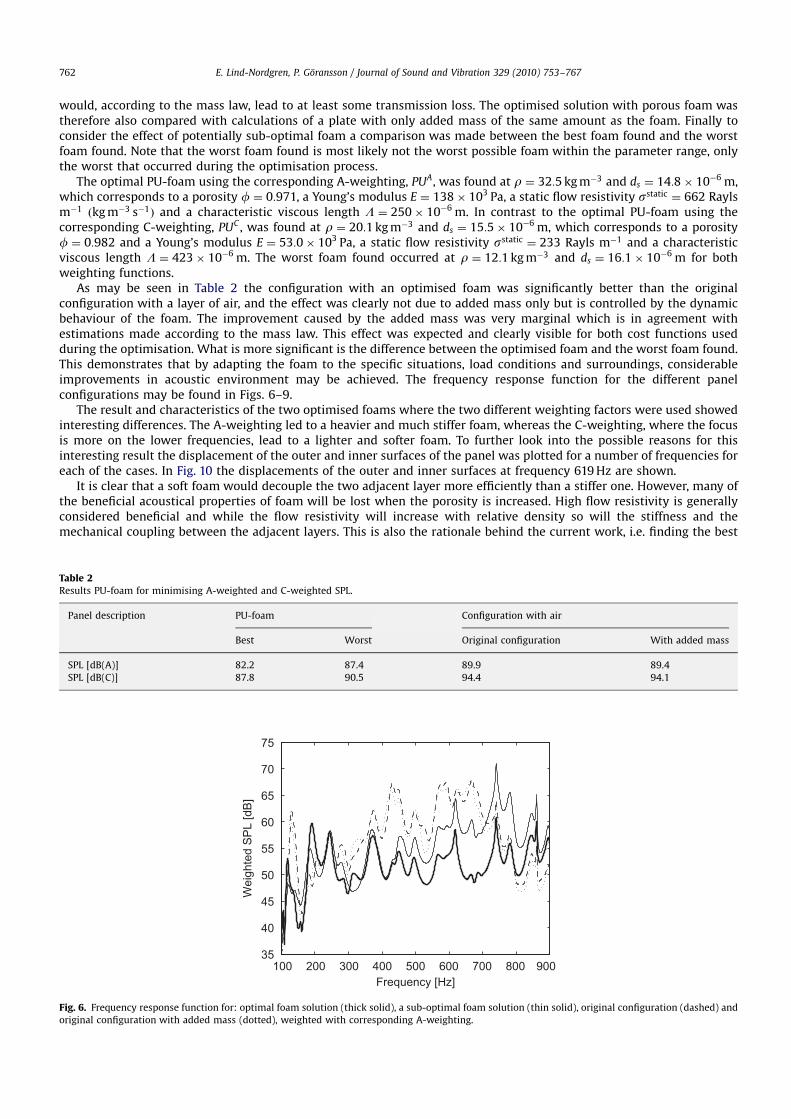
would, according to the mass law, lead to at least some transmission loss. The optimised solution with porous foam wastherefore also compared with calculations of a plate with only added mass of the same amount as the foam. Finally toconsider the effect of potentially sub-optimal foam a comparison was made between the best foam found and the worstfoam found. Note that the worst foam found is most likely not the worst possible foam within the parameter range, onlythe worst that occurred during the optimisation process.
The optimal PU-foam using the corresponding A-weighting, PUA, was found at r ¼ 32:5 kg m3 and ds ¼ 14:8 106 m,which corresponds to a porosity f ¼ 0:971, a Young’s modulus E ¼ 138 103 Pa, a static flow resistivity sstatic ¼ 662 Raylsm1 ðkg m3 s1Þ and a characteristic viscous length L ¼ 250 106 m. In contrast to the optimal PU-foam using thecorresponding C-weighting, PUC , was found at r ¼ 20:1 kg m3 and ds ¼ 15:5 106 m, which corresponds to a porosityf ¼ 0:982 and a Young’s modulus E ¼ 53:0 103 Pa, a static flow resistivity sstatic ¼ 233 Rayls m1 and a characteristicviscous length L ¼ 423 106 m. The worst foam found occurred at r ¼ 12:1 kg m3 and ds ¼ 16:1 106 m for bothweighting functions.
As may be seen in Table 2 the configuration with an optimised foam was significantly better than the originalconfiguration with a layer of air, and the effect was clearly not due to added mass only but is controlled by the dynamicbehaviour of the foam. The improvement caused by the added mass was very marginal which is in agreement withestimations made according to the mass law. This effect was expected and clearly visible for both cost functions usedduring the optimisation. What is more significant is the difference between the optimised foam and the worst foam found.This demonstrates that by adapting the foam to the specific situations, load conditions and surroundings, considerableimprovements in acoustic environment may be achieved. The frequency response function for the different panelconfigurations may be found in Figs. 6–9.
The result and characteristics of the two optimised foams where the two different weighting factors were used showedinteresting differences. The A-weighting led to a heavier and much stiffer foam, whereas the C-weighting, where the focusis more on the lower frequencies, lead to a lighter and softer foam. To further look into the possible reasons for thisinteresting result the displacement of the outer and inner surfaces of the panel was plotted for a number of frequencies foreach of the cases. In Fig. 10 the displacements of the outer and inner surfaces at frequency 619 Hz are shown.
It is clear that a soft foam would decouple the two adjacent layer more efficiently than a stiffer one. However, many ofthe beneficial acoustical properties of foam will be lost when the porosity is increased. High flow resistivity is generallyconsidered beneficial and while the flow resistivity will increase with relative density so will the stiffness and themechanical coupling between the adjacent layers. This is also the rationale behind the current work, i.e. finding the best
ARTICLE IN PRESS
100 200 300 400 500 600 700 800 90035
40
45
50
55
60
65
70
75
Frequency [Hz]
Wei
ghte
d S
PL
[dB
]
Fig. 6. Frequency response function for: optimal foam solution (thick solid), a sub-optimal foam solution (thin solid), original configuration (dashed) and
original configuration with added mass (dotted), weighted with corresponding A-weighting.
Table 2Results PU-foam for minimising A-weighted and C-weighted SPL.
Panel description PU-foam Configuration with air
Best Worst Original configuration With added mass
SPL [dB(A)] 82.2 87.4 89.9 89.4
SPL [dB(C)] 87.8 90.5 94.4 94.1
E. Lind-Nordgren, P. Goransson / Journal of Sound and Vibration 329 (2010) 753–767762
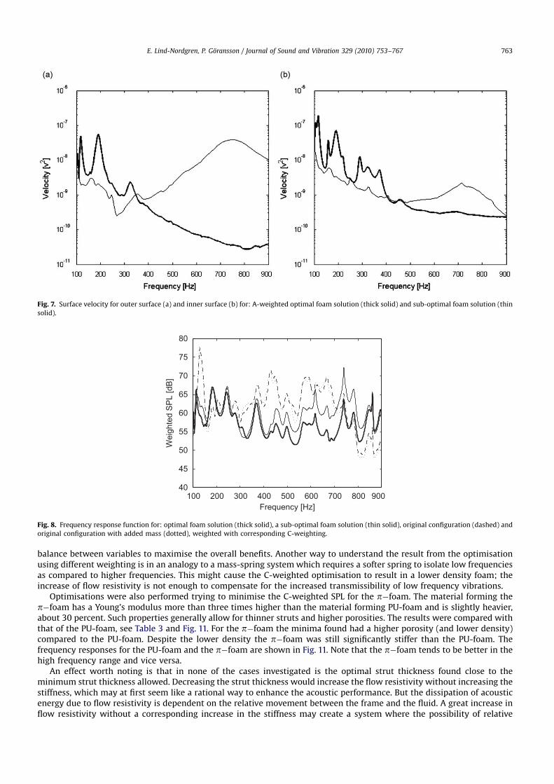
balance between variables to maximise the overall benefits. Another way to understand the result from the optimisationusing different weighting is in an analogy to a mass-spring system which requires a softer spring to isolate low frequenciesas compared to higher frequencies. This might cause the C-weighted optimisation to result in a lower density foam; theincrease of flow resistivity is not enough to compensate for the increased transmissibility of low frequency vibrations.
Optimisations were also performed trying to minimise the C-weighted SPL for the pfoam. The material forming thepfoam has a Young’s modulus more than three times higher than the material forming PU-foam and is slightly heavier,about 30 percent. Such properties generally allow for thinner struts and higher porosities. The results were compared withthat of the PU-foam, see Table 3 and Fig. 11. For the pfoam the minima found had a higher porosity (and lower density)compared to the PU-foam. Despite the lower density the pfoam was still significantly stiffer than the PU-foam. Thefrequency responses for the PU-foam and the pfoam are shown in Fig. 11. Note that the pfoam tends to be better in thehigh frequency range and vice versa.
An effect worth noting is that in none of the cases investigated is the optimal strut thickness found close to theminimum strut thickness allowed. Decreasing the strut thickness would increase the flow resistivity without increasing thestiffness, which may at first seem like a rational way to enhance the acoustic performance. But the dissipation of acousticenergy due to flow resistivity is dependent on the relative movement between the frame and the fluid. A great increase inflow resistivity without a corresponding increase in the stiffness may create a system where the possibility of relative
ARTICLE IN PRESS
Fig. 7. Surface velocity for outer surface (a) and inner surface (b) for: A-weighted optimal foam solution (thick solid) and sub-optimal foam solution (thin
solid).
100 200 300 400 500 600 700 800 90040
45
50
55
60
65
70
75
80
Frequency [Hz]
Wei
ghte
d S
PL
[dB
]
Fig. 8. Frequency response function for: optimal foam solution (thick solid), a sub-optimal foam solution (thin solid), original configuration (dashed) and
original configuration with added mass (dotted), weighted with corresponding C-weighting.
E. Lind-Nordgren, P. Goransson / Journal of Sound and Vibration 329 (2010) 753–767 763
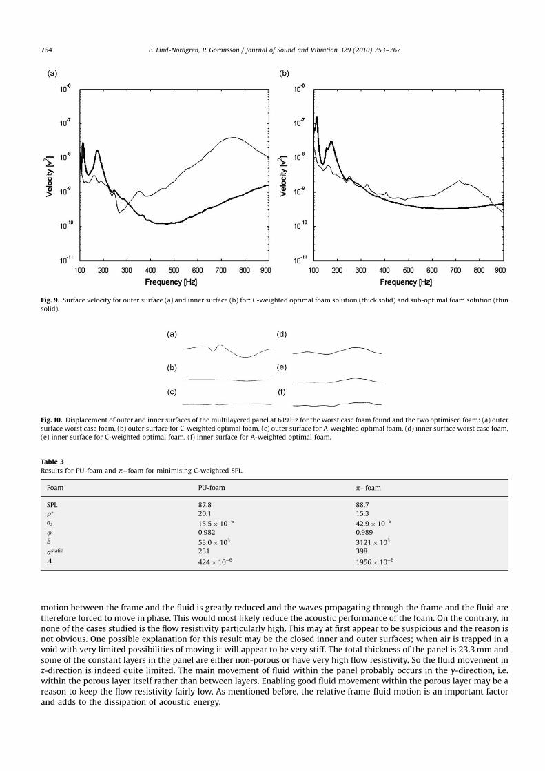
motion between the frame and the fluid is greatly reduced and the waves propagating through the frame and the fluid aretherefore forced to move in phase. This would most likely reduce the acoustic performance of the foam. On the contrary, innone of the cases studied is the flow resistivity particularly high. This may at first appear to be suspicious and the reason isnot obvious. One possible explanation for this result may be the closed inner and outer surfaces; when air is trapped in avoid with very limited possibilities of moving it will appear to be very stiff. The total thickness of the panel is 23.3 mm andsome of the constant layers in the panel are either non-porous or have very high flow resistivity. So the fluid movement inz-direction is indeed quite limited. The main movement of fluid within the panel probably occurs in the y-direction, i.e.within the porous layer itself rather than between layers. Enabling good fluid movement within the porous layer may be areason to keep the flow resistivity fairly low. As mentioned before, the relative frame-fluid motion is an important factorand adds to the dissipation of acoustic energy.
ARTICLE IN PRESS
Fig. 9. Surface velocity for outer surface (a) and inner surface (b) for: C-weighted optimal foam solution (thick solid) and sub-optimal foam solution (thin
solid).
Fig. 10. Displacement of outer and inner surfaces of the multilayered panel at 619 Hz for the worst case foam found and the two optimised foam: (a) outer
surface worst case foam, (b) outer surface for C-weighted optimal foam, (c) outer surface for A-weighted optimal foam, (d) inner surface worst case foam,
(e) inner surface for C-weighted optimal foam, (f) inner surface for A-weighted optimal foam.
Table 3
Results for PU-foam and pfoam for minimising C-weighted SPL.
Foam PU-foam pfoam
SPL 87.8 88.7
r 20.1 15.3
ds 15:5 106 42:9 106
f 0.982 0.989
E 53:0 103 3121 103
sstatic 231 398
L 424 106 1956 106
E. Lind-Nordgren, P. Goransson / Journal of Sound and Vibration 329 (2010) 753–767764
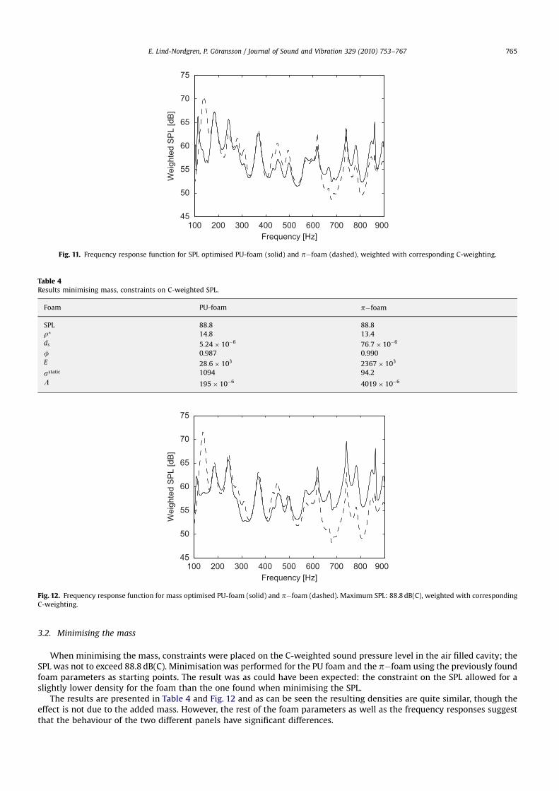
3.2. Minimising the mass
When minimising the mass, constraints were placed on the C-weighted sound pressure level in the air filled cavity; theSPL was not to exceed 88.8 dB(C). Minimisation was performed for the PU foam and the pfoam using the previously foundfoam parameters as starting points. The result was as could have been expected: the constraint on the SPL allowed for aslightly lower density for the foam than the one found when minimising the SPL.
The results are presented in Table 4 and Fig. 12 and as can be seen the resulting densities are quite similar, though theeffect is not due to the added mass. However, the rest of the foam parameters as well as the frequency responses suggestthat the behaviour of the two different panels have significant differences.
ARTICLE IN PRESS
100 200 300 400 500 600 700 800 90045
50
55
60
65
70
75
Frequency [Hz]
Wei
ghte
d S
PL
[dB
]
Fig. 11. Frequency response function for SPL optimised PU-foam (solid) and pfoam (dashed), weighted with corresponding C-weighting.
Table 4Results minimising mass, constraints on C-weighted SPL.
Foam PU-foam pfoam
SPL 88.8 88.8
r 14.8 13.4
ds 5:24 106 76:7 106
f 0.987 0.990
E 28:6 103 2367 103
sstatic 1094 94.2
L 195 106 4019 106
100 200 300 400 500 600 700 800 90045
50
55
60
65
70
75
Frequency [Hz]
Wei
ghte
d S
PL
[dB
]
Fig. 12. Frequency response function for mass optimised PU-foam (solid) and pfoam (dashed). Maximum SPL: 88.8 dB(C), weighted with corresponding
C-weighting.
E. Lind-Nordgren, P. Goransson / Journal of Sound and Vibration 329 (2010) 753–767 765
4. Conclusions
Despite the limited amount of foam and layer combinations tested, the results presented above suggest realistic changesof the microscopic properties of the foam that may be sufficient to adapt the foam to a specific environmental conditionand thereby achieve improved acoustic behaviour as well as reduced weight. The foam studied in this paper shows a non-convex behaviour, however, the number of minima within the parameter range seems to be limited which enables ameaningful optimisation.
These initial attempts to optimise foam on a microscopic level also show the significance of the cost function chosen toevaluate the effectiveness of the foam. By simply using different weighting factors when minimising the sound pressurelevels, the optimisation gave very different results. This raises the question of how to formulate a cost function that in thebest way describe the characteristics sought for. Such a cost function may include surface velocity, dissipated acousticenergy, sound power or a comparison to a frequency response spectrum chosen in advance. To further elaborate on possiblecost functions it is quite possible that an effective cost function may combine one or more of the acoustical estimationsabove with values referring to weight and cost in some weighted constellation.
Rather than to optimise only one foam layer it would be natural to want to optimise an entire multilayered panel, wherethe number of layers, the thickness of each layer and the foam properties of each layer are all variables to be considered.The different layers may consist of highly diverse material types, from thin, highly viscoelastic layers to thicker weak layers.The development of new foam material with high stiffness and the ability to form extremely thin struts, 108 m, may alsointroduce both new difficulties and new possibilities in the area of multilayered structures.
Acknowledgements
The authors would like to gratefully acknowledge the financial support of the European project Friendcopter, Contractno. AIP3-CT-2003-502773 and the European project Smart Structures, Contract no. MRTN-CT-2006-035559.
Appendix A
The foams used in the presented work were a polyurethane foam (PU-foam), and a polyimide foam (pfoam), Table A1.
Appendix B
The sub-layers of the panel are given in Tables B1 and B2, one for the solid layers and one for the fixed foam layer.
ARTICLE IN PRESS
Table A1Material properties for reference materials.
Material property PU-foam pfoam
rs ðkg m3Þ 1100 1400
Es (Pa) 450 106 1400 106
a1 [1] 1.17 1.17
r0 ðkg m3Þ 35.4 8
E0 (Pa) 164 103 848 103
s0 ðkg m3 s1Þ 4500 1000 103
L0 (m) 96:1 106 39 106
Table B1Material properties for solid sub-layers.
Material property Units Outer panel sheet Solid 1 Solid 2 Interior panel sheet
Density ðkg m3Þ 750 1510 2700 362
Young’s modulus (Pa) 8600 109 55 104 69 109 6:52 109
Poisson’s ratio [1] 0.29 0.4 0.31 0.3
Thickness (m) 0.005 0.001 0.0007 0.0036
E. Lind-Nordgren, P. Goransson / Journal of Sound and Vibration 329 (2010) 753–767766
References
[1] M.A. Biot, Theory of propagation of elastic waves in a fluid saturated porous solid. I. Low frequency range, Journal of the Acoustical Society of America28 (1) (1956) 168–178.
[2] M.A. Biot, Theory of propagation of elastic waves in a fluid saturated porous solid. II. Higher frequency range, Journal of the Acoustical Society ofAmerica 28 (2) (1956) 179–191.
[3] M.A. Biot, Theory of deformation of a porous viscoelastic anisotropic solid, Journal of Applied Physics 27 (3) (1956) 459–467.[4] F. Simon, S. Pauzin, D. Biron, Optimisation of sandwich trim panels for reducing helicopter internal noise, 30th European Rotocraft Forum, Vol. 2005,
2005, pp. 1025–1033.[5] O. Tanneau, J.B. Casimir, P. Lamary, Optimization of multilayered panels with poroelastic components for an acoustical transmission objective, Journal
of the Acoustical Society of America 120 (3) (2006) 1227–1238.[6] J.S. Lee, E.I. Kim, Y.Y. Kim, J.S. Kim, Y.J. Kang, Optimal poroelastic layer sequencing for sound transmission loss maximization by topology optimization
method, Journal of the Acoustical Society of America 122 (4) (2007) 2097–2106.[7] K. Svanberg, The method of moving asymptotes—a new method for structural optimization, International Journal for Numerical Methods in Engineering
24 (1987) 359–373.[8] F. Franco, K.A. Cunefare, M. Ruzzene, Structural-acoustic optimization of sandwich panels, Journal of Vibration and Acoustics 129 (3) (2007) 330–340.[9] C. Perrot, F. Chevillotte, R. Panneton, Bottom-up approach for microstructure optimization of sound absorbing materials, Journal of the Acoustical
Society of America 124 (2) (2008) 940–948.[10] C. Perrot, F. Chevillotte, R. Panneton, X. Olny, Bottom-up approach for microstructure optimization of sound absorbing materials, Invited
Paper—Proceedings of the 19th International Congress on Acoustics, ICA 2007, Madrid, Spain, 2007 (ISBN 84-87985-12-2).[11] C. Perrot, R. Panneton, X. Olny, From microstructure to acoustic behaviour of porous materials, Canadian Acoustics—Acoustique Canadienne 32 (3)
(2004) 18–19.[12] X. Olny, F. Sgard, C. Perrot, R. Panneton, Microscopic and mesoscopic approaches for describing and building sound absorbing porous materials,
Proceedings of the Second TUL-ENTPE Workshop: 187-206, 2004 (ISBN 2 86834 121 7).[13] C. Perrot, R. Panneton, X. Olny, R. Bouchard, Mesostructural approach for characterising macroscopic parameters of open cell foams with computed
microtomography, Proceedings of the Institute of Acoustics 25 (2003) 169–175 (ISBN 1 901656 56 X).[14] C. Zwikker, C.W. Kosten, Sound Absorbing Materials, Elsevier Publishing Company, Amsterdam, 1949 (Chapters II and III).[15] K. Dovstam, Augmented Hooke’s law in frequency domain. A three dimensional material damping formulation, International Journal of Solids and
Structures 32 (19) (1995) 2835–2852.[16] J.F. Allard, Propagation of Sound in Porous Media: Modelling Sound Absorbing Materials, Elsevier Applied Science, 1993.[17] D. Lafarge, P. Lemarnier, J.F. Allard, V. Tarnow, Dynamic compressibility of air in porous structures at audible frequencies, Journal of the Acoustical
Society of America 102 (4) (1997) 1995–2006.[18] S.R. Pride, A.F. Gangi, F.D. Morgan, Deriving the equations of motion for porous isotropic media, Journal of the Acoustical Society of America 92 (6)
(1992) 3278–3290.[19] D.L. Johnson, J. Koplik, R. Dashen, Theory of dynamic permeability and tortuosity in fluid-saturated porous media, The Journal of Fluid Mechanics 176
(1987) 379–402.[20] W.E. Warren, A.M. Kraynik, The linear elastic properties of open cell foams, Journal of Applied Mechanics 55 (2) (1988) 341–346.[21] W.E. Warren, A.M. Kraynik, Linear elastic behavior of a low-density Kelvin foam with open cells, Journal of Applied Mechanics 64 (4) (1997) 787–794.[22] L.J. Gibson, M.F. Ashby, Cellular Solids—Structure and Properties, second ed., Cambridge University Press, Cambridge, 1997 First published by
Pergamont Press Ltd., 1988.[23] P. Goransson, Acoustic and vibrational damping in porous solids, Philosophical Transactions of the Royal Society A 364 (2006) 89–108.[24] J.F. Allard, Y. Champoux, New empirical equations for sound propagation in rigid frame fibrous materials, Journal of the Acoustical Society of America 6
(91) (1992) 3346–3353.[25] N.E. Horlin, M. Nordstrom, P. Goransson, A 3-D hierarchical FE formulation of Biot’s equations for elasto-acoustic modelling of porous media, Journal
of Sound and Vibration 254 (4) (2001) 633–652.[26] N.E. Horlin, 3-D hierarchical hp-FEM applied to elasto-acoustic modelling of layered porous media, Journal of Sound and Vibration 285 (4) (2005)
341–363.
ARTICLE IN PRESS
Table B2Material properties for foam sub-layer.
Material property Units Foam 1
Bulk density ðkg m3Þ 354
Bulk Young’s modulus (Pa) 550 103
Poisson’s ratio [1] 0.39
Thickness (m) 0.005
a1 [1] 2.2
sstatic ðkg m3 s1Þ 1 106
L (m) 7:7 106
Porosity [1] 0:52
E. Lind-Nordgren, P. Goransson / Journal of Sound and Vibration 329 (2010) 753–767 767

Material Property Based Structural and AcousticOptimization of a Multifunctional Vehicle Body
Panel
Christopher J. Cameron∗PhD Student
Eleonora Lind Nordgren†
PhD StudentPer Wennhage
Assistant ProfessorPeter Göransson
Professor
Centre for ECO2 Vehicle DesignDepartment of Aeronautical and Vehicle Engineering
Kunglinga Tekniska Högskolan (KTH)Teknikringen 8
10044 Stockholm, Sweden
Conventional vehicle passenger compartments often achievefunctional requirements using a complex assembly of com-ponents. As each component is optimized for a single task,the assembly as a whole is often suboptimal in achieving thesystem performance requirements. In this paper, a novel it-erative design approach based on using a multi-layered loadbearing sandwich panel with integrated acoustic capabilitiesis developed focusing on material properties and their effecton the systems behavior. The proposed panel is meant to ful-fil multiple system functionalities simultaneously, thus sim-plifying the assembly and reducing mass. Open cell acousticfoams are used to achieve acoustic performance, and the ef-fect of altering the stacking sequence as well as introducingan air gap within the acoustic treatment is studied in detail todetermine effects on the acoustic and structural performanceof the panel as a whole.
NomenclatureNVH Automotive Noise, Vibration, and Harshness.CF Carbon Fiber.GF Glass Fiber.CSM Chopped Strand Mat.Vf θ Volume Fraction fiber in lamina with direction θ.tθ Thickness of lamina with direction θ.PET Polyethylene terephthalate.
∗Corresponding Author Structural optimization. Email: [email protected]†Corresponding Author Acoustic optimization. Email: [email protected]
SPL Sound Pressure Levelds average strut thickness of solid frameEs Young’s modulus for solid frame materialE∗ Young’s modulus for homogenised foamls average strut length of solid framep acoustic pressureα∞ tortuosityΛ viscous characteristic lengthΛ’ characteristic thermal lengthρ f density of fluidρs density of solid frame materialρ∗ bulk density of solid frameσstatic static flow resistivity of foamφ porosity, volume fraction of open pore fluid contentω frequency
1 IntroductionFunctional requirements of a modern automobiles pas-
senger compartment include such things as structural in-tegrity, protection from the elements, aesthetic appearance,and comfort in terms of seating, tactile feedback, and theacoustic environment. In the majority of automobiles, thesefunctional requirements are achieved by assembling a groupof components, each optimized to perform a single task. Theresult of this design ideology is a complex system filled withcompromise which is sub-optimal in achieving the globalperformance requirements.
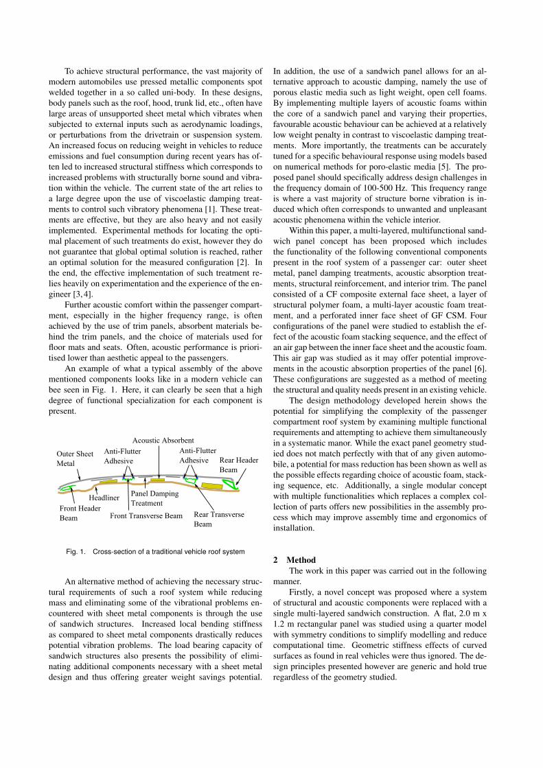
To achieve structural performance, the vast majority ofmodern automobiles use pressed metallic components spotwelded together in a so called uni-body. In these designs,body panels such as the roof, hood, trunk lid, etc., often havelarge areas of unsupported sheet metal which vibrates whensubjected to external inputs such as aerodynamic loadings,or perturbations from the drivetrain or suspension system.An increased focus on reducing weight in vehicles to reduceemissions and fuel consumption during recent years has of-ten led to increased structural stiffness which corresponds toincreased problems with structurally borne sound and vibra-tion within the vehicle. The current state of the art relies toa large degree upon the use of viscoelastic damping treat-ments to control such vibratory phenomena [1]. These treat-ments are effective, but they are also heavy and not easilyimplemented. Experimental methods for locating the opti-mal placement of such treatments do exist, however they donot guarantee that global optimal solution is reached, ratheran optimal solution for the measured configuration [2]. Inthe end, the effective implementation of such treatment re-lies heavily on experimentation and the experience of the en-gineer [3, 4].
Further acoustic comfort within the passenger compart-ment, especially in the higher frequency range, is oftenachieved by the use of trim panels, absorbent materials be-hind the trim panels, and the choice of materials used forfloor mats and seats. Often, acoustic performance is priori-tised lower than aesthetic appeal to the passengers.
An example of what a typical assembly of the abovementioned components looks like in a modern vehicle canbee seen in Fig. 1. Here, it can clearly be seen that a highdegree of functional specialization for each component ispresent.
Fig. 1. Cross-section of a traditional vehicle roof system
An alternative method of achieving the necessary struc-tural requirements of such a roof system while reducingmass and eliminating some of the vibrational problems en-countered with sheet metal components is through the useof sandwich structures. Increased local bending stiffnessas compared to sheet metal components drastically reducespotential vibration problems. The load bearing capacity ofsandwich structures also presents the possibility of elimi-nating additional components necessary with a sheet metaldesign and thus offering greater weight savings potential.
In addition, the use of a sandwich panel allows for an al-ternative approach to acoustic damping, namely the use ofporous elastic media such as light weight, open cell foams.By implementing multiple layers of acoustic foams withinthe core of a sandwich panel and varying their properties,favourable acoustic behaviour can be achieved at a relativelylow weight penalty in contrast to viscoelastic damping treat-ments. More importantly, the treatments can be accuratelytuned for a specific behavioural response using models basedon numerical methods for poro-elastic media [5]. The pro-posed panel should specifically address design challenges inthe frequency domain of 100-500 Hz. This frequency rangeis where a vast majority of structure borne vibration is in-duced which often corresponds to unwanted and unpleasantacoustic phenomena within the vehicle interior.
Within this paper, a multi-layered, multifunctional sand-wich panel concept has been proposed which includesthe functionality of the following conventional componentspresent in the roof system of a passenger car: outer sheetmetal, panel damping treatments, acoustic absorption treat-ments, structural reinforcement, and interior trim. The panelconsisted of a CF composite external face sheet, a layer ofstructural polymer foam, a multi-layer acoustic foam treat-ment, and a perforated inner face sheet of GF CSM. Fourconfigurations of the panel were studied to establish the ef-fect of the acoustic foam stacking sequence, and the effect ofan air gap between the inner face sheet and the acoustic foam.This air gap was studied as it may offer potential improve-ments in the acoustic absorption properties of the panel [6].These configurations are suggested as a method of meetingthe structural and quality needs present in an existing vehicle.
The design methodology developed herein shows thepotential for simplifying the complexity of the passengercompartment roof system by examining multiple functionalrequirements and attempting to achieve them simultaneouslyin a systematic manor. While the exact panel geometry stud-ied does not match perfectly with that of any given automo-bile, a potential for mass reduction has been shown as well asthe possible effects regarding choice of acoustic foam, stack-ing sequence, etc. Additionally, a single modular conceptwith multiple functionalities which replaces a complex col-lection of parts offers new possibilities in the assembly pro-cess which may improve assembly time and ergonomics ofinstallation.
2 MethodThe work in this paper was carried out in the following
manner.Firstly, a novel concept was proposed where a system
of structural and acoustic components were replaced with asingle multi-layered sandwich construction. A flat, 2.0 m x1.2 m rectangular panel was studied using a quarter modelwith symmetry conditions to simplify modelling and reducecomputational time. Geometric stiffness effects of curvedsurfaces as found in real vehicles were thus ignored. The de-sign principles presented however are generic and hold trueregardless of the geometry studied.
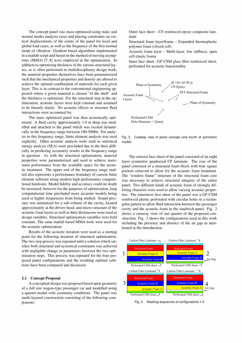
The concept panel was mass optimized using static andnormal modes analysis cases and placing constraints on ver-tical displacements of the centre of the panel for local andglobal load cases, as well as the frequency of the first normalmode of vibration. Gradient based algorithms implementedin a matlab script and based on the method of moving asymp-totes (MMA) [7, 8] were employed in the optimization. Inaddition to optimizing thickness of the various structural lay-ers, as is often performed in multidisciplinary design work,the material properties themselves have been parameterizedsuch that the mechanical properties and density are altered toachieve the optimal combination of materials for each givenlayer. This is in contrast to the conventional engineering ap-proach where a given material is chosen "of the shelf" andthe thickness is optimized. For the structural step in the op-timization, acoustic layers were kept constant and assumedto be linearly elastic. No acoustic effects or structure fluidinteractions were accounted for.
The mass optimized panel was then acoustically opti-mized. A fluid cavity approximately 1.0 m deep was mod-elled and attached to the panel which was excited dynami-cally in the frequency range between 100-500Hz. For analy-sis in this frequency range, finite element analysis was usedexplicitly. Other acoustic analysis tools such as statisticalenergy analysis (SEA) were precluded due to the their diffi-culty in predicting accurately results in the frequency rangein question. As with the structural optimization, materialproperties were parameterized and used to achieve maxi-mum performance from the available space for the acous-tic treatment. The upper end of the frequency range stud-ied also represents a performance boundary of current finiteelement software using modern high performance computa-tional hardware. Model fidelity and accuracy could no doubtbe increased, however for the purposes of optimization, longcomputational time precluded more accurate models beingused or higher frequencies from being studied. Sound pres-sure was minimised for a sub-volume of the cavity, locatedapproximately at the drivers head, and micro-structure of theacoustic foam layers as well as their thicknesses were used asdesign variables. Structural optimization variables were heldconstant. The same matlab based MMA tools were used forthe acoustic optimization.
Results of the acoustic iteration were used as a startingpoint for the following iteration of structural optimization.The two step process was repeated until a solution which sat-isfies both structural and acoustical constraints was achievedwith negligible change in parameters between the two opti-mization steps. This process was repeated for the four pro-posed panel configurations and the resulting optimal solu-tions have been compared and discussed.
2.1 Concept ProposalA conceptual design was proposed based upon geometry
of a full size wagon-type passenger car and modelled usinga quarter model with symmetry conditions. The panel wasmulti-layered construction consisting of the following com-ponents:
Outer face sheet – CF reinforced epoxy composite lam-inateStructural foam layer/frame – Expanded thermoplasticpolymer foam (closed cell)Acoustic foam layer – Multi-layer, low stiffness, opencell elastic foamsInner face sheet –GF CSM glass fiber reinforced sheet,perforated for acoustic functionality
Fig. 2. Cutaway view of panel concept (one fourth of symmetricmodel)
The exterior face sheet of the panel consisted of an eightlayer symmetric quadraxial CF laminate. The core of thepanel consisted of a structural foam block with four squarepockets removed to allow for the acoustic foam treatment.The "window frame" structure of the structural foam corewas necessary to achieve structural integrity of the entirepanel. Two different kinds of acoustic foam of strongly dif-fering character were used to allow varying acoustic proper-ties. The innermost face sheet of the panel was a GF CSMreinforced plastic perforated with circular holes in a rectan-gular pattern to allow fluid interaction between the passengercavity and the acoustic foam in the sandwich panel. Fig. 2shows a cutaway view of one quarter of the proposed con-struction. Fig. 3 shows the configurations used in this workincluding the presence and absence of the air gap as men-tioned in the introduction.
Fig. 3. Stacking sequences of configurations 1-4
2.2 Structural Optimization2.2.1 Structural modelling
Structural modelling and analysis was performed usingthe Altair Hyperworks suite. The outer face sheet was mod-elled using 3-D shell elements and composite laminate prop-erties. Structural and acoustic foam were modelled usingmultiple layers of brick elements and the perforated innerface sheet was modelled using two layers of brick elements.Linear isotropic material properties were used for all foamcomponents and the inner face sheet. In total the modelcontained approximately 86000 nodes, 84000 elements, and270000 degrees of freedom using a nominal mesh size of 10mm. In the structural optimization step, acoustic interactionswere ignored and only mechanical properties were consid-ered.
2.2.2 Design variables and material propertiesFor the structural optimization, a total of nine design
variables were chosen. These variables were as follows:
1. Vf 0 in outer face sheet2. Vf 45 in outer face sheet3. Vf 90 in outer face sheet4. t0 in outer face sheet5. t45 in outer face sheet6. t90 in outer face sheet7. Thickness of structural foam layer8. Density of structural foam layer9. Thickness of inner face sheet
Fiber volume fraction in each lamina was allowed tovary from 0.01 to 0.6 and mechanical properties were cal-culated using relationships for basic composite theory takenfrom the literature [9] and shown in Eqn. (1 - 5). Table1 shows the material data used. While allowing for a lowfiber volume fraction may seem counter intuitive, in caseswhere demands on mechanical properties are low, mass maybe saved by replacing the higher density CF with lower den-sity matrix material.
E11 = (Vf )E f 11 +(1.0−Vf )Em (1)
E12 = E13 =Vf
E f+
1−Vf
Em(2)
G12 = G13 =Gm
1−√
Vf (1−Gm/G f 12)(3)
G23 =Gm
1−Vf (1−Gm/G f 12)(4)
νlamina =Vf ·ν f +(1−Vf ) ·νm (5)
Density of the structural foam was chosen as a designvariable and used to alter the mechanical properties of the
Table 1. Material properties for matrix, fibers, and CSM sheet (non-perforated)
Matrix CF GF CSM
E11(tensile) [MPa] 3200 220600 15000
G12 = G23 [MPa] 1185 30130 5769
ρ [kg/m3] 1125 9000 1700
ν [–] 0.35 0.20 0.3
material according to Eqn. ( 6 - 8), which are taken fromthe literature [10]. A closed cell, thermoplastic foam wasassumed using the mechanical properties of PET.
E f oam
Esolid≈ φ2
(ρ f oam
ρsolid
)2
+ (1−φ)ρ f oam
ρsolid
+P0(1−2ν f oam)
Esolid−ρ f oam/ρsolid(6)
G f oam
Esolid≈ 3
8
(φ2(
ρ f oam
ρsolid)2 +(1−φ)
ρ f oam
ρsolid
)(7)
ν f oam ≈13
(8)
Manufacturers data for Divinycell P series, and AirexT90 and T92 was obtained from technical data sheetson the respective manufacturers homepage 1 2 [Retrieved22/11/2010]. The given properties were correlated withEqn. (6) and (7), and the assumption that φ = 0.8 , as givenin the literature [10] was checked for this case.
Fig. 4. Compressive modulus as function of density
1www.diabgroup.com/europe/products/e_divinycell_p.html
2www.corematerials.3acomposites.com/airex-foams.html
Exact agreement between manufacturers data and theabove relationships was not obtained. Better agreement inthe equation for compressive modulus was obtained usingφ = 0.72, which necessitated a scaling factor of 0.8 timesthe calculated shear modulus to obtain reasonable agreement.Fig.s 4 and 5 show the manufacturers data and theoreticalproperties as functions of density.
Fig. 5. Shear modulus as function of density
A fixed degree of perforation assuming 2.0 mm holesdrilled in a square pattern with 3.5 mm between hole cen-tres was used. This configuration was chosen as it was con-sidered to be the minimum degree of perforation to allowfor sufficient acoustic transparency [11]. Tighter hole spac-ing increases acoustic transparency but reduces bending stiff-ness and vice versa. Equivalent material properties were usedrather than modelling individual holes within the model. Themethods used to derive the properties are omitted here for thesake of brevity, and instead the authors would refer to previ-ous work [12] or the original literature for bending stiffnessof perforated plates [13–15].
2.2.3 Load cases and boundary conditionsStructural optimization was performed using two static
load cases and normal modes analysis. For the first staticload case, a pressure equivalent to a hand firmly pressing onthe roof was applied on a circular area approximately 100mm in diameter in the centre of the quarter panel model.For the second static load case a pressure was applied overthe entire panel, equivalent to 2000 kg pressing on the en-tire roof. Boundary conditions applied to the model can beseen in Fig. 6. Symmetry and clamped constraints were ap-plied across the entire thickness (z direction in Fig. 6) of thepanel. The boundary conditions used were considered a rea-sonable representation of how the panel might be fastened tothe front and rear headers (large, stiff, crossbeams) and thelongitudinal beams in the roof.
For the normal modes analysis case, it should be noted
Fig. 6. Top and side view of panel showing boundary conditions
that symmetric boundary conditions preclude non-symmetricmodes of vibration. For the given case, this is not a problemas it is primarily the first mode of vibration which is of in-terest and which generally tends to cause the most acousticdiscomfort.
2.3 Acoustic Optimization2.3.1 Acoustic modeling
To simulate the acoustic behaviour of the panel the panelwas connected to an air cavity in which the sound pressurelevel in typical listener positions could be calculated. Thepanel was excited using dynamic forces in the x-, y-, and z-direction. The forces were applied over the top surface ofthe elements along the edge of the CF epoxy top sheet, Fig.7 and the system response was evaluated for the frequencyrange 100 – 500 Hz.
Fig. 7. Dynamic forces applied to the CF Laminate
As the roof was represented by a quarter model, symme-try boundary conditions were applied at the symmetry edgesthrough all layers. The inner perforated plate was also fixedin the x-, y- and z-direction along x = 0 and y = 0 to avoidrigid body motion.
For computational reasons both the excitation and theresponse of the system was limited to the frequency range100-500 Hz. The acoustic response of the system was mod-elled using FE-based numerical methods where the porousfoams were modelled using Biot theory [16–18].
The theories used to model the foam assume materialisotropy, small displacements and linearly elastic materials.The numerical model must take into account not only theproperties of the individual porous layers, e.g. the fluid inthe pores, the solid frame structure and the coupling betweenthem. It also has to consider the boundaries to other solid,fluid or porous layers, with appropriate treatment of the kine-matic conditions, the mass flow continuity conditions and therelevant stress balances. Also, special care has to be taken inthe selection of trial functions to get convergent solutions toBiot’s equations, especially for multi-layered structures, forwhich hp-FEM3 is a convenient finite element base. Herethe finite element solutions were obtained using the meth-ods thoroughly discussed and properly addressed in worksby Hörlin et al. [19] and by Hörlin [20] and will not be re-peated here. However, the complexity of the problem makesit computationally expensive to solve and as each frequencyis solved independently, limiting the frequency range is a ne-cessity.
2.3.2 Design variables and material propertiesIn order to carry out a meaningful optimization of the
acoustic foam it is necessary to use design variables that canbe changed independently of one another. In porous foam,several of the parameters used to calculate the response, forexample the homogenized Young’s modulus, E∗, and thebulk density, ρ∗, are inter related in a quite complex way.An alternative is to use microstructural geometric properties.To relate the macroscopic properties of the foam to the un-derlying microscopic properties scaling laws are used. Con-tributions to developing scaling laws and increasing the un-derstanding of the mechanical properties of foam have beenmade by several researchers, e.g [10, 21–25]. A method forusing scaling laws to optimize porous foam in multi-layeredstructures has been proposed previously [26]. For complete-ness, however, the more important scaling laws used aresummarized below.
ρ∗ = ρre f
(ds
dre f
)2( lre f
ls
)2
(9)
φ = 1− ρ∗
ρs(10)
E∗ = Ere f
(ρ∗
ρre f
)2
(11)
Λ =ds
4(ρ∗/ρs)(12)
3Convergence is achieved by refining the mesh and/or increasing the ap-proximation order
Λ′ = 2 ·Λ (13)
α∞ = 1− 1−α∞re f
ln(φre f )· ln(φ∗) (14)
σstatic = σstaticre f
(ρ∗
ρre f
)2
·(
dre f
ds
)2
· α∞
α∞re f·
(1− ρre f
ρs
)
(1− ρ∗
ρs
)
(15)The acoustic foam A was a Polyurethane foam (PU
foam) and the acoustic foam B was a Polyimide foam (pifoam). The reference material properties of the two foamsare listed in Table 2.
Material property PU foam pi foam
ρs [kg m−3] 1100 1400
Es [Pa] 450 ·106 1400 ·106
α∞re f [1] 1.17 1.17
ρ∗re f [kg m−3] 35.4 8
E∗re f [Pa] 164 ·103 848 ·103
σstaticre f [kg m−3 s−1] 4500 1000 ·103
Λre f [m] 96.1 ·10−6 39 ·10−6
Table 2. Material properties for reference materials.
The design variable used in the acoustic optimizationwas the scaled length of the struts ls/lre f in the two foamlayers and the thickness of each foam layer. These designvariables will be referred to as lPU , lpi, tPU and tpi. Con-straints were put on maximum and minimum relative strutlength, which could vary between 0.5 and 5, and maximumand minimum thickness of each layer, which could vary be-tween 1 mm and 50 mm, Constraints were also put on maxi-mum and minimum total thickness.
The aim of the acoustic optimization was to improve theNVH comfort inside the vehicle and the objective function ofwas chosen to be the unweighted sound pressure level (SPL)in a subvolume of the air cavity, Ωsub, summed over the en-tire frequency range.
〈SPL〉Ωsub = 10 · log
fmax
∑f= f1
(p2
f ·∆ f f)
p20
(16)
The choice of objective function will obviously have agreat effect on the outcome of the optimization. Alternative
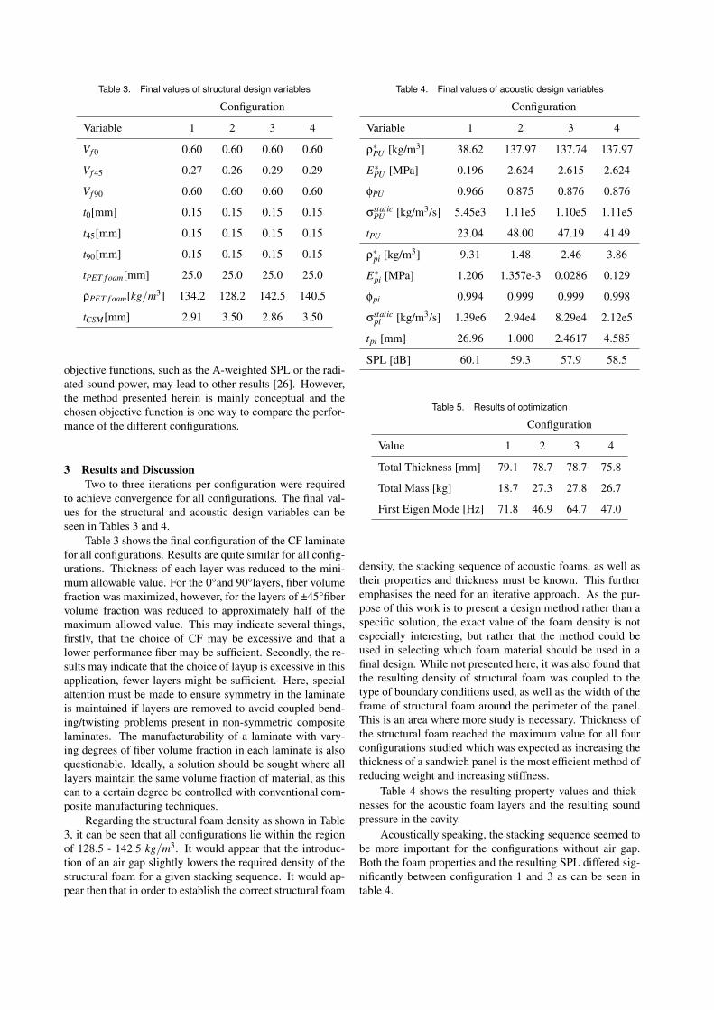
Table 3. Final values of structural design variables
Configuration
Variable 1 2 3 4
Vf 0 0.60 0.60 0.60 0.60
Vf 45 0.27 0.26 0.29 0.29
Vf 90 0.60 0.60 0.60 0.60
t0[mm] 0.15 0.15 0.15 0.15
t45[mm] 0.15 0.15 0.15 0.15
t90[mm] 0.15 0.15 0.15 0.15
tPET f oam[mm] 25.0 25.0 25.0 25.0
ρPET f oam[kg/m3] 134.2 128.2 142.5 140.5
tCSM[mm] 2.91 3.50 2.86 3.50
objective functions, such as the A-weighted SPL or the radi-ated sound power, may lead to other results [26]. However,the method presented herein is mainly conceptual and thechosen objective function is one way to compare the perfor-mance of the different configurations.
3 Results and DiscussionTwo to three iterations per configuration were required
to achieve convergence for all configurations. The final val-ues for the structural and acoustic design variables can beseen in Tables 3 and 4.
Table 3 shows the final configuration of the CF laminatefor all configurations. Results are quite similar for all config-urations. Thickness of each layer was reduced to the mini-mum allowable value. For the 0°and 90°layers, fiber volumefraction was maximized, however, for the layers of ±45°fibervolume fraction was reduced to approximately half of themaximum allowed value. This may indicate several things,firstly, that the choice of CF may be excessive and that alower performance fiber may be sufficient. Secondly, the re-sults may indicate that the choice of layup is excessive in thisapplication, fewer layers might be sufficient. Here, specialattention must be made to ensure symmetry in the laminateis maintained if layers are removed to avoid coupled bend-ing/twisting problems present in non-symmetric compositelaminates. The manufacturability of a laminate with vary-ing degrees of fiber volume fraction in each laminate is alsoquestionable. Ideally, a solution should be sought where alllayers maintain the same volume fraction of material, as thiscan to a certain degree be controlled with conventional com-posite manufacturing techniques.
Regarding the structural foam density as shown in Table3, it can be seen that all configurations lie within the regionof 128.5 - 142.5 kg/m3. It would appear that the introduc-tion of an air gap slightly lowers the required density of thestructural foam for a given stacking sequence. It would ap-pear then that in order to establish the correct structural foam
Table 4. Final values of acoustic design variables
Configuration
Variable 1 2 3 4
ρ∗PU [kg/m3] 38.62 137.97 137.74 137.97
E∗PU [MPa] 0.196 2.624 2.615 2.624
φPU 0.966 0.875 0.876 0.876
σstaticPU [kg/m3/s] 5.45e3 1.11e5 1.10e5 1.11e5
tPU 23.04 48.00 47.19 41.49
ρ∗pi [kg/m3] 9.31 1.48 2.46 3.86
E∗pi [MPa] 1.206 1.357e-3 0.0286 0.129
φpi 0.994 0.999 0.999 0.998
σstaticpi [kg/m3/s] 1.39e6 2.94e4 8.29e4 2.12e5
tpi [mm] 26.96 1.000 2.4617 4.585
SPL [dB] 60.1 59.3 57.9 58.5
Table 5. Results of optimization
Configuration
Value 1 2 3 4
Total Thickness [mm] 79.1 78.7 78.7 75.8
Total Mass [kg] 18.7 27.3 27.8 26.7
First Eigen Mode [Hz] 71.8 46.9 64.7 47.0
density, the stacking sequence of acoustic foams, as well astheir properties and thickness must be known. This furtheremphasises the need for an iterative approach. As the pur-pose of this work is to present a design method rather than aspecific solution, the exact value of the foam density is notespecially interesting, but rather that the method could beused in selecting which foam material should be used in afinal design. While not presented here, it was also found thatthe resulting density of structural foam was coupled to thetype of boundary conditions used, as well as the width of theframe of structural foam around the perimeter of the panel.This is an area where more study is necessary. Thickness ofthe structural foam reached the maximum value for all fourconfigurations studied which was expected as increasing thethickness of a sandwich panel is the most efficient method ofreducing weight and increasing stiffness.
Table 4 shows the resulting property values and thick-nesses for the acoustic foam layers and the resulting soundpressure in the cavity.
Acoustically speaking, the stacking sequence seemed tobe more important for the configurations without air gap.Both the foam properties and the resulting SPL differed sig-nificantly between configuration 1 and 3 as can be seen intable 4.
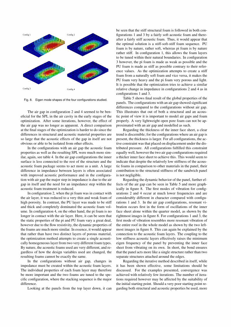
Config 1 Config 2
Config 3 Config 4
Fig. 8. Eigen mode shapes of the four configurations studied.
The air gap in configuration 2 and 4 seemed to be ben-eficial for the SPL in the air cavity in the early stages of theoptimization. After some iterations, however, the effect ofthe air gap was no longer as apparent. A direct comparisonat the final stages of the optimization is harder to do since thedifferences in structural and acoustic material properties areso large that the acoustic effects of the gap in itself are notobvious or able to be isolated from other effects.
In the configurations with an air gap the acoustic foamproperties as well as the resulting SPL were much more sim-ilar, again, see table 4. In the air gap configurations the innersurface is less connected to the rest of the structure and theacoustic foam package seems to act more as a unit. A largedifference in impedance between layers is often associatedwith improved acoustic performance and in the configura-tion with air gap the major step in impedance is due to the airgap in itself and the need for an impedance step within theacoustic foam treatment is reduced.
In configuration 2, when the pi foam was in contact withthe air layer, it was reduced to a very thin and weak foam ofhigh porosity. In contrast, the PU layer was made to be stiffand thick and completely dominated the acoustic foam vol-ume. In configuration 4, on the other hand, the pi foam is nolonger in contact with the air layer. Here, it can be seen thatthe static properties of the pi and PU foam vary a great deal,however due to the flow resistivity, the dynamic properties ofthe foams are much more similar. In essence, it would appearthat rather than have two distinct layers of porous material,the optimization method attempts to create a single acousti-cally homogeneous layer from two very different foam types.By nature, the acoustic foams used are very different, and re-gardless of how the design variables used are changed, theresulting foams cannot be exactly the same.
In the configurations without air gap, changes inimpedance must be created within the acoustic foam layers.The individual properties of each foam layer may thereforebe more important and the two foams are tuned to the spe-cific configuration, where the stacking sequence is the majordifference.
Looking at the panels from the top layer down, it can
be seen that the stiff structural foam is followed in both con-figurations 1 and 3 by a fairly soft acoustic foam and there-after a fairly stiff acoustic foam. Thus, it would appear thatthe optimal solution is a stiff-soft-stiff foam sequence. PUfoam is by nature, rather soft, whereas pi foam is by naturerather stiff. In configuration 1, this allows the foam layersto be tuned within their natural boundaries. In configuration3 however, the pi foam is made as weak as possible and thePU foam is made as stiff as possible contrary to their refer-ence values. As the optimization attempts to create a stifffoam from a naturally soft foam and vice versa, it makes thePU foam very heavy and the pi foam very porous and light.It is possible that the optimization tries to achieve a similarrelative change in impedance in configurations 2 and 4 as inconfigurations 1 and 3.
Table 5 shows final result of the global properties of thepanels. The configurations with an air gap showed significantdifferences compared to the configurations without air gap.This illustrates that out of both a structural and an acous-tic point of view it is important to model air gaps and foamproperly. A very lightweight open pore foam can not be ap-proximated with an air gap and modelled as such.
Regarding the thickness of the inner face sheet, a cleartrend is discernible; for the configurations where an air gap ispresent, the thickness is larger. For all configurations, the ac-tive constraint was that placed on displacement under the dis-tributed pressure. All configurations fulfilled this constraintequally well, however the two air gap configurations requireda thicker inner face sheet to achieve this. This would seem toindicate that despite the relatively low stiffness of the acous-tic foams in comparison to other materials in the panel, theircontribution to the structural stiffness of the sandwich panelis not negligible.
Regarding the dynamic behavior of the panel, further ef-fects of the air gap can be seen in Table 5 and more graph-ically in figure 8. The first modes of vibration for config-urations 2 and 4 occur at much lower frequencies and areconsiderably different in character compared with configu-rations 1 and 3. In the air gap configurations, resonant vi-bration occurs first in the form of oscillations of the innerface sheet alone within the quarter model, as shown by therightmost images in figure 8. For configurations 1 and 3, thefirst mode of vibration resembles more resonant vibration ofthe entire roof in the whole model as shown by the two left-most images in figure 8. This can again be explained by theconnection to the acoustic foam layers. The coupling to thelow stiffness acoustic layers effectively raises the minimumeigen frequency of the panel by preventing the inner facesheet from vibrating on its own. In short, the bond ensuresthat the panel acts more like a single structure rather than twoseparate structures attached around the edges.
Regarding the iterative method described in itself, whileit has been shown effective, some limitations should bediscussed. For the examples presented, convergence wasachieved with relatively few iterations. The number of itera-tions required however may be affected by the suitability ofthe initial starting point. Should a very poor starting point re-garding both structural and acoustic properties be used, more
iterations may be required due to the complex inter-relatednature of the structural-acoustic problem.
Certain design variables were quick to converge to a fi-nal solution, while others required much more time. In thestructural optimization, fiber volume fraction in particularwas the design variable requiring the most time to achieveconvergence. Why this occurs is not clear. In the acous-tic optimization, the thickness of the two acoustic foam lay-ers were the slowest variables to converge. This is perhapsmore understandable, as changes in thickness of the acous-tic foams effects directly the overall stiffness of the structurewhich will have a direct impact on the acoustic performance.Thus, any changes in the acoustic foam layer thickness mustoften be accompanied with changes in the acoustic foam ma-terial properties to compensate for the change in overall stiff-ness.
As the case study provided has used a relatively simplemodel and geometry, direct comparisons to existing vehiclesolutions cannot be made easily, especially in terms of acous-tic performance. The outcome of the case study does how-ever suggest that the method could be used on a real vehiclestructure and contribute significantly to understanding alter-native design options for modern vehicles. In addition it canbe stated that the panel does show promise in reducing themass of the conventional roof system while offering the pos-sibility of tuning the acoustic performance and potentiallysimplifying the assembly process.
In this paper the optimization process was divided intotwo steps for several reasons. The optimization algorithmused is gradient based and therefore requires a perturbationiteration for each design variable used in the problem. Thiscan lead to extremely long iteration times for large numbersof design variables. In this case, the acoustic calculationswere the most time consuming, requiring approximately 1min per frequency using 2 Hz intervals on a cluster of 6 mul-tiple processor Linux workstations with 16-32GB of internalmemory. Each frequency needs to be calculated separatelythrough the frequency range, and in order to calculate thegradients for each variable, the entire frequency range mustbe calculated for each perturbation. Understandably, as thenumber of variables in the problem increase, so does the cal-culation time. By dividing the problem into two separateoptimization loops, variables which primarily affect eitherstructural or acoustic properties can be handled separatelyand calculation time can be reduced.
For both the structural and acoustic optimizationschemes, the concept of material property parametrisationhas been thoroughly implemented, and further emphasis isperhaps prudent. The authors propose that the method hereinrepresents a new way of thinking in terms of mechanical de-sign, especially from an industrial perspective. Rather thanchanging the construction to match the material, both the de-sign and material are altered to achieve the functionality re-quired. While the parametrisation scheme used for the struc-tural optimization variables is based on well established prin-ciples, the authors believe this to be the first time such prin-ciples have been combined in the form presented and usedas a proactive designs tool rather than reactive calculation or
estimation tool. In terms of the parametrisation tools and hp-FEM code used for the acoustic analysis, it should be notedthat the specific implementation used is unique and repre-sents the forefront of what is possible with current technol-ogy and modelling methods. While commercial software ca-pable of calculating acoustics in porous media is beginningto penetrate the market and be used in industrial research anddevelopment, none of these implementations allow the flex-ibility of parameterized acoustic material properties and aremost certainly not used in optimization schemes due to theprohibitive length of time required to solve the models.
In the context of the design methodology describedherein, the concept of topology optimization might alsoseem interesting, however within the optimization frame-work presented, this proves impossible using conven-tional topology optimization techniques(such as homogeni-sation/density based methods). This is due partially to thenecessity of interpreting resulting topologies between inter-actions, and due to the inability for such methods to accountfor the mechanical properties of the acoustic foam in struc-tural analysis when no air gap is presented. The authors hopeto present a method to deal with such issues in a separatepublication in the near future.
4 ConclusionsAn iterative design methodology for a multifunctional
body panel which integrates the functionality of the roof sys-tem of a passenger car has been proposed and explained.Specifically, system requirements for structural integrity andacoustic performance have been addressed. The method hasproven successful at defining material properties and thick-nesses for a multifunctional vehicle panel as shown with acase study. The effects of changes to material properties onthe behavior of the panel have been studied in detail, and cer-tain key parameters have been identified regarding both thestructural and acoustic performance. Light weight, highlyporous acoustic foams were used in the core of the panel foracoustic functionality and it was found that despite their rel-atively low stiffness, they played a critical role in the struc-tural efficiency of the panel. The coupling between inner facesheet and low stiffness foam allowed the inner face sheet tobe thinner, and effectively raised the frequency of the firstmode of vibration of the panel. Stacking sequence of theacoustic foams had little effect on the structural performancebut proved crucial to the acoustic performance and the totalpanel mass. The effect of introducing an air gap between theface sheet and acoustic foam was difficult to see explicitly inthe acoustic performance due to other significant differencesin the properties of the panel. Optimization of the acousticlayer thickness proved that a high degree of coupling existedbetween the acoustic and structural properties of the panelnecessitating an iterative approach to the optimization prob-lem. Finally, while direct comparisons to conventional solu-tions are difficult due to the simplicity of the case study used,the results indicate that the method is promising, and that theproposed panel has potential to provide reduced mass, tune-able acoustic performance, and system simplification which
should reduce time on the assembly line.
AchnowledgementsThis work was performed within the Centre for ECO2
Vehicle Design with financial support from the SwedishAgency for Innovation Systems (VINNOVA), KTH, andSaab Automobile AB. The financial support is gratefully ac-knowledged.
References[1] Rao, M. D., 2003. “Recent applications of viscoelastic
damping for noise control in automobiles and commer-cial aeroplanes”. pp. 457–474.
[2] Reis, D. B., and Nicoletti, R., 2010. “Positioning ofdeadeners for vibration reduction in vehicle roof usingembedded sensitivity”. Journal of Vibration and Acous-tics, 132(April), pp. 021007–1 – 021007–8.
[3] S.M.Beane, M.M.Marchi, and D.S.Snyder, 1995. “Uti-lizing optimized panel damping treatments to improvepowertrain induced nvh and sound quality”. AppliedAcoustics, 45(2), pp. 181–187.
[4] J.Bienert, 2002. “Optimisation of damping layers in carbodies”. Proceedings of the 2002 International Confer-ence on Noise and Vibration Engineering, ISMA, Sept,pp. 2005–2010.
[5] P. Göransson, 2008. “Tailored acoustic and vibrationaldamping in porous solids – engineering performance inaerospace applications”. Aerospace Science and Tech-nology, 12, pp. 26–41.
[6] Cummings, A., Rice, H., and Wilson, R., 1999. “Ra-diation damping in plates, induced by porous media”.pp. 143–167.
[7] Svanberg, K., 1987. “The method of movingasymptotes-a new method for structural optimization”.International Journal for Numerical Methods in Engi-neering, 24(2), Feb, pp. 359–373.
[8] Svanberg, K., 2002. “A class of globally convergentoptimization methods based on conservative convexseparable approximations”. SIAM J. OPTIM., 12(2),pp. 555–573.
[9] Chamis, C., 1984. “Simplified composite microme-chanics equations for strength, fracture toughness andenviromental effects”. SAMPE Quarterly, July, pp. 41–55.
[10] Gibson, L. J., and Ashby, M. F., 1997. Cellular Solids:Structure and Properties-Second edition. CambridgeUniversity Press.
[11] Ihle, A., Ernst, T., Baier, H., Datashvili, L., Hoffmann,J., Göransson, P., Fasold, D., Portela, P., Santos, M.,and Santiago-Prowald, J., 2009. “Large porous an-tenna and spacecraft structures: Thermo-elastic and vi-broacoustic modelling and effects and its verificationvia test.”. In 11th European Conference on SpacecraftStructures, Materials and Mechanical testing. ToulouseSeptember 15-17.
[12] Cameron, C. J., Wennhage, P., Göransson, P., and
Rhamqvist, S., 2010. “Structural-acoustic design of amulti-functional sandwich panel in an automotive con-text”. Journal of Sandwich Structures and Materials,12(6), November, pp. 684–708.
[13] A.I.Soler, and W.S.Hill, 1977. “Effective bending prop-erties for stress analysis of rectangular tubesheets”.Transactions of the ASME: Journal of Engineering forPower, July, pp. 365–370.
[14] K.A.Burgemeister, and C.H.Hansen, 1996. “Calcu-lating resonance frequencies of perforated panels”.pp. 387–399.
[15] M.Forskitt, J.R.Moon, and P.A.Brook, 1991. “Elasticproperties of plates perforated by elliptical holes”. Ap-plied Mathematical Modelling, 15(4), April, pp. 182–190.
[16] M.A.Biot, 1956. “Theory of propagation of elasticwaves in a fluid saturated porous solid. i. low frequencyrange”. J. Acoust. Soc. Am., 28, pp. 168–178.
[17] M.A.Biot, 1956. “Theory of propagation of elasticwaves in a fluid saturated porous solid. ii. higher fre-quency range”. J. Acoust. Soc. Am., 28, pp. 179–191.
[18] M.A.Biot, 1956. “Theory of deformation of a porousviscoelastic anisotropic solid”. J. Appl. Phys, 27,pp. 459–467.
[19] Hörlin, N. E., Nordström, M., and Göransson, P., 2001.“A 3-D hierarchical FE formulation of Biot’s eguationsfor elasto-acoustic modelling of porous media.”. J.Sound Vib., 254(4), pp. 633–652.
[20] Hörlin, N. E., 2005. “3-D hierarchical hp-FEM appliedto elasto-acoustic modelling of layered porous media.”.J. Sound Vib., 285(4), pp. 341–363.
[21] Warren, W. E., and Kraynik, A. M., 1988. “The linearelastic properties of open cell foams.”. J. Appl. Mech.,55(2), pp. 341–346.
[22] Warren, W. E., and Kraynik, A. M., 1997. “Linear elas-tic behavior of a low-density Kelvin foam with opencells.”. J. Appl. Mech., 64(4), pp. 787–794.
[23] Allard, J. F., and Champoux, Y., 1992. “New empiricalequations for sound propagation in rigid frame fibrousmaterials.”. J. Acoust. Soc. Am., 6(91), pp. 3346–3353.
[24] Comiti, J., and Renaud, M., 1989. “A new model fordetermining mean structure parameters of fixed bedsfrom pressure drop measurements: application to bedspacked with parallelepipedal particles”. Chemical En-gineering Science, 44(7), pp. 1539 – 1545.
[25] Göransson, P., 2006. “Acoustic and vibrational damp-ing in porous solids.”. Phil. Trans. R. Soc. A, 364,pp. 89–108.
[26] Lind-Nordgren, E., and Göransson, P., 2010. “Opti-mising open porous foam for acoustical and vibrationalperformance”. Journal of Sound and Vibration, 329(7),pp. 753–767.
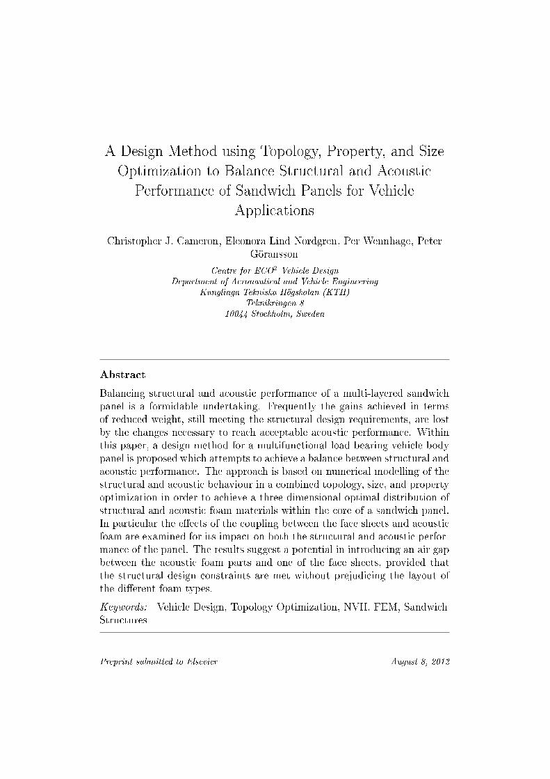
A Design Method using Topology, Property, and Size
Optimization to Balance Structural and Acoustic
Performance of Sandwich Panels for Vehicle
Applications
Christopher J. Cameron, Eleonora Lind Nordgren, Per Wennhage, PeterGöransson
Centre for ECO2 Vehicle DesignDepartment of Aeronautical and Vehicle Engineering
Kunglinga Tekniska Högskolan (KTH)Teknikringen 8
10044 Stockholm, Sweden
Abstract
Balancing structural and acoustic performance of a multi-layered sandwichpanel is a formidable undertaking. Frequently the gains achieved in termsof reduced weight, still meeting the structural design requirements, are lostby the changes necessary to reach acceptable acoustic performance. Withinthis paper, a design method for a multifunctional load bearing vehicle bodypanel is proposed which attempts to achieve a balance between structural andacoustic performance. The approach is based on numerical modelling of thestructural and acoustic behaviour in a combined topology, size, and propertyoptimization in order to achieve a three dimensional optimal distribution ofstructural and acoustic foam materials within the core of a sandwich panel.In particular the eects of the coupling between the face sheets and acousticfoam are examined for its impact on both the structural and acoustic perfor-mance of the panel. The results suggest a potential in introducing an air gapbetween the acoustic foam parts and one of the face sheets, provided thatthe structural design constraints are met without prejudicing the layout ofthe dierent foam types.
Keywords: Vehicle Design, Topology Optimization, NVH, FEM, SandwichStructures
Preprint submitted to Elsevier August 8, 2012
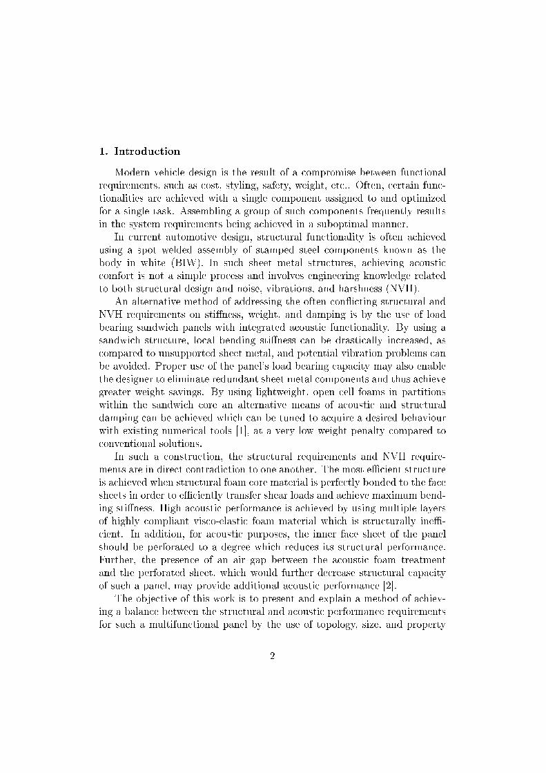
1. Introduction
Modern vehicle design is the result of a compromise between functionalrequirements, such as cost, styling, safety, weight, etc.. Often, certain func-tionalities are achieved with a single component assigned to and optimizedfor a single task. Assembling a group of such components frequently resultsin the system requirements being achieved in a suboptimal manner.
In current automotive design, structural functionality is often achievedusing a spot welded assembly of stamped steel components known as thebody in white (BIW). In such sheet metal structures, achieving acousticcomfort is not a simple process and involves engineering knowledge relatedto both structural design and noise, vibrations, and harshness (NVH).
An alternative method of addressing the often conicting structural andNVH requirements on stiness, weight, and damping is by the use of loadbearing sandwich panels with integrated acoustic functionality. By using asandwich structure, local bending stiness can be drastically increased, ascompared to unsupported sheet metal, and potential vibration problems canbe avoided. Proper use of the panel's load bearing capacity may also enablethe designer to eliminate redundant sheet metal components and thus achievegreater weight savings. By using lightweight, open cell foams in partitionswithin the sandwich core an alternative means of acoustic and structuraldamping can be achieved which can be tuned to acquire a desired behaviourwith existing numerical tools [1], at a very low weight penalty compared toconventional solutions.
In such a construction, the structural requirements and NVH require-ments are in direct contradiction to one another. The most ecient structureis achieved when structural foam core material is perfectly bonded to the facesheets in order to eciently transfer shear loads and achieve maximum bend-ing stiness. High acoustic performance is achieved by using multiple layersof highly compliant visco-elastic foam material which is structurally ine-cient. In addition, for acoustic purposes, the inner face sheet of the panelshould be perforated to a degree which reduces its structural performance.Further, the presence of an air gap between the acoustic foam treatmentand the perforated sheet, which would further decrease structural capacityof such a panel, may provide additional acoustic performance [2].
The objective of this work is to present and explain a method of achiev-ing a balance between the structural and acoustic performance requirementsfor such a multifunctional panel by the use of topology, size, and property
2
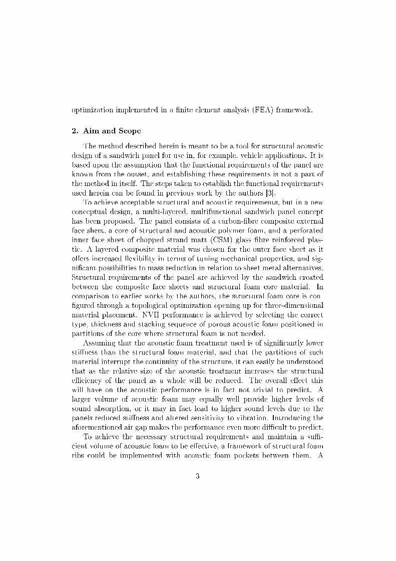
optimization implemented in a nite element analysis (FEA) framework.
2. Aim and Scope
The method described herein is meant to be a tool for structural acousticdesign of a sandwich panel for use in, for example, vehicle applications. It isbased upon the assumption that the functional requirements of the panel areknown from the outset, and establishing these requirements is not a part ofthe method in itself. The steps taken to establish the functional requirementsused herein can be found in previous work by the authors [3].
To achieve acceptable structural and acoustic requirements, but in a newconceptual design, a multi-layered, multifunctional sandwich panel concepthas been proposed. The panel consists of a carbon-bre composite externalface sheet, a core of structural and acoustic polymer foam, and a perforatedinner face sheet of chopped strand matt (CSM) glass bre reinforced plas-tic. A layered composite material was chosen for the outer face sheet as itoers increased exibility in terms of tuning mechanical properties, and sig-nicant possibilities to mass reduction in relation to sheet metal alternatives.Structural requirements of the panel are achieved by the sandwich createdbetween the composite face sheets and structural foam core material. Incomparison to earlier works by the authors, the structural foam core is con-gured through a topological optimization opening up for three-dimensionalmaterial placement. NVH performance is achieved by selecting the correcttype, thickness and stacking sequence of porous acoustic foam positioned inpartitions of the core where structural foam is not needed.
Assuming that the acoustic foam treatment used is of signicantly lowerstiness than the structural foam material, and that the partitions of suchmaterial interrupt the continuity of the structure, it can easily be understoodthat as the relative size of the acoustic treatment increases the structuraleciency of the panel as a whole will be reduced. The overall eect thiswill have on the acoustic performance is in fact not trivial to predict. Alarger volume of acoustic foam may equally well provide higher levels ofsound absorption, or it may in fact lead to higher sound levels due to thepanels reduced stiness and altered sensitivity to vibration. Introducing theaforementioned air gap makes the performance even more dicult to predict.
To achieve the necessary structural requirements and maintain a su-cient volume of acoustic foam to be eective, a framework of structural foamribs could be implemented with acoustic foam pockets between them. A
3
schematic representation of such a conguration can be seen in gure, 1.While it may be possible to achieve adequate performance in this manner,it is unlikely that an arbitrary conguration, even one based on sound engi-neering experience and good engineering judgement, will coincide with theminimum weight design.
In addition to the materials described, the idea of using an air gap withinthe structure in order to increase the acoustic performance is tested. Byinserting a thin layer of air into the acoustic treatment of the structure, achange in impedance can be achieved which might oer increased dissipationof acoustic waves within the treatment.
The presence or absence of an air gap is a signicant alteration to thesandwich structure, and so two panel congurations are examined. In therst conguration, perfect bonding between all layers is assumed, as in aconventional sandwich structure. In the second conguration, a small air gapis introduced between the inner face sheet and the acoustic foam treatment.An illustration of the proposed panel concept can be seen in gure 1.
Figure 1: Cutaway view of multifunctional panel concept. 1/4 model size 0.6x1.0 m.
3. The Optimization Design Process
The central idea of this work is that in order to achieve a successful design,functional requirements should be the controlling factor and optimizationtools should be used to tailor the desired panel to meet the needs required.
In order to assess certain aspects of structural integrity and NVH perfor-mance, computationally expensive forms of FEA are required. These meth-
4
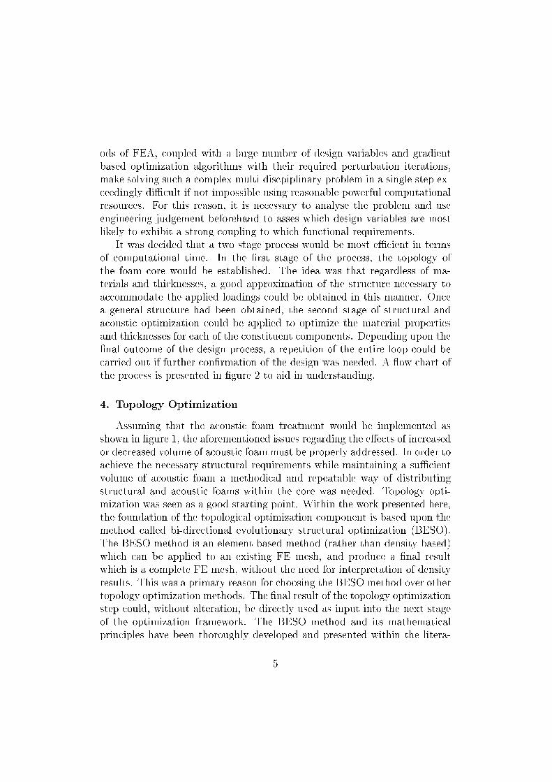
ods of FEA, coupled with a large number of design variables and gradientbased optimization algorithms with their required perturbation iterations,make solving such a complex multi-discpiplinary problem in a single step ex-ceedingly dicult if not impossible using reasonable powerful computationalresources. For this reason, it is necessary to analyse the problem and useengineering judgement beforehand to asses which design variables are mostlikely to exhibit a strong coupling to which functional requirements.
It was decided that a two stage process would be most ecient in termsof computational time. In the rst stage of the process, the topology ofthe foam core would be established. The idea was that regardless of ma-terials and thicknesses, a good approximation of the structure necessary toaccommodate the applied loadings could be obtained in this manner. Oncea general structure had been obtained, the second stage of structural andacoustic optimization could be applied to optimize the material propertiesand thicknesses for each of the constituent components. Depending upon thenal outcome of the design process, a repetition of the entire loop could becarried out if further conrmation of the design was needed. A ow chart ofthe process is presented in gure 2 to aid in understanding.
4. Topology Optimization
Assuming that the acoustic foam treatment would be implemented asshown in gure 1, the aforementioned issues regarding the eects of increasedor decreased volume of acoustic foam must be properly addressed. In order toachieve the necessary structural requirements while maintaining a sucientvolume of acoustic foam a methodical and repeatable way of distributingstructural and acoustic foams within the core was needed. Topology opti-mization was seen as a good starting point. Within the work presented here,the foundation of the topological optimization component is based upon themethod called bi-directional evolutionary structural optimization (BESO).The BESO method is an element based method (rather than density based)which can be applied to an existing FE mesh, and produce a nal resultwhich is a complete FE mesh, without the need for interpretation of densityresults. This was a primary reason for choosing the BESO method over othertopology optimization methods. The nal result of the topology optimizationstep could, without alteration, be directly used as input into the next stageof the optimization framework. The BESO method and its mathematicalprinciples have been thoroughly developed and presented within the litera-
5
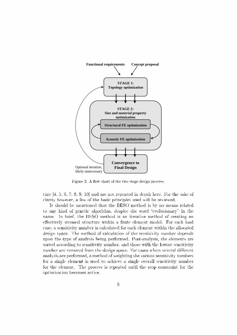
STAGE 1: Topology optimization
Convergence to Final Design
STAGE 2: Size and material property
optimization
Structural FE optimization
Acoustic FE optimization
Optional iteration, likely unnecessary
Concept proposal Functional requirements
Figure 2: A ow chart of the two stage design process.
ture [4, 5, 6, 7, 8, 9, 10] and are not repeated in depth here. For the sake ofclarity however, a few of the basic principles used will be reviewed.
It should be mentioned that the BESO method is by no means relatedto any kind of genetic algorithm, despite the word evolutionary in thename. In brief, the BESO method is an iterative method of creating aneectively stressed structure within a nite element model. For each loadcase, a sensitivity number is calculated for each element within the allocateddesign space. The method of calculation of the sensitivity number dependsupon the type of analysis being performed. Post-analysis, the elements aresorted according to sensitivity number, and those with the lowest sensitivitynumber are removed from the design space. For cases where several dierentanalysis are performed, a method of weighting the various sensitivity numbersfor a single element is used to achieve a single overall sensitivity numberfor the element. The process is repeated until the stop constraint for theoptimization becomes active.
6
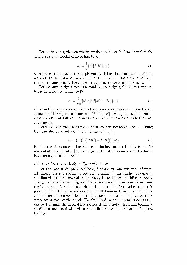
For static cases, the sensitivity number, α for each element within thedesign space is calculated according to [6]:
αi =1
2uiT [Ki]ui (1)
where ui corresponds to the displacement of the ith element, and K cor-responds to the stiness matrix of the ith element. This static sensitivitynumber is equivalent to the element strain energy for a given element.
For dynamic analysis such as normal modes analysis, the sensitivity num-ber is described according to [5]:
αi =1
mi
uiT [ω2i [M
i]−Ki]ui (2)
where in this case ui corresponds to the eigen vector displacements of the ithelement for the eigen frequency α. [M ] and [K] correspond to the elementmass and element stiness matrices respectively. mi corresponds to the massof element i.
For the case of linear buckling, a sensitivity number for change in bucklingload can also be found within the literature [11, 12]:
λi = uiT([∆Ki] + λi[K
ig])ui (3)
in this case, λi represents the change in the load proportionality factor forremoval of the element i. [Kg] is the geometric stiness matrix for the linearbuckling eigen value problem.
4.1. Load Cases and Analysis Types of Interest
For the case study presented here, four specic analysis were of inter-est; linear elastic response to localised loading, linear elastic response todistributed pressure, normal modes analysis, and linear buckling responseduring in-plane loading. Figure 3 visualises these four analysis types usingthe 1/4 symmetric model used within the paper. The rst load case is staticpressure applied to an area approximately 100 mm in diameter at the centreof the panel. The second load case is a static pressure distributed over theentire top surface of the panel. The third load case is a normal modes anal-ysis to determine the natural frequencies of the panel with certain boundaryconditions and the nal load case is a linear buckling analysis of in-planeloading.
7
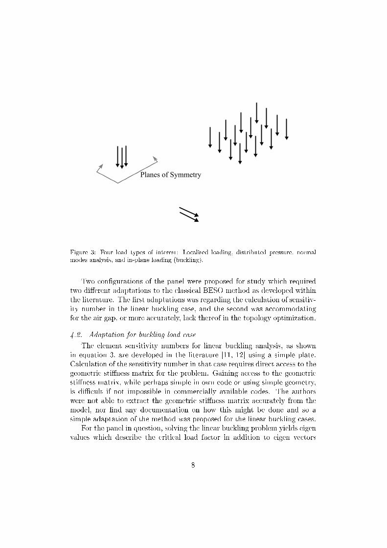
Figure 3: Four load types of interest: Localised loading, distributed pressure, normalmodes analysis, and in-plane loading (buckling).
Two congurations of the panel were proposed for study which requiredtwo dierent adaptations to the classical BESO method as developed withinthe literature. The rst adaptations was regarding the calculation of sensitiv-ity number in the linear buckling case, and the second was accommodatingfor the air gap, or more accurately, lack thereof in the topology optimization.
4.2. Adaptation for buckling load case
The element sensitivity numbers for linear buckling analysis, as shownin equation 3, are developed in the literature [11, 12] using a simple plate.Calculation of the sensitivity number in that case requires direct access to thegeometric stiness matrix for the problem. Gaining access to the geometricstiness matrix, while perhaps simple in own code or using simple geometry,is dicult if not impossible in commercially available codes. The authorswere not able to extract the geometric stiness matrix accurately from themodel, nor nd any documentation on how this might be done and so asimple adaptation of the method was proposed for the linear buckling cases.
For the panel in question, solving the linear buckling problem yields eigenvalues which describe the critical load factor in addition to eigen vectors
8
which describe the panels out of plane deformation or buckling modes. Us-ing Abaqus, element strain energy, as used in equations 1 and 2, can becalculated for the buckling deformation and easily obtained from the results.The objective in using topology optimization in this case is to place core ma-terial most eectively to resist precisely such modes of unstable deformation.Thus, by using this element strain energy and calculating sensitivity numbersfor buckling in the same manner as those of the static load case in equation1, structural foam should be placed to inhibit such modes of deformation.
Once a method of calculating element sensitivity numbers has been es-tablished, some method of comparing sensitivity between load cases mustbe used to establish which elements are of most importance to full whichload case. This is achieved within the literature through placing constraintson displacements and eigen frequencies in normal modes analysis [6, 8] andnormalising between cases to make sure all constraints are fullled [9]. Forlinear buckling analysis, the critical buckling load was treated as a constraintin precisely the same manor as an eigen value is treated in the literature fornormal modes analysis. This allowed the same weighting methods to be usedas described above.
The adaptation of the BESO method to the buckling load cases broadenssomewhat the methods areas of application. The motivation for the bucklingload case adaptation is relatively simple, and as described herein, lacks anythorough mathematical development. Nevertheless, the results appeared tobe reasonable and were completely repeatable within the study and thus theauthors feel it is justied.
4.3. Adaptation for swap functionality
The second adaptation to the BESO method was necessary for the panelconguration where perfect bonding between all layers is assumed. For thepanel conguration with no connection between the inner face sheet and theacoustic foam, i.e. an air gap, adding or removing elements from the sandwichcore according to the conventional methods of BESO is sucient. For thecase where a bond was present between the acoustic foam and inner facesheet however, simply removing elements is not acceptable. In previous work[13] the authors have found that the coupling between the inner face sheetand the acoustic foam treatment plays a critical role in not only the acousticperformance, but even in the structural eciency of the panel. While theacoustic foam is relatively compliant, it does contribute to the transfer ofshear loadings in static cases, and provides an elastic support for the inner
9
face sheet which inhibits resonant vibration. This eect is signicant andcannot be ignored during optimization.
To deal with this problem, a swap functionality was implemented whereinelements which should ordinarily be removed from the design space wereinstead assigned the material properties of the acoustic foam. This swapmethod is benecial in multiple ways. Firstly, it obviously retains the acousticmaterial within the model and accounts for its contribution to the structure.Secondly, it helps to eliminate any potential singularities within the globalstiness matrix which may be caused by elements becoming free-coupledwhen the design is converging to a nal solution and the dierence in elementsensitivity numbers becomes very small. This swap methodology was onlyrealisable using an element based method such as BESO rather than a densitybased method.
More formally stated, the topology optimization problem for both con-gurations proposed was formulated as follows.
minimize mpanel
subject to:
δZmax ≤ a LC1δZmax ≤ b LC2ω(1) ≥ c LC3λ(1) ≥ d LC4
(4)
Where mpanel is the panel mass, δZmax the maximum vertical displace-ment of the panel, ω(1) the rst eigen frequency from normal modes analysis,λ(1) the load proportionality factory for the rst buckling mode. Constantsad represent arbitrary values of constraints, and LC1LC4 are the four loadcases described previously.
The BESO parameters and weighting methods, including the novel adap-tations described, were implemented in a python script which was run inAbaqus CAE nite element analysis software to solve the optimization prob-lem shown above. The script imported and created Abaqus models, executedthe Abaqus FE solver, calculated the element sensitivity numbers, and al-tered the geometry in the model accordingly. Topology optimization wasperformed using a one-quarter size model of the entire panel with symmetry
10
boundary conditions applied through all layers along the symmetry edges tominimize computational time. As a starting point for topology optimization,a core of nearly 100% structural foam was assumed and only a single ele-ment was assigned the properties of the acoustic foam. No restrictions wereplaced on the amount of material to be removed. Optimization was stoppedwhen all constraints were fullled and the overall change in mass betweeniterations was less than a pre-determined small amount.
Convergence of the topology optimization represents completion of therst stage in the overall design process. To maintain emphasis on the de-sign process as a whole rather than a sum of parts, results of the topologyoptimization stage are presented in the results and discussion section of thepaper.
5. Size and Property Optimization
Having established the most eective general shape for structural foamwithin the core of the panel, the next stage in the proposed design process wasto determine the dimensions and mechanical properties of the various layersboth in regards to structural and acoustic functionality. As computationalresources are a limiting factor, and to gain a more thorough understanding ofthe overall problem and allow a larger number of design variables, this stagein the design process was split into a two step iterative loop. The st stepaddresses structural functionality, and the second step acoustic functionality,both using a number of design variables deemed interesting and relevant forstudy.
5.1. Structural optimization
To correctly determine the optimal size and material properties from astructural standpoint, a number of parameters were chosen as design vari-ables. While implementing thickness variables is trivial, using material prop-erties as variables required a method of parameterization to some meaningfulphysical quantity. A list of the variables used is shown below, and followingis a brief description of their relevance and parameterization.
1. Vf0: Volume fraction bre in 0°lamina
2. Vf45: Volume fraction bre in ± 45°lamina
3. Vf90: Volume fraction bre in 90°lamina
4. t0: Lamina thickness of 0°lamina
11
5. t45: Lamina thickness of ± 45°lamina6. t90: Lamina thickness of 90°lamina7. tST : Thickness of structural foam layer8. ρST : Density of structural foam layer9. tCSM : Thickness of inner face sheet
Volume fraction bre describes the percentage of bre reinforcement con-tent in relation to the matrix (i.e. epoxy) content within a layer of compositematerial. As the amount of bre increases, so does the stiness and strengthof the composite, however at the expense of added mass as the bres are ofmuch higher density than the matrix material. This variable was used ineach layer of the eight layer laminate to manipulate the mechanical prop-erties according to micro-mechanical relationships well established within inthe literature [14]. These relationships can be seen in equations 5 to 9. Thesubscript numbers in these equations refer to the direction in which the prop-erties are measured, 1 is the axial direction of the bre, and 2 is the in-planetransverse direction, and 3 is the out of plane direction. Fibre volume frac-tion was allowed to vary from 0.00 (i.e. 100% matrix) to 0.60 (a typical maxvalue in practice) and layer lamina thickness from 0.010 to 2.875 mm. Table1 shows the material data used for the outer face sheet. Allowing for such alow bre volume fraction and thickness in the lamina was seen as a methodof checking to see that the selected materials and lay-up were appropriate.Should the bres prove excessively sti in a given layer, the matrix materialcould for example be replaced with lower density matrix material to savemass. Should a certain layer prove unnecessary, it could in practicality beremoved from the lay-up.
E11 = (Vf )Ef11 + (1.0− Vf )Em (5)
E12 = E13 =VfEf
+1− VfEm
(6)
G12 = G13 =Gm
1−√Vf (1−Gm/Gf12)
(7)
G23 =Gm
1− Vf (1−Gm/Gf12)(8)
νlamina = Vf · νf + (1− Vf ) · νm (9)
12
Matrix CF GF CSME11(tensile) [MPa] 3200 220600 15000G12 = G23 [MPa] 1185 30130 5769ρ [kg/m3] 1125 9000 1700ν [] 0.35 0.20 0.3
Table 1: Material properties for matrix, bers, and CSM sheet (non-perforated)
The density of the structural foam, ρST , was chosen to alter the mechan-ical properties of the foam according to equations (10) to (12), which arewell established in the literature [15]. The foam was assumed to be closedcell, and based on PET. Data for commercially available foams, namely Di-vinycell P series, and Airex T90 and T92 , was obtained from technical datasheets on the respective manufacturers homepage1 [Retrieved 22/11/2010].Properties from the manufacturers were correlated with equation (10) and(11), and the assumption that the porosity, φ = 0.8 from the literature [15]was checked. Exact agreement between manufacturers' data and the theo-retical values was not obtained. Better agreement regarding the compressivemodulus was obtained using φ = 0.7, which required a scaling factor of 0.8times the calculated shear modulus to obtain reasonable agreement. Figures4 and 5 show the manufacturers data and theoretical properties as functionsof density. In addition to foam density, thickness of the structural foam core,tST , was also used as a design variable due to its fundamental importance tosandwich stiness.
EfoamEsolid
≈ φ2
(ρfoamρsolid
)2
+ (1− φ)ρfoamρsolid
+P0(1− 2νfoam)
Esolid − ρfoam/ρsolid(10)
Gfoam
Esolid≈ 3
8
(φ2(
ρfoamρsolid
)2 + (1− φ)ρfoamρsolid
)(11)
νfoam ≈1
3(12)
1www.diabgroup.com/europe/products/e_divinycell_p.html
www.corematerials.3acomposites.com/airex-foams.html
13
Figure 4: Compressive modulus as function of density.
For the inner face sheet the thickness, tCSM , was the only design variableconsidered, in order to limit the number of design variables. A xed degreeof perforation assuming 2.0 mm holes drilled in a square pattern with 3.5mm between hole centres was used. This was considered to be the mini-mum degree of perforation to allow for sucient acoustic transparency [16].Tighter hole spacing increases acoustic transparency but reduces bendingstiness and vice versa. In the model, individual holes were ignored and in-stead equivalent material properties were used for the perforated sheet andobtained using methods developed in previous work [17].
The exact same optimization problem as described in the previous designstage, i.e. minimize mass subject to functional constraints, was solved usingthe method of moving asymptotes (MMA) [18, 19]. The output from thenal iteration of topology optimization gave the FE model with new topol-ogy, and the variables described above for material properties and thicknesswere implemented in the optimization framework. All material propertiesrelating to the acoustic foam components remained constant. All load cases,boundary conditions and constraints on displacements etc. were the sameas in the previous design stage. The optimization was stopped when su-
14
Figure 5: Shear modulus as function of density.
cient convergence in both the objective function and the design variables wasachieved. The next step was to optimize the acoustic behaviour and relevantmaterial properties.
5.2. Acoustic Optimization
For this conceptual optimization of acoustic performance the acoustictreatment was placed in layers in the volume not occupied by structuralfoam elements from the topology optimization. Two dierent foam layercombinations were used and they were tried both with and without an airgap between the inner face sheet and the acoustic foam combination, a total offour dierent congurations, gure 6. The acoustic foam A was a comparablysoft Polyurethane foam (PU foam) and the acoustic foam B was a relativelysti Polyimide foam (pi foam).
As can be seen in gure 6, the foams were stacked in an A-B-(air) or A-A-(air) sequence, i.e. in two congurations a single foam was split into twodistinct layers. The reason for using two separate layers of the same foamtype was to explore the possibility that the foam layers would be perceivedas one homogeneous layer by ascribing them the same material properties,
15
Figure 6: Conceptual visualization of the four dierent congurations in the acousticoptimization. Note that structural foam topology (dark grey) diers between the air gapand non air gap congurations.
or whether there existed possible benets in having two separate layers withdierent material properties as suggested in results previously obtained bythe authors. The task of determining the acoustically better choice betweena single or multiple layer conguration could then be left to the optimizationalgorithm.
The acoustic behaviour of the panel was studied using in house FE code.An air cavity of the length and breadth of the panel and 1.5 m in depth(i.e. of comparable size to a vehicle passenger compartment) was attachedto the perforated side of the panel and the sound pressure level (SPL) in asub volume of the cavity generated by dynamically exciting the panel wascalculated. The sub volume within the cavity was located approximatelywhere listeners would be positioned, and was considered a good metric forquantifying the acoustic comfort in the vehicle.
Excitation of the panel was in the form of dynamic forces in the x-, y-,and z-direction applied over the top surface of the elements along the edgeof the CF epoxy top sheet as seen in gure 7.
As in the structural problem, the roof was represented by a quarter modeland symmetry boundary conditions were applied at the symmetry edgesthrough all layers. The inner perforated plate was xed in the x-, y- andz-direction along x = 0 and y = 0.
For the dynamic and acoustic analysis, FE-based numerical methods wereused where the porous foams were modelled using Biot theory [20, 21, 22].The theories used to model the acoustic foam assume material isotropy, smalldisplacements and linearly elastic materials. Here the nite element solu-tions were obtained using the methods thoroughly discussed and properlyaddressed in works by Hörlin et al. [23] and by Hörlin [24] and will not be
16
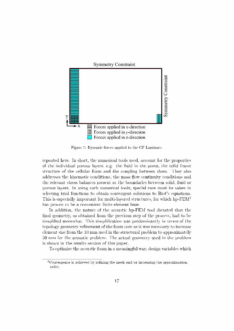
Figure 7: Dynamic forces applied to the CF Laminate.
repeated here. In short, the numerical tools used, account for the propertiesof the individual porous layers, e.g. the uid in the pores, the solid framestructure of the cellular foam and the coupling between them. They alsoaddresses the kinematic conditions, the mass ow continuity conditions andthe relevant stress balances present at the boundaries between solid, uid orporous layers. In using such numerical tools, special care must be taken inselecting trial functions to obtain convergent solutions to Biot's equations.This is especially important for multi-layered structures, for which hp-FEM2
has proven to be a convenient nite element base.In addition, the nature of the acoustic hp-FEM tool dictated that the
nal geometry, as obtained from the previous step of the process, had to besimplied somewhat. This simplication was predominantly in terms of thetopology geometry renement of the foam core as it was necessary to increaseelement size from the 10 mm used in the structural problem to approximately50 mm for the acoustic problem. The actual geometry used in the problemis shown in the results section of this paper.
To optimize the acoustic foam in a meaningful way, design variables which
2Convergence is achieved by rening the mesh and/or increasing the approximationorder.
17
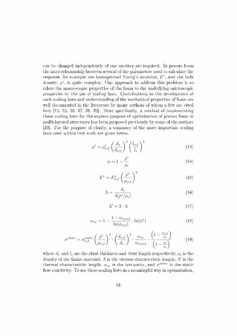
can be changed independently of one another are required. In porous foamthe inter-relationship between several of the parameters used to calculate theresponse, for example the homogenised Young's modulus, E∗, and the bulkdensity, ρ∗, is quite complex. One approach to address this problem is torelate the macroscopic properties of the foam to the underlying microscopicproperties by the use of scaling laws. Contributions to the development ofsuch scaling laws and understanding of the mechanical properties of foam arewell documented in the literature by many authors of whom a few are citedhere [15, 25, 26, 27, 28, 29]. More specically, a method of implementingthese scaling laws for the express purpose of optimization of porous foam inmulti-layered structures has been proposed previously by some of the authors[30]. For the purpose of clarity, a summary of the more important scalinglaws used within this work are given below.
ρ∗ = ρ∗ref
(dsdref
)2(lrefls
)2
(13)
φ = 1− ρ∗
ρs(14)
E∗ = E∗ref
(ρ∗
ρref
)2
(15)
Λ =ds
4(ρ∗/ρs)(16)
Λ′ = 2 · Λ (17)
α∞ = 1− 1− α∞refln(φref )
· ln(φ∗) (18)
σstatic = σstaticref
(ρ∗
ρref
)2
·(drefds
)2
· α∞α∞ref
·
(1− ρref
ρs
)
(1− ρ∗
ρs
) (19)
where ds and ls are the strut thickness and strut length respectively, ρs is thedensity of the frame material, Λ is the viscous characteristic length, Λ′ is thethermal characteristic length, α∞ is the tortuosity, and σstatic is the staticow resistivity. To use these scaling laws in a meaningful way in optimization,
18
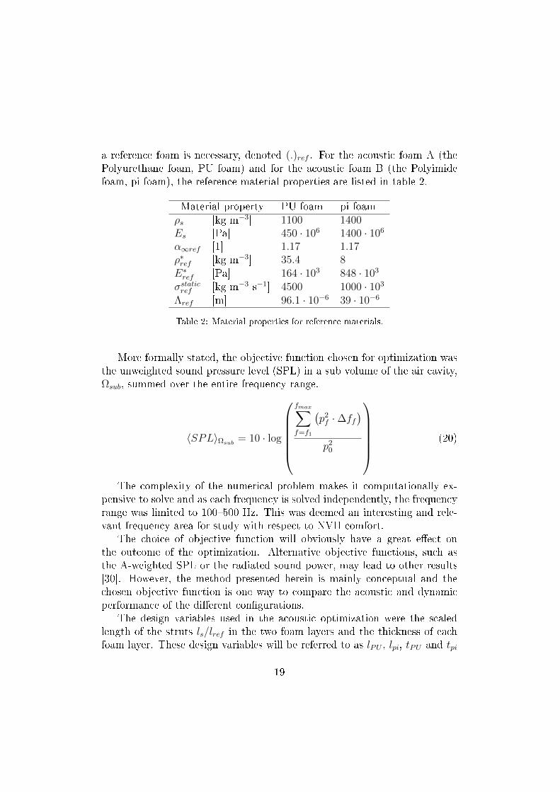
a reference foam is necessary, denoted (.)ref . For the acoustic foam A (thePolyurethane foam, PU foam) and for the acoustic foam B (the Polyimidefoam, pi foam), the reference material properties are listed in table 2.
Material property PU foam pi foamρs [kg m−3] 1100 1400Es [Pa] 450 · 106 1400 · 106
α∞ref [1] 1.17 1.17ρ∗ref [kg m−3] 35.4 8E∗ref [Pa] 164 · 103 848 · 103
σstaticref [kg m−3 s−1] 4500 1000 · 103
Λref [m] 96.1 · 10−6 39 · 10−6
Table 2: Material properties for reference materials.
More formally stated, the objective function chosen for optimization wasthe unweighted sound pressure level (SPL) in a sub volume of the air cavity,Ωsub, summed over the entire frequency range.
〈SPL〉Ωsub= 10 · log
fmax∑
f=f1
(p2f ·∆ff
)
p20
(20)
The complexity of the numerical problem makes it computationally ex-pensive to solve and as each frequency is solved independently, the frequencyrange was limited to 100500 Hz. This was deemed an interesting and rele-vant frequency area for study with respect to NVH comfort.
The choice of objective function will obviously have a great eect onthe outcome of the optimization. Alternative objective functions, such asthe A-weighted SPL or the radiated sound power, may lead to other results[30]. However, the method presented herein is mainly conceptual and thechosen objective function is one way to compare the acoustic and dynamicperformance of the dierent congurations.
The design variables used in the acoustic optimization were the scaledlength of the struts ls/lref in the two foam layers and the thickness of eachfoam layer. These design variables will be referred to as lPU , lpi, tPU and tpi
19
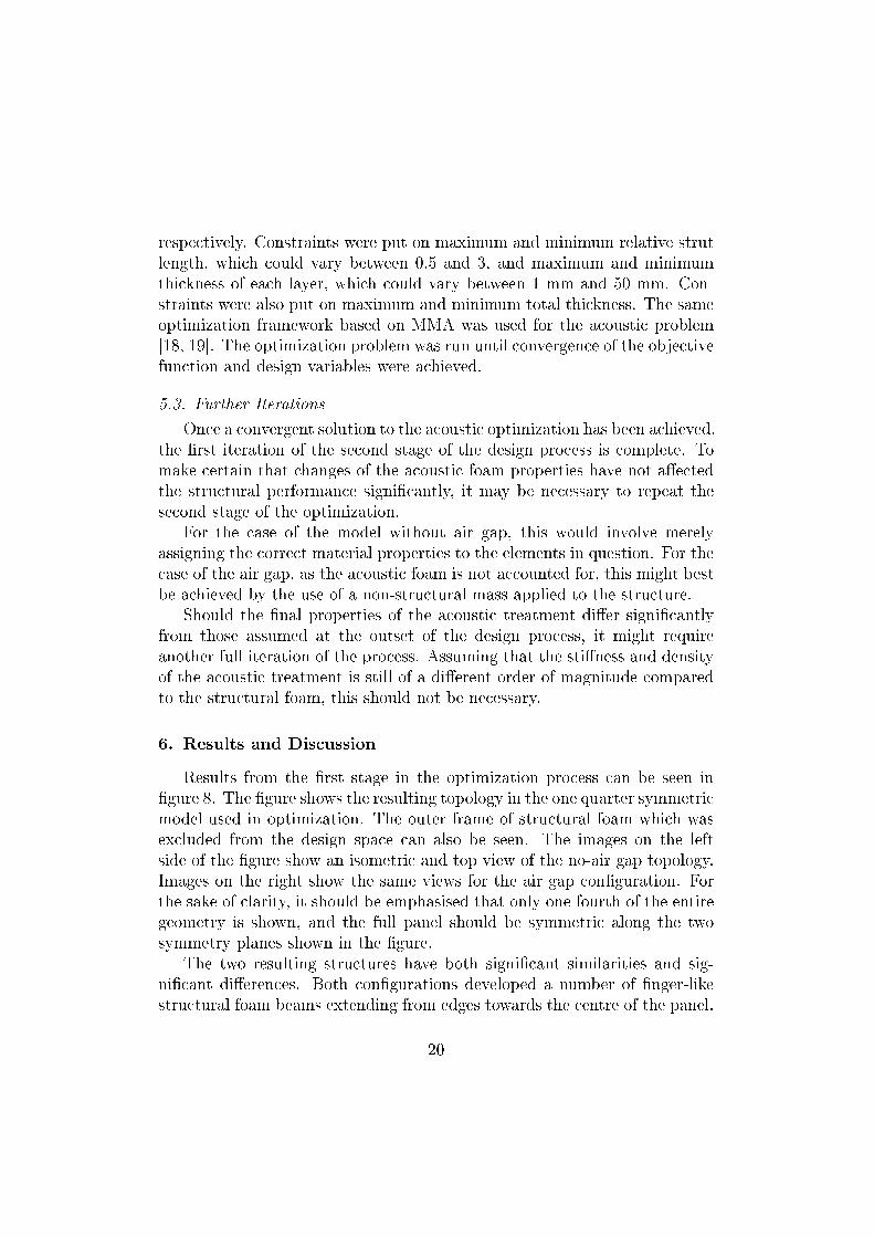
respectively. Constraints were put on maximum and minimum relative strutlength, which could vary between 0.5 and 3, and maximum and minimumthickness of each layer, which could vary between 1 mm and 50 mm. Con-straints were also put on maximum and minimum total thickness. The sameoptimization framework based on MMA was used for the acoustic problem[18, 19]. The optimization problem was run until convergence of the objectivefunction and design variables were achieved.
5.3. Further Iterations
Once a convergent solution to the acoustic optimization has been achieved,the rst iteration of the second stage of the design process is complete. Tomake certain that changes of the acoustic foam properties have not aectedthe structural performance signicantly, it may be necessary to repeat thesecond stage of the optimization.
For the case of the model without air gap, this would involve merelyassigning the correct material properties to the elements in question. For thecase of the air gap, as the acoustic foam is not accounted for, this might bestbe achieved by the use of a non-structural mass applied to the structure.
Should the nal properties of the acoustic treatment dier signicantlyfrom those assumed at the outset of the design process, it might requireanother full iteration of the process. Assuming that the stiness and densityof the acoustic treatment is still of a dierent order of magnitude comparedto the structural foam, this should not be necessary.
6. Results and Discussion
Results from the rst stage in the optimization process can be seen ingure 8. The gure shows the resulting topology in the one quarter symmetricmodel used in optimization. The outer frame of structural foam which wasexcluded from the design space can also be seen. The images on the leftside of the gure show an isometric and top view of the no-air gap topology.Images on the right show the same views for the air gap conguration. Forthe sake of clarity, it should be emphasised that only one fourth of the entiregeometry is shown, and the full panel should be symmetric along the twosymmetry planes shown in the gure.
The two resulting structures have both signicant similarities and sig-nicant dierences. Both congurations developed a number of nger-likestructural foam beams extending from edges towards the centre of the panel.
20
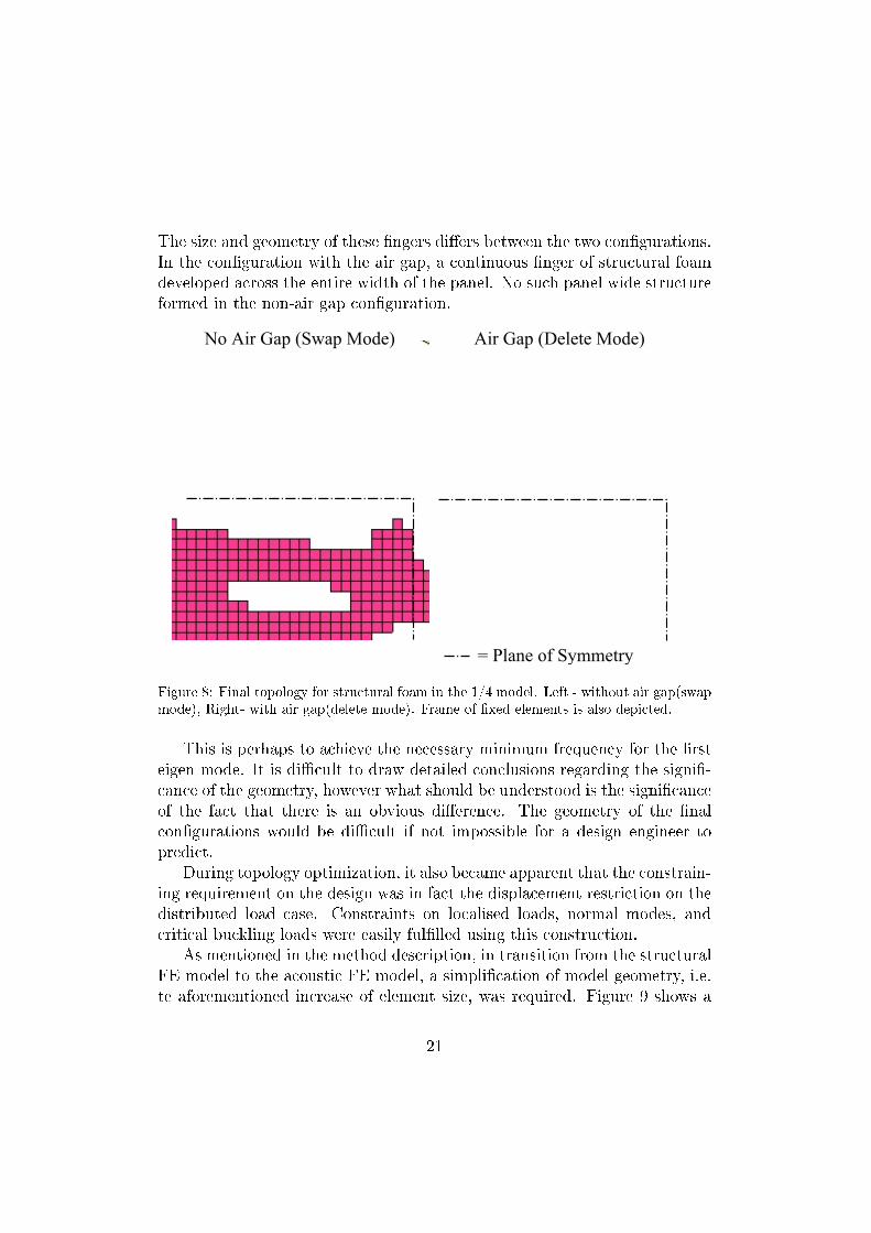
The size and geometry of these ngers diers between the two congurations.In the conguration with the air gap, a continuous nger of structural foamdeveloped across the entire width of the panel. No such panel wide structureformed in the non-air gap conguration.
Figure 8: Final topology for structural foam in the 1/4 model. Left - without air gap(swapmode), Right- with air gap(delete mode). Frame of xed elements is also depicted.
This is perhaps to achieve the necessary minimum frequency for the rsteigen mode. It is dicult to draw detailed conclusions regarding the signi-cance of the geometry, however what should be understood is the signicanceof the fact that there is an obvious dierence. The geometry of the nalcongurations would be dicult if not impossible for a design engineer topredict.
During topology optimization, it also became apparent that the constrain-ing requirement on the design was in fact the displacement restriction on thedistributed load case. Constraints on localised loads, normal modes, andcritical buckling loads were easily fullled using this construction.
As mentioned in the method description, in transition from the structuralFE model to the acoustic FE model, a simplication of model geometry, i.e.te aforementioned increase of element size, was required. Figure 9 shows a
21
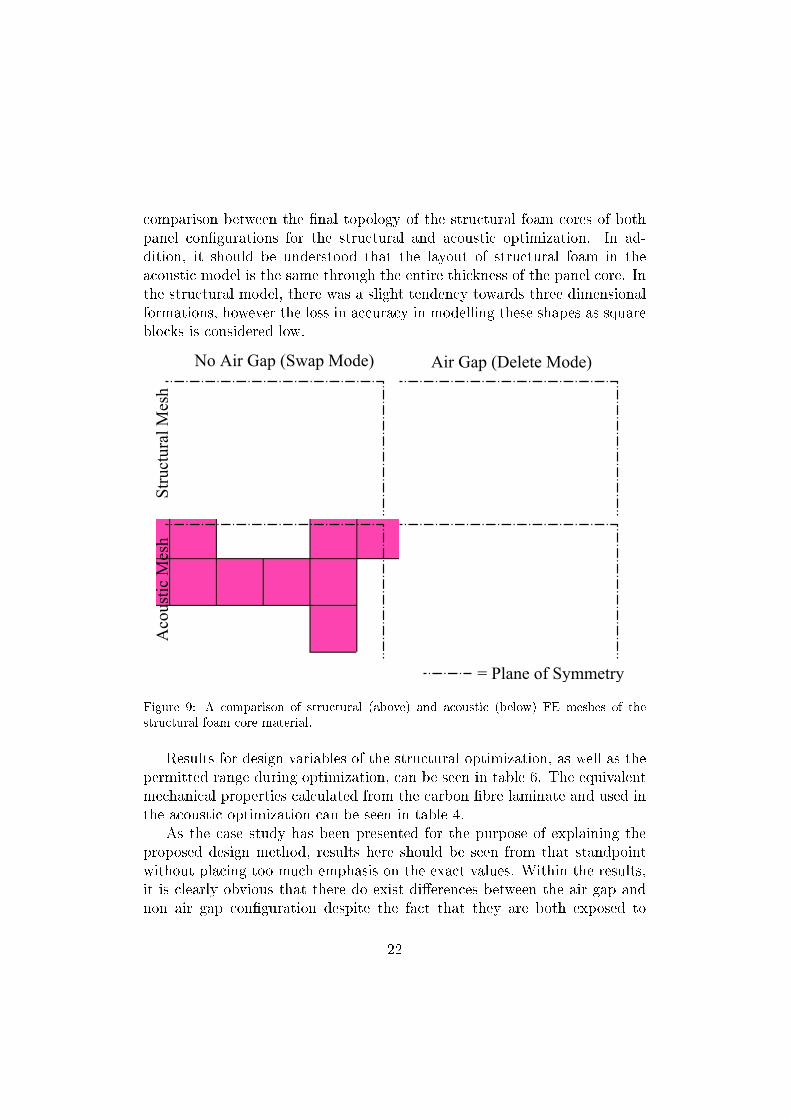
comparison between the nal topology of the structural foam cores of bothpanel congurations for the structural and acoustic optimization. In ad-dition, it should be understood that the layout of structural foam in theacoustic model is the same through the entire thickness of the panel core. Inthe structural model, there was a slight tendency towards three dimensionalformations, however the loss in accuracy in modelling these shapes as squareblocks is considered low.
Figure 9: A comparison of structural (above) and acoustic (below) FE meshes of thestructural foam core material.
Results for design variables of the structural optimization, as well as thepermitted range during optimization, can be seen in table 6. The equivalentmechanical properties calculated from the carbon bre laminate and used inthe acoustic optimization can be seen in table 4.
As the case study has been presented for the purpose of explaining theproposed design method, results here should be seen from that standpointwithout placing too much emphasis on the exact values. Within the results,it is clearly obvious that there do exist dierences between the air gap andnon air gap conguration despite the fact that they are both exposed to
22
identical load cases and constraints. This is of course directly coupled tothe geometry of the foam cores, which is in turn steered by the presence orabsence of the air gap.
Regarding the composite laminate face sheet, it is interesting to note thattwo dierent congurations with signicantly dierent mechanical propertiesand lay-ups were achieved during optimization, however their total thick-ness is nearly identical. The air gap conguration required a face sheet ofmuch higher stiness than that of the non-gap conguration. While it maynot prove possible or desirable to produce such a lay-up, the results of thisoptimization at least give the designer an indication of which layers are ofprimary importance, and which layers might be removed and the optimiza-tion repeated. Alternatively, it may be a good method to help the engineerchoose more conventional material for use in the face sheet. For example,observing the thickness of 1.8 mm and a required equivalent stiness in theregion of 50 MPa, perhaps magnesium would be a better choice in regardsto manufacturing despite the weight penalty.
The thickness of the foam core in both examples reached the maximumallowable value. This is not surprising as it is well known that increasinga sandwich structures thickness is the most mass-ecient way of increasingstiness. In this case, a structural foam density somewhere in the middle ofthe allowable span was achieved for both congurations. These two variables,thickness and density, are inherently entwined. As long as the load case issuch that a foam of more than the minimum density is required, the thicknesswill be increased as much as possible. Not until the foam reaches minimumdensity will the optimization begin to reduce the sandwich thickness to shedmass. Further evidence of the importance of the coupling between inner facesheet and acoustic foam can be seen in the higher density, and thus stier,structural foam in the air gap conguration.
The degree of perforation, and thus the mechanical properties, of theinner face sheet were identical, and from a practical standpoint, so were thenal thicknesses.
The results from the acoustic foam optimization are shown in table 5.The resulting microscopic foam properties as well as foam layer thicknessesdier considerably between congurations. This would seem to imply thatthe acoustic response of the panel is quite sensitive to changes in acoustictreatment despite the eectiveness of the structural foam sandwich frame-work. Comparison of the changes in objective function values during theoptimization process imply that a signicant improvement of the SPL may
23
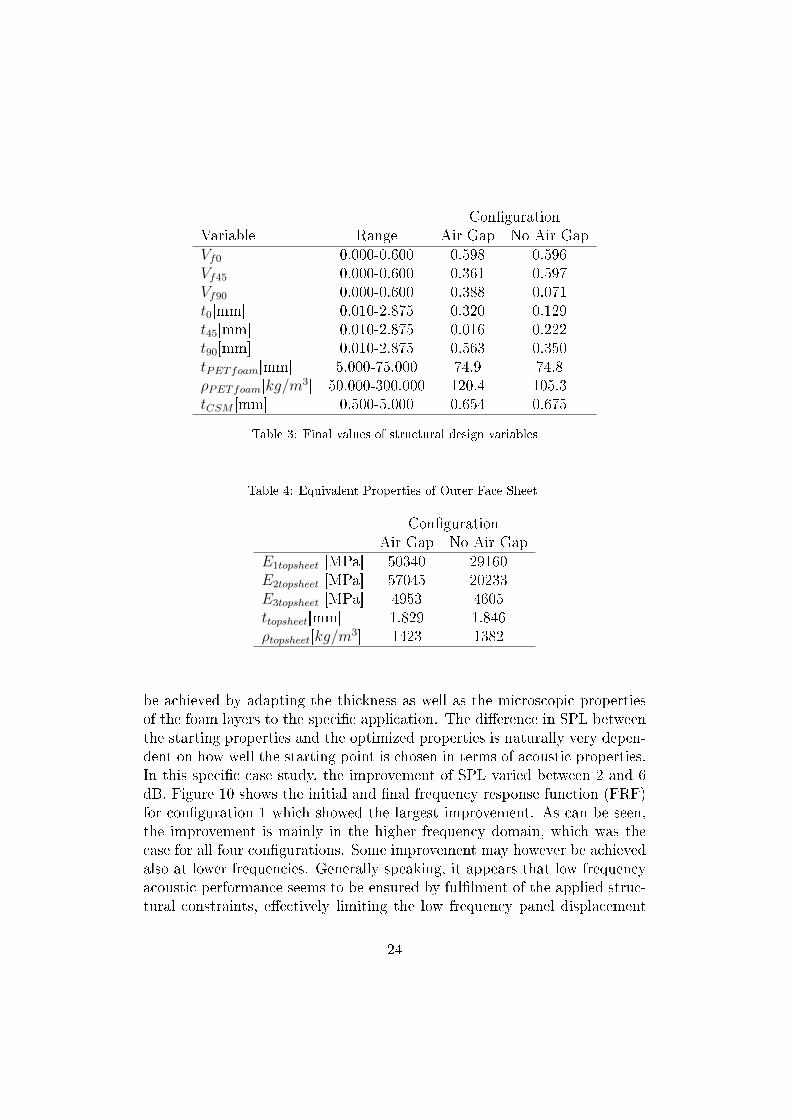
CongurationVariable Range Air Gap No Air GapVf0 0.000-0.600 0.598 0.596Vf45 0.000-0.600 0.361 0.597Vf90 0.000-0.600 0.388 0.071t0[mm] 0.010-2.875 0.320 0.129t45[mm] 0.010-2.875 0.016 0.222t90[mm] 0.010-2.875 0.563 0.350tPETfoam[mm] 5.000-75.000 74.9 74.8ρPETfoam[kg/m
3] 50.000-300.000 120.4 105.3tCSM [mm] 0.500-5.000 0.654 0.675
Table 3: Final values of structural design variables
Table 4: Equivalent Properties of Outer Face Sheet
CongurationAir Gap No Air Gap
E1topsheet [MPa] 50340 29160E2topsheet [MPa] 57045 20233E3topsheet [MPa] 4953 4605ttopsheet[mm] 1.829 1.846ρtopsheet[kg/m
3] 1423 1382
be achieved by adapting the thickness as well as the microscopic propertiesof the foam layers to the specic application. The dierence in SPL betweenthe starting properties and the optimized properties is naturally very depen-dent on how well the starting point is chosen in terms of acoustic properties.In this specic case study, the improvement of SPL varied between 2 and 6dB. Figure 10 shows the initial and nal frequency response function (FRF)for conguration 1 which showed the largest improvement. As can be seen,the improvement is mainly in the higher frequency domain, which was thecase for all four congurations. Some improvement may however be achievedalso at lower frequencies. Generally speaking, it appears that low frequencyacoustic performance seems to be ensured by fullment of the applied struc-tural constraints, eectively limiting the low frequency panel displacement
24
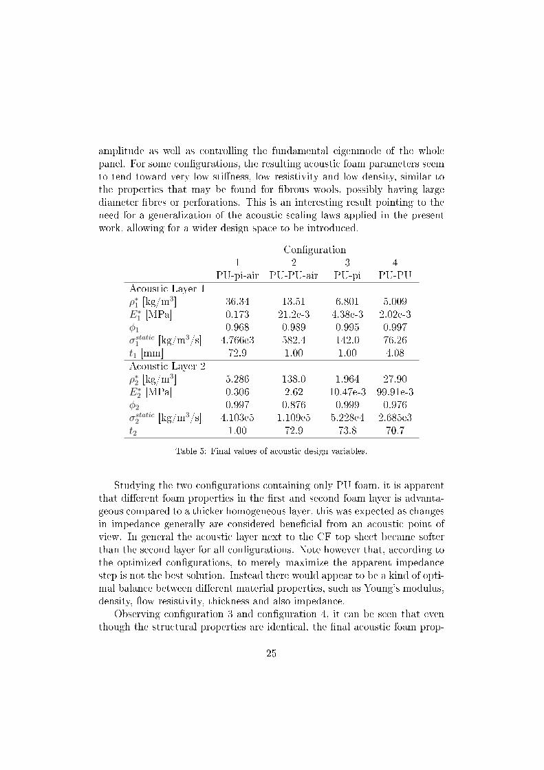
amplitude as well as controlling the fundamental eigenmode of the wholepanel. For some congurations, the resulting acoustic foam parameters seemto tend toward very low stiness, low resistivity and low density, similar tothe properties that may be found for brous wools, possibly having largediameter bres or perforations. This is an interesting result pointing to theneed for a generalization of the acoustic scaling laws applied in the presentwork, allowing for a wider design space to be introduced.
Conguration1 2 3 4
PU-pi-air PU-PU-air PU-pi PU-PUAcoustic Layer 1ρ∗1 [kg/m
3] 36.34 13.51 6.801 5.009E∗1 [MPa] 0.173 21.2e-3 4.38e-3 2.02e-3φ1 0.968 0.989 0.995 0.997σstatic1 [kg/m3/s] 4.766e3 582.4 142.0 76.26t1 [mm] 72.9 1.00 1.00 4.08Acoustic Layer 2ρ∗2 [kg/m
3] 5.286 138.0 1.964 27.90E∗2 [MPa] 0.306 2.62 10.47e-3 99.91e-3φ2 0.997 0.876 0.999 0.976σstatic2 [kg/m3/s] 4.103e5 1.109e5 5.228e4 2.685e3t2 1.00 72.9 73.8 70.7
Table 5: Final values of acoustic design variables.
Studying the two congurations containing only PU foam, it is apparentthat dierent foam properties in the rst and second foam layer is advanta-geous compared to a thicker homogeneous layer, this was expected as changesin impedance generally are considered benecial from an acoustic point ofview. In general the acoustic layer next to the CF top sheet became softerthan the second layer for all congurations. Note however that, according tothe optimized congurations, to merely maximize the apparent impedancestep is not the best solution. Instead there would appear to be a kind of opti-mal balance between dierent material properties, such as Young's modulus,density, ow resistivity, thickness and also impedance.
Observing conguration 3 and conguration 4, it can be seen that eventhough the structural properties are identical, the nal acoustic foam prop-
25
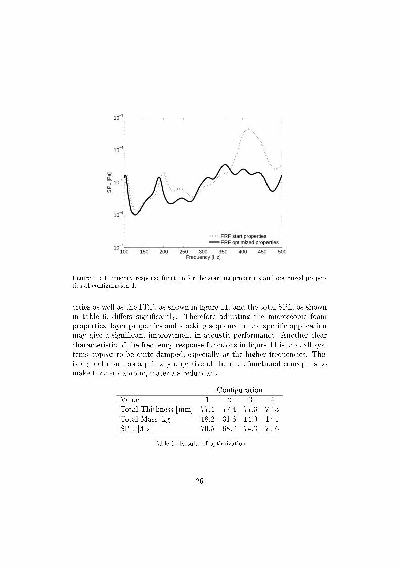
100 150 200 250 300 350 400 450 50010
−7
10−6
10−5
10−4
10−3
Frequency [Hz]
SP
L [P
a]
FRF start propertiesFRF optimized properties
Figure 10: Frequency response function for the starting properties and optimized proper-ties of conguration 1.
erties as well as the FRF, as shown in gure 11, and the total SPL, as shownin table 6, diers signicantly. Therefore adjusting the microscopic foamproperties, layer properties and stacking sequence to the specic applicationmay give a signicant improvement in acoustic performance. Another clearcharacteristic of the frequency response functions in gure 11 is that all sys-tems appear to be quite damped, especially at the higher frequencies. Thisis a good result as a primary objective of the multifunctional concept is tomake further damping materials redundant.
CongurationValue 1 2 3 4Total Thickness [mm] 77.4 77.4 77.3 77.3Total Mass [kg] 18.2 31.6 14.0 17.1SPL [dB] 70.5 68.7 74.3 71.6
Table 6: Results of optimization
26
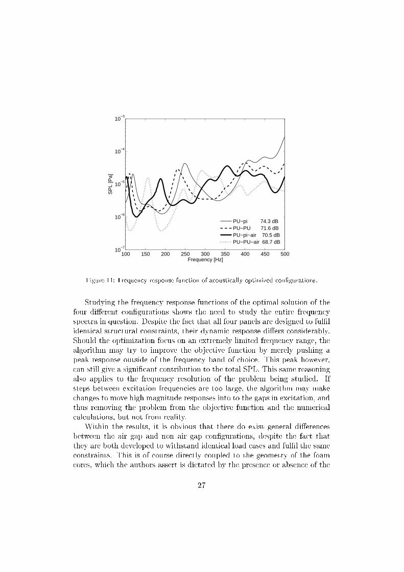
100 150 200 250 300 350 400 450 50010
−7
10−6
10−5
10−4
10−3
Frequency [Hz]
SP
L [P
a]
PU−pi 74.3 dBPU−PU 71.6 dBPU−pi−air 70.5 dBPU−PU−air 68.7 dB
Figure 11: Frequency response function of acoustically optimized congurations.
Studying the frequency response functions of the optimal solution of thefour dierent congurations shows the need to study the entire frequencyspectra in question. Despite the fact that all four panels are designed to fullidentical structural constraints, their dynamic response diers considerably.Should the optimization focus on an extremely limited frequency range, thealgorithm may try to improve the objective function by merely pushing apeak response outside of the frequency band of choice. This peak however,can still give a signicant contribution to the total SPL. This same reasoningalso applies to the frequency resolution of the problem being studied. Ifsteps between excitation frequencies are too large, the algorithm may makechanges to move high magnitude responses into to the gaps in excitation, andthus removing the problem from the objective function and the numericalcalculations, but not from reality.
Within the results, it is obvious that there do exist general dierencesbetween the air gap and non air gap congurations, despite the fact thatthey are both developed to withstand identical load cases and full the sameconstraints. This is of course directly coupled to the geometry of the foamcores, which the authors assert is dictated by the presence or absence of the
27
air gap. For the congurations studied, the results would suggest that theair gap does have a positive inuence on sound pressure level in general,however this comes at the cost of a mass penalty, as shown in table 6. Hereit can be further emphasised that the often used practice of introducing anair gap into an acoustic treatment, especially an acoustically treated struc-ture, and comparing the result with the original conguration is somewhatmisguided. The air gap not only introduces changes in impedance and dis-continuities in vibration transfer paths, it also fundamentally changes thenature of the structure in question. Should two layered structures be com-pared, they should be equivalent. Optimizing a structure for a certain setof loading conditions, and then changing the structure to function with an-other, eectively renders the optimization process void. One could argue thatto achieve an optimal non-gap conguration the topology achieved using theconventional BESO scheme would be sucient (i.e. removing elements only),and that the second part of the optimization could be carried out with a newmesh accounting for the coupling. Certainly this could be done, however theauthors rmly assert that this conguration is not the most optimal for sucha panel. While no topology optimization scheme can guarantee that the mostoptimal solution for the system has been achieved, the authors neverthelessfeel that the methods presented here provide a suciently robust solutionworthy of further study.
As the objective of this work is to present a possible method for combinedstructural acoustic optimization, parts of the model, load cases and bound-ary conditions have obviously been idealised. To apply this method in anactual design scenario, a better understanding of the specics of the problemwould be necessary and a certain degree of model renement required. Todo otherwise would be to optimize a solution for a dierent problem than itwas meant to solve.
Regarding the aspects of acoustic comfort, the objective function shouldreect the properties sought after. Here, only unweighted SPL has beencalculated. There exist a multitude of other metrics which might be appro-priate to study. In the eld of acoustics this represents an entire sub-topic ofresearch in itself as not only SPL but also attributes like harshness and tonal-ity aect the perception of sound. These phenomena are often addressed inpsycho-acoustics and are beyond the scope of the present work. It is howeverobvious that the choice of objective function will greatly inuence the resultof the optimization and the properties thus achieved.
28
7. Conclusions
The design methodology developed herein shows the potential for simpli-fying the passenger compartment system complexity by examining multiplefunctional requirements and attempting to achieve them simultaneously in asystematic manner. The proposed multifunctional panel, while not directlycomparable to any given automobile car body due to simplications in geom-etry, shows a clear potential for mass reduction. A sandwich panel with a coretopology tailored to full a multitude of functional load cases can replace nu-merous conventional components. Combining this topology with an acoustictreatment and optimizing the structural and acoustic performance simulta-neously makes certain that the intrinsic coupling and conicts between thetwo physical mechanisms are addressed.
Standard topology optimization tools have been adapted to deal with theload cases and materials in question, and with particular focus placed on anair gap in the acoustic treatment for increased acoustic functionality. Theeect of such a gap, on both the structure and its acoustic response, wasexamined and discussed at length. Material properties and layer thicknessesin both the structural and acoustic layers were implemented in the iterativeoptimization process to achieve maximum possible structural weight savingsand acoustic performance simultaneously. The proposed method oers a newapproach to systematically deal with the combined structural and acousticproblems encountered in modern vehicle design.
References
[1] P. Göransson, Aerospace Science and Technology 12 (2008) 2641.
[2] A. Cummings, H. Rice, R. Wilson, J. Sound Vib. 1 (1999) 143167.
[3] C. J. Cameron, E. Lind, P. Wennhage, P. Göransson, Int. J. VehicleStructures & Systems (2009) 113.
[4] Y. Xie, G. Steven, Computers and Structures 49 (1993) 885896.
[5] Y. Xie, G. Steven, Computers and Structures 58 (1996) 10671073.
[6] D. N. Chu, Y. Xie, A. Hira, G.P.Steven, Finite Elements in Analysisand Design 21 (1996) 239251.
29
[7] O. Querin, G. Steven, Y. Xie, Engineering Computations (Swansea,Wales) 15 (1998) 10311048.
[8] J. Rong, Y. Xie, X. Yang, Q. Liang, J. Sound Vib. 234 (2000) 177189.
[9] K. Proos, G. Steven, O. Querin, Y. Xie, AIAA Journal 39 (2001) 20062012.
[10] X. Huang, Y. Xie, Structural and Multidisciplinary Optimization 35(2008) 8992.
[11] D.Manickarajah, Y. Xie, G. Steven, Finite Elements in Analysis andDesign 29 (1998) 205230.
[12] D.Manickarajah, Y. Xie, G. Steven, Computers and Structures 75 (2000)4554.
[13] C. J. Cameron, E. Lind, P. Wennhage, P. Göransson, in: Proceedingsof ICCM-17, 17th International Conference on Composite Materials,Edinburgh, Scotland,July 2009.
[14] C. Chamis, SAMPE Quarterly (1984) 4155.
[15] L. J. Gibson, M. F. Ashby, Cellular Solids: Structure and Properties-Second edition, Cambridge University Press, 1997.
[16] A. Ihle, T. Ernst, H. Baier, L. Datashvili, J. Homann, P. Göransson,D. Fasold, P. Portela, M. Santos, J. Santiago-Prowald, in: 11th Eu-ropean Conference on Spacecraft Structures, Materials and Mechanicaltesting. Toulouse September 15-17.
[17] C. J. Cameron, P. Wennhage, P. Göransson, S. Rhamqvist, Journal ofSandwich Structures and Materials 12 (2010) 684708.
[18] K. Svanberg, International Journal for Numerical Methods in Engineer-ing 24 (1987) 359373.
[19] K. Svanberg, SIAM J. OPTIM. 12 (2002) 555573.
[20] M.A.Biot, J. Acoust. Soc. Am. 28 (1956) 168178.
[21] M.A.Biot, J. Acoust. Soc. Am. 28 (1956) 179191.
30
[22] M.A.Biot, J. Appl. Phys 27 (1956) 459467.
[23] N. E. Hörlin, M. Nordström, P. Göransson, J. Sound Vib. 254 (2001)633652.
[24] N. E. Hörlin, J. Sound Vib. 285 (2005) 341363.
[25] W. E. Warren, A. M. Kraynik, J. Appl. Mech. 55 (1988) 341346.
[26] W. E. Warren, A. M. Kraynik, J. Appl. Mech. 64 (1997) 787794.
[27] J. F. Allard, Y. Champoux, J. Acoust. Soc. Am. 6 (1992) 33463353.
[28] J. Comiti, M. Renaud, Chemical Engineering Science 44 (1989) 1539 1545.
[29] P. Göransson, Phil. Trans. R. Soc. A 364 (2006) 89108.
[30] E. Lind-Nordgren, P. Göransson, J. Sound Vib. 329 (2010) 753767.
31

Alignment of anisotropic poro-elastic layers Sensitivity in vibroacoustic
response due to angular orientation of anisotropic elastic and acoustic
properties
Eleonora Lind Nordgrena) and Peter Göranssonb)
Centre for ECO2V ehicleDesign,MWL,KTH, 10044Stockholm
Jean-François Deüc)
Laboratoire de Mécanique des Structures et des Systèmes Couplés (LMSSC), CNAM, Paris
(Dated: August 6, 2012)
Modeling of acoustic porous materials has traditionally assumed open cell structures with isotropicelastic and acoustic properties although all cellular materials are to some extent anisotropic. Thishas been viewed as an acceptable level of simplication, as in some cases isotropic models give a quitesatisfactory correlation between experimental and computed results. However, in other situationsthe dierences are signicant, raising questions related to the inuence of anisotropy on the acousticbehavior of porous materials, as these are not yet fully understood. In an eort to investigatethe eects of anisotropy in the material properties, this paper explores the inuence of angularchanges of two anisotropic open cell porous materials on their acoustic responses when assembledin multilayered panels. Numerical simulations of two hypothetical multilayered acoustic panels areperformed and their acoustic response, as a function of angular changes of anisotropic materialproperties, is evaluated using gradient based optimization techniques to nd and compare possibleextremes in acoustic behavior. The results show that anisotropy of the porous material propertiesas well as their angular orientations both have signicant inuence on the acoustic response of thepanels. This discloses new possibilities to improve already existing acoustic panel without addingextra weight or volume. The results also highlight the importance of further advancing the knowledgeof anisotropic porous material behavior.
PACS numbers:
I. INTRODUCTION
Introducing porous materials as elasto-acoustic dissi-pative components in multilayered structures is a well es-tablished way of handling noise and vibration problems.Their low weight combined with their multi-functionalcharacter make them quite attractive in a wide range ofdemanding applications, such as automotive, aerospace,railway, etc. With the increasing interest in reducing thevehicle body weight in order to lower the environmen-tal impact of transportation there is a growing need tomodel such materials with a high degree of delity. Inmany applications of porous materials, the assumptionof isotropic properties yields satisfactory correlations be-tween experimental and computed results. This is par-ticularly true in cases where airborne sound absorptionis of interest. However, in situations where the structure-borne properties are important, the sources of dierencesbetween predicted and measured results are not fully un-derstood. Biot generalized the theory of porous materialto anisotropic modeling8, opening up for a new researchfront in the acoustics of poro-elastic materials. Apartfrom being an interesting subject in itself, this has re-cently raised questions related to the possible inuence of
a)E-mail: [email protected])E-mail: [email protected])E-mail: [email protected]
the potentially anisotropic character of poro-elastic ma-terials, including the potential for tailoring of such prop-erties, should they be known in sucient detail. Boththese are within the scope of the present work, aiming atexploring whether the possible anisotropy of the consti-tutive properties may be important enough to inuencethe performance, thus possibly explaining the above men-tioned discrepancies, to a signicant extent. To providenecessary and meaningful data, as well as applicationcases appropriate for simulations, for such an investiga-tion, material models of anisotropic poro-elastic materi-als together with proper simulation tools are required.Both these topics are at the front of the research for theacoustics of poro-elastic materials, as an example is thecharacterization of the acoustic parameters still an issuewhere more research is needed16 as complete determi-nation of the acoustic parameters of anisotropic foam re-quires both time, experience and development of new ad-vanced measurement and estimation techniques24,13,11,9.In addition, simulation models allowing for parametricstudies are necessary in order to assess the inuence ofanisotropy on the vibro-acoustic behavior of structurescomprising porous materials18,15,12.
The objective of the present work is to study the per-formance sensitivity of two dierent materials, havingtwo dierent types of material symmetries as well as dif-fering in elastic and acoustic properties, in a numericalexperiment. The focus is on the inuence of anisotrop-icity in general, and on the eects of aligning two layersof the same material relative to each other in particu-
Alignment of anisotropic poro-elastic layers 1
lar. The simulation set up is composed of two layersof porous material in contact with an aluminum platealong one surface and separated from an identical platethrough an air gap along the opposite. This particularset up has been chosen in order to stress the inuenceof both elastic and acoustic properties on the responsebehavior10,12. The sensitivity is analyzed through the so-lution of an optimization problem using previously pub-lished techniques20. Clearly there is a need to set an ap-propriate level of complexity of the anisotropic materialmodels used in this preliminary investigation. While acompletely general material model would imply that theelastic, the acoustic, the anelastic and the visco-acousticmaterial tensors all have their own material coordinatesystem, it is here assumed for simplicity and transparencythat all properties are given in the same reference coor-dinate system. The relative alignment of the materialsis then constructed as rotations of the reference systems,with respect to the body coordinate axes of the two lay-ers.
II. GOVERNING EQUATIONS
A poro-elastic medium consists of an elastic solid con-taining an interconnected network of pores lled with aviscous uid. Both the solid and the uid in the poresare usually considered to be continuous. The porous ma-terial is modeled as a homogeneous equivalent solid anda homogeneous equivalent uid acting and interacting inthe same space.
Starting from the early models by Biot4,5,6 and Biotand Willis7 the method of modeling foam materials havebeen developed by e.g. Johnson et al.17, Allard1, Allardand Champoux2 and Pride et al.22
Biot extended the isotropic theory of porous materialto allow for anisotropic modeling8 and there is a gen-eral awareness that anisotropy may have a signicant in-uence on the acoustic behavior of porous materials18.It is also well established that the many parametersused to characterized materials in the Biot-Johnsson-Champoux-Allard model dier in dierent direction inanisotropic materials24,13,11. However, the acoustic pa-rameters, such as static viscous permeability and vis-cous characteristic length, in dierent directions of analmost transversely isotropic foam does not necessarilyline up with the main directions visible in the geometri-cal sense21.
The mixed anisotropic displacement pressure formula-tion underpinning the current work, has recently beenproposed by Horlin and Goransson15 and is a generaliza-tion of the weak statement derived by Atalla et al.3. Itassumes that the material of the solid frame is linearlyelastic and isotropic and that the anisotropy of the mate-rial is entirely related to the microstructural geometry. Acomplete description of the model used here is beyond thescope of the present paper, and the interested reader isreferred to the work mentioned above. For completeness,a summary of the most important parts will be given.
A. Anisotropic displacement pressure formulation
When summarizing the mixed anisotropic displace-ment pressure formulation, the notations used is ex-plained throughout the paper except for the following,regarding tensor notation. The component ordinal num-ber in a Cartesian co-ordinate system, e.g. i = 1, 2, 3 isnoted i, j, k. Partial derivates with respect to xi is writ-ten (.),i = ∂(.)/∂xi. Kronecker's delta is δij . Also, Carte-sian tensor notation with Einstein's summation conven-tion is used, i.e. repeated indices imply a summation ofthese terms. Based on this, the strong form of the solidframe equation is given as:
−Cijklusk,l − φ
(δij +
Qij
R
)p
−ω2(ρ11ij − ρ12
ik ρ22kl ρ
12lj
)usj
−φ(δij + ρ12
ik ρ22kj
)p,j= 0, (1)
and the strong form of the uid equation is:
−φ2
Rp− φ
(δkl +
Qkl
R
)usk,l −
φ2
ω2ρ22kjp,kj
+φ(δjl + ρ22
kj ρ12kl
)usl,j= 0 (2)
where Cijkl is the solid frame Hooke's matrix, usi isthe solid frame displacement, ω is the angular frequency[rad/s], φ is the porosity, i.e. the volume fraction of openpore uid content and p is the acoustic pore pressure and
R =φ2Ks
1− φ−KsCijkldijdkl + φKs/Kf(3)
Qij =[(1− φ)− Cijkldkl]φKs
1− φ−KsCijkldijdkl + φKs/Kf(4)
where Ks is the unjacketed frame bulk modulus, dij isthe unjacketed compressibility compliance tensor.
As the uid itself is assumed to be isotropic, R isa scalar quantity, Kf is obtained using the model byLafarge et al.19. The dilatational coupling Qij is how-ever a second order tensor due to the assumed elasticanisotropy.
The equivalent density tensors, ρ11ij , ρ
12ij and ρ22
ij , aswell as the tortuosity tensor, αij , are anisotropic gener-alizations of those used by Allard1 and may be denedas
ρ11ij = ρ1δij + ρaij −
i
ωbij (5)
ρ12ij = −ρaij −
i
ωbij (6)
Alignment of anisotropic poro-elastic layers 2
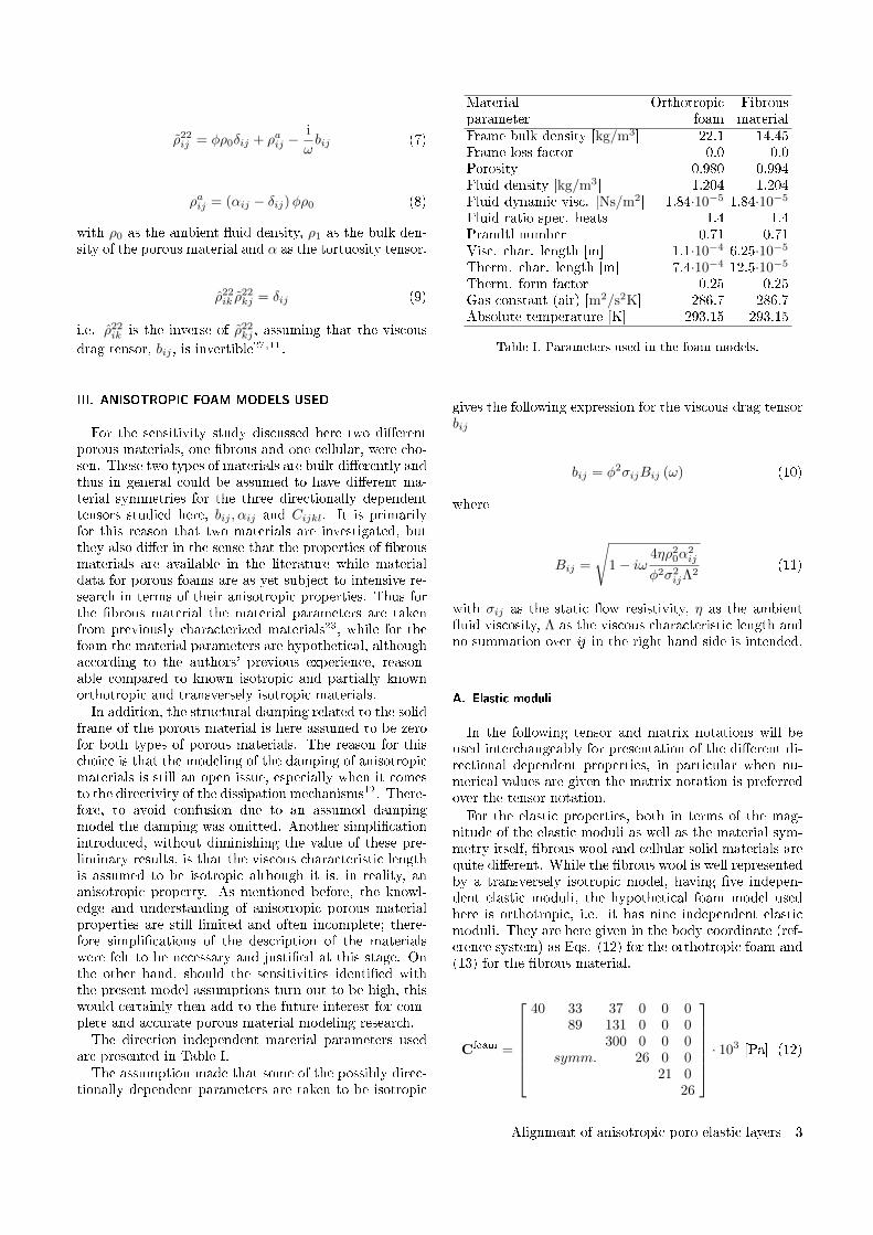
ρ22ij = φρ0δij + ρaij −
i
ωbij (7)
ρaij = (αij − δij)φρ0 (8)
with ρ0 as the ambient uid density, ρ1 as the bulk den-sity of the porous material and α as the tortuosity tensor.
ρ22ik ρ
22kj = δij (9)
i.e. ρ22ik is the inverse of ρ22
kj , assuming that the viscous
drag tensor, bij , is invertible27,11.
III. ANISOTROPIC FOAM MODELS USED
For the sensitivity study discussed here two dierentporous materials, one brous and one cellular, were cho-sen. These two types of materials are built dierently andthus in general could be assumed to have dierent ma-terial symmetries for the three directionally dependenttensors studied here, bij , αij and Cijkl. It is primarilyfor this reason that two materials are investigated, butthey also dier in the sense that the properties of brousmaterials are available in the literature while materialdata for porous foams are as yet subject to intensive re-search in terms of their anisotropic properties. Thus forthe brous material the material parameters are takenfrom previously characterized materials23, while for thefoam the material parameters are hypothetical, althoughaccording to the authors' previous experience, reason-able compared to known isotropic and partially knownorthotropic and transversely isotropic materials.In addition, the structural damping related to the solid
frame of the porous material is here assumed to be zerofor both types of porous materials. The reason for thischoice is that the modeling of the damping of anisotropicmaterials is still an open issue, especially when it comesto the directivity of the dissipation mechanisms12. There-fore, to avoid confusion due to an assumed dampingmodel the damping was omitted. Another simplicationintroduced, without diminishing the value of these pre-liminary results, is that the viscous characteristic lengthis assumed to be isotropic although it is, in reality, ananisotropic property. As mentioned before, the knowl-edge and understanding of anisotropic porous materialproperties are still limited and often incomplete; there-fore simplications of the description of the materialswere felt to be necessary and justied at this stage. Onthe other hand, should the sensitivities identied withthe present model assumptions turn out to be high, thiswould certainly then add to the future interest for com-plete and accurate porous material modeling research.The direction independent material parameters used
are presented in Table I.The assumption made that some of the possibly direc-
tionally dependent parameters are taken to be isotropic
Material Orthotropic Fibrousparameter foam materialFrame bulk density [kg/m3] 22.1 14.45Frame loss factor 0.0 0.0Porosity 0.980 0.994Fluid density [kg/m3] 1.204 1.204Fluid dynamic visc. [Ns/m2] 1.84·10−5 1.84·10−5
Fluid ratio spec. heats 1.4 1.4Prandtl number 0.71 0.71Visc. char. length [m] 1.1·10−4 6.25·10−5
Therm. char. length [m] 7.4·10−4 12.5·10−5
Therm. form factor 0.25 0.25Gas constant (air) [m2/s2K] 286.7 286.7Absolute temperature [K] 293.15 293.15
Table I. Parameters used in the foam models.
gives the following expression for the viscous drag tensorbij
bij = φ2σijBij (ω) (10)
where
Bij =
√1− iω
4ηρ20α
2ij
φ2σ2ijΛ
2(11)
with σij as the static ow resistivity, η as the ambientuid viscosity, Λ as the viscous characteristic length andno summation over ij in the right hand side is intended.
A. Elastic moduli
In the following tensor and matrix notations will beused interchangeably for presentation of the dierent di-rectional dependent properties, in particular when nu-merical values are given the matrix notation is preferredover the tensor notation.
For the elastic properties, both in terms of the mag-nitude of the elastic moduli as well as the material sym-metry itself, brous wool and cellular solid materials arequite dierent. While the brous wool is well representedby a transversely isotropic model, having ve indepen-dent elastic moduli, the hypothetical foam model usedhere is orthotropic, i.e. it has nine independent elasticmoduli. They are here given in the body coordinate (ref-erence system) as Eqs. (12) for the orthotropic foam and(13) for the brous material.
Cfoam =
40 33 37 0 0 089 131 0 0 0
300 0 0 0symm. 26 0 0
21 026
· 103 [Pa] (12)
Alignment of anisotropic poro-elastic layers 3
Cbrous =
17.2 0 0 0 0 017.2 0 0 0 0
1.025 0 0 0symm. 1.6 0 0
1.6 013.7
·103 [Pa]
(13)
B. Flow resistivity and tortuosity
For the ow resistivity tensor, both types of materialsare taken as transversely isotropic and are given by Eqs.(14) for the orthotropic foam and (15) for the brousmaterial.
σfoam =
37500 0 00 37500 00 0 55000
[Pa s/m2] (14)
σbrous =
21000 0 00 21000 00 0 41000
[Pa s/m2] (15)
From these tensors another reason for choosing to includetwo materials is evident, as for the brous material the ra-tio between visco-acoustic and elastic properties is quitedierent compared to the more rigid foam giving rise toquite dierent interactions between the elastic and theacoustic elds in the materials.Concluding the listing of the directional dependent ma-
terial properties, for the foam, the tortuosity was as-sumed to be orthotropic, Eq. (16), while for the brouswool it was assumed to be isotropic, Eq. (17).
αfoam =
1.5 0 00 1.0 00 0 2.0
(16)
αbrous =
1.12 0 00 1.12 00 0 1.12
(17)
Note that the principal directions of the static ow resis-tivity tensors, σ, and the tortuosity, α, are assumed toline up with the principal directions of the solid frameHooke's matrix, C. This is, however, not necessarily thecase for all porous materials21, the consequences of whichwould be a natural next step to investigate in the currentwork.
C. Tensor transformation matrices
In this paper the anisotropic ow resistivity, theanisotropic tortuosity and the anisotropic elastic prop-
erties are the three parameters used to describe theanisotropy of the two porous materials, and therefore theonly ones that may inuence the acoustic properties withangular changes. It is assumed that the material proper-ties may be transformed through a pure rotation arounda xed coordinate system. For the rotation of the sec-ond order tensors, i.e. ow resistivity and tortuosity, thefollowing symmetric transformation is used,
A =
a11 a12 a13
a21 a22 a23
a31 a32 a33
(18)
with transformations of the type
〈.〉rot = AT 〈.〉A (19)
applied for ρ11ij , ρ
22ij , ρ
12ij in Eqs. (5) to (8). In Eq. (18),
the two rst columns are given through two orthonormalvectors, dening the xrot-yrot plane of the new coordi-nate system, and the third column is computed as thecross product of these to form the new xrot-yrot-zrot 'scoordinate system in which the material properties arecomputed for a given rotation of the material. Pleasenote that the new xrot-yrot-zrot-coordinate system maybe dierent for the two porous layers in each congura-tion, as schematically shown in Fig. 3.
Similarly for the fourth order elasticity tensor the fol-lowing transformation is used
T =
[T11 T12
T21 T22
](20)
where
T11 =
a2
11 a212 a2
13
a221 a2
22 a223
a231 a2
32 a233
(21)
T21 =
a21a31 a22a32 a23a33
a11a31 a12a32 a13a33
a11a21 a12a22 a13a23
(22)
T12 =
2a12a13 2a11a13 2a11a12
2a22a23 2a21a23 2a21a22
2a32a33 2a31a33 2a31a32
(23)
T22 =
a22a33 + a23a32 a21a33 + a23a31 a21a32 + a22a31
a12a33 + a13a32 a11a33 + a13a31 a11a32 + a12a31
a12a23 + a13a22 a11a23 + a13a21 a11a22 + a12a21
(24)
where the aij are given by Eq. (18) and the correspond-ing transformations being of the type
Alignment of anisotropic poro-elastic layers 4
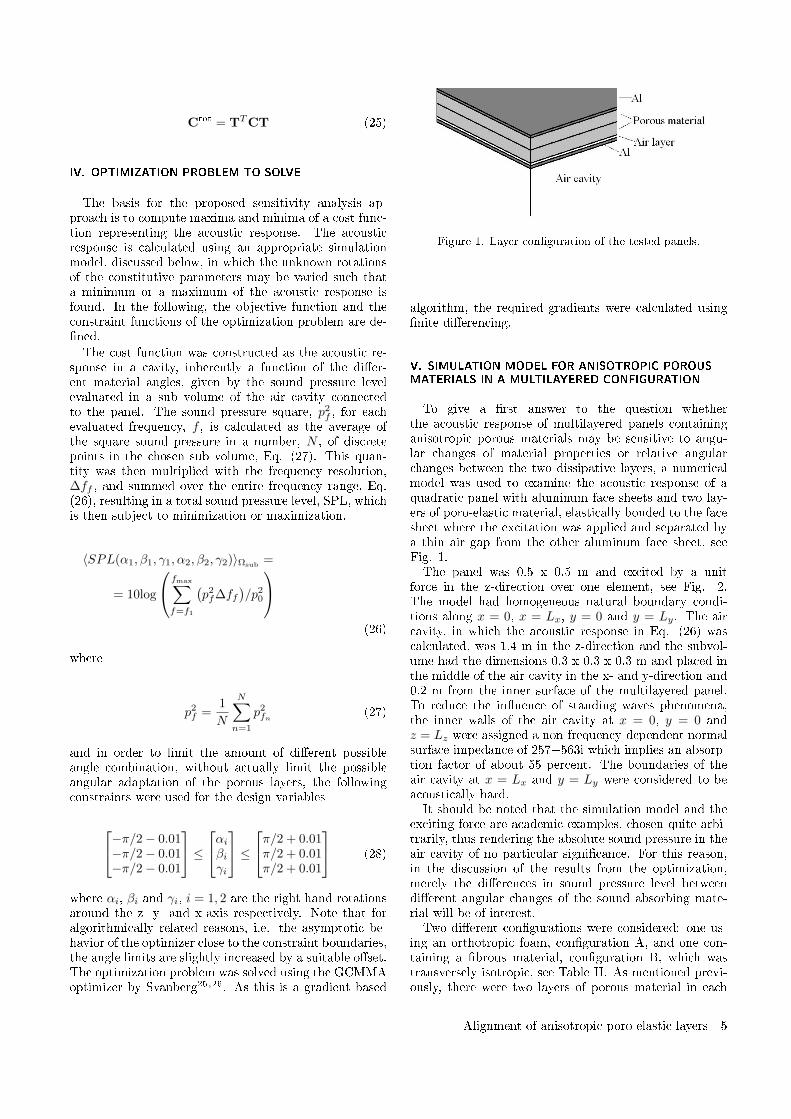
Crot = TTCT (25)
IV. OPTIMIZATION PROBLEM TO SOLVE
The basis for the proposed sensitivity analysis ap-proach is to compute maxima and minima of a cost func-tion representing the acoustic response. The acousticresponse is calculated using an appropriate simulationmodel, discussed below, in which the unknown rotationsof the constitutive parameters may be varied such thata minimum or a maximum of the acoustic response isfound. In the following, the objective function and theconstraint functions of the optimization problem are de-ned.The cost function was constructed as the acoustic re-
sponse in a cavity, inherently a function of the dier-ent material angles, given by the sound pressure levelevaluated in a sub volume of the air cavity connectedto the panel. The sound pressure square, p2
f , for eachevaluated frequency, f , is calculated as the average ofthe square sound pressure in a number, N , of discretepoints in the chosen sub volume, Eq. (27). This quan-tity was then multiplied with the frequency resolution,∆ff , and summed over the entire frequency range, Eq.(26), resulting in a total sound pressure level, SPL, whichis then subject to minimization or maximization.
〈SPL(α1, β1, γ1, α2, β2, γ2)〉Ωsub=
= 10log
fmax∑
f=f1
(p2f∆ff
)/p2
0
(26)
where
p2f =
1
N
N∑
n=1
p2fn (27)
and in order to limit the amount of dierent possibleangle combination, without actually limit the possibleangular adaptation of the porous layers, the followingconstraints were used for the design variables
−π/2− 0.01−π/2− 0.01−π/2− 0.01
≤
αi
βiγi
≤
π/2 + 0.01π/2 + 0.01π/2 + 0.01
(28)
where αi, βi and γi, i = 1, 2 are the right hand rotationsaround the z- y- and x-axis respectively. Note that foralgorithmically related reasons, i.e. the asymptotic be-havior of the optimizer close to the constraint boundaries,the angle limits are slightly increased by a suitable oset.The optimization problem was solved using the GCMMAoptimizer by Svanberg25,26. As this is a gradient based
Figure 1. Layer conguration of the tested panels.
algorithm, the required gradients were calculated usingnite dierencing.
V. SIMULATION MODEL FOR ANISOTROPIC POROUSMATERIALS IN A MULTILAYERED CONFIGURATION
To give a rst answer to the question whetherthe acoustic response of multilayered panels containinganisotropic porous materials may be sensitive to angu-lar changes of material properties or relative angularchanges between the two dissipative layers, a numericalmodel was used to examine the acoustic response of aquadratic panel with aluminum face sheets and two lay-ers of poro-elastic material, elastically bonded to the facesheet where the excitation was applied and separated bya thin air gap from the other aluminum face sheet, seeFig. 1.The panel was 0.5 x 0.5 m and excited by a unit
force in the z-direction over one element, see Fig. 2.The model had homogeneous natural boundary condi-tions along x = 0, x = Lx, y = 0 and y = Ly. The aircavity, in which the acoustic response in Eq. (26) wascalculated, was 1.4 m in the z-direction and the subvol-ume had the dimensions 0.3 x 0.3 x 0.3 m and placed inthe middle of the air cavity in the x- and y-direction and0.2 m from the inner surface of the multilayered panel.To reduce the inuence of standing waves phenomena,the inner walls of the air cavity at x = 0, y = 0 andz = Lz were assigned a non-frequency-dependent normalsurface impedance of 257+563i which implies an absorp-tion factor of about 55 percent. The boundaries of theair cavity at x = Lx and y = Ly were considered to beacoustically hard.It should be noted that the simulation model and the
exciting force are academic examples, chosen quite arbi-trarily, thus rendering the absolute sound pressure in theair cavity of no particular signicance. For this reason,in the discussion of the results from the optimization,merely the dierences in sound pressure level betweendierent angular changes of the sound absorbing mate-rial will be of interest.Two dierent congurations were considered: one us-
ing an orthotropic foam, conguration A, and one con-taining a brous material, conguration B, which wastransversely isotropic, see Table II. As mentioned previ-ously, there were two layers of porous material in each
Alignment of anisotropic poro-elastic layers 5
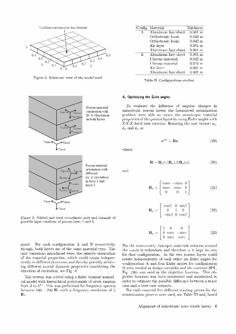
Figure 2. Schematic view of the model used.
Figure 3. Global and local co-ordinate axes and example ofpossible layer rotations of porous layer 1 and 2.
panel. For each conguration A and B respectively,though, both layers are of the same material type. Theonly variations introduced were, the relative orientationof the material properties, which could rotate indepen-dently in dierent directions and thereby possibly achiev-ing dierent overall dynamic properties considering thedirection of excitation, see Fig. 3.
The system was solved using a nite element numeri-cal model with hierarchical polynomials of order rangingfrom 2 to 514. This was performed for frequency spectrabetween 100 700 Hz with a frequency resolution of 5Hz.
Cong. Material ThicknessA Aluminum face sheet 0.001 m
Orthotropic foam 0.042 mOrthotropic foam 0.042 mAir layer 0.001 mAluminum face sheet 0.001 m
B Aluminum face sheet 0.001 mFibrous material 0.042 mFibrous material 0.042 mAir layer 0.001 mAluminum face sheet 0.001 m
Table II. Congurations studied.
A. Optimizing the Euler angles
To evaluate the inuence of angular changes inanisotropic porous layers the formulated optimizationproblem were able to rotate the anisotropic materialproperties of the porous layers by using Euler angles withZ-Y-X xed axis rotation. Rotating the unit vectors ez,ey and ex as
erot = Re (29)
where
R = Rx(γ)Ry(β)Rz(α) (30)
and
Rz =
cosα −sinα 0sinα cosα 0
0 0 1
(31)
Ry =
cosβ 0 sinβ0 1 0
−sinβ 0 cosβ
(32)
Rx =
1 0 00 cosγ −sinγ0 sinγ cosγ
(33)
For the transversely isotropic materials rotation aroundthe z-axis is redundant and therefore α is kept to zerofor that conguration. As the two porous layers couldrotate independently of each other six Euler angles forconguration A and four Euler angles for congurationB were needed as design variables and the summed SPL,Eq. (26) was used as the objective function. This ob-jective function was both minimized and maximized inorder to estimate the possible dierence between a worstcase and a best case scenario.For each material ve dierent starting points for the
minimization process were used, see Table III and, based
Alignment of anisotropic poro-elastic layers 6
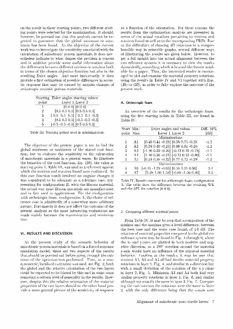
on the result in those starting points, two dierent start-ing points were selected for the maximization. It should,however, be pointed out that this analysis cannot be ex-pected to guarantee that the global minimum or max-imum has been found. As the objective of the currentwork was to investigate the sensitivity associated with theorientation of anisotropic porous materials, it does nev-ertheless indicate to what degree the problem is convexand in addition provide some useful information aboutthe dierences between dierent minima or maxima bothin terms of the chosen objective function but also in theresulting Euler angles. And most importantly, it doesprovide a rst estimation of possible dierences in acous-tic response that may be caused by angular changes ofanisotropic acoustic porous materials.
Starting Euler angles starting valuespoint Layer 1 Layer 21 [0 0 0] [0 0 0]2 [0.5 0.5 0.5] [0.5 0.5 0.5]3 [-0.5 -0.5 -0.5] [-0.5 -0.5 -0.5]4 [0.5 0.5 0.5] [-0.5 -0.5 -0.5]5 [-0.5 -0.5 -0.5] [0.5 0.5 0.5]
Table III. Starting points used in minimizations.
The objective of the present paper is not to nd theglobal minimum or maximum of the stated cost func-tion, but to evaluate the sensitivity to the orientationof anisotropic materials in a general sense. To illustratethe behavior of the cost function, Eq. (26), the value atstarting point 1, Table III, was used as a reference againstwhich the minima and maxima found were evaluated. Asthis cost function result involved no angular changes itwas considered to be adequate as a reference case, rep-resenting for conguration B, with the brous material,the actual way most brous materials are manufactured,and in fact used in applications. For the congurationwith orthotropic foam, conguration A, the choice of ref-erence case is admittedly of a somewhat more arbitrarynature. Fortunately it does not aect the outcome of thepresent analysis as the most interesting evaluations aremade mainly between the maximization and minimiza-tion.
VI. RESULTS AND DISCUSSION
As the present study of the acoustic behavior ofanisotropic porous materials is based on a forced responsesimulation model, there are two aspects of the resultsthat should be pointed out before going through the out-come of the optimizations performed. First, as a non-symmetric, localized excitation was used, see Fig. 2, boththe global and the relative orientation of the two layerscould be expected to be biased by this and in some senseremoving a certain level of generality in the results. How-ever, despite this the relative orientation of the materialproperties of the two layers should on the other hand pro-vide a more general picture of the sensitivity of response
as a function of the orientation. For these reasons theresults from the optimization analysis are presented interms of the actual rotations pertaining to minima andmaxima found as well as to the corresponding FRFs. Dueto the diculties of showing 3D rotations in a compre-hensible way in printable graphs, several dierent waysof illustrating the results are given below. However, toget a full insight into the actual alignment between thetwo reference systems it is necessary to view the resultsdynamically, something which is beyond the format avail-able for a paper. Thus, the interested reader is encour-aged to plot and examine the material property rotationsusing the results in Table IV and VI together with Eqs.(29) to (33), in order to fully explore the outcome of thepresent work.
A. Orthotropic foam
An overview of the results for the orthotropic foam,using the ve starting points in Table III, are found inTable IV.
Start Min/ Euler angles end values Di. SPLpoint Max Layer 1 Layer 2 [dB]
Minimizations1 A1 [0.45 0.41 -0.25] [0.38 0.75 -0.25] -1.22 A2 [0.38 0.40 -0.25] [0.66 0.81 -0.20] -1.23 A3 [-1.46 0.39 -0.20] [-0.43 0.49 -0.78] -1.14 A4 [1.40 0.36 -0.21] [-0.12 0.33 -0.80] -1.15 A5 [0.24 0.38 -0.32] [0.77 0.72 -0.29] -1.2
Maximizations5 A6 [-0.45 -1.28 -0.65] [0.58 1.51 0.56] +3.44 A7 [1.28 1.06 1.58] [-0.89 -1.56 0.36] +3.2
Table IV. Results overview for orthotropic foam, congurationA. The table show the dierence between the resulting SPLand the SPL for rotation [0 0 0].
1. Comparing dierent extremal points
From Table IV, it may be seen that a comparison of theminima and the maxima gives a level dierence, betweenthe best case and the worst case found, of 4.6 dB. Therotation of material properties compared to the global co-ordinate system may be found in Fig. 4 through 9, wherethe x- and y-axes are plotted in both positive and neg-ative direction, as a 180 rotation around the materialz-axis would have no inuence of the physical materialbehavior. Looking at the results, it may be seen thatminima A1, A2 and A5 all had similar material propertyrotations in layer 1, Fig. 4, and similar in z-direction butwith a small deviation of the rotation of the x-y-planein layer 2, Fig. 5. Minimum A3 and A4 both had verysimilar property rotations in layer 1, Fig. 6, and similaralthough not exactly the same in layer 2, Fig. 7. Compar-ing the two maxima the rotations were the same in layer2, with the only dierence being that the z-axes were
Alignment of anisotropic poro-elastic layers 7
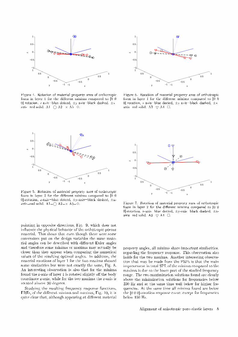
−1−0.5
00.5
1
−1
−0.5
0
0.5
1−1
−0.5
0
0.5
1
xy
z
Figure 4. Rotation of material property axes of orthotropicfoam in layer 1 for the dierent minima compared to [0 00]-rotation, z-axis=blue dotted, ±y-axis=black dashed, ±x-axis=red solid. A1=© A2=× A5=3.
−1−0.5
00.5
1
−1
−0.5
0
0.5
1−1
−0.5
0
0.5
1
xy
z
Figure 5. Rotation of material property axes of orthotropicfoam in layer 2 for the dierent minima compared to [0 00]-rotation, z-axis=blue dotted, ±y-axis=black dashed, ±x-axis=red solid. A1=© A2=× A5=3.
pointing in opposite directions, Fig. 9, which does notinuence the physical behavior of the orthotropic porousmaterial. This shows that even though there were someconstraints put on the design variables the same mate-rial angles can be described with dierent Euler anglesand therefore some minima or maxima may actually becloser than they appear when comparing the numericalvalues of the resulting optimal angles. In addition, thematerial rotations of layer 1 for the two maxima showedsome similarities but were not exactly the same, Fig. 8.An interesting observation is also that for the minimafound the z-axis of layer 1 is rotated slightly o the bodycoordinate z-axis, while for the two maxima the z-axis isrotated almost 90 degrees.
Studying the resulting frequency response functions,FRFs, of the dierent minima and maxima, Fig. 10, it isquite clear that, although appearing at dierent material
−1−0.5
00.5
1
−1
−0.5
0
0.5
1−1
−0.5
0
0.5
1
xy
z
Figure 6. Rotation of material property axes of orthotropicfoam in layer 1 for the dierent minima compared to [0 00]-rotation, z-axis=blue dotted, ±y-axis=black dashed, ±x-axis=red solid. A3=5 A4=.
−1−0.5
00.5
1
−1
−0.5
0
0.5
1−1
−0.5
0
0.5
1
xy
z
Figure 7. Rotation of material property axes of orthotropicfoam in layer 2 for the dierent minima compared to [0 00]-rotation, z-axis=blue dotted, ±y-axis=black dashed, ±x-axis=red solid. A3=5 A4=.
property angles, all minima share important similarities,regarding the frequency response. This observation alsoholds for the two maxima. Another interesting observa-tion that may be made from the FRFs is that the mainimprovement in total SPL of the minima compared to themaxima is due to the lower part of the studied frequencyrange. The two maximization solutions found are clearlyabove the minimization solutions for frequencies below250 Hz and at the same time well below for higher fre-quencies. At the same time all minima found are belowthe [0 0 0]-rotation response curve, except for frequenciesbelow 150 Hz.
Alignment of anisotropic poro-elastic layers 8
−1−0.5
00.5
1
−1
−0.5
0
0.5
1−1
−0.5
0
0.5
1
xy
z
Figure 8. Rotation of material property axes of orthotropicfoam in layer 1 for the dierent maxima compared to [0 00]-rotation, z-axis=blue dotted, ±y-axis=black dashed, ±x-axis=red solid. A6=3 A7=.
−1−0.5
00.5
1
−1
−0.5
0
0.5
1−1
−0.5
0
0.5
1
xy
z
Figure 9. Rotation of material property axes of orthotropicfoam in layer 2 for the dierent maxima compared to [0 00]-rotation, z-axis=blue dotted, ±y-axis=black dashed, ±x-axis=red solid. A6=3 A7=.
2. Layer orientation within the dierent extremal points
To further illustrate the nature of the dierent optimafound, the relative rotations between layer 1 and 2 foreach extremal point, represented in terms of the com-puted direction cosines between the x-, y-, and z-axes forlayer 1 and layer 2 material orientations respectively, aregiven in Table V.
Relative Extremal pointrotation A1 A2 A3 A4 A5 A6 A7x-axis 18 26 48 96 35 103 86
y-axis 9 22 49 100 33 78 90
z-axis 19 24 31 32 20 162 151
Table V. Relative rotation between the axes of layer 1 and 2for each extremal point.
100 200 300 400 500 600 70010
−9
10−8
10−7
10−6
10−5
10−4
Figure 10. FRF of the dierent maxima and minima found forthe orthotropic foam compared to [0 0 0]-rotation, blue dot-ted. A1=blue solid, A2=black solid, A3=red solid, A4=greensolid, A5=magenta solid, A6=magenta dashed, A7=greendashed.
−1−0.5
00.5
1
−1
−0.5
0
0.5
1−1
−0.5
0
0.5
1
xy
z
Figure 11. Relative rotation of material property axes of or-thotropic material for layer 1 (solid) and layer 2 (dashed)minimum A2. x-axis=× y-axis=5 z-axis=©.
Looking at the relative orientation between the rstand second layer of the panel there seems to occur somesimilarities between the dierent minima and maxima,especially for the relative angle between the z-axes. Es-pecially minima A1, A2 and A5 were quite similar, seeFig. 11 and 12, while for minima A3 and A4 the similar-ities were not as obvious, mainly due to the deviation ofthe rotation of the x-y-plane in layer 2 as shown in Fig.7.
B. Fibrous material
For the transversely isotropic brous material, usingthe ve starting points in Table III, an overview of theoptima found are shown in Table VI.
Alignment of anisotropic poro-elastic layers 9
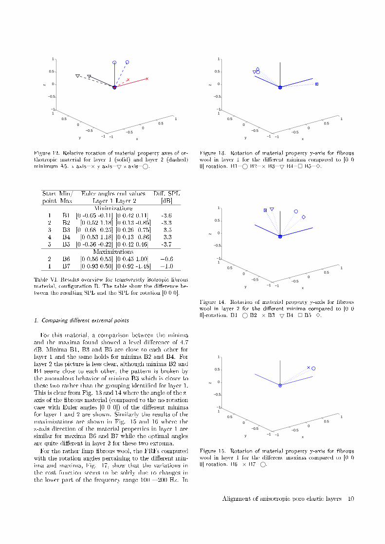
−1−0.5
00.5
1
−1
−0.5
0
0.5
1−1
−0.5
0
0.5
1
xy
z
Figure 12. Relative rotation of material property axes of or-thotropic material for layer 1 (solid) and layer 2 (dashed)minimum A5. x-axis=× y-axis=5 z-axis=©.
Start Min/ Euler angles end values Di. SPLpoint Max Layer 1 Layer 2 [dB]
Minimizations1 B1 [0 -0.65 -0.11] [0 0.42 0.11] -3.62 B2 [0 0.52 1.18] [0 0.13 -0.85] -3.33 B3 [0 -0.68 -0.25] [0 0.26 -0.75] -3.54 B4 [0 0.53 1.18] [0 0.13 -0.86] -3.35 B5 [0 -0.56 -0.22] [0 0.42 0.46] -3.7
Maximizations2 B6 [0 0.56 0.55] [0 0.45 1.00] +0.61 B7 [0 0.93 0.50] [0 0.92 -1.48] +1.0
Table VI. Results overview for transversely isotropic brousmaterial, conguration B. The table show the dierence be-tween the resulting SPL and the SPL for rotation [0 0 0].
1. Comparing dierent extremal points
For this material, a comparison between the minimaand the maxima found showed a level dierence of 4.7dB. Minima B1, B3 and B5 are close to each other forlayer 1 and the same holds for minima B2 and B4. Forlayer 2 the picture is less clear, although minima B2 andB4 seems close to each other, the pattern is broken bythe anomalous behavior of minima B3 which is closer tothese two rather than the grouping identied for layer 1.This is clear from Fig. 13 and 14 where the angle of the z-axis of the brous material (compared to the no rotationcase with Euler angles [0 0 0]) of the dierent minimafor layer 1 and 2 are shown. Similarly the results of themaximizations are shown in Fig. 15 and 16 where thez-axis direction of the material properties in layer 1 aresimilar for maxima B6 and B7 while the optimal anglesare quite dierent in layer 2 for these two extrema.For the rather limp brous wool, the FRFs computed
with the rotation angles pertaining to the dierent min-ima and maxima, Fig. 17, show that the variations inthe cost function seems to be solely due to changes inthe lower part of the frequency range 100 200 Hz. In
−1−0.5
00.5
1
−1
−0.5
0
0.5
1−1
−0.5
0
0.5
1
xy
z
Figure 13. Rotation of material property y-axis for brouswool in layer 1 for the dierent minima compared to [0 00]-rotation. B1=© B2=× B3=5 B4= B5=3.
−1−0.5
00.5
1
−1
−0.5
0
0.5
1−1
−0.5
0
0.5
1
xy
z
Figure 14. Rotation of material property y-axis for brouswool in layer 2 for the dierent minima compared to [0 00]-rotation. B1=© B2=× B3=5 B4= B5=3.
−1−0.5
00.5
1
−1
−0.5
0
0.5
1−1
−0.5
0
0.5
1
xy
z
Figure 15. Rotation of material property y-axis for brouswool in layer 1 for the dierent maxima compared to [0 00]-rotation. B6=× B7=©.
Alignment of anisotropic poro-elastic layers 10
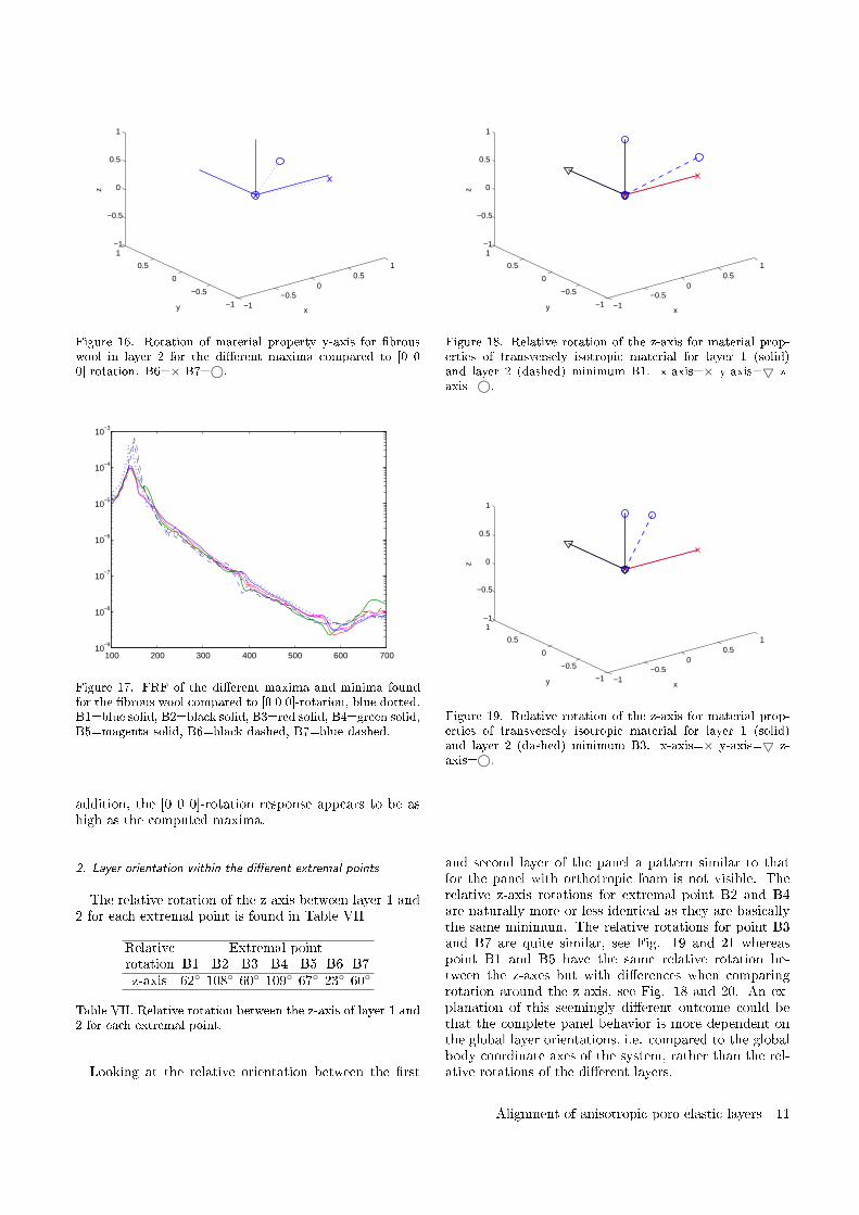
−1−0.5
00.5
1
−1
−0.5
0
0.5
1−1
−0.5
0
0.5
1
xy
z
Figure 16. Rotation of material property y-axis for brouswool in layer 2 for the dierent maxima compared to [0 00]-rotation. B6=× B7=©.
100 200 300 400 500 600 70010
−9
10−8
10−7
10−6
10−5
10−4
10−3
Figure 17. FRF of the dierent maxima and minima foundfor the brous wool compared to [0 0 0]-rotation, blue dotted.B1=blue solid, B2=black solid, B3=red solid, B4=green solid,B5=magenta solid, B6=black dashed, B7=blue dashed.
addition, the [0 0 0]-rotation response appears to be ashigh as the computed maxima.
2. Layer orientation within the dierent extremal points
The relative rotation of the z-axis between layer 1 and2 for each extremal point is found in Table VII
Relative Extremal pointrotation B1 B2 B3 B4 B5 B6 B7z-axis 62 108 60 109 67 23 60
Table VII. Relative rotation between the z-axis of layer 1 and2 for each extremal point.
Looking at the relative orientation between the rst
−1−0.5
00.5
1
−1
−0.5
0
0.5
1−1
−0.5
0
0.5
1
xy
z
Figure 18. Relative rotation of the z-axis for material prop-erties of transversely isotropic material for layer 1 (solid)and layer 2 (dashed) minimum B1. x-axis=× y-axis=5 z-axis=©.
−1−0.5
00.5
1
−1
−0.5
0
0.5
1−1
−0.5
0
0.5
1
xy
z
Figure 19. Relative rotation of the z-axis for material prop-erties of transversely isotropic material for layer 1 (solid)and layer 2 (dashed) minimum B3. x-axis=× y-axis=5 z-axis=©.
and second layer of the panel a pattern similar to thatfor the panel with orthotropic foam is not visible. Therelative z-axis rotations for extremal point B2 and B4are naturally more or less identical as they are basicallythe same minimum. The relative rotations for point B3and B7 are quite similar, see Fig. 19 and 21 whereaspoint B1 and B5 have the same relative rotation be-tween the z-axes but with dierences when comparingrotation around the z-axis, see Fig. 18 and 20. An ex-planation of this seemingly dierent outcome could bethat the complete panel behavior is more dependent onthe global layer orientations, i.e. compared to the globalbody coordinate axes of the system, rather than the rel-ative rotations of the dierent layers.
Alignment of anisotropic poro-elastic layers 11
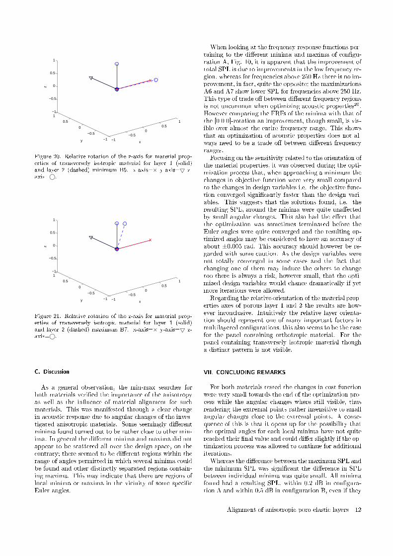
−1−0.5
00.5
1
−1
−0.5
0
0.5
1−1
−0.5
0
0.5
1
xy
z
Figure 20. Relative rotation of the z-axis for material prop-erties of transversely isotropic material for layer 1 (solid)and layer 2 (dashed) minimum B5. x-axis=× y-axis=5 z-axis=©.
−1−0.5
00.5
1
−1
−0.5
0
0.5
1−1
−0.5
0
0.5
1
xy
z
Figure 21. Relative rotation of the z-axis for material prop-erties of transversely isotropic material for layer 1 (solid)and layer 2 (dashed) maximum B7. x-axis=× y-axis=5 z-axis=©.
C. Discussion
As a general observation, the min-max searches forboth materials veried the importance of the anisotropyas well as the inuence of material alignment for suchmaterials. This was manifested through a clear changein acoustic response due to angular changes of the inves-tigated anisotropic materials. Some seemingly dierentminima found turned out to be rather close to other min-ima. In general the dierent minima and maxima did notappear to be scattered all over the design space, on thecontrary; there seemed to be dierent regions within therange of angles permitted in which several minima couldbe found and other distinctly separated regions contain-ing maxima. This may indicate that there are regions oflocal minima or maxima in the vicinity of some specicEuler angles.
When looking at the frequency response functions per-taining to the dierent minima and maxima of congu-ration A, Fig. 10, it is apparent that the improvement oftotal SPL is due to improvements in the low frequency re-gion, whereas for frequencies above 250 Hz there is no im-provement, in fact, quite the opposite; the maximizationsA6 and A7 show lower SPL for frequencies above 250 Hz.This type of trade o between dierent frequency regionsis not uncommon when optimizing acoustic properties20.However comparing the FRFs of the minima with that ofthe [0 0 0]-rotation an improvement, though small, is vis-ible over almost the entire frequency range. This showsthat an optimization of acoustic properties does not al-ways need to be a trade o between dierent frequencyranges.Focusing on the sensitivity related to the orientation of
the material properties, it was observed during the opti-mization process that, when approaching a minimum thechanges in objective function were very small comparedto the changes in design variables i.e. the objective func-tion converged signicantly faster than the design vari-ables. This suggests that the solutions found, i.e. theresulting SPL, around the minima were quite unaectedby small angular changes. This also had the eect thatthe optimization was sometimes terminated before theEuler angles were quite converged and the resulting op-timized angles may be considered to have an accuracy ofabout ±0.005 rad. This accuracy should however be re-garded with some caution. As the design variables werenot totally converged in some cases and the fact thatchanging one of them may induce the others to changetoo there is always a risk, however small, that the opti-mized design variables would chance dramatically if yetmore iterations were allowed.Regarding the relative orientation of the material prop-
erties axes of porous layer 1 and 2 the results are how-ever inconclusive. Intuitively the relative layer orienta-tion should represent one of many important factors inmultilayered congurations, this also seems to be the casefor the panel containing orthotropic material. For thepanel containing transversely isotropic material thougha distinct pattern is not visible.
VII. CONCLUDING REMARKS
For both materials tested the changes in cost functionwere very small towards the end of the optimization pro-cess while the angular changes where still visible, thusrendering the extremal points rather insensitive to smallangular changes close to the extremal points. A conse-quence of this is that it opens up for the possibility thatthe optimal angles for each local minima have not quitereached their nal value and could dier slightly if the op-timization process was allowed to continue for additionaliterations.Whereas the dierence between the maximum SPL and
the minimum SPL was signicant the dierence in SPLbetween individual minima was quite small. All minimafound had a resulting SPL, within 0.2 dB in congura-tion A and within 0.5 dB in conguration B, even if they
Alignment of anisotropic poro-elastic layers 12
were found at quite dierent Euler angles. In addition thesmall dierence in FRF between dierent minima and theapparent tendency to appear in a limited number of min-ima regions may indicate that once the regions of localminima and maxima have been found, the exact Eulerangles are less important, as long as the material anglesstay within a minima region and thus avoid maxima re-gions. For practical applications this would probably bea quite compelling physical feature.Studying the frequency response functions of congu-
ration A, Fig. 10, it is quite obvious that the improve-ment in SPL is restricted to frequencies around 200 Hz,substantially improving the SPL at those frequencies atthe expense of the SPL at higher frequencies. If the fre-quency range of interest was altered and thus excludingfrequencies below for example 250 Hz the outcome of theoptimization would doubtlessly be totally dierent. Aweighting function applied to the FRF or other exten-sions or limitations of the frequency range would alsoinuence the result. Obviously, a proper choice of objec-tive function and frequency range of interest is thereforeof outmost importance to achieve a useful result in prac-tical applications.Finally one can conclude that there are signicant pos-
sibilities of improvement in practical applications con-nected with angular modication of anisotropic mate-rial properties of acoustic absorbents. Such improvementcan according to the numerical simulations be achievedwithin an existing acoustic panel using readily availableporous material without adding extra weight or volume.However, the knowledge of anisotropic material proper-ties, including their principal directions as well as theirstructural losses and other damping behavior is todayvery limited, making anisotropic porous acoustic materi-als an important area well deserving further research.
VIII. ACKNOWLEDGMENT
This work was performed within the Centre for ECO2
Vehicle Design. The nancial support is gratefully ac-knowledged.
IX. REFERENCES
1 J-F. Allard. Propagation of sound in porous media: mod-elling sound absorbing materials. Elsevier Applied Science,1993.
2 J.-F. Allard and Y. Champoux. New empirical equationsfor sound propagation in rigid frame brous materials. J.Acoust. Soc. Am., 6(91):33463353, 1992.
3 N. Atalla, M. A. Hamdi, and R. Panneton. Enhanced weakintegral formulation for the mixed (u,p) poroelastic equa-tions. J. Acoust. Soc. Am., 109(6):30653068, 2001.
4 M. A. Biot. Theory of propagation of elastic waves in auid saturated porous solid. I. Low frequency range. J.Acoust. Soc. Am., 28:168178, 1956:1.
5 M. A. Biot. Theory of propagation of elastic waves in auid saturated porous solid. II. Higher frequency range. J.Acoust. Soc. Am., 28:179191, 1956:2.
6 M. A. Biot. Theory of deformation of a porous viscoelasticanisotropic solid. J. Appl. Phys., 27:459467, 1956:3.
7 M. A. Biot and D. G. Willis. The elastic coecients of thetheory of consolidation. J. Appl. Mech., 24:594601, 1957.
8 M. A. Biot. Mechanics of deformation and acoustic prop-agation in porous media. J. Appl. Phys., 33(4):14821498,1962.
9 J. Cuenca and P. Goransson. An inverse method for theestimation of elastic and anelastic properties of the porousframe of anisotropic open-cell foams. J. Acoust. Soc. Am.Accepted for publication June 2012.
10 P. Göransson. Tailored acoustic and vibrational dampingin porous solids Engineering performance in aerospaceapplications. Aerospace Science and Technology, 12:2641,2008.
11 P. Göransson, R. Guastavino, and N.-E. Hörlin. Measure-ment and inverse estimation of 3d anisotropic ow resistiv-ity for porous materials. J. Sound Vib., 327(3-5):354367,2009.
12 P. Göransson and N.-E. Hörlin. Vibro-acoustic modellingof anisotropic porous elastic materials: A preliminarystudy of the in.uence of anisotropy on the predicted perfor-mance in a multi-layer arrangement. Acta Acustica unitedwith Acustica, 96(2):258265, 2010.
13 R. Guastavino and P. Göransson. A 3d displacement mea-surement methodology for anisotropic porous cellular foammaterials. Polymer Testing, 26(6):711719, 2007.
14 N.-E. Hörlin. 3-D hierarchical hp-FEM applied to elasto-acoustic modelling of layered porous media. J. Sound Vib.,285(4):341363, 2005.
15 N.-E. Hörlin and P. Göransson. Weak, anisotropic sym-metric formulations of biot's equations for vibro-acousticmodelling of porous elastic materials. Int. J. Numer. Meth.Engng, 84(12):15191540, 2010.
16 L. Jaouen, A. Renault, and M. Deverge. Elastic and damp-ing characterizations of acoustical porous materials: Avail-able experimental methods and applications to a melaminefoam. Applied Acoustics, 69(12):11291140, 2008.
17 D. L. Johnson, J. Koplik, and R. Dashen. Theory of dy-namic permiability and tortuosity in uid-saturated porousmedia. J. Fluid Mech., 176:379402, 1987.
18 P. Khurana, L. Boeckx, W. Lauriks, P. Leclaire, O. Dazel,and J.-F. Allard. A description of transversely isotropicsound absorbing porous materials by transfer matrices. J.Acoust. Soc. Am., 125(2):915921, 2009.
19 D. Lafarge, P. Lemarnier, J.-F. Allard, and V. Tarnow.Dynamic compressibility of air in porous structures at au-dible frequencies. J. Acoust. Soc. Am, 102(4):19952006,1997.
20 E. Lind-Nordgren and P. Göransson. Optimising openporous foam for acoustical and vibrational performance.J. Sound Vib., 329(7):753767, 2010.
21 M. Melon, E. Mariez, C. Ayrault, and S. Sahraoui. Acous-tical and mechanical characterization of anisotropic open-cell foams. J. Acoust. Soc. Am., 104(5):26222627, 1998.
22 S. R. Pride, A. F. Gangi, and F. D. Morgan. Deriving theequations of motion for porous isotropic media. J. Acoust.Soc. Am, 92(6):32783290, 1992.
23 H. J. Rice and P. Göransson. A dynamical model of lightbrous materials. International Journal of Mechanical Sci-ences, 41(4-5):561579, 1999.
24 S. Sahraoui, E. Mariez, and M. Etchessahar. Linear elasticproperties of anisotropic open-cell foams. J. Acoust. Soc.Am., 110(1):635637, 2001.
25 K. Svanberg. The method of moving asymptotes a newmethod for structural optimization. Int. J. Numer. Meth.
Alignment of anisotropic poro-elastic layers 13
Engng, 24:359373, 1987.26 K. Svanberg. A class of globally convergent optimization
methods based on conservative convex separable approxi-mations. SIAM Journal on Optimization, 12(2):555573,2002.
27 L. Wang. Flows through porous media: A theoreticaldevelopment at macroscale. Transport in Porous Media,39(1):124, 2000.
Alignment of anisotropic poro-elastic layers 14

Eleonora LIND NORDGREN
A study of tailoring acoustic porousmaterial properties when designing
lightweight multilayered vehicle panels
Resume :
Le present travail explore la possibilite d’adapter des materiaux poro-elastiques legers pour des applications specifiques. En particulier,
une approche de conception est presentee, combinant simulations par la methodes des elements finis et techniques d’optimisation,
permettant ainsi d’ameliorer les proprietes dynamiques et acoustiques de panneaux multicouches comprenant des materiaux poreux.
Les modeles numeriques sont fondes sur la theorie de Biot qui utilise des modeles equivalents fluide/solide avec des proprietes
macroscopiques spatialement homogeneisees, decrivant le comportement physique des materiaux poro-elastiques. Afin de syste-
matiquement identifier et comparer certaines proprietes specifiques, benefiques ou defavorables, le modele numerique est connecte
a un optimiseur fonde sur les gradients. Les parametres macroscopiques utilises dans la theorie de Biot etant lies, il ne peuvent
etre utilises comme variables independantes. Par consequent, des lois d’echelle sont appliquees afin de connecter les proprietes
macroscopiques du materiau aux proprietes geometriques microscopiques, qui elles peuvent etre modifiees independamment.
L’approche de conception est egalement combinee avec l’optimisation de la masse d’un panneau sandwich structure, afin d’examiner
les possibilites de combiner exigences structurelles et acoustiques, qui peuvent etre en conflit. En prenant le soin d’etablir un equilibre
entre composantes acoustiques et structurelles, des effets de synergie plutot que destructifs peuvent etre obtenus, donnant lieu a des
panneaux multifonctionnels. Cela pourrait rendre l’ajout de traitements acoustiques redondant, qui par ailleurs annulerait tout ou
partie du gain en masse obtenu par optimisation.
Les resultats indiquent un veritable potentiel d’amelioration des proprietes dynamiques et acoustiques de panneaux multi-couches,
pour un ajout minimum en termes de masse et volume. La technique de modelisation developpee pourrait egalement etre
implementee au sein d’outils numeriques futures pour la conception de panneaux legers de vehicules. Cela aurait le potentiel de
reduire substantiellement la masse tout en limitant, voire supprimant l’impact negatif sur les proprietes acoustiques et vibratoires,
pourtant une consequence courante de la reduction de la masse, participant ainsi a l’effort de developpement de vehicules futures
plus legers et efficaces.
Mots cles :
materiaux poroelastiques, materiaux poreux, optimisation, la theorie de Biot, propagation d’onde.
Abstract :
The present work explores the possibilities of adapting poro-elastic lightweight acoustic materials to specific applications. More
explicitly, a design approach is presented where finite element based numerical simulations are combined with optimization techniques
to improve the dynamic and acoustic properties of lightweight multilayered panels containing poro-elastic acoustic materials.
The numerical models are based on Biot theory which uses equivalent fluid/solid models with macroscopic space averaged material
properties to describe the physical behaviour of poro-elastic materials. To systematically identify and compare specific beneficial
or unfavourable material properties, the numerical model is connected to a gradient based optimizer. As the macroscopic material
parameters used in Biot theory are interrelated, they are not suitable to be used as independent design variables. Instead scaling
laws are applied to connect macroscopic material properties to the underlying microscopic geometrical properties that may be altered
independently.
The design approach is also combined with a structural sandwich panel mass optimization, to examine possible ways to handle the,
sometimes contradicting, structural and acoustic demands. By carefully balancing structural and acoustic components, synergetic
rather than contradictive effects could be achieved, resulting in multifunctional panels; hopefully making additional acoustic treatment,
which may otherwise undo major parts of the weight reduction, redundant.
The results indicate a significant potential to improve the dynamic and acoustic properties of multilayered panels with a minimum
of added weight and volume. The developed modelling techniques could also be implemented in future computer based design tools
for lightweight vehicle panels. This would possibly enable efficient mass reduction while limiting or, perhaps, totally avoiding the
negative impact on sound and vibration properties that is, otherwise, a common side effect of reducing weight, thus helping to
achieve lighter and more energy efficient vehicles in the future.
Keywords :
porous material, poroelastic material, optimization, Biot theory, acoustic wave propagation.
Related Documents