Afsheen Salmiya et.al; International Journal of Advance Research and Development © 2018, www.IJARND.com All Rights Reserved Page | 57 (Volume3, Issue5) Available online at: www.ijarnd.com A self-sufficient waiter robo for serving in restaurants Salmiya Afsheen 1 , Lubna Fathima 2 , Zabiha Khan 3 , Mohammed Elahi 4 1,2 Student, Ghousia College of Engineering, Ramanagara, Karnataka 3,4 Assistant Professor, Ghousia College of Engineering, Ramanagara, Karnataka ABSTRACT This article describes the design and development of a waiter Robo which is considered as a possible solution to human automation. The Waiter - robo technology will replace manual work. In cafes, restaurants, hotels, and lodges, many individuals face a lot of problems due to abundant peak hours, the inconvenience of work and due to manual order processing these imperfections can be handled by using an electronic automation system called “Waiter Robo” are used for ordering food, beverages, cleaning tables etc. The order from menu bar via kitchen is broadcasted on the wireless network. The menu bar includes LCD, Keypad, and Bluetooth module. When an individual place an order using the electronic menu bar. Using communication network the order is sent to kitchen and reception. Then food is handover to the individual. Keyword: LCD, Pathfinder sensor, Obstacle sensor, Bluetooth, Arduino. 1. INTRODUCTION Robot is used to serve humanity. The branch of robotics that plays such a vital role is called “social automaton”. Due to modernization in robotic technologies, many new designs and mechanisms are being implemented which are able to read human thoughts and understand the action. Such robots find vast applications of assistive robotics. There is an ever-rising trend in using robots in restaurants for automation. The robots are programmed in such a way that they can welcome guest, take the order, and sever food to the customer. Designing these robots can be effective to learn advance concepts in human-robot interaction, develop new models and protocols for communication as well as use new architectures for real-time path planning, guidance, and control. 2. DESIGN OF ROBO WAITER The robotic technology takes the place of manual work. In manual café systems, one can witness a lot of problems. The robot waiter is an innovation and the concept can be used for restaurant automation in various fast food chains. The robot waiter works as a line following robot for which four sensors are used. The project has two important parts namely the Menu Bar and the Robot itself. Figure 1: Interaction of Robo with Clients MENU BAR The menu bar is based on the LCD, Keypad, and the Bluetooth module. The LCD is used to display the order of menu bar, while the Keypad is used to select the order. The customer places the order using the electronic menu bar. The order is sent to the kitchen and reception using Bluetooth. The Bluetooth module is used for the wireless communication having the range of 10 meters in non- line of sight (NLOS) while 50 meters in line of sight (LOS). The robot waiter will work on the phenomenon of line following, we

Welcome message from author
This document is posted to help you gain knowledge. Please leave a comment to let me know what you think about it! Share it to your friends and learn new things together.
Transcript
Afsheen Salmiya et.al; International Journal of Advance Research and Development
© 2018, www.IJARND.com All Rights Reserved Page | 57
(Volume3, Issue5) Available online at: www.ijarnd.com
A self-sufficient waiter robo for serving in restaurants Salmiya Afsheen1, Lubna Fathima2, Zabiha Khan3, Mohammed Elahi4
1,2Student, Ghousia College of Engineering, Ramanagara, Karnataka 3,4Assistant Professor, Ghousia College of Engineering, Ramanagara, Karnataka
ABSTRACT
This article describes the design and development of a waiter Robo which is considered as a possible solution to human
automation. The Waiter - robo technology will replace manual work. In cafes, restaurants, hotels, and lodges, many individuals
face a lot of problems due to abundant peak hours, the inconvenience of work and due to manual order processing these
imperfections can be handled by using an electronic automation system called “Waiter Robo” are used for ordering food,
beverages, cleaning tables etc. The order from menu bar via kitchen is broadcasted on the wireless network. The menu bar
includes LCD, Keypad, and Bluetooth module. When an individual place an order using the electronic menu bar. Using
communication network the order is sent to kitchen and reception. Then food is handover to the individual.
Keyword: LCD, Pathfinder sensor, Obstacle sensor, Bluetooth, Arduino.
1. INTRODUCTION
Robot is used to serve humanity. The branch of robotics that plays such a vital role is called “social automaton”. Due to
modernization in robotic technologies, many new designs and mechanisms are being implemented which are able to read human
thoughts and understand the action. Such robots find vast applications of assistive robotics. There is an ever-rising trend in using
robots in restaurants for automation. The robots are programmed in such a way that they can welcome guest, take the order, and
sever food to the customer. Designing these robots can be effective to learn advance concepts in human-robot interaction, develop
new models and protocols for communication as well as use new architectures for real-time path planning, guidance, and control.
2. DESIGN OF ROBO WAITER
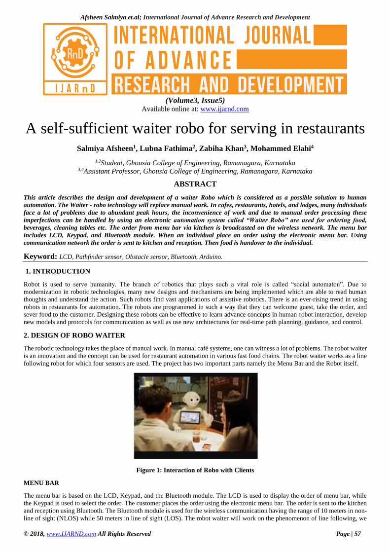
The robotic technology takes the place of manual work. In manual café systems, one can witness a lot of problems. The robot waiter
is an innovation and the concept can be used for restaurant automation in various fast food chains. The robot waiter works as a line
following robot for which four sensors are used. The project has two important parts namely the Menu Bar and the Robot itself.
Figure 1: Interaction of Robo with Clients
MENU BAR
The menu bar is based on the LCD, Keypad, and the Bluetooth module. The LCD is used to display the order of menu bar, while
the Keypad is used to select the order. The customer places the order using the electronic menu bar. The order is sent to the kitchen
and reception using Bluetooth. The Bluetooth module is used for the wireless communication having the range of 10 meters in non-
line of sight (NLOS) while 50 meters in line of sight (LOS). The robot waiter will work on the phenomenon of line following, we
Afsheen Salmiya et.al; International Journal of Advance Research and Development
© 2018, www.IJARND.com All Rights Reserved Page | 58
have used four IR sensors; the two sensors in the centre are used for line following and set the robot waiter on line, The other two
sensors installed on sides are used for table counting, i.e. if the robot count one, it means that it has stopped on the first table, and if
the robot count two, the robot has stopped on the second table for 20 seconds and so on. The command to stop at the table number
is sent to the robot wirelessly from the kitchen using WLAN wireless transmitter. This is because the range of WLAN is higher as
compared to Bluetooth.
Here IR sensors are used as a feedback element to keep the robot tracking the line. Once all sensors are “ON” for the first time, the
controller waits for the RF command. If the command is for table 1, then the microcontroller follows these instructions:
If all sensors status is “ON” for the second time, then wait for 20 seconds.
After 20 seconds, a motor “ON” command is sent till all sensors are “ON” the fourth time, same as for table number.
In case, when the second sensor is “ON” and the third sensor is in “OFF” condition, the microcontroller sends a command
to motor 2 “ON” and motor 1 “OFF” in order to follow the line.
Similarly, in other cases, the second sensor is “OFF” and third is “ON”. So, in this way, we control the robot on track line and
accuracy is also improved.
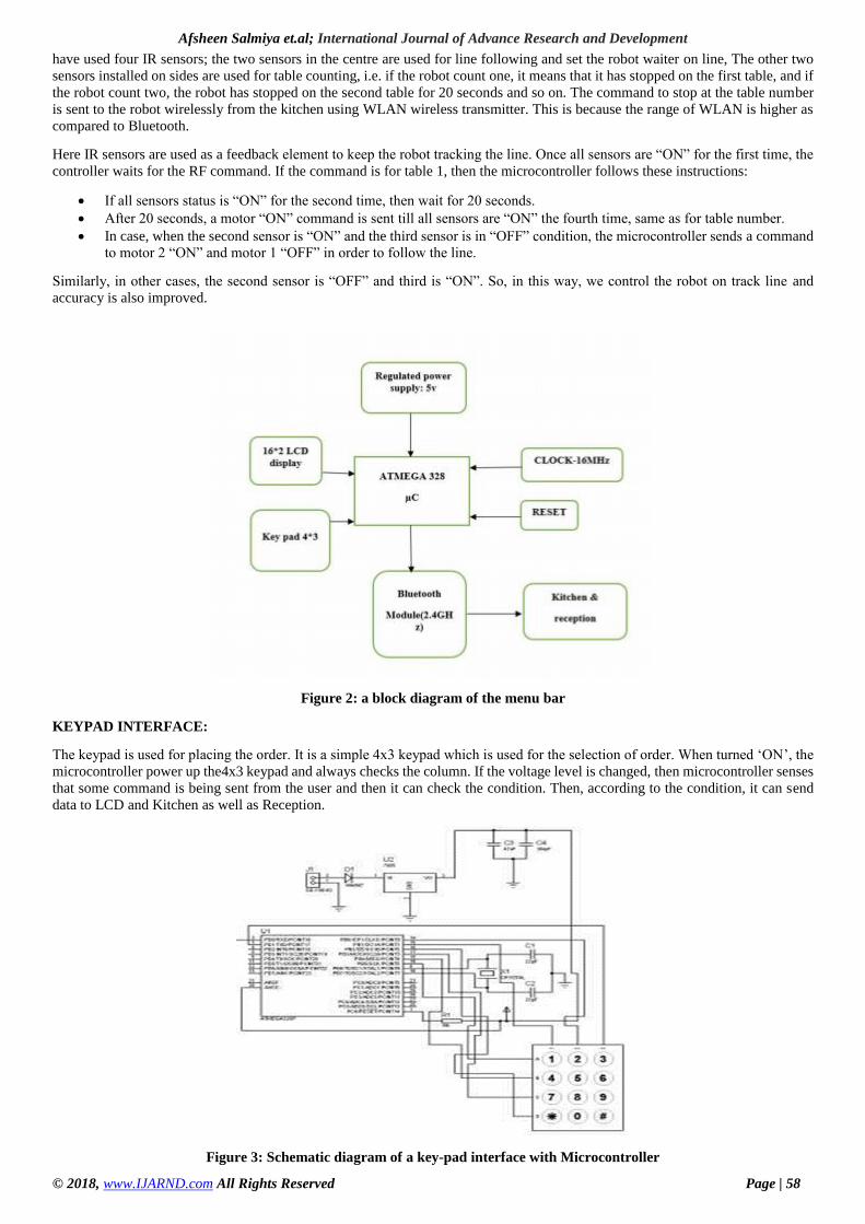
Figure 2: a block diagram of the menu bar
KEYPAD INTERFACE:
The keypad is used for placing the order. It is a simple 4x3 keypad which is used for the selection of order. When turned ‘ON’, the
microcontroller power up the4x3 keypad and always checks the column. If the voltage level is changed, then microcontroller senses
that some command is being sent from the user and then it can check the condition. Then, according to the condition, it can send
data to LCD and Kitchen as well as Reception.
Figure 3: Schematic diagram of a key-pad interface with Microcontroller
Afsheen Salmiya et.al; International Journal of Advance Research and Development
© 2018, www.IJARND.com All Rights Reserved Page | 59
LCD INTERFACE:
The Interface of LCD with the keypad so that the customer can see his order. The R/W (read/write) pin of the LCD is used to display
messages. If the microcontroller sends ‘0’ to the R/W pin then it is in “read mode” used to read characters from the LCD. However,
if the microcontroller sends ‘1’ to that pin it is in “write mode”. Since the LCD is used to display the order which the customer
wants, we only require write mode by displaying the order to the customer when he is typing keys.
The LCD has 16 columns and two rows and is monochrome display. The LCD used in the menu bar is 16×2. We use only 4 pins
of the LCD for data receiving. So, there is a variable resistor placed for the control of the brightness of the LCD. This LCD has pins
and schematic diagram are shown in Figure 4.
Figure 4: LCD Interface
BLUETOOTH INTERFACE:
Bluetooth module (HC-06) contain 4 pins namely power (Vcc), ground (GND), Rx (receiving) and the Tx (transmitting) pin. In this
circuit, we use crystal frequency of 16MHz for heart beat signal according to their basic requirement. We have used the Bluetooth
module as a wireless communication device for the communication between the Reception, kitchen and Menu Bar. The Bluetooth
module transfers data from the table to reception & kitchen at a baud rate of 9600 bps. The customer selects the order, the order
transfer wirelessly via Bluetooth to the kitchen and reception.
VOLTAGE REGULATOR:
The voltage regulator provides the voltage levels according to our need for this project, we require two regulators; the First regulator
can regulate +5V and other provides 3.3V. The +5V regulator used for the supply of a microcontroller and the second one with 3.3V
regulated output is used for supply to the X-BEE module. For +5V regulator, we use LM 7805 and for 3.3V we used LF 33 regulator.
3. CONTROLLER UNIT (ATMEGA328)
1) ARDUINO
Arduino Uno is a microcontroller board based on the ATmega328P. It has 14 digital input/output pins (of which 6 can be used as
PWM outputs), 6 analog inputs, a 16 MHz quartz crystal, a USB connection, a power jack, an ICSP header and a reset button. It
contains everything needed to support the microcontroller; simply connect it to a computer with a USB cable or power it with an
AC-to-DC adapter or battery to get started.
Microcontroller
Figure 5(a): Arduino Uno board Pin description
Afsheen Salmiya et.al; International Journal of Advance Research and Development
© 2018, www.IJARND.com All Rights Reserved Page | 60
2) ATMEGA328 MEMORY:
N Flash (32K) (15-bit addresses)
Program memory – read-only
Non-volatile
Allocate data to Flash using PROGMEM keyword
SRAM (2K)
Temporary values, stack, etc.
Volatile
Limited space! EEPROM (1K) Long-term data
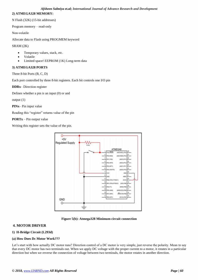
3) ATMEGA328 PORTS
Three 8-bit Ports (B, C, D)
Each port controlled by three 8-bit registers. Each bit controls one I/O pin
DDRx– Direction register
Defines whether a pin is an input (0) or and
output (1)
PINx– Pin input value
Reading this “register” returns value of the pin
PORTx – Pin output value
Writing this register sets the value of the pin.
Figure 5(b): Atmega328 Minimum circuit connection
4. MOTOR DRIVER
1) H-Bridge Circuit (L293d)
(a) How Does Dc Motor Work???
Let’s start with how actually DC motor runs? Direction control of a DC motor is very simple, just reverse the polarity. Mean to say
that every DC motor has two terminals out. When we apply DC voltage with the proper current to a motor, it rotates in a particular
direction but when we reverse the connection of voltage between two terminals, the motor rotates in another direction.
Afsheen Salmiya et.al; International Journal of Advance Research and Development
© 2018, www.IJARND.com All Rights Reserved Page | 61
Figure 6(a): working of DC motor
(b) Controlling Using Micro-Controllers!!!
I think you are now familiar how to change the direction of DC motor. Now let us consider how to control motor using
Microcontroller provided:
The microcontroller provides us only digital logic (1 or a 0).
We can’t provide polarity from microcontroller Digital I/O.
We can’t connect motors to Controller as mostly motors run on voltage level more than +5V, and motors demand high
current (depends).
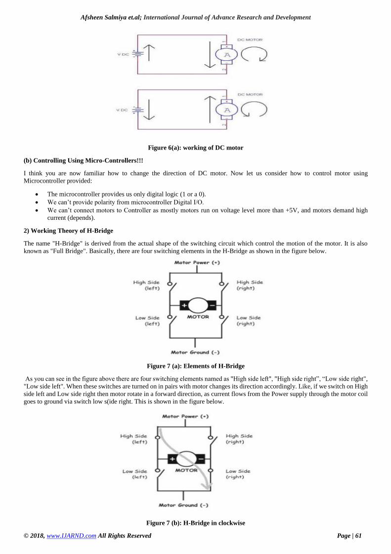
2) Working Theory of H-Bridge
The name "H-Bridge" is derived from the actual shape of the switching circuit which control the motion of the motor. It is also
known as "Full Bridge". Basically, there are four switching elements in the H-Bridge as shown in the figure below.
Figure 7 (a): Elements of H-Bridge
As you can see in the figure above there are four switching elements named as "High side left", "High side right”, “Low side right",
"Low side left". When these switches are turned on in pairs with motor changes its direction accordingly. Like, if we switch on High
side left and Low side right then motor rotate in a forward direction, as current flows from the Power supply through the motor coil
goes to ground via switch low s(ide right. This is shown in the figure below.
Figure 7 (b): H-Bridge in clockwise
Afsheen Salmiya et.al; International Journal of Advance Research and Development
© 2018, www.IJARND.com All Rights Reserved Page | 62
Similarly, if we switch on the High side right and Low side left then motor rotate in reverse direction, as current flows from the
Power supply through the motor coil goes to ground via switch low side left. This is shown in the figure below.
Figure 7 (c): H-Bridge in Anticlockwise
H-Bridge is a special circuit which allows motor rotation in both directions. From four terminals of H-bridge, you can control the
direction of a DC motor. Using L293D Dual H-Bridge Depending on current & power requirements, we can make our own H-bridge
using transistors/MOSFETs but it will be better to demonstrate the working if we use some readymade IC such as L293D, it’s a
dual half H-bridge IC. We can drive a maximum of two DC motor and one stepper motor using one L293D.
Figure 8 (d): H-Bridge motor connected to the controller
Decision Table will look like
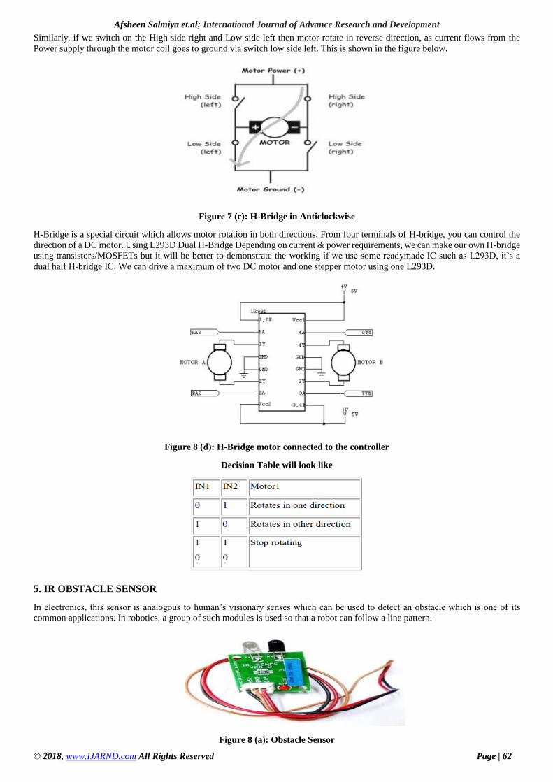
5. IR OBSTACLE SENSOR
In electronics, this sensor is analogous to human’s visionary senses which can be used to detect an obstacle which is one of its
common applications. In robotics, a group of such modules is used so that a robot can follow a line pattern.
Figure 8 (a): Obstacle Sensor
Afsheen Salmiya et.al; International Journal of Advance Research and Development
© 2018, www.IJARND.com All Rights Reserved Page | 63
Working Mechanism
An IR sensor is basically a device which consists of a pair of an IR LED and a photodiode which is collectively called a photo-
coupler or an optocoupler. The IR LED emits IR radiation, reception and/or intensity of reception of which by the photodiode
dictates the output of the sensor.
Now, there are so many ways by which the radiation may or may not be able to reach the photodiode. Let’s discuss a few.
Direct incidence
We may hold the IR LED directly in front of the photodiode, such that almost all the radiation emitted, reaches the photodiode. This
creates an invisible line of IR radiation between the IR LED and the photodiode. Now, if an opaque object is placed obstructing this
line, the radiation will not reach the photodiode and will get either reflected or absorbed by the obstructing object. This mechanism
is used in object counters and burglar alarms.
Indirect Incidence
High school physics taught us that black color absorbs all radiation, and the color white reflects all radiation. We use this very
knowledge to build our IR sensor. If we place the IR LED and the photodiode side by side, close together, the radiation from the IR
LED will get emitted straight in the direction to which the IR LED is pointing towards, and so is the photodiode, and hence there
will be no incidence of the radiation on the photodiode. Please refer to the right part of the illustration given below for better
understanding. But, if we place an opaque object in front of the two, two cases occur:
Reflective Surface
If the object is reflective, (White or some other light color), then most of the radiation will get reflected by it and will get incident
on the photodiode. For further understanding, please refer to the left part of the illustration below.
Non-reflective Surface
If the object is non-reflective, (Black or some other dark color), then most of the radiation will get absorbed by it, and will not
become incident on the photodiode. It is similar to there being no surface (object) at all, for the sensor, as in both the cases, it does
not receive any radiation.
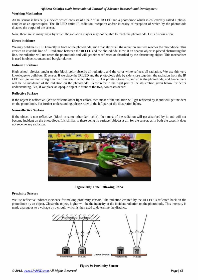
Figure 8(b): Line Following Robo
Proximity Sensors
We use reflective indirect incidence for making proximity sensors. The radiation emitted by the IR LED is reflected back on the
photodiode by an object. Closer the object, higher will be the intensity of the incident radiation on the photodiode. This intensity is
made analogous to a voltage by a circuit, which is then used to determine the distance.
Figure 9: Proximity Sensor
Afsheen Salmiya et.al; International Journal of Advance Research and Development
© 2018, www.IJARND.com All Rights Reserved Page | 64
Proximity sensors find use in Touch Screen phones, apart from many other devices. In a Touch Screen Phone, the touch screen
needs to disable when it is held near the ear, while in use, so that even if the cheek makes contact with the tough screen, there is no
effect.
6. ADVANTAGES & DISADVANTAGES
(a) Advantages
Effective and efficient work as we are using robots.
Reduces customer waiting time. One time investment in the system.
Work can be faster and may reduce the cost of laboring.
(b) Disadvantages
Cost of maintenance is high for robots.
7. APPLICATION AND IMPROVEMENTS
APPLICATION
Hotel Robo is used for delivering food, drinks, to the respective tables and rooms.
It is also used for room service.
It reduces the customers waiting time.
IMPROVEMENTS
Further, it can be implemented for cooking in restaurants.
Carrying luggage from one place to another of customers of restaurants.
Implemented as staff in hospitals.
In Industries as labor to pick the objects and place in its destination.
It can be used as a maid in houses for servicing the elder persons.
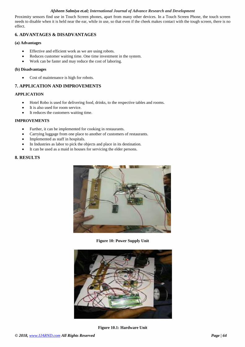
8. RESULTS
Figure 10: Power Supply Unit
Figure 10.1: Hardware Unit
Afsheen Salmiya et.al; International Journal of Advance Research and Development
© 2018, www.IJARND.com All Rights Reserved Page | 65
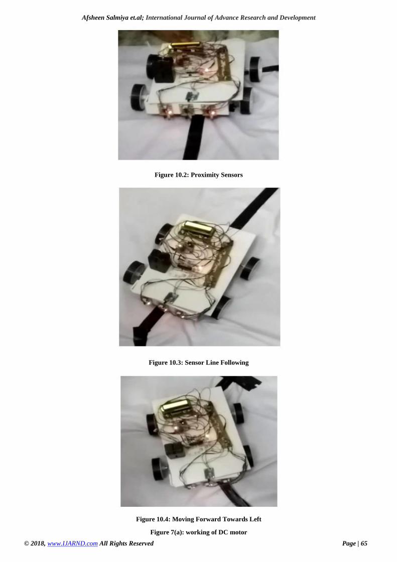
Figure 10.2: Proximity Sensors
Figure 10.3: Sensor Line Following
Figure 10.4: Moving Forward Towards Left
Figure 7(a): working of DC motor
Afsheen Salmiya et.al; International Journal of Advance Research and Development
© 2018, www.IJARND.com All Rights Reserved Page | 66
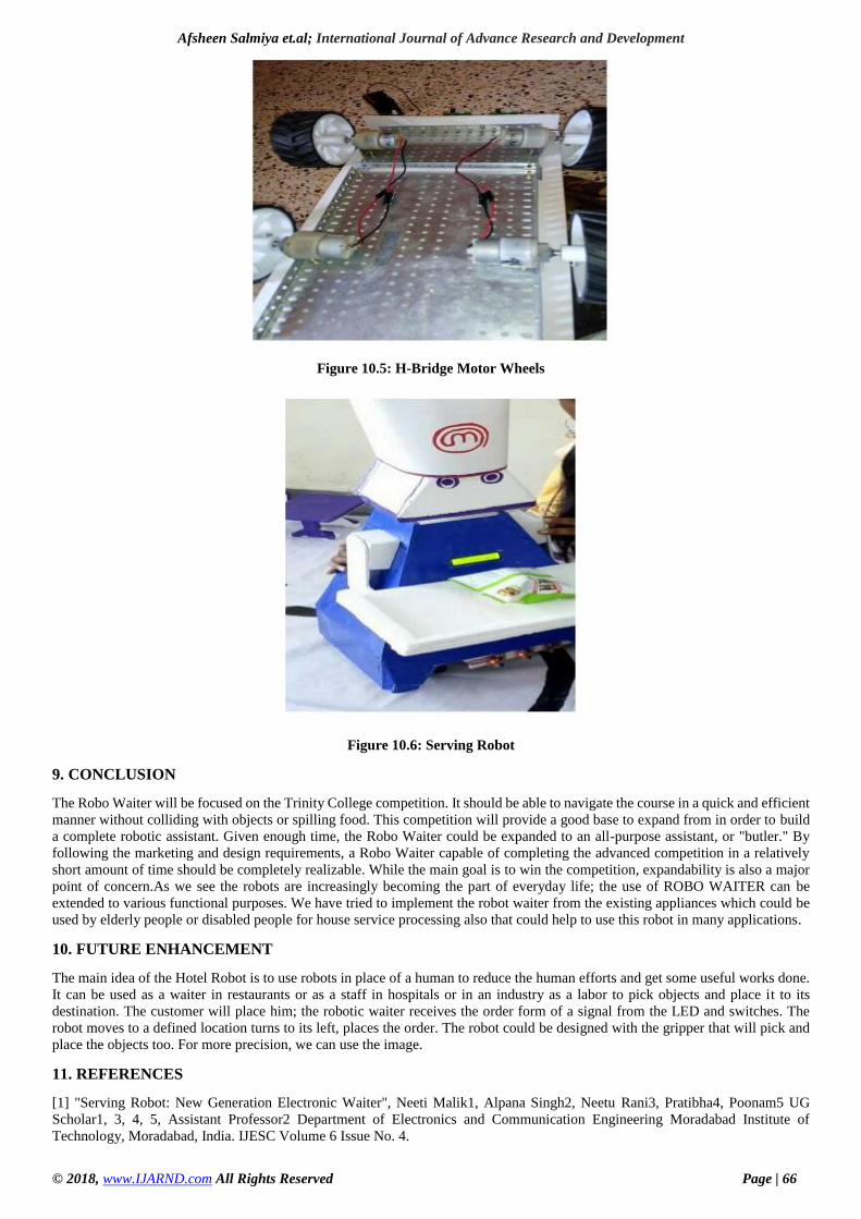
Figure 10.5: H-Bridge Motor Wheels
Figure 10.6: Serving Robot
9. CONCLUSION
The Robo Waiter will be focused on the Trinity College competition. It should be able to navigate the course in a quick and efficient
manner without colliding with objects or spilling food. This competition will provide a good base to expand from in order to build
a complete robotic assistant. Given enough time, the Robo Waiter could be expanded to an all-purpose assistant, or "butler." By
following the marketing and design requirements, a Robo Waiter capable of completing the advanced competition in a relatively
short amount of time should be completely realizable. While the main goal is to win the competition, expandability is also a major
point of concern.As we see the robots are increasingly becoming the part of everyday life; the use of ROBO WAITER can be
extended to various functional purposes. We have tried to implement the robot waiter from the existing appliances which could be
used by elderly people or disabled people for house service processing also that could help to use this robot in many applications.
10. FUTURE ENHANCEMENT
The main idea of the Hotel Robot is to use robots in place of a human to reduce the human efforts and get some useful works done.
It can be used as a waiter in restaurants or as a staff in hospitals or in an industry as a labor to pick objects and place it to its
destination. The customer will place him; the robotic waiter receives the order form of a signal from the LED and switches. The
robot moves to a defined location turns to its left, places the order. The robot could be designed with the gripper that will pick and
place the objects too. For more precision, we can use the image.
11. REFERENCES
[1] "Serving Robot: New Generation Electronic Waiter", Neeti Malik1, Alpana Singh2, Neetu Rani3, Pratibha4, Poonam5 UG
Scholar1, 3, 4, 5, Assistant Professor2 Department of Electronics and Communication Engineering Moradabad Institute of
Technology, Moradabad, India. IJESC Volume 6 Issue No. 4.
Afsheen Salmiya et.al; International Journal of Advance Research and Development
© 2018, www.IJARND.com All Rights Reserved Page | 67
[2] "A Hotel Assistant System Using Mobile Robots", Joaquin Lopez, Diego Perez, International Journal of Advanced Robotic
Systems, 2013.
[3] "Waiter Robot- Solution to Restaurant Automation", M. Asif, M. Sabeen, Dept. of Electrical Engineering, Riphah International
University Islamabad, MDSRC-2015.
[4] "Design of a Remote-controlled and GPS-guided Autonomous Robot for Precision Farming", Llker Unal, Mehmet Topakci,
International Journal of Advanced Robotic System, 2015
[5] "Military Robotics: Latest Trends and Spatial Grasp Solutions", Peter Simon, Sapaty, Institute of Mathematical Machines and
Systems, 2015.
[6] "ROBOT AS A WAITER FOR RESTAURANTS", Akshay Agarwal, Pradeep Gupta, Faisal Iqbal, Amit Kumar, Abdullah
Madani UG Scholar, Assistant Professor Department of Electronics and Communication Engineering Moradabad Institute of
Technology, Moradabad-244001 Uttar Pradesh, India, International Journal of Scientific Research and Management Studies
(IJSRMS) ISSN: 2349-3771 Volume 3 Issue 7, pg: 271-274.
[7] "An autonomous robot for waiter service in restaurants", Mohd. Abdullah Omair, Md. Amir Khan, Dept. of EEE, BRAC
University, Dhaka, Bangladesh, SPRING 2015
[8] "AUTOMATED FOOD ATTENDANCE ROBOT", Nur Izzati Binti Abdullah, Dept. of EEE, University Malaysia Pahang,
November 2017.
[9] "Robots in Hospitality and Tourism: A Research Agenda", Jamie Murphy, Charles, The Australian School of Management perth,
Australia.
[10] "Smart Floor Cleaning Robot (CLEAR)", Uman Khalid, Muhammad Faizan Baloch, Dept. of Electronics Engineering, Institute
of Engineering Science and Technology, 2015
[11] R. C. Hibbeler, Engineering Mechanics Dynamics, Upper Saddle River: Pearson Prentice Hall, 2010.
[12] K. Severinson-Eklundh, A. Green, and H.Hüttenrauch, "Social and collaborative aspects of interaction with a service robot,"
Robotics and autonomous systems, vol. 42, pp.223-234, 2003.
[13] S. Pieskä, M. Luimula, J. Jauhiainen, and V. Spiz, "Social service robots in public and private environments," Recent
Researches in Circuits, Systems, Multimedia and Automatic Control, pp. 190-196, 2012.
[14] C. Jayawardena, I. H. Kuo, U. Unger, A. Igic, R. Wong, C. I. Watson, et al., "Deployment of a service robot to help older
people," in intelligent robots and Systems (IROS), 2010 IEEE/RSJ International Conference on,2010, pp. 5990-5995.
[15] K. Dautenhahn, S. Woods, C. Kaouri, M.L. Walters, K. L. Koay, and I. Werry, "What is a robot companion-friend, assistant or
butler?," in intelligent robots and Systems, 2005.(IROS 2005). 2005 IEEE/RSJ International Conference on, 2005, pp. 1192-1197.
[16] S. Pieskä, M. Luimula, J. Jauhiainen, and V. Spitz, "Social Service Robots in Wellness and Restaurant Applications," Journal
of communication and Computer, vol.10, pp. 116-123, 2013. B. A. Maxwell, L. A. Meeden, N. Addo, L. Brown, P. Dickson, J. Ng,
et al., "Alfred: The robot waiter who remembers you," in Proceedings of AAAI workshop on robotics, 1999.
[17] T. Lozano-Perez, I. J. Cox, and G. T. Wilfong, Autonomous robot vehicles: Springer Science & Business Media, 2012.
[18]http://www.nexrobotics.com/index.php?page=shop.product_details&flypage=flypage.tpl&category_id=32&pr
oduct_id=185&option=com_virtuemart&Itemid=45
[19]https://github.com/eyantra/Autonomous_Waiter_Robot_using_Firebird_ATmega2560/blob/master/Documetat
ion/Autonomous_Waiter_Robot.pdf
[20] “http://arduino.cc/en/Tutorial/HomePage
[21] http://www.nex-robotics.com/products/fire-bird-v-robots/fire-bird-v-atmega2560-robotic-research-platform.html
[22] https://github.com/akshar100/eyantra-firebird-
[23] https://decibel.ni.com/content/docs/DOC-30926
[24] http://www.iosrjournals.org/iosr-jeee/Papers/Vol6- issue5/L0658084.pdf.
Related Documents