International Research Journal of Engineering and Technology (IRJET) e-ISSN: 2395-0056 Volume: 07 Issue: 12 | Dec 2020 www.irjet.net p-ISSN: 2395-0072 © 2020, IRJET | Impact Factor value: 7.529 | ISO 9001:2008 Certified Journal | Page 1942 A Review on Different Dispersion Management Schemes for DWDM- PON FTTH Systems Shukriya Salim 1 & Saniya Azeem 2 1 M.Tech Student, Department of Electronics and Communication Engineering, TKM College of Engineering, Kollam, Kerala, India 2 Department of Electronics and Communication Engineering, TKM College of Engineering, Kollam, Kerala, India ------------------------------------------------------------------------***------------------------------------------------------------------------- Abstract: Fiber to the Home (FTTH) is a broadband network architecture, used in last mile telecommunication which provides uninterrupted high speed internet services. It is an ultimate fiber access solution where each subscriber is connected to an optical fiber. It promises connection speeds of up to 100 mbps which is of 20 to 100 times as fast as typical cable modem. For fiber deployment, Passive Optical Network (PON) is preferred over Active Optical Network (AON), because PON is very cost effective and demand minimum amount of maintenance. PON uses Wavelength Division Multiplexing (WDM) to realize bi-directional transport on a single fiber. But as the number of users increases WDM is not enough. So Dense Wavelength Division Multiplexing (DWDM) is used. DWDM covers a large territory and can support up to 40 channels at 100 GHz spacing. The achievement of having some high data rate communication schemes in any optical fiber systems used for communication is limited by many elements like non-linear effects, dispersion and attenuation. Out of these, dispersion have most impact on the system. Dispersion occurs when the incoming signal components transmit through optical fiber at various speed and detect in the receiver at various times. It limits the transmission capacity of the system and thereby reduces the bandwidth. Modal, Chromatic and Polarization Mode Dispersion are the three main types of dispersion. Out of these, mostly chromatic dispersion and Polarization mode dispersion occurs in FTTH systems. So there is a need for efficient dispersion management schemes for the best transmission of optical signals through fibers. In this paper, as assessment of different dispersion management techniques used in DWDM-PON FTTH network is done. A comparison between the techniques are drawn and performance matrices such as Q-factor and Bit Error Rate (BER) are evaluated. Keywords: FTTH, DWDM-PON, Q-factor, BER, AON I. INTRODUCTION In recent years there is a rapid increase in technology, because of the demand of high bandwidth from each end users. The optical fiber is the most advanced transmission medium and the only one that is capable of supporting next generation networks and services. The main advantages of having a last mile of optical fiber are many such as greater speed, higher bandwidth, longer distance from the central to the subscriber, resistance to electromagnetic interference, higher security, and reduced signal attenuation. Moreover, the fact of using PON technology assumes the elimination of active components outside the network such as repeaters and optical amplifiers, therefore decreasing the initial investment, reducing power consumption and lesser points of failure. Fiber to the x (FTTX; also spelled "Fibre") or fiber in the loop is a generic term for any broadband network architecture using optical fiber to provide all or part of the local loop used for last mile telecommunications. As fiber optic cables are able to carry much more data than copper cables, especially over long distances [1]. Residential areas already served by balanced pair distribution plant call for a trade-off between cost and capacity. The closer the fiber head, the higher the cost of construction and the higher the channel capacity. In places not served by metallic facilities, little cost is saved by not running fiber to the home. Fiber to the x is the key method used to drive next-generation access (NGA), which describes a significant upgrade to the Broadband available by making a step change in speed and quality of the service. This is typically thought of as asymmetrical with a download speed of 24 Mbit/s plus and a fast upload speed. FTTH (fiber-to-the-home) is a form of fiber-optic communication delivery that reaches one living working space. The fiber extends from the central office to the subscriber's living or working space [2]. Once at the subscriber's living or working space, the signal may be conveyed throughout the space using any means, including twisted pair, coaxial cable, wireless, power line communication, or optical fiber. FTTH provides uninterrupted high-speed internet services and promises connection speeds of up to 100 mbps which is of 20 to 100 times as fast as typical cable modem. Optical fiber cables have virtually unlimited capacity. So FTTH will be able to support broadband demands for the foreseeable future. With FTTH more devices can connect to the internet simultaneously. In addition users can get internet and TV services over the same broadband network connection.

Welcome message from author
This document is posted to help you gain knowledge. Please leave a comment to let me know what you think about it! Share it to your friends and learn new things together.
Transcript

International Research Journal of Engineering and Technology (IRJET) e-ISSN: 2395-0056
Volume: 07 Issue: 12 | Dec 2020 www.irjet.net p-ISSN: 2395-0072
© 2020, IRJET | Impact Factor value: 7.529 | ISO 9001:2008 Certified Journal | Page 1942
A Review on Different Dispersion Management Schemes for DWDM-
PON FTTH Systems
Shukriya Salim1 & Saniya Azeem2
1M.Tech Student, Department of Electronics and Communication Engineering, TKM College of Engineering, Kollam, Kerala, India
2Department of Electronics and Communication Engineering, TKM College of Engineering, Kollam, Kerala, India ------------------------------------------------------------------------***------------------------------------------------------------------------- Abstract: Fiber to the Home (FTTH) is a broadband network architecture, used in last mile telecommunication which provides uninterrupted high speed internet services. It is an ultimate fiber access solution where each subscriber is connected to an optical fiber. It promises connection speeds of up to 100 mbps which is of 20 to 100 times as fast as typical cable modem. For fiber deployment, Passive Optical Network (PON) is preferred over Active Optical Network (AON), because PON is very cost effective and demand minimum amount of maintenance. PON uses Wavelength Division Multiplexing (WDM) to realize bi-directional transport on a single fiber. But as the number of users increases WDM is not enough. So Dense Wavelength Division Multiplexing (DWDM) is used. DWDM covers a large territory and can support up to 40 channels at 100 GHz spacing. The achievement of having some high data rate communication schemes in any optical fiber systems used for communication is limited by many elements like non-linear effects, dispersion and attenuation. Out of these, dispersion have most impact on the system. Dispersion occurs when the incoming signal components transmit through optical fiber at various speed and detect in the receiver at various times. It limits the transmission capacity of the system and thereby reduces the bandwidth. Modal, Chromatic and Polarization Mode Dispersion are the three main types of dispersion. Out of these, mostly chromatic dispersion and Polarization mode dispersion occurs in FTTH systems. So there is a need for efficient dispersion management schemes for the best transmission of optical signals through fibers. In this paper, as assessment of different dispersion management techniques used in DWDM-PON FTTH network is done. A comparison between the techniques are drawn and performance matrices such as Q-factor and Bit Error Rate (BER) are evaluated.
Keywords: FTTH, DWDM-PON, Q-factor, BER, AON
I. INTRODUCTION
In recent years there is a rapid increase in technology, because of the demand of high bandwidth from each end users. The optical fiber is the most advanced transmission medium and the only one that is capable of supporting next generation networks and services. The main advantages of having a last mile of optical fiber are many such as greater speed, higher bandwidth, longer distance from the central to the subscriber, resistance to electromagnetic interference, higher security, and reduced signal attenuation. Moreover, the fact of using PON technology assumes the elimination of active components outside the network such as repeaters and optical amplifiers, therefore decreasing the initial investment, reducing power consumption and lesser points of failure.
Fiber to the x (FTTX; also spelled "Fibre") or fiber in the loop is a generic term for any broadband network architecture using optical fiber to provide all or part of the local loop used for last mile telecommunications. As fiber optic cables are able to carry much more data than copper cables, especially over long distances [1]. Residential areas already served by balanced pair distribution plant call for a trade-off between cost and capacity. The closer the fiber head, the higher the cost of construction and the higher the channel capacity. In places not served by metallic facilities, little cost is saved by not running fiber to the home. Fiber to the x is the key method used to drive next-generation access (NGA), which describes a significant upgrade to the Broadband available by making a step change in speed and quality of the service. This is typically thought of as asymmetrical with a download speed of 24 Mbit/s plus and a fast upload speed.
FTTH (fiber-to-the-home) is a form of fiber-optic communication delivery that reaches one living working space. The fiber extends from the central office to the subscriber's living or working space [2]. Once at the subscriber's living or working space, the signal may be conveyed throughout the space using any means, including twisted pair, coaxial cable, wireless, power line communication, or optical fiber. FTTH provides uninterrupted high-speed internet services and promises connection speeds of up to 100 mbps which is of 20 to 100 times as fast as typical cable modem. Optical fiber cables have virtually unlimited capacity. So FTTH will be able to support broadband demands for the foreseeable future. With FTTH more devices can connect to the internet simultaneously. In addition users can get internet and TV services over the same broadband network connection.
International Research Journal of Engineering and Technology (IRJET) e-ISSN: 2395-0056
Volume: 07 Issue: 12 | Dec 2020 www.irjet.net p-ISSN: 2395-0072
© 2020, IRJET | Impact Factor value: 7.529 | ISO 9001:2008 Certified Journal | Page 1943
II. NETWORK ARCHITECTURES OF FTTH
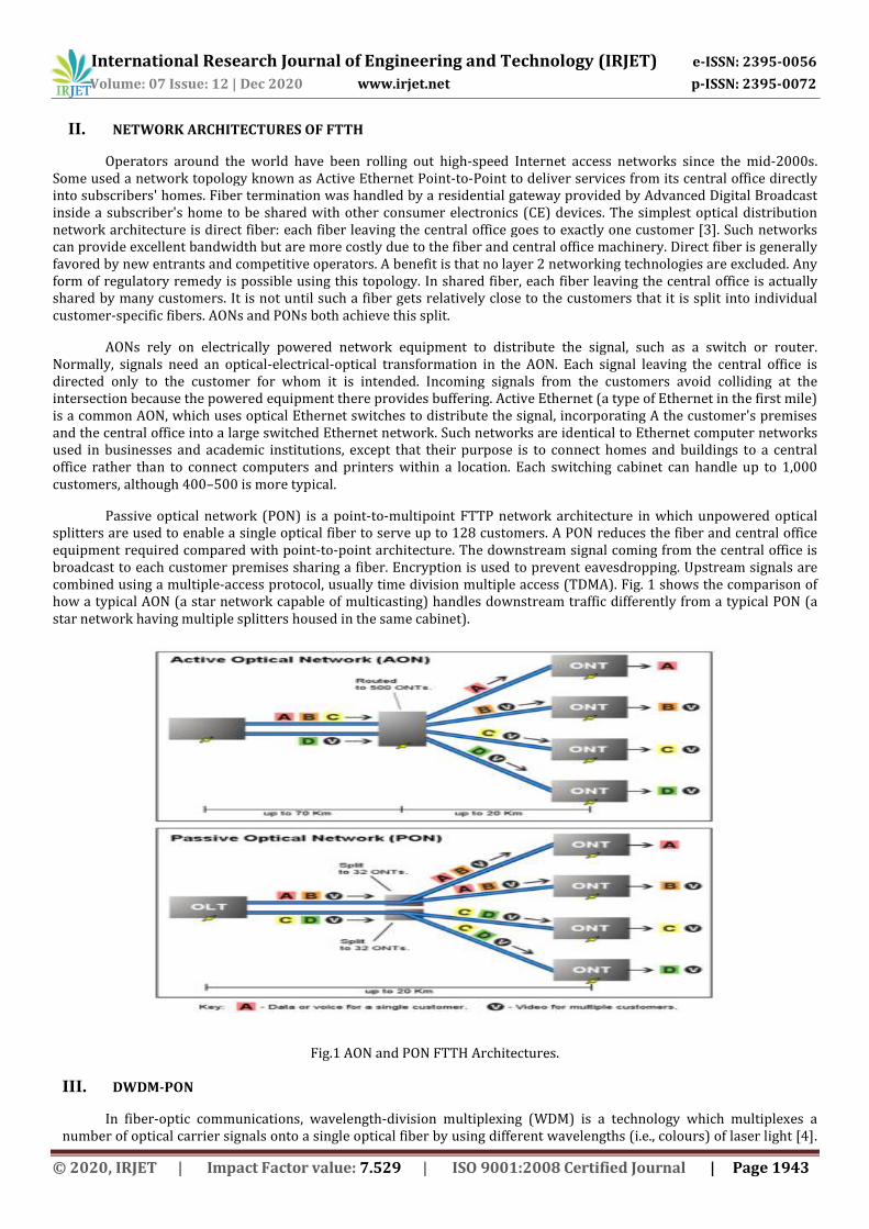
Operators around the world have been rolling out high-speed Internet access networks since the mid-2000s. Some used a network topology known as Active Ethernet Point-to-Point to deliver services from its central office directly into subscribers' homes. Fiber termination was handled by a residential gateway provided by Advanced Digital Broadcast inside a subscriber's home to be shared with other consumer electronics (CE) devices. The simplest optical distribution network architecture is direct fiber: each fiber leaving the central office goes to exactly one customer [3]. Such networks can provide excellent bandwidth but are more costly due to the fiber and central office machinery. Direct fiber is generally favored by new entrants and competitive operators. A benefit is that no layer 2 networking technologies are excluded. Any form of regulatory remedy is possible using this topology. In shared fiber, each fiber leaving the central office is actually shared by many customers. It is not until such a fiber gets relatively close to the customers that it is split into individual customer-specific fibers. AONs and PONs both achieve this split.
AONs rely on electrically powered network equipment to distribute the signal, such as a switch or router. Normally, signals need an optical-electrical-optical transformation in the AON. Each signal leaving the central office is directed only to the customer for whom it is intended. Incoming signals from the customers avoid colliding at the intersection because the powered equipment there provides buffering. Active Ethernet (a type of Ethernet in the first mile) is a common AON, which uses optical Ethernet switches to distribute the signal, incorporating A the customer's premises and the central office into a large switched Ethernet network. Such networks are identical to Ethernet computer networks used in businesses and academic institutions, except that their purpose is to connect homes and buildings to a central office rather than to connect computers and printers within a location. Each switching cabinet can handle up to 1,000 customers, although 400–500 is more typical.
Passive optical network (PON) is a point-to-multipoint FTTP network architecture in which unpowered optical splitters are used to enable a single optical fiber to serve up to 128 customers. A PON reduces the fiber and central office equipment required compared with point-to-point architecture. The downstream signal coming from the central office is broadcast to each customer premises sharing a fiber. Encryption is used to prevent eavesdropping. Upstream signals are combined using a multiple-access protocol, usually time division multiple access (TDMA). Fig. 1 shows the comparison of how a typical AON (a star network capable of multicasting) handles downstream traffic differently from a typical PON (a star network having multiple splitters housed in the same cabinet).
Fig.1 AON and PON FTTH Architectures.
III. DWDM-PON
In fiber-optic communications, wavelength-division multiplexing (WDM) is a technology which multiplexes a number of optical carrier signals onto a single optical fiber by using different wavelengths (i.e., colours) of laser light [4].
International Research Journal of Engineering and Technology (IRJET) e-ISSN: 2395-0056
Volume: 07 Issue: 12 | Dec 2020 www.irjet.net p-ISSN: 2395-0072
© 2020, IRJET | Impact Factor value: 7.529 | ISO 9001:2008 Certified Journal | Page 1944
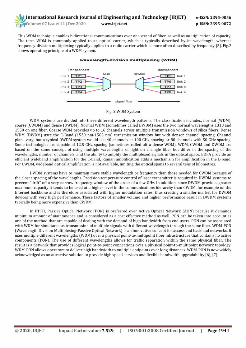
This WDM technique enables bidirectional communications over one strand of fiber, as well as multiplication of capacity. The term WDM is commonly applied to an optical carrier, which is typically described by its wavelength, whereas frequency-division multiplexing typically applies to a radio carrier which is more often described by frequency [5]. Fig.2 shows operating principle of a WDM system.
Fig. 2 WDM System
WDM systems are divided into three different wavelength patterns. The classification includes, normal (WDM), coarse (CWDM) and dense (DWDM). Normal WDM (sometimes called BWDM) uses the two normal wavelengths 1310 and 1550 on one fiber. Coarse WDM provides up to 16 channels across multiple transmission windows of silica fibers. Dense WDM (DWDM) uses the C-Band (1530 nm-1565 nm) transmission window but with denser channel spacing. Channel plans vary, but a typical DWDM system would use 40 channels at 100 GHz spacing or 80 channels with 50 GHz spacing. Some technologies are capable of 12.5 GHz spacing (sometimes called ultra-dense WDM). WDM, CWDM and DWDM are based on the same concept of using multiple wavelengths of light on a single fiber but differ in the spacing of the wavelengths, number of channels, and the ability to amplify the multiplexed signals in the optical space. EDFA provide an efficient wideband amplification for the C-band, Raman amplification adds a mechanism for amplification in the L-band. For CWDM, wideband optical amplification is not available, limiting the optical spans to several tens of kilometres.
DWDM systems have to maintain more stable wavelength or frequency than those needed for CWDM because of the closer spacing of the wavelengths. Precision temperature control of laser transmitter is required in DWDM systems to prevent "drift" off a very narrow frequency window of the order of a few GHz. In addition, since DWDM provides greater maximum capacity it tends to be used at a higher level in the communications hierarchy than CWDM, for example on the Internet backbone and is therefore associated with higher modulation rates, thus creating a smaller market for DWDM devices with very high performance. These factors of smaller volume and higher performance result in DWDM systems typically being more expensive than CWDM.
In FTTH, Passive Optical Network (PON) is preferred over Active Optical Network (AON) because it demands minimum amount of maintanence and is considered as a cost effective method as well. PON can be taken into account as one of the method that are capable of dealing with the demand of high bandwidth from end users. PON can be associated with WDM for simultaneous transmission of multiple signals with different wavelength through the same fiber. WDM-PON (Wavelength Division Multiplexing-Passive Optical Network) is an innovative concept for access and backhaul networks. It uses multiple different wavelengths (WDM) over a physical point-to-multipoint fiber infrastructure that contains no active components (PON). The use of different wavelengths allows for traffic separation within the same physical fiber. The result is a network that provides logical point-to-point connections over a physical point-to-multipoint network topology. WDM-PON allows operators to deliver high bandwidth to multiple endpoints over long distances. WDM-PON is now widely acknowledged as an attractive solution to provide high speed services and flexible bandwidth upgradability [6], [7].

International Research Journal of Engineering and Technology (IRJET) e-ISSN: 2395-0056
Volume: 07 Issue: 12 | Dec 2020 www.irjet.net p-ISSN: 2395-0072
© 2020, IRJET | Impact Factor value: 7.529 | ISO 9001:2008 Certified Journal | Page 1945
Fig. 3 DWDM – PON System
To further improve the system capacity and support more subscribers in the future dense wavelength-division multiplexing passive optical network (DWDM-PON), the number of wavelengths should be increased. Thus reducing the channel spacing from currently available 100/50 GHz to 25 GHz is desirable [8]–[10]. Thus DWDM-PON can cover a large territory and can serve up to 128 customers through a single channel.
DWDM-PON is a fascinating resolution to please the worldwide rising needs for transmission capability in spite, of are badly restricted by dispersion. Dispersion limits the transmission capacity and thereby reduces bandwidth of the channel.
IV. DISPERSION IN FTTH
Dispersion is the spreading of the signal over time. It represents a broad class of phenomena related to the fact that the velocity of the electromagnetic wave depends on the wavelength. In telecommunication the term of dispersion is used to describe the processes which cause that the signal carried by the electromagnetic wave and propagating in an optical fiber is degraded as a result of the dispersion phenomena. This degradation occurs because the different components of radiation having different frequencies propagate with different velocities [11].
Fig. 4 Effects of Dispersion
Types of Dispersion
Dispersion shortens the distance that the signal travels inside the fiber and defame the signal at the receiver. It can be classified into three main types.
Modal Dispersion Chromatic Dispersion Polarization mode Dispersion
Modal dispersion is a distortion mechanism occurring in multimode fibers and other waveguides, in which the signal is spread in time because the propagation velocity of the optical signal is not the same for all modes. Modal dispersion limits the bandwidth of multimode fibers. For example, a typical step-index fiber with a 50 μm core would be limited to approximately 20 MHz for a one kilometer length, in other words, a bandwidth of 20 MHz·km. Modal dispersion
International Research Journal of Engineering and Technology (IRJET) e-ISSN: 2395-0056
Volume: 07 Issue: 12 | Dec 2020 www.irjet.net p-ISSN: 2395-0072
© 2020, IRJET | Impact Factor value: 7.529 | ISO 9001:2008 Certified Journal | Page 1946
may be considerably reduced, but never completely eliminated, by the use of a core having a graded refractive index profile. However, multimode graded-index fibers having bandwidths exceeding 3.5 GHz·km at 850 nm are now commonly manufactured for use in 10 Gbit/s data links. Modal dispersion occurs even with an ideal, monochromatic light source.
Chromatic dispersion is the term given to the phenomenon by which different spectral components of a pulse travel at different velocities. Chromatic dispersion arises for two reasons. The first reason is that the refractive index of silica, the material used to make optical fiber, is frequency dependent. Thus different frequency components travel at different speeds in silica. This component of chromatic dispersion is called material dispersion. Although material dispersion is the principle component of chromatic dispersion for most fibers, there is a second component, called waveguide dispersion. To understand the physical origin of waveguide dispersion, we need to know that the light energy of a mode propagates partly in the core and partly in the cladding. Also that the effective index of a mode lies between the refractive indices of the cladding and the core. The actual value of the effective index between these two limits depends on the proportion of power that is contained in the cladding and the core. If most of the power is contained in the core, the effective index is closer to the core refractive index; if most of it propagates in the cladding, the effective index is closer to the cladding refractive index.
A special case of modal dispersion is polarization mode dispersion (PMD), a fiber dispersion phenomenon usually associated with single-mode fibers. PMD results when two modes that normally travel at the same speed due to fiber core geometric and stress symmetry (for example, two orthogonal polarizations in a waveguide of circular or square cross-section), travel at different speeds due to random imperfections that break the symmetry. PMD represents the polarization dependence of the propagation characteristics of light waves in optical fiber.
In this review work, different dispersion management schemes for efficient transmission of data through optical fiber cables in FTTH systems have been reviewed. The basic working principle, advantages, disadvantages, and comparison between the techniques are also discussed.
V. DISPERSION MANAGEMENT SCHEMES
Various works related to dispersion management schemes in optical fiber communication system suitable for FTTH systems from year 2009 till date has been included in this section. The basic working principle of these schemes and corresponding outputs have been discussed below.
Dochhan et al [12] proposed a system with FBG dispersion compensation in a 43 Gbit/s WDM system by comparing different FBG types and modulation formats. In this paper, a 5 channel WDM transmission system with 100 GHz channel spacing at 43 Gbit/s over up to 20 spans of 80 km standard single mode fiber (SSMF) is performed. The types of FBG’s used here are: Channelized FBG and Broadband FBG. Channelized FBGs have a spectral range of 100 GHz and offers individual pass bands with piecewise linear group delay. While broadband FBGs offer linear group delay over the whole C- band. The modulation formats includes NRZ-ASK, DPSK with NRZ and return-to-zero (RZ) pulse shape and Optical Duo Binary (ODB). NRZ-ASK acts as reference, while other formats are taken into account as possible upgrade options. The input power is varied from -3 to 3 dBm. Dispersion compensation FBGs are applied after each span. The FBGs phase and frequency responses are extracted from group delay and insertion loss measurements. At the receiver side, the five WDM channels are demultipluxed and the residual dispersion is optimized by the evaluation of the eye opening for the central channel. OSNR and different modulation formats are compared. It is found out that for channelized FBG, ODB performs best due to its narrow bandwidth. With the use of a broadband FBG, DPSK shows the best results, while ODB is comparable to NRZ-ASK. Also DPSK is less sensitive to sinusoidal phase ripples than other formats and more tolerant towards fiber non-linearities. This explains good results in a system with interaction of non-linearities and concludes that system with FBG dispersion compensation strongly depends on FBG type.
In a work by Kumar et. al. [13], performance analysis of an optical communication system of wavelength 1550nm, with and without FBG for dispersion compensation is done in Optisystem Software. A basic single channel system using EDFA at a bit rate of 10 Gbit/sec with an input power of 5 dBm and fiber length of 15 km is designed with and without using FBG. Dispersion compensation using FBG is done at the receiver side after amplification. Fiber Bragg gratings act like tiny mirrors in a fiber that reflect specific wavelengths due to periodic changes in the index of the fiber core. Good eye opening is obtained when FBG is used. The simulated transmission system have been analyzed on the basis of different parameters such as input power (dBm), fiber cable length (km), FBG Length (mm) and attenuation coefficient (dB/km). Output power (dBm), noise figure (dB), gain (dB) and Q-Factor (dB) are measured. From the simulation result it is found out that the input power, cable length and attenuation constant are directly proportional to noise figure, output power, and gain. Also the Q-factor are getting decreased with increase in fiber length and attenuation coefficient. Increasing FBG length result in decrease in gain and Q-factor with increase in output power.
International Research Journal of Engineering and Technology (IRJET) e-ISSN: 2395-0056
Volume: 07 Issue: 12 | Dec 2020 www.irjet.net p-ISSN: 2395-0072
© 2020, IRJET | Impact Factor value: 7.529 | ISO 9001:2008 Certified Journal | Page 1947
U.N Charles et al. [14] simulated a two channel WDM optical communication system with single mode fiber over long haul of 100 km to investigate the effect of Self Phase Modulation (SPM), Cross Phase Modulation (XPM) and Four Wave Mixing (FWM). SPM occurs when an intensity modulated signal travels through a fiber. XPM arises from intensity fluctuations from other channels present in a WDM system. FWM is a third order non-linearity caused by the non-linear refractive index of the fiber. More dispersion means less FWM. It is observed that XPM effect causes serious distortion in the signal, whereas in FWM effect, high improvement of Q factor is seen at the expense of eye opening, due to generation of new signal at a cost of power. It is concluded that FWM nonlinear effect is more advantageous and effective as compared to SPM and XPM. FWM is also harmful for WDM systems since it leads to interchannel crosstalk and the dispersion management technique is often used to suppress it.
In Revathy et.al. [15], performance analysis of an optical communication system of wavelength 1550nm and link length of 27.464km, with and without solitons for dispersion management is done. Here fundamental solitons are generated by sech (τ) pulse shape. This means that the dispersion and non-linearity cancel each other with non-linearity length equal to dispersion length, only when the pulse shape is hyperbolic secant. In the proposed system, hyperbolic secant pulse of power 32.68mW is generated by the optical sech pulse generator at user defined bit rates. The sech pulse is launched into the single mode fiber with an attenuation of 0.2 dB/km and dispersion of 1.17 ps/nm-km. Results show that in the system without soliton, the pulse gets broadened and the power is reduced. Thus it is clear that output gets dispersed after passing through the fiber and degrade the signal. But in the system with soliton parameters, the exact shape of the pulse is maintained. That is undispersed even after passing through a fiber of length 27.464 km. Thus it is concluded that solitons are more suitable for dispersion free high speed long-range communications
In [16], Savitha et al. designed a 4 channel DWDM transmission system each at 10 Gbps and performance of the system is analyzed at different fiber length and different input power. Each channel has a spacing of 0.4 nm wavelength and a 16 bit pattern proceed by zeroes. In solitons, the pulse width must be of small fraction of the bit slot to ensure that the solitons are well separated from each other. Fiber length of range 10 km to 25 km is used in this experiment and the results show that BER increases and Q-factor decreases with increase in fiber length. Optimized BER is obtained as the distance increases with increased input power. Dispersion is managed and noise in the system remain constant throughout the transmission. Stable transmission with improved performance is obtained by using Soliton in the system. Thus dispersion is managed and noise present in the system remain constant throughout the transmission. Also the output power of the system decreases as compared to the input power of each user. Thus it is concluded that the soliton approach of transmission makes the system stable and improves the performance of the system due to high Q-factor, bit error rate and lesser drop in power.
P. Naheeda et. al.[17] designed a 4 channel WDM optical network at 8Gbps with a channel spacing of 200 GHz with dispersion compensation using DCF. DCF is capable of compensating fiber GVD if average optical power is kept low enough that non-linear effect inside the fiber is negligible. The performance of the system is evaluated using the parameters, BER and Q factor, with pre, post and symmetrical compensation techniques using DCF at various link lengths. DCF pre-compensation scheme achieve dispersion compensation by placing the DCF before a conventional single mode fiber, where post compensation scheme achieve dispersion compensation by placing the DCF after the single mode fiber. Symmetrical/mix consists of both pre and post compensation. A comparison of performance of the system with non-return-to-zero (NRZ) and return–to-zero (RZ) modulation format is also done and best performance is obtained with symmetrical compensation. When comparing pre and post compensation, the later shows best performance. The performance of the WDM system is further enhanced when RZ modulation format is used.
In a work by A.F Sayed et. al. [18], a mathematical model is derived where Q-Factor is defined as a function of chromatic dispersion to optimize the parameters of CFBG as a dispersion compensator. Then the proposed model is applied on a certain WDM optical fiber link using Matlab program. On the other hand, the same link is also simulated with opti-system software and the results are compared. Fiber Bragg gratings, where fiber core is modulated with grating planes that contains chirped spaces is termed as chirped fiber Bragg Grating. In this paper, 210 km WDM optical link is simulated with a bit rate of 10 Gigabit/s with 80 mm CFBG for dispersion compensation. Correctness of mathematical model is done by applying it with matlab software and comparing the result with the result of the proposed simulation model. Results show that the proposed mathematical model was almost matched the result from the simulation model and Q-factor was improved by 40% compared to other systems.
E. K Rotich Kipnoo et. al. [19] demonstrated Raman-based, dispersion-managed VCSEL technology for fiber-to-the-hut application. The use of vertical cavity surface emitting lasers (VCSELs) in the fiber-to-the-home (FTTH) flavour for Africa, known as fiber-to-the-hut is investigated. Vertical Cavity Surface Emitting Lasers (VCSEL) offer high bandwidth, single mode operation within C-L bands, wavelength tunabilities and is energy efficient. It is ideal for relatively short distance high speed optical communication networks. A 4.25 Gb/s VCSEL in a dispersion managed, Raman assisted network achieved error free transmission beyond 100 km, which is suited for FTTHut scenario. Negative dispersion Fiber
International Research Journal of Engineering and Technology (IRJET) e-ISSN: 2395-0056
Volume: 07 Issue: 12 | Dec 2020 www.irjet.net p-ISSN: 2395-0072
© 2020, IRJET | Impact Factor value: 7.529 | ISO 9001:2008 Certified Journal | Page 1948
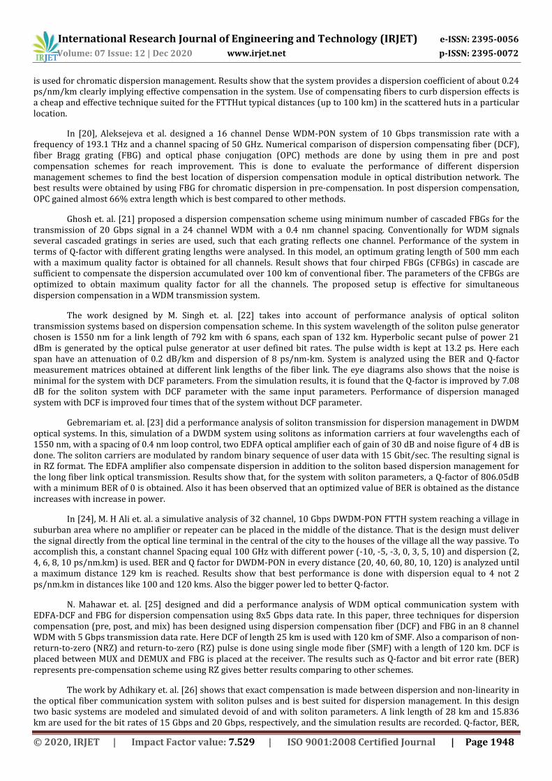
is used for chromatic dispersion management. Results show that the system provides a dispersion coefficient of about 0.24 ps/nm/km clearly implying effective compensation in the system. Use of compensating fibers to curb dispersion effects is a cheap and effective technique suited for the FTTHut typical distances (up to 100 km) in the scattered huts in a particular location.
In [20], Aleksejeva et al. designed a 16 channel Dense WDM-PON system of 10 Gbps transmission rate with a frequency of 193.1 THz and a channel spacing of 50 GHz. Numerical comparison of dispersion compensating fiber (DCF), fiber Bragg grating (FBG) and optical phase conjugation (OPC) methods are done by using them in pre and post compensation schemes for reach improvement. This is done to evaluate the performance of different dispersion management schemes to find the best location of dispersion compensation module in optical distribution network. The best results were obtained by using FBG for chromatic dispersion in pre-compensation. In post dispersion compensation, OPC gained almost 66% extra length which is best compared to other methods.
Ghosh et. al. [21] proposed a dispersion compensation scheme using minimum number of cascaded FBGs for the transmission of 20 Gbps signal in a 24 channel WDM with a 0.4 nm channel spacing. Conventionally for WDM signals several cascaded gratings in series are used, such that each grating reflects one channel. Performance of the system in terms of Q-factor with different grating lengths were analysed. In this model, an optimum grating length of 500 mm each with a maximum quality factor is obtained for all channels. Result shows that four chirped FBGs (CFBGs) in cascade are sufficient to compensate the dispersion accumulated over 100 km of conventional fiber. The parameters of the CFBGs are optimized to obtain maximum quality factor for all the channels. The proposed setup is effective for simultaneous dispersion compensation in a WDM transmission system.
The work designed by M. Singh et. al. [22] takes into account of performance analysis of optical soliton transmission systems based on dispersion compensation scheme. In this system wavelength of the soliton pulse generator chosen is 1550 nm for a link length of 792 km with 6 spans, each span of 132 km. Hyperbolic secant pulse of power 21 dBm is generated by the optical pulse generator at user defined bit rates. The pulse width is kept at 13.2 ps. Here each span have an attenuation of 0.2 dB/km and dispersion of 8 ps/nm-km. System is analyzed using the BER and Q-factor measurement matrices obtained at different link lengths of the fiber link. The eye diagrams also shows that the noise is minimal for the system with DCF parameters. From the simulation results, it is found that the Q-factor is improved by 7.08 dB for the soliton system with DCF parameter with the same input parameters. Performance of dispersion managed system with DCF is improved four times that of the system without DCF parameter.
Gebremariam et. al. [23] did a performance analysis of soliton transmission for dispersion management in DWDM optical systems. In this, simulation of a DWDM system using solitons as information carriers at four wavelengths each of 1550 nm, with a spacing of 0.4 nm loop control, two EDFA optical amplifier each of gain of 30 dB and noise figure of 4 dB is done. The soliton carriers are modulated by random binary sequence of user data with 15 Gbit/sec. The resulting signal is in RZ format. The EDFA amplifier also compensate dispersion in addition to the soliton based dispersion management for the long fiber link optical transmission. Results show that, for the system with soliton parameters, a Q-factor of 806.05dB with a minimum BER of 0 is obtained. Also it has been observed that an optimized value of BER is obtained as the distance increases with increase in power.
In [24], M. H Ali et. al. a simulative analysis of 32 channel, 10 Gbps DWDM-PON FTTH system reaching a village in suburban area where no amplifier or repeater can be placed in the middle of the distance. That is the design must deliver the signal directly from the optical line terminal in the central of the city to the houses of the village all the way passive. To accomplish this, a constant channel Spacing equal 100 GHz with different power (-10, -5, -3, 0, 3, 5, 10) and dispersion (2, 4, 6, 8, 10 ps/nm.km) is used. BER and Q factor for DWDM-PON in every distance (20, 40, 60, 80, 10, 120) is analyzed until a maximum distance 129 km is reached. Results show that best performance is done with dispersion equal to 4 not 2 ps/nm.km in distances like 100 and 120 kms. Also the bigger power led to better Q-factor.
N. Mahawar et. al. [25] designed and did a performance analysis of WDM optical communication system with EDFA-DCF and FBG for dispersion compensation using 8x5 Gbps data rate. In this paper, three techniques for dispersion compensation (pre, post, and mix) has been designed using dispersion compensation fiber (DCF) and FBG in an 8 channel WDM with 5 Gbps transmission data rate. Here DCF of length 25 km is used with 120 km of SMF. Also a comparison of non-return-to-zero (NRZ) and return-to-zero (RZ) pulse is done using single mode fiber (SMF) with a length of 120 km. DCF is placed between MUX and DEMUX and FBG is placed at the receiver. The results such as Q-factor and bit error rate (BER) represents pre-compensation scheme using RZ gives better results comparing to other schemes.
The work by Adhikary et. al. [26] shows that exact compensation is made between dispersion and non-linearity in the optical fiber communication system with soliton pulses and is best suited for dispersion management. In this design two basic systems are modeled and simulated devoid of and with soliton parameters. A link length of 28 km and 15.836 km are used for the bit rates of 15 Gbps and 20 Gbps, respectively, and the simulation results are recorded. Q-factor, BER,
International Research Journal of Engineering and Technology (IRJET) e-ISSN: 2395-0056
Volume: 07 Issue: 12 | Dec 2020 www.irjet.net p-ISSN: 2395-0072
© 2020, IRJET | Impact Factor value: 7.529 | ISO 9001:2008 Certified Journal | Page 1949
eye height, and eye diagram are investigated. In addition, 1310 nm, 1380 nm, 1550 nm, and 1560 nm wavelengths are used for simulation with the soliton system for a bit rates of 15 Gbps and 20 Gbps to investigate the ideal wavelength with improved Q-factor. Results show that 1310 nm wavelength produced the maximum Q-factor for both the bit rate.
VI. DISCUSSIONS
From the analysis it is clear that dispersion management is efficiently done in systems that uses solitons. Solitons can be used to efficiently transmit data without any attenuation for long distance communications. Based on the literature review done the following section includes comparative analysis of different methods based on Q-factor, SNR and BER.
The quality factor is a measure of exactly how noisy a pulse is for problem solving purposes. Q-factor affords a
qualitative explanation of performance of the receiver. Q-factor determines the performance of a communication channel and facilitates system performance analysis. The quality of optical and other measurements is often characterized with a signal-to-noise ratio (SNR, S/N ratio). This is generally understood to be the ratio of the detected powers (not amplitudes), and is often expressed in decibels. The Q-factor recommends the minimum signal-to-noise ratio (SNR) required to obtain a particular bit error rate (BER) for a given signal. It is required higher SNR (dB) ratio to acquire higher bit rate. Bit error rate (BER) is a measure of signal quality received for digital data transmission systems. It is an important parameter to describe the quality of the data link. By means of BER, it is possible to compare the quality of different systems for data transmission. It is defined by the ratio of the number of bits received in error to the total number of bits received in the defined time interval.
Mainly three methods are used for dispersion management in optical fiber communication system. By using DCF,
FBG and solitons, dispersion can be compensated. Each method have its own advantages and disadvantages. Moreover these techniques can improve the Q-factor strongly and improves transmission than that of systems without any dispersion compensation modules.
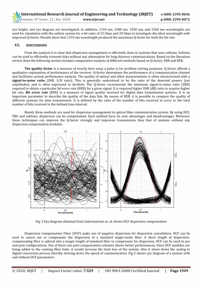
Fig. 5 Eye diagram obtained from Gabremariam et. al. shows DCF dispersion compensation
Dispersion Compensation Fiber (DCF) make use of negative dispersion for dispersion cancellation. DCF can be used to cancel out or compensate the dispersion of a standard single-mode fiber. A short length of dispersion-compensating fiber is spliced into a longer length of standard fiber to compensate for dispersion. DCF can be used in pre and post configurations. Out of these two post compensation schemes shows better performances. Since DCF modules are being added to the existing fiber links, it would increase the total loss of the system. Also it slows down the analog to digital conversion process thereby slowing down the speed of communication. Fig 5 shows eye diagram of a system with and without DCF parameters.

International Research Journal of Engineering and Technology (IRJET) e-ISSN: 2395-0056
Volume: 07 Issue: 12 | Dec 2020 www.irjet.net p-ISSN: 2395-0072
© 2020, IRJET | Impact Factor value: 7.529 | ISO 9001:2008 Certified Journal | Page 1950
Fiber Bragg Gratings (FBG) are reflecting devices, constructed from short segments of optical fiber that reflects particular wavelengths of light and transmits all others. It is achieved by creating a periodic variation in the refractive index of the core. A fiber Bragg grating (FBG) can therefore be used as an inline optical filter to block certain wavelengths, or as a wavelength-specific reflector. The germanium-doped fiber is photosensitive, which means that the refractive index of the core changes with exposure to UV light. The amount of the change depends on the intensity and duration of the exposure as well as the photosensitivity of the fiber. To write a high reflectivity fiber Bragg grating directly in the fiber the level of doping with germanium needs to be high. The main disadvantage of FBG is that its architecture is complex. For multichannel system a number FBGs are needed which will make the system costly. Also by using FBG, the transmitted signal suffers from imperfections in their group delay characteristics, known as group delay ripples (GDRs). Fig 6 shows eye diagram obtained when optical communication systems are designed with and without FBG for dispersion compensation.
Fig. 6 Eye diagram obtained from Kumar et. al. shows FBG dispersion compensation
Solitons are narrow pulses that can retain their shape and preserve their velocity over the entire propagation distance. It is done by the exact balance between non-linearity due to self-phase modulation (SPM) and linear broadening due to group velocity dispersion (GVD). By using soliton transmission we can propagate data without any dispersion. But for transmission of multiple solitons through same system will results in soliton interactions. These are due to equal amplitude of solitons in multi-channel systems. Also there is a high-speed system parameter mismatch and also the transmission path of solitons were related to dispersion effects. So the system must be defined such a way that these limitations must also be taken into account. Fig 7 shows eye diagram of optical communication system with and without solitons for dispersion management.

International Research Journal of Engineering and Technology (IRJET) e-ISSN: 2395-0056
Volume: 07 Issue: 12 | Dec 2020 www.irjet.net p-ISSN: 2395-0072
© 2020, IRJET | Impact Factor value: 7.529 | ISO 9001:2008 Certified Journal | Page 1951
Fig. 7 Eye diagram obtained from Adhikari et. al. shows DCF dispersion compensation
VII. CONCLUSION
Fiber to the home (FTTH) is the delivery of a communications signal over optical fiber from the operator's switching equipment all the way to a home or business, thereby replacing existing copper infrastructure such as telephone wires and coaxial cable. By using DWDM-PON, it is possible to improve the transition line by adding more channel in the same single fiber. From the analysis, it is seen that dispersion management using optical solitons have higher performance compared to other methods. A high Q factor with 0 BER is obtained with a simple soliton dispersion management system. Moreover, it is found that the soliton pulses remain dispersion free due to the exact compensation between the SPM and GVD. In addition, it is suggested that the soliton pulses is best suited for the dispersion management in high-speed long range communications. Also it is understood from the review that more works in this area related to solitons are needed for effectively mitigating dispersion in DWDM systems.
REFERENCES
[1] “How Fiber Optics Work”. https://computer.howstuffworks.com/fiber-optic4.htm. How Stuff Works. Retrieved 2 June 2020.
[2] "FTTH Council – Definition of Terms" (PDF). FTTH Council. September 2011. Archived from the original (PDF) on October 8, 2013. Retrieved June 27, 2013.
[3] Dieter Elixmann, et al., "The Economics of Next Generation Access-Final Report: Study for the European Competitive Telecommunication Association (ECTA)", WIK-Consult GmbH, 10 September 2008. Retrieved 12 July 2012.
[4] Cai, Hong; Parks, Joseph. W (2015). "Optofluidic wavelength division multiplexing for single-virus detection". Proceedings of the National Academy of Sciences of the United States of America. 112: 12933–12937 – via JSTOR.
[5] Yuan, Ye; Wang, Chao (2019). "Multipath Transmission of Marine Electromagnetic Data Based on Distributed Sensors". Journal of Coastal Research. 97: 99–102 – via JSTOR.
[6] K. Grobe and J. P. Elbers, BPON in adolescence: From TDMA to WDM-PON, IEEE Commun. Mag., vol. 46, no. 1, pp. 26–34, Jan. 2008.
[7] A. Fu-Tai, D. Gutierrez, K. K. Soo, L. J. Woo, and L. G. Kazovsky, BSUCCESS-HPON: A next-generation optical access architecture for smooth migration from TDM-PON to WDM-PON, IEEE Commun. Mag., vol. 43, no. 11, pp. S40–S47, Nov. 2005.
[8] A. Chowdhury, C. Hung-Chang, and C. Gee-Kung, BCentralized, colorless, wavelength reusable 25 GHz spaced DWDM-PON with 10 Gb/s DPSK downstream and re-modulated 10 Gb/s duobinary upstream for next-generation local access system, in Proc. ECOC, 2008, pp. 1–2.
[9] J.-Y. Kim, S.-R. Moon, S.-H. Yoo, and C.-H. Lee, BDWDM-PON at 25 GHz channel spacing based on ASE injection seeding, in Proc. ECOC, 2012, p. We.1.B.4.
[10] G.-K. Chang, A. Chowdhury, Z. Jia, H.-C. Chien, M.-F. Huang, J. Yu, and G. Ellinas, B Key technologies of WDM-PON for future converged optical broadband access networks [Invited], IEEE/OSA J. Opt. Commun. Netw. vol. 1, no. 4, pp. C35–C50, Sep. 2009.

International Research Journal of Engineering and Technology (IRJET) e-ISSN: 2395-0056
Volume: 07 Issue: 12 | Dec 2020 www.irjet.net p-ISSN: 2395-0072
© 2020, IRJET | Impact Factor value: 7.529 | ISO 9001:2008 Certified Journal | Page 1952
[11] Born, Max; Wolf, Emil (October 1999). Principles of Optics. Cambridge: Cambridge University Press. pp. 14–24. ISBN 0-521-64222-1.
[12] A. Dochhan, S. Smolorz, H. Rohde and W. Rosenkranz, "FBG dispersion compensation in a 43 Gbit/s WDM system: Comparing different FBG types and modulation formats“, 11th International Conference on Transparent Optical Networks, Azores, pp. 1-4, IEEE 2009. doi: 10.1109/ICTON.2009.5185240.
[13] K. Kumar, A.K Jaiswal, K. Maneesh, N. Agarwal, “Performance Analysis of dispersion compensation using Fiber Bragg Grating (FBG) in Optical Communication”, International Journal of Current Engineering and Technology, Vol.4, No.3, pp. 1527-1531, June 2014.
[14] U.N. Charles, S.N. John, “Analysis and Applications of Nonlinearities in Optical Fibers in Wavelength Division Multiplexed Systems”, International Journal of Optoelectronic Engineering, Vol.5, No.1, pp. 1-5, 2015. doi: 10.5923/j.ijoe.20150501.01.
[15] N. Revathy, R. Mohan, R.S Asha, “A Survey on Dispersion Management using Optical Solitons in Optical Communication System”, Global Colloquium in Recent Advancement and Effectual Researches in Engineering, Science and Technology, Procedia Technology 25, pp. 552 – 559, Elsevier 2016. doi: 10.1016/j.protcy.2016.08.144.
[16] Savitha, A. Sharma, “Performance Analysis of 4 X 10 Gbps DWDM Soliton System Using Different Parameters”, International Journal for Science, Management and Technology, pp. 17 - 24, Springer 2016.
[17] P. Neheeda, M. Pradeep, P.J. Shaija, “Analysis of WDM System With Dispersion Compensation Schemes”, 6th International Conference On Advances In Computing & Communications, Procedia Computer Science 93, pp. 647 – 654 , Elsevier 2016. doi: 10.1016/j.procs.2016.07.254.
[18] A.F. Sayed, T.M. Barakat, I.A. Ali, “A Novel Dispersion Compensation Model using Efficient CFBG Reflectors for WDM Optical Networks”, International Journal of Microwave and Optical Technology, vol.12, no.3, pp. 230 - 238, May 2017.
[19] E.K. Rotich Kipnoo, D. Kiboi Boiyo, G.M. Isoe, T.V. Chabata, R.R.G. Gamatham, A.W.R. Leitch, T.B. Gibbon, “Demonstration of Raman-based, dispersion-managed VCSEL technology for fiber-to-the-hut application”, Optical Fiber Technology, vol. 34, pp. 1 - 5, Elsevier 2017. doi: 10.1016/j.yofte.2016.12.001
[20] M. Aleksejeva, S. Spolitis, “Performance Investigation of Dispersion Compensation Methods for WDM-PON Transmission Systems”, Progress In Electromagnetics Research Symposium (PIERS), pp. 2437 - 2442, Springer 2017.
[21] C. Ghosh, V. Priye, “Dispersion compensation in a 24 × 20 Gbps DWDM system by cascaded chirped FBGs”, Optik, vol. 164, pp. 335 - 344, Elsevier 2018. doi: 10.1016/j.ijleo.2018.03.037.
[22] G. G. Gebremariam, M. Singh, “Performance Analysis of Optical Soliton Transmission Systems Based on Dispersion Compensation Scheme”, International Journal of Current Advanced Research, vol. 7, no. 3 pp. 10619-10622, March 2018. doi: http://dx.doi.org/10.24327/ijcar.2018.10622.1806.
[23] Gebrekiros Gebreyesus Gebremariam, “Performance Analysis of Soliton Transmission For Dispersion Management In DWDM Optical Systems”, International Journal Of Scientific & Technology Research, vol. 7, no. 2, February 2018.
[24] M.H. Ali, A.M. Almufti, A. Hiba, “Simulative Analyzing of Covering Suburban Areas with 32 × 10 Gbps DWDM-PON FTTH Using Different Dispersion and Power”, Journal of Communications, vol. 14, no. 5, pp. 381 – 389. doi: 10.12720/jcm.14.5.381-389.
[25] N. Mahawar and A. Khunteta, “Design and performance analysis of WDM optical Communication system with EDFA-DCF and FBG for dispersion compensation using 8x5 Gbps data rate”, Fourth International Conference on Communication and Electronics Systems (ICCES 2019), pp. 431-435, IEEE 2019. doi: 10.1109/ICCES45898.2019.9002236.
[26] A. Adhikary, B. Hossain, T. Zaman, S.J. Soheli, A. Rahman, “Performance Analysis Of Q-factor On Wavelengths And Bit Rates Using Optical Solitons With Dispersion Management”, Journal of Optik, vol. 49, no. 3, Springer 2020. doi: https://doi.org/10.1007/s12596-020-00646-y.
[27] Senior. M John, “Optical Fiber Communication – Principles and Practice”, Pearson, edition 3, 2010
Related Documents