International Research Journal of Engineering and Technology (IRJET) e-ISSN: 2395-0056 Volume: 05 Issue: 08 | Aug 2018 www.irjet.net p-ISSN: 2395-0072 © 2018, IRJET | Impact Factor value: 7.211 | ISO 9001:2008 Certified Journal | Page 571 Effects of different reinforcement schemes and column shapes on the response of reinforced concrete columns subjected to blast loading Mr. N. P. Patil 1 , Prof. V. G. Khurd 2 1 Student, Dept. of Civil Engineering, Sanjay Ghodawat Group of Institutions, Atigre, Shivaji University, Kolhapur, India 2 Assistant Professor, Dept. of Civil Engineering, Sanjay Ghodawat Group of Institutions, Atigre, Shivaji University, Kolhapur, India ---------------------------------------------------------------------***--------------------------------------------------------------------- Abstract – Concerns have risen for response of building structure when subjected to blast loading as it involves loss of lives and response of buildings which are mostly designed with conventional approach without considering the effect of sudden dynamic loading on the structure. Failure of the load- bearing member in an building structure can lead to the catastrophic damage to the structure including widespread buildings failure. Hence, it is necessary to study the effect of blast loading on the behaviour of reinforced concrete column as column is the most important structural element of the building while reinforced concrete is the most desirable material due to its availability. Reinforced concrete columns in this study were detailed according IS 456:2000 and IS 13920:2016 Indian Standard Codes. Using a high-fidelity physics-based finite element code, LS-DYNA, a numerical study was undertaken to investigate the effects of different reinforcement schemes and column shapes on the blast resistance of RC columns. The study shows that the transverse reinforcement spacing and axial loading significantly affects the behavior of RC columns when subjected to blast loading. The results from this study also revealed that circular shaped columns displayed prominently higher blast resistance when compared to square shaped columns. The different longitudinal arrangement schemes showed significant variation in response of RC columns when subjected to blast loading at low scaled distances. Key Words: Blast, Column shapes, Explosion, Finite element analysis, Longitudinal reinforcement, LS-DYNA, Reinforced concrete column, Scaled distance, Transverse reinforcement. 1. INTRODUCTION An explosion within or nearby a building can cause significant damage to the built structure. Blast can be caused under various scenarios like terrorist bombing including vehicle-borne bomb, blast due to high pressure, quarry- blasting, explosion due to negligence at industries dealing with explosive chemicals and many more. The increase in the number of terrorist attacks over the past few decades has led to growing concerns about the performance of buildings designed for aesthetics and economy when subjected to blast loading. The United States Federal Emergency Management Agency (FEMA) [3] reports that approximately one in every two terrorist attacks involves the use of explosives. Therefore, terrorist attacks around the world have revealed the blast load vulnerability of buildings designed and constructed without due consideration to blast loading. Reinforced concrete has been shown to be a desirable material of choice in blast resistant structures due to its availability, relatively low cost, and its inherent ability to absorb energy produced by explosions. Understanding the behaviour of components of a structure in a blast event is therefore critical in increasing the survivability of the structure. The Oklahoma City bombing had drawn the attention of researchers to the importance of understanding blast resistance of reinforced concrete columns. Since it was shown that, in such catastrophic events, first floor columns can fail and lead to progressive collapse of the building. The lack of experimental research into the blast resistance of building components stems from lack of access to test sites, the high cost of transportation of specimens to the site, rental of heavy equipment to setup experimental tests, and hazards associated with explosion testing. These constraints limit the number of tests that can be performed and the number of parameters that can be investigated in each test program. With recent developments in computer software and hardware technology, numerical modelling techniques present a viable and cost effective alternative to explosive field testing. Numerical modelling offers researchers the ability to conduct an extensive investigation of many design parameters at a significantly lower cost. By understanding the use of finite element packages, more efficient and better analyses can be made to fully understand the response of individual structural components and their contribution to a structure as a whole subjected to various loads. Hence, this study is carried out to understand the effect of blast loading on a certain structural element i.e. reinforced concrete column designed according to the specifications mentioned in Indian IS codes. 2. OBJECTIVES The objectives of the research work reported in this paper were, primarily: To study the effect of varying transverse reinforcement spacing (seismic detailing) on the blast resistance of RC columns.

Welcome message from author
This document is posted to help you gain knowledge. Please leave a comment to let me know what you think about it! Share it to your friends and learn new things together.
Transcript
International Research Journal of Engineering and Technology (IRJET) e-ISSN: 2395-0056
Volume: 05 Issue: 08 | Aug 2018 www.irjet.net p-ISSN: 2395-0072
© 2018, IRJET | Impact Factor value: 7.211 | ISO 9001:2008 Certified Journal | Page 571
Effects of different reinforcement schemes and column shapes on the
response of reinforced concrete columns subjected to blast loading
Mr. N. P. Patil1, Prof. V. G. Khurd2
1Student, Dept. of Civil Engineering, Sanjay Ghodawat Group of Institutions, Atigre, Shivaji University, Kolhapur, India
2Assistant Professor, Dept. of Civil Engineering, Sanjay Ghodawat Group of Institutions, Atigre, Shivaji University, Kolhapur, India
---------------------------------------------------------------------***---------------------------------------------------------------------Abstract – Concerns have risen for response of building structure when subjected to blast loading as it involves loss of lives and response of buildings which are mostly designed with conventional approach without considering the effect of sudden dynamic loading on the structure. Failure of the load-bearing member in an building structure can lead to the catastrophic damage to the structure including widespread buildings failure. Hence, it is necessary to study the effect of blast loading on the behaviour of reinforced concrete column as column is the most important structural element of the building while reinforced concrete is the most desirable material due to its availability. Reinforced concrete columns in this study were detailed according IS 456:2000 and IS 13920:2016 Indian Standard Codes. Using a high-fidelity physics-based finite element code, LS-DYNA, a numerical study was undertaken to investigate the effects of different reinforcement schemes and column shapes on the blast resistance of RC columns. The study shows that the transverse reinforcement spacing and axial loading significantly affects the behavior of RC columns when subjected to blast loading. The results from this study also revealed that circular shaped columns displayed prominently higher blast resistance when compared to square shaped columns. The different longitudinal arrangement schemes showed significant variation in response of RC columns when subjected to blast loading at low scaled distances.
Key Words: Blast, Column shapes, Explosion, Finite element analysis, Longitudinal reinforcement, LS-DYNA, Reinforced concrete column, Scaled distance, Transverse reinforcement.
1. INTRODUCTION
An explosion within or nearby a building can cause significant damage to the built structure. Blast can be caused under various scenarios like terrorist bombing including vehicle-borne bomb, blast due to high pressure, quarry-blasting, explosion due to negligence at industries dealing with explosive chemicals and many more. The increase in the number of terrorist attacks over the past few decades has led to growing concerns about the performance of buildings designed for aesthetics and economy when subjected to blast loading. The United States Federal Emergency Management Agency (FEMA) [3] reports that approximately one in every two terrorist attacks involves the use of explosives.
Therefore, terrorist attacks around the world have revealed the blast load vulnerability of buildings designed and constructed without due consideration to blast loading.
Reinforced concrete has been shown to be a desirable material of choice in blast resistant structures due to its availability, relatively low cost, and its inherent ability to absorb energy produced by explosions. Understanding the behaviour of components of a structure in a blast event is therefore critical in increasing the survivability of the structure. The Oklahoma City bombing had drawn the attention of researchers to the importance of understanding blast resistance of reinforced concrete columns. Since it was shown that, in such catastrophic events, first floor columns can fail and lead to progressive collapse of the building.
The lack of experimental research into the blast resistance of building components stems from lack of access to test sites, the high cost of transportation of specimens to the site, rental of heavy equipment to setup experimental tests, and hazards associated with explosion testing. These constraints limit the number of tests that can be performed and the number of parameters that can be investigated in each test program. With recent developments in computer software and hardware technology, numerical modelling techniques present a viable and cost effective alternative to explosive field testing. Numerical modelling offers researchers the ability to conduct an extensive investigation of many design parameters at a significantly lower cost. By understanding the use of finite element packages, more efficient and better analyses can be made to fully understand the response of individual structural components and their contribution to a structure as a whole subjected to various loads. Hence, this study is carried out to understand the effect of blast loading on a certain structural element i.e. reinforced concrete column designed according to the specifications mentioned in Indian IS codes.
2. OBJECTIVES
The objectives of the research work reported in this paper were, primarily:
To study the effect of varying transverse reinforcement spacing (seismic detailing) on the blast resistance of RC columns.

International Research Journal of Engineering and Technology (IRJET) e-ISSN: 2395-0056
Volume: 05 Issue: 08 | Aug 2018 www.irjet.net p-ISSN: 2395-0072
© 2018, IRJET | Impact Factor value: 7.211 | ISO 9001:2008 Certified Journal | Page 572
To study the effect of axial load on the blast resistance of RC columns.
To study the effect of column shapes on the blast resistance of RC columns.
To study the effect of longitudinal reinforcement arrangement on the blast resistance of RC columns.
3. LITERATURE REVIEW
It is very difficult to experimentally study the effect of extreme loads including blast loads on structures, the evaluation of the damage caused by blast loads on a structure is also very difficult to conduct. The behaviour of existing RC structure is unknown when subjected to extreme loads as they are not designed to resist the same. Hence, it is important to find ways to evaluate and predict the behaviour of the RC structures to blast loads. Use of FEA software to evaluate the damages caused by blast loads is widely used these days, this is because the availability of large material library, ease of accessing them and changing parameters, the ability to simulate problems that are very difficult to carry out experimentally, the costless efforts compared to experiments, and the safety of using FEA software.
3.1 Explosions and blast-loading types
An explosion can be defined as a very fast chemical reaction involving a solid, dust or gas, during which a rapid release of hot gases and energy takes place [5]. Non-contact, unconfined explosions, external to a structure are considered in this study which are of three types mentioned as follows:
(a.) Free-air blast
(b.) Air blast
(c.) Surface blast
3.2 Scaling laws
The effect of distance on the blast characteristics can be taken into account by the introduction of scaling laws. These laws have the ability to scale parameters, which were defined through experiments, in order to be used for varying values of distance and charge energy release. The experimental results are, in this way, generalized to include cases that are different from the initial experimental setup. The most common blast scaling laws are the ones introduced by Hopkinson-Cranz and Sachs. The idea behind both formulations is that during the detonation of two charges of the same explosive that have similar geometry but different weight and are situated at the same scaled distance from a target surface, similar blast waves are produced at the point of interest as long as they are under the same atmospheric conditions. According to Hopkinson-Cranz law, a dimensional scaled distance is introduced as described by Equation (1),
Z = R/W1/3 (1)
where, R is the distance from the detonation source to the point of interest [m] and W is the weight (more precisely: the mass) of the explosive [kg].
3.3 Blast wave reflection
The interaction between an object and a blast wave generates a pressure pattern which is different than the idealized time history presented in Figure-1. As the blast wave travels through space, decreasing in speed and peak pressure value, it encircles every object/structure that lies within its range. The load that has to be withstood by a structure depends on various parameters, such as the type and weight of the explosive charge, the distance of the detonation point, the structure’s geometry and type, the interaction of the wave with the environment and the ground, etc. When the blast wave comes to contact with a rigid surface the pressure that is reflected is larger than the incident peak pressure Pso. The reason for this rise is attributed to the nature of the propagation of the blast wave through the air. While the wave travels, it moves along air particles that collide with the surface upon arrival. In an ideal linear-elastic case the particles should be able to bounce back freely leading to a reflected pressure equal to the incident pressure, and thus the surface would experience a doubling of the acting pressure. In a strong blast wave, which as a shock wave is a non-linear phenomenon, the reflection of these particles is obstructed by subsequent air particles that are transferred there, thus leading to much higher reflected pressure values. In this case the surface would experience an acting pressure much higher than the incident one.
Figure-1 : Incident, reflected and dynamic pressure time
histories.
Clearly it is this reflected pressure to be used for design. Figure-1 shows the difference between the incident and the reflected pressure in an infinite surface. As just noted, the reflected pressure can be several times larger than the incident pressure, depending on the geometry of the structure, the type, size, weight and distance of the explosive as well as the interference of other obstacles between the detonation point and the structure. Figure-1 also depicts a typical dynamic pressure time history.
International Research Journal of Engineering and Technology (IRJET) e-ISSN: 2395-0056
Volume: 05 Issue: 08 | Aug 2018 www.irjet.net p-ISSN: 2395-0072
© 2018, IRJET | Impact Factor value: 7.211 | ISO 9001:2008 Certified Journal | Page 573
3.4 Review of previous literature
El-Dakhakhni et al. [4] developed a nonlinear model to study the response of blast-loaded reinforced concrete RC columns. The strain rate dependency and the axial load and P−∆ effects on the flexural rigidity variation along the column heights were implemented in the model. Strain rate and axial load effects on a typical RC column cross section were investigated by developing strain-rate dependent moment-curvature relationships and force-moment interaction diagrams. Analysis results showed that the column cross section strength and deformation capacity are highly dependent on the level of strain rates.
Bao and Li [1] investigated the response and residual capacity of RC columns subjected to the combined effect of gravity and blast loading using numerical simulation techniques. The authors investigated the effects of transverse reinforcement ratio and axial loading on the response of the columns. Increase in transverse reinforcement ratio was reported to increase the core concrete confinement and longitudinal reinforcement restraint against buckling and thus the blast resistance of RC columns. However, the presence of a high amount of longitudinal reinforcements resulted in sudden shear failure. Bao and Li [1] limited their research to close-in explosions at a fixed standoff distance. Wu et al. [13] also tested reinforced concrete columns detailed for seismic resistance in accordance with American Concrete Institute (ACI) Building Design Code to study the residual capacity of RC columns subjected to contact explosions and axial loads. Wu et al. [13] also limited their research to close-in explosions and did not investigate the performance of the RC columns under varying scaled distances (the ratio of the stand-off distance to the cube root of the charge mass of the explosive.)
Williams and Williamson [12] carried out experimental and computational research to understand the behaviour of blast-loaded concrete bridge members. Although spalling of concrete cover off the back of reinforced concrete walls subjected to blast loads was a well-understood phenomenon, specimens experimentally tested for this research exhibited spalling of side-cover concrete, which previously has not been reported in the research literature. Using detailed finite-element models, this paper explains the cross-sectional response mechanisms that cause spalling of side-cover concrete in blast-loaded slender reinforced concrete members by numerically reproducing the behaviour observed during the experimental testing program.
Other researchers like Parisi and Augenti [9] assessed the influence of seismic design criteria on blast resistance of RC framed structures. Two 3D models were developed and analyzed for a case-study building: one was designed for earthquake resistance according to Eurocode 8 (EC8); the other was designed only for gravity loads according to codes and practice going back to the 1970s. Seismic design criteria provided sufficient robustness only against some blast
scenarios. In the case of EC8-nonconforming building, inclined beams in the staircase induced higher robustness against explosions occurring there and global ductility reduced under increasing loadbearing capacity. The latter can enhance by increasing longitudinal rebar in a way to avoid flexural–shear interaction, and/or reducing stirrup spacing.
Conrad and Abass [2] investigated the response of reinforced concrete columns subjected to blast loading using a high-fidelity physics-based finite element code, LS-DYNA, a numerical study was undertaken to investigate the effects of transverse reinforcement spacing on the blast resistance of RC columns. The RC columns were modelled with transverse reinforcement detailing representative of columns detailed as conventional and seismic columns at various levels of seismicity. The numerical models were validated with experimental results from live explosion field testing. The study shows that the effect of transverse reinforcement spacing and axial loading significantly affects RC column behaviour under blast loading at low scaled distances. At higher scaled distances, however, the effects were insignificant.
4. RC COLUMN DETAILING
RC columns with dimensions 300x300 mm square column & 340 mm diameter circular column of height 3000mm, meeting the clause specifications of IS 13920:2016 [7] was used for simulations. Column dimensions of square and circular column are based on equal axial load carrying capacity.
Figure-2 (a) presents, the reinforcement detailing for the columns included in the investigation. All the square columns had 4-25mm longitudinal reinforcement (As/Ac = 2.20%) and 10mm transverse reinforcement at various spacing. The detailing of circular columns included 6-20mm longitudinal reinforcement (As/Ac = 2.10%) and 10mm transverse reinforcement at various spacing. Columns designed for gravity load resistance only are detailed in accordance with clause 26.5.3.2 of IS 456:2000 [6] where transverse reinforcement spacing is determined from the column dimension and reinforcement size (longitudinal and transverse). In this paper such columns are detailed with 10mm transverse reinforcement at 300mm spacing and designated as conventional columns (CONV and CIR_CONV for square and circular columns respectively). Columns subjected to seismically induced deformations are detailed in accordance with clause 8.1 of IS 13920:2016 [7]. These columns were detailed with reduced transverse reinforcement spacing of 75mm in plastic hinge regions, top and bottom of the columns, and 150mm between the plastic hinge regions. These columns were designated as seismic-1 columns (SEIS-1 and CIR_SEIS-1 for square and circular columns respectively). However the maximum moment occurs near the mid-height of the column when subjected to blast loading. Thus special confinement reinforcement detailing is done throughout the column height in order to
International Research Journal of Engineering and Technology (IRJET) e-ISSN: 2395-0056
Volume: 05 Issue: 08 | Aug 2018 www.irjet.net p-ISSN: 2395-0072
© 2018, IRJET | Impact Factor value: 7.211 | ISO 9001:2008 Certified Journal | Page 574
provide the required confinement and ductility. These columns were detailed in accordance to clause 8.3 of IS 13920:2016 [7] with reduced transverse reinforcement spacing of 75mm provided over the full height of the column. These columns were designated as seismic-2 columns (SEIS-2 and CIR_SEIS-2 for square and circular columns respectively).
To study the effect of different longitudinal reinforcement arrangement schemes, columns with three different reinforcement arrangement schemes where detailed in accordance with IS 456:2000 [6]. Three square columns with 8-20mm longitudinal reinforcement (As/Ac = 2.80%) and 8mm transverse reinforcement at 300mm spacing were detailed according to clause 26.5.3.2.b of IS 456:2000 [6]. First longitudinal reinforcement arrangement scheme designated as LRAS-1 had 8-20mm longitudinal bars distributed in two rows of 4-20mm each at two opposite faces of the column normal to the direction of the incident blast wave. Second longitudinal reinforcement arrangement scheme designated as LRAS-2 had 8-20mm longitudinal bars distributed in two rows of 4-20mm each at two opposite faces of the column parallel to the direction of the incident blast wave. The third longitudinal reinforcement arrangement scheme designated as LRAS-3 consisted of 8-20mm longitudinal bars distributed equally along all the four faces of the column.
5. NUMERICAL MODELLING AND VALIDATION
The LS-DYNA software used for the numerical modelling, has the capability of modelling the blast loading using empirical blast load calculation code – CONWEP. Use of empirical code for blast load calculation precludes requires less time for analysis, only modelling of the structure is required and defining the mass and coordinates of the explosion, then LS-DYNA software calculates the pressure from the explosion and apply it to the chosen structural surface. The simplicity is the most important advantage of this method compared with other methods. This method also gives very good results [11] compared to computationally expensive computational fluid dynamics based codes.
5.1 Finite element modelling of RC columns
Selection of appropriate element types is essential for accurate modelling in the finite element method (FEM). The element selection is based on the application, the level of accuracy desired, and the time cost associated with the numerical computation. The compatibility of the selected element with the constitutive material model used in the numerical analysis procedure is also very important.
The 8-noded under-integrated solid hexahedron element was chosen to model the concrete while the Hughes-Liu beam element was used to model both the longitudinal and transverse reinforcement in the RC columns. The Hughes-Liu beam element, used in modelling both the longitudinal as well as transverse reinforcement in the RC columns, has been
used by several researchers for numerical modelling [1] and has been reported to yield computationally efficient and accurate results. The 8-noded under-integrated solid element has also been reported to yield acceptable results in comparison with the fully integrated solid element.
5.2 Constitutive material models used
The Continuous Surface Cap Model (MAT_CSCM_159) was chosen to model the concrete while the Material_Piecewise _Linear_Plasticity (MAT_024) model was used to model the steel reinforcement in the RC columns.
5.3 Concrete-steel reinforcement bond
The method used in this study create concrete-steel reinforcement bond which allows for meshing the concrete and the reinforcement separately and coupling the concrete and reinforcing bar nodes using the CONSTRAINED_LAGRANGE_ IN_SOLID keycard in LS-DYNA [8]. The CONSTRAINED_LAGRANGE_ IN_SOLID keycard requires, as input, the master (in this case concrete) and slave (reinforcing bars) components of the meshed parts.
5.4 Blast loading and axial loading
Blast loading on the RC columns was simulated with the LOAD_BLAST_ENHANCED (LBE) keycard in LS-DYNA [8]. In LS-DYNA blast loading can be modelled using: LOAD_BLAST, LOAD_BLAST_ENHANCED or multi-material Arbitrary Lagrangian-Eulerean (MMALE) formulation. The LBE is computationally less expensive when compared to the detailed multi-material Arbitrary Lagrangian Eulerian method and requires fewer input parameters. The LBE keycard has been reported to produce blast loading with acceptable accuracy for numerical simulations.
The axial loading of the RC columns in the numerical simulations was accomplished in two phases. In the first phase, the axial loading was applied to the top surface nodes as linearly increasing load to the axial load level. The load is maintained for a few milliseconds until the internal stress stabilize at the stress corresponding to the ALR considered in the simulation. The static pressure is then maintained throughout the second phase of the loading which involves lateral blast loading on the column.
5.5 Validation of numerical model
The finite element numerical models were validated with results from an experimental test program reported by Siba [10]. Explosive charge masses of 100 kg and 150 kg of ammonium nitrate fuel oil (ANFO), corresponding to about 82-kg and 123-kg equivalent TNT masses respectively, were detonated at scaled distances ranging from 0.25 m/kg1/3 to 0.85 m/kg1/3.
Table -1: Mesh Sensitivity Analysis

International Research Journal of Engineering and Technology (IRJET) e-ISSN: 2395-0056
Volume: 05 Issue: 08 | Aug 2018 www.irjet.net p-ISSN: 2395-0072
© 2018, IRJET | Impact Factor value: 7.211 | ISO 9001:2008 Certified Journal | Page 575
In order to optimize the accuracy of the results while minimizing high computational cost of the numerical work, a mesh sensitivity analysis was carried out. The reinforced concrete columns, were modelled with mesh sizes ranging from 10 mm to 100 mm. For the mesh sensitivity analysis, one of the conventionally detailed RC column with the detailing scheme for column denoted as CONV-7 was modelled and subjected to 82 kg of TNT ( a TNT equivalent mass of the 100 kg of ANFO) used in experimental test program [10]. The explosive was set at a stand-off distance of 2.5 m and a height of burst of 1 m. Table-1 shows the maximum displacements from the different mesh sizes and the approximate run times associated with each of the mesh sizes.
Table -1: Mesh Sensitivity Analysis
Figure-2: Comparison of displacement time histories
Figure-2 on the other hands shows a comparison of the displacement-time histories for the various mesh sizes used and the experimental displacement-time history for a total run time of 40 milliseconds. From Figure-2, the maximum displacements decrease with decreasing mesh size, converging to the experimental displacement at a mesh size of 10 mm. The total run time and the associated disk space requirements of mesh sizes smaller than 15 mm, made it impractical to use mesh sizes less than 15 mm. A 15-mm mesh size was observed to give adequate accuracy at reasonable run times and was chosen for all subsequent analysis.
Figure-3 presents post-test damage profiles of the conventional RC columns from the experimental test and numerical simulation, under blast loading from the 82-kg TNT charge explosion. The blast loading did not cause significant damage to the RC column; flexural cracking developed on the back face.
Figure-3: Comparison of damaged profiles of CONV-7
5.6 Parametric analysis of RC columns under blast loading
Parametric analyses were conducted after validating the numerical models with experimental test results. The parametric analyses studied the effect of scaled distance, different charge masses at constant scaled distance, different reinforcement schemes, combined effect of blast loading and axial loading and effect of different column shapes on response of RC columns.
5.6.1 Effect of different charge masses at same scaled distance
The Hopkinson-Cranz scaling law ensures the same peak pressure is produced by different explosive charge masses at a specified scaled distance when detonated in the same atmosphere. Figure-4 shows displacement time histories of CONV RC column subjected to blast loading from different explosive charge masses at constant scaled distance. Figure-4 shows that the maximum displacement increases with increasing explosive charge mass but at same scaled distance of 0.8 m/kg1/3.
Figure-5 shows displacement time histories of CONV RC column subjected to blast loading from different explosive charge masses at constant scaled distance of 1.0 m/kg1/3. Figure-5 also shows that the maximum displacement increases with increasing explosive charge mass but at same scaled distance. While the maximum displacement observed at scaled distance of 1.0 m/kg1/3 were significantly lower than at the scaled distance of 1.2 m/kg1/3 for the same charge masses.
Mesh Size (mm)
Number of Elements
Maximum Displacement (mm)
Run Time (s)
Disk Space Used (GB)
100 470 59 6 0.09
50 2560 45.6 26 0.37
30 10640 41.2 111 1.33
15 81320 35.7 1538 9.29
10 272000 33.6 5779 30.10
Experimental 32.4

International Research Journal of Engineering and Technology (IRJET) e-ISSN: 2395-0056
Volume: 05 Issue: 08 | Aug 2018 www.irjet.net p-ISSN: 2395-0072
© 2018, IRJET | Impact Factor value: 7.211 | ISO 9001:2008 Certified Journal | Page 576
Figure-4: DTHP for different charge masses (0.8 m/kg1/3)
Figure-5: DTHP for different charge masses (1.0 m/kg1/3)
Figure-6: DTHP for different charge masses (1.2 m/kg1/3)
Figure-6 shows displacement time histories of CONV RC column subjected to blast loading from different explosive charge masses at constant scaled distance of 1.2 m/kg1/3.
5.6.2 Effect of transverse reinforcement spacing
To study the effect of reinforcement detailing on the behaviour of the modelled RC columns, three scaled distances of 0.8 m/kg1/3, 1.0 m/kg1/3 and 1.2 m/kg1/3 were considered. At each of these scaled distances, the RC columns, with no axial loading on them, were subjected to blast loading from detonation of 100 kg, 250 kg, 500 kg and 1000 kg charge masses.
Figure-7: DTHP for 100 kg charge mass (0.8 m/kg1/3)
Figure-7 shows displacement time histories for CONV, SEIS-1 and SEIS-2 columns when subjected to blast loading caused due to a charge mass of 100 kg at scaled distance of 0.8 m/kg1/3. The difference in maximum displacement observed due different transverse reinforcement spacing was insignificant.
Figure-8: DTHP for 100 kg charge mass (1.0 m/kg1/3)
Figure-8 shows displacement time histories for CONV, SEIS-1 and SEIS-2 columns when subjected to blast loading caused due to a charge mass of 100 kg at scaled distance of 1.0 m/kg1/3. The difference in maximum displacement observed due different transverse reinforcement spacing was insignificant.

International Research Journal of Engineering and Technology (IRJET) e-ISSN: 2395-0056
Volume: 05 Issue: 08 | Aug 2018 www.irjet.net p-ISSN: 2395-0072
© 2018, IRJET | Impact Factor value: 7.211 | ISO 9001:2008 Certified Journal | Page 577
Figure-9 shows displacement time histories for CONV, SEIS-1 and SEIS-2 columns when subjected to blast loading caused due to a charge mass of 500 kg at scaled distance of 0.8 m/kg1/3. The difference in maximum displacement observed due different transverse reinforcement spacing very significant. While the CONV column did not achieve maximum displacement in the analysis termination time of 60 milliseconds.
Figure-9: DTHP for 500 kg charge mass (0.8 m/kg1/3)
Figure-10 shows displacement time histories for CONV, SEIS-1 and SEIS-2 columns when subjected to blast loading caused due to a charge mass of 500 kg at scaled distance of 1.0 m/kg1/3. The difference in maximum displacement observed due different transverse reinforcement spacing was insignificant when compared to that at scaled distance of 0.8 m/kg1/3.
ii
Figure-10: DTHP for 500 kg charge mass (1.0 m/kg1/3)
5.6.3 Effect of axial load ratio
The effect of axial loading on the RC columns was investigated at scaled distances of 0.8 m/kg1/3 and 1.0 m/kg1/3. The three different RC column types were subjected to 100-kg and 250-kg charge masses, at various scaled
distances, while the RC columns were simultaneously subjected to different axial load ratios of 0.0, 0.1, 0.2 and 0.35.
Figure-11: DTHP for SEIS-1 at 100 kg charge mass (0.8 m/kg1/3)
Figure-11 shows displacement time histories for SEIS-1 columns when subjected to blast loading caused due to a charge mass of 100 kg at scaled distance of 0.8 m/kg1/3 and different axial loads for respective ALR values of 0.0, 0.1, 0.2, 0.35. The Figure-11 shows that the maximum lateral displacement decreases as the ALR value increases.
Figure-12: DTHP for SEIS-1 at 500 kg charge mass (0.8 m/kg1/3)
Figure-12 shows displacement time histories for SEIS-1 columns when subjected to blast loading caused due to a charge mass of 500 kg at scaled distance of 0.8 m/kg1/3 and different axial loads for respective ALR values of 0.0, 0.1, 0.2, 0.35. The Figure-12 shows that the maximum lateral displacement decreases as the ALR value increases from 0.0 to 0.2 but at the ALR value of 0.35 the lateral displacement increases significantly.
Figure-13 shows displacement time histories for SEIS-1 columns when subjected to blast loading caused due to a

International Research Journal of Engineering and Technology (IRJET) e-ISSN: 2395-0056
Volume: 05 Issue: 08 | Aug 2018 www.irjet.net p-ISSN: 2395-0072
© 2018, IRJET | Impact Factor value: 7.211 | ISO 9001:2008 Certified Journal | Page 578
charge mass of 100 kg at scaled distance of 1.0 m/kg1/3 and different axial loads for respective ALR values of 0.0, 0.1, 0.2, 0.35. The Figure-13 shows that the maximum lateral displacement decreases as the ALR value increases.
Figure-13: DTHP for SEIS-1 at 100 kg charge mass(1.0 m/kg1/3)
Figure-14 shows displacement time histories for SEIS-1 columns when subjected to blast loading caused due to a charge mass of 500 kg at scaled distance of 1.0 m/kg1/3 and different axial loads for respective ALR values of 0.0, 0.1, 0.2, 0.35. The Figure-14 shows that the maximum lateral displacement decreases as the ALR value increases.
Figure-14: DTHP for SEIS-1 at 500 kg charge mass (1.0 m/kg1/3)
5.6.4 Effect of different column shapes
The effect of column shape on behaviour of RC columns were investigated at scaled distances of 0.8 m/kg1/3. The two different RC column shapes consisting of three column types each were subjected to 250-kg charge mass, at scaled distance 0.8 m/kg1/3 , while the RC columns were simultaneously subjected to different axial load ratios of 0.0, 0.1, 0.2 and 0.35.
Figure-15: DTHP for conventionally detailed columns at 250 kg charge mass (z= 0.8 m/kg1/3 and ALR = 0.1)
Figure-15 shows displacement time histories for CONV and CIR_CONV columns when subjected to blast loading caused due to a charge mass of 250 kg at scaled distance of 0.8 m/kg1/3 and axial load for the ALR value of 0.1. The Figure-15 shows that the maximum lateral displacement for circular column is significantly lower than that compared to square column.
Figure-16: DTHP for conventionally detailed columns at 250 kg charge mass (z= 0.8 m/kg1/3 and ALR = 0.35)
Figure-16 shows displacement time histories for CONV and CIR_CONV columns when subjected to blast loading caused due to a charge mass of 250 kg at scaled distance of 0.8 m/kg1/3 and axial load for the ALR value of 0.35. The Figure-16 shows that the maximum lateral displacement for circular column is significantly lower than that compared to square column.
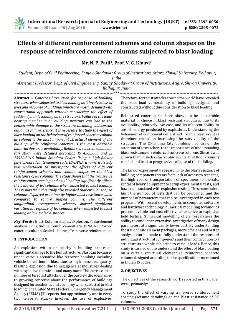
Figure-17 shows displacement time histories for SEIS-2 and CIR_SEIS-1 columns when subjected to blast loading caused due to a charge mass of 250 kg at scaled distance of 0.8 m/kg1/3 and axial load for the ALR value of 0.1. The Figure-17 shows that the maximum lateral displacement for circular
International Research Journal of Engineering and Technology (IRJET) e-ISSN: 2395-0056
Volume: 05 Issue: 08 | Aug 2018 www.irjet.net p-ISSN: 2395-0072
© 2018, IRJET | Impact Factor value: 7.211 | ISO 9001:2008 Certified Journal | Page 579
column is significantly lower than that compared to square column.
Figure-17: DTHP for columns with seismic-1 detailing at 250 kg charge mass (z= 0.8 m/kg1/3 and ALR = 0.1)
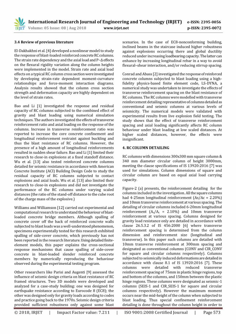
Figure-18 shows displacement time histories for SEIS-2 and CIR_SEIS-1 columns when subjected to blast loading caused due to a charge mass of 250 kg at scaled distance of 0.8 m/kg1/3 and axial load for the ALR value of 0.35. The Figure-18 shows that the maximum lateral displacement for circular column is significantly lower than that compared to square column.
Figure-18: DTHP for columns with seismic-1 detailing at 250 kg charge mass (z= 0.8 m/kg1/3 and ALR = 0.35)
5.6.5 Effect of different longitudinal reinforcement arrangement schemes
The effect of different longitudinal reinforcement arrangement scheme on behaviour of conventionally detailed RC columns were investigated at scaled distance of 0.8 m/kg1/3. The RC columns consisting of three different longitudinal reinforcement arrangement schemes were subjected to 100 kg and 250 kg charge mass, at scaled distance 0.8 m/kg1/3 , while the RC columns were
simultaneously subjected to different axial load ratios of 0.0, 0.1, 0.2 and 0.35. The RC columns with three different longitudinal reinforcement arrangement schemes are denoted as LRAS-1, LRAS-2 and LRAS-3.
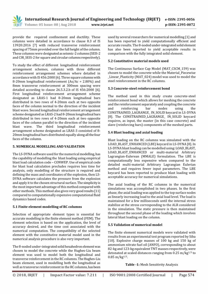
Figure-19: DTHP for conventionally detailed columns at 100 kg charge mass (z= 0.8 m/kg1/3 and ALR = 0.1)
Figure-19 shows displacement time histories for conventionally detailed columns with different longitudinal reinforcement arrangement schemes when subjected to blast loading caused due to a charge mass of 100 kg at scaled distance of 0.8 m/kg1/3 and axial load for the ALR value of 0.1. The Figure-19 shows that there is no significant difference in maximum lateral displacement for different longitudinal reinforcement arrangement schemes.
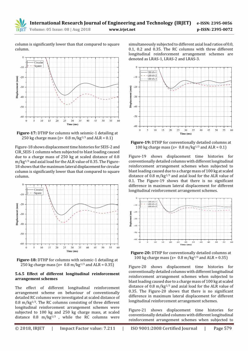
Figure-20: DTHP for conventionally detailed columns at 100 kg charge mass (z= 0.8 m/kg1/3 and ALR = 0.35)
Figure-20 shows displacement time histories for conventionally detailed columns with different longitudinal reinforcement arrangement schemes when subjected to blast loading caused due to a charge mass of 100 kg at scaled distance of 0.8 m/kg1/3 and axial load for the ALR value of 0.35. The Figure-20 shows that there is no significant difference in maximum lateral displacement for different longitudinal reinforcement arrangement schemes.
Figure-21 shows displacement time histories for conventionally detailed columns with different longitudinal reinforcement arrangement schemes when subjected to

International Research Journal of Engineering and Technology (IRJET) e-ISSN: 2395-0056
Volume: 05 Issue: 08 | Aug 2018 www.irjet.net p-ISSN: 2395-0072
© 2018, IRJET | Impact Factor value: 7.211 | ISO 9001:2008 Certified Journal | Page 580
blast loading caused due to a charge mass of 250 kg at scaled distance of 0.8 m/kg1/3 and axial load for the ALR value of 0.1. The Figure-21 shows that there is significant difference in maximum lateral displacement for different longitudinal reinforcement arrangement schemes LRAS-1 and LRAS-2 while the difference in maximum displacement between LRAS-1 and LRAS-3 is insignificant.
Figure-21: DTHP for conventionally detailed columns at 250 kg charge mass (z= 0.8 m/kg1/3 and ALR = 0.1)
Figure-22 shows displacement time histories for conventionally detailed columns with different longitudinal reinforcement arrangement schemes when subjected to blast loading caused due to a charge mass of 250 kg at scaled distance of 0.8 m/kg1/3 and axial load for the ALR value of 0.35. The Figure-22 shows that there is significant difference in maximum lateral displacement for different longitudinal reinforcement arrangement schemes LRAS-1 and LRAS-2 but lower when that compared to for columns at ALR value of 0.1 while the difference in maximum displacement between LRAS-1 and LRAS-3 is insignificant.
Figure-22: DTHP for conventionally detailed columns at 250 kg charge mass (z= 0.8 m/kg1/3 and ALR = 0.35)
In order to summarize, even if the lateral displacement observed in case of LRAS-1 is the least the reliability of such reinforcement arrangement scheme depends entirely on the direction of the incident blast wave.
6 CONCLUSIONS
The conclusions drawn from the numerical work presented in this paper are as follows:
Generally, at the same scaled distance, increasing the magnitude of charge masses resulted in increased lateral displacement and much more extensive damage to the RC column, especially at smaller scaled distances. At higher scaled distance, however, the difference in the lateral displacements from different charge masses at the same scaled distance was observed to have decreased significantly.
Reduction of transverse reinforcement spacing in RC columns resulted in reduced lateral displacements at lower scaled distances. The lateral displacements increased with increasing charge mass at constant scaled distance.
Reduction in transverse reinforcement spacing had
insignificant effect on lateral displacement of RC
columns at larger scaled distances.
The gravity loads from upper stories on the
behaviour of RC columns subjected to blast loading
was reduced lateral displacement in general.
At high axial load ratios, RC columns displayed large lateral displacement and suffered crushing of concrete and the subsequent buckling of longitudinal reinforcing bars in the mid-region at high blast load levels, especially at low scaled distances.
The lateral displacement of circular RC columns was significantly reduced when that compared to square RC columns subjected to blast loading. Reduction in lateral displacement for circular columns was observed in case of both conventionally detailed RC columns as well as RC columns with seismic detailing.
Difference in lateral displacement for RC columns with different longitudinal reinforcement arrangement schemes of was insignificant at low blast load levels while significant change in lateral displacement was observed at high blast load levels at low scaled distance.
Longitudinal reinforcement arrangement scheme in which equal reinforcement is distributed across all the faces of the column was observed most reliable to resist the effect of blast loading on the column structure.

International Research Journal of Engineering and Technology (IRJET) e-ISSN: 2395-0056
Volume: 05 Issue: 08 | Aug 2018 www.irjet.net p-ISSN: 2395-0072
© 2018, IRJET | Impact Factor value: 7.211 | ISO 9001:2008 Certified Journal | Page 581
REFERENCES
[1] Bao, X., and Li, B., 2010, “Residual Strength of Blast Damaged Reinforced Concrete Columns,” Int. J. Impact. Eng., 37(3), pp. 295–308.
[2] Conrad, K., and Abass, B., 2017, “Effects of Transverse Reinforcement spacing on the Response of Reinforced Concrete Columns Subjected to Blast Loading,” Eng. Struct., 142, pp. 148–164.
[3] FEMA., 2003, Risk Management Series: Reference Manual to Mitigate Potential Terrorist Attack Against Buildings. Federal Emergency Management Agency.
[4] El-Dakhakhni, W., Mekky, W., and Changiz-Rezaei, S., 2009, “Vulnerability Screening and Capacity Assessment of Reinforced Concrete Columns Subjected to Blast,” J. Perform. Constr. Facil., 23(5), 353-365.
[5] Karlos, V., & Solomos, G., 2013, “Calculation of Blast Loads for Application to Structural Components,” Institute for the Protection and Security of the Citizen, Luxembourg, pp. 55.
[6] IS 456:2000., “Indian Standard Plain and Reinforced Concrete - Code of Practice,” Fourth Revision.
[7] IS 13920:2016., “Indian Standard Ductile Design and Detailing of Reinforced Concrete Structures Subjected to Seismic Forces – Code of Practice,” Fourth Revision.
[8] LS-DYNA, M., 2017, “LS-DYNA Keyword User’s Manual,” Livermore Software Technology Corporation, Livermore, California.
[9] Parisi, F., and Augenti, N., 2012, “Influence of Seismic Design Criteria on Blast Resistance of RC Framed Buildings: A Case Study,” Eng. Struct., 44, pp. 78–93.
[10] Siba, F., 2014, “Near-field Explosion Effects on Reinforced Concrete Columns: An Experimental Investigation,” Department of Civil and Environmental Engineering, Carleton University.
[11] Tabatabaei, Z. S., and Volz, J. S., 2012, “A Comparison between Three Different Blast Methods in LS-DYNA®: LBE, MM-ALE, Coupling of LBE and MM-ALE,” In the 12th International LS-DYNA User Conference, Michigan, USA.
[12] Williams, G., and Williamson, E., 2011, “Response of Reinforced Concrete Bridge Columns Subjected to Blast Loads,” J. Struct. Eng., 137(9), pp. 903–913.
[13] Wu, K-C., Li, B., and Tsai, K-C., 2011, “The Effects of Explosive Mass Ratio on Residual Compressive Capacity of Contact Blast Damaged Composite Columns,” J. Constr. Steel. Res., 67(4), pp. 602–12.
BIOGRAPHIES
Mr. Nikhil P. Patil is post graduate student in structural engineering program in department of civil engineering at Sanjay Ghodawat Group of Institutions, Atigre, Kolhapur, India
Prof. Virupaksh G. Khurd is Assistant Professor in department of civil engineering at Sanjay Ghodawat Group of Institutions, Atigre, Kolhapur, India
Related Documents