A Reconfigurable FEC system based on Reed-Solomon codec for DVB and 802.16 network LAMIA CHAARI, MOHAMED FOURATI, NOURI MASMOUDI, LOTFI KAMOUN Electronic and Information Technologies Laboratory (L.E.T.I) Sfax National Engineering School, 3038 SFAX TUNISIE [email protected] [email protected] Abstract: This article proposes, a reconfigurable FEC system based on Reed-Solomon codec for DVB and WiMax networks. The proposed architecture implements various programmable primitive polynomials. A lot of VLSI implementations have been described in literature. This paper introduces a highly parametrical RS-coder-decoder on FPGAs. The implementation, written in a hardware description language (HDL), is based on an Berlekamp massey, Chain and Formey Algorithms. We have defined an advanced RS encoder-decoder architecture based on parameterization approach which is a key solution for software defined radio (SDR) systems. Our parameterization approach is used in order to implement on FPGA a generic RS coder-decoder for DVB and WiMax networks. IEEE Std. 802.16 specifies that the codec performs a variable number of check symbols in a codeword ( ranges from 0 to 32, inclusive). The value of check symbols are specified for each burst profile by the MAC layer according to cross layer concept. Keywords and phrases: Reedsolomon, Berlekamp massey, Chain, Formey, FPGA, implementation , VHDL, WiMax, DVB. 1 Introduction: Reed-Solomon (RS) codes are described in a paper by Reed and Solomon in 1960[1]. RS are powerful error correcting codes that can be employed in a wide variety of digital communications systems from digital media to wireless communications and deep-space probes as well as in memory and storage systems. Reed-solomon codes are used to correct errors in many systems including: storage devices (compact disk, DVD, barcodes,etc….) [2,3], wireless and mobile communications (including cellular telephones, microwave links, etc…)[4, 5], digital satellite communications[6], digital television, digital video broadcasting (DVB)[7], high speed modem such as ADSL, Xdsl…[8] power line communications (PLC) [9] digital vestigial sideband (VSB) system [10] cable modem [11], The speed and complexity of these systems necessitate designers and researchers to break a way from traditional architectures and design methodologies. A design combining software and hardware is flexible enough to make it optimal for 4th generation systems [12]. Field programmable gate arrays (FPGA) have evolved from being a flexible logic design platform to a signal-processing engine [13]. An increasing number of signal processing functions in FPGA and several capabilities like embedded memory and advanced routing. The availability of high density and high performance make them highly designable for developing hardware prototypes of communication systems. Parameterization [14] is a new field of study derived from software radio domain. This field proposes a new approach in which similarities and differences between systems and standards must be identified and then parameterized. We can distinguish two types of parameterization either by common functions or by common operators. Parameterization by common operators, it consists to find a common operator of the highest level, which would be used by the maximum functions of many standards including future standard. Parameterization by common functions, it consists to identify the common functions of WSEAS TRANSACTIONS on CIRCUITS and SYSTEMS Lamia Chaari, Mohamed Fourati, Nouri Masmoudi, Lotfi Kamoun ISSN: 1109-2734 729 Issue 8, Volume 8, August 2009

Welcome message from author
This document is posted to help you gain knowledge. Please leave a comment to let me know what you think about it! Share it to your friends and learn new things together.
Transcript
A Reconfigurable FEC system based on Reed-Solomon codec for DVB and 802.16 network
LAMIA CHAARI, MOHAMED FOURATI, NOURI MASMOUDI, LOTFI KAMOUN
Electronic and Information Technologies Laboratory (L.E.T.I) Sfax National Engineering School, 3038 SFAX TUNISIE
[email protected] [email protected]
Abstract: This article proposes, a reconfigurable FEC system based on Reed-Solomon codec for
DVB and WiMax networks. The proposed architecture implements various programmable primitive polynomials. A lot of VLSI implementations have been described in literature. This paper introduces a highly parametrical RS-coder-decoder on FPGAs. The implementation, written in a hardware description language (HDL), is based on an Berlekamp massey, Chain and Formey Algorithms. We have defined an advanced RS encoder-decoder architecture based on parameterization approach which is a key solution for software defined radio (SDR) systems. Our parameterization approach is used in order to implement on FPGA a generic RS coder-decoder for DVB and WiMax networks. IEEE Std. 802.16 specifies that the codec performs a variable number of check symbols in a codeword ( ranges from 0 to 32, inclusive). The value of check symbols are specified for each burst profile by the MAC layer according to cross layer concept.
Keywords and phrases: Reedsolomon, Berlekamp massey, Chain, Formey, FPGA, implementation
, VHDL, WiMax, DVB.
1 Introduction: Reed-Solomon (RS) codes are described in
a paper by Reed and Solomon in 1960[1]. RS are powerful error correcting codes that can be employed in a wide variety of digital communications systems from digital media to wireless communications and deep-space probes as well as in memory and storage systems. Reed-solomon codes are used to correct errors in many systems including: storage devices (compact disk, DVD,
barcodes,etc….) [2,3], wireless and mobile communications
(including cellular telephones, microwave links, etc…)[4, 5],
digital satellite communications[6], digital television, digital video
broadcasting (DVB)[7], high speed modem such as ADSL,
Xdsl…[8] power line communications (PLC) [9] digital vestigial sideband (VSB) system
[10] cable modem [11],
The speed and complexity of these systems necessitate designers and researchers to break a way from traditional architectures and design
methodologies. A design combining software and hardware is flexible enough to make it optimal for 4th generation systems [12].
Field programmable gate arrays (FPGA) have evolved from being a flexible logic design platform to a signal-processing engine [13]. An increasing number of signal processing functions in FPGA and several capabilities like embedded memory and advanced routing. The availability of high density and high performance make them highly designable for developing hardware prototypes of communication systems.
Parameterization [14] is a new field of study derived from software radio domain. This field proposes a new approach in which similarities and differences between systems and standards must be identified and then parameterized. We can distinguish two types of parameterization either by common functions or by common operators. Parameterization by common operators, it consists to find a common operator of the highest level, which would be used by the maximum functions of many standards including future standard. Parameterization by common functions, it consists to identify the common functions of
WSEAS TRANSACTIONS on CIRCUITS and SYSTEMSLamia Chaari, Mohamed Fourati, Nouri Masmoudi, Lotfi Kamoun
ISSN: 1109-2734 729 Issue 8, Volume 8, August 2009

all standards that will be implemented in reconfigurable systems.
In addition, since past research has proposed several efficient algorithms [15, 16, 17] and architectures [18,19, 20] for the RS coder-decoder that could be used as parameters for an advanced reconfigurable architectures.
This article is structured in eight sections.
Section 2 provide a brief description of Reed-Solomon codes. Section 3 describes RS codec architectures and is sketching briefly the principle functionality of RS decoder. In section 4, several implementation RS coder-decoder architectures are studied. Section 5 discuss parameterization approach used in order to implement a reconfigurable RS coder-decoder for DVB, mobile and wireless systems. Section 6 explains our conception and an optimized FPGA implementation of a reconfigurable FEC systems based on RS codes used in new generation systems. Design decisions and simulation results of the verification process are reported and discussed in section 7. Finally, we summarize and conclude this article in section 8; also we propose some recommendations for future research.
2 Reed-Solomon CODECs: Reed Solomon (RS) codes are a subset of Bose Chaudhuri-Hochquenghem (BCH) codes [21 22] and are linear block codes[23]. They are powerful error-correcting codes whose symbols are chosen from a finite field, GF(m). Their non-binary nature makes them particularly suitable to correct error bursts.
A Reed-Solomon code is specified as RS(n,k) with m-bit symbols. This means that the encoder takes k data symbols of s bits each and adds parity symbols to make an n symbol codeword. There are n-k parity symbols of s bits each. A Reed-Solomon decoder can correct up to t symbols that contain errors in a codeword, where 2t = n-k. If the location of the symbol errors is marked as an erasure, the RS decoder can correct twice as many errors. External circuitry identifies which symbols have errors and passes this information to the decoder using the eras_sym signal. The eras_sym input indicates an erasure (when the erasures-supporting decoder option is selected).
2.1 Encoding of Reed-Solomon codes Let (u0, u1, u2,…, uk-1) denote k m-bit data symbols. These symbols are encoded into a codeword (c0, c1, c2,…, cn-1). This encoding process is best described in terms of data polynomial: I(x) = u0+ u1x + u2x
2 + …+ uk-1xk-1 (1)
C(x) = c0+ c1x + c2x2 + …+ cn-1x
n-1 (2) C(x) are polynomial multiple of G(x), which is the generator polynomial of the code, which is defined as
)12
0()( )0(∏
−
=−= +
t
ixxG imα (3)
where m0 is typically 0 or 1 Since 2t
consécutive power 120100 ,......., −++ tmmm ααα of
α are rootsof G(x), C(x) is amultiple of G(x), it follows that
120,0)( )0( −≤≤=+ tiC imα (4) for all codeword polynomials C(x). In fact,an arbitary polynomial of degree less than n is a codeword polynomial if and only if it satisfies equation 4.
Asystematic encoding produces codeword polynomials that are comprised of data followed by parity check symbols (figure 1), and it is obtained as follows (Equation 5) Figure 1: RS encoding Pa(x) = (x2t * I(x))mod G(x) (5) It follows that the codeword is given by (Cn-1, Cn-2,….., C1,C0)= (uk-1, uk-2,….., u1,u0, Pn-k-
1, Pn-k-2,….., P1,P0) and consists of the data symbols followed by the check symbols. In digital hardware, the encoder is an LFSR with internal feedback connections corresponding to G(x), as seen in Figure 2. The operations involved are GF addition and multiplication. The computation of the remainder is implemented on digital hardware using a linear feedback shift register configuration as shown in Figure 2. The final contents of the shift registers will contain the remainder.
n
Data I(x) Pariy Pa(x)
2t k
WSEAS TRANSACTIONS on CIRCUITS and SYSTEMSLamia Chaari, Mohamed Fourati, Nouri Masmoudi, Lotfi Kamoun
ISSN: 1109-2734 730 Issue 8, Volume 8, August 2009

Figure 2: Typical RS encoder implementation 2.2 Decoding of Reed-Solomon codes The general decoding steps are illustrated in
Figure 3. The syndrome calculator generates a set of syndromes from the received codeword polynomial R(x). From the syndromes, the key equation solver produces the error locator polynomial σ(x) and the error evaluator polynomial Ω( x) which can be used by the Chien Search and the Error Value Evaluator to determine the error locations and error values, respectively.
Figure 3: The simplified Reed-Solomon decoding flowchart.
3 RS decoding Algorithms study 3.1 Syndrome computation
The Syndrome calculation block treats the input codeword as a series of polynomial coefficients and calculates a syndrome polynomial of 2t coefficients. The syndrome polynomial contains the location and magnitude of up to t errors in an invalid codeword. A valid codeword generates a syndrome polynomial with all zero coefficients.
Assuming a corrupt transmission, the received codeword R consists of the original codeword which is superposed by the error E: By definition the syndrome polynomial is S(x)
)i(RiS,x )1i(t2
1iS)x(S i α=−
==∑ , (6)
R(x) =R0+R1x+ R2x2+…..+ RN-1x
N-1 (7) then Si= R0+αi
(R1+ αi (R2+…..+αi (RN-1))) (8)
where R(x) is a received polynomial and RN-1
is the first received symbol into a syndrome cell. This structure describe a recursive operation multiplies and accumulates a constant value αI with the input data. As shown in Figure 4(a), at each cycle, the partial syndrome is multiplied with and accumulated with the received symbol. After all the received symbols are processed, the accumulated result is the iième syndrome. Figure 4(b) shows how the 16 syndrome cells (for t= 8 ) are organized in our chip. By controlling the multiplexer in Figure 4(b), we can generate different syndrome sequences for the calculation of the discrepancy in the key equation solver. Table I shows all 16 different syndrome sequences [24].
Figure 4 (a) Syndrome cell S Figure 4 (a) Syndrome cell S
3.2 Key Equation Solver The main component of an RS-decoder is
the key equation calculation block. It solves a set of 2t linearly dependent equations. It generates the key equations (σ(x): locator polynomial and Ω(x): evaluator polynomial) from the syndrome polynomials. The locator polynomial contains information about the location of bad symbols in the codeword. The evaluator polynomial contains information about the error magnitude of the bad symbols. The two polynomials σ(x) and Ω(x) are
Error value
Syndrôme calculator
key equation solver
Chien Search
Error Value Evaluator
R(x) S(x)
σ(x)
Ω( x)
Error location
g0 g11
g2 g2t-1
Reg Reg Reg
u0, u1,u2,………,uk-1
Pa(x)
D Si
iα
Rj
iSα
Si+1 Mux
Si
Si+1
S1 S2 S3 S4 S5 S6 S7 S8 S7 S8
S9 S10 S11 S12 S13 S14 S15 S16
8 Rj
WSEAS TRANSACTIONS on CIRCUITS and SYSTEMSLamia Chaari, Mohamed Fourati, Nouri Masmoudi, Lotfi Kamoun
ISSN: 1109-2734 731 Issue 8, Volume 8, August 2009
defined respectively by the following equations 9 and 10.
( )∏=
⋅−=w
iiXxx
1
1 )(σ (9)
where w : is the number of errors occurs in R(x).
)xw
ij,1j*jX1(iX
w
1iiY)x( ∏∑
≠=−
==Ω (10)
The two polynomials are related to S(x)
through the Key equation (Eq11) [25, 26], so we can determine the above two unknown polynomials σ(x) and Ω(x) by solving the key equation:
txxxxS 2 mod )()(*)( Ω=σ (11) The techniques frequently used to solve the
key equation include the Berlekamp–Massey algorithm [25,27,28,29], the Euclidean algorithm [29,30]. Compared to the Euclidean algorithm, the Berlekamp–Massey algorithm is generally considered to be the one with the least hardware complexity [31].
3.2.1 Berlekamp–Massey algorithm
One of the fastest and hence often preferred algorithm is the so called “Berlekamp Massey Algorithm” (BMA) that solves
01t2
w)x(S)x(∑
−=σ , (12)
where w ≤t is the number of errors that have occurred. So eq 12 can be developed as Eq 13
0...
...
0...
0...
22221212
22112
11211
=++++
=++++=++++
−−−
++
−+
wtwttt
wwww
wwww
SSSS
SSSS
SSSS
σσσ
σσσσσσ
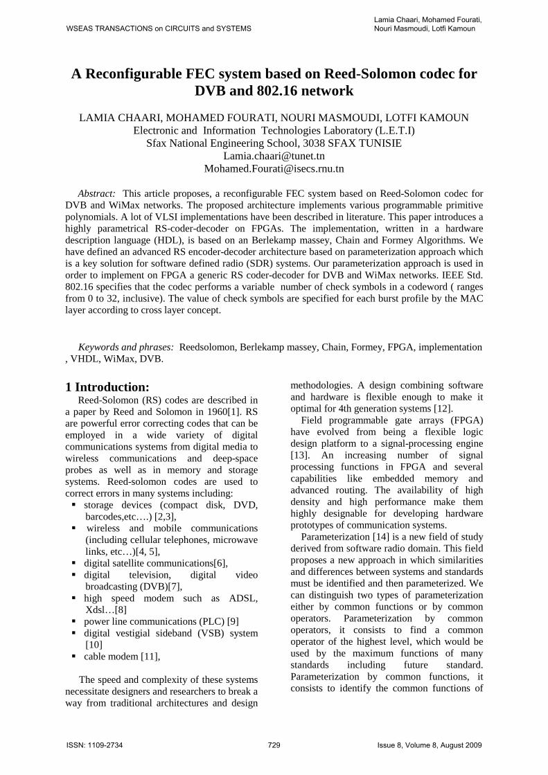
The problem of finding the minimum-degree solution to the key equation is the same as trying to find the smallest (LFSR) σ(x), that generates the first 2t terms of S (figure 5). The algorithm aims to find an LFSR of minimal length such that the first (2t) elements in the LFSR output sequence are the (2t) syndromes. The taps of this shift register are the coefficients of the desired error locator polynomial, σ(x) [33].
Figure 5 : Berlekamp–Massey algorithm based on LFSR implementation
∑=
−−=w
iijij SS
1
*σ
If syndrome values are known, we can compute σ(x) polynomial by the following diagram (figure6)
Figure 6: Barlekamp massey algorithm [32]
…….
…
−σ1 −σ2 −σω−1 −σω
Sj-1 Sj-2 Sj-w Sj-w-1
Sj-w-2
….. S1
Initialize:
0=w , xxB =)( , 1)(0 =xσ , 0=wL et 0=j
1ww +=
Compute error in the next syndrome:
∑∑−−
=−
=− =+=
11
01
11 **
ww L
lwl
L
lwlww SSSd σσ
0=wdYes
Compute new connection polynomial for which 0=wd
)(*)()( 1 xBdxxT ww −= −σ
No
No
)()( xTxw <=σ
)()( 11 xdxB ww
−−<= σ
)()( xTxw <=σ
ww
w
w
TL
Lwj
jwT
<=−<=−<=
−1
Yes
)(*)( xBxxB <=
jwLw −<−1
t2=ω No
End
Yes
WSEAS TRANSACTIONS on CIRCUITS and SYSTEMSLamia Chaari, Mohamed Fourati, Nouri Masmoudi, Lotfi Kamoun
ISSN: 1109-2734 732 Issue 8, Volume 8, August 2009
The implementation was a purely
functional VHDL description. 3.2.2 Error Magnitudes polynomial Computing
Solving the key equation (Eq. 11) determines the error evaluator or error magnitude polynomial, Ω(x). An efficient way of computing Ω(x) is to perform parallel computation of σ(x). Using the Berlekamp–Massey algorithm, this involves an iterative algorithm to compute. However, if is first obtained, from the key equation and the Newton’s identity we could derive as follows: Ω(x) = S(x)σ(x) mod x2t
= (S1 + S2x +…. + S2tx2t-1)•
( σ1 + σ2x +…. + σtxt) mod x2t
≡ Ω(0) + Ω(1)x + ….. + Ω(t-1) xt-1
Ω(i) = Si +1σ0 + Siσ1 + …. + S1σi , i = 0, 1, …. t-1
The penalty of this efficient computation is
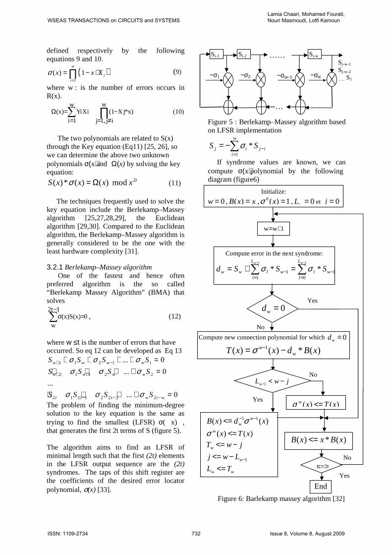
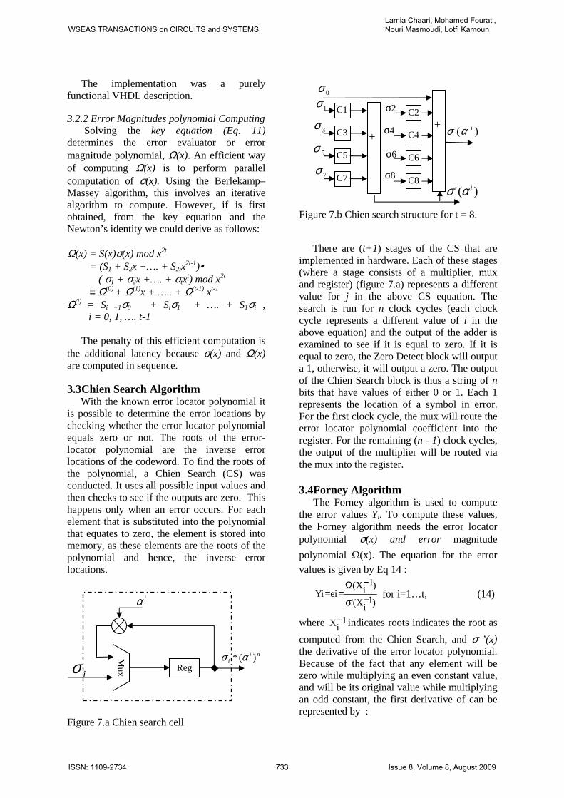
the additional latency because σ(x) and Ω(x) are computed in sequence. 3.3Chien Search Algorithm
With the known error locator polynomial it is possible to determine the error locations by checking whether the error locator polynomial equals zero or not. The roots of the error-locator polynomial are the inverse error locations of the codeword. To find the roots of the polynomial, a Chien Search (CS) was conducted. It uses all possible input values and then checks to see if the outputs are zero. This happens only when an error occurs. For each element that is substituted into the polynomial that equates to zero, the element is stored into memory, as these elements are the roots of the polynomial and hence, the inverse error locations.
Figure 7.a Chien search cell
Figure 7.b Chien search structure for t = 8.
There are (t+1) stages of the CS that are
implemented in hardware. Each of these stages (where a stage consists of a multiplier, mux and register) (figure 7.a) represents a different value for j in the above CS equation. The search is run for n clock cycles (each clock cycle represents a different value of i in the above equation) and the output of the adder is examined to see if it is equal to zero. If it is equal to zero, the Zero Detect block will output a 1, otherwise, it will output a zero. The output of the Chien Search block is thus a string of n bits that have values of either 0 or 1. Each 1 represents the location of a symbol in error. For the first clock cycle, the mux will route the error locator polynomial coefficient into the register. For the remaining (n - 1) clock cycles, the output of the multiplier will be routed via the mux into the register. 3.4Forney Algorithm
The Forney algorithm is used to compute the error values Yi. To compute these values, the Forney algorithm needs the error locator polynomial σ(x) and error magnitude
polynomial Ω(x). The equation for the error values is given by Eq 14 :
)1iX('
)1iX(
ieiY −σ
−Ω== for i=1…t, (14)
where 1iX− indicates roots indicates the root as
computed from the Chien Search, and σ ’(x) the derivative of the error locator polynomial. Because of the fact that any element will be zero while multiplying an even constant value, and will be its original value while multiplying an odd constant, the first derivative of can be represented by :
iσ
Mu
x
iα
Reg
nii )(* ασ
3σ
0σ
7σ
5σ
1σ +
C1
C3
C5
C7
)( iασ
)(' iασ
6σ
C2
C4
C6
C8
4σ
8σ
2σ +
WSEAS TRANSACTIONS on CIRCUITS and SYSTEMSLamia Chaari, Mohamed Fourati, Nouri Masmoudi, Lotfi Kamoun
ISSN: 1109-2734 733 Issue 8, Volume 8, August 2009
)1iX(odd1
iX1)1
iX(' −σ−=−σ (15)
Then we can rewrite Eq 14 as the following format:
)1iX(odd
1iX)1iX(
ieiY −σ
−−Ω== (16 )
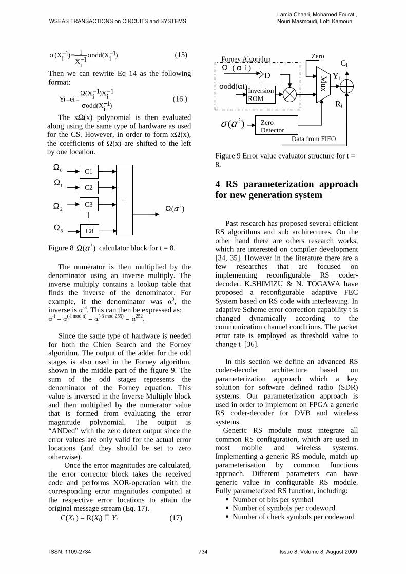
The xΩ(x) polynomial is then evaluated along using the same type of hardware as used for the CS. However, in order to form xΩ(x), the coefficients of Ω(x) are shifted to the left by one location. Figure 8 )( iαΩ calculator block for t = 8.
The numerator is then multiplied by the
denominator using an inverse multiply. The inverse multiply contains a lookup table that finds the inverse of the denominator. For example, if the denominator was α3, the inverse is α-3. This can then be expressed as: α
-i = α(-i mod n) = α(-3 mod 255) = α252. Since the same type of hardware is needed
for both the Chien Search and the Forney algorithm. The output of the adder for the odd stages is also used in the Forney algorithm, shown in the middle part of the figure 9. The sum of the odd stages represents the denominator of the Forney equation. This value is inversed in the Inverse Multiply block and then multiplied by the numerator value that is formed from evaluating the error magnitude polynomial. The output is “ANDed” with the zero detect output since the error values are only valid for the actual error locations (and they should be set to zero otherwise).
Once the error magnitudes are calculated, the error corrector block takes the received code and performs XOR-operation with the corresponding error magnitudes computed at the respective error locations to attain the original message stream (Eq. 17).
C(Xi ) = R(Xi) ⊕ Yi (17)
Figure 9 Error value evaluator structure for t = 8. 4 RS parameterization approach for new generation system
Past research has proposed several efficient RS algorithms and sub architectures. On the other hand there are others research works, which are interested on compiler development [34, 35]. However in the literature there are a few researches that are focused on implementing reconfigurable RS coder-decoder. K.SHIMIZU & N. TOGAWA have proposed a reconfigurable adaptive FEC System based on RS code with interleaving. In adaptive Scheme error correction capability t is changed dynamically according to the communication channel conditions. The packet error rate is employed as threshold value to change t [36].
In this section we define an advanced RS
coder-decoder architecture based on parameterization approach which a key solution for software defined radio (SDR) systems. Our parameterization approach is used in order to implement on FPGA a generic RS coder-decoder for DVB and wireless systems.
Generic RS module must integrate all common RS configuration, which are used in most mobile and wireless systems. Implementing a generic RS module, match up parameterisation by common functions approach. Different parameters can have generic value in configurable RS module. Fully parameterized RS function, including:
Number of bits per symbol Number of symbols per codeword Number of check symbols per codeword
Zero
2Ω
0Ω
8Ω
1Ω +
C1
C2
C3
C8
)( iαΩ
Y i
)( iασ
Mux
Zero Detector
Data from FIFO
)i( αΩ
)i(odd ασInversion ROM
Forney Algorithm
D
Ri
Ci
WSEAS TRANSACTIONS on CIRCUITS and SYSTEMSLamia Chaari, Mohamed Fourati, Nouri Masmoudi, Lotfi Kamoun
ISSN: 1109-2734 734 Issue 8, Volume 8, August 2009

Field polynomial First root of generator polynomial
The symbol width (m) defines the field generator polynomial. Table 1 illustrates this correspondence. Symbol Width Field generator polynomial 3 x3+x+1 4 x4+x+1 5 x5+x2+1 6 x6+x+1 7 x7+x3+1 8 x8+x4+x3+x2+1 9 x9+x4+1 10 x10+x3+1 11 x11+x2+1 12 x12+x6+x4+x+1
Table 1: Correspondence between symbol
width and the field generator polynomial All most new generation standards use
eight value as symbol width this leads to use x8+x4+x3+x2+1 as a field generator polynomial.
4.1 RS parameterization for DVB
norm DVB has three standards that use identical
RS code parameters. These are satellite (DVB-S), cable (DVB-C) and terrestrial (DVB-T). The most widely used of the three protocols is DVB-S [Sohi20001.
All DVB standards employ the same (204,188) RS code. All DVB standards operate in GF(28), and are based on a (255,239) RS code. Therefore, the same Galois Field arithmetic units and hardware can be used for different DVB standards. Table 2 summarize RS parameters for DVB.
Parameter Symbol DVB
Field Polynomial P(x) X8+X4+X3+X2+1 Generator polynomial G(x) (x-α0)(x- α1)(x-
α2)…(x- α15)
Bits number/Symbol m 8 Code length n 204 Message length k 188 Parity Symbols 2t 16
Table 2: RS parameters for DVB
4.2 RS parameterization for Wireless 802.16
IEEE Std. 802.16 specifies the outer code requirements for RS code as follows:
The specified code generator polynomials are given by:
- Code Generator Polynomial:
g(x) =(x+µ1)(x+µ2) ... (x+µ2T), where µ=02hex - Field Generator Polynomial: p(x) = x8 + x4 + x3 + x2 + 1 The specified code has a block length of
255 bytes and shall be configured as an RS(255,255-R) code with information bytes preceded by (255-K) zero symbols, where K is the codeword length and R the number of redundancy bytes (R = 2*T ranges from 2 to 32, inclusive). The value of K and T are specified for each burst profile by the MAC. [37]
The variable decoder supports real-time changing of the number of symbols in the codeword, and R, the number of check symbols in a codeword.
5 FPGA implementation of a configurable FEC systems based on RS codes for DVB and 802.16 network
Overall hardware implementation of the
controller design consists of the entry of the conceptual design into electronic description format (design entry), conversion of the design into a logic level form (synthesis), and translation of the design into the physical FPGA specific component placement and signal routing (implementation). The design verification process consists of testing the design for conformity at several intermediate stages. The verification steps performed after each major stage of the design are shown in figure 10 and include: behavioral or functional simulations, synthesis checks, postsynthesis timing verification, and post-implementation timing verification. All of these steps are done using simulation tools like Xilinx’s Foundation ISE Tools [38] and Modelsim XE 6.0d.
WSEAS TRANSACTIONS on CIRCUITS and SYSTEMSLamia Chaari, Mohamed Fourati, Nouri Masmoudi, Lotfi Kamoun
ISSN: 1109-2734 735 Issue 8, Volume 8, August 2009
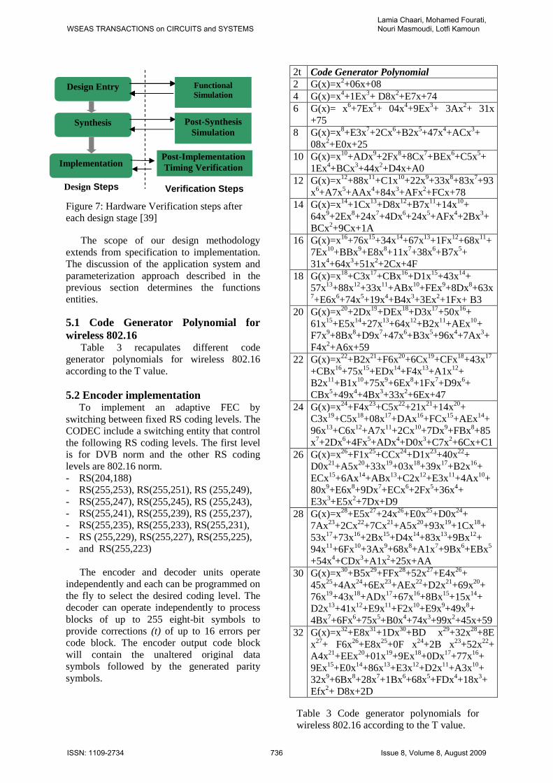
Figure 7: Hardware Verification steps after each design stage [39]
The scope of our design methodology extends from specification to implementation. The discussion of the application system and parameterization approach described in the previous section determines the functions entities.
5.1 Code Generator Polynomial for wireless 802.16
Table 3 recapulates different code generator polynomials for wireless 802.16 according to the T value.
5.2 Encoder implementation
To implement an adaptive FEC by switching between fixed RS coding levels. The CODEC include a switching entity that control the following RS coding levels. The first level is for DVB norm and the other RS coding levels are 802.16 norm. - RS(204,188) - RS(255,253), RS(255,251), RS (255,249), - RS(255,247), RS(255,245), RS (255,243), - RS(255,241), RS(255,239), RS (255,237), - RS(255,235), RS(255,233), RS(255,231), - RS (255,229), RS(255,227), RS(255,225), - and RS(255,223)
The encoder and decoder units operate
independently and each can be programmed on the fly to select the desired coding level. The decoder can operate independently to process blocks of up to 255 eight-bit symbols to provide corrections (t) of up to 16 errors per code block. The encoder output code block will contain the unaltered original data symbols followed by the generated parity symbols.
2t Code Generator Polynomial 2 G(x)=x2+06x+08 4 G(x)=x4+1Ex3+ D8x2+E7x+74 6 G(x)= x6+7Ex5+ 04x4+9Ex3+ 3Ax2+ 31x
+75 8 G(x)=x8+E3x7+2Cx6+B2x5+47x4+ACx3+
08x2+E0x+25
10 G(x)=x10+ADx9+2Fx8+8Cx7+BEx6+C5x5+ 1Ex4+BCx3+44x2+D4x+A0
12 G(x)=x12+88x11+C1x10+22x9+33x8+83x7+93x6+A7x5+AAx4+84x3+AFx2+FCx+78
14 G(x)=x14+1Cx13+D8x12+B7x11+14x10+ 64x9+2Ex8+24x7+4Dx6+24x5+AFx4+2Bx3+BCx2+9Cx+1A
16 G(x)=x16+76x15+34x14+67x13+1Fx12+68x11+7Ex10+BBx9+E8x8+11x7+38x6+B7x5+ 31x4+64x3+51x2+2Cx+4F
18 G(x)=x18+C3x17+CBx16+D1x15+43x14+ 57x13+88x12+33x11+ABx10+FEx9+8Dx8+63x7+E6x6+74x5+19x4+B4x3+3Ex2+1Fx+ B3
20 G(x)=x20+2Dx19+DEx18+D3x17+50x16+ 61x15+E5x14+27x13+64x12+B2x11+AEx10+ F7x9+8Bx8+D9x7+47x6+B3x5+96x4+7Ax3+F4x2+A6x+59
22 G(x)=x22+B2x21+F6x20+6Cx19+CFx18+43x17
+CBx16+75x15+EDx14+F4x13+A1x12+ B2x11+B1x10+75x9+6Ex8+1Fx7+D9x6+ CBx5+49x4+4Bx3+33x2+6Ex+47
24 G(x)=x24+F4x23+C5x22+21x21+14x20+ C3x19+C5x18+08x17+DAx16+FCx15+AEx14+96x13+C6x12+A7x11+2Cx10+7Dx9+FBx8+85x7+2Dx6+4Fx5+ADx4+D0x3+C7x2+6Cx+C1
26 G(x)=x26+F1x25+CCx24+D1x23+40x22+ D0x21+A5x20+33x19+03x18+39x17+B2x16+ ECx15+6Ax14+ABx13+C2x12+E3x11+4Ax10+ 80x9+E6x8+9Dx7+ECx6+2Fx5+36x4+ E3x3+E5x2+7Dx+D9
28 G(x)=x28+E5x27+24x26+E0x25+D0x24+ 7Ax23+2Cx22+7Cx21+A5x20+93x19+1Cx18+ 53x17+73x16+2Bx15+D4x14+83x13+9Bx12+ 94x11+6Fx10+3Ax9+68x8+A1x7+9Bx6+EBx5
+54x4+CDx3+A1x2+25x+AA
30 G(x)=x30+B5x29+FFx28+52x27+E4x26+ 45x25+4Ax24+6Ex23+AEx22+D2x21+69x20+ 76x19+43x18+ADx17+67x16+8Bx15+15x14+ D2x13+41x12+E9x11+F2x10+E9x9+49x8+ 4Bx7+6Fx6+75x5+B0x4+74x3+99x2+45x+59
32 G(x)=x32+E8x31+1Dx30+BD x29+32x28+8E x27+ F6x26+E8x25+0F x24+2B x23+52x22+ A4x21+EEx20+01x19+9Ex18+0Dx17+77x16+ 9Ex15+E0x14+86x13+E3x12+D2x11+A3x10+ 32x9+6Bx8+28x7+1Bx6+68x5+FDx4+18x3+ Efx2+ D8x+2D
Design Entry
Synthesis
Implementation
Functional Simulation
Post-Synthesis Simulation
Post-Implementation Timing Verification
Verification Steps Design Steps
Table 3 Code generator polynomials for wireless 802.16 according to the T value.
WSEAS TRANSACTIONS on CIRCUITS and SYSTEMSLamia Chaari, Mohamed Fourati, Nouri Masmoudi, Lotfi Kamoun
ISSN: 1109-2734 736 Issue 8, Volume 8, August 2009
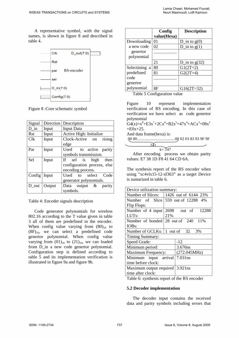
A representative symbol, with the signal names, is shown in figure 8 and described in table 4.
Figure 8 :Core schematic symbol Signal Direction Description D_in Input Input Data Rst Input Active High: Initialize Clk Input Clock-Active on rising
edge Par Input Used to active parity
symbols transmission. Sel Input If sel is high then
configuration process, else encoding process.
Config Input Used to select Code generator polynomials.
D_out Output Data output & parity symbols.
Table 4: Encoder signals description
Code generator polynomials for wireless 802.16 according to the T value given in table 3 all of them are predefined in the encoder. When config value varying from (80)16 to (8F)16, we can select a predefined code genertor polynomial. When config value varying from (01)16 to (21)16, we can loaded from D_in a new code genertor polynomial. Configuration step is defined according to table 5 and its implementation verification is illustrated in figure 9a and figure 9b.
Config value(Hexa)
Description
Downloading a new code
genertor polynomial
01 D_in to g(0) 02 D_in to g(1) .....................
21 D_in to g(32) Selectining a predefined code genertor polynomial
80 G1(2T=2) 81 G2(2T=4) .....................
8F G16(2T=32) Table 5 Configuration value
Figure 10 represent implementation verification of RS encoding. In this case of verification we have select as code genertor polynomial G4(x)=x8+E3x7+2Cx6+B2x5+47x4+ACx3+08x2
+E0x+25. And data frame(hexa) is: 00 00......................................00 02 03 83 93 9F 9F
After encoding process we obtain parity
values: E7 38 1D F8 41 64 CD 6A.
The synthesis report of the RS encoder when using “xc4vlx15-12-sf363” as a target Device is sumarized in table 6. Device utilization summary: Number of Slices: 1426 out of 6144 23% Number of Slice Flip Flops:
559 out of 12288 4%
Number of 4 input LUTs:
2698 out of 12288 21%
Number of bonded IOBs:
28 out of 240 11%
Number of GCLKs: 1 out of 32 3% Timing Summary: Speed Grade: -12 Minimum period: 3.676ns Maximum Frequency: (272.045MHz) Minimum input arrival time before clock:
7.031ns
Maximum output required time after clock:
3.921ns
Table 6: synthesis report of the RS encoder 5.2 Decoder implementation
The decoder input contains the received
data and parity symbols including errors that
RS-encoder
241 k= 247
WSEAS TRANSACTIONS on CIRCUITS and SYSTEMSLamia Chaari, Mohamed Fourati, Nouri Masmoudi, Lotfi Kamoun
ISSN: 1109-2734 737 Issue 8, Volume 8, August 2009
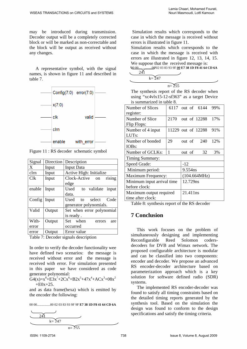
may be introduced during transmission. Decoder output will be a completely corrected block or will be marked as non-correctable and the block will be output as received without any changes.
A representative symbol, with the signal names, is shown in figure 11 and described in table 7.
Figure 11 : RS decoder schematic symbol Signal Direction Description X Input Input Data clrn Input Active High: Initialize Clk Input Clock-Active on rising
edge enable Input Used to validate input
data. Config Input Used to select Code
generator polynomials. Valid Output Set when error polynomial
is ready . With-error
Output Set when errors are occurred
error Output Error value Table 7: Decoder signals description In order to verify the decoder functionality wee have defined two scenarios: the message is received without error and the message is received with error. For simulation presented in this paper we have considered as code generator polynomial: G4(x)=x8+E3x7+2Cx6+B2x5+47x4+ACx3+08x2
+E0x+25. and as data frame(hexa) which is emitted by the encoder the following: 00 00................00 02 03 83 93 9F 9F E7 38 1D F8 41 64 CD 6A
Simulation results which corresponds to the case in which the message is received without errors is illustrated in figure 11. Simulation results which corresponds to the case in which the message is received with errors are illustrated in figure 12, 13, 14, 15. We suppose that the received message is: 00 00................00 02 03 83 93 9F 00 E7 38 1D F8 41 64 CD 6A The synthesis report of the RS decoder when using “xc4vlx15-12-sf363” as a target Device is summarized in table 8.
Number of Slices register:
6117 out of 6144 99%
Number of Slice Flip Flops:
2170 out of 12288 17%
Number of 4 input LUTs:
11229 out of 12288 91%
Number of bonded IOBs:
29 out of 240 12%
Number of GCLKs: 1 out of 32 3% Timing Summary: Speed Grade: -12 Minimum period: 9.554ns Maximum Frequency: (104.664MHz) Minimum input arrival time before clock:
12.729ns
Maximum output required time after clock:
21.411ns
Table 8: synthesis report of the RS decoder 7 Conclusion
This work focuses on the problem of
simultaneously designing and implementing Reconfigurable Reed Solomon coders-decoders for DVB and Wimax network. The proposed configurable architecture is modular and can be classified into two components: encoder and decoder. We propose an advanced RS encoder-decoder architecture based on parameterization approach which is a key solution for software defined radio (SDR) systems.
The implemented RS encoder-decoder was found to satisfy all timing constraints based on the detailed timing reports generated by the synthesis tool. Based on the simulation the design was found to conform to the design specifications and satisfy the timing criteria. 241
k= 247
n= 255
241
k= 247
n= 255
WSEAS TRANSACTIONS on CIRCUITS and SYSTEMSLamia Chaari, Mohamed Fourati, Nouri Masmoudi, Lotfi Kamoun
ISSN: 1109-2734 738 Issue 8, Volume 8, August 2009
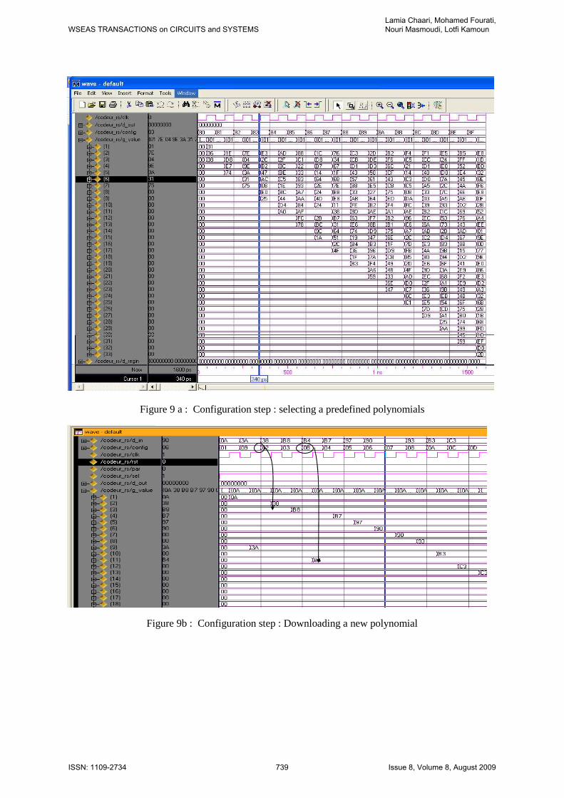
Figure 9 a : Configuration step : selecting a predefined polynomials
Figure 9b : Configuration step : Downloading a new polynomial
WSEAS TRANSACTIONS on CIRCUITS and SYSTEMSLamia Chaari, Mohamed Fourati, Nouri Masmoudi, Lotfi Kamoun
ISSN: 1109-2734 739 Issue 8, Volume 8, August 2009
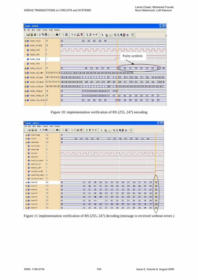
Figure 10: implementation verification of RS (255, 247) encoding
Figure 11 implementation verification of RS (255, 247) decoding (message is received without errors )
Parity symbols
WSEAS TRANSACTIONS on CIRCUITS and SYSTEMSLamia Chaari, Mohamed Fourati, Nouri Masmoudi, Lotfi Kamoun
ISSN: 1109-2734 740 Issue 8, Volume 8, August 2009
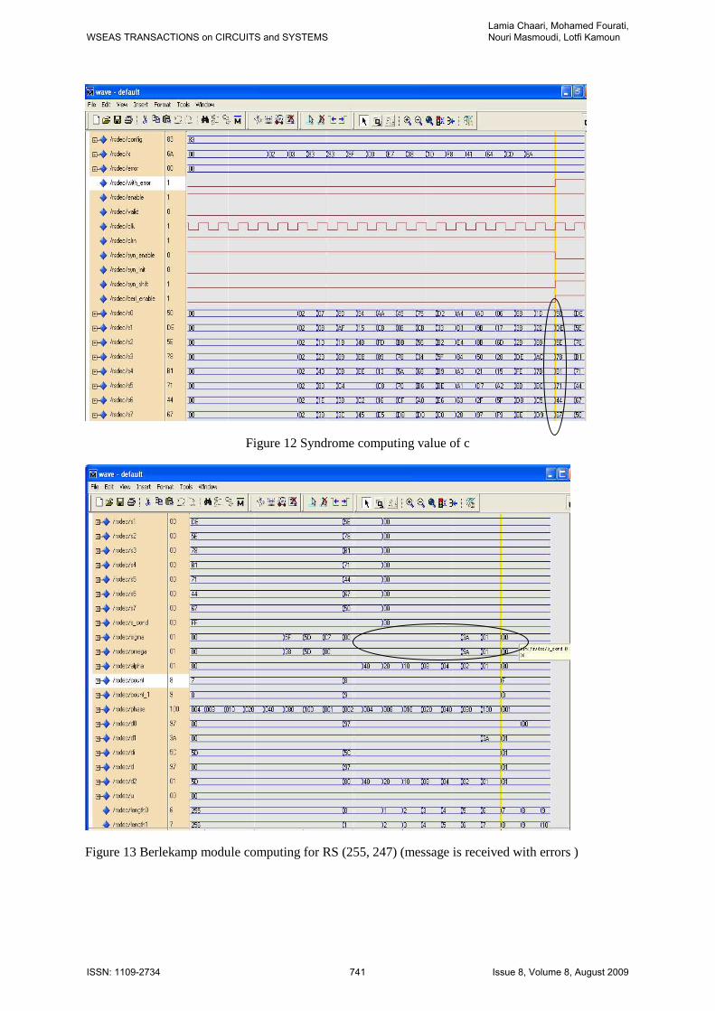
Figure 12 Syndrome computing value of c
Figure 13 Berlekamp module computing for RS (255, 247) (message is received with errors )
WSEAS TRANSACTIONS on CIRCUITS and SYSTEMSLamia Chaari, Mohamed Fourati, Nouri Masmoudi, Lotfi Kamoun
ISSN: 1109-2734 741 Issue 8, Volume 8, August 2009

Figure 14 Chien module computing for RS (255, 247) (message is received with errors )
Figure 15: Errors polynomial computing
WSEAS TRANSACTIONS on CIRCUITS and SYSTEMSLamia Chaari, Mohamed Fourati, Nouri Masmoudi, Lotfi Kamoun
ISSN: 1109-2734 742 Issue 8, Volume 8, August 2009
9 Bibliography [1] I. S. Reed and G. Solomon, “ Polynomial codes over certain finite fields”, Journal of the Society for Industrial and Applied Mathematics, 8:300-304, 1960 [2] T. R. N. Rao and E. Fujiwara, Error Control Coding for ComputerSystems, Prentice-Hall, Englewood Cliffs, NJ, USA, 1989. [3] H.C.Chang, C.B.Shung, CY.Lee, “A Reed-Solomon product-code (RS-PC) decoder chip for DVD applications”, Solid-State Circuits, IEEE Journal , Volume: 36 Issue: 2 , Feb. 2001 Page(s): 229 –238 [4] Y.Cho, K.Kang, J.Lee and H.Shin “Proactive Reed-Solomon Bypasss (PRSB): A Technique for Real-Time Multimedia Processing in 3G Cellular Broadcast Networks”, The 11th IEEE International Conference on Embedded and Real-Time computing system and application, 17-19 August 2005, Hong Kong [5] J.SHIAN LI M.W. GUO, “Improving 802.11 Wireless TCP Performance with Adaptive Reed-Solomon Codes: An Experimental Study”, JOURNAL OF INFORMATION SCIENCE AND ENGINEERING 21, 1201-1211 (2005) [6]M.F.Arnal, “Optimisation de la fiabilité pour des communications multipoint par satellite géostationnaire, Thèse, Ecole Nationale supèrieure des télecommunications de paris, 15 dec 2004. [7] DVB, “Framing structure, channel coding and modulation for digital terrestrial television,” ETSI EN 300 744, vol. 4.1, January 2001 [8] Saswat Panigrahi and Tho Le-Ngoc “Fine-Granularity Loading Schemes Using Adaptive Reed-Solomon Coding for xDSL-DMT Systems” EURASIP Journal on Applied Signal Processing, volume 2006 (2006), Article ID 65716, 13 pages [9]HomePlug Powerline Alliance, “Medium Interface Specification. Release 0.5,” November 2000. [10] DAVIC 1.4 Specification. Part 8, “Lower Layer Protocols and Physical Interface,” 1998 [11] ATSC, “ATSC Digital Television Standard, ATSC standard A/53B,” August 2001. [12] M.Bednara, K.Danne, M.Deppe, O.Oberschelp, F.Slomka, J.Teich, “Design and Implementation of Digital Linear Control
Systems on Reconfigurable Hardware”, EURASIP Journal on Applied Signal Processing 2003:6, 594–602, 2003 Hindawi Publishing Corporation [13] W. Tuttlebee, “Software defined radio, baseband technology for 3Ghandsets and basestation,”. Edition JohnWiley & Sons, 2003, 350 pages, ISBN 0-470-86770-1 [14] L.Chaari, M.Fourati, N.Masmoudi and L.Kamoun, “Re-configurability study for digital baseband processing unit for multimode handset architectures”, 12th European Wireless Conference "Enabling Technologies for Wireless Multimedia Communications", April 2 - 5, 2006 - Athens, Greece [15] G.V Meerbergen, M.Moonen, H.De Man, “TURBO-LIKE SOFT-DECISION DECODING OF REED-SOLOMON CODES »,in Proc. of the IEEE Global Telecommunications Conference (Globecom), Dallas, USA, Nov. 2004, pp. 199 – 203 [16] D. Augot, L.Pecquet, “An Alternative to Factorization: a Speedup for Sudan's Decoding Algorithm and its Generalization to Algebraic-Geometric Codes”, Projet CODES, Rapport de recherche n_3532 _ Octobre 1998 _ 15 pages, ISSN 0249-6399 [17] W.J. GROSS, F. R. KSCHISCHANG, R. KOETTER, P. GLENN GULAK,” Towards a VLSI Architecture for Interpolation-Based Soft-Decision Reed-Solomon Decoders”, Journal of VLSI Signal Processing 39, 93–111, 2005 Springer Science + Business Media, [18] D.V.Sarwate, N Rshanbhag, “ High6Speed Architectures for reed-Solomon Decoders”, IEEE trans, VLSI System, revised june 7, 2000 [19] A. Flocke, H. Blume, and T. G. Noll, “Implementation and modeling of parametrizable high-speed Reed Solomon decoders on FPGAs”, Advances in Radio Science, 3, 271–276, 2005, SRef-ID: 1684-9973/ars/2005-3-271, © Copernicus GmbH 2005 [20] Jung H. Lee Jaesung Lee, Myung H. Sunwoo, “Design of Application-Specific Instructions and Hardware Accelerator for Reed-Solomon Codecs”, EURASIP Journal on Applied Signal Processing 2003:13, 1346–1354 Processing 2003:13, 1346–135 2003 Hindawi Publishing Corporation [21] A. A. Pantchichkine, « Cours Mathématiques des codes correcteurs d’erreurs », Master-2 de mathématiques
WSEAS TRANSACTIONS on CIRCUITS and SYSTEMSLamia Chaari, Mohamed Fourati, Nouri Masmoudi, Lotfi Kamoun
ISSN: 1109-2734 743 Issue 8, Volume 8, August 2009
(M2P), "Cryptologie, Sécurité et Codage d’Information", 2004/2005, Module 506a [22] M. A. Ingale,“Error Correcting Codes in Optical Communication Systems”, A Master Thesis, School of Electrical Engineering Department of Signals and Systems, Chalmers University of Technology, January 2003 [23] B.Sklar “ Digital communication-Fundamentals and Applications”, Pearson Education Asia , 2001 [24] H.C.Chang, C.B.Shung, and C.Y.Lee, “A Reed–Solomon Product-Code (RS-PC) Decoder Chip for DVD Applications”, IEEE JOURNAL OF SOLID-STATE CIRCUITS, VOL. 36, NO. 2, FEBRUARY 2001 229. [25] E.R.Berklamp,” Algebric coding theory, McGraw-Hill, New york, 1968: revised edition Aegean Park Press, Laguna Lills, CA, 1984. [26]R.E.Blahut, “Theory and practice off error control codes”, Addison-Weseley, 1983. [27] J. Massey, “Shift-register synthesis and BCH decoding,” IEEE Trans. Inform. Theory, vol. IT-15, pp. 122–127, Jan. 1969. [28] N.Ben Atti, G.M.Diaz–Toca,Hlombardi, “The Berlekamp-Massey Algorithm revisited”, Volume 17 , Issue 1 (April 2006) , Pages: 75 – 82, Year of Publication: 2006, ISSN:0938-1279 [29]S.Dietler, « Implémentation de codes de Reed-Solomon sur FPGA pour communications spatiales », Diploma Project,, 24 janury 2006 [30] Y. Sugiyama, M. Kasahara, S. Hirasawa, and T. Namekawa, “A method for solving key equation for decoding Goppa codes,” Information and Control, vol. 27, pp. 87–99, Jan. 1975. [31] I. Reed, M. Shih, and T. Truong, “VLSI design of inverse-free Berlekamp–Massey algorithm,” Proc. IEE, pt. E, vol. 138, pp. 295–298, Sept. 1991. [32] Charles LEE , L.H , Error-Control Block Codes, Artech House Publishers, 2000 [33] S. B. Wicker, Error control Systems for Digital Communication and Storage, Prentice Hall, 1995. [34] J.k.Park andJ.T.Kim,” Soft IP Compiler for a reed-Solomon Decoder”, ETRI Journal, Volume 25, Number 5, October 2003. [35] Reed-Solomon Compiler from Altera Corporation New in Version 4.1.0, Avril 2006. [36]K.Shimizu, N.Togawa, I.Kenaga and S.Goto, “A reconfigurable adaptive FEC System based on Reed-Solomon code with
interleaving”, IEICE Trans.INF SYST, Vol E88-D N).7, july 2005 [37] Altera Corporation, “Implementing an IEEE Std. 802.16-Compliant FEC Decoder”, M-WP-IEEE802.16-1.0, December 2001, ver. 1.0 [38] Xilinx Inc., Xilinx Foundation ISE version 8.12i, http://www.xilinx.com [39] V.Subramanian, “Configurable Architecture for System-Level Prototyping of High-Speed Embedded Wireless Communication Systems », Master Thesis , faculty of the Virginia Polytechnic Institute and State University, January 13, 2003.
WSEAS TRANSACTIONS on CIRCUITS and SYSTEMSLamia Chaari, Mohamed Fourati, Nouri Masmoudi, Lotfi Kamoun
ISSN: 1109-2734 744 Issue 8, Volume 8, August 2009
Related Documents