A Normal Form Object-Oriented Entity Relationship Diagram Tok Wang LING and Pit Koon TEO Department of Information Systems and Computer Science National University of Singapore Abstract. A normal form object-oriented entity relationship (OOER) diagram is presented to address a set of 00 data modelling issues, viz. the inability to judge the quality of an 00 schema, the presence of inheri- tance conflicts in ISA hierarchies, the lack of explicit support for different relationship types (m;n, n-ary, recursive etc.) in some 00 data models and the lack of general and flexible support for views. Three approaches are described to translate good quality 00 schemas from a normal form OOER diagram. The first approach translates 00 schemas whoee un- derlying 00 data models support the notion of relationship. Thereare no undesirable redundancies in the translated schemes. The second ap- proach provides for 00 data models that do not support the notion of relationship. Some redundancies may arise because of m-n, n-ary rek tionships, but these can be controlled. The third approach treats each 00 schema as au external schema of a conceptual schema represented by a normal form OOER diagram. Redundancies may’ exist at the external schema level, but no redundancies exist at the conceptual echema level. 1 Introduction The tremendous interest in the object-oriented (00) approach has exposed a number of inadequacies [ZO] which are now widely recognised, e.g. lack of a for- mal foundation, a navigational, as opposed to a declarative interface, lack of a standard query language etc. Some of these issues have been addressed, but many remain unresolved. In this paper, we focus on a set of 00 data modelling issues which can be resolved by leveraging techniquestl4, 15, 161 in entity rela- tionship (ER) data modelling@]. Th ese issues include (1) the inability to judge the quality of an 00 schema design, (2) the presence of inheritance conflicts in class hierarchies, (3) the lack of explicit support for different relationship types (m-n, n-ary, recursive etc.) in some 00 data models and (4) the lack of general and flexible support for views. To address these issues, we introduce the notion of a normal form OOER diagram. A normal form OOER diagram extends the classical ER diagram[q in three ways. First, it incorporates the behavioural notions of methods and derived attributes. The additions of these active components and associated semantics for inheritance and complex objects to an ER diagram produce an OOER diagram. Second, the structural properties of the OOER diagram, which are in fact those. of an ER diagram, are in normal form. This guarantees that

Welcome message from author
This document is posted to help you gain knowledge. Please leave a comment to let me know what you think about it! Share it to your friends and learn new things together.
Transcript

A Normal Form Object-Oriented Entity Relationship Diagram
Tok Wang LING and Pit Koon TEO
Department of Information Systems and Computer Science National University of Singapore
Abstract. A normal form object-oriented entity relationship (OOER) diagram is presented to address a set of 00 data modelling issues, viz. the inability to judge the quality of an 00 schema, the presence of inheri- tance conflicts in ISA hierarchies, the lack of explicit support for different relationship types (m;n, n-ary, recursive etc.) in some 00 data models and the lack of general and flexible support for views. Three approaches are described to translate good quality 00 schemas from a normal form OOER diagram. The first approach translates 00 schemas whoee un- derlying 00 data models support the notion of relationship. Thereare no undesirable redundancies in the translated schemes. The second ap- proach provides for 00 data models that do not support the notion of relationship. Some redundancies may arise because of m-n, n-ary rek tionships, but these can be controlled. The third approach treats each 00 schema as au external schema of a conceptual schema represented by a normal form OOER diagram. Redundancies may’ exist at the external schema level, but no redundancies exist at the conceptual echema level.
1 Introduction
The tremendous interest in the object-oriented (00) approach has exposed a number of inadequacies [ZO] which are now widely recognised, e.g. lack of a for- mal foundation, a navigational, as opposed to a declarative interface, lack of a standard query language etc. Some of these issues have been addressed, but many remain unresolved. In this paper, we focus on a set of 00 data modelling issues which can be resolved by leveraging techniquestl4, 15, 161 in entity rela- tionship (ER) data modelling@]. Th ese issues include (1) the inability to judge the quality of an 00 schema design, (2) the presence of inheritance conflicts in class hierarchies, (3) the lack of explicit support for different relationship types (m-n, n-ary, recursive etc.) in some 00 data models and (4) the lack of general and flexible support for views.
To address these issues, we introduce the notion of a normal form OOER diagram. A normal form OOER diagram extends the classical ER diagram[q in three ways. First, it incorporates the behavioural notions of methods and derived attributes. The additions of these active components and associated semantics for inheritance and complex objects to an ER diagram produce an OOER diagram. Second, the structural properties of the OOER diagram, which are in fact those. of an ER diagram, are in normal form. This guarantees that
242
relations generated from a normal form OOER diagram are either in 3NF or 5NF. A normal form OOER diagram does not have undesirable redundancies. It allows the quality of a schema baaed on it to be judged. Third, it does not have any inheritance conflicts in its ISA hierarchies. In [19], we have proposed a complete algorithm which resolves inheritance conflicts in ISA hierarchies.
In this paper, we describe the translation of 00 schemas from a normal form OOER diagram. Each entity type can be translated directly into a class, but, generally, three approaches can be adopted to handle the translations for relationship sets. The first two approaches depend on whether the underlying 00 data model for a translated 00 schema provides explicit support for the notion of relationship. If the notion of relationship is supported, then each m-n, n-ary or recursive relationship set can be translated into a class in the 00 schema. There are no undesirable redundancies in the translated schemas. Otherwise, an embedded, inter-class reference is used to link classes implicitly. In this case, some redundancies may arise because of m-n and n-ary relationships, but these can be controlled. The third approach is a flexible view mechanism that treats each 00 schema as a view of a normal form OOER diagram. We propose a 3- level ER-based schema architecture with the conceptual schema represented by a normal form OOER diagram. Each 00 schema is treated as an external schema that is generated from the conceptual schema by using a set of mapping rules. In [18], mapping rules have been defined to generate 02 external schemas from an OOER diagram. The same rules can be used to generate 02 external schemas from a normal form OOER diagram. Distinct sets of mapping rules[lli, 161 can be used to generate hierarchical, network, ER diagrams, and nested relations external schemas from a normal form OOER diagram. This approach is flexible in the sense that users can choose to view the conceptual schema in ways that they wish to and are comfortable with. The advantages of these data models (00, hierarchical, network, etc.) are preserved at the external schema level.
Section 2 discusses the motivation behind this paper. Section 3 introduces the concept of an OOER diagram. In Section 4, the normal form OOER diagram is defined. Section 5 discusses the steps to transform an OOER diagram into a normal form OOER diagram. Section 6 discusses the generation of 00 schemas from a normal form OOER diagram. Section 7 concludes the paper.
2 Motivation
This paper is motivated by the following observations. First, it is diflicult to judge the quality of an 00 database schema design because, unlike the rela- tional model, it does not have normalisation and dependency theories to assist in database schema design. Second, the 00 approach uses inter-object references (through pointers) and the class hierarchy to represent relationships between classes. Different relationship types (m-n, n-ary, recursive etc.) are represented somewhat imperfectly. For example, consider the following schema from [13]:
(obl, <name: “john”, spouse: O&B) (062, <name; “mary”, spouse: obl>)
.
243
where obl and ob2 are OIDe. There is an inverse relationship reference (a redun- dant relationship) in-the spouse field that can introduce maintenance problems when there are changea in the spouse field, e.g. if “john” and “mary” are di- vorced, then references in the spouse field of both “john” and “mary” must be updated. This is a contradiction to the easy maintainability objective of the 00 paradigm. To resolve this problem, the relationship between “john” and “mary” should be made explicit. As another example, consider the SUPPLIER (S), PART (P), SUPPLIES (SP) database [7], in which S and P are related by an m-n relationship type SP. Using inter-object references, each supplier object is associated with a set of part objects and their respective quantities. Such a struc- ture does not facilitate symmetric queries. To circumvent this deficiency, each part object is then associated with a set of supplier objects and their respective quantities. This introduces redundancy which may lead to updating anomalies. The problems are similar to those of hierarchical models. These problems are amplified when n-ary (n > 2) relationships are considered. There is no feasible solution for representing an n-ary relationship using inter-object references in the 00 paradigm.
Third, except for those OODBMSs that are based on the extended relational model (e.g. POSTGRES [21]), most OODBMSs do not fit into the flevel achema architecture framework as spelled out in the ANSI/X3/SPARC proposal[fl] for DBMSs. Users of most OODBMSs are often presented with a large-grained con- ceptual schema, with little or no facility for defining views. Some proposals for views in OODBMSs have been made[l, 10,221, but the incorporation of a flexible and general view mechanism in OODBMSs is still a research issue.
Fourth, there can be inheritance contlicta in ISA hierarchies.’ Several tech- niques have been proposed to resolve these conflicts, e.g. choosing the first in a list of superclasses, as in ORION[4], using type information as in IRIS[9], deny- ing the creation of (sub)classes with conflicting attributee, as in POSTGRES[21], and explicitly choosing the required property to inherit@], as, in 02 etc. These techniques are generally not satisfactory. For example, Orion’s technique is quite arbitrary and may not yield the required semantics, while POSTGRES’s ap preach is rather inflexible. It is not clear how IRIS determines type specificity. In 02, if twu conflicting properties have different semantics, then explicitly choos- ing one of the two properties to inherit will preclude the user from inheriting the other property. This may not be .desirable. In [19], we have proposed a complete algorithm which resolves inheritance conflicts by examining the semantics of the conflicting properties.
3 An Object-Oriented Entity Relationship Diagram
The ER approach for database schema design uses the concepte of entity type and relationship set, each of which has associated structural properties or at- tributes. An attribute can be single valued, multi-valued or composite. Differ- ent relationship sets are .allowed, e.g. m-n, n-ary, recursive, existence dependent (EX) and identifier dependent (ID) weak relationship sets, special relationship

244
sets such as ISA, UNION, INTERSECTION etc. The structure of a datab can be represented by using an entity-relationship diagram.
Many extensions have been made to the ER approachto improve its ~16 fulness as a database design tool. In [14], a normal form for ER diagrams was introduced which allows the ‘goodness’ of ER diagrams, to be judged *Good nor- mal form relations, either in 3NF or SNF, can be generated from a normal fotm ER diagram by using the techniques introduced in 144. In [lg, 161, &he normal form ER diagram was used to represent the conceptual schema .of a three level schema architecture. External schemas based on the hierarchical, network, ER and nested relations data models can be generated from the conceptual achema by using distinct sets of mapping rules. In effect, this approach allows a user to have different views of the normal form ER diagram.
We believe that this approach can be extended to support 00 external schemas, and to resolve the problems mentioned in Saction 2. Specifically; ‘all the structural properties of the 00 approach can be derived (genkrated) from an ER diagram[l8]. For instance, an 00 clsss hierarchy can be ditly rep- resented using the ER relationship type ‘ISA’. A composite object[ll], e.g. a VEHICLE and its component parts, can be represented by the ER relationship type IS-PART-OF. Existentially dependent objects [12] which cannot .exis# in- dependently of their parent objects correspond to ER weak entics. E&h weak entity type is associated with a parent (regular) entity type through ad existence dependent (EX) relationship or an identifier dependent (ID) ~relationship. The 00 approach also supports the concept of a complex object. In a complex oh ject, the relationships among component objects are not made explicit, but are embedded within the complex object as inter-object references. Note that a com- posite object is a complex object in which the relationships between an object and its component objects are IS-PART-OF relationships.. In the ER approach, the relationships among components of a complex object are made explicit. This is a strong advantage of the ER approach.
The ER model does not have the concept of methods. Furthermore, in the ER model, there are no concepts such as overloading and overridingofproperti~ which are used in 00 inheritance hierarchies. These concepts can be ineorpo- rated in the ER approach, but inheritance conflicts can occur in ISA hierarchies and must be resolved.
We now define the notion of an OOER diagram, and then explain what we mean by inheritance conflicts in ISA hierarchies. In the rest of this paper, we we the term class to refer to entity type in order to conform to usual 00 rtotatione.
Definition 1: An object-oriented entity relationship (OOER) diagram is an ER diagram augmented with methods and derived attributes. An OOER diagram is specifically characterised by the following:
- Methods and derived attributes can be defined for both ent&y.typea and relationship sets in an OOER diagram. We use the generic term peeped to refer to methods, attributes and deri,ved attributes. In an OOER dlc gram, methods and derived attributes are represented in the same way aa attributes, except that they are suffixed by a pair of parentheses. A line end*

245
ing in a single (double) arrowhead(s) links an entity type or relationship set to a method or derived attribute that returns a single (multiple) value(e), similar to the notation for single-valued (multi-valued) attttribtrk. A line without arrowhead is used to link an entity type or relationship set to a method that performs some generally useful functions and does not return a value, e.g. printing an object’s status, firing an employee etc; the cardinality information associated with arrowheads is meaningleee in this context.
- Entity types related through the ISA relationship type are organ&d into an ISA hierarchy. Suppose A and B are entity typea such that A ISA B. Then A inherits, and possibly override, the attributes and methodir of B.
- Components of complex objects belong to classes which are modelled as entity types in the OOER diagram. The relationship seta among these en- tity types are explicitly represented in the OOER diagram, using the usual notation for representing relationship sets in classical ER diagrams.
Figure 1 is an example OOER diagram which will be used to explain some of the concepts. In Figure 1, DOCTOR and NURSE both have a method called bonus() which returns a single value, while EMPLOYEE and PATIENT both have a derived attribute called age0 which also returns a single value. PATIENT has a method called up&et), which does not return a value. Note the line linking updote() to PATIENT.
Definition 3: A property is specified in a class if it is either defined or redefined for the class. A redefined property overloads a similarly named property in some superclass of the class.
As a general rule, only properties specified in an entity type (class) are rep resented in OOER diagrams. Sometimes, for clarity, we allow inherited key at- tributes to be explicitly represented for an entity type. For-example, in Figure 1, empNo is explicitly represented in DOCTOR and NURSE even though empNo is specified in EMPLOYEE, and inherited by both DOCTOR and NURSE.
Definition 3: An inherited property is well-defined if it is specified in one and only one superclass, possibly indirect.
In Figure 2, method pl() and attribute p2 are defined in class Z. Method pl() is redefined in class C and hence are explicitly represented as a property of class C in the OOER diagram. Class B inherits pl() and p2 from class Z, while class C inherits p2 from class Z. Since these properties are inherited rat&r than specified in the classes, they are not explicitly shown on the OOER, diagram.
Definition 4: A con&t situation exists when an inherited property is not well-defined, i.e. two or more superclasaea specify the same property.
In Figure 2, classes B and C have commonly named properties pl() and p2, but only pl() contributes to a conflict situation in clam A. Method pl(),ia not well defined in A (there are two cl- Z and C which specify PI()), i.e. clesa A has an inheritance conflict involving pl(), but p2 is well defined (only clues Z defines ~2).
In [19], we propose that conflicts occur because of: (1) redundant ISA re- lationships, (2) poor or erroneous design, (3) properties in superclausee with the same name and same semantics, and (4) properties in euperclaaeee with the

246
PEDIATRICIAN
Fig. 1. An OOER diagram
same name and different semantics. A complete algorithm is proposed there which resolves inheritance conflicts systematically by considering the semantics of properties.
An OOER diagram may have undesirable redundancies and inheritance con- flicts in its ISA hierarchies. For example, in Figure 1, suppose the functional de- pendency: ward# + floor holds for PATIENT. Then, there will be redundancy if PATIENT records are stored baaed on the attributes for ‘PATIENT shown in Figure 1. Furthermore, the dependency: ward# + floor is ‘not explicitly de- picted on the OOER diagram. As another example, suppose CARING-DOCTOR is a subclass of both DOCTOR and NURSE in Figure 1. DOCTOR and NURSE both have a method bonus(). Then CARING-DOCTOR haa a conflict situation which must, be resolved. In the next section, a normal form for OOER diagram

247
Fig. 2. An Inheritance Diagram
is defined that improves on an OOER diagram by removing undesirable redun- dancies and inheritance conflicts from ISA hierarchies.
4 Normal Form OOER Diagram
The objectives for defining a normal form OOER diagram from an OOER dia- gram are :
1. to capture and preserve the semantics of the real world, in terms of func- tional, multi-valued and join dependencies, by representing them explicitly in the OOER diagram.
2. to ensure that all the relationships represented in the OOER. diagram are non-redundant, i.e. none of the relationships can be derived from other re- lationships.
3. to ensure that the relations translated from the ER diagram are in good normal form, either in 3NF or 5NF.
4. to ensure that all inheritance conflicts are eliminated from ISA hierarchies.
The concept of a normal form OOER diagram depends on the twin concepts of an entity type normal form and a reladionship set normal form. Entity type and relationship set normal forms have been defined in [14]. The results there can be used directly because they improve on the structural properties of an OOER diagram and do not depend on the behavioural properties of the 0OER.diagran-1. We reproduce these results here for completeness. Note that definitions 5 to 10 and lemmas 1 to 4 are taken directly from [14], slightly modified to account for the concept of an OOER diagram. Definition 10 extends the original definition of a normal form for ER diagrams in [14].
248
Definition 5; Let E be an entity type and K be its identifier in an OOER diagram. The set of basic dependencies of E, BD(E), is defined as follows:
1. For each many-to-one attribute A of E, K + A is a functional dependency (FD) in BD(E).
2. For each one-to-many multivalued attribute A of E, A + K is an FD in BD(E).
3. For each one-to-many and many-to-many multivalued attribute A of E, K ++ A is a multivalued dependency (MVD) in BD(E).
4. For each key Kl of E which is not the identifier of E, K + Kl and Kl + K are FDs in BD(E).
5. No other FDs or MVDs are in BD(E).
Informally, the set of basic dependencies of an entity type E are the functional dependencies and multivalued dependencies of E which are explicitly shown in the OOER di,agram.
Definition 6: An entity type % of an OOER diagram-is said to be in entity normal form (ENF) if all functional dependencies and multivalued dependencies which only involve attributes of E, can be derived (or implied) from the set of basic dependencies of E, BD(E), by using Armstrong’s ‘axioms for functional dependencies and inference rules for multivalued dependen&&].
In Figure 1, suppose the FD: ward# + floor holds for PATIENT. Then PATIENT is not in entity normal form because this dependency is not in, nor derivable from, the set of basic dependencies for the entity type. We normalise PATIENT in the next section.
Lemma 1: Let E be an entity type of an OOER diagram. If E is in ENF, then the following statements hold:
1. Each single valued attribute A of E is fully dependent on each key of E which does not contain A, and on each one-to-many attribute of E.
2. All components of any composite single valued attribute A of E are fully dependent on each key of E which does not contain A.
3. There is no non-trivial functional dependencies defined. among components of any composite attribute of E.
4. For each one-to-many attribute A of E and for each many-to-many attribute B of E, A -++ B is a strong MVD, i.e. the FD: A + B does not hold.
5. For each key K of E and for each multivalued attribute A of E, K +-+ A is a strong MVD.
6. No multivaluedattribute of E is multi-dependent’on a part of a key of E. 7. No component of a composite multivalued attribute of E is multi-dependent
on the identifier of E.
Lemma 2: An entity type E of an OOER diagram is in ENF if and only if it satisfies the following conditions:
1. Any non-trivial canonical form full dependency (i.e. the right side of the FD is a single attribute) A -+ B which only involves attributes and components of composite attributes of E implies
249
(a) A is a key,of.E or A is a one-tomany attribute of E, and (b) B is a single valued attribute or B is 8 component of a composite single
valued attribute of E. 2. Any strong MVD: A ++ B which only involves attributes and components
of composite attributes of E and in which B is not multi-dependent on any proper subset of A and no proper subset of B is multi-dependent on. A, implies (a) A is a key.of E or A is a one-to-many attribute of E, and (b) B is a multivalued attribute of E.
Lemmas 1 and 2 can be proved directly using the definition of an ENF entity type, Armstrong’s axioms for functional dependencies and inference rules for multivalued dependencies.
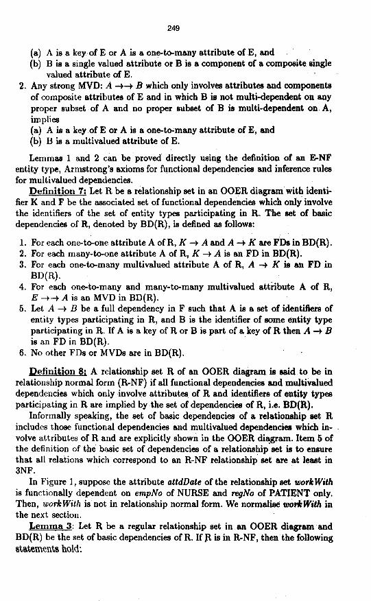
Definition 7: Let R be a relationship set in an OOER diagram with identi- fier K and F be the associated set of functional dependencies which only involve the identifiers of the set of entity types participating in R. The set of basic dependencies of R, denoted by BD(R), is defined 8s follows:
1. For each one-to-one attribute A of R, K + A and A + K are FDs in BD(R). . . 2. For each many-to-one attribute A of R, K + A is 8n FD in BD(R).
3. For each one-to-many multivalued attribute A of R, A -+ K ig an FD in BD(R).
4. For each one-to-many and many-to-many multivalued attribute A of R, E -++ A is an MVD in BD(R).
5. Let A + B be a full dependency in F such that A is a set of identiilers of entity types participating in R, and B is the identifier of some entity type participating in R. If A is a key of R or B is part of a key of R then A + B is an FD in BD(R).
6. No other FDs or MVDs are in BD(R).
Definition 8; A relationship set R of an OOER diagram is ssrid to be in relationship normal form (R-NF) if all functional dependencies snd multiv8lued dependencies which only involve attributes of R and identifiers of entity types participating in R are implied by the set of dependencies of R, i.e. BD(R).
Informally speaking, the set of basic dependencies of a relationship set R includes those functional dependencies and multivalued dependencies which in- volve attributes of R and are explicitly shown in the OOER di!gram. Item 5 of the definition of the basic set of dependencies of a relationship set is to ensure that all relations which correspond to an R-NF relationship set are at least in 3NF.
In Figure 1, suppose the attribute attdDate of the relationship set workwith is functionally dependent on empNo of NURSE and regNo of PATIENT only. Then, w&With is not in relationship normal form. We normalii wo&With in the next section.
Lemma 3: Let R be a regular relationship set in an OOER diagram and BD(R) be the set of basic dependencies of R. If .R is in R-NF, then the following statements hold:

250
1. All many-to-one attributes of R are fully dependent on each key, each one- to-one attribute and each on&o-many attribute of R.
2. All components of any composite single valued attribute A of R are fully dependent on each key of R, each one-to-many attribute and each one-t* one attribute of R which is not equal to A.
3. .There is no non-trivial functional dependencies defined among components of any composite attribute of R.
4. For each one-to-many (or one-to-one) attribute A of R and for each many- to-many attribute B of R, A -++ B is a strong MVD. ’
5. .For each key K of R and for each multivalued attribute A of R, K +-+ A is a strong MVD.
6. No multivalued attribute of R is multi-dependent on a part of a key of E.’ 7. No component of a composite multivalued attribute of R is multi-dependent
on the identifier of E.
This lemma is similar to lemma 1. Lemma 4: Let R be a regular relationship set in an OOER diagram and
BD(R) be the set of basic dependencies of R. R is in R-NF if and only if it satisfies the following conditions:
1. Any non-trivial full dependency: A + B which only involves attributes, com- ponents of composite attributes, and identifiers of entity types participating in R, and in which B is an attribute or a component of a composite attribute of R implies (a) A is a key of R, or A is a one-to-many or one-to-one attribute of R, and (b) B is a single valued attribute or a component of a composite single yalued
attribute of R. 2. Any non-trivial full dependency: A + B which only involves attributes of
identifiers of entity types participating in R and in which B is a single at- tribute, implies either A is a key of R or B is part of a key or R.
3. Any strong MVD: A ++ B which only involves attributesi components of composite attributes, and identifiers of entity types participating in A and in which B is not multi-dependent on any proper subset of A and no proper subset of B is multi-dependent on A, implies (a) A is a key of R, or A is a one-to-one or one-to-many attribute of R, and (b) B is a multivalued attribute of R.
Lemma 4 is similar to lemma 2, kxcept the extra condition (2) in lemma 4. Definition 9: Let D be an OOER diagram. The set of basic dependencies
of D, denoted by BD(D), is defined as the union of the sets of dependencies of all entity types of D and the sets of basic dependencies of all relationship sets of D.
Definition 10: An OOER diagram D is a normal form OOER diagram if it satisfies the following conditions:
1. All property names are distinct and of different semantics within an entity type or relationship set. All key attributes must be distinct, except for key attributes inherited from superclasses in ISA hierarchies.

251
2. Every entity type in the OOER diagram is in ENF. 3. Every relationship set in the OOER diagram is in RNF. 4. All relationships and dependencies are implied by the set of basic dependen-
cies of D. 5. Every relationship set R with no associated attribute defined on it, satisfies
the condition that R is not equal to a projection of the join of any two or more other relationship sets
6. There are no inheritance conflicts in its ISA hierarchies.
Informally, in condition one, we adopt a relaxed form of the universal rela- tion assumption. The second condition ensures that all relations generated for all entity types are in 5NF. The fourth condition ensures that the OOER di+ gram has captured all the relationships and dependencies of the given database. The third and fifth conditions ensure that all relations generated for all regular relationship sets are either in 3NF or 5NF and that there is no relation in BCNF but not in 4NF or 5NF.
5 Deriving a normal form OOER diagram
In this section, we convert the OOER diagram of Figure 1 to a normal .form OOER diagram. The result of the conversion is shown in Figure 3. The following steps are adopted in order to achieve the conversion:
(Step 1) Ensure that all. property names within each entity type and rela- tionship set are distinct and of different semantics. Ensure that all key attributes are uniquely named, other than those inherited from superclasses.
(Step 2) Convert any non ENF entity type to ENF. We remove all unde- sirable functional dependencies and/or multivalued dependencies by introducing new entity types and relationship sets.
(Step 3) Convert any non R-NF relationship set to R-NF. We remove all undesirable functional dependencies, multivalued dependencies, and/or join de- pendencies either by introducing new entity types and relationship sets or by splitting the relationship set into smaller ones.
(Step 4) Remove each relationship set which has no associated attributes and is equal to a projection of the join of two or more other relationship sets.
(Step 5) Remove any inheritance conflicts from ISA hierarchies. In step 1, we adopt a relaxed form of the universal relation assumption, as
noted in Section 4, Definition 10. Key attributes must be unique, except for those inherited from superclasses. In Figure 3, for example, DOCTOR and NURSE inherits the key attribute empNo from EMPLOYEE. The empNo key attribute is therefore not uniquely named in this ISA (or UNION) hierarchy. Strictly, we need not display empNo of DOCTOR and NURSE explicitly on the OOER diagram, since empNo is specified in EMPLOYEE. Non-key attributes and method names may not be unique. For example, in Figure 3, both EMPLOYEE and PATIENT have similarly named attributes name and dab, and derived attribute aget). In such cases, the context is sufficient to distinguish among these non-key attributes and methods.

DEPARTMENT
1 PEFIATRI\CIANj
(degree) --
1
Fig. 3. Normal Form OOER Diagram
In Step 2, if an entity type is not in normal form, we remove some of the attributes involved and .create some hew entity types and relatiomrhip sets. For example, the PATIENT entity type in Figure 1 is normaheed by remov- ing its WC&# and floor attributes and creating a new entity type WARD and relationship set stay, as shown in Figure 3. This is to ensure that the FD: ward# -+ floor is explicitly represented in the OOER diqram.
In Step 3, if a relationship set is not in normal form, we remove some of the attributes involved and create some new entity types and relatioinrhip mete, or split the relationship set into two or more smaller relationship se&e. Fo+example, in Figure 1, the relationship work With is not in relationship normal form b&au%e its attribute &&ate is functionally dependent on etnpNo of NVF@E srtd n+JVo of PATlENT only. In Figure 3, we norm&se the work With relatioriship set ‘of

253
Figure 1 by creating a new relationship set attendTo with 8n as8ociated attribute attdDate.
In Step 4, we remove any relationship set with no associated attributes which is equal to 8 projection of the join of two or more other relationship eet8, To detect such relationship sets, we require information about the oemantic meaning of the relationship sets which can be provided by the database deeigner or owner. Thii step also remove8 any redundant ISA relationships. A direct ISA relationship A ISA C is redundant if there is some entity B such that A ISA B and B ISA C. This redundancy is a result of the transitivity of the ISA relatiowhip #ct. In Figure 1, the ISA relationship set between PEDIATRICIAN and EMPLOYEE is redundant, and must be removed, as shown in Figure 3.
In Step 5, inheritance conflicts in ISA hierarchies are removed by using the method introduced in [19]. We will not describe the details here, but give 8n example to illustrate how we can remove inheritance conflicts.
Example: In Section 3, we describe a conflict situation involving a class CARING-DOCTOR which is a subclass of both DOCTOR and NUI@E (a multi- ple inheritance situation). DOCTOR and NURSE both specify a method bonus() which causes a conflict situation for CARINGDOCTOR. This conflict situation can be resolved by considering the semantics of bonus(). If the semantics (im- plementation) of bonus() is the same for both DOCTOR and NURSE, then it is better to factor bonus0 to a more general class EMPLOYEE. If the semen- tica of bonus(,) is different, then several approaches can be taken to resolve the conflict[l9]. First, we can rename the property bonus() for either DOCTOR or NURSE, or both, so that CARING-DOCTOR can inherit both these methods. This approach is not consistent with the use of similarly named propestiea in ISA hierarchies in order to support polymorphism. Second, CARING-DOCTOR may explicitly choose to inherit from either DOCTOR or NURSE, depending on the required seinantics. This precludes CARINGDOCTOR from inheriting both bonus0 methods. Third, CARINGDOCTOR may specify its cIwn defini- tion of the bonus{) method, i.e. it overrides the definition of bonus0 in its two superclasses.
We now explain how the normal form OOER diagram can be used ti address three of the. problems of Sect&n 2. The problem related to views ia addreaeed in the next section. Firstly, the normal form OOER diagram preserves application semantics by explicitly capturing entity types, relationship sets (m-n, h+ry, re cursive, ISA etc.) and their attributes. By providing strong support for different relationship types among entity types, the ER approach eliminate8 the prob- lems that the 00 approach faces in representing these relationship typee. For instance, the problems of the ‘spouse’ relationship of Section 2, or the relation- ship between suppliers and parts (e.g. presence -of redundant pointers, probled in supporting symmetric queries etc.) are eliminated.
Secondly, a normal form OOER diagram uses established ER, normalisa- tion and dependency theories to provide a strong theoretical foundation. It is therefore possible to judge the quality of a schema based on the ER approach.
Thirdly, a normal form OOER diagram does not have any inheritance con- flicts in its ISA. hierarchies. This is by its definition.
254
6 Generating 00 Schemas
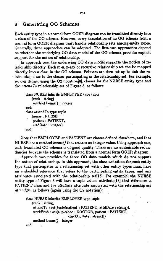
Each entity type in a normal form OOER diagram can be translated directly into a class of the 00 schema. However, every translation of an 00 schema from a normal form OOER diagram must handle relationship sets amongentity types. Generally, three approaches can be adopted. The fist two approaches depend on whether the underlying 00 data model of the 00 schema provides explicit support for the notion of relationship.
In approach one, the underlying 00 data model supports the notion of re- lationship directly. Each m-n, n-ary or recursive relationship set can be mapped directly into a class in the 00 schema. Pointers are then set up to link the re- lationship class to the classes participating in the relationship set. For example, we can define, using the 02 notation@], classes for the NURSE entity type and the attendTo relationship set of Figure 3, as follows:
class NURSE inherits EMPLOYEE type tuple (rank : string) method bonus() : integer
end; class attendTo type tuple
(nurse : NURSE, patient : PATIENT, attdDate : integer)
end;
Note that EMPL0YE.E and PATIENT are classes defined elsewhere, and that NURSE has a method bonus0 that returns an integer value. Using approach one, each translated 00 schema is of good quality. There are no undesirable redun- dancies because the schema is translated from a normal form OOER diagram.
Approach two provides for those 00 data models which do not support the notion of relationship. In this approach, the class definition for.each entity type that participates in a relationship set with other entity types must have an embedded reference that refers to the participating entity types, and any attributes associated with the relationship set[l8]. For example, the MUFjSE entity type of Figure 3 will have a tuple-valued attribute[B] that rkferences a PATIENT class and the attdDate attribute associated with the relationship set attendTo, as follows (again using the 02 notation):
class NURSE inherits EMPLOYEE type tuple (rank : string, attendTo : set(tuple(patient : PATIENT, attdDate : string)), workwith : set(tuple(doc : DOCTOR, patient : PATIENT,
&ckUpDate : string))) method bonus0 : integer
end;

255
class PATIENT type tuple (regNo : string, name : string, dob : string, sex : char, attendTo : set(tuple(nurse : NURSE, attdDate : string)), workWith : set(tuple(doc : DOCTOR, nurse : NURSE,
checkUpDate : string))) method age0 : integer,
update0 end;
Note that EMPLOYEE is a class defined elsewhere and PATIENT has a method update{) which. d oes not return any value. Using approach two, each translated 00 schema does not contain undesirable redundancies except those arising from the existence of m-n and n-ary relationship sets. These redundancies can be controlled at the system level, similar in concept to the physical/virtual pairing feature in IMS[7]. The spouse schema of Section 2 is another example of using approach two.
The third approach treats each 00 schema as a view of a normal formOOER diagram. We propose a three level ER-based schema architecture to support this view mechanism. The conceptual schema is represented by a norm.al form OOER diagram. Each 00 schema is a view or external schema of the conceptual schema that is generated by using a set of mapping rules. In [18], a set of mapping rules has been defined to generate 02 external schemas from an OOER diagram. This set of rules can still be applied to a normal form OOER diagram.
Each entity type in the conceptual schema can be mapped to a class in the 00 external schema. If there is a relationship set between two entity types Er and E2, then without loss of generality, Es can be a set-valued attribute in the class specification of El. For example, the class DOCTOR has-an attribute Ddc- Pat whose value is a set of entities in the class PATIENT. Note that we can have different views of how the entity types are related in the external schema. For example, an instance of the class PATIENT can have a set of associated doctors while an instance of the class DOCTOR can have a set of associated patients. Any redundancy in the external schema is virtual as no redundancy exists in the conceptual schema.
The following 00 external schema, again using the 02 notation, is generated by applying the mapping rules given in [18].
class EMPLOYEE type tuple (empNo : string, name : string, dob : integer) method age0 : integer
end; class DOCTOR inherits EMPLOYEE type tuple
(qual ; set(tuple(year : string, degree : string)), Dot-Pat : set(PATIENT))
256
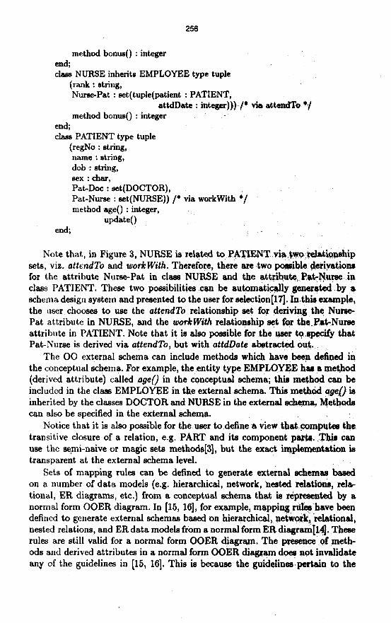
method bonus0 : integer end; class NURSE inherits EMPLOYEE type tuple
(rank : string, Nurse-Pat : eet(tuple(patient : PATIENT,
attdDate : integer))) ‘/* via attendTo */ method bonus0 : integer
end; class PATIENT type tuple
(regNo : string, name : string, dob : string, sex:char, Pat-Dot : set(DOCTOR), Pat-Nurse : set(NUFtSE)) /* via workwith ;/ method age0 : integer,
UpdW) end; -
Note that, in Figure 3, NURSE is related to PATIENT via tvq;relationahip sets, viz. attendTo and work With. Therefore, there are two poaoible derivations for the attribute Nurse-Pat in class NURSE and the attribute Pat-Nurse. in class PATIENT. These two possibilities can be automatically generated .by a schema design system and presented to the user for selection[ll;l]. Inthie example, the user chooses to use the attendTo relationship set for deriving the Nunre- Pat attribute in NURSE, and the workWith relationship set for the.Pat-Nuree attribute in PATIENT. Note that it is also possible for the user to qpecify that Pat-Nurse is derived via attendTo, but with attdllate abetracted OUT. :
The 00 external schema can include methods which have been defined in the conceptual schema. For example, the entity type EMPLOYEE has a method (derived attribute) called Pge() in the conceptual schema; this method can be included in the class EMPLOYEE in the external schema. This method aget) is inherited by the classes DOCTOR and NURSE in the external scheana Methods can also be specified in the external schema.
Notice that it is also possible for the ueer to definer a view that ,computee the transitive closure of a relation, e.g. PART and its component parta. .Thie can use the semi-naive or magic sets methode[3], but the exact implementation ie transparent at the external schema level.
Sets of mapping rules can be defined to generate external schemaa baaed on a number of data models (e.g. hierarchical, network, nested relatlona, rela- tional, ER diagrams, etc.) from a conceptual schema that is represented by a normal form OOER diagram. In [15, 161, for example, mapping r&$have been defined to generate external schemas based on hierarchical, net&ark, ‘relational, nested relations, and ER data models from a normal form ER diagram[Hj. .Theae rules are still valid for a normal form OOER diagram. The pence of meth- ods and derived attributes in a normal form OOER diag3+n doee not invalidate any of the guidelines in [15, 161. This is because the guidelines pertain to the

257
structural properties of a normal form ER diagram, whereas methods~and d& rived attributes provide an orthogonal behavioural perspective. Depending on the needs of users, the appropriate external schemes can be defined. External schemas may not necessarily be normal&d, and therefore users may perceive some form of ‘redundancy’. However, this redundancy is virtual in the sense that no redundancy exists at the conceptual schema level and data is not stored redundantly.
7 Conclusion
In this paper, we have defined the notion of an OOER diagram. An OOER dia- gram is a classical ER diagram augmented with methods and derived attributes. It incorporates 00 concepts such as methods, inheritance (through the &A, UNION, DECOMPOSE, INTERSECTION relationships), class (entity or rela- tionship), existentially dependent objects (weak entities) etc. An OOER diagram may have redundancies and inheritance conflicts in itsISA hierarchies. The con- cept of a normal form OOER diagram is then proposed which improves on an OOER diagram by removing undesirable redundancies from the OOER diagram, and any inheritance conflicts from its ISA hierarchies. An OOER diagram is of ‘good’ quality if the OOER diagram is in normal form.
By using the normal form OOER diagram as a tool to design 00 schemas, we can address a number of 00 data modelling inadequacies, viz. (1)‘the inability to judge the quality of an 00 database schema, (2) the presence of inheritance conflicts in ISA hierarchies, (3) the lack of explicit support for different types of relationship (m-n, nary, recursive etc.) in some 00 data models, and (4) the lack of flexible support for views. Object-oriented.schemaa.can be translated from a normal form OOER diagram. Snch translations must handle relationship sets that are explicitly represented in the normal form OOER diagram. We provide three different approachesto handle the translations. The first approach can be used to translate 00 schemas whose underlying 00 data modelssupport the notion of relationship. Using this approach, the translated 00 schemas do not have any undesirable redundancies because they are translated from a normal form OOER diagram. The second approach is used when the underlying 00 data models do not support the notion of relationship. In this case, some red~udanciee may arise because of the existence of m-n and n-ary relationship s+r,:but these redundancies can be controlled at the system level. The third approach provides a flexible view mechanism built on an ER-based &level schema architecture. In the third approach, the normal form OOER diagram is the conceptual schema while each 00 schema is a view or external schema that is generated.from the conceptual schema by using a set of mapping rules. There may’be redundancies at the external schema level, but these redundancies are virtual. No redundancies exist at the conceptual schema level.

References
1. S. Abiteboul, A. Bonner: Objects and Views. Proc. ACM Sigmod ht. Conf. OXI
Management of Data, 1991. 2. ANSI/X3/SPARC Study Group on Data Base Management Syateme: kerim k
port. FDT (ACM Sigmod bulletin) Vol. 7, No. 2, 1975. 3. F. Bancilhon, R. Fl.amdcrishnan: An Amateur’s Introduction to &cursive Query
Processing. Proc. ACM Sigmod Int. Conf. on Management of Data, 1986, pp. 1652. 4. J. Banerjee et al: Data model issues for object-oriented applications. ACM ‘Ikans-
actions on Office Information Systems, Vol. 5, No. 1, Jan 87, pp. 3-26. 5. C. Beeri, R. Fagin, J. Howard: A complete asiomatitationfor junchonal and mtd-
tiualued dependencies in database relations. Proc. ACM Sigmod Int. Conf. Man- agement of Data, 1977.
6. P. P. Chen: The entity-relationship model: toward a unified view of data. ACM Transactions on Database Systems, Vol. 1, No. 1, 1976.
7. C. Date: An introduction to database systems Vol. 1. Addison Wesley, 4th edition, 1986.
8. 0. Deux et al: The 02 system. Commtications of the ACM, Vol. 34, No. 10, Ott 1991, pp. 35-48.
9. D. Fishman et al: IRIS: An object-oriented database management syslem. ACM Transactions on Office Information Systems, Vol. 5, No. 1, Jan 87, pp. 48-69.
10. B.Hailpern, H.Ossher: &tending objects to support multiple interfaces and access controls. IEEE Transactions on Software Engineering, Vol. 16, No. 11, Nov 1990.
11. W. Kim et al: Composite object support in an object-oriented database sydtem. Proc. OOPSLA, 1987.
12. W. Kim: An introduction to object-oriented databases. MIT Press, 1990. 13. C. Lecluse, ,P. Richard, F. Velez: O??, an object-oriented data model. Proc. ACM
Sigmod Int. Conf. on Management of Data, Jun 1988. 14. T.W. Ling: A normal form for entity-relationship diagrams. Proc. 4th Int. Conf.
on Entity-Relationship Approach, 1985, pp. 24-35. 15. T.W. Ling: A three level schema archihecture ER-based data base management
system. Proc. 6th Int. Conf. on Entity Relationship Approach, 1987, pp. 181-196. 16. T.W. Ling: External schema3 of entity-relationship based data base management
systems. In Entity-Relationship Approach, C. Batini (Eds.), EIsevier Science Pub- lishers, 1989.
17. T.W. Ling, M.L. Lee: A Prolog implementation of an entity-relationship based database management system. Proc. 1OtIi Int. Conf. on Entity ReIatio&ip Ap proach, 1991.
18. T.W. Ling, P.K. Teo, L.L. Yam Genemting object-oriented views Mm an ER- based conceptual schema. 3rd Int. Symposium on Data- Systems for Advanced Applications, Apr 6-8, Taejon, Korea, 1993.
19. T.W. Ling, P.K. Teo: Inheritance conflicts in object-orienkd systems. Proc. Database and Expert Systems Applications, Prague, Czech Rep., Sep 1993.
20. T.W. Ling, P.K. Tea: Toward resolving inadequacies in objectoriented data models. Information and Software Technology, Vol. 35, No. 5, May 1993.
21. L. Rowe, M. Stonebraker: The Postgres data model. In The Poatgrea Papers, Memo UCB/ERL M86/85 (Revised), University of California, Berkeley, Jun 87.
22. J. Shilling, P. Sweeney: Three steps to views: extending the object-oriented paradigm. Proc. OOPSLA, 1989.
Related Documents