DEFENCE I < m J DEFENSE A New Remote-Sensing Method for Mine Detection using HPM Irradiation and IR Detection S.M. Khanna, F. Paquet, R. Apps and J.S. Seregelyi Defence Research Establishment Ottawa DEFENCE RESEARCH ESTABLISHMENT OTTAWA TECHNICAL REPORT DREOTR 1999-132 December 1999 20000131 028 1^1 National Defense f^aTiaHa' Defence nationale DISTRIBUTION STATEMENT A V^cUldUcl Approved for Public Release Distribution Unlimited r ETl6 QUAIJSY nXSESfBO) I

Welcome message from author
This document is posted to help you gain knowledge. Please leave a comment to let me know what you think about it! Share it to your friends and learn new things together.
Transcript
DEFENCE I < m J DEFENSE
A New Remote-Sensing Method for Mine Detection using HPM Irradiation and IR Detection
S.M. Khanna, F. Paquet, R. Apps and J.S. Seregelyi Defence Research Establishment Ottawa
DEFENCE RESEARCH ESTABLISHMENT OTTAWA
TECHNICAL REPORT DREOTR 1999-132
December 1999 20000131 028 1^1 National Defense f^aTiaHa' ■ ▼■ Defence nationale DISTRIBUTION STATEMENT A V^cUldUcl
Approved for Public Release Distribution Unlimited
rETl6 QUAIJSY nXSESfBO) I
.v.. Ru DEFENCE! « 1 DEFENSE
A New Remote-Sensing Method for Mine Detection using HPM Irradiation and IR Detection
S.M. Khanna and F. Paquet Radiation Effects Group Space Systems & Technology Section
R. Apps and J.S. Seregelyi Microwave Analysis & Countermeasures Group Electronic Countermeasures Section
DEFENCE RESEARCH ESTABLISHMENT OTTAWA
TECHNICAL REPORT DREOTR 1999-132
December 1999
Project 5EC11
ABSTRACT
A remote-sensing method based on active high-power microwave (HPM) illumination and detection in the infrared (IR) region is described for the detection of shallow buried landmines. This method is based on different interactions of the incident HPM radiation with the mine and the surrounding soil which occur due to a difference in their complex dielectric constants. This leads to the development of a thermal signature of the mine at the soil surface that can be detected in the infrared region. The thermal signature which is observed initially in near real-time persists for several minutes following HPM illumination. It is primarily made up of two components. The first component appears on the soil surface in near real-time due to the interference of the incident HPM beam and the HPM beam reflected by the mine. A second signature is due to the absorption of microwave energy by the mine. This signature appears at the soil surface after a brief time-delay from the start of HPM illumination. At any instant, the resultant thermal signature at the soil surface is the sum of the two time-dependent signatures. In this report we provide both laboratory and field trial results obtained using this method to detect metallic and non-metallic mine surrogates, dummy mines without explosives and live mines with explosives but without any fuse.
RESUME
Une methode de teledetection basee sur 1'irradiation et la detection active de micro-onde de grande puissance (HPM) dans la region infrarouge (IR) est decrite pour la detection des mines enterres sous la surface du sol. Cette methode est basee sur les interactions differentes du rayonnement du HPM incident avec la mine contrairement ä celles du sol environnant. Ceci se produit en raison d'une difference dans la constante dielectrique complexe de la mine et du sol avoisinant. Ce phenomene mene au developpement d'une signature thermique de la mine ä la surface du sol qui peut etre detectee dans la region infrarouge. La signature peut etre detectee en temps quasi-reel aussi bien qu'apres un bref delai suivant l'irradiation de HPM. La signature thermique ä la surface du sol se compose principalement de deux composants. Un des composant est le resultat de 1'interference du faisceau HPM incident et de celui reflechi. Cette signature apparait ä la surface du sol en temps quasi-reel. Une deuxieme signature est cause par l'absorbtion par la mine de l'energie micro-onde. Cette signature apparait ä la surface du sol avec un certain delai par rapport ä l'irradiation de HPM. A chaque instant, la signature thermique resultante est la somme des deux signatures dependantes du temps. Dans ce document, nous presentons les resultats experimentaux obtenus par le biais d'experiences de laboratoire et d'essais en conditions reelles pour la detection de mines metalliques, non metalliques, factices sans explosif et reelles avec explosif mais sans fusible.
m
EXECUTIVE SUMMARY
It is estimated that there are over one hundred million anti-personnel mines that are scattered in a number of countries throughout the world. It is important that these mines are detected and destroyed. However, at present, there is no adequate mine detection method that has an acceptably high detection rate and a low false alarm rate. In the present paper, a new mine detection method is presented which is based on active illumination of the target with high power microwave (HPM) radiation and detection of the resulting signatures in the infrared (IR) wavelength region. Experimental results are presented from laboratory experiments and field trials based on this method for the detection of metallic and non-metallic mine surrogates, dummy mines and live mines without fuses. This method complements the passive infrared remote-sensing method for mine detection. The main advantages of this method include the simplicity of the underlying principle of target detection, remote-sensing operation, ability to detect targets under cloudy conditions with little dependence on solar diurnal cycle and ability to detect both metallic and non-metallic mines. Its main drawback appears to be the use of high power microwaves for its operation.
Khanna S.M., Paquet F., Apps R. and Seregelyi J.S., A new remote-sensing method for mine detection using HPM irradiation and IR detection . Defence Research Establishment Ottawa, DREO TR 1999-132, December 1999
SOMMAIRE
II est estime que plus de cent millions de mines antipersonnelles sont eparpillees dans plusieurs pays ä travers le monde. II est important que ces mines soient detectees et detruites. Cependant, il n'existe presentement aucune methode de detection de mine adequate ayant un taux acceptable de detection et de fausse d'alarme. Dans ce document, on y presente une nouvelle methode de detection de mine qui est basee sur 1'irradiation active de la cible avec le rayonnement de la micro-onde de grande puissance (HPM) et la detection des signatures resultantes dans la region de longueur d'onde infrarouge (IR). Bases sur cette methode, les resultats experimentaux des experiences de laboratoire et des essais en conditions reelles pour la detection des substituts metalliques et non metalliques de mines, des mines factices et des mines reelles sans fusible sont presentes. Cette methode complete la methode de teledetection de mine ä infrarouge passive. Les principaux avantages de cette methode incluent la simplicity du principe fondamental de la detection de cible, l'operation de teledetection, la capacite de detecter des cibles sous un ciel couvert avec peu de dependance du cycle solaire et la capacite de detecter les mines metallique et non metallique ä la fois. L'inconvenient majeur semble etre l'utilisation de micro-onde ä grande puissance pour son operation.
Khanna S.M., Paquet F., Apps R. and Seregelyi J.S., Une nouvelle methode de teledetection de mines utilisant l'irradiation de micro-onde de grande puissance (HPM) et la detection infrarouge (IR), Le Centre de Recherche pour la Defense Ottawa, CRDO TR 1999-132, December 1999 (en anglais)

TABLE OF CONTENTS
ABSTRACT iii
RESUME Hi
EXECUTIVE SUMMARY v
SOMMAERE v
TABLE OF CONTENTS vii
LIST OF FIGURES ix
1. INTRODUCTION 1
2. THEORY 3
2.1 HPMTRMETHOD 3
2.2 PASSIVE IR METHOD 6
3. EXPERIMENTAL METHOD AND RESULTS 8
3.1 LABORATORY RESULTS 10
3.1.1 ANECHOIC CHAMBER RESULTS 10
3.1.2 RESULTS FROM OUTSIDE THE ANECHOIC CHAMBER 13
3.2 FIELD TRIAL RESULTS 16
4. CONCLUSIONS 21
5. REFERENCES 21
vii
LIST OF FIGURES
Fig. 1. Dielectric properties of sand at 2.45 GHz as a function of Moisture content
Fig 2a: Schematic of a model3 showing a buried mine in the ground. a: Undisturbed soil; b: soil above mine; c: mine 7
Fig 2b: Schematic of a simplified model3 to explain passive infrared imaging method using a constant heat flow and different heat impedances in the mine and the reference (no mine) sites. T«, is the temperature deep inside the ground 7
Figure 3: PMA 1, PMA2 andPMA3 mines used in this work 9
Figure 4: IR picture of the sand surface above three mine surrogates buried in dry sand after irradiating them with PM 11
Figure 5: IR pictures of soil surface showing the effect of reflection of microwaves from two mine surrogates buried at different depths in moist sand 12
Figure 6: Experimental set-up for real-time HPM/IR imaging outside the anechoic chamber. The height of the horn could be adjusted 14
Figure 7: IR pictures of the sand surface over mine surrogates buried in moist sand at different depths. The temperature range of the data are shown in each picture, a: Before HPM irradiation; b: 2 min. after irradiation; c: 5.5 min after HPM irradiation; d: 5.5 min after irradiation but without any compensation for non-uniform HPM illumination; e: A 3D representation of Fig. 7d showing IR intensity across the image. HPM spot intensity has been removed from Figs. 7b and 7c. Fig. 7c and 7d are the same except that the spot has been removed in Fig.7c 15
Figure 8: Experimental arrangement used in field trials at DRES for the detection of real mines using the HPM/IR method 17
Figure 9: Standard photographs showing PMA 1 and PMA 3 buried in soil without turf (Fig. 9a) and soil with turf (Fig. 9b). The soil above the mines had been removed to take this photograph 18
IX
T JST OF FIGURES
Figure 10: JR. pictures of loose soil covering PMA 1 containing explosives, a: Before HPM irradiation; b: 3 min from start of HPM irradiation; c: 20 min after HPM irradiation. Soil moisture content: 1.33%; Depth of mine: 1.5 cm.; Microwave power level: 5kW; Time of irradiation: 5 min. The mine is visible due to microwave absorption by the mine as shown in Fig. 10 c. Results due to reflection of microwaves by the mine are ambiguous (Fig. 10 b). Enhanced thermal features in this picture could be related to the mine .19
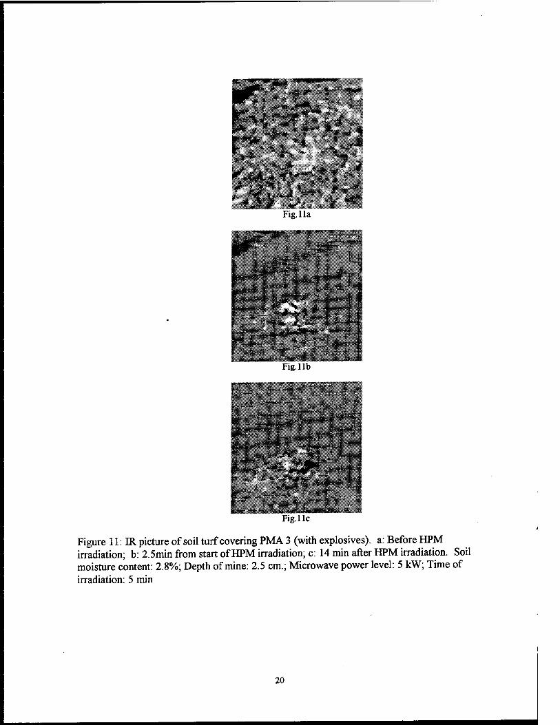
Figure 11: JR. picture of soil turf covering PMA 3 (with explosives). a: Before HPM irradiation; b: 2.5min from start of HPM irradiation; c: 14 min after HPM irradiation. Soil moisture content: 2.8%;. Depth of mine: 2.5 cm.; Microwave power level: 5 kW; Time of irradiation: 5 min
1. INTRODUCTION
There are over 110 million deployed and 100 million stockpiled anti-personnel mines in a number of countries throughout the world1. The question of stopping further proliferation and deployment of the mines has been gaining momentum. The recent international treaty to ban the use of the mines by most of the countries of the world gives hope for the elimination of these weapons. One can hope that new mines will not be deployed in the future and that the mines which are buried in the ground will be detected and destroyed. Unfortunately, the present technology for detection of the buried mines is not adequate2. The problems are further aggravated since most anti-personnel mines have been deployed in poor countries and in rather difficult and remote terrain. Non-government organizations (NGOs) supported by local population and with limited resources are often responsible for mine detection and demining. New improved methods are needed to successfully detect and destroy the buried mines through out the world in a reasonable time-period at a manageable cost.
The most common method for mine detection at present is based on manual probing, which is clearly very dangerous, slow and labour intensive. It can easily result in an accident during the demining process. The other popular method is based on detection of the metal in the buried mine. However, the metal content in current anti-personel mine is very small. As a result, it is very difficult to detect anti-personnel mines with small metal content through the conventional electromagnetic method. Further, this method leads to a high false alarm rate.
A large number of high technology methods are being tested for mine detection. For military and humanitarian applications of such methods, a successful mine detection method must be inexpensive, easy to use, and should have a high detection rate. The new detection method must have superior detection sensitivity, a high detection rate and a lower false alarm rate than already available through existing methods. The method should also be forward- looking to avoid the risk of straddling the mine during detection. These new methods, which are at various stages of research and development, include: ground penetrating radar, passive3 and active infrared remote sensing, laser excitation, nuclear detection methods including thermal neutron activation, nuclear magnetic resonance, chemical detection of trace elements including the detection of vapours leaking from the mine, biological methods, acoustic methods, and high speed hot water jets.
Amongst the various high technology methods currently under development, the following methods are more developed and show promise for improved mine detection capabilities. These include: conventional electromagnetic techniques, passive thermal infrared remote-sensing, ground probe radar and thermal neutron activation. Individually, these methods also suffer from one or all of the problems including poor detection rate, low detection accuracy and high false alarms to varying degrees. However, a fusion of data from these sensors could provide a system that may be acceptable for most applications. Amongst these methods, passive IR imaging3 method is particularly attractive due to the simplicity of the technique, remote- sensing capability and relatively low cost as compared to other methods. This method has its own problems. In this technique, the mine signature is strongly dependent on the diurnal variations in solar illumination, the type of soil, soil moisture content, and temperature gradients in the soil. The mine signature may be almost non-existent under cloudy conditions. Active infrared methods have been proposed for mine detection. These methods typically require the
use of a scanning laser system. The reflection from the mines (on the ground surface) could provide information on the location of the mines. Recently, Li et al.5 have obtained results which indicate the possibility of imaging surface and buried mines through the use of thermal step function excitation using infrared heating lamps. Limited target signature, background clutter and false alarms under various experimental conditions are the principal problems in these methods.
Recently, the present authors suggested a novel method for the detection of near-surface buried anti-personnel mines. This method is based on a new hybrid approach which uses a high power active illumination at microwave frequencies and the detection of mine signature at the soil surface in the thermal infrared wavelength region. This is a novel concept since the illumination and detection wavelengths were quite different. This is quite unlike typical active remote-sensing systems where these two wavelengths are generally in the same wavelength region. It is hoped that detection in the thermal infrared region (IR) would provide improved resolution than detection with a microwave imaging system. Further the IR detection sensors are compact in comparison to microwave imaging systems. Later, it was discovered that other groups are independently attempting similar mine detection techniques6. However, to the best of our knowledge, the present work is the only one which clearly identifies two specific components in the HPM illumination and IR detection process; the first being the near real-time scattering, and the second the late-time thermal effects. These distinct processes are superimposed to form'the final observed result. No other researchers specifically identify, and provide clear experimental evidence, of the physical mechanisms at work in this method.
In the present report, the proposed method for mine detection using high power microwave illumination (HPM) and infrared (IR) detection will be discussed first. This section will also include a discussion of the conventional passive infrared remote-sensing method for mine detection. This will be followed with a description of the experimental methods used in the present work. Laboratory results for mine detection using this method will be given for mine surrogates made of various types of plastics and metallic mines buried in different type of soils. Laboratory results for mines without explosives will then be presented. Finally, the results of field trials with real mines with explosives but without fuses will be presented. Some of these results were presented at a recent meeting on mine detection7. We believe these are the first unambiguous, successful, laboratory and field results on surrogate and actual mines using the HPM/IR detection method. Also, for the first time, two separate contributions to the mine thermal signatures are shown clearly in these results which support our qualitative explanation. These contributions stress the processes responsible for the development of these signatures in this technique.
2. THEORY
2.1 HPM/IR METHOD
In this Section, we will describe the principle of the HPM/IR method for mine detection and point out the differences between this method and the passive infrared method for the detection of the buried mines. The HPM/IR method is based on the fact that in general the complex dielectric constant of a mine is different from that of the soil surrounding it. When a mined area is radiated with high power microwaves, a fraction of the incident HPM radiation is reflected back to the atmosphere and the balance is transmitted into the ground. The transmitted component is attenuated within the ground at a rate which is dependent on the dielectric properties of the soil. Further, when the transmitted component is incident on an interface, such as a soil/buried mine interface, it is partly reflected back into the soil and the balance is transmitted into the mine. The HPM components incident at and reflected from the soil/mine interface interfere and produce an interference pattern in the soil above the mine which leads to alternating hot and cold areas in that region. Further, a fraction of the HPM radiation transmitted into the mine is absorbed by the mine. As a result, the mine will be warmer or colder than the soil surrounding it dependent on the relative values of the complex dielectric constants. Both of these phenomena, the microwave interference above the mine and the microwave absorption by the mine, lead to a thermal signature of the mine on the soil surface which can be detected in the thermal infrared region. The thermal signature of the mine at the soil surface due to the reflection of microwaves at the soil/mine interface occurs in near real- time from the start of HPM irradiation. The thermal signature at the soil surface, due to microwave absorption by the mine followed with a thermal conduction process, occurs after a small time delay following HPM irradiation. At any instant, the thermal signature of the mine at the soil surface is a sum of these two components. The infrared detector detects only the resultant temperature contrast at the soil surface above the mine.
When an electromagnetic wave travels from media 1 to media 2, a part of the incident radiation is reflected and the balance is transmitted into media 2. For normal incidence, the reflection coefficient T\\ for parallel polarization electric field is given by
(1)
where 8* is the complex permittivity and the subscript corresponds to the media. Further,
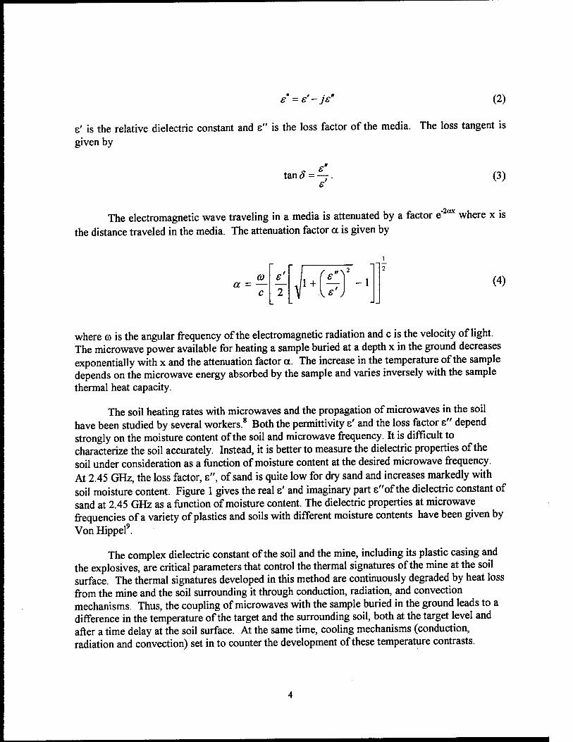
£ =e'-je" (2)
e' is the relative dielectric constant and e" is the loss factor of the media. The loss tangent is given by
e tan 8 - —.
e (3)
The electromagnetic wave traveling in a media is attenuated by a factor e" °* where x is the distance traveled in the media. The attenuation factor a is given by
a - CO £
~1 1 + -1 (4)
where o is the angular frequency of the electromagnetic radiation and c is the velocity of light. The microwave power available for heating a sample buried at a depth x in the ground decreases exponentially with x and the attenuation factor a. The increase in the temperature of the sample depends on the microwave energy absorbed by the sample and varies inversely with the sample thermal heat capacity.
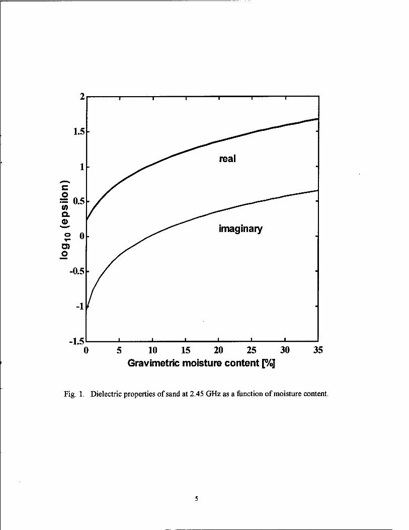
The soil heating rates with microwaves and the propagation of microwaves in the soil have been studied by several workers.8 Both the permittivity s' and the loss factor e" depend strongly on the moisture content of the soil and microwave frequency. It is difficult to characterize the soil accurately. Instead, it is better to measure the dielectric properties of the soil under consideration as a function of moisture content at the desired microwave frequency. At 2.45 GHz, the loss factor, e", of sand is quite low for dry sand and increases markedly with soil moisture content. Figure 1 gives the real s' and imaginary part e"of the dielectric constant of sand at 2.45 GHz as a function of moisture content. The dielectric properties at microwave frequencies of a variety of plastics and soils with different moisture contents have been given by Von Hippel9.
The complex dielectric constant of the soil and the mine, including its plastic casing and the explosives, are critical parameters that control the thermal signatures of the mine at the soil surface. The thermal signatures developed in this method are continuously degraded by heat loss from the mine and the soil surrounding it through conduction, radiation, and convection mechanisms. Thus, the coupling of microwaves with the sample buried in the ground leads to a difference in the temperature of the target and the surrounding soil, both at the target level and after a time delay at the soil surface. At the same time, cooling mechanisms (conduction, radiation and convection) set in to counter the development of these temperature contrasts.
L 1 1 1 1 1 1
1.5
real 1 ■
^. c o
■ ^M 0.5 ^0^0000~*"~~~'^
</> Q.
31 © 0
imaginary T-
G) O
0.5 ■
-1 -
1 * • j 1 i —i "
0 5 10 15 20 25 30 Gravimetric moisture content [%]
35
Fig. 1. Dielectric properties of sand at 2.45 GHz as a function of moisture content.
Kashyap and Louie10have analyzed the electromagnetic scattering by an object buried in the soil using finite difference time domain (FDTD) method. They find that an interference pattern is established in the soil region between the soil/air boundary and the soil/mine boundary which leads to hot and cold regions in this area.
2.2 PASSIVE IR METHOD
There are fundamental differences in the mechanisms leading to a temperature contrast at the soil surface above the mine in the case of the enhanced surface heating IR method and the HPM/IR method. It is best to review the passive IR method to understand these differences. Simard3 has given a clear description of the processes involved in passive IR imaging of buried mines. As described by Simard,3 these processes lead to different soil surface temperatures, Tm
and Tr, above the mine and at a near-by soil surface reference site without a mine, respectively. Assuming a one dimensional conduction process, these temperatures can be determined by solving the differential heat equation for the three zones a, b and c shown in Figure 2a.
8T _ „ d2T dt T 8x
Krirr (5)
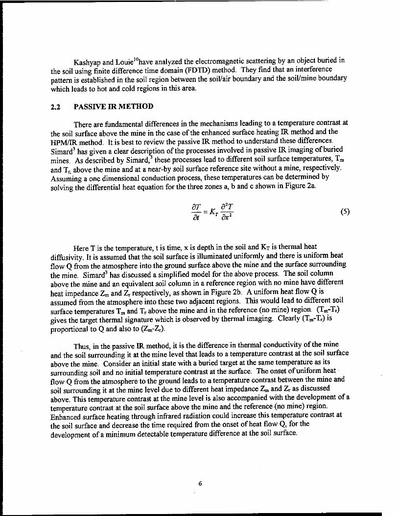
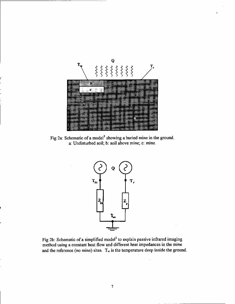
Here T is the temperature, t is time, x is depth in the soil and KT is thermal heat diffüsivity. It is assumed that the soil surface is illuminated uniformly and there is uniform heat flow Q from the atmosphere into the ground surface above the mine and the surface surrounding the mine. Simard3 has discussed a simplified model for the above process. The soil column above the mine and an equivalent soil column in a reference region with no mine have different heat impedance Zm and Zr respectively, as shown in Figure 2b. A uniform heat flow Q is assumed from the atmosphere into these two adjacent regions. This would lead to different soil surface temperatures Tm and Tr above the mine and in the reference (no mine) region. (Tm-Tr) gives the target thermal signature which is observed by thermal imaging. Clearly (Tm-Tr) is proportional to Q and also to (Zm-Zr).
Thus, in the passive IR method, it is the difference in thermal conductivity of the mine and the soil surrounding it at the mine level that leads to a temperature contrast at the soil surface above the mine. Consider an initial state with a buried target at the same temperature as its surrounding soil and no initial temperature contrast at the surface. The onset of uniform heat flow Q from the atmosphere to the ground leads to a temperature contrast between the mine and soil surrounding it at the mine level due to different heat impedance Zm and Zr as discussed above. This temperature contrast at the mine level is also accompanied with the development of a temperature contrast at the soil surface above the mine and the reference (no mine) region. Enhanced surface heating through infrared radiation could increase this temperature contrast at the soil surface and decrease the time required from the onset of heat flow Q, for the development of a minimum detectable temperature difference at the soil surface.
, .icy. . - , :>:-'w-r '" •
?. -fri
rsflfe;
fü
Fig 2a: Schematic of a model3 showing a buried mine in the ground, a: Undisturbed soil; b: soil above mine; c: mine.
©«© *m i» T.
Fig 2b: Schematic of a simplified model3 to explain passive infrared imaging method using a constant heat flow and different heat impedances in the mine and the reference (no mine) sites. T» is the temperature deep inside the ground.
However, infrared radiation cannot penetrate the soil. As such, it cannot interact with the mine directly to yield a temperature contrast at the mine level. Enhanced surface heating interacts with the mine only indirectly through the thermal conduction process. In contrast, microwaves penetrate a relatively long distance into the ground depending on the soil moisture content and microwave frequency, and interact directly with a mine buried near the surface and the soil surrounding it. The effect of this direct interaction can lead to a temperature contrast at the soil surface in a shorter time period than in an active IR (enhanced surface heating) imaging system.
3. EXPERIMENTAL METHOD AND RESULTS
A 5kW magnetron operating at 2.45 GHz was used as an HPM source. A waveguide (WR 284) with a standard gain horn antenna (EMCO 3160-03) were used to obtain a large cross- section beam. The targets were placed under the horn symmetric to its principal axis. The horn- to-soil surface distance was adjustable. Most of the work was done with a horn-to-soil surface distance of 56 cm, although data was also taken with distances ranging from 30 to 88 cm. The microwave power output at the magnetron was varied from 1 to 5 kW. The typical time of microwave illumination ranged from 1 to 3 min. The microwave power density at the soil surface was estimated to be 1 to 3 W/cm2. An 8-12 urn infrared camera provided infrared imagery of the soil surface covering the target.
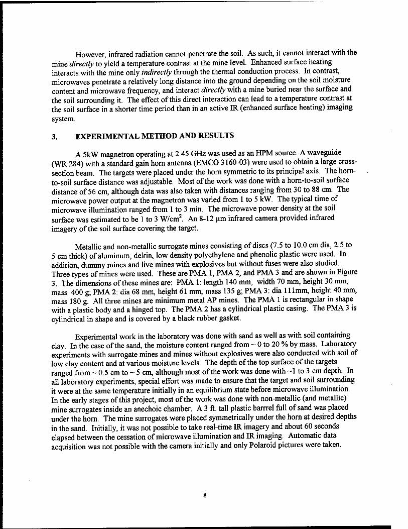
Metallic and non-metallic surrogate mines consisting of discs (7.5 to 10.0 cm dia, 2.5 to 5 cm thick) of aluminum, delrin, low density polyethylene and phenolic plastic were used. In addition, dummy mines and live mines with explosives but without fuses were also studied. Three types of mines were used. These are PMA 1, PMA 2, and PMA 3 and are shown in Figure 3. The dimensions of these mines are: PMA 1: length 140 mm, width 70 mm, height 30 mm, mass 400 g; PMA 2: dia 68 mm, height 61 mm, mass 135 g; PMA 3: dia 111mm, height 40 mm, mass 180 g. All three mines are minimum metal AP mines. The PMA 1 is rectangular in shape with a plastic body and a hinged top. The PMA 2 has a cylindrical plastic casing. The PMA 3 is cylindrical in shape and is covered by a black rubber gasket.
Experimental work in the laboratory was done with sand as well as with soil containing clay. In the case of the sand, the moisture content ranged from ~ 0 to 20 % by mass. Laboratory experiments with surrogate mines and mines without explosives were also conducted with soil of low clay content and at various moisture levels. The depth of the top surface of the targets ranged from ~ 0.5 cm to ~ 5 cm, although most of the work was done with ~1 to 3 cm depth. In all laboratory experiments, special effort was made to ensure that the target and soil surrounding it were at the same temperature initially in an equilibrium state before microwave illumination. In the early stages of this project, most of the work was done with non-metallic (and metallic) mine surrogates inside an anechoic chamber. A 3 ft. tall plastic barrrel full of sand was placed under the horn. The mine surrogates were placed symmetrically under the horn at desired depths in the sand. Initially, it was not possible to take real-time IR imagery and about 60 seconds elapsed between the cessation of microwave illumination and IR imaging. Automatic data acquisition was not possible with the camera initially and only Polaroid pictures were taken.
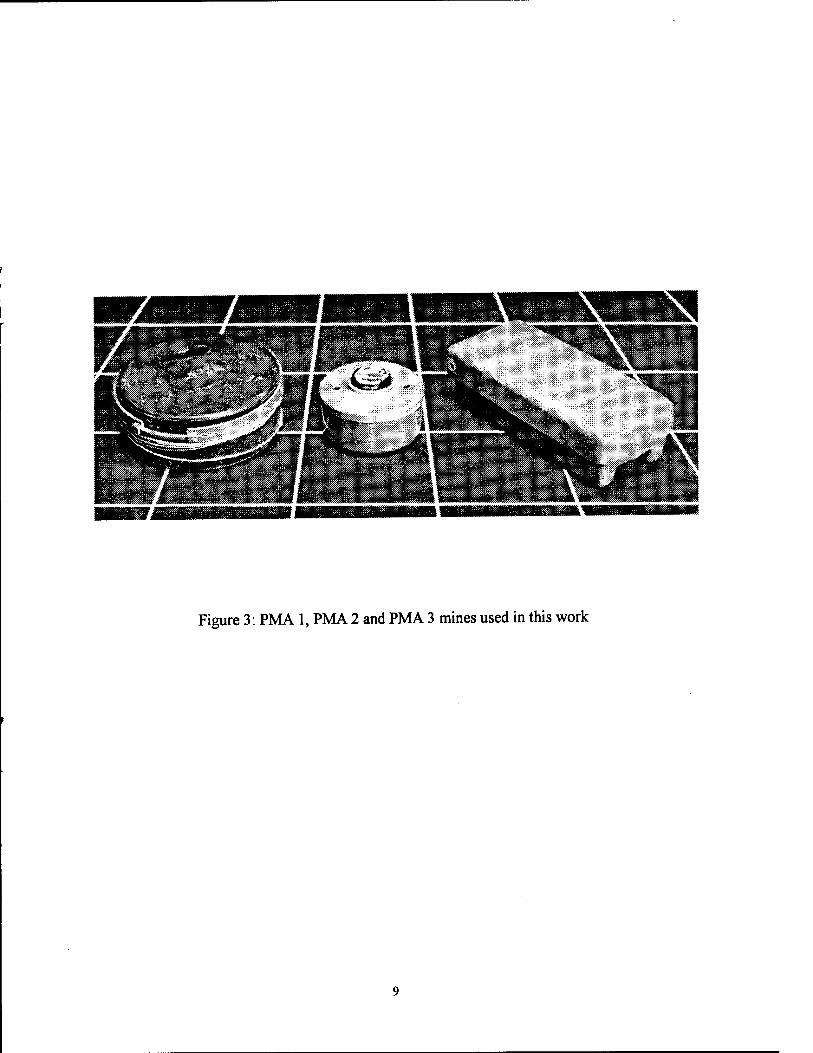
Figure 3: PMA 1, PMA 2 and PMA 3 mines used in this work
3.1 LABORATORY RESULTS
3.1.1 ANECHOIC CHAMBER RESULTS We will first describe the results of the work done inside an anechoic chamber. This will
be followed with the results taken in the laboratory but outside the anechoic chamber. Initially, to test the principle of this method, targets with different dielectric properties were placed at various depths in dry sand and illuminated with HPM for 1-5 min. Polaroid pictures of the targets were taken with an IR camera after the cessation of HPM irradiation. Figure 4 shows IR pictures of three mine surrogates consisting of a square phenolic (bottom left, 10x10 cm, 2.5cm thick, depth 1.1 cm), phenolic disc (bottom right, 3.8 cm dia, 5 cm thick, depth 0.9 cm) and delrin disc (top right, 10 cm dia, 5 cm thick, 1.4 cm depth) buried in dry sand. The picture was taken 13 min. after irradiating the sand with HPM at 5 kW for 3 min. These IR signatures on the soil surface are due to the difference in microwave absorption by the mine surrogates and soil surrounding them at the mine level. This results in temperature contrast between the mines and the surrounding soil at the mine level as well as at the soil surface. The temperature contrast at the soil surface is recorded by an IR camera.
The following results represent some of the best results which can only be explained in terms of the interference of the incident and reflected microwave radiation in the region between the mine and the soil/air interface. Thermal effects at the soil surface due to reflection of microwaves from mine surrogates buried in moist sand with 14% moisture content are shown in Fig. 5. A microwave power level of 5 kW was used for 1 min duration. In Fig. 5a, two identical mine surrogates (delrin disc dia: 10 cm, thickness 2.5 cm) were buried at different depths (left target: 1.6 cm, right target: 1.0 cm). The central region in these pictures is still hot due to the heating of the soil by HPM. The two targets appear in Fig. 5a as a hot spot on the left side and a cold spot on the right side against a general bright background. Although the two targets are of the same material, the path difference at the soil surface between the incident and reflected beams is different for these two targets due to the difference in their depths. This leads to a constructive interference at the surface for the left target and a destructive interference for the right target.
Further confirmation of this process was obtained by varying the depth of these targets (Fig. 5b). The new depths are 0.9 cm and 1.5 cm for the left and right targets respectively. Note that the left signature changed from a hot signature in Fig. 5a to a cold signature in Fig. 5b. Similarly, the right signature changed from a cold signature to a hot signature in these pictures. Additional confirmation of the reflected phenomenon is given by the results shown in Fig. 5c. This figure depicts different thermal effects due to reflection of microwaves from two targets made of different materials which are buried at the same depth (~ 0.6 cm). The left target is an aluminum disc while the target at the right is a delrin disc. The aluminum target gives a hot signature while the delrin target gives a cold signature. The opposite polarity of the signatures from these two targets at the same depth is due to the phase reversal of the microwave field upon reflection at a metallic surface.
Optimal IR interference patterns are obtained in a uniform media as was the case in Figs.5a - 5c. In a non-uniform media, random scattering of the microwaves would tend to scatter the reflected signal from the target and degrade the interference pattern. The size of the targets
10
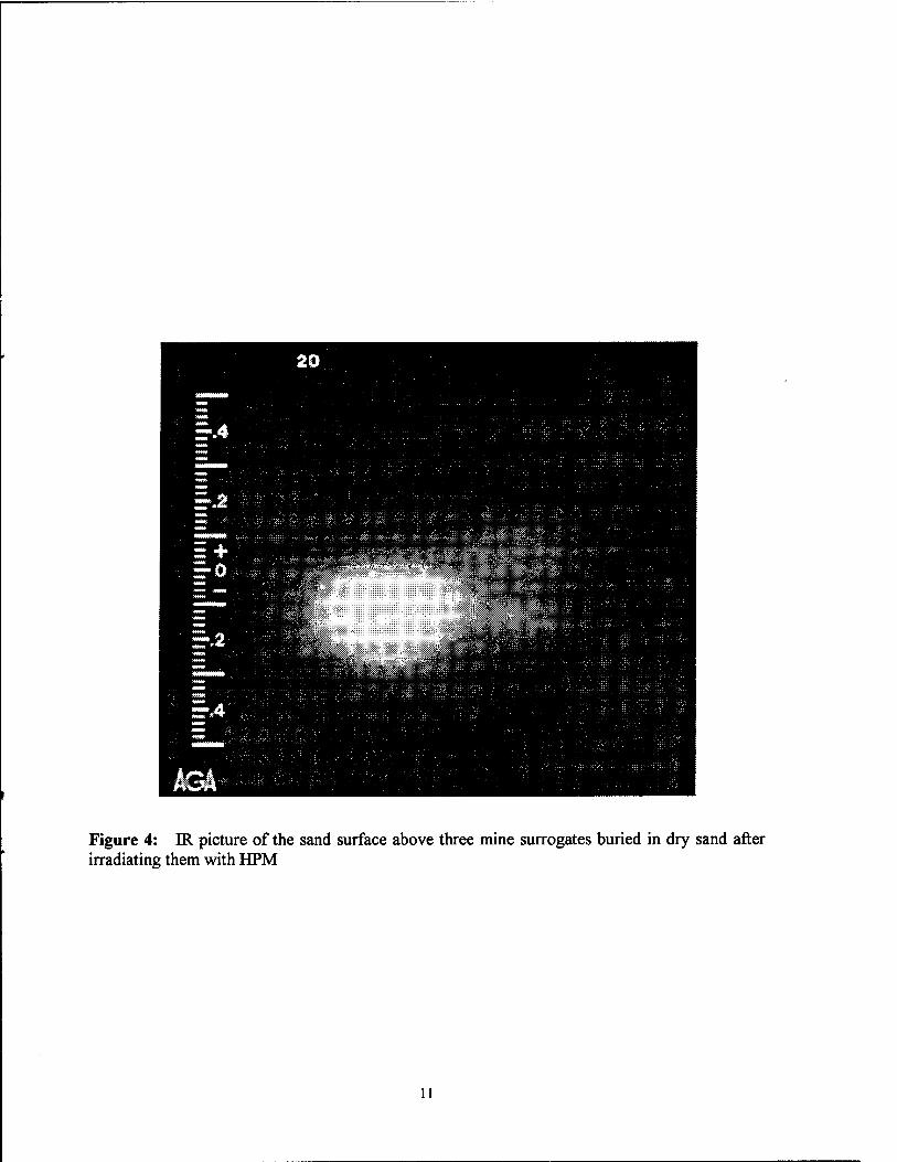
Figure 4: IR picture of the sand surface above three mine surrogates buried in dry sand after irradiating them with HPM
11
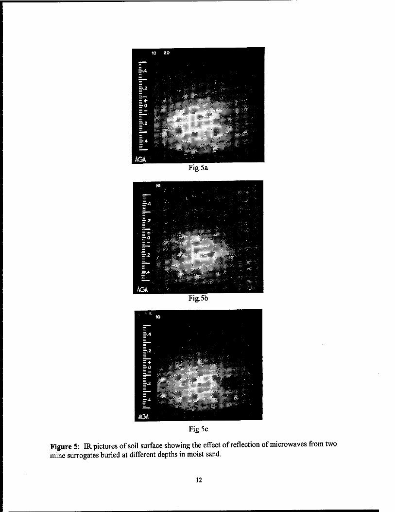
Fig. 5a
Fig.5b
Fig. 5 c
Figure 5: IR pictures of soil surface showing the effect of reflection of microwaves from two mine surrogates buried at different depths in moist sand.
12
as compared to the HPM wavelength is critical to obtain high resolution images of the targets without much scattering from the target edges as can be seen in Fig. 4.
3.1.2 RESULTS FROM OUTSIDE THE ANECHOIC CHAMBER
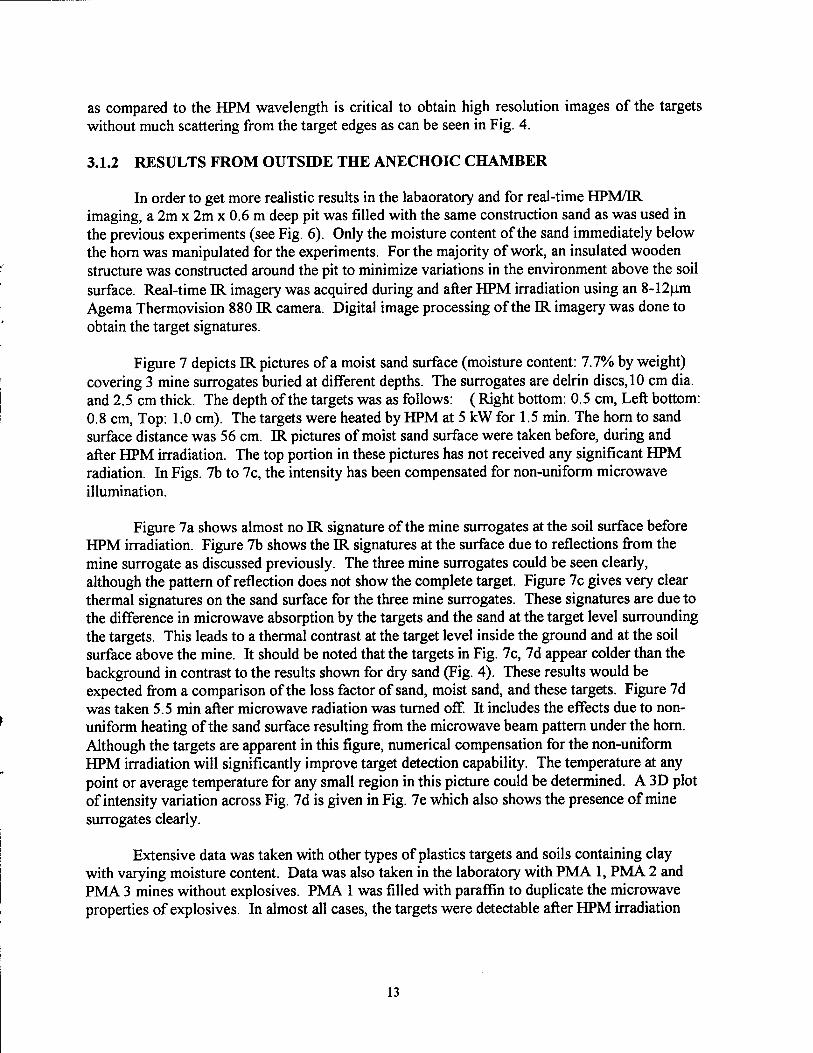
In order to get more realistic results in the labaoratory and for real-time HPM/IR imaging, a 2m x 2m x 0.6 m deep pit was filled with the same construction sand as was used in the previous experiments (see Fig. 6). Only the moisture content of the sand immediately below the horn was manipulated for the experiments. For the majority of work, an insulated wooden structure was constructed around the pit to minimize variations in the environment above the soil surface. Real-time IR imagery was acquired during and after HPM irradiation using an 8-12um Agema Thermovision 880 IR camera. Digital image processing of the IR imagery was done to obtain the target signatures.
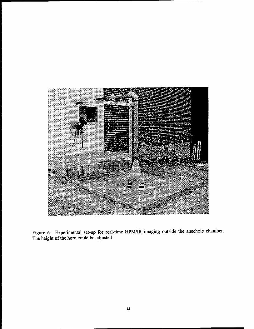
Figure 7 depicts IR pictures of a moist sand surface (moisture content: 7.7% by weight) covering 3 mine surrogates buried at different depths. The surrogates are delrin discs, 10 cm dia. and 2.5 cm thick. The depth of the targets was as follows: (Right bottom: 0.5 cm, Left bottom: 0.8 cm, Top: 1.0 cm). The targets were heated by HPM at 5 kW for 1.5 min. The horn to sand surface distance was 56 cm. IR pictures of moist sand surface were taken before, during and after HPM irradiation. The top portion in these pictures has not received any significant HPM radiation. In Figs. 7b to 7c, the intensity has been compensated for non-uniform microwave illumination.
Figure 7a shows almost no IR signature of the mine surrogates at the soil surface before HPM irradiation. Figure 7b shows the IR signatures at the surface due to reflections from the mine surrogate as discussed previously. The three mine surrogates could be seen clearly, although the pattern of reflection does not show the complete target. Figure 7c gives very clear thermal signatures on the sand surface for the three mine surrogates. These signatures are due to the difference in microwave absorption by the targets and the sand at the target level surrounding the targets. This leads to a thermal contrast at the target level inside the ground and at the soil surface above the mine. It should be noted that the targets in Fig. 7c, 7d appear colder than the background in contrast to the results shown for dry sand (Fig. 4). These results would be expected from a comparison of the loss factor of sand, moist sand, and these targets. Figure 7d was taken 5.5 min after microwave radiation was turned off. It includes the effects due to non- uniform heating of the sand surface resulting from the microwave beam pattern under the horn. Although the targets are apparent in this figure, numerical compensation for the non-uniform HPM irradiation will significantly improve target detection capability. The temperature at any point or average temperature for any small region in this picture could be determined. A 3D plot of intensity variation across Fig. 7d is given in Fig. 7e which also shows the presence of mine surrogates clearly.
Extensive data was taken with other types of plastics targets and soils containing clay with varying moisture content. Data was also taken in the laboratory with PMA 1, PMA 2 and PMA 3 mines without explosives. PMA 1 was filled with paraffin to duplicate the microwave properties of explosives. In almost all cases, the targets were detectable after HPM irradiation
13
£?^i
r'/?*s,j ! »e*^
-;• ";?*' *£*>*]
^^^^«^^ WB&
&*:v- - ""*-.-. '-'V.-. .,v'. ■*■-*
\::^.'-■■■■■ i.-';/ * *>& "'-'.; ^->^ &^HP
-, > *■' 'il'
Figure 6: Experimental set-up for real-time HPM/IR imaging outside the anechoic chamber. The height of the horn could be adjusted.
14
through thermal signatures on the soil surface, either through the reflected signal from the mine, or the differential absorption by the mine as compared to the soil surrounding it or both.
W^^^^^W^^^
Fig.7a
Temperature range: 1.7C
i**-'
Fig.7b
Temperature range: 5.4C
Fig.7c
Temperature range: 3.9C
Fig.7d
Temperature range: 7.7C Fig. 7e
Figure 7: IR pictures of the sand surface over mine surrogates buried in moist sand at different depths. The temperature range of the data are shown in each picture, a: Before HPM irradiation; b: 2 min. after irradiation; c: 5.5 min after HPM irradiation; d: 5.5 min after irradiation but without any compensation for non-uniform HPM illumination; e: A 3D representation of Fig. 7d showing IR intensity across the image. HPM spot intensity has been removed from Figs. 7b and 7c. Fig. 7c and 7d are the same except that the spot has been removed in Fig. 7c
15
3.2 FIELD TRIAL RESULTS
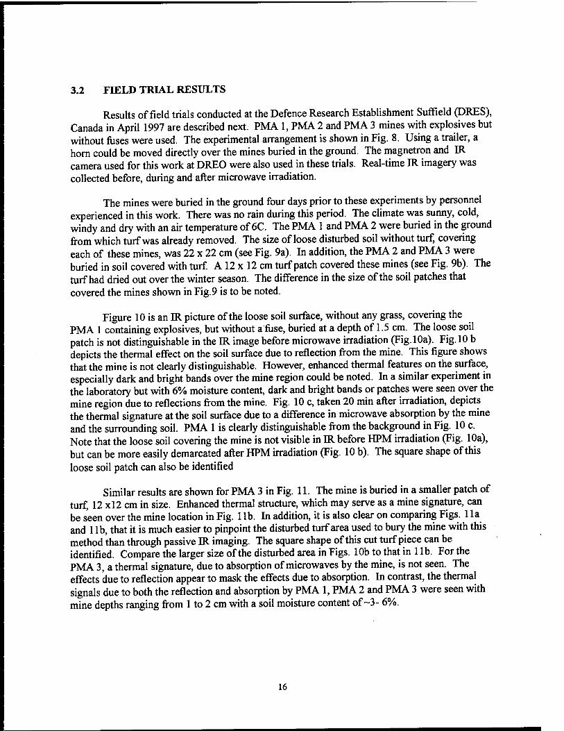
Results of field trials conducted at the Defence Research Establishment Suffield (DRES), Canada in April 1997 are described next. PMA 1, PMA 2 and PMA 3 mines with explosives but without fuses were used. The experimental arrangement is shown in Fig. 8. Using a trailer, a horn could be moved directly over the mines buried in the ground. The magnetron and IR camera used for this work at DREO were also used in these trials. Real-time IR imagery was collected before, during and after microwave irradiation.
The mines were buried in the ground four days prior to these experiments by personnel experienced in this work. There was no rain during this period. The climate was sunny, cold, windy and dry with an air temperature of 6C. The PMA 1 and PMA 2 were buried in the ground from which turf was already removed. The size of loose disturbed soil without turf, covering each of these mines, was 22 x 22 cm (see Fig. 9a). In addition, the PMA 2 and PMA 3 were buried in soil covered with turf. A 12 x 12 cm turf patch covered these mines (see Fig. 9b). The turf had dried out over the winter season. The difference in the size of the soil patches that covered the mines shown in Fig. 9 is to be noted.
Figure 10 is an IR picture of the loose soil surface, without any grass, covering the PMA 1 containing explosives, but without a fuse, buried at a depth of 1.5 cm. The loose soil patch is not distinguishable in the IR image before microwave irradiation (Fig. 10a). Fig. 10 b depicts the thermal effect on the soil surface due to reflection from the mine. This figure shows that the mine is not clearly distinguishable. However, enhanced thermal features on the surface, especially dark and bright bands over the mine region could be noted. In a similar experiment in the laboratory but with 6% moisture content, dark and bright bands or patches were seen over the mine region due to reflections from the mine. Fig. 10 c, taken 20 min after irradiation, depicts the thermal signature at the soil surface due to a difference in microwave absorption by the mine and the surrounding soil. PMA 1 is clearly distinguishable from the background in Fig. 10 c. Note that the loose soil covering the mine is not visible in IR before HPM irradiation (Fig. 10a), but can be more easily demarcated after HPM irradiation (Fig. 10 b). The square shape of this loose soil patch can also be identified
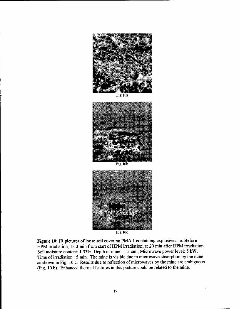
Similar results are shown for PMA 3 in Fig. 11. The mine is buried in a smaller patch of turf, 12 xl2 cm in size. Enhanced thermal structure, which may serve as a mine signature, can be seen over the mine location in Fig. 1 lb. In addition, it is also clear on comparing Figs. 1 la and 1 lb, that it is much easier to pinpoint the disturbed turf area used to bury the mine with this method than through passive IR imaging. The square shape of this cut turf piece can be identified. Compare the larger size of the disturbed area in Figs. 10b to that in 1 lb. For the PMA 3, a thermal signature, due to absorption of microwaves by the mine, is not seen. The effects due to reflection appear to mask the effects due to absorption. In contrast, the thermal signals due to both the reflection and absorption by PMA 1, PMA 2 and PMA 3 were seen with mine depths ranging from 1 to 2 cm with a soil moisture content of ~3- 6%.
16
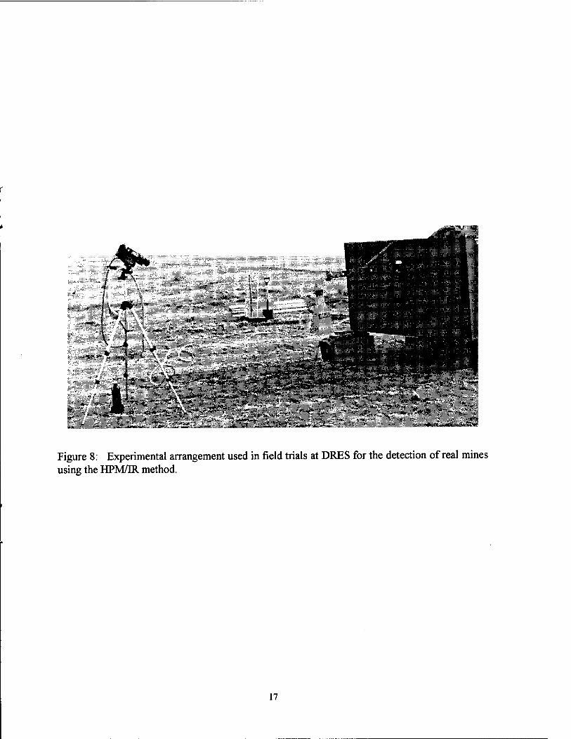
Figure 8: Experimental arrangement used in field trials at DRES for the detection of real mines using the HPM/IR method.
17
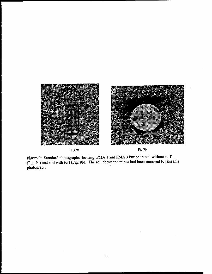
Fig.9a Fig.9b
Figure 9: Standard photographs showing PMA 1 and PMA 3 buried in soil without turf (Fig. 9a) and soil with turf (Fig. 9b). The soil above the mines had been removed to take this photograph
18
Bpl
H
Fig. 10a
Fig. 10b
Fig. 10c
Figure 10: IR pictures of loose soil covering PMA 1 containing explosives, a: Before HPM irradiation; b: 3 min from start of HPM irradiation; c: 20 min after HPM irradiation. Soil moisture content: 1.33%; Depth of mine: 1.5 cm.; Microwave power level: 5 kW; Time of irradiation: 5 min. The mine is visible due to microwave absorption by the mine as shown in Fig. 10 c. Results due to reflection of microwaves by the mine are ambiguous (Fig. 10 b). Enhanced thermal features in this picture could be related to the mine.
19
^Ssil1
Fig. 1 la
SEP
L-Sfl !K^£«*3l
Fig. lib
' ■-'JV.Vj.rJ
?is%;*:»''#|jg;Ä] :t#
g":Mä^^ifel m
tan &*4 V * " , ! Pip» ~~» #*s<P^^€i^^
Fig. lie
Figure 11: IR picture of soil turf covering PMA 3 (with explosives), a: Before HPM irradiation; b: 2.5min from start of HPM irradiation; c: 14 min after HPM irradiation. Soil moisture content: 2.8%; Depth of mine: 2.5 cm.; Microwave power level: 5 kW; Time of irradiation: 5 min
20
4. CONCLUSIONS
Our results using 2.45 GHz HPM irradiation and IR detection in the thermal infrared region confirm that the HPM/ER method can provide a powerful remote-sensing technique for detecting mines buried near the soil surface. The mine signatures arise due to both reflection and absorption by the mine and appear as thermal signatures at the soil surface above the mine. This method is complementary to passive IR mine detection techniques and can detect mines under cloudy and wet conditions. This method can also be used as a pre-confirmatory method for precise localization of a mine from a stand-off distance
There are several factors which play important roles in controlling the signal-to-noise ratio for the thermal signature of the buried mine. The frequency of microwave irradiation, soil moisture content, dielectric constants of the mine and its constituents, soil type, soil surface features, size and shape complexity of the mine are amongst the important factors which will determine the temperature contrast of the mine signature at the soil surface. On the other hand, the fundamental nature, simplicity and remote-sensing capability are very attractive features of this method. Further work is needed to determine the impact of these parameters in a practical HPM/IR mine detection system.
5. REFERENCES
1. http ://www. care, org/ world wide web-site 2. J.E. McFee, Y. Das, A. Carruthers, S. Murray, P. Gallagher, and G. Briosi, "CRAD
Countermine R&D Study - Final Report", Defence Research Establishment Suffield Special Publication 174, April 1994.
3. J.-R. Simard, "Theoretical and experimental characterizations of the IR technology for the detection of low-metal and non-metallic buried landmines" DREV-R 9615, Defence Research Establishment Valcartier, Quebec, Canada, March 1997.
4. T. Cousins, T.A. Zones, J.R. Brisson, J.E. McFee, T.J. Jamieson, E.J. Waller, F.J. LeMay, H. Ing, E.T.H. Clifford, and E.B. Selkirk, " The development of a thermal neutron activation (TNA) system as a confirmatory non-metallic land mine detector", Presented at MARC IV, Kona, Hawaii, April 1997.
5. P. Li, A. Maad, F. Moshary, M.F. Arend, and S. Ahmed, "Infrared imaging of buried objects by thermal step-function excitations", Appl. Optics, 34, pp. 5809-5816, 1995.
6. L.J. Carter, G.H. Bryant, M. Le Fevre, and W.C. Wong, "Moisture and landmine detection" Proc. of the Conference on Detection of Abandoned Land Mines, IEE Conference Publication No. 431, pp. 83-87, 1996
7. S.M. Khanna, F. Paquet, R. Apps and J.S. Seregelyi, "New hybrid remote sensing method using HPM illumination/IR detection for mine detection", SPIE Conference 3392, 1998.
8. J. S. Seregelyi, R. Apps, M. Boyle and C. Gardner, "Microwave heating of soil", DREO Report, DREO Report 1331, Feb 1998.
9. R. Von Hippel, Dielectric Materials and Applications, pp. 314-327, M.I.T. Press, Aug. 1966. 10. S. Kashyap and A. Louie, "Electromagnetic scattering by an object buried in soil",
ANTEM 98 Symposium on Antenna Technology and Applied Electromagnetics, p.397-400, 1998.
21
UNCLASSIFIED -23- SECURITY CLASSIFICATION OF FORM
(highest classification of Title, Abstract, Keywords)
DOCUMENT CONTROL DATA (Security classification of title, body of abstract and indexing annotation must be entered when the overall document is classified)
1. ORIGINATOR (the name and address of the organization preparing the document. Organizations for whom the document was prepared, e.g. Establishment sponsoring a contractor's report, or tasking agency, are entered in section 8.)
Defence Research Establishment Ottawa Ottawa, Ontario K1A0Z4
SECURITY CLASSIFICATION (overall security classification of the document, including special warning terms if applicable)
UNCLASSIFIED
3. TITLE (the complete document title as indicated on the title page. Its classification should be indicated by the appropriate abbreviation (S,C or U) in parentheses after the title.)
A new remote-sensing method for mine detection using HPM irradiation and IR detection (U)
4. AUTHORS (Last name, first name, middle initial)
Khanna, Shyam M, Paquet, Francois, Apps Rene and Seregelyi, Joesph
5. DATE OF PUBLICATION (month and year of publication of document)
December 1999
6a. NO. OF PAGES (total containing information. Include Annexes, Appendices, etc.)
21
6b. NO. OF REFS (total cited in document)
21 7. DESCRIPTIVE NOTES (the category of the document, e.g. technical report, technical note or memorandum. If appropriate, enter the type of
report, e.g. interim, progress, summary, annual or final. Give the inclusive dates when a specific reporting period is covered.)
DREO Technical Report
8. SPONSORING ACTIVITY (the name of the department project office or laboratory sponsoring the research and development. Include the address.)
Space Systems and Technology Section Defence Research Establishment Ottawa, Ottawa, Ontario, K1A 0Z4
9a. PROJECT OR GRANT NO. frf appropriate, the applicable research and development project or grant number under which the document was written. Please specify whether project or grant)
5EC11
9b. CONTRACT NO. (if appropriate, the applicable number under which the document was written)
10a.ORIGINATOR'S DOCUMENT NUMBER (the official document number by which the document is identified by the originating activity. This number must be unique to this document.)
DREO Technical Report # TR1999-132
10b. OTHER DOCUMENT NOS. (Any other numbers which may be assigned this document either by the originator or by the sponsor)
11. DOCUMENT AVAILABILITY (any limitations on further dissemination of the document, other than those imposed by security classification)
x) Unlimited distribution
) Distribution limited to defence departments and defence contractors; further distribution only as approved
) Distribution limited to defence departments and Canadian defence contractors; further distribution only as approved ) Distribution limited to government departments and agencies; further distribution only as approved ) Distribution limited to defence departments; further distribution only as approved ) Other (please specify):
12. DOCUMENT ANNOUNCEMENT (any limitation to the bibliographic announcement of this document. This will normally correspond to the Document Availability (11). However, where further distribution (beyond the audience specified in 11) is possible, a wider announcement audience may be selected.)
Unlimited Announcement
UNCLASSIFIED SECURITY CLASSIFICATION OF FORM DCD03 2/06/87
-24- UNCLASSIFffiD
SECURITY CLASSIFICATION OF FORM
13 ABSTRACT (a brief and factual summary of the document. It may also appear elsewhere in the body of the document itself. It is highly desirable that the abstract of classified documents be unclassified. Each paragraph of the abstract shall begin with an indication of the security classification of the information in the paragraph (unless the document itself is unclassified) represented as (S), (C), or (U). It is not necessary to include here abstracts in both official languages unless the text is bilingual).
A remote-sensing method based on active high-power microwave (HPM) illumination and detection in the infrared (TU) region is described for the detection of shallow buried landmines. This method is based on different interactions of the incident HPM radiation with the mine and the surrounding soil which occur due to a difference in their complex dielectric constants. This leads to the development of a thermal signature of the mine at the soil surface that can be detected in the infrared region. The thermal signature which is observed initially in near real-time persists for several minutes following HPM illumination. It is primarily made up of two components. The first component appears on the soil surface in near real-time due to the interference of the incident HPM beam and the HPM beam reflected by the mine. A second signature is due to the absorption of microwave energy by the mine. This signature appears at the soil surface after a brief time-delay from the start of HPM illumination. At any instant, the resultant thermal signature at the soil surface is the sum of the two time-dependent signatures. In this report we provide both laboratory and field trial results obtained using this method to detect metallic and non-metallic mine surrogates, dummy mines without explosives and live mines with explosives but without any fuse.
14. KEYWORDS, DESCRIPTORS or IDENTIFIERS (technically meaningful terms or short phrases that characterize a document and could be helpful in cataloguing the document. They should be selected so that no security classification is required. Identifiers such as equipment model designation, trade name, military project code name, geographic location may also be included. If possible keywords should be selected from a published thesaurus, e.g. Thesaurus of Engineering and Scientific Terms (TEST) and that thesaurus-identified. If H is not possible to select indexing terms which are Unclassified, the classification of each should be indicated as with the title.)
Mine Detection, High Power Microwave, Infrared Detection, Non-metallic Mines, Anti-personnel Mines
UNCLASSIFIED SECURITY CLASSIFICATION OF FORM
Related Documents