Sensors 2010, 10, 3703-3717; doi:10.3390/s100403703 sensors ISSN 1424-8220 www.mdpi.com/journal/sensors Article A New Automatic System for Angular Measurement and Calibration in Radiometric Instruments Jose Manuel Andujar Marquez, Miguel Ángel Martínez Bohórquez *, Jonathan Medina Garcia and Francisco Jose Aguilar Nieto Departamento de Ingeniería Electrónica, de Sistemas Informáticos y Automática, Escuela Politécnica Superior de la Universidad de Huelva, Ctra. Palos de la Ftra.-Huelva s/n, 21819 Palos de la Frontera, Huelva, Spain; E-Mails: [email protected] (J.M.A.M.); [email protected] (J.M.G.); [email protected] (F.J.A.N.) * Author to whom correspondence should be addressed; E-Mail: [email protected]; Tel: +34-959-217-656; Fax: +34-959-217-304. Received: 1 February 2010; in revised form: 19 March 2010 / Accepted: 30 March 2010 / Published: 13 April 2010 Abstract: This paper puts forward the design, construction and testing of a new automatic system for angular-response measurement and calibration in radiometric instruments. Its main characteristics include precision, speed, resolution, noise immunity, easy programming and operation. The developed system calculates the cosine error of the radiometer under test by means of a virtual instrument, from the measures it takes and through a mathematical procedure, thus allowing correcting the radiometer with the aim of preventing cosine error in its measurements. Keywords: angular response; calibration; cosine error; data acquisition; radiometric instrument; solar irradiance 1. Introduction This paper puts forward the design, construction and testing of a new automatic system for angular-response measurement and calibration in radiometric instruments. Solar irradiance (energy falling on a surface measure, W/m 2 ) measurement is mainly performed by radiometers [1]. The most widely-used radiometers are those measuring within the visible (radiation) [2] and ultraviolet (UV) OPEN ACCESS

Welcome message from author
This document is posted to help you gain knowledge. Please leave a comment to let me know what you think about it! Share it to your friends and learn new things together.
Transcript
Sensors 2010, 10, 3703-3717; doi:10.3390/s100403703
sensors ISSN 1424-8220
www.mdpi.com/journal/sensors
Article
A New Automatic System for Angular Measurement and Calibration in Radiometric Instruments
Jose Manuel Andujar Marquez, Miguel Ángel Martínez Bohórquez *, Jonathan Medina Garcia
and Francisco Jose Aguilar Nieto
Departamento de Ingeniería Electrónica, de Sistemas Informáticos y Automática, Escuela Politécnica
Superior de la Universidad de Huelva, Ctra. Palos de la Ftra.-Huelva s/n, 21819 Palos de la Frontera,
Huelva, Spain; E-Mails: [email protected] (J.M.A.M.); [email protected] (J.M.G.);
[email protected] (F.J.A.N.)
* Author to whom correspondence should be addressed; E-Mail: [email protected];
Tel: +34-959-217-656; Fax: +34-959-217-304.
Received: 1 February 2010; in revised form: 19 March 2010 / Accepted: 30 March 2010 /
Published: 13 April 2010
Abstract: This paper puts forward the design, construction and testing of a new automatic
system for angular-response measurement and calibration in radiometric instruments. Its
main characteristics include precision, speed, resolution, noise immunity, easy programming
and operation. The developed system calculates the cosine error of the radiometer under test
by means of a virtual instrument, from the measures it takes and through a mathematical
procedure, thus allowing correcting the radiometer with the aim of preventing cosine error
in its measurements.
Keywords: angular response; calibration; cosine error; data acquisition; radiometric
instrument; solar irradiance
1. Introduction
This paper puts forward the design, construction and testing of a new automatic system for
angular-response measurement and calibration in radiometric instruments. Solar irradiance (energy
falling on a surface measure, W/m2) measurement is mainly performed by radiometers [1]. The most
widely-used radiometers are those measuring within the visible (radiation) [2] and ultraviolet (UV)
OPEN ACCESS
Sensors 2010, 10
3704
spectra. For solar irradiance measurement, the radiometer’s input optics must provide appropriate
angular response, also known as cosine [3,4] or Lambert-Law response. The Lambert Law (or Lambert’s
cosine law) states that the lighting produced on a given surface by a punctual light source is
proportional to the cosine of the angle of incidence. According to it, radiometer maximum response is
obtained when solar irradiance falls perpendicularly on the radiometer sensor surface (the sun is at its
zenith), while its minimum response is obtained when the sun is on the horizon
(angle of incidence = 90°). For any other angles, instrument response follows the cosine function. Thus,
for instance, for an incidence angle of 60°, the response is half of the maximum. The irradiance (E)
measured by an ideal radiometer for any given solar zenith angle (angle to the perpendicular to the
ground plane) is the product of the irradiance measured in the vertical E0 by the cosine of that angle.
Thus:
0 cosE E (1)
The angular response of real instruments deviates from the previous equation. In fact, most of them
tend to underestimate actual solar irradiance. This fact is known as cosine error [5,6]. The cosine error
of a given instrument is defined as the deviation between the actual angular response provided by the
equipment and the ideal angular response [7] given by Equation (1).
Cosine error is one of the main causes of error in radiometric-instrument measurement [8] and its
magnitude ranges from units to some percentage tens, depending on the angle of incidence [9], which
hinders the comparison of data provided by instruments in different locations [10], hence the
importance of intercomparisons of radiometric instruments in standardized labs at international level.
Radiometers measure global irradiance (i.e., the sum of direct and diffuse irradiance (diffuse
irradiance is produced by the dispersion effects of atmospheric components, including clouds), both of
which present cosine error when measured). Several methods were designed for cosine-error analysis
in radiometer measurement such as the measurement of direct and global, or diffuse and global
irradiance, either at the same time or one immediately after another, as long as steady atmospheric
conditions are kept along measurement. In general, we only dispose of global irradiance measures
obtained by the equipment under test. The methodology used in this work is put forward in [8,11].
Reference [12] presents a different method for cosine-error measurement in a radiometric
instrument by means of measurements from two broadband instruments aimed at studying the angular
response of a Brewer spectroradiometer: one for global and the other for diffuse irradiance
measurement. The works presented in [13,14] shall also be highlighted.
Instrument angular response mainly affects the direct component of global radiation. To a lower
extent, diffuse radiation is mainly affected by two factors: (1) the diffuse radiation generated in
close-to-horizon angles is a little part of total measured diffuse radiation, and (2) within the UV region,
this radiation is even less as a result of the increasing ozone absorption due to the higher optical path
length. In most broadband radiometers and spectroradiometers, the cosine error increases as the solar
zenith angle does [15,16].
The cosine error may be reduced by means of different physical and/or mechanic procedures.
Therefore, accurate knowledge of the instrument’s angular response becomes necessary, since it allows
analytical instrument characterization [17]. To determine the angular response of a given radiometric
instrument, different trials and tests must be completed both in lab and in the study field [18,19].
Sensors 2010, 10
3705
The angular response in radiometric instruments is currently characterized manually. The system
presented here is an automatic instrument to measure and calibrate radiometric instruments with no
human handling. The developed system has been operating since September 2007 in the lab of
radiometric-instrument test and characterization in the INTA (Spanish National Institute of Aerospace
Technique), in its headquarters in El Arenosillo (Mazagón, Huelva, Spain). This system was
successfully tested first in an international campaign on intercomparison in 2007 for the measurement
and calibration of 22 radiometric instruments from different countries [20]. The results obtained with
this system are much better than those previously obtained through manual trials. The developed
equipment improves measurement reliability, resolution and precision, and reduces the time necessary
for angular response determination. Moreover, it also leads to noticeable improvement regarding its
capacity to immunize experiments against electromagnetic and light noise, since tests are performed in
a dark chamber with no human presence or handling. The developed system is registered at the
Spanish Patent and Trademark Office under the reference P200703162, PCT/ES2009/000042 and
international reference WO/2009/095515.
The present paper is organized as follows: Section 2 describes the system’s modules and elements.
Section 3 explains system-testing aimed at assuring design requirements are met regarding both
accuracy and precision. Section 4 describes the operational process for radiometer measurement and
calibration by means of the developed system. The conclusions of this work are contributed in
Section 5. Finally, this paper also includes an appendix and an acknowledgment section.
2. System Description
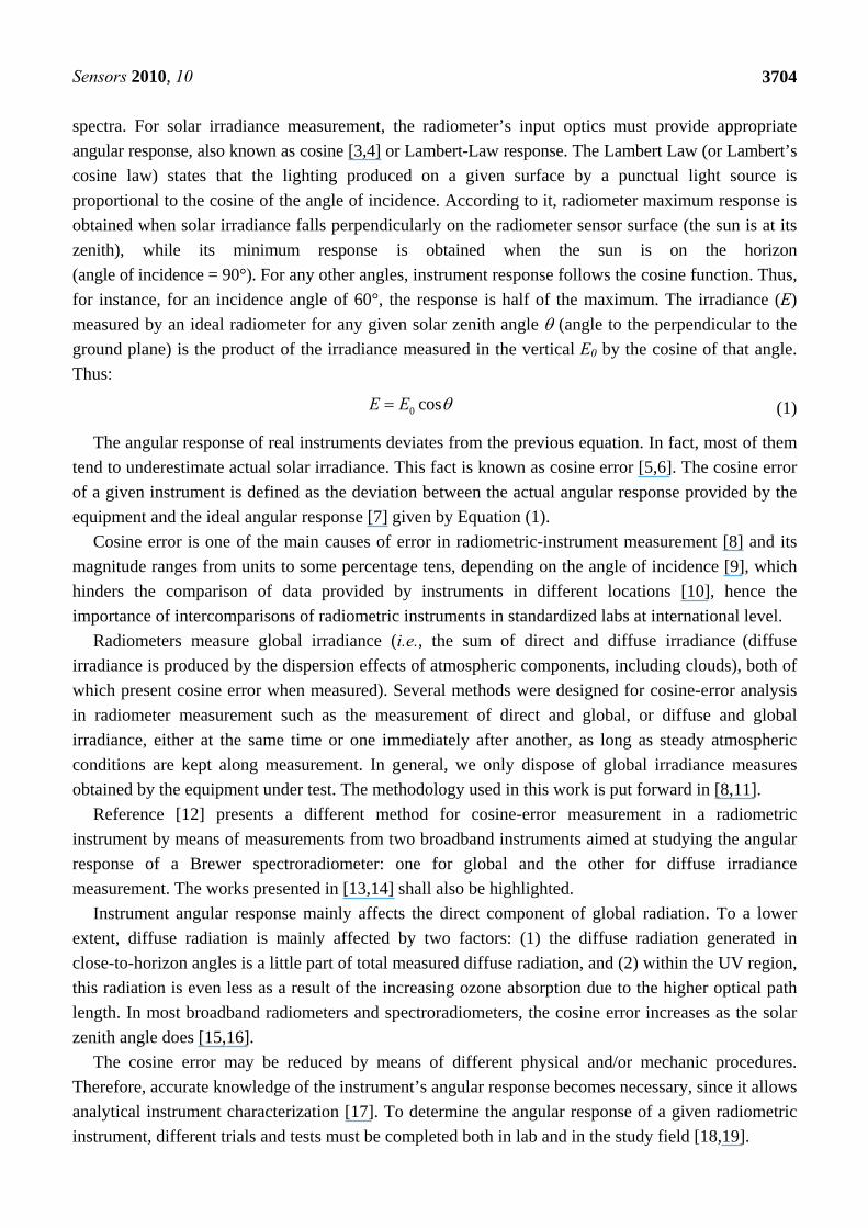
The block diagram of this system for angular-response measurement and calibration in radiometric
instruments is shown in Figure 1. This figure only intends to illustrate the main system components,
since its mechanical operation and movement capacity is illustrated in subsequent figures.
Figure 1. General block diagram for the developed system.
DATA ACQUISITION
SYSTEM
AUTOMATIC ARM
2
45
UNDER TEST RADIOMETER
RS - 232
1
6
3
Sensors 2010, 10
3706
The system is formed by an automatic arm [Figure 1(4)] (it is known as a “automatic arm”, since it
includes a clamp-shaped device which holds and moves the radiometer under test [Figure 1(5)] with
great precision, although it bears no resemblance to the shape of a human arm). During the test, the
radiometer is lighted by a calibrated lamp [Figure 1(6)] whose radiation spectrum covers the
radiometer’s measurement spectrum [21]. With the aim of subjecting the radiometer under test to the
whole range of angles of solar incidence by means of the calibrated lamp, the automatic arm spins
from +90° to –90° (angle to the vertical to the ground plane), thus obtaining and registering
radiometer’s measurements for each angle, which are collected and processed by a high-performance
Data Acquisition System (DAS) [Figure 1(2)] acting as an interface between the user and the PC.
Digital Multimeter (DMM) AgilentTM 34970A [22] is used in this application for DAS (using a DMM
of these characteristics as DAS may seem exaggerated. However, its high precision, easy operation
and, mainly, its current availability are the reasons behind this choice). The precision of this DMM
is 6½ digits, which includes a DAS-card with both analogical and digital inputs and outputs.
600 readings per second can be stored through each channel, with an exploration speed of up to
250 channels per second. Obtained signals are sent to a PC [Figure 1(1)] through RS-232 serial
communication and subsequently stored and processed at the PC to obtain the necessary parameters
allowing angular-error measurement and radiometer calibration. Overall system operation is also
controlled through the PC. A virtual instrument (VI), programmed and designed in LabVIEWTM, also
controls the measure-acquisition and measure-processing systems. Batch-shield wires are used for
DMM-automatic arm connections [Figure 1(3)] to avoid undesired-signal (noise) feedback, since
voltage levels at radiometer output are of the order of mV. Undoubtedly, the most important subsystem
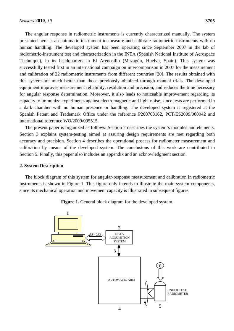
is the automatic arm, whose block diagram is shown in Figure 2. Each of the blocks shall be
described next.
Figure 2. Block diagram of the automatic arm.
Sensors 2010, 10
3707
2.1. DAS-automatic Arm Communication Module
The DAS communication module [Figure 2(1)] is a card gathering the automatic arm’s input and
output signals coming from DAS. By means of the VI, the PC sends DAS the necessary commands
for: (1) Placing the arm’s motors and tripod leveller [Figure 3(d)]. Set-point voltages for motor
government are analogical signals of 0, 2.5 and 5 V reaching the controlling module of the arm’s
motors [Figure 2(3)]. This module is responsible for generating the PWM control signal of all motors;
(2) Turning on, by means of a digital output, the screeding light-emitting diode (LED) indicator [see
Figure 3(e)]. This indicator reports alignment between the spinning centre of the automatic arm’s
holding clamp and the radiometer’s sensor element; (3) Collecting the analogical voltage-output signal
of each radiometer by means of an analogical voltage input. This signal (the irradiance measure of the
radiometer under test) is digitalized, sent and processed at the PC; and, finally, (4) Receiving possible
anomalies by means of digital inputs and monitoring automatic-arm operation signals. On the other
hand, DAS sends the PC signals of (1) Output voltage and angular position of each radiometer under
test; and (2) The automatic arm’s state-control signals. All these PC-automatic arm communication
signals are transmitted by means of a 6-conductor, batch-shield multi-polar wire [Figure 2(10)].
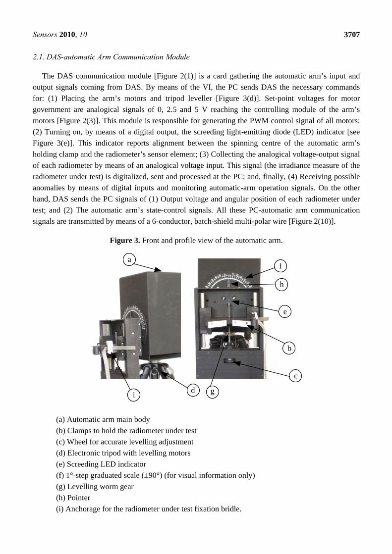
Figure 3. Front and profile view of the automatic arm.
(a) Automatic arm main body
(b) Clamps to hold the radiometer under test
(c) Wheel for accurate levelling adjustment
(d) Electronic tripod with levelling motors
(e) Screeding LED indicator
(f) 1°-step graduated scale (90°) (for visual information only)
(g) Levelling worm gear
(h) Pointer
(i) Anchorage for the radiometer under test fixation bridle.
a
di
c
e
b
h
g
f
Sensors 2010, 10
3708
2.2. Power Supply
The power supply [Figure 2(2)] provides the automatic system with the necessary energy to operate
and power its motors and control electronics. It is connected as an external module not to influence
measurements, since its transformer may induce noises (the power for the whole system is 220 AC).
The power source is short-circuitable and capable of supplying up to 2 A, and disposes of a
12 V-output.
2.3. Motor-control Module
The motor-control module [Figure 2(3)] comprises two identical commercial cards (MD22 [23]:
Devantech Ltd.). Each of these cards can control two medium-power continuous-current motors. The
servomotor placing the clamp which fastens and holds the radiometer under test is connected to one of
the card outputs [Figure 2(4)]. The other three available card outputs control the tripod’s three
levelling servomotors guaranteeing the radiometer under test is kept parallel to the ground for a zenith
angle of 0°. Cards accept 5 different kinds of control. Precisely, the one with two analogical inputs is
used here. The motor-control module works with a set-point signal of 0 V for the maximum speed in
one spinning direction, 2.5 V for the central resting position and 5 V for the maximum spinning speed
in the other direction. According to the received set-point signal (0, 2.5 or 5 V), the module generates
the necessary PWM signal for motor control [Figure 2(4 and 7)]. Servomotors stop when: (1) The
clamp has placed the radiometer in the desired angle, and (2) The system has placed the radiometer
parallel to the ground.
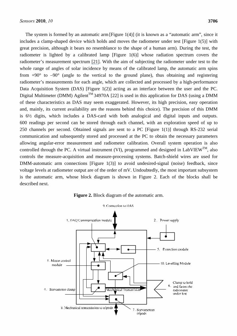
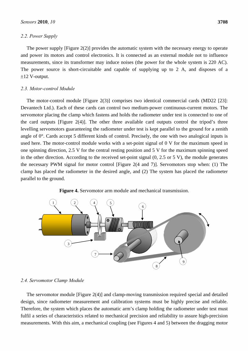
Figure 4. Servomotor arm module and mechanical transmission.
1 2
3
4 5 6
7
8 9
2.4. Servomotor Clamp Module
The servomotor module [Figure 2(4)] and clamp-moving transmission required special and detailed
design, since radiometer measurement and calibration systems must be highly precise and reliable.
Therefore, the system which places the automatic arm’s clamp holding the radiometer under test must
fulfil a series of characteristics related to mechanical precision and reliability to assure high-precision
measurements. With this aim, a mechanical coupling (see Figures 4 and 5) between the dragging motor
Sensors 2010, 10
3709
and the axis holding the clamp-device was designed to guarantee steady transmission involves no
mechanical fatigue, lifetime adjustment (no play and no maintenance) and 1/60-degree angular
resolution. This resolution is much higher than that used so far for radiometer measurement and
calibration. Tripod-moving servomotors [Figure 2(7)] are not particularly highlighted, as they are
connected to each of the three legs of the tripod by a much simpler and less demanding coupling than
that shown in Figures 4 and 5: a coupling to a worm drive which regulates the height of each tripod.
The elements of the transmission system of the clamp servomotor (Figure 4) are described next:
1. DC Servomotor: The motor used is a continuous-current geared motor
2. Gear reducer: It is the first reduction stage and belongs to the short block
3. Sensor and optic encoder barrier: It is a standard kind of infrared-beam sensors/detectors:
sensor TCST 1030 —located on both sides of the optical barrier—emits and receives light,
which is interrupted by the perforated disk (4)
4. Encoder perforated disk: The disk used contains 120 perforations per revolution. However,
encoder measurement (3) is made with double quadrature, so as to produce 240 pulses along a
complete revolution. Therefore, resolution is 360/240 (1.5 degrees). However, as we shall see
later on, this number of pulses is multiplied by the relation existing in the transmission up to
the main axis (9), which pushes the system’s final resolution over 1.5 degrees
5. Homokinetic coupling: This aluminium coupling is inserted between the first (2) and second
(6) reduction boxes, thus helping to avoid possible transmission mismatches and being highly-
recommendable for precision couplings
6. Helical worm-drive gear reducer: This gear-reduction stage is based on a crown including a
worm drive or helical gear assembly which allows blocking the final axis when the motor is not
operating. Its adjustments show no play. The reduction relation of the helical gear assembly is
30:1, which means that the screw (6) spins once for every 30 motor-axis revolutions
7. Chain pinion: This is the last reduction relation. It is performed with chain-assembled steel
pinions. Pinions keep a 3:1 ratio and are capable of standing much higher pairs of forces than
those demanded by the automatic arm, thus avoiding possible fatigue risks
8. Metallic chain: It is used to assure no transmission displacement and avoid plays and
maintenance. Its breakage stress is unreachable, thus offering lifetime guarantee
9. Final positioning axis: This axis is responsible for transmitting movement to the arm’s clamp
system which holds and moves the radiometer under test. The stainless steel with special
machining it is made out of allows leading the wires powering the levelling LED through its
interior, thus avoiding them getting caught with the arm’s clamp movements
10. Limit switch (see Figure 5(10)): It is a protection in case of software failure. The motor stops
when maximum 90° spinning is exceeded by the clamp holding the radiometer.
According to the encoder perforated disk and reduction steps (6–7), the resolution of the developed
system is:
360 1 1 360 1degrees
240 30 3 21600 60 (2)
This means that, for an encoder pulse (1.5 degrees in the motor axis), a 1/60-degree resolution is
obtained in the clamp holding and positioning the radiometer.
Sensors 2010, 10
3710
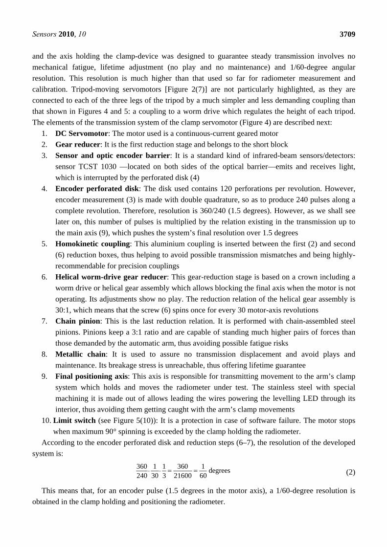
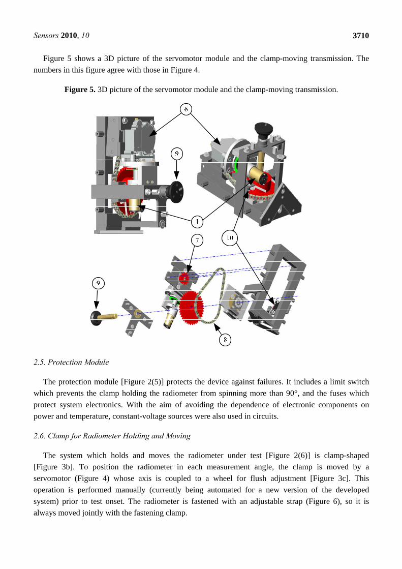
Figure 5 shows a 3D picture of the servomotor module and the clamp-moving transmission. The
numbers in this figure agree with those in Figure 4.
Figure 5. 3D picture of the servomotor module and the clamp-moving transmission.
2.5. Protection Module
The protection module [Figure 2(5)] protects the device against failures. It includes a limit switch
which prevents the clamp holding the radiometer from spinning more than 90°, and the fuses which
protect system electronics. With the aim of avoiding the dependence of electronic components on
power and temperature, constant-voltage sources were also used in circuits.
2.6. Clamp for Radiometer Holding and Moving
The system which holds and moves the radiometer under test [Figure 2(6)] is clamp-shaped
[Figure 3b]. To position the radiometer in each measurement angle, the clamp is moved by a
servomotor (Figure 4) whose axis is coupled to a wheel for flush adjustment [Figure 3c]. This
operation is performed manually (currently being automated for a new version of the developed
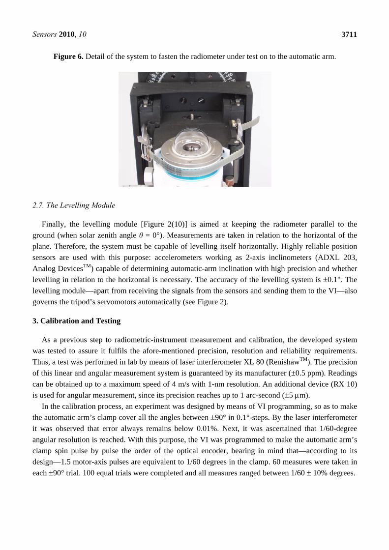
system) prior to test onset. The radiometer is fastened with an adjustable strap (Figure 6), so it is
always moved jointly with the fastening clamp.
Sensors 2010, 10
3711
Figure 6. Detail of the system to fasten the radiometer under test on to the automatic arm.
2.7. The Levelling Module
Finally, the levelling module [Figure 2(10)] is aimed at keeping the radiometer parallel to the
ground (when solar zenith angle θ = 0°). Measurements are taken in relation to the horizontal of the
plane. Therefore, the system must be capable of levelling itself horizontally. Highly reliable position
sensors are used with this purpose: accelerometers working as 2-axis inclinometers (ADXL 203,
Analog DevicesTM) capable of determining automatic-arm inclination with high precision and whether
levelling in relation to the horizontal is necessary. The accuracy of the levelling system is 0.1°. The
levelling module—apart from receiving the signals from the sensors and sending them to the VI—also
governs the tripod’s servomotors automatically (see Figure 2).
3. Calibration and Testing
As a previous step to radiometric-instrument measurement and calibration, the developed system
was tested to assure it fulfils the afore-mentioned precision, resolution and reliability requirements.
Thus, a test was performed in lab by means of laser interferometer XL 80 (RenishawTM). The precision
of this linear and angular measurement system is guaranteed by its manufacturer (±0.5 ppm). Readings
can be obtained up to a maximum speed of 4 m/s with 1-nm resolution. An additional device (RX 10)
is used for angular measurement, since its precision reaches up to 1 arc-second (5 m).
In the calibration process, an experiment was designed by means of VI programming, so as to make
the automatic arm’s clamp cover all the angles between 90° in 0.1°-steps. By the laser interferometer
it was observed that error always remains below 0.01%. Next, it was ascertained that 1/60-degree
angular resolution is reached. With this purpose, the VI was programmed to make the automatic arm’s
clamp spin pulse by pulse the order of the optical encoder, bearing in mind that—according to its
design—1.5 motor-axis pulses are equivalent to 1/60 degrees in the clamp. 60 measures were taken in
each 90° trial. 100 equal trials were completed and all measures ranged between 1/60 10% degrees.
Sensors 2010, 10
3712
4. Field use of the System. Experimentation
The developed system has been operating since September 2007 in the lab for radiometric-instrument
assay and characterization in the headquarters of the INTA (Spanish National Institute of Aerospace
Technique) in El Arenosillo (Mazagón, Huelva, Spain). This system was successfully tested first in an
international campaign on intercomparison in 2007 for the measurement and calibration of 22
radiometric instruments from different countries [20].
Use of the Developed System in the Lab of Radiometric-instrument Test and Characterization
So far, this paper only deals with the measurement of the response of the radiometer under test to
radiation received from different angles (90°). However, for subsequent calibration, the mathematical
procedure detailed in Appendix 1 must be applied for cosine-error calculation. The sum of both steps
guarantees the radiometer’s reliability, since its cosine error for each angle is known.
The operation procedure with the developed system is as follows: The radiometer under test is
placed into the arm’s clamp and fastened (Figure 6). Next, the VI is started. Firstly, the radiometer is
levelled in relation to the ground plane (the former must be parallel to the latter). After levelling, the
VI shall show the corresponding confirmation message. Subsequently, the user performs manual
screeding (currently being automated for a new version of the system) of the radiometer under test
(Figure 3c): vertical adjustment to align the rotation axis of the automatic arm with the sensor element
of the radiometer. Next, the measurement-onset button is pressed and—after a user-adjustable
time-period for leaving the test room— the measurement process begins with the values specified by
the user. These values are: initial and final angular value (usually 90°), value of each step (choice:
0.1°, 1°, 2°, etc.), and time for measure acquisition in each step. Once these data are provided, data
collection begins according to the programmed path. Results are finally displayed in screen and saved
into a file.
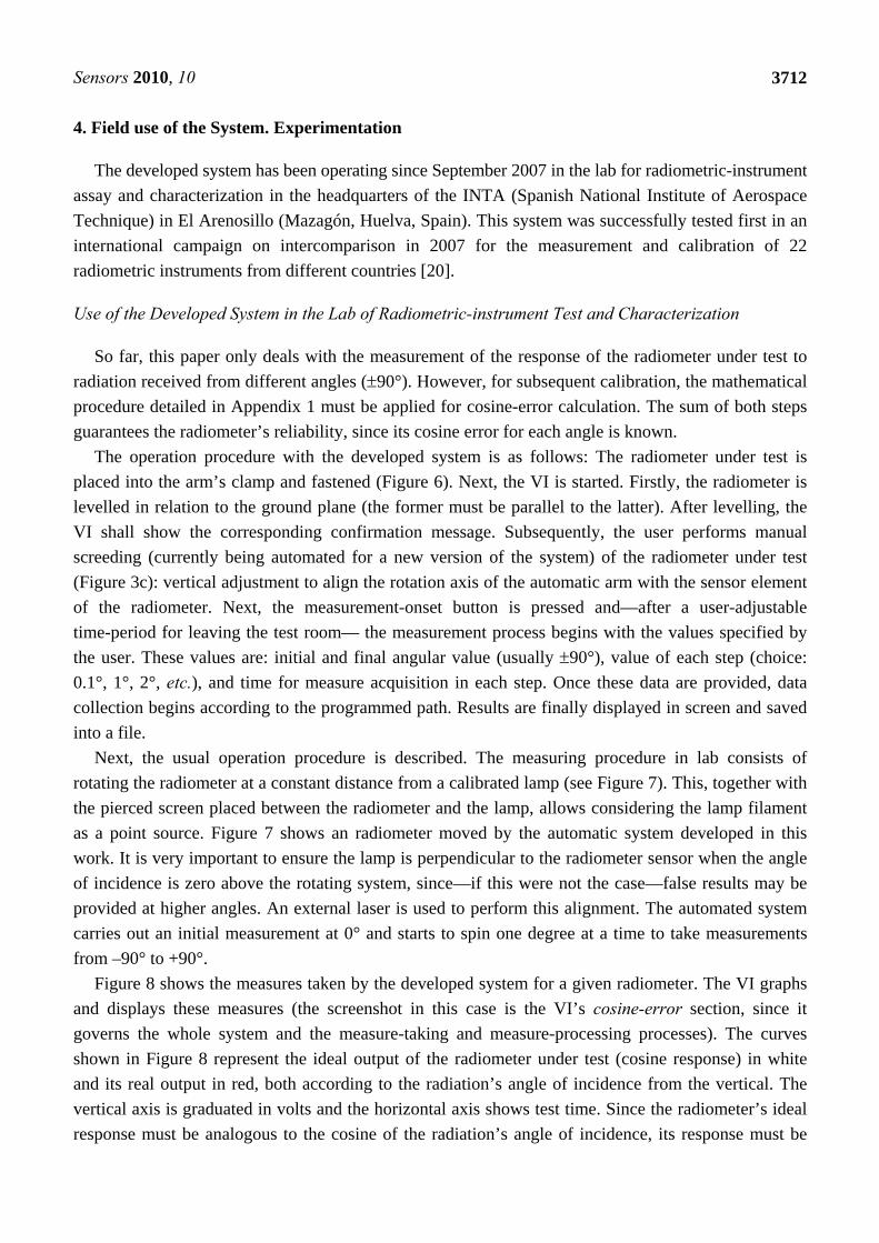
Next, the usual operation procedure is described. The measuring procedure in lab consists of
rotating the radiometer at a constant distance from a calibrated lamp (see Figure 7). This, together with
the pierced screen placed between the radiometer and the lamp, allows considering the lamp filament
as a point source. Figure 7 shows an radiometer moved by the automatic system developed in this
work. It is very important to ensure the lamp is perpendicular to the radiometer sensor when the angle
of incidence is zero above the rotating system, since—if this were not the case—false results may be
provided at higher angles. An external laser is used to perform this alignment. The automated system
carries out an initial measurement at 0° and starts to spin one degree at a time to take measurements
from –90° to +90°.
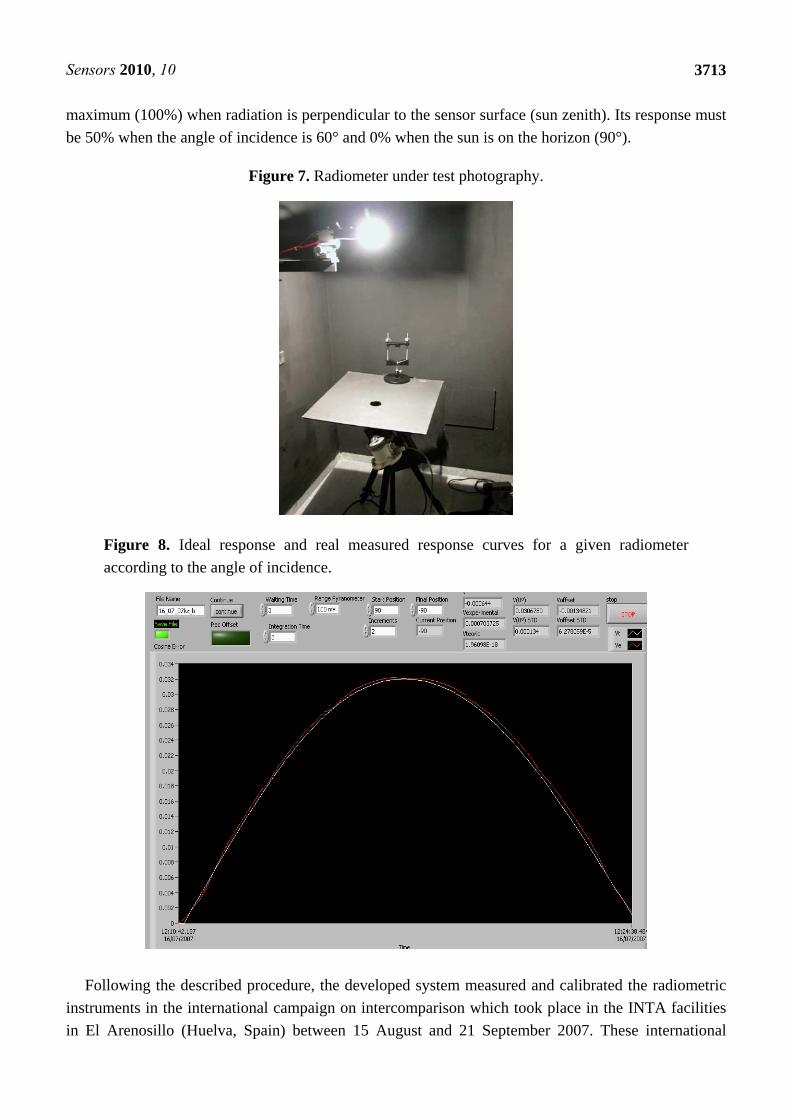
Figure 8 shows the measures taken by the developed system for a given radiometer. The VI graphs
and displays these measures (the screenshot in this case is the VI’s cosine-error section, since it
governs the whole system and the measure-taking and measure-processing processes). The curves
shown in Figure 8 represent the ideal output of the radiometer under test (cosine response) in white
and its real output in red, both according to the radiation’s angle of incidence from the vertical. The
vertical axis is graduated in volts and the horizontal axis shows test time. Since the radiometer’s ideal
response must be analogous to the cosine of the radiation’s angle of incidence, its response must be
Sensors 2010, 10
3713
maximum (100%) when radiation is perpendicular to the sensor surface (sun zenith). Its response must
be 50% when the angle of incidence is 60° and 0% when the sun is on the horizon (90°).
Figure 7. Radiometer under test photography.
Figure 8. Ideal response and real measured response curves for a given radiometer
according to the angle of incidence.
Following the described procedure, the developed system measured and calibrated the radiometric
instruments in the international campaign on intercomparison which took place in the INTA facilities
in El Arenosillo (Huelva, Spain) between 15 August and 21 September 2007. These international
Sensors 2010, 10
3714
campaigns are usually organized every one or two years in different standardized scientific centres
worldwide, following World Meteorological Organization (WMO) recommendations [24]. Obtained
results were excellent and are reported in [20].
5. Conclusions
This paper puts forward the design, construction and testing of an automatic system for
angular-response measurement and calibration in radiometric instruments. This system includes an
automatic arm which, by means of its clamp, automatically holds and places the radiometer under test
to cover, in programmable steps (degrees and tenths of degree), the movement of solar irradiance
falling onto a radiometer in normal operation (90°). Radiometer test is performed with a calibrated
lamp as a radiation source whose radiation spectrum covers the radiometer’s measurement
spectrum. The system also includes a high-performance DAS and a PC as a controller by means of a
specifically-designed VI.
The developed system allows much higher resolution than that reached so far, since 1/60 degrees is
reached for all angles of incidence. This is achieved by means of the mechanical transmission system
located in the arm’s clamp and the incorporated servomotor. To guarantee the perpendicularity of the
radiometer under test when the light source is at its zenith (solar zenith angle = 0°), the developed
system automatically levels itself.
Regarding the calibration of tested instruments, the VI calculates—from the given measures and by
means of the mathematical procedure in Appendix 1—the cosine error of the instrument, which allows
correcting the tested radiometer in its current location, thus eliminating cosine error from its
measurements. The system developed in this work has been operating successfully, with no
breakdowns, since September 2007 in the lab of radiometric-instrument test and characterization in the
headquarters of the INTA (Spanish National Institute of Aerospace Technique) in El Arenosillo
(Mazagón, Huelva, Spain). Until the arrival of this system to lab, the process of radiometer
measurement and calibration was performed manually, with much less measurement precision,
resolution and quality, thus also being much more time-consuming. Apart from the foregoing, the
avoidance of errors due to human handling must also be taken into account.
The system developed in this work was registered at the Spanish Patent and Trademark Office
under reference P200703162, PCT/ES2009/000042 and international reference WO/2009/095515.
Acknowledgments
The present work is a contribution of the DPI2007 62336 project, funded by the Spanish Ministry
for Education and Science and by the European Regional Development Union. The authors of the
present paper thank the INTA Station of Atmospheric Exploration in El Arenosillo (Mazagón, Huelva,
Spain) and, particularly, B. A. de la Morena and J. M. Villaplana for their help and support.
References and Notes
1. Zerlaut, G. Solar radiation instrumentation. In Solar Resources; Hulstrom, R.L., Ed.; The MIT
Press: Cambridge, MA, USA, 1989; pp. 173-308.
Sensors 2010, 10
3715
2. Martínez, M.; Andújar, J.; Enrique, J. A New and inexpensive pyranometer for the visible spectral
range. Sensors 2009, 9, 4615-4634.
3. Michalsky, J.J.; Harrison, L.C.; Berkheiser W.E. Cosine response characteristics of some
radiometric and photometric sensors. Solar Energ. 1995, 54, 397-402.
4. McCluney, R. Introduction to Radiometry and Photometry; Artech House: Boston, MA,
USA/London, UK, 1994.
5. Suehrcke H.; Ling, C.P.; McCormick, P.G. The dynamic response of instruments measuring
instantaneous solar radiation. Solar Energ. 1990, 44, 145-148.
6. Beaubien, D.J.; Bisberg, A.; Beaubien, A.F. Investigations in pyranometer design. J. Atmos.
Ocean. Technol. 1998, 15, 677-686.
7. Balenzategui, J.L.; Chenlo, F. Measurement and analysis of angular response of bare and
encapsulated silicon solar cells. Solar Energ. Mater. Solar Cells 2005, 86, 53-83.
8. Gröbner, J.; Blumthaler, M.; Ambach, W. Experimental investigation of spectral global irradiance
measurement errors due to a non ideal cosine response. J. Geophys. Res. 1996, 23, 2493-2496.
9. Seckmeyer, G.; Bernhard, G. Cosine error correction of spectral UV irradiances. Atmos. Radiat.
1993, 2049, 140-151.
10. Kimlin, M.; Sabburg, J.; Parisi, A.; Meltzer, R. Comparison of Brewer spectrophotometer
ultraviolet data from similar latitudes in the Northern and Southern hemisphere. J. Atmos. Sol.-
Terr. Phys. 2003, 65, 1401-1410.
11. Bais, A.; Kazadzis, S.; Balis, D.; Zerefos, C.; Blunthaler, M. Correcting global solar ultraviolet
spectra recorded by a Brewer spectroradiometer for its angular response error. Appl. Opt. 1998,
31, 6339-6344.
12. Feister, P.; Grewe, R.; Gericke, K. A method for correction for cosine errors in measurements of
spectral UV irradiance. Solar Energ. 1997, 60, 313-332.
13. Fioletov, V.; Kerr, J.; Wardle, D.; Krotkov, N.; Herman, J. Comparison of Brewer ultraviolet
irradiance measurements with TOMS satellite retrievals. Opt. Eng. 2002, 41, 3051-3061.
14. Bernhard, G.; Booth, C.; Ehramjian, J. The quality of data from the national science foundations’s
UV monitoring network for polar regions. In Proceedings of SPIE(2003), San Diego, CA, USA,
August 3, 2003; pp. 79-93.
15. Reda, I.; Stoffel, T.; Myers D. A method to calibrate a solar pyranometer for measuring reference
diffuse irradiance. Solar Energ. 2003, 74, 103-112.
16. King, D.L.; Myers, D.R. Silicon-Photodiode pyranometers: operational characteristics, historical
experiences, and new calibration procedures. In Proceedings of the 26th PVSC, Anaheim, CA,
USA, September 29–October 3, 1997; pp. 1285-1288.
17. Feister, P.M.; Grewe, R.; Gericke, K. A method for correction for cosine errors in measurements
of spectral UV irradiance. Solar Energ. 1997, 60, 313-332.
18. Vilaplana, J.M.; Sorribas, M.; Luccini, E.; Vergaz, R.; Cachorro, V.; Piacentini, R.;
González-Frías, C.; De la Morena, B.; De Frutos, A. Calibración de un biómetro Yankee UVB-1
basada en medidas espectrales de un espectrofotómetro Brewer de doble monocromador. In
Proceedings of III Asamblea Hispano-Portuguesa de Geodesia y Geofísica, Valencia, Spain,
2002; pp. 1204-1208.
Sensors 2010, 10
3716
19. Vilaplana, J.M.; Cachorro, V.; Sorribas, M.; Luccini, E.; De Frutos, A.; Berjón, A.; De la Morena,
B. Modified calibration procedures for a Yankee Environmental System UVB-1 biometer based
on spectral measurements with a Brewer spectrophotometer. Photochem. Photobiol. 2006, 82,
508-514.
20. Vilaplana, J.M.; Serrano, A.; Antón, M.; Cancillo, M. L; Parias, M.; Gröbner, J.; Hülsen, G.;
Zablocky, G.; Díaz, A.; De la Morena B. Report of the El Arenosillo/ INTA-COST Calibration
and Intercomparison Campaign of UVER Broadband Radiometers, El Arenosillo, Huelva, Spain,
2007.
21. Early, M.A.; Thompson, A. Irradiance of horizontal quartz-halogen standard lamps. J. Res. Natl.
Inst. Stand. Technol. 1996, 101, 141-153.
22. Agilent 34970A User Guide. Available online: http://cp.literature.agilent.com/litweb/pdf/
34970-90003.pdf (accessed on November 10, 2009).
23. MD22 Motor Driver. Available online: http://www.robot-electronics.co.uk/htm/md22tech.htm/
(accessed on November 10, 2009).
24. World Meteorological Organization Global Atmospheric Watch. Instruments to Measure
Solar Ultraviolet Radiation. Part 2: Broadband Instruments Measuring Erythemally Weighted
Solar Irradiance. Available online: ftp://ftp.wmo.int/Documents/PublicWeb/arep/gaw/
final_gaw164_bookmarks_17jul.pdf (accessed in March, 2010).
25. Kipp & Zonen CM 21 Instructions Manual. Available online: http://www.kippzonen.com/
?download/5291/CM+21+Pyranometer+-+Manual+(English).aspx/ (accessed on November 10,
2009).
26. Balan, M.C.; Damian, M.; Jäntschi, L. Preliminary results on design and implementation of a
solar radiation monitoring system. Sensors 2008, 8, 963-978.
27. Bais, A.F.; Kazadzis, S.; Balis, D.; Zerefos, C.S.; Blunthaler, M. Correcting global solar
ultraviolet spectra recorded by a Brewer spectroradiometer for its angular response error. Appl.
Opt. 1998, 37, 6339-6344.
28. Feister, P.M.; Grewe, R.; Gericke, K. A method for correction for cosine errors in measurements
of spectral UV irradiance. Solar Energ. 1997, 60, 313-332.
Appendix: cosine-error calculation in radiometric instruments
There are several methods used to calculate the value of the cosine error in radiometric devices.
Some manufacturers use simplified expressions such as those in [25]. Nevertheless, the procedure
explained next is widely used in research and calibration centres.
Radiometer-measured irradiance should follow the ideal angular response given by the cosine law.
Deviations from this angular response produce systematic measurement errors which do not only
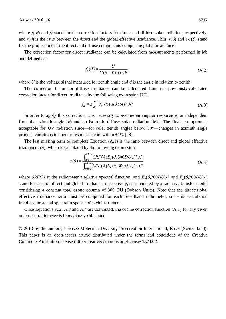
depend on solar zenith angle but also on the division of solar radiation into direct and diffuse [26]. The
cosine correction function used to correct these deviations is based on the following expression:
1( ) =
( ) ( ) (1 ( ))b d
COSCORf r f r
(A.1)
Sensors 2010, 10
3717
where fb() and fd stand for the correction factors for direct and diffuse solar radiation, respectively,
and r() is the ratio between the direct and the global effective irradiance. Thus, r() and 1-r() stand
for the proportions of the direct and diffuse components composing global irradiance.
The correction factor for direct irradiance can be calculated from measurements performed in lab
and defined as:
,cos0)=(
=)(
U
Ufb (A.2)
where U is the voltage signal measured for zenith angle and is the angle in relation to zenith.
The correction factor for diffuse irradiance can be calculated from the previously-calculated
correction factor for direct irradiance by the following expression [27]: /2
0= 2 ( )sin cosd bf f d
(A.3)
In order to apply this correction, it is necessary to assume an angular response error independent
from the azimuth angle () and an isotropic diffuse solar radiation field. The first assumption is
acceptable for UV radiation since—for solar zenith angles below 80°—changes in azimuth angle
produce variations in angular response errors within 1% [28].
The last missing term to complete Equation (A.1) is the ratio between direct and global effective
irradiance r(), which is calculated by the following expression: 400
280400
280
( ) ( ,300 , )( ) =
( ) ( ,300 , )
nm
bnmnm
gnm
SRF E DU dr
SRF E DU d
(A.4)
where SRF() is the radiometer’s relative spectral function, and Eb(,300DU,) and Eg(,300DU,)
stand for spectral direct and global irradiance, respectively, as calculated by a radiative transfer model
considering a constant total ozone column of 300 DU (Dobson Units). Note that the direct/global
effective irradiance ratio must be computed for each broadband radiometer, since its calculation
involves the actual spectral response of each instrument.
Once Equations A.2, A.3 and A.4 are computed, the cosine correction function (A.1) for any given
under test radiometer is immediately calculated.
© 2010 by the authors; licensee Molecular Diversity Preservation International, Basel (Switzerland).
This paper is an open-access article distributed under the terms and conditions of the Creative
Commons Attribution license (http://creativecommons.org/licenses/by/3.0/).
Related Documents


