General rights Copyright and moral rights for the publications made accessible in the public portal are retained by the authors and/or other copyright owners and it is a condition of accessing publications that users recognise and abide by the legal requirements associated with these rights. • Users may download and print one copy of any publication from the public portal for the purpose of private study or research. • You may not further distribute the material or use it for any profit-making activity or commercial gain • You may freely distribute the URL identifying the publication in the public portal If you believe that this document breaches copyright please contact us providing details, and we will remove access to the work immediately and investigate your claim. Downloaded from orbit.dtu.dk on: Aug 31, 2018 A multi-radio, multi-hop ad-hoc radio communication network for Communications- Based Train Control (CBTC) Farooq, Jahanzeb; Bro, Lars; Karstensen, Rasmus Thystrup; Soler, José Published in: Proceedings of IEEE Vehicular Technology Conference-Fall 2017 Link to article, DOI: 10.1109/VTCFall.2017.8288281 Publication date: 2018 Document Version Peer reviewed version Link back to DTU Orbit Citation (APA): Farooq, J., Bro, L., Karstensen, R. T., & Soler, J. (2018). A multi-radio, multi-hop ad-hoc radio communication network for Communications-Based Train Control (CBTC). In Proceedings of IEEE Vehicular Technology Conference-Fall 2017 IEEE. DOI: 10.1109/VTCFall.2017.8288281

Welcome message from author
This document is posted to help you gain knowledge. Please leave a comment to let me know what you think about it! Share it to your friends and learn new things together.
Transcript
General rights Copyright and moral rights for the publications made accessible in the public portal are retained by the authors and/or other copyright owners and it is a condition of accessing publications that users recognise and abide by the legal requirements associated with these rights.
• Users may download and print one copy of any publication from the public portal for the purpose of private study or research. • You may not further distribute the material or use it for any profit-making activity or commercial gain • You may freely distribute the URL identifying the publication in the public portal
If you believe that this document breaches copyright please contact us providing details, and we will remove access to the work immediately and investigate your claim.
Downloaded from orbit.dtu.dk on: Aug 31, 2018
A multi-radio, multi-hop ad-hoc radio communication network for Communications-Based Train Control (CBTC)
Farooq, Jahanzeb; Bro, Lars; Karstensen, Rasmus Thystrup; Soler, José
Published in:Proceedings of IEEE Vehicular Technology Conference-Fall 2017
Link to article, DOI:10.1109/VTCFall.2017.8288281
Publication date:2018
Document VersionPeer reviewed version
Link back to DTU Orbit
Citation (APA):Farooq, J., Bro, L., Karstensen, R. T., & Soler, J. (2018). A multi-radio, multi-hop ad-hoc radio communicationnetwork for Communications-Based Train Control (CBTC). In Proceedings of IEEE Vehicular TechnologyConference-Fall 2017 IEEE. DOI: 10.1109/VTCFall.2017.8288281
A multi-radio, multi-hop ad-hoc radio communication
network for Communications-Based Train Control
(CBTC)
Jahanzeb Farooq1,2, Lars Bro3, Rasmus Thystrup Karstensen1, José Soler2 1Siemens A/S, Ballerup, Denmark
2DTU Fotonik, Technical University of Denmark, Lyngby, Denmark 3nyantec UG, Berlin, Germany
[email protected], [email protected], [email protected], [email protected]
Abstract—Communications-Based Train Control (CBTC) is a
modern signalling system that uses radio communication to
transfer train control information between train and wayside.
The trackside networks in these systems are mostly based on
conventional infrastructure Wi-Fi (IEEE 802.11). It means a
train has to continuously associate (i.e. perform handshake) with
the trackside Wi-Fi Access Points (AP) as it moves, which incurs
communication delays. Additionally, these APs are connected to
the wayside infrastructure via optical fiber cables that incurs
huge costs. This paper presents a novel design in which trackside
nodes function in ad-hoc Wi-Fi mode, which means no
association has to be performed with them prior to transmitting.
A node upon receiving packets from a train forwards these
packets to the next node, forming a chain of nodes. Following this
chain, packets arrive at the destination. To make the design
resilient against interference and failures, transmissions are
separated on multiple frequencies and a node forwards packets
to not only one but two of its neighbors. This paper investigates
the resiliency, redundancy and scalability performance of this
design and presents the results both from a field experiment
involving prototype hardware and an extensive simulation study.
Keywords—Railway signalling, CBTC, radio communication,
Wi-Fi, IEEE 802.11, ad-hoc, multi-radio, multi-hop
I. INTRODUCTION
Communications-Based Train Control (CBTC) is a widely popular modern railway signalling system that uses radio communication to transfer train control information between the train and the wayside. This results in high resolution and real-time train control information which increases the line capacity by safely reducing the distance (headway) between trains running on the same track. Despite its short range and lack of support for mobility, the IEEE 802.11 WLAN, also known as Wi-Fi, has prevailed as the radio technology of choice for CBTC systems, mainly due to its cost-effectiveness.
To ensure a continuous wireless connectivity, hundreds of Wi-Fi Access Points (APs) are installed at the trackside. Each AP is next connected to the wayside (normally a Traffic Control Center (TCC)) via Ethernet. The train must associate (i.e. perform handshake) to an AP first to be able to transmit, just like in an ordinary infrastructure Wi-Fi network. However, there are a number of challenges. Firstly, installing cables to connect each AP to the wayside is expensive and time-
consuming. The cost of installing optical fiber cable can be as high as around 30,000 EUR per kilometer. Secondly, the train on-board equipment must roam from one AP to the other as the train moves. The IEEE 802.11 technology was originally designed for users in stationary office environments and thus inherently lacks support for mobility. Therefore, complex roaming algorithms are employed by CBTC systems to solve this problem. Nonetheless, roaming results in delays in communication and limits the supported train speed as well.
This paper presents a novel design for an ad-hoc based radio communication network (patent pending [1]). In this design, there are no "APs". Nodes function as plain Wi-Fi nodes, in an ad-hoc manner. A node broadcasts packets to the nodes within its range. A nearby node, upon receiving a packet, re-transmits (forwards) the packet, which is then picked up by the next nearby node. A chain of nodes is thus formed, following which the packets reach at the last node in the chain, and are forwarded to the wayside backbone over a wired link. Thus, a train does not have to worry about first associating with an AP as well as roaming. Wired links between the nodes and the wayside backbone are no longer needed, except the two nodes at each end of the chain. Furthermore, to make the chain resilient against failures and interference, transmissions are separated on multiple frequencies and a node forwards packets to two of its neighbors rather than one. Additional advantage of this design is that a node can be placed anywhere at the trackside and not only at designated points where connections to the pre-installed Ethernet cable are accessible.
Despite originally intended for a CBTC trackside network, the application of the proposed design is not limited to it, e.g. it can serve as a superior alternative to the conventional “Wi-Fi over Long Distance” (WiLD) method used to provide low-cost, long-distance Wi-Fi based wireless access to rural areas.
Two experimental studies were carried out to study the performance of the design primarily in terms of number of packets transferred across the chain, the resiliency and redundancy enabled by it, and its scalability. A field experiment [2] was carried out first to provide with a proof-of-concept. An extensive simulation study was performed next to verify the findings of the experimental study and extend the study to various additional scenarios. This paper provides with an overview of the two studies and discusses results.
This work was partly funded by Innovation Fund Denmark.
The rest of this paper is laid out as follows. Section II discusses related work. Section III presents an overview of the CBTC systems. Section IV provides an overview of the proposed design. Sections V and VI provide an overview of the field and simulation studies and present their results. Section VII discusses future work. Section VIII concludes the paper.
II. RELATED WORK
A multi-hop ad-hoc network formed as a chain of nodes presents a suitable candidate for a long-distance network. Most of the related work, however, focuses on networks where all nodes operate on a single frequency. Since nodes must forward packets for other nodes, the capacity degrades sharply with the growing size of the network as a node must contend with additional nodes than its two immediate neighbors. Thus, these networks offer only a fraction of the capacity achieved by a single-hop network, as the capacity drops to one-half with each hop and to 1/7 as the number of nodes increases beyond 10 [3], [4]. Additional reasons include “the hidden node problem” which is inevitable in multi-hop scenarios where two nodes communicating to another node are not necessarily in each other’s range. Furthermore, IEEE 802.11’s Carrier Sense Multiple Access/Collision Avoidance (CSMA/CA) mechanism—which is based on carrier sensing—does not work optimally in wireless networks where the interference range is often larger than the transmission range, as the power sufficient to introduce noise in a transmission is much lower than that required for a successful transmission [5].
III. OVERVIEW OF CBTC SYSTEMS
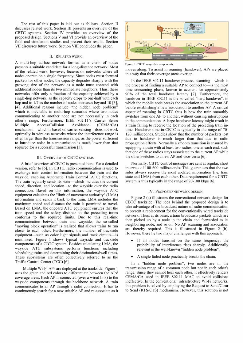
A brief overview of CBTC is presented here. For a detailed version, refer to [6]. In CBTC, radio communication is used to exchange train control information between the train and the wayside, enabling Automatic Train Control (ATC) functions. The train regularly sends its state—which includes the current speed, direction, and location—to the wayside over the radio connection. Based on this information, the wayside ATC equipment calculates the "limit of movement authority" (LMA) information and sends it back to the train. LMA includes the maximum speed and distance the train is permitted to travel. Based on LMA, the onboard ATC equipment ensures that the train speed and the safety distance to the preceding trains conforms to the required limits. Due to this real-time communication between train and wayside, the so-called "moving block operation" is realized that allows trains to run closer to each other. Furthermore, the number of trackside equipment—such as color light signals and track circuits—is minimized. Figure 1 shows typical wayside and trackside components of a CBTC system. Besides calculating LMA, the wayside ATC subsystems perform functions including scheduling trains and determining their destination/dwell times. These subsystems are often collectively referred to as the Traffic Control Center (TCC) [6].
Multiple Wi-Fi APs are deployed at the trackside. Figure 1 uses the green and red colors to differentiate between the APs' coverage areas. Each AP is connected (over a wired link) to the wayside components through the backbone network. A train communicates to an AP through a radio connection. It has to continuously search for a new suitable AP and re-associate as it
moves along. To assist in roaming (handover), APs are placed in a way that their coverage areas overlap.
In the IEEE 802.11 handover process, scanning—which is the process of finding a suitable AP to connect to—is the most time consuming phase, known to account for approximately 90% of the total handover latency [7]. Furthermore, the handover in IEEE 802.11 is the so-called "hard handover", in which the mobile node breaks the association to the current AP before establishing a new association to another AP. A critical aspect of roaming in CBTC thus is how the train smoothly switches from one AP to another, without causing interruptions in the communication. A large handover latency might result in a train failing to receive the location of the preceding train in-time. Handover time in CBTC is typically in the range of 70-120 milliseconds. Studies show that the number of packets lost due to handover is much larger than that due to radio propagation effects. Normally a smooth transition is ensured by equipping a train with at least two radios, one at each end, such that one of these radios stays associated to the current AP while the other switches to a new AP and vice-versa [6].
Normally, CBTC control messages are sent at regular, short intervals of 100-600 milliseconds. This guarantees that the two sides always receive the most updated information (i.e. train state and LMA) from each other. Data requirement for a CBTC system is thus typically in the range of 20-100 kbps [6].
IV. PROPOSED NETWORK DESIGN
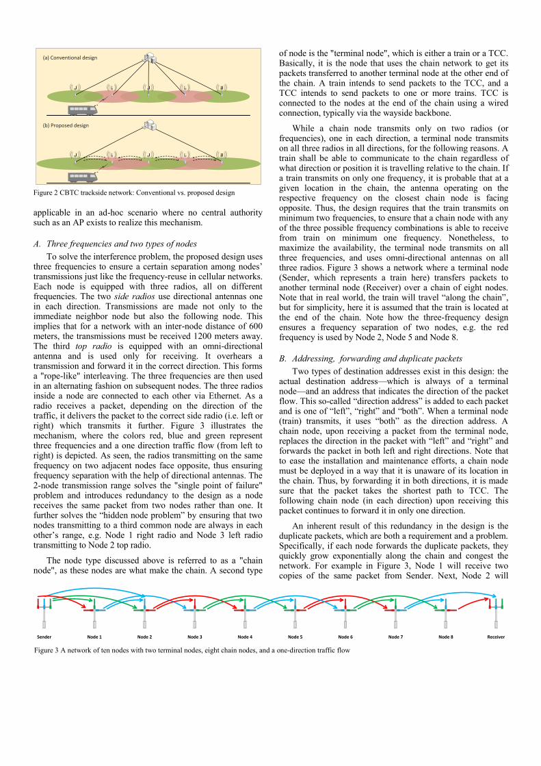
Figure 2 (a) illustrates the conventional network design for CBTC trackside. The idea behind the proposed design is to take advantage of the broadcast nature of radio communication to present a replacement for the conventionally wired trackside network. Thus, at its basic, a train broadcasts packets which are then picked up by a node in the chain and forwarded to its neighboring node, and so on. No AP scanning and association are thereby required. This is illustrated in Figure 2 (b). However, there lie two major challenges with this approach.
If all nodes transmit on the same frequency, the probability of interference rises sharply. Additionally relevant is the well-known "hidden node problem".
A single failed node practically breaks the chain.
In a "hidden node problem", two nodes are in the transmission range of a common node but not in each other's range. Since they cannot hear each other, it effectively renders CSMA/CA used in IEEE 802.11 MAC to avoid collisions ineffective. In the conventional, infrastructure Wi-Fi networks, this problem is solved by employing the Request to Send/Clear to Send (RTS/CTS) mechanism. However, this solution is not
ATCInterlocking
TrafficControl Centre
Wi-Fi Access Point(AP)
AP's radiocoverage area
Radio connectionOnboard antenna
Way
sid
eTr
acks
ide
Train
Figure 1 CBTC wayside components
applicable in an ad-hoc scenario where no central authority such as an AP exists to realize this mechanism.
A. Three frequencies and two types of nodes
To solve the interference problem, the proposed design uses three frequencies to ensure a certain separation among nodes’ transmissions just like the frequency-reuse in cellular networks. Each node is equipped with three radios, all on different frequencies. The two side radios use directional antennas one in each direction. Transmissions are made not only to the immediate neighbor node but also the following node. This implies that for a network with an inter-node distance of 600 meters, the transmissions must be received 1200 meters away. The third top radio is equipped with an omni-directional antenna and is used only for receiving. It overhears a transmission and forward it in the correct direction. This forms a "rope-like" interleaving. The three frequencies are then used in an alternating fashion on subsequent nodes. The three radios inside a node are connected to each other via Ethernet. As a radio receives a packet, depending on the direction of the traffic, it delivers the packet to the correct side radio (i.e. left or right) which transmits it further. Figure 3 illustrates the mechanism, where the colors red, blue and green represent three frequencies and a one direction traffic flow (from left to right) is depicted. As seen, the radios transmitting on the same frequency on two adjacent nodes face opposite, thus ensuring frequency separation with the help of directional antennas. The 2-node transmission range solves the "single point of failure" problem and introduces redundancy to the design as a node receives the same packet from two nodes rather than one. It further solves the “hidden node problem” by ensuring that two nodes transmitting to a third common node are always in each other’s range, e.g. Node 1 right radio and Node 3 left radio transmitting to Node 2 top radio.
The node type discussed above is referred to as a "chain node", as these nodes are what make the chain. A second type
of node is the "terminal node", which is either a train or a TCC. Basically, it is the node that uses the chain network to get its packets transferred to another terminal node at the other end of the chain. A train intends to send packets to the TCC, and a TCC intends to send packets to one or more trains. TCC is connected to the nodes at the end of the chain using a wired connection, typically via the wayside backbone.
While a chain node transmits only on two radios (or frequencies), one in each direction, a terminal node transmits on all three radios in all directions, for the following reasons. A train shall be able to communicate to the chain regardless of what direction or position it is travelling relative to the chain. If a train transmits on only one frequency, it is probable that at a given location in the chain, the antenna operating on the respective frequency on the closest chain node is facing opposite. Thus, the design requires that the train transmits on minimum two frequencies, to ensure that a chain node with any of the three possible frequency combinations is able to receive from train on minimum one frequency. Nonetheless, to maximize the availability, the terminal node transmits on all three frequencies, and uses omni-directional antennas on all three radios. Figure 3 shows a network where a terminal node (Sender, which represents a train here) transfers packets to another terminal node (Receiver) over a chain of eight nodes. Note that in real world, the train will travel “along the chain”, but for simplicity, here it is assumed that the train is located at the end of the chain. Note how the three-frequency design ensures a frequency separation of two nodes, e.g. the red frequency is used by Node 2, Node 5 and Node 8.
B. Addressing, forwarding and duplicate packets
Two types of destination addresses exist in this design: the actual destination address—which is always of a terminal node—and an address that indicates the direction of the packet flow. This so-called “direction address” is added to each packet and is one of “left”, “right” and “both”. When a terminal node (train) transmits, it uses “both” as the direction address. A chain node, upon receiving a packet from the terminal node, replaces the direction in the packet with “left” and “right” and forwards the packet in both left and right directions. Note that to ease the installation and maintenance efforts, a chain node must be deployed in a way that it is unaware of its location in the chain. Thus, by forwarding it in both directions, it is made sure that the packet takes the shortest path to TCC. The following chain node (in each direction) upon receiving this packet continues to forward it in only one direction.
An inherent result of this redundancy in the design is the duplicate packets, which are both a requirement and a problem. Specifically, if each node forwards the duplicate packets, they quickly grow exponentially along the chain and congest the network. For example in Figure 3, Node 1 will receive two copies of the same packet from Sender. Next, Node 2 will
Sender Node 1 Node 2 Node 3 Node 4 Node 5 Node 6 Node 7 Node 8 Receiver Figure 3 A network of ten nodes with two terminal nodes, eight chain nodes, and a one-direction traffic flow
(a) Conventional design
(b) Proposed design
Figure 2 CBTC trackside network: Conventional vs. proposed design
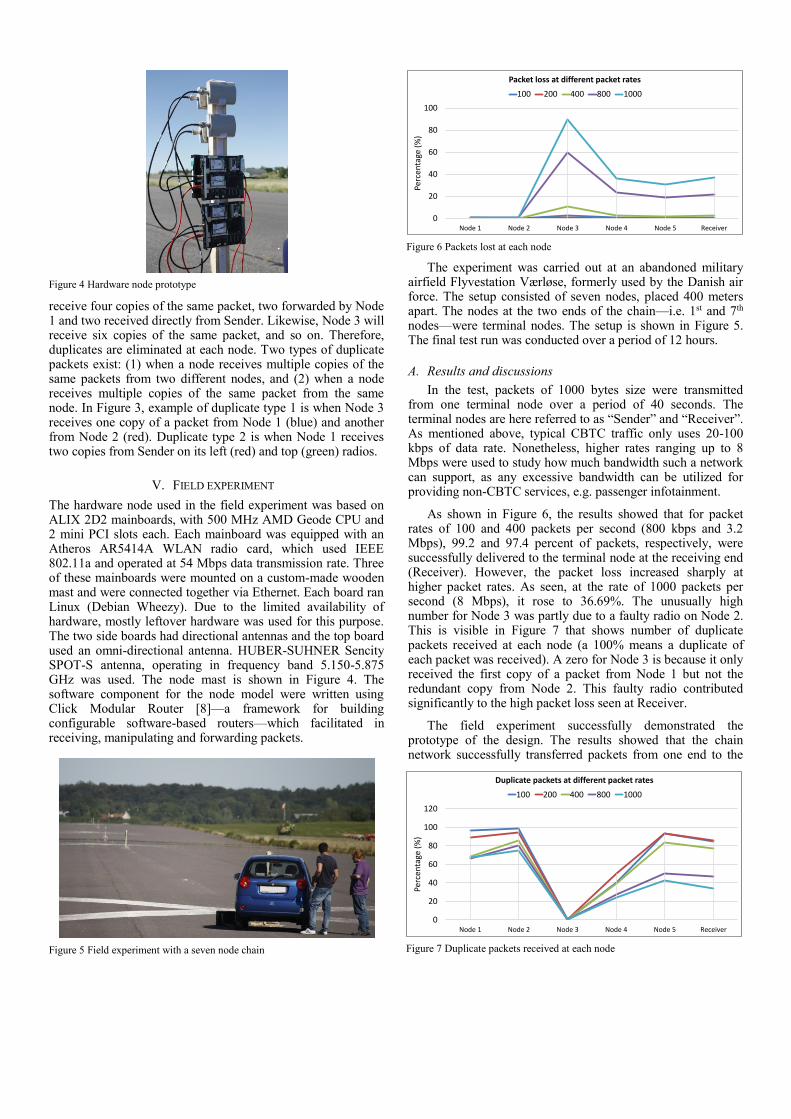
receive four copies of the same packet, two forwarded by Node 1 and two received directly from Sender. Likewise, Node 3 will receive six copies of the same packet, and so on. Therefore, duplicates are eliminated at each node. Two types of duplicate packets exist: (1) when a node receives multiple copies of the same packets from two different nodes, and (2) when a node receives multiple copies of the same packet from the same node. In Figure 3, example of duplicate type 1 is when Node 3 receives one copy of a packet from Node 1 (blue) and another from Node 2 (red). Duplicate type 2 is when Node 1 receives two copies from Sender on its left (red) and top (green) radios.
V. FIELD EXPERIMENT
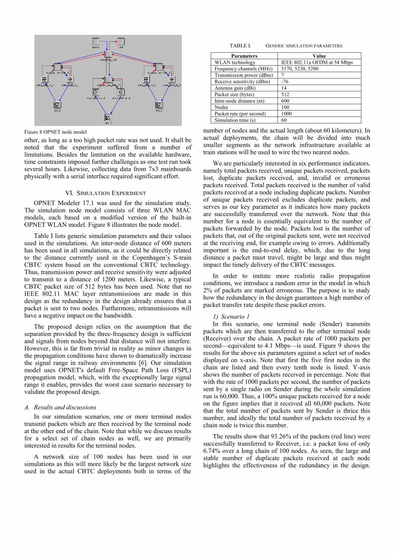
The hardware node used in the field experiment was based on ALIX 2D2 mainboards, with 500 MHz AMD Geode CPU and 2 mini PCI slots each. Each mainboard was equipped with an Atheros AR5414A WLAN radio card, which used IEEE 802.11a and operated at 54 Mbps data transmission rate. Three of these mainboards were mounted on a custom-made wooden mast and were connected together via Ethernet. Each board ran Linux (Debian Wheezy). Due to the limited availability of hardware, mostly leftover hardware was used for this purpose. The two side boards had directional antennas and the top board used an omni-directional antenna. HUBER-SUHNER Sencity SPOT-S antenna, operating in frequency band 5.150-5.875 GHz was used. The node mast is shown in Figure 4. The software component for the node model were written using Click Modular Router [8]—a framework for building configurable software-based routers—which facilitated in receiving, manipulating and forwarding packets.
The experiment was carried out at an abandoned military airfield Flyvestation Værløse, formerly used by the Danish air force. The setup consisted of seven nodes, placed 400 meters apart. The nodes at the two ends of the chain—i.e. 1st and 7th nodes—were terminal nodes. The setup is shown in Figure 5. The final test run was conducted over a period of 12 hours.
A. Results and discussions
In the test, packets of 1000 bytes size were transmitted from one terminal node over a period of 40 seconds. The terminal nodes are here referred to as “Sender” and “Receiver”. As mentioned above, typical CBTC traffic only uses 20-100 kbps of data rate. Nonetheless, higher rates ranging up to 8 Mbps were used to study how much bandwidth such a network can support, as any excessive bandwidth can be utilized for providing non-CBTC services, e.g. passenger infotainment.
As shown in Figure 6, the results showed that for packet rates of 100 and 400 packets per second (800 kbps and 3.2 Mbps), 99.2 and 97.4 percent of packets, respectively, were successfully delivered to the terminal node at the receiving end (Receiver). However, the packet loss increased sharply at higher packet rates. As seen, at the rate of 1000 packets per second (8 Mbps), it rose to 36.69%. The unusually high number for Node 3 was partly due to a faulty radio on Node 2. This is visible in Figure 7 that shows number of duplicate packets received at each node (a 100% means a duplicate of each packet was received). A zero for Node 3 is because it only received the first copy of a packet from Node 1 but not the redundant copy from Node 2. This faulty radio contributed significantly to the high packet loss seen at Receiver.
The field experiment successfully demonstrated the prototype of the design. The results showed that the chain network successfully transferred packets from one end to the
Figure 4 Hardware node prototype
0
20
40
60
80
100
120
Node 1 Node 2 Node 3 Node 4 Node 5 Receiver
Perc
en
tage
(%
)
Duplicate packets at different packet rates
100 200 400 800 1000
Figure 7 Duplicate packets received at each node
0
20
40
60
80
100
Node 1 Node 2 Node 3 Node 4 Node 5 Receiver
Perc
en
tage
(%
)
Packet loss at different packet rates
100 200 400 800 1000
Figure 6 Packets lost at each node
Figure 5 Field experiment with a seven node chain
other, as long as a too high packet rate was not used. It shall be noted that the experiment suffered from a number of limitations. Besides the limitation on the available hardware, time constraints imposed further challenges as one test run took several hours. Likewise, collecting data from 7x3 mainboards physically with a serial interface required significant effort.
VI. SIMULATION EXPERIMENT
OPNET Modeler 17.1 was used for the simulation study. The simulation node model consists of three WLAN MAC models, each based on a modified version of the built-in OPNET WLAN model. Figure 8 illustrates the node model.
Table I lists generic simulation parameters and their values used in the simulations. An inter-node distance of 600 meters has been used in all simulations, as it could be directly related to the distance currently used in the Copenhagen’s S-train CBTC system based on the conventional CBTC technology. Thus, transmission power and receive sensitivity were adjusted to transmit to a distance of 1200 meters. Likewise, a typical CBTC packet size of 512 bytes has been used. Note that no IEEE 802.11 MAC layer retransmissions are made in this design as the redundancy in the design already ensures that a packet is sent to two nodes. Furthermore, retransmissions will have a negative impact on the bandwidth.
The proposed design relies on the assumption that the separation provided by the three-frequency design is sufficient and signals from nodes beyond that distance will not interfere. However, this is far from trivial in reality as minor changes in the propagation conditions have shown to dramatically increase the signal range in railway environments [6]. Our simulation model uses OPNET's default Free-Space Path Loss (FSPL) propagation model, which, with the exceptionally large signal range it enables, provides the worst case scenario necessary to validate the proposed design.
A. Results and discussions
In our simulation scenarios, one or more terminal nodes transmit packets which are then received by the terminal node at the other end of the chain. Note that while we discuss results for a select set of chain nodes as well, we are primarily interested in results for the terminal nodes.
A network size of 100 nodes has been used in our simulations as this will more likely be the largest network size used in the actual CBTC deployments both in terms of the
number of nodes and the actual length (about 60 kilometers). In actual deployments, the chain will be divided into much smaller segments as the network infrastructure available at train stations will be used to wire the two nearest nodes.
We are particularly interested in six performance indicators, namely total packets received, unique packets received, packets lost, duplicate packets received, and, invalid or erroneous packets received. Total packets received is the number of valid packets received at a node including duplicate packets. Number of unique packets received excludes duplicate packets, and serves as our key parameter as it indicates how many packets are successfully transferred over the network. Note that this number for a node is essentially equivalent to the number of packets forwarded by the node. Packets lost is the number of packets that, out of the original packets sent, were not received at the receiving end, for example owing to errors. Additionally important is the end-to-end delay, which, due to the long distance a packet must travel, might be large and thus might impact the timely delivery of the CBTC messages.
In order to imitate more realistic radio propagation conditions, we introduce a random error in the model in which 2% of packets are marked erroneous. The purpose is to study how the redundancy in the design guarantees a high number of packet transfer rate despite these packet errors.
1) Scenario 1 In this scenario, one terminal node (Sender) transmits
packets which are then transferred to the other terminal node (Receiver) over the chain. A packet rate of 1000 packets per second—equivalent to 4.1 Mbps—is used. Figure 9 shows the results for the above six parameters against a select set of nodes displayed on x-axis. Note that first the five first nodes in the chain are listed and then every tenth node is listed. Y-axis shows the number of packets received in percentage. Note that with the rate of 1000 packets per second, the number of packets sent by a single radio on Sender during the whole simulation run is 60,000. Thus, a 100% unique packets received for a node on the figure implies that it received all 60,000 packets. Note that the total number of packets sent by Sender is thrice this number, and ideally the total number of packets received by a chain node is twice this number.
The results show that 93.26% of the packets (red line) were successfully transferred to Receiver, i.e. a packet loss of only 6.74% over a long chain of 100 nodes. As seen, the large and stable number of duplicate packets received at each node highlights the effectiveness of the redundancy in the design.
Figure 8 OPNET node model
TABLE I. GENERIC SIMULATION PARAMETERS
Parameters Value
WLAN technology IEEE 802.11a OFDM at 54 Mbps
Frequency channels (MHz) 5170, 5230, 5290
Transmission power (dBm) 7
Receive sensitivity (dBm) -76
Antenna gain (dBi) 14
Packet size (bytes) 512
Inter-node distance (m) 600
Nodes 100
Packet rate (per second) 1000
Simulation time (s) 60
Furthermore, the frequency separation successfully minimizes interference as the number of erroneous packets is minimum—except for the first few nodes. As a result, only a negligible drop in the number of packets received—both total and unique—is seen at each subsequent node in the chain.
The results highlight a shortcoming of the design as well, albeit trivial. As a terminal node transmits on all frequencies in all directions in contrast to a chain node, the inherent frequency separation guaranteed otherwise in the chain is not fully achievable, resulting in interference on the nodes nearest to a terminal node. This is evident from the first part of Figure 9 where a dramatic rise in the number of erroneous packets—and as a result a drop in the number of total and duplicate packets—is seen at Nodes 2 to 4.
At Node 2, Sender’s transmissions result in collisions with those of Node 1. Note that Node 2 is the only node in this chain that is in the transmission range of two nodes transmitting on the same frequency, and thus the only to experience collisions. As seen, nearly all transmissions from Sender result in collisions on Node 2. While Nodes 3 and 4 are outside Sender’s transmission range, they are still in its interference range. For example, at Node 3, Sender’s transmissions interfere with those of Nodes 1 and 2. Nonetheless, as seen in Figure 9, due to the redundant design, only a minor drop in the number of unique packets received (red line) is seen at these nodes.
Interference introduced by Sender to Node 1’s transmissions is particularly crucial. Due to the short distance between these two nodes, the insignificant difference in the received power of the two signals at Node 3 results in very low signal-to-noise ratio (SNR). Thus, 83% of the erroneous packets at Node 3 are received on its left radio. Notably, this phenomenon occurs only in the beginning of the chain where two nodes with a short distance between them (Sender and Node 1) will be transmitting on the same frequency.
Nonetheless, beyond this problematic initial part of the chain, i.e. from Node 5 onward, a stable number of packets received is seen at each node as the interference from Sender dies off. Additionally, this implies that a network of a smaller size of e.g. 20 or 50 nodes would have fared exactly the same.
As discussed in Section IV.B, the exceptionally high number of total packets received at Node 1 is because Nodes 2 and 3, upon receiving packets directly from Sender, forward them in both directions, thus arriving back on Node 1.
Additional results—not presented here due to the limited space—showed a significantly low end-to-end delay of 2 milliseconds at Receiver. Since transmissions are separated by frequencies, there can be at most two nodes contending for the medium on one frequency at a given location in the chain. Thus, MAC contention delay and queueing delay are irrelevant. Notably, the IEEE CBTC standard [9] specifies a typical end-to-end delay of 500 milliseconds.
2) Scenario 2 The idea behind making the design redundant—i.e. by
transmitting packets to two neighbors—is to make it robust against random node failures. Failing a node and examining its impact on the network resiliency thus is an essential part of the evaluation. Thus, in this scenario, to present with the worst possible case, every second node in the chain is purposely failed, essentially making it a network with no redundancy.
Figure 10 presents the results. As expected, the number of duplicate packets has fallen to zero for all nodes—except for Node 2 that receives type 2 duplicates from Sender. Thus, the number of total and unique packets has become equal for each node. As a consequence, a sharp drop is seen in number of packets received at each node. Similarly, a sharp increase in packets lost is seen, accumulating to 71.8% at Receiver. The shortcoming identified in Scenario 1 related to a terminal node’s transmissions is more emphasized here. Note that as in Scenario 1, Node 4 received about 40% erroneous packets from Node 2 due to the interference from Sender. In Scenario 1, the redundant packets from Node 3 compensated for this. However, now, without redundancy, these erroneous packets result in packet loss, which is then accumulated over the chain, accounting for 55.7% of the total packet loss seen at Receiver.
Nonetheless, the results show that due to the redundancy in the design, the network sustains the failure of a remarkably large number of nodes (50 out of 100) as it still managed to transfer packets across the chain. Note that in a regular chain network, a single failed node can break the whole chain. Comparing the results for unique packets received (red line) between Figure 9 and Figure 10 highlights how the redundancy in the former ensures a stable number of packets received—on average 93.74% of packets—across the 100 nodes, while for the latter (scenario without redundancy), it sees a sharp drop.
3) Scenario 3 In this scenario, Scenario 1 is extended with two flows, one
in each direction. Note that this is equivalent to transmitting 8.2 Mbps. The results are presented in Figure 11. Note that a
0
50
100
150
200
250
300
Pe
rce
nta
ge %
Total packets Unique packets Duplicate packets
Packets lost Erroneous packets Collisions
Figure 9 Results for Scenario 1
0
50
100
150
200
Pe
rce
nta
ge %
Total packets Unique packets Duplicate packets
Packets lost Erroneous packets Collisions
Figure 10 Results for Scenario 2: A network with no redundancy
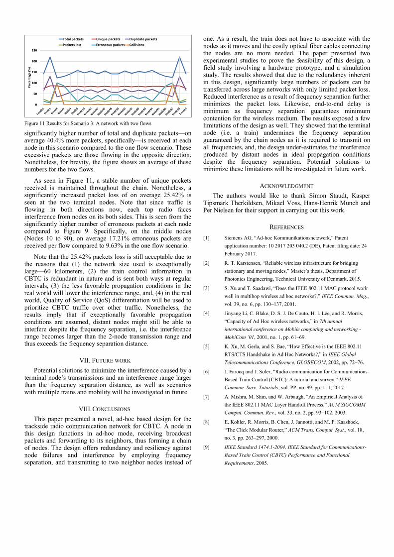
significantly higher number of total and duplicate packets—on average 40.4% more packets, specifically—is received at each node in this scenario compared to the one flow scenario. These excessive packets are those flowing in the opposite direction. Nonetheless, for brevity, the figure shows an average of these numbers for the two flows.
As seen in Figure 11, a stable number of unique packets received is maintained throughout the chain. Nonetheless, a significantly increased packet loss of on average 25.42% is seen at the two terminal nodes. Note that since traffic is flowing in both directions now, each top radio faces interference from nodes on its both sides. This is seen from the significantly higher number of erroneous packets at each node compared to Figure 9. Specifically, on the middle nodes (Nodes 10 to 90), on average 17.21% erroneous packets are received per flow compared to 9.63% in the one flow scenario.
Note that the 25.42% packets loss is still acceptable due to the reasons that (1) the network size used is exceptionally large—60 kilometers, (2) the train control information in CBTC is redundant in nature and is sent both ways at regular intervals, (3) the less favorable propagation conditions in the real world will lower the interference range, and, (4) in the real world, Quality of Service (QoS) differentiation will be used to prioritize CBTC traffic over other traffic. Nonetheless, the results imply that if exceptionally favorable propagation conditions are assumed, distant nodes might still be able to interfere despite the frequency separation, i.e. the interference range becomes larger than the 2-node transmission range and thus exceeds the frequency separation distance.
VII. FUTURE WORK
Potential solutions to minimize the interference caused by a terminal node’s transmissions and an interference range larger than the frequency separation distance, as well as scenarios with multiple trains and mobility will be investigated in future.
VIII. CONCLUSIONS
This paper presented a novel, ad-hoc based design for the trackside radio communication network for CBTC. A node in this design functions in ad-hoc mode, receiving broadcast packets and forwarding to its neighbors, thus forming a chain of nodes. The design offers redundancy and resiliency against node failures and interference by employing frequency separation, and transmitting to two neighbor nodes instead of
one. As a result, the train does not have to associate with the nodes as it moves and the costly optical fiber cables connecting the nodes are no more needed. The paper presented two experimental studies to prove the feasibility of this design, a field study involving a hardware prototype, and a simulation study. The results showed that due to the redundancy inherent in this design, significantly large numbers of packets can be transferred across large networks with only limited packet loss. Reduced interference as a result of frequency separation further minimizes the packet loss. Likewise, end-to-end delay is minimum as frequency separation guarantees minimum contention for the wireless medium. The results exposed a few limitations of the design as well. They showed that the terminal node (i.e. a train) undermines the frequency separation guaranteed by the chain nodes as it is required to transmit on all frequencies, and, the design under-estimates the interference produced by distant nodes in ideal propagation conditions despite the frequency separation. Potential solutions to minimize these limitations will be investigated in future work.
ACKNOWLEDGMENT
The authors would like to thank Simon Staudt, Kasper Tipsmark Therkildsen, Mikael Voss, Hans-Henrik Munch and Per Nielsen for their support in carrying out this work.
REFERENCES
[1] Siemens AG, “Ad-hoc Kommunikationsnetzwerk,” Patent
application number: 10 2017 203 040.2 (DE), Patent filing date: 24
February 2017.
[2] R. T. Karstensen, “Reliable wireless infrastructure for bridging
stationary and moving nodes,” Master’s thesis, Department of
Photonics Engineering, Technical University of Denmark, 2015.
[3] S. Xu and T. Saadawi, “Does the IEEE 802.11 MAC protocol work
well in multihop wireless ad hoc networks?,” IEEE Commun. Mag.,
vol. 39, no. 6, pp. 130–137, 2001.
[4] Jinyang Li, C. Blake, D. S. J. De Couto, H. I. Lee, and R. Morris,
“Capacity of Ad Hoc wireless networks,” in 7th annual
international conference on Mobile computing and networking -
MobiCom ’01, 2001, no. 1, pp. 61–69.
[5] K. Xu, M. Gerla, and S. Bae, “How Effective is the IEEE 802.11
RTS/CTS Handshake in Ad Hoc Networks?,” in IEEE Global
Telecommunications Conference, GLOBECOM, 2002, pp. 72–76.
[6] J. Farooq and J. Soler, “Radio communication for Communications-
Based Train Control (CBTC): A tutorial and survey,” IEEE
Commun. Surv. Tutorials, vol. PP, no. 99, pp. 1–1, 2017.
[7] A. Mishra, M. Shin, and W. Arbaugh, “An Empirical Analysis of
the IEEE 802.11 MAC Layer Handoff Process,” ACM SIGCOMM
Comput. Commun. Rev., vol. 33, no. 2, pp. 93–102, 2003.
[8] E. Kohler, R. Morris, B. Chen, J. Jannotti, and M. F. Kaashoek,
“The Click Modular Router,” ACM Trans. Comput. Syst., vol. 18,
no. 3, pp. 263–297, 2000.
[9] IEEE Standard 1474.1-2004, IEEE Standard for Communications-
Based Train Control (CBTC) Performance and Functional
Requirements. 2005.
0
50
100
150
200
250
Pe
rce
nta
ge (
%)
Total packets Unique packets Duplicate packets
Packets lost Erroneous packets Collisions
Figure 11 Results for Scenario 3: A network with two flows
Related Documents