Scholars' Mine Scholars' Mine Masters Theses Student Theses and Dissertations Spring 2013 A generalized approach for compliant mechanism design using A generalized approach for compliant mechanism design using the synthesis with compliance method, with experimental the synthesis with compliance method, with experimental validation validation Ashish B. Koli Follow this and additional works at: https://scholarsmine.mst.edu/masters_theses Part of the Mechanical Engineering Commons Department: Department: Recommended Citation Recommended Citation Koli, Ashish B., "A generalized approach for compliant mechanism design using the synthesis with compliance method, with experimental validation" (2013). Masters Theses. 7099. https://scholarsmine.mst.edu/masters_theses/7099 This thesis is brought to you by Scholars' Mine, a service of the Missouri S&T Library and Learning Resources. This work is protected by U. S. Copyright Law. Unauthorized use including reproduction for redistribution requires the permission of the copyright holder. For more information, please contact [email protected].

Welcome message from author
This document is posted to help you gain knowledge. Please leave a comment to let me know what you think about it! Share it to your friends and learn new things together.
Transcript

Scholars' Mine Scholars' Mine
Masters Theses Student Theses and Dissertations
Spring 2013
A generalized approach for compliant mechanism design using A generalized approach for compliant mechanism design using
the synthesis with compliance method, with experimental the synthesis with compliance method, with experimental
validation validation
Ashish B. Koli
Follow this and additional works at: https://scholarsmine.mst.edu/masters_theses
Part of the Mechanical Engineering Commons
Department: Department:
Recommended Citation Recommended Citation Koli, Ashish B., "A generalized approach for compliant mechanism design using the synthesis with compliance method, with experimental validation" (2013). Masters Theses. 7099. https://scholarsmine.mst.edu/masters_theses/7099
This thesis is brought to you by Scholars' Mine, a service of the Missouri S&T Library and Learning Resources. This work is protected by U. S. Copyright Law. Unauthorized use including reproduction for redistribution requires the permission of the copyright holder. For more information, please contact [email protected].

A GENERALIZED APPROACH FOR COMPLIANT MECHANISM DESIGN USING
THE SYNTHESIS WITH COMPLIANCE METHOD, WITH EXPERIMENTAL
VALIDATION
by
ASHISH BHARAT KOLI
A THESIS
Presented to the Faculty of the Graduate School of the
MISSOURI UNIVERSITY OF SCIENCE AND TECHNOLOGY
In Partial Fulfillment of the Requirements for the Degree
MASTER OF SCIENCE IN MECHANICAL ENGINEERING
2013
Approved by
Dr. Ashok Midha, Advisor Dr. K. Chandrashekhara
Dr. Xiaoping Du

2013
Ashish Bharat Koli
All Rights Reserved
iii
ABSTRACT
Compliant mechanisms offer numerous advantages over their rigid-body
counterparts. The synthesis with compliance technique synthesizes compliant
mechanisms for conventional rigid-body synthesis tasks with energy/torque specifications
at precision positions. In spite of its usefulness, the method suffers from some
limitations/problems. The purpose of this work is to investigate these sensitivities with
the synthesis with compliance technique and improve upon existing method. A new,
simple but efficient, method for synthesis with compliance using an optimization
approach is proposed, and its usefulness and simplicity demonstrated over the existing
method. The strongly and weakly coupled system of kinematic and energy/torque
equations in the existing method has been studied, and the new method is made simple by
removing the strong coupling between these sets of equations. All synthesis cases are
solved by treating them as though they are governed by weakly coupled systems of
equations.
Representative examples of different synthesis tasks are presented. The results are
verified with finite element analysis software ABAQUS® and ANSYS® by means of
coupler curve/precision position comparisons, and stored energy comparisons. An
experimental setup has been devised to perform experiments on compliant mechanisms
for validation purposes. The results obtained using the Pseudo-Rigid-Body Model
(PRBM) for compliant mechanism synthesis match closely with experimental and finite
element analysis (FEA) results, and hence reinforce the utility of the synthesis with
compliance method using the PRBM in compliant mechanism synthesis.

iv
ACKNOWLEDGMENTS
I would like to express my gratitude to my advisor Dr. Ashok Midha for his
guidance, and never ending support both academically and financially during last two
years. His optimism and enthusiasm for the research were a constant source of
encouragement to me, without which this work would not have been accomplished.
I would also like to thank Dr. K. Chandrashekhara and Dr. Xiaoping Du for their
valuable time and effort as members of my thesis committee. I offer special thanks to Dr.
Ashok Midha and Dr. K. Chandrashekhara for all that I have learned from them in and
out of classes.
Additionally, I would like to thank the Department of Mechanical and Aerospace
Engineering at Missouri S&T for providing me with financial support in the form of
Graduate Teaching Assistantships. I express my sincere thanks to my friends and
research associates Sushrut Bapat, Raghvendra Kuber, Vivekanada Chinta for their
support, critique, encouraging thoughts and discussions.
Finally, I would like to thank my parents Mr. Bharat Koli, Mrs. Khashabai Koli,
and my sister Mrs. Ashwini Patil, for their never ending support and love, and God
Almighty for guiding me throughout my life.
v
TABLE OF CONTENTS
Page
ABSTRACT ....................................................................................................................... iii
ACKNOWLEDGMENTS ................................................................................................. iv
LIST OF ILLUSTRATIONS ........................................................................................... viii
LIST OF TABLES .............................................................................................................. x
SECTION
1. INTRODUCTION ....................................................................................................... 1
1.1. DEFINITION........................................................................................................ 1
1.2. HISTORICAL DEVELOPMENT ........................................................................ 5
1.3. SCOPE OF INVESTIGATION ............................................................................ 8
2. SYNTHESIS OF RIGID-BODY AND COMPLIANT MECHANISMS ................. 10
2.1. RIGID-BODY FOUR-BAR MECHANISM SYNTHESIS ............................... 10
2.1.1. Function Generation..................................................................................... 13
2.1.2. Path Generation. ........................................................................................... 15
2.1.3. Motion Generation ....................................................................................... 18
2.1.4. Path Generation with Prescribed Timing. .................................................... 18
2.2. COMPLIANT MECHANISM DESIGN ............................................................ 19
2.2.1. Pseudo-Rigid-Body Model Concept. ........................................................... 20
2.2.2. Types of Compliant Segments and Equivalent PRBMs. ............................. 21
2.2.2.1. Fixed-pinned compliant segment. ......................................................... 22
2.2.2.2. Fixed-guided compliant segment. ......................................................... 24
2.2.2.3. Small-length flexural pivot.................................................................... 26
2.3. COMPLIANT MECHANISM SYNTHESIS. .................................................... 28
2.3.1. Compliant Mechanism Synthesis Methods Using PRBM Concept. ............ 30
vi
2.3.1.1. Rigid-body replacement (kinematic) synthesis. .................................... 30
2.3.1.2. Synthesis with compliance (kinetostatic synthesis). ............................. 31
2.3.2. Energy Considerations. ................................................................................ 32
2.4. COMPLIANT SEGMENT DESIGN ................................................................. 35
2.4.1. Fixed-Pinned Segment. ................................................................................ 36
2.4.2. Fixed-Guided Compliant Segment .............................................................. 37
2.4.3. Small-Length Flexural Pivot. ....................................................................... 37
2.5. SUMMARY........................................................................................................ 38
3. SYNTHESIS WITH COMPLIANCE FOR ENERGY AND TORQUE SPECIFICATIONS AND NEED FOR OPTIMIZATION APPROACH TO SOLVE ENERGY/TORQUE EQUATIONS............................................................ 39
3.1. SYNTHESIS WITH COMPLIANCE ................................................................ 39
3.1.1. Kinematic Considerations. ........................................................................... 42
3.1.2. Energy/Torque Considerations. ................................................................... 43
3.2. NEED OF COUPLER EQUATION FOR STRONGLY COUPLED SYSTEM ............................................................................................................ 47
3.3. SYNTHESIS CASE WITH NON-PRESCRIBED ENERGY-FREE STATE ... 47
3.4. LIMITATIONS/PROBLEMS WITH SYNTHESIS WITH COMPLIANCE TECHNIQUE ..................................................................................................... 53
3.5. OPTIMIZATION APPROACH IN SYNTHESIS WITH COMPLIANCE TECHNIQUE ..................................................................................................... 59
3.6. SUMMARY........................................................................................................ 61
4. SYNTHESIS WITH COMPLIANCE TECHNIQUE WITH OPTIMIZATION APPROACH AND DIFFERENT CASES ................................................................ 62
4.1. INTRODUCTION TO OPTIMIZATION .......................................................... 62
4.1.1. Optimization Design Process and Mathematical Modeling......................... 64
4.2. TYPES OF OPTIMIZATION. ........................................................................... 66
4.2.1. Unconstrained Optimization. ....................................................................... 66
4.2.2. Constrained Optimization. ........................................................................... 67
vii
4.3. OPTIMIZATION ROUTINE FOR SOLVING ENERGY/TORQUE EQUATIONS IN SYNTHESIS WITH COMPLIANCE TECHNIQUE ........... 68
4.3.1. Recommendations for Energy/Toque Specifications. .................................. 72
4.3.2. Notions on Energy Equivalence................................................................... 75
4.4. STRONGLY COUPLED VS. WEAKLY COUPLED SYSTEM ...................... 76
4.5. DIFFERENT CASES ......................................................................................... 86
4.5.1. Case 1: Undeflected Position of the Mechanism Different from the Specified Positions. ...................................................................................... 86
4.5.2. Case 2: Undeflected Position of the Mechanism to be one of the Specified Positions. ...................................................................................... 93
4.5.3. Case 3: All Four Torsional Spring Constants Same. ................................... 97
4.5.4. Case 4: Application of Straight-Line Generating Compliant Mechanism in Vehicle Suspension System. .................................................................. 102
4.7. SUMMARY...................................................................................................... 108
5. EXPERIMENTAL VALIDATION ........................................................................ 109
5.1. EXPERIMENTAL SETUP .............................................................................. 109
5.2. EXAMPLE ....................................................................................................... 112
5.3. TESTING AND RESULTS.............................................................................. 117
5.4. DISCUSSION OF RESULTS .......................................................................... 124
5.5. SUMMARY...................................................................................................... 125
6. CONCLUSIONS AND FUTURE WORK ............................................................. 126
6.1. CONCLUSIONS .............................................................................................. 126
6.2. RECOMMENDATIONS.................................................................................. 128
BIBLIOGRAPHY ........................................................................................................... 129
APPENDICES
A. RELATIVE ERROR CALCULATION ................................................................ 134
B. MATLAB® CODES ............................................................................................... 136
VITA ............................................................................................................................... 142
viii
LIST OF ILLUSTRATIONS
Page
Figure 1.1. A Rigid-Body Four-Bar (Crank-Rocker) Mechanism ...................................... 1
Figure 1.2. A Compliant Crimping Mechanism with its Rigid-Body Counterparts (Howell, 2001) .................................................................................................. 2
Figure 2.1. Schematic of Rigid-Body Four-Bar Mechanism ............................................ 12
Figure 2.2. Vector Schematic of Four-Bar Mechanism in its 1st and jth Precision Positions for Function Generation .................................................................. 14
Figure 2.3. Vector Schematic of the Four-Bar Mechanism in its 1st and jth Precision Positions for Path, Motion Generation and Path Generation with Prescribed Timing ........................................................................................... 16
Figure 2.4. A Compliant Cantilever Beam with Large-Deflection ................................... 22
Figure 2.5. A Pseudo-Rigid-Body Model of Compliant Cantilever Beam with Large-Deflection ............................................................................................. 23
Figure 2.6. A Fully Compliant Mechanism (Howell, 2001) ............................................. 25
Figure 2.7. A Fixed-Guided Compliant Beam with Constant Beam-End Angle .............. 25
Figure 2.8. A Pseudo-Rigid-Body Model of Fixed-Guided Compliant Beam with Constant Beam-End Angle ............................................................................. 26
Figure 2.9. A Small-Length Flexural Pivot ...................................................................... 27
Figure 2.10. A Pseudo-Rigid-Body Model of a Small-Length Flexural Pivot ................. 28
Figure 2.11. A Four-Bar Mechanism with Four Torsional Springs at the Pivots ............. 33
Figure 3.1. A Four-Bar Mechanism with Four Torsional Springs at the Pivots ............... 41
Figure 3.2. 18 Possible Configurations of Compliant Mechanism Types from Pseudo-Rigid-Body Four-Bar Mechanism .................................................... 46
Figure 3.3. A Flowchart Showing Synthesis with Compliance Technique ...................... 56
Figure 4.1. A Flowchart Showing Optimization Design Process ..................................... 65
Figure 4.2. A Flowchart Showing Synthesis with Compliance Technique using Optimization Approach ................................................................................... 77
Figure 4.3. Solid Model of a Compliant Mechanism with One Fixed-Free Segment ...... 82
Figure 4.4. Coupler Curve Obtained from PRBM with Precision Positions .................... 83
ix
Figure 4.5. Solid Model of a Compliant Mechanism with One Fixed-Fixed Segment .... 93
Figure 4.6. Coupler Curve Obtained from PRBM with Precision Positions .................... 93
Figure 4.7. Solid Model of a Compliant Mechanism with Two Fixed-Fixed Segment.... 97
Figure 4.8. Coupler Curve Obtained from PRBM with Precision Positions .................... 97
Figure 4.9. Solid Model of a Compliant Mechanism with Four Small-Length Flexural Pivots .............................................................................................. 101
Figure 4.10. Coupler Curve Obtained from PRBM with Precision Positions ................ 101
Figure 4.11. Rigid-body Hoeken Straight-Line Mechanism .......................................... 104
Figure 4.12. Solid Model of Compliant Straight-Line Generating Mechanism with Two Small-Length Flexural Pivots ............................................................. 107
Figure 4.13. Coupler Curve Obtained from PRBM with Precision Positions ................ 107
Figure 5.1. Experimental Setup CAD ............................................................................. 110
Figure 5.2. Experimental Setup with Compliant Mechanism ......................................... 111
Figure 5.3. Experimental Setup with Compliant Mechanism and Loading Arrangement ................................................................................................. 112
Figure 5.4. Solid Model of Compliant Mechanism ........................................................ 115
Figure 5.5. CAD Models (a) Input Compliant Link (b) Output Link (c) Coupler .......... 116
Figure 5.6. An Experimental Setup................................................................................. 117
Figure 5.7. Compliant Mechanism for Experiment (a) Input Compliant Link (b) Output Link (c) Coupler (d) Ground Link .............................................. 119
Figure 5.8. Compliant Mechanism in Energy-Free State ............................................... 120
Figure 5.9. Compliant Mechanism Loaded..................................................................... 121
Figure 5.10. The Capstan Friction Equation Experiment ............................................... 122
Figure 5.11. Coupler Curve Obtained from PRBM with Precision Positions ................ 123
x
LIST OF TABLES
Page
Table 3.1. Design Choices Based on Number of Torsional Springs for Function Generation Synthesis with Compliance ........................................................... 48
Table 3.2. Design Choices Based on Number of Torsional Springs for Path Generation Synthesis with Compliance ........................................................... 50
Table 3.3. Design Choices Based on Number of Torsional Springs for Motion Generation Synthesis with Compliance ........................................................... 51
Table 3.4. Design Choices Based on Number of Torsional Springs for Path Generation with Prescribed Timing Synthesis with Compliance .................... 52
Table 4.1. Precision Positions Comparison PRBM vs. Compliant Mechanism (FEA) .... 81
Table 4.2. Energy Comparison PRBM vs. Compliant Mechanism (FEA) ....................... 83
Table 4.3. Design Choices Based on Number of Torsional Springs for Function Generation Synthesis with Compliance Technique Using Optimization Approach .......................................................................................................... 85
Table 4.4. Design Choices Based on Number of Torsional Springs for Path Generation Synthesis with Compliance Technique Using Optimization Approach .......................................................................................................... 88
Table 4.5. Design Choices Based on Number of Torsional Springs for Motion Generation Synthesis with Compliance Technique Using Optimization Approach .......................................................................................................... 89
Table 4.6. Design Choices Based on Number of Torsional Springs for Path Generation with Prescribed Timing Synthesis with Compliance Technique Using Optimization Approach ....................................................... 90
Table 4.7. Precision Positions Comparison PRBM vs. Compliant Mechanism (FEA) .... 92
Table 4.8. Energy Comparison PRBM vs. Compliant Mechanism (FEA) ....................... 92
Table 4.9. Precision Positions Comparison PRBM vs. Compliant Mechanism (FEA) .... 96
Table 4.10. Energy Comparison PRBM vs. Compliant Mechanism (FEA) ..................... 96
Table 4.11. Precision Positions Comparison PRBM vs. Compliant Mechanism (FEA) 100
Table 4.12. Energy Comparison PRBM vs. Compliant Mechanism (FEA) ................... 100
Table 4.13. Precision Positions Comparison PRBM vs. Compliant Mechanism (FEA) 106
Table 4.14. Energy Comparison PRBM vs. Compliant Mechanism (FEA) ................... 106
Table 5.1. Energy Comparison PRBM vs. Compliant Mechanism (FEA) ..................... 114
1. INTRODUCTION
The compliant mechanisms are functionally similar to the rigid-body mechanisms
but they gain some or all of their mobility from the deflection of flexible members rather
than from movable joints only (Howell 2001).
1.1. DEFINITION
A kinematic mechanism is a mechanical device used to transfer or transform
motion, force, or energy (Erdman et al., 1997). The rigid-body mechanisms consist of
rigid links joined together by joints or kinematic pairs and they gain their mobility from
the movable joints only. A four-bar mechanism is a very well-known example of a rigid-
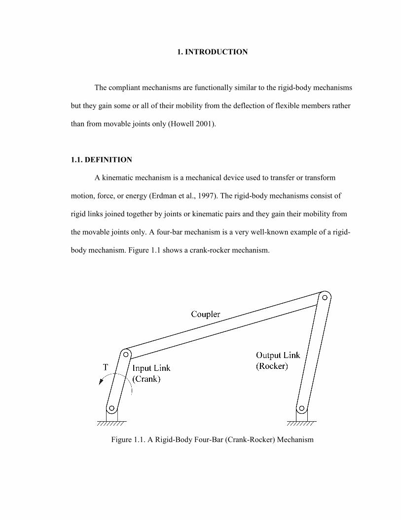
body mechanism. Figure 1.1 shows a crank-rocker mechanism.
Figure 1.1. A Rigid-Body Four-Bar (Crank-Rocker) Mechanism
2
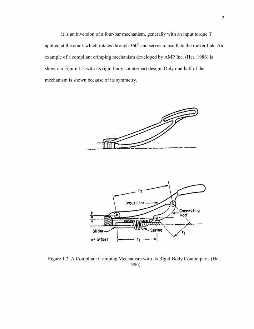
It is an inversion of a four-bar mechanism, generally with an input torque T
applied at the crank which rotates through 3600 and serves to oscillate the rocker link. An
example of a compliant crimping mechanism developed by AMP Inc. (Her, 1986) is
shown in Figure 1.2 with its rigid-body counterpart design. Only one-half of the
mechanism is shown because of its symmetry.
Figure 1.2. A Compliant Crimping Mechanism with its Rigid-Body Counterparts (Her, 1986)

3
A pseudo-rigid-body model concept (Howell and Midha, 1994) provides a simple
way to use the vast rigid-body mechanism knowledge base available to synthesize and
analyze compliant mechanisms. It models the large deflections of the flexible segments,
reducing them to their rigid-body kinematic counterparts and torsional springs to
represent their compliance, their equivalence being maintained in their force-deflection
characteristics. The compliant mechanisms can be fully compliant consisting of no rigid
links or joints, or can be partially compliant with flexible segments and rigid links and
joints. The compliant mechanisms have numerous advantages (Howell, 2001) as follows:
1. The compliant mechanisms may contain fewer parts, or can be
manufactured/molded as one-piece resulting in cost reduction due to reduced
assembly time, simplified manufacturing processes, and general integration of
form and function.
2. With less number of parts, the compliant mechanisms are relatively lighter as
compared with rigid-body mechanisms.
3. The compliant mechanisms have fewer movable joints.
i) This results in reduced wear and reduced need for lubrication
ii) Lacking lash, it reduces the noise and vibration
4. Less number of joints also helps increase the mechanical precision, making them
useful in high-precision instruments.
5. As the compliant mechanisms achieve some of their mobility from the deflection
of their flexible members, the stored strain energy may be transferred,
transformed or released at a later time in a different manner. They can be used to
design mechanisms having specific force-deflection properties, e.g. compliant

4
constant-force mechanism, which generates a nearly constant output force in
response to, say, a linear input displacement.
6. The compliant mechanisms can be easily miniaturized and so they may result in
space savings and find useful applications in MEMS devices.
The compliant mechanisms also have few disadvantages, as follows:
1. Due to the large deflections of flexible links, the design and analysis of compliant
mechanisms is more difficult than that of rigid-body mechanisms.
2. Fatigue analysis is important in the design of compliant mechanisms, and the
choice of material is critical to attain a required fatigue life. The large deflection
of a flexible member is limited by its geometric and material properties. The
compliant segmentscannot produce continuous rotational motion, as does a rigid-
body crank.
3. Flexible segments under stress for long periods of time, or at high temperatures,
may experience stress relaxation or creep and may be rendered ineffective in their
function.
In spite of the above disadvantages, compliant mechanisms are continuing to
findimportant applications (Howell, 2001) in the engineering world and society at large,
such as micro-sensors and actuators in micro-electro-mechanical (MEMS) devices,
crashworthiness applications in automobiles due to the energy storage characteristics,
precision machines, robotics, biomedical devices and prosthetics, surgical tools, adaptive
structures, etc. Compliant mechanisms are also widely used in items such as grippers,
Compliers®, bicycle brakes, binder clips, staple removers, etc.

5
1.2. HISTORICAL DEVELOPMENT
Use of flexible members to store energy and create motion has been in use since
ages, e.g. in bows and catapults (Howell, 2001). The strain energy stored in the bow is
released in the form of kinetic energy of the arrow. A systematic development of
compliant mechanisms started in the second half of the twentieth century. Burns (1964)
and Burns and Crossley (1968) performed the kinetostatic synthesis of flexible-link
mechanisms. They considered a four-bar planar linkage with a flexible coupler and took
into account the geometrical behavior of the flexible link along with an applied torque.
Sevak and McLarnan (1974) synthesized and analyzed flexible link mechanisms for
function generation using finite element analysis and optimization techniques, in
particular, Fletcher and Powell’s variable metric method. Shoup and Mclarnan (1971)
and Shoup (1972) used elliptic integrals to arrive at first approximations of the
parameters including forces, elastic properties, dimensions, etc. occurring in the
equations of the undulating and nodal elastic describing the static behavior of an end-
loaded flexible strip. These first approximations are useful in obtaining iterative solutions
of equations for force or motion analysis of flexible-link mechanisms containing
members that undergo large elastic deflections. Winter and Shoup (1972) performed
displacement analysis of path-generating flexible-link mechanisms using elliptic integrals
and obtained their coupler curves.
Bishop and Drucker (1945) obtained a solution for the large-deflection of a
cantilever beam using elliptic integrals. Elliptic integrals were used for more complex
geometries and loading conditions in later works (e.g. Frish-Fay 1962; Mattiason, 1981;
and Zhang, 2012). Numerical techniques like chain algorithm may be found in earlier
6
works by Harrison (1973) and Miller (1980). The beam is discretized into smaller beam
elements and each segment is analyzed in succession. Thus, the small displacements of
each element are combined through chain calculation to obtain the large deflection of
entire beam. Miller (1980) used the shooting method along with a Newton-type iteration
to obtain improved estimates. Her (1986) and Midha et al. (1992) extended the chain
algorithm idea with critical improvements, developing a more accurate chain calculation
algorithm for use in large deflection, compliant mechanism analysis. A graphical, user-
driven Newton-Raphson technique which allows accurate solutions of loads in large
deflection problems is presented by Hill (1990). A line search technique is also included
to enhance the stability of this numerical method.
Her (1986) and Her and Midha (1987) developed appropriate terminology for the
compliant mechanisms, and identified their kinematic properties. The concept of
compliance number is also introduced which helps in evaluating the degrees of freedom
of compliant mechanisms. Howell (1993) and Howell and Midha (1994) developed a
method for designing compliant mechanisms using small-length flexural pivots. Howell
(1991), and Howell and Midha (1995) proposed the pseudo-rigid-body concept for
initially straight cantilevered flexible segments, subjected to end force or moment
loading. Pauly (2002) presented an improved values of pseudo-rigid-body model
parameters for compliant beams with nearly axial, tensile end force loads. Dado (2000)
presented a variable parametric pseudo-rigid-body model for large-deflection beams with
end loads. Norton (1991), Midha et al. (1992a), Midha et al. (1992b) and Midha et al.
(1994) outlined the nomenclature and classification of the compliant mechanisms.
Norton (1991), Norton et al. (1991),(1993), and Midha et al (2000) used pseudo-rigid-

7
body model concepts to study kinematic mobility of the compliant mechanisms and to
specify the limit positions of compliant mechanisms. Mettlach and Midha (1999) outlined
the concept of characteristic deflection domain in compliant mechanism design and
analysis. Murphy (1993) used type synthesis technique in compliant mechanisms and
represented compliant mechanisms by matrix representation based on kinematics and on
compliant segment types and connectivity between the segments.
Howell (1993) used kinematic loop-closure equations along with energy/torque
considerations to account for the energy storage in compliant mechanisms to synthesize
the compliant mechanisms for specified energy/ torques at precision positions. Mettlach
and Midha (1995), (1996) presented graphical techniques and used Burmester theory to
synthesize compliant mechanisms for more number of precision positions. Dado (2005)
developed a variable parametric pseudo-rigid-body model for limit position synthesis of
complaint four-bar mechanism with energy specifications. Annamalai (2003), Midha et
al. (2004) used the pseudo-rigid-body model concept to synthesize the compliant four-bar
mechanism with energy and torque specifications. Kolachalam (2003), Midha et al.
(2011) synthesized the compliant single strip mechanisms for energy, torque and force
specifications. Saggere and Kota (2001), synthesized the four-bar mechanism with
compliant coupler which requires prescribed shape change along with rigid-body motion
for motion generation. Tari and Su (2011) presented a complex solution framework by
polynomial approximations of nonlinear the kinematic and energy equations for
kinetostatic synthesis of compliant mechanism. Midha et al. (2012) developed a
technique using pseudo-rigid-body-model to analyze fixed-guided compliant beam with
an inflection point.

8
1.3. SCOPE OF INVESTIGATION
The objectives of this work are: a) To investigate the sensitivities of the synthesis
with compliance technique, and to improve upon the existing method of compliant
mechanism synthesis by overcoming the limitations/problems, associated with it. b)
Study the effects of strongly coupling and weakly coupling of kinematic and
energy/torque equations on the solutions. c) Validate the results obtained from synthesis
with compliance technique using pseudo-rigid-body model with commercial FEA
software and with the experimental results.
Section 2 reviews three precision positions synthesis of a rigid-body four-bar
mechanism, introduces the pseudo-rigid-body model concept and presents the PRBMs for
different types of compliant segments in which a compliant segment is represented as
combination of rigid-body links joined at pivot points with torsional springs. The
synthesis techniques for compliant mechanisms using pseudo-rigid-body model concept
are briefly discussed. Section 3 discusses the synthesis with compliance technique
applied to generalized synthesis of compliant mechanism with energy/torque
specifications. This Section also outlines the limitations/problems associated with the
existing method and introduces the use of optimization in synthesis with compliance
method.
Section 4 begins with review of optimization concept, and explains the
optimization design process, types of optimization. A new method using optimization for
solving energy/torque equations is explained. The design tables outlining the number of
equations, number of unknowns and number of free choices for different synthesis types
and precision positions with different number of torsional springs are presented. The

9
different cases of synthesis based on energy/torque specifications at the precision
positions, different types of compliant segments using type synthesis etc. are given with
appropriate examples. This Section also includes a discussion on the energy equivalence
between a compliant mechanism and corresponding pseudo-rigid-body model. The
results obtained are compared with commercial FEA software ABAQUS® and ANSYS®
by means of coupler curve/precision positions comparisons and energy/torque
comparisons. The proposed method is applied to synthesize a straight-line generating
compliant mechanism, which can be used in a suspension system of small robotic
vehicles.
Section 5 discusses the need for the experimental verification of the results and
outlines the experimental setup manufactured. A compliant mechanism synthesis
example is provided and the results obtained are compared with, FEA software and with
experimental results. Section 6 summarizes the current research effort and outlines the
recommendations for future study.
10
2. SYNTHESIS OF RIGID-BODY AND COMPLIANT MECHANISMS
Kinematic synthesis is a process of designing a mechanism for specified
functions. Many different techniques are available for synthesis of the rigid-body
mechanisms such as graphical methods, analytical methods and optimization methods.
The class of the synthesis problem often decides the choice of the proper method. The
rigid-body synthesis can be accomplished by considering kinematic considerations only;
however to synthesize the compliant mechanisms, one has to take into account the large
deflections of the flexible members that arise due to the material and geometric
nonlinearities along with the kinematic considerations. A pseudo-rigid-body model
(Howell and Midha, 1995) is a technique to model the flexible member, which undergo
large deflections using the rigid-body members and torsional springs that reflect the
equivalent force-deflection characteristics (Howell 2001). In this way, the available rigid-
body synthesis techniques can be applied to synthesize and analyze the compliant
mechanisms (Howell and Midha, 1996).
This Section reviews the rigid-body synthesis methods and classification of the
synthesis problems. A pseudo-rigid body model concept is discussed for the different
types of compliant segments. Synthesis of compliant mechanisms using PRBM is
presented followed by the review of compliant mechanism synthesis methods.
2.1. RIGID-BODY FOUR-BAR MECHANISM SYNTHESIS
The two major categories in the area of synthesis (Sandor and Erdman, 1984) are
type synthesis which includes finding mechanism type, number of links in the
11
mechanism, degrees of freedom etc. for given synthesis problem and dimensional
synthesis which calculates the dimensions of the mechanisms e.g. link lengths, starting
position etc. for a pre-selected mechanism type. Depending on the tasks performed, the
kinematic synthesis is classified into three different types (Sandor and Erdman, 1984;
Norton, 1999) function generation, path generation and motion generation. They are
briefly discussed as follows:
In function generation, the input function (input link 2 position, in Figure 2.1) is
correlated with the output function (output link 4 position) at the precision positions. In
the path generation, the floating point on the coupler link, called as coupler point is
required to traverse a prescribed path. If the position of the coupler point is correlated
with the input-link positions or with time, the synthesis is called path generation with
prescribed timing. In the motion generation, the position of the coupler point is correlated
with the orientation of the coupler link i.e. coupler link is guided through the prescribed
sequence. The synthesis methods are discussed herewith for a three precision positions
synthesis of a four-bar mechanism. The precision positions are the positions prescribed
for successive locations of the output (coupler or rocker) link in the plane (Norton, 1999).
In the Figure 2.1, P is the precision position. The number of precision positions for which
the mechanism can be synthesized is limited by the number of equations available to get
the solution (Norton, 1999). A rigid-body four-bar mechanism can be easily synthesized
graphically and analytically for two or three precision positions. A closed form solution
for loop-closure equations is possible even for four and five precision positions four-bar
synthesis problem (Erdman and Sandor, 1997; Norton, 1999). A Burmester theory is
often used for four precision positions rigid-body synthesis (Howell, 2001). Many
12
researchers have developed solutions for the 5 to 9 precision positions synthesis problems
using continuation methods also known as homotopy methods (Norton, 1999).
Figure 2.1. Schematic of a Rigid-Body Four-Bar Mechanism
The analytical synthesis method uses the vector dyadic approach. A pair of
vectors is called a dyad (Sandor and Erdman 1984; Howell, 2001). The independent
closed loops are identified in the mechanism and the loop-closure vector equations are
obtained (Mallik et al., 1994). Each such vector equation will give two scalar equations.
The solutions of this set of equations will synthesize the mechanism. Generally a four-bar
mechanism can be represented by two dyads. The loop-closure equations can be obtained
13
using two dyads in initial and final position of the mechanism. The solutions to these
equations will yield a four-bar mechanism dimensions.
In many cases, it may happen that, the number of equations available is less than
number of unknowns to find. In such cases, a user has to make best guesses for some of
the unknowns and they are known as free choices so as to solve the system of equations
for remaining variables. Again analytical synthesis may yield the infinite number of
solutions owing the freedom of assigning values to the free choices. It is a designer's
judgment to select the best solution of all the possible solutions and it may require
analysis and iterations. In the following sections, the vector loop approach is used for
three precision positions rigid-body synthesis of a four-bar mechanism.
2.1.1. Function Generation. As discussed above, in function generation a
mechanism is synthesized for relation between input link angle and output link angle at
precision positions. In function generation (Midha et al. 1997; Annamalai, 2003) output
link angle,ψ�, is specified as a function of input link angle, ϕ�, where jrepresents j�
position of the mechanism. The vector schematic of a four-bar mechanism for function
generation for any two precision positions is shown in Figure 2.2. Z is the input link and
Z� is output link, γ�represents the rotation of the Z� coupler link from its initial position
to j� position.
Following the loop �Z → Z� → Z� → Z�� → Z�� → Z �� in 1st and j�positions of
the mechanism in Figure 2.2, the vector loop-closure equation can be written as follows.
Z + Z� − Z� + Z�� − Z�� − Z � = 0 (1)
where, Z � = Z e��� ; Z�� = Z�e���; Z�� = Z�e�ψ�
14
Figure 2.2. Vector Schematic of Four-Bar Mechanism in its 1st and j� Precision Positions for Function Generation
Using above relations equation (1) can be written as follows
Z �1 − e���� + Z��1 − e���� + Z��e�ψ� − 1� = 0 (2)
Considering three precision positions synthesis problem the vector loop-closure equation
for positions 1 and 2 can be written using equation (2) as
Z �1 − e�� � + Z��1 − e�� � + Z��e�ψ − 1� = 0 (3)
Similarly, for positions 1 and 3;
Z �1 − e��!� + Z��1 − e��!� + Z��e�ψ! − 1� = 0 (4)
Vector equations (3) and (4) represents 4 scalar equations, let the vector Z" can be
represented in complex number form in its first position as
15
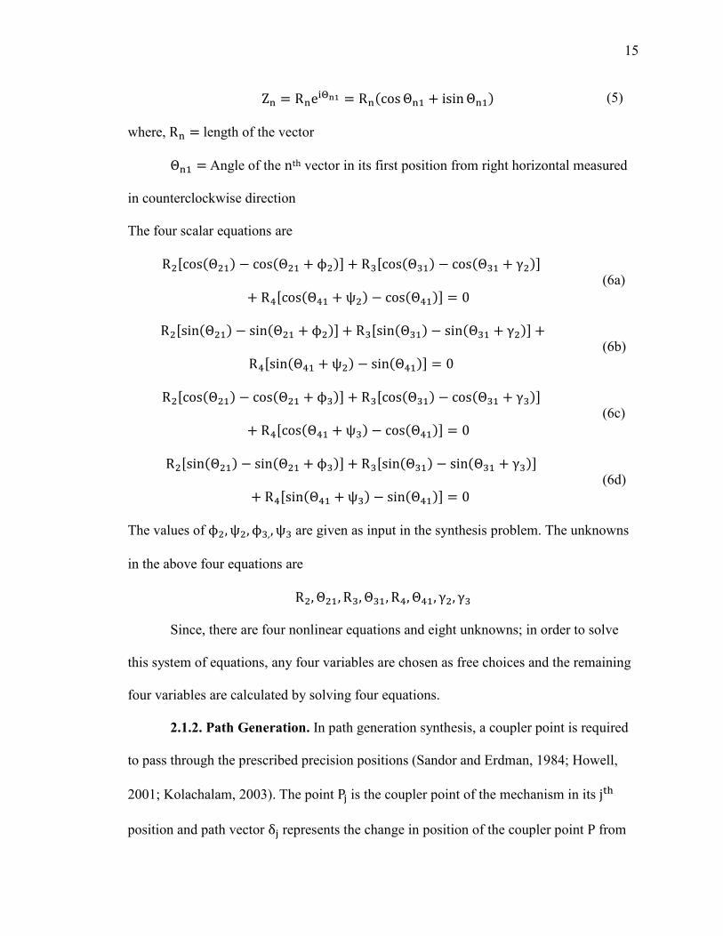
Z" = R"e�$%& = R"'cosΘ"+ + isinΘ"+. (5)
where, R" = length of the vector
Θ"+ = Angle of the nth vector in its first position from right horizontal measured
in counterclockwise direction
The four scalar equations are
R /cos'Θ +. − cos'Θ + + ϕ .0 + R�/cos'Θ�+. − cos'Θ�+ + γ .0+ R�/cos'Θ�+ + ψ . − cos'Θ�+.0 = 0 (6a)
R /sin'Θ +. − sin'Θ + + ϕ .0 + R�/sin'Θ�+. − sin'Θ�+ + γ .0 +R�/sin'Θ�+ + ψ . − sin'Θ�+.0 = 0 (6b)
R /cos'Θ +. − cos'Θ + + ϕ�.0 + R�/cos'Θ�+. − cos'Θ�+ + γ�.0+ R�/cos'Θ�+ + ψ�. − cos'Θ�+.0 = 0 (6c)
R /sin'Θ +. − sin'Θ + + ϕ�.0 + R�/sin'Θ�+. − sin'Θ�+ + γ�.0+ R�/sin'Θ�+ + ψ�. − sin'Θ�+.0 = 0 (6d)
The values of ϕ , ψ , ϕ�,, ψ� are given as input in the synthesis problem. The unknowns
in the above four equations are
R , Θ +, R�, Θ�+, R�, Θ�+, γ , γ� Since, there are four nonlinear equations and eight unknowns; in order to solve
this system of equations, any four variables are chosen as free choices and the remaining
four variables are calculated by solving four equations.
2.1.2. Path Generation. In path generation synthesis, a coupler point is required
to pass through the prescribed precision positions (Sandor and Erdman, 1984; Howell,
2001; Kolachalam, 2003). The point P� is the coupler point of the mechanism in its j�
position and path vector δ� represents the change in position of the coupler point P from
16
14 position to j� position. The vector loop-closure equations for path generation
synthesis can be obtained using two dyads: the input 'A6AP+. and output 'B6BP+. dyads
from Figure 2.3.
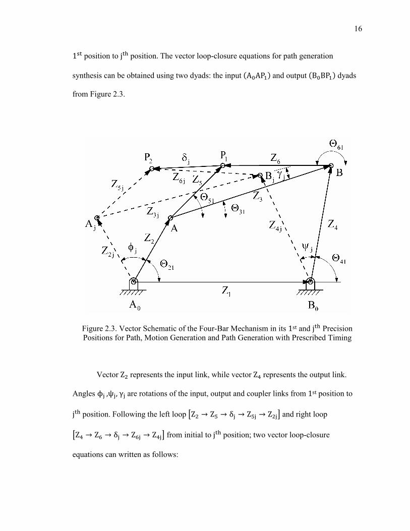
Figure 2.3. Vector Schematic of the Four-Bar Mechanism in its 1st and j� Precision Positions for Path, Motion Generation and Path Generation with Prescribed Timing
Vector Z represents the input link, while vector Z� represents the output link.
Angles ϕ�,ψ�,γ� are rotations of the input, output and coupler links from 1st position to
j� position. Following the left loop �Z → Z8 → δ� → Z8� → Z �� and right loop
�Z� → Z9 → δ� → Z9� → Z��� from initial to j� position; two vector loop-closure
equations can written as follows:
17
Z �e��� − 1� + Z8�e��� − 1� = δ� (7)
Z��e�:� − 1� + Z9�e��� − 1� = δ� (8)
These two vector equations will yield four scalar equations for two precision positions.
For three precision position synthesis case using the equations (7) and (8), four loop-
closure equations can be obtained as follows:
For positions 1 and 2;
Z �e�� − 1� + Z8�e�� − 1� = δ (9)
Z��e�: − 1� + Z9�e�� − 1� = δ (10)
For positions 1 and 3;
Z �e��! − 1� + Z8�e��! − 1� = δ� (11)
Z��e�:! − 1� + Z9�e��! − 1� = δ� (12)
The above four vector loop-closure equations will yield eight scalar equations using
equation (5) and they are as follows:
R /cos'Θ + + ϕ . − cos'Θ +.0 + R8/cos'Θ8+ + γ . − cos'Θ8+.0 = Re'δ . (13a)
R /sin'Θ + + ϕ .− sin'Θ +.0 + R8/sin'Θ8+ + γ .− sin'Θ8+.0 = Im'δ . (13b)
R�/cos'Θ�+ + ψ . − cos'Θ�+.0 + R9/cos'Θ9+ + γ . − cos'Θ9+.0 = Re'δ . (13c)
R�/sin'Θ�+ + ψ .− sin'Θ�+.0 + R9/sin'Θ9+ + γ .− sin'Θ9+.0 = Im'δ . (13d)
R /cos'Θ + + ϕ�. − cos'Θ +.0 + R8/cos'Θ8+ + γ�. − cos'Θ8+.0 = Re'δ�. (13e)
R /sin'Θ + + ϕ�.− sin'Θ +.0 + R8/sin'Θ8+ + γ�.− sin'Θ8+.0 = Im'δ�. (13f)
R�/cos'Θ�+ + ψ�. − cos'Θ�+.0 + R9/cos'Θ9+ + γ�. − cos'Θ9+.0 = Re'δ�. (13g)
R�/sin'Θ�+ + ψ�.− sin'Θ�+.0 + R9/sin'Θ9+ + γ�.− sin'Θ9+.0 = Im'δ�. (13h)
18
where, Re'δ .and Im'δ . represents the real and imaginary parts of the path vector δ
and the same applies for vector δ�. For the path generation synthesis δ and δ�are
specified as input while the unknowns in the above equations are
R , Θ +, R8, Θ8+, R�, Θ�+, R9, Θ9+, ϕ , ϕ�,ψ , ψ�,γ , γ� Since, there are 8 non-linear equations and 14 unknowns, in order to solve this
system of equations any of the 6 variables are chosen as free choices and the remaining
eight variables are calculated by solving eight equations.
2.1.3. Motion Generation. In motion generation synthesis (Sandor and Erdman,
1984; Howell, 2001; Kolachalam, 2003) in addition to the precision positions, the coupler
orientations are also specified at each precision position (Figure 2.3). The governing
loop-closure equations for three precision positions motion generation synthesis case are
the same as those for the path generation synthesis case but the number of unknowns gets
reduced by two due to specification of couple link angle 'γ�. at precision positions. The
unknowns are
R , Θ +, R8, Θ8+, R�, Θ�+, R9, Θ9+, ϕ , ϕ�,ψ , ψ�There are 8 non-linear equations and 12 unknowns, any four variables are considered as
free choices so as to solve the above system of equations for 8 unknown variables.
2.1.4. Path Generation with Prescribed Timing. In path generation with
prescribed timing synthesis (Sandor and Erdman, 1984; Howell, 2001; Kolachalam,
2003) the precision positions are correlated with input link angles. This is similar to the
motion generation expect instead of coupler link angles 'γ�., input link angles 'ϕ�. are
specified at precision positions (Figure 2.3). The governing loop-closure equations for
19
three precision positions path generation with prescribed timing synthesis case are the
same as those for the path generation or motion generation synthesis case.
Here, the unknowns are
R , Θ +, R8, Θ8+, R�, Θ�+, R9, Θ9+, ψ , ψ�, γ ,γ� In this case also, there are 8 non-linear equations and 12 unknowns, any four
variables are considered as free choices so as to solve the above system of equations for 8
unknown variables.
2.2. COMPLIANT MECHANISM DESIGN
Compliant mechanisms involve the large nonlinear deflections, so the
conventional linear equations are not applicable to the compliant mechanisms design.
These large deflections cause geometric nonlinearities in the compliant mechanisms.
Bisshopp and Drucker (1945), developed elliptic integrals for analysis of large-deflection
analysis problems. Elliptic integrals are the functions like trigonometric functions where
an input is given and result is calculated by series of expansion (Howell, 2001).
e.g. cosine trigonometric function where angle can be an input and result will be obtained
by cosine series expansion. One difference in analogy between the trigonometric function
and elliptic integrals is the trigonometric functions have only one independent function,
while elliptic integrals may require two or three independent variables. The use of elliptic
integrals is limited to the relatively simple geometries and simple loading cases due to
several simplifying assumptions such as linear material properties, inextensible materials
(Howell, 2001).
20
A nonlinear finite element analysis and chain algorithm (Her et al., 1992) can be
used for analysis of more complicated geometries and loadings problems (Howell, 2001).
These methods can be useful in analyzing the compliant mechanisms obtained using
pseudo-rigid-body model concept technique. These methods can also be used to analyze
the complex geometry problems which will be difficult to model using pseudo-rigid-body
models. However, it will be still wise decision to use pseudo-rigid-body models in the
preliminary design stages to obtain the general understanding of the behavior and
characteristics of the mechanism and then use above methods to improve the design
obtained.
2.2.1. Pseudo-Rigid-Body Model Concept. A pseudo-rigid-body model concept
is used to model the large deflections of flexible members using rigid-body members and
torsional springs having equivalent force-deflections characteristics (Howell and Midha,
1996; Howell 2001). It can be shown that free end of the flexible cantilever beam with
force at the free end follows a nearly circular path, having some radius of curvature along
the beam's length (Howell, 2001). This idea is used to develop the parametric
approximations for the beam's deflection path, wherein it is assumed that nearly circular
path travel of beam's end can be modeled by two rigid links joined at characteristic pivot
(Howell, 1991) along the beam (Howell and Midha, 1995; Howell, 2001). The
characteristic pivot location on the beam is measured as a fraction of beam length from
the beam end. This fractional distance is known as characteristic radius,γ=, where γ is
called as characteristic radius factor. The average value of the characteristic radius factor
γ is found to be 0.85. For most of the pseudo-rigid-body models of the various beam
types, this value can be taken as the preliminary estimate. The characteristic radius,γ=,
21
represents the radius of circular deflection path traversed by the end of pseudo-rigid-body
link. The torsional spring at the characteristic pivot is used to model the force-deflection
characteristics of the flexible beam and represents the beam's resistance to the deflection
and this resistance can be modeled by the stiffness coefficient,Κ$, which represents
torsional spring property of the beam. The average value of Κ$ is taken as 2.65 for
0.5< n < 1.0 (Howell, 2001).
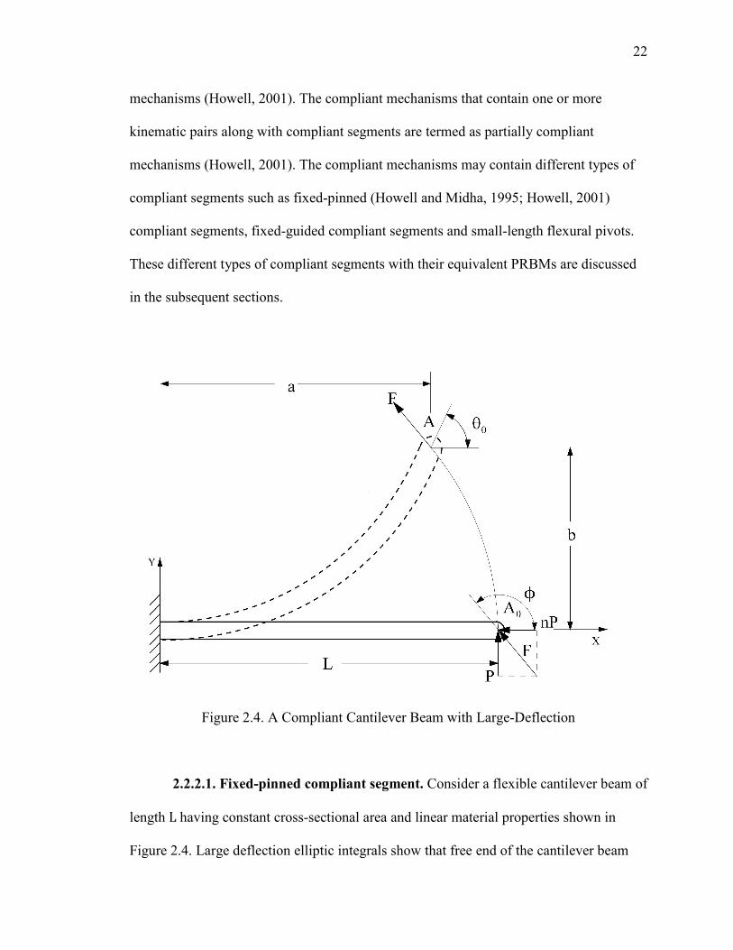
Figure 2.4 shows the initially straight cantilever beam of length L which
undergoes the large deflection due to applied transverse and axial end forces P and nP
respectively. θ6, is the beam end angle of the cantilever beam. Figure 2.5 shows the
equivalent pseudo-rigid-body model of the cantilever beam with two rigid links and
torsional spring at the characteristic pivot. The angle by which the characteristic radius or
the longer pseudo-rigid-body link rotates is referred as pseudo-rigid-body angle Θ. The
nearly linear relationship is approximated between θ6 and Θ (Howell and Midha, 1995;
Howell, 2001) by
θ6 = cFΘ (14)
where, cF is the parametric angle coefficient. More explanation on pseudo-rigid-body
models can be found in Compliant Mechanisms, Howell 2001.
2.2.2. Types of Compliant Segments and Equivalent PRBMs. The compliant
mechanisms can have compliant segments as well as rigid links and joints. Depending on
the types of links and joints in the mechanism, compliant mechanisms are classified as
fully compliant mechanisms or partially compliant mechanisms. The mechanism shown
in Figure 2.6 has no traditional joints and so zero links. These mechanisms obtain all of
their motions from deflections of flexible members and termed as fully compliant
22
mechanisms (Howell, 2001). The compliant mechanisms that contain one or more
kinematic pairs along with compliant segments are termed as partially compliant
mechanisms (Howell, 2001). The compliant mechanisms may contain different types of
compliant segments such as fixed-pinned (Howell and Midha, 1995; Howell, 2001)
compliant segments, fixed-guided compliant segments and small-length flexural pivots.
These different types of compliant segments with their equivalent PRBMs are discussed
in the subsequent sections.
Figure 2.4. A Compliant Cantilever Beam with Large-Deflection
2.2.2.1. Fixed-pinned compliant segment. Consider a flexible cantilever beam of
length L having constant cross-sectional area and linear material properties shown in
Figure 2.4. Large deflection elliptic integrals show that free end of the cantilever beam
23
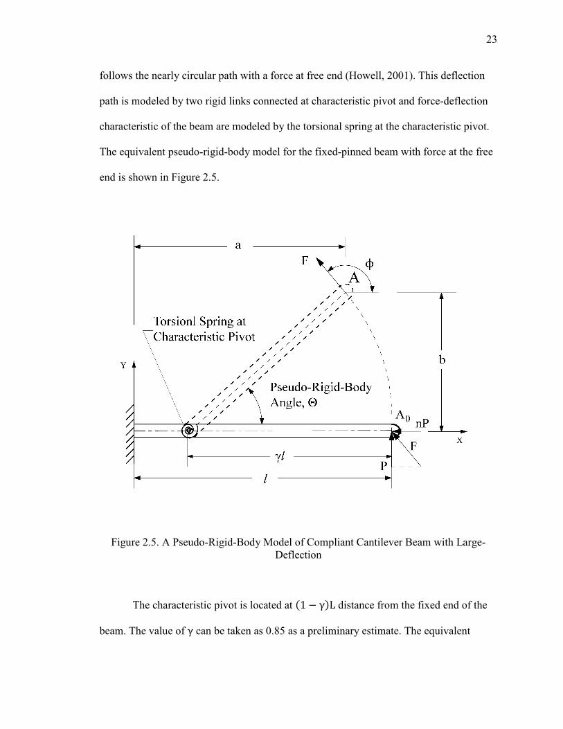
follows the nearly circular path with a force at free end (Howell, 2001). This deflection
path is modeled by two rigid links connected at characteristic pivot and force-deflection
characteristic of the beam are modeled by the torsional spring at the characteristic pivot.
The equivalent pseudo-rigid-body model for the fixed-pinned beam with force at the free
end is shown in Figure 2.5.
Figure 2.5. A Pseudo-Rigid-Body Model of Compliant Cantilever Beam with Large-Deflection
The characteristic pivot is located at '1 − γ.L distance from the fixed end of the
beam. The value of γ can be taken as 0.85 as a preliminary estimate. The equivalent
24
spring constant,Κ, of the torsional spring attached at the characteristic pivot, can be
determined using the equation (Howell, 2001):
Κ = γΚ$ ΕΙL (15)
where, Κ$ ≡ Stiffness coefficient (average value of Κ$ can be taken as 2.65)
Ε ≡ Elastic modulus
Ι ≡ Moment of inertia
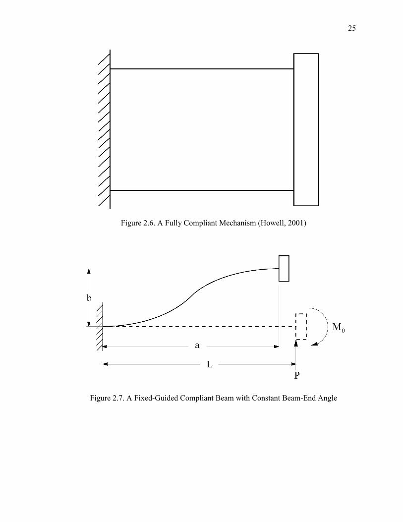
2.2.2.2. Fixed-guided compliant segment. Consider a cantilever flexible beam
with loadings as shown in Figure 2.7. The one end of the beam is fixed while the other
end is to be maintained at constant angle and in order to have a constant beam-end angle,
the resultant moment Μ6 must be present at the free end with the force Ρ. The resulting
deflected shape of the beam is anti-symmetric at its centerline, where the curvature
becomes zero (Howell, 2001). Moment also becomes zero at the mid-length as it is
proportional to the curvature according the Euler-Bernoulli principle.
Considering only the one-half of the beam, it will have force P at its end and it
will have same pseudo-rigid-body model as discussed for the fixed-pinned segment. The
pseudo-rigid-body model for the whole beam can be obtained by combining the two anti-
symmetric one-half beam models as shown in Figure 2.8. Thus, PRBM consists of three
rigid links joined at two characteristic pivots as shown in Figure 2.8 with two torsional
springs; one at each characteristic pivot. The characteristic pivot is located at the distance
'1 − γ. L from each end. The value of γ can be taken as 0.85.
25
Figure 2.6. A Fully Compliant Mechanism (Howell, 2001)
Figure 2.7. A Fixed-Guided Compliant Beam with Constant Beam-End Angle
26
The torsional spring constant, Κ, of the each spring can be determined by the following
the expression (Howell, 2001):
Κ = 2γΚ$ ΕΙL (16)
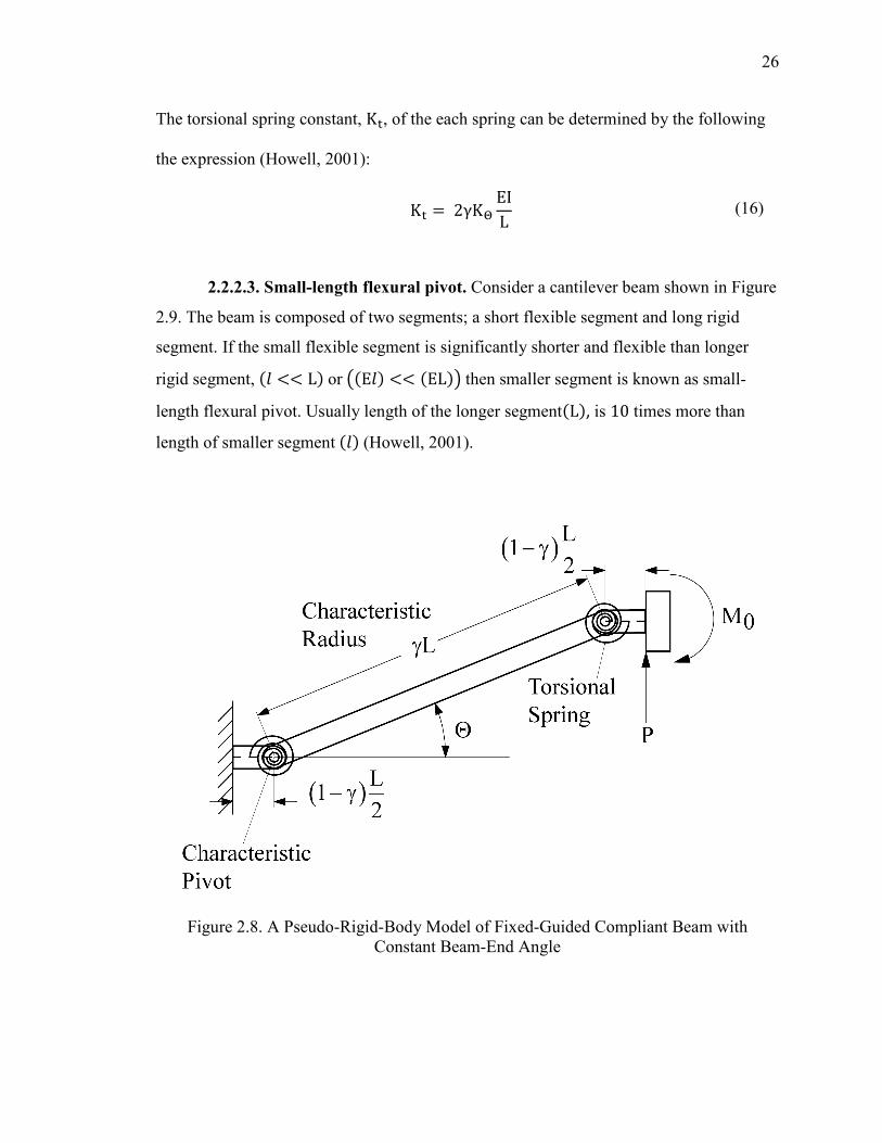
2.2.2.3. Small-length flexural pivot. Consider a cantilever beam shown in Figure
2.9. The beam is composed of two segments; a short flexible segment and long rigid
segment. If the small flexible segment is significantly shorter and flexible than longer
rigid segment, '= << L.or �'E=. << 'EL.� then smaller segment is known as small-
length flexural pivot. Usually length of the longer segment'L., is 10 times more than
length of smaller segment '=. (Howell, 2001).
Figure 2.8. A Pseudo-Rigid-Body Model of Fixed-Guided Compliant Beam with Constant Beam-End Angle
27
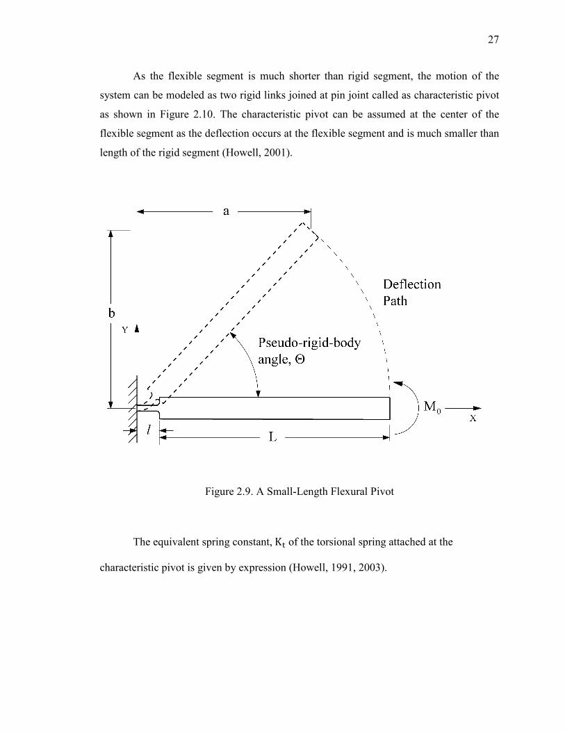
As the flexible segment is much shorter than rigid segment, the motion of the
system can be modeled as two rigid links joined at pin joint called as characteristic pivot
as shown in Figure 2.10. The characteristic pivot can be assumed at the center of the
flexible segment as the deflection occurs at the flexible segment and is much smaller than
length of the rigid segment (Howell, 2001).
Figure 2.9. A Small-Length Flexural Pivot
The equivalent spring constant,Κ of the torsional spring attached at the
characteristic pivot is given by expression (Howell, 1991, 2003).
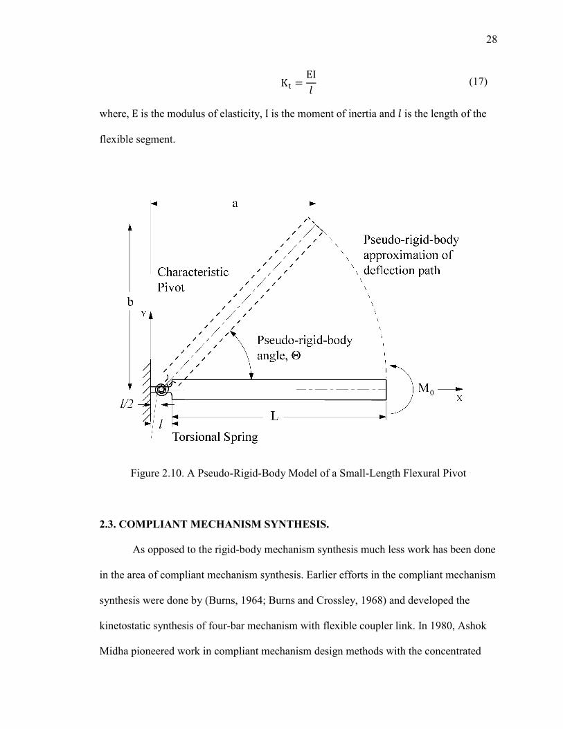
28
Κ = ΕΙ= (17)
where, Ε is the modulus of elasticity, Ι is the moment of inertia and = is the length of the
flexible segment.
Figure 2.10. A Pseudo-Rigid-Body Model of a Small-Length Flexural Pivot
2.3. COMPLIANT MECHANISM SYNTHESIS.
As opposed to the rigid-body mechanism synthesis much less work has been done
in the area of compliant mechanism synthesis. Earlier efforts in the compliant mechanism
synthesis were done by (Burns, 1964; Burns and Crossley, 1968) and developed the
kinetostatic synthesis of four-bar mechanism with flexible coupler link. In 1980, Ashok
Midha pioneered work in compliant mechanism design methods with the concentrated
29
compliance. Howell and Midha (1994) developed the pseudo-rigid-body model, which
modeled the flexible segments by equivalent rigid links and torsional springs and made
the compliant mechanism synthesis much easier using available rigid-body mechanism
theories. Mettlach and Midha (1995) presented a graphical synthesis technique using
Burmester theory to design the compliant mechanisms for more number of precision
positions. Murphy et al. (1996) developed the method based in graph theory to design the
different topologies of the compliant mechanisms employing type synthesis techniques.
Annamalai (2003), Midha et al. (2004) used the pseudo-rigid-body model concept to
synthesize the pseudo-rigid-body four-bar mechanism with energy/torque specifications.
Kolachalam (2003), Midha et al. (2011) synthesized the compliant single strip
mechanisms for energy, torque and force specifications. Dado (2005) developed a
variable parametric pseudo-rigid-body model for limit position synthesis of complaint
four-bar mechanism with energy specifications.
Design methodologies for the distributed compliance first appeared in the works
of Ananthsuresh (1994). In this case, continuum solid mechanics methods are used
instead of rigid-body kinematics. Ananthsuresh (1994) used the structural optimization
technique to design the compliant mechanisms with distributed compliance by using
homogenization method and using the displacement of one point as objective function.
Another structural optimization method using mechanism deformation energy as
objective function is developed by Frecker et al. (1997). Saggere and Kota (2001)
synthesized the four-bar mechanism with compliant coupler which requires prescribed
shape change along with rigid-body motion for motion generation. In the recent times, Lu
and Kota (2003) used load-path methodology and genetic algorithms in designing the
30
shape morphing compliant mechanisms. Krovi et al. (2002) studied the kinetostatic
synthesis of planar-coupled serial chain mechanisms by combining precision point
synthesis and optimization.
Su and McCarthy (2007) synthesized the bi-stable four-bar compliant mechanism
using polynomial homotopy technique. Tari and Su (2011) presented a complex solution
framework for kinetostatic synthesis of compliant four-bar mechanism. There are other
design methods for compliant mechanisms known as inverse design methods that allow
designer to determine the initial shape such that it attains the desired shape under applied
loads (Albanesi et al. 2010).
2.3.1. Compliant Mechanism Synthesis Methods Using PRBM Concept.
Compliant mechanism synthesis poses many challenges that are not found in rigid-body
synthesis. Unlike the rigid-body mechanism, motion of the compliant mechanism
depends on the location, direction and magnitude of the applied forces. The compliant
mechanisms inherently have limits on geometry. e.g. the compliant segments such as
small-length flexural pivots can't fully rotate. For motion, the compliant segments have to
deform, this induces stresses in them. So, stress and fatigue are of major concern while
designing compliant mechanisms etc. The compliant mechanism synthesis using pseudo-
rigid-body model can be divided into two major classes (Howell, 2001) rigid-body-
replacement synthesis and synthesis with compliance. These methods are discussed in
detail in following sections.
2.3.1.1. Rigid-body replacement (kinematic) synthesis. The synthesis of
compliant mechanisms in which rigid-body equations are directly applied to the pseudo-
rigid-body model without any concern for energy storage characteristics of the
31
mechanism, is called as rigid-body replacement synthesis. As only kinematic equations
are considered only for synthesis, this is also known as kinematic synthesis. In this
approach, pseudo-rigid-body model is obtained for compliant mechanism and using rigid-
body kinematic equations, link lengths are obtained. Once the kinematic geometry is
obtained, structural properties of the mechanism are determined according to the
allowable stresses or the input requirements. This synthesis approach is particularly
useful when a compliant mechanism is to be used for conventional rigid body tasks like
function generation, path generation etc. without considering energy storage in the
mechanism.
The major task in this synthesis method is determining and evaluating the pseudo-
rigid-body model for the compliant mechanism as the synthesis may yield number of
solutions that may be valid for rigid-body mechanism but not for the compliant
mechanism due to some practical limits on the geometry, e.g. small-length flexural pivots
can't rotate fully. So, the iterative approach will be more useful in this compliant
mechanism synthesis method.
2.3.1.2. Synthesis with compliance (kinetostatic synthesis). The compliant
mechanism synthesis technique, which considers energy storage characteristics in the
flexible segments in addition to the rigid-body kinematic equations, is termed as
synthesis with compliance (Howell and Midha, 1994; Howell, 2001). As both kinematic
equations and static force equations are considered for the synthesis, this is also known as
kinetostatic synthesis. The synthesis includes loop-closure equations for the pseudo-rigid-
body model and energy equations. The energy storage characteristics of the mechanism
can be considered as energy stored in the system as function of input, required input
32
torque or force and required input and output force or torque at each precision position
(Howell, 2001). The example of synthesis with compliance can be a mechanism designed
for path generation with energies or torques or forces specified at the precision positions.
As discussed in the rigid-body replacement synthesis, in this method also an appropriate
pseudo-rigid-body model for the compliant mechanism is obtained using kinematic
equations. The structural properties of the flexible segments are then determined
according to the allowable stresses or the input requirements using the energy equations.
The energy is stored in the form of strain energy in the flexible members of
compliant mechanisms. This energy can be accounted using the torsional springs of
appropriate stiffness values at characteristic pivots in the pseudo-rigid-body model. The
consideration of energy equations along with kinematic equations for the synthesis results
in two sets of unknowns in the system of equations. i) kinematic variables includes link
lengths, angles of the pseudo-rigid-body model links ii) energy variables consists of
spring constants, K, related to the stiffness coefficient, Κ$, and undeflected spring
parameters, β6, related to the initial pseudo-rigid-body model, Θ6. Figure 2.11 shows the
four-bar mechanism with four torsional springs attached at pin joints.
2.3.2. Energy Considerations. In designing compliant mechanism using
synthesis with compliance technique, energies are specified at precision positions in
addition to the kinematic variable specifications depending synthesis type e.g. for the
motion generation synthesis case, coupler link angles (γ4) are specified along with
precision positions. Considering the pseudo-rigid-body four-bar mechanism, a maximum
of four torsional springs can be attached at the four pin joints.
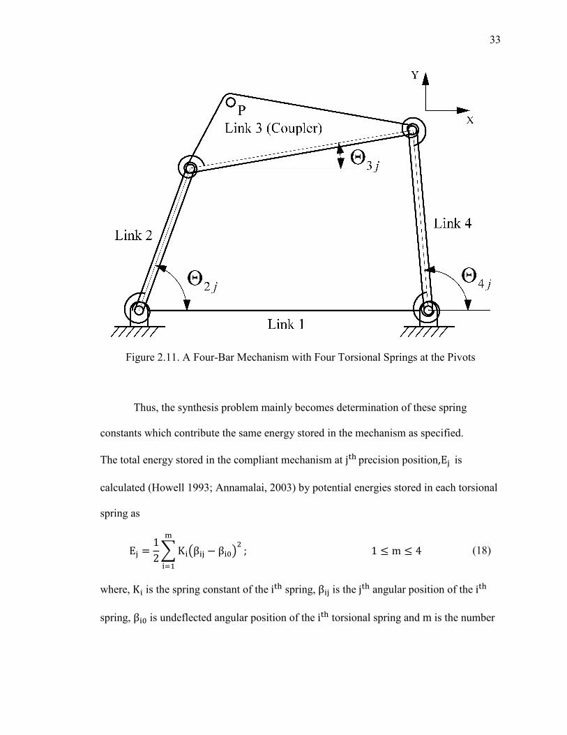
33
Figure 2.11. A Four-Bar Mechanism with Four Torsional Springs at the Pivots
Thus, the synthesis problem mainly becomes determination of these spring
constants which contribute the same energy stored in the mechanism as specified.
The total energy stored in the compliant mechanism at j�precision position,E� is
calculated (Howell 1993; Annamalai, 2003) by potential energies stored in each torsional
spring as
E� = 12PΚ��β�� − β�6�
Q
�R+; 1 ≤ m ≤ 4 (18)
where, � is the spring constant of the i� spring, � is the j� angular position of the i�
spring, β�6 is undeflected angular position of the i� torsional spring and m is the number
34
of torsional springs in the mechanism. The angle � can be expressed in terms of pseudo-
rigid-body model angle, Θ6 (Howell, 1993; Annamalai, 2003) as follows:
β+� = Θ � (19a)
β � = 1806 − �Θ � − Θ��� (19b)
β�� = Θ�� − Θ�� (19c)
� = �� (19d)
where, �� is the angle of the i� link in the j�position. Using equations (19), the
mechanism total energy,E� in j� position can be written as follows:
E� = 12 VΚ+�Θ � − Θ 6� + Κ ��Θ�� − Θ�6� − �Θ � − Θ 6��
+ Κ���Θ�� − Θ�6� − �Θ�� − Θ�6�� + Κ��Θ�� − Θ�6� � (20)
Considering three precision positions synthesis problem, equation (20) can be written for
each precision position as follows:
E+ = 12 /Κ+'Θ + − Θ 6. + Κ /'Θ�+ − Θ�6. − 'Θ + − Θ 6.0
+ Κ�/'Θ�+ − Θ�6. − 'Θ�+ − Θ�6.0 + Κ�'Θ�+ − Θ�6. 0(21a)
E = 12 /Κ+'Θ + + ϕ − Θ 6.
+ Κ /'Θ�+ + γ − Θ�6. − 'Θ + + ϕ − Θ 6.0 + Κ�/'Θ�+ + ψ − Θ�6. − 'Θ�+ + γ − Θ�6.0 + Κ�'Θ�+ + ψ − Θ�6. 0
(21b)
35
E� = 12 /Κ+'Θ + + ϕ� − Θ 6.
+ Κ /'Θ�+ + γ� − Θ�6. − 'Θ + + ϕ� − Θ 6.0 + Κ�/'Θ�+ + ψ� − Θ�6. − 'Θ�+ + γ� − Θ�6.0 + Κ�'Θ�+ + ψ� − Θ�6. 0
(21c)
These three energy equations can be solved for four unknown spring constants.
i.e. Κ+, Κ , Κ�, Κ�. If the first precision position of the mechanism is considered to be an
undeflected position i.e. zero-energy position of the mechanism, then the system of
reduced equations is used and is given below:
E+ = 0 (22a)
E = 12 /Κ+'ϕ . + Κ 'ϕ − γ . + Κ�'ψ − γ . + Κ�'ψ . 0 (22b)
E = 12 /Κ+'ϕ�. + Κ 'ϕ� − γ�. + Κ�'ψ� − γ�. + Κ�'ψ�. 0 (22c)
In this particular case, first energy equation is trivial and may be neglected. Other
two energy equations can solved for four unknowns Κ+, Κ , Κ�, Κ�. Once the pseudo-
rigid-body four-bar mechanism has been synthesized, the next step is to determine the
dimensions of the flexible members. In this work, rectangular sections of compliant
members have been assumed.
2.4. COMPLIANT SEGMENT DESIGN
Depending on the type of the compliant segments i.e. fixed-pinned segment,
fixed-guided segment, small-length flexural pivot considered in the compliant
36
mechanism, dimensions of compliant segments can be determined as discussed in the
following sections.
2.4.1. Fixed-Pinned Segment. The equivalent pseudo-rigid-body model for the
fixed-pinned compliant segment is shown in Figure 2.5. After determining all the pseudo-
rigid-body link lengths from the synthesis; if a fixed-pinned segment is selected as a
flexible member, the distance of the characteristic pivot from the fixed end of the
compliant beam is taken as '1 − γ.L, where, γcan be taken as 0.85 and the stiffness
coefficient is assumed to be 2.65. It is assured that the pin joint of the pseudo-rigid-body
link and characteristic pivot coincides with each other. Thus, pseudo-rigid-body link
lengths obtained are used to find the characteristic radius, γL. The total link length of
compliant fixed-pinned segment L can be obtained as:
γL = |Z| ⇒ L = |Z|/γ (23)
where, |Z| = R = length of the pseudo-rigid-body link
Once the spring constants are known, the equation (15) and equation (23) is used to
determine the either width or thickness of the segment by assuming an appropriate value
for the other as follows:
I = bh�12 (24)
b = 12ΚLγΚ$Εh� (25)
h = [ 12ΚLγΚ$Εb\+� (26)
37
2.4.2. Fixed-Guided Compliant Segment. The equivalent pseudo-rigid-body
model for the fixed-guided compliant segment with constant beam-end angle is shown in
Figure 2.8. This model assumes that one end of the compliant segment is maintained at
constant angle. For the compliant mechanism motions considered here, it will be difficult
to enforce this assumption, so this model is used as a possible approximation.
If a fixed-guided compliant segment is selected, the distance to the characteristic
pivot from the either end is given by'1 − γ. L , the value of γ is assumed to be 0.85 and
stiffness coefficient to be 2.65. While using fixed-guided compliant segment in the
mechanism, it is reasonable to assume two same spring constants on the one pseudo-
rigid-body link. It is assured that the pin joints of the pseudo-rigid-body link and
characteristic pivots coincide with each other. Thus, pseudo-rigid-body link lengths
obtained are used to find the characteristic radius, γL. The total link length of compliant
fixed-guided segmentL, can be obtained using equation (23). Once the spring constants
are known, the equation (16) is used to determine the either width or thickness of the
segment by assuming an appropriate value for the other as follows:
b = 6ΚLγΚ$Εh� (27)
h = [ 6ΚLγΚ$Εb\
+� (28)
2.4.3. Small-Length Flexural Pivot. The equivalent pseudo-rigid-body model of
the small-length flexural pivot is shown in Figure 2.10. The compliant mechanisms with
flexure pivots, utilizes the small-length flexural pivots assumption. If the small length
flexural pivot is selected as a compliant segment, the characteristic pivot is located at its
38
center. The length of small-length flexural pivot is assumed to ] ++6^
� of the pseudo-rigid-
body link length.
= = L10 (29)
Once the length of the small-length flexural pivot and spring constant of torsional spring
are known, equation (17) is used to determine the either width or thickness by assuming
an appropriate value for the other as follows:
b = 12Κ=Εh� (30)
h = [12Κ=Εb \+� (31)
2.5. SUMMARY
In this Section, the rigid-body synthesis methods for three-precision positions
synthesis of a four-bar mechanism are reviewed. A pseudo-rigid-body concept is
discussed and pseudo-rigid-body models are presented for three types of compliant
segments. The compliant mechanism synthesis methods are reviewed. The two synthesis
methods for compliant mechanism synthesis using pseudo-rigid-body model concept are
discussed and energy considerations for compliant mechanism synthesis are introduced.
The different types of compliant segments such small-length flexural pivots, full-length
compliant segments are designed.

39
3. SYNTHESIS WITH COMPLIANCE FOR ENERGY AND TORQUE
SPECIFICATIONS AND NEED FOR OPTIMIZATION APPROACH TO SOLVE
ENERGY/TORQUE EQUATIONS
Synthesis with compliance technique (Howell and Midha, 1996; Howell, 2001)
synthesizes the compliant mechanisms considering both loop-closure kinematic equations
and energy/toque equations. This concept was introduced briefly in Section 2 applied to
synthesis of a pseudo-rigid-body four-bar mechanism for three precision positions with
energy specified at each position and a particular case where first precision position is
energy-free position of the mechanism i.e. energy is zero at the first precision position.
This Section reviews the general synthesis with compliance technique applied to different
synthesis problems such as function generation, path generation etc. with more than three
precision positions and torque specifications problems also. The Section also enlists the
design tables, which gives an easy tool for the user to determine the number of equations
and number of unknowns required to synthesize the pseudo-rigid-body four-bar
mechanism for energy and torque specifications. The limitations/problems with synthesis
with compliance technique are presented in subsequent sections. The new approach to
solve the system of energy/torque equations using optimization is introduced at the end of
the Section.
3.1. SYNTHESIS WITH COMPLIANCE
The synthesis with compliance technique uses pseudo-rigid-body model concept
for compliant mechanism synthesis. This method provides multiplicity of solutions along
with expediency and accuracy of the solutions (Annamalai, 2003). The pseudo-rigid-body
links and their orientations in precision positions constitute the kinematic equations i.e.

40
loop-closure equations, while the spring constants and deflections of springs attached at
the characteristic pivots in pseudo-rigid-body model constitutes energy equations and
results in two different sets of unknowns.
i. Kinematic variables consisting of pseudo-rigid-body link lengths and their angles
corresponding to precision positions, and
ii. Energy variables consisting of spring constants and undeflected torsional spring
positions.
Thus, the loop-closure equations represent kinematic mobility of the mechanism,
while the energy/torque equations represent the mechanism compliance. The compliant
mechanisms can be reduced to pseudo-rigid-body model with rigid links and torsional
springs. Consider the basic four-bar mechanism with its pin joints representing
characteristic pivots and torsional springs at the characteristic pivots representing the
segment compliances as shown in Figure 3.1. Depending on the number of springs in the
system, the number of unknowns i.e. kinematic variables and energy variables introduced
in the system changes. The variables common in both the kinematic equations and energy
equations cause coupling in them.
41
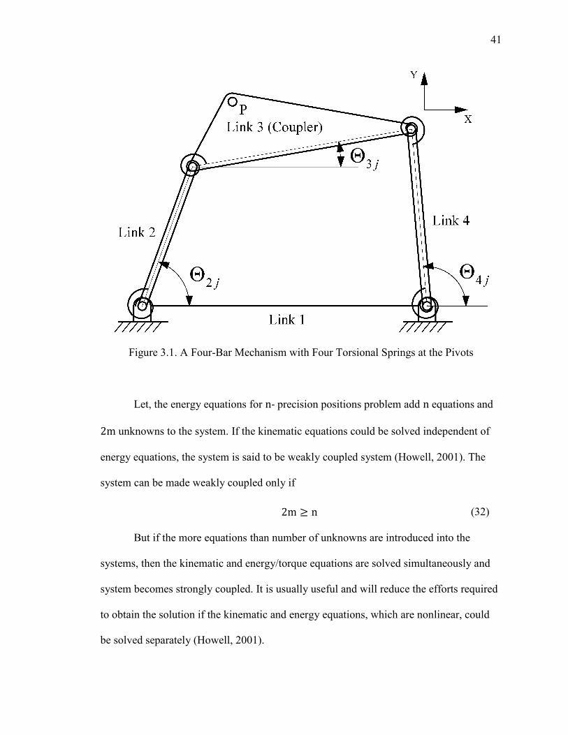
Figure 3.1. A Four-Bar Mechanism with Four Torsional Springs at the Pivots
Let, the energy equations for n- precision positions problem add n equations and
2m unknowns to the system. If the kinematic equations could be solved independent of
energy equations, the system is said to be weakly coupled system (Howell, 2001). The
system can be made weakly coupled only if
But if the more equations than number of unknowns are introduced into the
systems, then the kinematic and energy/torque equations are solved simultaneously and
system becomes strongly coupled. It is usually useful and will reduce the efforts required
to obtain the solution if the kinematic and energy equations, which are nonlinear, could
be solved separately (Howell, 2001).
2m ≥ n (32)
42
The inclusion of different types of compliant segments in the mechanism gives
wide range of solutions to the design problems (Howell, 2001). For a pseudo-rigid-body
four-bar mechanism, with different types of compliant segments such as small-length
flexural pivots, full-length compliant segments, all possible 18 configurations depending
on the number of springs used are presented in Figure 3.2 (Midha et al., 1997;
Annamalai, 2003). Using different compliant segment types for pseudo-rigid-body links
and starting with four torsional springs in the mechanism, three compliant mechanism
configurations (Figure 3.2 A-C) are possible. Similarly, five compliant mechanism
configurations (Figure 3.2 D-H) with three springs, eight configurations (Figure 3.2 I-P)
with two springs and two configurations (Figure 3.2 Q,R) with one spring are possible,
resulting in total of 18 configurations. It is the user's decision to choose the suitable
configuration for particular task considering design and manufacturing constraints.
3.1.1. Kinematic Considerations. The kinematic synthesis of pseudo-rigid-body
mechanism is discussed in Section 2.1. It is reviewed quickly here for the sake of
continuity. In function generation, the vector loop �Z → Z� → Z� → Z�� → Z�� → Z �� in
14 and j� positions of the mechanism in Figure 2.2, gives following loop-closure
equation:
Z �1 − e���� + Z��1 − e���� + Z��e�:� − 1� = 0 (2)
In path generation, motion generation and path generation with prescribed timing,
left loop �Z → Z8 → δ� → Z8� → Z �� and right loop �Z� → Z9 → δ� → Z9� → Z��� from
initial to j� position of the mechanism in Figure 2.3; give following two vector loop-
closure equations:
43
Z �e��� − 1� + Z8�e��� − 1� = δ� (7)
Z��e�:� − 1� + Z9�e��� − 1� = δ� (8)
3.1.2. Energy/Torque Considerations. The total energy stored in the compliant
mechanism at j� precision position,E�, is calculated (Howell, 1993; Annamalai, 2003) by
the potential energies stored in each torsional spring of the corresponding pseudo-rigid-
body model as
E� = 12PΚ��β�� − β�6�
Q
�R+; 1 ≤ m ≤ 4 (18)
where, � is the spring constant of the i� spring, � is the j�angular position of the
i�spring, β�6 is the undeflected angular position of the i�torsional spring and m is the
number of torsional springs in the mechanism. The corresponding torque equation
(Howell, 1993; Mettlach 1996; Annamalai, 2003) is given as
T � =PK��β�� − β�6� dβ��dSQ
�R+1 ≤ m ≤ 4 (33)
where, S represents the input variable for the mechanism. The angle � is related to
pseudo-rigid-body angles as given in equations (19) as follows:
β+� = Θ � (19a) β � = 1806 − �Θ � − Θ��� (19b) β�� = Θ�� − Θ�� (19c) β�� = Θ�� (19d)
where, Θ�� is the angle of the i�link in the j�position. If Θ is the input, then cde�cf may be
expressed as:
44
[dβ+dΘ \� = 1 (34a)
[dβ dΘ \� = [dΘ�dΘ \� − 1 = h�� − 1 (34b)
[dβ�dΘ \� = [dΘ�dΘ \� − [dΘ�dΘ \� = h�� − h�� (34c)
[dβ�dΘ \� = [dΘ�dΘ \� = h�� (34d)
where, h�� represents the first-order kinematic coefficient of the i� link at the j� position,
and is defined (Hall, 1981) as follows:
h�� = R sin�Θ�� − Θ ��R� sin�Θ�� − Θ��� (35a)
h�� = R sin�Θ�� − Θ ��R� sin�Θ�� − Θ��� (35b)
Using equations (19) in equation (18), energy at the j� position can be written as:
E� = 12 VΚ+�Θ � − Θ 6� + Κ ��Θ�� − Θ�6� − �Θ � − Θ 6��
+ Κ���Θ�� − Θ�6� − �Θ�� − Θ�6�� + Κ��Θ�� − Θ�6� �(20)
Using equations (19), (33) and (34) in equation (32), the torque at the j� position can be
written as:
45
T � = Κ+�Θ � − Θ 6�
+ Κ ��Θ�� − Θ�6� − �Θ � − Θ 6�� gR sin�Θ�� − Θ ��R� sin�Θ�� − Θ��� − 1h
+ Κ���Θ�� − Θ�6� − �Θ�� − Θ�6�� gR sin�Θ�� − Θ ��R� sin�Θ�� − Θ���
− R sin�Θ�� − Θ ��R� sin�Θ�� − Θ���h + Κ��Θ�� − Θ�6� R sin�Θ�� − Θ ��
R� sin�Θ�� − Θ���
(36)
where, Θ"6 represents the angular position of the n� link in the energy-free state.
The number of equations, number of unknowns and number of free choices for
function generation, path, and motion generation and path generation with prescribed
timing for given number of torsional springs 'm. are summarized in the Tables 3.1-3.4
respectively (Annamalai, 2003). For example, for a function generation synthesis of four-
bar mechanism for three precision positions with one torsional spring, there are 7
equations comprised of 4 loop-closure equations and 3 energy/torque equations and 10
unknowns, and hence 3 free choices yielding the solutions in the order of '∞.�. In the
last column of the table, notations s.c. and w.c. represents strongly coupled and weakly
coupled cases respectively.
For function generation synthesis case for five precision positions with one
spring, the number of equations become more than unknowns, hence over-constraining
the system and so not included in the Table 3.1 (Annamalai, 2003).
46
Figure 3.2. 18 Possible Configurations of Compliant Mechanism Types from Pseudo-Rigid-Body Four-Bar Mechanism
47
3.2. NEED OF COUPLER EQUATION FOR STRONGLY COUPLED SYSTEM
The torque equation (36) involving first-order kinematic coefficients, adds two
additional unknowns to the system R� and ��, where represents j� precision position.
In pseudo-rigid-body synthesis for three-precision positions with one spring for torque
specifications (e.g. refer to Table 3.3) when j > 1,Θ�� is given by �Θ�+ + γ��, where γ� is
the angle of coupler in j� precision position relative to the first precision position. Hence,
if �+ is determined, then �� can be easily calculated. For function generation synthesis
case, this may be free choice or can be solved for from kinematic equations. However, for
the other synthesis cases requiring use of dyads such as motion generation Θ�+ is not
readily available.
For weakly coupled system of equations, Θ�+ can be determined separately from
kinematic equations after solving loop-closure equations. However, for strongly coupled
system, it needs to be solved simultaneously and can be easily obtained from use of
coupler equation as follows (Figure 2.3):
Ζ� − Ζ8 + Ζ9 = 0 (37)
Accordingly, for strongly coupled, torque specification case, except for the
function generation, the number of equations and number of unknowns are increased by
two and are indicated within brackets in Tables 3.2-3.4.
3.3. SYNTHESIS CASE WITH NON-PRESCRIBED ENERGY-FREE STATE
Consider a synthesis case, where energy-free state of the compliant mechanism is
different from prescribed positions.

48
Table 3.1. Design Choices Based on Number of Torsional Springs for Function Generation Synthesis with Compliance
Number of
Torsional Springs
Number of
Equations
Number of Unknowns
Number of
Free Choices
Three Precision Positions
1 7 Z , Z�, Z�, γ , γ�, Κ+, β+6 (10)
3 (s.c.)
2 9* Z , Z�, Z�, γ , γ�, Κ+, Κ , Θ 6, Θ�6, Θ�6 (13)
4 (w.c.)
3 9* " + Κ� (14) 5 (w.c.)
4 9* " + Κ� (15) 6 (w.c.)
Four Precision Positions
1 10 Z , Z�, Z�, γ , γ�, γ�, Κ+, β+6 11)
1 (s.c.)
2 14* Z+, Z , Z�, Z�, γ , γ�, γ�, Κ+, Κ , Θ 6, Θ�6, Θ�6 (16)
2 (s.c.)
3 12 Z , Z�, Z�, γ , γ�, γ�, Κ+, Κ , Κ�, Θ 6, Θ�6, Θ�6 (15)
3 (w.c.)
4 12 " + Κ� (16) 4 (w.c.)
Five Precision Positions
2 17* Z , Z�, Z�, γ , γ�, γ�, γ8, Κ+, Κ , Θ 6, Θ�6, Θ�6 (17)
0 (s.c.)
4 17* Z , Z�, Z�, γ , γ�, γ�, γ8, Κ+, Κ , Κ�, Θ 6, Θ�6, Θ�6 (18)
1 (s.c.)
5 15 " + Κ� (17) 2 (w.c.)
* Equation (38) gives two more scalar equations. s.c. and w.c. denotes the strongly and weakly coupled system.
For a pseudo-rigid-body four-bar mechanism with more than one spring, the
deflection-free state of the one spring doesn't govern the deflection-free state of the other
springs. But for the monolithic compliant mechanism, the energy-free state of the one
compliant segment implies the energy-free state of the all compliant segments in the
49
mechanism at that position. Thus, while synthesizing the compliant mechanism, the
deflection-free state of all springs in pseudo-rigid-body mechanism should be related
with each other. Even if the resulting mechanism may be valid pseudo-rigid-body
mechanism with independent springs, it cannot be a valid one-piece compliant
mechanism until the deflection-free states of the torsional springs are not related with
each other. These additional constraints need to relate the deflection-free state angles
(Θ"6. of the springs with one another. At the energy-free state of the mechanism i.e. at
the zero-energy position of the mechanism, β�6 of the springs are related to the pseudo-
rigid-body link angles Θ"6 by equation (19). Since, Θ"6 are the part of designed pseudo-
rigid-body mechanism, they need to satisfy the following four-bar loop-closure equation
in energy-free position of the mechanism, where, the subscript '0' refers to the energy-free
state of the mechanism.
Ζ 6 + Ζ�6 = Ζ+ + Ζ�6 (38)
This equation provides additional constraints to the deflection-free state of the
springs in the mechanism. The equation (38) would suffice to satisfactorily synthesize the
weakly coupled system. However for a strongly coupled system, few additional equations
are needed for satisfactory solution. For example, for strongly coupled function
generation synthesis case with non-prescribed energy-free state, the equations (2), (18) or
(36), and (38), adds Ζ+ as an additional unknown. To accommodate these two new
unknowns, first-precision position four-bar loop-closure equation as below is used.
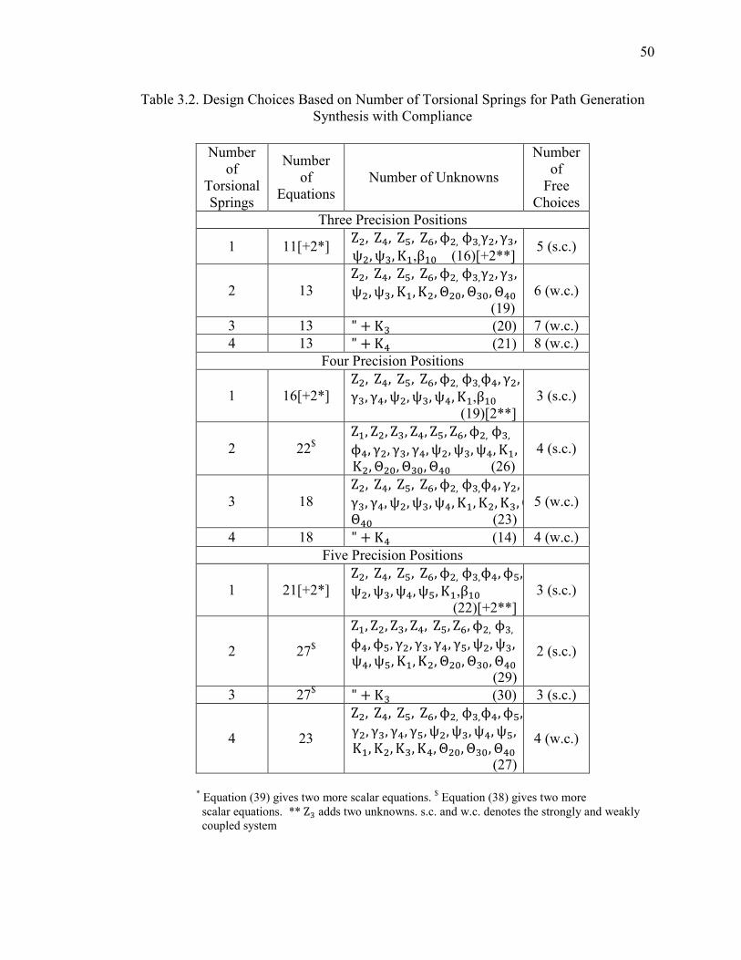
50
Table 3.2. Design Choices Based on Number of Torsional Springs for Path Generation Synthesis with Compliance
Number of
Torsional Springs
Number of
Equations Number of Unknowns
Number of
Free Choices
Three Precision Positions
1 11[+2*] Z , Z�, Z8, Z9, ϕ ,ϕ�,γ , γ�, ψ , ψ�, Κ+,β+6 (16)[+2**]
5 (s.c.)
2 13
Z , Z�, Z8, Z9, ϕ ,ϕ�,γ , γ�, ψ , ψ�, Κ+, Κ , Θ 6, Θ�6, Θ�6 (19)
6 (w.c.)
3 13 " + Κ� (20) 7 (w.c.)
4 13 " + Κ� (21) 8 (w.c.)
Four Precision Positions
1 16[+2*]
Z , Z�, Z8, Z9, ϕ ,ϕ�,ϕ�, γ , γ�, γ�, ψ , ψ�, ψ�, Κ+,β+6 (19)[2**]
3 (s.c.)
2 22$
Z+, Z , Z�, Z�, Z8, Z9, ϕ ,ϕ�, ϕ�, γ , γ�, γ�, ψ , ψ�, ψ�, Κ+, Κ , Θ 6, Θ�6, Θ�6 (26)
4 (s.c.)
3 18
Z , Z�, Z8, Z9, ϕ ,ϕ�,ϕ�, γ , γ�, γ�, ψ , ψ�, ψ�, Κ+, Κ , Κ�, ΘΘ�6 (23)
5 (w.c.)
4 18 " + Κ� (14) 4 (w.c.)
Five Precision Positions
1 21[+2*]
Z , Z�, Z8, Z9, ϕ ,ϕ�,ϕ�, ϕ8,ψ , ψ�, ψ�, ψ8, Κ+,β+6 (22)[+2**]
3 (s.c.)
2 27$
Z+, Z , Z�, Z�, Z8, Z9, ϕ ,ϕ�, ϕ�, ϕ8, γ , γ�, γ�, γ8, ψ , ψ�, ψ�, ψ8, Κ+, Κ , Θ 6, Θ�6, Θ�6 (29)
2 (s.c.)
3 27$ " + Κ� (30) 3 (s.c.)
4 23
Z , Z�, Z8, Z9, ϕ ,ϕ�,ϕ�, ϕ8, γ , γ�, γ�, γ8, ψ , ψ�, ψ�, ψ8, Κ+, Κ , Κ�, Κ�, Θ 6, Θ�6, Θ�6 (27)
4 (w.c.)
* Equation (39) gives two more scalar equations. $ Equation (38) gives two more
scalar equations. **Z� adds two unknowns. s.c. and w.c. denotes the strongly and weakly coupled system
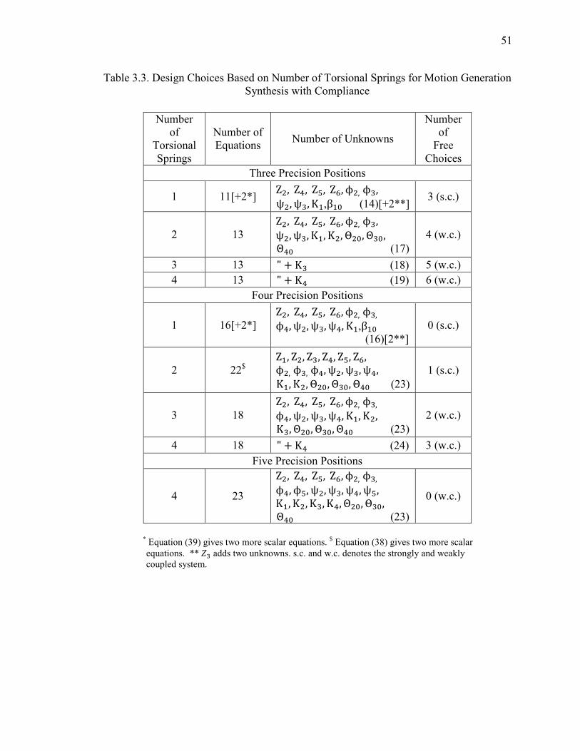
51
Table 3.3. Design Choices Based on Number of Torsional Springs for Motion Generation Synthesis with Compliance
Number of
Torsional Springs
Number of Equations
Number of Unknowns
Number of
Free Choices
Three Precision Positions
1 11[+2*] Z , Z�, Z8, Z9, ϕ ,ϕ�, ψ , ψ�, Κ+,β+6 (14)[+2**]
3 (s.c.)
2 13
Z , Z�, Z8, Z9, ϕ ,ϕ�, ψ , ψ�, Κ+, Κ , Θ 6, Θ�6, Θ�6 (17)
4 (w.c.)
3 13 " + Κ� (18) 5 (w.c.)
4 13 " + Κ� (19) 6 (w.c.)
Four Precision Positions
1 16[+2*]
Z , Z�, Z8, Z9, ϕ ,ϕ�, ϕ�, ψ , ψ�, ψ�, Κ+,β+6 (16)[2**]
0 (s.c.)
2 22$
Z+, Z , Z�, Z�, Z8, Z9, ϕ ,ϕ�,ϕ�, ψ , ψ�, ψ�, Κ+, Κ , Θ 6, Θ�6, Θ�6 (23)
1 (s.c.)
3 18
Z , Z�, Z8, Z9, ϕ ,ϕ�, ϕ�, ψ , ψ�, ψ�, Κ+, Κ , Κ�, Θ 6, Θ�6, Θ�6 (23)
2 (w.c.)
4 18 " + Κ� (24) 3 (w.c.)
Five Precision Positions
4 23
Z , Z�, Z8, Z9, ϕ ,ϕ�, ϕ�, ϕ8, ψ , ψ�, ψ�, ψ8, Κ+, Κ , Κ�, Κ�, Θ 6, Θ�6, Θ�6 (23)
0 (w.c.)
* Equation (39) gives two more scalar equations. $ Equation (38) gives two more scalar
equations. **m� adds two unknowns. s.c. and w.c. denotes the strongly and weakly coupled system.
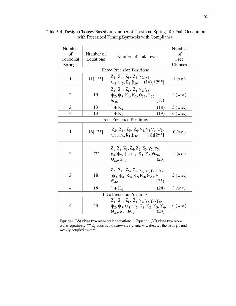
52
Table 3.4. Design Choices Based on Number of Torsional Springs for Path Generation with Prescribed Timing Synthesis with Compliance
Number of
Torsional Springs
Number of Equations
Number of Unknowns
Number of
Free Choices
Three Precision Positions
1 11[+2*] Z , Z�, Z8, Z9, γ ,γ�, ψ , ψ�, Κ+,β+6 (14)[+2**]
3 (s.c.)
2 13
Z , Z�, Z8, Z9, γ ,γ�, ψ , ψ�, Κ+, Κ , Θ 6, Θ�6, Θ�6 (17)
4 (w.c.)
3 13 " + Κ� (18) 5 (w.c.)
4 13 " + Κ� (19) 6 (w.c.)
Four Precision Positions
1 16[+2*] Z , Z�, Z8, Z9, γ ,γ�,γ�, ψ , ψ�, ψ�, Κ+,β+6 (16)[2**]
0 (s.c.)
2 22$
Z+, Z , Z�, Z�, Z8, Z9, γ ,γ�, γ�, ψ , ψ�, ψ�, Κ+, Κ , Θ 6, Θ�6, Θ�6 (23)
1 (s.c.)
3 18
Z , Z�, Z8, Z9, γ ,γ�,γ�, ψ , ψ�, ψ�, Κ+, Κ , Κ�, Θ 6, Θ�6, Θ�6 (23)
2 (w.c.)
4 18 " + Κ� (24) 3 (w.c.)
Five Precision Positions
4 23
Z , Z�, Z8, Z9, γ ,γ�,γ�, γ8, ψ , ψ�, ψ�, ψ8, Κ+, Κ , Κ�, Κ�, Θ 6, Θ�6,Θ�6 (23)
0 (w.c.)
* Equation (38) gives two more scalar equations. $ Equation (37) gives two more
scalar equations. **Z� adds two unknowns. s.c. and w.c. denotes the strongly and weakly coupled system

53
Ζ + Ζ� = Ζ+ + Ζ� (39)
For the remaining synthesis cases; Ζ+ and Ζ� become additional unknowns. In
order to accommodate these, the coupler equation (37) is used in addition to the equation
(39). Thus, the system accumulates the four more scalar equations. The above discussion
is applicable to the four-bar synthesis case with two or more springs. For pseudo-rigid-
body four-bar mechanism with one spring, the energy-free state of that spring will be the
energy-free state of the mechanism and so no additional constraints are required.
As mentioned before, above discussion assumes the energy-free state of the
mechanism is different from the prescribed positions of the mechanism. If the energy-free
state of the mechanism is assumed to be one of the prescribed positions, then reduced
system of equations can be used for synthesis. In Tables 3.3 and 3.4, for five precision
positions synthesis, the cases with one, two and three springs are not included due to
over-constraining of the system with more number of equations than more number of
unknowns. In Tables 3.2-3.4, the numbers in the brackets refer to additional equations or
unknowns arising, when the torque is specified at the precision positions instead of
energies. The synthesis with compliance method using strongly coupled and weakly
coupled system of equations can be represented as flowchart shown Figure 3.3.
3.4. LIMITATIONS/PROBLEMS WITH SYNTHESIS WITH COMPLIANCE
TECHNIQUE
Though the synthesis with compliant technique is useful to synthesize compliant
mechanisms for specified energy/torques at precision positions, it has some
limitations/problems. In next section, these limitations/problems are presented.

54
• The synthesis with compliance technique solves the kinematic and energy/torque
equations using strongly coupled and weakly coupled system approach depending
on the number of unknowns in common (condition given by the equation (32)).
The kinematic and energy/torque equations are nonlinear equations and generally
solving nonlinear equations by coupling increases the complexity of the system
and computational time also. It will be advantageous if the coupling between
kinematic and energy/torque equations can be reduced and equations can be
solved separately.
• The variables involved in the system include kinematic and energy variables.
They are generally more than number of equations. In order to solve the
equations, the user has to assign reasonable values to selected free choices and
initial guesses to the remaining unknowns. In the strongly coupled system of
equations, kinematic and energy/torque equations are solved simultaneously and
numbers of variables are more. It becomes cumbersome to assign the reasonable
values to large number of variables.
e.g. from Table 3.3, for three precision positions motion generation
synthesis with one spring for energy specification, which is strongly coupled case,
the number of equations involved are 11 and number of variables are 14, giving 3
free choices. It is little more cumbersome to assign reasonable values to all of 14
different variables in order to get reasonable solution.
• In weakly coupled system of equations, kinematic equations are solved separately
and kinematic configuration is solved for, before solving the energy/torque
equations; as a result the latter system frequently yields negative solutions for
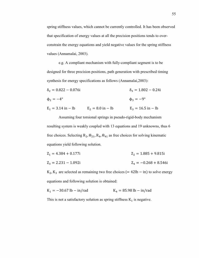
55
spring stiffness values, which cannot be currently controlled. It has been observed
that specification of energy values at all the precision positions tends to over-
constrain the energy equations and yield negative values for the spring stiffness
values (Annamalai, 2003).
e.g. A compliant mechanism with fully-compliant segment is to be
designed for three precision positions, path generation with prescribed timing
synthesis for energy specifications as follows (Annamalai,2003):
δ = 0.822 − 0.076iδ� = 1.802 − 0.24iϕ = −4°ϕ� = −9°Ε+ = 3.14in − lbΕ = 8.0in − lbΕ� = 16.5in − lb Assuming four torsional springs in pseudo-rigid-body mechanism
resulting system is weakly coupled with 13 equations and 19 unknowns, thus 6
free choices. Selecting R , Θ +, R�, Θ�+ as free choices for solving kinematic
equations yield following solution.
Z+ = 4.384 + 0.177iZ = 1.885 + 9.815iZ� = 2.231 − 1.092iZ� = −0.268 + 8.546iK , K� are selected as remaining two free choices (= 42lb − in. to solve energy
equations and following solution is obtained:
K+ = −30.67lb − in/radK� = 85.98lb − in/radThis is not a satisfactory solution as spring stiffness K+ is negative.
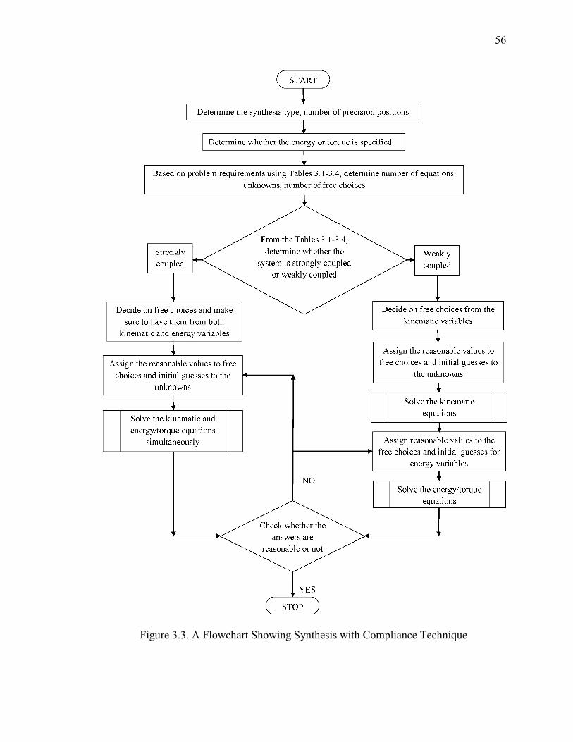
56
Figure 3.3. A Flowchart Showing Synthesis with Compliance Technique
57
• Because of the nonlinearity of the equations involved in the system, the solutions
are very sensitive to the values assigned to the free choices and initial guesses.
Even the slight change in their values won't give solutions or may give
unreasonable solutions.
e.g. In the above example, while solving the energy equations we have 3 energy
equations and 2 zero-energy state loop-closure equations with 7 unknowns: 4
spring constants, K+, K , K�, K�and 3 zero-energy position link angles,
Θ 6, Θ�6, Θ�6. In order to solve this system, two variables let K = 50lb −in/radandK� = 50lb − in/rad are selected as free choices and initial guesses
are assigned to the remaining the 5 variables as follows:
K+ = 40lb − in/rad,K� = 40lb − in/rad, Θ 6 = Θ + = 79.129°, Θ�6 = Θ�+ = −26.071°,andΘ�6 = Θ�+ = 91.798° The energies specified at three precision positions are
Ε+ = 3.14in − lbΕ = 8.0in − lbΕ� = 16.5in − lb
With these values, the solution is obtained as follows:
K+ = 32.664lb − in/radK� = 2.434lb − in/radHowever, if energy value at first precision position is changed slightly from
3.14in − lbto 3.15in − lb, following solution is obtained with one spring
constant negative which is not acceptable.
K+ = 65.718lb − in/radK� = −20.154lb − in/rad• If the system of equations yields the negative or the unrealistic solutions, one
approach is to change free choices until a reasonable solution is achieved
(Howell, 2001); but this may require many iterations to get the desired solution,
58
especially for a strongly coupled system and there is no way for the user to assist
in assigning values to free choices and initial guesses so as to achieve the realistic
solutions easily.
Some efforts have been done to overcome some of above-mentioned
problems. In order, not to over-constrain the energy equations which may yield
negative spring stiffness values in weakly coupled system of equations,
(Annamalai, 2003) suggested to solve the energy equations by taking energy at
one of the precision positions to be unknown instead of specifying all the
energies.
e.g. The example presented above (Annamalai, 2003) has one of spring
constant negative, in order to overcome this problem, Ε+ is treated as unknown
and K+,K ,K� are selected as free choices and solution obtained is
Ε+ = 3.16in − lb K� = 37.682in − lb/rad
Even for the strongly coupled system of equations, wherein all the
kinematic and energy/torque unknowns would be simultaneously solved for, it has
been suggested to take care while selecting free choices so as not to nearly
completely define kinematic configuration and this may give unrealistic solutions.
In order to get multiple solutions, which includes realistic and unrealistic
solutions, Tari and Su (2011) developed polynomial solver based framework for
solving kinetostatic synthesis equations. They approximated the nonlinear energy
equations into polynomials using numerical approximations and generated
multiple solutions using polynomial homotopy technique and then sifted out the
solutions with negative spring stiffness values.

59
3.5. OPTIMIZATION APPROACH IN SYNTHESIS WITH COMPLIANCE
TECHNIQUE
A new, simple way to solve kinematic and energy/torque equations is proposed
using optimization approach that overcomes some of the above-mentioned
limitations/problems with synthesis with compliance technique. This method is briefly
introduced in the following paragraphs and it will be explained in detail in Section 4.
In the new approach, instead of solving kinematic and energy/torque equations as
strongly coupled and weakly coupled system, they are solved as weakly coupled system
only. The kinematic loop-closure equations are solved using conventional nonlinear
equations solving algorithms such as Newton-Raphson algorithm; while energy/torque
equations are solved by using constrained optimization technique. This solves many of
above-mentioned limitations/problems associated with the existing method.
In this method, the coupling between kinematic and energy/torque equations is
reduced and the equations are solved as weakly coupled system, thus making the method
computationally simple and fast.
Due to weakly coupled system of equations, kinematic and energy variables are
separated from each other and so user has to assign reasonable values to the relatively
less number of variables (for kinematic variables only). Due to the use of optimization for
solving energy/torque equations, the user is not required to make free choices for solving
these equations.
Thus, the sensitivity of solutions to the values assigned to the free choices and
initial guesses is somewhat reduced. e.g. In the example presented in above section, the
solutions are very sensitive to the values assigned to the free choices and initial guesses.
When the same energy equations are solved by new approach using optimization, the
60
solutions are not changed much with the little changes in values assigned to the variables.
Here, the zero-energy position loop-closure equations are solved separately. So there will
be 3 energy equations and 4 unknown spring constants. In the previous method, user has
to select two of the spring constants as free choices but in optimization approach user is
not required to make free choices. The initial values are assigned 4 spring constants as
follows with same energies as in the above example.
K+ = 40lb − in/rad,K = 50lb − in/rad,K� = 50lb − in/rad,K� = 40lb − in/rad
Ε+ = 3.14in − lbΕ = 8.0in − lbΕ� = 16.5in − lbThe solution obtained is as follows
K+ = 38.5034lb − in/rad,K = 44.0435lb − in/rad, K� = 42.3228lb − in/rad,K� = 37.5872lb − in/rad
When the energy value at first precision position is changed from 3.14in − lb to
3.15in − lb, the solution is not changed much and it is still acceptable.
K+ = 38.5042lb − in/rad,K = 44.0473lb − in/rad, K� = 42.3279lb − in/rad,K� = 37.5886lb − in/rad
One of the main problems with synthesis of compliance technique is negative or
unreasonable values of the spring constants in the solution of weakly coupled system.
This is overcome by applying lower and upper bounds to the solutions in the optimization
for solving energy/torque equations. e.g. the example presented above shows that
synthesis with compliance technique gives negative answer for one of spring constant but
with new approach, the solutions are positive and acceptable.
61
While solving the energy/torque equations using constrained optimization
technique, the objective function is evaluated at each solution point. This value gives a
way to the user, to decide the direction, in which the values assigned to the initial guesses
or energy specifications should change, if required, to get an acceptable solution. This
will significantly reduce the number of iterations to get the solution.
3.6. SUMMARY
The synthesis with compliance method is explained in detail. The energy and
torque considerations for synthesis are presented along with kinematic equations. The
tables giving information about number of equations, number of unknowns and number
of free choices for different synthesis cases with varying number of springs in four-bar
pseudo-rigid-body model are enlisted. The limitations/problems with the current
synthesis with compliance technique are explained with suitable examples. At the end of
the Section, new method for solving kinematic and energy/torque equations using
optimization approach, which overcomes limitations/problems with existing method is
introduced.
62
4. SYNTHESIS WITH COMPLIANCE TECHNIQUE WITH OPTIMIZATION
APPROACH AND DIFFERENT CASES
The synthesis with compliance technique suffers from some limitations/problems
as discussed previous Section. To overcome these problems, a new approach for
synthesis with compliance technique using optimization is introduced in Section 3. In this
Section, the optimization concept is briefly reviewed at the beginning followed by
explanation of use of optimization in the synthesis with compliance technique. The
optimization routine developed for energy equations is discussed later along with suitable
examples. The different cases of synthesis like use of type synthesis i.e. use of small-
length flexural pivots or full-length compliant segments to replace the springs in the
pseudo-rigid-body model, and other cases like undeflected position of the mechanism to
be one of the precision positions etc. are presented with examples. The energy
equivalence of pseudo-rigid-body model and corresponding compliant mechanism is
discussed and comparison between the solutions obtained using pseudo-rigid-body
models and commercial finite element software ABAQUS® and ANSYS® is presented.
Finally, few recommendations for energy/torque to be specified at the precision positions
are suggested.
4.1. INTRODUCTION TO OPTIMIZATION
Optimization is a design tool which helps user automatically to identify the
optimal design from number of available design solutions or even from the infinite
number of design solutions (Rao, 2009). The use of optimization is increasing in the
industry to select optimal designs as it provides a designer with cheap and efficient way
63
to identify the optimal solution before physical deployment. Even the optimization is
used in day-to-day life regularly. e.g. one may want to minimize the monthly expenditure
for resources maintaining certain level of living or while buying a car, one may want to
meet certain exceptions like fuel economy, maintenance costs etc. with a maximum limit
for the price. Engineering designs also work in the same way, where objectives are met or
optimized satisfying some design constraints.
The first step in the optimization is creating the optimization model in
mathematical formulations known as optimization modeling (Nocedal and Wright, 2000).
The modeling involves deciding the objective, a quantitative measure for the performance
of a system under study. e.g. the objective of the study could be maximizing profit,
minimizing expenditure etc. The objective depends on the certain characteristics of the
system known as design variables or unknowns. These variables are often constrained in
some way but they may be unconstrained at times. The goal of the optimization problem
is finding the values of these variables which optimize the objective. The modeling is the
first and the most important step in the optimization process. If the model is too
simplistic, it may not give useful insights into the practical problem; and if it is too
complex, it may be difficult to solve (Nocedal and Wright, 2000).
After creating the model, the second step in the optimization process is the
solving the model. Three methods are generally used and they are analytical method,
graphical method and numerical method (Rao, 2009). The use of analytical and graphical
methods is limited to the simple problems such as problems with simple objective
function. Usually engineering design problems are complex and include too many design
variables with complicated objective functions and constraints (Rao, 2009). In such cases,
64
numerical methods are used to solve the optimization models. With numerical method,
the optimal design starts from initial design point. The numerical optimizer evaluates the
objective function, constraints and their derivatives at the design point. Based on the
function value and derivatives, the solver decides the search direction along which the
objective function is likely to descend. The step size along the descent direction is
decided, so that the value of objective function decreases to the lowest possible value
without violating any constraints. The current design point moves in the descent direction
by the step size to the new design point in the next iteration. The solver evaluates the
objective function, constraints and derivatives at the new design point and check for the
convergence of the solution. If the solution does not converge, then solver finds new
search direction and step size to obtain new design point and continues to do so until it
finds the optimal solution.
The last step in the optimization process is the posterior analysis in which the user
performs some analyses tasks on the optimal solution to determine whether the solution is
optimal, whether it is reasonable etc. The optimal solution obtained depends on where
optimization search process starts; when multiple local optimal points exist. So in order
to obtain the global optimal solution different starting points should be used.
4.1.1. Optimization Design Process and Mathematical Modeling. The above
discussed steps in the optimization design process can be shown in flowchart as shown in
Figure 4.1. Mathematically, optimization is the minimization or maximization of an
objective function subject to constraints of the variables.
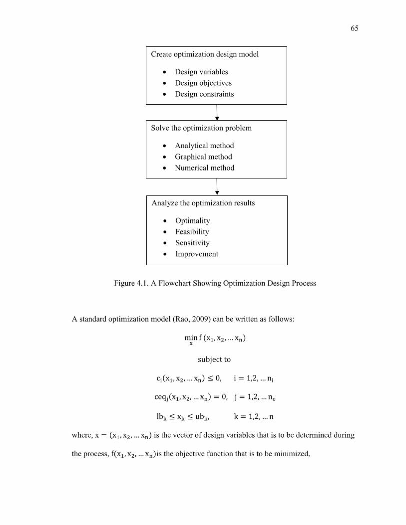
65
Figure 4.1. A Flowchart Showing Optimization Design Process
A standard optimization model (Rao, 2009) can be written as follows:
minu f'x+, x , … x". subjectto
c�'x+, x , … x". ≤ 0,i = 1,2, … n� ceq�'x+, x , … x". = 0,j = 1,2, … n{
lb| ≤ x| ≤ ub|,k = 1,2, … n
where, x = 'x+, x , … x". is the vector of design variables that is to be determined during
the process, f'x+, x , … x".is the objective function that is to be minimized,
Create optimization design model
• Design variables
• Design objectives
• Design constraints
Solve the optimization problem
• Analytical method
• Graphical method
• Numerical method
Analyze the optimization results
• Optimality
• Feasibility
• Sensitivity
• Improvement
66
c�'x+, x , … x". is the inequality constraint function, ceq�'x+, x , … x". is the equality
constraint function, lb| and ub| are the lower and the upper bounds of the design variable
respectively. If the designer wishes to maximize the objective function;f'x+, x , … x". is
changed to −f'x+, x , … x". Different software can be used to solve the optimization problems such as
Microsoft Excel, MATLAB® etc. In this work, MATLAB® is used to solve the
optimization problems, as it is easier to write the three separate files for objective
function file containing objective function, constraints file containing equality and
inequality constraints & lower and upper bounds and main file that calls the objective
function, constraints functions and solves the problem. They can be edited easily if they
are written separately.
4.2. TYPES OF OPTIMIZATION.
The optimization problems can be classified according to the nature of the
objective function, constraints (e.g. linear, nonlinear, convex), the nature of the variables
(e.g. small, large), the smoothness of the functions (e.g. differentiable, or non-
differentiable) and so on (Nocedal and Wright, 2000). One of the important
classifications of the optimization problems is according to the constraints on the
variables i.e. unconstrained optimization which has no constraints and constrained
optimization in which the variables are constrained in some way.
4.2.1. Unconstrained Optimization. In this type of optimization, the variables
are unconstrained. Sometimes for the problems with the natural constraints, it may be
safe to disregard the constraints on the variables as they do not affect the solution or the
67
do not interfere with the solution (Nocedal and Wright, 2000). In the unconstrained
optimization, the objective function is minimized that depends upon real variables and
without restrictions. There are many algorithms available for the unconstrained
optimization of smooth functions. All of them require the user to give a starting point. It
will be easy for the user who has knowledge of the application and data set of the
problem to give a reasonable initial starting point. Most of the algorithms use two
strategies to move to the next design point from the starting point i) Line search methods
and ii) Trust region methods. More information about these strategies and unconstrained
optimization can be found in Numerical Optimization Nocedal and Wright, 2000.
The mathematical formulation for this kind of optimization is as follows:
minu f'x. with no restrictions on variables.
The MATLAB® provides many different solvers for the unconstrained
optimization such as fminunc, fminsearch etc. It is the user's responsibility to choose the
right solver of the optimization problem depending on type of objective function and
constraint functions. More information on choosing right type of optimization solver can
be found in HELP in MATLAB®.
4.2.2. Constrained Optimization. In this type of optimization, there are some
constraints on the variables e.g. size or shape constraint in design problem or expenditure
constraints on the profitability problem etc. These constraints may be simple bounds on
the variables like 0 ≤ x+ ≤ 100 or some linear unequality constraints such as x+ + x <500 or linear equality constraints x+ − x = 50 or it may be some complex nonlinear
68
relationships among the variables. A mathematical formulation of these optimization
problems is (Nocedal and Wright, 2000) as follows:
minu f'x. subjectto
c�'x. ≤ 0,i = 1,2, … n� ceq�'x. = 0, j = 1,2, … n{
lb| ≤ x| ≤ ub|,k = 1,2, … n
where, f'x. is a objective function, c�'x. are the unequality constraints, ceq�'x. are the
equality constraints and lb|, &ub| represents the lower and upper bounds for the design
variable x respectively.
For the constrained optimization, MATLAB® has many different solvers, such as
fmincon, fminbnd, fseminf etc. Each solver is used to solve particular type of problems,
e.g. fminbnd is used to find the minimum of a single-variable function on a fixed interval,
fseminf is used to find semi-infinitely constrained multivariable nonlinear function and
fmincon is used to minimum of constrained nonlinear multivariable function. In this
work, the MATLAB® optimization solver, fmincon is used to solve the optimization
problem.
4.3. OPTIMIZATION ROUTINE FOR SOLVING ENERGY/TORQUE
EQUATIONS IN SYNTHESIS WITH COMPLIANCE TECHNIQUE
In the synthesis with compliance technique, the kinematic and energy/torque
equations are solved either strongly coupled or weakly coupled depending on the number
on the equations and unknowns introduced in the system due to energy/torque
69
considerations using conventional nonlinear equations solver algorithm. A new way is
proposed to solve the kinematic equations by conventional algorithm and energy/torque
equations by optimization approach separately.
The optimization design process involves the three steps as shown in Figure 4.1.
The first step is creating optimization design model which includes objective function
and constraint functions. The energy/torque considerations introduce number of
energy/torque equations in the system in addition to the kinematic equations depending
on the number of precision positions and energy/torque specified at the precision
positions. Let us consider a general synthesis case: A four-bar mechanism with four
torsional springs at the pivots is to be synthesized for three precision positions with
energy specifications for motion generation. The system has 8 loop-closure kinematic
equations given by equations (13), 3 energy equations at three precision positions given
by equations (21) and 2 scalar loop-closure equations at the energy-free state of the
mechanism given by equation (38). The loop-closure kinematic equations are as follows:
R /cos'Θ + + ϕ . − cos'Θ +.0 + R8/cos'Θ8+ + γ . − cos'Θ8+.0 = Re'δ . (13a)
R /sin'Θ + + ϕ .− sin'Θ +.0 + R8/sin'Θ8+ + γ .− sin'Θ8+.0 = Im'δ . (13b)
R�/cos'Θ�+ + ψ . − cos'Θ�+.0 + R9/cos'Θ9+ + γ . − cos'Θ9+.0 = Re'δ . (13c)
R�/sin'Θ�+ + ψ .− sin'Θ�+.0 + R9/sin'Θ9+ + γ .− sin'Θ9+.0 = Im'δ . (13d)
R /cos'Θ + + ϕ�. − cos'Θ +.0 + R8/cos'Θ8+ + γ�. − cos'Θ8+.0 = Re'δ�. (13e)
R /sin'Θ + + ϕ�.− sin'Θ +.0 + R8/sin'Θ8+ + γ�.− sin'Θ8+.0 = Im'δ�. (13f)
R�/cos'Θ�+ + ψ�. − cos'Θ�+.0 + R9/cos'Θ9+ + γ�. − cos'Θ9+.0 = Re'δ�. (13g)
R�/sin'Θ�+ + ψ�.− sin'Θ�+.0 + R9/sin'Θ9+ + γ�.− sin'Θ9+.0 = Im'δ�. (13h)
70
Thus, there are 8 equations and 12 unknowns for the motion generation synthesis.
So, 4 free choices are required to solve the above equations and to obtain the kinematic
configuration. The 3 energy equations and vector loop-closure equation for zero-energy
position are as follows:
E+ = 12 /Κ+'Θ + − Θ 6. + Κ /'Θ�+ − Θ�6. − 'Θ + − Θ 6.0
+ Κ�/'Θ�+ − Θ�6. − 'Θ�+ − Θ�6.0 + Κ�'Θ�+ − Θ�6. 0(21a)
E = 12 /Κ+'Θ + + ϕ − Θ 6.
+ Κ /'Θ�+ + γ − Θ�6. − 'Θ + + ϕ − Θ 6.0 + Κ�/'Θ�+ + ψ − Θ�6. − 'Θ�+ + γ − Θ�6.0 + Κ�'Θ�+ + ψ − Θ�6. 0
(21b)
E� = 12 /Κ+'Θ + + ϕ� − Θ 6.
+ Κ /'Θ�+ + γ� − Θ�6. − 'Θ + + ϕ� − Θ 6.0 + Κ�/'Θ�+ + ψ� − Θ�6. − 'Θ�+ + γ� − Θ�6.0 + Κ�'Θ�+ + ψ� − Θ�6. 0
(21c)
Ζ 6 + Ζ�6 = Ζ+6 + Ζ�6 (38)
The equation (38) will give 2 scalar equations and has 3 unknowns. These 2
equations are solved simultaneously with energy equations in the existing method. In the
new approach, these 2 equations are separated from energy equations and solved by
making one free choice. Thus, 3 energy equations have 4 spring stiffness as unknowns
and all other variables are known from kinematic equations and from zero-energy loop-
closure equations. The energy equations are solved using optimization. One of the main
71
problems with the synthesis with compliance technique is the solutions yielding negative
and unrealistic spring stiffness values. This is overcome by constraining the spring
stiffness values i.e. by applying the lower and upper bounds. The optimization problem is
created as below:
f+'K+, K , K�, K�. = E+ − ~+ /Κ+'Θ + − Θ 6. + Κ /'Θ�+ − Θ�6. − 'Θ + − Θ 6.0 +Κ�/'Θ�+ − Θ�6. − 'Θ�+ − Θ�6.0 + Κ�'Θ�+ − Θ�6. 0� f 'K+, K , K�, K�. = E − ~+ /Κ+'Θ + + ϕ − Θ 6. + Κ /'Θ�+ + γ − Θ�6. −'Θ + + ϕ − Θ 6.0 + Κ�/'Θ�+ + ψ − Θ�6. − 'Θ�+ + γ − Θ�6.0 + Κ�'Θ�+ + ψ −Θ�6. 0� f�'K+, K , K�, K�. = E� − +
/Κ+'Θ + + ϕ� − Θ 6. + Κ /'Θ�+ + γ� − Θ�6. −'Θ + + ϕ� − Θ 6.0 + Κ�/'Θ�+ + ψ� − Θ�6. − 'Θ�+ + γ� − Θ�6.0 + Κ�'Θ�+ + ψ� −Θ�6. 0
f = f+ + f + f�
Minimizef Above equations form the objective function of the optimization problem. The
upper and lower bounds are applied to the spring stiffness, K values, as per the user's
requirement. The constraint function includes any restrictions on the design variables i.e.
spring stiffness e.g. all spring stiffness are equal or a fixed-guided compliant segment has
two torsional springs at the characteristic pivots in pseudo-rigid-body model. It will be
convenient to size the compliant segment if two spring constants are same. This
restriction on spring stiffness values should be put in the constraint function.
72
In MATLAB®, fmincon optimization solver is used for the constrained
optimization. The same optimization routine can also be used for torque specifications
instead of energy specifications at the precision positions. The equation for the torque at
the j� position of the mechanism is given by equation (36).
T � = Κ+�Θ � − Θ 6�
+ Κ ��Θ�� − Θ�6� − �Θ � − Θ 6�� gR sin�Θ�� − Θ ��R� sin�Θ�� − Θ��� − 1h
+ Κ���Θ�� − Θ�6� − �Θ�� − Θ�6�� gR sin�Θ�� − Θ ��R� sin�Θ�� − Θ���
− R sin�Θ�� − Θ ��R� sin�Θ�� − Θ���h + Κ��Θ�� − Θ�6� R sin�Θ�� − Θ ��
R� sin�Θ�� − Θ���
(36)
The objective function for torque specification case is formed in the same way as
that for energy specification case. Using equation (36), the torque equations for three
precision positions can be written as shown in equations (40). The Section 4.5 shows
different cases/examples of compliant mechanism synthesis such as undeflected position
of the mechanism to be different form precision positions, one precision position to be
undeflected position of the mechanism etc.
4.3.1. Recommendations for Energy/Toque Specifications. The energy/torque
specifications at the precision positions are input to the problem. As the kinematic loop-
closure equations and energy/torque equations are nonlinear equations, specification of
energy/torque values significantly affect the solution.
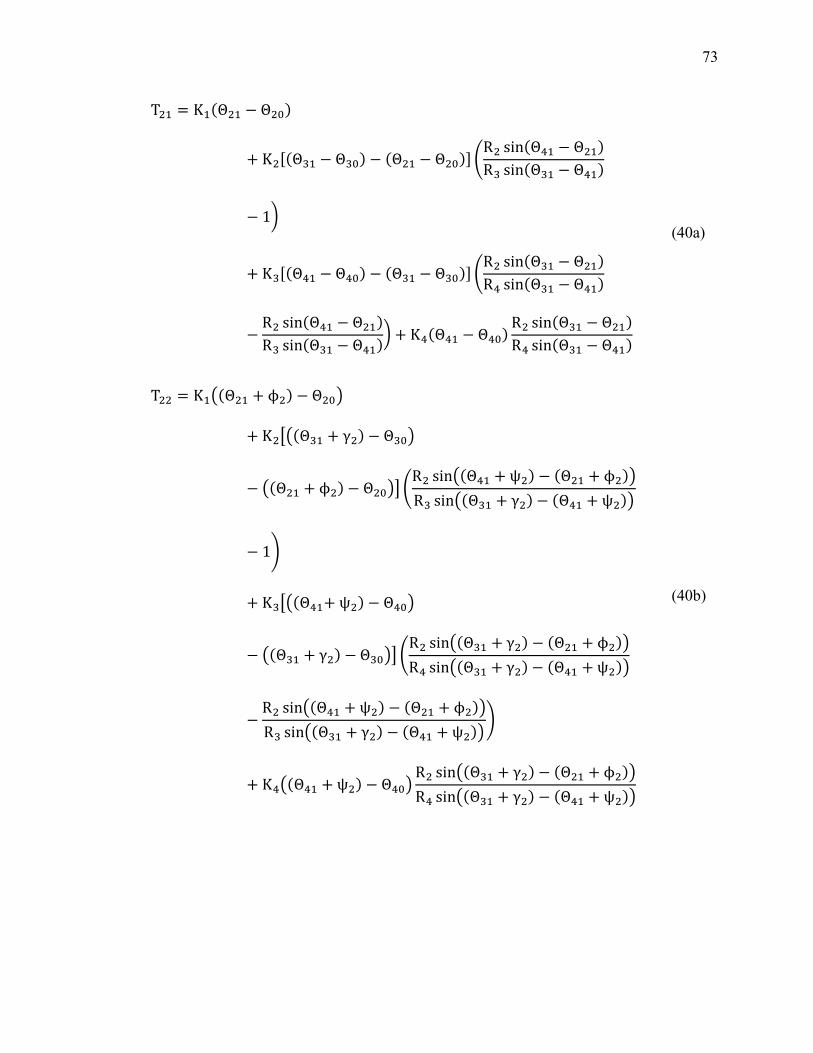
73
T + = Κ+'Θ + − Θ 6.+ Κ /'Θ�+ − Θ�6. − 'Θ + − Θ 6.0 gR sin'Θ�+ − Θ +.R� sin'Θ�+ − Θ�+.− 1\
+ Κ�/'Θ�+ − Θ�6. − 'Θ�+ − Θ�6.0 gR sin'Θ�+ − Θ +.R� sin'Θ�+ − Θ�+.
− R sin'Θ�+ − Θ +.R� sin'Θ�+ − Θ�+.\ + Κ�'Θ�+ − Θ�6. R sin'Θ�+ − Θ +.R� sin'Θ�+ − Θ�+.
(40a)
T = Κ+�'Θ + + ϕ . − Θ 6�+ Κ ��'Θ�+ + γ . − Θ�6�
− �'Θ + + ϕ . − Θ 6�� gR sin�'Θ�+ + ψ . − 'Θ + + ϕ .�R� sin�'Θ�+ + γ . − 'Θ�+ + ψ .�
− 1h
+ Κ���'Θ�++ψ . − Θ�6�
− �'Θ�+ + γ . − Θ�6�� gR sin�'Θ�+ + γ . − 'Θ + + ϕ .�R� sin�'Θ�+ + γ . − 'Θ�+ +ψ .�
− R sin�'Θ�+ + ψ . − 'Θ + + ϕ .�R� sin�'Θ�+ + γ . − 'Θ�+ + ψ .�h
+ Κ��'Θ�+ + ψ . − Θ�6� R sin�'Θ�+ + γ . − 'Θ + + ϕ .�R� sin�'Θ�+ + γ . − 'Θ�+ + ψ .�
(40b)
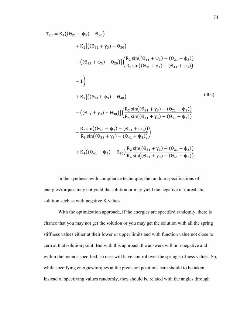
74
T � = Κ+�'Θ + + ϕ�. − Θ 6�+ Κ ��'Θ�+ + γ�. − Θ�6�
− �'Θ + + ϕ�. − Θ 6�� gR sin�'Θ�+ + ψ�. − 'Θ + + ϕ�.�R� sin�'Θ�+ + γ�. − 'Θ�+ + ψ�.�
− 1h
+ Κ���'Θ�++ψ�. − Θ�6�
− �'Θ�+ + γ�. − Θ�6�� gR sin�'Θ�+ + γ�. − 'Θ + + ϕ�.�R� sin�'Θ�+ + γ�. − 'Θ�+ + ψ�.�
− R sin�'Θ�+ + ψ�. − 'Θ + + ϕ�.�R� sin�'Θ�+ + γ�. − 'Θ�+ + ψ�.�h
+ Κ��'Θ�+ + ψ�. − Θ�6� R sin�'Θ�+ + γ�. − 'Θ + + ϕ�.�R� sin�'Θ�+ + γ�. − 'Θ�+ + ψ�.�
(40c)
In the synthesis with compliance technique, the random specifications of
energies/torques may not yield the solution or may yield the negative or unrealistic
solution such as with negative K values.
With the optimization approach, if the energies are specified randomly, there is
chance that you may not get the solution or you may get the solution with all the spring
stiffness values either at their lower or upper limits and with function value not close to
zero at that solution point. But with this approach the answers will non-negative and
within the bounds specified, so user will have control over the spring stiffness values. So,
while specifying energies/torques at the precision positions care should to be taken.
Instead of specifying values randomly, they should be related with the angles through

75
which the pseudo-rigid-body links with torsional springs are moving from one precision
position to other. The function value at the solution is an indicator of the correctness of
the solution. As the objective function is minimized for solving energy equations by
optimization approach, its value at the solution point should be very close to zero. The
synthesis with compliance method using optimization approach is shown as flowchart in
Figure 4.2.
4.3.2. Notions on Energy Equivalence. The pseudo-rigid-body four-bar
mechanism is a rigid-body four-bar mechanism with torsional springs at the pivot points,
and the compliant mechanism represents the single continuum, where the some or all
segments deflect and gives desired motion to the mechanism and stores energy in flexible
segments. The synthesis with compliance technique initially helps in designing a pseudo-
rigid-body mechanism and then using a pseudo-rigid-body model concept, the compliant
mechanism is obtained.
The total energy stored in the pseudo-rigid-body mechanism is obtained by
summing up the energies stored in the individual torsional springs at that precision
position. The energy stored in the compliant segment has been calculated by chain
algorithm assuming the bending energy to be predominant in planar compliant
mechanism (Annamalai, 2003). In this work, the energy stored in the compliant
mechanism is calculated using commercial finite element software ABAQUS® and/or
ANSYS® as strain energy stored in the mechanism. Thus, the compliant mechanism
designed for energy specifications, ensures the energy equivalence between compliant
mechanism and its pseudo-rigid-body model.

76
In general, for any compliant mechanism synthesized using synthesis with
compliance technique, it can be assured that energy stored in the compliant mechanism is
of the same order of that of stored in pseudo-rigid-body model from which the compliant
mechanism is obtained (Annamalai, 2003).
However, this energy equivalence does not necessarily ascertain the same the
dynamic properties of the two mechanisms. The kinematics of the compliant mechanism
is expected to vary in different degrees under different circumstances from that of
corresponding pseudo-rigid-body model.
4.4. STRONGLY COUPLED VS. WEAKLY COUPLED SYSTEM
In the synthesis with compliance technique, the kinematic equations and
energy/torque equations are solved as either strongly coupled or weakly coupled system
of equations depending on the number of equations and number of unknowns introduced
in the system by energy/torque considerations. The condition for the system to be solved
as weakly coupled is given by equation (32). In the weakly coupled system, the kinematic
equations and energy/torque equations are solved separately while in strongly coupled
system, kinematic and energy/torque equations are solved simultaneously. However, as
the kinematic and energy/torque equations are generally nonlinear, coupling between
them increases the complexity of the system.
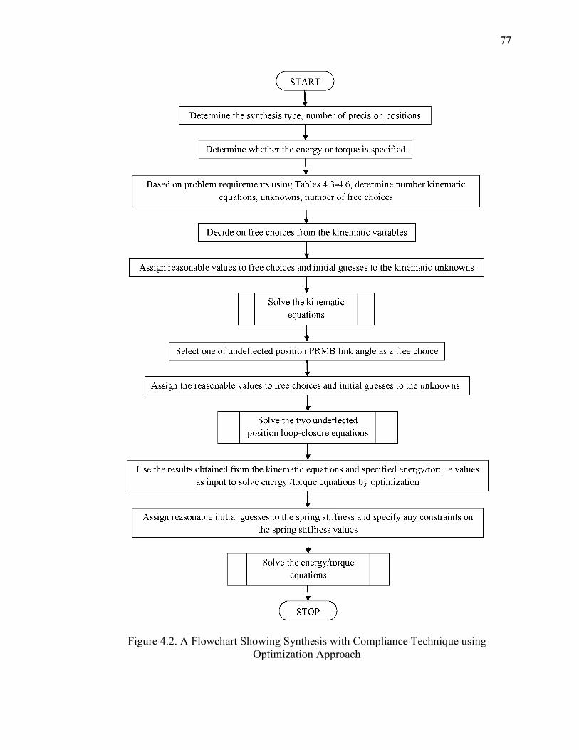
77
Figure 4.2. A Flowchart Showing Synthesis with Compliance Technique using Optimization Approach

78
In order to find the effects of strongly coupled and weakly coupled system of
equations, for the strongly coupled case of synthesis; the two strategies are proposed for
to study the effects.
• Treated as a strongly coupled system: kinematic and energy equations are solved
simultaneously
• Treated as a weakly coupled system: kinematic equations are solved by a
nonlinear equations solver and then the energy/torque equations are solved by
optimization
e.g. It is desired to synthesize a compliant mechanism for three precision positions
motion generation synthesis, energy specified at these points as follows:
δ = −2 + iδ� = −4 + 0.75iγ = −7°γ� = −14°Ε+ = 1.16in − lbΕ = 28.45in − lbΕ� = 95.80in − lb
Assuming one torsional spring in the pseudo-rigid-body model four-bar
mechanism, there are 11 equations, 14 unknowns and 3 free choices, resulting in strongly
coupled system (Table 3.3). Hence, kinematic and energy equations have to be solved
simultaneously. A compliant mechanism with one fixed-free segment as shown in Figure
3.2 (R) is selected for synthesis. R , R�andθ + are selected as free choices. Reasonable
initial estimates have assigned to remaining 11 variables. The energy-free state loop-
closure equation (38) is not really needed for this case as it has only one spring. But in
order to know the mechanism configuration in energy-free state, these two scalar
equations are added. This adds 2 more equations and 3 unknowns. The coupler equation
(37) and first precision position loop-closure equation (39) are considered to determine
79
remaining link lengths and angles. These add 4 scalar equations and 4 unknowns. Using
equations (6), (21), (37), (38) and (39), the following solution is obtained:
Z+ = 11.852 + 2.472iZ = 4.596 + 2.571iZ� = 9.26 + 2.077iZ� = 2.004 + 3.362iZ8 = 5.425 + 2.689iZ9 = −3.835 + 0.612iϕ = 27.367°ϕ� = 48.979°ψ = 31.488°ψ� = 64.433°K� = 119.996in − lb/radΘ�6 = 51.961°Θ 6 = 29.999°Θ�6 = 16.043°
In the second technique, the kinematic and energy equations are solved separately
i.e. as weakly coupled system. The kinematic equations are solved by conventional
nonlinear equations solver and energy equations are solved by constrained optimization
approach. In the above example, we have 8 kinematic loop-closure equations and 12
unknowns, giving 4 free choices and solution obtained for kinematic configuration is as
below:
Z = 4.496 + 3.857iZ� = 2 + 1.732iZ8 = 5.425 + 2.689iZ9 = −3.856 + 0.608iϕ = 27.367°ϕ� = 48.979ψ = 31.473°ψ� = 64.43°
The coupler equation (37) and first-precision position loop-closure equation (39) are
solved separately and solution obtained is follows:
Z+ = 11.877 + 2.474iZ� = 9.282 + 2.081i
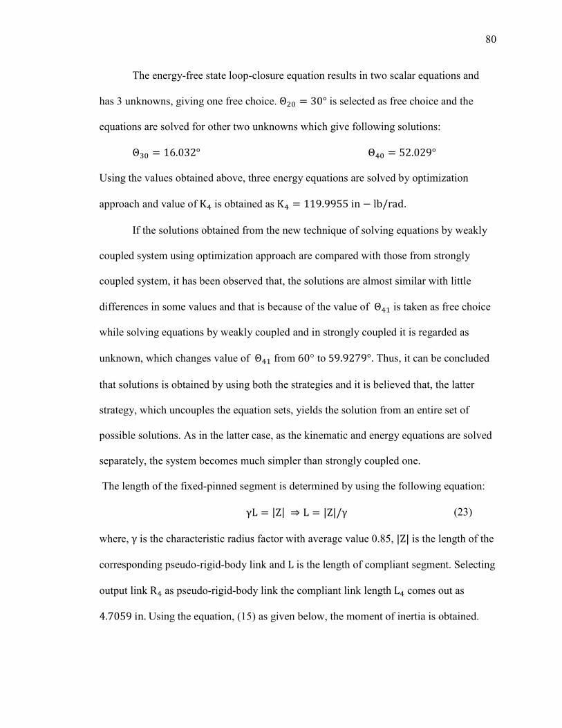
80
The energy-free state loop-closure equation results in two scalar equations and
has 3 unknowns, giving one free choice. Θ 6 = 30° is selected as free choice and the
equations are solved for other two unknowns which give following solutions:
Θ�6 = 16.032°Θ�6 = 52.029°Using the values obtained above, three energy equations are solved by optimization
approach and value of K� is obtained as K� = 119.9955in − lb/rad.
If the solutions obtained from the new technique of solving equations by weakly
coupled system using optimization approach are compared with those from strongly
coupled system, it has been observed that, the solutions are almost similar with little
differences in some values and that is because of the value of Θ�+ is taken as free choice
while solving equations by weakly coupled and in strongly coupled it is regarded as
unknown, which changes value of Θ�+ from 60° to 59.9279°. Thus, it can be concluded
that solutions is obtained by using both the strategies and it is believed that, the latter
strategy, which uncouples the equation sets, yields the solution from an entire set of
possible solutions. As in the latter case, as the kinematic and energy equations are solved
separately, the system becomes much simpler than strongly coupled one.
The length of the fixed-pinned segment is determined by using the following equation:
γL = |Z| ⇒ L = |Z|/γ (23)
where, γ is the characteristic radius factor with average value 0.85, |Z| is the length of the
corresponding pseudo-rigid-body link and L is the length of compliant segment. Selecting
output link R� as pseudo-rigid-body link the compliant link length L� comes out as
4.7059in.Using the equation, (15) as given below, the moment of inertia is obtained.
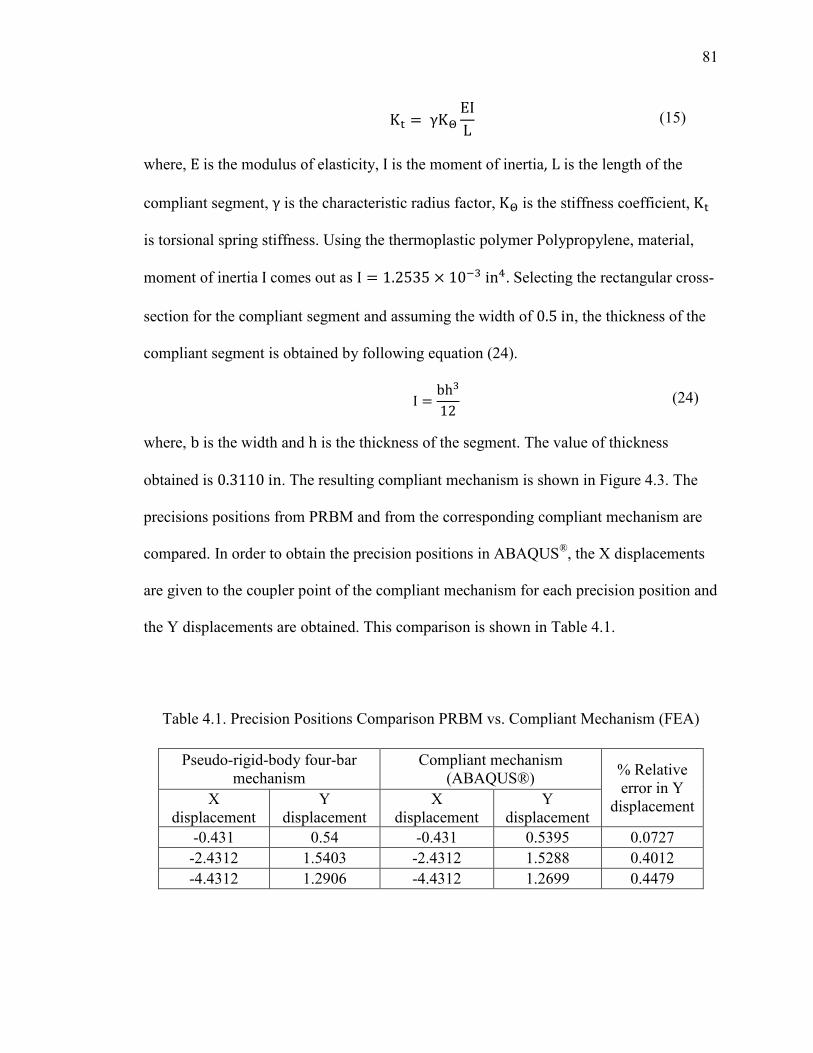
81
Κ = γΚ$ ΕΙL (15)
where, Ε is the modulus of elasticity, Ι is the moment of inertia, L is the length of the
compliant segment, γ is the characteristic radius factor, Κ$ is the stiffness coefficient, Κ is torsional spring stiffness. Using the thermoplastic polymer Polypropylene, material,
moment of inertia Ι comes out as Ι = 1.2535 × 10��in�. Selecting the rectangular cross-
section for the compliant segment and assuming the width of 0.5in, the thickness of the
compliant segment is obtained by following equation (24).
I = bh�12 (24)
where, b is the width and h is the thickness of the segment. The value of thickness
obtained is 0.3110in. The resulting compliant mechanism is shown in Figure 4.3. The
precisions positions from PRBM and from the corresponding compliant mechanism are
compared. In order to obtain the precision positions in ABAQUS®, the X displacements
are given to the coupler point of the compliant mechanism for each precision position and
the Y displacements are obtained. This comparison is shown in Table 4.1.
Table 4.1. Precision Positions Comparison PRBM vs. Compliant Mechanism (FEA)
Pseudo-rigid-body four-bar mechanism
Compliant mechanism (ABAQUS®)
% Relative error in Y
displacement X displacement
Y displacement
X displacement
Y displacement
-0.431 0.54 -0.431 0.5395 0.0727
-2.4312 1.5403 -2.4312 1.5288 0.4012
-4.4312 1.2906 -4.4312 1.2699 0.4479
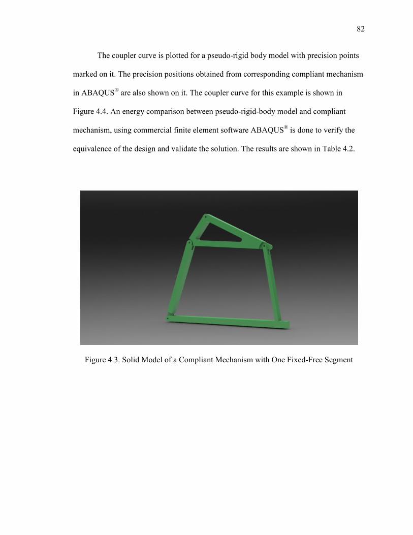
82
The coupler curve is plotted for a pseudo-rigid body model with precision points
marked on it. The precision positions obtained from corresponding compliant mechanism
in ABAQUS® are also shown on it. The coupler curve for this example is shown in
Figure 4.4. An energy comparison between pseudo-rigid-body model and compliant
mechanism, using commercial finite element software ABAQUS® is done to verify the
equivalence of the design and validate the solution. The results are shown in Table 4.2.
Figure 4.3. Solid Model of a Compliant Mechanism with One Fixed-Free Segment
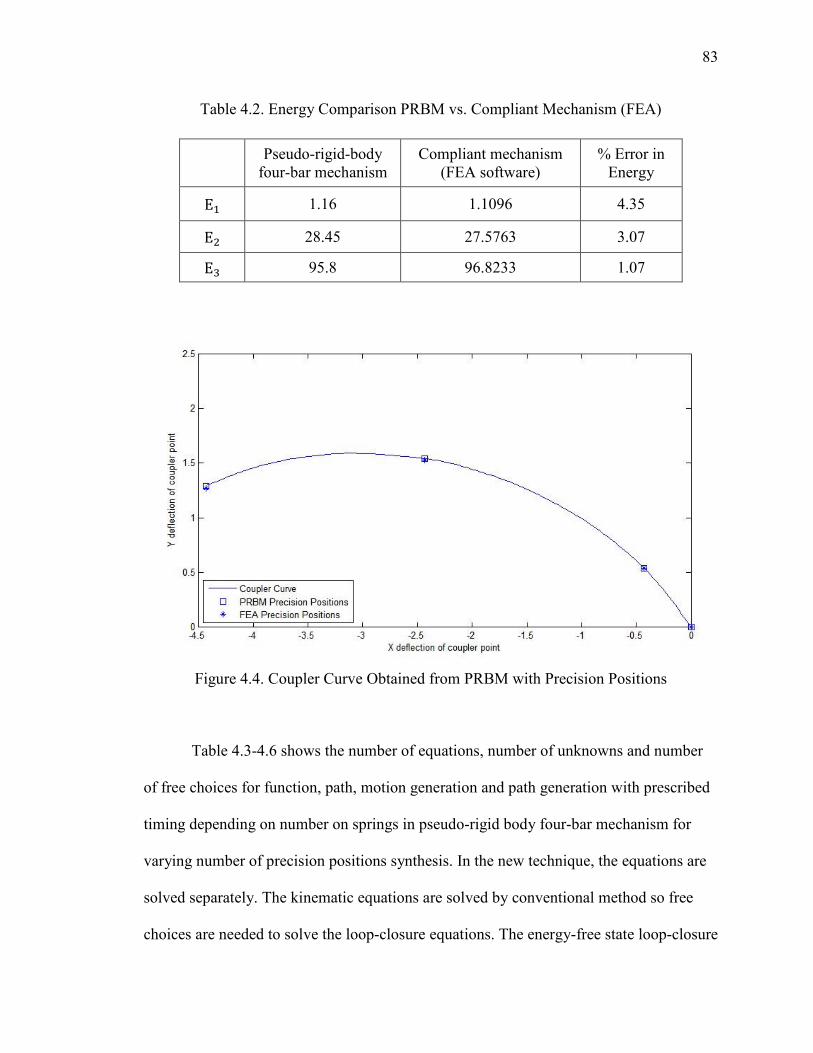
83
Table 4.2. Energy Comparison PRBM vs. Compliant Mechanism (FEA)
Pseudo-rigid-body
four-bar mechanism Compliant mechanism
(FEA software) % Error in
Energy
E+ 1.16 1.1096 4.35
E 28.45 27.5763 3.07
E� 95.8 96.8233 1.07
Figure 4.4. Coupler Curve Obtained from PRBM with Precision Positions
Table 4.3-4.6 shows the number of equations, number of unknowns and number
of free choices for function, path, motion generation and path generation with prescribed
timing depending on number on springs in pseudo-rigid body four-bar mechanism for
varying number of precision positions synthesis. In the new technique, the equations are
solved separately. The kinematic equations are solved by conventional method so free
choices are needed to solve the loop-closure equations. The energy-free state loop-closure
84
equation gives two scalar equations and three unknowns, requiring one free choice there.
As the energy equations are solved by the optimization method, no free choices are
needed. In the tables, the number of equations is shown as addition of number kinematic
equations, energy-free state loop-closure equations and energy/torque equations. The last
column indicates the number of free choices and it includes the free choices for solving
the kinematic equations and one free choice of energy-free state loop-closure equations.
e.g. from Table 4.4, for three precision positions path generation synthesis with four
springs has 8+2+3=13 equations, 12 kinematic unknowns and 7 energy unknowns giving
5 free choices.
From Tables 3.1-3.4, it can be seen that with the synthesis with compliance
technique due to strongly coupling of kinematic equations and energy/torque equations,
few synthesis cases can't be solved due to over-constraining of the system as number of
equations are more than number of variables. Those cases are listed below:
1) Function generation synthesis for five precision positions with one torsional spring in
pseudo-rigid-body four-bar mechanism.
2) Motion generation synthesis for five precision positions with one, two, three torsional
springs in pseudo-rigid-body four-bar mechanism.
3) Path generation with prescribed timing synthesis for five precision positions with one,
two, three torsional springs in pseudo-rigid-body four-bar mechanism.

85
Table 4.3. Design Choices Based on Number of Torsional Springs for Function Generation Synthesis with Compliance Technique Using Optimization Approach
Number of
Torsional Springs
Number of Equations
Number of Kinematic Unknowns
Number of Energy
Unknowns
Number of
Free Choices
Three Precision Positions
1 4+2+3=9 Z , Z�, Z�, γ , γ� (8) Κ+, Θ 6, Θ�6, Θ�6 (4)
5
2 4+2+3=9 Z , Z�, Z�, γ , γ� (8) Κ+, Κ , Θ 6, Θ�6, Θ�6 (5)
5
3 4+2+3=9 Z , Z�, Z�, γ , γ� (8) " + Κ� (6) 5
4 4+2+3=9 Z , Z�, Z�, γ , γ� (8) " + Κ� (7) 5
Four Precision Positions
1 6+2+4=12 Z , Z�, Z�, γ , γ�, γ�, (9)
Κ+, Θ 6, Θ�6, Θ�6 (4) 4
2 6+2+4=12 Z , Z�, Z�, γ , γ�, γ�, (9)
Κ+, Κ , Θ 6, Θ�6, Θ�6 (5) 4
3 6+2+4=12 Z , Z�, Z�, γ , γ�, γ�, (9)
" + Κ� (6) 4
4 6+2+4=12 Z , Z�, Z�, γ , γ�, γ�, (9)
" + Κ� (7) 4
Five Precision Positions
1 8+2+5=15 Z , Z�, Z�, γ , γ�, γ�, γ8 (10)
Κ+, Θ 6, Θ�6, Θ�6 (4) 3
2 8+2+5=15 Z , Z�, Z�, γ , γ�, γ�, γ8 (10)
Κ+, Κ , Θ 6, Θ�6, Θ�6 (5) 3
3 8+2+5=15 Z , Z�, Z�, γ , γ�, γ�, γ8 (10)
" + Κ� (6) 3
4 8+2+5=15 Z , Z�, Z�, γ , γ�, γ�, γ8 (10)
" + Κ� (7) 3
From Tables 4.3-4.6, obtained using new method using optimization approach, as
the kinematic and energy/torque equations are solved separately, all of synthesis cases
mentioned above which couldn't be solved by existing method are solvable by new
approach.
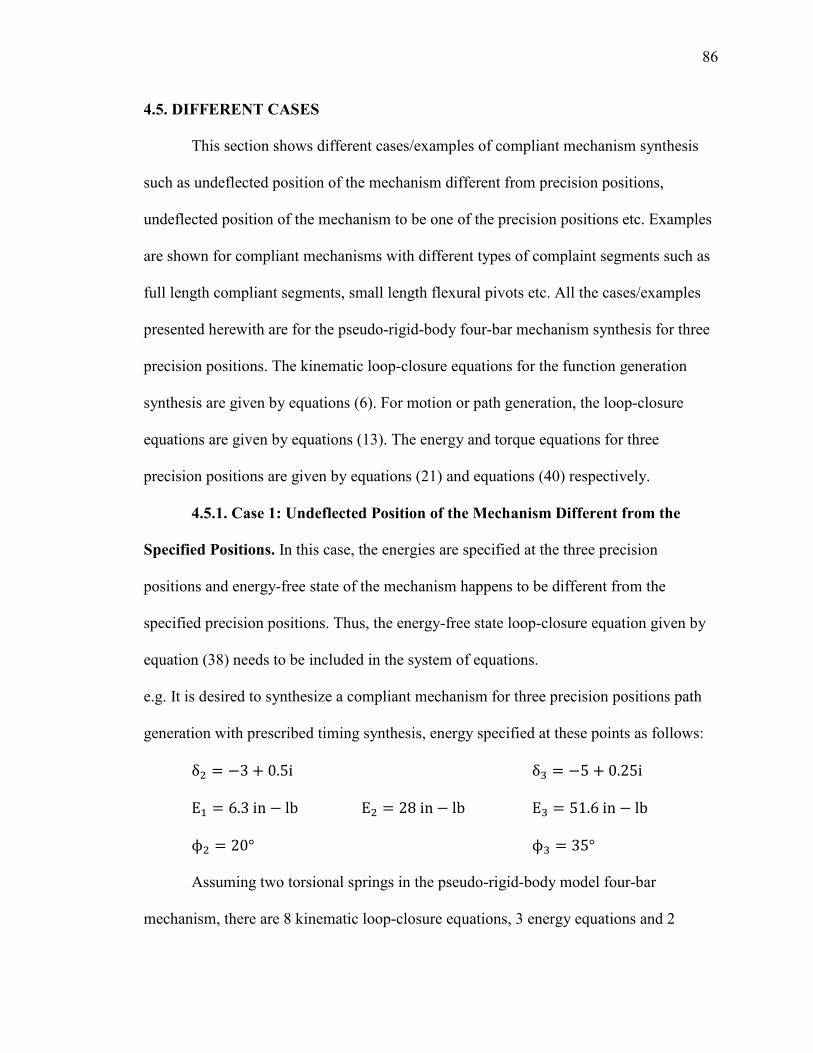
86
4.5. DIFFERENT CASES
This section shows different cases/examples of compliant mechanism synthesis
such as undeflected position of the mechanism different from precision positions,
undeflected position of the mechanism to be one of the precision positions etc. Examples
are shown for compliant mechanisms with different types of complaint segments such as
full length compliant segments, small length flexural pivots etc. All the cases/examples
presented herewith are for the pseudo-rigid-body four-bar mechanism synthesis for three
precision positions. The kinematic loop-closure equations for the function generation
synthesis are given by equations (6). For motion or path generation, the loop-closure
equations are given by equations (13). The energy and torque equations for three
precision positions are given by equations (21) and equations (40) respectively.
4.5.1. Case 1: Undeflected Position of the Mechanism Different from the
Specified Positions. In this case, the energies are specified at the three precision
positions and energy-free state of the mechanism happens to be different from the
specified precision positions. Thus, the energy-free state loop-closure equation given by
equation (38) needs to be included in the system of equations.
e.g. It is desired to synthesize a compliant mechanism for three precision positions path
generation with prescribed timing synthesis, energy specified at these points as follows:
δ = −3 + 0.5iδ� = −5 + 0.25iE+ = 6.3in − lbΕ = 28in − lbΕ� = 51.6in − lbϕ = 20°ϕ� = 35°
Assuming two torsional springs in the pseudo-rigid-body model four-bar
mechanism, there are 8 kinematic loop-closure equations, 3 energy equations and 2
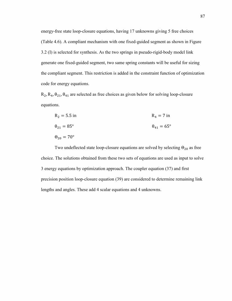
87
energy-free state loop-closure equations, having 17 unknowns giving 5 free choices
(Table 4.6). A compliant mechanism with one fixed-guided segment as shown in Figure
3.2 (I) is selected for synthesis. As the two springs in pseudo-rigid-body model link
generate one fixed-guided segment, two same spring constants will be useful for sizing
the compliant segment. This restriction is added in the constraint function of optimization
code for energy equations.
R , R�, θ +, θ�+ are selected as free choices as given below for solving loop-closure
equations.
R = 5.5inR� = 7inθ + = 85°θ�+ = 65°Θ 6 = 70°
Two undeflected state loop-closure equations are solved by selecting Θ 6 as free
choice. The solutions obtained from these two sets of equations are used as input to solve
3 energy equations by optimization approach. The coupler equation (37) and first
precision position loop-closure equation (39) are considered to determine remaining link
lengths and angles. These add 4 scalar equations and 4 unknowns.
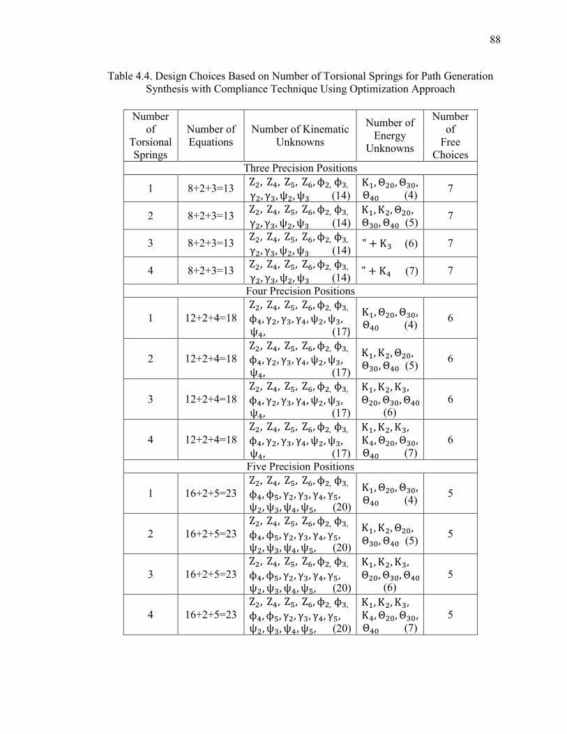
88
Table 4.4. Design Choices Based on Number of Torsional Springs for Path Generation Synthesis with Compliance Technique Using Optimization Approach
Number of
Torsional Springs
Number of Equations
Number of Kinematic Unknowns
Number of Energy
Unknowns
Number of
Free Choices
Three Precision Positions
1 8+2+3=13 Z , Z�, Z8, Z9, ϕ ,ϕ�, γ , γ�, ψ , ψ� (14)
Κ+, Θ 6, Θ�6, Θ�6 (4) 7
2 8+2+3=13 Z , Z�, Z8, Z9, ϕ ,ϕ�, γ , γ�, ψ , ψ� (14)
Κ+, Κ , Θ 6, Θ�6, Θ�6 (5) 7
3 8+2+3=13 Z , Z�, Z8, Z9, ϕ ,ϕ�, γ , γ�, ψ , ψ� (14)
" + Κ� (6) 7
4 8+2+3=13 Z , Z�, Z8, Z9, ϕ ,ϕ�, γ , γ�, ψ , ψ� (14)
" + Κ� (7) 7
Four Precision Positions
1 12+2+4=18
Z , Z�, Z8, Z9, ϕ ,ϕ�, ϕ�, γ , γ�, γ�, ψ , ψ�, ψ�, (17)
Κ+, Θ 6, Θ�6, Θ�6 (4) 6
2 12+2+4=18
Z , Z�, Z8, Z9, ϕ ,ϕ�, ϕ�, γ , γ�, γ�, ψ , ψ�, ψ�, (17)
Κ+, Κ , Θ 6, Θ�6, Θ�6 (5) 6
3 12+2+4=18
Z , Z�, Z8, Z9, ϕ ,ϕ�, ϕ�, γ , γ�, γ�, ψ , ψ�, ψ�, (17)
Κ+, Κ , Κ�, Θ 6, Θ�6, Θ�6 (6)
6
4 12+2+4=18
Z , Z�, Z8, Z9, ϕ ,ϕ�, ϕ�, γ , γ�, γ�, ψ , ψ�, ψ�, (17)
Κ+, Κ , Κ�, Κ�, Θ 6, Θ�6, Θ�6 (7)
6
Five Precision Positions
1 16+2+5=23
Z , Z�, Z8, Z9, ϕ ,ϕ�, ϕ�, ϕ8, γ , γ�, γ�, γ8, ψ , ψ�, ψ�, ψ8, (20)
Κ+, Θ 6, Θ�6, Θ�6 (4) 5
2 16+2+5=23
Z , Z�, Z8, Z9, ϕ ,ϕ�, ϕ�, ϕ8, γ , γ�, γ�, γ8, ψ , ψ�, ψ�, ψ8, (20)
Κ+, Κ , Θ 6, Θ�6, Θ�6 (5) 5
3 16+2+5=23
Z , Z�, Z8, Z9, ϕ ,ϕ�, ϕ�, ϕ8, γ , γ�, γ�, γ8, ψ , ψ�, ψ�, ψ8, (20)
Κ+, Κ , Κ�, Θ 6, Θ�6, Θ�6 (6)
5
4 16+2+5=23
Z , Z�, Z8, Z9, ϕ ,ϕ�, ϕ�, ϕ8, γ , γ�, γ�, γ8, ψ , ψ�, ψ�, ψ8, (20)
Κ+, Κ , Κ�, Κ�, Θ 6, Θ�6, Θ�6 (7)
5
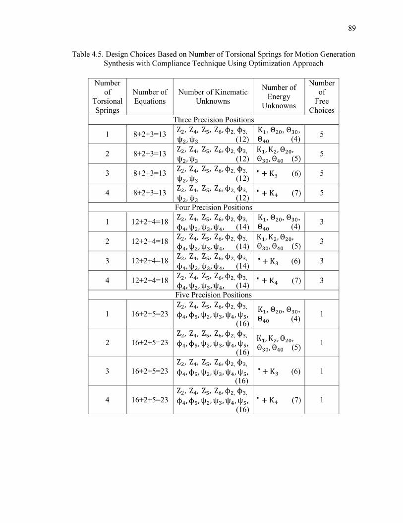
89
Table 4.5. Design Choices Based on Number of Torsional Springs for Motion Generation Synthesis with Compliance Technique Using Optimization Approach
Number of
Torsional Springs
Number of Equations
Number of Kinematic Unknowns
Number of Energy
Unknowns
Number of
Free Choices
Three Precision Positions
1 8+2+3=13 Z , Z�, Z8, Z9, ϕ ,ϕ�, ψ , ψ� (12)
Κ+, Θ 6, Θ�6, Θ�6 (4) 5
2 8+2+3=13 Z , Z�, Z8, Z9, ϕ ,ϕ�, ψ , ψ� (12)
Κ+, Κ , Θ 6, Θ�6, Θ�6 (5) 5
3 8+2+3=13 Z , Z�, Z8, Z9, ϕ ,ϕ�, ψ , ψ� (12)
" + Κ� (6) 5
4 8+2+3=13 Z , Z�, Z8, Z9, ϕ ,ϕ�, ψ , ψ� (12)
" + Κ� (7) 5
Four Precision Positions
1 12+2+4=18 Z , Z�, Z8, Z9, ϕ ,ϕ�, ϕ�, ψ , ψ�, ψ�, (14)
Κ+, Θ 6, Θ�6, Θ�6 (4) 3
2 12+2+4=18 Z , Z�, Z8, Z9, ϕ ,ϕ�, ϕ�, ψ , ψ�, ψ�, (14)
Κ+, Κ , Θ 6, Θ�6, Θ�6 (5) 3
3 12+2+4=18 Z , Z�, Z8, Z9, ϕ ,ϕ�, ϕ�, ψ , ψ�, ψ�, (14)
" + Κ� (6) 3
4 12+2+4=18 Z , Z�, Z8, Z9, ϕ ,ϕ�, ϕ�, ψ , ψ�, ψ�, (14)
" + Κ� (7) 3
Five Precision Positions
1 16+2+5=23
Z , Z�, Z8, Z9, ϕ ,ϕ�, ϕ�, ϕ8, ψ , ψ�, ψ�, ψ8, (16)
Κ+, Θ 6, Θ�6, Θ�6 (4) 1
2 16+2+5=23
Z , Z�, Z8, Z9, ϕ ,ϕ�, ϕ�, ϕ8, ψ , ψ�, ψ�, ψ8, (16)
Κ+, Κ , Θ 6, Θ�6, Θ�6 (5) 1
3 16+2+5=23
Z , Z�, Z8, Z9, ϕ ,ϕ�, ϕ�, ϕ8, ψ , ψ�, ψ�, ψ8, (16)
" + Κ� (6) 1
4 16+2+5=23
Z , Z�, Z8, Z9, ϕ ,ϕ�, ϕ�, ϕ8, ψ , ψ�, ψ�, ψ8, (16)
" + Κ� (7) 1
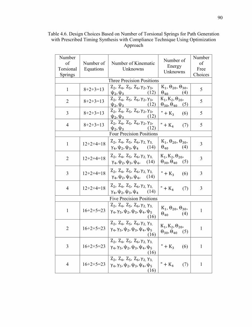
90
Table 4.6. Design Choices Based on Number of Torsional Springs for Path Generation with Prescribed Timing Synthesis with Compliance Technique Using Optimization
Approach
Number of
Torsional Springs
Number of Equations
Number of Kinematic Unknowns
Number of Energy
Unknowns
Number of
Free Choices
Three Precision Positions
1 8+2+3=13 Z , Z�, Z8, Z9, γ , γ�, ψ , ψ� (12)
Κ+, Θ 6, Θ�6, Θ�6 (4) 5
2 8+2+3=13 Z , Z�, Z8, Z9, γ , γ�, ψ , ψ� (12)
Κ+, Κ , Θ 6, Θ�6, Θ�6 (5) 5
3 8+2+3=13 Z , Z�, Z8, Z9, γ , γ�, ψ , ψ� (12)
" + Κ� (6) 5
4 8+2+3=13 Z , Z�, Z8, Z9, γ , γ�, ψ , ψ� (12)
" + Κ� (7) 5
Four Precision Positions
1 12+2+4=18 Z , Z�, Z8, Z9, γ ,γ�, γ�, ψ , ψ�, ψ� (14)
Κ+, Θ 6, Θ�6, Θ�6 (4) 3
2 12+2+4=18 Z , Z�, Z8, Z9, γ ,γ�, γ�, ψ , ψ�, ψ�, (14)
Κ+, Κ , Θ 6, Θ�6, Θ�6 (5) 3
3 12+2+4=18 Z , Z�, Z8, Z9, γ ,γ�, γ�, ψ , ψ�, ψ�, (14)
" + Κ� (6) 3
4 12+2+4=18 Z , Z�, Z8, Z9, γ ,γ�, γ�, ψ , ψ�, ψ� (14)
" + Κ� (7) 3
Five Precision Positions
1 16+2+5=23
Z , Z�, Z8, Z9, γ ,γ�, γ�, γ8, ψ , ψ�, ψ�, ψ8 (16)
Κ+, Θ 6, Θ�6, Θ�6 (4) 1
2 16+2+5=23
Z , Z�, Z8, Z9, γ ,γ�, γ�, γ8, ψ , ψ�, ψ�, ψ8 (16)
Κ+, Κ , Θ 6, Θ�6, Θ�6 (5) 1
3 16+2+5=23
Z , Z�, Z8, Z9, γ ,γ�, γ�, γ8, ψ , ψ�, ψ�, ψ8 (16)
" + Κ� (6) 1
4 16+2+5=23
Z , Z�, Z8, Z9, γ ,γ�, γ�, γ8, ψ , ψ�, ψ�, ψ8 (16)
" + Κ� (7) 1
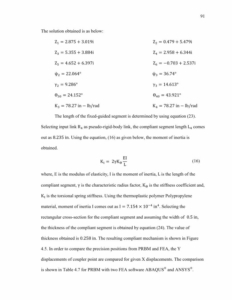
91
The solution obtained is as below:
Z+ = 2.875 + 3.019iZ = 0.479 + 5.479iZ� = 5.355 + 3.884iZ� = 2.958 + 6.344iZ8 = 4.652 + 6.397iZ9 = −0.703 + 2.537iψ = 22.064°ψ� = 36.74°γ = 9.286°γ� = 14.613°Θ�6 = 24.152°Θ�6 = 43.921°K� = 78.27in − lb/radK� = 78.27in − lb/rad
The length of the fixed-guided segment is determined by using equation (23).
Selecting input link R� as pseudo-rigid-body link, the compliant segment length L� comes
out as 8.235in. Using the equation, (16) as given below, the moment of inertia is
obtained.
Κ = 2γΚ$ ΕΙL (16)
where, Ε is the modulus of elasticity, Ι is the moment of inertia, L is the length of the
compliant segment, γ is the characteristic radius factor, Κ$ is the stiffness coefficient and,
Κ is the torsional spring stiffness. Using the thermoplastic polymer Polypropylene
material, moment of inertia Ι comes out as Ι = 7.154 × 10��in�. Selecting the
rectangular cross-section for the compliant segment and assuming the width of 0.5in,
the thickness of the compliant segment is obtained by equation (24). The value of
thickness obtained is 0.258in. The resulting compliant mechanism is shown in Figure
4.5. In order to compare the precision positions from PRBM and FEA, the Y
displacements of coupler point are compared for given X displacements. The comparison
is shown in Table 4.7 for PRBM with two FEA software ABAQUS® and ANSYS®.
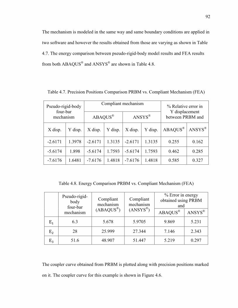
92
The mechanism is modeled in the same way and same boundary conditions are applied in
two software and however the results obtained from those are varying as shown in Table
4.7. The energy comparison between pseudo-rigid-body model results and FEA results
from both ABAQUS® and ANSYS® are shown in Table 4.8.
Table 4.7. Precision Positions Comparison PRBM vs. Compliant Mechanism (FEA)
Pseudo-rigid-body four-bar
mechanism
Compliant mechanism
% Relative error in Y displacement
between PRBM and ABAQUS® ANSYS®
X disp. Y disp. X disp. Y disp. X disp. Y disp. ABAQUS® ANSYS®
-2.6171 1.3978 -2.6171 1.3135 -2.6171 1.3135 0.255 0.162
-5.6174 1.898 -5.6174 1.7593 -5.6174 1.7593 0.462 0.285
-7.6176 1.6481 -7.6176 1.4818 -7.6176 1.4818 0.585 0.327
Table 4.8. Energy Comparison PRBM vs. Compliant Mechanism (FEA)
Pseudo-rigid-body
four-bar mechanism
Compliant mechanism
(ABAQUS®)
Compliant mechanism (ANSYS®)
% Error in energy obtained using PRBM
and
ABAQUS® ANSYS®
E+ 6.3 5.678 5.9705 9.869 5.231
E 28 25.999 27.344 7.146 2.343
E� 51.6 48.907 51.447 5.219 0.297
The coupler curve obtained from PRBM is plotted along with precision positions marked
on it. The coupler curve for this example is shown in Figure 4.6.
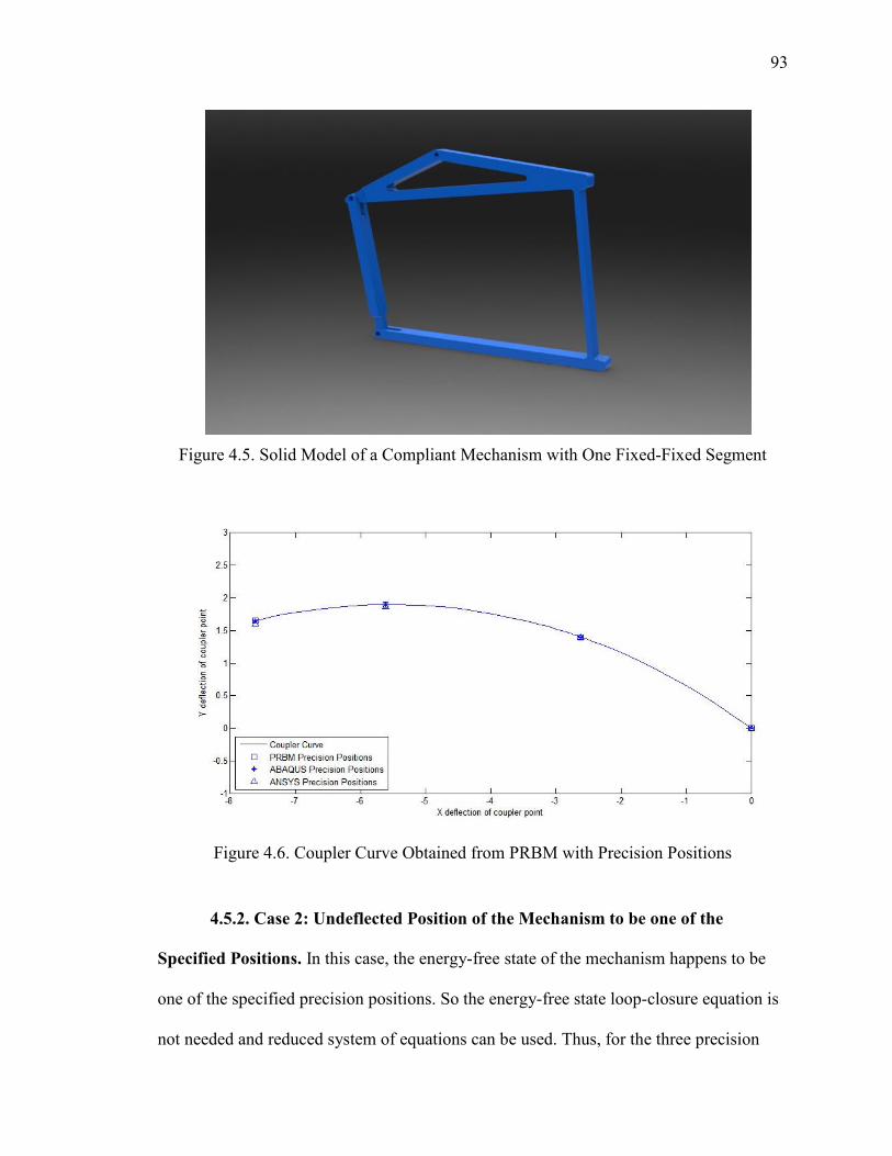
93
Figure 4.5. Solid Model of a Compliant Mechanism with One Fixed-Fixed Segment
Figure 4.6. Coupler Curve Obtained from PRBM with Precision Positions
4.5.2. Case 2: Undeflected Position of the Mechanism to be one of the
Specified Positions. In this case, the energy-free state of the mechanism happens to be
one of the specified precision positions. So the energy-free state loop-closure equation is
not needed and reduced system of equations can be used. Thus, for the three precision
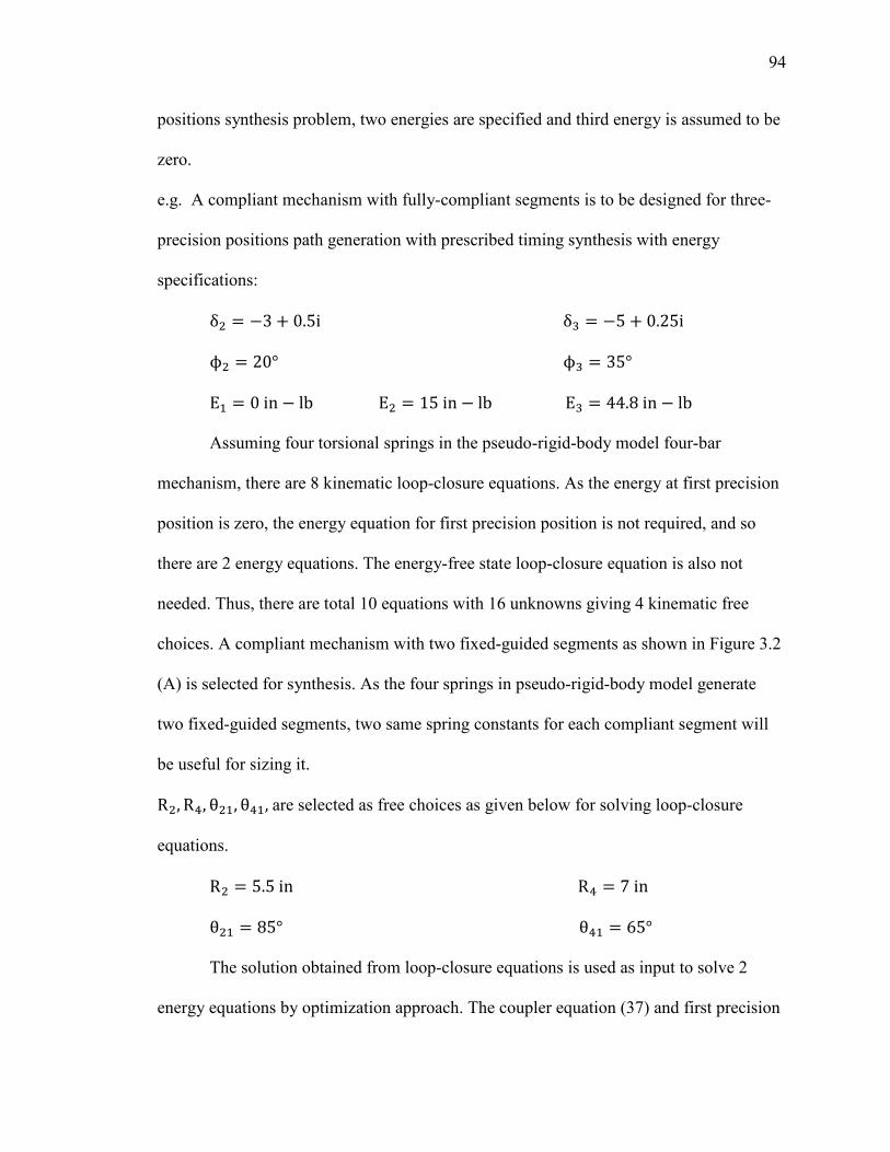
94
positions synthesis problem, two energies are specified and third energy is assumed to be
zero.
e.g. A compliant mechanism with fully-compliant segments is to be designed for three-
precision positions path generation with prescribed timing synthesis with energy
specifications:
δ = −3 + 0.5iδ� = −5 + 0.25iϕ = 20°ϕ� = 35°Ε+ = 0in − lbΕ = 15in − lbΕ� = 44.8in − lb
Assuming four torsional springs in the pseudo-rigid-body model four-bar
mechanism, there are 8 kinematic loop-closure equations. As the energy at first precision
position is zero, the energy equation for first precision position is not required, and so
there are 2 energy equations. The energy-free state loop-closure equation is also not
needed. Thus, there are total 10 equations with 16 unknowns giving 4 kinematic free
choices. A compliant mechanism with two fixed-guided segments as shown in Figure 3.2
(A) is selected for synthesis. As the four springs in pseudo-rigid-body model generate
two fixed-guided segments, two same spring constants for each compliant segment will
be useful for sizing it.
R , R�, θ +, θ�+, are selected as free choices as given below for solving loop-closure
equations.
R = 5.5inR� = 7inθ + = 85°θ�+ = 65°
The solution obtained from loop-closure equations is used as input to solve 2
energy equations by optimization approach. The coupler equation (37) and first precision
95
position loop-closure equation (39) are considered to determine remaining link lengths
and angles. These add 4 scalar equations and 4 unknowns. The solution obtained is as
below:
Z+ = 2.876 + 3.019iZ = 0.4794 + 5.479iZ� = 5.355 + 3.885iZ� = 2.958 + 4.110iZ8 = 4.652 + 6.422iZ9 = −0.703 + 2.537iγ = 9.286°γ� = 14.613°ψ = 22.064°ψ� = 36.74°K+ = 80.882in − lb/radK = 80.882in − lb/rad
K� = 87.733in − lb/radK� = 87.733in − lb/rad The length of the fixed-guided segment is determined by using equation (23).
Selecting input link R pseudo-rigid-body link, the compliant segment length L comes
out as 7.0588in. Using the equation (16), the moment of inertia is obtained. Using the
thermoplastic polymer Polypropylene material, moment of inertia Ι comes out as
Ι = 5.808 × 10��in�. Similarly, for output pseudo-rigid-body link, R�, the compliant
segment length L� comes out as 8.235in and moment of inertia as
Ι = 8.019 × 10��in�.Selecting the rectangular cross-section for the compliant segments
and assuming the width of 0.5in, the thickness of the compliant segment obtained for
input link is 0.2406in and for output link is 0.2679in. The resulting compliant
mechanism is shown in Figure 4.7. In order to compare the precision positions from
PRBM and FEA, the Y displacements of coupler point are compared for given X
displacements. The comparison is shown in Table 4.9 for PRBM with two FEA software
ABAQUS® and ANSYS® .The mechanism is modeled in the same way and same
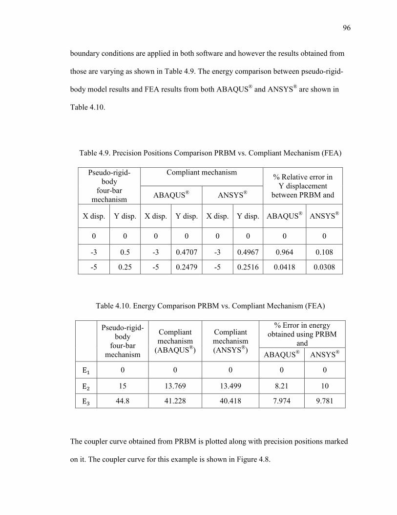
96
boundary conditions are applied in both software and however the results obtained from
those are varying as shown in Table 4.9. The energy comparison between pseudo-rigid-
body model results and FEA results from both ABAQUS® and ANSYS® are shown in
Table 4.10.
Table 4.9. Precision Positions Comparison PRBM vs. Compliant Mechanism (FEA)
Pseudo-rigid-body
four-bar mechanism
Compliant mechanism
% Relative error in Y displacement
between PRBM and ABAQUS® ANSYS®
X disp. Y disp. X disp. Y disp. X disp. Y disp. ABAQUS® ANSYS®
0 0 0 0 0 0 0 0
-3 0.5 -3 0.4707 -3 0.4967 0.964 0.108
-5 0.25 -5 0.2479 -5 0.2516 0.0418 0.0308
Table 4.10. Energy Comparison PRBM vs. Compliant Mechanism (FEA)
Pseudo-rigid-body
four-bar mechanism
Compliant mechanism
(ABAQUS®)
Compliant mechanism (ANSYS®)
% Error in energy obtained using PRBM
and
ABAQUS® ANSYS®
E+ 0 0 0 0 0
E 15 13.769 13.499 8.21 10
E� 44.8 41.228 40.418 7.974 9.781
The coupler curve obtained from PRBM is plotted along with precision positions marked
on it. The coupler curve for this example is shown in Figure 4.8.
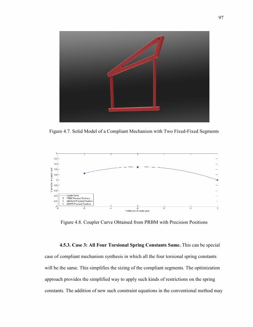
97
Figure 4.7. Solid Model of a Compliant Mechanism with Two Fixed-Fixed Segments
Figure 4.8. Coupler Curve Obtained from PRBM with Precision Positions
4.5.3. Case 3: All Four Torsional Spring Constants Same. This can be special
case of compliant mechanism synthesis in which all the four torsional spring constants
will be the same. This simplifies the sizing of the compliant segments. The optimization
approach provides the simplified way to apply such kinds of restrictions on the spring
constants. The addition of new such constraint equations in the conventional method may
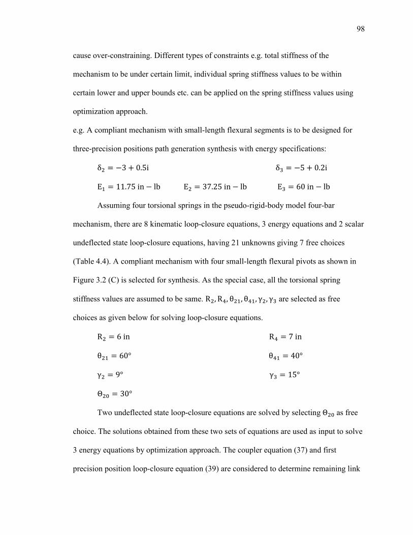
98
cause over-constraining. Different types of constraints e.g. total stiffness of the
mechanism to be under certain limit, individual spring stiffness values to be within
certain lower and upper bounds etc. can be applied on the spring stiffness values using
optimization approach.
e.g. A compliant mechanism with small-length flexural segments is to be designed for
three-precision positions path generation synthesis with energy specifications:
δ = −3 + 0.5iδ� = −5 + 0.2iE+ = 11.75in − lbE = 37.25in − lbE� = 60in − lb
Assuming four torsional springs in the pseudo-rigid-body model four-bar
mechanism, there are 8 kinematic loop-closure equations, 3 energy equations and 2 scalar
undeflected state loop-closure equations, having 21 unknowns giving 7 free choices
(Table 4.4). A compliant mechanism with four small-length flexural pivots as shown in
Figure 3.2 (C) is selected for synthesis. As the special case, all the torsional spring
stiffness values are assumed to be same. R , R�, θ +, θ�+, γ , γ� are selected as free
choices as given below for solving loop-closure equations.
R = 6inR� = 7inθ + = 60°θ�+ = 40°γ = 9°γ� = 15°Θ 6 = 30°
Two undeflected state loop-closure equations are solved by selecting Θ 6 as free
choice. The solutions obtained from these two sets of equations are used as input to solve
3 energy equations by optimization approach. The coupler equation (37) and first
precision position loop-closure equation (39) are considered to determine remaining link
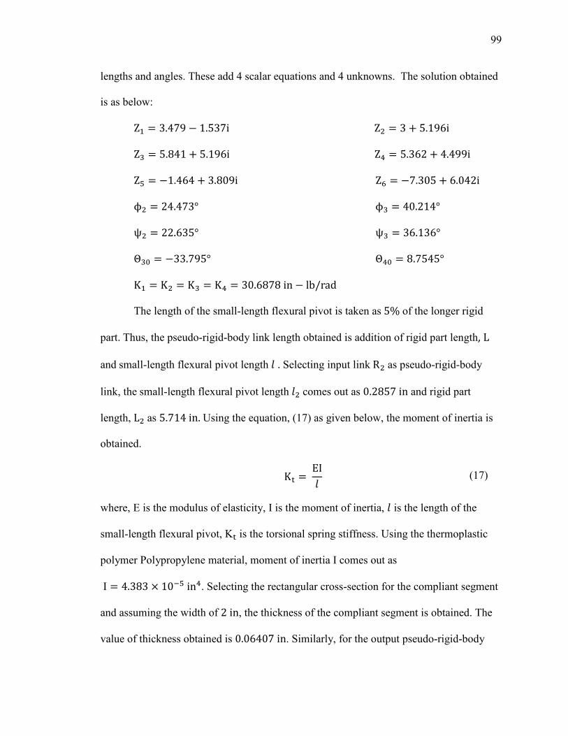
99
lengths and angles. These add 4 scalar equations and 4 unknowns. The solution obtained
is as below:
Z+ = 3.479 − 1.537iZ = 3 + 5.196iZ� = 5.841 + 5.196iZ� = 5.362 + 4.499iZ8 = −1.464 + 3.809iZ9 = −7.305 + 6.042iϕ = 24.473°ϕ� = 40.214°ψ = 22.635°ψ� = 36.136°Θ�6 = −33.795°Θ�6 = 8.7545°K+ = K = K� = K� = 30.6878in − lb/rad
The length of the small-length flexural pivot is taken as 5% of the longer rigid
part. Thus, the pseudo-rigid-body link length obtained is addition of rigid part length, L
and small-length flexural pivot length = . Selecting input link R as pseudo-rigid-body
link, the small-length flexural pivot length = comes out as 0.2857in and rigid part
length, L as 5.714in.Using the equation, (17) as given below, the moment of inertia is
obtained. Κ =ΕΙ= (17)
where, Ε is the modulus of elasticity, Ι is the moment of inertia, = is the length of the
small-length flexural pivot, Κ is the torsional spring stiffness. Using the thermoplastic
polymer Polypropylene material, moment of inertia Ι comes out as
Ι = 4.383 × 10�8in�. Selecting the rectangular cross-section for the compliant segment
and assuming the width of 2in, the thickness of the compliant segment is obtained. The
value of thickness obtained is 0.06407in. Similarly, for the output pseudo-rigid-body
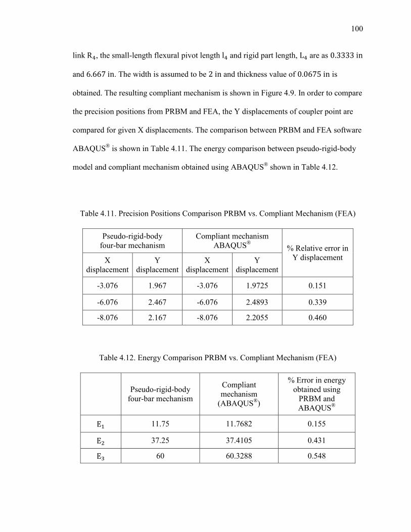
100
linkR�, the small-length flexural pivot length l� and rigid part length, L� are as 0.3333in
and 6.667in. The width is assumed to be 2in and thickness value of 0.0675in is
obtained. The resulting compliant mechanism is shown in Figure 4.9. In order to compare
the precision positions from PRBM and FEA, the Y displacements of coupler point are
compared for given X displacements. The comparison between PRBM and FEA software
ABAQUS® is shown in Table 4.11. The energy comparison between pseudo-rigid-body
model and compliant mechanism obtained using ABAQUS® shown in Table 4.12.
Table 4.11. Precision Positions Comparison PRBM vs. Compliant Mechanism (FEA)
Pseudo-rigid-body four-bar mechanism
Compliant mechanism ABAQUS® % Relative error in
Y displacement X displacement
Y displacement
X displacement
Y displacement
-3.076 1.967 -3.076 1.9725 0.151
-6.076 2.467 -6.076 2.4893 0.339
-8.076 2.167 -8.076 2.2055 0.460
Table 4.12. Energy Comparison PRBM vs. Compliant Mechanism (FEA)
Pseudo-rigid-body
four-bar mechanism
Compliant mechanism
(ABAQUS®)
% Error in energy obtained using
PRBM and ABAQUS®
E+ 11.75 11.7682 0.155
E 37.25 37.4105 0.431
E� 60 60.3288 0.548
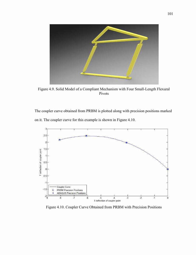
101
Figure 4.9. Solid Model of a Compliant Mechanism with Four Small-Length Flexural Pivots
The coupler curve obtained from PRBM is plotted along with precision positions marked
on it. The coupler curve for this example is shown in Figure 4.10.
Figure 4.10. Coupler Curve Obtained from PRBM with Precision Positions
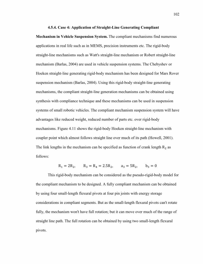
102
4.5.4. Case 4: Application of Straight-Line Generating Compliant
Mechanism in Vehicle Suspension System. The compliant mechanisms find numerous
applications in real life such as in MEMS, precision instruments etc. The rigid-body
straight-line mechanisms such as Watt's straight-line mechanism or Robert straight-line
mechanism (Barlas, 2004) are used in vehicle suspension systems. The Chebyshev or
Hoeken straight-line generating rigid-body mechanism has been designed for Mars Rover
suspension mechanism (Barlas, 2004). Using this rigid-body straight-line generating
mechanisms, the compliant straight-line generation mechanisms can be obtained using
synthesis with compliance technique and these mechanisms can be used in suspension
systems of small robotic vehicles. The compliant mechanism suspension system will have
advantages like reduced weight, reduced number of parts etc. over rigid-body
mechanisms. Figure 4.11 shows the rigid-body Hoeken straight-line mechanism with
coupler point which almost follows straight line over much of its path (Howell, 2001).
The link lengths in the mechanism can be specified as function of crank length R as
follows:
R+ = 2R , R� = R� = 2.5R , a� = 5R , b� = 0
This rigid-body mechanism can be considered as the pseudo-rigid-body model for
the compliant mechanism to be designed. A fully compliant mechanism can be obtained
by using four small-length flexural pivots at four pin joints with energy storage
considerations in compliant segments. But as the small-length flexural pivots can't rotate
fully, the mechanism won't have full rotation; but it can move over much of the range of
straight line path. The full rotation can be obtained by using two small-length flexural
pivots.
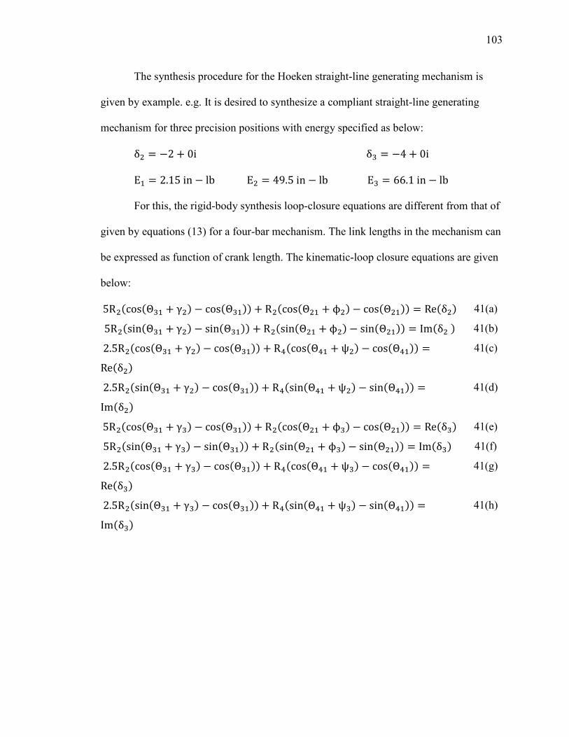
103
The synthesis procedure for the Hoeken straight-line generating mechanism is
given by example. e.g. It is desired to synthesize a compliant straight-line generating
mechanism for three precision positions with energy specified as below:
δ = −2 + 0iδ� = −4 + 0iE+ = 2.15in − lbE = 49.5in − lbE� = 66.1in − lb
For this, the rigid-body synthesis loop-closure equations are different from that of
given by equations (13) for a four-bar mechanism. The link lengths in the mechanism can
be expressed as function of crank length. The kinematic-loop closure equations are given
below:
5R 'cos'Θ�+ + γ . − cos'Θ�+.. + R 'cos'Θ + + ϕ . − cos'Θ +.. = Re'δ . 41(a)
5R 'sin'Θ�+ + γ . − sin'Θ�+.. + R 'sin'Θ + + ϕ . − sin'Θ +.. = Im'δ . 41(b)
2.5R 'cos'Θ�+ + γ . − cos'Θ�+.. + R�'cos'Θ�+ + ψ . − cos'Θ�+.. =Re'δ .
41(c)
2.5R 'sin'Θ�+ + γ . − cos'Θ�+.. + R�'sin'Θ�+ + ψ . − sin'Θ�+.. =Im'δ .
41(d)
5R 'cos'Θ�+ + γ�. − cos'Θ�+.. + R 'cos'Θ + + ϕ�. − cos'Θ +.. = Re'δ�. 41(e)
5R 'sin'Θ�+ + γ�. − sin'Θ�+.. + R 'sin'Θ + + ϕ�. − sin'Θ +.. = Im'δ�. 41(f)
2.5R 'cos'Θ�+ + γ�. − cos'Θ�+.. + R�'cos'Θ�+ + ψ�. − cos'Θ�+.. =Re'δ�.
41(g)
2.5R 'sin'Θ�+ + γ�. − cos'Θ�+.. + R�'sin'Θ�+ + ψ�. − sin'Θ�+.. =Im'δ�.
41(h)
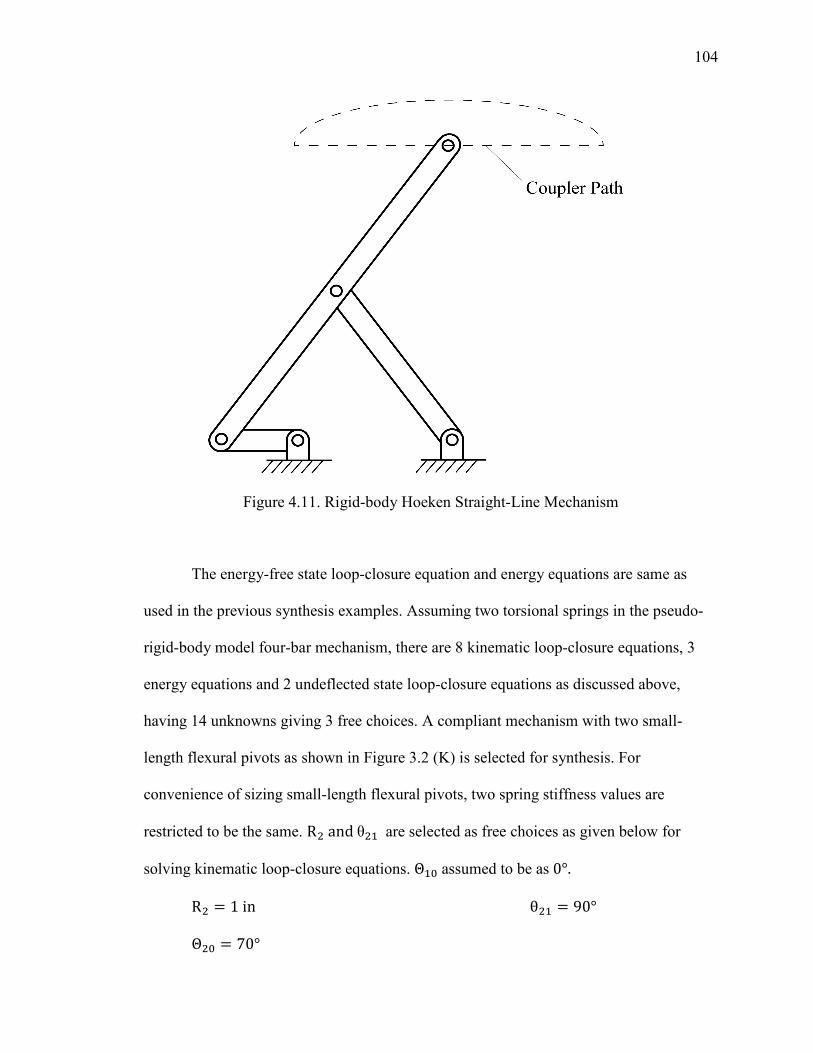
104
Figure 4.11. Rigid-body Hoeken Straight-Line Mechanism
The energy-free state loop-closure equation and energy equations are same as
used in the previous synthesis examples. Assuming two torsional springs in the pseudo-
rigid-body model four-bar mechanism, there are 8 kinematic loop-closure equations, 3
energy equations and 2 undeflected state loop-closure equations as discussed above,
having 14 unknowns giving 3 free choices. A compliant mechanism with two small-
length flexural pivots as shown in Figure 3.2 (K) is selected for synthesis. For
convenience of sizing small-length flexural pivots, two spring stiffness values are
restricted to be the same. R andθ + are selected as free choices as given below for
solving kinematic loop-closure equations. Θ+6 assumed to be as 0°. R = 1inθ + = 90°Θ 6 = 70°
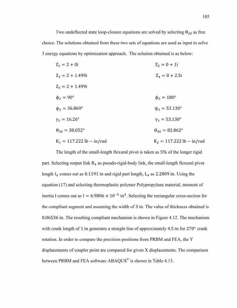
105
Two undeflected state loop-closure equations are solved by selecting Θ 6 as free
choice. The solutions obtained from these two sets of equations are used as input to solve
3 energy equations by optimization approach. The solution obtained is as below:
Z+ = 2 + 0iZ = 0 + 1iZ� = 2 + 1.499iZ� = 0 + 2.5iZ8 = 2 + 1.499iϕ = 90°ϕ� = 180°ψ = 36.869°ψ� = 53.130°γ = 16.26°γ� = 53.130°Θ�6 = 38.052°Θ�6 = 82.862°K+ = 117.222lb − in/radK = 117.222lb − in/rad
The length of the small-length flexural pivot is taken as 5% of the longer rigid
part. Selecting output link R� as pseudo-rigid-body link, the small-length flexural pivot
length =� comes out as 0.1191in and rigid part length, L� as 2.2809in. Using the
equation (17) and selecting thermoplastic polymer Polypropylene material, moment of
inertia Ι comes out as Ι = 6.9806 × 10�8in�. Selecting the rectangular cross-section for
the compliant segment and assuming the width of 3in. The value of thickness obtained is
0.06536in. The resulting compliant mechanism is shown in Figure 4.12. The mechanism
with crank length of 1in generates a straight line of approximately 4.5in for 270° crank
rotation. In order to compare the precision positions from PRBM and FEA, the Y
displacements of coupler point are compared for given X displacements. The comparison
between PRBM and FEA software ABAQUS® is shown in Table 4.13.
106
Table 4.13. Precision Positions Comparison PRBM vs. Compliant Mechanism (FEA)
Pseudo-rigid-body four-bar mechanism
Compliant mechanism ABAQUS® % Relative error in
Y displacement X displacement
Y displacement
X displacement
Y displacement
-0.2793 -0.0215 -0.2793 -0.02038 0.399
-2.2793 -0.0215 -2.2793 -0.01045 0.484
-4.2793 -0.0215 -4.2793 -0.0213 0.005
The energy comparison between pseudo-rigid-body model and compliant mechanism
obtained using ABAQUS® shown in Table 4.14.
Table 4.14. Energy Comparison PRBM vs. Compliant Mechanism (FEA)
Pseudo-rigid-body
four-bar mechanism
Compliant mechanism
(ABAQUS®)
% Error in energy obtained using
PRBM and ABAQUS®
E+ 2.15 2.1327 0.806
E 49.5 49.2079 0.590
E� 66.1 66.915 1.233
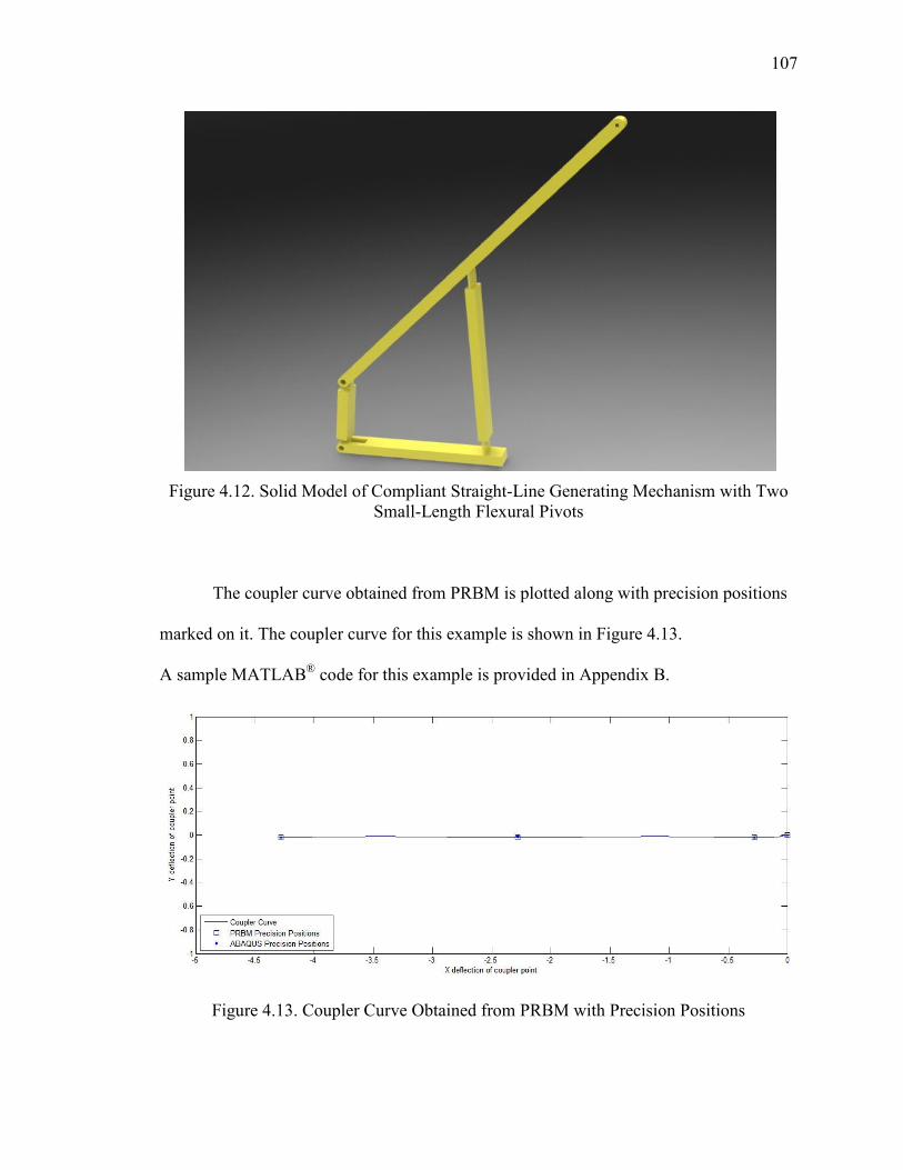
107
Figure 4.12. Solid Model of Compliant Straight-Line Generating Mechanism with Two Small-Length Flexural Pivots
The coupler curve obtained from PRBM is plotted along with precision positions
marked on it. The coupler curve for this example is shown in Figure 4.13.
A sample MATLAB® code for this example is provided in Appendix B.
Figure 4.13. Coupler Curve Obtained from PRBM with Precision Positions
108
The pseudo-rigid-body model considered for fixed-guided segments in this work
was tailored to work for fixed-guided segments with constant beam end angle. But it is
observed that the PRBM considered here for fixed-guided segment works well for fixed-
guided segments with varying beam end angles also. It has been observed that, the FEA
software ABAQUS® and ANSYS® give different solutions of the precision position
displacements and energies at precision positions for the problem modeled in the same
way. The formula to calculate the percentage relative error in displacement can be found
in Appendix A.
4.7. SUMMARY
In this Section, the optimization concept, types of optimization and design process
are reviewed. The optimization routine developed for solving energy/torque equations is
presented. The strongly coupling and weakly coupling of kinematic and energy/torque
equations is studied and the results are explained with example. The energy equivalence
between pseudo-rigid-body model and the corresponding compliant mechanism using
FEA is discussed. The tables outlining the number of equations, number of variables, and
number of free choices for different synthesis cases with different number of springs are
presented. The different cases of synthesis based on number of torsional springs, types of
compliant segments etc. are presented. The results obtained from pseudo-rigid-body
model concept are compared with FEA. The new approach is used to synthesize the
straight-line generating compliant mechanism which can be used in the suspension
system of small robotic vehicles.
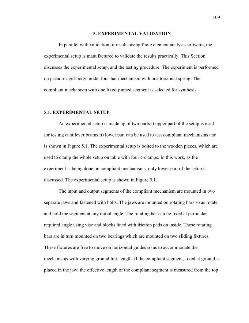
109
5. EXPERIMENTAL VALIDATION
In parallel with validation of results using finite element analysis software, the
experimental setup is manufactured to validate the results practically. This Section
discusses the experimental setup, and the testing procedure. The experiment is performed
on pseudo-rigid-body model four-bar mechanism with one torsional spring. The
compliant mechanism with one fixed-pinned segment is selected for synthesis.
5.1. EXPERIMENTAL SETUP
An experimental setup is made up of two parts i) upper part of the setup is used
for testing cantilever beams ii) lower part can be used to test compliant mechanisms and
is shown in Figure 5.1. The experimental setup is bolted to the wooden pieces, which are
used to clamp the whole setup on table with four c-clamps. In this work, as the
experiment is being done on compliant mechanisms, only lower part of the setup is
discussed. The experimental setup is shown in Figure 5.1.
The input and output segments of the compliant mechanism are mounted in two
separate jaws and fastened with bolts. The jaws are mounted on rotating bars so as rotate
and hold the segment at any initial angle. The rotating bar can be fixed at particular
required angle using vise and blocks lined with friction pads on inside. These rotating
bars are in turn mounted on two bearings which are mounted on two sliding fixtures.
These fixtures are free to move on horizontal guides so as to accommodate the
mechanisms with varying ground link length. If the compliant segment, fixed at ground is
placed in the jaw; the effective length of the compliant segment is measured from the top
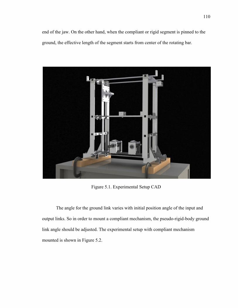
110
end of the jaw. On the other hand, when the compliant or rigid segment is pinned to the
ground, the effective length of the segment starts from center of the rotating bar.
Figure 5.1. Experimental Setup CAD
The angle for the ground link varies with initial position angle of the input and
output links. So in order to mount a compliant mechanism, the pseudo-rigid-body ground
link angle should be adjusted. The experimental setup with compliant mechanism
mounted is shown in Figure 5.2.
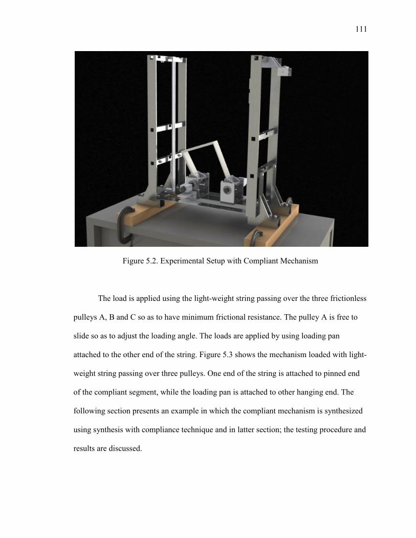
111
Figure 5.2. Experimental Setup with Compliant Mechanism
The load is applied using the light-weight string passing over the three frictionless
pulleys A, B and C so as to have minimum frictional resistance. The pulley A is free to
slide so as to adjust the loading angle. The loads are applied by using loading pan
attached to the other end of the string. Figure 5.3 shows the mechanism loaded with light-
weight string passing over three pulleys. One end of the string is attached to pinned end
of the compliant segment, while the loading pan is attached to other hanging end. The
following section presents an example in which the compliant mechanism is synthesized
using synthesis with compliance technique and in latter section; the testing procedure and
results are discussed.
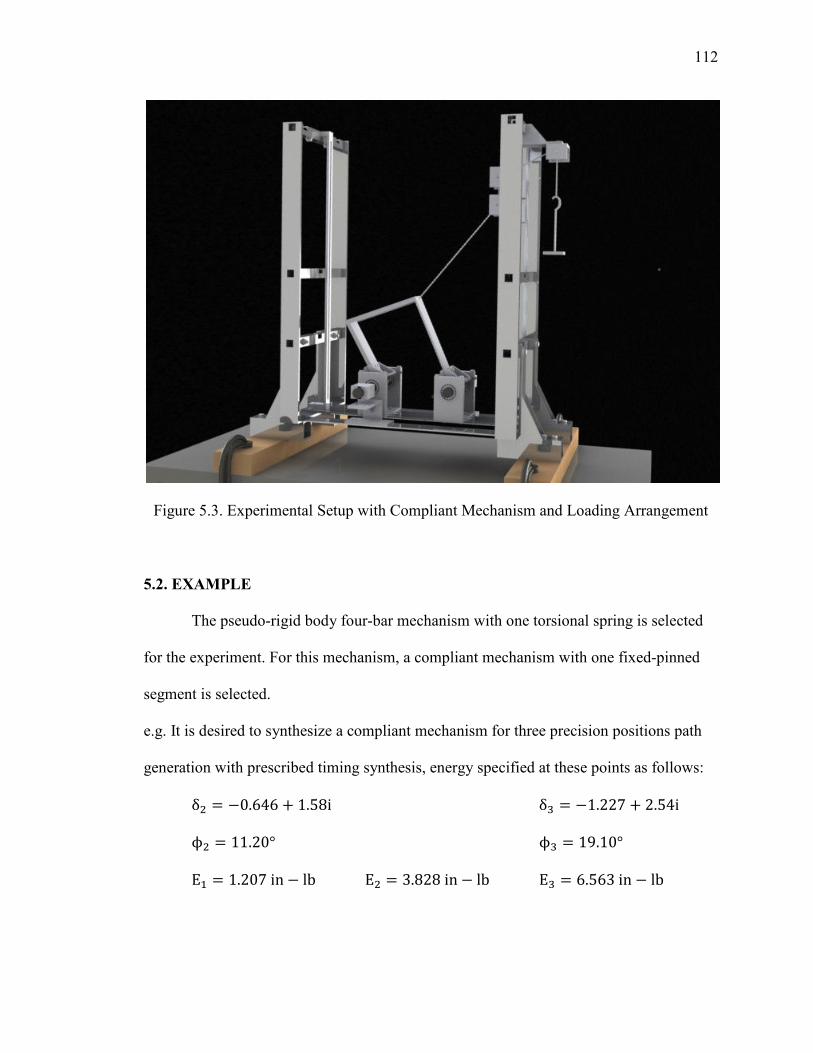
112
Figure 5.3. Experimental Setup with Compliant Mechanism and Loading Arrangement
5.2. EXAMPLE
The pseudo-rigid body four-bar mechanism with one torsional spring is selected
for the experiment. For this mechanism, a compliant mechanism with one fixed-pinned
segment is selected.
e.g. It is desired to synthesize a compliant mechanism for three precision positions path
generation with prescribed timing synthesis, energy specified at these points as follows:
δ = −0.646 + 1.58iδ� = −1.227 + 2.54iϕ = 11.20°ϕ� = 19.10°Ε+ = 1.207in − lbΕ = 3.828in − lbΕ� = 6.563in − lb
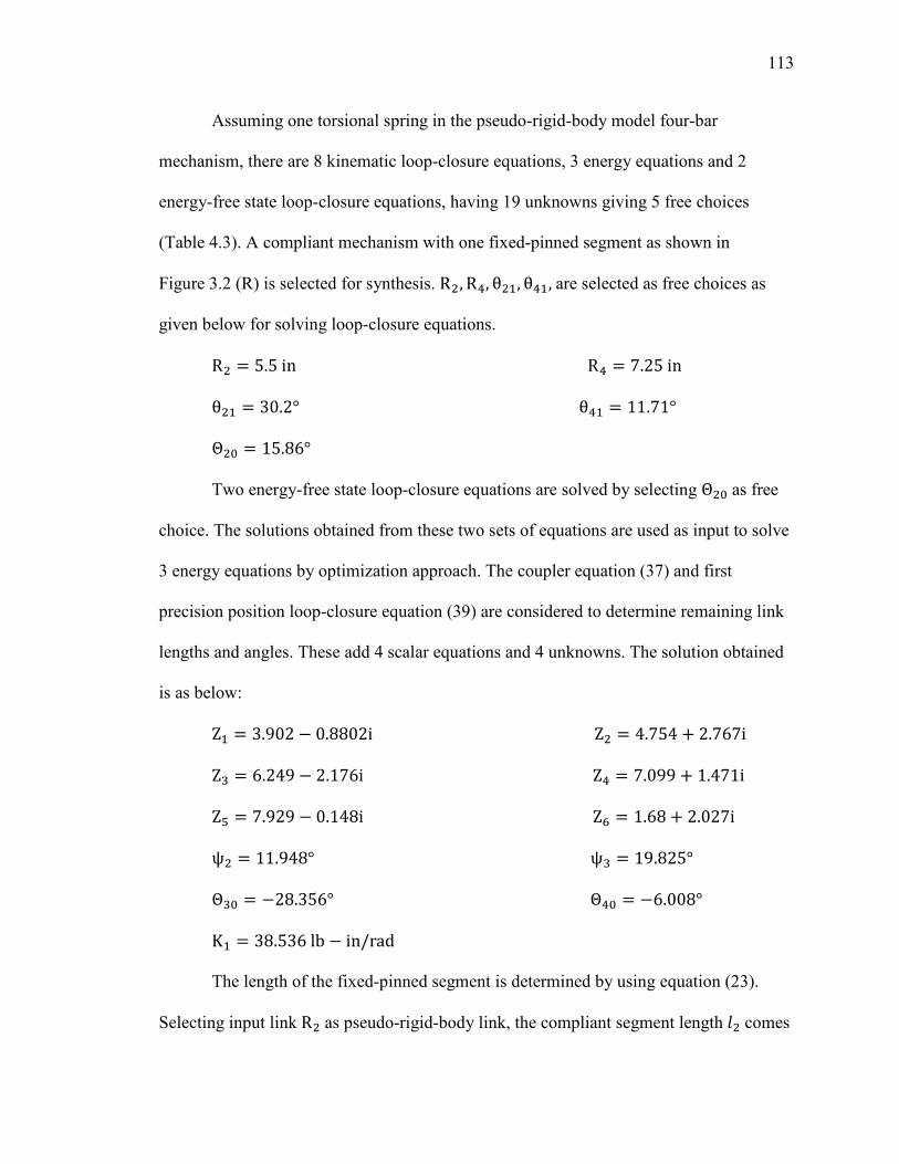
113
Assuming one torsional spring in the pseudo-rigid-body model four-bar
mechanism, there are 8 kinematic loop-closure equations, 3 energy equations and 2
energy-free state loop-closure equations, having 19 unknowns giving 5 free choices
(Table 4.3). A compliant mechanism with one fixed-pinned segment as shown in
Figure 3.2 (R) is selected for synthesis. R , R�, θ +, θ�+,are selected as free choices as
given below for solving loop-closure equations.
R = 5.5inR� = 7.25inθ + = 30.2°θ�+ = 11.71°Θ 6 = 15.86°
Two energy-free state loop-closure equations are solved by selecting Θ 6 as free
choice. The solutions obtained from these two sets of equations are used as input to solve
3 energy equations by optimization approach. The coupler equation (37) and first
precision position loop-closure equation (39) are considered to determine remaining link
lengths and angles. These add 4 scalar equations and 4 unknowns. The solution obtained
is as below:
Z+ = 3.902 − 0.8802iZ = 4.754 + 2.767iZ� = 6.249 − 2.176iZ� = 7.099 + 1.471iZ8 = 7.929 − 0.148iZ9 = 1.68 + 2.027iψ = 11.948°ψ� = 19.825°Θ�6 = −28.356°Θ�6 = −6.008°K+ = 38.536lb − in/rad
The length of the fixed-pinned segment is determined by using equation (23).
Selecting input link R as pseudo-rigid-body link, the compliant segment length = comes
114
out as 6.4706in. Using the equation (15), the moment of inertia is obtained. Using the
Delrin® as material, moment of inertia Ι comes out as Ι = 2.212 × 10��in�. Selecting
the rectangular cross-section for the compliant segment and assuming the width of 1.5in,
the thickness of the compliant segment is obtained as 0.121in. The resulting compliant
mechanism is shown in Figure 5.4.and individual links are shown in Figure 5.5.
An energy comparison between pseudo-rigid-body model and compliant
mechanism, using commercial finite element software ABAQUS® is done to verify
equivalence of the design and validate the solution. Given the dimensional and material
properties of the compliant mechanism, the ABAQUS® is used to find out the energy
stored in the mechanism at precision positions. The results are shown below in Table
5.1.
Table 5.1. Energy Comparison PRBM vs. Compliant Mechanism (FEA)
Pseudo-rigid-body
four-bar mechanism Compliant mechanism
(ABAQUS®) % Error in
Energy
E+ 1.207 1.149 4.82
E 3.829 3.636 5.04
E� 6.563 6.231 5.07

115
Figure 5.4. Solid Model of A Compliant Mechanism
The dimensions of the three links are as follows:
Input compliant link:
Length L = 6.4706in, width b = 1.5in and thickness h = 0.121in
Output link:
Length R� = 7in, width b = 0.6in and thickness h = 0.5in
Coupler: It has three links rigidly joined.
R� = 6.616in, R8 = 7.926in, and R9 = 2.633in, width b = 2.491in and
thickness h = 0.3in
Ground link:
Length R+ = 4.169in
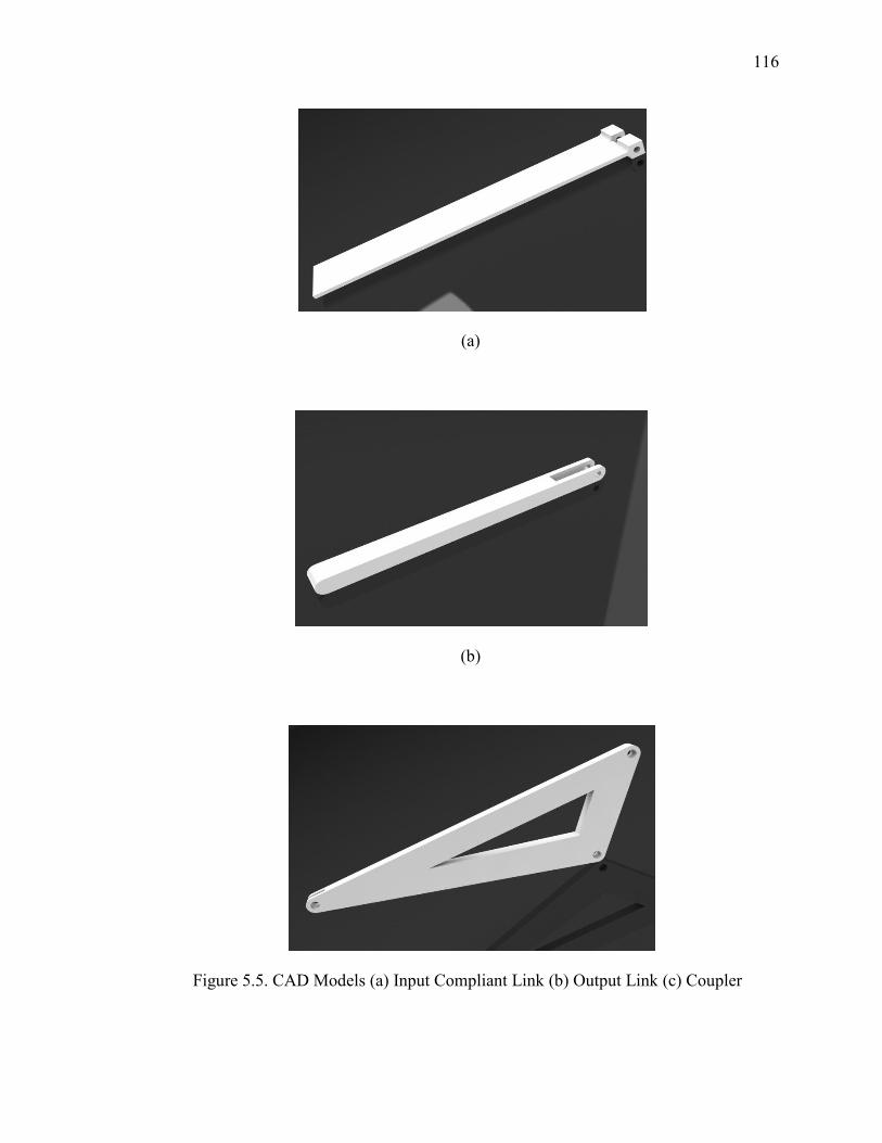
116
(a)
(b)
Figure 5.5. CAD Models (a) Input Compliant Link (b) Output Link (c) Coupler
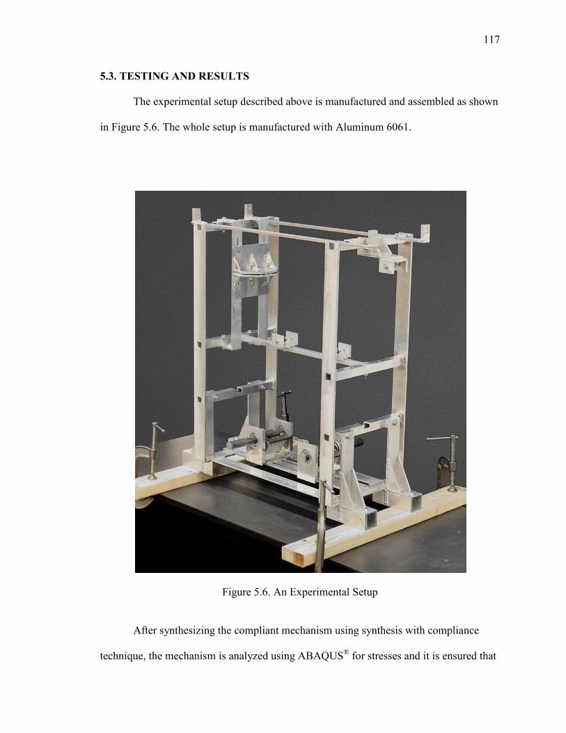
117
5.3. TESTING AND RESULTS
The experimental setup described above is manufactured and assembled as shown
in Figure 5.6. The whole setup is manufactured with Aluminum 6061.
Figure 5.6. An Experimental Setup
After synthesizing the compliant mechanism using synthesis with compliance
technique, the mechanism is analyzed using ABAQUS® for stresses and it is ensured that
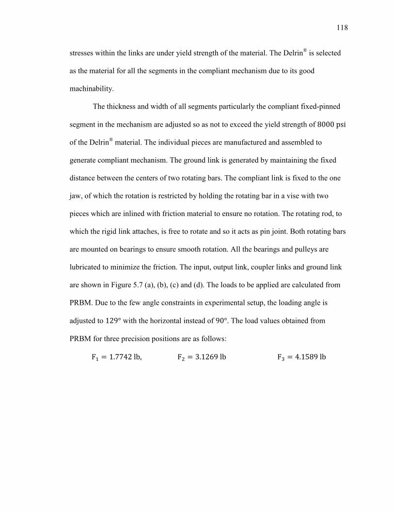
118
stresses within the links are under yield strength of the material. The Delrin® is selected
as the material for all the segments in the compliant mechanism due to its good
machinability.
The thickness and width of all segments particularly the compliant fixed-pinned
segment in the mechanism are adjusted so as not to exceed the yield strength of 8000psi of the Delrin® material. The individual pieces are manufactured and assembled to
generate compliant mechanism. The ground link is generated by maintaining the fixed
distance between the centers of two rotating bars. The compliant link is fixed to the one
jaw, of which the rotation is restricted by holding the rotating bar in a vise with two
pieces which are inlined with friction material to ensure no rotation. The rotating rod, to
which the rigid link attaches, is free to rotate and so it acts as pin joint. Both rotating bars
are mounted on bearings to ensure smooth rotation. All the bearings and pulleys are
lubricated to minimize the friction. The input, output link, coupler links and ground link
are shown in Figure 5.7 (a), (b), (c) and (d). The loads to be applied are calculated from
PRBM. Due to the few angle constraints in experimental setup, the loading angle is
adjusted to 129° with the horizontal instead of 90°. The load values obtained from
PRBM for three precision positions are as follows:
F+ = 1.7742lb,F = 3.1269lbF� = 4.1589lb
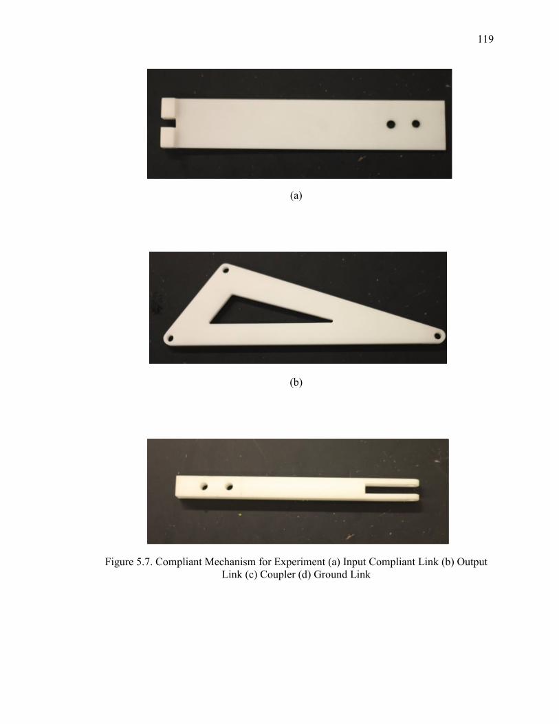
119
(a)
(b)
Figure 5.7. Compliant Mechanism for Experiment (a) Input Compliant Link (b) Output Link (c) Coupler (d) Ground Link
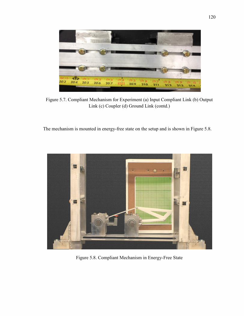
120
Figure 5.7. Compliant Mechanism for Experiment (a) Input Compliant Link (b) Output
Link (c) Coupler (d) Ground Link (contd.)
The mechanism is mounted in energy-free state on the setup and is shown in Figure 5.8.
Figure 5.8. Compliant Mechanism in Energy-Free State
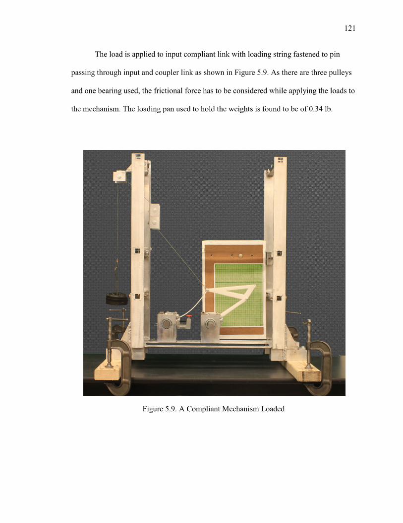
121
The load is applied to input compliant link with loading string fastened to pin
passing through input and coupler link as shown in Figure 5.9. As there are three pulleys
and one bearing used, the frictional force has to be considered while applying the loads to
the mechanism. The loading pan used to hold the weights is found to be of 0.34 lb.
Figure 5.9. A Compliant Mechanism Loaded
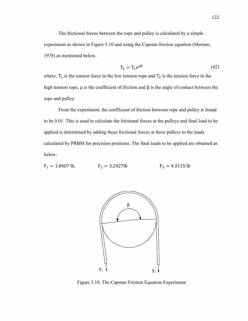
122
The frictional forces between the rope and pulley is calculated by a simple
experiment as shown in Figure 5.10 and using the Capstan friction equation (Meriam,
1978) as mentioned below.
T = T+e�d (42)
where, T+ is the tension force in the low tension rope and T is the tension force in the
high tension rope, μ is the coefficient of friction and β is the angle of contact between the
rope and pulley.
From the experiment, the coefficient of friction between rope and pulley is found
to be 0.01. This is used to calculate the frictional forces at the pulleys and final load to be
applied is determined by adding these frictional forces at three pulleys to the loads
calculated by PRBM for precision positions. The final loads to be applied are obtained as
below:
F+ = 1.8407lb,F = 3.2427lbF� = 4.3115lb
Figure 5.10. The Capstan Friction Equation Experiment
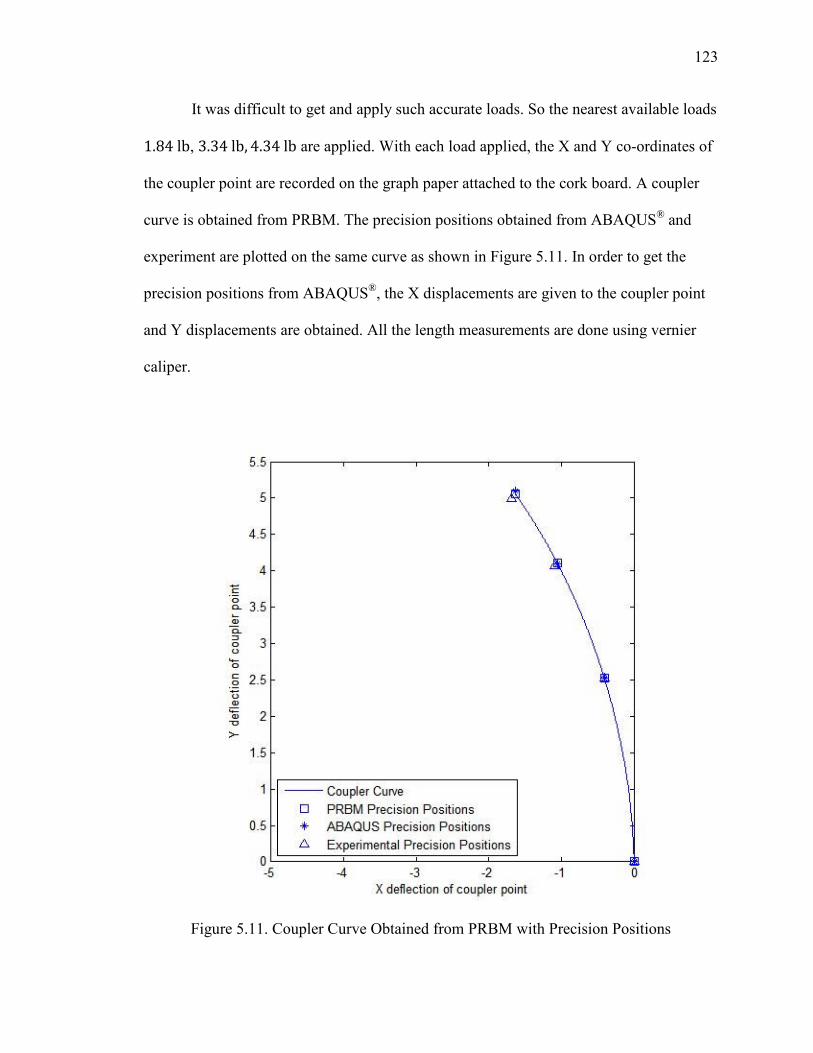
123
It was difficult to get and apply such accurate loads. So the nearest available loads
1.84lb, 3.34lb, 4.34lb are applied. With each load applied, the X and Y co-ordinates of
the coupler point are recorded on the graph paper attached to the cork board. A coupler
curve is obtained from PRBM. The precision positions obtained from ABAQUS® and
experiment are plotted on the same curve as shown in Figure 5.11. In order to get the
precision positions from ABAQUS®, the X displacements are given to the coupler point
and Y displacements are obtained. All the length measurements are done using vernier
caliper.
Figure 5.11. Coupler Curve Obtained from PRBM with Precision Positions

124
5.4. DISCUSSION OF RESULTS
The measured data points are plotted and a smooth coupler curve passing through
those points is drawn. Figure 5.11 shows the coupler curve comparison obtained from
PRBM, FEA and experiment. There are many sources of errors which cause the
deviations in precision positions. Some of them are listed below:
• The loads applied are little higher than the obtained from theoretical calculation.
This may have induced some errors in the deflection,
• All the theoretical calculations are done considering link length and angle
dimensions up to third digit after the decimal point. But while manufacturing it
was very difficult to manufacture the parts with that precision. e.g. The length of
coupler links used in theoretical calculations are R� = 7.926in, R8 = 6.616in, R9 = 2.633in; but the actual parts are manufactured with the
dimensions R� = 7.9in, R8 = 6.6in, R9 = 2.6in.
• The Young's modulus of the beam's material is not provided by the manufacturer.
The value of E is calculated in the lab using PRBM formulae by applying load of
0.84lb and measuring deflection.
• Errors in measurement
• The average values of PRBM parameters such as γ and KF are considered. This
assumption contributed to some extent in the errors.
With these many sources of the error, the results obtained are fairly accurate and
the relative error in the precision position displacements is below 1.58%. With the more
research work in this direction, the errors may be further reduced and accuracy of the
results can be improved.

125
5.5. SUMMARY
In this Section, the experimental setup designed, and manufactured to perform
experiments on compliant cantilever beam and mechanism is presented. The testing
procedure and mechanism synthesized for an experiment are explained with CAD models
and photographs. The path generation with prescribed timing synthesis for three precision
positions with energy specifications synthesis example is provided and the results are
validated by comparing precision positions and energies at precision positions. The
possible sources of error are briefly discussed at the end.
126
6. CONCLUSIONS AND FUTURE WORK
6.1. CONCLUSIONS
The pseudo-rigid-body model (PRBM) naturally enables the use of the vast body
of existing knowledge of rigid-body mechanism synthesis and analysis techniques for
compliant mechanism synthesis and analysis, and vice versa. The synthesis with
compliance technique uses the PRBM concept to synthesize compliant mechanisms for
conventional rigid-body mechanism tasks, e.g. path generation, motion generation, etc.
with energy/torque considerations at the precision positions. The existing synthesis with
compliance technique is reviewed and its limitations in the current form of usage are
discussed with examples. A methodology for synthesis with compliance technique, using
an optimization approach, is developed which overcomes the limitations such as negative
or unrealistic solutions for the critical spring stiffness values. It provides a way to guide
the user as to how the values of the initial estimates should be changed in order to obtain
realistic solutions in fewer number of iterations. This methodology makes the synthesis
procedure computationally simple, expedient and less cumbersome by separating the set
of kinematic equations from the energy/torque equations.
Many of the synthesis cases for the compliant mechanisms, with a four-bar
PRBM, which were not easily solvable by the synthesis with compliance technique, now
were readily solved with the new method. The design tables providing information about
the number of equations, number of unknowns and number of free choices for a pseudo-
rigid-body four-bar mechanism, with varying number of torsional springs for different
synthesis types, may be readily used for synthesis. Recommendations for energy/torque
specifications at the precision positions are given so as to make the solution procedure
127
easy. The strongly coupled and weakly coupled system of kinematic and energy/torque
equations have been studied. It is demonstrated that even solving the synthesis cases
which are characterized as strongly coupled, by treating and solving them as weakly
coupled systems, also readily provide solutions. These solutions are likely subsets from
the entire set of possible solutions to the nonlinear system of equations. The new
approach, for solving equations by treating them as a weakly coupled system, has certain
advantages such as computationally simple, fast and more stable. The user has to assign
reasonable values to a relatively smaller number of variables, as compared to a strongly
coupled system, solved in the conventional way.
Different cases of synthesis have been presented using the proposed technique for
various synthesis tasks of a pseudo-rigid-body four-bar mechanism, for three precision
positions with energy/torque specifications. These include a general synthesis case where
the undeflected state of the mechanism is different from the prescribed precision
positions. The synthesis case, where the undeflected state of the mechanism is coincident
with one of the precision positions, will require a reduced system of equations to be
solved. Different compliant segments have been used in examples to validate the
synthesis technique and the PRBMs. A straight-line generating compliant mechanism,
which could be used in the suspension system of a small robotic vehicle, is synthesized.
The finite element analysis software ABAQUS® and/or ANSYS® are used to analyze the
synthesized compliant mechanism, for the purpose of validation. The experiment was
conducted using a designed compliant mechanism containing one fixed-free segment; the
PRBM results are satisfactorily verified using the FEA and experimental results.
128
6.2. RECOMMENDATIONS
This work presents the use of synthesis with compliance technique, augmented by
incorporating an optimization approach for a pseudo-rigid-body four-bar mechanism for
three precision positions synthesis problems. This method is also applicable to synthesis
cases with more than three precision positions. A distinct possibility exists, since the
kinematic and energy/torque equations are separated from each other (treated as a weakly
coupled system), that we should be able to use the proposed technique to synthesize
compliant mechanisms which have PRBMs other than four-bar mechanisms, e.g. five-bar
mechanisms, etc.
The PRBMs used in this work, for the fixed-free compliant segment and the
fixed-guided compliant segment, assumes the average values of the PRBM parameters,
such as characteristic radius factor and stiffness coefficient. This assumption introduces
some errors in the results. More accurate results may be obtained by the use of variable
PRBM parameters as functions of the load factor.
The experiment has been performed on a compliant mechanism synthesized for
three precision positions with energy specifications, and consisting of one fixed-free
compliant segment. The results go a long way to validate the usefulness of the proposed
method as well as the PRBM concept. In future work, extensive experimental validation
should be conducted involving more complex compliant mechanisms, with different
compliant segment types, for different synthesis tasks and with more precision positions,
and for torque specification cases also.
Metallic inserts could be used in the segments to synthesize compliant
mechanisms with low creep and higher strength properties.
129
BIBLIOGRAPHY
Albanesi, A. E., Fachinotti, V. D., and Pucheta, M. A., 2010, "A Review on Design Methods for Compliant Mechanisms," Asociación Argentina de Mecánica
Computacional, Mecánica Computacional Vol. XXIX, pp. 59-72.
Anantsuresh, G. K., 1994, "A New Design Paradigm for Micro-Electro-Mechanical Systems and Investigation on the Compliant Mechanism Synthesis," Ph.D. Thesis, University of Michigan, Ann Arbor. Annamalai, Y., 2003, "Compliant Mechanism Synthesis for Energy and Torque Specifications," M.S. Thesis, University of Missouri-Rolla. Bisshopp, K.E., and Drucker, D.C., 1945, "Large Deflection of Cantilever Beams," Quarterly of Applied Mathematics, Vol. 3, No. 3, pp. 272-275. Barlas, F., 2004, "Design of a mars Rover Suspension Mechanism," M.S. Thesis, Izmir Institute of Technology, Turkey. Burns, R. H., 1964, "The Kinenostatic Synthesis of Flexible Link Mechanisms," Ph.D. Dissertation, Yale University. Burns, R. H., and Crossley, F. R. E., 1968, "Kinetostatic Synthesis of Flexible Link Mechanisms," ASME Paper 68-Mech-36. Dado, M. H., 2000, "Variable Parametric Pseudo-Rigid-Body Model for Large-Deflection Beams with End Loads," International Journal of Non-Linear Mechanics, Vol. 36 pp. 1123-1133. Dado, M. H., 2005, "Limit Position Synthesis and Analysis of Compliant 4-Bar Mechanisms with Specified Energy Levels Using Variable Parametric Pseudo-Rigid-Body Model," Mechanism and Machine Theory Vol. 40, No.8 pp. 977-992. Erdman, A. G., and Sandor, G. N., 1997, Mechanism Design and Analysis, Vol.1, 3rd Ed., Prentice Hall, Upper Saddle River, NJ. Frecker, M. I., Ananthasuresh, G. K., Nishiwaki, S., Kikuchi, N., and Kota, S., 1997, " Topological Synthesis of Compliant Mechanisms Using Multi-Criteria Optimization," Journal of Mechanisms, Transmissions, and Automation in Design, Trans. ASME, Vol. 119, pp. 238-245. Frish-Fay, R., 1962, Flexible Bars, Butterworths, London. Harrison, H.B., 1973, “Post-Buckling Analysis of Non-Uniform Elastic Columns,” International Journal for Numerical Methods in Engineering, Vol. 7, pp. 196-210.
130
Her, I., 1986, “Methodology for Compliant Mechanism Design,” Ph.D. Dissertation, Purdue University. Her, I., and Midha, A., 1987, “A Compliance Number Concept for Compliant Mechanism, and Type Synthesis,” Journal of Mechanisms, Transmissions, and
Automation in Design, Trans. ASME, Vol. 109, No. 3, pp. 348-355. Her, I., Midha, A., and Salamon, B. A., 1992, "A Methodology for Compliant Mechanisms Design: Part II - Shooting Method and Application", Advances in design
Automation, (Ed.: D. A. Hoeltzel), DE-Vol. 44-2, 18th ASME Design Automation Conference, pp. 39-45. Hill, T.C., and Midha, A., 1990, “A Graphical User-Driven Newton-Raphson Technique for the use in the Analysis and Design of Compliant Mechanisms,” Journal of
Mechanisms, Transmissions, and Automation in Design, Trans. ASME, Vol. 112, No. 1, pp. 123-130. Howell, L. L., and A. Midha, 1994, "A Method for the Design of Compliant Mechanisms with Small-Length Flexural Pivots," Journal of Mechanisms, Transmissions, and
Automation in Design, Trans. ASME, Vol. 116, No. 1, pp. 280-290. Howell, L. L., and Midha, A., 1995, "Parametric Deflection Approximations for End Loaded, Large-Deflection Beams in Compliant Mechanisms," Journal of Mechanisms,
Transmissions, and Automation in Design, Trans. ASME, Vol.117, No.1, pp. 156-165. Howell, L. L., 2001, Compliant Mechanisms, John Wiley and Sons, Inc., New York, New York. Howell, L. L., and Midha, A., 1996, "A Loop-Closure Theory for the Analysis and Synthesis of Compliant Mechanisms," Journal of Mechanisms, Transmissions, and
Automation in Design, Trans. ASME, Vol. 118, No.1, pp. 121-125. Howell, L. L., 1991, "The Design and Analysis of Large-Deflection Members in Compliant Mechanisms," M.S. Thesis, Purdue University. Howell, L. L., and Midha, A., 1994, "A Generalized Loop-Closure Theory for the Analysis and Synthesis of Compliant Mechanisms, "Machine Elements and Machine
Dynamics, (Eds.: G. R. Pennock et al.), D E-Vol. 71, 23rd Biennial ASME Mechanisms Conference, pp. 491-500. Howell, L. L., 1993, "A Generalized Loop-Closure Theory for the Analysis and Synthesis of Compliant Mechanisms," Ph.D. Dissertation, Purdue University. Kolachalam, S. K., 2003, "Synthesis of Compliant Single-Strip Mechanisms that may be Represented by a Dyad," M.S. Thesis, University of Missouri-Rolla.
131
Krovi, V., Ananthsuresh, G. K., and Kumar, V., 2002, "Kinematic and Kinetostatic Synthesis of Planar coupled Serial Chain Mechanisms," Journal of Mechanisms,
Transmissions, and Automation in Design, Trans. ASME, Vol. 124, No.2, pp. 301-312. Lu, K. J., and Kota, S., 2003, "Design of Compliant Mechanisms for Morphing Structural Shapes," Journal of Intelligent Systems and Structures, Vol. 14, pp. 379-391. Mallik, A. K., Ghosh, A., Dittrich, G., 1994, Kinematic Analysis and Synthesis of
Mechanisms, CRC Press Inc., Boca Reton, Florida. Mattiason, K., 1981, "Numerical Resukts from Large Deflection Beam and Frame Problmes Analyzed by means of Elliptic Integrals," International Journal for Numerical
Methods in Engineering, pp. 145-153. Meriam, J. L., 1978, Engineering Mechanics Volume 1, STATICS, J. Wiley & Sons, pp. 301-302. Mettlach, G. A., and Midha, A., 1995, "Four-Precision-Point-Synthesis of Compliant Mechanisms using Burmester Theory," Proceedings of the 4th National Applied
Mechanisms and Robotics Conference, Vol. II, Cincinnati, Ohio, pp. 63-01 - 63-08. Mettlach, G. A., 1996, "Analysis and Design of Compliant Mechanisms using Analytical and Graphical Techniques," Ph.D. Dissertation, Purdue University. Mettlach, G.A., and Midha, A., 1999, “Characteristic Deflection Domain Concept in Compliant Mechanism Design and Analysis,” Proceedings of the 6
th National Applied
Mechanisms and Robotics Conference, Cincinnati, Ohio, pp. 27-1 – 27-6. Midha, A., Her, I., and Salamon, B.A., 1992, “A Methodology for Compliant Mechanisms Design: Part I – Introduction and Large Deflection Analysis,” Advances in
Design Automation, (Ed.: D.A. Hoeltzel), DE-Vol. 44-2, 18th ASME Design Automation Conference, pp. 29-38. Midha, A., Her, I., and Salamon, B.A., 1992a, “On the Nomenclature and Classification of Compliant Mechanisms: The Components of Mechanisms," Flexible Mechanisms,
Dynamics and Analysis, (Eds.: G. Kinzel et al.), DE-Vol. 47, 22nd Biennial ASME Mechanisms Conference, pp. 237-245. Midha, A., Her, I., and Salamon, B.A., 1992b, “On the Nomenclature and Classification of Compliant Mechanisms: Abstractions of Mechanisms, and Mechanism Synthesis Problems,” Flexible Mechanisms, Dynamics and Analysis, (Eds.: G. Kinzel et al.), DE-Vol. 47, 22nd Biennial ASME Mechanisms Conference, pp. 222-235.
132
Midha, A., Norton T. W. and Howell, L. L. 1994 "On the Nomenclature, Classification, and Abstractions of Compliant Mechanisms," Journal of Mechanisms, Transmissions,
and Automation in Design, Trans. ASME, Vol. 116, No. 1, pp. 270-279. Midha, A., Christensen, M. N., and Erickson, M. J., 1997, "On the Enumeration and Synthesis of Compliant Mechanisms using Pseudo-Rigid-Body Four-Bar Mechanism," Proceedings of the 5th National Applied Mechanisms & Robotics Conference, Vol. 2, Cincinnati, Ohio, pp. 93-01 - 93-08. Midha, A., Howell, L. L., and Norton T. W.2000 "Limit Positions of Compliant Mechanisms Using the Pseudo-Rigid-Body-Model Concept," Mechanism and Machine
Theory, Vol. 35, No. 1, pp. 99-115. Midha, A., Annamalai, Y., and Kolachalam, S. K., 2004, "A Compliant Mechanism Design Methodology for Coupled and Uncoupled Systems, and Governing Free Choice Selection Considerations" Proceedings of DETC'04 ASME Design Engineering Technical
Conferences and Computers and Information in Engineering Conference, Salt Lake City, Utah, pp. 57579-1-9. Midha, A., Kolachalam, S. K., and Annamalai, Y., 2011, "On the Classification of Compliant Mechanisms and Synthesis Compliant of Single-Strip Mechanisms" Proceedings of the ASME 2011 International Design Engineering Technical Conferences
& Computers and Information in Engineering Conference, Washington, DC pp. 71400-1-10. Midha, A., Bapat, S., Mavanthoor, A., and Chinta V., 2012, “Analysis of a Fixed-Guided Compliant Beam with an Inflection Point Using the Pseudo-Rigid-Body Model (PRBM) Concept,” Proceedings of the ASME 2012 International Design Engineering Technical
Conferences & Computers and Information in Engineering Conference, Chicago, IL, pp. 71400-1-10 Miller, R.E., 1980, “Numerical Analysis of a Generalized Plane Elastica,” International
Journal for Numerical Methods in Engineering, Vol. 15, pp. 325-332. Murphy, M.D., 1993, “A Generalized Theory for the Type Synthesis and Design of Compliant Mechanisms,” Ph.D. Dissertation, Purdue University. Murphy, M. D., Midha, A., and Howell, L. L., 1994, "The Topological Synthesis of Compliant Mechanisms," Machine Elements and machine Dynamics: Proceedings of the
1994 ASME Mechanisms Conference, DE-Vol. 71, pp. 475-479. Nocedal, J., Wright S.J., 2006, Numerical Optimization, Second Edition, Springer Science + Business Media, LLC, New York. Norton, R. L., 1999, Design of Machinery, McGraw-Hill, Boston, Massachusetts.
133
Norton, T.W., 1991, “On the Nomenclature, Classification, and Mobility of Compliant Mechanisms,” M.S. Thesis, Purdue University. Norton, T. W., Howell, L. L., and Midha, A., 1993, "On the Graphical Synthesis Techniques for Planar Four-Bar Mechanisms: Limit Positions and High Performance,' Section 4.5, Modern Kinematics: Developments in the Last Forty Years, (Ed.: A. G. Erdman), John Wiley and Sons, Inc, New York, New York. Pauly, J., 2002, "Analysis of Compliant Mechanisms with Complex-Shaped Segments," M.S. Thesis, University of Missouri - Rolla. Rao, S. S., Engineering Optimization: Theory and Practice, John Wiley and Sons, Inc., Fourth Edition, New Jersey. Saggere, L., and Kota, S., 2001, "Synthesis of Planar, Compliant Four-Bar Mechanisms for Compliant-Segment Motion Generation," Journal of Mechanisms, Transmissions, and
Automation in Design, Trans. ASME, Vol. 123, No. 4, pp. 535-541. Sandor, G.N., and Erdman, A.G., 1984, Mechanism Design: Analysis and Synthesis, Vol. 2, Prentice Hall, Upper Saddle River, NJ. Sevak, N. M., and McLarnan, C. W., 1974, "Optimal Synthesis of Flexible Link Mechanisms with Large Static Deflections," Journal of Engineering for Industry, Trans. ASME, Vol.97,No. 2, pp. 520-526. Shoup, T.E., and Mclarnan, C.W. 1971, “On the Use of the Undulating Elastica for the Analysis of Flexible Link Devices,” Journal of Engineering for Industry, Trans. ASME, pp. 263-267. Shoup, T.E., 1972, “On the Use of Nodal Elastica for the Analysis of Flexible Link Devices,” Journal of Engineering Industry, Trans. ASME, Vol. 94, No. 3, pp. 871-875. Su, H-J., and McCarthy, J. M., 2007, "Synthesis of Bistable Compliant Four-Bar Mechanisms Using Polynomial Homotopy," Journal of Mechanisms, Transmissions, and
Automation in Design, Trans. ASME, Vol. 129, No.10, pp. 1094-1098. Tari, H., and Su H-J., 2011, "A Complex Solution Framework for the Kinetostatic Synthesis of a Compliant Four-Bar Mechanism," Mechanism and Machine Theory, Vol. 46, pp. 1137-1152.
Zhang, A., and Chen, G., 2012, "A Comprehensive Elliptic Integral Solution to the Large Deflection Problem in Compliant Mechanisms," Proceedings of the ASME 2012
International Design Engineering Technical Conferences & Computers and Information
in Engineering Conference, August 12-15, 2012, Chicago, pp. 70239-1-10.

APPENDIX A
RELATIVE ERROR CALCULATION
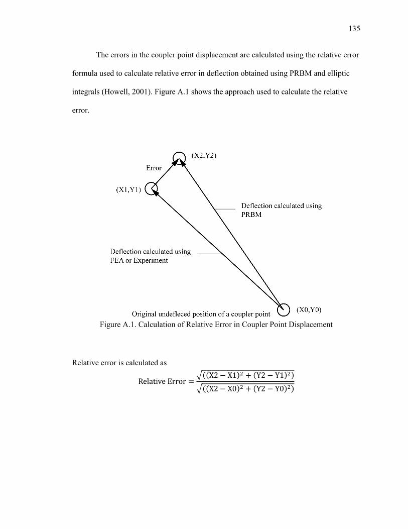
135
The errors in the coupler point displacement are calculated using the relative error
formula used to calculate relative error in deflection obtained using PRBM and elliptic
integrals (Howell, 2001). Figure A.1 shows the approach used to calculate the relative
error.
Figure A.1. Calculation of Relative Error in Coupler Point Displacement
Relative error is calculated as
RelativeError = �''X2 − X1. + 'Y2 − Y1. .�''X2 − X0. + 'Y2 − Y0. .

APPENDIX B
MATLAB® CODES
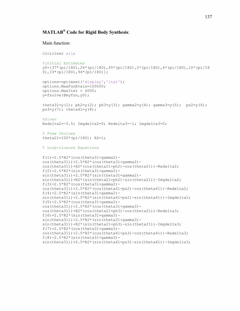
137
MATLAB® Code for Rigid Body Synthesis:
Main function:
clc;clear all;
%Initial Estimates y0=[37*(pi/180),24*(pi/180),45*(pi/180),2*(pi/180),6*(pi/180),10*(pi/18
0),19*(pi/180),94*(pi/180)];
options=optimset('display','iter'); options.MaxFunEvals=100000; options.MaxIter = 4000; y=fsolve(@myfun,y0);
theta31=y(1); ph2=y(2); ph3=y(3); gamma2=y(4); gamma3=y(5); ps2=y(6);
ps3=y(7); theta41=y(8);
%Given Redelta2=-0.5; Imgdelta2=0; Redelta3=-1; Imgdelta3=0;
% Free Choices theta21=100*(pi/180); R2=1;
% Loop-closure Equations
f(1)=2.5*R2*(cos(theta31+gamma2)-
cos(theta31))+2.5*R2*(cos(theta31+gamma2)-
cos(theta31))+R2*(cos(theta21+ph2)-cos(theta21))-Redelta2; f(2)=2.5*R2*(sin(theta31+gamma2)-
sin(theta31))+2.5*R2*(sin(theta31+gamma2)-
sin(theta31))+R2*(sin(theta21+ph2)-sin(theta21))-Imgdelta2; f(3)=2.5*R2*(cos(theta31+gamma2)-
cos(theta31))+2.5*R2*(cos(theta41+ps2)-cos(theta41))-Redelta2; f(4)=2.5*R2*(sin(theta31+gamma2)-
sin(theta31))+2.5*R2*(sin(theta41+ps2)-sin(theta41))-Imgdelta2; f(5)=2.5*R2*(cos(theta31+gamma3)-
cos(theta31))+2.5*R2*(cos(theta31+gamma3)-
cos(theta31))+R2*(cos(theta21+ph3)-cos(theta21))-Redelta3; f(6)=2.5*R2*(sin(theta31+gamma3)-
sin(theta31))+2.5*R2*(sin(theta31+gamma3)-
sin(theta31))+R2*(sin(theta21+ph3)-sin(theta21))-Imgdelta3; f(7)=2.5*R2*(cos(theta31+gamma3)-
cos(theta31))+2.5*R2*(cos(theta41+ps3)-cos(theta41))-Redelta3; f(8)=2.5*R2*(sin(theta31+gamma3)-
sin(theta31))+2.5*R2*(sin(theta41+ps3)-sin(theta41))-Imgdelta3;
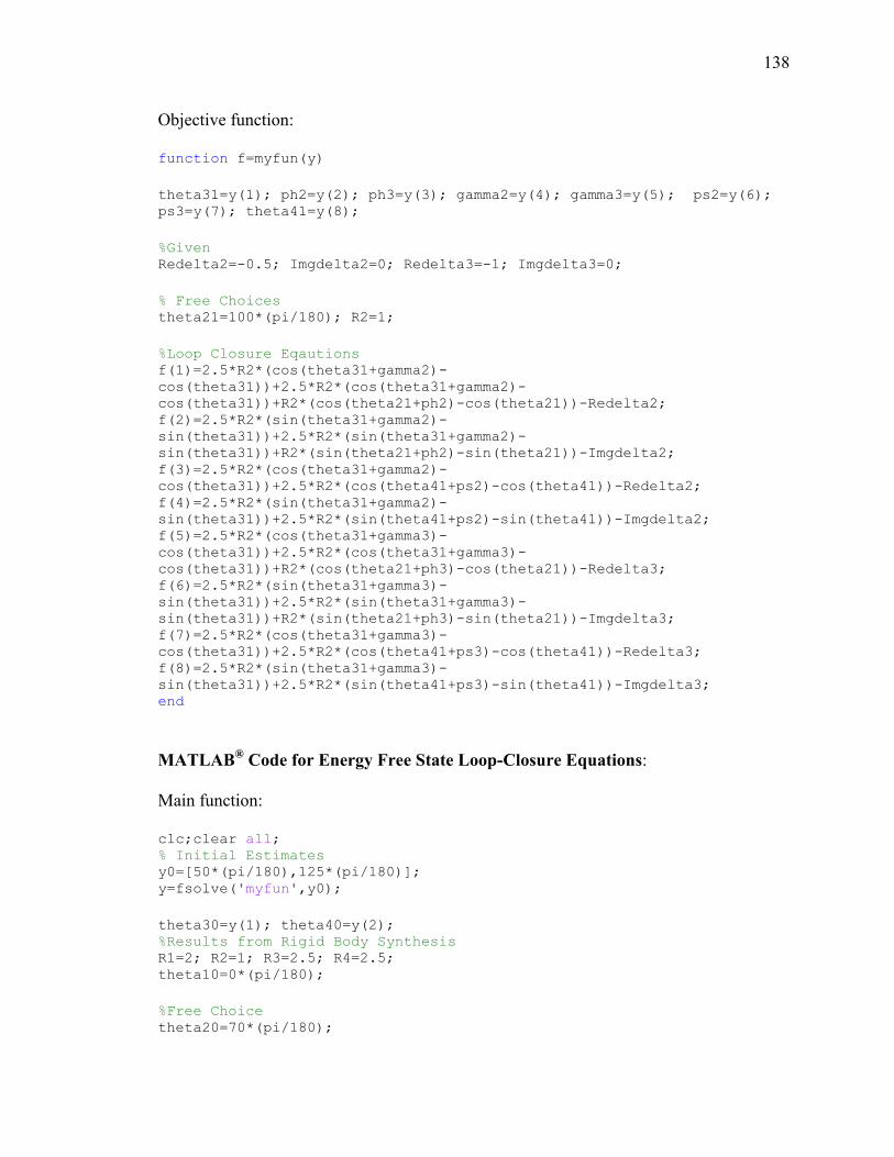
138
Objective function:
function f=myfun(y)
theta31=y(1); ph2=y(2); ph3=y(3); gamma2=y(4); gamma3=y(5); ps2=y(6);
ps3=y(7); theta41=y(8);
%Given Redelta2=-0.5; Imgdelta2=0; Redelta3=-1; Imgdelta3=0;
% Free Choices theta21=100*(pi/180); R2=1;
%Loop Closure Eqautions f(1)=2.5*R2*(cos(theta31+gamma2)-
cos(theta31))+2.5*R2*(cos(theta31+gamma2)-
cos(theta31))+R2*(cos(theta21+ph2)-cos(theta21))-Redelta2; f(2)=2.5*R2*(sin(theta31+gamma2)-
sin(theta31))+2.5*R2*(sin(theta31+gamma2)-
sin(theta31))+R2*(sin(theta21+ph2)-sin(theta21))-Imgdelta2; f(3)=2.5*R2*(cos(theta31+gamma2)-
cos(theta31))+2.5*R2*(cos(theta41+ps2)-cos(theta41))-Redelta2; f(4)=2.5*R2*(sin(theta31+gamma2)-
sin(theta31))+2.5*R2*(sin(theta41+ps2)-sin(theta41))-Imgdelta2; f(5)=2.5*R2*(cos(theta31+gamma3)-
cos(theta31))+2.5*R2*(cos(theta31+gamma3)-
cos(theta31))+R2*(cos(theta21+ph3)-cos(theta21))-Redelta3; f(6)=2.5*R2*(sin(theta31+gamma3)-
sin(theta31))+2.5*R2*(sin(theta31+gamma3)-
sin(theta31))+R2*(sin(theta21+ph3)-sin(theta21))-Imgdelta3; f(7)=2.5*R2*(cos(theta31+gamma3)-
cos(theta31))+2.5*R2*(cos(theta41+ps3)-cos(theta41))-Redelta3; f(8)=2.5*R2*(sin(theta31+gamma3)-
sin(theta31))+2.5*R2*(sin(theta41+ps3)-sin(theta41))-Imgdelta3; end
MATLAB® Code for Energy Free State Loop-Closure Equations:
Main function:
clc;clear all; % Initial Estimates y0=[50*(pi/180),125*(pi/180)]; y=fsolve('myfun',y0);
theta30=y(1); theta40=y(2); %Results from Rigid Body Synthesis R1=2; R2=1; R3=2.5; R4=2.5; theta10=0*(pi/180);
%Free Choice theta20=70*(pi/180);
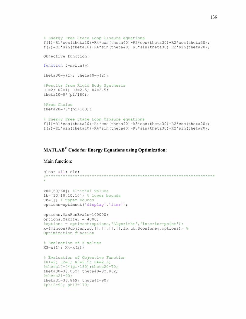
139
% Energy Free State Loop-Closure equations f(1)=R1*cos(theta10)+R4*cos(theta40)-R3*cos(theta30)-R2*cos(theta20); f(2)=R1*sin(theta10)+R4*sin(theta40)-R3*sin(theta30)-R2*sin(theta20);
Objective function:
function f=myfun(y)
theta30=y(1); theta40=y(2);
%Results from Rigid Body Synthesis R1=2; R2=1; R3=2.5; R4=2.5; theta10=0*(pi/180);
%Free Choice theta20=70*(pi/180);
% Energy Free State Loop-Closure equations f(1)=R1*cos(theta10)+R4*cos(theta40)-R3*cos(theta30)-R2*cos(theta20); f(2)=R1*sin(theta10)+R4*sin(theta40)-R3*sin(theta30)-R2*sin(theta20);
MATLAB® Code for Energy Equations using Optimization:
Main function:
clear all; clc; %**********************************************************************
*
x0=[60;60]; %Initial values lb=[10,10,10,10]; % lower bounds ub=[]; % upper bounds options=optimset('display','iter');
options.MaxFunEvals=100000; options.MaxIter = 4000; %options = optimset(options,'Algorithm','interior-point'); x=fmincon(@objfun,x0,[],[],[],[],lb,ub,@confuneq,options); %
Optimization function
% Evaluation of K values K3=x(1); K4=x(2);
% Evaluation of Objective Function %R1=2; R2=1; R3=2.5; R4=2.5; %theta10=0*(pi/180);theta20=70; theta30=38.052; theta40=82.862; %theta21=90; theta31=36.869; theta41=90; %phi2=90; phi3=170;
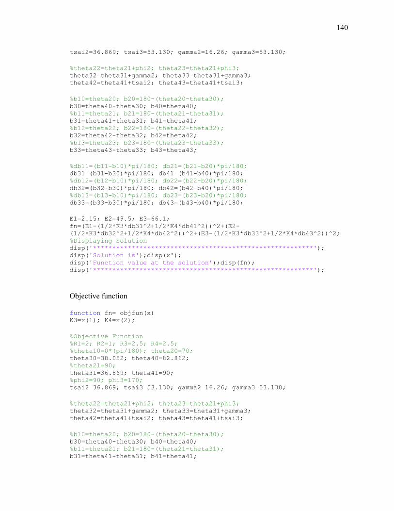
140
tsai2=36.869; tsai3=53.130; gamma2=16.26; gamma3=53.130;
%theta22=theta21+phi2; theta23=theta21+phi3; theta32=theta31+gamma2; theta33=theta31+gamma3; theta42=theta41+tsai2; theta43=theta41+tsai3;
%b10=theta20; b20=180-(theta20-theta30); b30=theta40-theta30; b40=theta40; %b11=theta21; b21=180-(theta21-theta31); b31=theta41-theta31; b41=theta41; %b12=theta22; b22=180-(theta22-theta32); b32=theta42-theta32; b42=theta42; %b13=theta23; b23=180-(theta23-theta33); b33=theta43-theta33; b43=theta43;
%db11=(b11-b10)*pi/180; db21=(b21-b20)*pi/180; db31=(b31-b30)*pi/180; db41=(b41-b40)*pi/180; %db12=(b12-b10)*pi/180; db22=(b22-b20)*pi/180; db32=(b32-b30)*pi/180; db42=(b42-b40)*pi/180; %db13=(b13-b10)*pi/180; db23=(b23-b20)*pi/180; db33=(b33-b30)*pi/180; db43=(b43-b40)*pi/180;
E1=2.15; E2=49.5; E3=66.1; fn=(E1-(1/2*K3*db31^2+1/2*K4*db41^2))^2+(E2-
(1/2*K3*db32^2+1/2*K4*db42^2))^2+(E3-(1/2*K3*db33^2+1/2*K4*db43^2))^2; %Displaying Solution disp('*********************************************************'); disp('Solution is');disp(x'); disp('Function value at the solution');disp(fn); disp('*********************************************************');
Objective function
function fn= objfun(x) K3=x(1); K4=x(2);
%Objective Function %R1=2; R2=1; R3=2.5; R4=2.5; %theta10=0*(pi/180); theta20=70; theta30=38.052; theta40=82.862; %theta21=90; theta31=36.869; theta41=90; %phi2=90; phi3=170; tsai2=36.869; tsai3=53.130; gamma2=16.26; gamma3=53.130;
%theta22=theta21+phi2; theta23=theta21+phi3; theta32=theta31+gamma2; theta33=theta31+gamma3; theta42=theta41+tsai2; theta43=theta41+tsai3;
%b10=theta20; b20=180-(theta20-theta30); b30=theta40-theta30; b40=theta40; %b11=theta21; b21=180-(theta21-theta31); b31=theta41-theta31; b41=theta41;
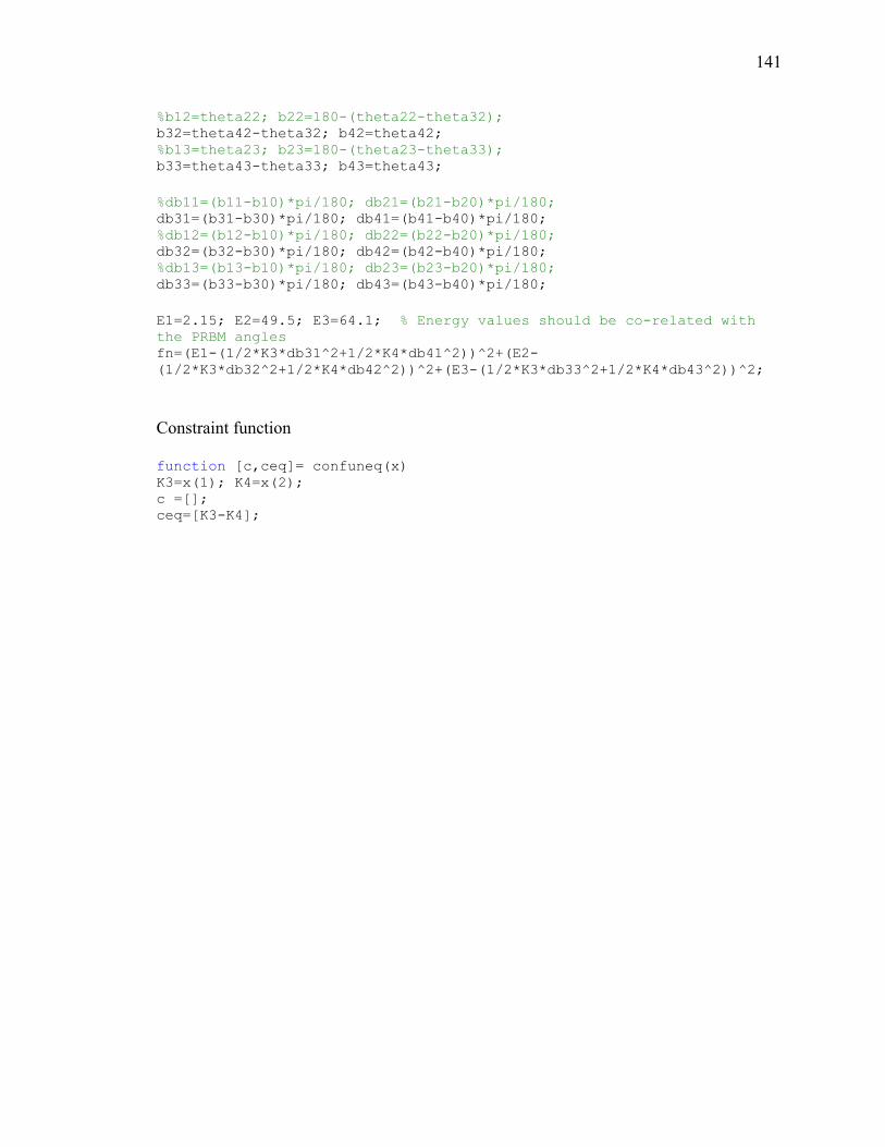
141
%b12=theta22; b22=180-(theta22-theta32); b32=theta42-theta32; b42=theta42; %b13=theta23; b23=180-(theta23-theta33); b33=theta43-theta33; b43=theta43;
%db11=(b11-b10)*pi/180; db21=(b21-b20)*pi/180; db31=(b31-b30)*pi/180; db41=(b41-b40)*pi/180; %db12=(b12-b10)*pi/180; db22=(b22-b20)*pi/180; db32=(b32-b30)*pi/180; db42=(b42-b40)*pi/180; %db13=(b13-b10)*pi/180; db23=(b23-b20)*pi/180; db33=(b33-b30)*pi/180; db43=(b43-b40)*pi/180;
E1=2.15; E2=49.5; E3=64.1; % Energy values should be co-related with
the PRBM angles fn=(E1-(1/2*K3*db31^2+1/2*K4*db41^2))^2+(E2-
(1/2*K3*db32^2+1/2*K4*db42^2))^2+(E3-(1/2*K3*db33^2+1/2*K4*db43^2))^2;
Constraint function
function [c,ceq]= confuneq(x) K3=x(1); K4=x(2); c =[]; ceq=[K3-K4];

142
VITA
Ashish Bharat Koli was born in 1987 in India. He received his Bachelor’s degree
in Mechanical Engineering from Walchand College of Engineering in Sangli, India, in
June 2008. After undergraduate school, he worked in Hindustan Petroleum Corporation
Ltd. for two years. He was admitted to a Master of Science degree program in
Mechanical Engineering at Missouri University of Science and Technology, Rolla, MO,
in the Fall semester, 2010, and graduated in May 2013.

Related Documents


