Acta Astronautica 65 (2009) 365 – 375 www.elsevier.com/locate/actaastro A free-standing space elevator structure: A practical alternative to the space tether B.M. Quine a, b, ∗ , R.K. Seth b , Z.H. Zhu a a Department of Earth and Space Science and Engineering, York University, 4700 Keele Street, Toronto, Ontario, Canada M3J 1P3 b Department of Physics and Astronomy, York University, 4700 Keele Street, Toronto, Ontario, Canada M3J 1P3 Received 16 October 2007; accepted 27 February 2009 Available online 19 April 2009 Abstract Space tethers have been investigated widely as a means to provide easy access to space. However, the design and construction of such a device presents significant unsolved technological challenges. We propose an alternative approach to the construction of a space elevator that utilizes a free-standing core structure to provide access to near space regions and to reduce the cost of space launch. The structure is comprised of pneumatically inflated sections that are actively controlled and stabilized to balance external disturbances and support the structure. Such an approach avoids problems associated with a space tether including material strength constraints, the need for in-space construction, the fabrication of a cable at least 50,000 km in length, and the ageing and meteorite-damage effects associated with a thin tether or cable in Low Earth Orbit. An example structure constructed at 5km altitude and extending to 20km above sea level is described. The stability and control of the structure, methods for construction and its utility for space launch and other applications are discussed. © 2009 Elsevier Ltd. All rights reserved. Keywords: Space elevator; Cantilevered beam; Pneumatic structure 1. Introduction To access space or near space, payloads must gain significant potential and kinetic energy. Traditionally, regions above aircraft altitude are accessed using rock- etry, where mass is expelled at high velocity in order to achieve thrust in the opposite direction. This pro- cess is extremely inefficient as rockets must counter the gravitational force during the flight by carrying mass in ∗ Corresponding author at: Department of Earth and Space Science and Engineering, York University, 4700 Keele Street, Toronto, Ontario, Canada M3J 1P3. Tel.: +14167362100; fax: +1 416 7365817. E-mail address: [email protected] (B.M. Quine). 0094-5765/$ - see front matter © 2009 Elsevier Ltd. All rights reserved. doi:10.1016/j.actaastro.2009.02.018 the form of propellant and must overcome atmospheric drag. In contrast, if a payload is at least partially hauled to space or near space along an elevator system, the work done is significantly less as no expulsion mass must be carried to do work against gravity, and lower ascent speeds in the atmosphere can virtually elimi- nate atmospheric drag. Elevator cars’ motion may also be powered remotely by electrical or inductive means, eliminating the need to carry any fuel. Stations can be provided that are stationary in space and, consequently, leverage the advantages offered by geostationary orbit but from a vantage point both closer and physically con- nected to the surface. In this paper, we describe the design concept for a space elevator based on a self-supporting core structure that is pressurized pneumatically and controlled actively

Welcome message from author
This document is posted to help you gain knowledge. Please leave a comment to let me know what you think about it! Share it to your friends and learn new things together.
Transcript
Acta Astronautica 65 (2009) 365–375www.elsevier.com/locate/actaastro
A free-standing space elevator structure: A practical alternative to thespace tether
B.M. Quinea,b,∗, R.K. Sethb, Z.H. ZhuaaDepartment of Earth and Space Science and Engineering, York University, 4700 Keele Street, Toronto, Ontario, Canada M3J 1P3
bDepartment of Physics and Astronomy, York University, 4700 Keele Street, Toronto, Ontario, Canada M3J 1P3
Received 16 October 2007; accepted 27 February 2009Available online 19 April 2009
Abstract
Space tethers have been investigated widely as a means to provide easy access to space. However, the design and constructionof such a device presents significant unsolved technological challenges. We propose an alternative approach to the constructionof a space elevator that utilizes a free-standing core structure to provide access to near space regions and to reduce the cost ofspace launch. The structure is comprised of pneumatically inflated sections that are actively controlled and stabilized to balanceexternal disturbances and support the structure. Such an approach avoids problems associated with a space tether includingmaterial strength constraints, the need for in-space construction, the fabrication of a cable at least 50,000km in length, and theageing and meteorite-damage effects associated with a thin tether or cable in Low Earth Orbit. An example structure constructedat 5km altitude and extending to 20km above sea level is described. The stability and control of the structure, methods forconstruction and its utility for space launch and other applications are discussed.© 2009 Elsevier Ltd. All rights reserved.
Keywords: Space elevator; Cantilevered beam; Pneumatic structure
1. Introduction
To access space or near space, payloads must gainsignificant potential and kinetic energy. Traditionally,regions above aircraft altitude are accessed using rock-etry, where mass is expelled at high velocity in orderto achieve thrust in the opposite direction. This pro-cess is extremely inefficient as rockets must counter thegravitational force during the flight by carrying mass in
∗Corresponding author at: Department of Earth and SpaceScience and Engineering, York University, 4700 Keele Street,Toronto, Ontario, Canada M3J 1P3. Tel.: +14167362100;fax: +14167365817.
E-mail address: [email protected] (B.M. Quine).
0094-5765/$ - see front matter © 2009 Elsevier Ltd. All rights reserved.doi:10.1016/j.actaastro.2009.02.018
the form of propellant and must overcome atmosphericdrag. In contrast, if a payload is at least partially hauledto space or near space along an elevator system, thework done is significantly less as no expulsion massmust be carried to do work against gravity, and lowerascent speeds in the atmosphere can virtually elimi-nate atmospheric drag. Elevator cars’ motion may alsobe powered remotely by electrical or inductive means,eliminating the need to carry any fuel. Stations can beprovided that are stationary in space and, consequently,leverage the advantages offered by geostationary orbitbut from a vantage point both closer and physically con-nected to the surface.In this paper, we describe the design concept for a
space elevator based on a self-supporting core structurethat is pressurized pneumatically and controlled actively
366 B.M. Quine et al. / Acta Astronautica 65 (2009) 365–375
in order to support the structural load and dampen ex-ternal disturbance forces.
2. Background
It has previously been proposed, most famously byClarke in his 1978 novel, The Fountains of Paradise,that a space elevator could be constructed using a ca-ble and counter-balanced mass system [1]. For Earth’sgravity and spin rate, such a solution requires a cable ofat least 35,000km in length and a counter balance masssimilar to a small asteroid. Such a system could be con-structed by launching the cable into space or manufac-turing it in situ and lowering it into contact with Earth.However, the technological obstacles that must be over-come, including the construction of a cable with suitablestrength characteristics or the in-space construction ofthe apparatus, have not been realized since Clarke pop-ularized the concept. Known materials are simply notstrong enough to enable the construction of a cable ofthat length that would even be capable of supporting itsown weight.Pearson (1975) provided a physical basis for the con-
struction of such a device [2]. Along with Clarke, hereasoned that the tower must be constructed from geo-stationary orbit outwards in both directions in order tokeep the structure in gravitational balance. Using forcederivatives, he calculated that the tower or cable wouldneed to be at least 144,000km long in order to be in bal-ance with a net weight of zero and characteristic of theEarth’s radius, surface gravity, and period of rotation.He proposed an area taper exponent for the structure of0.776r0/h where r0 is the radius of the Earth and h isthe specific strength or characteristic height to which aconstant diameter tower could be built to in a 1g field.Suitable materials can be classified from the relationh = �/�g0 where � is the maximum allowable materialstress and g0 is the surface gravity. Pearson proposedgraphite crystals with a material stress of 46.5GPa anddensity 2200kgm−3 yield a solution with h = 2150kmand a taper ratio of 10 without safety factors applied.Such a structure would certainly have significant utility;payloads ascending to the top of the structure could evenbe injected into escape orbits without the use of rock-etry. However, the construction of the device, requiringinnovations in materials and in space manufacture aswell as at least 24,000 flights of a modified space shuttlewith geostationary capability to raise the constructionmaterial, place severe constraints regarding practicality.Edwards (2000) argues that a counter balance com-
prising spent upper rocket stages (3440kgstage−1)would reduce the cable length to 117,000km and
proposes a ribbon-like structure comprising 1.5�m rib-bons each of mass 5000kg [3]. Assuming a structurecomprising carbon-nanotubes (of density 1300kgm−3
and tensile strength 130GPa) with epoxy compositesections, then four Titan IV/Centaur launches would berequired to deliver to GEO the initial ribbons. Thesewould be capable of sustaining a climbing robot ofmass 528kg with a safety margin of two. Climberswould then haul up and attach with epoxy furthernanotube tapes, each contributing 7.96kg to the loadcapacity of cable and using an average of 42kW ofelectrical power beamed to the climber by a 4GWmicrowave or laser groundstation. After 250 ascents,the cable would be capable of raising a 13,000kg pay-load every five days. This concept is seemly muchmore practical than Pearson’s in-orbit constructionapproach. However, as Edwards identifies, there areother engineering challenges that would seem to placesevere constraints regarding the practicality of such adevice:
(1) Meteorite damage will destroy Earth-to-space ca-bles of dimension less than several centimeterswithin weeks. Construction is therefore a raceagainst time and the completed cable would needcontinuous maintenance and repair. The climberswould need to be able to ascend through a wide va-riety of partially severed cable conditions withoutinducing further failure. Based on the ribbon width,Edwards estimates the probability of a meteor’ssevering one or more of the initial cables at 0.4 peryear. However, the analysis would seem to implythat meteors would strike the cable perpendicularto the width dimension rather than at some acuteangle that would cause much smaller meteorites toinduce ribbon failure.
(2) Low Earth Orbit (LEO) cable impacts from natu-ral and artificial satellites 10cm or larger would beexpected to occur at a rate of 1 impact per year.Consequently, a mechanism to maneuver the cable(perhaps by moving the anchor point) would be re-quired, and a high-accuracy radar tracking programwould be needed to map precisely the orbital tra-jectories of objects intersecting the cable.
(3) Atomic oxygen damage will remove epoxy/nanotube material at a rate of approximately1�mmonth−1. Consequently, a surface coatingwould be required to protect the cable at altitudeswith high atomic oxygen densities. The coatingwould need to be resistive to mechanical abrasion(from the climbers) and would also likely requirereapplication during the lifecycle of the device.
B.M. Quine et al. / Acta Astronautica 65 (2009) 365–375 367
(4) Lightning strikes would pose a significant risk tocable integrity. The construction of the anchor pointat high altitude would reduce the probability of astrike; however, the probability of a nearby strike isestimated at 1 every 13 years based on data gath-ered in Alaska. This figure seems unacceptably highgiven that a single strike is likely to severe the ca-ble entirely. Furthermore, the lightening data doesnot account for the increase in lightening frequencydue to the presence of the cable itself, and, conse-quently, the actual risk is highly uncertain. It seemsunlikely that this problem can be easily mitigated.
Since the original concept was popularized, several al-ternative elevator concepts have been proposed. In 2000,Boyd and Thomas proposed a design for a space el-evator that moves payloads between locations locatedat substantially fixed orbital distances from the Earth[4]. The device incorporates a cable system capable oftransporting payloads between orbital locations lever-aging the energy efficiency of an elevator device thatclimbs the tether. As the device has no part attached tothe Earth’s surface, a secondary means must be utilizedto attach initially the payload to the elevator.In 2004, Dempsey proposed a system and method for
a space elevator comprising a flexible tension structuredeployed above and below geosynchronous altitude [5].In contrast to the traditional tether approach, Dempseyproposes the use of a transport tether shaped into dou-ble catenary with one catenary below synchronous orbitaltitude and the second catenary above synchronous or-bit altitude. The tether configuration forms a harmonicoscillator using a combination of gravitational and cen-tripetal forces with the zero crossing of the harmonicoscillator at an altitude of approximately one half syn-chronous orbit altitude of the attached elevator. Oneend of the tether is substantially attached to an equa-torial surface location enabling transportation from thesurface. The other end of the tether is attached to acounter mass in an orbit above geosynchronous alti-tude. The tether is configured such that it extends downfrom geosynchronous orbit to near the ground, loopsback up to geosynchronous altitude and finally loopsback down to the surface mounting point. An addi-tional tether attached to the surface is utilized to stabi-lize the downward loop and for control of the elevator.Payloads may be raised using centripetal force in anenergy-efficient manner without the need for additionalpower sources; however, the method requires a cablesubstantially longer than Clarke’s original concept and,consequently, is subject to an even greater engineeringchallenge to manufacture a suitable tether.
All such structures rely on the development of ma-terials to construct cables of enormous strength. Themost common approach is the application of carbon-nanotube; however, Pugno (2006) argues that thepresence of microscale defects alone will prevent thefabrication of a cable with sufficient tensile strengtheven if the theoretical strength limit can be realizedin a macroscopic cable [6]. Pugno concludes that ageosynchronous space tether, if built as designed today,will certainly break.Another intriguing proposal for a space elevator is the
space fountain. In this concept, a cable-like structure isconstructed that guides a high-speed mass stream in anevacuated closed loop, usually by superconductingmag-nets. The cable is supported by momentum exchangewith the mass stream. A ground-based station reacceler-ates the mass stream to compensate for losses. A spacestation attached at the top of the cable maintains a geo-stationary position without the need of geosynchronousorbit.Lofstrom (1985) describes launch loop—a 2000km
cable structure anchored at both ends and at intervalsalong its length that extends 80km vertically [7]. Thestructure is maintained by energy and momentum ex-change with a moving ribbon of mass 15.6×10⁷ kg,which is accelerated to 14kms−1 inside the cable. Theribbon is also used for payload acceleration. We es-timate the mass of the structure as 1.5×10⁷ kg fromthe data provided and assuming a single ribbon sys-tem. The main disadvantage of the mass exchange ap-proach is the result of failure of the guiding system.Lofstrom estimates that failure of the ribbon would re-lease 1.5×10¹⁵ J, enough to boil 400,000m3 of water.Since in the authors’ opinion catastrophic failure of thedevice can be expected occasionally, the 2000km struc-ture could not be constructed near populated areas. Thecontainment of a metal ribbon moving at hypersonicvelocity has yet to be demonstrated at any scale. If thistechnology can be realized, it will likely find first ap-plication as a method of energy storage.
3. A free-standing structure
We propose an alternative device to provide accessto the near space and space environments that uti-lizes a self-supporting core structure [8]. The structureprovides a fixed link between ground and near spacelocations enabling the transportation of equipment, per-sonnel and other objects or people to platforms or podsabove the surface of the Earth for the purpose of scien-tific research, communications and tourism. The devicemay be assembled from the surface upwards, avoiding

368 B.M. Quine et al. / Acta Astronautica 65 (2009) 365–375
difficult and expensive in-orbit construction. The space-elevator tower can provide access to lower altituderegions and can also be scaled to access altitudes above15km, or the typical ceiling altitude for commercialaviation. The approach may be further scaled to pro-vide direct access to altitudes above 200km and withthe gravitation potential of Low Earth Orbit withoutthe technical challenges associated with constructing acable at least 35,000km long. The elevator platformsalso have significant advantages over orbiting satelliteplatforms. Geographically fixed but providing access toregions of space closer to the surface than geostation-ary orbit, elevator platforms provide the ideal means tocommunicate over a wide area and to conduct remotesensing and tourism activities. As a tourist destination,the elevator platforms provide stations located at fixedattitudes from the surface for observation. The elevatorplatforms provide the means to access safely a regionof space with a view extending hundreds of kilometers.
4. Structural concept
The device comprises a pneumatically pressurizedcore structure consisting of compartments arranged insegments with equipment decks or pods. The compart-ments are constructed using conventional high stressmaterials such as Kevlar pressurized with a gas mix-ture of low atomic mass such as hydrogen or helium.
platform
segment
controlpods
A B C
platform platform
segment segment
Fig. 1. Core-structure configurations (A, B and C).
An inertial stabilization maintains the attitude of thestructure with respect to the planet surface using a va-riety of methods including pressure balancing and an-gular momentum stabilization.Typical core-structure configurations of the elevator
are shown in Fig. 1. Elevator A has a platform andmain pod with segments arranged in a four-segmentsquare configuration with an open lattice structure tobrace segments together between decks. Elevator B hasa platform and main pod with a segment arrangementof constant exterior diameter and comprising pressur-ized compartments with decks and pods internal tothe segment structure. This option may be desirablefrom a construction perspective and also if the elevatorcars grip the outside diameter of the core. Elevator Chas a platform and main pod with a tapered segmentconfiguration and lattice structure incorporating largepods that intersect the segment structure. A 7.0m scalemodel of a structure similar to Elevator A is shownin Fig. 2. This 1:2000 scale model comprises three0.082m diameter cores braced at intervals of 1.0m(first four intervals) and 1.5m (last two intervals). Theoverall diameter of the structure is 0.34m. Constructedof laminated polyethylene (Young’s modulus of thematerial measured as 258MPa) with an average wallthickness of 0.0013m, the structure has a total mass of17kg excluding the base support and is free-standingwhen pressurized with air above 48,000Pa (7 PSI).

B.M. Quine et al. / Acta Astronautica 65 (2009) 365–375 369
Fig. 2. 7.0m demonstration device installed in stairwell.
4.1. Design analysis
The pressure-cell walls consist of a material with veryhigh tensile strength-to-mass ratio, for example, boronor a Kevlar polyethylene composite at a thickness able toretain the cell pressure with adequate margins of safetyin accordance with engineering practice. Air or gas isused to pressurize the cells using an interlinked networkof plumbing such that cells may be repressurized fromtime to time. At typical surface conditions, atmosphericair has a density of 1.29kgm−3. For a pressurized ves-sel, the pressure variation with altitude may be derivedby consideration of the gravitational force on a unit areaair parcel as: g��z = −�p, where g is the accelera-tion due to gravity (9.8ms−2 on Earth), � is the massdensity of the gas, p is the pressure and z is altitude.At atmospheric pressures the behavior of the gas maybe characterized by the ideal gas law as p = �RT /M ,where R is the universal gas constant, M is the molarmass of the gas and T is the temperature in Kelvin. As-suming a constant cell temperature and approximatinggravity as constant over altitude, we integrate to obtainthe pressure at the top of a cell of altitude z as
p(z) = p0 exp(−z/H ) (1)
where H = RT /gM and is the scale height of the gascolumn and p0 is the base pressure. For Earth’s atmo-sphere, H∼7.6km. The load capacity in kilograms of avertical cylinder of length l and diameter d that has no
structural strength under compression is therefore
L = �d2 p0 exp(−l/H )
4g. (2)
Assuming the case of a simple single cell structure, themass of such a segment is given as
melement = �A�dl. (3)
If the segment is in firm contact with the ground, theapparatus must support only this structural mass as themass of the pressurization gas may be supported fromthe base. If the segment is further up the structure, thesupporting structure must support the segment mass andthe mass of the pressurization gas which is given as
mgas = �0b�d2H (1 − exp(−l/H ))
4(4)
where �0 is the mass density of the gas at one atmo-sphere and b is the gas pressure at the base in Bar.This expression can also be used to compute the buoy-ant mass that provides some support for the core. Thecenter of gravity of the support gas is given by
zcof g = H (1 − (1 + l/H ) exp(−l/H ))
(1 − exp(−l/H ))(5)
Other gases may be utilized with lower molecularmasses than that of air. The mass advantages of otherpressurization gases may be approximated by the ratioof their molecular mass with that of nitrogen gas (thedominant constituent of atmospheric air). Thus a struc-ture pressurized with hydrogen will require 28/2= 14times less gas by mass and with helium 28/4= 7 timesless.The force required to buckle a simple column similar
to elevator structure B under load is given as:
Lbuckling = �2E I
l ′2, (6)
where l′ is the effective column length depending on theboundary conditions of the column, E is the effectiveYoung’s modulus of the thin-walled column when thecore is pressurized and I is the moment of inertia ofcross-sectional area. Assuming that the elevator core isfixed at the base and gyroscopically pinned at the top,then l′ = l. For a thin-walled circular-section cylinder,I = ∫
y2d A = 2�tr3, where t is the thickness and r isthe radius.Consider an example core-structure design for an
Earth-based elevator to access near space at 20km alti-tude. Advantageously, to access orbit, the elevator couldbe constructed at 5km altitude in one of four regions on

370 B.M. Quine et al. / Acta Astronautica 65 (2009) 365–375
the equator. The core would be required to span a further15km altitude. Based on Elevator B, a suitable struc-ture comprises of gas cells with constant wall thickness1.2cm arranged in a torus of inner diameter 228m andouter diameter 230m. Fabricated from Boron, a 15kmelevator structure can be supported by 150bar hydro-gen gas. Approximating the structure as two concentriccylinders, the mass of the structure is 6.5×10⁸ kg, andthe mass of the pressurization gas needed is 1.4×10⁸ kg.Other core designs may be analyzed by comparison withthe two-cylinder design and by appropriate adjustmentfor the amount of wall material utilized.Constructed at 5km altitude, the structure would have
a buoyant mass of 3.1×10⁶ kg giving a total mass of7.8×108 kg. The load capacity of the structure, in ex-cess of that needed to support itself, is 3.1×10⁸ kg offorce equivalent. The critical buckling load at the topis 4.1×10⁹ N, and at the center of gravity (located at7.3km up the core) the critical load is 1.6×10⁹ N, whichexceeds significantly the dead weight load of the build-ing, including the mass of the gas, indicating that thecore would be structurally stable and able to supportthe raising of payloads of mass in excess of 106 kg. Byfurther tapering the wall thickness, further design mar-gin may be obtained by lowering the center of grav-ity and reducing the structural mass, or taller structuresmay be constructed. Alternatively, the core diameterscan be tapered to increase the structural stiffness inthe base, although the variation of core diameter maybe undesirable for mounting elevator machinery. Ad-ditionally, the core can be segmented and pressurizedequivalently without inducing an imbalance of supportforces between segment walls. The feasibility of theuse of pneumatic beams requires experimental investi-gation in order to validate theoretical predictions. Zhu,Seth and Quine (2008) examine theoretical predictionscompared with experiment for inflated circular sectioncantilevered beams [9]. Work on the performance ofmulti-beamed structures is forthcoming.
4.2. Active stabilization system
In space-elevator configuration, the core structurewill be arranged along a linear axis such that the sumof centripetal, gravity and external forces is minimizedin the horizontal axes. The weight of the structure andother vertical forces are counteracted by the pneumaticpressure in the cells of the core. Active control ma-chinery is desirable to stabilize the structure againstbuckling or falling and to couple disturbance torquesinto other axes. Gyro stabilization is also desirablein order to cause disturbance torques applied to the
1st mode
c of g
h
θ
B
2nd
mode
3rd
mode
ω
Fig. 3. Elevator structure primary bending modes.
elevator to induce rotating oscillations in the elevatorcore rather than longitudinal motions. Fig. 3 illustratesa typical modal control strategy. The primary control isexerted on the first bending mode of the core structure.An elevator with center of mass at an altitude h underdeformation by an external bending moment B mustutilize a control law and actuator system in order toadjust the center of mass such that the attitude of thecore structure is at an angle � to the normal in orderto counteract the disturbance. Other structure-bendingmoments do not displace substantially the center ofmass of the core structure. Consequently, the corestructure can be controlled independently by the vari-ation of segment pressures along the core at a wave-length and period characteristic of the bending mode.Conveniently, an extended Kalman filter that does notrequire the computation of model derivatives [10] maybe utilized to predict the amplitude and phase of thebending modes from nonlinear models developed todescribe structural behavior. Geodetic sensors measurethe precise orientation of the elevator structure andits rate of change. Measurements of cell pressure andload are also supplied to the estimator that generates areal-time estimate of system state. Additionally windloads and other forcing terms are measured in order toimprove the dynamic response.The presence of a gyroscopic stabilization system
will cause an oscillation �, which is beneficial tocontrol as it provides efficient energy storage of time-varying torques B as shown in Fig. 3; oscillationsmay be damped by pneumatic dampers that vary thecompartment pressures at the core-structure harmonicfrequencies so as to dampen oscillations actively. Theenergy that may be extracted by damping is given asthe product of rate of change of pressure and sum of

B.M. Quine et al. / Acta Astronautica 65 (2009) 365–375 371
Table 1Control performance tradeoff.
Lean angleerror (deg)
Control force(fraction of weight)
Controlaccuracy (m)
1 1/57 1220.1 1/572 12.20.01 1/5729 1.2
the compartment volumes. The control system typicallyacts on the first six bending moments of the core or un-til the structural bending modes may be neglected. Thedamping effect may be achieved actively using a highpressure line-and-vent network system and passivelyby allowing support gas to vent from compartmentto compartment along a connecting line network. Forthe primary bending mode the force exerted transverseto the core structure is mg sin �. Consequently, for abuilding lean angle of 1.0◦ the force is 1/57 of theweight force. Pearson anticipates a peak wind veloc-ity of 150ms−1 giving a typical dynamic pressure of8300Nm−2 applied over a 3km vertical interval. Forour 15km structure, this corresponds to a total dynamicpressure force of 3.0×10⁹ N applied at approximately1.5km above the structure base. Assuming weight forceis the sole means of control stabilization, the center ofgravity of the structure (7.4km above the base) wouldneed to be inclined at 2.0◦ from the vertical in orderto counter this force. Located at 5km altitude, it isextremely unlikely that the structure would encountersuch a large disturbance in the real world. The max-imum control forces that must be exerted to stabilizethe core structure are determined by the lean angleerror in the primary bending mode as tabulated inTable 1. Therefore, if the attitude error of the corestructure can be maintained at less than 0.1◦ thenthe maximum reaction force required from the activecontrol system is 1.3×10⁷ N (or 1400 tonnes of massequivalent force).
4.3. Compressor machinery
Unless cells are pre-pressurized and in case of leak-age, the compressor stations are required to pump gasinto the elevator. Compressor stations may be sized bypredicting and monitoring compartment leak rates withtime and including margin for tower pneumatic control.Alternatively, a high pressure gas line may be utilizedto pressurize and control the core structure with com-pressor machinery and pressure reservoirs mounted onthe ground.
4.4. Gyro-control machinery
Control machinery may be located along the elevatorin substantial contact with the core. The control ma-chinery consists of a set of one or more heavy spinningwheels or gyroscopes that increase the angular momen-tum of the elevator’s core structure in order to stabilizeits orientation in space. Conveniently, the wheels mayalso be adapted to act as compressors and pressurizethe structure. The wheels are spun at high radial veloc-ities in order to ensure that a significant fraction of thestructure’s angular momentum is stored in their motion.The machinery normally operates continuously whilethe structure is in operation and is duplicated so as toensure redundancy and downtime for maintenance ac-cess. The wheels may also be installed inside the pres-surized cells so as to induce vortices in the support gasto further enhance the gyroscopic mass; however, thisprocess may not be very energy efficient. The minimumwheel speed required to completely stabilize a spinninggyroscope with respect to gravity is given as:
�min =√4mgl Ix
I 2z, (7)
where mg is the weight of the core structure, l is thelength of the core structure, Ix is the inertia moment andIz the polar inertia moment of the cross-section of thecore structure, respectively.For realistic wheel-speed solutions, cores may only
be completely stabilized up to 150m; however, the sta-bilization effect is still useful. In a single wheel de-sign, the wheel would be orientated to spin with itsaxis aligned with the elevator core such that horizontalforces applied to the core were transferred to proces-sional motions in the core.The control machinery also includes active damping
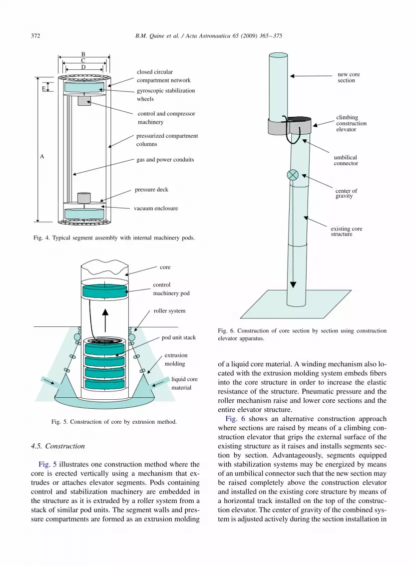
systems that enhance the structure’s ability to damp os-cillations by leaking air from cell to cell using a controlvalve network. This machinery may be controlled andpowered by pneumatic or electrical means as is con-venient and can provide a means to communicate withelevator components. A typical segment configurationis shown in Fig. 4. The segment consists of a closedcircular compartment network with internal gyroscopicstabilization wheels and control and compressor ma-chinery supported by pressurization gas in compartmentcolumns. The segment is supplied with resources in-cluding gas and power along conduits mounted betweenpressure decks. The gyro wheels are encapsulated inseparate sections so that they may be run under near-vacuum conditions.
372 B.M. Quine et al. / Acta Astronautica 65 (2009) 365–375
closed circularcompartment network
gyroscopic stabilizationwheels
control and compressormachinery
pressurized compartmentcolumns
gas and power conduits
pressure deck
A
BCD
E
vacuum enclosure
Fig. 4. Typical segment assembly with internal machinery pods.
core
controlmachinery pod
roller system
pod unit stack
extrusionmolding
liquid corematerial
Fig. 5. Construction of core by extrusion method.
4.5. Construction
Fig. 5 illustrates one construction method where thecore is erected vertically using a mechanism that ex-trudes or attaches elevator segments. Pods containingcontrol and stabilization machinery are embedded inthe structure as it is extruded by a roller system from astack of similar pod units. The segment walls and pres-sure compartments are formed as an extrusion molding
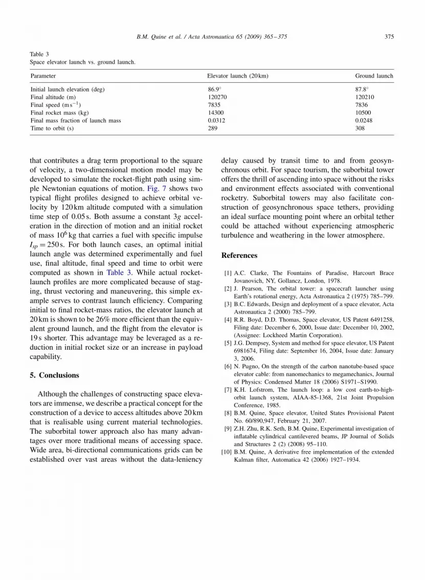
new coresection
climbingconstructionelevator
existing corestructure
center ofgravity
umbilicalconnector
Fig. 6. Construction of core section by section using constructionelevator apparatus.
of a liquid core material. A winding mechanism also lo-cated with the extrusion molding system embeds fibersinto the core structure in order to increase the elasticresistance of the structure. Pneumatic pressure and theroller mechanism raise and lower core sections and theentire elevator structure.Fig. 6 shows an alternative construction approach
where sections are raised by means of a climbing con-struction elevator that grips the external surface of theexisting structure as it raises and installs segments sec-tion by section. Advantageously, segments equippedwith stabilization systems may be energized by meansof an umbilical connector such that the new section maybe raised completely above the construction elevatorand installed on the existing core structure by means ofa horizontal track installed on the top of the construc-tion elevator. The center of gravity of the combined sys-tem is adjusted actively during the section installation in

B.M. Quine et al. / Acta Astronautica 65 (2009) 365–375 373
order to maintain it over the core’s surface footprint andto provide support for the structure in the presence ofexternal disturbance torques. The use of gyro stabiliza-tion during construction would be desirable as sectionsup to 150m may be balanced on a pivot mount.
4.6. Maintenance and decommissioning
For reliability and repair, a multi-core segmentedstructure is desirable in order to ensure that elevator in-tegrity can be maintained during maintenance of cellsand to facilitate leak repair. Failure tolerance can be en-hanced by the duplication of subsystems used in otherhigh technology systems, with critical systems such ascompressors and gyro-stabilization wheels operated inhot redundancy mode. A segmented core structure alsoenables the disassembly of the system during decom-missioning and enables the core structure to be disman-tled in a top-down process while power and pressure aremaintained to the remaining core structure and systems.
4.7. Operation
A platform or pod supported by the space-elevatortower has significant advantages over orbiting satelliteplatforms. Geographically fixed but providing access toregions of space closer to the surface than geostation-ary orbit, elevator platforms provide the ideal means tocommunicate over a wide area and to conduct remotesensing and tourism activities. As a tourist destination,the elevator platforms provide stations located at fixedaltitudes from the surface for observation. The elevatorplatforms provide the means to access a region of spacesafely with a view extending hundreds of kilometers.Small systems may be mobile and delivered to sites fortemporary applications such as the provision of tempo-rary communications towers typically between 25 and150m. Elevator cars enable equipment to be accessedand maintained during operation.For a spherical planet of radius r, and elevator of
height h, the horizon is at a surface distance s of
s = r arccos
(r
r + h
)(8)
assuming a level surface and neglecting diffraction. Thiscorresponds to a line of sight that is horizontal at thehorizon. As an example, on Earth (r= 6380km) anelevator extending 20km above the surface will havea view extending 500km and access a surface areaof 780,000km2. For a line of sight with an elevationof � radians above the horizon the geometry is more
complex but can be recast in terms of the height ofelevator required as
h = r
cos(s/r )− r + r tan(s/r ) sin �
sin(�/2 − s/r − �). (9)
Thus an elevator of height 20km will have a line ofsight greater than 10◦ elevation at surface distances ofup to a range of 108km and access an area more than36,000km2.
4.8. Utility for space launch
Although ascending to an altitude significantly below35,000km will not place a payload directly into Earthorbit, a platform or pod supported by the space-elevatortower has significant advantages over a surface-basedlaunch platform. While surface-based rockets must bedesigned to overcome atmospheric air resistance, launchfrom a high-altitude platform has no such requirement,and, consequently, existing space equipment such as anorbital transfer stage or conventional upper stage can beused to insert payloads directly into Earth orbit. Ideally,payloads should be raised to the highest feasible alti-tude before launching in order to maximize the energyadvantages; however, the energy advantages for spaceflight are readily leveraged above 5km. The energy re-quired for a surface launch to Low Earth Orbit can beexpressed per kilogram of payload as the sum of poten-tial and kinetic terms as
EOrbit = gh1 + 12 (v − v0)
2 (10)
where h1 is the altitude of the orbit, v is the orbital veloc-ity and v0 is the initial velocity (assuming this is in thesame direction of motion). Here, we have assumed con-servatively that g is constant with altitude; however, fora typical LEO altitude (h1 = 300km), g = 0.9g0 whereg0 is the surface gravity. By inspection, the energy re-quired is approximately 1MJ per 100km of orbital al-titude in potential energy and 27MJ in kinetic energyassuming a 7.9kms−1 orbital speed and an energy effi-cient equatorial launch. For a space elevator, the energyrequired is
E ′Orbit = g(h1 − h) + 1
2 (v − v0 − �h)2 (11)
where � is the angular rate of rotation of the planet(� = 7.27 × 10⁻⁵ rads−1 for Earth) and assuming anequatorial surface site. For a 20km elevator, the energyrequirement is reduced by approximately 0.2MJ; for a300km structure, the energy is reduced by 3MJ. Thisnet reduction in payload energy appears small; however,rocketry is an extremely inefficient means of providing

374 B.M. Quine et al. / Acta Astronautica 65 (2009) 365–375
Table 2Effective gravity.
Tangentialvelocityvp (kms−1)
Effectivegravityg′ (ms−2)
Reductionover surfacegravity (ms−2)
1.0 9.58 0.222.0 9.11 0.693.0 8.33 1.474.0 7.24 2.567.0 2.08 7.71
payload energy, particularly during the early phase ofspaceflight as we now discuss.Consider a rocket of mass m launched vertically in
order to escape the lower atmosphere. The equation ofmotion is
ma = mvp − mg, (12)
where a is the acceleration of the mass, m is the rateof use of fuel mass and vp is the exit velocity of thepropellant. In order to simply hover (a= 0), the massfraction of fuel that must be expelled is(m
m
)= g
vp= g
gIsp= 1
Isp, (13)
where Isp is the specific impulse of the rocket fuel inseconds. Consequently, a typical biopropellant system(Isp = 300s) must burn 1/300 of the rocket mass in fuelper second of flight in order simply to hover. In orderto overcome this loss, the rocket must gain velocitytangential to the surface as rapidly as possible. This hasthe effect of reducing the effective gravity that must beovercome as
g′ = r2g0(r + h)2
− v2t
(r + h). (14)
This reduction can be tabulated, as shown in Table 2.Thus for tangential velocities less than 4kms−1, the re-duction in gravitational acceleration is less than 25%.If we now consider a typical launch scenario and flightto 20km, we may compare the energy used to obtainan efficiency ratio for the rocket and, consequently, de-termine an overall energy saving by employing a spaceelevator for the initial ascent. The rate of energy dissi-pation by the rocket is given as the kinetic energy im-parted to the fuel as
E = 1
2mv2p = m(a + g)
2vp. (15)
Consider a typical launch with a= 3g and fuel specificimpulse Isp = 300s. If we assume the early flight to
0 2 4 6 8 10 12
x 105
0
2
4
6
8
10
12
14x 104
distance travelled [m]
heig
ht a
bove
gro
und
[m]
20 km launchground launch
Fig. 7. Ground and elevator launch (initial altitude of 20km) com-parison.
20km is almost vertical, the time to ascend to 20kmis t = √
2h/a = 36.9s, and the vertical velocity is1.1kms−1. If we assume that the mass of the rocketis 20 times that of the payload (m= 20) then in thisexample E = 1.2MJkg−1 s−1, and, consequently, thepropulsive energy required for rocket launch to 20kmis approximately 43MJkg−1 while the gain in kineticenergy by the payload is 0.6MJ and the gain in po-tential energy is 0.2MJ. The efficiency of the rocketin achieving useful work on the payload is therefore0.8/43= 0.0186 or 1.86% during this flight phase. As-suming staging occurs after 20km altitude, the rocketmass at 20km is exp(−4/300∗36.9)= 0.61 and henceapproximately 39% of the launch mass in fuel must beconsumed.In contrast, the work efficiency of a well designed
electric elevator (m= 1.5) may approach 30% with pri-mary losses in power conversion and the gravitationalpotential gained by the elevator car. The efficienciesmay be higher if the car’s potential energy is recoveredduring descent. Although the efficiency gains are onlyapplied to a small fraction of the total energy needed forlaunch, the use of a space elevator avoids the verticalascent phase while the rocket escapes the atmosphere,and little horizontal velocity is gained in order to coun-teract gravity. The elevator launch advantage may beexamined by simple numerical simulation to comparelaunch from 20km with launch from the ground. Con-sider a highly simplified scenario where a single stage-to-orbit rocket is launched to a typical circular orbitalheight of 120km. Using Eqs. (12) and (14) and assum-ing an adiabatic approximation for atmospheric density
B.M. Quine et al. / Acta Astronautica 65 (2009) 365–375 375
Table 3Space elevator launch vs. ground launch.
Parameter Elevator launch (20km) Ground launch
Initial launch elevation (deg) 86.9◦ 87.8◦Final altitude (m) 120270 120210Final speed (ms−1) 7835 7836Final rocket mass (kg) 14300 10500Final mass fraction of launch mass 0.0312 0.0248Time to orbit (s) 289 308
that contributes a drag term proportional to the squareof velocity, a two-dimensional motion model may bedeveloped to simulate the rocket-flight path using sim-ple Newtonian equations of motion. Fig. 7 shows twotypical flight profiles designed to achieve orbital ve-locity by 120km altitude computed with a simulationtime step of 0.05s. Both assume a constant 3g accel-eration in the direction of motion and an initial rocketof mass 106 kg that carries a fuel with specific impulseIsp = 250s. For both launch cases, an optimal initiallaunch angle was determined experimentally and fueluse, final altitude, final speed and time to orbit werecomputed as shown in Table 3. While actual rocket-launch profiles are more complicated because of stag-ing, thrust vectoring and maneuvering, this simple ex-ample serves to contrast launch efficiency. Comparinginitial to final rocket-mass ratios, the elevator launch at20km is shown to be 26% more efficient than the equiv-alent ground launch, and the flight from the elevator is19s shorter. This advantage may be leveraged as a re-duction in initial rocket size or an increase in payloadcapability.
5. Conclusions
Although the challenges of constructing space eleva-tors are immense, we describe a practical concept for theconstruction of a device to access altitudes above 20kmthat is realisable using current material technologies.The suborbital tower approach also has many advan-tages over more traditional means of accessing space.Wide area, bi-directional communications grids can beestablished over vast areas without the data-leniency
delay caused by transit time to and from geosyn-chronous orbit. For space tourism, the suborbital toweroffers the thrill of ascending into space without the risksand environment effects associated with conventionalrocketry. Suborbital towers may also facilitate con-struction of geosynchronous space tethers, providingan ideal surface mounting point where an orbital tethercould be attached without experiencing atmosphericturbulence and weathering in the lower atmosphere.
References
[1] A.C. Clarke, The Fountains of Paradise, Harcourt BraceJovanovich, NY, Gollancz, London, 1978.
[2] J. Pearson, The orbital tower: a spacecraft launcher usingEarth’s rotational energy, Acta Astronautica 2 (1975) 785–799.
[3] B.C. Edwards, Design and deployment of a space elevator, ActaAstronautica 2 (2000) 785–799.
[4] R.R. Boyd, D.D. Thomas, Space elevator, US Patent 6491258,Filing date: December 6, 2000, Issue date: December 10, 2002,(Assignee: Lockheed Martin Corporation).
[5] J.G. Dempsey, System and method for space elevator, US Patent6981674, Filing date: September 16, 2004, Issue date: January3, 2006.
[6] N. Pugno, On the strength of the carbon nanotube-based spaceelevator cable: from nanomechanics to megamechanics, Journalof Physics: Condensed Matter 18 (2006) S1971–S1990.
[7] K.H. Lofstrom, The launch loop: a low cost earth-to-high-orbit launch system, AIAA-85-1368, 21st Joint PropulsionConference, 1985.
[8] B.M. Quine, Space elevator, United States Provisional PatentNo. 60/890,947, February 21, 2007.
[9] Z.H. Zhu, R.K. Seth, B.M. Quine, Experimental investigation ofinflatable cylindrical cantilevered beams, JP Journal of Solidsand Structures 2 (2) (2008) 95–110.
[10] B.M. Quine, A derivative free implementation of the extendedKalman filter, Automatica 42 (2006) 1927–1934.
Related Documents