Acta of Bioengineering and Biomechanics Original paper Vol. 17, No. 2, 2015 DOI: 10.5277/ ABB-00046-2014-02 A finite element model of the L4-L5-S1 human spine segment including the heterogeneity and anisotropy of the discs HECTOR E. JARAMILLO 1, 2 , LESSBY GÓMEZ 1, 3 , JOSE J. GARCÍ A 1 * 1 Universidad del Valle, Cali-Colombia. 2 Universidad Autonoma de Occidente, Cali-Colombia. 3 Universidad Libre, Cali-Colombia. With the aim to study disc degeneration and the risk of injury during occupational activities, a new finite element (FE) model of the L4-L5-S1 segment of the human spine was developed based on the anthropometry of a typical Colombian worker. Beginning with medi- cal images, the programs CATIA and SOLIDWORKS were used to generate and assemble the vertebrae and create the soft structures of the segment. The software ABAQUS was used to run the analyses, which included a detailed model calibration using the experimental step-wise reduction data for the L4-L5 component, while the L5-S1 segment was calibrated in the intact condition. The range of motion curves, the intradiscal pressure and the lateral bulging under pure moments were considered for the calibration. As opposed to other FE models that include the L5-S1 disc, the model developed in this study considered the regional variations and anisotropy of the annulus as well as a realistic description of the nucleus geometry, which allowed an improved representation of experimental data during the valida- tion process. Hence, the model can be used to analyze the stress and strain distributions in the L4-L5 and L5-S1 discs of workers per- forming activities such as lifting and carrying tasks. Key words: intervertebral disc, L4-L5-S1 segment, finite element model, human spine, hyperelastic model 1. Introduction Low back pain is a disorder frequently found in a high percentage of the world population. There is a high economic and social impact associated with this dysfunction, which is often caused by pathologies originated in the lumbar spine. In turn, these patholo- gies are usually produced by excessive deformation or degeneration of the soft structures located between each pair of vertebraes, known as intervertebral discs [4]. Many experimental and theoretical studies have been carried out to better understand the biomechanics of the lumbar spine in order to reduce the risk of disc injury or degeneration. Compared to experimental testing, theoretical mod- els using the Finite Element (FE) method are a rela- tively inexpensive and fast way to accomplish the mechanical analysis of the human spine. In addition, theoretical simulations allow investigating the behav- ior of the lumbar spine under conditions that cannot be reproduced in in vitro or in vivo experiments. Many models have been developed to analyze the mechani- cal behavior of the lumbar spine between the L1 and L5 vertebras, e.g. [2], [8], [24], [25]. However, only four models have included the intervertebral disc lo- cated between L5 and the sacrum [3], [7], [9], [11], [17]. It is in the L5-S1 disc where hernias and degen- eration are frequently documented since it is known to support the highest load in the spine. Additionally, the geometry of the L5-S1 segment has important varia- tions with respect to that of other spine segments. The model by Bellinpi et al. [3] uses an ortho- tropic description for the annulus and does not ac- ______________________________ * Corresponding author: Jose Jaime García, Universidad del Valle, Cali, Colombia. E-mail: [email protected] Received: March 5th, 2014 Accepted for publication: September 16th, 2014

Welcome message from author
This document is posted to help you gain knowledge. Please leave a comment to let me know what you think about it! Share it to your friends and learn new things together.
Transcript
Acta of Bioengineering and Biomechanics Original paperVol. 17, No. 2, 2015 DOI: 10.5277/ ABB-00046-2014-02
A finite element modelof the L4-L5-S1 human spine segment
including the heterogeneity and anisotropy of the discs
HECTOR E. JARAMILLO1, 2, LESSBY GOMEZ1, 3, JOSE J. GARCIA1*
1 Universidad del Valle, Cali-Colombia.2 Universidad Autonoma de Occidente, Cali-Colombia.
3 Universidad Libre, Cali-Colombia.
With the aim to study disc degeneration and the risk of injury during occupational activities, a new finite element (FE) model of theL4-L5-S1 segment of the human spine was developed based on the anthropometry of a typical Colombian worker. Beginning with medi-cal images, the programs CATIA and SOLIDWORKS were used to generate and assemble the vertebrae and create the soft structures ofthe segment. The software ABAQUS was used to run the analyses, which included a detailed model calibration using the experimentalstep-wise reduction data for the L4-L5 component, while the L5-S1 segment was calibrated in the intact condition. The range of motioncurves, the intradiscal pressure and the lateral bulging under pure moments were considered for the calibration. As opposed to other FEmodels that include the L5-S1 disc, the model developed in this study considered the regional variations and anisotropy of the annulus aswell as a realistic description of the nucleus geometry, which allowed an improved representation of experimental data during the valida-tion process. Hence, the model can be used to analyze the stress and strain distributions in the L4-L5 and L5-S1 discs of workers per-forming activities such as lifting and carrying tasks.
Key words: intervertebral disc, L4-L5-S1 segment, finite element model, human spine, hyperelastic model
1. Introduction
Low back pain is a disorder frequently found ina high percentage of the world population. There isa high economic and social impact associated withthis dysfunction, which is often caused by pathologiesoriginated in the lumbar spine. In turn, these patholo-gies are usually produced by excessive deformation ordegeneration of the soft structures located betweeneach pair of vertebraes, known as intervertebral discs[4]. Many experimental and theoretical studies havebeen carried out to better understand the biomechanicsof the lumbar spine in order to reduce the risk of discinjury or degeneration.
Compared to experimental testing, theoretical mod-els using the Finite Element (FE) method are a rela-
tively inexpensive and fast way to accomplish themechanical analysis of the human spine. In addition,theoretical simulations allow investigating the behav-ior of the lumbar spine under conditions that cannotbe reproduced in in vitro or in vivo experiments. Manymodels have been developed to analyze the mechani-cal behavior of the lumbar spine between the L1 andL5 vertebras, e.g. [2], [8], [24], [25]. However, onlyfour models have included the intervertebral disc lo-cated between L5 and the sacrum [3], [7], [9], [11],[17]. It is in the L5-S1 disc where hernias and degen-eration are frequently documented since it is known tosupport the highest load in the spine. Additionally, thegeometry of the L5-S1 segment has important varia-tions with respect to that of other spine segments.
The model by Bellinpi et al. [3] uses an ortho-tropic description for the annulus and does not ac-
______________________________
* Corresponding author: Jose Jaime García, Universidad del Valle, Cali, Colombia. E-mail: [email protected]: March 5th, 2014Accepted for publication: September 16th, 2014
H.E. JARAMILLO et al.16
count for material nonlinearities as the discs are rep-resented asa linear elastic material. On the otherhand, Guan et al. [11] consider material nonlineari-ties with a hyperelastic formulation but do not in-clude the anisotropy caused by the reinforcing fibersof the annulus. It has been shown that both the ani-sotropy and material nonlinearities play an importantrole in the mechanics of the spine [29]. The model byEzquerro et al. [7], [9] includes a linear elastic de-scription for the nucleus and the annulus matrix, andtakes into account anisotropy and material nonline-arities by using cables attached to the nodes of themesh, which makes the orientation of the fibers to bemesh-dependent. A more recent model by Mora-marco et al. [17] takes into account anisotropy andmaterial nonlinearities with a Neo-Hookean formu-lation for the nucleus, the annulus matrix, and thereinforcing fibers.
These four models have provided a reasonableapproximation of experimental data for the intactsegments. However, these models describe eachcomponent of the disc, the nucleus and the annulus,as homogeneous materials and do not consider thevariation of the fiber angle with position, which hasbeen shown to be an important factor that modifiesthe mechanics of the spine [22]. Moreover, the mod-els by Moramarco et al. [17] and Bellini et al. [3]represent the nucleus as a cylinder, which does notappear to be a realistic representation for this com-ponent.
A finite element model that can provide an accu-rate approximation of stress and strain fields in thedisc is a useful tool that can be used to assess the riskof injury of workers performing activities, such aslifting and carrying weights. Hence, the aim of thisstudy was to develop and calibrate an FE model ofthe lumbar L4-L5-S1 segment considering the an-thropometry of a typical Colombian worker. Themodel was oriented to provide an accurate assess-ment of the mechanical parameters in the interverte-bral discs, which are the structures of the spine thatare more prone to suffer injury and degeneration.Thus, the model included the representation of re-gional variations of material properties in the discs aswell as the change of fiber orientation with positionand a realistic geometry for the nucleus. This modelwill allow performing the analyses of stress andstrain distributions in the lumbar discs of Colombianworkers that lift and transport bags as part of theirdaily activities, which may lead to a more objectivedetermination of the risk of injury compared toevaluations based on the maximum magnitude of theload.
2. Materials and methods
2.1. Geometry reconstruction
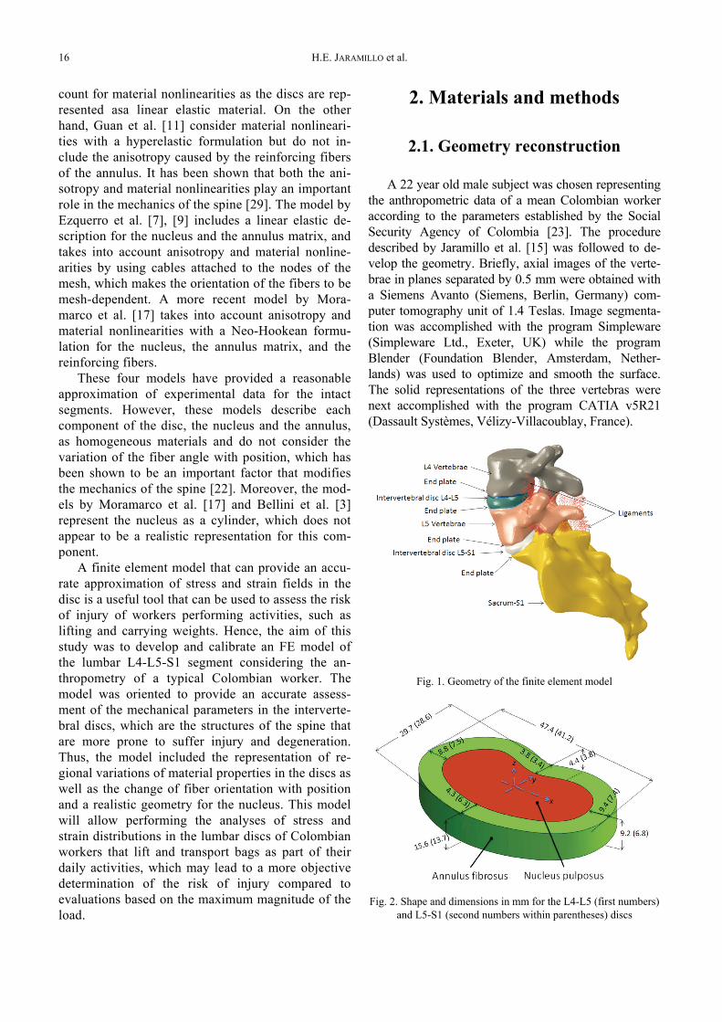
A 22 year old male subject was chosen representingthe anthropometric data of a mean Colombian workeraccording to the parameters established by the SocialSecurity Agency of Colombia [23]. The proceduredescribed by Jaramillo et al. [15] was followed to de-velop the geometry. Briefly, axial images of the verte-brae in planes separated by 0.5 mm were obtained witha Siemens Avanto (Siemens, Berlin, Germany) com-puter tomography unit of 1.4 Teslas. Image segmenta-tion was accomplished with the program Simpleware(Simpleware Ltd., Exeter, UK) while the programBlender (Foundation Blender, Amsterdam, Nether-lands) was used to optimize and smooth the surface.The solid representations of the three vertebras werenext accomplished with the program CATIA v5R21(Dassault Systèmes, Vélizy-Villacoublay, France).
Fig. 1. Geometry of the finite element model
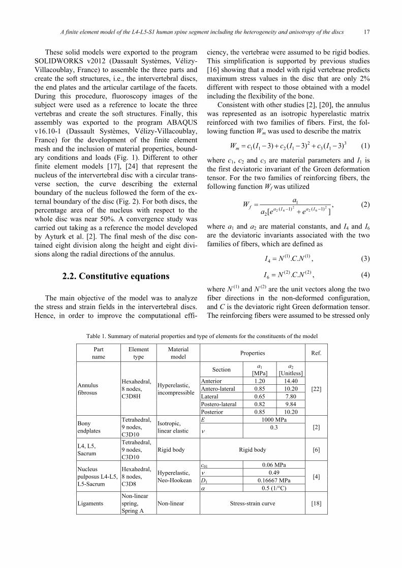
Fig. 2. Shape and dimensions in mm for the L4-L5 (first numbers)and L5-S1 (second numbers within parentheses) discs
A finite element model of the L4-L5-S1 human spine segment including the heterogeneity and anisotropy of the discs 17
These solid models were exported to the programSOLIDWORKS v2012 (Dassault Systèmes, Vélizy-Villacoublay, France) to assemble the three parts andcreate the soft structures, i.e., the intervertebral discs,the end plates and the articular cartilage of the facets.During this procedure, fluoroscopy images of thesubject were used as a reference to locate the threevertebras and create the soft structures. Finally, thisassembly was exported to the program ABAQUSv16.10-1 (Dassault Systèmes, Vélizy-Villacoublay,France) for the development of the finite elementmesh and the inclusion of material properties, bound-ary conditions and loads (Fig. 1). Different to otherfinite element models [17], [24] that represent thenucleus of the intervertebral disc with a circular trans-verse section, the curve describing the externalboundary of the nucleus followed the form of the ex-ternal boundary of the disc (Fig. 2). For both discs, thepercentage area of the nucleus with respect to thewhole disc was near 50%. A convergence study wascarried out taking as a reference the model developedby Ayturk et al. [2]. The final mesh of the disc con-tained eight division along the height and eight divi-sions along the radial directions of the annulus.
2.2. Constitutive equations
The main objective of the model was to analyzethe stress and strain fields in the intervertebral discs.Hence, in order to improve the computational effi-
ciency, the vertebrae were assumed to be rigid bodies.This simplification is supported by previous studies[16] showing that a model with rigid vertebrae predictsmaximum stress values in the disc that are only 2%different with respect to those obtained with a modelincluding the flexibility of the bone.
Consistent with other studies [2], [20], the annuluswas represented as an isotropic hyperelastic matrixreinforced with two families of fibers. First, the fol-lowing function Wm was used to describe the matrix
313
21211 )3()3()3( −+−+−= IcIcIcWm (1)
where c1, c2 and c3 are material parameters and I1 isthe first deviatoric invariant of the Green deformationtensor. For the two families of reinforcing fibers, thefollowing function Wf was utilized
,][
262
242 )1()1(
2
1−− +
=IaIaf
eeaaW (2)
where a1 and a2 are material constants, and I4 and I6
are the deviatoric invariants associated with the twofamilies of fibers, which are defined as
)1()1(4 .. NCNI = , (3)
)2()2(6 .. NCNI = , (4)
where N (1) and N (2) are the unit vectors along the twofiber directions in the non-deformed configuration,and C is the deviatoric right Green deformation tensor.The reinforcing fibers were assumed to be stressed only
Table 1. Summary of material properties and type of elements for the constituents of the model
Partname
Elementtype
Materialmodel Properties Ref.
Section a1[MPa]
a2[Unitless]
Anterior 1.20 14.40Antero-lateral 0.85 10.20Lateral 0.65 7.80Postero-lateral 0.82 9.84
Annulusfibrosus
Hexahedral,8 nodes,C3D8H
Hyperelastic,incompressible
Posterior 0.85 10.20
[22]
E 1000 MPaBonyendplates
Tetrahedral,9 nodes,C3D10
Isotropic,linear elastic ν 0.3 [2]
L4, L5,Sacrum
Tetrahedral,9 nodes,C3D10
Rigid body Rigid body [6]
c01 0.06 MPaν 0.49D1 0.16667 MPa
Nucleuspulposus L4-L5,L5-Sacrum
Hexahedral,8 nodes,C3D8
Hyperelastic,Neo-Hookean
α 0.5 (1/°C)
[4]
LigamentsNon-linearspring,Spring A
Non-linear Stress-strain curve [18]
H.E. JARAMILLO et al.18
under a positive strain. A subroutine Uanisohyper ofthe program ABAQUS was developed to implementthe aforementioned energy functions. Consistent withother studies [2], [22], the directions of the fibers variedwith the radial coordinate from 25° on the outer bound-ary to 46° on the inner boundary, where this angle wasmeasured with respect to the transverse plane.
Similar to Noailly et al. [18], the nucleus was de-scribed as a hyperelastic, Neo-Hookean material. Thebony end plates were represented as a linear elastic ma-terial with an elasticity modulus E equal to 1000 MPaand a Poisson’s ratio ν equal to 0.3 [4]. The ligamentswere described as nonlinear springs [19] working onlyunder tension. Material properties and type of ele-ments are summarized in Table 1.
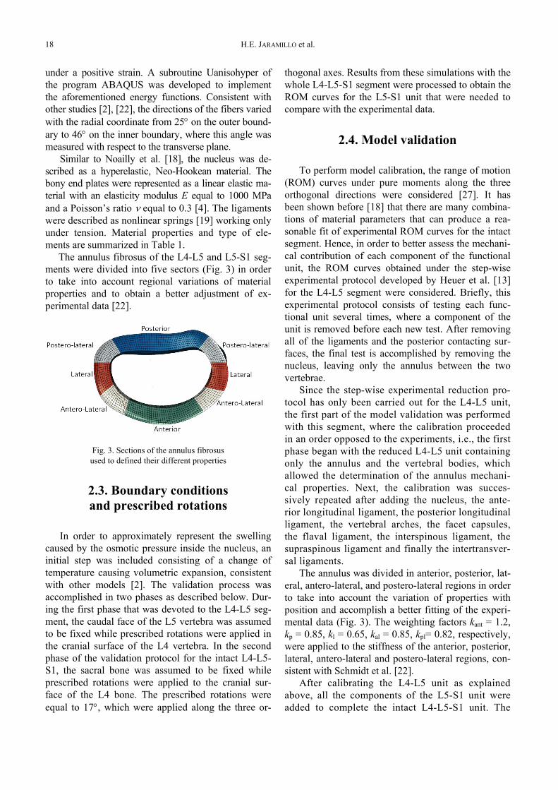
The annulus fibrosus of the L4-L5 and L5-S1 seg-ments were divided into five sectors (Fig. 3) in orderto take into account regional variations of materialproperties and to obtain a better adjustment of ex-perimental data [22].
Fig. 3. Sections of the annulus fibrosusused to defined their different properties
2.3. Boundary conditionsand prescribed rotations
In order to approximately represent the swellingcaused by the osmotic pressure inside the nucleus, aninitial step was included consisting of a change oftemperature causing volumetric expansion, consistentwith other models [2]. The validation process wasaccomplished in two phases as described below. Dur-ing the first phase that was devoted to the L4-L5 seg-ment, the caudal face of the L5 vertebra was assumedto be fixed while prescribed rotations were applied inthe cranial surface of the L4 vertebra. In the secondphase of the validation protocol for the intact L4-L5-S1, the sacral bone was assumed to be fixed whileprescribed rotations were applied to the cranial sur-face of the L4 bone. The prescribed rotations wereequal to 17°, which were applied along the three or-
thogonal axes. Results from these simulations with thewhole L4-L5-S1 segment were processed to obtain theROM curves for the L5-S1 unit that were needed tocompare with the experimental data.
2.4. Model validation
To perform model calibration, the range of motion(ROM) curves under pure moments along the threeorthogonal directions were considered [27]. It hasbeen shown before [18] that there are many combina-tions of material parameters that can produce a rea-sonable fit of experimental ROM curves for the intactsegment. Hence, in order to better assess the mechani-cal contribution of each component of the functionalunit, the ROM curves obtained under the step-wiseexperimental protocol developed by Heuer et al. [13]for the L4-L5 segment were considered. Briefly, thisexperimental protocol consists of testing each func-tional unit several times, where a component of theunit is removed before each new test. After removingall of the ligaments and the posterior contacting sur-faces, the final test is accomplished by removing thenucleus, leaving only the annulus between the twovertebrae.
Since the step-wise experimental reduction pro-tocol has only been carried out for the L4-L5 unit,the first part of the model validation was performedwith this segment, where the calibration proceededin an order opposed to the experiments, i.e., the firstphase began with the reduced L4-L5 unit containingonly the annulus and the vertebral bodies, whichallowed the determination of the annulus mechani-cal properties. Next, the calibration was succes-sively repeated after adding the nucleus, the ante-rior longitudinal ligament, the posterior longitudinalligament, the vertebral arches, the facet capsules,the flaval ligament, the interspinous ligament, thesupraspinous ligament and finally the intertransver-sal ligaments.
The annulus was divided in anterior, posterior, lat-eral, antero-lateral, and postero-lateral regions in orderto take into account the variation of properties withposition and accomplish a better fitting of the experi-mental data (Fig. 3). The weighting factors kant = 1.2,kp = 0.85, kl = 0.65, kal = 0.85, kpl= 0.82, respectively,were applied to the stiffness of the anterior, posterior,lateral, antero-lateral and postero-lateral regions, con-sistent with Schmidt et al. [22].
After calibrating the L4-L5 unit as explainedabove, all the components of the L5-S1 unit wereadded to complete the intact L4-L5-S1 unit. The
A finite element model of the L4-L5-S1 human spine segment including the heterogeneity and anisotropy of the discs 19
mechanical properties of the components added wereassumed to be equal to those of the L4-L5 segment.The L5-S1 segment was calibrated in the intact con-dition since the step-wise reduction method had notbeen carried out for this segment. In this step, theROM curves of the intact unit were compared withthose obtained by Panjabi et al. [21] and Guan et al.[10], except for the axial rotation curve, which wasnot reported by Guan et al. [10]. During this stage,only the properties of the springs representing thecontacting surfaces were modified to obtain a betteradjustment of the experimental curves.
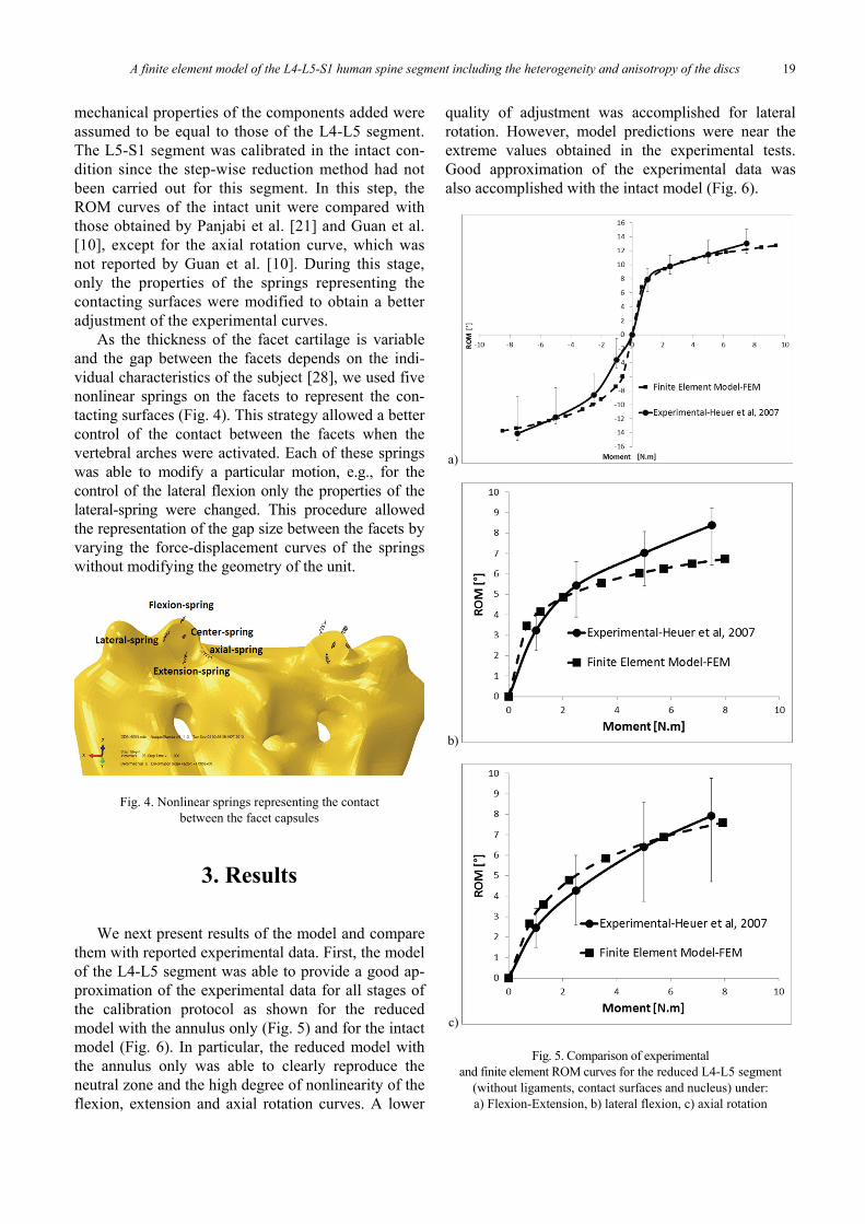
As the thickness of the facet cartilage is variableand the gap between the facets depends on the indi-vidual characteristics of the subject [28], we used fivenonlinear springs on the facets to represent the con-tacting surfaces (Fig. 4). This strategy allowed a bettercontrol of the contact between the facets when thevertebral arches were activated. Each of these springswas able to modify a particular motion, e.g., for thecontrol of the lateral flexion only the properties of thelateral-spring were changed. This procedure allowedthe representation of the gap size between the facets byvarying the force-displacement curves of the springswithout modifying the geometry of the unit.
Fig. 4. Nonlinear springs representing the contactbetween the facet capsules
3. Results
We next present results of the model and comparethem with reported experimental data. First, the modelof the L4-L5 segment was able to provide a good ap-proximation of the experimental data for all stages ofthe calibration protocol as shown for the reducedmodel with the annulus only (Fig. 5) and for the intactmodel (Fig. 6). In particular, the reduced model withthe annulus only was able to clearly reproduce theneutral zone and the high degree of nonlinearity of theflexion, extension and axial rotation curves. A lower
quality of adjustment was accomplished for lateralrotation. However, model predictions were near theextreme values obtained in the experimental tests.Good approximation of the experimental data wasalso accomplished with the intact model (Fig. 6).
a)
b)
c)
Fig. 5. Comparison of experimentaland finite element ROM curves for the reduced L4-L5 segment
(without ligaments, contact surfaces and nucleus) under:a) Flexion-Extension, b) lateral flexion, c) axial rotation
H.E. JARAMILLO et al.20
a)
b)
c)
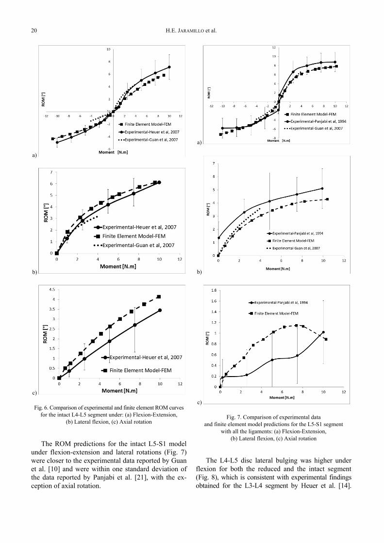
Fig. 6. Comparison of experimental and finite element ROM curvesfor the intact L4-L5 segment under: (a) Flexion-Extension,
(b) Lateral flexion, (c) Axial rotation
The ROM predictions for the intact L5-S1 modelunder flexion-extension and lateral rotations (Fig. 7)were closer to the experimental data reported by Guanet al. [10] and were within one standard deviation ofthe data reported by Panjabi et al. [21], with the ex-ception of axial rotation.
a)
b)
c)
Fig. 7. Comparison of experimental dataand finite element model predictions for the L5-S1 segment
with all the ligaments: (a) Flexion-Extension,(b) Lateral flexion, (c) Axial rotation
The L4-L5 disc lateral bulging was higher underflexion for both the reduced and the intact segment(Fig. 8), which is consistent with experimental findingsobtained for the L3-L4 segment by Heuer et al. [14].
A finite element model of the L4-L5-S1 human spine segment including the heterogeneity and anisotropy of the discs 21
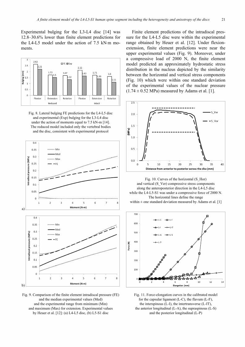
Experimental bulging for the L3-L4 disc [14] was12.8–30.6% lower than finite element predictions forthe L4-L5 model under the action of 7.5 kN⋅m mo-ments.
Fig. 8. Lateral bulging FE predictions for the L4-L5 discand experimental (Exp) bulging for the L3-L4 disc
under the action of moments equal to 7.5 kN-m [14].The reduced model included only the vertebral bodies
and the disc, consistent with experimental protocol
a)
b)
Fig. 9. Comparison of the finite element intradiscal pressure (FE)and the median experimental values (Med)
and the experimental range from minimum (Min)and maximum (Max) for extension. Experimental values
by Heuer et al. [12]: (a) L4-L5 disc, (b) L5-S1 disc
Finite element predictions of the intradiscal pres-sure for the L4-L5 disc were within the experimentalrange obtained by Heuer et al. [12]. Under flexion-extension, finite element predictions were near theupper experimental values (Fig. 9). Moreover, undera compressive load of 2000 N, the finite elementmodel predicted an approximately hydrostatic stressdistribution in the nucleus depicted by the similaritybetween the horizontal and vertical stress components(Fig. 10) which were within one standard deviationof the experimental values of the nuclear pressure(1.74 ± 0.52 MPa) measured by Adams et al. [1].
Fig. 10. Curves of the horizontal (S_Hor)and vertical (S_Ver) compressive stress componentsalong the anteroposterior direction in the L4-L5 disc
while the L4-L5-S1 was under a compressive force of 2000 N.The horizontal lines define the range
within ± one standard deviation measured by Adams et al. [1]
Fig. 11. Force-elongation curves in the calibrated modelfor the capsular ligament (L-C), the flavum (L-F),the interspinous (L-I), the intertransverse (L-IT),
the anterior longitudinal (L-A), the supraspinous (L-S)and the posterior longitudinal (L-P)
H.E. JARAMILLO et al.22
Force-elongation curves of the ligaments (Fig. 11)depict a typical behavior characterized by an initialcompliant zone followed by stiffening under strain.This behavior is consistent with the microstructureof the ligaments composed of crimped fibers that donot sustain load under low deformations and subse-quently stiffen under higher strains, due to the in-creased alignment of the fibers in the direction ofloading.
The constants c1, c2 and c3 or the energy functionof equation (1) were 0.015 MPa, –0.019 MPa and0.041 MPa, respectively, while the constants a1 and a2of Equation (2) describing the energy function of thefibers were in the ranges 0.65–1.20 MPa and 7.8–14.4,respectively (Table 1).
4. Discussion
A new model of the functional spine unit L4-L5-S1was developed including a detailed representation ofregional variations and anisotropy of the annulusas well as a realistic description of the nucleus ge-ometry. The model may be used to provide and accu-rate description of mechanical parameters in thelumbar spine discs of workers performing risk-injuryoccupational activities such as lifting and carryingweights.
Since the model was oriented to analyze the stressdistribution in the intervertebral discs, special atten-tion was paid to consider details that may affect re-sults. First, the model included a more realistic repre-sentation of the shape of the nucleus, which wascreated with its external perimeter following theboundary of the vertebral bodies. This form is differ-ent to the circular cross-sectional area assumed inother models [17]. In addition, this model took intoaccount regional variations of material properties andthe change of fiber orientation along the radial direc-tion, which have been considered to be importantfactors affecting the biomechanics of the spine in pre-vious L4-L5 models [22]. Compared to other modelsthat include the L5-S1 disc [8], [11], the currentmodel provides a more realistic representation of thevertebral bodies and a more precise modeling of theanisotropy of the annulus.
The parameters c1, c2, c3 of the energy function ofthe annulus matrix equation (1) are equal to thosereported by Ayturk et al. [2]. However, the parametersa1 and a2 of the energy function representing the fibersthat were in the ranges 0.65–1.20 MPa and 7.8–14.4,respectively, are one order of magnitude different than
the parameters reported by Ayturk et al. [2] for theL4-L5 segment, which are equal to 0.03 MPa and 120,respectively. It has to be noted that the parameter a2obtained in our study is more consistent with the di-rect measurements for human annulus tissue accom-plished by Cortés et al. [5], who determined a rangefor a2 equal to 5.64–8.78. Important differences withrespect to the results by Ayturk et al. [2] may be dueto both the regional variations of material propertiesand the change of fiber orientation with position thatwere taken into account in this study.
A detailed protocol using step-wise reduction ex-perimental data for the L4-L5 segment [13] was fol-lowed for a proper validation of the model, which isan important step to guarantee that finite element pre-dictions are realistic. Specifically, the step-wise cali-bration protocol allows an accurate assessment of themechanical contribution of each component in thekinematic behavior of the unit. The curves of ROM vsmoment displayed the main nonlinear features of theexperimental curves at all stages of the step-wise re-duction method. In addition, other parameters such asthe intra-discal pressure and lateral bulging were closeto the values reported in experimental studies.
FE predictions provided a good fitting of the ex-perimental curves reported by Guan et al. [10] andPanjabi et al. [21] for the L5-S1 segment under flex-ion-extension and lateral bending, where model pre-dictions were closer to experimental results by Guanet al. [10]. A higher degree of difference was obtainedwith respect to the form of the axial rotation experi-mental curve presented by Panjabi et al. [21], eventhough the terminal values at 10 N-m were similar(Fig. 7c). However, we have not found axial-rotationROM curves reported for other FE models that in-clude the L5-S1 disc [17] that may be used to comparewith our FE predictions in order to understand thesource of this difference.
The discrepancies of finite element model andexperimental predictions for bulging may be attrib-uted to the differences of cross-sectional area of theL4-L5 disc compared to experimental data forL3-L4 reported by Heuer et al. [14]. Another sourceof difference may be the loss of water during thestep-wise experimental protocol, given the exten-sive time required to complete all tests. Due to thisfactor, the hydrated soft tissue became more com-pressible and consequently the lateral displacementswere lower.
Some limitations are inherent to the developedmodel. First, vertebral bodies were considered to berigid, which means that model predictions cannot beused to assess the stress distribution and the risk of
A finite element model of the L4-L5-S1 human spine segment including the heterogeneity and anisotropy of the discs 23
fracture in the bones. With respect to the mechanicalpredictions for the disc, a previous study [6] indicatedthat maximum stress and intradiscal pressure onlychanged a maximum of 2% when rigid bones wereconsidered, compared to the predictions obtained withan accurate representation of the elasticity of the bones.The rigid-body assumption is also adopted in the recentmodel reported by Moramarco et al. [17]. Additionally,the rigid assumption for the bones implies importantreductions on the time required to analyze the model.Another limitation is that the contacting surfaces wererepresented using nonlinear gap elements, meaning thatthe model is not capable of providing the stress distri-bution in the cartilage of the facets. Again, this repre-sentation of the contacting surfaces does not affect thestress distribution in the discs.
Acknowledgments
We acknowledge the support of COLCIENCIAS (contract110651929063) to accomplish this study.
References
[1] ADAMS M.A., MCNALLY D.S., DOLAN P., “stress” Distri-butions Inside Intervertebral Discs the Effects of Age andDegeneration, J. Bone Joint. Surg. Br., 1996, 78-B, 965–972.
[2] AYTURK U.M., GARCIA J.J., PUTTLITZ C.M., The Microme-chanical Role of the Annulus Fibrosus Components UnderPhysiological Loading of the Lumbar Spine, J. Biomech.Eng., 2010, 132, 061007–061007.
[3] BELLINI C.M., GALBUSERA F., RAIMONDI M.T., MINEO G.V.,BRAYDA-BRUNO M., Biomechanics of the lumbar spine afterdynamic stabilization, J. Spinal Disord. Tech., 2007, 20,423–429.
[4] BOGDUK N., Clinical Anatomy of the Lumbar Spine & Sa-crum, 1995.
[5] CORTES D.H., HAN W.M., SMITH L.J., ELLIOTT D.M., Me-chanical properties of the extra-fibrillar matrix of humanannulus fibrosus are location and age dependent, J. Orthop.Res., 2013, 31(11), 1725–1732.
[6] DIAZ C.A., GARCÍA J.J., PUTTLITZ C., Influence of vertebrastiffness in the finite element analysis of the intervertebraldisc, ASME, Fajarado, Puerto Rico, USA, 2012, 2.
[7] EZQUERRO F., SIMÓN A., PRADO M., PÉREZ A., Combinationof finite element modeling and optimization for the study oflumbar spine biomechanics considering the 3D thorax–pelvisorientation, Med. Eng. Phys., 2004, 26, 11–22.
[8] EZQUERRO F., VACAS F.G., POSTIGO S., PRADO M., SIMÓN A.,Calibration of the finite element model of a lumbar func-tional spinal unit using an optimization technique basedon differential evolution, Med. Eng. Phys., 2011, 33,89–95.
[9] EZQUERRO JUANCO F., SIMÓN MATA A., MELLADO ARJONA E.,VILLANUEVA PAREJA F., Modelo de elementos finitos de lacolumna lumbar, Biomecánica. 1999, VII, 46–52.
[10] GUAN Y., YOGANANDAN N., MOORE J., PINTAR F.A., ZHANG J.,MAIMAN D.J. et al., Moment–rotation responses of the
human lumbosacral spinal column, J. Biomech., 2007, 40,1975–1980.
[11] GUAN Y., YOGANANDAN N., ZHANG J., PINTAR F.A., CUSICKJ.F., WOLFLA C.E. et al., Validation of a clinical finite ele-ment model of the human lumbosacral spine, Med. Bio. Eng.Comput., 2006, 44, 633–641.
[12] HEUER F., SCHMIDT H., L. CLAES, WILKE H.-J., Stepwisereduction of functional spinal structures increase vertebraltranslation and intradiscal pressure, J. Biomech., 2007, 40,795–803.
[13] HEUER F., SCHMIDT H., KLEZL Z., CLAES L., WILKE H.-J.,Stepwise reduction of functional spinal structures increaserange of motion and change lordosis angle, J. Biomech.,2007, 40, 271–280.
[14] HEUER F., SCHMIDT H., WILKE H.-J., Stepwise reduction offunctional spinal structures increase disc bulge and surfacestrains, J. Biomech., 2008, 41, 1953–1960.
[15] JARAMILLO H.E., GARCÍA A., GÓMEZ L., ESCOBAR W.,GARCÍA J.J., Procedimiento para generar mallas deelementos finitos de la columna vertebral humana a partir deimágenes médicas, Revista el Hombre y la Máquina, 2012,40, 79–86.
[16] MEIJER G.J.M., HOMMINGA J., HEKMAN E.E.G., VELDHUIZENA.G., VERKERKE G.J., The effect of three-dimensional geo-metrical changes during adolescent growth on the biome-chanics of a spinal motion segment, J. Biomech., 2010, 43,1590–1597.
[17] MORAMARCO V., PÉREZ DEL PALOMAR A., PAPPALETTERE C.,DOBLARÉ M., An accurate validation of a computationalmodel of a human lumbosacral segment, J. Biomech., 2010,43, 334–342.
[18] NOAILLY J., WILKE H.-J., PLANELL J.A., LACROIX D., Howdoes the geometry affect the internal biomechanics ofa lumbar spine bi-segment finite element model? Conse-quences on the validation process, J. Biomech., 2007, 40,2414–2425.
[19] NOAILLY J., Model Developments for In Silico Studies of theLumbar Spine Biomechanics, Universidad Politecnica deCataluña, Universidad Politecnica de Cataluña, España,2009.
[20] O’CONNELL G.D., GUERIN H.L., ELLIOTT D.M., Theoreticaland Uniaxial Experimental Evaluation of Human AnnulusFibrosus Degeneration, J. Biomech. Eng., 2009, 131,111007.
[21] PANJABI M.M., OXLAND T.R., YAMAMOTO I., CRISCO J.J.,Mechanical behavior of the human lumbar and lumbosacralspine as shown by three-dimensional load-displacementcurves, J. Bone Joint. Surg., Series A, 1994, 76, 413–424.
[22] SCHMIDT H., HEUER F., SIMON U., KETTLER A., ROHLMANN A.,CLAES L. et al., Application of a new calibration methodfor a three-dimensional finite element model of a humanlumbar annulus fibrosus, Clin. Biomech., 2006, 21, 337–344.
[23] Seguro Social, Parámetros antropométricos de la poblaciónlaboral Colombiana – 1995 Acopla 95, Seguro Social,Bogotá, 2002.
[24] TYNDYK M.A., BARRON V., MCHUGH P.E., O’MAHONEY D.,Generation of a finite element model of the thoracolumbarspine, Acta Bioeng. Biomech., 2007, 9, 35–46.
[25] WANG J.L., PARNIANPOUR M., SHIRAZI-ADL A., ENGIN A.E.,LI S., PATWARDHAN A., Development and validation of a vis-coelastic finite element model of an L2/L3 motion segment,Theor. Appl. Fract. Mec., 1997, 28, 81–93.
H.E. JARAMILLO et al.24
[26] WEISSE B., AIYANGAR A.K., AFFOLTER C., GANDER R.,TERRASI G.P., PLOEG H., Determination of the translationaland rotational stiffnesses of an L4-L5 functional spinal unitusing a specimen-specific finite element model, J. Mech. Be-hav. Biomed. Mater, 2012, 13, 45–61.
[27] WILKE H.-J., NEEF P., CAIMI M., HOOGLAND T., CLAES L.E.,New in vivo measurements of pressures in the intervertebraldisc in daily life, Spine, 1999, 24, 755–762.
[28] WOLDTVEDT D.J., WOMACK W., GADOMSKI B.C., SCHULDT D.,PUTTLITZ C.M., Finite element lumbar spine facet contactparameter predictions are affected by the cartilage thicknessdistribution and initial joint gap size, J. Biomech. Eng.,2011, 133(6), 061009
[29] YOGANANDAN N., MYKLEBUST J.B., RAY G., PINTAR F.,SANCES A., A non-linear finite element model of a spinalsegment, Mathematical Modelling, 1987, 8, 617–622.
Related Documents


![Lumbar Intervertebral Disc Endoscopy - InTech - Opencdn.intechopen.com/.../InTech-Lumbar_intervertebral_disc_endoscop… · mainly located in the L4-L5 and L5-S1 motion segments [1],](https://static.cupdf.com/doc/110x72/5b9b266209d3f20b318cd7f6/lumbar-intervertebral-disc-endoscopy-intech-mainly-located-in-the-l4-l5.jpg)