Advances in Coal Gasification, Hydrogenation, and Gas Treating for the Production of Chemicals and Fuels Christopher Higman* ,† and Samuel Tam ‡ † Higman Consulting GmbH, 65824 Schwalbach, Germany ‡ Advanced Energy Systems Division, Office of Fossil Energy, U.S. Department of Energy, Washington, D.C. 20585, United States CONTENTS 1. Introduction 1674 2. Background to Gasification 1674 2.1. Chemistry and Thermodynamics 1674 2.2. Process Realization 1675 2.2.1. Operating Temperature 1675 2.2.2. Bed Type 1676 3. Gasification Research and Development 1676 3.1. Coal Properties Relevant to Gasification 1676 3.1.1. Reactivity of Coal and Other Chars 1677 3.1.2. Behavior of Mineral Matter 1677 3.2. Coal Preparation and Feeding 1679 3.2.1. Fines Reduction in Crushing Facilities 1679 3.2.2. Slurry Feeding Systems 1679 3.2.3. Dry Feeding Systems 1680 3.2.4. Dry Solids Pumps 1681 3.2.5. Cogasification of Alternative Feedstocks 1681 3.3. Gasification Reactors 1682 3.3.1. Fixed Bed Gasifiers 1682 3.3.2. Fluid Bed Gasifiers 1683 3.3.3. Entrained Flow Gasifiers 1683 3.3.4. Reactor Containment 1684 3.3.5. Two-Stage Gasification 1685 3.3.6. Other Issues 1685 3.4. Contaminant Species in Raw Syngas 1686 3.4.1. Nitrogen Species 1686 3.4.2. Alkali Metals 1687 3.4.3. Trace Elements 1687 3.5. Syngas Coolers 1688 3.5.1. Radiant Coolers 1688 3.5.2. Quench Systems 1688 3.6. Primary Gas Cleaning 1689 3.6.1. Solids Removal from Raw Syngas 1689 3.7. Alternative Configurations 1689 3.7.1. Catalytic Gasification 1689 3.7.2. Hydrogasification 1690 3.7.3. Chemical Looping 1690 3.7.4. Other 1690 4. Gas Treating 1690 4.1. Desulfurization 1691 4.1.1. Zinc 1692 4.1.2. Iron 1692 4.1.3. Calcium 1692 4.1.4. Other Sorbents 1692 4.1.5. COS Hydrolysis and Removal 1692 4.2. Trace Element Removal 1693 4.2.1. Mercury 1693 4.2.2. Arsenic and Selenium 1693 4.3. Water Gas Shift (WGS) 1693 4.3.1. Alternative Catalysts 1694 4.3.2. Reactors 1694 4.4. Hydrogen−Carbon Dioxide Separation 1694 4.4.1. CO 2 Sorbents 1694 4.4.2. Hydrogen Membranes 1694 5. Chemicals from Syngas 1694 5.1. Ammonia 1695 5.2. Hydrogen 1695 5.3. Methanol and Derivatives 1695 5.3.1. Methanol Derivatives 1695 5.4. Ethanol 1696 5.5. Oxo Alcohols 1696 5.6. Monoethylene Glycol (MEG) 1696 5.7. Substitute Natural Gas (SNG) 1696 5.8. Liquefied Petroleum Gas (LPG) 1697 5.9. Fischer−Tropsch Synthesis 1697 5.10. Direct Reduced Iron (DRI) 1697 6. Chemicals from Pyrolysis Byproducts of Gas- ification 1697 7. Direct Hydrogenation to Liquids 1697 7.1. Process Description 1698 7.2. Commercial Plant 1698 7.3. Research and Development (R&D) Activities 1698 8. Conclusions 1699 Author Information 1699 Corresponding Author 1699 Notes 1699 Biographies 1699 Acknowledgments 1700 Abbreviations and Acronyms 1700 Special Issue: 2014 Chemicals from Coal, Alkynes, and Biofuels Received: April 6, 2013 Published: October 21, 2013 Review pubs.acs.org/CR © 2013 American Chemical Society 1673 dx.doi.org/10.1021/cr400202m | Chem. Rev. 2014, 114, 1673−1708

A. Advances in Coal Gasi
Feb 08, 2016
A description of Hydrogen production via Coal Gasification Technology
Welcome message from author
This document is posted to help you gain knowledge. Please leave a comment to let me know what you think about it! Share it to your friends and learn new things together.
Transcript
Advances in Coal Gasification, Hydrogenation, and Gas Treating forthe Production of Chemicals and FuelsChristopher Higman*,† and Samuel Tam‡
†Higman Consulting GmbH, 65824 Schwalbach, Germany‡Advanced Energy Systems Division, Office of Fossil Energy, U.S. Department of Energy, Washington, D.C. 20585, United States
CONTENTS
1. Introduction 16742. Background to Gasification 1674
2.1. Chemistry and Thermodynamics 16742.2. Process Realization 1675
2.2.1. Operating Temperature 16752.2.2. Bed Type 1676
3. Gasification Research and Development 16763.1. Coal Properties Relevant to Gasification 1676
3.1.1. Reactivity of Coal and Other Chars 16773.1.2. Behavior of Mineral Matter 1677
3.2. Coal Preparation and Feeding 16793.2.1. Fines Reduction in Crushing Facilities 16793.2.2. Slurry Feeding Systems 16793.2.3. Dry Feeding Systems 16803.2.4. Dry Solids Pumps 16813.2.5. Cogasification of Alternative Feedstocks 1681
3.3. Gasification Reactors 16823.3.1. Fixed Bed Gasifiers 16823.3.2. Fluid Bed Gasifiers 16833.3.3. Entrained Flow Gasifiers 16833.3.4. Reactor Containment 16843.3.5. Two-Stage Gasification 16853.3.6. Other Issues 1685
3.4. Contaminant Species in Raw Syngas 16863.4.1. Nitrogen Species 16863.4.2. Alkali Metals 16873.4.3. Trace Elements 1687
3.5. Syngas Coolers 16883.5.1. Radiant Coolers 16883.5.2. Quench Systems 1688
3.6. Primary Gas Cleaning 16893.6.1. Solids Removal from Raw Syngas 1689
3.7. Alternative Configurations 16893.7.1. Catalytic Gasification 1689
3.7.2. Hydrogasification 16903.7.3. Chemical Looping 16903.7.4. Other 1690
4. Gas Treating 16904.1. Desulfurization 1691
4.1.1. Zinc 16924.1.2. Iron 16924.1.3. Calcium 16924.1.4. Other Sorbents 16924.1.5. COS Hydrolysis and Removal 1692
4.2. Trace Element Removal 16934.2.1. Mercury 16934.2.2. Arsenic and Selenium 1693
4.3. Water Gas Shift (WGS) 16934.3.1. Alternative Catalysts 16944.3.2. Reactors 1694
4.4. Hydrogen−Carbon Dioxide Separation 16944.4.1. CO2 Sorbents 16944.4.2. Hydrogen Membranes 1694
5. Chemicals from Syngas 16945.1. Ammonia 16955.2. Hydrogen 16955.3. Methanol and Derivatives 1695
5.3.1. Methanol Derivatives 16955.4. Ethanol 16965.5. Oxo Alcohols 16965.6. Monoethylene Glycol (MEG) 16965.7. Substitute Natural Gas (SNG) 16965.8. Liquefied Petroleum Gas (LPG) 16975.9. Fischer−Tropsch Synthesis 16975.10. Direct Reduced Iron (DRI) 1697
6. Chemicals from Pyrolysis Byproducts of Gas-ification 1697
7. Direct Hydrogenation to Liquids 16977.1. Process Description 16987.2. Commercial Plant 16987.3. Research and Development (R&D) Activities 1698
8. Conclusions 1699Author Information 1699
Corresponding Author 1699Notes 1699Biographies 1699
Acknowledgments 1700Abbreviations and Acronyms 1700
Special Issue: 2014 Chemicals from Coal, Alkynes, and Biofuels
Received: April 6, 2013Published: October 21, 2013
Review
pubs.acs.org/CR
© 2013 American Chemical Society 1673 dx.doi.org/10.1021/cr400202m | Chem. Rev. 2014, 114, 1673−1708
Nomenclature 1700References 1700
1. INTRODUCTION
World ammonia production in 2010 is reported to be 159million tons per annum,1 of which Chinese coal-basedproduction is estimated to be 39 million tons.2 This amountsto about 25% of total worldwide production. A similar situationobtains for methanol. Global capacity is reported as 69 milliontons per annum,3 of which coal-based capacity, again mostly inChina, is estimated as 27 million tons or about 39% of theworld total. While much of this methanol is further processedto conventional methanol derivatives such as formaldehyde,solvents, methyl tert-butyl ether (MTBE), and acetyls, othermarkets have opened up in recent years. Newer methanolderivatives include dimethyl ether (DME), gasoline via theExxonMobil MTG (methanol to gasoline) and similarprocesses, and olefins. Other chemicals being manufacturedon an industrial scale from coal-derived synthesis gas (H2 + COor syngas) include oxo alcohols, monoethylene glycol (MEG),substitute natural gas (SNG), and Fischer−Tropsch liquids.It is almost exactly 100 years since the start-up of Carl
Bosch’s first industrial synthetic ammonia plant in Oppau,Germany, on Sept 9, 1913.4 The hydrogen for this plant wasproduced from coal using the water gas process. The capacitywas 30 metric tons per day (t/d), modest compared with the3300 t/d units being offered today. However, this was not thebeginning of chemicals from coal gasification. In 1910Kietaible5 discussed the manufacture of both hydrogen andformic acid from “generator gas” or water gas. At the time, thedevelopment of airships was seen as a mass market for coal-based hydrogen production. Formic acid was used as anintermediate for synthetic dyestuffs and oxalic acid. Coal tarbased chemistry is even older, but it is not the subject of thisreview.Chemicals production from syngas, whether generated by
coal gasification or steam reforming of natural gas, is a majorand largely mature industrial activity with a broad range ofcommercial licensors. Much research and development takesplace in the commercial laboratories of such companies and istherefore not accessible in the same manner as academicresearch. Nonetheless the results of this work become visiblethrough the patent literature and with each further improve-ment in the industrial processes.Coal gasification is but one means of generating synthesis
gas. The synthesis of chemicals from syngas is largelyindependent of the source of the syngas, so that mostdevelopments applicable to syngas from steam reforming ofnatural gas are applicable to syngas generated from coalgasification. This review will therefore focus on advances ingasification and associated gas treatment technology with onlybrief mention being made of the chemicals that can bemanufactured from the treated syngas. Synthetic fuels havebeen included in the definition of chemicals, so brief mention isalso made of Fischer−Tropsch synthesis. Direct hydrogenationof coal is however discussed in more detail.Coal gasification is used in the power industry in the
integrated gasification combined cycle (IGCC) configuration,but this cannot be considered as part of the chemical industryand is therefore not discussed. The demands placed particularlyon gas treatment are different, but many of the techniquesdescribed here will find their way into advanced IGCCs,
particularly those incorporating carbon capture. Schoff et al.have reviewed the research and development needs for IGCC,and the reader is referred to that source for further detail.6
Although many of the techniques used for coal gasificationhave their analogues in biomass gasification, the differences,both in the combustible material and in the associated mineralmatter, call in many cases for different solutions in detail.Therefore, while this review will occasionally mention biomassgasification as a starting point for chemicals manufacture, e.g.,under the heading of cogasification, there is no attempt to coverthe topic in a comprehensive manner.As referred to above, the coals-to-chemicals industry is an
established and mature industry. It will therefore be an aim ofthis review to look at potential advances in this light, examiningthe status quo of industrial practice and identifying whatimprovements are needed or could be useful and relating workperformed in the past five years to those needs.
2. BACKGROUND TO GASIFICATIONGasification can be described as the “conversion of anycarbonaceous feedstock into a gaseous product with a usefulchemical heating value.”7 Initially the focus was on devolatiliza-tion and pyrolysis since the 19th century town gas market wasmainly for lighting, where a high hydrocarbon content was ofbenefit. For modern chemical synthesis applications a heavyhydrocarbon free gas mainly consisting of hydrogen and carbonmonoxide is desired, so the emphasis is on the partial oxidationreactions.2.1. Chemistry and Thermodynamics
The principle reactions which take place during the gasificationof pure carbon are those involving carbon, oxygen, andhydrogen and in particular their compounds carbon monoxide,carbon dioxide, water (or steam), and methane. Simplifyingcoal to pure carbon, the most important reactions are
partial oxidation:
+ → Δ = −HC 12O CO 111 MJ/kmol2 298 K
0(1)
CO oxidation:
+ → Δ = −HCO 12O CO 283 MJ/kmol2 2 298 K
0
(2)
water gas reaction:
+ ⇄ +
Δ = +H
C H O(g) CO H
131 MJ/kmol2 2
298 K0
(3)
and
Boudouard reaction:
+ ⇄ Δ = +HC CO 2CO 172 MJ/kmol2 298 K0
(4)
In gasification processes the reactions involving free oxygenare essentially complete. The carbon conversion is usually 95%or higher, whereby the failure to reach 100% conversion is dueto nonthermodynamic effects. At the high temperatures atwhich most processes operate, the reactions reach close toequilibrium and the final gas composition is determined by theCO shift reaction:
+ ⇄ +
Δ = −H
CO H O(g) CO H
41 MJ/kmol2 2 2
298 K0
(5)
Chemical Reviews Review
dx.doi.org/10.1021/cr400202m | Chem. Rev. 2014, 114, 1673−17081674
and the steam methane reforming reaction:
+ ⇄ +
Δ = +H
CH H O(g) CO 3H
206 MJ/kmol4 2 2
298 K0
(6)
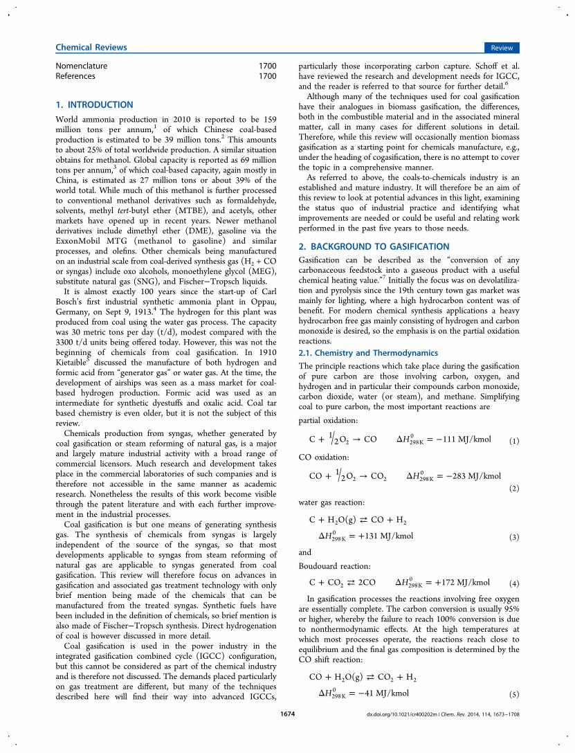
Coal is of course much more complex than pure carbon. Theaccepted sequence of events in coal gasification can besummarized as in Figure 1. In an initial pyrolysis phase,volatiles are driven off from the coal. Vapor phase reactionsproceed quickly. The heterogeneous char gasification is thedetermining factor in the overall reaction kinetics.Temperatures of gasification reactors are typically sufficiently
high that methane is usually the only hydrocarbon present inany appreciable quantity. It is however possible that pyrolysisproducts survive and are contained in the synthesis gas,particularly in counterflow moving bed reactors.The pressure and temperature of the gasifier have an
influence on the gas composition. The contents of CH4 andCO2 in the synthesis gas increase with increasing pressure. Asthe gasification temperature increases, the methane contentdrops and the H2/CO ratio shifts toward increasing CO.Typical industrial gasification processes today operate in the
range 25−80 bar depending on application. At these pressures,temperatures of above 1250 °C are required in order toproduce a synthesis gas with a low (<0.5 mol %) methanecontent. While an increased methane content is beneficial for,e.g., substitute natural gas (SNG) production, it would becounterproductive for synthesis of other chemicals such asammonia or methanol, where methane is an inert. Nonetheless,
even low temperature fluid bed processes operating around 950°C generate sufficiently little methane that, where consid-erations determined by the quality of the coal to be gasifiedindicate their use, they are used.Many chemical synthesis processes such as those for
methanol and ammonia are conducted at high pressures80to 100 bar or higher. For such applications it is advantageous toperform the gasification at high pressure, since this will reducethe compression energy requirement of the overall integratedprocess.
2.2. Process Realization
In the practical realization of gasification processes a broadrange of reactor types has been and continues to be used. Themost important differentiating characteristics are discussed insections 2.2.1 and 2.2.2.
2.2.1. Operating Temperature. Operating temperature,i.e., whether to apply a slagging or nonslagging operation, isfundamental to the design concept of a gasification system. Inmany cases the temperature is dictated by the bed type.Entrained flow gasifiers all operate at slagging temperatures;fluid bed gasifiers operate in the nonslagging mode. However,the moving bed offers a choice between, e.g., the Lurgi drybottom gasifier and the BGL slagging gasifier. For slagginggasifiers the temperature must be high enough that the slag is afree-flowing liquid, which can be extracted through a slag tap atthe bottom of the gasifier. For nonslagging gasifiers thetemperature must be sufficiently lower than the ash softeningtemperature that sintering and agglomeration into larger
Figure 1. Sequence of reactions in coal gasification. [Adapted with permission from Reimert, R. and Schaub, G. Gas Production. In Ullmann’sEncyclopedia of Industrial Chemistry, 5th ed.; VCH: Weinheim, Germany, 1989; Vol. A12, p 215. Copyright 1989 Wiley-VCH.]
Table 1. Characteristics of Different Categories of Gasification Process [Adapted with Permission from ref 7. Copyright 2003Elsevier.]
category moving bed fluid bed entrained flow
ash conditions dry ash slagging dry ash agglomerating slagging
typical processes Lurgi, SEDIN BGL Winkler, HTW, CFB, TRIG KRW, U-Gas, AFB Shell, GEE, E-Gas, Siemens, KT,and others; see Table2
feed characteristics
size 1/4−2 in. 1/4−2 in. 1/4−1/2 in. 1/4−1/2 in. <200 μm
acceptabilityof fines
limited better than dry ash good better unlimited
acceptabilityof cakingcoal
yes (with stirrer) yes (with stirrer) possibly yes yes
preferredcoal rank
any any low any any (dry feed); high (slurry feed)
operatingcharacteristics
outlet gastemperature
low (450−650 °C) low (450−650 °C) moderate (900−1050 °C) moderate (900−1050 °C) high (1250−1600 °C)
oxidantdemand
low low moderate moderate high
steamdemand
high low moderate moderate low
other characteristics hydrocarbons in gas hydrocarbons in gas lower carbon conversion lower carbon conversion pure gas, high carbon conversion
Chemical Reviews Review
dx.doi.org/10.1021/cr400202m | Chem. Rev. 2014, 114, 1673−17081675
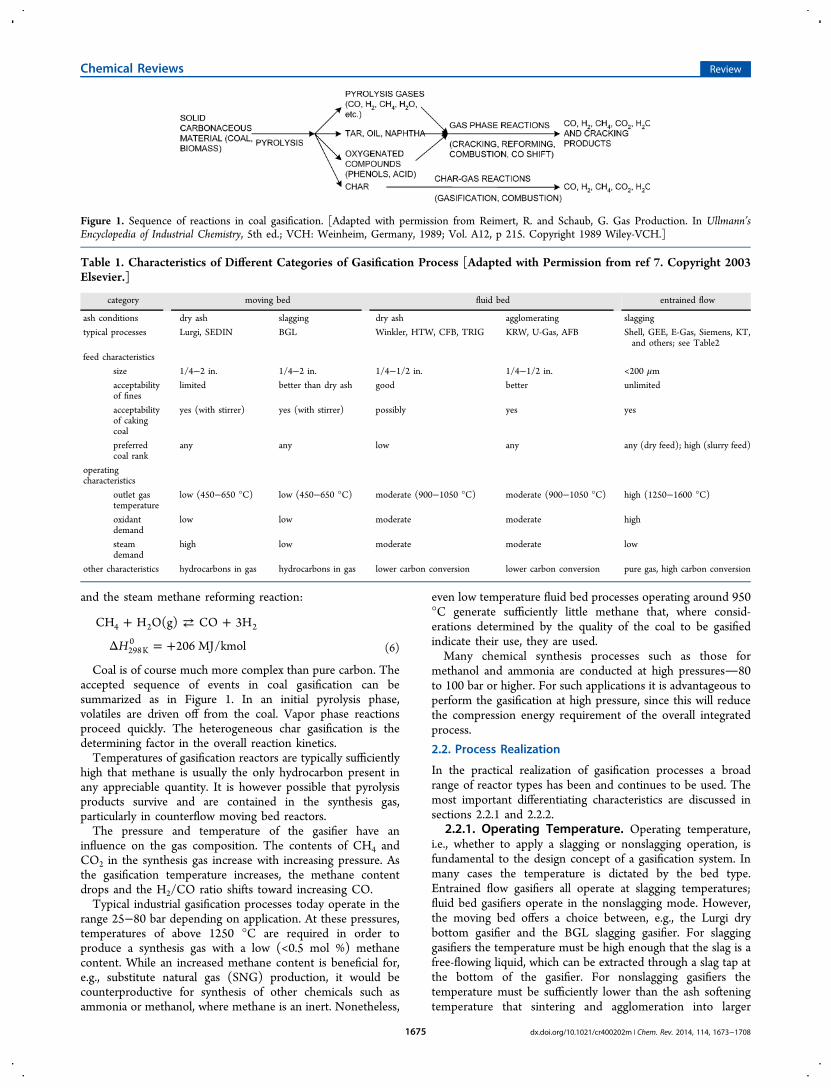
particles are avoided. In between these two temperatureregimes is an effective “no-go zone” in which sticky ash willcreate operating problems in any system.2.2.2. Bed Type. As described by this author elsewhere,8
Gasification reactors are generally classified according to bedtype as listed in Table 1 and portrayed in Figure 2:9 moving bed
gasifiers, fluid bed gasifiers, and entrained flow gasifiers. Only afew gasifiers fall outside this classification. Further details of theclassification system are provided below.8
Moving bed gasifiers (also called fixed bed gasifiers...)are characterized by a bed, in which the coal movesslowly downward under gravity as it is gasified by a blastor oxidant, which generally, but not universally, movescountercurrent to the coal. In such a countercurrentarrangement, the hot synthesis gas from the gasificationzone is used to preheat and pyrolyze the downwardflowing coal. [This arrangement reduces the oxygenconsumption,] but pyrolysis products as well as moisturebrought into the reactor with the coal are present in theproduct synthesis gas. [Depending on coal quality andother circumstances, the methane content of the drysyngas can be anything between 5 and 15 mol %.] Theoutlet temperature of the synthesis gas is generally low,even if higher temperatures are reached in the heart ofthe bed. Moving bed processes operate on lump coal. Anexcessive amount of fines, particularly if the coal hasstrong caking properties, can block the passage of the up-flowing syngas.
Fluid bed gasifiers offer extremely good mixing betweenfeed and oxidant, which promotes both heat and masstransfer. This ensures an even distribution of material inthe bed, and hence a certain amount of only partiallyreacted fuel is inevitably removed with the ash. Thisplaces a limitation on the carbon conversion of fluid bedprocesses. The operation of fluid bed gasifiers is generallyrestricted to temperatures below the softening point of
the ash, since agglomeration of soft ash particles willdisturb the fluidization of the bed.... Sizing of the particlesin the feed is critical: material which is too fine will tendto become entrained in the syngas and leave the bedoverhead. This is usually partially captured in a cycloneand returned to the bed. The lower temperatureoperation of fluid bed processes means that [they handlereactive feedstocks such as low rank coals and biomassbetter than bituminous coals. The methane content ofthe syngas is in the range 2−7 mol %.][As a means to improve carbon conversion, some
gasifiers contact the ash with an additional stream ofoxidant as it is extracted from the gasifier. This providesadditional carbon burn off from the ash. The temperaturerises at this point, and the ash particles formagglomerates.]Entrained flow gasifiers operate with feed and [oxidant]in cocurrent flow. The residence time in these processesis short (a few seconds). The feed is ground to a size of200 μm or less to promote mass transfer and allowtransport in the gas. Given the short residence time, hightemperatures are required to ensure a good conversionand therefore all entrained flow gasifiers operate in theslagging range [(i.e., above the melting temperature ofthe ash)]. The high temperature operation creates a highoxygen demand for this type of process. An advantage ofentrained flow gasifiers is that they do not generally haveany specific technical limitations on the type of coalused.... Additionally, the ash is produced in the form ofan inert slag or frit, which can be used as a constructionmaterial. This is achieved with the penalty of additionaleffort in coal preparation as well as the high oxygenconsumption, especially in the case of coal−water slurriesand/or coals with a high moisture or ash content.
Where the fusion temperature of the ash is high, in particularhigher than acceptable for a refractory lining, then it is possibleto add a fluxing agent to allow operation at a lowertemperature.
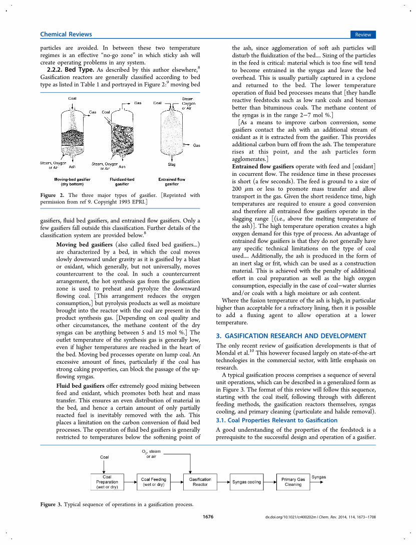
3. GASIFICATION RESEARCH AND DEVELOPMENTThe only recent review of gasification developments is that ofMondal et al.10 This however focused largely on state-of-the-arttechnologies in the commercial sector, with little emphasis onresearch.A typical gasification process comprises a sequence of several
unit operations, which can be described in a generalized form asin Figure 3. The format of this review will follow this sequence,starting with the coal itself, following through with differentfeeding methods, the gasification reactors themselves, syngascooling, and primary cleaning (particulate and halide removal).3.1. Coal Properties Relevant to Gasification
A good understanding of the properties of the feedstock is aprerequisite to the successful design and operation of a gasifier.
Figure 2. The three major types of gasifier. [Reprinted withpermission from ref 9. Copyright 1993 EPRI.]
Figure 3. Typical sequence of operations in a gasification process.
Chemical Reviews Review
dx.doi.org/10.1021/cr400202m | Chem. Rev. 2014, 114, 1673−17081676
The properties most relevant to a particular operation willdepend, at least to some extent, on the type of gasifieremployed, but in all cases it will be necessary to adapt theoperation to allow for changes in the feed. While thedetermination of much coal characterization data is a routinematter, often performed by and available from sellers andtraders, char reactivity will in almost all cases need to beassessed by the gasifier designer or operator. Similarly, while theash fusion temperature data is often available from the seller,this can provide only an indication of the likely operationtemperature. For slagging gasifiers the viscosity−temperaturerelationship will have to be determined. For fixed and fluid bedgasifiers the need is to have an understanding of the onset ofclinkering. Both these areas, char reactivity and the behavior ofmineral matter in coal, continue to be the subjects of intenseinvestigation.3.1.1. Reactivity of Coal and Other Chars. Feedstock
reactivity generally receives more consideration in connectionwith fluid bed gasifiers, and it is often assumed that entrainedflow gasifiers operate at temperatures sufficiently high that therate of reaction is determined by bulk diffusion rather thaninherent reactivity. While this may be true, it is still necessary tohave a good understanding of the apparent reactivity at hightemperature. On the scale-up of the 26 bar Texaco gasifier forthe Polk Power Station, the expected carbon conversion was97.5−98%, but actual performance was “in the low to mid 90%range”.11 This has been attributed to insufficient residence timein the reactor.12 The same references note that the carbonconversion dropped further on gasifying a fuel containing 55%petroleum coke, which has a much lower reactivity than coal.There is unfortunately no clear standard for reporting
reactivity, so numerical data is often difficult to compare orinterpret. The most common procedure is to determinereactivity at atmospheric pressure under CO2 or steam, but asdiscussed below, even the preparation of the char can have aninfluence on the result. However, for lack of a standard it isalways necessary to report the conditions under which themeasurement was made to avoid any misinterpretation.There is an awareness of a need to determine reactivities
under conditions similar to those obtaining under actualindustrial conditions. Studies have been performed underabsolute pressures in the range 20−25 bar. Roberts and Harrisfound reduced reaction rates with an increased CO partialpressure.13 An investigation of reactivity of petroleum cokeunder a CO2 atmosphere without CO did not reveal anypressure influence.14 In a different investigation char wasprepared under different pressures up to 20 bar and thengasified at atmospheric pressure under steam.15 The charsgenerated under pressure were found to be more reactive, butfurther work will be needed to determine the effect of pressureand gas composition. It should however be noted that all thiswork has been conducted at temperatures in the 800−1000 °Crange. This provides insights appropriate to fluid bed processes,but for entrained flow gasifiers operating in the 1400−1600 °Crange, these investigations will need to be extended.Some work has been performed at higher temperatures, but
then mostly at atmospheric pressure. One such was thedetermination by Zhan et al. of the catalytic effect of blackliquor on the gasification reactivity of petroleum coke,16 whichwas conducted up to 1400 °C, but this must be considered as aspecial case and unlikely to be able to find direct transfer ofapplicability to other situations.
The difficulty of transferring results from reactivity studies ofone coal to another coal is the reason that so much work isperformed in this area. Liu et al. found that the rate of heatingduring pyrolysis influenced the reactivity of Binxian coal char.17
Faster pyrolysis at higher temperatures increases the reactivity.On the other hand, demineralization of the coal with HF andHCl prior to pyrolysis reduced the reactivity when it wastreated otherwise similarly. Reactivity is usually measured withCO2 as the gasifying medium, but some have used steamagainst the background of generating a hydrogen-rich gas.18,19
Tay and Li compared the results of gasifying with pure CO2and a gas containing 4000 ppm O2 in Ar, both at 800 °C.20
Although both atmospheres are oxidizing, “the reactivities ofthe chars prepared in pure CO2 were of a much highermagnitude” than of those prepared in the O2/Ar atmosphere.
3.1.2. Behavior of Mineral Matter. 3.1.2.1. Ash FusionTemperatures. The ash fusion temperature (AFT), usuallycharacterized by the initial deformation temperature (IDT) asdefined by standard test procedures (e.g., ASTM D1857), is animportant coal characteristic for any gasification process. Forfluid bed processes it determines the upper limit for theoperating temperature, since above this temperature agglom-eration of the particles is likely. For entrained flow processesthe temperature must be above the fluid temperature (FT) toallow the molten ash to be drawn off as a molten slag. Note thatentrained flow processes will actually operate at significantlyabove FT, since, as discussed below, the slag viscosityrequirements will demand this.There has been much effort devoted to determining a
method to predict the AFT from the chemical composition ofthe ash, but the validity of the results obtained has generallybeen limited to coals of similar origin to that used to test theproposed model, at least with any degree of accuracy. Recentwork with thermochemical equilibrium models such asFactSage has brought the goal nearer.21−23 While each ofthese studies concentrated on coals from a specific region andthe correlations of measured data with predicted results werereasonable, there are still limitations. Song et al.24 systematicallyvaried the amounts of SiO2, Al2O3, CaO, Fe2O3, and MgOadded to some Chinese coals under an inert (Ar) atmosphereand generally found good agreement in the shape of atemperature−component plotin particular the componentconcentration required to achieve the minimum AFTbut theabsolute values for the predicted AFT still show some deviationfrom the measured values. Even with such a deviation, resultslike these will provide a good guide to determining the optimalflux addition rates. It should be noted also that Song et al. alsodemonstrated the difference in AFT predictions under inertand reducing atmospheres,24 so this also provides an additionalreason to take care in applying absolute temperatures derivedfrom FactSage to a particular industrial situation.
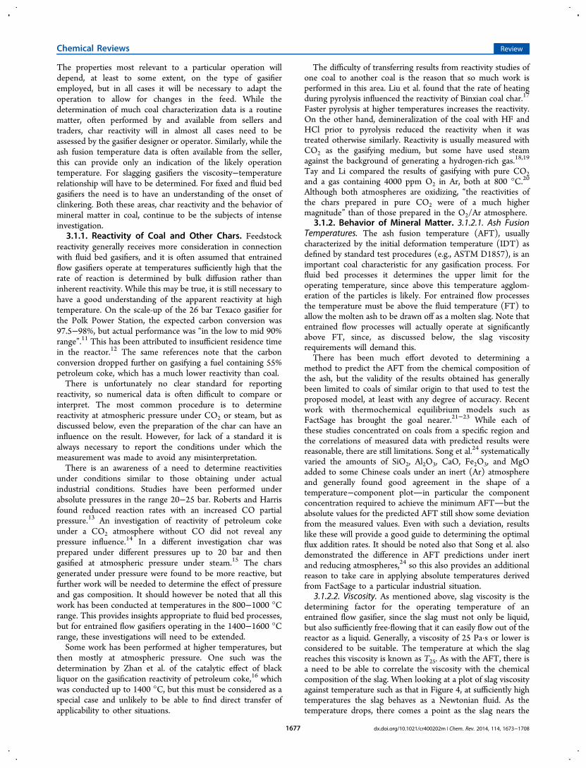
3.1.2.2. Viscosity. As mentioned above, slag viscosity is thedetermining factor for the operating temperature of anentrained flow gasifier, since the slag must not only be liquid,but also sufficiently free-flowing that it can easily flow out of thereactor as a liquid. Generally, a viscosity of 25 Pa·s or lower isconsidered to be suitable. The temperature at which the slagreaches this viscosity is known as T25. As with the AFT, there isa need to be able to correlate the viscosity with the chemicalcomposition of the slag. When looking at a plot of slag viscosityagainst temperature such as that in Figure 4, at sufficiently hightemperatures the slag behaves as a Newtonian fluid. As thetemperature drops, there comes a point as the slag nears the
Chemical Reviews Review
dx.doi.org/10.1021/cr400202m | Chem. Rev. 2014, 114, 1673−17081677
solidification temperature, where this is no longer so. Thistemperature is known as the critical temperature or Tcv. Atheoretical model to calculate slag viscosity developed byUrbain et al.25 and modified by Kalmanovitch and Frank26 hasbeen shown to give good results for slags in the Newtonianregion27 above Tcv. Extensive empirical work to determine theTcv was performed on the system SiO2−Al2O3−CaO−FeO fora wide variety of Australian coals.28 Work continues in this areaand in particular comparisons are made with data derived fromFactSage; however, much of this is related to specificcircumstances.29−33
The transition from a Newtonian fluid at Tcv is attributed tothe onset of crystallization of species in the slag during cooldown. Understanding this process can assist in the prediction ofTcv. Yuan et al. measured the viscosity on cooling various slagsfrom 200 °C over the fluid temperature to a temperature atwhich the viscosity had increased markedly.34 In parallel theseslags were simulated with FactSage. For coal ash samples rich inAl2O3 and SiO2, mullite was the first solid phase to form, evenat temperatures above 1600 °C; for those with more CaO andFe2O3, anorthite was the first solid phase to form. Nakano et alused a synthetic ash mixture to simulate a coal−petroleum coke(petcoke) mix.35 With a high proportion of petcoke, the firstsolid phase is karelianite (V2O3). The presence of mullite,which was predicted by FactSage, was not observed, even with alower proportion of petcoke.3.1.2.3. Char−Slag Transition. Carbon conversion rates in
fluid bed gasification tend not to be as good as for entrainedflow gasifiers. Values of 92−95% are typical unless there is anagglomeration stage to improve them. On the other hand, therecan be some advantage to limiting the conversion rate. In aseries of ash deposition experiments, under both oxidizing36
and gasification37 conditions, Li et al. determined that, as charparticles were gasified, there was a transition point at which thedeposition rate of the mineral matter on an impingement plateincreased rapidly. Increasing the conversion rate beyond thischar−slag transition point will therefore increase the likelihoodof fouling of a syngas cooler. This work provides thebackground to the empirically determined industrial practicein oil gasification, whereby carbon conversion is deliberatelynot increased beyond a value of about 99.0−99.5% dependingon ash content, since doing so will cause ash deposition in thecooler.
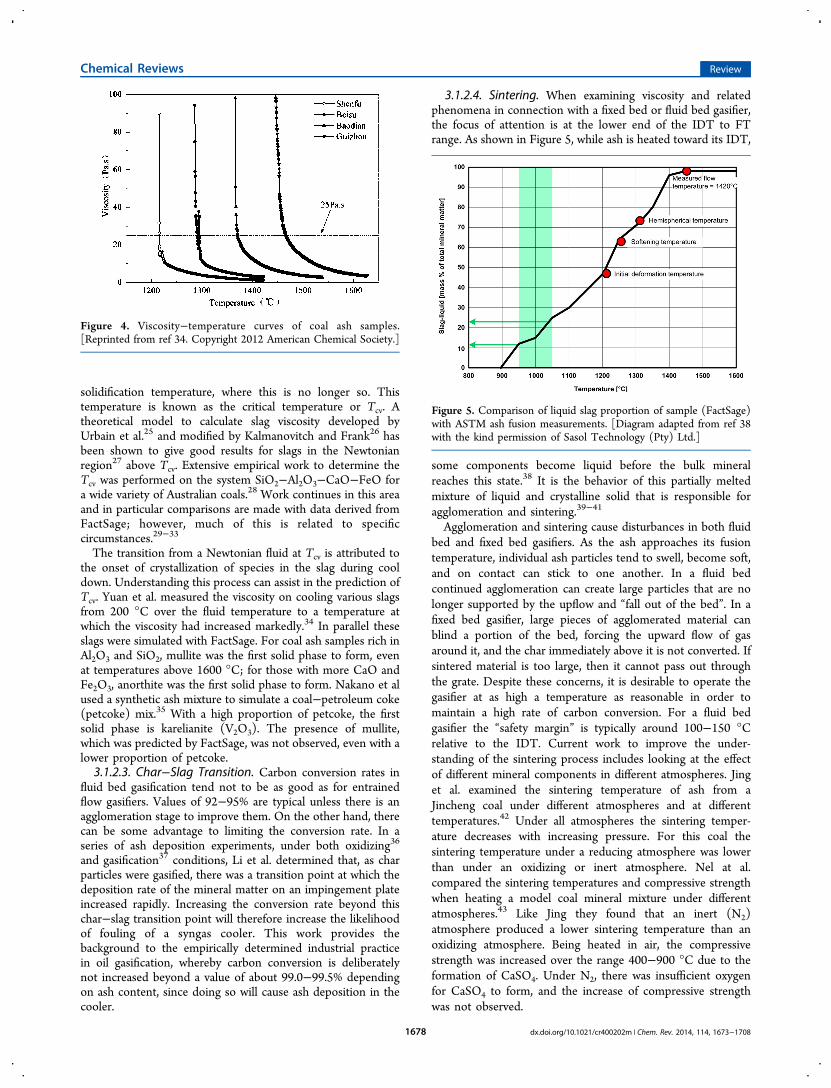
3.1.2.4. Sintering. When examining viscosity and relatedphenomena in connection with a fixed bed or fluid bed gasifier,the focus of attention is at the lower end of the IDT to FTrange. As shown in Figure 5, while ash is heated toward its IDT,
some components become liquid before the bulk mineralreaches this state.38 It is the behavior of this partially meltedmixture of liquid and crystalline solid that is responsible foragglomeration and sintering.39−41
Agglomeration and sintering cause disturbances in both fluidbed and fixed bed gasifiers. As the ash approaches its fusiontemperature, individual ash particles tend to swell, become soft,and on contact can stick to one another. In a fluid bedcontinued agglomeration can create large particles that are nolonger supported by the upflow and “fall out of the bed”. In afixed bed gasifier, large pieces of agglomerated material canblind a portion of the bed, forcing the upward flow of gasaround it, and the char immediately above it is not converted. Ifsintered material is too large, then it cannot pass out throughthe grate. Despite these concerns, it is desirable to operate thegasifier at as high a temperature as reasonable in order tomaintain a high rate of carbon conversion. For a fluid bedgasifier the “safety margin” is typically around 100−150 °Crelative to the IDT. Current work to improve the under-standing of the sintering process includes looking at the effectof different mineral components in different atmospheres. Jinget al. examined the sintering temperature of ash from aJincheng coal under different atmospheres and at differenttemperatures.42 Under all atmospheres the sintering temper-ature decreases with increasing pressure. For this coal thesintering temperature under a reducing atmosphere was lowerthan under an oxidizing or inert atmosphere. Nel at al.compared the sintering temperatures and compressive strengthwhen heating a model coal mineral mixture under differentatmospheres.43 Like Jing they found that an inert (N2)atmosphere produced a lower sintering temperature than anoxidizing atmosphere. Being heated in air, the compressivestrength was increased over the range 400−900 °C due to theformation of CaSO4. Under N2, there was insufficient oxygenfor CaSO4 to form, and the increase of compressive strengthwas not observed.
Figure 4. Viscosity−temperature curves of coal ash samples.[Reprinted from ref 34. Copyright 2012 American Chemical Society.]
Figure 5. Comparison of liquid slag proportion of sample (FactSage)with ASTM ash fusion measurements. [Diagram adapted from ref 38with the kind permission of Sasol Technology (Pty) Ltd.]
Chemical Reviews Review
dx.doi.org/10.1021/cr400202m | Chem. Rev. 2014, 114, 1673−17081678
3.1.2.5. Kinetics. Most current work on the correlationbetween slag properties and chemical composition has beenbased on the calculation of thermodynamic equilibrium of theminerals. Wang et al. have examined the kinetic behavior of twodifferent coals with differing AFTs and found considerabledifferences. In particular, the content of Na2O, K2O, and CaOcan inhibit the rate of mullite formation. Further work will benecessary to develop these observations into a more widelyapplicable model.44
3.1.2.6. Surface Tension. Besides viscosity there are otherproperties of the liquid slag which are needed for modeling anddesign of gasifiers and high temperature particulate removalequipment. Melchior et al. have investigated the effect ofpressure up to 10 bar on surface tension,45 a property for whichhitherto only data under atmospheric pressure has beenavailable in the literature.3.2. Coal Preparation and Feeding
One of the greater challenges in any gasification process is thatof charging a pressurized gasifier vessel with a solid coalfeedstock.46 This has to be performed with due considerationfor the safety of the system, since any failure or leakage runs therisk of discharging flammable and toxic syngas into thesurroundings. For entrained flow gasifiers both wet and drysystems for size reduction, pressurizing, transporting, andmeasuring coal feed flow have been developed and are inindustrial use. Nonetheless, there is still considerable incentiveto improve the efficiency, reliability, and cost of these systemsand that has been the focus of research in this area.As described elsewhere,8
In a dry feed system the coal is ground to a size of about100 μm and simultaneously dried in a roller mill similarto those used in conventional pulverized coal units. Thepulverized coal is pressurized in a lock hopper systemand deposited into a feed vessel, from which it istransported by pneumatic conveying. For ammoniaproduction the carrier gas is typically pure nitrogenfrom the air separation unit (ASU), but for many otherchemical applications where nitrogen is undesirable, CO2is used. Generally a dry feed system contributes to ahigher gasifier efficiency. However the amount of carriergas required for the pneumatic transport of the coal intothe gasifier increases with pressure. The economic limitfor dry feed systems is generally considered to be about40 bar. For low rank coals a pre-drying system upstreamthe mills may be necessary.For wet feed systems the slurry is made in a rod mill into
which pre-crushed (∼2 in.) coal and water are fed. Thecoal is ground in a wet milling process to a size of about100 μm. The slurry is pumped to the reactor pressuretypically by a membrane piston pump, which allowsgasifier operation at up to 80 bar. This can be anadvantage for some chemical applications. The need toevaporate the water from the slurry in the gasifier reducesthe efficiency of slurry fed systems. In the case of lowrank coals the high inherent moisture of the coal doesnot contribute to the transport properties of the slurry,so that it is superimposed on to the about 35% free watercontent. The total water content entering the gasifier canthen become so large that economic operation with aslurry feed is impossible.
3.2.1. Fines Reduction in Crushing Facilities. One of thefirst steps in any gasification process is size reduction to at least
a transportable size of about <50 mm. Whether the gasificationfacility is located at the mine, as are for instance the Sasolfacilities in South Africa, or remotely, there is likely to be anincentive to minimize the production of fines. Typical tradedcoal sizes are 2 in. maximum top size and maximum 30% ≤ 2mm.47
Moving bed gasifiers such as those of Lurgi and BGL (BritishGas−Lurgi) can only accept a small to moderate amount offines (<5−7%) without the risk of the fines blocking part of thebed and causing “channeling” of the gas around the blockage.48
Such channeling is associated with the material in the blockedarea not being converted and also possible breakthrough ofoxygen through the channel into the syngas. Fines that arise outof the coal preparation must therefore either be directed to alarge pulverized coal boiler, such as at the Dakota GasificationSNG plant,49 or be briquetted to make them suitable forfeeding to the gasifier, such as in the Hulunbeier BGL ammoniaplant in Inner Mongolia.50
In plants without briquetting facilities considerable effort isdevoted to minimizing the fines make during precrushing andtransport activities. In order to support such activities at theSasol coal-to-liquids plant in Secunda, South Africa, work isbeing conducted at North-West University (South Africa) togain a better understanding of the comminution characteristicsof South African coals.51
A similar situation obtains with fluid beds, though the desiredsize range is smaller (2−6 mm), and similar work has takenplace to define how one can minimize fines generation duringthe process of size reduction with an impact crusher.52 Thestudy determined that the rotational speed of the crusher is arelevant though weak parameter over which the operator doeshave some control, but recognizes that the quality of the feedcoal to a crushing system is the most important factor.
3.2.2. Slurry Feeding Systems. Coal−water slurries forslurry-feed gasifiers typically have a solids content of 62−68%.53The water in the slurry must be evaporated in the gasifier,which contributes to the lower efficiency of such systemscompared with a dry feed system. The limitation to reducingthe water content is generally the viscosity of the slurry, whichmust be typically less than 1000−1200 mPa·s at a shear rate of100 s−1. Viscosities higher than this create practical problemsfor filtering and pumping. In an industrial application, there isusually a buffer tank containing 8−12 h holdup between slurrymanufacture and gasifier. The solids should not settle out in thebuffer tank or in the pipelines of the system. Another criticalproperty of the slurry is therefore its stability.The use of surfactants and in particular ammonium
lignosulfonate as an additive to achieve a higher solids contentwhile maintaining an acceptable viscosity is well-known.54
Further efforts continue to be made to increase the solidscontent of coal−water slurries. Additives that have beeninvestigated include black liquor,55,56 sewage sludge,57,58
algae,59 ethanol,60 and natural plant extracts.61 The motivationfor much of this work is however disposal of wastes andexamining the effect of coslurrying waste streams with the coal.Black liquor is, perhaps unsurprisingly, beneficial; sewagesludge, having a high degree of inherent moisture, reducesthe overall solids content of the slurry at an acceptable viscosity,though Wang et al. did observe an improvement in the stabilitycharacteristics of the slurry.62
Liu investigated the effect of limestone addition as a means ofdesulfurization in connection with slurry feed combustion.63
This data is applicable also, when limestone is added as a
Chemical Reviews Review
dx.doi.org/10.1021/cr400202m | Chem. Rev. 2014, 114, 1673−17081679
fluxant. The effect of adding small quantities of limestone to thecoal has a minor detrimental effect on slurry quality, bothincreasing viscosity and reducing stability, but these effectsincrease rapidly with increasing proportions of limestone.Another approach has been to pretreat the coal prior to
slurrying. This is potentially particularly attractive for low rankcoals, since generally much lower solids concentrations can beachieved than with high rank coals. Yu et al. performed ahydrothermal dewatering on two different Chinese browncoals.64 In one case the solids concentration was increased from45.7 to 59.5 wt %, and in the other case it was increased from53.7 to 62.1 wt %. This brings a brown coal slurry into almostthe same range as “a typical optimized slurry.”65
The Electric Power Research Institute (EPRI), Palo Alto,CA, has proposed an alternative approach to reducing theefficiency loss attributable to the evaporation of the continuousphase of the slurry, namely, to replace the water by liquid CO2,which has a lower heat of evaporation.66 EPRI recently receiveda contract from the U.S. DOE to pursue this work further.67
3.2.2.1. Slurry Feed Injectors. Another aspect of slurry feedgasifiers that has received continuous development attention isthe relatively short life of the feed injectors or burners. EastmanChemicals reported improving their feed injector life from arecord 91 days in 200168 to 122 days in 2003.69 Althoughfurther improvements have been made since (e.g., Zhou reports150 days70), the contrast with the 1−2 year life of a dry feedburner remains remarkable. This author attributes at least partof this difference to the instability of the flame pattern causedby the flashing of the liquid phase and the resultant thermalfatigue on the burner face. Much of the improvement to datehas been accomplished by improved materials of constructionand minor geometrical changes, but addressing this basic issuehas not been so well discussed in public. Attempts atdeveloping an understanding of the flow patterns in thebreakup are in progress,71 but there is still a need for a modelbased on the underlying physics.72 Superimposing the flashingeffects on such a model remains a task for the future. GE hasannounced an improvement program, the results of which havebeen incorporated into the design for the recently (September2012) started-up Edwardsport IGCC.73
3.2.3. Dry Feeding Systems. 3.2.3.1. Milling. Dry feedingsystems for entrained flow gasifiers use the same millingequipment as is used for conventional pulverized coal boilersand benefit from incremental improvements made for theboiler market.3.2.3.2. Lock Hoppering of Pulverized Coal. The conven-
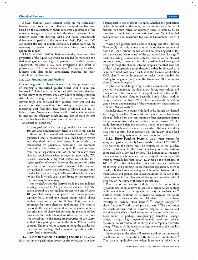
tional method of moving dry solids from a region of lowpressure to one of high pressure is to use lock hoppers. Atypical configuration is shown in Figure 6.74 Pulverized coal isstored in the atmospheric storage bin. One of the lock hoppersis depressurized and the valves between it and the storage binare opened allowing coal to be charged to the lock hopper. Thelock hopper is then blocked in and pressurized to the pressureof the feeding vessel. The valve to the feeding vessel is thenopened and the coal is discharged. The lock hopper is againblocked in and depressurized, restarting the cycle. The secondlock hopper works on a similar, but staggered cycle to smoothout the supply of coal to the feed vessel. The whole operation iscontrolled electronically with appropriate safeguards againstvalve malfunction and the like.In terms of reliability and maintenance the lock hopper
system is considered to be one of the most critical parts of a dryfeed gasification system. The key issues are the risk of bridging,
so that when a discharge valve opens the hopper does notdischarge, and the reliability of the valves themselves.Avoiding bridging is usually accomplished by aeration with
an inert gas such as nitrogen as shown in Figure 6. As describedby Lu et al., the pulverized coal is typical of a Geldart Type Cpowder that is difficult to fluidize.75 Different technologiesinclude different solutions in detail and are also the subject ofcontinuous incremental improvement.76 As described below,there can be reasons to use CO2 rather than nitrogen as inertgas. Lu et al. also investigated the effect of changing theaeration gas to CO2.
77 At low pressures, CO2 was much lesseffective as a fluidizing agent than air. However, already at 4 barthe difference was much less noticeable. A comparison at thetypical 25−40 bar of a dry feed gasifier has not been identified.The valves operate on a cycle of typically about 30 min. They
can be expected to be subject to erosion by the passing coal, butat the same time they may not leak even after continuous use,since this would defeat the pressure cycling, which is the wholebasis of the lock hoppering process.
3.2.3.3. Pneumatic Conveying. The actual feeding of coal tothe burner of a dry feed entrained flow gasifier is by pneumaticconveying from the feed vessel as shown in Figure 6. Transportis in the dense phase, in which a density of 350−450 kg coal/m3 carrier gas is achieved.78 Initially this dense feed conveyingwas performed with nitrogen as carrier gas, since in thegasification environment this was a readily available inert gas.Typically the nitrogen appears in a concentration of about 6%in the raw syngas. For ammonia (or power) applications, this isnot harmful. For other applications such as methanol, SNG, orFischer−Tropsch synthesis, this level of inert material in thesynthesis gas is undesirable: compression energy for the inertcomponent of the syngas is consumed to no good purpose andthe amount of syngas accompanying the inert purge is also aloss to the system. In such cases CO2 is used as carrier gas. Inapplications where nitrogen is undesirable, there is usually aCO2 removal unit in the syngas processing, which provides asource of carrier gas as well as a means of adjusting thestoichiometry of the gas for the synthesis.However, care must be taken in the design of systems
suitable for CO2. Cong et al. have investigated the character-
Figure 6. Typical lock hopper arrangement for pulverized coal.[Reprinted with permission from ref 74. Copyright 2013 Siemens FuelGasification Technology GmbH & Co. KG.]
Chemical Reviews Review
dx.doi.org/10.1021/cr400202m | Chem. Rev. 2014, 114, 1673−17081680
istics of pulverized coal pneumatic conveying using alternativelyCO2 and air and report several differences.79 For the samesolids mass flow rate, the required CO2 gas flow rate is higherthan that of air. One result is a 20% increase in energy demandto transport the same mass of solids, when using CO2. Part ofthis work included the study of flow patterns and pressuresignals in a horizontal pneumatic conveying line.80 They foundmultiple flow patterns and were able to correlate the flowpatterns with pressure signals providing a means of character-izing the flow patterns and their variation. This offers potentialfor improved monitoring of the dense flow pneumatic transportand early warning of operational disturbance.3.2.3.4. Lock Hoppering for Fixed Bed Gasifiers. Lock
hoppering of lump coal for fixed bed reactors, while sharing thesame basic pressure cycle, is much simpler than for pulverizedcoal supply to an entrained flow gasifier. The lock hopperdischarges directly into the reactor and is built integrally with it.However, the gas losses from the lock hopper depressurizationare syngas, rather than an inert gas. The safety considerationsand cost of these losses are therefore of even more concernthan in the case of the entrained flow gasifiers. In some casesthe lock gas is simply burned in a flare; in others it isrecompressed and added to the syngas. The scale of theselosses is increased with pressure, and for the 100 bar fixed beddemonstration unit Ruhr 100, twin lock hoppers were installed.The cycles of the two lock hoppers were integrated so that thedepressurization gas of the one hopper could be used aspressurizing gas for the otherat least until pressureequalization was achieved. This arrangement achieved a 70%savings in pressurizing gas.81 The first twin locks on anindustrial scale were implemented on a BGL gasifier atSchwarze Pumpe, Germany, in 2001.82 They are included inthe design of the recently announced Lurgi “Mark Plus” gasifier,an up-scaled version of the previous Mark IV design.83
3.2.4. Dry Solids Pumps. One potential means of reducingthe capital cost of dry feeding is the use of so-called “dry solidspumps”. The first concepts were developed in the 1980s.84,85
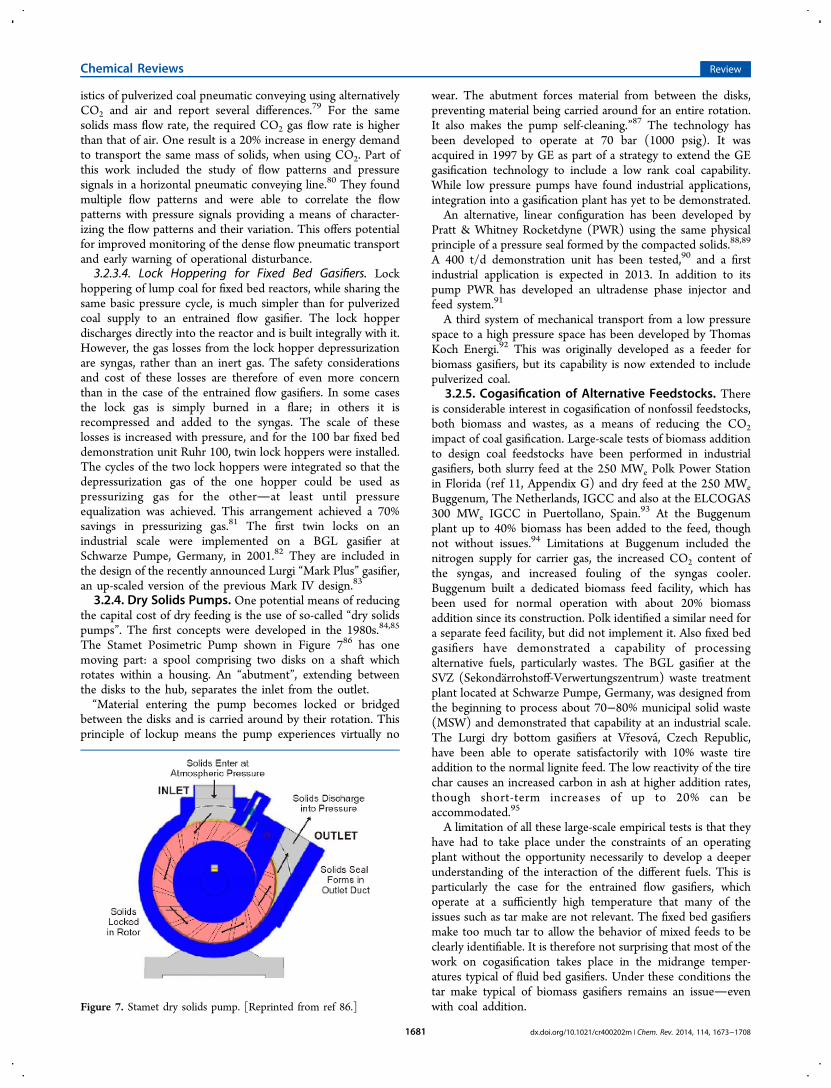
The Stamet Posimetric Pump shown in Figure 786 has onemoving part: a spool comprising two disks on a shaft whichrotates within a housing. An “abutment”, extending betweenthe disks to the hub, separates the inlet from the outlet.“Material entering the pump becomes locked or bridged
between the disks and is carried around by their rotation. Thisprinciple of lockup means the pump experiences virtually no
wear. The abutment forces material from between the disks,preventing material being carried around for an entire rotation.It also makes the pump self-cleaning.”87 The technology hasbeen developed to operate at 70 bar (1000 psig). It wasacquired in 1997 by GE as part of a strategy to extend the GEgasification technology to include a low rank coal capability.While low pressure pumps have found industrial applications,integration into a gasification plant has yet to be demonstrated.An alternative, linear configuration has been developed by
Pratt & Whitney Rocketdyne (PWR) using the same physicalprinciple of a pressure seal formed by the compacted solids.88,89
A 400 t/d demonstration unit has been tested,90 and a firstindustrial application is expected in 2013. In addition to itspump PWR has developed an ultradense phase injector andfeed system.91
A third system of mechanical transport from a low pressurespace to a high pressure space has been developed by ThomasKoch Energi.92 This was originally developed as a feeder forbiomass gasifiers, but its capability is now extended to includepulverized coal.
3.2.5. Cogasification of Alternative Feedstocks. Thereis considerable interest in cogasification of nonfossil feedstocks,both biomass and wastes, as a means of reducing the CO2impact of coal gasification. Large-scale tests of biomass additionto design coal feedstocks have been performed in industrialgasifiers, both slurry feed at the 250 MWe Polk Power Stationin Florida (ref 11, Appendix G) and dry feed at the 250 MWeBuggenum, The Netherlands, IGCC and also at the ELCOGAS300 MWe IGCC in Puertollano, Spain.93 At the Buggenumplant up to 40% biomass has been added to the feed, thoughnot without issues.94 Limitations at Buggenum included thenitrogen supply for carrier gas, the increased CO2 content ofthe syngas, and increased fouling of the syngas cooler.Buggenum built a dedicated biomass feed facility, which hasbeen used for normal operation with about 20% biomassaddition since its construction. Polk identified a similar need fora separate feed facility, but did not implement it. Also fixed bedgasifiers have demonstrated a capability of processingalternative fuels, particularly wastes. The BGL gasifier at theSVZ (Sekondarrohstoff-Verwertungszentrum) waste treatmentplant located at Schwarze Pumpe, Germany, was designed fromthe beginning to process about 70−80% municipal solid waste(MSW) and demonstrated that capability at an industrial scale.The Lurgi dry bottom gasifiers at Vresova, Czech Republic,have been able to operate satisfactorily with 10% waste tireaddition to the normal lignite feed. The low reactivity of the tirechar causes an increased carbon in ash at higher addition rates,though short-term increases of up to 20% can beaccommodated.95
A limitation of all these large-scale empirical tests is that theyhave had to take place under the constraints of an operatingplant without the opportunity necessarily to develop a deeperunderstanding of the interaction of the different fuels. This isparticularly the case for the entrained flow gasifiers, whichoperate at a sufficiently high temperature that many of theissues such as tar make are not relevant. The fixed bed gasifiersmake too much tar to allow the behavior of mixed feeds to beclearly identifiable. It is therefore not surprising that most of thework on cogasification takes place in the midrange temper-atures typical of fluid bed gasifiers. Under these conditions thetar make typical of biomass gasifiers remains an issueevenwith coal addition.Figure 7. Stamet dry solids pump. [Reprinted from ref 86.]
Chemical Reviews Review
dx.doi.org/10.1021/cr400202m | Chem. Rev. 2014, 114, 1673−17081681
Pinto et al. have examined the results of cogasification ofvarious coals with pine, bagasse, refuse-derived fuel, andpolyethylene wastes in a pilot-scale fluid bed gasifier operatingwith air or oxygen−steam mixture at 850 °C.96−99 In all casestars were produced, though in varying amounts depending onthe quality of the noncoal component of the fuel. A gas cleanupsystem using two fixed beds of dolomite and Ni-based catalystwas used. Tars were reduced to below 1% in all cases after thedolomite and were not detected downstream the Ni catalyst.Velez et al.100 and Alzate et al.101 have conducted tests withsteam gasification of coal−sawdust pellets.It is important to develop a good understanding of how trace
elements, particularly those introduced by waste addition, willbehave. For instance, Zhang et al. investigated gasification of acoal−sewage sludge mixture in different proportions.102 Thesewage sludge itself contained about 2.85 wt % phosphorus.Organic phosphorus, nonapatite inorganic phosphorus (NAIP,not Ca-bound phosphorus), and apatite phosphorus (AIP, Ca-bound phosphorus) account for 9.0, 73.0, and 18.0 wt % of thetotal phosphorus, respectively. They found that while the bulkof the organic phosphorus volatilized already during thepyrolysis stage, there was little obvious volatilization ofinorganic phosphorus until about 1200 °C. Thus most of thephosphorus was bound in the slag after gasification.Aigner et al. performed cogasification of wood and coal in a
100 kWth pilot dual fluid bed indirect gasifier in differingproportions to study the effect of varying the proportions ofbiomass and coal.103 All gas components show a linearrelationship with linearly changing fuel ratios. No synergeticeffects of cogasification between coal and biomass were found.Zhu et al. looked at the effect of blending ratio on pyrolysis in astraw−coal mixture.104 They also found no synergies in thechar yield from the pyrolysis. There was, however, an increaseof gasification reactivity with increased ratio of wheat straw-to-coal.3.2.5.1. Cogasification with Petroleum Coke. Cogasifica-
tion of petroleum coke (petcoke) with coal is already practicedindustrially, particularly in locations where the petcoke has lowvalue. The ELCOGAS dry feed IGCC in Puertollano, Spain,was designed for a 50:50 mixture of petroleum coke and highash, low sulfur coal. The principle lesson learned from thatplant specific to the petcoke feed was that more attention to thedetail design of the grinding equipment was necessary.105 TheWabash and Polk slurry feed demonstration IGCCs wereoriginally designed only for a range of coals. Since theconclusion of the DOE demonstration program in January2000, the Wabash plant has operated on 100% petcoke with theaddition of only 2−3% limestone or boiler bottom ash flux.106
Polk has operated on a coal−petcoke ratio of about 45:55 since2001 (ref 11, p 1-28). The principle limitation on increasing thepetroleum coke feed at Polk is the capacity of the sulfurrecovery unit.Nonetheless, cogasification of petcoke and coal continues to
attract research attention. Petroleum coke is much less reactivethan coal. There are multiple reasons for this. The BET specificsurface area of petcoke is much lower than that of coals; there islittle alkaline or alkaline earth material with catalytic activity forgasification in the ash; the ash with its typically high vanadiumcontent has a very high fusion temperature. This all results inthe need to operate the gasifier at higher temperature to achievea high carbon conversion similar to what one would achievewith a bituminous coal. Economically, the higher oxygendemand removes part of the benefit of petroleum coke as a
cheap fuel. In refractory-lined gasifiers a higher operatingtemperature may be undesirable in order to maintain a longerrefractory lifetime, so a low single pass conversion may have tobe accepted. For a single stage gasifier such as Polk, a highcarbon fraction of the slag stream is separated from the slag andrecycled to the gasifier.107 In a two-stage gasifier, the charrecycle will be larger. It is against this background that thecontinued efforts to find improvements must be understood.Vejahati et al. have followed up earlier work on cogasifying
oil sand coke with Albertan coal, but they failed to find anysynergies.108 There is however no indication of the ash contentor composition in the coal, so it is difficult to evaluate thisfinding. On the other hand, Zhan et al. investigated theinfluence of blending methods on the cogasification reactivityof petroleum coke and lignite and found wet grinding to bemore beneficial than dry milling.109 The lignite used was a highash (18.24 wt %) material with 12.6 wt % CaO in the ash. Theloss of weight with time as measured with TGA was improvedagainst that of undiluted petcoke in both cases, but this effectwas much more marked in the case of wet grinding. This isattributed to the improved mixing achieved with wet grinding.
3.3. Gasification Reactors
3.3.1. Fixed Bed Gasifiers. Still today more syngas isproduced using the Lurgi fixed bed dry bottom gasifier orderivatives than any other. Locations using it are however fewbut large, being located in South Africa, the United States(North Dakota), Czech Republic, and China. It is therefore notsurprising that research is largely limited to these countries andto coals specific to them.One of the most important techniques in developing a
further understanding of fixed bed reactors is the “turn out”, inwhich the contents of a shut-down reactor is sampled whileslowly removing it through the grate. Bunt and Waanders haveperformed studies on the basis of this technique examining thefate of the principle reacting elements (C, H, N, O, S) over thedepth of the reactor bed as well as the changes in the ashspeciation. It was found that, in the oxidation zone, ashcomponents oxidize also and in the case studied consumed2.5% of the total oxygen supplied to the reactor.110 van Dyk etal. pursued this phenomenon and have developed a correlationbetween oxygen capture tendencies and CaO content valid forSouth African Highveld coals.111
In a second study Bunt and Waanders observed developmentof particle size through the reactor. Of the +25 mm particles,85% had already broken up into finer size fractions in theupper, drying, and “slow pyrolysis” zones.112 In a third studythey and Wagner found influences of different petrographies onthe behavior of coal particles in the reactor.113
A similar “turn-out” exercise performed on two gasifiersoperating on North Dakota lignite showed that about two-thirds of the reactor volume was taken up with drying anddevolatilization of the coal. Nonetheless the high reactivity ofthe lignite char allowed it to be gasified with an overall carbonconversion of 98% within a third of the remaining space.114
Skhonde et al. used the results from a gasifier turn-out tofollow the behavior of sulfur in a fixed bed gasifier.115
A second technique used to see the effect of particle size ongasification is the small-scale pipe reactor, which can be movedfrom the vertical position to the horizontal and opened upaxially to allow sample taking and visual inspection of the bedprofile.116
Chemical Reviews Review
dx.doi.org/10.1021/cr400202m | Chem. Rev. 2014, 114, 1673−17081682
One of the byproducts of a fixed bed gasifier is known as“dusty tar”, condensed heavy hydrocarbons from the pyrolysisstage contaminated by particulate matter carried over in thesyngas from the gasifier bed. van Dyk et al. investigated thismaterial as a potential feed to a liquids gasifier.117 The viscosityof the tar is very high (>1000 cP at 80 °C), but can be reducedto <300 cP by milling, addition of waste solvent streams, orboth. For the South African coal from which this dusty tar isproduced, the ash fusion temperature is >1350 °C, but it can bereduced to 1250 °C using an 8% CaO flux. Any effect of theflux addition on the dusty tar viscosity is not reported.While most work on fixed bed gasification is performed at
locations close to industrial facilities, it is interesting to notethat an air-blown pilot plant was started up successfully in Italyin 2009 and has been operated in two campaigns since.118 Thefocus of this work is the development of small-to-medium-scaleequipment (10−15 MWth).Fixed bed gasifiers are notoriously difficult to model
accurately, so any published advance on existing models canbe of benefit to the community. One such is that of Grieco andBaldi,119 who based their model on the work of Hobbs et al.,120
while removing some of the simplifying assumptions.3.3.2. Fluid Bed Gasifiers. Fluid bed gasification is largely
the realm of low rank coals and biomass. The results of Cao etal., who investigated cogasification of methane with coals ofvarious ranks, show clearly the superior performance of lowrank coals compared with higher rank coals, when gasified in afluid bed reactor. Under essentially similar conditions in thesame fluid bed gasifier, they obtained carbon conversions of94.7 and 93.6% for lignite and subbituminous coal, respectively,and 68.5 and 82.9% for two different bituminous coals.121
One industrial scale technology, the high temperatureWinkler (HTW) process, was developed for Rhenischlignite.122 KBR/Southern’s TRIG transport integrated gasifierwas developed primarily with Powder River Basin (PRB)subbituminous coal in mind,123 and the first industrialapplication in the 524 MWe Kemper County IGCC is forMississippi lignite.124
However, some work on fluid bed gasification continues tobe performed on bituminous coals. Duan et al. explored theeffects of oxygen/carbon and steam/coal ratios as well as a hightemperature gasification agent supply to an air-blown 70 mmcirculating fluid bed (CFB) gasifier operating on Huaibeibituminous coal at 3 bar. While the trends shown by varying the
operating mode were as might be expected, the carbonconversion did not exceed 90% in any of the runs performed.125
Ju et al. performed similar studies on an 800 mm industrialscale atmospheric CFB unit with a Xuzhou bituminous coal.126
The carbon conversion was also much lower that would bedesired in an industrial application.The addition of an agglomerating stage to a fluid bed gasifier
is one approach to addressing the low carbon conversion ratestypical of fluid bed gasifiers operating on high rank coals.Thompson reports carbon conversions of up to 99% in a U-Gasplant operating on feeds ranging from run-of-mine bituminouscoal through high ash subbituminous coal to a high moisturelignite.127 Unfortunately, it is not clear with which of thevarious feedstocks this high conversion rate was achieved. Liu etal. have developed a simulation model of the ash agglomeratingfluidized bed (AFB) gasifier, which compares well with the testresults of a pilot plant operating on Jincheng anthracite.128 Inthis case also, carbon conversion is below 90%.Dual fluidized bed (DFB) systems are well-known from
biomass gasification.129 A particular attraction of the system isthe ability to produce a medium BTU gas (350−450 MJ/kmol)without the use of an oxygen plant. Experience with coal ishowever limited. The DFB unit in Gussing, Austria, wasoriginally designed for biomass (wood chip) feed and isnormally operated thus. Coal feed has however been testedwith success. Zhang et al. report that application of the DFBprinciple to coal is also being developed in both Japan andChina.130 In particular, Wang et al. have initiated work in thisdirection. They operated a pilot DFB plant initially with air andthen backed off some of the air with steam. Although the resultsindicate that operation in a purely steam-blown gasificationmode is possible, the plant was not operated in this mannerduring the campaigns reported.131
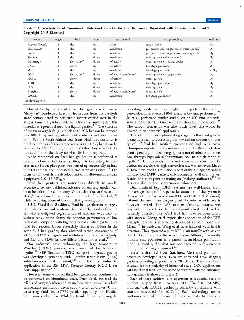
3.3.3. Entrained Flow Gasifiers. Most coal gasificationprocesses developed since 1950 are entrained flow, slagginggasifiers operating at pressures of 20−80 bar. They have beenselected for the majority of industrial-scale IGCC applicationswith hard coal feed. An overview of currently offered entrainedflow gasifiers is shown in Table 2.Each of these gasifiers is in operation at industrial scale in
numbers varying from 1 to over 100. (The first 170 MWeindustrial-scale EAGLE gasifier is currently in planning withstart-up scheduled for 2017.132) Each technology ownercontinues to make incremental improvements to secure a
Table 2. Characteristics of Commercial Entrained Flow Gasification Processes [Reprinted with Permission from ref 7.Copyright 2003 Elsevier.]
process stages feed flow reactor wall syngas cooling oxidant
Koppers-Totzek 1 dry up jacket syngas cooler O2
Shell SCGP 1 dry up membrane gas quench and syngas cooler water quencha O2
Prenflo 1 dry up membrane gas quench and syngas cooler water quencha O2
Siemens 1 dry down membrane water quench radiant coolera O2
GE Energy 1 slurry, drya down refractory water quench or radiant cooler O2
E-Gas 2 slurry up refractory two-stage gasification O2
MHI 2 dry up membrane two-stage gasification air/O2
OMB 1 slurry, drya down refractory, membranea water quench or syngas cooler O2
MCSG 1 slurry down refractory water quench O2
TPRI 2 dry up membrane two-stage gasification O2
HT-L 1 dry down membrane water quench O2
Tsinghua 2 slurry down refractory, membranea water quench O2
EAGLE 2 dry up membrane two-stage gasification O2
aIn development.
Chemical Reviews Review
dx.doi.org/10.1021/cr400202m | Chem. Rev. 2014, 114, 1673−17081683
competitive advantage. The focus of most such improvementsis reduced cost and enhanced reliability, availability, andmaintainability (RAM) performance. Efforts are devoted bothto the gasification process as it takes place in the gasificationchamber as described here and to equipment-oriented aspectsdiscussed in the following sections.As discussed in section 3.2.2.1, the atomization performance
of a slurry burner is critical for the satisfactory performance ofthe gasifier. Yu et al.,133 Zhao et al.,134 and Jakobs et al.135 haveall investigated and improved on the performance of their ownburners, but the results are, as might be expected, all specific tothose designs.Flow patterns in the reactor space are important. In order to
achieve a good rate of carbon conversion, the distribution ofresidence time for individual particles must be maintained closeto the average residence time. Particles with a low residencetime leave the reaction chamber before the carbon is fullyreacted, lowering the overall conversion rate. Opposed burnersused by various designers (Shell, Uhde, and the East ChinaUniversity of Science and Technology (ECUST)) address thisissue. On the other hand, diametrically opposed burners can bea cause of flame instability as determined by Li et al.136,137
unless suitable measures are taken.The effect of flow pattern on temperature distribution is
equally important to maintain the integrity of the containmentsystem. Yan, Yu, and co-workers have measured the temper-ature distributions in a bench-scale gasifier with opposedburners.138,139 Although short-term operation with two burnersis sometimes suggested,140 their work identifies that this is notadvisable and runs the risk of shortening the life of the unusedburners or refractory. They recommend feeding inert gasthrough the unused burners during such an operation.3.3.4. Reactor Containment. A reactor containment
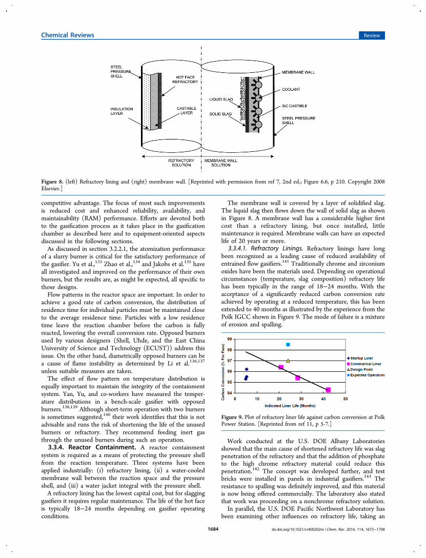
system is required as a means of protecting the pressure shellfrom the reaction temperature. Three systems have beenapplied industrially: (i) refractory lining, (ii) a water-cooledmembrane wall between the reaction space and the pressureshell, and (iii) a water jacket integral with the pressure shell.A refractory lining has the lowest capital cost, but for slagging
gasifiers it requires regular maintenance. The life of the hot faceis typically 18−24 months depending on gasifier operatingconditions.
The membrane wall is covered by a layer of solidified slag.The liquid slag then flows down the wall of solid slag as shownin Figure 8. A membrane wall has a considerable higher firstcost than a refractory lining, but once installed, littlemaintenance is required. Membrane walls can have an expectedlife of 20 years or more.
3.3.4.1. Refractory Linings. Refractory linings have longbeen recognized as a leading cause of reduced availability ofentrained flow gasifiers.141 Traditionally chrome and zirconiumoxides have been the materials used. Depending on operationalcircumstances (temperature, slag composition) refractory lifehas been typically in the range of 18−24 months. With theacceptance of a significantly reduced carbon conversion rateachieved by operating at a reduced temperature, this has beenextended to 40 months as illustrated by the experience from thePolk IGCC shown in Figure 9. The mode of failure is a mixtureof erosion and spalling.
Work conducted at the U.S. DOE Albany Laboratoriesshowed that the main cause of shortened refractory life was slagpenetration of the refractory and that the addition of phosphateto the high chrome refractory material could reduce thispenetration.142 The concept was developed further, and testbricks were installed in panels in industrial gasifiers.143 Theresistance to spalling was definitely improved, and this materialis now being offered commercially. The laboratory also statedthat work was proceeding on a nonchrome refractory solution.In parallel, the U.S. DOE Pacific Northwest Laboratory has
been examining other influences on refractory life, taking an
Figure 8. (left) Refractory lining and (right) membrane wall. [Reprinted with permission from ref 7, 2nd ed.; Figure 6.6, p 210. Copyright 2008Elsevier.]
Figure 9. Plot of refractory liner life against carbon conversion at PolkPower Station. [Reprinted from ref 11, p 5-7.]
Chemical Reviews Review
dx.doi.org/10.1021/cr400202m | Chem. Rev. 2014, 114, 1673−17081684
integrated approach to include modeling and processoptimization.144 In work focused on a novel steelmakingprocess involving integration of petroleum coke gasification anddirect reduction of iron (DRI), Puente-Ornelas et al. found thatmagnesium aluminate could be an effective nonchromeaddition to reduce slag penetration into an aluminarefractory.145 Alumina refractories have been used in oilgasification with success for over 50 years, but have littleresistance to coal slags, so it will be interesting to see how thisidea develops further.General Electric (GE or GE Energy) has patented the
addition of manganese oxide to the feedstock to improverefractory life.146 GE has advertised that it is using a proprietary“advanced refractory” material for the recently constructedgasifiers at Edwardsport, IN, but no details have beenreleased.147
3.3.4.2. Membrane Walls. An alternative to the refractorywall is a water-cooled membrane wall. Seggiani developed amodel of the slag flow down the membrane wall for the Prenflogasifier in Puertollano,148 which has provided a starting pointfor many researchers. This model was used to predict theeffects of changes in the gasifier operating conditions,considering both operating temperature and slag propertychanges. After such perturbations, it was estimated that the slaglayer would take about 2 h to reach the new steady statecondition.Li et al. used a simplified, steady-state version of this model
to simulate the slag layer on the membrane wall of the TPRI(Thermal Power Research Institute) two-stage membrane wallgasifier and found good agreement with practice in the pilotplant.149
Liang et al. performed a similar exercise in comparing itsmodel of heat transfer behavior and slag deposition with a pilotplant.150 In follow-up work Lin, Liang, and co-workersextended their model to include more detail on the geometricaleffects of studs and fins in the wall. With this they theninvestigated the stresses in the solid slag layer, both in steadystate151 and during transitions.152 With this model it is possibleto estimate the rate of change of operating parameters that canbe achieved without risking cracking of the solid slag layer.Slag deposition on the walls of a boiler is undesirable for a
number of reasons, not least of which is reduced heat transferand loss of efficiency. It is therefore not surprising that effortsare being made to understand the mechanisms involved anddevelop numerical models to be able to predict slag formationand deposition under these conditions.153,154 Yong andGhoniem155,156 modified Seggiani’s model by assuming acubic temperature profile across the molten slag layer,combined this with the steady-state slag flow model of Wanget al,.157 and included their own slag capture predictioncriterion. They incorporated these submodels into a CFD(computational fluid dynamics) model of a pilot-scalepressurized oxy-fuel combustor, but the same methodologycould be applied also to a membrane wall gasifier.For the gasification situation Ni et al. have developed a
submodel to predict slag deposition and applied it both tomembrane wall and refractory lined systems.158,159
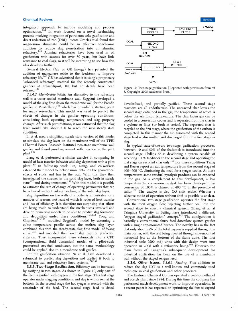
3.3.5. Two-Stage Gasification. Efficiency can be increasedby gasifying in two stages. As shown in Figure 10, only part ofthe feed is gasified with oxygen in the first stage. This first stageoperates under slagging conditions, and slag is withdrawn at thebottom. In the second stage the hot syngas is reacted with theremainder of the feed. The second stage feed is dried,
devolatilized, and partially gasified. These second stagereactions are all endothermic. The unreacted char leaves thesecond stage entrained in the gas, the temperature of which isbelow the ash fusion temperature. The char laden gas can becooled in a convection cooler and is separated from the char ina cyclone or filter (or both in series). The separated char isrecycled to the first stage, where the gasification of the carbon iscompleted. In this manner the ash associated with the secondstage feed is also molten and discharged from the first stage asslag.In typical state-of-the-art two-stage gasification processes,
between 10 and 50% of the feedstock is introduced into thesecond stage. Phillips 66 is developing a system capable ofaccepting 100% feedstock to the second stage and operating thefirst stage on recycled char only.160 For these conditions Tsangand Keeler report an exit temperature from the second stage of400−700 °C, eliminating the need for a syngas cooler. At thesetemperatures some residual pyrolysis products can be expectedin the gas. As a complement to this development, a lowtemperature tar conversion catalyst has been developed. Tarconversion of 100% is claimed at 400 °C in the presence ofsulfur.161 The catalyst is also CO shift active. Whether aselective mode of operation without shift is possible is unclear.Conventional two-stage gasification operates the first stage
with the total oxygen flow, injecting further coal into thesecond stage to effect a chemical quench. Zhang et al. atTsinghua University in Beijing have introduced a different,“oxygen staged gasification” concept.162 The configuration isbasically a conventional slurry feed downflow quench gasifierwith a single top-mounted burner. The novelty lies in the factthat only about 85% of the total oxygen is supplied through themain burner, with the rest being injected through side-mountedhorizontal jets at the bottom of the flame zone. The firstindustrial scale (500 t/d) units with this design went intooperation in 2006 with a refractory lining.163 However, themain focus of Tsinghua’s subsequent development forindustrial application has been on the use of a membranewall without the staged oxygen feed.
3.3.6. Other Issues. 3.3.6.1. Fluxing. Flux addition toreduce the slag IDT is a well-known and commonly usedtechnique in coal gasification and other processes.The Eastman Chemical Co. has operated a coal-to-methanol
and acetyls plant since 1984. During this time the company hasperformed much development work to improve operations. Ina recent paper it has reported on optimizing the flux to expand
Figure 10. Two-stage gasification. [Reprinted with permission from ref8. Copyright 2008 Academic Press.]
Chemical Reviews Review
dx.doi.org/10.1021/cr400202m | Chem. Rev. 2014, 114, 1673−17081685

the range of suitable gasification fuels for their plant.164 Themost important find was the recognition that Mg-based fluxessuch as olivine can achieve better results in viscosity reductionthan the more commonly used Ca-based fluxes.Li et al. also investigated the effect of Mg-based fluxes on an
Anhui coal. They found that a reduction of the IDT from 1398to 1350 °C could be achieved with only 2.8 mass % Mg-basedflux compared with 6.2 mass % Ca-based flux.165
3.3.6.2. Carbon in Slag. Carbon conversions of 98−99.5%can be achieved in entrained flow gasifiers. Much of theunconverted carbon is intimately associated with the slag andmay be inaccessible to any oxidant which could convert it.Studies have been made to understand the partition of theunconverted carbon between coarse slag, fine slag, and, whererelevant, fly slag and the nature of the association with themineral matter. There are three main routes in slag formationin a gasifier. Coarse slag is derived from the slag whichaccumulates on and flows down the reactor wall before enteringthe slag quench chamber (which may or may not serve also asgas quench depending on gasifier design). Finer particles ofmineral matter also enter the slag quench and are designated asfine slag. A third stream is the fly slag that leaves the gasifierwith the syngas. This may be collected separately in a dry filteror washed out in a scrubber. In the latter case the rundownwater is usually mixed with the quench water blowdown, so thefine slag is a mixture from two sources.Zhao et al. examined the slag material from a downflow
slurry-feed quench gasifier.166 Montagnaro et al. performed asimilar exercise for an upflow dry-feed gasifier with syngascooler and dry filtration.167 The basic findings were direction-ally similar in that there was much more carbon in the fine slagthan in the coarse slag and that the mechanism by which thecarbon is entrained in the coarse and fine slags is different. Thecarbon in coarse slag has become surrounded by slag afterimpact. It has not had the same residence time in contact withthe gas and is more reactive than the carbon associated with thefine slag. Gu et al. also examined the fly slag from two Texacogasifiers and found that the carbon in the slag was more reactivethan the parent coal char.168
The fly slag is an important difference between the twogasification processes. The fly slag from the quench gasifier isremoved from the gas in the scrubber and mixed with the fineslag. Unfortunately, it is not clear whether this “fly slag” wasdrawn from the scrubber rundown or, like the materialexamined by Zhao et al., the mixed fine slag from the quench.In the case of the upflow gasifier it is collected separately andwas found to contain very little carbon (∼5 mass %).Independently of these studies of material from industrial
gasifiers, Shannon et al. have adopted an analytic approach todetermining the mechanism by which carbon particles becometrapped in the liquid slag layer on a gasifier wall.169
3.3.6.3. Temperature Measurement. In an ideal situation,the control of a gasifier operation would be by temperaturecontrol. This is done in fluid bed reactors, where thetemperature is usually less than 1000 °C. The conditionsinside an entrained flow gasifier, however, make the directmeasurement of temperature extremely difficult. In refractory-lined gasifiers thermocouples have been used extensively for oilgasification, but only have an average lifetime of about 6months.170 In a coal gasifier the expected lifetime would beeven shorter due to slag attack on the ceramic sheath.Alternative, indirect methods such as using the methane
content in the syngas to infer the temperature are used but aretoo slow to detect rapid upset conditions.Texaco made considerable efforts to develop a pyrometer for
operation in a pressurized environment.171 Difficulties to beovercome included maintaining a line of sight through theliquid slag on the gasifier wall and understanding to whatexactly the temperature measurement relatedgas, ungasifiedparticles, or the opposite wall. The system was tested at thePolk Power Station gasifier, but was not taken into industrialservice. A different optical system was developed at about thesame time using a single-crystal sapphire disk, but it has alsonot achieved commercial success.The search for a reliable and robust system that can be used
in a gasifier control system continues. A group at StanfordUniversity has with support from EPRI developed a laser-basedsystem that has been tested at a pilot-scale coal gasifier at theUniversity of Utah. A further test campaign was planned forNovember 2012 in the U.S. National Carbon Capture Center(NCCC) at Wilsonville, AL.172
3.3.6.4. Online Ash Analysis. Gasifier control operatestypically by mass ratio control between the oxidant supply andthe feedstock to the gasifier. This is often referred to as theoxygen-to-carbon (O/C) ratio, but in reality it is at best only anapproximation, since any change in the coal quality cannot befactored in to the coal flow measurement. An increase in ashcontent of the coal at constant measured O/C ratio will lead toa higher real O/C ratio in the gasifier and thus to a higheroperating temperature. A change in the slag viscositycharacteristics for the feed coal may require a higher operatingtemperature to maintain a free-flowing slag flow out of thegasifier. Ash quantity and ash quality are at present determinedoffline in a procedure taking some hours, so even with a goodfeedstock management system, a fine control is not possible.There is therefore considerable incentive to develop an onlinecoal characterization device, which will allow more precisecontrol of the gasifier.Eastman Chemical Co. recognized the potential for such a
device in its own operations, focusing in the first place on ashcomposition and its effect on slag viscosity.173 Nonetheless thistechnology has not found use in other parts of the industry.An alternative approach using laser-induced breakdown
spectroscopy (LIBS) is currently being developed at LehighUniversity with support from EPRI.174 The project includes thedevelopment of an artificial neural network model to relate theelemental composition as measured by LIBS to the IDT of themineral matter. Field results in an operating power plantshowed the LIBS technology to be accurate and repeatablewithin the requirements of a industrial operation. Laboratoryvalidation of the technology under coal−water slurry conditionsis proposed as a next step before application in a gasificationenvironment.
3.4. Contaminant Species in Raw Syngas
3.4.1. Nitrogen Species. During gasification nitrogenspecies in the coal tend to form ammonia, hydrogen cyanide,and nitrogen. There is little published work on this topicspecific to gasification, and much of the process has to bededuced from work primarily aimed at understanding NOxformation in a combustion situation. Both ammonia and HCNare potentially important impurities in process condensate fromall gasification processes. In the Lurgi fixed bed gasificationprocess and also in the KBR/Southern TRIG fluidized bedprocess,175 sufficient ammonia may be formed that it is
Chemical Reviews Review
dx.doi.org/10.1021/cr400202m | Chem. Rev. 2014, 114, 1673−17081686
worthwhile recovering it as anhydrous ammonia for commercialgain. In many entrained flow gasifiers the quantities ofammonia are insufficient for this to be attractive. In suchcases the ammonia is stripped out of the water and combustedin the sulfur recovery unit.176
Park et al. showed that increasing concentrations of steaminfluence the distribution of nitrogen species in the syngas, inparticular “resulting in the increase of NH3 at the expense ofN2”.
177 McKenzie et al. also found that steam played a vital rolein converting a large proportion of coal-N into NH3. However,the importance of this effect “decreased with increasing coalrank”.178 Both these findings are consistent with the industrialpractice described above.Tsubouchi and Ohtsuka have pointed out the catalytic roles
of metal cations, in particular Ca2+ and Fe3+, in secondaryreactions of volatile nitrogen and char nitrogen,179 specificallyduring pyrolysis. The presence of these ions, whether in thenative coal or subsequently added to previously demineralizedcoal, aids the conversion of coal-N to N2 at the expenseparticularly of NH3.3.4.2. Alkali Metals. 3.4.2.1. Alkalis in Fixed and Fluid
Beds. Some lignites have a high content of sodium, in manycases present mostly as sodium chloride. In fixed bed gasifiersthis has led to excessive clinkering. Extensive tests wereperformed using central German lignite with about 2.1 mass %Na (in coal, 18 mass % in ash). These tests were only partiallysuccessful, and the measures taken affected the economicsnegatively.180 Lignite with about 6−8% sodium in ash issuccessfully gasified in North Dakota, but also in this case greatcare has to be exercised to avoid excessive clinkering.181
In fluid beds the present of alkalis can create the conditionsfor agglomeration. Dahlin et al. encountered agglomeration anddepositing problems in a fluid bed transport gasifier whengasifying the same North Dakota lignite.182 The agglomerationwas attributed to vaporization of the sodium species and theformation of sticky sodium silicates in combination with thebed material. Tests were made with a broad range of varioussorbents, initially in the laboratory. Kaolin was determined tohave the best potential and operation without deposition wassuccessfully demonstrated during a 300 h test run in a pilotplant.183
3.4.2.2. Alkali Metals in Syngas.Much investigation into thepresence of alkali metals in syngas is motivated by biomassgasification issues, but the knowledge gained can be ofconsiderable use to coal gasification applications as well.While alkali metals can show useful catalytic effects in thegasification process itself, many species formed in the gasifierleave it in the vapor phase and present issues in the immediatedownstream equipment. Sodium compounds are known tocondense out in syngas coolers causing fouling and possiblyeven blockage. Conventional removal of alkalis in a barrier filterrequires prior cooling to about 450 °C to ensure they are in thesolid phase, which poses a limitation to hot gas cleanupconcepts.Blasing and Muller have investigated the release of alkalis,
sulfur, and chlorine in an effort to generate a basicunderstanding of the phenomena, both in a batch process184
and in a drop tube reactor under helium with 5 mol %oxygen.185 The main alkali species present in the gas were NaO,KOH, NaCl, and KCl. Furthermore, they found, like others,that lignites with high Al and Si contents had a high retentioncapability for alkali metal species, especially for hydroxides,under gasification like conditions at 1400 °C. Weindlich and
Muller reviewed a wide variety of potential sorbents includingbauxite, kaolin, and sand. They concluded that kaolin with anAl2O3/SiO2 ratio between 1/5 and 1/3 was an effective sorbentfor reducing alkali metal chlorides to below 100 ppbv.186 Thesorbent can then be extracted from the gas on a hightemperature ceramic filter.Matsuoka et al. have investigated the behavior of alkali and
alkaline earth metals in gasification of low rank coals. While Caspecies were found to interact with inherent clay minerals toform complex aluminosilicates, dispersed species of Na and Kmostly vaporized and no interaction with inherent minerals wasobserved.187
3.4.3. Trace Elements. Trace elements in coal are typicallydefined as those with concentration of less than 1000 ppmw inthe mineral matter. Many of these trace elements present risksto the environment or to synthesis catalysts, and it is necessaryto have a good understanding of their fate in a gasifier anddownstream processing. This understanding is an importantprerequisite to the development of an effective design tomitigate such risks. The reducing atmosphere in a gasifier willcause a different speciation from that known from combustion.Furthermore, details of gasification processes such as operatingpressure and temperature as well as the primary gas treatment(solids and halide removal) will lead to different partitioning, soeach process must be considered individually.Trace elements are contained in the coal in different forms
and are associated with different main elements, both organicand inorganic. Although most gasification processes operate attemperatures which destroy such association, this is not alwaysthe case. Wang et al.188 and Vejahati et al.189 have presentedreviews examining correlations between trace elements andmain elements in coal.Font et al. have examined the partitioning of trace elements
at the ELCOGAS Prenflo IGCC in Spain.190 They foundmercury to be consistently only in the gas phase, but thepartitioning of arsenic and selenium exhibited considerablevariation. The proportion of arsenic reporting to the gas phasevaried between 0.01 and 42%. The slag contained only about5% in all four measurement campaigns with the variation beingtaken up by the fly ash. Vapor phase selenium varied between 5and 23% of the totalagain with most of the rest in the fly ash.A correlation was found between the Cl content of the gas andthe amount of these volatiles, which is attributed to theformation of low boiling chlorides. Conversely, increasing theamount of calcium was found to decrease the amount of vaporphase heavy metals, presumably by preferentially binding theCl. Li et al also found indications that the increase of volatilityof mercury correlated with the halogen content of the coal.191
One must expect that the partitioning characteristics of aquench gasifier or a two-stage gasifier will be different fromthose of a single-stage upflow gasifier. While there is a limitedamount of data on partitioning available from the Polk andWabash IGCCs, further detailed studies of such systems needto be performed.Considerable work has been undertaken by Bunt and
Waanders on industrial fixed bed gasifiers in conjunction withSasol to determine partitioning and speciation of Hg, As, Se,Cd, and Pb192 as well as of Cu, Mo, Ni, and Zn193 and of Ba,Co, Cr, Mn, and V.194 In all cases the behavior in the dryingand devolatilization zones of the reactor were consideredseparately from the gasification and combustion zones. Thiswork was accompanied by FactSage equilibrium calculations,which in most cases showed reasonable agreement. Discrep-
Chemical Reviews Review
dx.doi.org/10.1021/cr400202m | Chem. Rev. 2014, 114, 1673−17081687
ancies were found, however, for As, attributed to condensationphenomena during countercurrent flow not included in theFactSage model used. While the results will not be applicable toother gasifier types, the theoretical underpinning of themeasurements will allow good estimation of similar gasifiersoperating on different coals. This work was followed up by acomparison of the behavior of Hg, As, Se, Cd, and Pb in similargasifiers operating on Dakota lignite.195 Despite differences infeed concentrations and mode of occurrence of these metals inthe lignite and despite the lower operation temperaturesrequired for lignite gasification, the partitioning behavior wasfound to be generally similar. In particular, As was shown to bethe least volatile. If one considers the work of Font et al. atELCOGAS,190 then the influence of halides may need to beconsidered, particularly given the relatively high chloridecontent of the North Dakota lignite. Note that in alaboratory-scale fixed bed gasifier Li et al. found sometemperature effect on the volatility, particularly of Pb and Asunder a CO2 atmosphere.
196
In a related project Wagner et al. investigated the overallmercury mass balance across the total Sasol petrochemicalcomplex.197 Whereas Bunt and Waanders had drawn theirbalancing envelope around the gasifier only, the wider studyalso determined that the mercury retention in the tar removalfrom the syngas was minimal (less than the ash). Essentially allthe mercury in the raw syngas is captured as a solid in theRectisol plant prior to processing in the Fischer−Tropschsynthesis, leaving the conventional coal-fired auxiliary boilers asthe primary mercury emission source from the plant. It isinteresting to note the contrast with the adsorption of mercuryon fly ash in the primary gas cleaning at the ELCOGAS plantdescribed above.
3.5. Syngas Coolers
High temperature gas cooling is one of the critical designaspects of any entrained flow slagging gasifier. The gas leavingthe reaction chamber contains fly slag, small entrained dropletsof molten ash, which on cooling pass through a plastic, stickyphase before solidifying. This temperature range between free-flowing liquid and dry solid poses difficulties for heat exchange,since the fly slag will tend to adhere to any heat transfer surfacewith which it comes into contact as it cools. Techniques tobridge this “no-go zone” must ensure that no sticky ash comesinto contact with heat exchange or other surfaces, while it is inthis intermediate temperature range. This can be achieved in anumber of ways, including quenching with water or cooledsyngas.3.5.1. Radiant Coolers. One approach to addressing the
problem of sticky ash is the use of a radiant cooler. Flowpatterns in such a cooler are designed to minimize impinge-ment of slag particles onto the heat exchange surfaces so thatthey do not adhere and foul the surfaces. Such a flow patterninhibits convective heat transfer; thus radiant heat transfer ispredominant. Texaco used such designs in its SAR198 and CoolWater199 development and demonstration plants. This solutionwas also implemented at the industrial scale at the Polk 250MWe Power Station and included lessons learned from theearlier two plants.200 The use of radiant heat transfer, whileaddressing the fouling issues, does not provide a high heat flux,so radiant coolers tend to be large and expensive. The cooler(shell plus internals) for Polk weighs 740 t. By and large theobjectives set for the Polk unit were met. “The design exittemperature was 1400 °F [760 °C], but despite not using the
soot blower system, the exit temperature is consistently below1350 °F [732 °C].”201 “Virtually all of the slag and about halfthe fly ash” are collected in a water pool (sump) located at thebottom of the cooler. The balance of the fly ash continues to beentrained in the gas stream, which leaves the radiant coolerthrough two exit ducts to two conventional shell and tubeconvective heat exchangers. Despite the low measured gastemperatures, the fly ash is still sticky and accumulates on theinlet tube sheet of the convective syngas cooler, which has beena constant source of unplanned maintenance.Research in this area has focused on optimizing heat transfer
so as to reduce the overall weight and cost of such units andalso gaining a better understanding of the flow patterns and flyash behaviorin particular so as to protect the downstreamequipment.General Electric (successor to Texaco) has further developed
the Polk design for a new 2 × 309 MWe plant in Edwardsport,IN, which started up in October 2012. The radiant coolerdesign used at Edwardsport will raise approximately 30% moresteam than the radiant cooler at Tampa. The diameter of theradiant cooler will be 0.6 m (2 ft.) or 10% less than that atTampa, but the overall length will be 2.75 m (9 ft) more whilemaintaining the overall weight of 740 t.202 In addition, GE hasmodified the sump of the radiant syngas cooler (RSC) into awater quench, by submerging the gas outlet of the cooler.203
This eliminates all risk of fly ash fouling in the downstreamequipment. This concept was already considered after the CoolWater experience204 and further refined.205,206 Details of theactual execution in Edwardsport, however, have not beenpublished.The East China University of Science and Technology
(ECUST) has published results of its modeling of a radiantcooler.207 This provides useful insights, because suchcalculations were previously kept as proprietary knowledge ofthe vessel manufacturers. The flow pattern results compare wellwith a cold flow model.208 It is noteworthy that the particletemperature profile is calculated separately from that of thegas.209 However, the temperature profile within the particles isnot yet addressed. When looking for explanations of theexperience at Polk, the possibility of a warmer, soft coresurrounded by a cooler thin solid shell, which is damaged onimpact, needs to be considered. A start-up case with lowerpressures and higher velocities would also be of benefit. Theexisting work provides a good basis for such additional studies.Siemens has also been developing a radiant cooler to offer in
conjunction with its dry-feed gasifier.210 As with the GE design,the radiant cooler is followed immediately by a water quench toreduce fouling risks. The Siemens design retains its existingspray quench system rather than submerged quench.The U.S. National Energy Technology Laboratory has
initiated a program to “explore ways to mitigate and bettermanage syngas cooler plugging and fouling.”211 Initial analyticalwork has started, and associated laboratory work will proceedduring 2013.
3.5.2. Quench Systems. The alternative to syngas coolingby steam raising is a water quench. Quench systems are cheaperthan syngas coolers, but in power applications failure to use thehot syngas for steam raising will carry a 2−3% points efficiencyloss. For most chemical applications a CO shift is requiredatleast for part of the gas stream. Typically the syngas exits thequench water saturated at 200 °C or higher. This is thenavailable for the CO shift, so the performance penalty is less.
Chemical Reviews Review
dx.doi.org/10.1021/cr400202m | Chem. Rev. 2014, 114, 1673−17081688
Most chemical applications will include a quench coolingsystem.There are two different designs: the submerged quench with
dip tube as practiced by, e.g., GE Energy and the spray quenchof which the Siemens gasifier is an example. Shell and Uhde,both of which had previously offered exclusively steam-raisingcoolers, have both announced the development of quenchdesigns. The first Uhde quench gasifier will be in a biomass-to-liquids demonstration plant in France.212 Shell has ademonstration plant under construction in Nanjing.213
3.6. Primary Gas Cleaning
The raw syngas exiting a gasifier includes some residualentrained solids in the form of fly slag. Furthermore, chlorine inthe feedstock is mostly present in the gas as vapor-phase HCl.Removal of solids and chlorides from the raw syngas is usuallyconsidered as part of the complete gasification process and assuch is supplied by all the gasification technology vendors.Particulate removal may be performed wet, in a scrubber, or
dry with a candle filter. The wet systems combine particulateremoval and chloride removal in a single step. The scrubberrundown, or “black water”, must be cooled and cleaned.While the water handling in the dry systems is much simpler,
the candle filter itself is a source of maintenance cost. In anycase, a water wash to remove chlorides is required downstreamthe filter. In contrast to wet particulate removal, the wash wateris largely free of particulate matter.3.6.1. Solids Removal from Raw Syngas. Dry solids
removal by filtration is used in many different processconfigurations. Compared with wet systems, it has theadvantage of simplifying the treatment of process condensateand the water used to remove halides downstream from thefilter. In fluid bed processes, e.g., TRIG or U-Gas, the purposeis basically similar, though the solids are fly ash rather than flyslag. In two-stage gasifiers, e.g., E-Gas or MHI, the task isdifferent, in that the solids comprise char and ash which are tobe recycled to the gasifier first stage. Heidenreich has reviewedthe current status of hot gas filtration, and the reader is referredthere for details.214
In some entrained flow processes, e.g., Shell and Prenflo, therecovered fly slag can be sold as a byproduct, though qualitycontrol is important. Font et al. have developed a quick methodfor determining the glass content of fly ash.215
Industrial experience is generally in the temperature range upto 250 °C, although there are examples of higher operatingtemperatures, e.g., downstream the Varnamo biomass gasifier,where the temperature was 350−400 °C.216 Although ceramiccandles have the capability of operating at 800 °C or higher,process application in gasification is limited to about 450 °C.Above this temperature the risk of some of the alkalis passingthrough in the vapor phase is considered too high.Both ceramic (Shell, Prenflo) and sintered metal (E-Gas)
candles are used in industrial operations. As part of thedevelopment of the TRIG process, Southern Company Servicestested various materials including iron aluminide and siliconcarbide.217 Sharma et al. have reviewed recent developmentsand also discussed ideas for further research.218 These includeadding adsorbents to syngas at high temperatures to fix thealkalis and halides, thus allowing full exploitation of the hightemperature capability of ceramics (cf. Blasing and Muller insection 3.4.2.2). They also introduce the concept of a “pulselessfilter” with continuous partial removal of the solids. This hasthe advantage of eliminating the stress cycling on the candles
induced by the reverse pulse cleaning. In addition, the dust isnever fully removed from the candle surface, so dust ingressinto the filter structure after each cleaning pulse is avoided.Chen et al. have proposed a new quality control method for
ceramic filter candles using a nondestructive dynamic character-ization technique.219
3.7. Alternative Configurations
A number of alternative configurations have been consideredand in some cases been applied industrially. Plasma gasificationhas been applied in a number of plants for waste gasification,but not industrially with coal. Underground gasification isadvocated by some, and a demonstration unit in Australia has infact produced small quantities of Fischer−Tropsch liquids.220
The issues are however mainly of a geological nature andtherefore not discussed here.
3.7.1. Catalytic Gasification. One approach which hasattracted attention over the years is that of catalytic gasification.This approach utilizes the favorable equilibrium for methane atlow temperatures. Conventional fluid bed processes operatingin the 800−1000 °C range produce a gas with a methanecontent in the range 3−6 mol %. A catalytic gasification processcan operate in the range 600−700 °C, producing significantlymore methane.221 Such a process was developed by Exxonbetween 1978 and 1981 but not pursued to industrialmaturity.222 This technology has been developed further byGreat Point Energy, Inc., including its use for petroleum cokegasification.223 However, little of a technical nature has beenpublished on these developments.It is generally well documented that potassium salts exhibit a
higher catalytic effect than calcium.224,225 In a comparisonbetween potassium salts and calcium salts, Zhang et al. foundthat calcium salts provided a maximum conversion rate in thelow conversion range, while potassium salts were more effectiveas the conversion increased.226
However, there is substantial catalyst degeneration and lossof potassium salts by catalyst volatilization or formation or“water-insoluble compounds” such as KAlSO4 after contactwith the mineral matter in the coal.227 In this respect calciumcompounds are far less sensitive and this has maintained theinterest in calcium as a catalyst. However, also in this case it isnecessary to have a suitable means of catalyst recovery forreuse. Much of the calcium is present as water-insolublecalcium carbonate after gasification, so organic or inorganicacids may be used for calcium recovery. Zhang et al. have used“crude vinegar”, a light fraction of the liquids derived frombiomass pyrolysis.228 The results were superior to theequivalent technique with acetic acid. Furthermore, it wasfound that the use of crude vinegar could improve the catalyticactivity of the indigenous crystalline calcium in a bituminouscoal.Wang, Jiang, and co-workers have also been researching
catalytic gasification, but the aim is to minimize the methanemake while still using K2CO3 as catalyst, but they limit themethane make by separating pyrolysis and partial oxidation ofthe resulting char.229 Further deactivation of the catalyst couldbe reduced by the addition of Ca(OH)2.
230,231 This concept hasbeen extended to catalytic gasification of petroleum coke, andan optimum temperature for hydrogen production of around750 °C was determined.232
Sharma et al. have investigated the catalytic gasification ofHyperCoal, a coal that has been separated from its ash contentby solvent extraction. The gasification rate was examined over
Chemical Reviews Review
dx.doi.org/10.1021/cr400202m | Chem. Rev. 2014, 114, 1673−17081689
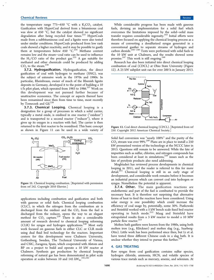
the temperature range 775−650 °C with a K2CO3 catalyst.Gasification with HyperCoal derived from a bituminous coalwas slow at 650 °C, but the catalyst showed no significantdegradation after being recycled four times.233 HyperCoalsmade from a subbituminous coal and a lignite were also testedunder similar conditions. HyperCoals produced from low rankcoals showed a higher reactivity, and it may be possible to gasifythem at temperatures below 650 °C.234 Methane contentremains low and the steam−coal ratio can be used to influencethe H2/CO ratio of the product gas.235 A gas suitable formethanol and other chemicals could be produced by addingCO2 to the steam.236
3.7.2. Hydrogasification. Hydrogasification, the directgasification of coal with hydrogen to methane (SNG), wasthe subject of extensive work in the 1970s and 1980s. Inparticular, Rheinbraun, owner of much of the Rhenish lignitedeposits in Germany, developed it to the point of building a 10t/h pilot plant, which operated from 1983 to 1986.237 Work onthis development was not pursued further because ofunattractive economics. The concept or aspects thereof havebeen reexamined since then from time to time, most recentlyby Tomeczek and Gil.238
3.7.3. Chemical Looping. Chemical looping is adesignation for a group of processes in which a solid carrier,typically a metal oxide, is oxidized in one reactor (“oxidizer”)and is transported to a second reactor (“reducer”), where itgives up its oxygen in a reaction with fuel. The carrier is thenreturned to the first reactor to be reoxidized. This basic conceptas shown in Figure 11 can be used in a wide variety of
applications including combustion and gasification and bothwith gaseous or solid fuels. Chemical looping combustion(CLC), in which the nitrogen from the combustion air isdischarged from the oxidizer and the CO2 from the fuel isdischarged from the reducer, opens the way to an elegantmethod for CO2 capture.239 There is also a considerableamount of research devoted to chemical looping reforming(CLR) for syngas and hydrogen applications.240 Most earlywork focused on gaseous fuels in either CLC or CLR modeusing dual fluid bed technology for the reactors. Importantcenters for this development were Chalmers University,Gothenburg, Sweden, The Technical University of Vienna,and CSIC, Zaragoza, Spain, which cooperated with Alstom andBP on a project to build and operate a 10 kW reactor atChalmers. Synthesis gas production by chemical loopingreforming of natural gas has been demonstrated in pilot scaleoperation at scales between 10 and 145 kWth.
241,242
While considerable progress has been made with gaseousfuels, devising an implementation for a solid fuel whichovercomes the limitations imposed by the solid−solid masstransfer requires considerable ingenuity.243 Initial efforts weretherefore focused on applying the chemical looping process as ameans of converting a desulfurized syngas generated in aconventional gasifier to separate streams of hydrogen andcarbon dioxide.244−246 Tests were performed with solid fuels inthe 10 kW unit at Chalmers, and the results showed somepromise.247 This work is still ongoing.248
Research has also been initiated into direct chemical loopingcombustion of coal (CDCL) at Ohio State University (Figure12). A 25 kW subpilot unit ran for over 200 h in January 2013.
Solid fuel conversion was “nearly 100%” and the purity of theCO2 stream was over 99%.249 Plans are in place to install a 250kW pressurized version of the technology at the NCCC later in2013. Questions still remain to be answered. While the fate ofimpurities such as sulfur, chlorine, and nitrogen compounds hasbeen considered at least in simulations,250 issues such as thefate of pyrolysis products also need addressing.Moghtaderi has reviewed process developments in chemical
looping in 2011, and the reader is referred to this for moredetail.251 Chemical looping is still in an early stage ofdevelopment, and considerable work remains before it becomesan industrial process which can convert coal into hydrogen orsyngas. Nonetheless the potential is apparent.
3.7.4. Other. The main gasification reactions areendothermic and part of the fuel is combusted to provide thenecessary heat. It is therefore not surprising that alternativeforms of heat to feed the reaction have been considered. Usingsolar energy is one possibility which could increase theefficiency of coal usage by, potentially, some 30%. Piatkowskiand Steinfeld worked with a 5 kW bench scale fixed bed reactoroperating in batch mode.252 Maag and Steinfeld haveextrapolated results from a 3 kW reactor to model a 10 MWparticle flow reactor.253
Molten bath gasifiers were known from the 1980s, using bothmolten iron (e.g., Klockner) and molten slag (e.g., Saarberg-Otto). Little work has been performed since then, but Li et al.have tested three different Chinese coals in a slag bath. It isunclear whether they intend to pursue this further.254
4. GAS TREATINGRaw syngas from coal gasification contains sulfur species,hydrogen chloride, ammonia, HCN, and volatile species ofvarious trace metals such as mercury, arsenic, and selenium. At
Figure 11. Chemical looping combustion. [Reprinted with permissionfrom ref 242. Copyright 2010 Elsevier.]
Figure 12. Coal direct chemical looping (CDCL). [Reprinted from ref250. Copyright 2012 American Chemical Society.]
Chemical Reviews Review
dx.doi.org/10.1021/cr400202m | Chem. Rev. 2014, 114, 1673−17081690

high temperatures also alkalis can be present. Chlorides as wellas part of the ammonia and HCN are generally removed in awater wash. Alkalis can be removed either wet in a scrubber ordry in a particulate filter. These processes are generally integralto the gasification process as described above. Gas purificationprocesses are devoted to removing the sulfur species and theremaining traces according to the requirements of thedownstream synthesis process.The H2/CO ratio of a raw syngas produced from coal is in
many cases too low for the requirements of the synthesisprocess. In such cases shifting the CO with steam to H2 andCO2 will be needed, probably with a subsequent CO2 removalstep. The CO shift is usually classified as syngas conditioning.Gas treatment includes both purification and conditioning.Typical requirements of various syntheses are listed in Table
3, and these specifications provide the basis for purification andconditioning processes.
4.1. Desulfurization
Sulfur in raw synthesis gas generally reports as H2S and COS,with the latter representing anything between 5 and 10% of thetotal sulfur. In some cases such as the Lurgi fixed bed gasifierother species such as thiols may be present in small (ppmv)quantities. Given the fact that sulfur is a poison to a widevariety of catalysts, its removal down to parts-per-billion levelsis an important part of any coal-to-chemicals complex. State-of-the-art technology uses regenerable physical or chemicalsolvents such as methanol (Rectisol process), dimethyl ethersof polyethylene glycol (Selexol process), or amines. The
physical solvents have the advantages of being able to removeH2S and COS to a residual 1−10 ppmv (Selexol) or even 0.1ppmv (Rectisol), of being selective, and of having a (relatively)low energy demand for solvent regeneration; it is acknowl-edged, however, that they are very expensive in capital cost.Amine washes generally require much less capital expenditure,but have a very high steam demand for solvent regeneration. Inview of this cost situation, for a long time there has beenconsiderable interest in developing alternative systems that canoffer “Rectisol performance at MDEA [methyl diethanolamine]cost”.255 A number of different approaches have been applied tofinding a solution to this task, but most of them have beenbased on adsorption technologies. Performing this task attemperatures described as “warm” (250−500 °C) or “hot”(>750 °C) has an added attraction for power applications, sinceavoiding dropping the temperature below the water dew pointcan improve the cycle efficiency by up to 3% points.Comprehensive reviews of development in adsorption
technologies have been published by Cheah et al. in 2009256
and by Meng et al. in 2010.257 Both these reviews focusedlargely on the use of metal oxides in biomass gasificationapplications, but many of the issues are the same as for coal.One major difference is that coal-based syngas is likely tocontain significantly more sulfur than syngas from biomass.This will shift the economic break-even point betweenadsorption and absorption technologies in favor of the latter.The other principal difference is in the content of traceelements, which may or may not impact the efficacy of aparticular adsorbent. Metals considered in these reviews include
Table 3. Specifications for Various Synthesis Gases
product H2/CO total S poisons other source
ammonia ∞ <100 ppbv CO + H2O < 20 ppmv H2/N2 = 3.0 a, b, cO2+ CO2 < 10 ppmv inerts < 2%Cl < 100 ppbvP, As
hydrogen (by methanation) ∞ <100 ppbv halides, As CO + CO2 < 2% dO2 < 1%
methanol ≈2.0 (H2+CO2) <100 ppbv halides < 10 ppbv CO2 ≈ 3% c, e≈2.05 (CO−CO2) NH3 < 10 ppmv
HCN < 10 ppbvFe/Ni carbonyls < 10 ppbvC2H2 < 5 ppmvunsaturates < 300 ppmv
oxo alcohols ≈1.0 H2S, COS, organosulfur O2, strong acids, HCN, dienes CO2 < 0.5% fMEG (for cryogenic H2−CO separation) 1.5 <100 ppbv CO2 < 100 ppmv
H2O < 10 ppmvSNG 3.0 <20−100 ppbv halides, AsFischer−Tropsch (dependent on process) 1.3−2.6 <10 ppb to <1 ppmv NH3, HCN < 1 ppmv g
halides < 10 ppbvalkaline metals < 10 ppmvtars, phenolsHg, As, Se
DRI 0.5−∞ (CO + H2) <0.3% N2 < 6% h>2 (CO2 + H2O) preferred < 100 ppmv preferred < 1%preferred > 11 CH4 3−4%
aReference 285. bVancini, C. A. Synthesis of Ammonia; Macmillan: London, 1971. cSpath, P. L.; Dayton, D. C. Preliminary ScreeningTechnical andEconomic Assessment of Synthesis Gas to Fuels and Chemicals with Emphasis on the Potential for Biomass-Derived Syngas; Report TP-510-34929; U.S.DOE-NREL: Golden, CO, December 2003. dMuller, W. D. Gas Production. In Ullmann’s Encyclopedia of Industrial Chemistry, 5th ed.; VCH:Weinheim, Germany, 1989, Vol. A12, p 245. eReference 323. fBahrmann and Bach. Oxo synthesis. In Ullmann’s Encyclopedia of Industrial Chemistry,6th ed.; Wiley-VCH: Weinheim, Germany, 2003; Vol. 24, p 553. gBoerrigter, H.; den Uil, H.; Calis, H.-P. Green Diesel from Biomass via Fischer-Tropsch Synthesis: New Insights in Gas Cleaning and Process Design. Presented at Pyrolysis and Gasification of Biomass and Waste. ExpertMeeting, Strasbourg, October 2002. hReference 358.
Chemical Reviews Review
dx.doi.org/10.1021/cr400202m | Chem. Rev. 2014, 114, 1673−17081691
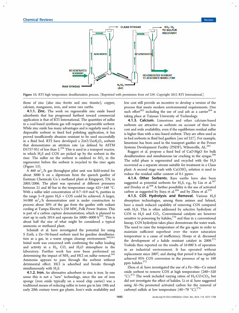
those of zinc (also zinc ferrite and zinc titanite), copper,calcium, manganese, iron, and some rare earths.4.1.1. Zinc. The work on regenerable zinc oxide based
adsorbents that has progressed furthest toward commercialapplication is that of RTI International. The quantities of sulfurin a coal-based synthesis gas will require a regenerable sorbent.While zinc oxide has many advantages and is regularly used as adisposable sorbent in fixed bed polishing application, it hasproved insufficiently abrasion resistant to be used successfullyin a fluid bed. RTI have developed a ZnO/ZnAl2O4 sorbentthat demonstrates an attrition rate (as defined by ASTMD5757-95) of less than 2.258 This is used in a transport reactor,in which H2S and COS are picked up by the sorbent in theriser. The sulfur on the sorbent is oxidized to SO2 in theregenerator before the sorbent is recycled to the riser again(Figure 13).A 460 m3
n/h gas throughput pilot unit was field-tested forabout 3000 h on a slipstream from the quench gasifier ofEastman Chemicals Co.’s methanol plant at Kingsport, TN, in2005/2006. The plant was operated at different pressuresbetween 21 and 40 bar in the temperature range 425−540 °C.With a sulfur inlet concentration of 0.7−0.9 mol %, purities inthe range 5−8 ppmv H2S + COS could be achieved. A larger,54 000 m3
n/h demonstration unit is under construction toprocess about 30% of the gas from the gasifier with radiantcooling at Tampa Electric’s 250 MWe Polk Power Station. Thisis part of a carbon capture demonstration, which is planned tostart up in early 2014 and operate for 5000−8000 h259. This isabout half the size of what might be considered a typicalammonia or methanol plant.Schmidt et al. have investigated the potential for using
S Zorb, a Zn−Ni-based sorbent used for gasoline desulfuriza-tion as a gas, in a warm syngas cleanup environment.260,261
Initial work was concerned with confirming the sulfur loadingand activity in a H2, CO, and H2O atmosphere in thelaboratory. Further work has now been performed ondetermining the impact of NH3 and HCl on sulfur removal.262
Ammonia appears to pass through the sorbent withoutdetrimental effect. HCl is adsorbed and breaks throughsimultaneously with H2S.4.1.2. Iron. An alternative adsorbent to zinc is iron. In one
sense this is not a “new” technology, since the use of ironsponge (iron oxide typically on a wood chip carrier) was atraditional means of reducing sulfur in town gas in late 19th andearly 20th century town gas plants. Iron’s wide availability and
low cost still provide an incentive to develop a version of theprocess that meets modern environmental requirements. Onesuch effort263 including the use of coal ash as a carrier264 istaking place at Taiyuan University of Technology.
4.1.3. Calcium. Limestone and other calcium-basedsorbents are attractive as sorbents on account of their lowcost and wide availability, even if the equilibrium residual sulfuris higher than with a zinc-based sorbent. They are often used asin-bed sorbents in fluid bed gasifiers [see ref 257]. For example,limestone has been used in the transport gasifier at the PowerSystems Development Facility (PSDF), Wilsonville, AL.265
Ruggeri et al. propose a fixed bed of CaO·MgO for bulkdesulfurization and simultaneous tar cracking in the syngas.266
The solid phase is regenerated and recycled with the H2Srecovered as a separate stream suitable for treatment in a Clausplant. A second stage wash with Ca(OH)2 solution is used toreduce the residual sulfur content of 0.1 ppmv.
4.1.4. Other Sorbents. Rare earths have also beensuggested as potential sorbents for H2S, e.g., by Liu et al.267
and Dooley et al.268 A further possibility is the use of activatedcarbon as suggested by Itaya et al.269 and by Zhou et al.270
4.1.5. COS Hydrolysis and Removal. Various H2Sabsorption technologies, among them amines and Selexol,have a much reduced capability of removing COS comparedwith H2S. This is often addressed by selective hydrolysis ofCOS to H2S and CO2. Conventional catalysts are howeversensitive to poisoning by halides,176 and thus in a conventionallineup, COS hydrolysis takes place downstream the water wash.The need to raise the temperature of the gas again in order tomaintain sufficient superheat over the water saturationtemperature is a cause of inefficiency. Honjo et al. discussedthe development of a halide resistant catalyst in 2008.271
Yoshida then reported on the results of 16 000 h of operationin an industrial environment. It has operated withoutreplacement since 2007, and during that period it has regularlyachieved 95% COS conversion in the presence of up to 100ppm halides.272
Zhou et al. have investigated the use of a Fe−Mn−Ce mixedoxide sorbent to remove COS at high temperature (280−320°C).273 The work included varying ratios of H2:CO:CO2, butdid not investigate the effect of halides. Li et al. have suggestedusing Al−Na promoted activated carbon for the removal ofcarbonyl sulfide at low temperature (40−70 °C).274
Figure 13. RTI high temperature desulfurization process. [Reprinted with permission from ref 259. Copyright 2012 RTI International.]
Chemical Reviews Review
dx.doi.org/10.1021/cr400202m | Chem. Rev. 2014, 114, 1673−17081692
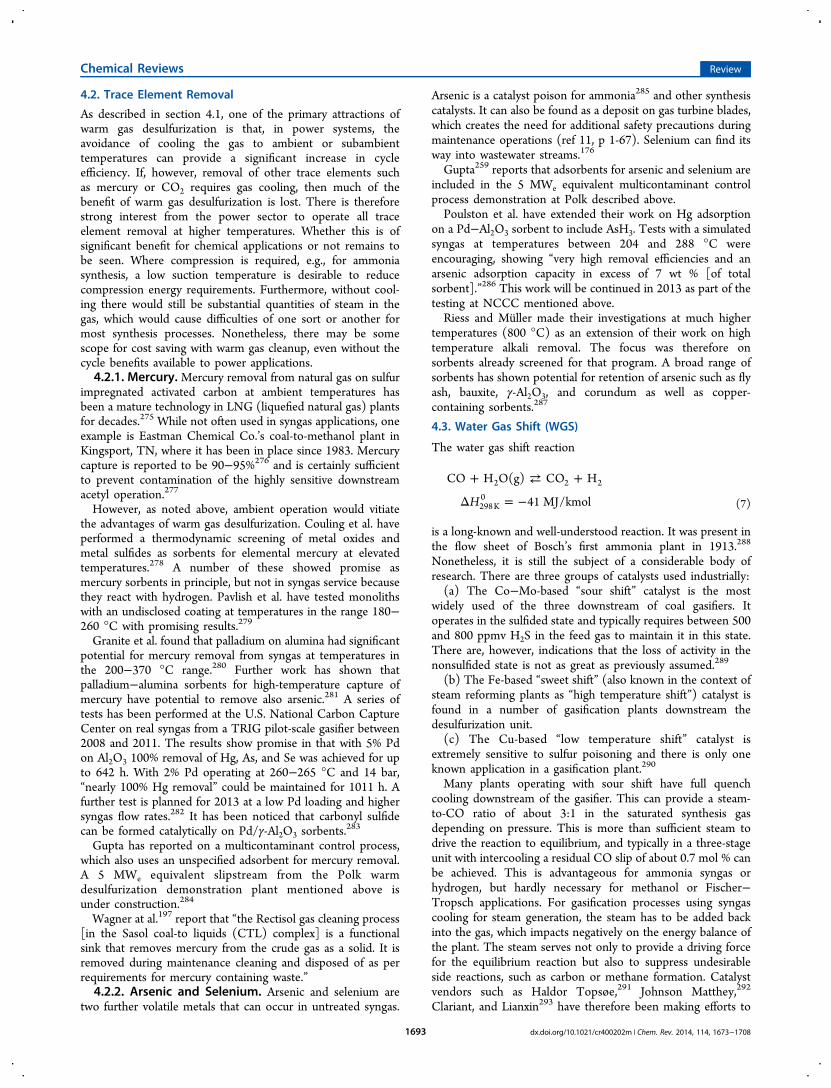
4.2. Trace Element Removal
As described in section 4.1, one of the primary attractions ofwarm gas desulfurization is that, in power systems, theavoidance of cooling the gas to ambient or subambienttemperatures can provide a significant increase in cycleefficiency. If, however, removal of other trace elements suchas mercury or CO2 requires gas cooling, then much of thebenefit of warm gas desulfurization is lost. There is thereforestrong interest from the power sector to operate all traceelement removal at higher temperatures. Whether this is ofsignificant benefit for chemical applications or not remains tobe seen. Where compression is required, e.g., for ammoniasynthesis, a low suction temperature is desirable to reducecompression energy requirements. Furthermore, without cool-ing there would still be substantial quantities of steam in thegas, which would cause difficulties of one sort or another formost synthesis processes. Nonetheless, there may be somescope for cost saving with warm gas cleanup, even without thecycle benefits available to power applications.4.2.1. Mercury. Mercury removal from natural gas on sulfur
impregnated activated carbon at ambient temperatures hasbeen a mature technology in LNG (liquefied natural gas) plantsfor decades.275 While not often used in syngas applications, oneexample is Eastman Chemical Co.’s coal-to-methanol plant inKingsport, TN, where it has been in place since 1983. Mercurycapture is reported to be 90−95%276 and is certainly sufficientto prevent contamination of the highly sensitive downstreamacetyl operation.277
However, as noted above, ambient operation would vitiatethe advantages of warm gas desulfurization. Couling et al. haveperformed a thermodynamic screening of metal oxides andmetal sulfides as sorbents for elemental mercury at elevatedtemperatures.278 A number of these showed promise asmercury sorbents in principle, but not in syngas service becausethey react with hydrogen. Pavlish et al. have tested monolithswith an undisclosed coating at temperatures in the range 180−260 °C with promising results.279
Granite et al. found that palladium on alumina had significantpotential for mercury removal from syngas at temperatures inthe 200−370 °C range.280 Further work has shown thatpalladium−alumina sorbents for high-temperature capture ofmercury have potential to remove also arsenic.281 A series oftests has been performed at the U.S. National Carbon CaptureCenter on real syngas from a TRIG pilot-scale gasifier between2008 and 2011. The results show promise in that with 5% Pdon Al2O3 100% removal of Hg, As, and Se was achieved for upto 642 h. With 2% Pd operating at 260−265 °C and 14 bar,“nearly 100% Hg removal” could be maintained for 1011 h. Afurther test is planned for 2013 at a low Pd loading and highersyngas flow rates.282 It has been noticed that carbonyl sulfidecan be formed catalytically on Pd/γ-Al2O3 sorbents.
283
Gupta has reported on a multicontaminant control process,which also uses an unspecified adsorbent for mercury removal.A 5 MWe equivalent slipstream from the Polk warmdesulfurization demonstration plant mentioned above isunder construction.284
Wagner at al.197 report that “the Rectisol gas cleaning process[in the Sasol coal-to liquids (CTL) complex] is a functionalsink that removes mercury from the crude gas as a solid. It isremoved during maintenance cleaning and disposed of as perrequirements for mercury containing waste.”4.2.2. Arsenic and Selenium. Arsenic and selenium are
two further volatile metals that can occur in untreated syngas.
Arsenic is a catalyst poison for ammonia285 and other synthesiscatalysts. It can also be found as a deposit on gas turbine blades,which creates the need for additional safety precautions duringmaintenance operations (ref 11, p 1-67). Selenium can find itsway into wastewater streams.176
Gupta259 reports that adsorbents for arsenic and selenium areincluded in the 5 MWe equivalent multicontaminant controlprocess demonstration at Polk described above.Poulston et al. have extended their work on Hg adsorption
on a Pd−Al2O3 sorbent to include AsH3. Tests with a simulatedsyngas at temperatures between 204 and 288 °C wereencouraging, showing “very high removal efficiencies and anarsenic adsorption capacity in excess of 7 wt % [of totalsorbent].”286 This work will be continued in 2013 as part of thetesting at NCCC mentioned above.Riess and Muller made their investigations at much higher
temperatures (800 °C) as an extension of their work on hightemperature alkali removal. The focus was therefore onsorbents already screened for that program. A broad range ofsorbents has shown potential for retention of arsenic such as flyash, bauxite, γ-Al2O3, and corundum as well as copper-containing sorbents.287
4.3. Water Gas Shift (WGS)
The water gas shift reaction
+ ⇄ +
Δ = −H
CO H O(g) CO H
41 MJ/kmol2 2 2
298 K0
(7)
is a long-known and well-understood reaction. It was present inthe flow sheet of Bosch’s first ammonia plant in 1913.288
Nonetheless, it is still the subject of a considerable body ofresearch. There are three groups of catalysts used industrially:(a) The Co−Mo-based “sour shift” catalyst is the most
widely used of the three downstream of coal gasifiers. Itoperates in the sulfided state and typically requires between 500and 800 ppmv H2S in the feed gas to maintain it in this state.There are, however, indications that the loss of activity in thenonsulfided state is not as great as previously assumed.289
(b) The Fe-based “sweet shift” (also known in the context ofsteam reforming plants as “high temperature shift”) catalyst isfound in a number of gasification plants downstream thedesulfurization unit.(c) The Cu-based “low temperature shift” catalyst is
extremely sensitive to sulfur poisoning and there is only oneknown application in a gasification plant.290
Many plants operating with sour shift have full quenchcooling downstream of the gasifier. This can provide a steam-to-CO ratio of about 3:1 in the saturated synthesis gasdepending on pressure. This is more than sufficient steam todrive the reaction to equilibrium, and typically in a three-stageunit with intercooling a residual CO slip of about 0.7 mol % canbe achieved. This is advantageous for ammonia syngas orhydrogen, but hardly necessary for methanol or Fischer−Tropsch applications. For gasification processes using syngascooling for steam generation, the steam has to be added backinto the gas, which impacts negatively on the energy balance ofthe plant. The steam serves not only to provide a driving forcefor the equilibrium reaction but also to suppress undesirableside reactions, such as carbon or methane formation. Catalystvendors such as Haldor Topsøe,291 Johnson Matthey,292
Clariant, and Lianxin293 have therefore been making efforts to
Chemical Reviews Review
dx.doi.org/10.1021/cr400202m | Chem. Rev. 2014, 114, 1673−17081693
reduce the steam requirement for CO shift. In all of these casesvery little detail has been published for commercial reasons.4.3.1. Alternative Catalysts. Besides the application in
bulk chemicals such as ammonia and methanol, the water gasshift reaction has also been considered as a step in producinghydrogen for fuel cell applications. Hwang et al. describe somedisadvantages of the conventional catalysts for this application.“They require long-term activation procedures, are pyrophoric,and are intolerant of poisons, condensation and oxidation.”294
Further, there could be additional advantages to operation atlower temperatures. Various workers are therefore looking atnoble metal catalysts for this application, particularly CeO2-supported Pt295 and Pd,296 but also with other supportsystems.297 The extent to which all the issues listed byHwang et al., in particular poisoning, are addressed remains forfuture work.Haryanto et al. have looked at the use of Ni as a WGS
catalyst. Activity for WGS at 450 °C was found to be good.Although a loss of efficiency for hydrogen production due tomethane formation was noted, there was no discussion of theassociated exotherm. This will need to be addressed before Nican become a contender for this application.298
4.3.2. Reactors. A different route to improving theefficiency of the CO shift process is to remove one of theproducts continuously from the reaction space. This causes theshift reaction equilibrium to move toward the product side,thus increasing the conversion. Two approaches have beentaken.Sorption-enhanced water gas shift (SEWGS) is a method by
which CO2 is captured on a sorbent in the reactor. The reactoris taken offline cyclically and the CO2 desorbed. Multiplereactors with staggered cycles ensure continuous operation.Allam et al. screened many different potential sorbents beforeidentifying a promoted hydrotalcite as showing “the highestcyclic capacity for removal of CO2 under the conditions ofinterest”.299 This was tested first in a single column unit andthen demonstrated in a multicolumn unit. The resultingperformance did not reach “levels predicted through modelingand required for economic value”.300 However, there iscontinued interest in the concept,301 including the use ofalternative sorbents.302 Steen has reported on a different effortwhich in 2012 was at the sorbent screening and evaluationstage.303
An alternative is to incorporate a membrane into the reactorand extract hydrogen from the reaction space.304−306
Compared with SEWGS, the concept has the advantage ofbeing continuous and of avoiding the mechanical issues of hightemperature switching valves. On the other hand, it requires asuitable hydrogen membrane which exhibits a high hydrogenflux rate, mechanical strength, and resistance to poisons. Thefocus of work on this concept is therefore the development ofsuitable membranes, which is discussed in section 4.4.2.
4.4. Hydrogen−Carbon Dioxide Separation
Current technology for separating hydrogen and CO2 isgenerally based on CO2 absorption in the same solutions asused for desulfurization. The principal alternative technologyfor providing pure hydrogen is pressure swing adsorption. Boththese technologies operate at ambient or even subambienttemperatures. As discussed above for desulfurization, thenecessary cooling can be a considerable source of inefficiency,where it is not required for other reasons. There is thereforesubstantial interest in H2/CO2 separation at high temperatures.
The main focus of this interest is IGCC with carbon captureand hydrogen generation for fuel cells rather than chemicalapplications. Nonetheless, as these technologies develop andmature, it is possible that they could find a place in chemicalproduction. The two areas of attention are high temperatureCO2 sorbents and hydrogen membranes.
4.4.1. CO2 Sorbents. RTI International has included thedevelopment of a CO2 adsorbent operating under “warm”conditions in its multicontaminant control suite. A 0.5 MWeequivalent pilot scale unit is to be included as part of the 50MWe warm gas desulfurization demonstration at the PolkIGCC, mentioned already.307
TDA Research Inc. has tested a (undisclosed) hightemperature CO2 sorbent at the NCCC, Wilsonville, AL,over 200 cycles, achieving over 98% CO2 removal fromdesulfurized syngas at temperatures above 200 °C.308
Hassanzadeh and Abbasian tested various magnesium-basedsorbents. They found that a natural dolomite modified bysemicalcining and then impregnated with potassium gave thebest results, with operation in the temperature range 300−450°C.309
Some sorbents primarily developed for SEWGS may be usedoutside the shift reactor as well.
4.4.2. Hydrogen Membranes. Much effort has beeninvested in palladium membranes by, e.g., Zhang, Qiao, and co-workers,310,311 and also by Karellas et al.312 Tests with 4.5 kg/hsulfur-free syngas have been conducted at the NCCC on apalladium membrane supplied by Worcester PolytechnicInstitute.308
However, concerns about the potential cost of usingpalladium have led others to look for alternatives. Jack et al.have developed a dense (undisclosed) metal membrane thatoperates “at near water gas shift conditions”. A “12 lb/day”(∼5.4 kg/d) subscale engineering prototype plant was built andtested on industrial quality syngas at the Eastman Chemicalplant at Kingsport, TN. One set of “5 ft” (∼1.5 m) tubesoperated over a range of 16 different conditions for ∼250 h andthe flux stability previously determined in the laboratory wasconfirmed. A “250 lb/day” (∼113 kg/d) process developmentunit was planned to be operated during 2012, and a 4−10 t/dprecommercial module is planned for 2015.313
Dolan et al. have developed a range of vanadium based alloys,which demonstrate improved flux at a practical membranethickness and reduced cost.314−316 In particular, alloying withnickel and titanium is used to address the problem of hydrogenembrittlement encountered with pure vanadium, whilemaintaining the high hydrogen solubility that vanadium offers.The NCCC has tested carbon membranes supplied by Media
Processing Technology and polymer membranes fromMembrane Technology & Research as well.308 Others haveperformed laboratory testing of ceramics, e.g., Othman et al.317
and Vaitsi et al.318
5. CHEMICALS FROM SYNGASThe production of chemicals from syngas is largelyindependent of the source of the syngas, so most developmentsapplicable to syngas generated by steam reforming of naturalgas are applicable to syngas generated from coal gasification. Itis therefore not intended at this point to review generaldevelopments in the field of chemical syntheses from syngas.However, small differences in syngas quality according tosource can have an effect on the detail design of synthesis unitsand these will be mentioned.
Chemical Reviews Review
dx.doi.org/10.1021/cr400202m | Chem. Rev. 2014, 114, 1673−17081694
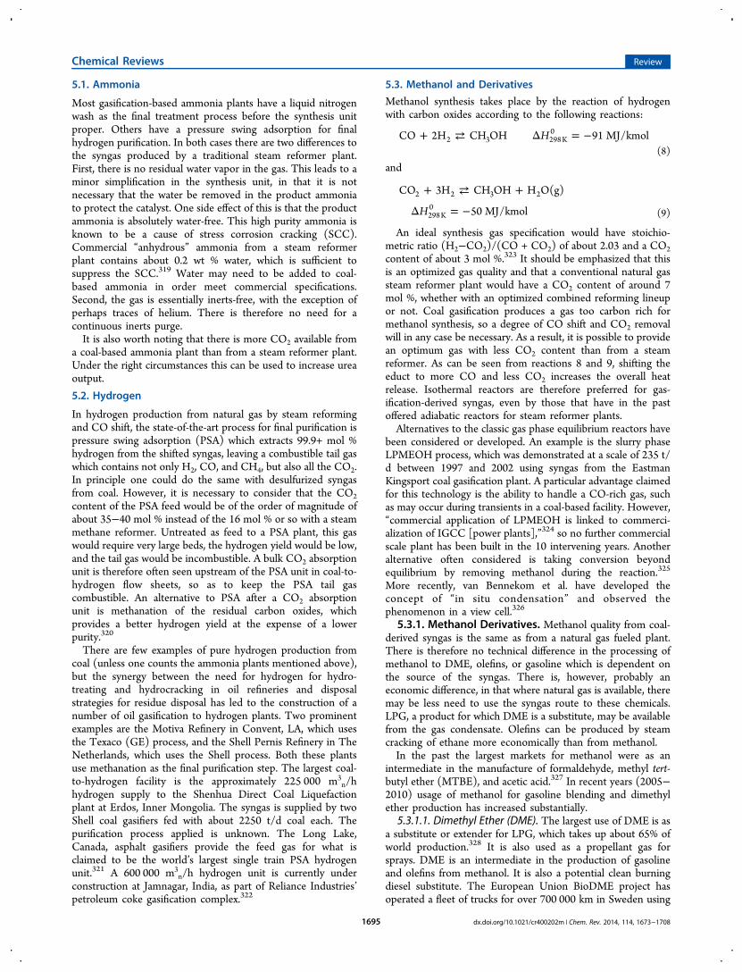
5.1. Ammonia
Most gasification-based ammonia plants have a liquid nitrogenwash as the final treatment process before the synthesis unitproper. Others have a pressure swing adsorption for finalhydrogen purification. In both cases there are two differences tothe syngas produced by a traditional steam reformer plant.First, there is no residual water vapor in the gas. This leads to aminor simplification in the synthesis unit, in that it is notnecessary that the water be removed in the product ammoniato protect the catalyst. One side effect of this is that the productammonia is absolutely water-free. This high purity ammonia isknown to be a cause of stress corrosion cracking (SCC).Commercial “anhydrous” ammonia from a steam reformerplant contains about 0.2 wt % water, which is sufficient tosuppress the SCC.319 Water may need to be added to coal-based ammonia in order meet commercial specifications.Second, the gas is essentially inerts-free, with the exception ofperhaps traces of helium. There is therefore no need for acontinuous inerts purge.It is also worth noting that there is more CO2 available from
a coal-based ammonia plant than from a steam reformer plant.Under the right circumstances this can be used to increase ureaoutput.
5.2. Hydrogen
In hydrogen production from natural gas by steam reformingand CO shift, the state-of-the-art process for final purification ispressure swing adsorption (PSA) which extracts 99.9+ mol %hydrogen from the shifted syngas, leaving a combustible tail gaswhich contains not only H2, CO, and CH4, but also all the CO2.In principle one could do the same with desulfurized syngasfrom coal. However, it is necessary to consider that the CO2content of the PSA feed would be of the order of magnitude ofabout 35−40 mol % instead of the 16 mol % or so with a steammethane reformer. Untreated as feed to a PSA plant, this gaswould require very large beds, the hydrogen yield would be low,and the tail gas would be incombustible. A bulk CO2 absorptionunit is therefore often seen upstream of the PSA unit in coal-to-hydrogen flow sheets, so as to keep the PSA tail gascombustible. An alternative to PSA after a CO2 absorptionunit is methanation of the residual carbon oxides, whichprovides a better hydrogen yield at the expense of a lowerpurity.320
There are few examples of pure hydrogen production fromcoal (unless one counts the ammonia plants mentioned above),but the synergy between the need for hydrogen for hydro-treating and hydrocracking in oil refineries and disposalstrategies for residue disposal has led to the construction of anumber of oil gasification to hydrogen plants. Two prominentexamples are the Motiva Refinery in Convent, LA, which usesthe Texaco (GE) process, and the Shell Pernis Refinery in TheNetherlands, which uses the Shell process. Both these plantsuse methanation as the final purification step. The largest coal-to-hydrogen facility is the approximately 225 000 m3
n/hhydrogen supply to the Shenhua Direct Coal Liquefactionplant at Erdos, Inner Mongolia. The syngas is supplied by twoShell coal gasifiers fed with about 2250 t/d coal each. Thepurification process applied is unknown. The Long Lake,Canada, asphalt gasifiers provide the feed gas for what isclaimed to be the world’s largest single train PSA hydrogenunit.321 A 600 000 m3
n/h hydrogen unit is currently underconstruction at Jamnagar, India, as part of Reliance Industries’petroleum coke gasification complex.322
5.3. Methanol and Derivatives
Methanol synthesis takes place by the reaction of hydrogenwith carbon oxides according to the following reactions:
+ ⇄ Δ = −HCO 2H CH OH 91 MJ/kmol2 3 298 K0
(8)
and
+ ⇄ +
Δ = −H
CO 3H CH OH H O(g)
50 MJ/kmol2 2 3 2
298 K0
(9)
An ideal synthesis gas specification would have stoichio-metric ratio (H2−CO2)/(CO + CO2) of about 2.03 and a CO2content of about 3 mol %.323 It should be emphasized that thisis an optimized gas quality and that a conventional natural gassteam reformer plant would have a CO2 content of around 7mol %, whether with an optimized combined reforming lineupor not. Coal gasification produces a gas too carbon rich formethanol synthesis, so a degree of CO shift and CO2 removalwill in any case be necessary. As a result, it is possible to providean optimum gas with less CO2 content than from a steamreformer. As can be seen from reactions 8 and 9, shifting theeduct to more CO and less CO2 increases the overall heatrelease. Isothermal reactors are therefore preferred for gas-ification-derived syngas, even by those that have in the pastoffered adiabatic reactors for steam reformer plants.Alternatives to the classic gas phase equilibrium reactors have
been considered or developed. An example is the slurry phaseLPMEOH process, which was demonstrated at a scale of 235 t/d between 1997 and 2002 using syngas from the EastmanKingsport coal gasification plant. A particular advantage claimedfor this technology is the ability to handle a CO-rich gas, suchas may occur during transients in a coal-based facility. However,“commercial application of LPMEOH is linked to commerci-alization of IGCC [power plants],”324 so no further commercialscale plant has been built in the 10 intervening years. Anotheralternative often considered is taking conversion beyondequilibrium by removing methanol during the reaction.325
More recently, van Bennekom et al. have developed theconcept of “in situ condensation” and observed thephenomenon in a view cell.326
5.3.1. Methanol Derivatives. Methanol quality from coal-derived syngas is the same as from a natural gas fueled plant.There is therefore no technical difference in the processing ofmethanol to DME, olefins, or gasoline which is dependent onthe source of the syngas. There is, however, probably aneconomic difference, in that where natural gas is available, theremay be less need to use the syngas route to these chemicals.LPG, a product for which DME is a substitute, may be availablefrom the gas condensate. Olefins can be produced by steamcracking of ethane more economically than from methanol.In the past the largest markets for methanol were as an
intermediate in the manufacture of formaldehyde, methyl tert-butyl ether (MTBE), and acetic acid.327 In recent years (2005−2010) usage of methanol for gasoline blending and dimethylether production has increased substantially.
5.3.1.1. Dimethyl Ether (DME). The largest use of DME is asa substitute or extender for LPG, which takes up about 65% ofworld production.328 It is also used as a propellant gas forsprays. DME is an intermediate in the production of gasolineand olefins from methanol. It is also a potential clean burningdiesel substitute. The European Union BioDME project hasoperated a fleet of trucks for over 700 000 km in Sweden using
Chemical Reviews Review
dx.doi.org/10.1021/cr400202m | Chem. Rev. 2014, 114, 1673−17081695
DME produced from syngas derived from black liquorgasification.329
DME is conventionally produced by dehydration ofmethanol. Starting from coal, this route involves adding waterat the CO shift stage, which is then removed in thedehydration. Haldor Topsøe has developed a route directlyto DME on the basis of the stoichiometry
+ = +3H 3CO CH OCH CO2 3 3 2 (10)
thus avoiding the addition and subsequent removal of thewater.330
Others including Nie et al.331 have investigated catalysts forthis route as well.5.3.1.2. Gasoline. Mobil (now ExxonMobil) developed the
methanol-to-gasoline (MTG) process in the 1970s and built afirst industrial 14 500 bpd (∼1700 t/d) plant in New Zealandin 1985, which operated for 12 years before production stoppedfor commercial reasons. A first coal-based 2500 bpd (∼290 t/d)MTG plant was built in Jincheng, Shanxi, China, and started upin 2009. This plant has incorporated all the learning from theplant in New Zealand.332 Other plants are in various stages ofplanning.Haldor Topsøe uses the integrated syngas-to-DME route
described above in its TIGAS integrated gasoline process. A 1t/d pilot plant has been operated for over 7000 h. A 23 bpd(∼2.7 t/d) pilot plant to operate on biomass-derived syngas atthe Gas Technology Institute, Des Plaines, IL, was scheduledfor start-up in 2012 with all testing to be complete byNovember 2013.333
5.3.1.3. Olefins. Methanol can be converted to olefins byessentially the same mechanisms as for MTG, namelydehydration to DME and subsequent further dehydration tothe hydrocarbon. Three versions developed in the 1990s havematured to industrial-scale processes. The UOP/Norsk HydroMTO process uses a fluid bed technology. Four licenses havebeen sold for plants in China, the first of which is expected tocome on stream in 2013.334 The Dalian Institute of ChemicalPhysics DMTO fluid bed process was used for the ShenhuaBautou 600 000 t/a olefin plant, which started commercialoperation in 2011. The Lurgi propylene selective MTP processuses a fixed bed and is included in two plants in China whichstarted up in 2011/2012. A third plant has been ordered.335
5.4. Ethanol
Interest in syngas to ethanol has primarily been in the contextof biofuels, providing a possible route to ethanol from thoseparts of plants not currently accessible to fermentationtechnologies, “cellulosic ethanol”. However, the issuessurrounding the synthesis of ethanol from syngas remain thesame, whether the source of the syngas is biomass or coal.Subramani et al. have reviewed the search for an efficientcatalytic process for the conversion of syngas to ethanol.336 Thediscussion looked at three main routes: direct synthesis on a Ru
catalyst, or indirect, either via homologation of methanol orhydrogenation of acetic acid. Ethanol can be synthesized over aRu catalyst, but both yield and selectivity are poor. This isconfirmed by a more recent paper by Chen et al., who wereable to achieve some improvement by supporting a Ru/Mncatalyst on modified SBA-15 molecular sieves.337 The selectivityto ethanol increased from 9.3 to 12.8% compared with anamorphous silica-supported catalyst. Clearly considerably morework will have to be performed, if ethanol is to be synthesizeddirectly from syngas, whether biomass or coal-derived.On the other hand, Sterin and Fotheringham have recently
(September 2012) announced the successful development of acommercial technology for ethanol production via syngas.338
Technical details have not been revealed, but on the basis oftheir presentation and the patent literature, e.g., Johnston etal.,339 it can be assumed that the technology applies the aceticacid hydration route.
5.5. Oxo Alcohols
Oxo alcohols are produced by reacting syngas with an olefin toproduce an aldehyde and hydrogenating the aldehyde to obtainthe alcohol. Commercial products range from C6 to C12alcohols for use as plasticizers and surfactants. Syngas volumesare generally small compared with methanol or ammoniaplants, so a dedicated coal gasifer to generate the requiredsyngas is unlikely to be economical. The Sasol higher alcoholsplant producing 120 million t/a mixed C12/C13 alcohols isclaimed to be “part of the first commercial route used anywherefor manufacturing surfactant alcohols from coal.”340
5.6. Monoethylene Glycol (MEG)
Conventionally, ethylene glycol has been produced byhydration of ethylene oxide either directly or via ethylenecarbonate. In recent years a route from synthesis gas has beendeveloped in China. As shown in Figure 14,341 the processstarts by splitting the synthesis gas so that the CO can beoxidized with methyl nitrite to produce dimethyl oxalate(DMO). The hydrogen is used to convert the DMO to MEGand methanol.342 The methanol is separated from the MEGand recycled. Methyl nitrite is prepared by oxidizing the nitricoxide recycled from the carbonylation step by reaction withmethanol and oxygen. The only feedstocks consumed are CO,hydrogen, and oxygen.The first 200 000 t/a plants in Tongliao, Inner Mongolia, and
Xinxiang, Henan, are in operation. Eight more, including fourpilot plants, are in various stages of commissioning, and afurther nine are under construction.343
5.7. Substitute Natural Gas (SNG)
Kopyscinski et al. have reviewed the status of SNG technologiesfrom 1950 to 2009,344 and it is not intended to repeat this workin this article. However, the commercial environment in whichSNG technology finds itself in 2013 has changed sodramatically since then that a discussion of intermediate
Figure 14. Coal to MEG block flow diagram. [Reprinted with permission from ref 341. Copyright 2013 ASIACHEM.]
Chemical Reviews Review
dx.doi.org/10.1021/cr400202m | Chem. Rev. 2014, 114, 1673−17081696
developments is more than appropriate. Whereas the price ofnatural gas in the United States (Henry Hub) was between$10/MMBTU and $12/MMBTU in the summer of 2008,345 ithas fallen to below $3/MMBTU for most of 2012. This hasbeen due to a combination of the rapid development of shalegas production and a generally reduced economic activity.Kopyscinski et al. include a list of 15 announced SNG projects,12 of which were in the United State, most of them due to be inservice by 2012 or 2013. The changed price situation has meantthat not one of these 12 has entered construction. On the otherhand, the successful start-up of one of the three Chineseprojects identified in the list (Hexigten) was announced in2012.346 Furthermore, projects not yet identified in 2009 arewell into construction, for example, at Guangyang, SouthKorea, which is due to start up at the end of 2013.347 These twoprojects use the Davy HICOM and Topsøe TREMP processes,respectively. Other plants are also under construction in China.Other technological developments have taken place as well.
Lurgi in cooperation with BASF has upgraded the technologyused since 1984 in the North Dakota SNG plant. The Lurgi HTMethanation process uses an advanced catalyst capable ofoperation at 650 °C. The flow sheet has a recycle around twoadiabatic methanation reactors followed by a single polishingreactor.348 Ruggeri has presented an alternative flow sheetproposed by Foster Wheeler and Clariant (formerly SudChemie), which eliminates the gas recycle, places the CO shiftwithin the SNG unit, and removes CO2 after methanation.349
Both these developments are essentially incrementalimprovements on existing technologies where the main advancehas been in the catalyst. Others have taken a more radicalapproach to the key issues of heat removal and carbonmanagement. Gotz et al. are developing a slurry-phase reactoroperating at a temperature of between 280 and 300 °C. A Ni−Al2O3 catalyst is suspended in an inert fluid through which thegas is bubbled.350,351 Conversion rates in a single isothermalreactor are good; the gas hourly space velocity (GHSV) is,however, low and the subject of the main development effort.The current focus is on biomass applications, so reactor size isunlikely to be a limitation.Ryi et al. have developed a nickel membrane which can be
installed in a thin plate reactor.352 Liu et al. have made ceramicplates coated with nickel catalyst as the first step toward thedevelopment of a microchannel reactor.353
5.8. Liquefied Petroleum Gas (LPG)
Liquefied petroleum gas (LPG) is not currently considered as afuel to be derived from synthesis gas. Nonetheless Ma et al.have investigated this possibility. The route to LPG is viamethanol, dehydration to DME, further dehydration to olefins,and hydrogenation of the olefins using a mixed catalyst at 30−40 bar.354 While the 73−80% selectivity for the C3/C4 fractionmay present some encouragement, direct use of DME is morelikely to find favor, since in at least one major market, rural fuelsupplies, DME is already establishing itself as a directcompetitor of LPG, where a coal derived product is required.
5.9. Fischer−Tropsch Synthesis
Fischer−Tropsch (F−T) synthesis of hydrocarbons fromsynthesis gas is a wide subject, and for details the reader isreferred to standard works.355,356 It is however important toreview the interface between synthesis gas production and thesynthesis itself. High temperature Fischer−Tropsch with ironcatalyst (originally Synthol, later SAS) is the mainstay of Sasol’scoal-based complex in Secunda, South Africa. Low temperature
Fischer−Tropsch with iron catalyst (ARGE) is included in theplant at Sasolburg, South Africa, which also used coalgasification for syngas generation from its inception in 1955until it was replaced by natural gas feed in 2004. Both plants use(or used) Rectisol acid gas removal and provide a solid base ofexperience for iron catalyst with coal gas. Other industrial scaleF−T facilities, such as Bintulu, Malaysia, and Oryx and Pearl inQatar use low temperature F−T with cobalt catalyst inconjunction with natural gas feed. Cobalt catalysts are knownto be more sensitive than iron catalysts. At present (2012) thereare no industrial scale F−T units with cobalt catalyst operatingon coal gas, although a number of projects with thiscombination are being considered. It is expected that theseprojects will include additional adsorbents to protect thecatalyst from the various trace elements that may be in the coal-based syngas.5.10. Direct Reduced Iron (DRI)
It may be debatable whether a metallurgical syngas applicationcan be considered as chemical. Nonetheless, for the sake ofcompleteness, its application to direct reduced iron ismentioned here. Historically, industrial applications of theDRI process have used dry (CO2) reforming of natural gas tosupply the reducing gas. There has been some interest in theuse of coal as a source of syngas, particularly in locations shortof natural gas, but it is only recently that the first plant has beenconstructed in Angul, India, with start-up planned for 2013.357
It is preferred that the reduction ratio, (CO + H2)/(CO2 +H2O), be greater than 11, but values as low as 2 areacceptable.358 The preferred methane content of 3−4% shouldalso be noted, since this can influence the gasifier selection.Small amounts of sulfur up to 0.3% are acceptable, but lowervalues are preferred, since sulfur removal downstream will addto the costs.
6. CHEMICALS FROM PYROLYSIS BYPRODUCTS OFGASIFICATION
Countercurrent updraft gasifiers such as those of Lurgi, Sasol,or BGL use hot synthesis gas from the gasification zone topyrolyze the incoming coal. A part of these pyrolysis products iscarried out with the raw syngas and is condensed and removedin a water wash. Heavy, non-water-soluble hydrocarbons areseparated from the aqueous gas liquor phase. The quantities ofthese materials can be sufficient to make it worthwhile torecover at least part as salable byproducts. Typical of industrialinstallations such as those of Sasol or Dakota Gasification isrecovery of ammonia, phenol, and cresylic acid.181,359 In theSasol Secunda facility the tar is distilled and hydrotreated torecover naphtha and distillate as blending components for therefinery. In particular, the high density distillate produced wasan important feature, since it provided “the main source ofdiesel density in the refinery” (ref 356, p 198).Sasol continues to explore new ways of exploiting this
pyrolysis material in cooperation with various partners.360−362
Pan, Long, and co-workers have also performed character-ization studies on medium-temperature gasification of coaltar.363,364 Further opportunities for chemical production fromtars generally are described elsewhere.365,366
7. DIRECT HYDROGENATION TO LIQUIDSThe alternative to the indirect (syngas and Fischer−Tropsch)route from coal to automotive fuels is the direct hydrogenationof coal to liquids (DCL). The hydrogenation of coal at high
Chemical Reviews Review
dx.doi.org/10.1021/cr400202m | Chem. Rev. 2014, 114, 1673−17081697
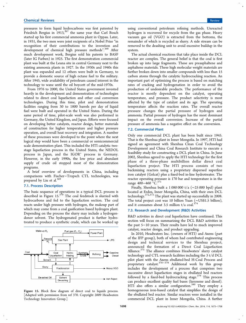
pressures to form liquid hydrocarbons was first patented byFriedrich Bergius in 1913,367 the same year that Carl Boschstarted up his first commercial ammonia plant in Oppau. Later,in 1931, the two men were joint recipients of a Nobel Prize “inrecognition of their contributions to the invention anddevelopment of chemical high pressure methods”.368 Aftermuch development work, Bergius sold his patents to BASF(later IG Farben) in 1925. The first demonstration commercialplant was built at the Leuna site in central Germany next to theexisting ammonia plants in 1927. In the 1930s and 1940s thisplant was expanded and 12 others were built in Germany, toprovide a domestic source of high octane fuel to the military.After 1945, wide availability of petroleum caused interest in thetechnology to wane until the oil boycott of the mid-1970s.From 1976 to 2000, the United States government invested
heavily in the development and demonstration of technologiesrelated to direct coal liquefaction and other coal conversiontechnologies. During this time, pilot and demonstrationfacilities ranging from 30 to 1800 barrels per day of liquidfuel were built and operated in the United States. During thesame period of time, pilot-scale work was also performed inGermany, the United Kingdom, and Japan. Efforts were focusedon developing better catalysts, reactor design, better materialsof construction for higher temperature and higher pressureoperation, and overall heat recovery and integration. A numberof these processes were developed to the point where the nextlogical step would have been a commercial or semicommercialscale demonstration plant. This included the HTI catalytic two-stage liquefaction process in the United States, the NEDOLprocess in Japan, and the IGOR+ process in Germany.However, in the early 1990s, the low price and abundantsupply of crude oil stopped most of the demonstrationprograms.A brief overview of developments in China, including
comparisons with Fischer−Tropsch CTL technologies, wasprepared by Liu et al.369
7.1. Process Description
The basic sequence of operations in a typical DCL process isdescribed in Figure 15.370 The coal feedstock is slurried withhydrocarbons and fed to the liquefaction section. The coalreacts under high pressure with hydrogen, the makeup part ofwhich may come from a coal gasification based hydrogen plant.Depending on the process the slurry may include a hydrogen-donor solvent. The hydrogenated product is further hydro-treated to produce a synthetic crude, which can be worked up
using conventional petroleum refining methods. Unreactedhydrogen is recovered for recycle from the gas phase. Heavyvacuum gas oil (VGO) is extracted from the bottoms, theremainder of which is recycled as slurry. A side stream can beremoved to the deashing unit to avoid excessive buildup in thesystem.The actual chemical reactions that take place inside the DCL
reactor are complex. The general belief is that the coal is firstbroken up into large fragments. These are preasphaltene andasphaltene materials. These high molecular weight materials arefurther broken down into smaller compounds with less than 15carbon atoms through the catalytic hydrocracking reaction. Animportant part of optimizing the process is based on matchingrates of cracking and hydrogenation in order to avoid theproduction of undesirable products. The performance of thereactor is mostly dependent on the catalyst, operatingtemperature, and pressure. The product selectivity is mostaffected by the type of catalyst and its age. The operatingtemperature affects the reaction rates. The overall reactorpressure changes the partial pressure of hydrogen andammonia. Partial pressure of hydrogen has the most dominantimpact on the overall conversion. Increase of the partialpressure of ammonia has a negative effect on the conversion.
7.2. Commercial Plant
Only one commercial DCL plant has been built since 1945.That is the Shenhua plant in Inner Mongolia. In 1997, HTI hadsigned an agreement with Shenhua Clean Coal TechnologyDevelopment and China Coal Research Institute to execute afeasibility study for constructing a DCL plant in China. In June2002, Shenhua agreed to apply the HTI technology for the firstphase of a three-phase multibillion dollar direct coalliquefaction project. The HTI process consists of twobackmixing reactors using a proprietary dispersed superfineiron catalyst (Gelcat) plus a fixed-bed in-line hydrotreater. Thereactor operating pressure is 170 bar and temperature is in therange 400−460 °C.371
Finally, Shenhua built a 1 080 000 t/a (∼25 000 bpd) plantlocated at Erdos, Inner Mongolia, China, with their own DCLtechnology.372,373 The plant was started up successfully in 2008.The total project cost was 10 billion Yuan (∼US$1.5 billion),and it consumes about 3.5 million t/a coal.374
7.3. Research and Development (R&D) Activities
R&D activities in direct coal liquefaction have continued. Thissection will focus on summarizing the DCL R&D activities inthe past 5−10 years. Their results have led to much improvedcatalyst, reactor design, and product upgrading.In 2010, Headwaters Inc. (owners of HTI) and Axens (part
of the IFP group), both of whom had contributed engineeringdesign and technical services to the Shenhua project,announced the formation of a Direct Coal LiquefactionAlliance.375 The alliance combines Headwaters’ slurry catalysttechnology and CTL research facilities including the 3 t/d DCLpilot plant with the Axens ebullated-bed H-Coal Process andproprietary catalyst.376−378 Additional work by this groupincludes the development of a process that comprises twosuccessive direct liquefaction stages in ebullated bed reactorsfollowed by a fixed-bed hydrocracking stage.379 This processcan produce excellent quality fuel bases (kerosene and diesel).HTI also offers a similar configuration.380 They employ ahomogeneous iron-based catalyst that simplifies the design ofthe ebullated bed reactor. Similar reactors were installed in thecommercial DCL plant in Inner Mongolia, China. A further
Figure 15. Block flow diagram of direct coal to liquids process.[Adapted with permission from ref 370. Copyright 2009 HeadwatersTechnology Innovation Group.]
Chemical Reviews Review
dx.doi.org/10.1021/cr400202m | Chem. Rev. 2014, 114, 1673−17081698
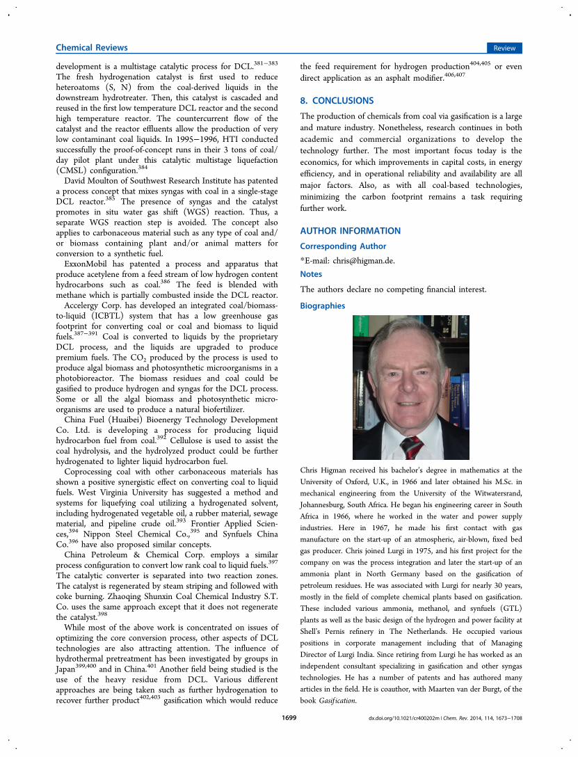
development is a multistage catalytic process for DCL.381−383
The fresh hydrogenation catalyst is first used to reduceheteroatoms (S, N) from the coal-derived liquids in thedownstream hydrotreater. Then, this catalyst is cascaded andreused in the first low temperature DCL reactor and the secondhigh temperature reactor. The countercurrent flow of thecatalyst and the reactor effluents allow the production of verylow contaminant coal liquids. In 1995−1996, HTI conductedsuccessfully the proof-of-concept runs in their 3 tons of coal/day pilot plant under this catalytic multistage liquefaction(CMSL) configuration.384
David Moulton of Southwest Research Institute has patenteda process concept that mixes syngas with coal in a single-stageDCL reactor.385 The presence of syngas and the catalystpromotes in situ water gas shift (WGS) reaction. Thus, aseparate WGS reaction step is avoided. The concept alsoapplies to carbonaceous material such as any type of coal and/or biomass containing plant and/or animal matters forconversion to a synthetic fuel.ExxonMobil has patented a process and apparatus that
produce acetylene from a feed stream of low hydrogen contenthydrocarbons such as coal.386 The feed is blended withmethane which is partially combusted inside the DCL reactor.Accelergy Corp. has developed an integrated coal/biomass-
to-liquid (ICBTL) system that has a low greenhouse gasfootprint for converting coal or coal and biomass to liquidfuels.387−391 Coal is converted to liquids by the proprietaryDCL process, and the liquids are upgraded to producepremium fuels. The CO2 produced by the process is used toproduce algal biomass and photosynthetic microorganisms in aphotobioreactor. The biomass residues and coal could begasified to produce hydrogen and syngas for the DCL process.Some or all the algal biomass and photosynthetic micro-organisms are used to produce a natural biofertilizer.China Fuel (Huaibei) Bioenergy Technology Development
Co. Ltd. is developing a process for producing liquidhydrocarbon fuel from coal.392 Cellulose is used to assist thecoal hydrolysis, and the hydrolyzed product could be furtherhydrogenated to lighter liquid hydrocarbon fuel.Coprocessing coal with other carbonaceous materials has
shown a positive synergistic effect on converting coal to liquidfuels. West Virginia University has suggested a method andsystems for liquefying coal utilizing a hydrogenated solvent,including hydrogenated vegetable oil, a rubber material, sewagematerial, and pipeline crude oil.393 Frontier Applied Scien-ces,394 Nippon Steel Chemical Co.,395 and Synfuels ChinaCo.396 have also proposed similar concepts.China Petroleum & Chemical Corp. employs a similar
process configuration to convert low rank coal to liquid fuels.397
The catalytic converter is separated into two reaction zones.The catalyst is regenerated by steam striping and followed withcoke burning. Zhaoqing Shunxin Coal Chemical Industry S.T.Co. uses the same approach except that it does not regeneratethe catalyst.398
While most of the above work is concentrated on issues ofoptimizing the core conversion process, other aspects of DCLtechnologies are also attracting attention. The influence ofhydrothermal pretreatment has been investigated by groups inJapan399,400 and in China.401 Another field being studied is theuse of the heavy residue from DCL. Various differentapproaches are being taken such as further hydrogenation torecover further product402,403 gasification which would reduce
the feed requirement for hydrogen production404,405 or evendirect application as an asphalt modifier.406,407
8. CONCLUSIONS
The production of chemicals from coal via gasification is a largeand mature industry. Nonetheless, research continues in bothacademic and commercial organizations to develop thetechnology further. The most important focus today is theeconomics, for which improvements in capital costs, in energyefficiency, and in operational reliability and availability are allmajor factors. Also, as with all coal-based technologies,minimizing the carbon footprint remains a task requiringfurther work.
AUTHOR INFORMATION
Corresponding Author
*E-mail: [email protected].
Notes
The authors declare no competing financial interest.
Biographies
Chris Higman received his bachelor’s degree in mathematics at the
University of Oxford, U.K., in 1966 and later obtained his M.Sc. inmechanical engineering from the University of the Witwatersrand,
Johannesburg, South Africa. He began his engineering career in SouthAfrica in 1966, where he worked in the water and power supply
industries. Here in 1967, he made his first contact with gasmanufacture on the start-up of an atmospheric, air-blown, fixed bed
gas producer. Chris joined Lurgi in 1975, and his first project for thecompany on was the process integration and later the start-up of an
ammonia plant in North Germany based on the gasification ofpetroleum residues. He was associated with Lurgi for nearly 30 years,
mostly in the field of complete chemical plants based on gasification.These included various ammonia, methanol, and synfuels (GTL)
plants as well as the basic design of the hydrogen and power facility atShell’s Pernis refinery in The Netherlands. He occupied various
positions in corporate management including that of Managing
Director of Lurgi India. Since retiring from Lurgi he has worked as anindependent consultant specializing in gasification and other syngas
technologies. He has a number of patents and has authored manyarticles in the field. He is coauthor, with Maarten van der Burgt, of the
book Gasif ication.
Chemical Reviews Review
dx.doi.org/10.1021/cr400202m | Chem. Rev. 2014, 114, 1673−17081699
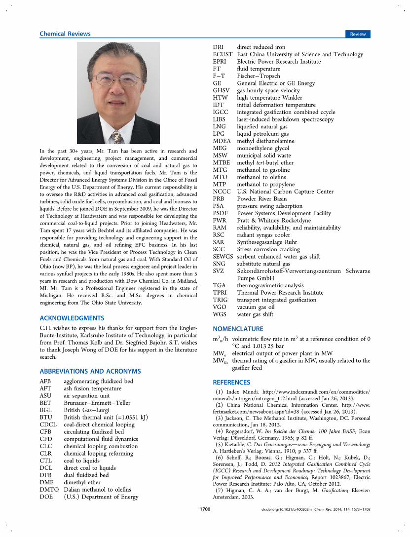
In the past 30+ years, Mr. Tam has been active in research anddevelopment, engineering, project management, and commercialdevelopment related to the conversion of coal and natural gas topower, chemicals, and liquid transportation fuels. Mr. Tam is theDirector for Advanced Energy Systems Division in the Office of FossilEnergy of the U.S. Department of Energy. His current responsibility isto oversee the R&D activities in advanced coal gasification, advancedturbines, solid oxide fuel cells, oxycombustion, and coal and biomass toliquids. Before he joined DOE in September 2009, he was the Directorof Technology at Headwaters and was responsible for developing thecommercial coal-to-liquid projects. Prior to joining Headwaters, Mr.Tam spent 17 years with Bechtel and its affiliated companies. He wasresponsible for providing technology and engineering support in thechemical, natural gas, and oil refining EPC business. In his lastposition, he was the Vice President of Process Technology in CleanFuels and Chemicals from natural gas and coal. With Standard Oil ofOhio (now BP), he was the lead process engineer and project leader invarious synfuel projects in the early 1980s. He also spent more than 5years in research and production with Dow Chemical Co. in Midland,MI. Mr. Tam is a Professional Engineer registered in the state ofMichigan. He received B.Sc. and M.Sc. degrees in chemicalengineering from The Ohio State University.
ACKNOWLEDGMENTSC.H. wishes to express his thanks for support from the Engler-Bunte-Institute, Karlsruhe Institute of Technology, in particularfrom Prof. Thomas Kolb and Dr. Siegfried Bajohr. S.T. wishesto thank Joseph Wong of DOE for his support in the literaturesearch.
ABBREVIATIONS AND ACRONYMSAFB agglomerating fluidized bedAFT ash fusion temperatureASU air separation unitBET Brunauer−Emmett−TellerBGL British Gas−LurgiBTU British thermal unit (=1.0551 kJ)CDCL coal-direct chemical loopingCFB circulating fluidized bedCFD computational fluid dynamicsCLC chemical looping combustionCLR chemical looping reformingCTL coal to liquidsDCL direct coal to liquidsDFB dual fluidized bedDME dimethyl etherDMTO Dalian methanol to olefinsDOE (U.S.) Department of Energy
DRI direct reduced ironECUST East China University of Science and TechnologyEPRI Electric Power Research InstituteFT fluid temperatureF−T Fischer−TropschGE General Electric or GE EnergyGHSV gas hourly space velocityHTW high temperature WinklerIDT initial deformation temperatureIGCC integrated gasification combined ccycleLIBS laser-induced breakdown spectroscopyLNG liquefied natural gasLPG liquid petroleum gasMDEA methyl diethanolamineMEG monoethylene glycolMSW municipal solid wasteMTBE methyl tert-butyl etherMTG methanol to gasolineMTO methanol to olefinsMTP methanol to propyleneNCCC U.S. National Carbon Capture CenterPRB Powder River BasinPSA pressure swing adsorptionPSDF Power Systems Development FacilityPWR Pratt & Whitney RocketdyneRAM reliability, availability, and maintainabilityRSC radiant syngas coolerSAR Synthesegasanlage RuhrSCC Stress corrosion crackingSEWGS sorbent enhanced water gas shiftSNG substitute natural gasSVZ Sekonda rrohstoff-Verwertungszentrum Schwarze
Pumpe GmbHTGA thermogravimetric analysisTPRI Thermal Power Research InstituteTRIG transport integrated gasificationVGO vacuum gas oilWGS water gas shift
NOMENCLATUREm3
n/h volumetric flow rate in m3 at a reference condition of 0°C and 1.013 25 bar
MWe electrical output of power plant in MWMWth thermal rating of a gasifier in MW, usually related to the
gasifier feed
REFERENCES(1) Index Mundi. http://www.indexmundi.com/en/commodities/minerals/nitrogen/nitrogen_t12.html (accessed Jan 26, 2013).(2) China National Chemical Information Center. http://www.fertmarket.com/newsabout.aspx?id=38 (accessed Jan 26, 2013).(3) Jackson, C. The Methanol Institute, Washington, DC. Personalcommunication, Jan 18, 2012.(4) Roggersdorf, W. Im Reiche der Chemie: 100 Jahre BASF; EconVerlag: Dusseldorf, Germany, 1965; p 82 ff.(5) Kietaible, C. Das Generatorgasseine Erzeugung und Verwendung;A. Hartleben’s Verlag: Vienna, 1910; p 337 ff.(6) Schoff, R.; Booras, G.; Higman, C.; Holt, N.; Kubek, D.;Sorensen, J.; Todd, D. 2012 Integrated Gasification Combined Cycle(IGCC) Research and Development Roadmap: Technology Developmentfor Improved Performance and Economics; Report 1023867; ElectricPower Research Institute: Palo Alto, CA, October 2012.(7) Higman, C. A. A.; van der Burgt, M. Gasification; Elsevier:Amsterdam, 2003.
Chemical Reviews Review
dx.doi.org/10.1021/cr400202m | Chem. Rev. 2014, 114, 1673−17081700
(8) Higman, C. A. A. Gasification. In Combustion Engineering Issues forSolid Fuel Systems; Miller, B. G., Tillman, D. A., Eds.; Academic Press/Elsevier, Burlington, MA, 2008; p 434.(9) Holt, N. A. Coal Gasification Guidebook: Status, Applications andTechnologies; Report TR-102034; Electric Power Research Institute:Palo Alto, CA, December 1993.(10) Mondal, P.; Dang, G. S.; Garg, M. O. Fuel Process. Technol. 2011,92, 1395.(11) Hornick, M. J.; McDaniel, J. E. Tampa Electric Polk Power StationIntegrated Gasification Combined Cycle Project: Final Technical Report;NETL/DE-FC-21-91MC27363; National Energy Technology Labo-ratory: Morgantown, WV, August 2002; p 1-33.(12) Holt, N. A. Gasification Technology Status December 2011;Report 1022031; Electric Power Research Institute: Palo Alto, CA,December 2011; pp 4-14−4-15.(13) Roberts, D. G.; Harris, D. J. Energy Fuels 2012, 26, 176.(14) Malekshahian, M.; Hill, J. M. Energy Fuels 2011, 25, 4043.(15) Fermoso, J.; Gil, M. V.; García, S.; Pevida, C.; Pis, J. J.; Rubiera,F. Energy Fuels 2011, 25, 3574.(16) Zhan, X. L.; Zhou, Z. J.; Wang, F. C. Appl. Energy 2010, 87,1710.(17) Liu, T. F.; Fang, Y. T.; Wang, Y. Fuel 2008, 87, 460.(18) Smolin ski, A. Energy Convers. Manage. 2011, 52, 37.(19) Zhang, S.; Min, Z. H.; Tay, H- L.; Asadullah, M.; Li, C. Z. Fuel2011, 90, 1529.(20) Tay, H. L.; Li, C. Z. Fuel Process. Technol. 2010, 91, 800.(21) Song, W. J.; Tang, L. H.; Zhu, X. D.; Wu, Y. Q.; Zhu, Z. B.;Koyama, S. Energy Fuels 2009, 23, 1990.(22) van Dyk, J. C. Miner. Eng. 2006, 19, 280.(23) Thompson, D. Fuel 2010, 89, 2062.(24) Song, W. J.; Tang, L. H.; Zhu, X. D.; Wu, Y. Q.; Zhu, Z. B.;Koyama, S. Energy Fuels 2010, 24, 182−189.(25) Urbain, G.; Cambier, F.; Deletter, M.; Anseau, M. R. Trans. J. Br.Ceram. Soc. 1981, 80, 139.(26) Kalmanovitch, D. P.; Frank, M. An Effective Model of Viscosityfor Ash Deposition Phenomena. Energy Foundation Conferences -Mineral Matter and Ash Deposition from Coal; Santa Barbara, CA;February 22−26, 1988; pp 89−101.(27) Browning, G. J.; Bryant, G. W.; Hurst, H. J.; Lucas, J. A.; Wall,T. F. Energy Fuels 2003, 17, 731.(28) Patterson, J. H.; Hurst, H. J.; Quintanaar, A. Slag CompositionalLimits for Coal Use in Slagging Gasifiers. Presented at the 19th AnnualInternational Pittsburgh Coal Conference, Pittsburgh, PA, Sept 23−27,2002.(29) Song, W. J.; Tang, L. H.; Zhu, X. D.; Wu, Y. Q.; Zhu, Z. B.;Koyama, S. Fuel 2010, 89, 1709.(30) Yu, G. S.; Zhu, Q. R.; Chi, G. Z.; Guo, Q. H.; Zhou, Z. J. FuelProcess. Technol. 2012, 104, 136.(31) Song, W. J.; Tang, L. H.; Zhu, X. D.; Wu, Y. Q.; Rong, Y. Q.;Zhu, Z. B.; Koyama, S. Fuel 2009, 88, 297.(32) Duchesne, M. A.; Ilyushechkin, A. Y.; Hughes, R. W.; Lu, D. Y.;McCalden, D. J.; Macchi, A.; Anthony, E. J. Fuel 2012, 97, 321.(33) Zhu, J. X.; Kaneko, T. K.; Mu, H. Y.; Bennett, J. P.; Sridhar, S.Energy Fuels 2012, 26, 4465.(34) Yuan, H. P.; Liang, Q. F.; Gong, X. Energy Fuels 2012, 26, 3717.(35) Nakano, J.; Sridhar, S.; Moss, T.; Bennett, J.; Kwong, K.-S.Energy Fuels 2009, 23, 4723.(36) Li, S. H.; Whitty, K. J. Energy Fuels 2009, 23, 1998.(37) Li, S. H.; Wu, Y. X.; Whitty, K. J. Energy Fuels 2010, 24, 1868.(38) van Dyk, J. C.; Keyser, M. J. Application of FactSageEquilibrium Simulations to Quantify the Effect of Mineral Types onSlag Formation during Thermal Conversion of Coal. Presented at the5th International Freiberg Conference on IGCC and XtLTechnologies, Leipzig, Germany, May 20−24, 2012.(39) van Dyk, J. C.; Waanders, F. B.; Benson, S. A.; Laumb, M. L.;Hack, K. Fuel 2009, 88, 67.(40) Matjie, R. H.; French, D.; Ward, C. R.; Pistorius, P. C.; Li, Z. S.Fuel Process. Technol. 2011, 92, 1426.
(41) Li, F. H.; Huang, J. J.; Fang, Y. T.; Wang, Y. Energy Fuels 2011,25, 273.(42) Jing, N. J.; Wang, Q. H.; Luo, Z. Y.; Cen, K. Fuel 2011, 90, 2645.(43) Nel, M. V.; Strydom, C. A.; Schobert, H. H.; Beukes, J. P.; Bunt,J. R. Fuel Process. Technol. 2011, 92, 1042.(44) Wang, H. G.; Qiu, P. H.; Zhu, Y.; Wu, S. J.; Zhao, W. H.; Wu, S.H. Energy Fuels 2011, 25, 5594.(45) Melchior, T.; Blasing, M.; Putz, G.; Muller, M. Fuel 2011, 90,280.(46) Reimert, R. Chem. Ing. Tech. 1981, 53, 335.(47) SCoTA Specification High Ash Australian Coal. http://www.globalcoa l .com/Brochureware/standardTradingContract/specifications/?CFID=2543603&CFTOKEN=87592505#ASH (ac-cessed Jan 31, 2013).(48) Schilling, H.-D.; Bonn, B.; Krauß, U. Coal Gasification: ExistingProcesses and New Developments; Graham & Trotman: London, 1981;p 73 (translated from German).(49) Panek, J. M.; Grasser, J. Practical Experience Gained during theFirst Twenty Years of Operation of the Great Plains Gasification Plant andImplications for Future Projects; U.S. Department of Energy: Office ofFossil Energy, April 2006. http://www.fossil.energy.gov/programs/powersystems/publications/Brochures/dg_knowledge_gained.pdf(accessed Feb 24, 2013).(50) Olschar, M.; Schulze, O. The BGL Commercial Plants and PilotTesting. Presented at the 5th International Freiberg Conference onIGCC and XtL Technologies, Leipzig, Germany, May 21−24, 2012.(51) Viljoen, J. Private communication, Jan 21, 2013.(52) Eswaraiah, C.; Gupta, A.; Nagarajan, R.; Rajavel, M.;Nandakumar, K. Fuel Process. Technol. 2008, 89, 704.(53) Hornick, M. J.; McDaniel, J. E. Tampa Electric Polk Power StationIntegrated Gasification Combined Cycle Project: Final Technical Report;NETL/DE-FC-21-91MC27363; National Energy Technology Labo-ratory: Morgantown, WV, August 2002; p 1-12.(54) Yaghmaie, F.; Mckeon, R. J. (Texaco Inc.). Coal-Water Slurriesof Low Viscosity and Method for Their Preparation. U.S. Patent4,502,868, March 5, 1985.(55) Zhou, M. S.; Kong, Q.; Pan, B.; Qiu, X. Q.; Yang, D. J.; Lou, H.M. Fuel 2010, 89, 716.(56) Zhan, X. L.; Zhou, Z. J.; Kang, W. Z.; Wang, F. C. Fuel Process.Technol. 2010, 91, 1256.(57) Li, W. D.; Li, W. F.; Liu, H. F.; Yu, Z. H. Fuel 2009, 88, 2241.(58) Li, W. D.; Li, W. F.; Liu, H. F. Fuel 2010, 89, 2505.(59) Li, W. D.; Li, W. F.; Liu, H. F. Fuel 2010, 89, 965.(60) Bae, J.-S.; Lee, D.-W.; Park, S.-J.; Lee, Y.-J.; Hong, J.-C.; Ra, H.W.; Han, C.; Choi, Y.-C. Energy Fuels 2012, 26, 6033.(61) Senapati, P. K.; Das, D.; Nayak, A.; Mishra, P. K. Energy Sources,Part A 2008, 30, 1788.(62) Wang, R. K.; Liu, J. Z.; Yu, Y. J.; Hu, Y. X.; Zhou, J. H.; Cen, K.Energy Fuels 2011, 25, 747.(63) Liu, J. Z.; Zhao, W. D.; Zhou, J. H.; Cheng, J.; Zhang, G. X.;Feng, Y. G.; Cen, K. Fuel. Process. Technol. 2009, 90, 91.(64) Yu, Y. J.; Liu, J. Z.; Wang, R. K.; Zhou, J. H.; Cen, K. EnergyConvers. Manage. 2012, 57, 8.(65) Schlinger, W. G. The Texaco Coal Gasification Process. InHandbook of Synfuels Technology; Meyers, R. A., Ed.; McGraw-Hill:New York, 1984; pp 3−11.(66) Phillips, J. N. CoalFleet RD&D Augmentation Plan for IntegratedGasification Combines Cycle (IGCC) Power Plants; Report 1013219;Electric Power Research Institute: Palo Alto, CA, January 2007.(67) U.S. DOE-NETL. Carbon Dioxide Coal Slurry for FeedingLow-Rank Coal to Gasifiers; DOE Project DE-FE0007977; http://www.netl.doe.gov/technologies/coalpower/gasification/projects/adv-gas/epri-co2slurry-low-rank.html (accessed Feb 24, 2013).(68) Trapp, W. Eastman and Gasification: the Next Step, Building onPast Success. Presented at the Gasification Technologies Conference,San Francisco, Oct 8−10, 2001.(69) Trapp, W. Gasification Plant Design and Operation for a CleanReliable Energy Source of the Future. Presented at the EuropeanGasification Conference, Brighton, U.K., May 10−12, 2004.
Chemical Reviews Review
dx.doi.org/10.1021/cr400202m | Chem. Rev. 2014, 114, 1673−17081701
(70) Zhou, Z. J. Experience and Future Development of ECUSTGasification. Presented at the Gasification Technologies Conference,Washington, DC, Oct 30, 2012.(71) Cao, X. K.; Sun, Z. G.; Li, W. F.; Liu, H. F.; Yu, Z. H. Phys.Fluids 2007, 19, 057103.(72) Zhao, H.; Liu, H. F.; Cao, X. K.; Li, W. F.; Xu, J. L. Int. J.Multiphase Flow 2011, 37, 530.(73) Crew, J. GE Gasification Project Update. Presented at theGasification Technologies Conference, Washington, DC, Oct 28,2012.(74) Haberzettl, A. Siemens Fuel Gasification Technology GmbH &Co. KG, Personal communication, April 17, 2013.(75) Lu, H. F.; Guo, X. L.; Gong, X.; Cong, X. L.; Liu, K.; Qi, H. F.Chem. Eng. Sci. 2012, 71, 438.(76) Berggren, W. D. Sluice Vessel and Method of Operating Such aSluice Vessel. U.S. Patent Appl. 2009/0218371, Sept 3, 2009.(77) Lu, H. F.; Guo, X. L.; Gong, X.; Cong, X. L.; Liu, K.; Qi, H. F.Ind. Eng. Chem. Res. 2012, 51, 3709.(78) Schingnitz, M. Gaskombinat Schwarze Pumpe-Verfahren(GSP). In Die Veredlung und Umwandlung von Kohle: Technologienund Projekte 1970 bis 2000 in Deutschland; Schmalfeld, J., Ed; DGMK:Hamburg, Germany, 2008; p 539.(79) Cong, X. L.; Guo, X. L.; Gong, X.; Lu, H. F.; Liu, K.; Qi, H. F.Powder Technol. 2012, 219, 135.(80) Cong, X. L.; Guo, X. L.; Gong, X.; Lu, H. F.; Dong, W. B.Powder Technol. 2011, 208, 600.(81) Reimert, R. Chem. Ing. Tech. 1986, 58, 890.(82) Picard, L.; Kamka, F.; Jochmann, A. Development Status ofBGL-Gasification. Presented at the First International FreibergConference on IGCC & XtL Technologies, Freiberg, Germany, June16−18, 2005.(83) Weiss, M. M. Update on New Project & Design Developmentswith Lurgi’s FBDB Gasifier. Presented at the Fifth InternationalConference on Clean Coal Technologies CCT 2011, Zaragosa, Spain,May 8−12, 2011.(84) Hay, A.; Bonk, D. L. Stamet Solids Pump Feeds Coal into 210psig in a DOE Supported ProjectDOE/METC/C-96/7208.Presented at Power-Gen America, Anaheim, CA, Dec 5−7, 1995.(85) Firth, D. Multiple Choke Apparatus Transporting and MeteringMaterial. U.S. Patent 4,988,239, Jan 29, 1991.(86) U.S. DOE-NETL. Continuous Pressure Injection of Solid Fuelsinto Advanced Combustion System Pressures. http://www.netl.doe.gov/publications/factsheets/project/Proj397.pdf (accessed Feb 24,2013).(87) Saunders, T.; Aldred, D. Development of a Coal Feeder forContinuous Injection into Gasification Operating Pressures of 1000psi. Presented at the 23rd Annual International Pittsburgh CoalConference, Pittsburgh, PA, September 2006.(88) Fusselman, S. P.; Saunders, T.; Sprouse, K. M.; Fulton, J. W.;Raterman, M. PWR Compact Gasification Development Status.Presented at the 26th Annual International Pittsburgh Coal Confer-ence, Pittsburgh, PA, Sept 21−24, 2009.(89) Sprouse, K.; Matthews, D. R. Linear Tractor Dry Coal ExtrusionPump. U.S. Patent 7,387,197 B2, June 17, 2008.(90) Darby, A. Dry Solids Pump Development Status. Presented atthe Gasification Technologies Conference, Washington, DC, Oct 31,2012.(91) Sprouse, K.; Widman, F.; Darby, A. Conceptual Design of anUltra-Dense Phase Injector and Feed System; Pratt & WhitneyRocketdyne Inc.: Canoga Park, CA, April 2006.(92) Koch, T. TKE Feed System. Presented at the GasificationTechnologies Conference, Washington, DC, Oct 31, 2011.(93) Schellberg, W.; Garcia Pena, F.; Hooper, M. World’s LargestIGCC Celebrates 10th Anniversary. Presented at the 25th AnnualInternational Pittsburgh Coal Conference, Pittsburgh, PA, Sept 29−Oct 2, 2008.(94) Wolters, C.; Kanaar, M. Co-Gasification of Biomass: NuonPower Buggenum. Presented at Workshop of the 7th EuropeanGasification Conference, Barcelona, April 2006.
(95) Straka, P.; Bucko, Z. Fuel Process. Technol. 2009, 90, 1202.(96) Pinto, F.; Neto Andre, R.; Franco, C.; Lopes, H.; Gulyurtlu, I.;Cabrita, I. Fuel 2009, 88, 2392.(97) Pinto, F.; Neto Andre, R.; Franco, C.; Lopes, H.; Carolino, C.;Costa, R.; Gulyurtlu, I. Fuel 2010, 89, 3340.(98) Pinto, F.; Neto Andre, R.; Franco, C.; Carolino, C.; Costa, R.;Miranda, M.; Gulyurtlu, I. Fuel 2012, 101, 102.(99) Pinto, F.; Neto Andre, R.; Lopes, H.; Franco, C.; Carolino, C.;Costa, R.; Galhetas, M.; Miranda, M.; Gulyurtlu, I. Fuel 2012, 97, 770.(100) Velez, J. F.; Chejne, F.; Valdes, C. F.; Emery, E. J.; Londono, C.Fuel 2009, 88, 424.(101) Alzate, C. A.; Chejne, F.; Valdes, C. F.; Berrio, A.; de La Cruz,J.; Londono, C. A. Fuel 2009, 88, 437.(102) Zhang, Q.; Liu, H. F.; Li, W. F.; Xu, J. L.; Liang, Q. F. EnergyFuels 2012, 26, 2830.(103) Aigner, I.; Pfeifer, C.; Hofbauer, H. Fuel 2011, 90, 2404.(104) Zhu, W. K.; Song, W. L.; Lin, W. G. Fuel Process. Technol. 2008,89, 890.(105) Casero, P.; García Pena, F. Puertollano IGCC Plant: PresentPosition and Future Competitiveness. Presented at the 22nd AnnualInternational Pittsburgh Coal Conference, Pittsburgh, PA, Sept 12−15,2005.(106) Amick, P. E-Gas Technology Update. Presented at the CoalAsia 2013 Conference, New Delhi, Feb 10, 2013.(107) Geertsema, A.; Groppo, J.; Price, C. Demonstration of aBeneficiation Technology for Texaco Gasifier Slag. Presented at theGasification Technologies Conference, San Francisco, October 2002.(108) Vejahati, F.; Katalambula, H.; Gupta, R. Energy Fuels 2012, 26,219.(109) Zhan, X. L.; Jia, J.; Zhou, Z. J.; Wang, F. C. Energy Convers.Manage. 2011, 52, 1810.(110) Bunt, J. R.; Waanders, F. B. Fuel 2008, 87, 1751.(111) van Dyk, J. C.; Waanders, F. B.; van Heerden, J. H. P. Fuel2008, 87, 2735.(112) Bunt, J. R.; Waanders, F. B. Fuel 2008, 87, 2856.(113) Bunt, J. R.; Wagner, N. J.; Waanders, F. B. Fuel 2009, 88, 771.(114) Mangena, S. J.; Bunt, J. R.; Waanders, F. B.; Baker, G. Fuel2011, 90, 167.(115) Skhonde, M. P.; Matjie, R. H.; Bunt, J. R.; Strydom, A. C.;Schobert, H. Energy Fuels 2009, 23, 229.(116) Bunt, J. R.; Waanders, F. B. Fuel 2009, 88, 585.(117) van Dyk, J. C.; Keyser, M. J.; Waanders, F. B.; Conradie, M.Fuel 2010, 89, 229.(118) Pettinau, A.; Frau, C.; Ferrara, F. Fuel Process. Technol. 2011,92, 1946.(119) Grieco, E. M.; Baldi, G. Chem. Eng. Sci. 2011, 66, 5749.(120) Hobbs, M. L.; Radulovic, P. T.; Smoot, L. D. AIChE J. 1992,38, 681.(121) Cao, Y.; Gao, Z. Y.; Jin, J.; Zhou, H. C.; Cohron, M.; Zhao, H.Y.; Liu, H. Y.; Pan, W. P. Energy Fuels 2008, 22, 1720.(122) Adlhoch, W. Hochtemperatur-Winkler Verfahren (HTW). InDie Veredlung und Umwandlung von Kohle: Technologien und Projekte1970 bis 2000 in Deutschland; Schmalfeld, J., Ed.; DGMK: Hamburg,Germany, 2008; pp 409−446.(123) Southern Company Services, Inc. Power Systems Develop-ment Facility: Final Report; U.S. DOE Cooperative Agreement DE-FC21-90MC25140, Wilsonville, AL, April 2009.(124) Pinkston, T. Update on the Kemper County IGCC Project.Presented at the Gasification Technologies Conference, Washington,DC, Oct 28−31, 2012.(125) Duan, F.; Jin, B.; Huang, Y. J.; Li, B.; Wu, Y. M.; Zhang, M. Y.Energy Fuels 2010, 24, 3150.(126) Ju, F. D.; Chen, H. P.; Yang, H. P.; Wang, X. H.; Zhang, S. H.;Liu, D. C. Fuel Process. Technol. 2010, 91, 818.(127) Thompson, C. Cleanly Unlocking the Value of Low RankCoal. Presented at the Gasification Technologies Conference,Washington, DC, Nov 2, 2010.(128) Liu, Z. Y.; Fang, Y. T.; Deng, S. P.; Huang, J. J.; Zhao, J. T.;Cheng, Z. H. Energy Fuels 2012, 26, 1237.
Chemical Reviews Review
dx.doi.org/10.1021/cr400202m | Chem. Rev. 2014, 114, 1673−17081702
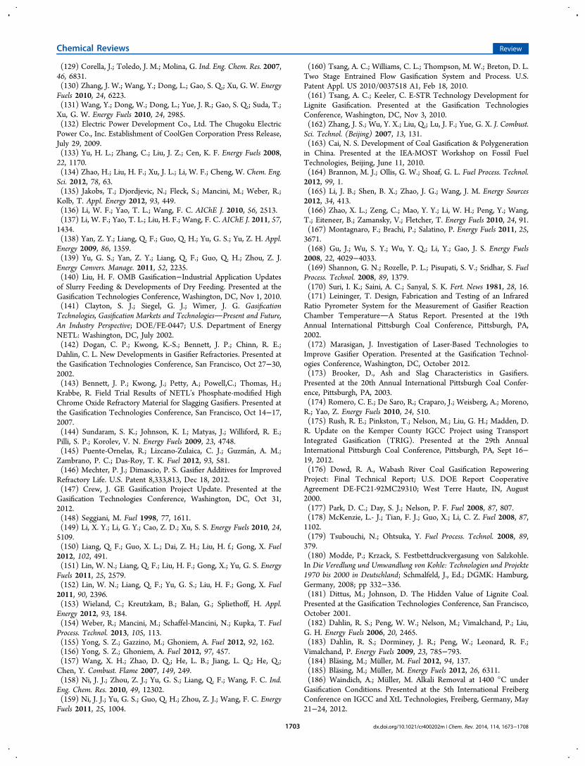
(129) Corella, J.; Toledo, J. M.; Molina, G. Ind. Eng. Chem. Res. 2007,46, 6831.(130) Zhang, J. W.; Wang, Y.; Dong, L.; Gao, S. Q.; Xu, G. W. EnergyFuels 2010, 24, 6223.(131) Wang, Y.; Dong, W.; Dong, L.; Yue, J. R.; Gao, S. Q.; Suda, T.;Xu, G. W. Energy Fuels 2010, 24, 2985.(132) Electric Power Development Co., Ltd. The Chugoku ElectricPower Co., Inc. Establishment of CoolGen Corporation Press Release,July 29, 2009.(133) Yu, H. L.; Zhang, C.; Liu, J. Z.; Cen, K. F. Energy Fuels 2008,22, 1170.(134) Zhao, H.; Liu, H. F.; Xu, J. L.; Li, W. F.; Cheng, W. Chem. Eng.Sci. 2012, 78, 63.(135) Jakobs, T.; Djordjevic, N.; Fleck, S.; Mancini, M.; Weber, R.;Kolb, T. Appl. Energy 2012, 93, 449.(136) Li, W. F.; Yao, T. L.; Wang, F. C. AIChE J. 2010, 56, 2513.(137) Li, W. F.; Yao, T. L.; Liu, H. F.; Wang, F. C. AIChE J. 2011, 57,1434.(138) Yan, Z. Y.; Liang, Q. F.; Guo, Q. H.; Yu, G. S.; Yu, Z. H. Appl.Energy 2009, 86, 1359.(139) Yu, G. S.; Yan, Z. Y.; Liang, Q. F.; Guo, Q. H.; Zhou, Z. J.Energy Convers. Manage. 2011, 52, 2235.(140) Liu, H. F. OMB Gasification−Industrial Application Updatesof Slurry Feeding & Developments of Dry Feeding. Presented at theGasification Technologies Conference, Washington, DC, Nov 1, 2010.(141) Clayton, S. J.; Siegel, G. J.; Wimer, J. G. GasificationTechnologies, Gasification Markets and TechnologiesPresent and Future,An Industry Perspective; DOE/FE-0447; U.S. Department of EnergyNETL: Washington, DC, July 2002.(142) Dogan, C. P.; Kwong, K.-S.; Bennett, J. P.; Chinn, R. E.;Dahlin, C. L. New Developments in Gasifier Refractories. Presented atthe Gasification Technologies Conference, San Francisco, Oct 27−30,2002.(143) Bennett, J. P.; Kwong, J.; Petty, A.; Powell,C.; Thomas, H.;Krabbe, R. Field Trial Results of NETL’s Phosphate-modified HighChrome Oxide Refractory Material for Slagging Gasifiers. Presented atthe Gasification Technologies Conference, San Francisco, Oct 14−17,2007.(144) Sundaram, S. K.; Johnson, K. I.; Matyas, J.; Williford, R. E.;Pilli, S. P.; Korolev, V. N. Energy Fuels 2009, 23, 4748.(145) Puente-Ornelas, R.; Lizcano-Zulaica, C. J.; Guzman, A. M.;Zambrano, P. C.; Das-Roy, T. K. Fuel 2012, 93, 581.(146) Mechter, P. J.; Dimascio, P. S. Gasifier Additives for ImprovedRefractory Life. U.S. Patent 8,333,813, Dec 18, 2012.(147) Crew, J. GE Gasification Project Update. Presented at theGasification Technologies Conference, Washington, DC, Oct 31,2012.(148) Seggiani, M. Fuel 1998, 77, 1611.(149) Li, X. Y.; Li, G. Y.; Cao, Z. D.; Xu, S. S. Energy Fuels 2010, 24,5109.(150) Liang, Q. F.; Guo, X. L.; Dai, Z. H.; Liu, H. f.; Gong, X. Fuel2012, 102, 491.(151) Lin, W. N.; Liang, Q. F.; Liu, H. F.; Gong, X.; Yu, G. S. EnergyFuels 2011, 25, 2579.(152) Lin, W. N.; Liang, Q. F.; Yu, G. S.; Liu, H. F.; Gong, X. Fuel2011, 90, 2396.(153) Wieland, C.; Kreutzkam, B.; Balan, G.; Spliethoff, H. Appl.Energy 2012, 93, 184.(154) Weber, R.; Mancini, M.; Schaffel-Mancini, N.; Kupka, T. FuelProcess. Technol. 2013, 105, 113.(155) Yong, S. Z.; Gazzino, M.; Ghoniem, A. Fuel 2012, 92, 162.(156) Yong, S. Z.; Ghoniem, A. Fuel 2012, 97, 457.(157) Wang, X. H.; Zhao, D. Q.; He, L. B.; Jiang, L. Q.; He, Q.;Chen, Y. Combust. Flame 2007, 149, 249.(158) Ni, J. J.; Zhou, Z. J.; Yu, G. S.; Liang, Q. F.; Wang, F. C. Ind.Eng. Chem. Res. 2010, 49, 12302.(159) Ni, J. J.; Yu, G. S.; Guo, Q. H.; Zhou, Z. J.; Wang, F. C. EnergyFuels 2011, 25, 1004.
(160) Tsang, A. C.; Williams, C. L.; Thompson, M. W.; Breton, D. L.Two Stage Entrained Flow Gasification System and Process. U.S.Patent Appl. US 2010/0037518 A1, Feb 18, 2010.(161) Tsang, A. C.; Keeler, C. E-STR Technology Development forLignite Gasification. Presented at the Gasification TechnologiesConference, Washington, DC, Nov 3, 2010.(162) Zhang, J. S.; Wu, Y. X.; Liu, Q.; Lu, J. F.; Yue, G. X. J. Combust.Sci. Technol. (Beijing) 2007, 13, 131.(163) Cai, N. S. Development of Coal Gasification & Polygenerationin China. Presented at the IEA-MOST Workshop on Fossil FuelTechnologies, Beijing, June 11, 2010.(164) Brannon, M. J.; Ollis, G. W.; Shoaf, G. L. Fuel Process. Technol.2012, 99, 1.(165) Li, J. B.; Shen, B. X.; Zhao, J. G.; Wang, J. M. Energy Sources2012, 34, 413.(166) Zhao, X. L.; Zeng, C.; Mao, Y. Y.; Li, W. H.; Peng, Y.; Wang,T.; Eiteneer, B.; Zamansky, V.; Fletcher, T. Energy Fuels 2010, 24, 91.(167) Montagnaro, F.; Brachi, P.; Salatino, P. Energy Fuels 2011, 25,3671.(168) Gu, J.; Wu, S. Y.; Wu, Y. Q.; Li, Y.; Gao, J. S. Energy Fuels2008, 22, 4029−4033.(169) Shannon, G. N.; Rozelle, P. L.; Pisupati, S. V.; Sridhar, S. FuelProcess. Technol. 2008, 89, 1379.(170) Suri, I. K.; Saini, A. C.; Sanyal, S. K. Fert. News 1981, 28, 16.(171) Leininger, T. Design, Fabrication and Testing of an InfraredRatio Pyrometer System for the Measurement of Gasifier ReactionChamber TemperatureA Status Report. Presented at the 19thAnnual International Pittsburgh Coal Conference, Pittsburgh, PA,2002.(172) Marasigan, J. Investigation of Laser-Based Technologies toImprove Gasifier Operation. Presented at the Gasification Technol-ogies Conference, Washington, DC, October 2012.(173) Brooker, D., Ash and Slag Characteristics in Gasifiers.Presented at the 20th Annual International Pittsburgh Coal Confer-ence, Pittsburgh, PA, 2003.(174) Romero, C. E.; De Saro, R.; Craparo, J.; Weisberg, A.; Moreno,R.; Yao, Z. Energy Fuels 2010, 24, 510.(175) Rush, R. E.; Pinkston, T.; Nelson, M.; Liu, G. H.; Madden, D.R. Update on the Kemper County IGCC Project using TransportIntegrated Gasification (TRIG). Presented at the 29th AnnualInternational Pittsburgh Coal Conference, Pittsburgh, PA, Sept 16−19, 2012.(176) Dowd, R. A., Wabash River Coal Gasification RepoweringProject: Final Technical Report; U.S. DOE Report CooperativeAgreement DE-FC21-92MC29310; West Terre Haute, IN, August2000.(177) Park, D. C.; Day, S. J.; Nelson, P. F. Fuel 2008, 87, 807.(178) McKenzie, L.- J.; Tian, F. J.; Guo, X.; Li, C. Z. Fuel 2008, 87,1102.(179) Tsubouchi, N.; Ohtsuka, Y. Fuel Process. Technol. 2008, 89,379.(180) Modde, P.; Krzack, S. Festbettdruckvergasung von Salzkohle.In Die Veredlung und Umwandlung von Kohle: Technologien und Projekte1970 bis 2000 in Deutschland; Schmalfeld, J., Ed.; DGMK: Hamburg,Germany, 2008; pp 332−336.(181) Dittus, M.; Johnson, D. The Hidden Value of Lignite Coal.Presented at the Gasification Technologies Conference, San Francisco,October 2001.(182) Dahlin, R. S.; Peng, W. W.; Nelson, M.; Vimalchand, P.; Liu,G. H. Energy Fuels 2006, 20, 2465.(183) Dahlin, R. S.; Dorminey, J. R.; Peng, W.; Leonard, R. F.;Vimalchand, P. Energy Fuels 2009, 23, 785−793.(184) Blasing, M.; Muller, M. Fuel 2012, 94, 137.(185) Blasing, M.; Muller, M. Energy Fuels 2012, 26, 6311.(186) Waindich, A.; Muller, M. Alkali Removal at 1400 °C underGasification Conditions. Presented at the 5th International FreibergConference on IGCC and XtL Technologies, Freiberg, Germany, May21−24, 2012.
Chemical Reviews Review
dx.doi.org/10.1021/cr400202m | Chem. Rev. 2014, 114, 1673−17081703
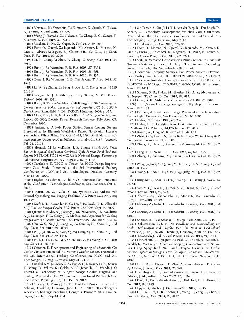
(187) Matsuoka, K.; Yamashita, T.; Kuramoto, K.; Suzuki, Y.; Takaya,A.; Tomita, A. Fuel 2008, 87, 885.(188) Wang, J.; Yamada, O.; Nakazato, T.; Zhang, Z. G.; Suzuki, Y.;Sakanishi, K. Fuel 2008, 87, 2211.(189) Vejahati, F.; Xu, Z.; Gupta, R. Fuel 2010, 89, 904.(190) Font, O.; Querol, X.; Izquierdo, M.; Alvarez, E.; Moreno, N.;Diez, S.; Alvarez-Rodríguez, R.; Clemente-Jul, C.; Coca, P.; GarciaPena, F. Fuel 2010, 89, 3250.(191) Li, Y.; Zhang, J.; Zhao, Y.; Zheng, C. Energy Fuels 2011, 25,3988.(192) Bunt, J. R.; Waanders, F. B. Fuel 2008, 87, 2374.(193) Bunt, J. R.; Waanders, F. B. Fuel 2009, 88, 961.(194) Bunt, J. R.; Waanders, F. B. Fuel 2010, 89, 537.(195) Bunt, J. R.; Waanders, F. B. Fuel Process. Technol. 2011, 92,1646.(196) Li, W. Y.; Zhong, L.; Feng, J.; Xie, K. C. Energy Sources 2010,32, 818.(197) Wagner, N. J.; Hlatshwayo, T. B.; Ginster, M. Fuel Process.Technol. 2008, 89, 1351.(198) Bonn, B. Texaco-Verfahren (GE-Energy) In Die Veredlung undUmwandlung von Kohle: Technologien und Projekte 1970 bis 2000 inDeutschland; Schmalfeld, J., Ed.; DGMK: Hamburg, 2008; p 527.(199) Clark, E. V.; Holt, N. A. Cool Water Coal Gasification Program;Report GS-6806; Electric Power Research Institute: Palo Alto, CA,December 1990.(200) Jenkins, S. D. Polk Power Station Syngas Cooling System.Presented at the Eleventh Worldwide Texaco Gasification LicenseeSymposium. White Plains, NY, Oct 10−13, 1994. Available at http://www.osti.gov/bridge/product.biblio.jsp?osti_id=10115197 (accessedFeb 24, 2013).(201) Hornick, M. J.; McDaniel, J. E. Tampa Electric Polk PowerStation Integrated Gasification Combined Cycle Project: Final TechnicalReport; NETL/DE-FC-21-91MC27363; National Energy TechnologyLaboratory: Morgantown, WV, August 2002; p 1-19.(202) Payrhuber, K. TECO to Today: An IGCC Design Improve-ment Case Study. Presented at the 3rd International FreibergConference on IGCC and XtL Technologies, Dresden, Germany,May 18−21, 2009.(203) Rigdon, R.; Schmoe, L. The IGCC Reference Plant. Presentedat the Gasification Technologies Conference, San Francisco, Oct 11,2005.(204) Martin, M. C.; Gulko, G. M. Synthetic Gas Radiant withInternal Quenching and Purging Facilities. U.S. Patent 5,233,943, Aug10, 1993.(205) Kraft, D. L.; Alexander, K. C.; Fry, S. R.; Doyle, T. E.; Albrecht,M. J. Radiant Syngas Cooler. U.S. Patent 7,587,995, Sept 15, 2009.(206) Jiimenez-Hiyke, A. J.; Storey, J. M.; Stevenson, J. S.; Avagliano,A. J.; Leininger, T. F.; Corry, J. B. Method and Apparatus for CoolingSyngas within a Gasifier system. U.S. Patent 8,197,564, June 12, 2012.(207) Yu, G. S.; Ni, J. J.; Liang, Q. F.; Guo, Q. H.; Zhou, Z. J. Ind.Eng. Chem. Res. 2009, 48, 10094.(208) Ni, J. J.; Yu, G. S.; Guo, Q. H.; Liang, Q. F.; Zhou, Z. J. Ind.Eng. Chem. Res. 2010, 49, 4452.(209) Ni, J. J.; Yu, G. S.; Guo, Q. H.; Dai, Z. H.; Wang, F. C. Chem.Eng. Sci. 2011, 66, 448.(210) Gunther, U. Development and Engineering of a Synthetic GasCooler Concept Integrated in a Siemens Gasifier Design. Presented atthe 5th International Freiberg Conference on IGCC and XtLTechnologies, Leipzig, Germany, May 21−24, 2012.(211) Bockelie, M. J.; Davis, K. A.; Fry, A. F.; Denison, M. K.; Shurtz,T.; Wang, D.; Whitty, K.; Celebi, M. C.; Jaramillo, C.; Wendt, J. O.Toward a Technology to Mitigate Syngas Cooler Plugging andFouling. Presented at the 29th Annual International Pittsburgh CoalConference, Pittsburgh, PA, Oct 15−18, 2012.(212) Ullrich, N.; Viguie, J. C. The BioTFuel Project. Presented atAchema, Frankfurt, Germany, June 18−22, 2012. http://kongress.achema.de/Beitragseinreichung/Congress+Planner/Datei_handler-tagung-559-file-5199-p-44.html.
(213) van Paasen, S.; Xu, J.; Li, X. J.; van der Berg, R.; Ten Bosch, D.;Abbate, G. Technology Development for Shell Coal Gasification.Presented at the 5th Freiberg Conference on IGCC and XtLTechnologies, Leipzig, Germany, May 2012.(214) Heidenreich, S. Fuel 2013, 104, 84.(215) Font, O.; Moreno, N.; Querol, X.; Izquierdo, M.; Alvarez, E.;Diez, S.; Elvira, J.; Antenucci, D.; Nugteren, H.; Plana, F.; Lopez, A.;Coca, P.; Garcia Pena, F. Fuel 2010, 89, 2971.(216) Stahl, K. Varnamo Demonstration Plant, Sweden. In HandbookBiomass Gasification; Knoef, H., Ed.; BTG Biomass TechnologyGroup: Enschede, The Netherlands, 2005; p 144.(217) Southern Company Services, Inc. Power Systems Develop-ment Facility Final Report; DOE DE-FC21-90MC25140; April 2009.http://www.nationalcarboncapturecenter .com/PSDF/pdf/PSDF%20Final%20Report%20DE-FC21-90MC25140.pdf (accessedMarch 18, 2013).(218) Sharma, S. D.; Dolan, M.; Ilyushechkin, A. Y.; McLennan, K.G.; Nguyen, T.; Chase, D. Fuel 2010, 89, 817.(219) Chen, S. E.; Nishihama, Y.; Yue, P. Fuel 2008, 87, 2807.(220) http://www.lincenergy.com/gas_to_liquids.php. (accessedMarch 18 2013)(221) Perlman, A. Great Point Energy. Presented at the GasificationTechnologies Conference, San Francisco, Oct 16, 2007.(222) Nahas, N. C. Fuel 1983, 62, 239.(223) Nahas, N. C. Catalytic Steam Gasification of Petroleum Coketo Methane. U.S. Patent 8,114,176 B2, Feb 12, 2012.(224) Karimi, A.; Gray, M. R. Fuel 2011, 90, 120.(225) Zhao, C. S.; Lin, L. S.; Pang, K. L.; Xiang, W. G.; Chen, X. P.Fuel Process. Technol. 2010, 91, 805.(226) Zhang, Y.; Hara, S.; Kajitani, S.; Ashizawa, M. Fuel 2010, 89,152.(227) Lang, R. J.; Neavel, R. C. Fuel 1982, 61, 620−626.(228) Zhang, Y.; Ashizawa, M.; Kajitani, S.; Hara, S. Fuel 2010, 89,417.(229) Wang, J.; Jiang, M. Q.; Yao, Y. H.; Zhang, Y. M.; Cao, J. Q. Fuel2009, 88, 1572.(230) Wang, J.; Yao, Y. H.; Cao, J. Q.; Jiang, M. Q. Fuel 2010, 89,310.(231) Jiang, M. Q.; Zhou, R.; Hu, J.; Wang, F. C.; Wang, J. Fuel 2012,99, 64.(232) Wu, Y. Q.; Wang, J. J.; Wu, S. Y.; Huang, S.; Gao, J. S. FuelProcess. Technol. 2011, 92, 523.(233) Sharma, A.; Takanohashi, T.; Morishita, K.; Takarada, T.;Saito, I. Fuel 2008, 87, 491.(234) Sharma, A.; Saito, I.; Takanohashi, T. Energy Fuels 2008, 22,3561.(235) Sharma, A.; Saito, I.; Takanohashi, T. Energy Fuels 2009, 23,4887.(236) Sharma, A.; Takanohashi, T. Energy Fuels 2010, 24, 1745.(237) Schumacher, H.-J. In Die Veredlung und Umwandlung vonKohle: Technologien und Projekte 1970 bis 2000 in Deutschland;Schmalfeld, J., Ed.; DGMK: Hamburg, Germany, 2008; pp 447−483.(238) Tomeczek, J.; Gil, S. Fuel Process. Technol. 2010, 91, 1564.(239) Linderholm, C.; Lyngfelt, A.; Beal, C.; Trikkel, A.; Kuusik, R.;Jerndal, E.; Mattison, T. Chemical Looping Combustion with NaturalGas Using Spray-Dried NiO-Based Oxygen Carriers. In CarbonDioxide Capture for Storage in Deep Geological FormationsResults fromthe CO2 Capture Project; Eide, L. I., Ed.; CPL Press: Newbury, U.K.,2009.(240) Ortiz, M.; de Diego, L. F.; Abad, A.; García-Labiano, F.; Gayan,P.; Adanez, J. Energy Fuels 2012, 26, 791.(241) de Diego, L. F.; García-Labiano, F.; Gayan, P.; Celaya, J.;Palacios, J. M.; Adanez, J. Fuel 2007, 86, 1036.(242) Proll, T.; Bolhar-Nordenkampf, J.; Kolbitsch, P.; Hofbauer, H.Fuel 2010, 89, 1249.(243) Epple, B.; Strohle, J. VGB PowerTech 2008, 11, 85.(244) Li, F. X.; Kim, H. R.; Sridhar, D.; Wang, F.; Zeng, L.; Chen, J.;Fan, L. S. Energy Fuels 2009, 23, 4182.
Chemical Reviews Review
dx.doi.org/10.1021/cr400202m | Chem. Rev. 2014, 114, 1673−17081704
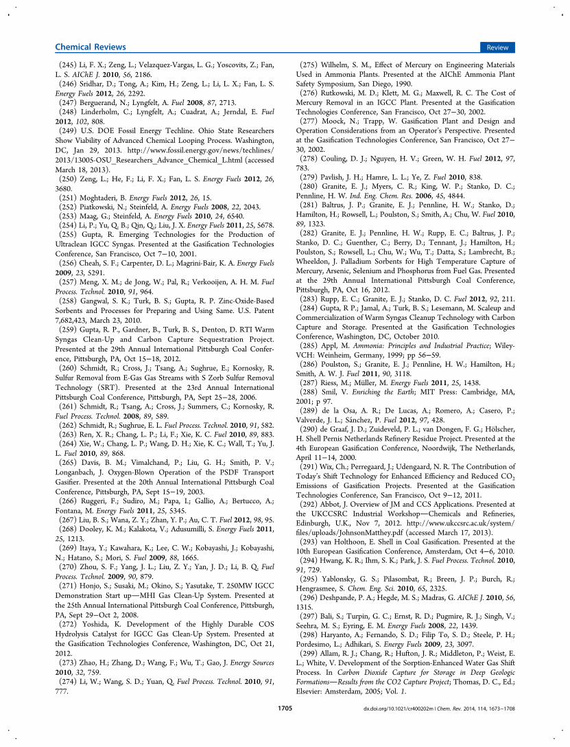
(245) Li, F. X.; Zeng, L.; Velazquez-Vargas, L. G.; Yoscovits, Z.; Fan,L. S. AIChE J. 2010, 56, 2186.(246) Sridhar, D.; Tong, A.; Kim, H.; Zeng, L.; Li, L. X.; Fan, L. S.Energy Fuels 2012, 26, 2292.(247) Berguerand, N.; Lyngfelt, A. Fuel 2008, 87, 2713.(248) Linderholm, C.; Lyngfelt, A.; Cuadrat, A.; Jerndal, E. Fuel2012, 102, 808.(249) U.S. DOE Fossil Energy Techline. Ohio State ResearchersShow Viability of Advanced Chemical Looping Process. Washington,DC, Jan 29, 2013. http://www.fossil.energy.gov/news/techlines/2013/13005-OSU_Researchers_Advance_Chemical_L.html (accessedMarch 18, 2013).(250) Zeng, L.; He, F.; Li, F. X.; Fan, L. S. Energy Fuels 2012, 26,3680.(251) Moghtaderi, B. Energy Fuels 2012, 26, 15.(252) Piatkowski, N.; Steinfeld, A. Energy Fuels 2008, 22, 2043.(253) Maag, G.; Steinfeld, A. Energy Fuels 2010, 24, 6540.(254) Li, P.; Yu, Q. B.; Qin, Q.; Liu, J. X. Energy Fuels 2011, 25, 5678.(255) Gupta, R. Emerging Technologies for the Production ofUltraclean IGCC Syngas. Presented at the Gasification TechnologiesConference, San Francisco, Oct 7−10, 2001.(256) Cheah, S. F.; Carpenter, D. L.; Magrini-Bair, K. A. Energy Fuels2009, 23, 5291.(257) Meng, X. M.; de Jong, W.; Pal, R.; Verkooijen, A. H. M. FuelProcess. Technol. 2010, 91, 964.(258) Gangwal, S. K.; Turk, B. S.; Gupta, R. P. Zinc-Oxide-BasedSorbents and Processes for Preparing and Using Same. U.S. Patent7,682,423, March 23, 2010.(259) Gupta, R. P., Gardner, B., Turk, B. S., Denton, D. RTI WarmSyngas Clean-Up and Carbon Capture Sequestration Project.Presented at the 29th Annual International Pittsburgh Coal Confer-ence, Pittsburgh, PA, Oct 15−18, 2012.(260) Schmidt, R.; Cross, J.; Tsang, A.; Sughrue, E.; Kornosky, R.Sulfur Removal from E-Gas Gas Streams with S Zorb Sulfur RemovalTechnology (SRT). Presented at the 23rd Annual InternationalPittsburgh Coal Conference, Pittsburgh, PA, Sept 25−28, 2006.(261) Schmidt, R.; Tsang, A.; Cross, J.; Summers, C.; Kornosky, R.Fuel Process. Technol. 2008, 89, 589.(262) Schmidt, R.; Sughrue, E. L. Fuel Process. Technol. 2010, 91, 582.(263) Ren, X. R.; Chang, L. P.; Li, F.; Xie, K. C. Fuel 2010, 89, 883.(264) Xie, W.; Chang, L. P.; Wang, D. H.; Xie, K. C.; Wall, T.; Yu, J.L. Fuel 2010, 89, 868.(265) Davis, B. M.; Vimalchand, P.; Liu, G. H.; Smith, P. V.;Longanbach, J. Oxygen-Blown Operation of the PSDF TransportGasifier. Presented at the 20th Annual International Pittsburgh CoalConference, Pittsburgh, PA, Sept 15−19, 2003.(266) Ruggeri, F.; Sudiro, M.; Papa, I.; Gallio, A.; Bertucco, A.;Fontana, M. Energy Fuels 2011, 25, 5345.(267) Liu, B. S.; Wana, Z. Y.; Zhan, Y. P.; Au, C. T. Fuel 2012, 98, 95.(268) Dooley, K. M.; Kalakota, V.; Adusumilli, S. Energy Fuels 2011,25, 1213.(269) Itaya, Y.; Kawahara, K.; Lee, C. W.; Kobayashi, J.; Kobayashi,N.; Hatano, S.; Mori, S. Fuel 2009, 88, 1665.(270) Zhou, S. F.; Yang, J. L.; Liu, Z. Y.; Yan, J. D.; Li, B. Q. FuelProcess. Technol. 2009, 90, 879.(271) Honjo, S.; Susaki, M.; Okino, S.; Yasutake, T. 250MW IGCCDemonstration Start upMHI Gas Clean-Up System. Presented atthe 25th Annual International Pittsburgh Coal Conference, Pittsburgh,PA, Sept 29−Oct 2, 2008.(272) Yoshida, K. Development of the Highly Durable COSHydrolysis Catalyst for IGCC Gas Clean-Up System. Presented atthe Gasification Technologies Conference, Washington, DC, Oct 21,2012.(273) Zhao, H.; Zhang, D.; Wang, F.; Wu, T.; Gao, J. Energy Sources2010, 32, 759.(274) Li, W.; Wang, S. D.; Yuan, Q. Fuel Process. Technol. 2010, 91,777.
(275) Wilhelm, S. M., Effect of Mercury on Engineering MaterialsUsed in Ammonia Plants. Presented at the AIChE Ammonia PlantSafety Symposium, San Diego, 1990.(276) Rutkowski, M. D.; Klett, M. G.; Maxwell, R. C. The Cost ofMercury Removal in an IGCC Plant. Presented at the GasificationTechnologies Conference, San Francisco, Oct 27−30, 2002.(277) Moock, N.; Trapp, W. Gasification Plant and Design andOperation Considerations from an Operator’s Perspective. Presentedat the Gasification Technologies Conference, San Francisco, Oct 27−30, 2002.(278) Couling, D. J.; Nguyen, H. V.; Green, W. H. Fuel 2012, 97,783.(279) Pavlish, J. H.; Hamre, L. L.; Ye, Z. Fuel 2010, 838.(280) Granite, E. J.; Myers, C. R.; King, W. P.; Stanko, D. C.;Pennline, H. W. Ind. Eng. Chem. Res. 2006, 45, 4844.(281) Baltrus, J. P.; Granite, E. J.; Pennline, H. W.; Stanko, D.;Hamilton, H.; Rowsell, L.; Poulston, S.; Smith, A.; Chu, W. Fuel 2010,89, 1323.(282) Granite, E. J.; Pennline, H. W.; Rupp, E. C.; Baltrus, J. P.;Stanko, D. C.; Guenther, C.; Berry, D.; Tennant, J.; Hamilton, H.;Poulston, S.; Rowsell, L.; Chu, W.; Wu, T.; Datta, S.; Lambrecht, B.;Wheeldon, J. Palladium Sorbents for High Temperature Capture ofMercury, Arsenic, Selenium and Phosphorus from Fuel Gas. Presentedat the 29th Annual International Pittsburgh Coal Conference,Pittsburgh, PA, Oct 16, 2012.(283) Rupp, E. C.; Granite, E. J.; Stanko, D. C. Fuel 2012, 92, 211.(284) Gupta, R P.; Jamal, A.; Turk, B. S.; Lesemann, M. Scaleup andCommercialization of Warm Syngas Cleanup Technology with CarbonCapture and Storage. Presented at the Gasification TechnologiesConference, Washington, DC, October 2010.(285) Appl, M. Ammonia: Principles and Industrial Practice; Wiley-VCH: Weinheim, Germany, 1999; pp 56−59.(286) Poulston, S.; Granite, E. J.; Pennline, H. W.; Hamilton, H.;Smith, A. W. J. Fuel 2011, 90, 3118.(287) Riess, M.; Muller, M. Energy Fuels 2011, 25, 1438.(288) Smil, V. Enriching the Earth; MIT Press: Cambridge, MA,2001; p 97.(289) de la Osa, A. R.; De Lucas, A.; Romero, A.; Casero, P.;Valverde, J. L.; Sanchez, P. Fuel 2012, 97, 428.(290) de Graaf, J. D.; Zuideveld, P. L.; van Dongen, F. G.; Holscher,H. Shell Pernis Netherlands Refinery Residue Project. Presented at the4th European Gasification Conference, Noordwijk, The Netherlands,April 11−14, 2000.(291) Wix, Ch.; Perregaard, J.; Udengaard, N. R. The Contribution ofToday’s Shift Technology for Enhanced Efficiency and Reduced CO2
Emissions of Gasification Projects. Presented at the GasificationTechnologies Conference, San Francisco, Oct 9−12, 2011.(292) Abbot, J. Overview of JM and CCS Applications. Presented atthe UKCCSRC Industrial WorkshopChemicals and Refineries,Edinburgh, U.K., Nov 7, 2012. http://www.ukccsrc.ac.uk/system/files/uploads/JohnsonMatthey.pdf (accessed March 17, 2013).(293) van Holthoon, E. Shell in Coal Gasification. Presented at the10th European Gasification Conference, Amsterdam, Oct 4−6, 2010.(294) Hwang, K. R.; Ihm, S. K.; Park, J. S. Fuel Process. Technol. 2010,91, 729.(295) Yablonsky, G. S.; Pilasombat, R.; Breen, J. P.; Burch, R.;Hengrasmee, S. Chem. Eng. Sci. 2010, 65, 2325.(296) Deshpande, P. A.; Hegde, M. S.; Madras, G. AIChE J. 2010, 56,1315.(297) Bali, S.; Turpin, G. C.; Ernst, R. D.; Pugmire, R. J.; Singh, V.;Seehra, M. S.; Eyring, E. M. Energy Fuels 2008, 22, 1439.(298) Haryanto, A.; Fernando, S. D.; Filip To, S. D.; Steele, P. H.;Pordesimo, L.; Adhikari, S. Energy Fuels 2009, 23, 3097.(299) Allam, R. J.; Chang, R.; Hufton, J. R.; Middleton, P.; Weist, E.L.; White, V. Development of the Sorption-Enhanced Water Gas ShiftProcess. In Carbon Dioxide Capture for Storage in Deep GeologicFormationsResults from the CO2 Capture Project; Thomas, D. C., Ed.;Elsevier: Amsterdam, 2005; Vol. 1.
Chemical Reviews Review
dx.doi.org/10.1021/cr400202m | Chem. Rev. 2014, 114, 1673−17081705
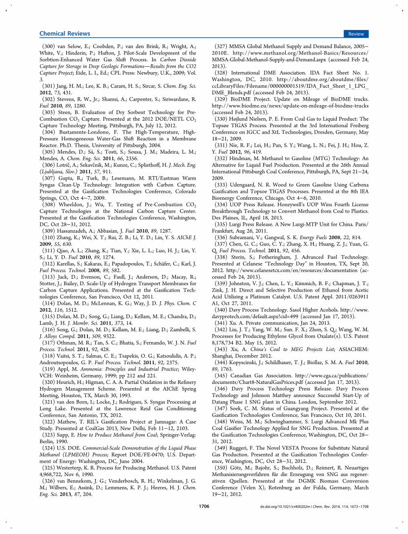
(300) van Selow, E.; Coobden, P.; van den Brink, R.; Wright, A.;White, V.; Hinderin, P.; Hufton, J. Pilot-Scale Development of theSorbtion-Enhanced Water Gas Shift Process. In Carbon DioxideCapture for Storage in Deep Geologic FormationsResults from the CO2Capture Project; Eide, L. I., Ed.; CPL Press: Newbury, U.K., 2009; Vol.3.(301) Jang, H. M.; Lee, K. B.; Caram, H. S.; Sircar, S. Chem. Eng. Sci.2012, 73, 431.(302) Stevens, R. W., Jr.; Shamsi, A.; Carpenter, S.; Siriwardane, R.Fuel 2010, 89, 1280.(303) Steen, B. Evaluation of Dry Sorbent Technology for Pre-Combustion CO2 Capture. Presented at the 2012 DOE/NETL CO2
Capture Technology Meeting, Pittsburgh, PA, July 12, 2012.(304) Bustamente-Londono, F. The High-Temperature, High-Pressure Homogeneous Water-Gas Shift Reaction in a MembraneReactor. Ph.D. Thesis, University of Pittsburgh, 2004.(305) Mendes, D.; Sa, S.; Tosti, S.; Sousa, J. M.; Madeira, L. M.;Mendes, A. Chem. Eng. Sci. 2011, 66, 2356.(306) Lotric, A.; Sekavcnik, M.; Kunze, C.; Spliethoff, H. J. Mech. Eng.(Ljubljana, Slov.) 2011, 57, 911.(307) Gupta, R.; Turk, B.; Lesemann, M. RTI/Eastman WarmSyngas Clean-Up Technology: Integration with Carbon Capture.Presented at the Gasification Technologies Conference, ColoradoSprings, CO, Oct 4−7, 2009.(308) Wheeldon, J.; Wu, T. Testing of Pre-Combustion CO2
Capture Technologies at the National Carbon Capture Center.Presented at the Gasification Technologies Conference, Washington,DC, Oct 28−31, 2012.(309) Hassanzadeh, A.; Abbasian, J. Fuel 2010, 89, 1287.(310) Zhang, K.; Wei, X. T.; Rui, Z. B.; Li, Y. D.; Lin, Y. S. AIChE J.2009, 55, 630.(311) Qiao, A. L.; Zhang, K.; Tian, Y.; Xie, L. L.; Luo, H. J.; Lin, Y.S.; Li, Y. D. Fuel 2010, 89, 1274.(312) Karellas, S.; Kakaras, E.; Papadopoulos, T.; Schafer, C.; Karl, J.Fuel Process. Technol. 2008, 89, 582.(313) Jack, D.; Evenson, C.; Faull, J.; Anderson, D.; Macay, R.;Stotter, J.; Bailey, D. Scale-Up of Hydrogen Transport Membranes forCarbon Capture Applications. Presented at the Gasification Tech-nologies Conference, San Francisco, Oct 12, 2011.(314) Dolan, M. D.; McLennan, K. G.; Way, J. D. J. Phys. Chem. C2012, 116, 1512.(315) Dolan, M. D.; Song, G.; Liang, D.; Kellam, M. E.; Chandra, D.;Lamb, J. H. J. Membr. Sci. 2011, 373, 14.(316) Song, G.; Dolan, M. D.; Kellam, M. E.; Liang, D.; Zambelli, S.J. Alloys Compd. 2011, 509, 9322.(317) Othman, M. R.; Tan, S. C.; Bhatia, S.; Fernando, W. J. N. FuelProcess. Technol. 2011, 92, 428.(318) Vaitsi, S. T.; Salmas, C. E.; Tsapekis, O. G.; Katsoulidis, A. P.;Androutsopoulos, G. P. Fuel Process. Technol. 2011, 92, 2375.(319) Appl, M. Ammonia: Principles and Industrial Practice; Wiley-VCH: Weinheim, Germany, 1999; pp 212 and 221.(320) Heurich, H.; Higman, C. A. A. Partial Oxidation in the RefineryHydrogen Management Scheme. Presented at the AIChE SpringMeeting, Houston, TX, March 30, 1993.(321) van den Born, I.; Locke, J.; Rodrigues, S. Syngas Processing atLong Lake. Presented at the Lawrence Reid Gas ConditioningConference, San Antonio, TX, 2012.(322) Mathew, T. RIL’s Gasification Project at Jamnagar: A CaseStudy. Presented at CoalGas 2013, New Delhi, Feb 11−12, 2103.(323) Supp, E. How to Produce Methanol from Coal; Springer-Verlag:Berlin, 1990.(324) U.S. DOE. Commercial-Scale Demonstration of the Liquid PhaseMethanol (LPMEOH) Process; Report DOE/FE-0470; U.S. Depart-ment of Energy: Washington, DC, June 2004.(325) Westerterp, K. R. Process for Producing Methanol. U.S. Patent4,968,722, Nov 6, 1990.(326) van Bennekom, J. G.; Venderbosch, R. H.; Winkelman, J. G.M.; Wilbers, E.; Assink, D.; Lemmens, K. P. J.; Heeres, H. J. Chem.Eng. Sci. 2013, 87, 204.
(327) MMSA Global Methanol Supply and Demand Balance, 2005−2010E. http://www.methanol.org/Methanol-Basics/Resources/MMSA-Global-Methanol-Supply-and-Demand.aspx (accessed Feb 24,2013).(328) International DME Association. IDA Fact Sheet No. 1.Washington, DC, 2010. http://aboutdme.org/aboutdme/files/ccLibraryFiles/Filename/000000001519/IDA_Fact_Sheet_1_LPG_DME_Blends.pdf (accessed Feb 24, 2013).(329) BioDME Project. Update on Mileage of BioDME trucks.http://www.biodme.eu/news/update-on-mileage-of-biodme-trucks(accessed Feb 24, 2013).(330) Højlund Nielsen, P. E. From Coal Gas to Liquid Product: TheTopsøe TIGAS Process. Presented at the 3rd International FreibergConference on IGCC and XtL Technologies, Dresden, Germany, May18−21, 2009.(331) Nie, R. F.; Lei, H.; Pan, S. Y.; Wang, L. N.; Fei, J. H.; Hou, Z.Y. Fuel 2012, 96, 419.(332) Hindman, M. Methanol to Gasoline (MTG) Technology: AnAlternative for Liquid Fuel Production. Presented at the 26th AnnualInternational Pittsburgh Coal Conference, Pittsburgh, PA, Sept 21−24,2009.(333) Udengaard, N. R. Wood to Green Gasoline Using CarbonaGasification and Topsoe TIGAS Processes. Presented at the 8th IEABioenergy Conference, Chicago, Oct 4−6, 2010.(334) UOP Press Release. Honeywell’s UOP Wins Fourth LicenseBreakthrough Technology to Convert Methanol from Coal to Plastics.Des Plaines, IL, April 18, 2013.(335) Lurgi Press Release. A New Lurgi-MTP Unit for China. Paris/Frankfurt, Aug 26, 2011.(336) Subramani, V.; Gangwal, S. K. Energy Fuels 2008, 22, 814.(337) Chen, G. C.; Guo, C. Y.; Zhang, X. H.; Huang, Z. J.; Yuan, G.Q. Fuel Process. Technol. 2011, 92, 456.(338) Sterin, S.; Fotheringham, J. Advanced Fuel Technology.Presented at Celanese “Technology Day” in Houston, TX, Sept 20,2012. http://www.celanesetcx.com/en/resources/documentation (ac-cessed Feb 24, 2013).(339) Johnston, V. J.; Chen, L. Y.; Kimmich, B. F.; Chapman, J. T.;Zink, J. H. Direct and Selective Production of Ethanol from AceticAcid Utilizing a Platinum Catalyst. U.S. Patent Appl. 2011/0263911A1, Oct 27, 2011.(340) Davy Process Technology. Sasol Higher Acohols. http://www.davyprotech.com/default.aspx?cid=499 (accessed Jan 17, 2013).(341) Xu. A. Private communication, Jan 24, 2013.(342) Liu, J. T.; Yang, W. M.; Sun. F. X.; Zhon, S. Q.; Wang, W. M.Processes for Producing Ethylene Glycol from Oxalate(s). U.S. Patent8,178,734 B2. May 15, 2012.(343) Xu, A. China’s Coal to MEG Projects List; ASIACHEM:Shanghai, December 2012.(344) Kopyscinski, J.; Schildhauer, T. J.; Biollaz, S. M. A. Fuel 2010,89, 1763.(345) Canadian Gas Association. http://www.cga.ca/publications/documents/Chart8-NaturalGasPrices.pdf (accessed Jan 17, 2013).(346) Davy Process Technology Press Release. Davy ProcessTechnology and Johnson Matthey announce Successful Start-Up ofDatang Phase 1 SNG plant in China. London, September 2012.(347) Soek, C. M. Status of Guangyang Project. Presented at theGasification Technologies Conference, San Francisco, Oct 10, 2011.(348) Weiss, M. M.; Schwinghammer, S. Lurgi Advanced Mk PlusCoal Gasifier Technology Applied for SNG Production. Presented atthe Gasification Technologies Conference, Washington, DC, Oct 28−31, 2012.(349) Ruggeri, F. The Novel VESTA Process for Substitute NaturalGas Production. Presented at the Gasification Technologies Confer-ence, Washington, DC, Oct 28−31, 2012.(350) Gotz, M.; Bajohr, S.; Buchholz, D.; Reimert, R. NeuartigesMethanisierungsverfahren fur die Erzeugung von SNG aus regener-ativen Quellen. Presented at the DGMK Biomass ConversionConference (Velen X), Rotenburg an der Fulda, Germany, March19−21, 2012.
Chemical Reviews Review
dx.doi.org/10.1021/cr400202m | Chem. Rev. 2014, 114, 1673−17081706
(351) Gotz, M.; Reimert, R.; Bajohr, S. Application of a Three PhaseReactor for the Production of SNG. Presented at the 29th AnnualInternational Pittsburgh Coal Conference, Pittsburgh, PA, Oct 15−18,2012.(352) Ryi, S. K.; Lee, S. W.; Hwang, K. r.; Park, J. S. Fuel 2012, 94,64.(353) Liu, Z. H.; Chu, B. Z.; Zhai, X. L.; Jin, Y.; Cheng, Y. Fuel 2012,95, 599.(354) Ma, X. G.; Ge, Q. J.; Fang, C. Y.; Ma, J. G.; Xu, H. Y. Fuel2011, 90, 2051.(355) Fischer−Tropsch Technology; Steynberg, A. P., Dry, M. E., Eds.;Studies in Surface Science and Catalysis 152; Elsevier: Amsterdam,2004.(356) de Klerk, A. Fischer−Tropsch Refining; Wiley-VCH: Weinheim,Germany, 2011.(357) Weiss, M. M.; Turna, O. Lurgi Clean Coal Technology Co..Presented at the Gasification Technologies Conference, ColoradoSprings, CO, Oct 4−7, 2009.(358) Cheeley, R. Combining Gasifiers with the Midrex DirectReduction Process. Presented at the 4th European GasificationConference, Noordwijk, The Netherlands, April 11−13, 2000.(359) Mako, P. F.; Samuel, W. A. The Sasol Approach to LiquidFuels from Coal via the Fischer−Tropsch Reaction. In Handbook ofSynfuels Technology; Meyers, R. A., Ed.; McGraw-Hill: New York,1984; pp 2−28.(360) Mokoena, K.; Van der Walt, T. J.; Morgan, T. J.; Herod, A. A.;Kandiyoti, R. Fuel 2008, 87, 751.(361) George, A.; Morgan, T. J.; Alvarez, P.; Millan, M.; Herod, A.A.; Kandiyoti, R. Fuel 2010, 89, 2953.(362) Papole, G.; Focke, W. W.; Manyala, N. Fuel 2012, 98, 243.(363) Pan, N.; Cui, D. C.; Li, R. L.; Shi, Q.; Chung, K. H.; Long, H.-Y.; Li, Y. Y.; Zhang, Y. H.; Zhao, S. Q.; Xu, C. M. Energy Fuels 2012,26, 5719.(364) Long, H. Y.; Shi, Q.; Pan, N.; Zhang, Y. H.; Cui, D. C.; Chung,K. H.; Zhao, S. Q.; Xu, C. M. Energy Fuels 2012, 26, 3424.(365) Mene dez Lo pez, R.; Patrick, J. Chem. Rev. 2014,DOI: 10.1021/cr400256y.(366) Morgan, T. J.; Kandiyoti, R. Chem. Rev. 2014, DOI: 10.1021/cr400194p.(367) Bergius, F.; Billwiller, J.; Verfahren zur Herstellung vonflussigen oder loslichen organischen Verbindungen aus Steinkohle u.dergl. German Patent DE 301231, Aug 9, 1913.(368) The Nobel Prize in Chemistry 1931. http://www.nobelprize.org/nobel_prizes/chemistry/laureates/1931/ (accessed March 30,2013).(369) Liu, Z. Y.; Shi, S. D.; Li, Y. W. Chem. Eng. Sci. 2010, 65, 12.(370) Lepinski, J.; Lee, T.; Tam, S. Recent Advances in Direct CoalLiquefaction Technology. Presented at the 237th ACS NationalMeeting, Salt Lake City, UT, March 26, 2009.(371) Comolli, A. G.; Zhou, P.; Lee, L. K. Direct Coal LiquefactionProof-of-Concept ProgramFinal Report; U.S. DOE Contract No.AC22-92PC92148, PB Run 9 and 10; January 2000.(372) Zhang, Y. Z.; Shu G. P.; Jin, J. L.; Cui, M. L.; Wu, X. Z.; Ren, X.K.; Xu, Y. W.; Liang, S. P.; Huang, J. W.; Yuan, M.; Gao, J. Z.; Zhu, Y.F. A Process for Direct Liquefaction of Coal. U.S. Patent Appl. US2009/0283450 A2, Nov 9, 2009.(373) Zhang, Y. Z.; Shu G. P.; Jin, J. L.; Cui, M. L.; Wu, X. Z.; Ren, X.K.; Xu, Y. W.; Liang, S. P.; Huang, J. W.; Yuan, M.; Gao, J. Z.; Zhu, Y.F. A Process for Direct Coal Liquefaction. U.S. Patent 7,763,167, July27, 2010.(374) Si, T.Shenhua Shows the Way to Make Gas from Coal. ChinaDaily 2009, Jan 22.(375) Headwaters Press Release. Headwaters Incorporated andAxens Form Direct Coal Liquefaction Alliance. Headwaters News-Break, No. 253, Jan 19, 2010.(376) Duddy, J.; Lee, T. Direct Coal Liquefaction, Alliance DCL.Presented at World CTL 2010 Beijing, China, April 13−15, 2010.
(377) Lee, L. K.; Lepinski, J.; Duddy, J. Direct Coal LiquefactionUltra Clean Fuels and a Specific Case Study. Presented at World CTL2011, Paris, France, March 1−3, 2011.(378) Lee, L. K.; Duddy, J. Benefits for Coal and Oil Co-Processing.Presented at World CTL 2012, Beijing, China, April 17−20, 2012.(379) Charon, N.; Dulot, H.; Quignard, A.; Weiss, W. CoalConversion Process and Products, Comprising Two Direct EbullatedBed Liquefaction Stages and a Fixed Bed Hydrocracking Stage. U.S.Patent Appl. US 2011/0230688 A1, Sept 22, 2011.(380) Zhou, P. Z.; Lee, L. K.; Comolli, A. Ultra-Clean Liquid Fuelsfrom Shenhua Coal Liquefaction. Proceedings of the Second InternationalSymposium on Clean Coal Technology, November 1999, Beijing; ChinaCoal Industry Publishing House: Beijing, 1999; pp 817−824.(381) MacArthur, J. B.; Duddy, J. E. Direct Coal Liquefaction withIntegrated Product Hydrotreating and Catalyst Cascading. Int. PatentWO 2011/021081 A1, Feb 24, 2011.(382) MacArthur, J. B.; Duddy, J. E. Direct Coal Liquefaction withIntegrated Product Hydrotreating and Catalyst Cascading. U.S. PatentAppl. US 2011/0042272 A1, Feb 12, 2011.(383) MacArthur, J. B.; Colyar, J. J.; Duddy, J. E. Process ForUpgrading Coal Pyrolysis Oils. U.S. Patent Appl. US 2010/0147743A1, June 17, 2010.(384) Comolli, A. G.; Lee, L. K.; Pradhan, V. R., Stalzer, R. H.;Karolkiewicz, W. F.; Pablacio, R. M. Direct Liquefaction Proof-of-Concept Program, Topical Report, POC Run 02; Work PerformedUnder U.S. DOE Contract No. AC22-92-PC92148, December 1996.(385) Moulton, D. S.; Erwin, J. Synthetic Hydrocarbon Productionby Direct Reduction of Carbonaceous Materials with Synthesis Gas.U.S. Patent Appl. US 2012/0161077 A1, June 28, 2012.(386) Keusenkothen, P. F.; Herschkowitz, F. Conversion of Co-FedMethane and Low Hydrogen Content Hydrocarbon Feedstocks toAcetylene. Int. Patent WO 2010/065200 A1, June 10, 2010.(387) Fiato, R. A.; Bauman, R. F.; Zaczepinski, S.; Bisio, A. IntegratedCoal to Liquids Process and System with CO2 Mitigation Using AlgalBiomass. Int. Patent WO 2012/082627 A1, June 21, 2012.(388) Fiato, R. A.; Bauman, R. F.; Zaczepinski, S.; Bisio, A. IntegratedCoal to Liquids Process. Eur. Patent EP 2443217, Dec 25, 2012.(389) Fiato, R. A. Integrated Coal to Liquids Process. Int. Patent WO2010/135381 A1, Nov 25, 2012.(390) Fiato, R. A.; Wang,Y. Q. An Integrated Coal LiquefactionProcess. Int. Patent WO 2008/083601 A1, July 17, 2008.(391) Fiato, R. A.; Wang, Y. Q. An Integrated Coal to LiquidsProcess. Int. Patent WO 2008/083600 A1, July 17, 2008.(392) Zhu, Z. L.; Sun, M. M.; Su, C. G. Process for Producing LiquidHydrocarbon Fuel by Coal Hydrolysis. Int. Patent WO 2012/129783A1, Oct 4, 2012.(393) Stiller, A. H.; Chalifoux, G. A.; Eberth, E. G.; Kennel, E. B.;Stansberry, P. G. Novel Hydrogenated Solvents for Coal Liquefaction.Int. Patent WO 2011/163300 A2, Dec 29, 2011.(394) Witherspoon, J. A. Method and Apparatus for Liquefaction andDistilllation of Volatile Matter within Solid Carbonaceous Material.Int. Patent WO 2011/130130 A2, Oct 20, 2011.(395) Ohashi, K.; Horibe, K.; Yaga, M.; Ohta, M.; Misumi, Y.; Nagal,M. Solvent for Coal Liquefaction, Method for Producing Same andMethod for Producing Liquefied Coal Oil. Int. Patent WO 2011/121953 A1, Oct 6, 2011.(396) Cui, M. L.; Huang, J. W.; Hao, X.; Cao, L. R.; Li, Y. W. Methodand Equipment for Multistage Liquefying of Carbonaceous Solid Fuel.U.S. Patent Appl. US 2011/0174683 A1, July 21, 2011.(397) Xu, Y. B.; Dai, L. S.; Zhang, Z. G.; Cui, S. Y.; Gong, J. H.; Xie,C. G.; Long, J.; Nie, H., Da, Z. J.; Zhang, J. S.; Liu, T.; Mao, A. G.Method for Obtaining Light Fuel from Inferior Feedstock. Int. PatentWO 2009/111953 A1, Sept 17, 2009.(398) Wu, K.; Chen, C.; Hunag, W. Y.; Peng, P.; Wu, C. L. Methodfor Liquefying Coal. Int. Patent WO 2009/076894 A1, June 25, 2009.(399) Inoue, T.; Okuma, O.; Masuda, K.; Yasumuro, M.; Miura, K.Energy Fuels 2012, 26, 2198.(400) Inoue, T.; Okuma, O.; Masuda, K.; Yasumuro, M.; Miura, K.Energy Fuels 2012, 26, 5821.
Chemical Reviews Review
dx.doi.org/10.1021/cr400202m | Chem. Rev. 2014, 114, 1673−17081707

(401) Wang, Z. C.; Shui, H. F.; Pei, Z. N.; Gao, J. S. Fuel 2008, 87,527.(402) Lei, Z. P.; Gao, L. J.; Shui, H. F.; Wang, Z. C.; Ren, S. B. EnergySources 2012, 34, 2287.(403) Li, J.; Yang, J. L.; Liu, Z. Y. Fuel Process. Technol. 2009, 90, 490.(404) Chu, X. J.; Li, W.; Li, B. Q.; Chen, H. K. Fuel 2008, 87, 211.(405) Liu, X.; Zhou, Z. J.; Hu, Q. J.; Dai, Z. H.; Wang, F. C. EnergyFuels 2012, 34, 1695.(406) Yang, J. L.; Wang, Z. X.; Liu, Z. Y.; Zhang, Y. Z. Energy Fuels2009, 23, 4717.(407) Wua, M. M.; Yang, J. L.; Zhang, Y. Z. Fuel 2012, 100, 66.
Chemical Reviews Review
dx.doi.org/10.1021/cr400202m | Chem. Rev. 2014, 114, 1673−17081708
Related Documents


