OM914271-0815-B Contents Performance Specifications................... Front Cover Safety Precautions ................................................. 3 Tips for Safe Operation .......................................... 3 Techniques of Operation ........................................ 4 Installation .............................................................. 5 Clutch Operation .................................................... 5 Remote Control Switch Operation.......................... 5 Care and Maintenance ........................................... 5 Assembling Your Winch ......................................... 6 Lubrication/Cable Installation ................................. 7 Troubleshooting Guide ........................................... 7 Winch Parts List ..................................................8-9 Warranty ................................................ Back Cover Congratulations You have purchased the finest winch available in its service class. The OM 5000™ is a 5,000 lb. rated detach- able winch. It can be easily mounted to the front and rear of vehicle for self-recovery and multiple applications. It allows one winch to be used on multiple vehicles, and can be quickly installed and removed to avoid extra vehicle weight. The Quick Mount is available in either a 5,000 lb. rating with, 80ft. of 1/4 inch galvanized aircraft wire cable. Stan- dard with the OM 5000™ is a 12 ft. remote control switch, anti-theft locking pin, 2 ft. battery cables (optional 20ft. battery cables for rear mount) and a hawse fairlead. Front mount requires a standard receiver mounting kit. A stan- dard ball hitch can be used with rear mounted OM 5000™ to assist with loading and unloading. The QM 5000™ winch features a highly efficient 3 stage planetary gear set which transmits torque from a series wound D.C. motor (QM 5000). A positive clutch allows free spooling for quick cable deployment. An automatic load holding brake is designed to hold the full rated capacity of the winch. It was designed and manufactured to provide you with the utmost in utility. As with any device that combines power and movement in use, there are dangers if improperly used. At the same time, there are easier and faster ways for getting the job done if certain precau- tions are taken first. Please read this manual carefully. It contains useful ideas in ob- taining the most efficient operation from your Ramsey winch and safety procedures you need to know before beginning use. When you follow our guidelines for operation, your Ramsey winch will give you many years of service. Thank you for choosing Ramsey. You will be glad you have one working for you! Ramsey Winch Company OWNER’S MANUAL Front and Rear Mount Detachable Electric Winch Model Quick-Mount 5000H (QM5000H) (lbs) NO 1,000 3,000 5,000 (kg) LOAD 450 1,350 2,260 (FPM) 12V 39 31 8 6 (MPM) 12V 11.8 9.4 2.4 1.8 (FPM) 24V 47 26 21 12 (MPM) 24V 14.3 7.9 6.4 3.6 12V 72 180 295 420 24V 38 87 124 184 Amp Draw First Layer Line Pull Line Speed First Layer Layer of Cable 1 2 3 4 (lbs) 5,000 4,200 3,600 3,200 (kg) 2,260 1,900 1,630 1,450 (ft)* 15 30 55 80 (m)* 4 9 16 24 Rated Line Pull Per Layer Cumulative Cable Capacity Per Layer 1/4" (6mm) dia. Cable * Depends on cable being uniformly wound onto drum. Ramsey performance data is compiled from actual winch testing. TM

Welcome message from author
This document is posted to help you gain knowledge. Please leave a comment to let me know what you think about it! Share it to your friends and learn new things together.
Transcript

OM914271-0815-B
Contents
Performance Specifications ...................Front Cover
Safety Precautions .................................................3
Tips for Safe Operation ..........................................3
Techniques of Operation ........................................4
Installation ..............................................................5
Clutch Operation ....................................................5
Remote Control Switch Operation ..........................5
Care and Maintenance ...........................................5
Assembling Your Winch .........................................6
Lubrication/Cable Installation .................................7
Troubleshooting Guide ...........................................7
Winch Parts List ..................................................8-9
Warranty ................................................ Back Cover
CongratulationsYou have purchased the fi nest winch available in its
service class. The OM 5000™ is a 5,000 lb. rated detach-
able winch. It can be easily mounted to the front and rear
of vehicle for self-recovery and multiple applications. It
allows one winch to be used on multiple vehicles, and can
be quickly installed and removed to avoid extra vehicle
weight.
The Quick Mount is available in either a 5,000 lb. rating
with, 80ft. of 1/4 inch galvanized aircraft wire cable. Stan-
dard with the OM 5000™ is a 12 ft. remote control switch,
anti-theft locking pin, 2 ft. battery cables (optional 20ft.
battery cables for rear mount) and a hawse fairlead. Front
mount requires a standard receiver mounting kit. A stan-
dard ball hitch can be used with rear mounted OM 5000™
to assist with loading and unloading.
The QM 5000™ winch features a highly effi cient 3 stage
planetary gear set which transmits torque from a series
wound D.C. motor (QM 5000). A positive clutch allows free
spooling for quick cable deployment. An automatic load
holding brake is designed to hold the full rated capacity of
the winch. It was designed and manufactured to provide
you with the utmost in utility.
As with any device that combines power and movement in use,
there are dangers if improperly used. At the same time, there are
easier and faster ways for getting the job done if certain precau-
tions are taken fi rst.
Please read this manual carefully. It contains useful ideas in ob-
taining the most effi cient operation from your Ramsey winch and
safety procedures you need to know before beginning use. When
you follow our guidelines for operation, your Ramsey winch will
give you many years of service. Thank you for choosing Ramsey.
You will be glad you have one working for you!
Ramsey Winch Company
OWNER’S MANUAL
Front and Rear MountDetachable Electric WinchModel Quick-Mount 5000H (QM5000H)
(lbs) NO 1,000 3,000 5,000
(kg) LOAD 450 1,350 2,260
(FPM) 12V 39 31 8 6
(MPM) 12V 11.8 9.4 2.4 1.8
(FPM) 24V 47 26 21 12
(MPM) 24V 14.3 7.9 6.4 3.6
12V 72 180 295 420
24V 38 87 124 184Amp Draw
First Layer Line Pull
Line Speed
First Layer
Layer of Cable 1 2 3 4
(lbs) 5,000 4,200 3,600 3,200
(kg) 2,260 1,900 1,630 1,450
(ft)* 15 30 55 80
(m)* 4 9 16 24
Rated Line Pull Per Layer
Cumulative Cable
Capacity Per Layer 1/4"
(6mm) dia. Cable
* Depends on cable being uniformly wound onto drum. Ramsey performance data is
compiled from actual winch testing.
TM

3
SAFETY PRECAUTIONS & OPERATION TIPS
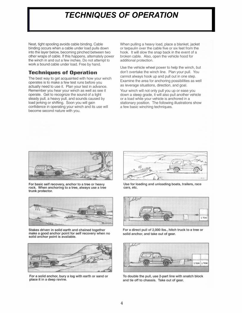
4
TECHNIQUES OF OPERATION
5
InstallationThe Quick MountTM is solely and exclusively designed for vehicle mounted, non-industrial applications. All other applications will void warranty.
The Quick MountTM must be front mounted with a front receiver hitch available from Ramsey for select- ed ve-hicles. For rear mounting of the QM 5000, any standard Class III rear receiver hitch may be used.
For normal self recovery work, your existing electrical system is adequate. Your battery must be kept in good condition. A fully charged battery and proper connec-tions are essential.
For front mounting, route quick connect battery power lead through grille, leaving connector on outside and connect red cable to positive(+) terminal and black cable to negative(-) terminal of battery. Secure cable under hood with cable ties.
For rear mounting connect battery power lead as in-structed above. Secure cables under vehicle away from moving parts and exhaust system. Terminate routing near the center of the vehicle at the rear. BE SURE BATTERY CABLES ARE NOT DRAWN TAUT ACROSS ANY SURFACES WHICH COULD POSSI- BLY DAM-AGE THEM.
Secure Quick MountTM in the receiver with the Ramsey locking pin. Connect quick disconnect from Quick MountTM winch to battery power lead. Plug remote switch into receptacle on solenoid assembly.
Clutch OperationThe winch clutch allows rapid unspooling of the cable for hooking onto the load or anchor point. The clutch is operated by the shifter lever located on the gear hous-ing end of the winch. Disengage the clutch, (move the clutch shifter lever to the “OUT” position.) Free spool some cable off the drum. Engage the clutch, (move the clutch shifter lever to the “IN” position.)
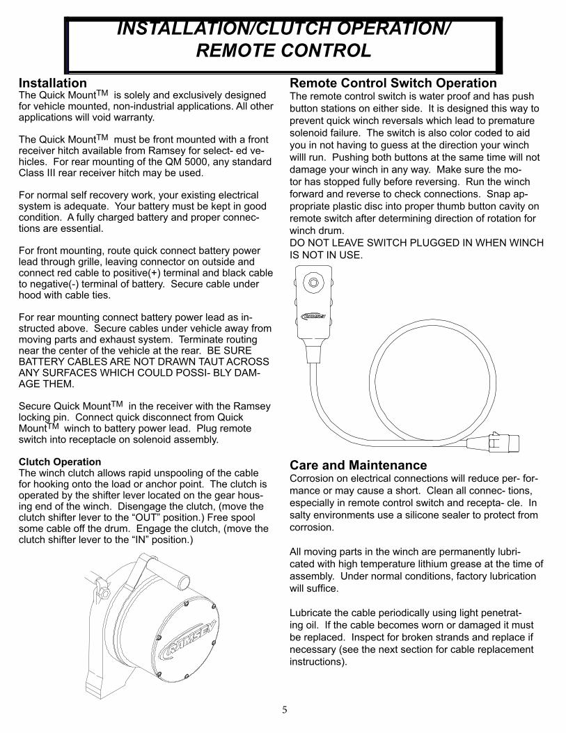
Remote Control Switch OperationThe remote control switch is water proof and has push
button stations on either side. It is designed this way to
prevent quick winch reversals which lead to premature
solenoid failure. The switch is also color coded to aid
you in not having to guess at the direction your winch
willl run. Pushing both buttons at the same time will not
damage your winch in any way. Make sure the mo-
tor has stopped fully before reversing. Run the winch
forward and reverse to check connections. Snap ap-
propriate plastic disc into proper thumb button cavity on
remote switch after determining direction of rotation for
winch drum.
DO NOT LEAVE SWITCH PLUGGED IN WHEN WINCH
IS NOT IN USE.
Care and MaintenanceCorrosion on electrical connections will reduce per- for-
mance or may cause a short. Clean all connec- tions,
especially in remote control switch and recepta- cle. In
salty environments use a silicone sealer to protect from
corrosion.
All moving parts in the winch are permanently lubri-
cated with high temperature lithium grease at the time of
assembly. Under normal conditions, factory lubrication
will suffi ce.
Lubricate the cable periodically using light penetrat-
ing oil. If the cable becomes worn or damaged it must
be replaced. Inspect for broken strands and replace if
necessary (see the next section for cable replacement
instructions).
INSTALLATION/CLUTCH OPERATION/
REMOTE CONTROL

6
Assembling your Winch
To assemble your QM winch to the quick mount
channel, attach handles to both ends of the quick
mount channel using (2) black 3/8” button head
screws for each handle as shown below. Tighten
to 20 ft-lbs. torque.
Once the handles are attached, lift the winch into
the quick mount channel. Feed the looped end
of the prewrapped cable through the fairlead.
Place a 3/8” nut and fl atwasher in each of the feet
of the winch. Align the four mounting holes
in the channel with the feet of the winch. Place a
lockwasher on each 3/8” hex head bolt and
press a bolt through each mounting hole and start
it through a nut in the foot of the winch. Do not
tighten until all of the bolts have been start- ed.
Tighten evenly to 34 ft-lbs. torque.
Align the base of the clevis hook with the
loop on the end of the wire cable. Run the pin
through the clevis hook and the loop. Push the
cotter pin through the hole in the pin and bend
the cotter pin to lock.
20 ft-lbs.torque
34 ft-lbs.torque
QM5000H TM
WINCH ASSEMBLY
7
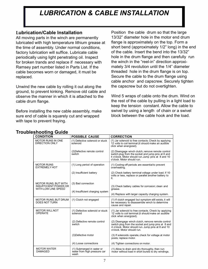
CONDITION POSSIBLE CAUSE CORRECTION
MOTOR RUNS IN ONE DIRECTION ONLY
(1) Defective solenoid or stuck solenoid
(2)Defective remote control switch
(1) Jar solenoid to free contacts. Check by applying 12 volts to coil terminal (it should make an audible click when energized).
(2) Disengage winch clutch, remove remote control switch plug from the socket and jump pins at 8 and 4 o'clock. Motor should run.Jump pins at 8 and 10 o'clock. Motor should run.
MOTOR RUNS EXTREMELY HOT
MOTOR RUNS, BUT WITH INSUFFICIENT POWER,OR WITH LOW LINE SPEED
(1) Long period of operation
(2) Insufficient battery
(3) Bad connection
(4) Insufficient charging system
(1) Cooling-off periods are essential to prevent overheating.
(2) Check battery terminal voltage under load. If 10 volts or less, replace or parallel another battery to it.
(3) Check battery cables for corrosion; clean and grease.
(4) Replace with larger capacity charging system.
MOTOR RUNS, BUT DRUM DOES NOT TURN
(1) Clutch not engaged (1) If clutch engaged but symptom still exists, it will be necessary to disassemble winch to determine cause and repair.
MOTOR WILL NOT OPERATE
(1) Defective solenoid or stuck solenoid
(2) Defective remote control switch
(3)Defective motor
(4) Loose connections
(1) Jar solenoid to free contacts. Check by applying 12 volts to coil terminal (it should make an audible click when energized).
(2) Disengage winch clutch, remove remote control switch plug from the socket and jump pins at 8 and 4 o'clock. Motor should run. Jump pins at 8 and 10 o'clock. Motor should run.
(3) If solenoids operate, check for voltage at motor posts; replace motor.
(4) Tighten connections on motor.
MOTOR WATER DAMAGED
(1) Submerged in water or water from high pressure car wash
(1) Allow to drain and dry thoroughly, then run motor without load in short bursts to dry windings.
Lubrication/Cable lnstallationAll moving parts in the winch are permanently
lubri cated with high temperature lithium grease at
the time of assembly. Under normal conditions,
factory lubrication will suffi ce. Lubricate cable
periodically using light penetrating oil. Inspect
for broken trands and replace if necessary with
Ramsey part number listed in Parts List. If the
cable becomes worn or damaged, it must be
replaced.
Unwind the new cable by rolling it out along the
ground, to prevent kinking. Remove old cable and
observe the manner in which it is attached to the
cable drum fl ange.
Before installing the new cable assembly, make
sure end of cable is squarely cut and wrapped
with tape to prevent fraying.
Troubleshooting Guide
Position the cable drum so that the large
13/32” diameter hole in the motor end drum
fl ange is approximately on the top. Form a
short bend (approximately 1/2” long) in the end
of the cable. Insert the bend into the 13/32”
hole in the drum fl ange and then carefully run
the winch in the “reel-in” direction approxi-
mately 3/4 revolution until the 1/4” diameter
threaded hole in the drum fl ange is on top.
Secure the cable to the drum fl ange using
cable anchor and capscrew. Securely tighten
the capscrew but do not overtighten.
Wind 5 wraps of cable onto the drum. Wind on
the rest of the cable by pulling in a light load to
keep the tension constant. Allow the cable to
swivel by using a length of chain or a swivel
block between the cable hook and the load.
LUBRICATION & CABLE INSTALLATION

8
QM 5000H EXPLODED VIEW
& PARTS LIST
28
35
2932
14
20
33
8
46
19
34
30
4
44
28
31
4813
12
22
2
50
28
16
7
46
10
23
43
27
16
51
18
47
24
22
50
17
37
39
1
45
11
36350
38
5
15
6
41
25
26
9
49
40
39
42
21
Item
No.Qty. Part No. Description
Item
No.Qty. Part No. Description
1 1 247006 Gear Carrier Assembly - Output 25 2 414900 Screw-3/8-16NC X5/8,Flt SocHd/Fd/Ny
2 1 247007 Gear Carrier Assembly - Intermediate 24v 26 2 414937 Capscrew-3/8-16X3/4,HxSocButtHd
3 1 247024 Gear Carrier Assembly - Input 27 6 416273 Screw - #6-32NC x 3/8
4 1 251110 Switch Assembly - 12 ft 28 4 418018 Nut-1/4-20NC,Hex,Elastic Stop
5 1 251169 Cable Assembly - 80' x 1/4" (6mm) Dia. 29 2 418033 Nut-3/8-16NC,Hex,Reg
6 1 278210 Solenoid Assembly - 12v 30 4 418035 Nut - 3/8-16NC Hx reg Z/P
1 278211 Solenoid Assembly - 24v 31 2 418165 Washer-5/16 Shake Prf,Ext Teeth,Z/P
7 1 296285 Brake Assembly 32 2 418175 Lockwasher-3/8 Med Sect
8 1 296589 Motor/End Bearing Assembly - 12v 33 4 418177 Lockwasher - 3/8 Med Sect Z/P
1 296591 Motor/End Bearing Assembly - 24v 34 4 418181 Washer - 3/8 ID SAE Flat Z/P
9 1 299699 Winch Mounting Assembly 35 1 422018 Hawse Fairlead
10 1 332143 Drum - Cable 36 1 442207 Gasket - Gear Housing Cover
11 1 334143 Gear - Ring 37 1 444048 Gear - Output Sun
12 1 334147 Gear - Intermediate Sun 38 1 444097 Gear - Input Sun
13 1 338249 End Bearing 39 2 448061 Tie Bar
14 2 395294 QM Handle 40 1 448071 Cable Anchor
15 1 408315 Bracket-Solenoid Mounting 41 1 448097 Locking Pin
16 2 412056 Bushing - Drum 42 1 452005 Shifter Lever
17 1 412061 Bushing - Shaft 43 1 470053 Roll Pin - 1/8 Dia x 3/8 Lg
18 1 413018 Cover - Gear Housing 44 1 477002 Locking Ring
19 4 414316 Capscrew - 3/8-16NC x 1-1/4 Hx Hd GR5 Z/P 45 1 477013 Cam Ring
20 2 414320 Bolt-3/8-16NCX1 1/4,HxHd,GR5/Xylan Coated 46 2 477004 Ring - Half
21 1 414857 Bolt-1/4-20NCX1 1.5LG HXSOCHD,NYL,ZP 47 1 479007 Retainer - Ring Gear
22 3 414829 Capscrew - 1/4-20NC x 3/4 Soc Button Hd 48 6 494077 Spring
23 1 414830 Capscrew - 1/4-20NC x 3/8 Button Hd 49 2 518019 Thrust Washer
24 6 414861 Capscrew - 1/4-20NC x 3/4 Flat Soc Hd Nylok 50 3 518020 Thrust Washer
51 1 518027 Thrust Disc
QM 5000 Parts List (12v AND 24v)
TM
9
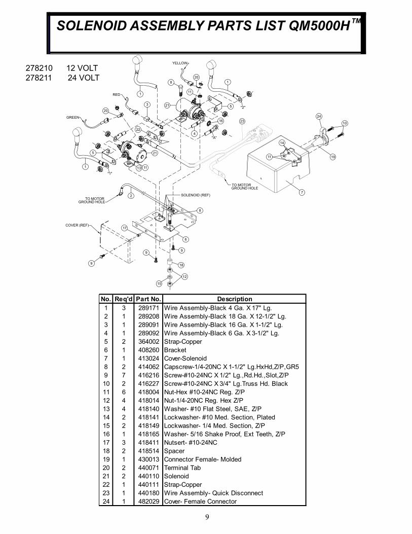
SOLENOID ASSEMBLY PARTS LIST QM5000HTM
278210 12 VOLT
278211 24 VOLT
2
1
5
22
6
8
16
1
5
11
3 21
21
2
4
1113
2
20
20
SOLENOID (REF)
"A"
1
7
9
10
14
11
12
15
17
18
24
19
YELLOW
GREEN
RED
COVER (REF)
9
23
TO MOTORGROUND HOLE
GROUND HOLETO MOTOR
8
9
"2"
"1"
No. Req'd Part No. Description
1 3 289171 Wire Assembly-Black 4 Ga. X 17" Lg.
2 1 289208 Wire Assembly-Black 18 Ga. X 12-1/2" Lg.
3 1 289091 Wire Assembly-Black 16 Ga. X 1-1/2" Lg.
4 1 289092 Wire Assembly-Black 6 Ga. X 3-1/2" Lg.
5 2 364002 Strap-Copper
6 1 408260 Bracket
7 1 413024 Cover-Solenoid
8 2 414062 Capscrew-1/4-20NC X 1-1/2" Lg.HxHd,Z/P,GR5
9 7 416216 Screw-#10-24NC X 1/2" Lg.,Rd.Hd.,Slot,Z/P
10 2 416227 Screw-#10-24NC X 3/4" Lg.Truss Hd. Black
11 6 418004 Nut-Hex #10-24NC Reg. Z/P
12 4 418014 Nut-1/4-20NC Reg. Hex Z/P
13 4 418140 Washer- #10 Flat Steel, SAE, Z/P
14 2 418141 Lockwasher- #10 Med. Section, Plated
15 2 418149 Lockwasher- 1/4 Med. Section, Z/P
16 1 418165 Washer- 5/16 Shake Proof, Ext Teeth, Z/P
17 3 418411 Nutsert- #10-24NC
18 2 418514 Spacer
19 1 430013 Connector Female- Molded
20 2 440071 Terminal Tab
21 2 440110 Solenoid
22 1 440111 Strap-Copper
23 1 440180 Wire Assembly- Quick Disconnect
24 1 482029 Cover- Female Connector
LIMITED WARRANTY
RAMSEY WINCH warrants each new RAMSEY WINCH to be free from defects in
material and workmanship for a period of one (1) year from date of purchase.
The obligation under this warranty, statutory or otherwise, is limited to the replacement
or repair at the Manufacturer's factory, or at a point designated by the Manufacturer, of
such part that shall appear to the Manufacturer, upon inspection of such part, to have
been defective in material or workmanship.
This warranty does not obligate RAMSEY WINCH to bear the cost of labor or trans
portation charges in connection with the replacement or repair of defective parts, nor
shall it apply to a product upon which repair or alterations have been made, unless
authorized by Manufacturer, or for equipment misused, neglected or which has not
been installed correctly.
RAMSEY WINCH shall in no event be liable for special or consequential damages.
RAMSEY WINCH makes no warranty in respect to accessories such as being subject
to the warranties of their respective manufacturers.
RAMSEY WINCH, whose policy is one of continuous improvement, reserves the right
to improve its products through changes in design or materials as it may deem desir
able without being obligated to incorporate such changes in products of prior manu
facture.
If field service at the request of the Buyer is rendered and the fault is found not to be
with RAMSEY WINCH's product, the Buyer shall pay the time and expense to the field
representative. Bills for service, labor or other expenses that have been incurred by
the Buyer without approval or authorization by RAMSEY WINCH will not be accepted.
See warranty card for details.


Ramsey Winch CompanyPost O� ce Box 581510
Tulsa, Oklahoma 74158-1510
Telephone: (#918) 438-2760 FAX: (#918) 438-6688
Related Documents