www.tjprc.org [email protected] PREVENTION OF FAILURE TO GIVE A GUARANTEE CONSTRUCTION OF BORED PILES FOUNDATION AT LEMAH IRENG BRIGDE, SEMARANG – SOLO TOLL ROAD, INDONESIA EDY PURWANTO Department of Civil Enginering , Faculty of Civil Engineering and P lanning, Islamic University of Indonesia, Yogyakarta, Indonesia ABSTRACT Lemah Ireng Bridge, section VI, Semarang – Solo toll road is a monumental stru cture for PT. Trans Marga Jateng Tbk., Publics Work Departement, Province of Central Java, Indonesia. The bridge has span of : 85 m – 130 m – 85 m and 25 m width, more than 35 m height above the land surface. The upper structure of the bridge is box girder and the sub-structure is bored piles foundation. The bridge consists of two piers (P-1 and P-2) and two abutments (Abut-1 and Abut-2). The Construction staging of Lemah Ireng bridge is a balanced cantilever method. The pier P-1 is located on valey with a slope steep and the foundation structure laids on the clay shale, so to ensure the structure stabilities needs geotechnical studies. This paper presents the historical case failure of the slope above the Pier P-1, results of Inclinometer measurement and analysis of slope stability uses Plaxis version 8.50. KEYWORDS: Lemah Ireng Bridge, Clay shale, Slope Failure, Inclinometer, Slope Stability INTRODUCTION Toll road construct ion is verry important activity to provide a good transportation public and to s olve the traffics jam in the national road fro m Semarang to Solo and the traffic jam in the national road relies the surrounding cities in the Central Java province. Toll road Semarang – Solo is constructed in two phases . Phase I is Semarang - Bawen section and the second phase is Bawen - Solo section. The main road alinnement passes at the villages, hilleys, forresters and agricultures areas. Based on the topography, the bridge should be bulit along from station 22+125 to station 22+840, that is Lemah Ireng bridge. The structure of the bridge consists of two piers (Piers P1 and P2) and two abutments (Abutment A1 and A2). The Lemah Ireng Bridge has tree spans of 85 m – 130 m – 85 m and 25 m witdh. The upper structure of the bridge is box girder and the sub structure is bored piles foundation. The Construction staging of Lemah Ireng bridge is a balanced cantilever method. (see Figure 1) Lemah Ireng bridge has a span 300 meters length and high from ground level more than 30 meters is a monumental project for PT. Trans Marga Jateng Tbk., Publics Work Department, Province of Central Java. That's because the amount of building bridges, in this project new and high technology used and the amount of the cost allocated, so that development requires expertise, supervision measured and well planned in order to get the maximum out according to plan. International Journal of Civil, Structural, Environmental and Infrastructure Engineering Research and Development (IJCSEIERD) ISSN(P): 2249-6866; ISSN(E): 2249-7978 Vol. 5, Issue 2, Apr 2015, 69-80 © TJPRC Pvt. Ltd.

Welcome message from author
This document is posted to help you gain knowledge. Please leave a comment to let me know what you think about it! Share it to your friends and learn new things together.
Transcript
8/9/2019 9. Civil - IJCSEIERD -Prevention of Failure at - EDY PURWANTO - Indonesia
http://slidepdf.com/reader/full/9-civil-ijcseierd-prevention-of-failure-at-edy-purwanto-indonesia 1/12
www.tjprc.org [email protected]
PREVENTION OF FAILURE TO GIVE A GUARANTEE CONSTRUCTION
OF BORED PILES FOUNDATION AT LEMAH IRENG BRIGDE,
SEMARANG – SOLO TOLL ROAD, INDONESIA
EDY PURWANTO
Department of Civil Enginering , Faculty of Civil Engineering and Planning, Islamic University of Indonesia,
Yogyakarta, Indonesia
ABSTRACT
Lemah Ireng Bridge, section VI, Semarang – Solo toll road is a monumental structure for PT. Trans Marga Jateng
Tbk., Publics Work Departement, Province of Central Java, Indonesia. The bridge has span of : 85 m – 130 m – 85 m and
25 m width, more than 35 m height above the land surface. The upper structure of the bridge is box girder and the
sub-structure is bored piles foundation. The bridge consists of two piers (P-1 and P-2) and two abutments (Abut-1 and
Abut-2). The Construction staging of Lemah Ireng bridge is a balanced cantilever method. The pier P-1 is located on valey
with a slope steep and the foundation structure laids on the clay shale, so to ensure the structure stabilities needs
geotechnical studies. This paper presents the historical case failure of the slope above the Pier P-1, results of Inclinometer
measurement and analysis of slope stability uses Plaxis version 8.50.
KEYWORDS: Lemah Ireng Bridge, Clay shale, Slope Failure, Inclinometer, Slope Stability
INTRODUCTION
Toll road construction is verry important activity to provide a good transportation public and to solve the traffics
jam in the national road from Semarang to Solo and the traffic jam in the national road relies the surrounding cities in the
Central Java province. Toll road Semarang – Solo is constructed in two phases. Phase I is Semarang - Bawen section and
the second phase is Bawen - Solo section.
The main road alinnement passes at the villages, hilleys, forresters and agricultures areas. Based on the
topography, the bridge should be bulit along from station 22+125 to station 22+840, that is Lemah Ireng bridge.
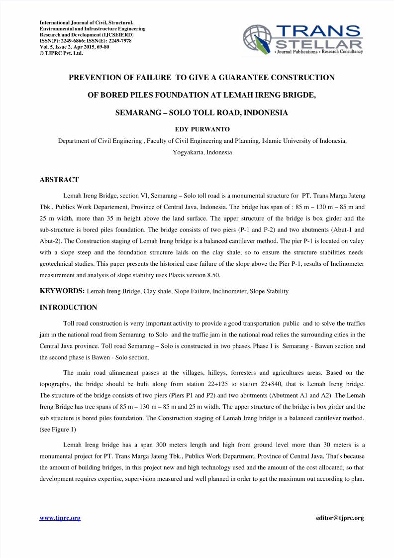
The structure of the bridge consists of two piers (Piers P1 and P2) and two abutments (Abutment A1 and A2). The Lemah
Ireng Bridge has tree spans of 85 m – 130 m – 85 m and 25 m witdh. The upper structure of the bridge is box girder and the
sub structure is bored piles foundation. The Construction staging of Lemah Ireng bridge is a balanced cantilever method.
(see Figure 1)
Lemah Ireng bridge has a span 300 meters length and high from ground level more than 30 meters is a
monumental project for PT. Trans Marga Jateng Tbk., Publics Work Department, Province of Central Java. That's because
the amount of building bridges, in this project new and high technology used and the amount of the cost allocated, so that
development requires expertise, supervision measured and well planned in order to get the maximum out according to plan.
International Journal of Civil, Structural,
Environmental and Infrastructure Engineering
Research and Development (IJCSEIERD)
ISSN(P): 2249-6866; ISSN(E): 2249-7978
Vol. 5, Issue 2, Apr 2015, 69-80
© TJPRC Pvt. Ltd.
8/9/2019 9. Civil - IJCSEIERD -Prevention of Failure at - EDY PURWANTO - Indonesia
http://slidepdf.com/reader/full/9-civil-ijcseierd-prevention-of-failure-at-edy-purwanto-indonesia 2/12
70 Edy Purwanto
Impact Factor (JCC): 5.7179 Index Copernicus Value (ICV): 3.0
Lemah Ireng bridge stands up on clay-shale. Clay-shale is a type of ground rock hard if not disturbed,
but otherwise the clay-shale when peeled, ground clay-shale contact with water and exposed to sunlight, the soil properties
of clay-shale will change. Physically clay-shale changes into mud and soil strength decreased significantly.
The slip failure occurred on the natural slope above Pier P-1 when the plat-form of Pier P-1 was constructed.
This failure caused by rain-fall infiltre enter the clay shale and it cause decline the shear strength of soil and be side that,
the soil work was realised in rain season,
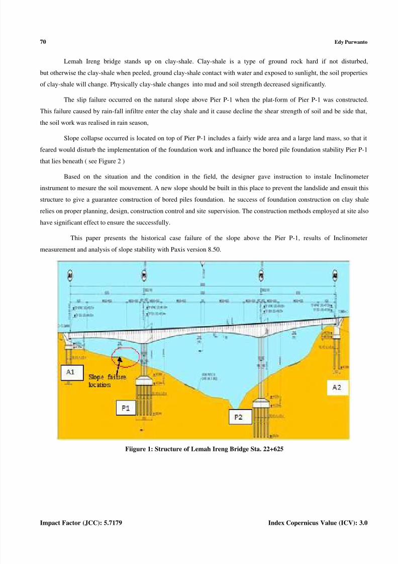
Slope collapse occurred is located on top of Pier P-1 includes a fairly wide area and a large land mass, so that it
feared would disturb the implementation of the foundation work and influance the bored pile foundation stability Pier P-1
that lies beneath ( see Figure 2 )
Based on the situation and the condition in the field, the designer gave instruction to instale Inclinometer
instrument to mesure the soil mouvement. A new slope should be built in this place to prevent the landslide and ensuit this
structure to give a guarantee construction of bored piles foundation. he success of foundation construction on clay shale
relies on proper planning, design, construction control and site supervision. The construction methods employed at site also
have significant effect to ensure the successfully.
This paper presents the historical case failure of the slope above the Pier P-1, results of Inclinometer
measurement and analysis of slope stability with Paxis version 8.50.
Fiigure 1: Structure of Lemah Ireng Bridge Sta. 22+625
8/9/2019 9. Civil - IJCSEIERD -Prevention of Failure at - EDY PURWANTO - Indonesia
http://slidepdf.com/reader/full/9-civil-ijcseierd-prevention-of-failure-at-edy-purwanto-indonesia 3/12
Prevention of Failure to Give a Guarantee Construction of Bored Piles 71Foundation at Lemah Ireng Brigde, Semarang – Solo Toll Road, Indonesia
www.tjprc.org [email protected]
Figure 2: Slope Failure Lacated at Above Pier P-1 Sta. 22+625
METHODOLOGY
General parameter of bridge: the structural concrete for all members of the bridges shall comply with the
following : Ec = 33234 Mpa, Deck = f’c= 40 Mpa., Pilecap and Abutment = f’c= 35 Mpa, Pile = f’c=30 MPA and Strength
at jacking = f’c= 35Mpa. Where f’c is the specifiied compressive strength of concrete at 28 days. Pier P-1 structure of
Lemah Ireng bridge supports the maximum bridge load because this structure located at the longest bridge span. This
structure laids on the steep valey with the natural slope steep and stands up on clay-shale.
Slope collapse occurred on the slopes located on the top position Pier P-1 stand . The collapse occurred at the time
of preparation work plat form for Pier P-1 Sta . 22 + 625 is in progress and the work takes place in the rainy season. To
assess more comprehensively on the slope collapse then the first step to do is to do a soil investigation at the site of the
collapse.
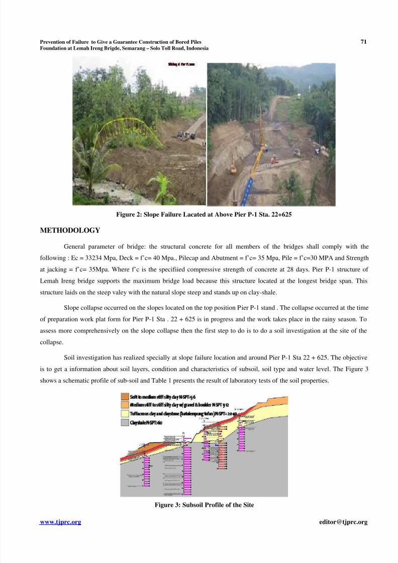
Soil investigation has realized specially at slope failure location and around Pier P-1 Sta 22 + 625. The objective
is to get a information about soil layers, condition and characteristics of subsoil, soil type and water level. The Figure 3
shows a schematic profile of sub-soil and Table 1 presents the result of laboratory tests of the soil properties.
Figure 3: Subsoil Profile of the Site
8/9/2019 9. Civil - IJCSEIERD -Prevention of Failure at - EDY PURWANTO - Indonesia
http://slidepdf.com/reader/full/9-civil-ijcseierd-prevention-of-failure-at-edy-purwanto-indonesia 4/12
72 Edy Purwanto
Impact Factor (JCC): 5.7179 Index Copernicus Value (ICV): 3.0
Table 1: Properties of the Clay-Shale
No. Clayshale
w
Natural
(%)
w
Saturated
(%)
GS
Compressive
Strength
(kg/cm2)
Cohesion
(kg/cm2)
Friction
Angle
( o )
Composition
Ca
(%)
Na
(%)
1. Tuffa 32,70 100 2,67 - 6,40 22 - -2.
Grey and
weathering 9,79 125,21 2,82 45,234 11,28 37,01 0,88 0,70
3.Dark andfresh 11,69 61,96 2,91 73,754 17,83 38,40 3,94 0,74
Source: PT. Selimut Bumi Adhi Cipta, 2012
The auther side, the condition in the field indicate that the ground moves downwards make a slit width of 1.00
meters along the northern slope. A sliding slope forms a gap and is accompanied by get out water significantly from the
gap. It indicates that the landslide which occurred caused by a rain water infiltrates into the ground and caused by a soil
cutting on the foot of the slope. The sliding slope include a fairly wide area and the movement of soil is predicted will
push the bored pile Pier P-1.
It will disturbs the smooth implementation of bored pile foundation work and raises fears would destabilize the
individual bored pile foundation before the time of execution of bored pile foundation united by a pile cap. Before the
bored pile foundation work carried out then this slope sliding problems should be studied comprehensively and find the
best solution first. The landslide covers a large area avalanche and to know more details of the landslide installed several
pieces of apparatus Inclinometer around the area until the establishment of the location of Pier P-1 Lemah Ireng bridge.
We predict this event disturbs the bored piles construction and the stability of the single bored pile, so it should be looked
for a good solution before the bored piles are constructed. To find out how much area that suffered catastrophic landslide
and will endanger the foundations, in the field needs some tools Inclinometer installed around the landslide area until thelocation of Pier P-1. Be expected with this recording and monitoring will be knowed the area of landslide and looked for
the good method to solve the problems occurs. The next will provide a guarantee of the stability of the foundation
structure at Pier P-1 .
INCLINOMETER MEASUREMENT
An Inclinometer or Clinometer is an instrument for measuring angles of slope (or tilt), elevation or depression of
an object with respect to gravity. Inclinometer measure both inclines (positive slopes, as seen by an observer looking
upwards) and declines (negative slopes, as seen by an observer looking downward) using three different units of measure :
degrees, percent and topo.
To indiquate a movement of soil in around of the slope location and location of the Pier-P1 structure, was
installed several inclinometers to measure the landslide or soil lateral mouvement. The observation with the inclinometers
take time more than 30 days and 25 m depth from the surface land existing. Layout of the Inclinometers is presented in
Figure 3 below.

8/9/2019 9. Civil - IJCSEIERD -Prevention of Failure at - EDY PURWANTO - Indonesia
http://slidepdf.com/reader/full/9-civil-ijcseierd-prevention-of-failure-at-edy-purwanto-indonesia 5/12
Prevention of Failure to Give a Guarantee Construction of Bored Piles 73Foundation at Lemah Ireng Brigde, Semarang – Solo Toll Road, Indonesia
www.tjprc.org [email protected]
Figure 4: Layout of the Inclinometer at Pier-P1 Sta. 22+625
The results of the mesurement with five inclinometers installed shows at Figure 5.
0
1
2
3
4
5
6
7
8
9
10
11
12
13
14
15
16
17
18
19
20
21
22
23
24
25
26
27
28
29
30
-0.060 -0.040 -0.020 0.000 0.020 0.040 0.060
Base Reading 15/03/12
3/4/2012
4/4/2012
5/4/2012
7/4/2012
9/4/2012
DISPLACEMENT VAL UE FACE A/B
GRAPHIC DISPLACEMENT IN-01
FACE A/B
A (Lereng)
D (Kanan)C (Kiri)
B ( !"an )
0
1
2
3
4
5
6
7
8
9
10
11
12
13
14
15
16
17
18
19
20
21
22
23
24
25
26
27
28
29
30
- 0.020 - 0.015 - 0.010 - 0.005 0.000 0.005 0.010 0.015 0.020
Base Reading 16/03/2012
19/03/12
20/03/12
21/03/12
22/03/12
24/03/12
26/03/12
27/03/12
28/03/12
29/03/12
30/03/12
31/03/12
02/04/12
DISPLACEMENT VALUE FACE C/D
GRAPHIC DISPLACEMENTIN 02
FACE C/D
A ( #a$an )
D ( Kanan)( Kiri ) C
B (!"an)
8/9/2019 9. Civil - IJCSEIERD -Prevention of Failure at - EDY PURWANTO - Indonesia
http://slidepdf.com/reader/full/9-civil-ijcseierd-prevention-of-failure-at-edy-purwanto-indonesia 6/12
74 Edy Purwanto
Impact Factor (JCC): 5.7179 Index Copernicus Value (ICV): 3.0
0
1
2
3
4
5
6
7
8
9
10
11
12
13
14
15
16
17
18
19
20
21
22
23
24
25
-0.040 -0.030 -0.020 -0.010 0.000 0.010 0.020 0.030 0.040
Base Reading 28/03/12
29/03/12
30/03/12
31/03/12
2/4/2012
DISPLACEMENT VALUE FACE A/B
GRAPHIC DISPLACEMENT IN-03
FACE A/B
A ( %!ngai )
DC ( &iri sa'a)
B ( !"an)
D E P T H ( m e t e r )
0
1
2
3
4
5
6
7
8
9
10
11
12
13
14
15
16
17
18
19
20
21
22
23
24
25
26
27
28
29
30
-0.100 -0.050 0.000 0.050 0.100
Base Reading 15/03/12
16/03/2012
19/03/12
20/03/12
21/03/12
22/03/12
24/03/12
DISPLACEMENT VAL UE FACE A/B
GRAPHIC DISPLACEMENT IN-0
FACE A/B
0.0
0.5
1.0
1.5
2.0
2.5
3.0
3.5
4.0
4.5
5.0
5.5
6.0
6.5
7.0
7.5
8.0
8.5
9.0
9.5
10.0
10.5
11.0
11.5
12.0
12.5
13.0
13.5
14.0
14.5
15.0
15.5
16.0
16.5
17.0
17.5
18.0
18.5
19.0
19.5
20.0
20.5
21.0
21.5
22.0
22.5
23.0
23.5
24.0
24.5
25.0
25.5
26.0
26.5
27.0
27.5
28.0
28.5
29.0
29.5
30.0
30.5
31.0
31.5
32.0
32.5
33.0
33.5 34.0
34.5
35.0
35.5
36.0
36.5
37.0
37.5
38.0
38.5
39.0
39.5
40.0
40.5
41.0
41.5
42.0
42.5
43.0
43.5
44.0
44.5
45.0
45.5
46.0
46.5
47.0
47.5
48.0
48.5
49.0
49.5
50.0
-0.050 -0.040 -0.030 -0.020 -0.010 0.000 0.010 0.020 0.030 0.040 0.050
D E P T H ( m e t e r )
DISPLACEMENT VALUE FACE A/B ( meter )
GRAPHIC DISPLACEMENT IN - 08
FACE A/BDATE READING : 21 / 04 / 2012
BASE READING 04/04/2012
DATE READING 16/04/2012
DATE READING 17/04/2012
DATE READING 18/04/2012
DATE READING 19/04/2012
DATE READING 20/04/2012
DATE READING 21/04/2012
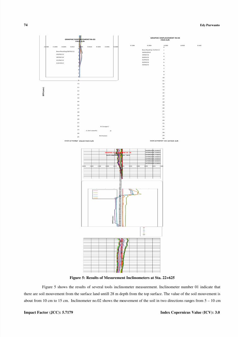
Figure 5: Results of Mesurement Inclinometers at Sta. 22+625
Figure 5 shows the results of several tools inclinometer measurement. Inclinometer number 01 indicate that
there are soil mouvement from the surface land untill 28 m depth from the top surface. The value of the soil mouvement isabout from 10 cm to 15 cm. Inclinometer no.02 shows the mouvement of the soil in two directions ranges from 5 – 10 cm
8/9/2019 9. Civil - IJCSEIERD -Prevention of Failure at - EDY PURWANTO - Indonesia
http://slidepdf.com/reader/full/9-civil-ijcseierd-prevention-of-failure-at-edy-purwanto-indonesia 7/12
Prevention of Failure to Give a Guarantee Construction of Bored Piles 75Foundation at Lemah Ireng Brigde, Semarang – Solo Toll Road, Indonesia
www.tjprc.org [email protected]
from the land surface to 25 m depth. Inclinometer no.3 shows the soil mouvement in two directions with ranges 20 cm
from top surface to 5 m depth and the soil mouvement change direction to 10-12 cm till the end of the Inclinometer.
Inclinometer no.04 address the mouvement of soil vers 1m at the top of surface and return to value of 0-5 cm displacement
untill the 30 m depth. Inclinometer no. 08 shows the soil mouvement from the top vers 10 cm and decline automatically atthe end. In general, the measurement of all Inclinometer shows a soil maximum mouvement at the top surface land and
tends decline untill the end of the Inclinometer. Beside that, in the field, there are differences elevation approximately 25 m
between the original surface land (before slipe failure happen) and after slipe failure happened.This prouves that the slip
failure happened is caused by reduced shear strength of the soil significantly.
SLOPE STABILITY
Pier P-1 structure laids on the steep natural valey and stands up on clay-shale. The slip failure occured when the
plat-form of Pier P-1 structure was realised. To take over this problem happened in the field and give a guarrantee
succesfully bored pile foundation construction needs geotechnical engineering
Results of the investigation in the field indiquate that the slope failure was identified caused by infiltration of rain
fall into to the soil and it cause reduction of shear strength of soil. From observation in the field the rain-fall water get out
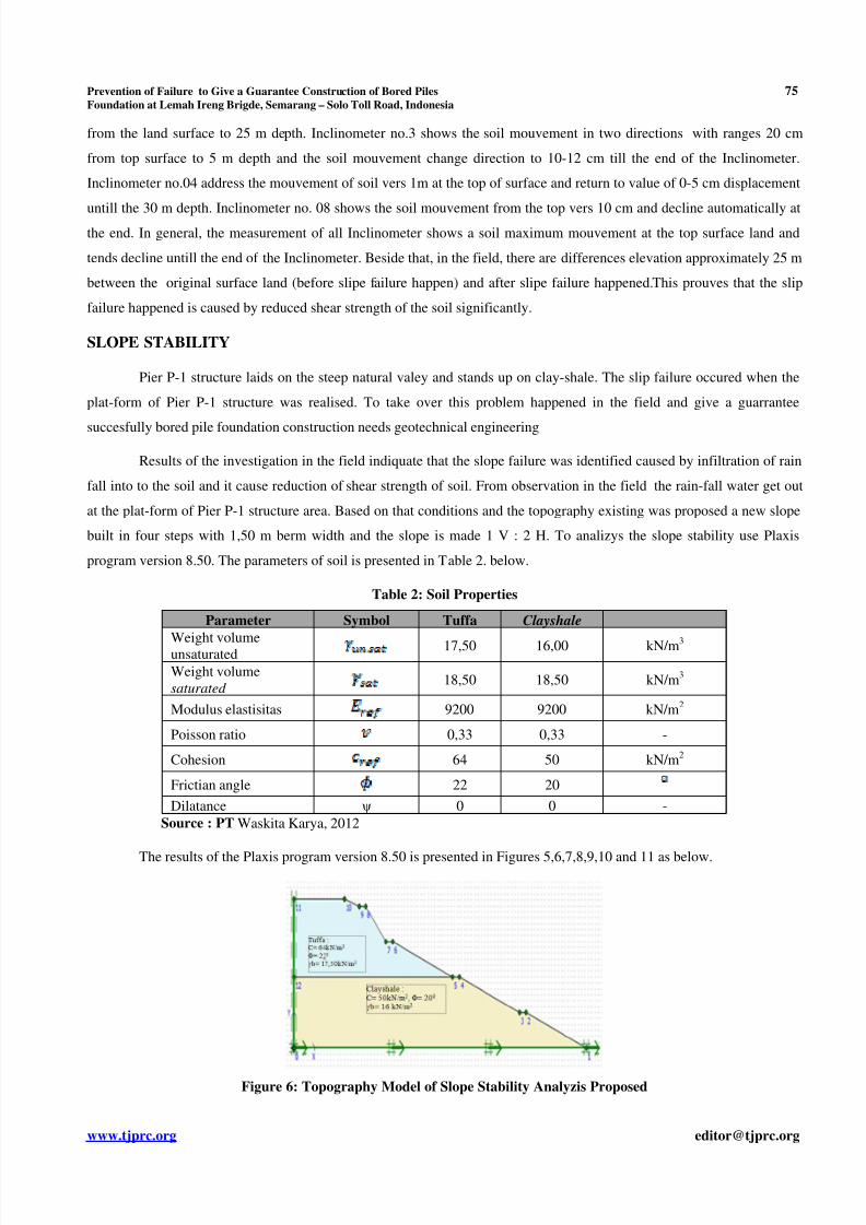
at the plat-form of Pier P-1 structure area. Based on that conditions and the topography existing was proposed a new slope
built in four steps with 1,50 m berm width and the slope is made 1 V : 2 H. To analizys the slope stability use Plaxis
program version 8.50. The parameters of soil is presented in Table 2. below.
Table 2: Soil Properties
Parameter Symbol Tuffa Clayshale
Weight volumeunsaturated 17,50 16,00 kN/m3
Weight volume
saturated 18,50 18,50 kN/m
3
Modulus elastisitas 9200 9200 kN/m2
Poisson ratio 0,33 0,33 -
Cohesion 64 50 kN/m2
Frictian angle 22 20
Dilatance ψ 0 0 -
Source : PT Waskita Karya, 2012
The results of the Plaxis program version 8.50 is presented in Figures 5,6,7,8,9,10 and 11 as below.
Figure 6: Topography Model of Slope Stability Analyzis Proposed
8/9/2019 9. Civil - IJCSEIERD -Prevention of Failure at - EDY PURWANTO - Indonesia
http://slidepdf.com/reader/full/9-civil-ijcseierd-prevention-of-failure-at-edy-purwanto-indonesia 8/12
76 Edy Purwanto
Impact Factor (JCC): 5.7179 Index Copernicus Value (ICV): 3.0
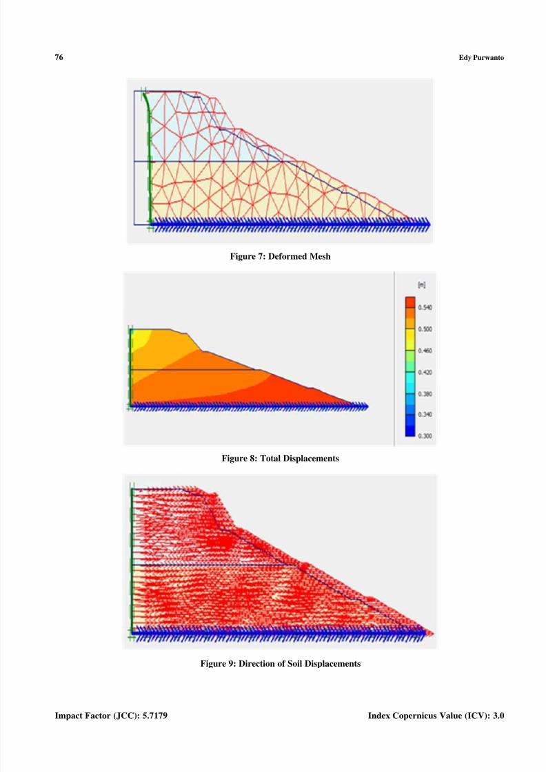
Figure 7: Deformed Mesh
Figure 8: Total Displacements
Figure 9: Direction of Soil Displacements

8/9/2019 9. Civil - IJCSEIERD -Prevention of Failure at - EDY PURWANTO - Indonesia
http://slidepdf.com/reader/full/9-civil-ijcseierd-prevention-of-failure-at-edy-purwanto-indonesia 9/12
Prevention of Failure to Give a Guarantee Construction of Bored Piles 77Foundation at Lemah Ireng Brigde, Semarang – Solo Toll Road, Indonesia
www.tjprc.org [email protected]
Figure 10: Effective Stress
Figure 11: Maximum Potential of Slope Failure
Figure 12: Safety Factors

8/9/2019 9. Civil - IJCSEIERD -Prevention of Failure at - EDY PURWANTO - Indonesia
http://slidepdf.com/reader/full/9-civil-ijcseierd-prevention-of-failure-at-edy-purwanto-indonesia 10/12
78 Edy Purwanto
Impact Factor (JCC): 5.7179 Index Copernicus Value (ICV): 3.0
The result of the Plaxis program shows the deformed mash in Figure 7. The Figure 8 shows total displacements
543,78.10-3
m and the direction of soil displacements is showed in Figure 9, Maximun potential of slope failure is presented
in Figure 10 and the Effective stress is -454,86 kN/m2 presented in Figure 11. Finally, the Figure 12 shows the safety factor
obtained. The safety factor is 2,60 more than 1,30 recomended in the field, so the slope is stable. From the slope stabilityanalysis used Plaxis version 8.50 got a good solution to prevent slope failure with a new slope built in four steps with 1,50
m berm width and the slope is made 1 V : 2 H.
CONCLUSIONS
The geotechnic review is important for a civil engineering consultant, consultant supervisi and contractor to have
some fundamental geotechnical knowledge to prevent failure occurs. To prevent the slope failure, a new slope should be
built in four steps with 1,50 m berm width and the slope is made 1 V : 2 H is recommanded. This new slope structure can
ultimately facilitate the work in the field
ACKNOWLEDGEMENTS
The authors wish to acknowledge the contributions and cooperations of PT. Trans marga Jateng and PT. Waskita
Karya on this research and the contruction in the field.
REFERENCES
1. Abramson W.T. et all. (1996). Slope Stability and Stabilization Methods, John Wiley & Sons, Inc. New York.
2.
Das B.M. (1984). Fundamentals of Soil Dynamic, Elservier Science Publishing Co.Inc. New York, USA.
3. Das, B.M. (1999). Principles of Foundation Engineering 4th Edition, Brooks/Cole Publishing Company.
4.
Duncan, J.M., and Buchignani, A.L.(1975). An Engineering Manual for Stability Studies, Civil Engineering
270B, University of California, Barkeley, CA.
5. Paulus P. Rahardjo. (2005.). Manual Pondasi Tiang, Edisi- 3, GEC – Geotechnical Engineering Center, Bandung.
6.
Dainty Zahrina Putri. (2013). Analisis Stabilitas Lereng dengan Perkuatan Geotekstil Menggunakan Software
Plaxis, Studi Kasus pada Lereng Sta. 2+225, Proyek Jalan Tol Semarang-Solo, Tugas Akhir S1, Yogyakarta.
7. PT. Global Perfex Synergi & ASS. (2012.). Justifikasi Teknik Pekerjaan Timbunan Abutment dan Badan Jalan
Lokal serta Fondasi Tiang Bor pada Overpass Sta.22+125 s/d Sta. 22+840, Bawen. Semarang, Semaran.
8.
PT. Global Perfex Synergi & ASS. (2012). Justifikasi Teknik Pekerjaan Dinding Penahan Tanah (Retainning
Wall) pada Abutment A2, Sta.22+125, Bawen. Semarang, Semarang.
9. PT. Global Perfex Synergi. (2012). Justifikasi Teknik Fondasi Tiang Bor pada Overpass Sta.22+850, Bawen,
Semarang.
10. PT. Global Perfex Synergi. (2012). Justifikasi Teknik Fondasi Tiang Bor pada Overpass Sta.21+800, Bawen,
Semarang.
11. PT. Selimut Bumi Adhi Cipta. (2012). Hasil uji Laboratotium tanah Batuan, Pembangunan Jalan Tol Semarang
– Bawen, Paket VI , Semarang.

8/9/2019 9. Civil - IJCSEIERD -Prevention of Failure at - EDY PURWANTO - Indonesia
http://slidepdf.com/reader/full/9-civil-ijcseierd-prevention-of-failure-at-edy-purwanto-indonesia 11/12
Prevention of Failure to Give a Guarantee Construction of Bored Piles 79Foundation at Lemah Ireng Brigde, Semarang – Solo Toll Road, Indonesia
www.tjprc.org [email protected]
12. PT. Waskita Karya Tbk. (2011). Laporan Soil Investigation Bor Mesin/Bor Log, Semarang.
13.
PT. Waskita Karya Tbk. (2012). Laporan Pelaksanaan Pengeboran fondasi tiang bor , Semarang.
14. PT. Wiecon Consultant. (2012). Sub-structure and Superstructure for Lemah Ireng Bridge, Final report,
Semarang.
15.
PT.Wirama Karya Consultant. (2004). Pekerjaan Pembangunan Jalan Tol Semarang – Solo, Semarang, Jawa
Tengah.
AUTHORS DETAIL
The Author is graduated in French 1996, Geotechnic expert, Director of Geotechnic Study Center and a Lecturer
at Department. of Civil Engineering, Faculty of Civil Engineering and Planning, Islamic University of Indonesia

8/9/2019 9. Civil - IJCSEIERD -Prevention of Failure at - EDY PURWANTO - Indonesia
http://slidepdf.com/reader/full/9-civil-ijcseierd-prevention-of-failure-at-edy-purwanto-indonesia 12/12
Related Documents


